US11103716B2 - Systems and methods for making and using a low-profile control module for an electrical stimulation system - Google Patents
Systems and methods for making and using a low-profile control module for an electrical stimulation systemDownload PDFInfo
- Publication number
- US11103716B2 US11103716B2US16/186,058US201816186058AUS11103716B2US 11103716 B2US11103716 B2US 11103716B2US 201816186058 AUS201816186058 AUS 201816186058AUS 11103716 B2US11103716 B2US 11103716B2
- Authority
- US
- United States
- Prior art keywords
- control module
- electronics housing
- connector
- assembly
- power
- Prior art date
- Legal status (The legal status is an assumption and is not a legal conclusion. Google has not performed a legal analysis and makes no representation as to the accuracy of the status listed.)
- Expired - Fee Related, expires
Links
Images


Classifications
- A—HUMAN NECESSITIES
- A61—MEDICAL OR VETERINARY SCIENCE; HYGIENE
- A61N—ELECTROTHERAPY; MAGNETOTHERAPY; RADIATION THERAPY; ULTRASOUND THERAPY
- A61N1/00—Electrotherapy; Circuits therefor
- A61N1/18—Applying electric currents by contact electrodes
- A61N1/32—Applying electric currents by contact electrodes alternating or intermittent currents
- A61N1/36—Applying electric currents by contact electrodes alternating or intermittent currents for stimulation
- A61N1/372—Arrangements in connection with the implantation of stimulators
- A61N1/375—Constructional arrangements, e.g. casings
- A—HUMAN NECESSITIES
- A61—MEDICAL OR VETERINARY SCIENCE; HYGIENE
- A61N—ELECTROTHERAPY; MAGNETOTHERAPY; RADIATION THERAPY; ULTRASOUND THERAPY
- A61N1/00—Electrotherapy; Circuits therefor
- A61N1/18—Applying electric currents by contact electrodes
- A61N1/32—Applying electric currents by contact electrodes alternating or intermittent currents
- A61N1/36—Applying electric currents by contact electrodes alternating or intermittent currents for stimulation
- A61N1/372—Arrangements in connection with the implantation of stimulators
- A61N1/378—Electrical supply
- A61N1/3787—Electrical supply from an external energy source
- A—HUMAN NECESSITIES
- A61—MEDICAL OR VETERINARY SCIENCE; HYGIENE
- A61N—ELECTROTHERAPY; MAGNETOTHERAPY; RADIATION THERAPY; ULTRASOUND THERAPY
- A61N1/00—Electrotherapy; Circuits therefor
- A61N1/02—Details
- A61N1/04—Electrodes
- A61N1/05—Electrodes for implantation or insertion into the body, e.g. heart electrode
- A61N1/0526—Head electrodes
- A61N1/0529—Electrodes for brain stimulation
- A—HUMAN NECESSITIES
- A61—MEDICAL OR VETERINARY SCIENCE; HYGIENE
- A61N—ELECTROTHERAPY; MAGNETOTHERAPY; RADIATION THERAPY; ULTRASOUND THERAPY
- A61N1/00—Electrotherapy; Circuits therefor
- A61N1/18—Applying electric currents by contact electrodes
- A61N1/32—Applying electric currents by contact electrodes alternating or intermittent currents
- A61N1/36—Applying electric currents by contact electrodes alternating or intermittent currents for stimulation
- A61N1/36014—External stimulators, e.g. with patch electrodes
- A61N1/36017—External stimulators, e.g. with patch electrodes with leads or electrodes penetrating the skin
- A—HUMAN NECESSITIES
- A61—MEDICAL OR VETERINARY SCIENCE; HYGIENE
- A61N—ELECTROTHERAPY; MAGNETOTHERAPY; RADIATION THERAPY; ULTRASOUND THERAPY
- A61N1/00—Electrotherapy; Circuits therefor
- A61N1/18—Applying electric currents by contact electrodes
- A61N1/32—Applying electric currents by contact electrodes alternating or intermittent currents
- A61N1/36—Applying electric currents by contact electrodes alternating or intermittent currents for stimulation
- A61N1/372—Arrangements in connection with the implantation of stimulators
- A61N1/375—Constructional arrangements, e.g. casings
- A61N1/37514—Brain implants
- A—HUMAN NECESSITIES
- A61—MEDICAL OR VETERINARY SCIENCE; HYGIENE
- A61N—ELECTROTHERAPY; MAGNETOTHERAPY; RADIATION THERAPY; ULTRASOUND THERAPY
- A61N1/00—Electrotherapy; Circuits therefor
- A61N1/18—Applying electric currents by contact electrodes
- A61N1/32—Applying electric currents by contact electrodes alternating or intermittent currents
- A61N1/36—Applying electric currents by contact electrodes alternating or intermittent currents for stimulation
- A61N1/372—Arrangements in connection with the implantation of stimulators
- A61N1/375—Constructional arrangements, e.g. casings
- A61N1/3752—Details of casing-lead connections
- A—HUMAN NECESSITIES
- A61—MEDICAL OR VETERINARY SCIENCE; HYGIENE
- A61N—ELECTROTHERAPY; MAGNETOTHERAPY; RADIATION THERAPY; ULTRASOUND THERAPY
- A61N1/00—Electrotherapy; Circuits therefor
- A61N1/18—Applying electric currents by contact electrodes
- A61N1/32—Applying electric currents by contact electrodes alternating or intermittent currents
- A61N1/36—Applying electric currents by contact electrodes alternating or intermittent currents for stimulation
- A61N1/372—Arrangements in connection with the implantation of stimulators
- A61N1/375—Constructional arrangements, e.g. casings
- A61N1/3758—Packaging of the components within the casing
- A—HUMAN NECESSITIES
- A61—MEDICAL OR VETERINARY SCIENCE; HYGIENE
- A61N—ELECTROTHERAPY; MAGNETOTHERAPY; RADIATION THERAPY; ULTRASOUND THERAPY
- A61N1/00—Electrotherapy; Circuits therefor
- A61N1/18—Applying electric currents by contact electrodes
- A61N1/32—Applying electric currents by contact electrodes alternating or intermittent currents
- A61N1/36—Applying electric currents by contact electrodes alternating or intermittent currents for stimulation
- A61N1/372—Arrangements in connection with the implantation of stimulators
- A61N1/378—Electrical supply
- H—ELECTRICITY
- H01—ELECTRIC ELEMENTS
- H01R—ELECTRICALLY-CONDUCTIVE CONNECTIONS; STRUCTURAL ASSOCIATIONS OF A PLURALITY OF MUTUALLY-INSULATED ELECTRICAL CONNECTING ELEMENTS; COUPLING DEVICES; CURRENT COLLECTORS
- H01R13/00—Details of coupling devices of the kinds covered by groups H01R12/70 or H01R24/00 - H01R33/00
- H01R13/02—Contact members
- H01R13/04—Pins or blades for co-operation with sockets
- H—ELECTRICITY
- H01—ELECTRIC ELEMENTS
- H01R—ELECTRICALLY-CONDUCTIVE CONNECTIONS; STRUCTURAL ASSOCIATIONS OF A PLURALITY OF MUTUALLY-INSULATED ELECTRICAL CONNECTING ELEMENTS; COUPLING DEVICES; CURRENT COLLECTORS
- H01R13/00—Details of coupling devices of the kinds covered by groups H01R12/70 or H01R24/00 - H01R33/00
- H01R13/62—Means for facilitating engagement or disengagement of coupling parts or for holding them in engagement
- H01R13/629—Additional means for facilitating engagement or disengagement of coupling parts, e.g. aligning or guiding means, levers, gas pressure electrical locking indicators, manufacturing tolerances
- H—ELECTRICITY
- H02—GENERATION; CONVERSION OR DISTRIBUTION OF ELECTRIC POWER
- H02J—CIRCUIT ARRANGEMENTS OR SYSTEMS FOR SUPPLYING OR DISTRIBUTING ELECTRIC POWER; SYSTEMS FOR STORING ELECTRIC ENERGY
- H02J50/00—Circuit arrangements or systems for wireless supply or distribution of electric power
- H02J50/10—Circuit arrangements or systems for wireless supply or distribution of electric power using inductive coupling
- A—HUMAN NECESSITIES
- A61—MEDICAL OR VETERINARY SCIENCE; HYGIENE
- A61N—ELECTROTHERAPY; MAGNETOTHERAPY; RADIATION THERAPY; ULTRASOUND THERAPY
- A61N1/00—Electrotherapy; Circuits therefor
- A61N1/02—Details
- A61N1/04—Electrodes
- A61N1/05—Electrodes for implantation or insertion into the body, e.g. heart electrode
- A61N1/0526—Head electrodes
- A61N1/0529—Electrodes for brain stimulation
- A61N1/0539—Anchoring of brain electrode systems, e.g. within burr hole
- A—HUMAN NECESSITIES
- A61—MEDICAL OR VETERINARY SCIENCE; HYGIENE
- A61N—ELECTROTHERAPY; MAGNETOTHERAPY; RADIATION THERAPY; ULTRASOUND THERAPY
- A61N1/00—Electrotherapy; Circuits therefor
- A61N1/02—Details
- A61N1/04—Electrodes
- A61N1/05—Electrodes for implantation or insertion into the body, e.g. heart electrode
- A61N1/0551—Spinal or peripheral nerve electrodes
- A—HUMAN NECESSITIES
- A61—MEDICAL OR VETERINARY SCIENCE; HYGIENE
- A61N—ELECTROTHERAPY; MAGNETOTHERAPY; RADIATION THERAPY; ULTRASOUND THERAPY
- A61N1/00—Electrotherapy; Circuits therefor
- A61N1/18—Applying electric currents by contact electrodes
- A61N1/32—Applying electric currents by contact electrodes alternating or intermittent currents
- A61N1/36—Applying electric currents by contact electrodes alternating or intermittent currents for stimulation
- A61N1/372—Arrangements in connection with the implantation of stimulators
- A61N1/375—Constructional arrangements, e.g. casings
- A61N1/3756—Casings with electrodes thereon, e.g. leadless stimulators
Definitions
- the present inventionis directed to the area of implantable electrical stimulation systems and methods of making and using the systems.
- the present inventionis also directed to a control module with an electronics housing and a power assembly that collectively form a sealed cavity, as well as methods of making and using the connector, control modules, and electrical stimulation systems.
- Implantable electrical stimulation systemshave proven therapeutic in a variety of diseases and disorders.
- spinal cord stimulation systemshave been used as a therapeutic modality for the treatment of chronic pain syndromes.
- Peripheral nerve stimulationhas been used to treat chronic pain syndrome and incontinence, with a number of other applications under investigation.
- Functional electrical stimulation systemshave been applied to restore some functionality to paralyzed extremities in spinal cord injury patients.
- a stimulatorcan include a control module (with a pulse generator) and one or more stimulator electrodes.
- the one or more stimulator electrodescan be disposed along one or more leads, or along the control module, or both.
- the stimulator electrodesare in contact with or near the nerves, muscles, or other tissue to be stimulated.
- the pulse generator in the control modulegenerates electrical pulses that are delivered by the electrodes to body tissue.
- a control module for an electrical stimulation systemincludes an electronics housing having an outer surface.
- An electronic subassemblyis disposed within the electronics housing.
- a power assemblyextends outwardly from the electronics housing and collectively with the electronics housing forms a sealed cavity.
- the power assemblyincludes a power source; a conduit assembly extending from the power source to the electronics housing; and one or more power conductors extending along the conduit assembly and electrically coupling the power source to the electronic subassembly.
- the control modulefurther includes one or more connector assemblies.
- Each of the one or more connector assembliesincludes a connector lumen configured to receive a lead; connector contacts arranged along the connector lumen and in electrical communication with the electronic subassembly; and connector conductors electrically coupled to the connector contacts.
- the conduit assemblyincludes a coupler and one or more tubular conduits extending from the coupler.
- the coupleris coupleable to the power source.
- the coupler and the one or more tubular conduitsform a portion of the sealed cavity.
- the one or more power conductorsextend through the one or more tubular conduits.
- the one or more tubular conduitsare flexible to permit bending relative to the electronics housing and power source upon application of a force and are configured to maintain a bent configuration.
- the one or more tubular conduitsare formed from a shape memory material.
- the one or more tubular conduitsinclude a bend forming an angle that is no smaller than 3° and no larger than 10°.
- the angle of the bendcorresponds to a contour of a portion of an outer surface of a skull to which the control module is attachable.
- the electronics housingincludes opposing parallel major surfaces extending along a first plane, and the bend causes the power assembly to extend along a second plane that is different from the first plane.
- feedthrough pinsextend through the electronics housing, and the conductors of the one or more connector assemblies are electrically coupled to the feedthrough pins, and the feedthrough pins are electrically coupled to the electronic subassembly.
- a charging coilis disposed external to the electronics housing and coupled to at least one of the feedthrough pins.
- one or more antennasare disposed external to the electronics housing and coupled to at least one of the feedthrough pins.
- a coveringis disposed over at least a portion of each of the electronics housing, the power assembly, and the one or more connector assemblies.
- a fastener apertureis defined in the covering, the fastener aperture configured to receive a fastener for fastening the control module to an outer surface of a skull.
- control modulewhen the control module is configured for fastening to an outer surface of a skull, the control module extends radially outwards from the outer surface of the skull by an amount no greater than 7 mm.
- an electrical stimulation systemincludes any of the above-described control modules, and an electrical stimulation lead coupleable to the control module.
- a method for making any of the above-described control modulesincludes disposing an electronic subassembly in an electronics housing.
- a power assembly having a power sourceis attached to at least one aperture defined in the electronics housing to create a sealed connection between the power assembly and the electronics housing.
- the power sourceis electrically coupled to the electronic subassembly.
- the electronics housingis sealed to, collectively with the power assembly, form a sealed cavity.
- a connector assemblyis electrically coupled to the electronic subassembly.
- the connector assemblyis configured to receive a lead.
- attaching a power assembly having a power source to at least one aperture defined in the electronics housingincludes attaching the power source and the electronics housing to opposing ends of a conduit assembly. In at least some embodiments, the method further includes bending the conduit assembly relative to the electronics housing and power source. In at least some embodiments, the method further includes coupling a charging coil and one or more antennas to the electronic subassembly.
- a control module for an electrical stimulation systemincludes an electronics housing having an outer surface.
- An electronic subassemblyis disposed within the electronics housing.
- a power assemblyextends laterally outwardly from the electronics housing and collectively with the electronics housing forms a sealed cavity.
- the power assemblyincludes a power source; and one or more power conductors disposed entirely in the sealed cavity and electrically coupling the power source to the electronic subassembly.
- One or more connector assembliesextend laterally outwardly from the electronics housing.
- Each of the one or more connector assembliesincludes a connector lumen configured to receive a lead; connector contacts arranged along the connector lumen and in electrical communication with the electronic subassembly; and connector conductors electrically coupled to the connector contacts.
- the one or more connector assembliesincludes a first connector assembly and a second connector assembly each extending laterally outwardly from the electronics housing, where the first connector assembly and the second connector assembly flank the power assembly.
- FIG. 1is a schematic view of one embodiment of an electrical stimulation system, according to the invention.
- FIG. 2is a schematic side view of one embodiment of an electrical stimulation lead, according to the invention.
- FIG. 3is a schematic overview of one embodiment of components of a stimulation system, including an electronic subassembly disposed within a control module, according to the invention
- FIG. 4Ais a schematic top view of one embodiment of a low-profile control module disposed along an outer surface of a skull and two leads extending from the control module and into the skull via burr holes covered with burr-hole covers, according to the invention;
- FIG. 4Bis a schematic front view of one embodiment of the low-profile control module of FIG. 4A disposed along an outer surface of a skull and two leads extending from the control module and into the skull via burr holes covered with burr-hole covers, according to the invention;
- FIG. 5Ais a schematic top view of one embodiment of a low-profile control module, the control module including a connector assembly and a sealed cavity formed collectively from an electronics housing and a power assembly, according to the invention;
- FIG. 5Bis a schematic end view of one embodiment of the low-profile control module of FIG. 5A , according to the invention.
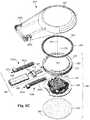
- FIG. 5Cis a schematic perspective, exploded view of one embodiment of the low-profile control module of FIG. 5A , according to the invention.
- FIG. 6is a schematic perspective, exploded view of an alternate embodiment of a low-profile control module including a connector assembly and a sealed cavity formed collectively from an electronics housing and a power assembly, according to the invention
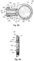
- FIG. 7Ais a schematic side view of one embodiment of the low-profile control module of FIG. 5A with the power assembly bent relative to the electronics housing, according to the invention
- FIG. 7Bis a schematic side view of one embodiment of the bent low-profile control module of FIG. 7A disposed along a patient's skull with the bending of the power assembly relative to the sealed electronics housing corresponding to a contour of the skull, according to the invention;
- FIG. 8Ais a schematic top view of another embodiment of a low-profile control module disposed along an outer surface of a skull and two leads extending from the control module and into the skull via burr holes covered with burr-hole covers, according to the invention.
- FIG. 8Bis a schematic front view of one embodiment of the low-profile control module of FIG. 8A disposed along an outer surface of a skull and two leads extending from the control module and into the skull via burr holes covered with burr-hole covers, according to the invention.
- the present inventionis directed to the area of implantable electrical stimulation systems and methods of making and using the systems.
- the present inventionis also directed to a control module with an electronics housing and a power assembly that collectively form a sealed cavity, as well as methods of making and using the connector, control modules, and electrical stimulation systems.
- Suitable implantable electrical stimulation systemsinclude, but are not limited to, a least one lead with one or more electrodes disposed on a distal portion of the lead and one or more terminals disposed on one or more proximal portions of the lead.
- Leadsinclude, for example, percutaneous leads, paddle leads, cuff leads, or any other arrangement of electrodes on a lead. Examples of electrical stimulation systems with leads are found in, for example, U.S. Pat. Nos.
- 2007/01500362009/0187222; 2009/0276021; 2010/0076535; 2010/0268298; 2011/0005069; 2011/0004267; 2011/0078900; 2011/0130817; 2011/0130818; 2011/0238129; 2011/0313500; 2012/0016378; 2012/0046710; 2012/0071949; 2012/0165911; 2012/0197375; 2012/0203316; 2012/0203320; 2012/0203321; 2012/0316615; 2013/0105071; and 2013/0197602, all of which are incorporated by reference.
- a percutaneous leadwill be exemplified, but it will be understood that the methods and systems described herein are also applicable to paddle leads and other leads.
- a percutaneous lead for electrical stimulation(for example, deep brain, spinal cord, peripheral nerve, or cardiac-tissue) includes stimulation electrodes that can be ring electrodes, segmented electrodes that extend only partially around the circumference of the lead, or any other type of electrode, or any combination thereof.
- the segmented electrodescan be provided in sets of electrodes, with each set having electrodes circumferentially distributed about the lead at a particular longitudinal position.
- a set of segmented electrodescan include any suitable number of electrodes including, for example, two, three, four, or more electrodes.
- the leadsare described herein relative to use for deep brain stimulation, but it will be understood that any of the leads can be used for applications other than deep brain stimulation, including spinal cord stimulation, peripheral nerve stimulation, dorsal root ganglion stimulation, sacral nerve stimulation, or stimulation of other nerves, muscles, and tissues.
- an electrical stimulation system 10includes one or more stimulation leads 12 and an implantable pulse generator (IPG) 14 .
- IPGimplantable pulse generator
- the system 10can also include one or more of an external remote control (RC) 16 , a clinician's programmer (CP) 18 , an external trial stimulator (ETS) 20 , or an external charger 22 .
- RCremote control
- CPclinician's programmer
- ETSexternal trial stimulator
- the IPG 14is physically connected, optionally, via one or more lead extensions 24 , to the stimulation lead(s) 12 .
- Each leadcarries multiple electrodes 26 arranged in an array.
- the IPG 14includes pulse generation circuitry that delivers electrical stimulation energy in the form of, for example, a pulsed electrical waveform (i.e., a temporal series of electrical pulses) to the electrode array 26 in accordance with a set of stimulation parameters.
- the implantable pulse generatorcan be implanted into a patient's body, for example, below the patient's clavicle area or within the patient's buttocks or abdominal cavity.
- the implantable pulse generatorcan have eight stimulation channels which may be independently programmable to control the magnitude of the current stimulus from each channel.
- the implantable pulse generatorcan have more or fewer than eight stimulation channels (e.g., 4-, 6-, 16-, 32-, or more stimulation channels).
- the implantable pulse generatorcan have one, two, three, four, or more connector ports, for receiving the terminals of the leads and/or lead extensions.
- the ETS 20may also be physically connected, optionally via the percutaneous lead extensions 28 and external cable 30 , to the stimulation leads 12 .
- the ETS 20which may have similar pulse generation circuitry as the IPG 14 , also delivers electrical stimulation energy in the form of, for example, a pulsed electrical waveform to the electrode array 26 in accordance with a set of stimulation parameters.
- One difference between the ETS 20 and the IPG 14is that the ETS 20 is often a non-implantable device that is used on a trial basis after the neurostimulation leads 12 have been implanted and prior to implantation of the IPG 14 , to test the responsiveness of the stimulation that is to be provided. Any functions described herein with respect to the IPG 14 can likewise be performed with respect to the ETS 20 .
- the RC 16may be used to telemetrically communicate with or control the IPG 14 or ETS 20 via a uni- or bi-directional wireless communications link 32 . Once the IPG 14 and neurostimulation leads 12 are implanted, the RC 16 may be used to telemetrically communicate with or control the IPG 14 via a uni- or bi-directional communications link 34 . Such communication or control allows the IPG 14 to be turned on or off and to be programmed with different stimulation parameter sets. The IPG 14 may also be operated to modify the programmed stimulation parameters to actively control the characteristics of the electrical stimulation energy output by the IPG 14 .
- the CP 18allows a user, such as a clinician, the ability to program stimulation parameters for the IPG 14 and ETS 20 in the operating room and in follow-up sessions. Alternately, or additionally, stimulation parameters can be programed via wireless communications (e.g., Bluetooth) between the RC 16 (or external device such as a hand-held electronic device) and the IPG 14 .
- wireless communicationse.g
- the CP 18may perform this function by indirectly communicating with the IPG 14 or ETS 20 , through the RC 16 , via a wireless communications link 36 . Alternatively, the CP 18 may directly communicate with the IPG 14 or ETS 20 via a wireless communications link (not shown).
- the stimulation parameters provided by the CP 18are also used to program the RC 16 , so that the stimulation parameters can be subsequently modified by operation of the RC 16 in a stand-alone mode (i.e., without the assistance of the CP 18 ).
- control moduleis used herein to describe a pulse generator (e.g., the IPG 14 or the ETS 20 of FIG. 1 ). Stimulation signals generated by the control module are emitted by electrodes of the lead(s) to stimulate patient tissue.
- the electrodes of the lead(s)are electrically coupled to terminals of the lead(s) that, in turn, are electrically coupleable with the control module.
- the lead(s)couple(s) directly with the control module.
- one or more intermediary devicese.g., a lead extension, an adaptor, a splitter, or the like are disposed between the lead(s) and the control module.
- Percutaneous leadsare described herein for clarity of illustration. It will be understood that paddle leads and cuff leads can be used in lieu of, or in addition to, percutaneous leads.
- the leads described hereininclude 8 electrodes (+1 auxiliary electrode in some embodiments). It will be understood that the leads could include any suitable number of electrodes.
- the leads described hereinexclusively include ring electrodes. It will be understood that the leads can include a distal-tip electrode, or one or more segmented electrodes in lieu of, or in addition to one or more ring electrodes.
- the term “elongated member” used hereinincludes leads (e.g., percutaneous, paddle, cuff, or the like), as well as intermediary devices (e.g., lead extensions, adaptors, splitters, or the like).
- FIG. 2illustrates one embodiment of a lead 110 with electrodes 125 disposed at least partially about a circumference of the lead 110 along a distal end portion of the lead and terminals 135 disposed along a proximal end portion of the lead.
- the lead 110can be implanted near or within the desired portion of the body to be stimulated such as, for example, the brain, spinal cord, or other body organs or tissues.
- access to the desired position in the braincan be accomplished by drilling a hole in the patient's skull or cranium with a cranial drill (commonly referred to as a burr), and coagulating and incising the dura mater, or brain covering.
- a burrcommonly referred to as a burr
- the lead 110can be inserted into the cranium and brain tissue with the assistance of a stylet (not shown).
- the lead 110can be guided to the target location within the brain using, for example, a stereotactic frame and a microdrive motor system.
- the microdrive motor systemcan be fully or partially automatic.
- the microdrive motor systemmay be configured to perform one or more the following actions (alone or in combination): insert the lead 110 , advance the lead 110 , retract the lead 110 , or rotate the lead 110 .
- measurement devices coupled to the muscles or other tissues stimulated by the target neurons, or a unit responsive to the patient or cliniciancan be coupled to the implantable pulse generator or microdrive motor system.
- the measurement device, user, or cliniciancan indicate a response by the target muscles or other tissues to the stimulation or recording electrode(s) to further identify the target neurons and facilitate positioning of the stimulation electrode(s).
- a measurement devicecan be used to observe the muscle and indicate changes in, for example, tremor frequency or amplitude in response to stimulation of neurons.
- the patient or cliniciancan observe the muscle and provide feedback.
- the lead 110 for deep brain stimulationcan include stimulation electrodes, recording electrodes, or both.
- the lead 110is rotatable so that the stimulation electrodes can be aligned with the target neurons after the neurons have been located using the recording electrodes.
- Stimulation electrodesmay be disposed on the circumference of the lead 110 to stimulate the target neurons. Stimulation electrodes may be ring-shaped so that current projects from each electrode equally in every direction from the position of the electrode along a length of the lead 110 . In the embodiment of FIG. 2 , two of the electrodes 125 are ring electrodes 120 . Ring electrodes typically do not enable stimulus current to be directed from only a limited angular range around of the lead. Segmented electrodes 130 , however, can be used to direct stimulus current to a selected angular range around the lead.
- segmented electrodesWhen segmented electrodes are used in conjunction with an implantable pulse generator that delivers constant current stimulus, current steering can be achieved to more precisely deliver the stimulus to a position around an axis of the lead (i.e., radial positioning around the axis of the lead). To achieve current steering, segmented electrodes can be utilized in addition to, or as an alternative to, ring electrodes.
- the lead 100includes a lead body 110 , terminals 135 , and one or more ring electrodes 120 and one or more sets of segmented electrodes 130 (or any other combination of electrodes).
- the lead body 110can be formed of a biocompatible, non-conducting material such as, for example, a polymeric material. Suitable polymeric materials include, but are not limited to, silicone, polyurethane, polyurea, polyurethane-urea, polyethylene, or the like.
- the lead 100may be in contact with body tissue for extended periods of time.
- the lead 100has a cross-sectional diameter of no more than 1.5 mm and may be in the range of 0.5 to 1.5 mm.
- the lead 100has a length of at least 10 cm and the length of the lead 100 may be in the range of 10 to 70 cm.
- the electrodes 125can be made using a metal, alloy, conductive oxide, or any other suitable conductive biocompatible material.
- suitable materialsinclude, but are not limited to, platinum, platinum iridium alloy, iridium, titanium, tungsten, palladium, palladium rhodium, or the like.
- the electrodesare made of a material that is biocompatible and does not substantially corrode under expected operating conditions in the operating environment for the expected duration of use.
- Each of the electrodescan either be used or unused (OFF).
- the electrodecan be used as an anode or cathode and carry anodic or cathodic current.
- an electrodemight be an anode for a period of time and a cathode for a period of time.
- Deep brain stimulation leadsmay include one or more sets of segmented electrodes. Segmented electrodes may provide for superior current steering than ring electrodes because target structures in deep brain stimulation are not typically symmetric about the axis of the distal electrode array. Instead, a target may be located on one side of a plane running through the axis of the lead.
- RSEAradially segmented electrode array
- current steeringcan be performed not only along a length of the lead but also around a circumference of the lead. This provides precise three-dimensional targeting and delivery of the current stimulus to neural target tissue, while potentially avoiding stimulation of other tissue. Examples of leads with segmented electrodes include U.S. Patents Nos.
- Segmented electrodescan also be used for other stimulation techniques including, but not limited to, spinal cord stimulation, peripheral nerve stimulation, dorsal root ganglion stimulation, or stimulation of other nerves, muscles, and tissues.
- FIG. 3is a schematic overview of one embodiment of components of an electrical stimulation system 300 including an electronic subassembly 358 disposed within a control module.
- the electronic subassembly 358may include one or more components of the IPG. It will be understood that the electrical stimulation system can include more, fewer, or different components and can have a variety of different configurations including those configurations disclosed in the stimulator references cited herein.
- a power source 312for example, a power source 312 , one or more antennas 318 , a receiver 302 , and a processor 304
- the electrical stimulation systemcan be positioned on one or more circuit boards or similar carriers within a sealed electronics housing of an implantable pulse generator (see e.g., 14 in FIG. 1 ), if desired.
- Any power source 312can be used including, for example, a battery such as a primary battery or a rechargeable battery.
- Examples of other power sourcesinclude super capacitors, nuclear or atomic batteries, mechanical resonators, infrared collectors, thermally-powered energy sources, flexural powered energy sources, bioenergy power sources, fuel cells, bioelectric cells, osmotic pressure pumps, and the like including the power sources described in U.S. Pat. No. 7,437,193, incorporated herein by reference.
- powercan be supplied by an external power source through inductive coupling via the optional antenna 318 or a secondary antenna.
- the antenna 318(or the secondary antenna) is implemented using the auxiliary electrically-conductive conductor.
- the external power sourcecan be in a device that is mounted on the skin of the user or in a unit that is provided near the user on a permanent or periodic basis.
- the batterymay be recharged using the optional antenna 318 , if desired. Power can be provided to the battery for recharging by inductively coupling the battery through the antenna to a recharging unit 316 external to the user. Examples of such arrangements can be found in the references identified above.
- the electronic subassembly 358 and, optionally, the power source 312can be disposed within a control module (e.g., the IPG 14 or the ETS 20 of FIG. 1 ).
- electrical stimulation signalsare emitted by the electrodes (e.g., 26 in FIG. 1 ) to stimulate nerve fibers, muscle fibers, or other body tissues near the electrical stimulation system.
- the processor 304is generally included to control the timing and electrical characteristics of the electrical stimulation system. For example, the processor 304 can, if desired, control one or more of the timing, frequency, strength, duration, and waveform of the pulses. In addition, the processor 304 can select which electrodes can be used to provide stimulation, if desired. In some embodiments, the processor 304 selects which electrode(s) are cathodes and which electrode(s) are anodes. In some embodiments, the processor 304 is used to identify which electrodes provide the most useful stimulation of the desired tissue.
- Any processorcan be used and can be as simple as an electronic device that, for example, produces pulses at a regular interval or the processor can be capable of receiving and interpreting instructions from an external programming unit 308 that, for example, allows modification of pulse characteristics.
- the processor 304is coupled to a receiver 302 which, in turn, is coupled to the optional antenna 318 . This allows the processor 304 to receive instructions from an external source to, for example, direct the pulse characteristics and the selection of electrodes, if desired.
- the antenna 318is capable of receiving signals (e.g., RF signals) from an external telemetry unit 306 which is programmed by the programming unit 308 .
- the programming unit 308can be external to, or part of, the telemetry unit 306 .
- the telemetry unit 306can be a device that is worn on the skin of the user or can be carried by the user and can have a form similar to a pager, cellular phone, or remote control, if desired.
- the telemetry unit 306may not be worn or carried by the user but may only be available at a home station or at a clinician's office.
- the programming unit 308can be any unit that can provide information to the telemetry unit 306 for transmission to the electrical stimulation system 300 .
- the programming unit 308can be part of the telemetry unit 306 or can provide signals or information to the telemetry unit 306 via a wireless or wired connection.
- One example of a suitable programming unitis a computer operated by the user or clinician to send signals to the telemetry unit 306 .
- the signals sent to the processor 304 via the antenna 318 and the receiver 302can be used to modify or otherwise direct the operation of the electrical stimulation system.
- the signalsmay be used to modify the pulses of the electrical stimulation system such as modifying one or more of pulse duration, pulse frequency, pulse waveform, and pulse strength.
- the signalsmay also direct the electrical stimulation system 300 to cease operation, to start operation, to start charging the battery, or to stop charging the battery.
- the stimulation systemdoes not include the antenna 318 or receiver 302 and the processor 304 operates as programmed.
- the electrical stimulation system 300may include a transmitter (not shown) coupled to the processor 304 and the antenna 318 for transmitting signals back to the telemetry unit 306 or another unit capable of receiving the signals.
- the electrical stimulation system 300may transmit signals indicating whether the electrical stimulation system 300 is operating properly or not or indicating when the battery needs to be charged or the level of charge remaining in the battery.
- the processor 304may also be capable of transmitting information about the pulse characteristics so that a user or clinician can determine or verify the characteristics.
- conventional control modulesinclude power sources, electronics, and connector assemblies that collectively create a size and shape that may limit the locations where the control module can be implanted. At least some conventional control modules stack a battery above, below and/or adjacent to the main electronic subassembly, thereby forming a hermetic enclosure of a size or shape that limits potential implantation locations. In some instances, the size or shape of a control module may prevent the control module from physically fitting within a desired implantation location. In other instances, although a control module may physically fit within a desired implantation location, the size or shape of the control module may result in an undesirable cosmetic issue, such as the control module causing visible bulging of patient tissue.
- leadsare typically extended through burr holes drilled into the patient's skull with the control module either implanted below the patient's clavicle area or disposed in a recessed region formed along an outer surface of the patient's skull.
- the leadsare undesirably tunneled along patient tissue from the burr holes in the skull to the patient's clavicle.
- such as techniquemay involve undesirably forming a lengthy tunnel along patient tissue.
- a medical practitionerneeds to carve out a section of skull large enough to position the control module within the carved-out region. Such a technique is time-consuming and tedious for the medical practitioner, and invasive for the patient.
- a low-profile control modulecan be implanted into a patient.
- the low-profile control module(“control module”) may increase the number of locations within a patient where a control module is implantable. Furthermore, the control module may also improve patient cosmetics, by reducing undesirable bulging of patient tissue caused by the control module.
- control moduleis described herein relative to use for deep brain stimulation. It will be understood, however, that the control module can be used for applications other than deep brain stimulation, including peripheral nerve stimulation (e.g., occipital nerve stimulation, pudental nerve stimulation, or the like), spinal cord stimulation, dorsal root ganglion stimulation, sacral nerve stimulation, or stimulation of other nerves, muscles, and tissues.
- peripheral nerve stimulatione.g., occipital nerve stimulation, pudental nerve stimulation, or the like
- spinal cord stimulatione.g., occipital nerve stimulation, pudental nerve stimulation, or the like
- dorsal root ganglion stimulatione.g., occipital nerve stimulation, pudental nerve stimulation, or the like
- sacral nerve stimulatione.g., occipital nerve stimulation, pudental nerve stimulation, or the like
- control moduleis suitable for disposing over the patient's skull and beneath the patient's scalp.
- control moduleis attachable to an outer surface of the patient's skull without being inset into a recess carved into the skull.
- the control modulewhen mounted to an outer surface of a patient's skull, the control module extends radially outwardly from the outer surface of the skull by no more than 20 mm, 18 mm, 16 mm, 14 mm, 12 mm, 10 mm, 9, mm, 8 mm, 7 mm, 6 mm, 5 mm, 4 mm, or 3 mm.
- control modulereduces a height dimension of the control module, as compared to conventional control modules, by removing the power supply from the electronics housing and, instead, positioning the power supply in a power assembly disposed laterally from the electronics housing, while still maintaining the power supply within the same sealed cavity as an electronic subassembly within the electronics housing.
- the power assembly and one or more connector assembliesare each lateral to the electronics housing. Accordingly, when, for example, the control module is disposed along an anatomical structure, such as a patient's skull, each of the electronics housing, the power supply, and the connector assembly are positioned lateral to one another and do not overlap.
- FIG. 4Ashows, in top view, one embodiment of an electrical stimulation system 410 that includes a control module 414 disposed along an outer surface of a skull 441 .
- FIG. 4Bshows the electrical stimulation system 410 and skull 441 in front view.
- Two leads 412 a, 412 bextend from the control module 414 and into the skull 441 via burr holes, over which burr hole covers 443 a, 443 b, respectively, are disposed.
- FIG. 8Ashows, in top view, another embodiment of an electrical stimulation system 810 that includes a control module 814 disposed along an outer surface of a skull 841 .
- FIG. 8Bshows the electrical stimulation system 810 and skull 841 in front view.
- Two leads 812 a, 812 bextend from the control module 814 and into the skull 841 via burr holes, over which burr hole covers 843 a, 843 b, respectively, are disposed.
- the control moduleextends radially outwards from the skull by approximately the same amount as the burr hole covers. Accordingly, when a patient's scalp is subsequently repositioned over the skull, the bulging caused by the control module may be less than would be possible with a conventional control module without undesirably disposing the conventional control module in a recess carved out of the skull.
- FIG. 5Ashows, in schematic top view, one embodiment of the control module 414 .
- FIG. 5Bshows the control module 414 in end view.
- FIG. 5Cshows the control module 414 in exploded, perspective view.
- the control module 414includes an electronics housing 545 , a power assembly 549 , one or more connector assemblies 553 a, 553 b, and a covering 557 disposed over at least a portion of each of the electronics housing 545 , the power assembly 549 , and the connector assemblies 553 a , 553 b.
- the electronics housing 545 and the power assembly 549collectively form a sealed cavity.
- the sealed cavityis hermetically sealed.
- the electronics housing 545includes a top piece 558 and a bottom piece 559 that can be attached (e.g., laser welded) to the top piece 557 to form a sealed environment within the electronics housing 545 .
- An electronic subassembly 560is disposed in the electronics housing 545 .
- the electronic subassembly 560includes a printed circuit board assembly.
- the electronics housingcan be formed from any biocompatible material suitable for providing a sealed environment.
- the electronics housingis formed from a material suitable for being laser welded.
- the electronics housingis formed from titanium.
- the electronics housing 545is disc-shaped, with a first major surface 561 , an opposing second major surface 563 , and a side surface 565 extending between the opposing major surfaces 561 , 563 .
- the first and second major surfacesare parallel to one another.
- the side surface 565has a length, or height, (the shortest distance between the first and second major surfaces) that is no more than 20 mm, 18 mm, 16 mm, 14 mm, 12 mm, 10 mm, 9, mm, 8 mm, 7 mm, 6 mm, 5 mm, 4 mm, or 3 mm.
- feedthrough pinssuch as feedthrough pin 577 are disposed along an outer surface of the electronics housing 545 .
- the feedthrough pinscan be disposed at any suitable location along the outer surface of the electronics housing. In the illustrated embodiments, the feedthrough pins are disposed along the periphery of the first major surface 561 .
- the feedthrough pinsenable components external to the sealed cavity to electrically couple with the electronic subassembly within the sealed cavity.
- the feedthrough pinsare electrically coupled to the electronic subassembly 560 , as shown schematically in FIG. 5C , by a dotted line 579 .
- the feedthrough pinsare electrically insulated from the electronics housing.
- One or more power apertures 567are defined along the electronics housing 549 .
- FIGS. 5A-5Ctwo power apertures are shown extending through the side surface 565 .
- the power assembly 549attaches to the power apertures 567 and extends outwardly therefrom to form a sealed environment therebetween.
- the power assemblyextends laterally outwardly from the electronics housing. As mentioned above, the electronics housing 545 and the power assembly 549 collectively form a sealed cavity.
- the power assembly 549includes one or more power supplies 569 , such as one or more batteries, disposed within the sealed cavity, yet the outside of the electronics housing 545 .
- the power supply 569is coupled directly to the electronics housing (e.g., via the power apertures).
- the power assembly 549includes at least one conduit assembly 571 extending between the power supply 569 and the electronics housing 545 .
- the power assemblyincludes multiple structures extending from (and forming a sealed environment with) the housing, where at least two of the multiple structures includes a different power source.
- the conduit assembly 571includes a coupler 572 coupled, or coupleable, to one or more tubular conduits 574 .
- the coupler 574is coupled to, and forms a sealed connection with, the power supply 569 .
- the one or more tubular conduits 574 of the conduit assembly(s) 571are coupled to, and form a sealed connection with, the electronics housing 545 (e.g., via the power apertures).
- one or more of the sealed connections along the electronics housing or the power assembly, or therebetween,is formed via laser welding.
- the coupler 574is disposed over power-supply contacts 568 of the power supply 569 .
- the power supplymay include a power-supply feedthrough assembly coupled to the power-supply contacts and extending through a shell of the power supply.
- the coupler 574forms a sealed connection with the portion of the power supply 569 that includes the power-supply contacts.
- the coupler 574is disposed over a portion of the power supply 569 .
- the coupler 574is disposed over the entire power supply 569 , thereby sealing the entire power supply within the coupler 574 .
- the one or more tubular conduits 574are of sufficient size to receive one or more power conductors 573 for electrically coupling the power supply 569 to the electronic subassembly 560 .
- one of the power conductors 573is shown schematically as a dotted line extending from along the conduit assembly 571 to a connection along the electronic subassembly 560 .
- the conduit assembly 571includes separate anode and cathode conduits for facilitating electrical separation of an anode power conductor from a cathode power conductor.
- the top and bottom pieces of the electronics housingare sealed (e.g., laser welded) after the one or more power conductors are electrically coupled to the electronic subassembly.
- One or more connector assembliesextend laterally from the electronics housing.
- the control moduleincludes a single connector assembly. In other embodiments, the control module includes multiple connector assemblies. In the illustrated embodiment, the control module includes two connector assemblies 553 a , 553 b. The connector assemblies 553 a, 553 b are each configured and arranged to receive a single lead.
- the connector assemblies 553 a, 553 bdefine connector lumens 581 a, 581 b , respectively. Each connector assembly 553 a, 553 b is configured to receive a proximal portion of a lead.
- An array of connector contactssuch as connector contacts 583 a , 583 b, is arranged along each of the connector lumens 581 a, 581 b, respectively, and is configured to electrically couple with terminals of the leads when the proximal portions of the leads are received by the connector assemblies.
- the connector contactscan be electrically isolated from one another by electrically-nonconductive spacers.
- the connector assembliesmay, optionally, include end stops to promote alignment of the lead terminals with the connector contacts.
- the connector contacts 583 a, 583 bare electrically coupled to the electronic subassembly 560 .
- the electronic subassembly 560is disposed in a sealed cavity, while the connector assemblies are external to the sealed cavity.
- connector conductorscan be extended between the connector contacts and the feedthrough pins disposed along the electronics housing which, in turn, extend into the electronics housing and electrically couple with the electronic subassembly. As an example, in the embodiment illustrated in FIG.
- connector conductorssuch as connector conductor 585 , electrically couple the connector contacts, such as connector contact 583 b of the connector assembly 553 b, to the feedthrough pins 577 which, in turn, are coupled to the electronic subassembly 560 (as shown in FIG. 5C ).
- the connector assembliescan extend outwardly from the electronics housing 545 in any suitable direction.
- the connector lumens 581 a, 581 b of the connector assemblyextend approximately radially (e.g., +/ ⁇ 10°) outwards from the electronics housing.
- the proximal portions of leadswhen proximal portions of leads are disposed in the connector assemblies, the proximal portions of the lead extend radially inwards towards the electronic subassembly, or the electronics housing, or both.
- the control modulemay be advantageous to form the control module with the connector assembly abutting, or in close proximity to, the power assembly to collectively form a lateral unit 595 of the control module.
- the lateral unit 595is shown with the connector assemblies 553 a, 553 b flanking the power assembly 549 , with the power assembly and connector lumens extending parallel to one another.
- Such an arrangementmay provide increased structure to both the power assembly and connector assemblies, as well as facilitate electrical connections between the connector contacts and the feedthrough pins when the feedthrough pins are disposed on opposing sides of the electronics housing.
- the power assemblyis configured to bend. In which case, it may be advantageous for the connector assemblies to bend with the power assembly to facilitate implantation of the control module along a contoured surface.
- the covering 557is disposed over at least a portion of each of the electronics housing and the lateral unit to provide protection to the control module. In at least some embodiments, the covering 557 also seals at least a portion of each of the electronics housing, power assembly, and one or more connector assemblies. In at least some embodiments, the covering 557 is formed from an electrically-nonconductive material to insulate the electrical components from one another and/or the patient. The covering can be formed from any suitable biocompatible material. In at least some embodiments, the covering 557 is formed from silicone.
- the covering 557defines one or more fastener apertures, such as fastener apertures 587 a, 587 b, for receiving fasteners (e.g., screws, pins, or the like) suitable for fastening the control module to patient tissue.
- fastenerse.g., screws, pins, or the like
- at least one of the fastener aperturesis disposed along the lateral unit of the control module.
- the fastener aperturesare configured to receive fasteners suitable for fastening the control module to an anatomical structure, such as an outer surface of a patient's skull (see e.g., FIGS. 4A-4B and 8A-8B ).
- the control module 414includes a charging coil 589 .
- the optional charging coilcan be coupled to the electronic subassembly via one or more of the feedthrough pins 577 .
- the control module 414includes one or more antennas 593 (e.g., Bluetooth, or the like).
- the optional antenna(s)can be coupled to the electronic subassembly via one or more of the feedthrough pins 577 .
- the charging coil and antenna(s)are disposed external to the electronics housing. In at least some embodiments, the charging coil and antenna(s) are disposed beneath, or embedded within, the electrically nonconductive covering 557 .
- FIG. 6shows, in schematic perspective, exploded view, the control module 814 .
- the control module 814includes an electronics housing 645 , a power assembly 649 , connector assemblies 653 a, 653 b, and a covering 657 disposed over at least a portion of each of the electronics housing 645 , the power assembly 649 , and the connector assemblies 653 a, 653 b.
- the connector assemblies 653 a, 653 bare configured to receive two leads and include connector contacts electrically coupled to an electronic subassembly 660 disposed in the electronics housing 645 .
- the power assembly 649is physically attached to the electronics housing 645 and extends laterally outwardly therefrom to collectively form a sealed cavity with the electronics housing.
- the power assembly 649includes a power supply 669 , such as one or more batteries, with power-supply contacts disposed within the sealed cavity, yet outside of the electronics housing 645 .
- the power supply 669is electrically coupled to the electronic subassembly 660 .
- the power assembly 649includes a conduit assembly 671 extending between the power supply 669 and the electronics housing 645 .
- the connector assemblies 653 a, 653 bextend laterally outward from the electronics housing.
- the power assembly 649 and the connector assemblies 653 a, 653 bcollectively form a lateral unit 695 extending laterally from the electronics housing 645 .
- the power assemblyextends approximately radially (e.g., +/ ⁇ 10°) outwards from the electronics housing and connector lumens of the connector assembly extend parallel to the power assembly.
- the control module 814includes a charging coil 689 .
- the control module 814includes one or more antennas 693 (e.g., Bluetooth, or the like).
- the control module 814includes a differently-shaped covering 657 from the control module 414 .
- the portion of the 657 disposed over the power assembly 649 and the connector assemblies 653 a, 653 bi.e., the lateral unit 695
- the portion of the covering 657 disposed over the lateral unit 695 and extending radially from the electronics housing 645has parallel opposing edges.
- the portion of the covering 557 disposed over the lateral unit 595 (see e.g., FIGS. 5A-5C ) and extending radially from the electronics housing 545has tapered opposing edges extending outwardly from the electronics housing 645 .
- the covering 657defines fastener apertures 687 a - c .
- the fastener aperturescan be disposed along any portion of the covering 657 suitable for anchoring the control module 814 to patient tissue.
- the fastener apertures 687 a , 687 bare defined along the portion of the covering 657 disposed over the electronics housing 645
- the fastener aperture 687 cis defined along the portion of the covering 657 disposed over the lateral unit 695 .
- the power assemblymay include at least one bend to enable the lateral unit of the control module to extend outwardly from the electronics housing out of plane with the major surfaces of electronics housing (i.e., at a non-180° angle relative to a major axis of the electronics housing). Providing such a bend may enable the control module to better conform to a curved surface when anchored to that surface than were the lateral unit to extend outwardly from the electronics housing in the same plane as the major surfaces of the electronics housing.
- the power assemblyincludes a bend forming an angle that corresponds to a contour of an anatomical structure, such as a portion of an outer surface of a patient's skull to which the control module is attachable.
- FIG. 7Ashows one embodiment of the control module 414 in side view.
- the electronics housingextends along a plane 797 which, in at least some embodiments, is parallel to the first major surface 561 and the second major surface 563 .
- the lateral unitextends from the electronics housing along a plane 798 that is not parallel to the plane 797 of the electronics housing. Instead, as shown in FIG. 7A , the plane 798 upon which the lateral unit 595 of the control module 414 extends forms an angle 796 with the plane 797 .
- the bending of the lateral unit 595 relative to the electronics housingis enabled by a bend formed along the conduit assembly 571 .
- the bendcan form any suitable angle 796 including, for example, 1°, 2°, 3°, 4°, 5°, 6°, 7°, 8°, 9°, 10°, 15°, 20°, 25°, 30°, 35°, 40°, 45°, 50°, 60°, 70°, 80°, 90°, 100°, 110°, 120°, 130°, 140°, 150°, 160°, 170°, or more.
- the bendis no smaller than 1° and no larger than 25°. In some embodiments, the bend is no smaller than 3° and no larger than 15°.
- the bendis no smaller than 5° and no larger than 10°.
- the angle 796is acute. In at least some embodiments, the angle 796 corresponds to a contour of an anatomical structure (e.g., a portion of an outer surface of a patient's skull) to which the control module is attachable.
- FIG. 7Bshows, in schematic side view, one embodiment of the control module 414 attached to an outer surface of a skull 741 .
- the control moduleis in a bent configuration with the lateral unit 595 out of plane with the major surfaces of the electronics housing.
- the angle of the bendcorresponds to the contour of the skull 741 so that the control module extends along the skull and maintains a consistently low profile.
- the bend in the conduit assemblyis formed during the manufacturing process.
- the conduit assemblyis formed from a material (e.g., a shape memory material, such as Nitinol) that is flexible enough to enable a medical practitioner to bend the conduit assembly, as needed, to provide a desired angle between the electronics housing and the lateral unit.
- the conduit assemblyis configured to maintain a given angle to which it is bent into until a subsequent external force is applied to the conduit assembly to change the angle of the bend.
- the conduit assemblyis configured to return to a given configuration when a force applied to the conduit assembly to form a bend of a particular angle is removed.
Landscapes
- Health & Medical Sciences (AREA)
- Engineering & Computer Science (AREA)
- Life Sciences & Earth Sciences (AREA)
- Public Health (AREA)
- Radiology & Medical Imaging (AREA)
- Nuclear Medicine, Radiotherapy & Molecular Imaging (AREA)
- Animal Behavior & Ethology (AREA)
- General Health & Medical Sciences (AREA)
- Biomedical Technology (AREA)
- Veterinary Medicine (AREA)
- Neurosurgery (AREA)
- Heart & Thoracic Surgery (AREA)
- Neurology (AREA)
- Biophysics (AREA)
- Computer Networks & Wireless Communication (AREA)
- Power Engineering (AREA)
- Psychology (AREA)
- Cardiology (AREA)
- Electrotherapy Devices (AREA)
Abstract
Description
Claims (20)
Priority Applications (1)
| Application Number | Priority Date | Filing Date | Title |
|---|---|---|---|
| US16/186,058US11103716B2 (en) | 2017-11-13 | 2018-11-09 | Systems and methods for making and using a low-profile control module for an electrical stimulation system |
Applications Claiming Priority (2)
| Application Number | Priority Date | Filing Date | Title |
|---|---|---|---|
| US201762585405P | 2017-11-13 | 2017-11-13 | |
| US16/186,058US11103716B2 (en) | 2017-11-13 | 2018-11-09 | Systems and methods for making and using a low-profile control module for an electrical stimulation system |
Publications (2)
| Publication Number | Publication Date |
|---|---|
| US20190143125A1 US20190143125A1 (en) | 2019-05-16 |
| US11103716B2true US11103716B2 (en) | 2021-08-31 |
Family
ID=64664393
Family Applications (1)
| Application Number | Title | Priority Date | Filing Date |
|---|---|---|---|
| US16/186,058Expired - Fee RelatedUS11103716B2 (en) | 2017-11-13 | 2018-11-09 | Systems and methods for making and using a low-profile control module for an electrical stimulation system |
Country Status (6)
| Country | Link |
|---|---|
| US (1) | US11103716B2 (en) |
| EP (1) | EP3710105B1 (en) |
| JP (1) | JP2021502215A (en) |
| CN (1) | CN111344042B (en) |
| AU (1) | AU2018364743B2 (en) |
| WO (1) | WO2019094786A1 (en) |
Cited By (2)
| Publication number | Priority date | Publication date | Assignee | Title |
|---|---|---|---|---|
| US20220386778A1 (en)* | 2019-11-28 | 2022-12-08 | Suzhou Sceneray Co., Ltd. | Auxiliary tool for surgery |
| WO2025076435A1 (en)* | 2023-10-06 | 2025-04-10 | Iota Biosciences, Inc. | Cranially mounted implantable neurostimulator housing and cradle thereof |
Families Citing this family (6)
| Publication number | Priority date | Publication date | Assignee | Title |
|---|---|---|---|---|
| US11497914B2 (en) | 2018-01-16 | 2022-11-15 | Boston Scientific Neuromodulation Corporation | Systems and methods for making and using an electrical stimulation system with a case-neutral battery |
| US11058870B2 (en) | 2018-03-09 | 2021-07-13 | Boston Scientific Neuromodulation Corporation | Burr hole plugs for electrical stimulation systems and methods of making and using |
| EP3765142B1 (en) | 2018-03-16 | 2022-05-04 | Boston Scientific Neuromodulation Corporation | Kit for securing burr hole plugs for stimulation systems |
| US11357992B2 (en) | 2019-05-03 | 2022-06-14 | Boston Scientific Neuromodulation Corporation | Connector assembly for an electrical stimulation system and methods of making and using |
| CN114099947A (en)* | 2020-08-27 | 2022-03-01 | 上海神奕医疗科技有限公司 | Medical device and medical system |
| US12343547B2 (en) | 2021-08-19 | 2025-07-01 | Boston Scientific Neuromodulation Corporation | Connectors for an electrical stimulation system and methods of making and using |
Citations (226)
| Publication number | Priority date | Publication date | Assignee | Title |
|---|---|---|---|---|
| US979652A (en) | 1910-03-11 | 1910-12-27 | Standard Electric Fittings Company | Gas connection for outlet-boxes. |
| US2186277A (en) | 1938-11-21 | 1940-01-09 | Gen Motors Corp | Grommet seal |
| US2521301A (en) | 1950-09-05 | Morrison | ||
| US2873822A (en) | 1954-02-03 | 1959-02-17 | Cushman Chuck Co | Bolt-type locking mechanisms for indexing devices |
| US2912712A (en) | 1955-10-31 | 1959-11-17 | William S Shamban | One-piece grommet |
| US3758827A (en) | 1971-06-18 | 1973-09-11 | Philips Corp | Piezoelectric ignition device |
| US3826952A (en) | 1972-09-14 | 1974-07-30 | Rion Co | High voltage generating device |
| US3829737A (en) | 1972-07-28 | 1974-08-13 | Genoud & Cie Sa | Piezo-electric lighters |
| US4114603A (en) | 1976-08-06 | 1978-09-19 | Wilkinson Harold A | Intracranial pressure monitoring catheter |
| JPS55112538A (en) | 1979-02-23 | 1980-08-30 | Hitachi Ltd | Local overheat diagnostic unit of rotary electric machine |
| US4245645A (en) | 1977-09-28 | 1981-01-20 | Arseneault Pierre Michel | Self-locking cerebral electrical probe |
| US4297609A (en) | 1979-04-06 | 1981-10-27 | Matsushita Electric Industrial Co., Ltd. | High-voltage generating device |
| US4315180A (en) | 1976-06-10 | 1982-02-09 | Matsushita Electric Industrial Co., Ltd. | High voltage piezoelectric generating device with lengthened spark time |
| US4328313A (en) | 1979-12-19 | 1982-05-04 | The United States Of America As Represented By The Secretary Of The Navy | Method of producing a plaque dispersing enzyme |
| US4328813A (en) | 1980-10-20 | 1982-05-11 | Medtronic, Inc. | Brain lead anchoring system |
| US4467800A (en) | 1982-04-16 | 1984-08-28 | Medtronic, Inc. | Tool for creating a pocket for a epidural electrode |
| US4741571A (en) | 1986-12-15 | 1988-05-03 | Dura Corporation | Manually foldable top for automobile vehicles |
| US4805634A (en) | 1986-06-06 | 1989-02-21 | Hellige Gmbh | Adapter assembly for use with a cranial biosensor |
| US4826487A (en) | 1987-05-04 | 1989-05-02 | Victory Engineering Company | Alignment button for stereotaxic plug and method of using the same |
| US4850359A (en) | 1987-10-16 | 1989-07-25 | Ad-Tech Medical Instrument Corporation | Electrical brain-contact devices |
| US4931056A (en) | 1987-09-04 | 1990-06-05 | Neurodynamics, Inc. | Catheter guide apparatus for perpendicular insertion into a cranium orifice |
| US4955891A (en) | 1985-07-02 | 1990-09-11 | Ohio Medical Instrument Company, Inc. | Method and apparatus for performing stereotactic surgery |
| US4998938A (en) | 1988-06-09 | 1991-03-12 | Neurodynamics, Inc. | Removable skull mounted work platform and method of assembling same |
| US5116345A (en) | 1990-11-28 | 1992-05-26 | Ohio Medical Instrument Co., Inc. | Stereotactically implanting an intracranial device |
| US5201737A (en) | 1991-04-11 | 1993-04-13 | Oswald Leibinger Gmbh | Plate for covering a drill hole in a skull cap and for fixing a cranial bone cover |
| US5235990A (en) | 1991-06-28 | 1993-08-17 | Dempsey Robert N | Apparatus for neutralizing irritants introduced into a body via a bite or sting |
| US5300080A (en) | 1991-11-01 | 1994-04-05 | David Clayman | Stereotactic instrument guided placement |
| US5330485A (en) | 1991-11-01 | 1994-07-19 | Clayman David A | Cerebral instrument guide frame and procedures utilizing it |
| US5464446A (en) | 1993-10-12 | 1995-11-07 | Medtronic, Inc. | Brain lead anchoring system |
| US5484445A (en) | 1993-10-12 | 1996-01-16 | Medtronic, Inc. | Sacral lead anchoring system |
| US5496356A (en) | 1993-03-29 | 1996-03-05 | Hudz; Paul H. | Piezo de-toxifier |
| US5503164A (en) | 1994-01-28 | 1996-04-02 | Osteogenics, Inc. | Device and method for repair of craniomaxillofacial bone defects including burr holes |
| US5549620A (en) | 1994-12-06 | 1996-08-27 | Bremer; Paul | Brain surgery with craniotomy pin |
| US5556421A (en)* | 1995-02-22 | 1996-09-17 | Intermedics, Inc. | Implantable medical device with enclosed physiological parameter sensors or telemetry link |
| US5707373A (en) | 1996-04-26 | 1998-01-13 | Ikonos Corporation | Bone fastener and instrument for insertion thereof |
| WO1998008554A1 (en) | 1996-08-29 | 1998-03-05 | Medtronic, Inc. | Brain stimulation system having an improved anchor for a lead or catheter |
| US5732699A (en) | 1992-02-20 | 1998-03-31 | Humanteknik Ab | Device for securing an object to a surface by vacuum |
| US5776144A (en) | 1996-05-10 | 1998-07-07 | Implex Gmbh Spezialhorgerate | Device for positioning and fixing of therapeutic, surgical, or diagnostic instruments |
| US5800504A (en) | 1996-01-19 | 1998-09-01 | La Tecnica S.R.L. | Portable device for treating insect bites |
| US5843150A (en) | 1997-10-08 | 1998-12-01 | Medtronic, Inc. | System and method for providing electrical and/or fluid treatment within a patient's brain |
| US5891028A (en) | 1994-07-01 | 1999-04-06 | Humanteknik Ab | Interface element for a biomedical electrode |
| US5897531A (en) | 1994-01-07 | 1999-04-27 | Amirana; Omar | Adhesive surgical retaining device |
| EP0911061A2 (en) | 1997-10-27 | 1999-04-28 | Neuropace, Inc. | System for the treatment of neurological disorders |
| US5916154A (en) | 1998-04-22 | 1999-06-29 | Nellcor Puritan Bennett | Method of enhancing performance in pulse oximetry via electrical stimulation |
| US5927277A (en) | 1995-04-28 | 1999-07-27 | Medtronic, Inc. | Method and apparatus for securing probes within a burr hole |
| US5954687A (en) | 1995-04-28 | 1999-09-21 | Medtronic, Inc. | Burr hole ring with catheter for use as an injection port |
| WO1999055408A1 (en) | 1998-04-29 | 1999-11-04 | Medtronic, Inc. | Burr hole ring with integral lead/catheter fixation device |
| US5984930A (en) | 1996-09-30 | 1999-11-16 | George S. Allen | Biopsy guide |
| US5993463A (en) | 1997-05-15 | 1999-11-30 | Regents Of The University Of Minnesota | Remote actuation of trajectory guide |
| US6006124A (en) | 1998-05-01 | 1999-12-21 | Neuropace, Inc. | Means and method for the placement of brain electrodes |
| WO2000013743A1 (en) | 1998-09-03 | 2000-03-16 | Surgical Navigation Technologies, Inc. | Anchoring system for a brain lead |
| US6050098A (en) | 1998-04-29 | 2000-04-18 | American Standard Inc. | Use of electronic expansion valve to maintain minimum oil flow |
| US6050998A (en) | 1999-05-21 | 2000-04-18 | Stephen A. Fletcher | Bone fastener |
| US6073048A (en) | 1995-11-17 | 2000-06-06 | Medtronic, Inc. | Baroreflex modulation with carotid sinus nerve stimulation for the treatment of heart failure |
| US6094598A (en) | 1996-04-25 | 2000-07-25 | Medtronics, Inc. | Method of treating movement disorders by brain stimulation and drug infusion |
| US6117143A (en) | 1998-09-11 | 2000-09-12 | Hybex Surgical Specialties, Inc. | Apparatus for frameless stereotactic surgery |
| US6126663A (en) | 1999-04-15 | 2000-10-03 | Hair; John Hunter | Expandable bone connector |
| US6128537A (en) | 1997-05-01 | 2000-10-03 | Medtronic, Inc | Techniques for treating anxiety by brain stimulation and drug infusion |
| US6134477A (en) | 1999-04-30 | 2000-10-17 | Medtronic, Inc. | Adjustable medical lead fixation system |
| US6171239B1 (en) | 1998-08-17 | 2001-01-09 | Emory University | Systems, methods, and devices for controlling external devices by signals derived directly from the nervous system |
| US6175710B1 (en) | 1991-07-06 | 2001-01-16 | Fujitsu Limited | Electrophotographic recording apparatus using developing device with one-component type developer and having combination of charge injection effect and conductive contact type charger |
| US6181969B1 (en) | 1998-06-26 | 2001-01-30 | Advanced Bionics Corporation | Programmable current output stimulus stage for implantable device |
| US6200329B1 (en) | 1998-08-31 | 2001-03-13 | Smith & Nephew, Inc. | Suture collet |
| US6210417B1 (en) | 1999-04-29 | 2001-04-03 | Medtronic, Inc. | Medical lead positioning and anchoring system |
| US6224450B1 (en) | 1998-08-28 | 2001-05-01 | Laurie J. Norton | Cycling activity belt |
| US6230049B1 (en) | 1999-08-13 | 2001-05-08 | Neuro Pace, Inc. | Integrated system for EEG monitoring and electrical stimulation with a multiplicity of electrodes |
| WO2001039830A2 (en) | 1999-11-29 | 2001-06-07 | Epic Biosonics Inc. | A totally implantable cochlear prosthesis |
| US6269266B1 (en)* | 1998-08-20 | 2001-07-31 | Implex Aktiengesellschaft Hearing Technology | Power supply module for an implantable device |
| US6269270B1 (en) | 1998-10-26 | 2001-07-31 | Birinder Bob Boveja | Apparatus and method for adjunct (add-on) therapy of Dementia and Alzheimer's disease utilizing an implantable lead and external stimulator |
| US6271094B1 (en) | 2000-02-14 | 2001-08-07 | International Business Machines Corporation | Method of making MOSFET with high dielectric constant gate insulator and minimum overlap capacitance |
| US6284729B1 (en) | 1996-11-06 | 2001-09-04 | Children's Medical Center Corporation | Methods and reagents for regulating obesity |
| US6295944B1 (en) | 2000-06-20 | 2001-10-02 | J Timothy Lovett | Automatic tethering system for a floating dock |
| US6308101B1 (en) | 1998-07-31 | 2001-10-23 | Advanced Bionics Corporation | Fully implantable cochlear implant system |
| US6321104B1 (en) | 1998-11-05 | 2001-11-20 | Medtronic, Inc. | Burr hole cap for fixation of cranial lead |
| US6324433B1 (en) | 2000-01-20 | 2001-11-27 | Electrocare Technologies, Llc | Electrode-lead coupling skull mounted port assembly |
| US20010051819A1 (en) | 1997-10-27 | 2001-12-13 | Fischell Robert E. | Implantable apparatus for treating neurological disorders |
| US20010056290A1 (en) | 1997-10-27 | 2001-12-27 | Fischell Robert E. | Methods for responsively treating neurological disorders |
| US6353762B1 (en) | 1999-04-30 | 2002-03-05 | Medtronic, Inc. | Techniques for selective activation of neurons in the brain, spinal cord parenchyma or peripheral nerve |
| US6356792B1 (en) | 2000-01-20 | 2002-03-12 | Electro Core Technologies, Llc | Skull mounted electrode lead securing assembly |
| US6356729B1 (en) | 1999-04-07 | 2002-03-12 | Ricoh Company, Ltd. | Electrophotographic toner, toner container containing the toner, image forming apparatus using the toner container and method for supplying the toner from the toner container |
| US6354299B1 (en) | 1997-10-27 | 2002-03-12 | Neuropace, Inc. | Implantable device for patient communication |
| US6356777B1 (en) | 1992-12-22 | 2002-03-12 | Schering Aktiengesellschaft | Methods of and apparatus for activating the muscle cells or nerves of the uterus or cervix |
| US6364278B1 (en) | 1999-11-05 | 2002-04-02 | Hon Hai Precision Ind. Co., Ltd. | Stand for supporting a computer |
| US6374140B1 (en) | 1998-04-30 | 2002-04-16 | Medtronic, Inc. | Method and apparatus for treating seizure disorders by stimulating the olfactory senses |
| US20020052610A1 (en) | 2000-04-07 | 2002-05-02 | Skakoon James G. | Deep organ access device and method |
| US6391985B1 (en) | 1999-10-21 | 2002-05-21 | Union Carbide Chemicals & Plastics Technology Corporation | High condensing mode polyolefin production under turbulent conditions in a fluidized bed |
| WO2002045795A2 (en) | 2000-12-07 | 2002-06-13 | Medtronic, Inc. | Directional brain stimulation and recording leads |
| US20020072770A1 (en) | 2000-04-05 | 2002-06-13 | Pless Benjamin D. | Electrical stimulation strategies to reduce the incidence of seizures |
| US6413263B1 (en) | 2000-04-24 | 2002-07-02 | Axon Instruments, Inc. | Stereotactic probe holder and method of use |
| US6427086B1 (en) | 1997-10-27 | 2002-07-30 | Neuropace, Inc. | Means and method for the intracranial placement of a neurostimulator |
| US6447443B1 (en) | 2001-01-13 | 2002-09-10 | Medtronic, Inc. | Method for organ positioning and stabilization |
| US6463328B1 (en) | 1996-02-02 | 2002-10-08 | Michael Sasha John | Adaptive brain stimulation method and system |
| US6464687B1 (en) | 1999-03-09 | 2002-10-15 | Ball Semiconductor, Inc. | Implantable drug delivery system |
| US6480743B1 (en) | 2000-04-05 | 2002-11-12 | Neuropace, Inc. | System and method for adaptive brain stimulation |
| US20020169485A1 (en) | 1995-10-16 | 2002-11-14 | Neuropace, Inc. | Differential neurostimulation therapy driven by physiological context |
| US6516227B1 (en) | 1999-07-27 | 2003-02-04 | Advanced Bionics Corporation | Rechargeable spinal cord stimulator system |
| US20030028199A1 (en) | 1998-04-14 | 2003-02-06 | Fathali Ghahremani | Slotted catheter guide for perpendicular insertion into a cranium orifice |
| WO2003026738A1 (en) | 2001-09-28 | 2003-04-03 | Northstar Neuroscience, Inc. | Methods and apparatus for electrically stimulating cells implanted in the nervous system |
| WO2003028521A2 (en) | 2001-09-30 | 2003-04-10 | Imad Younis | Electrode system for neural applications |
| US20030083724A1 (en) | 2001-10-31 | 2003-05-01 | Mandar Jog | Multichannel electrode and methods of using same |
| US6560486B1 (en) | 1999-10-12 | 2003-05-06 | Ivan Osorio | Bi-directional cerebral interface system |
| US20030088303A1 (en) | 2001-11-07 | 2003-05-08 | Goode Paul V | Multiplexed Medical device lead with standard header |
| US6571127B1 (en) | 1997-07-16 | 2003-05-27 | Impulse Dynamics N.V. | Method of increasing the motility of a GI tract |
| US6574498B1 (en) | 1999-09-16 | 2003-06-03 | Super Dimension Ltd. | Linking of an intra-body tracking system to external reference coordinates |
| US6597954B1 (en) | 1997-10-27 | 2003-07-22 | Neuropace, Inc. | System and method for controlling epileptic seizures with spatially separated detection and stimulation electrodes |
| US6609029B1 (en) | 2000-02-04 | 2003-08-19 | Advanced Bionics Corporation | Clip lock mechanism for retaining lead |
| US6609032B1 (en) | 1999-01-07 | 2003-08-19 | Advanced Bionics Corporation | Fitting process for a neural stimulation system |
| US6609020B2 (en) | 1999-12-01 | 2003-08-19 | Steven Gill | Neurosurgical guide device |
| US6618623B1 (en) | 2000-11-28 | 2003-09-09 | Neuropace, Inc. | Ferrule for cranial implant |
| US20040034367A1 (en) | 2002-08-14 | 2004-02-19 | Malinowski Zdzislaw B. | Cranial burr hole plug and insertion tool |
| US6741892B1 (en) | 2000-03-10 | 2004-05-25 | Advanced Bionics Corporation | Movable contact locking mechanism for spinal cord stimulator lead connector |
| WO2004052455A1 (en) | 2002-12-09 | 2004-06-24 | Medtronic, Inc. | Coupling module of a modular implantable medical device |
| US20040122446A1 (en) | 2002-12-20 | 2004-06-24 | Solar Matthew S. | Organ access device and method |
| US6795737B2 (en) | 1998-04-30 | 2004-09-21 | Medtronic Inc. | Techniques for positioning therapy delivery elements within a spinal cord or a brain |
| WO2004084749A1 (en) | 2003-03-26 | 2004-10-07 | Mrc Systems Gmbh | Device for determining the position of a target region in the brain |
| WO2004105640A2 (en) | 2003-05-29 | 2004-12-09 | The Cleveland Clinic Foundation | Excess lead retaining and management devices and methods of using same |
| US20050010261A1 (en) | 2002-10-21 | 2005-01-13 | The Cleveland Clinic Foundation | Application of stimulus to white matter to induce a desired physiological response |
| US6845267B2 (en) | 2000-09-28 | 2005-01-18 | Advanced Bionics Corporation | Systems and methods for modulation of circulatory perfusion by electrical and/or drug stimulation |
| US6845257B2 (en) | 2000-01-27 | 2005-01-18 | Biosense Webster, Inc. | Method for mapping electrical activity |
| US20050049646A1 (en) | 2003-09-01 | 2005-03-03 | Biotronik Gmbh & Co. Kg | Intracardial impedance measuring arrangement |
| US20050070458A1 (en) | 2003-09-26 | 2005-03-31 | John Erwin R. | System and method for correction of intracerebral chemical imbalances |
| US20050075679A1 (en) | 2002-09-30 | 2005-04-07 | Gliner Bradford E. | Methods and apparatuses for treating neurological disorders by electrically stimulating cells implanted in the nervous system |
| US20050075680A1 (en) | 2003-04-18 | 2005-04-07 | Lowry David Warren | Methods and systems for intracranial neurostimulation and/or sensing |
| US20050092707A1 (en) | 2003-10-29 | 2005-05-05 | Vinit Chantalat | Method and apparatus for sealing and re-sealing an annular vessel opening |
| US20050107753A1 (en) | 2002-02-01 | 2005-05-19 | Ali Rezai | Microinfusion device |
| US6920359B2 (en) | 2000-02-15 | 2005-07-19 | Advanced Bionics Corporation | Deep brain stimulation system for the treatment of Parkinson's Disease or other disorders |
| US20050182464A1 (en) | 2004-02-13 | 2005-08-18 | Schulte Gregory T. | Methods and apparatus for securing a therapy delivery device within a burr hole |
| US6944501B1 (en) | 2000-04-05 | 2005-09-13 | Neurospace, Inc. | Neurostimulator involving stimulation strategies and process for using it |
| US6950707B2 (en) | 2000-11-21 | 2005-09-27 | Advanced Bionics Corporation | Systems and methods for treatment of obesity and eating disorders by electrical brain stimulation and/or drug infusion |
| US20050228249A1 (en) | 2004-04-09 | 2005-10-13 | Neuropace, Inc. | Implantable lead system with seed electrodes |
| US7004948B1 (en) | 2001-01-31 | 2006-02-28 | Advanced Bionics Corporation | Cranial sealing plug |
| WO2006031317A2 (en) | 2004-08-09 | 2006-03-23 | The Johns Hopkins University | Implantable mri compatible stimulation leads and antennas and related systems and methods |
| US7033326B1 (en) | 2000-12-29 | 2006-04-25 | Advanced Bionics Corporation | Systems and methods of implanting a lead for brain stimulation |
| US7050855B2 (en) | 2002-01-29 | 2006-05-23 | Medtronic, Inc. | Medical implantable system for reducing magnetic resonance effects |
| US20060129204A1 (en) | 2004-12-15 | 2006-06-15 | Neuropace, Inc. | Modulation and analysis of cerebral perfusion in epilepsy and other neurological disorders |
| US7090661B2 (en) | 2002-04-23 | 2006-08-15 | Medtronic, Inc. | Catheter anchor system and method |
| US20060190054A1 (en) | 2005-02-22 | 2006-08-24 | Malinowski Zdzislaw B | Minimally invasive systems for locating an optimal location for deep brain stimulation |
| US20060190055A1 (en) | 2005-02-22 | 2006-08-24 | Malinowski Zdzislaw B | Minimally invasive methods for locating an optimal location for deep brain stimulation |
| US20060229686A1 (en) | 2005-03-31 | 2006-10-12 | Medtronic, Inc. | Monopolar stimulation assembly including at least one remote electrode |
| US20060247684A1 (en) | 2001-04-13 | 2006-11-02 | Greatbatch-Sierra, Inc. | Band stop filter employing a capacitor and an inductor tank circuit to enhance mri compatibility of active medical devices |
| US7146222B2 (en) | 2002-04-15 | 2006-12-05 | Neurospace, Inc. | Reinforced sensing and stimulation leads and use in detection systems |
| US7174219B2 (en) | 2004-03-30 | 2007-02-06 | Medtronic, Inc. | Lead electrode for use in an MRI-safe implantable medical device |
| US7177701B1 (en) | 2000-12-29 | 2007-02-13 | Advanced Bionics Corporation | System for permanent electrode placement utilizing microelectrode recording methods |
| US20070106143A1 (en) | 2005-11-08 | 2007-05-10 | Flaherty J C | Electrode arrays and related methods |
| US20070150036A1 (en) | 2005-12-27 | 2007-06-28 | Advanced Bionics Corporation | Stimulator leads and methods for lead fabrication |
| US7244150B1 (en) | 2006-01-09 | 2007-07-17 | Advanced Bionics Corporation | Connector and methods of fabrication |
| US20070173844A1 (en) | 2006-01-17 | 2007-07-26 | Ralph James D | Craniotomy closures and plugs |
| US20070208352A1 (en) | 1999-04-20 | 2007-09-06 | Surgical Navigation Technologies, Inc. | Instrument Guide System |
| US20070225773A1 (en) | 2005-09-28 | 2007-09-27 | Yang Shen | Implantable transcranial pulse generator having a collapsible portion |
| US20070233158A1 (en) | 2006-04-04 | 2007-10-04 | Daniel Rodriguez | Burr hole cap and methods of use |
| US20070265683A1 (en) | 2004-09-24 | 2007-11-15 | Dov Ehrlich | Method and Apparatus for Treatment of Tinnitus and Other Neurological Disorders by Brain Stimulation in the Inferior Colliculi and/or In Adjacent Areas |
| US7343205B1 (en) | 2002-08-20 | 2008-03-11 | Boston Scientific Neuromodulation Corp. | System and method for insertion of a device into the brain |
| US20080071313A1 (en) | 2005-11-11 | 2008-03-20 | Greatbatch Ltd. | Tank filters utilizing very low k materials, in series with lead wires or circuits of active medical devices to enhance mri compatibility |
| US20080086107A1 (en)* | 2004-07-19 | 2008-04-10 | Broncus Technologies, Inc. | Devices for delivering substances through an extra-anatomic opening created in an airway |
| US20080100061A1 (en) | 2006-10-30 | 2008-05-01 | Medtronic, Inc. | Breakaway connectors and systems |
| WO2008107822A1 (en) | 2007-03-02 | 2008-09-12 | Koninklijke Philips Electronics N.V. | Electrode system for deep brain stimulation |
| WO2008107815A1 (en) | 2007-03-02 | 2008-09-12 | Koninklijke Philips Electronics N.V. | Electrode system for deep brain stimulation |
| US7437193B2 (en) | 2002-06-28 | 2008-10-14 | Boston Scientific Neuromodulation Corporation | Microstimulator employing improved recharging reporting and telemetry techniques |
| WO2008134509A1 (en) | 2007-05-01 | 2008-11-06 | Medtronic, Inc. | Dual cannula system and method for using same |
| US20090112327A1 (en) | 2007-10-26 | 2009-04-30 | Courtney Lane | Burr hole plug designs |
| US20090118804A1 (en) | 2007-11-05 | 2009-05-07 | Advanced Bionics Corporation | Method of mounting minimally invasive plug electrodes within cranium of patient |
| US7548775B2 (en) | 2003-10-21 | 2009-06-16 | The Regents Of The University Of Michigan | Intracranial neural interface system |
| US20090157157A1 (en) | 2007-12-12 | 2009-06-18 | Schorn Greg M | Anchoring device for securing intracranial catheter or lead wire to a patient's skull |
| US20090187222A1 (en) | 2008-01-23 | 2009-07-23 | Boston Scientific Neuromodulation Corporation | Steerable stylet handle assembly |
| US20090187149A1 (en) | 2008-01-22 | 2009-07-23 | Medtronic, Inc. | Burr hole anchors, systems, and methods |
| US20090276021A1 (en) | 2008-04-30 | 2009-11-05 | Boston Scientific Neuromodulation Corporation | Electrodes for stimulation leads and methods of manufacture and use |
| US20090281623A1 (en) | 2008-05-12 | 2009-11-12 | Medtronic, Inc. | Customization of implantable medical devices |
| US20100023020A1 (en) | 2008-07-24 | 2010-01-28 | Boston Scientific Neuromodulation Corporation | Cam lock burr hole plug for securing retainer/plug base |
| US20100023100A1 (en) | 2008-07-24 | 2010-01-28 | Boston Scientific Neoromodulation Corporation | Cam lock burr hole plug for securing stimulation lead |
| US7672734B2 (en) | 2005-12-27 | 2010-03-02 | Boston Scientific Neuromodulation Corporation | Non-linear electrode array |
| US20100076535A1 (en) | 2008-09-25 | 2010-03-25 | Boston Scientific Neuromodulation Corporation | Leads with non-circular-shaped distal ends for brain stimulation systems and methods of making and using |
| US7756922B2 (en) | 2006-01-27 | 2010-07-13 | Oracle International Corporation | Schema annotations for managing cached document fragments |
| US7761165B1 (en) | 2005-09-29 | 2010-07-20 | Boston Scientific Neuromodulation Corporation | Implantable stimulator with integrated plastic housing/metal contacts and manufacture and use |
| US7766922B1 (en) | 2006-04-21 | 2010-08-03 | Advanced Neuromodulation Systems, Inc. | Burr hole caps and methods of use |
| US7783359B2 (en) | 2005-01-05 | 2010-08-24 | Boston Scientific Neuromodulation Corporation | Devices and methods using an implantable pulse generator for brain stimulation |
| US7787945B2 (en) | 2006-03-08 | 2010-08-31 | Neuropace, Inc. | Implantable seizure monitor |
| US7809446B2 (en) | 2005-01-05 | 2010-10-05 | Boston Scientific Neuromodulation Corporation | Devices and methods for brain stimulation |
| US20100268298A1 (en) | 2009-04-16 | 2010-10-21 | Boston Scientific Neuromodulation Corporation | Deep brain stimulation current steering with split electrodes |
| US20100280585A1 (en) | 2009-04-29 | 2010-11-04 | Medtronic, Inc. | Method and Apparatus for Securing an Electrode |
| US20100312193A1 (en) | 2007-10-08 | 2010-12-09 | Renishaw (Ireland) Limited | Neurosurgical cap |
| US20110005069A1 (en) | 2009-07-07 | 2011-01-13 | Boston Scientific Neuromodulation Corporation | Systems and leads with a radially segmented electrode array and methods of manufacture |
| US20110078900A1 (en) | 2009-07-07 | 2011-04-07 | Boston Scientific Neuromodulation Corporation | Methods for making leads with radially-aligned segmented electrodes for electrical stimulation systems |
| US7949395B2 (en) | 1999-10-01 | 2011-05-24 | Boston Scientific Neuromodulation Corporation | Implantable microdevice with extended lead and remote electrode |
| US20110130803A1 (en) | 2009-11-30 | 2011-06-02 | Boston Scientific Neuromodulation Corporation | Electrode array having concentric windowed cylinder electrodes and methods of making the same |
| US20110130816A1 (en) | 2009-11-30 | 2011-06-02 | Boston Scientific Neuromodulation Corporation | Electrode array with electrodes having cutout portions and methods of making the same |
| US20110130818A1 (en) | 2009-11-30 | 2011-06-02 | Boston Scientific Neuromodulation Corporation | Electrode array having concentric split ring electrodes and methods of making the same |
| US20110130817A1 (en) | 2009-11-30 | 2011-06-02 | Boston Scientific Neuromodulation Corporation | Electrode array having a rail system and methods of manufacturing the same |
| US7974706B2 (en) | 2006-03-30 | 2011-07-05 | Boston Scientific Neuromodulation Corporation | Electrode contact configurations for cuff leads |
| US20110238129A1 (en) | 2010-03-23 | 2011-09-29 | Boston Scientific Neuromodulation Corporation | Helical radial spacing of contacts on a cylindrical lead |
| US20110313500A1 (en) | 2010-06-18 | 2011-12-22 | Boston Scientific Neuromodulation Corporation | Electrode array having embedded electrodes and methods of making the same |
| US20120016378A1 (en) | 2010-07-16 | 2012-01-19 | Boston Scientific Neuromodulation Corporation | Systems and methods for radial steering of electrode arrays |
| US20120046710A1 (en) | 2010-08-18 | 2012-02-23 | Boston Scientific Neuromodulation Corporation | Methods, systems, and devices for deep brain stimulation using helical movement of the centroid of stimulation |
| US20120071949A1 (en) | 2010-09-21 | 2012-03-22 | Boston Scientific Neuromodulation Corporation | Systems and methods for making and using radially-aligned segmented electrodes for leads of electrical stimulation systems |
| US8150537B2 (en) | 2007-07-04 | 2012-04-03 | Hiroshima University | Transcranial electrical stimulation device |
| US20120165911A1 (en) | 2010-12-23 | 2012-06-28 | Boston Scientific Neuromodulation Corporation | Methods for making leads with segmented electrodes for electrical stimulation systems |
| US8224450B2 (en) | 2006-09-18 | 2012-07-17 | Boston Scientific Neuromodulation Corporation | Feed through interconnect assembly for an implantable stimulation system and methods of making and using |
| US20120197375A1 (en) | 2011-02-02 | 2012-08-02 | Boston Scientific Neuromodulation Corporation | Leads with spiral of helical segmented electrode arrays and methods of making and using the leads |
| US20120203320A1 (en) | 2011-02-08 | 2012-08-09 | Boston Scientific Neuromodulation Corporation | Leads with spirally arranged segmented electrodes and methods of making and using the leads |
| US20120203316A1 (en) | 2011-02-08 | 2012-08-09 | Boston Scientific Neuromodulation Corporation | Leads with segmented electrodes for electrical stimulation of planar regions and methods of making and using |
| US20120203321A1 (en) | 2011-02-08 | 2012-08-09 | Boston Scientific Neuromodulation Corporation | Methods for making leads with segmented electrodes for electrical stimulation systems |
| US8271094B1 (en) | 2005-09-30 | 2012-09-18 | Boston Scientific Neuromodulation Corporation | Devices with cannula and electrode lead for brain stimulation and methods of use and manufacture |
| US20120316615A1 (en) | 2011-06-07 | 2012-12-13 | Boston Scientific Neuromodulation Corporation | Systems and methods for making and using improved leads for electrical stimulation systems |
| US20130006410A1 (en) | 2009-10-30 | 2013-01-03 | Gentile Joseph P | Material Feeding Apparatus with Gripper Driving Member and Linkage |
| US8364278B2 (en) | 2002-01-29 | 2013-01-29 | Boston Scientific Neuromodulation Corporation | Lead assembly for implantable microstimulator |
| US20130066430A1 (en) | 2011-09-13 | 2013-03-14 | Jeffery V. Funderburk | Cranial burr hole plug with adaptable mounting surface |
| US20130105071A1 (en) | 2011-11-02 | 2013-05-02 | Boston Scientific Neuromodulation Corporation | Systems and methods for making and using improved leads for electrical stimulation systems |
| US20130197424A1 (en) | 2006-07-31 | 2013-08-01 | Cranial Medical Systems, Inc. | Lead and methods for brain monitoring and modulation |
| US20130197602A1 (en) | 2012-01-26 | 2013-08-01 | Boston Scientific Neuromodulation Corporation | Systems and methods for identifying the circumferential positioning of electrodes of leads for electrical stimulation systems |
| US20140039587A1 (en) | 2012-08-03 | 2014-02-06 | Boston Scientific Neuromodulation Corporation | Leads with electrode carrier for segmented electrodes and methods of making and using |
| US8688235B1 (en) | 2008-07-22 | 2014-04-01 | Boston Scientific Neuromodulation Corporation | Lead with transition and methods of manufacture and use |
| US8792993B2 (en) | 2012-06-01 | 2014-07-29 | Boston Scientific, Neuromodulation Corporation | Leads with tip electrode for electrical stimulation systems and methods of making and using |
| US20140257325A1 (en) | 2013-03-10 | 2014-09-11 | Neuropace, Inc. | Recessed Burr Hole Covers and Methods for Using the Same |
| US20140358207A1 (en) | 2013-05-31 | 2014-12-04 | Boston Scientific Neuromodulation Corporation | Segmented electrode leads formed from pre-electrodes with depressions or apertures and methods of making and using |
| US20140358209A1 (en) | 2013-05-31 | 2014-12-04 | Boston Scientific Neuromodulation Corporation | Leads with segmented electrodes and methods of making and using the leads |
| US20140353001A1 (en) | 2013-05-31 | 2014-12-04 | Boston Scientific Neuromodulation Corporation | Leads containing segmented electrodes with non-perpendicular legs and methods of making and using |
| US20140358208A1 (en) | 2013-05-31 | 2014-12-04 | Boston Scientific Neuromodulation Corporation | Segmented electrode leads formed from pre-electrodes with alignment features and methods of making and using the leads |
| US20140358210A1 (en) | 2013-05-31 | 2014-12-04 | Boston Scientific Neuromodulation Corporation | Methods for manufacturing segmented electrode leads using a removable ring and the leads formed thereby |
| US20150018915A1 (en) | 2013-07-12 | 2015-01-15 | Boston Scientific Neuromodulation Corporation | Leads with segmented electrodes and methods of making and using the leads |
| US20150045864A1 (en) | 2013-08-07 | 2015-02-12 | Boston Scientific Neuromodulation Corporation | Systems and methods for making and using segmented tip electrodes for leads of electrical stimulation systems |
| US20150051681A1 (en) | 2013-08-19 | 2015-02-19 | Boston Scientific Neuromodulation Corporation | Methods and systems for anodal stimulation to affect cranial and other nerves |
| US20150066120A1 (en) | 2013-08-30 | 2015-03-05 | Boston Scientific Neuromodulation Corporation | Methods of making segmented electrode leads using flanged carrier |
| US20150151113A1 (en) | 2013-12-02 | 2015-06-04 | Boston Scientific Neuromodulation Corporation | Electrical stimulation leads with helically arranged electrodes and methods of making and using |
| US9278208B1 (en) | 2003-10-20 | 2016-03-08 | University Of Central Florida Research Foundation, Inc. | Spatial-temporal deep brain stimulation methods and systems |
| US20160228692A1 (en) | 2015-02-06 | 2016-08-11 | Boston Scientific Neuromodulation Corporation | Systems and methods for making and using improved contact arrays for electrical stimulation systems |
| US9440070B2 (en) | 2012-11-26 | 2016-09-13 | Thyne Global, Inc. | Wearable transdermal electrical stimulation devices and methods of using them |
| US20170021162A1 (en) | 2015-07-23 | 2017-01-26 | Boston Scientific Neuromodulation Corporation | Burr hole plugs for electrical stimulation systems and methods of making and using |
Family Cites Families (3)
| Publication number | Priority date | Publication date | Assignee | Title |
|---|---|---|---|---|
| US8175710B2 (en) | 2006-03-14 | 2012-05-08 | Boston Scientific Neuromodulation Corporation | Stimulator system with electrode array and the method of making the same |
| CA2920305A1 (en)* | 2013-09-06 | 2015-03-12 | Boston Scientific Neuromodulation Corporation | Systems and methods for reducing electromagnetic field-induced heating from an implantable pulse generator |
| CA2962055C (en)* | 2014-09-22 | 2018-10-23 | Boston Scientific Neuromodulation Corporation | Devices and methods to use power spectrum or signal association for pain management |
- 2018
- 2018-11-09JPJP2020544363Apatent/JP2021502215A/enactivePending
- 2018-11-09CNCN201880073451.4Apatent/CN111344042B/enactiveActive
- 2018-11-09EPEP18816310.9Apatent/EP3710105B1/enactiveActive
- 2018-11-09USUS16/186,058patent/US11103716B2/ennot_activeExpired - Fee Related
- 2018-11-09WOPCT/US2018/060119patent/WO2019094786A1/ennot_activeCeased
- 2018-11-09AUAU2018364743Apatent/AU2018364743B2/ennot_activeCeased
Patent Citations (284)
| Publication number | Priority date | Publication date | Assignee | Title |
|---|---|---|---|---|
| US2521301A (en) | 1950-09-05 | Morrison | ||
| US979652A (en) | 1910-03-11 | 1910-12-27 | Standard Electric Fittings Company | Gas connection for outlet-boxes. |
| US2186277A (en) | 1938-11-21 | 1940-01-09 | Gen Motors Corp | Grommet seal |
| US2873822A (en) | 1954-02-03 | 1959-02-17 | Cushman Chuck Co | Bolt-type locking mechanisms for indexing devices |
| US2912712A (en) | 1955-10-31 | 1959-11-17 | William S Shamban | One-piece grommet |
| US3758827A (en) | 1971-06-18 | 1973-09-11 | Philips Corp | Piezoelectric ignition device |
| US3829737A (en) | 1972-07-28 | 1974-08-13 | Genoud & Cie Sa | Piezo-electric lighters |
| US3826952A (en) | 1972-09-14 | 1974-07-30 | Rion Co | High voltage generating device |
| US4315180A (en) | 1976-06-10 | 1982-02-09 | Matsushita Electric Industrial Co., Ltd. | High voltage piezoelectric generating device with lengthened spark time |
| US4114603A (en) | 1976-08-06 | 1978-09-19 | Wilkinson Harold A | Intracranial pressure monitoring catheter |
| US4245645A (en) | 1977-09-28 | 1981-01-20 | Arseneault Pierre Michel | Self-locking cerebral electrical probe |
| JPS55112538A (en) | 1979-02-23 | 1980-08-30 | Hitachi Ltd | Local overheat diagnostic unit of rotary electric machine |
| US4297609A (en) | 1979-04-06 | 1981-10-27 | Matsushita Electric Industrial Co., Ltd. | High-voltage generating device |
| US4328313A (en) | 1979-12-19 | 1982-05-04 | The United States Of America As Represented By The Secretary Of The Navy | Method of producing a plaque dispersing enzyme |
| US4328813A (en) | 1980-10-20 | 1982-05-11 | Medtronic, Inc. | Brain lead anchoring system |
| US4467800A (en) | 1982-04-16 | 1984-08-28 | Medtronic, Inc. | Tool for creating a pocket for a epidural electrode |
| US4955891A (en) | 1985-07-02 | 1990-09-11 | Ohio Medical Instrument Company, Inc. | Method and apparatus for performing stereotactic surgery |
| US4805634A (en) | 1986-06-06 | 1989-02-21 | Hellige Gmbh | Adapter assembly for use with a cranial biosensor |
| US4741571A (en) | 1986-12-15 | 1988-05-03 | Dura Corporation | Manually foldable top for automobile vehicles |
| US4826487A (en) | 1987-05-04 | 1989-05-02 | Victory Engineering Company | Alignment button for stereotaxic plug and method of using the same |
| US4931056A (en) | 1987-09-04 | 1990-06-05 | Neurodynamics, Inc. | Catheter guide apparatus for perpendicular insertion into a cranium orifice |
| US4850359A (en) | 1987-10-16 | 1989-07-25 | Ad-Tech Medical Instrument Corporation | Electrical brain-contact devices |
| US4998938A (en) | 1988-06-09 | 1991-03-12 | Neurodynamics, Inc. | Removable skull mounted work platform and method of assembling same |
| US5116345A (en) | 1990-11-28 | 1992-05-26 | Ohio Medical Instrument Co., Inc. | Stereotactically implanting an intracranial device |
| US5201737A (en) | 1991-04-11 | 1993-04-13 | Oswald Leibinger Gmbh | Plate for covering a drill hole in a skull cap and for fixing a cranial bone cover |
| US5235990A (en) | 1991-06-28 | 1993-08-17 | Dempsey Robert N | Apparatus for neutralizing irritants introduced into a body via a bite or sting |
| US6175710B1 (en) | 1991-07-06 | 2001-01-16 | Fujitsu Limited | Electrophotographic recording apparatus using developing device with one-component type developer and having combination of charge injection effect and conductive contact type charger |
| US5300080A (en) | 1991-11-01 | 1994-04-05 | David Clayman | Stereotactic instrument guided placement |
| US5330485A (en) | 1991-11-01 | 1994-07-19 | Clayman David A | Cerebral instrument guide frame and procedures utilizing it |
| US5732699A (en) | 1992-02-20 | 1998-03-31 | Humanteknik Ab | Device for securing an object to a surface by vacuum |
| US6356777B1 (en) | 1992-12-22 | 2002-03-12 | Schering Aktiengesellschaft | Methods of and apparatus for activating the muscle cells or nerves of the uterus or cervix |
| US5496356A (en) | 1993-03-29 | 1996-03-05 | Hudz; Paul H. | Piezo de-toxifier |
| US5464446A (en) | 1993-10-12 | 1995-11-07 | Medtronic, Inc. | Brain lead anchoring system |
| US5484445A (en) | 1993-10-12 | 1996-01-16 | Medtronic, Inc. | Sacral lead anchoring system |
| US5897531A (en) | 1994-01-07 | 1999-04-27 | Amirana; Omar | Adhesive surgical retaining device |
| US5503164A (en) | 1994-01-28 | 1996-04-02 | Osteogenics, Inc. | Device and method for repair of craniomaxillofacial bone defects including burr holes |
| US5891028A (en) | 1994-07-01 | 1999-04-06 | Humanteknik Ab | Interface element for a biomedical electrode |
| US5549620A (en) | 1994-12-06 | 1996-08-27 | Bremer; Paul | Brain surgery with craniotomy pin |
| US5556421A (en)* | 1995-02-22 | 1996-09-17 | Intermedics, Inc. | Implantable medical device with enclosed physiological parameter sensors or telemetry link |
| US5954687A (en) | 1995-04-28 | 1999-09-21 | Medtronic, Inc. | Burr hole ring with catheter for use as an injection port |
| US5927277A (en) | 1995-04-28 | 1999-07-27 | Medtronic, Inc. | Method and apparatus for securing probes within a burr hole |
| US20020169485A1 (en) | 1995-10-16 | 2002-11-14 | Neuropace, Inc. | Differential neurostimulation therapy driven by physiological context |
| US6073048A (en) | 1995-11-17 | 2000-06-06 | Medtronic, Inc. | Baroreflex modulation with carotid sinus nerve stimulation for the treatment of heart failure |
| US5800504A (en) | 1996-01-19 | 1998-09-01 | La Tecnica S.R.L. | Portable device for treating insect bites |
| US6463328B1 (en) | 1996-02-02 | 2002-10-08 | Michael Sasha John | Adaptive brain stimulation method and system |
| US6094598A (en) | 1996-04-25 | 2000-07-25 | Medtronics, Inc. | Method of treating movement disorders by brain stimulation and drug infusion |
| US5707373A (en) | 1996-04-26 | 1998-01-13 | Ikonos Corporation | Bone fastener and instrument for insertion thereof |
| US5776144A (en) | 1996-05-10 | 1998-07-07 | Implex Gmbh Spezialhorgerate | Device for positioning and fixing of therapeutic, surgical, or diagnostic instruments |
| US5865842A (en) | 1996-08-29 | 1999-02-02 | Medtronic, Inc. | System and method for anchoring brain stimulation lead or catheter |
| WO1998008554A1 (en) | 1996-08-29 | 1998-03-05 | Medtronic, Inc. | Brain stimulation system having an improved anchor for a lead or catheter |
| US5984930A (en) | 1996-09-30 | 1999-11-16 | George S. Allen | Biopsy guide |
| US6284729B1 (en) | 1996-11-06 | 2001-09-04 | Children's Medical Center Corporation | Methods and reagents for regulating obesity |
| US6128537A (en) | 1997-05-01 | 2000-10-03 | Medtronic, Inc | Techniques for treating anxiety by brain stimulation and drug infusion |
| US5993463A (en) | 1997-05-15 | 1999-11-30 | Regents Of The University Of Minnesota | Remote actuation of trajectory guide |
| US6571127B1 (en) | 1997-07-16 | 2003-05-27 | Impulse Dynamics N.V. | Method of increasing the motility of a GI tract |
| US5843150A (en) | 1997-10-08 | 1998-12-01 | Medtronic, Inc. | System and method for providing electrical and/or fluid treatment within a patient's brain |
| US20040153129A1 (en) | 1997-10-27 | 2004-08-05 | Neuropace, Inc. | System and method for controlling neurological disorders with spatially separated detection and therapy locations |
| US20020002390A1 (en) | 1997-10-27 | 2002-01-03 | Fischell Robert E. | Implantable neurostimulator having a data communication link |
| US6427086B1 (en) | 1997-10-27 | 2002-07-30 | Neuropace, Inc. | Means and method for the intracranial placement of a neurostimulator |
| US6128538A (en) | 1997-10-27 | 2000-10-03 | Neuropace, Inc. | Means and method for the treatment of neurological disorders |
| US6459936B2 (en) | 1997-10-27 | 2002-10-01 | Neuropace, Inc. | Methods for responsively treating neurological disorders |
| US6016449A (en) | 1997-10-27 | 2000-01-18 | Neuropace, Inc. | System for treatment of neurological disorders |
| US20060224216A1 (en) | 1997-10-27 | 2006-10-05 | Pless Benjamin D | System and method for controlling neurological disorders with spatially separated detection and therapy locations |
| US6134474A (en) | 1997-10-27 | 2000-10-17 | Neuropace, Inc. | Responsive implantable system for the treatment of neurological disorders |
| EP0911061A2 (en) | 1997-10-27 | 1999-04-28 | Neuropace, Inc. | System for the treatment of neurological disorders |
| US20010056290A1 (en) | 1997-10-27 | 2001-12-27 | Fischell Robert E. | Methods for responsively treating neurological disorders |
| US20010051819A1 (en) | 1997-10-27 | 2001-12-13 | Fischell Robert E. | Implantable apparatus for treating neurological disorders |
| US6354299B1 (en) | 1997-10-27 | 2002-03-12 | Neuropace, Inc. | Implantable device for patient communication |
| US6597954B1 (en) | 1997-10-27 | 2003-07-22 | Neuropace, Inc. | System and method for controlling epileptic seizures with spatially separated detection and stimulation electrodes |
| US20020099412A1 (en) | 1997-10-27 | 2002-07-25 | Neuropace, Inc. | Methods for using an implantable device for patient communication |
| US6647296B2 (en) | 1997-10-27 | 2003-11-11 | Neuropace, Inc. | Implantable apparatus for treating neurological disorders |
| US20030028199A1 (en) | 1998-04-14 | 2003-02-06 | Fathali Ghahremani | Slotted catheter guide for perpendicular insertion into a cranium orifice |
| US5916154A (en) | 1998-04-22 | 1999-06-29 | Nellcor Puritan Bennett | Method of enhancing performance in pulse oximetry via electrical stimulation |
| US6044304A (en) | 1998-04-29 | 2000-03-28 | Medtronic, Inc. | Burr ring with integral lead/catheter fixation device |
| WO1999055408A1 (en) | 1998-04-29 | 1999-11-04 | Medtronic, Inc. | Burr hole ring with integral lead/catheter fixation device |
| US6050098A (en) | 1998-04-29 | 2000-04-18 | American Standard Inc. | Use of electronic expansion valve to maintain minimum oil flow |
| US6374140B1 (en) | 1998-04-30 | 2002-04-16 | Medtronic, Inc. | Method and apparatus for treating seizure disorders by stimulating the olfactory senses |
| US6795737B2 (en) | 1998-04-30 | 2004-09-21 | Medtronic Inc. | Techniques for positioning therapy delivery elements within a spinal cord or a brain |
| US6006124A (en) | 1998-05-01 | 1999-12-21 | Neuropace, Inc. | Means and method for the placement of brain electrodes |
| US6181969B1 (en) | 1998-06-26 | 2001-01-30 | Advanced Bionics Corporation | Programmable current output stimulus stage for implantable device |
| US6308101B1 (en) | 1998-07-31 | 2001-10-23 | Advanced Bionics Corporation | Fully implantable cochlear implant system |
| US6171239B1 (en) | 1998-08-17 | 2001-01-09 | Emory University | Systems, methods, and devices for controlling external devices by signals derived directly from the nervous system |
| US6269266B1 (en)* | 1998-08-20 | 2001-07-31 | Implex Aktiengesellschaft Hearing Technology | Power supply module for an implantable device |
| US6224450B1 (en) | 1998-08-28 | 2001-05-01 | Laurie J. Norton | Cycling activity belt |
| US6200329B1 (en) | 1998-08-31 | 2001-03-13 | Smith & Nephew, Inc. | Suture collet |
| WO2000013743A1 (en) | 1998-09-03 | 2000-03-16 | Surgical Navigation Technologies, Inc. | Anchoring system for a brain lead |
| US6482182B1 (en) | 1998-09-03 | 2002-11-19 | Surgical Navigation Technologies, Inc. | Anchoring system for a brain lead |
| US6117143A (en) | 1998-09-11 | 2000-09-12 | Hybex Surgical Specialties, Inc. | Apparatus for frameless stereotactic surgery |
| US6269270B1 (en) | 1998-10-26 | 2001-07-31 | Birinder Bob Boveja | Apparatus and method for adjunct (add-on) therapy of Dementia and Alzheimer's disease utilizing an implantable lead and external stimulator |
| US6321104B1 (en) | 1998-11-05 | 2001-11-20 | Medtronic, Inc. | Burr hole cap for fixation of cranial lead |
| US6609032B1 (en) | 1999-01-07 | 2003-08-19 | Advanced Bionics Corporation | Fitting process for a neural stimulation system |
| US6464687B1 (en) | 1999-03-09 | 2002-10-15 | Ball Semiconductor, Inc. | Implantable drug delivery system |
| US6356729B1 (en) | 1999-04-07 | 2002-03-12 | Ricoh Company, Ltd. | Electrophotographic toner, toner container containing the toner, image forming apparatus using the toner container and method for supplying the toner from the toner container |
| US6126663A (en) | 1999-04-15 | 2000-10-03 | Hair; John Hunter | Expandable bone connector |
| US20070208352A1 (en) | 1999-04-20 | 2007-09-06 | Surgical Navigation Technologies, Inc. | Instrument Guide System |
| US6210417B1 (en) | 1999-04-29 | 2001-04-03 | Medtronic, Inc. | Medical lead positioning and anchoring system |
| US6353762B1 (en) | 1999-04-30 | 2002-03-05 | Medtronic, Inc. | Techniques for selective activation of neurons in the brain, spinal cord parenchyma or peripheral nerve |
| US6134477A (en) | 1999-04-30 | 2000-10-17 | Medtronic, Inc. | Adjustable medical lead fixation system |
| US6050998A (en) | 1999-05-21 | 2000-04-18 | Stephen A. Fletcher | Bone fastener |
| US6895280B2 (en) | 1999-07-27 | 2005-05-17 | Advanced Bionics Corporation | Rechargeable spinal cord stimulator system |
| US6516227B1 (en) | 1999-07-27 | 2003-02-04 | Advanced Bionics Corporation | Rechargeable spinal cord stimulator system |
| US6230049B1 (en) | 1999-08-13 | 2001-05-08 | Neuro Pace, Inc. | Integrated system for EEG monitoring and electrical stimulation with a multiplicity of electrodes |
| US6574498B1 (en) | 1999-09-16 | 2003-06-03 | Super Dimension Ltd. | Linking of an intra-body tracking system to external reference coordinates |
| US7949395B2 (en) | 1999-10-01 | 2011-05-24 | Boston Scientific Neuromodulation Corporation | Implantable microdevice with extended lead and remote electrode |
| US6560486B1 (en) | 1999-10-12 | 2003-05-06 | Ivan Osorio | Bi-directional cerebral interface system |
| US6391985B1 (en) | 1999-10-21 | 2002-05-21 | Union Carbide Chemicals & Plastics Technology Corporation | High condensing mode polyolefin production under turbulent conditions in a fluidized bed |
| US6364278B1 (en) | 1999-11-05 | 2002-04-02 | Hon Hai Precision Ind. Co., Ltd. | Stand for supporting a computer |
| WO2001039830A2 (en) | 1999-11-29 | 2001-06-07 | Epic Biosonics Inc. | A totally implantable cochlear prosthesis |
| US6609020B2 (en) | 1999-12-01 | 2003-08-19 | Steven Gill | Neurosurgical guide device |
| US6356792B1 (en) | 2000-01-20 | 2002-03-12 | Electro Core Technologies, Llc | Skull mounted electrode lead securing assembly |
| US6324433B1 (en) | 2000-01-20 | 2001-11-27 | Electrocare Technologies, Llc | Electrode-lead coupling skull mounted port assembly |
| US6845257B2 (en) | 2000-01-27 | 2005-01-18 | Biosense Webster, Inc. | Method for mapping electrical activity |
| US6609029B1 (en) | 2000-02-04 | 2003-08-19 | Advanced Bionics Corporation | Clip lock mechanism for retaining lead |
| US6271094B1 (en) | 2000-02-14 | 2001-08-07 | International Business Machines Corporation | Method of making MOSFET with high dielectric constant gate insulator and minimum overlap capacitance |
| US6920359B2 (en) | 2000-02-15 | 2005-07-19 | Advanced Bionics Corporation | Deep brain stimulation system for the treatment of Parkinson's Disease or other disorders |
| US6741892B1 (en) | 2000-03-10 | 2004-05-25 | Advanced Bionics Corporation | Movable contact locking mechanism for spinal cord stimulator lead connector |
| US6480743B1 (en) | 2000-04-05 | 2002-11-12 | Neuropace, Inc. | System and method for adaptive brain stimulation |
| US20050222641A1 (en) | 2000-04-05 | 2005-10-06 | Pless Benjamin D | Neurostimulator involving stimulation strategies and process for using it |
| US6944501B1 (en) | 2000-04-05 | 2005-09-13 | Neurospace, Inc. | Neurostimulator involving stimulation strategies and process for using it |
| US6466822B1 (en) | 2000-04-05 | 2002-10-15 | Neuropace, Inc. | Multimodal neurostimulator and process of using it |
| US7174213B2 (en) | 2000-04-05 | 2007-02-06 | Pless Benjamin D | Electrical stimulation strategies to reduce the incidence of seizures |
| US20020072770A1 (en) | 2000-04-05 | 2002-06-13 | Pless Benjamin D. | Electrical stimulation strategies to reduce the incidence of seizures |
| US20020077670A1 (en) | 2000-04-05 | 2002-06-20 | Archer Stephen T. | Stimulation signal generator for an implantable device |
| US6690974B2 (en) | 2000-04-05 | 2004-02-10 | Neuropace, Inc. | Stimulation signal generator for an implantable device |
| US20060212093A1 (en) | 2000-04-05 | 2006-09-21 | Pless Benjamin D | Differential neurostimulation therapy driven by physiological therapy |
| US7833231B2 (en) | 2000-04-07 | 2010-11-16 | Medtronic, Inc. | Device for immobilizing a primary instrument and method therefor |
| US20020156372A1 (en) | 2000-04-07 | 2002-10-24 | Image-Guided Neurologics, Inc. | Deep organ access device and method |
| US7815651B2 (en) | 2000-04-07 | 2010-10-19 | Medtronic, Inc. | Device for immobilizing a primary instrument and method therefor |
| US20020052610A1 (en) | 2000-04-07 | 2002-05-02 | Skakoon James G. | Deep organ access device and method |
| US7204840B2 (en) | 2000-04-07 | 2007-04-17 | Image-Guided Neurologics, Inc. | Deep organ access device and method |
| US7235084B2 (en) | 2000-04-07 | 2007-06-26 | Image-Guided Neurologics, Inc. | Deep organ access device and method |
| US6413263B1 (en) | 2000-04-24 | 2002-07-02 | Axon Instruments, Inc. | Stereotactic probe holder and method of use |
| US6295944B1 (en) | 2000-06-20 | 2001-10-02 | J Timothy Lovett | Automatic tethering system for a floating dock |
| US6845267B2 (en) | 2000-09-28 | 2005-01-18 | Advanced Bionics Corporation | Systems and methods for modulation of circulatory perfusion by electrical and/or drug stimulation |
| US6950707B2 (en) | 2000-11-21 | 2005-09-27 | Advanced Bionics Corporation | Systems and methods for treatment of obesity and eating disorders by electrical brain stimulation and/or drug infusion |
| US6618623B1 (en) | 2000-11-28 | 2003-09-09 | Neuropace, Inc. | Ferrule for cranial implant |
| WO2002045795A2 (en) | 2000-12-07 | 2002-06-13 | Medtronic, Inc. | Directional brain stimulation and recording leads |
| US7792590B1 (en) | 2000-12-29 | 2010-09-07 | Boston Scientific Neuromodulation Corporation | Implantable lead systems for brain stimulation |
| US7177701B1 (en) | 2000-12-29 | 2007-02-13 | Advanced Bionics Corporation | System for permanent electrode placement utilizing microelectrode recording methods |
| US7033326B1 (en) | 2000-12-29 | 2006-04-25 | Advanced Bionics Corporation | Systems and methods of implanting a lead for brain stimulation |
| US7450997B1 (en) | 2000-12-29 | 2008-11-11 | Boston Scientific Neuromodulation Corporation | Method of implanting a lead for brain stimulation |
| US6447443B1 (en) | 2001-01-13 | 2002-09-10 | Medtronic, Inc. | Method for organ positioning and stabilization |
| US7004948B1 (en) | 2001-01-31 | 2006-02-28 | Advanced Bionics Corporation | Cranial sealing plug |
| US20060247684A1 (en) | 2001-04-13 | 2006-11-02 | Greatbatch-Sierra, Inc. | Band stop filter employing a capacitor and an inductor tank circuit to enhance mri compatibility of active medical devices |
| US20030088274A1 (en) | 2001-09-28 | 2003-05-08 | Vertis Neuroscience, Inc. | Method and apparatus for electrically stimulating cells implanted in the nervous system |
| WO2003026738A1 (en) | 2001-09-28 | 2003-04-03 | Northstar Neuroscience, Inc. | Methods and apparatus for electrically stimulating cells implanted in the nervous system |
| WO2003028521A2 (en) | 2001-09-30 | 2003-04-10 | Imad Younis | Electrode system for neural applications |
| US20030083724A1 (en) | 2001-10-31 | 2003-05-01 | Mandar Jog | Multichannel electrode and methods of using same |
| US20030088303A1 (en) | 2001-11-07 | 2003-05-08 | Goode Paul V | Multiplexed Medical device lead with standard header |
| US8364278B2 (en) | 2002-01-29 | 2013-01-29 | Boston Scientific Neuromodulation Corporation | Lead assembly for implantable microstimulator |
| US7050855B2 (en) | 2002-01-29 | 2006-05-23 | Medtronic, Inc. | Medical implantable system for reducing magnetic resonance effects |
| US20050107753A1 (en) | 2002-02-01 | 2005-05-19 | Ali Rezai | Microinfusion device |
| US7146222B2 (en) | 2002-04-15 | 2006-12-05 | Neurospace, Inc. | Reinforced sensing and stimulation leads and use in detection systems |
| US7090661B2 (en) | 2002-04-23 | 2006-08-15 | Medtronic, Inc. | Catheter anchor system and method |
| US7437193B2 (en) | 2002-06-28 | 2008-10-14 | Boston Scientific Neuromodulation Corporation | Microstimulator employing improved recharging reporting and telemetry techniques |
| US20090182351A1 (en) | 2002-08-14 | 2009-07-16 | Boston Scientific Neuromodulation Corporation | Cranial burr hold plug and insertion tool |
| US20040034367A1 (en) | 2002-08-14 | 2004-02-19 | Malinowski Zdzislaw B. | Cranial burr hole plug and insertion tool |
| US7479146B2 (en) | 2002-08-14 | 2009-01-20 | Boston Scientific Neuromodulation Corporation | Cranial burr hole plug and insertion tool |
| US7343205B1 (en) | 2002-08-20 | 2008-03-11 | Boston Scientific Neuromodulation Corp. | System and method for insertion of a device into the brain |
| US20050075679A1 (en) | 2002-09-30 | 2005-04-07 | Gliner Bradford E. | Methods and apparatuses for treating neurological disorders by electrically stimulating cells implanted in the nervous system |
| US20050010261A1 (en) | 2002-10-21 | 2005-01-13 | The Cleveland Clinic Foundation | Application of stimulus to white matter to induce a desired physiological response |
| US20040176673A1 (en) | 2002-12-09 | 2004-09-09 | Wahlstrand Carl D. | Concavity of an implantable medical device |
| US20040176814A1 (en)* | 2002-12-09 | 2004-09-09 | Ruchika Singhal | Overmold for a modular implantable medical device |
| US20040172090A1 (en)* | 2002-12-09 | 2004-09-02 | Janzig Darren A. | Coupling module of a modular implantable medical device |
| WO2004052455A1 (en) | 2002-12-09 | 2004-06-24 | Medtronic, Inc. | Coupling module of a modular implantable medical device |
| US7529586B2 (en) | 2002-12-09 | 2009-05-05 | Medtronic, Inc. | Concavity of an implantable medical device |
| US20040122446A1 (en) | 2002-12-20 | 2004-06-24 | Solar Matthew S. | Organ access device and method |
| US7636596B2 (en) | 2002-12-20 | 2009-12-22 | Medtronic, Inc. | Organ access device and method |
| WO2004084749A1 (en) | 2003-03-26 | 2004-10-07 | Mrc Systems Gmbh | Device for determining the position of a target region in the brain |
| US20050075680A1 (en) | 2003-04-18 | 2005-04-07 | Lowry David Warren | Methods and systems for intracranial neurostimulation and/or sensing |
| US7454251B2 (en) | 2003-05-29 | 2008-11-18 | The Cleveland Clinic Foundation | Excess lead retaining and management devices and methods of using same |
| WO2004105640A2 (en) | 2003-05-29 | 2004-12-09 | The Cleveland Clinic Foundation | Excess lead retaining and management devices and methods of using same |
| US20050015128A1 (en) | 2003-05-29 | 2005-01-20 | Rezai Ali R. | Excess lead retaining and management devices and methods of using same |
| US20050049646A1 (en) | 2003-09-01 | 2005-03-03 | Biotronik Gmbh & Co. Kg | Intracardial impedance measuring arrangement |
| US20050070458A1 (en) | 2003-09-26 | 2005-03-31 | John Erwin R. | System and method for correction of intracerebral chemical imbalances |
| US9278208B1 (en) | 2003-10-20 | 2016-03-08 | University Of Central Florida Research Foundation, Inc. | Spatial-temporal deep brain stimulation methods and systems |
| US7548775B2 (en) | 2003-10-21 | 2009-06-16 | The Regents Of The University Of Michigan | Intracranial neural interface system |
| US20050092707A1 (en) | 2003-10-29 | 2005-05-05 | Vinit Chantalat | Method and apparatus for sealing and re-sealing an annular vessel opening |
| US20050182464A1 (en) | 2004-02-13 | 2005-08-18 | Schulte Gregory T. | Methods and apparatus for securing a therapy delivery device within a burr hole |
| US20050182421A1 (en) | 2004-02-13 | 2005-08-18 | Schulte Gregory T. | Methods and apparatus for securing a therapy delivery device within a burr hole |
| US20050182424A1 (en) | 2004-02-13 | 2005-08-18 | Schulte Gregory T. | Methods and apparatus for securing a therapy delivery device within a burr hole |
| US20050182423A1 (en) | 2004-02-13 | 2005-08-18 | Schulte Gregory T. | Methods and apparatus for securing a therapy delivery device within a burr hole |
| WO2005079903A2 (en) | 2004-02-13 | 2005-09-01 | Medtronic, Inc. | Methods and apparatus for securing a therapy delivery device within a burr hole |
| US20050182425A1 (en) | 2004-02-13 | 2005-08-18 | Schulte Gregory T. | Methods and apparatus for securing a therapy delivery device within a burr hole |
| US20050182422A1 (en) | 2004-02-13 | 2005-08-18 | Schulte Gregory T. | Apparatus for securing a therapy delivery device within a burr hole and method for making same |
| US7174219B2 (en) | 2004-03-30 | 2007-02-06 | Medtronic, Inc. | Lead electrode for use in an MRI-safe implantable medical device |
| US20050228249A1 (en) | 2004-04-09 | 2005-10-13 | Neuropace, Inc. | Implantable lead system with seed electrodes |
| US20080086107A1 (en)* | 2004-07-19 | 2008-04-10 | Broncus Technologies, Inc. | Devices for delivering substances through an extra-anatomic opening created in an airway |
| WO2006031317A2 (en) | 2004-08-09 | 2006-03-23 | The Johns Hopkins University | Implantable mri compatible stimulation leads and antennas and related systems and methods |
| US20070265683A1 (en) | 2004-09-24 | 2007-11-15 | Dov Ehrlich | Method and Apparatus for Treatment of Tinnitus and Other Neurological Disorders by Brain Stimulation in the Inferior Colliculi and/or In Adjacent Areas |
| US20060129204A1 (en) | 2004-12-15 | 2006-06-15 | Neuropace, Inc. | Modulation and analysis of cerebral perfusion in epilepsy and other neurological disorders |
| US7809446B2 (en) | 2005-01-05 | 2010-10-05 | Boston Scientific Neuromodulation Corporation | Devices and methods for brain stimulation |
| US7783359B2 (en) | 2005-01-05 | 2010-08-24 | Boston Scientific Neuromodulation Corporation | Devices and methods using an implantable pulse generator for brain stimulation |
| US20110004267A1 (en) | 2005-01-05 | 2011-01-06 | Boston Scientific Neuromodulation Corporation | Devices and methods for brain stimulation |
| US20060190055A1 (en) | 2005-02-22 | 2006-08-24 | Malinowski Zdzislaw B | Minimally invasive methods for locating an optimal location for deep brain stimulation |
| US20060190054A1 (en) | 2005-02-22 | 2006-08-24 | Malinowski Zdzislaw B | Minimally invasive systems for locating an optimal location for deep brain stimulation |
| US20080243219A1 (en) | 2005-02-22 | 2008-10-02 | Boston Scientific Neuromodulation Corporation | Minimally invasive systems for locating an optimal location for deep brain stimulation |
| US7369899B2 (en) | 2005-02-22 | 2008-05-06 | Boston Scientific Neuromodulation Corporation | Minimally invasive systems for locating an optimal location for deep brain stimulation |
| US20060229686A1 (en) | 2005-03-31 | 2006-10-12 | Medtronic, Inc. | Monopolar stimulation assembly including at least one remote electrode |
| US7421297B2 (en) | 2005-03-31 | 2008-09-02 | Medtronic, Inc. | Monopolar stimulation assembly including at least one remote electrode |
| US20070225773A1 (en) | 2005-09-28 | 2007-09-27 | Yang Shen | Implantable transcranial pulse generator having a collapsible portion |
| US7761165B1 (en) | 2005-09-29 | 2010-07-20 | Boston Scientific Neuromodulation Corporation | Implantable stimulator with integrated plastic housing/metal contacts and manufacture and use |
| US8271094B1 (en) | 2005-09-30 | 2012-09-18 | Boston Scientific Neuromodulation Corporation | Devices with cannula and electrode lead for brain stimulation and methods of use and manufacture |
| US20070106143A1 (en) | 2005-11-08 | 2007-05-10 | Flaherty J C | Electrode arrays and related methods |
| US20080071313A1 (en) | 2005-11-11 | 2008-03-20 | Greatbatch Ltd. | Tank filters utilizing very low k materials, in series with lead wires or circuits of active medical devices to enhance mri compatibility |
| US7672734B2 (en) | 2005-12-27 | 2010-03-02 | Boston Scientific Neuromodulation Corporation | Non-linear electrode array |
| US20070150036A1 (en) | 2005-12-27 | 2007-06-28 | Advanced Bionics Corporation | Stimulator leads and methods for lead fabrication |
| US7244150B1 (en) | 2006-01-09 | 2007-07-17 | Advanced Bionics Corporation | Connector and methods of fabrication |
| US20070173844A1 (en) | 2006-01-17 | 2007-07-26 | Ralph James D | Craniotomy closures and plugs |
| US7833253B2 (en) | 2006-01-17 | 2010-11-16 | Biodynamics Llc | Craniotomy closures and plugs |
| US7756922B2 (en) | 2006-01-27 | 2010-07-13 | Oracle International Corporation | Schema annotations for managing cached document fragments |
| US7787945B2 (en) | 2006-03-08 | 2010-08-31 | Neuropace, Inc. | Implantable seizure monitor |
| US7974706B2 (en) | 2006-03-30 | 2011-07-05 | Boston Scientific Neuromodulation Corporation | Electrode contact configurations for cuff leads |
| US20070233158A1 (en) | 2006-04-04 | 2007-10-04 | Daniel Rodriguez | Burr hole cap and methods of use |
| US7766922B1 (en) | 2006-04-21 | 2010-08-03 | Advanced Neuromodulation Systems, Inc. | Burr hole caps and methods of use |
| US20130197424A1 (en) | 2006-07-31 | 2013-08-01 | Cranial Medical Systems, Inc. | Lead and methods for brain monitoring and modulation |
| US8224450B2 (en) | 2006-09-18 | 2012-07-17 | Boston Scientific Neuromodulation Corporation | Feed through interconnect assembly for an implantable stimulation system and methods of making and using |
| WO2008054699A2 (en) | 2006-10-30 | 2008-05-08 | Medtronic, Inc | Breakaway connectors and systems |
| US20080100061A1 (en) | 2006-10-30 | 2008-05-01 | Medtronic, Inc. | Breakaway connectors and systems |
| WO2008054691A2 (en) | 2006-10-30 | 2008-05-08 | Medtronic, Inc. | Externally releasable body portal anchors and systems |
| US20080172068A1 (en) | 2006-10-30 | 2008-07-17 | Adams Matthew H | Externally releasable body portal anchors and systems |
| WO2008107815A1 (en) | 2007-03-02 | 2008-09-12 | Koninklijke Philips Electronics N.V. | Electrode system for deep brain stimulation |
| WO2008107822A1 (en) | 2007-03-02 | 2008-09-12 | Koninklijke Philips Electronics N.V. | Electrode system for deep brain stimulation |
| WO2008134509A1 (en) | 2007-05-01 | 2008-11-06 | Medtronic, Inc. | Dual cannula system and method for using same |
| US20080275466A1 (en) | 2007-05-01 | 2008-11-06 | James Grant Skakoon | Dual cannula system and method for using same |
| US8150537B2 (en) | 2007-07-04 | 2012-04-03 | Hiroshima University | Transcranial electrical stimulation device |
| US20100312193A1 (en) | 2007-10-08 | 2010-12-09 | Renishaw (Ireland) Limited | Neurosurgical cap |
| US20090112327A1 (en) | 2007-10-26 | 2009-04-30 | Courtney Lane | Burr hole plug designs |
| WO2009055746A2 (en) | 2007-10-26 | 2009-04-30 | Boston Scientific Neuromodulation Corporation | Burr hole plug designs |
| US20100145357A1 (en) | 2007-10-26 | 2010-06-10 | Boston Scientific Neuromodulation Corporation | Burr hole plug having dual slidable clamping mechanisms |
| US20090118804A1 (en) | 2007-11-05 | 2009-05-07 | Advanced Bionics Corporation | Method of mounting minimally invasive plug electrodes within cranium of patient |
| US20090157157A1 (en) | 2007-12-12 | 2009-06-18 | Schorn Greg M | Anchoring device for securing intracranial catheter or lead wire to a patient's skull |
| US20090187149A1 (en) | 2008-01-22 | 2009-07-23 | Medtronic, Inc. | Burr hole anchors, systems, and methods |
| US20090187222A1 (en) | 2008-01-23 | 2009-07-23 | Boston Scientific Neuromodulation Corporation | Steerable stylet handle assembly |
| US20090276021A1 (en) | 2008-04-30 | 2009-11-05 | Boston Scientific Neuromodulation Corporation | Electrodes for stimulation leads and methods of manufacture and use |
| US20090281623A1 (en) | 2008-05-12 | 2009-11-12 | Medtronic, Inc. | Customization of implantable medical devices |
| US8688235B1 (en) | 2008-07-22 | 2014-04-01 | Boston Scientific Neuromodulation Corporation | Lead with transition and methods of manufacture and use |
| US20100023020A1 (en) | 2008-07-24 | 2010-01-28 | Boston Scientific Neuromodulation Corporation | Cam lock burr hole plug for securing retainer/plug base |
| US20100023100A1 (en) | 2008-07-24 | 2010-01-28 | Boston Scientific Neoromodulation Corporation | Cam lock burr hole plug for securing stimulation lead |
| US20100076535A1 (en) | 2008-09-25 | 2010-03-25 | Boston Scientific Neuromodulation Corporation | Leads with non-circular-shaped distal ends for brain stimulation systems and methods of making and using |
| US8473061B2 (en) | 2009-04-16 | 2013-06-25 | Boston Scientific Neuromodulation Corporation | Deep brain stimulation current steering with split electrodes |
| US20100268298A1 (en) | 2009-04-16 | 2010-10-21 | Boston Scientific Neuromodulation Corporation | Deep brain stimulation current steering with split electrodes |
| US20100280585A1 (en) | 2009-04-29 | 2010-11-04 | Medtronic, Inc. | Method and Apparatus for Securing an Electrode |
| US20110078900A1 (en) | 2009-07-07 | 2011-04-07 | Boston Scientific Neuromodulation Corporation | Methods for making leads with radially-aligned segmented electrodes for electrical stimulation systems |
| US20110005069A1 (en) | 2009-07-07 | 2011-01-13 | Boston Scientific Neuromodulation Corporation | Systems and leads with a radially segmented electrode array and methods of manufacture |
| US20130006410A1 (en) | 2009-10-30 | 2013-01-03 | Gentile Joseph P | Material Feeding Apparatus with Gripper Driving Member and Linkage |
| US8295944B2 (en) | 2009-11-30 | 2012-10-23 | Boston Scientific Neuromodulation Corporation | Electrode array with electrodes having cutout portions and methods of making the same |
| US20110130803A1 (en) | 2009-11-30 | 2011-06-02 | Boston Scientific Neuromodulation Corporation | Electrode array having concentric windowed cylinder electrodes and methods of making the same |
| US20110130816A1 (en) | 2009-11-30 | 2011-06-02 | Boston Scientific Neuromodulation Corporation | Electrode array with electrodes having cutout portions and methods of making the same |
| US20110130818A1 (en) | 2009-11-30 | 2011-06-02 | Boston Scientific Neuromodulation Corporation | Electrode array having concentric split ring electrodes and methods of making the same |
| US20110130817A1 (en) | 2009-11-30 | 2011-06-02 | Boston Scientific Neuromodulation Corporation | Electrode array having a rail system and methods of manufacturing the same |
| US8391985B2 (en) | 2009-11-30 | 2013-03-05 | Boston Scientific Neuromodulation Corporation | Electrode array having concentric windowed cylinder electrodes and methods of making the same |
| US20110238129A1 (en) | 2010-03-23 | 2011-09-29 | Boston Scientific Neuromodulation Corporation | Helical radial spacing of contacts on a cylindrical lead |
| US8571665B2 (en) | 2010-03-23 | 2013-10-29 | Boston Scientific Neuromodulation Corporation | Helical radial spacing of contacts on a cylindrical lead |
| US20110313500A1 (en) | 2010-06-18 | 2011-12-22 | Boston Scientific Neuromodulation Corporation | Electrode array having embedded electrodes and methods of making the same |
| US20120016378A1 (en) | 2010-07-16 | 2012-01-19 | Boston Scientific Neuromodulation Corporation | Systems and methods for radial steering of electrode arrays |
| US20120046710A1 (en) | 2010-08-18 | 2012-02-23 | Boston Scientific Neuromodulation Corporation | Methods, systems, and devices for deep brain stimulation using helical movement of the centroid of stimulation |
| US20120071949A1 (en) | 2010-09-21 | 2012-03-22 | Boston Scientific Neuromodulation Corporation | Systems and methods for making and using radially-aligned segmented electrodes for leads of electrical stimulation systems |
| US20120165911A1 (en) | 2010-12-23 | 2012-06-28 | Boston Scientific Neuromodulation Corporation | Methods for making leads with segmented electrodes for electrical stimulation systems |
| US20120197375A1 (en) | 2011-02-02 | 2012-08-02 | Boston Scientific Neuromodulation Corporation | Leads with spiral of helical segmented electrode arrays and methods of making and using the leads |
| US20120203316A1 (en) | 2011-02-08 | 2012-08-09 | Boston Scientific Neuromodulation Corporation | Leads with segmented electrodes for electrical stimulation of planar regions and methods of making and using |
| US20120203321A1 (en) | 2011-02-08 | 2012-08-09 | Boston Scientific Neuromodulation Corporation | Methods for making leads with segmented electrodes for electrical stimulation systems |
| US20120203320A1 (en) | 2011-02-08 | 2012-08-09 | Boston Scientific Neuromodulation Corporation | Leads with spirally arranged segmented electrodes and methods of making and using the leads |
| US20120316615A1 (en) | 2011-06-07 | 2012-12-13 | Boston Scientific Neuromodulation Corporation | Systems and methods for making and using improved leads for electrical stimulation systems |
| US20130066431A1 (en) | 2011-09-13 | 2013-03-14 | Jeffery V. Funderburk | Fastener holding tool for a cranial burr hole plug |
| US20130066430A1 (en) | 2011-09-13 | 2013-03-14 | Jeffery V. Funderburk | Cranial burr hole plug with adaptable mounting surface |
| US20130105071A1 (en) | 2011-11-02 | 2013-05-02 | Boston Scientific Neuromodulation Corporation | Systems and methods for making and using improved leads for electrical stimulation systems |
| US20130197602A1 (en) | 2012-01-26 | 2013-08-01 | Boston Scientific Neuromodulation Corporation | Systems and methods for identifying the circumferential positioning of electrodes of leads for electrical stimulation systems |
| US8792993B2 (en) | 2012-06-01 | 2014-07-29 | Boston Scientific, Neuromodulation Corporation | Leads with tip electrode for electrical stimulation systems and methods of making and using |
| US20140039587A1 (en) | 2012-08-03 | 2014-02-06 | Boston Scientific Neuromodulation Corporation | Leads with electrode carrier for segmented electrodes and methods of making and using |
| US9440070B2 (en) | 2012-11-26 | 2016-09-13 | Thyne Global, Inc. | Wearable transdermal electrical stimulation devices and methods of using them |
| US20140257325A1 (en) | 2013-03-10 | 2014-09-11 | Neuropace, Inc. | Recessed Burr Hole Covers and Methods for Using the Same |
| US20140353001A1 (en) | 2013-05-31 | 2014-12-04 | Boston Scientific Neuromodulation Corporation | Leads containing segmented electrodes with non-perpendicular legs and methods of making and using |
| US20140358208A1 (en) | 2013-05-31 | 2014-12-04 | Boston Scientific Neuromodulation Corporation | Segmented electrode leads formed from pre-electrodes with alignment features and methods of making and using the leads |
| US20140358210A1 (en) | 2013-05-31 | 2014-12-04 | Boston Scientific Neuromodulation Corporation | Methods for manufacturing segmented electrode leads using a removable ring and the leads formed thereby |
| US20140358209A1 (en) | 2013-05-31 | 2014-12-04 | Boston Scientific Neuromodulation Corporation | Leads with segmented electrodes and methods of making and using the leads |
| US20140358207A1 (en) | 2013-05-31 | 2014-12-04 | Boston Scientific Neuromodulation Corporation | Segmented electrode leads formed from pre-electrodes with depressions or apertures and methods of making and using |
| US20150018915A1 (en) | 2013-07-12 | 2015-01-15 | Boston Scientific Neuromodulation Corporation | Leads with segmented electrodes and methods of making and using the leads |
| US20150045864A1 (en) | 2013-08-07 | 2015-02-12 | Boston Scientific Neuromodulation Corporation | Systems and methods for making and using segmented tip electrodes for leads of electrical stimulation systems |
| US20150051681A1 (en) | 2013-08-19 | 2015-02-19 | Boston Scientific Neuromodulation Corporation | Methods and systems for anodal stimulation to affect cranial and other nerves |
| US20150066120A1 (en) | 2013-08-30 | 2015-03-05 | Boston Scientific Neuromodulation Corporation | Methods of making segmented electrode leads using flanged carrier |
| US20150151113A1 (en) | 2013-12-02 | 2015-06-04 | Boston Scientific Neuromodulation Corporation | Electrical stimulation leads with helically arranged electrodes and methods of making and using |
| US20160228692A1 (en) | 2015-02-06 | 2016-08-11 | Boston Scientific Neuromodulation Corporation | Systems and methods for making and using improved contact arrays for electrical stimulation systems |
| US20170021162A1 (en) | 2015-07-23 | 2017-01-26 | Boston Scientific Neuromodulation Corporation | Burr hole plugs for electrical stimulation systems and methods of making and using |
Non-Patent Citations (7)
| Title |
|---|
| Axelsson, Stefan et al., Longitudinal cephalometric standards for the neurocranium in Norwegians from 6 to 21 years of age, European Journal of Orthodontics, vol. 25 (2003) pp. 185-198. |
| Dickhaus H., Ganser KA, Stuabert A., Bonsanto MM, Wirtz CR, Tronnier VM, Kunze S: Quantification of brain shift effects by MR-imaging. Engineering in Medicine and Biology Society vol. 2: 491-494, 1997. |
| International Search Report and Written Opinion for PCT Application No. PCT/US2018/060119 dated Feb. 12, 2019. |
| Lieberman, Daniel E. et al., Basicranial influence on overall cranial shape, Journal of Human Evolution, vol. 38 (2000) pp. 291-315. |
| Nimsky C., Gansland 0., Cerny S., Hastreiter P, Greiner G., Fahlbusch R.: Quantification of, visualization of, and compensation for brain shift using intraoperative magnetic resonance imaging. Neurosurgery 47, 1070-1080, 2000. |
| Roberts DW. Hartov A. Kennedy FE, Miga MI, Paulsen KD: Intraoperative brain shift and deformation: A quantitative analysis of cortical displacement in 28 cases. Neurosurgery 43:749-760, 1998. |
| Winkler D., Tittgemeyer M., Schwartz J., Preul C., Strecker K., Meixensberger J.: The first evaluation of brain shift during functional neurosurgery by deformation field analysis. Journal of Neurology, Neurosurgery, and Psychiatry 76 (8): 1161-3, 2005. |
Cited By (3)
| Publication number | Priority date | Publication date | Assignee | Title |
|---|---|---|---|---|
| US20220386778A1 (en)* | 2019-11-28 | 2022-12-08 | Suzhou Sceneray Co., Ltd. | Auxiliary tool for surgery |
| US12127685B2 (en)* | 2019-11-28 | 2024-10-29 | Sceneray Co., Ltd. | Auxiliary tool for surgery |
| WO2025076435A1 (en)* | 2023-10-06 | 2025-04-10 | Iota Biosciences, Inc. | Cranially mounted implantable neurostimulator housing and cradle thereof |
Also Published As
| Publication number | Publication date |
|---|---|
| AU2018364743A1 (en) | 2020-05-28 |
| CN111344042A (en) | 2020-06-26 |
| JP2021502215A (en) | 2021-01-28 |
| CN111344042B (en) | 2023-09-26 |
| AU2018364743B2 (en) | 2021-08-12 |
| EP3710105A1 (en) | 2020-09-23 |
| WO2019094786A1 (en) | 2019-05-16 |
| EP3710105B1 (en) | 2023-10-04 |
| US20190143125A1 (en) | 2019-05-16 |
Similar Documents
| Publication | Publication Date | Title |
|---|---|---|
| US11103716B2 (en) | Systems and methods for making and using a low-profile control module for an electrical stimulation system | |
| US10286205B2 (en) | Systems and methods for making and using improved contact arrays for electrical stimulation systems | |
| US10905871B2 (en) | Lead assemblies with arrangements to confirm alignment between terminals and contacts | |
| US9561362B2 (en) | Systems and methods for making and using improved contact arrays for electrical stimulation systems | |
| US9833611B2 (en) | Systems and methods for making and using improved contact arrays for electrical stimulation systems | |
| US9616220B2 (en) | Systems and methods for making and using tip electrodes for leads of electrical stimulation systems | |
| US20180369596A1 (en) | Systems and methods for providing an auxiliary electrical connection along an electrical stimulation system | |
| US10814127B2 (en) | Slotted sleeve neurostimulation device | |
| US20180021569A1 (en) | Systems and methods for making and using an electrical stimulation system for stimulation of dorsal root ganglia | |
| WO2019217415A1 (en) | Connector assembly for an electrical stimulation system | |
| US20190290924A1 (en) | Implantable prostheses for reducing visibility of bulging from implanted medical devices | |
| US11013913B2 (en) | Kits and methods for securing a burr hole plugs for stimulation systems | |
| US11497914B2 (en) | Systems and methods for making and using an electrical stimulation system with a case-neutral battery | |
| US11058870B2 (en) | Burr hole plugs for electrical stimulation systems and methods of making and using | |
| EP3946569B1 (en) | Low-profile control module for an electrical stimulation system | |
| US8849419B2 (en) | Systems and methods for making and using electrodes for enhancing stimulation penetration of patient tissue | |
| US20250144409A1 (en) | Burr hole plugs with lead retention arrangements and methods of making and using |
Legal Events
| Date | Code | Title | Description |
|---|---|---|---|
| AS | Assignment | Owner name:BOSTON SCIENTIFIC NEUROMODULATION CORPORATION, CALIFORNIA Free format text:ASSIGNMENT OF ASSIGNORS INTEREST;ASSIGNORS:FUNDERBURK, JEFFERY VAN;MALINOWSKI, ZDZISLAW BERNARD;SIGNING DATES FROM 20180924 TO 20180925;REEL/FRAME:047465/0458 Owner name:BOSTON SCIENTIFIC NEUROMODULATION CORPORATION, CAL Free format text:ASSIGNMENT OF ASSIGNORS INTEREST;ASSIGNORS:FUNDERBURK, JEFFERY VAN;MALINOWSKI, ZDZISLAW BERNARD;SIGNING DATES FROM 20180924 TO 20180925;REEL/FRAME:047465/0458 | |
| FEPP | Fee payment procedure | Free format text:ENTITY STATUS SET TO UNDISCOUNTED (ORIGINAL EVENT CODE: BIG.); ENTITY STATUS OF PATENT OWNER: LARGE ENTITY | |
| STPP | Information on status: patent application and granting procedure in general | Free format text:APPLICATION DISPATCHED FROM PREEXAM, NOT YET DOCKETED | |
| STPP | Information on status: patent application and granting procedure in general | Free format text:DOCKETED NEW CASE - READY FOR EXAMINATION | |
| STPP | Information on status: patent application and granting procedure in general | Free format text:NON FINAL ACTION MAILED | |
| STPP | Information on status: patent application and granting procedure in general | Free format text:RESPONSE TO NON-FINAL OFFICE ACTION ENTERED AND FORWARDED TO EXAMINER | |
| STPP | Information on status: patent application and granting procedure in general | Free format text:FINAL REJECTION MAILED | |
| STPP | Information on status: patent application and granting procedure in general | Free format text:RESPONSE AFTER FINAL ACTION FORWARDED TO EXAMINER | |
| STPP | Information on status: patent application and granting procedure in general | Free format text:NOTICE OF ALLOWANCE MAILED -- APPLICATION RECEIVED IN OFFICE OF PUBLICATIONS | |
| STCF | Information on status: patent grant | Free format text:PATENTED CASE | |
| FEPP | Fee payment procedure | Free format text:MAINTENANCE FEE REMINDER MAILED (ORIGINAL EVENT CODE: REM.); ENTITY STATUS OF PATENT OWNER: LARGE ENTITY | |
| LAPS | Lapse for failure to pay maintenance fees | Free format text:PATENT EXPIRED FOR FAILURE TO PAY MAINTENANCE FEES (ORIGINAL EVENT CODE: EXP.); ENTITY STATUS OF PATENT OWNER: LARGE ENTITY | |
| STCH | Information on status: patent discontinuation | Free format text:PATENT EXPIRED DUE TO NONPAYMENT OF MAINTENANCE FEES UNDER 37 CFR 1.362 |