US11103712B2 - Connector assemblies with novel spacers for electrical stimulation systems and methods of making and using same - Google Patents
Connector assemblies with novel spacers for electrical stimulation systems and methods of making and using sameDownload PDFInfo
- Publication number
- US11103712B2 US11103712B2US16/247,293US201916247293AUS11103712B2US 11103712 B2US11103712 B2US 11103712B2US 201916247293 AUS201916247293 AUS 201916247293AUS 11103712 B2US11103712 B2US 11103712B2
- Authority
- US
- United States
- Prior art keywords
- lead
- connector
- intermediate region
- connector assembly
- radial
- Prior art date
- Legal status (The legal status is an assumption and is not a legal conclusion. Google has not performed a legal analysis and makes no representation as to the accuracy of the status listed.)
- Active, expires
Links
- AWYMFBJJKFTCFO-ULUSZKPHSA-NC(C1)[C@@H]2C1CCC2Chemical compoundC(C1)[C@@H]2C1CCC2AWYMFBJJKFTCFO-ULUSZKPHSA-N0.000description1
Images


Classifications
- A—HUMAN NECESSITIES
- A61—MEDICAL OR VETERINARY SCIENCE; HYGIENE
- A61N—ELECTROTHERAPY; MAGNETOTHERAPY; RADIATION THERAPY; ULTRASOUND THERAPY
- A61N1/00—Electrotherapy; Circuits therefor
- A61N1/18—Applying electric currents by contact electrodes
- A61N1/32—Applying electric currents by contact electrodes alternating or intermittent currents
- A61N1/36—Applying electric currents by contact electrodes alternating or intermittent currents for stimulation
- A61N1/372—Arrangements in connection with the implantation of stimulators
- A61N1/375—Constructional arrangements, e.g. casings
- A61N1/3752—Details of casing-lead connections
- A—HUMAN NECESSITIES
- A61—MEDICAL OR VETERINARY SCIENCE; HYGIENE
- A61N—ELECTROTHERAPY; MAGNETOTHERAPY; RADIATION THERAPY; ULTRASOUND THERAPY
- A61N1/00—Electrotherapy; Circuits therefor
- A61N1/18—Applying electric currents by contact electrodes
- A61N1/32—Applying electric currents by contact electrodes alternating or intermittent currents
- A61N1/36—Applying electric currents by contact electrodes alternating or intermittent currents for stimulation
- A61N1/3605—Implantable neurostimulators for stimulating central or peripheral nerve system
- A61N1/3606—Implantable neurostimulators for stimulating central or peripheral nerve system adapted for a particular treatment
- A61N1/36071—Pain
- A—HUMAN NECESSITIES
- A61—MEDICAL OR VETERINARY SCIENCE; HYGIENE
- A61N—ELECTROTHERAPY; MAGNETOTHERAPY; RADIATION THERAPY; ULTRASOUND THERAPY
- A61N1/00—Electrotherapy; Circuits therefor
- A61N1/02—Details
- A61N1/04—Electrodes
- A61N1/05—Electrodes for implantation or insertion into the body, e.g. heart electrode
- A61N1/0526—Head electrodes
- A61N1/0529—Electrodes for brain stimulation
- A61N1/0534—Electrodes for deep brain stimulation
- A—HUMAN NECESSITIES
- A61—MEDICAL OR VETERINARY SCIENCE; HYGIENE
- A61N—ELECTROTHERAPY; MAGNETOTHERAPY; RADIATION THERAPY; ULTRASOUND THERAPY
- A61N1/00—Electrotherapy; Circuits therefor
- A61N1/02—Details
- A61N1/04—Electrodes
- A61N1/05—Electrodes for implantation or insertion into the body, e.g. heart electrode
- A61N1/0551—Spinal or peripheral nerve electrodes
- A61N1/0553—Paddle shaped electrodes, e.g. for laminotomy
- H—ELECTRICITY
- H01—ELECTRIC ELEMENTS
- H01R—ELECTRICALLY-CONDUCTIVE CONNECTIONS; STRUCTURAL ASSOCIATIONS OF A PLURALITY OF MUTUALLY-INSULATED ELECTRICAL CONNECTING ELEMENTS; COUPLING DEVICES; CURRENT COLLECTORS
- H01R13/00—Details of coupling devices of the kinds covered by groups H01R12/70 or H01R24/00 - H01R33/00
- H01R13/46—Bases; Cases
- H01R13/52—Dustproof, splashproof, drip-proof, waterproof, or flameproof cases
- H01R13/5224—Dustproof, splashproof, drip-proof, waterproof, or flameproof cases for medical use
- H—ELECTRICITY
- H01—ELECTRIC ELEMENTS
- H01R—ELECTRICALLY-CONDUCTIVE CONNECTIONS; STRUCTURAL ASSOCIATIONS OF A PLURALITY OF MUTUALLY-INSULATED ELECTRICAL CONNECTING ELEMENTS; COUPLING DEVICES; CURRENT COLLECTORS
- H01R2201/00—Connectors or connections adapted for particular applications
- H01R2201/12—Connectors or connections adapted for particular applications for medicine and surgery
- H—ELECTRICITY
- H01—ELECTRIC ELEMENTS
- H01R—ELECTRICALLY-CONDUCTIVE CONNECTIONS; STRUCTURAL ASSOCIATIONS OF A PLURALITY OF MUTUALLY-INSULATED ELECTRICAL CONNECTING ELEMENTS; COUPLING DEVICES; CURRENT COLLECTORS
- H01R24/00—Two-part coupling devices, or either of their cooperating parts, characterised by their overall structure
- H01R24/58—Contacts spaced along longitudinal axis of engagement
Definitions
- the present inventionis directed to the area of implantable electrical stimulation systems and methods of making and using the systems.
- the present inventionis also directed to connectors utilizing a novel spacer design, as well as methods of making and using the same.
- Implantable electrical stimulation systemshave proven therapeutic in a variety of diseases and disorders.
- spinal cord stimulation systemshave been used as a therapeutic modality for the treatment of chronic pain syndromes.
- Peripheral nerve stimulationhas been used to treat chronic pain syndrome and incontinence, with a number of other applications under investigation.
- Functional electrical stimulation systemshave been applied to restore some functionality to paralyzed extremities in spinal cord injury patients.
- Stimulation of the brainsuch as deep brain stimulation, can be used to treat a variety of diseases or disorders.
- a stimulatorcan include a control module (with a pulse generator), one or more leads, and an array of stimulator electrodes on each lead.
- the stimulator electrodesare in contact with or near the nerves, muscles, or other tissue to be stimulated.
- the pulse generator in the control modulegenerates electrical pulses that are delivered by the electrodes to body tissue.
- One embodimentis a connector assembly including an elongated connector housing having a first end, a second end, and a length, the connector housing defining a port at the second end of the connector housing, the port configured for receiving a proximal end of a lead or lead extension; a lead lumen that extends from the port along at least a portion of the length of the connector housing; connector contacts axially spaced-apart and disposed along the lead lumen such that the connector contacts are each exposed to the lead lumen, the connector contacts configured for coupling to terminals along a proximal end of a lead or lead extension when the proximal end of the lead or lead extension is inserted into the lead lumen; and non-conductive spacers disposed between adjacent connector contacts.
- Each of the spacersincludes a first radial sidewall, a second radial sidewall, and an intermediate region extending between, and connecting, the first and second radial sidewalls.
- the first and second radial sidewalls and intermediate regiondefine boundaries of an open circumferential space. wherein the first and second radial sidewalls and intermediate region define boundaries of an open circumferential space.
- the open circumferential spaceis disposed on a first side of the intermediate region and the lead lumen is disposed on a second side of the intermediate region opposite the first side.
- the intermediate regionis configured and arranged to form a seal with the proximal end of the lead or lead extension when inserted into the lead lumen.
- the first and second radial sidewalls and the intermediate regionin combination, have a U-shaped cross-section.
- the intermediate regionhas a V-shaped cross-section.
- the intermediate regionin cross-section, is curved towards a center of the lead lumen. In at least some embodiments, in cross-section, the intermediate region forms right angles with the first and second sidewalls.
- the spacerfurther includes a bridge extending from the first radial sidewall to the second radial sidewall and forming an additional boundary of the open circumferential space.
- the spacerfurther includes a radial ridge extending inwardly from surface of the intermediate region and around at least a portion of a perimeter of the surface of the intermediate region. In at least some embodiments, the radial ridge extends around the entire perimeter of the surface of the intermediate region.
- the intermediate regionis configured and arranged to stretch or deflect when the proximal end of the lead or lead extension is inserted into the lead lumen.
- the first radial sidewall, second radial sidewall, and intermediate regionhave an equal thickness when a lead or lead extension is not inserted into the lead lumen.
- the connector assemblyis configured and arranged so that at least one of the connector contacts acts as a stop to stretching or deflection of the intermediate region of at least one of the spacers as the proximal end of the lead or lead extension is inserted into the lead lumen.
- the connector assemblyis configured and arranged so that at least one of the connector contacts acts as a stop to retraction of the intermediate region of at least one of the spacers as the proximal end of the lead or lead extension is removed into the lead lumen.
- At least one of the first and second radial sidewallsis configured and arranged to form a seal with the connector housing.
- the first radial sidewallis configured and arranged to stretch or deflect when the proximal end of the lead or lead extension is inserted into the lead lumen.
- the second radial sidewallis configured and arranged to stretch or deflect when the proximal end of the lead or lead extension is inserted into the lead lumen.
- an electrical stimulating systemincluding an electrical stimulation lead including a proximal end, a distal end, a plurality of terminals disposed along the proximal end, and a plurality of electrodes disposed along the distal end; and a control module coupleable to the electrical stimulation lead.
- the control moduleincludes a housing, an electronic subassembly disposed in the housing; and any of the connector assemblies describe above, where at least one of the connector contacts is electrically coupled to the electronic subassembly.
- a lead extensionincluding any of the connector assemblies describe above disposed on a first end of the lead extension; and terminals disposed along a second end of the lead extension.
- a further embodimentis a lead assembly that includes the lead extension and a lead.
- Another embodimentis an electrical stimulation system that includes the lead assembly and a control module coupleable to the lead assembly.
- the control moduleincludes a housing and an electronic subassembly disposed in the housing. In at least some embodiments, the control module also includes any of the connector assemblies described above.
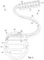
- FIG. 1is a schematic view of one embodiment of an electrical stimulation system that includes a paddle body coupled to a control module via lead bodies, according to the invention
- FIG. 2is a schematic view of another embodiment of an electrical stimulation system that includes a percutaneous lead body coupled to a control module via a lead body, according to the invention
- FIG. 3Ais a schematic view of one embodiment of a plurality of connector assemblies disposed in the control module of FIG. 1 , the connector assemblies configured to receive the proximal portions of the lead bodies of FIG. 1 , according to the invention;
- FIG. 3Bis a schematic view of one embodiment of a connector assembly disposed in the control module of FIG. 2 , the connector assembly configured to receive the proximal portion of one of the lead body of FIG. 2 , according to the invention;
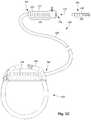
- FIG. 3Cis a schematic view of one embodiment of a proximal portion of the lead body of FIG. 2 , a lead extension, and the control module of FIG. 2 , the lead extension configured to couple the lead body to the control module, according to the invention;
- FIG. 4is a schematic, cross-sectional view of one embodiment of a connector assembly according to the invention.
- FIG. 5Ais a schematic, partially cut away, perspective view of one embodiment of a spacer, according to the invention.
- FIG. 5Bis a schematic, cross-sectional view of the spacer of FIG. 5A , according to the invention.
- FIG. 5Cis a schematic, partially cut away, perspective view of a second embodiment of a spacer, according to the invention.
- FIG. 5Dis a schematic, cross-sectional view of the spacer of FIG. 5C , according to the invention.
- FIG. 5Eis a schematic, cross-sectional view of a third embodiment of a spacer, according to the invention.
- FIGS. 6A-6Fare a schematic, cross-sectional views of a portion of the spacer of FIG. 5C , a connector contact, and a lead illustrating one embodiment of interaction between the spacer and the lead during insertion and retraction of the lead from a connector assembly, according to the invention.
- FIG. 7is a schematic overview of one embodiment of components of a stimulation system, including an electronic subassembly disposed within a control module, according to the invention.
- the present inventionis directed to the area of implantable electrical stimulation systems and methods of making and using the systems.
- the present inventionis also directed to connectors utilizing a novel spacer design, as well as methods of making and using the same.
- Suitable implantable electrical stimulation systemsinclude, but are not limited to, a least one lead with one or more electrodes disposed along a distal end of the lead and one or more terminals disposed along the one or more proximal ends of the lead.
- Leadsinclude, for example, percutaneous leads, paddle leads, and cuff leads. Examples of electrical stimulation systems with leads are found in, for example, U.S. Pat. Nos.
- connectors, connector contacts and connector assemblies for electrical stimulation systems with leadsare found in, for example, U.S. Pat. Nos. 8,849,396; 7,244,150; 8,600,507; 8,897,876; 8,682,439; U.S. Patent Applications Publication Nos. 2012/0053646; 2014/0148885; 2015/0209575; 2016/0059019; and U.S. Patent Provisional Patent Application Nos. 62/193,472; 62/216,594; 62/259,463; and 62/278,667, all of which are incorporated by reference in their entireties.
- FIG. 1illustrates schematically one embodiment of an electrical stimulation system 100 .
- the electrical stimulation systemincludes a control module (e.g., a stimulator or pulse generator) 102 and a lead 103 .
- the lead 103including a paddle body 104 and one or more lead bodies 106 coupling the control module 102 to the paddle body 104 .
- the paddle body 104 and the one or more lead bodies 106form the lead 103 .
- the paddle body 104typically includes a plurality of electrodes 134 that form an array of electrodes 133 .
- the control module 102typically includes an electronic subassembly 110 and an optional power source 120 disposed in a sealed housing 114 . In FIG. 1 , two lead bodies 106 are shown coupled to the control module 102 .
- the control module 102typically includes one or more connector assemblies 144 into which the proximal end of the one or more lead bodies 106 can be plugged to make an electrical connection via connector contacts (e.g., 316 in FIG. 3A ) disposed in the connector assembly 144 and terminals (e.g., 310 in FIG. 3A ) on each of the one or more lead bodies 106 .
- the connector contactsare coupled to the electronic subassembly 110 and the terminals are coupled to the electrodes 134 .
- FIG. 1two connector assemblies 144 are shown.
- the one or more connector assemblies 144may be disposed in a header 150 .
- the header 150provides a protective covering over the one or more connector assemblies 144 .
- the header 150may be formed using any suitable process including, for example, casting, molding (including injection molding), and the like.
- one or more lead extensions 324can be disposed between the one or more lead bodies 106 and the control module 102 to extend the distance between the one or more lead bodies 106 and the control module 102 .
- the electrical stimulation systemcan include more, fewer, or different components and can have a variety of different configurations including those configurations disclosed in the electrical stimulation system references cited herein.
- the electrodes 134can be disposed in an array at or near the distal end of a lead body 106 ′ forming a percutaneous lead 103 , as illustrated in FIG. 2 .
- the percutaneous leadmay be isodiametric along the length of the lead body 106 ′′.
- the lead body 106 ′can be coupled with a control module 102 ′ with a single connector assembly 144 .
- the electrical stimulation system or components of the electrical stimulation systemincluding one or more of the lead bodies 106 , the control module 102 , and, in the case of a paddle lead, the paddle body 104 , are typically implanted into the body of a patient.
- the electrical stimulation systemcan be used for a variety of applications including, but not limited to, spinal cord stimulation, brain stimulation, neural stimulation, muscle activation via stimulation of nerves innervating muscle, and the like.
- the electrodes 134can be formed using any conductive, biocompatible material. Examples of suitable materials include metals, alloys, conductive polymers, conductive carbon, and the like, as well as combinations thereof. In at least some embodiments, one or more of the electrodes 134 are formed from one or more of: platinum, platinum iridium, palladium, titanium, or rhenium.
- the number of electrodes 134 in the array of electrodes 133may vary. For example, there can be two, three, four, five, six, seven, eight, nine, ten, eleven, twelve, thirteen, fourteen, fifteen, sixteen, or more electrodes 134 . As will be recognized, other numbers of electrodes 134 may also be used. In FIG. 1 , sixteen electrodes 134 are shown.
- the electrodes 134can be formed in any suitable shape including, for example, round, oval, triangular, rectangular, pentagonal, hexagonal, heptagonal, octagonal, or the like.
- the electrodes of the paddle body 104 or one or more lead bodies 106are typically disposed in, or separated by, a non-conductive, biocompatible material including, for example, silicone, polyurethane, and the like or combinations thereof.
- the paddle body 104 and one or more lead bodies 106may be formed in the desired shape by any process including, for example, molding (including injection molding), casting, and the like. Electrodes and connecting wires can be disposed onto or within a paddle body either prior to or subsequent to a molding or casting process.
- the non-conductive materialtypically extends from the distal end of the lead 103 to the proximal end of each of the one or more lead bodies 106 .
- the non-conductive, biocompatible material of the paddle body 104 and the one or more lead bodies 106may be the same or different.
- the paddle body 104 and the one or more lead bodies 106may be a unitary structure or can be formed as two separate structures that are permanently or detachably coupled together.
- Terminalsare typically disposed at the proximal end of the one or more lead bodies 106 for connection to corresponding conductive contacts (e.g., 316 in FIG. 3A ) in connector assemblies (e.g., 144 in FIG. 1 ) disposed on, for example, the control module 102 (or to other devices, such as conductive contacts on a lead extension, an operating room cable, a splitter, an adaptor, or the like).
- Conductive wiresextend from the terminals (e.g., 310 in FIG. 3A ) to the electrodes 134 .
- one or more electrodes 134are electrically coupled to a terminal (e.g., 310 in FIG. 3A ).
- each terminale.g., 310 in FIG. 3A
- the conductive wiresmay be embedded in the non-conductive material of the lead or can be disposed in one or more lumens (not shown) extending along the lead. In some embodiments, there is an individual lumen for each conductive wire. In other embodiments, two or more conductive wires may extend through a lumen. There may also be one or more lumens (not shown) that open at, or near, the proximal end of the lead, for example, for inserting a stylet rod to facilitate placement of the lead within a body of a patient. Additionally, there may also be one or more lumens (not shown) that open at, or near, the distal end of the lead, for example, for infusion of drugs or medication into the site of implantation of the paddle body 104 . The one or more lumens may, optionally, be flushed continually, or on a regular basis, with saline, epidural fluid, or the like. The one or more lumens can be permanently or removably sealable at the distal end.
- the one or more lead bodies 106may be coupled to the one or more connector assemblies 144 disposed on the control module 102 .
- the control module 102can include any suitable number of connector assemblies 144 including, for example, two three, four, five, six, seven, eight, or more connector assemblies 144 . It will be understood that other numbers of connector assemblies 144 may be used instead.
- each of the two lead bodies 106includes eight terminals that are shown coupled with eight conductive contacts disposed in a different one of two different connector assemblies 144 .
- FIG. 3Ais a schematic side view of one embodiment of a plurality of connector assemblies 144 disposed on the control module 102 .
- the control module 102includes two connector assemblies 144 .
- the control module 102includes four connector assemblies 144 .
- proximal ends 306 of the plurality of lead bodies 106are shown configured for insertion to the control module 102 .
- FIG. 3Bis a schematic side view of one embodiment of a single connector assembly 144 disposed on the control module 102 ′. In FIG. 3B , the proximal end 306 of the single lead body 106 ′ is shown configured for insertion to the control module 102 ′.
- the one or more connector assemblies 144are disposed in the header 150 .
- the header 150defines one or more ports 304 into which the proximal end(s) 306 of the one or more lead bodies 106 / 106 ′ with terminals 310 can be inserted, as shown by directional arrows 312 , in order to gain access to the connector contacts disposed in the one or more connector assemblies 144 .
- the one or more connector assemblies 144each include a connector housing 314 and a plurality of connector contacts 316 disposed therein.
- the connector housing 314defines a port (not shown) that provides access to the plurality of connector contacts 316 .
- one or more of the connector assemblies 144further includes a retaining element 318 configured to fasten the corresponding lead body 106 / 106 ′ to the connector assembly 144 when the lead body 106 / 106 ′ is inserted into the connector assembly 144 to prevent undesired detachment of the lead body 106 / 106 ′ from the connector assembly 144 .
- the retaining element 318may include an aperture 320 through which a fastener (e.g., a set screw, pin, or the like) may be inserted and secured against an inserted lead body 106 / 106 ′.
- the connector contacts 316can be aligned with the terminals 310 disposed on the one or more lead bodies 106 / 106 ′ to electrically couple the control module 102 to the electrodes ( 134 of FIG. 1 ) disposed at a distal end of the one or more lead bodies 106 .
- Examples of connector assemblies in control modulesare found in, for example, U.S. Pat. Nos. 7,244,150 and 8,224,450, which are incorporated by reference.
- the electrical stimulation systemincludes one or more lead extensions.
- the one or more lead bodies 106 / 106 ′can be coupled to one or more lead extensions which, in turn, are coupled to the control module 102 / 102 ′.
- a lead extension connector assembly 322is disposed on a lead extension 324 .
- the lead extension connector assembly 322is shown disposed at a distal end 326 of the lead extension 324 .
- the lead extension connector assembly 322includes a contact housing 328 .
- the contact housing 328defines at least one port 330 into which a proximal end 306 of the lead body 106 ′ with terminals 310 can be inserted, as shown by directional arrow 338 .
- the lead extension connector assembly 322also includes a plurality of connector contacts 340 .
- the connector contacts 340 disposed in the contact housing 328can be aligned with the terminals 310 on the lead body 106 to electrically couple the lead extension 324 to the electrodes ( 134 of FIG. 1 ) disposed at a distal end (not shown) of the lead body 106 ′.
- the proximal end of a lead extensioncan be similarly configured as a proximal end of a lead body.
- the lead extension 324may include a plurality of conductive wires (not shown) that electrically couple the connector contacts 340 to terminal on a proximal end 348 of the lead extension 324 .
- the conductive wires disposed in the lead extension 324can be electrically coupled to a plurality of terminals (not shown) disposed on the proximal end 348 of the lead extension 324 .
- the proximal end 348 of the lead extension 324is configured for insertion into a lead extension connector assembly disposed in another lead extension.
- the proximal end 348 of the lead extension 324is configured for insertion into the connector assembly 144 disposed on the control module 102 ′.
- control modules 102 / 102 ′can receive either lead bodies 106 / 106 ′ or lead extensions 324 .
- electrical stimulation system 100can include a plurality of lead extensions 224 .
- each of the lead bodies 106 shown in FIGS. 1 and 3Acan, alternatively, be coupled to a different lead extension 224 which, in turn, are each coupled to different ports of a two-port control module, such as the control module 102 of FIGS. 1 and 3A .
- the connector assembly described belowmay be disposed in many different locations including, for example, on lead extensions (see e.g., 322 of FIG. 3C ), lead adapters, lead splitters, the connector portion of control modules (see e.g., 144 of FIGS. 1-3B ), or the like.
- the connector assembliesare disposed on the distal ends of lead extensions.
- a connector assembly in the control module or on a lead extension or other locationcan include an arrangement of connector contacts separated by spacers (which may also be referred to as seals).
- the spacersisolate or electrically insulate the connector contacts from each other and may also provide a seal with the lead to further isolate the connector contacts from each other.
- the spacersprovide a sealing force or pressure on the lead body and array of terminals at an end of the lead or lead extension. Providing the seal increases the force for insertion of the lead or lead extension. The insertion force may result in difficulty inserting a lead, user dissatisfaction, or even lead damage due to high columnar loads.
- adding more connector contacts in a connector and terminals on the lead or lead extensionwill typically increase the insertion force. Therefore, it is desirable to develop spacer configurations with lower insertion force than conventional spacers.
- a spacercan include radial sidewalls with an intermediate region extending between, and connecting, the radial sidewalls.
- the radial sidewalls and intermediate regiondefine (e.g., form at least a portion of a boundary for) an open circumferential space opposite the lead lumen of the connector to facilitate stretching, deflection, or other deformation of the spacer as the lead is inserted or removed from the connector.
- the open circumferential spaceis disposed on a first side of the intermediate region and the lead lumen is disposed on a second side of the intermediate region opposite the first side.
- this spacercan provide a reliable seal with the lead or lead extension inserted into the connector and may also provide a seal with a housing of the connector.
- FIG. 4Ashows a schematic, perspective view of a connector assembly 400 having a connector housing 402 , connector contacts 404 , spacers 406 that separate the connector contacts, an optional end stop 408 , and an optional retention block 410 .
- the connector housing 402includes apertures 412 exposing the individual connector contacts 404 for attachment of a conductor (e.g., a wire—not shown) to the connector contact.
- the apertures 412 in a finished connector assembly 400are filled after or during attachment of the conductors to the connector contacts 404 .
- the connector assembly 400includes, for one or more (or all) of the spacers 406 , a support ring 420 as part of the corresponding spacer or as a separate component.
- the connector housing 402defines a port 414 that provides access to a lead lumen 416 and the connector contacts 404 .
- the connector housing 402can be made of any suitable material or materials.
- the connector assembly 400further includes a retention block 410 to fasten the corresponding lead body (or a retention ring on the lead body) of the lead or lead extension to the connector assembly 400 when the lead body is inserted into the connector assembly and prevent undesired detachment of the lead body from the connector assembly or misalignment of the terminals on the lead body with the connector contacts.
- the retaining element 318may include an aperture 418 through which a fastener (e.g., a set screw, pin, or the like) may be inserted and secured against an inserted lead body.
- a fastenere.g., a set screw, pin, or the like
- Other types of retention blocks or retention assembliescan be used including, but not limited to, those described in U.S. Pat. No. 9,440,066; U.S. patent application Ser. Nos. 15/627,016 and 15/641,688; and U.S. Provisional Patent Application Ser. No. 62/464,710, all of which are incorporated herein by reference.
- the connector contacts 404may take the form of conductive spring contacts or any other suitable contact arrangement.
- Examples of connector contactsinclude, but are not limited to, canted coil contacts available from Bal Seal Engineering, Inc. (Foothill Collins, Calif.) and contacts described in U.S. Pat. Nos. 7,803,021; 8,682,439; 8,897,876; 9,409,032; 9,604,068; 9,656,093; and 9,770,598; U.S. Patent Application Publications Nos. 2011/0022100; 2016/0228692; and 2016/0296745; U.S. patent application Ser. Nos. 15/627,016 and 15/656,612; and U.S. Provisional Patent Application Ser. No. 62/483,141, all of which are incorporated herein by reference.
- the connector assembly 400may include an end stop 408 which, at least in part, modulates insertion of the lead or lead extension into the port 414 .
- the end stop 408can be disposed in the lead lumen 416 of the connector assembly 400 .
- the end stop 408can provide one or more surfaces upon which the inserted lead or lead extension contacts, when the lead or lead extension is fully inserted into the port 414 . In some cases, the end stop 408 can provide the proximal-most point of insertion for the lead or lead extension within the connector assembly 400 .
- FIGS. 5A and 5Billustrate schematic views (perspective view— FIG. 5A and cross-sectional view— FIG. 5B ) of one embodiment of a spacer 406 .
- the spacer 406can be described as having a first radial sidewall 580 , a second radial sidewall 582 , and an intermediate region 584 that extends between, and connects, the first and second radial sidewalls.
- the first radial sidewall 580 , the second radial sidewall 882 , and the intermediate region 584are U-shaped in cross-section.
- the intermediate region 584 of the illustrated embodiment in FIGS. 5A and 5Bis curved towards the center of the lead lumen 416 .
- the first and second radial sidewalls 580 , 582 and intermediate region 584define, at least in part, an open circumferential space 586 .
- the open circumferential space 586is opposite the lead lumen 416 with respect to the intermediate region 584 .
- the first and second radial sidewalls 580 , 582 and the intermediate region 584can form, at least in part, boundaries of the open circumferential space 586 .
- the open circumferential space 586separates the first radial sidewall 580 from the second radial sidewall 582 .
- the presence of the open circumferential space 586facilitates deformation of the first radial sidewall 580 , second radial sidewall 582 , or intermediate region 584 (or any combination thereof) during insertion or removal of the lead from the lead lumen 416 (see, for example, FIGS. 6A-6F ).
- the open circumferential space 586does not impede the deformation of the spacer 406 .
- the spacer 406can include a bridge 588 that connects the first radial sidewall 580 to the second radial sidewall 582 along an outer portion of the spacer 406 .
- the bridge 588may further define the open circumferential space 586 .
- the bridge 588may provide additional stability to the spacer 406 and prevent or reduce longitudinal compression of the sidewalls 580 , 582 towards each other.
- the spacer 406can be made of any suitable flexible, non-conductive material including, but not limited to, silicone, polyurethane, or the like.
- the material of the spacer 406is preferably stretchable.
- the spacer 406is formed by molding.
- the shortest inner diameter 585 of the intermediate region 584is preferably equal to, or slightly smaller (for example, no more than 15%, 10%, or 5% smaller) than, the diameter of the lead or lead extension to be inserted into the connector assembly 400 .
- the intermediate region 584makes a seal (preferably, a hermetic seal) with the portion of the lead or lead extension inserted into the connector assembly 400 .
- a ratio of sealing force to insertion forceis at least 1.5, 1.6, 1.7, or 1.8. This ratio can be determined using a finite element analysis.
- the insertion forcecan be considered the combination of two forces: displacement and friction.
- Displacementis the force generated by moving the portions of the spacer 406 , such as, but not limited to, the intermediate region 584 .
- the normal forceis the sealing force and may be, for example, derived from the radial component of a force related to the stretching of the spacer 406 .
- the friction coefficientdepends on the materials of the spacer and the lead, in combination, and other factors such surface texture and possibly lubricity. Calculation of these forces in 360 degrees with multiple interactions between these forces can be complicated, but may be modeled.
- the outer diameter 587 of the spacer 406is equal to or slightly larger (for example, no more than 15%, 10%, or 5% larger) than, the inner diameter of the connector housing 402 of the connector assembly 400 .
- the first radial sidewall or second radial sidewall 580 , 582makes a seal (preferably, a hermetic seal) with the connector housing 402 of the connector assembly 400 .
- the first radial sidewall and second radial sidewall 580 , 582make a seal (preferably, a hermetic seal) with the adjacent connector contacts 404 (or with an adjacent connector contact 404 and the end stop 408 or retention block 410 ) of the connector assembly 400 .
- the thicknesses of the first radial sidewall 580 , the second radial sidewall, and the intermediate region 584are equal or differ by no more than 5%, 10%, or 20%. In other embodiments, the first and second radial sidewalls 580 , 582 can be thicker or thinner than the intermediate region 584 . In at least some embodiments, the thicknesses of the first and second radial sidewalls may be different from each other. In at least some embodiments, the thicknesses of the first radial sidewall 580 , the second radial sidewall, and the intermediate region 584 may vary.
- FIGS. 5C and 5Dillustrate a second embodiment of a spacer 406 ′
- FIG. 5Eillustrates a third embodiment of a spacer 406 ′′
- the spacers 406 ′, 406 ′′both include a first radial sidewall 580 , second radial sidewall 582 , and an intermediate region 584 and the arrangement, design considerations, features, and properties of these spacers and their component elements are the same as, unless indicated otherwise, the elements described above with respect to spacer 406 illustrated in FIGS. 5A and 5B .
- the intermediate region 584 of the spacer 406 ′ of FIGS. 5C and 5Dhas a V-shape in cross-section.
- the intermediate region 584 of the spacer 406 ′′ of FIG. 5Eis, in cross-section, straight between the two radial sidewalls 580 , 582 and forms a right angle with the first and second radial sidewalls 580 , 582 .
- the intermediate region 584 , first radial sidewall 580 , and second radial sidewall 582 of spacer 406 ′′ in FIG. 5Emay be considered as forming a “square U” in cross-section.
- any of the embodiments described hereincan include one or more radial ridges 590 ( FIG. 5E ) extending around a portion of (or the entire) perimeter of the lead-contacting surface of the intermediate region 584 , as illustrated in FIG. 5E .
- the illustrated embodiment in FIG. 5Ehas one radial ridge that is centered on the intermediate region 584 and extends around the entire perimeter of the lead-contacting surface of the intermediate region. It will be recognized that any other number of radial ridges (e.g., two, three, four, or more) can be used and that the radial ridges may only extend around a portion of the perimeter or may be separated into multiple segments (for example, two, three, four, or more segments) that each extend around only a portion of the perimeter.
- the radial ridge(s) 590need not be centered with respect to the intermediate region 584 but can be spaced apart from either side of the center.
- the radial ridge(s) 590may facilitate forming a seal with the lead or lead extension.
- FIGS. 6A-6Fare cross-sectional views of a portion of a spacer 406 ′ (see, FIGS. 5C and 5D ), lead 106 , and contact 404 during the insertion ( FIGS. 6A-6C ) and retraction ( FIGS. 6D-6F ) of the lead 106 into/out of a connector assembly.
- FIGS. 6A-6Fillustrate one embodiment of the alterations to the spacer 406 ′ during the insertion/retraction processes. It will be recognized that other spacers of the invention made of different materials or having different forms may move, stretch, deflect, or otherwise deform differently.
- the end of the lead 106makes contact with the spacer 406 ′.
- the intermediate region 584 of the spacermay stretch, deflect, or deform, as illustrated in FIG. 6B .
- one or both of the first radial sidewall 580 or second radial sidewall 582may also deform, deflect, or stretch.
- the intermediate region 584may return to its original shape or a form similar to its original shape, as illustrated in FIG. 5C . In other embodiments, the intermediate region may remain substantially stretched, deflected, or otherwise deformed.
- an adjacent connector contact 404FIG.
- the intermediate region 584makes a seal (more preferably, a hermetic seal) with the lead 106 .
- the intermediate region 584moves back toward the connector contact 404 , as illustrated in FIGS. 6D and 6E , and may stretch, deflect, or otherwise deform. In at least some embodiments, the connector contact 404 may prevent or hinder the intermediate region 584 from rolling backward and inverting. As the end of the lead 106 moves past spacer 406 ′, the intermediate region 584 may return to its original shape, as illustrated in FIG. 6F , (although, in some embodiments, there may be residual deformation, deflection, stretching, or other inelastic changes to the spacer shape).
- FIG. 7is a schematic overview of one embodiment of components of an electrical stimulation system 700 including an electronic subassembly 710 disposed within a control module. It will be understood that the electrical stimulation system can include more, fewer, or different components and can have a variety of different configurations including those configurations disclosed in the stimulator references cited herein.
- a power source 712can be used including, for example, a battery such as a primary battery or a rechargeable battery.
- a batterysuch as a primary battery or a rechargeable battery.
- other power sourcesinclude super capacitors, nuclear or atomic batteries, mechanical resonators, infrared collectors, thermally-powered energy sources, flexural powered energy sources, bioenergy power sources, fuel cells, bioelectric cells, osmotic pressure pumps, and the like including the power sources described in U.S. Pat. No. 7,437,193, incorporated herein by reference.
- powercan be supplied by an external power source through inductive coupling via the optional antenna 718 or a secondary antenna.
- the external power sourcecan be in a device that is mounted on the skin of the user or in a unit that is provided near the user on a permanent or periodic basis.
- the batterymay be recharged using the optional antenna 718 , if desired. Power can be provided to the battery for recharging by inductively coupling the battery through the antenna to a recharging unit 716 external to the user. Examples of such arrangements can be found in the references identified above.
- electrical currentis emitted by the electrodes 134 on the paddle or lead body to stimulate nerve fibers, muscle fibers, or other body tissues near the electrical stimulation system.
- the processor 704is generally included to control the timing and electrical characteristics of the electrical stimulation system. For example, the processor 704 can, if desired, control one or more of the timing, frequency, strength, duration, and waveform of the pulses. In addition, the processor 704 can select which electrodes can be used to provide stimulation, if desired. In some embodiments, the processor 704 selects which electrode(s) are cathodes and which electrode(s) are anodes. In some embodiments, the processor 704 is used to identify which electrodes provide the most useful stimulation of the desired tissue.
- Any processorcan be used and can be as simple as an electronic device that, for example, produces pulses at a regular interval or the processor can be capable of receiving and interpreting instructions from an external programming unit 708 that, for example, allows modification of pulse characteristics.
- the processor 704is coupled to a receiver 702 which, in turn, is coupled to the optional antenna 718 . This allows the processor 704 to receive instructions from an external source to, for example, direct the pulse characteristics and the selection of electrodes, if desired.
- the antenna 718is capable of receiving signals (e.g., RF signals) from an external telemetry unit 706 which is programmed by the programming unit 708 .
- the programming unit 708can be external to, or part of, the telemetry unit 706 .
- the telemetry unit 706can be a device that is worn on the skin of the user or can be carried by the user and can have a form similar to a pager, cellular phone, or remote control, if desired.
- the telemetry unit 706may not be worn or carried by the user but may only be available at a home station or at a clinician's office.
- the programming unit 708can be any unit that can provide information to the telemetry unit 706 for transmission to the electrical stimulation system 700 .
- the programming unit 708can be part of the telemetry unit 706 or can provide signals or information to the telemetry unit 706 via a wireless or wired connection.
- One example of a suitable programming unitis a computer operated by the user or clinician to send signals to the telemetry unit 706 .
- the signals sent to the processor 704 via the antenna 718 and the receiver 702can be used to modify or otherwise direct the operation of the electrical stimulation system.
- the signalsmay be used to modify the pulses of the electrical stimulation system such as modifying one or more of pulse duration, pulse frequency, pulse waveform, and pulse strength.
- the signalsmay also direct the electrical stimulation system 700 to cease operation, to start operation, to start charging the battery, or to stop charging the battery.
- the stimulation systemdoes not include the antenna 718 or receiver 702 and the processor 704 operates as programmed.
- the electrical stimulation system 700may include a transmitter (not shown) coupled to the processor 704 and the antenna 718 for transmitting signals back to the telemetry unit 706 or another unit capable of receiving the signals.
- the electrical stimulation system 700may transmit signals indicating whether the electrical stimulation system 700 is operating properly or not or indicating when the battery needs to be charged or the level of charge remaining in the battery.
- the processor 704may also be capable of transmitting information about the pulse characteristics so that a user or clinician can determine or verify the characteristics.
Landscapes
- Health & Medical Sciences (AREA)
- Public Health (AREA)
- Engineering & Computer Science (AREA)
- Nuclear Medicine, Radiotherapy & Molecular Imaging (AREA)
- Radiology & Medical Imaging (AREA)
- Life Sciences & Earth Sciences (AREA)
- Animal Behavior & Ethology (AREA)
- Biomedical Technology (AREA)
- General Health & Medical Sciences (AREA)
- Veterinary Medicine (AREA)
- Neurology (AREA)
- Neurosurgery (AREA)
- Pain & Pain Management (AREA)
- Orthopedic Medicine & Surgery (AREA)
- Cardiology (AREA)
- Heart & Thoracic Surgery (AREA)
- Electrotherapy Devices (AREA)
Abstract
Description
Claims (20)
Priority Applications (1)
| Application Number | Priority Date | Filing Date | Title |
|---|---|---|---|
| US16/247,293US11103712B2 (en) | 2018-01-16 | 2019-01-14 | Connector assemblies with novel spacers for electrical stimulation systems and methods of making and using same |
Applications Claiming Priority (2)
| Application Number | Priority Date | Filing Date | Title |
|---|---|---|---|
| US201862617990P | 2018-01-16 | 2018-01-16 | |
| US16/247,293US11103712B2 (en) | 2018-01-16 | 2019-01-14 | Connector assemblies with novel spacers for electrical stimulation systems and methods of making and using same |
Publications (2)
| Publication Number | Publication Date |
|---|---|
| US20190217103A1 US20190217103A1 (en) | 2019-07-18 |
| US11103712B2true US11103712B2 (en) | 2021-08-31 |
Family
ID=67212662
Family Applications (1)
| Application Number | Title | Priority Date | Filing Date |
|---|---|---|---|
| US16/247,293Active2039-11-19US11103712B2 (en) | 2018-01-16 | 2019-01-14 | Connector assemblies with novel spacers for electrical stimulation systems and methods of making and using same |
Country Status (1)
| Country | Link |
|---|---|
| US (1) | US11103712B2 (en) |
Families Citing this family (3)
| Publication number | Priority date | Publication date | Assignee | Title |
|---|---|---|---|---|
| US11052259B2 (en) | 2018-05-11 | 2021-07-06 | Boston Scientific Neuromodulation Corporation | Connector assembly for an electrical stimulation system and methods of making and using |
| US11357992B2 (en) | 2019-05-03 | 2022-06-14 | Boston Scientific Neuromodulation Corporation | Connector assembly for an electrical stimulation system and methods of making and using |
| US12343547B2 (en) | 2021-08-19 | 2025-07-01 | Boston Scientific Neuromodulation Corporation | Connectors for an electrical stimulation system and methods of making and using |
Citations (403)
| Publication number | Priority date | Publication date | Assignee | Title |
|---|---|---|---|---|
| US3222471A (en) | 1963-06-10 | 1965-12-07 | Ripley Company Inc | Multiple electrical connector with longitudinal spaced contacts carried by insulating key |
| US3601747A (en) | 1969-09-18 | 1971-08-24 | Singer General Precision | Brush block retractor and alignment device |
| US3718142A (en) | 1971-04-23 | 1973-02-27 | Medtronic Inc | Electrically shielded, gas-permeable implantable electro-medical apparatus |
| US3757789A (en) | 1971-10-26 | 1973-09-11 | I Shanker | Electromedical stimulator lead connector |
| US3771106A (en) | 1971-04-14 | 1973-11-06 | New Nippon Electric Co | Socket suited for revolving the lamp attached thereto |
| US3908668A (en) | 1974-04-26 | 1975-09-30 | Medtronic Inc | Tissue stimulator with sealed lead connector |
| US3951154A (en) | 1974-04-30 | 1976-04-20 | Medtronic, Inc. | Lead connector for electro-medical device |
| US3990727A (en) | 1976-01-26 | 1976-11-09 | Stephen Franics Gallagher | Quick detachable coupler |
| US4003616A (en) | 1975-12-03 | 1977-01-18 | Clairol Incorporated | Swivelling electrical connector |
| US4112953A (en) | 1977-03-11 | 1978-09-12 | Medcor, Inc. | Pacer stimulator with improved lead connector |
| US4142532A (en) | 1978-04-07 | 1979-03-06 | Medtronic, Inc. | Body implantable stimulator with novel connector and method |
| US4180078A (en) | 1978-04-07 | 1979-12-25 | Medtronic, Inc. | Lead connector for a body implantable stimulator |
| US4245642A (en) | 1979-06-28 | 1981-01-20 | Medtronic, Inc. | Lead connector |
| US4259962A (en) | 1979-08-24 | 1981-04-07 | Cordis Corporation | Sealing system for cardiac pacer lead connector |
| US4310001A (en) | 1980-04-21 | 1982-01-12 | Medtronic, Inc. | Connector assembly for body implantable medical systems |
| US4364625A (en) | 1980-06-12 | 1982-12-21 | Bell Telephone Laboratories, Incorporated | Electrical jack assembly |
| US4367907A (en) | 1980-08-04 | 1983-01-11 | Magnetic Controls Company | Circuit monitoring jack |
| US4411276A (en) | 1981-04-28 | 1983-10-25 | Medtronic, Inc. | Implantable multiple connector |
| US4411277A (en) | 1981-04-28 | 1983-10-25 | Medtronic, Inc. | Implantable connector |
| US4461194A (en) | 1982-04-28 | 1984-07-24 | Cardio-Pace Medical, Inc. | Tool for sealing and attaching a lead to a body implantable device |
| US4466441A (en) | 1982-08-02 | 1984-08-21 | Medtronic, Inc. | In-line and bifurcated cardiac pacing lead connector |
| US4516820A (en) | 1983-01-27 | 1985-05-14 | The Commonwealth Of Australia | Cochlear prosthesis package connector |
| US4540236A (en) | 1983-07-18 | 1985-09-10 | Cordis Corporation | Quick lock/quick release connector |
| USRE31990E (en) | 1978-11-22 | 1985-09-24 | Intermedics, Inc. | Multiple function lead assembly and method for inserting assembly into an implantable tissue stimulator |
| US4602624A (en) | 1984-10-11 | 1986-07-29 | Case Western Reserve University | Implantable cuff, method of manufacture, and method of installation |
| US4603696A (en) | 1985-02-14 | 1986-08-05 | Medtronic, Inc. | Lead connector |
| US4614395A (en) | 1985-04-04 | 1986-09-30 | Cordis Corporation | Quick connector to medical electrical lead |
| US4630611A (en) | 1981-02-02 | 1986-12-23 | Medtronic, Inc. | Orthogonally-sensing lead |
| US4695116A (en) | 1984-02-27 | 1987-09-22 | Switchcraft, Inc. | Stacked electrical jacks |
| US4695117A (en) | 1985-06-03 | 1987-09-22 | Switchcraft, Inc. | Jack module and jackfield |
| US4712557A (en) | 1986-04-28 | 1987-12-15 | Cordis Leads, Inc. | A pacer including a multiple connector assembly with removable wedge and method of use |
| US4715380A (en) | 1986-04-03 | 1987-12-29 | Telectronics N.V. | Capped pacer neck containing a connector assembly |
| US4744370A (en) | 1987-04-27 | 1988-05-17 | Cordis Leads, Inc. | Lead assembly with selectable electrode connection |
| US4784141A (en) | 1987-08-04 | 1988-11-15 | Cordis Leads, Inc. | Lead locking mechanism for cardiac pacers |
| US4832032A (en) | 1985-08-16 | 1989-05-23 | La Jolla Technology, Inc. | Electrical apparatus protective interconnect |
| US4840580A (en) | 1987-06-05 | 1989-06-20 | Siemens Ag | Connector arrangement for a lead for an implantable stimulation device |
| US4850359A (en) | 1987-10-16 | 1989-07-25 | Ad-Tech Medical Instrument Corporation | Electrical brain-contact devices |
| US4860750A (en) | 1986-04-17 | 1989-08-29 | Intermedics Inc. | Sidelock pacer lead connector |
| US4867708A (en) | 1986-12-27 | 1989-09-19 | Iizuka Electric Industry Company Limited | Electric jack |
| US4869255A (en) | 1987-12-04 | 1989-09-26 | Ad-Tech Medical Instrument Corp. | Electrical connection device |
| US4898173A (en) | 1988-04-22 | 1990-02-06 | Medtronic, Inc. | In-line pacemaker connector system |
| US4899753A (en) | 1985-10-02 | 1990-02-13 | Fukuda Denshi Co., Ltd. | Electrocardiographic electrode |
| US4951687A (en) | 1989-01-31 | 1990-08-28 | Medtronic, Inc. | Medical electrical lead connector |
| US4995389A (en) | 1985-12-16 | 1991-02-26 | Telectronics Pacing Systems, Inc. | Multielectrode quick connect cardiac pacing lead connector assembly |
| US5000177A (en) | 1990-01-29 | 1991-03-19 | Cardiac Pacemakers, Inc. | Bipolar lead adapter with resilient housing and rigid retainers for plug seals |
| US5000194A (en) | 1988-08-25 | 1991-03-19 | Cochlear Corporation | Array of bipolar electrodes |
| US5007864A (en) | 1989-11-27 | 1991-04-16 | Siemens-Pacesetter, Inc. | Device for adapting a pacemaker lead to a pacemaker |
| US5007435A (en) | 1988-05-25 | 1991-04-16 | Medtronic, Inc. | Connector for multiconductor pacing leads |
| US5070605A (en) | 1988-04-22 | 1991-12-10 | Medtronic, Inc. | Method for making an in-line pacemaker connector system |
| US5082453A (en) | 1991-05-16 | 1992-01-21 | Siemens-Pacesetter, Inc. | Multi-contact connector system for an implantable medical device |
| US5086773A (en) | 1990-09-10 | 1992-02-11 | Cardiac Pacemakers, Inc. | Tool-less pacemaker lead assembly |
| US5135001A (en) | 1990-12-05 | 1992-08-04 | C. R. Bard, Inc. | Ultrasound sheath for medical diagnostic instruments |
| US5193540A (en) | 1991-12-18 | 1993-03-16 | Alfred E. Mann Foundation For Scientific Research | Structure and method of manufacture of an implantable microstimulator |
| US5193539A (en) | 1991-12-18 | 1993-03-16 | Alfred E. Mann Foundation For Scientific Research | Implantable microstimulator |
| US5201865A (en) | 1991-10-28 | 1993-04-13 | Medtronic, Inc. | Medical lead impedance measurement system |
| US5241957A (en) | 1991-11-18 | 1993-09-07 | Medtronic, Inc. | Bipolar temporary pacing lead and connector and permanent bipolar nerve wire |
| US5252090A (en) | 1992-09-30 | 1993-10-12 | Telectronics Pacing Systems, Inc. | Self-locking implantable stimulating lead connector |
| US5261395A (en) | 1992-03-02 | 1993-11-16 | Cardiac Pacemaker, Inc. | Tooless pulse generator to lead connection |
| EP0580928A1 (en) | 1992-07-31 | 1994-02-02 | ARIES S.r.l. | A spinal electrode catheter |
| US5312439A (en) | 1991-12-12 | 1994-05-17 | Loeb Gerald E | Implantable device having an electrolytic storage electrode |
| US5324312A (en) | 1992-05-06 | 1994-06-28 | Medtronic, Inc. | Tool-less threaded connector assembly |
| US5330521A (en) | 1992-06-29 | 1994-07-19 | Cohen Donald M | Low resistance implantable electrical leads |
| US5336246A (en) | 1993-06-23 | 1994-08-09 | Telectronics Pacing Systems, Inc. | Lead connector assembly for medical device and method of assembly |
| US5348481A (en) | 1993-09-29 | 1994-09-20 | Cardiometrics, Inc. | Rotary connector for use with small diameter flexible elongate member having electrical capabilities |
| US5354326A (en) | 1993-01-27 | 1994-10-11 | Medtronic, Inc. | Screening cable connector for interface to implanted lead |
| US5358514A (en) | 1991-12-18 | 1994-10-25 | Alfred E. Mann Foundation For Scientific Research | Implantable microdevice with self-attaching electrodes |
| US5368496A (en) | 1993-12-10 | 1994-11-29 | Tetrad Corporation | Connector assembly having control lever actuation |
| US5374279A (en) | 1992-10-30 | 1994-12-20 | Medtronic, Inc. | Switchable connector block for implantable defibrillator |
| US5383913A (en) | 1993-04-21 | 1995-01-24 | Schiff; Steven M. | Bidirectional lead connector for left or right sided implantation of pacemakers and/or other implantable electrophysiologic devices and a method for using the same |
| US5413595A (en) | 1993-10-15 | 1995-05-09 | Pacesetter, Inc. | Lead retention and seal for implantable medical device |
| US5435731A (en) | 1994-05-12 | 1995-07-25 | Kang; Steve | Rotatable hidden connector for telephone transmitter |
| US5458629A (en) | 1994-02-18 | 1995-10-17 | Medtronic, Inc. | Implantable lead ring electrode and method of making |
| US5486202A (en) | 1993-12-17 | 1996-01-23 | Intermedics, Inc. | Cardiac stimulator lead connector |
| US5489225A (en) | 1993-12-16 | 1996-02-06 | Ventritex, Inc. | Electrical terminal with a collet grip for a defibrillator |
| US5509928A (en) | 1995-03-02 | 1996-04-23 | Pacesetter, Inc. | Internally supported self-sealing septum |
| US5522874A (en) | 1994-07-28 | 1996-06-04 | Gates; James T. | Medical lead having segmented electrode |
| US5534019A (en) | 1994-12-09 | 1996-07-09 | Ventritex, Inc. | Cardiac defibrillator with case that can be electrically active or inactive |
| US5545188A (en) | 1995-06-05 | 1996-08-13 | Intermedics, Inc. | Cardiac pacemaker with collet-type lead connector |
| US5545189A (en) | 1995-11-02 | 1996-08-13 | Ventritex, Inc. | Case-activating switch assembly for an implantable cardiac stimulation device |
| US5560358A (en) | 1994-09-08 | 1996-10-01 | Radionics, Inc. | Connector design for multi-contact medical electrode |
| US5582180A (en) | 1994-11-04 | 1996-12-10 | Physio-Control Corporation | Combination three-twelve lead electrocardiogram cable |
| WO1997032628A1 (en) | 1996-03-07 | 1997-09-12 | Axon Engineering, Inc. | Polymer-metal foil structure for neural stimulating electrodes |
| US5679026A (en) | 1995-12-21 | 1997-10-21 | Ventritex, Inc. | Header adapter for an implantable cardiac stimulation device |
| US5683433A (en) | 1995-05-17 | 1997-11-04 | Ventritex, Inc. | Implantable medical apparatus with magnifying header |
| US5711316A (en) | 1996-04-30 | 1998-01-27 | Medtronic, Inc. | Method of treating movement disorders by brain infusion |
| US5713922A (en) | 1996-04-25 | 1998-02-03 | Medtronic, Inc. | Techniques for adjusting the locus of excitation of neural tissue in the spinal cord or brain |
| US5720631A (en) | 1995-12-07 | 1998-02-24 | Pacesetter, Inc. | Lead lumen sealing device |
| US5730628A (en) | 1996-09-25 | 1998-03-24 | Pacesetter, Inc. | Multi-contact connector for an implantable medical device |
| US5755743A (en) | 1996-06-05 | 1998-05-26 | Implex Gmbh Spezialhorgerate | Implantable unit |
| US5766042A (en) | 1995-12-28 | 1998-06-16 | Medtronic, Inc. | Tool-less locking and sealing assembly for implantable medical device |
| US5782892A (en) | 1997-04-25 | 1998-07-21 | Medtronic, Inc. | Medical lead adaptor for external medical device |
| EP0650694B1 (en) | 1993-11-01 | 1998-07-29 | Polartechnics Ltd | Apparatus for diseased tissue type recognition |
| US5796044A (en) | 1997-02-10 | 1998-08-18 | Medtronic, Inc. | Coiled wire conductor insulation for biomedical lead |
| US5800495A (en) | 1997-03-27 | 1998-09-01 | Sulzer Intermedics Inc. | Endocardial lead assembly |
| US5807144A (en) | 1996-01-29 | 1998-09-15 | Pacesetter Ab | Device for affixing a lead connector to an implantable stimulator |
| US5837006A (en) | 1996-09-10 | 1998-11-17 | Medtronic, Inc. | Retraction stop for helical medical lead electrode |
| US5843141A (en) | 1997-04-25 | 1998-12-01 | Medronic, Inc. | Medical lead connector system |
| US5843148A (en) | 1996-09-27 | 1998-12-01 | Medtronic, Inc. | High resolution brain stimulation lead and method of use |
| US5906634A (en) | 1997-08-08 | 1999-05-25 | Cardiac Pacemakers, Inc. | Implantable device having a quick connect mechanism for leads |
| US5931861A (en) | 1997-04-25 | 1999-08-03 | Medtronic, Inc. | Medical lead adaptor having rotatable locking clip mechanism |
| US5938688A (en) | 1997-10-22 | 1999-08-17 | Cornell Research Foundation, Inc. | Deep brain stimulation method |
| US5951595A (en) | 1996-05-13 | 1999-09-14 | Pacesetteer, Inc. | Setscrewless connector assembly for implantable medical devices |
| US5968082A (en) | 1996-03-04 | 1999-10-19 | Biotronik Mess- Und Therapiegeraete Gmbh & Co. Ingenieurbuero Berlin | Pacemaker lead locking mechanism |
| WO1999055411A2 (en) | 1998-04-30 | 1999-11-04 | Medtronic, Inc. | Apparatus and method for expanding a stimulation lead body in situ |
| US5989077A (en) | 1998-03-13 | 1999-11-23 | Intermedics Inc | Connector for implantable medical device |
| US6006135A (en) | 1997-09-26 | 1999-12-21 | Medtronic, Inc. | Apparatus for interconnecting implantable electrical leads and medical device |
| US6018684A (en) | 1998-07-30 | 2000-01-25 | Cardiac Pacemakers, Inc. | Slotted pacing/shocking electrode |
| US6042432A (en) | 1997-08-11 | 2000-03-28 | Yazaki Corporation | Terminal for charging with large current |
| US6051017A (en) | 1996-02-20 | 2000-04-18 | Advanced Bionics Corporation | Implantable microstimulator and systems employing the same |
| US6080188A (en) | 1997-06-16 | 2000-06-27 | Medtronic, Inc. | Setscrew less lead connector system for medical devices |
| WO2000038574A1 (en) | 1998-12-23 | 2000-07-06 | Nuvasive, Inc. | Nerve surveillance cannulae systems |
| US6112120A (en) | 1997-07-03 | 2000-08-29 | Ela Medical S.A. | Apparatus for connecting a probe connector and an active implantable medical device |
| US6112121A (en) | 1998-09-09 | 2000-08-29 | Intermedics Inc. | Implantable medical device with positive indication of lead connection and connector therefor |
| US6125302A (en) | 1997-09-02 | 2000-09-26 | Advanced Bionics Corporation | Precurved modiolar-hugging cochlear electrode |
| US6134478A (en) | 1998-06-05 | 2000-10-17 | Intermedics Inc. | Method for making cardiac leads with zone insulated electrodes |
| US6154678A (en) | 1999-03-19 | 2000-11-28 | Advanced Neuromodulation Systems, Inc. | Stimulation lead connector |
| US6162101A (en) | 1998-09-03 | 2000-12-19 | Pmt Corporation | Connector assembly for electrodes |
| US6167311A (en) | 1999-06-14 | 2000-12-26 | Electro Core Techniques, Llc | Method of treating psychological disorders by brain stimulation within the thalamus |
| US6167314A (en) | 1998-04-14 | 2000-12-26 | Intermedics Inc. | Cardiac pacemaker lead with pacemaker connector |
| US6164284A (en) | 1997-02-26 | 2000-12-26 | Schulman; Joseph H. | System of implantable devices for monitoring and/or affecting body parameters |
| US6175710B1 (en) | 1991-07-06 | 2001-01-16 | Fujitsu Limited | Electrophotographic recording apparatus using developing device with one-component type developer and having combination of charge injection effect and conductive contact type charger |
| US6181969B1 (en) | 1998-06-26 | 2001-01-30 | Advanced Bionics Corporation | Programmable current output stimulus stage for implantable device |
| US6185452B1 (en) | 1997-02-26 | 2001-02-06 | Joseph H. Schulman | Battery-powered patient implantable device |
| US6198969B1 (en) | 1998-02-12 | 2001-03-06 | Advanced Bionics Corporation | Implantable connector for multi-output neurostimulators |
| US6208894B1 (en) | 1997-02-26 | 2001-03-27 | Alfred E. Mann Foundation For Scientific Research And Advanced Bionics | System of implantable devices for monitoring and/or affecting body parameters |
| US6224450B1 (en) | 1998-08-28 | 2001-05-01 | Laurie J. Norton | Cycling activity belt |
| US6271094B1 (en) | 2000-02-14 | 2001-08-07 | International Business Machines Corporation | Method of making MOSFET with high dielectric constant gate insulator and minimum overlap capacitance |
| WO2001058520A1 (en) | 2000-02-09 | 2001-08-16 | Transneuronix, Inc. | Medical implant device for electrostimulation using discrete micro-electrodes |
| US20010023368A1 (en) | 1999-04-26 | 2001-09-20 | Advanced Neuromodulation Systems, Inc. | Implantable lead and method of manufacture |
| US6295944B1 (en) | 2000-06-20 | 2001-10-02 | J Timothy Lovett | Automatic tethering system for a floating dock |
| US6319021B1 (en) | 2000-12-19 | 2001-11-20 | Hon Hai Precision Ind. Co., Ltd. | Power connector providing improved performance |
| US6321126B1 (en) | 1998-12-07 | 2001-11-20 | Advanced Bionics Corporation | Implantable connector |
| US6322559B1 (en) | 1998-07-06 | 2001-11-27 | Vnus Medical Technologies, Inc. | Electrode catheter having coil structure |
| US6364278B1 (en) | 1999-11-05 | 2002-04-02 | Hon Hai Precision Ind. Co., Ltd. | Stand for supporting a computer |
| US6370434B1 (en) | 2000-02-28 | 2002-04-09 | Cardiac Pacemakers, Inc. | Cardiac lead and method for lead implantation |
| US6391985B1 (en) | 1999-10-21 | 2002-05-21 | Union Carbide Chemicals & Plastics Technology Corporation | High condensing mode polyolefin production under turbulent conditions in a fluidized bed |
| US6397108B1 (en) | 2000-04-03 | 2002-05-28 | Medtronic Inc. | Safety adaptor for temporary medical leads |
| US6415168B1 (en) | 2000-04-19 | 2002-07-02 | Ad-Tech Medical Instrument Corporation | Electrical connector for multi-contact medical electrodes |
| US6430442B1 (en) | 2000-02-29 | 2002-08-06 | Medtronic, Inc. | Split contact with super elastic retaining ring for implantable medical device |
| US6428336B1 (en) | 1997-03-25 | 2002-08-06 | Radi Medical Systems Ab | Female connector |
| US6428368B1 (en) | 2001-03-26 | 2002-08-06 | Pacesetter, Inc. | Side actuated lead connector assembly for implantable tissue stimulation device |
| WO2002068042A1 (en) | 2001-02-28 | 2002-09-06 | Gill Steven Streatfield | Brain electrode |
| US20020143376A1 (en) | 2000-05-05 | 2002-10-03 | Chinn Kenny K. | Multiple in-line contact connector |
| US6466824B1 (en) | 2001-04-23 | 2002-10-15 | Medtronic, Inc. | Bi-atrial and/or bi-ventricular patient safety cable and methods regarding same |
| US20020156513A1 (en) | 2000-08-17 | 2002-10-24 | Borkan William N. | Spinal cord stimulation leads |
| US6473654B1 (en) | 2000-03-08 | 2002-10-29 | Advanced Bionics Corporation | Lead anchor |
| US20020183817A1 (en) | 2000-12-07 | 2002-12-05 | Paul Van Venrooij | Directional brain stimulation and recording leads |
| US6498952B2 (en) | 2001-03-08 | 2002-12-24 | Pacesetter, Inc. | Hermetically sealed feedthrough connector using shape memory alloy for implantable medical device |
| US6516227B1 (en) | 1999-07-27 | 2003-02-04 | Advanced Bionics Corporation | Rechargeable spinal cord stimulator system |
| US6556873B1 (en) | 1999-11-29 | 2003-04-29 | Medtronic, Inc. | Medical electrical lead having variable bending stiffness |
| US6564078B1 (en) | 1998-12-23 | 2003-05-13 | Nuvasive, Inc. | Nerve surveillance cannula systems |
| US6605094B1 (en) | 1999-11-19 | 2003-08-12 | Advanced Bionics Corporation | Integrated subcutaneous tunneling and carrying tool |
| US6609032B1 (en) | 1999-01-07 | 2003-08-19 | Advanced Bionics Corporation | Fitting process for a neural stimulation system |
| US6609029B1 (en) | 2000-02-04 | 2003-08-19 | Advanced Bionics Corporation | Clip lock mechanism for retaining lead |
| US20030163171A1 (en) | 2002-02-28 | 2003-08-28 | Kast John E. | In-line lead header for an implantable medical device |
| US6654641B1 (en) | 1998-10-27 | 2003-11-25 | St. Jude Medical Ab | Heart stimulator housing having a tubular connector |
| US6662035B2 (en) | 2001-09-13 | 2003-12-09 | Neuropace, Inc. | Implantable lead connector assembly for implantable devices and methods of using it |
| US6663570B2 (en) | 2002-02-27 | 2003-12-16 | Volcano Therapeutics, Inc. | Connector for interfacing intravascular sensors to a physiology monitor |
| US6671534B2 (en) | 2000-04-19 | 2003-12-30 | Ad-Tech Medical Instrument Corporation | Electrical connector for multi-contact medical electrodes |
| US6671553B1 (en) | 2001-05-23 | 2003-12-30 | Pacesetter, Inc. | Implantable cardiac lead having terminating connector strain relief and method of manufacture |
| US6678564B2 (en) | 2001-12-06 | 2004-01-13 | Advanced Cochlear Systems, Inc. | Bio-implant and method of making the same |
| US20040064164A1 (en) | 2002-09-30 | 2004-04-01 | Ries Andrew J. | Connector module jumper for quadrapolar leads |
| US6741892B1 (en) | 2000-03-10 | 2004-05-25 | Advanced Bionics Corporation | Movable contact locking mechanism for spinal cord stimulator lead connector |
| WO2004045707A1 (en) | 2002-11-20 | 2004-06-03 | Advanced Neuromodulation Systems, Inc. | Apparatus for directionally stimulating nerve tissue |
| US6757039B2 (en) | 2002-06-17 | 2004-06-29 | Yao-Dong Ma | Paper white cholesteric displays employing reflective elliptical polarizer |
| US6757970B1 (en) | 2000-11-07 | 2004-07-06 | Advanced Bionics Corporation | Method of making multi-contact electrode array |
| US6799991B2 (en) | 2001-09-05 | 2004-10-05 | Medtronic, Inc. | Medical lead connector |
| US6805675B1 (en) | 2000-09-12 | 2004-10-19 | Medtronic, Inc. | Method and apparatus for deflecting a screw-in lead |
| US20040230268A1 (en) | 2003-05-13 | 2004-11-18 | Medtronic, Inc. | Medical lead adaptor assembly |
| US20040260373A1 (en) | 2003-06-19 | 2004-12-23 | Medtronic, Inc. | Medical lead adaptor |
| US20050027327A1 (en) | 2003-07-31 | 2005-02-03 | Medtronic, Inc. | Small format connector clip of an implantable medical device |
| US20050027326A1 (en) | 2003-07-31 | 2005-02-03 | Ries Andrew J. | Connector assembly for connecting a lead and an implantable medical device |
| US6854994B2 (en) | 2001-04-19 | 2005-02-15 | Medtronic, Inc. | Medical electrical lead connector arrangement including anti-rotation means |
| US20050038489A1 (en) | 2003-08-14 | 2005-02-17 | Grill Warren M. | Electrode array for use in medical stimulation and methods thereof |
| US20050043770A1 (en) | 2003-08-21 | 2005-02-24 | Medtronic, Inc. | Multi-polar electrical medical lead connector system |
| US20050043771A1 (en) | 2003-08-21 | 2005-02-24 | Medtronic, Inc. | Multi-polar electrical medical lead connector system |
| US6878013B1 (en) | 2003-12-02 | 2005-04-12 | Edgar G. Behan | Connector apparatus for a medical device |
| US20050137665A1 (en) | 2003-10-03 | 2005-06-23 | Medtronic Inc. | Implantabel electrical connector system |
| US6913478B2 (en) | 2002-07-01 | 2005-07-05 | Dixi Microtechniques, S.A. | Multi-contact connector for electrode for example for medical use |
| US6921295B2 (en) | 2001-04-19 | 2005-07-26 | Medtronic, Inc. | Medical lead extension and connection system |
| US20050171587A1 (en) | 2003-11-25 | 2005-08-04 | Advanced Neuromodulation Systems, Inc. | Directional stimulation lead and orientation system |
| US20050186829A1 (en) | 2004-02-23 | 2005-08-25 | Balsells Peter J. | Stackable assembly for direct connection between a pulse generator and a human body |
| US6968235B2 (en) | 2001-07-17 | 2005-11-22 | Medtronic, Inc. | Enhanced method and apparatus to identify and connect a small diameter lead with a low profile lead connector |
| US20050272280A1 (en) | 2001-10-22 | 2005-12-08 | Osypka Thomas P | Lead adaptor having low resistance conductors and/or encapsulated housing |
| US6980863B2 (en) | 2003-03-20 | 2005-12-27 | Medtronic, Inc. | Neurological stimulation lead extension |
| US20060015163A1 (en) | 2004-07-19 | 2006-01-19 | Team Brown Enterprises, Llc | Lead extender for implantable device |
| US20060025841A1 (en) | 2004-07-27 | 2006-02-02 | Mcintyre Cameron | Thalamic stimulation device |
| US20060030918A1 (en) | 2004-08-04 | 2006-02-09 | Chinn Kenny K | Operating room lead connector |
| EP1625875A1 (en) | 2004-08-09 | 2006-02-15 | Advanced Neuromodulation Systems, Inc. | System and method for providing strain relief for medical device leads |
| US7027852B2 (en) | 2002-05-21 | 2006-04-11 | Pacesetter, Inc. | Lead with distal tip surface electrodes connected in parallel |
| US7058452B2 (en) | 2000-03-08 | 2006-06-06 | St. Jude Medical Ab | Pacemaker connector part and manufacturing process for making same |
| US7069081B2 (en) | 2001-02-08 | 2006-06-27 | Wilson Greatbatch Ltd. | One piece header assembly for an implantable medical device |
| US20060167522A1 (en) | 2005-01-25 | 2006-07-27 | Malinowski Zdzislaw B | Connector for use in an implantable stimulator device |
| US7083474B1 (en) | 2004-12-08 | 2006-08-01 | Pacesetter, Inc. | System for lead retention and sealing of an implantable medical device |
| US7110827B2 (en) | 2003-04-25 | 2006-09-19 | Medtronic, Inc. | Electrical connectors for medical lead having weld-less wiring connection |
| US7108549B2 (en) | 2004-03-30 | 2006-09-19 | Medtronic, Inc. | Medical electrical connector |
| US20060224208A1 (en) | 2005-04-05 | 2006-10-05 | Bal Seal Engineering Co., Inc. | Medical electronics electrical implantable medical devices |
| US7128600B2 (en) | 2001-10-22 | 2006-10-31 | Oscor Inc. | Adapter for electrical stimulation leads |
| US20060247697A1 (en) | 2005-04-28 | 2006-11-02 | Vinod Sharma | Rate control during AF using cellular intervention to modulate AV node |
| US20060247749A1 (en) | 2005-05-02 | 2006-11-02 | Advanced Bionics Corporation | Compliant stimulating electrodes and leads and methods of manufacture and use |
| US20060259106A1 (en) | 2005-05-12 | 2006-11-16 | Arnholt Devon N | Interconnected electrode assembly for a lead connector and method therefor |
| US7155283B2 (en) | 2003-12-11 | 2006-12-26 | Medtronic, Inc. | Connector header grommet for an implantable medical device |
| US7164951B2 (en) | 2003-07-31 | 2007-01-16 | Medtronic, Inc. | Electrical connector assembly having integrated conductive element and elastomeric seal for coupling medical leads to implantable medical devices |
| US7168165B2 (en) | 2005-03-07 | 2007-01-30 | Medtronic, Inc. | Fabrication of electrical medical leads employing multi-filar wire conductors |
| US20070042648A1 (en) | 2005-05-19 | 2007-02-22 | Bal Seal Engineering Co., Inc. | Electrical connector with embedded canted coil spring |
| US7191009B2 (en) | 2004-08-09 | 2007-03-13 | Medtronic, Inc. | Means for increasing implantable medical device electrode surface area |
| US7195523B2 (en) | 2004-08-26 | 2007-03-27 | Bal Seal Engineering Co., Inc. | Electrical conductive path for a medical electronics device |
| US7203548B2 (en) | 2002-06-20 | 2007-04-10 | Advanced Bionics Corporation | Cavernous nerve stimulation via unidirectional propagation of action potentials |
| US7231253B2 (en) | 1997-08-01 | 2007-06-12 | Medtronic, Inc. | IMD connector header with grommet retainer |
| US20070142889A1 (en) | 2005-12-19 | 2007-06-21 | Advanced Bionics Corporation | Electrode arrangement for nerve stimulation and methods of treating disorders |
| US20070150036A1 (en) | 2005-12-27 | 2007-06-28 | Advanced Bionics Corporation | Stimulator leads and methods for lead fabrication |
| US7241180B1 (en) | 2006-01-31 | 2007-07-10 | Medtronic, Inc. | Medical electrical lead connector assembly |
| US20070161294A1 (en) | 2006-01-09 | 2007-07-12 | Advanced Bionics Corporation | Connector and methods of fabrication |
| US20070168007A1 (en) | 2005-01-11 | 2007-07-19 | Advanced Bionics Corporation | Lead Assembly and Method of Making Same |
| US20070203546A1 (en) | 2006-02-24 | 2007-08-30 | Medtronic, Inc. | Electrical and activation field models for configuring stimulation therapy |
| US7270568B2 (en) | 2001-10-22 | 2007-09-18 | Oscor Inc. | Adapter for electrical stimulation leads |
| US20070219551A1 (en) | 2003-09-22 | 2007-09-20 | Honour Kirk S | Medical device with flexible printed circuit |
| US7283878B2 (en) | 2004-10-12 | 2007-10-16 | Medtronic, Inc. | Lead stabilizer and extension wire |
| US7292890B2 (en) | 2002-06-20 | 2007-11-06 | Advanced Bionics Corporation | Vagus nerve stimulation via unidirectional propagation of action potentials |
| WO2008018067A2 (en) | 2006-08-07 | 2008-02-14 | Alpha Omega Engineering Ltd. | Cerebral electrodes and methods of operating same |
| US20080077186A1 (en) | 2006-04-18 | 2008-03-27 | Proteus Biomedical, Inc. | High phrenic, low capture threshold pacing devices and methods |
| US20080103580A1 (en) | 2006-10-31 | 2008-05-01 | Medtronic, Inc. | Implantable medical elongated member with dual purpose conduit |
| WO2008053789A1 (en) | 2006-10-31 | 2008-05-08 | Semiconductor Energy Laboratory Co., Ltd. | Semiconductor device |
| US20080114230A1 (en) | 2006-11-14 | 2008-05-15 | Bruce Addis | Electrode support |
| US20080139031A1 (en) | 2006-12-07 | 2008-06-12 | Ries Andrew J | Connector assembly with internal seals and manufacturing method |
| US7402083B2 (en) | 2006-03-23 | 2008-07-22 | Medtronic, Inc. | Medical electrical lead connection systems and methods |
| US20080177167A1 (en) | 2007-01-18 | 2008-07-24 | Medtronic, Inc. | Hermetic lead connector assembly |
| WO2008100841A1 (en) | 2007-02-14 | 2008-08-21 | Medtronic, Inc. | Implantable medical lead including a directional electrode and fixation elements along an interior surface |
| US20080208279A1 (en) | 2007-01-18 | 2008-08-28 | Medtronic, Inc. | Internal hermetic lead connector for implantable device |
| US20080208277A1 (en) | 2007-01-18 | 2008-08-28 | Medtronic, Inc. | Internal hermetic lead connector for implantable device |
| US20080208278A1 (en) | 2007-01-18 | 2008-08-28 | Medtronic, Inc. | Methods of manufacturing a hermetic lead connector |
| US7422487B2 (en) | 2005-01-27 | 2008-09-09 | Oscos Inc. | Electrical connector and devices using the same |
| US7430958B2 (en) | 2004-09-30 | 2008-10-07 | Yan Kwong Wong | Double blade peeling device for vegetables and fruits |
| US7437193B2 (en) | 2002-06-28 | 2008-10-14 | Boston Scientific Neuromodulation Corporation | Microstimulator employing improved recharging reporting and telemetry techniques |
| US20080255647A1 (en) | 2004-12-22 | 2008-10-16 | Marc Jensen | Implantable Addressable Segmented Electrodes |
| US20080274651A1 (en) | 2007-05-03 | 2008-11-06 | Boyd Garth W | Electrical connection apparatus |
| US7450997B1 (en) | 2000-12-29 | 2008-11-11 | Boston Scientific Neuromodulation Corporation | Method of implanting a lead for brain stimulation |
| US7489971B1 (en) | 2004-06-05 | 2009-02-10 | Advanced Neuromodulation Systems, Inc. | Notched electrode for electrostimulation lead |
| WO2009025816A1 (en) | 2007-08-20 | 2009-02-26 | Medtronic, Inc. | Electrode configurations for directional leads |
| US20090054941A1 (en) | 2007-08-20 | 2009-02-26 | Medtronic, Inc. | Stimulation field management |
| US7512446B2 (en) | 2003-10-24 | 2009-03-31 | Medtronic, Inc. | Lead fixation tool |
| US7516447B2 (en) | 2002-02-22 | 2009-04-07 | Bea Systems, Inc. | Methods and apparatus for building, customizing and using software abstractions of external entities |
| US7526339B2 (en) | 2006-03-27 | 2009-04-28 | Medtronic, Inc. | IPG connector headers for implantable medical devices |
| US7539542B1 (en) | 2003-01-09 | 2009-05-26 | Boston Scientific Neuromodulation Corporation | Lead connector, lead adapter, and lead insertion apparatus |
| US7554493B1 (en) | 2002-07-08 | 2009-06-30 | Boston Scientific Neuromodulation Corporation | Folded monopole antenna for implanted medical device |
| US20090187222A1 (en) | 2008-01-23 | 2009-07-23 | Boston Scientific Neuromodulation Corporation | Steerable stylet handle assembly |
| US20090204192A1 (en) | 2008-02-11 | 2009-08-13 | Intelect Medical, Inc. | Directional electrode devices with locating features |
| WO2009102536A1 (en) | 2008-02-12 | 2009-08-20 | Intelect Medical, Inc. | Directional lead assembly |
| EP2092952A1 (en) | 2008-02-19 | 2009-08-26 | Bradley D. Vilims | Electrical stimulation device |
| US7583999B2 (en) | 2006-07-31 | 2009-09-01 | Cranial Medical Systems, Inc. | Multi-channel connector for brain stimulation system |
| US7590451B2 (en) | 2005-10-31 | 2009-09-15 | Medtronic, Inc. | Axial lead connector for implantable medical devices |
| US20090264943A1 (en) | 2008-04-21 | 2009-10-22 | Boston Scientific Neuromodulation Corporation | High-resolution connector for a neurostimulation lead |
| US20090276021A1 (en) | 2008-04-30 | 2009-11-05 | Boston Scientific Neuromodulation Corporation | Electrodes for stimulation leads and methods of manufacture and use |
| US20090287191A1 (en) | 2007-12-18 | 2009-11-19 | Searete Llc, A Limited Liability Corporation Of The State Of Delaware | Circulatory monitoring systems and methods |
| WO2009148939A1 (en) | 2008-06-03 | 2009-12-10 | Medtronic, Inc. | Lead having radially spaced apart contacts to allow for adjustability |
| US7650184B2 (en) | 2005-12-01 | 2010-01-19 | Boston Scientific Neuromodulation Corporation | Cylindrical multi-contact electrode lead for neural stimulation and method of making same |
| US20100029127A1 (en) | 2008-07-31 | 2010-02-04 | Rob Sjostedt | Device for securing leads into in-line connector devices |
| US20100030298A1 (en) | 2006-09-26 | 2010-02-04 | Koninklijke Philips Electronics N.V. | Tissue stimulation method and apparatus |
| US20100036468A1 (en) | 2006-12-13 | 2010-02-11 | Koninklijke Philips Electronics N.V. | First time right placement of a dbs lead |
| US7668601B2 (en) | 2007-04-26 | 2010-02-23 | Medtronic, Inc. | Implantable medical lead with multiple electrode configurations |
| US7672734B2 (en) | 2005-12-27 | 2010-03-02 | Boston Scientific Neuromodulation Corporation | Non-linear electrode array |
| US20100057176A1 (en) | 2008-09-03 | 2010-03-04 | Boston Scientific Neuromodulation Corporation | Implantable electric stimulation system and methods of making and using |
| US20100070012A1 (en) | 2008-09-15 | 2010-03-18 | Boston Scientific Neuromodulation Corporation | Lead connection system for an implantable electrical stimulation system and methods for making and using the systems |
| US20100076535A1 (en) | 2008-09-25 | 2010-03-25 | Boston Scientific Neuromodulation Corporation | Leads with non-circular-shaped distal ends for brain stimulation systems and methods of making and using |
| US20100082076A1 (en) | 2008-09-29 | 2010-04-01 | Chong Il Lee | Method and means for connecting and controlling a large number of contacts for electrical cell stimulation in living organisms |
| US20100094387A1 (en) | 2008-10-09 | 2010-04-15 | Boston Scientific Neuromodulation Corporation | Electrode design for leads of implantable electric stimulation systems and methods of making and using |
| US20100100152A1 (en) | 2007-03-02 | 2010-04-22 | Koninklijke Philips Electronics N.V. | Electrode system for deep brain stimulation |
| US7736191B1 (en) | 2008-05-27 | 2010-06-15 | Jerzy Roman Sochor | Implantable connector with protected contacts |
| US7758384B2 (en) | 2007-02-26 | 2010-07-20 | Medtronic, Inc. | Implantable bifurcated neurostimulator adapters |
| US7761165B1 (en) | 2005-09-29 | 2010-07-20 | Boston Scientific Neuromodulation Corporation | Implantable stimulator with integrated plastic housing/metal contacts and manufacture and use |
| US7761985B2 (en) | 2005-01-31 | 2010-07-27 | Medtronic, Inc. | Method of manufacturing a medical lead |
| US7783359B2 (en) | 2005-01-05 | 2010-08-24 | Boston Scientific Neuromodulation Corporation | Devices and methods using an implantable pulse generator for brain stimulation |
| US7798864B2 (en) | 2008-03-12 | 2010-09-21 | Boston Scientific Neuromodulation Corporation | Low-profile connector for a neurostimulation lead |
| US7803021B1 (en) | 2008-07-21 | 2010-09-28 | Boston Scientific Neuromodulation Corporation | Implantable electrical stimulation systems with leaf spring connective contacts and methods of making and using |
| US7809446B2 (en) | 2005-01-05 | 2010-10-05 | Boston Scientific Neuromodulation Corporation | Devices and methods for brain stimulation |
| US20100268298A1 (en) | 2009-04-16 | 2010-10-21 | Boston Scientific Neuromodulation Corporation | Deep brain stimulation current steering with split electrodes |
| US7822482B2 (en) | 2005-07-29 | 2010-10-26 | Medtronic, Inc. | Electrical stimulation lead with rounded array of electrodes |
| US7822477B2 (en) | 2007-08-15 | 2010-10-26 | Bal Seal Engineering, Inc. | Connector assembly for use with medical devices |
| US20100269338A1 (en) | 2009-04-24 | 2010-10-28 | Advanced Neuromodulation Systems, Inc. | Medical leads with segmented electrodes and methods of fabrication thereof |
| US20100269339A1 (en) | 2009-04-24 | 2010-10-28 | Advanced Neuromodulation Systems, Inc. | Method of fabricating stimulation lead by fusing connector segment between lead body and electrode portion of the lead |
| US20100287770A1 (en) | 2009-05-14 | 2010-11-18 | Cochlear Limited | Manufacturing an electrode carrier for an implantable medical device |
| US7848802B2 (en) | 2006-02-24 | 2010-12-07 | Medtronic, Inc. | Programming interface with a concentric axial view of a stimulation lead with complex electrode array geometry |
| US7860570B2 (en) | 2002-06-20 | 2010-12-28 | Boston Scientific Neuromodulation Corporation | Implantable microstimulators and methods for unidirectional propagation of action potentials |
| US7856707B2 (en) | 2002-04-22 | 2010-12-28 | Medtronic, Inc. | Method for performing a coplanar connection between a conductor and a contact on an implantable lead |
| US20110005069A1 (en) | 2009-07-07 | 2011-01-13 | Boston Scientific Neuromodulation Corporation | Systems and leads with a radially segmented electrode array and methods of manufacture |
| US20110022100A1 (en) | 2009-07-21 | 2011-01-27 | Boston Scientific Neuromodulation Corporation | Multi-port modular connector for implantable electrical stimulation systems and methods of making and using |
| US20110047795A1 (en) | 2009-09-01 | 2011-03-03 | Kevin Turner | Medical leads with segmented electrodes and methods of fabrication thereof |
| US20110077699A1 (en) | 2009-09-30 | 2011-03-31 | John Swanson | Medical leads with segmented electrodes and methods of fabrication thereof |
| US20110078900A1 (en) | 2009-07-07 | 2011-04-07 | Boston Scientific Neuromodulation Corporation | Methods for making leads with radially-aligned segmented electrodes for electrical stimulation systems |
| US7949395B2 (en) | 1999-10-01 | 2011-05-24 | Boston Scientific Neuromodulation Corporation | Implantable microdevice with extended lead and remote electrode |
| US20110130816A1 (en) | 2009-11-30 | 2011-06-02 | Boston Scientific Neuromodulation Corporation | Electrode array with electrodes having cutout portions and methods of making the same |
| US20110130803A1 (en) | 2009-11-30 | 2011-06-02 | Boston Scientific Neuromodulation Corporation | Electrode array having concentric windowed cylinder electrodes and methods of making the same |
| US20110130817A1 (en) | 2009-11-30 | 2011-06-02 | Boston Scientific Neuromodulation Corporation | Electrode array having a rail system and methods of manufacturing the same |
| US20110130818A1 (en) | 2009-11-30 | 2011-06-02 | Boston Scientific Neuromodulation Corporation | Electrode array having concentric split ring electrodes and methods of making the same |
| US7974706B2 (en) | 2006-03-30 | 2011-07-05 | Boston Scientific Neuromodulation Corporation | Electrode contact configurations for cuff leads |
| US7974705B2 (en) | 2008-11-13 | 2011-07-05 | Proteus Biomedical, Inc. | Multiplexed multi-electrode neurostimulation devices |
| US7979140B2 (en) | 2006-12-12 | 2011-07-12 | Alfred E. Mann Foundation For Scientific Research | Segmented electrode |
| US20110184480A1 (en) | 2010-01-28 | 2011-07-28 | Medtronic, Inc. | Lead connector with glass braze |
| US20110238129A1 (en) | 2010-03-23 | 2011-09-29 | Boston Scientific Neuromodulation Corporation | Helical radial spacing of contacts on a cylindrical lead |
| US20110245903A1 (en) | 2010-04-02 | 2011-10-06 | Boston Scientific Neuromodulation Corporation | Directional lead assembly |
| US8046073B1 (en) | 2008-04-16 | 2011-10-25 | Boston Scientifique Neuromodulation Corporation | Lead connector for an implantable electric stimulation system and methods of making and using |
| US20110270330A1 (en) | 2010-04-29 | 2011-11-03 | Medtronic, Inc. | Diffusion bonded lead connector |
| US20110301665A1 (en) | 2008-11-12 | 2011-12-08 | Ecole Polytechnique Federale De Lausanne | Microfabricated neurostimulation device |
| US8078280B2 (en) | 2003-04-25 | 2011-12-13 | Medtronic, Inc. | Implantable biomedical electrical connectors having integral side and inner walls |
| US20110313500A1 (en) | 2010-06-18 | 2011-12-22 | Boston Scientific Neuromodulation Corporation | Electrode array having embedded electrodes and methods of making the same |
| US8099177B2 (en) | 2006-03-02 | 2012-01-17 | St. Jude Medical Ab | Implantable medical lead and method for the manufacture thereof |
| US20120016378A1 (en) | 2010-07-16 | 2012-01-19 | Boston Scientific Neuromodulation Corporation | Systems and methods for radial steering of electrode arrays |
| US8100726B2 (en) | 2010-03-26 | 2012-01-24 | Hon Hai Precision Ind. Co., Ltd. | Waterproof audio jack and method of making the same |
| US20120046710A1 (en) | 2010-08-18 | 2012-02-23 | Boston Scientific Neuromodulation Corporation | Methods, systems, and devices for deep brain stimulation using helical movement of the centroid of stimulation |
| US20120053646A1 (en) | 2010-08-31 | 2012-03-01 | Boston Scientific Neuromodulation Corporation | Systems and methods for making and using connector assembly retainers for electrical stimulation systems |
| US8140163B1 (en) | 2008-05-23 | 2012-03-20 | Advanced Neuromodulation Systems, Inc. | Implantable pulse generator and method of use |
| US20120071937A1 (en) | 2010-09-22 | 2012-03-22 | Boston Scientific Neuromodulation Corporation | Systems and methods for making and using connectors for electrical stimulation systems |
| US20120071949A1 (en) | 2010-09-21 | 2012-03-22 | Boston Scientific Neuromodulation Corporation | Systems and methods for making and using radially-aligned segmented electrodes for leads of electrical stimulation systems |
| US8167660B2 (en) | 2009-09-04 | 2012-05-01 | Bal Seal Engineering, Inc. | Connector assemblies for use with implantable medical devices |
| US8175710B2 (en) | 2006-03-14 | 2012-05-08 | Boston Scientific Neuromodulation Corporation | Stimulator system with electrode array and the method of making the same |
| US8190259B1 (en) | 2007-04-10 | 2012-05-29 | Advanced Neuromodulation Systems, Inc. | Header design for implantable pulse generator |
| US8206180B1 (en) | 2007-10-02 | 2012-06-26 | Medtronic Inc. | Connector assemblies and contacts for implantable medical electrical systems |
| US20120165911A1 (en) | 2010-12-23 | 2012-06-28 | Boston Scientific Neuromodulation Corporation | Methods for making leads with segmented electrodes for electrical stimulation systems |
| US8224450B2 (en) | 2006-09-18 | 2012-07-17 | Boston Scientific Neuromodulation Corporation | Feed through interconnect assembly for an implantable stimulation system and methods of making and using |
| US20120185019A1 (en) | 2010-04-29 | 2012-07-19 | Donatelle Plastics, Inc. | Header for implantable pulse generator and method of making same |
| US8225504B2 (en) | 2009-04-24 | 2012-07-24 | Advanced Neuromodulation Systems, Inc. | Medical leads with segmented electrodes and methods of fabrication thereof |
| US20120197375A1 (en) | 2011-02-02 | 2012-08-02 | Boston Scientific Neuromodulation Corporation | Leads with spiral of helical segmented electrode arrays and methods of making and using the leads |
| US20120203320A1 (en) | 2011-02-08 | 2012-08-09 | Boston Scientific Neuromodulation Corporation | Leads with spirally arranged segmented electrodes and methods of making and using the leads |
| US20120203321A1 (en) | 2011-02-08 | 2012-08-09 | Boston Scientific Neuromodulation Corporation | Methods for making leads with segmented electrodes for electrical stimulation systems |
| US20120203302A1 (en) | 2011-02-08 | 2012-08-09 | Boston Scientific Neuromodulation Corporation | Systems and methods for making and using improved lead extension connectors for electrical stimulation systems |
| US20120203316A1 (en) | 2011-02-08 | 2012-08-09 | Boston Scientific Neuromodulation Corporation | Leads with segmented electrodes for electrical stimulation of planar regions and methods of making and using |
| US20120232603A1 (en) | 2011-03-11 | 2012-09-13 | Greatbatch Ltd. | Low insertion force electrical connector for implantable medical devices |
| US8271094B1 (en) | 2005-09-30 | 2012-09-18 | Boston Scientific Neuromodulation Corporation | Devices with cannula and electrode lead for brain stimulation and methods of use and manufacture |
| US20120253443A1 (en) | 2008-04-11 | 2012-10-04 | Bal Seal Engineering, Inc. | Connector cartridge stack for electrical transmission |
| US20120259386A1 (en) | 2011-04-08 | 2012-10-11 | Boston Scientific Neuromodulation Corporation | Systems and methods for making and using improved connectors for electrical stimulation systems |
| US8301255B2 (en) | 2008-08-12 | 2012-10-30 | Boston Scientific Neuromodulation Corporation | Retention assemblies for implantable electric stimulation systems and methods of making and using |
| US8321025B2 (en) | 2006-07-31 | 2012-11-27 | Cranial Medical Systems, Inc. | Lead and methods for brain monitoring and modulation |
| US20120316615A1 (en) | 2011-06-07 | 2012-12-13 | Boston Scientific Neuromodulation Corporation | Systems and methods for making and using improved leads for electrical stimulation systems |
| US8342887B2 (en) | 2009-04-22 | 2013-01-01 | Tyco Electronics Corporation | Image guide wire connection |
| US8364278B2 (en) | 2002-01-29 | 2013-01-29 | Boston Scientific Neuromodulation Corporation | Lead assembly for implantable microstimulator |
| US20130053864A1 (en) | 2011-08-30 | 2013-02-28 | Greatbatch Ltd. | Lead body with inner and outer co-axial coils |
| US8412330B2 (en) | 2007-10-03 | 2013-04-02 | Medtronic, Inc. | Connector assemblies for implantable medical electrical systems |
| US20130098678A1 (en) | 2011-10-19 | 2013-04-25 | Boston Scientific Neuromodulation Corporation | Systems and methods for making and using a side-loading operating room cable of an electrical stimulation system |
| US20130109254A1 (en) | 2011-10-28 | 2013-05-02 | Medtronic, Inc. | Lead End Having Inner Support |
| US20130105071A1 (en) | 2011-11-02 | 2013-05-02 | Boston Scientific Neuromodulation Corporation | Systems and methods for making and using improved leads for electrical stimulation systems |
| US20130116754A1 (en) | 2011-11-08 | 2013-05-09 | Vivek Sharma | Medical device contact assemblies for use with implantable leads, and associated systems and methods |
| US20130149031A1 (en) | 2011-09-21 | 2013-06-13 | Bal Seal Engineering, Inc. | Multi-latching mechanisms and related methods |
| US20130197602A1 (en) | 2012-01-26 | 2013-08-01 | Boston Scientific Neuromodulation Corporation | Systems and methods for identifying the circumferential positioning of electrodes of leads for electrical stimulation systems |
| US20130197603A1 (en) | 2012-01-27 | 2013-08-01 | Greatbatch, Ltd. | Contact block using spherical electrical contacts for electrically contacting implantable leads |
| US20130218154A1 (en) | 2012-02-16 | 2013-08-22 | Boston Scientific Neuromodulation Corporation | Systems and methods for making and using implantable electrical systems with leads that couple to multiple connector ports |
| US8527054B2 (en) | 2009-06-30 | 2013-09-03 | Richard B. North | Implantable medical device connector |
| US20130261684A1 (en) | 2012-03-30 | 2013-10-03 | Boston Scientific Neuromodulation Corporation | Leads with x-ray fluorescent capsules for electrode identification and methods of manufacture and use |
| US20130288501A1 (en) | 2012-03-21 | 2013-10-31 | Bal Seal Engineering, Inc. | Connectors with electrical or signal carrying capabilities and related methods |
| WO2013162775A2 (en) | 2012-04-27 | 2013-10-31 | Medtronic, Inc. | Structures and techniques for medical lead fabrication |
| US8583237B2 (en) | 2010-09-13 | 2013-11-12 | Cranial Medical Systems, Inc. | Devices and methods for tissue modulation and monitoring |
| US20130304140A1 (en) | 2012-05-08 | 2013-11-14 | Boston Scientific Neuromodulation Corporation | Systems and methods for making and using improved connector contacts for electrical stimulation systems |
| US20130317587A1 (en) | 2012-05-25 | 2013-11-28 | Boston Scientific Neuromodulation Corporation | Methods for stimulating the dorsal root ganglion with a lead having segmented electrodes |
| US20130325091A1 (en) | 2012-06-01 | 2013-12-05 | Boston Scientific Neuromodulation Corporation | Leads with tip electrode for electrical stimulation systems and methods of making and using |
| WO2014018092A1 (en) | 2012-07-26 | 2014-01-30 | Medtronic, Inc. | Implantable medical leads |
| US20140039587A1 (en) | 2012-08-03 | 2014-02-06 | Boston Scientific Neuromodulation Corporation | Leads with electrode carrier for segmented electrodes and methods of making and using |
| US20140088666A1 (en) | 2006-02-24 | 2014-03-27 | Medtronic, Inc. | Unwrapped 2d view of a stimulation lead with complex electrode array geometry |
| US8688235B1 (en) | 2008-07-22 | 2014-04-01 | Boston Scientific Neuromodulation Corporation | Lead with transition and methods of manufacture and use |
| US8784143B2 (en) | 2011-04-20 | 2014-07-22 | Cardiac Pacemakers, Inc. | Cantilevered spring contact for an implantable medical device |
| US20140358207A1 (en) | 2013-05-31 | 2014-12-04 | Boston Scientific Neuromodulation Corporation | Segmented electrode leads formed from pre-electrodes with depressions or apertures and methods of making and using |
| US20140353001A1 (en) | 2013-05-31 | 2014-12-04 | Boston Scientific Neuromodulation Corporation | Leads containing segmented electrodes with non-perpendicular legs and methods of making and using |
| US20140358208A1 (en) | 2013-05-31 | 2014-12-04 | Boston Scientific Neuromodulation Corporation | Segmented electrode leads formed from pre-electrodes with alignment features and methods of making and using the leads |
| US20140358210A1 (en) | 2013-05-31 | 2014-12-04 | Boston Scientific Neuromodulation Corporation | Methods for manufacturing segmented electrode leads using a removable ring and the leads formed thereby |
| US20140358209A1 (en) | 2013-05-31 | 2014-12-04 | Boston Scientific Neuromodulation Corporation | Leads with segmented electrodes and methods of making and using the leads |
| US20150018915A1 (en) | 2013-07-12 | 2015-01-15 | Boston Scientific Neuromodulation Corporation | Leads with segmented electrodes and methods of making and using the leads |
| US20150025609A1 (en) | 2013-07-18 | 2015-01-22 | Boston Scientific Neuromodulation Corporation | Systems and methods for making and using improved operating-room cables for electrical stimulation systems |
| US20150021817A1 (en) | 2013-07-22 | 2015-01-22 | Boston Scientific Neuromodulation Corporation | Molded segmented electrode leads and systems and methods of manufacturing and using the leads and systems |
| US20150045864A1 (en) | 2013-08-07 | 2015-02-12 | Boston Scientific Neuromodulation Corporation | Systems and methods for making and using segmented tip electrodes for leads of electrical stimulation systems |
| US8968331B1 (en) | 2010-04-24 | 2015-03-03 | Jerzy Roman Sochor | Implantable lead and surgical accessories |
| US20150066120A1 (en) | 2013-08-30 | 2015-03-05 | Boston Scientific Neuromodulation Corporation | Methods of making segmented electrode leads using flanged carrier |
| US20150119965A1 (en) | 2013-10-25 | 2015-04-30 | Boston Scientific Neuromodulation Corporation | Lead anchor with pivotable paddles and systems and methods using the lead anchor |
| US20150151113A1 (en) | 2013-12-02 | 2015-06-04 | Boston Scientific Neuromodulation Corporation | Electrical stimulation leads with helically arranged electrodes and methods of making and using |
| US20150209575A1 (en) | 2014-01-27 | 2015-07-30 | Boston Scientific Neuromodulation Corporation | Systems and methods for making and using connector assemblies for implantable medical device systems |
| US9162048B2 (en) | 2013-05-15 | 2015-10-20 | Boston Scientific Neuromodulation Corporation | Systems and methods for making and using tip electrodes for leads of electrical stimulation systems |
| US20150360023A1 (en) | 2014-06-13 | 2015-12-17 | Boston Scientific Neuromodulation Corporation | Leads with electrode carriers for segmented electrodes and methods of making and using |
| US20150374978A1 (en) | 2014-06-27 | 2015-12-31 | Boston Scientific Neuromodulation Corporation | Methods and systems for electrical stimulation including a shielded lead |
| US9234591B2 (en) | 2013-03-15 | 2016-01-12 | Bal Seal Engineering, Inc. | High pressure lip seals with anti-extrusion and anti-galling properties and related methods |
| US20160059019A1 (en) | 2014-08-29 | 2016-03-03 | Boston Scientific Neuromodulation Corporation | Systems and methods for making and using improved connector contacts for electrical stimulation systems |
| US20160129265A1 (en) | 2014-11-10 | 2016-05-12 | Boston Scientific Neuromodulation Corporation | Systems and methods for making and using improved connector contacts for electrical stimulation systems |
| US20160129242A1 (en) | 2014-11-10 | 2016-05-12 | Boston Scientific Neuromodulation Corporation | Systems and methods for making and using improved contact arrays for electrical stimulation systems |
| US9352147B2 (en) | 2009-04-27 | 2016-05-31 | Boston Scientific Neuromodulation Corporation | Torque lock anchor and methods and devices using the anchor |
| US20160158558A1 (en) | 2014-12-09 | 2016-06-09 | Boston Scientific Neuromodulation Corportion | Electrical stimulation system with tool-less lead extension and methods of making and using |
| US20160206891A1 (en) | 2015-01-16 | 2016-07-21 | Boston Scientific Neuromodulation Corporation | Electrical stimulation system with intraoperative cable and methods of making and using |
| US9403022B2 (en) | 2010-01-29 | 2016-08-02 | Medtronic, Inc. | Header assembly for implantable medical device |
| US20160228692A1 (en) | 2015-02-06 | 2016-08-11 | Boston Scientific Neuromodulation Corporation | Systems and methods for making and using improved contact arrays for electrical stimulation systems |
| US20160296745A1 (en) | 2015-04-10 | 2016-10-13 | Boston Scientific Neuromodulation Corporation | Systems and methods for making and using improved contact arrays for electrical stimulation systems |
| US9498618B2 (en) | 2010-03-31 | 2016-11-22 | Medtronic, Inc. | Medical cable connector for a medical lead providing an electrical receptacle that is movable relative to an outer body |
| US9504839B2 (en) | 2013-07-15 | 2016-11-29 | Boston Scientific Neuromodulation Corporation | Tension clamp side loading lead anchor and methods and systems using the lead anchor |
| US20160375238A1 (en) | 2015-06-26 | 2016-12-29 | Boston Scientific Neuromodulation Corporation | Systems and methods for making and using a temporary lead |
| US20170072187A1 (en) | 2015-09-10 | 2017-03-16 | Boston Scientific Neuromodulation Corporation | Connectors for electrical stimulation systems and methods of making and using |
| US9656093B2 (en) | 2015-07-16 | 2017-05-23 | Boston Scientific Neuromodulation Corporation | Systems and methods for making and using connector contact arrays for electrical stimulation systems |
| US20170143978A1 (en) | 2015-11-24 | 2017-05-25 | Boston Scientific Neuromodulation Corporation | Connector for electrical stimulation and methods of making and using |
| US20170203104A1 (en) | 2016-01-14 | 2017-07-20 | Boston Scientific Neuromodulation Corporation | Systems and methods for making and using connector contact arrays for electrical stimulation systems |
| US20170333702A1 (en)* | 2016-05-17 | 2017-11-23 | Boston Scientific Neuromodulation Corporation | Systems and method for anchoring a lead for neurostimulation of a target anatomy |
| US20170361108A1 (en) | 2016-06-20 | 2017-12-21 | Boston Scientific Neuromodulation Corporation | Threaded connector assembly and methods of making and using the same |
| US9855413B2 (en) | 2010-04-29 | 2018-01-02 | Donatelle Plastics, Inc. | Header for implantable pulse generator and method of making same |
| US20180008832A1 (en) | 2016-07-08 | 2018-01-11 | Boston Scientific Neuromodulation Corporation | Threaded connector assembly and methods of making and using the same |
| US20180028820A1 (en) | 2016-07-29 | 2018-02-01 | Boston Scientific Neuromodulation Corporation | Biased ball-spring contacts for electrical stimulation systems and methods of making and using same |
| US20180093098A1 (en) | 2016-09-30 | 2018-04-05 | Boston Scientific Neuromodulation Corporation | Connector assemblies with bending limiters for electrical stimulation systems and methods of making and using same |
| US20180243570A1 (en) | 2017-02-28 | 2018-08-30 | Boston Scientific Neuromodulation Corporation | Toolless connector for latching stimulation leads and methods of making and using |
| US20180289968A1 (en) | 2017-04-07 | 2018-10-11 | Boston Scientific Neuromodulation Corporation | Tapered implantable lead and connector interface and methods of making and using |
| US20180369596A1 (en) | 2017-06-26 | 2018-12-27 | Boston Scientific Neuromodulation Corporation | Systems and methods for providing an auxiliary electrical connection along an electrical stimulation system |
| US20190030345A1 (en) | 2017-07-25 | 2019-01-31 | Boston Scientific Neuromodulation Corporation | Systems and methods for making and using an enhanced connector of an electrical stimulation system |
| US20190103696A1 (en) | 2017-10-03 | 2019-04-04 | Boston Scientific Neuromodulation Corporation | Connectors with spring contacts for electrical stimulation systems and methods of making and using same |
- 2019
- 2019-01-14USUS16/247,293patent/US11103712B2/enactiveActive
Patent Citations (466)
| Publication number | Priority date | Publication date | Assignee | Title |
|---|---|---|---|---|
| US3222471A (en) | 1963-06-10 | 1965-12-07 | Ripley Company Inc | Multiple electrical connector with longitudinal spaced contacts carried by insulating key |
| US3601747A (en) | 1969-09-18 | 1971-08-24 | Singer General Precision | Brush block retractor and alignment device |
| US3771106A (en) | 1971-04-14 | 1973-11-06 | New Nippon Electric Co | Socket suited for revolving the lamp attached thereto |
| US3718142A (en) | 1971-04-23 | 1973-02-27 | Medtronic Inc | Electrically shielded, gas-permeable implantable electro-medical apparatus |
| US3757789A (en) | 1971-10-26 | 1973-09-11 | I Shanker | Electromedical stimulator lead connector |
| US3908668A (en) | 1974-04-26 | 1975-09-30 | Medtronic Inc | Tissue stimulator with sealed lead connector |
| US3951154A (en) | 1974-04-30 | 1976-04-20 | Medtronic, Inc. | Lead connector for electro-medical device |
| US4003616A (en) | 1975-12-03 | 1977-01-18 | Clairol Incorporated | Swivelling electrical connector |
| US3990727A (en) | 1976-01-26 | 1976-11-09 | Stephen Franics Gallagher | Quick detachable coupler |
| US4112953A (en) | 1977-03-11 | 1978-09-12 | Medcor, Inc. | Pacer stimulator with improved lead connector |
| US4142532A (en) | 1978-04-07 | 1979-03-06 | Medtronic, Inc. | Body implantable stimulator with novel connector and method |
| US4180078A (en) | 1978-04-07 | 1979-12-25 | Medtronic, Inc. | Lead connector for a body implantable stimulator |
| USRE31990E (en) | 1978-11-22 | 1985-09-24 | Intermedics, Inc. | Multiple function lead assembly and method for inserting assembly into an implantable tissue stimulator |
| US4245642A (en) | 1979-06-28 | 1981-01-20 | Medtronic, Inc. | Lead connector |
| US4259962A (en) | 1979-08-24 | 1981-04-07 | Cordis Corporation | Sealing system for cardiac pacer lead connector |
| US4310001A (en) | 1980-04-21 | 1982-01-12 | Medtronic, Inc. | Connector assembly for body implantable medical systems |
| US4364625A (en) | 1980-06-12 | 1982-12-21 | Bell Telephone Laboratories, Incorporated | Electrical jack assembly |
| US4367907A (en) | 1980-08-04 | 1983-01-11 | Magnetic Controls Company | Circuit monitoring jack |
| US4630611A (en) | 1981-02-02 | 1986-12-23 | Medtronic, Inc. | Orthogonally-sensing lead |
| US4411277A (en) | 1981-04-28 | 1983-10-25 | Medtronic, Inc. | Implantable connector |
| US4411276A (en) | 1981-04-28 | 1983-10-25 | Medtronic, Inc. | Implantable multiple connector |
| US4461194A (en) | 1982-04-28 | 1984-07-24 | Cardio-Pace Medical, Inc. | Tool for sealing and attaching a lead to a body implantable device |
| US4466441A (en) | 1982-08-02 | 1984-08-21 | Medtronic, Inc. | In-line and bifurcated cardiac pacing lead connector |
| US4516820A (en) | 1983-01-27 | 1985-05-14 | The Commonwealth Of Australia | Cochlear prosthesis package connector |
| US4540236A (en) | 1983-07-18 | 1985-09-10 | Cordis Corporation | Quick lock/quick release connector |
| US4695116A (en) | 1984-02-27 | 1987-09-22 | Switchcraft, Inc. | Stacked electrical jacks |
| US4602624A (en) | 1984-10-11 | 1986-07-29 | Case Western Reserve University | Implantable cuff, method of manufacture, and method of installation |
| US4603696A (en) | 1985-02-14 | 1986-08-05 | Medtronic, Inc. | Lead connector |
| US4614395A (en) | 1985-04-04 | 1986-09-30 | Cordis Corporation | Quick connector to medical electrical lead |
| US4695117A (en) | 1985-06-03 | 1987-09-22 | Switchcraft, Inc. | Jack module and jackfield |
| US4832032A (en) | 1985-08-16 | 1989-05-23 | La Jolla Technology, Inc. | Electrical apparatus protective interconnect |
| US4899753A (en) | 1985-10-02 | 1990-02-13 | Fukuda Denshi Co., Ltd. | Electrocardiographic electrode |
| US4995389A (en) | 1985-12-16 | 1991-02-26 | Telectronics Pacing Systems, Inc. | Multielectrode quick connect cardiac pacing lead connector assembly |
| US4715380A (en) | 1986-04-03 | 1987-12-29 | Telectronics N.V. | Capped pacer neck containing a connector assembly |
| US4860750A (en) | 1986-04-17 | 1989-08-29 | Intermedics Inc. | Sidelock pacer lead connector |
| US4712557A (en) | 1986-04-28 | 1987-12-15 | Cordis Leads, Inc. | A pacer including a multiple connector assembly with removable wedge and method of use |
| US4867708A (en) | 1986-12-27 | 1989-09-19 | Iizuka Electric Industry Company Limited | Electric jack |
| US4744370A (en) | 1987-04-27 | 1988-05-17 | Cordis Leads, Inc. | Lead assembly with selectable electrode connection |
| US4840580A (en) | 1987-06-05 | 1989-06-20 | Siemens Ag | Connector arrangement for a lead for an implantable stimulation device |
| US4784141A (en) | 1987-08-04 | 1988-11-15 | Cordis Leads, Inc. | Lead locking mechanism for cardiac pacers |
| US4850359A (en) | 1987-10-16 | 1989-07-25 | Ad-Tech Medical Instrument Corporation | Electrical brain-contact devices |
| US4869255A (en) | 1987-12-04 | 1989-09-26 | Ad-Tech Medical Instrument Corp. | Electrical connection device |
| US4898173A (en) | 1988-04-22 | 1990-02-06 | Medtronic, Inc. | In-line pacemaker connector system |
| US5070605A (en) | 1988-04-22 | 1991-12-10 | Medtronic, Inc. | Method for making an in-line pacemaker connector system |
| US5007435A (en) | 1988-05-25 | 1991-04-16 | Medtronic, Inc. | Connector for multiconductor pacing leads |
| US5000194A (en) | 1988-08-25 | 1991-03-19 | Cochlear Corporation | Array of bipolar electrodes |
| US4951687A (en) | 1989-01-31 | 1990-08-28 | Medtronic, Inc. | Medical electrical lead connector |
| US5007864A (en) | 1989-11-27 | 1991-04-16 | Siemens-Pacesetter, Inc. | Device for adapting a pacemaker lead to a pacemaker |
| US5000177A (en) | 1990-01-29 | 1991-03-19 | Cardiac Pacemakers, Inc. | Bipolar lead adapter with resilient housing and rigid retainers for plug seals |
| US5086773A (en) | 1990-09-10 | 1992-02-11 | Cardiac Pacemakers, Inc. | Tool-less pacemaker lead assembly |
| US5135001A (en) | 1990-12-05 | 1992-08-04 | C. R. Bard, Inc. | Ultrasound sheath for medical diagnostic instruments |
| US5082453A (en) | 1991-05-16 | 1992-01-21 | Siemens-Pacesetter, Inc. | Multi-contact connector system for an implantable medical device |
| US6175710B1 (en) | 1991-07-06 | 2001-01-16 | Fujitsu Limited | Electrophotographic recording apparatus using developing device with one-component type developer and having combination of charge injection effect and conductive contact type charger |
| US5201865A (en) | 1991-10-28 | 1993-04-13 | Medtronic, Inc. | Medical lead impedance measurement system |
| US5241957A (en) | 1991-11-18 | 1993-09-07 | Medtronic, Inc. | Bipolar temporary pacing lead and connector and permanent bipolar nerve wire |
| US5312439A (en) | 1991-12-12 | 1994-05-17 | Loeb Gerald E | Implantable device having an electrolytic storage electrode |
| US5193540A (en) | 1991-12-18 | 1993-03-16 | Alfred E. Mann Foundation For Scientific Research | Structure and method of manufacture of an implantable microstimulator |
| US5193539A (en) | 1991-12-18 | 1993-03-16 | Alfred E. Mann Foundation For Scientific Research | Implantable microstimulator |
| US5358514A (en) | 1991-12-18 | 1994-10-25 | Alfred E. Mann Foundation For Scientific Research | Implantable microdevice with self-attaching electrodes |
| US5261395A (en) | 1992-03-02 | 1993-11-16 | Cardiac Pacemaker, Inc. | Tooless pulse generator to lead connection |
| US5433734A (en) | 1992-05-06 | 1995-07-18 | Medtronic, Inc. | Tool-less threaded connector assembly |
| US5324312A (en) | 1992-05-06 | 1994-06-28 | Medtronic, Inc. | Tool-less threaded connector assembly |
| US5330521A (en) | 1992-06-29 | 1994-07-19 | Cohen Donald M | Low resistance implantable electrical leads |
| US5374285A (en) | 1992-07-31 | 1994-12-20 | Aries S.R.L. | Spinal electrode catheter |
| EP0580928A1 (en) | 1992-07-31 | 1994-02-02 | ARIES S.r.l. | A spinal electrode catheter |
| US5252090A (en) | 1992-09-30 | 1993-10-12 | Telectronics Pacing Systems, Inc. | Self-locking implantable stimulating lead connector |
| US5374279A (en) | 1992-10-30 | 1994-12-20 | Medtronic, Inc. | Switchable connector block for implantable defibrillator |
| US5354326A (en) | 1993-01-27 | 1994-10-11 | Medtronic, Inc. | Screening cable connector for interface to implanted lead |
| US5383913A (en) | 1993-04-21 | 1995-01-24 | Schiff; Steven M. | Bidirectional lead connector for left or right sided implantation of pacemakers and/or other implantable electrophysiologic devices and a method for using the same |
| US5336246A (en) | 1993-06-23 | 1994-08-09 | Telectronics Pacing Systems, Inc. | Lead connector assembly for medical device and method of assembly |
| US5348481A (en) | 1993-09-29 | 1994-09-20 | Cardiometrics, Inc. | Rotary connector for use with small diameter flexible elongate member having electrical capabilities |
| US5413595A (en) | 1993-10-15 | 1995-05-09 | Pacesetter, Inc. | Lead retention and seal for implantable medical device |
| EP0650694B1 (en) | 1993-11-01 | 1998-07-29 | Polartechnics Ltd | Apparatus for diseased tissue type recognition |
| US5800350A (en) | 1993-11-01 | 1998-09-01 | Polartechnics, Limited | Apparatus for tissue type recognition |
| US5368496A (en) | 1993-12-10 | 1994-11-29 | Tetrad Corporation | Connector assembly having control lever actuation |
| US5489225A (en) | 1993-12-16 | 1996-02-06 | Ventritex, Inc. | Electrical terminal with a collet grip for a defibrillator |
| US5486202A (en) | 1993-12-17 | 1996-01-23 | Intermedics, Inc. | Cardiac stimulator lead connector |
| US5458629A (en) | 1994-02-18 | 1995-10-17 | Medtronic, Inc. | Implantable lead ring electrode and method of making |
| US5435731A (en) | 1994-05-12 | 1995-07-25 | Kang; Steve | Rotatable hidden connector for telephone transmitter |
| US5522874A (en) | 1994-07-28 | 1996-06-04 | Gates; James T. | Medical lead having segmented electrode |
| US5560358A (en) | 1994-09-08 | 1996-10-01 | Radionics, Inc. | Connector design for multi-contact medical electrode |
| US5582180A (en) | 1994-11-04 | 1996-12-10 | Physio-Control Corporation | Combination three-twelve lead electrocardiogram cable |
| US5534019A (en) | 1994-12-09 | 1996-07-09 | Ventritex, Inc. | Cardiac defibrillator with case that can be electrically active or inactive |
| US5509928A (en) | 1995-03-02 | 1996-04-23 | Pacesetter, Inc. | Internally supported self-sealing septum |
| US5683433A (en) | 1995-05-17 | 1997-11-04 | Ventritex, Inc. | Implantable medical apparatus with magnifying header |
| US5545188A (en) | 1995-06-05 | 1996-08-13 | Intermedics, Inc. | Cardiac pacemaker with collet-type lead connector |
| US5545189A (en) | 1995-11-02 | 1996-08-13 | Ventritex, Inc. | Case-activating switch assembly for an implantable cardiac stimulation device |
| US5720631A (en) | 1995-12-07 | 1998-02-24 | Pacesetter, Inc. | Lead lumen sealing device |
| US5679026A (en) | 1995-12-21 | 1997-10-21 | Ventritex, Inc. | Header adapter for an implantable cardiac stimulation device |
| US5766042A (en) | 1995-12-28 | 1998-06-16 | Medtronic, Inc. | Tool-less locking and sealing assembly for implantable medical device |
| US5807144A (en) | 1996-01-29 | 1998-09-15 | Pacesetter Ab | Device for affixing a lead connector to an implantable stimulator |
| US6051017A (en) | 1996-02-20 | 2000-04-18 | Advanced Bionics Corporation | Implantable microstimulator and systems employing the same |
| US5968082A (en) | 1996-03-04 | 1999-10-19 | Biotronik Mess- Und Therapiegeraete Gmbh & Co. Ingenieurbuero Berlin | Pacemaker lead locking mechanism |
| WO1997032628A1 (en) | 1996-03-07 | 1997-09-12 | Axon Engineering, Inc. | Polymer-metal foil structure for neural stimulating electrodes |
| US5987361A (en) | 1996-03-07 | 1999-11-16 | Axon Engineering, Inc. | Polymer-metal foil structure for neural stimulating electrodes |
| US5713922A (en) | 1996-04-25 | 1998-02-03 | Medtronic, Inc. | Techniques for adjusting the locus of excitation of neural tissue in the spinal cord or brain |
| US5711316A (en) | 1996-04-30 | 1998-01-27 | Medtronic, Inc. | Method of treating movement disorders by brain infusion |
| US5951595A (en) | 1996-05-13 | 1999-09-14 | Pacesetteer, Inc. | Setscrewless connector assembly for implantable medical devices |
| US5755743A (en) | 1996-06-05 | 1998-05-26 | Implex Gmbh Spezialhorgerate | Implantable unit |
| US5837006A (en) | 1996-09-10 | 1998-11-17 | Medtronic, Inc. | Retraction stop for helical medical lead electrode |
| US5730628A (en) | 1996-09-25 | 1998-03-24 | Pacesetter, Inc. | Multi-contact connector for an implantable medical device |
| EP0832667B1 (en) | 1996-09-27 | 2004-02-25 | Medtronic, Inc. | High resolution brain stimulation lead |
| US5843148A (en) | 1996-09-27 | 1998-12-01 | Medtronic, Inc. | High resolution brain stimulation lead and method of use |
| US5796044A (en) | 1997-02-10 | 1998-08-18 | Medtronic, Inc. | Coiled wire conductor insulation for biomedical lead |
| US6208894B1 (en) | 1997-02-26 | 2001-03-27 | Alfred E. Mann Foundation For Scientific Research And Advanced Bionics | System of implantable devices for monitoring and/or affecting body parameters |
| US6164284A (en) | 1997-02-26 | 2000-12-26 | Schulman; Joseph H. | System of implantable devices for monitoring and/or affecting body parameters |
| US6185452B1 (en) | 1997-02-26 | 2001-02-06 | Joseph H. Schulman | Battery-powered patient implantable device |
| US6428336B1 (en) | 1997-03-25 | 2002-08-06 | Radi Medical Systems Ab | Female connector |
| US5800495A (en) | 1997-03-27 | 1998-09-01 | Sulzer Intermedics Inc. | Endocardial lead assembly |
| US5782892A (en) | 1997-04-25 | 1998-07-21 | Medtronic, Inc. | Medical lead adaptor for external medical device |
| US6192278B1 (en) | 1997-04-25 | 2001-02-20 | Medtronic, Inc. | Medical lead adaptor |
| US6343233B1 (en) | 1997-04-25 | 2002-01-29 | Medtronic, Inc. | Medical lead adaptor |
| US6038481A (en) | 1997-04-25 | 2000-03-14 | Medtronic, Inc. | Medical lead adaptor |
| US6038479A (en) | 1997-04-25 | 2000-03-14 | Medtronic, Inc. | Medical lead adaptor |
| US5843141A (en) | 1997-04-25 | 1998-12-01 | Medronic, Inc. | Medical lead connector system |
| US5931861A (en) | 1997-04-25 | 1999-08-03 | Medtronic, Inc. | Medical lead adaptor having rotatable locking clip mechanism |
| US6080188A (en) | 1997-06-16 | 2000-06-27 | Medtronic, Inc. | Setscrew less lead connector system for medical devices |
| US6112120A (en) | 1997-07-03 | 2000-08-29 | Ela Medical S.A. | Apparatus for connecting a probe connector and an active implantable medical device |
| US7231253B2 (en) | 1997-08-01 | 2007-06-12 | Medtronic, Inc. | IMD connector header with grommet retainer |
| US5906634A (en) | 1997-08-08 | 1999-05-25 | Cardiac Pacemakers, Inc. | Implantable device having a quick connect mechanism for leads |
| US6042432A (en) | 1997-08-11 | 2000-03-28 | Yazaki Corporation | Terminal for charging with large current |
| US6604283B1 (en) | 1997-09-02 | 2003-08-12 | Advanced Bionics Corporation | Method of making precurved, modiolar-hugging cochlear electrode |
| US6125302A (en) | 1997-09-02 | 2000-09-26 | Advanced Bionics Corporation | Precurved modiolar-hugging cochlear electrode |
| US6006135A (en) | 1997-09-26 | 1999-12-21 | Medtronic, Inc. | Apparatus for interconnecting implantable electrical leads and medical device |
| US5938688A (en) | 1997-10-22 | 1999-08-17 | Cornell Research Foundation, Inc. | Deep brain stimulation method |
| US6198969B1 (en) | 1998-02-12 | 2001-03-06 | Advanced Bionics Corporation | Implantable connector for multi-output neurostimulators |
| US5989077A (en) | 1998-03-13 | 1999-11-23 | Intermedics Inc | Connector for implantable medical device |
| US6167314A (en) | 1998-04-14 | 2000-12-26 | Intermedics Inc. | Cardiac pacemaker lead with pacemaker connector |
| WO1999055411A3 (en) | 1998-04-30 | 2000-02-17 | Medtronic Inc | Apparatus and method for expanding a stimulation lead body in situ |
| WO1999055411A2 (en) | 1998-04-30 | 1999-11-04 | Medtronic, Inc. | Apparatus and method for expanding a stimulation lead body in situ |
| US6161047A (en) | 1998-04-30 | 2000-12-12 | Medtronic Inc. | Apparatus and method for expanding a stimulation lead body in situ |
| US6134478A (en) | 1998-06-05 | 2000-10-17 | Intermedics Inc. | Method for making cardiac leads with zone insulated electrodes |
| US6181969B1 (en) | 1998-06-26 | 2001-01-30 | Advanced Bionics Corporation | Programmable current output stimulus stage for implantable device |
| US6322559B1 (en) | 1998-07-06 | 2001-11-27 | Vnus Medical Technologies, Inc. | Electrode catheter having coil structure |
| US6018684A (en) | 1998-07-30 | 2000-01-25 | Cardiac Pacemakers, Inc. | Slotted pacing/shocking electrode |
| US6224450B1 (en) | 1998-08-28 | 2001-05-01 | Laurie J. Norton | Cycling activity belt |
| US6162101A (en) | 1998-09-03 | 2000-12-19 | Pmt Corporation | Connector assembly for electrodes |
| US6112121A (en) | 1998-09-09 | 2000-08-29 | Intermedics Inc. | Implantable medical device with positive indication of lead connection and connector therefor |
| US6654641B1 (en) | 1998-10-27 | 2003-11-25 | St. Jude Medical Ab | Heart stimulator housing having a tubular connector |
| US6321126B1 (en) | 1998-12-07 | 2001-11-20 | Advanced Bionics Corporation | Implantable connector |
| US6564078B1 (en) | 1998-12-23 | 2003-05-13 | Nuvasive, Inc. | Nerve surveillance cannula systems |
| WO2000038574A1 (en) | 1998-12-23 | 2000-07-06 | Nuvasive, Inc. | Nerve surveillance cannulae systems |
| US6609032B1 (en) | 1999-01-07 | 2003-08-19 | Advanced Bionics Corporation | Fitting process for a neural stimulation system |
| US6154678A (en) | 1999-03-19 | 2000-11-28 | Advanced Neuromodulation Systems, Inc. | Stimulation lead connector |
| US20100077606A1 (en) | 1999-04-26 | 2010-04-01 | Damon Ray Black | Method of forming a lead |
| US20010023368A1 (en) | 1999-04-26 | 2001-09-20 | Advanced Neuromodulation Systems, Inc. | Implantable lead and method of manufacture |
| US6167311A (en) | 1999-06-14 | 2000-12-26 | Electro Core Techniques, Llc | Method of treating psychological disorders by brain stimulation within the thalamus |
| US6516227B1 (en) | 1999-07-27 | 2003-02-04 | Advanced Bionics Corporation | Rechargeable spinal cord stimulator system |
| US7949395B2 (en) | 1999-10-01 | 2011-05-24 | Boston Scientific Neuromodulation Corporation | Implantable microdevice with extended lead and remote electrode |
| US6391985B1 (en) | 1999-10-21 | 2002-05-21 | Union Carbide Chemicals & Plastics Technology Corporation | High condensing mode polyolefin production under turbulent conditions in a fluidized bed |
| US6364278B1 (en) | 1999-11-05 | 2002-04-02 | Hon Hai Precision Ind. Co., Ltd. | Stand for supporting a computer |
| US6605094B1 (en) | 1999-11-19 | 2003-08-12 | Advanced Bionics Corporation | Integrated subcutaneous tunneling and carrying tool |
| US6556873B1 (en) | 1999-11-29 | 2003-04-29 | Medtronic, Inc. | Medical electrical lead having variable bending stiffness |
| US6609029B1 (en) | 2000-02-04 | 2003-08-19 | Advanced Bionics Corporation | Clip lock mechanism for retaining lead |
| WO2001058520A1 (en) | 2000-02-09 | 2001-08-16 | Transneuronix, Inc. | Medical implant device for electrostimulation using discrete micro-electrodes |
| US6271094B1 (en) | 2000-02-14 | 2001-08-07 | International Business Machines Corporation | Method of making MOSFET with high dielectric constant gate insulator and minimum overlap capacitance |
| US6370434B1 (en) | 2000-02-28 | 2002-04-09 | Cardiac Pacemakers, Inc. | Cardiac lead and method for lead implantation |
| US6430442B1 (en) | 2000-02-29 | 2002-08-06 | Medtronic, Inc. | Split contact with super elastic retaining ring for implantable medical device |
| US7058452B2 (en) | 2000-03-08 | 2006-06-06 | St. Jude Medical Ab | Pacemaker connector part and manufacturing process for making same |
| US6473654B1 (en) | 2000-03-08 | 2002-10-29 | Advanced Bionics Corporation | Lead anchor |
| US6741892B1 (en) | 2000-03-10 | 2004-05-25 | Advanced Bionics Corporation | Movable contact locking mechanism for spinal cord stimulator lead connector |
| US6397108B1 (en) | 2000-04-03 | 2002-05-28 | Medtronic Inc. | Safety adaptor for temporary medical leads |
| US6671534B2 (en) | 2000-04-19 | 2003-12-30 | Ad-Tech Medical Instrument Corporation | Electrical connector for multi-contact medical electrodes |
| US6415168B1 (en) | 2000-04-19 | 2002-07-02 | Ad-Tech Medical Instrument Corporation | Electrical connector for multi-contact medical electrodes |
| US6725096B2 (en) | 2000-05-05 | 2004-04-20 | Advanced Bionics Corporation | Multiple in-line contact connector |
| US20020143376A1 (en) | 2000-05-05 | 2002-10-03 | Chinn Kenny K. | Multiple in-line contact connector |
| US6295944B1 (en) | 2000-06-20 | 2001-10-02 | J Timothy Lovett | Automatic tethering system for a floating dock |
| EP1181947B1 (en) | 2000-08-17 | 2006-01-11 | William N. Borkan | Spinal cord stimulation leads |
| US20020156513A1 (en) | 2000-08-17 | 2002-10-24 | Borkan William N. | Spinal cord stimulation leads |
| US6510347B2 (en) | 2000-08-17 | 2003-01-21 | William N. Borkan | Spinal cord stimulation leads |
| US6805675B1 (en) | 2000-09-12 | 2004-10-19 | Medtronic, Inc. | Method and apparatus for deflecting a screw-in lead |
| US7396335B2 (en) | 2000-09-12 | 2008-07-08 | Medtronic, Inc. | Method and apparatus for deflecting a screw-in lead |
| US6757970B1 (en) | 2000-11-07 | 2004-07-06 | Advanced Bionics Corporation | Method of making multi-contact electrode array |
| US20020183817A1 (en) | 2000-12-07 | 2002-12-05 | Paul Van Venrooij | Directional brain stimulation and recording leads |
| US6319021B1 (en) | 2000-12-19 | 2001-11-20 | Hon Hai Precision Ind. Co., Ltd. | Power connector providing improved performance |
| US7450997B1 (en) | 2000-12-29 | 2008-11-11 | Boston Scientific Neuromodulation Corporation | Method of implanting a lead for brain stimulation |
| US7792590B1 (en) | 2000-12-29 | 2010-09-07 | Boston Scientific Neuromodulation Corporation | Implantable lead systems for brain stimulation |
| US7069081B2 (en) | 2001-02-08 | 2006-06-27 | Wilson Greatbatch Ltd. | One piece header assembly for an implantable medical device |
| US7287995B2 (en) | 2001-02-21 | 2007-10-30 | Stein Paul M | Medical lead and lead connector system |
| US20050015130A1 (en) | 2001-02-28 | 2005-01-20 | Gill Steven Streatfield | Brain electrode |
| US20110131808A1 (en) | 2001-02-28 | 2011-06-09 | Medtronic, Inc. | Brain electrode |
| WO2002068042A1 (en) | 2001-02-28 | 2002-09-06 | Gill Steven Streatfield | Brain electrode |
| US6498952B2 (en) | 2001-03-08 | 2002-12-24 | Pacesetter, Inc. | Hermetically sealed feedthrough connector using shape memory alloy for implantable medical device |
| US6428368B1 (en) | 2001-03-26 | 2002-08-06 | Pacesetter, Inc. | Side actuated lead connector assembly for implantable tissue stimulation device |
| US6854994B2 (en) | 2001-04-19 | 2005-02-15 | Medtronic, Inc. | Medical electrical lead connector arrangement including anti-rotation means |
| US6921295B2 (en) | 2001-04-19 | 2005-07-26 | Medtronic, Inc. | Medical lead extension and connection system |
| US6466824B1 (en) | 2001-04-23 | 2002-10-15 | Medtronic, Inc. | Bi-atrial and/or bi-ventricular patient safety cable and methods regarding same |
| US6671553B1 (en) | 2001-05-23 | 2003-12-30 | Pacesetter, Inc. | Implantable cardiac lead having terminating connector strain relief and method of manufacture |
| US6968235B2 (en) | 2001-07-17 | 2005-11-22 | Medtronic, Inc. | Enhanced method and apparatus to identify and connect a small diameter lead with a low profile lead connector |
| US6799991B2 (en) | 2001-09-05 | 2004-10-05 | Medtronic, Inc. | Medical lead connector |
| US6662035B2 (en) | 2001-09-13 | 2003-12-09 | Neuropace, Inc. | Implantable lead connector assembly for implantable devices and methods of using it |
| US20050272280A1 (en) | 2001-10-22 | 2005-12-08 | Osypka Thomas P | Lead adaptor having low resistance conductors and/or encapsulated housing |
| US7270568B2 (en) | 2001-10-22 | 2007-09-18 | Oscor Inc. | Adapter for electrical stimulation leads |
| US7128600B2 (en) | 2001-10-22 | 2006-10-31 | Oscor Inc. | Adapter for electrical stimulation leads |
| US6678564B2 (en) | 2001-12-06 | 2004-01-13 | Advanced Cochlear Systems, Inc. | Bio-implant and method of making the same |
| US8364278B2 (en) | 2002-01-29 | 2013-01-29 | Boston Scientific Neuromodulation Corporation | Lead assembly for implantable microstimulator |
| US7516447B2 (en) | 2002-02-22 | 2009-04-07 | Bea Systems, Inc. | Methods and apparatus for building, customizing and using software abstractions of external entities |
| US6663570B2 (en) | 2002-02-27 | 2003-12-16 | Volcano Therapeutics, Inc. | Connector for interfacing intravascular sensors to a physiology monitor |
| US20030163171A1 (en) | 2002-02-28 | 2003-08-28 | Kast John E. | In-line lead header for an implantable medical device |
| US6895276B2 (en) | 2002-02-28 | 2005-05-17 | Medtronic, Inc. | In-line lead header for an implantable medical device |
| US7856707B2 (en) | 2002-04-22 | 2010-12-28 | Medtronic, Inc. | Method for performing a coplanar connection between a conductor and a contact on an implantable lead |
| US7027852B2 (en) | 2002-05-21 | 2006-04-11 | Pacesetter, Inc. | Lead with distal tip surface electrodes connected in parallel |
| US6757039B2 (en) | 2002-06-17 | 2004-06-29 | Yao-Dong Ma | Paper white cholesteric displays employing reflective elliptical polarizer |
| US7203548B2 (en) | 2002-06-20 | 2007-04-10 | Advanced Bionics Corporation | Cavernous nerve stimulation via unidirectional propagation of action potentials |
| US7860570B2 (en) | 2002-06-20 | 2010-12-28 | Boston Scientific Neuromodulation Corporation | Implantable microstimulators and methods for unidirectional propagation of action potentials |
| US7292890B2 (en) | 2002-06-20 | 2007-11-06 | Advanced Bionics Corporation | Vagus nerve stimulation via unidirectional propagation of action potentials |
| US7437193B2 (en) | 2002-06-28 | 2008-10-14 | Boston Scientific Neuromodulation Corporation | Microstimulator employing improved recharging reporting and telemetry techniques |
| US6913478B2 (en) | 2002-07-01 | 2005-07-05 | Dixi Microtechniques, S.A. | Multi-contact connector for electrode for example for medical use |
| US7554493B1 (en) | 2002-07-08 | 2009-06-30 | Boston Scientific Neuromodulation Corporation | Folded monopole antenna for implanted medical device |
| US20040064164A1 (en) | 2002-09-30 | 2004-04-01 | Ries Andrew J. | Connector module jumper for quadrapolar leads |
| US7047084B2 (en) | 2002-11-20 | 2006-05-16 | Advanced Neuromodulation Systems, Inc. | Apparatus for directionally stimulating nerve tissue |
| WO2004045707A1 (en) | 2002-11-20 | 2004-06-03 | Advanced Neuromodulation Systems, Inc. | Apparatus for directionally stimulating nerve tissue |
| US7539542B1 (en) | 2003-01-09 | 2009-05-26 | Boston Scientific Neuromodulation Corporation | Lead connector, lead adapter, and lead insertion apparatus |
| US6980863B2 (en) | 2003-03-20 | 2005-12-27 | Medtronic, Inc. | Neurological stimulation lead extension |
| US7110827B2 (en) | 2003-04-25 | 2006-09-19 | Medtronic, Inc. | Electrical connectors for medical lead having weld-less wiring connection |
| US8078280B2 (en) | 2003-04-25 | 2011-12-13 | Medtronic, Inc. | Implantable biomedical electrical connectors having integral side and inner walls |
| US20040230268A1 (en) | 2003-05-13 | 2004-11-18 | Medtronic, Inc. | Medical lead adaptor assembly |
| US20040260373A1 (en) | 2003-06-19 | 2004-12-23 | Medtronic, Inc. | Medical lead adaptor |
| US7242987B2 (en) | 2003-06-19 | 2007-07-10 | Medtronic, Inc. | Medical lead adaptor |
| US7225034B2 (en) | 2003-06-19 | 2007-05-29 | Medtronic, Inc. | Medical lead adaptor |
| US7164951B2 (en) | 2003-07-31 | 2007-01-16 | Medtronic, Inc. | Electrical connector assembly having integrated conductive element and elastomeric seal for coupling medical leads to implantable medical devices |
| US20050027327A1 (en) | 2003-07-31 | 2005-02-03 | Medtronic, Inc. | Small format connector clip of an implantable medical device |
| US20050027326A1 (en) | 2003-07-31 | 2005-02-03 | Ries Andrew J. | Connector assembly for connecting a lead and an implantable medical device |
| US20050038489A1 (en) | 2003-08-14 | 2005-02-17 | Grill Warren M. | Electrode array for use in medical stimulation and methods thereof |
| US20050043771A1 (en) | 2003-08-21 | 2005-02-24 | Medtronic, Inc. | Multi-polar electrical medical lead connector system |
| US20050043770A1 (en) | 2003-08-21 | 2005-02-24 | Medtronic, Inc. | Multi-polar electrical medical lead connector system |
| US20070219551A1 (en) | 2003-09-22 | 2007-09-20 | Honour Kirk S | Medical device with flexible printed circuit |
| US20050137665A1 (en) | 2003-10-03 | 2005-06-23 | Medtronic Inc. | Implantabel electrical connector system |
| US7286882B2 (en) | 2003-10-03 | 2007-10-23 | Medtronic, Inc. | Implantable electrical connector system |
| US7512446B2 (en) | 2003-10-24 | 2009-03-31 | Medtronic, Inc. | Lead fixation tool |
| US20050171587A1 (en) | 2003-11-25 | 2005-08-04 | Advanced Neuromodulation Systems, Inc. | Directional stimulation lead and orientation system |
| US6878013B1 (en) | 2003-12-02 | 2005-04-12 | Edgar G. Behan | Connector apparatus for a medical device |
| US7155283B2 (en) | 2003-12-11 | 2006-12-26 | Medtronic, Inc. | Connector header grommet for an implantable medical device |
| US20050186829A1 (en) | 2004-02-23 | 2005-08-25 | Balsells Peter J. | Stackable assembly for direct connection between a pulse generator and a human body |
| US7108549B2 (en) | 2004-03-30 | 2006-09-19 | Medtronic, Inc. | Medical electrical connector |
| US8036755B2 (en) | 2004-06-05 | 2011-10-11 | Advanced Neuromodulation Systems, Inc. | Notched electrode for electrostimulation lead |
| US7489971B1 (en) | 2004-06-05 | 2009-02-10 | Advanced Neuromodulation Systems, Inc. | Notched electrode for electrostimulation lead |
| US20060015163A1 (en) | 2004-07-19 | 2006-01-19 | Team Brown Enterprises, Llc | Lead extender for implantable device |
| US20060025841A1 (en) | 2004-07-27 | 2006-02-02 | Mcintyre Cameron | Thalamic stimulation device |
| US8239042B2 (en) | 2004-08-04 | 2012-08-07 | Boston Scientific Neuromodulation Corporation | Operating room lead connector |
| US7548788B2 (en) | 2004-08-04 | 2009-06-16 | Boston Scientific Neuromodulation Corporation | Operating room lead connector |
| US20060030918A1 (en) | 2004-08-04 | 2006-02-09 | Chinn Kenny K | Operating room lead connector |
| EP1625875A1 (en) | 2004-08-09 | 2006-02-15 | Advanced Neuromodulation Systems, Inc. | System and method for providing strain relief for medical device leads |
| US7191009B2 (en) | 2004-08-09 | 2007-03-13 | Medtronic, Inc. | Means for increasing implantable medical device electrode surface area |
| US7195523B2 (en) | 2004-08-26 | 2007-03-27 | Bal Seal Engineering Co., Inc. | Electrical conductive path for a medical electronics device |
| US7430958B2 (en) | 2004-09-30 | 2008-10-07 | Yan Kwong Wong | Double blade peeling device for vegetables and fruits |
| US7283878B2 (en) | 2004-10-12 | 2007-10-16 | Medtronic, Inc. | Lead stabilizer and extension wire |
| US7083474B1 (en) | 2004-12-08 | 2006-08-01 | Pacesetter, Inc. | System for lead retention and sealing of an implantable medical device |
| US20080255647A1 (en) | 2004-12-22 | 2008-10-16 | Marc Jensen | Implantable Addressable Segmented Electrodes |
| US7809446B2 (en) | 2005-01-05 | 2010-10-05 | Boston Scientific Neuromodulation Corporation | Devices and methods for brain stimulation |
| US7783359B2 (en) | 2005-01-05 | 2010-08-24 | Boston Scientific Neuromodulation Corporation | Devices and methods using an implantable pulse generator for brain stimulation |
| US20110004267A1 (en) | 2005-01-05 | 2011-01-06 | Boston Scientific Neuromodulation Corporation | Devices and methods for brain stimulation |
| US20070168007A1 (en) | 2005-01-11 | 2007-07-19 | Advanced Bionics Corporation | Lead Assembly and Method of Making Same |
| US20060167522A1 (en) | 2005-01-25 | 2006-07-27 | Malinowski Zdzislaw B | Connector for use in an implantable stimulator device |
| US7585190B2 (en) | 2005-01-27 | 2009-09-08 | Oscor Inc. | Electrical connector and devices using the same |
| US7422487B2 (en) | 2005-01-27 | 2008-09-09 | Oscos Inc. | Electrical connector and devices using the same |
| US8000808B2 (en) | 2005-01-31 | 2011-08-16 | Medtronic, Inc. | Medical lead with segmented electrode |
| US20110056076A1 (en) | 2005-01-31 | 2011-03-10 | Medtronic, Inc. | Medical lead with segmented electrode |
| US7761985B2 (en) | 2005-01-31 | 2010-07-27 | Medtronic, Inc. | Method of manufacturing a medical lead |
| US7168165B2 (en) | 2005-03-07 | 2007-01-30 | Medtronic, Inc. | Fabrication of electrical medical leads employing multi-filar wire conductors |
| US20060224208A1 (en) | 2005-04-05 | 2006-10-05 | Bal Seal Engineering Co., Inc. | Medical electronics electrical implantable medical devices |
| US20060247697A1 (en) | 2005-04-28 | 2006-11-02 | Vinod Sharma | Rate control during AF using cellular intervention to modulate AV node |
| US20060247749A1 (en) | 2005-05-02 | 2006-11-02 | Advanced Bionics Corporation | Compliant stimulating electrodes and leads and methods of manufacture and use |
| US20060259106A1 (en) | 2005-05-12 | 2006-11-16 | Arnholt Devon N | Interconnected electrode assembly for a lead connector and method therefor |
| US20070042648A1 (en) | 2005-05-19 | 2007-02-22 | Bal Seal Engineering Co., Inc. | Electrical connector with embedded canted coil spring |
| US7822482B2 (en) | 2005-07-29 | 2010-10-26 | Medtronic, Inc. | Electrical stimulation lead with rounded array of electrodes |
| US7761165B1 (en) | 2005-09-29 | 2010-07-20 | Boston Scientific Neuromodulation Corporation | Implantable stimulator with integrated plastic housing/metal contacts and manufacture and use |
| US8271094B1 (en) | 2005-09-30 | 2012-09-18 | Boston Scientific Neuromodulation Corporation | Devices with cannula and electrode lead for brain stimulation and methods of use and manufacture |
| US7590451B2 (en) | 2005-10-31 | 2009-09-15 | Medtronic, Inc. | Axial lead connector for implantable medical devices |
| US7650184B2 (en) | 2005-12-01 | 2010-01-19 | Boston Scientific Neuromodulation Corporation | Cylindrical multi-contact electrode lead for neural stimulation and method of making same |
| US20070142889A1 (en) | 2005-12-19 | 2007-06-21 | Advanced Bionics Corporation | Electrode arrangement for nerve stimulation and methods of treating disorders |
| US7672734B2 (en) | 2005-12-27 | 2010-03-02 | Boston Scientific Neuromodulation Corporation | Non-linear electrode array |
| US20070150036A1 (en) | 2005-12-27 | 2007-06-28 | Advanced Bionics Corporation | Stimulator leads and methods for lead fabrication |
| US7244150B1 (en) | 2006-01-09 | 2007-07-17 | Advanced Bionics Corporation | Connector and methods of fabrication |
| US20070161294A1 (en) | 2006-01-09 | 2007-07-12 | Advanced Bionics Corporation | Connector and methods of fabrication |
| US7241180B1 (en) | 2006-01-31 | 2007-07-10 | Medtronic, Inc. | Medical electrical lead connector assembly |
| US7848802B2 (en) | 2006-02-24 | 2010-12-07 | Medtronic, Inc. | Programming interface with a concentric axial view of a stimulation lead with complex electrode array geometry |
| US20140088666A1 (en) | 2006-02-24 | 2014-03-27 | Medtronic, Inc. | Unwrapped 2d view of a stimulation lead with complex electrode array geometry |
| US20070203546A1 (en) | 2006-02-24 | 2007-08-30 | Medtronic, Inc. | Electrical and activation field models for configuring stimulation therapy |
| US8099177B2 (en) | 2006-03-02 | 2012-01-17 | St. Jude Medical Ab | Implantable medical lead and method for the manufacture thereof |
| US8175710B2 (en) | 2006-03-14 | 2012-05-08 | Boston Scientific Neuromodulation Corporation | Stimulator system with electrode array and the method of making the same |
| US7402083B2 (en) | 2006-03-23 | 2008-07-22 | Medtronic, Inc. | Medical electrical lead connection systems and methods |
| US7526339B2 (en) | 2006-03-27 | 2009-04-28 | Medtronic, Inc. | IPG connector headers for implantable medical devices |
| US7974706B2 (en) | 2006-03-30 | 2011-07-05 | Boston Scientific Neuromodulation Corporation | Electrode contact configurations for cuff leads |
| US20080077186A1 (en) | 2006-04-18 | 2008-03-27 | Proteus Biomedical, Inc. | High phrenic, low capture threshold pacing devices and methods |
| US20130197424A1 (en) | 2006-07-31 | 2013-08-01 | Cranial Medical Systems, Inc. | Lead and methods for brain monitoring and modulation |
| US8321025B2 (en) | 2006-07-31 | 2012-11-27 | Cranial Medical Systems, Inc. | Lead and methods for brain monitoring and modulation |
| US7583999B2 (en) | 2006-07-31 | 2009-09-01 | Cranial Medical Systems, Inc. | Multi-channel connector for brain stimulation system |
| US8849415B2 (en) | 2006-07-31 | 2014-09-30 | Boston Scientific Neuromodulation Corporation | Multi-channel connector for brain stimulation system |
| US20080215125A1 (en) | 2006-08-07 | 2008-09-04 | Alpha Omega Engineering Ltd. | Directional stimulation of neural tissue |
| WO2008018067A2 (en) | 2006-08-07 | 2008-02-14 | Alpha Omega Engineering Ltd. | Cerebral electrodes and methods of operating same |
| US8224450B2 (en) | 2006-09-18 | 2012-07-17 | Boston Scientific Neuromodulation Corporation | Feed through interconnect assembly for an implantable stimulation system and methods of making and using |
| US20100030298A1 (en) | 2006-09-26 | 2010-02-04 | Koninklijke Philips Electronics N.V. | Tissue stimulation method and apparatus |
| US20080103580A1 (en) | 2006-10-31 | 2008-05-01 | Medtronic, Inc. | Implantable medical elongated member with dual purpose conduit |
| US7840188B2 (en) | 2006-10-31 | 2010-11-23 | Semiconductor Energy Laboratory Co., Ltd. | Semiconductor device |
| US8041309B2 (en) | 2006-10-31 | 2011-10-18 | Semiconductor Energy Laboratory Co., Ltd. | Semiconductor device |
| WO2008053789A1 (en) | 2006-10-31 | 2008-05-08 | Semiconductor Energy Laboratory Co., Ltd. | Semiconductor device |
| US20080114230A1 (en) | 2006-11-14 | 2008-05-15 | Bruce Addis | Electrode support |
| US20080139031A1 (en) | 2006-12-07 | 2008-06-12 | Ries Andrew J | Connector assembly with internal seals and manufacturing method |
| US7979140B2 (en) | 2006-12-12 | 2011-07-12 | Alfred E. Mann Foundation For Scientific Research | Segmented electrode |
| US20100036468A1 (en) | 2006-12-13 | 2010-02-11 | Koninklijke Philips Electronics N.V. | First time right placement of a dbs lead |
| US20080208278A1 (en) | 2007-01-18 | 2008-08-28 | Medtronic, Inc. | Methods of manufacturing a hermetic lead connector |
| US20080208277A1 (en) | 2007-01-18 | 2008-08-28 | Medtronic, Inc. | Internal hermetic lead connector for implantable device |
| US20080208279A1 (en) | 2007-01-18 | 2008-08-28 | Medtronic, Inc. | Internal hermetic lead connector for implantable device |
| US20080177167A1 (en) | 2007-01-18 | 2008-07-24 | Medtronic, Inc. | Hermetic lead connector assembly |
| WO2008100841A1 (en) | 2007-02-14 | 2008-08-21 | Medtronic, Inc. | Implantable medical lead including a directional electrode and fixation elements along an interior surface |
| US7758384B2 (en) | 2007-02-26 | 2010-07-20 | Medtronic, Inc. | Implantable bifurcated neurostimulator adapters |
| US20100100152A1 (en) | 2007-03-02 | 2010-04-22 | Koninklijke Philips Electronics N.V. | Electrode system for deep brain stimulation |
| US8190259B1 (en) | 2007-04-10 | 2012-05-29 | Advanced Neuromodulation Systems, Inc. | Header design for implantable pulse generator |
| US7668601B2 (en) | 2007-04-26 | 2010-02-23 | Medtronic, Inc. | Implantable medical lead with multiple electrode configurations |
| US20080274651A1 (en) | 2007-05-03 | 2008-11-06 | Boyd Garth W | Electrical connection apparatus |
| US7822477B2 (en) | 2007-08-15 | 2010-10-26 | Bal Seal Engineering, Inc. | Connector assembly for use with medical devices |
| US20090054941A1 (en) | 2007-08-20 | 2009-02-26 | Medtronic, Inc. | Stimulation field management |
| WO2009025816A1 (en) | 2007-08-20 | 2009-02-26 | Medtronic, Inc. | Electrode configurations for directional leads |
| US8206180B1 (en) | 2007-10-02 | 2012-06-26 | Medtronic Inc. | Connector assemblies and contacts for implantable medical electrical systems |
| US8412330B2 (en) | 2007-10-03 | 2013-04-02 | Medtronic, Inc. | Connector assemblies for implantable medical electrical systems |
| US20090287191A1 (en) | 2007-12-18 | 2009-11-19 | Searete Llc, A Limited Liability Corporation Of The State Of Delaware | Circulatory monitoring systems and methods |
| US20090187222A1 (en) | 2008-01-23 | 2009-07-23 | Boston Scientific Neuromodulation Corporation | Steerable stylet handle assembly |
| US20090204192A1 (en) | 2008-02-11 | 2009-08-13 | Intelect Medical, Inc. | Directional electrode devices with locating features |
| US8019440B2 (en) | 2008-02-12 | 2011-09-13 | Intelect Medical, Inc. | Directional lead assembly |
| WO2009102536A1 (en) | 2008-02-12 | 2009-08-20 | Intelect Medical, Inc. | Directional lead assembly |
| EP2092952A1 (en) | 2008-02-19 | 2009-08-26 | Bradley D. Vilims | Electrical stimulation device |
| US7798864B2 (en) | 2008-03-12 | 2010-09-21 | Boston Scientific Neuromodulation Corporation | Low-profile connector for a neurostimulation lead |
| US20120253443A1 (en) | 2008-04-11 | 2012-10-04 | Bal Seal Engineering, Inc. | Connector cartridge stack for electrical transmission |
| US8046073B1 (en) | 2008-04-16 | 2011-10-25 | Boston Scientifique Neuromodulation Corporation | Lead connector for an implantable electric stimulation system and methods of making and using |
| US20090264943A1 (en) | 2008-04-21 | 2009-10-22 | Boston Scientific Neuromodulation Corporation | High-resolution connector for a neurostimulation lead |
| US8046074B2 (en) | 2008-04-21 | 2011-10-25 | Boston Scientific Neuromodulation Corporation | High-resolution connector for a neurostimulation lead |
| US20090276021A1 (en) | 2008-04-30 | 2009-11-05 | Boston Scientific Neuromodulation Corporation | Electrodes for stimulation leads and methods of manufacture and use |
| US8140163B1 (en) | 2008-05-23 | 2012-03-20 | Advanced Neuromodulation Systems, Inc. | Implantable pulse generator and method of use |
| US7736191B1 (en) | 2008-05-27 | 2010-06-15 | Jerzy Roman Sochor | Implantable connector with protected contacts |
| WO2009148939A1 (en) | 2008-06-03 | 2009-12-10 | Medtronic, Inc. | Lead having radially spaced apart contacts to allow for adjustability |
| US7803021B1 (en) | 2008-07-21 | 2010-09-28 | Boston Scientific Neuromodulation Corporation | Implantable electrical stimulation systems with leaf spring connective contacts and methods of making and using |
| US8688235B1 (en) | 2008-07-22 | 2014-04-01 | Boston Scientific Neuromodulation Corporation | Lead with transition and methods of manufacture and use |
| US20100029127A1 (en) | 2008-07-31 | 2010-02-04 | Rob Sjostedt | Device for securing leads into in-line connector devices |
| US8301255B2 (en) | 2008-08-12 | 2012-10-30 | Boston Scientific Neuromodulation Corporation | Retention assemblies for implantable electric stimulation systems and methods of making and using |
| US20100057176A1 (en) | 2008-09-03 | 2010-03-04 | Boston Scientific Neuromodulation Corporation | Implantable electric stimulation system and methods of making and using |
| US20100070012A1 (en) | 2008-09-15 | 2010-03-18 | Boston Scientific Neuromodulation Corporation | Lead connection system for an implantable electrical stimulation system and methods for making and using the systems |
| US20100076535A1 (en) | 2008-09-25 | 2010-03-25 | Boston Scientific Neuromodulation Corporation | Leads with non-circular-shaped distal ends for brain stimulation systems and methods of making and using |
| US20100082076A1 (en) | 2008-09-29 | 2010-04-01 | Chong Il Lee | Method and means for connecting and controlling a large number of contacts for electrical cell stimulation in living organisms |
| US8359107B2 (en) | 2008-10-09 | 2013-01-22 | Boston Scientific Neuromodulation Corporation | Electrode design for leads of implantable electric stimulation systems and methods of making and using |
| US20100094387A1 (en) | 2008-10-09 | 2010-04-15 | Boston Scientific Neuromodulation Corporation | Electrode design for leads of implantable electric stimulation systems and methods of making and using |
| US20110301665A1 (en) | 2008-11-12 | 2011-12-08 | Ecole Polytechnique Federale De Lausanne | Microfabricated neurostimulation device |
| US7974705B2 (en) | 2008-11-13 | 2011-07-05 | Proteus Biomedical, Inc. | Multiplexed multi-electrode neurostimulation devices |
| US20100268298A1 (en) | 2009-04-16 | 2010-10-21 | Boston Scientific Neuromodulation Corporation | Deep brain stimulation current steering with split electrodes |
| US20140142671A1 (en) | 2009-04-16 | 2014-05-22 | Boston Scientific Neuromodulation Corporation | Deep brain stimulation current steering with split electrodes |
| US8342887B2 (en) | 2009-04-22 | 2013-01-01 | Tyco Electronics Corporation | Image guide wire connection |
| US8225504B2 (en) | 2009-04-24 | 2012-07-24 | Advanced Neuromodulation Systems, Inc. | Medical leads with segmented electrodes and methods of fabrication thereof |
| US20100269338A1 (en) | 2009-04-24 | 2010-10-28 | Advanced Neuromodulation Systems, Inc. | Medical leads with segmented electrodes and methods of fabrication thereof |
| US20100269339A1 (en) | 2009-04-24 | 2010-10-28 | Advanced Neuromodulation Systems, Inc. | Method of fabricating stimulation lead by fusing connector segment between lead body and electrode portion of the lead |
| US9352147B2 (en) | 2009-04-27 | 2016-05-31 | Boston Scientific Neuromodulation Corporation | Torque lock anchor and methods and devices using the anchor |
| US20100287770A1 (en) | 2009-05-14 | 2010-11-18 | Cochlear Limited | Manufacturing an electrode carrier for an implantable medical device |
| US8527054B2 (en) | 2009-06-30 | 2013-09-03 | Richard B. North | Implantable medical device connector |
| US20110005069A1 (en) | 2009-07-07 | 2011-01-13 | Boston Scientific Neuromodulation Corporation | Systems and leads with a radially segmented electrode array and methods of manufacture |
| US20110078900A1 (en) | 2009-07-07 | 2011-04-07 | Boston Scientific Neuromodulation Corporation | Methods for making leads with radially-aligned segmented electrodes for electrical stimulation systems |
| US9270070B2 (en) | 2009-07-07 | 2016-02-23 | Boston Scientific Neuromodulation Corporation | Methods of manufacturing leads with a radially segmented electrode array |
| US20110022100A1 (en) | 2009-07-21 | 2011-01-27 | Boston Scientific Neuromodulation Corporation | Multi-port modular connector for implantable electrical stimulation systems and methods of making and using |
| US8600507B2 (en) | 2009-07-21 | 2013-12-03 | Boston Scientific Neuromodulation Corporation | Multi-port modular connector for implantable electrical stimulation systems and methods of making and using |
| US20110047795A1 (en) | 2009-09-01 | 2011-03-03 | Kevin Turner | Medical leads with segmented electrodes and methods of fabrication thereof |
| US8167660B2 (en) | 2009-09-04 | 2012-05-01 | Bal Seal Engineering, Inc. | Connector assemblies for use with implantable medical devices |
| US20110077699A1 (en) | 2009-09-30 | 2011-03-31 | John Swanson | Medical leads with segmented electrodes and methods of fabrication thereof |
| US20110130816A1 (en) | 2009-11-30 | 2011-06-02 | Boston Scientific Neuromodulation Corporation | Electrode array with electrodes having cutout portions and methods of making the same |
| US8391985B2 (en) | 2009-11-30 | 2013-03-05 | Boston Scientific Neuromodulation Corporation | Electrode array having concentric windowed cylinder electrodes and methods of making the same |
| US20110130818A1 (en) | 2009-11-30 | 2011-06-02 | Boston Scientific Neuromodulation Corporation | Electrode array having concentric split ring electrodes and methods of making the same |
| US20110130803A1 (en) | 2009-11-30 | 2011-06-02 | Boston Scientific Neuromodulation Corporation | Electrode array having concentric windowed cylinder electrodes and methods of making the same |
| US20110130817A1 (en) | 2009-11-30 | 2011-06-02 | Boston Scientific Neuromodulation Corporation | Electrode array having a rail system and methods of manufacturing the same |
| US8295944B2 (en) | 2009-11-30 | 2012-10-23 | Boston Scientific Neuromodulation Corporation | Electrode array with electrodes having cutout portions and methods of making the same |
| US20110184480A1 (en) | 2010-01-28 | 2011-07-28 | Medtronic, Inc. | Lead connector with glass braze |
| US9403022B2 (en) | 2010-01-29 | 2016-08-02 | Medtronic, Inc. | Header assembly for implantable medical device |
| US20110238129A1 (en) | 2010-03-23 | 2011-09-29 | Boston Scientific Neuromodulation Corporation | Helical radial spacing of contacts on a cylindrical lead |
| US8100726B2 (en) | 2010-03-26 | 2012-01-24 | Hon Hai Precision Ind. Co., Ltd. | Waterproof audio jack and method of making the same |
| US9498618B2 (en) | 2010-03-31 | 2016-11-22 | Medtronic, Inc. | Medical cable connector for a medical lead providing an electrical receptacle that is movable relative to an outer body |
| US20110245903A1 (en) | 2010-04-02 | 2011-10-06 | Boston Scientific Neuromodulation Corporation | Directional lead assembly |
| US8968331B1 (en) | 2010-04-24 | 2015-03-03 | Jerzy Roman Sochor | Implantable lead and surgical accessories |
| US9855413B2 (en) | 2010-04-29 | 2018-01-02 | Donatelle Plastics, Inc. | Header for implantable pulse generator and method of making same |
| US20120185019A1 (en) | 2010-04-29 | 2012-07-19 | Donatelle Plastics, Inc. | Header for implantable pulse generator and method of making same |
| US20110270330A1 (en) | 2010-04-29 | 2011-11-03 | Medtronic, Inc. | Diffusion bonded lead connector |
| US20110313500A1 (en) | 2010-06-18 | 2011-12-22 | Boston Scientific Neuromodulation Corporation | Electrode array having embedded electrodes and methods of making the same |
| US20120016378A1 (en) | 2010-07-16 | 2012-01-19 | Boston Scientific Neuromodulation Corporation | Systems and methods for radial steering of electrode arrays |
| US20120046710A1 (en) | 2010-08-18 | 2012-02-23 | Boston Scientific Neuromodulation Corporation | Methods, systems, and devices for deep brain stimulation using helical movement of the centroid of stimulation |
| US20120053646A1 (en) | 2010-08-31 | 2012-03-01 | Boston Scientific Neuromodulation Corporation | Systems and methods for making and using connector assembly retainers for electrical stimulation systems |
| US9409032B2 (en) | 2010-08-31 | 2016-08-09 | Boston Scientific Neuromodulation Corporation | Systems and methods for making and using connector assembly retainers for electrical stimulation systems |
| US8583237B2 (en) | 2010-09-13 | 2013-11-12 | Cranial Medical Systems, Inc. | Devices and methods for tissue modulation and monitoring |
| US20120071949A1 (en) | 2010-09-21 | 2012-03-22 | Boston Scientific Neuromodulation Corporation | Systems and methods for making and using radially-aligned segmented electrodes for leads of electrical stimulation systems |
| US20120071937A1 (en) | 2010-09-22 | 2012-03-22 | Boston Scientific Neuromodulation Corporation | Systems and methods for making and using connectors for electrical stimulation systems |
| US8897876B2 (en) | 2010-09-22 | 2014-11-25 | Boston Scientific Neuromodulation Corporation | Systems and methods for making and using connectors for electrical stimulation systems |
| US20120165911A1 (en) | 2010-12-23 | 2012-06-28 | Boston Scientific Neuromodulation Corporation | Methods for making leads with segmented electrodes for electrical stimulation systems |
| US20140180375A1 (en) | 2011-02-02 | 2014-06-26 | Boston Scientific Neruomodulation Corporation | Leads with spiral of helical segmented electrode arrays and methods of making and using the leads |
| US20120197375A1 (en) | 2011-02-02 | 2012-08-02 | Boston Scientific Neuromodulation Corporation | Leads with spiral of helical segmented electrode arrays and methods of making and using the leads |
| US20120203320A1 (en) | 2011-02-08 | 2012-08-09 | Boston Scientific Neuromodulation Corporation | Leads with spirally arranged segmented electrodes and methods of making and using the leads |
| US20120203302A1 (en) | 2011-02-08 | 2012-08-09 | Boston Scientific Neuromodulation Corporation | Systems and methods for making and using improved lead extension connectors for electrical stimulation systems |
| US20120203321A1 (en) | 2011-02-08 | 2012-08-09 | Boston Scientific Neuromodulation Corporation | Methods for making leads with segmented electrodes for electrical stimulation systems |
| US20120203316A1 (en) | 2011-02-08 | 2012-08-09 | Boston Scientific Neuromodulation Corporation | Leads with segmented electrodes for electrical stimulation of planar regions and methods of making and using |
| US20120232603A1 (en) | 2011-03-11 | 2012-09-13 | Greatbatch Ltd. | Low insertion force electrical connector for implantable medical devices |
| US8682439B2 (en) | 2011-04-08 | 2014-03-25 | Boston Scientific Neuromodulation Corporation | Systems and methods for making and using improved connectors for electrical stimulation systems |
| US20140148885A1 (en) | 2011-04-08 | 2014-05-29 | Boston Scientific Neuromodulation Corporation | Systems and methods for making and using improved connectors for electrical stimulation systems |
| US20120259386A1 (en) | 2011-04-08 | 2012-10-11 | Boston Scientific Neuromodulation Corporation | Systems and methods for making and using improved connectors for electrical stimulation systems |
| US8784143B2 (en) | 2011-04-20 | 2014-07-22 | Cardiac Pacemakers, Inc. | Cantilevered spring contact for an implantable medical device |
| US20120316615A1 (en) | 2011-06-07 | 2012-12-13 | Boston Scientific Neuromodulation Corporation | Systems and methods for making and using improved leads for electrical stimulation systems |
| US20130053864A1 (en) | 2011-08-30 | 2013-02-28 | Greatbatch Ltd. | Lead body with inner and outer co-axial coils |
| US20130149031A1 (en) | 2011-09-21 | 2013-06-13 | Bal Seal Engineering, Inc. | Multi-latching mechanisms and related methods |
| US20130098678A1 (en) | 2011-10-19 | 2013-04-25 | Boston Scientific Neuromodulation Corporation | Systems and methods for making and using a side-loading operating room cable of an electrical stimulation system |
| US9101775B2 (en) | 2011-10-19 | 2015-08-11 | Boston Scientific Neuromodulation Corportion | Systems and methods for making and using a side-loading operating room cable of an electrical stimulation system |
| US20130109254A1 (en) | 2011-10-28 | 2013-05-02 | Medtronic, Inc. | Lead End Having Inner Support |
| US20130105071A1 (en) | 2011-11-02 | 2013-05-02 | Boston Scientific Neuromodulation Corporation | Systems and methods for making and using improved leads for electrical stimulation systems |
| US20130116754A1 (en) | 2011-11-08 | 2013-05-09 | Vivek Sharma | Medical device contact assemblies for use with implantable leads, and associated systems and methods |
| US20130197602A1 (en) | 2012-01-26 | 2013-08-01 | Boston Scientific Neuromodulation Corporation | Systems and methods for identifying the circumferential positioning of electrodes of leads for electrical stimulation systems |
| US8831742B2 (en) | 2012-01-26 | 2014-09-09 | Boston Scientific Neuromodulation Corporation | Systems and methods for identifying the circumferential positioning of electrodes of leads for electrical stimulation systems |
| US20130197603A1 (en) | 2012-01-27 | 2013-08-01 | Greatbatch, Ltd. | Contact block using spherical electrical contacts for electrically contacting implantable leads |
| US20130218154A1 (en) | 2012-02-16 | 2013-08-22 | Boston Scientific Neuromodulation Corporation | Systems and methods for making and using implantable electrical systems with leads that couple to multiple connector ports |
| US20130288501A1 (en) | 2012-03-21 | 2013-10-31 | Bal Seal Engineering, Inc. | Connectors with electrical or signal carrying capabilities and related methods |
| US20130261684A1 (en) | 2012-03-30 | 2013-10-03 | Boston Scientific Neuromodulation Corporation | Leads with x-ray fluorescent capsules for electrode identification and methods of manufacture and use |
| WO2013162775A2 (en) | 2012-04-27 | 2013-10-31 | Medtronic, Inc. | Structures and techniques for medical lead fabrication |
| US8849396B2 (en) | 2012-05-08 | 2014-09-30 | Boston Scientific Neuromodulation Corporation | Systems and methods for making and using improved connector contacts for electrical stimulation systems |
| US20130304140A1 (en) | 2012-05-08 | 2013-11-14 | Boston Scientific Neuromodulation Corporation | Systems and methods for making and using improved connector contacts for electrical stimulation systems |
| US20130317587A1 (en) | 2012-05-25 | 2013-11-28 | Boston Scientific Neuromodulation Corporation | Methods for stimulating the dorsal root ganglion with a lead having segmented electrodes |
| US20130325091A1 (en) | 2012-06-01 | 2013-12-05 | Boston Scientific Neuromodulation Corporation | Leads with tip electrode for electrical stimulation systems and methods of making and using |
| WO2014018092A1 (en) | 2012-07-26 | 2014-01-30 | Medtronic, Inc. | Implantable medical leads |
| US8897891B2 (en) | 2012-08-03 | 2014-11-25 | Boston Scientific Neuromodulation Corporation | Leads with electrode carrier for segmented electrodes and methods of making and using |
| US20140039587A1 (en) | 2012-08-03 | 2014-02-06 | Boston Scientific Neuromodulation Corporation | Leads with electrode carrier for segmented electrodes and methods of making and using |
| US9234591B2 (en) | 2013-03-15 | 2016-01-12 | Bal Seal Engineering, Inc. | High pressure lip seals with anti-extrusion and anti-galling properties and related methods |
| US9162048B2 (en) | 2013-05-15 | 2015-10-20 | Boston Scientific Neuromodulation Corporation | Systems and methods for making and using tip electrodes for leads of electrical stimulation systems |
| US20140358208A1 (en) | 2013-05-31 | 2014-12-04 | Boston Scientific Neuromodulation Corporation | Segmented electrode leads formed from pre-electrodes with alignment features and methods of making and using the leads |
| US20140358209A1 (en) | 2013-05-31 | 2014-12-04 | Boston Scientific Neuromodulation Corporation | Leads with segmented electrodes and methods of making and using the leads |
| US20140358207A1 (en) | 2013-05-31 | 2014-12-04 | Boston Scientific Neuromodulation Corporation | Segmented electrode leads formed from pre-electrodes with depressions or apertures and methods of making and using |
| US9149630B2 (en) | 2013-05-31 | 2015-10-06 | Boston Scientific Neuromodulation Corporation | Segmented electrode leads formed from pre-electrodes with alignment features and methods of making and using the leads |
| US20140358210A1 (en) | 2013-05-31 | 2014-12-04 | Boston Scientific Neuromodulation Corporation | Methods for manufacturing segmented electrode leads using a removable ring and the leads formed thereby |
| US9498620B2 (en) | 2013-05-31 | 2016-11-22 | Boston Scientific Neuromodulation Corporation | Leads containing segmented electrodes with non-perpendicular legs and methods of making and using |
| US9381348B2 (en) | 2013-05-31 | 2016-07-05 | Boston Scientific Neuromodulation Corporation | Leads with segmented electrodes and methods of making and using the leads |
| US20140353001A1 (en) | 2013-05-31 | 2014-12-04 | Boston Scientific Neuromodulation Corporation | Leads containing segmented electrodes with non-perpendicular legs and methods of making and using |
| US9289596B2 (en) | 2013-07-12 | 2016-03-22 | Boston Scientific Neuromodulation Corporation | Leads with segmented electrodes and methods of making and using the leads |
| US20150018915A1 (en) | 2013-07-12 | 2015-01-15 | Boston Scientific Neuromodulation Corporation | Leads with segmented electrodes and methods of making and using the leads |
| US9504839B2 (en) | 2013-07-15 | 2016-11-29 | Boston Scientific Neuromodulation Corporation | Tension clamp side loading lead anchor and methods and systems using the lead anchor |
| US20150025609A1 (en) | 2013-07-18 | 2015-01-22 | Boston Scientific Neuromodulation Corporation | Systems and methods for making and using improved operating-room cables for electrical stimulation systems |
| US20150021817A1 (en) | 2013-07-22 | 2015-01-22 | Boston Scientific Neuromodulation Corporation | Molded segmented electrode leads and systems and methods of manufacturing and using the leads and systems |
| US20150045864A1 (en) | 2013-08-07 | 2015-02-12 | Boston Scientific Neuromodulation Corporation | Systems and methods for making and using segmented tip electrodes for leads of electrical stimulation systems |
| US20150066120A1 (en) | 2013-08-30 | 2015-03-05 | Boston Scientific Neuromodulation Corporation | Methods of making segmented electrode leads using flanged carrier |
| US20150119965A1 (en) | 2013-10-25 | 2015-04-30 | Boston Scientific Neuromodulation Corporation | Lead anchor with pivotable paddles and systems and methods using the lead anchor |
| US20150151113A1 (en) | 2013-12-02 | 2015-06-04 | Boston Scientific Neuromodulation Corporation | Electrical stimulation leads with helically arranged electrodes and methods of making and using |
| US9440066B2 (en) | 2014-01-27 | 2016-09-13 | Boston Scientific Neuromodulation Corporation | Systems and methods for making and using connector assemblies for implantable medical device systems |
| US20150209575A1 (en) | 2014-01-27 | 2015-07-30 | Boston Scientific Neuromodulation Corporation | Systems and methods for making and using connector assemblies for implantable medical device systems |
| US20150360023A1 (en) | 2014-06-13 | 2015-12-17 | Boston Scientific Neuromodulation Corporation | Leads with electrode carriers for segmented electrodes and methods of making and using |
| US20150374978A1 (en) | 2014-06-27 | 2015-12-31 | Boston Scientific Neuromodulation Corporation | Methods and systems for electrical stimulation including a shielded lead |
| US20160059019A1 (en) | 2014-08-29 | 2016-03-03 | Boston Scientific Neuromodulation Corporation | Systems and methods for making and using improved connector contacts for electrical stimulation systems |
| US9770598B2 (en) | 2014-08-29 | 2017-09-26 | Boston Scientific Neuromodulation Corporation | Systems and methods for making and using improved connector contacts for electrical stimulation systems |
| US20160129242A1 (en) | 2014-11-10 | 2016-05-12 | Boston Scientific Neuromodulation Corporation | Systems and methods for making and using improved contact arrays for electrical stimulation systems |
| US9604068B2 (en) | 2014-11-10 | 2017-03-28 | Boston Scientific Neuromodulation Corporation | Systems and methods for making and using improved connector contacts for electrical stimulation systems |
| US20160129265A1 (en) | 2014-11-10 | 2016-05-12 | Boston Scientific Neuromodulation Corporation | Systems and methods for making and using improved connector contacts for electrical stimulation systems |
| US20160158558A1 (en) | 2014-12-09 | 2016-06-09 | Boston Scientific Neuromodulation Corportion | Electrical stimulation system with tool-less lead extension and methods of making and using |
| US20160206891A1 (en) | 2015-01-16 | 2016-07-21 | Boston Scientific Neuromodulation Corporation | Electrical stimulation system with intraoperative cable and methods of making and using |
| US20160228692A1 (en) | 2015-02-06 | 2016-08-11 | Boston Scientific Neuromodulation Corporation | Systems and methods for making and using improved contact arrays for electrical stimulation systems |
| US20160296745A1 (en) | 2015-04-10 | 2016-10-13 | Boston Scientific Neuromodulation Corporation | Systems and methods for making and using improved contact arrays for electrical stimulation systems |
| US20160375238A1 (en) | 2015-06-26 | 2016-12-29 | Boston Scientific Neuromodulation Corporation | Systems and methods for making and using a temporary lead |
| US9656093B2 (en) | 2015-07-16 | 2017-05-23 | Boston Scientific Neuromodulation Corporation | Systems and methods for making and using connector contact arrays for electrical stimulation systems |
| US20170072187A1 (en) | 2015-09-10 | 2017-03-16 | Boston Scientific Neuromodulation Corporation | Connectors for electrical stimulation systems and methods of making and using |
| US20170143978A1 (en) | 2015-11-24 | 2017-05-25 | Boston Scientific Neuromodulation Corporation | Connector for electrical stimulation and methods of making and using |
| US20170203104A1 (en) | 2016-01-14 | 2017-07-20 | Boston Scientific Neuromodulation Corporation | Systems and methods for making and using connector contact arrays for electrical stimulation systems |
| US20170333702A1 (en)* | 2016-05-17 | 2017-11-23 | Boston Scientific Neuromodulation Corporation | Systems and method for anchoring a lead for neurostimulation of a target anatomy |
| US20170361108A1 (en) | 2016-06-20 | 2017-12-21 | Boston Scientific Neuromodulation Corporation | Threaded connector assembly and methods of making and using the same |
| US20180008832A1 (en) | 2016-07-08 | 2018-01-11 | Boston Scientific Neuromodulation Corporation | Threaded connector assembly and methods of making and using the same |
| US20180028820A1 (en) | 2016-07-29 | 2018-02-01 | Boston Scientific Neuromodulation Corporation | Biased ball-spring contacts for electrical stimulation systems and methods of making and using same |
| US20180093098A1 (en) | 2016-09-30 | 2018-04-05 | Boston Scientific Neuromodulation Corporation | Connector assemblies with bending limiters for electrical stimulation systems and methods of making and using same |
| US20180243570A1 (en) | 2017-02-28 | 2018-08-30 | Boston Scientific Neuromodulation Corporation | Toolless connector for latching stimulation leads and methods of making and using |
| US20180289968A1 (en) | 2017-04-07 | 2018-10-11 | Boston Scientific Neuromodulation Corporation | Tapered implantable lead and connector interface and methods of making and using |
| US20180369596A1 (en) | 2017-06-26 | 2018-12-27 | Boston Scientific Neuromodulation Corporation | Systems and methods for providing an auxiliary electrical connection along an electrical stimulation system |
| US20190030345A1 (en) | 2017-07-25 | 2019-01-31 | Boston Scientific Neuromodulation Corporation | Systems and methods for making and using an enhanced connector of an electrical stimulation system |
| US20190103696A1 (en) | 2017-10-03 | 2019-04-04 | Boston Scientific Neuromodulation Corporation | Connectors with spring contacts for electrical stimulation systems and methods of making and using same |
Also Published As
| Publication number | Publication date |
|---|---|
| US20190217103A1 (en) | 2019-07-18 |
Similar Documents
| Publication | Publication Date | Title |
|---|---|---|
| US9839787B2 (en) | Systems and methods for making and using connector contact arrays for electrical stimulation systems | |
| US9731111B2 (en) | Systems and methods for making and using improved connectors for electrical stimulation systems | |
| US11020586B2 (en) | Distally curved electrical stimulation lead and methods of making and using | |
| US9409032B2 (en) | Systems and methods for making and using connector assembly retainers for electrical stimulation systems | |
| US9764149B2 (en) | Systems and methods for making and using improved connector contacts for electrical stimulation systems | |
| US10905871B2 (en) | Lead assemblies with arrangements to confirm alignment between terminals and contacts | |
| US10286205B2 (en) | Systems and methods for making and using improved contact arrays for electrical stimulation systems | |
| US10603499B2 (en) | Tapered implantable lead and connector interface and methods of making and using | |
| US9833611B2 (en) | Systems and methods for making and using improved contact arrays for electrical stimulation systems | |
| US8849396B2 (en) | Systems and methods for making and using improved connector contacts for electrical stimulation systems | |
| US10543374B2 (en) | Connector assemblies with bending limiters for electrical stimulation systems and methods of making and using same | |
| US9782597B2 (en) | Electrical stimulation system with tool-less lead extension and methods of making and using | |
| US20180028820A1 (en) | Biased ball-spring contacts for electrical stimulation systems and methods of making and using same | |
| US8897889B2 (en) | Electrode design for leads of implantable electric stimulation systems and methods of making and using | |
| US20170143978A1 (en) | Connector for electrical stimulation and methods of making and using | |
| US20190192861A1 (en) | Connector assemblies with novel seal for electrical stimulation systems and methods of making and using same | |
| US9636498B2 (en) | Lead anchor with a wedge and systems using the lead anchor | |
| WO2018022460A1 (en) | Systems and methods for making and using an electrical stimulation system for peripheral nerve stimulation | |
| US20140018885A1 (en) | Systems and methods for making and using an electrical stimulation system with a tissue-penetrating electrode | |
| US11103712B2 (en) | Connector assemblies with novel spacers for electrical stimulation systems and methods of making and using same | |
| US8849419B2 (en) | Systems and methods for making and using electrodes for enhancing stimulation penetration of patient tissue |
Legal Events
| Date | Code | Title | Description |
|---|---|---|---|
| AS | Assignment | Owner name:BOSTON SCIENTIFIC NEUROMODULATION CORPORATION, CALIFORNIA Free format text:ASSIGNMENT OF ASSIGNORS INTEREST;ASSIGNOR:LOPEZ, THOMAS PAUL;REEL/FRAME:047993/0085 Effective date:20181016 Owner name:BOSTON SCIENTIFIC NEUROMODULATION CORPORATION, CAL Free format text:ASSIGNMENT OF ASSIGNORS INTEREST;ASSIGNOR:LOPEZ, THOMAS PAUL;REEL/FRAME:047993/0085 Effective date:20181016 | |
| FEPP | Fee payment procedure | Free format text:ENTITY STATUS SET TO UNDISCOUNTED (ORIGINAL EVENT CODE: BIG.); ENTITY STATUS OF PATENT OWNER: LARGE ENTITY | |
| STPP | Information on status: patent application and granting procedure in general | Free format text:NON FINAL ACTION MAILED | |
| STPP | Information on status: patent application and granting procedure in general | Free format text:RESPONSE TO NON-FINAL OFFICE ACTION ENTERED AND FORWARDED TO EXAMINER | |
| STPP | Information on status: patent application and granting procedure in general | Free format text:NOTICE OF ALLOWANCE MAILED -- APPLICATION RECEIVED IN OFFICE OF PUBLICATIONS | |
| STCF | Information on status: patent grant | Free format text:PATENTED CASE | |
| MAFP | Maintenance fee payment | Free format text:PAYMENT OF MAINTENANCE FEE, 4TH YEAR, LARGE ENTITY (ORIGINAL EVENT CODE: M1551); ENTITY STATUS OF PATENT OWNER: LARGE ENTITY Year of fee payment:4 |