US11103649B2 - Autoinjector and method of assembling - Google Patents
Autoinjector and method of assemblingDownload PDFInfo
- Publication number
- US11103649B2 US11103649B2US15/579,024US201615579024AUS11103649B2US 11103649 B2US11103649 B2US 11103649B2US 201615579024 AUS201615579024 AUS 201615579024AUS 11103649 B2US11103649 B2US 11103649B2
- Authority
- US
- United States
- Prior art keywords
- syringe
- carrier
- case
- syringe carrier
- flexible arms
- Prior art date
- Legal status (The legal status is an assumption and is not a legal conclusion. Google has not performed a legal analysis and makes no representation as to the accuracy of the status listed.)
- Active
Links
Images


Classifications
- A—HUMAN NECESSITIES
- A61—MEDICAL OR VETERINARY SCIENCE; HYGIENE
- A61M—DEVICES FOR INTRODUCING MEDIA INTO, OR ONTO, THE BODY; DEVICES FOR TRANSDUCING BODY MEDIA OR FOR TAKING MEDIA FROM THE BODY; DEVICES FOR PRODUCING OR ENDING SLEEP OR STUPOR
- A61M5/00—Devices for bringing media into the body in a subcutaneous, intra-vascular or intramuscular way; Accessories therefor, e.g. filling or cleaning devices, arm-rests
- A61M5/178—Syringes
- A61M5/20—Automatic syringes, e.g. with automatically actuated piston rod, with automatic needle injection, filling automatically
- A61M5/2033—Spring-loaded one-shot injectors with or without automatic needle insertion
- A—HUMAN NECESSITIES
- A61—MEDICAL OR VETERINARY SCIENCE; HYGIENE
- A61M—DEVICES FOR INTRODUCING MEDIA INTO, OR ONTO, THE BODY; DEVICES FOR TRANSDUCING BODY MEDIA OR FOR TAKING MEDIA FROM THE BODY; DEVICES FOR PRODUCING OR ENDING SLEEP OR STUPOR
- A61M5/00—Devices for bringing media into the body in a subcutaneous, intra-vascular or intramuscular way; Accessories therefor, e.g. filling or cleaning devices, arm-rests
- A61M5/178—Syringes
- A61M5/31—Details
- A61M5/32—Needles; Details of needles pertaining to their connection with syringe or hub; Accessories for bringing the needle into, or holding the needle on, the body; Devices for protection of needles
- A61M5/3202—Devices for protection of the needle before use, e.g. caps
- A61M5/3204—Needle cap remover, i.e. devices to dislodge protection cover from needle or needle hub, e.g. deshielding devices
- A—HUMAN NECESSITIES
- A61—MEDICAL OR VETERINARY SCIENCE; HYGIENE
- A61M—DEVICES FOR INTRODUCING MEDIA INTO, OR ONTO, THE BODY; DEVICES FOR TRANSDUCING BODY MEDIA OR FOR TAKING MEDIA FROM THE BODY; DEVICES FOR PRODUCING OR ENDING SLEEP OR STUPOR
- A61M5/00—Devices for bringing media into the body in a subcutaneous, intra-vascular or intramuscular way; Accessories therefor, e.g. filling or cleaning devices, arm-rests
- A61M5/178—Syringes
- A61M5/20—Automatic syringes, e.g. with automatically actuated piston rod, with automatic needle injection, filling automatically
- A61M2005/2006—Having specific accessories
- A61M2005/2013—Having specific accessories triggering of discharging means by contact of injector with patient body
- A—HUMAN NECESSITIES
- A61—MEDICAL OR VETERINARY SCIENCE; HYGIENE
- A61M—DEVICES FOR INTRODUCING MEDIA INTO, OR ONTO, THE BODY; DEVICES FOR TRANSDUCING BODY MEDIA OR FOR TAKING MEDIA FROM THE BODY; DEVICES FOR PRODUCING OR ENDING SLEEP OR STUPOR
- A61M5/00—Devices for bringing media into the body in a subcutaneous, intra-vascular or intramuscular way; Accessories therefor, e.g. filling or cleaning devices, arm-rests
- A61M5/178—Syringes
- A61M5/24—Ampoule syringes, i.e. syringes with needle for use in combination with replaceable ampoules or carpules, e.g. automatic
- A61M2005/2403—Ampoule inserted into the ampoule holder
- A61M2005/2407—Ampoule inserted into the ampoule holder from the rear
- A—HUMAN NECESSITIES
- A61—MEDICAL OR VETERINARY SCIENCE; HYGIENE
- A61M—DEVICES FOR INTRODUCING MEDIA INTO, OR ONTO, THE BODY; DEVICES FOR TRANSDUCING BODY MEDIA OR FOR TAKING MEDIA FROM THE BODY; DEVICES FOR PRODUCING OR ENDING SLEEP OR STUPOR
- A61M5/00—Devices for bringing media into the body in a subcutaneous, intra-vascular or intramuscular way; Accessories therefor, e.g. filling or cleaning devices, arm-rests
- A61M5/178—Syringes
- A61M5/24—Ampoule syringes, i.e. syringes with needle for use in combination with replaceable ampoules or carpules, e.g. automatic
- A61M2005/2433—Ampoule fixed to ampoule holder
- A61M2005/2437—Ampoule fixed to ampoule holder by clamping means
- A61M2005/244—Ampoule fixed to ampoule holder by clamping means by flexible clip
- A—HUMAN NECESSITIES
- A61—MEDICAL OR VETERINARY SCIENCE; HYGIENE
- A61M—DEVICES FOR INTRODUCING MEDIA INTO, OR ONTO, THE BODY; DEVICES FOR TRANSDUCING BODY MEDIA OR FOR TAKING MEDIA FROM THE BODY; DEVICES FOR PRODUCING OR ENDING SLEEP OR STUPOR
- A61M2205/00—General characteristics of the apparatus
- A61M2205/58—Means for facilitating use, e.g. by people with impaired vision
- A61M2205/581—Means for facilitating use, e.g. by people with impaired vision by audible feedback
- A—HUMAN NECESSITIES
- A61—MEDICAL OR VETERINARY SCIENCE; HYGIENE
- A61M—DEVICES FOR INTRODUCING MEDIA INTO, OR ONTO, THE BODY; DEVICES FOR TRANSDUCING BODY MEDIA OR FOR TAKING MEDIA FROM THE BODY; DEVICES FOR PRODUCING OR ENDING SLEEP OR STUPOR
- A61M2207/00—Methods of manufacture, assembly or production
- A—HUMAN NECESSITIES
- A61—MEDICAL OR VETERINARY SCIENCE; HYGIENE
- A61M—DEVICES FOR INTRODUCING MEDIA INTO, OR ONTO, THE BODY; DEVICES FOR TRANSDUCING BODY MEDIA OR FOR TAKING MEDIA FROM THE BODY; DEVICES FOR PRODUCING OR ENDING SLEEP OR STUPOR
- A61M5/00—Devices for bringing media into the body in a subcutaneous, intra-vascular or intramuscular way; Accessories therefor, e.g. filling or cleaning devices, arm-rests
- A61M5/178—Syringes
- A61M5/31—Details
- A61M5/315—Pistons; Piston-rods; Guiding, blocking or restricting the movement of the rod or piston; Appliances on the rod for facilitating dosing ; Dosing mechanisms
- A61M5/31565—Administration mechanisms, i.e. constructional features, modes of administering a dose
- A61M5/31566—Means improving security or handling thereof
- A61M5/3157—Means providing feedback signals when administration is completed
Definitions
- the disclosurerelates to an autoinjector and method of assembling the autoinjector.
- Administering an injectionis a process that presents a number of mental and physical risks and challenges for users and healthcare professionals.
- Injection devicestypically fall into two categories—manual devices and autoinjectors.
- manual forceis required to drive a medicament through a needle. This is typically done by a plunger, which is continuously pressed during the injection.
- a plungerwhich is continuously pressed during the injection.
- the plungeris released prematurely, the injection will stop and may not deliver an intended dose.
- the force required to push the plungermay be too high (e.g., if the user is elderly or a child).
- aligning the injection device, administering the injection, and keeping the injection device still during the injectionmay require dexterity which some patients may not have.
- Autoinjector devicesaim to make self-injection easier for patients.
- a conventional autoinjectormay provide the force for administering the injection by a spring, a trigger button, or other mechanisms used to activate the injection.
- Autoinjectorsmay be single-use or reusable devices.
- a syringe carrier for an autoinjectorcomprising a housing adapted to receive a syringe having a needle encapsulated by a removable protective needle sheath, and two or more flexible arms protruding outwards in a relaxed state and adapted to couple with the syringe in a mounted position, wherein in the mounted position, the flexible arms are deflected radially inwards due, in part, to an axial force operating on the syringe carrier.
- the flexible armsare deflected radially inwards due to a relative movement of the syringe carrier with respect to the syringe. This relative movement may be caused by the axial force on the syringe carrier.
- the inward deflection of the flexible armsis provided by a ramp control.
- the casecomprises a ramp at its inner surface.
- the flexible armsextend distally from a carrier front end. In a further exemplary embodiment, the flexible arms are symmetrically arranged around the carrier front end. The flexible arms protrude radially outwards in a relaxed state.
- the flexible armsin particular a distal end of the flexible arms comprise protrusions inwardly directed onto the syringe and configured to couple with a distal shoulder of the syringe.
- the syringeis a pre-filled syringe having a needle.
- a medicament container having a needlemay be provided.
- an outer diameter of the protrusionsis smaller than an outer diameter of the protective needle sheath and an outer diameter of a shaft of the syringe.
- the smaller outer diameter of the protrusionssupports and thus pre-positions the syringe at an axial position with respect to the syringe carrier and the protective needle sheath in the final mounted position.
- the housingincludes a proximal aperture having an outer diameter, in part, smaller than an outer diameter of a proximal syringe flange.
- the proximal aperturehas an elliptical or oval form and thus the outer diameter of the proximal aperture may be smaller as well as larger than the circular outer diameter of the proximal syringe flange.
- an autoinjectorcomprising at least a syringe carrier and a case adapted to receive the syringe carrier.
- the caseis adapted to inwardly deflect the flexible arms in the mounted position when the axial force operates onto the syringe carrier.
- the casecomprises at least one inwardly directed edge, e.g. a ramp, operating onto the flexible arms wherein the inward deflection of the flexible arms in the mounted position forces the syringe and the protective needle sheath apart when the axial force operates onto the syringe carrier.
- the design of the syringe carrier and the caseare such that a protective needle sheath, e.g. a rigid or a rubber needle sheath, is automatically displaced to a predetermined position during assembly to provide sufficient clearance to support the syringe at the datum.
- the casecomprises at least one inwardly directed rigid edge, e.g. circumferential-ridged edge or latches, at a distal end in the direction of the protective needle sheath.
- the edgeis formed as a ramp.
- the syringe carriercomprises holding clamps on an axial carrier rear end, e.g. opposite to the direction of the protective needle sheath for releasable holding of the syringe carrier in the case.
- the holding clampsare integrally formed with the syringe carrier, e.g. as tongues.
- the holding clampsare outwardly directed.
- the syringe carriercomprises at least two clamps arranged opposite to each other on a carrier rear end, e.g. on a carrier flange or carrier head.
- the casecomprises at least one inner support to releasably hold the holding clamps.
- the inner supportmay be formed as an inner groove or slot or opening.
- the casecomprises a front case and a rear case.
- the front casemay be adapted to releasably hold the carrier at its rear end and to fixedly hold the carrier at its front end. Furthermore, the front case is adapted to enclose the autoinjector and to deflect the flexible arms of the carrier radially inwards in the mounted position.
- the rear caseis adapted to prevent axial movement of the syringe relative to the case and to close an axial case end opposite to the direction of the protective needle sheath.
- the autoinjectorfurther comprises a needle shroud telescopically coupled to the case and movable between an extended position relative to the case in which the needle is covered and a retracted position relative to the case in which the needle is exposed, a shroud spring biasing the needle shroud in a distal direction relative to the case, a plunger slidably disposed in the case, and a drive spring to drive the plunger.
- the casecomprises the front case and the rear case which is surrounded by the front case along a longitudinal direction and adapted to close an open proximal end of the front case.
- the needle shroudincludes an inner shroud boss on which an inner case boss of the case abuts.
- the holding clampsare released from the case so that the syringe carrier together with the assembled syringe may be moved within the case.
- the casecomprises one or more openings or one or more apertures to allow insertion of at least one assembling tool for applying a force to release the at least one holding clamp of the syringe carrier from the case and to move the syringe carrier within the case.
- a method of assembling an autoinjectorcomprises the steps of: providing a case in which a syringe carrier with flexible arms protruding inwards in a relaxed state is mounted, providing a syringe with a needle encapsulated by a removable protective needle sheath, inserting and pre-positioning the syringe axially into the syringe carrier and inserting a front-assembling tool at a distal end of the case and a back-assembling tool at a proximal end of the case, finally mounting the syringe into the syringe carrier by releasing the syringe carrier from the case and moving the syringe carrier forwards within the case until the flexible arms are deflected radially inwards to couple with the syringe in the mounted position due, in part, to an axial force operating on the syringe carrier.
- the inward deflection of the flexible arms in the mounted and final positiondisplaces the protective needle sheath to allow space to support the syringe at its datum.
- the flexible arms of the syringe carrierare held rigidly by the case, e.g. by a ramp or edge, and thus safely support the syringe.
- the flexible armsradially deflect due, in part, to an axial force operating on the syringe carrier, so that the syringe carrier is relatively moved with respect to the case and, finally, in addition with respect to the syringe.
- the syringeis moved into an opened carrier rear end axially forwards until a syringe flange engages the carrier rear end.
- a back-assembling toolWhen inserting the syringe into the syringe carrier, for example, a back-assembling tool is pushed axially forward onto the syringe.
- a back-assembling toolfor releasing the syringe carrier from the case and moving the syringe carrier forwards within in the case, for example, a back-assembling tool is pushed axially forward onto the syringe carrier so that the carrier moves together with the syringe in a forward direction.
- the syringe carrierFor finally mounting and positioning of the syringe within the syringe carrier, when moving the syringe carrier forwards within the case and reaching the mounted position, the syringe carrier with the syringe is moved forwards until the protective needle sheath of the syringe engages and comes in contact with the front-assembling tool arranged in the cap so that the syringe stops and is fixed.
- the back-assembling toolkeeps pushing on the syringe carrier. Due to these further axial forces onto the syringe carrier, the syringe carrier is further relatively moved with respect to the syringe until the syringe carrier contacts the front-assembling tool arranged in the cap.
- the flexible armsengage a case ramp or case edge so that the flexible arms slide over the ramp or edge and are deflected radially inwards when reaching the final mounted position.
- the flexible armsengage and displace the protective needle sheath to allow space to support the syringe in its final position and at its datum.
- the caseis adapted to restrain and support the inward deflection of the flexible arms, forcing the syringe and the protective needle sheath apart.
- a method of assembling an autoinjectorcomprises the steps of: providing a front subassembly comprising a front case with a mounted needle shroud and an open case rear end in which the syringe carrier with a carrier front end and a carrier rear end is mounted, providing the syringe with a needle encapsulated by a removable protective needle sheath, inserting the syringe axially into the case rear end by pushing a syringe flange until the syringe flange engages the carrier rear end, finally mounting the syringe into the carrier by the following steps: releasing the syringe carrier from the case and moving the syringe carrier forwards, so that the syringe carrier together with the syringe moves in a forward direction within the case until the flexible arms are deflected radially inwards to couple with the syringe in the mounted position due, in part, to an
- the caseis adapted to restrain the inward deflection of the flexible arms when the syringe carrier reaches the mounted position such that, due to an axial force acting onto the syringe carrier, the case operates onto the flexible arms, forcing the syringe and the protective needle sheath apart.
- the flexible armsengage behind the rear end of the protective needle sheath.
- the protective needle sheath and the syringeare spaced apart until the flexible arms are restrained and forced radially inwards by the case. At this point, the syringe carrier and the protective needle sheath move as one while the syringe is “left behind” until the flexible arms of the syringe carrier are fully engaged.
- the carrier designallows accurate support of the syringe on its datum despite large variations in syringe and needle shield dimensions and in the relative positioning of the needle shield and syringe.
- the syringe carriernamely the inwardly deflected arms, allows a large syringe datum with a robust support surface with high safety margin.
- the final assemblingis simplified and allows an axial assembly process.
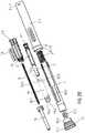
- FIG. 1is a simplified longitudinal section of an exemplary embodiment of an autoinjector after assembly
- FIGS. 2A to 2Dare schematic perspective partly cut-away views after assembly (in more detail), an explosion view of an exemplary embodiment of an autoinjector, a perspective view of an exemplary embodiment of a back-assembling tool and a perspective view of an exemplary embodiment of a front-assembling tool,
- FIG. 3is a schematic exploded view of an exemplary embodiment of a front subassembly comprising a front case with a mounted syringe carrier into which a syringe is to be assembled and of a front-assembling tool,
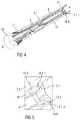
- FIG. 4is a schematic perspective view of an exemplary embodiment of a front subassembly with a mounted front case into which a syringe and a front-assembling tool are mounted,
- FIG. 5is a schematic enlarged partial view of the rear end of the front subassembly
- FIGS. 6A, 6B, 6Care schematic perspective views of an exemplary embodiment of a front subassembly with a mounted front case into which a front-assembling tool and a back-assembling tool are mounted,
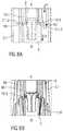
- FIGS. 7, 8A, 8Bare schematic enlarged partial views of the front subassembly with an arranged front-assembling tool
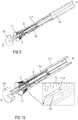
- FIG. 9is a schematic perspective view of an exemplary embodiment of the finally positioned front subassembly
- FIG. 10is a schematic perspective view of an exemplary embodiment of the finally positioned front subassembly with removed back-assembling tool and partially removed front-assembling tool
- FIG. 11is a schematic enlarged partial view of the finally assembled front subassembly
- FIG. 12is a schematic exploded view of a front subassembly and a back subassembly
- FIG. 13is a schematic perspective view of the assembled front subassembly and back subassembly
- FIG. 14is schematic enlarged partial view of the distal end of the finally assembled back subassembly
- FIG. 15is a schematic perspective view of an exemplary embodiment of a syringe carrier.
- FIG. 1is a simplified longitudinal section of an exemplary embodiment of an autoinjector 1 after assembly and shows the main assembling parts.
- FIG. 2Ais a schematic perspective partly cut-away view of the autoinjector 1 .
- FIG. 2Bshows an explosion view of all components of the autoinjector 1 .
- FIGS. 2A, 2Bshow the assembled autoinjector 1 in more detail.
- the autoinjector 1comprises a case 2 .
- the case 2is designed as a multi-part.
- the case 2comprises a front case 2 . 1 and a rear case 2 . 2 .
- the rear case 2 . 2is surrounded by the front case 2 . 1 along a longitudinal direction and adapted to close an open proximal end of the front case 2 . 1 .
- the case 2is adapted to hold a syringe 3 .
- the syringe 3may be a pre-filled syringe or a pre-filled medicament container and has a needle 4 arranged at a distal end.
- the syringe 3may be pre-assembled.
- a protective needle sheath 5may be removably coupled to the needle 4 .
- the protective needle sheath 5may be a rubber needle sheath or a rigid needle sheath (which is composed of rubber and a full or partial plastic shell).
- a stopper 6is arranged for sealing the syringe 3 proximally and for displacing a medicament M contained in the syringe 3 through the needle 4 .
- the syringemay be a cartridge or a container which includes the medicament M and engages a removable needle (e.g., by threads, snaps, friction, etc.).
- a cap 11may be removably disposed at a distal end of the case 2 .
- the cap 11may include a grip element 11 . 2 (e.g., a barb, a hook, a narrowed section, etc.) arranged to engage the protective needle sheath 5 , the cap 11 and/or a needle shroud 7 telescoped within the case 2 .
- the cap 11may comprise grip features 11 . 1 for facilitating removal of the cap 11 (e.g., by twisting and/or pulling the cap 11 relative to the case 2 .
- the cap 11comprises a barb 20 grasping the protective needle sheath 5 in a final mounted position of the syringe 3 within the case 2 .
- a shroud spring 8(shown in FIG. 2A ) is arranged to bias the needle shroud 7 in a distal direction D against the case 2 .
- a drive spring 9is arranged within the case 2 .
- a plunger 10serves for forwarding a force of the drive spring 9 to the stopper 6 .
- the plunger 10is hollow and the drive spring 9 is arranged within the plunger 10 biasing the plunger 10 in the distal direction D against the case 2 .
- the plunger 10may be solid and the drive spring 9 may engage a proximal end of the plunger 10 .
- the drive spring 9could be wrapped around the outer diameter of the plunger 10 and extend within the syringe 3 .
- a plunger release mechanism 12is arranged for preventing release of the plunger 10 prior to retraction of the needle shroud 7 relative to the case 2 , and for releasing the plunger 10 once the needle shroud 7 is sufficiently retracted.
- a shroud lock mechanism 14is arranged to prevent retraction of the needle shroud 7 relative to the case 2 when the cap 11 is in place, thereby avoiding unintentional activation of the autoinjector 1 (e.g., if dropped, during shipping or packaging, etc.).
- the shroud lock mechanism 14may comprise one or more compliant beams 11 . 3 on the cap 11 and a respective number of apertures 7 . 6 (shown in FIG. 2A ) in the needle shroud 7 adapted to receive each of the compliant beams 11 . 3 .
- the compliant beams 11 . 3abut a radial stop 2 . 15 on the case 2 , which prevents the compliant beams 11 . 3 from disengaging the apertures 7 . 6 .
- the cap 11When the cap 11 is attached to the autoinjector 1 , axial movement of the cap 11 in the proximal direction P relative the case 2 , is limited by a rib 11 . 4 on the cap 11 abutting the case 2 .
- the compliant beams 11 . 3may abut an edge of the aperture 7 . 6 and deflect to disengage the aperture 7 . 6 , allowing for removal of the cap 11 and the protective needle sheath 5 attached thereto.
- the cap 11comprises a closable opening 11 . 5 for inserting a front assembling tool 19 (an example is shown in FIG. 2D ).
- the compliant beams 11 . 3 and/or the apertures 7 . 6may be ramped to reduce force necessary to disengage the compliant beams 11 . 3 from the apertures 7 . 6 .
- the autoinjector 1comprises at least an audible indicator 13 (shown in FIG. 2A ) for producing an audible feedback of completion of medicament M delivery.
- the audible indicator 13is formed, for example, as a bistable spring and is held in the rear case 2 . 2 .
- the rear case 2 . 2is adapted to prevent axial movement of the syringe 3 after assembling, in particular during storage, transportation, and normal use.
- the rear case 2 . 2comprises at its front end resilient arms 15 .
- the resilient arms 15are formed as inwardly directed arms in a relaxed state.
- the autoinjector 1comprises a syringe carrier 16 .
- the syringe carrier 16is adapted to assemble and hold the syringe 3 within the case 2 and is further explained in more detail.
- the syringe 3is a 1.0 ml pre-filled syringe with a rigid protective needle sheath 5 .
- the syringe 3 and the protective needle sheath 5have large variations in dimensions.
- the design of the syringe carrier 16 and the front case 2 . 1are adapted to automatically displace and position the protective needle sheath 5 to a predetermined position during assembly to provide sufficient clearance to support the syringe 3 at its datum in the mounted position.
- the syringe carrier 16comprises flexible arms 16 . 1 adapted to mount and position the syringe 3 and hold it in a mounted position.
- the flexible arms 16 . 1protrude outwards in a relaxed state.
- the syringe carrier 16comprises a housing 16 . 0 adapted to receive the syringe 3 and at least two flexible arms 16 . 1 adapted to couple with the syringe 3 in the mounted position.
- the housing 16 . 0is formed as a hollow cylinder.
- the flexible arms 16 . 1are distally extended from an axial carrier front end 16 . 2 of the housing 16 . 0 .
- the flexible arms 16 . 1protrude outwards in a relaxed state, e.g. are outwardly formed, e.g. angled.
- the flexible arms 16 . 1comprise inwardly directed protrusions 16 . 3 at distal ends of the flexible arms 16 . 1 .
- the at least two flexible arms 16 . 1are adapted to couple with the syringe 3 in the mounted position, such that the outwardly protruded flexible arms 16 . 1 are deflected radially inwards in the mounted position due to a relative movement of the syringe carrier 16 with respect to the syringe 3 .
- This relative movementmay be caused by an axial force operating on the syringe carrier 16 , e.g. on a carrier rear end 16 . 4 .
- the front case 2 . 1is adapted to restrain the inward deflection of the flexible arms 16 . 1 when the syringe 3 is in the mounted position, such that an assembled force of the case 2 operates onto the flexible arms 16 . 1 , forcing the syringe 3 and the protective needle sheath 5 apart, so that the syringe 3 is secured in the mounted position shown in FIGS. 1 and 2A .
- the carrier 16comprises a carrier rear end 16 . 4 opposite to the carrier front end 16 . 2 .
- the carrier 16comprises a carrier flange 16 . 5 with holding clamps 16 . 6 for releasable intermittent holding of the carrier 16 relative to the case 2 .
- the holding clamps 16 . 6are integrally formed on the carrier flange 16 . 5 as tongues. Proximal ends of the holding clamps 16 . 6 are outwardly directed to engage slots 2 . 1 . 1 of the case 2 .
- the carrier 16comprises two holding clamps 16 . 6 arranged opposite to each other.
- the front case 2 . 1may comprise an inner support to releasably hold the holding clamps 16 . 6 .
- the inner supportmay be formed as an inner groove.
- the syringe carrier 16comprises ribs 16 . 8 on the outer surface of the flexible arms 16 . 1 to provide a stopping function for the relative movement of the syringe carrier 16 with respect to the syringe 3 .
- the ribs 16 . 8correspond with cuts or nuts (not shown) within the inner surface of the front case 2 . 1 .
- the autoinjector 1may be formed from at least two subassemblies, e.g., a control or front subassembly 1 . 1 and a drive or rear subassembly 1 . 2 , to allow for flexibility as to the time and location of manufacture of the subassemblies 1 . 1 , 1 . 2 and final assembly with the syringe 3 .
- FIGS. 2C and 2Dshow a perspective view of an exemplary embodiment of a back-assembling tool 18 having rigid arms 18 . 1 and of a front-assembling tool 19 having rigid arms 19 . 1 .
- FIG. 3is a perspective exploded view of an exemplary embodiment of a front subassembly 1 . 1 of an autoinjector 1 .
- the front subassembly 1 . 1comprises at least the front case 2 . 1 , the needle shroud 7 and the syringe carrier 16 , in which the syringe 3 is assembled.
- the needle shroud 7 and the syringe carrier 16are mounted into the front case 2 . 1 .
- the syringe carrier 16is stable due to clamp connection of the holding clamps 16 . 6 within slots 2 . 1 . 1 of the front case 2 . 1 at its rear end.
- the case 2comprises one or more apertures to allow insertion of the syringe 3 and insertion of the front-assembling tool 19 .
- the case 2in particular the front case 2 . 1 , is provided in which the syringe carrier 16 is pre-assembled and mounted.
- the syringe 3 with the needle 4 encapsulated by the removable protective needle sheath 5is inserted and pre-positioned axially into the syringe carrier 16 as described in more detail below.
- the syringe carrier 16is axially inserted into the front case 2 . 1 from a proximal end P, until holding clamps 16 . 6 of the syringe carrier 16 engage retaining slots 2 . 1 . 1 in the front case 2 . 1 , so that the syringe carrier 16 is fixed and stable in the front case 2 . 1 .
- the shroud spring 8is inserted into the needle shroud 7 (shown in FIG. 1 , not shown in FIG. 4 ) and the needle shroud 7 with the shroud spring 8 is inserted into a distal end 2 . 1 . 2 of the front case 2 . 1 .
- the cap 11 together with the barb 11 . 2is arranged over the distal end of the needle shroud 7 .
- the syringe 3may be inserted into the front subassembly 1 . 1 , namely into the syringe carrier 16 from its carrier rear end 16 . 4 .
- the syringe 3is dropped into the opened carrier rear end 16 . 4 axially forwards until the syringe flange 3 . 1 engages the carrier rear end 16 . 4 as it is shown in FIGS. 4 and 5 .
- the syringe flange 3 . 1engages a proximal shoulder 16 . 5 . 1 of the carrier flange 16 . 5 .
- the syringe flange 3 . 1engages a distal shoulder of the carrier flange 16 . 5 .
- the front-assembling tool 19When inserting the syringe 3 into the syringe carrier 16 , the front-assembling tool 19 is inserted into the front case 2 . 1 . In particular, the front-assembling tool 19 is pushed into the cap 11 and onto the protective needle sheath 5 axially forwards.
- the flexible arms 16 . 1protrude outwards and engage a shaft of the syringe 3 (shown in FIG. 4 ).
- FIG. 4shows in detail the front subassembly 1 . 1 with the mounted syringe carrier 16 together with the mounted syringe 3 in an intermediate assembling position.
- the syringe carrier 16is provided.
- the housing 16 . 0 of the syringe carrier 16comprises an inner diameter larger than the outer diameter of a shaft of the syringe 3 .
- the housing 16 . 0includes a proximal aperture having an outer diameter, in part, smaller than an outer diameter of the proximal syringe flange 3 . 1 .
- the axial force F 1 applied to the syringe carrier 16is smaller than a holding force, e.g. friction force, between the syringe carrier 16 and the syringe 3 , e.g. between their contacting surfaces. Furthermore, the axial force F 1 is greater than the retention force of the holding clamps 16 . 6 on the front case 2 . 1 .
- the back-assembling tool 18is inserted into the front case 2 . 1 until it contacts the carrier rear end 16 . 4 . Afterwards, the back-assembling tool 18 is pushed onto the syringe carrier 16 axially forwards so that the syringe carrier 16 is released from the case 2 and moves together with the syringe 3 in a forward direction. As best seen in FIG. 6B , the arms 18 . 1 of the back-assembling tool 18 are attached to the syringe carrier 16 .
- the carrier rear end 16 . 4comprises an elliptical or oval form and has an outer diameter, in part, larger than the outer diameter of the syringe flange 3 . 1 .
- FIG. 7shows the engagement of the distal end of the protective needle sheath 5 with a stamp 19 . 2 of the front-assembling tool 19 so that the syringe 3 is stopped and fixed in the front case 2 . 1 .
- FIG. 8Ashows the further assembling step, wherein the back-assembling tool 18 is further pushed onto the syringe carrier 16 so that the syringe carrier 16 is further moved with respect to the syringe 3 within the case 2 , until the syringe carrier 16 also comes in contact with the front-assembling tool 19 .
- the arms 19 . 1are inserted into the distal end of the syringe carrier 16 until the arms 19 . 1 engage inner edges 16 . 9 of the syringe carrier 16 , as shown in FIG. 7 . Due to further axial force F 1 to the syringe carrier 16 , the front-assembling tool 19 is also moved forwards and extends partially out of the cap 11 , as best seen in FIG. 9 .
- the flexible arms 16 . 1are ready to engage the front case 2 . 1 , in particular the edge 2 . 1 . 3 .
- the edge 2 . 1 . 3is formed as a ramp, e.g. a guiding ramp to control the inward deflection of the flexible arms 16 . 1 .
- the flexible arms 16 . 1enter the ramps and are deflected inwards to couple with the distal end of the syringe 3 in the final mounted position.
- the movement of the syringe carrier 16is stopped as the ribs 16 . 8 on the back of the flexible arms 16 . 1 engage a cut end or nut end arranged in the front case 2 . 1 .
- the flexible arms 16 . 1engage and displace the protective needle sheath 5 to allow space to support the syringe 3 in the final position and at the datum. Furthermore, in this final mounted position, the case 2 , in particular the ramp, is adapted to restrain and support the inward deflection of the flexible arms 16 . 1 , forcing the syringe 3 and the protective needle sheath 5 apart.
- the flexible arms 16 . 1are inwardly deflected and restrained in the mounted position by the edge 2 . 1 . 3 according to arrow F 2 so that the protective needle sheath 5 is displaced according to arrows F 3 to allow space between the syringe 3 and the protective needle sheath 5 and to support and position the syringe 3 in the final mounted position.
- the radially inwards deflected flexible arms 16 . 1are positioned a distance from the proximal end of the protective needle sheath 5 , e.g. in a distance of minus 0.3 mm.
- the flexible arms 16 . 1 of the syringe carrier 16are rigidly held and stable by the edge 2 . 1 . 3 of the front case 2 . 1 to safely support and position the syringe 3 .
- FIG. 9shows the syringe carrier 16 and the syringe 3 in the final mounted position.
- the front-assembling tool 19is partially pushed out of the cap 11 .
- FIG. 10shows the further assembling step wherein the back-assembling tool 18 is removed.
- the length of the syringe carrier 16may be smaller than the length of the syringe 3 to be assembled.
- the front-assembling tool 19is further removed from the cap 11 enabling the protective needle sheath 5 , as well as the syringe 3 and the syringe carrier 16 , due to the engagement of the inwardly deflected arms 16 . 1 onto the distal end of the syringe 3 , to move and fall into the cap 11 .
- Due to the inserted front-assembling tool 19cap arms 11 . 6 are deflected outwards as shown in FIG. 11 to support the further movement of the syringe 3 and the syringe carrier 16 into the cap 11 .
- the distal end (datum) of the syringe 3hits the flexible arms 16 . 1 of the syringe carrier 16 in the final mounting position.
- FIGS. 12 to 14show the last assembling step, wherein the front assembling tool 19 is completely removed, allowing the cap arms 11 . 6 to close up and engage on the protective needle sheath 5 .
- the rear case 2 . 2is ready to insert into the proximal end of the front case 2 . 1 .
- the resilient arms 15ensure that the syringe 3 cannot move backwards into the proximal direction P.
- FIG. 1shows a longitudinal section of the autoinjector 1 after final assembly, wherein the rear subassembly 1 . 2 (also called drive subassembly) is mounted onto the front subassembly 1 . 1 .
- the rear subassembly 1 . 2also called drive subassembly
- the rear subassembly 1 . 2comprises the plunger 10 , the drive spring 9 and the rear case 2 . 2 .
- the drive spring 9is inserted into the plunger 10 and the plunger 10 is inserted in the rear case 2 . 2 in the proximal direction P, thereby compressing the drive spring 9 .
- the plunger 10 and the drive spring 9reach a compressed position, it is rotated by an angle, e.g.
- the rear case 2 . 2may have a cam surface to engage the plunger 10 to induce this rotation prior to the plunger 10 and the drive spring 9 reaching the compressed position.
- the autoinjector 1may be kept in temperature controlled environment (e.g., cold chain storage) to, for example, reduce creep in highly stressed components, e.g. under load from the drive spring 9 .
- temperature controlled environmente.g., cold chain storage
- a force required to press the needle shroud 7may be approximately 2 N to 12 N.
- the mechanismmay work with a higher force.
- the syringe 3 used in the autoinjector 1may be a syringe capable of containing approximately 1 mL of the medicament M. In another exemplary embodiment, the syringe 3 used in the autoinjector 1 may be a syringe capable of containing approximately 2 mL of the medicament M.
- the autoinjector 1 according to the present disclosuremay have an increased shelf-life compared to conventional autoinjectors, because, for example, only the plunger 10 is subjected to the relatively high force of the drive spring 9 .
- the autoinjector 1may be used as a platform as the drive spring 9 can be changed to alter a force applied to the plunger 10 , e.g. for delivering medicaments with different viscosities drugs or reconstituted medicaments, or changing a time required to inject a dose of the medicament.
- the cap 11is suitable for being applied with any kind of injection device or autoinjector.
- drugor “medicament” are used herein to describe one or more pharmaceutically active compounds.
- a drug or medicamentcan include at least one small or large molecule, or combinations thereof, in various types of formulations, for the treatment of one or more diseases.
- Exemplary pharmaceutically active compoundsmay include small molecules; polypeptides, peptides and proteins (e.g., hormones, growth factors, antibodies, antibody fragments, and enzymes); carbohydrates and polysaccharides; and nucleic acids, double or single stranded DNA (including naked and cDNA), RNA, antisense nucleic acids such as antisense DNA and RNA, small interfering RNA (siRNA), ribozymes, genes, and oligonucleotides. Nucleic acids may be incorporated into molecular delivery systems such as vectors, plasmids, or liposomes. Mixtures of one or more of these drugs are also contemplated.
- a drug delivery deviceshall encompass any type of device or system configured to dispense a drug into a human or animal body.
- a drug delivery devicemay be an injection device (e.g., syringe, pen injector, auto injector, large-volume device, pump, perfusion system, or other device configured for intraocular, subcutaneous, intramuscular, or intravascular delivery), skin patch (e.g., osmotic, chemical, micro-needle), inhaler (e.g., nasal or pulmonary), implantable (e.g., coated stent, capsule), or feeding systems for the gastro-intestinal tract.
- the presently described drugsmay be particularly useful with injection devices that include a needle, e.g., a small gauge needle.
- the drug or medicamentmay be contained in a primary package or “drug container” adapted for use with a drug delivery device.
- the drug containermay be, e.g., a cartridge, syringe, reservoir, or other vessel configured to provide a suitable chamber for storage (e.g., short- or long-term storage) of one or more pharmaceutically active compounds.
- the chambermay be designed to store a drug for at least one day (e.g., 1 to at least 30 days).
- the chambermay be designed to store a drug for about 1 month to about 2 years. Storage may occur at room temperature (e.g., about 20° C.), or refrigerated temperatures (e.g., from about ⁇ 4° C. to about 4° C.).
- the drug containermay be or may include a dual-chamber cartridge configured to store two or more components of a drug formulation (e.g., a drug and a diluent, or two different types of drugs) separately, one in each chamber.
- the two chambers of the dual-chamber cartridgemay be configured to allow mixing between the two or more components of the drug or medicament prior to and/or during dispensing into the human or animal body.
- the two chambersmay be configured such that they are in fluid communication with each other (e.g., by way of a conduit between the two chambers) and allow mixing of the two components when desired by a user prior to dispensing.
- the two chambersmay be configured to allow mixing as the components are being dispensed into the human or animal body.
- the drug delivery devices and drugs described hereincan be used for the treatment and/or prophylaxis of many different types of disorders.
- exemplary disordersinclude, e.g., diabetes mellitus or complications associated with diabetes mellitus such as diabetic retinopathy, thromboembolism disorders such as deep vein or pulmonary thromboembolism.
- Further exemplary disordersare acute coronary syndrome (ACS), angina, myocardial infarction, cancer, macular degeneration, inflammation, hay fever, atherosclerosis and/or rheumatoid arthritis.
- ACSacute coronary syndrome
- anginamyocardial infarction
- cancermacular degeneration
- inflammationhay fever
- atherosclerosisand/or rheumatoid arthritis.
- Exemplary drugs for the treatment and/or prophylaxis of diabetes mellitus or complications associated with diabetes mellitusinclude an insulin, e.g., human insulin, or a human insulin analogue or derivative, a glucagon-like peptide (GLP-1), GLP-1 analogues or GLP-1 receptor agonists, or an analogue or derivative thereof, a dipeptidyl peptidase-4 (DPP4) inhibitor, or a pharmaceutically acceptable salt or solvate thereof, or any mixture thereof.
- the term “derivative”refers to any substance which is sufficiently structurally similar to the original substance so as to have substantially similar functionality or activity (e.g., therapeutic effectiveness).
- Exemplary insulin analoguesare Gly(A21), Arg(B31), Arg(B32) human insulin (insulin glargine); Lys(B3), Glu(B29) human insulin; Lys(B28), Pro(B29) human insulin; Asp(B28) human insulin; human insulin, wherein proline in position B28 is replaced by Asp, Lys, Leu, Val or Ala and wherein in position B29 Lys may be replaced by Pro; Ala(B26) human insulin; Des(B28-B30) human insulin; Des(B27) human insulin and Des(B30) human insulin.
- Exemplary insulin derivativesare, for example, B29-N-myristoyl-des(B30) human insulin; B29-N-palmitoyl-des(B30) human insulin; B29-N-myristoyl human insulin; B29-N-palmitoyl human insulin; B28-N-myristoyl LysB28ProB29 human insulin; B28-N-palmitoyl-LysB28ProB29 human insulin; B30-N-myristoyl-ThrB29LysB30 human insulin; B30-N-palmitoyl-ThrB29LysB30 human insulin; B29-N—(N-palmitoyl-gamma-glutamyl)-des(B30) human insulin; B29-N—(N-lithocholyl-gamma-glutamyl)-des(B30) human insulin; B29-N-( ⁇ -carboxyheptadecanoyl)-des(B30) human insulin and B29-N-
- GLP-1, GLP-1 analogues and GLP-1 receptor agonistsare, for example: Lixisenatide/AVE0010/ZP10/Lyxumia, Exenatide/Exendin-4/Byetta/Bydureon/ITCA 650/AC-2993 (a 39 amino acid peptide which is produced by the salivary glands of the Gila monster), Liraglutide/Victoza, Semaglutide, Taspoglutide, Syncria/Albiglutide, Dulaglutide, rExendin-4, CJC-1134-PC, PB-1023, TTP-054, Langlenatide/HM-11260C, CM-3, GLP-1 Eligen, ORMD-0901, NN-9924, NN-9926, NN-9927, Nodexen, Viador-GLP-1, CVX-096, ZYOG-1, ZYD-1, GSK-2374697, DA-3091, MAR-701, MAR709, ZP
- An exemplary oligonucleotideis, for example: mipomersen/Kynamro, a cholesterol-reducing antisense therapeutic for the treatment of familial hypercholesterolemia.
- DPP4 inhibitorsare Vildagliptin, Sitagliptin, Denagliptin, Saxagliptin, Berberine.
- hormonesinclude hypophysis hormones or hypothalamus hormones or regulatory active peptides and their antagonists, such as Gonadotropine (Follitropin, Lutropin, Choriongonadotropin, Menotropin), Somatropine (Somatropin), Desmopressin, Terlipressin, Gonadorelin, Triptorelin, Leuprorelin, Buserelin, Nafarelin, and Goserelin.
- GonadotropineFollitropin, Lutropin, Choriongonadotropin, Menotropin
- SomatropineSomatropin
- DesmopressinTerlipressin
- GonadorelinTriptorelin
- LeuprorelinBuserelin
- NafarelinNafarelin
- GoserelinGoserelin.
- Exemplary polysaccharidesinclude a glucosaminoglycane, a hyaluronic acid, a heparin, a low molecular weight heparin or an ultra-low molecular weight heparin or a derivative thereof, or a sulphated polysaccharide, e.g. a poly-sulphated form of the above-mentioned polysaccharides, and/or a pharmaceutically acceptable salt thereof.
- An example of a pharmaceutically acceptable salt of a poly-sulphated low molecular weight heparinis enoxaparin sodium.
- An example of a hyaluronic acid derivativeis Hylan G-F 20/Synvisc, a sodium hyaluronate.
- antibodyrefers to an immunoglobulin molecule or an antigen-binding portion thereof.
- antigen-binding portions of immunoglobulin moleculesinclude F(ab) and F(ab′) 2 fragments, which retain the ability to bind antigen.
- the antibodycan be polyclonal, monoclonal, recombinant, chimeric, de-immunized or humanized, fully human, non-human, (e.g., murine), or single chain antibody.
- the antibodyhas effector function and can fix complement.
- the antibodyhas reduced or no ability to bind an Fc receptor.
- the antibodycan be an isotype or subtype, an antibody fragment or mutant, which does not support binding to an Fc receptor, e.g., it has a mutagenized or deleted Fc receptor binding region.
- fragmentrefers to a polypeptide derived from an antibody polypeptide molecule (e.g., an antibody heavy and/or light chain polypeptide) that does not comprise a full-length antibody polypeptide, but that still comprises at least a portion of a full-length antibody polypeptide that is capable of binding to an antigen.
- Antibody fragmentscan comprise a cleaved portion of a full length antibody polypeptide, although the term is not limited to such cleaved fragments.
- Antibody fragmentsthat are useful in the present disclosure include, for example, Fab fragments, F(ab′)2 fragments, scFv (single-chain Fv) fragments, linear antibodies, monospecific or multispecific antibody fragments such as bispecific, trispecific, and multispecific antibodies (e.g., diabodies, triabodies, tetrabodies), minibodies, chelating recombinant antibodies, tribodies or bibodies, intrabodies, nanobodies, small modular immunopharmaceuticals (SMIP), binding-domain immunoglobulin fusion proteins, camelized antibodies, and VHH containing antibodies. Additional examples of antigen-binding antibody fragments are known in the art.
- CDRcomplementarity-determining region
- framework regionrefers to amino acid sequences within the variable region of both heavy and light chain polypeptides that are not CDR sequences, and are primarily responsible for maintaining correct positioning of the CDR sequences to permit antigen binding.
- framework regionsthemselves typically do not directly participate in antigen binding, as is known in the art, certain residues within the framework regions of certain antibodies can directly participate in antigen binding or can affect the ability of one or more amino acids in CDRs to interact with antigen.
- Exemplary antibodiesare anti PCSK-9 mAb (e.g., Alirocumab), anti IL-6 mAb (e.g., Sarilumab), and anti IL-4 mAb (e.g., Dupilumab).
- anti PCSK-9 mAbe.g., Alirocumab
- anti IL-6 mAbe.g., Sarilumab
- anti IL-4 mAbe.g., Dupilumab
- the compounds described hereinmay be used in pharmaceutical formulations comprising (a) the compound(s) or pharmaceutically acceptable salts thereof, and (b) a pharmaceutically acceptable carrier.
- the compoundsmay also be used in pharmaceutical formulations that include one or more other active pharmaceutical ingredients or in pharmaceutical formulations in which the present compound or a pharmaceutically acceptable salt thereof is the only active ingredient.
- the pharmaceutical formulations of the present inventionencompass any formulation made by admixing a compound described herein and a pharmaceutically acceptable carrier.
- Pharmaceutically acceptable salts of any drug described hereinare also contemplated for use in drug delivery devices.
- Pharmaceutically acceptable saltsare for example acid addition salts and basic salts.
- Acid addition saltsare e.g. HCl or HBr salts.
- Basic saltsare e.g. salts having a cation selected from an alkali or alkaline earth metal, e.g.
- R1 to R4independently of each other mean: hydrogen, an optionally substituted C1-C6-alkyl group, an optionally substituted C2-C6-alkenyl group, an optionally substituted C6-C10-aryl group, or an optionally substituted C6-C10-heteroaryl group.
- R1 to R4independently of each other mean: hydrogen, an optionally substituted C1-C6-alkyl group, an optionally substituted C2-C6-alkenyl group, an optionally substituted C6-C10-aryl group, or an optionally substituted C6-C10-heteroaryl group.
- solvatesare for example hydrates or alkanolates such as methanolates or ethanolates.
Landscapes
- Health & Medical Sciences (AREA)
- Vascular Medicine (AREA)
- Engineering & Computer Science (AREA)
- Anesthesiology (AREA)
- Biomedical Technology (AREA)
- Heart & Thoracic Surgery (AREA)
- Hematology (AREA)
- Life Sciences & Earth Sciences (AREA)
- Animal Behavior & Ethology (AREA)
- General Health & Medical Sciences (AREA)
- Public Health (AREA)
- Veterinary Medicine (AREA)
- Infusion, Injection, And Reservoir Apparatuses (AREA)
Abstract
Description
- 1 autoinjector
- 1.1 front subassembly
- 1.2 rear subassembly
- 2 case
- 2.1 front case
- 2.1.1 slots
- 2.1.2 distal end of front case
- 2.1.3 edge
- 2.2 rear case
- 2.15 radial stop
- 3 syringe
- 3.1 syringe flange
- 4 needle
- 5 protective needle sheath
- 6 stopper
- 7 needle shroud
- 8 shroud spring
- 9 drive spring
- 10 plunger
- 11 cap
- 11.1 grip features
- 11.2 grip element
- 11.3 compliant beams
- 11.4 rib
- 11.5 opening
- 11.6 cap arm
- 12 plunger release mechanism
- 13 audible indicator
- 14 shroud lock mechanism
- 15 resilient arms
- 16 syringe carrier
- 16.0 housing
- 16.1 flexible arms
- 16.2 carrier front end
- 16.3 protrusions
- 16.4 carrier rear end
- 16.5 carrier flange
- 16.5.1 proximal shoulder
- 16.6 holding clamps
- 16.7 support element
- 16.8 rib
- 17 viewing window
- 18 back-assembling tool
- 18.1 arms
- 19 front-assembling tool
- 19.1 arms
- 19.2 stamp
- F1 to F3 arrow
- D distal end
- M medicament
- P proximal end
Claims (21)
Applications Claiming Priority (4)
| Application Number | Priority Date | Filing Date | Title |
|---|---|---|---|
| EP15170597 | 2015-06-03 | ||
| EP15170597 | 2015-06-03 | ||
| EP15170597.7 | 2015-06-03 | ||
| PCT/EP2016/062462WO2016193356A1 (en) | 2015-06-03 | 2016-06-02 | Autoinjector and method of assembling |
Related Parent Applications (1)
| Application Number | Title | Priority Date | Filing Date |
|---|---|---|---|
| PCT/EP2016/062462A-371-Of-InternationalWO2016193356A1 (en) | 2015-06-03 | 2016-06-02 | Autoinjector and method of assembling |
Related Child Applications (1)
| Application Number | Title | Priority Date | Filing Date |
|---|---|---|---|
| US17/391,193ContinuationUS20220016358A1 (en) | 2015-06-03 | 2021-08-02 | Autoinjector and method of assembling |
Publications (2)
| Publication Number | Publication Date |
|---|---|
| US20180140782A1 US20180140782A1 (en) | 2018-05-24 |
| US11103649B2true US11103649B2 (en) | 2021-08-31 |
Family
ID=53276822
Family Applications (2)
| Application Number | Title | Priority Date | Filing Date |
|---|---|---|---|
| US15/579,024ActiveUS11103649B2 (en) | 2015-06-03 | 2016-06-02 | Autoinjector and method of assembling |
| US17/391,193PendingUS20220016358A1 (en) | 2015-06-03 | 2021-08-02 | Autoinjector and method of assembling |
Family Applications After (1)
| Application Number | Title | Priority Date | Filing Date |
|---|---|---|---|
| US17/391,193PendingUS20220016358A1 (en) | 2015-06-03 | 2021-08-02 | Autoinjector and method of assembling |
Country Status (14)
| Country | Link |
|---|---|
| US (2) | US11103649B2 (en) |
| EP (1) | EP3302642B1 (en) |
| JP (1) | JP6831339B2 (en) |
| KR (1) | KR20180015681A (en) |
| CN (1) | CN107666929B (en) |
| AR (1) | AR104874A1 (en) |
| AU (1) | AU2016269708A1 (en) |
| BR (1) | BR112017025748A2 (en) |
| DK (1) | DK3302642T3 (en) |
| IL (1) | IL255984A (en) |
| MX (1) | MX2017015509A (en) |
| RU (1) | RU2017146404A (en) |
| TW (1) | TW201705994A (en) |
| WO (1) | WO2016193356A1 (en) |
Cited By (5)
| Publication number | Priority date | Publication date | Assignee | Title |
|---|---|---|---|---|
| US20220016358A1 (en)* | 2015-06-03 | 2022-01-20 | Sanofi-Aventis Deutschland Gmbh | Autoinjector and method of assembling |
| US11400221B2 (en) | 2011-12-08 | 2022-08-02 | Sanofi-Aventis Deutschland Gmbh | Syringe carrier |
| US12036392B1 (en) | 2013-03-14 | 2024-07-16 | Sanofi-Aventis Deutschland Gmbh | Medicament container carrier and adapter |
| US12318597B2 (en) | 2015-06-03 | 2025-06-03 | Sanofi-Aventis Deutschland Gmbh | Syringe carrier for an autoinjector and method of assembling |
| US12440627B2 (en) | 2016-05-18 | 2025-10-14 | Sanofi-Aventis Deutschland Gmbh | Sheath remover and methods for assembly thereof |
Families Citing this family (22)
| Publication number | Priority date | Publication date | Assignee | Title |
|---|---|---|---|---|
| WO2018010947A1 (en) | 2016-07-14 | 2018-01-18 | Carebay Europe Ltd. | Administration mechanism for a medicament delivery device |
| US10307545B2 (en)* | 2017-05-01 | 2019-06-04 | Shl Medical Ag | Cap assembly for a medicament delivery device |
| CN111867659A (en)* | 2018-03-26 | 2020-10-30 | 艾斯曲尔医疗公司 | Medication container holder |
| EP3801694B1 (en) | 2018-06-08 | 2025-08-27 | Antares Pharma, Inc. | Auto-insert injector |
| MX2023010440A (en)* | 2021-03-10 | 2023-09-12 | Amgen Inc | Drug delivery device, subassembly for drug delivery device, syringe holder, and method of assembly. |
| WO2024094699A1 (en) | 2022-10-31 | 2024-05-10 | Sanofi | Container holder and drug delivery device comprising the container holder |
| EP4611851A1 (en) | 2022-10-31 | 2025-09-10 | Sanofi | Drug delivery device with feedback element and method for providing a user of a drug delivery device feedback regarding a dose dispensing process |
| CN120112323A (en) | 2022-10-31 | 2025-06-06 | 赛诺菲 | Audible indicator, indicator holder, and method of assembling an audible indicator |
| CN120129547A (en) | 2022-10-31 | 2025-06-10 | 赛诺菲 | Device body for a drug delivery device, component for a drug delivery device, and drug delivery device |
| EP4611850A1 (en) | 2022-10-31 | 2025-09-10 | Sanofi | Arrangement for a drug delivery device, drug delivery device and method for assembly |
| CN120187475A (en) | 2022-10-31 | 2025-06-20 | 赛诺菲 | Components for drug delivery devices |
| WO2024094703A1 (en) | 2022-10-31 | 2024-05-10 | Sanofi | Plunger for expelling a drug, drug delivery device, rear sub-assembly and corresponding methods |
| CN120166942A (en) | 2022-10-31 | 2025-06-17 | 赛诺菲 | Method of assembling components for a drug delivery device and drug delivery device |
| CN120129549A (en) | 2022-10-31 | 2025-06-10 | 赛诺菲 | Drug delivery device with two-part user indicator |
| EP4611852A1 (en) | 2022-10-31 | 2025-09-10 | Sanofi | Front sub-assembly for a drug delivery device |
| CN115737991A (en)* | 2022-12-27 | 2023-03-07 | 苏州恒瑞宏远医疗科技有限公司 | Automatic injection pen |
| WO2024146819A1 (en)* | 2023-01-04 | 2024-07-11 | Shl Medical Ag | Medicament delivery device |
| CN117182544A (en)* | 2023-08-25 | 2023-12-08 | 上海新耀湃科医疗科技股份有限公司 | Assembling method of prefilled syringe |
| GB2635893A (en)* | 2023-10-09 | 2025-06-04 | Actuate Tech Ltd | Drug delivery device |
| WO2025162926A1 (en) | 2024-01-29 | 2025-08-07 | Sanofi | Needle arrangement, drug delivery device comprising the needle arrangement and method for operating the drug delivery device |
| WO2025162927A1 (en) | 2024-01-29 | 2025-08-07 | Sanofi | Purifying device, system and method for purifying a needle for delivering a medicament |
| WO2025162928A1 (en) | 2024-01-29 | 2025-08-07 | Sanofi | Needle shroud unlock device for a medicament delivery device |
Citations (126)
| Publication number | Priority date | Publication date | Assignee | Title |
|---|---|---|---|---|
| GB407109A (en) | 1932-01-19 | 1934-03-15 | Erwin Rippstein | Improvements in or relating to syringes for subcutaneous injection |
| GB829724A (en) | 1957-10-17 | 1960-03-02 | Hoechst Ag | Holder for an injection syringe |
| US3026873A (en) | 1959-03-06 | 1962-03-27 | Pfizer & Co C | Aspirating hypodermic syringe holder |
| US3076455A (en) | 1958-12-19 | 1963-02-05 | Robert K Mcconnaughey | Holder for hypodermic syringe cartridges |
| US3144178A (en) | 1962-03-12 | 1964-08-11 | Stanley J Sarnoff | Cartridge holder |
| GB1122592A (en) | 1965-05-19 | 1968-08-07 | Franz Wantoch | Improvements in or relating to hypodermic syringes |
| US3880163A (en) | 1973-10-26 | 1975-04-29 | Jack H Ritterskamp | Medicinal syringe actuating device |
| US4563175A (en) | 1983-12-19 | 1986-01-07 | Lafond Margaret | Multiple syringe pump |
| US4643724A (en) | 1985-12-16 | 1987-02-17 | Alcon Laboratories, Inc. | Syringe holder |
| US4655751A (en) | 1986-02-14 | 1987-04-07 | Harbaugh John T | Liquid dispensing and receiving syringe |
| US4735311A (en) | 1986-04-09 | 1988-04-05 | The West Company | Needle shield assembly |
| US4838857A (en) | 1985-05-29 | 1989-06-13 | Becton, Dickinson And Company | Medical infusion device |
| US4871355A (en) | 1988-05-17 | 1989-10-03 | Steven Kikkawa | Injury resistant needle and blood collection tube holder |
| US4909791A (en) | 1988-02-16 | 1990-03-20 | Norelli Robert A | Safety cover for syringe needles |
| US4931040A (en) | 1988-04-13 | 1990-06-05 | Habley Medical Technology | Safety syringe having a combination needle cannula and articulating hub for retracting said cannula into a medication carpule |
| US4946447A (en) | 1989-02-14 | 1990-08-07 | Hardcastle Samuel L | Protective cover for hypodermic needle |
| US4964866A (en) | 1989-11-22 | 1990-10-23 | Becton, Dickinson And Company | Needle sheath assembly |
| US4973318A (en) | 1988-02-10 | 1990-11-27 | D.C.P. Af 1988 A/S | Disposable syringe |
| US4990142A (en) | 1989-10-23 | 1991-02-05 | Gte Products Corporation | Hypodermic syringe |
| US4997422A (en) | 1989-01-31 | 1991-03-05 | Chow Peter P | Hypodermic syringe with needle shield |
| US5078698A (en)* | 1991-02-19 | 1992-01-07 | Sterling Drug Inc. | Axial eject hypodermic syringe holder |
| US5085641A (en) | 1989-07-17 | 1992-02-04 | Survival Technology, Inc. | Conveniently carried frequent use auto-injector with improved cap structure |
| US5169392A (en) | 1988-06-28 | 1992-12-08 | Sherwood Medical Company | Combined syringe and needle shield and method of manufacture |
| EP0518416A1 (en) | 1991-06-13 | 1992-12-16 | Duphar International Research B.V | Injection device |
| US5282793A (en) | 1989-10-02 | 1994-02-01 | Larson Eldon E | Syringe holder and applicator |
| US5320609A (en) | 1992-12-07 | 1994-06-14 | Habley Medical Technology Corporation | Automatic pharmaceutical dispensing syringe |
| US5322511A (en) | 1992-04-21 | 1994-06-21 | Sterling Winthrop Inc. | Portable hand-held power injector |
| US5344407A (en) | 1993-05-04 | 1994-09-06 | Ryan Dana W | Safety holder for pre-filled disposable syringe cartridge |
| US5356395A (en) | 1993-12-14 | 1994-10-18 | Chen Shih Shuan | Safety syringe shield |
| US5368578A (en) | 1994-03-10 | 1994-11-29 | Sterling Winthrop Inc. | Hypodermic syringe holder |
| US5383858A (en) | 1992-08-17 | 1995-01-24 | Medrad, Inc. | Front-loading medical injector and syringe for use therewith |
| US5383863A (en) | 1993-11-15 | 1995-01-24 | Mardones; Nestor E. | Attachment for maximum safety of hypodermic syringes |
| US5439450A (en) | 1994-07-18 | 1995-08-08 | Becton, Dickinson And Company | Method of delivering a blood sample to an evacuated receptacle |
| US5451214A (en) | 1993-03-22 | 1995-09-19 | Hajishoreh; Kaveh-Karimi | Syringe apparatus |
| US5480387A (en) | 1991-07-24 | 1996-01-02 | Medico Development Investment Company | Injection device |
| EP0692272A1 (en) | 1994-07-14 | 1996-01-17 | Carlos Jose Marano | Syringes |
| US5520653A (en) | 1995-09-01 | 1996-05-28 | Medrad, Inc. | Syringe adapter for front-loading medical injector |
| US5599309A (en) | 1993-03-24 | 1997-02-04 | Owen Mumford Limited | Injection devices |
| US5637101A (en) | 1995-01-09 | 1997-06-10 | Med-Safe Systems, Inc. | Quick release needle coupling system |
| US5709662A (en) | 1996-08-23 | 1998-01-20 | Becton Dickinson France, S.A. | Cartridge for an injection device |
| US5779675A (en) | 1995-08-25 | 1998-07-14 | Medrad, Inc. | Front load pressure jacket system with syringe holder |
| FR2764195A1 (en) | 1997-06-10 | 1998-12-11 | Blue Star Corp | SELF-RETRACTING NEEDLE SYRINGE |
| US5865805A (en) | 1997-07-16 | 1999-02-02 | Liebel-Flarsheim Company | Power injector and side loadable syringe support therefor for plunger pushrod type syringes |
| WO1999010030A2 (en) | 1997-08-21 | 1999-03-04 | Owen Mumford Limited | Improvements relating to injection devices |
| WO1999022792A1 (en) | 1997-11-03 | 1999-05-14 | Ermanno Greco | Self-injection device |
| US5913844A (en) | 1997-06-17 | 1999-06-22 | Liebel-Flarsheim Company | Power injector and method providing removal of used disposable syringe |
| US5928205A (en) | 1995-03-24 | 1999-07-27 | Owen Mumford Limited | Medical injection devices |
| US5928698A (en) | 1998-03-31 | 1999-07-27 | Soyad; Tony T. | Method of making a carambola beverage |
| WO2000024441A1 (en) | 1998-10-26 | 2000-05-04 | Pharmacia Ab | Autoinjector |
| US6090082A (en) | 1998-02-23 | 2000-07-18 | Becton, Dickinson And Company | Vial retainer interface to a medication delivery pen |
| WO2001008727A1 (en) | 1999-07-30 | 2001-02-08 | Medrad, Inc. | Injector systems and syringe adapters for use therewith |
| US6203530B1 (en) | 1997-01-28 | 2001-03-20 | Pos-T-Vac, Inc. | Auto-injection device |
| US6210369B1 (en) | 1997-12-16 | 2001-04-03 | Meridian Medical Technologies Inc. | Automatic injector |
| WO2001060435A1 (en) | 2000-02-18 | 2001-08-23 | Astrazeneca Ab | Automatically operable safety shield system for syringes |
| WO2001093926A2 (en) | 2000-06-08 | 2001-12-13 | Mayo Foundation For Medical Education And Research | Automated injection device for administration of liquid medicament |
| WO2002047746A1 (en) | 2000-12-14 | 2002-06-20 | Shl Medical Ab | Auto-injector |
| US6454743B1 (en) | 1998-04-30 | 2002-09-24 | Schering Aktiengesellschaft | Injection device |
| US6544234B1 (en) | 1998-01-24 | 2003-04-08 | B D Medico S.A.R.L. | Injection device |
| US20030105430A1 (en)* | 2001-11-30 | 2003-06-05 | Elan Pharma International Limited Wil House | Automatic injector |
| US6613022B1 (en) | 2000-05-05 | 2003-09-02 | Safety Syringes, Inc. | Passive needle guard for syringes |
| GB2388033A (en) | 2002-05-02 | 2003-11-05 | Pa Consulting Services | Automatic injection device |
| WO2003099358A2 (en) | 2002-05-23 | 2003-12-04 | Seedlings Life Science Ventures, Llc. | Apparatus for rapid auto-injection of medication |
| WO2004007006A2 (en) | 2002-07-12 | 2004-01-22 | Becton Dickinson France | Syringe accessory |
| WO2004020026A1 (en) | 2002-08-29 | 2004-03-11 | Novo Nordisk A/S | Frontloaded injection device |
| WO2004050150A2 (en) | 2002-12-02 | 2004-06-17 | Tyco Healthcare Group Lp | Safety shield for medical needles |
| GB2396298A (en) | 2002-12-17 | 2004-06-23 | Pa Consulting Services | Injection device and drive coupling |
| GB2397767A (en) | 2002-12-17 | 2004-08-04 | Pa Consulting Services | Injection device |
| WO2005001161A1 (en) | 2003-06-30 | 2005-01-06 | Tdk Corporation | Mask material for reactive ion etching, mask and dry etching method |
| US20050020979A1 (en) | 2003-07-22 | 2005-01-27 | Safety Syringes, Inc. | Systems and methods for automatic medical injection with safeguard |
| US20050027255A1 (en) | 2003-07-31 | 2005-02-03 | Sid Technologies, Llc | Automatic injector |
| US20050075608A1 (en) | 2002-02-28 | 2005-04-07 | Dca Design International Limited | Medicament delivery device |
| US20050101919A1 (en) | 2003-11-07 | 2005-05-12 | Lennart Brunnberg | Device for an injector |
| US20050115507A1 (en) | 2002-01-15 | 2005-06-02 | S. A. E. Afikim Computerized Dairy Management System | Identification of small ruminants |
| US20050165353A1 (en) | 2002-03-18 | 2005-07-28 | Olivier Pessin | Needle protection device for a syringe and an injection device comprising a syringe and said protection device |
| WO2005070481A1 (en) | 2004-01-23 | 2005-08-04 | The Medical House Plc | Injection device |
| WO2005115506A1 (en) | 2004-05-28 | 2005-12-08 | Cilag Gmbh International | Releasable coupling and injection device |
| WO2005115507A1 (en) | 2004-05-28 | 2005-12-08 | Cilag Gmbh International | Injection device |
| US20050277896A1 (en) | 2002-11-25 | 2005-12-15 | Walter Messerli | Device for securing injection needles |
| US20060036216A1 (en) | 2001-10-15 | 2006-02-16 | Compagnie Plastic Omnium | Safety device for a syringe |
| US20060167412A1 (en) | 2003-06-05 | 2006-07-27 | Jeremy Marshall | Syringe firing mechanism |
| EP1702643A2 (en) | 1997-08-20 | 2006-09-20 | B. Braun Melsungen Ag | Spring clip as needle tip protection for a safety IV catheter |
| WO2006106291A1 (en) | 2005-04-06 | 2006-10-12 | Cilag Ag International | Injection device |
| WO2006106295A1 (en) | 2005-04-06 | 2006-10-12 | Cilag Ag International | Injection device (adaptable device) |
| CN1911467A (en) | 2006-08-08 | 2007-02-14 | 林作钱 | Needle retraction type safety injector |
| GB2434317A (en) | 2006-01-23 | 2007-07-25 | Medical House Plc | Autoinjector |
| WO2007083115A1 (en) | 2006-01-23 | 2007-07-26 | The Medical House Plc | Improved autoinjector supporting the syringe at the front |
| WO2007104636A1 (en) | 2006-03-10 | 2007-09-20 | Novo Nordisk A/S | An injection device and a method of changing a cartridge in the device |
| US20070260348A1 (en) | 2003-12-05 | 2007-11-08 | Ben Gordils | Portable table carrier for construction plans |
| US20080147003A1 (en) | 2001-04-18 | 2008-06-19 | Thomas Menzi | Safety spring catheter introducer assembly |
| GB2447339A (en) | 2007-03-07 | 2008-09-10 | Medical House Plc | An autoinjector having a plunger biasing means |
| US20080228143A1 (en) | 2004-01-23 | 2008-09-18 | The Medical House Plc | Injection Device |
| US20080262427A1 (en) | 2005-11-03 | 2008-10-23 | Edgar Hommann | Auto-injector activation triggering element |
| WO2009019437A1 (en) | 2007-08-08 | 2009-02-12 | Cilag Gmbh International | Injection device with locking mechanism for syringe carrier |
| JP2009077943A (en) | 2007-09-26 | 2009-04-16 | Jms Co Ltd | Syringe holder and syringe device |
| US20090105663A1 (en)* | 2007-10-11 | 2009-04-23 | Rexam Pharma La Verpilliere | Safety device for a liquid injection syringe, and a syringe assembly including the device |
| DE202009009119U1 (en) | 2009-07-02 | 2009-12-31 | B. Braun Melsungen Ag | Protection device for a hypodermic needle |
| US20100179507A1 (en) | 2009-01-12 | 2010-07-15 | Stryker Development Llc | Syringe and method of use |
| WO2010097116A1 (en) | 2009-02-26 | 2010-09-02 | Tecpharma Licensing Ag | Product container holder for an injection device and for receiving a product container |
| WO2010136078A1 (en) | 2009-05-29 | 2010-12-02 | Tecpharma Licensing Ag | Injection device, especially auto-injector, comprising an anti-pricking mechanism and/or overload protection for a product container. |
| GB2471473A (en) | 2009-06-30 | 2011-01-05 | Owen Mumford Ltd | Syringe sheath remover |
| EP2279771A1 (en) | 2008-05-22 | 2011-02-02 | Sol-Millennium Medical Products Co., Ltd. | New safe latching type self-destroying syringe |
| WO2011101378A1 (en) | 2010-02-18 | 2011-08-25 | Sanofi-Aventis Deutschland Gmbh | Finger guard for an injection device |
| EP2438952A1 (en) | 2010-10-08 | 2012-04-11 | Sanofi-Aventis Deutschland GmbH | Finger guard for an injection device |
| WO2012073032A1 (en) | 2010-12-02 | 2012-06-07 | Oval Medical Technologies Limited | A drive assembly for an autoinjector and a method of assembling an autoinjector |
| WO2012089445A1 (en) | 2010-12-06 | 2012-07-05 | Novo Nordisk Health Care Ag | Wheel operated drug delivery device |
| WO2013083614A1 (en) | 2011-12-08 | 2013-06-13 | Sanofi-Aventis Deutschland Gmbh | Syringe carrier |
| US20130220869A1 (en) | 2010-11-08 | 2013-08-29 | Shl Group Ab | Container Holder Assembly |
| RU2012137269A (en) | 2010-02-01 | 2014-03-10 | Санофи-Авентис Дойчланд Гмбх | CARTRIDGE HOLDER, DRUG DELIVERY DEVICE AND METHOD FOR ATTACHING THE CARTRIDGE TO THE CARTRIDGE HOLDER |
| EP2727617A1 (en) | 2012-11-06 | 2014-05-07 | Sanofi-Aventis Deutschland GmbH | Autoinjector |
| CN103945879A (en) | 2011-09-09 | 2014-07-23 | 默克专利股份公司 | Reloadable auto-injector |
| US20140243753A1 (en)* | 2011-07-05 | 2014-08-28 | Shl Group Ab | Needle Sheath Remover Assembly |
| EP2777684A1 (en) | 2013-03-14 | 2014-09-17 | Sanofi-Aventis Deutschland GmbH | Medicament container carrier and adapter |
| US8845594B2 (en) | 2008-06-19 | 2014-09-30 | Cilag Gmbh International | Auto-injector with filling means |
| US20140323985A1 (en) | 2011-12-08 | 2014-10-30 | Sanofi-Aventis Deutschland Gmbh | Syringe Carrier |
| US8876785B2 (en) | 2008-12-12 | 2014-11-04 | Shl Group Ab | Delivery member attachment device |
| US20140336590A1 (en) | 2011-12-21 | 2014-11-13 | Sanofi-Aventis Deutschland Gmbh | Autoinjector |
| US8900197B2 (en) | 2008-06-20 | 2014-12-02 | West Pharmaceutical Services, Inc. | Automatic injection mechanism with frontal buttress |
| US8992746B2 (en) | 2010-12-02 | 2015-03-31 | Dainippon Screen Mfg. Co., Ltd. | Anodizing apparatus |
| US9072833B2 (en) | 2006-06-01 | 2015-07-07 | Cilag Gmbh International | Injection device |
| US9216256B2 (en) | 2009-10-16 | 2015-12-22 | Janssen Biotech, Inc. | Palm activated drug delivery device |
| US9233213B2 (en) | 2009-10-16 | 2016-01-12 | Janssen Biotech, Inc. | Palm activated drug delivery device |
| US9242053B2 (en) | 2008-08-28 | 2016-01-26 | Owen Mumford Limited | Autoinjection devices |
| EP3153197A1 (en) | 2011-12-08 | 2017-04-12 | Sanofi-Aventis Deutschland GmbH | Syringe carrier |
| US9757520B2 (en) | 2006-06-01 | 2017-09-12 | Cilag Gmbh International | Injection device |
| US9867940B2 (en) | 2011-12-15 | 2018-01-16 | Shl Group Ab | Auto-injection device |
| US20180140781A1 (en) | 2015-06-03 | 2018-05-24 | Sanofi-Aventis Deutschland Gmbh | Syringe Carrier for an Autoinjector and Method of Assembling |
Family Cites Families (9)
| Publication number | Priority date | Publication date | Assignee | Title |
|---|---|---|---|---|
| US3783997A (en)* | 1972-04-17 | 1974-01-08 | Sherwood Medical Ind Inc | Syringe package |
| FR2733687B1 (en)* | 1995-05-04 | 1997-10-03 | Brunel Marc | METHOD FOR MANUFACTURING A PRE-FILLED INJECTION DEVICE CONTAINING A DOSE OF LIQUID TO BE INJECTED, AND INJECTION DEVICE PRODUCED |
| GB0007269D0 (en)* | 2000-03-24 | 2000-05-17 | Parker David W | Improvements in or relating to hypodermic syringes |
| GB0625169D0 (en)* | 2006-12-18 | 2007-01-24 | Medical House Plc The | Improved autoinjector |
| CA2790283A1 (en)* | 2010-02-22 | 2011-08-25 | Sanofi-Aventis Deutschland Gmbh | Force transmission arrangement for auto-injector |
| WO2011101382A1 (en)* | 2010-02-22 | 2011-08-25 | Sanofi-Aventis Deutschland Gmbh | Auto - injector with needle shroud and needle protection cap |
| EP2661297B1 (en)* | 2011-01-04 | 2018-05-23 | Sanofi-Aventis Deutschland GmbH | Injection device comprising a pre-filled syringe and a safety device |
| EP2988799B1 (en)* | 2013-04-23 | 2019-02-27 | E3D Agricultural Cooperative Association Ltd. | Automatic injection device for administration of high viscosity medication |
| TW201705994A (en)* | 2015-06-03 | 2017-02-16 | 賽諾菲阿凡提斯德意志有限公司 | Automatic syringe and assembly method |
- 2016
- 2016-06-01TWTW105117145Apatent/TW201705994A/enunknown
- 2016-06-02RURU2017146404Apatent/RU2017146404A/ennot_activeApplication Discontinuation
- 2016-06-02DKDK16728653Tpatent/DK3302642T3/enactive
- 2016-06-02JPJP2017562776Apatent/JP6831339B2/enactiveActive
- 2016-06-02KRKR1020177037822Apatent/KR20180015681A/ennot_activeWithdrawn
- 2016-06-02EPEP16728653.3Apatent/EP3302642B1/enactiveActive
- 2016-06-02AUAU2016269708Apatent/AU2016269708A1/ennot_activeAbandoned
- 2016-06-02WOPCT/EP2016/062462patent/WO2016193356A1/ennot_activeCeased
- 2016-06-02USUS15/579,024patent/US11103649B2/enactiveActive
- 2016-06-02CNCN201680032332.5Apatent/CN107666929B/enactiveActive
- 2016-06-02ARARP160101628Apatent/AR104874A1/enunknown
- 2016-06-02MXMX2017015509Apatent/MX2017015509A/enunknown
- 2016-06-02BRBR112017025748Apatent/BR112017025748A2/ennot_activeApplication Discontinuation
- 2017
- 2017-11-29ILIL255984Apatent/IL255984A/enunknown
- 2021
- 2021-08-02USUS17/391,193patent/US20220016358A1/enactivePending
Patent Citations (161)
| Publication number | Priority date | Publication date | Assignee | Title |
|---|---|---|---|---|
| GB407109A (en) | 1932-01-19 | 1934-03-15 | Erwin Rippstein | Improvements in or relating to syringes for subcutaneous injection |
| GB829724A (en) | 1957-10-17 | 1960-03-02 | Hoechst Ag | Holder for an injection syringe |
| US3076455A (en) | 1958-12-19 | 1963-02-05 | Robert K Mcconnaughey | Holder for hypodermic syringe cartridges |
| US3026873A (en) | 1959-03-06 | 1962-03-27 | Pfizer & Co C | Aspirating hypodermic syringe holder |
| US3144178A (en) | 1962-03-12 | 1964-08-11 | Stanley J Sarnoff | Cartridge holder |
| GB1122592A (en) | 1965-05-19 | 1968-08-07 | Franz Wantoch | Improvements in or relating to hypodermic syringes |
| US3880163A (en) | 1973-10-26 | 1975-04-29 | Jack H Ritterskamp | Medicinal syringe actuating device |
| US4563175A (en) | 1983-12-19 | 1986-01-07 | Lafond Margaret | Multiple syringe pump |
| US4838857A (en) | 1985-05-29 | 1989-06-13 | Becton, Dickinson And Company | Medical infusion device |
| US4643724A (en) | 1985-12-16 | 1987-02-17 | Alcon Laboratories, Inc. | Syringe holder |
| US4655751A (en) | 1986-02-14 | 1987-04-07 | Harbaugh John T | Liquid dispensing and receiving syringe |
| US4735311A (en) | 1986-04-09 | 1988-04-05 | The West Company | Needle shield assembly |
| US4973318A (en) | 1988-02-10 | 1990-11-27 | D.C.P. Af 1988 A/S | Disposable syringe |
| US4909791A (en) | 1988-02-16 | 1990-03-20 | Norelli Robert A | Safety cover for syringe needles |
| US4931040A (en) | 1988-04-13 | 1990-06-05 | Habley Medical Technology | Safety syringe having a combination needle cannula and articulating hub for retracting said cannula into a medication carpule |
| US4871355A (en) | 1988-05-17 | 1989-10-03 | Steven Kikkawa | Injury resistant needle and blood collection tube holder |
| US5169392A (en) | 1988-06-28 | 1992-12-08 | Sherwood Medical Company | Combined syringe and needle shield and method of manufacture |
| US4997422A (en) | 1989-01-31 | 1991-03-05 | Chow Peter P | Hypodermic syringe with needle shield |
| US4946447A (en) | 1989-02-14 | 1990-08-07 | Hardcastle Samuel L | Protective cover for hypodermic needle |
| US5085641A (en) | 1989-07-17 | 1992-02-04 | Survival Technology, Inc. | Conveniently carried frequent use auto-injector with improved cap structure |
| US5282793A (en) | 1989-10-02 | 1994-02-01 | Larson Eldon E | Syringe holder and applicator |
| US4990142A (en) | 1989-10-23 | 1991-02-05 | Gte Products Corporation | Hypodermic syringe |
| US5000744A (en) | 1989-10-23 | 1991-03-19 | Gte Products Corporation | Hypodermic syringe |
| US4964866A (en) | 1989-11-22 | 1990-10-23 | Becton, Dickinson And Company | Needle sheath assembly |
| US5078698A (en)* | 1991-02-19 | 1992-01-07 | Sterling Drug Inc. | Axial eject hypodermic syringe holder |
| EP0518416A1 (en) | 1991-06-13 | 1992-12-16 | Duphar International Research B.V | Injection device |
| US5480387A (en) | 1991-07-24 | 1996-01-02 | Medico Development Investment Company | Injection device |
| US5322511A (en) | 1992-04-21 | 1994-06-21 | Sterling Winthrop Inc. | Portable hand-held power injector |
| US5383858B1 (en) | 1992-08-17 | 1996-10-29 | Medrad Inc | Front-loading medical injector and syringe for use therewith |
| US5383858A (en) | 1992-08-17 | 1995-01-24 | Medrad, Inc. | Front-loading medical injector and syringe for use therewith |
| US5320609A (en) | 1992-12-07 | 1994-06-14 | Habley Medical Technology Corporation | Automatic pharmaceutical dispensing syringe |
| US5451214A (en) | 1993-03-22 | 1995-09-19 | Hajishoreh; Kaveh-Karimi | Syringe apparatus |
| US5599309A (en) | 1993-03-24 | 1997-02-04 | Owen Mumford Limited | Injection devices |
| US5344407A (en) | 1993-05-04 | 1994-09-06 | Ryan Dana W | Safety holder for pre-filled disposable syringe cartridge |
| US5383863A (en) | 1993-11-15 | 1995-01-24 | Mardones; Nestor E. | Attachment for maximum safety of hypodermic syringes |
| US5356395A (en) | 1993-12-14 | 1994-10-18 | Chen Shih Shuan | Safety syringe shield |
| US5368578A (en) | 1994-03-10 | 1994-11-29 | Sterling Winthrop Inc. | Hypodermic syringe holder |
| EP0692272A1 (en) | 1994-07-14 | 1996-01-17 | Carlos Jose Marano | Syringes |
| US5439450A (en) | 1994-07-18 | 1995-08-08 | Becton, Dickinson And Company | Method of delivering a blood sample to an evacuated receptacle |
| US5637101A (en) | 1995-01-09 | 1997-06-10 | Med-Safe Systems, Inc. | Quick release needle coupling system |
| US5928205A (en) | 1995-03-24 | 1999-07-27 | Owen Mumford Limited | Medical injection devices |
| US5779675A (en) | 1995-08-25 | 1998-07-14 | Medrad, Inc. | Front load pressure jacket system with syringe holder |
| US5520653A (en) | 1995-09-01 | 1996-05-28 | Medrad, Inc. | Syringe adapter for front-loading medical injector |
| US5709662A (en) | 1996-08-23 | 1998-01-20 | Becton Dickinson France, S.A. | Cartridge for an injection device |
| CA2212489A1 (en) | 1996-08-23 | 1998-02-23 | Becton Dickson And Company | An improved cartridge for an injection device |
| US6203530B1 (en) | 1997-01-28 | 2001-03-20 | Pos-T-Vac, Inc. | Auto-injection device |
| FR2764195A1 (en) | 1997-06-10 | 1998-12-11 | Blue Star Corp | SELF-RETRACTING NEEDLE SYRINGE |
| WO1998056442A1 (en) | 1997-06-10 | 1998-12-17 | Blue Star Corporation | Self-retracting syringe needle |
| US5913844A (en) | 1997-06-17 | 1999-06-22 | Liebel-Flarsheim Company | Power injector and method providing removal of used disposable syringe |
| US5865805A (en) | 1997-07-16 | 1999-02-02 | Liebel-Flarsheim Company | Power injector and side loadable syringe support therefor for plunger pushrod type syringes |
| EP1702643A2 (en) | 1997-08-20 | 2006-09-20 | B. Braun Melsungen Ag | Spring clip as needle tip protection for a safety IV catheter |
| WO1999010030A2 (en) | 1997-08-21 | 1999-03-04 | Owen Mumford Limited | Improvements relating to injection devices |
| US6656163B1 (en) | 1997-08-21 | 2003-12-02 | Ares-Trading S.A. | Injection devices |
| WO1999022792A1 (en) | 1997-11-03 | 1999-05-14 | Ermanno Greco | Self-injection device |
| US6210369B1 (en) | 1997-12-16 | 2001-04-03 | Meridian Medical Technologies Inc. | Automatic injector |
| US6544234B1 (en) | 1998-01-24 | 2003-04-08 | B D Medico S.A.R.L. | Injection device |
| US6090082A (en) | 1998-02-23 | 2000-07-18 | Becton, Dickinson And Company | Vial retainer interface to a medication delivery pen |
| US5928698A (en) | 1998-03-31 | 1999-07-27 | Soyad; Tony T. | Method of making a carambola beverage |
| US6454743B1 (en) | 1998-04-30 | 2002-09-24 | Schering Aktiengesellschaft | Injection device |
| WO2000024441A1 (en) | 1998-10-26 | 2000-05-04 | Pharmacia Ab | Autoinjector |
| US6371939B2 (en) | 1998-10-26 | 2002-04-16 | Pharmacia Ab | Autoinjector |
| WO2001008727A1 (en) | 1999-07-30 | 2001-02-08 | Medrad, Inc. | Injector systems and syringe adapters for use therewith |
| US6743205B2 (en) | 1999-07-30 | 2004-06-01 | Medrad, Inc. | Injector systems and syringe adapters for use therewith |
| US20010011163A1 (en) | 1999-07-30 | 2001-08-02 | Nolan William J. | Injector systems and syringe adapters for use therewith |
| US6726657B1 (en) | 1999-07-30 | 2004-04-27 | Medrad, Inc. | Injector systems and syringe adapters for use therewith |
| WO2001060435A1 (en) | 2000-02-18 | 2001-08-23 | Astrazeneca Ab | Automatically operable safety shield system for syringes |
| US7118552B2 (en) | 2000-02-18 | 2006-10-10 | Astrazeneca Ab | Automatically operable safety shield system for syringes |
| US6613022B1 (en) | 2000-05-05 | 2003-09-02 | Safety Syringes, Inc. | Passive needle guard for syringes |
| WO2001093926A2 (en) | 2000-06-08 | 2001-12-13 | Mayo Foundation For Medical Education And Research | Automated injection device for administration of liquid medicament |
| US20040039336A1 (en) | 2000-12-14 | 2004-02-26 | Mikael Amark | Auto-injector |
| WO2002047746A1 (en) | 2000-12-14 | 2002-06-20 | Shl Medical Ab | Auto-injector |
| US20080147003A1 (en) | 2001-04-18 | 2008-06-19 | Thomas Menzi | Safety spring catheter introducer assembly |
| US20060036216A1 (en) | 2001-10-15 | 2006-02-16 | Compagnie Plastic Omnium | Safety device for a syringe |
| US20030105430A1 (en)* | 2001-11-30 | 2003-06-05 | Elan Pharma International Limited Wil House | Automatic injector |
| US20050115507A1 (en) | 2002-01-15 | 2005-06-02 | S. A. E. Afikim Computerized Dairy Management System | Identification of small ruminants |
| US20050075608A1 (en) | 2002-02-28 | 2005-04-07 | Dca Design International Limited | Medicament delivery device |
| US20050165353A1 (en) | 2002-03-18 | 2005-07-28 | Olivier Pessin | Needle protection device for a syringe and an injection device comprising a syringe and said protection device |
| GB2388033A (en) | 2002-05-02 | 2003-11-05 | Pa Consulting Services | Automatic injection device |
| WO2003099358A2 (en) | 2002-05-23 | 2003-12-04 | Seedlings Life Science Ventures, Llc. | Apparatus for rapid auto-injection of medication |
| WO2004007006A2 (en) | 2002-07-12 | 2004-01-22 | Becton Dickinson France | Syringe accessory |
| US20060161114A1 (en) | 2002-07-12 | 2006-07-20 | Frederic Perot | Syringe accessory |
| JP2006516901A (en) | 2002-07-12 | 2006-07-13 | ベクトン・ディキンソン・フランス・ソシエテ・アノニム | Accessories for syringes |
| US20040108339A1 (en)* | 2002-08-29 | 2004-06-10 | Hansen Michael Ejstrup | Frontloaded injection device |
| WO2004020026A1 (en) | 2002-08-29 | 2004-03-11 | Novo Nordisk A/S | Frontloaded injection device |
| JP2005536300A (en) | 2002-08-29 | 2005-12-02 | ノボ・ノルデイスク・エー/エス | Forward retractable injection device |
| US20050277896A1 (en) | 2002-11-25 | 2005-12-15 | Walter Messerli | Device for securing injection needles |
| JP2006507903A (en) | 2002-12-02 | 2006-03-09 | タイコ・ヘルスケア・グループ・リミテッド・パートナーシップ | Medical needle safety shield |
| WO2004050150A2 (en) | 2002-12-02 | 2004-06-17 | Tyco Healthcare Group Lp | Safety shield for medical needles |
| GB2397767A (en) | 2002-12-17 | 2004-08-04 | Pa Consulting Services | Injection device |
| GB2396298A (en) | 2002-12-17 | 2004-06-23 | Pa Consulting Services | Injection device and drive coupling |
| US20060167412A1 (en) | 2003-06-05 | 2006-07-27 | Jeremy Marshall | Syringe firing mechanism |
| WO2005001161A1 (en) | 2003-06-30 | 2005-01-06 | Tdk Corporation | Mask material for reactive ion etching, mask and dry etching method |
| US20050020979A1 (en) | 2003-07-22 | 2005-01-27 | Safety Syringes, Inc. | Systems and methods for automatic medical injection with safeguard |
| US20050027255A1 (en) | 2003-07-31 | 2005-02-03 | Sid Technologies, Llc | Automatic injector |
| US7717877B2 (en) | 2003-07-31 | 2010-05-18 | Sid Technologies, Llc | Injecting apparatus |
| US20050101919A1 (en) | 2003-11-07 | 2005-05-12 | Lennart Brunnberg | Device for an injector |
| US20070260348A1 (en) | 2003-12-05 | 2007-11-08 | Ben Gordils | Portable table carrier for construction plans |
| US20080228143A1 (en) | 2004-01-23 | 2008-09-18 | The Medical House Plc | Injection Device |
| WO2005070481A1 (en) | 2004-01-23 | 2005-08-04 | The Medical House Plc | Injection device |
| WO2005115507A1 (en) | 2004-05-28 | 2005-12-08 | Cilag Gmbh International | Injection device |
| US20090012471A1 (en) | 2004-05-28 | 2009-01-08 | Cilag Ag Interntional | Injection Device |
| CN101022841A (en) | 2004-05-28 | 2007-08-22 | 西拉格国际有限公司 | Injection device |
| WO2005115506A1 (en) | 2004-05-28 | 2005-12-08 | Cilag Gmbh International | Releasable coupling and injection device |
| WO2006106295A1 (en) | 2005-04-06 | 2006-10-12 | Cilag Ag International | Injection device (adaptable device) |
| WO2006106291A1 (en) | 2005-04-06 | 2006-10-12 | Cilag Ag International | Injection device |
| US20080262427A1 (en) | 2005-11-03 | 2008-10-23 | Edgar Hommann | Auto-injector activation triggering element |
| US20100152655A1 (en) | 2006-01-23 | 2010-06-17 | The Medical House Plc | Improved autoinjector supporting the syringe at the front |
| WO2007083115A1 (en) | 2006-01-23 | 2007-07-26 | The Medical House Plc | Improved autoinjector supporting the syringe at the front |
| US20070173770A1 (en) | 2006-01-23 | 2007-07-26 | The Medical House Plc | Injection device |
| GB2434317A (en) | 2006-01-23 | 2007-07-25 | Medical House Plc | Autoinjector |
| US8647299B2 (en) | 2006-01-23 | 2014-02-11 | The Medical House Limited | Autoinjector supporting the syringe at the front |
| CN101420995A (en) | 2006-01-23 | 2009-04-29 | 医药家庭公司 | Improved autoinjector supporting the syringe at the front |
| JP2009523587A (en) | 2006-01-23 | 2009-06-25 | ザ メディカル ハウス ピーエルシー | Improved auto-injector that supports the syringe in front |
| WO2007104636A1 (en) | 2006-03-10 | 2007-09-20 | Novo Nordisk A/S | An injection device and a method of changing a cartridge in the device |
| US20090254027A1 (en) | 2006-03-10 | 2009-10-08 | Novo Nordisk A/S | Injection Device and a Method of Changing a Cartridge in the Device |
| CN101400393A (en) | 2006-03-10 | 2009-04-01 | 诺沃-诺迪斯克有限公司 | An injection device and a method of changing a cartridge in the device |
| JP2009529395A (en) | 2006-03-10 | 2009-08-20 | ノボ・ノルデイスク・エー/エス | INJECTION DEVICE AND METHOD OF REPLACING A CARTRIDGE |
| US9072833B2 (en) | 2006-06-01 | 2015-07-07 | Cilag Gmbh International | Injection device |
| US9757520B2 (en) | 2006-06-01 | 2017-09-12 | Cilag Gmbh International | Injection device |
| CN1911467A (en) | 2006-08-08 | 2007-02-14 | 林作钱 | Needle retraction type safety injector |
| GB2447339A (en) | 2007-03-07 | 2008-09-10 | Medical House Plc | An autoinjector having a plunger biasing means |
| WO2009019437A1 (en) | 2007-08-08 | 2009-02-12 | Cilag Gmbh International | Injection device with locking mechanism for syringe carrier |
| JP2009077943A (en) | 2007-09-26 | 2009-04-16 | Jms Co Ltd | Syringe holder and syringe device |
| US20090105663A1 (en)* | 2007-10-11 | 2009-04-23 | Rexam Pharma La Verpilliere | Safety device for a liquid injection syringe, and a syringe assembly including the device |
| EP2279771A1 (en) | 2008-05-22 | 2011-02-02 | Sol-Millennium Medical Products Co., Ltd. | New safe latching type self-destroying syringe |
| US8845594B2 (en) | 2008-06-19 | 2014-09-30 | Cilag Gmbh International | Auto-injector with filling means |
| US8900197B2 (en) | 2008-06-20 | 2014-12-02 | West Pharmaceutical Services, Inc. | Automatic injection mechanism with frontal buttress |
| US9242053B2 (en) | 2008-08-28 | 2016-01-26 | Owen Mumford Limited | Autoinjection devices |
| US8876785B2 (en) | 2008-12-12 | 2014-11-04 | Shl Group Ab | Delivery member attachment device |
| US20100179507A1 (en) | 2009-01-12 | 2010-07-15 | Stryker Development Llc | Syringe and method of use |
| WO2010097116A1 (en) | 2009-02-26 | 2010-09-02 | Tecpharma Licensing Ag | Product container holder for an injection device and for receiving a product container |
| US20120053528A1 (en) | 2009-02-26 | 2012-03-01 | Markus Bollenbach | Product container holder for an injection device and for receiving a product container |
| WO2010136078A1 (en) | 2009-05-29 | 2010-12-02 | Tecpharma Licensing Ag | Injection device, especially auto-injector, comprising an anti-pricking mechanism and/or overload protection for a product container. |
| WO2011001161A1 (en) | 2009-06-30 | 2011-01-06 | Owen Mumford Limited | Syringe cap remover |
| US20120186075A1 (en)* | 2009-06-30 | 2012-07-26 | Owen Mumford Ltd | Syringe cap remover |
| GB2471473A (en) | 2009-06-30 | 2011-01-05 | Owen Mumford Ltd | Syringe sheath remover |
| DE202009009119U1 (en) | 2009-07-02 | 2009-12-31 | B. Braun Melsungen Ag | Protection device for a hypodermic needle |
| US9216256B2 (en) | 2009-10-16 | 2015-12-22 | Janssen Biotech, Inc. | Palm activated drug delivery device |
| US9233213B2 (en) | 2009-10-16 | 2016-01-12 | Janssen Biotech, Inc. | Palm activated drug delivery device |
| RU2012137269A (en) | 2010-02-01 | 2014-03-10 | Санофи-Авентис Дойчланд Гмбх | CARTRIDGE HOLDER, DRUG DELIVERY DEVICE AND METHOD FOR ATTACHING THE CARTRIDGE TO THE CARTRIDGE HOLDER |
| WO2011101378A1 (en) | 2010-02-18 | 2011-08-25 | Sanofi-Aventis Deutschland Gmbh | Finger guard for an injection device |
| EP2438952A1 (en) | 2010-10-08 | 2012-04-11 | Sanofi-Aventis Deutschland GmbH | Finger guard for an injection device |
| US20130220869A1 (en) | 2010-11-08 | 2013-08-29 | Shl Group Ab | Container Holder Assembly |
| JP2014500089A (en) | 2010-12-02 | 2014-01-09 | オーバル メディカル テクノロジーズ リミテッド | Drive assembly for self-injector and method for assembling self-injector |
| WO2012073032A1 (en) | 2010-12-02 | 2012-06-07 | Oval Medical Technologies Limited | A drive assembly for an autoinjector and a method of assembling an autoinjector |
| US8992746B2 (en) | 2010-12-02 | 2015-03-31 | Dainippon Screen Mfg. Co., Ltd. | Anodizing apparatus |
| JP2014500086A (en) | 2010-12-06 | 2014-01-09 | ノボ ノルディスク ヘルス ケア アーゲー | Wheel operated drug delivery device |
| WO2012089445A1 (en) | 2010-12-06 | 2012-07-05 | Novo Nordisk Health Care Ag | Wheel operated drug delivery device |
| US20140243753A1 (en)* | 2011-07-05 | 2014-08-28 | Shl Group Ab | Needle Sheath Remover Assembly |
| CN103945879A (en) | 2011-09-09 | 2014-07-23 | 默克专利股份公司 | Reloadable auto-injector |
| US20140323985A1 (en) | 2011-12-08 | 2014-10-30 | Sanofi-Aventis Deutschland Gmbh | Syringe Carrier |
| US20140330213A1 (en) | 2011-12-08 | 2014-11-06 | Sanofi-Aventis Deutschland Gmbh | Syringe carrier |
| WO2013083614A1 (en) | 2011-12-08 | 2013-06-13 | Sanofi-Aventis Deutschland Gmbh | Syringe carrier |
| EP2788052A1 (en) | 2011-12-08 | 2014-10-15 | Sanofi-Aventis Deutschland GmbH | Syringe carrier |
| EP3153197A1 (en) | 2011-12-08 | 2017-04-12 | Sanofi-Aventis Deutschland GmbH | Syringe carrier |
| US10434258B2 (en) | 2011-12-08 | 2019-10-08 | Sanofi-Aventis Deutschland Gmbh | Syringe carrier |
| US9867940B2 (en) | 2011-12-15 | 2018-01-16 | Shl Group Ab | Auto-injection device |
| US20140336590A1 (en) | 2011-12-21 | 2014-11-13 | Sanofi-Aventis Deutschland Gmbh | Autoinjector |
| EP2727617A1 (en) | 2012-11-06 | 2014-05-07 | Sanofi-Aventis Deutschland GmbH | Autoinjector |
| EP2777684A1 (en) | 2013-03-14 | 2014-09-17 | Sanofi-Aventis Deutschland GmbH | Medicament container carrier and adapter |
| US20180140781A1 (en) | 2015-06-03 | 2018-05-24 | Sanofi-Aventis Deutschland Gmbh | Syringe Carrier for an Autoinjector and Method of Assembling |
Non-Patent Citations (22)
| Title |
|---|
| Chinese Search Report in Application No. 201280069195.4, dated Dec. 5, 2012, 2 pages. |
| Chinese Search Report in Chinese Application No. 201280069203.5, dated Oct. 9, 2015, 2 pages. |
| European Search Report in European Application No. 11192585.5, dated Apr. 20, 2012, 5 pages. |
| Extended European Search Report in Application No. 16195290.8, dated Mar. 15, 2017, 6 pages. |
| Extended European Search Report in Application No. 16195292.4, dated Mar. 15, 2017, 6 pages. |
| International Preliminary Report on Patentability in International Application No. PCT/EP2012/074468, dated Jun. 10, 2014, 5 pages. |
| International Preliminary Report on Patentability in International Application No. PCT/EP2012/074469, dated Jun. 10, 2014, 5 pages. |
| International Preliminary Report on Patentability in International Application No. PCT/EP2016/062503, dated Dec. 5, 2017, 6 pages. |
| International Search Report and Written Opinion in International Application No. PCT/EP2012/074466, dated Feb. 7, 2013, 9 pages. |
| International Search Report and Written Opinion in International Application No. PCT/EP2016/062462, dated Sep. 27, 2016, 10 pages. |
| International Search Report and Written Opinion in International Application No. PCT/EP2016/062503, dated Aug. 17, 2016, 9 pages. |
| International Search Report for Int. App. No. PCT/EP2012/074468, completed Mar. 13, 2013. |
| International Search Report for Int. App. No. PCT/EP2012/074469, completed Feb. 26, 2013. |
| International Search Report in Application No. PCT/EP2011/052300, dated Jun. 16, 2011, 4 pages. |
| International Search Report in Application No. PCT/GB2005/002108, dated Sep. 6, 2005, 2 pages. |
| International Search Report in Application No. PCT/US00/20623, dated Nov. 21, 2000, 3 pages. |
| Merriam Webster Dictionary definition for "hinge". Available online Dec. 18, 2016 at https://www.merriamwebster.com/dictionary/hinge). |
| PCT International Preliminary Report on Patentability in International Appln No. PCT/EP2016/062462, dated Dec. 5, 2017, 7 pages. |
| PCT International Preliminary Report on Patentability in International Appln. No. PCT/EP2012/074466, dated Jun. 10, 2014, 5 pages. |
| PCT International Preliminary Report on Patentability in International Appln. No. PCT/EP2012/074471, dated Jun. 10, 2014, 6 pages. |
| PCT International Search Report and Written Opinion in International Appln. No. PCT/EP2012/074471, dated Mar. 22, 2013, 8 pages. |
| Rote Liste, "50. Hypophysen-, Hypothalamushormone, andere regulatorische Peptide u. ihre Hemmstoffe," Chapter 50, ed. 2008, 20 pages. |
Cited By (20)
| Publication number | Priority date | Publication date | Assignee | Title |
|---|---|---|---|---|
| US12102801B2 (en) | 2011-12-08 | 2024-10-01 | Sanofi-Aventis Deutschland Gmbh | Syringe carrier |
| US11400221B2 (en) | 2011-12-08 | 2022-08-02 | Sanofi-Aventis Deutschland Gmbh | Syringe carrier |
| US11400223B2 (en) | 2011-12-08 | 2022-08-02 | Sanofi-Aventis Deutschland Gmbh | Syringe carrier |
| US11400222B2 (en) | 2011-12-08 | 2022-08-02 | Sanofi-Aventis Deutschland Gmbh | Syringe carrier |
| US11406764B2 (en) | 2011-12-08 | 2022-08-09 | Sanofi-Aventis Deutschland Gmbh | Syringe carrier |
| US11406763B2 (en) | 2011-12-08 | 2022-08-09 | Sanofi-Aventis Deutschland Gmbh | Syringe carrier |
| US11511043B2 (en) | 2011-12-08 | 2022-11-29 | Sanofi-Aventis Deutschland Gmbh | Syringe carrier |
| US11980744B2 (en) | 2011-12-08 | 2024-05-14 | Sanofi-Aventis Deutschland Gmbh | Syringe carrier |
| US12102803B2 (en) | 2011-12-08 | 2024-10-01 | Sanofi-Aventis Deutschland Gmbh | Syringe carrier |
| US12102800B2 (en) | 2011-12-08 | 2024-10-01 | Sanofi-Aventis Deutschland Gmbh | Syringe carrier |
| US12102802B2 (en) | 2011-12-08 | 2024-10-01 | Sanofi-Aventis Deutschland Gmbh | Syringe carrier |
| US12102799B2 (en) | 2011-12-08 | 2024-10-01 | Sanofi-Aventis Deutschland Gmbh | Syringe carrier |
| US12036392B1 (en) | 2013-03-14 | 2024-07-16 | Sanofi-Aventis Deutschland Gmbh | Medicament container carrier and adapter |
| US12357757B2 (en) | 2013-03-14 | 2025-07-15 | Sanofi-Aventis Deutschland Gmbh | Medicament container carrier and adapter |
| US12370310B2 (en) | 2013-03-14 | 2025-07-29 | Sanofi-Aventis Deutschland Gmbh | Medicament container carrier and adapter |
| US12420015B2 (en) | 2013-03-14 | 2025-09-23 | Sanofi-Aventis Deutschland Gmbh | Medicament container carrier and adapter |
| US12427252B2 (en) | 2013-03-14 | 2025-09-30 | Sanofi-Aventis Deutschland Gmbh | Medicament container carrier and adapter |
| US20220016358A1 (en)* | 2015-06-03 | 2022-01-20 | Sanofi-Aventis Deutschland Gmbh | Autoinjector and method of assembling |
| US12318597B2 (en) | 2015-06-03 | 2025-06-03 | Sanofi-Aventis Deutschland Gmbh | Syringe carrier for an autoinjector and method of assembling |
| US12440627B2 (en) | 2016-05-18 | 2025-10-14 | Sanofi-Aventis Deutschland Gmbh | Sheath remover and methods for assembly thereof |
Also Published As
| Publication number | Publication date |
|---|---|
| BR112017025748A2 (en) | 2018-08-14 |
| TW201705994A (en) | 2017-02-16 |
| AU2016269708A1 (en) | 2018-01-18 |
| CN107666929A (en) | 2018-02-06 |
| US20220016358A1 (en) | 2022-01-20 |
| JP6831339B2 (en) | 2021-02-17 |
| IL255984A (en) | 2018-01-31 |
| MX2017015509A (en) | 2018-02-21 |
| DK3302642T3 (en) | 2019-12-09 |
| US20180140782A1 (en) | 2018-05-24 |
| EP3302642B1 (en) | 2019-09-11 |
| RU2017146404A (en) | 2019-07-09 |
| CN107666929B (en) | 2021-06-18 |
| WO2016193356A1 (en) | 2016-12-08 |
| HK1248157A1 (en) | 2018-10-12 |
| EP3302642A1 (en) | 2018-04-11 |
| AR104874A1 (en) | 2017-08-23 |
| JP2018516692A (en) | 2018-06-28 |
| KR20180015681A (en) | 2018-02-13 |
Similar Documents
| Publication | Publication Date | Title |
|---|---|---|
| US20220016358A1 (en) | Autoinjector and method of assembling | |
| US20250262389A1 (en) | Syringe Carrier for an Autoinjector and Method of Assembling | |
| US20210322683A1 (en) | Shroud lock | |
| US20250144312A1 (en) | Drug delivery device with feedback mechanism | |
| US11642463B2 (en) | Drug delivery device | |
| US20230116177A1 (en) | Drug delivery device | |
| US11654246B2 (en) | Drug delivery device | |
| EP3302630B1 (en) | Syringe support and autoinjector | |
| US11771838B2 (en) | Audible indicator | |
| HK1248157B (en) | Autoinjector and method of assembling | |
| HK1247872B (en) | Syringe carrier for an autoinjector and method of assembling |
Legal Events
| Date | Code | Title | Description |
|---|---|---|---|
| FEPP | Fee payment procedure | Free format text:ENTITY STATUS SET TO UNDISCOUNTED (ORIGINAL EVENT CODE: BIG.); ENTITY STATUS OF PATENT OWNER: LARGE ENTITY | |
| AS | Assignment | Owner name:SANOFI-AVENTIS DEUTSCHLAND GMBH, GERMANY Free format text:ASSIGNMENT OF ASSIGNORS INTEREST;ASSIGNORS:KEMP, THOMAS MARK;MOSEBACH, CARSTEN;SIGNING DATES FROM 20160923 TO 20160927;REEL/FRAME:045082/0831 | |
| STPP | Information on status: patent application and granting procedure in general | Free format text:DOCKETED NEW CASE - READY FOR EXAMINATION | |
| STPP | Information on status: patent application and granting procedure in general | Free format text:NON FINAL ACTION MAILED | |
| STPP | Information on status: patent application and granting procedure in general | Free format text:FINAL REJECTION MAILED | |
| STPP | Information on status: patent application and granting procedure in general | Free format text:RESPONSE AFTER FINAL ACTION FORWARDED TO EXAMINER | |
| STPP | Information on status: patent application and granting procedure in general | Free format text:ADVISORY ACTION MAILED | |
| STPP | Information on status: patent application and granting procedure in general | Free format text:NON FINAL ACTION MAILED | |
| STPP | Information on status: patent application and granting procedure in general | Free format text:RESPONSE TO NON-FINAL OFFICE ACTION ENTERED AND FORWARDED TO EXAMINER | |
| STPP | Information on status: patent application and granting procedure in general | Free format text:RESPONSE TO NON-FINAL OFFICE ACTION ENTERED AND FORWARDED TO EXAMINER | |
| STPP | Information on status: patent application and granting procedure in general | Free format text:NOTICE OF ALLOWANCE MAILED -- APPLICATION RECEIVED IN OFFICE OF PUBLICATIONS | |
| STPP | Information on status: patent application and granting procedure in general | Free format text:DOCKETED NEW CASE - READY FOR EXAMINATION | |
| STPP | Information on status: patent application and granting procedure in general | Free format text:NOTICE OF ALLOWANCE MAILED -- APPLICATION RECEIVED IN OFFICE OF PUBLICATIONS | |
| STCF | Information on status: patent grant | Free format text:PATENTED CASE | |
| CC | Certificate of correction | ||
| MAFP | Maintenance fee payment | Free format text:PAYMENT OF MAINTENANCE FEE, 4TH YEAR, LARGE ENTITY (ORIGINAL EVENT CODE: M1551); ENTITY STATUS OF PATENT OWNER: LARGE ENTITY Year of fee payment:4 |