US11103280B2 - Lead insertion devices and associated systems and methods - Google Patents
Lead insertion devices and associated systems and methodsDownload PDFInfo
- Publication number
- US11103280B2 US11103280B2US16/284,720US201916284720AUS11103280B2US 11103280 B2US11103280 B2US 11103280B2US 201916284720 AUS201916284720 AUS 201916284720AUS 11103280 B2US11103280 B2US 11103280B2
- Authority
- US
- United States
- Prior art keywords
- dilator
- cannula
- patient
- lumen
- entry point
- Prior art date
- Legal status (The legal status is an assumption and is not a legal conclusion. Google has not performed a legal analysis and makes no representation as to the accuracy of the status listed.)
- Active, expires
Links
- 238000003780insertionMethods0.000titleabstractdescription41
- 230000037431insertionEffects0.000titleabstractdescription41
- 238000000034methodMethods0.000titleabstractdescription40
- 238000013507mappingMethods0.000claimsdescription8
- 230000035515penetrationEffects0.000claimsdescription6
- 238000007913intrathecal administrationMethods0.000claimsdescription5
- 238000005516engineering processMethods0.000description34
- 238000002513implantationMethods0.000description9
- 238000002560therapeutic procedureMethods0.000description9
- 230000006870functionEffects0.000description8
- 239000007787solidSubstances0.000description8
- 210000000278spinal cordAnatomy0.000description8
- 208000002193PainDiseases0.000description7
- -1polypropylenePolymers0.000description5
- 230000000638stimulationEffects0.000description5
- 229910052788bariumInorganic materials0.000description4
- DSAJWYNOEDNPEQ-UHFFFAOYSA-Nbarium atomChemical compound[Ba]DSAJWYNOEDNPEQ-UHFFFAOYSA-N0.000description4
- 239000007943implantSubstances0.000description4
- 239000000463materialSubstances0.000description4
- 230000000926neurological effectEffects0.000description4
- 230000008569processEffects0.000description4
- 210000001519tissueAnatomy0.000description4
- 238000011282treatmentMethods0.000description4
- 239000004743PolypropyleneSubstances0.000description3
- 239000004809TeflonSubstances0.000description3
- 229920006362Teflon®Polymers0.000description3
- 208000027418Wounds and injuryDiseases0.000description3
- 230000006378damageEffects0.000description3
- 230000000694effectsEffects0.000description3
- 208000014674injuryDiseases0.000description3
- 230000007246mechanismEffects0.000description3
- 210000005036nerveAnatomy0.000description3
- 208000035824paresthesiaDiseases0.000description3
- 229920001155polypropylenePolymers0.000description3
- 229920001343polytetrafluoroethylenePolymers0.000description3
- 239000004810polytetrafluoroethyleneSubstances0.000description3
- 241001269524DuraSpecies0.000description2
- 229920001903high density polyethylenePolymers0.000description2
- 239000004700high-density polyethyleneSubstances0.000description2
- 208000015181infectious diseaseDiseases0.000description2
- 230000002401inhibitory effectEffects0.000description2
- 229920001684low density polyethylenePolymers0.000description2
- 239000004702low-density polyethyleneSubstances0.000description2
- 230000004007neuromodulationEffects0.000description2
- 230000008058pain sensationEffects0.000description2
- 230000035807sensationEffects0.000description2
- 208000020446Cardiac diseaseDiseases0.000description1
- 208000000094Chronic PainDiseases0.000description1
- 229920004943Delrin®Polymers0.000description1
- 208000016285Movement diseaseDiseases0.000description1
- 208000008238Muscle SpasticityDiseases0.000description1
- 206010028980NeoplasmDiseases0.000description1
- 230000003444anaesthetic effectEffects0.000description1
- 210000003484anatomyAnatomy0.000description1
- 239000003242anti bacterial agentSubstances0.000description1
- 229940088710antibiotic agentDrugs0.000description1
- 230000009286beneficial effectEffects0.000description1
- 230000000903blocking effectEffects0.000description1
- 201000011510cancerDiseases0.000description1
- 150000001875compoundsChemical class0.000description1
- 229920001940conductive polymerPolymers0.000description1
- 239000004020conductorSubstances0.000description1
- 230000008878couplingEffects0.000description1
- 238000010168coupling processMethods0.000description1
- 238000005859coupling reactionMethods0.000description1
- 208000037265diseases, disorders, signs and symptomsDiseases0.000description1
- 208000035475disorderDiseases0.000description1
- 230000005674electromagnetic inductionEffects0.000description1
- 208000019622heart diseaseDiseases0.000description1
- 238000003384imaging methodMethods0.000description1
- 238000012804iterative processMethods0.000description1
- 238000013187longer-term treatmentMethods0.000description1
- 238000012986modificationMethods0.000description1
- 230000004048modificationEffects0.000description1
- 238000012806monitoring deviceMethods0.000description1
- 238000012544monitoring processMethods0.000description1
- 210000003205muscleAnatomy0.000description1
- 210000000653nervous systemAnatomy0.000description1
- 230000001537neural effectEffects0.000description1
- 238000011084recoveryMethods0.000description1
- 230000004043responsivenessEffects0.000description1
- 230000001953sensory effectEffects0.000description1
- 208000018198spasticityDiseases0.000description1
- 239000000758substrateSubstances0.000description1
- 238000012360testing methodMethods0.000description1
- 230000001225therapeutic effectEffects0.000description1
Images


Classifications
- A—HUMAN NECESSITIES
- A61—MEDICAL OR VETERINARY SCIENCE; HYGIENE
- A61B—DIAGNOSIS; SURGERY; IDENTIFICATION
- A61B17/00—Surgical instruments, devices or methods
- A61B17/34—Trocars; Puncturing needles
- A61B17/3468—Trocars; Puncturing needles for implanting or removing devices, e.g. prostheses, implants, seeds, wires
- A—HUMAN NECESSITIES
- A61—MEDICAL OR VETERINARY SCIENCE; HYGIENE
- A61B—DIAGNOSIS; SURGERY; IDENTIFICATION
- A61B17/00—Surgical instruments, devices or methods
- A61B17/34—Trocars; Puncturing needles
- A61B17/3401—Puncturing needles for the peridural or subarachnoid space or the plexus, e.g. for anaesthesia
- A—HUMAN NECESSITIES
- A61—MEDICAL OR VETERINARY SCIENCE; HYGIENE
- A61B—DIAGNOSIS; SURGERY; IDENTIFICATION
- A61B17/00—Surgical instruments, devices or methods
- A61B17/34—Trocars; Puncturing needles
- A61B17/3417—Details of tips or shafts, e.g. grooves, expandable, bendable; Multiple coaxial sliding cannulas, e.g. for dilating
- A—HUMAN NECESSITIES
- A61—MEDICAL OR VETERINARY SCIENCE; HYGIENE
- A61N—ELECTROTHERAPY; MAGNETOTHERAPY; RADIATION THERAPY; ULTRASOUND THERAPY
- A61N1/00—Electrotherapy; Circuits therefor
- A61N1/02—Details
- A61N1/04—Electrodes
- A61N1/05—Electrodes for implantation or insertion into the body, e.g. heart electrode
- A61N1/0551—Spinal or peripheral nerve electrodes
Definitions
- the present technologyis directed generally to insertion devices for percutaneously placing patient leads, and associated systems and methods. Insertion devices, and associated systems and methods in accordance with the present technology are suitable for placing multiple leads through a single percutaneous access point.
- Implantable neurological stimulation systemsgenerally have an implantable pulse generator (IPG) that is operably coupled to one or more leads that deliver electrical pulses to neurological tissue or muscle tissue.
- IPGimplantable pulse generator
- leadsthat deliver electrical pulses to neurological tissue or muscle tissue.
- IPGimplantable pulse generator
- SCSspinal cord stimulation
- the conductive ringsoperate as individual electrodes or contacts to deliver electrical signals to the patient.
- the SCS leadsare typically implanted either surgically or percutaneously through a needle inserted into the epidural space, often with the assistance of a stylet.
- the pulse generatorapplies electrical pulses to the electrodes, which in turn modify the function of the patient's nervous system, such as by altering the patients responsiveness to sensory stimuli and/or altering the patient's motor-circuit output.
- the electrical pulsescan generate sensations that mask or otherwise alter the patient's sensation of pain. For example, in many cases, patients report a tingling or paresthesia that is perceived as more pleasant and/or less uncomfortable than the underlying pain sensation. In other cases, the patients can report pain relief without paresthesia or other sensations.
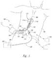
- FIG. 1is a partially schematic illustration of a spinal cord stimulation system positioned to deliver therapeutic signals in accordance with an embodiment of the present technology.
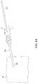
- FIGS. 2-4are isometric views of an insertion needle having a cannula and a stylet configured in accordance with an embodiment of the present technology.
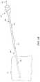
- FIGS. 5A and 5Bare isometric and cross-sectional side views, respectively, of a dilator configured in accordance with another embodiment of the present technology.
- FIGS. 6A and 6Bare isometric views of a dilator and a cannula during a procedure in accordance with an embodiment of the present technology.
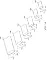
- FIGS. 7A and 7Bare isometric views of a set of dilators configured in accordance with a further embodiment of the present technology.
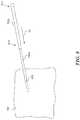
- FIG. 8is an isometric view of a first dilator and a second dilator during a procedure in accordance with an embodiment of the present technology.
- FIG. 9is an isometric view of a dilator configured in accordance with another embodiment of the present technology.
- FIG. 10is an isometric view of a set of dilators configured in accordance with a further embodiment of the present technology.
- FIG. 11is a partially schematic isometric view of a dilator having a mapping contact configured in accordance with another embodiment of the present technology.
- the present technologyis directed generally to insertion devices and systems and methods for neuromodulation systems, and more specifically to single access or single entrance point insertion systems for implanting spinal cord modulation leads.
- Several embodiments of the present technologyinclude access systems having insertion needles and multiple dilators.
- the insertion needles and dilatorsare configured in a variety of suitable manners and can be employed independently or together to implant multiple leads through a single percutaneous entry point in a patient.
- the present technologycan include an insertion needle having a cannula, a stylet, and a series of dilators that can operate together to open and expand a single percutaneous entry point in a patient.
- the devices, systems and associated methodscan have different configurations, components, and/or procedures. Still other embodiments may eliminate particular components and/or procedures.
- the present technologywhich includes associated devices, systems, procedures, methods of use, and instructions for steps included in a method of use, may include other embodiments with additional elements or steps, and/or may include other embodiments with or without several of the features or steps shown and described below with reference to FIGS. 1-11 .
- embodiments presented in FIG. 1may describe lead implantation in spinal cord stimulation systems, other embodiments of the presented technology are applicable in other fields and/or other neuromodulation settings and/or other surgical lead or tool implantations.
- FIG. 1schematically illustrates a representative patient system 100 for providing relief from chronic pain and/or other conditions, arranged relative to the general anatomy of a patient's spinal cord 191 .
- the overall patient system 100can include one or more signal delivery devices 110 , which may be implanted within a patient 190 , typically at or near the patient's spinal cord midline 189 , coupled to an implantable pulse generator 101 .
- the signal delivery devices 110carry features for delivering therapy to the patient 190 after implantation.
- the pulse generator 101can be connected directly to the signal delivery devices 110 , or it can be coupled to the signal delivery devices 110 via a signal link or lead extension 102 .
- the signal delivery devices 110can include one or more elongated lead(s) or lead body or bodies 111 (identified individually as a first lead 111 a and a second lead 111 b ).
- the terms “lead” and “lead body”include any of a number of suitable substrates and/or support members that carry devices for providing therapy signals to the patient 190 .
- the lead or leads 111can include one or more electrodes or electrical contacts that direct electrical signals into the patient's tissue, such as to provide for patient pain relief.
- the signal delivery devices 110can include structures other than a lead body (e.g., a paddle) that also direct electrical signals and/or other types of signals to the patient 190 .
- the pulse generator 101can transmit therapy signals (e.g., electrical signals) to the signal delivery devices 110 that up-regulate (e.g., stimulate or excite) and/or down-regulate (e.g., block or suppress) target nerves.
- therapy signalse.g., electrical signals
- up-regulatee.g., stimulate or excite
- down-regulatee.g., block or suppress
- target nervese.g., to “modulate” or provide “modulation” to the target nerves refers generally to having either type of the foregoing effects on the target nerves.
- the pulse generator 101can include a machine-readable (e.g., computer-readable) medium containing instructions for generating and transmitting suitable therapy signals.
- the pulse generator 101 and/or other elements of the system 100can include one or more processor(s) 107 , memory unit(s) 108 and/or input/output device(s) 112 .
- the process of providing electrical signals, providing guidance information for positioning the signal delivery devices 110 , and/or executing other associated functionscan be performed by computer-executable instructions contained by computer-readable media located at the pulse generator 101 and/or other system components.
- the pulse generator 101can include multiple portions, elements, and/or subsystems (e.g., for directing signals in accordance with multiple signal delivery parameters), carried in a single housing, as shown in FIG. 1 , or in multiple housings.
- the pulse generator 101can obtain power to generate the therapy signals from an external power source 103 .
- the external power source 103can transmit power to the implanted pulse generator 101 using electromagnetic induction (e.g., RF signals).
- the external power source 103can include an external coil 104 that communicates with a corresponding internal coil (not shown) within the implantable pulse generator 101 .
- the external power source 103can be portable for ease of use.
- an external stimulator or trial modulator 105can be coupled to the signal delivery devices 110 during an initial procedure, prior to implanting the pulse generator 101 .
- a practitionere.g., a physician and/or a company representative
- the practitioneruses a cable assembly 120 to temporarily connect the trial modulator 105 to the signal delivery devices 110 . The practitioner can test the efficacy of the signal delivery devices 110 in an initial position.
- the practitionercan then disconnect the cable assembly 120 (e.g., at a connector 122 ), reposition the signal delivery devices 110 , and reapply the electrical signals.
- This processcan be performed iteratively until the practitioner obtains the desired position for the signal delivery devices 110 .
- the practitionermay move the partially implanted signal delivery devices 110 without disconnecting the cable assembly 120 .
- the iterative process of repositioning the signal delivery devices 110 and/or varying the therapy parametersmay not be performed.
- the pulse generator 101 , the lead extension 102 , the trial modulator 105 and/or the connector 122can each include a receiving element 109 .
- the receiving elements 109can be patient implantable elements, or the receiving elements 109 can be integral with an external patient treatment element, device or component (e.g., the trial modulator 105 and/or the connector 122 ).
- the receiving elements 109can be configured to facilitate a simple coupling and decoupling procedure between the signal delivery devices 110 , the lead extension 102 , the pulse generator 101 , the trial modulator 105 and/or the connector 122 .
- Receiving elements 109can be at least generally similar in structure and function to those described in U.S.
- the practitionercan implant the implantable pulse generator 101 within the patient 190 for longer term treatment.
- the signal delivery parameters provided by the pulse generator 101can still be updated after the pulse generator 101 is implanted, via a wireless physician's programmer 117 (e.g., a physician's laptop, physician's remote, etc.) and/or a wireless patient programmer 106 (e.g., a patient's laptop, patient's remote, etc.).
- Inserting SCS leads percutaneouslycan provide a less invasive procedure than direct surgical implantation of the leads. Percutaneous insertion can reduce patient discomfort and recovery time associated with the procedure. In many instances, it is preferable to insert more than one SCS lead at a given treatment location. For example, two cylindrical leads are often positioned proximate to each other at a treatment location. Current percutaneous insertion devices require separate access/entrance points for inserting each individual lead into the epidural space, or other suitable implant location. However, each additional access/entrance point increases patient discomfort and increases the probability of infection. Accordingly, presented herein is a percutaneous implantation system that facilitates implanting multiple SCS leads through a single access/entrance point.
- FIGS. 2-4are isometric views of an insertion needle 200 having a cannula 202 and a stylet 204 configured to implant leads, such as signal delivery devices 111 a and/or 111 b of FIG. 1 , in accordance with an embodiment of the present technology.
- FIG. 2illustrates the insertion needle 200 in a disassembled state, with the cannula 202 and the stylet 204 spaced apart from each other.
- FIGS. 3 and 4illustrate the insertion needle 200 in an assembled state, with the stylet 204 positioned within, and removeably coupled to, the cannula 202 , as described further below. Referring first to FIG.
- the cannula 202includes a lumen 203 that extends from a proximal end 206 to a distal end 208 .
- the proximal end 206can include a cannula hub 205 and the distal end 208 can have a beveled cannula tip 207 .
- the stylet 204extends from a proximal end 210 having a stylet hub 209 to a distal end 212 having a beveled stylet tip 211 .
- the stylet 204 in the illustrated embodimentincludes a solid cylinder 213 that extends from the stylet hub 209 to the beveled stylet tip 211 .
- the stylet 204can include a lumen and/or other non-solid portions.
- the stylet 204includes a removable hub 209 .
- a removable hub 209allows the stylet 204 to serve both its primary function of aiding in the insertion of the cannula 202 , as well as a secondary function of acting as a first dilator or dilator guide.
- the cannula 202 in the illustrated embodiments of FIGS. 2-4is a 14 gauge cannula.
- the cannula 202can be of a size in the range of 12 gauge to 18 gauge. In other embodiments, the cannula 202 can be larger than 12 gauge, or smaller than 18 gauge.
- the lumen 203 of the cannula 202can be configured to receive the stylet 204 for assembling the insertion needle 200 .
- the distal end 212 of the stylet 204can be inserted into the cannula lumen 203 at the proximal end 206 of the cannula 202 .
- the stylet 204can be advanced within the lumen 203 until the stylet hub 209 contacts and/or engages the cannula hub 205 , as shown in FIG. 3 .
- the beveled stylet tip 211can be shaped to match the beveled cannula tip 207 .
- the beveled cannula tip 207 and the beveled stylet tip 211can align to form a generally uniform beveled insertion needle tip 402 , as shown in FIG. 4 .
- the cannula hub 205FIG.
- the cannula hub 205mates with the stylet hub 209 in only one position so as to align the stylet tip 211 with the cannula tip 207 , thereby establishing the uniform beveled insertion needle tip 402 .
- the beveled insertion needle tip 402can be shaped in a variety of suitable manners.
- the beveled insertion needle tip 402is generally “shovel” shaped (e.g., curved).
- the beveled insertion needle tip 402can include a beveled end that is straight, rather than curved.
- the insertion needle tip 402can include other suitable shapes or configurations, e.g., compound curves.
- stylet tip 211 and the cannula tip 207may be configured such that their combined surface area reduces the amount of directed pressure the beveled insertion needle tip 402 exerts on a tissue-needle interface (i.e., the pressure on the patient tissue at the point of insertion of the needle 200 ).
- an assembled insertion needle 200can be inserted into a patient to create a percutaneous entry point.
- the solid stylet 204can “block” the cannula lumen 203 and reduce the possibility of “needle hole” injuries and/or other potential complications.
- the beveled insertion needle tip 402 with the solid stylet 204can act as a sharp wedge that opens up a percutaneous entry point in a patient without “coring” a hole in the patient. I.e., the solid stylet 204 can effectively close off the entrance to the lumen 203 at the distal end 208 of the cannula 202 , thereby reducing the possibility for the cannula 202 to cut a “core” of skin from the patient.
- the stylet 204can be removed from the cannula 202 .
- the stylet 204can be extracted from the cannula 202 by grasping and pulling the stylet hub 209 while holding the cannula hub 205 ( FIGS. 2 and 3 ). Removing the stylet 204 can provide for expanding a percutaneous entry point, as described below.
- the stylet hub 209may be removed, and the cannula 202 may be withdrawn over the stylet 204 . With the stylet hub 209 removed, the stylet 204 may serve as an initial dilator or dilator guide for further opening of the percutaneous entry point.
- FIGS. 5A and 5Bare isometric and cross-sectional side views, respectively, of a dilator 502 configured in accordance with an embodiment of the present technology.
- the dilator 502can be used in conjunction with the cannula 202 and the stylet 204 shown in FIGS. 2-4 , as will be described further below.
- the dilator 502includes a lumen 504 extending through the dilator 502 from a proximal end 506 to a distal end 508 .
- the distal end 508 of the dilator 502can include a tapered section 510 , and the outside diameter of the dilator 502 can vary from a first diameter D 1 at the distal end 508 to a second diameter D 2 , greater than the first diameter D 1 , at the proximal end 506 .
- the dilator 502can be configured to be received within the cannula 202 .
- the second diameter D 2can be less than the width of the cannula lumen 203 ( FIG. 2 ), such that the dilator 502 can be inserted into the lumen 203 .
- the dilator 502may also be configured to be received over the stylet 213 .
- the first and second diameter D 1 and D 2can be greater than the outer diameter of the stylet 213 .
- the dilator 502can be constructed from a variety of suitable materials (e.g., polypropylene, polytetrafluoroethylene (PTFE), Delrin, high density polyethylene (HDPE), low density polyethylene (LDPE), or Teflon) and can be constructed to have varying amounts of flexibility.
- PTFEpolytetrafluoroethylene
- HDPEhigh density polyethylene
- LDPElow density polyethylene
- TeflonTeflon
- the dilator 502can be flexible and soft (e.g., bendable along a longitudinal axis and relatively pliable), and in other embodiments the dilator 502 can be rigid and stiff (e.g., unbendable about a longitudinal axis and relatively unpliable).
- the dilator 502can be constructed with materials that are loaded with barium, e.g., polypropylene loaded with barium or Teflon loaded with barium.
- the dilator 502can be radiopaque, which can be beneficial for radiographic imaging techniques.
- FIGS. 6A and 6Bare isometric views of the dilator 502 and the cannula 202 during a procedure in accordance with an embodiment of the present technology.
- the practitionerinserts the cannula 202 through a percutaneous entry point 602 into a patient 190 , to position a distal end (not visible) of the cannula 202 beneath the patient's skin.
- the dilator 502 in FIG. 6Ais positioned for insertion into the patient 190 through the cannula lumen 203 .
- FIGS. 1after removal of the stylet 204 ( FIGS.
- the distal end 508 of the dilator 502can be inserted into the lumen 203 , and the distal end 508 can be advanced in the direction of arrow A 1 past the percutaneous entry point 602 . Accordingly, the dilator 502 can extend through the percutaneous entry point 602 within the lumen 203 . It should be noted that the dilator 502 is of a length that is greater than the length of the cannula 202 . After the dilator 502 has been positioned to extend through the percutaneous entry point 602 , the cannula 202 can be removed, as illustrated in FIG. 6B . In the illustrated embodiment of FIG.
- the dilator 502extends through the percutaneous entry point 602 .
- the cannula 202can be removed by grasping and pulling the cannula hub 205 in the direction of arrow A 2 until the cannula 202 is separated from the dilator 502 .
- the dilator 502has an overall length that is longer than the length of the cannula 202 .
- the proximal end 506 of the dilator 502can be held while the cannula 202 is pulled in the direction of A 2 to remove the cannula 202 from the patient 190 .
- a portion 604 of the dilator 502is exposed near the percutaneous entry point 602 .
- the practitionercan hold this portion 604 of the dilator 502 in place as he/she moves the cannula 202 further in the direction of A 2 and separates the cannula 202 from the dilator 502 .
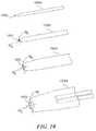
- FIGS. 7A and 7Bare isometric views of a set of dilators 702 (identified individually as first-sixth dilators 702 a - 702 f ) configured in accordance with an embodiment of the present technology.
- FIG. 7Aillustrates the entire length of each of the dilators 702
- FIG. 7Bis a close-up view illustrating a distal end of each of the dilators 702 .
- each of the dilators 702can be at least generally similar in structure and function to the dilator 502 shown in FIGS. 5A-6B .
- the dilators 702have corresponding increasing outside diameters OD (identified individually as first-sixth outside diameters OD 1 -OD 6 ). Additionally, the dilators 702 include corresponding lumens 703 having increasing inside diameters ID (identified individually as first-sixth inside diameters ID 1 -ID 6 ). In a particular embodiment, the sixth dilator 702 f is the last or final dilator, while in other embodiments, the dilator set 702 can include any suitable number of dilators greater than or equal to two.
- the second dilator 702 b through the sixth dilator 702 fcan be configured to fit over the corresponding next smallest dilator 702 (e.g., the first dilator 702 a through the fifth dilator 702 e ).
- the second dilator 702 bincludes an inside diameter ID 2 that is larger than the outside diameter OD 1 of the first dilator 702 a , such that the second dilator 702 b can slide over the first dilator 702 a.
- FIG. 8is an isometric view of the first dilator 702 a and the second dilator 702 b during a procedure in accordance with an embodiment of the present technology.
- the second or other subsequent dilator 702 bcan be configured to fit over the first or other preceding dilator 702 a .
- the first dilator 702 ais positioned to extend through the percutaneous entry point 602 into the patient 190 .
- the first dilator 702 acan be inserted into the patient 190 in a manner at least generally similar to that described above with respect to the dilator 502 shown in FIGS. 5A-6B .
- the second dilator 702 bcan be positioned over the first dilator 702 a and maneuvered to expand the percutaneous entry point 602 .
- the second dilator 702 bcan be advanced in the direction of arrow A 1 along the first dilator 702 a .
- a tapered portion 810 of the second dilator 702 bcan act to expand the percutaneous entry point 602 as the second dilator 702 b is moved further in the direction of arrow A 1 .
- a proximal end (not shown) of the first dilator 702 acan extend out of a distal end 812 of the second dilator 702 b .
- the practitionercan grasp the proximal end of the first dilator 702 a and remove it from the patient 190 and from within the second dilator 702 b .
- This processcan be halted after two dilators, or repeated with any suitable number of additional dilators, e.g., the third dilator 702 c through the final dilator 702 f , to incrementally expand the percutaneous entry point 602 .
- the expansion of the percutaneous entry point 602 obtained by increasing the outside diameters ODs of successive dilators 702corresponds to an increase in the inside diameters IDs of the lumens 703 of the dilators 702 .
- Thiscan produce a desired final inside diameter ID large enough to accommodate inserted signal delivery devices (e.g., leads).
- the final dilator 702can be selected to have an inside diameter ID that simultaneously accommodates two leads, e.g., side by side.
- a particular leadcan have an approximate external diameter of 4 French (1.33 mm).
- a dilator 702 having an inside diameter ID slightly larger than 8 French (2.66 mm), e.g., a dilator having a 9 French (3 mm) inside diameter IDcan be the final dilator 702 that is inserted through a percutaneous entry point, thereby allowing two 4 French leads to be inserted through the dilator lumen 703 in a side by side configuration.
- dilators 702 having lumens 703 with different sized inside diameters IDcan be chosen to accommodate the insertion of two or more devices having larger or smaller dimensions than the 4 French leads discussed above.
- dilators 702can include lumens 703 having inside diameters IDs chosen to accommodate two leads having different external diameters.
- a dilator 702 having an 8 French inside diameter IDcan accommodate a first lead having a 3 French external diameter and a second lead having a 4 French external diameter.
- the external diameter of the leads discussed hereincan include a diameter of a circular cross-section, the term external diameter, and/or diameter, can include a variety of other dimensions.
- FIG. 7includes six dilators 702
- other embodimentscan include additional or fewer dilators 702 .
- two dilators 702can be sufficient to expand a percutaneous entry point to the desired inside diameter ID.
- only the first dilator 702 a and the second dilator 702 bmay be used.
- a cannula having a lumen sized to receive the third dilator 702 cmay be used, and the third dilator 702 c may be used with the fourth dilator 702 d to expand the percutaneous entry point.
- a set of dilatorsmay be provided together as a group, and the appropriate dilators 702 may be selected for a particular procedure.
- the length of each dilator 702is at least approximately equal. In other embodiments, the length of each dilator 702 can decrease as the diameter increases. In this manner, when a subsequent dilator 702 is positioned over a preceding dilator 702 and advanced to the same depth within a patient, a proximal end of the preceding dilator 702 remains exposed.
- a physician, surgeon, or other medical practitionercan grasp the proximal end of the preceding dilator 702 to remove it from within the patient 190 , without needing to insert the subsequent dilator 702 deeper than the preceding dilator 702 .
- FIG. 9is an isometric view of a dilator 902 configured in accordance with a further embodiment of the present technology.
- the dilator 902can be at least generally similar in structure and function to the dilators 502 and 702 described above with respect to FIGS. 5A to 8 .
- the dilator 902can be constructed from a variety of suitable materials, including, e.g., polypropylene, PTFE, and Teflon.
- the dilator 902includes a solid tube 904 extending from a proximal end 906 to a distal end 908 .
- the distal end 908includes a shovel-shaped beveled dilator tip 910 .
- the beveled dilator tip 910can be shaped to match the beveled stylet tip 211 ( FIG. 4 ).
- the dilator 902can be used in place of the stylet 204 to create a percutaneous entry point.
- the dilator 902can be positioned within the cannula 202 ( FIGS. 2-4 ) with the beveled dilator tip 910 aligning with the beveled cannula tip 207 .
- the practitionercan simultaneously insert the cannula 202 and the dilator 902 into a patient to create the percutaneous entry point, with the solid core of the dilator 902 blocking the cannula lumen 203 , e.g., to prevent tissue coring.
- the dilator 902can reduce the possibility for injuries in a manner at least generally similar to those described above with respect to the stylet 204 .
- the dilator 902can include an aperture or lumen, or other non-solid portion (e.g., a blind hole), small enough to not cause coring.
- the dilator 902can also reduce the number of steps required to position a dilator 702 having a desired inside diameter ID. For example, in contrast to the procedure described above with respect to FIGS. 2-6B , after the percutaneous entry point has been created with the cannula 202 and the dilator 902 , the cannula 202 can be removed from the patient, leaving the dilator 902 extending through the percutaneous entry point. One of the dilators 702 can subsequently be positioned over the dilator 902 and advanced into the patient. Accordingly, the dilator 902 can obviate the need to replace the stylet 204 with a first dilator 702 a prior to inserting a second dilator 702 b.
- the dilator 902 in FIG. 9includes a proximal end 906 having no hub.
- a removable hubcan be added to the dilator 902 at the proximal end 906 to facilitate creating a percutaneous entry point.
- the removable hubcan operably couple the dilator 902 to the cannula 202 and/or can aid in maintaining the alignment of the beveled dilator tip 910 with the beveled cannula tip 207 .
- the removable hubcan be separated from the dilator 902 after the percutaneous entry point has been created, thereby allowing the cannula 202 to be removed over the dilator 902 .
- the cannula hub 205can include a mechanism that can removeably couple the dilator 902 to the cannula 202 .
- thiscan include a tube clamp (e.g., a tube clamp having a quick release mechanism).
- other securing mechanismscan be used to temporarily secure the dilator 902 within the cannula 202 (e.g., male and female threads).
- the dilator 902can include a compressible hub at the proximal end 906 .
- the compressible hubcan assist in maintaining the position of the dilator 902 within the cannula 202 and/or aligning the beveled dilator tip 910 and the beveled cannula tip 207 , and can also be compressed to fit through the cannula lumen 203 .
- various embodiments described hereininclude descriptions of methods of use, other embodiments can include instructing one or more steps included in a method of use.
- FIG. 10is an isometric view of a set of dilators 1002 (identified individually as a first-fourth (e.g., final) dilator 1002 a - 1002 d ) configured in accordance with an embodiment of the present technology. Similar to the dilators 702 described above, the dilators 1002 can be used to expand a percutaneous entry point to provide for the insertion of other medical devices. For example, the dilators 1002 include lumens 1003 that increase in size from the first dilator 1002 a to the final dilator 1002 d .
- the cross-sectional shape of the dilators 1002 and the lumens 1003 in the second dilator 1002 b through the final dilator 1002 dis not circular, but elliptical.
- the second-fourth dilators 1002 b - 1002 d , and their respective lumens 1003have widths along a first cross-sectional axis W F that are longer than the widths along a second cross-sectional axis W S .
- the elliptical shape of the second-final dilator 1002 b - 1002 dcan allow one or more medical devices to be inserted through a smaller percutaneous entry point.
- the lumen 1003 of the final dilator 1002 dcan be sized to allow two cylindrical leads to pass through simultaneously.
- the width of the dilator lumen 1003 along the first cross-sectional axis W F for the final dilator 1002 dcan be approximately 9 French (3 mm) to accommodate two 4 French (1.33 mm) leads side by side along the first cross-sectional axis W F .
- the dilator 1002 dcan have a smaller width along the second cross-sectional axis W S .
- the lumen 1003can have a width along the second cross-sectional axis W S of approximately 5 French (1.66 mm). Accordingly, the dilator 1002 d can have a smaller outside dimension, and thereby produce a smaller percutaneous entry than that produced by a dilator having a round cross-sectional area.
- the size of the lumens 1003can be smaller or larger than this example to provide a desired size for the insertion of two or more medical devices having larger or smaller dimensions.
- the illustrated embodimentincludes four dilators 1002 , other embodiments may include more or fewer dilators 1002 .
- the dilators 1002can be employed in a manner at least generally similar to the dilators 702 and 902 described above. For example, after a percutaneous entry point has been created with the cannula 202 and the stylet 204 , the stylet 204 can be removed, the first dilator 1002 a can be inserted into the cannula 204 , the cannula 204 can be removed from the patient, and the second dilator 1002 b through the final dilator 1002 d can be sequentially inserted into the patient over the preceding dilator to expand the percutaneous entry point.
- the dilator 902can be used in conjunction with the cannula 202 (as described above) and the second dilator 1002 b through the final dilator 1002 d can be sequentially inserted into the patient over the preceding dilator to expand the percutaneous entry point.
- FIG. 11is a partially schematic isometric view of a dilator 1102 having a mapping contact 1104 configured in accordance with another embodiment of the present technology.
- the dilator 1102can be at least generally similar in structure and function to the dilator 1002 described above with respect to FIG. 10 .
- the dilator 1102can be used in combination with the cannula 202 to both create a percutaneous entry point and to identify penetration of a patient's dura.
- the mapping contact 1104includes a metallic band 1105 that extends around the circumference of the dilator 1102 at a distal end 1112 of the dilator 1102 .
- a pair of conducting lines 1106can connect the contact 1104 to a plug 1108 at a proximal end 1110 of the dilator 1102 .
- a connector(not shown) can be inserted into the plug 1108 to connect the dilator 1102 to a monitoring device that can monitor the impedance in an electrical circuit that includes the contact 1104 . Changes in the impedance of the electrical circuit that occur as the contact 1104 enters a patient's dura can provide an indication of intrathecal penetration.
- the dilator 1102can be configured in a variety of suitable manners, including in manners at least generally similar to those described in U.S. patent application Ser. No.
- mapping contact 1104can include a variety of suitable conductive materials, e.g., conductive polymers.
- Percutaneous implantation systems in accordance with the present technologycan provide several benefits. For example, by reducing the number of access points necessary for a percutaneous implantation, embodiments in accordance with the present technology can reduce the amount of anesthetic required, reduce infections, and reduce the need for antibiotics. Additionally, the percutaneous implantation systems described herein can reduce the number of steps and the amount of time required for insertion procedures. For example, while existing procedures often require a guidewire to be inserted to provide guidance for an expansion device, embodiments of the present technology can eliminate this step. The embodiment described above with respect to FIGS. 2-6B , for example, provides for the insertion of the dilator 502 through the lumen 203 of the cannula 502 , without requiring a guidewire.
- Removing the steps required for the insertion and the eventual withdrawal of a guidewirereduces the time required to perform a given implantation. Furthermore, reducing the number of devices inserted into a patient can reduce the chance of patient injury (e.g., accidental spinal taps).
- Access systems in accordance with the present technologycan provide for the insertion of high frequency modulation systems, including those described in the following co-owned patent applications: U.S. patent application Ser. No. 12/264,836, filed Nov. 4, 2008, and titled MULTI-FREQUENCY NEURAL TREATMENTS AND ASSOCIATED SYSTEMS AND METHODS; U.S. patent application Ser. No. 12/765,747, filed Apr. 22, 2010, and titled SELECTIVE HIGH-FREQUENCY SPINAL CORD MODULATION FOR INHIBITING PAIN WITH REDUCED SIDE EFFECTS AND ASSOCIATED SYSTEMS AND METHODS; and U.S. patent application Ser. No. 13/607,617, filed Sep.
- a system for implanting a plurality of medical devices in a patient through a single percutaneous entry pointcomprising: (a) a cannula having a cannula lumen extending therethrough, the cannula lumen having an inside diameter; (b) a first dilator having an outside diameter smaller than the inside diameter of the cannula lumen, the first dilator positionable within the cannula lumen to prevent coring upon insertion of the cannula and the first dilator into the patient to produce the percutaneous entry point; and (c) at least one additional dilator, including a final dilator, wherein each additional dilator includes a dilator lumen having an inside diameter larger than an outside diameter of a preceding dilator, and wherein each additional dilator is positionable over a preceding dilator to expand the percutaneous entry point.
- the systemmay further comprise two leads, each lead having a diameter, and wherein the final dilator includes a lumen having an inside diameter greater than the sum of the diameters of the leads.
- the final dilatormay include a lumen having an elliptical cross-sectional shape, wherein a diameter along a first axis of the dilator lumen is greater than the sum of the diameters of the leads.
- a distal end of the cannulacan include a beveled tip having a shovel shape and a distal end of the first dilator can include a beveled tip having a shovel shape positioned to align with the beveled tip of the cannula.
- the first dilatorcan include a beveled tip and a removable hub, wherein the cannula includes a beveled tip, and wherein the removable hub is positioned to align the beveled tip of the cannula with the beveled tip of the dilator.
- the first dilatorcan include a mapping contact positioned to detect intrathecal penetration.
- a patient systemcomprises: (a) two leads positionable to deliver electrical therapy signals, each lead having a diameter; (b) an insertion needle including a cannula and a stylet, wherein the cannula includes a cannula lumen having an inside diameter, and the stylet includes an outside diameter smaller than the inside diameter of the cannula lumen; (c) a first dilator having an outside diameter smaller than the inside diameter of the cannula lumen and positionable within the cannula lumen; and (d) at least one additional dilator, including a final dilator, wherein each additional dilator includes a dilator lumen having an inside diameter larger than an outside diameter of a preceding dilator, wherein each additional dilator is positionable over a preceding dilator to expand a percutaneous entry point, and wherein the final dilator includes a dilator lumen having an inside diameter or width greater than the sum of the diameters of the leads.
- the final dilatorcan include an elliptical cross-sectional shape, wherein the width is a first width along a first cross-sectional axis, and wherein the lumen of the final dilator includes a second width along a second cross-sectional axis that is smaller than the first width and larger than the diameter of either of the two leads.
- the distal end of the cannula and the distal end of the first dilatorcan form a beveled tip having a shovel shape.
- a method for treating a patientcomprising: (a) inserting or instructing insertion of a preceding dilator into a patient; (b) positioning or instructing positioning of and advancement of a subsequent dilator over the preceding dilator and into the patient; (c) removing or instructing removal of the preceding dilator from the patient; (d) inserting or instructing insertion of at least two medical devices side by side into the subsequent dilator; and (e) advancing or instructing advancement of the medical devices into the patient.
- the methodmay further comprise: (f) inserting or instructing the insertion of a cannula into the patient to create a single percutaneous entry point, wherein the cannula is inserted into the patient simultaneously with the preceding dilator; and/or (g) instructing the monitoring of an electrical circuit that includes a mapping contact on the preceding dilator to detect intrathecal penetration.
- the two medical devicescan be two percutaneous leads for the delivery of electrical therapy to the patient.
- some of the embodiments described aboveinclude a stylet having a hub.
- a stylet having no huband/or a removable hub
- a needle having a removable hubcan be inserted into a patient to create a percutaneous entry point, and after the hub is removed, a dilator can be slid over the needle to expand the entry point.
- dilators having round and elliptical shapescan be constructed in accordance with the present technology.
- dilatorscan include oval shaped lumens.
- dilators in accordance with the present technologycan have asymmetrical distal ends (e.g., scarfed or beveled ends) that can incrementally enter a percutaneous entry point as the dilator is inserted. That is, a portion of the distal end of the dilator can enter the percutaneous entry point before the remainder of the distal portion.
- distal endse.g., scarfed or beveled ends
Landscapes
- Health & Medical Sciences (AREA)
- Life Sciences & Earth Sciences (AREA)
- Surgery (AREA)
- Heart & Thoracic Surgery (AREA)
- General Health & Medical Sciences (AREA)
- Veterinary Medicine (AREA)
- Engineering & Computer Science (AREA)
- Biomedical Technology (AREA)
- Nuclear Medicine, Radiotherapy & Molecular Imaging (AREA)
- Public Health (AREA)
- Animal Behavior & Ethology (AREA)
- Pathology (AREA)
- Medical Informatics (AREA)
- Molecular Biology (AREA)
- Cardiology (AREA)
- Radiology & Medical Imaging (AREA)
- Anesthesiology (AREA)
- Neurosurgery (AREA)
- Orthopedic Medicine & Surgery (AREA)
- Neurology (AREA)
- Media Introduction/Drainage Providing Device (AREA)
Abstract
Description
Claims (8)
Priority Applications (1)
| Application Number | Priority Date | Filing Date | Title |
|---|---|---|---|
| US16/284,720US11103280B2 (en) | 2012-12-10 | 2019-02-25 | Lead insertion devices and associated systems and methods |
Applications Claiming Priority (3)
| Application Number | Priority Date | Filing Date | Title |
|---|---|---|---|
| US13/710,341US9308022B2 (en) | 2012-12-10 | 2012-12-10 | Lead insertion devices and associated systems and methods |
| US15/085,913US10213229B2 (en) | 2012-12-10 | 2016-03-30 | Lead insertion devices and associated systems and methods |
| US16/284,720US11103280B2 (en) | 2012-12-10 | 2019-02-25 | Lead insertion devices and associated systems and methods |
Related Parent Applications (1)
| Application Number | Title | Priority Date | Filing Date |
|---|---|---|---|
| US15/085,913DivisionUS10213229B2 (en) | 2012-12-10 | 2016-03-30 | Lead insertion devices and associated systems and methods |
Publications (2)
| Publication Number | Publication Date |
|---|---|
| US20190254706A1 US20190254706A1 (en) | 2019-08-22 |
| US11103280B2true US11103280B2 (en) | 2021-08-31 |
Family
ID=50881793
Family Applications (3)
| Application Number | Title | Priority Date | Filing Date |
|---|---|---|---|
| US13/710,341Active2033-10-20US9308022B2 (en) | 2012-12-10 | 2012-12-10 | Lead insertion devices and associated systems and methods |
| US15/085,913Active2033-09-15US10213229B2 (en) | 2012-12-10 | 2016-03-30 | Lead insertion devices and associated systems and methods |
| US16/284,720Active2033-07-05US11103280B2 (en) | 2012-12-10 | 2019-02-25 | Lead insertion devices and associated systems and methods |
Family Applications Before (2)
| Application Number | Title | Priority Date | Filing Date |
|---|---|---|---|
| US13/710,341Active2033-10-20US9308022B2 (en) | 2012-12-10 | 2012-12-10 | Lead insertion devices and associated systems and methods |
| US15/085,913Active2033-09-15US10213229B2 (en) | 2012-12-10 | 2016-03-30 | Lead insertion devices and associated systems and methods |
Country Status (1)
| Country | Link |
|---|---|
| US (3) | US9308022B2 (en) |
Families Citing this family (47)
| Publication number | Priority date | Publication date | Assignee | Title |
|---|---|---|---|---|
| US8965482B2 (en) | 2010-09-30 | 2015-02-24 | Nevro Corporation | Systems and methods for positioning implanted devices in a patient |
| US8805519B2 (en) | 2010-09-30 | 2014-08-12 | Nevro Corporation | Systems and methods for detecting intrathecal penetration |
| US9308022B2 (en) | 2012-12-10 | 2016-04-12 | Nevro Corporation | Lead insertion devices and associated systems and methods |
| US9480574B2 (en) | 2013-03-14 | 2016-11-01 | Benvenue Medical, Inc. | Spinal fusion implants and devices and methods for deploying such implants |
| CA2903843C (en) | 2013-03-15 | 2019-03-05 | Alfred E. Mann Foundation For Scientific Research | Current sensing multiple output current stimulators with fast turn on time |
| US9265935B2 (en) | 2013-06-28 | 2016-02-23 | Nevro Corporation | Neurological stimulation lead anchors and associated systems and methods |
| US9780596B2 (en) | 2013-07-29 | 2017-10-03 | Alfred E. Mann Foundation For Scientific Research | Microprocessor controlled class E driver |
| US10434307B2 (en) | 2013-10-15 | 2019-10-08 | Medtronic, Inc. | Methods and devices for subcutaneous lead implantation |
| US10792490B2 (en)* | 2013-11-12 | 2020-10-06 | Medtronic, Inc. | Open channel implant tools and implant techniques utilizing such tools |
| US9610436B2 (en) | 2013-11-12 | 2017-04-04 | Medtronic, Inc. | Implant tools with attachment feature and multi-positional sheath and implant techniques utilizing such tools |
| US10314605B2 (en) | 2014-07-08 | 2019-06-11 | Benvenue Medical, Inc. | Apparatus and methods for disrupting intervertebral disc tissue |
| CA2958210C (en) | 2014-08-15 | 2023-09-26 | Axonics Modulation Technologies, Inc. | Integrated electromyographic clinician programmer for use with an implantable neurostimulator |
| ES2782556T3 (en) | 2014-08-15 | 2020-09-15 | Axonics Modulation Tech Inc | System for neurostimulation electrode configurations based on neuronal location |
| AU2015301401B2 (en) | 2014-08-15 | 2020-01-16 | Axonics Modulation Technologies, Inc. | Electromyographic lead positioning and stimulation titration in a nerve stimulation system for treatment of overactive bladder |
| CA3208375A1 (en) | 2014-08-15 | 2016-02-18 | Axonics, Inc. | External pulse generator device and associated methods for trial nerve stimulation |
| AU2015301398B2 (en) | 2014-08-15 | 2020-05-21 | Axonics Modulation Technologies, Inc. | Implantable lead affixation structure for nerve stimulation to alleviate bladder dysfunction and other indications |
| US11083491B2 (en) | 2014-12-09 | 2021-08-10 | Medtronic, Inc. | Extravascular implant tools utilizing a bore-in mechanism and implant techniques using such tools |
| US10888695B2 (en) | 2014-12-09 | 2021-01-12 | Medtronic, Inc. | Over the needle implant tools and implant techniques utilizing such tools |
| US10349978B2 (en) | 2014-12-18 | 2019-07-16 | Medtronic, Inc. | Open channel implant tool with additional lumen and implant techniques utilizing such tools |
| JP6751718B2 (en) | 2015-01-09 | 2020-09-09 | アクソニクス モジュレーション テクノロジーズ インコーポレイテッド | Mounting devices and related methods for use with neurostimulation charging devices |
| CN107427675B (en) | 2015-01-09 | 2021-10-26 | 艾克索尼克斯股份有限公司 | Patient remote control and associated method for use with a neurostimulation system |
| CA2973192C (en) | 2015-01-09 | 2023-04-04 | Axonics Modulation Technologies, Inc. | Improved antenna and methods of use for an implantable nerve stimulator |
| US10022243B2 (en) | 2015-02-06 | 2018-07-17 | Benvenue Medical, Inc. | Graft material injector system and method |
| AU2016291554B2 (en) | 2015-07-10 | 2021-01-07 | Axonics Modulation Technologies, Inc. | Implantable nerve stimulator having internal electronics without ASIC and methods of use |
| JP6876363B2 (en) | 2016-01-29 | 2021-05-26 | アクソニクス モジュレーション テクノロジーズ インコーポレイテッド | Methods and systems for frequency adjustment that optimize the charging of implantable neurostimulators |
| WO2017139784A1 (en) | 2016-02-12 | 2017-08-17 | Axonics Modulation Technologies, Inc. | External pulse generator device and associated methods for trial nerve stimulation |
| US10244956B2 (en) | 2016-02-12 | 2019-04-02 | Nuvectra Corporation | Stimulation needle apparatus and method |
| US10980999B2 (en) | 2017-03-09 | 2021-04-20 | Nevro Corp. | Paddle leads and delivery tools, and associated systems and methods |
| US10758286B2 (en)* | 2017-03-22 | 2020-09-01 | Benvenue Medical, Inc. | Minimal impact access system to disc space |
| US11369410B2 (en) | 2017-04-27 | 2022-06-28 | Bard Access Systems, Inc. | Magnetizing system for needle assemblies including orientation key system for positioning needle tray in magnetizer |
| US11166745B2 (en)* | 2017-09-12 | 2021-11-09 | Jessica Jameson | Multi-port epidural needle |
| WO2019140286A2 (en)* | 2018-01-11 | 2019-07-18 | Wendel Mark | Method and device for inserting at least one medical component within the body |
| WO2019148083A1 (en) | 2018-01-29 | 2019-08-01 | Benvenue Medical, Inc. | Minimally invasive interbody fusion |
| WO2019165108A1 (en) | 2018-02-22 | 2019-08-29 | Axonics Modulation Technologies, Inc. | Neurostimulation leads for trial nerve stimulation and methods of use |
| WO2019178575A1 (en) | 2018-03-16 | 2019-09-19 | Benvenue Medical, Inc. | Articulated instrumentation and methods of using the same |
| WO2019191423A1 (en) | 2018-03-29 | 2019-10-03 | Nevro Corp. | Leads having sidewall openings, and associated systems and methods |
| US11642537B2 (en) | 2019-03-11 | 2023-05-09 | Axonics, Inc. | Charging device with off-center coil |
| US11439829B2 (en) | 2019-05-24 | 2022-09-13 | Axonics, Inc. | Clinician programmer methods and systems for maintaining target operating temperatures |
| WO2020242900A1 (en) | 2019-05-24 | 2020-12-03 | Axonics Modulation Technologies, Inc. | Trainer device for a neurostimulator programmer and associated methods of use with a neurostimulation system |
| EP4512454A3 (en) | 2019-12-06 | 2025-04-23 | Boston Scientific Scimed, Inc. | Endoscopic ultrasound guided access needle |
| US12420103B1 (en) | 2020-08-20 | 2025-09-23 | Axonics, Inc. | Neurostimulation leads with reduced current leakage |
| US11911140B2 (en) | 2020-11-09 | 2024-02-27 | Bard Access Systems, Inc. | Medical device magnetizer |
| CN114464394A (en) | 2020-11-10 | 2022-05-10 | 巴德阿克塞斯系统股份有限公司 | Devices, systems and methods for magnetizing medical devices while maintaining their sterility |
| EP4358836A1 (en) | 2021-06-22 | 2024-05-01 | Bard Access Systems, Inc. | Medical device magnetizer system with indicators |
| EP4377976A1 (en) | 2021-07-26 | 2024-06-05 | Bard Access Systems, Inc. | Medical-device magnetizer systems and methods |
| WO2025080871A1 (en)* | 2023-10-10 | 2025-04-17 | Massachusetts Institute Of Technology | Devices and methods for spatially targeted placement of structures in tissues |
| WO2025129025A1 (en)* | 2023-12-15 | 2025-06-19 | United States Government As Represented By The Department Of Veterans Affairs | Dilator and methods of using same |
Citations (302)
| Publication number | Priority date | Publication date | Assignee | Title |
|---|---|---|---|---|
| US3774618A (en) | 1972-07-03 | 1973-11-27 | Avery Labor Inc | Implantable nerve stimulation electrode |
| US4136703A (en) | 1978-03-09 | 1979-01-30 | Vitatron Medical B.V. | Atrial lead and method of inserting same |
| US4141365A (en) | 1977-02-24 | 1979-02-27 | The Johns Hopkins University | Epidural lead electrode and insertion needle |
| US4285347A (en) | 1979-07-25 | 1981-08-25 | Cordis Corporation | Stabilized directional neural electrode lead |
| US4374527A (en) | 1978-07-19 | 1983-02-22 | Medtronic, Inc. | Body stimulation lead |
| US4379462A (en) | 1980-10-29 | 1983-04-12 | Neuromed, Inc. | Multi-electrode catheter assembly for spinal cord stimulation |
| US4383532A (en) | 1980-10-14 | 1983-05-17 | Medtronic, Inc. | Epidural lead advancer |
| US4414986A (en) | 1982-01-29 | 1983-11-15 | Medtronic, Inc. | Biomedical stimulation lead |
| US4465079A (en) | 1982-10-13 | 1984-08-14 | Medtronic, Inc. | Biomedical lead with fibrosis-inducing anchoring strand |
| US4466690A (en) | 1981-06-24 | 1984-08-21 | Peter Osypka | Connector for the conductors of implanted medical devices |
| US4498482A (en) | 1979-12-13 | 1985-02-12 | Medtronic, Inc. | Transvenous pacing lead having improved stylet |
| EP0158316A2 (en) | 1984-04-10 | 1985-10-16 | Walsh Manufacturing (Mississauga) Limited | Anastomosis devices and kit |
| US4573448A (en)* | 1983-10-05 | 1986-03-04 | Pilling Co. | Method for decompressing herniated intervertebral discs |
| US4683895A (en) | 1985-07-25 | 1987-08-04 | Cordis Corporation | Suture sleeve anchoring device |
| US4764132A (en) | 1986-03-28 | 1988-08-16 | Siemens-Pacesetter, Inc. | Pacemaker connector block for proximal ring electrode |
| US4796642A (en) | 1987-12-28 | 1989-01-10 | Cordis Leads, Inc. | Pacing lead stylet |
| US4898173A (en) | 1988-04-22 | 1990-02-06 | Medtronic, Inc. | In-line pacemaker connector system |
| WO1990003824A1 (en) | 1988-10-12 | 1990-04-19 | Huntington Medical Research Institutes | Bidirectional helical electrode for nerve stimulation |
| US4919653A (en) | 1987-07-28 | 1990-04-24 | Martinez Antonio E | Device for locating the epidural space |
| US4934367A (en) | 1988-04-22 | 1990-06-19 | Medtronic, Inc. | In-line pacemaker connector system |
| US5070605A (en) | 1988-04-22 | 1991-12-10 | Medtronic, Inc. | Method for making an in-line pacemaker connector system |
| US5072458A (en) | 1987-05-07 | 1991-12-17 | Capintec, Inc. | Vest for use in an ambulatory physiological evaluation system including cardiac monitoring |
| US5081990A (en) | 1990-05-11 | 1992-01-21 | New York University | Catheter for spinal epidural injection of drugs and measurement of evoked potentials |
| US5106376A (en) | 1989-07-07 | 1992-04-21 | B. Braun Melsungen Ag | Anaesthesia set |
| US5121754A (en) | 1990-08-21 | 1992-06-16 | Medtronic, Inc. | Lateral displacement percutaneously inserted epidural lead |
| US5129404A (en) | 1990-12-21 | 1992-07-14 | Intermedics, Inc. | Implantable endocardial lead with retractable fixation apparatus |
| US5179962A (en) | 1991-06-20 | 1993-01-19 | Possis Medical, Inc. | Cardiac lead with retractible fixators |
| US5190529A (en) | 1991-05-20 | 1993-03-02 | The Kendall Company | Advancement sleeve and adapter for a catheter |
| US5257636A (en) | 1991-04-02 | 1993-11-02 | Steven J. White | Apparatus for determining position of an endothracheal tube |
| US5351697A (en) | 1991-12-16 | 1994-10-04 | Rensseleaer Polytechnic Institute | Three-dimensional impedance imaging process |
| US5354326A (en) | 1993-01-27 | 1994-10-11 | Medtronic, Inc. | Screening cable connector for interface to implanted lead |
| US5360441A (en) | 1992-10-30 | 1994-11-01 | Medtronic, Inc. | Lead with stylet capture member |
| US5392791A (en) | 1992-04-24 | 1995-02-28 | Siemens Elema Ab | Controllable intracardial electrode device |
| US5458629A (en) | 1994-02-18 | 1995-10-17 | Medtronic, Inc. | Implantable lead ring electrode and method of making |
| US5480421A (en) | 1992-10-30 | 1996-01-02 | Medtronic, Inc. | Lead with stylet capture member |
| EP0709111A2 (en) | 1994-07-28 | 1996-05-01 | Medtronic, Inc. | Medical electrical lead system having a torque transfer stylet |
| US5562722A (en) | 1994-03-14 | 1996-10-08 | Medical Evaluation Devices & Instruments Corp. | Multiple electrode catheter |
| US5669882A (en) | 1996-04-23 | 1997-09-23 | Pyles; Stephen | Curved epidural needle system |
| US5690117A (en) | 1995-03-20 | 1997-11-25 | Gilbert; John W. | Ultrasonic-fiberoptic imaging ventricular catheter |
| US5730628A (en) | 1996-09-25 | 1998-03-24 | Pacesetter, Inc. | Multi-contact connector for an implantable medical device |
| US5843146A (en) | 1997-04-30 | 1998-12-01 | Medtronic Incorporated | Adjustable medical lead anchor |
| US5843148A (en) | 1996-09-27 | 1998-12-01 | Medtronic, Inc. | High resolution brain stimulation lead and method of use |
| US5846226A (en) | 1997-05-12 | 1998-12-08 | Urmey; William F. | Spinal-epidural administration system |
| US5871531A (en) | 1997-09-25 | 1999-02-16 | Medtronic, Inc. | Medical electrical lead having tapered spiral fixation |
| US5895416A (en) | 1997-03-12 | 1999-04-20 | Medtronic, Inc. | Method and apparatus for controlling and steering an electric field |
| US5902236A (en) | 1997-09-03 | 1999-05-11 | Pmt Corporation | Tissue electrode for recording and stimulation |
| US5935159A (en) | 1996-12-19 | 1999-08-10 | Medtronic, Inc. | Medical electrical lead |
| US5957912A (en) | 1998-04-16 | 1999-09-28 | Camino Neurocare, Inc. | Catheter having distal stylet opening and connector |
| US5983126A (en) | 1995-11-22 | 1999-11-09 | Medtronic, Inc. | Catheter location system and method |
| US6024702A (en) | 1997-09-03 | 2000-02-15 | Pmt Corporation | Implantable electrode manufactured with flexible printed circuit |
| US6055456A (en) | 1999-04-29 | 2000-04-25 | Medtronic, Inc. | Single and multi-polar implantable lead for sacral nerve electrical stimulation |
| US6104960A (en) | 1998-07-13 | 2000-08-15 | Medtronic, Inc. | System and method for providing medical electrical stimulation to a portion of the nervous system |
| US6106460A (en) | 1998-03-26 | 2000-08-22 | Scimed Life Systems, Inc. | Interface for controlling the display of images of diagnostic or therapeutic instruments in interior body regions and related data |
| US6154678A (en) | 1999-03-19 | 2000-11-28 | Advanced Neuromodulation Systems, Inc. | Stimulation lead connector |
| US6161047A (en) | 1998-04-30 | 2000-12-12 | Medtronic Inc. | Apparatus and method for expanding a stimulation lead body in situ |
| US6185463B1 (en) | 1997-05-01 | 2001-02-06 | Medtronic, Inc. | Implantable short resistant lead |
| US6192278B1 (en) | 1997-04-25 | 2001-02-20 | Medtronic, Inc. | Medical lead adaptor |
| US6205361B1 (en) | 1998-02-10 | 2001-03-20 | Advanced Bionics Corporation | Implantable expandable multicontact electrodes |
| US6214016B1 (en) | 1999-04-29 | 2001-04-10 | Medtronic, Inc. | Medical instrument positioning device internal to a catheter or lead and method of use |
| US6216045B1 (en) | 1999-04-26 | 2001-04-10 | Advanced Neuromodulation Systems, Inc. | Implantable lead and method of manufacture |
| US20010000800A1 (en) | 1999-07-07 | 2001-05-03 | Cardiac Pacemakers, Inc. | System and assembly having conductive fixation features |
| US6249707B1 (en) | 1999-04-30 | 2001-06-19 | Medtronic, Inc. | Apparatus and method for percutaneous implant of a paddle style lead |
| US6263230B1 (en) | 1997-05-08 | 2001-07-17 | Lucent Medical Systems, Inc. | System and method to determine the location and orientation of an indwelling medical device |
| US6273877B1 (en) | 2000-07-20 | 2001-08-14 | Becton, Dickinson And Company | Epidural needle with secondary bevel |
| US20010014820A1 (en) | 1998-01-20 | 2001-08-16 | Medtronic, Inc. | Method of stimulating brain tissue using combined micro-macro brain stimulation lead |
| US20010025192A1 (en) | 1999-04-29 | 2001-09-27 | Medtronic, Inc. | Single and multi-polar implantable lead for sacral nerve electrical stimulation |
| US6309401B1 (en) | 1999-04-30 | 2001-10-30 | Vladimir Redko | Apparatus and method for percutaneous implant of a paddle style lead |
| US6321123B1 (en) | 1999-03-08 | 2001-11-20 | Medtronic Inc. | J-shaped coronary sinus lead |
| US20020022873A1 (en) | 2000-08-10 | 2002-02-21 | Erickson John H. | Stimulation/sensing lead adapted for percutaneous insertion |
| US20020042642A1 (en) | 1999-04-29 | 2002-04-11 | Gerber Martin Theodore | Implantable lead for sacral nerve electrical stimulation |
| US6371943B1 (en) | 1997-09-08 | 2002-04-16 | Epimed International, Inc. | Spring tip needle combination |
| US20020052640A1 (en) | 2000-08-04 | 2002-05-02 | Steve Bigus | Sheath for self-expanding stents |
| US6415187B1 (en) | 1998-02-10 | 2002-07-02 | Advanced Bionics Corporation | Implantable, expandable, multicontact electrodes and insertion needle for use therewith |
| US20020128700A1 (en) | 2001-03-08 | 2002-09-12 | Cross Thomas E. | Lead with adjustable angular and spatial relationships between electrodes |
| US6451030B2 (en) | 2000-06-30 | 2002-09-17 | Li Medical Technologies, Inc. | Rotor blade anchor and tool for installing same particularlly for arthroscopic installation |
| US6456874B1 (en) | 2000-03-13 | 2002-09-24 | Arrow International Inc. | Instrument for delivery of anaesthetic drug |
| US6473654B1 (en) | 2000-03-08 | 2002-10-29 | Advanced Bionics Corporation | Lead anchor |
| US6482049B1 (en) | 1999-07-16 | 2002-11-19 | Amphenol Corporation | Radially resilient electrical connector |
| US20020173718A1 (en) | 2001-05-20 | 2002-11-21 | Mordechai Frisch | Array system and method for locating an in vivo signal source |
| US6516807B1 (en) | 1994-10-11 | 2003-02-11 | Ep Technologies, Inc. | System and methods for locating and guiding operative elements within interior body regions |
| WO2003011361A2 (en) | 2001-08-02 | 2003-02-13 | Teodulo Aves | Medical needle |
| US6522932B1 (en) | 1998-02-10 | 2003-02-18 | Advanced Bionics Corporation | Implantable, expandable, multicontact electrodes and tools for use therewith |
| US6529774B1 (en) | 2000-11-09 | 2003-03-04 | Neuropace, Inc. | Extradural leads, neurostimulator assemblies, and processes of using them for somatosensory and brain stimulation |
| US6549812B1 (en) | 1999-11-29 | 2003-04-15 | Medtronic, Inc. | Medical electrical lead having bending stiffness which increase in the distal direction |
| US6556873B1 (en) | 1999-11-29 | 2003-04-29 | Medtronic, Inc. | Medical electrical lead having variable bending stiffness |
| US6554809B2 (en) | 2001-08-02 | 2003-04-29 | Teodulo Aves | Epidural catheter needle |
| US20030114895A1 (en) | 1999-04-14 | 2003-06-19 | Transneuronix, Inc. | Gastric stimulator apparatus and method for installing |
| EP1334745A1 (en) | 2002-02-12 | 2003-08-13 | BIOTRONIK Mess- und Therapiegeräte GmbH & Co Ingenieurbüro Berlin | Guide wire and implantable lead |
| US20030199949A1 (en) | 2002-04-22 | 2003-10-23 | Xavier Pardo | Stylet for an implantable lead |
| US20030199952A1 (en) | 2002-04-22 | 2003-10-23 | Stolz Brian T. | Implantable lead with improved distal tip |
| US20030199953A1 (en) | 2002-04-22 | 2003-10-23 | Stolz Brian T. | Implantable lead with coplanar contact coupling |
| US20030199951A1 (en) | 2002-04-22 | 2003-10-23 | Pardo Xavier E. | Implantable lead with improved conductor lumens |
| US20030199948A1 (en) | 2002-04-19 | 2003-10-23 | Kokones Scott B. | Multiport neurological screening cable |
| US20030220677A1 (en) | 2002-05-22 | 2003-11-27 | Doan Phong D. | Implantable coronary sinus lead and lead system |
| US20040015133A1 (en) | 2000-05-31 | 2004-01-22 | Hussain Karim | Epidural apparatus |
| US20040024440A1 (en) | 2002-04-22 | 2004-02-05 | Cole Mary Lee | Implantable lead with isolated contact coupling |
| US6704605B2 (en) | 2002-01-31 | 2004-03-09 | Cardiac Pacemakers, Inc. | Medical electrode assembly |
| US20040088034A1 (en) | 2002-10-31 | 2004-05-06 | Smits Karel F.A.A. | Implantable medical lead designs |
| US20040088033A1 (en) | 2002-10-31 | 2004-05-06 | Smits Karel F.A.A. | Implantable medical lead designs |
| US20040087877A1 (en) | 2000-08-23 | 2004-05-06 | Besz William John | Catheter locator apparatus and method of use |
| US6733500B2 (en) | 2000-03-31 | 2004-05-11 | Medtronic, Inc. | Method and system for delivering a medical electrical lead within a venous system |
| US6745079B2 (en) | 2001-11-07 | 2004-06-01 | Medtronic, Inc. | Electrical tissue stimulation apparatus and method |
| US6754539B1 (en) | 2000-08-10 | 2004-06-22 | Advanced Neuromodulation Systems, Inc. | Spinal cord stimulation lead with an anode guard |
| US6758854B1 (en) | 1997-05-09 | 2004-07-06 | St. Jude Medical | Splittable occlusion balloon sheath and process of use |
| US6805676B2 (en) | 2000-10-03 | 2004-10-19 | Cook Incorporated | Manoeuverable guide wire and method of using same |
| US20040215305A1 (en) | 2003-04-25 | 2004-10-28 | Sage Shahn S. | Implantable lead with intermediate insertion port for receiving a stiffening member |
| US20040215301A1 (en) | 2003-04-23 | 2004-10-28 | Lokhoff Nicolaas M. | Medical lead with a pivotal tip |
| US20040215307A1 (en) | 2001-11-29 | 2004-10-28 | Koen Michels | Medical lead designs for lead placement through tissue |
| EP1477203A2 (en) | 2003-05-15 | 2004-11-17 | Biotronik GmbH & Co. KG | Epicardial electrode |
| US20040243206A1 (en) | 2003-01-03 | 2004-12-02 | Tadlock Charles H. | System, method, and combined electrical and chemical stimulation lead for stimulation of a person's nerve tissue |
| US6836687B2 (en) | 2000-03-31 | 2004-12-28 | Medtronic, Inc. | Method and system for delivery of a medical electrical lead within a venous system |
| US20050004638A1 (en) | 2002-10-23 | 2005-01-06 | Medtronic, Inc. | Medical lead and manufacturing method therefor |
| US20050021119A1 (en) | 2003-04-25 | 2005-01-27 | Medtronic, Inc. | Implantable medical lead and system, and method of use thereof |
| US20050049663A1 (en) | 2003-08-29 | 2005-03-03 | Harris Charmaine K. | Percutaneous flat lead introducer |
| US20050049664A1 (en) | 2003-08-29 | 2005-03-03 | Harris Charmaine K. | Percutaneous flat lead introducer |
| US20050049486A1 (en) | 2003-08-28 | 2005-03-03 | Urquhart Steven J. | Method and apparatus for performing stereotactic surgery |
| US20050065588A1 (en) | 2003-09-23 | 2005-03-24 | Medtronic, Inc. | Medical electrical lead system including pre-formed J-shape stylet |
| US20050090885A1 (en) | 2003-10-23 | 2005-04-28 | Medtronic, Inc. | Medical lead and manufacturing method therefor |
| US20050096718A1 (en) | 2003-10-31 | 2005-05-05 | Medtronic, Inc. | Implantable stimulation lead with fixation mechanism |
| US20050107861A1 (en) | 2003-10-03 | 2005-05-19 | Harris Charmaine K. | Kit for implantation of therapy elements |
| US6901289B2 (en) | 2000-12-29 | 2005-05-31 | Medtronic, Inc. | System for providing electrical stimulation to a left chamber of a heart |
| US20050137646A1 (en) | 2003-12-22 | 2005-06-23 | Scimed Life Systems, Inc. | Method of intravascularly delivering stimulation leads into brain |
| US20050182422A1 (en) | 2004-02-13 | 2005-08-18 | Schulte Gregory T. | Apparatus for securing a therapy delivery device within a burr hole and method for making same |
| US6934589B2 (en) | 2000-12-29 | 2005-08-23 | Medtronic, Inc. | System and method for placing endocardial leads |
| US20050203599A1 (en) | 2004-03-12 | 2005-09-15 | Scimed Life Systems, Inc. | Modular stimulation lead network |
| US20050222658A1 (en) | 2004-03-30 | 2005-10-06 | Medtronic, Inc. | Lead electrode for use in an MRI-safe implantable medical device |
| US20050222659A1 (en) | 2004-03-30 | 2005-10-06 | Medtronic, Inc. | Lead electrode for use in an MRI-safe implantable medical device |
| US20050222657A1 (en) | 2004-03-30 | 2005-10-06 | Wahlstrand Carl D | MRI-safe implantable lead |
| US6970747B2 (en) | 2002-01-11 | 2005-11-29 | Kokones Scott B | Neurostimulation lead stylet handle |
| US6971393B1 (en)* | 2000-11-15 | 2005-12-06 | George Mamo | Minimally invasive method for implanting a sacral stimulation lead |
| US20050283216A1 (en) | 2004-06-21 | 2005-12-22 | Pyles Stephen T | Apparatus and method for displacing tissue obstructions |
| US6980863B2 (en) | 2003-03-20 | 2005-12-27 | Medtronic, Inc. | Neurological stimulation lead extension |
| US20050288759A1 (en) | 2003-08-08 | 2005-12-29 | Jones Timothy S | Method and apparatus for implanting an electrical stimulation lead using a flexible introducer |
| US20060030918A1 (en) | 2004-08-04 | 2006-02-09 | Chinn Kenny K | Operating room lead connector |
| US6999819B2 (en) | 2001-08-31 | 2006-02-14 | Medtronic, Inc. | Implantable medical electrical stimulation lead fixation method and apparatus |
| US20060041295A1 (en) | 2004-08-17 | 2006-02-23 | Osypka Thomas P | Positive fixation percutaneous epidural neurostimulation lead |
| US7020531B1 (en) | 2001-05-01 | 2006-03-28 | Intrapace, Inc. | Gastric device and suction assisted method for implanting a device on a stomach wall |
| US7022109B1 (en) | 2001-07-09 | 2006-04-04 | Ditto Deborah L | Pain abatement catheter system |
| US20060089697A1 (en) | 2004-10-21 | 2006-04-27 | Medtronic, Inc. | Implantable medical lead |
| US20060089695A1 (en) | 2004-10-21 | 2006-04-27 | Medtronic, Inc. | Implantable medical lead with helical reinforcement |
| US20060089696A1 (en) | 2004-10-21 | 2006-04-27 | Medtronic, Inc. | Implantable medical lead with reinforced outer jacket |
| US20060089691A1 (en) | 2004-10-21 | 2006-04-27 | Medtronic, Inc. | Implantable medical lead with axially oriented coiled wire conductors |
| US20060089692A1 (en) | 2004-10-21 | 2006-04-27 | Medtronic, Inc. | Implantable medical lead with stylet guide tube |
| US7047082B1 (en) | 1999-09-16 | 2006-05-16 | Micronet Medical, Inc. | Neurostimulating lead |
| US20060127158A1 (en) | 2004-10-21 | 2006-06-15 | Medtronic, Inc. | Implantable electrical lead retention system and method |
| US7069083B2 (en) | 2002-12-13 | 2006-06-27 | Advanced Neuromodulation Systems, Inc. | System and method for electrical stimulation of the intervertebral disc |
| US20060168805A1 (en) | 2005-01-31 | 2006-08-03 | Michael Hegland | Method of manufacturing a medical lead |
| US7090661B2 (en) | 2002-04-23 | 2006-08-15 | Medtronic, Inc. | Catheter anchor system and method |
| US20060200218A1 (en) | 2005-02-01 | 2006-09-07 | Wahlstrand Carl D | Extensible implantable medical lead |
| US20060206183A1 (en) | 2004-08-31 | 2006-09-14 | Pyles Stephen T | Spinal cord stimulator lead for neurostimulation having a fluid delivery lumen and/0r a distensible balloon |
| US20060206118A1 (en) | 2005-03-11 | 2006-09-14 | Kim Daniel H | Percutaneous endoscopic access tools for the spinal epidural space and related methods of treatment |
| US20060247749A1 (en) | 2005-05-02 | 2006-11-02 | Advanced Bionics Corporation | Compliant stimulating electrodes and leads and methods of manufacture and use |
| US20060253182A1 (en) | 2004-10-21 | 2006-11-09 | Medtronic, Inc. | Transverse Tripole Neurostimulation Lead, System and Method |
| US20060264122A1 (en) | 2005-05-23 | 2006-11-23 | Cardiac Pacemakers, Inc. | Connector assembly |
| US7146222B2 (en) | 2002-04-15 | 2006-12-05 | Neurospace, Inc. | Reinforced sensing and stimulation leads and use in detection systems |
| US7153307B2 (en) | 1998-08-14 | 2006-12-26 | Kyphon Inc. | Systems and methods for placing materials into bone |
| US7181288B1 (en) | 2002-06-24 | 2007-02-20 | The Cleveland Clinic Foundation | Neuromodulation device and method of using the same |
| US7184838B2 (en) | 2003-10-02 | 2007-02-27 | Medtronic, Inc. | Implantable medical lead and method of manufacture |
| US7184842B2 (en) | 2003-08-08 | 2007-02-27 | Medtronic, Inc. | Medical electrical lead anchoring |
| US7184841B1 (en) | 2004-08-19 | 2007-02-27 | Cardiac Pacemakers, Inc. | Pacing lead stabilizer |
| US7187982B2 (en) | 2003-08-08 | 2007-03-06 | Medtronic, Inc. | Medical electrical lead anchoring |
| US20070055332A1 (en) | 2005-09-03 | 2007-03-08 | Enpath Medical, Inc. | Self fixing spinal cord stimulation lead and delivery system |
| US7191018B2 (en) | 1998-04-30 | 2007-03-13 | Medtronic, Inc. | Techniques for positioning therapy delivery elements within a spinal cord or brain |
| US7200446B2 (en) | 1999-07-21 | 2007-04-03 | Borkan William N | Catheter leads for the intrathecal space and method of use |
| US7206642B2 (en) | 2002-04-22 | 2007-04-17 | Medtronic, Inc. | Implantable lead with improved stylet lumen |
| US20070100408A1 (en) | 2005-10-28 | 2007-05-03 | Medtronic, Inc. | Electrical stimulation lead with proximal common electrode |
| US20070135881A1 (en) | 2005-01-11 | 2007-06-14 | Vilims Bradley D | Combination Electrical Stimulating And Infusion Medical Device and Method |
| US7241283B2 (en) | 2003-04-25 | 2007-07-10 | Ad-Tech Medical Instrument Corp. | Method for intracranial catheter treatment of brain tissue |
| US20070191903A1 (en) | 2006-01-24 | 2007-08-16 | Bruinstroop Jan K P | Method for controlling micturition |
| US20070213795A1 (en) | 2003-05-08 | 2007-09-13 | Kerry Bradley | Implantable medical lead |
| US20070249901A1 (en) | 2003-03-07 | 2007-10-25 | Ohline Robert M | Instrument having radio frequency identification systems and methods for use |
| US20070255366A1 (en) | 2006-04-27 | 2007-11-01 | Medtronic, Inc. | Implantable medical electrical stimulation lead fixation method and apparatus |
| US20070255364A1 (en) | 2006-04-27 | 2007-11-01 | Medtronic, Inc. | Implantable medical electrical stimulation lead fixation method and apparatus |
| US20070255370A1 (en) | 2006-04-28 | 2007-11-01 | Bonde Eric H | Implantable medical electrical stimulation lead, such as a PNE lead, and method of use |
| US20070255367A1 (en) | 2006-04-27 | 2007-11-01 | Medtronic, Inc. | Implantable Medical Electrical Stimulation Lead Fixation Method and Apparatus |
| US20070255371A1 (en) | 2006-04-28 | 2007-11-01 | Bonde Eric H | System and method for electrically probing and providing medical electrical stimulation |
| US20070255365A1 (en) | 2006-04-27 | 2007-11-01 | Medtronic, Inc. | Implantable Medical Electrical Stimulation Lead Fixation Method and Apparatus |
| US20070255369A1 (en) | 2006-04-28 | 2007-11-01 | Bonde Eric H | Multi-electrode peripheral nerve evaluation lead and related system and method of use |
| US20070261115A1 (en) | 2006-04-27 | 2007-11-08 | Medtronic, Inc. | Implantable medical electrical stimulation lead fixation method and apparatus |
| US7299095B1 (en) | 2003-12-17 | 2007-11-20 | Pacesetter, Inc. | Electrical contact assembly |
| US7363076B2 (en) | 2003-06-09 | 2008-04-22 | Palo Alto Investors | Treatment of conditions through modulation of the autonomic nervous system |
| US20080103572A1 (en) | 2006-10-31 | 2008-05-01 | Medtronic, Inc. | Implantable medical lead with threaded fixation |
| US20080103576A1 (en) | 2006-10-31 | 2008-05-01 | Medtronic, Inc. | Implantable medical elongated member including expandable fixation member |
| US20080103580A1 (en) | 2006-10-31 | 2008-05-01 | Medtronic, Inc. | Implantable medical elongated member with dual purpose conduit |
| US20080103573A1 (en) | 2006-10-31 | 2008-05-01 | Medtronic, Inc. | Implantable medical elongated member including wire-like fixation elements |
| US20080103578A1 (en) | 2006-10-31 | 2008-05-01 | Medtronic, Inc. | Implantable medical elongated member with in situ formed fixation element |
| US20080103569A1 (en) | 2006-10-31 | 2008-05-01 | Medtronic, Inc. | Implantable medical elongated member including fixation elements along an interior surface |
| US20080103579A1 (en) | 2006-10-31 | 2008-05-01 | Medtronic, Inc. | Implantable medical elongated member with adhesive elements |
| US7379776B1 (en) | 2005-05-09 | 2008-05-27 | Pacesetter, Inc. | Stylet design |
| US7383090B2 (en) | 2003-10-20 | 2008-06-03 | Greatbatch Ltd. | Connection for a coiled lead to an electrical contact for an implantable medical device |
| US20080132926A1 (en) | 2006-12-01 | 2008-06-05 | Eichmann Stephen E | Devices and methods for accessing the epidural space |
| US7386341B2 (en) | 2000-03-13 | 2008-06-10 | Arrow International, Inc. | Instrument and method for delivery of anaesthetic drugs |
| US20080156333A1 (en) | 2006-12-31 | 2008-07-03 | David Wolf Galpern | Radio lucent restraining device |
| US20080183259A1 (en) | 2007-01-30 | 2008-07-31 | Cardiac Pacemakers, Inc. | Spiral configurations for intravascular lead stability |
| US20080183221A1 (en) | 2006-12-06 | 2008-07-31 | Spinal Modulation, Inc. | Hard tissue anchors and delivery devices |
| US20080183257A1 (en) | 2007-01-29 | 2008-07-31 | Spinal Modulation, Inc. | Sutureless lead retention features |
| US7421297B2 (en) | 2005-03-31 | 2008-09-02 | Medtronic, Inc. | Monopolar stimulation assembly including at least one remote electrode |
| US7425142B1 (en) | 2007-03-16 | 2008-09-16 | Ad-Tech Medical Instrument Corp. | Electrical connector for an in-body multi-contact medical electrode device |
| US20080262430A1 (en) | 2007-04-18 | 2008-10-23 | Access Scientific, Inc. | Access device |
| US20080300651A1 (en) | 2007-05-30 | 2008-12-04 | Medtronic, Inc. | Voiding event identification based on patient input |
| US20090048638A1 (en) | 2007-08-15 | 2009-02-19 | Gerry Rey | Connector assembly for use with medical devices |
| US7499755B2 (en) | 2002-10-23 | 2009-03-03 | Medtronic, Inc. | Paddle-style medical lead and method |
| US20090069803A1 (en) | 2007-09-10 | 2009-03-12 | Medtronic, Inc. | Selective depth electrode deployment for electrical stimulation |
| US20090125060A1 (en) | 2007-11-09 | 2009-05-14 | Rivard Adam J | Compression control lead anchoring device |
| US20090204173A1 (en) | 2007-11-05 | 2009-08-13 | Zi-Ping Fang | Multi-Frequency Neural Treatments and Associated Systems and Methods |
| US20090216306A1 (en) | 2008-02-21 | 2009-08-27 | Boston Scientific Neuromodulation Corporation | Temporary neurostimulation lead identification device |
| US20090259280A1 (en) | 2007-10-15 | 2009-10-15 | Kevin Wilkin | Electrical stimulation lead with bioerodible anchors and anchor straps |
| WO2009129329A1 (en) | 2008-04-16 | 2009-10-22 | Nevro Corporation | Treatment devices with delivery-activated inflatable members, and associated systems and methods for treating the spinal cord and other tissues |
| US7627380B2 (en) | 2005-03-31 | 2009-12-01 | Covidien Ag | Method and apparatus for monitoring disc pressure during heat treatment of an intervertebral disc |
| US20090299444A1 (en) | 2008-05-29 | 2009-12-03 | Nevro Corporation | Percutaneous Leads with Laterally Displaceable Portions, and Associated Systems and Methods |
| US20090319013A1 (en) | 2008-05-19 | 2009-12-24 | Boling C Lance | Implantable neural stimulation electrode assemblies and methods for stimulating spinal neural sites |
| US20100063356A1 (en) | 2007-01-03 | 2010-03-11 | Smith Robert C | Access sheath with removable optical penetrating member |
| US7684873B2 (en) | 2006-10-31 | 2010-03-23 | Medtronic, Inc. | Implantable medical lead including a directional electrode and fixation elements along an interior surface |
| US20100094115A1 (en) | 2005-01-31 | 2010-04-15 | Pond Jr John D | Electrically insulated surgical needle assembly |
| US20100094116A1 (en) | 2008-10-07 | 2010-04-15 | Lucent Medical Systems, Inc. | Percutaneous magnetic gastrostomy |
| US20100114283A1 (en) | 2008-10-31 | 2010-05-06 | Medtronic, Inc. | Implantable medical lead |
| US20100137938A1 (en) | 2008-10-27 | 2010-06-03 | Eyad Kishawi | Selective stimulation systems and signal parameters for medical conditions |
| US20100179562A1 (en) | 2009-01-14 | 2010-07-15 | Linker Fred I | Stimulation leads, delivery systems and methods of use |
| US20100204569A1 (en) | 2007-11-26 | 2010-08-12 | C. R. Bard, Inc. | System for placement of a catheter including a signal-generating stylet |
| US7797057B2 (en) | 2002-10-23 | 2010-09-14 | Medtronic, Inc. | Medical paddle lead and method for spinal cord stimulation |
| US7805188B2 (en) | 2000-03-24 | 2010-09-28 | Micor, Inc. | Anesthesia conduction catheter for delivery of electrical stimulus |
| US20100256696A1 (en) | 2009-04-07 | 2010-10-07 | Boston Scientific Neuromodulation Corporation | Anchoring Units For Implantable Electrical Stimulation Systems And Methods Of Making And Using |
| US20100267265A1 (en) | 2009-04-20 | 2010-10-21 | Farshid Dilmaghanian | In-line connector stack with testing capability |
| US20100274326A1 (en) | 2009-04-22 | 2010-10-28 | Yougandh Chitre | Selective high frequency spinal cord modulation for inhibiting pain with reduced side effects, and associated systems and methods, including implantable patient leads |
| US20100280570A1 (en) | 2007-10-30 | 2010-11-04 | Volker Sturm | Apparatus for the stimulation of the spinal chord |
| US20100286551A1 (en) | 2009-05-08 | 2010-11-11 | Rhythmia Medical, Inc. | Impedance Based Anatomy Generation |
| US20100292769A1 (en) | 2009-05-15 | 2010-11-18 | Brounstein Daniel M | Methods, systems and devices for neuromodulating spinal anatomy |
| US20100305670A1 (en) | 2009-05-26 | 2010-12-02 | Hall Peter C | Method and Devices for Coupling a Lead Conductor Member to a Functional Component |
| US7853321B2 (en) | 2005-03-14 | 2010-12-14 | Boston Scientific Neuromodulation Corporation | Stimulation of a stimulation site within the neck or head |
| CN101920065A (en) | 2009-06-17 | 2010-12-22 | 宇大伟 | Cardiac pacemaker |
| US20100324414A1 (en) | 2007-02-08 | 2010-12-23 | Rhythmia Medical, Inc., A Delaware Corporation | Catheter tracking and endocardium representation generation |
| US20100324570A1 (en) | 2005-06-09 | 2010-12-23 | Medtronic, Inc. | Introducer for therapy delivery elements |
| US20110004281A1 (en) | 2009-07-03 | 2011-01-06 | Jones Robert E | Implantable anchor with locking cam |
| US7881806B2 (en) | 2006-10-31 | 2011-02-01 | Medtronic, Inc. | Medical lead delivery device |
| US20110071593A1 (en) | 2009-09-18 | 2011-03-24 | Nevro Corporation | Couplings for implanted leads and external stimulators, and associated systems and methods |
| US20110106100A1 (en) | 2009-10-30 | 2011-05-05 | Medtronic, Inc. | Steerable percutaneous paddle stimulation lead |
| US20110160568A1 (en) | 2009-12-30 | 2011-06-30 | Medtronic, Inc. | Lead Tracking and Positioning System and Method |
| US20110166582A1 (en) | 2006-06-21 | 2011-07-07 | Intrapace, Inc. | Endoscopic Device Delivery System |
| US20110178573A1 (en) | 2009-04-27 | 2011-07-21 | Boston Scientific Neuromodulation Corporation | Torque lock anchor and methods and devices using the anchor |
| US8019439B2 (en) | 2005-01-11 | 2011-09-13 | Boston Scientific Neuromodulation Corporation | Lead assembly and method of making same |
| US8019443B2 (en) | 2008-04-01 | 2011-09-13 | Boston Scientific Neuromodulation Corporation | Anchoring units for leads of implantable electric stimulation systems and methods of making and using |
| US20110224682A1 (en) | 2010-03-11 | 2011-09-15 | Westlund Randy W | Methods of implanting electrode leads for use with implantable neuromuscular electrical stimulator |
| US20110245903A1 (en) | 2010-04-02 | 2011-10-06 | Boston Scientific Neuromodulation Corporation | Directional lead assembly |
| US8060207B2 (en) | 2003-12-22 | 2011-11-15 | Boston Scientific Scimed, Inc. | Method of intravascularly delivering stimulation leads into direct contact with tissue |
| US8078280B2 (en) | 2003-04-25 | 2011-12-13 | Medtronic, Inc. | Implantable biomedical electrical connectors having integral side and inner walls |
| US8140172B1 (en) | 2008-07-11 | 2012-03-20 | Advanced Neuromodulation Systems, Inc. | Implantable anchor with locking arm |
| US8204569B2 (en) | 2006-04-27 | 2012-06-19 | Medtronic, Inc. | Implantable medical electrical stimulation lead fixation method and apparatus |
| US8224459B1 (en) | 2004-04-30 | 2012-07-17 | Boston Scientific Neuromodulation Corporation | Insertion tool for paddle-style electrode |
| US8229573B2 (en) | 2009-07-21 | 2012-07-24 | Boston Scientific Neuromodulation Corporation | Spring passive lead anchor and methods and devices using the anchor |
| US20120209285A1 (en) | 2011-02-16 | 2012-08-16 | Boston Scientific Neuromodulation Corporation | Systems and methods for implanting paddle lead assemblies of electrical stimulation systems |
| US20120232626A1 (en) | 2011-03-11 | 2012-09-13 | Greatbatch Ltd. | Anchor sleeve for implantable lead |
| US8301268B1 (en) | 2009-12-28 | 2012-10-30 | Advanced Neuromodulation Systems, Inc. | Implantable anchor with rotating cam |
| US20130066331A1 (en) | 2011-09-14 | 2013-03-14 | Nevro Corporation | Tapered, curved stylets for inserting spinal cord modulation leads and associated systems and methods |
| US20130066411A1 (en) | 2011-09-08 | 2013-03-14 | James R. Thacker | Selective high frequency spinal cord modulation for inhibiting pain, including cephalic and/or total body pain with reduced side effects, and associated systems and methods |
| US8412349B2 (en) | 2009-06-04 | 2013-04-02 | Boston Scientific Neuromodulation Corporation | Three-piece button anchor and methods and devices using the anchor |
| US20130116754A1 (en) | 2011-11-08 | 2013-05-09 | Vivek Sharma | Medical device contact assemblies for use with implantable leads, and associated systems and methods |
| US8483845B2 (en) | 2011-03-11 | 2013-07-09 | Greatbatch Ltd. | Anchor for implantable medical device |
| US8494652B2 (en) | 2010-08-09 | 2013-07-23 | Advanced Neuromodulation Systems, Inc. | Implantable medical anchor |
| US20130245739A1 (en) | 2012-03-14 | 2013-09-19 | Anatoly Arber | Self-anchored stimulator lead and method of insertion |
| US8548601B2 (en) | 2008-09-15 | 2013-10-01 | Boston Scientific Neuromodulation Corporation | Lead connection system for an implantable electrical stimulation system and methods for making and using the systems |
| US20130261697A1 (en) | 2012-04-02 | 2013-10-03 | Nevro Corporation | Devices for controlling spinal cord modulation for inhibiting pain, and associated systems and methods, including controllers for automated parameter selection |
| US20130268037A1 (en) | 2012-04-10 | 2013-10-10 | NeuroAccess Technologies | Electrical lead with coupling features |
| US20130296957A1 (en) | 2004-10-29 | 2013-11-07 | Medtronic, Inc. | Expandable fixation mechanism |
| US8634934B2 (en) | 2008-02-12 | 2014-01-21 | Intelect Medical, Inc. | Directional lead assembly |
| US20140031837A1 (en) | 2011-04-04 | 2014-01-30 | Stimwave Technologies, Inc. | Implantable Lead |
| US8644954B2 (en) | 2005-03-14 | 2014-02-04 | Boston Scientific Neuromodulation Corporation | Methods and systems for facilitating stimulation of one or more stimulation sites |
| US20140081362A1 (en) | 2012-09-15 | 2014-03-20 | Steve Wicklund | Implantable Medical Stimulator Lead With A Deployable Array Element And Method Of Use |
| US8731671B2 (en) | 2010-08-25 | 2014-05-20 | Cardiac Pacemakers, Inc. | Header contact for an implantable device |
| EP2731671A2 (en) | 2011-07-11 | 2014-05-21 | Interventional Autonomics Corporation | Catheter system for acute neuromodulation |
| US20140155973A1 (en) | 2012-12-05 | 2014-06-05 | Spinal Modulation, Inc. | Tissue-captured anchors and methods of use |
| US8761902B2 (en) | 2010-03-11 | 2014-06-24 | Advanced Neuromodulation Systems, Inc. | Implantable anchor for medical stimulation leads |
| US20140180305A1 (en) | 2004-04-30 | 2014-06-26 | Boston Scientific Neuromodulation Corporation | Insertion tool for paddle-style electrode |
| US8805519B2 (en) | 2010-09-30 | 2014-08-12 | Nevro Corporation | Systems and methods for detecting intrathecal penetration |
| US20140303685A1 (en) | 2012-04-09 | 2014-10-09 | Pacesetter, Inc. | System for nerve sensing and stimulation employing multi-electrode array |
| US20140343656A1 (en) | 2013-05-14 | 2014-11-20 | Boston Scientific Neuromodulation Corporation | Electrical stimulation leads with anchoring unit and electrode arrangement and methods of making and using |
| US20140343564A1 (en) | 2013-03-15 | 2014-11-20 | Advanced Neuromodulation Systems, Inc. dba St. Jude Neuromodulation Division | Paddle leads for neurostimulation and method of delivering the same |
| US20150005859A1 (en) | 2013-06-28 | 2015-01-01 | Nevro Corporation | Neurological stimulation lead anchors and associated systems and methods |
| US20150029046A1 (en) | 2013-07-23 | 2015-01-29 | Gulfstream Aerospace Corporation | Methods and systems for displaying backup airspeed of an aircraft |
| US20150151114A1 (en) | 2013-12-04 | 2015-06-04 | Boston Scientific Neuromodulation Corporation | Insertion tool for implanting a paddle lead and methods and systems utilizing the tool |
| US9089672B2 (en) | 2011-09-23 | 2015-07-28 | Cook Medical Technologies Llc | Introducer placement system |
| US9138574B2 (en) | 2013-06-26 | 2015-09-22 | Medtronic, Inc. | Anchor deployment for implantable medical devices |
| US20160059006A1 (en) | 2014-08-26 | 2016-03-03 | Pacesetter, Inc. | Cardiac lead with snap-lock construction of integrated distal tip assembly |
| US9308022B2 (en) | 2012-12-10 | 2016-04-12 | Nevro Corporation | Lead insertion devices and associated systems and methods |
| US9409010B2 (en) | 2014-01-29 | 2016-08-09 | Biotronik Se & Co. Kg | Electrode fixing sleeve with stiffened fastening portion and method for production thereof |
| US20160346553A1 (en) | 2014-01-27 | 2016-12-01 | Boston Scientific Neuromodulation Corporation | Systems and methods for making and using connector assemblies for implantable medical device systems |
| US9510818B2 (en) | 2012-12-05 | 2016-12-06 | St. Jude Medical Luxembourg Holdings SMI S.A.R.L. (“SJM LUX SMI”) | Twist-grip anchors and methods of use |
| US9517332B2 (en) | 2011-01-27 | 2016-12-13 | Medtronic, Inc. | Anchors including rigid bodies defining full length slots for use with implantable medical leads |
| US9517334B2 (en) | 2013-08-19 | 2016-12-13 | Boston Scientific Neuromodulation Corporation | Lead anchors and systems and methods employing the lead anchors |
| US20160360993A1 (en) | 2010-09-30 | 2016-12-15 | Nevro Corporation | Systems and methods for positioning implanted devices in a patient |
| US20170151432A1 (en) | 2009-03-31 | 2017-06-01 | Inspire Medical Systems, Inc. | Percutaneous access for systems and methods of treating sleep-related disordered breathing |
| US20170189676A1 (en) | 2011-05-03 | 2017-07-06 | Boston Scientific Neuromodulation Corporation | Tissue fixation and repair systems and methods |
| US20170252032A1 (en) | 2014-09-17 | 2017-09-07 | Cardiomech As | Device for heart repair |
| US20170281949A1 (en) | 2016-03-30 | 2017-10-05 | Nevro Corp. | Distributed electrode lead configurations and associated systems and methods |
| US9889293B2 (en) | 2013-11-08 | 2018-02-13 | Nuvectra Corporation | Implantable medical lead for stimulation of multiple nerves |
| US20180099147A1 (en) | 2016-10-11 | 2018-04-12 | Nuvectra Corporation | Implantable anchor locking mechanism |
| US9987482B2 (en) | 2014-05-27 | 2018-06-05 | Boston Scientific Neuromodulation Corporation | Systems and methods for making and using reversible mechanical lead anchors for electrical stimulation systems |
| US10016604B2 (en) | 2013-03-15 | 2018-07-10 | Globus Medical, Inc. | Implantable pulse generator that generates spinal cord stimulation signals for a human body |
| US10092744B2 (en) | 2014-04-23 | 2018-10-09 | Medtronic, Inc. | Active fixation medical electrical lead |
| US20180296827A1 (en) | 2017-04-12 | 2018-10-18 | Boston Scientific Neuromodulation Corporation | Directional electrical stimulation leads and systems with anchoring units and methods of making and using |
| US10105536B2 (en) | 2015-10-15 | 2018-10-23 | Pacesetter, Inc. | Fixation sleeve equipped leadless pulse generator |
| US20180311494A1 (en) | 2017-04-28 | 2018-11-01 | Boston Scientific Neuromodulation Corporation | Lead anchors for electrical stimulation leads and systems and methods of making and using |
| US20190001122A1 (en) | 2017-06-30 | 2019-01-03 | G-Thereapeutics BV | Lead for neuromodulation |
Family Cites Families (1)
| Publication number | Priority date | Publication date | Assignee | Title |
|---|---|---|---|---|
| US6516227B1 (en) | 1999-07-27 | 2003-02-04 | Advanced Bionics Corporation | Rechargeable spinal cord stimulator system |
- 2012
- 2012-12-10USUS13/710,341patent/US9308022B2/enactiveActive
- 2016
- 2016-03-30USUS15/085,913patent/US10213229B2/enactiveActive
- 2019
- 2019-02-25USUS16/284,720patent/US11103280B2/enactiveActive
Patent Citations (365)
| Publication number | Priority date | Publication date | Assignee | Title |
|---|---|---|---|---|
| US3774618A (en) | 1972-07-03 | 1973-11-27 | Avery Labor Inc | Implantable nerve stimulation electrode |
| US4141365A (en) | 1977-02-24 | 1979-02-27 | The Johns Hopkins University | Epidural lead electrode and insertion needle |
| US4136703A (en) | 1978-03-09 | 1979-01-30 | Vitatron Medical B.V. | Atrial lead and method of inserting same |
| US4374527A (en) | 1978-07-19 | 1983-02-22 | Medtronic, Inc. | Body stimulation lead |
| US4285347A (en) | 1979-07-25 | 1981-08-25 | Cordis Corporation | Stabilized directional neural electrode lead |
| US4498482A (en) | 1979-12-13 | 1985-02-12 | Medtronic, Inc. | Transvenous pacing lead having improved stylet |
| US4383532A (en) | 1980-10-14 | 1983-05-17 | Medtronic, Inc. | Epidural lead advancer |
| US4379462A (en) | 1980-10-29 | 1983-04-12 | Neuromed, Inc. | Multi-electrode catheter assembly for spinal cord stimulation |
| US4466690A (en) | 1981-06-24 | 1984-08-21 | Peter Osypka | Connector for the conductors of implanted medical devices |
| US4414986A (en) | 1982-01-29 | 1983-11-15 | Medtronic, Inc. | Biomedical stimulation lead |
| US4465079A (en) | 1982-10-13 | 1984-08-14 | Medtronic, Inc. | Biomedical lead with fibrosis-inducing anchoring strand |
| US4573448A (en)* | 1983-10-05 | 1986-03-04 | Pilling Co. | Method for decompressing herniated intervertebral discs |
| EP0158316A2 (en) | 1984-04-10 | 1985-10-16 | Walsh Manufacturing (Mississauga) Limited | Anastomosis devices and kit |
| US4683895A (en) | 1985-07-25 | 1987-08-04 | Cordis Corporation | Suture sleeve anchoring device |
| US4764132A (en) | 1986-03-28 | 1988-08-16 | Siemens-Pacesetter, Inc. | Pacemaker connector block for proximal ring electrode |
| US5072458A (en) | 1987-05-07 | 1991-12-17 | Capintec, Inc. | Vest for use in an ambulatory physiological evaluation system including cardiac monitoring |
| US4919653A (en) | 1987-07-28 | 1990-04-24 | Martinez Antonio E | Device for locating the epidural space |
| US4796642A (en) | 1987-12-28 | 1989-01-10 | Cordis Leads, Inc. | Pacing lead stylet |
| US4898173A (en) | 1988-04-22 | 1990-02-06 | Medtronic, Inc. | In-line pacemaker connector system |
| US4934367A (en) | 1988-04-22 | 1990-06-19 | Medtronic, Inc. | In-line pacemaker connector system |
| US5070605A (en) | 1988-04-22 | 1991-12-10 | Medtronic, Inc. | Method for making an in-line pacemaker connector system |
| WO1990003824A1 (en) | 1988-10-12 | 1990-04-19 | Huntington Medical Research Institutes | Bidirectional helical electrode for nerve stimulation |
| US5106376A (en) | 1989-07-07 | 1992-04-21 | B. Braun Melsungen Ag | Anaesthesia set |
| US5081990A (en) | 1990-05-11 | 1992-01-21 | New York University | Catheter for spinal epidural injection of drugs and measurement of evoked potentials |
| US5121754A (en) | 1990-08-21 | 1992-06-16 | Medtronic, Inc. | Lateral displacement percutaneously inserted epidural lead |
| US5129404A (en) | 1990-12-21 | 1992-07-14 | Intermedics, Inc. | Implantable endocardial lead with retractable fixation apparatus |
| US5257636A (en) | 1991-04-02 | 1993-11-02 | Steven J. White | Apparatus for determining position of an endothracheal tube |
| US5190529A (en) | 1991-05-20 | 1993-03-02 | The Kendall Company | Advancement sleeve and adapter for a catheter |
| US5179962A (en) | 1991-06-20 | 1993-01-19 | Possis Medical, Inc. | Cardiac lead with retractible fixators |
| US5351697A (en) | 1991-12-16 | 1994-10-04 | Rensseleaer Polytechnic Institute | Three-dimensional impedance imaging process |
| US5392791A (en) | 1992-04-24 | 1995-02-28 | Siemens Elema Ab | Controllable intracardial electrode device |
| US5360441A (en) | 1992-10-30 | 1994-11-01 | Medtronic, Inc. | Lead with stylet capture member |
| US5480421A (en) | 1992-10-30 | 1996-01-02 | Medtronic, Inc. | Lead with stylet capture member |
| US5354326A (en) | 1993-01-27 | 1994-10-11 | Medtronic, Inc. | Screening cable connector for interface to implanted lead |
| US5458629A (en) | 1994-02-18 | 1995-10-17 | Medtronic, Inc. | Implantable lead ring electrode and method of making |
| US5562722A (en) | 1994-03-14 | 1996-10-08 | Medical Evaluation Devices & Instruments Corp. | Multiple electrode catheter |
| EP0709111A2 (en) | 1994-07-28 | 1996-05-01 | Medtronic, Inc. | Medical electrical lead system having a torque transfer stylet |
| US6516807B1 (en) | 1994-10-11 | 2003-02-11 | Ep Technologies, Inc. | System and methods for locating and guiding operative elements within interior body regions |
| US5690117A (en) | 1995-03-20 | 1997-11-25 | Gilbert; John W. | Ultrasonic-fiberoptic imaging ventricular catheter |
| US5983126A (en) | 1995-11-22 | 1999-11-09 | Medtronic, Inc. | Catheter location system and method |
| US5669882A (en) | 1996-04-23 | 1997-09-23 | Pyles; Stephen | Curved epidural needle system |
| US5730628A (en) | 1996-09-25 | 1998-03-24 | Pacesetter, Inc. | Multi-contact connector for an implantable medical device |
| US5843148A (en) | 1996-09-27 | 1998-12-01 | Medtronic, Inc. | High resolution brain stimulation lead and method of use |
| US5935159A (en) | 1996-12-19 | 1999-08-10 | Medtronic, Inc. | Medical electrical lead |
| US5895416A (en) | 1997-03-12 | 1999-04-20 | Medtronic, Inc. | Method and apparatus for controlling and steering an electric field |
| US6192278B1 (en) | 1997-04-25 | 2001-02-20 | Medtronic, Inc. | Medical lead adaptor |
| US5843146A (en) | 1997-04-30 | 1998-12-01 | Medtronic Incorporated | Adjustable medical lead anchor |
| US6185463B1 (en) | 1997-05-01 | 2001-02-06 | Medtronic, Inc. | Implantable short resistant lead |
| US6263230B1 (en) | 1997-05-08 | 2001-07-17 | Lucent Medical Systems, Inc. | System and method to determine the location and orientation of an indwelling medical device |
| US6758854B1 (en) | 1997-05-09 | 2004-07-06 | St. Jude Medical | Splittable occlusion balloon sheath and process of use |
| US5846226A (en) | 1997-05-12 | 1998-12-08 | Urmey; William F. | Spinal-epidural administration system |
| US6024702A (en) | 1997-09-03 | 2000-02-15 | Pmt Corporation | Implantable electrode manufactured with flexible printed circuit |
| US5902236A (en) | 1997-09-03 | 1999-05-11 | Pmt Corporation | Tissue electrode for recording and stimulation |
| US6371943B1 (en) | 1997-09-08 | 2002-04-16 | Epimed International, Inc. | Spring tip needle combination |
| US5871531A (en) | 1997-09-25 | 1999-02-16 | Medtronic, Inc. | Medical electrical lead having tapered spiral fixation |
| US20010014820A1 (en) | 1998-01-20 | 2001-08-16 | Medtronic, Inc. | Method of stimulating brain tissue using combined micro-macro brain stimulation lead |
| US20020022872A1 (en) | 1998-01-20 | 2002-02-21 | Medtronic, Inc. | Combined micro-macro brain stimulation lead and method of using same |
| US20010027336A1 (en) | 1998-01-20 | 2001-10-04 | Medtronic, Inc. | Combined micro-macro brain stimulation system |
| US20010016765A1 (en) | 1998-01-20 | 2001-08-23 | Medtronic, Inc. | Method of Identifying Functional Boundaries Between Brain Structures |
| US6205361B1 (en) | 1998-02-10 | 2001-03-20 | Advanced Bionics Corporation | Implantable expandable multicontact electrodes |
| US6415187B1 (en) | 1998-02-10 | 2002-07-02 | Advanced Bionics Corporation | Implantable, expandable, multicontact electrodes and insertion needle for use therewith |
| US6522932B1 (en) | 1998-02-10 | 2003-02-18 | Advanced Bionics Corporation | Implantable, expandable, multicontact electrodes and tools for use therewith |
| US6106460A (en) | 1998-03-26 | 2000-08-22 | Scimed Life Systems, Inc. | Interface for controlling the display of images of diagnostic or therapeutic instruments in interior body regions and related data |
| US5957912A (en) | 1998-04-16 | 1999-09-28 | Camino Neurocare, Inc. | Catheter having distal stylet opening and connector |
| US7191018B2 (en) | 1998-04-30 | 2007-03-13 | Medtronic, Inc. | Techniques for positioning therapy delivery elements within a spinal cord or brain |
| US6161047A (en) | 1998-04-30 | 2000-12-12 | Medtronic Inc. | Apparatus and method for expanding a stimulation lead body in situ |
| US6104960A (en) | 1998-07-13 | 2000-08-15 | Medtronic, Inc. | System and method for providing medical electrical stimulation to a portion of the nervous system |
| US7153307B2 (en) | 1998-08-14 | 2006-12-26 | Kyphon Inc. | Systems and methods for placing materials into bone |
| US6321123B1 (en) | 1999-03-08 | 2001-11-20 | Medtronic Inc. | J-shaped coronary sinus lead |
| US6154678A (en) | 1999-03-19 | 2000-11-28 | Advanced Neuromodulation Systems, Inc. | Stimulation lead connector |
| US20030114895A1 (en) | 1999-04-14 | 2003-06-19 | Transneuronix, Inc. | Gastric stimulator apparatus and method for installing |
| US20050192655A1 (en) | 1999-04-26 | 2005-09-01 | Black Damon R. | Method of forming a lead |
| US20050138791A1 (en) | 1999-04-26 | 2005-06-30 | Black Damon R. | Method of forming a lead |
| US20010023368A1 (en) | 1999-04-26 | 2001-09-20 | Advanced Neuromodulation Systems, Inc. | Implantable lead and method of manufacture |
| US6981314B2 (en) | 1999-04-26 | 2006-01-03 | Advanced Neuromodulation Systems, Inc. | Method of forming a lead |
| US20050138792A1 (en) | 1999-04-26 | 2005-06-30 | Black Damon R. | Method of forming a lead |
| US6216045B1 (en) | 1999-04-26 | 2001-04-10 | Advanced Neuromodulation Systems, Inc. | Implantable lead and method of manufacture |
| US20020042642A1 (en) | 1999-04-29 | 2002-04-11 | Gerber Martin Theodore | Implantable lead for sacral nerve electrical stimulation |
| US20040093053A1 (en) | 1999-04-29 | 2004-05-13 | Medtronic, Inc. | Single and multi-polar implantable lead for sacral nerve electrical stimulation |
| US6055456A (en) | 1999-04-29 | 2000-04-25 | Medtronic, Inc. | Single and multi-polar implantable lead for sacral nerve electrical stimulation |
| US6214016B1 (en) | 1999-04-29 | 2001-04-10 | Medtronic, Inc. | Medical instrument positioning device internal to a catheter or lead and method of use |
| US20010025192A1 (en) | 1999-04-29 | 2001-09-27 | Medtronic, Inc. | Single and multi-polar implantable lead for sacral nerve electrical stimulation |
| US6251115B1 (en) | 1999-04-29 | 2001-06-26 | Medtronic, Inc. | Method for the medical treatment of the neurological system |
| US6249707B1 (en) | 1999-04-30 | 2001-06-19 | Medtronic, Inc. | Apparatus and method for percutaneous implant of a paddle style lead |
| US6309401B1 (en) | 1999-04-30 | 2001-10-30 | Vladimir Redko | Apparatus and method for percutaneous implant of a paddle style lead |
| US6553264B2 (en) | 1999-04-30 | 2003-04-22 | Medtronics, Inc. | Method for percutaneous implant of a paddle style lead |
| US20020072787A1 (en) | 1999-07-07 | 2002-06-13 | Cardiac Pacemakers, Inc. | System and assembly having conductive fixation features |
| US20010000800A1 (en) | 1999-07-07 | 2001-05-03 | Cardiac Pacemakers, Inc. | System and assembly having conductive fixation features |
| US6482049B1 (en) | 1999-07-16 | 2002-11-19 | Amphenol Corporation | Radially resilient electrical connector |
| US7200446B2 (en) | 1999-07-21 | 2007-04-03 | Borkan William N | Catheter leads for the intrathecal space and method of use |
| US7051419B2 (en) | 1999-09-16 | 2006-05-30 | Micronet Medical, Inc. | Neurostimulating lead |
| US7047082B1 (en) | 1999-09-16 | 2006-05-16 | Micronet Medical, Inc. | Neurostimulating lead |
| US6718211B2 (en) | 1999-11-29 | 2004-04-06 | Medtronic, Inc. | Medical electrical lead having bending stiffnesses which increase in the distal direction |
| US20040162601A1 (en) | 1999-11-29 | 2004-08-19 | Medtronic, Inc. | Medical electrical lead having bending stiffnesses which increase in the distal direction |
| US6549812B1 (en) | 1999-11-29 | 2003-04-15 | Medtronic, Inc. | Medical electrical lead having bending stiffness which increase in the distal direction |
| US6556873B1 (en) | 1999-11-29 | 2003-04-29 | Medtronic, Inc. | Medical electrical lead having variable bending stiffness |
| US6741893B2 (en) | 1999-11-29 | 2004-05-25 | Medtronic, Inc. | Medical electrical lead having variable bending stiffness |
| US6473654B1 (en) | 2000-03-08 | 2002-10-29 | Advanced Bionics Corporation | Lead anchor |
| US20020198568A1 (en) | 2000-03-13 | 2002-12-26 | Fred Hafer | Instrument and method for delivery of anaesthetic drug |
| US6456874B1 (en) | 2000-03-13 | 2002-09-24 | Arrow International Inc. | Instrument for delivery of anaesthetic drug |
| US7386341B2 (en) | 2000-03-13 | 2008-06-10 | Arrow International, Inc. | Instrument and method for delivery of anaesthetic drugs |
| US7805188B2 (en) | 2000-03-24 | 2010-09-28 | Micor, Inc. | Anesthesia conduction catheter for delivery of electrical stimulus |
| US6836687B2 (en) | 2000-03-31 | 2004-12-28 | Medtronic, Inc. | Method and system for delivery of a medical electrical lead within a venous system |
| US6733500B2 (en) | 2000-03-31 | 2004-05-11 | Medtronic, Inc. | Method and system for delivering a medical electrical lead within a venous system |
| US20040015133A1 (en) | 2000-05-31 | 2004-01-22 | Hussain Karim | Epidural apparatus |
| US6451030B2 (en) | 2000-06-30 | 2002-09-17 | Li Medical Technologies, Inc. | Rotor blade anchor and tool for installing same particularlly for arthroscopic installation |
| US6273877B1 (en) | 2000-07-20 | 2001-08-14 | Becton, Dickinson And Company | Epidural needle with secondary bevel |
| US20020052640A1 (en) | 2000-08-04 | 2002-05-02 | Steve Bigus | Sheath for self-expanding stents |
| US20090132017A1 (en) | 2000-08-10 | 2009-05-21 | Erickson John H | Stimulation/sensing lead adapted for percutaneous insertion |
| US6895283B2 (en) | 2000-08-10 | 2005-05-17 | Advanced Neuromodulation Systems, Inc. | Stimulation/sensing lead adapted for percutaneous insertion |
| US20130041445A1 (en) | 2000-08-10 | 2013-02-14 | John H. Erickson | Stimulation/sensing lead adapted for percutaneous insertion |
| US6754539B1 (en) | 2000-08-10 | 2004-06-22 | Advanced Neuromodulation Systems, Inc. | Spinal cord stimulation lead with an anode guard |
| US20020022873A1 (en) | 2000-08-10 | 2002-02-21 | Erickson John H. | Stimulation/sensing lead adapted for percutaneous insertion |
| US20040087877A1 (en) | 2000-08-23 | 2004-05-06 | Besz William John | Catheter locator apparatus and method of use |
| US6805676B2 (en) | 2000-10-03 | 2004-10-19 | Cook Incorporated | Manoeuverable guide wire and method of using same |
| US6529774B1 (en) | 2000-11-09 | 2003-03-04 | Neuropace, Inc. | Extradural leads, neurostimulator assemblies, and processes of using them for somatosensory and brain stimulation |
| US6971393B1 (en)* | 2000-11-15 | 2005-12-06 | George Mamo | Minimally invasive method for implanting a sacral stimulation lead |
| US6901289B2 (en) | 2000-12-29 | 2005-05-31 | Medtronic, Inc. | System for providing electrical stimulation to a left chamber of a heart |
| US6934589B2 (en) | 2000-12-29 | 2005-08-23 | Medtronic, Inc. | System and method for placing endocardial leads |
| US20020128700A1 (en) | 2001-03-08 | 2002-09-12 | Cross Thomas E. | Lead with adjustable angular and spatial relationships between electrodes |
| US7020531B1 (en) | 2001-05-01 | 2006-03-28 | Intrapace, Inc. | Gastric device and suction assisted method for implanting a device on a stomach wall |
| US20020173718A1 (en) | 2001-05-20 | 2002-11-21 | Mordechai Frisch | Array system and method for locating an in vivo signal source |
| US7022109B1 (en) | 2001-07-09 | 2006-04-04 | Ditto Deborah L | Pain abatement catheter system |
| WO2003011361A2 (en) | 2001-08-02 | 2003-02-13 | Teodulo Aves | Medical needle |
| US6554809B2 (en) | 2001-08-02 | 2003-04-29 | Teodulo Aves | Epidural catheter needle |
| US6902547B2 (en) | 2001-08-02 | 2005-06-07 | Teodulo Aves | Medical needle |
| WO2003013650A1 (en) | 2001-08-10 | 2003-02-20 | Advanced Neuromodulation Systems, Inc. | Stimulation/sensing lead adapted for percutaneous insertion |
| US6999819B2 (en) | 2001-08-31 | 2006-02-14 | Medtronic, Inc. | Implantable medical electrical stimulation lead fixation method and apparatus |
| US8036756B2 (en) | 2001-08-31 | 2011-10-11 | Medtronics Inc | Implantable medical electrical stimulation lead fixation method and apparatus |
| US20070050004A1 (en) | 2001-08-31 | 2007-03-01 | Medtronic, Inc. | Implantable medical lead including tine markers |
| US8000805B2 (en) | 2001-08-31 | 2011-08-16 | Medtronic, Inc. | Implantable medical lead including tine markers |
| US7546164B2 (en) | 2001-11-07 | 2009-06-09 | Medtronic, Inc. | Electrical tissue stimulation apparatus and method |
| US20040186544A1 (en) | 2001-11-07 | 2004-09-23 | Medtronic, Inc. | Electrical tissue stimulation apparatus and method |
| US6745079B2 (en) | 2001-11-07 | 2004-06-01 | Medtronic, Inc. | Electrical tissue stimulation apparatus and method |
| US20040215307A1 (en) | 2001-11-29 | 2004-10-28 | Koen Michels | Medical lead designs for lead placement through tissue |
| US6970747B2 (en) | 2002-01-11 | 2005-11-29 | Kokones Scott B | Neurostimulation lead stylet handle |
| US6704605B2 (en) | 2002-01-31 | 2004-03-09 | Cardiac Pacemakers, Inc. | Medical electrode assembly |
| EP1334745A1 (en) | 2002-02-12 | 2003-08-13 | BIOTRONIK Mess- und Therapiegeräte GmbH & Co Ingenieurbüro Berlin | Guide wire and implantable lead |
| US7146222B2 (en) | 2002-04-15 | 2006-12-05 | Neurospace, Inc. | Reinforced sensing and stimulation leads and use in detection systems |
| US20030199948A1 (en) | 2002-04-19 | 2003-10-23 | Kokones Scott B. | Multiport neurological screening cable |
| US20030199949A1 (en) | 2002-04-22 | 2003-10-23 | Xavier Pardo | Stylet for an implantable lead |
| US20030199953A1 (en) | 2002-04-22 | 2003-10-23 | Stolz Brian T. | Implantable lead with coplanar contact coupling |
| US20040024440A1 (en) | 2002-04-22 | 2004-02-05 | Cole Mary Lee | Implantable lead with isolated contact coupling |
| US7184840B2 (en) | 2002-04-22 | 2007-02-27 | Medtronic, Inc. | Implantable lead with isolated contact coupling |
| US20030199951A1 (en) | 2002-04-22 | 2003-10-23 | Pardo Xavier E. | Implantable lead with improved conductor lumens |
| US7206642B2 (en) | 2002-04-22 | 2007-04-17 | Medtronic, Inc. | Implantable lead with improved stylet lumen |
| US20030199952A1 (en) | 2002-04-22 | 2003-10-23 | Stolz Brian T. | Implantable lead with improved distal tip |
| US7090661B2 (en) | 2002-04-23 | 2006-08-15 | Medtronic, Inc. | Catheter anchor system and method |
| US7270650B2 (en) | 2002-04-23 | 2007-09-18 | Medtronic, Inc. | Catheter anchor system and method |
| US20030220677A1 (en) | 2002-05-22 | 2003-11-27 | Doan Phong D. | Implantable coronary sinus lead and lead system |
| US7181288B1 (en) | 2002-06-24 | 2007-02-20 | The Cleveland Clinic Foundation | Neuromodulation device and method of using the same |
| US20100318165A1 (en) | 2002-10-23 | 2010-12-16 | Medtronic, Inc. | Medical lead and method |
| US20050004638A1 (en) | 2002-10-23 | 2005-01-06 | Medtronic, Inc. | Medical lead and manufacturing method therefor |
| US7499755B2 (en) | 2002-10-23 | 2009-03-03 | Medtronic, Inc. | Paddle-style medical lead and method |
| US7797057B2 (en) | 2002-10-23 | 2010-09-14 | Medtronic, Inc. | Medical paddle lead and method for spinal cord stimulation |
| US20040088034A1 (en) | 2002-10-31 | 2004-05-06 | Smits Karel F.A.A. | Implantable medical lead designs |
| US20040088033A1 (en) | 2002-10-31 | 2004-05-06 | Smits Karel F.A.A. | Implantable medical lead designs |
| US8010207B2 (en) | 2002-10-31 | 2011-08-30 | Medtronic, Inc. | Implantable medical lead designs |
| US7069083B2 (en) | 2002-12-13 | 2006-06-27 | Advanced Neuromodulation Systems, Inc. | System and method for electrical stimulation of the intervertebral disc |
| US20040243206A1 (en) | 2003-01-03 | 2004-12-02 | Tadlock Charles H. | System, method, and combined electrical and chemical stimulation lead for stimulation of a person's nerve tissue |
| US20070249901A1 (en) | 2003-03-07 | 2007-10-25 | Ohline Robert M | Instrument having radio frequency identification systems and methods for use |
| US6980863B2 (en) | 2003-03-20 | 2005-12-27 | Medtronic, Inc. | Neurological stimulation lead extension |
| US20040215301A1 (en) | 2003-04-23 | 2004-10-28 | Lokhoff Nicolaas M. | Medical lead with a pivotal tip |
| US20050021119A1 (en) | 2003-04-25 | 2005-01-27 | Medtronic, Inc. | Implantable medical lead and system, and method of use thereof |
| US8078280B2 (en) | 2003-04-25 | 2011-12-13 | Medtronic, Inc. | Implantable biomedical electrical connectors having integral side and inner walls |
| US20080114433A1 (en) | 2003-04-25 | 2008-05-15 | Medtronic, Inc. | Implantable Medical Lead and System, and Method of Use Thereof |
| US20040215305A1 (en) | 2003-04-25 | 2004-10-28 | Sage Shahn S. | Implantable lead with intermediate insertion port for receiving a stiffening member |
| US7241283B2 (en) | 2003-04-25 | 2007-07-10 | Ad-Tech Medical Instrument Corp. | Method for intracranial catheter treatment of brain tissue |
| US20070213795A1 (en) | 2003-05-08 | 2007-09-13 | Kerry Bradley | Implantable medical lead |
| EP1477203A2 (en) | 2003-05-15 | 2004-11-17 | Biotronik GmbH & Co. KG | Epicardial electrode |
| US7363076B2 (en) | 2003-06-09 | 2008-04-22 | Palo Alto Investors | Treatment of conditions through modulation of the autonomic nervous system |
| US7184842B2 (en) | 2003-08-08 | 2007-02-27 | Medtronic, Inc. | Medical electrical lead anchoring |
| US7187982B2 (en) | 2003-08-08 | 2007-03-06 | Medtronic, Inc. | Medical electrical lead anchoring |
| US7359755B2 (en) | 2003-08-08 | 2008-04-15 | Advanced Neuromodulation Systems, Inc. | Method and apparatus for implanting an electrical stimulation lead using a flexible introducer |
| US20050288759A1 (en) | 2003-08-08 | 2005-12-29 | Jones Timothy S | Method and apparatus for implanting an electrical stimulation lead using a flexible introducer |
| US8014873B2 (en) | 2003-08-08 | 2011-09-06 | Advanced Neuromodulation Systems, Inc. | Apparatus for implanting an electrical stimulation lead |
| US20050049486A1 (en) | 2003-08-28 | 2005-03-03 | Urquhart Steven J. | Method and apparatus for performing stereotactic surgery |
| US20050049663A1 (en) | 2003-08-29 | 2005-03-03 | Harris Charmaine K. | Percutaneous flat lead introducer |
| US20050049664A1 (en) | 2003-08-29 | 2005-03-03 | Harris Charmaine K. | Percutaneous flat lead introducer |
| US20050065588A1 (en) | 2003-09-23 | 2005-03-24 | Medtronic, Inc. | Medical electrical lead system including pre-formed J-shape stylet |
| US7184838B2 (en) | 2003-10-02 | 2007-02-27 | Medtronic, Inc. | Implantable medical lead and method of manufacture |
| US20050107861A1 (en) | 2003-10-03 | 2005-05-19 | Harris Charmaine K. | Kit for implantation of therapy elements |
| US7383090B2 (en) | 2003-10-20 | 2008-06-03 | Greatbatch Ltd. | Connection for a coiled lead to an electrical contact for an implantable medical device |
| US20050090885A1 (en) | 2003-10-23 | 2005-04-28 | Medtronic, Inc. | Medical lead and manufacturing method therefor |
| US20050096718A1 (en) | 2003-10-31 | 2005-05-05 | Medtronic, Inc. | Implantable stimulation lead with fixation mechanism |
| US7299095B1 (en) | 2003-12-17 | 2007-11-20 | Pacesetter, Inc. | Electrical contact assembly |
| US8060207B2 (en) | 2003-12-22 | 2011-11-15 | Boston Scientific Scimed, Inc. | Method of intravascularly delivering stimulation leads into direct contact with tissue |
| US20050137646A1 (en) | 2003-12-22 | 2005-06-23 | Scimed Life Systems, Inc. | Method of intravascularly delivering stimulation leads into brain |
| US7604644B2 (en) | 2004-02-13 | 2009-10-20 | Medtronic, Inc. | Apparatus for securing a therapy delivery device within a burr hole |
| US20050182422A1 (en) | 2004-02-13 | 2005-08-18 | Schulte Gregory T. | Apparatus for securing a therapy delivery device within a burr hole and method for making same |
| US20050182421A1 (en) | 2004-02-13 | 2005-08-18 | Schulte Gregory T. | Methods and apparatus for securing a therapy delivery device within a burr hole |
| US20050182425A1 (en) | 2004-02-13 | 2005-08-18 | Schulte Gregory T. | Methods and apparatus for securing a therapy delivery device within a burr hole |
| US20050182420A1 (en) | 2004-02-13 | 2005-08-18 | Schulte Gregory T. | Low profile apparatus for securing a therapy delivery device within a burr hole |
| US20050182424A1 (en) | 2004-02-13 | 2005-08-18 | Schulte Gregory T. | Methods and apparatus for securing a therapy delivery device within a burr hole |
| US7590454B2 (en) | 2004-03-12 | 2009-09-15 | Boston Scientific Neuromodulation Corporation | Modular stimulation lead network |
| US20050203599A1 (en) | 2004-03-12 | 2005-09-15 | Scimed Life Systems, Inc. | Modular stimulation lead network |
| US20050222657A1 (en) | 2004-03-30 | 2005-10-06 | Wahlstrand Carl D | MRI-safe implantable lead |
| US20050222659A1 (en) | 2004-03-30 | 2005-10-06 | Medtronic, Inc. | Lead electrode for use in an MRI-safe implantable medical device |
| US20050222658A1 (en) | 2004-03-30 | 2005-10-06 | Medtronic, Inc. | Lead electrode for use in an MRI-safe implantable medical device |
| US8224459B1 (en) | 2004-04-30 | 2012-07-17 | Boston Scientific Neuromodulation Corporation | Insertion tool for paddle-style electrode |
| US20140180305A1 (en) | 2004-04-30 | 2014-06-26 | Boston Scientific Neuromodulation Corporation | Insertion tool for paddle-style electrode |
| US20050283216A1 (en) | 2004-06-21 | 2005-12-22 | Pyles Stephen T | Apparatus and method for displacing tissue obstructions |
| US20060030918A1 (en) | 2004-08-04 | 2006-02-09 | Chinn Kenny K | Operating room lead connector |
| US20060041295A1 (en) | 2004-08-17 | 2006-02-23 | Osypka Thomas P | Positive fixation percutaneous epidural neurostimulation lead |
| US7184841B1 (en) | 2004-08-19 | 2007-02-27 | Cardiac Pacemakers, Inc. | Pacing lead stabilizer |
| US20060206183A1 (en) | 2004-08-31 | 2006-09-14 | Pyles Stephen T | Spinal cord stimulator lead for neurostimulation having a fluid delivery lumen and/0r a distensible balloon |
| US20060089692A1 (en) | 2004-10-21 | 2006-04-27 | Medtronic, Inc. | Implantable medical lead with stylet guide tube |
| US20060089695A1 (en) | 2004-10-21 | 2006-04-27 | Medtronic, Inc. | Implantable medical lead with helical reinforcement |
| US20060089696A1 (en) | 2004-10-21 | 2006-04-27 | Medtronic, Inc. | Implantable medical lead with reinforced outer jacket |
| US20060089697A1 (en) | 2004-10-21 | 2006-04-27 | Medtronic, Inc. | Implantable medical lead |
| US20060253182A1 (en) | 2004-10-21 | 2006-11-09 | Medtronic, Inc. | Transverse Tripole Neurostimulation Lead, System and Method |
| US20060089691A1 (en) | 2004-10-21 | 2006-04-27 | Medtronic, Inc. | Implantable medical lead with axially oriented coiled wire conductors |
| US20060127158A1 (en) | 2004-10-21 | 2006-06-15 | Medtronic, Inc. | Implantable electrical lead retention system and method |
| US20130296957A1 (en) | 2004-10-29 | 2013-11-07 | Medtronic, Inc. | Expandable fixation mechanism |
| US20070135881A1 (en) | 2005-01-11 | 2007-06-14 | Vilims Bradley D | Combination Electrical Stimulating And Infusion Medical Device and Method |
| US8019439B2 (en) | 2005-01-11 | 2011-09-13 | Boston Scientific Neuromodulation Corporation | Lead assembly and method of making same |
| US20100094115A1 (en) | 2005-01-31 | 2010-04-15 | Pond Jr John D | Electrically insulated surgical needle assembly |
| US20060168805A1 (en) | 2005-01-31 | 2006-08-03 | Michael Hegland | Method of manufacturing a medical lead |
| US20060200218A1 (en) | 2005-02-01 | 2006-09-07 | Wahlstrand Carl D | Extensible implantable medical lead |
| US20060206118A1 (en) | 2005-03-11 | 2006-09-14 | Kim Daniel H | Percutaneous endoscopic access tools for the spinal epidural space and related methods of treatment |
| US7853321B2 (en) | 2005-03-14 | 2010-12-14 | Boston Scientific Neuromodulation Corporation | Stimulation of a stimulation site within the neck or head |
| US8644954B2 (en) | 2005-03-14 | 2014-02-04 | Boston Scientific Neuromodulation Corporation | Methods and systems for facilitating stimulation of one or more stimulation sites |
| US7627380B2 (en) | 2005-03-31 | 2009-12-01 | Covidien Ag | Method and apparatus for monitoring disc pressure during heat treatment of an intervertebral disc |
| US7421297B2 (en) | 2005-03-31 | 2008-09-02 | Medtronic, Inc. | Monopolar stimulation assembly including at least one remote electrode |
| US20060247749A1 (en) | 2005-05-02 | 2006-11-02 | Advanced Bionics Corporation | Compliant stimulating electrodes and leads and methods of manufacture and use |
| US7379776B1 (en) | 2005-05-09 | 2008-05-27 | Pacesetter, Inc. | Stylet design |
| US20060264122A1 (en) | 2005-05-23 | 2006-11-23 | Cardiac Pacemakers, Inc. | Connector assembly |
| US20100324570A1 (en) | 2005-06-09 | 2010-12-23 | Medtronic, Inc. | Introducer for therapy delivery elements |
| US7640064B2 (en) | 2005-09-03 | 2009-12-29 | Greatbatch Ltd. | Self fixing spinal cord stimulation lead and delivery system |
| US20070055332A1 (en) | 2005-09-03 | 2007-03-08 | Enpath Medical, Inc. | Self fixing spinal cord stimulation lead and delivery system |
| US20070100408A1 (en) | 2005-10-28 | 2007-05-03 | Medtronic, Inc. | Electrical stimulation lead with proximal common electrode |
| US20070191903A1 (en) | 2006-01-24 | 2007-08-16 | Bruinstroop Jan K P | Method for controlling micturition |
| US20070255366A1 (en) | 2006-04-27 | 2007-11-01 | Medtronic, Inc. | Implantable medical electrical stimulation lead fixation method and apparatus |
| US8200343B2 (en) | 2006-04-27 | 2012-06-12 | Medtronic, Inc. | Implantable medical electrical stimulation lead fixation method and apparatus |
| US20070255364A1 (en) | 2006-04-27 | 2007-11-01 | Medtronic, Inc. | Implantable medical electrical stimulation lead fixation method and apparatus |
| US20070255367A1 (en) | 2006-04-27 | 2007-11-01 | Medtronic, Inc. | Implantable Medical Electrical Stimulation Lead Fixation Method and Apparatus |
| US20070261115A1 (en) | 2006-04-27 | 2007-11-08 | Medtronic, Inc. | Implantable medical electrical stimulation lead fixation method and apparatus |
| US9026226B2 (en) | 2006-04-27 | 2015-05-05 | Medtronic, Inc. | Implantable medical electrical stimulation lead fixation method and apparatus |
| US8204569B2 (en) | 2006-04-27 | 2012-06-19 | Medtronic, Inc. | Implantable medical electrical stimulation lead fixation method and apparatus |
| US20070255365A1 (en) | 2006-04-27 | 2007-11-01 | Medtronic, Inc. | Implantable Medical Electrical Stimulation Lead Fixation Method and Apparatus |
| US20150141787A1 (en) | 2006-04-28 | 2015-05-21 | Medtronic Inc. | Multi-electrode peripheral nerve evaluation lead and related system and method of use |
| US20070255370A1 (en) | 2006-04-28 | 2007-11-01 | Bonde Eric H | Implantable medical electrical stimulation lead, such as a PNE lead, and method of use |
| US20110202097A1 (en) | 2006-04-28 | 2011-08-18 | Medtronic, Inc. | System and method for electrically probing and providing medical electrical stimulation |
| US20070255369A1 (en) | 2006-04-28 | 2007-11-01 | Bonde Eric H | Multi-electrode peripheral nerve evaluation lead and related system and method of use |
| US20070255371A1 (en) | 2006-04-28 | 2007-11-01 | Bonde Eric H | System and method for electrically probing and providing medical electrical stimulation |
| US20110166582A1 (en) | 2006-06-21 | 2011-07-07 | Intrapace, Inc. | Endoscopic Device Delivery System |
| US20080103578A1 (en) | 2006-10-31 | 2008-05-01 | Medtronic, Inc. | Implantable medical elongated member with in situ formed fixation element |
| US20080103573A1 (en) | 2006-10-31 | 2008-05-01 | Medtronic, Inc. | Implantable medical elongated member including wire-like fixation elements |
| US7684873B2 (en) | 2006-10-31 | 2010-03-23 | Medtronic, Inc. | Implantable medical lead including a directional electrode and fixation elements along an interior surface |
| EP2086630A1 (en) | 2006-10-31 | 2009-08-12 | Medtronic, Inc. | Implantable medical elongated member including expandable fixation member |
| US20080103572A1 (en) | 2006-10-31 | 2008-05-01 | Medtronic, Inc. | Implantable medical lead with threaded fixation |
| US20080103579A1 (en) | 2006-10-31 | 2008-05-01 | Medtronic, Inc. | Implantable medical elongated member with adhesive elements |
| US20080103569A1 (en) | 2006-10-31 | 2008-05-01 | Medtronic, Inc. | Implantable medical elongated member including fixation elements along an interior surface |
| US20080103576A1 (en) | 2006-10-31 | 2008-05-01 | Medtronic, Inc. | Implantable medical elongated member including expandable fixation member |
| US7881806B2 (en) | 2006-10-31 | 2011-02-01 | Medtronic, Inc. | Medical lead delivery device |
| US7904149B2 (en) | 2006-10-31 | 2011-03-08 | Medtronic, Inc. | Implantable medical elongated member including fixation elements along an interior surface |
| US20080103580A1 (en) | 2006-10-31 | 2008-05-01 | Medtronic, Inc. | Implantable medical elongated member with dual purpose conduit |
| US7922738B2 (en) | 2006-12-01 | 2011-04-12 | Insite Medical Technologies, Inc. | Devices and methods for accessing the epidural space |
| US20080132926A1 (en) | 2006-12-01 | 2008-06-05 | Eichmann Stephen E | Devices and methods for accessing the epidural space |
| US20080183221A1 (en) | 2006-12-06 | 2008-07-31 | Spinal Modulation, Inc. | Hard tissue anchors and delivery devices |
| US20080156333A1 (en) | 2006-12-31 | 2008-07-03 | David Wolf Galpern | Radio lucent restraining device |
| US20100063356A1 (en) | 2007-01-03 | 2010-03-11 | Smith Robert C | Access sheath with removable optical penetrating member |
| US20080183257A1 (en) | 2007-01-29 | 2008-07-31 | Spinal Modulation, Inc. | Sutureless lead retention features |
| US20080183259A1 (en) | 2007-01-30 | 2008-07-31 | Cardiac Pacemakers, Inc. | Spiral configurations for intravascular lead stability |
| US20100324414A1 (en) | 2007-02-08 | 2010-12-23 | Rhythmia Medical, Inc., A Delaware Corporation | Catheter tracking and endocardium representation generation |
| US7425142B1 (en) | 2007-03-16 | 2008-09-16 | Ad-Tech Medical Instrument Corp. | Electrical connector for an in-body multi-contact medical electrode device |
| US20080262430A1 (en) | 2007-04-18 | 2008-10-23 | Access Scientific, Inc. | Access device |
| US20080300651A1 (en) | 2007-05-30 | 2008-12-04 | Medtronic, Inc. | Voiding event identification based on patient input |
| US20090048638A1 (en) | 2007-08-15 | 2009-02-19 | Gerry Rey | Connector assembly for use with medical devices |
| US20090069803A1 (en) | 2007-09-10 | 2009-03-12 | Medtronic, Inc. | Selective depth electrode deployment for electrical stimulation |
| US20090259280A1 (en) | 2007-10-15 | 2009-10-15 | Kevin Wilkin | Electrical stimulation lead with bioerodible anchors and anchor straps |
| US20100280570A1 (en) | 2007-10-30 | 2010-11-04 | Volker Sturm | Apparatus for the stimulation of the spinal chord |
| US20090204173A1 (en) | 2007-11-05 | 2009-08-13 | Zi-Ping Fang | Multi-Frequency Neural Treatments and Associated Systems and Methods |
| US20090125060A1 (en) | 2007-11-09 | 2009-05-14 | Rivard Adam J | Compression control lead anchoring device |
| US8249720B2 (en) | 2007-11-09 | 2012-08-21 | Cardiac Pacemakers, Inc. | Compression member suture sleeve |
| US20100204569A1 (en) | 2007-11-26 | 2010-08-12 | C. R. Bard, Inc. | System for placement of a catheter including a signal-generating stylet |
| US8634934B2 (en) | 2008-02-12 | 2014-01-21 | Intelect Medical, Inc. | Directional lead assembly |
| US20090216306A1 (en) | 2008-02-21 | 2009-08-27 | Boston Scientific Neuromodulation Corporation | Temporary neurostimulation lead identification device |
| US8019443B2 (en) | 2008-04-01 | 2011-09-13 | Boston Scientific Neuromodulation Corporation | Anchoring units for leads of implantable electric stimulation systems and methods of making and using |
| US8326439B2 (en) | 2008-04-16 | 2012-12-04 | Nevro Corporation | Treatment devices with delivery-activated inflatable members, and associated systems and methods for treating the spinal cord and other tissues |
| WO2009129329A1 (en) | 2008-04-16 | 2009-10-22 | Nevro Corporation | Treatment devices with delivery-activated inflatable members, and associated systems and methods for treating the spinal cord and other tissues |
| US20090319013A1 (en) | 2008-05-19 | 2009-12-24 | Boling C Lance | Implantable neural stimulation electrode assemblies and methods for stimulating spinal neural sites |
| US20090299444A1 (en) | 2008-05-29 | 2009-12-03 | Nevro Corporation | Percutaneous Leads with Laterally Displaceable Portions, and Associated Systems and Methods |
| US8108052B2 (en) | 2008-05-29 | 2012-01-31 | Nervo Corporation | Percutaneous leads with laterally displaceable portions, and associated systems and methods |
| US8140172B1 (en) | 2008-07-11 | 2012-03-20 | Advanced Neuromodulation Systems, Inc. | Implantable anchor with locking arm |
| US8548601B2 (en) | 2008-09-15 | 2013-10-01 | Boston Scientific Neuromodulation Corporation | Lead connection system for an implantable electrical stimulation system and methods for making and using the systems |
| US20100094116A1 (en) | 2008-10-07 | 2010-04-15 | Lucent Medical Systems, Inc. | Percutaneous magnetic gastrostomy |
| US20100137938A1 (en) | 2008-10-27 | 2010-06-03 | Eyad Kishawi | Selective stimulation systems and signal parameters for medical conditions |
| US20100114283A1 (en) | 2008-10-31 | 2010-05-06 | Medtronic, Inc. | Implantable medical lead |
| US20100179562A1 (en) | 2009-01-14 | 2010-07-15 | Linker Fred I | Stimulation leads, delivery systems and methods of use |
| US20170151432A1 (en) | 2009-03-31 | 2017-06-01 | Inspire Medical Systems, Inc. | Percutaneous access for systems and methods of treating sleep-related disordered breathing |
| US20100256696A1 (en) | 2009-04-07 | 2010-10-07 | Boston Scientific Neuromodulation Corporation | Anchoring Units For Implantable Electrical Stimulation Systems And Methods Of Making And Using |
| US20170151428A1 (en) | 2009-04-07 | 2017-06-01 | Boston Scientific Neuromodulation Corporation | Anchoring units for implantable electrical stimulation systems and methods of making and using |
| US20100267265A1 (en) | 2009-04-20 | 2010-10-21 | Farshid Dilmaghanian | In-line connector stack with testing capability |
| US8712533B2 (en) | 2009-04-22 | 2014-04-29 | Nevro Corporation | Selective high frequency spinal cord modulation for inhibiting pain with reduced side effects, and associated systems and methods |
| US20100274315A1 (en) | 2009-04-22 | 2010-10-28 | Konstantinos Alataris | Selective high frequency spinal cord modulation for inhibiting pain with reduced side effects, and associated systems and methods, including practitioner processes |
| US20100274314A1 (en) | 2009-04-22 | 2010-10-28 | Konstantinos Alataris | Selective high frequency spinal cord modulation for inhibiting pain with reduced side effects, and associated systems and methods |
| US20100274326A1 (en) | 2009-04-22 | 2010-10-28 | Yougandh Chitre | Selective high frequency spinal cord modulation for inhibiting pain with reduced side effects, and associated systems and methods, including implantable patient leads |
| US20110178573A1 (en) | 2009-04-27 | 2011-07-21 | Boston Scientific Neuromodulation Corporation | Torque lock anchor and methods and devices using the anchor |
| US20100286551A1 (en) | 2009-05-08 | 2010-11-11 | Rhythmia Medical, Inc. | Impedance Based Anatomy Generation |
| US20100292769A1 (en) | 2009-05-15 | 2010-11-18 | Brounstein Daniel M | Methods, systems and devices for neuromodulating spinal anatomy |
| US20100305670A1 (en) | 2009-05-26 | 2010-12-02 | Hall Peter C | Method and Devices for Coupling a Lead Conductor Member to a Functional Component |
| US8412349B2 (en) | 2009-06-04 | 2013-04-02 | Boston Scientific Neuromodulation Corporation | Three-piece button anchor and methods and devices using the anchor |
| CN101920065A (en) | 2009-06-17 | 2010-12-22 | 宇大伟 | Cardiac pacemaker |
| US20110004281A1 (en) | 2009-07-03 | 2011-01-06 | Jones Robert E | Implantable anchor with locking cam |
| US20130138191A1 (en) | 2009-07-03 | 2013-05-30 | Advanced Neuromodulation Systems, Inc. | Implantable anchor with locking cam |
| US8229573B2 (en) | 2009-07-21 | 2012-07-24 | Boston Scientific Neuromodulation Corporation | Spring passive lead anchor and methods and devices using the anchor |
| US8467883B2 (en) | 2009-07-21 | 2013-06-18 | Boston Scientific Neuromodulation Corporation | Spring passive lead anchor and methods and devices using the anchor |
| US20110071593A1 (en) | 2009-09-18 | 2011-03-24 | Nevro Corporation | Couplings for implanted leads and external stimulators, and associated systems and methods |
| US20110106100A1 (en) | 2009-10-30 | 2011-05-05 | Medtronic, Inc. | Steerable percutaneous paddle stimulation lead |
| US8301268B1 (en) | 2009-12-28 | 2012-10-30 | Advanced Neuromodulation Systems, Inc. | Implantable anchor with rotating cam |
| US20110160568A1 (en) | 2009-12-30 | 2011-06-30 | Medtronic, Inc. | Lead Tracking and Positioning System and Method |
| US20110224682A1 (en) | 2010-03-11 | 2011-09-15 | Westlund Randy W | Methods of implanting electrode leads for use with implantable neuromuscular electrical stimulator |
| US8761902B2 (en) | 2010-03-11 | 2014-06-24 | Advanced Neuromodulation Systems, Inc. | Implantable anchor for medical stimulation leads |
| US20110245903A1 (en) | 2010-04-02 | 2011-10-06 | Boston Scientific Neuromodulation Corporation | Directional lead assembly |
| US8494652B2 (en) | 2010-08-09 | 2013-07-23 | Advanced Neuromodulation Systems, Inc. | Implantable medical anchor |
| US8731671B2 (en) | 2010-08-25 | 2014-05-20 | Cardiac Pacemakers, Inc. | Header contact for an implantable device |
| US8805519B2 (en) | 2010-09-30 | 2014-08-12 | Nevro Corporation | Systems and methods for detecting intrathecal penetration |
| US20160354609A1 (en) | 2010-09-30 | 2016-12-08 | Nevro Corporation | Systems and methods for detecting intrathecal penetration |
| US20160360993A1 (en) | 2010-09-30 | 2016-12-15 | Nevro Corporation | Systems and methods for positioning implanted devices in a patient |
| US9517332B2 (en) | 2011-01-27 | 2016-12-13 | Medtronic, Inc. | Anchors including rigid bodies defining full length slots for use with implantable medical leads |
| US20120209285A1 (en) | 2011-02-16 | 2012-08-16 | Boston Scientific Neuromodulation Corporation | Systems and methods for implanting paddle lead assemblies of electrical stimulation systems |
| US20120232626A1 (en) | 2011-03-11 | 2012-09-13 | Greatbatch Ltd. | Anchor sleeve for implantable lead |
| US8483845B2 (en) | 2011-03-11 | 2013-07-09 | Greatbatch Ltd. | Anchor for implantable medical device |
| US20140031837A1 (en) | 2011-04-04 | 2014-01-30 | Stimwave Technologies, Inc. | Implantable Lead |
| US20170189676A1 (en) | 2011-05-03 | 2017-07-06 | Boston Scientific Neuromodulation Corporation | Tissue fixation and repair systems and methods |
| EP2731671A2 (en) | 2011-07-11 | 2014-05-21 | Interventional Autonomics Corporation | Catheter system for acute neuromodulation |
| US20130066411A1 (en) | 2011-09-08 | 2013-03-14 | James R. Thacker | Selective high frequency spinal cord modulation for inhibiting pain, including cephalic and/or total body pain with reduced side effects, and associated systems and methods |
| US20130066331A1 (en) | 2011-09-14 | 2013-03-14 | Nevro Corporation | Tapered, curved stylets for inserting spinal cord modulation leads and associated systems and methods |
| US9089672B2 (en) | 2011-09-23 | 2015-07-28 | Cook Medical Technologies Llc | Introducer placement system |
| US20130116754A1 (en) | 2011-11-08 | 2013-05-09 | Vivek Sharma | Medical device contact assemblies for use with implantable leads, and associated systems and methods |
| US20130245739A1 (en) | 2012-03-14 | 2013-09-19 | Anatoly Arber | Self-anchored stimulator lead and method of insertion |
| US20130261697A1 (en) | 2012-04-02 | 2013-10-03 | Nevro Corporation | Devices for controlling spinal cord modulation for inhibiting pain, and associated systems and methods, including controllers for automated parameter selection |
| US8676331B2 (en) | 2012-04-02 | 2014-03-18 | Nevro Corporation | Devices for controlling spinal cord modulation for inhibiting pain, and associated systems and methods, including controllers for automated parameter selection |
| US20140303685A1 (en) | 2012-04-09 | 2014-10-09 | Pacesetter, Inc. | System for nerve sensing and stimulation employing multi-electrode array |
| US20130268037A1 (en) | 2012-04-10 | 2013-10-10 | NeuroAccess Technologies | Electrical lead with coupling features |
| US20140081362A1 (en) | 2012-09-15 | 2014-03-20 | Steve Wicklund | Implantable Medical Stimulator Lead With A Deployable Array Element And Method Of Use |
| US9510818B2 (en) | 2012-12-05 | 2016-12-06 | St. Jude Medical Luxembourg Holdings SMI S.A.R.L. (“SJM LUX SMI”) | Twist-grip anchors and methods of use |
| US20140155973A1 (en) | 2012-12-05 | 2014-06-05 | Spinal Modulation, Inc. | Tissue-captured anchors and methods of use |
| US9308022B2 (en) | 2012-12-10 | 2016-04-12 | Nevro Corporation | Lead insertion devices and associated systems and methods |
| US10213229B2 (en) | 2012-12-10 | 2019-02-26 | Nevro Corp. | Lead insertion devices and associated systems and methods |
| US20160302827A1 (en) | 2012-12-10 | 2016-10-20 | Nevro Corporation | Lead insertion devices and associated systems and methods |
| US10016604B2 (en) | 2013-03-15 | 2018-07-10 | Globus Medical, Inc. | Implantable pulse generator that generates spinal cord stimulation signals for a human body |
| US20140343564A1 (en) | 2013-03-15 | 2014-11-20 | Advanced Neuromodulation Systems, Inc. dba St. Jude Neuromodulation Division | Paddle leads for neurostimulation and method of delivering the same |
| US20140343656A1 (en) | 2013-05-14 | 2014-11-20 | Boston Scientific Neuromodulation Corporation | Electrical stimulation leads with anchoring unit and electrode arrangement and methods of making and using |
| US9138574B2 (en) | 2013-06-26 | 2015-09-22 | Medtronic, Inc. | Anchor deployment for implantable medical devices |
| US9265935B2 (en) | 2013-06-28 | 2016-02-23 | Nevro Corporation | Neurological stimulation lead anchors and associated systems and methods |
| US20150005859A1 (en) | 2013-06-28 | 2015-01-01 | Nevro Corporation | Neurological stimulation lead anchors and associated systems and methods |
| US9687649B2 (en) | 2013-06-28 | 2017-06-27 | Nevro Corp. | Neurological stimulation lead anchors and associated systems and methods |
| US20150029046A1 (en) | 2013-07-23 | 2015-01-29 | Gulfstream Aerospace Corporation | Methods and systems for displaying backup airspeed of an aircraft |
| US9517334B2 (en) | 2013-08-19 | 2016-12-13 | Boston Scientific Neuromodulation Corporation | Lead anchors and systems and methods employing the lead anchors |
| US9889293B2 (en) | 2013-11-08 | 2018-02-13 | Nuvectra Corporation | Implantable medical lead for stimulation of multiple nerves |
| US20150151114A1 (en) | 2013-12-04 | 2015-06-04 | Boston Scientific Neuromodulation Corporation | Insertion tool for implanting a paddle lead and methods and systems utilizing the tool |
| US20160346553A1 (en) | 2014-01-27 | 2016-12-01 | Boston Scientific Neuromodulation Corporation | Systems and methods for making and using connector assemblies for implantable medical device systems |
| US9409010B2 (en) | 2014-01-29 | 2016-08-09 | Biotronik Se & Co. Kg | Electrode fixing sleeve with stiffened fastening portion and method for production thereof |
| US10092744B2 (en) | 2014-04-23 | 2018-10-09 | Medtronic, Inc. | Active fixation medical electrical lead |
| US9987482B2 (en) | 2014-05-27 | 2018-06-05 | Boston Scientific Neuromodulation Corporation | Systems and methods for making and using reversible mechanical lead anchors for electrical stimulation systems |
| US20160059006A1 (en) | 2014-08-26 | 2016-03-03 | Pacesetter, Inc. | Cardiac lead with snap-lock construction of integrated distal tip assembly |
| US20170252032A1 (en) | 2014-09-17 | 2017-09-07 | Cardiomech As | Device for heart repair |
| US10105536B2 (en) | 2015-10-15 | 2018-10-23 | Pacesetter, Inc. | Fixation sleeve equipped leadless pulse generator |
| US20170281949A1 (en) | 2016-03-30 | 2017-10-05 | Nevro Corp. | Distributed electrode lead configurations and associated systems and methods |
| US20180099147A1 (en) | 2016-10-11 | 2018-04-12 | Nuvectra Corporation | Implantable anchor locking mechanism |
| US20180296827A1 (en) | 2017-04-12 | 2018-10-18 | Boston Scientific Neuromodulation Corporation | Directional electrical stimulation leads and systems with anchoring units and methods of making and using |
| US20180311494A1 (en) | 2017-04-28 | 2018-11-01 | Boston Scientific Neuromodulation Corporation | Lead anchors for electrical stimulation leads and systems and methods of making and using |
| US20190001122A1 (en) | 2017-06-30 | 2019-01-03 | G-Thereapeutics BV | Lead for neuromodulation |
Non-Patent Citations (8)
| Title |
|---|
| Calthorpe et al., "The History of Spinal Needles: getting to the point," Anaesthesia, vol. 59, 2004, 11 pages. |
| Cook Medical, Lead Management, "Byrd Dilator Sheaths—Telescoping Polypropylene," http://www.cookmedical.com/im/dataSheet.dp?id=5453, 2012, 2 pages. |
| Cook Medical, Lead Management, "Byrd Dilator Sheaths—Telescoping PTFE," http://www.cookmedical.com/im/dataSheet.do?id=5455, 2012, 1 page. |
| Intrel® Model 7490 / 7491 Extensions for Spinal Cord Stimulation (SCS), Medtronic Neuro, Minneapolis, MN 1984, 9 pages. |
| Kulkami et al., "A two-layered forward model of tissue for electrical impedance tomography," Physiol Meas., 30(6); pp. 1-24, Jun. 2009. |
| Kumar et al., "Spinal Cord Stimulation in Treatment of Chronic Benign Pain: Challenges in Treatment Planning and Present Status, a 22-Year Experience," Neurosurgery, vol. 58, No. 3, Mar. 2006, 16 pages. |
| Malecka et al., "Long-Term Consequences of Endocardial Leads Present in Cardiovascular System," Department of Electrocardiology, Institute of Cardiology, Modern Pacemakers—Present and Future, 2011, 18 pages. |
| Medtronic, "Physician and Hospital Staff Manual," InterStrim System, ; Neurological Division. 93 pages, undated. |
Also Published As
| Publication number | Publication date |
|---|---|
| US20190254706A1 (en) | 2019-08-22 |
| US20160302827A1 (en) | 2016-10-20 |
| US9308022B2 (en) | 2016-04-12 |
| US20140163655A1 (en) | 2014-06-12 |
| US10213229B2 (en) | 2019-02-26 |
Similar Documents
| Publication | Publication Date | Title |
|---|---|---|
| US11103280B2 (en) | Lead insertion devices and associated systems and methods | |
| US9724126B2 (en) | Introduction of medical lead into patient | |
| EP2675520B1 (en) | Systems and methods for implanting paddle lead assemblies of electrical stimulation systems | |
| US9381030B2 (en) | Tunneling tool for implantable leads | |
| US11628295B2 (en) | Systems and methods for making and using a lead introducer with a seal for an electrical stimulation system | |
| US9610434B2 (en) | System and method for making and using a lead introducer for an implantable electrical stimulation system | |
| US20100179626A1 (en) | System and method for implanting a paddle lead | |
| US11759631B2 (en) | Paddle leads and delivery tools, and associated systems and methods | |
| US20110071540A1 (en) | Lead with distal engagement feature to facilitate lead placement | |
| US11420045B2 (en) | Leads having sidewall openings, and associated systems and methods | |
| US9604050B2 (en) | Systems and methods for percutaneously implanting into a patient a paddle lead of an electrical stimulation system | |
| US10143848B2 (en) | Neurological stimulator method with detachable lead connection arrangement | |
| US20180333173A1 (en) | Systems and methods for making and using a lead introducer for an electrical stimulation system | |
| US20110071606A1 (en) | Bifurcated lead system and apparatus | |
| US20210330977A1 (en) | Neuromodulation catheter | |
| US20080103577A1 (en) | Implantable medical elongated member including a tissue receiving fixation cavity | |
| US11219759B2 (en) | Systems and methods for introducing an electrical stimulation lead into a patient | |
| US20100324625A1 (en) | Bracketing scar for treating pain with electrical stimulation | |
| US20190209209A1 (en) | Method and device for inserting at least one medical component within the body | |
| WO2009148938A1 (en) | Lead with distal engagement element to facilitate lead placement |
Legal Events
| Date | Code | Title | Description |
|---|---|---|---|
| FEPP | Fee payment procedure | Free format text:ENTITY STATUS SET TO UNDISCOUNTED (ORIGINAL EVENT CODE: BIG.); ENTITY STATUS OF PATENT OWNER: LARGE ENTITY | |
| STPP | Information on status: patent application and granting procedure in general | Free format text:RESPONSE TO NON-FINAL OFFICE ACTION ENTERED AND FORWARDED TO EXAMINER | |
| STPP | Information on status: patent application and granting procedure in general | Free format text:NOTICE OF ALLOWANCE MAILED -- APPLICATION RECEIVED IN OFFICE OF PUBLICATIONS | |
| STCF | Information on status: patent grant | Free format text:PATENTED CASE | |
| AS | Assignment | Owner name:WILMINGTON TRUST, NATIONAL ASSOCIATION, AS AGENT, MINNESOTA Free format text:PATENT SECURITY AGREEMENT;ASSIGNOR:NEVRO CORP.;REEL/FRAME:065744/0302 Effective date:20231130 | |
| MAFP | Maintenance fee payment | Free format text:PAYMENT OF MAINTENANCE FEE, 4TH YEAR, LARGE ENTITY (ORIGINAL EVENT CODE: M1551); ENTITY STATUS OF PATENT OWNER: LARGE ENTITY Year of fee payment:4 | |
| AS | Assignment | Owner name:NEVRO CORP., CALIFORNIA Free format text:RELEASE BY SECURED PARTY;ASSIGNOR:WILMINGTON TRUST, NATIONAL ASSOCIATION, AS AGENT;REEL/FRAME:070743/0001 Effective date:20250403 |