US11101554B2 - Dual antiphase antenna for better signal transmission into human body or signal reception from human body - Google Patents
Dual antiphase antenna for better signal transmission into human body or signal reception from human bodyDownload PDFInfo
- Publication number
- US11101554B2 US11101554B2US16/502,346US201916502346AUS11101554B2US 11101554 B2US11101554 B2US 11101554B2US 201916502346 AUS201916502346 AUS 201916502346AUS 11101554 B2US11101554 B2US 11101554B2
- Authority
- US
- United States
- Prior art keywords
- antenna
- antiphase
- dual
- patch
- patches
- Prior art date
- Legal status (The legal status is an assumption and is not a legal conclusion. Google has not performed a legal analysis and makes no representation as to the accuracy of the status listed.)
- Active
Links
- 230000009977dual effectEffects0.000titleclaimsabstractdescription69
- 230000008054signal transmissionEffects0.000titleclaims4
- 230000005540biological transmissionEffects0.000claimsabstractdescription5
- 238000013461designMethods0.000claimsabstractdescription4
- 239000000758substrateSubstances0.000claimsdescription25
- 239000000523sampleSubstances0.000claimsdescription12
- 230000010363phase shiftEffects0.000claims3
- 238000000926separation methodMethods0.000claims3
- 241001465754MetazoaSpecies0.000abstractdescription4
- 238000012986modificationMethods0.000abstractdescription2
- 230000004048modificationEffects0.000abstractdescription2
- 238000003384imaging methodMethods0.000description8
- 206010006187Breast cancerDiseases0.000description5
- 208000026310Breast neoplasmDiseases0.000description5
- 238000001514detection methodMethods0.000description5
- 239000006187pillSubstances0.000description5
- 238000012216screeningMethods0.000description4
- 241000124008MammaliaSpecies0.000description3
- 230000037182bone densityEffects0.000description3
- 230000000747cardiac effectEffects0.000description3
- 208000030886Traumatic Brain injuryDiseases0.000description2
- 230000031016anaphaseEffects0.000description2
- 238000013459approachMethods0.000description2
- 210000003141lower extremityAnatomy0.000description2
- 239000002184metalSubstances0.000description2
- 230000005404monopoleEffects0.000description2
- 230000003071parasitic effectEffects0.000description2
- 239000007787solidSubstances0.000description2
- 210000001364upper extremityAnatomy0.000description2
- 206010019196Head injuryDiseases0.000description1
- 239000000853adhesiveSubstances0.000description1
- 230000001070adhesive effectEffects0.000description1
- PNEYBMLMFCGWSK-UHFFFAOYSA-Naluminium oxideInorganic materials[O-2].[O-2].[O-2].[Al+3].[Al+3]PNEYBMLMFCGWSK-UHFFFAOYSA-N0.000description1
- 238000003491arrayMethods0.000description1
- 239000000919ceramicSubstances0.000description1
- 230000007423decreaseEffects0.000description1
- 206010012601diabetes mellitusDiseases0.000description1
- 210000002615epidermisAnatomy0.000description1
- 210000001035gastrointestinal tractAnatomy0.000description1
- 239000000499gelSubstances0.000description1
- 239000000463materialSubstances0.000description1
- 238000000034methodMethods0.000description1
- 230000035515penetrationEffects0.000description1
- 210000003491skinAnatomy0.000description1
Images


Classifications
- H—ELECTRICITY
- H01—ELECTRIC ELEMENTS
- H01Q—ANTENNAS, i.e. RADIO AERIALS
- H01Q1/00—Details of, or arrangements associated with, antennas
- H01Q1/36—Structural form of radiating elements, e.g. cone, spiral, umbrella; Particular materials used therewith
- H—ELECTRICITY
- H04—ELECTRIC COMMUNICATION TECHNIQUE
- H04B—TRANSMISSION
- H04B13/00—Transmission systems characterised by the medium used for transmission, not provided for in groups H04B3/00 - H04B11/00
- H04B13/005—Transmission systems in which the medium consists of the human body
- H—ELECTRICITY
- H01—ELECTRIC ELEMENTS
- H01Q—ANTENNAS, i.e. RADIO AERIALS
- H01Q1/00—Details of, or arrangements associated with, antennas
- H01Q1/27—Adaptation for use in or on movable bodies
- H01Q1/273—Adaptation for carrying or wearing by persons or animals
- H—ELECTRICITY
- H01—ELECTRIC ELEMENTS
- H01Q—ANTENNAS, i.e. RADIO AERIALS
- H01Q21/00—Antenna arrays or systems
- H01Q21/28—Combinations of substantially independent non-interacting antenna units or systems
- H—ELECTRICITY
- H01—ELECTRIC ELEMENTS
- H01Q—ANTENNAS, i.e. RADIO AERIALS
- H01Q3/00—Arrangements for changing or varying the orientation or the shape of the directional pattern of the waves radiated from an antenna or antenna system
- H01Q3/26—Arrangements for changing or varying the orientation or the shape of the directional pattern of the waves radiated from an antenna or antenna system varying the relative phase or relative amplitude of energisation between two or more active radiating elements; varying the distribution of energy across a radiating aperture
- H01Q3/2605—Array of radiating elements provided with a feedback control over the element weights, e.g. adaptive arrays
- H01Q3/2611—Means for null steering; Adaptive interference nulling
- H01Q3/2617—Array of identical elements
- H01Q3/2623—Array of identical elements composed of two antennas
- H—ELECTRICITY
- H01—ELECTRIC ELEMENTS
- H01Q—ANTENNAS, i.e. RADIO AERIALS
- H01Q5/00—Arrangements for simultaneous operation of antennas on two or more different wavebands, e.g. dual-band or multi-band arrangements
- H01Q5/30—Arrangements for providing operation on different wavebands
- H01Q5/378—Combination of fed elements with parasitic elements
- H01Q5/392—Combination of fed elements with parasitic elements the parasitic elements having dual-band or multi-band characteristics
- H—ELECTRICITY
- H01—ELECTRIC ELEMENTS
- H01Q—ANTENNAS, i.e. RADIO AERIALS
- H01Q9/00—Electrically-short antennas having dimensions not more than twice the operating wavelength and consisting of conductive active radiating elements
- H01Q9/04—Resonant antennas
- H01Q9/0407—Substantially flat resonant element parallel to ground plane, e.g. patch antenna
Definitions
- the present inventionrelates to a new dual antenna design and a plurality of its modifications to better transmit a radio frequency signal into human or animal body, or receive a radio frequency signal from human or animal body.
- Dedicated antennas for radiating into the body or receiving from the bodyare located on the skin surface. They are applicable to wireless body area networks, microwave imaging, as well as implanted body sensors and actuators. Such antennas include loops and coils, broadband monopoles/dipoles and their modern printed versions as well as small-size arrays. More recently, wideband and multiband single patch antennas have been suggested and investigated including slotted antennas. Emphasis is usually on the (ultra) wideband performance. Single slotted patch antennas, single printed dipoles and loops, and spiral antennas suffer from a lower transmission coefficient through the body.
- the dual antiphase antenna of the present inventionapplies a different technical approach. Instead of using a single antenna radiator or a conventional directional array of in-phase radiators, two closely-spaced single patch antennas driven in antiphase (with the signals of opposite polarity) are used.
- the two antiphase antenna radiatorsprovide a greater penetration depth and transmitted signal into the body than one single antenna or the two adjacent antennas driven in phase (with the same signal polarity). This observation has been justified via numerical modeling and experimentally.
- the present inventionapplies this approach to a plurality of dual antiphase antenna configurations and to a plurality of dual antiphase antenna applications.
- the preferred applicationis receiving a wireless signal from an implanted sensor located within the body to a dual antiphase antenna, which is located on the body surface. It is pertinent to communications with implanted body sensors, in particular with cardiac sensors, via a body area network.
- the further applicationis receiving a wireless signal from a smart pill located within a gastrointestinal tract to a dual antiphase antenna, which is located on the body surface. It is pertinent to gastroenterology telemetry with smart pills via a body area network.
- the further applicationis microwave propagation between two or more on-body antiphase antennas through upper or lower extremities. It is pertinent to microwave imaging for bone density estimation.
- microwave breast cancer imaging with two or more on-body dual antiphase antennasis pertinent to microwave breast cancer screening and detection.
- the further applicationis microwave head imaging with on-body dual antiphase antennas. It is pertinent to stroke and TBI (traumatic brain injury) detection.
- the present inventionprovides a specialized antenna for a wireless transmitter/receiver comprising plurality of dual anaphase antennas for use on the human body or other mammal.
- the dual antiphase antennaconsists of two closely-spaced identical single patch antennas of a small size.
- the single patch antennaconsists of a metal ground plane, a dielectric substrate, and a top or surface metal patch. The surface patch may be transmitting or receiving.
- the two closely-spaced single patch antennas of a small sizemust be driven in antiphase, with the signals of opposite polarity, and with the top patches facing toward the body.
- the dual anaphase antenna of the present inventionmay be a transmit antenna or receive antenna with a wide bandwidth (in excess of 50%).
- the antiphase transmission and/or receptionis achieved by connecting each individual patch antenna to a 180 degrees microwave power splitter or to a 180 degrees microwave power combiner, respectively.
- the power splitter or power combineris preferably wideband or broadband.
- each patch antennais independently matched to a certain impedance prior to connecting to a power splitter/combiner, via an impedance matching network.
- the preferred matching impedance value for a 900 MHz frequency bandis approximately 10-j5 ohms and the impedance tolerance is approximately 30% or ⁇ 3 ⁇ j1.5 ohms when FR4 dielectric substrate is used. This value assures a wide antenna bandwidth. It may change for other dielectric substrates and for other frequency bands.
- the power splitter/combiner and the two impedance matching networkscan either be the three separate blocks or they can be assembled together using one printed circuit.
- the output of the power splitter/combineris directly connected to a microwave transmitter (an RF power amplifier) or to a receiver (a low noise front end amplifier), respectively. This completes the dual antiphase antenna assembly and connection.
- each of the plurality of patch antennasare either probe-fed or microstrip-fed, with or without an inset.
- the feeds of each of the patch antennasmay be located at the furthest distance from each other (preferred), at the closest distance from each other, or close to any edge of the patch.
- the individual patch antennasuse the same solid substrate.
- the substrate materials usedmay include, but are not limited to FR4, alumina, or Rogers ceramics.
- the individual patch antennasmay use individual solid substrates.
- the individual patch antennasmay be printed on a flexible substrate.
- the top patches of the two patch antennasmust be located as close as possible to the body. In a preferred embodiment, the top patches should be placed in direct contact with the body. In further embodiments methods such as pressure, gels, and adhesives may be used to ensure contact of the top patches with the body.
- each of the patch antennas of the present inventionmay use a single top patch without slots or parasitic patches.
- the patch antennasmy use a slotted top patch, stacked top patch, or a top patch with parasitic elements.
- the dual antiphase antennahas the total size of approximately 2′′ by 3 ⁇ 4′′ and thickness of approximately 128 mil when operating in the 900 MHz band and when FR4 substrate is used. This size approximately proportionally decreases with increasing frequency.
- top rectangular patchesmay be used including, but not limited to planar inverted F antennas (PIFAs) pointing toward the body and forming the dual antiphase antenna, top printed loops pointing toward the body and forming the dual antiphase antenna with or without the ground plane, and top printed dipoles or monopoles pointing toward the body and also forming the dual antiphase antenna, with or without the ground plane.
- PIFAsplanar inverted F antennas
- the dual antiphase antennais used singularly with an implanted medical device such as cardiac device, or diabetic monitor, or a smart pill, via a body area network.
- an implanted medical devicesuch as cardiac device, or diabetic monitor, or a smart pill
- two or more dual antiphase antennamay be used for microwave imaging across the human body such as with bone density screening, breast cancer screening, and stroke/head injuries microwave detection.
- FIGS. 1 a - dare schematic representations of the preferred and further applications of the dual antiphase antenna.
- FIG. 2is a schematic representation of a preferred configuration of the dual antiphase antenna with two impedance matching networks and a 180 degrees power splitter/combiner, which is further connected to a transmitter/receiver.
- FIGS. 3 a and bis a schematic representation of a preferred configuration of the dual antiphase antenna with the probe feeds on the opposite sides of the top patches.
- FIGS. 4 a and bis a schematic representation of a further configuration of the dual antiphase antenna with the probe feeds in echelon.
- FIGS. 5 a and bis a schematic representation of a further configuration of the dual antiphase antenna with the probe feeds on the closest sides of the top patches.
- FIGS. 6 a and bis a schematic representation of a preferred configuration of the dual antiphase antenna with the microstrip feeds on the opposite sides of the top patches.
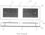
- FIGS. 7 a and bis a schematic representation of a further configuration of the dual antiphase antenna with the microstrip feeds in echelon.
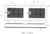
- FIGS. 8 a and bis a schematic representation of a further configuration of the dual antiphase antenna with the microstrip feeds on the closest sides of the top patches.
- FIG. 1 ais a schematic representation of the preferred application of the dual antiphase antenna 20 receiving a wireless signal from an implanted sensor 21 to the dual antiphase antenna 20 .
- the top 24 of dual antiphase antenna 20is placed on or in close proximity to the epidermal layer 23 of a mammal 26 while the bottom 25 faces away from the epidural layer 23 of the mammal 26 .
- This applicationis pertinent to communications with implanted body sensors, in particular with cardiac sensors, via a body area network.
- FIG. 1 aincludes a schematic representation of another application of the dual antiphase antenna 20 receiving a wireless signal from a smart pill 22 to the dual antiphase antenna 20 . It is pertinent to gastroenterology telemetry with smart pills via a body area network.
- FIG. 1 bis a schematic representation of another application of the dual antiphase antenna 20 wherein microwave propagation between two antiphase antennas 20 through upper or lower extremities is analyzed. It is pertinent to microwave imaging for bone density estimation.
- FIG. 1 cis a schematic representation of another application of the dual antiphase antenna 20 wherein microwave antiphase antennas 20 are used for breast cancer imaging. It is pertinent to microwave breast cancer screening and detection.
- FIG. 1 dis a schematic representation of another application of the dual antiphase antenna 20 showing microwave head imaging with dual antiphase antennas 20 . It is pertinent to stroke and TBI (traumatic brain injury) detection.
- FIG. 2shows a schematic representation of a preferred configuration of the dual antiphase antenna 20 wherein the patch antenna feeds 3 and 4 are as far apart as possible.
- the dual antiphase antenna 20with top 24 and bottom 25 , is fed via a 180 degrees power splitter/combiner 10 connected to the antennas through two matching networks 11 .
- the power splitter 10is further connected to either transmitter or receiver 14 .
- the power splitter/combiner 10 and the two matching networks 11may be combined together into one single block.
- FIG. 3 ashows a top view schematic representation of a preferred configuration of the dual antiphase antenna 20 with a probe feed.
- the dual antiphase antenna 20is comprised of dielectric substrate 1 and two surface patches 2 .
- FIG. 3 bshows a side view schematic representation of a preferred configuration of the dual antiphase antenna 20 consisting of dielectric substrate 1 , two surface patches 2 , patch antenna feeds 3 , 4 , and a ground plane 5 .
- the dielectric substrate 1consists of a first side 27 and a second side 28 .
- the two surface patches 2are located the first side 27 of the dielectric substrate 1 and the ground plane is located on the second side 28 of the dielectric substrate 1 .
- the feeds 3 and 4are located close to the opposite edges of patches 2 .
- FIG. 4 ashows a top view schematic representation of a further configuration of the dual antiphase antenna 20 with a probe feed comprised of dielectric substrate 1 and two surface patches 2 .
- FIG. 4 bshows a side view schematic representation of the dual antiphase antenna 20 consisting of dielectric substrate 1 , two surface patches 2 , patch antenna feeds 3 , 4 , and a ground plane 5 .
- the feeds 3 and 4are located in echelon, similar to the standard patch antenna array.
- FIG. 5 ashows a top view schematic representation of a preferred configuration of the dual antiphase antenna 20 with a probe feed consisting of dielectric substrate 1 and two surface patches 2 .
- FIG. 5 bshows a side view schematic representation of the dual antiphase antenna 20 with a probe feed consisting of dielectric substrate 1 , two surface patches 2 , patch antenna feeds 3 , 4 , and a ground plane 5 . The feeds are located close to the nearest edges of patches 2 .
- FIG. 6 ashows a top view schematic representation of a preferred configuration of the dual antiphase antenna 20 with a microstrip feed.
- the dual antiphase antenna 20consists of dielectric substrate 1 and two surface patches 2 and antenna feeds 15 and 16 .
- FIG. 6 bshows a side view schematic representation of the dual antiphase antenna 20 with a microstrip feed consisting of dielectric substrate 1 , two surface patches 2 , antenna feeds 15 , 16 , and a ground plane 5 .
- the feeds 15 and 16are located close to the opposite edges of patches 2 .
- FIG. 7 ashows a schematic representation of a further configuration of the dual antiphase antenna 20 with a microstrip feed.
- the dual antiphase antenna 20consists of dielectric substrate 1 , two surface patches 2 , and patch antenna feeds 15 and 16 .
- FIG. 7 bis a side view schematic representation of dual antiphase antenna 20 with a microstrip feed consisting of dielectric substrate 1 , two surface patches 2 , and patch antenna feeds 15 , 16 , and a ground plane 5 .
- the feeds 15 and 16are located in echelon, similar to the standard patch antenna array.
- FIG. 8 ashows a top view schematic representation of a further configuration of the dual antiphase antenna 20 with a microstrip feed.
- the dual antiphase antenna 20consists of dielectric substrate 1 , two surface patches 2 , and patch antenna feeds 15 , 16 .
- FIG. 8 bshows a side view schematic representation of the dual antiphase antenna 20 with a microstrip feed consisting of dielectric substrate 1 , two surface patches 2 , and patch antenna feeds 15 , 16 , and a ground plane 5 .
- the feeds 15 and 16are located close to the nearest edges of patches 2 .
Landscapes
- Engineering & Computer Science (AREA)
- Computer Networks & Wireless Communication (AREA)
- Signal Processing (AREA)
- Variable-Direction Aerials And Aerial Arrays (AREA)
- Waveguide Aerials (AREA)
Abstract
Description
Claims (10)
Priority Applications (1)
| Application Number | Priority Date | Filing Date | Title |
|---|---|---|---|
| US16/502,346US11101554B2 (en) | 2018-01-16 | 2019-07-03 | Dual antiphase antenna for better signal transmission into human body or signal reception from human body |
Applications Claiming Priority (2)
| Application Number | Priority Date | Filing Date | Title |
|---|---|---|---|
| US15/872,324US10657338B2 (en) | 2017-01-16 | 2018-01-16 | Microwave antenna array and testbed for osteoporosis detection |
| US16/502,346US11101554B2 (en) | 2018-01-16 | 2019-07-03 | Dual antiphase antenna for better signal transmission into human body or signal reception from human body |
Related Parent Applications (1)
| Application Number | Title | Priority Date | Filing Date |
|---|---|---|---|
| US15/872,324Continuation-In-PartUS10657338B2 (en) | 2017-01-16 | 2018-01-16 | Microwave antenna array and testbed for osteoporosis detection |
Publications (2)
| Publication Number | Publication Date |
|---|---|
| US20190326666A1 US20190326666A1 (en) | 2019-10-24 |
| US11101554B2true US11101554B2 (en) | 2021-08-24 |
Family
ID=68236571
Family Applications (1)
| Application Number | Title | Priority Date | Filing Date |
|---|---|---|---|
| US16/502,346ActiveUS11101554B2 (en) | 2018-01-16 | 2019-07-03 | Dual antiphase antenna for better signal transmission into human body or signal reception from human body |
Country Status (1)
| Country | Link |
|---|---|
| US (1) | US11101554B2 (en) |
Families Citing this family (2)
| Publication number | Priority date | Publication date | Assignee | Title |
|---|---|---|---|---|
| CN112086748B (en)* | 2020-09-25 | 2025-05-27 | 深圳迈睿智能科技有限公司 | Transmitting and receiving same element anti-phase microwave detection module |
| CN213520320U (en)* | 2020-09-25 | 2021-06-22 | 深圳迈睿智能科技有限公司 | Reverse-phase double-feed microwave detection module |
Citations (17)
| Publication number | Priority date | Publication date | Assignee | Title |
|---|---|---|---|---|
| JP2000245736A (en) | 1999-02-25 | 2000-09-12 | Kyoto Densoku Kk | Osteoporosis diagnostic device |
| US6285901B1 (en) | 1999-08-25 | 2001-09-04 | Echo Medical Systems, L.L.C. | Quantitative magnetic resonance method and apparatus for bone analysis |
| US20050190106A1 (en)* | 2001-10-16 | 2005-09-01 | Jaume Anguera Pros | Multifrequency microstrip patch antenna with parasitic coupled elements |
| US20060241377A1 (en) | 2005-03-08 | 2006-10-26 | James Timothy W | System and method for bone strength assessment |
| US20070117524A1 (en)* | 2005-11-23 | 2007-05-24 | Ky-Hien Do | Quasi-circulator for antenna multi-coupler system |
| US20070238992A1 (en) | 2006-02-01 | 2007-10-11 | Sdgi Holdings, Inc. | Implantable sensor |
| US20090124215A1 (en)* | 2007-09-04 | 2009-05-14 | Sierra Wireless, Inc. | Antenna Configurations for Compact Device Wireless Communication |
| US7601120B2 (en) | 2001-11-30 | 2009-10-13 | Petro Moilanen | Method and device for the non-invasive assessment of bones |
| US20100152584A1 (en) | 2006-07-25 | 2010-06-17 | Arie Ariav | Method for measuring various parameters of bones and joints |
| US20110263961A1 (en)* | 2007-11-05 | 2011-10-27 | Micrima Limited | Antenna for Investigating Structure of Human or Animal |
| US8301221B2 (en) | 2006-09-29 | 2012-10-30 | Depuy Products, Inc. | Apparatus and method for monitoring the position of an orthopaedic prosthesis |
| US20120296234A1 (en) | 2011-05-16 | 2012-11-22 | Smith & Nephew, Inc. | Measuring skeletal distraction |
| US20130018240A1 (en) | 2011-07-12 | 2013-01-17 | Mccoy Kim | Body measurement and imaging with a mobile device |
| US8449556B2 (en) | 2005-03-29 | 2013-05-28 | Martin W. Roche | Method for detecting body parameters |
| US20140125526A1 (en)* | 2012-11-08 | 2014-05-08 | Samsung Electronics Co., Ltd. | Multiband antenna and electronic apparatus having the same |
| US9496601B1 (en)* | 2014-01-16 | 2016-11-15 | Google Inc. | Antenna assembly utilizing space between a battery and a housing |
| US9589482B2 (en) | 2014-09-10 | 2017-03-07 | At&T Intellectual Property I, L.P. | Bone conduction tags |
- 2019
- 2019-07-03USUS16/502,346patent/US11101554B2/enactiveActive
Patent Citations (17)
| Publication number | Priority date | Publication date | Assignee | Title |
|---|---|---|---|---|
| JP2000245736A (en) | 1999-02-25 | 2000-09-12 | Kyoto Densoku Kk | Osteoporosis diagnostic device |
| US6285901B1 (en) | 1999-08-25 | 2001-09-04 | Echo Medical Systems, L.L.C. | Quantitative magnetic resonance method and apparatus for bone analysis |
| US20050190106A1 (en)* | 2001-10-16 | 2005-09-01 | Jaume Anguera Pros | Multifrequency microstrip patch antenna with parasitic coupled elements |
| US7601120B2 (en) | 2001-11-30 | 2009-10-13 | Petro Moilanen | Method and device for the non-invasive assessment of bones |
| US20060241377A1 (en) | 2005-03-08 | 2006-10-26 | James Timothy W | System and method for bone strength assessment |
| US8449556B2 (en) | 2005-03-29 | 2013-05-28 | Martin W. Roche | Method for detecting body parameters |
| US20070117524A1 (en)* | 2005-11-23 | 2007-05-24 | Ky-Hien Do | Quasi-circulator for antenna multi-coupler system |
| US20070238992A1 (en) | 2006-02-01 | 2007-10-11 | Sdgi Holdings, Inc. | Implantable sensor |
| US20100152584A1 (en) | 2006-07-25 | 2010-06-17 | Arie Ariav | Method for measuring various parameters of bones and joints |
| US8301221B2 (en) | 2006-09-29 | 2012-10-30 | Depuy Products, Inc. | Apparatus and method for monitoring the position of an orthopaedic prosthesis |
| US20090124215A1 (en)* | 2007-09-04 | 2009-05-14 | Sierra Wireless, Inc. | Antenna Configurations for Compact Device Wireless Communication |
| US20110263961A1 (en)* | 2007-11-05 | 2011-10-27 | Micrima Limited | Antenna for Investigating Structure of Human or Animal |
| US20120296234A1 (en) | 2011-05-16 | 2012-11-22 | Smith & Nephew, Inc. | Measuring skeletal distraction |
| US20130018240A1 (en) | 2011-07-12 | 2013-01-17 | Mccoy Kim | Body measurement and imaging with a mobile device |
| US20140125526A1 (en)* | 2012-11-08 | 2014-05-08 | Samsung Electronics Co., Ltd. | Multiband antenna and electronic apparatus having the same |
| US9496601B1 (en)* | 2014-01-16 | 2016-11-15 | Google Inc. | Antenna assembly utilizing space between a battery and a housing |
| US9589482B2 (en) | 2014-09-10 | 2017-03-07 | At&T Intellectual Property I, L.P. | Bone conduction tags |
Non-Patent Citations (5)
| Title |
|---|
| Golnabi et al.,Microwave Tomography for Bone Imaging, IEEE International Symposium on Biomedical Imaging, Chicago Mar. 30-Apr. 2, 2011. |
| Meaney et al., 3D Microwave Bone Imaging, 6th European Conference on Antennas and Propagation, Mar. 26-30, 2012. |
| Meaney et al., Bone Dialectric Property Variation as a Function of Mineralization at Microwave Frequencies, International Journal of Biomedical Engineering, vol. 2012, Article ID 649612, 9, Jan. 16, 2012. |
| Meaney et al., Clinical Microwave Tomographic Imaging of the Calcaneus: A First-in-Human Case Study of Two Subjects, IEEE Transactions on Biomedical Engineering, vol. 59, No. 12, Dec. 2012. |
| Zhou et al., Microwave Tomographic Imaging for Osteoporosis Screening: a Pilot Clinical Study, 32nd Annual International Conference of the IEEE EMBS Buenos Aires, Argentina, Aug. 31-Sep. 4, 2010. |
Also Published As
| Publication number | Publication date |
|---|---|
| US20190326666A1 (en) | 2019-10-24 |
Similar Documents
| Publication | Publication Date | Title |
|---|---|---|
| EP2227140B1 (en) | Antenna for investigating structure of human or animal | |
| Singh et al. | Micro strip patch antenna and its applications: a survey | |
| EP3474372B1 (en) | Antenna for wearable radio system and associated method of making | |
| Sabban | New wideband printed antennas for medical applications | |
| US6982675B2 (en) | Internal multi-band antenna with multiple layers | |
| US9831559B2 (en) | Low-profile blanket antenna | |
| CN101331649A (en) | Single layer dual band antenna with circular polarization and single feed point | |
| US20130249764A1 (en) | Compact planar inverted f-antenna for multiband communication | |
| US11101554B2 (en) | Dual antiphase antenna for better signal transmission into human body or signal reception from human body | |
| CN113937501B (en) | Broadband GNSS antenna | |
| US20170018849A1 (en) | Antenna and related method | |
| Sabban | Comprehensive study of printed antennas on human body for medical applications | |
| Hire et al. | A Review on Microstrip Patch Antenna Design and its Applications | |
| KR100980779B1 (en) | Consumer Chip Antenna | |
| CN108832283A (en) | A Novel Flexible Dual-Band Loop Capsule Antenna | |
| Abdollahvand et al. | A compact UWB printed antenna with bandwidth enhancement for in-body microwave imaging applications | |
| Kathuria et al. | 24 GHz flexible LCP antenna array for radar-based noncontact vital sign monitoring | |
| Saeed et al. | Rectangular loop mm-wave antenna for wearable applications | |
| Mohamadzade et al. | Low-profile pattern reconfigurable antenna for wireless body area networks | |
| CN102738566A (en) | Miniaturized three-band satellite communication antenna | |
| Sonet et al. | Dual band G-slot 5G antenna for wireless body area network | |
| TW200805782A (en) | Dual band flat antenna | |
| Sabban | Wearable antennas for medical applications | |
| Tak et al. | Design of a dual band repeater antenna for medical self-monitoring applications | |
| Ashok et al. | Inset fed slotted patch antenna array for microwave imaging applications |
Legal Events
| Date | Code | Title | Description |
|---|---|---|---|
| FEPP | Fee payment procedure | Free format text:ENTITY STATUS SET TO UNDISCOUNTED (ORIGINAL EVENT CODE: BIG.); ENTITY STATUS OF PATENT OWNER: SMALL ENTITY | |
| FEPP | Fee payment procedure | Free format text:ENTITY STATUS SET TO SMALL (ORIGINAL EVENT CODE: SMAL); ENTITY STATUS OF PATENT OWNER: SMALL ENTITY | |
| STPP | Information on status: patent application and granting procedure in general | Free format text:DOCKETED NEW CASE - READY FOR EXAMINATION | |
| STPP | Information on status: patent application and granting procedure in general | Free format text:NON FINAL ACTION MAILED | |
| STPP | Information on status: patent application and granting procedure in general | Free format text:RESPONSE TO NON-FINAL OFFICE ACTION ENTERED AND FORWARDED TO EXAMINER | |
| STPP | Information on status: patent application and granting procedure in general | Free format text:FINAL REJECTION MAILED | |
| STPP | Information on status: patent application and granting procedure in general | Free format text:RESPONSE AFTER FINAL ACTION FORWARDED TO EXAMINER | |
| STPP | Information on status: patent application and granting procedure in general | Free format text:NOTICE OF ALLOWANCE MAILED -- APPLICATION RECEIVED IN OFFICE OF PUBLICATIONS | |
| AS | Assignment | Owner name:NEVA ELECTROMAGNETICS, LLC, MASSACHUSETTS Free format text:ASSIGNMENT OF ASSIGNORS INTEREST;ASSIGNORS:MAKAROV, SERGEY N.;NOETSCHER, GREGORY M.;MAKAROV, VIKTOR;AND OTHERS;SIGNING DATES FROM 20190609 TO 20190610;REEL/FRAME:056821/0817 | |
| STPP | Information on status: patent application and granting procedure in general | Free format text:PUBLICATIONS -- ISSUE FEE PAYMENT RECEIVED | |
| STPP | Information on status: patent application and granting procedure in general | Free format text:PUBLICATIONS -- ISSUE FEE PAYMENT VERIFIED | |
| STCF | Information on status: patent grant | Free format text:PATENTED CASE | |
| MAFP | Maintenance fee payment | Free format text:PAYMENT OF MAINTENANCE FEE, 4TH YR, SMALL ENTITY (ORIGINAL EVENT CODE: M2551); ENTITY STATUS OF PATENT OWNER: SMALL ENTITY Year of fee payment:4 |