US11100673B2 - Systems and methods for localization using surface imaging - Google Patents
Systems and methods for localization using surface imagingDownload PDFInfo
- Publication number
- US11100673B2 US11100673B2US15/762,378US201615762378AUS11100673B2US 11100673 B2US11100673 B2US 11100673B2US 201615762378 AUS201615762378 AUS 201615762378AUS 11100673 B2US11100673 B2US 11100673B2
- Authority
- US
- United States
- Prior art keywords
- template
- vehicle
- target surface
- location
- reference templates
- Prior art date
- Legal status (The legal status is an assumption and is not a legal conclusion. Google has not performed a legal analysis and makes no representation as to the accuracy of the status listed.)
- Expired - Fee Related, expires
Links
Images


Classifications
- G—PHYSICS
- G06—COMPUTING OR CALCULATING; COUNTING
- G06T—IMAGE DATA PROCESSING OR GENERATION, IN GENERAL
- G06T7/00—Image analysis
- G06T7/70—Determining position or orientation of objects or cameras
- G06T7/73—Determining position or orientation of objects or cameras using feature-based methods
- G06T7/74—Determining position or orientation of objects or cameras using feature-based methods involving reference images or patches
- G—PHYSICS
- G06—COMPUTING OR CALCULATING; COUNTING
- G06F—ELECTRIC DIGITAL DATA PROCESSING
- G06F18/00—Pattern recognition
- G06F18/20—Analysing
- G06F18/22—Matching criteria, e.g. proximity measures
- G—PHYSICS
- G06—COMPUTING OR CALCULATING; COUNTING
- G06F—ELECTRIC DIGITAL DATA PROCESSING
- G06F18/00—Pattern recognition
- G06F18/20—Analysing
- G06F18/24—Classification techniques
- G06F18/241—Classification techniques relating to the classification model, e.g. parametric or non-parametric approaches
- G06F18/2413—Classification techniques relating to the classification model, e.g. parametric or non-parametric approaches based on distances to training or reference patterns
- G06F18/24133—Distances to prototypes
- G06K9/00785—
- G06K9/00798—
- G06K9/527—
- G06K9/6215—
- G06K9/6271—
- G—PHYSICS
- G06—COMPUTING OR CALCULATING; COUNTING
- G06V—IMAGE OR VIDEO RECOGNITION OR UNDERSTANDING
- G06V10/00—Arrangements for image or video recognition or understanding
- G06V10/40—Extraction of image or video features
- G06V10/52—Scale-space analysis, e.g. wavelet analysis
- G—PHYSICS
- G06—COMPUTING OR CALCULATING; COUNTING
- G06V—IMAGE OR VIDEO RECOGNITION OR UNDERSTANDING
- G06V10/00—Arrangements for image or video recognition or understanding
- G06V10/40—Extraction of image or video features
- G06V10/54—Extraction of image or video features relating to texture
- G—PHYSICS
- G06—COMPUTING OR CALCULATING; COUNTING
- G06V—IMAGE OR VIDEO RECOGNITION OR UNDERSTANDING
- G06V10/00—Arrangements for image or video recognition or understanding
- G06V10/70—Arrangements for image or video recognition or understanding using pattern recognition or machine learning
- G06V10/764—Arrangements for image or video recognition or understanding using pattern recognition or machine learning using classification, e.g. of video objects
- G—PHYSICS
- G06—COMPUTING OR CALCULATING; COUNTING
- G06V—IMAGE OR VIDEO RECOGNITION OR UNDERSTANDING
- G06V20/00—Scenes; Scene-specific elements
- G06V20/50—Context or environment of the image
- G06V20/52—Surveillance or monitoring of activities, e.g. for recognising suspicious objects
- G06V20/54—Surveillance or monitoring of activities, e.g. for recognising suspicious objects of traffic, e.g. cars on the road, trains or boats
- G—PHYSICS
- G06—COMPUTING OR CALCULATING; COUNTING
- G06V—IMAGE OR VIDEO RECOGNITION OR UNDERSTANDING
- G06V20/00—Scenes; Scene-specific elements
- G06V20/50—Context or environment of the image
- G06V20/56—Context or environment of the image exterior to a vehicle by using sensors mounted on the vehicle
- G06V20/588—Recognition of the road, e.g. of lane markings; Recognition of the vehicle driving pattern in relation to the road
- G06K9/38—
- G—PHYSICS
- G06—COMPUTING OR CALCULATING; COUNTING
- G06T—IMAGE DATA PROCESSING OR GENERATION, IN GENERAL
- G06T2207/00—Indexing scheme for image analysis or image enhancement
- G06T2207/10—Image acquisition modality
- G06T2207/10004—Still image; Photographic image
- G—PHYSICS
- G06—COMPUTING OR CALCULATING; COUNTING
- G06T—IMAGE DATA PROCESSING OR GENERATION, IN GENERAL
- G06T2207/00—Indexing scheme for image analysis or image enhancement
- G06T2207/20—Special algorithmic details
- G06T2207/20048—Transform domain processing
- G—PHYSICS
- G06—COMPUTING OR CALCULATING; COUNTING
- G06T—IMAGE DATA PROCESSING OR GENERATION, IN GENERAL
- G06T2207/00—Indexing scheme for image analysis or image enhancement
- G06T2207/20—Special algorithmic details
- G06T2207/20212—Image combination
- G—PHYSICS
- G06—COMPUTING OR CALCULATING; COUNTING
- G06T—IMAGE DATA PROCESSING OR GENERATION, IN GENERAL
- G06T2207/00—Indexing scheme for image analysis or image enhancement
- G06T2207/30—Subject of image; Context of image processing
- G06T2207/30244—Camera pose
- G—PHYSICS
- G06—COMPUTING OR CALCULATING; COUNTING
- G06T—IMAGE DATA PROCESSING OR GENERATION, IN GENERAL
- G06T2207/00—Indexing scheme for image analysis or image enhancement
- G06T2207/30—Subject of image; Context of image processing
- G06T2207/30248—Vehicle exterior or interior
- G06T2207/30252—Vehicle exterior; Vicinity of vehicle
- H—ELECTRICITY
- H04—ELECTRIC COMMUNICATION TECHNIQUE
- H04N—PICTORIAL COMMUNICATION, e.g. TELEVISION
- H04N19/00—Methods or arrangements for coding, decoding, compressing or decompressing digital video signals
- H04N19/60—Methods or arrangements for coding, decoding, compressing or decompressing digital video signals using transform coding
- H—ELECTRICITY
- H04—ELECTRIC COMMUNICATION TECHNIQUE
- H04N—PICTORIAL COMMUNICATION, e.g. TELEVISION
- H04N23/00—Cameras or camera modules comprising electronic image sensors; Control thereof
- H04N23/56—Cameras or camera modules comprising electronic image sensors; Control thereof provided with illuminating means
- H04N5/2256—
Definitions
- aspects of the present disclosurerelate to location identification and mapping and more particularly to systems and methods for determining a location by matching compressed encoded surface structural patterns.
- SLAMSimultaneous localization and mapping
- Such SLAM techniquesare tailored to available computational and sensor input resources, and as such, the ability of conventional autonomous devices to obtain sufficient information to navigate and make decisions within complex and fluctuating environments is often hindered by prohibitive costs, high data bandwidth requirements, and other fidelity or computational deficiencies. It is with these observations in mind, among others, that various aspects of the present disclosure were conceived and developed.
- a raw image of a target surfaceis captured using at least one imager.
- the raw imageis encoded into a template using at least one transform.
- the templatespecifies a course direction and an intensity gradient at one or more spatial frequencies of a pattern of the target surface.
- the templateis compared to a subset of reference templates selected from a gallery stored in one or more storage media. A location of the target surface is identified when the template matches a reference template in the subset.
- At least one imageris mounted on a vehicle and configured to capture a raw image of a target surface along a path of travel of the vehicle.
- One or more storage mediastore a set of reference templates, and each of the reference templates corresponds to a road surface with a known location.
- At least one processordetermines a location of the vehicle by matching a template to one of the reference templates. The template is generated by encoding the raw image using at least one transform.
- a template encoded from a raw image of a target surface using at least one transformis received.
- the raw imageis captured using at least one imager, and the template specifies a course direction and an intensity gradient at one or more spatial frequencies of a pattern of the target surface.
- the templateis compared to a subset of reference templates selected from a gallery stored in one or more databases. A location of the target surface is identified when the template matches a reference template in the subset.
- FIG. 1is a diagram of an example localization system using road surface images to determine a location of a vehicle.
- FIG. 2illustrates an example imaging system for capturing a raw image of a target surface.
- FIG. 3is a block diagram of an example system for identifying a location of a target surface.
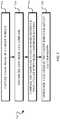
- FIG. 4is an example localization system, including a localizer which may run on a computer server, computing device, or other device coupled with a network, for localization using surface imaging.
- FIG. 5illustrates example operations for identifying a location of a target surface.
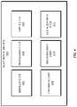
- FIG. 6is a functional block diagram of an electronic device including operational units arranged to perform various operations of the presently disclosed technology.
- FIG. 7is an example computing system that may implement various systems and methods of the presently disclosed technology.
- an optical systemcaptures a raw image of a texture pattern of a target surface.
- a localizercompresses and encodes the raw image into a template for efficient storage, fast comparison, and spatial registration with a gallery of reference templates, each corresponding to a known location. By matching the template with one of the references templates, a location of the target surface is determined.
- the optical systemis mounted on a vehicle, such as an automobile, and captures a raw image of a target surface on a road as the vehicle moves along a path of travel.
- the localizerencodes the raw image into a template using at least one transform, such as a log Gabor feature encoder.
- the templateis thus in a form for comparison to a gallery of reference templates, each of which corresponds to a known location on a road.
- the templateis aligned to the reference templates using registration optimization, such as hamming distance minimization or an application of correlation theorem.
- Road surfacesinclude vast amounts of unique information (e.g., hundreds of bits in 30 cm 2 patches), permitting a match of the template to one of the reference templates with a high level of accuracy.
- a location of the vehicle, along with other travel information, such as a direction of travel, a speed of travel, and the like,may be determined by registering the template with one of the reference templates.
- the various systems and methods disclosed hereingenerally provide for localization and navigation using surface structural patterns.
- the example implementations discussed hereinreference vehicle localization and navigation using road surface patterns.
- the presently disclosed technologyis applicable in other localization, navigation, and mapping contexts and to other autonomous devices, including, without limitation, robots, unmanned aerial vehicles, and other vehicles or devices, as well as to other types of target surfaces, such as walls, sidewalks, paths, and other surfaces with high amounts of unique texture or structure information.
- a localizer 102captures one or more raw images of a target surface 104 to determine travel information of a vehicle 106 relative to a notion of the environment in which the vehicle 106 travels along a road 108 .
- the target surface 104includes contrast information in the form of a pattern of dark and light features, corresponding to the surface texture. Small regions of the contrast information include vast amounts of identifiable and registrable information.
- the target surface 104may be a 30 cm by 30 cm patch including potentially hundreds of bits of unique information for localization of the vehicle 106 .
- the localizer 102thus uses image-based random patterns of surfaces on the road 108 and/or 3-dimensional surface morphology of the surfaces on the road 108 as a source of localization for the vehicle 106 . Localization consists of determining the current pose of the vehicle 106 within an environment in a precise manner.
- the localizer 102captures a raw image of the target surface 104 using an imaging system.
- the target surface 104is disposed under the vehicle 106 during image capture.
- the localizer 102captures raw images of the target surface 104 along the path of travel as the vehicle 106 passes over the target surface 104 .
- the localizer 102may obtain a better quality image through control of illumination of the target surface 104 , external image capture factors, and/or the like. It will be appreciated, however, that the target surface 104 may be imaged in front of the vehicle 106 , behind the vehicle 106 , and/or anywhere in a vicinity of the vehicle 106 .
- the localizer 102encodes the raw image of the target surface 104 into a template in a form for comparison and taking into account the lighting conditions of the environment in which the target surface 104 is disposed as well as any other image capture phenomena capable of altering the raw image or otherwise decreasing the fidelity of registration.
- the localizer 102encodes and compresses the raw image into a template of the target surface 104 to facilitate storage and/or comparison and spatial registration with a gallery 112 of reference templates 114 .
- the gallery 112includes reference templates 114 for surfaces in road networks and other drivable regions within a geographical scale, such as a global scale, a regional scale, a country scale, a state scale, a city scale, a local scale defined by a radius from a central point (e.g., a charging station 110 ), and/or the like.
- the localizer 102may cache a portion or an entirety of the gallery 112 in memory, access the gallery 112 over a network, and/or the like.
- the localizer 102encodes and compresses the raw image of the target surface 104 into the template using at least one transform, including, but not limited to, a feature encoder with a log Gabor base filter function, a feature encoder with a Haar transform base filter function, a feature encoder with a Fourier transform base filter function, a feature encoder with a discrete cosine transform base filter function, a signal definition using a Histogram of Gradient filter, a signal definition using a Local Binary Pattern filter, and/or feature encoders with other base filter functions or signal definitions filters.
- the template of the target surface 104may be defined through optimization and classification, which relate to the intrinsic information content of the target surface 104 . For example, a phase of the template may be used as a robust signal for comparison to the gallery 112 of reference templates 114 .
- the raw image of the target surface 104is encoded and compressed into a binary template, which expresses the contrast information of the target surface 104 using a series of two symbols (e.g., a series of 0's and 1's), using a base set of first order log Gabor feature encoders.
- the binary template of the target surface 104indicates a course direction and an intensity gradient at one or more spatial frequencies of a pattern of the target surface.
- the binary template of the target surface 104may be used for comparison to the gallery 112 of reference templates 114 , which are each stored in a form for comparison.
- each of the reference templates 114may be stored as binary templates for comparison.
- templates of the road 108 that are generated as the vehicle 106 moves along the path of travelare used to update the gallery 112 .
- the localizer 102may provide new templates or updates to the reference templates 114 for storage in the gallery 112 .
- the localizer 102may communicate with the gallery 112 over a network, via the charging station 110 , and/or using other wired or wireless connections. Because the templates are compressed, as described herein, the data rate to send the new and updated templates to the gallery 112 is low.
- a subset of the reference templates 114is identified from the gallery 112 and stored in memory of the localizer 102 for comparison to templates generated during travel.
- the subset of reference templates 114may be identified based on a general location of the vehicle 106 , a previously known location the vehicle 106 , a geographical area in which the vehicle 106 is located, and/or the like.
- the general location of the vehicle 106may be determined using Global Positioning System (GPS), Lidar, radar, longer throw imaging, low resolution road surface matching, and/or other location services.
- GPSGlobal Positioning System
- the localizer 102uses a low-resolution scale of the template of the target surface 104 to identify a subset of the reference templates 112 and uses a high resolution scale of the template of the target surface 104 to match one of the reference templates 112 for localization.
- the previously known locationmay correspond to one or more previously localized segments 116 along the path of travel of the vehicle 106 on the road 108 , a stopping location of the vehicle 106 (e.g., where the vehicle 106 was turned off or connected to the charging station 110 ), and/or the like.
- the localizer 102performs a frequent sampling of the road 108 at low accuracy. Stated differently, the localizer 102 discards part of the imaging data for the target surface 104 and performs a low accuracy match to the reference template 114 .
- the localizer 102determines that the vehicle 106 is traveling along a sequence based on the one or more previously localized segments 116 , the localizer 102 determines the location of the vehicle 106 with a high level of confidence based on a low accuracy match of the template for the target surface 104 to the reference template 114 following next in the sequence.
- the part of the imaging data discardedmay be low frequency data, high frequency data, and/or the most valuable data determined based on a weighted mutual entropy of the imaging data.
- the geographical area in which the vehicle 106 is locatedmay correspond to an average distance range of an electric vehicle battery.
- the vehicle 106connects with the charging station 110 to charge a battery of the vehicle 106 .
- the charging station 110may store the gallery 114 with the reference templates 112 corresponding to surfaces within the average distance range of the vehicle battery from the charging station 110 .
- the localizer 102retrieves the gallery 112 from the charging station 110 and stores the gallery 112 in memory for comparison during travel.
- the gallery 112may be updated via a vehicle 106 connection with the charging station 110 and/or with information obtained over a network.
- the localizer 102may use registration optimization, including, but not limited to, hamming distance minimization, application of correlation theorem, and/or the like, to align the template of the target surface 104 to the reference templates 114 .
- the localizer 102compares the template of the target surface 104 to the reference templates 114 selected from the gallery 112 with a high registration speed. For example, the localizer 102 may perform millions of comparisons and registrations per second.
- the localizer 102determines a location of the target surface 104 and other travel information with a high level of accuracy (e.g., on a sub-millimeter scale).
- the matching accuracyis tunable based on location, operational parameters of the vehicle 106 , and/or the like.
- the localizer 102may use a higher matching accuracy when the vehicle 106 is located within an urban area or turning and use a lower matching accuracy when the vehicle 106 is located in a rural area or when the vehicle 106 is traveling along a straight path (e.g., on a highway).
- travel information for the vehicle 106is determined.
- travel informationmay include, without limitation, a geographical location of the vehicle 106 , an orientation of the vehicle 106 relative to the target surface 104 , a pitch and altitude of the vehicle 106 , an optical flow of the vehicle 106 , and/or the like.
- the travel informationmay be overlaid on a map (e.g., a 3-D map), such that the location, orientation, pitch and altitude, and optical flow are provided relative to a notion of the environment in which the vehicle 106 travels.
- the geographical location of the vehicle 106may be determined by matching the template of the target surface 104 to one of the reference templates 112 , each of which corresponding to a known location on the map.
- the geographical locationis provided as an x-y position on a map.
- the orientation of the vehicle 106corresponds to a horizontal angle of the vehicle 106 relative to the target surface 104 , for example, resulting from the vehicle 106 changing lanes or turning.
- the orientation of the vehicle 106is determined through an alignment of the template of the target surface 104 with the reference template 114 through registration, which may be supplemented with additional information captured by the localizer 102 using one or more sensors, such as a compass.
- the pitchcorresponds a vertical angle of the vehicle 106 relative to a plane of the target surface 104
- the altitudecorresponds to a height of the vehicle 106 above or below the plane of the target surface 104
- the pitch and altitude of the vehicle 106may vary, for example, by the vehicle 106 traveling over a bump or hitting a road deformity, such as a pothole.
- the pitch and/or altitude of the vehicle 106may be determined by skewing the template of the target surface 104 until it matches against the reference template 114 during registration and/or using 3-dimensional morphology of the target surface 104 obtained through triangulation of the raw images captured using structured light.
- the optical flowprovides a direct measurement of the velocity of the vehicle 106 as it moves along the path of travel on the road 108 .
- the optical flowmay further provide a direct measurement of friction of the road 108 by comparing the velocity measured by the localizer 102 with a distance measured using wheel motion of the vehicle 106 .
- the optical flowis determined by measuring how fast the vehicle 106 traverses over the target surface 104 along the road 108 .
- the localizer 106may communicate with other sub-systems of the vehicle 106 to provide the travel information, including the location of the vehicle 106 , for use with other layers of semantic information (e.g., road network information, vehicle and pedestrian traffic information, weather information, etc.) in decision-making support for controlling operations of the vehicle 106 .
- the localizer 106may further output the travel information for display on a user interface, with which a driver or other passenger may interact.
- the localizer 102utilizes the road surfacing imaging in replace of or complementary to other localization techniques.
- Localization using road surface imagingcovers unique environmental conditions where other localization techniques may be inadequate. For example, conditions where a view from the vehicle 106 is blocked by surrounding vehicles, such as semi-trucks, inhibit localization through Lidar, longer throw imaging, or radar. Weather conditions, such as fog, may similarly inhibit such localization techniques. GPS and other space-based navigation systems may suffer from fidelity issues in urban areas or other areas where line of sight to the necessary satellites is blocked. In these situations, the localizer 102 may rely on road surface imaging as a primary localization source and such localization techniques as secondary sources. It will be appreciated, however, that in some scenarios, road surface imaging may be used to supplement other localization techniques.
- the imaging system 200includes at least one light source 202 configured to emit light 204 for illuminating the target surface 104 and at least one imager 208 configured to generate the raw image of the target surface 104 from returns 206 from the target surface 104 .
- the imaging system 200does not include the light source 202 .
- the returns 206may pass through various optical elements, such as a polarizer 210 , a filter 212 , and/or the like, depending on properties of the transform for encoding the raw image captured using the imaging system 200 .
- Sunlight or other ambient light, as well as other background lightmay create returns in the imager 208 , which may contaminate the raw image.
- the light source 202is a high power, pulsed illuminator, which may be time synchronized with the imager 208 exposure to reduce the illumination time. Background light, including ambient light and light from other external sources, is rejected using such high power, pulsed illumination. Further, the short illumination time prevents any eye safety hazards for other drivers on the road 108 caused by the light source 202 .
- the imaging system 200may reduce background light using correlated double sampling where the imager 208 takes back-to-back exposures of the target surface 104 .
- the first exposureis with the light source 202 off, such that only ambient light is collected by the imager 208 .
- the second exposureincludes the light 204 emitted by the light source 202 .
- the background lightis subtracted from the image data of the second exposure, leaving the contribution of the light 204 in the raw image.
- Correlated double samplingprovides uniform and controllable illumination conditions for capture of the target surface 104 without the variability of background light, thereby facilitating encoding and registration of the template for the target surface 104 .
- the light source 202may be configured to emit the light 204 and the imager 208 to capture the returns 206 depending on properties of the transform for encoding the raw image captured using the imaging system 200 .
- the light source 202 and the imager 208may be configured to capture the raw image of the target surface 104 using structured light, in multi-wavelength space, based on wavelength differential, using polarization, using light in the visible spectrum, using light in the near infrared (NIR) spectrum, using stereoscopic methods, and/or the like.
- a capture rate of the imaging system 200may vary depending on localization of the vehicle 106 and operational parameters of the imaging system 200 .
- the capture rate of the imaging system 200is proportional to a velocity of the vehicle 106 , a field of view, a location and/or the like.
- the imaging system 200may capture raw images at a higher rate where the vehicle 106 is localized to an area that does not have corresponding reference templates 114 mapped in the gallery 112 .
- the imaging system 200may capture raw images at a lower rate where the vehicle 106 is localized to a previously known patch of road.
- the localizer 102may track the location and trajectory of the vehicle 106 using integrated velocity data between relatively sparse localization through road surface imaging.
- a raw image 300 of a target surfaceis captured using an imaging system.
- the target surfacemay be, without limitation, a road surface, a wall surface, a sidewalk surface, a path surface, a landmark surface, or other surfaces with high amounts of unique texture or structure information.
- the raw image 300is encoded into a template 302 using one or more transforms, including, but not limited to, a feature encoder with a log Gabor base filter function, a feature encoder with a Haar transform base filter function, a feature encoder with a Fourier transform base filter function, a feature encoder with a discrete cosine transform base filter function, a signal definition using a Histogram of Gradient filter, a signal definition using a Local Binary Pattern filter, a scale invariant feature transform, a notch filter, and/or feature encoders with other base filter functions or signal definitions filters.
- a set of first order log Gabor feature encodersis applied to the raw image 300 .
- the set of first order log Gabor feature encoderssimultaneously analyzes the space and frequency characteristics of the raw image 300 , thereby transforming the raw image 300 into the template 302 with a feature representation of the surface texture for registration.
- the template 302is a binary template, which expresses the contrast information of the raw image 300 using a series of two symbols (e.g., a series of 0's and 1's).
- the binary templatewill be nominal in size (e.g., 10,000 bits) facilitating storage and transmission of the template 302 .
- the template 302indicates a course direction and an intensity gradient at one or more spatial frequencies of a pattern of the target surface.
- the template 302may be used for comparison to a gallery 304 of reference templates 306 , which each correspond to a surface with a mapped location.
- the reference templates 306are encoded and compressed for storage in a manner that mirrors the template 302 , for example, as highly compressed binary templates.
- the gallery 304may be populated with the reference templates 306 using one or more vehicles. For example, one or more calibration vehicles may slowly traverse various surfaces to generate an initial set of reference templates 306 that may be updated over time. As another example, the reference templates 306 may be obtained through crowd sourcing using calibration markers. Templates generated by vehicles for the same surface may be combined to build a statistical accuracy through the use of a plurality of templates (e.g., 10-20) for the same surface. As the surfaces may change over time, the reference templates 306 may be updated in similar manners. New and/or updated reference templates 306 may be input to the gallery 304 via a variety of connections discussed herein, including by connecting with a charging station, over a network, and/or the like. The template 302 is added to the gallery 304 in such manners and contexts.
- a gallery subset 308 of the reference templates 306is identified from the gallery 304 for comparison to the template 302 for localization.
- the gallery subset 308may include one, some, or all of the reference templates 306 .
- the reference templates 306 included in the gallery subset 308are identified based on an estimated location 314 of the target surface.
- the estimated location 314may be based on a general location of the vehicle, a previously known location the vehicle, a geographical area in which the vehicle is located, and/or the like.
- the gallery subset 308is searched over scale, rotation, and translation space to register the template 302 with one of the reference templates 306 .
- registration optimizationincluding, but not limited to, hamming distance minimization, application of correlation theorem, and/or the like, are used to align the template 302 to the reference templates 306 .
- an aligned template 310may be generated from the template 302 using registration optimization.
- a hierarchal matching approachis used with levels corresponding to one or more features of varying sensitivity to rotation, scale, and translation.
- a first levelmay search features that are less sensitive to rotation, scale, and/or translation to provide a general area. For example, a number of holes in the target surface may be defined as a topological encoder method, which is rotation, scale, and translation invariant.
- One or more selected the reference templates 306 matching the number of holes of the template 302may be identified.
- a second levelnormalizes the template 302 into the aligned template 310 for comparison to the one or more selected reference templates 306 with a higher level of accuracy and therefore sensitivity to rotation, scale, and translation.
- the aligned template 310may be generated with rotation, scale, and translation invariance.
- the raw image 300may be captured using structured light illumination to provide the aligned template 310 with scale invariance.
- the raw image 300 and/or the template 302may be scaled by a fixed scale factor to fit the geometry of the imaging system corresponding to the reference templates 306 .
- the aligned template 310may be generated with rotation and translation invariance using other image data and/or date captured using other sensors.
- a compass and/or a direction of the sunprovide an orientation of the vehicle when the raw image 300 was captured, and GPS provides a trajectory of the vehicle along a path of travel when the raw image 300 was captured.
- the raw image 300may be rotated to match a direction of capture of the reference templates 306 and/or to a normalized direction (e.g., with north oriented at a top of the raw image 300 ).
- the raw image 300may be similarly translated based on the data providing the orientation of the vehicle when the raw image 300 was captured.
- the aligned template 310may be oriented for comparison to the gallery subset 308 with rotation, scale, and translation invariance.
- the aligned template 310is compared to the reference templates 306 in the gallery subset 308 with a high registration speed. By matching the aligned template 310 with one of the reference templates 306 , a measured location 312 of the target surface, as well as other travel information, is determined with a high level of accuracy (e.g., on a sub-millimeter scale).
- travel informationmay include, without limitation, a geographical location, an orientation, a pitch and altitude, an optical flow, and/or the like.
- FIG. 4is an example localization system 400 , including a localizer 402 which may run on a computer server, computing device, or other network device, for localization using surface imaging.
- the localizer 402accesses and interacts with an imaging system 404 and/or a reference gallery 408 directly or via a network 406 .
- the localizer 402 , the imaging system 404 , and one or more storage media 410 storing the reference gallery 408are deployed locally within the vehicle 106 .
- the reference gallery 408may be retrieved from the charging station 110 and stored in the storage media 410 .
- the imaging system 404is deployed in the vehicle 106 and communicates raw images to the localizer 402 over the network 406 for localization of the vehicle 106 , and the localizer 402 communicates the location to the vehicle 106 .
- the localizer 402is deployed within the vehicle 106 and retrieves a subset of reference templates from the reference gallery 408 stored in the storage media 410 over the network 406 for comparison. It will be appreciated by those skilled in the art that these implementations illustrate a few example configurations of the systems 100 and 400 and that other configurations are contemplated.
- the network 406is used by one or more computing or data storage devices, such as the storage media 410 in the form of one or more databases, for implementing the localization system 400 .
- a driver or other passengermay access and interact with the localization information using a user device communicatively connected to the localizer 402 directly or via the network 406 .
- the user deviceis generally any form of computing device, such as a computer, mobile device, smartphone, tablet, multimedia console, vehicle interface console, and/or the like.
- a server 412may host the system 400 .
- the server 412may also host a website or an application, such as the localizer 402 that users visit to access the system 400 .
- the server 412may be one single server, a plurality of servers with each such server being a physical server or a virtual machine, or a collection of both physical servers and virtual machines.
- a cloudhosts one or more components of the system 400 .
- One or more vehicles 106 , the localizer 402 , the imaging system 404 , user devices, the server 412 , and other resources, such as the database 410 , connected to the network 406may access one or more other servers for access to one or more websites, applications, web services interfaces, and/or the like that are used for localization, mapping, and/or other services.
- the server 412may also host a search engine that the system 400 uses for accessing and modifying information used for localization and mapping.
- FIG. 5illustrates example operations 500 for identifying a location of a target surface.
- an operation 502captures a raw image of a target surface using at least one imager.
- the imagermay be mounted on a vehicle to capture the raw image of the target surface along a path of travel of the vehicle.
- At least one light sourcemay be time synchronized with the imager and configured to illuminate the target surface.
- an operation 504encodes the raw image into a template using at least one transform.
- the operation 504may further compress the raw image into the template.
- the templatemay be a binary template encoded based on a set of first order log Gabor feature encoders.
- the templatespecifies a course direction and an intensity gradient at one or more spatial frequencies of a pattern of the target surface.
- the templatemay be received over a network from at least one computing unit, such as a processor, of a vehicle.
- An operation 506compares the template comparing the template to a set of reference templates selected from a gallery stored in one or more storage media.
- Each of the reference templatescorresponds to a surface, such as a road surface, with a mapped or otherwise known location.
- the storage mediamay include one or more databases accessible over a network.
- the set of reference templatesmay be selected from the gallery based on a previous location of the vehicle determined using one or more previously captured raw images, retrieved from the gallery over the network, retrieved from a charging station, and/or the like.
- the templateis aligned to the set of reference templates for comparison using registration optimization, such as hamming distance minimization, an application of correlation theorem, and/or the like.
- An operation 508determines a location of the target surface based on the comparison.
- the operation 508identifies the location of the target surface when the template matches a reference template in the set of reference templates.
- the operation 508may communicate the location of the target surface to at least one computing unit of a vehicle.
- the gallerymay be updated by storing the template in the storage media.
- FIG. 6an electronic device 600 including operational units 602 - 612 arranged to perform various operations of the presently disclosed technology is shown.
- the operational units 602 - 612 of the device 600are implemented by hardware or a combination of hardware and software to carry out the principles of the present disclosure. It will be understood by persons of skill in the art that the operational units 602 - 612 described in FIG. 65 may be combined or separated into sub-blocks to implement the principles of the present disclosure. Therefore, the description herein supports any possible combination or separation or further definition of the operational units 602 - 612 .
- the electronic device 600includes a display unit 602 to display information, such as a graphical user interface, and a processing unit 604 in communication with the display unit 602 and an input unit 606 to receive data from one or more input devices or systems, such as the localizer 102 .
- Various operations described hereinmay be implemented by the processing unit 604 using data received by the input unit 606 to output information for display using the display unit 602 .
- the electronic device 600includes an encoding unit 608 , a registration unit 610 , and a localization unit 612 .
- the encoding unit 608encodes and compresses a raw image of a target surface captured using an imaging system into a template using at least one transform.
- the registration unit 610aligns and registers the template with a reference templates matched from a gallery, and the localization unit 612 determines a location of the target surface and other travel information for a vehicle based on the registration of the template with the reference template.
- the electronic device 600includes units implementing the operations described with respect to FIG. 5 .
- the operation 504may be implemented by the encoding unit 608
- the operation 506may be implemented by the registration unit 610
- the operation 508may be implemented by the localization unit 612 .
- FIG. 7a detailed description of an example computing system 700 having one or more computing units that may implement various systems and methods discussed herein is provided.
- the computing system 700may be applicable to the localizer 102 and other computing or network devices. It will be appreciated that specific implementations of these devices may be of differing possible specific computing architectures not all of which are specifically discussed herein but will be understood by those of ordinary skill in the art.
- the computer system 700may be a computing system is capable of executing a computer program product to execute a computer process. Data and program files may be input to the computer system 700 , which reads the files and executes the programs therein. Some of the elements of the computer system 700 are shown in FIG. 7 , including one or more hardware processors 702 , one or more data storage devices 704 , one or more memory devices 708 , and/or one or more ports 708 - 712 . Additionally, other elements that will be recognized by those skilled in the art may be included in the computing system 700 but are not explicitly depicted in FIG. 7 or discussed further herein. Various elements of the computer system 700 may communicate with one another by way of one or more communication buses, point-to-point communication paths, or other communication means not explicitly depicted in FIG. 7 .
- the processor 702may include, for example, a central processing unit (CPU), a microprocessor, a microcontroller, a digital signal processor (DSP), and/or one or more internal levels of cache. There may be one or more processors 702 , such that the processor 702 comprises a single central-processing unit, or a plurality of processing units capable of executing instructions and performing operations in parallel with each other, commonly referred to as a parallel processing environment.
- CPUcentral processing unit
- DSPdigital signal processor
- the computer system 700may be a conventional computer, a distributed computer, or any other type of computer, such as one or more external computers made available via a cloud computing architecture.
- the presently described technologyis optionally implemented in software stored on the data stored device(s) 704 , stored on the memory device(s) 706 , and/or communicated via one or more of the ports 708 - 712 , thereby transforming the computer system 700 in FIG. 7 to a special purpose machine for implementing the operations described herein.
- Examples of the computer system 700include personal computers, terminals, workstations, mobile phones, tablets, laptops, personal computers, multimedia consoles, gaming consoles, set top boxes, and the like.
- the one or more data storage devices 704may include any non-volatile data storage device capable of storing data generated or employed within the computing system 700 , such as computer executable instructions for performing a computer process, which may include instructions of both application programs and an operating system (OS) that manages the various components of the computing system 700 .
- the data storage devices 704may include, without limitation, magnetic disk drives, optical disk drives, solid state drives (SSDs), flash drives, and the like.
- the data storage devices 704may include removable data storage media, non-removable data storage media, and/or external storage devices made available via a wired or wireless network architecture with such computer program products, including one or more database management products, web server products, application server products, and/or other additional software components.
- the one or more memory devices 706may include volatile memory (e.g., dynamic random access memory (DRAM), static random access memory (SRAM), etc.)
- volatile memorye.g., dynamic random access memory (DRAM), static random access memory (SRAM), etc.
- non-volatile memorye.g., read-only memory (ROM), flash memory, etc.
- Machine-readable mediamay include any tangible non-transitory medium that is capable of storing or encoding instructions to perform any one or more of the operations of the present disclosure for execution by a machine or that is capable of storing or encoding data structures and/or modules utilized by or associated with such instructions.
- Machine-readable mediamay include a single medium or multiple media (e.g., a centralized or distributed database, and/or associated caches and servers) that store the one or more executable instructions or data structures.
- the computer system 700includes one or more ports, such as an input/output (I/O) port 708 , a communication port 710 , and a sub-systems port 712 , for communicating with other computing, network, or vehicle devices. It will be appreciated that the ports 708 - 712 may be combined or separate and that more or fewer ports may be included in the computer system 700 .
- I/Oinput/output
- the ports 708 - 712may be combined or separate and that more or fewer ports may be included in the computer system 700 .
- the I/O port 708may be connected to an I/O device, or other device, by which information is input to or output from the computing system 700 .
- I/O devicesmay include, without limitation, one or more input devices, output devices, and/or environment transducer devices.
- the input devicesconvert a human-generated signal, such as, human voice, physical movement, physical touch or pressure, and/or the like, into electrical signals as input data into the computing system 700 via the I/O port 708 .
- the output devicesmay convert electrical signals received from computing system 700 via the I/O port 708 into signals that may be sensed as output by a human, such as sound, light, and/or touch.
- the input devicemay be an alphanumeric input device, including alphanumeric and other keys for communicating information and/or command selections to the processor 702 via the I/O port 708 .
- the input devicemay be another type of user input device including, but not limited to: direction and selection control devices, such as a mouse, a trackball, cursor direction keys, a joystick, and/or a wheel; one or more sensors, such as a camera, a microphone, a positional sensor, an orientation sensor, a gravitational sensor, an inertial sensor, and/or an accelerometer; and/or a touch-sensitive display screen (“touchscreen”).
- the output devicesmay include, without limitation, a display, a touchscreen, a speaker, a tactile and/or haptic output device, and/or the like. In some implementations, the input device and the output device may be the same device, for example, in the case of a touchscreen.
- the environment transducer devicesconvert one form of energy or signal into another for input into or output from the computing system 700 via the I/O port 708 .
- an electrical signal generated within the computing system 700may be converted to another type of signal, and/or vice-versa.
- the environment transducer devicessense characteristics or aspects of an environment local to or remote from the computing device 700 , such as, light, sound, temperature, pressure, magnetic field, electric field, chemical properties, physical movement, orientation, acceleration, gravity, and/or the like.
- the environment transducer devicesmay generate signals to impose some effect on the environment either local to or remote from the example computing device 700 , such as, physical movement of some object (e.g., a mechanical actuator), heating or cooling of a substance, adding a chemical substance, and/or the like.
- some objecte.g., a mechanical actuator
- heating or cooling of a substancee.g., heating or cooling of a substance, adding a chemical substance, and/or the like.
- a communication port 710is connected to a network by way of which the computer system 700 may receive network data useful in executing the methods and systems set out herein as well as transmitting information and network configuration changes determined thereby.
- the communication port 710connects the computer system 700 to one or more communication interface devices configured to transmit and/or receive information between the computing system 700 and other devices by way of one or more wired or wireless communication networks or connections. Examples of such networks or connections include, without limitation, Universal Serial Bus (USB), Ethernet, Wi-Fi, Bluetooth®, Near Field Communication (NFC), Long-Term Evolution (LTE), and so on.
- One or more such communication interface devicesmay be utilized via the communication port 710 to communicate one or more other machines, either directly over a point-to-point communication path, over a wide area network (WAN) (e.g., the Internet), over a local area network (LAN), over a cellular (e.g., third generation (3G) or fourth generation (4G)) network, or over another communication means.
- WANwide area network
- LANlocal area network
- 4Gfourth generation
- the communication port 710may communicate with an antenna or other link for electromagnetic signal transmission and/or reception.
- an antennamay be employed to receive Global Positioning System (GPS) data to facilitate determination of a location of a machine, vehicle, or another device.
- GPSGlobal Positioning System
- the computer system 700may include a sub-systems port 712 for communicating with one or more systems related to a vehicle to control an operation of the vehicle and/or exchange information between the computer system 700 and one or more sub-systems of the vehicle.
- sub-systems of a vehicleinclude, without limitation, imaging systems, radar, lidar, motor controllers and systems, battery control, fuel cell or other energy storage systems or controls in the case of such vehicles with hybrid or electric motor systems, autonomous or semi-autonomous processors and controllers, steering systems, brake systems, light systems, navigation systems, environment controls, entertainment systems, and the like.
- localization information and software and other modules and servicesmay be embodied by instructions stored on the data storage devices 704 and/or the memory devices 706 and executed by the processor 702 .
- the computer system 700may be integrated with or otherwise form part of a vehicle. In some instances, the computer system 700 is a portable device that may be in communication and working in conjunction with various systems or sub-systems of a vehicle.
- the present disclosurerecognizes that the use of such information may be used to the benefit of users.
- the location information of a vehiclemay be used to provide targeted information concerning a “best” path or route to the vehicle and to avoid surface hazards. Accordingly, use of such information enables calculated control of an autonomous vehicle. Further, other uses for location information that benefit a user of the vehicle are also contemplated by the present disclosure.
- a system incorporating some or all of the technologies described hereincan include hardware and/or software that prevents or blocks access to such personal data.
- the systemcan allow users to “opt in” or “opt out” of participation in the collection of personal data or portions thereof.
- userscan select not to provide location information, or permit provision of general location information (e.g., a geographic region or zone), but not precise location information.
- Entities responsible for the collection, analysis, disclosure, transfer, storage, or other use of such personal datashould comply with established privacy policies and/or practices. Such entities should safeguard and secure access to such personal data and ensure that others with access to the personal data also comply. Such entities should implement privacy policies and practices that meet or exceed industry or governmental requirements for maintaining the privacy and security of personal data. For example, an entity should collect users' personal data for legitimate and reasonable uses and not share or sell the data outside of those legitimate uses. Such collection should occur only after receiving the users' informed consent. Furthermore, third parties can evaluate these entities to certify their adherence to established privacy policies and practices.
- FIG. 7is but one possible example of a computer system that may employ or be configured in accordance with aspects of the present disclosure. It will be appreciated that other non-transitory tangible computer-readable storage media storing computer-executable instructions for implementing the presently disclosed technology on a computing system may be utilized.
- the methods disclosedmay be implemented as sets of instructions or software readable by a device. Further, it is understood that the specific order or hierarchy of steps in the methods disclosed are instances of example approaches. Based upon design preferences, it is understood that the specific order or hierarchy of steps in the method can be rearranged while remaining within the disclosed subject matter.
- the accompanying method claimspresent elements of the various steps in a sample order, and are not necessarily meant to be limited to the specific order or hierarchy presented.
- the described disclosuremay be provided as a computer program product, or software, that may include a non-transitory machine-readable medium having stored thereon instructions, which may be used to program a computer system (or other electronic devices) to perform a process according to the present disclosure.
- a machine-readable mediumincludes any mechanism for storing information in a form (e.g., software, processing application) readable by a machine (e.g., a computer).
- the machine-readable mediummay include, but is not limited to, magnetic storage medium, optical storage medium; magneto-optical storage medium, read only memory (ROM); random access memory (RAM); erasable programmable memory (e.g., EPROM and EEPROM); flash memory; or other types of medium suitable for storing electronic instructions.
Landscapes
- Engineering & Computer Science (AREA)
- Theoretical Computer Science (AREA)
- General Physics & Mathematics (AREA)
- Physics & Mathematics (AREA)
- Multimedia (AREA)
- Computer Vision & Pattern Recognition (AREA)
- Data Mining & Analysis (AREA)
- Evolutionary Computation (AREA)
- Artificial Intelligence (AREA)
- Life Sciences & Earth Sciences (AREA)
- General Engineering & Computer Science (AREA)
- Evolutionary Biology (AREA)
- Bioinformatics & Computational Biology (AREA)
- Bioinformatics & Cheminformatics (AREA)
- Computing Systems (AREA)
- Health & Medical Sciences (AREA)
- Software Systems (AREA)
- Medical Informatics (AREA)
- General Health & Medical Sciences (AREA)
- Databases & Information Systems (AREA)
- Traffic Control Systems (AREA)
- Image Analysis (AREA)
- Navigation (AREA)
Abstract
Description
Claims (19)
Priority Applications (1)
| Application Number | Priority Date | Filing Date | Title |
|---|---|---|---|
| US15/762,378US11100673B2 (en) | 2015-09-24 | 2016-09-21 | Systems and methods for localization using surface imaging |
Applications Claiming Priority (3)
| Application Number | Priority Date | Filing Date | Title |
|---|---|---|---|
| US201562232337P | 2015-09-24 | 2015-09-24 | |
| PCT/US2016/052856WO2017053407A1 (en) | 2015-09-24 | 2016-09-21 | Systems and methods for localization using surface imaging |
| US15/762,378US11100673B2 (en) | 2015-09-24 | 2016-09-21 | Systems and methods for localization using surface imaging |
Related Parent Applications (1)
| Application Number | Title | Priority Date | Filing Date |
|---|---|---|---|
| PCT/US2016/052856A-371-Of-InternationalWO2017053407A1 (en) | 2015-09-24 | 2016-09-21 | Systems and methods for localization using surface imaging |
Related Child Applications (1)
| Application Number | Title | Priority Date | Filing Date |
|---|---|---|---|
| US17/406,369ContinuationUS11948330B2 (en) | 2015-09-24 | 2021-08-19 | Systems and methods for localization using surface imaging |
Publications (2)
| Publication Number | Publication Date |
|---|---|
| US20180276847A1 US20180276847A1 (en) | 2018-09-27 |
| US11100673B2true US11100673B2 (en) | 2021-08-24 |
Family
ID=57145019
Family Applications (2)
| Application Number | Title | Priority Date | Filing Date |
|---|---|---|---|
| US15/762,378Expired - Fee RelatedUS11100673B2 (en) | 2015-09-24 | 2016-09-21 | Systems and methods for localization using surface imaging |
| US17/406,369ActiveUS11948330B2 (en) | 2015-09-24 | 2021-08-19 | Systems and methods for localization using surface imaging |
Family Applications After (1)
| Application Number | Title | Priority Date | Filing Date |
|---|---|---|---|
| US17/406,369ActiveUS11948330B2 (en) | 2015-09-24 | 2021-08-19 | Systems and methods for localization using surface imaging |
Country Status (2)
| Country | Link |
|---|---|
| US (2) | US11100673B2 (en) |
| WO (1) | WO2017053407A1 (en) |
Families Citing this family (11)
| Publication number | Priority date | Publication date | Assignee | Title |
|---|---|---|---|---|
| US10832426B2 (en) | 2015-09-24 | 2020-11-10 | Apple Inc. | Systems and methods for surface monitoring |
| US10442439B1 (en) | 2016-08-18 | 2019-10-15 | Apple Inc. | System and method for road friction coefficient estimation |
| DE102017222600B3 (en) | 2017-12-13 | 2018-12-27 | Audi Ag | Optical position determination of a vehicle by means of a convolutional autencoder and / or a deep neural network |
| US10782411B2 (en)* | 2018-01-12 | 2020-09-22 | Uatc, Llc | Vehicle pose system |
| WO2019183393A1 (en)* | 2018-03-21 | 2019-09-26 | Lei Zhou | Controlling movement of an automated guided vehicle |
| US12353978B2 (en)* | 2018-06-01 | 2025-07-08 | Hitachi Rail Gts Canada Inc. | System for and method of data encoding and/or decoding using neural networks |
| JP7324086B2 (en)* | 2019-08-15 | 2023-08-09 | キヤノン株式会社 | Information processing device, information processing method |
| US20220379679A1 (en)* | 2019-11-04 | 2022-12-01 | ClearMotion, Inc. | Vehicle system control based on road feature detection and classification |
| CN115493598B (en)* | 2022-11-15 | 2023-03-10 | 西安羚控电子科技有限公司 | Target positioning method and device in motion process and storage medium |
| JP2024098449A (en)* | 2023-01-10 | 2024-07-23 | トヨタ自動車株式会社 | Information processing device and information processing system |
| CN116466363B (en)* | 2023-04-23 | 2025-05-27 | 东南大学 | Laser radar position identification method for matching loop-back frames by using binary fingerprints |
Citations (94)
| Publication number | Priority date | Publication date | Assignee | Title |
|---|---|---|---|---|
| US3113308A (en) | 1956-06-18 | 1963-12-03 | Gen Precision Inc | Apparatus for measuring doppler frequency differences |
| US3833906A (en) | 1972-02-14 | 1974-09-03 | Midwest Microwave Inc | Doppler radar for land vehicles |
| US3918058A (en) | 1972-05-30 | 1975-11-04 | Fujitsu Ltd | Vehicle skid control system |
| US3974500A (en) | 1975-01-13 | 1976-08-10 | The Singer Company | Velocity sensing apparatus |
| US4050071A (en) | 1976-05-17 | 1977-09-20 | Rca Corporation | Bi-static radar speed sensor |
| US4107680A (en) | 1976-11-01 | 1978-08-15 | Rca Corporation | Digitally processed radar speed sensor |
| US4170006A (en) | 1971-08-30 | 1979-10-02 | United Technologies Corporation | Radar speed measurement from range determined by focus |
| US4349897A (en) | 1981-04-24 | 1982-09-14 | The United States Of America As Represented By The Secretary Of The Navy | Bistatic Doppler underwater intrusion detection sonar |
| US4414548A (en) | 1981-03-30 | 1983-11-08 | Trw Inc. | Doppler speed sensing apparatus |
| GB2148651A (en) | 1983-09-14 | 1985-05-30 | Gen Electric Co Plc | Doppler speed measurement |
| US4641349A (en) | 1985-02-20 | 1987-02-03 | Leonard Flom | Iris recognition system |
| US4653316A (en) | 1986-03-14 | 1987-03-31 | Kabushiki Kaisha Komatsu Seisakusho | Apparatus mounted on vehicles for detecting road surface conditions |
| US4781465A (en) | 1983-12-23 | 1988-11-01 | Honda Giken Kogyo Kabushiki Kaisha | Device for detecting road surface condition |
| US4980633A (en) | 1989-03-23 | 1990-12-25 | Vdo Adolf Schindling Ag | Method and apparatus for measuring a vehicle's own speed by the Doppler radar principle |
| US5061932A (en) | 1989-08-10 | 1991-10-29 | Lucas Industries Public Limited Company | Road surface sensing system for a vehicle |
| US5189425A (en) | 1990-09-14 | 1993-02-23 | Dabbs John W T | Method and apparatus for monitoring vehicular traffic |
| US5204682A (en) | 1991-03-22 | 1993-04-20 | U.S. Philips Corporation | Doppler radar speed sensor |
| US5579012A (en) | 1994-12-05 | 1996-11-26 | Uniden Corporation | Speed detecting apparatus |
| US5751241A (en) | 1994-07-06 | 1998-05-12 | Lewiner; Jacques | Method and apparatus for measuring the speed of a moving body |
| US20010054976A1 (en) | 2000-05-25 | 2001-12-27 | Bayerische Motoren Werke Aktiengesellschaft | Device and process for measuring distance and speed |
| US20010056327A1 (en) | 1999-09-27 | 2001-12-27 | Televigation, Inc. | Method and system for a real-time distributed navigation system |
| US20020176608A1 (en)* | 2001-05-23 | 2002-11-28 | Rose David Walter | Surface-profiling system and method therefor |
| US6492938B1 (en) | 2002-02-11 | 2002-12-10 | Delphi Technologies, Inc. | Method of associating target data in a multi-slope FMCW radar system |
| US6606052B1 (en) | 2002-03-07 | 2003-08-12 | Visteon Global Technologies, Inc. | Method and apparatus for detecting multiple objects with frequency modulated continuous wave radar |
| US6778125B1 (en) | 2003-11-20 | 2004-08-17 | Agilent Technologies, Inc. | Dual path analog-to-digital conversion method and system |
| US20050002558A1 (en)* | 2003-05-23 | 2005-01-06 | Uwe Franke | Camera based position recognition for a road vehicle |
| US20060232444A1 (en) | 2005-04-13 | 2006-10-19 | Lg Electronics Inc. | Mobile communication terminal and method for providing intelligent vehicle information |
| US20070090991A1 (en) | 2005-05-31 | 2007-04-26 | Hitachi, Ltd. | Absolute velocity measuring device |
| US20070142996A1 (en) | 2005-12-17 | 2007-06-21 | Chankyu Lee | Adaptive cruise control system and method for vehicle |
| US20080071465A1 (en) | 2006-03-03 | 2008-03-20 | Chapman Craig H | Determining road traffic conditions using data from multiple data sources |
| US20080122680A1 (en) | 2006-11-24 | 2008-05-29 | Hitachi, Ltd. | Radar apparatus and signal processing method |
| US7421334B2 (en) | 2003-04-07 | 2008-09-02 | Zoom Information Systems | Centralized facility and intelligent on-board vehicle platform for collecting, analyzing and distributing information relating to transportation infrastructure and conditions |
| US20090116697A1 (en) | 2007-10-26 | 2009-05-07 | Ahmed Shalaby | Method and Tool for Surface Texture Evaluation |
| US7545313B2 (en) | 2004-11-12 | 2009-06-09 | Mitsubishi Electric Corporation | Off-axis angle estimation method and apparatus using the same |
| US20090201193A1 (en) | 2004-06-22 | 2009-08-13 | Robert Bosch Gmbh | Radar sensor and method for analyzing objects |
| US20090271101A1 (en) | 2008-04-23 | 2009-10-29 | Verizon Data Services Llc | Traffic monitoring systems and methods |
| WO2009147406A1 (en) | 2008-06-06 | 2009-12-10 | Agd Systems Limited | Radar methods and apparatus |
| US20100017128A1 (en) | 2007-06-05 | 2010-01-21 | Gm Global Technology Operations, Inc. | Radar, Lidar and camera enhanced methods for vehicle dynamics estimation |
| US20100131229A1 (en) | 2008-11-24 | 2010-05-27 | Gm Global Technology Operations, Inc. | Dynamic observer for the estimation of vehicle lateral velocity |
| US20100131146A1 (en) | 2008-11-24 | 2010-05-27 | Gm Global Technology Operations, Inc. | Estimation of surface lateral coefficient of friction |
| US20100131145A1 (en) | 2008-11-24 | 2010-05-27 | Gm Global Technology Operations, Inc. | Vehicle lateral velocity and surface friction estimation using force tables |
| CN101777253A (en) | 2009-12-24 | 2010-07-14 | 戴磊 | Real-time road condition acquiring, analyzing and back-feeding and intelligent transportation integrated service system |
| US20100176921A1 (en) | 2009-01-09 | 2010-07-15 | Sirit Technologies Inc. | Determining speeds of radio frequency tags |
| US20100208937A1 (en)* | 2007-10-02 | 2010-08-19 | Marcin Michal Kmiecik | Method of capturing linear features along a reference-line across a surface for use in a map database |
| US20100250056A1 (en) | 2009-03-24 | 2010-09-30 | Ford Global Technologies, Llc | System and Method for Improving Vehicle Performance on Grade |
| WO2010134824A1 (en) | 2009-05-20 | 2010-11-25 | Modulprodukter As | Driving assistance device and vehicle system |
| US20110060478A1 (en) | 2009-09-09 | 2011-03-10 | Gm Global Technology Operations, Inc. | Vehicular terrain detection system and method |
| US8063797B1 (en) | 2010-07-31 | 2011-11-22 | ParkMe LLC | Parking information collection system and method |
| WO2012062764A1 (en) | 2010-11-08 | 2012-05-18 | Tomtom Developement Germany Gmbh | A vehicle data system and method |
| WO2012136494A1 (en) | 2011-04-02 | 2012-10-11 | Valeo Schalter Und Sensoren Gmbh | Method for determining a correction value for the measurement of a target angle with a radar device, driver assistance system and motor vehicle |
| US8332132B2 (en) | 2007-03-09 | 2012-12-11 | Tomtom International B.V. | Navigation device assisting road traffic congestion management |
| US20120323431A1 (en) | 2011-06-14 | 2012-12-20 | INRO Technologies Limited | Method and apparatus for sharing map data associated with automated industrial vehicles |
| WO2013127666A1 (en) | 2012-03-01 | 2013-09-06 | Robert Bosch Gmbh | Method for automatically carrying out a driving maneuver |
| US8599062B2 (en) | 2008-07-31 | 2013-12-03 | Mitsubishi Electric Corporation | Object detection with multiple frequency chirps |
| EP2669633A2 (en) | 2012-05-30 | 2013-12-04 | Toyota Motor Engineering & Manufacturing North America, Inc. | System and method for hazard detection and sharing |
| US20130342692A1 (en) | 2011-01-26 | 2013-12-26 | Nanjing University | Ptz video visibility detection method based on luminance characteristic |
| US20140005932A1 (en)* | 2012-06-29 | 2014-01-02 | Southwest Research Institute | Location And Motion Estimation Using Ground Imaging Sensor |
| US20140088860A1 (en) | 2012-09-26 | 2014-03-27 | Intel Corporation | Method, apparatus and system for mapping a course of a mobile device |
| US8718861B1 (en) | 2012-04-11 | 2014-05-06 | Google Inc. | Determining when to drive autonomously |
| WO2014139821A1 (en) | 2013-03-15 | 2014-09-18 | Volkswagen Aktiengesellschaft | Automatic driving route planning application |
| US20140297092A1 (en) | 2013-03-26 | 2014-10-02 | Toyota Motor Engineering & Manufacturing North America, Inc. | Intensity map-based localization with adaptive thresholding |
| US20140343842A1 (en)* | 2013-05-17 | 2014-11-20 | Honda Motor Co., Ltd. | Localization using road markings |
| US8941739B2 (en) | 2011-12-01 | 2015-01-27 | Hyundai Motor Company | Apparatus and method for detecting road surface properties |
| US20150070207A1 (en) | 2013-09-06 | 2015-03-12 | Valeo Radar Systems, Inc. | Method and Apparatus For Self Calibration of A Vehicle Radar System |
| US20150069224A1 (en) | 2013-09-06 | 2015-03-12 | Ricoh Company, Ltd. | Light guide member, object detection apparatus, and vehicle |
| US8994928B2 (en) | 2011-03-02 | 2015-03-31 | Toyota Jidosha Kabushiki Kaisha | Laser radar device |
| US9024809B2 (en) | 2011-03-17 | 2015-05-05 | Sony Corporation | Object detection system and method |
| EP2884299A1 (en) | 2013-12-16 | 2015-06-17 | Autoliv Development AB | Speed determination of a target |
| US20150285712A1 (en) | 2014-04-03 | 2015-10-08 | The Goodyear Tire & Rubber Company | Model-based longitudinal stiffness estimation system and method |
| US20150291027A1 (en) | 2012-10-24 | 2015-10-15 | Audi Ag | Method and system for operating a drive train of a motor vehicle |
| US20150334269A1 (en) | 2014-05-19 | 2015-11-19 | Soichiro Yokota | Processing apparatus, processing system, and processing method |
| US20150344037A1 (en) | 2012-12-19 | 2015-12-03 | Audi Ag | Method and device for predictive determination of a parameter value of a surface on which a vehicle can drive |
| US20150369912A1 (en) | 2013-09-12 | 2015-12-24 | Panasonic Corporation | Radar device, vehicle, and moving object speed detection method |
| US20160042644A1 (en) | 2014-08-07 | 2016-02-11 | Verizon Patent And Licensing Inc. | Method and System for Determining Road Conditions Based on Driver Data |
| US20160110997A1 (en) | 2014-10-20 | 2016-04-21 | Empire Technology Development Llc | Vehicle traffic management |
| US20160133130A1 (en) | 2014-11-12 | 2016-05-12 | GM Global Technology Operations LLC | Method and apparatus for determining traffic safety events using vehicular participative sensing systems |
| US20160133131A1 (en) | 2014-11-12 | 2016-05-12 | GM Global Technology Operations LLC | Use of participative sensing systems to enable enhanced road friction estimation |
| US20160209845A1 (en) | 2015-01-15 | 2016-07-21 | Nissan North America, Inc. | Autonomous vehicle routing and navigation using passenger docking locations |
| US20160274239A1 (en) | 2015-03-16 | 2016-09-22 | Here Global B.V. | Vehicle Obstruction Detection |
| US20160321926A1 (en) | 2015-04-28 | 2016-11-03 | Robert Bosch Gmbh | Method for identifying parking areas and/or free spaces-- |
| US20170010184A1 (en) | 2015-07-08 | 2017-01-12 | The Goodyear Tire & Rubber Company | Tire sensor-based vehicle state estimation system and method |
| US20170225688A1 (en) | 2014-08-04 | 2017-08-10 | Modelway S.R.L. | Method for estimating variables affecting the vehicle dynamics and corresponding virtual sensor |
| US20170261315A1 (en) | 2014-08-04 | 2017-09-14 | Nissan Motor Co., Ltd. | Self-Position Calculating Apparatus and Self-Position Calculating Method |
| US20170344010A1 (en) | 2016-05-27 | 2017-11-30 | Uber Technologies, Inc. | Facilitating rider pick-up for a self-driving vehicle |
| WO2017208670A1 (en) | 2016-05-30 | 2017-12-07 | 日本電気株式会社 | Object sensing device, vehicle-mounted radar system, surveillance radar system, object sensing method, and program |
| US9863928B1 (en) | 2013-03-20 | 2018-01-09 | United Parcel Service Of America, Inc. | Road condition detection system |
| US20180015931A1 (en) | 2016-07-13 | 2018-01-18 | Mitsubishi Electric Research Laboratories, Inc. | System and Method for Determining State of Stiffness of Tires of Vehicle |
| US20180121833A1 (en) | 2016-10-28 | 2018-05-03 | Inrix Inc. | Parking space routing |
| US20180174454A1 (en) | 2016-12-21 | 2018-06-21 | Mastercard International Incorporated | Method and system for predicting parking space availability using multi-factor analytics |
| US20180276832A1 (en) | 2015-09-24 | 2018-09-27 | Apple Inc. | Systems and methods for surface monitoring |
| US20180283895A1 (en) | 2015-09-24 | 2018-10-04 | Apple Inc. | Navigation system and method |
| US10247816B1 (en) | 2015-07-06 | 2019-04-02 | Apple Inc. | Apparatus and method to measure slip and velocity |
| US20190107400A1 (en)* | 2017-08-03 | 2019-04-11 | aiPod, Inc. | Localization of Autonomous Vehicles via Ground Image Recognition |
| US10442439B1 (en) | 2016-08-18 | 2019-10-15 | Apple Inc. | System and method for road friction coefficient estimation |
- 2016
- 2016-09-21USUS15/762,378patent/US11100673B2/ennot_activeExpired - Fee Related
- 2016-09-21WOPCT/US2016/052856patent/WO2017053407A1/ennot_activeCeased
- 2021
- 2021-08-19USUS17/406,369patent/US11948330B2/enactiveActive
Patent Citations (97)
| Publication number | Priority date | Publication date | Assignee | Title |
|---|---|---|---|---|
| US3113308A (en) | 1956-06-18 | 1963-12-03 | Gen Precision Inc | Apparatus for measuring doppler frequency differences |
| US4170006A (en) | 1971-08-30 | 1979-10-02 | United Technologies Corporation | Radar speed measurement from range determined by focus |
| US3833906A (en) | 1972-02-14 | 1974-09-03 | Midwest Microwave Inc | Doppler radar for land vehicles |
| US3918058A (en) | 1972-05-30 | 1975-11-04 | Fujitsu Ltd | Vehicle skid control system |
| US3974500A (en) | 1975-01-13 | 1976-08-10 | The Singer Company | Velocity sensing apparatus |
| US4050071A (en) | 1976-05-17 | 1977-09-20 | Rca Corporation | Bi-static radar speed sensor |
| US4107680A (en) | 1976-11-01 | 1978-08-15 | Rca Corporation | Digitally processed radar speed sensor |
| US4414548A (en) | 1981-03-30 | 1983-11-08 | Trw Inc. | Doppler speed sensing apparatus |
| US4349897A (en) | 1981-04-24 | 1982-09-14 | The United States Of America As Represented By The Secretary Of The Navy | Bistatic Doppler underwater intrusion detection sonar |
| GB2148651A (en) | 1983-09-14 | 1985-05-30 | Gen Electric Co Plc | Doppler speed measurement |
| US4781465A (en) | 1983-12-23 | 1988-11-01 | Honda Giken Kogyo Kabushiki Kaisha | Device for detecting road surface condition |
| US4641349A (en) | 1985-02-20 | 1987-02-03 | Leonard Flom | Iris recognition system |
| US4653316A (en) | 1986-03-14 | 1987-03-31 | Kabushiki Kaisha Komatsu Seisakusho | Apparatus mounted on vehicles for detecting road surface conditions |
| US4980633A (en) | 1989-03-23 | 1990-12-25 | Vdo Adolf Schindling Ag | Method and apparatus for measuring a vehicle's own speed by the Doppler radar principle |
| US5061932A (en) | 1989-08-10 | 1991-10-29 | Lucas Industries Public Limited Company | Road surface sensing system for a vehicle |
| US5189425A (en) | 1990-09-14 | 1993-02-23 | Dabbs John W T | Method and apparatus for monitoring vehicular traffic |
| US5204682A (en) | 1991-03-22 | 1993-04-20 | U.S. Philips Corporation | Doppler radar speed sensor |
| US5751241A (en) | 1994-07-06 | 1998-05-12 | Lewiner; Jacques | Method and apparatus for measuring the speed of a moving body |
| US5579012A (en) | 1994-12-05 | 1996-11-26 | Uniden Corporation | Speed detecting apparatus |
| US20010056327A1 (en) | 1999-09-27 | 2001-12-27 | Televigation, Inc. | Method and system for a real-time distributed navigation system |
| US20010054976A1 (en) | 2000-05-25 | 2001-12-27 | Bayerische Motoren Werke Aktiengesellschaft | Device and process for measuring distance and speed |
| US20020176608A1 (en)* | 2001-05-23 | 2002-11-28 | Rose David Walter | Surface-profiling system and method therefor |
| US6492938B1 (en) | 2002-02-11 | 2002-12-10 | Delphi Technologies, Inc. | Method of associating target data in a multi-slope FMCW radar system |
| US6606052B1 (en) | 2002-03-07 | 2003-08-12 | Visteon Global Technologies, Inc. | Method and apparatus for detecting multiple objects with frequency modulated continuous wave radar |
| US7421334B2 (en) | 2003-04-07 | 2008-09-02 | Zoom Information Systems | Centralized facility and intelligent on-board vehicle platform for collecting, analyzing and distributing information relating to transportation infrastructure and conditions |
| US20050002558A1 (en)* | 2003-05-23 | 2005-01-06 | Uwe Franke | Camera based position recognition for a road vehicle |
| US6778125B1 (en) | 2003-11-20 | 2004-08-17 | Agilent Technologies, Inc. | Dual path analog-to-digital conversion method and system |
| US20090201193A1 (en) | 2004-06-22 | 2009-08-13 | Robert Bosch Gmbh | Radar sensor and method for analyzing objects |
| US7545313B2 (en) | 2004-11-12 | 2009-06-09 | Mitsubishi Electric Corporation | Off-axis angle estimation method and apparatus using the same |
| US20060232444A1 (en) | 2005-04-13 | 2006-10-19 | Lg Electronics Inc. | Mobile communication terminal and method for providing intelligent vehicle information |
| US20070090991A1 (en) | 2005-05-31 | 2007-04-26 | Hitachi, Ltd. | Absolute velocity measuring device |
| US20070142996A1 (en) | 2005-12-17 | 2007-06-21 | Chankyu Lee | Adaptive cruise control system and method for vehicle |
| US20080071465A1 (en) | 2006-03-03 | 2008-03-20 | Chapman Craig H | Determining road traffic conditions using data from multiple data sources |
| US20080122680A1 (en) | 2006-11-24 | 2008-05-29 | Hitachi, Ltd. | Radar apparatus and signal processing method |
| US7508337B2 (en) | 2006-11-24 | 2009-03-24 | Hitachi, Ltd. | Radar apparatus and signal processing method |
| US8332132B2 (en) | 2007-03-09 | 2012-12-11 | Tomtom International B.V. | Navigation device assisting road traffic congestion management |
| US20100017128A1 (en) | 2007-06-05 | 2010-01-21 | Gm Global Technology Operations, Inc. | Radar, Lidar and camera enhanced methods for vehicle dynamics estimation |
| US20100208937A1 (en)* | 2007-10-02 | 2010-08-19 | Marcin Michal Kmiecik | Method of capturing linear features along a reference-line across a surface for use in a map database |
| US20090116697A1 (en) | 2007-10-26 | 2009-05-07 | Ahmed Shalaby | Method and Tool for Surface Texture Evaluation |
| US20090271101A1 (en) | 2008-04-23 | 2009-10-29 | Verizon Data Services Llc | Traffic monitoring systems and methods |
| WO2009147406A1 (en) | 2008-06-06 | 2009-12-10 | Agd Systems Limited | Radar methods and apparatus |
| US8599062B2 (en) | 2008-07-31 | 2013-12-03 | Mitsubishi Electric Corporation | Object detection with multiple frequency chirps |
| US20100131229A1 (en) | 2008-11-24 | 2010-05-27 | Gm Global Technology Operations, Inc. | Dynamic observer for the estimation of vehicle lateral velocity |
| US20100131146A1 (en) | 2008-11-24 | 2010-05-27 | Gm Global Technology Operations, Inc. | Estimation of surface lateral coefficient of friction |
| US20100131145A1 (en) | 2008-11-24 | 2010-05-27 | Gm Global Technology Operations, Inc. | Vehicle lateral velocity and surface friction estimation using force tables |
| US20100176921A1 (en) | 2009-01-09 | 2010-07-15 | Sirit Technologies Inc. | Determining speeds of radio frequency tags |
| US20100250056A1 (en) | 2009-03-24 | 2010-09-30 | Ford Global Technologies, Llc | System and Method for Improving Vehicle Performance on Grade |
| WO2010134824A1 (en) | 2009-05-20 | 2010-11-25 | Modulprodukter As | Driving assistance device and vehicle system |
| US20110060478A1 (en) | 2009-09-09 | 2011-03-10 | Gm Global Technology Operations, Inc. | Vehicular terrain detection system and method |
| CN101777253A (en) | 2009-12-24 | 2010-07-14 | 戴磊 | Real-time road condition acquiring, analyzing and back-feeding and intelligent transportation integrated service system |
| US8063797B1 (en) | 2010-07-31 | 2011-11-22 | ParkMe LLC | Parking information collection system and method |
| WO2012062764A1 (en) | 2010-11-08 | 2012-05-18 | Tomtom Developement Germany Gmbh | A vehicle data system and method |
| US20130342692A1 (en) | 2011-01-26 | 2013-12-26 | Nanjing University | Ptz video visibility detection method based on luminance characteristic |
| US8994928B2 (en) | 2011-03-02 | 2015-03-31 | Toyota Jidosha Kabushiki Kaisha | Laser radar device |
| US9024809B2 (en) | 2011-03-17 | 2015-05-05 | Sony Corporation | Object detection system and method |
| WO2012136494A1 (en) | 2011-04-02 | 2012-10-11 | Valeo Schalter Und Sensoren Gmbh | Method for determining a correction value for the measurement of a target angle with a radar device, driver assistance system and motor vehicle |
| US20120323431A1 (en) | 2011-06-14 | 2012-12-20 | INRO Technologies Limited | Method and apparatus for sharing map data associated with automated industrial vehicles |
| US8941739B2 (en) | 2011-12-01 | 2015-01-27 | Hyundai Motor Company | Apparatus and method for detecting road surface properties |
| WO2013127666A1 (en) | 2012-03-01 | 2013-09-06 | Robert Bosch Gmbh | Method for automatically carrying out a driving maneuver |
| US8718861B1 (en) | 2012-04-11 | 2014-05-06 | Google Inc. | Determining when to drive autonomously |
| EP2669633A2 (en) | 2012-05-30 | 2013-12-04 | Toyota Motor Engineering & Manufacturing North America, Inc. | System and method for hazard detection and sharing |
| US20140005932A1 (en)* | 2012-06-29 | 2014-01-02 | Southwest Research Institute | Location And Motion Estimation Using Ground Imaging Sensor |
| US20140088860A1 (en) | 2012-09-26 | 2014-03-27 | Intel Corporation | Method, apparatus and system for mapping a course of a mobile device |
| US20150291027A1 (en) | 2012-10-24 | 2015-10-15 | Audi Ag | Method and system for operating a drive train of a motor vehicle |
| US20150344037A1 (en) | 2012-12-19 | 2015-12-03 | Audi Ag | Method and device for predictive determination of a parameter value of a surface on which a vehicle can drive |
| US20170219364A1 (en) | 2013-03-15 | 2017-08-03 | Volkswagen Aktiengesellschaft | Automatic driving route planning application |
| WO2014139821A1 (en) | 2013-03-15 | 2014-09-18 | Volkswagen Aktiengesellschaft | Automatic driving route planning application |
| US9863928B1 (en) | 2013-03-20 | 2018-01-09 | United Parcel Service Of America, Inc. | Road condition detection system |
| US20140297092A1 (en) | 2013-03-26 | 2014-10-02 | Toyota Motor Engineering & Manufacturing North America, Inc. | Intensity map-based localization with adaptive thresholding |
| US20140343842A1 (en)* | 2013-05-17 | 2014-11-20 | Honda Motor Co., Ltd. | Localization using road markings |
| US20150069224A1 (en) | 2013-09-06 | 2015-03-12 | Ricoh Company, Ltd. | Light guide member, object detection apparatus, and vehicle |
| US20150070207A1 (en) | 2013-09-06 | 2015-03-12 | Valeo Radar Systems, Inc. | Method and Apparatus For Self Calibration of A Vehicle Radar System |
| US20150369912A1 (en) | 2013-09-12 | 2015-12-24 | Panasonic Corporation | Radar device, vehicle, and moving object speed detection method |
| EP2884299A1 (en) | 2013-12-16 | 2015-06-17 | Autoliv Development AB | Speed determination of a target |
| US20150285712A1 (en) | 2014-04-03 | 2015-10-08 | The Goodyear Tire & Rubber Company | Model-based longitudinal stiffness estimation system and method |
| US20150334269A1 (en) | 2014-05-19 | 2015-11-19 | Soichiro Yokota | Processing apparatus, processing system, and processing method |
| US20170261315A1 (en) | 2014-08-04 | 2017-09-14 | Nissan Motor Co., Ltd. | Self-Position Calculating Apparatus and Self-Position Calculating Method |
| US20170225688A1 (en) | 2014-08-04 | 2017-08-10 | Modelway S.R.L. | Method for estimating variables affecting the vehicle dynamics and corresponding virtual sensor |
| US20160042644A1 (en) | 2014-08-07 | 2016-02-11 | Verizon Patent And Licensing Inc. | Method and System for Determining Road Conditions Based on Driver Data |
| US20160110997A1 (en) | 2014-10-20 | 2016-04-21 | Empire Technology Development Llc | Vehicle traffic management |
| US20160133130A1 (en) | 2014-11-12 | 2016-05-12 | GM Global Technology Operations LLC | Method and apparatus for determining traffic safety events using vehicular participative sensing systems |
| US20160133131A1 (en) | 2014-11-12 | 2016-05-12 | GM Global Technology Operations LLC | Use of participative sensing systems to enable enhanced road friction estimation |
| US20160209845A1 (en) | 2015-01-15 | 2016-07-21 | Nissan North America, Inc. | Autonomous vehicle routing and navigation using passenger docking locations |
| US20160274239A1 (en) | 2015-03-16 | 2016-09-22 | Here Global B.V. | Vehicle Obstruction Detection |
| US20160321926A1 (en) | 2015-04-28 | 2016-11-03 | Robert Bosch Gmbh | Method for identifying parking areas and/or free spaces-- |
| US10247816B1 (en) | 2015-07-06 | 2019-04-02 | Apple Inc. | Apparatus and method to measure slip and velocity |
| US20170010184A1 (en) | 2015-07-08 | 2017-01-12 | The Goodyear Tire & Rubber Company | Tire sensor-based vehicle state estimation system and method |
| US20180276832A1 (en) | 2015-09-24 | 2018-09-27 | Apple Inc. | Systems and methods for surface monitoring |
| US20180283895A1 (en) | 2015-09-24 | 2018-10-04 | Apple Inc. | Navigation system and method |
| US10832426B2 (en) | 2015-09-24 | 2020-11-10 | Apple Inc. | Systems and methods for surface monitoring |
| US20170344010A1 (en) | 2016-05-27 | 2017-11-30 | Uber Technologies, Inc. | Facilitating rider pick-up for a self-driving vehicle |
| WO2017208670A1 (en) | 2016-05-30 | 2017-12-07 | 日本電気株式会社 | Object sensing device, vehicle-mounted radar system, surveillance radar system, object sensing method, and program |
| US20180015931A1 (en) | 2016-07-13 | 2018-01-18 | Mitsubishi Electric Research Laboratories, Inc. | System and Method for Determining State of Stiffness of Tires of Vehicle |
| US10442439B1 (en) | 2016-08-18 | 2019-10-15 | Apple Inc. | System and method for road friction coefficient estimation |
| US20180121833A1 (en) | 2016-10-28 | 2018-05-03 | Inrix Inc. | Parking space routing |
| US20180174454A1 (en) | 2016-12-21 | 2018-06-21 | Mastercard International Incorporated | Method and system for predicting parking space availability using multi-factor analytics |
| US20190107400A1 (en)* | 2017-08-03 | 2019-04-11 | aiPod, Inc. | Localization of Autonomous Vehicles via Ground Image Recognition |
Non-Patent Citations (14)
| Title |
|---|
| App Store Preview, "inRoute Route Planner," Carob Apps, LLC, https://itunes.apple.com/us/app/inroute-intelligent-route/id703796787?mt=8, accessed Mar. 21, 2018. |
| Baumgartner et al., "Acceleration-independent along-track velocity estimation of moving targets," IET Radar, Sonar, and Navigation, 2010, vol. 4, No. 3, pp. 474-487. |
| Condliffe, Jamie, "Road Trip Planner Lets You Choose a Route With the Best Weather." Jun. 19, 2012, https://gizmodo.com/5919495/5919495/road-trip-planner-lets-you-choose-a-route-with-the-best-weather, accessed Mar. 21, 2018. |
| Coyle, John, "Jaguar Land Rover's ‘Pothole Alert’ Warns About Hated Hazard," Jun. 10, 2015, http://www.motorauthority.com/news/1098673_jaguar-land-rovers-pothole-alert-warns-about-hated-hazard, accessed Sep. 12, 2016. |
| Fang, Hui, et al. "Ground-texture-based localization for intelligent vehicles." IEEE Transactions on Intelligent Transportation Systems 10.3 (2009): 463-468. (Year: 2009).* |
| Fang, Hui, Ming Yang, and Ruqing Yang. "Ground texture matching based global localization for intelligent vehicles in urban environment." 2007 IEEE Intelligent Vehicles Symposium. IEEE, 2007. (Year: 2007).* |
| Furgale, Paul, et al. "Toward automated driving in cities using close-to-market sensors: An overview of the v-charge project." 2013 IEEE Intelligent Vehicles Symposium (IV). IEEE, 2013. (Year: 2013).* |
| Garun, Natt, "Weather Channel's road trip planner helps predict the forecast along your drive," Jun. 19, 2012, https://www.digitaltrends.com/home/weather-channels-road-trip-planner/, accessed Mar. 21, 2018. |
| Google Play, "Weather Route—Free," App description, https://play.google.com/store/apps/details?id=com.voyagegames.weatherroute&hl=en, accessed Mar. 21, 2018. |
| Kozak K, Alban M. Ranger: A ground-facing camera-based localization system for ground vehicles. In 2016 IEEE/ION Position, Location and Navigation Symposium (PLANS) Apr. 11, 2016 (pp. 170-178). IEEE. (Year: 2016).* |
| Nam, "Application of Novel Lateral Tire Force Sensors to Vehicle Parameter Estimation of Electric Vehicles," Sensors, 2015. vol. 15, pp. 28385-28401. |
| Revolta, Doug, "Pothole detection system showcased by Jaguar Land Rover," Jun. 17, 2015, http://www.autocar.co.uk/car-news/new-cars/pothole-detection-system-showcased-jaguar-land-rover, accessed Jun. 18, 2015. |
| Shen et al., "A Fast Alternative for Template Matching: An ObjectCode Method," 2013 Second IAPR Asian Conference on Pattern Recognition, IEEE, Nov. 5, 2013, pp. 425-429. |
| Shen, Yiping, et al. "A Fast Alternative for Template Matching: An ObjectCode Method." 2013 2nd IAPR Asian Conference on Pattern Recognition. IEEE, 2013. (Year: 2013).* |
Also Published As
| Publication number | Publication date |
|---|---|
| US20180276847A1 (en) | 2018-09-27 |
| US20210383569A1 (en) | 2021-12-09 |
| WO2017053407A1 (en) | 2017-03-30 |
| US11948330B2 (en) | 2024-04-02 |
Similar Documents
| Publication | Publication Date | Title |
|---|---|---|
| US11948330B2 (en) | Systems and methods for localization using surface imaging | |
| US10935978B2 (en) | Vehicle self-localization using particle filters and visual odometry | |
| CN108089572B (en) | Method and device for vehicle positioning | |
| EP3674662B1 (en) | Automatic detection and positioning of pole-like objects in 3d | |
| CN112105890B (en) | Map generation system based on RGB point cloud for automatic driving vehicle | |
| US10663305B2 (en) | Map matched aggregation for K-anonymity in trajectory data | |
| US20200174107A1 (en) | Lidar and camera rotational position calibration using multiple point cloud comparisons | |
| Xiong et al. | A kind of novel ITS based on space-air-ground big-data | |
| CN111561940B (en) | Method, device and system for verifying map data using an activity management platform | |
| EP3644013B1 (en) | Method, apparatus, and system for location correction based on feature point correspondence | |
| US9842282B2 (en) | Method and apparatus for classifying objects and clutter removal of some three-dimensional images of the objects in a presentation | |
| CN107454128A (en) | System and method for providing inter-vehicular communication between automatic driving vehicle | |
| CN108399218A (en) | Automatic driving vehicle positioning based on Walsh kernels shadow casting technique | |
| HK1244869A1 (en) | Map updates from a connected vehicle fleet | |
| KR20210061722A (en) | Method, apparatus, computer program and computer readable recording medium for producing high definition map | |
| CN108700879A (en) | Object Recognition in Autonomous Vehicles | |
| US11003934B2 (en) | Method, apparatus, and system for selecting sensor systems for map feature accuracy and reliability specifications | |
| EP3671547A1 (en) | Automatic 3d positioning of road signs detected in 2d images | |
| US10902634B2 (en) | Method and apparatus for providing feature triangulation | |
| US11055862B2 (en) | Method, apparatus, and system for generating feature correspondence between image views | |
| CN111565213B (en) | Method, device and system for providing interface for issuing sensor data request | |
| Zhao et al. | Automated traffic surveillance system with aerial camera arrays imagery: Macroscopic data collection with vehicle tracking | |
| US20220207997A1 (en) | Traffic Flow Estimation Apparatus, Traffic Flow Estimation Method, Traffic Flow Estimation Program, And Storage Medium Storing Traffic Flow Estimation Program | |
| EP3663972A1 (en) | Method and apparatus for providing real time feature triangulation | |
| CN116635746A (en) | Systems, methods, and computer program products for detecting road marking points from LIDAR data |
Legal Events
| Date | Code | Title | Description |
|---|---|---|---|
| FEPP | Fee payment procedure | Free format text:ENTITY STATUS SET TO UNDISCOUNTED (ORIGINAL EVENT CODE: BIG.); ENTITY STATUS OF PATENT OWNER: LARGE ENTITY | |
| STPP | Information on status: patent application and granting procedure in general | Free format text:DOCKETED NEW CASE - READY FOR EXAMINATION | |
| STPP | Information on status: patent application and granting procedure in general | Free format text:NON FINAL ACTION MAILED | |
| STPP | Information on status: patent application and granting procedure in general | Free format text:RESPONSE TO NON-FINAL OFFICE ACTION ENTERED AND FORWARDED TO EXAMINER | |
| STPP | Information on status: patent application and granting procedure in general | Free format text:FINAL REJECTION MAILED | |
| STPP | Information on status: patent application and granting procedure in general | Free format text:DOCKETED NEW CASE - READY FOR EXAMINATION | |
| STPP | Information on status: patent application and granting procedure in general | Free format text:NON FINAL ACTION MAILED | |
| STPP | Information on status: patent application and granting procedure in general | Free format text:RESPONSE TO NON-FINAL OFFICE ACTION ENTERED AND FORWARDED TO EXAMINER | |
| STPP | Information on status: patent application and granting procedure in general | Free format text:NOTICE OF ALLOWANCE MAILED -- APPLICATION RECEIVED IN OFFICE OF PUBLICATIONS | |
| STPP | Information on status: patent application and granting procedure in general | Free format text:PUBLICATIONS -- ISSUE FEE PAYMENT RECEIVED | |
| STPP | Information on status: patent application and granting procedure in general | Free format text:PUBLICATIONS -- ISSUE FEE PAYMENT VERIFIED | |
| STCF | Information on status: patent grant | Free format text:PATENTED CASE | |
| FEPP | Fee payment procedure | Free format text:MAINTENANCE FEE REMINDER MAILED (ORIGINAL EVENT CODE: REM.); ENTITY STATUS OF PATENT OWNER: LARGE ENTITY | |
| LAPS | Lapse for failure to pay maintenance fees | Free format text:PATENT EXPIRED FOR FAILURE TO PAY MAINTENANCE FEES (ORIGINAL EVENT CODE: EXP.); ENTITY STATUS OF PATENT OWNER: LARGE ENTITY | |
| STCH | Information on status: patent discontinuation | Free format text:PATENT EXPIRED DUE TO NONPAYMENT OF MAINTENANCE FEES UNDER 37 CFR 1.362 |