US11100259B2 - Method and system for displaying room interiors on a floor plan - Google Patents
Method and system for displaying room interiors on a floor planDownload PDFInfo
- Publication number
- US11100259B2 US11100259B2US15/959,877US201815959877AUS11100259B2US 11100259 B2US11100259 B2US 11100259B2US 201815959877 AUS201815959877 AUS 201815959877AUS 11100259 B2US11100259 B2US 11100259B2
- Authority
- US
- United States
- Prior art keywords
- walls
- floor
- room
- perspective
- floor plan
- Prior art date
- Legal status (The legal status is an assumption and is not a legal conclusion. Google has not performed a legal analysis and makes no representation as to the accuracy of the status listed.)
- Active, expires
Links
Images


Classifications
- G—PHYSICS
- G06—COMPUTING OR CALCULATING; COUNTING
- G06F—ELECTRIC DIGITAL DATA PROCESSING
- G06F30/00—Computer-aided design [CAD]
- G06F30/10—Geometric CAD
- G06F30/13—Architectural design, e.g. computer-aided architectural design [CAAD] related to design of buildings, bridges, landscapes, production plants or roads
- G—PHYSICS
- G01—MEASURING; TESTING
- G01C—MEASURING DISTANCES, LEVELS OR BEARINGS; SURVEYING; NAVIGATION; GYROSCOPIC INSTRUMENTS; PHOTOGRAMMETRY OR VIDEOGRAMMETRY
- G01C15/00—Surveying instruments or accessories not provided for in groups G01C1/00 - G01C13/00
- G01C15/002—Active optical surveying means
- G—PHYSICS
- G06—COMPUTING OR CALCULATING; COUNTING
- G06T—IMAGE DATA PROCESSING OR GENERATION, IN GENERAL
- G06T19/00—Manipulating 3D models or images for computer graphics
- H—ELECTRICITY
- H04—ELECTRIC COMMUNICATION TECHNIQUE
- H04W—WIRELESS COMMUNICATION NETWORKS
- H04W4/00—Services specially adapted for wireless communication networks; Facilities therefor
- H04W4/02—Services making use of location information
- H04W4/023—Services making use of location information using mutual or relative location information between multiple location based services [LBS] targets or of distance thresholds
Definitions
- Emergency respondersare often called to the scene of an ongoing incident, such as a barricaded gunman or school shooting, and must respond quickly to the incident within a structure, such as a facility and/or building, in which they may not be familiar. In many cases, the first few moments when the first responder arrives may mean life or death for individuals confronted by the situation. While first responders often train on the specific facility to which they must respond, they typically do not have the necessary familiarity to instinctively locate specific rooms within which the events are unfolding.
- FIG. 1illustrates a schematic diagram of hardware forming an exemplary embodiment of a system for automatically generating a three dimensional floor plan of a structure.
- the systemincludes an image capturing system and a computer system.
- FIG. 2illustrates an exemplary three-dimensional model floor plan created using a LiDAR scanner of the image capturing system illustrated in FIG. 1 .
- FIG. 3illustrates a schematic diagram of the system illustrated in FIG. 1 , communicating via a network with multiple processors.
- FIG. 4Aillustrates an exemplary prior art floor plan depicting an overhead view of an interior room having walls and a floor positioned between the walls.
- FIG. 4Billustrates an exemplary multi-3D perspective floor plan depicting an overhead view of the interior room in FIG. 4A , wherein elements on the walls are visible from the overhead view.
- FIG. 4Cillustrates an exemplary prior art floor plan depicting a single perspective view of multiple interior rooms.
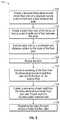
- FIG. 5is a flow chart of an exemplary method for generating a multi-3D perspective floor plan having real-life physical characteristics of a set of walls and a floor of an interior room in accordance with the present disclosure.
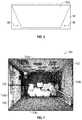
- FIG. 6illustrates a cross-sectional view of the multi-3D perspective floor plan in which a first wall is skewed in a first direction and a second wall is skewed in a second direction.
- FIG. 7illustrates an exemplary multi-3D perspective floor plan having real-life physical characteristics of a set of walls and a floor of a structure from an overhead view.
- FIG. 8Aillustrates an exemplary screen shot of a webpage showing a floor plan with one room having the multi-3D perspective floor plan shown in FIG. 7 .
- FIG. 8Billustrates an exemplary screen shot of a webpage showing the multi-3D perspective floor plan illustrated in FIG. 8A with two rooms.
- FIG. 9is a flow chart of another exemplary method for generating a multi-3D perspective floor plan representation using a textured three-dimensional model in accordance with the present disclosure.
- the terms “comprises,” “comprising,” “includes,” “including,” “has,” “having,” or any other variations thereof,are intended to cover a non-exclusive inclusion.
- a process, method, article, or apparatus that comprises a list of elementsis not necessarily limited to only those elements, but may also include other elements not expressly listed or inherent to such process, method, article, or apparatus.
- “or”refers to an inclusive and not to an exclusive “or”. For example, a condition A or B is satisfied by one of the following: A is true (or present) and B is false (or not present), A is false (or not present) and B is true (or present), and both A and B are true (or present).
- any reference to “one embodiment,” “an embodiment,” “some embodiments,” “one example,” “for example,” or “an example”means that a particular element, feature, structure or characteristic described in connection with the embodiment is included in at least one embodiment.
- the appearance of the phrase “in some embodiments” or “one example” in various places in the specificationis not necessarily all referring to the same embodiment, for example.
- Circuitrymay be analog and/or digital components, or one or more suitably programmed processors (e.g., microprocessors) and associated hardware and software, or hardwired logic. Also, “components” may perform one or more functions.
- the term “component,”may include hardware, such as a processor (e.g., microprocessor), an application specific integrated circuit (ASIC), field programmable gate array (FPGA), a combination of hardware and software, and/or the like.
- processoras used herein means a single processor or multiple processors working independently or together to collectively perform a task.
- Softwaremay include one or more computer readable instructions that when executed by one or more components cause the component to perform a specified function. It should be understood that the algorithms described herein may be stored on one or more non-transient memory. Exemplary non-transient memory may include random access memory, read only memory, flash memory, and/or the like. Such non-transient memory may be electrically based, optically based, and/or the like.
- the term useris not limited to a human being, and may comprise, a computer, a server, a website, a processor, a network interface, a human, a user terminal, a virtual computer, combinations thereof, and the like, for example.
- the three-dimensional floor plan of the structureincludes multi-three dimensional perspective floor plan (i.e., multi-3D perspective floor plan) of real-life physical characteristics of walls and/or a floor of the structure created from a floor plan and image data.
- the multi-3D perspective floor planprovides a three-dimensional fitted representation of real-life physical characteristics.
- the three dimensional fitted representation of real-life physical characteristicsmay include a set of walls of the interior room from an overhead perspective in a nadir direction from a viewpoint located between two walls, such as at a center of the room.
- Each roommay have a different perspective such that for a first room and a second room, a first three dimensional fitted representation of real-life physical characteristics of the walls of the first room may be from a first perspective having a first viewing direction extending from a first viewing location.
- a second three-dimensional fitted representation of real-life physical characteristics of the walls of the second roommay be from a second perspective with a second viewing direction extending from a second viewing location.
- the first viewing directionmay differ from the second viewing direction and/or the first viewing location may differ from the second viewing location.
- the apparatus 10includes a computer system for storing a database of three-dimensional floor plans of structures with corresponding geo-location data identifying the structures within the database.
- the geo-location datacan be an address (street, city and/or zip code) for each structure or one or more geospatial coordinates such as latitude/longitude.
- the computer systemhas computer executable logic that, when executed by a processor, causes the computer system to receive a geographic point from a user, search the database to find three-dimensional floor plans that correspond to the geographic point, and make the three-dimensional floor plans that contain the geographic point available to the user.
- a method of providing three-dimensional floor plans of structures to a user with the apparatus 10includes the following steps.
- the apparatus 10includes a database hosted by a computer system that stores data indicative of a plurality of floor plans of structures with corresponding geo-location data identifying the structures within the database.
- the floor planshave a room(s) comprising a set of walls and a floor between the walls in the set, and a set of image data depicting the walls and the floor of the room(s).
- Image datamay include, but is not limited to, captured images, computer-aided design (CAD) images, hand drawn images, and/or the like.
- CADcomputer-aided design
- a selection of a geographic pointis received by one or more I/O ports of a computer system hosting the database from a user and the database is then searched to find floor plans that contain the selected geographic point and the set of image data depicting the walls and the floor of the room(s).
- the floor plans and the set of image data depicting the walls and the floor of the floor plan that contain the selected geographic pointare then made available to the user via the one or more I/O port of the computer system.
- the apparatus 10may include an image capturing system 12 and one or more computer systems 14 .
- the apparatus 10may solely include one or more computer systems 14 , with the apparatus obtaining image data (e.g., one or more images) from a third party system.
- the image capturing system 12may obtain image data, in addition to, image data obtained from a third party system.
- the image capturing system 12may include one or more capturing devices 16 collecting one or more images of an interior of a structure.
- the image capturing system 12may include one or more capturing devices 16 collecting one or more images of a floor and/or walls of an interior room.
- the following disclosuremay relate to an interior room including the floor and walls of the interior rooms, however, it should be noted that one skilled in the art will appreciate that the system and methods as disclosed herein may be applied to any structure and is not limited to interior rooms.
- the capturing device 16may be capable of capturing images photographically and/or electronically.
- the capturing device 16may include known or determinable characteristics including, but not limited to, focal length, sensor size, aspect ratio, radial and other distortion terms, principal point offset, pixel pitch, alignment, and/or the like.
- the capturing device 16may provide one or more images from a viewing location within the room that extends in a viewing direction to provide a particular perspective of physical characteristics within the interior of the room.
- the capturing device 16 of the image capturing system 12may include, but is not limited to, one or more conventional cameras, digital cameras, digital sensors, charge-coupled devices, and/or the like.
- the capturing device 16may be one or more conventional cameras manually operated by a user positioned within an interior of the room to collect one or more images of the floor and/or walls of the room.
- the capturing device 16 of the image capturing system 12may include one or more 360-degree camera systems collecting one or more images of the floor and/or walls of the interior room.
- the capturing device 16may include a 360-degree camera system such as the IPIX system, manufactured by IPIX Corporation.
- the 360-degree camera systemmay include one or more ultra-wide fish-eye lenses capable of capturing the room in two or more images. Such images may be stitch together to form one or more contiguous views of at least a portion or the entire room.
- the imagerymay then be displayed in a viewer (e.g., IPIX viewer).
- Each wall and/or the floor of the interior roommay be extracted into separate images for processing as described in further detail herein.
- the capturing device 16 of the image capturing system 12may include one or more scanners.
- the capturing device 16may use a LiDAR scanner, such as the Trimble TIMMS unit, distributed by Applanix based in Richmond Hill, Ontario.
- the room scannermay be used to collect three-dimensional data points of the floor and/or walls and form a three-dimensional model of the interior room.
- the three-dimensional data pointsmay be loaded into the three-dimensional model viewer.
- FIG. 2illustrates an exemplary three-dimensional model floor plan 20 created using a LiDAR scanner.
- One or more walls and/or the floormay be projected and extracted into separate images for processing as described in further detail herein.
- the image capturing system 12may further include a RGB sensor.
- the RGB sensormay be used in addition to the room scanner to enhance color of acquired images.
- the RBG sensormay provide color representation to the three-dimensional data points collected by a LiDAR scanner.
- the capturing device 16may acquire image data including, but not limited to, one or more images, and issue one or more image data signals (IDS) 22 corresponding to the particular image data acquired (e.g., one or more particular images and/or photographs).
- the image datamay be stored in the computer system 14 .
- the image capturing system 12may further include a positioning and orientation device, such as a GPS and/or, an inertial measurement unit, which collects data indicative of a three-dimensional location of the sensor of the capturing device 16 , an orientation of the sensor, as well as compass direction of the sensor each time the images and/or photographs are acquired.
- the computer system 14may be a system or systems that are able to embody and/or execute the logic of the processes described herein.
- Logic embodied in the form of software instructions and/or firmwaremay be executed on any appropriate hardware.
- logic embodied in the form of software instructions or firmwaremay be executed on a dedicated system or systems, or on a personal computer system, or on a distributed processing computer system, and/or the like.
- logicmay be implemented in a stand-alone environment operating on a single computer system and/or logic may be implemented in a networked environment, such as a distributed system using multiple computers and/or processors.
- the computer system 14may include one or more processors 24 communicating with one or more input devices 26 , output devices 28 , and/or I/O ports 30 enabling the input and/or output of data to and from the computer system 14 to the image capturing system 12 and/or a user.
- the term “user”is not limited to a human, and may comprise a human using a computer, a host system, a smart phone, a tablet, a computerized pen or writing device, combinations thereof, and/or the like, for example, but not by way of limitation.
- the one or more input devices 26may be capable of receiving information input from a user and/or one or more processors, and transmitting such information to the processor 24 .
- the one or more input devices 26may include, but are not limited to, implementation as a keyboard, touchscreen, mouse, trackball, microphone, fingerprint reader, infrared port, slide-out keyboard, flip-out keyboard, cell phone, PDA, video game controller, remote control, fax machine, network interface, speech recognition, gesture recognition, eye tracking, brain-computer interface, combinations thereof, and/or the like.
- the one or more output devices 28may be capable of outputting information in a form perceivable by a user and/or processor(s).
- the one or more output devices 28may include, but are not limited to, implementations as a computer monitor, a screen, a touchscreen, a speaker, a website, a television set, a smart phone, a PDA, a cell phone, a fax machine, a printer, a laptop computer, an optical head-mounted display (OHMD), combinations thereof, and/or the like.
- the one or more input devices 26 and the one or more output devices 28may be implemented as a single device, such as, for example, a touchscreen or a tablet.
- output of information in a form perceivable by a user and/or processormay comprise displaying or providing for display a webpage (e.g., webpage having one or more images and software to permit formation of a floor plan), electronic communications, e-mail, and/or electronic correspondence to one or more user terminals interfacing with a computer and/or computer network(s) and/or allowing the one or more users to participate, such as by interacting with one or more mechanisms on a webpage, electronic communications, e-mail, and/or electronic correspondence by sending and/or receiving signals (e.g., digital, optical, and/or the like) via a computer network interface (e.g., Ethernet port, TCP/IP port, optical port, cable modem, combinations thereof, and/or the like).
- a usermay be provided with a web page in a web browser, or in a software application, for example.
- the image data signals 22may be provided to the computer system 14 .
- the image data signals 22may be received by the computer system 14 via the I/O port 30 .
- the I/O port 30may comprise one or more physical and/or virtual ports.
- the computer system 14may issue an image capturing signal 32 to the image capturing system 12 to thereby cause the capturing device 16 to acquire and/or capture an image at a predetermined location and/or at a predetermined interval.
- the image capturing signal 32may be a point collection signal given to a room scanner (e.g., LiDAR scanner) to thereby cause the room scanner to collect points at a predetermined location and/or at a predetermined interval.
- the computer system 14may include one or more processors 24 working together, or independently to execute processor executable code, and one or more memories 34 capable of storing processor executable code.
- each element of the computer system 14may be partially or completely network-based or cloud-based, and may or may not be located in a single physical location.
- the one or more processors 24may be implemented as a single or plurality of processors working together, or independently, to execute the logic as described herein. Exemplary embodiments of the one or more processors 24 may include, but are not limited to, a digital signal processor (DSP), a central processing unit (CPU), a field programmable gate array (FPGA), a microprocessor, a multi-core processor, and/or combination thereof, for example.
- DSPdigital signal processor
- CPUcentral processing unit
- FPGAfield programmable gate array
- microprocessore.g., a microprocessor
- multi-core processore.g., multi-core processor, and/or combination thereof, for example.
- the one or more processors 24may be capable of communicating via a network (e.g., analog, digital, optical, and/or the like) via one or more ports (e.g., physical or virtual ports) using a network protocol.
- a networke.g., analog, digital, optical, and/or the like
- the processors 24may be located remotely from one another, in the same location, or comprising a unitary multi-core processor.
- the one or more processors 24may be capable of reading and/or executing processor executable code and/or capable of creating, manipulating, retrieving, altering, and/or storing data structures into one or more memories 34 .
- the one or more memories 34may be capable of storing processor executable code. Additionally, the one or more memories 34 may be implemented as a conventional non-transient memory, such as, for example, random access memory (RAM), a CD-ROM, a hard drive, a solid state drive, a flash drive, a memory card, a DVD-ROM, a floppy disk, an optical drive, combinations thereof, and/or the like, for example.
- RAMrandom access memory
- the one or more memories 34may be located in the same physical location as the computer system 14 .
- one or more memories 34may be located in a different physical location as the computer system 14 , with the computer system 14 communicating with one or more memories 34 via a network, for example.
- one or more of the memories 34may be implemented as a “cloud memory” (i.e., one or more memories 34 may be partially or completely based on or accessed using a network, for example).
- the one or more memories 34may store processor executable code and/or information comprising one or more databases 36 and program logic 38 .
- the database 36may be hosted by the computer system 14 and stores data indicative of a plurality of floor plans of structures with corresponding geo-location data identifying the structures within the database.
- the floor planshave one or more rooms comprising a set of walls and a floor between the walls in the set, and a set of image data depicting the walls and the floor of the room(s).
- the processor executable codemay be stored as a data structure, such as a database and/or data table, for example.
- the geo-location datacan be an address (street, city and/or zip code) for each structure or one or more geospatial coordinates such as latitude/longitude.
- the computer system 14 and/or the image capturing system 12may be in communication with one or more additional processors 40 .
- the computer system 14may communicate with the one or more additional processors 40 via a network 42 .
- the terms “network-based”, “cloud-based”, and any variations thereofmay include the provision of configurable computational resources on demand via interfacing with a computer and/or computer network, with software and/or data at least partially located on the computer and/or computer network, by pooling processing power of two or more networked processors.
- the network 42may be the Internet and/or other network.
- a primary user interface of the image capturing software and/or image manipulation softwaremay be delivered through a series of web pages. It should be noted that the primary user interface of the image capturing software and/or image manipulation software may be replaced by another type of interface, such as, for example, a Windows-based application.
- the network 42may be almost any type of network.
- the network 42may interface by optical and/or electronic interfaces, and/or may use a plurality of network topographies and/or protocols including, but not limited to, Ethernet, TCP/IP, circuit switched paths, and/or combinations thereof.
- the network 42may be implemented as the World Wide Web (or Internet), a local area network (LAN), a wide area network (WAN), a metropolitan network, a wireless network, a cellular network, a Global System for Mobile Communications (GSM) network, a code division multiple access (CDMA) network, a 3G network, a 4G network, a satellite network, a radio network, an optical network, a cable network, a public switched telephone network, an Ethernet network, combinations thereof, and/or the like.
- GSMGlobal System for Mobile Communications
- CDMAcode division multiple access
- 3G networkThird Generation
- 4Gfourth generation
- satellite networka radio network
- an optical networka cable network
- public switched telephone networkan Ethernet network, combinations thereof, and/or the like.
- the network 42may use a variety of network protocols to permit bi-directional interface and/or communication of data and/or information. It is conceivable that in the near future, embodiments of the present disclosure may use more advanced networking topologies.
- the computer system 14 and image capturing system 12may be capable of interfacing and/or communicating with the one or more computer systems including processors 40 via the network 42 . Additionally, the one or more processors 40 may be capable of communicating with each other via the network 42 . For example, the computer system 14 may be capable of interfacing by exchanging signals (e.g., analog, digital, optical, and/or the like) via one or more ports (e.g., physical ports or virtual ports) using a network protocol, for example.
- signalse.g., analog, digital, optical, and/or the like
- portse.g., physical ports or virtual ports
- the processors 40may include, but are not limited to implementation as a variety of different types of computer systems, such as a server system having multiple servers in a configuration suitable to provide a commercial computer based business system (such as a commercial web-site), a personal computer, a smart phone, a network-capable television set, a television set-top box, a tablet, an e-book reader, a laptop computer, a desktop computer, a network-capable handheld device, a video game console, a server, a digital video recorder, a DVD player, a Blu-Ray player, a wearable computer, a ubiquitous computer, combinations thereof, and/or the like.
- a server system having multiple servers in a configuration suitable to provide a commercial computer based business systemsuch as a commercial web-site
- a personal computersuch as a smart phone, a network-capable television set, a television set-top box, a tablet, an e-book reader, a laptop computer, a desktop computer, a network-capable handheld
- the computer systems comprising the processors 40may include one or more input devices 44 , one or more output devices 46 , processor executable code, and/or a web browser capable of accessing a website and/or communicating information and/or data over a network, such as network 42 .
- the computer systems comprising the one or more processors 40may include one or more non-transient memory comprising processor executable code and/or software applications, for example.
- the computer system 14may be modified to communicate with any of these processors 40 and/or future developed devices capable of communicating with the computer system 14 via the network 42 .
- the one or more input devices 44may be capable of receiving information input from a user, processors, and/or environment, and transmit such information to the processor 40 and/or the network 42 .
- the one or more input devices 44may include, but are not limited to, implementation as a keyboard, touchscreen, mouse, trackball, microphone, fingerprint reader, infrared port, slide-out keyboard, flip-out keyboard, cell phone, PDA, video game controller, remote control, fax machine, network interface, speech recognition, gesture recognition, eye tracking, brain-computer interface, combinations thereof, and/or the like.
- the one or more output devices 46may be capable of outputting information in a form perceivable by a user and/or processor(s).
- the one or more output devices 46may include, but are not limited to, implementations as a computer monitor, a screen, a touchscreen, a speaker, a website, a television set, a smart phone, a PDA, a cell phone, a fax machine, a printer, a laptop computer, an optical head-mounted display (OHMD), combinations thereof, and/or the like.
- the one or more input devices 44 and the one or more output devices 46may be implemented as a single device, such as, for example, a touchscreen or a tablet.
- the computer system 14may execute the program logic 38 controlling the reading, manipulation, and/or storing of the image data signal(s) 22 .
- the program logic 38may cause the processor to generate one or more output signals indicative of a multi-3D perspective floor plan created from one or more floor plans and one or more sets of image data.
- the location, orientation and/or compass direction of the one or more capturing devices 16 relative to the floor and/or walls at the precise moment each image is capturedmay be recorded within the one or more memories 34 .
- Location datamay be associated with the corresponding captured image. Such location data may be included within the image data signals 22 .
- the one or more processors 24may create and/or store in the one or more memories 34 , one or more output image and data files.
- the processor 24may convert image data signals 22 into computer-readable output image, data files, and/or LIDAR 3D point cloud files.
- the output image, data files, and/or LIDAR 3D point cloud filesmay include a plurality of captured image data corresponding to captured images, positional data, and/or LIDAR 3D point clouds corresponding thereto.
- Output image, data files, and/or LIDAR 3D point cloud filesmay then be further provided, displayed and/or used for generating a multi-3D perspective floor plan of an interior room.
- the multi-3D perspective floor plan of the interior roomincludes a three-dimensional fitted representation of real-life physical characteristics of an interior of the room.
- FIG. 4Aillustrates an exemplary floor plan 50 a as is currently known within the art.
- the floor plan 50 adepicts an overhead view of an interior room 52 having walls 54 a - d and a floor 56 .
- a symbol 58commonly used within the art to represent a window.
- a symbol 60commonly used within the art to represent a door.
- symbols, such as symbols 58 and 60do not provide real-life physical characteristics of the interior room 52 but merely show a representation of location of the window and door respectively.
- FIG. 4Billustrates a multi-3D perspective floor plan 50 b of the interior room 52 of FIG. 4B having a multi-3D perspective real-life characteristics of the room including the walls 54 a - d and the floor 56 .
- the multi-3D perspective floor plan 50 bagain depicts an overhead view of the interior room 52 ; however, each wall 54 a - d is extracted, with the floor 56 resized and positioned at a distance d from an outline 62 of the interior room 52 .
- Providing the distance d between the floor 56 and the outline 62 of the interior room 52allows the perspective to include views of the walls 54 a - d such that real life physical characteristics within and on the walls may be illustrated.
- a window 64 positioned on the wall 54 bis illustrated in the multi-3D perspective floor plan 50 b of FIG. 4B as compared to representation by the symbol 58 in floor plan 50 a of FIG. 4A .
- the door 66 positioned on the wall 54 dis illustrated in the multi-3D perspective floor plan 50 b of FIG. 4B as compared to representation by the symbol 60 in the floor plan 50 a of FIG. 4A .
- Real-life physical characteristicsmay be further added to the walls 54 a - d and/or floor 56 using images and/or data as described in further detail herein.
- Images and/or datamay further provide users with a quick reference and visual representation of the interior room.
- Emergency respondersare often called to a scene of an incident in progress and must respond quickly within a structure.
- the emergency respondermay have limited knowledge regarding elements (e.g., doors, windows, location of interior rooms) within the structure.
- the multi-3D perspective floor plan 50 bmay provide an overhead representation that includes real-life physical characteristics of the walls of the interior room.
- FIG. 4Cillustrates a perspective floor plan 50 c of a single view perspective currently used within the art.
- the perspective floor plan 50 cdepicts an overhead view; however, physical characteristics on one or more interior walls 54 may not be visible as the perspective floor plan 50 c is presented from a single perspective in such two-dimensional representations of three-dimensional floor plans.
- physical characteristics on two walls 54 e and 54 gmay be visible; however, on walls 54 f and 54 h, physical characteristics are not visible in the room 52 a.
- FIG. 5illustrates a flow chart 70 of an exemplary method for generating the multi-3D perspective floor plan 50 b created from one or more floor plans and one or more sets of image data using the computer system 14 . It should be apparent to one skilled in the art that additional interior rooms 52 and/or walls 54 may be included within the multi-3D perspective floor plan 50 b.
- the multi-3D perspective floor plan 50 bmay allow a first responder to quickly visualize a three-dimensional representation of the interior room 52 while viewing an entire floor plan at once.
- elements of interest within the structuree.g., real-life physical characteristics
- elements of interest within the structuremay be quickly identified and distinguished relative to other objects within the structure.
- interior roomssuch as auditoriums, swimming pools, boiler rooms, may be quickly identified and distinguished relative to regular classrooms by visually identifying specifics characteristics (e.g., desks) of the rooms.
- the multi-3D perspective floor plan 50 bmay provide a first responder with an instinctive feel for objects and/or characteristics within the interior room 52 .
- the first respondermay be able to determine the number and magnitude of windows, whether there is sufficient cover within the room, and/or other information not readily obtained via the basic floor plan 50 a illustrated in FIG. 4A or the perspective floor plan 50 c illustrated in FIG. 4C .
- a basic floor plansimilar to the floor plan 50 a of FIG. 4A may be created and/or obtained.
- the floor plan 50 amay include an overhead view of the interior room 52 having one or more walls 54 and the floor 56 between the walls 54 .
- the floor plan 50 amay include multiple rooms. In embodiments having multiple rooms, rooms may be contiguous, adjoining, and/or separate rooms.
- the background of the floor plan 50 amay be filled with a distinct color.
- the background of the floor plan 50 amay be filled with pure red (RGB 255, 0, 0). Filling the background of the floor plan 50 a may aid in providing three-dimensional conceptual features as discussed in further detail herein.
- each wall 54may be extracted within the floor plan 50 a to provide a fitted representation of each wall.
- each view of each wall 54may be formed within the multi-3D perspective floor plan 50 b by extracting the wall 54 a distance d from the outline 62 of the interior room 52 .
- the distance dis determined relative to the scale of the floor plan 50 a.
- the distance dmay be a number of pixels or a percentage of an area of the floor 56 and determined such that elements of each wall 54 may be visually represented without also obscuring the floor 56 .
- the distance dis used for each wall 54 a - d, it should be noted, that each wall may be extracted such that distance d may vary from one wall versus another wall.
- each wall 54 a - dmay be extracted such that the distance d of each wall may be substantially similar.
- the floor 56may be resized to accommodate the extracted walls 54 .
- image datae.g., one or more images, CAD images, and/or data renderings
- image data of the floor 56may be obtained from the image capturing system 12 via the computer system 14 .
- image data of the floor 56may be obtained from a third party system.
- the image datamay be obtained via the one or more additional processors 40 .
- a usermay obtain images of the interior room 52 and provide the images to the computer system 14 via the network 42 .
- image datamay be obtained via a third party system and accessed via the network 42 .
- one or more images and/or data renderingsmay be obtained via an image database from a third party system.
- the computer system 14may access the third party system via the network 42 storing and/or manipulating the images with memory 34 .
- image data of the floor 56may be fitted to the resized floor 56 within the multi-3D perspective floor plan 50 b.
- one or more images of the floor 56may be scaled, rotated, and/or otherwise distorted to fit the sizing of the floor 56 within the multi-3D perspective floor plan 50 b.
- image data for each wall 54may be obtained. Similar to image data of the floor 56 , in some embodiments, image data of each wall 54 may be obtained from the image capturing system 12 via the computer system 14 , from a third party system, by users via the one or more additional processors 40 , via a third party system accessed via the network 42 , and/or the like.
- the image data (e.g., one or more images) for each wall 54may be fitted within the space provided between the resized floor 56 and the outline 62 of the interior room 52 .
- one or more images of each wall 54may be scaled, rotated, and/or otherwise distorted to fit the spacing between the resized floor 56 and the outline 62 of the interior room 52 to provide a 3D fitted representation of real-life physical characteristics of the walls 54 from a particular perspective (e.g., overhead perspective) having a particular viewing direction extending from a viewing location (e.g. nadir).
- fitting image data to each wall 54 to fit the spacing between the resized floor 56 and the outline 62 of the interior room 52may further include skewing the image.
- FIG. 6illustrates an exemplary image 94 associated with the wall 54 b of FIG. 4B .
- the imageis skewed in a first direction 96 and a second direction 98 , generally towards each other. Skewing of the image 94 may aid in creating the three-dimensional perspective of real-life physical characteristics of the wall 54 b.
- skewing of the imagemay be manually or automatically generated by the computer system 14 .
- one or more three dimensional conceptual featuresmay be optionally added to the multi-3D perspective floor plan 50 b.
- the background of the interior room 52may be filled with the distinct color (e.g., RGB (255, 0, 0).
- Positioning the floor 56 and/or walls 54 such that the distinct color is shownmay extrude depth and present cues to the human brain to visualize a three-dimensional structure.
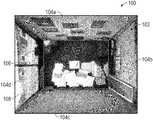
- FIG. 7illustrates an exemplary fitted image 100 (or floor plan 100 ) of a room 102 having multiple walls 104 a - 104 d and a floor 106 .
- the multi-3D perspective fitted image 100 of the room 102provides real-life physical characteristics via three-dimensional fitted representations of the real-life characteristics of the imagery and/or data of the walls 104 a - 104 d and the floor 106 from a particular perspective (e.g., overhead perspective).
- Items on the walls 104 a - 104 d and within the room 102provide real-life characteristics not seen within typical floor plan views.
- the magnitude and location of a window 108may be seen via the fitted view provided on the wall 104 d.
- each wall 104 a - 104 d within the room 102provides such real-life characteristics as the perspective is not limited to a single direction.
- each image and/or a composite image of the interior room 52may be overlaid on the floor plan rendering a multi-3D perspective floor plan representation.
- the multi-3D perspective fitted image 100may be provided as a layer that is overlaid on a typical floor plan.
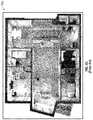
- FIG. 8Aillustrates an exemplary screen shot 110 of a webpage having a floor plan 112 .
- the floor plan 112includes multiple rooms and hall ways, including the room 102 rendered in FIG. 7 .
- the multi-3D perspective floor plan 100 of the room 102may be added into the floor plan 112 , as is shown in FIG. 8A , such that a user has an option to select and/or view either the typical floor plan view or the multi-3D perspective floor plan representation for each room.
- FIG. 8Billustrates an exemplary screen shot 110 of a webpage having the floor plan 112 with the room 102 and an additional room 102 b.
- the room 102includes a 3D fitted representation of real-life physical characteristics of the walls 104 a - d and the floor 106 from an overhead perspective having a nadir viewing direction extending from a first location.
- the room 102 bincludes a 3D fitted representation of real-life physical characteristics of the walls 104 e - h and the floor 106 a from an overhead perspective having a nadir viewing direction extending from a second location.
- the floor plan 112is provided with two rooms (i.e., the room 102 and the room 102 b ) displayed with the 3D fitted representation, it should be understood that more rooms or even all of the rooms in the floor plan 112 can be shown with the 3D fitted representation.
- the floor plan 112 and the floor plan 100 with imagery showing real-life physical characteristicsmay each be individual layers such that each one may be visually provided by user selection.
- GISGeographical Information System
- Both the floor plan 112 and the floor plan 100 with imagerymay be used as layers within the GIS software such that the user may select the floor plan 112 with imagery to provide additional detailed information as needed.
- the softwaremay further include instructions such that when a user selects a room within the floor plan 112 or the floor plan 100 , a menu may be provided adding options for viewing such room via the floor plan 112 , the floor plan 100 , or a three-dimensional model of the room.
- a first responder using one or more processors 40may select the room 102 within the floor plan 112 .
- a menumay be provided to the first responder to select whether to view the room 102 using the floor plan 100 , giving the first responder a visual representation of real-life physical characteristics of the room 102 .
- the menumay provide an option to enter a three-dimensional model rendering program to view the room 102 .
- some GIS systemsare fully three-dimensionally aware such that the three-dimensional model of the room 102 may be a third layer capable of being selected by a user.
- the first respondermay be able to access the floor plan 112 , the floor plan 100 , and/or a three-dimensional model of the room 102 without having to locate additional software and/or third party programs on the scene.
- the floor plan 100 having imagery overlaid thereinmay be provided within a physical report.
- the floor plan 100 having imagery overlaid thereinmay be provided in a hard copy.
- Hard copiesmay allow for external markings (e.g., markers, grease pencils) during an emergency situation. Additionally, hard copies may reduce reliance on technology mishaps during the emergency situation (e.g., battery life, screen viewing in sunlight, and/or the like).
- the hard copy of the floor plan 100 having imagery overlaid thereinmay be provided within a lock box at the physical location of the structure.
- the lock boxmay house the hard copy such that first responders may be able to access the floor plan 100 on scene during an emergency event.
- the floor plan 100 having imagery overlaid thereinmay be created automatically using a textured three-dimensional model floor plan, such as the floor plan 20 depicted in FIG. 2 .
- FIG. 9illustrates a flow chart 114 of an exemplary method for generating a multi-3D perspective representation of real-life physical characteristics of the set of walls 54 and floor 56 of the interior room 52 from an overhead perspective using images and/or data acquired from the image capturing system 12 and using a textured three-dimensional model floor plan 20 .
- a textured three-dimensional model floor plansimilar to the floor plan 20 illustrated in FIG. 2 , may be created and/or obtained.
- the three-dimensional model floor planmay include one or more rooms 130 comprising a set of walls 132 a - d and a floor 134 between the walls.
- a RGB sensormay be provided during creation of the floor plan 20 .
- the RBG sensormay provide color representations of elements within the data points obtained.
- the computer system 14may generate the floor plan 20 using data obtained from the image capturing system 12 (e.g., LiDAR scanner and/or RGB sensor). Alternatively, the computer system 14 may obtain the floor plan 20 from a third party system via the network 42 .
- a basic floor plansimilar to the floor plan 50 a of FIG. 4A may be created and/or obtained.
- the floor plan 50 amay include an overhead view of the one or more rooms 130 .
- Each room 130may include one or more walls 54 and the floor 56 between the walls 54 .
- the floor plan 50 amay include multiple rooms 130 .
- the rooms 130may be contiguous, adjoining, and/or separate rooms.
- each wall 54 of the floor plan 50 amay be extruded by a pre-defined distance d.
- the distance dmay be determined relative to the scale of the floor plan 50 a. The distance may also be determined such that elements on and/or positioned adjacent to each wall 54 may be visually represented without obscuring the floor 56 .
- the distance dis used for each wall 54 a - d, it should be noted, that each wall may be extracted such that distance d may vary from one wall versus another wall. Alternatively, each wall may be extracted such that the distance d may be substantially similar.
- the floor 56may be resized to accommodate the extracted walls 54 generating the multi-3D perspective floor plan 50 b illustrated in FIG. 4B .
- a rendering of the floor 134 from the textured three-dimensional floor plan 20may be extracted.
- the floor 134may be fit to the resized floor 56 within the multi-3D perspective floor plan 50 b.
- the extracted rendering of the floor 134 from the textured three-dimensional floor plan 20may be scaled, rotated, and/or otherwise fit to the sizing of the floor 56 within the multi-3D perspective floor plan 50 b.
- each wall 132 a - d from the textured three-dimensional floor plan 20may be extracted.
- each wall 132 a - dmay be fit within the space provided between resized floor 56 and the outline 62 of the interior room 52 within the respective positions within the floor plan 50 a.
- each wall 132 a - dmay be scaled, rotated, and/or otherwise fit to the spacing between the resized floor 56 and the outline 62 of the interior room 52 .
- fitting each extract wall 132 a - d to the spacing between the resized floor 56 and the outline 62 of the interior room 52may further include skewing the extracted wall 132 similar to the wall illustrated in FIG. 6 .
- a step 128the steps of the method may be repeated for each structure within the floor plan 50 a such that a multi-3D perspective floor plan of the structure includes a fitted representation of real-life physical characteristics of walls 132 a - d and floor 134 of the room 130 .
- the multi-3D perspective floor planmay be used in other applications as well.
- Building management softwaremay include the multi-3D perspective floor plan such that building managers are able to use the visual representations provided by the multi-3D perspective floor plan for their planning and/or management.
- the multi-3D perspective floor planmay be used and/or distributed as evacuation plans, such that people within a structure may be able to easily locate emergency exits, and/or the like.
- the multi-3D perspective floor planmay be used to identify and visualize proposed changes to a structure.
- multi-3D perspective floor plansmay be created of a proposed space and/or structure, and the space and/or structure may be analyzed in relation to a current structure.
Landscapes
- Engineering & Computer Science (AREA)
- Physics & Mathematics (AREA)
- General Physics & Mathematics (AREA)
- Geometry (AREA)
- Theoretical Computer Science (AREA)
- Computer Hardware Design (AREA)
- General Engineering & Computer Science (AREA)
- Computer Networks & Wireless Communication (AREA)
- Signal Processing (AREA)
- Civil Engineering (AREA)
- Mathematical Optimization (AREA)
- Pure & Applied Mathematics (AREA)
- Evolutionary Computation (AREA)
- Structural Engineering (AREA)
- Computational Mathematics (AREA)
- Architecture (AREA)
- Mathematical Analysis (AREA)
- Computer Graphics (AREA)
- Software Systems (AREA)
- Radar, Positioning & Navigation (AREA)
- Remote Sensing (AREA)
- Processing Or Creating Images (AREA)
Abstract
Description
Claims (22)
Priority Applications (1)
| Application Number | Priority Date | Filing Date | Title |
|---|---|---|---|
| US15/959,877US11100259B2 (en) | 2014-02-08 | 2018-04-23 | Method and system for displaying room interiors on a floor plan |
Applications Claiming Priority (3)
| Application Number | Priority Date | Filing Date | Title |
|---|---|---|---|
| US201461937488P | 2014-02-08 | 2014-02-08 | |
| US14/617,575US9953112B2 (en) | 2014-02-08 | 2015-02-09 | Method and system for displaying room interiors on a floor plan |
| US15/959,877US11100259B2 (en) | 2014-02-08 | 2018-04-23 | Method and system for displaying room interiors on a floor plan |
Related Parent Applications (1)
| Application Number | Title | Priority Date | Filing Date |
|---|---|---|---|
| US14/617,575ContinuationUS9953112B2 (en) | 2014-02-08 | 2015-02-09 | Method and system for displaying room interiors on a floor plan |
Publications (2)
| Publication Number | Publication Date |
|---|---|
| US20180239842A1 US20180239842A1 (en) | 2018-08-23 |
| US11100259B2true US11100259B2 (en) | 2021-08-24 |
Family
ID=53775123
Family Applications (2)
| Application Number | Title | Priority Date | Filing Date |
|---|---|---|---|
| US14/617,575Active2036-03-16US9953112B2 (en) | 2014-02-08 | 2015-02-09 | Method and system for displaying room interiors on a floor plan |
| US15/959,877Active2036-06-13US11100259B2 (en) | 2014-02-08 | 2018-04-23 | Method and system for displaying room interiors on a floor plan |
Family Applications Before (1)
| Application Number | Title | Priority Date | Filing Date |
|---|---|---|---|
| US14/617,575Active2036-03-16US9953112B2 (en) | 2014-02-08 | 2015-02-09 | Method and system for displaying room interiors on a floor plan |
Country Status (3)
| Country | Link |
|---|---|
| US (2) | US9953112B2 (en) |
| CA (1) | CA2938973A1 (en) |
| WO (1) | WO2015120188A1 (en) |
Families Citing this family (38)
| Publication number | Priority date | Publication date | Assignee | Title |
|---|---|---|---|---|
| US10127667B2 (en)* | 2014-08-01 | 2018-11-13 | Locuslabs, Inc. | Image-based object location system and process |
| DE102014013678B3 (en)* | 2014-09-10 | 2015-12-03 | Faro Technologies, Inc. | Method for optically sensing and measuring an environment with a handheld scanner and gesture control |
| US9602811B2 (en) | 2014-09-10 | 2017-03-21 | Faro Technologies, Inc. | Method for optically measuring three-dimensional coordinates and controlling a three-dimensional measuring device |
| US10062205B2 (en)* | 2014-10-16 | 2018-08-28 | Trick 3D | Systems and methods for generating an interactive floor plan |
| WO2016106365A1 (en)* | 2014-12-22 | 2016-06-30 | Robert Bosch Gmbh | System and methods for generating procedural window lighting effects |
| DK3275204T3 (en)* | 2015-03-24 | 2020-09-21 | Carrier Corp | SYSTEM AND METHOD FOR COLLECTING AND ANALYZING MULTI-DIMENSIONAL BUILDING INFORMATION |
| US10628802B2 (en) | 2016-05-19 | 2020-04-21 | Lockheed Martin Corporation | Systems and methods for assessing damage to infrastructure assets |
| JP6220486B1 (en)* | 2016-05-27 | 2017-10-25 | 楽天株式会社 | 3D model generation system, 3D model generation method, and program |
| WO2017203710A1 (en) | 2016-05-27 | 2017-11-30 | 楽天株式会社 | Three-dimensional model generation system, three-dimensional model generation method, and program |
| US10032267B2 (en) | 2016-06-09 | 2018-07-24 | Lockheed Martin Corporation | Automating the assessment of damage to infrastructure assets |
| US11526744B2 (en)* | 2016-07-09 | 2022-12-13 | Doxel, Inc. | Monitoring construction of a structure |
| US10643089B2 (en) | 2016-10-13 | 2020-05-05 | Ricoh Company, Ltd. | Information processing system to obtain and manage images of a property |
| WO2018080552A1 (en) | 2016-10-24 | 2018-05-03 | Carrington Charles C | System for generating virtual building plan data based upon stored and scanned building data and related methods |
| US9823658B1 (en) | 2016-11-04 | 2017-11-21 | Loveland Innovations, LLC | Systems and methods for adaptive property analysis via autonomous vehicles |
| US10521664B2 (en) | 2016-11-04 | 2019-12-31 | Loveland Innovations, LLC | Systems and methods for autonomous perpendicular imaging of test squares |
| US10776887B2 (en)* | 2017-02-07 | 2020-09-15 | Enseo, Inc. | System and method for making reservations in a hospitality establishment |
| US10984182B2 (en) | 2017-05-12 | 2021-04-20 | Loveland Innovations, LLC | Systems and methods for context-rich annotation and report generation for UAV microscan data |
| US10364027B2 (en) | 2017-10-24 | 2019-07-30 | Loveland Innovations, LLC | Crisscross boustrophedonic flight patterns for UAV scanning and imaging |
| US11501224B2 (en)* | 2018-01-24 | 2022-11-15 | Andersen Corporation | Project management system with client interaction |
| WO2019205069A1 (en)* | 2018-04-27 | 2019-10-31 | Beijing Didi Infinity Technology And Development Co., Ltd. | Systems and methods for updating 3d model of building |
| CN108961395B (en)* | 2018-07-03 | 2019-07-30 | 上海亦我信息技术有限公司 | A method of three dimensional spatial scene is rebuild based on taking pictures |
| US10366287B1 (en) | 2018-08-24 | 2019-07-30 | Loveland Innovations, LLC | Image analysis and estimation of rooftop solar exposure |
| US11205072B2 (en) | 2018-08-24 | 2021-12-21 | Loveland Innovations, LLC | Solar ray mapping via divergent beam modeling |
| US11210514B2 (en) | 2018-08-24 | 2021-12-28 | Loveland Innovations, LLC | Image analysis and estimation of rooftop solar exposure via solar ray mapping |
| KR102658568B1 (en)* | 2018-12-05 | 2024-04-19 | 소니그룹주식회사 | Room Shaders for Animated Films |
| US11243656B2 (en)* | 2019-08-28 | 2022-02-08 | Zillow, Inc. | Automated tools for generating mapping information for buildings |
| US12014120B2 (en) | 2019-08-28 | 2024-06-18 | MFTB Holdco, Inc. | Automated tools for generating mapping information for buildings |
| US11227083B2 (en) | 2019-09-06 | 2022-01-18 | BeamUp, Ltd. | Structural design systems and methods for semantic enrichment of floor plans for rule-based application of functional requirement to spaces |
| US11756129B1 (en) | 2020-02-28 | 2023-09-12 | State Farm Mutual Automobile Insurance Company | Systems and methods for light detection and ranging (LIDAR) based generation of an inventory list of personal belongings |
| EP4136568A1 (en)* | 2020-04-13 | 2023-02-22 | Charles C. Carrington | Georeferencing a generated floorplan and generating structural models |
| US12248907B1 (en) | 2020-04-27 | 2025-03-11 | State Farm Mutual Automobile Insurance Company | Systems and methods for commercial inventory mapping |
| CN112945085A (en)* | 2020-08-03 | 2021-06-11 | 深圳市明源云链互联网科技有限公司 | Measurement method and electronic device |
| US11532116B2 (en) | 2020-10-30 | 2022-12-20 | Loveland Innovations, Inc. | Graphical user interface for controlling a solar ray mapping |
| CN112200916B (en)* | 2020-12-08 | 2021-03-19 | 深圳市房多多网络科技有限公司 | Method and device for generating house type graph, computing equipment and storage medium |
| US11481704B2 (en) | 2021-03-09 | 2022-10-25 | Togal.Ai Inc. | Methods and apparatus for artificial intelligence conversion of change orders into an actionable interface |
| US12197829B2 (en) | 2021-03-09 | 2025-01-14 | CodeComply.Ai, Corp. | Artificial intelligence determination of building smoke and indoor air quality management |
| US11475174B2 (en)* | 2021-03-09 | 2022-10-18 | Togal.Ai Inc. | Methods and apparatus for artificial intelligence conversion of a two-dimensional reference into an actionable interface |
| US11651533B2 (en)* | 2021-05-07 | 2023-05-16 | Tencent America LLC | Method and apparatus for generating a floor plan |
Citations (178)
| Publication number | Priority date | Publication date | Assignee | Title |
|---|---|---|---|---|
| US2273876A (en) | 1940-02-12 | 1942-02-24 | Frederick W Lutz | Apparatus for indicating tilt of cameras |
| US3153784A (en) | 1959-12-24 | 1964-10-20 | Us Industries Inc | Photo radar ground contour mapping system |
| US3594556A (en) | 1969-01-08 | 1971-07-20 | Us Navy | Optical sight with electronic image stabilization |
| US3614410A (en) | 1969-06-12 | 1971-10-19 | Knight V Bailey | Image rectifier |
| US3621326A (en) | 1968-09-30 | 1971-11-16 | Itek Corp | Transformation system |
| US3661061A (en) | 1969-05-05 | 1972-05-09 | Atomic Energy Commission | Picture position finder |
| US3716669A (en) | 1971-05-14 | 1973-02-13 | Japan Eng Dev Co | Mapping rectifier for generating polarstereographic maps from satellite scan signals |
| US3725563A (en) | 1971-12-23 | 1973-04-03 | Singer Co | Method of perspective transformation in scanned raster visual display |
| US3864513A (en) | 1972-09-11 | 1975-02-04 | Grumman Aerospace Corp | Computerized polarimetric terrain mapping system |
| US3866602A (en) | 1973-05-29 | 1975-02-18 | Olympus Optical Co | Endoscope camera with orientation indicator |
| US3877799A (en) | 1974-02-06 | 1975-04-15 | United Kingdom Government | Method of recording the first frame in a time index system |
| US4015080A (en) | 1973-04-30 | 1977-03-29 | Elliott Brothers (London) Limited | Display devices |
| US4044879A (en) | 1975-03-07 | 1977-08-30 | Siemens Aktiengesellschaft | Arrangement for recording characters using mosaic recording mechanisms |
| US4184711A (en) | 1977-10-14 | 1980-01-22 | Yasuo Wakimoto | Folding canvas chair |
| US4240108A (en) | 1977-10-03 | 1980-12-16 | Grumman Aerospace Corporation | Vehicle controlled raster display system |
| US4281354A (en) | 1978-05-19 | 1981-07-28 | Raffaele Conte | Apparatus for magnetic recording of casual events relating to movable means |
| US4344683A (en) | 1979-09-29 | 1982-08-17 | Agfa-Gevaert Aktiengesellschaft | Quality control method and apparatus for photographic pictures |
| US4360876A (en) | 1979-07-06 | 1982-11-23 | Thomson-Csf | Cartographic indicator system |
| US4382678A (en) | 1981-06-29 | 1983-05-10 | The United States Of America As Represented By The Secretary Of The Army | Measuring of feature for photo interpretation |
| US4387056A (en) | 1981-04-16 | 1983-06-07 | E. I. Du Pont De Nemours And Company | Process for separating zero-valent nickel species from divalent nickel species |
| US4396942A (en) | 1979-04-19 | 1983-08-02 | Jackson Gates | Video surveys |
| US4463380A (en) | 1981-09-25 | 1984-07-31 | Vought Corporation | Image processing system |
| US4489322A (en) | 1983-01-27 | 1984-12-18 | The United States Of America As Represented By The Secretary Of The Air Force | Radar calibration using direct measurement equipment and oblique photometry |
| US4490742A (en) | 1982-04-23 | 1984-12-25 | Vcs, Incorporated | Encoding apparatus for a closed circuit television system |
| US4491399A (en) | 1982-09-27 | 1985-01-01 | Coherent Communications, Inc. | Method and apparatus for recording a digital signal on motion picture film |
| US4495500A (en) | 1982-01-26 | 1985-01-22 | Sri International | Topographic data gathering method |
| US4527055A (en) | 1982-11-15 | 1985-07-02 | Honeywell Inc. | Apparatus for selectively viewing either of two scenes of interest |
| US4543603A (en) | 1982-11-30 | 1985-09-24 | Societe Nationale Industrielle Et Aerospatiale | Reconnaissance system comprising an air-borne vehicle rotating about its longitudinal axis |
| US4586138A (en) | 1982-07-29 | 1986-04-29 | The United States Of America As Represented By The United States Department Of Energy | Route profile analysis system and method |
| US4635136A (en) | 1984-02-06 | 1987-01-06 | Rochester Institute Of Technology | Method and apparatus for storing a massive inventory of labeled images |
| US4653136A (en) | 1985-06-21 | 1987-03-31 | Denison James W | Wiper for rear view mirror |
| US4653316A (en) | 1986-03-14 | 1987-03-31 | Kabushiki Kaisha Komatsu Seisakusho | Apparatus mounted on vehicles for detecting road surface conditions |
| US4673988A (en) | 1985-04-22 | 1987-06-16 | E.I. Du Pont De Nemours And Company | Electronic mosaic imaging process |
| US4686474A (en) | 1984-04-05 | 1987-08-11 | Deseret Research, Inc. | Survey system for collection and real time processing of geophysical data |
| US4688092A (en) | 1986-05-06 | 1987-08-18 | Ford Aerospace & Communications Corporation | Satellite camera image navigation |
| US4689748A (en) | 1979-10-09 | 1987-08-25 | Messerschmitt-Bolkow-Blohm Gesellschaft Mit Beschrankter Haftung | Device for aircraft and spacecraft for producing a digital terrain representation |
| US4707698A (en) | 1976-03-04 | 1987-11-17 | Constant James N | Coordinate measurement and radar device using image scanner |
| US4758850A (en) | 1985-08-01 | 1988-07-19 | British Aerospace Public Limited Company | Identification of ground targets in airborne surveillance radar returns |
| US4805033A (en) | 1987-02-18 | 1989-02-14 | Olympus Optical Co., Ltd. | Method of forming oblique dot pattern |
| US4807024A (en) | 1987-06-08 | 1989-02-21 | The University Of South Carolina | Three-dimensional display methods and apparatus |
| US4814896A (en) | 1987-03-06 | 1989-03-21 | Heitzman Edward F | Real time video data acquistion systems |
| US4814711A (en) | 1984-04-05 | 1989-03-21 | Deseret Research, Inc. | Survey system and method for real time collection and processing of geophysicals data using signals from a global positioning satellite network |
| US4843463A (en) | 1988-05-23 | 1989-06-27 | Michetti Joseph A | Land vehicle mounted audio-visual trip recorder |
| US4899296A (en) | 1987-11-13 | 1990-02-06 | Khattak Anwar S | Pavement distress survey system |
| US4906198A (en) | 1988-12-12 | 1990-03-06 | International Business Machines Corporation | Circuit board assembly and contact pin for use therein |
| US4953227A (en) | 1986-01-31 | 1990-08-28 | Canon Kabushiki Kaisha | Image mosaic-processing method and apparatus |
| US4956872A (en) | 1986-10-31 | 1990-09-11 | Canon Kabushiki Kaisha | Image processing apparatus capable of random mosaic and/or oil-painting-like processing |
| US5034812A (en) | 1988-11-14 | 1991-07-23 | Smiths Industries Public Limited Company | Image processing utilizing an object data store to determine information about a viewed object |
| US5086314A (en) | 1990-05-21 | 1992-02-04 | Nikon Corporation | Exposure control apparatus for camera |
| US5121222A (en) | 1989-06-14 | 1992-06-09 | Toshiaki Endoh | Method and apparatus for producing binary picture with detection and retention of plural binary picture blocks having a thin line pattern including an oblique line |
| US5138444A (en) | 1991-09-05 | 1992-08-11 | Nec Corporation | Image pickup system capable of producing correct image signals of an object zone |
| US5155597A (en) | 1990-11-28 | 1992-10-13 | Recon/Optical, Inc. | Electro-optical imaging array with motion compensation |
| US5164825A (en) | 1987-03-30 | 1992-11-17 | Canon Kabushiki Kaisha | Image processing method and apparatus for mosaic or similar processing therefor |
| US5166789A (en) | 1989-08-25 | 1992-11-24 | Space Island Products & Services, Inc. | Geographical surveying using cameras in combination with flight computers to obtain images with overlaid geographical coordinates |
| US5191174A (en) | 1990-08-01 | 1993-03-02 | International Business Machines Corporation | High density circuit board and method of making same |
| US5200793A (en) | 1990-10-24 | 1993-04-06 | Kaman Aerospace Corporation | Range finding array camera |
| US5210586A (en) | 1990-06-27 | 1993-05-11 | Siemens Aktiengesellschaft | Arrangement for recognizing obstacles for pilots of low-flying aircraft |
| US5231435A (en) | 1991-07-12 | 1993-07-27 | Blakely Bruce W | Aerial camera mounting apparatus |
| US5247356A (en) | 1992-02-14 | 1993-09-21 | Ciampa John A | Method and apparatus for mapping and measuring land |
| US5251037A (en) | 1992-02-18 | 1993-10-05 | Hughes Training, Inc. | Method and apparatus for generating high resolution CCD camera images |
| US5265173A (en) | 1991-03-20 | 1993-11-23 | Hughes Aircraft Company | Rectilinear object image matcher |
| US5267042A (en) | 1991-01-11 | 1993-11-30 | Pioneer Electronic Corporation | Image pickup device for automatically recording the location where an image is recorded |
| US5270756A (en) | 1992-02-18 | 1993-12-14 | Hughes Training, Inc. | Method and apparatus for generating high resolution vidicon camera images |
| US5296884A (en) | 1990-02-23 | 1994-03-22 | Minolta Camera Kabushiki Kaisha | Camera having a data recording function |
| US5335072A (en) | 1990-05-30 | 1994-08-02 | Minolta Camera Kabushiki Kaisha | Photographic system capable of storing information on photographed image data |
| US5342999A (en) | 1992-12-21 | 1994-08-30 | Motorola, Inc. | Apparatus for adapting semiconductor die pads and method therefor |
| US5345086A (en) | 1962-11-28 | 1994-09-06 | Eaton Corporation | Automatic map compilation system |
| US5353055A (en) | 1991-04-16 | 1994-10-04 | Nec Corporation | Image pickup system with an image pickup device for control |
| US5369443A (en) | 1991-04-12 | 1994-11-29 | Abekas Video Systems, Inc. | Digital video effects generator |
| US5402170A (en) | 1991-12-11 | 1995-03-28 | Eastman Kodak Company | Hand-manipulated electronic camera tethered to a personal computer |
| US5414462A (en) | 1993-02-11 | 1995-05-09 | Veatch; John W. | Method and apparatus for generating a comprehensive survey map |
| US5467271A (en) | 1993-12-17 | 1995-11-14 | Trw, Inc. | Mapping and analysis system for precision farming applications |
| US5481479A (en) | 1992-12-10 | 1996-01-02 | Loral Fairchild Corp. | Nonlinear scanning to optimize sector scan electro-optic reconnaissance system performance |
| US5486948A (en) | 1989-03-24 | 1996-01-23 | Canon Hanbai Kabushiki Kaisha | Stereo image forming apparatus having a light deflection member in each optical path |
| US5506644A (en) | 1992-08-18 | 1996-04-09 | Olympus Optical Co., Ltd. | Camera |
| US5508736A (en) | 1993-05-14 | 1996-04-16 | Cooper; Roger D. | Video signal processing apparatus for producing a composite signal for simultaneous display of data and video information |
| US5555018A (en) | 1991-04-25 | 1996-09-10 | Von Braun; Heiko S. | Large-scale mapping of parameters of multi-dimensional structures in natural environments |
| US5604534A (en) | 1995-05-24 | 1997-02-18 | Omni Solutions International, Ltd. | Direct digital airborne panoramic camera system and method |
| US5617224A (en) | 1989-05-08 | 1997-04-01 | Canon Kabushiki Kaisha | Imae processing apparatus having mosaic processing feature that decreases image resolution without changing image size or the number of pixels |
| US5633946A (en) | 1994-05-19 | 1997-05-27 | Geospan Corporation | Method and apparatus for collecting and processing visual and spatial position information from a moving platform |
| US5668593A (en) | 1995-06-07 | 1997-09-16 | Recon/Optical, Inc. | Method and camera system for step frame reconnaissance with motion compensation |
| US5677515A (en) | 1991-10-18 | 1997-10-14 | Trw Inc. | Shielded multilayer printed wiring board, high frequency, high isolation |
| US5798786A (en) | 1996-05-07 | 1998-08-25 | Recon/Optical, Inc. | Electro-optical imaging detector array for a moving vehicle which includes two axis image motion compensation and transfers pixels in row directions and column directions |
| US5835133A (en) | 1996-01-23 | 1998-11-10 | Silicon Graphics, Inc. | Optical system for single camera stereo video |
| US5841574A (en) | 1996-06-28 | 1998-11-24 | Recon/Optical, Inc. | Multi-special decentered catadioptric optical system |
| US5844602A (en) | 1996-05-07 | 1998-12-01 | Recon/Optical, Inc. | Electro-optical imaging array and camera system with pitch rate image motion compensation which can be used in an airplane in a dive bomb maneuver |
| US5850352A (en) | 1995-03-31 | 1998-12-15 | The Regents Of The University Of California | Immersive video, including video hypermosaicing to generate from multiple video views of a scene a three-dimensional video mosaic from which diverse virtual video scene images are synthesized, including panoramic, scene interactive and stereoscopic images |
| US5852753A (en) | 1997-11-10 | 1998-12-22 | Lo; Allen Kwok Wah | Dual-lens camera with shutters for taking dual or single images |
| US5894323A (en) | 1996-03-22 | 1999-04-13 | Tasc, Inc, | Airborne imaging system using global positioning system (GPS) and inertial measurement unit (IMU) data |
| WO1999018732A1 (en) | 1997-10-06 | 1999-04-15 | Ciampa John A | Digital-image mapping |
| US5899945A (en) | 1995-04-17 | 1999-05-04 | Space Systems/Loral, Inc. | Attitude control and navigation system for high resolution imaging |
| US5963664A (en) | 1995-06-22 | 1999-10-05 | Sarnoff Corporation | Method and system for image combination using a parallax-based technique |
| US6037945A (en) | 1997-12-16 | 2000-03-14 | Xactware, Inc. | Graphical method for modeling and estimating construction costs |
| EP1010966A1 (en) | 1998-12-15 | 2000-06-21 | Aerowest GmbH | Method for generating a three dimensional object description |
| US6094215A (en) | 1998-01-06 | 2000-07-25 | Intel Corporation | Method of determining relative camera orientation position to create 3-D visual images |
| US6097854A (en) | 1997-08-01 | 2000-08-01 | Microsoft Corporation | Image mosaic construction system and apparatus with patch-based alignment, global block adjustment and pair-wise motion-based local warping |
| US6108032A (en) | 1996-11-05 | 2000-08-22 | Lockheed Martin Fairchild Systems | System and method for image motion compensation of a CCD image sensor |
| CA2402234A1 (en) | 1999-03-08 | 2000-09-14 | Tci Incorporated | Electric mammograph |
| US6130705A (en) | 1998-07-10 | 2000-10-10 | Recon/Optical, Inc. | Autonomous electro-optical framing camera system with constant ground resolution, unmanned airborne vehicle therefor, and methods of use |
| US6157747A (en) | 1997-08-01 | 2000-12-05 | Microsoft Corporation | 3-dimensional image rotation method and apparatus for producing image mosaics |
| US6201546B1 (en) | 1998-05-29 | 2001-03-13 | Point Cloud, Inc. | Systems and methods for generating three dimensional, textured models |
| US6222583B1 (en) | 1997-03-27 | 2001-04-24 | Nippon Telegraph And Telephone Corporation | Device and system for labeling sight images |
| US6236886B1 (en) | 1996-12-11 | 2001-05-22 | Technology Commercialization International | Method for producing a tomographic image of the body and electric impedance tomograph |
| US6256057B1 (en) | 1996-11-05 | 2001-07-03 | Lockhead Martin Corporation | Electro-optical reconnaissance system with forward motion compensation |
| US20020041328A1 (en) | 2000-03-29 | 2002-04-11 | Astrovision International, Inc. | Direct broadcast imaging satellite system apparatus and method for providing real-time, continuous monitoring of earth from geostationary earth orbit and related services |
| US20020041717A1 (en) | 2000-08-30 | 2002-04-11 | Ricoh Company, Ltd. | Image processing method and apparatus and computer-readable storage medium using improved distortion correction |
| US6421610B1 (en) | 2000-09-15 | 2002-07-16 | Ernest A. Carroll | Method of preparing and disseminating digitized geospatial data |
| US6434280B1 (en) | 1997-11-10 | 2002-08-13 | Gentech Corporation | System and method for generating super-resolution-enhanced mosaic images |
| US20020114536A1 (en) | 1998-09-25 | 2002-08-22 | Yalin Xiong | Aligning rectilinear images in 3D through projective registration and calibration |
| US20030014224A1 (en) | 2001-07-06 | 2003-01-16 | Yanlin Guo | Method and apparatus for automatically generating a site model |
| US20030043824A1 (en) | 2001-08-31 | 2003-03-06 | Remboski Donald J. | Vehicle active network and device |
| US20030088362A1 (en) | 2000-08-16 | 2003-05-08 | Imagelinks, Inc. | 3-dimensional interactive image modeling system |
| US6597818B2 (en) | 1997-05-09 | 2003-07-22 | Sarnoff Corporation | Method and apparatus for performing geo-spatial registration of imagery |
| US20030164962A1 (en) | 2002-03-01 | 2003-09-04 | Nims Jerry C. | Multiple angle display produced from remote optical sensing devices |
| US6639596B1 (en) | 1999-09-20 | 2003-10-28 | Microsoft Corporation | Stereo reconstruction from multiperspective panoramas |
| JP2003317089A (en) | 2002-04-24 | 2003-11-07 | Dainippon Printing Co Ltd | Image correction method and system |
| US20030214585A1 (en) | 2002-01-09 | 2003-11-20 | Bakewell Charles Adams | Mobile enforcement platform with aimable violation identification and documentation system for multiple traffic violation types across all lanes in moving traffic, generating composite display images and data to support citation generation, homeland security, and monitoring |
| US6711475B2 (en) | 2000-03-16 | 2004-03-23 | The Johns Hopkins University | Light detection and ranging (LIDAR) mapping system |
| US6731329B1 (en) | 1999-05-14 | 2004-05-04 | Zsp Geodaetische Systeme Gmbh | Method and an arrangement for determining the spatial coordinates of at least one object point |
| WO2004044692A2 (en) | 2002-11-08 | 2004-05-27 | Pictometry International Corp. | Oblique geolocation and measurement system |
| US6747686B1 (en) | 2001-10-05 | 2004-06-08 | Recon/Optical, Inc. | High aspect stereoscopic mode camera and method |
| US20040122628A1 (en) | 2002-12-03 | 2004-06-24 | Laurie Michael Stuart | Method and device for generating two-dimensional floor plans |
| US20040167709A1 (en) | 2002-09-20 | 2004-08-26 | M7 Visual Intelligence, Lp | Vehicle based data collection and processing system |
| US6810383B1 (en) | 2000-01-21 | 2004-10-26 | Xactware, Inc. | Automated task management and evaluation |
| US6826539B2 (en) | 1999-12-31 | 2004-11-30 | Xactware, Inc. | Virtual structure data repository and directory |
| US6829584B2 (en) | 1999-12-31 | 2004-12-07 | Xactware, Inc. | Virtual home data repository and directory |
| US6834128B1 (en) | 2000-06-16 | 2004-12-21 | Hewlett-Packard Development Company, L.P. | Image mosaicing system and method adapted to mass-market hand-held digital cameras |
| US6876763B2 (en) | 2000-02-03 | 2005-04-05 | Alst Technical Excellence Center | Image resolution improvement using a color mosaic sensor |
| US20050073241A1 (en) | 1999-06-21 | 2005-04-07 | Semiconductor Energy Laboratory Co., Ltd. | EL display device, driving method thereof, and electronic equipment provided with the display device |
| US20050088251A1 (en) | 2003-10-23 | 2005-04-28 | Nihon Dempa Kogyo Co., Ltd. | Crystal oscillator |
| US20050169521A1 (en) | 2004-01-31 | 2005-08-04 | Yacov Hel-Or | Processing of mosaic digital images |
| WO2005088251A1 (en) | 2004-02-27 | 2005-09-22 | Intergraph Software Technologies Company | Forming a single image from overlapping images |
| US20060028550A1 (en) | 2004-08-06 | 2006-02-09 | Palmer Robert G Jr | Surveillance system and method |
| US7009638B2 (en) | 2001-05-04 | 2006-03-07 | Vexcel Imaging Gmbh | Self-calibrating, digital, large format camera with single or multiple detector arrays and single or multiple optical systems |
| US7018050B2 (en) | 2003-09-08 | 2006-03-28 | Hewlett-Packard Development Company, L.P. | System and method for correcting luminance non-uniformity of obliquely projected images |
| US20060092043A1 (en) | 2004-11-03 | 2006-05-04 | Lagassey Paul J | Advanced automobile accident detection, data recordation and reporting system |
| US7046401B2 (en) | 2001-06-01 | 2006-05-16 | Hewlett-Packard Development Company, L.P. | Camera-based document scanning system using multiple-pass mosaicking |
| US7061650B2 (en) | 1999-05-25 | 2006-06-13 | Silverbrook Research Pty Ltd | Method and apparatus for bayer mosaic image conversion |
| US7065260B2 (en) | 2000-10-27 | 2006-06-20 | Microsoft Corporation | Rebinning methods and arrangements for use in compressing image-based rendering (IBR) data |
| EP1696204A2 (en) | 2002-11-08 | 2006-08-30 | Pictometry International Corp. | Method and apparatus for capturing, geolocating and measuring oblique images |
| US20060238383A1 (en) | 2005-04-21 | 2006-10-26 | Microsoft Corporation | Virtual earth rooftop overlay and bounding |
| US7133551B2 (en) | 2002-02-07 | 2006-11-07 | National Central University | Semi-automatic reconstruction method of 3-D building models using building outline segments |
| US20060250515A1 (en) | 1998-09-16 | 2006-11-09 | Olympus Optical Co., Ltd. | Image pickup apparatus |
| US20060256109A1 (en) | 2005-03-18 | 2006-11-16 | Kristin Acker | Interactive floorplan viewer |
| US7142984B2 (en) | 2005-02-08 | 2006-11-28 | Harris Corporation | Method and apparatus for enhancing a digital elevation model (DEM) for topographical modeling |
| US20070024612A1 (en) | 2005-07-27 | 2007-02-01 | Balfour Technologies Llc | System for viewing a collection of oblique imagery in a three or four dimensional virtual scene |
| US7184072B1 (en) | 2000-06-15 | 2007-02-27 | Power View Company, L.L.C. | Airborne inventory and inspection system and apparatus |
| US20070046448A1 (en) | 2002-09-20 | 2007-03-01 | M7 Visual Intelligence | Vehicle based data collection and processing system and imaging sensor system and methods thereof |
| US7199793B2 (en) | 2002-05-21 | 2007-04-03 | Mok3, Inc. | Image-based modeling and photo editing |
| US7233691B2 (en) | 1999-12-29 | 2007-06-19 | Geospan Corporation | Any aspect passive volumetric image processing method |
| US7277572B2 (en) | 2003-10-10 | 2007-10-02 | Macpearl Design Llc | Three-dimensional interior design system |
| US20070237420A1 (en) | 2006-04-10 | 2007-10-11 | Microsoft Corporation | Oblique image stitching |
| WO2008028040A2 (en) | 2006-08-30 | 2008-03-06 | Pictometry International Corp. | Mosaic oblique images and methods of making and using same |
| US20080120031A1 (en) | 2006-11-16 | 2008-05-22 | Daniel Rosenfeld | Tracking method |
| US20080158256A1 (en) | 2006-06-26 | 2008-07-03 | Lockheed Martin Corporation | Method and system for providing a perspective view image by intelligent fusion of a plurality of sensor data |
| US20090177458A1 (en) | 2007-06-19 | 2009-07-09 | Ch2M Hill, Inc. | Systems and methods for solar mapping, determining a usable area for solar energy production and/or providing solar information |
| US20090208095A1 (en) | 2008-02-15 | 2009-08-20 | Microsoft Corporation | Site modeling using image data fusion |
| US20090237396A1 (en) | 2008-03-24 | 2009-09-24 | Harris Corporation, Corporation Of The State Of Delaware | System and method for correlating and synchronizing a three-dimensional site model and two-dimensional imagery |
| US20090307255A1 (en)* | 2008-06-06 | 2009-12-10 | Johnson Controls Technology Company | Graphical management of building devices |
| US20090304227A1 (en) | 2008-02-01 | 2009-12-10 | Daniel Ian Kennedy | Methods and Systems for Provisioning Energy Systems |
| US20100066559A1 (en)* | 2002-07-27 | 2010-03-18 | Archaio, Llc | System and method for simultaneously viewing, coordinating, manipulating and interpreting three-dimensional and two-dimensional digital images of structures for providing true scale measurements and permitting rapid emergency information distribution |
| US7728833B2 (en) | 2004-08-18 | 2010-06-01 | Sarnoff Corporation | Method for generating a three-dimensional model of a roof structure |
| JP2010197100A (en) | 2009-02-23 | 2010-09-09 | Nagoya Institute Of Technology | Apparatus for acquiring positional information between room and furniture as three-dimensional information |
| US20100275018A1 (en)* | 2007-12-20 | 2010-10-28 | Pedersen Thomas Jam | System and method for conversion and distribution of graphical objects |
| US7832267B2 (en) | 2007-04-25 | 2010-11-16 | Ecometriks, Llc | Method for determining temporal solar irradiance values |
| US20100296693A1 (en) | 2009-05-22 | 2010-11-25 | Thornberry Dale R | System and process for roof measurement using aerial imagery |
| US7844499B2 (en) | 2005-12-23 | 2010-11-30 | Sharp Electronics Corporation | Integrated solar agent business model |
| US20110033110A1 (en) | 2008-04-23 | 2011-02-10 | Pasco Corporation | Building roof outline recognizing device, building roof outline recognizing method, and building roof outline recognizing program |
| US20110205228A1 (en) | 2007-04-27 | 2011-08-25 | Peter Temesvari | Virtual trace-multiple view modeling system and method |
| US20110270584A1 (en) | 2010-05-03 | 2011-11-03 | Honeywell International Inc. | Building structure discovery and display from various data artifacts at scene |
| US8078396B2 (en) | 2004-08-31 | 2011-12-13 | Meadow William D | Methods for and apparatus for generating a continuum of three dimensional image data |
| US20130246204A1 (en) | 2012-03-19 | 2013-09-19 | Chris T. Thornberry | Method and System for Quick Square Roof Reporting |
| US20130278755A1 (en)* | 2012-03-19 | 2013-10-24 | Google, Inc | Apparatus and Method for Spatially Referencing Images |
| US20140095122A1 (en) | 2011-05-23 | 2014-04-03 | Blu Homes, Inc. | Method, apparatus and system for customizing a building via a virtual environment |
| US8705843B2 (en) | 2006-10-11 | 2014-04-22 | Gta Geoinformatik Gmbh | Method for texturizing virtual three-dimensional objects |
| US20140267717A1 (en)* | 2013-03-15 | 2014-09-18 | Robert Bosch Gmbh | System and Method for Generation of a Room Model |
| US20160055268A1 (en)* | 2014-06-06 | 2016-02-25 | Matterport, Inc. | Semantic understanding of 3d data |
| US9398413B1 (en)* | 2014-03-18 | 2016-07-19 | Amazon Technologies, Inc. | Mapping electronic devices within an area |
Family Cites Families (1)
| Publication number | Priority date | Publication date | Assignee | Title |
|---|---|---|---|---|
| WO2013141923A2 (en)* | 2011-12-20 | 2013-09-26 | Sadar 3D, Inc. | Scanners, targets, and methods for surveying |
- 2015
- 2015-02-05WOPCT/US2015/014674patent/WO2015120188A1/enactiveApplication Filing
- 2015-02-05CACA2938973Apatent/CA2938973A1/enactivePending
- 2015-02-09USUS14/617,575patent/US9953112B2/enactiveActive
- 2018
- 2018-04-23USUS15/959,877patent/US11100259B2/enactiveActive
Patent Citations (201)
| Publication number | Priority date | Publication date | Assignee | Title |
|---|---|---|---|---|
| US2273876A (en) | 1940-02-12 | 1942-02-24 | Frederick W Lutz | Apparatus for indicating tilt of cameras |
| US3153784A (en) | 1959-12-24 | 1964-10-20 | Us Industries Inc | Photo radar ground contour mapping system |
| US5345086A (en) | 1962-11-28 | 1994-09-06 | Eaton Corporation | Automatic map compilation system |
| US3621326A (en) | 1968-09-30 | 1971-11-16 | Itek Corp | Transformation system |
| US3594556A (en) | 1969-01-08 | 1971-07-20 | Us Navy | Optical sight with electronic image stabilization |
| US3661061A (en) | 1969-05-05 | 1972-05-09 | Atomic Energy Commission | Picture position finder |
| US3614410A (en) | 1969-06-12 | 1971-10-19 | Knight V Bailey | Image rectifier |
| US3716669A (en) | 1971-05-14 | 1973-02-13 | Japan Eng Dev Co | Mapping rectifier for generating polarstereographic maps from satellite scan signals |
| US3725563A (en) | 1971-12-23 | 1973-04-03 | Singer Co | Method of perspective transformation in scanned raster visual display |
| US3864513A (en) | 1972-09-11 | 1975-02-04 | Grumman Aerospace Corp | Computerized polarimetric terrain mapping system |
| US4015080A (en) | 1973-04-30 | 1977-03-29 | Elliott Brothers (London) Limited | Display devices |
| US3866602A (en) | 1973-05-29 | 1975-02-18 | Olympus Optical Co | Endoscope camera with orientation indicator |
| US3877799A (en) | 1974-02-06 | 1975-04-15 | United Kingdom Government | Method of recording the first frame in a time index system |
| US4044879A (en) | 1975-03-07 | 1977-08-30 | Siemens Aktiengesellschaft | Arrangement for recording characters using mosaic recording mechanisms |
| US4707698A (en) | 1976-03-04 | 1987-11-17 | Constant James N | Coordinate measurement and radar device using image scanner |
| US4240108A (en) | 1977-10-03 | 1980-12-16 | Grumman Aerospace Corporation | Vehicle controlled raster display system |
| US4184711A (en) | 1977-10-14 | 1980-01-22 | Yasuo Wakimoto | Folding canvas chair |
| US4281354A (en) | 1978-05-19 | 1981-07-28 | Raffaele Conte | Apparatus for magnetic recording of casual events relating to movable means |
| US4396942A (en) | 1979-04-19 | 1983-08-02 | Jackson Gates | Video surveys |
| US4360876A (en) | 1979-07-06 | 1982-11-23 | Thomson-Csf | Cartographic indicator system |
| US4344683A (en) | 1979-09-29 | 1982-08-17 | Agfa-Gevaert Aktiengesellschaft | Quality control method and apparatus for photographic pictures |
| US4689748A (en) | 1979-10-09 | 1987-08-25 | Messerschmitt-Bolkow-Blohm Gesellschaft Mit Beschrankter Haftung | Device for aircraft and spacecraft for producing a digital terrain representation |
| US4387056A (en) | 1981-04-16 | 1983-06-07 | E. I. Du Pont De Nemours And Company | Process for separating zero-valent nickel species from divalent nickel species |
| US4382678A (en) | 1981-06-29 | 1983-05-10 | The United States Of America As Represented By The Secretary Of The Army | Measuring of feature for photo interpretation |
| US4463380A (en) | 1981-09-25 | 1984-07-31 | Vought Corporation | Image processing system |
| US4495500A (en) | 1982-01-26 | 1985-01-22 | Sri International | Topographic data gathering method |
| US4490742A (en) | 1982-04-23 | 1984-12-25 | Vcs, Incorporated | Encoding apparatus for a closed circuit television system |
| US4586138A (en) | 1982-07-29 | 1986-04-29 | The United States Of America As Represented By The United States Department Of Energy | Route profile analysis system and method |
| US4491399A (en) | 1982-09-27 | 1985-01-01 | Coherent Communications, Inc. | Method and apparatus for recording a digital signal on motion picture film |
| US4527055A (en) | 1982-11-15 | 1985-07-02 | Honeywell Inc. | Apparatus for selectively viewing either of two scenes of interest |
| US4543603A (en) | 1982-11-30 | 1985-09-24 | Societe Nationale Industrielle Et Aerospatiale | Reconnaissance system comprising an air-borne vehicle rotating about its longitudinal axis |
| US4489322A (en) | 1983-01-27 | 1984-12-18 | The United States Of America As Represented By The Secretary Of The Air Force | Radar calibration using direct measurement equipment and oblique photometry |
| US4635136A (en) | 1984-02-06 | 1987-01-06 | Rochester Institute Of Technology | Method and apparatus for storing a massive inventory of labeled images |
| US4814711A (en) | 1984-04-05 | 1989-03-21 | Deseret Research, Inc. | Survey system and method for real time collection and processing of geophysicals data using signals from a global positioning satellite network |
| US4686474A (en) | 1984-04-05 | 1987-08-11 | Deseret Research, Inc. | Survey system for collection and real time processing of geophysical data |
| US4673988A (en) | 1985-04-22 | 1987-06-16 | E.I. Du Pont De Nemours And Company | Electronic mosaic imaging process |
| US4653136A (en) | 1985-06-21 | 1987-03-31 | Denison James W | Wiper for rear view mirror |
| US4758850A (en) | 1985-08-01 | 1988-07-19 | British Aerospace Public Limited Company | Identification of ground targets in airborne surveillance radar returns |
| US4953227A (en) | 1986-01-31 | 1990-08-28 | Canon Kabushiki Kaisha | Image mosaic-processing method and apparatus |
| US4653316A (en) | 1986-03-14 | 1987-03-31 | Kabushiki Kaisha Komatsu Seisakusho | Apparatus mounted on vehicles for detecting road surface conditions |
| US4688092A (en) | 1986-05-06 | 1987-08-18 | Ford Aerospace & Communications Corporation | Satellite camera image navigation |
| US4956872A (en) | 1986-10-31 | 1990-09-11 | Canon Kabushiki Kaisha | Image processing apparatus capable of random mosaic and/or oil-painting-like processing |
| US4805033A (en) | 1987-02-18 | 1989-02-14 | Olympus Optical Co., Ltd. | Method of forming oblique dot pattern |
| US4814896A (en) | 1987-03-06 | 1989-03-21 | Heitzman Edward F | Real time video data acquistion systems |
| US5164825A (en) | 1987-03-30 | 1992-11-17 | Canon Kabushiki Kaisha | Image processing method and apparatus for mosaic or similar processing therefor |
| US4807024A (en) | 1987-06-08 | 1989-02-21 | The University Of South Carolina | Three-dimensional display methods and apparatus |
| US4899296A (en) | 1987-11-13 | 1990-02-06 | Khattak Anwar S | Pavement distress survey system |
| US4843463A (en) | 1988-05-23 | 1989-06-27 | Michetti Joseph A | Land vehicle mounted audio-visual trip recorder |
| US5034812A (en) | 1988-11-14 | 1991-07-23 | Smiths Industries Public Limited Company | Image processing utilizing an object data store to determine information about a viewed object |
| US4906198A (en) | 1988-12-12 | 1990-03-06 | International Business Machines Corporation | Circuit board assembly and contact pin for use therein |
| US5486948A (en) | 1989-03-24 | 1996-01-23 | Canon Hanbai Kabushiki Kaisha | Stereo image forming apparatus having a light deflection member in each optical path |
| US5617224A (en) | 1989-05-08 | 1997-04-01 | Canon Kabushiki Kaisha | Imae processing apparatus having mosaic processing feature that decreases image resolution without changing image size or the number of pixels |
| US5121222A (en) | 1989-06-14 | 1992-06-09 | Toshiaki Endoh | Method and apparatus for producing binary picture with detection and retention of plural binary picture blocks having a thin line pattern including an oblique line |
| US5166789A (en) | 1989-08-25 | 1992-11-24 | Space Island Products & Services, Inc. | Geographical surveying using cameras in combination with flight computers to obtain images with overlaid geographical coordinates |
| US5296884A (en) | 1990-02-23 | 1994-03-22 | Minolta Camera Kabushiki Kaisha | Camera having a data recording function |
| US5086314A (en) | 1990-05-21 | 1992-02-04 | Nikon Corporation | Exposure control apparatus for camera |
| US5335072A (en) | 1990-05-30 | 1994-08-02 | Minolta Camera Kabushiki Kaisha | Photographic system capable of storing information on photographed image data |
| US5210586A (en) | 1990-06-27 | 1993-05-11 | Siemens Aktiengesellschaft | Arrangement for recognizing obstacles for pilots of low-flying aircraft |
| US5191174A (en) | 1990-08-01 | 1993-03-02 | International Business Machines Corporation | High density circuit board and method of making same |
| US5200793A (en) | 1990-10-24 | 1993-04-06 | Kaman Aerospace Corporation | Range finding array camera |
| US5155597A (en) | 1990-11-28 | 1992-10-13 | Recon/Optical, Inc. | Electro-optical imaging array with motion compensation |
| US5267042A (en) | 1991-01-11 | 1993-11-30 | Pioneer Electronic Corporation | Image pickup device for automatically recording the location where an image is recorded |
| US5265173A (en) | 1991-03-20 | 1993-11-23 | Hughes Aircraft Company | Rectilinear object image matcher |
| US5369443A (en) | 1991-04-12 | 1994-11-29 | Abekas Video Systems, Inc. | Digital video effects generator |
| US5353055A (en) | 1991-04-16 | 1994-10-04 | Nec Corporation | Image pickup system with an image pickup device for control |
| US5555018A (en) | 1991-04-25 | 1996-09-10 | Von Braun; Heiko S. | Large-scale mapping of parameters of multi-dimensional structures in natural environments |
| US5231435A (en) | 1991-07-12 | 1993-07-27 | Blakely Bruce W | Aerial camera mounting apparatus |
| US5138444A (en) | 1991-09-05 | 1992-08-11 | Nec Corporation | Image pickup system capable of producing correct image signals of an object zone |
| US5677515A (en) | 1991-10-18 | 1997-10-14 | Trw Inc. | Shielded multilayer printed wiring board, high frequency, high isolation |
| US5402170A (en) | 1991-12-11 | 1995-03-28 | Eastman Kodak Company | Hand-manipulated electronic camera tethered to a personal computer |
| US5247356A (en) | 1992-02-14 | 1993-09-21 | Ciampa John A | Method and apparatus for mapping and measuring land |
| US5270756A (en) | 1992-02-18 | 1993-12-14 | Hughes Training, Inc. | Method and apparatus for generating high resolution vidicon camera images |
| US5251037A (en) | 1992-02-18 | 1993-10-05 | Hughes Training, Inc. | Method and apparatus for generating high resolution CCD camera images |
| US5506644A (en) | 1992-08-18 | 1996-04-09 | Olympus Optical Co., Ltd. | Camera |
| US5481479A (en) | 1992-12-10 | 1996-01-02 | Loral Fairchild Corp. | Nonlinear scanning to optimize sector scan electro-optic reconnaissance system performance |
| US5342999A (en) | 1992-12-21 | 1994-08-30 | Motorola, Inc. | Apparatus for adapting semiconductor die pads and method therefor |
| US5414462A (en) | 1993-02-11 | 1995-05-09 | Veatch; John W. | Method and apparatus for generating a comprehensive survey map |
| US5508736A (en) | 1993-05-14 | 1996-04-16 | Cooper; Roger D. | Video signal processing apparatus for producing a composite signal for simultaneous display of data and video information |
| US5467271A (en) | 1993-12-17 | 1995-11-14 | Trw, Inc. | Mapping and analysis system for precision farming applications |
| US5633946A (en) | 1994-05-19 | 1997-05-27 | Geospan Corporation | Method and apparatus for collecting and processing visual and spatial position information from a moving platform |
| US5850352A (en) | 1995-03-31 | 1998-12-15 | The Regents Of The University Of California | Immersive video, including video hypermosaicing to generate from multiple video views of a scene a three-dimensional video mosaic from which diverse virtual video scene images are synthesized, including panoramic, scene interactive and stereoscopic images |
| US5899945A (en) | 1995-04-17 | 1999-05-04 | Space Systems/Loral, Inc. | Attitude control and navigation system for high resolution imaging |
| US5604534A (en) | 1995-05-24 | 1997-02-18 | Omni Solutions International, Ltd. | Direct digital airborne panoramic camera system and method |
| US5668593A (en) | 1995-06-07 | 1997-09-16 | Recon/Optical, Inc. | Method and camera system for step frame reconnaissance with motion compensation |
| US5963664A (en) | 1995-06-22 | 1999-10-05 | Sarnoff Corporation | Method and system for image combination using a parallax-based technique |
| US5835133A (en) | 1996-01-23 | 1998-11-10 | Silicon Graphics, Inc. | Optical system for single camera stereo video |
| US5894323A (en) | 1996-03-22 | 1999-04-13 | Tasc, Inc, | Airborne imaging system using global positioning system (GPS) and inertial measurement unit (IMU) data |
| US5798786A (en) | 1996-05-07 | 1998-08-25 | Recon/Optical, Inc. | Electro-optical imaging detector array for a moving vehicle which includes two axis image motion compensation and transfers pixels in row directions and column directions |
| US5844602A (en) | 1996-05-07 | 1998-12-01 | Recon/Optical, Inc. | Electro-optical imaging array and camera system with pitch rate image motion compensation which can be used in an airplane in a dive bomb maneuver |
| US6088055A (en) | 1996-05-07 | 2000-07-11 | Recon /Optical, Inc. | Electro-optical imaging array and camera system with pitch rate image motion compensation |
| US5841574A (en) | 1996-06-28 | 1998-11-24 | Recon/Optical, Inc. | Multi-special decentered catadioptric optical system |
| US6373522B2 (en) | 1996-11-05 | 2002-04-16 | Bae Systems Information And Electronic Systems Integration Inc. | Electro-optical reconnaissance system with forward motion compensation |
| US6256057B1 (en) | 1996-11-05 | 2001-07-03 | Lockhead Martin Corporation | Electro-optical reconnaissance system with forward motion compensation |
| US6108032A (en) | 1996-11-05 | 2000-08-22 | Lockheed Martin Fairchild Systems | System and method for image motion compensation of a CCD image sensor |
| US6236886B1 (en) | 1996-12-11 | 2001-05-22 | Technology Commercialization International | Method for producing a tomographic image of the body and electric impedance tomograph |
| US6222583B1 (en) | 1997-03-27 | 2001-04-24 | Nippon Telegraph And Telephone Corporation | Device and system for labeling sight images |
| US6597818B2 (en) | 1997-05-09 | 2003-07-22 | Sarnoff Corporation | Method and apparatus for performing geo-spatial registration of imagery |
| US6097854A (en) | 1997-08-01 | 2000-08-01 | Microsoft Corporation | Image mosaic construction system and apparatus with patch-based alignment, global block adjustment and pair-wise motion-based local warping |
| US6157747A (en) | 1997-08-01 | 2000-12-05 | Microsoft Corporation | 3-dimensional image rotation method and apparatus for producing image mosaics |
| WO1999018732A1 (en) | 1997-10-06 | 1999-04-15 | Ciampa John A | Digital-image mapping |
| US6434280B1 (en) | 1997-11-10 | 2002-08-13 | Gentech Corporation | System and method for generating super-resolution-enhanced mosaic images |
| US5852753A (en) | 1997-11-10 | 1998-12-22 | Lo; Allen Kwok Wah | Dual-lens camera with shutters for taking dual or single images |
| US6816819B1 (en) | 1997-12-16 | 2004-11-09 | Xactware, Inc. | Graphical method and system for modeling and estimating construction parameters |
| US6037945A (en) | 1997-12-16 | 2000-03-14 | Xactware, Inc. | Graphical method for modeling and estimating construction costs |
| US6094215A (en) | 1998-01-06 | 2000-07-25 | Intel Corporation | Method of determining relative camera orientation position to create 3-D visual images |
| US6201546B1 (en) | 1998-05-29 | 2001-03-13 | Point Cloud, Inc. | Systems and methods for generating three dimensional, textured models |
| US6130705A (en) | 1998-07-10 | 2000-10-10 | Recon/Optical, Inc. | Autonomous electro-optical framing camera system with constant ground resolution, unmanned airborne vehicle therefor, and methods of use |
| US20060250515A1 (en) | 1998-09-16 | 2006-11-09 | Olympus Optical Co., Ltd. | Image pickup apparatus |
| US20020114536A1 (en) | 1998-09-25 | 2002-08-22 | Yalin Xiong | Aligning rectilinear images in 3D through projective registration and calibration |
| EP1010966A1 (en) | 1998-12-15 | 2000-06-21 | Aerowest GmbH | Method for generating a three dimensional object description |
| US6167300A (en) | 1999-03-08 | 2000-12-26 | Tci Incorporated | Electric mammograph |
| EP1180967A1 (en) | 1999-03-08 | 2002-02-27 | TCI Incorporated | Electric mammograph |
| WO2000053090A1 (en) | 1999-03-08 | 2000-09-14 | Tci Incorporated | Electric mammograph |
| DE60017384T2 (en) | 1999-03-08 | 2006-03-02 | Tci Inc., Albuquerque | ELECTRIC MAMMOGRAPH |
| CA2402234A1 (en) | 1999-03-08 | 2000-09-14 | Tci Incorporated | Electric mammograph |
| US6731329B1 (en) | 1999-05-14 | 2004-05-04 | Zsp Geodaetische Systeme Gmbh | Method and an arrangement for determining the spatial coordinates of at least one object point |
| US7123382B2 (en) | 1999-05-25 | 2006-10-17 | Silverbrook Research Pty Ltd | Method for bayer mosaic image conversion |
| US7061650B2 (en) | 1999-05-25 | 2006-06-13 | Silverbrook Research Pty Ltd | Method and apparatus for bayer mosaic image conversion |
| US20050073241A1 (en) | 1999-06-21 | 2005-04-07 | Semiconductor Energy Laboratory Co., Ltd. | EL display device, driving method thereof, and electronic equipment provided with the display device |
| US6639596B1 (en) | 1999-09-20 | 2003-10-28 | Microsoft Corporation | Stereo reconstruction from multiperspective panoramas |
| US7233691B2 (en) | 1999-12-29 | 2007-06-19 | Geospan Corporation | Any aspect passive volumetric image processing method |
| US6829584B2 (en) | 1999-12-31 | 2004-12-07 | Xactware, Inc. | Virtual home data repository and directory |
| US6826539B2 (en) | 1999-12-31 | 2004-11-30 | Xactware, Inc. | Virtual structure data repository and directory |
| US6810383B1 (en) | 2000-01-21 | 2004-10-26 | Xactware, Inc. | Automated task management and evaluation |
| US6876763B2 (en) | 2000-02-03 | 2005-04-05 | Alst Technical Excellence Center | Image resolution improvement using a color mosaic sensor |
| US6711475B2 (en) | 2000-03-16 | 2004-03-23 | The Johns Hopkins University | Light detection and ranging (LIDAR) mapping system |
| US20020041328A1 (en) | 2000-03-29 | 2002-04-11 | Astrovision International, Inc. | Direct broadcast imaging satellite system apparatus and method for providing real-time, continuous monitoring of earth from geostationary earth orbit and related services |
| US7184072B1 (en) | 2000-06-15 | 2007-02-27 | Power View Company, L.L.C. | Airborne inventory and inspection system and apparatus |
| US6834128B1 (en) | 2000-06-16 | 2004-12-21 | Hewlett-Packard Development Company, L.P. | Image mosaicing system and method adapted to mass-market hand-held digital cameras |
| US20030088362A1 (en) | 2000-08-16 | 2003-05-08 | Imagelinks, Inc. | 3-dimensional interactive image modeling system |
| US20020041717A1 (en) | 2000-08-30 | 2002-04-11 | Ricoh Company, Ltd. | Image processing method and apparatus and computer-readable storage medium using improved distortion correction |
| US6421610B1 (en) | 2000-09-15 | 2002-07-16 | Ernest A. Carroll | Method of preparing and disseminating digitized geospatial data |
| US7065260B2 (en) | 2000-10-27 | 2006-06-20 | Microsoft Corporation | Rebinning methods and arrangements for use in compressing image-based rendering (IBR) data |
| US7009638B2 (en) | 2001-05-04 | 2006-03-07 | Vexcel Imaging Gmbh | Self-calibrating, digital, large format camera with single or multiple detector arrays and single or multiple optical systems |
| US7046401B2 (en) | 2001-06-01 | 2006-05-16 | Hewlett-Packard Development Company, L.P. | Camera-based document scanning system using multiple-pass mosaicking |
| US7509241B2 (en) | 2001-07-06 | 2009-03-24 | Sarnoff Corporation | Method and apparatus for automatically generating a site model |
| US20030014224A1 (en) | 2001-07-06 | 2003-01-16 | Yanlin Guo | Method and apparatus for automatically generating a site model |
| US20030043824A1 (en) | 2001-08-31 | 2003-03-06 | Remboski Donald J. | Vehicle active network and device |
| US6747686B1 (en) | 2001-10-05 | 2004-06-08 | Recon/Optical, Inc. | High aspect stereoscopic mode camera and method |
| US7262790B2 (en) | 2002-01-09 | 2007-08-28 | Charles Adams Bakewell | Mobile enforcement platform with aimable violation identification and documentation system for multiple traffic violation types across all lanes in moving traffic, generating composite display images and data to support citation generation, homeland security, and monitoring |
| US20030214585A1 (en) | 2002-01-09 | 2003-11-20 | Bakewell Charles Adams | Mobile enforcement platform with aimable violation identification and documentation system for multiple traffic violation types across all lanes in moving traffic, generating composite display images and data to support citation generation, homeland security, and monitoring |
| US7133551B2 (en) | 2002-02-07 | 2006-11-07 | National Central University | Semi-automatic reconstruction method of 3-D building models using building outline segments |
| US20030164962A1 (en) | 2002-03-01 | 2003-09-04 | Nims Jerry C. | Multiple angle display produced from remote optical sensing devices |
| JP2003317089A (en) | 2002-04-24 | 2003-11-07 | Dainippon Printing Co Ltd | Image correction method and system |
| US7199793B2 (en) | 2002-05-21 | 2007-04-03 | Mok3, Inc. | Image-based modeling and photo editing |
| US20100066559A1 (en)* | 2002-07-27 | 2010-03-18 | Archaio, Llc | System and method for simultaneously viewing, coordinating, manipulating and interpreting three-dimensional and two-dimensional digital images of structures for providing true scale measurements and permitting rapid emergency information distribution |
| US20070046448A1 (en) | 2002-09-20 | 2007-03-01 | M7 Visual Intelligence | Vehicle based data collection and processing system and imaging sensor system and methods thereof |
| US7127348B2 (en) | 2002-09-20 | 2006-10-24 | M7 Visual Intelligence, Lp | Vehicle based data collection and processing system |
| US20040167709A1 (en) | 2002-09-20 | 2004-08-26 | M7 Visual Intelligence, Lp | Vehicle based data collection and processing system |
| ATE331204T1 (en) | 2002-11-08 | 2006-07-15 | Pictometry Int Corp | METHOD AND DEVICE FOR CAPTURE, GEOLOCALIZATION AND MEASURING OBLIQUELY TAKEN IMAGES |
| DE60306301T2 (en) | 2002-11-08 | 2006-11-16 | Pictometry International Corp. | Method and device for detecting, geolocating and measuring obliquely recorded images |
| EP1418402B1 (en) | 2002-11-08 | 2006-06-21 | Pictometry International Corp. | Method and apparatus for capturing, geolocating and measuring oblique images |
| CA2505566A1 (en) | 2002-11-08 | 2004-05-27 | Stephen Schultz | Oblique geolocation and measurement system |
| EP1696204A2 (en) | 2002-11-08 | 2006-08-30 | Pictometry International Corp. | Method and apparatus for capturing, geolocating and measuring oblique images |
| MXPA05004987A (en) | 2002-11-08 | 2006-02-17 | Pictometry Int Corp | Oblique geolocation and measurement system. |
| DK1418402T3 (en) | 2002-11-08 | 2006-10-23 | Pictometry Int Corp | Method and apparatus for recording, geolocating and measuring oblique images |
| CN1735897A (en) | 2002-11-08 | 2006-02-15 | 皮克托米特里国际公司 | Tilt Geolocation and Measurement System |
| WO2004044692A2 (en) | 2002-11-08 | 2004-05-27 | Pictometry International Corp. | Oblique geolocation and measurement system |
| US20040105090A1 (en) | 2002-11-08 | 2004-06-03 | Schultz Stephen L. | Method and apparatus for capturing, geolocating and measuring oblique images |
| BR0316110A (en) | 2002-11-08 | 2005-09-27 | Pictometry Int Corp | Systems for capturing images and geolocation data corresponding to them and for viewing, geolocating and measuring based on oblique captured images and methods for taking measurements within an obliquely viewed image and for capturing oblique images of an area of interest. |
| ES2266704T3 (en) | 2002-11-08 | 2007-03-01 | Pictometry International Corp. | PROCEDURE AND APPARATUS TO CAPTURE, GEOLOCALIZE AND MEASURE OBLIQUE IMAGES. |
| US20040122628A1 (en) | 2002-12-03 | 2004-06-24 | Laurie Michael Stuart | Method and device for generating two-dimensional floor plans |
| US7018050B2 (en) | 2003-09-08 | 2006-03-28 | Hewlett-Packard Development Company, L.P. | System and method for correcting luminance non-uniformity of obliquely projected images |
| US7277572B2 (en) | 2003-10-10 | 2007-10-02 | Macpearl Design Llc | Three-dimensional interior design system |
| US20050088251A1 (en) | 2003-10-23 | 2005-04-28 | Nihon Dempa Kogyo Co., Ltd. | Crystal oscillator |
| US20050169521A1 (en) | 2004-01-31 | 2005-08-04 | Yacov Hel-Or | Processing of mosaic digital images |
| WO2005088251A1 (en) | 2004-02-27 | 2005-09-22 | Intergraph Software Technologies Company | Forming a single image from overlapping images |
| US20060028550A1 (en) | 2004-08-06 | 2006-02-09 | Palmer Robert G Jr | Surveillance system and method |
| US7728833B2 (en) | 2004-08-18 | 2010-06-01 | Sarnoff Corporation | Method for generating a three-dimensional model of a roof structure |
| US8078396B2 (en) | 2004-08-31 | 2011-12-13 | Meadow William D | Methods for and apparatus for generating a continuum of three dimensional image data |
| US20060092043A1 (en) | 2004-11-03 | 2006-05-04 | Lagassey Paul J | Advanced automobile accident detection, data recordation and reporting system |
| US7348895B2 (en) | 2004-11-03 | 2008-03-25 | Lagassey Paul J | Advanced automobile accident detection, data recordation and reporting system |
| US7142984B2 (en) | 2005-02-08 | 2006-11-28 | Harris Corporation | Method and apparatus for enhancing a digital elevation model (DEM) for topographical modeling |
| US20060256109A1 (en) | 2005-03-18 | 2006-11-16 | Kristin Acker | Interactive floorplan viewer |
| US20060238383A1 (en) | 2005-04-21 | 2006-10-26 | Microsoft Corporation | Virtual earth rooftop overlay and bounding |
| US20070024612A1 (en) | 2005-07-27 | 2007-02-01 | Balfour Technologies Llc | System for viewing a collection of oblique imagery in a three or four dimensional virtual scene |
| US7844499B2 (en) | 2005-12-23 | 2010-11-30 | Sharp Electronics Corporation | Integrated solar agent business model |
| US20070237420A1 (en) | 2006-04-10 | 2007-10-11 | Microsoft Corporation | Oblique image stitching |
| US20080158256A1 (en) | 2006-06-26 | 2008-07-03 | Lockheed Martin Corporation | Method and system for providing a perspective view image by intelligent fusion of a plurality of sensor data |
| US20080123994A1 (en) | 2006-08-30 | 2008-05-29 | Stephen Schultz | Mosaic Oblique Images and Methods of Making and Using Same |
| WO2008028040A2 (en) | 2006-08-30 | 2008-03-06 | Pictometry International Corp. | Mosaic oblique images and methods of making and using same |
| US8705843B2 (en) | 2006-10-11 | 2014-04-22 | Gta Geoinformatik Gmbh | Method for texturizing virtual three-dimensional objects |
| US20080120031A1 (en) | 2006-11-16 | 2008-05-22 | Daniel Rosenfeld | Tracking method |
| US7832267B2 (en) | 2007-04-25 | 2010-11-16 | Ecometriks, Llc | Method for determining temporal solar irradiance values |
| US20110205228A1 (en) | 2007-04-27 | 2011-08-25 | Peter Temesvari | Virtual trace-multiple view modeling system and method |
| US20090177458A1 (en) | 2007-06-19 | 2009-07-09 | Ch2M Hill, Inc. | Systems and methods for solar mapping, determining a usable area for solar energy production and/or providing solar information |
| US20100275018A1 (en)* | 2007-12-20 | 2010-10-28 | Pedersen Thomas Jam | System and method for conversion and distribution of graphical objects |
| US20090304227A1 (en) | 2008-02-01 | 2009-12-10 | Daniel Ian Kennedy | Methods and Systems for Provisioning Energy Systems |
| US20090208095A1 (en) | 2008-02-15 | 2009-08-20 | Microsoft Corporation | Site modeling using image data fusion |
| US20090237396A1 (en) | 2008-03-24 | 2009-09-24 | Harris Corporation, Corporation Of The State Of Delaware | System and method for correlating and synchronizing a three-dimensional site model and two-dimensional imagery |
| US20110033110A1 (en) | 2008-04-23 | 2011-02-10 | Pasco Corporation | Building roof outline recognizing device, building roof outline recognizing method, and building roof outline recognizing program |
| US20090307255A1 (en)* | 2008-06-06 | 2009-12-10 | Johnson Controls Technology Company | Graphical management of building devices |
| JP2010197100A (en) | 2009-02-23 | 2010-09-09 | Nagoya Institute Of Technology | Apparatus for acquiring positional information between room and furniture as three-dimensional information |
| US20100296693A1 (en) | 2009-05-22 | 2010-11-25 | Thornberry Dale R | System and process for roof measurement using aerial imagery |
| US20110270584A1 (en) | 2010-05-03 | 2011-11-03 | Honeywell International Inc. | Building structure discovery and display from various data artifacts at scene |
| US20140095122A1 (en) | 2011-05-23 | 2014-04-03 | Blu Homes, Inc. | Method, apparatus and system for customizing a building via a virtual environment |
| US20130246204A1 (en) | 2012-03-19 | 2013-09-19 | Chris T. Thornberry | Method and System for Quick Square Roof Reporting |
| US20130278755A1 (en)* | 2012-03-19 | 2013-10-24 | Google, Inc | Apparatus and Method for Spatially Referencing Images |
| US20140267717A1 (en)* | 2013-03-15 | 2014-09-18 | Robert Bosch Gmbh | System and Method for Generation of a Room Model |
| US9398413B1 (en)* | 2014-03-18 | 2016-07-19 | Amazon Technologies, Inc. | Mapping electronic devices within an area |
| US20160055268A1 (en)* | 2014-06-06 | 2016-02-25 | Matterport, Inc. | Semantic understanding of 3d data |
Non-Patent Citations (108)
| Title |
|---|
| "Airvideo Analysis", Microimages, Inc., Lincoln, NE, 1 page, Dec. 1992. |
| "Image Measurement and Aerial Photography", Magazine for all branches of Photogrammetry and its fringe areas, Organ of the German Photogrammetry Association, Berlin-Wilmersdorf, No. 1, 1958. |
| "Mobile Mapping Systems Lesson 4", Lesson 4 SURE 382 Geographic Information Systems II, pp. 1-29, Jul. 2, 2006. |
| "POS AV" APPLANIX, Product Outline, airborne@applanix.com, 3 pages, Mar. 28, 2007. |
| "POS AV" georeferenced by APPLANIX aided inertial technology, http://www.applanix.com/products/posav_index.php. |
| "POSTrack V5 Specifications" 2005. |
| "Protecting Natural Resources with Remote Sensing", Proceeding of the Third Forest Service Remote Sensing Applications Conference—Apr. 9-13, 1990. |
| "Remote Sensing for Resource Inventory Planning and Monitoring", Proceeding of the Second Forest Service Remote Sensing Applications Conference—Slidell, Louisiana and NSTL, Mississippi, Apr. 11-15, 1988. |
| "RGB Spectrum Videographics Report, vol. 4, No. 1, McDonnell Douglas Integrates RGB Spectrum Systems in Helicopter Simulators", pp. 1-6, 1995. |
| "Standards for Digital Orthophotos", National Mapping Program Technical Instructions, US Department of the Interior, Dec. 1996. |
| "The First Scan Converter with Digital Video Output", Introducing . . . The RGB/Videolink 1700D-1, RGB Spectrum, 2 pages, 1995. |
| Ackermann, Prospects of Kinematic GPS Aerial Triangulation, ITC Journal, 1992. |
| Aden, "Room Portraits," retrieved from the internet site http://mennoaden.com/room_portraits.html [retrieved on Jun. 9, 2015]. |
| AeroDach®Online Roof Evaluation Standard Delivery Format and 3D Data File: Document Version 01.00.2002 with publication in 2002, 13 pages. |
| Aerowest Pricelist of Geodata as of Oct. 21, 2005 and translations to English 3 pages. |
| Amsbary, "Virtual IKEA: User Interaction in 2d and 3d Spaces", Masters Project, Georgia Institute of Technology, Apr. 11, 2007. |
| Anonymous, "Live automatic coordinates for aerial images," Advanced Imaging, 12(6):51, Jun. 1997. |
| Anonymous, "Pictometry and US Geological Survey announce—Cooperative Research and Development Agreement," Press Release published Oct. 20, 1999. |
| Applicad Online Product Bulletin archive from Jan. 7, 2003, 4 pages. |
| Applicad Reports dated Nov. 25, 1999-Mar. 9, 2005, 50 pages. |
| Applicad Sorcerer Guide, Version 3, Sep. 8, 1999, 142 pages. |
| Artes F., & Hutton, J., "GPS and Inertial Navigation Delivering", Sep. 2005, GEOconnexion International Magazine, p. 52-53, Sep. 2005. |
| Bignone et al, Automatic Extraction of Generic House Roofs from High Resolution Aerial Imagery, Communication Technology Laboratory, Swiss Federal Institute of Technology ETH, CH-8092 Zurich, Switzerland, 12 pages, 1996. |
| Canadian Intellectual Property Office, Office Action regarding Canadian Patent Application No. 2,938,973, dated Apr. 13, 2021. |
| Ciampa, J. A., Oversee, Presented at Reconstruction After Urban earthquakes, Buffalo, NY, 1989. |
| Ciampa, John A., "Pictometry Digital Video Mapping", SPIE, vol. 2598, pp. 140-148, 1995. |
| Dillow, "Grin, or bare it, for aerial shot," Orange County Register (California), Feb. 25, 2001. |
| Dunford et al., Remote Sensing for Rural Development Planning in Africa, The Journal for the International Institute for Aerial Survey and Earth Sciences, 2:99-108, 1983. |
| Dunston et al., "An Immersive Virtual Reality Mockup for Design Review of Hospital Patient Rooms", 7th Int. Conf. on Construction Applications of Virtual Reality, 2007. |
| ERDAS Field Guide, Version 7.4, A Manual for a commercial image processing system, 1990. |
| Farin et al., "Floorplan Reconstruction from Panoramic Images", In Proc. of ACM 15th Int. Conf. on Multimedia, 2007, pp. 823-826. |
| Gagnon, P.A., Agnard, J. P., Nolette, C., & Boulianne, M., "A Micro-Computer based General Photogrammetric System", Photogrammetric Engineering and Remote Sensing, vol. 56, No. 5., pp. 623-625, 1990. |
| Garrett, "Pictometry: Aerial photography on steroids," Law Enforcement Technology 29(7):114-116, Jul. 2002. |
| Geospan 2007 Job proposal. |
| Graham, Horita TRG-50 SMPTE Time-Code Reader, Generator, Window Inserter, 1990. |
| Graham, Lee A., "Airborne Video for Near-Real-Time Vegetation Mapping", Journal of Forestry, 8:28-32, 1993. |
| Greening et al., Commercial Applications of GPS-Assisted Photogrammetry, Presented at GIS/LIS Annual Conference and Exposition, Phoenix, AZ, Oct. 1994. |
| Heipke, et al, "Test Goals and Test Set Up for the OEEPE Test—Integrated Sensor Orientation", 1999. |
| Hess, L.L, et al., "Geocoded Digital Videography for Validation of Land Cover Mapping in the Amazon Basin", International Journal of Remote Sensing, vol. 23, No. 7, pp. 1527-1555, 2002. |
| Hiatt, "Sensor Integration Aids Mapping at Ground Zero", Photogrammetric Engineering and Remote Sensing, Sep. 2002, p. 877-878. |
| Hinthorne, J., et al., "Image Processing in The Grass GIS", Geoscience and Remote Sensing Symposium, 4:2227-2229, 1991. |
| Imhof, Ralph K., "Mapping from Oblique Photographs", Manual of Photogrammetry, Chapter 18, 1966. |
| International Search Report and Written Opinion of PCT/US2015/014674, Korean Intellectual Property Office, dated May 8, 2015. |
| Jensen, John R., Introductory Digital Image Processing: A Remote Sensing Perspective, Prentice-Hall, 1986; 399 pages. |
| Konecny, G., "Analytical Aerial Triangulation with Convergent Photography", Department of Surveying Engineering, University of New Brunswick, pp. 37-57, 1966. |
| Konecny, G., "Interior Orientation and Convergent Photography", Photogrammetric Engineering, pp. 625-634, 1965. |
| Konecny, G., "Issues of Digital Mapping", Leibniz University Hannover, Germany, GIS Ostrava 2008, Ostrava Jan. 27-30, 2008, pp. 1-8. |
| Konecny, G., "Mechanische Radialtriangulation mit Konvergentaufnahmen", Bildmessung und Luftbildwesen, 1958, No. 1. |
| Kumar, et al., "Registration of Video to Georeferenced Imagery", Sarnoff Corporation, CN5300, Princeton, NJ, 1998. |
| Lapine, Lewis A., "Practical Photogrammetric Control by Kinematic GPS", GPS World, 1(3):44-49, 1990. |
| Lapine, Lewis A., Airborne Kinematic GPS Positioning for Photogrammetry—The Determination of the Camera Exposure Station, Silver Spring, MD, 11 pages, at least as early as 2000. |
| Linden et al., Airborne Video Automated Processing, US Forest Service Internal report, Fort Collins, CO, 1993. |
| McConnel, Proceedings Aerial Pest Detection and Monitoring Workshop—1994.pdf, USDA Forest Service Forest Pest Management, Northern Region, Intermountain region, Forest Insects and Diseases, Pacific Northwest Region. |
| Miller, "Digital software gives small Arlington the Big Picture," Government Computer NewsState & Local, 7(12), Dec. 2001. |
| Mitchell, "The World from Above: Menno Aden's ‘Room Portraits’," Apartment Therapy, retrieved from internet site http://www.apartmenttherapy.com/the-world-from-above-184514 [retrieved on Jun. 9, 2015], Feb. 22, 2013. |
| Mostafa, "Camera/IMU Boresight Calibration: New Advances and Performance Analysis", Proceedings of the ASPRS Annual Meeting, Washington, D.C., Apr. 21-26, 2002. |
| Mostafa, "ISAT Direct Exterior Orientation QA/QC Strategy Using POS Data", Proceedings of OEEPE Workshop: Integrated Sensor Orientation, Hanover, Germany, Sep. 17-18, 2001. |
| Mostafa, "Precision Aircraft GPS Positioning Using CORS", Photogrammetric Engineering and Remote Sensing, Nov. 2002, p. 1125-1126. |
| Mostafa, et al., "Airborne DGPS Without Dedicated Base Stations for Mapping Applications", Proceedings of ION-GPS 2001, Salt Lake City, Utah, USA, Sep. 11-14. |
| Mostafa, et al., "Airborne Direct Georeferencing of Frame Imagery: An Error Budget", The 3rd International Symposium on Mobile Mapping Technology, Cairo, Egypt, Jan. 3-5, 2001. |
| Mostafa, et al., "Digital image georeferencing from a multiple camera system by GPS/INS," ISP RS Journal of Photogrammetry & Remote Sensing, 56(I): I-12, Jun. 2001. |
| Mostafa, et al., "Direct Positioning and Orientation Systems How do they Work? What is the Attainable Accuracy?", Proceeding, American Society of Photogrammetry and Remote Sensing Annual Meeting, St. Louis, MO, Apr. 24-27, 2001. |
| Mostafa, et al., "Ground Accuracy from Directly Georeferenced Imagery", Published in GIM International vol. 14 No. 12 Dec. 2000. |
| Mostafa, et al., System Performance Analysis of INS/DGPS Integrated System for Mobile Mapping System (MMS), Department of Geomatics Engineering, University of Calgary, Commission VI, WG VI/4, Mar. 2004. |
| Mostafa, M.R. and Hutton, J., "Airborne Kinematic Positioning and Attitude Determination Without Base Stations", Proceedings, International Symposium on Kinematic Systems in Geodesy, Geomatics, and Navigation (KIS 2001) Banff, Alberta, Canada, Jun. 4-8, 2001. |
| Myhre et al., "Airborne Video Technology", Forest Pest Management/Methods Application Group, Fort Collins, CO, pp. 1-6, at least as early as Jul. 30, 2006. |
| Myhre et al., "Airborne Videography—A Potential Tool for Resource Managers"—Proceedings: Resource Technology 90, 2nd International Symposium on Advanced Technology in Natural Resource Management, 5 pages, 1990. |
| Myhre et al., "An Airborne Video System Developed Within Forest Pest Management—Status and Activities", 10 pages, 1992. |
| Myhre et al., Aerial Photography for Forest Pest Management, Proceedings of Second Forest Service Remote Sensing Applications Conference, Slidell, Louisiana, 153-162, 1988. |
| Myhre, "ASPRS/ACSM/RT 92" Technical papers, Washington, D.C., vol. 5 Resource Technology 92, Aug. 3-8, 1992. |
| Myhre, Dick, "Airborne Video System Users Guide", USDA Forest Service, Forest Pest Management Applications Group, published by Management Assistance Corporation of America, 6 pages, 1992. |
| Noronha et al., "Detection and Modeling of Building from Multiple Aerial Images," Institute for Robotics and Intelligent Systems, University of Southern California, Nov. 27, 2001, 32 pages. |
| Norton-Griffiths et al., "Aerial Point Sampling for Land Use Surveys", Journal of Biogeography, 15:149-156, 1988. |
| Norton-Griffiths et al., 1982. "Sample surveys from light aircraft combining visual observations and very large scale color photography". University of Arizona Remote Sensing Newsletter 82-2:1-4. |
| Novak, Rectification of Digital Imagery, Photogrammetric Engineering and Remote Sensing, 339-344, 1992. |
| POS AV "Digital Frame Camera Applications", 3001 Inc., Brochure, 2007. |
| POS AV "Digital Scanner Applications", Earthdata Brochure, Mar. 2007. |
| POS AV "Film Camera Applications" AeroMap Brochure, Mar. 2007. |
| POS AV "Lidar Applications" MD Atlantic Brochure, Mar. 2007. |
| POS AV "OEM System Specifications", 2005. |
| POS AV "Synthetic Aperture Radar Applications", Overview, Orbisat Brochure, Mar. 2007. |
| POSTrack, "Factsheet", APPLANIX, Ontario, Canada, www.applanix.com, Mar. 2007. |
| Rattigan, "Towns get new view from above," The Boston Globe, Sep. 5, 2002. |
| Reed, "Firm gets latitude to map O.C. in 3D," Orange County Register (California), Sep. 27, 2000. |
| Reyes, "Orange County freezes ambitious aerial photography project," Los Angeles Times, Oct. 16, 2000. |
| RGB "Computer Wall", RGB Spectrum, 4 pages, 1995. |
| Robertson et al., "Building Architectural Models from Many Views Using Map Constraints", European Conference on Computer Vision: Lecture Notes in Computer Science vol. 2351, 2002, pp. 155-169. |
| Roman, "Multiperspective Imaging for Automated Urban Visualization", Doctoral Dissertation, Stanford University, Sep. 2006. |
| Rosenberg, "A Room With a View (From Above)", Behold: The Photo Blog, accessed at http://www.slate.com/blogs/behold/2013/01/14/menno_aden_room_portraits_taken_from_above_photos.html, [retrieved on Jun. 9, 2015], Jan. 14, 2013. |
| Slaymaker et al., Mapping Deciduous Forests in Southern New England using Aerial Videography and Hyperclustered Multi-Temporal Landsat TM Imagery, Department of Forestry and Wildlife Management, University of Massachusetts, 1996. |
| Slaymaker, Dana M., "Point Sampling Surveys with GPS-logged Aerial Videography", Gap Bulletin No. 5, University of Idaho, http://www.gap.uidaho.edu/Bulletins/5/PSSwGPS.html, 1996. |
| Slaymaker, et al., "A System for Real-time Generation of Geo-referenced Terrain Models", 4232A-08, SPIE Enabling Technologies for Law Enforcement Boston, MA, ftp://vis-ftp.cs.umass.edu/Papers/schultz/spie2000.pdf, 2000. |
| Slaymaker, et al., "Calculating Forest Biomass With Small Format Aerial Photography, Videography and a Profiling Laser", In Proceedings of the 17th Biennial Workshop on Color Photography and Videography in Resource Assessment, Reno, NV, 1999. |
| Slaymaker, et al., "Cost-effective Determination of Biomass from Aerial Images", Lecture Notes in Computer Science, 1737:67-76, http://portal.acm.org/citation.cfm?id=648004.743267&coll=GUIDE&dl=, 1999. |
| Slaymaker, et al., "Madagascar Protected Areas Mapped with GPS-logged Aerial Video and 35mm Air Photos", Earth Observation magazine, vol. 9, No. 1, http://www.eomonline.com/Common/Archives/2000jan/00jan_tableofcontents.html, pp. 1-4, 2000. |
| Slaymaker, et al.,"Integrating Small Format Aerial Photography, Videography, and a Laser Profiler for Environmental Monitoring", In ISPRS WG III/1 Workshop on Integrated Sensor Calibration and Orientation, Portland, Maine, 1999. |
| Star et al., "Geographic Information Systems an Introduction", Prentice-Hall, 1990. |
| Tao, "Mobile Mapping Technology for Road Network Data Acquisition", Journal of Geospatial Engineering, vol. 2, No. 2, pp. 1-13, 2000. |
| Tarnavsky et al., "Semiautomatic Floor-Plan Reconstruction from a 360° Panoramic Image", In Proc. of 2nd VISAPP Conference, 2012, pp. 345-350. |
| Tomasi et al., "Shape and Motion from Image Streams: a Factorization Method"—Full Report on the Orthographic Case, pp. 9795-9802, 1992. |
| Warren, Fire Mapping with the Fire Mousetrap, Aviation and Fire Management, Advanced Electronics System Development Group, USDA Forest Service, 1986. |
| Weaver, "County gets an eyeful," The Post-Standard (Syracuse, NY), May 18, 2002. |
| Welch, R., "Desktop Mapping with Personal Computers", Photogrammetric Engineering and Remote Sensing, 1651-1662, 1989. |
| Westervelt, James, "Introduction to GRASS 4", pp. 1-25, 1991. |
| www.archive.org Web site showing archive of German AeroDach Web Site http://www.aerodach.de from Jun. 13, 2004 (retrieved Sep. 20, 2012) and translations to English 4 pages. |
| Xactimate Claims Estimating Software archive from Feb. 12, 2010, 8 pages. |
| Yin et al., "Generating 3D Building Models from Architectural Drawings: A Survey," IEEE Computer Graphics and Applications, IEEE Computer Society, Jan./Feb. 2009, pp. 20-30. |
| Zhu, Zhigang, Hanson, Allen R., "Mosaic-Based 3D Scene Representation and Rendering", Image Processing, 2005, ICIP 2005, IEEE International Conference on 1(2005). |
Also Published As
| Publication number | Publication date |
|---|---|
| US20150227644A1 (en) | 2015-08-13 |
| WO2015120188A1 (en) | 2015-08-13 |
| US9953112B2 (en) | 2018-04-24 |
| CA2938973A1 (en) | 2015-08-13 |
| US20180239842A1 (en) | 2018-08-23 |
Similar Documents
| Publication | Publication Date | Title |
|---|---|---|
| US11100259B2 (en) | Method and system for displaying room interiors on a floor plan | |
| US11645781B2 (en) | Automated determination of acquisition locations of acquired building images based on determined surrounding room data | |
| EP2118882B1 (en) | Computer system for continuous oblique panning | |
| US9269196B1 (en) | Photo-image-based 3D modeling system on a mobile device | |
| US10339384B2 (en) | Construction photograph integration with 3D model images | |
| US10791268B2 (en) | Construction photograph integration with 3D model images | |
| US11636659B1 (en) | Method and system for curating a virtual model for feature identification | |
| US12045951B2 (en) | Automated building information determination using inter-image analysis of multiple building images | |
| JP6496671B2 (en) | Information processing apparatus, terminal apparatus, information processing method, and program | |
| US20130271462A1 (en) | Multi-component method of creating computer models of real estate properties for the purpose of conducting virtual and interactive real estate tours | |
| US10127667B2 (en) | Image-based object location system and process | |
| CN107851333A (en) | Image generating device, image generating system, and image generating method | |
| US20150154798A1 (en) | Visual Transitions for Photo Tours Between Imagery in a 3D Space | |
| US9792021B1 (en) | Transitioning an interface to a neighboring image | |
| JP6686547B2 (en) | Image processing system, program, image processing method | |
| JP6617547B2 (en) | Image management system, image management method, and program | |
| JP2022501751A (en) | Systems and methods for selecting complementary images from multiple images for 3D geometric extraction | |
| US11334232B1 (en) | Systems and methods for interactive maps | |
| US20180039715A1 (en) | System and method for facilitating an inspection process | |
| JP2017182681A (en) | Image processing system, information processing apparatus, program | |
| Krasić et al. | Comparative analysis of terrestrial semi-automatic and automatic photogrammetry in 3D modeling process | |
| JP2017168132A (en) | Virtual object display system, display system program, and display method | |
| Bryan | 3D Recording, Documentation and Management of Cultural Heritage | |
| US20150287316A1 (en) | Encoding Location-Based Reminders |
Legal Events
| Date | Code | Title | Description |
|---|---|---|---|
| AS | Assignment | Owner name:PICTOMETRY INTERNATIONAL CORP., NEW YORK Free format text:ASSIGNMENT OF ASSIGNORS INTEREST;ASSIGNOR:SCHULTZ, STEPHEN L.;REEL/FRAME:045612/0270 Effective date:20140217 | |
| FEPP | Fee payment procedure | Free format text:ENTITY STATUS SET TO UNDISCOUNTED (ORIGINAL EVENT CODE: BIG.); ENTITY STATUS OF PATENT OWNER: LARGE ENTITY | |
| AS | Assignment | Owner name:HPS INVESTMENT PARTNERS, LLC,, NEW YORK Free format text:SECOND LIEN PATENT SECURITY AGREEMENT;ASSIGNOR:PICTOMETRY INTERNATIONAL CORP.;REEL/FRAME:046823/0755 Effective date:20180814 | |
| AS | Assignment | Owner name:MORGAN STANLEY SENIOR FUNDING, INC., AS COLLATERAL AGENT, NEW YORK Free format text:FIRST LIEN PATENT SECURITY AGREEMENT;ASSIGNOR:PICTOMETRY INTERNATIONAL CORP.;REEL/FRAME:046919/0065 Effective date:20180814 Owner name:MORGAN STANLEY SENIOR FUNDING, INC., AS COLLATERAL Free format text:FIRST LIEN PATENT SECURITY AGREEMENT;ASSIGNOR:PICTOMETRY INTERNATIONAL CORP.;REEL/FRAME:046919/0065 Effective date:20180814 | |
| STPP | Information on status: patent application and granting procedure in general | Free format text:DOCKETED NEW CASE - READY FOR EXAMINATION | |
| STPP | Information on status: patent application and granting procedure in general | Free format text:NON FINAL ACTION MAILED | |
| STPP | Information on status: patent application and granting procedure in general | Free format text:RESPONSE TO NON-FINAL OFFICE ACTION ENTERED AND FORWARDED TO EXAMINER | |
| STPP | Information on status: patent application and granting procedure in general | Free format text:NOTICE OF ALLOWANCE MAILED -- APPLICATION RECEIVED IN OFFICE OF PUBLICATIONS | |
| STPP | Information on status: patent application and granting procedure in general | Free format text:PUBLICATIONS -- ISSUE FEE PAYMENT RECEIVED | |
| STPP | Information on status: patent application and granting procedure in general | Free format text:PUBLICATIONS -- ISSUE FEE PAYMENT VERIFIED | |
| STCF | Information on status: patent grant | Free format text:PATENTED CASE | |
| STPP | Information on status: patent application and granting procedure in general | Free format text:WITHDRAW FROM ISSUE AWAITING ACTION | |
| STPP | Information on status: patent application and granting procedure in general | Free format text:AWAITING TC RESP., ISSUE FEE NOT PAID | |
| STPP | Information on status: patent application and granting procedure in general | Free format text:NOTICE OF ALLOWANCE MAILED -- APPLICATION RECEIVED IN OFFICE OF PUBLICATIONS | |
| STCF | Information on status: patent grant | Free format text:PATENTED CASE | |
| MAFP | Maintenance fee payment | Free format text:PAYMENT OF MAINTENANCE FEE, 4TH YEAR, LARGE ENTITY (ORIGINAL EVENT CODE: M1551); ENTITY STATUS OF PATENT OWNER: LARGE ENTITY Year of fee payment:4 | |
| AS | Assignment | Owner name:MORGAN STANLEY SENIOR FUNDING, INC., MARYLAND Free format text:FIRST LIEN SECURITY AGREEMENT;ASSIGNORS:EAGLE VIEW TECHNOLOGIES, INC.;PICTOMETRY INTERNATIONAL CORP.;REEL/FRAME:070671/0078 Effective date:20250327 | |
| AS | Assignment | Owner name:OMNIEARTH, INC., VIRGINIA Free format text:RELEASE OF FIRST LIEN SECURITY INTEREST IN PATENTS;ASSIGNOR:MORGAN STANLEY SENIOR FUNDING, INC.;REEL/FRAME:070786/0022 Effective date:20250407 Owner name:EAGLE VIEW TECHNOLOGIES, INC., WASHINGTON Free format text:RELEASE OF FIRST LIEN SECURITY INTEREST IN PATENTS;ASSIGNOR:MORGAN STANLEY SENIOR FUNDING, INC.;REEL/FRAME:070786/0022 Effective date:20250407 Owner name:PICTOMETRY INTERNATIONAL CORP., NEW YORK Free format text:RELEASE OF FIRST LIEN SECURITY INTEREST IN PATENTS;ASSIGNOR:MORGAN STANLEY SENIOR FUNDING, INC.;REEL/FRAME:070786/0022 Effective date:20250407 | |
| AS | Assignment | Owner name:PICTOMETRY INTERNATIONAL CORP., NEW YORK Free format text:RELEASE BY SECURED PARTY;ASSIGNOR:HPS INVESTMENT PARTNERS, LLC;REEL/FRAME:070828/0266 Effective date:20250411 |