US11099317B2 - Multi-stage optical waveguide for a luminaire - Google Patents
Multi-stage optical waveguide for a luminaireDownload PDFInfo
- Publication number
- US11099317B2 US11099317B2US16/539,163US201916539163AUS11099317B2US 11099317 B2US11099317 B2US 11099317B2US 201916539163 AUS201916539163 AUS 201916539163AUS 11099317 B2US11099317 B2US 11099317B2
- Authority
- US
- United States
- Prior art keywords
- waveguide
- light
- stages
- coupling surface
- coupling
- Prior art date
- Legal status (The legal status is an assumption and is not a legal conclusion. Google has not performed a legal analysis and makes no representation as to the accuracy of the status listed.)
- Active
Links
Images


Classifications
- G—PHYSICS
- G02—OPTICS
- G02B—OPTICAL ELEMENTS, SYSTEMS OR APPARATUS
- G02B6/00—Light guides; Structural details of arrangements comprising light guides and other optical elements, e.g. couplings
- G02B6/0001—Light guides; Structural details of arrangements comprising light guides and other optical elements, e.g. couplings specially adapted for lighting devices or systems
- G02B6/0011—Light guides; Structural details of arrangements comprising light guides and other optical elements, e.g. couplings specially adapted for lighting devices or systems the light guides being planar or of plate-like form
- G02B6/0013—Means for improving the coupling-in of light from the light source into the light guide
- G02B6/0015—Means for improving the coupling-in of light from the light source into the light guide provided on the surface of the light guide or in the bulk of it
- G02B6/002—Means for improving the coupling-in of light from the light source into the light guide provided on the surface of the light guide or in the bulk of it by shaping at least a portion of the light guide, e.g. with collimating, focussing or diverging surfaces
- G02B6/0021—Means for improving the coupling-in of light from the light source into the light guide provided on the surface of the light guide or in the bulk of it by shaping at least a portion of the light guide, e.g. with collimating, focussing or diverging surfaces for housing at least a part of the light source, e.g. by forming holes or recesses
- G—PHYSICS
- G02—OPTICS
- G02B—OPTICAL ELEMENTS, SYSTEMS OR APPARATUS
- G02B6/00—Light guides; Structural details of arrangements comprising light guides and other optical elements, e.g. couplings
- G02B6/0001—Light guides; Structural details of arrangements comprising light guides and other optical elements, e.g. couplings specially adapted for lighting devices or systems
- G02B6/0011—Light guides; Structural details of arrangements comprising light guides and other optical elements, e.g. couplings specially adapted for lighting devices or systems the light guides being planar or of plate-like form
- G02B6/0075—Arrangements of multiple light guides
- G02B6/0076—Stacked arrangements of multiple light guides of the same or different cross-sectional area
- F—MECHANICAL ENGINEERING; LIGHTING; HEATING; WEAPONS; BLASTING
- F21—LIGHTING
- F21K—NON-ELECTRIC LIGHT SOURCES USING LUMINESCENCE; LIGHT SOURCES USING ELECTROCHEMILUMINESCENCE; LIGHT SOURCES USING CHARGES OF COMBUSTIBLE MATERIAL; LIGHT SOURCES USING SEMICONDUCTOR DEVICES AS LIGHT-GENERATING ELEMENTS; LIGHT SOURCES NOT OTHERWISE PROVIDED FOR
- F21K9/00—Light sources using semiconductor devices as light-generating elements, e.g. using light-emitting diodes [LED] or lasers
- F21K9/60—Optical arrangements integrated in the light source, e.g. for improving the colour rendering index or the light extraction
- F21K9/61—Optical arrangements integrated in the light source, e.g. for improving the colour rendering index or the light extraction using light guides
- F—MECHANICAL ENGINEERING; LIGHTING; HEATING; WEAPONS; BLASTING
- F21—LIGHTING
- F21S—NON-PORTABLE LIGHTING DEVICES; SYSTEMS THEREOF; VEHICLE LIGHTING DEVICES SPECIALLY ADAPTED FOR VEHICLE EXTERIORS
- F21S8/00—Lighting devices intended for fixed installation
- F21S8/02—Lighting devices intended for fixed installation of recess-mounted type, e.g. downlighters
- F21S8/026—Lighting devices intended for fixed installation of recess-mounted type, e.g. downlighters intended to be recessed in a ceiling or like overhead structure, e.g. suspended ceiling
- F—MECHANICAL ENGINEERING; LIGHTING; HEATING; WEAPONS; BLASTING
- F21—LIGHTING
- F21V—FUNCTIONAL FEATURES OR DETAILS OF LIGHTING DEVICES OR SYSTEMS THEREOF; STRUCTURAL COMBINATIONS OF LIGHTING DEVICES WITH OTHER ARTICLES, NOT OTHERWISE PROVIDED FOR
- F21V7/00—Reflectors for light sources
- F21V7/0091—Reflectors for light sources using total internal reflection
- G—PHYSICS
- G02—OPTICS
- G02B—OPTICAL ELEMENTS, SYSTEMS OR APPARATUS
- G02B6/00—Light guides; Structural details of arrangements comprising light guides and other optical elements, e.g. couplings
- G02B6/0001—Light guides; Structural details of arrangements comprising light guides and other optical elements, e.g. couplings specially adapted for lighting devices or systems
- G02B6/0011—Light guides; Structural details of arrangements comprising light guides and other optical elements, e.g. couplings specially adapted for lighting devices or systems the light guides being planar or of plate-like form
- G02B6/0013—Means for improving the coupling-in of light from the light source into the light guide
- G02B6/0015—Means for improving the coupling-in of light from the light source into the light guide provided on the surface of the light guide or in the bulk of it
- G02B6/0018—Redirecting means on the surface of the light guide
- G—PHYSICS
- G02—OPTICS
- G02B—OPTICAL ELEMENTS, SYSTEMS OR APPARATUS
- G02B6/00—Light guides; Structural details of arrangements comprising light guides and other optical elements, e.g. couplings
- G02B6/0001—Light guides; Structural details of arrangements comprising light guides and other optical elements, e.g. couplings specially adapted for lighting devices or systems
- G02B6/0011—Light guides; Structural details of arrangements comprising light guides and other optical elements, e.g. couplings specially adapted for lighting devices or systems the light guides being planar or of plate-like form
- G02B6/0013—Means for improving the coupling-in of light from the light source into the light guide
- G02B6/0023—Means for improving the coupling-in of light from the light source into the light guide provided by one optical element, or plurality thereof, placed between the light guide and the light source, or around the light source
- G02B6/0031—Reflecting element, sheet or layer
- G—PHYSICS
- G02—OPTICS
- G02B—OPTICAL ELEMENTS, SYSTEMS OR APPARATUS
- G02B6/00—Light guides; Structural details of arrangements comprising light guides and other optical elements, e.g. couplings
- G02B6/0001—Light guides; Structural details of arrangements comprising light guides and other optical elements, e.g. couplings specially adapted for lighting devices or systems
- G02B6/0011—Light guides; Structural details of arrangements comprising light guides and other optical elements, e.g. couplings specially adapted for lighting devices or systems the light guides being planar or of plate-like form
- G02B6/0033—Means for improving the coupling-out of light from the light guide
- G02B6/0035—Means for improving the coupling-out of light from the light guide provided on the surface of the light guide or in the bulk of it
- G02B6/0036—2-D arrangement of prisms, protrusions, indentations or roughened surfaces
- G—PHYSICS
- G02—OPTICS
- G02B—OPTICAL ELEMENTS, SYSTEMS OR APPARATUS
- G02B6/00—Light guides; Structural details of arrangements comprising light guides and other optical elements, e.g. couplings
- G02B6/0001—Light guides; Structural details of arrangements comprising light guides and other optical elements, e.g. couplings specially adapted for lighting devices or systems
- G02B6/0011—Light guides; Structural details of arrangements comprising light guides and other optical elements, e.g. couplings specially adapted for lighting devices or systems the light guides being planar or of plate-like form
- G02B6/0033—Means for improving the coupling-out of light from the light guide
- G02B6/0035—Means for improving the coupling-out of light from the light guide provided on the surface of the light guide or in the bulk of it
- G02B6/0038—Linear indentations or grooves, e.g. arc-shaped grooves or meandering grooves, extending over the full length or width of the light guide
- G—PHYSICS
- G02—OPTICS
- G02B—OPTICAL ELEMENTS, SYSTEMS OR APPARATUS
- G02B6/00—Light guides; Structural details of arrangements comprising light guides and other optical elements, e.g. couplings
- G02B6/0001—Light guides; Structural details of arrangements comprising light guides and other optical elements, e.g. couplings specially adapted for lighting devices or systems
- G02B6/0011—Light guides; Structural details of arrangements comprising light guides and other optical elements, e.g. couplings specially adapted for lighting devices or systems the light guides being planar or of plate-like form
- G02B6/0033—Means for improving the coupling-out of light from the light guide
- G02B6/0035—Means for improving the coupling-out of light from the light guide provided on the surface of the light guide or in the bulk of it
- G02B6/0045—Means for improving the coupling-out of light from the light guide provided on the surface of the light guide or in the bulk of it by shaping at least a portion of the light guide
- G02B6/0046—Tapered light guide, e.g. wedge-shaped light guide
- G—PHYSICS
- G02—OPTICS
- G02B—OPTICAL ELEMENTS, SYSTEMS OR APPARATUS
- G02B6/00—Light guides; Structural details of arrangements comprising light guides and other optical elements, e.g. couplings
- G02B6/24—Coupling light guides
- G—PHYSICS
- G02—OPTICS
- G02B—OPTICAL ELEMENTS, SYSTEMS OR APPARATUS
- G02B6/00—Light guides; Structural details of arrangements comprising light guides and other optical elements, e.g. couplings
- G02B6/24—Coupling light guides
- G02B6/26—Optical coupling means
- G02B6/262—Optical details of coupling light into, or out of, or between fibre ends, e.g. special fibre end shapes or associated optical elements
- G—PHYSICS
- G02—OPTICS
- G02B—OPTICAL ELEMENTS, SYSTEMS OR APPARATUS
- G02B6/00—Light guides; Structural details of arrangements comprising light guides and other optical elements, e.g. couplings
- G02B6/24—Coupling light guides
- G02B6/26—Optical coupling means
- G02B6/30—Optical coupling means for use between fibre and thin-film device
- G02B6/305—Optical coupling means for use between fibre and thin-film device and having an integrated mode-size expanding section, e.g. tapered waveguide
- G—PHYSICS
- G02—OPTICS
- G02B—OPTICAL ELEMENTS, SYSTEMS OR APPARATUS
- G02B6/00—Light guides; Structural details of arrangements comprising light guides and other optical elements, e.g. couplings
- G02B6/24—Coupling light guides
- G02B6/26—Optical coupling means
- G02B6/32—Optical coupling means having lens focusing means positioned between opposed fibre ends
- G—PHYSICS
- G02—OPTICS
- G02B—OPTICAL ELEMENTS, SYSTEMS OR APPARATUS
- G02B6/00—Light guides; Structural details of arrangements comprising light guides and other optical elements, e.g. couplings
- G02B6/24—Coupling light guides
- G02B6/26—Optical coupling means
- G02B6/34—Optical coupling means utilising prism or grating
Definitions
- the present subject matterrelates to lighting devices, and more particularly, to a luminaire incorporating an optical waveguide having multiple stages.
- An optical waveguidemixes and directs light emitted by one or more light sources, such as one or more light emitting diodes (LEDs).
- a typical optical waveguideincludes three main components: one or more coupling surfaces or elements comprising a coupling optic, one or more distribution elements, and one or more extraction elements.
- the coupling component(s)direct light into the distribution element(s), and condition the light to interact with the subsequent components.
- the one or more distribution elementscontrol how light flows through the waveguide and is dependent on the waveguide geometry and material.
- the extraction element(s)determine how light is removed by controlling where and in what direction the light exits the waveguide.
- the coupling element of a waveguidemay be comprised of one or more of a number of optical elements, including a ‘primary’ source optic (such as the lens on an LED component package), one or more intermediate optical elements (such as a lens or array of lenses) interposed between the source and the waveguide coupling surface or surfaces, one or more reflective or scattering surfaces surrounding the sources, and specific optical geometries formed in the waveguide coupling surfaces themselves.
- a ‘primary’ source opticsuch as the lens on an LED component package
- intermediate optical elementssuch as a lens or array of lenses
- Proper design of the elements that comprise the coupling elementcan provide control over the spatial and angular spread of light within the waveguide (and thus how the light interacts with the extraction elements), maximize the coupling efficiency of light into the waveguide, and improve the mixing of light from various sources within the waveguide (which is particularly important when the color from the sources varies—either by design or due to normal bin-to-bin variation in lighting components).
- the elements of the waveguide coupling systemcan use refraction, reflection, total internal reflection, and surface or volume scattering to control the distribution of light injected into the waveguide.
- each ray that is incident on the coupling surfacehas a portion that is reflected (Fresnel reflection) and a portion that is transmitted into the waveguide.
- the percentage that is reflectedis smallest when the ray strikes the coupling surface at an angle of incidence relative to the surface normal close to zero (i.e., approximately normal to the surface).
- the percentage that is reflectedis largest when the ray is incident at a large angle relative to the surface normal of the coupling surface (i.e., approximately parallel to the surface).
- a light sourcetypically emitting a Lambertian distribution of light
- each light sourcecomprising an LED may be positioned in a cylindrical coupling cavity within the waveguide, and a reflective cap having a cone-shaped plug diverter may be placed at the opposite end of the coupling cavity, as described in copending U.S. patent application Ser. No. 13/839,949, filed Mar. 15, 2013, now U.S. Pat. No. 9,581,751, entitled “Optical Waveguide and Lamp Including Same,” U.S. patent application Ser. No. 14/101,086, filed Dec. 9, 2013, now U.S. Pat. No.
- Such discrete source placementcan have advantages for thermal management of heat generated by the LED sources, but can also lead to increased cost compared to arrangements where the LED sources are all affixed to a single printed circuit board. Additionally, steps must be taken to prevent inadequate color mixing that would otherwise lead to non-uniform appearance in the luminance of the waveguide.
- the simplest exampleis a fiber-optic cable, which is designed to transport light from one end of the cable to another with minimal loss in between. To achieve this, fiber optic cables are only gradually curved and sharp bends in the waveguide are avoided. In accordance with well-known principles of total internal reflection light traveling through a waveguide is reflected back into or escapes from the waveguide at an outer surface thereof, depending upon the angle of incidence of the light with the surface.
- the light rayscontinue to travel through the waveguide until such rays strike an index interface surface at a particular angle less than an angle measured with respect to a line normal to the surface point at which the light rays are incident (or, equivalently, until the light rays exceed an angle measured with respect to a line tangent to the surface point at which the light rays are incident) and the light rays escape.
- the lightIn order for an extraction element to remove light from the waveguide, the light must first contact the feature comprising the element.
- the waveguide surfacesBy appropriately shaping the waveguide surfaces, one can control the flow of light across the extraction feature(s) and thus influence both the position from which light is emitted and the angular distribution of the emitted light.
- the design of the coupling and distribution surfaces, in combination with the spacing (distribution), shape, and other characteristic(s) of the extraction featuresprovides control over the appearance of the waveguide (luminance), its resulting light distribution (illuminance), and system optical efficiency.
- Hulse U.S. Pat. No. 5,812,714discloses a waveguide bend element configured to change a direction of travel of light from a first direction to a second direction.
- the waveguide bend elementincludes a collector element that collects light emitted from a light source and directs the light into an input face of the waveguide bend element.
- Light entering the bend elementis reflected internally along an outer surface and exits the element at an output face.
- the outer surfacecomprises beveled angular surfaces or a curved surface oriented such that most of the light entering the bend element is internally reflected until the light reaches the output face
- a light emitting panel assemblythat comprises a transparent light emitting panel having a light input surface, a light transition area, and one or more light sources.
- Light sourcesare preferably embedded or bonded in the light transition area to eliminate any air gaps, thus reducing light loss and maximizing the emitted light.
- the light transition areamay include reflective and/or refractive surfaces around and behind each light source to reflect and/or refract and focus the light more efficiently through the light transition area into the light input surface of the light-emitting panel.
- a pattern of light extracting deformitiesmay be provided on one or both sides of the panel members.
- a variable pattern of deformitiesmay break up the light rays such that the internal angle of reflection of a portion of the light rays will be great enough to cause the light rays either to be emitted out of the panel or reflected back through the panel and emitted out of the other side.
- Simon U.S. Pat. No. 5,897,201discloses various embodiments of architectural lighting.
- a quasi-point sourcedevelops light that is collimated in a radially outward direction and exit means of distribution optics direct the collimated light out of the optics.
- Kelly et al. U.S. Pat. No. 8,430,548discloses light fixtures that use a variety of light sources, such as an incandescent bulb, a fluorescent tube, and multiple LEDs.
- a volumetric diffusercontrols the spatial luminance uniformity and angular spread of light from the light fixture.
- the volumetric diffuserincludes one or more regions of volumetric light scattering particles.
- the volumetric diffusermay be used in conjunction with a waveguide to extract light.
- Dau et al U.S. Pat. No. 8,506,112discloses illumination devices having multiple light emitting elements, such as LEDs disposed in a row.
- a collimating optical elementreceives light developed by the LEDs and a light guide directs the collimated light from the optical element to an optical extractor, which extracts the light.
- the light direction deviceincludes a plurality of opposing collimators disposed about a plurality of LEDs on one side of the device. Each collimator collimates light developed by the LEDs and directs the collimated light through output surfaces of the collimators toward angled reflectors disposed on a second side opposite the first side of the device. The collimated light reflects off the reflectors out of from the one side perpendicular thereto.
- the collimatorsare integral with a waveguide having reflective surfaces disposed on a second side of the waveguide, and the collimated light is directed toward the reflective surfaces. The light incident on the reflective surfaces is directed from the one side of the device, as in the one embodiment.
- an optical waveguideincludes a first waveguide portion and a second waveguide portion adjacent to and separate from the first waveguide portion.
- the waveguide portionsinclude light coupling portions that are at least partially aligned and adapted to receive light developed by a light source.
- the first waveguide portionfurther has a first major surface with light direction features and a second major surface opposite the first major surface.
- the second waveguide portionfurther has a third major surface proximate the second major surface with an air gap disposed therebetween and a fourth major surface opposite the third major surface wherein the fourth major surface includes a cavity extending therein.
- an optical waveguidecomprises first and second waveguide stages having first and second at least partially aligned interior light coupling cavities, respectively, first and second light transmission portions, respectively, separated from one another by an air gap, and first and second light extraction portions, respectively.
- the light transmission portion of each of the first and second waveguide stagesis disposed between the interior light coupling cavity and the light extraction portion of such stage along a lateral dimension thereof.
- the light extraction portion of the first stageis disposed outside of the light extraction portion of the second stage along the lateral dimension of the second stage.
- a luminaireincludes a housing and an optical waveguide disposed in the housing.
- the optical waveguideincludes first and second stages each having a light coupling portion and a light extraction portion.
- a light sourceis also disposed in the housing and is adapted to develop light that is directly incident on both of the light coupling portions of the first and second stages. Light incident on the light coupling portions travels through the first and second stages and the light extraction portions direct light out of the stages.
- an optical waveguidecomprises a plurality of waveguide portions arranged in a stack with each waveguide portion having a coupling surface and a surface opposite the coupling surface.
- the coupling surface of a first waveguide portionis aligned with a light source and adapted to receive light developed by the light source and each next waveguide is aligned with each previous waveguide such that light escaping through the surface opposite the coupling surface of each previous waveguide is received by the coupling surface of the next waveguide.
- FIG. 1is an isometric view of a luminaire incorporating an optical waveguide
- FIG. 2is a sectional view taken generally along the lines 2 - 2 of FIG. 1 ;
- FIG. 3is an exploded isometric view from above of the luminaire of FIGS. 1 and 2 ;
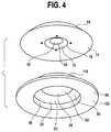
- FIG. 4is a fragmentary exploded isometric view from below of the waveguide stages of FIG. 3 ;
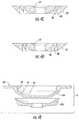
- FIG. 4Ais a plan view of the first waveguide stage of FIG. 4 ;
- FIG. 4Bis a bottom elevational view of the second waveguide stage of FIG. 4 ;
- FIGS. 4C and 4Dare cross-sectional views of alternative embodiments of the first waveguide stage of FIG. 4 ;
- FIG. 4Eis a cross-sectional view of an alternative embodiment of the second waveguide stage of FIG. 4 ;
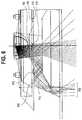
- FIGS. 5 and 6are ray trace diagrams simulating light passage through the waveguide stages of FIG. 2 ;
- FIG. 7is a side elevational view of another embodiment of a multi-stage waveguide
- FIG. 8is a sectional view of the stage 200 a of FIG. 7 ;
- FIGS. 9 and 10are sectional views of alternate embodiments of luminaires incorporating the multi-stage waveguide of FIG. 7 .
- a luminaire 10includes a housing 12 , a mounting device 14 secured to the housing 12 , a junction box 16 , and a heat sink 18 .
- the housing 12comprises a reflector 20 , a shield 22 , and an extension ring 24 that are secured together in any suitable fashion, such as by fasteners (not shown), welds, brackets, or the like.
- the mounting device 14may include conventional joist hangers 26 a , 26 b secured to two brackets 28 a , 28 b , respectively.
- the brackets 28 a , 28 bare, in turn, secured in any suitable fashion, such as by fasteners (not shown) to a flange 30 of the extension ring 24 .
- the luminaire 10may be suspended by fasteners extending through the joist hangers 26 into a structural member, such as one or more joists (not shown). Any other suitable support structure(s) could instead be used, including device(s) that allow the luminaire to be used in new construction or in retrofit applications.
- the junction box 16is mounted on a plate 34 that is, in turn, secured in any suitable fashion (again, e.g., by fasteners, not shown) to the flange 30 .
- the heat sink 18is mounted atop the shield 22 .
- a light source junction box 40is disposed on the heat sink 18 and is mounted thereon in any suitable fashion.
- a conduit 42houses electrical conductors that interconnect component(s) in the light source junction box 40 with power supplied to the junction box 16 .
- a light source 50 comprising at least one light emitting diode (LED) elementis firmly captured by a retention ring 52 and fasteners 56 ( FIG. 2 ) and/or another fastening element(s), such as adhesive, against an undersurface 54 of the heat sink 18 .
- the light source 50may be a single white or other color LED chip or other bare component, or each may comprise multiple LEDs either mounted separately or together on a single substrate or package to form a module 51 .
- One or more primary optics, such as one or more lenses,may be disposed over each LED or group of LEDs. Light developed by the light source 50 is directed downwardly as seen in FIGS. 2 and 3 and either travels directly through interior bores 58 , 59 ( FIGS.
- first and second optical waveguide stages or portions 64 , 66respectively, of an optical waveguide 68 .
- the waveguide stages 64 , 66are secured to the heat exchanger 18 in any convenient fashion, such as by fasteners, adhesive, brackets, or the like, or is simply sandwiched together and firmly captured between a shouldered surface 61 and a base surface 63 of the shield 22 .
- the coupling surface 60extends entirely through an interior portion of the first stage 64 (i.e., the coupling surface defines a through-bore) and comprises a frustoconical surface.
- the coupling surface 62comprises a blind bore having a frustoconical shape and defined in part by a planar base portion 69 that also directly receives light from the light source 50 .
- the coupling surfaces 60 , 62are preferably at least partially aligned, and in the illustrated embodiment, are fully aligned in the sense that such surfaces have coincident longitudinal axes 70 a , 70 b , respectively, ( FIG. 2 ).
- Alignment holes 117may be provided to aid in alignment of the light source 50 with the first stage 64 . Alignment holes 117 may contact or be attached to the retention ring 52 that captures the light source 50 . An embodiment may provide protrusions on the retention ring 52 that are received by the alignment holes 117 . Alternative embodiments may attach the retention ring 52 to the first stage 64 by way of a screw, bolt, fastener, or the like.
- the coupling surface 62may comprise a through-bore rather than a blind bore (such an arrangement is shown in FIGS. 5 and 6 ), although the latter has the advantage of providing an enclosed space to house and protect the light source 50 .
- the first and second stages 64 , 66are preferably circular in plan view and nested together.
- the first stage 64further includes a light transmission portion 70 and a light extraction portion 72 .
- the light transmission portion 70is disposed laterally between the coupling surface 60 and the light extraction portion 72 .
- the first stage 64further includes a substantially planar lower surface 74 and a tapered lower surface 76 that meet at an interface surface 78 .
- the light extraction portion 72includes light extraction or direction features 80 , 82 and a light recycling portion or redirection feature 88 intermediate the light extraction features 80 , 82 .
- the second stage 66includes a light extraction feature or portion 90 and a central cavity 92 defined by a lower planar base surface 94 , a lower tapered surface 96 , and a cylindrical surface 98 .
- a planar circumferential flange 100surrounds the light extraction feature 90 and the central cavity 92 .
- the flange 100facilitates retention of the stages 64 , 66 in the luminaire and may enclose and protect the various components thereof.
- the flange 100may not serve an optical function, although this need not be the case.
- the first and second stages 64 , 66are disposed such that the light extraction portion 72 of the first stage 64 is disposed outside of the light extraction portion 90 of the second stage 66 .
- the first stage 64may include a first major surface with light extraction features 80 , 82 and a second major surface opposite the first major surface.
- the second stage 66may include a third major surface proximate the second major surface of the first stage 64 and a fourth major surface opposite the third major surface.
- the second and third major surfaces of the first and second stages 64 , 66respectively, may be disposed such that an air gap is disposed therebetween as described below.
- the central cavity 92may extend into the fourth major surface of the second stage 66 .
- the light source 50may include, for example, at least one phosphor-coated LED either alone or in combination with at least one color LED, such as a green LED, a yellow LED, a red LED, etc.
- each LED module 51 or a plurality of such elements or modulesmay include one or more blue shifted yellow LEDs and one or more red LEDs.
- the LEDsmay be disposed in different configurations and/or layouts on the module as desired. Different color temperatures and appearances could be produced using other LED combinations, as is known in the art.
- the light source 50comprises any LED, for example, an MT-G LED incorporating TrueWhite® LED technology or as disclosed in U.S. patent application Ser. No.
- each LED element or module 51may comprise one or more LEDs disposed within a coupling cavity with an air gap being disposed between the LED element or module 51 and a light input surface.
- each of the LED element(s) or module(s) 51preferably has a lambertian or near-lambertian light distribution, although each may have a directional emission distribution (e.g., a side emitting distribution), as necessary or desirable. More generally, any lambertian, symmetric, wide angle, preferential-sided, or asymmetric beam pattern LED element(s) or module(s) may be used as the light source.
- the material(s) of the waveguide stages 64 , 66are the same as one another or different, and/or one or both may comprise composite materials.
- the material(s)are of optical grade, exhibit TIR characteristics, and comprise, but are not limited to, one or more of acrylic, air, polycarbonate, molded silicone, glass, and/or cyclic olefin copolymers, and combinations thereof, possibly in a layered or other arrangement, to achieve a desired effect and/or appearance.
- the waveguide stages 64 , 66are both solid and/or one or both have one or more voids or discrete bodies of differing materials therein.
- the waveguide stages 64 , 66may be fabricated using any suitable manufacturing processes such as hot embossing or molding, including injection/compression molding. Other manufacturing methods may be used as desired.
- Each of the extraction features 80 , 82may be generally of the shape disclosed in U.S. application Ser. No. 13/839,949, filed Mar. 15, 2013, now U.S. Pat. No. 9,581,751, entitled “Optical Waveguide and Lamp Including Same”, owned by the assignee of the present application and the disclosure of which is incorporated by reference herein.
- the first stage 64is disposed atop the second stage 66 such that the substantially planar lower surface 74 and the tapered lower surface 76 of the first stage 64 are disposed adjacent an upper planar base surface 112 ( FIGS. 2, 3, and 4 ) and an upper tapered surface 114 comprising a portion of the light extraction feature 90 of the second stage 66 .
- Disposed at a location adjacent an interface 110 between the upper planar base surface 112 and the upper tapered surface 114 ( FIG. 3 ) or at one or more points or areas where the first and second stages 64 , 66 are adjacent one anotheris at least one protrusion that may be continuous or discontinuous and which may have an annular or other shape. In the illustrated embodiment of FIGS.
- each protrusion 115extends from the upper planar base surface 112 of the second stage 66 and are received by four cavities 116 (two of which are seen in FIG. 3 and three of which are visible in FIG. 6 ), formed at least in the planar lower surface 74 of the first stage 64 .
- a first height of each protrusionis slightly greater than a second height of each cavity such that an air gap 120 ( FIG. 6 ) is maintained between the stages 64 , 66 .
- the air gap 120may be of either constant thickness or varying thickness in alternative embodiments.
- the luminaire 10develops a beam spread or beam angle of between about 10 degrees and about 60 degrees, and more preferably between about 10 degrees and about 45 degrees, and most preferably between about 15 degrees and about 40 degrees.
- the luminaireis further capable of developing a light intensity of at least about 2000 lumens, and more preferably a light intensity of about 4000 to about 15,000 lumens, and more preferably a light output of about 6000 lumens to about 10,000 lumens or higher.
- thermal issuesmay require additional features to be employed.
- the multi-stage nested waveguide optics separated by an air gapare employed to achieve high lumen output with low perceived glare and to allow a narrow luminaire spacing to luminaire height ratio to be realized.
- the luminaire 10uses as little as a single light source and multiple optics.
- the luminaire 10is particularly suited for use in applications where ceiling heights are relatively great, and where luminaires are to be spread relatively far apart, although the embodiments disclosed herein are not limited to such applications.
- each stagemay contribute to the achievement of a desired beam angle. Desirable beam angles may include 15 degrees, 25 degrees, and 40 degrees.
- the first stage 64may be machined with light extraction features 80 , 82 and/or one or more light redirection features 88 having slightly different sizes and angles as seen in FIGS. 4C and 4D . Further, the first stage 64 and/or second stage 66 may be positioned in a selected relative alignment with respect to the light source 50 in order to obtain a desired beam angle. Varying the relative alignment of the first stage 64 and/or the second stage 66 with respect to the light source 50 allows more or less light to couple directly with the first stage 64 and/or the second stage 66 . The variation in relative alignment may be in the transverse direction, the circumferential direction, or both.
- selected surfaces of the second stage 66may be machined with texturing, for example, on the light output surfaces 94 , 96 , 98 , 100 . Such texturing may aid in diffusion of output light.
- One optional texturingis specified by Mold-Tech of Standex Engraving Group, located in Illinois and other locations in the U.S. and around the world, under specification number 11040 .
- the second stage 66may be machined, molded, or otherwise formed as two pieces 156 , 158 . When formed as two pieces as shown in FIG.
- the first portion 156may be polished and the second portion 158 may have the texturing applied to the respective surfaces.
- the second stage 66may be assembled from the two pieces 156 , 158 using acrylic glue or another suitable adhesive.
- the waveguide configurations for obtaining 15, 25, and 40-degree beam anglesmay be created with different combinations of the above-described embodiments for the first and second stages 64 , 66 .
- a 15 degree beam anglemay be achieved by combining a polished second stage 66 with the first stage having the pattern of extraction and redirection features 80 , 82 , and 88 , respectively, shown in FIG. 4C .
- a 25 degree beam anglemay be achieved by combining the textured second stage 66 , shown prior to final assembly in FIG. 4E , with the same first stage 64 feature pattern used in the 15 degree beam angle configuration.
- a 40-degree beam anglemay be achieved by combining the textured second stage 66 with the first stage 64 having the extraction feature pattern shown in FIG. 4D .
- FIGS. 5 and 6are ray trace diagrams simulating the passage of light through the first and second stages 64 , 66 , respectively.
- the first stage 64splits the light incident on the coupling surface 60 and/or traveling through the into groups of light rays.
- a first group 140 of such light raystravels through the interior bores 58 , 59 and the planar base portion 69 and out the luminaire 10 with a minimal spread to develop a collimated central illumination distribution portion.
- a second group of light rays 142is incident on the coupling surface 60 , enters the first stage 64 , strikes the first extraction feature 80 , exits the first stage 64 in a collimated fashion, and is directed through the air gap 120 into the second stage 66 .
- the second group of light rays 142is refracted at the tapered surface 96 and exits the luminaire 10 to produce a collimated first intermediate annular illumination portion.
- a third group of light rays 144 originally incident on the coupling surface 60totally internally reflects off surfaces of the first stage 64 comprising the substantially planar lower surface 74 at the index interface defining the air gap 120 , and travels through the light recycling portion 88 where the light rays are refracted.
- the refracted lighttotally internally reflects off the light extraction feature 82 and travels out of the first waveguide stage 64 .
- the lateral dimension of the first waveguide stage 64is larger than a lateral dimension of the second stage 66 such that at least some of the light reflected off the light extraction feature 82 exits the first stage 64 , passes through the planar circumferential flange 100 of the second stage 66 and out of the luminaire 10 to produce a collimated outer annular illumination portion.
- the first stage 64thus splits a portion of the light developed by the light source 50 and collimates the light.
- the second stage 66receives about 40%-50% of the light developed by the light source 50 .
- a portion of the light developed by the light source 50 that is incident on the coupling surface 62is refracted upon entering the stage 66 and totally internally reflects off surfaces of the second stage 66 including the planar lower base surface 94 , the planar upper base surface 112 , and/or the tapered lower surface 76 , and is directed out the second stage 66 by the surface 114 of the extraction feature 90 to develop a collimated second intermediate annular illumination distribution portion 150 .
- the light extraction features 80 , 82 , and 90are preferably (although not necessarily) annular in overall shape. Further, the outer surfaces thereof are preferably frustoconical in shape, although this also need not be the case. For example, any or all of the features 80 , 82 , 90 may have a curved outer surface, or a surface comprising a piecewise linear approximation of a curve, or another shape. Still further, the features 80 , 82 , 90 may overall be continuous or discontinuous, the features 80 , 82 , 90 may have a cross-sectional shape that varies or does not vary with length, etc.
- the illumination distribution portions 140 , 142 , 144 , and 150together form an overall illumination distribution that is substantially uniform, both in terms of color and intensity, and has a beam spread as noted above.
- light diffusing featuressuch as texturing, lenticular features, or radial bumps can be applied onto one or more corresponding optical features to reduce or eliminate imaging of the light produced by the individual LEDs.
- the surfaces of the reflector 20may be shaped and coated or otherwise formed with a specular or other reflective material so that stray light beams are emitted downwardly together with the light beams forming the illumination distribution portions 140 , 142 , 144 , and 150 .
- stages 64 , 66may be modified or omitted, and/or one or more additional stages may be added to obtain other illumination patterns, if desired.
- a light sourcesuch as one or more LED elements or modules (not shown) disposed in a base 204 to obtain a light engine that develops an illumination distribution, for example, closely resembling or identical to a compact fluorescent lamp.
- the stages 200are substantially, if not completely identical to one another, and hence only the waveguide stage 200 a will be described in detail herein.
- the stages 200are maintained in assembled relationship by any suitable means such as acrylic glue, another adhesive, a bracket, one or more rods that are anchored in end plates, fasteners, etc., or a combination thereof.
- the stage 200 ais circular cylindrical in shape and has a central axis of symmetry 206 .
- An internal cavity 208is V-shaped in cross section and the stage is made of any of the optical materials disclosed herein.
- the internal cavity 208may have an alternate cross-sectional shape, such as a parabola, a frustum, a conical shape, an elliptic paraboloid shape, a frustoconical shape, or a combination of shapes.
- the surface defining the internal cavity 208may act as a light redirection feature.
- the internal cavity 208forms an air gap within the waveguide. The air gap enables the surface defining the internal cavity 208 to re-direct light toward the exterior surface 210 of waveguide stage 200 a . At least some of the redirected light may further be collimated upon said redirection.
- the stage 200 amay be a machined waveguide having all surfaces polished.
- the exterior cylindrical surface 210may be slightly diffused by roughening or scatter coating or texturing, potentially leading to a more uniform luminance appearance.
- the base 204may consist of a housing cap and a machined heatsink.
- the housing capmay optionally be made of plastic, such as the plastic varieties used in fused deposition modeling (FDM) or other suitable manufacturing processes.
- the light engine obtained from combining the base 204 and stacked waveguide stages 200 a , 200 b , . . . , 200 Nmay be part of an arrangement within a downlight such as luminaires 212 , 214 shown in FIGS. 9 and 10 .
- a luminaire 212 having a vertical lamping position, as seen in FIG. 9provides an intensity distribution resembling that of a similarly situated compact florescent lamp.
- a luminaire 214 having a horizontal lamping positionas seen in FIG.
- luminaires 212 , 214 described hereinmay provide better efficiency than a luminaire containing a comparable compact florescent lamp.
- any of the embodiments disclosed hereinmay include a power circuit for operating the LEDs having a buck regulator, a boost regulator, a buck-boost regulator, a SEPIC power supply, or the like, and may comprise a driver circuit as disclosed in U.S. patent application Ser. No. 14/291,829, filed May 30, 2014, now U.S. Pat. No. 9,791,110, entitled “High Efficiency Driver Circuit with Fast Response” by Hu et al. or U.S. patent application Ser. No. 14/292,001, filed May 30, 2014, now U.S. Pat. No. 9,303,823, entitled “SEPIC Driver Circuit with Low Input Current Ripple” by Hu et al. incorporated by reference herein.
- the circuitmay further be used with light control circuitry that controls color temperature of any of the embodiments disclosed herein in accordance with viewer input such as disclosed in U.S. patent application Ser. No. 14/292,286, filed May 30, 2014, now U.S. Pat. No. 10,278,250, entitled “Lighting Fixture Providing Variable CCT” by Pope et al. incorporated by reference herein.
- any of the embodiments disclosed hereinmay be used in a luminaire having one or more communication components forming a part of the light control circuitry, such as an RF antenna that senses RF energy.
- the communication componentsmay be included, for example, to allow the luminaire to communicate with other luminaires and/or with an external wireless controller, such as disclosed in U.S. patent application Ser. No. 13/782,040, filed Mar. 1, 2013, now U.S. Pat. No. 8,975,827, entitled “Lighting Fixture for Distributed Control” or U.S. Provisional Application No. 61/932,058, filed Jan. 27, 2014, entitled “Enhanced Network Lighting” both owned by the assignee of the present application and the disclosures of which are incorporated by reference herein.
- the light control circuitryincludes at least one of a network component, an RF component, a control component, and a sensor.
- the sensormay provide an indication of ambient lighting levels thereto and/or occupancy within the room or illuminated area. Such sensor may be integrated into the light control circuitry.
- each disclosed luminaireprovides an aesthetically pleasing, sturdy, cost effective luminaire for use in general lighting.
- the lightingis accomplished with reduced glare as compared to conventional lighting systems.
- the extraction features disclosed hereinefficiently extract light out of the waveguide.
- At least some of the luminaires disclosed hereinare particularly adapted for use in installations, such as, replacement or retrofit lamps, indoor products, (e.g., downlights, troffers, a lay-in or drop-in application, a surface mount application onto a wall or ceiling, etc.), and outdoor products.
- the luminaires disclosed hereinpreferably develop light at a color temperature of between about 2500 degrees Kelvin and about 6200 degrees Kelvin, and more preferably between about 2500 degrees Kelvin and about 5000 degrees Kelvin, and most preferably between about 3000 degrees Kelvin and about 5000 degrees Kelvin.
- At least some of the luminaires disclosed hereinpreferably exhibit an efficacy of at least about 60 lumens per watt, and more preferably at least about 75 lumens per watt. Further, at least some of the optical coupling members and waveguides disclosed herein preferably exhibit an overall efficiency (i.e., light extracted out of the waveguide divided by light injected into the waveguide) of at least about 90 percent.
- a color rendition index (CRI) of at least about 70is preferably attained by at least some of the luminaires disclosed herein, with a CRI of at least about 80 being more preferable. Any desired particular output light distribution could be developed.
- Fresnel lensesare generally planar in nature, and are therefore not well suited to re-directing high-angle light emitted by the source, leading to a loss in optical efficiency.
- lightis coupled into the optical stages, where primarily TIR is used for re-direction and collimation. This coupling allows the full range of angular emission from the source, including high-angle light, to be re-directed and collimated, resulting in higher optical efficiency in a more compact form factor.
- the distribution and direction of light within the waveguideis better known, and hence, light is controlled and extracted in a more controlled fashion.
- lightbounces back and forth through the waveguide.
- lightis extracted as much as possible over one pass through each of the waveguide stages to minimize losses.
- a waveguidemay include various combinations of optical features, such as coupling and/or extraction features, to produce a desired light distribution.
- a lighting systemmay be designed without constraint due to color mixing requirements, the need for uniformity of color and brightness, and other limits that might otherwise result from the use of a specific light source.
- the light transport aspect of a waveguideallows for the use of various form factors, sizes, materials, and other design choices. The design options for a lighting system utilizing a waveguide as described herein are not limited to any specific application and/or a specific light source.
- the embodiments disclosed hereinbreak light up into different portions that are controlled by separate stages that are axially stacked or offset, with or without an air gap therebetween, to develop a desired illumination distribution. While the embodiments disclosed herein do not utilize a light diverter in a coupling cavity to spread such light into the waveguide, and hence, the illumination distribution is limited by the size of the light source, one could use a light diverter to obtain a different illumination distribution, if desired.
Landscapes
- Physics & Mathematics (AREA)
- Optics & Photonics (AREA)
- General Physics & Mathematics (AREA)
- Engineering & Computer Science (AREA)
- General Engineering & Computer Science (AREA)
- Microelectronics & Electronic Packaging (AREA)
- Non-Portable Lighting Devices Or Systems Thereof (AREA)
- Planar Illumination Modules (AREA)
Abstract
Description
| State of the | Improved Standards Achievable | ||
| art standards | by Present Embodiments | ||
| Input coupling | 90% | About 95% plus improvements |
| efficiency (coupling + | through color mixing, source | |
| waveguide) | mixing, and control within the | |
| Output efficiency | ||
| 90% | About 95%: improved through | |
| (extraction) | extraction efficiency plus | |
| controlled distribution of light | ||
| from the waveguide | ||
| Total system | ~70% | About 80%: great control, many |
| choices of output distribution | ||
Claims (19)
Priority Applications (3)
| Application Number | Priority Date | Filing Date | Title |
|---|---|---|---|
| US16/539,163US11099317B2 (en) | 2013-01-30 | 2019-08-13 | Multi-stage optical waveguide for a luminaire |
| US17/346,700US11675120B2 (en) | 2013-01-30 | 2021-06-14 | Optical waveguides for light fixtures and luminaires |
| US18/950,412US20250075868A1 (en) | 2013-01-30 | 2024-11-18 | Lighting Devices Having Optical Waveguides for Controlled Light Distribution |
Applications Claiming Priority (5)
| Application Number | Priority Date | Filing Date | Title |
|---|---|---|---|
| US201361758660P | 2013-01-30 | 2013-01-30 | |
| US13/840,563US10436969B2 (en) | 2013-01-30 | 2013-03-15 | Optical waveguide and luminaire incorporating same |
| US13/839,949US9581751B2 (en) | 2013-01-30 | 2013-03-15 | Optical waveguide and lamp including same |
| US14/726,152US10422944B2 (en) | 2013-01-30 | 2015-05-29 | Multi-stage optical waveguide for a luminaire |
| US16/539,163US11099317B2 (en) | 2013-01-30 | 2019-08-13 | Multi-stage optical waveguide for a luminaire |
Related Parent Applications (2)
| Application Number | Title | Priority Date | Filing Date |
|---|---|---|---|
| US14/726,152DivisionUS10422944B2 (en) | 2013-01-30 | 2015-05-29 | Multi-stage optical waveguide for a luminaire |
| US15/710,913ContinuationUS10508794B2 (en) | 2013-01-30 | 2017-09-21 | LED troffer fixture having a wide lens |
Related Child Applications (2)
| Application Number | Title | Priority Date | Filing Date |
|---|---|---|---|
| US16/692,130ContinuationUS10794572B2 (en) | 2013-01-30 | 2019-11-22 | LED troffer fixture having a wide lens |
| US17/346,700ContinuationUS11675120B2 (en) | 2013-01-30 | 2021-06-14 | Optical waveguides for light fixtures and luminaires |
Publications (2)
| Publication Number | Publication Date |
|---|---|
| US20200003947A1 US20200003947A1 (en) | 2020-01-02 |
| US11099317B2true US11099317B2 (en) | 2021-08-24 |
Family
ID=54068645
Family Applications (3)
| Application Number | Title | Priority Date | Filing Date |
|---|---|---|---|
| US14/726,152Active2033-04-20US10422944B2 (en) | 2013-01-30 | 2015-05-29 | Multi-stage optical waveguide for a luminaire |
| US16/539,163ActiveUS11099317B2 (en) | 2013-01-30 | 2019-08-13 | Multi-stage optical waveguide for a luminaire |
| US17/346,700ActiveUS11675120B2 (en) | 2013-01-30 | 2021-06-14 | Optical waveguides for light fixtures and luminaires |
Family Applications Before (1)
| Application Number | Title | Priority Date | Filing Date |
|---|---|---|---|
| US14/726,152Active2033-04-20US10422944B2 (en) | 2013-01-30 | 2015-05-29 | Multi-stage optical waveguide for a luminaire |
Family Applications After (1)
| Application Number | Title | Priority Date | Filing Date |
|---|---|---|---|
| US17/346,700ActiveUS11675120B2 (en) | 2013-01-30 | 2021-06-14 | Optical waveguides for light fixtures and luminaires |
Country Status (1)
| Country | Link |
|---|---|
| US (3) | US10422944B2 (en) |
Cited By (3)
| Publication number | Priority date | Publication date | Assignee | Title |
|---|---|---|---|---|
| US20210311246A1 (en)* | 2013-01-30 | 2021-10-07 | Ideal Industries Lighting Llc | Optical waveguides for light fixtures and luminaires |
| US20230161127A1 (en)* | 2020-04-15 | 2023-05-25 | CommScope Connectivity Belgium BV | Device and method for sealing cables in telecommunications enclosures |
| US12372219B2 (en)* | 2014-05-30 | 2025-07-29 | Cree Lighting Usa Llc | LED luminaire with a cavity, finned interior, and a curved outer wall extending from a surface on which the light source is mounted |
Families Citing this family (16)
| Publication number | Priority date | Publication date | Assignee | Title |
|---|---|---|---|---|
| US9798072B2 (en) | 2013-03-15 | 2017-10-24 | Cree, Inc. | Optical element and method of forming an optical element |
| US10209429B2 (en) | 2013-03-15 | 2019-02-19 | Cree, Inc. | Luminaire with selectable luminous intensity pattern |
| US9651740B2 (en) | 2014-01-09 | 2017-05-16 | Cree, Inc. | Extraction film for optical waveguide and method of producing same |
| US11306897B2 (en) | 2015-02-09 | 2022-04-19 | Ecosense Lighting Inc. | Lighting systems generating partially-collimated light emissions |
| US9869450B2 (en) | 2015-02-09 | 2018-01-16 | Ecosense Lighting Inc. | Lighting systems having a truncated parabolic- or hyperbolic-conical light reflector, or a total internal reflection lens; and having another light reflector |
| US10310157B2 (en)* | 2015-12-04 | 2019-06-04 | Apple Inc. | Multi-piece light guide for enhanced alignment through an opaque surface |
| US10082283B2 (en)* | 2016-03-24 | 2018-09-25 | 3M Innovative Properties Company | Apparatus and method for ambient light measurement by a solid state light bulb |
| US10416377B2 (en) | 2016-05-06 | 2019-09-17 | Cree, Inc. | Luminaire with controllable light emission |
| US11719882B2 (en) | 2016-05-06 | 2023-08-08 | Ideal Industries Lighting Llc | Waveguide-based light sources with dynamic beam shaping |
| GB2557278B (en)* | 2016-12-02 | 2019-01-09 | Disruptive Marketing Ltd | Halo lighting unit |
| US10935783B1 (en)* | 2019-09-17 | 2021-03-02 | Aquabyte, Inc. | Optical system for capturing digital images in an aquaculture environment in situ |
| BE1028048B1 (en)* | 2020-02-11 | 2021-09-07 | Kreon | recessed spot |
| US11555587B1 (en)* | 2021-06-25 | 2023-01-17 | Usai, Llc | Wall wash micro light fixture |
| PL244490B1 (en)* | 2023-03-22 | 2024-01-29 | Healthcare Support Team Spolka Z Ograniczona Odpowiedzialnoscia | LED lamp with a two-stage color mixer for generating and transmitting light with a programmable color |
| US20250075877A1 (en)* | 2023-09-06 | 2025-03-06 | Lutron Technology Company Llc | Optical system for a lighting device |
| US20250314365A1 (en)* | 2024-04-04 | 2025-10-09 | Lucifer Lighting Company | Light Fixture Assembly With A Glare Mask |
Citations (139)
| Publication number | Priority date | Publication date | Assignee | Title |
|---|---|---|---|---|
| US3372740A (en) | 1966-01-12 | 1968-03-12 | Westinghouse Electric Corp | Lighting luminaire which is liquid cooled |
| US3532871A (en) | 1968-05-20 | 1970-10-06 | Ford Motor Co | Combination running light-reflector |
| DE3812764A1 (en) | 1988-04-16 | 1989-10-26 | Gerd Bonus | Pendant luminaire having a halogen lamp |
| US5398179A (en) | 1992-08-03 | 1995-03-14 | Innovative Industries Of Tampa, Inc. | Compact fluorescent hard wire adaptor for recessed cans |
| US5537304A (en) | 1994-11-10 | 1996-07-16 | Dal Partnership | Lighting fixture canopy |
| US5613751A (en) | 1995-06-27 | 1997-03-25 | Lumitex, Inc. | Light emitting panel assemblies |
| US5613770A (en) | 1994-05-16 | 1997-03-25 | Lite Corporation | Apparatus for securing component panels in a lighting fixture |
| US5676457A (en) | 1993-01-21 | 1997-10-14 | Simon; Jerome H. | Lineal light distribution |
| US5685634A (en) | 1996-08-22 | 1997-11-11 | Display Solutions, Inc. | Lens assembly for matrix lamp displays |
| US5719649A (en) | 1994-06-08 | 1998-02-17 | Kabushiki Kaisha Toshiba | Light guide and liquid crystal display device using it |
| US5719619A (en) | 1994-10-08 | 1998-02-17 | Sony Corporation | Bidirectional broadcasting method, bidirectional broadcasting system and receiver apparatus for bidirectional broadcast |
| US5806955A (en) | 1992-04-16 | 1998-09-15 | Tir Technologies, Inc. | TIR lens for waveguide injection |
| US5812714A (en) | 1997-01-30 | 1998-09-22 | Cooper Industries, Inc. | Optical waveguide elements for a distributed lighting system |
| US5839823A (en) | 1996-03-26 | 1998-11-24 | Alliedsignal Inc. | Back-coupled illumination system with light recycling |
| US5863113A (en) | 1993-06-22 | 1999-01-26 | Mitsubishi Rayon Co., Ltd. | Plane light source unit |
| US5897201A (en) | 1993-01-21 | 1999-04-27 | Simon; Jerome H. | Architectural lighting distributed from contained radially collimated light |
| US6097549A (en) | 1997-08-12 | 2000-08-01 | Breault Research Organization, Inc. | Bireflective lens element |
| US6193383B1 (en) | 1998-03-27 | 2001-02-27 | Citizen Electronics Co., Ltd. | Linear light source unit |
| US6257737B1 (en) | 1999-05-20 | 2001-07-10 | Philips Electronics Na | Low-profile luminaire having a reflector for mixing light from a multi-color linear array of LEDs |
| US20020018350A1 (en)* | 1997-04-22 | 2002-02-14 | Lepley Geoffrey Peter | Illuminated looped light pipe |
| US20020025129A1 (en)* | 1998-08-31 | 2002-02-28 | Cyrus Biscardi | Ultrathin optical panel and a method of making an ultrathin optical panel |
| US6443594B1 (en) | 2000-03-31 | 2002-09-03 | Koninklijke Philips Electronics N.V. | One-piece lens arrays for collimating and focusing light and led light generators using same |
| US6517222B1 (en) | 2001-08-01 | 2003-02-11 | Linear Lighting Corp. | System and method for leveling suspended lighting fixtures and a longitudunal axis |
| US6554451B1 (en) | 1999-08-27 | 2003-04-29 | Lumileds Lighting U.S., Llc | Luminaire, optical element and method of illuminating an object |
| US20040114361A1 (en) | 2002-12-12 | 2004-06-17 | Hubbell Incorporated | Lighting fixture end cap |
| US20040146241A1 (en) | 2003-01-29 | 2004-07-29 | Institut National D'optique | Light coupling between a light source and an optical waveguide |
| EP1503026A2 (en) | 2003-07-28 | 2005-02-02 | SWS Gesellschaft für Glasbaubeschläge mbH | Punctual fixing device |
| US20050073857A1 (en)* | 2003-10-06 | 2005-04-07 | Kuo Chia Shin | Light guiding frame with a plurality of guiding tracks |
| US7008097B1 (en) | 2003-02-25 | 2006-03-07 | Ilight Technologies, Inc. | Illumination device for simulating neon or fluorescent lighting including a waveguide and a scattering cap |
| US7083313B2 (en) | 2004-06-28 | 2006-08-01 | Whelen Engineering Company, Inc. | Side-emitting collimator |
| US7090370B2 (en) | 2001-06-08 | 2006-08-15 | Advanced Leds Limited | Exterior luminaire |
| US20070058359A1 (en)* | 2005-09-13 | 2007-03-15 | Goroh Saitoh | Illumination device and display device |
| US20070115569A1 (en) | 2004-07-02 | 2007-05-24 | Efun Technology Co., Ltd. | Brightness enhancement film having curved prism units and microstructure layer |
| US20080002399A1 (en) | 2006-06-29 | 2008-01-03 | Russell George Villard | Modular led lighting fixture |
| WO2008047278A2 (en) | 2006-10-16 | 2008-04-24 | Koninklijke Philips Electronics N.V. | Luminaire with leds |
| US7393124B1 (en) | 2005-05-04 | 2008-07-01 | Kenneth Riley Williams | Architectural mast-mounted support system |
| US20080232133A1 (en)* | 2007-03-23 | 2008-09-25 | Victor Company Of Japan, Limited | Lighting device and display device |
| WO2008126011A1 (en) | 2007-04-12 | 2008-10-23 | Koninklijke Philips Electronics N.V. | Improved light guide and light-output device |
| US7488093B1 (en) | 2007-12-27 | 2009-02-10 | Fu Zhun Precision Industry (Shen Zhen) Co., Ltd. | LED lamp with a cover and a heat sink |
| US7520650B2 (en) | 2004-06-28 | 2009-04-21 | Whelen Engineering Company, Inc. | Side-emitting collimator |
| US20090103293A1 (en) | 2007-10-17 | 2009-04-23 | Xicato, Inc. | Illumination Device with Light Emitting Diodes and Moveable Light Adjustment Member |
| US7534013B1 (en) | 2003-01-16 | 2009-05-19 | Simon Jerome H | Illuminating devices using small PT sources including LEDs |
| US20090185389A1 (en)* | 2008-01-18 | 2009-07-23 | Osram Sylvania Inc | Light guide for a lamp |
| US7566159B2 (en) | 2007-05-31 | 2009-07-28 | Avago Technologies Ecbu Ip (Singapore) Pte. Ltd. | Side-emitting LED package with improved heat dissipation |
| US7587117B2 (en) | 1992-03-23 | 2009-09-08 | 3M Innovative Properties Company | Luminaire device |
| US7593615B2 (en) | 2006-02-10 | 2009-09-22 | Rpc Photonics, Inc. | Optical devices for guiding illumination |
| WO2009130653A1 (en) | 2008-04-23 | 2009-10-29 | Koninklijke Philips Electronics N.V. | A lighting system |
| WO2009141778A1 (en) | 2008-05-22 | 2009-11-26 | Koninklijke Philips Electronics N.V. | Luminaire kit and method |
| WO2009144638A1 (en) | 2008-05-30 | 2009-12-03 | Koninklijke Philips Electronics N.V. | Round illumination device |
| US7628508B2 (en) | 2006-10-03 | 2009-12-08 | Stanley Electric Co., Ltd. | Illuminating device |
| US7635205B2 (en) | 2007-07-24 | 2009-12-22 | Fu Zhun Precision Industry (Shen Zhen) Co., Ltd. | LED lamp with heat dissipation device |
| US7641363B1 (en) | 2008-06-16 | 2010-01-05 | Li-Hong Technological Co., Ltd. | LED streetlight structure |
| US20100124074A1 (en)* | 2008-11-19 | 2010-05-20 | Joseph Brychell | Optimized distribution of light extraction from an edge lit light source |
| US7736019B2 (en) | 2006-10-10 | 2010-06-15 | Yanchers Corporation | Lighting system |
| JP3161425U (en) | 2010-05-19 | 2010-07-29 | 株式会社ドウシシャ | ceiling light |
| US20100202142A1 (en)* | 2007-05-01 | 2010-08-12 | Morgan Solar Inc. | Illumination device |
| US20100238671A1 (en) | 2009-03-18 | 2010-09-23 | Koninklijke Philips Electronics N.V. | Led luminaire |
| US7810960B1 (en) | 2007-11-13 | 2010-10-12 | Inteltech Corporation | Light fixture assembly having improved heat dissipation capabilities |
| US20100301360A1 (en) | 2009-06-02 | 2010-12-02 | Van De Ven Antony P | Lighting devices with discrete lumiphor-bearing regions on remote surfaces thereof |
| US20100302783A1 (en) | 2009-05-28 | 2010-12-02 | Chakrakodi Vishnu Shastry | Led street light lens |
| US20100315833A1 (en) | 2008-01-30 | 2010-12-16 | Digital Optics International Llc | Thin illumination system |
| US20110044022A1 (en) | 2009-08-20 | 2011-02-24 | Illumitex, Inc. | System and method for a phosphor coated lens |
| US7914193B2 (en) | 2008-02-15 | 2011-03-29 | Lunera Lighting, Inc. | LED light fixture |
| US7967477B2 (en) | 2007-09-06 | 2011-06-28 | Philips Lumileds Lighting Company Llc | Compact optical system and lenses for producing uniform collimated light |
| US20110187273A1 (en) | 2010-01-30 | 2011-08-04 | Koninklijke Philips Electronics N.V. | Lighting control system for a plurality of luminaires |
| EP2354640A1 (en) | 2010-02-09 | 2011-08-10 | Everlight Electronics Co., Ltd. | Electronic device and lighting unit thereof |
| US20110233568A1 (en) | 2008-12-18 | 2011-09-29 | Set Co., Ltd. | Led street lamp |
| US20110305027A1 (en) | 2010-06-09 | 2011-12-15 | Richard Ham | Induction streetlight |
| US20110317436A1 (en) | 2010-06-24 | 2011-12-29 | Thermoking Technology International | Outdoor light unit with angle adjustability |
| US8087807B2 (en) | 2009-06-05 | 2012-01-03 | Fu Zhun Precision Industry (Shen Zhen) Co., Ltd. | LED lamp |
| US8096671B1 (en) | 2009-04-06 | 2012-01-17 | Nmera, Llc | Light emitting diode illumination system |
| US8096681B2 (en) | 2008-12-24 | 2012-01-17 | Fu Zhun Precision Industry (Shen Zhen) Co., Ltd. | LED lamp |
| US20120026728A1 (en) | 2011-05-13 | 2012-02-02 | Xiaomei Lou | Led roadway luminaire |
| US8131131B2 (en) | 1999-11-26 | 2012-03-06 | Victor Company Of Japan, Limited | Method and apparatus for transmitting information, and reproducing apparatus, receiving apparatus and recording medium for the information, and transmission data thereof |
| US20120152490A1 (en) | 2010-12-20 | 2012-06-21 | Xiangyu Wen | Fastening type heat-dissipation structure |
| US20120212957A1 (en) | 2010-04-10 | 2012-08-23 | Lg Innotek Co., Ltd. | Lighting apparatus |
| US8272756B1 (en) | 2008-03-10 | 2012-09-25 | Cooper Technologies Company | LED-based lighting system and method |
| US8277106B2 (en) | 2007-05-10 | 2012-10-02 | Koninklijke Philips Electronics N.V. | Lighting device |
| US8287152B2 (en) | 2008-03-24 | 2012-10-16 | Amoluxe Co., Ltd. | Lighting apparatus using light emitting diode |
| US20120287654A1 (en) | 2009-12-25 | 2012-11-15 | Shenzhen Bang-Bell Electronics Co., Ltd | Led streetlamp installation seat and led streetlamp |
| US20120287677A1 (en) | 2009-12-08 | 2012-11-15 | 3M Innovative Properties Company | Optical constructions incorporating a light guide and low refractive index films |
| US8317366B2 (en) | 2005-04-29 | 2012-11-27 | Eveready Battery Company, Inc. | Light distributor |
| US20120307496A1 (en) | 2011-05-26 | 2012-12-06 | Phillips Iii William E | Led lighting apparatus with reflectors |
| US20130003409A1 (en) | 2010-03-18 | 2013-01-03 | Koninklijke Philips Electronics, N.V. | light mixing module, and a luminaire comprising such a light mixing module |
| US20130003363A1 (en) | 2011-07-01 | 2013-01-03 | Cree, Inc. | Reverse total internal reflection features in linear profile for lighting applications |
| US8353606B2 (en) | 2010-07-02 | 2013-01-15 | Jinsung Cnc Co. Ltd. | Streetlight |
| US20130044497A1 (en)* | 2010-05-26 | 2013-02-21 | S. K. G. Co., Ltd. | Illumination device |
| US8382387B1 (en) | 2011-01-21 | 2013-02-26 | Shaun C. Sandoval | Cobra head streetlight fixture surveillance system |
| US8408737B2 (en) | 2010-03-10 | 2013-04-02 | Cooper Technologies Company | Light emitting diode sign lighter |
| US20130088890A1 (en) | 2011-10-11 | 2013-04-11 | GE Lighting Solutions, LLC | Edge-lit luminaire |
| US8419224B2 (en) | 2010-11-24 | 2013-04-16 | Optotech Corporatipn | Light-emitting diode streetlight structure |
| US8425071B2 (en) | 2006-09-30 | 2013-04-23 | Cree, Inc. | LED lighting fixture |
| US8430548B1 (en) | 2004-11-17 | 2013-04-30 | Fusion Optix, Inc. | Enhanced light fixture with volumetric light scattering |
| US20130107528A1 (en) | 2011-11-01 | 2013-05-02 | Lsi Industries, Inc. | Luminaires and lighting structures |
| US8434892B2 (en) | 2011-03-30 | 2013-05-07 | Varroccorp Holding Bv | Collimator assembly |
| US8434893B2 (en) | 2007-10-17 | 2013-05-07 | Lsi Industries, Inc. | Luminaire and methods of use |
| US20130128593A1 (en) | 2011-11-22 | 2013-05-23 | Hon Hai Precision Industry Co., Ltd. | Portable electronic device |
| US8449142B1 (en) | 2009-10-14 | 2013-05-28 | C-M Glo, Llc | Reinforced housing structure for a lighted sign or lighting fixture |
| US8469559B2 (en) | 2011-03-28 | 2013-06-25 | Target Brands, Inc. | Edge-lit lighting product |
| US8475010B2 (en) | 2008-05-30 | 2013-07-02 | Koninklijke Philips Electronics N.V. | Illumination device comprising a collimator |
| US20130170210A1 (en) | 2011-12-30 | 2013-07-04 | Cree, Inc. | Led fixture with heat pipe |
| US20130201715A1 (en) | 2011-08-08 | 2013-08-08 | Quarkstar Llc | Illumination devices including multiple light emitting elements |
| US20130215612A1 (en) | 2012-02-22 | 2013-08-22 | Koninklijke Philips Electronics N.V. | Optical System for LEDs for Control of Stray Light |
| US20130229804A1 (en) | 2006-02-27 | 2013-09-05 | Ronald G. Holder | LED Device for Wide Beam Generation |
| US8541795B2 (en) | 2004-10-12 | 2013-09-24 | Cree, Inc. | Side-emitting optical coupling device |
| US20130250584A1 (en) | 2012-03-22 | 2013-09-26 | Leotek Electronics Corporation | Light emitting device |
| US20130265761A1 (en) | 2012-04-06 | 2013-10-10 | Ruud Lighting, Inc. | LED Light Fixture with Inter-Fin Air-Flow Interrupters |
| US8573823B2 (en) | 2011-08-08 | 2013-11-05 | Quarkstar Llc | Solid-state luminaire |
| US20130300310A1 (en) | 2012-05-08 | 2013-11-14 | Yuequan Hu | Light emitting diode driver with isolated control circuits |
| US8585253B2 (en) | 2009-08-20 | 2013-11-19 | Illumitex, Inc. | System and method for color mixing lens array |
| US8593070B2 (en) | 2009-07-29 | 2013-11-26 | General Electric Company | Three-phase LED power supply |
| US8608351B2 (en) | 2011-03-09 | 2013-12-17 | Lunera Lighting, Inc. | Removable optical component for luminaire |
| US20130343079A1 (en) | 2012-06-20 | 2013-12-26 | Energy Focus, Inc. | Elongated LED Lighting Arrangement |
| US20130343045A1 (en) | 2012-06-22 | 2013-12-26 | Pervaiz Lodhie | LED Light Module |
| US20130343055A1 (en) | 2011-03-16 | 2013-12-26 | Osram Gmbh | Lighting apparatus |
| US20140226361A1 (en)* | 2012-02-14 | 2014-08-14 | Sergiy Victorovich Vasylyev | Face-lit waveguide illumination systems |
| EP2784380A1 (en) | 2013-03-26 | 2014-10-01 | Kabushiki Kaisha Toshiba | Illumination device and light-guiding member |
| US20140313765A1 (en) | 2013-04-19 | 2014-10-23 | Abl Ip Holding Llc | Annulus shaped luminaire |
| US20150055371A1 (en) | 2013-03-15 | 2015-02-26 | Cree, Inc. | Luminaire with Selectable Luminous Intensity Pattern |
| US20150055369A1 (en) | 2013-03-15 | 2015-02-26 | Cree, Inc. | Luminaires utilizing edge coupling |
| US8975827B2 (en) | 2012-07-01 | 2015-03-10 | Cree, Inc. | Lighting fixture for distributed control |
| US20150160396A1 (en) | 2013-03-15 | 2015-06-11 | Cree, Inc. | Luminaire Utilizing Waveguide |
| US9099592B2 (en) | 2010-07-13 | 2015-08-04 | E I Du Pont De Nemours And Company | Optical element producing a modulated region of increased light intensity and optically enhanced photovoltaic cell and LED lighting device including the same |
| US20150253488A1 (en)* | 2013-03-15 | 2015-09-10 | Cree, Inc. | Luminaire utilizing waveguide |
| US20150285980A1 (en)* | 2012-11-08 | 2015-10-08 | Fraen Corporation | Multi-led/multi-chip color mixing optics |
| US20150285461A1 (en) | 2014-04-02 | 2015-10-08 | Bridgelux, Inc. | Optics for chip-on-board lighting having a protrusion |
| US20150323142A1 (en) | 2013-10-02 | 2015-11-12 | Patlite Corporation | Signal Indicator Lamp |
| US9256018B2 (en)* | 2009-03-12 | 2016-02-09 | Morgan Solar Inc. | Stimulated emission luminescent light-guide solar concentrators |
| US20160047969A1 (en) | 2013-03-15 | 2016-02-18 | Cree, Inc. | Optical Waveguide Body |
| US9303823B2 (en) | 2014-04-25 | 2016-04-05 | Cree, Inc. | SEPIC driver circuit with low input current ripple |
| US9305470B2 (en) | 2010-07-21 | 2016-04-05 | Kobe Steel, Ltd. | Cu alloy film for display device and display device |
| US9442243B2 (en) | 2013-01-30 | 2016-09-13 | Cree, Inc. | Waveguide bodies including redirection features and methods of producing same |
| US9581751B2 (en) | 2013-01-30 | 2017-02-28 | Cree, Inc. | Optical waveguide and lamp including same |
| US9690029B2 (en) | 2013-01-30 | 2017-06-27 | Cree, Inc. | Optical waveguides and luminaires incorporating same |
| US9706617B2 (en) | 2012-07-01 | 2017-07-11 | Cree, Inc. | Handheld device that is capable of interacting with a lighting fixture |
| US9818919B2 (en) | 2012-06-11 | 2017-11-14 | Cree, Inc. | LED package with multiple element light source and encapsulant having planar surfaces |
| US9869432B2 (en) | 2013-01-30 | 2018-01-16 | Cree, Inc. | Luminaires using waveguide bodies and optical elements |
| US10278250B2 (en) | 2014-05-30 | 2019-04-30 | Cree, Inc. | Lighting fixture providing variable CCT |
| US10422944B2 (en) | 2013-01-30 | 2019-09-24 | Ideal Industries Lighting Llc | Multi-stage optical waveguide for a luminaire |
Family Cites Families (3)
| Publication number | Priority date | Publication date | Assignee | Title |
|---|---|---|---|---|
| DE10249113B4 (en)* | 2002-10-22 | 2010-04-08 | Odelo Gmbh | Vehicle lamp, in particular tail lamp, preferably for motor vehicles |
| US20070059359A1 (en) | 2005-06-07 | 2007-03-15 | Thomas Backensfeld | Immediate-release and high-drug-load pharmaceutical formulations of non-micronised (4-chlorophenyl)[4-(4-pyridylmethyl)phthalazin-1-yl] and salts thereof |
| US7813131B2 (en) | 2008-04-17 | 2010-10-12 | Aeon Lighting Technology Inc. | Modular outdoor LED power supply |
- 2015
- 2015-05-29USUS14/726,152patent/US10422944B2/enactiveActive
- 2019
- 2019-08-13USUS16/539,163patent/US11099317B2/enactiveActive
- 2021
- 2021-06-14USUS17/346,700patent/US11675120B2/enactiveActive
Patent Citations (155)
| Publication number | Priority date | Publication date | Assignee | Title |
|---|---|---|---|---|
| US3372740A (en) | 1966-01-12 | 1968-03-12 | Westinghouse Electric Corp | Lighting luminaire which is liquid cooled |
| US3532871A (en) | 1968-05-20 | 1970-10-06 | Ford Motor Co | Combination running light-reflector |
| DE3812764A1 (en) | 1988-04-16 | 1989-10-26 | Gerd Bonus | Pendant luminaire having a halogen lamp |
| US7587117B2 (en) | 1992-03-23 | 2009-09-08 | 3M Innovative Properties Company | Luminaire device |
| US5806955A (en) | 1992-04-16 | 1998-09-15 | Tir Technologies, Inc. | TIR lens for waveguide injection |
| US5398179A (en) | 1992-08-03 | 1995-03-14 | Innovative Industries Of Tampa, Inc. | Compact fluorescent hard wire adaptor for recessed cans |
| US5897201A (en) | 1993-01-21 | 1999-04-27 | Simon; Jerome H. | Architectural lighting distributed from contained radially collimated light |
| US5676457A (en) | 1993-01-21 | 1997-10-14 | Simon; Jerome H. | Lineal light distribution |
| US5863113A (en) | 1993-06-22 | 1999-01-26 | Mitsubishi Rayon Co., Ltd. | Plane light source unit |
| US5613770A (en) | 1994-05-16 | 1997-03-25 | Lite Corporation | Apparatus for securing component panels in a lighting fixture |
| US5719649A (en) | 1994-06-08 | 1998-02-17 | Kabushiki Kaisha Toshiba | Light guide and liquid crystal display device using it |
| US5719619A (en) | 1994-10-08 | 1998-02-17 | Sony Corporation | Bidirectional broadcasting method, bidirectional broadcasting system and receiver apparatus for bidirectional broadcast |
| US5537304A (en) | 1994-11-10 | 1996-07-16 | Dal Partnership | Lighting fixture canopy |
| US5613751A (en) | 1995-06-27 | 1997-03-25 | Lumitex, Inc. | Light emitting panel assemblies |
| US5839823A (en) | 1996-03-26 | 1998-11-24 | Alliedsignal Inc. | Back-coupled illumination system with light recycling |
| US5685634A (en) | 1996-08-22 | 1997-11-11 | Display Solutions, Inc. | Lens assembly for matrix lamp displays |
| US5812714A (en) | 1997-01-30 | 1998-09-22 | Cooper Industries, Inc. | Optical waveguide elements for a distributed lighting system |
| US20020018350A1 (en)* | 1997-04-22 | 2002-02-14 | Lepley Geoffrey Peter | Illuminated looped light pipe |
| US6097549A (en) | 1997-08-12 | 2000-08-01 | Breault Research Organization, Inc. | Bireflective lens element |
| US6193383B1 (en) | 1998-03-27 | 2001-02-27 | Citizen Electronics Co., Ltd. | Linear light source unit |
| US20020025129A1 (en)* | 1998-08-31 | 2002-02-28 | Cyrus Biscardi | Ultrathin optical panel and a method of making an ultrathin optical panel |
| US6257737B1 (en) | 1999-05-20 | 2001-07-10 | Philips Electronics Na | Low-profile luminaire having a reflector for mixing light from a multi-color linear array of LEDs |
| US6554451B1 (en) | 1999-08-27 | 2003-04-29 | Lumileds Lighting U.S., Llc | Luminaire, optical element and method of illuminating an object |
| US8131131B2 (en) | 1999-11-26 | 2012-03-06 | Victor Company Of Japan, Limited | Method and apparatus for transmitting information, and reproducing apparatus, receiving apparatus and recording medium for the information, and transmission data thereof |
| US6443594B1 (en) | 2000-03-31 | 2002-09-03 | Koninklijke Philips Electronics N.V. | One-piece lens arrays for collimating and focusing light and led light generators using same |
| US7090370B2 (en) | 2001-06-08 | 2006-08-15 | Advanced Leds Limited | Exterior luminaire |
| US6517222B1 (en) | 2001-08-01 | 2003-02-11 | Linear Lighting Corp. | System and method for leveling suspended lighting fixtures and a longitudunal axis |
| US20040114361A1 (en) | 2002-12-12 | 2004-06-17 | Hubbell Incorporated | Lighting fixture end cap |
| US7534013B1 (en) | 2003-01-16 | 2009-05-19 | Simon Jerome H | Illuminating devices using small PT sources including LEDs |
| US20040146241A1 (en) | 2003-01-29 | 2004-07-29 | Institut National D'optique | Light coupling between a light source and an optical waveguide |
| US7008097B1 (en) | 2003-02-25 | 2006-03-07 | Ilight Technologies, Inc. | Illumination device for simulating neon or fluorescent lighting including a waveguide and a scattering cap |
| EP1503026A2 (en) | 2003-07-28 | 2005-02-02 | SWS Gesellschaft für Glasbaubeschläge mbH | Punctual fixing device |
| US20050073857A1 (en)* | 2003-10-06 | 2005-04-07 | Kuo Chia Shin | Light guiding frame with a plurality of guiding tracks |
| US7083313B2 (en) | 2004-06-28 | 2006-08-01 | Whelen Engineering Company, Inc. | Side-emitting collimator |
| US7520650B2 (en) | 2004-06-28 | 2009-04-21 | Whelen Engineering Company, Inc. | Side-emitting collimator |
| US20070115569A1 (en) | 2004-07-02 | 2007-05-24 | Efun Technology Co., Ltd. | Brightness enhancement film having curved prism units and microstructure layer |
| US8541795B2 (en) | 2004-10-12 | 2013-09-24 | Cree, Inc. | Side-emitting optical coupling device |
| US8430548B1 (en) | 2004-11-17 | 2013-04-30 | Fusion Optix, Inc. | Enhanced light fixture with volumetric light scattering |
| US8317366B2 (en) | 2005-04-29 | 2012-11-27 | Eveready Battery Company, Inc. | Light distributor |
| US7393124B1 (en) | 2005-05-04 | 2008-07-01 | Kenneth Riley Williams | Architectural mast-mounted support system |
| US20070058359A1 (en)* | 2005-09-13 | 2007-03-15 | Goroh Saitoh | Illumination device and display device |
| US7593615B2 (en) | 2006-02-10 | 2009-09-22 | Rpc Photonics, Inc. | Optical devices for guiding illumination |
| US20130229804A1 (en) | 2006-02-27 | 2013-09-05 | Ronald G. Holder | LED Device for Wide Beam Generation |
| US20080002399A1 (en) | 2006-06-29 | 2008-01-03 | Russell George Villard | Modular led lighting fixture |
| US8425071B2 (en) | 2006-09-30 | 2013-04-23 | Cree, Inc. | LED lighting fixture |
| US7628508B2 (en) | 2006-10-03 | 2009-12-08 | Stanley Electric Co., Ltd. | Illuminating device |
| US7736019B2 (en) | 2006-10-10 | 2010-06-15 | Yanchers Corporation | Lighting system |
| WO2008047278A2 (en) | 2006-10-16 | 2008-04-24 | Koninklijke Philips Electronics N.V. | Luminaire with leds |
| US20100110673A1 (en) | 2006-10-16 | 2010-05-06 | Koninklijke Philips Electronics N.V. | Luminaire with leds |
| US20080232133A1 (en)* | 2007-03-23 | 2008-09-25 | Victor Company Of Japan, Limited | Lighting device and display device |
| WO2008126011A1 (en) | 2007-04-12 | 2008-10-23 | Koninklijke Philips Electronics N.V. | Improved light guide and light-output device |
| US20120019942A1 (en) | 2007-05-01 | 2012-01-26 | Morgan Solar Inc. | Light-Guide Solar Panel and Method of Fabrication Thereof |
| US20100202142A1 (en)* | 2007-05-01 | 2010-08-12 | Morgan Solar Inc. | Illumination device |
| US8277106B2 (en) | 2007-05-10 | 2012-10-02 | Koninklijke Philips Electronics N.V. | Lighting device |
| US7566159B2 (en) | 2007-05-31 | 2009-07-28 | Avago Technologies Ecbu Ip (Singapore) Pte. Ltd. | Side-emitting LED package with improved heat dissipation |
| US7635205B2 (en) | 2007-07-24 | 2009-12-22 | Fu Zhun Precision Industry (Shen Zhen) Co., Ltd. | LED lamp with heat dissipation device |
| US7967477B2 (en) | 2007-09-06 | 2011-06-28 | Philips Lumileds Lighting Company Llc | Compact optical system and lenses for producing uniform collimated light |
| US20140029257A1 (en) | 2007-10-17 | 2014-01-30 | Lsi Industries, Inc. | Roadway luminaire and methods of use |
| US20090103293A1 (en) | 2007-10-17 | 2009-04-23 | Xicato, Inc. | Illumination Device with Light Emitting Diodes and Moveable Light Adjustment Member |
| US8567983B2 (en) | 2007-10-17 | 2013-10-29 | Lsi Industries, Inc. | Roadway luminaire and methods of use |
| US8434893B2 (en) | 2007-10-17 | 2013-05-07 | Lsi Industries, Inc. | Luminaire and methods of use |
| US7810960B1 (en) | 2007-11-13 | 2010-10-12 | Inteltech Corporation | Light fixture assembly having improved heat dissipation capabilities |
| US7488093B1 (en) | 2007-12-27 | 2009-02-10 | Fu Zhun Precision Industry (Shen Zhen) Co., Ltd. | LED lamp with a cover and a heat sink |
| US20090185389A1 (en)* | 2008-01-18 | 2009-07-23 | Osram Sylvania Inc | Light guide for a lamp |
| US20100315833A1 (en) | 2008-01-30 | 2010-12-16 | Digital Optics International Llc | Thin illumination system |
| US7914193B2 (en) | 2008-02-15 | 2011-03-29 | Lunera Lighting, Inc. | LED light fixture |
| US8272756B1 (en) | 2008-03-10 | 2012-09-25 | Cooper Technologies Company | LED-based lighting system and method |
| US8287152B2 (en) | 2008-03-24 | 2012-10-16 | Amoluxe Co., Ltd. | Lighting apparatus using light emitting diode |
| WO2009130653A1 (en) | 2008-04-23 | 2009-10-29 | Koninklijke Philips Electronics N.V. | A lighting system |
| WO2009141778A1 (en) | 2008-05-22 | 2009-11-26 | Koninklijke Philips Electronics N.V. | Luminaire kit and method |
| US8393774B2 (en) | 2008-05-22 | 2013-03-12 | Koninklijke Philips Electronics N.V. | Luminaire kit and method |
| WO2009144638A1 (en) | 2008-05-30 | 2009-12-03 | Koninklijke Philips Electronics N.V. | Round illumination device |
| US8434913B2 (en) | 2008-05-30 | 2013-05-07 | Koninklijke Philips Electronics N.V. | Round illumination device |
| US8475010B2 (en) | 2008-05-30 | 2013-07-02 | Koninklijke Philips Electronics N.V. | Illumination device comprising a collimator |
| US7641363B1 (en) | 2008-06-16 | 2010-01-05 | Li-Hong Technological Co., Ltd. | LED streetlight structure |
| US20100124074A1 (en)* | 2008-11-19 | 2010-05-20 | Joseph Brychell | Optimized distribution of light extraction from an edge lit light source |
| US20110233568A1 (en) | 2008-12-18 | 2011-09-29 | Set Co., Ltd. | Led street lamp |
| US8096681B2 (en) | 2008-12-24 | 2012-01-17 | Fu Zhun Precision Industry (Shen Zhen) Co., Ltd. | LED lamp |
| US9256018B2 (en)* | 2009-03-12 | 2016-02-09 | Morgan Solar Inc. | Stimulated emission luminescent light-guide solar concentrators |
| US8414155B2 (en) | 2009-03-18 | 2013-04-09 | Koninklijke Philips Electronics N.V. | LED luminaire |
| US20100238671A1 (en) | 2009-03-18 | 2010-09-23 | Koninklijke Philips Electronics N.V. | Led luminaire |
| US8096671B1 (en) | 2009-04-06 | 2012-01-17 | Nmera, Llc | Light emitting diode illumination system |
| US20100302783A1 (en) | 2009-05-28 | 2010-12-02 | Chakrakodi Vishnu Shastry | Led street light lens |
| US8905595B2 (en) | 2009-05-28 | 2014-12-09 | Dialight Corporation | LED street light lens |
| US20100301360A1 (en) | 2009-06-02 | 2010-12-02 | Van De Ven Antony P | Lighting devices with discrete lumiphor-bearing regions on remote surfaces thereof |
| US8087807B2 (en) | 2009-06-05 | 2012-01-03 | Fu Zhun Precision Industry (Shen Zhen) Co., Ltd. | LED lamp |
| US8593070B2 (en) | 2009-07-29 | 2013-11-26 | General Electric Company | Three-phase LED power supply |
| US8585253B2 (en) | 2009-08-20 | 2013-11-19 | Illumitex, Inc. | System and method for color mixing lens array |
| US20110044022A1 (en) | 2009-08-20 | 2011-02-24 | Illumitex, Inc. | System and method for a phosphor coated lens |
| US8449128B2 (en) | 2009-08-20 | 2013-05-28 | Illumitex, Inc. | System and method for a lens and phosphor layer |
| US8449142B1 (en) | 2009-10-14 | 2013-05-28 | C-M Glo, Llc | Reinforced housing structure for a lighted sign or lighting fixture |
| US20120287677A1 (en) | 2009-12-08 | 2012-11-15 | 3M Innovative Properties Company | Optical constructions incorporating a light guide and low refractive index films |
| US20120287654A1 (en) | 2009-12-25 | 2012-11-15 | Shenzhen Bang-Bell Electronics Co., Ltd | Led streetlamp installation seat and led streetlamp |
| US8547022B2 (en) | 2010-01-30 | 2013-10-01 | Koninklijke Philips N.V. | Lighting control system for a plurality of luminaires |
| US20110187273A1 (en) | 2010-01-30 | 2011-08-04 | Koninklijke Philips Electronics N.V. | Lighting control system for a plurality of luminaires |
| EP2354640A1 (en) | 2010-02-09 | 2011-08-10 | Everlight Electronics Co., Ltd. | Electronic device and lighting unit thereof |
| US8408737B2 (en) | 2010-03-10 | 2013-04-02 | Cooper Technologies Company | Light emitting diode sign lighter |
| US20130003409A1 (en) | 2010-03-18 | 2013-01-03 | Koninklijke Philips Electronics, N.V. | light mixing module, and a luminaire comprising such a light mixing module |
| US20120212957A1 (en) | 2010-04-10 | 2012-08-23 | Lg Innotek Co., Ltd. | Lighting apparatus |
| JP3161425U (en) | 2010-05-19 | 2010-07-29 | 株式会社ドウシシャ | ceiling light |
| US20130044497A1 (en)* | 2010-05-26 | 2013-02-21 | S. K. G. Co., Ltd. | Illumination device |
| US20110305027A1 (en) | 2010-06-09 | 2011-12-15 | Richard Ham | Induction streetlight |
| US20110317436A1 (en) | 2010-06-24 | 2011-12-29 | Thermoking Technology International | Outdoor light unit with angle adjustability |
| US8353606B2 (en) | 2010-07-02 | 2013-01-15 | Jinsung Cnc Co. Ltd. | Streetlight |
| US9099592B2 (en) | 2010-07-13 | 2015-08-04 | E I Du Pont De Nemours And Company | Optical element producing a modulated region of increased light intensity and optically enhanced photovoltaic cell and LED lighting device including the same |
| US9305470B2 (en) | 2010-07-21 | 2016-04-05 | Kobe Steel, Ltd. | Cu alloy film for display device and display device |
| US8419224B2 (en) | 2010-11-24 | 2013-04-16 | Optotech Corporatipn | Light-emitting diode streetlight structure |
| US20120152490A1 (en) | 2010-12-20 | 2012-06-21 | Xiangyu Wen | Fastening type heat-dissipation structure |
| US8382387B1 (en) | 2011-01-21 | 2013-02-26 | Shaun C. Sandoval | Cobra head streetlight fixture surveillance system |
| US8608351B2 (en) | 2011-03-09 | 2013-12-17 | Lunera Lighting, Inc. | Removable optical component for luminaire |
| US20130343055A1 (en) | 2011-03-16 | 2013-12-26 | Osram Gmbh | Lighting apparatus |
| US8469559B2 (en) | 2011-03-28 | 2013-06-25 | Target Brands, Inc. | Edge-lit lighting product |
| US8434892B2 (en) | 2011-03-30 | 2013-05-07 | Varroccorp Holding Bv | Collimator assembly |
| US20120026728A1 (en) | 2011-05-13 | 2012-02-02 | Xiaomei Lou | Led roadway luminaire |
| US20130294063A1 (en) | 2011-05-13 | 2013-11-07 | GE Lighting Solutions, LLC | Led roadway luminaire |
| US8485684B2 (en) | 2011-05-13 | 2013-07-16 | GE Lighting Solutions, LLC | LED roadway luminaire |
| US20120307496A1 (en) | 2011-05-26 | 2012-12-06 | Phillips Iii William E | Led lighting apparatus with reflectors |
| US20130003363A1 (en) | 2011-07-01 | 2013-01-03 | Cree, Inc. | Reverse total internal reflection features in linear profile for lighting applications |
| US8573823B2 (en) | 2011-08-08 | 2013-11-05 | Quarkstar Llc | Solid-state luminaire |
| US8506112B1 (en) | 2011-08-08 | 2013-08-13 | Quarkstar Llc | Illumination devices including multiple light emitting elements |
| US20130201715A1 (en) | 2011-08-08 | 2013-08-08 | Quarkstar Llc | Illumination devices including multiple light emitting elements |
| US20130088890A1 (en) | 2011-10-11 | 2013-04-11 | GE Lighting Solutions, LLC | Edge-lit luminaire |
| US20130107528A1 (en) | 2011-11-01 | 2013-05-02 | Lsi Industries, Inc. | Luminaires and lighting structures |
| US20130128593A1 (en) | 2011-11-22 | 2013-05-23 | Hon Hai Precision Industry Co., Ltd. | Portable electronic device |
| US20130170210A1 (en) | 2011-12-30 | 2013-07-04 | Cree, Inc. | Led fixture with heat pipe |
| US20140226361A1 (en)* | 2012-02-14 | 2014-08-14 | Sergiy Victorovich Vasylyev | Face-lit waveguide illumination systems |
| US20130215612A1 (en) | 2012-02-22 | 2013-08-22 | Koninklijke Philips Electronics N.V. | Optical System for LEDs for Control of Stray Light |
| US20130250584A1 (en) | 2012-03-22 | 2013-09-26 | Leotek Electronics Corporation | Light emitting device |
| US20130265761A1 (en) | 2012-04-06 | 2013-10-10 | Ruud Lighting, Inc. | LED Light Fixture with Inter-Fin Air-Flow Interrupters |
| US20130300310A1 (en) | 2012-05-08 | 2013-11-14 | Yuequan Hu | Light emitting diode driver with isolated control circuits |
| US9818919B2 (en) | 2012-06-11 | 2017-11-14 | Cree, Inc. | LED package with multiple element light source and encapsulant having planar surfaces |
| US20130343079A1 (en) | 2012-06-20 | 2013-12-26 | Energy Focus, Inc. | Elongated LED Lighting Arrangement |
| US20130343045A1 (en) | 2012-06-22 | 2013-12-26 | Pervaiz Lodhie | LED Light Module |
| US8975827B2 (en) | 2012-07-01 | 2015-03-10 | Cree, Inc. | Lighting fixture for distributed control |
| US9706617B2 (en) | 2012-07-01 | 2017-07-11 | Cree, Inc. | Handheld device that is capable of interacting with a lighting fixture |
| US20150285980A1 (en)* | 2012-11-08 | 2015-10-08 | Fraen Corporation | Multi-led/multi-chip color mixing optics |
| US9869432B2 (en) | 2013-01-30 | 2018-01-16 | Cree, Inc. | Luminaires using waveguide bodies and optical elements |
| US9690029B2 (en) | 2013-01-30 | 2017-06-27 | Cree, Inc. | Optical waveguides and luminaires incorporating same |
| US9581751B2 (en) | 2013-01-30 | 2017-02-28 | Cree, Inc. | Optical waveguide and lamp including same |
| US10436969B2 (en) | 2013-01-30 | 2019-10-08 | Ideal Industries Lighting Llc | Optical waveguide and luminaire incorporating same |
| US10422944B2 (en) | 2013-01-30 | 2019-09-24 | Ideal Industries Lighting Llc | Multi-stage optical waveguide for a luminaire |
| US9442243B2 (en) | 2013-01-30 | 2016-09-13 | Cree, Inc. | Waveguide bodies including redirection features and methods of producing same |
| US20150055371A1 (en) | 2013-03-15 | 2015-02-26 | Cree, Inc. | Luminaire with Selectable Luminous Intensity Pattern |
| US20150160396A1 (en) | 2013-03-15 | 2015-06-11 | Cree, Inc. | Luminaire Utilizing Waveguide |
| US20160047969A1 (en) | 2013-03-15 | 2016-02-18 | Cree, Inc. | Optical Waveguide Body |
| US20150253488A1 (en)* | 2013-03-15 | 2015-09-10 | Cree, Inc. | Luminaire utilizing waveguide |
| US20150055369A1 (en) | 2013-03-15 | 2015-02-26 | Cree, Inc. | Luminaires utilizing edge coupling |
| EP2784380A1 (en) | 2013-03-26 | 2014-10-01 | Kabushiki Kaisha Toshiba | Illumination device and light-guiding member |
| US10180529B2 (en) | 2013-03-26 | 2019-01-15 | Kabushiki Kaisha Toshiba | Illumination device and light-guiding member |
| US20140313765A1 (en) | 2013-04-19 | 2014-10-23 | Abl Ip Holding Llc | Annulus shaped luminaire |
| US20150323142A1 (en) | 2013-10-02 | 2015-11-12 | Patlite Corporation | Signal Indicator Lamp |
| US20150285461A1 (en) | 2014-04-02 | 2015-10-08 | Bridgelux, Inc. | Optics for chip-on-board lighting having a protrusion |
| US9791110B2 (en) | 2014-04-25 | 2017-10-17 | Cree, Inc. | High efficiency driver circuit with fast response |
| US9303823B2 (en) | 2014-04-25 | 2016-04-05 | Cree, Inc. | SEPIC driver circuit with low input current ripple |
| US10278250B2 (en) | 2014-05-30 | 2019-04-30 | Cree, Inc. | Lighting fixture providing variable CCT |
Non-Patent Citations (10)
| Title |
|---|
| Communication Pursuant to Article 94(3), corresponding to European Patent application No. 17779482.3, dated Jun. 16, 2020, 5 pages. |
| European Examination Report corresponding to European Patent Application No. 14745897.0 (5 pages) (dated Aug. 10, 2020). |
| Final Office Action for U.S. Appl. No. 14/726,152, dated Feb. 6, 2019, 12 pages. |
| Final Office Action for U.S. Appl. No. 14/726,152, dated Oct. 6, 2017, 15 pages. |
| International Search Report and Written Opinion for International Application No. PCT/US15/32011, Applicant Cree, Inc., dated Oct. 23, 2015. |
| International Search Report and Written Opinion for International Application No. PCT/US15/32210, Applicant Cree, Inc., dated Oct. 26, 2015. |
| Non-Final Office Action for U.S. Appl. No. 14/726,152, dated Mar. 21, 2017, 16 pages. |
| Non-Final Office Action for U.S. Appl. No. 14/726,152, dated May 3, 2018, 14 pages. |
| Notice of Allowance for U.S. Appl. No. 14/726,152, dated May 13, 2019, 10 pages. |
| Supplementary European Search Report, corresponding to EP 17816329.1, dated Oct. 22, 2019, 9 pgs. |
Cited By (4)
| Publication number | Priority date | Publication date | Assignee | Title |
|---|---|---|---|---|
| US20210311246A1 (en)* | 2013-01-30 | 2021-10-07 | Ideal Industries Lighting Llc | Optical waveguides for light fixtures and luminaires |
| US11675120B2 (en)* | 2013-01-30 | 2023-06-13 | Ideal Industries Lighting Llc | Optical waveguides for light fixtures and luminaires |
| US12372219B2 (en)* | 2014-05-30 | 2025-07-29 | Cree Lighting Usa Llc | LED luminaire with a cavity, finned interior, and a curved outer wall extending from a surface on which the light source is mounted |
| US20230161127A1 (en)* | 2020-04-15 | 2023-05-25 | CommScope Connectivity Belgium BV | Device and method for sealing cables in telecommunications enclosures |
Also Published As
| Publication number | Publication date |
|---|---|
| US20210311246A1 (en) | 2021-10-07 |
| US20200003947A1 (en) | 2020-01-02 |
| US11675120B2 (en) | 2023-06-13 |
| US10422944B2 (en) | 2019-09-24 |
| US20150260905A1 (en) | 2015-09-17 |
Similar Documents
| Publication | Publication Date | Title |
|---|---|---|
| US11099317B2 (en) | Multi-stage optical waveguide for a luminaire | |
| US11169313B2 (en) | Optical waveguide bodies and luminaires utilizing same | |
| US10168467B2 (en) | Luminaires utilizing edge coupling | |
| US10865958B2 (en) | Multi-waveguide LED luminaire with outward emission | |
| US9366799B2 (en) | Optical waveguide bodies and luminaires utilizing same | |
| US11070493B2 (en) | Simplified low profile module with light guide for pendant, surface mount, wall mount and stand alone luminaires | |
| US9366396B2 (en) | Optical waveguide and lamp including same | |
| EP3111138B1 (en) | Luminaires utilizing edge coupling | |
| US11536894B2 (en) | Modular waveguides and fixtures utilizing same | |
| EP2951499B1 (en) | Optical waveguide bodies | |
| US9411086B2 (en) | Optical waveguide assembly and light engine including same | |
| JP2016201371A (en) | Lighting device comprising a plurality of light emitting elements | |
| US10208923B2 (en) | Optical components for luminaire | |
| EP3102873B1 (en) | Optical waveguide bodies and luminaires utilizing same |
Legal Events
| Date | Code | Title | Description |
|---|---|---|---|
| FEPP | Fee payment procedure | Free format text:ENTITY STATUS SET TO UNDISCOUNTED (ORIGINAL EVENT CODE: BIG.); ENTITY STATUS OF PATENT OWNER: LARGE ENTITY | |
| STPP | Information on status: patent application and granting procedure in general | Free format text:DOCKETED NEW CASE - READY FOR EXAMINATION | |
| STPP | Information on status: patent application and granting procedure in general | Free format text:NON FINAL ACTION MAILED | |
| STPP | Information on status: patent application and granting procedure in general | Free format text:RESPONSE TO NON-FINAL OFFICE ACTION ENTERED AND FORWARDED TO EXAMINER | |
| STPP | Information on status: patent application and granting procedure in general | Free format text:NOTICE OF ALLOWANCE MAILED -- APPLICATION RECEIVED IN OFFICE OF PUBLICATIONS | |
| STPP | Information on status: patent application and granting procedure in general | Free format text:AWAITING TC RESP., ISSUE FEE NOT PAID | |
| STPP | Information on status: patent application and granting procedure in general | Free format text:NOTICE OF ALLOWANCE MAILED -- APPLICATION RECEIVED IN OFFICE OF PUBLICATIONS | |
| STPP | Information on status: patent application and granting procedure in general | Free format text:DOCKETED NEW CASE - READY FOR EXAMINATION | |
| STPP | Information on status: patent application and granting procedure in general | Free format text:NOTICE OF ALLOWANCE MAILED -- APPLICATION RECEIVED IN OFFICE OF PUBLICATIONS | |
| STPP | Information on status: patent application and granting procedure in general | Free format text:PUBLICATIONS -- ISSUE FEE PAYMENT RECEIVED | |
| STPP | Information on status: patent application and granting procedure in general | Free format text:PUBLICATIONS -- ISSUE FEE PAYMENT VERIFIED | |
| STCF | Information on status: patent grant | Free format text:PATENTED CASE | |
| AS | Assignment | Owner name:FGI WORLDWIDE LLC, NEW YORK Free format text:SECURITY INTEREST;ASSIGNOR:IDEAL INDUSTRIES LIGHTING LLC;REEL/FRAME:064897/0413 Effective date:20230908 | |
| MAFP | Maintenance fee payment | Free format text:PAYMENT OF MAINTENANCE FEE, 4TH YEAR, LARGE ENTITY (ORIGINAL EVENT CODE: M1551); ENTITY STATUS OF PATENT OWNER: LARGE ENTITY Year of fee payment:4 |