US11098909B2 - Methods and systems for turbulent, corrosion resistant heat exchangers - Google Patents
Methods and systems for turbulent, corrosion resistant heat exchangersDownload PDFInfo
- Publication number
- US11098909B2 US11098909B2US16/653,397US201916653397AUS11098909B2US 11098909 B2US11098909 B2US 11098909B2US 201916653397 AUS201916653397 AUS 201916653397AUS 11098909 B2US11098909 B2US 11098909B2
- Authority
- US
- United States
- Prior art keywords
- membrane
- desiccant
- air
- plate
- heat exchanger
- Prior art date
- Legal status (The legal status is an assumption and is not a legal conclusion. Google has not performed a legal analysis and makes no representation as to the accuracy of the status listed.)
- Active
Links
Images


Classifications
- F—MECHANICAL ENGINEERING; LIGHTING; HEATING; WEAPONS; BLASTING
- F28—HEAT EXCHANGE IN GENERAL
- F28D—HEAT-EXCHANGE APPARATUS, NOT PROVIDED FOR IN ANOTHER SUBCLASS, IN WHICH THE HEAT-EXCHANGE MEDIA DO NOT COME INTO DIRECT CONTACT
- F28D9/00—Heat-exchange apparatus having stationary plate-like or laminated conduit assemblies for both heat-exchange media, the media being in contact with different sides of a conduit wall
- F—MECHANICAL ENGINEERING; LIGHTING; HEATING; WEAPONS; BLASTING
- F24—HEATING; RANGES; VENTILATING
- F24F—AIR-CONDITIONING; AIR-HUMIDIFICATION; VENTILATION; USE OF AIR CURRENTS FOR SCREENING
- F24F3/00—Air-conditioning systems in which conditioned primary air is supplied from one or more central stations to distributing units in the rooms or spaces where it may receive secondary treatment; Apparatus specially designed for such systems
- F24F3/12—Air-conditioning systems in which conditioned primary air is supplied from one or more central stations to distributing units in the rooms or spaces where it may receive secondary treatment; Apparatus specially designed for such systems characterised by the treatment of the air otherwise than by heating and cooling
- F24F3/14—Air-conditioning systems in which conditioned primary air is supplied from one or more central stations to distributing units in the rooms or spaces where it may receive secondary treatment; Apparatus specially designed for such systems characterised by the treatment of the air otherwise than by heating and cooling by humidification; by dehumidification
- F24F3/1411—Air-conditioning systems in which conditioned primary air is supplied from one or more central stations to distributing units in the rooms or spaces where it may receive secondary treatment; Apparatus specially designed for such systems characterised by the treatment of the air otherwise than by heating and cooling by humidification; by dehumidification by absorbing or adsorbing water, e.g. using an hygroscopic desiccant
- F24F3/1417—Air-conditioning systems in which conditioned primary air is supplied from one or more central stations to distributing units in the rooms or spaces where it may receive secondary treatment; Apparatus specially designed for such systems characterised by the treatment of the air otherwise than by heating and cooling by humidification; by dehumidification by absorbing or adsorbing water, e.g. using an hygroscopic desiccant with liquid hygroscopic desiccants
- B—PERFORMING OPERATIONS; TRANSPORTING
- B01—PHYSICAL OR CHEMICAL PROCESSES OR APPARATUS IN GENERAL
- B01D—SEPARATION
- B01D53/00—Separation of gases or vapours; Recovering vapours of volatile solvents from gases; Chemical or biological purification of waste gases, e.g. engine exhaust gases, smoke, fumes, flue gases, aerosols
- B01D53/14—Separation of gases or vapours; Recovering vapours of volatile solvents from gases; Chemical or biological purification of waste gases, e.g. engine exhaust gases, smoke, fumes, flue gases, aerosols by absorption
- B01D53/18—Absorbing units; Liquid distributors therefor
- B—PERFORMING OPERATIONS; TRANSPORTING
- B01—PHYSICAL OR CHEMICAL PROCESSES OR APPARATUS IN GENERAL
- B01D—SEPARATION
- B01D53/00—Separation of gases or vapours; Recovering vapours of volatile solvents from gases; Chemical or biological purification of waste gases, e.g. engine exhaust gases, smoke, fumes, flue gases, aerosols
- B01D53/22—Separation of gases or vapours; Recovering vapours of volatile solvents from gases; Chemical or biological purification of waste gases, e.g. engine exhaust gases, smoke, fumes, flue gases, aerosols by diffusion
- B01D53/229—Integrated processes (Diffusion and at least one other process, e.g. adsorption, absorption)
- B—PERFORMING OPERATIONS; TRANSPORTING
- B01—PHYSICAL OR CHEMICAL PROCESSES OR APPARATUS IN GENERAL
- B01D—SEPARATION
- B01D53/00—Separation of gases or vapours; Recovering vapours of volatile solvents from gases; Chemical or biological purification of waste gases, e.g. engine exhaust gases, smoke, fumes, flue gases, aerosols
- B01D53/26—Drying gases or vapours
- B01D53/263—Drying gases or vapours by absorption
- B—PERFORMING OPERATIONS; TRANSPORTING
- B01—PHYSICAL OR CHEMICAL PROCESSES OR APPARATUS IN GENERAL
- B01D—SEPARATION
- B01D53/00—Separation of gases or vapours; Recovering vapours of volatile solvents from gases; Chemical or biological purification of waste gases, e.g. engine exhaust gases, smoke, fumes, flue gases, aerosols
- B01D53/26—Drying gases or vapours
- B01D53/265—Drying gases or vapours by refrigeration (condensation)
- B—PERFORMING OPERATIONS; TRANSPORTING
- B01—PHYSICAL OR CHEMICAL PROCESSES OR APPARATUS IN GENERAL
- B01D—SEPARATION
- B01D53/00—Separation of gases or vapours; Recovering vapours of volatile solvents from gases; Chemical or biological purification of waste gases, e.g. engine exhaust gases, smoke, fumes, flue gases, aerosols
- B01D53/26—Drying gases or vapours
- B01D53/268—Drying gases or vapours by diffusion
- F—MECHANICAL ENGINEERING; LIGHTING; HEATING; WEAPONS; BLASTING
- F28—HEAT EXCHANGE IN GENERAL
- F28D—HEAT-EXCHANGE APPARATUS, NOT PROVIDED FOR IN ANOTHER SUBCLASS, IN WHICH THE HEAT-EXCHANGE MEDIA DO NOT COME INTO DIRECT CONTACT
- F28D21/00—Heat-exchange apparatus not covered by any of the groups F28D1/00 - F28D20/00
- F28D21/0015—Heat and mass exchangers, e.g. with permeable walls
- F—MECHANICAL ENGINEERING; LIGHTING; HEATING; WEAPONS; BLASTING
- F28—HEAT EXCHANGE IN GENERAL
- F28D—HEAT-EXCHANGE APPARATUS, NOT PROVIDED FOR IN ANOTHER SUBCLASS, IN WHICH THE HEAT-EXCHANGE MEDIA DO NOT COME INTO DIRECT CONTACT
- F28D5/00—Heat-exchange apparatus having stationary conduit assemblies for one heat-exchange medium only, the media being in contact with different sides of the conduit wall, using the cooling effect of natural or forced evaporation
- F—MECHANICAL ENGINEERING; LIGHTING; HEATING; WEAPONS; BLASTING
- F28—HEAT EXCHANGE IN GENERAL
- F28D—HEAT-EXCHANGE APPARATUS, NOT PROVIDED FOR IN ANOTHER SUBCLASS, IN WHICH THE HEAT-EXCHANGE MEDIA DO NOT COME INTO DIRECT CONTACT
- F28D9/00—Heat-exchange apparatus having stationary plate-like or laminated conduit assemblies for both heat-exchange media, the media being in contact with different sides of a conduit wall
- F28D9/0031—Heat-exchange apparatus having stationary plate-like or laminated conduit assemblies for both heat-exchange media, the media being in contact with different sides of a conduit wall the conduits for one heat-exchange medium being formed by paired plates touching each other
- F28D9/0043—Heat-exchange apparatus having stationary plate-like or laminated conduit assemblies for both heat-exchange media, the media being in contact with different sides of a conduit wall the conduits for one heat-exchange medium being formed by paired plates touching each other the plates having openings therein for circulation of at least one heat-exchange medium from one conduit to another
- F28D9/005—Heat-exchange apparatus having stationary plate-like or laminated conduit assemblies for both heat-exchange media, the media being in contact with different sides of a conduit wall the conduits for one heat-exchange medium being formed by paired plates touching each other the plates having openings therein for circulation of at least one heat-exchange medium from one conduit to another the plates having openings therein for both heat-exchange media
- F—MECHANICAL ENGINEERING; LIGHTING; HEATING; WEAPONS; BLASTING
- F28—HEAT EXCHANGE IN GENERAL
- F28F—DETAILS OF HEAT-EXCHANGE AND HEAT-TRANSFER APPARATUS, OF GENERAL APPLICATION
- F28F1/00—Tubular elements; Assemblies of tubular elements
- F28F1/02—Tubular elements of cross-section which is non-circular
- F—MECHANICAL ENGINEERING; LIGHTING; HEATING; WEAPONS; BLASTING
- F28—HEAT EXCHANGE IN GENERAL
- F28F—DETAILS OF HEAT-EXCHANGE AND HEAT-TRANSFER APPARATUS, OF GENERAL APPLICATION
- F28F13/00—Arrangements for modifying heat-transfer, e.g. increasing, decreasing
- F28F13/06—Arrangements for modifying heat-transfer, e.g. increasing, decreasing by affecting the pattern of flow of the heat-exchange media
- F28F13/12—Arrangements for modifying heat-transfer, e.g. increasing, decreasing by affecting the pattern of flow of the heat-exchange media by creating turbulence, e.g. by stirring, by increasing the force of circulation
- F—MECHANICAL ENGINEERING; LIGHTING; HEATING; WEAPONS; BLASTING
- F28—HEAT EXCHANGE IN GENERAL
- F28F—DETAILS OF HEAT-EXCHANGE AND HEAT-TRANSFER APPARATUS, OF GENERAL APPLICATION
- F28F19/00—Preventing the formation of deposits or corrosion, e.g. by using filters or scrapers
- F28F19/02—Preventing the formation of deposits or corrosion, e.g. by using filters or scrapers by using coatings, e.g. vitreous or enamel coatings
- F—MECHANICAL ENGINEERING; LIGHTING; HEATING; WEAPONS; BLASTING
- F28—HEAT EXCHANGE IN GENERAL
- F28F—DETAILS OF HEAT-EXCHANGE AND HEAT-TRANSFER APPARATUS, OF GENERAL APPLICATION
- F28F21/00—Constructions of heat-exchange apparatus characterised by the selection of particular materials
- F28F21/06—Constructions of heat-exchange apparatus characterised by the selection of particular materials of plastics material
- F28F21/065—Constructions of heat-exchange apparatus characterised by the selection of particular materials of plastics material the heat-exchange apparatus employing plate-like or laminated conduits
- F—MECHANICAL ENGINEERING; LIGHTING; HEATING; WEAPONS; BLASTING
- F28—HEAT EXCHANGE IN GENERAL
- F28F—DETAILS OF HEAT-EXCHANGE AND HEAT-TRANSFER APPARATUS, OF GENERAL APPLICATION
- F28F3/00—Plate-like or laminated elements; Assemblies of plate-like or laminated elements
- F—MECHANICAL ENGINEERING; LIGHTING; HEATING; WEAPONS; BLASTING
- F28—HEAT EXCHANGE IN GENERAL
- F28F—DETAILS OF HEAT-EXCHANGE AND HEAT-TRANSFER APPARATUS, OF GENERAL APPLICATION
- F28F9/00—Casings; Header boxes; Auxiliary supports for elements; Auxiliary members within casings
- F28F9/24—Arrangements for promoting turbulent flow of heat-exchange media, e.g. by plates
- B—PERFORMING OPERATIONS; TRANSPORTING
- B01—PHYSICAL OR CHEMICAL PROCESSES OR APPARATUS IN GENERAL
- B01D—SEPARATION
- B01D53/00—Separation of gases or vapours; Recovering vapours of volatile solvents from gases; Chemical or biological purification of waste gases, e.g. engine exhaust gases, smoke, fumes, flue gases, aerosols
- B01D53/22—Separation of gases or vapours; Recovering vapours of volatile solvents from gases; Chemical or biological purification of waste gases, e.g. engine exhaust gases, smoke, fumes, flue gases, aerosols by diffusion
- B01D2053/221—Devices
- B01D2053/222—Devices with plates
- B—PERFORMING OPERATIONS; TRANSPORTING
- B01—PHYSICAL OR CHEMICAL PROCESSES OR APPARATUS IN GENERAL
- B01D—SEPARATION
- B01D63/00—Apparatus in general for separation processes using semi-permeable membranes
- B01D63/08—Flat membrane modules
- B01D63/082—Flat membrane modules comprising a stack of flat membranes
- B01D63/084—Flat membrane modules comprising a stack of flat membranes at least one flow duct intersecting the membranes
- B01D63/085—Flat membrane modules comprising a stack of flat membranes at least one flow duct intersecting the membranes specially adapted for two fluids in mass exchange flow
- F—MECHANICAL ENGINEERING; LIGHTING; HEATING; WEAPONS; BLASTING
- F24—HEATING; RANGES; VENTILATING
- F24F—AIR-CONDITIONING; AIR-HUMIDIFICATION; VENTILATION; USE OF AIR CURRENTS FOR SCREENING
- F24F3/00—Air-conditioning systems in which conditioned primary air is supplied from one or more central stations to distributing units in the rooms or spaces where it may receive secondary treatment; Apparatus specially designed for such systems
- F24F3/12—Air-conditioning systems in which conditioned primary air is supplied from one or more central stations to distributing units in the rooms or spaces where it may receive secondary treatment; Apparatus specially designed for such systems characterised by the treatment of the air otherwise than by heating and cooling
- F24F3/14—Air-conditioning systems in which conditioned primary air is supplied from one or more central stations to distributing units in the rooms or spaces where it may receive secondary treatment; Apparatus specially designed for such systems characterised by the treatment of the air otherwise than by heating and cooling by humidification; by dehumidification
- F24F2003/1435—Air-conditioning systems in which conditioned primary air is supplied from one or more central stations to distributing units in the rooms or spaces where it may receive secondary treatment; Apparatus specially designed for such systems characterised by the treatment of the air otherwise than by heating and cooling by humidification; by dehumidification comprising semi-permeable membrane
- F—MECHANICAL ENGINEERING; LIGHTING; HEATING; WEAPONS; BLASTING
- F28—HEAT EXCHANGE IN GENERAL
- F28D—HEAT-EXCHANGE APPARATUS, NOT PROVIDED FOR IN ANOTHER SUBCLASS, IN WHICH THE HEAT-EXCHANGE MEDIA DO NOT COME INTO DIRECT CONTACT
- F28D21/00—Heat-exchange apparatus not covered by any of the groups F28D1/00 - F28D20/00
- F28D2021/0019—Other heat exchangers for particular applications; Heat exchange systems not otherwise provided for
- F28D2021/0038—Other heat exchangers for particular applications; Heat exchange systems not otherwise provided for for drying or dehumidifying gases or vapours
Definitions
- the present applicationrelates generally to the use of liquid desiccants to dehumidify and cool (and in some cases humidify and heat) an air stream entering a space. More specifically, the application relates to the use of micro-porous and other membranes to separate the liquid desiccant from the air stream wherein the fluid streams (air, cooling or heating fluids, and liquid desiccants) are made to flow turbulently so that high heat and moisture transfer rates between the fluids can occur.
- the applicationfurther relates to corrosion resistant heat exchangers between two or three fluids. Such heat exchangers can use gravity induced pressures (siphoning) to keep the micro-porous membranes properly attached to the heat exchanger structure.
- Liquid desiccantshave been used in parallel to conventional vapor compression HVAC equipment to help reduce humidity in spaces, particularly in spaces that either require large amounts of outdoor air or that have large humidity loads inside the building space itself.
- Humid climatessuch as for example Miami, Fla. require a large amount of energy to properly treat (dehumidify and cool) the fresh air that is required for a space's occupant comfort.
- Conventional vapor compression systemshave only a limited ability to dehumidify and tend to overcool the air, oftentimes requiring energy intensive reheat systems, which significantly increase the overall energy costs because reheat adds an additional heat-load to the cooling coil.
- Liquid desiccant systemshave been used for many years and are generally quite efficient at removing moisture from the air stream.
- liquid desiccant systemsgenerally use concentrated salt solutions such as solutions of LiCl, LiBr or CaCl 2 and water.
- Such brinesare strongly corrosive, even in small quantities so numerous attempt have been made over the years to prevent desiccant carry-over to the air stream that is to be treated.
- One approachgenerally categorized as closed desiccant systems—is commonly used in equipment dubbed absorption chillers, places the brine in a vacuum vessel, which then contains the desiccant and since the air is not directly exposed to the desiccant; such systems do not have any risk of carry-over of desiccant particles to the supply air stream.
- Absorption chillershowever tend to be expensive both in terms of first cost and maintenance costs.
- Open desiccant systemsallow direct contact between the air stream and the desiccant, generally by flowing the desiccant over a packed bed similar to those used in cooling towers.
- Such packed bed systemssuffer from other disadvantages besides still having a carry-over risk: the high resistance of the packed bed to the air stream results in larger fan power and pressure drops across the packed bed, requiring thus more energy.
- the dehumidification processis adiabatic, since the heat of condensation that is released during the absorption of water vapor into the desiccant has no place to go. As a result, both the desiccant and the air stream are heated by the release of the heat of condensation.
- a 2-part plate structurethat has a first part made from a harder plastic (such as, e.g., ABS (Acrylonitrile butadiene styrene)) and a second part made from a compliant material (such as, e.g., EPDM (ethylene propylene diene monomer) rubber or Polyurethane).
- a harder plasticsuch as, e.g., ABS (Acrylonitrile butadiene styrene)
- a compliant materialsuch as, e.g., EPDM (ethylene propylene diene monomer) rubber or Polyurethane.
- Heat exchangersare very commonly used in many applications for heat transfer and energy recovery. Most heat exchangers are constructed out of metals such as copper, stainless steel and aluminum. Generally speaking such heat exchangers incorporate feature that attempt at disturbing the fluid flows in order to enhance the heat transfer between the fluid and the metal surfaces. Boundary layers on the surface of the metals create larger resistances to heat transfer. In quite a few applications, one or both of the fluids can be corrosive to the commonly used metals. Surface coatings can help prevent corrosion, but tend to also have decreased heat transfer. Metals that are not sensitive to corrosion such as Titanium, are generally considered expensive to use and difficult to work with. Plastics can be used but they oftentimes cannot withstand the operating pressures and temperatures that are typically used for the fluids. There thus remains a need for a cost-effective, corrosion resistant liquid to liquid heat exchanger.
- the liquid desiccantis running down the face of a support plate as a falling film.
- the liquid desiccantis covered by a microporous membrane so that liquid desiccant is unable to enter the air stream, but water vapor in the air stream is able to be absorbed into the liquid desiccant.
- the air streamcontains a turbulator: a material or feature that induces turbulence in the air flow so that the air does not become laminar over the surface of the desiccant.
- the turbulatoris a plastic netting material. In some embodiments, the turbulator is a series of plastic wires that span across the air flow. In some embodiments, the membrane is a bi-axially stretched polypropylene membrane. In some embodiments, the liquid desiccant is running through a wicking material such as a fabric or a thin screen material, wherein the fabric or screen material sets a fixed distance between the support plate and membrane. In some embodiments, the screen material or fabric provides a mixing or turbulence to the desiccant so that fresh desiccant is brought close to the membrane and spent desiccant is removed from the surface near the membrane.
- the membraneis bonded through the screen or wicking material onto a support plate.
- the support plateis a somewhat thermally conductive rigid plastic such as a fiberglass reinforced plastic.
- the support plateis cooled on the opposite side by a cooling fluid.
- the cooling fluidis water or a water/glycol mixture.
- the cooling fluidis running through a plastic mesh wherein the plastic mesh sets the distance between the support plate and a second support plate and wherein the cooling fluid is made to become turbulent by the mesh.
- the meshis a dual plane diamond plastic mesh.
- the second support plateis bonded to the first support plate by a series of adhesive dots so that the plates do not bulge out due to the cooling fluid pressure.
- the support platesare formed so that similar features of the diamond mesh are formed directly into the support plate.
- the support plateis joined to a second support plate wherein both plates contain features that achieve the functions of the diamond mesh: setting a fixed distance between the two support plates and creating a turbulent mixing cooling fluid flow.
- the features of the wicking material or screen material on the desiccant sideare also incorporated into the support plates.
- the glue dots on either or both the desiccant or cooling fluid sideare replaced by thermal bonding, ultrasonic bonding, or some other bonding method to connect to a membrane or to a second support plate.
- the support plateitself contains an adhesive in the plastic that is activate by some process, either by heat, or ultrasonic sound or microwaves or some other suitable method.
- the diamond meshcomprises a co-extruded plastic and an adhesive.
- the plasticis coated with an adhesive in a separate process step.
- the second support plateprovides a second screen and mesh and faces a second air gap containing a second air turbulator.
- a so constructed membrane plate assemblyis provided with multiple liquid supply- and drain ports so that uniform liquid distribution is achieved across the surfaces of the membrane and support plates.
- the portsare reconfigurable so that the air can be directed in either a horizontal or vertical fashion across the membranes.
- the air turbulatoris constructed so that it is effective for either horizontal or vertical air flow.
- the liquid portscan be configured so that the cooling fluid is always flowing against the direction of the air flow so that a counter-flow heat exchange function is obtained.
- the drain ports to the plateare constructed in such a way as to provide a siphoning of the leaving liquids thereby creating a negative pressure between the support plates with respect to atmospheric pressure and a negative pressure between the support plate and the membrane ensuring that the membrane stays flat against the screening material or wicking fabric.
- the main seals in between the support platesare constructed so as to provide a self-draining function so no liquids stay inside the membrane plate system.
- such self-draining sealscreate separate areas for the liquid desiccants and for the cooling fluids so that a leak in one of the seals will not affect the other fluid.
- the support plateis only partially covered by a membrane, thereby providing an additional area for sensible only cooling.
- the partially covered support platesencounter a vertical air flow and an also vertical heat transfer fluid flow directed in a direction opposite or counter to the air flow.
- the partially covered support platesupports a horizontal air flow and an also horizontal heat transfer fluid flow directed primarily in a direction counter to the air flow.
- the glue dotsare minimized to take advantage of the siphoning of the liquids leaving the channels of the plate thereby maximizing the available membrane area.
- the spaceris made from a rubber material such as EPDM.
- the spacerhas annular seals providing separation between the liquids and sealing the spacer to the surface of the support plate.
- the spaceris fully coated with an adhesive.
- the spaceralso contains features to support the air netting turbulator.
- the spacercontains features that keep the air turbulator under tension.
- the spaceris shaped so that it also provides a wall to channel the air stream in a proper direction.
- the rubber materialis over-molded on the support plate.
- the spacer and the air netting turbulatorform a single manufactured component.
- the air netting and spacerare separate components.
- the air netting turbulatorcontains support structures designed to hold a membrane in a fixed location.
- the air netting turbulator, membranes and support plates, with or without cooling fluid centersare stacked wherein the spacer and support netting eliminate the need for adhesives.
- the plates, support structures and spacersare made from flexible materials so that the structures can be rolled into a cylindrical shape. In some embodiments a force is applied to the compliant spaces to adjust and air gap between membrane plates.
- the forceis applied in a larger amount near one end of the membrane plate and a smaller amount near the opposite end of a membrane plate, resulting in an air gap that is smaller on one end as it is on the opposite end.
- the variable air gapis matched to the shrinkage or expansion of air in the channel.
- the variable air gapis dynamically adjusted to optimize between membrane efficiency and air pressure drop in the channel.
- the spacersare made to be wider on one side of a membrane module and narrower on the opposite side of the membrane module.
- the air gapsare so adjusted to match the expansion or contraction of the air in between the membrane plates.
- a series of so constructed plates and spacers as discussed aboveare placed in a block.
- the blockcontains a larger series of plates.
- the blockcan be reconfigured so that the air stream enters from either a vertical aspect or a horizontal aspect into the plates.
- the ports in the blockcan be reconfigured so that the cooling fluid is always directed against the flow of the air stream.
- the cooling fluidis replaced by a heating fluid.
- the heating fluidis used to evaporate water vapor from the desiccant into the air stream through the membrane rather than absorbing water vapor into the desiccant when the fluid is cool.
- air treatment modulescomprising alternating rigid and flexible materials.
- the rigid elementuses a liquid distribution header at the top of the module and a similar liquid distribution header at the bottom of the module, connected by two support plates.
- the headersare split to supply two fluids to a series of membranes.
- one set of membranesreceives fluids from one portion of the top header, while a second set of membranes receives fluids from a second portion of the header.
- the headersare made with a flexible material such as, e.g., EPDM rubber, while the support plates are made with a more rigid material such as, e.g., ABS or PET.
- the support platesare doped with fire retarding additives or thermally conductive additives.
- the support plateshave holes for fluid supply and fluid drain incorporated in them.
- the support plateshave a series of membranes attached over them.
- the membranesare connected to the support plate using an adhesive.
- the adhesiveis contained in a screen material that also provides turbulent mixing of the liquid.
- the adhesiveis connected through a thin screen material that provides turbulent mixing of the fluid.
- the turbulating featuresare integrated into the support plate.
- the support plateshave turbulating features on either side of them.
- the screen materialis formed in such a way as to provide a surface turbulence in the air stream.
- the membraneis formed in such a way as to provide turbulence in the air stream.
- the membraneis adhered over the features in the screen material so that the combination creates turbulence in the air stream.
- the support platehas added features that create ridges over which the screen material and membranes are formed to create turbulence in the air stream.
- the air gaps between the support platesare filled with a flexible structural material to support the membranes.
- the flexible structural materialprovides an edge seal for the air gaps.
- the flexible structural materialprovides turbulence to the air stream.
- the turbulating featureis located on the surface of the membranes. In some embodiments the turbulating feature is located in the middle of the air gap. In some embodiments, the flexible structural material provides liquid passages to the supply liquids or drain liquids from the membranes. In some embodiments the turbulator has walls that are sloped at an angle to the air stream. In some embodiments the turbulator walls that are alternatingly sloped at opposite angles to the air stream. In some embodiments the turbulator walls get smaller in the downstream direction. In some embodiments the turbulator has a secondary structure that contains walls that are directing the air stream back towards the opposite direction from the primary wall structure in such a way that a rotation in the air stream is enhanced. In some embodiments the combination of primary and secondary walls results in a counter-rotating air stream down an air channel.
- a membrane air treatment modulereceives a primary air flow in a primarily vertical orientation and a secondary air flow in a primarily horizontal orientation.
- the vertical air flowis exposed to one set of membranes, whereas the horizontal air flow is exposed to a second set of membranes.
- the one or both sets of membranesare replaced with a flocking, fabric, netting or other hydrophilic material on the surface of the membrane support plate.
- the primary air flowis exposed to one fluid through one set of the membranes, and the secondary air flow is exposed to a second fluid through the other set of membranes.
- the first fluidis a desiccant solution such as LiCl and water, CaCl 2 and water or other suitable liquid desiccant.
- the second fluidis water or seawater or waste water or other inexpensive water source.
- the fluidsare the same.
- the primary and secondary air channelsare both oriented to be generally horizontal. In some embodiments, both the channels expose air to the same liquid behind a series of membranes.
- the primary air channelis generally horizontal wherein the air is exposed to a liquid desiccant and wherein a portion of the thus treated is diverted to the secondary channel wherein the treated air is mixed with a secondary air stream and exposed to a different liquid such as water.
- the wateris replaced with seawater or wastewater.
- the diverted air flowis adjustable to that the amount of diverted air can be varied.
- the diverted air flowis adjustable to vary the mixture ratio between the diverted air and the secondary air stream.
- the diverted air flowis directed to near the rear entry of the primary air flow channels where the effect of the dried primary air has a larger cooling effect in the secondary air stream than if the air flow was directed to near the rear exit of the primary air flow channels.
- the fluidsare corrosive fluids.
- the fluidsfunction as desiccants.
- the desiccantscontain LiCl, CaCl 2 , Ca(NO 3 ) 2 , LiBr and water or other salt solutions.
- one liquidis hot and the other liquid is cold.
- the parallel plate structurecomprises plates with an adhesive edge seal.
- the platesare made of a plastic material.
- the plastic materialis a fiberglass reinforced plastic, or Poly-Ethylene-Terephthalate (PET) or other plastic material.
- the plate materialis a sheet of corrosion resistant material such as Titanium.
- the plate materialis a thermally doped engineering plastic.
- the dopantsare ceramics such as disclosed in U.S. Patent Application Publication No. 2012/0125581.
- the space between the platesis filled with a dual planar diamond extruded mesh.
- the meshprovides a fixed distance between the plates while allowing for passage of the fluids.
- the meshcreates turbulence in the fluids.
- the meshcomprises a co-extruded plastic and an adhesive.
- the plasticis coated with an adhesive in a separate process step.
- the adhesivecomprises adhesive dots that reach though the mesh between two sheets of plate material.
- the seals between the parallel platesare made out of an adhesive.
- the adhesiveis a 3M 550 or 5200 adhesive or a similar polyurethane adhesive.
- the sealsare shaped so as to create opposing flow profiles between opposing plates.
- Membrane modulesoften suffer from problems wherein glue or adhesion layers are stressed by temperature differences across the various components. This is particularly difficult in components used for the regeneration of the desiccant, since many common plastics have high thermal expansion coefficients. Oftentimes specialty high-temperature plastics are employed that are expensive to use in manufacturing. Bonding large surface areas together also creates problems with the adhesion and can cause stress fractures over time. Potting techniques (typically a liquid poured plastic) have some resilience if the potting material remains somewhat compliant even after curing. However the systems and methods described herein are significantly more resistant to expansion caused by high temperatures, which keeping the manufacturing process simple and robust.
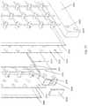
- a 2-way membrane moduleutilizes a set of refrigerant lines to actively cool a desiccant flowing behind a series of membranes.
- Flowing a desiccant directly over metal tubes such as copper refrigerant linesis problematic since the desiccants (typically Halide salts) are highly corrosive to most metals. Titanium is a possible exception but is cost prohibitive to employ.
- systems and methods described hereinshow a plastic support sheet that is wrapped around copper refrigerant lines thereby achieving direct cooling of the desiccant rather than using an indirect evaporative channel for cooling of the desiccant.
- the refrigerantis running in copper tubing.
- the copper tubingis wrapped by a plastic support sheet.
- the plastic support sheetforms the support structure for a membrane, which in turn contains a desiccant fluid.
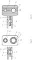
- FIG. 1illustrates a prior art 3-way, cross-flow heat exchanger that employs a double U-shaped cooling liquid path, a falling film desiccant flow (downward) and a horizontal air flow.
- FIG. 2illustrates a detail of FIG. 1 .
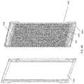
- FIG. 3shows a plastic two-way liquid to liquid heat exchanger as shown in US Patent Application Publication No. 2012/0125581.
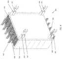
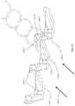
- FIG. 4shows a 3-way reconfigurable counter-flow heat exchanger in accordance with various embodiments set up with vertical air flow (downward), vertical cooling fluid flow (upward) and a vertical falling film desiccant (downward) behind a membrane.
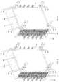
- FIG. 5demonstrates a different configuration of the heat exchanger from FIG. 4 set up as a cross-flow system with horizontal air flow, a vertical cooling fluid flow (upward) and a falling film desiccant (downward) behind a membrane.
- FIG. 6shows the heat exchanger of FIG. 5 in a counter-flow setup again with horizontal air flow, but with horizontal cooling fluid flow (against the direction of the air flow) and a falling film desiccant (downward) behind a membrane.
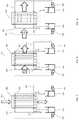
- FIG. 7shows a schematic flow diagram of the 3-way heat exchanger of FIG. 4 wherein the fluids are collected through a gravity drain circulation system.
- FIG. 8shows a schematic flow diagram of the 3-way heat exchanger of FIG. 5 wherein the fluids are collected through a gravity drain circulation system.
- FIG. 9shows a schematic flow diagram of the 3-way heat exchanger of FIG. 6 wherein the fluids are collected through a gravity drain circulation system.
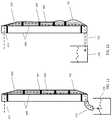
- FIG. 10shows a cross-sectional view of the individual plates that provide 3-way heat exchange between air, desiccant and a cooling fluid, including the materials that create turbulence in the air, desiccant and water channels.
- FIG. 11demonstrates a siphoning drain for the 3-way heat exchanger plate of FIG. 10 which allows the membranes to stay flat against the support structure.
- One of the membraneshas been removed for purposes of illustration.
- FIG. 12illustrates a non-siphoning drain for the same 3-way heat exchanger but shows that the membrane bulges into the air gap.
- One of the membraneshas been removed for purposes of illustration.
- FIG. 13illustrates an alternate orientation of the syphoning drain for the 3-way heat exchanger plate of FIG. 10 , which allows for an almost horizontal, flat orientation of the 3-way heat exchanger plates.
- FIG. 14shows a spacer that is used between two membrane plates of FIG. 600 with individual fluid seals for desiccant and cooling fluid.
- FIG. 15illustrates a spacer that is used between two membrane plates of FIG. 10 with a full seal encompassing both the desiccant and cooling fluid.
- FIG. 16shows an embodiment of a spacer over-molded on each side of the individual plates of FIG. 10 with an adhesive to make the final connection between the plates.
- FIG. 17shows an embodiment of a spacer over-molded on only one side of the individual plates of FIG. 10 with an adhesive to make the final connection between the plates.
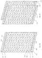
- FIG. 18shows an embodiment of a set of spacers of FIG. 14 used to connect a set of membrane plates as were shown in FIG. 10 , wherein the spacers are of equal thickness creating uniform channel widths between the membrane plates.
- FIG. 19shows an embodiment of a set of spacers of FIG. 14 used to connect a set of membrane plates as were shown in FIG. 10 , wherein the spacers are of unequal thickness creating varying channel widths between the membrane plates.
- FIG. 20shows the 3-way heat exchanger of FIG. 4 with the front cover face plate removed so that the first air channel is visible.
- FIG. 21shows the 3-way heat exchanger of FIG. 20 with several additional membrane plates removed for purposes of illustration.
- FIG. 22shows the 3-way heat exchanger of FIG. 5 with the front cover face plate removed so that the first air channel is visible.
- FIG. 23shows the 3-way heat exchanger of FIG. 5 with several additional membrane plates removed for purposes of illustration.
- FIG. 24illustrates an alternate turbulator for the air channels shown in
- FIG. 21is a diagrammatic representation of FIG. 21 .
- FIG. 25illustrates an alternate turbulator for the air channels shown in FIG. 23 .
- FIG. 26shows an exploded assembly drawing of a single membrane plate in accordance with one or more embodiments.
- FIG. 27illustrates a seal and turbulator detail for the core of the membrane plate in accordance with one or more embodiments.
- FIG. 28illustrates the seal, turbulator and adhesive dots as an integral unit.
- FIG. 29shows an alternate construction of the seal wherein the desiccant and cooling fluids are in separate seal areas and wherein the seal is shaped in such a way as to be self-draining.
- FIG. 30shows the seal of FIG. 29 mounted against a thermally conductive cover plate with drain- and supply-holes for the fluids.
- FIG. 31shows the assembly of FIG. 30 with a turbulating mesh and adhesive dots installed in the middle of the cooling fluid area.
- FIG. 32illustrates the assembly steps from the assembly of FIG. 31 through the final assembly of a single membrane plate and spacers.
- FIG. 33illustrates the assembly process of multiple membrane plates.
- FIG. 34illustrates a detail of FIG. 33 .
- FIG. 35shows a set of surface turbulators in the prior art.
- FIG. 36illustrates a set of surface turbulators using a membrane and support structure as the means of creating turbulent flow.
- FIG. 37shows a turbulator that is able to generate a counter-rotating flow in a narrow air channel.
- FIG. 38shows half-plate assembly with an over-molded spacer and a membrane attached in accordance with one or more embodiments
- FIG. 39shows and exploded view of the half-plate assembly of FIG. 38 in accordance with one or more embodiments.
- FIG. 40illustrates how two half-plates are adhered to form a single membrane plate in accordance with one or more embodiments.
- FIG. 41shows an air-turbulating netting material that can also provide mechanical support to the membrane structure.
- FIG. 42shows a detail of FIG. 41 wherein two membranes connected to two 3-way membrane plates are supported by an air-turbulating netting.
- FIG. 43shows a similar detail of FIG. 42 wherein two membranes connected to two 2-way membrane plates are supporting by an air-turbulating netting.
- FIG. 44shows an embodiment of an air turbulating netting wherein the netting also incorporates support structures designed to keep membranes mechanically in place and wherein edge spacers are integrated to the design.
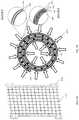
- FIG. 45shows how the air turbulating netting can support a membrane structure that is rolled into a cylindrical structure.
- Detail “A”shows a 2-way heat exchanger plate structure.
- Detail “B”shows a 3-way heat exchanger plate structure.
- FIG. 46shows how the air turbulating netting can support a flat membrane structure for a 3-way heat exchanger plate structure.
- FIG. 47shows how the air turbulating netting can support a flat membrane structure for a 2-way heat exchanger plate structure.
- FIG. 48shows a support plate that has been die-cut and thermoformed to incorporate features for cooling fluid and desiccant distribution.
- FIG. 49shows how the support plate from FIG. 48 can be joined with another support plate from FIG. 48 to form a complete plate structure.
- FIG. 50illustrates how the two support plates from FIG. 49 are joined to form a single plate in a transparent aspect.
- FIG. 51shows a detail of a corner of the support plate of FIG. 48 .
- FIG. 52shows an arrangement of seals for the liquid desiccant, membrane and cooling fluids of FIG. 10 .
- FIG. 53shows an alternate arrangement of seals wherein the desiccant runs behind a membrane in zone “A” and the zone “B” only provides sensible cooling.
- FIG. 54shows an alternate arrangement of seals wherein the desiccant runs on a first section “A” of the membrane plate and there is no membrane on a second section “B” of the membrane plate.
- FIG. 55shows a 2-way heat exchanger in accordance with one or more embodiments.
- FIG. 56shows a cut-away detail of the 2 way heat exchanger at an odd level intersection.
- FIG. 57shows a cut-away detail of the 2 way heat exchanger at an even level intersection.
- FIG. 58illustrates the assembly of a single plate of the two-way heat exchanger of FIG. 55 .
- FIG. 59shows an odd-level plate assembly of the two-way heat exchanger.
- FIG. 60shows an even-level plate assembly of the two-way heat exchanger.
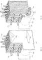
- FIG. 61illustrates a 2-part membrane plate assembly that utilizes a primary air stream in a vertical orientation and a secondary air flow in a cross flow, horizontal orientation wherein the cross flow air stream provides indirect cooling to the main air stream.
- FIG. 62shows the 2-part membrane plate assembly of FIG. 61 with an outer membrane removed for illustrative purposes.
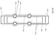
- FIG. 63shows the rear-side of 2-part membrane plate assembly of FIG. 61 .
- FIG. 64shows a detail corner of FIG. 63 .
- FIG. 65shows a different aspect of FIG. 64 with an inner membrane and air turbulator removed for clarity.
- FIG. 66shows an exploded view of the 2-part membrane plate assembly of FIG. 61 .
- FIG. 67shows a detailed aspect of FIG. 66 .
- FIG. 68shows a cross-sectional view of the top of 2-part the membrane plate assembly of FIG. 61 .
- FIG. 69shows a cross-sectional view of the bottom of the 2-part membrane plate assembly of FIG. 61 .
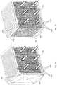
- FIG. 70shows a cross flow plate module utilizing multiple copies of the 2-part membrane plate assembly from FIG. 61 .
- FIG. 71shows the cross flow plate module of FIG. 70 integrated into an air treatment module wherein a portion of the primary supply air stream is diverted and mixed with the secondary cross flow air stream.
- FIG. 72illustrates the air treatment module of FIG. 71 with one side cover removed for illustrating the ability to vary the amount of air from the main stream to be diverted to the cross flow air stream.
- FIG. 73shows a detail of FIG. 72 .
- FIG. 74illustrates an alternate embodiment of the system of FIG. 71 , wherein the air stream is directed to the top portion of the cross flow plate module.
- FIG. 75shows a 2-part module wherein one plate provides 4 flow paths for liquids to be exposed to an air stream and wherein the air stream is primarily horizontal.
- FIG. 76shows an exploded view of the 2-part module of FIG. 75 .
- FIG. 77shows a detail of the exploded view of FIG. 76 .
- FIG. 78shows an air treatment module with horizontal air flow wherein the air stream is exposed to liquids on each of the channels in the module.
- FIG. 79shows the air treatment module of FIG. 78 with cover plates removed.
- FIG. 80illustrates the air treatment module of FIGS. 61-63 wherein the support plate has been modified to accommodate a set of refrigerant lines flowing inside the support plate so that direct cooling of the desiccant is provided.
- FIG. 1depicts a 3-way heat exchanger in the prior art wherein air enters a stack of vertical plates.
- the vertical plateshave provisions for a cooling fluid 38 and are coated with a flocking material.
- a liquid desiccantis applied to the flocking material that slowly falls down the surface of the plate, while absorbing water vapor from the air stream and conducting heat from the condensation and air into the cooling fluid.
- FIG. 2shows a cross section of a plate of FIG. 1 in the prior art wherein the cooling fluid enters at location 34 , flows down to the bottom location 38 and back up to the upper location 38 . The fluid then flows again to the bottom and back up to the exit port 36 .
- the long, narrow passages in the fluid flowresult in laminar fluid flows and, as can be seen in the figure, the air flow entering at 10 is at right angles to the cooling fluid flows.
- FIG. 3illustrates a 2-way heat exchanger wherein alternating patterns are applied to a series of plates. The patterns are meant to disturb (turbulate) the fluid flows.
- 2-way heat exchangersare constructed using metals because high pressures and temperatures are common in 2-way heat exchangers.
- Titanium heat exchangerscan be employed, but Titanium is expensive and generally hard to work with (drilling, welding etc.).
- Plastic heat-exchangershave been build and proposed but can usually not withstand very high pressures or temperatures.
- FIG. 4shows a flexible, completely turbulent flow, corrosion resistant, self-draining, negative pressure, membrane protected, counter-flow 3-way heat exchanger meant for capturing water vapor from and air stream while simultaneously cooling the air stream.
- the high temperature, high humidity air stream 301enters a series of membrane plates 303 that cool and dehumidify the air stream.
- the cool, dry, leaving air 302is supplied to a space such as for example a space in a building.
- a desiccantis supplied through supply ports 304 . Two ports are provided on each side of the plate block structure 300 . The supply ports are spaced apart in such a way as to provide a uniform desiccant film flow across the membrane plates 303 .
- the desiccant filmfalls through gravity and is collected at the bottom of the plate block 300 and exits through the drain ports 305 .
- a cooling fluid(or heating fluid as the case may be) is supplied through ports 306 at the bottom of the plate block 300 . Again, the cooling fluid supply ports are spaced in such a way as to provide uniform cooling fluid flow inside the membrane plates 300 .
- the cooling fluidruns upward inside the membrane plates 303 and leaves the plate block 300 through the ports 307 .
- Front/rear covers 308 and side covers 309provide structural support and thermal insulation and ensure that air does not leave through the sides of the block.
- FIG. 5shows the plate block of FIG. 4 reconfigured in such a way the air stream now can enter the block in a horizontal orientation.
- the airenters at 401 and leaves the block at 402 .
- Top and bottom covers 403ensure structural support and prevent air from leaking out of the top and bottom of the plate block.
- FIG. 6illustrates the plate block of FIG. 5 however the cooling fluid flow has been reconfigured so that the fluid enters on the right hand side of the block at ports 306 on the bottom right and port 405 on the top right. The fluid now leaves the block at ports 307 on the top left and port 404 on the bottom left. As can be seen from the figure, the cooling fluid flows in the opposite direction to the air stream flow, resulting in better heat and moisture transfer between the air and the desiccant and cooling water.
- FIG. 7illustrates a simplified fluid flow diagram corresponding to the plate block configuration of FIG. 4 .
- the air streamflows over the membrane plate surface starting at point 501 .
- the membrane plate 504is constructed as a hollow structure with fluid passages.
- the cooling fluid pump 507pumps fluid 502 into the hollow plate where it is distributed.
- the fluidthen runs upward and leaves at exit port 505 .
- the fluidcan enter the plate at more than one port to ensure uniform fluid distribution as is shown in the figure.
- the drain 505is constructed in such a way as to create a siphoning effect when the liquid drains out into the tank 509 . This results in a slightly negative pressure in the plate structure. The negative pressure helps prevent the plate from bulging out.
- a typical plate heightis 500 to 600 mm, with a typical thickness of 3 mm and a width of 400 to 500 mm.
- the hydraulic pressurecan push the walls of the plate apart resulting in a narrowing of the air gaps between the plates and at worst a pinching off of the air gap altogether.
- the siphoning and negative pressureforces the plates inward rather than outward and the air gap is properly maintained.
- the desiccant 503is pumped by pump 506 to the top of the plate where it runs down as a falling film on the outside surface of the plate.
- the liquid desiccantis contained to the surface of the plate by a thin, microporous membrane (not shown).
- the membraneforces the liquid desiccant into a drain channel in the plate, and similar to the cooling fluid, the desiccant drains through a siphoning drain 510 into a desiccant tank 508 .
- the siphoning effectis even more important on the desiccant side of the system, since the membrane is typically very thin (around 20 ⁇ m) and thus can bulge into the air gap much more easily.
- FIG. 8illustrates the flow diagram corresponding to the plate block configuration of FIG. 5 .
- the air streamenters at 501 across the plate surface.
- the flows of the other flows of the cooling fluid and the desiccantare unchanged from the flows in FIG. 7 .
- FIG. 10shows a cross-sectional construction detail of a single membrane plate assembly.
- Incoming air 601is directed over two mesh-shaped, air-turbulators 602 .
- the air-turbulators 602can be constructed of various inexpensive materials such as poly-propylene extruded plastic netting or plastic lines, or other convenient materials.
- An example of a netting that can function as an air-turbulatoris the black poly-propylene OB1200 netting made by Industrial Netting, 7681 Setzler Pkwy N. Minneapolis, Minn. 55445, USA.
- the membrane plateshave a membrane 603 helps prevent liquids from entering the air stream, the membrane plates unlike systems without membranes, can accommodate turbulent air flows, since the turbulent flow is not able to knock desiccant into the air stream.
- the air-turbulatorcan thus enhance heat and moisture transfer from the airstream into the liquid desiccant without running the risk of desiccant carry-over.
- the membraneis for example the EZ2090 poly-propylene, microporous membrane manufactured by Celgard, LLC, 13800 South Lakes Drive Charlotte, N.C. 28273.
- the membraneis approximately 65% open area and has a typical thickness of about 20 ⁇ m. This type of membrane is structurally very uniform in pore size and is thin enough to not create a significant thermal barrier.
- the uniform pore sizeensures that there are no areas or spots of liquid desiccant breaking through the membrane.
- the open areaallows for good contact between the air and the desiccant.
- the polypropylenehas a very low surface energy making it hard to bond to by conventional adhesives. Heat-bonding is possible but carries risk of damage to the membrane by creating pin-holes. Also the membrane is typically not able to withstand temperatures of much more than 90 C, which means that thermal welding needs to be a well-controlled process.
- Another optionis to bond the membrane 603 bonded by adhesive dots 607 to a thin, thermally conductive plastic sheet 609 .
- the adhesive dotscan for example be adhesive 550 or 5200 manufactured by 3M Corp., 3M Center St. Paul, Minn. 55144-1000.
- the non-solvent based adhesivesare able to mechanically “grab” the membrane structure and are thus able to adhere well to both the membrane 603 and the plate structure 609 .
- the adhesive dots 607are spaced about 2.5 cm apart in a pattern suitable to create good adhesion across the entire face of the plate structure 609 .
- the plate structure 609comprises a reinforced polymer such as a fiberglass reinforced plastic sheet, PET film or engineered plastic selected for rigidity and inertness to the desiccant solutions.
- the plate structure 609is typically a sheet roughly 450 mm wide, 600 mm high and 0.4 mm thick.
- the plate plasticcan be thermally doped to enhance heat transfer between the desiccant 606 and the cooling fluid 608 .
- the adhesive dots 607are applied through a fine screen material 606 .
- the screen material 606is for example a thin polypropylene screen XN 4900 manufactured by Industrial Netting, 7681 Setzler Pkwy N. Minneapolis, Minn. 55445, USA.
- the screen 606serves two major functions: it turbulates the desiccant 610 as it is flowing down the surface of the support plate 609 . It also sets a fixed distance between the support plate 609 and the membrane 603 , which results in better desiccant distribution and an even thickness of the desiccant film 610 as it is flowing down the support plate 609 .
- the desiccantenters the membrane plate through supply port 611 , which is offset horizontally from the membrane area as will be shown in FIG. 26 .
- the desiccantflows through the distribution header 604 , which can be manufactured using an adhesive seal or plastic part as will also be shown in FIG. 26 .
- the distribution header 604has a series of small approximately 0.5 mm holes 616 , which ensure a generally even desiccant film distribution on the top of the support plate 609 .
- the desiccantthen proceeds to flow turbulently through the screen 606 .
- the membraneis adhered to the support plate through the adhesive dots 607 as well as adhered with an edge seal 617 .
- the edge sealcan either be made with an adhesive such as 3M 550 or 5200 mentioned earlier or with a high-temperature capable double sided adhesive tape such as 3MTM Adhesive Transfer Tape 950 3M Id: 70-0060-3055-8 as manufactured by 3M Corp.
- the desiccantreaches the bottom of the support plate, and the bottom seal forces the desiccant into the support plate drain holes 619 .
- the desiccantthen proceeds to the drain port 614 , where a siphoning drain 615 collects the desiccant into a tank (not shown).
- a cooling fluidenters the cooling supply port 613 .
- the cooling fluidenters a hollow area between the two support plates 609 .
- the hollow areameasures approximately 550 mm ⁇ 430 mm ⁇ 2.5 mm thick.
- the hollow areais completely separated from the desiccant area by the seals 604 .
- the hollow areais also filled by a cooling-fluid turbulator 608 .
- This turbulator 608can comprise a coarse diamond shaped screen such as the XN 4700 diamond mesh manufactured by Industrial Netting, 7681 Setzler Pkwy N. Minneapolis, Minn. 55445, USA.
- the diamond meshis a two-planar material that serves two functions: it sets the distance between the two support plates 609 to a precisely controlled and uniform distance.
- the 2-planar diamond meshhas the advantage that it contains enough variation in the wire thicknesses that it does not significantly obstruct liquid flow.
- the diamond structurealso distributes the cooling fluid evenly in the hollow area with no inactive flow areas that can result in uneven cooling performance of the membrane plate structure.
- additional adhesive dots 620can be made from similar material to the adhesive dots 607 .
- the adhesive dots 620are also placed in a regular pattern that ensures an even connection between the two plates, typically 2.5 cm apart so as to create proper support against the force of the cooling fluid that fills the hollow area. Rather than employing adhesive dots 620 , it would be clear to those skilled in the art that other methods of bonding the support plates 609 to the turbulator mesh 608 and the opposite support plate 609 can be devised, for example by coating the mesh 608 with an adhesive or by co-extruding the mesh 608 with an adhesive so that the mesh 608 already contains an adhesive that can be activated by heat or some other activation mechanism.
- the membrane plate assembly of FIG. 10thus has 3 turbulent fluid flows in a counter-flow arrangement, is constructed with inexpensive materials, is corrosion resistant and is easily manufactured.
- the membrane plateis also easily reconfigurable to accommodate both horizontal and vertical air flow with the cooling fluid in a counter-flow arrangement. It is also possible to adhere the membrane 603 , screen 606 , adhesive dots 607 and support plate 609 in a roll-to-roll process. In such a process the adhesives chosen might be different or may be applied for example with a screen printing system.
- FIG. 11 and FIG. 12illustrate the effect that the desiccant pressure can have on the shape of the very thin membrane 603 .
- the liquid desiccantenters the membrane plate structure at port 611 . It flows through a small port (not shown) into the fine screening material 606 described earlier and then proceeds as a falling film through the screening material 606 .
- a small portnot shown
- adhesive dots 607hold the membrane 603 against the screening material 606
- a backpressurecan develop near the bottom of the membrane plate 701 that results in the membrane bulging into the air-gap thereby reducing or cutting off air flow as shown in FIG. 12 .
- FIG. 12In FIG.
- a proper siphoning drain 614has been attached, which allows the desiccant to be sucked down the drain 614 and into the collection tank 508 resulting in a negative pressure in area 702 .
- a non-siphoning drainsuch as shown in FIG. 12 will enhance the backpressure and result in bulging of the membrane.
- the advantage of using a siphoning drainis that it reduces the need for adhesive dots 607 between the membrane 603 and the support plate 609 .
- the siphoning drainis a unique feature that allows the desiccant plate to be used in almost horizontal orientation such as is shown in FIG. 13 .
- the siphoning drain 614collects liquid desiccant at the lower edge of the plate.
- the membranes in location 701are kept flat against the screening material 606 by the negative pressure.
- the siphoning featurecan also be used in the main water channel 608 which similarly reduces the need for the adhesive dots 620 that connect the support plates 609 .
- FIG. 14shows a spacer 750 A that is used to connect two of the membrane support plates 609 as was shown in FIG. 10 .
- the spacer 750 Ais typically made from a slightly compliant rubber such as EPDM or other suitable material.
- the spacerprovides two fluid connections. Connection 753 is used to provide or drain cooling fluid to/from the membrane plates shown in FIG. 10 and connection 755 is used for supplying or draining desiccant from the membrane plates. Either connection is surrounded by a sealing material 752 and 754 .
- the sealing materialcan be an adhesive or a separate sealing ring with adhesives on both sides of the ring such as a ring made from 3M VHB Adhesive Transfer Tape F9473PC or similar material.
- Aspect 757shows a side orientation of the spacer construction with the seal 752 also visible as well as the two membrane support plates 609 .
- FIG. 15shows an alternate implementation of the spacer wherein the whole spacer 750 B has been coated by an adhesive 756 .
- Aspect 758again shows a side orientation of the space construction. It will be obvious to those skilled in the art that many variations and combinations of seals and adhesives can be made suitable for connecting the membrane plates of FIG. 10 .
- FIG. 16illustrates a side orientation embodiment wherein the EPDM material 761 is over-molded on the support plate 609 .
- An adhesive 760makes the connection between the two over-molded parts thereby connecting the two membrane plates.
- FIG. 17shows an alternate embodiment wherein the over-molding 762 is applied to only one of the two support plates 609 .
- FIG. 18illustrates a use of the spacers 763 of FIG. 14 wherein the spacers all have equal thickness allowing even spacing between the membrane plates 764 .
- the incoming air stream 765is directed between the spacers 763 and gets treated in area 766 before exiting the plates 767 .
- the membrane plates 764are treating the air stream.
- cooling modewhen the membrane plates are low in temperature, the air stream is contracting since it is being cooled and dehumidified simultaneously. It can be beneficial in that circumstance to apply forces 768 and 769 on the plate assembly thereby reducing the air gap width between the plates, which the compliant EPDM spacers will allow. By reducing the air gap, the efficiency of cooling and dehumidification is increased.
- the airalso will experience a larger resistance to flow in the channels and therefore there will be a tradeoff between cooling efficiency and pressure drop.
- the forces 768 and 769can be applied equally thereby resulting in a more even reduction of the air gap, or can be applied unevenly thereby reducing the air gap more at one side of the membrane plates compared to the other side of the plates. This can be advantageous to compensate for the reduction on air volume.
- air entering the membrane plates at a temperature of 35 Chas a density of about 1.13 kg/m 3 and has a density of 1.20 kg/m 3 at a leaving temperature of 20 C. This increase in density results in a reduction in surface velocity near the exit of the membrane plates.
- the surface velocity of the air over the membranescan be held constant, which allows a more optimum efficiency along the membrane surface.
- FIG. 19shows an alternate embodiment of the membrane module of FIG. 18 wherein the spacers 773 near the entrance of the membrane plates 764 are made wider than the spacers 774 near the exit of the membrane plates.
- the warmer entering air 770enters the membrane plates 764 and gradually shrinks as it is being cooled by the membrane plates in air channel 771 .
- the leaving air 772has shrunk to a smaller size matching more closely to the width of the spacers 774 near the exit of the membrane module. It will be clear by those skilled in the art that if the air is being heated by the membrane module, as is the case if the module functions as a regenerator, the membrane plates may be arranged to increase their air gaps to accommodate the expanding air as it is moving through the membrane plates.
- FIG. 20now illustrates the plate block of FIG. 4 with the front cover face plate removed so that the first air gap and first membrane plate are visible.
- the four spacers 750 Aare shown to provide the fluid connections to the first membrane plate 802 .
- the air turbulator 801which as discussed earlier can be a series of plastic lines or a mesh material attached to the side cover plates 309 in such a way as to sit in the middle of the air gap where the air flow obstruction has the greatest effect on turbulence.
- FIG. 21shows the plate block of FIG. 20 with multiple plates removed so that fluid connection into the membrane plates 803 are visible.
- the desiccantis supplied through port 611 and drains out through port 614 .
- the cooling fluidenters through port 613 and leaves through port 612 .
- FIG. 22now illustrates the plate block of FIG. 5 with the front cover face plate removed so that the first air gap and first membrane plate are visible.
- the four spacers 750 Aare shown to provide the fluid connections to the first membrane plate 902 .
- the air turbulator 901which as discussed earlier can be a series of plastic lines or a mesh material attached to the top and bottom cover plates 403 in such a way as to sit in the middle of the air gap where the air flow obstruction has the greatest effect on turbulence.
- FIG. 23shows the plate block of FIG. 22 with multiple plates removed so that fluid connection into the membrane plate 903 are visible.
- the desiccantis supplied through port 611 and drains out through port 614 .
- the cooling fluidenters through port 613 and leaves through port 612 .
- FIG. 24illustrates an alternative air-mesh wherein the turbulence is provided by horizontal plastic lines 1001 that obstruct the air in the gaps between the membrane plates.
- This embodimentis less flexible because if the air flow direction is converted to a horizontal flow as is shown in FIG. 25 the wires 1002 need to be repositioned as well.
- FIG. 26illustrates an exploded view of an embodiment of the membrane plate as discussed in FIG. 10 .
- a membrane 1101has provisions 1106 for fluid passages cut into it, or the corners of the membrane can simply be removed as shown at 1107 .
- a glue- or tape seal 1102seals the edges of the membrane 1101 to the support plate 609 .
- a screen material or wicking fabric 606is adhered to the support plate 609 with glue dots 607 as discussed earlier.
- the support plate 609can be made of various plastics such as fiberglass reinforced plastic or thermally doped engineering plastics.
- the support platehas provisions for fluids as well as a series of small desiccant supply holes 1108 and desiccant drain holes 1103 .
- the support plate 609is in turn bonded to a diamond mesh 1105 with a main seal 604 surrounding it.
- the main seal 604provides liquid seal as well as confines the areas for cooling fluids, and desiccants.
- the cooling fluid turbulator 608is also shown. As can be seen from the figure, the system is symmetrical about the mean seal 604 and cooling fluid turbulator 608 . Therefore a second support plate 609 , screen 606 and membrane 1101 are adhered to the opposite side of the mean seal 604 . Bonding four spacers 750 A to the four corners of the membrane plate, allows for connection to the next membrane plate. Repeating the assembly of FIG. 26 allows for a multi-plate stack to be built and eventually configured into a complete plate block.
- FIG. 27shows the mean seal 604 , which as discussed before can be made entirely from an adhesive or an injection molded plastic part with an adhesive covered surface.
- the main seal 604creates areas for desiccant supply 1201 and desiccant drainage 1202 , which are separate from the cooling fluid area 1203 .
- a diamond mesh turbulator 608is placed in the middle of the seal 604 .
- the final assembly of the componentsis shown in FIG. 28 , which also shows the pattern of adhesive dots 620 that are used to bond the assembly to the 2 support plates that were shown in FIG. 26 .
- FIG. 29shows an alternate seal arrangement to the arrangement from FIG. 27 .
- the cooling fluid seal 1301is now distinctly a separate seal from the desiccant supply seal 1302 and the desiccant drain seal 1303 .
- the seals 1302 and 1303form channels 1304 and 1305 that are shaped to enable the desiccant to drain easily.
- the cooling fluid seal 1301is shaped to enable the cooling fluid to drain easily. This self-draining feature makes draining the system for service significantly easier and less messy.
- FIG. 30shows the seal assembly of FIG. 29 place on top of one of the support plates 609 .
- the desiccant supply holes 1108 and drain holes 1103are placed on a horizontal line, whereas the seals are constructed with and angle with respect to the horizontal plane.
- the holes 611 , 612 , 613 and 614 in the support plate 609are also shown and these are placed in the corner of the seals so as to not to create a pocket where liquids can collect.
- FIG. 31finally shows the installation of the diamond mesh turbulator 608 and the adhesive dots 620 that connect the two support plates 609 .
- FIG. 32shows the remaining assembly process.
- Aspect 1401is the same as was shown in FIG. 31 .
- Aspect 1402illustrates the second support plate 609 installed together with the fine screening material 606 and the adhesive dots 607 for attaching the membrane.
- Aspect 1403shows the application of the membrane 1101 and the spacers 750 A as discussed earlier.
- FIG. 33shows an alternate spacer design 1501 that also integrates wires 1503 and a side cover 1502 .
- the integral spacers 1501can be stacked vertically around the membrane plates 1504 and provide the side seal for the air flow, thus eliminating the need for a separate side cover 309 as was shown in for example FIG. 300 .
- the integral spacers 1501could be a plastic material molded over the wires 1503 or alternatively a mesh could be over-molded as well.
- FIG. 34shows a detail of the bottom corner of FIG. 33 .
- the detailalso illustrates that it is possible to design a feature 1551 into the integral spacer 1501 that provides a spring tension to the wires 1503 .
- the spring feature 1551helps ensure that the wires 1503 stay properly tensioned through different temperatures so that sagging or vibration in the wires is inhibited.
- FIG. 35illustrates a surface turbulator as described in the prior art.
- An air stream 1555is directed into a channel between two surfaces 1552 , which can be membranes.
- the surface turbulators 1553are placed at distances typically 10 to 15 times the width of the channel at alternating sides of the channel.
- the surface turbulatorcauses small eddies or vortices 1554 behind the turbulator which allows a larger amount of molecules in the air stream to be directed towards the membrane surfaces.
- the surface turbulatorsalso cause a small area 1556 that is covered by the turbulator and is thus inactive for transport of molecules through the membrane.
- FIG. 36shows a surface turbulator that uses the membrane itself to create eddies and vortices in the air stream. Since the membrane is relatively thin, it is possible to form the screen 606 in such a way that it holds the membrane at an acute angle to the air stream as is illustrated by element 1559 .
- the support surface 609can also be formed to create a ridge 1557 , which then in turn forms a ridge in the screen 606 . It is also possible to adhere a separate material 1558 to the support surface 609 rather than forming the support material itself.
- the advantage of these methodsis that the desiccant that is running in the screen material 606 is now forced to stay close to the membrane 1552 , which enhances the interaction between the air stream and the desiccant streams. As can be seen from the figure, by forming the membrane over these ridges, the surface area is increased and thus the efficiency of the system is improved as well.
- FIG. 37shows a turbulator that is able to generate a counter-rotating air flow in a narrow air channel.
- the turbulatoris also able to support a membrane structure such as is shown in FIG. 78 and is easily manufacturable, for example using injection molding technology.
- an air stream 1556 - 3is directed to the turbulator structure.
- the structureis clamped in a narrow slot, for example in-between two membrane surfaces.
- the top of the turbulator structure 1556 - 1contacts a membrane or surface and is not shown.
- the bottom of the turbulator structure 1556 - 2contacts a second membrane or surface and is also not shown.
- a section of the air stream 1556 - 5 that is a small distance away from air stream 1556 - 4contacts a wall 1556 - 9 that is placed at an angle to the air stream, but in the opposite angle of wall 1556 - 6 . Again, this wall slopes down in the direction of the air stream. As a result the air stream 1556 - 5 is forced into a rotation over the wall. Again an optional obstruction 1556 - 8 forces the air stream in the other direction, resulting in a left-handed rotation of the air stream.
- the two streamscombine to a counter-rotation air stream behind the turbulator as is shown by air streams 1556 - 4 and 1556 - 5 .
- FIG. 38shows an alternate construction for a half-membrane plate structure 1560 .
- the support plate 609as discussed earlier now has an over-molded spacer 1561 .
- the spacer 1561also acts as a side seal for the air flow similar to FIG. 33 .
- the membrane 1562covers a thin screen 1563 .
- the exploded view in FIG. 39shows that the membrane 1562 is placed over the thin screen 1563 .
- the structurecan be manufactured with simple manufacturing operations such as die-cutting, over-molding, stencil printing and roll-to-roll assembly processes.
- FIG. 40illustrates how two half-plates 1560 can be connected by using the seal arrangement from FIG. 1300 .
- the main seal 1301contains the cooling fluid.
- the desiccant supply seal 1302 and the desiccant collection seal 1303complete the assembly. After connecting the two half-plates as shown in the figure, multiple plates can be stacked to create a complete block of plates.
- FIG. 41shows an air-turbulating netting material that can also provide mechanical support to the membrane structure in a half-plate aspect of the design. Since the membrane is relatively thin as mentioned above ( ⁇ 20 ⁇ m), several techniques need to be employed to ensure that the membrane does not release from the support structure and enter into the air-stream. As shown in FIG. 700 a negative syphoning pressure in the liquid desiccant stream can help ensure that the membrane 603 stays flat against the support screen 606 . Adhesive dots 607 ensure that the screen and the membrane stay in place.
- FIG. 41shows an alternative air mesh support structure 1572 to the adhesive dots 607 .
- the air mesh support structure 1572has two functions: it provides a level of turbulent mixing of the air stream and it contacts the membrane to keep it against its support plate. The edge and liquid path seals 1502 were discussed earlier in FIG. 33 .
- FIG. 42shows a detail cut-out of FIG. 41 wherein two membranes connected to two 3-way membrane plates are supported by an air-turbulating netting 1572 .
- the membranes 603are contacted by the air mesh support structure 1572 from the air-gap side and by the screen material 606 from the liquid desiccant side.
- a 3-way heat exchanger(which utilizes air, liquid desiccant, and a cooling fluid) would also have a water turbulating mesh 608 and a water sealing structure 1302 as shown earlier.
- the support plates 609provide mechanical isolation between the liquid desiccant running through the screen 606 and the cooling fluid running through the plate mesh 608 .
- FIG. 43shows a similar detail to FIG. 42 wherein two membranes connected to two 2-way membrane plates are supporting by an air-turbulating netting.
- a 2-way membrane heat exchangerair and desiccant without a cooling fluid
- the same air mesh support structure 1572can be deployed.
- the cooling fluid layeris simply eliminated from the plate structures.
- FIG. 44shows an embodiment of an air turbulating netting wherein the netting also incorporates support structures designed to keep membranes mechanically in place as well as a set of spacers meant to keep the air stream contained to a slot between two membrane plates.
- the shape of the support structurescan be designed to generally minimize the area lost on the membrane while still achieving good support.
- the shape of the “wires” between the support structurescan be designed to optimize the air turbulence and mixing.
- the edge spacers 1502are designed to provide one or more fluid connections between stacks of membrane plates.
- the air turbulating nettingcan be manufactured with many different techniques such as forming, injection molding or other common manufacturing steps. By making the air turbulating netting from a flexible material such as EPDM, the netting remains elastic and can supply a force to the membranes.
- FIG. 45shows how the air turbulating netting can support a membrane structure that is rolled into a cylindrical structure.
- Detail “A”shows a 2-way heat exchanger plate structure.
- Detail “B”shows a 3-way heat exchanger plate structure.
- the structurecan be rolled into a multilayer cylindrical structure. Forces (represented by the arrows 1576 ) constrain the rolled up structure.
- Supply and drain bulkheads 1575provide for the fluid connections for the cooling fluids and desiccant.
- the air streamis perpendicular to the plane of the figure and is directed to only run through the rolled up structure.
- Detail “A”shows the rolled up structure for a 2-way air to desiccant heat exchanger
- detail “B”shows the rolled up structure for a 3-way air, desiccant and cooling fluid structure.
- FIG. 46shows how the air turbulating netting can support a flat membrane structure for a 3-way heat exchanger plate structure.
- the structure shown in the figurecontains five 3-way liquid desiccant plates in the design of FIG. 10 .
- Endplates 1578are providing a force 1577 on the five plates and the six air mesh support structures.
- the assembly shownreduces the need for adhesives and the adhesive dots 607 and 620 from FIG. 10 can be eliminated.
- FIG. 47shows how the air turbulating netting can support a flat membrane structure for a 2-way heat exchanger plate structure.
- the structure shown in the figurecontains five 2-way liquid desiccant plates. Endplates 1578 are providing a force 1577 on the five plates and the six air mesh support structures. The assembly shown reduces the need for adhesives.
- FIG. 48a thermo-formed, die-cut support plate 1581 is shown.
- the function of the support plate 1581is identical to that of support plate 609 in FIG. 10 , however both the diamond mesh 608 , the wicking fabric or screen material 606 and the desiccant and cooling fluid supply and drain channels (labeled 611 , 612 , 613 and 614 in FIG. 10 ) have been integrated into the mold design.
- the desiccant supply channel 611allows the desiccant to run along the desiccant header 1585 .
- the desiccantexits the header 1585 through the holes 1108 and can run on the outside of the support plate 1581 .
- Desiccant collection holes 1103allow the desiccant to re-enter the support plate and run through the desiccant drain header 1584 to exit at drain 614 . Similar to FIG. 10 , the cooling fluid enters the support plate through opening 614 , and exits at the top of the plate at 612 .
- Feature 1582is a formed-in feature that functions like the diamond mesh shown in earlier figures. The feature 1582 can be formed in many different ways, but should accomplish three main functions: 1) set the distance between two support plates, 2) create turbulent mixing in the cooling fluid while maintaining uniform cooling fluid flow patterns, and 3) provide a bonding surface to a second support plate.
- the small features 1583are raised slight above the surface of the support plate into the direction of the desiccant. These features provide for a similar function as the wicking fabric or screen material 606 as was shown in FIG. 10 .
- the featuresprovide for mixing of the desiccant, they allow the membrane (not shown) to be bonded to the support plate and they set a uniform, firm distance between the membrane and the support plate so that uniform heat- and water vapor transport occur.
- FIG. 49shows how two support plates from FIG. 48 can be attached back to back to provide a full plate structure. For clarity the two plates are shown separated a small distance.
- the feature 1582 on support plate 1581is mated to a similar feature 1587 on support plate 1586 .
- a full desiccant supply header, a desiccant drain header and a cooling fluid sectionare formed.
- the features 1582 and 1587touch in numerous places creating a convoluted path for the cooling fluid flow.
- FIG. 50shows the two joined plates. In the figure one of the plates has been shown transparently so that the overlapping features 1582 and 1587 can be seen to allow for fluid passage, turbulent mixing and a solid distance between support plates.
- FIG. 51finally shows a detail back-side view of the bottom-left corner of the support plate 1581 as was shown in FIG. 48 .
- the small features 1583protrude into the desiccant area by typically 0.5 mm.
- the cooling fluid features 1582protrude into the cooling fluid area, by typically 1.5 to 2.0 mm.
- the cooling fluid supply port 613is typically connected on the desiccant side by a compliant spacer as was shown in FIG. 14 . Desiccant is collected through the ports 1103 into the header 1584 and eventually drains through ports 614 .
- FIG. 52shows an arrangement of the seals involved in the plate design 609 of FIG. 10 .
- the liquid desiccant 1591enters through port 611 , and runs inside the seal area 1304 .
- the desiccantexits the seal area 1304 through the weeping holes 1108 and is contained by the membrane edge seal 1102 .
- the desiccant seal 1102drives the desiccant into the plate through the drain holes 1103 , after which the lower desiccant seal 1303 drains the desiccant through port 614 .
- the cooling fluid 1592enters the plate at port 613 , and runs upward until it exits at port 612 .
- FIG. 53shows an alternate arrangement that can be useful if additional sensible cooling without dehumidification through the membrane is desirable.
- the desiccant drain 613is now located somewhere near the upper portion of the plate in such a way that the desiccant drains away and the membrane seal 1102 (and the membrane—not shown) is now only covering the upper portion of the plate.
- the desiccant 1591enters through port 611 and runs down the surface of the plate through weeping holes 1108 and drains out through collection holes 1103 and through the drain port 613 .
- the seal 1593is now shaped in such a way as the allow the cooling fluid 1592 to pass in the middle of the plate through opening 1594 .
- the desiccant collection seal 1595is now split in 2 portions with each side draining through a separate port 613 .
- FIG. 54illustrates another embodiment of the arrangement of FIG. 53 wherein the air stream 601 is directed primarily in a horizontal fashion across the membrane across the membrane surface 1102 .
- the membraneIn section “A” the membrane is present with a desiccant behind the membrane and the air is dehumidified as well as cooled.
- Section “B”does not have a membrane and is therefore only providing additional sensible cooling to the air stream.
- the cooling fluid supplies 15967 and 1597can now enter in for example ports 612 and 613 and the fluid channel 1598 can be shaped in such a way as to provide a counter-flow to the air stream 601 .
- the advantage of this arrangementis that the cooling section “B” is acting on air that has already been dehumidified and therefore no condensation will occur in section “B”.
- FIG. 55illustrates a 2-way liquid to liquid heat-exchanger that uses similar concepts to the ones described above.
- Two main reinforced cover plates 1601 and 1602contain a stack of plastic plates 1603 .
- Liquid supply ports 1604 and 1606 and liquid drain ports 1605 and 1607provide a counter-flow arrangement.
- FIG. 56shows the 2-way heat exchanger from FIG. 55 with one of the covers removed.
- the hole 1701provides for a passage of liquid “A” that flows up through a diamond mesh turbulator 1707 and into the drain hole 1703 .
- a main seal 1705provides separation between the liquids “A” and “B” and the outside environment. As can be seen from the figure liquid “B” does not flow into the channel as the seal 1705 simply transports it to the next plate.
- the diamond mesh turbulator 1707provides two main functions: it sets the distance between the support plates 1706 and creates turbulent liquid flow across the plates.
- FIG. 57shows the 2-way heat exchanger from FIG. 55 with an additional plate 1705 removed. As can be seen from the figure the seal 1705 now circles the opposite set of holes so that the fluid “B” can flow through the diamond mesh turbulator 1707 .
- FIG. 58shows the support plate 1706 which can be made similarly to the support plate 609 of the 3-way heat exchanger from a fiberglass reinforced plastic or a thermally conductive engineering plastic.
- the seal 1705can again be made with an adhesive as discussed before for example 3M 550 or 5200 polyurethane adhesives. Such adhesives can be applied by hand or through a specifically designed adhesive robot system.
- a diamond mesh turbulator 1707is applied inside the adhesive seal as was shown in FIG. 56 .
- FIG. 59 and FIG. 60show the alternating plates that make up the full plate stack 1603 as was shown in FIG. 55 .
- FIG. 61illustrates a 2-part membrane plate module wherein one part is made from a flexible material such as a polyurethane or EPDM rubber.
- a flexible materialsuch as a polyurethane or EPDM rubber.
- membrane modulescan be subject to higher temperatures, the assembly of the module is critical to ensure that temperature gradients do not cause materials to crack or adhesive bonds to fail. Oftentimes those failures are observed when plastics (which tend to have large thermal expansion coefficients) expand and generate stresses on bonds and adhesives.
- Membranesare often “potted” (meaning a liquid plastic is used to create seals between various components) but such potting materials once they cure can also easily fail. In liquid desiccant heat exchangers, this is particularly of importance on the regenerator, and to a lesser extent on the conditioner. Furthermore, supplying liquids evenly on opposite sides of non-internally cooled thin plates is oftentimes difficult.
- a 2-part structure where one portion is made from a pliable material such as EPDM or polyurethaneis significantly more forgiving
- FIG. 61shows a module with 2 distinct air passages 2006 and 2011 and two distinct sections 2007 and 2008 .
- a front-side outer membrane 2001is attached to a semi-rigid plate 2015 (which is more easily seen in FIG. 62 ).
- the liquid header 2007 at the top of the structureforms, combined with a flexible EPDM or similar material section 2008 , a supply fluid channel 2005 for the outer membrane and a second fluid supply channel 2004 for the inner membranes 2012 . It is worthwhile observing that there are two ports 2005 and 2004 on either end of the structure. This is because the fluids should preferably be distributed evenly across the surface of the membrane. It is very difficult to provide a uniform layer if the fluid gets too far away from the entry port.
- the liquidsare drained through the drain 2002 for the inner membranes and the drain 2003 for the outer membranes.
- the flexible material 2008can optionally also provide an edge seal 2009 to guide the air 2006 in a vertical aspect through the flexible material 2008 , similar to the material 602 in FIG. 10 while also providing a certain amount of turbulent air mixing.
- the flexible component 2008serves several functions: it provides a pliant interface between stacks of plates 2007 ; it provides passages for liquids between stacks of plates 2007 ; it provides an air channel edge seal 2009 ; it provides support for the outer membranes between stacks of plates 2007 ; and it provides a measured amount of air turbulence in the air channel.
- FIG. 62shows the 2-part plate stack of FIG. 61 with the membrane 2001 removed.
- the rigid support plate 2015is clearly visible with liquid supply holes 2013 (which serve to provide a liquid behind the membrane 2001 ) and liquid drain holes 2014 .
- the figureshows how a liquid 2014 enters the 2-part structure 2007 / 2008 at the top of the figure, runs into the fluid header, through a supply hole 2013 and over the outer surface of the support plate 2015 .
- the support plate 2015can be outfitted with various features to adhere the membrane 2001 and also to provide turbulent flow of the fluid as discussed in the description of FIG. 10 .
- FIG. 63shows the rear-side of the 2-part plate stack of FIG. 61 .
- a rear-side outer membrane 2016is being supported by the flexible structure 2008 which also contains supports 2017 for the rear-outer membrane 2016 .
- FIG. 64shows a detailed aspect of the lower left corner of FIG. 63 .
- the figureshows the front outer-membrane 2001 attached to the support plate 2015 .
- One of the two inner membranes 2012is also shown.
- the secondary air stream 2011is being turbulated by the membrane support structure 2010 .
- the structure 2010also contains a membrane edge seal 2021 which is set up in a way such that liquids between the inner membrane 2012 and the support plate 2015 can drain into the fluid drain holes 2025 (shown in FIG. 65 ).
- the lower fluid header 2007is similar in construction to the upper fluid header or can be identical.
- the fluid headerscan be made from an extruded plastic such as ABS or a flexible plastic such as EPDM.
- the header end-caphas been shown removed for clarity.
- the inner membrane fluid drain channel 2022 and the outer membrane fluid drain channel 2023are also visible in the figure.
- the figurealso shows the turbulator 2019 which has been made part of the flexible structure 2008 .
- Membrane support pads 2020keep the membrane 2016 in place. It should be clear that the support pads 2020 are serving the same function as the supports 1572 in FIG. 41 . It is also clear that the membranes can be held against the support plate 2015 by a syphoning effect as discussed under FIG. 700 .
- FIG. 65shows the same aspect as FIG. 64 with the inner membrane 2012 and the inner membrane support structure 2010 removed.
- the figurealso shows the membrane support features 2015 A used for either attaching the membranes and for diverting the fluid flows or both.
- the fluid path 2024 for the fluid behind the inner membraneis shown.
- the fluid drain holes 2025 in the lower headerare also visible.
- FIG. 66shows the 2-part membrane plate assembly from FIG. 61 in an “exploded view” aspect.
- the inner membrane support structure 2010has two inner membranes 2012 on either side of the structure.
- the upper and lower fluid headers 2007supply and drain fluid from the membrane structures for both the inner and outer membranes.
- Support plates 2015provide rigid support and features for turbulating the fluids.
- the outer membranes 2001 and 2016are attached on the outside of the support plates 2015 .
- the flexible structure 2008finally completes the structure.
- FIG. 67shows a close-up view of the upper fluid header with the fluid supply channel 2026 for the outer membranes and the fluid supply channel 2027 for the inner membranes visible.
- the outer membranesreceive fluids through the supply holes 2029 and the inner membranes receive fluid through the supply holes 2028 .
- FIG. 68illustrates the fluid supply paths for the outer membrane 2029 as well as the fluid path 2033 for the inner membrane.
- FIG. 69illustrates the fluid drain path 2032 for the outer membrane as well as the fluid drain path 2024 for the inner membrane. Drain holes 2025 and the fluid channel 2022 for the inner membranes are shown as are the lower drain holes 2031 for the outer membranes on the fluid channel 2023 .
- FIG. 70shows a stack of multiple 2-plate structures arranged into a cross-flow air treatment module.
- Liquidsare supplied at the top of the structure through two ports 2005 for achieving more uniform fluid distribution across the outer membranes.
- the two ports 2004provide even fluid distribution across the inner membranes.
- Drain ports 2002 and 2003provide drainage for the inner membranes and outer membranes respectively.
- the fluids behind the inner and outer membranescan be different or identical.
- one of the fluidscould be a desiccant and the other could be plain water, or seawater or waste water.
- Other fluidsare also possible.
- the primary air stream 2007can be in an downward or in an upward aspect and the cross-flow air stream 2010 can enter the module from either side.
- FIG. 71demonstrates an application of the membrane module of FIG. 70 wherein the primary air stream 2006 comprising outdoor air flows generally vertically through the module and is partially diverted by diverter 2503 to become part of the secondary air stream flowing generally horizontally through the module.
- An additional secondary air stream 2501which can, e.g., also be an outside air stream is applied as well.
- the primary air stream 2006is dehumidified through the outer membranes. If water is provided through the ports 2004 , the secondary air stream will cause an evaporative cooling effect on the backside of the support plates 2015 shown earlier. This indirect evaporative cooling effect removes the latent heat as well as sensible heat from the primary air stream.
- the end plates 2502 and 2504provide support and mounting of the plate stacks as well as a convenient interface for the fluids
- FIG. 72shows the system of FIG. 71 with the end plate 2504 removed.
- the diverter 2503is diverting a portion 2507 of the air in the channel.
- the divertercan be made from a flexible or adjustable material or parts so that the diverted air portion can be varied for example by moving the intake opening 2506 or the secondary air mixing ratio by moving section 2505 . This allows the secondary air stream composition to be varied; for example in hot weather that is dry, there may be little need to use any of the primary dry air.
- FIG. 73shows a detail of the lower left corner of FIG. 72 , clearly showing how the primary air path in the vertical slots is changed to become the horizontal air path in the secondary air stream.
- FIG. 74shows an alternate embodiment of the system in FIG. 71 . wherein a portion 2507 of the primary air stream 2006 , after it has been treated by the membrane module plates 2513 is directed in ducts 2510 to flow up 2508 and to the top of the membrane module and where it is turned to a horizontal secondary air stream in such a way as to run in the alternate channels formed by the horizontal slots.
- the advantage of this arrangementis that the treated dry air 2509 is now mixed at the most advantageous location near the top of the secondary channel, where it has the greatest cooling effect on the primary air stream 2006 .
- the secondary air stream 2501now provides cooling near the bottom of the membrane plates 2513 .
- the exiting air 2511is then combined with the exiting air 2512 that is the result of the diverted air flow 2507 .
- FIG. 75illustrates an alternate embodiment of the 2-part plate stack of FIG. 61 .
- the vertical air flow membrane support structure 2008has been modified to allow for a horizontal air flow.
- the new membrane support structure 2601again is constructed from a compliant material such as Polyurethane or EPDM rubber. It also can provide for air turbulation and membrane support features as well as an edge seal and liquid passages.
- FIG. 76shows an “exploded view” of the 2-part plate stack of FIG. 75 .
- the structureis essentially unchanged from that of FIG. 66 with the exception of the membrane support structure 2601 that now provides for horizontal air flow.
- FIG. 77shows a detail of the lower left corner of FIG. 76 .
- the front outer-membrane 2001attaches to the support plate 2015 , which in turn is adhered to the lower header 2007 .
- the membrane support structure 2010provides support for the inner membranes 2012 .
- Fluid drains 2025 for the inner membranesallow fluids to drain into channel 2002 .
- Drain holes 2031 in the support plate 2015allow the outer membranes 2001 and 2016 to drain into the lower fluid channel 2003 .
- FIG. 78now illustrates a membrane module wherein air in a horizontal aspect is contacted by fluids behind the membranes.
- Ports 2005provide fluids to the outer membranes and ports 2004 provide fluids to the inner membranes.
- Ports 2002drain the fluids from the inner membranes and ports 2003 drain the outer membranes.
- the fluids provided to ports 2005 and 2004are identical (for example they both contain the same desiccant) then the fluid channels and supply channels can be combined into a single channel. This would simplify the membrane modules construction.
- FIG. 80illustrates a cross sectional view of the module described under FIGS. 61-63 , with similar construction details as was shown in FIGS. 64-69 , wherein the support plate 2015 has been modified so that it can wrap around a refrigerant line 2801 as is shown by the bulge in the plate 2802 .
- Refrigerantsare typically operating at high pressures which can vary from 200 to 600 psi, necessitating the use of metal lines.
- the refrigerant lines 2801can provide cooling (or heating as the case may be) to the desiccant by thermal conduction through the support plate 2015 .
- the liquid desiccant that is running behind the membranes 2012 and 2016is highly corrosive so that direct contact with the metal refrigerant lines is undesirable, unless the refrigerant lines are made of a highly inert metal like titanium which can be cost prohibitive.
- By wrapping the support plate 2015 around the refrigerant lines 2801a good thermal contact can be achieved, without the need for a titanium pipe and simple copper tubing (which is commonly used for refrigerants) can be employed. It is also possible to construct the refrigerant lines at an angle to the air stream so that the “bulge” in the membrane 2802 functions similarly to the surface turbulators as was shown in FIGS. 35 and 36 .
- the refrigerant linesallow for direct cooling of the desiccant and can be repeated every several inches to prevent the desiccant from heating up too much as it is running from the top to the bottom of the membrane plate.
- the advantage of this approachis that the air can now be dehumidified and cooled with a conventional vapor compression system, rather than using indirect backside evaporative cooling as was shown for example in FIG. 71 .
Landscapes
- Engineering & Computer Science (AREA)
- Physics & Mathematics (AREA)
- Mechanical Engineering (AREA)
- General Engineering & Computer Science (AREA)
- Thermal Sciences (AREA)
- Chemical & Material Sciences (AREA)
- Analytical Chemistry (AREA)
- General Chemical & Material Sciences (AREA)
- Oil, Petroleum & Natural Gas (AREA)
- Chemical Kinetics & Catalysis (AREA)
- Combustion & Propulsion (AREA)
- Geometry (AREA)
- Fluid Mechanics (AREA)
- Drying Of Gases (AREA)
- Central Air Conditioning (AREA)
- Heat-Exchange Devices With Radiators And Conduit Assemblies (AREA)
- Separation Using Semi-Permeable Membranes (AREA)
Abstract
Description
Claims (11)
Priority Applications (1)
| Application Number | Priority Date | Filing Date | Title |
|---|---|---|---|
| US16/653,397US11098909B2 (en) | 2012-06-11 | 2019-10-15 | Methods and systems for turbulent, corrosion resistant heat exchangers |
Applications Claiming Priority (10)
| Application Number | Priority Date | Filing Date | Title |
|---|---|---|---|
| US201261658205P | 2012-06-11 | 2012-06-11 | |
| US201261729139P | 2012-11-21 | 2012-11-21 | |
| US201261731227P | 2012-11-29 | 2012-11-29 | |
| US201261736213P | 2012-12-12 | 2012-12-12 | |
| US201361758035P | 2013-01-29 | 2013-01-29 | |
| US201361789357P | 2013-03-15 | 2013-03-15 | |
| US13/915,262US9101875B2 (en) | 2012-06-11 | 2013-06-11 | Methods and systems for turbulent, corrosion resistant heat exchangers |
| US14/823,639US9835340B2 (en) | 2012-06-11 | 2015-08-11 | Methods and systems for turbulent, corrosion resistant heat exchangers |
| US15/799,456US10443868B2 (en) | 2012-06-11 | 2017-10-31 | Methods and systems for turbulent, corrosion resistant heat exchangers |
| US16/653,397US11098909B2 (en) | 2012-06-11 | 2019-10-15 | Methods and systems for turbulent, corrosion resistant heat exchangers |
Related Parent Applications (1)
| Application Number | Title | Priority Date | Filing Date |
|---|---|---|---|
| US15/799,456ContinuationUS10443868B2 (en) | 2012-06-11 | 2017-10-31 | Methods and systems for turbulent, corrosion resistant heat exchangers |
Publications (2)
| Publication Number | Publication Date |
|---|---|
| US20200141593A1 US20200141593A1 (en) | 2020-05-07 |
| US11098909B2true US11098909B2 (en) | 2021-08-24 |
Family
ID=49758855
Family Applications (6)
| Application Number | Title | Priority Date | Filing Date |
|---|---|---|---|
| US13/915,222Active2033-08-04US9101874B2 (en) | 2012-06-11 | 2013-06-11 | Methods and systems for turbulent, corrosion resistant heat exchangers |
| US13/915,199Active2033-09-15US9308490B2 (en) | 2012-06-11 | 2013-06-11 | Methods and systems for turbulent, corrosion resistant heat exchangers |
| US13/915,262Active2033-08-25US9101875B2 (en) | 2012-06-11 | 2013-06-11 | Methods and systems for turbulent, corrosion resistant heat exchangers |
| US14/823,639Expired - Fee RelatedUS9835340B2 (en) | 2012-06-11 | 2015-08-11 | Methods and systems for turbulent, corrosion resistant heat exchangers |
| US15/799,456ActiveUS10443868B2 (en) | 2012-06-11 | 2017-10-31 | Methods and systems for turbulent, corrosion resistant heat exchangers |
| US16/653,397ActiveUS11098909B2 (en) | 2012-06-11 | 2019-10-15 | Methods and systems for turbulent, corrosion resistant heat exchangers |
Family Applications Before (5)
| Application Number | Title | Priority Date | Filing Date |
|---|---|---|---|
| US13/915,222Active2033-08-04US9101874B2 (en) | 2012-06-11 | 2013-06-11 | Methods and systems for turbulent, corrosion resistant heat exchangers |
| US13/915,199Active2033-09-15US9308490B2 (en) | 2012-06-11 | 2013-06-11 | Methods and systems for turbulent, corrosion resistant heat exchangers |
| US13/915,262Active2033-08-25US9101875B2 (en) | 2012-06-11 | 2013-06-11 | Methods and systems for turbulent, corrosion resistant heat exchangers |
| US14/823,639Expired - Fee RelatedUS9835340B2 (en) | 2012-06-11 | 2015-08-11 | Methods and systems for turbulent, corrosion resistant heat exchangers |
| US15/799,456ActiveUS10443868B2 (en) | 2012-06-11 | 2017-10-31 | Methods and systems for turbulent, corrosion resistant heat exchangers |
Country Status (6)
| Country | Link |
|---|---|
| US (6) | US9101874B2 (en) |
| EP (2) | EP3686538A1 (en) |
| KR (1) | KR102189997B1 (en) |
| CN (1) | CN104508417B (en) |
| ES (1) | ES2755800T3 (en) |
| WO (1) | WO2013188388A2 (en) |
Families Citing this family (60)
| Publication number | Priority date | Publication date | Assignee | Title |
|---|---|---|---|---|
| US9004284B2 (en)* | 2009-10-01 | 2015-04-14 | Vitrinite Services, Llc | Mineral slurry drying method and system |
| CN110220254A (en) | 2010-05-25 | 2019-09-10 | 7Ac技术公司 | The method and system of air conditioning and other processing is carried out using liquid drier |
| AU2011258203A1 (en)* | 2010-05-26 | 2013-01-10 | The Charles Stark Draper Laboratory, Inc. | Microfabricated artificial lung assist device, and methods of use and manufacture thereof |
| US9389025B2 (en)* | 2011-06-08 | 2016-07-12 | Ail Research Inc. | Heat and mass exchangers having extruded plates |
| CN104508417B (en) | 2012-06-11 | 2017-03-29 | 7Ac技术公司 | For the method and system of the corrosion resistant heat exchanger of turbulence type |
| WO2014089164A1 (en) | 2012-12-04 | 2014-06-12 | 7Ac Technologies, Inc. | Methods and systems for cooling buildings with large heat loads using desiccant chillers |
| US9492795B2 (en)* | 2013-02-22 | 2016-11-15 | Battelle Memorial Institute | Membrane device and process for mass exchange, separation, and filtration |
| US9631848B2 (en) | 2013-03-01 | 2017-04-25 | 7Ac Technologies, Inc. | Desiccant air conditioning systems with conditioner and regenerator heat transfer fluid loops |
| CN105121966B (en) | 2013-03-14 | 2018-06-01 | 7Ac技术公司 | For the method and system of liquid drier air handling system transformation |
| KR102099693B1 (en) | 2013-03-14 | 2020-05-15 | 7에이씨 테크놀로지스, 아이엔씨. | Methods and systems for mini-split liquid desiccant air conditioning |
| EP3008396B1 (en) | 2013-06-12 | 2019-10-23 | 7AC Technologies, Inc. | Liquid desiccant air conditioning system |
| US20160138817A1 (en)* | 2013-06-25 | 2016-05-19 | 3M Innovative Properties Company | Flexible liquid desiccant heat and mass transfer panels |
| WO2015109113A2 (en)* | 2014-01-16 | 2015-07-23 | Ail Research Inc. | Dewpoint indirect evaporative cooler |
| EP3120082A4 (en) | 2014-02-16 | 2018-04-18 | BE Power Tech, Inc. | Liquid desiccant regeneration system and method of operating the same |
| US20160377302A1 (en)* | 2014-02-28 | 2016-12-29 | 3M Innovative Properties Company | Flexible liquid desiccant heat and mass transfer panels with a hydrophilic layer |
| KR102391093B1 (en) | 2014-03-20 | 2022-04-27 | 에머슨 클리메이트 테크놀로지즈 인코퍼레이티드 | Rooftop liquid desiccant systems and methods |
| JP6391264B2 (en)* | 2014-03-20 | 2018-09-19 | 住友精密工業株式会社 | Heat exchanger |
| JP2017513625A (en) | 2014-04-23 | 2017-06-01 | ザ チャールズ スターク ドレイパー ラボラトリー インク | Blood oxygenator |
| US10161690B2 (en)* | 2014-09-22 | 2018-12-25 | Hamilton Sundstrand Space Systems International, Inc. | Multi-layer heat exchanger and method of distributing flow within a fluid layer of a multi-layer heat exchanger |
| US20160123683A1 (en)* | 2014-10-30 | 2016-05-05 | Ford Global Technologies, Llc | Inlet air turbulent grid mixer and dimpled surface resonant charge air cooler core |
| CN107110525B (en) | 2014-11-21 | 2020-02-11 | 7Ac技术公司 | Method and system for micro-fluidic desiccant air conditioning |
| SG10201503433XA (en)* | 2015-04-30 | 2016-11-29 | Matthias Enzenhofer | Humidity Management Device And Method |
| US10533810B2 (en) | 2015-05-20 | 2020-01-14 | Other Lab, Llc | Near-isothermal compressor/expander |
| EP3144485A1 (en)* | 2015-09-16 | 2017-03-22 | Siemens Aktiengesellschaft | Turbomachine component with cooling features and a method for manufacturing such a turbomachine component |
| WO2017070173A1 (en)* | 2015-10-20 | 2017-04-27 | 7Ac Technologies, Inc. | Methods and systems for thermoforming two and three way heat exchangers |
| AT518082B1 (en)* | 2016-03-31 | 2017-07-15 | Gerhard Kunze Dr | Air conditioning by multi-phase plate heat exchanger |
| US11391474B2 (en)* | 2016-08-04 | 2022-07-19 | Energy Wall Llc | System, components, and methods for air, heat, and humidity exchanger |
| US10168114B2 (en)* | 2016-08-30 | 2019-01-01 | Hamilton Sundstrand Corporation | Integral drain assembly for a heat exchanger and method of forming |
| IT201700018072A1 (en)* | 2017-02-17 | 2018-08-17 | Univ Degli Studi Genova | Improved three-fluid membrane contactor and integrated energy-efficient air-conditioning system using this contactor. |
| CN106949577A (en)* | 2017-05-13 | 2017-07-14 | 昆山斯莱姆节能科技有限公司 | Total heat exchange core and the new blower fan using the Total heat exchange core |
| WO2019075121A1 (en) | 2017-10-10 | 2019-04-18 | Other Lab, Llc | Conformable heat exchanger system and method |
| US10921001B2 (en)* | 2017-11-01 | 2021-02-16 | 7Ac Technologies, Inc. | Methods and apparatus for uniform distribution of liquid desiccant in membrane modules in liquid desiccant air-conditioning systems |
| EP3704415A4 (en)* | 2017-11-01 | 2021-11-03 | 7AC Technologies, Inc. | TANK SYSTEM FOR AN AIR CONDITIONING SYSTEM WITH LIQUID DRYING AGENTS |
| US11022330B2 (en)* | 2018-05-18 | 2021-06-01 | Emerson Climate Technologies, Inc. | Three-way heat exchangers for liquid desiccant air-conditioning systems and methods of manufacture |
| CN108954527A (en)* | 2018-08-16 | 2018-12-07 | 中山路得斯空调有限公司 | System for small split type liquid dehumidification air conditioner and use method thereof |
| KR102069074B1 (en)* | 2018-08-23 | 2020-01-22 | 엘지전자 주식회사 | Dehumidifier |
| CN109186008B (en)* | 2018-10-19 | 2023-11-28 | 际高科技有限公司 | Household water source double-plate heat recovery fresh air handling unit |
| JP7278172B2 (en)* | 2018-10-23 | 2023-05-19 | 東京エレクトロン株式会社 | Substrate processing equipment |
| US11117090B2 (en) | 2018-11-26 | 2021-09-14 | Palo Alto Research Center Incorporated | Electrodialytic liquid desiccant dehumidifying system |
| WO2020160028A1 (en)* | 2019-01-29 | 2020-08-06 | Treau, Inc. | Film heat exchanger coupling system and method |
| CN113544446B (en) | 2019-03-07 | 2023-07-14 | 艾默生环境优化技术有限公司 | Climate control system with absorption chiller |
| JP6822525B2 (en)* | 2019-06-28 | 2021-01-27 | ダイキン工業株式会社 | Heat exchanger and heat pump equipment |
| CN116949777A (en)* | 2019-08-14 | 2023-10-27 | Lg电子株式会社 | Clothes dryer |
| US11439948B2 (en)* | 2019-12-09 | 2022-09-13 | Mahle International Gmbh | Membrane module for mitigating evaporative fuel emissions of automobiles |
| US11385000B2 (en) | 2020-09-25 | 2022-07-12 | Emerson Climate Technologies, Inc. | Systems and methods for a non-pressurized closed loop water sub-system |
| US20220099313A1 (en) | 2020-09-25 | 2022-03-31 | Emerson Climate Technologies, Inc. | Systems and methods for a refrigerant sub-system for a heating, ventilation, and air conditioning system |
| IT202000026251A1 (en)* | 2020-11-04 | 2022-05-04 | Ibs Tech Spa | HEAT EXCHANGER |
| DE102020129403A1 (en)* | 2020-11-09 | 2022-05-12 | GMT Membrantechnik GmbH | Membrane contactor for transferring water vapor between two gas streams |
| US11808527B2 (en)* | 2021-03-05 | 2023-11-07 | Copeland Lp | Plastic film heat exchanger for low pressure and corrosive fluids |
| US12085293B2 (en) | 2021-03-17 | 2024-09-10 | Mojave Energy Systems, Inc. | Staged regenerated liquid desiccant dehumidification systems |
| US12345025B2 (en)* | 2021-07-07 | 2025-07-01 | Genesis Systems Llc | Atmospheric water generation systems and methods |
| WO2023015394A2 (en) | 2021-08-13 | 2023-02-16 | Nortek Air Solutions Canada, Inc. | Liquid desiccant absorption chiller |
| US11944934B2 (en) | 2021-12-22 | 2024-04-02 | Mojave Energy Systems, Inc. | Electrochemically regenerated liquid desiccant dehumidification system using a secondary heat pump |
| CN115900401A (en)* | 2022-11-30 | 2023-04-04 | 中国船舶集团有限公司第七一一研究所 | Heat Exchanger |
| KR20250122478A (en) | 2022-12-12 | 2025-08-13 | 모하비 에너지 시스템즈, 인코포레이티드 | Liquid desiccant air conditioning system and control method |
| US12276436B2 (en) | 2023-04-07 | 2025-04-15 | Mojave Energy Systems, Inc. | Ultra low flow desiccant air conditioning systems devices and methods |
| WO2024233247A1 (en)* | 2023-05-05 | 2024-11-14 | Baltimore Aircoil Company, Inc. | Sheet membrane apparatus |
| JP2025020905A (en)* | 2023-07-31 | 2025-02-13 | セイコーエプソン株式会社 | Gas separation membrane unit and gas separation device |
| WO2025042424A1 (en)* | 2023-08-21 | 2025-02-27 | Copeland Lp | Three-way heat exchange module having uniform fluid distribution |
| US12337371B1 (en) | 2023-12-20 | 2025-06-24 | Copeland Lp | Systems and methods for assembling liquid desiccant air conditioner panels using flexible alignment features |
Citations (308)
| Publication number | Priority date | Publication date | Assignee | Title |
|---|---|---|---|---|
| US1791086A (en) | 1926-10-11 | 1931-02-03 | Koppers Co Inc | Process for dehydrating gas |
| US2221787A (en) | 1936-08-31 | 1940-11-19 | Calorider Corp | Method and apparatus for conditioning air and other gases |
| US2235322A (en) | 1940-01-29 | 1941-03-18 | J F Pritchard & Company | Air drying |
| US2290465A (en) | 1939-04-20 | 1942-07-21 | Robert B P Crawford | Air conditioning system |
| US2433741A (en) | 1943-02-13 | 1947-12-30 | Robert B P Crawford | Chemical dehumidifying method and means |
| US2634958A (en) | 1948-12-03 | 1953-04-14 | Modine Mfg Co | Heat exchanger |
| US2660159A (en) | 1950-06-30 | 1953-11-24 | Surface Combustion Corp | Unit heater with draft hood |
| US2708915A (en) | 1952-11-13 | 1955-05-24 | Manville Boiler Co Inc | Crossed duct vertical boiler construction |
| US2939686A (en) | 1955-02-04 | 1960-06-07 | Cherry Burrell Corp | Double port heat exchanger plate |
| US2988171A (en) | 1959-01-29 | 1961-06-13 | Dow Chemical Co | Salt-alkylene glycol dew point depressant |
| US3119446A (en) | 1959-09-17 | 1964-01-28 | American Thermocatalytic Corp | Heat exchangers |
| US3193001A (en) | 1963-02-05 | 1965-07-06 | Lithonia Lighting Inc | Comfort conditioning system |
| US3276634A (en) | 1960-06-24 | 1966-10-04 | Arnot Alfred Erwin Reginald | Water dispensers |
| US3410581A (en) | 1967-01-26 | 1968-11-12 | Young Radiator Co | Shell-and-tube type heat-exchanger |
| US3409969A (en) | 1965-06-28 | 1968-11-12 | Westinghouse Electric Corp | Method of explosively welding tubes to tube plates |
| US3455338A (en) | 1967-06-19 | 1969-07-15 | Walter M Pollit | Composite pipe composition |
| GB1172247A (en) | 1966-04-20 | 1969-11-26 | Apv Co Ltd | Improvements in or relating to Plate Heat Exchangers |
| US3718181A (en) | 1970-08-17 | 1973-02-27 | Du Pont | Plastic heat exchange apparatus |
| US4100331A (en) | 1977-02-03 | 1978-07-11 | Nasa | Dual membrane, hollow fiber fuel cell and method of operating same |
| US4164125A (en) | 1977-10-17 | 1979-08-14 | Midland-Ross Corporation | Solar energy assisted air-conditioning apparatus and method |
| US4176523A (en) | 1978-02-17 | 1979-12-04 | The Garrett Corporation | Adsorption air conditioner |
| US4180126A (en) | 1973-11-13 | 1979-12-25 | Gas Developments Corporation | Air conditioning apparatus and method |
| US4205529A (en) | 1978-12-04 | 1980-06-03 | The United States Of America As Represented By The United States Department Of Energy | LiCl Dehumidifier LiBr absorption chiller hybrid air conditioning system with energy recovery |
| US4209368A (en) | 1978-08-07 | 1980-06-24 | General Electric Company | Production of halogens by electrolysis of alkali metal halides in a cell having catalytic electrodes bonded to the surface of a porous membrane/separator |
| US4222244A (en) | 1978-11-07 | 1980-09-16 | Gershon Meckler Associates, P.C. | Air conditioning apparatus utilizing solar energy and method |
| US4235221A (en) | 1979-08-23 | 1980-11-25 | Murphy Gerald G | Solar energy system and apparatus |
| US4239507A (en) | 1977-10-06 | 1980-12-16 | Robert Benoit | Method of separation of a gas from a gas mixture |
| US4259849A (en) | 1979-02-15 | 1981-04-07 | Midland-Ross Corporation | Chemical dehumidification system which utilizes a refrigeration unit for supplying energy to the system |
| US4305456A (en) | 1977-08-12 | 1981-12-15 | Paul Mueller Company | Condenser and hot water system |
| US4324947A (en) | 1979-05-16 | 1982-04-13 | Dumbeck Robert F | Solar energy collector system |
| US4341263A (en) | 1980-11-11 | 1982-07-27 | Morteza Arbabian | Waste water heat recovery apparatus |
| US4399862A (en) | 1981-08-17 | 1983-08-23 | Carrier Corporation | Method and apparatus for proven demand air conditioning control |
| US4429545A (en) | 1981-08-03 | 1984-02-07 | Ocean & Atmospheric Science, Inc. | Solar heating system |
| US4435339A (en) | 1979-08-06 | 1984-03-06 | Tower Systems, Inc. | Falling film heat exchanger |
| US4444992A (en) | 1980-11-12 | 1984-04-24 | Massachusetts Institute Of Technology | Photovoltaic-thermal collectors |
| US4583996A (en) | 1983-11-04 | 1986-04-22 | Kabushiki Kaisha Toyota Chuo Kenkyusho | Apparatus for separating condensable gas |
| US4607132A (en) | 1985-08-13 | 1986-08-19 | Jarnagin William S | Integrated PV-thermal panel and process for production |
| US4612019A (en) | 1982-07-22 | 1986-09-16 | The Dow Chemical Company | Method and device for separating water vapor from air |
| US4649899A (en) | 1985-07-24 | 1987-03-17 | Moore Roy A | Solar tracker |
| US4660390A (en) | 1986-03-25 | 1987-04-28 | Worthington Mark N | Air conditioner with three stages of indirect regeneration |
| US4686938A (en) | 1986-09-26 | 1987-08-18 | Process Equipment & Service Co., Inc. | System for heating liquid in a separator |
| US4691530A (en) | 1986-09-05 | 1987-09-08 | Milton Meckler | Cogeneration and central regeneration multi-contactor air conditioning system |
| US4703629A (en) | 1986-12-15 | 1987-11-03 | Moore Roy A | Solar cooling apparatus |
| JPS62297647A (en) | 1986-06-18 | 1987-12-24 | Ohbayashigumi Ltd | Dehumidification system of building |
| US4730600A (en) | 1981-12-16 | 1988-03-15 | The Coleman Company, Inc. | Condensing furnace |
| US4744414A (en) | 1986-09-02 | 1988-05-17 | Arco Chemical Company | Plastic film plate-type heat exchanger |
| US4766952A (en) | 1985-11-15 | 1988-08-30 | The Furukawa Electric Co., Ltd. | Waste heat recovery apparatus |
| US4786301A (en) | 1985-07-01 | 1988-11-22 | Rhodes Barry V | Desiccant air conditioning system |
| US4832115A (en) | 1986-07-09 | 1989-05-23 | Albers Technologies Corporation | Method and apparatus for simultaneous heat and mass transfer |
| US4872578A (en) | 1988-06-20 | 1989-10-10 | Itt Standard Of Itt Corporation | Plate type heat exchanger |
| US4882907A (en) | 1980-02-14 | 1989-11-28 | Brown Ii William G | Solar power generation |
| US4887438A (en) | 1989-02-27 | 1989-12-19 | Milton Meckler | Desiccant assisted air conditioner |
| US4900448A (en) | 1988-03-29 | 1990-02-13 | Honeywell Inc. | Membrane dehumidification |
| US4910971A (en) | 1988-02-05 | 1990-03-27 | Hydro Thermal Engineering Pty. Ltd. | Indirect air conditioning system |
| US4939906A (en) | 1989-06-09 | 1990-07-10 | Gas Research Institute | Multi-stage boiler/regenerator for liquid desiccant dehumidifiers |
| US4941324A (en) | 1989-09-12 | 1990-07-17 | Peterson John L | Hybrid vapor-compression/liquid desiccant air conditioner |
| US4955205A (en) | 1989-01-27 | 1990-09-11 | Gas Research Institute | Method of conditioning building air |
| US4971142A (en) | 1989-01-03 | 1990-11-20 | The Air Preheater Company, Inc. | Heat exchanger and heat pipe therefor |
| US4976313A (en) | 1986-10-22 | 1990-12-11 | Alfa-Laval Thermal Ab | Plate heat exchanger with a double-wall structure |
| JPH02306067A (en) | 1989-05-12 | 1990-12-19 | Baltimore Aircoil Co Inc | Absorption type freezing |
| US4979965A (en) | 1988-08-01 | 1990-12-25 | Ahlstromforetagen Svenska Ab | Method of dehumidifying gases |
| US4984434A (en) | 1989-09-12 | 1991-01-15 | Peterson John L | Hybrid vapor-compression/liquid desiccant air conditioner |
| US4987750A (en) | 1986-07-08 | 1991-01-29 | Gershon Meckler | Air conditioning apparatus |
| US5005371A (en) | 1989-09-04 | 1991-04-09 | Nishiyodo Air Conditioner Co., Ltd. | Adsorption thermal storage apparatus and adsorption thermal storage system including the same |
| JPH03125830A (en) | 1989-10-09 | 1991-05-29 | Daikin Ind Ltd | humidity controller |
| JPH03213921A (en) | 1990-01-18 | 1991-09-19 | Mitsubishi Electric Corp | Air conditioner with display screen |
| US5181387A (en) | 1985-04-03 | 1993-01-26 | Gershon Meckler | Air conditioning apparatus |
| US5182921A (en) | 1992-04-10 | 1993-02-02 | Industrial Technology Research Institute | Solar dehumidifier |
| US5186903A (en) | 1991-09-27 | 1993-02-16 | North Carolina Center For Scientific Research, Inc. | Apparatus for treating indoor air |
| US5191771A (en) | 1991-07-05 | 1993-03-09 | Milton Meckler | Polymer desiccant and system for dehumidified air conditioning |
| US5221520A (en) | 1991-09-27 | 1993-06-22 | North Carolina Center For Scientific Research, Inc. | Apparatus for treating indoor air |
| US5351497A (en) | 1992-12-17 | 1994-10-04 | Gas Research Institute | Low-flow internally-cooled liquid-desiccant absorber |
| US5353606A (en) | 1991-10-15 | 1994-10-11 | Yoho Robert W | Desiccant multi-fuel hot air/water air conditioning unit |
| US5361828A (en) | 1993-02-17 | 1994-11-08 | General Electric Company | Scaled heat transfer surface with protruding ramp surface turbulators |
| US5375429A (en) | 1992-06-26 | 1994-12-27 | Sanyo Electric Co., Ltd. | Method and apparatus for controlling an air conditioner with a solor cell |
| US5448895A (en) | 1993-01-08 | 1995-09-12 | Engelhard/Icc | Hybrid heat pump and desiccant space conditioning system and control method |
| US5462113A (en) | 1994-06-20 | 1995-10-31 | Flatplate, Inc. | Three-circuit stacked plate heat exchanger |
| US5471852A (en) | 1991-07-05 | 1995-12-05 | Meckler; Milton | Polymer enhanced glycol desiccant heat-pipe air dehumidifier preconditioning system |
| JPH08105669A (en) | 1994-10-04 | 1996-04-23 | Tokyo Gas Co Ltd | Regenerator for absorption refrigerator |
| US5528905A (en) | 1994-03-25 | 1996-06-25 | Essex Invention S.A. | Contactor, particularly a vapour exchanger for the control of the air hygrometric content, and a device for air handling |
| US5534186A (en) | 1993-12-15 | 1996-07-09 | Gel Sciences, Inc. | Gel-based vapor extractor and methods |
| US5582026A (en) | 1992-07-07 | 1996-12-10 | Barto, Sr.; Stephen W. | Air conditioning system |
| US5595690A (en) | 1995-12-11 | 1997-01-21 | Hamilton Standard | Method for improving water transport and reducing shrinkage stress in membrane humidifying devices and membrane humidifying devices |
| US5605628A (en) | 1988-05-24 | 1997-02-25 | North West Water Group Plc | Composite membranes |
| US5606865A (en) | 1994-07-06 | 1997-03-04 | Caron; Leofred | Portable air cooler |
| WO1997021061A1 (en) | 1995-12-06 | 1997-06-12 | Indupal B.V. | Continuous-flow heat exchanger, apparatus comprising the same, and evaporator system |
| US5638900A (en) | 1995-01-27 | 1997-06-17 | Ail Research, Inc. | Heat exchange assembly |
| US5641337A (en) | 1995-12-08 | 1997-06-24 | Permea, Inc. | Process for the dehydration of a gas |
| EP0781972A2 (en) | 1995-12-28 | 1997-07-02 | Ebara Corporation | Heat-exchange element |
| US5661983A (en) | 1995-06-02 | 1997-09-02 | Energy International, Inc. | Fluidized bed desiccant cooling system |
| US5685152A (en) | 1995-04-19 | 1997-11-11 | Sterling; Jeffrey S. | Apparatus and method for converting thermal energy to mechanical energy |
| US5685485A (en) | 1994-03-22 | 1997-11-11 | Siemens Aktiengesellschaft | Apparatus for apportioning and atomizing fluids |
| JPH10220914A (en) | 1997-02-07 | 1998-08-21 | Osaka Gas Co Ltd | Plate type evaporator and absorbing device of absorbing type freezer |
| US5797272A (en) | 1994-05-30 | 1998-08-25 | F F Seeley Nominees Pty Ltd | Vacuum dewatering of desiccant brines |
| US5816065A (en) | 1996-01-12 | 1998-10-06 | Ebara Corporation | Desiccant assisted air conditioning system |
| US5860284A (en) | 1996-07-19 | 1999-01-19 | Novel Aire Technologies, L.L.C. | Thermally regenerated desiccant air conditioner with indirect evaporative cooler |
| US5860285A (en) | 1997-06-06 | 1999-01-19 | Carrier Corporation | System for monitoring outdoor heat exchanger coil |
| WO1999022180A1 (en) | 1997-10-29 | 1999-05-06 | Agam Energy Systems Ltd. | Heat pump/engine system and a method for utilizing same |
| JPH11137948A (en) | 1997-11-07 | 1999-05-25 | Daikin Ind Ltd | Dehumidifier |
| US5928808A (en) | 1995-10-30 | 1999-07-27 | Eshraghi; Ray R. | Fibrous electrochemical feed cells |
| JPH11197439A (en) | 1998-01-14 | 1999-07-27 | Ebara Corp | Dehumidification air-conditioner |
| US5933702A (en) | 1995-09-06 | 1999-08-03 | Universal Air Technology | Photocatalytic air disinfection |
| US5950442A (en) | 1996-05-24 | 1999-09-14 | Ebara Corporation | Air conditioning system |
| JPH11351700A (en) | 1998-06-08 | 1999-12-24 | Osaka Gas Co Ltd | Plate-type evaporator of absorption refrigerating machine and absorber |
| US6012296A (en) | 1997-08-28 | 2000-01-11 | Honeywell Inc. | Auctioneering temperature and humidity controller with reheat |
| US6018954A (en) | 1995-04-20 | 2000-02-01 | Assaf; Gad | Heat pump system and method for air-conditioning |
| WO2000011426A1 (en) | 1998-08-25 | 2000-03-02 | Agam Energy Systems Ltd. | Evaporative media unit for cooling tower |
| US6035657A (en) | 1995-10-12 | 2000-03-14 | Cryogen, Inc. | Flexible catheter cryosurgical system |
| US6083387A (en) | 1996-06-20 | 2000-07-04 | Burnham Technologies Ltd. | Apparatus for the disinfection of fluids |
| US6103969A (en) | 1999-11-29 | 2000-08-15 | Bussey; Clifford | Solar energy collector |
| JP2000230730A (en) | 1999-02-08 | 2000-08-22 | Daikin Ind Ltd | Air conditioning system |
| WO2000055546A1 (en) | 1999-03-14 | 2000-09-21 | Drykor Ltd. | Dehumidifier/air-conditioning system |
| US6131649A (en) | 1997-09-19 | 2000-10-17 | Millipore Corporation | Heat exchange apparatus |
| US6134903A (en) | 1997-12-04 | 2000-10-24 | Fedders Corporation | Portable liquid desiccant dehumidifier |
| US6138470A (en) | 1997-12-04 | 2000-10-31 | Fedders Corporation | Portable liquid desiccant dehumidifier |
| US6156102A (en) | 1998-11-10 | 2000-12-05 | Fantom Technologies Inc. | Method and apparatus for recovering water from air |
| US6171374B1 (en) | 1998-05-29 | 2001-01-09 | Ballard Power Systems Inc. | Plate and frame fluid exchanging assembly with unitary plates and seals |
| KR20010017939A (en) | 1999-08-16 | 2001-03-05 | 김병주 | Falling film-type heat and mass exchanger using capillary force |
| US6216489B1 (en) | 1997-12-04 | 2001-04-17 | Fedders Corporation | Liquid desiccant air conditioner |
| US6216483B1 (en) | 1997-12-04 | 2001-04-17 | Fedders Corporation | Liquid desiccant air conditioner |
| US6244062B1 (en) | 1999-11-29 | 2001-06-12 | David Prado | Solar collector system |
| US6247604B1 (en) | 1994-03-17 | 2001-06-19 | Smithkline Beecham P.L.C. | Desiccant-containing stopper |
| US20010008148A1 (en) | 2000-01-13 | 2001-07-19 | Koichi Ito | Air passage switching device and vehicle air conditioner |
| EP1120609A1 (en) | 2000-01-24 | 2001-08-01 | Agam Energy Systems Ltd. | System for dehumidification of air in an enclosure |
| US20010015500A1 (en) | 2000-01-19 | 2001-08-23 | Hiroshi Shimanuki | Humidifer |
| US20020023740A1 (en) | 2000-06-23 | 2002-02-28 | Ail Research, Inc. | Heat exchange assembly |
| US20020026797A1 (en) | 2000-09-05 | 2002-03-07 | Sundhar Shaam P. | Direct current mini air conditioning system |
| US20020038552A1 (en) | 2000-07-27 | 2002-04-04 | Valeriy Maisotsenko | Method and apparatus of indirect-evaporation cooling |
| US6417423B1 (en) | 1998-09-15 | 2002-07-09 | Nanoscale Materials, Inc. | Reactive nanoparticles as destructive adsorbents for biological and chemical contamination |
| US20020098395A1 (en) | 2001-01-22 | 2002-07-25 | Honda Giken Kogyo Kabushiki Kaisha | Fuel cell system and humidification method |
| JP2002206834A (en) | 2000-12-28 | 2002-07-26 | Seibu Giken Co Ltd | Indirect evaporative cooling system |
| US20020104439A1 (en) | 2000-11-13 | 2002-08-08 | Elena N. Komkova | Gas separation device |
| WO2002066901A1 (en) | 2000-05-15 | 2002-08-29 | Drykor Ltd. | Dehumidifier/air-conditioning system |
| US6442951B1 (en) | 1998-06-30 | 2002-09-03 | Ebara Corporation | Heat exchanger, heat pump, dehumidifier, and dehumidifying method |
| US20020139320A1 (en) | 2001-03-30 | 2002-10-03 | Honda Giken Kogyo Kabushiki Kaisha | Humidifying module |
| US20020139245A1 (en) | 2001-03-30 | 2002-10-03 | Kesten Arthur S. | Dehumidification process and apparatus using collodion membrane |
| US20020148602A1 (en) | 2001-04-11 | 2002-10-17 | Toyo Radiator Co., Ltd. | Heat exchanger core |
| WO2002086391A1 (en) | 2001-04-23 | 2002-10-31 | Drykor Ltd. | Apparatus for conditioning air |
| US6487872B1 (en) | 1997-11-16 | 2002-12-03 | Drykor Ltd. | Dehumidifier system |
| US6488900B1 (en) | 1998-10-20 | 2002-12-03 | Mesosystems Technology, Inc. | Method and apparatus for air purification |
| US20020185266A1 (en)* | 1999-10-08 | 2002-12-12 | Carrier Corporation | Plate-type heat exchanger |
| US20030000230A1 (en) | 1999-06-25 | 2003-01-02 | Kopko William L. | High-efficiency air handler |
| WO2003004937A1 (en) | 2001-07-03 | 2003-01-16 | Agam Energy Systems Ltd. | An air conditioning system |
| US6514321B1 (en) | 2000-10-18 | 2003-02-04 | Powermax, Inc. | Dehumidification using desiccants and multiple effect evaporators |
| US20030029185A1 (en) | 2000-04-14 | 2003-02-13 | Kopko William Leslie | Desiccant air conditioner with thermal storage |
| US20030033821A1 (en) | 2001-08-20 | 2003-02-20 | Valeriy Maisotsenko | Method of evaporative cooling of a fluid and apparatus therefor |
| US20030051498A1 (en) | 2001-09-17 | 2003-03-20 | Sanford David I. | Hybrid powered evaporative cooler and method therefor |
| US20030051367A1 (en) | 2001-09-17 | 2003-03-20 | Griffin John C. | Conditioning apparatus |
| US6539731B2 (en) | 2001-03-30 | 2003-04-01 | Arthus S. Kesten | Dehumidification process and apparatus |
| US6557365B2 (en) | 2001-02-28 | 2003-05-06 | Munters Corporation | Desiccant refrigerant dehumidifier |
| US20030106680A1 (en) | 2001-03-13 | 2003-06-12 | Dais Analytic Corporation | Heat and moisture exchange device |
| US20030121271A1 (en) | 2001-02-28 | 2003-07-03 | Munters Corporation | Desiccant refrigerant dehumidifier systems |
| US20030209017A1 (en) | 2000-09-27 | 2003-11-13 | Valeriy Maisotsenko | Method and plate apparatus for dew point evaporative cooler |
| US6660069B2 (en) | 2001-07-23 | 2003-12-09 | Toyota Jidosha Kabushiki Kaisha | Hydrogen extraction unit |
| US20030230092A1 (en) | 2002-04-24 | 2003-12-18 | Andrew Lowenstein | Air conditioning system |
| US6684649B1 (en) | 1999-11-05 | 2004-02-03 | David A. Thompson | Enthalpy pump |
| US20040040697A1 (en) | 2002-05-03 | 2004-03-04 | Pierre Michel St. | Heat exchanger with nested flange-formed passageway |
| KR20040026242A (en) | 2002-09-23 | 2004-03-31 | 주식회사 에어필 | Liquid dessicant cooling system using heat pump |
| US20040061245A1 (en) | 2002-08-05 | 2004-04-01 | Valeriy Maisotsenko | Indirect evaporative cooling mechanism |
| US6739142B2 (en) | 2000-12-04 | 2004-05-25 | Amos Korin | Membrane desiccation heat pump |
| US20040101698A1 (en) | 1999-09-22 | 2004-05-27 | Nkk Corporation | Resin film laminated metal sheet for can and method for fabricating the same |
| WO2004046618A1 (en) | 2002-11-17 | 2004-06-03 | Agam Energy Systems Ltd. | Air conditioning system and methods_____________________________ |
| US20040109798A1 (en) | 2001-04-25 | 2004-06-10 | Alfa Laval Vicarb | Advanced device for exchange and/or reaction between fluids |
| US20040118125A1 (en) | 2002-12-19 | 2004-06-24 | Potnis Shailesh Vijay | Turbine inlet air-cooling system and method |
| US20040134212A1 (en) | 2003-01-14 | 2004-07-15 | Lg Electronics Inc. | Cooling/heating system of air conditioner |
| US6766817B2 (en) | 2001-07-25 | 2004-07-27 | Tubarc Technologies, Llc | Fluid conduction utilizing a reversible unsaturated siphon with tubarc porosity action |
| US20040194944A1 (en) | 2002-09-17 | 2004-10-07 | Hendricks Terry Joseph | Carbon nanotube heat-exchange systems |
| US20040230092A1 (en) | 2000-09-07 | 2004-11-18 | Thierfelder Christopher A. | Implantable article and method |
| US20040231512A1 (en) | 2003-02-28 | 2004-11-25 | Slayzak Steven J. | Using liquid desiccant as a regenerable filter for capturing and deactivating contaminants |
| US20040261440A1 (en) | 2001-12-27 | 2004-12-30 | Mordechai Forkosh | High efficiency dehumidifiers and combined dehumidifying/air-conditioning systems |
| US6854279B1 (en) | 2003-06-09 | 2005-02-15 | The United States Of America As Represented By The Secretary Of The Navy | Dynamic desiccation cooling system for ships |
| US6887303B2 (en) | 2000-12-01 | 2005-05-03 | Daimlerchrysler Ag | Device for continuously humidifying and dehumidifying feed air |
| US20050095433A1 (en) | 2003-10-31 | 2005-05-05 | Bogerd Jos V.D. | Multilayered articles and method of manufacture thereof |
| US20050106021A1 (en) | 2003-11-19 | 2005-05-19 | General Electric Company | Hot gas path component with mesh and dimpled cooling |
| US20050109052A1 (en) | 2003-09-30 | 2005-05-26 | Albers Walter F. | Systems and methods for conditioning air and transferring heat and mass between airflows |
| JP2005134060A (en) | 2003-10-31 | 2005-05-26 | Daikin Ind Ltd | Humidity control device |
| US20050133082A1 (en) | 2003-12-20 | 2005-06-23 | Konold Annemarie H. | Integrated solar energy roofing construction panel |
| KR100510774B1 (en) | 2003-05-26 | 2005-08-30 | 한국생산기술연구원 | Hybrid dehumidified cooling system |
| US6938434B1 (en) | 2002-01-28 | 2005-09-06 | Shields Fair | Cooling system |
| US20050210907A1 (en) | 2004-03-17 | 2005-09-29 | Gillan Leland E | Indirect evaporative cooling of a gas using common product and working gas in a partial counterflow configuration |
| US20050218535A1 (en) | 2002-08-05 | 2005-10-06 | Valeriy Maisotsenko | Indirect evaporative cooling mechanism |
| US20050217485A1 (en) | 2000-04-01 | 2005-10-06 | Membraflow Gmbh & Co. Kg Filter-Systeme | Filter module |
| US20050257551A1 (en) | 2004-05-22 | 2005-11-24 | Gerald Landry | Desiccant-assisted air conditioning system and process |
| US6986428B2 (en) | 2003-05-14 | 2006-01-17 | 3M Innovative Properties Company | Fluid separation membrane module |
| WO2006006177A1 (en) | 2004-07-14 | 2006-01-19 | Agam Energy System Ltd. | Systems and methods for dehumidification |
| US20060070728A1 (en) | 2002-12-02 | 2006-04-06 | Lg Electronics Inc. | Heat exchanger of ventilating system |
| US20060124287A1 (en) | 2002-10-31 | 2006-06-15 | Reinders Johannes Antonius M | Heat exchanger and method of manufacture thereof |
| US20060156750A1 (en) | 2004-04-09 | 2006-07-20 | Andrew Lowenstein | Heat and mass exchanger |
| US20060156761A1 (en) | 2003-07-15 | 2006-07-20 | Stefano Mola | Climate control system with a vapour compression circuit combined with an absorption circuit |
| JP2006263508A (en) | 2005-03-22 | 2006-10-05 | Seiichiro Deguchi | Moisture absorbing device, drying box, air drier and air conditioner |
| US7143597B2 (en) | 2004-06-30 | 2006-12-05 | Speakman Company | Indirect-direct evaporative cooling system operable from sustainable energy source |
| US20060278089A1 (en) | 2003-05-26 | 2006-12-14 | Frank Theilow | Device for extraction of water from atmospheric air |
| JP2006529022A (en) | 2003-05-21 | 2006-12-28 | ヴァイマール,トマス | Thermodynamic apparatus and method for heat absorption |
| US7191821B2 (en) | 2002-09-10 | 2007-03-20 | Alfa Laval Corporate Ab | Plate heat exchanger |
| US20070169916A1 (en) | 2006-01-20 | 2007-07-26 | Wand Steven M | Double-wall, vented heat exchanger |
| US20070175234A1 (en) | 2004-10-12 | 2007-08-02 | Roger Pruitt | Method and apparatus for generating drinking water by condensing air humidity |
| US7279215B2 (en) | 2003-12-03 | 2007-10-09 | 3M Innovative Properties Company | Membrane modules and integrated membrane cassettes |
| JP2008020138A (en) | 2006-07-13 | 2008-01-31 | Daikin Ind Ltd | Humidity control device |
| US7337615B2 (en) | 2003-04-16 | 2008-03-04 | Reidy James J | Thermoelectric, high-efficiency, water generating device |
| WO2008037079A1 (en) | 2006-09-29 | 2008-04-03 | Dpoint Technologies Inc. | Pleated heat and humidity exchanger with flow field elements |
| US20080127965A1 (en) | 2006-12-05 | 2008-06-05 | Andy Burton | Method and apparatus for solar heating air in a forced draft heating system |
| US20080156471A1 (en) | 2006-12-28 | 2008-07-03 | Lg Electronics Inc. | Heat exchange element for ventilating apparatus |
| US20080196758A1 (en) | 2006-12-27 | 2008-08-21 | Mcguire Dennis | Portable, self-sustaining power station |
| US20080203866A1 (en) | 2007-01-26 | 2008-08-28 | Chamberlain Cliff S | Rooftop modular fan coil unit |
| US20080302357A1 (en) | 2007-06-05 | 2008-12-11 | Denault Roger | Solar photovoltaic collector hybrid |
| US20080314567A1 (en) | 2005-12-22 | 2008-12-25 | Alfa Laval Corporate Ab | Heat Exchanger Mixing Systen |
| CN101336358A (en) | 2005-12-22 | 2008-12-31 | 奥克西康比希尔公司 | evaporative cooling device |
| US20090000732A1 (en) | 2006-01-17 | 2009-01-01 | Henkel Corporation | Bonded Fuel Cell Assembly, Methods, Systems and Sealant Compositions for Producing the Same |
| US20090056919A1 (en) | 2007-08-14 | 2009-03-05 | Prodigy Energy Recovery Systems Inc. | Heat exchanger |
| CN100476308C (en) | 2001-11-26 | 2009-04-08 | 大金工业株式会社 | Humidity control device |
| US20090095162A1 (en) | 2007-10-15 | 2009-04-16 | Green Comfort Systems, Inc. | Dehumidifier system |
| JP2009517622A (en) | 2005-11-28 | 2009-04-30 | オプティマイアー ホールディング ベー フェー イー オー | Dew point cooling system |
| US20090126913A1 (en) | 2007-11-16 | 2009-05-21 | Davis Energy Group, Inc. | Vertical counterflow evaporative cooler |
| US20090173096A1 (en) | 2008-01-08 | 2009-07-09 | Calvin Wade Wohlert | Methodology for converting existing packaged rooftop air conditioning units to be served from a centralized water cooled refrigeration and/or heat pump system |
| US20090183857A1 (en) | 2007-10-19 | 2009-07-23 | David Bland Pierce | Turbulator for a heat exchanger tube, and method of manufacture |
| WO2009094032A1 (en) | 2008-01-25 | 2009-07-30 | Midwest Research Institute | Indirect evaporative cooler using membrane-contained, liquid desiccant for dehumidification |
| JP2009180433A (en) | 2008-01-31 | 2009-08-13 | Tohoku Univ | Wet desiccant air conditioner |
| US20090200022A1 (en) | 2007-10-19 | 2009-08-13 | Jose Luis Bravo | Cryogenic treatment of gas |
| JP2009192101A (en) | 2008-02-12 | 2009-08-27 | Univ Of Tokyo | Replacement air conditioning system |
| US20090238685A1 (en) | 2006-05-08 | 2009-09-24 | Roland Santa Ana | Disguised air displacement device |
| JP2009281668A (en) | 2008-05-22 | 2009-12-03 | Dyna-Air Co Ltd | Humidity controller |
| WO2009144880A1 (en) | 2008-05-27 | 2009-12-03 | ダイナエアー株式会社 | Humidity control device |
| JP2009293831A (en) | 2008-06-03 | 2009-12-17 | Dyna-Air Co Ltd | Humidity conditioning device |
| WO2009157277A1 (en) | 2008-06-22 | 2009-12-30 | 柳町 靖子 | Air conditioning device |
| US20100000247A1 (en) | 2008-07-07 | 2010-01-07 | Bhatti Mohinder S | Solar-assisted climate control system |
| US20100012309A1 (en) | 2006-05-22 | 2010-01-21 | Statiqcooling B.V. | Enthalpy Exchanger |
| CN101636630A (en) | 2006-11-09 | 2010-01-27 | 奥克西康比希尔公司 | High Efficiency Heat Exchangers and Dehumidifiers |
| US20100018322A1 (en) | 2008-05-07 | 2010-01-28 | Airbus Deutschland Gmbh | Switchable Vortex Generator and Array Formed Therewith, and Uses of the Same |
| US20100051083A1 (en) | 2008-09-03 | 2010-03-04 | Boyk Bill | Solar tracking platform with rotating truss |
| US20100077783A1 (en) | 2008-09-30 | 2010-04-01 | Bhatti Mohinder S | Solid oxide fuel cell assisted air conditioning system |
| US20100084120A1 (en) | 2008-10-03 | 2010-04-08 | Jian-Min Yin | Heat exchanger and method of operating the same |
| US20100090356A1 (en) | 2008-10-10 | 2010-04-15 | Ldworks, Llc | Liquid desiccant dehumidifier |
| US20100170776A1 (en) | 2007-01-20 | 2010-07-08 | Ehrenberg Scott G | Multi-phase selective mass transfer through a membrane |
| US7758671B2 (en) | 2006-08-14 | 2010-07-20 | Nanocap Technologies, Llc | Versatile dehumidification process and apparatus |
| JP2010247022A (en) | 2009-04-13 | 2010-11-04 | Mitsubishi Electric Corp | Liquid desiccant regenerator and desiccant dehumidifier air conditioner |
| US7841201B2 (en) | 2006-04-04 | 2010-11-30 | Efficient Energy Gmbh | Heat pump that evaporates water as a working liquid to generate a working vapor |
| EP2256434A2 (en) | 2009-04-08 | 2010-12-01 | Alfonso Di Donato | Heating, air conditioning, air treatment using photovoltaic plants |
| JP2011064359A (en) | 2009-09-15 | 2011-03-31 | Dyna Air Kk | Humidity control device |
| US20110073290A1 (en) | 2009-09-30 | 2011-03-31 | Young Soo Chang | Heat exchanger for dehumidifier using liquid desiccant and dehumidifier using liquid desiccant having the same |
| US7930896B2 (en) | 2003-12-04 | 2011-04-26 | Daikin Industries, Ltd. | Air conditioning system |
| US20110100618A1 (en) | 2009-11-02 | 2011-05-05 | Exaflop, Llc | Data Center With Low Power Usage Effectiveness |
| JP2011092815A (en) | 2009-10-27 | 2011-05-12 | Dyna Air Kk | Dehumidifier |
| WO2011062808A1 (en) | 2009-11-23 | 2011-05-26 | Carrier Corporation | Method and device for air conditioning with humidity control |
| US20110126885A1 (en) | 2008-07-30 | 2011-06-02 | Solaris Synergy Ltd. | Photovoltaic solar power generation system |
| US20110132027A1 (en) | 2008-08-08 | 2011-06-09 | Khaled Gommed | Liquid desiccant dehumidification system and heat /mass exchanger therefor |
| JP2011163682A (en) | 2010-02-10 | 2011-08-25 | Asahi Kogyosha Co Ltd | Indirect evaporation cooling type outdoor air conditioner system |
| US20110209858A1 (en) | 2010-02-26 | 2011-09-01 | Earthclean Tohoku Co., Ltd. | Indirect Evaporative Cooling Apparatus |
| CN102282426A (en) | 2009-01-30 | 2011-12-14 | 大金工业株式会社 | Air-conditioning units without drains |
| WO2011161547A2 (en) | 2010-06-24 | 2011-12-29 | Venmar, Ces Inc. | Liquid-to-air membrane energy exchanger |
| US20120052785A1 (en) | 2010-08-25 | 2012-03-01 | Fujitsu Limited | Cooling system and cooling method |
| US8141379B2 (en) | 2010-12-02 | 2012-03-27 | King Fahd University Of Petroleum & Minerals | Hybrid solar air-conditioning system |
| JP2012073013A (en) | 2010-02-23 | 2012-04-12 | Chubu Electric Power Co Inc | Heating and cooling device |
| US20120114527A1 (en) | 2009-04-15 | 2012-05-10 | Alfa Laval Corporate Ab | Flow module |
| US20120118148A1 (en) | 2010-11-12 | 2012-05-17 | The Texas A&M University System | Systems and methods for air dehumidification and sensible cooling using a multiple stage pump |
| CN202229469U (en) | 2011-08-30 | 2012-05-23 | 福建成信绿集成有限公司 | Compression heat pump system with liquid dehumidifying function |
| US20120125581A1 (en) | 2010-05-25 | 2012-05-24 | 7Ac Technologies, Inc. | Heat exchanger and associated methods |
| WO2012082093A1 (en) | 2010-12-13 | 2012-06-21 | Ducool Ltd. | Method and apparatus for conditioning air |
| US20120152318A1 (en) | 2009-08-28 | 2012-06-21 | Seung Cheol Kee | Water tank having a power-generating function |
| US8337590B2 (en) | 2008-02-08 | 2012-12-25 | R + I Alliance | Device for drying a gas, in particular air, application thereof to a device, and method for collecting a gas sample |
| CN202734094U (en) | 2012-08-09 | 2013-02-13 | 上海理工大学 | Air conditioning system capable of recycling waste heat |
| US20130056177A1 (en) | 2011-09-02 | 2013-03-07 | Venmar Ces, Inc. | Energy exchange system for conditioning air in an enclosed structure |
| JP2013064549A (en) | 2011-09-16 | 2013-04-11 | Daikin Industries Ltd | Air conditioning system |
| US20130101909A1 (en) | 2011-10-24 | 2013-04-25 | Mann+Hummel Gmbh | Humidifier for a Fuel Cell |
| US20130227982A1 (en) | 2010-11-23 | 2013-09-05 | Ducool Ltd. | Air conditioning system |
| WO2013172789A1 (en) | 2012-05-16 | 2013-11-21 | Nanyang Technological University | A dehumidifying system, a method of dehumidifying and a cooling system |
| US20130340449A1 (en) | 2012-06-20 | 2013-12-26 | Alliance For Sustainable Energy, Llc | Indirect evaporative cooler using membrane-contained liquid desiccant for dehumidification and flocked surfaces to provide coolant flow |
| US8623210B2 (en) | 2006-03-02 | 2014-01-07 | Sei-ichi Manabe | Pore diffusion type flat membrane separating apparatus |
| US8648209B1 (en) | 2005-12-31 | 2014-02-11 | Joseph P. Lastella | Loop reactor for making biodiesel fuel |
| US20140054004A1 (en) | 2012-08-24 | 2014-02-27 | Venmar Ces, Inc. | Membrane support assembly for an energy exchanger |
| US20140054013A1 (en) | 2012-08-24 | 2014-02-27 | Venmar Ces, Inc. | Liquid panel assembly |
| US8695363B2 (en) | 2011-03-24 | 2014-04-15 | General Electric Company | Thermal energy management system and method |
| US20140150656A1 (en) | 2012-06-11 | 2014-06-05 | 7Ac Technologies, Inc. | Methods and systems for turbulent, corrosion resistant heat exchangers |
| US20140150481A1 (en) | 2012-12-04 | 2014-06-05 | 7Ac Technologies, Inc. | Methods and systems for cooling buildings with large heat loads using desiccant chillers |
| US8790454B2 (en) | 2011-04-05 | 2014-07-29 | Korea Institute Of Science And Technology | Heat exchanger having dehumidifying liquid and dehumidifier having the same |
| US20140223947A1 (en) | 2013-02-13 | 2014-08-14 | Carrier Corporation | Dehumidification system for air conditioning |
| US20140245769A1 (en) | 2013-03-01 | 2014-09-04 | 7Ac Technologies, Inc. | Desiccant air conditioning methods and systems |
| US20140250935A1 (en) | 2013-03-11 | 2014-09-11 | General Electric Company | Desiccant based chilling system |
| US20140260399A1 (en) | 2013-03-14 | 2014-09-18 | 7Ac Technologies, Inc. | Methods and systems for mini-split liquid desiccant air conditioning |
| US20140264968A1 (en) | 2013-03-15 | 2014-09-18 | Venmar Ces, Inc | System and method for forming an energy exchange assembly |
| US20140260398A1 (en) | 2013-03-13 | 2014-09-18 | Alliance For Sustainable Energy, Llc | Indirect evaporative coolers with enhanced heat transfer |
| US20140262125A1 (en) | 2013-03-14 | 2014-09-18 | Venmar Ces, Inc. | Energy exchange assembly with microporous membrane |
| US20140260367A1 (en) | 2013-03-15 | 2014-09-18 | Venmar Ces, Inc. | Control system and method for a liquid desiccant air delivery system |
| US20140260371A1 (en) | 2013-03-14 | 2014-09-18 | 7Ac Technologies, Inc. | Methods and systems for liquid desiccant air conditioning system retrofit |
| US20140262144A1 (en) | 2013-03-14 | 2014-09-18 | Venmar Ces, Inc | Membrane-integrated energy exchange assembly |
| US20140260369A1 (en) | 2013-03-15 | 2014-09-18 | Venmar Ces, Inc | Evaporative cooling system with liquid-to-air membrane energy exchanger |
| EP2787293A1 (en) | 2013-03-04 | 2014-10-08 | Carrier Corporation | Integrated membrane dehumidification system |
| US8876943B2 (en) | 2009-09-14 | 2014-11-04 | Random Technologies Llc | Apparatus and methods for changing the concentration of gases in liquids |
| US8881806B2 (en) | 2008-10-13 | 2014-11-11 | Shell Oil Company | Systems and methods for treating a subsurface formation with electrical conductors |
| US20140360373A1 (en) | 2013-06-11 | 2014-12-11 | Hamilton Sundstrand Corporation | Air separation module with removable core |
| US20140366567A1 (en) | 2013-06-12 | 2014-12-18 | 7Ac Technologies, Inc. | In-ceiling liquid desiccant air conditioning system |
| US20150029754A1 (en) | 2012-02-17 | 2015-01-29 | 3M Innovative Properties Company | Anamorphic light guide |
| US20150153210A1 (en) | 2013-12-04 | 2015-06-04 | Gilbarco Inc. | Fuel dispenser coriolis flow meter |
| US20150228993A1 (en)* | 2013-06-04 | 2015-08-13 | Panasonic Intellectual Property Management Co., Lt | Membrane-electrode assembly, manufacture method thereof, and solid polymer fuel cell |
| US20150300754A1 (en) | 2013-11-19 | 2015-10-22 | 7Ac Technologies, Inc. | Methods and systems for turbulent, corrosion resistant heat exchangers |
| US20150308711A1 (en)* | 2014-04-28 | 2015-10-29 | Idalex Technologies, Inc. | Heat Recovery Method and Apparatus |
| US20150316288A1 (en) | 2012-12-28 | 2015-11-05 | Like ERICKSON | Flow Control Systems and Methods for a Phase Change Material Solar Receiver |
| US20150323216A1 (en) | 2012-11-07 | 2015-11-12 | Andri Engineering Ab | A heat exchanger and a ventilation assembly comprising it |
| US20150338140A1 (en) | 2014-03-20 | 2015-11-26 | 7Ac Technologies, Inc. | Rooftop liquid desiccant systems and methods |
| US20160033192A1 (en) | 2010-05-18 | 2016-02-04 | Christopher Lee Martin | Heat dissipation systems with hygroscopic working fluid |
| US20160187011A1 (en) | 2014-11-21 | 2016-06-30 | 7Ac Technologies, Inc. | Methods and systems for mini-split liquid desiccant air conditioning |
| US20170045257A1 (en)* | 2015-08-14 | 2017-02-16 | Trane International Inc. | Heat exchange assembly in an air to air heat exchanger |
| US20170106639A1 (en)* | 2015-10-20 | 2017-04-20 | 7Ac Technologies, Inc. | Methods and systems for thermoforming two and three way heat exchangers |
| US9631824B1 (en) | 2016-09-14 | 2017-04-25 | Grahame Ernest Maisey | Liquid desiccant HVAC system |
| US20170205154A1 (en) | 2014-10-02 | 2017-07-20 | 2Ndair B.V. | A method of conditioning air and an air-conditioner module |
| US10041692B2 (en) | 2013-02-26 | 2018-08-07 | Carrier Corporation | Regeneration air mixing for a membrane based hygroscopic material dehumidification system |
| US10591191B2 (en) | 2013-12-24 | 2020-03-17 | Carrier Corporation | Refrigerant riser for evaporator |
| US20200173671A1 (en) | 2018-12-03 | 2020-06-04 | 7Ac Technologies, Inc. | Liquid desiccant air-conditioning systems using antifreeze-free heat transfer fluids |
| US20200182493A1 (en) | 2018-12-06 | 2020-06-11 | 7Ac Technologies, Inc. | Liquid desiccant air-conditioning systems and methods for greenhouses and growth cells |
Family Cites Families (1)
| Publication number | Priority date | Publication date | Assignee | Title |
|---|---|---|---|---|
| JPS5371686A (en)* | 1976-12-09 | 1978-06-26 | Efu Konerii Robaato | Tubular molecule filtering apparatus |
- 2013
- 2013-06-11CNCN201380030370.3Apatent/CN104508417B/enactiveActive
- 2013-06-11KRKR1020147036005Apatent/KR102189997B1/enactiveActive
- 2013-06-11USUS13/915,222patent/US9101874B2/enactiveActive
- 2013-06-11EPEP19194179.8Apatent/EP3686538A1/ennot_activeWithdrawn
- 2013-06-11USUS13/915,199patent/US9308490B2/enactiveActive
- 2013-06-11WOPCT/US2013/045161patent/WO2013188388A2/enactiveApplication Filing
- 2013-06-11ESES13804563Tpatent/ES2755800T3/enactiveActive
- 2013-06-11USUS13/915,262patent/US9101875B2/enactiveActive
- 2013-06-11EPEP13804563.8Apatent/EP2859294B1/enactiveActive
- 2015
- 2015-08-11USUS14/823,639patent/US9835340B2/ennot_activeExpired - Fee Related
- 2017
- 2017-10-31USUS15/799,456patent/US10443868B2/enactiveActive
- 2019
- 2019-10-15USUS16/653,397patent/US11098909B2/enactiveActive
Patent Citations (417)
| Publication number | Priority date | Publication date | Assignee | Title |
|---|---|---|---|---|
| US1791086A (en) | 1926-10-11 | 1931-02-03 | Koppers Co Inc | Process for dehydrating gas |
| US2221787A (en) | 1936-08-31 | 1940-11-19 | Calorider Corp | Method and apparatus for conditioning air and other gases |
| US2290465A (en) | 1939-04-20 | 1942-07-21 | Robert B P Crawford | Air conditioning system |
| US2235322A (en) | 1940-01-29 | 1941-03-18 | J F Pritchard & Company | Air drying |
| US2433741A (en) | 1943-02-13 | 1947-12-30 | Robert B P Crawford | Chemical dehumidifying method and means |
| US2634958A (en) | 1948-12-03 | 1953-04-14 | Modine Mfg Co | Heat exchanger |
| US2660159A (en) | 1950-06-30 | 1953-11-24 | Surface Combustion Corp | Unit heater with draft hood |
| US2708915A (en) | 1952-11-13 | 1955-05-24 | Manville Boiler Co Inc | Crossed duct vertical boiler construction |
| US2939686A (en) | 1955-02-04 | 1960-06-07 | Cherry Burrell Corp | Double port heat exchanger plate |
| US2988171A (en) | 1959-01-29 | 1961-06-13 | Dow Chemical Co | Salt-alkylene glycol dew point depressant |
| US3119446A (en) | 1959-09-17 | 1964-01-28 | American Thermocatalytic Corp | Heat exchangers |
| US3276634A (en) | 1960-06-24 | 1966-10-04 | Arnot Alfred Erwin Reginald | Water dispensers |
| US3193001A (en) | 1963-02-05 | 1965-07-06 | Lithonia Lighting Inc | Comfort conditioning system |
| US3409969A (en) | 1965-06-28 | 1968-11-12 | Westinghouse Electric Corp | Method of explosively welding tubes to tube plates |
| GB1172247A (en) | 1966-04-20 | 1969-11-26 | Apv Co Ltd | Improvements in or relating to Plate Heat Exchangers |
| US3410581A (en) | 1967-01-26 | 1968-11-12 | Young Radiator Co | Shell-and-tube type heat-exchanger |
| US3455338A (en) | 1967-06-19 | 1969-07-15 | Walter M Pollit | Composite pipe composition |
| US3718181A (en) | 1970-08-17 | 1973-02-27 | Du Pont | Plastic heat exchange apparatus |
| US4180126A (en) | 1973-11-13 | 1979-12-25 | Gas Developments Corporation | Air conditioning apparatus and method |
| US4100331A (en) | 1977-02-03 | 1978-07-11 | Nasa | Dual membrane, hollow fiber fuel cell and method of operating same |
| US4305456A (en) | 1977-08-12 | 1981-12-15 | Paul Mueller Company | Condenser and hot water system |
| US4239507A (en) | 1977-10-06 | 1980-12-16 | Robert Benoit | Method of separation of a gas from a gas mixture |
| US4164125A (en) | 1977-10-17 | 1979-08-14 | Midland-Ross Corporation | Solar energy assisted air-conditioning apparatus and method |
| US4176523A (en) | 1978-02-17 | 1979-12-04 | The Garrett Corporation | Adsorption air conditioner |
| US4209368A (en) | 1978-08-07 | 1980-06-24 | General Electric Company | Production of halogens by electrolysis of alkali metal halides in a cell having catalytic electrodes bonded to the surface of a porous membrane/separator |
| US4222244A (en) | 1978-11-07 | 1980-09-16 | Gershon Meckler Associates, P.C. | Air conditioning apparatus utilizing solar energy and method |
| US4205529A (en) | 1978-12-04 | 1980-06-03 | The United States Of America As Represented By The United States Department Of Energy | LiCl Dehumidifier LiBr absorption chiller hybrid air conditioning system with energy recovery |
| US4259849A (en) | 1979-02-15 | 1981-04-07 | Midland-Ross Corporation | Chemical dehumidification system which utilizes a refrigeration unit for supplying energy to the system |
| US4324947A (en) | 1979-05-16 | 1982-04-13 | Dumbeck Robert F | Solar energy collector system |
| US4435339A (en) | 1979-08-06 | 1984-03-06 | Tower Systems, Inc. | Falling film heat exchanger |
| US4235221A (en) | 1979-08-23 | 1980-11-25 | Murphy Gerald G | Solar energy system and apparatus |
| US4882907A (en) | 1980-02-14 | 1989-11-28 | Brown Ii William G | Solar power generation |
| US4341263A (en) | 1980-11-11 | 1982-07-27 | Morteza Arbabian | Waste water heat recovery apparatus |
| US4444992A (en) | 1980-11-12 | 1984-04-24 | Massachusetts Institute Of Technology | Photovoltaic-thermal collectors |
| US4429545A (en) | 1981-08-03 | 1984-02-07 | Ocean & Atmospheric Science, Inc. | Solar heating system |
| US4399862A (en) | 1981-08-17 | 1983-08-23 | Carrier Corporation | Method and apparatus for proven demand air conditioning control |
| US4730600A (en) | 1981-12-16 | 1988-03-15 | The Coleman Company, Inc. | Condensing furnace |
| US4612019A (en) | 1982-07-22 | 1986-09-16 | The Dow Chemical Company | Method and device for separating water vapor from air |
| US4583996A (en) | 1983-11-04 | 1986-04-22 | Kabushiki Kaisha Toyota Chuo Kenkyusho | Apparatus for separating condensable gas |
| US5181387A (en) | 1985-04-03 | 1993-01-26 | Gershon Meckler | Air conditioning apparatus |
| US4786301A (en) | 1985-07-01 | 1988-11-22 | Rhodes Barry V | Desiccant air conditioning system |
| US4649899A (en) | 1985-07-24 | 1987-03-17 | Moore Roy A | Solar tracker |
| US4607132A (en) | 1985-08-13 | 1986-08-19 | Jarnagin William S | Integrated PV-thermal panel and process for production |
| US4766952A (en) | 1985-11-15 | 1988-08-30 | The Furukawa Electric Co., Ltd. | Waste heat recovery apparatus |
| US4660390A (en) | 1986-03-25 | 1987-04-28 | Worthington Mark N | Air conditioner with three stages of indirect regeneration |
| JPS62297647A (en) | 1986-06-18 | 1987-12-24 | Ohbayashigumi Ltd | Dehumidification system of building |
| US4987750A (en) | 1986-07-08 | 1991-01-29 | Gershon Meckler | Air conditioning apparatus |
| US4832115A (en) | 1986-07-09 | 1989-05-23 | Albers Technologies Corporation | Method and apparatus for simultaneous heat and mass transfer |
| US4744414A (en) | 1986-09-02 | 1988-05-17 | Arco Chemical Company | Plastic film plate-type heat exchanger |
| US4691530A (en) | 1986-09-05 | 1987-09-08 | Milton Meckler | Cogeneration and central regeneration multi-contactor air conditioning system |
| US4686938A (en) | 1986-09-26 | 1987-08-18 | Process Equipment & Service Co., Inc. | System for heating liquid in a separator |
| US4976313A (en) | 1986-10-22 | 1990-12-11 | Alfa-Laval Thermal Ab | Plate heat exchanger with a double-wall structure |
| US4703629A (en) | 1986-12-15 | 1987-11-03 | Moore Roy A | Solar cooling apparatus |
| US4910971A (en) | 1988-02-05 | 1990-03-27 | Hydro Thermal Engineering Pty. Ltd. | Indirect air conditioning system |
| US4900448A (en) | 1988-03-29 | 1990-02-13 | Honeywell Inc. | Membrane dehumidification |
| US5605628A (en) | 1988-05-24 | 1997-02-25 | North West Water Group Plc | Composite membranes |
| US4872578A (en) | 1988-06-20 | 1989-10-10 | Itt Standard Of Itt Corporation | Plate type heat exchanger |
| US4979965A (en) | 1988-08-01 | 1990-12-25 | Ahlstromforetagen Svenska Ab | Method of dehumidifying gases |
| US4971142A (en) | 1989-01-03 | 1990-11-20 | The Air Preheater Company, Inc. | Heat exchanger and heat pipe therefor |
| US4955205A (en) | 1989-01-27 | 1990-09-11 | Gas Research Institute | Method of conditioning building air |
| US4887438A (en) | 1989-02-27 | 1989-12-19 | Milton Meckler | Desiccant assisted air conditioner |
| JPH02306067A (en) | 1989-05-12 | 1990-12-19 | Baltimore Aircoil Co Inc | Absorption type freezing |
| US4939906A (en) | 1989-06-09 | 1990-07-10 | Gas Research Institute | Multi-stage boiler/regenerator for liquid desiccant dehumidifiers |
| US5005371A (en) | 1989-09-04 | 1991-04-09 | Nishiyodo Air Conditioner Co., Ltd. | Adsorption thermal storage apparatus and adsorption thermal storage system including the same |
| US4984434A (en) | 1989-09-12 | 1991-01-15 | Peterson John L | Hybrid vapor-compression/liquid desiccant air conditioner |
| US4941324A (en) | 1989-09-12 | 1990-07-17 | Peterson John L | Hybrid vapor-compression/liquid desiccant air conditioner |
| JPH03125830A (en) | 1989-10-09 | 1991-05-29 | Daikin Ind Ltd | humidity controller |
| JPH03213921A (en) | 1990-01-18 | 1991-09-19 | Mitsubishi Electric Corp | Air conditioner with display screen |
| US5191771A (en) | 1991-07-05 | 1993-03-09 | Milton Meckler | Polymer desiccant and system for dehumidified air conditioning |
| US5471852A (en) | 1991-07-05 | 1995-12-05 | Meckler; Milton | Polymer enhanced glycol desiccant heat-pipe air dehumidifier preconditioning system |
| US5221520A (en) | 1991-09-27 | 1993-06-22 | North Carolina Center For Scientific Research, Inc. | Apparatus for treating indoor air |
| US5186903A (en) | 1991-09-27 | 1993-02-16 | North Carolina Center For Scientific Research, Inc. | Apparatus for treating indoor air |
| US5353606A (en) | 1991-10-15 | 1994-10-11 | Yoho Robert W | Desiccant multi-fuel hot air/water air conditioning unit |
| US5182921A (en) | 1992-04-10 | 1993-02-02 | Industrial Technology Research Institute | Solar dehumidifier |
| US5375429A (en) | 1992-06-26 | 1994-12-27 | Sanyo Electric Co., Ltd. | Method and apparatus for controlling an air conditioner with a solor cell |
| US5582026A (en) | 1992-07-07 | 1996-12-10 | Barto, Sr.; Stephen W. | Air conditioning system |
| US5351497A (en) | 1992-12-17 | 1994-10-04 | Gas Research Institute | Low-flow internally-cooled liquid-desiccant absorber |
| US5448895A (en) | 1993-01-08 | 1995-09-12 | Engelhard/Icc | Hybrid heat pump and desiccant space conditioning system and control method |
| US5361828A (en) | 1993-02-17 | 1994-11-08 | General Electric Company | Scaled heat transfer surface with protruding ramp surface turbulators |
| US5534186A (en) | 1993-12-15 | 1996-07-09 | Gel Sciences, Inc. | Gel-based vapor extractor and methods |
| US6247604B1 (en) | 1994-03-17 | 2001-06-19 | Smithkline Beecham P.L.C. | Desiccant-containing stopper |
| US5685485A (en) | 1994-03-22 | 1997-11-11 | Siemens Aktiengesellschaft | Apparatus for apportioning and atomizing fluids |
| US5528905A (en) | 1994-03-25 | 1996-06-25 | Essex Invention S.A. | Contactor, particularly a vapour exchanger for the control of the air hygrometric content, and a device for air handling |
| US5797272A (en) | 1994-05-30 | 1998-08-25 | F F Seeley Nominees Pty Ltd | Vacuum dewatering of desiccant brines |
| US5462113A (en) | 1994-06-20 | 1995-10-31 | Flatplate, Inc. | Three-circuit stacked plate heat exchanger |
| US5606865A (en) | 1994-07-06 | 1997-03-04 | Caron; Leofred | Portable air cooler |
| JPH08105669A (en) | 1994-10-04 | 1996-04-23 | Tokyo Gas Co Ltd | Regenerator for absorption refrigerator |
| US5638900A (en) | 1995-01-27 | 1997-06-17 | Ail Research, Inc. | Heat exchange assembly |
| US5685152A (en) | 1995-04-19 | 1997-11-11 | Sterling; Jeffrey S. | Apparatus and method for converting thermal energy to mechanical energy |
| USRE39288E1 (en) | 1995-04-20 | 2006-09-19 | Gad Assaf | Heat pump system and method for air-conditioning |
| US6018954A (en) | 1995-04-20 | 2000-02-01 | Assaf; Gad | Heat pump system and method for air-conditioning |
| US5661983A (en) | 1995-06-02 | 1997-09-02 | Energy International, Inc. | Fluidized bed desiccant cooling system |
| US5933702A (en) | 1995-09-06 | 1999-08-03 | Universal Air Technology | Photocatalytic air disinfection |
| US6035657A (en) | 1995-10-12 | 2000-03-14 | Cryogen, Inc. | Flexible catheter cryosurgical system |
| US5928808A (en) | 1995-10-30 | 1999-07-27 | Eshraghi; Ray R. | Fibrous electrochemical feed cells |
| WO1997021061A1 (en) | 1995-12-06 | 1997-06-12 | Indupal B.V. | Continuous-flow heat exchanger, apparatus comprising the same, and evaporator system |
| US5641337A (en) | 1995-12-08 | 1997-06-24 | Permea, Inc. | Process for the dehydration of a gas |
| US5595690A (en) | 1995-12-11 | 1997-01-21 | Hamilton Standard | Method for improving water transport and reducing shrinkage stress in membrane humidifying devices and membrane humidifying devices |
| JPH09184692A (en) | 1995-12-28 | 1997-07-15 | Ebara Corp | Heat exchanging element |
| EP0781972A2 (en) | 1995-12-28 | 1997-07-02 | Ebara Corporation | Heat-exchange element |
| US5832993A (en) | 1995-12-28 | 1998-11-10 | Ebara Corporation | Heat-exchange element |
| US5816065A (en) | 1996-01-12 | 1998-10-06 | Ebara Corporation | Desiccant assisted air conditioning system |
| US5950442A (en) | 1996-05-24 | 1999-09-14 | Ebara Corporation | Air conditioning system |
| US6083387A (en) | 1996-06-20 | 2000-07-04 | Burnham Technologies Ltd. | Apparatus for the disinfection of fluids |
| US5860284A (en) | 1996-07-19 | 1999-01-19 | Novel Aire Technologies, L.L.C. | Thermally regenerated desiccant air conditioner with indirect evaporative cooler |
| JPH10220914A (en) | 1997-02-07 | 1998-08-21 | Osaka Gas Co Ltd | Plate type evaporator and absorbing device of absorbing type freezer |
| US5860285A (en) | 1997-06-06 | 1999-01-19 | Carrier Corporation | System for monitoring outdoor heat exchanger coil |
| US6012296A (en) | 1997-08-28 | 2000-01-11 | Honeywell Inc. | Auctioneering temperature and humidity controller with reheat |
| US6131649A (en) | 1997-09-19 | 2000-10-17 | Millipore Corporation | Heat exchange apparatus |
| US6266975B1 (en) | 1997-10-29 | 2001-07-31 | Agam Energy Systems Ltd. | Heat pump/engine system and a method for utilizing same |
| WO1999022180A1 (en) | 1997-10-29 | 1999-05-06 | Agam Energy Systems Ltd. | Heat pump/engine system and a method for utilizing same |
| JPH11137948A (en) | 1997-11-07 | 1999-05-25 | Daikin Ind Ltd | Dehumidifier |
| US6546746B2 (en) | 1997-11-16 | 2003-04-15 | Drykor Ltd. | Dehumidifier system |
| US6976365B2 (en) | 1997-11-16 | 2005-12-20 | Drykor Ltd. | Dehumidifier/air-conditioning system |
| US20040112077A1 (en) | 1997-11-16 | 2004-06-17 | Mordechai Forkosh | Dehumidifier/air-conditioning system |
| US6487872B1 (en) | 1997-11-16 | 2002-12-03 | Drykor Ltd. | Dehumidifier system |
| US6216489B1 (en) | 1997-12-04 | 2001-04-17 | Fedders Corporation | Liquid desiccant air conditioner |
| US20010013226A1 (en) | 1997-12-04 | 2001-08-16 | Potnis Shailesh V. | Liquid desiccant air conditioner |
| US6138470A (en) | 1997-12-04 | 2000-10-31 | Fedders Corporation | Portable liquid desiccant dehumidifier |
| US6216483B1 (en) | 1997-12-04 | 2001-04-17 | Fedders Corporation | Liquid desiccant air conditioner |
| US6134903A (en) | 1997-12-04 | 2000-10-24 | Fedders Corporation | Portable liquid desiccant dehumidifier |
| JPH11197439A (en) | 1998-01-14 | 1999-07-27 | Ebara Corp | Dehumidification air-conditioner |
| US6171374B1 (en) | 1998-05-29 | 2001-01-09 | Ballard Power Systems Inc. | Plate and frame fluid exchanging assembly with unitary plates and seals |
| JPH11351700A (en) | 1998-06-08 | 1999-12-24 | Osaka Gas Co Ltd | Plate-type evaporator of absorption refrigerating machine and absorber |
| US6442951B1 (en) | 1998-06-30 | 2002-09-03 | Ebara Corporation | Heat exchanger, heat pump, dehumidifier, and dehumidifying method |
| US6502807B1 (en) | 1998-08-25 | 2003-01-07 | Agam Energy Systems Ltd. | Evaporative media unit for cooling tower |
| WO2000011426A1 (en) | 1998-08-25 | 2000-03-02 | Agam Energy Systems Ltd. | Evaporative media unit for cooling tower |
| US6417423B1 (en) | 1998-09-15 | 2002-07-09 | Nanoscale Materials, Inc. | Reactive nanoparticles as destructive adsorbents for biological and chemical contamination |
| US6488900B1 (en) | 1998-10-20 | 2002-12-03 | Mesosystems Technology, Inc. | Method and apparatus for air purification |
| US6156102A (en) | 1998-11-10 | 2000-12-05 | Fantom Technologies Inc. | Method and apparatus for recovering water from air |
| JP2000230730A (en) | 1999-02-08 | 2000-08-22 | Daikin Ind Ltd | Air conditioning system |
| WO2000055546A1 (en) | 1999-03-14 | 2000-09-21 | Drykor Ltd. | Dehumidifier/air-conditioning system |
| US20030000230A1 (en) | 1999-06-25 | 2003-01-02 | Kopko William L. | High-efficiency air handler |
| KR20010017939A (en) | 1999-08-16 | 2001-03-05 | 김병주 | Falling film-type heat and mass exchanger using capillary force |
| US20040101698A1 (en) | 1999-09-22 | 2004-05-27 | Nkk Corporation | Resin film laminated metal sheet for can and method for fabricating the same |
| US20020185266A1 (en)* | 1999-10-08 | 2002-12-12 | Carrier Corporation | Plate-type heat exchanger |
| US6684649B1 (en) | 1999-11-05 | 2004-02-03 | David A. Thompson | Enthalpy pump |
| US6103969A (en) | 1999-11-29 | 2000-08-15 | Bussey; Clifford | Solar energy collector |
| US6244062B1 (en) | 1999-11-29 | 2001-06-12 | David Prado | Solar collector system |
| US20010008148A1 (en) | 2000-01-13 | 2001-07-19 | Koichi Ito | Air passage switching device and vehicle air conditioner |
| US20010015500A1 (en) | 2000-01-19 | 2001-08-23 | Hiroshi Shimanuki | Humidifer |
| EP1120609A1 (en) | 2000-01-24 | 2001-08-01 | Agam Energy Systems Ltd. | System for dehumidification of air in an enclosure |
| US6463750B2 (en) | 2000-01-24 | 2002-10-15 | Agam Energy Systems Ltd. | System for dehumidification of air in an enclosure |
| US20050217485A1 (en) | 2000-04-01 | 2005-10-06 | Membraflow Gmbh & Co. Kg Filter-Systeme | Filter module |
| US20030029185A1 (en) | 2000-04-14 | 2003-02-13 | Kopko William Leslie | Desiccant air conditioner with thermal storage |
| WO2002066901A1 (en) | 2000-05-15 | 2002-08-29 | Drykor Ltd. | Dehumidifier/air-conditioning system |
| US20020023740A1 (en) | 2000-06-23 | 2002-02-28 | Ail Research, Inc. | Heat exchange assembly |
| US6745826B2 (en) | 2000-06-23 | 2004-06-08 | Ail Research, Inc. | Heat exchange assembly |
| US20020038552A1 (en) | 2000-07-27 | 2002-04-04 | Valeriy Maisotsenko | Method and apparatus of indirect-evaporation cooling |
| US6497107B2 (en) | 2000-07-27 | 2002-12-24 | Idalex Technologies, Inc. | Method and apparatus of indirect-evaporation cooling |
| US20020026797A1 (en) | 2000-09-05 | 2002-03-07 | Sundhar Shaam P. | Direct current mini air conditioning system |
| US20040230092A1 (en) | 2000-09-07 | 2004-11-18 | Thierfelder Christopher A. | Implantable article and method |
| US20030209017A1 (en) | 2000-09-27 | 2003-11-13 | Valeriy Maisotsenko | Method and plate apparatus for dew point evaporative cooler |
| US7197887B2 (en) | 2000-09-27 | 2007-04-03 | Idalex Technologies, Inc. | Method and plate apparatus for dew point evaporative cooler |
| US6514321B1 (en) | 2000-10-18 | 2003-02-04 | Powermax, Inc. | Dehumidification using desiccants and multiple effect evaporators |
| US20020104439A1 (en) | 2000-11-13 | 2002-08-08 | Elena N. Komkova | Gas separation device |
| US6887303B2 (en) | 2000-12-01 | 2005-05-03 | Daimlerchrysler Ag | Device for continuously humidifying and dehumidifying feed air |
| US6739142B2 (en) | 2000-12-04 | 2004-05-25 | Amos Korin | Membrane desiccation heat pump |
| JP2002206834A (en) | 2000-12-28 | 2002-07-26 | Seibu Giken Co Ltd | Indirect evaporative cooling system |
| US20020098395A1 (en) | 2001-01-22 | 2002-07-25 | Honda Giken Kogyo Kabushiki Kaisha | Fuel cell system and humidification method |
| CN1633575A (en) | 2001-02-21 | 2005-06-29 | 德瑞艾克有限公司 | Dehumidifier/air-conditioning system |
| CN100366981C (en) | 2001-02-21 | 2008-02-06 | 德瑞艾克有限公司 | Dehumidifier/Air Conditioning System |
| US20030121271A1 (en) | 2001-02-28 | 2003-07-03 | Munters Corporation | Desiccant refrigerant dehumidifier systems |
| US6557365B2 (en) | 2001-02-28 | 2003-05-06 | Munters Corporation | Desiccant refrigerant dehumidifier |
| US20030106680A1 (en) | 2001-03-13 | 2003-06-12 | Dais Analytic Corporation | Heat and moisture exchange device |
| US6497749B2 (en) | 2001-03-30 | 2002-12-24 | United Technologies Corporation | Dehumidification process and apparatus using collodion membrane |
| US20020139245A1 (en) | 2001-03-30 | 2002-10-03 | Kesten Arthur S. | Dehumidification process and apparatus using collodion membrane |
| US6539731B2 (en) | 2001-03-30 | 2003-04-01 | Arthus S. Kesten | Dehumidification process and apparatus |
| US20020139320A1 (en) | 2001-03-30 | 2002-10-03 | Honda Giken Kogyo Kabushiki Kaisha | Humidifying module |
| US20020148602A1 (en) | 2001-04-11 | 2002-10-17 | Toyo Radiator Co., Ltd. | Heat exchanger core |
| WO2002086391A1 (en) | 2001-04-23 | 2002-10-31 | Drykor Ltd. | Apparatus for conditioning air |
| JP2004524504A (en) | 2001-04-23 | 2004-08-12 | ドライコー リミテッド | Air conditioner |
| US20040211207A1 (en) | 2001-04-23 | 2004-10-28 | Mordechai Forkosh | Apparatus for conditioning air |
| US20040109798A1 (en) | 2001-04-25 | 2004-06-10 | Alfa Laval Vicarb | Advanced device for exchange and/or reaction between fluids |
| WO2003004937A1 (en) | 2001-07-03 | 2003-01-16 | Agam Energy Systems Ltd. | An air conditioning system |
| US20040168462A1 (en) | 2001-07-03 | 2004-09-02 | Gad Assaf | Air conditioning system |
| US6660069B2 (en) | 2001-07-23 | 2003-12-09 | Toyota Jidosha Kabushiki Kaisha | Hydrogen extraction unit |
| US6918404B2 (en) | 2001-07-25 | 2005-07-19 | Tubarc Technologies, Llc | Irrigation and drainage based on hydrodynamic unsaturated fluid flow |
| US7066586B2 (en) | 2001-07-25 | 2006-06-27 | Tubarc Technologies, Llc | Ink refill and recharging system |
| US6766817B2 (en) | 2001-07-25 | 2004-07-27 | Tubarc Technologies, Llc | Fluid conduction utilizing a reversible unsaturated siphon with tubarc porosity action |
| US20030033821A1 (en) | 2001-08-20 | 2003-02-20 | Valeriy Maisotsenko | Method of evaporative cooling of a fluid and apparatus therefor |
| US6854278B2 (en) | 2001-08-20 | 2005-02-15 | Valeriy Maisotsenko | Method of evaporative cooling of a fluid and apparatus therefor |
| US20030051498A1 (en) | 2001-09-17 | 2003-03-20 | Sanford David I. | Hybrid powered evaporative cooler and method therefor |
| US20030051367A1 (en) | 2001-09-17 | 2003-03-20 | Griffin John C. | Conditioning apparatus |
| CN100476308C (en) | 2001-11-26 | 2009-04-08 | 大金工业株式会社 | Humidity control device |
| US20040261440A1 (en) | 2001-12-27 | 2004-12-30 | Mordechai Forkosh | High efficiency dehumidifiers and combined dehumidifying/air-conditioning systems |
| US6938434B1 (en) | 2002-01-28 | 2005-09-06 | Shields Fair | Cooling system |
| US6848265B2 (en) | 2002-04-24 | 2005-02-01 | Ail Research, Inc. | Air conditioning system |
| US20030230092A1 (en) | 2002-04-24 | 2003-12-18 | Andrew Lowenstein | Air conditioning system |
| US20040040697A1 (en) | 2002-05-03 | 2004-03-04 | Pierre Michel St. | Heat exchanger with nested flange-formed passageway |
| US20040061245A1 (en) | 2002-08-05 | 2004-04-01 | Valeriy Maisotsenko | Indirect evaporative cooling mechanism |
| US20050218535A1 (en) | 2002-08-05 | 2005-10-06 | Valeriy Maisotsenko | Indirect evaporative cooling mechanism |
| US7191821B2 (en) | 2002-09-10 | 2007-03-20 | Alfa Laval Corporate Ab | Plate heat exchanger |
| US20040194944A1 (en) | 2002-09-17 | 2004-10-07 | Hendricks Terry Joseph | Carbon nanotube heat-exchange systems |
| KR20040026242A (en) | 2002-09-23 | 2004-03-31 | 주식회사 에어필 | Liquid dessicant cooling system using heat pump |
| US20060124287A1 (en) | 2002-10-31 | 2006-06-15 | Reinders Johannes Antonius M | Heat exchanger and method of manufacture thereof |
| WO2004046618A1 (en) | 2002-11-17 | 2004-06-03 | Agam Energy Systems Ltd. | Air conditioning system and methods_____________________________ |
| EP1563229A1 (en) | 2002-11-17 | 2005-08-17 | Agam Energy Systems Ltd. | Air conditioning system and methods |
| US20060042295A1 (en) | 2002-11-17 | 2006-03-02 | Gad Assaf | Air conditioning system and methods |
| US7430878B2 (en) | 2002-11-17 | 2008-10-07 | Agam Energy Systems, Ltd. | Air conditioning system and methods |
| US7228891B2 (en) | 2002-12-02 | 2007-06-12 | Lg Electronics Inc. | Heat exchanger of ventilating system |
| US20060070728A1 (en) | 2002-12-02 | 2006-04-06 | Lg Electronics Inc. | Heat exchanger of ventilating system |
| US20040118125A1 (en) | 2002-12-19 | 2004-06-24 | Potnis Shailesh Vijay | Turbine inlet air-cooling system and method |
| US6945065B2 (en) | 2003-01-14 | 2005-09-20 | Lg Electronics Inc. | Cooling/heating system of air conditioner |
| US20040134212A1 (en) | 2003-01-14 | 2004-07-15 | Lg Electronics Inc. | Cooling/heating system of air conditioner |
| US7306650B2 (en) | 2003-02-28 | 2007-12-11 | Midwest Research Institute | Using liquid desiccant as a regenerable filter for capturing and deactivating contaminants |
| US20040231512A1 (en) | 2003-02-28 | 2004-11-25 | Slayzak Steven J. | Using liquid desiccant as a regenerable filter for capturing and deactivating contaminants |
| US7337615B2 (en) | 2003-04-16 | 2008-03-04 | Reidy James J | Thermoelectric, high-efficiency, water generating device |
| US6986428B2 (en) | 2003-05-14 | 2006-01-17 | 3M Innovative Properties Company | Fluid separation membrane module |
| JP2006529022A (en) | 2003-05-21 | 2006-12-28 | ヴァイマール,トマス | Thermodynamic apparatus and method for heat absorption |
| KR100510774B1 (en) | 2003-05-26 | 2005-08-30 | 한국생산기술연구원 | Hybrid dehumidified cooling system |
| US20060278089A1 (en) | 2003-05-26 | 2006-12-14 | Frank Theilow | Device for extraction of water from atmospheric air |
| US6854279B1 (en) | 2003-06-09 | 2005-02-15 | The United States Of America As Represented By The Secretary Of The Navy | Dynamic desiccation cooling system for ships |
| US20060156761A1 (en) | 2003-07-15 | 2006-07-20 | Stefano Mola | Climate control system with a vapour compression circuit combined with an absorption circuit |
| US20050109052A1 (en) | 2003-09-30 | 2005-05-26 | Albers Walter F. | Systems and methods for conditioning air and transferring heat and mass between airflows |
| US7258923B2 (en) | 2003-10-31 | 2007-08-21 | General Electric Company | Multilayered articles and method of manufacture thereof |
| US20050095433A1 (en) | 2003-10-31 | 2005-05-05 | Bogerd Jos V.D. | Multilayered articles and method of manufacture thereof |
| JP2005134060A (en) | 2003-10-31 | 2005-05-26 | Daikin Ind Ltd | Humidity control device |
| US20050106021A1 (en) | 2003-11-19 | 2005-05-19 | General Electric Company | Hot gas path component with mesh and dimpled cooling |
| US7279215B2 (en) | 2003-12-03 | 2007-10-09 | 3M Innovative Properties Company | Membrane modules and integrated membrane cassettes |
| US7930896B2 (en) | 2003-12-04 | 2011-04-26 | Daikin Industries, Ltd. | Air conditioning system |
| US20050133082A1 (en) | 2003-12-20 | 2005-06-23 | Konold Annemarie H. | Integrated solar energy roofing construction panel |
| US20050210907A1 (en) | 2004-03-17 | 2005-09-29 | Gillan Leland E | Indirect evaporative cooling of a gas using common product and working gas in a partial counterflow configuration |
| US7269966B2 (en) | 2004-04-09 | 2007-09-18 | Ail Reasearch, Inc. | Heat and mass exchanger |
| US20060156750A1 (en) | 2004-04-09 | 2006-07-20 | Andrew Lowenstein | Heat and mass exchanger |
| US20050257551A1 (en) | 2004-05-22 | 2005-11-24 | Gerald Landry | Desiccant-assisted air conditioning system and process |
| US7143597B2 (en) | 2004-06-30 | 2006-12-05 | Speakman Company | Indirect-direct evaporative cooling system operable from sustainable energy source |
| US7938888B2 (en) | 2004-07-14 | 2011-05-10 | Agam Energy Systems Ltd. | Systems and methods for dehumidification |
| US20070234743A1 (en) | 2004-07-14 | 2007-10-11 | Agam Energy System Ltd. | Systems and Methods for Dehumidification |
| WO2006006177A1 (en) | 2004-07-14 | 2006-01-19 | Agam Energy System Ltd. | Systems and methods for dehumidification |
| EP1781995A1 (en) | 2004-07-14 | 2007-05-09 | Agam Energy Systems Ltd. | Systems and methods for dehumidification |
| US20070175234A1 (en) | 2004-10-12 | 2007-08-02 | Roger Pruitt | Method and apparatus for generating drinking water by condensing air humidity |
| JP2006263508A (en) | 2005-03-22 | 2006-10-05 | Seiichiro Deguchi | Moisture absorbing device, drying box, air drier and air conditioner |
| US8499576B2 (en) | 2005-11-28 | 2013-08-06 | Optimair Bv Io | Dewpoint cooling device |
| JP2009517622A (en) | 2005-11-28 | 2009-04-30 | オプティマイアー ホールディング ベー フェー イー オー | Dew point cooling system |
| US20080314567A1 (en) | 2005-12-22 | 2008-12-25 | Alfa Laval Corporate Ab | Heat Exchanger Mixing Systen |
| CN101336358A (en) | 2005-12-22 | 2008-12-31 | 奥克西康比希尔公司 | evaporative cooling device |
| US8648209B1 (en) | 2005-12-31 | 2014-02-11 | Joseph P. Lastella | Loop reactor for making biodiesel fuel |
| US20090000732A1 (en) | 2006-01-17 | 2009-01-01 | Henkel Corporation | Bonded Fuel Cell Assembly, Methods, Systems and Sealant Compositions for Producing the Same |
| US20070169916A1 (en) | 2006-01-20 | 2007-07-26 | Wand Steven M | Double-wall, vented heat exchanger |
| US8623210B2 (en) | 2006-03-02 | 2014-01-07 | Sei-ichi Manabe | Pore diffusion type flat membrane separating apparatus |
| US7841201B2 (en) | 2006-04-04 | 2010-11-30 | Efficient Energy Gmbh | Heat pump that evaporates water as a working liquid to generate a working vapor |
| US20090238685A1 (en) | 2006-05-08 | 2009-09-24 | Roland Santa Ana | Disguised air displacement device |
| US20100012309A1 (en) | 2006-05-22 | 2010-01-21 | Statiqcooling B.V. | Enthalpy Exchanger |
| JP2008020138A (en) | 2006-07-13 | 2008-01-31 | Daikin Ind Ltd | Humidity control device |
| US7758671B2 (en) | 2006-08-14 | 2010-07-20 | Nanocap Technologies, Llc | Versatile dehumidification process and apparatus |
| WO2008037079A1 (en) | 2006-09-29 | 2008-04-03 | Dpoint Technologies Inc. | Pleated heat and humidity exchanger with flow field elements |
| CN101636630A (en) | 2006-11-09 | 2010-01-27 | 奥克西康比希尔公司 | High Efficiency Heat Exchangers and Dehumidifiers |
| US20080127965A1 (en) | 2006-12-05 | 2008-06-05 | Andy Burton | Method and apparatus for solar heating air in a forced draft heating system |
| US20080196758A1 (en) | 2006-12-27 | 2008-08-21 | Mcguire Dennis | Portable, self-sustaining power station |
| US20080156471A1 (en) | 2006-12-28 | 2008-07-03 | Lg Electronics Inc. | Heat exchange element for ventilating apparatus |
| US8500960B2 (en) | 2007-01-20 | 2013-08-06 | Dais Analytic Corporation | Multi-phase selective mass transfer through a membrane |
| US20100170776A1 (en) | 2007-01-20 | 2010-07-08 | Ehrenberg Scott G | Multi-phase selective mass transfer through a membrane |
| US20080203866A1 (en) | 2007-01-26 | 2008-08-28 | Chamberlain Cliff S | Rooftop modular fan coil unit |
| US20080302357A1 (en) | 2007-06-05 | 2008-12-11 | Denault Roger | Solar photovoltaic collector hybrid |
| US20090056919A1 (en) | 2007-08-14 | 2009-03-05 | Prodigy Energy Recovery Systems Inc. | Heat exchanger |
| US20090095162A1 (en) | 2007-10-15 | 2009-04-16 | Green Comfort Systems, Inc. | Dehumidifier system |
| US20090183857A1 (en) | 2007-10-19 | 2009-07-23 | David Bland Pierce | Turbulator for a heat exchanger tube, and method of manufacture |
| US20090200022A1 (en) | 2007-10-19 | 2009-08-13 | Jose Luis Bravo | Cryogenic treatment of gas |
| US20090126913A1 (en) | 2007-11-16 | 2009-05-21 | Davis Energy Group, Inc. | Vertical counterflow evaporative cooler |
| US20090173096A1 (en) | 2008-01-08 | 2009-07-09 | Calvin Wade Wohlert | Methodology for converting existing packaged rooftop air conditioning units to be served from a centralized water cooled refrigeration and/or heat pump system |
| US8353175B2 (en) | 2008-01-08 | 2013-01-15 | Calvin Wade Wohlert | Roof top air conditioning units having a centralized refrigeration system |
| JP2011511244A (en) | 2008-01-25 | 2011-04-07 | アライアンス フォー サステイナブル エナジー リミテッド ライアビリティ カンパニー | Indirect evaporative cooler using liquid desiccant contained in membrane for dehumidification |
| US8769971B2 (en) | 2008-01-25 | 2014-07-08 | Alliance For Sustainable Energy, Llc | Indirect evaporative cooler using membrane-contained, liquid desiccant for dehumidification |
| US20170074530A1 (en) | 2008-01-25 | 2017-03-16 | Alliance For Sustainable Energy, Llc | Indirect Evaporative Cooler Using Membrane-Contained, Liquid Desiccant for Dehumidification |
| WO2009094032A1 (en) | 2008-01-25 | 2009-07-30 | Midwest Research Institute | Indirect evaporative cooler using membrane-contained, liquid desiccant for dehumidification |
| US20100319370A1 (en) | 2008-01-25 | 2010-12-23 | Alliance For Sustainable Energy, Llc | Indirect evaporative cooler using membrane-contained, liquid desiccant for dehumidification |
| JP2009180433A (en) | 2008-01-31 | 2009-08-13 | Tohoku Univ | Wet desiccant air conditioner |
| US8337590B2 (en) | 2008-02-08 | 2012-12-25 | R + I Alliance | Device for drying a gas, in particular air, application thereof to a device, and method for collecting a gas sample |
| JP2009192101A (en) | 2008-02-12 | 2009-08-27 | Univ Of Tokyo | Replacement air conditioning system |
| US20100018322A1 (en) | 2008-05-07 | 2010-01-28 | Airbus Deutschland Gmbh | Switchable Vortex Generator and Array Formed Therewith, and Uses of the Same |
| US20110101117A1 (en) | 2008-05-22 | 2011-05-05 | Dyna-Air Co., Ltd. | Humidity control device |
| JP2009281668A (en) | 2008-05-22 | 2009-12-03 | Dyna-Air Co Ltd | Humidity controller |
| EP2306100A1 (en) | 2008-05-27 | 2011-04-06 | Dyna-Air Co., Ltd. | Humidity control device |
| WO2009144880A1 (en) | 2008-05-27 | 2009-12-03 | ダイナエアー株式会社 | Humidity control device |
| TW201009269A (en) | 2008-05-27 | 2010-03-01 | Dyna Air Co Ltd | Humidity conditioning device |
| JP2009293831A (en) | 2008-06-03 | 2009-12-17 | Dyna-Air Co Ltd | Humidity conditioning device |
| WO2009157277A1 (en) | 2008-06-22 | 2009-12-30 | 柳町 靖子 | Air conditioning device |
| JP2010002162A (en) | 2008-06-22 | 2010-01-07 | Kiyoshi Yanagimachi | Air conditioning facility |
| US20100000247A1 (en) | 2008-07-07 | 2010-01-07 | Bhatti Mohinder S | Solar-assisted climate control system |
| US20110126885A1 (en) | 2008-07-30 | 2011-06-02 | Solaris Synergy Ltd. | Photovoltaic solar power generation system |
| US20110132027A1 (en) | 2008-08-08 | 2011-06-09 | Khaled Gommed | Liquid desiccant dehumidification system and heat /mass exchanger therefor |
| US8887523B2 (en) | 2008-08-08 | 2014-11-18 | Khaled Gommed | Liquid desiccant dehumidification system and heat/mass exchanger therefor |
| US20100051083A1 (en) | 2008-09-03 | 2010-03-04 | Boyk Bill | Solar tracking platform with rotating truss |
| US20100077783A1 (en) | 2008-09-30 | 2010-04-01 | Bhatti Mohinder S | Solid oxide fuel cell assisted air conditioning system |
| US20100084120A1 (en) | 2008-10-03 | 2010-04-08 | Jian-Min Yin | Heat exchanger and method of operating the same |
| US20100090356A1 (en) | 2008-10-10 | 2010-04-15 | Ldworks, Llc | Liquid desiccant dehumidifier |
| US8881806B2 (en) | 2008-10-13 | 2014-11-11 | Shell Oil Company | Systems and methods for treating a subsurface formation with electrical conductors |
| CN102282426A (en) | 2009-01-30 | 2011-12-14 | 大金工业株式会社 | Air-conditioning units without drains |
| EP2256434A2 (en) | 2009-04-08 | 2010-12-01 | Alfonso Di Donato | Heating, air conditioning, air treatment using photovoltaic plants |
| JP2010247022A (en) | 2009-04-13 | 2010-11-04 | Mitsubishi Electric Corp | Liquid desiccant regenerator and desiccant dehumidifier air conditioner |
| US20120114527A1 (en) | 2009-04-15 | 2012-05-10 | Alfa Laval Corporate Ab | Flow module |
| US20120152318A1 (en) | 2009-08-28 | 2012-06-21 | Seung Cheol Kee | Water tank having a power-generating function |
| US8876943B2 (en) | 2009-09-14 | 2014-11-04 | Random Technologies Llc | Apparatus and methods for changing the concentration of gases in liquids |
| JP2011064359A (en) | 2009-09-15 | 2011-03-31 | Dyna Air Kk | Humidity control device |
| US8696805B2 (en) | 2009-09-30 | 2014-04-15 | Korea Institute Of Science And Technology | Heat exchanger for dehumidifier using liquid desiccant and dehumidifier using liquid desiccant having the same |
| US20110073290A1 (en) | 2009-09-30 | 2011-03-31 | Young Soo Chang | Heat exchanger for dehumidifier using liquid desiccant and dehumidifier using liquid desiccant having the same |
| JP2011092815A (en) | 2009-10-27 | 2011-05-12 | Dyna Air Kk | Dehumidifier |
| US20110100618A1 (en) | 2009-11-02 | 2011-05-05 | Exaflop, Llc | Data Center With Low Power Usage Effectiveness |
| WO2011062808A1 (en) | 2009-11-23 | 2011-05-26 | Carrier Corporation | Method and device for air conditioning with humidity control |
| US20130199220A1 (en) | 2009-11-23 | 2013-08-08 | Carrier Corporation | Method and Device for Air Conditioning with Humidity Control |
| JP2011163682A (en) | 2010-02-10 | 2011-08-25 | Asahi Kogyosha Co Ltd | Indirect evaporation cooling type outdoor air conditioner system |
| JP2012073013A (en) | 2010-02-23 | 2012-04-12 | Chubu Electric Power Co Inc | Heating and cooling device |
| US20110209858A1 (en) | 2010-02-26 | 2011-09-01 | Earthclean Tohoku Co., Ltd. | Indirect Evaporative Cooling Apparatus |
| US20160033192A1 (en) | 2010-05-18 | 2016-02-04 | Christopher Lee Martin | Heat dissipation systems with hygroscopic working fluid |
| US20120186281A1 (en) | 2010-05-25 | 2012-07-26 | 7Ac Technologies, Inc. | Methods and systems for desiccant air conditioning using fluids heated or cooled by a solar thermal system |
| US20120125581A1 (en) | 2010-05-25 | 2012-05-24 | 7Ac Technologies, Inc. | Heat exchanger and associated methods |
| US20120131940A1 (en)* | 2010-05-25 | 2012-05-31 | 7Ac Technologies, Inc. | Methods and systems for desiccant air conditioning with combustion contaminant filtering |
| US20120131937A1 (en) | 2010-05-25 | 2012-05-31 | 7Ac Technologies, Inc. | Methods and systems for desiccant air conditioning |
| US20120131938A1 (en) | 2010-05-25 | 2012-05-31 | 7Ac Technologies, Inc. | Air conditioning system with integrated solar inverter |
| US10753624B2 (en) | 2010-05-25 | 2020-08-25 | 7Ac Technologies, Inc. | Desiccant air conditioning methods and systems using evaporative chiller |
| US8943850B2 (en) | 2010-05-25 | 2015-02-03 | 7Ac Technologies, Inc. | Desalination methods and systems |
| US9000289B2 (en) | 2010-05-25 | 2015-04-07 | 7Ac Technologies, Inc. | Photovoltaic-thermal (PVT) module with storage tank and associated methods |
| US20150184876A1 (en) | 2010-05-25 | 2015-07-02 | 7Ac Technologies, Inc. | Methods and systems for desiccant air conditioning |
| US9086223B2 (en) | 2010-05-25 | 2015-07-21 | 7Ac Technologies, Inc. | Methods and systems for desiccant air conditioning |
| US9243810B2 (en) | 2010-05-25 | 2016-01-26 | 7AC Technologies | Methods and systems for desiccant air conditioning |
| US20120132513A1 (en) | 2010-05-25 | 2012-05-31 | 7Ac Technologies, Inc. | Desalination methods and systems |
| US20120131939A1 (en) | 2010-05-25 | 2012-05-31 | 7Ac Technologies, Inc. | Methods and systems for desiccant air conditioning |
| US20120125021A1 (en) | 2010-05-25 | 2012-05-24 | 7Ac Technologies, Inc. | Desiccant air conditioning methods and systems using evaporative chiller |
| US9273877B2 (en) | 2010-05-25 | 2016-03-01 | 7Ac Technologies, Inc. | Methods and systems for desiccant air conditioning |
| US9377207B2 (en) | 2010-05-25 | 2016-06-28 | 7Ac Technologies, Inc. | Water recovery methods and systems |
| US9429332B2 (en) | 2010-05-25 | 2016-08-30 | 7Ac Technologies, Inc. | Desiccant air conditioning methods and systems using evaporative chiller |
| US10168056B2 (en) | 2010-05-25 | 2019-01-01 | 7Ac Technologies, Inc. | Desiccant air conditioning methods and systems using evaporative chiller |
| US20120125031A1 (en) | 2010-05-25 | 2012-05-24 | 7Ac Technologies, Inc. | Methods and systems for desiccant air conditioning |
| US20160290665A1 (en) | 2010-05-25 | 2016-10-06 | 7Ac Technologies, Inc. | Desiccant air conditioning methods and systems using evaporative chiller |
| US20120125020A1 (en) | 2010-05-25 | 2012-05-24 | 7Ac Technologies, Inc. | Methods and systems for desiccant air conditioning using photovoltaic-thermal (pvt) modules |
| US8800308B2 (en) | 2010-05-25 | 2014-08-12 | 7Ac Technologies, Inc. | Methods and systems for desiccant air conditioning with combustion contaminant filtering |
| US10006648B2 (en) | 2010-05-25 | 2018-06-26 | 7Ac Technologies, Inc. | Methods and systems for desiccant air conditioning |
| US9709286B2 (en) | 2010-05-25 | 2017-07-18 | 7Ac Technologies, Inc. | Methods and systems for desiccant air conditioning |
| US9631823B2 (en) | 2010-05-25 | 2017-04-25 | 7Ac Technologies, Inc. | Methods and systems for desiccant air conditioning |
| US20130186121A1 (en) | 2010-06-24 | 2013-07-25 | University Of Sakatchewan | Liquid-to-air membrane energy exchanger |
| WO2011161547A2 (en) | 2010-06-24 | 2011-12-29 | Venmar, Ces Inc. | Liquid-to-air membrane energy exchanger |
| US20120052785A1 (en) | 2010-08-25 | 2012-03-01 | Fujitsu Limited | Cooling system and cooling method |
| US8641806B2 (en) | 2010-11-12 | 2014-02-04 | The Texas A&M University System | Systems and methods for multi-stage air dehumidification and cooling |
| US8496732B2 (en) | 2010-11-12 | 2013-07-30 | The Texas A&M University System | Systems and methods for air dehumidification and sensible cooling using a multiple stage pump |
| US20120118148A1 (en) | 2010-11-12 | 2012-05-17 | The Texas A&M University System | Systems and methods for air dehumidification and sensible cooling using a multiple stage pump |
| US20120118155A1 (en) | 2010-11-12 | 2012-05-17 | The Texas A&M Unversity System | Systems and methods for multi-stage air dehumidification and cooling |
| US8943844B2 (en) | 2010-11-23 | 2015-02-03 | Ducool Ltd. | Desiccant-based air conditioning system |
| US20150107287A1 (en) | 2010-11-23 | 2015-04-23 | Ducool Ltd. | Air conditioning system |
| US20130227982A1 (en) | 2010-11-23 | 2013-09-05 | Ducool Ltd. | Air conditioning system |
| US8141379B2 (en) | 2010-12-02 | 2012-03-27 | King Fahd University Of Petroleum & Minerals | Hybrid solar air-conditioning system |
| KR20140022785A (en) | 2010-12-13 | 2014-02-25 | 듀쿨, 엘티디. | Method and apparatus for conditioning air |
| US20130255287A1 (en) | 2010-12-13 | 2013-10-03 | Ducool Ltd. | Method and apparatus for conditioning air |
| WO2012082093A1 (en) | 2010-12-13 | 2012-06-21 | Ducool Ltd. | Method and apparatus for conditioning air |
| US8695363B2 (en) | 2011-03-24 | 2014-04-15 | General Electric Company | Thermal energy management system and method |
| US8790454B2 (en) | 2011-04-05 | 2014-07-29 | Korea Institute Of Science And Technology | Heat exchanger having dehumidifying liquid and dehumidifier having the same |
| CN202229469U (en) | 2011-08-30 | 2012-05-23 | 福建成信绿集成有限公司 | Compression heat pump system with liquid dehumidifying function |
| US20160290666A1 (en) | 2011-09-02 | 2016-10-06 | Nortek Air Solutions Canada, Inc. | Energy exchange system for conditioning air in an enclosed structure |
| US20130056177A1 (en) | 2011-09-02 | 2013-03-07 | Venmar Ces, Inc. | Energy exchange system for conditioning air in an enclosed structure |
| JP2013064549A (en) | 2011-09-16 | 2013-04-11 | Daikin Industries Ltd | Air conditioning system |
| US20130101909A1 (en) | 2011-10-24 | 2013-04-25 | Mann+Hummel Gmbh | Humidifier for a Fuel Cell |
| US8968945B2 (en) | 2011-10-24 | 2015-03-03 | Mann+Hummel Gmbh | Humidifier for a fuel cell |
| US20150029754A1 (en) | 2012-02-17 | 2015-01-29 | 3M Innovative Properties Company | Anamorphic light guide |
| WO2013172789A1 (en) | 2012-05-16 | 2013-11-21 | Nanyang Technological University | A dehumidifying system, a method of dehumidifying and a cooling system |
| US20140150657A1 (en) | 2012-06-11 | 2014-06-05 | 7Ac Technologies, Inc. | Methods and systems for turbulent, corrosion resistant heat exchangers |
| US9101875B2 (en) | 2012-06-11 | 2015-08-11 | 7Ac Technologies, Inc. | Methods and systems for turbulent, corrosion resistant heat exchangers |
| US20140150656A1 (en) | 2012-06-11 | 2014-06-05 | 7Ac Technologies, Inc. | Methods and systems for turbulent, corrosion resistant heat exchangers |
| US20200141593A1 (en) | 2012-06-11 | 2020-05-07 | 7Ac Technologies, Inc. | Methods and systems for turbulent, corrosion resistant heat exchangers |
| US9101874B2 (en) | 2012-06-11 | 2015-08-11 | 7Ac Technologies, Inc. | Methods and systems for turbulent, corrosion resistant heat exchangers |
| US9308490B2 (en) | 2012-06-11 | 2016-04-12 | 7Ac Technologies, Inc. | Methods and systems for turbulent, corrosion resistant heat exchangers |
| US20140150662A1 (en) | 2012-06-11 | 2014-06-05 | 7Ac Technologies, Inc. | Methods and systems for turbulent, corrosion resistant heat exchangers |
| US20180051897A1 (en) | 2012-06-11 | 2018-02-22 | 7Ac Technologies, Inc. | Methods and systems for turbulent, corrosion resistant heat exchangers |
| US9835340B2 (en) | 2012-06-11 | 2017-12-05 | 7Ac Technologies, Inc. | Methods and systems for turbulent, corrosion resistant heat exchangers |
| US20130340449A1 (en) | 2012-06-20 | 2013-12-26 | Alliance For Sustainable Energy, Llc | Indirect evaporative cooler using membrane-contained liquid desiccant for dehumidification and flocked surfaces to provide coolant flow |
| CN202734094U (en) | 2012-08-09 | 2013-02-13 | 上海理工大学 | Air conditioning system capable of recycling waste heat |
| US20170241655A1 (en) | 2012-08-24 | 2017-08-24 | Philip Paul LePoudre | Liquid panel assembly |
| US20140054004A1 (en) | 2012-08-24 | 2014-02-27 | Venmar Ces, Inc. | Membrane support assembly for an energy exchanger |
| US20140054013A1 (en) | 2012-08-24 | 2014-02-27 | Venmar Ces, Inc. | Liquid panel assembly |
| US20150323216A1 (en) | 2012-11-07 | 2015-11-12 | Andri Engineering Ab | A heat exchanger and a ventilation assembly comprising it |
| US10024601B2 (en) | 2012-12-04 | 2018-07-17 | 7Ac Technologies, Inc. | Methods and systems for cooling buildings with large heat loads using desiccant chillers |
| US20170167794A1 (en) | 2012-12-04 | 2017-06-15 | 7Ac Technologies, Inc. | Methods and systems for cooling buildings with large heat loads using desiccant chillers |
| US9506697B2 (en) | 2012-12-04 | 2016-11-29 | 7Ac Technologies, Inc. | Methods and systems for cooling buildings with large heat loads using desiccant chillers |
| US20140150481A1 (en) | 2012-12-04 | 2014-06-05 | 7Ac Technologies, Inc. | Methods and systems for cooling buildings with large heat loads using desiccant chillers |
| US20150316288A1 (en) | 2012-12-28 | 2015-11-05 | Like ERICKSON | Flow Control Systems and Methods for a Phase Change Material Solar Receiver |
| US20140223947A1 (en) | 2013-02-13 | 2014-08-14 | Carrier Corporation | Dehumidification system for air conditioning |
| US10041692B2 (en) | 2013-02-26 | 2018-08-07 | Carrier Corporation | Regeneration air mixing for a membrane based hygroscopic material dehumidification system |
| US9631848B2 (en) | 2013-03-01 | 2017-04-25 | 7Ac Technologies, Inc. | Desiccant air conditioning systems with conditioner and regenerator heat transfer fluid loops |
| US20170184319A1 (en) | 2013-03-01 | 2017-06-29 | 7Ac Technologies, Inc. | Desiccant air conditioning methods and systems |
| US20140245769A1 (en) | 2013-03-01 | 2014-09-04 | 7Ac Technologies, Inc. | Desiccant air conditioning methods and systems |
| US10760830B2 (en) | 2013-03-01 | 2020-09-01 | 7Ac Technologies, Inc. | Desiccant air conditioning methods and systems |
| EP2787293A1 (en) | 2013-03-04 | 2014-10-08 | Carrier Corporation | Integrated membrane dehumidification system |
| US20140250935A1 (en) | 2013-03-11 | 2014-09-11 | General Electric Company | Desiccant based chilling system |
| US20140260398A1 (en) | 2013-03-13 | 2014-09-18 | Alliance For Sustainable Energy, Llc | Indirect evaporative coolers with enhanced heat transfer |
| US10619867B2 (en) | 2013-03-14 | 2020-04-14 | 7Ac Technologies, Inc. | Methods and systems for mini-split liquid desiccant air conditioning |
| US20140260399A1 (en) | 2013-03-14 | 2014-09-18 | 7Ac Technologies, Inc. | Methods and systems for mini-split liquid desiccant air conditioning |
| US20140262125A1 (en) | 2013-03-14 | 2014-09-18 | Venmar Ces, Inc. | Energy exchange assembly with microporous membrane |
| US9709285B2 (en) | 2013-03-14 | 2017-07-18 | 7Ac Technologies, Inc. | Methods and systems for liquid desiccant air conditioning system retrofit |
| US20140262144A1 (en) | 2013-03-14 | 2014-09-18 | Venmar Ces, Inc | Membrane-integrated energy exchange assembly |
| US20140260371A1 (en) | 2013-03-14 | 2014-09-18 | 7Ac Technologies, Inc. | Methods and systems for liquid desiccant air conditioning system retrofit |
| US20170292722A1 (en) | 2013-03-14 | 2017-10-12 | 7Ac Technologies, Inc. | Methods and systems for liquid desiccant air conditioning system retrofit |
| US20180163977A1 (en) | 2013-03-14 | 2018-06-14 | 7Ac Technologies, Inc. | Methods and systems for mini-split liquid desiccant air conditioning |
| US20140260369A1 (en) | 2013-03-15 | 2014-09-18 | Venmar Ces, Inc | Evaporative cooling system with liquid-to-air membrane energy exchanger |
| US20140264968A1 (en) | 2013-03-15 | 2014-09-18 | Venmar Ces, Inc | System and method for forming an energy exchange assembly |
| US20140260367A1 (en) | 2013-03-15 | 2014-09-18 | Venmar Ces, Inc. | Control system and method for a liquid desiccant air delivery system |
| US20150228993A1 (en)* | 2013-06-04 | 2015-08-13 | Panasonic Intellectual Property Management Co., Lt | Membrane-electrode assembly, manufacture method thereof, and solid polymer fuel cell |
| US20140360373A1 (en) | 2013-06-11 | 2014-12-11 | Hamilton Sundstrand Corporation | Air separation module with removable core |
| US20140366567A1 (en) | 2013-06-12 | 2014-12-18 | 7Ac Technologies, Inc. | In-ceiling liquid desiccant air conditioning system |
| US10619868B2 (en) | 2013-06-12 | 2020-04-14 | 7Ac Technologies, Inc. | In-ceiling liquid desiccant air conditioning system |
| US9470426B2 (en) | 2013-06-12 | 2016-10-18 | 7Ac Technologies, Inc. | In-ceiling liquid desiccant air conditioning system |
| US20170102155A1 (en) | 2013-06-12 | 2017-04-13 | 7Ac Technologies, Inc. | In-ceiling liquid desiccant air conditioning system |
| US20150300754A1 (en) | 2013-11-19 | 2015-10-22 | 7Ac Technologies, Inc. | Methods and systems for turbulent, corrosion resistant heat exchangers |
| US20150153210A1 (en) | 2013-12-04 | 2015-06-04 | Gilbarco Inc. | Fuel dispenser coriolis flow meter |
| US10591191B2 (en) | 2013-12-24 | 2020-03-17 | Carrier Corporation | Refrigerant riser for evaporator |
| US20150338140A1 (en) | 2014-03-20 | 2015-11-26 | 7Ac Technologies, Inc. | Rooftop liquid desiccant systems and methods |
| US10323867B2 (en) | 2014-03-20 | 2019-06-18 | 7Ac Technologies, Inc. | Rooftop liquid desiccant systems and methods |
| US20200096241A1 (en) | 2014-03-20 | 2020-03-26 | 7AC Technologies, Inc | Rooftop liquid desiccant systems and methods |
| US10619895B1 (en) | 2014-03-20 | 2020-04-14 | 7Ac Technologies, Inc. | Rooftop liquid desiccant systems and methods |
| US20150308711A1 (en)* | 2014-04-28 | 2015-10-29 | Idalex Technologies, Inc. | Heat Recovery Method and Apparatus |
| US20170205154A1 (en) | 2014-10-02 | 2017-07-20 | 2Ndair B.V. | A method of conditioning air and an air-conditioner module |
| US10024558B2 (en) | 2014-11-21 | 2018-07-17 | 7Ac Technologies, Inc. | Methods and systems for mini-split liquid desiccant air conditioning |
| US10731876B2 (en) | 2014-11-21 | 2020-08-04 | 7Ac Technologies, Inc. | Methods and systems for mini-split liquid desiccant air conditioning |
| US20160187011A1 (en) | 2014-11-21 | 2016-06-30 | 7Ac Technologies, Inc. | Methods and systems for mini-split liquid desiccant air conditioning |
| US20170045257A1 (en)* | 2015-08-14 | 2017-02-16 | Trane International Inc. | Heat exchange assembly in an air to air heat exchanger |
| US20170106639A1 (en)* | 2015-10-20 | 2017-04-20 | 7Ac Technologies, Inc. | Methods and systems for thermoforming two and three way heat exchangers |
| US9631824B1 (en) | 2016-09-14 | 2017-04-25 | Grahame Ernest Maisey | Liquid desiccant HVAC system |
| US20200173671A1 (en) | 2018-12-03 | 2020-06-04 | 7Ac Technologies, Inc. | Liquid desiccant air-conditioning systems using antifreeze-free heat transfer fluids |
| US20200182493A1 (en) | 2018-12-06 | 2020-06-11 | 7Ac Technologies, Inc. | Liquid desiccant air-conditioning systems and methods for greenhouses and growth cells |
Non-Patent Citations (25)
| Title |
|---|
| 1-Open Absorption System for Cooling and Air Conditioning using Membrane Contactors—Annual Report 2005, Publication No. Publication 260097, Project: 101310—Open Absorption System for Cooling and Air Conditioning using Membrane Contactors, Date of publication: Mar. 31, 2006, Author: Manuel Conde-Petit, Robert Weber, Contractor: M. Conde Engineering. |
| 2-Open Absorption System for Cooling and Air Conditioning using Membrane Contactors—Annual, Report 2006, Publication No. Publication 260098, Project: 101310—Open Absorption System for Cooling and Air Conditioning using Membrane Contactors, Date of publication: Nov. 14, 2006, Author: Manuel Conde-Petit, Robert Weber, Contractor: M. Conde Engineering. |
| 3-Open Absorption System for Cooling and Air Conditioning Using Membrane Contactors—Final Report, Publication No. Publication 280139, Project: 101310—Open Absorption System for Cooling and Air Conditioning using Membrane Contactors, Date of publication: Jul. 8, 2008, Author: Viktor Dorer, Manuel Conde-Petit, Robert Weber, Contractor: M. Conde Engineering. |
| 4-Conde-Petit, M. 2007. Liquid Desiccant-Based Air-Conditioning Systems—LDACS, Proc. of the 1st European Conference on Polygeneration—Technologies and Applications, 217-234, A. Coronas, ed., Tarragona-Spain, Oct. 16-17, Published by CREVER—Universitat Rovira I Virgili, Tarragona, Spain. |
| 5-Conde-Petit, M. 2008. Open Absorption Systems for Air-Conditioning using Membrane Contactors,Proceedings '15. Schweizerisches Status-Seminar «Energie- und Umweltforschung im Bauwesen»', Sep. 11-12—ETH Zurich, Switzerland. Published by Brenet—Eggwilstr. 16a, CH-9552 Bronschhofen—Switzerland (brenet@vogel-tech.ch). |
| 6-Third Party Observations for PCT/US2011/037936, dated Sep. 24, 2012. |
| American Heritage Dictionary of the English Language, "duct," Houghton Mifflin Harcourt Publishing Company, 5th Ed., https://www.thefreedictionary.com/duct (2016). |
| American Heritage Dictionary of the English Language, "pipe," Houghton Mifflin Harcourt Publishing Company, 5th Ed., https://www.thefreedictionary.com/pipe (2016). |
| Ashrae, et al., "Desiccant Dehumidification and Pressue Drying Equipment," 2012 ASHRAE Handbook—HVAC Systems and Equipment, Chapter 24, pp. 24.1-24.12. |
| Beccali, et al., "Energy and Economic Assessment of Desiccant Cooling," Solar Energy, Issue 83, pp. 1828-1846, Aug. 2009. |
| Chinese Patent Application 201380030370.3, Office Action dated Mar. 10, 2016. |
| European Search Report for EP13804563.8, dated Feb. 10, 2016. |
| Fimbres-Weihs, et al., "Review of 3D CFD modeling of flow and mass transfer in narrow spacer-filled channels in membrane modules," Chemical Engineering and Processing 49 (2010) pp. 759-781. |
| International Search Report and Written Opinion for PCT/US2013/045161, dated Feb. 7, 2014. |
| Lachner, "An Investigation into the Feasibility of the Use of Water as a Refrigerant," International Refrigeration and Air Conditioning Conference, 723:1-9 (2004). |
| Li, F., et al., "Novel spacers for mass transfer enhancement in membrane separations," Journal of Membrane Science, 253 (2005), pp. 1-12. |
| Li, Y., et al., "CFD simulation of fluid flow through spacer-filled membrane module: selecting suitable cell types for periodic boundary conditions," Desalination 233 (2008) pp. 351-358. |
| Liu, et al., "Research Progress in Liquid Desiccant Air Conditioning Devices and Systems," Frontiers of Energy and Power Engineering in China, vol. 4, Issue 1, pp. 55-65, Feb. 2010. |
| Lowenstein, "A Solar Liquid-Desiccant Air Conditioner," Solar 2003, Proceedings of the 32nd ASES Annual Conference, Austin, TX, Jul. 2003. |
| Mathioulakis, "Desalination by Using Alternative Energy," Desalination, Issue 203, pp. 346-365, 2007. |
| Perry "Perry's Chemical Engineers handbook" 1999 McGraw Hill p. 11-52, 11-53. |
| Refrigerant—Random House Kernerman Webster's College Dictionary, "Refrigerant," Random House, <https://thefreedictionary.com/refrigerant> (2010). |
| Russell, et al., "Optimization of Photovolatic Thermal Collector Heat Pump Systems," ISES International Solar Energy Conference, Atlanta, GA, vol. 3, pp. 1870-1874, May 1979. |
| Siphon—Encyclopedia Americana. "Siphon." Grolier Online, 2015. Web. Apr. 3, 2015. 1 page. |
| Welty, "Liquid Desiccant Dehumidification," Engineered Systems, May 2010, vol. 27 Issue 5, p. 34. |
Also Published As
| Publication number | Publication date |
|---|---|
| CN104508417A (en) | 2015-04-08 |
| EP2859294A2 (en) | 2015-04-15 |
| US10443868B2 (en) | 2019-10-15 |
| US20140150656A1 (en) | 2014-06-05 |
| US9835340B2 (en) | 2017-12-05 |
| EP2859294B1 (en) | 2019-09-11 |
| EP2859294A4 (en) | 2016-03-09 |
| US9101874B2 (en) | 2015-08-11 |
| US20140150657A1 (en) | 2014-06-05 |
| KR102189997B1 (en) | 2020-12-11 |
| US20180051897A1 (en) | 2018-02-22 |
| US9101875B2 (en) | 2015-08-11 |
| ES2755800T3 (en) | 2020-04-23 |
| WO2013188388A3 (en) | 2014-04-10 |
| WO2013188388A2 (en) | 2013-12-19 |
| EP3686538A1 (en) | 2020-07-29 |
| US20140150662A1 (en) | 2014-06-05 |
| US20200141593A1 (en) | 2020-05-07 |
| CN104508417B (en) | 2017-03-29 |
| KR20150029650A (en) | 2015-03-18 |
| US9308490B2 (en) | 2016-04-12 |
| US20160187008A1 (en) | 2016-06-30 |
Similar Documents
| Publication | Publication Date | Title |
|---|---|---|
| US11098909B2 (en) | Methods and systems for turbulent, corrosion resistant heat exchangers | |
| EP3071893B1 (en) | Methods and systems for turbulent, corrosion resistant heat exchangers | |
| US11906199B2 (en) | Enthalpy exchanger | |
| EP1969300B1 (en) | Evaporative cooling device | |
| US20170106639A1 (en) | Methods and systems for thermoforming two and three way heat exchangers | |
| TWI429874B (en) | Evaporative cooling device | |
| CN110057083B (en) | Heat pipe total heat exchange core device | |
| JP2022083366A (en) | Total heat exchange type ventilation unit with less contamination | |
| WO2015126239A1 (en) | Heat and moisture exchanger |
Legal Events
| Date | Code | Title | Description |
|---|---|---|---|
| FEPP | Fee payment procedure | Free format text:ENTITY STATUS SET TO UNDISCOUNTED (ORIGINAL EVENT CODE: BIG.); ENTITY STATUS OF PATENT OWNER: LARGE ENTITY | |
| FEPP | Fee payment procedure | Free format text:ENTITY STATUS SET TO SMALL (ORIGINAL EVENT CODE: SMAL); ENTITY STATUS OF PATENT OWNER: LARGE ENTITY | |
| AS | Assignment | Owner name:7AC TECHNOLOGIES, INC., MASSACHUSETTS Free format text:ASSIGNMENT OF ASSIGNORS INTEREST;ASSIGNORS:VANDERMEULEN, PETER F.;ALLEN, MARK A.;LAFLAMME, ARTHUR;SIGNING DATES FROM 20141120 TO 20141121;REEL/FRAME:050959/0733 Owner name:7AC TECHNOLOGIES, INC., MASSACHUSETTS Free format text:ASSIGNMENT OF ASSIGNORS INTEREST;ASSIGNORS:VANDERMEULEN, PETER F.;ALLEN, MARK A.;LAFLAMME, ARTHUR;SIGNING DATES FROM 20131104 TO 20131105;REEL/FRAME:050959/0621 | |
| STPP | Information on status: patent application and granting procedure in general | Free format text:NON FINAL ACTION MAILED | |
| STPP | Information on status: patent application and granting procedure in general | Free format text:FINAL REJECTION MAILED | |
| AS | Assignment | Owner name:EMERSON CLIMATE TECHNOLOGIES, INC., OHIO Free format text:MERGER;ASSIGNOR:7AC TECHNOLOGIES, INC.;REEL/FRAME:055768/0739 Effective date:20210126 | |
| STPP | Information on status: patent application and granting procedure in general | Free format text:RESPONSE AFTER FINAL ACTION FORWARDED TO EXAMINER | |
| STPP | Information on status: patent application and granting procedure in general | Free format text:NOTICE OF ALLOWANCE MAILED -- APPLICATION RECEIVED IN OFFICE OF PUBLICATIONS | |
| STPP | Information on status: patent application and granting procedure in general | Free format text:AWAITING TC RESP., ISSUE FEE NOT PAID | |
| STPP | Information on status: patent application and granting procedure in general | Free format text:NOTICE OF ALLOWANCE MAILED -- APPLICATION RECEIVED IN OFFICE OF PUBLICATIONS | |
| FEPP | Fee payment procedure | Free format text:ENTITY STATUS SET TO UNDISCOUNTED (ORIGINAL EVENT CODE: BIG.); ENTITY STATUS OF PATENT OWNER: LARGE ENTITY | |
| STPP | Information on status: patent application and granting procedure in general | Free format text:PUBLICATIONS -- ISSUE FEE PAYMENT RECEIVED | |
| STPP | Information on status: patent application and granting procedure in general | Free format text:PUBLICATIONS -- ISSUE FEE PAYMENT VERIFIED | |
| STCF | Information on status: patent grant | Free format text:PATENTED CASE | |
| AS | Assignment | Owner name:COPELAND LP, OHIO Free format text:ENTITY CONVERSION;ASSIGNOR:EMERSON CLIMATE TECHNOLOGIES, INC.;REEL/FRAME:064058/0724 Effective date:20230503 | |
| AS | Assignment | Owner name:WELLS FARGO BANK, NATIONAL ASSOCIATION, AS COLLATERAL AGENT, CALIFORNIA Free format text:SECURITY INTEREST;ASSIGNOR:COPELAND LP;REEL/FRAME:064280/0695 Effective date:20230531 Owner name:U.S. BANK TRUST COMPANY, NATIONAL ASSOCIATION, AS NOTES COLLATERAL AGENT, MINNESOTA Free format text:SECURITY INTEREST;ASSIGNOR:COPELAND LP;REEL/FRAME:064279/0327 Effective date:20230531 Owner name:ROYAL BANK OF CANADA, AS COLLATERAL AGENT, CANADA Free format text:SECURITY INTEREST;ASSIGNOR:COPELAND LP;REEL/FRAME:064278/0598 Effective date:20230531 | |
| AS | Assignment | Owner name:U.S. BANK TRUST COMPANY, NATIONAL ASSOCIATION, AS NOTES COLLATERAL AGENT, MINNESOTA Free format text:SECURITY INTEREST;ASSIGNOR:COPELAND LP;REEL/FRAME:068241/0264 Effective date:20240708 | |
| MAFP | Maintenance fee payment | Free format text:PAYMENT OF MAINTENANCE FEE, 4TH YEAR, LARGE ENTITY (ORIGINAL EVENT CODE: M1551); ENTITY STATUS OF PATENT OWNER: LARGE ENTITY Year of fee payment:4 |