US11098813B2 - Binary fluid control valve system - Google Patents
Binary fluid control valve systemDownload PDFInfo
- Publication number
- US11098813B2 US11098813B2US16/505,468US201916505468AUS11098813B2US 11098813 B2US11098813 B2US 11098813B2US 201916505468 AUS201916505468 AUS 201916505468AUS 11098813 B2US11098813 B2US 11098813B2
- Authority
- US
- United States
- Prior art keywords
- fluid
- control valve
- fluid control
- restraining element
- space
- Prior art date
- Legal status (The legal status is an assumption and is not a legal conclusion. Google has not performed a legal analysis and makes no representation as to the accuracy of the status listed.)
- Expired - Fee Related
Links
Images


Classifications
- F—MECHANICAL ENGINEERING; LIGHTING; HEATING; WEAPONS; BLASTING
- F16—ENGINEERING ELEMENTS AND UNITS; GENERAL MEASURES FOR PRODUCING AND MAINTAINING EFFECTIVE FUNCTIONING OF MACHINES OR INSTALLATIONS; THERMAL INSULATION IN GENERAL
- F16K—VALVES; TAPS; COCKS; ACTUATING-FLOATS; DEVICES FOR VENTING OR AERATING
- F16K17/00—Safety valves; Equalising valves, e.g. pressure relief valves
- F16K17/40—Safety valves; Equalising valves, e.g. pressure relief valves with a fracturing member, e.g. fracturing diaphragm, glass, fusible joint
- A—HUMAN NECESSITIES
- A61—MEDICAL OR VETERINARY SCIENCE; HYGIENE
- A61F—FILTERS IMPLANTABLE INTO BLOOD VESSELS; PROSTHESES; DEVICES PROVIDING PATENCY TO, OR PREVENTING COLLAPSING OF, TUBULAR STRUCTURES OF THE BODY, e.g. STENTS; ORTHOPAEDIC, NURSING OR CONTRACEPTIVE DEVICES; FOMENTATION; TREATMENT OR PROTECTION OF EYES OR EARS; BANDAGES, DRESSINGS OR ABSORBENT PADS; FIRST-AID KITS
- A61F5/00—Orthopaedic methods or devices for non-surgical treatment of bones or joints; Nursing devices ; Anti-rape devices
- A61F5/0003—Apparatus for the treatment of obesity; Anti-eating devices
- A61F5/0013—Implantable devices or invasive measures
- A61F5/003—Implantable devices or invasive measures inflatable
- F—MECHANICAL ENGINEERING; LIGHTING; HEATING; WEAPONS; BLASTING
- F16—ENGINEERING ELEMENTS AND UNITS; GENERAL MEASURES FOR PRODUCING AND MAINTAINING EFFECTIVE FUNCTIONING OF MACHINES OR INSTALLATIONS; THERMAL INSULATION IN GENERAL
- F16K—VALVES; TAPS; COCKS; ACTUATING-FLOATS; DEVICES FOR VENTING OR AERATING
- F16K17/00—Safety valves; Equalising valves, e.g. pressure relief valves
- F16K17/36—Safety valves; Equalising valves, e.g. pressure relief valves actuated in consequence of extraneous circumstances, e.g. shock, change of position
- F16K17/38—Safety valves; Equalising valves, e.g. pressure relief valves actuated in consequence of extraneous circumstances, e.g. shock, change of position of excessive temperature
- A—HUMAN NECESSITIES
- A61—MEDICAL OR VETERINARY SCIENCE; HYGIENE
- A61F—FILTERS IMPLANTABLE INTO BLOOD VESSELS; PROSTHESES; DEVICES PROVIDING PATENCY TO, OR PREVENTING COLLAPSING OF, TUBULAR STRUCTURES OF THE BODY, e.g. STENTS; ORTHOPAEDIC, NURSING OR CONTRACEPTIVE DEVICES; FOMENTATION; TREATMENT OR PROTECTION OF EYES OR EARS; BANDAGES, DRESSINGS OR ABSORBENT PADS; FIRST-AID KITS
- A61F5/00—Orthopaedic methods or devices for non-surgical treatment of bones or joints; Nursing devices ; Anti-rape devices
- A61F5/0003—Apparatus for the treatment of obesity; Anti-eating devices
- A61F5/0013—Implantable devices or invasive measures
- A61F5/0036—Intragastrical devices
- F—MECHANICAL ENGINEERING; LIGHTING; HEATING; WEAPONS; BLASTING
- F16—ENGINEERING ELEMENTS AND UNITS; GENERAL MEASURES FOR PRODUCING AND MAINTAINING EFFECTIVE FUNCTIONING OF MACHINES OR INSTALLATIONS; THERMAL INSULATION IN GENERAL
- F16K—VALVES; TAPS; COCKS; ACTUATING-FLOATS; DEVICES FOR VENTING OR AERATING
- F16K31/00—Actuating devices; Operating means; Releasing devices
- F16K31/002—Actuating devices; Operating means; Releasing devices actuated by temperature variation
- F—MECHANICAL ENGINEERING; LIGHTING; HEATING; WEAPONS; BLASTING
- F16—ENGINEERING ELEMENTS AND UNITS; GENERAL MEASURES FOR PRODUCING AND MAINTAINING EFFECTIVE FUNCTIONING OF MACHINES OR INSTALLATIONS; THERMAL INSULATION IN GENERAL
- F16K—VALVES; TAPS; COCKS; ACTUATING-FLOATS; DEVICES FOR VENTING OR AERATING
- F16K31/00—Actuating devices; Operating means; Releasing devices
- F16K31/12—Actuating devices; Operating means; Releasing devices actuated by fluid
- F16K31/126—Actuating devices; Operating means; Releasing devices actuated by fluid the fluid acting on a diaphragm, bellows, or the like
- F16K31/1262—Actuating devices; Operating means; Releasing devices actuated by fluid the fluid acting on a diaphragm, bellows, or the like one side of the diaphragm being spring loaded
- F16K31/1264—Actuating devices; Operating means; Releasing devices actuated by fluid the fluid acting on a diaphragm, bellows, or the like one side of the diaphragm being spring loaded with means to allow the side on which the springs are positioned to be altered
Definitions
- the present inventiongenerally relates to the field of fluid control valves and more particularly the field of single-opening, binary fluid control valves that are initially closed and can be opened one time only to allow a fluid transfer between two spaces separated by a fluid impermeable barrier.
- Areas of application for valves of this typeinclude medical device balloons, in particular gastric balloons for weight loss.
- Intragastric balloons in their uninflated statecan be placed endoscopically or positioned using other methods and, once in place, are typically filled with a filling fluid through a thin catheter or conduit extending up the esophagus from the device in the stomach to an external fluid supply. This catheter is then removed from the device and extracted from the body through the esophagus. Upon removal of the catheter, the catheter system must seal the fluid communication between the interior of the device and the gastric environment to maintain the balloon in its filled state for the proscribed time.
- Endoscopic proceduresIn some gastric balloons an endoscopic procedure is used to remove the balloon at the end of its proscribed time. Endoscopic procedures, while generally safe, inherently carry some risk to the patient, are invasive, require the patient to visit an endoscopy facility, and require the services and costs of an endoscopist. For these reasons various self-opening or non-invasively-triggered fluid release mechanisms or valves have been developed.
- the present inventionrelates to devices and methods for releasing a fluid from a reservoir.
- the inventionrelates to self-opening release valves for emptying balloon-like devices. More particularly the invention relates to self-opening valves that open rapidly after initiation of the opening process, where self-opening generally implies no direct human action. In some variations, the valves can achieve full aperture opening in a rapid manner.
- the present disclosureincludes fluid release mechanisms for use with fluid filled devices and are especially useful in gastric balloons for occupying a space within the patient's body.
- a medical deviceincludes a fluid impermeable surface material forming a device body having an interior reservoir, the device body having a deployment profile and expandable to an active profile upon receiving the fluid filler material within the interior reservoir; a fluid path for evacuation of the fluid, a plug for sealing the fluid path, an energy storage element disposed to remove the plug from the fluid path, and a release material disposed to hold the plug in a sealing configuration in the evacuation path until the strength of the release material degrades below that which is needed to resist the energy storage element.
- FIG. 1is a block diagram of a fluid fillable balloon device.
- FIG. 2illustrates a gastric balloon in situ after filling.
- FIG. 3Ais a mechanical schematic showing the functional elements of a fluid control valve system, shown in its normally closed state.
- FIG. 3Bis a mechanical schematic showing the fluid control valve system of FIG. 4A in its opened state after the stored energy has been released.
- FIGS. 3C-3Gare alternative mechanical schematics of the fluid control valve system
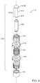
- FIG. 4is an exploded perspective view of a variation of a fluid control valve with an external energy storage device.
- FIG. 5Ais a sectional view of the fluid control valve of FIG. 4 as installed in a wall of thin film material.
- FIG. 5Bis an exploded view of one variation of a socket assembly.
- FIG. 6illustrates a perspective view of the fluid control valve as a plug is being inserted into a socket assembly.
- FIG. 1illustrates schematic block diagram of an exemplary fluid fillable balloon device; in particular, it illustrates a gastric balloon device assembly 100 .
- FIG. 2is an illustration of device 100 in place in a patient's stomach after it has been inflated but before the filling tube has been removed.
- the devicegenerally comprises two states of interest: a pre-deployment or uninflated configuration and a deployed, inflated or active configuration; the deployed configuration is shown.
- the deviceis inflated with a fluid delivered through a tube 110 , also referred to herein as a catheter or conduit, wherein the tube may pass through a lumen in the wall of the balloon device or is coupled to a fluid path 112 between the exterior and the interior of the balloon device.
- the wall 102 of the balloonis fabricated from a thin film material such as, for example, polyurethane.
- the tubecomprises a balloon end or internal section 110 A that extends through fluid path 112 into the central enclosed space or reservoir 104 of device 100 .
- internal section 110 Astops short of the reservoir 104 .
- the conduit 110can be removed from the device once inflation is completed or after partial inflation. When the conduit is removed, fluid path 112 must be sealed to prevent the inflation fluid from leaking out, where sealing is accomplished by fill valve 113 , illustrated in FIG. 1 , which may comprise an external section 113 B, an internal section 113 A.
- elements of the fill valve 113have components installed inside conduit 110 as well as in fluid path 112 .
- balloon devicemay be self-inflating, wherein, for example, two reactive chemicals pre-stored inside the uninflated balloon combine once the balloon is in place.
- the combined materialssuch as an acid and bicarbonate of soda, give off a gas that inflates the balloon.
- release valve 126is a single-use device; that is, once it opens to release fluid it cannot close, or at least is not closed, again.
- the valvemay comprise a patch 128 of degradable material, which degrades or opens when exposed to either the natural stomach fluids or the filling fluid contained within reservoir 104 . Once patch 128 degrades, the filling fluid is free to escape into the patient's stomach. In certain cases, the degradation rate of the patch, and the resulting flow rate, cannot be controlled adequately.
- the release valves described hereinimprove the timing and adequacy of the flow rate of the release of filler fluids by controlling the degrading fluid and by providing a
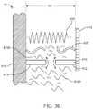
- FIG. 3Ais an exemplary mechanical schematic diagram of a fluid control valve system 10 that has a binary flow condition or operation, where “binary” indicates that the valve comprises an open state and a closed state. Where in the closed state the valve is closed to either fully or significantly prevent fluid flow. In the open state, the valve allows partial or maximum fluid flow.
- a mechanical schematic diagramis a simplified representation of the functional components of a mechanical system and the mechanical relationship therebetween. It does not necessarily represent the physical forms of the mechanical elements nor the physical layout, attachment, or configuration of any actual components.
- control valve system 10is achieved through the addition of an energy storage device disposed to force the valve to the fully open condition, a valve system 10 is disposed between two otherwise isolated spaces, spaces 510 and 520 , at least one of which contains a fluid 415 A. In some variations the second space also contains a fluid 415 B. In this variation, a valve system 10 includes three core mechanical components. The main component is a valve mechanism 410 that blocks or unblocks the flow of fluid from one space to the other. Schematically in FIG.
- valve mechanism 410is depicted as comprising a two element gate ( 412 , 414 ), where one element of the gate is a base 414 and a second element is a traveler 412 where traveler 412 and base 414 abut tightly enough to block the flow of any fluid 415 A/ 415 B through valve mechanism 410 .
- a mechanical schematiconly represents functional elements and is not intended to indicate the physical form of the element effecting that function.
- valve system 10comprises a second core component, an energy storage device 420 , for example a spring, where the energy storage device is disposed to move traveler 412 away from base 414 .
- an energy storage device 420for example a spring
- energy storage device 420is initially in a high energy storage configuration and disposed between head 418 and base support 416 with a distance D 1 between head 418 and base support 416 .
- the compressed energy storage device 420generates a force F directed to push traveler 412 away from base 414 , as indicated by the arrowheads at the ends of spring 420 .
- Energy storage device 420does not need to be attached to either head 418 or base support 416 (or, equivalently base 414 or traveler 412 ).
- one or both sides of the devicecan be connected to the respective adjacent head 418 or base support 416 .
- the third core component of a valve system 10is a restraining element 425 .
- restraining element 425is also disposed between head 418 and base support 416 , where restraining element 425 is in tension T which holds head 418 and base support 416 from moving apart, as indicated by the arrowheads showing the forces felt by head 418 and base support 416 .
- Valve system 10switches between the no-flow condition, shown schematically in FIG. 3A , and the full-flow condition, shown schematically in FIG. 3B , when restraining element 425 loses its ability to counteract the force F of energy storage device 420 .
- restraining element 425can be designed to lose strength by changing its temperature, by hydrolysis, by dissolution, by oxidation, or by any means appropriate for the restraining material and operational environment.
- restraining element 425breaks when the spring force exceeds the remaining strength of element 425 , as illustrated in the figure, but element 425 may also lose its ability to maintain the required tension if it plasticly deforms, that is, stretches permanently, or elastically deforms.
- restraining element 425allows energy storage device 420 to increase the distance between base support 416 and head 418 to D 2 , thereby allowing fluid flow through valve mechanism 410 as shown by the arrows.
- head 418 , traveler 412 , and a portion of restraining element 425no longer have a connection to base support 416 indicating that those parts of fluid control valve system 10 are free to float away by a distance greater than D 2 .
- energy storage device 420may be attached to head 418 instead of base support 416 while in yet other variations energy storage device 420 may connect head 418 and base support 416 even after opening, in which case D 2 is the length of energy storage device 420 in its low energy condition (e.g., no longer in compression). In yet other variations energy storage device 420 is not physically attached to either base support 416 or head 418 , in which case it may become a free-floating element once the constraining tension of restraining element 425 is removed.
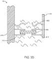
- FIGS. 3C, 3E, and 3Fare alternative mechanical schematics of the same fluid control valve system as depicted in FIG. 3A .
- FIG. 3Cillustrate a variation in which base 414 and traveler 412 sandwich energy storage device 420 between themselves directly (that is, the spring sits between the two portions and directly bears on them to move them apart) while restraining element 425 is directly or indirectly attached to the exterior of the “sandwich” to hold base 414 and traveler 412 tightly together, compressing energy storage device 420 .
- the mechanical schematic of FIG. 3Dillustrates the after-release mechanical relationships of the elements in the schematic of FIG. 3C .
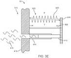
- FIG. 3Eillustrates schematically a variation of the valve system in which base 414 is in the form of a fluid path 450 which channels fluid 415 between the isolated spaces 510 , 520 .
- Traveler 412forms a plug or stopper that blocks fluid path 450 when the valve system is in its normally closed condition.
- the mechanical schematic of FIG. 3Ehelps clarify the use of a control valve system 10 in fluid filled balloon applications an embodiment of which is discussed below.
- control valve system 10it is possible to combine two or more functions into one physical element.
- the base, traveler, and restraining elementare all embodied in a single close-ended tube 530 .
- tube 530is a sealed fluid path between spaces 510 and 520 .
- Energy storage device 420is disposed to apply a force that is directed to pull the two ends 412 , 414 of tube 530 apart.
- the two endsdo not move apart while the walls of tube 530 remain strong enough to withstand the applied force.
- the restraining elementloses strength, as it is designed to do in specific environments, it will eventually allow the spring to pull tube 530 into two pieces, forming traveler 412 and base 414 and essentially allowing flow through the base support 416 , as shown in FIG. 3G .
- base 414 and traveler 412may comprise two jaws of a hinged component, with energy storage device 420 acting to open the hinge and restraining element 425 holding the hinge closed until element 424 loses strength as designed.
- FIG. 4is an exploded view of one variation of valve system 10 with an exterior energy storage device 420 in the form of a coil spring, where exterior indicates the spring 420 is exterior to the flow path through the valve system 10 .
- valve 410 of FIG. 3Acomprises traveler 412 in the form of a plug or pin, base 414 in the form of a socket into which plug 412 is inserted, and a compliant gasket 427 that surrounds plug 412 to ensure a snug and leak-proof fit when plug 412 is inserted into socket 414 .
- this variation of valve system 10also comprises energy storage device 420 implemented as a coil spring disposed between a spoked head 418 and a substantially identical spoked base support 416 , wherein restraining element 425 is a suture-like release material that is looped or stitched between the spokes of head 418 and base support 416 .
- Head 418 and base support 416each have a central hole large enough to accommodate plug 412 surrounded by gasket 427 .
- release material 425is stitched in a pattern to minimize tilting of head 418 relative to base support 416 both before and after initial release material breakdown.
- plug 412comprises an extended body 412 A with a larger diameter pinhead 412 B at one end, where the length of the extended body is designed to be longer than the length of the compressed coil spring 420 plus the thicknesses of the head 418 and base support 416 , and the diameter of pinhead 412 B is designed to be larger than the hole in head 418 to prevent plug 412 from fully entering or passing through the hole in head 418 .
- the spring, head, base support, and release materialcomprise a valve release subassembly 440 .
- socket 414is essentially a cylindrical tube disposed between the two spaces comprising a central lumen that allows fluid flow between the two spaces.
- socket 414is fabricated as a socket subassembly 442 that allows the socket to be attached to the wall 102 separating the two spaces, as will be described below.
- valve system 10is assembled by inserting plug 412 (with gasket 427 ), through the lumen in valve release subassembly 440 formed by the open central region of coiled spring 420 such that a tip 419 of plug 412 extends beyond the end of valve release subassembly 440 by a designed length.
- the exposed tip 419 of plug 412surrounded by gasket 427 , is subsequently inserted into socket subassembly 442 , where the gasketed tip 419 seals the lumen in socket subassembly 442 against fluid flow.
- tip 419 of plug 412is bulbous to compress gasket 427 against the innermost surface of socket assembly 442 while providing a leading edge that guides tip 419 into the lumen.
- valve system 10can be installed to control fluid flow between two spaces separated by a wall 102 of thin film material. While FIGS. 1 and 2 suggest the use of a valve system 10 to release fluid from a gastric balloon fabricated from thin film material, this is but an exemplary use.
- the valves described hereinmay be used in any situation where there is a fluid impervious barrier material separating two spaces and where fluid may be present on either or both sides of the barrier material.
- a valve system 10can be used to temporarily separate two reactive chemicals where one chemical is in fluid form.
- socket subassembly 442is attached to wall 102 , through which a hole is provided for fluid flow.
- a holeis provided for fluid flow.
- socket assembly 442comprises three parts: a retaining ring 444 , a wall anchor 310 , and a gasket jacket 210 .
- Gasket jacket 210is a thin-walled, hollow cylinder.
- the inner wall of the hollow cylinderis sized, and sometimes shaped, to grip the compliant, gasketed tip 419 of plug 412 .
- the inner wallmay be tapered to have a wider opening to accept plug 412 and to guide the tip 419 into a narrower portion wherein the compliant gasket is squeezed to make a tight fit.
- the inner wallmay be inscribed with a number of circumferential ridges and grooves to better grip the compliant gasket.
- the inner wallmay have an indented groove with a circular segment cross-section that matches the bulbous tip 419 of the gasketed plug; this groove acts a detent to provide a positive hold on tip 419 .
- Wall anchor 310is the primary means to attached gasket jacket 210 to a thin-film wall 102 . It is used to pinch a shaped section of wall 102 against the exterior of gasket jacket 210 . This pinching behavior is illustrated in the exploded, cross sectional view of socket assembly 442 of FIG. 5B .
- the wall sectionstarts out as a flat sheet but takes on the illustrated “stovepipe hat” shape after being stretched over a mandrel. Gasket jacket 210 is then inserted inside the wall section, most easily from the “brim” side of the stovepipe hat while wall anchor 310 is slipped over the exterior of the “pipe” section of the stovepipe, thereby trapping the wall material between jacket 210 and anchor 310 .
- anchor 310is fabricated from a soft material, for example a plastic, and toleranced to enclose the wall material without pulling or tearing it. Finally, a retaining ring 444 is placed over anchor 310 to squeeze it tightly against wall material 102 , pinching the material against gasket jacket 210 .
- FIG. 6illustrates one method for inserting plug 412 (with valve release subassembly 440 in place) into a socket assembly 442 that has been pre-installed in a wall 102 .
- gasket 427is extended by a convenient length to form a gasket extension 427 A that extends a convenience distance beyond plug tip 419 .
- This extended length 427 Ais not filled by any solid and can easily be threaded through the lumen in gasket jacket 210 .
- a portion 427 B of gasket extension 427 Aemerges through the lumen in gasket jacket 210 on the opposite side of wall 102 from plug 412 .
- Gasket extension 427 Amoves with relative ease through gasket jacket 210 because there is no plug inside this portion of the gasket.
- Tip 419 of plug 412is drawn into gasket jacket 210 by pulling on gasket extension 427 B until tip 419 is captured by jacket 210 .
- tip 419 and the gasket around itcannot pass fully through the lumen, so continuing to pull on gasket extension 427 B creates an increasing tension on gasket 427 .
- a preferential detachment point 429is created in gasket 427 by weakening the gasket at a pre-determined location by partially cutting through the gasket, creating a circumferential score, or otherwise weakening the gasket at the desired location.
- the desired locationseparates gasket 427 from gasket extension 427 A.
- the valveis installed in a fluid impervious wall 102 separating two spaces on either side of the wall, where at least one space has a fluid.
- Plug 412substantially fills the lumen in gasket jacket 210 and presses gasket 427 against the inner wall of the lumen in gasket jacket 210 to seal the lumen against fluid transfer.
- the space in which release valve subassembly 440 is locatedwill be designated as first or interior space and is bounded by wall 102 .
- release material 425is susceptible to deterioration when exposed to the environmental conditions in the interior space. In many variations the release material is filamentary.
- release materialsthat are available in filamentary suture form can include Polyglycolide (PGA), Polydioxanone (PDS), Poly(lactic-co-glycolic acid) (PLGA), Polylactide (PLA), Poly (4-hydroxybutyric acid) (P4HB), Polyglactin 910, and Polycaprolactone (PCL).
- PGAPolyglycolide
- PDSPolydioxanone
- PLGAPoly(lactic-co-glycolic acid)
- PLAPolylactide
- P4HBPoly (4-hydroxybutyric acid)
- PCLPolycaprolactone
- the interior spacemay be filled with a fluid which, over a designed period of time, dissolves or hydrolyses the suture.
- release material 425may be melted or softened by increasing the temperature in the interior space.
- release material 425Independent of the way release material 425 is weakened, after a designed time period the residual strength of release material 425 is inadequate to constrain the stored energy in spring 420 .
- spring 420expands it causes head 418 and base support 416 to separate. By definition, as they separate the distance between them enlarges.
- extended body 412 APrior to release material deterioration, extended body 412 A reached between the top of head 418 , through base support 416 , and into socket 414 . As the distance between head 418 and base support 416 increases, extended body 412 A is pulled into valve release subassembly 440 from the base support end, plug 412 being prevented from entering head 418 by pinhead 412 B. As extended body 412 A is pulled into valve release subassembly 440 it is automatically extracted from socket 414 , opening fluid control valve system 10 to allow fluid transfer between the interior space and a second or exterior space exterior to the wall 102 .
Landscapes
- Health & Medical Sciences (AREA)
- Engineering & Computer Science (AREA)
- General Engineering & Computer Science (AREA)
- Mechanical Engineering (AREA)
- Biomedical Technology (AREA)
- Life Sciences & Earth Sciences (AREA)
- Nursing (AREA)
- Orthopedic Medicine & Surgery (AREA)
- Child & Adolescent Psychology (AREA)
- Heart & Thoracic Surgery (AREA)
- Vascular Medicine (AREA)
- Obesity (AREA)
- Animal Behavior & Ethology (AREA)
- General Health & Medical Sciences (AREA)
- Public Health (AREA)
- Veterinary Medicine (AREA)
- Surgical Instruments (AREA)
- Infusion, Injection, And Reservoir Apparatuses (AREA)
- Prostheses (AREA)
Abstract
Description
Claims (24)
Priority Applications (4)
| Application Number | Priority Date | Filing Date | Title |
|---|---|---|---|
| US16/505,468US11098813B2 (en) | 2018-07-06 | 2019-07-08 | Binary fluid control valve system |
| US17/377,039US11828377B2 (en) | 2018-07-06 | 2021-07-15 | Binary fluid control valve system |
| US18/472,735US12209677B2 (en) | 2018-07-06 | 2023-09-22 | Binary fluid control valve system |
| US18/982,766US20250122943A1 (en) | 2018-07-06 | 2024-12-16 | Binary fluid control valve system |
Applications Claiming Priority (2)
| Application Number | Priority Date | Filing Date | Title |
|---|---|---|---|
| US201862694813P | 2018-07-06 | 2018-07-06 | |
| US16/505,468US11098813B2 (en) | 2018-07-06 | 2019-07-08 | Binary fluid control valve system |
Related Child Applications (1)
| Application Number | Title | Priority Date | Filing Date |
|---|---|---|---|
| US17/377,039ContinuationUS11828377B2 (en) | 2018-07-06 | 2021-07-15 | Binary fluid control valve system |
Publications (2)
| Publication Number | Publication Date |
|---|---|
| US20200011442A1 US20200011442A1 (en) | 2020-01-09 |
| US11098813B2true US11098813B2 (en) | 2021-08-24 |
Family
ID=69060359
Family Applications (4)
| Application Number | Title | Priority Date | Filing Date |
|---|---|---|---|
| US16/505,468Expired - Fee RelatedUS11098813B2 (en) | 2018-07-06 | 2019-07-08 | Binary fluid control valve system |
| US17/377,039ActiveUS11828377B2 (en) | 2018-07-06 | 2021-07-15 | Binary fluid control valve system |
| US18/472,735ActiveUS12209677B2 (en) | 2018-07-06 | 2023-09-22 | Binary fluid control valve system |
| US18/982,766PendingUS20250122943A1 (en) | 2018-07-06 | 2024-12-16 | Binary fluid control valve system |
Family Applications After (3)
| Application Number | Title | Priority Date | Filing Date |
|---|---|---|---|
| US17/377,039ActiveUS11828377B2 (en) | 2018-07-06 | 2021-07-15 | Binary fluid control valve system |
| US18/472,735ActiveUS12209677B2 (en) | 2018-07-06 | 2023-09-22 | Binary fluid control valve system |
| US18/982,766PendingUS20250122943A1 (en) | 2018-07-06 | 2024-12-16 | Binary fluid control valve system |
Country Status (5)
| Country | Link |
|---|---|
| US (4) | US11098813B2 (en) |
| EP (2) | EP3813922B1 (en) |
| CN (2) | CN112638464B (en) |
| ES (1) | ES2974220T3 (en) |
| WO (1) | WO2020010359A1 (en) |
Cited By (6)
| Publication number | Priority date | Publication date | Assignee | Title |
|---|---|---|---|---|
| US11497900B2 (en) | 2018-12-13 | 2022-11-15 | Allurion Technologies, Inc. | Enhanced fluid delivery system |
| US11559418B2 (en) | 2018-02-26 | 2023-01-24 | Allurion Technologies, Inc. | Automatic-sealing balloon-filling catheter system |
| US11766346B2 (en) | 2012-02-21 | 2023-09-26 | Allurion Technologies, Inc. | Methods and devices for deploying and releasing a temporary implant within the body |
| US11828377B2 (en) | 2018-07-06 | 2023-11-28 | Allurion Technologies, Inc. | Binary fluid control valve system |
| US12245962B2 (en) | 2023-04-12 | 2025-03-11 | Allurion Technologies, Inc. | Balloon sealing and fill valve |
| US12246163B2 (en) | 2023-04-12 | 2025-03-11 | Allurion Technologies, Inc. | Automatic-sealing balloon-filling catheter system |
Families Citing this family (1)
| Publication number | Priority date | Publication date | Assignee | Title |
|---|---|---|---|---|
| ES2608629T3 (en) | 2012-02-21 | 2017-04-12 | Allurion Technologies, Inc. | Devices for deployment and release of a temporary implant in the body |
Citations (105)
| Publication number | Priority date | Publication date | Assignee | Title |
|---|---|---|---|---|
| US2911988A (en) | 1956-01-24 | 1959-11-10 | Clarence J Ravn | Moisture releasable drain valve |
| US3586018A (en) | 1969-02-24 | 1971-06-22 | Thermia Verken Ab | Self-closing valve |
| US3638733A (en)* | 1970-03-03 | 1972-02-01 | Kidde & Co Walter | Heat operated fire extinguisher |
| US3853116A (en) | 1971-06-21 | 1974-12-10 | Investors In Ventures Inc | Implant methods and devices for influencing body fluids |
| US4133315A (en) | 1976-12-27 | 1979-01-09 | Berman Edward J | Method and apparatus for reducing obesity |
| US4141771A (en) | 1976-04-28 | 1979-02-27 | Imperial Chemical Industries Limited | Method of thermoforming |
| US4370374A (en) | 1979-09-04 | 1983-01-25 | Plate Bonn Gesellschaft Mit Beschrankter Haftung | Multilayer plastic film, process for its production and its use |
| US4723547A (en) | 1985-05-07 | 1988-02-09 | C. R. Bard, Inc. | Anti-obesity balloon placement system |
| US4732188A (en)* | 1987-06-15 | 1988-03-22 | Gt Development Corporation | Fuel tank cap with pressure/thermal relief |
| US4739758A (en) | 1986-05-19 | 1988-04-26 | Criticare Systems, Inc. | Apparatus for stomach cavity reduction |
| US4842007A (en) | 1988-09-08 | 1989-06-27 | Guard Associates, Inc. | Self-sealing valve for inflated bodies |
| US4899747A (en) | 1981-12-10 | 1990-02-13 | Garren Lloyd R | Method and appartus for treating obesity |
| US4949756A (en) | 1988-08-31 | 1990-08-21 | Uresil Corporation | One-way valve |
| US5018665A (en)* | 1990-02-13 | 1991-05-28 | Hale Fire Pump Company | Thermal relief valve |
| US5181921A (en) | 1990-05-25 | 1993-01-26 | Kaken Co., Ltd. | Detachable balloon with two self-sealing valves |
| US5336123A (en) | 1992-04-08 | 1994-08-09 | Vonco Products, Inc. | Inflatable flexible pouch |
| US5348537A (en) | 1992-07-15 | 1994-09-20 | Advanced Cardiovascular Systems, Inc. | Catheter with intraluminal sealing element |
| US5496203A (en) | 1994-03-25 | 1996-03-05 | Murray; Robert H. | Balloon valve assembly |
| US5507808A (en) | 1994-10-26 | 1996-04-16 | Becker; Hilton | Filling tube and seal construction |
| US5595521A (en) | 1994-01-10 | 1997-01-21 | M & D Balloons, Inc. | Balloons and balloon valves |
| US5950624A (en) | 1996-07-09 | 1999-09-14 | Hart; William T. | Oral appliance having hollow body |
| WO2000012167A1 (en) | 1998-08-26 | 2000-03-09 | Microcatheters Pty. Ltd. | Catheter guide |
| US6162251A (en) | 1999-05-25 | 2000-12-19 | Novamed Medical Products Manufacturing, Inc. | Saline implant having single valve with primary and secondary closures |
| US6259953B1 (en) | 1998-07-28 | 2001-07-10 | Intermedics, Inc. | cardiac lead with active fixation and biocompatible lubricant |
| US6367499B2 (en)* | 2000-03-02 | 2002-04-09 | Hamai Industries Limited | Safety valve |
| US6375972B1 (en) | 2000-04-26 | 2002-04-23 | Control Delivery Systems, Inc. | Sustained release drug delivery devices, methods of use, and methods of manufacturing thereof |
| US6460541B1 (en) | 2000-11-07 | 2002-10-08 | Polyzen, Inc. | Heat-sealed inflatable article, and method of making the same |
| US20020183777A1 (en) | 2001-06-04 | 2002-12-05 | Shannon Donald T. | Shrouded strain relief medical balloon device and method of use |
| US20020198470A1 (en) | 2001-06-26 | 2002-12-26 | Imran Mir A. | Capsule and method for treating or diagnosing the intestinal tract |
| US20030106583A1 (en)* | 2001-12-12 | 2003-06-12 | Hsi-Kuang Weng | General-purpose thermally-sensitive safety apparatus |
| US6644336B2 (en) | 2001-06-12 | 2003-11-11 | Oil States Industries, Inc. | Method and apparatus for automatic shutoff of a valve when a substance is present in a flow of fluid |
| US20030229263A1 (en) | 2000-04-14 | 2003-12-11 | Connors Kevin G. | Treatment of patients with a compressible attenuation device |
| US20030229384A1 (en) | 2000-06-20 | 2003-12-11 | Celsion Corporation | Method and apparatus for treatment of tissue adjacent a bodily conduit with a compression balloon |
| US6712832B2 (en) | 2001-10-15 | 2004-03-30 | Tilak M. Shah | Low-pressure medical balloons and method of making same |
| US20040101540A1 (en) | 1999-09-01 | 2004-05-27 | John Cooker | Oral delivery system and method for making same |
| US20040146559A1 (en) | 2002-09-28 | 2004-07-29 | Sowden Harry S. | Dosage forms having an inner core and outer shell with different shapes |
| US20040186502A1 (en) | 2003-03-19 | 2004-09-23 | Sampson Douglas C. | Self-Inflating intragastric volume-occupying device |
| US6814097B2 (en)* | 2001-03-20 | 2004-11-09 | Teleflex Gfi Control Systems L.P. | Pressure relief device |
| US20050055039A1 (en) | 2003-07-28 | 2005-03-10 | Polymorfix, Inc. | Devices and methods for pyloric anchoring |
| US20050150548A1 (en)* | 2003-03-02 | 2005-07-14 | Toshio Kita | Safety valve |
| US6939292B2 (en) | 2001-06-20 | 2005-09-06 | Olympus Corporation | Capsule type endoscope |
| WO2006020929A2 (en) | 2004-08-13 | 2006-02-23 | Phagia Technology | Intragastric volume-occupying device |
| US20060222705A1 (en) | 2005-03-31 | 2006-10-05 | Flanner Henry H | Pharmaceutical tablet and apparatus and method for making |
| US20070010791A1 (en) | 2005-07-07 | 2007-01-11 | Bristol-Myers Squibb Company | Valve for inflatable chamber of medical device |
| US7172613B2 (en) | 2000-03-13 | 2007-02-06 | Districlass Medical Sa | Intragastric device for treating morbid obesity |
| US20070078476A1 (en) | 2004-10-12 | 2007-04-05 | Hull Wendell C Sr | Overweight control apparatuses for insertion into the stomach |
| CA2925648A1 (en) | 2005-10-31 | 2007-05-10 | Reshape Medical, Inc. | Intragastric space filler with safety device |
| JP2008513132A (en) | 2004-09-16 | 2008-05-01 | ジュヴァ・メディカル・インコーポレーテッド | Tissue augmentation device |
| US20080195226A1 (en) | 2006-09-02 | 2008-08-14 | Williams Michael S | Intestinal sleeves and associated deployment systems and methods |
| US20080243071A1 (en) | 2007-03-30 | 2008-10-02 | Quijano Rodolfo C | Intragastric balloon system and therapeutic processes and products |
| US20080241094A1 (en) | 2002-12-19 | 2008-10-02 | Baronova, Inc. | Ingestible formulations for transient, noninvasive reduction of gastric volume |
| US20080249635A1 (en) | 2007-04-05 | 2008-10-09 | Barry Weitzner | Gastric filler devices for obesity therapy |
| US20080269555A1 (en) | 2005-02-24 | 2008-10-30 | Compagnie Europeenne D'etude Et De Recherche De Di Spositifs Pour L'lmplantation Par Laparoscopie | Intragastric Balloon With Extraction Reinforcement |
| US20080276992A1 (en)* | 2004-11-11 | 2008-11-13 | Kaoru Nomichi | Relief Valve Device |
| US20090024227A1 (en) | 2004-09-16 | 2009-01-22 | Evera Medical, Inc. | Methods of forming a multilayer tissue implant to create an accordion effect on the outer layer |
| US7485093B2 (en) | 2002-04-25 | 2009-02-03 | Given Imaging Ltd. | Device and method for in-vivo sensing |
| US20090118756A1 (en) | 2005-06-01 | 2009-05-07 | Nicolas Francois Michel Valencon | Intra-gastric balloon provided with a gel-containing valve, kit and use thereof |
| WO2009059803A1 (en) | 2007-11-09 | 2009-05-14 | Venera Khafizova | Externally inflatable gastric balloon device |
| WO2009059802A1 (en) | 2007-11-09 | 2009-05-14 | Venera Khafizova | Self-deflating gastric balloon device |
| US20090192535A1 (en) | 2007-12-20 | 2009-07-30 | Kasic Ii James | Swallowable Self-Expanding Gastric Space Occupying Device |
| US20090259246A1 (en) | 2008-04-14 | 2009-10-15 | Sherif Eskaros | Intragastric Volume-Occupying Device |
| US20090277515A1 (en)* | 2008-05-07 | 2009-11-12 | Rainer Pechtold | Resettable thermal pressure relief device |
| US20090299327A1 (en) | 2008-06-02 | 2009-12-03 | Lorna Vista Medical, Inc. | Inflatable medical devices |
| US20100062057A1 (en) | 2008-09-10 | 2010-03-11 | Pronova BioPharma Norge AS. | Formulation |
| US20100100116A1 (en) | 2008-10-16 | 2010-04-22 | Obalon Therapeutics, Inc. | Intragastric volume-occupying device and method for fabricating same |
| US20100114311A1 (en) | 2008-11-05 | 2010-05-06 | Hilton Becker | Multi-Lumen Breast Prothesis and Improved Valve Assembly Therefor |
| US20100121224A1 (en) | 2007-03-26 | 2010-05-13 | Jms Co., Ltd. | Balloon for measuring pressure related to oral cavity and method for producing the same |
| US20100174307A1 (en) | 2007-04-13 | 2010-07-08 | Allergan, Inc. | Remote deflation of intragastric balloon |
| US20100193050A1 (en)* | 2006-11-06 | 2010-08-05 | Job Lizenz Gmbg & Co. Kg | Safety valve for a gas cylinder |
| US20100246165A1 (en) | 2009-03-31 | 2010-09-30 | Diaz Edmundo B | Invisible and/ or non-invisible designed inflatables combined with electric black ultra-violet lights and inflator nozzle fixture accessories |
| US20100274194A1 (en) | 2003-06-20 | 2010-10-28 | Allergan, Inc. | Two-way slit valve |
| US20110004236A1 (en) | 2009-07-01 | 2011-01-06 | E2 Llc | Systems and Methods for Treating Obesity and Type 2 Diabetes |
| US20110112383A1 (en) | 2005-11-08 | 2011-05-12 | Plensat, Inc | Devices, systems and methods for treatment of eating disorders |
| WO2011106157A1 (en) | 2010-02-25 | 2011-09-01 | Ethicon Endo-Surgery, Inc. | Devices for treating morbid obesity using hydrogel |
| CN201977967U (en) | 2011-01-18 | 2011-09-21 | 郭加 | Intragastric ball packing device for losing weight |
| US8183227B1 (en) | 2011-07-07 | 2012-05-22 | Chemo S. A. France | Compositions, kits and methods for nutrition supplementation |
| US20120141545A1 (en) | 2010-12-03 | 2012-06-07 | Fuisz Richard C | Solid Dosage Form That Promotes Reliable Oral, Esophageal and GI Transit |
| US20120141544A1 (en) | 2010-12-03 | 2012-06-07 | Fuisz Richard C | Solid Dosage Form That Promotes Reliable Oral, Esophageal and GI Transit |
| US8202291B1 (en) | 2011-01-21 | 2012-06-19 | Obalon Therapeutics, Inc. | Intragastric device |
| US8292911B2 (en) | 2011-01-21 | 2012-10-23 | Obalon Therapeutics, Inc. | Intragastric device |
| US20120273050A1 (en)* | 2011-04-28 | 2012-11-01 | K&N Innovations, LLC | Automatic Shutoff Drain |
| US20130035711A1 (en) | 2010-10-18 | 2013-02-07 | Allergan, Inc. | Intragastric balloon for treating obesity |
| US20130165873A1 (en) | 2007-01-24 | 2013-06-27 | Acclarent, Inc. | Methods, devices and systems for treating and/or diagnosis of disorders of the ear, nose and throat |
| US20130190796A1 (en) | 2010-07-13 | 2013-07-25 | Loma Vista Medical, Inc. | "inflatable medical devices" |
| US20130218190A1 (en) | 2012-02-21 | 2013-08-22 | Allurion Technologies, Inc. | Methods and devices for deploying and releasing a temporary implant within the body |
| US20130289604A1 (en) | 2011-01-21 | 2013-10-31 | Obalon Therapeutics, Inc | Intragastric device |
| US20130296751A1 (en) | 2012-03-29 | 2013-11-07 | Ruth E. Martin | Oral device and method for the use thereof |
| US8585676B2 (en) | 2007-02-05 | 2013-11-19 | Polyzen Inc. | Multi-lumen lay-flat tubing, catheter articles comprising same, and method of manufacture thereof |
| US20140066967A1 (en) | 2012-02-21 | 2014-03-06 | Allurion Technologies, Inc. | Anatomically adapted ingestible delivery systems and methods |
| US8740845B2 (en) | 2007-09-25 | 2014-06-03 | Polyzen Inc. | Multi-layer film welded articulated balloon |
| US20140188151A1 (en) | 2012-02-21 | 2014-07-03 | Allurion Technologies, Inc. | Methods and devices for deploying and releasing a temporary implant within the body |
| US8784486B2 (en) | 2008-04-28 | 2014-07-22 | Allergan, Inc. | Breast implants having a flush patch and methods of using same to augment or reconstruct a breast |
| WO2015066545A1 (en) | 2013-11-01 | 2015-05-07 | Allurion Technologies, Inc. | Methods and devices for deploying and releasing a temporary implant within the body |
| US20150196408A1 (en) | 2012-02-21 | 2015-07-16 | Allurion Technologies, Inc. | Methods and devices for deploying and releasing a temporary implant within the body |
| US20160010758A1 (en)* | 2013-03-04 | 2016-01-14 | Kawasaki Jukogyo Kabushiki Kaisha | Fusible plug type pressure relief valve |
| US20160109029A1 (en) | 2014-10-15 | 2016-04-21 | Baker Products Ltd. | Temperature controlled purge valve with washer/o-ring seal stack |
| WO2016145076A1 (en) | 2015-03-09 | 2016-09-15 | Allurion Technologies, Inc. | Methods and devices for deploying and releasing a temporary implant within the body |
| US9463106B2 (en) | 2012-09-10 | 2016-10-11 | Boston Scientific Scimed, Inc. | Catheter with releasable balloon and related methods |
| US20170211715A1 (en) | 2016-01-21 | 2017-07-27 | GM Global Technology Operations LLC | Oil bypass valve with temporary spacer to provide initially opened fluid circuit |
| WO2017136840A1 (en) | 2016-02-05 | 2017-08-10 | Allurion Technologies, Inc. | Method of fabrication for devices for deploying and releasing a temporary implant within the body |
| US20170312111A1 (en) | 2016-04-27 | 2017-11-02 | Synerz Medical, Inc. | Anchorless Intragastric Device For Treating Obesity |
| WO2018142761A1 (en) | 2017-01-31 | 2018-08-09 | 日本ライフライン株式会社 | Balloon catheter |
| US20180311484A1 (en) | 2017-05-01 | 2018-11-01 | Allurion Technologies, Inc. | Method of fabrication for devices for deploying and releasing a temporary implant within the body |
| WO2019165449A1 (en) | 2018-02-26 | 2019-08-29 | Allurion Technologies, Inc. | Automatic-sealing balloon-filling catheter system |
| WO2020010359A1 (en) | 2018-07-06 | 2020-01-09 | Allurion Technologies, Inc. | Binary fluid control valve system |
Family Cites Families (46)
| Publication number | Priority date | Publication date | Assignee | Title |
|---|---|---|---|---|
| BE414416A (en) | 1934-03-01 | |||
| US3592207A (en)* | 1969-05-12 | 1971-07-13 | Richard A Borello | Air duct closure |
| US4253201A (en) | 1979-05-24 | 1981-03-03 | Ross David A | Prosthesis with self-sealing valve |
| US4614188A (en) | 1980-08-15 | 1986-09-30 | Seymour Bazell | Balloon catheter |
| US4636213A (en) | 1985-01-24 | 1987-01-13 | Pakiam Anthony I | Implantable prosthesis |
| US5092847A (en) | 1990-04-06 | 1992-03-03 | Sherwood Medical Company | Enteral feeding tube stylet |
| US5222970A (en) | 1991-09-06 | 1993-06-29 | William A. Cook Australia Pty. Ltd. | Method of and system for mounting a vascular occlusion balloon on a delivery catheter |
| US5632297A (en)* | 1995-09-26 | 1997-05-27 | Amcast Industrial Corporation | Piston-type thermally or pressure activated relief device |
| DE19831698C2 (en)* | 1998-07-15 | 2000-08-31 | Caremed Medical Produkte Ag | Check valve, in particular for an implantable artificial bladder |
| US6453907B1 (en) | 1999-08-12 | 2002-09-24 | Obtech Medical Ag | Food intake restriction with energy transfer device |
| US6663648B1 (en) | 2000-06-15 | 2003-12-16 | Cordis Corporation | Balloon catheter with floating stiffener, and procedure |
| US6733512B2 (en)* | 2002-03-07 | 2004-05-11 | Mcghan Jim J. | Self-deflating intragastric balloon |
| US7169134B2 (en)* | 2002-03-26 | 2007-01-30 | Ultradent Products, Inc. | Apparatus with rotatable valve syringe |
| US6981978B2 (en) | 2002-08-30 | 2006-01-03 | Satiety, Inc. | Methods and devices for maintaining a space occupying device in a relatively fixed location within a stomach |
| US9060844B2 (en) | 2002-11-01 | 2015-06-23 | Valentx, Inc. | Apparatus and methods for treatment of morbid obesity |
| DK174883B1 (en)* | 2003-02-27 | 2004-01-19 | Unomedical As | Disposable urine bag for collecting urine |
| US20060058829A1 (en) | 2003-03-19 | 2006-03-16 | Sampson Douglas C | Intragastric volume-occupying device |
| US8048169B2 (en) | 2003-07-28 | 2011-11-01 | Baronova, Inc. | Pyloric valve obstructing devices and methods |
| US7951121B2 (en)* | 2003-07-30 | 2011-05-31 | Navilyst Medical, Inc. | Pressure actuated valve with improved slit configuration |
| US20060004323A1 (en) | 2004-04-21 | 2006-01-05 | Exploramed Nc1, Inc. | Apparatus and methods for dilating and modifying ostia of paranasal sinuses and other intranasal or paranasal structures |
| US20070207199A1 (en) | 2005-12-28 | 2007-09-06 | Sogin Stephen J | Appetite suppression device |
| FR2897529B1 (en) | 2006-02-17 | 2008-10-31 | Cie Euro Etude Rech Paroscopie | INTRA-GASTRIC BALLOON WITH SHAPE MEMORY |
| US8398668B2 (en) | 2006-04-19 | 2013-03-19 | Vibrynt, Inc. | Devices and methods for treatment of obesity |
| US7740023B2 (en)* | 2006-08-18 | 2010-06-22 | Restaurant Technologies, Inc. | Check valve assemblies and related methods |
| US20080306441A1 (en) | 2007-04-10 | 2008-12-11 | Wilson-Cook Medical Inc. | Non-buckling balloon catheter with spring loaded floating flexible tip |
| CA2703486A1 (en) | 2007-10-23 | 2009-04-30 | Allergan, Inc. | Pressure sensing intragastric balloon |
| EP2282801A1 (en) | 2008-05-01 | 2011-02-16 | Edwards Lifesciences Corporation | Balloon deployment device and method |
| US20100110311A1 (en) | 2008-10-30 | 2010-05-06 | Samsung Electronics Co., Ltd. | Method and system for adjusting a presentation of image data |
| US9913964B2 (en) | 2008-12-29 | 2018-03-13 | Acclarnet, Inc. | System and method for dilating an airway stenosis |
| US20110275882A1 (en)* | 2010-05-05 | 2011-11-10 | Syncardia Systems, Inc | Valve for ventricular assist device |
| US8986374B2 (en)* | 2010-05-10 | 2015-03-24 | Edwards Lifesciences Corporation | Prosthetic heart valve |
| CA2822311C (en) | 2011-01-17 | 2021-10-19 | Novita Therapeutics, Llc | Detachable metal balloon delivery device and method |
| US8647358B2 (en) | 2011-01-21 | 2014-02-11 | Obalon Therapeutics Inc. | Intragastric device |
| US8628571B1 (en)* | 2012-11-13 | 2014-01-14 | Mitraltech Ltd. | Percutaneously-deliverable mechanical valve |
| US9713578B2 (en) | 2012-12-20 | 2017-07-25 | Sabry Gabriel | Feeding tube with inflatable balloon component |
| AU2015249561B2 (en)* | 2014-04-25 | 2019-08-15 | CreatiVasc Medical Corporation | Magnetically activated arteriovenous access valve system and related methods |
| JP2016030000A (en)* | 2014-07-28 | 2016-03-07 | 株式会社クローバージャパン | Carbonated spring generation device |
| US20160045719A1 (en) | 2014-08-15 | 2016-02-18 | Acclarent, Inc. | Shaft system for balloon dilation |
| CA2980018C (en) | 2015-03-19 | 2018-02-20 | Prytime Medical Devices, Inc. | System and method for low-profile occlusion balloon catheter |
| US20180168839A1 (en) | 2015-07-10 | 2018-06-21 | Allurion Technologies, Inc | Methods and devices for confirming placement of a device within a cavity |
| GB2541221B (en)* | 2015-08-12 | 2021-04-14 | Royal United Hospitals Bath Nhs Found Trust | Pinch valve for a urinary drainage system |
| US10368872B2 (en) | 2016-06-02 | 2019-08-06 | Prytime Medical Devices, Inc. | System and method for low profile occlusion balloon catheter |
| JP6804246B2 (en)* | 2016-09-21 | 2020-12-23 | 川崎重工業株式会社 | Glass ball type safety valve |
| US10238516B1 (en) | 2017-11-01 | 2019-03-26 | Barix Medical Corp. | Simplified implantable gastric balloon system with self deflating timer |
| EP3720395B1 (en) | 2017-12-07 | 2024-05-22 | ReShape Lifesciences Inc. | Intragastric device with self-deflation |
| EP3886774A4 (en) | 2018-12-13 | 2022-09-28 | Allurion Technologies, Inc. | Enhanced fluid delivery system |
- 2019
- 2019-07-08CNCN201980056182.5Apatent/CN112638464B/enactiveActive
- 2019-07-08WOPCT/US2019/040869patent/WO2020010359A1/ennot_activeCeased
- 2019-07-08EPEP19831434.6Apatent/EP3813922B1/enactiveActive
- 2019-07-08USUS16/505,468patent/US11098813B2/ennot_activeExpired - Fee Related
- 2019-07-08EPEP23208874.0Apatent/EP4295820B1/enactiveActive
- 2019-07-08CNCN202111588091.1Apatent/CN114376777B/enactiveActive
- 2019-07-08ESES19831434Tpatent/ES2974220T3/enactiveActive
- 2021
- 2021-07-15USUS17/377,039patent/US11828377B2/enactiveActive
- 2023
- 2023-09-22USUS18/472,735patent/US12209677B2/enactiveActive
- 2024
- 2024-12-16USUS18/982,766patent/US20250122943A1/enactivePending
Patent Citations (140)
| Publication number | Priority date | Publication date | Assignee | Title |
|---|---|---|---|---|
| US2911988A (en) | 1956-01-24 | 1959-11-10 | Clarence J Ravn | Moisture releasable drain valve |
| US3586018A (en) | 1969-02-24 | 1971-06-22 | Thermia Verken Ab | Self-closing valve |
| US3638733A (en)* | 1970-03-03 | 1972-02-01 | Kidde & Co Walter | Heat operated fire extinguisher |
| US3853116A (en) | 1971-06-21 | 1974-12-10 | Investors In Ventures Inc | Implant methods and devices for influencing body fluids |
| US4141771A (en) | 1976-04-28 | 1979-02-27 | Imperial Chemical Industries Limited | Method of thermoforming |
| US4133315A (en) | 1976-12-27 | 1979-01-09 | Berman Edward J | Method and apparatus for reducing obesity |
| US4370374A (en) | 1979-09-04 | 1983-01-25 | Plate Bonn Gesellschaft Mit Beschrankter Haftung | Multilayer plastic film, process for its production and its use |
| US4899747A (en) | 1981-12-10 | 1990-02-13 | Garren Lloyd R | Method and appartus for treating obesity |
| US4723547A (en) | 1985-05-07 | 1988-02-09 | C. R. Bard, Inc. | Anti-obesity balloon placement system |
| US4739758A (en) | 1986-05-19 | 1988-04-26 | Criticare Systems, Inc. | Apparatus for stomach cavity reduction |
| US4732188A (en)* | 1987-06-15 | 1988-03-22 | Gt Development Corporation | Fuel tank cap with pressure/thermal relief |
| US4949756A (en) | 1988-08-31 | 1990-08-21 | Uresil Corporation | One-way valve |
| US4842007A (en) | 1988-09-08 | 1989-06-27 | Guard Associates, Inc. | Self-sealing valve for inflated bodies |
| US5018665A (en)* | 1990-02-13 | 1991-05-28 | Hale Fire Pump Company | Thermal relief valve |
| US5181921A (en) | 1990-05-25 | 1993-01-26 | Kaken Co., Ltd. | Detachable balloon with two self-sealing valves |
| US5336123A (en) | 1992-04-08 | 1994-08-09 | Vonco Products, Inc. | Inflatable flexible pouch |
| US5348537A (en) | 1992-07-15 | 1994-09-20 | Advanced Cardiovascular Systems, Inc. | Catheter with intraluminal sealing element |
| US5595521A (en) | 1994-01-10 | 1997-01-21 | M & D Balloons, Inc. | Balloons and balloon valves |
| US5496203A (en) | 1994-03-25 | 1996-03-05 | Murray; Robert H. | Balloon valve assembly |
| US5507808A (en) | 1994-10-26 | 1996-04-16 | Becker; Hilton | Filling tube and seal construction |
| US5950624A (en) | 1996-07-09 | 1999-09-14 | Hart; William T. | Oral appliance having hollow body |
| US6259953B1 (en) | 1998-07-28 | 2001-07-10 | Intermedics, Inc. | cardiac lead with active fixation and biocompatible lubricant |
| WO2000012167A1 (en) | 1998-08-26 | 2000-03-09 | Microcatheters Pty. Ltd. | Catheter guide |
| US6162251A (en) | 1999-05-25 | 2000-12-19 | Novamed Medical Products Manufacturing, Inc. | Saline implant having single valve with primary and secondary closures |
| US20040101540A1 (en) | 1999-09-01 | 2004-05-27 | John Cooker | Oral delivery system and method for making same |
| US6367499B2 (en)* | 2000-03-02 | 2002-04-09 | Hamai Industries Limited | Safety valve |
| US7172613B2 (en) | 2000-03-13 | 2007-02-06 | Districlass Medical Sa | Intragastric device for treating morbid obesity |
| US20030229263A1 (en) | 2000-04-14 | 2003-12-11 | Connors Kevin G. | Treatment of patients with a compressible attenuation device |
| US6375972B1 (en) | 2000-04-26 | 2002-04-23 | Control Delivery Systems, Inc. | Sustained release drug delivery devices, methods of use, and methods of manufacturing thereof |
| US20030229384A1 (en) | 2000-06-20 | 2003-12-11 | Celsion Corporation | Method and apparatus for treatment of tissue adjacent a bodily conduit with a compression balloon |
| US6460541B1 (en) | 2000-11-07 | 2002-10-08 | Polyzen, Inc. | Heat-sealed inflatable article, and method of making the same |
| US6814097B2 (en)* | 2001-03-20 | 2004-11-09 | Teleflex Gfi Control Systems L.P. | Pressure relief device |
| US20020183777A1 (en) | 2001-06-04 | 2002-12-05 | Shannon Donald T. | Shrouded strain relief medical balloon device and method of use |
| US6644336B2 (en) | 2001-06-12 | 2003-11-11 | Oil States Industries, Inc. | Method and apparatus for automatic shutoff of a valve when a substance is present in a flow of fluid |
| US6939292B2 (en) | 2001-06-20 | 2005-09-06 | Olympus Corporation | Capsule type endoscope |
| US20020198470A1 (en) | 2001-06-26 | 2002-12-26 | Imran Mir A. | Capsule and method for treating or diagnosing the intestinal tract |
| US6712832B2 (en) | 2001-10-15 | 2004-03-30 | Tilak M. Shah | Low-pressure medical balloons and method of making same |
| US20030106583A1 (en)* | 2001-12-12 | 2003-06-12 | Hsi-Kuang Weng | General-purpose thermally-sensitive safety apparatus |
| US7485093B2 (en) | 2002-04-25 | 2009-02-03 | Given Imaging Ltd. | Device and method for in-vivo sensing |
| US20040146559A1 (en) | 2002-09-28 | 2004-07-29 | Sowden Harry S. | Dosage forms having an inner core and outer shell with different shapes |
| US20080241094A1 (en) | 2002-12-19 | 2008-10-02 | Baronova, Inc. | Ingestible formulations for transient, noninvasive reduction of gastric volume |
| US20050150548A1 (en)* | 2003-03-02 | 2005-07-14 | Toshio Kita | Safety valve |
| US20040186502A1 (en) | 2003-03-19 | 2004-09-23 | Sampson Douglas C. | Self-Inflating intragastric volume-occupying device |
| US20100274194A1 (en) | 2003-06-20 | 2010-10-28 | Allergan, Inc. | Two-way slit valve |
| US20050055039A1 (en) | 2003-07-28 | 2005-03-10 | Polymorfix, Inc. | Devices and methods for pyloric anchoring |
| JP2008515464A (en) | 2004-08-09 | 2008-05-15 | バロノヴァ,インク. | Pylor mooring device and method |
| WO2006020929A2 (en) | 2004-08-13 | 2006-02-23 | Phagia Technology | Intragastric volume-occupying device |
| US20090048684A1 (en) | 2004-09-16 | 2009-02-19 | Evera Medical, Inc. | Methods of forming a multilayer tissue implant having a compliance that simulates tissue |
| JP2008513132A (en) | 2004-09-16 | 2008-05-01 | ジュヴァ・メディカル・インコーポレーテッド | Tissue augmentation device |
| US20090024227A1 (en) | 2004-09-16 | 2009-01-22 | Evera Medical, Inc. | Methods of forming a multilayer tissue implant to create an accordion effect on the outer layer |
| US20070078476A1 (en) | 2004-10-12 | 2007-04-05 | Hull Wendell C Sr | Overweight control apparatuses for insertion into the stomach |
| US20080276992A1 (en)* | 2004-11-11 | 2008-11-13 | Kaoru Nomichi | Relief Valve Device |
| US20080269555A1 (en) | 2005-02-24 | 2008-10-30 | Compagnie Europeenne D'etude Et De Recherche De Di Spositifs Pour L'lmplantation Par Laparoscopie | Intragastric Balloon With Extraction Reinforcement |
| US20060222705A1 (en) | 2005-03-31 | 2006-10-05 | Flanner Henry H | Pharmaceutical tablet and apparatus and method for making |
| US20090118756A1 (en) | 2005-06-01 | 2009-05-07 | Nicolas Francois Michel Valencon | Intra-gastric balloon provided with a gel-containing valve, kit and use thereof |
| US20070010791A1 (en) | 2005-07-07 | 2007-01-11 | Bristol-Myers Squibb Company | Valve for inflatable chamber of medical device |
| CA2925648A1 (en) | 2005-10-31 | 2007-05-10 | Reshape Medical, Inc. | Intragastric space filler with safety device |
| US20110112383A1 (en) | 2005-11-08 | 2011-05-12 | Plensat, Inc | Devices, systems and methods for treatment of eating disorders |
| US20080195226A1 (en) | 2006-09-02 | 2008-08-14 | Williams Michael S | Intestinal sleeves and associated deployment systems and methods |
| US20100193050A1 (en)* | 2006-11-06 | 2010-08-05 | Job Lizenz Gmbg & Co. Kg | Safety valve for a gas cylinder |
| US20130165873A1 (en) | 2007-01-24 | 2013-06-27 | Acclarent, Inc. | Methods, devices and systems for treating and/or diagnosis of disorders of the ear, nose and throat |
| US8585676B2 (en) | 2007-02-05 | 2013-11-19 | Polyzen Inc. | Multi-lumen lay-flat tubing, catheter articles comprising same, and method of manufacture thereof |
| US20100121224A1 (en) | 2007-03-26 | 2010-05-13 | Jms Co., Ltd. | Balloon for measuring pressure related to oral cavity and method for producing the same |
| US20080243071A1 (en) | 2007-03-30 | 2008-10-02 | Quijano Rodolfo C | Intragastric balloon system and therapeutic processes and products |
| US20080249635A1 (en) | 2007-04-05 | 2008-10-09 | Barry Weitzner | Gastric filler devices for obesity therapy |
| JP2010523280A (en) | 2007-04-13 | 2010-07-15 | アラーガン、インコーポレイテッド | Remote contraction of intragastric balloon |
| US20100174307A1 (en) | 2007-04-13 | 2010-07-08 | Allergan, Inc. | Remote deflation of intragastric balloon |
| US8740845B2 (en) | 2007-09-25 | 2014-06-03 | Polyzen Inc. | Multi-layer film welded articulated balloon |
| WO2009059803A1 (en) | 2007-11-09 | 2009-05-14 | Venera Khafizova | Externally inflatable gastric balloon device |
| WO2009059802A1 (en) | 2007-11-09 | 2009-05-14 | Venera Khafizova | Self-deflating gastric balloon device |
| US20090192535A1 (en) | 2007-12-20 | 2009-07-30 | Kasic Ii James | Swallowable Self-Expanding Gastric Space Occupying Device |
| US8287562B2 (en) | 2007-12-20 | 2012-10-16 | 7L, Llc | Swallowable self-expanding gastric space occupying device |
| JP2011517611A (en) | 2008-04-14 | 2011-06-16 | ゴア エンタープライズ ホールディングス,インコーポレイティド | Device occupying the stomach volume |
| US20090259246A1 (en) | 2008-04-14 | 2009-10-15 | Sherif Eskaros | Intragastric Volume-Occupying Device |
| US8784486B2 (en) | 2008-04-28 | 2014-07-22 | Allergan, Inc. | Breast implants having a flush patch and methods of using same to augment or reconstruct a breast |
| US20090277515A1 (en)* | 2008-05-07 | 2009-11-12 | Rainer Pechtold | Resettable thermal pressure relief device |
| US20090299327A1 (en) | 2008-06-02 | 2009-12-03 | Lorna Vista Medical, Inc. | Inflatable medical devices |
| US20100062057A1 (en) | 2008-09-10 | 2010-03-11 | Pronova BioPharma Norge AS. | Formulation |
| US20100100116A1 (en) | 2008-10-16 | 2010-04-22 | Obalon Therapeutics, Inc. | Intragastric volume-occupying device and method for fabricating same |
| US7854745B2 (en) | 2008-10-16 | 2010-12-21 | Obalon Therapeutics, Inc. | Intragastric device |
| US20100137897A1 (en) | 2008-10-16 | 2010-06-03 | Obalon Therapeutics, Inc. | Intragastric device |
| US20100114311A1 (en) | 2008-11-05 | 2010-05-06 | Hilton Becker | Multi-Lumen Breast Prothesis and Improved Valve Assembly Therefor |
| US20100246165A1 (en) | 2009-03-31 | 2010-09-30 | Diaz Edmundo B | Invisible and/ or non-invisible designed inflatables combined with electric black ultra-violet lights and inflator nozzle fixture accessories |
| US20110004236A1 (en) | 2009-07-01 | 2011-01-06 | E2 Llc | Systems and Methods for Treating Obesity and Type 2 Diabetes |
| WO2011106157A1 (en) | 2010-02-25 | 2011-09-01 | Ethicon Endo-Surgery, Inc. | Devices for treating morbid obesity using hydrogel |
| US20130190796A1 (en) | 2010-07-13 | 2013-07-25 | Loma Vista Medical, Inc. | "inflatable medical devices" |
| US20130035711A1 (en) | 2010-10-18 | 2013-02-07 | Allergan, Inc. | Intragastric balloon for treating obesity |
| US20120141544A1 (en) | 2010-12-03 | 2012-06-07 | Fuisz Richard C | Solid Dosage Form That Promotes Reliable Oral, Esophageal and GI Transit |
| US20120141545A1 (en) | 2010-12-03 | 2012-06-07 | Fuisz Richard C | Solid Dosage Form That Promotes Reliable Oral, Esophageal and GI Transit |
| CN201977967U (en) | 2011-01-18 | 2011-09-21 | 郭加 | Intragastric ball packing device for losing weight |
| US8202291B1 (en) | 2011-01-21 | 2012-06-19 | Obalon Therapeutics, Inc. | Intragastric device |
| US20120232576A1 (en) | 2011-01-21 | 2012-09-13 | Obalon Therapeutics, Inc. | Intragastric device |
| US9827128B2 (en) | 2011-01-21 | 2017-11-28 | Obalon Therapeutics, Inc. | Intragastric device |
| US9662239B2 (en) | 2011-01-21 | 2017-05-30 | Obalon Therapeutics, Inc. | Intragastric device |
| EP3117865A1 (en) | 2011-01-21 | 2017-01-18 | Obalon Therapeutics, Inc. | Intragastric device |
| US20130289604A1 (en) | 2011-01-21 | 2013-10-31 | Obalon Therapeutics, Inc | Intragastric device |
| US8292911B2 (en) | 2011-01-21 | 2012-10-23 | Obalon Therapeutics, Inc. | Intragastric device |
| US20120273050A1 (en)* | 2011-04-28 | 2012-11-01 | K&N Innovations, LLC | Automatic Shutoff Drain |
| US8183227B1 (en) | 2011-07-07 | 2012-05-22 | Chemo S. A. France | Compositions, kits and methods for nutrition supplementation |
| US20160278957A1 (en) | 2012-02-21 | 2016-09-29 | Allurion Technologies, Inc. | Methods and devices for deploying and releasing a temporary implant within the body |
| US10182932B2 (en) | 2012-02-21 | 2019-01-22 | Allurion Technologies, Inc. | Methods and devices for deploying and releasing a temporary implant within the body |
| US20140066967A1 (en) | 2012-02-21 | 2014-03-06 | Allurion Technologies, Inc. | Anatomically adapted ingestible delivery systems and methods |
| US20140188151A1 (en) | 2012-02-21 | 2014-07-03 | Allurion Technologies, Inc. | Methods and devices for deploying and releasing a temporary implant within the body |
| US10307279B2 (en) | 2012-02-21 | 2019-06-04 | Allurion Technologies, Inc. | Ingestible delivery systems and methods |
| US8814898B2 (en) | 2012-02-21 | 2014-08-26 | Allurion Techologies, Inc. | Methods and devices for deploying and releasing a temporary implant within the body |
| US20140296903A1 (en) | 2012-02-21 | 2014-10-02 | Allurion Technologies, Inc. | Methods and devices for deploying and releasing a temporary implant within the body |
| US8870907B2 (en) | 2012-02-21 | 2014-10-28 | Allurion Technologies, Inc. | Methods and devices for deploying and releasing a temporary implant within the body |
| EP2817062A1 (en) | 2012-02-21 | 2014-12-31 | Allurion Technologies, Inc. | Methods and devices for deploying and releasing a temporary implant within the body |
| US8974483B2 (en) | 2012-02-21 | 2015-03-10 | Allurion Technologies, Inc. | Methods and devices for deploying and releasing a temporary implant within the body |
| WO2014074625A1 (en) | 2012-02-21 | 2014-05-15 | Allurion Technologies, Inc. | Anatomically adapted ingestible delivery systems and methods |
| US20150196408A1 (en) | 2012-02-21 | 2015-07-16 | Allurion Technologies, Inc. | Methods and devices for deploying and releasing a temporary implant within the body |
| US20180344498A1 (en) | 2012-02-21 | 2018-12-06 | Allurion Technologies, Inc. | Methods and devices for deploying and releasing a temporary implant within the body |
| US20180071127A1 (en) | 2012-02-21 | 2018-03-15 | Allurion Technologies, Inc. | Ingestible delivery systems and methods |
| US9387107B2 (en) | 2012-02-21 | 2016-07-12 | Allurion Technologies, Inc. | Methods and devices for deploying and releasing a temporary implant within the body |
| US20180042747A1 (en) | 2012-02-21 | 2018-02-15 | Allurion Technologies, Inc. | Methods and devices for deploying and releasing a temporary implant within the body |
| US20130267984A1 (en) | 2012-02-21 | 2013-10-10 | Allurion Technologies, Inc. | Methods and devices for deploying and releasing a temporary implant within the body |
| US9849018B2 (en) | 2012-02-21 | 2017-12-26 | Allurion Technologies, Inc. | Ingestible delivery systems and methods |
| CA2865056A1 (en) | 2012-02-21 | 2013-08-29 | Allurion Technologies, Inc. | Methods and devices for deploying and releasing a temporary implant within the body |
| WO2013126593A1 (en) | 2012-02-21 | 2013-08-29 | Allurion Technologies, Inc. | Methods and devices for deploying and releasing a temporary implant within the body |
| US9827129B2 (en) | 2012-02-21 | 2017-11-28 | Allurion Technologies, Inc. | Methods and devices for deploying and releasing a temporary implant within the body |
| US20130218190A1 (en) | 2012-02-21 | 2013-08-22 | Allurion Technologies, Inc. | Methods and devices for deploying and releasing a temporary implant within the body |
| US20130296751A1 (en) | 2012-03-29 | 2013-11-07 | Ruth E. Martin | Oral device and method for the use thereof |
| US9463106B2 (en) | 2012-09-10 | 2016-10-11 | Boston Scientific Scimed, Inc. | Catheter with releasable balloon and related methods |
| US20160010758A1 (en)* | 2013-03-04 | 2016-01-14 | Kawasaki Jukogyo Kabushiki Kaisha | Fusible plug type pressure relief valve |
| WO2015066545A1 (en) | 2013-11-01 | 2015-05-07 | Allurion Technologies, Inc. | Methods and devices for deploying and releasing a temporary implant within the body |
| US20160109029A1 (en) | 2014-10-15 | 2016-04-21 | Baker Products Ltd. | Temperature controlled purge valve with washer/o-ring seal stack |
| WO2016145076A1 (en) | 2015-03-09 | 2016-09-15 | Allurion Technologies, Inc. | Methods and devices for deploying and releasing a temporary implant within the body |
| US20170211715A1 (en) | 2016-01-21 | 2017-07-27 | GM Global Technology Operations LLC | Oil bypass valve with temporary spacer to provide initially opened fluid circuit |
| WO2017136840A1 (en) | 2016-02-05 | 2017-08-10 | Allurion Technologies, Inc. | Method of fabrication for devices for deploying and releasing a temporary implant within the body |
| US20170312111A1 (en) | 2016-04-27 | 2017-11-02 | Synerz Medical, Inc. | Anchorless Intragastric Device For Treating Obesity |
| WO2018142761A1 (en) | 2017-01-31 | 2018-08-09 | 日本ライフライン株式会社 | Balloon catheter |
| US20180311484A1 (en) | 2017-05-01 | 2018-11-01 | Allurion Technologies, Inc. | Method of fabrication for devices for deploying and releasing a temporary implant within the body |
| US20190262157A1 (en) | 2018-02-26 | 2019-08-29 | Allurion Technologies, Inc. | Automatic-sealing balloon-filling catheter system |
| WO2019165449A1 (en) | 2018-02-26 | 2019-08-29 | Allurion Technologies, Inc. | Automatic-sealing balloon-filling catheter system |
| US10470908B2 (en) | 2018-02-26 | 2019-11-12 | Allurion Technologies, Inc. | Automatic-sealing balloon-filling catheter system |
| US20190388259A1 (en) | 2018-02-26 | 2019-12-26 | Allurion Technologies, Inc. | Automatic-sealing balloon-filling catheter system |
| US20190388258A1 (en) | 2018-02-26 | 2019-12-26 | Allurion Technologies, Inc. | Automatic-sealing balloon-filling catheter system |
| US10583024B2 (en) | 2018-02-26 | 2020-03-10 | Allurion Technologies, Inc. | Automatic-sealing balloon-filling catheter system |
| US10588768B2 (en) | 2018-02-26 | 2020-03-17 | Allurion Technologies, Inc. | Automatic-sealing balloon-filling catheter system |
| WO2020010359A1 (en) | 2018-07-06 | 2020-01-09 | Allurion Technologies, Inc. | Binary fluid control valve system |
Non-Patent Citations (1)
| Title |
|---|
| Stony Brook Medicine "Obalon Swallowable Balloon Capsules" Feb. 21, 2017, 2 pages. Retrieved from the Internet [Sep. 2, 2020] URL: https://www.youtube.com/watch?v=CEznWcGacLI. |
Cited By (9)
| Publication number | Priority date | Publication date | Assignee | Title |
|---|---|---|---|---|
| US11766346B2 (en) | 2012-02-21 | 2023-09-26 | Allurion Technologies, Inc. | Methods and devices for deploying and releasing a temporary implant within the body |
| US12409056B2 (en) | 2012-02-21 | 2025-09-09 | Allurion Technologies, Llc | Methods and devices for deploying and releasing a temporary implant within the body |
| US11559418B2 (en) | 2018-02-26 | 2023-01-24 | Allurion Technologies, Inc. | Automatic-sealing balloon-filling catheter system |
| US12109138B2 (en) | 2018-02-26 | 2024-10-08 | Allurion Technologies, Inc. | Automatic-sealing balloon-filling catheter system |
| US11828377B2 (en) | 2018-07-06 | 2023-11-28 | Allurion Technologies, Inc. | Binary fluid control valve system |
| US12209677B2 (en) | 2018-07-06 | 2025-01-28 | Allurion Technologies, Inc. | Binary fluid control valve system |
| US11497900B2 (en) | 2018-12-13 | 2022-11-15 | Allurion Technologies, Inc. | Enhanced fluid delivery system |
| US12245962B2 (en) | 2023-04-12 | 2025-03-11 | Allurion Technologies, Inc. | Balloon sealing and fill valve |
| US12246163B2 (en) | 2023-04-12 | 2025-03-11 | Allurion Technologies, Inc. | Automatic-sealing balloon-filling catheter system |
Also Published As
| Publication number | Publication date |
|---|---|
| EP4295820A3 (en) | 2024-02-28 |
| WO2020010359A1 (en) | 2020-01-09 |
| CN112638464B (en) | 2021-12-14 |
| EP4295820B1 (en) | 2025-08-27 |
| EP3813922C0 (en) | 2023-12-20 |
| EP3813922A1 (en) | 2021-05-05 |
| ES2974220T3 (en) | 2024-06-26 |
| CN114376777A (en) | 2022-04-22 |
| US20250122943A1 (en) | 2025-04-17 |
| US20210341069A1 (en) | 2021-11-04 |
| EP3813922A4 (en) | 2022-06-29 |
| US11828377B2 (en) | 2023-11-28 |
| US20200011442A1 (en) | 2020-01-09 |
| EP4295820C0 (en) | 2025-08-27 |
| US20240084908A1 (en) | 2024-03-14 |
| CN114376777B (en) | 2024-02-02 |
| US12209677B2 (en) | 2025-01-28 |
| CN112638464A (en) | 2021-04-09 |
| EP3813922B1 (en) | 2023-12-20 |
| EP4295820A2 (en) | 2023-12-27 |
Similar Documents
| Publication | Publication Date | Title |
|---|---|---|
| US12209677B2 (en) | Binary fluid control valve system | |
| US12109138B2 (en) | Automatic-sealing balloon-filling catheter system | |
| EP2227194B1 (en) | Gastric space occupier systems | |
| US4634443A (en) | Single circuit elastofluidic sphincter | |
| DK3117865T3 (en) | INTRAGASTRIC DEVICE | |
| KR20150052009A (en) | Intragastric balloon | |
| US12246163B2 (en) | Automatic-sealing balloon-filling catheter system | |
| US12245962B2 (en) | Balloon sealing and fill valve |
Legal Events
| Date | Code | Title | Description |
|---|---|---|---|
| FEPP | Fee payment procedure | Free format text:ENTITY STATUS SET TO UNDISCOUNTED (ORIGINAL EVENT CODE: BIG.); ENTITY STATUS OF PATENT OWNER: SMALL ENTITY | |
| FEPP | Fee payment procedure | Free format text:ENTITY STATUS SET TO SMALL (ORIGINAL EVENT CODE: SMAL); ENTITY STATUS OF PATENT OWNER: SMALL ENTITY | |
| AS | Assignment | Owner name:ALLURION TECHNOLOGIES, INC., MASSACHUSETTS Free format text:ASSIGNMENT OF ASSIGNORS INTEREST;ASSIGNOR:NELSON, DAVID W.;REEL/FRAME:049863/0718 Effective date:20190716 | |
| STPP | Information on status: patent application and granting procedure in general | Free format text:DOCKETED NEW CASE - READY FOR EXAMINATION | |
| STPP | Information on status: patent application and granting procedure in general | Free format text:RESPONSE TO NON-FINAL OFFICE ACTION ENTERED AND FORWARDED TO EXAMINER | |
| STPP | Information on status: patent application and granting procedure in general | Free format text:NOTICE OF ALLOWANCE MAILED -- APPLICATION RECEIVED IN OFFICE OF PUBLICATIONS | |
| STPP | Information on status: patent application and granting procedure in general | Free format text:AWAITING TC RESP., ISSUE FEE NOT PAID | |
| STPP | Information on status: patent application and granting procedure in general | Free format text:NOTICE OF ALLOWANCE MAILED -- APPLICATION RECEIVED IN OFFICE OF PUBLICATIONS | |
| STPP | Information on status: patent application and granting procedure in general | Free format text:PUBLICATIONS -- ISSUE FEE PAYMENT RECEIVED | |
| STPP | Information on status: patent application and granting procedure in general | Free format text:PUBLICATIONS -- ISSUE FEE PAYMENT VERIFIED | |
| STCF | Information on status: patent grant | Free format text:PATENTED CASE | |
| AS | Assignment | Owner name:FORTRESS CREDIT CORP., NEW YORK Free format text:SECURITY INTEREST;ASSIGNOR:ALLURION TECHNOLOGIES, LLC;REEL/FRAME:064456/0568 Effective date:20230801 Owner name:FORTRESS CREDIT CORP., NEW YORK Free format text:SECURITY INTEREST;ASSIGNOR:ALLURION TECHNOLOGIES, LLC;REEL/FRAME:064453/0271 Effective date:20230801 | |
| AS | Assignment | Owner name:RTW INVESTMENTS, LP, NEW YORK Free format text:SECURITY INTEREST;ASSIGNOR:ALLURION TECHNOLOGIES, LLC;REEL/FRAME:064662/0956 Effective date:20230801 | |
| CC | Certificate of correction | ||
| AS | Assignment | Owner name:ACQUIOM AGENCY SERVICES LLC, COLORADO Free format text:SECURITY INTEREST;ASSIGNOR:ALLURION TECHNOLOGIES, LLC;REEL/FRAME:067135/0677 Effective date:20240416 Owner name:RTW INVESTMENTS, LP, NEW YORK Free format text:SECURITY INTEREST;ASSIGNOR:ALLURION TECHNOLOGIES, LLC;REEL/FRAME:067135/0251 Effective date:20240416 | |
| AS | Assignment | Owner name:ALLURION TECHNOLOGIES OPCO, INC., MASSACHUSETTS Free format text:CHANGE OF NAME;ASSIGNOR:ALLURION TECHNOLOGIES, INC.;REEL/FRAME:067428/0403 Effective date:20230731 Owner name:ALLURION TECHNOLOGIES, LLC, MASSACHUSETTS Free format text:MERGER AND CHANGE OF NAME;ASSIGNORS:ALLURION TECHNOLOGIES OPCO, INC.;COMPUTE HEALTH LLC;REEL/FRAME:067424/0616 Effective date:20230801 Owner name:ALLURION TECHNOLOGIES OPCO, INC., MASSACHUSETTS Free format text:MERGER;ASSIGNOR:COMPUTE HEALTH CORP.;REEL/FRAME:067424/0592 Effective date:20230801 | |
| AS | Assignment | Owner name:ACQUIOM AGENCY SERVICES LLC, COLORADO Free format text:CORRECTIVE ASSIGNMENT TO CORRECT THE PATENT NUMBER FROM 10307269 TO 10307279 PREVIOUSLY RECORDED ON REEL 67135 FRAME 677. ASSIGNOR(S) HEREBY CONFIRMS THE SECURITY INTEREST;ASSIGNOR:ALLURION TECHNOLOGIES, LLC;REEL/FRAME:067962/0692 Effective date:20240416 Owner name:RTW INVESTMENTS, LP, NEW YORK Free format text:CORRECTIVE ASSIGNMENT TO CORRECT THE PATENT NUMBER FROM 10307269 TO 10307279 PREVIOUSLY RECORDED ON REEL 67135 FRAME 251. ASSIGNOR(S) HEREBY CONFIRMS THE SECURITY INTEREST;ASSIGNOR:ALLURION TECHNOLOGIES, LLC;REEL/FRAME:067838/0268 Effective date:20240416 | |
| AS | Assignment | Owner name:ALLURION TECHNOLOGIES OPCO, INC., MASSACHUSETTS Free format text:CORRECTIVE ASSIGNMENT TO CORRECT THE WRONG PATENT NUMBER 10307269 TO PATENT NUMBER 10307279 PREVIOUSLY RECORDED AT REEL: 67424 FRAME: 403. ASSIGNOR(S) HEREBY CONFIRMS THE MERGER;ASSIGNOR:COMPUTE HEALTH CORP.;REEL/FRAME:068935/0273 Effective date:20230801 Owner name:ALLURION TECHNOLOGIES, LLC, MASSACHUSETTS Free format text:CORRECTIVE ASSIGNMENT TO CORRECT THE RECORD AND EXPUNGE PATENT NUMBER 10307269 AND REPLACE IT WITH 10307279 PREVIOUSLY RECORDED ON REEL 67424 FRAME 616. ASSIGNOR(S) HEREBY CONFIRMS THE MERGER AND CHANGE OF NAME;ASSIGNORS:ALLURION TECHNOLOGIES OPCO, INC.;COMPUTE HEALTH LLC;REEL/FRAME:068997/0947 Effective date:20230801 Owner name:ALLURION TECHNOLOGIES OPCO, INC., MASSACHUSETTS Free format text:CORRECTIVE ASSIGNMENT TO CORRECT THE EXPLUNGE PATENT NUMBER 10307269 AND REPLACE IT WITH 1037279 PREVIOUSLY RECORDED AT REEL: 67424 FRAME: 403. ASSIGNOR(S) HEREBY CONFIRMS THE ASSIGNMENT;ASSIGNOR:COMPUTE HEALTH CORP.;REEL/FRAME:068935/0273 Effective date:20230801 | |
| AS | Assignment | Owner name:ALLURION TECHNOLOGIES OPCO, INC., MASSACHUSETTS Free format text:CORRECTIVE ASSIGNMENT TO CORRECT THE THE RECORD AND EXPUNGE PATENT NUMBER 10307269 AND REPLACE IT WITH 10307279 PREVIOUSLY RECORDED ON REEL 67428 FRAME 403. ASSIGNOR(S) HEREBY CONFIRMS THE CHANGE OF NAME;ASSIGNOR:ALLURION TECHNOLOGIES, INC.;REEL/FRAME:070129/0072 Effective date:20230731 | |
| AS | Assignment | Owner name:ALLURION TECHNOLOGIES OPCO, INC., MASSACHUSETTS Free format text:CORRECTIVE ASSIGNMENT TO CORRECT PATENT NUMBER 10307269 AND REPLACE IT WITH 10307279 PREVIOUSLY RECORDED ON REEL 67424 FRAME 592. ASSIGNOR(S) HEREBY CONFIRMS THE MERGER;ASSIGNOR:COMPUTE HEALTH CORP.;REEL/FRAME:070191/0885 Effective date:20230801 | |
| FEPP | Fee payment procedure | Free format text:MAINTENANCE FEE REMINDER MAILED (ORIGINAL EVENT CODE: REM.); ENTITY STATUS OF PATENT OWNER: SMALL ENTITY | |
| LAPS | Lapse for failure to pay maintenance fees | Free format text:PATENT EXPIRED FOR FAILURE TO PAY MAINTENANCE FEES (ORIGINAL EVENT CODE: EXP.); ENTITY STATUS OF PATENT OWNER: SMALL ENTITY | |
| STCH | Information on status: patent discontinuation | Free format text:PATENT EXPIRED DUE TO NONPAYMENT OF MAINTENANCE FEES UNDER 37 CFR 1.362 |