US11097618B2 - Reconfigurable control architectures and algorithms for electric vehicle wireless energy transfer systems - Google Patents
Reconfigurable control architectures and algorithms for electric vehicle wireless energy transfer systemsDownload PDFInfo
- Publication number
- US11097618B2 US11097618B2US16/576,905US201916576905AUS11097618B2US 11097618 B2US11097618 B2US 11097618B2US 201916576905 AUS201916576905 AUS 201916576905AUS 11097618 B2US11097618 B2US 11097618B2
- Authority
- US
- United States
- Prior art keywords
- control
- controller
- source
- vehicle
- wireless
- Prior art date
- Legal status (The legal status is an assumption and is not a legal conclusion. Google has not performed a legal analysis and makes no representation as to the accuracy of the status listed.)
- Active
Links
Images


Classifications
- B—PERFORMING OPERATIONS; TRANSPORTING
- B60—VEHICLES IN GENERAL
- B60L—PROPULSION OF ELECTRICALLY-PROPELLED VEHICLES; SUPPLYING ELECTRIC POWER FOR AUXILIARY EQUIPMENT OF ELECTRICALLY-PROPELLED VEHICLES; ELECTRODYNAMIC BRAKE SYSTEMS FOR VEHICLES IN GENERAL; MAGNETIC SUSPENSION OR LEVITATION FOR VEHICLES; MONITORING OPERATING VARIABLES OF ELECTRICALLY-PROPELLED VEHICLES; ELECTRIC SAFETY DEVICES FOR ELECTRICALLY-PROPELLED VEHICLES
- B60L3/00—Electric devices on electrically-propelled vehicles for safety purposes; Monitoring operating variables, e.g. speed, deceleration or energy consumption
- B—PERFORMING OPERATIONS; TRANSPORTING
- B60—VEHICLES IN GENERAL
- B60L—PROPULSION OF ELECTRICALLY-PROPELLED VEHICLES; SUPPLYING ELECTRIC POWER FOR AUXILIARY EQUIPMENT OF ELECTRICALLY-PROPELLED VEHICLES; ELECTRODYNAMIC BRAKE SYSTEMS FOR VEHICLES IN GENERAL; MAGNETIC SUSPENSION OR LEVITATION FOR VEHICLES; MONITORING OPERATING VARIABLES OF ELECTRICALLY-PROPELLED VEHICLES; ELECTRIC SAFETY DEVICES FOR ELECTRICALLY-PROPELLED VEHICLES
- B60L53/00—Methods of charging batteries, specially adapted for electric vehicles; Charging stations or on-board charging equipment therefor; Exchange of energy storage elements in electric vehicles
- B60L53/10—Methods of charging batteries, specially adapted for electric vehicles; Charging stations or on-board charging equipment therefor; Exchange of energy storage elements in electric vehicles characterised by the energy transfer between the charging station and the vehicle
- B60L53/12—Inductive energy transfer
- B60L53/124—Detection or removal of foreign bodies
- B—PERFORMING OPERATIONS; TRANSPORTING
- B60—VEHICLES IN GENERAL
- B60L—PROPULSION OF ELECTRICALLY-PROPELLED VEHICLES; SUPPLYING ELECTRIC POWER FOR AUXILIARY EQUIPMENT OF ELECTRICALLY-PROPELLED VEHICLES; ELECTRODYNAMIC BRAKE SYSTEMS FOR VEHICLES IN GENERAL; MAGNETIC SUSPENSION OR LEVITATION FOR VEHICLES; MONITORING OPERATING VARIABLES OF ELECTRICALLY-PROPELLED VEHICLES; ELECTRIC SAFETY DEVICES FOR ELECTRICALLY-PROPELLED VEHICLES
- B60L53/00—Methods of charging batteries, specially adapted for electric vehicles; Charging stations or on-board charging equipment therefor; Exchange of energy storage elements in electric vehicles
- B60L53/10—Methods of charging batteries, specially adapted for electric vehicles; Charging stations or on-board charging equipment therefor; Exchange of energy storage elements in electric vehicles characterised by the energy transfer between the charging station and the vehicle
- B60L53/12—Inductive energy transfer
- B60L53/126—Methods for pairing a vehicle and a charging station, e.g. establishing a one-to-one relation between a wireless power transmitter and a wireless power receiver
- B—PERFORMING OPERATIONS; TRANSPORTING
- B60—VEHICLES IN GENERAL
- B60L—PROPULSION OF ELECTRICALLY-PROPELLED VEHICLES; SUPPLYING ELECTRIC POWER FOR AUXILIARY EQUIPMENT OF ELECTRICALLY-PROPELLED VEHICLES; ELECTRODYNAMIC BRAKE SYSTEMS FOR VEHICLES IN GENERAL; MAGNETIC SUSPENSION OR LEVITATION FOR VEHICLES; MONITORING OPERATING VARIABLES OF ELECTRICALLY-PROPELLED VEHICLES; ELECTRIC SAFETY DEVICES FOR ELECTRICALLY-PROPELLED VEHICLES
- B60L53/00—Methods of charging batteries, specially adapted for electric vehicles; Charging stations or on-board charging equipment therefor; Exchange of energy storage elements in electric vehicles
- B60L53/60—Monitoring or controlling charging stations
- H02J5/005—
- H—ELECTRICITY
- H02—GENERATION; CONVERSION OR DISTRIBUTION OF ELECTRIC POWER
- H02J—CIRCUIT ARRANGEMENTS OR SYSTEMS FOR SUPPLYING OR DISTRIBUTING ELECTRIC POWER; SYSTEMS FOR STORING ELECTRIC ENERGY
- H02J50/00—Circuit arrangements or systems for wireless supply or distribution of electric power
- H02J50/10—Circuit arrangements or systems for wireless supply or distribution of electric power using inductive coupling
- H02J50/12—Circuit arrangements or systems for wireless supply or distribution of electric power using inductive coupling of the resonant type
- H—ELECTRICITY
- H02—GENERATION; CONVERSION OR DISTRIBUTION OF ELECTRIC POWER
- H02J—CIRCUIT ARRANGEMENTS OR SYSTEMS FOR SUPPLYING OR DISTRIBUTING ELECTRIC POWER; SYSTEMS FOR STORING ELECTRIC ENERGY
- H02J50/00—Circuit arrangements or systems for wireless supply or distribution of electric power
- H02J50/60—Circuit arrangements or systems for wireless supply or distribution of electric power responsive to the presence of foreign objects, e.g. detection of living beings
- H—ELECTRICITY
- H02—GENERATION; CONVERSION OR DISTRIBUTION OF ELECTRIC POWER
- H02J—CIRCUIT ARRANGEMENTS OR SYSTEMS FOR SUPPLYING OR DISTRIBUTING ELECTRIC POWER; SYSTEMS FOR STORING ELECTRIC ENERGY
- H02J50/00—Circuit arrangements or systems for wireless supply or distribution of electric power
- H02J50/80—Circuit arrangements or systems for wireless supply or distribution of electric power involving the exchange of data, concerning supply or distribution of electric power, between transmitting devices and receiving devices
- H—ELECTRICITY
- H02—GENERATION; CONVERSION OR DISTRIBUTION OF ELECTRIC POWER
- H02J—CIRCUIT ARRANGEMENTS OR SYSTEMS FOR SUPPLYING OR DISTRIBUTING ELECTRIC POWER; SYSTEMS FOR STORING ELECTRIC ENERGY
- H02J50/00—Circuit arrangements or systems for wireless supply or distribution of electric power
- H02J50/90—Circuit arrangements or systems for wireless supply or distribution of electric power involving detection or optimisation of position, e.g. alignment
- H02J7/025—
- H—ELECTRICITY
- H02—GENERATION; CONVERSION OR DISTRIBUTION OF ELECTRIC POWER
- H02J—CIRCUIT ARRANGEMENTS OR SYSTEMS FOR SUPPLYING OR DISTRIBUTING ELECTRIC POWER; SYSTEMS FOR STORING ELECTRIC ENERGY
- H02J2310/00—The network for supplying or distributing electric power characterised by its spatial reach or by the load
- H02J2310/40—The network being an on-board power network, i.e. within a vehicle
- H02J2310/48—The network being an on-board power network, i.e. within a vehicle for electric vehicles [EV] or hybrid vehicles [HEV]
- H—ELECTRICITY
- H02—GENERATION; CONVERSION OR DISTRIBUTION OF ELECTRIC POWER
- H02J—CIRCUIT ARRANGEMENTS OR SYSTEMS FOR SUPPLYING OR DISTRIBUTING ELECTRIC POWER; SYSTEMS FOR STORING ELECTRIC ENERGY
- H02J7/00—Circuit arrangements for charging or depolarising batteries or for supplying loads from batteries
- H02J7/00032—Circuit arrangements for charging or depolarising batteries or for supplying loads from batteries characterised by data exchange
- H02J7/00034—Charger exchanging data with an electronic device, i.e. telephone, whose internal battery is under charge
- Y—GENERAL TAGGING OF NEW TECHNOLOGICAL DEVELOPMENTS; GENERAL TAGGING OF CROSS-SECTIONAL TECHNOLOGIES SPANNING OVER SEVERAL SECTIONS OF THE IPC; TECHNICAL SUBJECTS COVERED BY FORMER USPC CROSS-REFERENCE ART COLLECTIONS [XRACs] AND DIGESTS
- Y02—TECHNOLOGIES OR APPLICATIONS FOR MITIGATION OR ADAPTATION AGAINST CLIMATE CHANGE
- Y02T—CLIMATE CHANGE MITIGATION TECHNOLOGIES RELATED TO TRANSPORTATION
- Y02T10/00—Road transport of goods or passengers
- Y02T10/60—Other road transportation technologies with climate change mitigation effect
- Y02T10/70—Energy storage systems for electromobility, e.g. batteries
- Y—GENERAL TAGGING OF NEW TECHNOLOGICAL DEVELOPMENTS; GENERAL TAGGING OF CROSS-SECTIONAL TECHNOLOGIES SPANNING OVER SEVERAL SECTIONS OF THE IPC; TECHNICAL SUBJECTS COVERED BY FORMER USPC CROSS-REFERENCE ART COLLECTIONS [XRACs] AND DIGESTS
- Y02—TECHNOLOGIES OR APPLICATIONS FOR MITIGATION OR ADAPTATION AGAINST CLIMATE CHANGE
- Y02T—CLIMATE CHANGE MITIGATION TECHNOLOGIES RELATED TO TRANSPORTATION
- Y02T10/00—Road transport of goods or passengers
- Y02T10/60—Other road transportation technologies with climate change mitigation effect
- Y02T10/7072—Electromobility specific charging systems or methods for batteries, ultracapacitors, supercapacitors or double-layer capacitors
- Y—GENERAL TAGGING OF NEW TECHNOLOGICAL DEVELOPMENTS; GENERAL TAGGING OF CROSS-SECTIONAL TECHNOLOGIES SPANNING OVER SEVERAL SECTIONS OF THE IPC; TECHNICAL SUBJECTS COVERED BY FORMER USPC CROSS-REFERENCE ART COLLECTIONS [XRACs] AND DIGESTS
- Y02—TECHNOLOGIES OR APPLICATIONS FOR MITIGATION OR ADAPTATION AGAINST CLIMATE CHANGE
- Y02T—CLIMATE CHANGE MITIGATION TECHNOLOGIES RELATED TO TRANSPORTATION
- Y02T90/00—Enabling technologies or technologies with a potential or indirect contribution to GHG emissions mitigation
- Y02T90/10—Technologies relating to charging of electric vehicles
- Y02T90/12—Electric charging stations
- Y—GENERAL TAGGING OF NEW TECHNOLOGICAL DEVELOPMENTS; GENERAL TAGGING OF CROSS-SECTIONAL TECHNOLOGIES SPANNING OVER SEVERAL SECTIONS OF THE IPC; TECHNICAL SUBJECTS COVERED BY FORMER USPC CROSS-REFERENCE ART COLLECTIONS [XRACs] AND DIGESTS
- Y02—TECHNOLOGIES OR APPLICATIONS FOR MITIGATION OR ADAPTATION AGAINST CLIMATE CHANGE
- Y02T—CLIMATE CHANGE MITIGATION TECHNOLOGIES RELATED TO TRANSPORTATION
- Y02T90/00—Enabling technologies or technologies with a potential or indirect contribution to GHG emissions mitigation
- Y02T90/10—Technologies relating to charging of electric vehicles
- Y02T90/14—Plug-in electric vehicles
- Y—GENERAL TAGGING OF NEW TECHNOLOGICAL DEVELOPMENTS; GENERAL TAGGING OF CROSS-SECTIONAL TECHNOLOGIES SPANNING OVER SEVERAL SECTIONS OF THE IPC; TECHNICAL SUBJECTS COVERED BY FORMER USPC CROSS-REFERENCE ART COLLECTIONS [XRACs] AND DIGESTS
- Y02—TECHNOLOGIES OR APPLICATIONS FOR MITIGATION OR ADAPTATION AGAINST CLIMATE CHANGE
- Y02T—CLIMATE CHANGE MITIGATION TECHNOLOGIES RELATED TO TRANSPORTATION
- Y02T90/00—Enabling technologies or technologies with a potential or indirect contribution to GHG emissions mitigation
- Y02T90/10—Technologies relating to charging of electric vehicles
- Y02T90/16—Information or communication technologies improving the operation of electric vehicles
Definitions
- This disclosurerelates to wireless energy transfer and methods for controlling the operation and performance of electric vehicle wireless power transmission systems.
- Energy or powermay be transferred wirelessly using a variety of known radiative, or far-field, and non-radiative, or near-field, techniques as detailed, for example, in commonly owned U.S. patent application Ser. No. 12/613,686 published on May 6, 2010 as US 2010/010909445 and entitled “Wireless Energy Transfer Systems,” U.S. patent application Ser. No. 12/860,375 published on Dec. 9, 2010 as 2010/0308939 and entitled “Integrated Resonator-Shield Structures,” U.S. patent application Ser. No. 13/222,915 published on Mar. 15, 2012 as 2012/0062345 and entitled “Low Resistance Electrical Conductor,” U.S. patent application Ser. No. 13/283,811 published on Oct. 4, 2012 as US 2012/024898 and entitled “Multi-Resonator Wireless Energy Transfer for Lighting,” the contents of which are incorporated by reference.
- Recharging the batteries in full electric vehiclescurrently requires a user to plug a charging cord into the vehicle.
- the many disadvantages of using a charging cordincluding the inconvenience, weight, and awkwardness of the cord, the necessity of remembering to plug-in and un-plug the vehicle, and the potential for cords to be stolen, disconnected, damaged, etc., have motivated makers of electric vehicles to consider wireless recharging scenarios.
- Using a wireless power transmission system to recharge an electric vehiclehas the advantage that no user intervention may be required to recharge the vehicle's batteries. Rather, a user may be able to position a vehicle near a source of wireless electricity and then an automatic control system may recognize that a vehicle in need of charge is present and may initiate, sustain, and control the delivery of wireless power as needed.
- One of the advantages of wireless recharging of electric vehiclesis that the vehicles may be recharged using a variety of wireless power techniques while conforming to a variety of performance criteria.
- the variety of available wireless power techniques and acceptable performance criteriamay present challenges to system designers who may like to provide for interoperability between different wireless sources and wireless devices (usually integrated in the vehicles) and at the same time differentiate their products by offering certain enhanced features. Therefore there is a need for an electric vehicle wireless power system control architecture that may ensure safe, efficient and reliable performance that meets certain industry performance standards and that offers designers and users of the end-system the opportunity to customize their systems to offer differentiated and enhanced features to the drivers of their vehicles.
- This inventionrelates to a control architecture for electric vehicle (EV) wireless power transmission systems that may be segmented so that certain essential and/or standardized control circuits, programs, algorithms, and the like, are permanent to the system and so that other non-essential and/or augmentable control circuits, programs, algorithms, and the like, may be reconfigurable and/or customizable by a user of the system.
- the control architecturemay be distributed to various components of the wireless power system so that a combination of local or low-level controls operating at relatively high-speed can protect critical functionality of the system while higher-level and relatively lower speed control loops can be used to control other local and system-wide functionality. This combination of distributed and segmented control may offer flexibility in the design and implementation of higher level functions for end-use applications without the risk of disrupting lower level power electronics control functions.
- control architecturemay comprise both essential and non-essential control functions and may be distributed across at least one wireless source and at least one wireless device.
- Non-essential control functionsmay be arranged in a hierarchy so that, for example, more sophisticated users may have access to more, or different reconfigurable control functions than less sophisticated users.
- control architecturemay be scalable so that single sources can interoperate with multiple devices, single devices can interoperate with multiple sources, and so that both sources and devices may communicate with additional processors that may or may not be directly integrated into the wireless power charging system, and so on.
- the control architecturemay enable the wireless power systems to interact with larger networks such as the internet, the power grid, and a variety of other wireless and wired power systems.
- An example that illustrates some of the advantages of the distributed and segmented architecture we proposeis as follows.
- an original equipment manufacturer (OEM) of an EV wireless power transmission systemmay need to provide a system with certain guaranteed and/or standardized performance such as certain end-to-end transmission efficiency, certain tolerance to system variations, certain guarantees for reliability and safety and the like.
- An integrator who integrates the wireless power transmission system into an electric vehiclemay wish to distinguish their vehicle by guaranteeing higher efficiency and/or more robust safety features.
- control architectureis structured in such a way that the integrator can set certain thresholds in the control loops to ensure higher efficiency and/or may add additional hardware (peripherals) to the system to augment the existing safety features, then the integrator may be able to offer significant product differentiation while also guaranteeing that basic system requirements and/or standards are met.
- control architectureis not segmented to offer some reconfigurable functions while protecting the critical functions of the wireless power system, changing certain control loops and/or adding additional hardware may disrupt the required low-level power delivery, reliability, and safety performance of the system.
- inventive control architecture described in this disclosuremay be applied to wirelessly rechargeable electric vehicles using traditional inductive and magnetic resonance techniques. Because the performance of traditional inductive wireless power transmission systems is limited compared to the performance of magnetic resonance power transmission systems, the exemplary and non-limiting embodiments described in this disclosure will be for magnetic resonance systems. However, it should be understood that where reference is made to source and device resonators of magnetic resonance systems, those components may be replaced by primary coils and secondary coils in traditional inductive systems. It should also be understood that where an exemplary embodiment may refer to components such as amplifiers, rectifiers, power factor correctors and the like, it is to be understood that those are broad descriptions and that amplifiers may comprise additional circuitry for performing operations other than amplification.
- an amplifiermay comprise current and/or voltage and/or impedance sensing circuits, pulse-width modulation circuits, tuning circuits, impedance matching circuits, temperature sensing circuits, input power and output power control circuits and the like.
- a wireless energy transfer systemmay include a segmented control architecture.
- the wireless systemmay include a primary controller and a user configurable secondary controller that is in communication with the primary controller.
- the primary controllermay be configured to perform the essential control functions for the wireless system.
- the essential control functions of the primary controllermay include maintaining the wireless energy transfer operating safety limits.
- the primary controllermay monitor and control the voltage and currents on the components of the wireless energy transfer system.
- the user configurable secondary controllermay be configured to allow adjustment of non-safety critical parameters of the system such as adjusting the maximum power output, scheduling of on and off times, adjusting the frequency of energy transfer, and the like.
- the primary and secondary controllersmay be implemented on separate hardware or processors. In other exemplary embodiments the primary and secondary controllers may be virtual controllers and implemented on the same hardware.
- FIG. 1shows exemplary components in an electric vehicle wireless power transfer system.
- FIG. 2shows an exemplary charging system control diagram for an electric vehicle wireless power transfer system. This exemplary embodiment shows that system performance may be monitored with a laptop through the wireless and/or wired “Debug” and “Status” ports.
- FIG. 3shows a notional state diagram of the system charging cycle. Activation states are denoted by the rectangles. Conditional statements that enable transitions between states are enclosed in square brackets. Fault detection on either side results in both sides entering the Anomaly state.
- FIG. 4shows an exemplary charging cycle use-case.
- FIG. 5shows a Sequence Diagram for interaction between a source and an electric vehicle during an exemplary charging engagement.
- FIG. 6shows an exemplary embodiment of power factor corrector control loops.
- FIG. 7shows an exemplary embodiment of source amplifier control loops.
- FIG. 8shows an exemplary embodiment of device rectifier control loops.
- FIG. 9shows exemplary interfaces to and from an application source processor.
- FIG. 10shows exemplary interfaces to and from an application device processor.
- FIG. 11shows exemplary interfaces to and from an amplifier controller.
- FIG. 12shows exemplary interfaces to and from a recitfier controller.
- FIG. 13shows exemplary ASP control parameters.
- FIG. 14shows exemplary ADP control parameters.
- FIG. 15shows exemplary amplifier control parameters.
- FIG. 16shows exemplary rectifier control parameters.
- an electric vehiclemay be any type of vehicle such as a car, a boat, a plane, a bus, a scooter, a bike, a cart, a moving platform, and the like that comprises a rechargeable battery.
- the wireless power transmission systemmay provide power to the battery charging circuit of the electric vehicle and/or it may power the vehicle directly.
- Wireless powermay be provided to the vehicle while it is stationary or while it is moving.
- the power provided wirelessly to recharge the vehicle batterymay be more than 10 Watts (W), more than 100 W, more than a kilowatt (kW), more than 10 kW, and/or more than 100 kW, depending on the storage capacity and power requirements of the vehicle.
- control loops and/or less distributed and/or less segmented control architecturesmay be sufficient to ensure safe, reliable and efficient operation of the wireless power transmission system.
- redundant control loops and/or multi-level control architecturesmay be required to realize safe, reliable and efficient operation of the wireless power transfer system.
- This disclosuredescribes certain control tasks that may be necessary for enabling an electric vehicle charging engagement using a wireless energy transfer system as well as potential control loops, states, and sequences of interactions that may govern the performance of the system.
- the proposed control architectures and tasksmay enable transaction management (e.g. billing, power origination identification, direction of power flow), integration with vehicle electronics, and higher level control tasks for system operation, communications, and anomaly resolution.
- transaction managemente.g. billing, power origination identification, direction of power flow
- integration with vehicle electronicse.g. billing, power origination identification, direction of power flow
- integration with vehicle electronicse.g. billing, power origination identification, direction of power flow
- integration with vehicle electronicse.g. billing, power origination identification, direction of power flow
- integration with vehicle electronicse.g. billing, power origination identification, direction of power flow
- integration with vehicle electronicse.g. billing, power origination identification, direction of power flow
- higher level control tasksfor system operation, communications, and anomaly resolution.
- system parameters, signals and elementsmay be controlled using hardware control techniques, software control techniques, and/or a combinations of hardware and software control techniques, and that these techniques and the circuits and circuit elements used to implement them may be referred to as controllers and/or system controllers.
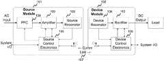
- FIG. 1A block diagram of an exemplary wireless electric vehicle (EV) battery charging system is shown in FIG. 1 .
- the systemis partitioned into a source module 101 and a device module 102 , with each module consisting of a resonator 103 , 104 and module control electronics 105 , 106 .
- the source module 101also consists of a power factor corrector (PFC) 108 and an amplifier 109 .
- the device module 102also consists of a rectifier 110 .
- the source module 101may be part of a charging station and the device module 102 may be mounted onto a vehicle. Power may be wirelessly transferred from the source 101 to the device 102 via the resonators 103 , 104 .
- Closed loop control of the transmitted powermay be performed through a communications link 107 between the source 101 and the device 102 .
- the communications link 107can be an out-of-band communications link, an in-band communications link, or a combination of in-band and out-of-band signaling protocols between the source 101 and device 102 .
- some or all of the system control functionsmay be realized in a computer, processor, server, network node and the like, separated from the source 101 and device 102 modules.
- the system controllermay control more than one source, more than one device and/or more than one system.
- a wireless power transmission system for electric vehicle chargingcan be designed so that it may support customization and modifications of the control architecture.
- Such customizations and modificationsmay be referred to as reconfigurations, and an architecture designed to support such reconfigurations may be referred to as reconfigurable.
- the control architecturemay be realized in physically separate components, such as multiple microprocessors and some functions, processes, controls, and the like may be reconfigurable by a user of the system, and some may not.
- the reconfigurable portions of the control architecturemay be implemented in certain chips, micro-processors, field programmable gate arrays (FPGAs), Peripheral Interface Controllers (PICs), Digital Signal Processors (DSPs), Application Specific Processors (ASPs), and the like.
- some reconfigurable portions of the control architecturemay reside in ASPs which may be 32-bit microcontrollers with C-language source code.
- the control codemay reside on a single processor and a user may have permission to access certain portions of the code.
- both hardware and software segmentation of the control functions of an EV wireless power transmission systemare contemplated in this disclosure.
- the system architecturemay support ASPs in the source 101 and device 102 modules and these processors may be referred to as Application Source Processors (ASP) and the Application Device Processors (ADP).
- ASPApplication Source Processor
- ADPApplication Device Processors
- This control architecturemay enable different users and/or manufacturers of different vehicles and vehicle systems to be able to add to the source code or customize it for integration with their vehicles and/or in their intended applications.
- processor, microprocessor, controller, and the liketo refer to the ASPs described above and any suitable type of microprocessor, field programmable gate array (FPGA), Peripheral Interface Controller (PIC), Digital Signal Processor (DSP), and the like, that is known to one of skill in the art.
- FPGAfield programmable gate array
- PICPeripheral Interface Controller
- DSPDigital Signal Processor
- the ASP and ADPmay be used to present certain system parameters and control points to wireless power system designers and/or vehicle integrators and to restrict access to certain other system parameters and control points.
- certain control featuresmay be essential to ensure proper and/or safe operation of a wireless power transmission system, and such control features may be implemented in hardware only loops and/or in physically separated microcontrollers and/or in restricted portions of the ASPs so that they may not be customized and/or modified by certain users of the systems.
- one, some or all of the control functions of the wireless power systemmay be based on hardware implementations and/or may be hard-coded into the system and/or may be soft-coded into the system but with restricted access so that only select and verified users may make changes to the various codes, programs, algorithms and the like, that control the system operation.
- the concept of partitioning the control plane into at least source-side and device-side functions and into at least high-level and low-level functionsis what enables the reconfigurability of system operation while guaranteeing certain safety, reliability and efficiency targets are met.
- the distribution and segmentation of the control planeallows flexibility in the adaptation of the higher level functions for vehicle designer and/or end user applications without the risk of disrupting the operation of the low level power electronics control functions.
- the partitioning of the control planeallows for variable control loop speeds; fast and medium speeds for the low level critical hardware control functions of the power electronics as well as slower control loop speeds for the high level designer and/or end user control loops.
- this partitioned control plan architecturemay scale to adjust to and support more functionality and applications, at the same time it may be adapted to changing hardware requirements and standardized requirements for the safe and efficient delivery of power.
- the fast and medium speed control loopsmay be adapted to support wireless power transmission at a range of operating frequencies and over a range of coupling coefficients, both of which may eventually be set by regulatory agencies.
- usersmay access and customize the higher level control functions to implement functionality that may include, but may not be limited to:
- FIG. 2shows an exemplary charging system control diagram for an electric vehicle wireless power transfer system.
- the source components 201 of the systemare shown on the left side of the diagram and the device (or vehicle) components 202 of the system are shown on the right.
- the source components 201include a power factor corrector 204 , a switching amplifier 205 , an amplifier controller 206 , an ASP 208 and a source coil 207 .
- the device components 202include an ADP 210 , a rectifier controller 211 , a rectifier 212 and a device coil 213 .
- the switching amplifier 205 in the source 201 of an electric vehicle wireless power transmission systemmay be any class of switching amplifier including, but not limited to, a class D amplifier, a class E amplifier and a class D/E amplifier.
- the switching frequency of the amplifier 205may be any frequency and may preferably be a frequency previously identified as suitable for driving inductor coils and/or magnetic resonators. In embodiments, the switching frequency may be between 10 kHz and 50 MHz. In embodiments, the frequency may be approximately 20 kHz, or approximately 44 kHz, or approximately 85 kHz, or approximately 145 kHz, or approximately 250 kHz. In embodiments, the switching frequency may be between 400 and 600 kHz, between 1 and 3 MHz, between 6 and 7 MHz, and/or between 13 and 14 MHz. In embodiments, the frequency of the switching amplifier 205 may be tunable and may be controlled.
- an amplifier controller 206may manage the electronic components in the amplifier 205 and/or in the PFC 204 and/or in the DC power supply (not shown).
- the amplifier controller 206may monitor and control so-called local control loops and local interlocks for conditions such as over voltage/current in the source electronics, ground-fault circuit interrupt in the source electronics, and out-of-specification AC impedance changes at the source coil 207 .
- the amplifier controller 206may react quickly to shut the system down safely in response to a variety of set point violations.
- the amplifier controller 206may expose registers for set-points and control to the ASP through an inter-integrated circuit (I 2 C) interface, referred to in the figure as the “User Interface”.
- the amplifier controller 206may also have a watchdog timer (or heartbeat input) to detect if communication with the Application Source Processor (ASP) 208 or with the vehicle has been lost.
- I 2 Cinter-integrated circuit
- the ASP 208may provide high-level control of the source electronics and the overall system charging cycle.
- the ASP 208may interface with a foreign-object-debris (FOD) detector that monitors the source module 201 for the presence of FOD and/or excessive temperature.
- FODforeign-object-debris
- the ASP 208may be connected to an in-band and/or out-of-band communications link 209 that may communicate with the vehicle-side application device processor (ADP) 210 to provide closed loop control of the charging cycle.
- ADPvehicle-side application device processor
- a rectifier controller 211may perform low-level and local functions for the device side 202 that are analogous to those described for the source side 201 .
- an I 2 C interfacemay be provided for interfacing with a higher-level ADP.
- the ADP 210could be configured to connect via a CAN-bus or equivalent to a battery manager that may control the power delivered from the rectifier 212 to the battery, vehicle engine or any time of power storage or management system on the vehicle.
- the ADP 210could communicate that information to the source-side ASP 208 which, in turn, could adjust the power settings on the amplifier controller 206 .
- control architecturemay be partitioned into three types of control loops: fast, medium and slow.
- the fast control loopsmay be for time critical functions (less than 1-ms latency) and may be either hardware control loops or interrupt-driven low-level software modules.
- Medium-speed control loopsmay be for functions that operate under real-time software control ( ⁇ 500-ms latency).
- Slow control loops(>500 ms latency) may be for functions with low bandwidth requirements or functions with unpredictable latency, for example, a 802.11-family wireless communication link.
- FIG. 2shows the three types of control loops as they may be applied to an exemplary electric vehicle wireless power transmission system.
- embedded software portions of the control loopsmay be partitioned between the amplifier and rectifier controllers 206 , 211 , respectively, and the processors (ASP 208 and ADP 210 ).
- the amplifier and rectifier controllers 206 , 211may handle the hardware control and the operation of high-power and/or sensitive electronics components.
- the ASPsmay handle the system control loop and may provide interfaces to external peripherals, such as FOD detectors, communication links, monitoring equipment, and other vehicle and source electronics.
- some of the functions that may operate under fast feedback-loop controlmay be based on hardware set-points and/or on software (programmable) set-points which may include but may not be limited to over-current protection, over-voltage protection, over-temperature protection, voltage and current regulation, transistor shoot-through current in the switching amplifier, GFCI (ground fault circuit interrupt) and critical system interlocks.
- system events that may cause damage to the system itself or to a user of the system in a short period of timemay be detected and reacted to using fast feedback-loop control.
- some of the functions that may operate under medium-speed feedback loopsmay include, but may not be limited to temperature set-point violations, impedance set points to declare an out-of-range condition for the source coil impedance, FOD detection, monitoring for violations of the minimum efficiency set point, local power control in the source-side electronics and processor heartbeat monitoring (i.e. watchdog-timer expiration).
- system eventsthat may cause damage to the system itself or to a user of the system in a medium period of time and/or that may cause the system to operate in an undesirable state (e.g. low efficiency) may be detected and reacted to using medium feedback-loop control.
- some of the functions that may operate under relatively slow-speed loop controlmay include but may not be limited to system power control loop (e.g. for executing a battery-charging profile), charge request/acknowledge messages between vehicle(s) and source(s), system start/stop messages, system level interlocks, RF communications link heartbeat monitoring (i.e. watchdog-timer expiration), status/GUI updates to a diagnostic laptop and messages for source/vehicle transactions, authentication and configuration.
- system eventsthat may cause damage to the system itself or to a user of the system in a long period of time and/or that may cause the system to operate in an undesirable state (e.g. low efficiency, insufficient information for closing a transaction) may be detected and reacted to using slow feedback-loop control.
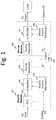
- FIG. 3shows a notional state diagram of the system charging cycle.
- the diagramshows examples of state machines that may be running on the ASPs in the source side 301 and the vehicle side 302 of the EV wireless power transmission system. Potential activation states are shown within each rectangle and potential conditional statements that must be satisfied to enable transitions between states are enclosed in square brackets.
- in-band, out-of-band, and/or a combination of in-band and out-of-band wireless communication links between the source and the vehiclemay provide for messaging and synchronization.
- the communications required to implement control functions, processes and the likemay piggy-back on existing or native communication systems in and around the vehicle.
- messagesmay be passed amongst the source(s), the vehicle(s), and any additional networked component(s) using CAN-bus equipment and protocols, Bluetooth equipment and protocols, Zigbee equipment and protocols, 2.4 GHz radio equipment and protocols, 802.11 equipment and protocols, and/or any proprietary signaling scheme equipment and protocols implemented by the user.
- the charging engagement between the source and vehicle for wireless chargingmay be similar to that described by SAE J1772 for wired charging, with additional steps added to support wireless charging.
- a wireless sourcemay be powered and available to supply power to a wireless device and may be referred to as being in the Available state.
- a wireless sourcemay constantly, periodically, occasionally and/or in response to some trigger, broadcast information regarding any of its availability, position, location, power supply capabilities, power costs, power origination (solar, coal burning plant, renewable, fossil fuel, etc.), resonator type, resonator cross-section (so that a vehicle may calculate and/or look-up an expected coupling coefficient with the source), and the like.
- a vehiclemay be receiving information broadcast by wireless power sources and may search for an available wireless power source, with matching hard-wired and/or use selectable features, over which it may park.
- the vehicle's communication linkmay be active so that it is in the Searching state. If vehicle identifies a suitable wireless source, it may approach that source and initiate two way communications with the source so that the source and device side control electronics can exchange configuration information.
- the source and vehicle sidesmay switch to their Docking states.
- both source and devicemay confirm their compatibility and an alignment error signal may be provided to the vehicle driver so that he/she can maneuver the car into proper position. Once in position, the drive train of the vehicle may be disabled and the source and device may enter the Coupled state.
- a ‘Charge Request’may be sent from the vehicle—either automatically or driver initiated, and may be received by the source.
- the Coupled statethere may be further exchange of configuration information, safety checks, and the like. Once those are passed, both sides may enter the Ready to Charge state.
- the vehiclein the Ready to Charge state, the vehicle may issue a ‘Start Charging’ command and both the source and the vehicle may enter the Charging state as the source power ramps up.
- both source and vehicleIn the Charging state, both source and vehicle may perform monitoring and logging of data, faults, and other diagnostics. Logging and monitoring may include, but may not be limited to an event loop that looks for hazardous and/or restricted Foreign Object Debris (FOD), overloads, unexpected temperature and/or efficiency excursions, and other asynchronous events.
- FODForeign Object Debris
- hazard and/or restricted object detectionthat occurs in the source during any of the powered states may cause the source to switch into its Anomaly state. If wireless communication is still working, the vehicle may be notified and may also drop into its Anomaly state. If wireless communication is down, the vehicle may enter its Anomaly state because it didn't ask for the wireless power to be shut down and because the wireless communications watchdog timer expires.
- the vehiclemay send a message to the source that results in the source entering its Anomaly state.
- the sourcemay send a message to the vehicle that results in the vehicle entering its Anomaly state.
- the source and/or vehiclemay automatically begin a process for handling or disposition of the anomaly.
- the processmay involve the source and vehicle exchanging health and status information to help discover the cause of the anomaly.
- the source and vehiclemay select a pre-planned action that corresponds to the cause. For example, in the event that detection of foreign object debris caused the anomaly, the source may reduce the power transfer level to a safe level where the foreign object debris does not overheat. In another example, in the event that the loss of RF communication was the cause, the source may stop power transfer until RF communication is re-established.
- the systemmay automatically communicate to a user that the system is in its Anomaly state. Communication may occur over the internet, over a wireless network, or over another communications link.
- chargingmay end when the vehicle sends a stop-charging (DONE) command to the source.
- the sourcemay immediately de-energize.
- the sourcemay return to the coupled state and may notify the vehicle of its state change.
- the vehiclemay switch to the Coupled state and may receive additional information about the charge engagement from the source. At this point, the vehicle may either stay put or it may depart. Once the source senses that a vehicle has departed, it may return to the Available state.
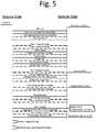
- FIG. 5shows another representation of some potential steps if a sequence of interactions in an exemplary embodiment of an EV wireless power transfer system.
- the diagramshows exemplary steps from the charging sequence described above following Unified Modeling Language (UML) conventions:
- UMLUnified Modeling Language
- control loopsmay be implemented to govern the operation of the wireless charging and/or powering of the electric vehicle.
- Some exemplary control loops for the exemplary system shown in FIG. 2are described below.
- the control loops described belowmay be sufficient for some systems or they may need to be modified or added to ensure proper operation of other systems.
- the description of control loopsshould not be interpreted as complete, but rather illustrative, to describe some of the issues considered when deciding whether system control loops might be fast, medium or slow in their response time, and whether or not they should be user reconfigurable.
- a power factor corrector 601may convert an AC line voltage 602 to a DC voltage 603 for the source. It may provide active power factor correction to the line side and may provide a fixed or variable DC voltage to the source amplifier. Control of a power factor corrector 601 may be performed through a combination of hardware circuits and firmware in the amplifier controller 604 . For example hardware circuits may be used to control against transient or short-duration anomalies, e.g.
- exceeding hard set-point limitssuch as local currents or voltages exceeding safety limits for circuit components, such as power MOSFETs, IGBTs, BJTs, diodes, capacitors, inductors, and resistors, and firmware in the amplifier controller 604 may be used to control against longer duration and slower developing anomalies, e.g. temperature warning limits, loss of synchronization of switching circuitry with the line voltage, and other system parameters that may affect power factor controller operation.
- an amplifier 701may provide the oscillating electrical drive to the wireless power system source resonator coil 702 .
- Hardware circuitsmay provide high-speed fault monitoring and processing. For example, violations of current and voltage set points and amplifier half-bridge (H-bridge) shoot-through may need to be detected within less than one millisecond in order to prevent catastrophic failures of the source electronics.
- system-level power requirementsmay be determined on the vehicle side and may be fed back from the ADP (not shown) to the ASP 704 .
- the ASP 704may request that the amplifier controller 703 increment or decrement the power from the amplifier 701 for example.
- the bandwidth of the power control loopmay be limited by the latency in the wireless link and by the latency in communication between the ADP and the battery manager.
- a rectifier 801may convert the AC power received from the device resonator coil 802 to DC output power 803 for the vehicle, vehicle battery or battery charger.
- a monitoring circuit for the rectifier output power, current and or voltage, as well as for the battery charge statemay provide the feedback for closed-loop control of the system's power transfer.
- the rectifier 801controlled by a rectifier controller 804 , may control the output voltage to maintain it within the range desired by the battery management system. Additional fault monitoring and an interface to vehicle charging control processes may be provided by the ADP 805 .
- a rectifier module 801may comprise a full-bridge diode rectifier, a solid-state switch (e.g. double pole, single throw (DPST) switch), and a clamp circuit for over-voltage protection.
- the full-bridge rectifiermay send DC power through the closed switch and the inactive clamp circuit to the battery system. If the battery system needs more current, it may request it from the ADP which may forward the request to the ASP on the source side. If the battery needs less current, the corresponding request may be made. The speed with which these conditions must be detected, communicated, and acted upon may be determined by how long the system can safely operate in a non-ideal mode.
- the systemmay be fine for the system to operate in a mode where the wireless power system is providing too little power to the vehicle battery, but it may be potentially hazardous to supply too much power.
- the excess power supplied by the wireless sourcemay heat components in the resonator, clamp circuit and/or battery charge circuit.
- the speed of the feedback control loopmay need to be fast enough to prevent damage to these components but may not need to be faster than that if a faster control loop is more expensive, more complex, and/or less desirable for any reason.
- a switch and a clampmay provide vehicle-side protection against potential failure modes. For example, if the vehicle side enters its Anomaly state, it may notify the source which may subsequently enter its Anomaly state and may turn down or shut down the source power. In case the wireless link is down or the source is unresponsive, the switch in the rectifier may open to protect the battery system.
- the second and third diagnostic interfacesmay be for running demonstration purposes and to provide diagnostic information in an easily accessible format.
- the connections with the laptopmay also use 802.11b.
- a Wi-Fi enabled routermay be required for simultaneous support of wireless connections for the ASP-ADP, ASP-Laptop, and ADP-Laptop.
- an 802.11b peer-to-peer connectioncould be used.
- the fourth and fifth interfacesmay be between the ASPs, other system controllers, and data loggers.
- Other system controllersmay be implemented in physically distinct microcontrollers as described in the exemplary embodiment, or they may be co-located in the same ASPs.
- an ASP 901may have a Wireless Communications Link Interface.
- the source-side ASP 901may communicate with the vehicle-side ADP over a wireless communication link 902 .
- the wireless protocolmay be implemented using TCP/IP over a 2.4 GHz Wi-Fi link.
- the RF modulemay be IEEE Std. 802.11b compatible with a 4-wire SPI interface to the ASP.
- a communication interface using the ASP 901 serial UART port 905may be available as an option.
- the serial portmight interface to an external wireless module to support the link.
- a standard UART interface 905may provide the flexibility to use any particular wireless protocol 917 that a user may want.
- an interface 915 between the ASP 901 and the amplifier controller 906there may be an interface 915 between the ASP 901 and the amplifier controller 906 .
- An amplifier controller 906may provide low-level control of the source electronics, while the ASP 901 may provide high-level control and may be responsible for the execution of the overall system charging cycle.
- the interface 915 to the amplifier controller 906may be presented as a set of control and status registers which may be accessible through an I 2 C serial bus 907 . Such an arrangement could support user customization of the control algorithms.
- an interface 910 between an ASP 901 and a FOD detection subsystemthere may be an interface 910 between an ASP 901 and a FOD detection subsystem.
- the ASP 901may be able to receive preprocessed digital data from a FOD processor 916 .
- a FOD processor 916may be designed to perform signal conditioning and threshold detection for the various types of sensors (e.g., 911 , 912 , 913 ) connected to it.
- the FOD processor 916may interrupt the ASP 901 and transmit the FOD decision-circuit results.
- the ASP 901may then take appropriate action (e.g.
- the FOD processor 916may also transmit the pre-decision signal-conditioned data in digital form to the ASP 901 so that soft decision algorithms that use other information can be implemented in the ASP 901 .
- an interface between an ASP 901 and a System Interlock 914 subsystemthere may be an interface between an ASP 901 and a System Interlock 914 subsystem.
- An interlock interfacemay consist of a set of optically coupled digital inputs which may act as system enables.
- the interlocks 914may be externally generated signals which may be asserted to turn on the system.
- the interlocks 914may also be able to be used by the user to shut down the system on command.
- the systems and signals that feed the external interlock signalsmay be application specific.
- a positioning and alignment interfacemay communicate data from a vehicle alignment and positioning sensor to an ASP 901 to determine whether sufficient wireless power transfer efficiency may be achieved given the measured relative position of source and device resonators. If the resonators are not sufficiently well aligned, the ASP 901 may communicate to the device ADP and instruct the system to generate a message to the driver that the vehicle needs to be repositioned and to inhibit system turn-on until proper positioning is established.
- a diagnostic/debug interfacemay be available across a wireless link between an ASP 901 and a laptop, or tablet, or smartphone or any other processing unit that preferably comprises a display.
- the wireless communications connectionmay be through a dedicated Wi-Fi network.
- the interfacemay allow a laptop, or other external controller, to put the EV wireless power transmission system in a diagnostic and/or customization mode where preset interlocks may be over-ridden and state changes may be forced onto the ASP.
- this interfacemay also allow a laptop, or other external controller, with a Wi-Fi capability to access the ASP 901 .
- the ASP 901may be capable of streaming state information to the laptop which may store it in a log file. Parameters that can be stored in the log file may include:
- the log fileshould be able to be viewed on the laptop and incorporated into a spreadsheet for later analysis.
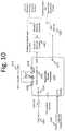
- FIG. 10shows exemplary interfaces to and from an application device processor and FIG. 14 shows exemplary ADP control parameters.
- an Application Device Processor (ADP) 1001may be a microprocessor that holds the state information for the vehicle side of an EV wireless power transfer system. Physically, it may be implemented in a PIC-32 microcontroller.
- the software running on the ADP 1001may execute the state transitions described previously, as well as the wireless communication with the source side and the diagnostic laptop, or other external controller. Users may modify or replace the software on the ADP 1001 to customize the operation and control of an EV wireless power transfer system.
- functional interfaces to the Application Device Processor 1001may include but may not be limited to:
- an interface 1011 between an ADP 1001 and a CAN Bus 1002there may be an interface 1011 between an ADP 1001 and a CAN Bus 1002 .
- the ADP 1001may include a CAN bus interface 1011 .
- software running on an ADP 1001may be augmented by a user to support a CAN bus interface 1011 even if the as-designed and/or as-delivered EV wireless power transfer system did not include this functionality.
- a vehicle-side Application Device Processor 1001may have a Wireless Communications Link Interface.
- a device-side ADP 1001may communicate with the source-side ASP over a wireless communication link.
- the wireless protocolmay be implemented using TCP/IP over a 2.4 GHz Wi-Fi link 1004 .
- the RF modulemay be IEEE Std. 802.11b compatible with a 4-wire SPI interface 1010 to the ADP.
- an interface 1005 between an ADP 1001 and a rectifier controller 1012there may be an interface 1005 between an ADP 1001 and a rectifier controller 1012 .
- the ADP 1001may communicate with the rectifier controller 1012 over an interface 1005 that may be similar to the one between the ASP and the amplifier controller.
- a rectifier controller 1012may provide low-level control of the device electronics, while the ADP 1001 may provide high-level control and may be responsible for the execution of the overall system charging cycle.
- the interface 1005 to the rectifier controller 1012may be presented as a set of control and status registers which may be accessible through an I 2 C serial bus 1006 . Such an arrangement could support user customization of the control algorithms.
- the interface 1005may also consist of, an Interrupt Request input 1007 and a set of uni-directional watchdog/heartbeat outputs 1008 .
- a positioning and alignment interfacemay communicate data from a vehicle alignment and positioning sensor to an ADP to determine whether sufficient wireless power transfer efficiency may be achieved given the measured relative position of source and device resonators. If the resonators are not sufficiently well aligned, the ADP may communicate to the source ASP and instruct the system to generate a message to the driver that the vehicle needs to be repositioned and to inhibit system turn-on until proper positioning is established.
- an interface between an ADP 1001 and a System Interlock subsystem 1009there may be an interface between an ADP 1001 and a System Interlock subsystem 1009 .
- This interfacemay be analogous to that described between an ASP and a System Interlock subsystem. It could be used by the battery manager to force a shutdown of the EV wireless power transfer system.
- the ADP 1001may enter its Anomaly state and may demand that the source shut down immediately and may open the switch in the rectifier circuit. In the case of an unresponsive source or an interrupted wireless communications link, the ADP 1001 may open the switch within 3 seconds, or an appropriate period of time, and communicating a command that the source shut down.
- a diagnostic/debug interfacemay be available across a wireless link between an ADP and a laptop, or tablet, or smartphone or any other processing unit that preferably comprises a display.
- the wireless communications connectionmay be through a dedicated Wi-Fi network.
- the interfacemay allow a laptop, or other external controller, to put the EV wireless power transmission system in a diagnostic and/or customization mode where preset interlocks may be over-ridden and state changes may be forced onto the ADP.
- this interfacemay also allow a laptop, or other external controller, with a Wi-Fi capability to access the ADP.
- the ADPmay be capable of streaming state information to the laptop which may store it in a log file. Parameters that can be stored in the log file may include:
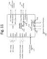
- FIG. 11shows exemplary interfaces to and from an amplifier controller and FIG. 15 shows exemplary amplifier control parameters.
- an amplifier controller 1101may provide low-level control to a Power Factor Corrector (PFC) 1102 and a switching amplifier 1103 .
- the interfaces between an amplifier controller 1101 and other system componentsmay include, but may not be limited to:
- FIG. 12shows exemplary interfaces to and from a rectifier controller and FIG. 16 shows exemplary rectifier control parameters.
- a rectifier controller 1201may provide high speed monitoring of rectifier power and system critical fault control.
- the interfaces between a rectifier controller 1201 and other system componentsmay include, but may not be limited to:
- a reconfigurable EV wireless power transmission systemmay be partitioned into notional subsystems so that the interactions between subsystems may be studied and design decisions made be made as to which control functions and set-points may be customizable by a user while still ensuring safe, efficient and reliable performance of the system.
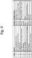
- One method to analyze the system performance impact of allowing customization and/or reconfigurability of the control architecture and/or algorithms and/or set-pointsis to perform a Failure Mode Effects Analysis (FMEA).
- FMEAFailure Mode Effects Analysis
- a preliminary FMEAmay comprise a prioritized listing of the known potential failure modes. FMEA may need to be an on-going activity as new system failure modes are identified.
- an FMEA process that scores potential failure modes in a number of categoriesmay be used to identify the severity of certain failure scenarios. Categories that may be used to identify customizable parameters may include, but may not be limited to
- the potential failure modesmay be prioritized according to their Risk Priority Number (RPN)-which is merely the product of their three category scores.
- RPNRisk Priority Number
Landscapes
- Engineering & Computer Science (AREA)
- Power Engineering (AREA)
- Computer Networks & Wireless Communication (AREA)
- Transportation (AREA)
- Mechanical Engineering (AREA)
- Life Sciences & Earth Sciences (AREA)
- Sustainable Development (AREA)
- Sustainable Energy (AREA)
- Electric Propulsion And Braking For Vehicles (AREA)
- Charge And Discharge Circuits For Batteries Or The Like (AREA)
Abstract
Description
- Programming an EV wireless source to connect through a wired internet connection in the source, or through Wi-Fi or the cellular network to display certain source attributes such as what type of resonator it comprises, how much energy it can supply, what the price is for the energy it supplies (this price may change during the day, being less expensive at night when the peak demand for electricity is lower, or it may change seasonally, costing more when the temperature is hot and air conditioning requirements are stressing the electrical supply), where the energy it supplies originates from (renewables, coal plant, etc.), does this source require a reservation, if it requires a reservation, when are the free times that can be reserved, what type of FOD detectors does it deploy, what is the status of the source (has FOD been detected and needs to be cleaned off before charging can be initiated, or has FOD been detected and so the source can only supply a limited amount of power).
- Programming an EV wireless power transfer system so that it may connect to a communication network and may contact the vehicle user to report the status of the charge cycle and to report when charging is complete or when charging has been interrupted or that the source and/or device are in an anomaly state.
- Programming an EV wireless power transfer system so that power is transmitted from the device back to the grid and managing the transaction so that the vehicle user is paid for supplying that energy.
- Programming a user interface in the vehicle so that information regarding the position of the vehicle resonator relative to the source resonator can be relayed to the driver of the vehicle. The relative position information may be used to give the vehicle driver an estimate of the wireless transfer efficiency with the vehicle in its current location and may offer the driver a chance to change the parking position to improve the wireless system performance. The user interface may include visible, audible, vibrational and the like feedback to help the driver reposition the vehicle.
- Time flows in the downward direction
- The vertical bars under each side represent activation of different states
- Arrows with solid lines indicate requests
- Arrows with dashed lines indicate responses
- Full arrow heads represent synchronous messages
- Half arrow heads represent asynchronous messages
- Arrows entering the diagram from off the page represent user actions
Note that the diagram is not intended to show every message in the exemplary engagement just some examples helpful to understanding the interaction.
- The battery manager requests an emergency disconnect
- The voltage clamp circuit is active for more than 3 seconds (or some set period of time, potentially user settable and reconfigurable)
- The wireless communications link is down
- The ADP does not update the watchdog timer in the rectifier controller
- A temperature, voltage, current, or other error-condition set point is violated.
- ASP-ADP: Wireless interface between the Application Source Processor on the source side and the Application Device Processor on the vehicle side.
- ASP-Laptop: Wireless interface used to send a webpage with source diagnostic information that can be displayed on a laptop for demonstration, system configuration, and debug purposes.
- ADP-Laptop: Wireless interface used to serve a webpage with device diagnostic information that can be displayed on a laptop for demonstration and debug purposes.
- ASP-AmpCon: an I2C interface between the ASP and the amplifier controller.
- ADP-RectCon: an I2C interface between the ADP and the rectifier controller.
- Wi-Fi link902 for communicating with the vehicle's -ADP and for a diagnostic display for user demonstrations, diagnostics and/or customization (iPAD or laptop)
- Serial Peripheral Interface (SPI)903 serial-link over
Ethernet 904 on a 2.4 GHz RF link for communicating with the vehicle's ADP - Hardware support for Universal Asynchronous Receiver/Transmitter (DART)905 serial-link over
Ethernet 904 on a 2.4 GHz RF link for an alternative method of communicating with the vehicle's ADP Interface 915 toamplifier controller 906- I2C907 for commanding and receiving status information
- Interrupt908 for high-priority tasks (e.g. FOD detection, source or vehicle anomaly)
- Bi-directional watchdog/
heartbeat signal 909 FOD detection interface 910- Metal object detector911
Temperature sensors 912- Living being sensor, such as
capacitive sensors 913 System process interlock 914 inputs-used for higher-level controllers that may need to shut down the source suddenly.- I2C interface to source side PIM (PCB Information Memory with a unique identifier (UID), configuration settings, etc.)
- Time-stamped events such as state changes, messages passed, messages received
- Measured voltages, currents, temperatures, and impedances that are being compared to set points by the ASP or amplifier controller.
- Configuration information such as software/firmware versions, hardware IDs, etc.
- Controller Area Network (CAN)
Bus 1002 implemented on the physical layer (PHY) on the device side for use with vehicle communication, diagnostic equipment, and/or measurement and or monitoring equipment - Serial-link over Ethernet1003 on a 2.4 GHz RF link for communicating with the Source ASP
- Wi-
Fi 1004 to a diagnostic display for user demonstrations and/or customizations (iPAD or laptop) - Interface to a
rectifier controller 1005 - I2C1006 for commanding and receiving status information
- Interrupt1007 for high-priority tasks (e.g. FOD detection, vehicle anomaly)
- Bi-directional watchdog/
heartbeat signal 1008 System process interlock 1009 inputs used for higher-level controllers on a vehicle that may need to disable the charging cycle.- I2C interface to Device side PIM (PCB Information Memory with UID, configuration settings, etc.)
- Controller Area Network (CAN)
- Time-stamped events such as state changes, messages passed, messages received
- Measured voltages, currents, temperatures, and impedances that are being compared to set points by the ADP or rectifier controller.
- Configuration information such as software/firmware versions, hardware IDs, etc.
- The log file could be viewed on the laptop and dumped into excel for later analysis.
Interface 1104 toApplication Source Processor 1105- I2C1106
- Interrupt1107
- Bi-directional Heartbeat/
Watchdog 1108
- PFC
Hardware control interface 1109 - Amplifier
hardware control interface 1110 - System
critical interlock inputs 1111 - System On/Off
- I2C interface1202 to
Application Device Processor 1203I2C 1204- Interrupt1205
- Bi-directional Heartbeat/
Watchdog 1206
- Rectifier hardware control/
status interface 1207 - Fault indicators such as over current, over voltage, over temperature, clamp circuit activated, etc.
- Device side system
critical interlock inputs 1208.
- I2C interface1202 to
- Severity (1-10): If the failure mode occurs, how severe (SEV) is the impact to system functionality, performance, or safety? A score of 10 indicates a major hazard and a score of 1 indicates a minor loss of performance or functionality.
- Likelihood (1-10): How likely is the failure to occur? A 10 indicates almost certain occurrence while a 1 indicates a very remote chance of occurrence (OCC).
- Undetectability (1-10): How likely is it that the failure will be detected (DET) and reacted to by the system during operation? A 10 indicates that the control architecture is very unlikely to detect the failure while a 1 indicates almost certain detection.
Claims (10)
Priority Applications (2)
| Application Number | Priority Date | Filing Date | Title |
|---|---|---|---|
| US16/576,905US11097618B2 (en) | 2011-09-12 | 2019-09-20 | Reconfigurable control architectures and algorithms for electric vehicle wireless energy transfer systems |
| US17/407,484US20220144092A1 (en) | 2011-09-12 | 2021-08-20 | Reconfigurable control architectures and algorithms for electric vehicle wireless energy transfer systems |
Applications Claiming Priority (5)
| Application Number | Priority Date | Filing Date | Title |
|---|---|---|---|
| US201161533281P | 2011-09-12 | 2011-09-12 | |
| US201161566450P | 2011-12-02 | 2011-12-02 | |
| US13/612,494US20130062966A1 (en) | 2011-09-12 | 2012-09-12 | Reconfigurable control architectures and algorithms for electric vehicle wireless energy transfer systems |
| US15/355,143US10424976B2 (en) | 2011-09-12 | 2016-11-18 | Reconfigurable control architectures and algorithms for electric vehicle wireless energy transfer systems |
| US16/576,905US11097618B2 (en) | 2011-09-12 | 2019-09-20 | Reconfigurable control architectures and algorithms for electric vehicle wireless energy transfer systems |
Related Parent Applications (1)
| Application Number | Title | Priority Date | Filing Date |
|---|---|---|---|
| US15/355,143ContinuationUS10424976B2 (en) | 2011-09-12 | 2016-11-18 | Reconfigurable control architectures and algorithms for electric vehicle wireless energy transfer systems |
Related Child Applications (1)
| Application Number | Title | Priority Date | Filing Date |
|---|---|---|---|
| US17/407,484ContinuationUS20220144092A1 (en) | 2011-09-12 | 2021-08-20 | Reconfigurable control architectures and algorithms for electric vehicle wireless energy transfer systems |
Publications (2)
| Publication Number | Publication Date |
|---|---|
| US20200014254A1 US20200014254A1 (en) | 2020-01-09 |
| US11097618B2true US11097618B2 (en) | 2021-08-24 |
Family
ID=47829204
Family Applications (4)
| Application Number | Title | Priority Date | Filing Date |
|---|---|---|---|
| US13/612,494AbandonedUS20130062966A1 (en) | 2011-09-12 | 2012-09-12 | Reconfigurable control architectures and algorithms for electric vehicle wireless energy transfer systems |
| US15/355,143Active2033-05-30US10424976B2 (en) | 2011-09-12 | 2016-11-18 | Reconfigurable control architectures and algorithms for electric vehicle wireless energy transfer systems |
| US16/576,905ActiveUS11097618B2 (en) | 2011-09-12 | 2019-09-20 | Reconfigurable control architectures and algorithms for electric vehicle wireless energy transfer systems |
| US17/407,484AbandonedUS20220144092A1 (en) | 2011-09-12 | 2021-08-20 | Reconfigurable control architectures and algorithms for electric vehicle wireless energy transfer systems |
Family Applications Before (2)
| Application Number | Title | Priority Date | Filing Date |
|---|---|---|---|
| US13/612,494AbandonedUS20130062966A1 (en) | 2011-09-12 | 2012-09-12 | Reconfigurable control architectures and algorithms for electric vehicle wireless energy transfer systems |
| US15/355,143Active2033-05-30US10424976B2 (en) | 2011-09-12 | 2016-11-18 | Reconfigurable control architectures and algorithms for electric vehicle wireless energy transfer systems |
Family Applications After (1)
| Application Number | Title | Priority Date | Filing Date |
|---|---|---|---|
| US17/407,484AbandonedUS20220144092A1 (en) | 2011-09-12 | 2021-08-20 | Reconfigurable control architectures and algorithms for electric vehicle wireless energy transfer systems |
Country Status (1)
| Country | Link |
|---|---|
| US (4) | US20130062966A1 (en) |
Families Citing this family (165)
| Publication number | Priority date | Publication date | Assignee | Title |
|---|---|---|---|---|
| US9421388B2 (en) | 2007-06-01 | 2016-08-23 | Witricity Corporation | Power generation for implantable devices |
| US8115448B2 (en) | 2007-06-01 | 2012-02-14 | Michael Sasha John | Systems and methods for wireless power |
| US9160203B2 (en) | 2008-09-27 | 2015-10-13 | Witricity Corporation | Wireless powered television |
| US8946938B2 (en) | 2008-09-27 | 2015-02-03 | Witricity Corporation | Safety systems for wireless energy transfer in vehicle applications |
| US9577436B2 (en) | 2008-09-27 | 2017-02-21 | Witricity Corporation | Wireless energy transfer for implantable devices |
| US8907531B2 (en) | 2008-09-27 | 2014-12-09 | Witricity Corporation | Wireless energy transfer with variable size resonators for medical applications |
| US20100259110A1 (en)* | 2008-09-27 | 2010-10-14 | Kurs Andre B | Resonator optimizations for wireless energy transfer |
| US8957549B2 (en) | 2008-09-27 | 2015-02-17 | Witricity Corporation | Tunable wireless energy transfer for in-vehicle applications |
| US8669676B2 (en) | 2008-09-27 | 2014-03-11 | Witricity Corporation | Wireless energy transfer across variable distances using field shaping with magnetic materials to improve the coupling factor |
| US9544683B2 (en) | 2008-09-27 | 2017-01-10 | Witricity Corporation | Wirelessly powered audio devices |
| US9744858B2 (en) | 2008-09-27 | 2017-08-29 | Witricity Corporation | System for wireless energy distribution in a vehicle |
| US8901779B2 (en) | 2008-09-27 | 2014-12-02 | Witricity Corporation | Wireless energy transfer with resonator arrays for medical applications |
| US8912687B2 (en) | 2008-09-27 | 2014-12-16 | Witricity Corporation | Secure wireless energy transfer for vehicle applications |
| US9184595B2 (en) | 2008-09-27 | 2015-11-10 | Witricity Corporation | Wireless energy transfer in lossy environments |
| US9105959B2 (en) | 2008-09-27 | 2015-08-11 | Witricity Corporation | Resonator enclosure |
| US8643326B2 (en)* | 2008-09-27 | 2014-02-04 | Witricity Corporation | Tunable wireless energy transfer systems |
| US20100277121A1 (en)* | 2008-09-27 | 2010-11-04 | Hall Katherine L | Wireless energy transfer between a source and a vehicle |
| US8497601B2 (en) | 2008-09-27 | 2013-07-30 | Witricity Corporation | Wireless energy transfer converters |
| US9035499B2 (en) | 2008-09-27 | 2015-05-19 | Witricity Corporation | Wireless energy transfer for photovoltaic panels |
| US8410636B2 (en) | 2008-09-27 | 2013-04-02 | Witricity Corporation | Low AC resistance conductor designs |
| US8933594B2 (en) | 2008-09-27 | 2015-01-13 | Witricity Corporation | Wireless energy transfer for vehicles |
| US8928276B2 (en) | 2008-09-27 | 2015-01-06 | Witricity Corporation | Integrated repeaters for cell phone applications |
| US8400017B2 (en) | 2008-09-27 | 2013-03-19 | Witricity Corporation | Wireless energy transfer for computer peripheral applications |
| US9106203B2 (en) | 2008-09-27 | 2015-08-11 | Witricity Corporation | Secure wireless energy transfer in medical applications |
| US9318922B2 (en) | 2008-09-27 | 2016-04-19 | Witricity Corporation | Mechanically removable wireless power vehicle seat assembly |
| US9246336B2 (en) | 2008-09-27 | 2016-01-26 | Witricity Corporation | Resonator optimizations for wireless energy transfer |
| US8922066B2 (en) | 2008-09-27 | 2014-12-30 | Witricity Corporation | Wireless energy transfer with multi resonator arrays for vehicle applications |
| US8772973B2 (en) | 2008-09-27 | 2014-07-08 | Witricity Corporation | Integrated resonator-shield structures |
| US9093853B2 (en) | 2008-09-27 | 2015-07-28 | Witricity Corporation | Flexible resonator attachment |
| US9601261B2 (en) | 2008-09-27 | 2017-03-21 | Witricity Corporation | Wireless energy transfer using repeater resonators |
| US8901778B2 (en) | 2008-09-27 | 2014-12-02 | Witricity Corporation | Wireless energy transfer with variable size resonators for implanted medical devices |
| US8598743B2 (en) | 2008-09-27 | 2013-12-03 | Witricity Corporation | Resonator arrays for wireless energy transfer |
| US8692412B2 (en)* | 2008-09-27 | 2014-04-08 | Witricity Corporation | Temperature compensation in a wireless transfer system |
| US9601270B2 (en) | 2008-09-27 | 2017-03-21 | Witricity Corporation | Low AC resistance conductor designs |
| US8937408B2 (en) | 2008-09-27 | 2015-01-20 | Witricity Corporation | Wireless energy transfer for medical applications |
| US9396867B2 (en) | 2008-09-27 | 2016-07-19 | Witricity Corporation | Integrated resonator-shield structures |
| US8482158B2 (en) | 2008-09-27 | 2013-07-09 | Witricity Corporation | Wireless energy transfer using variable size resonators and system monitoring |
| US9065423B2 (en) | 2008-09-27 | 2015-06-23 | Witricity Corporation | Wireless energy distribution system |
| US8629578B2 (en) | 2008-09-27 | 2014-01-14 | Witricity Corporation | Wireless energy transfer systems |
| US9515494B2 (en) | 2008-09-27 | 2016-12-06 | Witricity Corporation | Wireless power system including impedance matching network |
| US8723366B2 (en)* | 2008-09-27 | 2014-05-13 | Witricity Corporation | Wireless energy transfer resonator enclosures |
| US8963488B2 (en) | 2008-09-27 | 2015-02-24 | Witricity Corporation | Position insensitive wireless charging |
| US8947186B2 (en) | 2008-09-27 | 2015-02-03 | Witricity Corporation | Wireless energy transfer resonator thermal management |
| US9601266B2 (en) | 2008-09-27 | 2017-03-21 | Witricity Corporation | Multiple connected resonators with a single electronic circuit |
| US11397215B2 (en) | 2010-05-21 | 2022-07-26 | Qnovo Inc. | Battery adaptive charging using battery physical phenomena |
| US9142994B2 (en) | 2012-09-25 | 2015-09-22 | Qnovo, Inc. | Method and circuitry to adaptively charge a battery/cell |
| US10389156B2 (en) | 2010-05-21 | 2019-08-20 | Qnovo Inc. | Method and circuitry to adaptively charge a battery/cell |
| US12081057B2 (en) | 2010-05-21 | 2024-09-03 | Qnovo Inc. | Method and circuitry to adaptively charge a battery/cell |
| US11397216B2 (en) | 2010-05-21 | 2022-07-26 | Qnovo Inc. | Battery adaptive charging using a battery model |
| US11791647B2 (en) | 2010-05-21 | 2023-10-17 | Qnovo Inc. | Method and circuitry to adaptively charge a battery/cell |
| US8841881B2 (en) | 2010-06-02 | 2014-09-23 | Bryan Marc Failing | Energy transfer with vehicles |
| US9602168B2 (en) | 2010-08-31 | 2017-03-21 | Witricity Corporation | Communication in wireless energy transfer systems |
| US9948145B2 (en) | 2011-07-08 | 2018-04-17 | Witricity Corporation | Wireless power transfer for a seat-vest-helmet system |
| CN108110907B (en) | 2011-08-04 | 2022-08-02 | 韦特里西提公司 | Tunable wireless power supply architecture |
| EP2754222B1 (en) | 2011-09-09 | 2015-11-18 | Witricity Corporation | Foreign object detection in wireless energy transfer systems |
| US20130062966A1 (en) | 2011-09-12 | 2013-03-14 | Witricity Corporation | Reconfigurable control architectures and algorithms for electric vehicle wireless energy transfer systems |
| US9318257B2 (en) | 2011-10-18 | 2016-04-19 | Witricity Corporation | Wireless energy transfer for packaging |
| CA2853824A1 (en) | 2011-11-04 | 2013-05-10 | Witricity Corporation | Wireless energy transfer modeling tool |
| US9079043B2 (en) | 2011-11-21 | 2015-07-14 | Thoratec Corporation | Transcutaneous power transmission utilizing non-planar resonators |
| TW201328097A (en)* | 2011-12-23 | 2013-07-01 | Ind Tech Res Inst | Multi energy harvesting system |
| JP2015508987A (en) | 2012-01-26 | 2015-03-23 | ワイトリシティ コーポレーションWitricity Corporation | Wireless energy transmission with reduced field |
| US9796280B2 (en) | 2012-03-23 | 2017-10-24 | Hevo Inc. | Systems and mobile application for electric wireless charging stations |
| US9343922B2 (en) | 2012-06-27 | 2016-05-17 | Witricity Corporation | Wireless energy transfer for rechargeable batteries |
| US9287607B2 (en) | 2012-07-31 | 2016-03-15 | Witricity Corporation | Resonator fine tuning |
| US9595378B2 (en) | 2012-09-19 | 2017-03-14 | Witricity Corporation | Resonator enclosure |
| EP2909912B1 (en) | 2012-10-19 | 2022-08-10 | WiTricity Corporation | Foreign object detection in wireless energy transfer systems |
| US9842684B2 (en) | 2012-11-16 | 2017-12-12 | Witricity Corporation | Systems and methods for wireless power system with improved performance and/or ease of use |
| US20140233138A1 (en)* | 2013-02-15 | 2014-08-21 | Delphi Technologies, Inc. | Ground fault circuit interrupter |
| US20220024342A1 (en)* | 2013-03-15 | 2022-01-27 | Christopher V. Beckman | Flexible Electrical Energy Devices, Tanks and Related Systems and Methods |
| US9461492B1 (en) | 2013-04-19 | 2016-10-04 | Qnovo Inc. | Method and circuitry to adaptively charge a battery/cell using a charge-time parameter |
| US9365126B2 (en)* | 2013-05-10 | 2016-06-14 | Qualcomm Incorporated | System and method for detecting the presence of a moving object below a vehicle |
| US9857821B2 (en) | 2013-08-14 | 2018-01-02 | Witricity Corporation | Wireless power transfer frequency adjustment |
| JP2016530864A (en) | 2013-08-15 | 2016-09-29 | ヒューマヴォックス リミテッド | Wireless charger |
| US9466995B2 (en)* | 2013-11-07 | 2016-10-11 | Stored Energy Systems, a Limited Liability Company | Self-contained automatic battery charging systems and methods |
| US9948125B2 (en) | 2013-11-07 | 2018-04-17 | Stored Energy Systems, a Limited Liability Company | Systems and methods for self-contained automatic battery charging and battery-life-extension charging |
| JP6260262B2 (en)* | 2013-12-25 | 2018-01-17 | トヨタ自動車株式会社 | Non-contact power transmission system and control method thereof |
| US9780573B2 (en) | 2014-02-03 | 2017-10-03 | Witricity Corporation | Wirelessly charged battery system |
| US9952266B2 (en) | 2014-02-14 | 2018-04-24 | Witricity Corporation | Object detection for wireless energy transfer systems |
| US9716861B1 (en) | 2014-03-07 | 2017-07-25 | Steelcase Inc. | Method and system for facilitating collaboration sessions |
| US10664772B1 (en) | 2014-03-07 | 2020-05-26 | Steelcase Inc. | Method and system for facilitating collaboration sessions |
| US9793720B2 (en) | 2014-04-16 | 2017-10-17 | The Regents Of The University Of Michigan | Wireless power transfer using multiple near-field plates |
| KR20160145694A (en) | 2014-04-16 | 2016-12-20 | 위트리시티 코포레이션 | Wireless energy transfer for mobile device applications |
| US10114120B2 (en) | 2014-04-16 | 2018-10-30 | The Regents Of The University Of Michigan | Unidirectional near-field focusing using near-field plates |
| US9892849B2 (en) | 2014-04-17 | 2018-02-13 | Witricity Corporation | Wireless power transfer systems with shield openings |
| US9842687B2 (en) | 2014-04-17 | 2017-12-12 | Witricity Corporation | Wireless power transfer systems with shaped magnetic components |
| US9837860B2 (en) | 2014-05-05 | 2017-12-05 | Witricity Corporation | Wireless power transmission systems for elevators |
| JP2017518018A (en) | 2014-05-07 | 2017-06-29 | ワイトリシティ コーポレーションWitricity Corporation | Foreign object detection in wireless energy transmission systems |
| US9380682B2 (en) | 2014-06-05 | 2016-06-28 | Steelcase Inc. | Environment optimization for space based on presence and activities |
| US9955318B1 (en) | 2014-06-05 | 2018-04-24 | Steelcase Inc. | Space guidance and management system and method |
| US9766079B1 (en) | 2014-10-03 | 2017-09-19 | Steelcase Inc. | Method and system for locating resources and communicating within an enterprise |
| US10433646B1 (en) | 2014-06-06 | 2019-10-08 | Steelcaase Inc. | Microclimate control systems and methods |
| US11744376B2 (en) | 2014-06-06 | 2023-09-05 | Steelcase Inc. | Microclimate control systems and methods |
| US10614694B1 (en) | 2014-06-06 | 2020-04-07 | Steelcase Inc. | Powered furniture assembly |
| US10574079B1 (en)* | 2014-06-20 | 2020-02-25 | Qnovo Inc. | Wireless charging techniques and circuitry for a battery |
| US9954375B2 (en) | 2014-06-20 | 2018-04-24 | Witricity Corporation | Wireless power transfer systems for surfaces |
| US10574091B2 (en) | 2014-07-08 | 2020-02-25 | Witricity Corporation | Enclosures for high power wireless power transfer systems |
| CN107258046B (en) | 2014-07-08 | 2020-07-17 | 无线电力公司 | Resonator equalization in wireless power transfer systems |
| US9680531B2 (en) | 2014-08-01 | 2017-06-13 | Qualcomm Incorporated | System and method for detecting inadequate wireless coupling and improving in-band signaling in wireless power transfer systems |
| US9780575B2 (en) | 2014-08-11 | 2017-10-03 | General Electric Company | System and method for contactless exchange of power |
| US9852388B1 (en) | 2014-10-03 | 2017-12-26 | Steelcase, Inc. | Method and system for locating resources and communicating within an enterprise |
| US9843217B2 (en) | 2015-01-05 | 2017-12-12 | Witricity Corporation | Wireless energy transfer for wearables |
| US9815381B2 (en)* | 2015-02-27 | 2017-11-14 | Qualcomm Incorporated | Systems, methods, and apparatus for partial electronics integration in vehicle pads for wireless power transfer applications |
| USD773411S1 (en) | 2015-04-27 | 2016-12-06 | Witricity Corporation | Resonator coil |
| USD769835S1 (en) | 2015-05-15 | 2016-10-25 | Witricity Corporation | Resonator coil |
| USD770402S1 (en) | 2015-05-15 | 2016-11-01 | Witricity Corporation | Coil |
| USD770403S1 (en) | 2015-05-15 | 2016-11-01 | Witricity Corporation | Coil |
| US10733371B1 (en) | 2015-06-02 | 2020-08-04 | Steelcase Inc. | Template based content preparation system for use with a plurality of space types |
| USD770404S1 (en) | 2015-08-05 | 2016-11-01 | Witricity Corporation | Resonator coil |
| US10050457B2 (en)* | 2015-08-07 | 2018-08-14 | Paypal, Inc. | Smart charging of user devices |
| CN106477436B (en) | 2015-08-25 | 2019-11-12 | 奥的斯电梯公司 | Electromechanical propulsion system with Wireless power transmission system |
| US10248899B2 (en) | 2015-10-06 | 2019-04-02 | Witricity Corporation | RFID tag and transponder detection in wireless energy transfer systems |
| US9929721B2 (en) | 2015-10-14 | 2018-03-27 | Witricity Corporation | Phase and amplitude detection in wireless energy transfer systems |
| WO2017070227A1 (en) | 2015-10-19 | 2017-04-27 | Witricity Corporation | Foreign object detection in wireless energy transfer systems |
| WO2017070009A1 (en) | 2015-10-22 | 2017-04-27 | Witricity Corporation | Dynamic tuning in wireless energy transfer systems |
| US10075019B2 (en) | 2015-11-20 | 2018-09-11 | Witricity Corporation | Voltage source isolation in wireless power transfer systems |
| GB2545922B (en)* | 2015-12-30 | 2017-12-27 | Hyperdrive Innovation Ltd | Battery management system |
| GB201523105D0 (en) | 2015-12-30 | 2016-02-10 | Hyperdrive Innovation Ltd | Battery management system |
| WO2017136491A1 (en) | 2016-02-02 | 2017-08-10 | Witricity Corporation | Controlling wireless power transfer systems |
| CN114123540B (en) | 2016-02-08 | 2024-08-20 | 韦特里西提公司 | Variable capacitance device and high-power wireless energy transmission system |
| USD814432S1 (en) | 2016-02-09 | 2018-04-03 | Witricity Corporation | Resonator coil |
| US11011933B2 (en) | 2016-03-25 | 2021-05-18 | Fuji Corporation | Contactless electric power supply device |
| US10547472B2 (en)* | 2016-04-15 | 2020-01-28 | Thales Defense & Security, Inc. | Radio frequency (RF) coax interface for full data rate controller area network (CAN) protocol signaling with low latency |
| US9921726B1 (en) | 2016-06-03 | 2018-03-20 | Steelcase Inc. | Smart workstation method and system |
| KR101947866B1 (en)* | 2016-06-07 | 2019-02-14 | 현대자동차주식회사 | Control method and system for charging device of vehicle |
| US10650621B1 (en) | 2016-09-13 | 2020-05-12 | Iocurrents, Inc. | Interfacing with a vehicular controller area network |
| JP2016226291A (en)* | 2016-09-15 | 2016-12-28 | トヨタ自動車株式会社 | Power transmission system |
| US10369894B2 (en) | 2016-10-21 | 2019-08-06 | Hevo, Inc. | Parking alignment sequence for wirelessly charging an electric vehicle |
| US10264213B1 (en) | 2016-12-15 | 2019-04-16 | Steelcase Inc. | Content amplification system and method |
| US10128697B1 (en) | 2017-05-01 | 2018-11-13 | Hevo, Inc. | Detecting and deterring foreign objects and living objects at wireless charging stations |
| USD825503S1 (en) | 2017-06-07 | 2018-08-14 | Witricity Corporation | Resonator coil |
| USD818434S1 (en) | 2017-06-12 | 2018-05-22 | Witricity Corporation | Wireless charger |
| WO2019006376A1 (en) | 2017-06-29 | 2019-01-03 | Witricity Corporation | Protection and control of wireless power systems |
| JP2018078793A (en)* | 2017-12-06 | 2018-05-17 | トヨタ自動車株式会社 | Vehicle, power reception device and power transmission device |
| US10555369B2 (en)* | 2018-01-10 | 2020-02-04 | Toyota Motor Engineering & Manufacturing North America, Inc. | Network cloud load distribution for an electric vehicle application |
| US11272543B2 (en)* | 2018-02-21 | 2022-03-08 | Nxp B.V. | Physical layer device that connects to a shared media and method for operating a physical layer device that connects to a shared media |
| IL279198B1 (en) | 2018-06-07 | 2025-06-01 | Dd Dannar Llc | Systems and methods for a mobile platform |
| WO2020036357A1 (en)* | 2018-08-14 | 2020-02-20 | 엘지전자 주식회사 | Apparatus and method for detecting foreign object in wireless power transmission system |
| US10999099B2 (en)* | 2018-08-27 | 2021-05-04 | Nxp B.V. | Physical layer device and method for operating a physical layer device |
| KR102645042B1 (en)* | 2018-09-14 | 2024-03-08 | 현대자동차주식회사 | Reconfigurable electromagnetic wave shielding filter, wireless charger for vehicle having the same, and control method thereof |
| EP3647815A1 (en)* | 2018-10-31 | 2020-05-06 | Hyundai Motor Company | Position alignment apparatus and method for wireless power transfer |
| CN113169587B (en) | 2018-11-30 | 2022-04-15 | 韦特里西提公司 | System and method for low power excitation in high power wireless power systems |
| US11630748B2 (en) | 2019-03-27 | 2023-04-18 | Hamilton Sundstrand Corporation | Reconfigurable stand alone distributed system motor controllers |
| US11148537B2 (en) | 2019-04-26 | 2021-10-19 | Hyundai Motor Company | Method and apparatus for controlling wireless power transfer |
| CN114144960B (en) | 2019-05-24 | 2024-05-14 | 韦特里西提公司 | Protection circuit for wireless power receiver |
| CN114651381B (en) | 2019-08-26 | 2023-06-23 | 韦特里西提公司 | Active Rectification Control in Wireless Power Systems |
| US11258294B2 (en)* | 2019-11-19 | 2022-02-22 | Bloom Energy Corporation | Microgrid with power equalizer bus and method of operating same |
| JP7312966B2 (en)* | 2019-11-28 | 2023-07-24 | パナソニックIpマネジメント株式会社 | PARKING ASSIST DEVICE, VEHICLE, PARKING ASSIST METHOD, PROGRAM, AND NON-TEMPORARY RECORDING MEDIUM |
| WO2021154968A1 (en) | 2020-01-29 | 2021-08-05 | Witricity Corporation | Auxiliary power dropout protection for a wireless power transfer system |
| JP7381767B2 (en) | 2020-03-06 | 2023-11-16 | ワイトリシティ コーポレーション | Active rectification in wireless power systems |
| US12118178B1 (en) | 2020-04-08 | 2024-10-15 | Steelcase Inc. | Wayfinding services method and apparatus |
| CN111490603A (en)* | 2020-04-21 | 2020-08-04 | 北京理工大学 | Wireless electromagnetic transmission system and method for driving hub motor |
| US11984739B1 (en) | 2020-07-31 | 2024-05-14 | Steelcase Inc. | Remote power systems, apparatus and methods |
| US11866038B2 (en) | 2020-08-18 | 2024-01-09 | Toyota Motor North America, Inc. | Situation-specific transport power allocation |
| US11271611B1 (en)* | 2021-01-28 | 2022-03-08 | Nucurrent, Inc. | Wireless power transfer with in-band virtualized wired communications |
| US11483033B2 (en) | 2021-01-28 | 2022-10-25 | Nucurrent, Inc. | Wireless power transfer system with data versus power priority optimization |
| US12355527B2 (en) | 2021-01-28 | 2025-07-08 | Nucurrent, Inc. | High speed data communications system for industrial use in packaged goods |
| US11418069B1 (en) | 2021-01-28 | 2022-08-16 | Nucurrent, Inc. | Wireless power transfer system with data-priority and power-priority transfer modes |
| US11476898B2 (en) | 2021-01-28 | 2022-10-18 | Nucurrent, Inc. | Wireless power transfer system with mode switching using selective quality factor alteration |
| US11838076B2 (en) | 2021-01-28 | 2023-12-05 | Nucurrent, Inc. | Wireless power transmitter with in-band virtualized wired communications |
| US11316378B1 (en) | 2021-01-28 | 2022-04-26 | Nucurrent, Inc. | Wireless power receiver with in-band virtualized wired communications |
| US12170549B2 (en) | 2021-10-08 | 2024-12-17 | Nucurrent, Inc. | Heat diffuser in wrist worn wireless power and data system |
| US11626756B1 (en) | 2021-10-15 | 2023-04-11 | Nucurrent, Inc. | Wireless power and data transfer system with out of band communications hand off |
| US12231187B2 (en) | 2021-10-15 | 2025-02-18 | Nucurrent, Inc. | High speed data communications system for industrial use in packaged goods with out of band communications hand off |
| US11754618B2 (en) | 2021-10-15 | 2023-09-12 | Nucurrent, Inc. | Testing device for electronic devices with in-band virtualized wired communications |
| WO2024006941A1 (en) | 2022-06-30 | 2024-01-04 | Stored Energy Systems, LLC | Systems and methods for extending battery life |
Citations (604)
| Publication number | Priority date | Publication date | Assignee | Title |
|---|---|---|---|---|
| US645576A (en) | 1897-09-02 | 1900-03-20 | Nikola Tesla | System of transmission of electrical energy. |
| US787412A (en) | 1900-05-16 | 1905-04-18 | Nikola Tesla | Art of transmitting electrical energy through the natural mediums. |
| CA142352A (en) | 1905-04-17 | 1912-08-13 | Nikola Tesla | Electrical energy transmission |
| US1119732A (en) | 1907-05-04 | 1914-12-01 | Nikola Tesla | Apparatus for transmitting electrical energy. |
| US2133494A (en) | 1936-10-24 | 1938-10-18 | Harry F Waters | Wirelessly energized electrical appliance |
| US3517350A (en) | 1969-07-07 | 1970-06-23 | Bell Telephone Labor Inc | Energy translating device |
| US3535543A (en) | 1969-05-01 | 1970-10-20 | Nasa | Microwave power receiving antenna |
| US3780425A (en) | 1970-01-30 | 1973-12-25 | Atomic Energy Authority Uk | Thermoelectric units |
| US3871176A (en) | 1973-03-08 | 1975-03-18 | Combustion Eng | Large sodium valve actuator |
| US4088999A (en) | 1976-05-21 | 1978-05-09 | Nasa | RF beam center location method and apparatus for power transmission system |
| US4095998A (en) | 1976-09-30 | 1978-06-20 | The United States Of America As Represented By The Secretary Of The Army | Thermoelectric voltage generator |
| US4180795A (en) | 1976-12-14 | 1979-12-25 | Bridgestone Tire Company, Limited | Alarm device for informing reduction of pneumatic pressure of tire |
| US4280129A (en) | 1978-09-09 | 1981-07-21 | Wells Donald H | Variable mutual transductance tuned antenna |
| US4450431A (en) | 1981-05-26 | 1984-05-22 | Hochstein Peter A | Condition monitoring system (tire pressure) |
| US4588978A (en) | 1984-06-21 | 1986-05-13 | Transensory Devices, Inc. | Remote switch-sensing system |
| DE3824972A1 (en) | 1988-07-22 | 1989-01-12 | Roland Hiering | Illumination of christmas trees, decorations and artwork |
| JPH0297005A (en) | 1988-10-03 | 1990-04-09 | Tokyo Cosmos Electric Co Ltd | variable inductance |
| US5027709A (en) | 1990-04-26 | 1991-07-02 | Slagle Glenn B | Magnetic induction mine arming, disarming and simulation system |
| US5034658A (en) | 1990-01-12 | 1991-07-23 | Roland Hierig | Christmas-tree, decorative, artistic and ornamental object illumination apparatus |
| US5033295A (en) | 1988-05-04 | 1991-07-23 | Robert Bosch Gmbh | Device for transmission and evaluation of measurement signals for the tire pressure of motor vehicles |
| US5053774A (en) | 1987-07-31 | 1991-10-01 | Texas Instruments Deutschland Gmbh | Transponder arrangement |
| US5070293A (en) | 1989-03-02 | 1991-12-03 | Nippon Soken, Inc. | Electric power transmitting device with inductive coupling |
| US5118997A (en) | 1991-08-16 | 1992-06-02 | General Electric Company | Dual feedback control for a high-efficiency class-d power amplifier circuit |
| JPH04265875A (en) | 1991-02-21 | 1992-09-22 | Seiko Instr Inc | Plane type gradiometer |
| WO1992017929A1 (en) | 1991-03-26 | 1992-10-15 | Piper, James, William | Inductive power distribution system |
| US5216402A (en) | 1992-01-22 | 1993-06-01 | Hughes Aircraft Company | Separable inductive coupler |
| US5229652A (en) | 1992-04-20 | 1993-07-20 | Hough Wayne E | Non-contact data and power connector for computer based modules |
| WO1993023908A1 (en) | 1992-05-10 | 1993-11-25 | Auckland Uniservices Limited | A non-contact power distribution system |
| US5287112A (en) | 1993-04-14 | 1994-02-15 | Texas Instruments Incorporated | High speed read/write AVI system |
| US5341083A (en) | 1991-09-27 | 1994-08-23 | Electric Power Research Institute, Inc. | Contactless battery charging system |
| US5367242A (en) | 1991-09-20 | 1994-11-22 | Ericsson Radio Systems B.V. | System for charging a rechargeable battery of a portable unit in a rack |
| WO1994028560A1 (en) | 1993-05-21 | 1994-12-08 | Era Patents Limited | Power coupling |
| JPH06341410A (en) | 1993-06-02 | 1994-12-13 | Yaskawa Electric Corp | Universal hydraulic device |
| US5408209A (en) | 1993-11-02 | 1995-04-18 | Hughes Aircraft Company | Cooled secondary coils of electric automobile charging transformer |
| WO1995011545A1 (en) | 1993-10-21 | 1995-04-27 | Auckland Uniservices Limited | Inductive power pick-up coils |
| US5437057A (en) | 1992-12-03 | 1995-07-25 | Xerox Corporation | Wireless communications using near field coupling |
| US5455467A (en) | 1991-12-18 | 1995-10-03 | Apple Computer, Inc. | Power connection scheme |
| WO1996002970A1 (en) | 1994-07-13 | 1996-02-01 | Auckland Uniservices Limited | Inductively powered lighting |
| US5493691A (en) | 1993-12-23 | 1996-02-20 | Barrett; Terence W. | Oscillator-shuttle-circuit (OSC) networks for conditioning energy in higher-order symmetry algebraic topological forms and RF phase conjugation |
| US5522856A (en) | 1994-09-20 | 1996-06-04 | Vitatron Medical, B.V. | Pacemaker with improved shelf storage capacity |
| US5541604A (en) | 1993-09-03 | 1996-07-30 | Texas Instruments Deutschland Gmbh | Transponders, Interrogators, systems and methods for elimination of interrogator synchronization requirement |
| US5550452A (en) | 1993-07-26 | 1996-08-27 | Nintendo Co., Ltd. | Induction charging apparatus |
| US5565763A (en) | 1993-11-19 | 1996-10-15 | Lockheed Martin Corporation | Thermoelectric method and apparatus for charging superconducting magnets |
| US5594318A (en) | 1995-04-10 | 1997-01-14 | Norvik Traction Inc. | Traction battery charging with inductive coupling |
| US5630835A (en) | 1995-07-24 | 1997-05-20 | Cardiac Control Systems, Inc. | Method and apparatus for the suppression of far-field interference signals for implantable device data transmission systems |
| JPH09182323A (en) | 1995-12-28 | 1997-07-11 | Rohm Co Ltd | Non-contact type electric power transmission device |
| JPH09298847A (en) | 1996-04-30 | 1997-11-18 | Sony Corp | Non-contact charger |
| US5697956A (en) | 1995-06-02 | 1997-12-16 | Pacesetter, Inc. | Implantable stimulation device having means for optimizing current drain |
| US5703573A (en) | 1995-01-11 | 1997-12-30 | Sony Chemicals Corp. | Transmitter-receiver for non-contact IC card system |
| US5703461A (en) | 1995-06-28 | 1997-12-30 | Kabushiki Kaisha Toyoda Jidoshokki Seisakusho | Inductive coupler for electric vehicle charger |
| US5710413A (en) | 1995-03-29 | 1998-01-20 | Minnesota Mining And Manufacturing Company | H-field electromagnetic heating system for fusion bonding |
| US5742471A (en) | 1996-11-25 | 1998-04-21 | The Regents Of The University Of California | Nanostructure multilayer dielectric materials for capacitors and insulators |
| JPH10164837A (en) | 1996-11-26 | 1998-06-19 | Sony Corp | Power supply |
| US5821731A (en) | 1996-01-30 | 1998-10-13 | Sumitomo Wiring Systems, Ltd. | Connection system and connection method for an electric automotive vehicle |
| US5821728A (en) | 1996-07-22 | 1998-10-13 | Schwind; John P. | Armature induction charging of moving electric vehicle batteries |
| WO1998050993A1 (en) | 1997-05-06 | 1998-11-12 | Auckland Uniservices Limited | Inductive power transfer across an extended gap |
| US5864323A (en) | 1995-12-22 | 1999-01-26 | Texas Instruments Incorporated | Ring antennas for resonant circuits |
| JPH1175329A (en) | 1997-08-29 | 1999-03-16 | Hitachi Ltd | Non-contact IC card system |
| US5903134A (en) | 1998-03-30 | 1999-05-11 | Nippon Electric Industry Co., Ltd. | Inductive battery charger |
| JPH11188113A (en) | 1997-12-26 | 1999-07-13 | Nec Corp | POWER TRANSMISSION SYSTEM, POWER TRANSMISSION METHOD, AND ELECTRIC STIMULATION DEVICE HAVING THE POWER TRANSMISSION SYSTEM |
| US5923544A (en) | 1996-07-26 | 1999-07-13 | Tdk Corporation | Noncontact power transmitting apparatus |
| US5940509A (en) | 1995-06-30 | 1999-08-17 | Intermec Ip Corp. | Method and apparatus for controlling country specific frequency allocation |
| US5957956A (en) | 1994-06-21 | 1999-09-28 | Angeion Corp | Implantable cardioverter defibrillator having a smaller mass |
| US5959245A (en) | 1996-05-30 | 1999-09-28 | Commscope, Inc. Of North Carolina | Coaxial cable |
| US5986895A (en) | 1998-06-05 | 1999-11-16 | Astec International Limited | Adaptive pulse width modulated resonant Class-D converter |
| US5993996A (en) | 1997-09-16 | 1999-11-30 | Inorganic Specialists, Inc. | Carbon supercapacitor electrode materials |
| US5999308A (en) | 1998-04-01 | 1999-12-07 | Massachusetts Institute Of Technology | Methods and systems for introducing electromagnetic radiation into photonic crystals |
| US6012659A (en) | 1995-06-16 | 2000-01-11 | Daicel Chemical Industries, Ltd. | Method for discriminating between used and unused gas generators for air bags during car scrapping process |
| US6047214A (en) | 1998-06-09 | 2000-04-04 | North Carolina State University | System and method for powering, controlling, and communicating with multiple inductively-powered devices |
| US6066163A (en) | 1996-02-02 | 2000-05-23 | John; Michael Sasha | Adaptive brain stimulation method and system |
| US6067473A (en) | 1998-04-29 | 2000-05-23 | Medtronic, Inc. | Implantable medical device using audible sound communication to provide warnings |
| US6108579A (en) | 1996-04-15 | 2000-08-22 | Pacesetter, Inc. | Battery monitoring apparatus and method for programmers of cardiac stimulating devices |
| US6127799A (en) | 1999-05-14 | 2000-10-03 | Gte Internetworking Incorporated | Method and apparatus for wireless powering and recharging |
| WO2000077910A1 (en) | 1999-06-11 | 2000-12-21 | Abb Research Ltd. | Method and assembly for the wireless supply of electric energy to a number of actuators, actuator and primary winding therefor and system for a machine with a number of actuators |
| US6176433B1 (en) | 1997-05-15 | 2001-01-23 | Hitachi, Ltd. | Reader/writer having coil arrangements to restrain electromagnetic field intensity at a distance |
| US6184651B1 (en) | 2000-03-20 | 2001-02-06 | Motorola, Inc. | Contactless battery charger with wireless control link |
| US6207887B1 (en) | 1999-07-07 | 2001-03-27 | Hi-2 Technology, Inc. | Miniature milliwatt electric power generator |
| US6232841B1 (en) | 1999-07-01 | 2001-05-15 | Rockwell Science Center, Llc | Integrated tunable high efficiency power amplifier |
| US6238387B1 (en) | 1996-08-23 | 2001-05-29 | Team Medical, L.L.C. | Electrosurgical generator |
| US6252762B1 (en) | 1999-04-21 | 2001-06-26 | Telcordia Technologies, Inc. | Rechargeable hybrid battery/supercapacitor system |
| JP2001309580A (en) | 2000-04-25 | 2001-11-02 | Matsushita Electric Works Ltd | Non-contact power transfer apparatus |
| DE10029147A1 (en) | 2000-06-14 | 2001-12-20 | Ulf Tiemens | Installation for supplying toys with electrical energy, preferably for production of light, comprises a sender of electromagnetic waves which is located at a small distance above a play area with the toys |
| JP2002010535A (en) | 2000-06-27 | 2002-01-11 | Matsushita Electric Works Ltd | Non-contact power transmission device |
| DE20016655U1 (en) | 2000-09-25 | 2002-02-14 | iC-Haus GmbH, 55294 Bodenheim | System for wireless energy and data transmission |
| US20020032471A1 (en) | 2000-09-06 | 2002-03-14 | Loftin Scott M. | Low-power, high-modulation-index amplifier for use in battery-powered device |
| US20020105343A1 (en) | 1999-06-11 | 2002-08-08 | Guntram Scheible | System for a machine having a large number of proximity sensors, as well as a proximity sensor, and a primary winding for this purpose |
| US6436299B1 (en) | 1999-06-21 | 2002-08-20 | Amway Corporation | Water treatment system with an inductively coupled ballast |
| US6450946B1 (en) | 2000-02-11 | 2002-09-17 | Obtech Medical Ag | Food intake restriction with wireless energy transfer |
| US6452465B1 (en) | 2000-06-27 | 2002-09-17 | M-Squared Filters, Llc | High quality-factor tunable resonator |
| US20020130642A1 (en) | 2001-03-02 | 2002-09-19 | Ettes Wilhelmus Gerardus Maria | Inductive coupling system with capacitive parallel compensation of the mutual self-inductance between the primary and the secondary windings |
| US6459218B2 (en) | 1994-07-13 | 2002-10-01 | Auckland Uniservices Limited | Inductively powered lamp unit |
| US6459175B1 (en) | 1997-11-17 | 2002-10-01 | Patrick H. Potega | Universal power supply |
| US6473028B1 (en) | 1999-04-07 | 2002-10-29 | Stmicroelectronics S.A. | Detection of the distance between an electromagnetic transponder and a terminal |
| US20020167294A1 (en) | 2001-05-08 | 2002-11-14 | International Business Machines Corporation | Rechargeable power supply system and method of protection against abnormal charging |
| US6483202B1 (en) | 1997-11-17 | 2002-11-19 | Auckland Uniservices Limited | Control of inductive power transfer pickups |
| US6515878B1 (en) | 1997-08-08 | 2003-02-04 | Meins Juergen G. | Method and apparatus for supplying contactless power |
| US20030038641A1 (en) | 2000-03-02 | 2003-02-27 | Guntram Scheible | Proximity sensor |
| US6535133B2 (en) | 2000-11-16 | 2003-03-18 | Yazaki Corporation | Vehicle slide door power supply apparatus and method of supplying power to vehicle slide door |
| US20030062980A1 (en) | 2000-03-09 | 2003-04-03 | Guntram Scheible | Configuration for producing electrical power from a magnetic field |
| US20030062794A1 (en) | 2001-09-15 | 2003-04-03 | Guntram Scheible | Magnetic field production system, and configuration for wire-free supply of a large number of sensors and/or actuators using a magnetic field production system |
| US20030071034A1 (en) | 1998-07-10 | 2003-04-17 | Thompson Leslie L. | Resonant frequency tracking system and method for use in a radio frequency (RF) power supply |
| US6563425B2 (en) | 2000-08-11 | 2003-05-13 | Escort Memory Systems | RFID passive repeater system and apparatus |
| US6561975B1 (en) | 2000-04-19 | 2003-05-13 | Medtronic, Inc. | Method and apparatus for communicating with medical device systems |
| JP2003179526A (en) | 2001-12-11 | 2003-06-27 | Sony Corp | Non-contact communication system, and auxiliary device and method for non-contact communication |
| US20030124050A1 (en) | 2002-01-03 | 2003-07-03 | Tapesh Yadav | Post-processed nanoscale powders and method for such post-processing |
| US20030126948A1 (en) | 2000-02-15 | 2003-07-10 | Tapesh Yadav | High purity fine metal powders and methods to produce such powders |
| US6609023B1 (en) | 2002-09-20 | 2003-08-19 | Angel Medical Systems, Inc. | System for the detection of cardiac events |
| US20030160590A1 (en) | 2002-02-26 | 2003-08-28 | Schaefer Martin A. | Method and apparatus for charging sterilizable rechargeable batteries |
| US6631072B1 (en) | 1998-12-05 | 2003-10-07 | Energy Storage Systems Pty Ltd | Charge storage device |
| US20030199778A1 (en) | 1998-12-22 | 2003-10-23 | Marlin Mickle | Apparatus for energizing a remote station and related method |
| WO2003092329A2 (en) | 2002-04-26 | 2003-11-06 | Access Business Group International Llc | Inductively powered lamp assembly |
| US6650227B1 (en) | 1999-12-08 | 2003-11-18 | Hid Corporation | Reader for a radio frequency identification system having automatic tuning capability |
| WO2003096361A1 (en) | 2002-05-13 | 2003-11-20 | Splashpower Limited | Improvements relating to the transfer of electromagnetic power |
| US20030214255A1 (en) | 1999-06-21 | 2003-11-20 | Baarman David W. | Inductively powered apparatus |
| DE10221484A1 (en) | 2002-05-15 | 2003-11-27 | Hans-Joachim Laue | Inductive coils are used to provide electrical energy for inductive coupling used to transmit data from identification tag on animal to processing unit |
| US6664770B1 (en) | 1999-12-05 | 2003-12-16 | Iq- Mobil Gmbh | Wireless power transmission system with increased output voltage |
| US20040000974A1 (en) | 2002-06-26 | 2004-01-01 | Koninklijke Philips Electronics N.V. | Planar resonator for wireless power transfer |
| US6673250B2 (en) | 1999-06-21 | 2004-01-06 | Access Business Group International Llc | Radio frequency identification system for a fluid treatment system |
| US20040007399A1 (en) | 2000-10-13 | 2004-01-15 | Heinzmann John David | Method and device for battery load sharing |
| US6683256B2 (en) | 2002-03-27 | 2004-01-27 | Ta-San Kao | Structure of signal transmission line |
| US20040026998A1 (en) | 2002-07-24 | 2004-02-12 | Henriott Jay M. | Low voltage electrified furniture unit |
| WO2004015885A1 (en) | 2002-08-12 | 2004-02-19 | Mobilewise, Inc. | Wireless power supply system for small devices |
| US6696647B2 (en) | 2002-03-05 | 2004-02-24 | Hitachi Cable, Ltd. | Coaxial cable and coaxial multicore cable |
| US6703921B1 (en) | 1999-04-07 | 2004-03-09 | Stmicroelectronics S.A. | Operation in very close coupling of an electromagnetic transponder system |
| WO2004038888A2 (en) | 2002-10-28 | 2004-05-06 | Splashpower Limited | Unit and system for contactless power transfer |
| US20040100338A1 (en) | 2002-11-13 | 2004-05-27 | Clark Roger L. | Oscillator module incorporating looped-stub resonator |
| JP2004166459A (en) | 2002-11-15 | 2004-06-10 | Mitsui Eng & Shipbuild Co Ltd | Wireless power supply |
| US20040113847A1 (en) | 2002-12-12 | 2004-06-17 | Yihong Qi | Antenna with near-field radiation control |
| WO2004055654A2 (en) | 2002-12-16 | 2004-07-01 | Splashpower Limited | Adapting portable electrical devices to receive power wirelessly |
| US20040130916A1 (en) | 1999-06-21 | 2004-07-08 | Baarman David W. | Adaptive inductive power supply |
| US20040130915A1 (en) | 1999-06-21 | 2004-07-08 | Baarman David W. | Adaptive inductive power supply with communication |
| JP2004201458A (en) | 2002-12-20 | 2004-07-15 | Toko Inc | Multi-output power supply transformer |
| US20040142733A1 (en) | 1997-05-09 | 2004-07-22 | Parise Ronald J. | Remote power recharge for electronic equipment |
| US6772011B2 (en) | 2002-08-20 | 2004-08-03 | Thoratec Corporation | Transmission of information from an implanted medical device |
| US20040150934A1 (en) | 2003-02-04 | 2004-08-05 | Baarman David W. | Adapter |
| JP2004229144A (en) | 2003-01-24 | 2004-08-12 | Citizen Electronics Co Ltd | Surface mounting antenna |
| DE10304584A1 (en) | 2003-02-05 | 2004-08-19 | Abb Research Ltd. | Communication of power and data to sensors and actuators in a process uses field transmission and avoids wiring |
| US6798716B1 (en) | 2003-06-19 | 2004-09-28 | Bc Systems, Inc. | System and method for wireless electrical power transmission |
| US20040189246A1 (en) | 2002-12-23 | 2004-09-30 | Claudiu Bulai | System and method for inductive charging a wireless mouse |
| US6803744B1 (en) | 1999-11-01 | 2004-10-12 | Anthony Sabo | Alignment independent and self aligning inductive power transfer system |
| US20040201361A1 (en) | 2003-04-09 | 2004-10-14 | Samsung Electronics Co., Ltd. | Charging system for robot |
| US6806649B2 (en) | 2002-02-19 | 2004-10-19 | Access Business Group International Llc | Starter assembly for a gas discharge lamp |
| US20040227057A1 (en) | 2003-04-17 | 2004-11-18 | Ailocom Oy | Wireless power transmission |
| US20040233043A1 (en) | 2003-05-23 | 2004-11-25 | Hitachi, Ltd. | Communication system |
| US6825620B2 (en) | 1999-06-21 | 2004-11-30 | Access Business Group International Llc | Inductively coupled ballast circuit |
| US20040254676A1 (en) | 2003-06-11 | 2004-12-16 | Touch Automation | Automated business system and method of vending and returning a consumer product |
| WO2004112216A1 (en) | 2003-06-16 | 2004-12-23 | Abb Ab | Industrial robot |
| US20040267501A1 (en) | 2001-04-19 | 2004-12-30 | Freed Mason L. | Sensor apparatus management methods and apparatus |
| US6839035B1 (en) | 2003-10-07 | 2005-01-04 | A.C.C. Systems | Magnetically coupled antenna range extender |
| US20050007067A1 (en) | 1999-06-21 | 2005-01-13 | Baarman David W. | Vehicle interface |
| US6844702B2 (en) | 2002-05-16 | 2005-01-18 | Koninklijke Philips Electronics N.V. | System, method and apparatus for contact-less battery charging with dynamic control |
| US20050021134A1 (en) | 2003-06-30 | 2005-01-27 | Opie John C. | Method of rendering a mechanical heart valve non-thrombogenic with an electrical device |
| US20050027192A1 (en) | 2003-07-29 | 2005-02-03 | Assaf Govari | Energy transfer amplification for intrabody devices |
| US20050033382A1 (en) | 2003-08-04 | 2005-02-10 | Peter Single | Temperature regulated implant |
| US6856291B2 (en) | 2002-08-15 | 2005-02-15 | University Of Pittsburgh- Of The Commonwealth System Of Higher Education | Energy harvesting circuits and associated methods |
| US6858970B2 (en) | 2002-10-21 | 2005-02-22 | The Boeing Company | Multi-frequency piezoelectric energy harvester |
| JP2005057444A (en) | 2003-08-01 | 2005-03-03 | Mitsui Chemicals Inc | Small-sized high-sensitivity antenna |
| WO2005024865A2 (en) | 2003-09-08 | 2005-03-17 | Splashpower Limited | Inductive power transfer units having flux shields |
| EP1521206A2 (en) | 2003-10-01 | 2005-04-06 | Sony Corporation | Relaying apparatus and communication system |
| EP1524010A1 (en) | 2003-10-17 | 2005-04-20 | Alfred E. Mann Foundation for Scientific Research | Method and apparatus for efficient power/data transmission |
| US20050104453A1 (en) | 2003-10-17 | 2005-05-19 | Firefly Power Technologies, Inc. | Method and apparatus for a wireless power supply |
| US20050104064A1 (en) | 2002-03-01 | 2005-05-19 | John Hegarty | Semiconductor photodetector |
| US20050116683A1 (en) | 2002-05-13 | 2005-06-02 | Splashpower Limited | Contact-less power transfer |
| JP2005149238A (en) | 2003-11-17 | 2005-06-09 | Tdk Corp | Battery charger for ic card and passcase |
| US6906495B2 (en) | 2002-05-13 | 2005-06-14 | Splashpower Limited | Contact-less power transfer |
| US20050127866A1 (en) | 2003-12-11 | 2005-06-16 | Alistair Hamilton | Opportunistic power supply charge system for portable unit |
| US20050135122A1 (en) | 2002-05-13 | 2005-06-23 | Cheng Lily K. | Contact-less power transfer |
| WO2005060068A1 (en) | 2003-12-17 | 2005-06-30 | Abb Research Ltd | Tool for an industrial robot |
| US20050140482A1 (en) | 2002-05-13 | 2005-06-30 | Cheng Lily K. | Contact-less power transfer |
| US6917431B2 (en) | 2001-05-15 | 2005-07-12 | Massachusetts Institute Of Technology | Mach-Zehnder interferometer using photonic band gap crystals |
| US20050151511A1 (en) | 2004-01-14 | 2005-07-14 | Intel Corporation | Transferring power between devices in a personal area network |
| US20050156560A1 (en) | 2002-04-08 | 2005-07-21 | Motohiro Shimaoka | Charging apparatus by non-contact dielectric feeding |
| SG112842A1 (en) | 2002-06-28 | 2005-07-28 | Tunity Pte Ltd | Passive range extender/booster for rfid tag/reader |
| US20050189945A1 (en) | 2004-02-09 | 2005-09-01 | Arcady Reiderman | Method and apparatus of using magnetic material with residual magnetization in transient electromagnetic measurement |
| US20050194926A1 (en) | 2004-03-02 | 2005-09-08 | Di Stefano Michael V. | Wireless battery charger via carrier frequency signal |
| US6961619B2 (en) | 2000-08-29 | 2005-11-01 | Casey Don E | Subcutaneously implantable power supply |
| WO2005109598A1 (en) | 2004-05-11 | 2005-11-17 | Splashpower Limited | Controlling inductive power transfer systems |
| WO2005109597A1 (en) | 2004-05-11 | 2005-11-17 | Splashpower Limited | Controlling inductive power transfer systems |
| US20050253152A1 (en) | 2004-05-11 | 2005-11-17 | Klimov Victor I | Non-contact pumping of light emitters via non-radiative energy transfer |
| US6967462B1 (en) | 2003-06-05 | 2005-11-22 | Nasa Glenn Research Center | Charging of devices by microwave power beaming |
| US6975198B2 (en) | 2003-02-04 | 2005-12-13 | Access Business Group International Llc | Inductive coil assembly |
| US20050288741A1 (en) | 2004-06-24 | 2005-12-29 | Ethicon Endo-Surgery, Inc. | Low frequency transcutaneous energy transfer to implanted medical device |
| US20050288740A1 (en) | 2004-06-24 | 2005-12-29 | Ethicon Endo-Surgery, Inc. | Low frequency transcutaneous telemetry to implanted medical device |
| US20050288739A1 (en) | 2004-06-24 | 2005-12-29 | Ethicon, Inc. | Medical implant having closed loop transcutaneous energy transfer (TET) power transfer regulation circuitry |
| US20050288742A1 (en) | 2004-06-24 | 2005-12-29 | Ethicon Endo-Surgery, Inc. | Transcutaneous energy transfer primary coil with a high aspect ferrite core |
| US20060001509A1 (en) | 2004-06-30 | 2006-01-05 | Gibbs Phillip R | Systems and methods for automated resonant circuit tuning |
| US6988026B2 (en) | 1995-06-07 | 2006-01-17 | Automotive Technologies International Inc. | Wireless and powerless sensor and interrogator |
| US20060010902A1 (en) | 2003-06-06 | 2006-01-19 | Trinh David L | Thermal therapeutic method |
| US20060022636A1 (en) | 2004-07-30 | 2006-02-02 | Kye Systems Corporation | Pulse frequency modulation for induction charge device |
| WO2006011769A1 (en) | 2004-07-29 | 2006-02-02 | Jc Protek Co., Ltd. | An amplification relay device of electromagnetic wave and a radio electric power conversion apparatus using the above device |
| US20060053296A1 (en) | 2002-05-24 | 2006-03-09 | Axel Busboom | Method for authenticating a user to a service of a service provider |
| JP2006074848A (en) | 2004-08-31 | 2006-03-16 | Hokushin Denki Kk | Non-contact power transmission system |
| US20060066443A1 (en) | 2004-09-15 | 2006-03-30 | Tagsys Sa | Self-adjusting RF assembly |
| US7035076B1 (en) | 2005-08-15 | 2006-04-25 | Greatbatch-Sierra, Inc. | Feedthrough filter capacitor assembly with internally grounded hermetic insulator |
| US20060087283A1 (en) | 2004-10-18 | 2006-04-27 | Phillips Steven J | Cordless power system |
| US20060090956A1 (en) | 2004-11-04 | 2006-05-04 | Advanced Ultrasonic Solutions, Inc. | Ultrasonic rod waveguide-radiator |
| US20060132045A1 (en) | 2004-12-17 | 2006-06-22 | Baarman David W | Heating system and heater |
| US7069468B1 (en)* | 2001-11-15 | 2006-06-27 | Xiotech Corporation | System and method for re-allocating storage area network resources |
| US7069064B2 (en) | 2001-08-22 | 2006-06-27 | Telefonaktiebolaget Lm Ericsson (Publ) | Tunable ferroelectric resonator arrangement |
| US7084605B2 (en) | 2003-10-29 | 2006-08-01 | University Of Pittsburgh | Energy harvesting circuit |
| US20060184210A1 (en) | 2003-05-16 | 2006-08-17 | Medtronic, Inc. | Explantation of implantable medical device |
| US20060184209A1 (en) | 2004-09-02 | 2006-08-17 | John Constance M | Device for brain stimulation using RF energy harvesting |
| US20060185809A1 (en) | 2005-02-23 | 2006-08-24 | Abb. | Actuator system for use in control of a sheet or web forming process |
| US20060199620A1 (en) | 2005-02-24 | 2006-09-07 | Firefly Power Technologies, Inc. | Method, apparatus and system for power transmission |
| US20060202665A1 (en) | 2005-03-10 | 2006-09-14 | Microsoft Corporation | Inductive powering surface for powering portable devices |
| US20060214626A1 (en) | 2005-03-25 | 2006-09-28 | Nilson Lee A | Battery charging assembly for use on a locomotive |
| US20060219448A1 (en) | 2005-04-04 | 2006-10-05 | Grieve Malcolm J | Electric vehicle having multiple-use APU system |
| US7127293B2 (en) | 2002-03-15 | 2006-10-24 | Biomed Solutions, Llc | Biothermal power source for implantable devices |
| US20060238365A1 (en) | 2005-04-24 | 2006-10-26 | Elio Vecchione | Short-range wireless power transmission and reception |
| US20060270440A1 (en) | 2005-05-24 | 2006-11-30 | Firefly Power Technologies, Inc. | Power transmission network |
| US7147604B1 (en) | 2002-08-07 | 2006-12-12 | Cardiomems, Inc. | High Q factor sensor |
| US20060281435A1 (en) | 2005-06-08 | 2006-12-14 | Firefly Power Technologies, Inc. | Powering devices using RF energy harvesting |
| US20070010295A1 (en) | 2005-07-08 | 2007-01-11 | Firefly Power Technologies, Inc. | Power transmission system, apparatus and method with communication |
| US20070016089A1 (en) | 2005-07-15 | 2007-01-18 | Fischell David R | Implantable device for vital signs monitoring |
| WO2007008646A2 (en) | 2005-07-12 | 2007-01-18 | Massachusetts Institute Of Technology | Wireless non-radiative energy transfer |
| US20070013483A1 (en) | 2005-07-15 | 2007-01-18 | Allflex U.S.A. Inc. | Passive dynamic antenna tuning circuit for a radio frequency identification reader |
| US20070021140A1 (en) | 2005-07-22 | 2007-01-25 | Keyes Marion A Iv | Wireless power transmission systems and methods |
| US20070024246A1 (en) | 2005-07-27 | 2007-02-01 | Flaugher David J | Battery Chargers and Methods for Extended Battery Life |
| KR20070017804A (en) | 2005-08-08 | 2007-02-13 | (주)제이씨 프로텍 | Compact and lightweight wireless power transceiver |
| DE102005036290A1 (en) | 2005-08-02 | 2007-02-15 | Gebrüder Frei GmbH & Co. KG | Switching device for e.g. operator console, has switching unit that is designed as switch and is selected and operated by operating unit through wireless transmission of data between operating unit and switching unit |
| WO2007020583A2 (en) | 2005-08-16 | 2007-02-22 | Access Business Group International Llc | Inductive power supply, remote device powered by inductive power supply and method for operating same |
| US7191007B2 (en) | 2004-06-24 | 2007-03-13 | Ethicon Endo-Surgery, Inc | Spatially decoupled twin secondary coils for optimizing transcutaneous energy transfer (TET) power transfer characteristics |
| US7193418B2 (en) | 2004-07-23 | 2007-03-20 | Bruker Biospin Ag | Resonator system |
| US20070067678A1 (en) | 2005-07-11 | 2007-03-22 | Martin Hosek | Intelligent condition-monitoring and fault diagnostic system for predictive maintenance |
| US20070069687A1 (en) | 2005-09-29 | 2007-03-29 | Sony Ericsson Mobile Communications Japan, Inc. | Charging apparatus and charging system |
| WO2007042952A1 (en) | 2005-10-07 | 2007-04-19 | Koninklijke Philips Electronics, N.V. | Ear-thermometer with ear identification |
| USD541322S1 (en) | 2004-05-05 | 2007-04-24 | Russell Finex Limited | Resonator |
| US20070096875A1 (en) | 2005-10-02 | 2007-05-03 | Paul Waterhouse | Radio tag and system |
| US20070105429A1 (en) | 2005-11-04 | 2007-05-10 | Georgia Tech Research Corporation | High performance interconnect devices & structures |
| US20070117596A1 (en) | 2005-11-21 | 2007-05-24 | Powercast, Llc | Radio-frequency (RF) power portal |
| US20070126650A1 (en) | 2004-05-13 | 2007-06-07 | Wulf Guenther | Antenna Arrangement For Inductive Power Transmission And Use Of The Antenna Arrangement |
| US7233137B2 (en) | 2003-09-30 | 2007-06-19 | Sharp Kabushiki Kaisha | Power supply system |
| US20070145830A1 (en) | 2005-12-27 | 2007-06-28 | Mobilewise, Inc. | System and method for contact free transfer of power |
| US20070164839A1 (en) | 2004-06-14 | 2007-07-19 | Matsushita Electric Industrial Co., Ltd. | Electric machine signal selecting element |
| WO2007084716A2 (en) | 2006-01-18 | 2007-07-26 | Nigel Power Llc | Method and system for powering an electronic device via a wireless link |
| WO2007084717A2 (en) | 2006-01-18 | 2007-07-26 | Nigel Power Llc. | Method and apparatus for delivering energy to an electrical or electronic device via a wireless link |
| US7251527B2 (en) | 1997-09-15 | 2007-07-31 | Cardiac Pacemakers, Inc. | Method for monitoring end of life for battery |
| US20070176840A1 (en) | 2003-02-06 | 2007-08-02 | James Pristas | Multi-receiver communication system with distributed aperture antenna |
| US20070182367A1 (en) | 2006-01-31 | 2007-08-09 | Afshin Partovi | Inductive power source and charging system |
| US20070208263A1 (en) | 2006-03-01 | 2007-09-06 | Michael Sasha John | Systems and methods of medical monitoring according to patient state |
| JP2007266892A (en) | 2006-03-28 | 2007-10-11 | Sumida Corporation | Coil antenna |
| US20070257636A1 (en) | 2006-04-28 | 2007-11-08 | Medtronic, Inc. | Holster for charging pectorally implanted medical devices |
| US20070267918A1 (en) | 2004-04-30 | 2007-11-22 | Gyland Geir O | Device and Method of Non-Contact Energy Transmission |
| US20080014897A1 (en) | 2006-01-18 | 2008-01-17 | Cook Nigel P | Method and apparatus for delivering energy to an electrical or electronic device via a wireless link |
| US20080012569A1 (en) | 2005-05-21 | 2008-01-17 | Hall David R | Downhole Coils |
| KR20080007635A (en) | 2005-04-28 | 2008-01-22 | 마이크로튠 텍사스 엘. 피. | Dynamic Impedance Control System and Method for Minimizing Return Loss |
| US20080030415A1 (en) | 2006-08-02 | 2008-02-07 | Schlumberger Technology Corporation | Flexible Circuit for Downhole Antenna |
| US20080034258A1 (en) | 2006-04-11 | 2008-02-07 | Omron Corporation | Fault management apparatus, fault management method, fault management program and recording medium recording the same |
| US20080036588A1 (en) | 2006-06-23 | 2008-02-14 | Rod Iverson | Wireless electromagnetic parasitic power transfer |
| US20080051854A1 (en) | 2005-11-04 | 2008-02-28 | Cherik Bulkes | Mri compatible implanted electronic medical device with power and data communication capability |
| US20080047727A1 (en) | 2003-09-05 | 2008-02-28 | Newire, Inc. | Electrical wire and method of fabricating the electrical wire |
| US7340304B2 (en) | 2002-03-15 | 2008-03-04 | Biomed Soutions, Llc | Biothermal power source for implantable devices |
| US20080054638A1 (en) | 2006-09-01 | 2008-03-06 | Powercast Corporation | Hybrid power harvesting and method |
| US20080067874A1 (en) | 2006-09-14 | 2008-03-20 | Ryan Tseng | Method and apparatus for wireless power transmission |
| DE102006044057A1 (en) | 2006-09-20 | 2008-04-10 | Abb Patent Gmbh | Wireless power supply system for multiple electronic devices e.g. sensors, actuators has at least one field reinforcement or deflection unit that is brought into magnetic field such that resonance is adjusted |
| US7375492B2 (en) | 2003-12-12 | 2008-05-20 | Microsoft Corporation | Inductively charged battery pack |
| US7375493B2 (en) | 2003-12-12 | 2008-05-20 | Microsoft Corporation | Inductive battery charger |
| US7378817B2 (en) | 2003-12-12 | 2008-05-27 | Microsoft Corporation | Inductive power adapter |
| US7382636B2 (en) | 2005-10-14 | 2008-06-03 | Access Business Group International Llc | System and method for powering a load |
| US20080132909A1 (en) | 2006-12-01 | 2008-06-05 | Medtronic Navigation, Inc. | Portable electromagnetic navigation system |
| US20080133300A1 (en) | 2006-10-30 | 2008-06-05 | Mady Jalinous | System and apparatus for enterprise resilience |
| US7385357B2 (en) | 1999-06-21 | 2008-06-10 | Access Business Group International Llc | Inductively coupled ballast circuit |
| US20080154331A1 (en) | 2006-12-21 | 2008-06-26 | Varghese John | Device for multicentric brain modulation, repair and interface |
| US20080176521A1 (en) | 2007-01-19 | 2008-07-24 | Samsung Electronics Co., Ltd. | Method and system for power saving in wireless communications |
| US20080197802A1 (en) | 2007-02-16 | 2008-08-21 | Seiko Epson Corporation | Power transmission control device, power reception control device, non-contact power transmission system, power transmission device, power reception device, and electronic instrument |
| US20080197710A1 (en) | 2004-11-30 | 2008-08-21 | Abb Research Ltd. | Transmission Of Power Supply For Robot Applications Between A First Member And A Second Member Arranged Rotatable Relative To One Another |
| US20080211320A1 (en) | 2007-03-02 | 2008-09-04 | Nigelpower, Llc | Wireless power apparatus and methods |
| JP2008206327A (en) | 2007-02-21 | 2008-09-04 | Seiko Epson Corp | Power transmission control device, power reception control device, non-contact power transmission system, power transmission device, power reception device, and electronic equipment |
| JP2008206231A (en) | 2007-02-16 | 2008-09-04 | Seiko Epson Corp | Power reception control device, power transmission control device, non-contact power transmission system, power reception device, power transmission device, and electronic device |
| US20080238364A1 (en) | 2007-04-02 | 2008-10-02 | Visteon Global Technologies, Inc. | System for inductive power transfer |
| WO2008118178A1 (en) | 2007-03-27 | 2008-10-02 | Massachusetts Institute Of Technology | Wireless energy transfer |
| US20080255901A1 (en) | 2007-03-26 | 2008-10-16 | John Stuart Carroll | Kiosk systems and methods |
| US7443135B2 (en) | 2005-03-21 | 2008-10-28 | Hanrim Postech Co., Ltd. | No point of contact charging system |
| US20080265684A1 (en) | 2006-10-25 | 2008-10-30 | Laszlo Farkas | High power wireless resonant energy transfer system |
| US20080273242A1 (en) | 2003-09-30 | 2008-11-06 | Graham John Woodgate | Directional Display Apparatus |
| US20080272860A1 (en) | 2007-05-01 | 2008-11-06 | M/A-Com, Inc. | Tunable Dielectric Resonator Circuit |
| US20080278264A1 (en) | 2005-07-12 | 2008-11-13 | Aristeidis Karalis | Wireless energy transfer |
| US20080291277A1 (en) | 2007-01-12 | 2008-11-27 | Jacobsen Jeffrey J | Monocular display device |
| US20080301152A1 (en) | 2007-02-12 | 2008-12-04 | The Boeing Company | System and method for point-of-use instruction |
| US20080300660A1 (en) | 2007-06-01 | 2008-12-04 | Michael Sasha John | Power generation for implantable devices |
| US20080300657A1 (en) | 2007-05-31 | 2008-12-04 | Mark Raymond Stultz | Therapy system |
| US7462951B1 (en) | 2004-08-11 | 2008-12-09 | Access Business Group International Llc | Portable inductive power station |
| US7466213B2 (en) | 2003-10-06 | 2008-12-16 | Nxp B.V. | Resonator structure and method of producing it |
| US7471062B2 (en) | 2002-06-12 | 2008-12-30 | Koninklijke Philips Electronics N.V. | Wireless battery charging |
| WO2009009559A1 (en) | 2007-07-09 | 2009-01-15 | Nigelpower, Llc | Wireless energy transfer using coupled antennas |
| US20090033564A1 (en) | 2007-08-02 | 2009-02-05 | Nigel Power, Llc | Deployable Antennas for Wireless Power |
| US20090033280A1 (en) | 2006-01-31 | 2009-02-05 | Sung-Uk Choi | Contact-less power supply, contact-less charger systems and method for charging rechargeable battery cell |
| US20090038623A1 (en) | 2004-09-21 | 2009-02-12 | Pavad Medical, Inc. | Inductive power transfer system for palatal implant |
| US7492247B2 (en) | 2003-03-19 | 2009-02-17 | Sew-Eurodrive Gmbh & Co. Kg | Transmitter head and system for contactless energy transmission |
| WO2009023646A2 (en) | 2007-08-13 | 2009-02-19 | Nigelpower, Llc | Long range low frequency resonator and materials |
| US20090045772A1 (en) | 2007-06-11 | 2009-02-19 | Nigelpower, Llc | Wireless Power System and Proximity Effects |
| WO2009023155A2 (en) | 2007-08-09 | 2009-02-19 | Nigelpower, Llc | Increasing the q factor of a resonator |
| WO2009033043A2 (en) | 2007-09-05 | 2009-03-12 | University Of Florida Research Foundation, Inc. | Planar near-field wireless power charger and high-speed data communication platform |
| US20090067198A1 (en) | 2007-08-29 | 2009-03-12 | David Jeffrey Graham | Contactless power supply |
| US20090072628A1 (en) | 2007-09-13 | 2009-03-19 | Nigel Power, Llc | Antennas for Wireless Power applications |
| US20090072629A1 (en) | 2007-09-17 | 2009-03-19 | Nigel Power, Llc | High Efficiency and Power Transfer in Wireless Power Magnetic Resonators |
| US20090072782A1 (en) | 2002-12-10 | 2009-03-19 | Mitch Randall | Versatile apparatus and method for electronic devices |
| US20090072627A1 (en) | 2007-03-02 | 2009-03-19 | Nigelpower, Llc | Maximizing Power Yield from Wireless Power Magnetic Resonators |
| US20090079268A1 (en) | 2007-03-02 | 2009-03-26 | Nigel Power, Llc | Transmitters and receivers for wireless energy transfer |
| US20090079387A1 (en) | 2007-09-26 | 2009-03-26 | Seiko Epson Corporation | Power transmission control device, power transmitting device, power-transmitting-side device, and non-contact power transmission system |
| US20090085408A1 (en) | 2007-09-01 | 2009-04-02 | Maquet Gmbh & Co. Kg | Apparatus and method for wireless energy and/or data transmission between a source device and at least one target device |
| US20090085706A1 (en) | 2007-09-28 | 2009-04-02 | Access Business Group International Llc | Printed circuit board coil |
| US7514818B2 (en) | 2005-10-26 | 2009-04-07 | Matsushita Electric Works, Ltd. | Power supply system |
| US20090096413A1 (en) | 2006-01-31 | 2009-04-16 | Mojo Mobility, Inc. | System and method for inductive charging of portable devices |
| US20090102292A1 (en) | 2007-09-19 | 2009-04-23 | Nigel Power, Llc | Biological Effects of Magnetic Power Transfer |
| US20090108679A1 (en) | 2007-10-30 | 2009-04-30 | Ati Technologies Ulc | Wireless energy transfer |
| US20090108997A1 (en) | 2007-10-31 | 2009-04-30 | Intermec Ip Corp. | System, devices, and method for energizing passive wireless data communication devices |
| US20090115628A1 (en) | 2006-10-24 | 2009-05-07 | Kent Dicks | Systems and methods for wireless processing and adapter-based communication with a medical device |
| US20090127937A1 (en) | 2007-11-16 | 2009-05-21 | Nigelpower, Llc | Wireless Power Bridge |
| WO2009062438A1 (en) | 2007-11-09 | 2009-05-22 | City University Of Hong Kong | Planar battery charging system |
| US20090134712A1 (en) | 2007-11-28 | 2009-05-28 | Nigel Power Llc | Wireless Power Range Increase Using Parasitic Antennas |
| US20090139781A1 (en) | 2007-07-18 | 2009-06-04 | Jeffrey Brian Straubel | Method and apparatus for an electrical vehicle |
| WO2009070730A2 (en) | 2007-11-27 | 2009-06-04 | University Of Florida Research Foundation, Inc. | Method and apparatus for high efficiency scalable near-field wireless power transfer |
| US20090146892A1 (en) | 2007-12-07 | 2009-06-11 | Sony Ericsson Mobile Communications Japan, Inc. | Non-contact wireless communication apparatus, method of adjusting resonance frequency of non-contact wireless communication antenna, and mobile terminal apparatus |
| US20090145674A1 (en) | 2007-12-10 | 2009-06-11 | David Warren Lee | Hybrid electric vehicle |
| US20090153273A1 (en) | 2007-12-14 | 2009-06-18 | Darfon Electronics Corp. | Energy transferring system and method thereof |
| US20090160261A1 (en) | 2007-12-19 | 2009-06-25 | Nokia Corporation | Wireless energy transfer |
| US20090161078A1 (en) | 2007-12-21 | 2009-06-25 | Oculon Optoelectronics, Inc. | Projector, and mobile device and computer device having the same |
| WO2009081115A1 (en) | 2007-12-21 | 2009-07-02 | Amway (Europe) Limited | Inductive power transfer |
| US20090167449A1 (en) | 2007-10-11 | 2009-07-02 | Nigel Power, Llc | Wireless Power Transfer using Magneto Mechanical Systems |
| US20090174263A1 (en) | 2008-01-07 | 2009-07-09 | Access Business Group International Llc | Inductive power supply with duty cycle control |
| US20090179502A1 (en) | 2008-01-14 | 2009-07-16 | Nigelpower, Llc | Wireless powering and charging station |
| US20090189458A1 (en) | 2008-01-23 | 2009-07-30 | Toyota Jidosha Kabushiki Kaisha | Vehicle power supply apparatus and vehicle window member |
| US20090188396A1 (en) | 2007-08-06 | 2009-07-30 | Hofmann Matthias C | Oven with wireless temperature sensor for use in monitoring food temperature |
| US20090212636A1 (en) | 2008-01-10 | 2009-08-27 | Nigel Power Llc | Wireless desktop IT environment |
| US20090213028A1 (en) | 2008-02-27 | 2009-08-27 | Nigel Power, Llc | Antennas and Their Coupling Characteristics for Wireless Power Transfer via Magnetic Coupling |
| US20090218884A1 (en) | 2005-06-28 | 2009-09-03 | Soar Roger J | Contactless Battery Charging Apparel |
| US20090224723A1 (en) | 2008-03-07 | 2009-09-10 | Canon Kabushiki Kaisha | Charging apparatus |
| US20090224608A1 (en) | 2008-02-24 | 2009-09-10 | Nigel Power, Llc | Ferrite Antennas for Wireless Power Transfer |
| US20090224609A1 (en) | 2008-03-10 | 2009-09-10 | Nigel Power, Llc | Packaging and Details of a Wireless Power device |
| US20090230777A1 (en) | 2008-03-13 | 2009-09-17 | Access Business Group International Llc | Inductive power supply system with multiple coil primary |
| US20090237194A1 (en) | 2006-09-18 | 2009-09-24 | Koninklijke Philips Electronics N. V. | Apparatus, a system and a method for enabling electromagnetic energy transfer |
| US20090243394A1 (en) | 2008-03-28 | 2009-10-01 | Nigelpower, Llc | Tuning and Gain Control in Electro-Magnetic power systems |
| US20090243397A1 (en) | 2008-03-05 | 2009-10-01 | Nigel Power, Llc | Packaging and Details of a Wireless Power device |
| US20090251008A1 (en) | 2008-04-04 | 2009-10-08 | Shigeru Sugaya | Power Exchange Device, Power Exchange Method, Program, and Power Exchange System |
| WO2009126963A2 (en) | 2008-04-11 | 2009-10-15 | University Of Florida Research Foundation, Inc. | Power control duty cycle throttling scheme for planar wireless power transmission system |
| US20090261778A1 (en) | 2006-10-24 | 2009-10-22 | Hanrim Postech Co., Ltd. | Non-Contact Charger Available Of Wireless Data and Power Transmission, Charging Battery-Pack and Mobile Device Using Non-Contact Charger |
| US20090267558A1 (en) | 2008-04-28 | 2009-10-29 | Chun-Kil Jung | Wireless Power Charging System |
| US20090271048A1 (en) | 2008-04-28 | 2009-10-29 | Masataka Wakamatsu | Power Transmitting Apparatus, Power Transmission Method, Program, and Power Transmission System |
| US20090271047A1 (en) | 2008-04-28 | 2009-10-29 | Masataka Wakamatsu | Power transmitting apparatus, power receiving apparatus, power transmission method, program, and power transmission system |
| US20090273242A1 (en) | 2008-05-05 | 2009-11-05 | Nigelpower, Llc | Wireless Delivery of power to a Fixed-Geometry power part |
| US20090273318A1 (en) | 2008-04-30 | 2009-11-05 | Medtronic, Inc. | Time remaining to charge an implantable medical device, charger indicator, system and method therefore |
| US20090281678A1 (en) | 2008-05-12 | 2009-11-12 | Masataka Wakamatsu | Power Transmission Device, Power Transmission Method, Program, Power Receiving Device and Power Transfer System |
| US20090286476A1 (en) | 2008-05-13 | 2009-11-19 | Qualcomm Incorporated | Reverse link signaling via receive antenna impedance modulation |
| US20090284083A1 (en) | 2008-05-14 | 2009-11-19 | Aristeidis Karalis | Wireless energy transfer, including interference enhancement |
| US20090289595A1 (en) | 2008-05-20 | 2009-11-26 | Darfon Electronics Corp. | Wireless charging module and electronic apparatus |
| KR20090122072A (en) | 2008-05-23 | 2009-11-26 | 고려대학교 산학협력단 | Wireless power supply control system |
| US20090299918A1 (en) | 2008-05-28 | 2009-12-03 | Nigelpower, Llc | Wireless delivery of power to a mobile powered device |
| US20090305628A1 (en) | 2000-03-01 | 2009-12-10 | Geir Monsen Vavik | Method of obtaining single wire transmission line |
| WO2009149464A2 (en) | 2008-06-06 | 2009-12-10 | University Of Florida Research Foundation, Inc. | Method and apparatus for contactless power transfer |
| US20090308933A1 (en) | 2006-11-20 | 2009-12-17 | Semiconductor Energy Laboratory Co., Ltd. | Wireless power receiving device |
| WO2009155000A2 (en) | 2008-05-27 | 2009-12-23 | University Of Florida Research Foundation, Inc. | Method and apparatus for producing substantially uniform magnetic field |
| US20090322280A1 (en) | 2008-06-25 | 2009-12-31 | Seiko Epson Corporation | Power transmission control device, power transmission device, power receiving control device, power receiving device, and electronic apparatus |
| US20100001687A1 (en) | 2008-07-04 | 2010-01-07 | Yazaki Corporation | Battery charge monitoring device |
| US20100015918A1 (en) | 2008-07-18 | 2010-01-21 | Ferro Solutions, Inc. | Wireless transfer of information using magneto-electric devices |
| US20100013431A1 (en) | 2008-07-16 | 2010-01-21 | Xun Liu | Inductively Powered Sleeve For Mobile Electronic Device |
| US20100017249A1 (en) | 2008-07-11 | 2010-01-21 | Fincham Carson C K | Systems and methods for electric vehicle charging and power management |
| US20100036773A1 (en) | 2008-08-05 | 2010-02-11 | Broadcom Corporation | Integrated wireless resonant power charging and communication channel |
| US20100034238A1 (en) | 2008-08-05 | 2010-02-11 | Broadcom Corporation | Spread spectrum wireless resonant power delivery |
| US20100033021A1 (en) | 2008-08-05 | 2010-02-11 | Broadcom Corporation | Phased array wireless resonant power delivery system |
| US20100038970A1 (en) | 2008-04-21 | 2010-02-18 | Nigel Power, Llc | Short Range Efficient Wireless Power Transfer |
| US20100045114A1 (en) | 2008-08-20 | 2010-02-25 | Sample Alanson P | Adaptive wireless power transfer apparatus and method thereof |
| US20100052431A1 (en) | 2008-09-02 | 2010-03-04 | Sony Corporation | Non-contact power transmission device |
| US20100060077A1 (en) | 2006-11-15 | 2010-03-11 | Pilkington Automotive Deutschland Gmbh | Glazing |
| US20100066349A1 (en) | 2008-09-12 | 2010-03-18 | University Of Florida Research Foundation, Inc. | Method and Apparatus of Load Detection for a Planar Wireless Power System |
| US20100065352A1 (en) | 2008-09-18 | 2010-03-18 | Toyota Jidosha Kabushiki Kaisha | Noncontact electric power receiving device, noncontact electric power transmitting device, noncontact electric power feeding system, and electrically powered vehicle |
| US20100076524A1 (en) | 2003-10-02 | 2010-03-25 | Medtronic, Inc. | Inductively rechargeable external energy source, charger, system and method for a transcutaneous inductive charger for an implantable medical device |
| WO2010036980A1 (en) | 2008-09-27 | 2010-04-01 | Witricity Corporation | Wireless energy transfer systems |
| US20100081379A1 (en) | 2008-08-20 | 2010-04-01 | Intel Corporation | Wirelessly powered speaker |
| WO2010039967A1 (en) | 2008-10-01 | 2010-04-08 | Massachusetts Institute Of Technology | Efficient near-field wireless energy transfer using adiabatic system variations |
| US20100094381A1 (en) | 2008-10-13 | 2010-04-15 | Electronics And Telecommunications Research Institute | Apparatus for driving artificial retina using medium-range wireless power transmission technique |
| US20100104031A1 (en) | 2007-03-27 | 2010-04-29 | Delachaux S.A. | System for electrical power supply and for transmitting data without electrical contact |
| US20100109604A1 (en) | 2007-05-10 | 2010-05-06 | John Talbot Boys | Multi power sourced electric vehicle |
| US20100109443A1 (en) | 2008-07-28 | 2010-05-06 | Qualcomm Incorporated | Wireless power transmission for electronic devices |
| US20100115474A1 (en) | 2008-11-04 | 2010-05-06 | Kabushiki Kaisha Toyota Jidoshokki | Non-contact power transmission apparatus and method for designing non-contact power transmission apparatus |
| US20100117596A1 (en) | 2008-07-08 | 2010-05-13 | Qualcomm Incorporated | Wireless high power transfer under regulatory constraints |
| US20100117454A1 (en) | 2008-07-17 | 2010-05-13 | Qualcomm Incorporated | Adaptive matching and tuning of hf wireless power transmit antenna |
| US20100123452A1 (en) | 2008-11-17 | 2010-05-20 | Toyota Jidosha Kabushiki Kaisha | Power supply system and method of controlling power supply system |
| US20100123530A1 (en) | 2008-11-17 | 2010-05-20 | Samsung Electronics Co., Ltd. | Apparatus for wireless power transmission using high Q low frequency near magnetic field resonator |
| US20100127660A1 (en) | 2008-08-19 | 2010-05-27 | Qualcomm Incorporated | Wireless power transmission for portable wireless power charging |
| US20100151808A1 (en) | 2008-11-21 | 2010-06-17 | Qualcomm Incorporated | Reduced jamming between receivers and wireless power transmitters |
| US20100148723A1 (en) | 2008-09-02 | 2010-06-17 | Qualcomm Incorporated | Bidirectional wireless power transmission |
| US20100156570A1 (en) | 2008-12-18 | 2010-06-24 | Samsung Electronics Co., Ltd. | Resonator for wireless power transmission |
| US20100156355A1 (en) | 2008-12-19 | 2010-06-24 | Gm Global Technology Operations, Inc. | System and method for charging a plug-in electric vehicle |
| US20100156346A1 (en) | 2008-12-24 | 2010-06-24 | Kabushiki Kaisha Toyota Jidoshokki | Resonance-type non-contact charging apparatus |
| US20100156345A1 (en) | 2008-12-18 | 2010-06-24 | Motorola, Inc. | Systems, Apparatus and Devices for Wireless Charging of Electronic Devices |
| US20100164295A1 (en) | 2008-12-26 | 2010-07-01 | Katsuei Ichikawa | Wireless power transfer system and a load apparatus in the same wireless power transfer system |
| US20100164296A1 (en) | 2008-09-27 | 2010-07-01 | Kurs Andre B | Wireless energy transfer using variable size resonators and system monitoring |
| US20100164297A1 (en) | 2008-09-27 | 2010-07-01 | Kurs Andre B | Wireless energy transfer using conducting surfaces to shape fields and reduce loss |
| US20100164298A1 (en) | 2008-09-27 | 2010-07-01 | Aristeidis Karalis | Wireless energy transfer using magnetic materials to shape field and reduce loss |
| US20100171368A1 (en) | 2008-09-27 | 2010-07-08 | Schatz David A | Wireless energy transfer with frequency hopping |
| US20100179384A1 (en) | 2008-04-25 | 2010-07-15 | Hans David Hoeg | Wirelessly Powered Medical Devices And Instruments |
| US20100184371A1 (en) | 2008-09-17 | 2010-07-22 | Qualcomm Incorporated | Transmitters for wireless power transmission |
| US20100181845A1 (en) | 2008-09-27 | 2010-07-22 | Ron Fiorello | Temperature compensation in a wireless transfer system |
| US20100181961A1 (en) | 2009-01-22 | 2010-07-22 | Qualcomm Incorporated | Adaptive power control for wireless charging |
| US20100181964A1 (en) | 2009-01-22 | 2010-07-22 | Mark Huggins | Wireless power distribution system and method for power tools |
| US20100188183A1 (en) | 2007-06-12 | 2010-07-29 | Advanced Magnetic Solutions Limited | Magnetic Induction Devices And Methods For Producing Them |
| US20100187913A1 (en) | 2008-08-20 | 2010-07-29 | Smith Joshua R | Wireless power transfer apparatus and method thereof |
| US20100190436A1 (en) | 2008-08-26 | 2010-07-29 | Qualcomm Incorporated | Concurrent wireless power transmission and near-field communication |
| US20100190435A1 (en) | 2008-08-25 | 2010-07-29 | Qualcomm Incorporated | Passive receivers for wireless power transmission |
| US20100194207A1 (en) | 2009-02-04 | 2010-08-05 | Graham David S | Wireless power transfer with lighting |
| US20100194334A1 (en) | 2008-11-20 | 2010-08-05 | Qualcomm Incorporated | Retrofitting wireless power and near-field communication in electronic devices |
| US20100194335A1 (en) | 2008-11-13 | 2010-08-05 | Qualcomm Incorporated | Wireless power and data transfer for electronic devices |
| US20100194206A1 (en) | 2009-02-05 | 2010-08-05 | Qualcomm Incorporated | Wireless power for charging devices |
| US20100201513A1 (en) | 2009-02-06 | 2010-08-12 | Broadcom Corporation | Efficiency indicator for increasing efficiency of wireless power transfer |
| WO2010090539A1 (en) | 2009-02-05 | 2010-08-12 | Auckland Uniservices Limited | Inductive power transfer apparatus |
| WO2010090538A1 (en) | 2009-02-05 | 2010-08-12 | Auckland Uniservices Limited | Inductive power transfer apparatus |
| US20100201204A1 (en) | 2009-02-09 | 2010-08-12 | Kabushiki Kaisha Toyota Jidoshokki | Non-contact power transmission apparatus |
| US20100201201A1 (en) | 2009-02-10 | 2010-08-12 | Qualcomm Incorporated | Wireless power transfer in public places |
| US20100201203A1 (en) | 2008-09-27 | 2010-08-12 | Schatz David A | Wireless energy transfer with feedback control for lighting applications |
| US20100201189A1 (en) | 2008-05-13 | 2010-08-12 | Qualcomm Incorporated | Wireless power transfer for vehicles |
| US20100201313A1 (en) | 2009-02-06 | 2010-08-12 | Broadcom Corporation | Increasing efficiency of wireless power transfer |
| US20100201312A1 (en) | 2009-02-10 | 2010-08-12 | Qualcomm Incorporated | Wireless power transfer for portable enclosures |
| US20100201316A1 (en) | 2009-02-09 | 2010-08-12 | Kabushiki Kaisha Toyota Jidoshokki | Non-contact power transmission apparatus |
| US20100201310A1 (en) | 2009-02-06 | 2010-08-12 | Broadcom Corporation | Wireless power transfer system |
| US20100210233A1 (en) | 2008-09-08 | 2010-08-19 | Qualcomm Incorporated | Receive antenna arrangement for wireless power |
| WO2010093997A1 (en) | 2009-02-13 | 2010-08-19 | Witricity Corporation | Wireless energy transfer in lossy environments |
| US20100217553A1 (en) | 2009-01-22 | 2010-08-26 | Qualcomm Incorporated | Impedance change detection in wireless power transmission |
| US20100213770A1 (en) | 2007-09-17 | 2010-08-26 | Hideo Kikuchi | Induced power transmission circuit |
| US20100213895A1 (en) | 2009-02-24 | 2010-08-26 | Qualcomm Incorporated | Wireless power charging timing and charging control |
| US20100222010A1 (en) | 2009-02-13 | 2010-09-02 | Qualcomm Incorporated | Antenna sharing for wirelessly powered devices |
| US20100219694A1 (en) | 2008-09-27 | 2010-09-02 | Kurs Andre B | Wireless energy transfer in lossy environments |
| US20100219696A1 (en) | 2009-02-27 | 2010-09-02 | Toko, Inc. | Noncontact Electric Power Transmission System |
| US20100219695A1 (en) | 2009-02-27 | 2010-09-02 | Sony Corporation | Electric power supplying apparatus and electric power transmitting system using the same |
| US20100225270A1 (en) | 2009-03-08 | 2010-09-09 | Qualcomm Incorporated | Wireless power transfer for chargeable devices |
| US20100225271A1 (en) | 2007-10-25 | 2010-09-09 | Toyota Jidosha Kabushiki Kaisha | Electrical powered vehicle and power feeding device for vehicle |
| US20100225272A1 (en) | 2009-02-13 | 2010-09-09 | Qualcomm Incorporated | Wireless power for chargeable and charging devices |
| US7795708B2 (en) | 2006-06-02 | 2010-09-14 | Honeywell International Inc. | Multilayer structures for magnetic shielding |
| US20100234922A1 (en) | 2007-10-16 | 2010-09-16 | Peter Forsell | Method and apparatus for supplying energy to a medical device |
| WO2010104569A1 (en) | 2009-03-09 | 2010-09-16 | Neurds Inc. | System and method for wireless power transfer in implantable medical devices |
| US20100235006A1 (en) | 2009-03-12 | 2010-09-16 | Wendell Brown | Method and Apparatus for Automatic Charging of an Electrically Powered Vehicle |
| US20100231340A1 (en) | 2008-09-27 | 2010-09-16 | Ron Fiorello | Wireless energy transfer resonator enclosures |
| US20100231163A1 (en) | 2007-09-26 | 2010-09-16 | Governing Dynamics, Llc | Self-Charging Electric Vehicles and Aircraft, and Wireless Energy Distribution System |
| US20100237709A1 (en) | 2008-09-27 | 2010-09-23 | Hall Katherine L | Resonator arrays for wireless energy transfer |
| US20100244578A1 (en) | 2009-03-31 | 2010-09-30 | Fujitsu Limited | Power transmmission apparatus, power transmission/reception apparatus, and method of transmitting power |
| US20100244581A1 (en) | 2009-03-31 | 2010-09-30 | Fujitsu Limited | Wireless electric power supply method and wireless electric power supply apparatus |
| US20100244580A1 (en) | 2009-03-31 | 2010-09-30 | Fujitsu Limited | Wireless power supply apparatus |
| US20100244577A1 (en) | 2009-03-30 | 2010-09-30 | Fujitsu Limited | Wireless power supply system and wireless power supply method |
| US20100244576A1 (en) | 2009-03-25 | 2010-09-30 | Qualcomm Incorporated | Optimization of wireless power devices |
| US20100244579A1 (en) | 2009-03-26 | 2010-09-30 | Seiko Epson Corporation | Coil unit, and power transmission device and power reception device using the coil unit |
| US20100244767A1 (en) | 2009-03-27 | 2010-09-30 | Microsoft Corporation | Magnetic inductive charging with low far fields |
| US20100248622A1 (en) | 2009-03-28 | 2010-09-30 | Qualcomm Incorporated | Tracking receiver devices with wireless power systems, apparatuses, and methods |
| US20100244839A1 (en) | 2009-03-31 | 2010-09-30 | Fujitsu Limited | Power transmitting apparatus |
| US20100244582A1 (en) | 2009-03-31 | 2010-09-30 | Fujitsu Limited | Power Transfer Apparatus |
| US20100244583A1 (en) | 2009-03-31 | 2010-09-30 | Fujitsu Limited | Wireless power apparatus and wireless power-receiving method |
| US20100256481A1 (en) | 2007-09-27 | 2010-10-07 | Mareci Thomas H | Method and Apparatus for Providing a Wireless Multiple-Frequency MR Coil |
| US20100256831A1 (en) | 2009-04-03 | 2010-10-07 | Keith Abramo | Wireless power infrastructure |
| US20100253281A1 (en) | 2009-04-07 | 2010-10-07 | Qualcomm Incorporated | Wireless power transmission scheduling |
| US20100259108A1 (en) | 2008-09-27 | 2010-10-14 | Giler Eric R | Wireless energy transfer using repeater resonators |
| US20100259110A1 (en) | 2008-09-27 | 2010-10-14 | Kurs Andre B | Resonator optimizations for wireless energy transfer |
| US20100259109A1 (en) | 2009-04-14 | 2010-10-14 | Sony Corporation | Power transmission device, power transmission method, power reception device, power reception method, and power transmission system |
| US20100264746A1 (en) | 2009-03-31 | 2010-10-21 | Fujitsu Limited | Wireless power transmitting system, power receiving station, power transmitting station, and recording medium |
| US20100264747A1 (en) | 2008-09-27 | 2010-10-21 | Hall Katherine L | Wireless energy transfer converters |
| US7825544B2 (en) | 2005-12-02 | 2010-11-02 | Koninklijke Philips Electronics N.V. | Coupling system |
| US20100277121A1 (en) | 2008-09-27 | 2010-11-04 | Hall Katherine L | Wireless energy transfer between a source and a vehicle |
| US20100276995A1 (en) | 2009-04-29 | 2010-11-04 | Thomas Louis Marzetta | Security for wireless transfer of electrical power |
| US20100277004A1 (en) | 2007-12-25 | 2010-11-04 | Masayuki Suzuki | Planar coil and contactless electric power transmission device using the same |
| US20100277120A1 (en) | 2009-04-28 | 2010-11-04 | Qualcomm Incorporated | Parasitic devices for wireless power transfer |
| US20100277003A1 (en) | 2009-03-20 | 2010-11-04 | Qualcomm Incorporated | Adaptive impedance tuning in wireless power transmission |
| US7835417B2 (en) | 2008-07-15 | 2010-11-16 | Octrolix Bv | Narrow spectrum light source |
| US20100289341A1 (en) | 2009-02-10 | 2010-11-18 | Qualcomm Incorporated | Systems and methods relating to multi-dimensional wireless charging |
| US20100295506A1 (en) | 2008-09-19 | 2010-11-25 | Toyota Jidosha Kabushiki Kaisha | Noncontact power receiving apparatus and vehicle including the same |
| US20100295505A1 (en) | 2009-05-22 | 2010-11-25 | Chun-Kil Jung | Mobile terminals and battery packs for mobile terminals |
| US7843288B2 (en) | 2007-11-15 | 2010-11-30 | Samsung Electronics Co., Ltd. | Apparatus and system for transmitting power wirelessly |
| US20100308939A1 (en) | 2008-09-27 | 2010-12-09 | Kurs Andre B | Integrated resonator-shield structures |
| US20100314946A1 (en) | 2006-10-26 | 2010-12-16 | Koninklijke Philips Electronics N.V. | Floor covering and inductive power system |
| US20100328044A1 (en) | 2006-10-26 | 2010-12-30 | Koninklijke Philips Electronics N.V. | Inductive power system and method of operation |
| US20110004269A1 (en) | 2004-06-10 | 2011-01-06 | Medtronic Urinary Solutions, Inc. | Implantable pulse generator for providing functional and/or therapeutic stimulation of muscles and/or nerves and/or central nervous system tissue |
| US7884697B2 (en) | 2007-06-01 | 2011-02-08 | Industrial Technology Research Institute | Tunable embedded inductor devices |
| US20110031928A1 (en) | 2007-12-21 | 2011-02-10 | Soar Roger J | Soldier system wireless power and data transmission |
| US20110043049A1 (en) | 2008-09-27 | 2011-02-24 | Aristeidis Karalis | Wireless energy transfer with high-q resonators using field shaping to improve k |
| US20110043047A1 (en) | 2008-09-27 | 2011-02-24 | Aristeidis Karalis | Wireless energy transfer using field shaping to reduce loss |
| US20110043048A1 (en) | 2008-09-27 | 2011-02-24 | Aristeidis Karalis | Wireless energy transfer using object positioning for low loss |
| US20110049995A1 (en) | 2009-08-26 | 2011-03-03 | Sony Corporation | Noncontact electric power feeding apparatus, noncontact electric power receiving apparatus, noncontact electric power feeding method, noncontact electric power receiving method, and noncontact electric power feeding system |
| US20110074346A1 (en) | 2009-09-25 | 2011-03-31 | Hall Katherine L | Vehicle charger safety system and method |
| US7919886B2 (en) | 2007-08-31 | 2011-04-05 | Sony Corporation | Power receiving device and power transfer system |
| JP2011072074A (en) | 2009-09-24 | 2011-04-07 | Panasonic Electric Works Co Ltd | Noncontact charging system |
| US7923870B2 (en) | 2007-03-20 | 2011-04-12 | Seiko Epson Corporation | Noncontact power transmission system and power transmitting device |
| US7932798B2 (en) | 2005-03-14 | 2011-04-26 | Koninklijke Philips Electronics N.V. | System, an inductive power device, an energizable load and a method for enabling a wireless power transfer |
| US20110095618A1 (en) | 2008-09-27 | 2011-04-28 | Schatz David A | Wireless energy transfer using repeater resonators |
| KR20110050920A (en) | 2009-11-09 | 2011-05-17 | 삼성전자주식회사 | Load impedance determination device, wireless power transmission device and method |
| US20110115431A1 (en) | 2009-11-17 | 2011-05-19 | Qualcomm Incorporated | Selective wireless power transfer |
| US20110115303A1 (en)* | 2009-11-19 | 2011-05-19 | Access Business Group International Llc | Multiple use wireless power systems |
| US7948209B2 (en) | 2007-07-13 | 2011-05-24 | Hanrim Postech Co., Ltd. | Wireless charger system for battery pack solution and controlling method thereof |
| WO2011061821A1 (en) | 2009-11-18 | 2011-05-26 | 株式会社 東芝 | Wireless power transmission device |
| WO2011062827A2 (en) | 2009-11-17 | 2011-05-26 | Apple Inc. | Wireless power utilization in a local computing environment |
| US20110121920A1 (en) | 2008-09-27 | 2011-05-26 | Kurs Andre B | Wireless energy transfer resonator thermal management |
| WO2011061388A1 (en) | 2009-11-18 | 2011-05-26 | Nokia Corporation | Wireless energy repeater |
| US20110128015A1 (en) | 2009-11-03 | 2011-06-02 | Robert Bosch Gmbh | Foreign Object Detection in Inductive Coupled Devices |
| US20110133726A1 (en) | 2009-12-09 | 2011-06-09 | Alexander Ballantyne | Precision alignment system |
| US20110144931A1 (en) | 2009-12-15 | 2011-06-16 | Andre Smit | Method and apparatus for high-speed fault detection in distribution systems |
| US7963941B2 (en) | 2005-04-12 | 2011-06-21 | Wilk Peter J | Intra-abdominal medical method and associated device |
| US7969045B2 (en) | 2006-05-30 | 2011-06-28 | Sew-Eurodrive Gmbh & Co. Kg | Installation |
| US20110193416A1 (en) | 2008-09-27 | 2011-08-11 | Campanella Andrew J | Tunable wireless energy transfer systems |
| US7999506B1 (en) | 2008-04-09 | 2011-08-16 | SeventhDigit Corporation | System to automatically recharge vehicles with batteries |
| EP2357716A2 (en) | 2008-12-12 | 2011-08-17 | Hanrim Postech Co., Ltd. | Contactless power transmission device |
| US20110215086A1 (en) | 2010-03-02 | 2011-09-08 | Winharbor Technology Co., Ltd. | Wirelessly-chargeable stretch-resistant light-emitting or heat-emitting structure |
| WO2011112795A1 (en) | 2010-03-10 | 2011-09-15 | Witricity Corporation | Wireless energy transfer converters |
| US20110248573A1 (en) | 2010-04-07 | 2011-10-13 | Panasonic Corporation | Wireless power transmission system |
| US20110254503A1 (en) | 2010-04-08 | 2011-10-20 | Qualcomm Incorporated | Wireless power antenna alignment adjustment system for vehicles |
| US20110254377A1 (en) | 2010-04-08 | 2011-10-20 | Qualcomm Incorporated | Wireless power transmission in electric vehicles |
| US20110278943A1 (en) | 2010-05-11 | 2011-11-17 | Searete Llc, A Limited Liability Corporation Of The State Of Delaware | System including wearable power receiver and wearable power-output device |
| US20110304216A1 (en)* | 2010-06-10 | 2011-12-15 | Access Business Group International Llc | Coil configurations for inductive power transer |
| US20120001593A1 (en) | 2010-06-30 | 2012-01-05 | Stmicroelectronics S.R.L. | Apparatus for power wireless transfer between two devices and simultaneous data transfer |
| US20120007435A1 (en) | 2010-06-30 | 2012-01-12 | Panasonic Corporation | Power generator and power generation system |
| US20120032522A1 (en) | 2008-09-27 | 2012-02-09 | Schatz David A | Wireless energy transfer for implantable devices |
| US20120038525A1 (en) | 2008-09-12 | 2012-02-16 | Advanced Automotive Antennas S.L | Flush-mounted low-profile resonant hole antenna |
| US8131378B2 (en) | 1999-03-24 | 2012-03-06 | Second Sight Medical Products, Inc. | Inductive repeater coil for an implantable device |
| US20120062345A1 (en) | 2008-09-27 | 2012-03-15 | Kurs Andre B | Low resistance electrical conductor |
| WO2012037279A1 (en) | 2010-09-14 | 2012-03-22 | Witricity Corporation | Wireless energy distribution system |
| US20120077537A1 (en)* | 2010-09-23 | 2012-03-29 | Texas Instruments Incorporated | Systems and methods of wireless power transfer with interference detection |
| US20120083917A1 (en) | 2009-06-10 | 2012-04-05 | Fisher-Rosemount Systems, Inc. | Predicted fault analysis |
| US20120086867A1 (en) | 2008-09-27 | 2012-04-12 | Kesler Morris P | Modular upgrades for wirelessly powered televisions |
| US20120089410A1 (en) | 1999-11-22 | 2012-04-12 | Accenture Global Services Limited | System, method and article of manufacture for enhanced visibility during installation management in a network- based supply chain environment |
| US20120086284A1 (en) | 2008-09-27 | 2012-04-12 | Capanella Andrew J | Wireless transmission of solar generated power |
| US20120091796A1 (en) | 2008-09-27 | 2012-04-19 | Kesler Morris P | Wireless powered projector |
| US20120091949A1 (en) | 2008-09-27 | 2012-04-19 | Campanella Andrew J | Wireless energy transfer for energizing power tools |
| US20120091820A1 (en) | 2008-09-27 | 2012-04-19 | Campanella Andrew J | Wireless power transfer within a circuit breaker |
| US20120091950A1 (en) | 2008-09-27 | 2012-04-19 | Campanella Andrew J | Position insensitive wireless charging |
| US20120091819A1 (en) | 2008-09-27 | 2012-04-19 | Konrad Kulikowski | Computer that wirelessly powers accessories |
| US20120091794A1 (en) | 2008-09-27 | 2012-04-19 | Campanella Andrew J | Wirelessly powered laptop and desktop environment |
| US20120091795A1 (en) | 2008-09-27 | 2012-04-19 | Ron Fiorello | Wireless powered television |
| US20120091797A1 (en) | 2008-09-27 | 2012-04-19 | Kesler Morris P | Energized tabletop |
| US20120098350A1 (en) | 2008-09-27 | 2012-04-26 | Campanella Andrew J | Wireless energy transfer for photovoltaic panels |
| US20120110356A1 (en) | 2010-11-03 | 2012-05-03 | Broadcom Corporation | Providing power over ethernet within a vehicular communication network |
| US20120112532A1 (en) | 2008-09-27 | 2012-05-10 | Kesler Morris P | Tunable wireless energy transfer for in-vehicle applications |
| US20120112535A1 (en) | 2008-09-27 | 2012-05-10 | Aristeidis Karalis | Wireless energy transfer for vehicles |
| US20120112538A1 (en) | 2008-09-27 | 2012-05-10 | Kesler Morris P | Wireless energy transfer for vehicle applications |
| US20120112534A1 (en) | 2008-09-27 | 2012-05-10 | Kesler Morris P | Wireless energy transfer with multi resonator arrays for vehicle applications |
| US20120112531A1 (en) | 2008-09-27 | 2012-05-10 | Kesler Morris P | Secure wireless energy transfer for vehicle applications |
| US20120112536A1 (en) | 2008-09-27 | 2012-05-10 | Aristeidis Karalis | Wireless energy transfer for vehicles |
| US20120112691A1 (en) | 2008-09-27 | 2012-05-10 | Kurs Andre B | Wireless energy transfer for vehicles |
| US20120119575A1 (en) | 2008-09-27 | 2012-05-17 | Kurs Andre B | Wireless energy transfer for vehicles |
| US20120119576A1 (en) | 2008-09-27 | 2012-05-17 | Kesler Morris P | Safety systems for wireless energy transfer in vehicle applications |
| US20120119698A1 (en) | 2008-09-27 | 2012-05-17 | Aristeidis Karalis | Wireless energy transfer for vehicles |
| US20120119569A1 (en) | 2008-09-27 | 2012-05-17 | Aristeidis Karalis | Multi-resonator wireless energy transfer inside vehicles |
| US20120136527A1 (en) | 2010-11-30 | 2012-05-31 | Zonar Systems, Inc. | System and method for obtaining competitive pricing for vehicle services |
| US8193769B2 (en) | 2007-10-18 | 2012-06-05 | Powermat Technologies, Ltd | Inductively chargeable audio devices |
| US20120139355A1 (en) | 2008-09-27 | 2012-06-07 | Ganem Steven J | Wireless energy transfer for medical applications |
| US20120146575A1 (en) | 2010-12-10 | 2012-06-14 | EverHeart Systems LLC | Implantable wireless power system |
| US20120153733A1 (en) | 2008-09-27 | 2012-06-21 | Schatz David A | Wireless energy transfer systems |
| US20120153732A1 (en) | 2008-09-27 | 2012-06-21 | Kurs Andre B | Wireless energy transfer for computer peripheral applications |
| US20120153893A1 (en) | 2008-09-27 | 2012-06-21 | Schatz David A | Wireless energy transfer for supplying power and heat to a device |
| US20120153741A1 (en) | 2010-12-20 | 2012-06-21 | Yamamoto Kitao | Non-contact power feeding apparatus |
| US20120153736A1 (en) | 2008-09-27 | 2012-06-21 | Aristeidis Karalis | Wireless energy transfer using object positioning for improved k |
| US20120153738A1 (en) | 2008-09-27 | 2012-06-21 | Aristeidis Karalis | Wireless energy transfer across variable distances using field shaping with magnetic materials to improve the coupling factor |
| US20120153734A1 (en) | 2008-09-27 | 2012-06-21 | Kurs Andre B | Wireless energy transfer using conducting surfaces to shape field and improve k |
| US20120153737A1 (en) | 2008-09-27 | 2012-06-21 | Aristeidis Karalis | Wireless energy transfer over distance using field shaping to improve the coupling factor |
| US20120153735A1 (en) | 2008-09-27 | 2012-06-21 | Aristeidis Karalis | Wireless energy transfer with high-q resonators using field shaping to improve k |
| US8212414B2 (en) | 2008-07-10 | 2012-07-03 | Lockheed Martin Corporation | Resonant, contactless radio frequency power coupling |
| US20120184338A1 (en) | 2008-09-27 | 2012-07-19 | Kesler Morris P | Integrated repeaters for cell phone applications |
| US20120223573A1 (en) | 2008-09-27 | 2012-09-06 | Schatz David A | Flexible resonator attachment |
| US20120228954A1 (en) | 2008-09-27 | 2012-09-13 | Kesler Morris P | Tunable wireless energy transfer for clothing applications |
| US20120228953A1 (en) | 2008-09-27 | 2012-09-13 | Kesler Morris P | Tunable wireless energy transfer for furniture applications |
| US20120228952A1 (en) | 2008-09-27 | 2012-09-13 | Hall Katherine L | Tunable wireless energy transfer for appliances |
| US20120235567A1 (en) | 2008-09-27 | 2012-09-20 | Aristeidis Karalis | Tunable wireless energy transfer for outdoor lighting applications |
| US20120235500A1 (en) | 2008-09-27 | 2012-09-20 | Ganem Steven J | Wireless energy distribution system |
| US20120239117A1 (en) | 2008-09-27 | 2012-09-20 | Kesler Morris P | Wireless energy transfer with resonator arrays for medical applications |
| US20120235501A1 (en) | 2008-09-27 | 2012-09-20 | Kesler Morris P | Multi-resonator wireless energy transfer for medical applications |
| US20120235502A1 (en) | 2008-09-27 | 2012-09-20 | Kesler Morris P | Multi-resonator wireless energy transfer for implanted medical devices |
| US20120235566A1 (en) | 2008-09-27 | 2012-09-20 | Aristeidis Karalis | Tunable wireless energy transfer for lighting applications |
| US20120235503A1 (en) | 2008-09-27 | 2012-09-20 | Kesler Morris P | Secure wireless energy transfer in medical applications |
| US20120235634A1 (en) | 2008-09-27 | 2012-09-20 | Hall Katherine L | Wireless energy transfer with variable size resonators for medical applications |
| US20120235504A1 (en) | 2008-09-27 | 2012-09-20 | Kesler Morris P | Tunable wireless energy transfer for sensors |
| US20120235633A1 (en) | 2008-09-27 | 2012-09-20 | Kesler Morris P | Wireless energy transfer with variable size resonators for implanted medical devices |
| US20120242225A1 (en) | 2008-09-27 | 2012-09-27 | Aristeidis Karalis | Multi-resonator wireless energy transfer for exterior lighting |
| US20120242159A1 (en) | 2008-09-27 | 2012-09-27 | Herbert Toby Lou | Multi-resonator wireless energy transfer for appliances |
| US20120248888A1 (en) | 2008-09-27 | 2012-10-04 | Kesler Morris P | Wireless energy transfer with resonator arrays for medical applications |
| US20120248887A1 (en) | 2008-09-27 | 2012-10-04 | Kesler Morris P | Multi-resonator wireless energy transfer for sensors |
| US20120248886A1 (en) | 2008-09-27 | 2012-10-04 | Kesler Morris P | Multi-resonator wireless energy transfer to mobile devices |
| US20120248981A1 (en) | 2008-09-27 | 2012-10-04 | Aristeidis Karalis | Multi-resonator wireless energy transfer for lighting |
| US20120256494A1 (en) | 2008-09-27 | 2012-10-11 | Kesler Morris P | Tunable wireless energy transfer for medical applications |
| US20120265360A1 (en) | 2011-04-13 | 2012-10-18 | Andre Smit | Method and system for programming and implementing automated fault isolation and restoration using sequential logic |
| US20120267960A1 (en) | 2011-04-19 | 2012-10-25 | Qualcomm Incorporated | Wireless power transmitter tuning |
| US20120280765A1 (en) | 2008-09-27 | 2012-11-08 | Kurs Andre B | Low AC resistance conductor designs |
| US20120313449A1 (en) | 2008-09-27 | 2012-12-13 | Witricity Corporation | Resonator optimizations for wireless energy transfer |
| US20120313742A1 (en) | 2008-09-27 | 2012-12-13 | Witricity Corporation | Compact resonators for wireless energy transfer in vehicle applications |
| WO2012170278A2 (en) | 2011-06-06 | 2012-12-13 | Witricity Corporation | Wireless energy transfer for implantable devices |
| US20130007949A1 (en) | 2011-07-08 | 2013-01-10 | Witricity Corporation | Wireless energy transfer for person worn peripherals |
| WO2013013235A2 (en) | 2011-07-21 | 2013-01-24 | Witricity Corporation | Wireless power component selection |
| US20130033118A1 (en) | 2011-08-04 | 2013-02-07 | Witricity Corporation | Tunable wireless power architectures |
| US20130038402A1 (en) | 2011-07-21 | 2013-02-14 | Witricity Corporation | Wireless power component selection |
| US20130050882A1 (en) | 2011-08-25 | 2013-02-28 | Joseph R. Rostron | High impedance fault isolation system |
| US20130057364A1 (en) | 2008-09-27 | 2013-03-07 | Witricity Corporation | Resonator enclosure |
| US20130062966A1 (en) | 2011-09-12 | 2013-03-14 | Witricity Corporation | Reconfigurable control architectures and algorithms for electric vehicle wireless energy transfer systems |
| WO2013036947A2 (en) | 2011-09-09 | 2013-03-14 | Witricity Corporation | Foreign object detection in wireless energy transfer systems |
| US20130069753A1 (en) | 2011-09-16 | 2013-03-21 | Witricity Corporation | High frequency pcb coils |
| WO2013059441A1 (en) | 2011-10-18 | 2013-04-25 | Witricity Corporation | Wireless energy transfer for photovoltaic panels |
| US20130099587A1 (en) | 2011-10-18 | 2013-04-25 | Witricity Corporation | Wireless energy transfer for packaging |
| US20130106198A1 (en)* | 2010-07-16 | 2013-05-02 | Hanrim Postech Co., Ltd. | Core assembly for wireless power communication, power supplying device for wireless power communication having the same, and method for manufacturing the same |
| WO2013067484A1 (en) | 2011-11-04 | 2013-05-10 | Witricity Corporation | Wireless energy transfer modeling tool |
| US8457547B2 (en) | 2008-04-28 | 2013-06-04 | Cochlear Limited | Magnetic induction signal repeater |
| US8461817B2 (en) | 2007-09-11 | 2013-06-11 | Powercast Corporation | Method and apparatus for providing wireless power to a load device |
| US20130154383A1 (en) | 2011-12-16 | 2013-06-20 | Qualcomm Incorporated | System and method for low loss wireless power transmission |
| US20130175875A1 (en) | 2008-09-27 | 2013-07-11 | Witricity Corporation | Wireless energy transfer systems |
| US20130175874A1 (en) | 2012-01-09 | 2013-07-11 | Witricity Corporation | Wireless energy transfer for promotional items |
| US8487480B1 (en) | 2008-09-27 | 2013-07-16 | Witricity Corporation | Wireless energy transfer resonator kit |
| WO2013113017A1 (en) | 2012-01-26 | 2013-08-01 | Witricity Corporation | Wireless energy transfer with reduced fields |
| US20130221744A1 (en) | 2008-09-27 | 2013-08-29 | Witricity Corporation | Mechanically removable wireless power vehicle seat assembly |
| WO2013142840A1 (en) | 2012-03-23 | 2013-09-26 | Witricity Corporation | Integrated repeaters for cell phone applications |
| US20130334892A1 (en) | 2008-09-27 | 2013-12-19 | Witricity Corporation | Wireless energy transfer converters |
| US20140002012A1 (en) | 2012-06-27 | 2014-01-02 | Witricity Corporation | Wireless energy transfer for rechargeable batteries |
| WO2014004843A1 (en) | 2012-06-27 | 2014-01-03 | Witricity Corporation | Wireless energy transfer for rechargeable batteries |
| US20140070764A1 (en) | 2012-09-11 | 2014-03-13 | Qualcomm Incorporated | Wireless power transfer system coil arrangements and method of operation |
Family Cites Families (6)
| Publication number | Priority date | Publication date | Assignee | Title |
|---|---|---|---|---|
| JP4420068B2 (en)* | 2007-05-25 | 2010-02-24 | セイコーエプソン株式会社 | Power transmission device and electronic device |
| US20090313174A1 (en)* | 2008-06-16 | 2009-12-17 | International Business Machines Corporation | Approving Energy Transaction Plans Associated with Electric Vehicles |
| US8103391B2 (en)* | 2008-08-19 | 2012-01-24 | International Business Machines Corporation | System for detecting interrupt conditions during an electric vehicle charging process |
| AU2010203795A1 (en)* | 2009-01-06 | 2011-07-14 | Access Business Group International Llc | Wireless charging system with device power compliance |
| WO2011084936A2 (en)* | 2010-01-05 | 2011-07-14 | Access Business Group International Llc | Inductive charging system for electric vehicle |
| US8723368B2 (en)* | 2010-12-29 | 2014-05-13 | National Semiconductor Corporation | Electrically tunable inductor |
- 2012
- 2012-09-12USUS13/612,494patent/US20130062966A1/ennot_activeAbandoned
- 2016
- 2016-11-18USUS15/355,143patent/US10424976B2/enactiveActive
- 2019
- 2019-09-20USUS16/576,905patent/US11097618B2/enactiveActive
- 2021
- 2021-08-20USUS17/407,484patent/US20220144092A1/ennot_activeAbandoned
Patent Citations (828)
| Publication number | Priority date | Publication date | Assignee | Title |
|---|---|---|---|---|
| US645576A (en) | 1897-09-02 | 1900-03-20 | Nikola Tesla | System of transmission of electrical energy. |
| US649621A (en) | 1897-09-02 | 1900-05-15 | Nikola Tesla | Apparatus for transmission of electrical energy. |
| US787412A (en) | 1900-05-16 | 1905-04-18 | Nikola Tesla | Art of transmitting electrical energy through the natural mediums. |
| CA142352A (en) | 1905-04-17 | 1912-08-13 | Nikola Tesla | Electrical energy transmission |
| US1119732A (en) | 1907-05-04 | 1914-12-01 | Nikola Tesla | Apparatus for transmitting electrical energy. |
| US2133494A (en) | 1936-10-24 | 1938-10-18 | Harry F Waters | Wirelessly energized electrical appliance |
| US3535543A (en) | 1969-05-01 | 1970-10-20 | Nasa | Microwave power receiving antenna |
| US3517350A (en) | 1969-07-07 | 1970-06-23 | Bell Telephone Labor Inc | Energy translating device |
| US3780425A (en) | 1970-01-30 | 1973-12-25 | Atomic Energy Authority Uk | Thermoelectric units |
| US3871176A (en) | 1973-03-08 | 1975-03-18 | Combustion Eng | Large sodium valve actuator |
| US4088999A (en) | 1976-05-21 | 1978-05-09 | Nasa | RF beam center location method and apparatus for power transmission system |
| US4095998A (en) | 1976-09-30 | 1978-06-20 | The United States Of America As Represented By The Secretary Of The Army | Thermoelectric voltage generator |
| US4180795A (en) | 1976-12-14 | 1979-12-25 | Bridgestone Tire Company, Limited | Alarm device for informing reduction of pneumatic pressure of tire |
| US4280129A (en) | 1978-09-09 | 1981-07-21 | Wells Donald H | Variable mutual transductance tuned antenna |
| US4450431A (en) | 1981-05-26 | 1984-05-22 | Hochstein Peter A | Condition monitoring system (tire pressure) |
| US4588978A (en) | 1984-06-21 | 1986-05-13 | Transensory Devices, Inc. | Remote switch-sensing system |
| US5053774A (en) | 1987-07-31 | 1991-10-01 | Texas Instruments Deutschland Gmbh | Transponder arrangement |
| US5033295A (en) | 1988-05-04 | 1991-07-23 | Robert Bosch Gmbh | Device for transmission and evaluation of measurement signals for the tire pressure of motor vehicles |
| DE3824972A1 (en) | 1988-07-22 | 1989-01-12 | Roland Hiering | Illumination of christmas trees, decorations and artwork |
| JPH0297005A (en) | 1988-10-03 | 1990-04-09 | Tokyo Cosmos Electric Co Ltd | variable inductance |
| US5070293A (en) | 1989-03-02 | 1991-12-03 | Nippon Soken, Inc. | Electric power transmitting device with inductive coupling |
| US5034658A (en) | 1990-01-12 | 1991-07-23 | Roland Hierig | Christmas-tree, decorative, artistic and ornamental object illumination apparatus |
| US5027709A (en) | 1990-04-26 | 1991-07-02 | Slagle Glenn B | Magnetic induction mine arming, disarming and simulation system |
| JPH04265875A (en) | 1991-02-21 | 1992-09-22 | Seiko Instr Inc | Plane type gradiometer |
| WO1992017929A1 (en) | 1991-03-26 | 1992-10-15 | Piper, James, William | Inductive power distribution system |
| US5118997A (en) | 1991-08-16 | 1992-06-02 | General Electric Company | Dual feedback control for a high-efficiency class-d power amplifier circuit |
| US5367242A (en) | 1991-09-20 | 1994-11-22 | Ericsson Radio Systems B.V. | System for charging a rechargeable battery of a portable unit in a rack |
| US5341083A (en) | 1991-09-27 | 1994-08-23 | Electric Power Research Institute, Inc. | Contactless battery charging system |
| US5455467A (en) | 1991-12-18 | 1995-10-03 | Apple Computer, Inc. | Power connection scheme |
| US5216402A (en) | 1992-01-22 | 1993-06-01 | Hughes Aircraft Company | Separable inductive coupler |
| US5229652A (en) | 1992-04-20 | 1993-07-20 | Hough Wayne E | Non-contact data and power connector for computer based modules |
| US5898579A (en) | 1992-05-10 | 1999-04-27 | Auckland Uniservices Limited | Non-contact power distribution system |
| WO1993023908A1 (en) | 1992-05-10 | 1993-11-25 | Auckland Uniservices Limited | A non-contact power distribution system |
| US5437057A (en) | 1992-12-03 | 1995-07-25 | Xerox Corporation | Wireless communications using near field coupling |
| US5287112A (en) | 1993-04-14 | 1994-02-15 | Texas Instruments Incorporated | High speed read/write AVI system |
| US5374930A (en) | 1993-04-14 | 1994-12-20 | Texas Instruments Deutschland Gmbh | High speed read/write AVI system |
| WO1994028560A1 (en) | 1993-05-21 | 1994-12-08 | Era Patents Limited | Power coupling |
| JPH06341410A (en) | 1993-06-02 | 1994-12-13 | Yaskawa Electric Corp | Universal hydraulic device |
| US5550452A (en) | 1993-07-26 | 1996-08-27 | Nintendo Co., Ltd. | Induction charging apparatus |
| US5541604A (en) | 1993-09-03 | 1996-07-30 | Texas Instruments Deutschland Gmbh | Transponders, Interrogators, systems and methods for elimination of interrogator synchronization requirement |
| WO1995011545A1 (en) | 1993-10-21 | 1995-04-27 | Auckland Uniservices Limited | Inductive power pick-up coils |
| US5528113A (en) | 1993-10-21 | 1996-06-18 | Boys; John T. | Inductive power pick-up coils |
| US5408209A (en) | 1993-11-02 | 1995-04-18 | Hughes Aircraft Company | Cooled secondary coils of electric automobile charging transformer |
| US5565763A (en) | 1993-11-19 | 1996-10-15 | Lockheed Martin Corporation | Thermoelectric method and apparatus for charging superconducting magnets |
| US5493691A (en) | 1993-12-23 | 1996-02-20 | Barrett; Terence W. | Oscillator-shuttle-circuit (OSC) networks for conditioning energy in higher-order symmetry algebraic topological forms and RF phase conjugation |
| US5957956A (en) | 1994-06-21 | 1999-09-28 | Angeion Corp | Implantable cardioverter defibrillator having a smaller mass |
| EP1335477A2 (en) | 1994-07-13 | 2003-08-13 | Auckland Uniservices Limited | Inductively powered lighting |
| US6459218B2 (en) | 1994-07-13 | 2002-10-01 | Auckland Uniservices Limited | Inductively powered lamp unit |
| WO1996002970A1 (en) | 1994-07-13 | 1996-02-01 | Auckland Uniservices Limited | Inductively powered lighting |
| US5522856A (en) | 1994-09-20 | 1996-06-04 | Vitatron Medical, B.V. | Pacemaker with improved shelf storage capacity |
| US5703573A (en) | 1995-01-11 | 1997-12-30 | Sony Chemicals Corp. | Transmitter-receiver for non-contact IC card system |
| US5710413A (en) | 1995-03-29 | 1998-01-20 | Minnesota Mining And Manufacturing Company | H-field electromagnetic heating system for fusion bonding |
| US5594318A (en) | 1995-04-10 | 1997-01-14 | Norvik Traction Inc. | Traction battery charging with inductive coupling |
| US5697956A (en) | 1995-06-02 | 1997-12-16 | Pacesetter, Inc. | Implantable stimulation device having means for optimizing current drain |
| US6988026B2 (en) | 1995-06-07 | 2006-01-17 | Automotive Technologies International Inc. | Wireless and powerless sensor and interrogator |
| US6012659A (en) | 1995-06-16 | 2000-01-11 | Daicel Chemical Industries, Ltd. | Method for discriminating between used and unused gas generators for air bags during car scrapping process |
| US5703461A (en) | 1995-06-28 | 1997-12-30 | Kabushiki Kaisha Toyoda Jidoshokki Seisakusho | Inductive coupler for electric vehicle charger |
| US5940509A (en) | 1995-06-30 | 1999-08-17 | Intermec Ip Corp. | Method and apparatus for controlling country specific frequency allocation |
| US5630835A (en) | 1995-07-24 | 1997-05-20 | Cardiac Control Systems, Inc. | Method and apparatus for the suppression of far-field interference signals for implantable device data transmission systems |
| US5864323A (en) | 1995-12-22 | 1999-01-26 | Texas Instruments Incorporated | Ring antennas for resonant circuits |
| JPH09182323A (en) | 1995-12-28 | 1997-07-11 | Rohm Co Ltd | Non-contact type electric power transmission device |
| US5821731A (en) | 1996-01-30 | 1998-10-13 | Sumitomo Wiring Systems, Ltd. | Connection system and connection method for an electric automotive vehicle |
| US6066163A (en) | 1996-02-02 | 2000-05-23 | John; Michael Sasha | Adaptive brain stimulation method and system |
| US6108579A (en) | 1996-04-15 | 2000-08-22 | Pacesetter, Inc. | Battery monitoring apparatus and method for programmers of cardiac stimulating devices |
| JPH09298847A (en) | 1996-04-30 | 1997-11-18 | Sony Corp | Non-contact charger |
| US5959245A (en) | 1996-05-30 | 1999-09-28 | Commscope, Inc. Of North Carolina | Coaxial cable |
| US5821728A (en) | 1996-07-22 | 1998-10-13 | Schwind; John P. | Armature induction charging of moving electric vehicle batteries |
| US5923544A (en) | 1996-07-26 | 1999-07-13 | Tdk Corporation | Noncontact power transmitting apparatus |
| US6238387B1 (en) | 1996-08-23 | 2001-05-29 | Team Medical, L.L.C. | Electrosurgical generator |
| US5742471A (en) | 1996-11-25 | 1998-04-21 | The Regents Of The University Of California | Nanostructure multilayer dielectric materials for capacitors and insulators |
| JPH10164837A (en) | 1996-11-26 | 1998-06-19 | Sony Corp | Power supply |
| WO1998050993A1 (en) | 1997-05-06 | 1998-11-12 | Auckland Uniservices Limited | Inductive power transfer across an extended gap |
| US20040142733A1 (en) | 1997-05-09 | 2004-07-22 | Parise Ronald J. | Remote power recharge for electronic equipment |
| US6176433B1 (en) | 1997-05-15 | 2001-01-23 | Hitachi, Ltd. | Reader/writer having coil arrangements to restrain electromagnetic field intensity at a distance |
| US6515878B1 (en) | 1997-08-08 | 2003-02-04 | Meins Juergen G. | Method and apparatus for supplying contactless power |
| JPH1175329A (en) | 1997-08-29 | 1999-03-16 | Hitachi Ltd | Non-contact IC card system |
| US7251527B2 (en) | 1997-09-15 | 2007-07-31 | Cardiac Pacemakers, Inc. | Method for monitoring end of life for battery |
| US5993996A (en) | 1997-09-16 | 1999-11-30 | Inorganic Specialists, Inc. | Carbon supercapacitor electrode materials |
| US6483202B1 (en) | 1997-11-17 | 2002-11-19 | Auckland Uniservices Limited | Control of inductive power transfer pickups |
| US6459175B1 (en) | 1997-11-17 | 2002-10-01 | Patrick H. Potega | Universal power supply |
| JPH11188113A (en) | 1997-12-26 | 1999-07-13 | Nec Corp | POWER TRANSMISSION SYSTEM, POWER TRANSMISSION METHOD, AND ELECTRIC STIMULATION DEVICE HAVING THE POWER TRANSMISSION SYSTEM |
| US5903134A (en) | 1998-03-30 | 1999-05-11 | Nippon Electric Industry Co., Ltd. | Inductive battery charger |
| US5999308A (en) | 1998-04-01 | 1999-12-07 | Massachusetts Institute Of Technology | Methods and systems for introducing electromagnetic radiation into photonic crystals |
| US6067473A (en) | 1998-04-29 | 2000-05-23 | Medtronic, Inc. | Implantable medical device using audible sound communication to provide warnings |
| US5986895A (en) | 1998-06-05 | 1999-11-16 | Astec International Limited | Adaptive pulse width modulated resonant Class-D converter |
| US6047214A (en) | 1998-06-09 | 2000-04-04 | North Carolina State University | System and method for powering, controlling, and communicating with multiple inductively-powered devices |
| US20030071034A1 (en) | 1998-07-10 | 2003-04-17 | Thompson Leslie L. | Resonant frequency tracking system and method for use in a radio frequency (RF) power supply |
| US6631072B1 (en) | 1998-12-05 | 2003-10-07 | Energy Storage Systems Pty Ltd | Charge storage device |
| US20030199778A1 (en) | 1998-12-22 | 2003-10-23 | Marlin Mickle | Apparatus for energizing a remote station and related method |
| US8131378B2 (en) | 1999-03-24 | 2012-03-06 | Second Sight Medical Products, Inc. | Inductive repeater coil for an implantable device |
| US6703921B1 (en) | 1999-04-07 | 2004-03-09 | Stmicroelectronics S.A. | Operation in very close coupling of an electromagnetic transponder system |
| US6473028B1 (en) | 1999-04-07 | 2002-10-29 | Stmicroelectronics S.A. | Detection of the distance between an electromagnetic transponder and a terminal |
| US6252762B1 (en) | 1999-04-21 | 2001-06-26 | Telcordia Technologies, Inc. | Rechargeable hybrid battery/supercapacitor system |
| US6127799A (en) | 1999-05-14 | 2000-10-03 | Gte Internetworking Incorporated | Method and apparatus for wireless powering and recharging |
| US20020118004A1 (en) | 1999-06-11 | 2002-08-29 | Guntram Scheible | System for wirelessly supplying a large number of actuators of a machine with electrical power |
| US6597076B2 (en) | 1999-06-11 | 2003-07-22 | Abb Patent Gmbh | System for wirelessly supplying a large number of actuators of a machine with electrical power |
| US20020105343A1 (en) | 1999-06-11 | 2002-08-08 | Guntram Scheible | System for a machine having a large number of proximity sensors, as well as a proximity sensor, and a primary winding for this purpose |
| US6749119B2 (en) | 1999-06-11 | 2004-06-15 | Abb Research Ltd. | System for a machine having a large number of proximity sensors, as well as a proximity sensor, and a primary winding for this purpose |
| WO2000077910A1 (en) | 1999-06-11 | 2000-12-21 | Abb Research Ltd. | Method and assembly for the wireless supply of electric energy to a number of actuators, actuator and primary winding therefor and system for a machine with a number of actuators |
| US20040130915A1 (en) | 1999-06-21 | 2004-07-08 | Baarman David W. | Adaptive inductive power supply with communication |
| US7385357B2 (en) | 1999-06-21 | 2008-06-10 | Access Business Group International Llc | Inductively coupled ballast circuit |
| US6812645B2 (en) | 1999-06-21 | 2004-11-02 | Access Business Group International Llc | Inductively powered lamp assembly |
| US6825620B2 (en) | 1999-06-21 | 2004-11-30 | Access Business Group International Llc | Inductively coupled ballast circuit |
| US6831417B2 (en) | 1999-06-21 | 2004-12-14 | Access Business Group International Llc | Method of manufacturing a lamp assembly |
| US20070171681A1 (en) | 1999-06-21 | 2007-07-26 | Access Business Group International Llc | Adaptive inductive power supply |
| US20050007067A1 (en) | 1999-06-21 | 2005-01-13 | Baarman David W. | Vehicle interface |
| US20050093475A1 (en) | 1999-06-21 | 2005-05-05 | Kuennen Roy W. | Inductively coupled ballast circuit |
| US20050116650A1 (en) | 1999-06-21 | 2005-06-02 | Baarman David W. | Method of manufacturing a lamp assembly |
| US20050122058A1 (en) | 1999-06-21 | 2005-06-09 | Baarman David W. | Inductively powered apparatus |
| US7212414B2 (en) | 1999-06-21 | 2007-05-01 | Access Business Group International, Llc | Adaptive inductive power supply |
| US20050122059A1 (en) | 1999-06-21 | 2005-06-09 | Baarman David W. | Inductively powered apparatus |
| US20050127849A1 (en) | 1999-06-21 | 2005-06-16 | Baarman David W. | Inductively powered apparatus |
| US7639514B2 (en) | 1999-06-21 | 2009-12-29 | Access Business Group International Llc | Adaptive inductive power supply |
| US7180248B2 (en) | 1999-06-21 | 2007-02-20 | Access Business Group International, Llc | Inductively coupled ballast circuit |
| US6731071B2 (en) | 1999-06-21 | 2004-05-04 | Access Business Group International Llc | Inductively powered lamp assembly |
| US6436299B1 (en) | 1999-06-21 | 2002-08-20 | Amway Corporation | Water treatment system with an inductively coupled ballast |
| US20040130916A1 (en) | 1999-06-21 | 2004-07-08 | Baarman David W. | Adaptive inductive power supply |
| US20080191638A1 (en) | 1999-06-21 | 2008-08-14 | Access Business Group International Llc | Inductively coupled ballast circuit |
| US7615936B2 (en) | 1999-06-21 | 2009-11-10 | Access Business Group International Llc | Inductively powered apparatus |
| US7474058B2 (en) | 1999-06-21 | 2009-01-06 | Access Business Group International Llc | Inductively powered secondary assembly |
| US7126450B2 (en) | 1999-06-21 | 2006-10-24 | Access Business Group International Llc | Inductively powered apparatus |
| US20030214255A1 (en) | 1999-06-21 | 2003-11-20 | Baarman David W. | Inductively powered apparatus |
| US7118240B2 (en) | 1999-06-21 | 2006-10-10 | Access Business Group International Llc | Inductively powered apparatus |
| US20050127850A1 (en) | 1999-06-21 | 2005-06-16 | Baarman David W. | Inductively powered apparatus |
| US6673250B2 (en) | 1999-06-21 | 2004-01-06 | Access Business Group International Llc | Radio frequency identification system for a fluid treatment system |
| US6232841B1 (en) | 1999-07-01 | 2001-05-15 | Rockwell Science Center, Llc | Integrated tunable high efficiency power amplifier |
| US6207887B1 (en) | 1999-07-07 | 2001-03-27 | Hi-2 Technology, Inc. | Miniature milliwatt electric power generator |
| US6803744B1 (en) | 1999-11-01 | 2004-10-12 | Anthony Sabo | Alignment independent and self aligning inductive power transfer system |
| US20120089410A1 (en) | 1999-11-22 | 2012-04-12 | Accenture Global Services Limited | System, method and article of manufacture for enhanced visibility during installation management in a network- based supply chain environment |
| US6664770B1 (en) | 1999-12-05 | 2003-12-16 | Iq- Mobil Gmbh | Wireless power transmission system with increased output voltage |
| US6650227B1 (en) | 1999-12-08 | 2003-11-18 | Hid Corporation | Reader for a radio frequency identification system having automatic tuning capability |
| US6450946B1 (en) | 2000-02-11 | 2002-09-17 | Obtech Medical Ag | Food intake restriction with wireless energy transfer |
| US20030126948A1 (en) | 2000-02-15 | 2003-07-10 | Tapesh Yadav | High purity fine metal powders and methods to produce such powders |
| US20090305628A1 (en) | 2000-03-01 | 2009-12-10 | Geir Monsen Vavik | Method of obtaining single wire transmission line |
| US20030038641A1 (en) | 2000-03-02 | 2003-02-27 | Guntram Scheible | Proximity sensor |
| US20030062980A1 (en) | 2000-03-09 | 2003-04-03 | Guntram Scheible | Configuration for producing electrical power from a magnetic field |
| US6184651B1 (en) | 2000-03-20 | 2001-02-06 | Motorola, Inc. | Contactless battery charger with wireless control link |
| US6561975B1 (en) | 2000-04-19 | 2003-05-13 | Medtronic, Inc. | Method and apparatus for communicating with medical device systems |
| JP2001309580A (en) | 2000-04-25 | 2001-11-02 | Matsushita Electric Works Ltd | Non-contact power transfer apparatus |
| US6917163B2 (en) | 2000-06-12 | 2005-07-12 | Access Business Group International Llc | Inductively powered lamp assembly |
| DE10029147A1 (en) | 2000-06-14 | 2001-12-20 | Ulf Tiemens | Installation for supplying toys with electrical energy, preferably for production of light, comprises a sender of electromagnetic waves which is located at a small distance above a play area with the toys |
| JP2002010535A (en) | 2000-06-27 | 2002-01-11 | Matsushita Electric Works Ltd | Non-contact power transmission device |
| US6452465B1 (en) | 2000-06-27 | 2002-09-17 | M-Squared Filters, Llc | High quality-factor tunable resonator |
| US6563425B2 (en) | 2000-08-11 | 2003-05-13 | Escort Memory Systems | RFID passive repeater system and apparatus |
| US6961619B2 (en) | 2000-08-29 | 2005-11-01 | Casey Don E | Subcutaneously implantable power supply |
| US20020032471A1 (en) | 2000-09-06 | 2002-03-14 | Loftin Scott M. | Low-power, high-modulation-index amplifier for use in battery-powered device |
| DE20016655U1 (en) | 2000-09-25 | 2002-02-14 | iC-Haus GmbH, 55294 Bodenheim | System for wireless energy and data transmission |
| US20040007399A1 (en) | 2000-10-13 | 2004-01-15 | Heinzmann John David | Method and device for battery load sharing |
| US6535133B2 (en) | 2000-11-16 | 2003-03-18 | Yazaki Corporation | Vehicle slide door power supply apparatus and method of supplying power to vehicle slide door |
| US20020130642A1 (en) | 2001-03-02 | 2002-09-19 | Ettes Wilhelmus Gerardus Maria | Inductive coupling system with capacitive parallel compensation of the mutual self-inductance between the primary and the secondary windings |
| US20060181242A1 (en) | 2001-04-19 | 2006-08-17 | Freed Mason L | Sensor apparatus management methods and apparatus |
| US20040267501A1 (en) | 2001-04-19 | 2004-12-30 | Freed Mason L. | Sensor apparatus management methods and apparatus |
| US20020167294A1 (en) | 2001-05-08 | 2002-11-14 | International Business Machines Corporation | Rechargeable power supply system and method of protection against abnormal charging |
| US6917431B2 (en) | 2001-05-15 | 2005-07-12 | Massachusetts Institute Of Technology | Mach-Zehnder interferometer using photonic band gap crystals |
| US7069064B2 (en) | 2001-08-22 | 2006-06-27 | Telefonaktiebolaget Lm Ericsson (Publ) | Tunable ferroelectric resonator arrangement |
| US6937130B2 (en) | 2001-09-15 | 2005-08-30 | Abb Research Ltd. | Magnetic field production system, and configuration for wire-free supply of a large number of sensors and/or actuators using a magnetic field production system |
| US20030062794A1 (en) | 2001-09-15 | 2003-04-03 | Guntram Scheible | Magnetic field production system, and configuration for wire-free supply of a large number of sensors and/or actuators using a magnetic field production system |
| US7069468B1 (en)* | 2001-11-15 | 2006-06-27 | Xiotech Corporation | System and method for re-allocating storage area network resources |
| JP2003179526A (en) | 2001-12-11 | 2003-06-27 | Sony Corp | Non-contact communication system, and auxiliary device and method for non-contact communication |
| US20030124050A1 (en) | 2002-01-03 | 2003-07-03 | Tapesh Yadav | Post-processed nanoscale powders and method for such post-processing |
| US20040222751A1 (en) | 2002-02-19 | 2004-11-11 | Mollema Scott A. | Starter assembly for a gas discharge lamp |
| US6806649B2 (en) | 2002-02-19 | 2004-10-19 | Access Business Group International Llc | Starter assembly for a gas discharge lamp |
| US20030160590A1 (en) | 2002-02-26 | 2003-08-28 | Schaefer Martin A. | Method and apparatus for charging sterilizable rechargeable batteries |
| US20050104064A1 (en) | 2002-03-01 | 2005-05-19 | John Hegarty | Semiconductor photodetector |
| US6696647B2 (en) | 2002-03-05 | 2004-02-24 | Hitachi Cable, Ltd. | Coaxial cable and coaxial multicore cable |
| US7127293B2 (en) | 2002-03-15 | 2006-10-24 | Biomed Solutions, Llc | Biothermal power source for implantable devices |
| US7340304B2 (en) | 2002-03-15 | 2008-03-04 | Biomed Soutions, Llc | Biothermal power source for implantable devices |
| US6683256B2 (en) | 2002-03-27 | 2004-01-27 | Ta-San Kao | Structure of signal transmission line |
| US20050156560A1 (en) | 2002-04-08 | 2005-07-21 | Motohiro Shimaoka | Charging apparatus by non-contact dielectric feeding |
| WO2003092329A2 (en) | 2002-04-26 | 2003-11-06 | Access Business Group International Llc | Inductively powered lamp assembly |
| WO2003096361A1 (en) | 2002-05-13 | 2003-11-20 | Splashpower Limited | Improvements relating to the transfer of electromagnetic power |
| US20050116683A1 (en) | 2002-05-13 | 2005-06-02 | Splashpower Limited | Contact-less power transfer |
| US20050135122A1 (en) | 2002-05-13 | 2005-06-23 | Cheng Lily K. | Contact-less power transfer |
| US7239110B2 (en) | 2002-05-13 | 2007-07-03 | Splashpower Limited | Primary units, methods and systems for contact-less power transfer |
| US7248017B2 (en) | 2002-05-13 | 2007-07-24 | Spashpower Limited | Portable contact-less power transfer devices and rechargeable batteries |
| US6906495B2 (en) | 2002-05-13 | 2005-06-14 | Splashpower Limited | Contact-less power transfer |
| US7525283B2 (en) | 2002-05-13 | 2009-04-28 | Access Business Group International Llc | Contact-less power transfer |
| WO2003096512A2 (en) | 2002-05-13 | 2003-11-20 | Splashpower Limited | Contact-less power transfer |
| US7042196B2 (en) | 2002-05-13 | 2006-05-09 | Splashpower Limited | Contact-less power transfer |
| US20050140482A1 (en) | 2002-05-13 | 2005-06-30 | Cheng Lily K. | Contact-less power transfer |
| DE10221484A1 (en) | 2002-05-15 | 2003-11-27 | Hans-Joachim Laue | Inductive coils are used to provide electrical energy for inductive coupling used to transmit data from identification tag on animal to processing unit |
| US6844702B2 (en) | 2002-05-16 | 2005-01-18 | Koninklijke Philips Electronics N.V. | System, method and apparatus for contact-less battery charging with dynamic control |
| US20060053296A1 (en) | 2002-05-24 | 2006-03-09 | Axel Busboom | Method for authenticating a user to a service of a service provider |
| US7471062B2 (en) | 2002-06-12 | 2008-12-30 | Koninklijke Philips Electronics N.V. | Wireless battery charging |
| US6960968B2 (en) | 2002-06-26 | 2005-11-01 | Koninklijke Philips Electronics N.V. | Planar resonator for wireless power transfer |
| US20040000974A1 (en) | 2002-06-26 | 2004-01-01 | Koninklijke Philips Electronics N.V. | Planar resonator for wireless power transfer |
| SG112842A1 (en) | 2002-06-28 | 2005-07-28 | Tunity Pte Ltd | Passive range extender/booster for rfid tag/reader |
| US20040026998A1 (en) | 2002-07-24 | 2004-02-12 | Henriott Jay M. | Low voltage electrified furniture unit |
| US7147604B1 (en) | 2002-08-07 | 2006-12-12 | Cardiomems, Inc. | High Q factor sensor |
| WO2004015885A1 (en) | 2002-08-12 | 2004-02-19 | Mobilewise, Inc. | Wireless power supply system for small devices |
| US20040130425A1 (en) | 2002-08-12 | 2004-07-08 | Tal Dayan | Enhanced RF wireless adaptive power provisioning system for small devices |
| US6856291B2 (en) | 2002-08-15 | 2005-02-15 | University Of Pittsburgh- Of The Commonwealth System Of Higher Education | Energy harvesting circuits and associated methods |
| US6772011B2 (en) | 2002-08-20 | 2004-08-03 | Thoratec Corporation | Transmission of information from an implanted medical device |
| US6609023B1 (en) | 2002-09-20 | 2003-08-19 | Angel Medical Systems, Inc. | System for the detection of cardiac events |
| US6858970B2 (en) | 2002-10-21 | 2005-02-22 | The Boeing Company | Multi-frequency piezoelectric energy harvester |
| WO2004038888A2 (en) | 2002-10-28 | 2004-05-06 | Splashpower Limited | Unit and system for contactless power transfer |
| US20060061323A1 (en) | 2002-10-28 | 2006-03-23 | Cheng Lily K | Contact-less power transfer |
| US20040100338A1 (en) | 2002-11-13 | 2004-05-27 | Clark Roger L. | Oscillator module incorporating looped-stub resonator |
| JP2004166459A (en) | 2002-11-15 | 2004-06-10 | Mitsui Eng & Shipbuild Co Ltd | Wireless power supply |
| US20090072782A1 (en) | 2002-12-10 | 2009-03-19 | Mitch Randall | Versatile apparatus and method for electronic devices |
| US20040113847A1 (en) | 2002-12-12 | 2004-06-17 | Yihong Qi | Antenna with near-field radiation control |
| US20060205381A1 (en) | 2002-12-16 | 2006-09-14 | Beart Pilgrim G | Adapting portable electrical devices to receive power wirelessly |
| WO2004055654A2 (en) | 2002-12-16 | 2004-07-01 | Splashpower Limited | Adapting portable electrical devices to receive power wirelessly |
| JP2004201458A (en) | 2002-12-20 | 2004-07-15 | Toko Inc | Multi-output power supply transformer |
| US20040189246A1 (en) | 2002-12-23 | 2004-09-30 | Claudiu Bulai | System and method for inductive charging a wireless mouse |
| JP2004229144A (en) | 2003-01-24 | 2004-08-12 | Citizen Electronics Co Ltd | Surface mounting antenna |
| WO2004073177A2 (en) | 2003-02-04 | 2004-08-26 | Access Business Group International Llc | Inductively powered apparatus |
| WO2004073176A2 (en) | 2003-02-04 | 2004-08-26 | Access Business Group International Llc | Adapter |
| US7518267B2 (en) | 2003-02-04 | 2009-04-14 | Access Business Group International Llc | Power adapter for a remote device |
| US7116200B2 (en) | 2003-02-04 | 2006-10-03 | Access Business Group International Llc | Inductive coil assembly |
| US6975198B2 (en) | 2003-02-04 | 2005-12-13 | Access Business Group International Llc | Inductive coil assembly |
| US20040232845A1 (en) | 2003-02-04 | 2004-11-25 | Baarman David W. | Inductive coil assembly |
| US20040150934A1 (en) | 2003-02-04 | 2004-08-05 | Baarman David W. | Adapter |
| WO2004073166A2 (en) | 2003-02-04 | 2004-08-26 | Access Business Group International Llc | Adaptive inductive power supply with communication |
| WO2004073150A1 (en) | 2003-02-04 | 2004-08-26 | Access Business Group International Llc | Adaptive inductive power supply |
| US7132918B2 (en) | 2003-02-04 | 2006-11-07 | Access Business Group International Llc | Inductive coil assembly |
| DE10304584A1 (en) | 2003-02-05 | 2004-08-19 | Abb Research Ltd. | Communication of power and data to sensors and actuators in a process uses field transmission and avoids wiring |
| US20070176840A1 (en) | 2003-02-06 | 2007-08-02 | James Pristas | Multi-receiver communication system with distributed aperture antenna |
| US7492247B2 (en) | 2003-03-19 | 2009-02-17 | Sew-Eurodrive Gmbh & Co. Kg | Transmitter head and system for contactless energy transmission |
| US20040201361A1 (en) | 2003-04-09 | 2004-10-14 | Samsung Electronics Co., Ltd. | Charging system for robot |
| US20040227057A1 (en) | 2003-04-17 | 2004-11-18 | Ailocom Oy | Wireless power transmission |
| US20060184210A1 (en) | 2003-05-16 | 2006-08-17 | Medtronic, Inc. | Explantation of implantable medical device |
| US20040233043A1 (en) | 2003-05-23 | 2004-11-25 | Hitachi, Ltd. | Communication system |
| US6967462B1 (en) | 2003-06-05 | 2005-11-22 | Nasa Glenn Research Center | Charging of devices by microwave power beaming |
| US20060010902A1 (en) | 2003-06-06 | 2006-01-19 | Trinh David L | Thermal therapeutic method |
| US20040254676A1 (en) | 2003-06-11 | 2004-12-16 | Touch Automation | Automated business system and method of vending and returning a consumer product |
| WO2004112216A1 (en) | 2003-06-16 | 2004-12-23 | Abb Ab | Industrial robot |
| US6798716B1 (en) | 2003-06-19 | 2004-09-28 | Bc Systems, Inc. | System and method for wireless electrical power transmission |
| US20050021134A1 (en) | 2003-06-30 | 2005-01-27 | Opie John C. | Method of rendering a mechanical heart valve non-thrombogenic with an electrical device |
| US20050027192A1 (en) | 2003-07-29 | 2005-02-03 | Assaf Govari | Energy transfer amplification for intrabody devices |
| JP2005057444A (en) | 2003-08-01 | 2005-03-03 | Mitsui Chemicals Inc | Small-sized high-sensitivity antenna |
| US20050033382A1 (en) | 2003-08-04 | 2005-02-10 | Peter Single | Temperature regulated implant |
| US20080047727A1 (en) | 2003-09-05 | 2008-02-28 | Newire, Inc. | Electrical wire and method of fabricating the electrical wire |
| WO2005024865A2 (en) | 2003-09-08 | 2005-03-17 | Splashpower Limited | Inductive power transfer units having flux shields |
| US20070064406A1 (en) | 2003-09-08 | 2007-03-22 | Beart Pilgrim G W | Inductive power transfer units having flux shields |
| JP2007505480A (en) | 2003-09-08 | 2007-03-08 | スプラッシュパワー リミテッド | Inductive power transmission unit with magnetic flux shield |
| US7233137B2 (en) | 2003-09-30 | 2007-06-19 | Sharp Kabushiki Kaisha | Power supply system |
| US20080273242A1 (en) | 2003-09-30 | 2008-11-06 | Graham John Woodgate | Directional Display Apparatus |
| US20050125093A1 (en) | 2003-10-01 | 2005-06-09 | Sony Corporation | Relaying apparatus and communication system |
| EP1521206A2 (en) | 2003-10-01 | 2005-04-06 | Sony Corporation | Relaying apparatus and communication system |
| US20100076524A1 (en) | 2003-10-02 | 2010-03-25 | Medtronic, Inc. | Inductively rechargeable external energy source, charger, system and method for a transcutaneous inductive charger for an implantable medical device |
| US7466213B2 (en) | 2003-10-06 | 2008-12-16 | Nxp B.V. | Resonator structure and method of producing it |
| US6839035B1 (en) | 2003-10-07 | 2005-01-04 | A.C.C. Systems | Magnetically coupled antenna range extender |
| US7027311B2 (en) | 2003-10-17 | 2006-04-11 | Firefly Power Technologies, Inc. | Method and apparatus for a wireless power supply |
| US20050104453A1 (en) | 2003-10-17 | 2005-05-19 | Firefly Power Technologies, Inc. | Method and apparatus for a wireless power supply |
| US20050085873A1 (en) | 2003-10-17 | 2005-04-21 | Gord John C. | Method and apparatus for efficient power/data transmission |
| US20060164866A1 (en) | 2003-10-17 | 2006-07-27 | Vanderelli Timm A | Method and apparatus for a wireless power supply |
| EP1524010A1 (en) | 2003-10-17 | 2005-04-20 | Alfred E. Mann Foundation for Scientific Research | Method and apparatus for efficient power/data transmission |
| US7084605B2 (en) | 2003-10-29 | 2006-08-01 | University Of Pittsburgh | Energy harvesting circuit |
| JP2005149238A (en) | 2003-11-17 | 2005-06-09 | Tdk Corp | Battery charger for ic card and passcase |
| US20050127866A1 (en) | 2003-12-11 | 2005-06-16 | Alistair Hamilton | Opportunistic power supply charge system for portable unit |
| US7378817B2 (en) | 2003-12-12 | 2008-05-27 | Microsoft Corporation | Inductive power adapter |
| US7375492B2 (en) | 2003-12-12 | 2008-05-20 | Microsoft Corporation | Inductively charged battery pack |
| US7375493B2 (en) | 2003-12-12 | 2008-05-20 | Microsoft Corporation | Inductive battery charger |
| WO2005060068A1 (en) | 2003-12-17 | 2005-06-30 | Abb Research Ltd | Tool for an industrial robot |
| US20070276538A1 (en) | 2003-12-17 | 2007-11-29 | Abb Research Ltd. | Tool for an Industrial Robot |
| US20050151511A1 (en) | 2004-01-14 | 2005-07-14 | Intel Corporation | Transferring power between devices in a personal area network |
| US20050189945A1 (en) | 2004-02-09 | 2005-09-01 | Arcady Reiderman | Method and apparatus of using magnetic material with residual magnetization in transient electromagnetic measurement |
| US7288918B2 (en) | 2004-03-02 | 2007-10-30 | Distefano Michael Vincent | Wireless battery charger via carrier frequency signal |
| US20050194926A1 (en) | 2004-03-02 | 2005-09-08 | Di Stefano Michael V. | Wireless battery charger via carrier frequency signal |
| US20070267918A1 (en) | 2004-04-30 | 2007-11-22 | Gyland Geir O | Device and Method of Non-Contact Energy Transmission |
| USD541322S1 (en) | 2004-05-05 | 2007-04-24 | Russell Finex Limited | Resonator |
| USD545855S1 (en) | 2004-05-05 | 2007-07-03 | Russell Finex Limited | Resonator |
| US20050253152A1 (en) | 2004-05-11 | 2005-11-17 | Klimov Victor I | Non-contact pumping of light emitters via non-radiative energy transfer |
| WO2005109597A1 (en) | 2004-05-11 | 2005-11-17 | Splashpower Limited | Controlling inductive power transfer systems |
| US20090322158A1 (en) | 2004-05-11 | 2009-12-31 | Access Business Group International Llc | Controlling inductive power transfer systems |
| WO2005109598A1 (en) | 2004-05-11 | 2005-11-17 | Splashpower Limited | Controlling inductive power transfer systems |
| US7554316B2 (en) | 2004-05-11 | 2009-06-30 | Access Business Group International Llc | Controlling inductive power transfer systems |
| US20070126650A1 (en) | 2004-05-13 | 2007-06-07 | Wulf Guenther | Antenna Arrangement For Inductive Power Transmission And Use Of The Antenna Arrangement |
| JP2007537637A (en) | 2004-05-13 | 2007-12-20 | バクームシュメルツェ ゲゼルシャフト ミット ベシュレンクテル ハフツング ウント コンパニ コマンディートゲゼルシャフト | Inductive energy transmission antenna device and method of using the antenna device |
| US7545337B2 (en) | 2004-05-13 | 2009-06-09 | Vacuumscmelze Gmbh & Co. Kg | Antenna arrangement for inductive power transmission and use of the antenna arrangement |
| US20110004269A1 (en) | 2004-06-10 | 2011-01-06 | Medtronic Urinary Solutions, Inc. | Implantable pulse generator for providing functional and/or therapeutic stimulation of muscles and/or nerves and/or central nervous system tissue |
| US20070164839A1 (en) | 2004-06-14 | 2007-07-19 | Matsushita Electric Industrial Co., Ltd. | Electric machine signal selecting element |
| US20050288741A1 (en) | 2004-06-24 | 2005-12-29 | Ethicon Endo-Surgery, Inc. | Low frequency transcutaneous energy transfer to implanted medical device |
| US20050288739A1 (en) | 2004-06-24 | 2005-12-29 | Ethicon, Inc. | Medical implant having closed loop transcutaneous energy transfer (TET) power transfer regulation circuitry |
| US20050288742A1 (en) | 2004-06-24 | 2005-12-29 | Ethicon Endo-Surgery, Inc. | Transcutaneous energy transfer primary coil with a high aspect ferrite core |
| US20050288740A1 (en) | 2004-06-24 | 2005-12-29 | Ethicon Endo-Surgery, Inc. | Low frequency transcutaneous telemetry to implanted medical device |
| US7191007B2 (en) | 2004-06-24 | 2007-03-13 | Ethicon Endo-Surgery, Inc | Spatially decoupled twin secondary coils for optimizing transcutaneous energy transfer (TET) power transfer characteristics |
| US7599743B2 (en) | 2004-06-24 | 2009-10-06 | Ethicon Endo-Surgery, Inc. | Low frequency transcutaneous energy transfer to implanted medical device |
| US20060001509A1 (en) | 2004-06-30 | 2006-01-05 | Gibbs Phillip R | Systems and methods for automated resonant circuit tuning |
| US7193418B2 (en) | 2004-07-23 | 2007-03-20 | Bruker Biospin Ag | Resonator system |
| JP2008508842A (en) | 2004-07-29 | 2008-03-21 | ジェーシー プロテク カンパニー リミテッド | Electromagnetic wave amplification repeater and wireless power conversion device using the same |
| WO2006011769A1 (en) | 2004-07-29 | 2006-02-02 | Jc Protek Co., Ltd. | An amplification relay device of electromagnetic wave and a radio electric power conversion apparatus using the above device |
| US7885050B2 (en) | 2004-07-29 | 2011-02-08 | Jc Protek Co., Ltd. | Amplification relay device of electromagnetic wave and a radio electric power conversion apparatus using the above device |
| US20080266748A1 (en) | 2004-07-29 | 2008-10-30 | Hyung-Joo Lee | Amplification Relay Device of Electromagnetic Wave and a Radio Electric Power Conversion Apparatus Using the Above Device |
| US20060022636A1 (en) | 2004-07-30 | 2006-02-02 | Kye Systems Corporation | Pulse frequency modulation for induction charge device |
| US7462951B1 (en) | 2004-08-11 | 2008-12-09 | Access Business Group International Llc | Portable inductive power station |
| JP2006074848A (en) | 2004-08-31 | 2006-03-16 | Hokushin Denki Kk | Non-contact power transmission system |
| US20060184209A1 (en) | 2004-09-02 | 2006-08-17 | John Constance M | Device for brain stimulation using RF energy harvesting |
| US20060066443A1 (en) | 2004-09-15 | 2006-03-30 | Tagsys Sa | Self-adjusting RF assembly |
| US20090038623A1 (en) | 2004-09-21 | 2009-02-12 | Pavad Medical, Inc. | Inductive power transfer system for palatal implant |
| US20060087283A1 (en) | 2004-10-18 | 2006-04-27 | Phillips Steven J | Cordless power system |
| US20060090956A1 (en) | 2004-11-04 | 2006-05-04 | Advanced Ultrasonic Solutions, Inc. | Ultrasonic rod waveguide-radiator |
| US20080197710A1 (en) | 2004-11-30 | 2008-08-21 | Abb Research Ltd. | Transmission Of Power Supply For Robot Applications Between A First Member And A Second Member Arranged Rotatable Relative To One Another |
| US20060132045A1 (en) | 2004-12-17 | 2006-06-22 | Baarman David W | Heating system and heater |
| US20060185809A1 (en) | 2005-02-23 | 2006-08-24 | Abb. | Actuator system for use in control of a sheet or web forming process |
| US20060199620A1 (en) | 2005-02-24 | 2006-09-07 | Firefly Power Technologies, Inc. | Method, apparatus and system for power transmission |
| US20060202665A1 (en) | 2005-03-10 | 2006-09-14 | Microsoft Corporation | Inductive powering surface for powering portable devices |
| US7932798B2 (en) | 2005-03-14 | 2011-04-26 | Koninklijke Philips Electronics N.V. | System, an inductive power device, an energizable load and a method for enabling a wireless power transfer |
| US7443135B2 (en) | 2005-03-21 | 2008-10-28 | Hanrim Postech Co., Ltd. | No point of contact charging system |
| US20060214626A1 (en) | 2005-03-25 | 2006-09-28 | Nilson Lee A | Battery charging assembly for use on a locomotive |
| US20060219448A1 (en) | 2005-04-04 | 2006-10-05 | Grieve Malcolm J | Electric vehicle having multiple-use APU system |
| US7963941B2 (en) | 2005-04-12 | 2011-06-21 | Wilk Peter J | Intra-abdominal medical method and associated device |
| US20060238365A1 (en) | 2005-04-24 | 2006-10-26 | Elio Vecchione | Short-range wireless power transmission and reception |
| KR20080007635A (en) | 2005-04-28 | 2008-01-22 | 마이크로튠 텍사스 엘. 피. | Dynamic Impedance Control System and Method for Minimizing Return Loss |
| US20080012569A1 (en) | 2005-05-21 | 2008-01-17 | Hall David R | Downhole Coils |
| US20060270440A1 (en) | 2005-05-24 | 2006-11-30 | Firefly Power Technologies, Inc. | Power transmission network |
| US7844306B2 (en) | 2005-05-24 | 2010-11-30 | Powercast Corporation | Power transmission network |
| US20060281435A1 (en) | 2005-06-08 | 2006-12-14 | Firefly Power Technologies, Inc. | Powering devices using RF energy harvesting |
| US7863859B2 (en) | 2005-06-28 | 2011-01-04 | Cynetic Designs Ltd. | Contactless battery charging apparel |
| US20090218884A1 (en) | 2005-06-28 | 2009-09-03 | Soar Roger J | Contactless Battery Charging Apparel |
| US20070010295A1 (en) | 2005-07-08 | 2007-01-11 | Firefly Power Technologies, Inc. | Power transmission system, apparatus and method with communication |
| US20070067678A1 (en) | 2005-07-11 | 2007-03-22 | Martin Hosek | Intelligent condition-monitoring and fault diagnostic system for predictive maintenance |
| US8022576B2 (en) | 2005-07-12 | 2011-09-20 | Massachusetts Institute Of Technology | Wireless non-radiative energy transfer |
| US20100264745A1 (en) | 2005-07-12 | 2010-10-21 | Aristeidis Karalis | Resonators for wireless power applications |
| US20110074218A1 (en) | 2005-07-12 | 2011-03-31 | Aristedis Karalis | Wireless energy transfer |
| US20100102640A1 (en) | 2005-07-12 | 2010-04-29 | Joannopoulos John D | Wireless energy transfer to a moving device between high-q resonators |
| US20100102639A1 (en) | 2005-07-12 | 2010-04-29 | Joannopoulos John D | Wireless non-radiative energy transfer |
| US20100127575A1 (en) | 2005-07-12 | 2010-05-27 | Joannopoulos John D | Wireless energy transfer with high-q to more than one device |
| US20100102641A1 (en) | 2005-07-12 | 2010-04-29 | Joannopoulos John D | Wireless energy transfer across variable distances |
| US20100123355A1 (en) | 2005-07-12 | 2010-05-20 | Joannopoulos John D | Wireless energy transfer with high-q sub-wavelength resonators |
| US20100096934A1 (en) | 2005-07-12 | 2010-04-22 | Joannopoulos John D | Wireless energy transfer with high-q similar resonant frequency resonators |
| US20100127574A1 (en) | 2005-07-12 | 2010-05-27 | Joannopoulos John D | Wireless energy transfer with high-q at high efficiency |
| US20110148219A1 (en) | 2005-07-12 | 2011-06-23 | Aristeidis Karalis | Short range efficient wireless power transfer |
| US20120248884A1 (en) | 2005-07-12 | 2012-10-04 | Aristeidis Karalis | Wireless power transmission apparatus |
| US20110162895A1 (en) | 2005-07-12 | 2011-07-07 | Aristeidis Karalis | Noncontact electric power receiving device, noncontact electric power transmitting device, noncontact electric power feeding system, and electrically powered vehicle |
| US20090224856A1 (en) | 2005-07-12 | 2009-09-10 | Aristeidis Karalis | Wireless energy transfer |
| US20110169339A1 (en) | 2005-07-12 | 2011-07-14 | Aristeidis Karalis | Method and apparatus of load detection for a planar wireless power system |
| US20100133920A1 (en) | 2005-07-12 | 2010-06-03 | Joannopoulos John D | Wireless energy transfer across a distance to a moving device |
| US20100133919A1 (en) | 2005-07-12 | 2010-06-03 | Joannopoulos John D | Wireless energy transfer across variable distances with high-q capacitively-loaded conducting-wire loops |
| US20110181122A1 (en) | 2005-07-12 | 2011-07-28 | Aristeidis Karalis | Wirelessly powered speaker |
| WO2007008646A2 (en) | 2005-07-12 | 2007-01-18 | Massachusetts Institute Of Technology | Wireless non-radiative energy transfer |
| US20100117456A1 (en) | 2005-07-12 | 2010-05-13 | Aristeidis Karalis | Applications of wireless energy transfer using coupled antennas |
| US20080278264A1 (en) | 2005-07-12 | 2008-11-13 | Aristeidis Karalis | Wireless energy transfer |
| US20110193419A1 (en) | 2005-07-12 | 2011-08-11 | Aristeidis Karalis | Wireless energy transfer |
| US20110089895A1 (en) | 2005-07-12 | 2011-04-21 | Aristeidis Karalis | Wireless energy transfer |
| US20110198939A1 (en) | 2005-07-12 | 2011-08-18 | Aristeidis Karalis | Flat, asymmetric, and e-field confined wireless power transfer apparatus and method thereof |
| US20100117455A1 (en) | 2005-07-12 | 2010-05-13 | Joannopoulos John D | Wireless energy transfer using coupled resonators |
| US8395283B2 (en) | 2005-07-12 | 2013-03-12 | Massachusetts Institute Of Technology | Wireless energy transfer over a distance at high efficiency |
| US20100133918A1 (en) | 2005-07-12 | 2010-06-03 | Joannopoulos John D | Wireless energy transfer over variable distances between resonators of substantially similar resonant frequencies |
| US8395282B2 (en) | 2005-07-12 | 2013-03-12 | Massachusetts Institute Of Technology | Wireless non-radiative energy transfer |
| US8400019B2 (en) | 2005-07-12 | 2013-03-19 | Massachusetts Institute Of Technology | Wireless energy transfer with high-Q from more than one source |
| US20100123354A1 (en) | 2005-07-12 | 2010-05-20 | Joannopoulos John D | Wireless energy transfer with high-q devices at variable distances |
| US20110140544A1 (en) | 2005-07-12 | 2011-06-16 | Aristeidis Karalis | Adaptive wireless power transfer apparatus and method thereof |
| US20100225175A1 (en) | 2005-07-12 | 2010-09-09 | Aristeidis Karalis | Wireless power bridge |
| US8400022B2 (en) | 2005-07-12 | 2013-03-19 | Massachusetts Institute Of Technology | Wireless energy transfer with high-Q similar resonant frequency resonators |
| US8400018B2 (en) | 2005-07-12 | 2013-03-19 | Massachusetts Institute Of Technology | Wireless energy transfer with high-Q at high efficiency |
| US20100231053A1 (en) | 2005-07-12 | 2010-09-16 | Aristeidis Karalis | Wireless power range increase using parasitic resonators |
| US20110074347A1 (en) | 2005-07-12 | 2011-03-31 | Aristeidis Karalis | Wireless energy transfer |
| US20100207458A1 (en) | 2005-07-12 | 2010-08-19 | Joannopoulos John D | Wireless energy transfer over a distance with devices at variable distances |
| US20100237708A1 (en) | 2005-07-12 | 2010-09-23 | Aristeidis Karalis | Transmitters and receivers for wireless energy transfer |
| US20110221278A1 (en) | 2005-07-12 | 2011-09-15 | Aristeidis Karalis | Power supply system and method of controlling power supply system |
| US20100237707A1 (en) | 2005-07-12 | 2010-09-23 | Aristeidis Karalis | Increasing the q factor of a resonator |
| US20100123353A1 (en) | 2005-07-12 | 2010-05-20 | Joannopoulos John D | Wireless energy transfer with high-q from more than one source |
| US20100237706A1 (en) | 2005-07-12 | 2010-09-23 | Aristeidis Karalis | Wireless power system and proximity effects |
| US20110227530A1 (en) | 2005-07-12 | 2011-09-22 | Aristeidis Karalis | Wireless power transmission for portable wireless power charging |
| US20100253152A1 (en) | 2005-07-12 | 2010-10-07 | Aristeidis Karalis | Long range low frequency resonator |
| US20100201205A1 (en) | 2005-07-12 | 2010-08-12 | Aristeidis Karalis | Biological effects of magnetic power transfer |
| US20100127573A1 (en) | 2005-07-12 | 2010-05-27 | Joannopoulos John D | Wireless energy transfer over a distance at high efficiency |
| US20110049996A1 (en) | 2005-07-12 | 2011-03-03 | Aristeidis Karalis | Wireless desktop it environment |
| US20090195332A1 (en) | 2005-07-12 | 2009-08-06 | John D Joannopoulos | Wireless non-radiative energy transfer |
| US20110227528A1 (en) | 2005-07-12 | 2011-09-22 | Aristeidis Karalis | Adaptive matching, tuning, and power transfer of wireless power |
| US20110241618A1 (en) | 2005-07-12 | 2011-10-06 | Aristeidis Karalis | Methods and systems for wireless power transmission |
| US7825543B2 (en) | 2005-07-12 | 2010-11-02 | Massachusetts Institute Of Technology | Wireless energy transfer |
| US20100277005A1 (en) | 2005-07-12 | 2010-11-04 | Aristeidis Karalis | Wireless powering and charging station |
| US8400023B2 (en) | 2005-07-12 | 2013-03-19 | Massachusetts Institute Of Technology | Wireless energy transfer with high-Q capacitively loaded conducting loops |
| US20090195333A1 (en) | 2005-07-12 | 2009-08-06 | John D Joannopoulos | Wireless non-radiative energy transfer |
| US8400021B2 (en) | 2005-07-12 | 2013-03-19 | Massachusetts Institute Of Technology | Wireless energy transfer with high-Q sub-wavelength resonators |
| US8400024B2 (en) | 2005-07-12 | 2013-03-19 | Massachusetts Institute Of Technology | Wireless energy transfer across variable distances |
| US8400020B2 (en) | 2005-07-12 | 2013-03-19 | Massachusetts Institute Of Technology | Wireless energy transfer with high-Q devices at variable distances |
| US20100187911A1 (en) | 2005-07-12 | 2010-07-29 | Joannopoulos John D | Wireless energy transfer over distances to a moving device |
| US20110049998A1 (en) | 2005-07-12 | 2011-03-03 | Aristeidis Karalis | Wireless delivery of power to a fixed-geometry power part |
| US8076800B2 (en) | 2005-07-12 | 2011-12-13 | Massachusetts Institute Of Technology | Wireless non-radiative energy transfer |
| US20100181844A1 (en) | 2005-07-12 | 2010-07-22 | Aristeidis Karalis | High efficiency and power transfer in wireless power magnetic resonators |
| US20090267710A1 (en) | 2005-07-12 | 2009-10-29 | Joannopoulos John D | Wireless non-radiative energy transfer |
| US8084889B2 (en) | 2005-07-12 | 2011-12-27 | Massachusetts Institute Of Technology | Wireless non-radiative energy transfer |
| US20100327661A1 (en) | 2005-07-12 | 2010-12-30 | Aristeidis Karalis | Packaging and details of a wireless power device |
| US20110043046A1 (en) | 2005-07-12 | 2011-02-24 | Joannopoulos John D | Wireless energy transfer with high-q capacitively loaded conducting loops |
| US20100327660A1 (en) | 2005-07-12 | 2010-12-30 | Aristeidis Karalis | Resonators and their coupling characteristics for wireless power transfer via magnetic coupling |
| US20100171370A1 (en) | 2005-07-12 | 2010-07-08 | Aristeidis Karalis | Maximizing power yield from wireless power magnetic resonators |
| US7741734B2 (en) | 2005-07-12 | 2010-06-22 | Massachusetts Institute Of Technology | Wireless non-radiative energy transfer |
| US8097983B2 (en) | 2005-07-12 | 2012-01-17 | Massachusetts Institute Of Technology | Wireless energy transfer |
| US20110025131A1 (en) | 2005-07-12 | 2011-02-03 | Aristeidis Karalis | Packaging and details of a wireless power device |
| US20110012431A1 (en) | 2005-07-12 | 2011-01-20 | Aristeidis Karalis | Resonators for wireless power transfer |
| US20110018361A1 (en) | 2005-07-12 | 2011-01-27 | Aristeidis Karalis | Tuning and gain control in electro-magnetic power systems |
| US20090267709A1 (en) | 2005-07-12 | 2009-10-29 | Joannopoulos John D | Wireless non-radiative energy transfer |
| US20070222542A1 (en) | 2005-07-12 | 2007-09-27 | Joannopoulos John D | Wireless non-radiative energy transfer |
| US20070013483A1 (en) | 2005-07-15 | 2007-01-18 | Allflex U.S.A. Inc. | Passive dynamic antenna tuning circuit for a radio frequency identification reader |
| US20070016089A1 (en) | 2005-07-15 | 2007-01-18 | Fischell David R | Implantable device for vital signs monitoring |
| US20070021140A1 (en) | 2005-07-22 | 2007-01-25 | Keyes Marion A Iv | Wireless power transmission systems and methods |
| US20070024246A1 (en) | 2005-07-27 | 2007-02-01 | Flaugher David J | Battery Chargers and Methods for Extended Battery Life |
| DE102005036290A1 (en) | 2005-08-02 | 2007-02-15 | Gebrüder Frei GmbH & Co. KG | Switching device for e.g. operator console, has switching unit that is designed as switch and is selected and operated by operating unit through wireless transmission of data between operating unit and switching unit |
| KR20070017804A (en) | 2005-08-08 | 2007-02-13 | (주)제이씨 프로텍 | Compact and lightweight wireless power transceiver |
| US7035076B1 (en) | 2005-08-15 | 2006-04-25 | Greatbatch-Sierra, Inc. | Feedthrough filter capacitor assembly with internally grounded hermetic insulator |
| WO2007020583A2 (en) | 2005-08-16 | 2007-02-22 | Access Business Group International Llc | Inductive power supply, remote device powered by inductive power supply and method for operating same |
| US20090010028A1 (en) | 2005-08-16 | 2009-01-08 | Access Business Group International Llc | Inductive power supply, remote device powered by inductive power supply and method for operating same |
| US20070069687A1 (en) | 2005-09-29 | 2007-03-29 | Sony Ericsson Mobile Communications Japan, Inc. | Charging apparatus and charging system |
| US20070096875A1 (en) | 2005-10-02 | 2007-05-03 | Paul Waterhouse | Radio tag and system |
| WO2007042952A1 (en) | 2005-10-07 | 2007-04-19 | Koninklijke Philips Electronics, N.V. | Ear-thermometer with ear identification |
| US7382636B2 (en) | 2005-10-14 | 2008-06-03 | Access Business Group International Llc | System and method for powering a load |
| US7514818B2 (en) | 2005-10-26 | 2009-04-07 | Matsushita Electric Works, Ltd. | Power supply system |
| US20080051854A1 (en) | 2005-11-04 | 2008-02-28 | Cherik Bulkes | Mri compatible implanted electronic medical device with power and data communication capability |
| US20070105429A1 (en) | 2005-11-04 | 2007-05-10 | Georgia Tech Research Corporation | High performance interconnect devices & structures |
| US20070117596A1 (en) | 2005-11-21 | 2007-05-24 | Powercast, Llc | Radio-frequency (RF) power portal |
| US7825544B2 (en) | 2005-12-02 | 2010-11-02 | Koninklijke Philips Electronics N.V. | Coupling system |
| US20070145830A1 (en) | 2005-12-27 | 2007-06-28 | Mobilewise, Inc. | System and method for contact free transfer of power |
| US7521890B2 (en) | 2005-12-27 | 2009-04-21 | Power Science Inc. | System and method for selective transfer of radio frequency power |
| US20070178945A1 (en) | 2006-01-18 | 2007-08-02 | Cook Nigel P | Method and system for powering an electronic device via a wireless link |
| US20080014897A1 (en) | 2006-01-18 | 2008-01-17 | Cook Nigel P | Method and apparatus for delivering energy to an electrical or electronic device via a wireless link |
| WO2007084717A2 (en) | 2006-01-18 | 2007-07-26 | Nigel Power Llc. | Method and apparatus for delivering energy to an electrical or electronic device via a wireless link |
| WO2007084716A2 (en) | 2006-01-18 | 2007-07-26 | Nigel Power Llc | Method and system for powering an electronic device via a wireless link |
| US7952322B2 (en) | 2006-01-31 | 2011-05-31 | Mojo Mobility, Inc. | Inductive power source and charging system |
| US20070182367A1 (en) | 2006-01-31 | 2007-08-09 | Afshin Partovi | Inductive power source and charging system |
| US20090033280A1 (en) | 2006-01-31 | 2009-02-05 | Sung-Uk Choi | Contact-less power supply, contact-less charger systems and method for charging rechargeable battery cell |
| US20090096413A1 (en) | 2006-01-31 | 2009-04-16 | Mojo Mobility, Inc. | System and method for inductive charging of portable devices |
| US20070208263A1 (en) | 2006-03-01 | 2007-09-06 | Michael Sasha John | Systems and methods of medical monitoring according to patient state |
| JP2007266892A (en) | 2006-03-28 | 2007-10-11 | Sumida Corporation | Coil antenna |
| US20080034258A1 (en) | 2006-04-11 | 2008-02-07 | Omron Corporation | Fault management apparatus, fault management method, fault management program and recording medium recording the same |
| US20070257636A1 (en) | 2006-04-28 | 2007-11-08 | Medtronic, Inc. | Holster for charging pectorally implanted medical devices |
| US7969045B2 (en) | 2006-05-30 | 2011-06-28 | Sew-Eurodrive Gmbh & Co. Kg | Installation |
| US7795708B2 (en) | 2006-06-02 | 2010-09-14 | Honeywell International Inc. | Multilayer structures for magnetic shielding |
| US20080036588A1 (en) | 2006-06-23 | 2008-02-14 | Rod Iverson | Wireless electromagnetic parasitic power transfer |
| US20080030415A1 (en) | 2006-08-02 | 2008-02-07 | Schlumberger Technology Corporation | Flexible Circuit for Downhole Antenna |
| US20080054638A1 (en) | 2006-09-01 | 2008-03-06 | Powercast Corporation | Hybrid power harvesting and method |
| US20080067874A1 (en) | 2006-09-14 | 2008-03-20 | Ryan Tseng | Method and apparatus for wireless power transmission |
| US20090237194A1 (en) | 2006-09-18 | 2009-09-24 | Koninklijke Philips Electronics N. V. | Apparatus, a system and a method for enabling electromagnetic energy transfer |
| DE102006044057A1 (en) | 2006-09-20 | 2008-04-10 | Abb Patent Gmbh | Wireless power supply system for multiple electronic devices e.g. sensors, actuators has at least one field reinforcement or deflection unit that is brought into magnetic field such that resonance is adjusted |
| US20090115628A1 (en) | 2006-10-24 | 2009-05-07 | Kent Dicks | Systems and methods for wireless processing and adapter-based communication with a medical device |
| US20090261778A1 (en) | 2006-10-24 | 2009-10-22 | Hanrim Postech Co., Ltd. | Non-Contact Charger Available Of Wireless Data and Power Transmission, Charging Battery-Pack and Mobile Device Using Non-Contact Charger |
| US7880337B2 (en) | 2006-10-25 | 2011-02-01 | Laszlo Farkas | High power wireless resonant energy transfer system |
| US20080265684A1 (en) | 2006-10-25 | 2008-10-30 | Laszlo Farkas | High power wireless resonant energy transfer system |
| US20100328044A1 (en) | 2006-10-26 | 2010-12-30 | Koninklijke Philips Electronics N.V. | Inductive power system and method of operation |
| US20100314946A1 (en) | 2006-10-26 | 2010-12-16 | Koninklijke Philips Electronics N.V. | Floor covering and inductive power system |
| US20080133300A1 (en) | 2006-10-30 | 2008-06-05 | Mady Jalinous | System and apparatus for enterprise resilience |
| US20100060077A1 (en) | 2006-11-15 | 2010-03-11 | Pilkington Automotive Deutschland Gmbh | Glazing |
| US20090308933A1 (en) | 2006-11-20 | 2009-12-17 | Semiconductor Energy Laboratory Co., Ltd. | Wireless power receiving device |
| US20080132909A1 (en) | 2006-12-01 | 2008-06-05 | Medtronic Navigation, Inc. | Portable electromagnetic navigation system |
| US20080154331A1 (en) | 2006-12-21 | 2008-06-26 | Varghese John | Device for multicentric brain modulation, repair and interface |
| US20080291277A1 (en) | 2007-01-12 | 2008-11-27 | Jacobsen Jeffrey J | Monocular display device |
| US20080176521A1 (en) | 2007-01-19 | 2008-07-24 | Samsung Electronics Co., Ltd. | Method and system for power saving in wireless communications |
| US20080301152A1 (en) | 2007-02-12 | 2008-12-04 | The Boeing Company | System and method for point-of-use instruction |
| JP2008206231A (en) | 2007-02-16 | 2008-09-04 | Seiko Epson Corp | Power reception control device, power transmission control device, non-contact power transmission system, power reception device, power transmission device, and electronic device |
| US20080197802A1 (en) | 2007-02-16 | 2008-08-21 | Seiko Epson Corporation | Power transmission control device, power reception control device, non-contact power transmission system, power transmission device, power reception device, and electronic instrument |
| JP2008206327A (en) | 2007-02-21 | 2008-09-04 | Seiko Epson Corp | Power transmission control device, power reception control device, non-contact power transmission system, power transmission device, power reception device, and electronic equipment |
| US20090079268A1 (en) | 2007-03-02 | 2009-03-26 | Nigel Power, Llc | Transmitters and receivers for wireless energy transfer |
| US20090072627A1 (en) | 2007-03-02 | 2009-03-19 | Nigelpower, Llc | Maximizing Power Yield from Wireless Power Magnetic Resonators |
| US20090051224A1 (en) | 2007-03-02 | 2009-02-26 | Nigelpower, Llc | Increasing the q factor of a resonator |
| US8482157B2 (en) | 2007-03-02 | 2013-07-09 | Qualcomm Incorporated | Increasing the Q factor of a resonator |
| US20080211320A1 (en) | 2007-03-02 | 2008-09-04 | Nigelpower, Llc | Wireless power apparatus and methods |
| US20110266878A9 (en) | 2007-03-02 | 2011-11-03 | Nigel Power, Llc | Transmitters and receivers for wireless energy transfer |
| US20120001492A9 (en) | 2007-03-02 | 2012-01-05 | Nigelpower, Llc | Increasing the q factor of a resonator |
| WO2008109489A2 (en) | 2007-03-02 | 2008-09-12 | Nigelpower, Llc | Wireless power apparatus and methods |
| US7923870B2 (en) | 2007-03-20 | 2011-04-12 | Seiko Epson Corporation | Noncontact power transmission system and power transmitting device |
| US20080255901A1 (en) | 2007-03-26 | 2008-10-16 | John Stuart Carroll | Kiosk systems and methods |
| US20100104031A1 (en) | 2007-03-27 | 2010-04-29 | Delachaux S.A. | System for electrical power supply and for transmitting data without electrical contact |
| WO2008118178A1 (en) | 2007-03-27 | 2008-10-02 | Massachusetts Institute Of Technology | Wireless energy transfer |
| US20080238364A1 (en) | 2007-04-02 | 2008-10-02 | Visteon Global Technologies, Inc. | System for inductive power transfer |
| US20080272860A1 (en) | 2007-05-01 | 2008-11-06 | M/A-Com, Inc. | Tunable Dielectric Resonator Circuit |
| US20100109604A1 (en) | 2007-05-10 | 2010-05-06 | John Talbot Boys | Multi power sourced electric vehicle |
| US20080300657A1 (en) | 2007-05-31 | 2008-12-04 | Mark Raymond Stultz | Therapy system |
| US20080300660A1 (en) | 2007-06-01 | 2008-12-04 | Michael Sasha John | Power generation for implantable devices |
| US20120007441A1 (en) | 2007-06-01 | 2012-01-12 | Michael Sasha John | Wireless Power Harvesting and Transmission with Heterogeneous Signals. |
| US7884697B2 (en) | 2007-06-01 | 2011-02-08 | Industrial Technology Research Institute | Tunable embedded inductor devices |
| US8115448B2 (en) | 2007-06-01 | 2012-02-14 | Michael Sasha John | Systems and methods for wireless power |
| US20120206096A1 (en) | 2007-06-01 | 2012-08-16 | Witricity Corporation | Systems and methods for wireless power |
| US20090058361A1 (en) | 2007-06-01 | 2009-03-05 | Michael Sasha John | Systems and Methods for Wireless Power |
| US20090045772A1 (en) | 2007-06-11 | 2009-02-19 | Nigelpower, Llc | Wireless Power System and Proximity Effects |
| US20100188183A1 (en) | 2007-06-12 | 2010-07-29 | Advanced Magnetic Solutions Limited | Magnetic Induction Devices And Methods For Producing Them |
| WO2009009559A1 (en) | 2007-07-09 | 2009-01-15 | Nigelpower, Llc | Wireless energy transfer using coupled antennas |
| US20090015075A1 (en) | 2007-07-09 | 2009-01-15 | Nigel Power, Llc | Wireless Energy Transfer Using Coupled Antennas |
| US7948209B2 (en) | 2007-07-13 | 2011-05-24 | Hanrim Postech Co., Ltd. | Wireless charger system for battery pack solution and controlling method thereof |
| US20090139781A1 (en) | 2007-07-18 | 2009-06-04 | Jeffrey Brian Straubel | Method and apparatus for an electrical vehicle |
| WO2009018568A2 (en) | 2007-08-02 | 2009-02-05 | Nigelpower, Llc | Deployable antennas for wireless power |
| US20090033564A1 (en) | 2007-08-02 | 2009-02-05 | Nigel Power, Llc | Deployable Antennas for Wireless Power |
| US20090188396A1 (en) | 2007-08-06 | 2009-07-30 | Hofmann Matthias C | Oven with wireless temperature sensor for use in monitoring food temperature |
| WO2009023155A2 (en) | 2007-08-09 | 2009-02-19 | Nigelpower, Llc | Increasing the q factor of a resonator |
| WO2009023646A2 (en) | 2007-08-13 | 2009-02-19 | Nigelpower, Llc | Long range low frequency resonator and materials |
| US20090058189A1 (en) | 2007-08-13 | 2009-03-05 | Nigelpower, Llc | Long range low frequency resonator and materials |
| US20090067198A1 (en) | 2007-08-29 | 2009-03-12 | David Jeffrey Graham | Contactless power supply |
| US7919886B2 (en) | 2007-08-31 | 2011-04-05 | Sony Corporation | Power receiving device and power transfer system |
| US20090085408A1 (en) | 2007-09-01 | 2009-04-02 | Maquet Gmbh & Co. Kg | Apparatus and method for wireless energy and/or data transmission between a source device and at least one target device |
| WO2009033043A2 (en) | 2007-09-05 | 2009-03-12 | University Of Florida Research Foundation, Inc. | Planar near-field wireless power charger and high-speed data communication platform |
| US8461817B2 (en) | 2007-09-11 | 2013-06-11 | Powercast Corporation | Method and apparatus for providing wireless power to a load device |
| US20090072628A1 (en) | 2007-09-13 | 2009-03-19 | Nigel Power, Llc | Antennas for Wireless Power applications |
| US20090072629A1 (en) | 2007-09-17 | 2009-03-19 | Nigel Power, Llc | High Efficiency and Power Transfer in Wireless Power Magnetic Resonators |
| US20100213770A1 (en) | 2007-09-17 | 2010-08-26 | Hideo Kikuchi | Induced power transmission circuit |
| US20090102292A1 (en) | 2007-09-19 | 2009-04-23 | Nigel Power, Llc | Biological Effects of Magnetic Power Transfer |
| US20100231163A1 (en) | 2007-09-26 | 2010-09-16 | Governing Dynamics, Llc | Self-Charging Electric Vehicles and Aircraft, and Wireless Energy Distribution System |
| US20090079387A1 (en) | 2007-09-26 | 2009-03-26 | Seiko Epson Corporation | Power transmission control device, power transmitting device, power-transmitting-side device, and non-contact power transmission system |
| US20100256481A1 (en) | 2007-09-27 | 2010-10-07 | Mareci Thomas H | Method and Apparatus for Providing a Wireless Multiple-Frequency MR Coil |
| US20090085706A1 (en) | 2007-09-28 | 2009-04-02 | Access Business Group International Llc | Printed circuit board coil |
| US20090167449A1 (en) | 2007-10-11 | 2009-07-02 | Nigel Power, Llc | Wireless Power Transfer using Magneto Mechanical Systems |
| US20100234922A1 (en) | 2007-10-16 | 2010-09-16 | Peter Forsell | Method and apparatus for supplying energy to a medical device |
| US8193769B2 (en) | 2007-10-18 | 2012-06-05 | Powermat Technologies, Ltd | Inductively chargeable audio devices |
| US20100225271A1 (en) | 2007-10-25 | 2010-09-09 | Toyota Jidosha Kabushiki Kaisha | Electrical powered vehicle and power feeding device for vehicle |
| US20090108679A1 (en) | 2007-10-30 | 2009-04-30 | Ati Technologies Ulc | Wireless energy transfer |
| US20090108997A1 (en) | 2007-10-31 | 2009-04-30 | Intermec Ip Corp. | System, devices, and method for energizing passive wireless data communication devices |
| WO2009062438A1 (en) | 2007-11-09 | 2009-05-22 | City University Of Hong Kong | Planar battery charging system |
| US7843288B2 (en) | 2007-11-15 | 2010-11-30 | Samsung Electronics Co., Ltd. | Apparatus and system for transmitting power wirelessly |
| US20090127937A1 (en) | 2007-11-16 | 2009-05-21 | Nigelpower, Llc | Wireless Power Bridge |
| WO2009070730A2 (en) | 2007-11-27 | 2009-06-04 | University Of Florida Research Foundation, Inc. | Method and apparatus for high efficiency scalable near-field wireless power transfer |
| US20090134712A1 (en) | 2007-11-28 | 2009-05-28 | Nigel Power Llc | Wireless Power Range Increase Using Parasitic Antennas |
| US20090146892A1 (en) | 2007-12-07 | 2009-06-11 | Sony Ericsson Mobile Communications Japan, Inc. | Non-contact wireless communication apparatus, method of adjusting resonance frequency of non-contact wireless communication antenna, and mobile terminal apparatus |
| US8260200B2 (en) | 2007-12-07 | 2012-09-04 | Sony Mobile Communications Japan, Inc. | Non-contact wireless communication apparatus, method of adjusting resonance frequency of non-contact wireless communication antenna, and mobile terminal apparatus |
| US20090145674A1 (en) | 2007-12-10 | 2009-06-11 | David Warren Lee | Hybrid electric vehicle |
| US20090153273A1 (en) | 2007-12-14 | 2009-06-18 | Darfon Electronics Corp. | Energy transferring system and method thereof |
| US7994880B2 (en) | 2007-12-14 | 2011-08-09 | Darfon Electronics Corp. | Energy transferring system and method thereof |
| US20090160261A1 (en) | 2007-12-19 | 2009-06-25 | Nokia Corporation | Wireless energy transfer |
| US20100289449A1 (en) | 2007-12-19 | 2010-11-18 | Harri Heikki Elo | Wireless energy transfer |
| US20090161078A1 (en) | 2007-12-21 | 2009-06-25 | Oculon Optoelectronics, Inc. | Projector, and mobile device and computer device having the same |
| WO2009081115A1 (en) | 2007-12-21 | 2009-07-02 | Amway (Europe) Limited | Inductive power transfer |
| US20110031928A1 (en) | 2007-12-21 | 2011-02-10 | Soar Roger J | Soldier system wireless power and data transmission |
| US20100277004A1 (en) | 2007-12-25 | 2010-11-04 | Masayuki Suzuki | Planar coil and contactless electric power transmission device using the same |
| US20090174263A1 (en) | 2008-01-07 | 2009-07-09 | Access Business Group International Llc | Inductive power supply with duty cycle control |
| US20090212636A1 (en) | 2008-01-10 | 2009-08-27 | Nigel Power Llc | Wireless desktop IT environment |
| US20090179502A1 (en) | 2008-01-14 | 2009-07-16 | Nigelpower, Llc | Wireless powering and charging station |
| US20090189458A1 (en) | 2008-01-23 | 2009-07-30 | Toyota Jidosha Kabushiki Kaisha | Vehicle power supply apparatus and vehicle window member |
| US20090224608A1 (en) | 2008-02-24 | 2009-09-10 | Nigel Power, Llc | Ferrite Antennas for Wireless Power Transfer |
| US20090213028A1 (en) | 2008-02-27 | 2009-08-27 | Nigel Power, Llc | Antennas and Their Coupling Characteristics for Wireless Power Transfer via Magnetic Coupling |
| US20090243397A1 (en) | 2008-03-05 | 2009-10-01 | Nigel Power, Llc | Packaging and Details of a Wireless Power device |
| US20090224723A1 (en) | 2008-03-07 | 2009-09-10 | Canon Kabushiki Kaisha | Charging apparatus |
| US20090224609A1 (en) | 2008-03-10 | 2009-09-10 | Nigel Power, Llc | Packaging and Details of a Wireless Power device |
| US20090230777A1 (en) | 2008-03-13 | 2009-09-17 | Access Business Group International Llc | Inductive power supply system with multiple coil primary |
| US20090243394A1 (en) | 2008-03-28 | 2009-10-01 | Nigelpower, Llc | Tuning and Gain Control in Electro-Magnetic power systems |
| US20090251008A1 (en) | 2008-04-04 | 2009-10-08 | Shigeru Sugaya | Power Exchange Device, Power Exchange Method, Program, and Power Exchange System |
| US7999506B1 (en) | 2008-04-09 | 2011-08-16 | SeventhDigit Corporation | System to automatically recharge vehicles with batteries |
| WO2009126963A2 (en) | 2008-04-11 | 2009-10-15 | University Of Florida Research Foundation, Inc. | Power control duty cycle throttling scheme for planar wireless power transmission system |
| US20100038970A1 (en) | 2008-04-21 | 2010-02-18 | Nigel Power, Llc | Short Range Efficient Wireless Power Transfer |
| US20100179384A1 (en) | 2008-04-25 | 2010-07-15 | Hans David Hoeg | Wirelessly Powered Medical Devices And Instruments |
| US20090271047A1 (en) | 2008-04-28 | 2009-10-29 | Masataka Wakamatsu | Power transmitting apparatus, power receiving apparatus, power transmission method, program, and power transmission system |
| US20090267558A1 (en) | 2008-04-28 | 2009-10-29 | Chun-Kil Jung | Wireless Power Charging System |
| US20090271048A1 (en) | 2008-04-28 | 2009-10-29 | Masataka Wakamatsu | Power Transmitting Apparatus, Power Transmission Method, Program, and Power Transmission System |
| US8457547B2 (en) | 2008-04-28 | 2013-06-04 | Cochlear Limited | Magnetic induction signal repeater |
| US20090273318A1 (en) | 2008-04-30 | 2009-11-05 | Medtronic, Inc. | Time remaining to charge an implantable medical device, charger indicator, system and method therefore |
| US20090273242A1 (en) | 2008-05-05 | 2009-11-05 | Nigelpower, Llc | Wireless Delivery of power to a Fixed-Geometry power part |
| US20090281678A1 (en) | 2008-05-12 | 2009-11-12 | Masataka Wakamatsu | Power Transmission Device, Power Transmission Method, Program, Power Receiving Device and Power Transfer System |
| US20100201202A1 (en) | 2008-05-13 | 2010-08-12 | Qualcomm Incorporated | Wireless power transfer for furnishings and building elements |
| US20090284220A1 (en) | 2008-05-13 | 2009-11-19 | Qualcomm Incorporated | Method and apparatus for adaptive tuning of wireless power transfer |
| US20090286475A1 (en) | 2008-05-13 | 2009-11-19 | Qualcomm Incorporated | Signaling charging in wireless power environment |
| US20090284369A1 (en) | 2008-05-13 | 2009-11-19 | Qualcomm Incorporated | Transmit power control for a wireless charging system |
| US20090284218A1 (en) | 2008-05-13 | 2009-11-19 | Qualcomm Incorporated | Method and apparatus for an enlarged wireless charging area |
| US20100201189A1 (en) | 2008-05-13 | 2010-08-12 | Qualcomm Incorporated | Wireless power transfer for vehicles |
| US20090286476A1 (en) | 2008-05-13 | 2009-11-19 | Qualcomm Incorporated | Reverse link signaling via receive antenna impedance modulation |
| US20090286470A1 (en) | 2008-05-13 | 2009-11-19 | Qualcomm Incorporated | Repeaters for enhancement of wireless power transfer |
| US20090284245A1 (en) | 2008-05-13 | 2009-11-19 | Qualcomm Incorporated | Wireless power transfer for appliances and equipments |
| US20090284227A1 (en) | 2008-05-13 | 2009-11-19 | Qualcomm Incorporated | Receive antenna for wireless power transfer |
| US20090284082A1 (en) | 2008-05-13 | 2009-11-19 | Qualcomm Incorporated | Method and apparatus with negative resistance in wireless power transfers |
| WO2009140506A1 (en) | 2008-05-14 | 2009-11-19 | Massachusetts Institute Of Technology | Wireless energy transfer, including interference enhancement |
| US20090284083A1 (en) | 2008-05-14 | 2009-11-19 | Aristeidis Karalis | Wireless energy transfer, including interference enhancement |
| US20120068549A1 (en) | 2008-05-14 | 2012-03-22 | Aristeidis Karalis | Wireless energy transfer, including interference enhancement |
| US8076801B2 (en) | 2008-05-14 | 2011-12-13 | Massachusetts Institute Of Technology | Wireless energy transfer, including interference enhancement |
| US20090289595A1 (en) | 2008-05-20 | 2009-11-26 | Darfon Electronics Corp. | Wireless charging module and electronic apparatus |
| KR20090122072A (en) | 2008-05-23 | 2009-11-26 | 고려대학교 산학협력단 | Wireless power supply control system |
| WO2009155000A2 (en) | 2008-05-27 | 2009-12-23 | University Of Florida Research Foundation, Inc. | Method and apparatus for producing substantially uniform magnetic field |
| US20090299918A1 (en) | 2008-05-28 | 2009-12-03 | Nigelpower, Llc | Wireless delivery of power to a mobile powered device |
| WO2009149464A2 (en) | 2008-06-06 | 2009-12-10 | University Of Florida Research Foundation, Inc. | Method and apparatus for contactless power transfer |
| US20090322280A1 (en) | 2008-06-25 | 2009-12-31 | Seiko Epson Corporation | Power transmission control device, power transmission device, power receiving control device, power receiving device, and electronic apparatus |
| US20100001687A1 (en) | 2008-07-04 | 2010-01-07 | Yazaki Corporation | Battery charge monitoring device |
| US20100117596A1 (en) | 2008-07-08 | 2010-05-13 | Qualcomm Incorporated | Wireless high power transfer under regulatory constraints |
| US8212414B2 (en) | 2008-07-10 | 2012-07-03 | Lockheed Martin Corporation | Resonant, contactless radio frequency power coupling |
| US20100017249A1 (en) | 2008-07-11 | 2010-01-21 | Fincham Carson C K | Systems and methods for electric vehicle charging and power management |
| US7835417B2 (en) | 2008-07-15 | 2010-11-16 | Octrolix Bv | Narrow spectrum light source |
| US20100013431A1 (en) | 2008-07-16 | 2010-01-21 | Xun Liu | Inductively Powered Sleeve For Mobile Electronic Device |
| US20100117454A1 (en) | 2008-07-17 | 2010-05-13 | Qualcomm Incorporated | Adaptive matching and tuning of hf wireless power transmit antenna |
| US20100015918A1 (en) | 2008-07-18 | 2010-01-21 | Ferro Solutions, Inc. | Wireless transfer of information using magneto-electric devices |
| US20100109443A1 (en) | 2008-07-28 | 2010-05-06 | Qualcomm Incorporated | Wireless power transmission for electronic devices |
| US20100036773A1 (en) | 2008-08-05 | 2010-02-11 | Broadcom Corporation | Integrated wireless resonant power charging and communication channel |
| US20100034238A1 (en) | 2008-08-05 | 2010-02-11 | Broadcom Corporation | Spread spectrum wireless resonant power delivery |
| US20100033021A1 (en) | 2008-08-05 | 2010-02-11 | Broadcom Corporation | Phased array wireless resonant power delivery system |
| US20100127660A1 (en) | 2008-08-19 | 2010-05-27 | Qualcomm Incorporated | Wireless power transmission for portable wireless power charging |
| US20100045114A1 (en) | 2008-08-20 | 2010-02-25 | Sample Alanson P | Adaptive wireless power transfer apparatus and method thereof |
| US20100081379A1 (en) | 2008-08-20 | 2010-04-01 | Intel Corporation | Wirelessly powered speaker |
| US20100052811A1 (en) | 2008-08-20 | 2010-03-04 | Smith Joshua R | Flat, asymmetric, and e-field confined wireless power transfer apparatus and method thereof |
| US20100187913A1 (en) | 2008-08-20 | 2010-07-29 | Smith Joshua R | Wireless power transfer apparatus and method thereof |
| US20100190435A1 (en) | 2008-08-25 | 2010-07-29 | Qualcomm Incorporated | Passive receivers for wireless power transmission |
| US20100190436A1 (en) | 2008-08-26 | 2010-07-29 | Qualcomm Incorporated | Concurrent wireless power transmission and near-field communication |
| US20100052431A1 (en) | 2008-09-02 | 2010-03-04 | Sony Corporation | Non-contact power transmission device |
| US20100148723A1 (en) | 2008-09-02 | 2010-06-17 | Qualcomm Incorporated | Bidirectional wireless power transmission |
| US20100210233A1 (en) | 2008-09-08 | 2010-08-19 | Qualcomm Incorporated | Receive antenna arrangement for wireless power |
| US20120038525A1 (en) | 2008-09-12 | 2012-02-16 | Advanced Automotive Antennas S.L | Flush-mounted low-profile resonant hole antenna |
| US20100066349A1 (en) | 2008-09-12 | 2010-03-18 | University Of Florida Research Foundation, Inc. | Method and Apparatus of Load Detection for a Planar Wireless Power System |
| WO2010030977A2 (en) | 2008-09-12 | 2010-03-18 | University Of Florida Research Foundation, Inc. | Method and apparatus for load detection for a planar wireless power system |
| US20100184371A1 (en) | 2008-09-17 | 2010-07-22 | Qualcomm Incorporated | Transmitters for wireless power transmission |
| US20100065352A1 (en) | 2008-09-18 | 2010-03-18 | Toyota Jidosha Kabushiki Kaisha | Noncontact electric power receiving device, noncontact electric power transmitting device, noncontact electric power feeding system, and electrically powered vehicle |
| US20100295506A1 (en) | 2008-09-19 | 2010-11-25 | Toyota Jidosha Kabushiki Kaisha | Noncontact power receiving apparatus and vehicle including the same |
| US20120313742A1 (en) | 2008-09-27 | 2012-12-13 | Witricity Corporation | Compact resonators for wireless energy transfer in vehicle applications |
| US20120091949A1 (en) | 2008-09-27 | 2012-04-19 | Campanella Andrew J | Wireless energy transfer for energizing power tools |
| US8461720B2 (en) | 2008-09-27 | 2013-06-11 | Witricity Corporation | Wireless energy transfer using conducting surfaces to shape fields and reduce loss |
| US8461719B2 (en) | 2008-09-27 | 2013-06-11 | Witricity Corporation | Wireless energy transfer systems |
| US8461721B2 (en) | 2008-09-27 | 2013-06-11 | Witricity Corporation | Wireless energy transfer using object positioning for low loss |
| US20100308939A1 (en) | 2008-09-27 | 2010-12-09 | Kurs Andre B | Integrated resonator-shield structures |
| US20100181843A1 (en) | 2008-09-27 | 2010-07-22 | Schatz David A | Wireless energy transfer for refrigerator application |
| US8410636B2 (en) | 2008-09-27 | 2013-04-02 | Witricity Corporation | Low AC resistance conductor designs |
| US20100181845A1 (en) | 2008-09-27 | 2010-07-22 | Ron Fiorello | Temperature compensation in a wireless transfer system |
| US8461722B2 (en) | 2008-09-27 | 2013-06-11 | Witricity Corporation | Wireless energy transfer using conducting surfaces to shape field and improve K |
| US20100171368A1 (en) | 2008-09-27 | 2010-07-08 | Schatz David A | Wireless energy transfer with frequency hopping |
| US20100164298A1 (en) | 2008-09-27 | 2010-07-01 | Aristeidis Karalis | Wireless energy transfer using magnetic materials to shape field and reduce loss |
| US20100164297A1 (en) | 2008-09-27 | 2010-07-01 | Kurs Andre B | Wireless energy transfer using conducting surfaces to shape fields and reduce loss |
| US20100164296A1 (en) | 2008-09-27 | 2010-07-01 | Kurs Andre B | Wireless energy transfer using variable size resonators and system monitoring |
| US20100219694A1 (en) | 2008-09-27 | 2010-09-02 | Kurs Andre B | Wireless energy transfer in lossy environments |
| US8400017B2 (en) | 2008-09-27 | 2013-03-19 | Witricity Corporation | Wireless energy transfer for computer peripheral applications |
| US8466583B2 (en) | 2008-09-27 | 2013-06-18 | Witricity Corporation | Tunable wireless energy transfer for outdoor lighting applications |
| US20130154389A1 (en) | 2008-09-27 | 2013-06-20 | Witricity Corporation | Wireless energy transfer systems |
| US20130057364A1 (en) | 2008-09-27 | 2013-03-07 | Witricity Corporation | Resonator enclosure |
| US20110043049A1 (en) | 2008-09-27 | 2011-02-24 | Aristeidis Karalis | Wireless energy transfer with high-q resonators using field shaping to improve k |
| US8471410B2 (en) | 2008-09-27 | 2013-06-25 | Witricity Corporation | Wireless energy transfer over distance using field shaping to improve the coupling factor |
| US20110043047A1 (en) | 2008-09-27 | 2011-02-24 | Aristeidis Karalis | Wireless energy transfer using field shaping to reduce loss |
| US20110043048A1 (en) | 2008-09-27 | 2011-02-24 | Aristeidis Karalis | Wireless energy transfer using object positioning for low loss |
| US8476788B2 (en) | 2008-09-27 | 2013-07-02 | Witricity Corporation | Wireless energy transfer with high-Q resonators using field shaping to improve K |
| US8482158B2 (en) | 2008-09-27 | 2013-07-09 | Witricity Corporation | Wireless energy transfer using variable size resonators and system monitoring |
| US20130175875A1 (en) | 2008-09-27 | 2013-07-11 | Witricity Corporation | Wireless energy transfer systems |
| US20100141042A1 (en) | 2008-09-27 | 2010-06-10 | Kesler Morris P | Wireless energy transfer systems |
| US8487480B1 (en) | 2008-09-27 | 2013-07-16 | Witricity Corporation | Wireless energy transfer resonator kit |
| US8497601B2 (en) | 2008-09-27 | 2013-07-30 | Witricity Corporation | Wireless energy transfer converters |
| US20130200716A1 (en) | 2008-09-27 | 2013-08-08 | Morris P. Kesler | Wireless energy transfer resonator kit |
| US20120313449A1 (en) | 2008-09-27 | 2012-12-13 | Witricity Corporation | Resonator optimizations for wireless energy transfer |
| US8324759B2 (en) | 2008-09-27 | 2012-12-04 | Witricity Corporation | Wireless energy transfer using magnetic materials to shape field and reduce loss |
| US20100277121A1 (en) | 2008-09-27 | 2010-11-04 | Hall Katherine L | Wireless energy transfer between a source and a vehicle |
| US20120280765A1 (en) | 2008-09-27 | 2012-11-08 | Kurs Andre B | Low AC resistance conductor designs |
| US20110095618A1 (en) | 2008-09-27 | 2011-04-28 | Schatz David A | Wireless energy transfer using repeater resonators |
| US8304935B2 (en) | 2008-09-27 | 2012-11-06 | Witricity Corporation | Wireless energy transfer using field shaping to reduce loss |
| US20130221744A1 (en) | 2008-09-27 | 2013-08-29 | Witricity Corporation | Mechanically removable wireless power vehicle seat assembly |
| US8552592B2 (en) | 2008-09-27 | 2013-10-08 | Witricity Corporation | Wireless energy transfer with feedback control for lighting applications |
| US20120256494A1 (en) | 2008-09-27 | 2012-10-11 | Kesler Morris P | Tunable wireless energy transfer for medical applications |
| US20120248981A1 (en) | 2008-09-27 | 2012-10-04 | Aristeidis Karalis | Multi-resonator wireless energy transfer for lighting |
| US20120248886A1 (en) | 2008-09-27 | 2012-10-04 | Kesler Morris P | Multi-resonator wireless energy transfer to mobile devices |
| US20110121920A1 (en) | 2008-09-27 | 2011-05-26 | Kurs Andre B | Wireless energy transfer resonator thermal management |
| US20120248887A1 (en) | 2008-09-27 | 2012-10-04 | Kesler Morris P | Multi-resonator wireless energy transfer for sensors |
| US20120248888A1 (en) | 2008-09-27 | 2012-10-04 | Kesler Morris P | Wireless energy transfer with resonator arrays for medical applications |
| US20120242159A1 (en) | 2008-09-27 | 2012-09-27 | Herbert Toby Lou | Multi-resonator wireless energy transfer for appliances |
| US20120242225A1 (en) | 2008-09-27 | 2012-09-27 | Aristeidis Karalis | Multi-resonator wireless energy transfer for exterior lighting |
| US20120235633A1 (en) | 2008-09-27 | 2012-09-20 | Kesler Morris P | Wireless energy transfer with variable size resonators for implanted medical devices |
| US20100109445A1 (en) | 2008-09-27 | 2010-05-06 | Kurs Andre B | Wireless energy transfer systems |
| US20120235505A1 (en) | 2008-09-27 | 2012-09-20 | Schatz David A | Wireless energy transfer using repeater resonators |
| US20120235504A1 (en) | 2008-09-27 | 2012-09-20 | Kesler Morris P | Tunable wireless energy transfer for sensors |
| US20100264747A1 (en) | 2008-09-27 | 2010-10-21 | Hall Katherine L | Wireless energy transfer converters |
| WO2010036980A1 (en) | 2008-09-27 | 2010-04-01 | Witricity Corporation | Wireless energy transfer systems |
| US20120235634A1 (en) | 2008-09-27 | 2012-09-20 | Hall Katherine L | Wireless energy transfer with variable size resonators for medical applications |
| US20120235503A1 (en) | 2008-09-27 | 2012-09-20 | Kesler Morris P | Secure wireless energy transfer in medical applications |
| US20120235566A1 (en) | 2008-09-27 | 2012-09-20 | Aristeidis Karalis | Tunable wireless energy transfer for lighting applications |
| US20100259110A1 (en) | 2008-09-27 | 2010-10-14 | Kurs Andre B | Resonator optimizations for wireless energy transfer |
| US20110193416A1 (en) | 2008-09-27 | 2011-08-11 | Campanella Andrew J | Tunable wireless energy transfer systems |
| US20100259108A1 (en) | 2008-09-27 | 2010-10-14 | Giler Eric R | Wireless energy transfer using repeater resonators |
| US20120235502A1 (en) | 2008-09-27 | 2012-09-20 | Kesler Morris P | Multi-resonator wireless energy transfer for implanted medical devices |
| US20120235501A1 (en) | 2008-09-27 | 2012-09-20 | Kesler Morris P | Multi-resonator wireless energy transfer for medical applications |
| US20120239117A1 (en) | 2008-09-27 | 2012-09-20 | Kesler Morris P | Wireless energy transfer with resonator arrays for medical applications |
| US20120235500A1 (en) | 2008-09-27 | 2012-09-20 | Ganem Steven J | Wireless energy distribution system |
| US8643326B2 (en) | 2008-09-27 | 2014-02-04 | Witricity Corporation | Tunable wireless energy transfer systems |
| US20120235567A1 (en) | 2008-09-27 | 2012-09-20 | Aristeidis Karalis | Tunable wireless energy transfer for outdoor lighting applications |
| US20120228952A1 (en) | 2008-09-27 | 2012-09-13 | Hall Katherine L | Tunable wireless energy transfer for appliances |
| US20120228953A1 (en) | 2008-09-27 | 2012-09-13 | Kesler Morris P | Tunable wireless energy transfer for furniture applications |
| US20120228954A1 (en) | 2008-09-27 | 2012-09-13 | Kesler Morris P | Tunable wireless energy transfer for clothing applications |
| US8035255B2 (en) | 2008-09-27 | 2011-10-11 | Witricity Corporation | Wireless energy transfer using planar capacitively loaded conducting loop resonators |
| US8629578B2 (en) | 2008-09-27 | 2014-01-14 | Witricity Corporation | Wireless energy transfer systems |
| US8618696B2 (en) | 2008-09-27 | 2013-12-31 | Witricity Corporation | Wireless energy transfer systems |
| US20130334892A1 (en) | 2008-09-27 | 2013-12-19 | Witricity Corporation | Wireless energy transfer converters |
| US20120223573A1 (en) | 2008-09-27 | 2012-09-06 | Schatz David A | Flexible resonator attachment |
| CN102239633A (en) | 2008-09-27 | 2011-11-09 | 韦特里西提公司 | Wireless Energy Transfer System |
| US20130320773A1 (en) | 2008-09-27 | 2013-12-05 | Witricity Corporation | Wireless energy transfer for implantable devices |
| US20100231340A1 (en) | 2008-09-27 | 2010-09-16 | Ron Fiorello | Wireless energy transfer resonator enclosures |
| US20120184338A1 (en) | 2008-09-27 | 2012-07-19 | Kesler Morris P | Integrated repeaters for cell phone applications |
| US8598743B2 (en) | 2008-09-27 | 2013-12-03 | Witricity Corporation | Resonator arrays for wireless energy transfer |
| US20100201203A1 (en) | 2008-09-27 | 2010-08-12 | Schatz David A | Wireless energy transfer with feedback control for lighting applications |
| US20130307349A1 (en) | 2008-09-27 | 2013-11-21 | Witricity Corporation | Wireless energy transfer converters |
| US20120153735A1 (en) | 2008-09-27 | 2012-06-21 | Aristeidis Karalis | Wireless energy transfer with high-q resonators using field shaping to improve k |
| US8587155B2 (en) | 2008-09-27 | 2013-11-19 | Witricity Corporation | Wireless energy transfer using repeater resonators |
| US20120153737A1 (en) | 2008-09-27 | 2012-06-21 | Aristeidis Karalis | Wireless energy transfer over distance using field shaping to improve the coupling factor |
| US20120153734A1 (en) | 2008-09-27 | 2012-06-21 | Kurs Andre B | Wireless energy transfer using conducting surfaces to shape field and improve k |
| US8106539B2 (en) | 2008-09-27 | 2012-01-31 | Witricity Corporation | Wireless energy transfer for refrigerator application |
| US20120153738A1 (en) | 2008-09-27 | 2012-06-21 | Aristeidis Karalis | Wireless energy transfer across variable distances using field shaping with magnetic materials to improve the coupling factor |
| US20120032522A1 (en) | 2008-09-27 | 2012-02-09 | Schatz David A | Wireless energy transfer for implantable devices |
| US20120153736A1 (en) | 2008-09-27 | 2012-06-21 | Aristeidis Karalis | Wireless energy transfer using object positioning for improved k |
| JP2012504387A (en) | 2008-09-27 | 2012-02-16 | ウィトリシティ コーポレーション | Wireless energy transfer system |
| US20130278073A1 (en) | 2008-09-27 | 2013-10-24 | Witricity Corporation | Wireless energy transfer using variable size resonators and system monitoring |
| US20100237709A1 (en) | 2008-09-27 | 2010-09-23 | Hall Katherine L | Resonator arrays for wireless energy transfer |
| US20120062345A1 (en) | 2008-09-27 | 2012-03-15 | Kurs Andre B | Low resistance electrical conductor |
| US20120153893A1 (en) | 2008-09-27 | 2012-06-21 | Schatz David A | Wireless energy transfer for supplying power and heat to a device |
| US8587153B2 (en) | 2008-09-27 | 2013-11-19 | Witricity Corporation | Wireless energy transfer using high Q resonators for lighting applications |
| US20130300353A1 (en) | 2008-09-27 | 2013-11-14 | Witricity Corporation | Low ac resistance conductor designs |
| US20120153732A1 (en) | 2008-09-27 | 2012-06-21 | Kurs Andre B | Wireless energy transfer for computer peripheral applications |
| US20120086867A1 (en) | 2008-09-27 | 2012-04-12 | Kesler Morris P | Modular upgrades for wirelessly powered televisions |
| US20120153733A1 (en) | 2008-09-27 | 2012-06-21 | Schatz David A | Wireless energy transfer systems |
| US20120086284A1 (en) | 2008-09-27 | 2012-04-12 | Capanella Andrew J | Wireless transmission of solar generated power |
| US20120091796A1 (en) | 2008-09-27 | 2012-04-19 | Kesler Morris P | Wireless powered projector |
| US8441154B2 (en) | 2008-09-27 | 2013-05-14 | Witricity Corporation | Multi-resonator wireless energy transfer for exterior lighting |
| US20120091820A1 (en) | 2008-09-27 | 2012-04-19 | Campanella Andrew J | Wireless power transfer within a circuit breaker |
| US20120091950A1 (en) | 2008-09-27 | 2012-04-19 | Campanella Andrew J | Position insensitive wireless charging |
| US20120091819A1 (en) | 2008-09-27 | 2012-04-19 | Konrad Kulikowski | Computer that wirelessly powers accessories |
| US20120091794A1 (en) | 2008-09-27 | 2012-04-19 | Campanella Andrew J | Wirelessly powered laptop and desktop environment |
| US20120091795A1 (en) | 2008-09-27 | 2012-04-19 | Ron Fiorello | Wireless powered television |
| US20120091797A1 (en) | 2008-09-27 | 2012-04-19 | Kesler Morris P | Energized tabletop |
| US20120098350A1 (en) | 2008-09-27 | 2012-04-26 | Campanella Andrew J | Wireless energy transfer for photovoltaic panels |
| US20130278074A1 (en) | 2008-09-27 | 2013-10-24 | WiTricity Corportion | Wireless energy transfer using variable size resonators and system monitoring |
| US8569914B2 (en) | 2008-09-27 | 2013-10-29 | Witricity Corporation | Wireless energy transfer using object positioning for improved k |
| US20120112532A1 (en) | 2008-09-27 | 2012-05-10 | Kesler Morris P | Tunable wireless energy transfer for in-vehicle applications |
| US20120112535A1 (en) | 2008-09-27 | 2012-05-10 | Aristeidis Karalis | Wireless energy transfer for vehicles |
| US20120112538A1 (en) | 2008-09-27 | 2012-05-10 | Kesler Morris P | Wireless energy transfer for vehicle applications |
| US20120112534A1 (en) | 2008-09-27 | 2012-05-10 | Kesler Morris P | Wireless energy transfer with multi resonator arrays for vehicle applications |
| US20120112531A1 (en) | 2008-09-27 | 2012-05-10 | Kesler Morris P | Secure wireless energy transfer for vehicle applications |
| US20120112536A1 (en) | 2008-09-27 | 2012-05-10 | Aristeidis Karalis | Wireless energy transfer for vehicles |
| US20120112691A1 (en) | 2008-09-27 | 2012-05-10 | Kurs Andre B | Wireless energy transfer for vehicles |
| US20120139355A1 (en) | 2008-09-27 | 2012-06-07 | Ganem Steven J | Wireless energy transfer for medical applications |
| US20120119575A1 (en) | 2008-09-27 | 2012-05-17 | Kurs Andre B | Wireless energy transfer for vehicles |
| US20120119576A1 (en) | 2008-09-27 | 2012-05-17 | Kesler Morris P | Safety systems for wireless energy transfer in vehicle applications |
| US20120119698A1 (en) | 2008-09-27 | 2012-05-17 | Aristeidis Karalis | Wireless energy transfer for vehicles |
| US20120119569A1 (en) | 2008-09-27 | 2012-05-17 | Aristeidis Karalis | Multi-resonator wireless energy transfer inside vehicles |
| US20130278075A1 (en) | 2008-09-27 | 2013-10-24 | Witricity Corporation | Wireless energy transfer using variable size resonators and system monitoring |
| US20100148589A1 (en) | 2008-10-01 | 2010-06-17 | Hamam Rafif E | Efficient near-field wireless energy transfer using adiabatic system variations |
| WO2010039967A1 (en) | 2008-10-01 | 2010-04-08 | Massachusetts Institute Of Technology | Efficient near-field wireless energy transfer using adiabatic system variations |
| US8362651B2 (en) | 2008-10-01 | 2013-01-29 | Massachusetts Institute Of Technology | Efficient near-field wireless energy transfer using adiabatic system variations |
| US20100094381A1 (en) | 2008-10-13 | 2010-04-15 | Electronics And Telecommunications Research Institute | Apparatus for driving artificial retina using medium-range wireless power transmission technique |
| US20100115474A1 (en) | 2008-11-04 | 2010-05-06 | Kabushiki Kaisha Toyota Jidoshokki | Non-contact power transmission apparatus and method for designing non-contact power transmission apparatus |
| US20100194335A1 (en) | 2008-11-13 | 2010-08-05 | Qualcomm Incorporated | Wireless power and data transfer for electronic devices |
| US8178995B2 (en) | 2008-11-17 | 2012-05-15 | Toyota Jidosha Kabushiki Kaisha | Power supply system and method of controlling power supply system |
| US20100123452A1 (en) | 2008-11-17 | 2010-05-20 | Toyota Jidosha Kabushiki Kaisha | Power supply system and method of controlling power supply system |
| US20100123530A1 (en) | 2008-11-17 | 2010-05-20 | Samsung Electronics Co., Ltd. | Apparatus for wireless power transmission using high Q low frequency near magnetic field resonator |
| US20100194334A1 (en) | 2008-11-20 | 2010-08-05 | Qualcomm Incorporated | Retrofitting wireless power and near-field communication in electronic devices |
| US20100151808A1 (en) | 2008-11-21 | 2010-06-17 | Qualcomm Incorporated | Reduced jamming between receivers and wireless power transmitters |
| EP2357716A2 (en) | 2008-12-12 | 2011-08-17 | Hanrim Postech Co., Ltd. | Contactless power transmission device |
| US20100156345A1 (en) | 2008-12-18 | 2010-06-24 | Motorola, Inc. | Systems, Apparatus and Devices for Wireless Charging of Electronic Devices |
| US20100156570A1 (en) | 2008-12-18 | 2010-06-24 | Samsung Electronics Co., Ltd. | Resonator for wireless power transmission |
| US20100156355A1 (en) | 2008-12-19 | 2010-06-24 | Gm Global Technology Operations, Inc. | System and method for charging a plug-in electric vehicle |
| US20100156346A1 (en) | 2008-12-24 | 2010-06-24 | Kabushiki Kaisha Toyota Jidoshokki | Resonance-type non-contact charging apparatus |
| US20100164295A1 (en) | 2008-12-26 | 2010-07-01 | Katsuei Ichikawa | Wireless power transfer system and a load apparatus in the same wireless power transfer system |
| US20100217553A1 (en) | 2009-01-22 | 2010-08-26 | Qualcomm Incorporated | Impedance change detection in wireless power transmission |
| US20100181961A1 (en) | 2009-01-22 | 2010-07-22 | Qualcomm Incorporated | Adaptive power control for wireless charging |
| US20100181964A1 (en) | 2009-01-22 | 2010-07-22 | Mark Huggins | Wireless power distribution system and method for power tools |
| US20100194207A1 (en) | 2009-02-04 | 2010-08-05 | Graham David S | Wireless power transfer with lighting |
| US20100194206A1 (en) | 2009-02-05 | 2010-08-05 | Qualcomm Incorporated | Wireless power for charging devices |
| WO2010090539A1 (en) | 2009-02-05 | 2010-08-12 | Auckland Uniservices Limited | Inductive power transfer apparatus |
| WO2010090538A1 (en) | 2009-02-05 | 2010-08-12 | Auckland Uniservices Limited | Inductive power transfer apparatus |
| US20120025602A1 (en) | 2009-02-05 | 2012-02-02 | John Talbot Boys | Inductive power transfer apparatus |
| US20100201313A1 (en) | 2009-02-06 | 2010-08-12 | Broadcom Corporation | Increasing efficiency of wireless power transfer |
| US20100201513A1 (en) | 2009-02-06 | 2010-08-12 | Broadcom Corporation | Efficiency indicator for increasing efficiency of wireless power transfer |
| US20100201310A1 (en) | 2009-02-06 | 2010-08-12 | Broadcom Corporation | Wireless power transfer system |
| US20100201204A1 (en) | 2009-02-09 | 2010-08-12 | Kabushiki Kaisha Toyota Jidoshokki | Non-contact power transmission apparatus |
| US20100201316A1 (en) | 2009-02-09 | 2010-08-12 | Kabushiki Kaisha Toyota Jidoshokki | Non-contact power transmission apparatus |
| US20100201312A1 (en) | 2009-02-10 | 2010-08-12 | Qualcomm Incorporated | Wireless power transfer for portable enclosures |
| US20100289341A1 (en) | 2009-02-10 | 2010-11-18 | Qualcomm Incorporated | Systems and methods relating to multi-dimensional wireless charging |
| US20100201201A1 (en) | 2009-02-10 | 2010-08-12 | Qualcomm Incorporated | Wireless power transfer in public places |
| CN102439669A (en) | 2009-02-13 | 2012-05-02 | 韦特里西提公司 | Wireless energy transfer in lossy environments |
| US20100225272A1 (en) | 2009-02-13 | 2010-09-09 | Qualcomm Incorporated | Wireless power for chargeable and charging devices |
| WO2010093997A1 (en) | 2009-02-13 | 2010-08-19 | Witricity Corporation | Wireless energy transfer in lossy environments |
| US20100222010A1 (en) | 2009-02-13 | 2010-09-02 | Qualcomm Incorporated | Antenna sharing for wirelessly powered devices |
| US20100213895A1 (en) | 2009-02-24 | 2010-08-26 | Qualcomm Incorporated | Wireless power charging timing and charging control |
| US20100219695A1 (en) | 2009-02-27 | 2010-09-02 | Sony Corporation | Electric power supplying apparatus and electric power transmitting system using the same |
| US20100219696A1 (en) | 2009-02-27 | 2010-09-02 | Toko, Inc. | Noncontact Electric Power Transmission System |
| US20100225270A1 (en) | 2009-03-08 | 2010-09-09 | Qualcomm Incorporated | Wireless power transfer for chargeable devices |
| WO2010104569A1 (en) | 2009-03-09 | 2010-09-16 | Neurds Inc. | System and method for wireless power transfer in implantable medical devices |
| US20100235006A1 (en) | 2009-03-12 | 2010-09-16 | Wendell Brown | Method and Apparatus for Automatic Charging of an Electrically Powered Vehicle |
| US20100277003A1 (en) | 2009-03-20 | 2010-11-04 | Qualcomm Incorporated | Adaptive impedance tuning in wireless power transmission |
| US20100244576A1 (en) | 2009-03-25 | 2010-09-30 | Qualcomm Incorporated | Optimization of wireless power devices |
| US20100244579A1 (en) | 2009-03-26 | 2010-09-30 | Seiko Epson Corporation | Coil unit, and power transmission device and power reception device using the coil unit |
| US20100244767A1 (en) | 2009-03-27 | 2010-09-30 | Microsoft Corporation | Magnetic inductive charging with low far fields |
| US20100248622A1 (en) | 2009-03-28 | 2010-09-30 | Qualcomm Incorporated | Tracking receiver devices with wireless power systems, apparatuses, and methods |
| US20100244577A1 (en) | 2009-03-30 | 2010-09-30 | Fujitsu Limited | Wireless power supply system and wireless power supply method |
| US20100264746A1 (en) | 2009-03-31 | 2010-10-21 | Fujitsu Limited | Wireless power transmitting system, power receiving station, power transmitting station, and recording medium |
| US20100244581A1 (en) | 2009-03-31 | 2010-09-30 | Fujitsu Limited | Wireless electric power supply method and wireless electric power supply apparatus |
| US20100244578A1 (en) | 2009-03-31 | 2010-09-30 | Fujitsu Limited | Power transmmission apparatus, power transmission/reception apparatus, and method of transmitting power |
| US20100244839A1 (en) | 2009-03-31 | 2010-09-30 | Fujitsu Limited | Power transmitting apparatus |
| US20100244582A1 (en) | 2009-03-31 | 2010-09-30 | Fujitsu Limited | Power Transfer Apparatus |
| US20100244583A1 (en) | 2009-03-31 | 2010-09-30 | Fujitsu Limited | Wireless power apparatus and wireless power-receiving method |
| US20100244580A1 (en) | 2009-03-31 | 2010-09-30 | Fujitsu Limited | Wireless power supply apparatus |
| US20100256831A1 (en) | 2009-04-03 | 2010-10-07 | Keith Abramo | Wireless power infrastructure |
| US20100253281A1 (en) | 2009-04-07 | 2010-10-07 | Qualcomm Incorporated | Wireless power transmission scheduling |
| US20100259109A1 (en) | 2009-04-14 | 2010-10-14 | Sony Corporation | Power transmission device, power transmission method, power reception device, power reception method, and power transmission system |
| US20100277120A1 (en) | 2009-04-28 | 2010-11-04 | Qualcomm Incorporated | Parasitic devices for wireless power transfer |
| US20100276995A1 (en) | 2009-04-29 | 2010-11-04 | Thomas Louis Marzetta | Security for wireless transfer of electrical power |
| US20100295505A1 (en) | 2009-05-22 | 2010-11-25 | Chun-Kil Jung | Mobile terminals and battery packs for mobile terminals |
| US20120083917A1 (en) | 2009-06-10 | 2012-04-05 | Fisher-Rosemount Systems, Inc. | Predicted fault analysis |
| US20110049995A1 (en) | 2009-08-26 | 2011-03-03 | Sony Corporation | Noncontact electric power feeding apparatus, noncontact electric power receiving apparatus, noncontact electric power feeding method, noncontact electric power receiving method, and noncontact electric power feeding system |
| JP2011072074A (en) | 2009-09-24 | 2011-04-07 | Panasonic Electric Works Co Ltd | Noncontact charging system |
| US20110074346A1 (en) | 2009-09-25 | 2011-03-31 | Hall Katherine L | Vehicle charger safety system and method |
| US20110128015A1 (en) | 2009-11-03 | 2011-06-02 | Robert Bosch Gmbh | Foreign Object Detection in Inductive Coupled Devices |
| KR20110050920A (en) | 2009-11-09 | 2011-05-17 | 삼성전자주식회사 | Load impedance determination device, wireless power transmission device and method |
| US8334620B2 (en) | 2009-11-09 | 2012-12-18 | Samsung Electronics Co., Ltd. | Load impedance decision device, wireless power transmission device, and wireless power transmission method |
| US20110115431A1 (en) | 2009-11-17 | 2011-05-19 | Qualcomm Incorporated | Selective wireless power transfer |
| WO2011062827A2 (en) | 2009-11-17 | 2011-05-26 | Apple Inc. | Wireless power utilization in a local computing environment |
| WO2011061821A1 (en) | 2009-11-18 | 2011-05-26 | 株式会社 東芝 | Wireless power transmission device |
| WO2011061388A1 (en) | 2009-11-18 | 2011-05-26 | Nokia Corporation | Wireless energy repeater |
| US20110115303A1 (en)* | 2009-11-19 | 2011-05-19 | Access Business Group International Llc | Multiple use wireless power systems |
| US20110133726A1 (en) | 2009-12-09 | 2011-06-09 | Alexander Ballantyne | Precision alignment system |
| US20110144931A1 (en) | 2009-12-15 | 2011-06-16 | Andre Smit | Method and apparatus for high-speed fault detection in distribution systems |
| US20110215086A1 (en) | 2010-03-02 | 2011-09-08 | Winharbor Technology Co., Ltd. | Wirelessly-chargeable stretch-resistant light-emitting or heat-emitting structure |
| WO2011112795A1 (en) | 2010-03-10 | 2011-09-15 | Witricity Corporation | Wireless energy transfer converters |
| US20110248573A1 (en) | 2010-04-07 | 2011-10-13 | Panasonic Corporation | Wireless power transmission system |
| US20110254503A1 (en) | 2010-04-08 | 2011-10-20 | Qualcomm Incorporated | Wireless power antenna alignment adjustment system for vehicles |
| US20110254377A1 (en) | 2010-04-08 | 2011-10-20 | Qualcomm Incorporated | Wireless power transmission in electric vehicles |
| US20110278943A1 (en) | 2010-05-11 | 2011-11-17 | Searete Llc, A Limited Liability Corporation Of The State Of Delaware | System including wearable power receiver and wearable power-output device |
| US20110304216A1 (en)* | 2010-06-10 | 2011-12-15 | Access Business Group International Llc | Coil configurations for inductive power transer |
| US20120007435A1 (en) | 2010-06-30 | 2012-01-12 | Panasonic Corporation | Power generator and power generation system |
| US20120001593A1 (en) | 2010-06-30 | 2012-01-05 | Stmicroelectronics S.R.L. | Apparatus for power wireless transfer between two devices and simultaneous data transfer |
| US20130106198A1 (en)* | 2010-07-16 | 2013-05-02 | Hanrim Postech Co., Ltd. | Core assembly for wireless power communication, power supplying device for wireless power communication having the same, and method for manufacturing the same |
| CN103329397A (en) | 2010-09-14 | 2013-09-25 | 无线电力公司 | Wireless energy distribution system |
| JP2013543718A (en) | 2010-09-14 | 2013-12-05 | ウィットリシティ コーポレイション | Wireless energy distribution system |
| WO2012037279A1 (en) | 2010-09-14 | 2012-03-22 | Witricity Corporation | Wireless energy distribution system |
| US20120077537A1 (en)* | 2010-09-23 | 2012-03-29 | Texas Instruments Incorporated | Systems and methods of wireless power transfer with interference detection |
| US20120110356A1 (en) | 2010-11-03 | 2012-05-03 | Broadcom Corporation | Providing power over ethernet within a vehicular communication network |
| US20120136527A1 (en) | 2010-11-30 | 2012-05-31 | Zonar Systems, Inc. | System and method for obtaining competitive pricing for vehicle services |
| US20120146575A1 (en) | 2010-12-10 | 2012-06-14 | EverHeart Systems LLC | Implantable wireless power system |
| US20120153741A1 (en) | 2010-12-20 | 2012-06-21 | Yamamoto Kitao | Non-contact power feeding apparatus |
| US20120265360A1 (en) | 2011-04-13 | 2012-10-18 | Andre Smit | Method and system for programming and implementing automated fault isolation and restoration using sequential logic |
| US20120267960A1 (en) | 2011-04-19 | 2012-10-25 | Qualcomm Incorporated | Wireless power transmitter tuning |
| WO2012170278A2 (en) | 2011-06-06 | 2012-12-13 | Witricity Corporation | Wireless energy transfer for implantable devices |
| US20130007949A1 (en) | 2011-07-08 | 2013-01-10 | Witricity Corporation | Wireless energy transfer for person worn peripherals |
| US20130020878A1 (en) | 2011-07-21 | 2013-01-24 | Witricity Corporation | Wireless power component selection |
| WO2013013235A2 (en) | 2011-07-21 | 2013-01-24 | Witricity Corporation | Wireless power component selection |
| US20130038402A1 (en) | 2011-07-21 | 2013-02-14 | Witricity Corporation | Wireless power component selection |
| US20130033118A1 (en) | 2011-08-04 | 2013-02-07 | Witricity Corporation | Tunable wireless power architectures |
| WO2013020138A2 (en) | 2011-08-04 | 2013-02-07 | Witricity Corporation | Tunable wireless power architectures |
| US20130050882A1 (en) | 2011-08-25 | 2013-02-28 | Joseph R. Rostron | High impedance fault isolation system |
| WO2013036947A2 (en) | 2011-09-09 | 2013-03-14 | Witricity Corporation | Foreign object detection in wireless energy transfer systems |
| US20130069441A1 (en) | 2011-09-09 | 2013-03-21 | Witricity Corporation | Foreign object detection in wireless energy transfer systems |
| US20170066335A1 (en) | 2011-09-12 | 2017-03-09 | Witricity Corporation | Reconfigurable control architectures and algorithms for electric vehicle wireless energy transfer systems |
| US20130062966A1 (en) | 2011-09-12 | 2013-03-14 | Witricity Corporation | Reconfigurable control architectures and algorithms for electric vehicle wireless energy transfer systems |
| US20130069753A1 (en) | 2011-09-16 | 2013-03-21 | Witricity Corporation | High frequency pcb coils |
| WO2013059441A1 (en) | 2011-10-18 | 2013-04-25 | Witricity Corporation | Wireless energy transfer for photovoltaic panels |
| US20130099587A1 (en) | 2011-10-18 | 2013-04-25 | Witricity Corporation | Wireless energy transfer for packaging |
| US20130159956A1 (en) | 2011-11-04 | 2013-06-20 | Witricity Corporation | Wireless energy transfer modeling tool |
| WO2013067484A1 (en) | 2011-11-04 | 2013-05-10 | Witricity Corporation | Wireless energy transfer modeling tool |
| US20130154383A1 (en) | 2011-12-16 | 2013-06-20 | Qualcomm Incorporated | System and method for low loss wireless power transmission |
| US20130175874A1 (en) | 2012-01-09 | 2013-07-11 | Witricity Corporation | Wireless energy transfer for promotional items |
| WO2013113017A1 (en) | 2012-01-26 | 2013-08-01 | Witricity Corporation | Wireless energy transfer with reduced fields |
| US20130200721A1 (en) | 2012-01-26 | 2013-08-08 | Witricity Corporation | Wireless energy transfer with reduced fields |
| WO2013142840A1 (en) | 2012-03-23 | 2013-09-26 | Witricity Corporation | Integrated repeaters for cell phone applications |
| US20140002012A1 (en) | 2012-06-27 | 2014-01-02 | Witricity Corporation | Wireless energy transfer for rechargeable batteries |
| WO2014004843A1 (en) | 2012-06-27 | 2014-01-03 | Witricity Corporation | Wireless energy transfer for rechargeable batteries |
| US20140070764A1 (en) | 2012-09-11 | 2014-03-13 | Qualcomm Incorporated | Wireless power transfer system coil arrangements and method of operation |
Non-Patent Citations (119)
| Title |
|---|
| "In pictures: A year in technology", BBC News, (Dec. 28, 2007). |
| "Intel CTO Says Gap between Humans, Machines Will Close by 2050", Intel News Release, (See intel.com/.../20080821comp.htm?iid=S . . . ) (Printed Nov. 6, 2009). |
| "Next Little Thing 2010 Electricity without wires", CNN Money (See money.cnn.com/galleries/2009/smallbusiness/0911/gallery.next_little_thing_2010.smb/) (dated Nov. 30, 2009). |
| "Physics Update, Unwired Energy", Physics Today, pp. 26, (Jan. 2007) (See http://arxiv.org/abs/physics/0611063.). |
| Abe et al. "A Noncontact Charger Using a Resonant Converter with Parallel Capacitor of the Secondary Coil". IEEE, 36(2):444-451, Mar./Apr. 2000. |
| Ahmadian, M. et al., "Miniature Transmitter for Implantable Micro Systems", Proceedings of the 25th Annual International Conference of the IEEE EMBS Cancun, Mexico, pp. 3028-3031 (Sep. 17-21, 2003). |
| Aoki, T. et al., "Observation of strong coupling between one atom and a monolithic microresonator", Nature, vol. 443:671-674 (2006). |
| Apneseth et al. "Introducing wireless proximity switches" ABB Review Apr. 2002. |
| Aristeidis Karalis et al., "Efficient Wireless non-radiative mid-range energy transfer", Annals of Physics, vol. 323, pp. 34-48 (2008). |
| Baker et al., "Feedback Analysis and Design of RF Power Links for Low-Power Bionic Systems," IEEE Transactions on Biomedical Circuits and Systems, vol. 1(1):28-38 (Mar. 2007). |
| Balanis, C.A., "Antenna Theory: Analysis and Design," 3rd Edition, Sections 4.2, 4.3, 5.2, 5.3 (Wiley, New Jersey, 2005). |
| Berardelli, P., "Outlets Are Out", ScienceNOW Daily News, Science Now, http://sciencenow.sciencemag.org/ cgi/content/full/2006/1114/2, (Nov. 14, 2006) 2 pages. |
| Biever, C., "Evanescent coupling' could power gadgets wirelessly", NewScientistsTech.com, http://www. newscientisttech.com/article.ns?id=dn1 0575&print=true, (Nov. 15, 2006) 2 pages. |
| Borenstein, S., "Man tries wirelessly boosting batteries", (The Associated Press), USA Today, (Nov. 16, 2006) 1 page. |
| Borenstein, S., "Man tries wirelessly boosting batteries", AP Science Writer, Boston.com, (See http://www.boston.com/business/technology/articles/2006/11/15/man_tries_wirelessly_b . . . ) (Nov. 15, 2006). |
| Boyle, A., "Electro-nirvana? Not so fast", MSNBC, http:/lcosmiclog.msnbc.msn.com/_news/2007/06/08/4350760- electro-nirvana-not-so-fast, (Jun. 8, 2007) 1 page. |
| Budhia, M. et al., "A New IPT Magnetic Coupler for Electric Vehicle Charging Systems", IECON 2010—36th Annual Conference on IEEE Industrial Electronics Society, Glendale, AZ, pp. 2487-2492 (Nov. 7-10, 2010). |
| Budhia, M. et al., "Development and evaluation of single sided flux couplers for contactless electric vehicle charging", 2011 IEEE Energy Conversion Congress and Exposition (ECCE), Phoenix, AZ, pp. 614-621 (Sep. 17-22, 2011). |
| Budhia, M. et al.,"Development of a Single-Sided Flux Magnetic Coupler for Electric Vehicle IPT", IEEE Transactions on Industrial Electronics, vol. 60:318-328 (Jan. 2013). |
| Bulkeley, W. M., "MIT Scientists Pave the Way for Wireless Battery Charging", The Wall Street Journal (See http://online.wsj.com/article/SB118123955549228045.html?mod=googlenews_wsj), (Jun. 8, 2007) 2 pages. |
| Burri et al., "Invention Description", (Feb. 5, 2008). |
| Cass, S., "Air Power—Wireless data connections are common—now scientists are working on wireless power", Sponsored by IEEE Spectrum, http://spectrum.ieee.org/computing/hardware/air-power, (Nov. 2006) 2 pages. |
| Castelvecchi, Davide, "The Power of Induction—Cutting the last cord could resonate with our increasingly gadget dependent lives", Science News Online, vol. 172, No. 3, Jul. 21, 2007, 6 pages. |
| Chang, A., "Recharging the Wireless Way—Even physicists forget to recharge their cell phones sometimes.", PC Magazine, ABC News Internet Ventures, (Dec. 12, 2006) 1 page. |
| Chinaview, ,"Scientists light bulb with ‘wireless electricity’",www.Chinaview.cn, http://news.xinhuanet.com/english/2007-06/08/content_6215681.htm,Jun. 2007,1 page. |
| Cooks, G., "The vision of an MIT physicist: Getting rid of pesky rechargers", Boston.com, (Dec. 11, 2006) 1 page. |
| Derbyshire, D., "The end of the plug? Scientists invent wireless device that beams electricity through your home", Daily Mail, http://www.dailymail.co.uk/pages/live/articles/technology/technology.html?in_article_id=4 . . . ), (Jun. 7, 2007) 3 pages. |
| Eisenberg, Anne, "Automatic Recharging, From a Distance", The New York Times, (see www.nytimes.com/2012/03/11/business/built-in-wireless-chargeing-for-electronic-devices.html?_r=0) (published on Mar. 10, 2012). |
| Esser et al., "A New Approach to Power Supplies for Robots", IEEE, vol. 27(5):872-875, (Sep./Oct. 1991). |
| Fan, Shanhui et al., "Rate-Equation Analysis of Output Efficiency and Modulation Rate of Photomic-Crystal Light-Emitting Diodes", IEEE Journal of Quantum Electronics, vol. 36(10):1123-1130 (Oct. 2000). |
| Fenske et al., "Dielectric Materials at Microwave Frequencies", Applied Microwave & Wireless, pp. 92-100 (2000). |
| Fernandez, C. et al., "A simple dc-dc converter for the power supply of a cochlear implant", IEEE, pp. 1965-1970 (2003). |
| Ferris, David, "How Wireless Charging Will Make Life Simpler (and Greener)", Forbes (See forbes.com/sites/davidferris/2012/07/24/how-wireless-charging-will-make-life-simpler-and-greener/print/) (dated Jul. 24, 2012). |
| Fildes, J., "Physics Promises Wireless Power", (Science and Technology Reporter), BBC News, (Nov. 15, 2006) 3 pages. |
| Fildes, J., "The technology with impact 2007", BBC News, (Dec. 27, 2007) 3 pages. |
| Fildes, J., "Wireless energy promise powers up", BBC News, http://news.bbc.co.uk/2/hi/technology/6725955.stm, (Jun. 7, 2007) 3 pages. |
| Finkenzeller, Klaus, "RFID Handbook (2nd Edition)", The Nikkan Kogyo Shimbun, Ltd., pp. 19, 20, 38, 39, 43, 44, 62, 63, 67, 68, 87, 88, 291, 292 (Published on May 31, 2004). |
| Finkenzeller, Klaus, "RFID Handbook—Fundamentals and Applications in Contactless Smart Cards", Nikkan Kohgyo-sya, Kanno Taihei, first version, pp. 32-37, 253 (Aug. 21, 2001). |
| Freedman, D.H., "Power on a Chip", MIT Technology Review, (Nov. 2004). |
| Gary Peterson, "MIT WiTricity Not so Original After All", Feed Line No. 9, (See http://www.tfcbooks.com/articles/witricity.htm) printed Nov. 12, 2009. |
| Geyi, Wen, "A Method for the Evaluation of Small Antenna Q", IEEE Transactions on Antennas and Propagation, vol. 51(8):2124-2129 (Aug. 2003). |
| Hadley, F., "Goodbye Wires—MIT Team Experimentally Demonstrates Wireless Power Transfer, Potentially Useful for Power Laptops, Cell-Phones Without Cords", Massachusetts Institute of Technology, Institute for Soldier D Nanotechnologies, http://web.mit.edu/newsoffice/2007/wireless-0607.html, (Jun. 7, 2007) 3 pages. |
| Haus, H.A., "Waves and Fields in Optoelectronics," Chapter 7 "Coupling of Modes—Reasonators and Couplers" (Prentice-Hall, New Jersey, 1984). |
| Heikkinen et al., "Performance and Efficiency of Planar Rectennas for Short-Range Wireless Power Transfer at 2.45 GHz", Microwave and Optical Technology Letters, vol. 31(2):86-91, (Oct. 20, 2001). |
| Highfield, R., "Wireless revolution could spell end of plugs",(Science Editor), Telegraph.co.uk, http://www. telegraph.co.uk/news/main.jhtml?xml=/news/2007/06/07/nwireless1 07.xml, (Jun. 7, 2007) 3 pages. |
| Hirai et al., "Integral Motor with Driver and Wireless Transmission of Power and Information for Autonomous Subspindle Drive", IEEE, vol. 15(1):13-20, (Jan. 2000). |
| Hirai et al., "Practical Study on Wireless Transmission of Power and Information for Autonomous Decentralized Manufacturing System", IEEE, vol. 46(2):349-359, Apr. 1999. |
| Hirai et al., "Study on Intelligent Battery Charging Using Inductive Transmission of Power and Information", IEEE, vol. 15(2):335-345, (Mar. 2000). |
| Hirai et al., "Wireless Transmission of Power and Information and Information for Cableless Linear Motor Drive", IEEE, vol. 15(1):21-27, (Jan. 2000). |
| Hirayama, M., "Splashpower—World Leaders in Wireless Power", PowerPoint presentation, Splashpower Japan, (Sep. 3, 2007) 30 pages. |
| Ho, S. L. et al., "A Comparative Study Between Novel Witricity and Traditional Inductive Magnetic Coupling in Wireless Charging", IEEE Transactions on Magnetics, vol. 47(5):1522-1525 (May 2011). |
| INFOTECH Online, "Recharging gadgets without cables", infotech.indiatimes.com, (Nov. 17, 2006) 1 page. |
| Jackson, J. D., "Classical Electrodynamics", 3rd Edition, Wiley, New York, 1999, pp. 201-203. |
| Jackson, J.D., "Classical Electrodynamics," 3rd Edition, Sections 1.11, 5.5, 5.17, 6.9, 8.1, 8.8, 9.2, 9.3 (Wiley, New York, 1999). |
| Jacob, M. V. et al., "Lithium Tantalate—A High Permittivity Dielectric Material for Microwave Communication Systems", Proceedings of IEEE TENCON—Poster Papers, pp. 1362-1366, 2003. |
| Karalis, Aristeidis, "Electricity Unplugged", Feature: Wireless Energy Physics World, physicsworld.com, pp. 23-25 (Feb. 2009). |
| Kawamura et al., "Wireless Transmission of Power and Information Through One High-Frequency Resonant AC Link Inverter for Robot Manipulator Applications", IEEE, vol. 32(3):503-508, (May/Jun. 1996). |
| Kurs, A. et al., "Simultaneous mid-range power transfer to multiple devices", Applied Physics Letters, vol. 96, No. 044102 (2010). |
| Kurs, A. et al., "Wireless Power Transfer via Strongly Coupled Magnetic Resonances", Science vol. 317, pp. 83-86 (Jul. 6, 2007). |
| Kurs, A. et al.,"Optimized design of a low-resistance electrical conductor for the multimegahertz range", Applied Physics Letters, vol. 98:172504-172504-3 (Apr. 2011). |
| Lamb, Gregory M. ,"Look Ma—no wires!—Electricity broadcast through the air may someday run your home",The Christian Science Monitor,http://www.csmonitor.com/2006/1116/p14s01-stct.html,Nov. 15, 2006,2 pages. |
| Lee, "Antenna Circuit Design for RFID Applications," Microchip Technology Inc., AN710, 50 pages (2003). |
| Lee, "RFID Coil Design," Microchip Technology Inc., AN678, 21 pages (1998). |
| Liang et al., "Silicon waveguide two-photon absorption detector at 1.5 μm wavelength for autocorrelation measurements," Applied Physics Letters, 81(7):1323-1325 (Aug. 12, 2002). |
| Markoff, J. ,"Intel Moves to Free Gadgets of Their Recharging Cords", The New York Times—nytimes.com, Aug. 21, 2008, 2 pages. |
| Mediano, A. et al. "Design of class E amplifier with nonlinear and linear shunt capacitances for any duty cycle", IEEE Trans. Microwave Theor. Tech., vol. 55, No. 3, pp. 484-492, (2007). |
| Microchip Technology Inc., "microID 13.56 MHz Design Guide—MCRF355/360 Reader Reference Design," 24 pages (2001). |
| Minkel, J R. ,"Wireless Energy Lights Bulb from Seven Feet Away—Physicists vow to cut the cord between your laptop battery and the wall socket—with just a simple loop of wire",Scientific American,http://www.scientificamerican.com/article.cfm?id=wireless-energy-lights-bulb-from-seven-feet-away,Jun. 7, 2007,1 page. |
| Minkel, J R. ,"Wireless Energy Transfer May Power Devices at a Distance",Scientific American,Nov. 14, 2006,1 page. |
| Morgan, J., "Lab report: Pull the plug for a positive charge", The Herald, Web Issue 2680, (Nov. 16, 2006) 3 pages. |
| Moskvitch, Katia, "Wireless charging—the future for electric cars?", BBC News Technology (See www.bbc.co.uk/news/technology-14183409) (dated Jul. 21, 2011). |
| O'Brien et al., "Analysis of Wireless Power Supplies for Industrial Automation Systems", IEEE, pp. 367-372 (Nov. 2-6, 2003). |
| O'Brien et al., "Design of Large Air-Gap Transformers for Wireless Power Supplies", IEEE, pp. 1557-1562 (Jun. 15-19, 2003). |
| PCT/US2011/054544, International Search Report and Written Opinion for PCT/US2011/054544, dated Jan. 30, 2012, 17 pages. |
| PCT/US2012/054490, International Search Report and Written Opinion for PCT/US2012/054490, dated Feb. 28, 2013, 8 pages. |
| Pendry, J. B., "A Chiral Route to Negative Refraction", Science, vol. 306:1353-1355 (2004). |
| Physics Today, "Unwired energy questions asked answered", Sep. 2007, pp. 16-17. |
| Powercast LLC. "White Paper" Powercast simply wire free, 2003. |
| PR News Wire, "The Big Story for CES 2007: The public debut of eCoupled Intelligent Wireless Power", Press Release, Fulton Innovation LLC, Las Vegas, NV, (Dec. 27, 2006) 3 pages. |
| Press Release, ,"The world's first sheet-type wireless power transmission system: Will a socket be replaced by e-wall?",Public Relations Office, School of Engineering, University of Tokyo, Japan,Dec. 12, 2006,4 pages. |
| Presstv, "Wireless power transfer possible", http://edition.presstv.ir/detail/12754.html, Jun. 11, 2007, 1 page. |
| Reidy, C. (Globe Staff), "MIT discovery could unplug your iPod forever", Boston.com, http://www.boston.com/ business/ticker/2007/06/mit_discovery_c.html, (Jun. 7, 2007) 3 pages. |
| Risen, C., "Wireless Energy", The New York Times, (Dec. 9, 2007) 1 page. |
| Sakamoto et al., "A Novel Circuit for Non-Contact Charging Through Electro-Magnetic Coupling", IEEE, pp. 168-174 (1992). |
| Scheible, G. et al., "Novel Wireless Power Supply System for Wireless Communication Devices in Industrial Automation Systems", IEEE, pp. 1358-1363, (Nov. 5-8, 2002). |
| Schneider, D. "A Critical Look at Wireless Power", IEEE Spectrum, pp. 35-39 (May 2010). |
| Schneider, David, "Electrons Unplugged. Wireless power at a distance is still far away", IEEE Spectrum, pp. 35-39 (May 2010). |
| Schuder, J. C. et al., "An Inductively Coupled RF System for the Transmission of 1 kW of Power Through the Skin", IEEE Transactions on Bio-Medical Engineering, vol. BME-18, No. 4, pp. 265-273 (Jul. 1971). |
| Schuder, J. C., "Powering an Artificial Heart: Birth of the Inductively Coupled-Radio Frequency System in 1960", Artificial Organs, vol. 26:909-915 (2002). |
| Schuder, J.C. et al., "Energy Transport Into the Closed Chest From a Set of Very-Large Mutually Orthogonal Coils", Communication Electronics, vol. 64:527-534 (Jan. 1963). |
| Schutz, J. et al., "Load Adaptive Medium Frequency Resonant Power Supply", IEEE, pp. 282-287 (Nov. 2002). |
| Sekitani et al. "A large-area wireless power-transmission sheet using printed organic transistors and plastic MEMS switches" www.nature.com/naturematerials. Published online Apr. 29, 2007. |
| Sekitani et al., "A large-area flexible wireless power transmission sheet using printed plastic MEMS switches and organic field-effect transistors", IEDM '06, International Electron Devices Meeting, (Dec. 11-13, 2006) 4 pages. |
| Sekiya, H. et al., "FM/PWM control scheme in class DE inverter", IEEE Trans. Circuits Syst. I, vol. 51(7) (Jul. 2004). |
| Senge, M., "MIT's wireless electricity for mobile phones", Vanguard, http://www.vanguardngr.com/articles/2002/features/gsm/gsm211062007.htm, (Jun. 11, 2007) 1 page. |
| Sensiper, S., "Electromagnetic wave propogation on helical conductors", Technical Report No. 194 (based on PhD Thesis), Massachusetts Institute of Technology, (May 16, 1951) 126 pages. |
| Soljacic, M. , "Wireless Non-Radiative Energy Transfer—PowerPoint presentation". Massachusetts Institute of Technology, (Oct. 6, 2005). |
| Soljacic, M. et al., "Photonic-crystal slow-light enhancement of nonlinear phase sensitivity", J. Opt. Soc. Am B, vol. 19, No. 9, pp. 2052-2059 (Sep. 2002). |
| Soljacic, M. et al., "Wireless Energy Transfer Can Potentially Recharge Laptops Cell Phones Without Cords", (Nov. 14, 2006) 3 pages. |
| Soljacic, M., "Wireless nonradiative energy transfer", Visions of Discovery New Light on Physics, Cosmology, and Consciousness, Cambridge University Press, New York, NY pp. 530-542 (2011). |
| Someya, Takao. "The world's first sheet-type wireless power transmission system". University of Tokyo, (Dec. 12, 2006). |
| Staelin, David H. et al., Electromagnetic Waves, Chapters 2, 3, 4, and 8, pp. 46-176 and 336-405 (Prentice Hall Upper Saddle River, New Jersey 1998). |
| Stark III, Joseph C., "Wireless Power Transmission Utilizing a Phased Array of Tesla Coils", Master Thesis, Massachusetts Institute of Technology (2004). |
| Stewart, W., "The Power to Set you Free", Science, vol. 317:55-56 (Jul. 6, 2007). |
| Tang, S.C. et al., "Evaluation of the Shielding Effects on Printed-Circuit-Board Transformers Using Ferrite Plates and Copper Sheets", IEEE Transactions on Power Electronics, vol. 17:1080-1088 (Nov. 2002). |
| Tesla, Nikola, "High Frequency Oscillators for Electro-Therapeutic and Other Purposes", Proceedings of the IEEE, vol. 87:1282-1292 (Jul. 1999). |
| Tesla, Nikola, "High Frequency Oscillators for Electro-Therapeutic and Other Purposes", The Electrical Engineer, vol. XXVI, No. 50 (Nov. 17, 1898). |
| Texas Instruments, "HF Antenna Design Notes—Technical Application Report," Literature No. 11-08-26-003, 47 pages (Sep. 2003). |
| Thomsen et al., "Ultrahigh speed all-optical demultiplexing based on two-photon absorption in a laser diode," Electronics Letters, 34(19):1871-1872 (Sep. 17, 1998). |
| UPM Rafsec, "Tutorial overview of inductively coupled RFID Systems," 7 pages (May 2003). |
| Valtchev et al. "Efficient Resonant Inductive Coupling Energy Transfer Using New Magnetic and Design Criteria". IEEE, pp. 1293-1298, 2005. |
| Vandevoorde et al., "Wireless energy transfer for stand-alone systems: a comparison between low and high power applicability", Sensors and Actuators, vol. 92:305-311 (2001). |
| Vilkomerson, David et al., "Implantable Doppler System for Self-Monitoring Vascular Grafts", IEEE Ultrasonics Symposium, pp. 461-465 (2004). |
| Villeneuve, Pierre R. et al., "Microcavities in photonic crystals: Mode symmetry, tunability, and coupling efficiency", Physical Review B, vol. 54:7837-7842 (Sep. 15, 1996). |
| Yariv, Amnon et al., "Coupled-resonator optical waveguide: a proposal and analysis", Optics Letters, vol. 24(11):711-713 (Jun. 1, 1999). |
| Yates, David C. et al., "Optimal Transmission Frequency for Ultralow-Power Short-Range Radio Links", IEEE Transactions on Circuits and Systems—1, Regular Papers, vol. 51:1405-1413 (Jul. 2004). |
| Yoshihiro Konishi, Microwave Electronic Circuit Technology, Chapter 4, pp. 145-197 (Marcel Dekker, Inc., New York, NY 1998). |
| Ziaie, Babak et al., "A Low-Power Miniature Transmitter Using a Low-Loss Silicon Platform for Biotelemetry", Proceedings—19th International Conference IEEE/EMBS, pp. 2221-2224, (Oct. 30-Nov. 2, 1997) 4 pages. |
| Zierhofer, Clemens M. et al., "High-Efficiency Coupling-Insensitive Transcutaneous Power and Data Transmission via an Inductive Link", IEEE Transactions on Biomedical Engineering, vol. 37, No. 7, pp. 716-722 (Jul. 1990). |
Also Published As
| Publication number | Publication date |
|---|---|
| US10424976B2 (en) | 2019-09-24 |
| US20220144092A1 (en) | 2022-05-12 |
| US20200014254A1 (en) | 2020-01-09 |
| US20130062966A1 (en) | 2013-03-14 |
| US20170066335A1 (en) | 2017-03-09 |
Similar Documents
| Publication | Publication Date | Title |
|---|---|---|
| US11097618B2 (en) | Reconfigurable control architectures and algorithms for electric vehicle wireless energy transfer systems | |
| US11046200B2 (en) | On-board control device | |
| CN106103178B (en) | Systems, methods and apparatus related to wireless charging management | |
| JP5106606B2 (en) | Discharge system and electric vehicle | |
| US9931952B2 (en) | Electric vehicle wireless charging with monitoring of duration of charging operational mode | |
| KR101792267B1 (en) | Battery Management System and charger and Charging system for vehicle including the sames, and control method thereof | |
| KR101891976B1 (en) | Fast charging method, power source adapter and mobile terminal | |
| US20180205257A1 (en) | Wireless power transmitter and vehicle control unit connected thereto | |
| CN112009303A (en) | Control system and method for electric vehicle discharge control | |
| CN104283238B (en) | Onboard wireless charging system for mobile terminal | |
| KR20130044166A (en) | System, charging device, and method of charging a power storage device | |
| JP5361003B2 (en) | Distribution board | |
| CN108575101A (en) | Wireless power control method and device thereof | |
| US20180034271A1 (en) | Home charging and power back up unit | |
| CN104283239A (en) | Vehicle Wireless Charging System for Mobile Terminals | |
| KR101934938B1 (en) | Charging device, system, and method for controlling a charging device | |
| US20160082855A1 (en) | Connection monitoring apparatus and battery sharing system | |
| KR102732818B1 (en) | Multi charger for electric vehicle and method of generating control signal for multi charging | |
| US20170139434A1 (en) | Power supply with variable configurable current limit | |
| CN117841753A (en) | System and method for activation and control based on state of charge (SOC) | |
| CN111361415A (en) | Electric automobile energy management method, energy storage management controller and energy management unit | |
| JP6888327B2 (en) | Switch device | |
| US20240253481A1 (en) | Wireless power transfer system | |
| CN220874236U (en) | Energy storage power supply and energy storage system | |
| KR102339524B1 (en) | Communication interface system for sharing status information of navigation, Method for providing information of charging stations using the same, and Electric vehicle having the same |
Legal Events
| Date | Code | Title | Description |
|---|---|---|---|
| FEPP | Fee payment procedure | Free format text:ENTITY STATUS SET TO UNDISCOUNTED (ORIGINAL EVENT CODE: BIG.); ENTITY STATUS OF PATENT OWNER: LARGE ENTITY | |
| AS | Assignment | Owner name:WITRICITY CORPORATION, MASSACHUSETTS Free format text:ASSIGNMENT OF ASSIGNORS INTEREST;ASSIGNORS:VERGHESE, SIMON;KESLER, MORRIS P.;HALL, KATHERINE L.;AND OTHERS;SIGNING DATES FROM 20120917 TO 20120924;REEL/FRAME:050454/0014 | |
| STPP | Information on status: patent application and granting procedure in general | Free format text:APPLICATION DISPATCHED FROM PREEXAM, NOT YET DOCKETED | |
| STPP | Information on status: patent application and granting procedure in general | Free format text:DOCKETED NEW CASE - READY FOR EXAMINATION | |
| STPP | Information on status: patent application and granting procedure in general | Free format text:NON FINAL ACTION MAILED | |
| STPP | Information on status: patent application and granting procedure in general | Free format text:RESPONSE TO NON-FINAL OFFICE ACTION ENTERED AND FORWARDED TO EXAMINER | |
| STPP | Information on status: patent application and granting procedure in general | Free format text:NOTICE OF ALLOWANCE MAILED -- APPLICATION RECEIVED IN OFFICE OF PUBLICATIONS | |
| STPP | Information on status: patent application and granting procedure in general | Free format text:PUBLICATIONS -- ISSUE FEE PAYMENT RECEIVED | |
| STPP | Information on status: patent application and granting procedure in general | Free format text:PUBLICATIONS -- ISSUE FEE PAYMENT VERIFIED | |
| STCF | Information on status: patent grant | Free format text:PATENTED CASE | |
| MAFP | Maintenance fee payment | Free format text:PAYMENT OF MAINTENANCE FEE, 4TH YEAR, LARGE ENTITY (ORIGINAL EVENT CODE: M1551); ENTITY STATUS OF PATENT OWNER: LARGE ENTITY Year of fee payment:4 |