US11097131B2 - Eye probe for treatment with ultrasonic waves - Google Patents
Eye probe for treatment with ultrasonic wavesDownload PDFInfo
- Publication number
- US11097131B2 US11097131B2US15/562,612US201615562612AUS11097131B2US 11097131 B2US11097131 B2US 11097131B2US 201615562612 AUS201615562612 AUS 201615562612AUS 11097131 B2US11097131 B2US 11097131B2
- Authority
- US
- United States
- Prior art keywords
- ultrasonic waves
- ring
- probe
- base
- crown
- Prior art date
- Legal status (The legal status is an assumption and is not a legal conclusion. Google has not performed a legal analysis and makes no representation as to the accuracy of the status listed.)
- Active, expires
Links
- 239000000523sampleSubstances0.000titleclaimsabstractdescription71
- 230000008878couplingEffects0.000claimsabstractdescription30
- 238000010168coupling processMethods0.000claimsabstractdescription30
- 238000005859coupling reactionMethods0.000claimsabstractdescription30
- 239000012530fluidSubstances0.000claimsabstractdescription30
- 230000007170pathologyEffects0.000claimsdescription5
- 238000006073displacement reactionMethods0.000claimsdescription4
- 230000003100immobilizing effectEffects0.000claimsdescription3
- 230000005540biological transmissionEffects0.000claimsdescription2
- 239000007789gasSubstances0.000claimsdescription2
- 238000002604ultrasonographyMethods0.000abstract2
- 230000008397ocular pathologyEffects0.000abstract1
- 239000007788liquidSubstances0.000description12
- 230000002123temporal effectEffects0.000description7
- 230000004410intraocular pressureEffects0.000description6
- 210000001742aqueous humorAnatomy0.000description5
- 230000000694effectsEffects0.000description4
- 210000005224forefingerAnatomy0.000description4
- 210000005036nerveAnatomy0.000description4
- 230000003287optical effectEffects0.000description4
- XLYOFNOQVPJJNP-UHFFFAOYSA-NwaterSubstancesOXLYOFNOQVPJJNP-UHFFFAOYSA-N0.000description4
- 208000010412GlaucomaDiseases0.000description3
- 210000003811fingerAnatomy0.000description3
- 230000006870functionEffects0.000description3
- 238000004519manufacturing processMethods0.000description3
- 210000003813thumbAnatomy0.000description3
- 210000004240ciliary bodyAnatomy0.000description2
- 230000001627detrimental effectEffects0.000description2
- 230000014759maintenance of locationEffects0.000description2
- 238000000034methodMethods0.000description2
- 238000012986modificationMethods0.000description2
- 230000004048modificationEffects0.000description2
- 201000004569BlindnessDiseases0.000description1
- 238000009825accumulationMethods0.000description1
- 230000003213activating effectEffects0.000description1
- 210000003050axonAnatomy0.000description1
- 230000015572biosynthetic processEffects0.000description1
- 238000005345coagulationMethods0.000description1
- 230000001143conditioned effectEffects0.000description1
- 230000007850degenerationEffects0.000description1
- 230000006866deteriorationEffects0.000description1
- 238000007599dischargingMethods0.000description1
- 238000009826distributionMethods0.000description1
- 210000003128headAnatomy0.000description1
- 208000018769loss of visionDiseases0.000description1
- 231100000864loss of visionToxicity0.000description1
- 239000000463materialSubstances0.000description1
- 230000013011matingEffects0.000description1
- 201000001119neuropathyDiseases0.000description1
- 230000007823neuropathyEffects0.000description1
- 230000000149penetrating effectEffects0.000description1
- 230000002093peripheral effectEffects0.000description1
- 208000033808peripheral neuropathyDiseases0.000description1
- 238000003825pressingMethods0.000description1
- 230000000717retained effectEffects0.000description1
- 210000003786scleraAnatomy0.000description1
- 230000001225therapeutic effectEffects0.000description1
- 230000002792vascularEffects0.000description1
- 230000004393visual impairmentEffects0.000description1
Images


Classifications
- A—HUMAN NECESSITIES
- A61—MEDICAL OR VETERINARY SCIENCE; HYGIENE
- A61N—ELECTROTHERAPY; MAGNETOTHERAPY; RADIATION THERAPY; ULTRASOUND THERAPY
- A61N7/00—Ultrasound therapy
- A—HUMAN NECESSITIES
- A61—MEDICAL OR VETERINARY SCIENCE; HYGIENE
- A61F—FILTERS IMPLANTABLE INTO BLOOD VESSELS; PROSTHESES; DEVICES PROVIDING PATENCY TO, OR PREVENTING COLLAPSING OF, TUBULAR STRUCTURES OF THE BODY, e.g. STENTS; ORTHOPAEDIC, NURSING OR CONTRACEPTIVE DEVICES; FOMENTATION; TREATMENT OR PROTECTION OF EYES OR EARS; BANDAGES, DRESSINGS OR ABSORBENT PADS; FIRST-AID KITS
- A61F9/00—Methods or devices for treatment of the eyes; Devices for putting in contact-lenses; Devices to correct squinting; Apparatus to guide the blind; Protective devices for the eyes, carried on the body or in the hand
- A61F9/007—Methods or devices for eye surgery
- A—HUMAN NECESSITIES
- A61—MEDICAL OR VETERINARY SCIENCE; HYGIENE
- A61B—DIAGNOSIS; SURGERY; IDENTIFICATION
- A61B17/00—Surgical instruments, devices or methods
- A61B17/22—Implements for squeezing-off ulcers or the like on inner organs of the body; Implements for scraping-out cavities of body organs, e.g. bones; for invasive removal or destruction of calculus using mechanical vibrations; for removing obstructions in blood vessels, not otherwise provided for
- A61B17/225—Implements for squeezing-off ulcers or the like on inner organs of the body; Implements for scraping-out cavities of body organs, e.g. bones; for invasive removal or destruction of calculus using mechanical vibrations; for removing obstructions in blood vessels, not otherwise provided for for extracorporeal shock wave lithotripsy [ESWL], e.g. by using ultrasonic waves
- A61B17/2251—Implements for squeezing-off ulcers or the like on inner organs of the body; Implements for scraping-out cavities of body organs, e.g. bones; for invasive removal or destruction of calculus using mechanical vibrations; for removing obstructions in blood vessels, not otherwise provided for for extracorporeal shock wave lithotripsy [ESWL], e.g. by using ultrasonic waves characterised by coupling elements between the apparatus, e.g. shock wave apparatus or locating means, and the patient, e.g. details of bags, pressure control of bag on patient
- A61B2017/2253—Implements for squeezing-off ulcers or the like on inner organs of the body; Implements for scraping-out cavities of body organs, e.g. bones; for invasive removal or destruction of calculus using mechanical vibrations; for removing obstructions in blood vessels, not otherwise provided for for extracorporeal shock wave lithotripsy [ESWL], e.g. by using ultrasonic waves characterised by coupling elements between the apparatus, e.g. shock wave apparatus or locating means, and the patient, e.g. details of bags, pressure control of bag on patient using a coupling gel or liquid
- A—HUMAN NECESSITIES
- A61—MEDICAL OR VETERINARY SCIENCE; HYGIENE
- A61B—DIAGNOSIS; SURGERY; IDENTIFICATION
- A61B18/00—Surgical instruments, devices or methods for transferring non-mechanical forms of energy to or from the body
- A61B2018/00053—Mechanical features of the instrument of device
- A61B2018/00273—Anchoring means for temporary attachment of a device to tissue
- A61B2018/00291—Anchoring means for temporary attachment of a device to tissue using suction
- A—HUMAN NECESSITIES
- A61—MEDICAL OR VETERINARY SCIENCE; HYGIENE
- A61F—FILTERS IMPLANTABLE INTO BLOOD VESSELS; PROSTHESES; DEVICES PROVIDING PATENCY TO, OR PREVENTING COLLAPSING OF, TUBULAR STRUCTURES OF THE BODY, e.g. STENTS; ORTHOPAEDIC, NURSING OR CONTRACEPTIVE DEVICES; FOMENTATION; TREATMENT OR PROTECTION OF EYES OR EARS; BANDAGES, DRESSINGS OR ABSORBENT PADS; FIRST-AID KITS
- A61F9/00—Methods or devices for treatment of the eyes; Devices for putting in contact-lenses; Devices to correct squinting; Apparatus to guide the blind; Protective devices for the eyes, carried on the body or in the hand
- A61F9/007—Methods or devices for eye surgery
- A61F9/00781—Apparatus for modifying intraocular pressure, e.g. for glaucoma treatment
- A—HUMAN NECESSITIES
- A61—MEDICAL OR VETERINARY SCIENCE; HYGIENE
- A61N—ELECTROTHERAPY; MAGNETOTHERAPY; RADIATION THERAPY; ULTRASOUND THERAPY
- A61N7/00—Ultrasound therapy
- A61N2007/0004—Applications of ultrasound therapy
- A61N2007/0021—Neural system treatment
Definitions
- the present inventionrelates to the general technical field of non-invasive treatment devices for an eye pathology by generation of focused or non-focused ultrasonic waves, of high or low intensity.
- the inventionrelates to a probe of a device for generating ultrasonic waves for treating an eye pathology, such as for example the treatment of a glaucoma.
- Glaucomais an optical neuropathy, i.e. a degeneration of the optical nerve, this leading very often to an increase in the intraocular pressure (IOP).
- IOPintraocular pressure
- the aqueous humorWhen the aqueous humor is no longer discharged sufficiently rapidly, the latter accumulates, which induces an increase in the IOP.
- the increase in the IOPcompresses the axones in the optical nerve and may also compromise the vascularization of the optical nerve. A high IOP for a long period may induce a total loss of vision.
- a devicefor reducing the production of aqueous humor based on the principle of cyclo-coagulation with focused ultrasonic waves of high intensity which consists of destroying a portion of the ciliary bodies in order to reduce the production of aqueous humor.
- the device described in WO 2009/103721allows the treatment of one or several sectors of the eye in one single act.
- This devicecomprises a probe consisting of a ring and of means for generating ultrasonic waves.
- the ringhas a proximal portion intended to be in contact with an eye of a patient, and a distal portion intended to receive the means for generating ultrasonic waves.
- the means for generating ultrasonic waveshas a concave profile. More specifically, the means for generating ultrasonic waves comprise six transducers with the form of a cylinder segment positioned on a cylindrical crown of axis A-A′.
- the coupling liquidis generally conditioned in a flask of the dropwise type consisting:
- the practitioneris therefore forced to fill the ring with coupling liquid by applying pressure on the container for expelling the coupling liquid through the dispenser.
- the practitionerIn order to limit the period of the filling step, the practitioner generally applies a very strong pressure so that the liquid is expelled in the ring as a jet.
- this jetinduces turbulences with the liquid already contained in the ring, which causes the formation of air bubbles which may come and be accommodated between the eye and the means for generating ultrasonic waves.
- An object of the present inventionis to propose a solution to the problem described above.
- the inventionproposes a probe for treating an eye pathology comprising:
- the probe according to the inventioncomprises a flow rate regulator between the second and first bases of the generation means.
- This flow rate regulatorincludes a conduit for supplying a coupling fluid for which the dimensions are adapted for preventing the propagation towards the first base, of the bubbles contained in the coupling fluid.
- the dimensions of the fluid supply conduitare calculated so as to limit the risks of propagation of bubbles when the coupling fluid has a viscosity equal to that of water. This gives the possibility of guaranteeing that the function of suppressing the bubbles of the regulator are effective for any coupling fluid having a viscosity greater than or equal to that of water.
- the air bubblesare detrimental to the propagation of the ultrasonic waves because of their strong acoustic resistance.
- the flow rate regulatorgives the possibility of reducing the risk of presence of these air bubbles between the eye of the patient and the means for generating ultrasonic waves, which guarantees the whole efficiency of the probe.
- FIG. 1schematically illustrates a ring and means for generating ultrasonic waves of the probe
- FIG. 2schematically illustrates the eyes of a patient
- FIG. 3is a perspective view of the means for generating ultrasonic waves
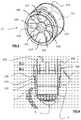
- FIG. 4schematically illustrates the probe once the ring and the means for generating ultrasonic waves are assembled.
- FIGS. 1 to 4an embodiment is illustrated of the probe for treating an eye pathology.
- the probecomprises:
- the means for generating ultrasonic waves 2are intended to cooperate with the ring 1 . More specifically, the ring 1 forms a housing for the means for generating ultrasonic waves 2 .
- the means for generating ultrasonic waves 2give the possibility of generating ultrasonic energy.
- the means for generating ultrasonic wavesgive the possibility of generating focused ultrasonic waves with high intensity.
- Theycomprise a ring-shaped crown 21 with an axis A-A′ including:
- the first base 211include at least one transducer 215 having a radiating element for generating ultrasonic waves.
- the profile of the radiating element(s)may be adapted for allowing the orientation and the focusing of the ultrasonic waves in a given point.
- the transducer 215may comprise reflector(s) for reflecting, orienting and focusing in a given point the ultrasonic waves generated by the radiating element(s).
- transducers 215extend over the first base 211 of the crown 21 .
- the transducers 215are grouped in two pairs of three transducers separated by two inactive sectors 217 .
- the inactive sectors 217are localized on the crown 21 so as to extend in a temporal/nasal plane B-B′ of the eye 4 when the probe is set into place on the eye 4 , these sectors 217 corresponding to areas of the eye 4 including the majority of the nerve and vascular endings.
- the ring 1allows adequate and constant positioning of the means for generating ultrasonic waves 2 , both for the centering and for the distance relatively to the sclera of the means for generating ultrasonic waves 2 .
- the ring 1comprises a truncated cone (or cone frustum) 11 with an axis A-A′, and a peripheral skirt 12 coaxial with the truncated cone 11 .
- the truncated cone 11is opened at both of its ends.
- the large base 111 of the truncated cone 11a so called “first end” in the following—comprises a supporting cradle intended to receive the means for generating ultrasonic waves 2 .
- the small base 112 of the truncated cone 11a so called “second end” subsequently—is intended to come into contact with the eye 4 .
- the second end 112may comprise an external annular flange able to be applied on the external surface of the eye 4 , this flange having a concave profile with a radius of curvature substantially equal to the radius of curvature of the eye 4 .
- the skirt 12comprises a ring-shaped wall 123 coaxial with the truncated cone 11 .
- the skirt 12extends outwards from the first end 111 of the truncated cone 11 . More specifically, the skirt 12 comprises first and second open endings 121 , 122 :
- the skirt 12has a shape mating the means for generating ultrasonic waves 2 . More specifically, the interior profile of the ring-shaped wall 123 is the conjugate of the outer profile of the crown 21 .
- the ring 1forms a housing for the means for generating ultrasonic waves 2 :
- the height (i.e. dimension along the A-A′ axis) of the ring-shaped wall 123is greater than the height of the crown 21 so that the second ending 122 is localized at a non-zero distance from the second base 212 .
- the probemay include means for generating a depression allowing the maintaining in position of the ring 1 on the eye 4 during the whole period of the treatment.
- the means for generating a depressionfor example comprise two suction nozzles 113 extending along a diameter of the second end 112 .
- Each nozzle 113is connected to an external suction device (not shown) for generating a depression at the nozzles 113 when the probe is positioned on the eye 4 . This gives the possibility of securing the ring 1 on the eye 4 by suction cup effect.
- each nozzle 113consists in an aperture opening onto the second end 112 so as to come into contact with the eye 4 of the patient. This gives the possibility of limiting the risks of a pressure drop of the suction (notably relatively to a nozzle with an oblong shape).
- the nozzles 113are laid out so as to be localized in the temporal/nasal plane B-B′ of the eye 4 when the probe is applied on the eye 4 .
- the eye 4has a substantially elliptical shape with a major radius contained in the temporal/nasal plane B-B′.
- the means for generating a depressionalso comprise:
- the ring-shaped conduit for circulation of airextends at the periphery of the second end 112 . It allows the distribution of the depression generated at the nozzles 113 .
- the access member 124extends radially towards the outside of the ring-shaped wall 123 .
- le access member 124is laid out so as to be positioned in the temporal/nasal plane B-B′ of the eye 4 when the probe is set into place on the eye 4 . This gives the possibility of not bothering the practitioner with the connection tubing during the treatment.
- the acoustic resistance of the airis very significant, the presence of an air bubble at a transducer 215 makes the latter inefficient. These air bubbles may be produced during the filling of the probe with the coupling fluid.
- this fillingis applied by projecting the coupling fluid on the second base 212 of the crown 21 after having assembled the ring 1 with the means for generating ultrasonic waves 2 .
- the probecomprises a flow rate regulator between the first and second_bases. The latter gives the possibility of preventing the circulation of air bubbles towards the first base 211 .
- the flow regulatorcomprises a conduit for supplying a coupling fluid.
- This conduitfor example consists in an aperture 3 between the ring-shaped wall 123 and the external side wall 213 .
- the dimensions of this aperture 3are provided so as to retain the bubbles on the second base 212 .
- This aperturealso allows the passing of the coupling fluid poured on the second base 212 towards the truncated cone 11 .
- at least one of the dimensions of the apertureis calculated so as to limit the propagation of bubbles towards the first base when the coupling fluid has a viscosity equal to that of water.
- the distance between the skirt 12 and the crown 21is constant in order to define a ring-shaped aperture 3 between the skirt 12 and the crown 21 .
- the distance between the skirt 12 and the crown 21may be comprised between 0.1 and 5 millimeters, preferentially between 0.5 and 2 millimeters. This allows the aperture 3 to filter the bubbles with a diameter greater than its thickness (i.e. dimension of the aperture according to a radius of the truncated cone) while guaranteeing sufficient cooperation between the ring 1 and the means for generating ultrasonic waves 2 .
- Splinesmay be made in the annular wall 123 and/or in the external side wall 213 for facilitating the flow of the coupling fluid towards the truncated cone 11 during the filling of the probe. This gives the possibility of increasing the flow rate of the coupling fluid in order to avoid risks of overflow during the filling.
- the splinesmay extend over the whole or part of the height (i.e. the dimension along the A-A′ axis) of the crown 21 .
- micro-bubblesmay nevertheless circulate in the fluid flow flowing between the second and first bases 212 , 211 .
- the surface of the crown 21may be treated for increasing its hydrophilic properties.
- the transducer(s)may be covered with a layer of hydrophilic material. This gives the possibility of limiting the adhesion of air bubbles on the transducer(s) 215 .
- the probealso comprises a purger for discharging the air contained in the ring 1 during the filling of the probe.
- the purgerincludes a chimney 218 coaxial with the central channel. This chimney 218 extends at right angles from the internal side wall 214 .
- the chimney 218gives the possibility of preventing the flow of the coupling fluid through the central channel during the filling of the probe. Thus, it forces the fluid to flow through the aperture 3 forming a flow rate regulator.
- the free end of the chimney 218comprises a hole for allowing the air to escape.
- the coupling fluidgradually takes the place of the air contained in the ring 1 .
- the airtends to accumulate in the central channel of the crown 21 .
- the hole made in the chimneythen allows this air to escape outwards from the probe.
- the probealso comprises gripping means for facilitating its handling by the practitioner, and giving him/her an indication on the area where his/her fingers are positioned.
- the gripping meansinclude:
- the first gripperfor example consists in two pins 125 extending radially towards the outside of the ring-shaped wall 123 .
- the pins 125may be laid out on the ring-shaped wall 123 so as to be positioned in an upper/lower plane C-C′ (orthogonal to the temporal/nasal plane B-B′) when the probe is set into place on the eye 4 . This allows the practitioner to be in an ergonomic position and be always placed at the head of the patient.
- each pin 126may have a concave possibly striated surface. This gives the possibility of reducing the risk of an accidental sliding between the first gripper and the surgical glove of the practitioner (which may in certain cases be humid).
- the second grippermay consist in free ends of two tabs 219 elastic and planar with shape memory. As illustrated in FIG. 4 , these two tabs 219 are positioned facing each other along a diameter of the crown 21 , and extend and protrude at the periphery of the second base 212 , in the extension of the external side wall 213 .
- a preformed dug imprintmay be made at the end of each tab 219 in order to limit the risks of sliding of the surgical glove of the practitioner on the second gripper.
- the probealso comprises a guide in translation for facilitating the assembly of the means for generating ultrasonic waves with the ring 1 .
- the guide in translationconsists in:
- the groove 126is made on the inner face of the ring-shaped wall 123 . This groove 126 is adapted for receiving the slider 216 .
- the slider 216radially extends towards the outside of the external side wall 213 .
- the slider 216may consist in a finger extending over one portion or over the totality of the height of the crown 21 .
- the guide in translationgives the possibility of preventing the relative rotation of the means for generating ultrasonic waves 2 relatively to the ring 1 around the axis A-A′.
- the probemay also comprise a blocker for attaching reversibly the means for generating ultrasonic waves 2 on the ring 1 .
- the blockergives the possibility of immobilizing (in translation) the means for generating ultrasonic waves 2 once the probe is assembled. It comprises:
- Each bulge 230is mounted on a respective elastic tab 219 and extends while radially protruding outwards on the whole width of the tab 219 .
- Each bulge 230is intended to cooperate with a respective bulge 130 made on the second ending 122 and radially extending inwards (i.e. in the direction of the A-A′ axis).
- the probemay also comprise a down holder for applying a down holding force on the means for generating ultrasonic waves 2 .
- a component of this down holding forceis parallel to the axis A-A′ and oriented towards the truncated cone 11 so as to flatten the ring 21 against the supporting cradle of the truncated cone 11 .
- a down holderis laid out on each bulge 230 .
- This down holderconsists in an angle formed between a normal to the tab and the surface of the bulge 230 intended to come into contact with its associated bulge 130 .
- the probemay also comprise a pair of associated abutments each to a respective tab 219 . These abutments have the function of limiting the travel of the tabs 219 .
- each abutmentconsists in a rigid blade 231 extending parallel to its associated tab 219 .
- the application of a clamping force on the tabs 219induces their torsion towards the axis A-A′ until a limiting position where the tabs 219 will come into contact with the blades 231 . Beyond this limiting position, the displacement of the tabs 219 towards the axis A-A′ is prevented by the blades 231 .
- each abutmentmay comprise a buttress 232 .
- the ring 1 and the means for generating ultrasonic waves 2are connected to a control system. More specifically:
- the practitionergrips the ring 1 by grasping the pins 125 between his/her thumb and his/her forefinger. He/she positions himself/herself at the front of the patient and lays the ring 1 on the eye 4 by putting the second end 112 in contact with the eye 4 .
- the suction deviceis activated for generating a depression at the nozzles 113 so as to secure the ring 1 on the eye 4 by a suction effect.
- the practitionerdisplaces the ring 1 for centering it on the eye 4 .
- the practitionertakes the means for generating ultrasonic waves 2 by clamping the ends of the elastic tabs 219 between his/her thumb and his/her forefinger. He/she positions the crown 21 above the skirt 12 .
- the bulges 230will come into contact with the bulges 130 .
- the elastic tabs 219deform until the bulges 230 have crossed the bulge 130 , and then reassume their rest positions.
- the crown 21is then blocked in the ring 1 by clipping by means of the bulges 230 and bulges 130 .
- the V shape of the bulges 230induces the constant application of a force against the bulges 130 which tend to flatten the crown 21 against the cradle of the truncated cone 11 in order to ensure accurate positioning of the means for generating ultrasonic waves 2 .
- the probeis assembled, the latter is filled with the coupling liquid.
- the practitionerpositions the flask drop wise above the probe and pours the liquid onto the second base 212 .
- the chimney 218prevents the liquid from penetrating into the central channel.
- the air bubbles with a diameter greater than the width of the aperture 3are retained at the second base 212 .
- the liquidgradually takes the place of the air which escapes through the hole of the chimney 218 via the central channel extending as far as the center of the first concave base 211 .
- the practitionerinterrupts the filling and activates the control device for applying the treatment.
- the probe described earlierguarantees to the practitioner good efficiency of the treatment.
Landscapes
- Health & Medical Sciences (AREA)
- Life Sciences & Earth Sciences (AREA)
- Public Health (AREA)
- Veterinary Medicine (AREA)
- Engineering & Computer Science (AREA)
- Biomedical Technology (AREA)
- Nuclear Medicine, Radiotherapy & Molecular Imaging (AREA)
- General Health & Medical Sciences (AREA)
- Animal Behavior & Ethology (AREA)
- Ophthalmology & Optometry (AREA)
- Radiology & Medical Imaging (AREA)
- Vascular Medicine (AREA)
- Heart & Thoracic Surgery (AREA)
- Surgery (AREA)
- Ultra Sonic Daignosis Equipment (AREA)
- Surgical Instruments (AREA)
Abstract
Description
- either by improving the draining of the aqueous humor through the trabeculum and the Schlemm channel of the eye,
- or by reducing the production of aqueous humor by the ciliary body of the eye.
- of a container containing the coupling liquid,
- of a drop dispenser mounted on the container, and
- of a plug for closing the dispenser.
- a ring including a truncated cone having a first end adapted for supporting means for generating ultrasonic waves and a second end for coming into contact with an eye of a patient,
- means for generating ultrasonic waves including a first base intended to come to face the first end, and a second base opposed to the first base,
remarkable in that the probe further comprises a flow rate regulator for suppressing the bubbles contained in a coupling fluid flowing towards the first base during the filling of the probe with said fluid.
- the ring may comprise a coaxial skirt with the truncated cone, and the means for generating ultrasonic waves may comprise a crown, the skirt extending outwards from the first end so as to surround the crown;
- the regulator may comprise an aperture defined between the skirt and the crown, said aperture extending over the whole height of the crown for allowing passing of the fluid between the second and first bases;
- the aperture may extend over the whole perimeter of the crown;
- the thickness of the aperture may be comprised between 0.1 mm and 5 mm, preferentially between 0.2 and 2 mm, and still more preferentially equal to 0.5 mm;
- the first base of the means for generating ultrasonic waves may comprise a hydrophilic treatment;
- the probe may also comprise a purger for the exhaust of the gases during the filling of the probe with the coupling fluid;
- the means for generating ultrasonic waves may comprise a crown having a central channel, the purger comprising at least one chimney coaxial with the central channel and extending outwards on the second base;
- the ring and the means for generating ultrasonic waves may be made in two distinct parts intended to be assembled, the probe comprising a guide for guiding the sliding of the means for generating ultrasonic waves relatively to the ring;
- the guide may consist in a groove laid out on the ring and a slider laid out on the means for generating ultrasonic waves;
- the probe may further comprise at least two suction nozzles on the second end, the nozzles being laid out so as to be localized in a temporal/nasal plane B-B′ of the eye when the probe is positioned on the eye;
- the means for generating ultrasonic waves may comprise a gripper extending on the second base;
- the ring and the means for generating ultrasonic waves may be made in two distinct parts intended to be assembled, the probe comprising blockers for immobilizing the ring relatively to the means for generating ultrasonic waves;
- the blockers may comprise a pair of elastic tabs with shape memory extending at the periphery of the second base, each tab including a bulge for cooperating by clipping with a bulge made on the ring so as to immobilize in translation the ring relatively to the means for generating ultrasonic waves;
- each bulge may have a V shape;
- the probe may further comprise at least one abutment for limiting the displacement of the tabs.
- a
ring 1, - means for generating
ultrasonic waves 2.
- a
- first and second
opposed bases - an
external side wall 213 between the first and second bases, and - an
internal side wall 214 defining a central channel between the first andsecond bases
- first and second
- the first ending121 being secured to the
first end 111, and - the second ending122 being opposed to the
second end 112.
- the first ending121 being secured to the
- the
truncated cone 11 extends under thecrown 21, facing thefirst base 211, and - the
skirt 12 encloses thecrown 21.
- the
- a ring-shaped conduit for circulation of air, and
- a
tubular access member 124
allowing the connection of thenozzles 113 to the external suction device via a connection tubing.
- a first gripper positioned on the
skirt 12 for allowing the practitioner to hold thering 1 between his/her thumb and his/her forefinger, and - a second gripper positioned on the
crown 21 for allowing the practitioner to handle the means for generatingultrasonic waves 2 between his/her finger and his/her forefinger.
- a first gripper positioned on the
- a
groove 126 laid out on thering 1 and - a
slider 216 laid out on the means for generatingultrasonic waves 2.
- a
- two
bulges 230 on the means for generatingultrasonic waves 2, - two
bulges 130 on thering 1.
- two
- the
ring 1 is connected to a suction device of the control system by means of a connection tubing, - the means for generating
ultrasonic waves 2 are connected to a generator of the control system by means of an electric cable.
- the
Claims (14)
Applications Claiming Priority (3)
| Application Number | Priority Date | Filing Date | Title |
|---|---|---|---|
| FR1500644AFR3034320B1 (en) | 2015-03-31 | 2015-03-31 | ULTRASOUND TREATMENT OCULAR PROBE |
| FR15/00644 | 2015-03-31 | ||
| PCT/EP2016/056898WO2016156381A1 (en) | 2015-03-31 | 2016-03-30 | Ocular probe for ultrasonic treatment |
Publications (2)
| Publication Number | Publication Date |
|---|---|
| US20180111008A1 US20180111008A1 (en) | 2018-04-26 |
| US11097131B2true US11097131B2 (en) | 2021-08-24 |
Family
ID=53177593
Family Applications (1)
| Application Number | Title | Priority Date | Filing Date |
|---|---|---|---|
| US15/562,612Active2037-11-25US11097131B2 (en) | 2015-03-31 | 2016-03-30 | Eye probe for treatment with ultrasonic waves |
Country Status (6)
| Country | Link |
|---|---|
| US (1) | US11097131B2 (en) |
| EP (1) | EP3277376B1 (en) |
| CN (1) | CN107427387B (en) |
| ES (1) | ES2849182T3 (en) |
| FR (1) | FR3034320B1 (en) |
| WO (1) | WO2016156381A1 (en) |
Cited By (1)
| Publication number | Priority date | Publication date | Assignee | Title |
|---|---|---|---|---|
| US12390667B2 (en) | 2020-08-21 | 2025-08-19 | Vitreosonic Inc. | Ultrasonic treatment of vitreous opacities |
Families Citing this family (8)
| Publication number | Priority date | Publication date | Assignee | Title |
|---|---|---|---|---|
| FR3062057B1 (en)* | 2017-01-20 | 2021-01-15 | Eye Tech Care | EYE PROBE WITH MOVABLE ULTRASOUND GENERATION MEANS |
| FR3104410B1 (en) | 2019-12-16 | 2021-12-31 | Eye Tech Care | PROCESSING DEVICE INCLUDING A TOOL HOLDER AND A TOOL HAVING CONTACT ROTATING MOVEMENT MEANS |
| FR3104408B1 (en) | 2019-12-16 | 2021-12-31 | Eye Tech Care | PROCESSING DEVICE INCLUDING A TOOL HOLDER AND A TOOL INCLUDING CONTACTLESS ROTATIONAL DISPLACEMENT MEANS |
| FR3104409B1 (en) | 2019-12-16 | 2022-10-21 | Eye Tech Care | PROCESSING DEVICE INCLUDING COUPLING LIQUID DETECTOR |
| CA3096285A1 (en) | 2020-10-16 | 2022-04-16 | Pulsemedica Corp. | Opthalmological imaging and laser delivery device, system and methods |
| CA3100460A1 (en) | 2020-11-24 | 2022-05-24 | Pulsemedica Corp. | Spatial light modulation targeting of therapeutic lasers for treatment of ophthalmological conditions |
| CA3224096A1 (en)* | 2021-06-30 | 2023-01-05 | Nir KATCHINSKIY | System, method, and devices for tissue manipulation using electronically steerable ultrasound transducer |
| CN120586311A (en)* | 2025-08-08 | 2025-09-05 | 浙江理工大学 | Ablation system and method |
Citations (41)
| Publication number | Priority date | Publication date | Assignee | Title |
|---|---|---|---|---|
| US4484569A (en)* | 1981-03-13 | 1984-11-27 | Riverside Research Institute | Ultrasonic diagnostic and therapeutic transducer assembly and method for using |
| US4634418A (en) | 1984-04-06 | 1987-01-06 | Binder Perry S | Hydrogel seton |
| US4787885A (en) | 1984-04-06 | 1988-11-29 | Binder Perry S | Hydrogel seton |
| US4936825A (en) | 1988-04-11 | 1990-06-26 | Ungerleider Bruce A | Method for reducing intraocular pressure caused by glaucoma |
| US4946436A (en) | 1989-11-17 | 1990-08-07 | Smith Stewart G | Pressure-relieving device and process for implanting |
| US5127901A (en) | 1990-05-18 | 1992-07-07 | Odrich Ronald B | Implant with subconjunctival arch |
| US5180362A (en) | 1990-04-03 | 1993-01-19 | Worst J G F | Gonio seton |
| US5230334A (en) | 1992-01-22 | 1993-07-27 | Summit Technology, Inc. | Method and apparatus for generating localized hyperthermia |
| US5360399A (en) | 1992-01-10 | 1994-11-01 | Robert Stegmann | Method and apparatus for maintaining the normal intraocular pressure |
| EP0627207A1 (en) | 1992-11-20 | 1994-12-07 | OKAMOTO, Shinseiro | Cornea operating method and apparatus |
| EP0627202A1 (en) | 1993-04-05 | 1994-12-07 | Procom S.A. | Prosthetic assembly for forming a knee joint |
| US5433701A (en) | 1994-12-21 | 1995-07-18 | Rubinstein; Mark H. | Apparatus for reducing ocular pressure |
| WO1996014019A1 (en) | 1994-11-07 | 1996-05-17 | Ophthalmic International, L.L.C. | Open angle glaucoma treatment apparatus and method |
| WO1996028213A1 (en) | 1995-03-16 | 1996-09-19 | Forskarpatent I Uppsala Ab | Ultrasound probe |
| US6039689A (en) | 1998-03-11 | 2000-03-21 | Riverside Research Institute | Stripe electrode transducer for use with therapeutic ultrasonic radiation treatment |
| US6267752B1 (en) | 1999-08-05 | 2001-07-31 | Medibell Medical Vision Technologies, Ltd. | Multi-functional eyelid speculum |
| WO2002038078A2 (en) | 2000-11-07 | 2002-05-16 | Horn Gerald D | A method and apparatus for the correction of presbyopia using high intensity focused ultrasound |
| EP1243236A1 (en) | 2001-03-21 | 2002-09-25 | Novosalud S.L. | Suction ring for microkeratomes |
| RU2197926C2 (en) | 1999-04-26 | 2003-02-10 | Рязанский государственный медицинский университет им. акад. И.П. Павлова | Method for treating glaucoma cases |
| RU2200522C1 (en) | 2002-07-10 | 2003-03-20 | Джафарли Таир Баратович | Method for treating the cases of open angle glaucoma by applying pneumocyclodestruction |
| EP1306068A2 (en) | 2001-10-24 | 2003-05-02 | Cesar C. Dr. Carriazo | Aspherical positioning ring |
| US20030116014A1 (en)* | 2001-12-21 | 2003-06-26 | Possanza Steven D. | Integrated use of deaeration methods to reduce bubbles and liquid waste |
| EP1325722A2 (en) | 2001-12-14 | 2003-07-09 | Cesar C. Dr. Carriazo | Adjustable suction ring |
| EP1350492A2 (en) | 2002-04-04 | 2003-10-08 | Gebauer GmbH | Insert for eye suction ring |
| US20030230690A1 (en)* | 1996-12-03 | 2003-12-18 | John Ostrovsky | Dual extrusion snap closed ceiling sign hanger |
| US20040015140A1 (en) | 2002-07-19 | 2004-01-22 | Shields Milton B. | Uveoscleral drainage device |
| DE20221042U1 (en) | 2001-10-24 | 2004-11-18 | Carriazo, Cesar C., Dr. | Securing apparatus for fixing aspherical eyeball when performing lamellar keratotomies, includes suction channel having aspherical eyeball engaging surface comprising interior engaging surface and superior engaging surface |
| WO2006018686A1 (en) | 2004-08-11 | 2006-02-23 | Insightec - Image Guided Treatment Ltd | Focused ultrasound system with adaptive anatomical aperture shaping |
| US20060209135A1 (en)* | 2005-03-21 | 2006-09-21 | Hoisington Paul A | Drop ejection device |
| WO2006129047A2 (en) | 2005-06-03 | 2006-12-07 | Theraclion | Distance-determining method and treatment apparatus which uses said method |
| WO2006136912A1 (en) | 2005-06-21 | 2006-12-28 | Insightec Ltd | Controlled, non-linear focused ultrasound treatment |
| EP1738725A1 (en) | 2005-06-30 | 2007-01-03 | Wavelight Laser Technologie AG | Apparatus for eye surgery |
| WO2007081750A2 (en) | 2006-01-06 | 2007-07-19 | The Curators Of The University Of Missouri | Ultrasound-mediated transcleral drug delivery |
| WO2008024795A2 (en) | 2006-08-22 | 2008-02-28 | Schwartz Donald N | Ultrasonic treatment of glaucoma |
| WO2009103721A1 (en) | 2008-02-19 | 2009-08-27 | Eye Tech Care | A method of treating an ocular pathology by applying high intensity focused ultrasound and device thereof |
| US8043235B2 (en)* | 2006-08-22 | 2011-10-25 | Schwartz Donald N | Ultrasonic treatment of glaucoma |
| US20120277597A1 (en)* | 2011-04-29 | 2012-11-01 | Dave Eshbaugh | Apparatus and methods for non-invasively measuring physiologic parameters of one or more subjects |
| US20130023768A1 (en)* | 2011-07-19 | 2013-01-24 | Ramin Hooriani | Ultrasound probe positioning immersion shell |
| US20130197633A1 (en)* | 2011-12-08 | 2013-08-01 | Eye Tech Care | Dispositif de succion pour le traitement d une pathologie oculaire |
| US8970090B2 (en)* | 2010-06-29 | 2015-03-03 | Denso Corporation | Ultrasonic sensor |
| US9125722B2 (en)* | 2012-02-09 | 2015-09-08 | Donald N. Schwartz | Device for the ultrasonic treatment of glaucoma having a concave tip |
Family Cites Families (2)
| Publication number | Priority date | Publication date | Assignee | Title |
|---|---|---|---|---|
| US8932238B2 (en)* | 2009-09-29 | 2015-01-13 | Liposonix, Inc. | Medical ultrasound device with liquid dispensing device coupled to a therapy head |
| WO2014150373A1 (en)* | 2013-03-15 | 2014-09-25 | Muffin Incorporated | Internal ultrasound assembly with port for fluid injection |
- 2015
- 2015-03-31FRFR1500644Apatent/FR3034320B1/enactiveActive
- 2016
- 2016-03-30EPEP16714834.5Apatent/EP3277376B1/enactiveActive
- 2016-03-30WOPCT/EP2016/056898patent/WO2016156381A1/ennot_activeCeased
- 2016-03-30ESES16714834Tpatent/ES2849182T3/enactiveActive
- 2016-03-30CNCN201680019529.5Apatent/CN107427387B/enactiveActive
- 2016-03-30USUS15/562,612patent/US11097131B2/enactiveActive
Patent Citations (43)
| Publication number | Priority date | Publication date | Assignee | Title |
|---|---|---|---|---|
| US4484569A (en)* | 1981-03-13 | 1984-11-27 | Riverside Research Institute | Ultrasonic diagnostic and therapeutic transducer assembly and method for using |
| US4634418A (en) | 1984-04-06 | 1987-01-06 | Binder Perry S | Hydrogel seton |
| US4787885A (en) | 1984-04-06 | 1988-11-29 | Binder Perry S | Hydrogel seton |
| US4936825A (en) | 1988-04-11 | 1990-06-26 | Ungerleider Bruce A | Method for reducing intraocular pressure caused by glaucoma |
| US4946436A (en) | 1989-11-17 | 1990-08-07 | Smith Stewart G | Pressure-relieving device and process for implanting |
| US5180362A (en) | 1990-04-03 | 1993-01-19 | Worst J G F | Gonio seton |
| US5127901A (en) | 1990-05-18 | 1992-07-07 | Odrich Ronald B | Implant with subconjunctival arch |
| US5360399A (en) | 1992-01-10 | 1994-11-01 | Robert Stegmann | Method and apparatus for maintaining the normal intraocular pressure |
| US5230334A (en) | 1992-01-22 | 1993-07-27 | Summit Technology, Inc. | Method and apparatus for generating localized hyperthermia |
| EP0627207A1 (en) | 1992-11-20 | 1994-12-07 | OKAMOTO, Shinseiro | Cornea operating method and apparatus |
| EP0627202A1 (en) | 1993-04-05 | 1994-12-07 | Procom S.A. | Prosthetic assembly for forming a knee joint |
| WO1996014019A1 (en) | 1994-11-07 | 1996-05-17 | Ophthalmic International, L.L.C. | Open angle glaucoma treatment apparatus and method |
| US5433701A (en) | 1994-12-21 | 1995-07-18 | Rubinstein; Mark H. | Apparatus for reducing ocular pressure |
| WO1996028213A1 (en) | 1995-03-16 | 1996-09-19 | Forskarpatent I Uppsala Ab | Ultrasound probe |
| US6162193A (en)* | 1995-03-16 | 2000-12-19 | Forskarpatent I Uppsala Ab | Ultrasound probe |
| US20030230690A1 (en)* | 1996-12-03 | 2003-12-18 | John Ostrovsky | Dual extrusion snap closed ceiling sign hanger |
| US6039689A (en) | 1998-03-11 | 2000-03-21 | Riverside Research Institute | Stripe electrode transducer for use with therapeutic ultrasonic radiation treatment |
| RU2197926C2 (en) | 1999-04-26 | 2003-02-10 | Рязанский государственный медицинский университет им. акад. И.П. Павлова | Method for treating glaucoma cases |
| US6267752B1 (en) | 1999-08-05 | 2001-07-31 | Medibell Medical Vision Technologies, Ltd. | Multi-functional eyelid speculum |
| WO2002038078A2 (en) | 2000-11-07 | 2002-05-16 | Horn Gerald D | A method and apparatus for the correction of presbyopia using high intensity focused ultrasound |
| EP1243236A1 (en) | 2001-03-21 | 2002-09-25 | Novosalud S.L. | Suction ring for microkeratomes |
| EP1306068A2 (en) | 2001-10-24 | 2003-05-02 | Cesar C. Dr. Carriazo | Aspherical positioning ring |
| DE20221042U1 (en) | 2001-10-24 | 2004-11-18 | Carriazo, Cesar C., Dr. | Securing apparatus for fixing aspherical eyeball when performing lamellar keratotomies, includes suction channel having aspherical eyeball engaging surface comprising interior engaging surface and superior engaging surface |
| EP1325722A2 (en) | 2001-12-14 | 2003-07-09 | Cesar C. Dr. Carriazo | Adjustable suction ring |
| US20030116014A1 (en)* | 2001-12-21 | 2003-06-26 | Possanza Steven D. | Integrated use of deaeration methods to reduce bubbles and liquid waste |
| EP1350492A2 (en) | 2002-04-04 | 2003-10-08 | Gebauer GmbH | Insert for eye suction ring |
| RU2200522C1 (en) | 2002-07-10 | 2003-03-20 | Джафарли Таир Баратович | Method for treating the cases of open angle glaucoma by applying pneumocyclodestruction |
| US20040015140A1 (en) | 2002-07-19 | 2004-01-22 | Shields Milton B. | Uveoscleral drainage device |
| WO2006018686A1 (en) | 2004-08-11 | 2006-02-23 | Insightec - Image Guided Treatment Ltd | Focused ultrasound system with adaptive anatomical aperture shaping |
| US20060209135A1 (en)* | 2005-03-21 | 2006-09-21 | Hoisington Paul A | Drop ejection device |
| WO2006129047A2 (en) | 2005-06-03 | 2006-12-07 | Theraclion | Distance-determining method and treatment apparatus which uses said method |
| WO2006136912A1 (en) | 2005-06-21 | 2006-12-28 | Insightec Ltd | Controlled, non-linear focused ultrasound treatment |
| EP1738725A1 (en) | 2005-06-30 | 2007-01-03 | Wavelight Laser Technologie AG | Apparatus for eye surgery |
| WO2007081750A2 (en) | 2006-01-06 | 2007-07-19 | The Curators Of The University Of Missouri | Ultrasound-mediated transcleral drug delivery |
| US8043235B2 (en)* | 2006-08-22 | 2011-10-25 | Schwartz Donald N | Ultrasonic treatment of glaucoma |
| WO2008024795A2 (en) | 2006-08-22 | 2008-02-28 | Schwartz Donald N | Ultrasonic treatment of glaucoma |
| US7909781B2 (en)* | 2006-08-22 | 2011-03-22 | Schwartz Donald N | Ultrasonic treatment of glaucoma |
| WO2009103721A1 (en) | 2008-02-19 | 2009-08-27 | Eye Tech Care | A method of treating an ocular pathology by applying high intensity focused ultrasound and device thereof |
| US8970090B2 (en)* | 2010-06-29 | 2015-03-03 | Denso Corporation | Ultrasonic sensor |
| US20120277597A1 (en)* | 2011-04-29 | 2012-11-01 | Dave Eshbaugh | Apparatus and methods for non-invasively measuring physiologic parameters of one or more subjects |
| US20130023768A1 (en)* | 2011-07-19 | 2013-01-24 | Ramin Hooriani | Ultrasound probe positioning immersion shell |
| US20130197633A1 (en)* | 2011-12-08 | 2013-08-01 | Eye Tech Care | Dispositif de succion pour le traitement d une pathologie oculaire |
| US9125722B2 (en)* | 2012-02-09 | 2015-09-08 | Donald N. Schwartz | Device for the ultrasonic treatment of glaucoma having a concave tip |
Non-Patent Citations (12)
| Title |
|---|
| Bron et al., "Prevalence de l'hypertonie oculaire et du glaucome dans une population francaise non selectionnee", J Fr. Ophtalmol., vol. 29, No. 6, 2006, pp. 635-641. |
| Chavrier et al., "Modeling of high-intensity focused ultrasound-induced lesions in the presence of cavitation bubbles", J. Acoust. Soc. Am., vol. 108, No. 1, Jul. 2000, pp. 432-440. |
| Coleman et al., "Therapeutic Ultrasound in the Treatment of Glaucoma", Ophthalmology, Mar. 1985, vol. 92, No. 3, pp. 339-346. |
| Dépistage Et Diagnostic Précoce Du Glaucome : Problématique Et Perspectives En France, Haute Autorité de santé-Service évaluation médico-économique et santé publique Nov. 2006. |
| Hamard et al., "Traitement des glaucomes refractaires", Encycl Med Chir (Elsevier, Paris), Ophtalmologie, 21-280-8-50,1997, 8 pages. |
| International Preliminary Report on Patentability received for PCT Patent Application No. PCT/EP2016/056898, dated Oct. 12, 2017, 14 pages. |
| International Search Report and Written Opinion received for PCT Patent Application No. PCT/EP2016/056898, dated May 3, 2016, 16 pages. |
| Lachkar et al., "Dépistage du glaucome chronique á angle ouvert", Encyclopédie Médico-Chirurgicale 21-275-A-20. |
| LIZZI & AL.: "Ultrasonic therapy and imaging in ophtamology", ACOUSTICAL IMAGING. THE HAGUE, 22 - 25 APRIL 1985., NEW YORK, PLENUM PRESS., US, vol. 14., 1 January 1985 (1985-01-01), US, pages 01 - 17., XP002079832 |
| Lizzi et al., "Ultrasonic Theraphy and Imaging in Ophthalmology", 1985, XP002079832, pp. 1-17. |
| Müller M., "Focusing water shock waves for lithotripsy by various ellipsoid reflectors", Biomed Tech (Berl), Apr. 1989, vol. 34, No. 4, pp. 62-72. |
| Rouland et al., "Étude observationnelle rétrospective de coûts des deux premiéres années de traitement dans le glaucome primitif à angle ouvert et I'hypertension oculaire en France", J Fr. Ophtalmol., 2001; vol. 24, No. 3, pp. 233-243. |
Cited By (1)
| Publication number | Priority date | Publication date | Assignee | Title |
|---|---|---|---|---|
| US12390667B2 (en) | 2020-08-21 | 2025-08-19 | Vitreosonic Inc. | Ultrasonic treatment of vitreous opacities |
Also Published As
| Publication number | Publication date |
|---|---|
| CN107427387B (en) | 2021-01-15 |
| ES2849182T3 (en) | 2021-08-16 |
| FR3034320A1 (en) | 2016-10-07 |
| CN107427387A (en) | 2017-12-01 |
| WO2016156381A1 (en) | 2016-10-06 |
| EP3277376A1 (en) | 2018-02-07 |
| US20180111008A1 (en) | 2018-04-26 |
| EP3277376B1 (en) | 2020-11-18 |
| FR3034320B1 (en) | 2017-04-28 |
Similar Documents
| Publication | Publication Date | Title |
|---|---|---|
| US11097131B2 (en) | Eye probe for treatment with ultrasonic waves | |
| EP2456402B1 (en) | Liquid holding interface device for ophthalmic laser procedures | |
| JP6203173B2 (en) | Intraocular drug delivery device | |
| US9724238B2 (en) | Ophthalmic interface apparatus, method of interfacing a surgical laser with an eye, and support ring for use with a suction ring | |
| US9180044B2 (en) | Eye injection device | |
| US11376160B2 (en) | Coupling interface between a laser source and a tissue to be treated | |
| KR20160021201A (en) | Inserter for tubular medical implant devices | |
| CN102497839B (en) | Parameters of ultrasonic equipment including devices generating high-intensity ultrasonic beams | |
| AU2012304721B2 (en) | Lens injector apparatus and method | |
| US4617018A (en) | Irrigating cannula for extracting lens nucleus for use in extracapsular cataract extraction | |
| WO2015108866A1 (en) | Non-invasive device for lowering intra-ocular pressure | |
| KR102377814B1 (en) | treatment device | |
| US20170340201A1 (en) | Device and method for fixing a relative geometric position of an eye | |
| CN207412301U (en) | Eye probe with removable ultrasonic generating unit | |
| TW202415354A (en) | Ocular needle guide and method to facilitate access to an eye | |
| US9308126B2 (en) | Non-invasive devices and methods for lowering intra-ocular pressure | |
| RU2391076C1 (en) | Eye fixation device for intraocular tumors removing | |
| CN220442808U (en) | A subassembly for retina split hole seals fixedly | |
| RU2125431C1 (en) | Keratoplasty device | |
| CN209252823U (en) | A medium-sized animal with a contact lens for fundus viewing | |
| JP2024517514A (en) | Coupling interface between the laser source and the treated tissue | |
| KR101679510B1 (en) | Epthelial remove brush for lasek | |
| CN112493986A (en) | Eye cup for ultrasonic biomicroscope detection | |
| RU126940U1 (en) | DEVICE FOR RINSING THE NOSE CAVITY (OPTIONS) | |
| BR112019015583B1 (en) | COUPLING INTERFACE AND DEVICE |
Legal Events
| Date | Code | Title | Description |
|---|---|---|---|
| FEPP | Fee payment procedure | Free format text:ENTITY STATUS SET TO UNDISCOUNTED (ORIGINAL EVENT CODE: BIG.); ENTITY STATUS OF PATENT OWNER: LARGE ENTITY | |
| STPP | Information on status: patent application and granting procedure in general | Free format text:DOCKETED NEW CASE - READY FOR EXAMINATION | |
| AS | Assignment | Owner name:EYE TECH CARE, FRANCE Free format text:ASSIGNMENT OF ASSIGNORS INTEREST;ASSIGNORS:CHAPUIS, PHILIPPE;CHARREL, THOMAS;DEVIGNE, CEDRIC;AND OTHERS;SIGNING DATES FROM 20171109 TO 20171213;REEL/FRAME:047450/0477 | |
| STPP | Information on status: patent application and granting procedure in general | Free format text:NON FINAL ACTION MAILED | |
| STPP | Information on status: patent application and granting procedure in general | Free format text:RESPONSE TO NON-FINAL OFFICE ACTION ENTERED AND FORWARDED TO EXAMINER | |
| STPP | Information on status: patent application and granting procedure in general | Free format text:FINAL REJECTION MAILED | |
| STPP | Information on status: patent application and granting procedure in general | Free format text:RESPONSE AFTER FINAL ACTION FORWARDED TO EXAMINER | |
| STPP | Information on status: patent application and granting procedure in general | Free format text:ADVISORY ACTION MAILED | |
| STPP | Information on status: patent application and granting procedure in general | Free format text:DOCKETED NEW CASE - READY FOR EXAMINATION | |
| STPP | Information on status: patent application and granting procedure in general | Free format text:NOTICE OF ALLOWANCE MAILED -- APPLICATION RECEIVED IN OFFICE OF PUBLICATIONS | |
| STCF | Information on status: patent grant | Free format text:PATENTED CASE | |
| MAFP | Maintenance fee payment | Free format text:PAYMENT OF MAINTENANCE FEE, 4TH YEAR, LARGE ENTITY (ORIGINAL EVENT CODE: M1551); ENTITY STATUS OF PATENT OWNER: LARGE ENTITY Year of fee payment:4 |