US11097094B2 - Wearable cardiac defibrillation system with electrode assemblies having pillow structure - Google Patents
Wearable cardiac defibrillation system with electrode assemblies having pillow structureDownload PDFInfo
- Publication number
- US11097094B2 US11097094B2US16/859,921US202016859921AUS11097094B2US 11097094 B2US11097094 B2US 11097094B2US 202016859921 AUS202016859921 AUS 202016859921AUS 11097094 B2US11097094 B2US 11097094B2
- Authority
- US
- United States
- Prior art keywords
- electrode
- electrode assembly
- support structure
- patient
- moisture barrier
- Prior art date
- Legal status (The legal status is an assumption and is not a legal conclusion. Google has not performed a legal analysis and makes no representation as to the accuracy of the status listed.)
- Active
Links
Images


Classifications
- A—HUMAN NECESSITIES
- A61—MEDICAL OR VETERINARY SCIENCE; HYGIENE
- A61N—ELECTROTHERAPY; MAGNETOTHERAPY; RADIATION THERAPY; ULTRASOUND THERAPY
- A61N1/00—Electrotherapy; Circuits therefor
- A61N1/02—Details
- A61N1/04—Electrodes
- A61N1/0404—Electrodes for external use
- A61N1/0472—Structure-related aspects
- A61N1/0484—Garment electrodes worn by the patient
- A—HUMAN NECESSITIES
- A61—MEDICAL OR VETERINARY SCIENCE; HYGIENE
- A61N—ELECTROTHERAPY; MAGNETOTHERAPY; RADIATION THERAPY; ULTRASOUND THERAPY
- A61N1/00—Electrotherapy; Circuits therefor
- A61N1/02—Details
- A61N1/04—Electrodes
- A61N1/0404—Electrodes for external use
- A61N1/0408—Use-related aspects
- A61N1/046—Specially adapted for shock therapy, e.g. defibrillation
- A—HUMAN NECESSITIES
- A61—MEDICAL OR VETERINARY SCIENCE; HYGIENE
- A61N—ELECTROTHERAPY; MAGNETOTHERAPY; RADIATION THERAPY; ULTRASOUND THERAPY
- A61N1/00—Electrotherapy; Circuits therefor
- A61N1/02—Details
- A61N1/04—Electrodes
- A61N1/0404—Electrodes for external use
- A61N1/0472—Structure-related aspects
- A61N1/0492—Patch electrodes
- A—HUMAN NECESSITIES
- A61—MEDICAL OR VETERINARY SCIENCE; HYGIENE
- A61N—ELECTROTHERAPY; MAGNETOTHERAPY; RADIATION THERAPY; ULTRASOUND THERAPY
- A61N1/00—Electrotherapy; Circuits therefor
- A61N1/18—Applying electric currents by contact electrodes
- A61N1/32—Applying electric currents by contact electrodes alternating or intermittent currents
- A61N1/38—Applying electric currents by contact electrodes alternating or intermittent currents for producing shock effects
- A61N1/39—Heart defibrillators
- A61N1/3968—Constructional arrangements, e.g. casings
Definitions
- SCASudden Cardiac Arrest
- ICDImplantable Cardioverter Defibrillator
- a WCD systemtypically includes a harness, vest, or other garment that is configured to be worn by the patient.
- the WCD systemincludes a defibrillator and external electrodes, which are attached to the inside of the harness, vest, or other garment.
- the external electrodescan help monitor the patient's ECG. If a shockable heart arrhythmia is detected, then the defibrillator of the WCD system delivers the appropriate electric shock through the patient's body, and thus through the heart.
- Electrodesmay need to make good electrical contact with the patient's skin, without being intrusive or irritating the skin.
- WCDWearable Cardiac Defibrillator
- a wearable cardiac defibrillation (WCD) systemincludes one or more flexible ECG electrodes.
- the WCD systemmay have a support structure that is dimensioned to be worn so as to press the electrodes towards the body of the patient.
- the electrodesmay be made from appropriate material so as to flex in order to match a contour of the body of the patient.
- a wearable cardiac defibrillation (WCD) systemincludes one or more electrode assemblies.
- the WCD systemmay have a support structure that is dimensioned to be worn so as to press the electrode assembly towards the body of the patient.
- the electrode assemblymay have an electrode, and a signal terminal electrically coupled to the electrode.
- the electrode assemblymay have a compressible pillow structure.
- the electrode assemblymay have a moisture barrier so as to trap moisture from the patient's skin, for better conduction and lateral shifting of the electrode along the patient's skin.
- the electrode assemblymay have an electrostatic shield between the electrode and the signal terminal so as to shield the electrode from electrical noise.
- Embodimentsmay result in garments that integrate the disclosed electrode, and which can be washed with normal household methods. This allows for simple cleaning of lotions or patient's sweat from the electrodes, which may improve patient hygiene and reduce the chance of skin infections. All of this will add to the patient's overall comfort with the garment, and thus enhance their compliance with wearing the garment.
- FIG. 1is a diagram of sample components of a Wearable Cardiac Defibrillator (WCD) system according to embodiments.
- WCDWearable Cardiac Defibrillator
- FIG. 2Ais a diagram of a detail of a flexible electrode of FIG. 1 that is made according to embodiments, and is applied to a patient's body under pressure.
- FIG. 2Bis a diagram of a detail of the electrode of FIG. 2A , as it is deposited on a flat level surface.
- FIG. 3is a diagram of sample components of a WCD system according to embodiments.
- FIG. 4Ais a diagram of some components of an electrode assembly of FIG. 1 that includes a pillow structure made according to embodiments and is applied to a patient's body under pressure.
- FIG. 4Bis a diagram of a detail of the pillow structure of the electrode assembly of FIG. 4A , as it is deposited on a flat surface.
- FIG. 5is a diagram of sample components of an electrode assembly, which is made according to embodiments that include a flexible inner conductor.
- FIG. 6Ais a diagram of sample components of an electrode assembly, which is made according to embodiments that include a flexible inner conductor which has a fabric that is coated with a metal.
- FIG. 6Bis a top view of a flexible inner conductor of FIG. 6A according to an embodiment.
- FIG. 7is a diagram of sample components of an electrode assembly, which is made according to embodiments that include a moisture barrier.
- FIG. 8is a diagram of sample components of an electrode assembly, which is made according to embodiments that include an electrostatic shield.
- FIG. 9is a diagram of sample components of an electrode assembly, which is made according to embodiments that include a cover.
- FIG. 10is a diagram of a sample electrode assembly according to an embodiment.
- FIG. 11Ais a diagram of sample components of an electrode assembly, which is made according to embodiments that include a moisture barrier.
- FIG. 11Bis a top view of a main surface of an electrode that may be used in the assembly of FIG. 11A according to an embodiment.
- FIG. 12is a diagram of sample components of an electrode assembly, which is made according to embodiments that include an electrostatic shield.
- FIG. 13is a diagram of sample components of an electrode assembly, which is made according to embodiments that include a cover.
- FIG. 14is a diagram of sample components of an electrode assembly, made according to embodiments that include an electrostatic shield.
- FIG. 15is a diagram of sample components of an electrode assembly, made according to embodiments that include an electrostatic shield and a corresponding reference terminal.
- WCDWearable Cardiac Defibrillator
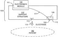
- FIG. 1is a diagram of sample components 100 of a WCD system according to embodiments.
- Components 100are intended to be worn by a patient 182 , typically according to specific instructions. Only a section of the body of patient 182 is shown, which can be the torso, or other bodily part.
- Components 100 of a WCD systemare now described in more detail.
- Components 100include a support structure 110 , which is shown partly abstractly in FIG. 1 .
- Support structure 110can be configured to be worn by patient 182 , typically according to a design.
- Support structure 110can thus be part of a belt, a harness, a garment, a holster, and so on.
- the wearable medical systemincludes a single support structure 110 . In other embodiments, more support structures may be included.
- Support structure 110can be dimensioned relative to the body of patient 182 to be worn with internal tension 112 . This dimensioning may be accomplished by, for example, making a portion be of adjustable length. In other words, in some embodiments at some times support structure 110 does not fit patient 182 everywhere loosely, but is worn with non-zero internal tension 112 .
- Tension 112is tension of non-zero magnitude that is internal to support structure 110 , and which can cause pressure 114 to be exerted onto the body of patient 182 when support structure 110 is worn. Pressure 114 may squeeze the body of patient 182 , preferably only gently. Internal tension 112 , and its resulting pressure 114 , may ensure that any electrodes of the WCD system make good electrical contact with the body of patient 182 . Accordingly, support structure 110 can be a continuous band, or have clasps (not shown) that lock together, etc.
- Components 100also include an electronics module 140 .
- Electronics module 140can be a part of a wearable medical system that performs any one or more of the following functions: monitor physiological signals of patient 182 , make determinations from these signals, communicate with the patient or with entities remote from the patient, store electrical energy for defibrillation, defibrillate, and so on.
- Electronics module 140can be configured to be coupled to support structure 110 . Coupling can be permanent, such as attaching. In some embodiments, however, electronics module 140 can be coupled to and uncoupled from support structure 110 , by the manufacturer, by patient 182 , and so on. For example, electronics module 140 can be thus coupled by being inserted in a special pocket 111 , and so on.
- Components 100additionally include an electrode 159 , which can be an ECG electrode. Electrode 159 can be stand-alone, or it may be attached to an additional component 149 of an electrode assembly. Electrode assemblies are described in more detail later in this document, and may have even more components. While only one electrode 159 is shown, of course more may be used.
- electrode 159can be configured to be coupled to support structure 110 , so that electrode 159 remains pressed against the body of patient 182 due to nonzero pressure 114 , when support structure 110 is worn by patient 182 as designed.
- electrode 159could be physically attached to support structure 110 , for example by being constructed permanently into it, be received into a suitable pocket 115 , etc.
- electrode 159could be coupled to support structure 110 but not be permanently physically attached to it.
- Electrode 159can be coupled to the skin of patient 182 by contacting the skin directly, or indirectly over clothing, depending on whether the electrode is dry or not, etc. Even when physically coupled to the skin over clothing, some electrodes can achieve electrical coupling with the patient's skin through the clothing.
- Electrode 159is of course conductive. This is written explicitly in this document, because electrode 159 can be made according to embodiments from materials that are unusual for electrodes.
- Electrode 159may also be flexible. For example, it may bend under pressure 114 . As can be seen in FIG. 2A , electrode 159 is flexible enough so as to acquire a first shape due being subjected to nonzero pressure 114 when support structure 110 is worn by patient 182 . The first shape of FIG. 2A is bent, as flexible electrode 159 follows a curved contour of the body of patient 182 . In FIG. 2A , support structure 110 is shown even more abstractly than in FIG. 1 . Due to the flexibility, electrodes according to embodiments can be integrated into a support structure in such a way as to have fairly even pressure across the complete electrode thereby reducing any perceived “pressure points” by the patient, and thus be more comfortable and increase patient compliance.
- electrode 159is flexible enough so as to acquire a second shape, if electrode 159 alone is deposited on a flat level surface 291 without being subjected to an external pressure.
- the second shapeis flat, which is different from the first shape of FIG. 2A .
- electrode 159may have to be separated from any electrode assembly. The ability to acquire the second shape so as to demonstrate the flexibility can sometimes be confirmed even without such a separation.
- the flexibility of electrode 159can be such that it transitions from the first shape to the second shape and vice versa immediately, or after some time. This time is preferably less than 1 hour, and preferably less than 10 min. Accordingly, hard materials like large pieces of metal may not serve well.
- Electrode 159may have a main surface, for example as shown in electrode 1159 in FIG. 11B .
- the main surface of electrode 1159is shown as rectangular, but it can be circular, oval, or of other shapes.
- the main surfacemay have a surface area of, say, 1 cm 2 to several cm 2 .
- electrode 159may be 2 cm on the side.
- the amount of curvature shown in FIG. 2Amay be larger than is the case for typical locations of the body of patient 182 , but the exaggeration in curvature is used in FIG. 2A to demonstrate the flexibility of electrode 159 .
- electrode 159 in FIGS. 1, 2A, 2Bshow its thickness, because they are side views. This thickness can be the height of protruding above the level of surface 291 in FIG. 2B .
- electrode 159is further thin, which means it has a small thickness. The thickness, then, can be measured in a direction perpendicular to the main surface.
- electrode 159may have an average thickness of less than 4 mm, less than 2 mm, or even less than 1 mm, for example 0.5 mm.
- Electrode 159may be made in a number of ways. For example, it can include a metal foil, such as aluminum or copper foil. Such a foil could be attached to a side of a piece of foam. Alternately, electrode 159 can include a material that includes polyurethane, or conductive polyurethane that contains one of carbon, carbon nanotubes, particles of a metal, and metal nanoparticles. Alternately, electrode 159 can include silicone, a conductive silicone rubber, and so on. The conductive silicone rubber may be enriched with conductive elements such as carbon, carbon nanotubes, particles of a metal, metal nanoparticles, and so on.
- Electrode 159may also include a material that includes polydimethylsiloxane (PDMS) silicone rubber, perhaps enriched with conductive elements such as mentioned above. Electrodes formed from silicone rubber with added conductive fillers can be more resistive than capacitive in nature. This resistive component allows for various features to be added that cannot be implemented with capacitive electrodes.
- the amplifiercan generate a dc coupled driven lead which is used to reduce common mode on the patient. This is often referred to as a Right Leg Drive though the electrode can be placed in various places. Some capacitive electrodes cannot be used for driven leads at frequencies that compensate for patient movement and power line interference. Using electrodes made from a silicone rubber greatly increases signal quality using driven leads.
- PDMSpolydimethylsiloxane
- the resistive componentalso allows the use of a “dc leads off” method for detecting when an electrode is not in good contact with the patient. This is both a simpler and more robust leads off method than the “ac leads off” required by capacitive electrodes.
- Embodiments of a silicone electrodecan thus be made without any electronics supporting the electrode itself.
- electrodes thus formed from silicone rubbermight not be affected much by commonly available lotions, and so the patient is free to use these both for general use or to minimize any effects of using the electrodes if the patient has very sensitive skin.
- electrode 159In choosing a material, care should be taken so that the material contacting the patient is biocompatible with the skin of the patient. Accordingly, if electrode 159 is worn over a garment, the material may not matter very much. If, however, electrode 159 is configured to contact the skin directly so it can make ohmic contact with it, then a material like aluminum may not be preferred. Ohmic contact makes for excellent signal quality. The electrode could be made capacitive, if need be.
- components 100may include a signal conductor 171 .
- Signal conductor 171can be configured to couple electronically electronics module 140 and electrode 159 when electronics module 140 is coupled to support structure 110 and support structure 110 is worn by patient 182 as per the instructions for use.
- Signal conductor 171may include a wire, a cable and so on. It may be integrated with support structure 110 at least in part, for example retained by special loops of it, suitable pockets of it, etc. Standard ECG cabling techniques can be used even with the silicone electrodes, because they generate a signal similar to that generated by a standard adhesive electrode.
- FIG. 3is a diagram of sample components 300 of a WCD system according to embodiments.
- Components 300include an electronics module 340 that can be made as electronics module 140 , and a support structure 310 that can be made as described for support structure 110 , adapted for differences.
- Support structure 310may include a suitable pocket 311 for electronics module 340 , and can be configured to be worn by a patient 382 .
- Support structure 310can be dimensioned relative to a body of patient 382 to be so worn with nonzero internal tension 312 , which causes nonzero pressure 314 to be exerted onto the body.
- Components 300additionally include an electrode assembly 350 .
- Electrode assembly 350can be configured to be coupled to support structure 310 so that electrode assembly 350 remains pressed against the body of patient 382 due to nonzero pressure 314 , when support structure 310 is worn by patient 382 .
- a number of configurations of components 300may accomplish this.
- electrode assembly 350could be physically attached to support structure 310 , for example by being constructed permanently into it, be received into a suitable pocket 315 , etc.
- electrode assembly 350could be coupled to support structure 310 but not be permanently physically attached to it.
- Electrode assembly 350can be constructed in many different ways. It can have components selected from many possible components. Examples are now described.
- Components 450are shown according to embodiments, which can be the components of electrode assembly 350 .
- Components 450include an electrode 459 , which can be an ECG electrode.
- Electrode 459can be made in any way known in the art, including ways described earlier in this document for flexible electrode 159 .
- Components 450additionally include a signal terminal 451 .
- signal terminal 451can advantageously be part of an electro-mechanical connector.
- An electro-mechanical connectorcan be implemented in many ways according to embodiments as is known in the art, for example with connector components that make a mechanical connection, and also complete an electrical connection upon making a mechanical connection. These electro-mechanical connectors include elements such as hooks, buttons, etc.
- Another example of an electro-mechanical connectoris a snap mechanical contact, which is also known as a snap fastener. This snap mechanical contact may match matingly with another snap mechanical contact of support structure 310 for coupling and uncoupling. For example, one can be male and the other can be female.
- Signal terminal 451can be electrically coupled to electrode 459 , which is a feature not shown in FIG. 4A but is described later in this document. This coupling should be made with a view to accommodating what is physically between signal terminal 451 and electrode 459 in each embodiment.
- components 300may include a signal conductor 371 .
- Signal conductor 371can be configured to couple electronically electronics module 340 and signal terminal 451 when electronics module 340 is coupled to support structure 310 and support structure 310 is worn by patient 382 .
- Signal conductor 371may include a wire, a cable and so on, and may be integrated with support structure 310 as described for signal conductor 171 .
- Signal conductor 371may have a first end and a second end, to accomplish the coupling.
- the first end of signal conductor 371may terminate in a first electro-mechanical connector that is on support structure 310 , and the signal terminal of an electrode assembly that is electrically coupled to the electrode can be part of a second electro-mechanical connector that can match matingly the first electro-mechanical connector.
- the first electro-mechanical connector and the second electro-mechanical connectorcan be made as mentioned above, for example they can include snap mechanical contacts, etc.
- components 450additionally include a pillow structure 456 .
- Pillow structure 456can be between electrode 459 and signal terminal 451 .
- Pillow structure 456can be flexible, and pressure 314 can maintain good electrical contact. The reduced pressure can thus help improve patient compliance with wearing the WCD system. So, pillow structure 456 can be flexible enough so as to acquire a first shape due to the electrode assembly being subjected to nonzero pressure 314 when support structure 310 is worn. As seen in FIG. 4A , this first shape is somewhat flattened. As seen in FIG. 4B , pillow structure 456 can be flexible enough so as to acquire a second shape if pillow structure 456 alone is deposited on a flat level surface 491 without pillow structure 456 being subjected to an external pressure such as pressure 314 . The second shape is different from the first shape, it is less flattened.
- the first shapeis a squeezed version of the second shape.
- pillow structure 456may have to be separated from the remainder of the electrode assembly. The ability to acquire the second shape as to demonstrate the flexibility can sometimes be confirmed even without such a separation.
- Pillow structure 456may be made in a number of ways. For example, it can include a piece of an open-celled foam, or a pouch filled with a fluid, such as air, a liquid, etc. Foam works well when it is resilient enough, since it is a single material. In some embodiments, the pillow structure includes a pouch that has a spring.
- an electrode assemblymay further include a flexible inner conductor.
- the signal terminalcan be electrically coupled to the electrode via the flexible inner conductor.
- the flexible inner conductorcan be electrically coupled to the signal terminal, to the electrode, or to both.
- the flexible inner conductormay flex when pillow structure 456 transitions from the first shape, e.g. of FIG. 4A , to the second shape, e.g. to that of FIG. 4B . Examples are now described.
- Components 550are shown according to embodiments, which can be the components of electrode assembly 350 .
- Components 550include an electrode 559 that can be as described for electrode 459 , a signal terminal 551 that can be as described for signal terminal 451 , and a pillow structure 556 that can be as described for pillow structure 456 .
- Components 550moreover include a flexible inner conductor 553 , which is a wire. Flexible inner conductor 553 is electrically coupled to both signal terminal 551 and to electrode 559 .
- Components 650are shown according to embodiments, which can be the components of electrode assembly 350 .
- Components 650include an electrode 659 that can be as described for electrode 459 , a signal terminal 651 that can be as described for signal terminal 451 , and a pillow structure 656 that can be as described for pillow structure 456 .
- Components 650moreover include a flexible inner conductor 653 , which includes a fabric.
- the fabriccan operate as a flexible substrate, and be advantageously coated with a metal, such as silver.
- Flexible inner conductor 653is electrically coupled directly to signal terminal 651 , and indirectly to electrode 659 .
- flexible inner conductor 653is coupled to electrode 659 via a conductive adhesive 658 .
- a conductive double-sided pressure sensitive adhesive tapecould be used, etc.
- electrode 659could also be intrinsically molded through or around the flexible conductor.
- flexible inner conductor 653can include a conductive fabric that is overmolded with the electrode.
- Flexible inner conductor 653can be planar.
- FIG. 6Ashows only a side view of it.
- FIG. 6Ba top view of conductor 653 is shown, where the fabric substrate is laid flat on a surface and the metal coating is not differentiated.
- conductor 653has a large portion 684 that is substantially coextensive with the main surface of electrode 659 , and a small portion 683 that is large enough to make contact with signal terminal 651 .
- Components 750are shown according to embodiments, which can be the components of electrode assembly 350 .
- Components 750include an electrode 759 that can be as described for electrode 459 , a signal terminal 751 that can be as described for signal terminal 451 , and a pillow structure 756 that can be as described for pillow structure 456 .
- Components 750moreover include a moisture barrier 757 .
- Moisture barrier 757is between electrode 759 and signal terminal 751 .
- moisture barrier 757is between electrode 759 and pillow structure 756 .
- electrode 759has a main surface that has holes. This feature is not shown in FIG. 7 , but is shown in FIG. 11B .
- Moisture barrier 757 of FIG. 7is intended to not permit water vapor to escape from the patient's skin.
- the trapped water vaporimproves conductivity of the electrode, and the quality of the detected signal.
- moisture barrier 757is made from a material that is substantially impermeable to water vapor so as to slow down the evaporation from the skin. This means that, if moisture barrier 757 is made from a material that has pores, these pores are not large enough to permit the skin to dry out in the usual conditions that the patient is expected to wear the WCD system.
- Candidatesare any continuous-surface material, even metal foil or a continuously coated water-resistant fabric material, such as the material that is sometimes used to make raincoats.
- Other materialscan be a thin polymer membrane, such as a urethane or silicone based material.
- Components 850are shown according to embodiments, which can be the components of electrode assembly 350 .
- Components 850include an electrode 859 that can be as described for electrode 459 , a signal terminal 851 that can be as described for signal terminal 451 , and a pillow structure 856 that can be as described for pillow structure 456 .
- Components 850moreover include an electrostatic shield 855 .
- Electrostatic shield 855is between signal terminal 851 and electrode 859 .
- electrostatic shield 855is between signal terminal 851 and pillow structure 856 .
- Electrostatic shield 855is intended to shield electrode 859 from any signals that may be traveling along any other signal conductors of the WCD system, and which are physically close to the electrode assembly.
- Electrostatic shield 855may shield electrode 859 from varying electric fields that are external to the patient. Such could be formed by clothing that has a static charge moving relative to electrode 859 or from another person who has a static charge moving in close proximity to the patient. There are other sources of varying electric fields as well.
- Electrostatic shield 855can be made in a number of ways. In embodiments, it can be made from a metal foil, such as copper. Electrostatic shield 855 is preferably protected from contacting the flexible conductor, and insulating is one way to do this. Accordingly, electrostatic shield 855 is sometimes a foil covered by an insulating tape.
- Components 950are shown according to embodiments, which can be the components of electrode assembly 350 .
- Components 950include an electrode 959 that can be as described for electrode 459 , a signal terminal 951 that can be as described for signal terminal 451 , and a pillow structure 956 that can be as described for pillow structure 456 .
- Components 950moreover include a cover 961 .
- Cover 961may surround pillow structure 956 at least in part.
- cover 961is flexible, and flexes when pillow structure 956 transitions from the first shape to the second shape.
- Cover 961may be made from any suitable material, such as fabric, plastic, etc.
- cover 961surrounds pillow structure 956 completely.
- the electrode assemblyfurther includes a backing which, together with cover 961 , completely surround pillow structure 956 .
- Electrode assembly 1050is shown, which is made according to an embodiment. Electrode assembly 1050 is a standalone electrode assembly. Whether standalone or not, electrode assembly 1050 can be used for electrode assembly 350 .
- Electrode assembly 1050includes an electrode 1059 that can be as described for electrode 459 , a signal terminal 1051 that can be as described for signal terminal 451 , and a flexible inner conductor 1053 that can be as described for flexible inner conductor 653 .
- signal terminal 1051can be part of a snap mechanical contact.
- Flexible inner conductor 1053is electrically coupled directly to signal terminal 1051 , and indirectly to electrode 1059 via a conductive adhesive 1058 .
- Electrode assembly 1050also includes a pillow structure 1056 that can be as described for pillow structure 456 , a moisture barrier 1057 that can be as described for moisture barrier 757 , and an electrostatic shield 1055 that can be as described for electrostatic shield 855 .
- Electrode assembly 1050additionally includes a reference terminal 1052 .
- Reference terminal 1052is coupled to electrostatic shield 1055 , and can serve as electrical ground.
- reference terminal 1052can be part of a snap mechanical contact, similarly with signal terminal 1051 .
- the WCD systemmay also include a reference conductor 372 , which can be seen in FIG. 3 .
- Reference conductor 372can be configured to couple electronically electronics module 340 and reference terminal 1052 , when electronics module 340 is coupled to support structure 310 and support structure 310 is worn by patient 382 .
- Electrode assembly 1050moreover includes a backing 1054 , on which signal terminal 1051 and reference terminal 1052 are provided.
- Backing 1054can be made from a hard plastic, or other suitable material.
- the snap mechanical contacts of signal terminal 1051 and reference terminal 1052are on backing 1054 . These snap mechanical contacts permit electrode assembly 1050 to be removable from the support structure.
- Signal terminal 1051 and reference terminal 1052are electrically connected with wire stubs 1091 , 1092 that go through suitable openings in backing 1054 .
- Electrode assembly 1050further includes a cover 1061 that can be as described for cover 961 .
- Backing 1054together with cover 1061 , completely surround pillow structure 1056 .
- FIG. 10the various components have been drawn with their appropriate relationships. To improve clarity, space has been added between the components that might not be there in actual embodiments.
- wire stub 1091can be shorter, and inner conductor 1053 may be touching backing 1054 .
- electrostatic shield 1055might be attached to inner conductor 1053 and backing 1054 , with wire stub 1092 being accordingly shorter.
- Pillow structure 1056might be much larger, pushing moisture barrier onto inner conductor 1053 and against electrode 1059 , while uniformly stretching cover 1061 . In fact, while inside the cover, pillow structure 1056 might be somewhat compressed compared to, say, how pillow structure 456 is shown in FIG. 4B .
- Components 1150are shown according to embodiments, which can be the components of electrode assembly 350 .
- Components 1150include an electrode 1159 that can be as described for electrode 459 , a signal terminal 1151 that can be as described for signal terminal 451 , and a moisture barrier 1157 that can be as described for moisture barrier 757 .
- FIG. 11Bis a top view of the main surface of electrode 1159 . It will be observed that electrode 1159 has holes or pores 1163 . If moisture barrier 1157 is indeed provided, it can cause moisture to be generated from the skin as described above, which holes 1163 can capture.
- components 1150do not include a pillow structure, although it could. However, components 1150 may include other features that were already described, for example an electrostatic shield 1255 as shown in FIG. 12 for electrode assembly components 1250 , a cover 1361 as shown in FIG. 13 for electrode assembly components 1350 , and so on.
- Components 1450are shown according to embodiments, which can be the components of electrode assembly 350 .
- Components 1450include electrode 1459 that can be as described for an electrode 459 , a signal terminal 1451 that can be as described for signal terminal 451 , and an electrostatic shield 1455 that can be as described for electrostatic shield 855 .
- components 1450do not include a pillow structure.
- components 1150may include other features that were already described, for example a reference terminal 1552 as shown in FIG. 15 for electrode assembly components 1550 , and so on.
- the phrases “constructed to” and/or “configured to”denote one or more actual states of construction and/or configuration that is fundamentally tied to physical characteristics of the element or feature preceding these phrases and, as such, reach well beyond merely describing an intended use. Any such elements or features can be implemented in a number of ways, as will be apparent to a person skilled in the art after reviewing the present disclosure, beyond any examples shown in this document.
Landscapes
- Health & Medical Sciences (AREA)
- Engineering & Computer Science (AREA)
- Biomedical Technology (AREA)
- Nuclear Medicine, Radiotherapy & Molecular Imaging (AREA)
- Radiology & Medical Imaging (AREA)
- Life Sciences & Earth Sciences (AREA)
- Animal Behavior & Ethology (AREA)
- General Health & Medical Sciences (AREA)
- Public Health (AREA)
- Veterinary Medicine (AREA)
- Cardiology (AREA)
- Heart & Thoracic Surgery (AREA)
- Measurement And Recording Of Electrical Phenomena And Electrical Characteristics Of The Living Body (AREA)
- Electrotherapy Devices (AREA)
Abstract
Description
Claims (26)
Priority Applications (3)
| Application Number | Priority Date | Filing Date | Title |
|---|---|---|---|
| US16/859,921US11097094B2 (en) | 2014-10-30 | 2020-04-27 | Wearable cardiac defibrillation system with electrode assemblies having pillow structure |
| US17/405,921US11745006B2 (en) | 2014-10-30 | 2021-08-18 | Wearable cardiac defibrillation system with electrode assemblies having pillow structure |
| US18/357,020US20230372702A1 (en) | 2014-10-30 | 2023-07-21 | Wearable cardiac defibrillation system with electrode assemblies having pillow structure |
Applications Claiming Priority (5)
| Application Number | Priority Date | Filing Date | Title |
|---|---|---|---|
| US201462072818P | 2014-10-30 | 2014-10-30 | |
| US14/710,799US9833607B2 (en) | 2014-10-30 | 2015-05-13 | Wearable cardiac defibrillation system with flexible electrodes |
| US15/800,027US10080886B2 (en) | 2014-10-30 | 2017-10-31 | Wearable cardiac defibrillation system with flexible electrodes |
| US16/107,854US10632302B2 (en) | 2014-10-30 | 2018-08-21 | Wearable cardiac defibrillation system with electrode assemblies having pillow structure |
| US16/859,921US11097094B2 (en) | 2014-10-30 | 2020-04-27 | Wearable cardiac defibrillation system with electrode assemblies having pillow structure |
Related Parent Applications (1)
| Application Number | Title | Priority Date | Filing Date |
|---|---|---|---|
| US16/107,854ContinuationUS10632302B2 (en) | 2014-10-30 | 2018-08-21 | Wearable cardiac defibrillation system with electrode assemblies having pillow structure |
Related Child Applications (1)
| Application Number | Title | Priority Date | Filing Date |
|---|---|---|---|
| US17/405,921ContinuationUS11745006B2 (en) | 2014-10-30 | 2021-08-18 | Wearable cardiac defibrillation system with electrode assemblies having pillow structure |
Publications (2)
| Publication Number | Publication Date |
|---|---|
| US20200360682A1 US20200360682A1 (en) | 2020-11-19 |
| US11097094B2true US11097094B2 (en) | 2021-08-24 |
Family
ID=54360229
Family Applications (6)
| Application Number | Title | Priority Date | Filing Date |
|---|---|---|---|
| US14/710,799Active2035-10-26US9833607B2 (en) | 2014-10-30 | 2015-05-13 | Wearable cardiac defibrillation system with flexible electrodes |
| US15/800,027ActiveUS10080886B2 (en) | 2014-10-30 | 2017-10-31 | Wearable cardiac defibrillation system with flexible electrodes |
| US16/107,854ActiveUS10632302B2 (en) | 2014-10-30 | 2018-08-21 | Wearable cardiac defibrillation system with electrode assemblies having pillow structure |
| US16/859,921ActiveUS11097094B2 (en) | 2014-10-30 | 2020-04-27 | Wearable cardiac defibrillation system with electrode assemblies having pillow structure |
| US17/405,921Active2035-07-06US11745006B2 (en) | 2014-10-30 | 2021-08-18 | Wearable cardiac defibrillation system with electrode assemblies having pillow structure |
| US18/357,020PendingUS20230372702A1 (en) | 2014-10-30 | 2023-07-21 | Wearable cardiac defibrillation system with electrode assemblies having pillow structure |
Family Applications Before (3)
| Application Number | Title | Priority Date | Filing Date |
|---|---|---|---|
| US14/710,799Active2035-10-26US9833607B2 (en) | 2014-10-30 | 2015-05-13 | Wearable cardiac defibrillation system with flexible electrodes |
| US15/800,027ActiveUS10080886B2 (en) | 2014-10-30 | 2017-10-31 | Wearable cardiac defibrillation system with flexible electrodes |
| US16/107,854ActiveUS10632302B2 (en) | 2014-10-30 | 2018-08-21 | Wearable cardiac defibrillation system with electrode assemblies having pillow structure |
Family Applications After (2)
| Application Number | Title | Priority Date | Filing Date |
|---|---|---|---|
| US17/405,921Active2035-07-06US11745006B2 (en) | 2014-10-30 | 2021-08-18 | Wearable cardiac defibrillation system with electrode assemblies having pillow structure |
| US18/357,020PendingUS20230372702A1 (en) | 2014-10-30 | 2023-07-21 | Wearable cardiac defibrillation system with electrode assemblies having pillow structure |
Country Status (2)
| Country | Link |
|---|---|
| US (6) | US9833607B2 (en) |
| EP (2) | EP3015131A1 (en) |
Cited By (1)
| Publication number | Priority date | Publication date | Assignee | Title |
|---|---|---|---|---|
| US20230372702A1 (en)* | 2014-10-30 | 2023-11-23 | West Affum Holdings Dac | Wearable cardiac defibrillation system with electrode assemblies having pillow structure |
Families Citing this family (14)
| Publication number | Priority date | Publication date | Assignee | Title |
|---|---|---|---|---|
| CN106456984B (en) | 2014-02-24 | 2019-07-09 | 元素科学公司 | External defibrillator |
| US11540762B2 (en)* | 2014-10-30 | 2023-01-03 | West Affum Holdings Dac | Wearable cardioverter defibrtillator with improved ECG electrodes |
| CN107690307B (en)* | 2015-05-28 | 2021-07-27 | 皇家飞利浦有限公司 | Dry electrodes for biopotential and skin impedance sensing and methods of use |
| EP4183446A1 (en) | 2015-08-26 | 2023-05-24 | Element Science, Inc. | Wearable defibrillation devices |
| US11865354B1 (en) | 2018-02-14 | 2024-01-09 | West Affum Holdings Dac | Methods and systems for distinguishing VT from VF |
| US11160990B1 (en)* | 2018-02-14 | 2021-11-02 | West Affum Holdings Corp. | Wearable cardioverter defibrillator (WCD) alarms |
| US11471693B1 (en) | 2018-02-14 | 2022-10-18 | West Affum Holdings Dac | Wearable cardioverter defibrillator (WCD) system choosing to consider ECG signals from different channels per QRS complex widths of the ECG signals |
| US12179032B2 (en) | 2018-02-14 | 2024-12-31 | West Affum Holdings Dac | Wearable cardioverter defibrillator (WCD) segment based episode opening and confirmation periods |
| CA3112450A1 (en) | 2018-10-10 | 2020-04-16 | Element Science, Inc. | Wearable medical device with disposable and reusable components |
| US11334826B2 (en)* | 2019-01-18 | 2022-05-17 | West Affum Holdings Corp. | WCD system prioritization of alerts based on severity and/or required timeliness of user response |
| US11191971B2 (en) | 2019-03-07 | 2021-12-07 | West Affum Holdings Corp. | Wearable cardioverter defibrillator (WCD) system with active ECG cable shielding |
| JP2021083779A (en)* | 2019-11-28 | 2021-06-03 | 富士フイルムビジネスイノベーション株式会社 | Electrode and biosignal measuring device |
| CN114680898A (en)* | 2020-12-31 | 2022-07-01 | 华为技术有限公司 | a wearable device |
| WO2024160952A1 (en)* | 2023-02-02 | 2024-08-08 | Vegard Tuseth | Wearable bystander garment |
Citations (79)
| Publication number | Priority date | Publication date | Assignee | Title |
|---|---|---|---|---|
| US3724355A (en) | 1970-06-12 | 1973-04-03 | K Schranz | Apparatus for processing exposed photographic film or the like |
| US4583524A (en) | 1984-11-21 | 1986-04-22 | Hutchins Donald C | Cardiopulmonary resuscitation prompting |
| US4619265A (en) | 1984-03-08 | 1986-10-28 | Physio-Control Corporation | Interactive portable defibrillator including ECG detection circuit |
| US4928690A (en) | 1988-04-25 | 1990-05-29 | Lifecor, Inc. | Portable device for sensing cardiac function and automatically delivering electrical therapy |
| US4955381A (en) | 1988-08-26 | 1990-09-11 | Cardiotronics, Inc. | Multi-pad, multi-function electrode |
| US5078134A (en) | 1988-04-25 | 1992-01-07 | Lifecor, Inc. | Portable device for sensing cardiac function and automatically delivering electrical therapy |
| US5228449A (en) | 1991-01-22 | 1993-07-20 | Athanasios G. Christ | System and method for detecting out-of-hospital cardiac emergencies and summoning emergency assistance |
| US5353793A (en) | 1991-11-25 | 1994-10-11 | Oishi-Kogyo Company | Sensor apparatus |
| US5394892A (en) | 1990-04-02 | 1995-03-07 | K J Mellet Nominees Pty Ltd | CPR prompting apparatus |
| US5405362A (en) | 1991-04-29 | 1995-04-11 | The Board Of Regents For The University Of Texas System | Interactive external defibrillation and drug injection system |
| US5474574A (en) | 1992-06-24 | 1995-12-12 | Cardiac Science, Inc. | Automatic external cardioverter/defibrillator |
| US5662690A (en) | 1994-12-08 | 1997-09-02 | Heartstream, Inc. | Defibrillator with training features and pause actuator |
| US5782878A (en) | 1994-12-07 | 1998-07-21 | Heartstream, Inc. | External defibrillator with communications network link |
| US5792204A (en) | 1996-05-08 | 1998-08-11 | Pacesetter, Inc. | Methods and apparatus for controlling an implantable device programmer using voice commands |
| WO1998039061A2 (en) | 1997-03-07 | 1998-09-11 | Cadent Medical Corporation | Wearable defibrillation system |
| US5902249A (en) | 1995-03-03 | 1999-05-11 | Heartstream, Inc. | Method and apparatus for detecting artifacts using common-mode signals in differential signal detectors |
| US5913685A (en) | 1996-06-24 | 1999-06-22 | Hutchins; Donald C. | CPR computer aiding |
| US6047203A (en) | 1997-03-17 | 2000-04-04 | Nims, Inc. | Physiologic signs feedback system |
| US6065154A (en) | 1998-04-07 | 2000-05-23 | Lifecor, Inc. | Support garments for patient-worn energy delivery apparatus |
| US6108197A (en) | 1992-05-15 | 2000-08-22 | Via, Inc. | Flexible wearable computer |
| US6201992B1 (en) | 1999-04-01 | 2001-03-13 | Agilent Technologies, Inc. | Defibrillator interface capable of generating video images |
| US6263238B1 (en) | 1998-04-16 | 2001-07-17 | Survivalink Corporation | Automatic external defibrillator having a ventricular fibrillation detector |
| US6287328B1 (en) | 1999-04-08 | 2001-09-11 | Agilent Technologies, Inc. | Multivariable artifact assessment |
| US6319011B1 (en) | 1995-04-06 | 2001-11-20 | Michael J. Motti | Automatic training defibrillator simulator and method |
| US6334070B1 (en) | 1998-11-20 | 2001-12-25 | Medtronic Physio-Control Manufacturing Corp. | Visual and aural user interface for an automated external defibrillator |
| US6356785B1 (en) | 1997-11-06 | 2002-03-12 | Cecily Anne Snyder | External defibrillator with CPR prompts and ACLS prompts and methods of use |
| US6437083B1 (en) | 2001-12-06 | 2002-08-20 | General Electric Company | Process for preparing branched aromatic polycarbonates |
| US20020181680A1 (en) | 1999-10-05 | 2002-12-05 | Marshal Linder | Data collection and system management for patient-worn medical devices |
| US6529875B1 (en) | 1996-07-11 | 2003-03-04 | Sega Enterprises Ltd. | Voice recognizer, voice recognizing method and game machine using them |
| US20030158593A1 (en) | 2002-02-19 | 2003-08-21 | Heilman Marlin S. | Cardiac garment |
| US6762917B1 (en) | 2001-06-12 | 2004-07-13 | Novx Corporation | Method of monitoring ESC levels and protective devices utilizing the method |
| US20050107834A1 (en) | 2003-11-13 | 2005-05-19 | Freeman Gary A. | Multi-path transthoracic defibrillation and cardioversion |
| US7065401B2 (en) | 2002-05-08 | 2006-06-20 | Michael Worden | Method of applying electrical signals to a patient and automatic wearable external defibrillator |
| US20060173499A1 (en) | 2005-01-31 | 2006-08-03 | Medtronic Emergency Response Systems, Inc. | System and method for using diagnostic pulses in connection with defibrillation therapy |
| US20080312709A1 (en) | 2007-06-13 | 2008-12-18 | Volpe Shane S | Wearable medical treatment device with motion/position detection |
| US20090005827A1 (en) | 2007-06-26 | 2009-01-01 | David Weintraub | Wearable defibrillator |
| US7559902B2 (en) | 2003-08-22 | 2009-07-14 | Foster-Miller, Inc. | Physiological monitoring garment |
| US20100007413A1 (en) | 2006-11-10 | 2010-01-14 | Koninklijke Philips Electronics N.V. | Ecg electrode contact quality measurement system |
| US20100298899A1 (en) | 2007-06-13 | 2010-11-25 | Donnelly Edward J | Wearable medical treatment device |
| US7865238B2 (en) | 2004-09-29 | 2011-01-04 | Koninklijke Philips Electronics N.V. | High-voltage module for an external defibrillator |
| US7870761B2 (en) | 2002-05-14 | 2011-01-18 | Koninklijke Philips Electronics N.V. | Garment and method for producing the same |
| US20110288605A1 (en) | 2010-05-18 | 2011-11-24 | Zoll Medical Corporation | Wearable ambulatory medical device with multiple sensing electrodes |
| US20110288604A1 (en) | 2010-05-18 | 2011-11-24 | Kaib Thomas E | Wearable therapeutic device |
| US20120112903A1 (en) | 2010-11-08 | 2012-05-10 | Zoll Medical Corporation | Remote medical device alarm |
| US20120144551A1 (en) | 2010-12-09 | 2012-06-14 | Eric Guldalian | Conductive Garment |
| US20120150008A1 (en) | 2010-12-09 | 2012-06-14 | Kaib Thomas E | Electrode with redundant impedance reduction |
| US20120158075A1 (en) | 2010-12-16 | 2012-06-21 | Kaib Thomas E | Water resistant wearable medical device |
| US20120191476A1 (en) | 2011-01-20 | 2012-07-26 | Reid C Shane | Systems and methods for collection, organization and display of ems information |
| US20120265265A1 (en) | 2011-04-13 | 2012-10-18 | Mehdi Razavi | Automated External Defibrillator Pad System |
| US20120283794A1 (en) | 2011-05-02 | 2012-11-08 | Kaib Thomas E | Patient-worn energy delivery apparatus and techniques for sizing same |
| US20120302860A1 (en) | 2011-03-25 | 2012-11-29 | Zoll Medical Corporation | Selection of optimal channel for rate determination |
| US8369944B2 (en) | 2007-06-06 | 2013-02-05 | Zoll Medical Corporation | Wearable defibrillator with audio input/output |
| US20130085538A1 (en) | 2011-09-01 | 2013-04-04 | Zoll Medical Corporation | Wearable monitoring and treatment device |
| US20130231711A1 (en) | 2012-03-02 | 2013-09-05 | Thomas E. Kaib | Systems and methods for configuring a wearable medical monitoring and/or treatment device |
| US20130245388A1 (en) | 2011-09-01 | 2013-09-19 | Mc10, Inc. | Electronics for detection of a condition of tissue |
| US20130274565A1 (en) | 2012-04-13 | 2013-10-17 | Alois Antonin Langer | Outpatient health emergency warning system |
| US20130325078A1 (en) | 2012-05-31 | 2013-12-05 | Zoll Medical Corporation | Medical monitoring and treatment device with external pacing |
| US20140012144A1 (en) | 2012-07-09 | 2014-01-09 | William E. Crone | Perfusion detection system |
| US20140025131A1 (en) | 2012-07-20 | 2014-01-23 | Physio-Control, Inc. | Wearable defibrillator with voice prompts and voice recognition |
| US20140046391A1 (en) | 2012-08-10 | 2014-02-13 | Physio-Control, Inc. | Wearable defibrillator system communicating via mobile communication device |
| US20140070957A1 (en) | 2012-09-11 | 2014-03-13 | Gianluigi LONGINOTTI-BUITONI | Wearable communication platform |
| US20140378812A1 (en) | 2011-12-20 | 2014-12-25 | Sensible Medical Innovatons | Thoracic garment of positioning electromagnetic (em) transducers and methods of using such thoracic garment |
| US20150039053A1 (en) | 2013-06-28 | 2015-02-05 | Zoll Medical Corporation | Systems and methods of delivering therapy using an ambulatory medical device |
| US9119547B2 (en) | 2005-12-20 | 2015-09-01 | Cardiac Pacemakers, Inc. | Arrhythmia discrimination based on determination of rate dependency |
| US9132267B2 (en) | 2013-03-04 | 2015-09-15 | Zoll Medical Corporation | Flexible therapy electrode system |
| US20160004831A1 (en) | 2014-07-07 | 2016-01-07 | Zoll Medical Corporation | Medical device with natural language processor |
| US9265432B2 (en) | 2008-05-07 | 2016-02-23 | Cameron Health, Inc. | Methods and devices for accurately classifying cardiac activity |
| US9345898B2 (en) | 2013-01-23 | 2016-05-24 | West Affum Holdings Corp. | Wearable cardiac defibrillator system controlling conductive fluid deployment |
| US20160283900A1 (en) | 2015-03-24 | 2016-09-29 | Zoll Medical Corporation | Low-power signaling for medical devices and medical device personnel |
| US20170319862A1 (en) | 2013-02-25 | 2017-11-09 | West Affum Holdings Corp. | Wcd system validating detected cardiac arrhythmias thoroughly so as to not sound loudly due to some quickly self-terminating cardiac arrhythmias |
| US20170367591A1 (en) | 2014-12-18 | 2017-12-28 | Koninklijke Philips N.V. | Wearable cardioverter defibrillator (wcd) apparatus and method for improved comfort and longer wear |
| US9901741B2 (en) | 2015-05-11 | 2018-02-27 | Physio-Control, Inc. | Wearable cardioverter defibrillator (WCD) system using sensor modules with reassurance code for confirmation before shock |
| US20180116537A1 (en) | 2014-07-07 | 2018-05-03 | Zoll Medical Corporation | System and Method for Distinguishing a Cardiac Event From Noise in an Electrocardiogram (ECG) Signal |
| US20180185662A1 (en) | 2017-01-05 | 2018-07-05 | West Affum Holdings Corp. | Wearable cardioverter defibrillator having adjustable alarm time |
| US20180184933A1 (en) | 2017-01-05 | 2018-07-05 | West Affum Holdings Corp. | Wearable cardioverter defibrillator having reduced noise prompts |
| US10016613B2 (en) | 2013-04-02 | 2018-07-10 | West Affum Holdings Corp. | Wearable cardiac defibrillator system long-term monitoring alternating patient parameters other than ECG |
| US20180243578A1 (en) | 2017-02-27 | 2018-08-30 | Zoll Medical Corporation | Ambulatory medical device interaction |
| US20190030352A1 (en) | 2017-07-28 | 2019-01-31 | West Affum Holdings Corp. | Wearable cardioverter defibrillator (wcd) system reacting to high-amplitude ecg noise |
| US20190076666A1 (en) | 2017-09-12 | 2019-03-14 | West Affum Holdings Corp. | Wearable cardioverter defibrillator (wcd) system warning ambulatory patient by weak alerting shock |
Family Cites Families (111)
| Publication number | Priority date | Publication date | Assignee | Title |
|---|---|---|---|---|
| US3612061A (en)* | 1969-02-20 | 1971-10-12 | Inst Of Medical Sciences The | Flexible cutaneous electrode matrix |
| JPS5963767A (en) | 1982-10-04 | 1984-04-11 | Oki Electric Ind Co Ltd | Semiconductor device |
| US4666432A (en) | 1985-09-13 | 1987-05-19 | Mcneish Kenneth | Catheter retaining means and method |
| US4698848A (en) | 1986-09-26 | 1987-10-13 | Buckley Mary C | Blouse for cardiac patients |
| JPH04320257A (en) | 1991-04-19 | 1992-11-11 | Oji Paper Co Ltd | Support for photographic paper |
| US5429593A (en) | 1993-12-23 | 1995-07-04 | Matory; Yvedt L. | Post-surgical, drainage accommodating, compression dressing |
| US5618208A (en) | 1994-06-03 | 1997-04-08 | Siemens Medical Systems, Inc. | Fully insulated, fully shielded electrical connector arrangement |
| US5708978A (en) | 1994-08-17 | 1998-01-20 | Johnsrud; Anna C. | Medical vest |
| EP0929341B1 (en)* | 1996-03-07 | 2005-08-24 | Axon Engineering, Inc. | Polymer-metal foil structure for neural stimulating electrodes |
| US6280461B1 (en) | 1996-05-23 | 2001-08-28 | Lifecor, Inc. | Patient-worn energy delivery apparatus |
| US5741306A (en) | 1996-05-23 | 1998-04-21 | Lifecor, Inc. | Patient-worn energy delivery apparatus |
| US6687523B1 (en) | 1997-09-22 | 2004-02-03 | Georgia Tech Research Corp. | Fabric or garment with integrated flexible information infrastructure for monitoring vital signs of infants |
| US5944669A (en) | 1997-11-20 | 1999-08-31 | Lifecor, Inc. | Apparatus and method for sensing cardiac function |
| US6125298A (en) | 1998-07-08 | 2000-09-26 | Survivalink Corporation | Defibrillation system for pediatric patients |
| US6450942B1 (en) | 1999-08-20 | 2002-09-17 | Cardiorest International Ltd. | Method for reducing heart loads in mammals |
| US6782293B2 (en)* | 2001-09-14 | 2004-08-24 | Zoll Medical Corporation | Defibrillation electrode assembly including CPR pad |
| US20040116969A1 (en) | 2002-08-26 | 2004-06-17 | Owen James M. | Pulse detection using patient physiological signals |
| US7177705B2 (en) | 2003-02-19 | 2007-02-13 | Stimu-Heal Inc. | Surface electrode for electrical stimulation of tissue |
| US8734421B2 (en) | 2003-06-30 | 2014-05-27 | Johnson & Johnson Consumer Companies, Inc. | Methods of treating pores on the skin with electricity |
| US7477940B2 (en) | 2003-06-30 | 2009-01-13 | J&J Consumer Companies, Inc. | Methods of administering an active agent to a human barrier membrane with galvanic generated electricity |
| KR101084554B1 (en) | 2003-09-12 | 2011-11-17 | 보디미디어 인코퍼레이티드 | Method and apparatus for measuring heart related parameters |
| DE102004009210A1 (en)* | 2004-02-25 | 2005-09-15 | Bauerfeind Ag | Elastic bandage with spaced electrodes |
| US20050228336A1 (en)* | 2004-04-07 | 2005-10-13 | Preston Keusch | Electrically assisted lidocaine and epinephrine delivery device having extended shelf-stability |
| EP1773185A4 (en) | 2004-06-18 | 2009-08-19 | Vivometrics Inc | Systems and methods for real-time physiological monitoring |
| US20070299325A1 (en) | 2004-08-20 | 2007-12-27 | Brian Farrell | Physiological status monitoring system |
| US8185199B2 (en) | 2005-02-10 | 2012-05-22 | Zoll Medical Corporation | Monitoring physiological signals during external electrical stimulation |
| US7762953B2 (en) | 2005-04-20 | 2010-07-27 | Adidas Ag | Systems and methods for non-invasive physiological monitoring of non-human animals |
| EP1991109A2 (en)* | 2005-09-22 | 2008-11-19 | Koninklijke Philips Electronics N.V. | System and method for providing event summary information using an encoded ecg waveform |
| TWI274576B (en) | 2005-10-12 | 2007-03-01 | Taiwan Textile Res Inst | Physiology detecting textile and physiology monitoring system |
| US8972017B2 (en) | 2005-11-16 | 2015-03-03 | Bioness Neuromodulation Ltd. | Gait modulation system and method |
| DE102005060985A1 (en) | 2005-12-20 | 2007-06-28 | Oestreich, Wolfgang, Dr.med. | System for mobile monitoring of heart functions has electrodes which are connected to central administrative unit through electrical conductors and these conductors are arranged in clothing |
| US8116863B2 (en) | 2006-03-21 | 2012-02-14 | Defibtech, Llc | System and method for effectively indicating element failure or a preventive maintenance condition in an automatic external defibrillator (AED) |
| US7738965B2 (en) | 2006-04-28 | 2010-06-15 | Medtronic, Inc. | Holster for charging pectorally implanted medical devices |
| US7878030B2 (en) | 2006-10-27 | 2011-02-01 | Textronics, Inc. | Wearable article with band portion adapted to include textile-based electrodes and method of making such article |
| US7816628B2 (en) | 2006-11-22 | 2010-10-19 | Products Of Tomorrow, Inc. | Heated garment |
| US8560044B2 (en) | 2007-05-16 | 2013-10-15 | Medicomp, Inc. | Garment accessory with electrocardiogram sensors |
| US8527028B2 (en) | 2007-05-16 | 2013-09-03 | Medicomp, Inc. | Harness with sensors |
| EP2194858B1 (en) | 2007-09-14 | 2017-11-22 | Corventis, Inc. | Medical device automatic start-up upon contact to patient tissue |
| US8116841B2 (en) | 2007-09-14 | 2012-02-14 | Corventis, Inc. | Adherent device with multiple physiological sensors |
| EP3922171A1 (en) | 2007-09-14 | 2021-12-15 | Medtronic Monitoring, Inc. | Adherent cardiac monitor with advanced sensing capabilities |
| WO2009036316A1 (en) | 2007-09-14 | 2009-03-19 | Corventis, Inc. | Energy management, tracking and security for adherent patient monitor |
| US8626297B2 (en) | 2007-09-20 | 2014-01-07 | Boston Scientific Neuromodulation Corporation | Apparatus and methods for charging an implanted medical device power source |
| US7753759B2 (en) | 2007-10-22 | 2010-07-13 | Tammy Pintor | Article of apparel for concealing objects |
| KR20100063651A (en) | 2008-12-03 | 2010-06-11 | 한국전자통신연구원 | Apparatus for measuring physiological signal of vehicles driver |
| JP5559810B2 (en) | 2008-12-15 | 2014-07-23 | コーヴェンティス,インク. | Patient monitoring system and method |
| TW201023826A (en) | 2008-12-24 | 2010-07-01 | Micro Star Int Co Ltd | Anti-interference wearable physiological sensing device |
| US8467860B2 (en) | 2009-01-20 | 2013-06-18 | Alexandria Salazar | Portable system and method for monitoring of a heart and other body functions |
| US8781576B2 (en) | 2009-03-17 | 2014-07-15 | Cardiothrive, Inc. | Device and method for reducing patient transthoracic impedance for the purpose of delivering a therapeutic current |
| US8615295B2 (en) | 2009-03-17 | 2013-12-24 | Cardiothrive, Inc. | External defibrillator |
| EP2445576A1 (en) | 2009-06-26 | 2012-05-02 | Zoll Medical Corporation | Defibrillation electrodes |
| US20110275915A1 (en) | 2010-05-10 | 2011-11-10 | Allgeyer Dean O | Arm and wrist cuffs and pulse oximeter clip with conductive material for electrodes on small medical home monitors |
| US8904214B2 (en) | 2010-07-09 | 2014-12-02 | Zoll Medical Corporation | System and method for conserving power in a medical device |
| US8548557B2 (en) | 2010-08-12 | 2013-10-01 | Covidien Lp | Medical electrodes |
| US9808196B2 (en) | 2010-11-17 | 2017-11-07 | Smart Solutions Technologies, S.L. | Sensors |
| EP2642916B1 (en) | 2010-11-23 | 2023-05-10 | ResMed Pty Ltd | Method and apparatus for detecting cardiac signals |
| JP5988991B2 (en) | 2010-12-10 | 2016-09-07 | ゾール メディカル コーポレイションZOLL Medical Corporation | Wearable treatment device |
| US20130281795A1 (en) | 2012-04-18 | 2013-10-24 | The Board Of Trustees Of The University Of Arkansas | Wearable remote electrophysiological monitoring system |
| US9135398B2 (en) | 2011-03-25 | 2015-09-15 | Zoll Medical Corporation | System and method for adapting alarms in a wearable medical device |
| DE102011018470B4 (en) | 2011-04-18 | 2013-01-10 | Otto Bock Healthcare Gmbh | Bandage and electrode system |
| EP2702621B1 (en) | 2011-04-28 | 2016-06-22 | Zoll Circulation, Inc. | Latch mechanism for battery retention |
| BR112013032419A2 (en) | 2011-06-20 | 2017-01-17 | Healthwatch Ltd | Independent, non-interfering usable health monitoring and alert system |
| US8868217B2 (en)* | 2011-06-27 | 2014-10-21 | Bioness Neuromodulation Ltd. | Electrode for muscle stimulation |
| US8742349B2 (en) | 2011-09-21 | 2014-06-03 | Carestream Health, Inc. | Portable radiographic detector exterior battery latch and methods for using the same |
| TW201316950A (en) | 2011-10-21 | 2013-05-01 | Chang-Ming Yang | Apparatus, method, and system for detecting physiological signal or electrode contact to skin |
| WO2013075270A1 (en) | 2011-11-25 | 2013-05-30 | Yang Chang-Ming | Object, method, and system for detecting heartbeat or whether or not electrodes are in proper contact |
| CN104219999A (en) | 2012-01-30 | 2014-12-17 | 感官系统公司 | Sensors, interfaces and sensor systems for data collection and integrated remote monitoring of conditions at or near body surfaces |
| CA2867205C (en) | 2012-03-16 | 2016-05-17 | Carre Technologies Inc. | Washable intelligent garment and components thereof |
| US20130317852A1 (en) | 2012-05-22 | 2013-11-28 | Geneva Healthcare, LLC | Medical device information portal |
| KR20130137327A (en) | 2012-06-07 | 2013-12-17 | 주식회사 라이프사이언스테크놀로지 | Apparatus for detect to vital signal from chair |
| US20150370320A1 (en) | 2014-06-20 | 2015-12-24 | Medibotics Llc | Smart Clothing with Human-to-Computer Textile Interface |
| CA2877041C (en) | 2012-06-28 | 2019-12-31 | Dirk Fritzsche | Device for muscle stimulation |
| US8639348B2 (en) | 2012-06-29 | 2014-01-28 | Zoll Medical Corporation | Providing life support |
| US9345872B2 (en)* | 2012-09-25 | 2016-05-24 | Walter M. Groteke | Conductive electrical garment |
| US10143405B2 (en) | 2012-11-14 | 2018-12-04 | MAD Apparel, Inc. | Wearable performance monitoring, analysis, and feedback systems and methods |
| JP6407881B2 (en) | 2012-11-24 | 2018-10-17 | ヘルスウォッチ・リミテッドHealthwatch Ltd. | Float loop type fabric electrode and knitting method thereof |
| US9320884B2 (en) | 2012-12-11 | 2016-04-26 | Nexus Control Systems, Llc | Method and system for switching shock vectors and decreasing transthoracic impedance for cardioversion and defibrillation |
| CN105007769B (en) | 2013-02-13 | 2017-03-08 | 健康监测有限公司 | Method for limiting the elasticity of selection area in knitted fabric |
| US9592403B2 (en) | 2013-02-25 | 2017-03-14 | West Affum Holdings Corp. | Wearable cardioverter defibrillator (WCD) system making shock/no shock determinations from multiple patient parameters |
| US20150328472A1 (en) | 2014-05-13 | 2015-11-19 | Physio-Control, Inc. | Wearable cardioverter defibrillator components discarding ecg signals prior to making shock/no shock determination |
| US9757579B2 (en) | 2013-02-25 | 2017-09-12 | West Affum Holdings Corp. | Wearable cardioverter defibrillator (WCD) system informing patient that it is validating just-detected cardiac arrhythmia |
| US9089685B2 (en) | 2013-02-25 | 2015-07-28 | West Affum Holdings Corp. | Wearable defibrillator with a multivector shock waveform |
| US20160113581A1 (en) | 2013-06-07 | 2016-04-28 | Healthwatch Ltd. | Docking station for smart garments |
| US10279189B2 (en) | 2013-06-14 | 2019-05-07 | Cardiothrive, Inc. | Wearable multiphasic cardioverter defibrillator system and method |
| US9955938B2 (en) | 2013-06-26 | 2018-05-01 | Zoll Medical Corporation | Therapeutic device including acoustic sensor |
| KR101494865B1 (en) | 2013-08-30 | 2015-02-23 | 연세대학교 산학협력단 | Array type electrode based on magnetic-induced method to detecting biosignal |
| KR101536139B1 (en) | 2013-09-05 | 2015-07-13 | 연세대학교 산학협력단 | Textile electrode kit, and the motion artifact-minimizing clothing installed with the kit |
| KR101641643B1 (en) | 2013-09-17 | 2016-08-01 | 전자부품연구원 | Method and Apparatus for Body State Recognition using the Impedance Charateristic Enhanced Electorde |
| IN2015DN02541A (en) | 2013-10-18 | 2015-09-11 | Healthwatch Ltd | |
| US10188159B2 (en) | 2013-10-25 | 2019-01-29 | Armour Technologies, Inc. | Apparatus, system, and method for reducing head or neck trauma |
| KR101383806B1 (en) | 2013-11-07 | 2014-04-09 | (주)라디안 | A defibrillator comprising surface pressure distribution sensor to guide whole processes from electric shock to cardiopulmonary resuscitaton as a consistent process |
| AU2014362378A1 (en) | 2013-12-11 | 2016-06-23 | Uber Technologies, Inc. | Optimizing selection of drivers for transport requests |
| SG11201607189VA (en) | 2014-03-09 | 2016-09-29 | Healthwatch Ltd | Elastic conductive stripe and methods of utilizing thereof |
| US9757576B2 (en) | 2014-03-18 | 2017-09-12 | West Affum Holdings Corp. | Reliable readiness indication for a wearable defibrillator |
| US9393437B2 (en) | 2014-04-02 | 2016-07-19 | West Affum Holdings Corp. | Pressure resistant conductive fluid containment |
| RU2016144983A (en) | 2014-04-17 | 2018-05-16 | Хелсуотч Лтд. | DEVICES AND METHODS FOR OBTAINING WORKING ECG SIGNALS BY USING DRY KNITTED ELECTRODES |
| KR101968941B1 (en) | 2014-04-18 | 2019-04-15 | 헬스와치 리미티드 | Connector and cable assembly for smart garments |
| US20160076175A1 (en) | 2014-09-11 | 2016-03-17 | Myant Capital Partners Inc. | Compression fabrics with tailored comfort |
| CA2904754C (en) | 2014-09-17 | 2023-01-24 | Myant Capitals Partners Inc. | Seamless silhouette with engineered insulation property |
| WO2016061709A1 (en) | 2014-10-21 | 2016-04-28 | Xin Niu | Bionic designed mems and methods for multiple artery pressure sensory information acquirements according to tcm theory |
| US9833607B2 (en)* | 2014-10-30 | 2017-12-05 | West Affum Holdings Corp. | Wearable cardiac defibrillation system with flexible electrodes |
| US9566033B2 (en) | 2014-11-03 | 2017-02-14 | Phillip Bogdanovich | Garment system with electronic components and associated methods |
| WO2016149751A1 (en) | 2015-03-23 | 2016-09-29 | Repono Pty Ltd | Muscle activity monitoring |
| US10535278B2 (en) | 2015-08-05 | 2020-01-14 | Myant, Inc. | Garment with stretch sensors |
| RU171819U1 (en) | 2015-12-23 | 2017-06-16 | ОАО "Научно-производственное предприятие космического приборостроения "КВАНТ" | CONSTRUCTION FOR CARDIOMONITORING WITH ELECTRODES FROM A CONDUCTIVE TISSUE |
| PL229622B1 (en) | 2016-05-30 | 2018-08-31 | Comarch Healthcare Spolka Akcyjna | ECG monitoring system |
| KR20170136083A (en) | 2016-05-30 | 2017-12-11 | 주식회사 라이프사이언스테크놀로지 | Coaching System using of Bioelectric Signal |
| WO2018013920A1 (en) | 2016-07-15 | 2018-01-18 | University Of Connecticut | Conductive polymer electrodes, wiring elements, and use thereof in health and sports monitoring |
| US10325442B2 (en) | 2016-10-12 | 2019-06-18 | Uber Technologies, Inc. | Facilitating direct rider driver pairing for mass egress areas |
| US11052241B2 (en) | 2016-11-03 | 2021-07-06 | West Affum Holdings Corp. | Wearable cardioverter defibrillator (WCD) system measuring patient's respiration |
| WO2018129718A1 (en) | 2017-01-13 | 2018-07-19 | 深圳先进技术研究院 | Device and method for use in detecting electrocardio signals |
| CN109157202B (en) | 2018-09-18 | 2021-06-01 | 东北大学 | Cardiovascular disease early warning system based on multi-physiological signal deep fusion |
- 2015
- 2015-05-13USUS14/710,799patent/US9833607B2/enactiveActive
- 2015-10-26EPEP15191436.3Apatent/EP3015131A1/ennot_activeWithdrawn
- 2015-10-26EPEP22155469.4Apatent/EP4032584A1/enactivePending
- 2017
- 2017-10-31USUS15/800,027patent/US10080886B2/enactiveActive
- 2018
- 2018-08-21USUS16/107,854patent/US10632302B2/enactiveActive
- 2020
- 2020-04-27USUS16/859,921patent/US11097094B2/enactiveActive
- 2021
- 2021-08-18USUS17/405,921patent/US11745006B2/enactiveActive
- 2023
- 2023-07-21USUS18/357,020patent/US20230372702A1/enactivePending
Patent Citations (97)
| Publication number | Priority date | Publication date | Assignee | Title |
|---|---|---|---|---|
| US3724355A (en) | 1970-06-12 | 1973-04-03 | K Schranz | Apparatus for processing exposed photographic film or the like |
| US4619265A (en) | 1984-03-08 | 1986-10-28 | Physio-Control Corporation | Interactive portable defibrillator including ECG detection circuit |
| USRE34800E (en) | 1984-11-21 | 1994-11-29 | Hutchins; Donald C. | Cardiopulmonary resuscitation prompting |
| US4583524A (en) | 1984-11-21 | 1986-04-22 | Hutchins Donald C | Cardiopulmonary resuscitation prompting |
| US4928690A (en) | 1988-04-25 | 1990-05-29 | Lifecor, Inc. | Portable device for sensing cardiac function and automatically delivering electrical therapy |
| US5078134A (en) | 1988-04-25 | 1992-01-07 | Lifecor, Inc. | Portable device for sensing cardiac function and automatically delivering electrical therapy |
| US4955381A (en) | 1988-08-26 | 1990-09-11 | Cardiotronics, Inc. | Multi-pad, multi-function electrode |
| US5394892A (en) | 1990-04-02 | 1995-03-07 | K J Mellet Nominees Pty Ltd | CPR prompting apparatus |
| US5228449A (en) | 1991-01-22 | 1993-07-20 | Athanasios G. Christ | System and method for detecting out-of-hospital cardiac emergencies and summoning emergency assistance |
| US5405362A (en) | 1991-04-29 | 1995-04-11 | The Board Of Regents For The University Of Texas System | Interactive external defibrillation and drug injection system |
| US5353793A (en) | 1991-11-25 | 1994-10-11 | Oishi-Kogyo Company | Sensor apparatus |
| US6108197A (en) | 1992-05-15 | 2000-08-22 | Via, Inc. | Flexible wearable computer |
| US5474574A (en) | 1992-06-24 | 1995-12-12 | Cardiac Science, Inc. | Automatic external cardioverter/defibrillator |
| US5782878A (en) | 1994-12-07 | 1998-07-21 | Heartstream, Inc. | External defibrillator with communications network link |
| US5662690A (en) | 1994-12-08 | 1997-09-02 | Heartstream, Inc. | Defibrillator with training features and pause actuator |
| US5902249A (en) | 1995-03-03 | 1999-05-11 | Heartstream, Inc. | Method and apparatus for detecting artifacts using common-mode signals in differential signal detectors |
| US6319011B1 (en) | 1995-04-06 | 2001-11-20 | Michael J. Motti | Automatic training defibrillator simulator and method |
| US5792204A (en) | 1996-05-08 | 1998-08-11 | Pacesetter, Inc. | Methods and apparatus for controlling an implantable device programmer using voice commands |
| US5913685A (en) | 1996-06-24 | 1999-06-22 | Hutchins; Donald C. | CPR computer aiding |
| US6529875B1 (en) | 1996-07-11 | 2003-03-04 | Sega Enterprises Ltd. | Voice recognizer, voice recognizing method and game machine using them |
| US6148233A (en) | 1997-03-07 | 2000-11-14 | Cardiac Science, Inc. | Defibrillation system having segmented electrodes |
| WO1998039061A2 (en) | 1997-03-07 | 1998-09-11 | Cadent Medical Corporation | Wearable defibrillation system |
| US20110022105A9 (en) | 1997-03-07 | 2011-01-27 | Owen James M | Defibrillation system |
| US6546285B1 (en) | 1997-03-07 | 2003-04-08 | Cardiac Science, Inc. | Long term wear electrode for defibrillation system |
| US6304780B1 (en) | 1997-03-07 | 2001-10-16 | Cardiac Science Inc. | External defibrillator system with diagnostic module |
| US6047203A (en) | 1997-03-17 | 2000-04-04 | Nims, Inc. | Physiologic signs feedback system |
| US6356785B1 (en) | 1997-11-06 | 2002-03-12 | Cecily Anne Snyder | External defibrillator with CPR prompts and ACLS prompts and methods of use |
| US6065154A (en) | 1998-04-07 | 2000-05-23 | Lifecor, Inc. | Support garments for patient-worn energy delivery apparatus |
| US6263238B1 (en) | 1998-04-16 | 2001-07-17 | Survivalink Corporation | Automatic external defibrillator having a ventricular fibrillation detector |
| US6334070B1 (en) | 1998-11-20 | 2001-12-25 | Medtronic Physio-Control Manufacturing Corp. | Visual and aural user interface for an automated external defibrillator |
| US6201992B1 (en) | 1999-04-01 | 2001-03-13 | Agilent Technologies, Inc. | Defibrillator interface capable of generating video images |
| US6287328B1 (en) | 1999-04-08 | 2001-09-11 | Agilent Technologies, Inc. | Multivariable artifact assessment |
| US6681003B2 (en) | 1999-10-05 | 2004-01-20 | Lifecor, Inc. | Data collection and system management for patient-worn medical devices |
| US20020181680A1 (en) | 1999-10-05 | 2002-12-05 | Marshal Linder | Data collection and system management for patient-worn medical devices |
| US6762917B1 (en) | 2001-06-12 | 2004-07-13 | Novx Corporation | Method of monitoring ESC levels and protective devices utilizing the method |
| US6437083B1 (en) | 2001-12-06 | 2002-08-20 | General Electric Company | Process for preparing branched aromatic polycarbonates |
| US20030158593A1 (en) | 2002-02-19 | 2003-08-21 | Heilman Marlin S. | Cardiac garment |
| US7065401B2 (en) | 2002-05-08 | 2006-06-20 | Michael Worden | Method of applying electrical signals to a patient and automatic wearable external defibrillator |
| US7870761B2 (en) | 2002-05-14 | 2011-01-18 | Koninklijke Philips Electronics N.V. | Garment and method for producing the same |
| US7559902B2 (en) | 2003-08-22 | 2009-07-14 | Foster-Miller, Inc. | Physiological monitoring garment |
| US20050107834A1 (en) | 2003-11-13 | 2005-05-19 | Freeman Gary A. | Multi-path transthoracic defibrillation and cardioversion |
| US20050107833A1 (en) | 2003-11-13 | 2005-05-19 | Freeman Gary A. | Multi-path transthoracic defibrillation and cardioversion |
| US7865238B2 (en) | 2004-09-29 | 2011-01-04 | Koninklijke Philips Electronics N.V. | High-voltage module for an external defibrillator |
| US20060173499A1 (en) | 2005-01-31 | 2006-08-03 | Medtronic Emergency Response Systems, Inc. | System and method for using diagnostic pulses in connection with defibrillation therapy |
| US9119547B2 (en) | 2005-12-20 | 2015-09-01 | Cardiac Pacemakers, Inc. | Arrhythmia discrimination based on determination of rate dependency |
| US20100007413A1 (en) | 2006-11-10 | 2010-01-14 | Koninklijke Philips Electronics N.V. | Ecg electrode contact quality measurement system |
| US20140324112A1 (en) | 2007-06-06 | 2014-10-30 | Zoll Medical Corporation | Wearable defibrillator with audio input/output |
| US8965500B2 (en) | 2007-06-06 | 2015-02-24 | Zoll Medical Corporation | Wearable defibrillator with audio input/output |
| US8369944B2 (en) | 2007-06-06 | 2013-02-05 | Zoll Medical Corporation | Wearable defibrillator with audio input/output |
| US20130144355A1 (en) | 2007-06-06 | 2013-06-06 | Zoll Medical Corporation | Wearable defibrillator with audio input/output |
| US7974689B2 (en) | 2007-06-13 | 2011-07-05 | Zoll Medical Corporation | Wearable medical treatment device with motion/position detection |
| US8140154B2 (en) | 2007-06-13 | 2012-03-20 | Zoll Medical Corporation | Wearable medical treatment device |
| US20100298899A1 (en) | 2007-06-13 | 2010-11-25 | Donnelly Edward J | Wearable medical treatment device |
| US8676313B2 (en) | 2007-06-13 | 2014-03-18 | Zoll Medical Corporation | Wearable medical treatment device with motion/position detection |
| US20080312709A1 (en) | 2007-06-13 | 2008-12-18 | Volpe Shane S | Wearable medical treatment device with motion/position detection |
| US20090005827A1 (en) | 2007-06-26 | 2009-01-01 | David Weintraub | Wearable defibrillator |
| US9265432B2 (en) | 2008-05-07 | 2016-02-23 | Cameron Health, Inc. | Methods and devices for accurately classifying cardiac activity |
| US9008801B2 (en) | 2010-05-18 | 2015-04-14 | Zoll Medical Corporation | Wearable therapeutic device |
| US20110288605A1 (en) | 2010-05-18 | 2011-11-24 | Zoll Medical Corporation | Wearable ambulatory medical device with multiple sensing electrodes |
| US20110288604A1 (en) | 2010-05-18 | 2011-11-24 | Kaib Thomas E | Wearable therapeutic device |
| US20120112903A1 (en) | 2010-11-08 | 2012-05-10 | Zoll Medical Corporation | Remote medical device alarm |
| WO2012064604A1 (en) | 2010-11-08 | 2012-05-18 | Zoll Medical Corporation | Remote medical device alarm |
| US20120150008A1 (en) | 2010-12-09 | 2012-06-14 | Kaib Thomas E | Electrode with redundant impedance reduction |
| US20120144551A1 (en) | 2010-12-09 | 2012-06-14 | Eric Guldalian | Conductive Garment |
| US20120158075A1 (en) | 2010-12-16 | 2012-06-21 | Kaib Thomas E | Water resistant wearable medical device |
| US20120191476A1 (en) | 2011-01-20 | 2012-07-26 | Reid C Shane | Systems and methods for collection, organization and display of ems information |
| US20120302860A1 (en) | 2011-03-25 | 2012-11-29 | Zoll Medical Corporation | Selection of optimal channel for rate determination |
| US20120265265A1 (en) | 2011-04-13 | 2012-10-18 | Mehdi Razavi | Automated External Defibrillator Pad System |
| US20120283794A1 (en) | 2011-05-02 | 2012-11-08 | Kaib Thomas E | Patient-worn energy delivery apparatus and techniques for sizing same |
| US20130085538A1 (en) | 2011-09-01 | 2013-04-04 | Zoll Medical Corporation | Wearable monitoring and treatment device |
| US9131901B2 (en) | 2011-09-01 | 2015-09-15 | Zoll Medical Corporation | Wearable monitoring and treatment device |
| US20130245388A1 (en) | 2011-09-01 | 2013-09-19 | Mc10, Inc. | Electronics for detection of a condition of tissue |
| US8644925B2 (en) | 2011-09-01 | 2014-02-04 | Zoll Medical Corporation | Wearable monitoring and treatment device |
| US20140378812A1 (en) | 2011-12-20 | 2014-12-25 | Sensible Medical Innovatons | Thoracic garment of positioning electromagnetic (em) transducers and methods of using such thoracic garment |
| US9878171B2 (en) | 2012-03-02 | 2018-01-30 | Zoll Medical Corporation | Systems and methods for configuring a wearable medical monitoring and/or treatment device |
| US20130231711A1 (en) | 2012-03-02 | 2013-09-05 | Thomas E. Kaib | Systems and methods for configuring a wearable medical monitoring and/or treatment device |
| US20130274565A1 (en) | 2012-04-13 | 2013-10-17 | Alois Antonin Langer | Outpatient health emergency warning system |
| US20130325078A1 (en) | 2012-05-31 | 2013-12-05 | Zoll Medical Corporation | Medical monitoring and treatment device with external pacing |
| US20140012144A1 (en) | 2012-07-09 | 2014-01-09 | William E. Crone | Perfusion detection system |
| US20140025131A1 (en) | 2012-07-20 | 2014-01-23 | Physio-Control, Inc. | Wearable defibrillator with voice prompts and voice recognition |
| US20140046391A1 (en) | 2012-08-10 | 2014-02-13 | Physio-Control, Inc. | Wearable defibrillator system communicating via mobile communication device |
| US20140070957A1 (en) | 2012-09-11 | 2014-03-13 | Gianluigi LONGINOTTI-BUITONI | Wearable communication platform |
| US9345898B2 (en) | 2013-01-23 | 2016-05-24 | West Affum Holdings Corp. | Wearable cardiac defibrillator system controlling conductive fluid deployment |
| US20170319862A1 (en) | 2013-02-25 | 2017-11-09 | West Affum Holdings Corp. | Wcd system validating detected cardiac arrhythmias thoroughly so as to not sound loudly due to some quickly self-terminating cardiac arrhythmias |
| US9132267B2 (en) | 2013-03-04 | 2015-09-15 | Zoll Medical Corporation | Flexible therapy electrode system |
| US10016613B2 (en) | 2013-04-02 | 2018-07-10 | West Affum Holdings Corp. | Wearable cardiac defibrillator system long-term monitoring alternating patient parameters other than ECG |
| US20150039053A1 (en) | 2013-06-28 | 2015-02-05 | Zoll Medical Corporation | Systems and methods of delivering therapy using an ambulatory medical device |
| US20180116537A1 (en) | 2014-07-07 | 2018-05-03 | Zoll Medical Corporation | System and Method for Distinguishing a Cardiac Event From Noise in an Electrocardiogram (ECG) Signal |
| US20160004831A1 (en) | 2014-07-07 | 2016-01-07 | Zoll Medical Corporation | Medical device with natural language processor |
| US20170367591A1 (en) | 2014-12-18 | 2017-12-28 | Koninklijke Philips N.V. | Wearable cardioverter defibrillator (wcd) apparatus and method for improved comfort and longer wear |
| US20160283900A1 (en) | 2015-03-24 | 2016-09-29 | Zoll Medical Corporation | Low-power signaling for medical devices and medical device personnel |
| US9901741B2 (en) | 2015-05-11 | 2018-02-27 | Physio-Control, Inc. | Wearable cardioverter defibrillator (WCD) system using sensor modules with reassurance code for confirmation before shock |
| US20180185662A1 (en) | 2017-01-05 | 2018-07-05 | West Affum Holdings Corp. | Wearable cardioverter defibrillator having adjustable alarm time |
| US20180184933A1 (en) | 2017-01-05 | 2018-07-05 | West Affum Holdings Corp. | Wearable cardioverter defibrillator having reduced noise prompts |
| US20180243578A1 (en) | 2017-02-27 | 2018-08-30 | Zoll Medical Corporation | Ambulatory medical device interaction |
| US20190030352A1 (en) | 2017-07-28 | 2019-01-31 | West Affum Holdings Corp. | Wearable cardioverter defibrillator (wcd) system reacting to high-amplitude ecg noise |
| US20190076666A1 (en) | 2017-09-12 | 2019-03-14 | West Affum Holdings Corp. | Wearable cardioverter defibrillator (wcd) system warning ambulatory patient by weak alerting shock |
Non-Patent Citations (4)
| Title |
|---|
| Heartstart MRx and XL AED Algorithm—Application Note, Jul. 2001, Edition 2 Phillips Healthcare, USA. |
| Klein, H. U., Goldenberg I., & Moss, A. J., Risk Stratification for Implantable Cardioverter Defibrillator Therapy: The Role of the Wearable Cardioverter-Defibrillator, Clinical update, European Heart Jounal, May 31, 2013, pp. 1-14, doi:10.1093/eurheartj/eht167, European Society of Cardiology. |
| Lifecor LifeVest System Model WCD 3100 Operator's Manual, 2006, PN 20B0040 Rev FI, Zoll Lifecor Corporation, Pittsburgh, PA. |
| Zoll LifeVest Model 4000 Patient Manual PN 20B0047 Rev B, (C) 2009-2012. |
Cited By (1)
| Publication number | Priority date | Publication date | Assignee | Title |
|---|---|---|---|---|
| US20230372702A1 (en)* | 2014-10-30 | 2023-11-23 | West Affum Holdings Dac | Wearable cardiac defibrillation system with electrode assemblies having pillow structure |
Also Published As
| Publication number | Publication date |
|---|---|
| US20180369569A1 (en) | 2018-12-27 |
| US20230372702A1 (en) | 2023-11-23 |
| EP4032584A1 (en) | 2022-07-27 |
| US10080886B2 (en) | 2018-09-25 |
| US20180064924A1 (en) | 2018-03-08 |
| US10632302B2 (en) | 2020-04-28 |
| US9833607B2 (en) | 2017-12-05 |
| US20200360682A1 (en) | 2020-11-19 |
| US11745006B2 (en) | 2023-09-05 |
| US20210379363A1 (en) | 2021-12-09 |
| EP3015131A1 (en) | 2016-05-04 |
| US20160121100A1 (en) | 2016-05-05 |
Similar Documents
| Publication | Publication Date | Title |
|---|---|---|
| US11097094B2 (en) | Wearable cardiac defibrillation system with electrode assemblies having pillow structure | |
| US12337168B2 (en) | Garments for wearable medical devices | |
| US20230080668A1 (en) | Wearable cardioverter defibrillator with improved ecg electrodes | |
| US11857329B2 (en) | Modular garment for a wearable medical device | |
| US9050451B2 (en) | Electrode assembly with magnetic connection | |
| US20180117302A1 (en) | A wet/dry convertible electrode and method of use | |
| JPWO2017043603A1 (en) | Biological information measuring device | |
| CN204971274U (en) | Good flexible electrode structure of contact stability | |
| AU2006343489B2 (en) | Device for peripheral information input in test subjects by means of electrical fields and currents | |
| CN209347930U (en) | A kind of terminal structure around neck formula pharyngitis physiotherapy equipment | |
| US20110213258A1 (en) | Strap based reliable heart rate or electro cardiogram monitor with wireless data transmission | |
| US11806521B1 (en) | System and method for a dry elastomer electrode in a wearable garment | |
| WO2021041778A1 (en) | Ear tips |
Legal Events
| Date | Code | Title | Description |
|---|---|---|---|
| FEPP | Fee payment procedure | Free format text:ENTITY STATUS SET TO UNDISCOUNTED (ORIGINAL EVENT CODE: BIG.); ENTITY STATUS OF PATENT OWNER: LARGE ENTITY | |
| STPP | Information on status: patent application and granting procedure in general | Free format text:RESPONSE TO NON-FINAL OFFICE ACTION ENTERED AND FORWARDED TO EXAMINER | |
| STPP | Information on status: patent application and granting procedure in general | Free format text:NOTICE OF ALLOWANCE MAILED -- APPLICATION RECEIVED IN OFFICE OF PUBLICATIONS | |
| STPP | Information on status: patent application and granting procedure in general | Free format text:AWAITING TC RESP., ISSUE FEE NOT PAID | |
| STPP | Information on status: patent application and granting procedure in general | Free format text:NOTICE OF ALLOWANCE MAILED -- APPLICATION RECEIVED IN OFFICE OF PUBLICATIONS | |
| STPP | Information on status: patent application and granting procedure in general | Free format text:PUBLICATIONS -- ISSUE FEE PAYMENT RECEIVED | |
| STPP | Information on status: patent application and granting procedure in general | Free format text:PUBLICATIONS -- ISSUE FEE PAYMENT VERIFIED | |
| STCF | Information on status: patent grant | Free format text:PATENTED CASE | |
| AS | Assignment | Owner name:WEST AFFUM HOLDINGS CORP., CAYMAN ISLANDS Free format text:ASSIGNMENT OF ASSIGNORS INTEREST;ASSIGNOR:PHYSIO-CONTROL, INC.;REEL/FRAME:058698/0179 Effective date:20150702 Owner name:PHYSIO-CONTROL, INC., WASHINGTON Free format text:ASSIGNMENT OF ASSIGNORS INTEREST;ASSIGNOR:CRONE, WILLIAM EDWARD;REEL/FRAME:058698/0686 Effective date:20150628 | |
| AS | Assignment | Owner name:PHYSIO-CONTROL, INC., WASHINGTON Free format text:ASSIGNMENT OF ASSIGNORS INTEREST;ASSIGNORS:MEEKER, DALLAS E.;BUCHANAN, ROBERT R.;MEDEMA, DOUGLAS K.;AND OTHERS;SIGNING DATES FROM 20220121 TO 20220131;REEL/FRAME:058849/0445 | |
| AS | Assignment | Owner name:PHYSIO-CONTROL, INC., WASHINGTON Free format text:ASSIGNMENT OF ASSIGNORS INTEREST;ASSIGNOR:FINNEY, DANIEL J.;REEL/FRAME:059225/0407 Effective date:20220308 | |
| AS | Assignment | Owner name:WEST AFFUM HOLDINGS DAC, IRELAND Free format text:ASSIGNMENT OF ASSIGNORS INTEREST;ASSIGNOR:WEST AFFUM HOLDINGS CORP.;REEL/FRAME:060389/0694 Effective date:20220427 | |
| AS | Assignment | Owner name:PERCEPTIVE CREDIT HOLDINGS IV, LP, NEW YORK Free format text:SECURITY AGREEMENT;ASSIGNOR:WEST AFFUM HOLDINGS DESIGNATED ACTIVITY COMPANY;REEL/FRAME:065116/0049 Effective date:20230929 | |
| MAFP | Maintenance fee payment | Free format text:PAYMENT OF MAINTENANCE FEE, 4TH YEAR, LARGE ENTITY (ORIGINAL EVENT CODE: M1551); ENTITY STATUS OF PATENT OWNER: LARGE ENTITY Year of fee payment:4 | |
| AS | Assignment | Owner name:WEST AFFUM HOLDINGS CORP., CAYMAN ISLANDS Free format text:ASSIGNMENT OF ASSIGNORS INTEREST;ASSIGNOR:PHYSIO-CONTROL DEVELOPMENT CO., LLC;REEL/FRAME:070295/0195 Effective date:20150611 Owner name:PHYSIO-CONTROL DEVELOPMENT CO., LLC, WASHINGTON Free format text:ASSIGNMENT OF ASSIGNORS INTEREST;ASSIGNOR:FINCH, DAVID PETER;REEL/FRAME:070295/0118 Effective date:20150702 |