US11096778B2 - Ophthalmic devices, system and methods that improve peripheral vision - Google Patents
Ophthalmic devices, system and methods that improve peripheral visionDownload PDFInfo
- Publication number
- US11096778B2 US11096778B2US15/491,843US201715491843AUS11096778B2US 11096778 B2US11096778 B2US 11096778B2US 201715491843 AUS201715491843 AUS 201715491843AUS 11096778 B2US11096778 B2US 11096778B2
- Authority
- US
- United States
- Prior art keywords
- optic
- lens
- iol
- eye
- existing
- Prior art date
- Legal status (The legal status is an assumption and is not a legal conclusion. Google has not performed a legal analysis and makes no representation as to the accuracy of the status listed.)
- Active, expires
Links
- 238000000034methodMethods0.000titleabstractdescription23
- 230000005043peripheral visionEffects0.000titleabstractdescription15
- 238000002513implantationMethods0.000abstractdescription11
- 238000013461designMethods0.000abstractdescription2
- 210000000695crystalline lenAnatomy0.000description316
- VSMDINRNYYEDRN-UHFFFAOYSA-N4-iodophenolChemical compoundOC1=CC=C(I)C=C1VSMDINRNYYEDRN-UHFFFAOYSA-N0.000description121
- 230000003287optical effectEffects0.000description121
- 210000001508eyeAnatomy0.000description100
- 230000002093peripheral effectEffects0.000description79
- 239000000463materialSubstances0.000description57
- 230000004075alterationEffects0.000description23
- 210000001525retinaAnatomy0.000description23
- 238000006073displacement reactionMethods0.000description19
- 230000004438eyesightEffects0.000description16
- 239000002775capsuleSubstances0.000description15
- 230000004287retinal locationEffects0.000description14
- 230000000007visual effectEffects0.000description12
- 230000006870functionEffects0.000description11
- 239000007779soft materialSubstances0.000description11
- 210000003484anatomyAnatomy0.000description8
- 208000002177CataractDiseases0.000description7
- 206010064930age-related macular degenerationDiseases0.000description7
- 210000002159anterior chamberAnatomy0.000description7
- 230000001886ciliary effectEffects0.000description7
- 238000012937correctionMethods0.000description7
- 210000003205muscleAnatomy0.000description7
- 210000001747pupilAnatomy0.000description7
- 201000009310astigmatismDiseases0.000description6
- 230000008859changeEffects0.000description6
- 210000004087corneaAnatomy0.000description6
- 229920003229poly(methyl methacrylate)Polymers0.000description6
- 239000004926polymethyl methacrylateSubstances0.000description6
- 238000001356surgical procedureMethods0.000description6
- 238000012546transferMethods0.000description6
- NIXOWILDQLNWCW-UHFFFAOYSA-Nacrylic acid groupChemical groupC(C=C)(=O)ONIXOWILDQLNWCW-UHFFFAOYSA-N0.000description5
- 230000008901benefitEffects0.000description5
- 210000004240ciliary bodyAnatomy0.000description5
- -1for exampleChemical compound0.000description5
- 230000005499meniscusEffects0.000description5
- 230000002207retinal effectEffects0.000description5
- 210000001519tissueAnatomy0.000description5
- 206010010071ComaDiseases0.000description4
- 239000004372Polyvinyl alcoholSubstances0.000description4
- 238000013459approachMethods0.000description4
- 230000004323axial lengthEffects0.000description4
- 230000001537neural effectEffects0.000description4
- 229920002451polyvinyl alcoholPolymers0.000description4
- 238000010276constructionMethods0.000description3
- 230000000875corresponding effectEffects0.000description3
- 230000000694effectsEffects0.000description3
- 239000011796hollow space materialSubstances0.000description3
- 239000000017hydrogelSubstances0.000description3
- 238000005259measurementMethods0.000description3
- 229920001296polysiloxanePolymers0.000description3
- 239000004814polyurethaneSubstances0.000description3
- 229920002635polyurethanePolymers0.000description3
- 239000004793PolystyreneSubstances0.000description2
- VYPSYNLAJGMNEJ-UHFFFAOYSA-NSilicium dioxideChemical compoundO=[Si]=OVYPSYNLAJGMNEJ-UHFFFAOYSA-N0.000description2
- 238000005452bendingMethods0.000description2
- 239000000560biocompatible materialSubstances0.000description2
- 229920001400block copolymerPolymers0.000description2
- 230000010261cell growthEffects0.000description2
- 230000006835compressionEffects0.000description2
- 238000007906compressionMethods0.000description2
- 229920001577copolymerPolymers0.000description2
- 238000002405diagnostic procedureMethods0.000description2
- 239000013013elastic materialSubstances0.000description2
- 210000003128headAnatomy0.000description2
- 230000007246mechanismEffects0.000description2
- 238000012986modificationMethods0.000description2
- 230000004048modificationEffects0.000description2
- 229920002223polystyrenePolymers0.000description2
- 230000000717retained effectEffects0.000description2
- 230000004256retinal imageEffects0.000description2
- 230000035945sensitivityEffects0.000description2
- 238000000926separation methodMethods0.000description2
- 230000004412visual outcomesEffects0.000description2
- 208000037663Best vitelliform macular dystrophyDiseases0.000description1
- 208000003098Ganglion CystsDiseases0.000description1
- HTTJABKRGRZYRN-UHFFFAOYSA-NHeparinChemical compoundOC1C(NC(=O)C)C(O)OC(COS(O)(=O)=O)C1OC1C(OS(O)(=O)=O)C(O)C(OC2C(C(OS(O)(=O)=O)C(OC3C(C(O)C(O)C(O3)C(O)=O)OS(O)(=O)=O)C(CO)O2)NS(O)(=O)=O)C(C(O)=O)O1HTTJABKRGRZYRN-UHFFFAOYSA-N0.000description1
- 239000002033PVDF binderSubstances0.000description1
- 239000004642PolyimideSubstances0.000description1
- 206010036346Posterior capsule opacificationDiseases0.000description1
- 208000007014Retinitis pigmentosaDiseases0.000description1
- 206010039729ScotomaDiseases0.000description1
- 208000027073Stargardt diseaseDiseases0.000description1
- 208000005400Synovial CystDiseases0.000description1
- VREFGVBLTWBCJP-UHFFFAOYSA-NalprazolamChemical compoundC12=CC(Cl)=CC=C2N2C(C)=NN=C2CN=C1C1=CC=CC=C1VREFGVBLTWBCJP-UHFFFAOYSA-N0.000description1
- 230000000903blocking effectEffects0.000description1
- 239000008280bloodSubstances0.000description1
- 210000004369bloodAnatomy0.000description1
- 210000001124body fluidAnatomy0.000description1
- 239000010839body fluidSubstances0.000description1
- 229910052681coesiteInorganic materials0.000description1
- 230000002596correlated effectEffects0.000description1
- 230000008878couplingEffects0.000description1
- 238000010168coupling processMethods0.000description1
- 238000005859coupling reactionMethods0.000description1
- 229910052906cristobaliteInorganic materials0.000description1
- 239000011243crosslinked materialSubstances0.000description1
- 230000001419dependent effectEffects0.000description1
- 201000010099diseaseDiseases0.000description1
- 208000037265diseases, disorders, signs and symptomsDiseases0.000description1
- 229920001971elastomerPolymers0.000description1
- 230000004373eye developmentEffects0.000description1
- 239000000835fiberSubstances0.000description1
- 229960002897heparinDrugs0.000description1
- 229920000669heparinPolymers0.000description1
- 230000002209hydrophobic effectEffects0.000description1
- 230000006872improvementEffects0.000description1
- 230000004377improving visionEffects0.000description1
- 238000004519manufacturing processMethods0.000description1
- 239000012528membraneSubstances0.000description1
- 239000002184metalSubstances0.000description1
- 239000000203mixtureSubstances0.000description1
- 208000001491myopiaDiseases0.000description1
- 230000001575pathological effectEffects0.000description1
- 230000004310photopic visionEffects0.000description1
- 229920002627poly(phosphazenes)Polymers0.000description1
- 229920002492poly(sulfone)Polymers0.000description1
- 229920002338polyhydroxyethylmethacrylatePolymers0.000description1
- 229920001721polyimidePolymers0.000description1
- 229920002981polyvinylidene fluoridePolymers0.000description1
- 230000008569processEffects0.000description1
- 230000004515progressive myopiaEffects0.000description1
- 208000014733refractive errorDiseases0.000description1
- 230000002040relaxant effectEffects0.000description1
- 230000004044responseEffects0.000description1
- 239000005060rubberSubstances0.000description1
- 230000004296scotopic visionEffects0.000description1
- 239000000377silicon dioxideSubstances0.000description1
- 235000012239silicon dioxideNutrition0.000description1
- 229910052682stishoviteInorganic materials0.000description1
- 238000012876topographyMethods0.000description1
- 229910052905tridymiteInorganic materials0.000description1
- 230000004304visual acuityEffects0.000description1
- 201000007790vitelliform macular dystrophyDiseases0.000description1
- 208000020938vitelliform macular dystrophy 2Diseases0.000description1
- 210000004127vitreous bodyAnatomy0.000description1
- XLYOFNOQVPJJNP-UHFFFAOYSA-NwaterSubstancesOXLYOFNOQVPJJNP-UHFFFAOYSA-N0.000description1
Images


Classifications
- A—HUMAN NECESSITIES
- A61—MEDICAL OR VETERINARY SCIENCE; HYGIENE
- A61F—FILTERS IMPLANTABLE INTO BLOOD VESSELS; PROSTHESES; DEVICES PROVIDING PATENCY TO, OR PREVENTING COLLAPSING OF, TUBULAR STRUCTURES OF THE BODY, e.g. STENTS; ORTHOPAEDIC, NURSING OR CONTRACEPTIVE DEVICES; FOMENTATION; TREATMENT OR PROTECTION OF EYES OR EARS; BANDAGES, DRESSINGS OR ABSORBENT PADS; FIRST-AID KITS
- A61F2/00—Filters implantable into blood vessels; Prostheses, i.e. artificial substitutes or replacements for parts of the body; Appliances for connecting them with the body; Devices providing patency to, or preventing collapsing of, tubular structures of the body, e.g. stents
- A61F2/02—Prostheses implantable into the body
- A61F2/14—Eye parts, e.g. lenses or corneal implants; Artificial eyes
- A61F2/16—Intraocular lenses
- A61F2/1613—Intraocular lenses having special lens configurations, e.g. multipart lenses; having particular optical properties, e.g. pseudo-accommodative lenses, lenses having aberration corrections, diffractive lenses, lenses for variably absorbing electromagnetic radiation, lenses having variable focus
- A61F2/1648—Multipart lenses
- A—HUMAN NECESSITIES
- A61—MEDICAL OR VETERINARY SCIENCE; HYGIENE
- A61F—FILTERS IMPLANTABLE INTO BLOOD VESSELS; PROSTHESES; DEVICES PROVIDING PATENCY TO, OR PREVENTING COLLAPSING OF, TUBULAR STRUCTURES OF THE BODY, e.g. STENTS; ORTHOPAEDIC, NURSING OR CONTRACEPTIVE DEVICES; FOMENTATION; TREATMENT OR PROTECTION OF EYES OR EARS; BANDAGES, DRESSINGS OR ABSORBENT PADS; FIRST-AID KITS
- A61F2/00—Filters implantable into blood vessels; Prostheses, i.e. artificial substitutes or replacements for parts of the body; Appliances for connecting them with the body; Devices providing patency to, or preventing collapsing of, tubular structures of the body, e.g. stents
- A61F2/02—Prostheses implantable into the body
- A61F2/14—Eye parts, e.g. lenses or corneal implants; Artificial eyes
- A61F2/16—Intraocular lenses
- A61F2/1602—Corrective lenses for use in addition to the natural lenses of the eyes or for pseudo-phakic eyes
- A—HUMAN NECESSITIES
- A61—MEDICAL OR VETERINARY SCIENCE; HYGIENE
- A61F—FILTERS IMPLANTABLE INTO BLOOD VESSELS; PROSTHESES; DEVICES PROVIDING PATENCY TO, OR PREVENTING COLLAPSING OF, TUBULAR STRUCTURES OF THE BODY, e.g. STENTS; ORTHOPAEDIC, NURSING OR CONTRACEPTIVE DEVICES; FOMENTATION; TREATMENT OR PROTECTION OF EYES OR EARS; BANDAGES, DRESSINGS OR ABSORBENT PADS; FIRST-AID KITS
- A61F2/00—Filters implantable into blood vessels; Prostheses, i.e. artificial substitutes or replacements for parts of the body; Appliances for connecting them with the body; Devices providing patency to, or preventing collapsing of, tubular structures of the body, e.g. stents
- A61F2/02—Prostheses implantable into the body
- A61F2/14—Eye parts, e.g. lenses or corneal implants; Artificial eyes
- A61F2/16—Intraocular lenses
- A61F2/1613—Intraocular lenses having special lens configurations, e.g. multipart lenses; having particular optical properties, e.g. pseudo-accommodative lenses, lenses having aberration corrections, diffractive lenses, lenses for variably absorbing electromagnetic radiation, lenses having variable focus
- A61F2/1624—Intraocular lenses having special lens configurations, e.g. multipart lenses; having particular optical properties, e.g. pseudo-accommodative lenses, lenses having aberration corrections, diffractive lenses, lenses for variably absorbing electromagnetic radiation, lenses having variable focus having adjustable focus; power activated variable focus means, e.g. mechanically or electrically by the ciliary muscle or from the outside
- A61F2/1629—Intraocular lenses having special lens configurations, e.g. multipart lenses; having particular optical properties, e.g. pseudo-accommodative lenses, lenses having aberration corrections, diffractive lenses, lenses for variably absorbing electromagnetic radiation, lenses having variable focus having adjustable focus; power activated variable focus means, e.g. mechanically or electrically by the ciliary muscle or from the outside for changing longitudinal position, i.e. along the visual axis when implanted
- A—HUMAN NECESSITIES
- A61—MEDICAL OR VETERINARY SCIENCE; HYGIENE
- A61F—FILTERS IMPLANTABLE INTO BLOOD VESSELS; PROSTHESES; DEVICES PROVIDING PATENCY TO, OR PREVENTING COLLAPSING OF, TUBULAR STRUCTURES OF THE BODY, e.g. STENTS; ORTHOPAEDIC, NURSING OR CONTRACEPTIVE DEVICES; FOMENTATION; TREATMENT OR PROTECTION OF EYES OR EARS; BANDAGES, DRESSINGS OR ABSORBENT PADS; FIRST-AID KITS
- A61F2/00—Filters implantable into blood vessels; Prostheses, i.e. artificial substitutes or replacements for parts of the body; Appliances for connecting them with the body; Devices providing patency to, or preventing collapsing of, tubular structures of the body, e.g. stents
- A61F2/02—Prostheses implantable into the body
- A61F2/14—Eye parts, e.g. lenses or corneal implants; Artificial eyes
- A61F2/16—Intraocular lenses
- A61F2002/1681—Intraocular lenses having supporting structure for lens, e.g. haptics
- A61F2002/1682—Intraocular lenses having supporting structure for lens, e.g. haptics having mechanical force transfer mechanism to the lens, e.g. for accommodating lenses
- G—PHYSICS
- G02—OPTICS
- G02C—SPECTACLES; SUNGLASSES OR GOGGLES INSOFAR AS THEY HAVE THE SAME FEATURES AS SPECTACLES; CONTACT LENSES
- G02C2202/00—Generic optical aspects applicable to one or more of the subgroups of G02C7/00
- G02C2202/10—Optical elements and systems for visual disorders other than refractive errors, low vision
Definitions
- This disclosuregenerally relates to devices, systems and methods that improve peripheral vision.
- Intraocular Lensesmay be used for restoring visual performance after a cataract or other ophthalmic procedure in which the natural crystalline lens is replaced with or supplemented by implantation of an IOL.
- a cataract or other ophthalmic procedurechanges the optics of the eye, generally a goal is to improve vision in the central field.
- peripheral aberrationsare changed, and that these aberrations differ significantly from those of normal, phakic eyes.
- the predominant changeis seen with respect to peripheral astigmatism, which is the main peripheral aberration in the natural eye, followed by sphere, and then higher order aberrations.
- Such changesmay have an impact on overall functional vision, on myopia progression, and—for newborns and children—on eye development.
- AMDretinal conditions that reduce central vision
- Other diseasesmay impact central vision, even at a very young age, such as Stargardt disease, Best disease, and inverse retinitis pigmentosa.
- Stargardt diseaseBest disease
- inverse retinitis pigmentosaThe visual outcome for patients suffering from these conditions can be improved by improving peripheral vision.
- IOLsintraocular lenses
- peripheral visionmay be balanced with good central vision in order to improve or maximize overall functional vision.
- peripheral visionmay be improved or maximized, taking into account the visual angle where the retina is healthy.
- the principal plane of an IOL previously implanted/to be implanted in the eye of a patient(also referred to herein as an existing IOL) is moved posteriorly, further from the iris and towards the retina, closer to the nodal point of the eye as compared to standard IOLs that are currently being implanted. This can effectively change the field curvature in the image plane, to better align with the shape of the retina.
- the location of the principal plane of the existing IOLcan be shifted (e.g., posteriorly) by displacing the existing IOL axially from its original axial position to a displaced axial location farther from the iris.
- the displaced axial locationis rearward of the location of the principal plane (or anterior surface of a standard IOL) or the location of the principal plane of a natural lens.
- Displacing the principal plane of the existing IOL posteriorly relative to the iriscan reduce peripheral aberrations of the eye which in turn can improve peripheral vision.
- the axial position of the existing IOLcan be selected to reduce one or more peripheral aberrations to improve peripheral vision relative to a standard IOL while accounting for other visual tradeoffs such as on-axis image quality.
- the principal plane (or the anterior surface) of an existing IOLcan be moved posteriorly by mechanically pushing the existing lens by an add-on lens (e.g., a piggyback lens).
- the existing IOLcan be pushed rearward toward the retina by a desired distance when the add-on lens is implanted in the eye. After the existing IOL is pushed to its desired axial location, the connections between the add-on lens and the existing IOL in conjunction with the structure and material properties of haptic systems attached to the existing IOL and the add-on lens can be relied upon to maintain the existing IOL at its desired axial location.
- the axial position of the existing IOLis between about 1.5 mm and about 2.5 mm behind the iris.
- the axial position of the existing IOLmay be about 1.9 mm behind the iris.
- the axial position of the existing IOLis between about 2.5 mm and about 3.5 mm behind the iris.
- the axial position of the existing IOLmay be about 2.9 mm behind the iris.
- the axial position of the existing IOLmay be between about 3.5 mm and about 4.1 mm behind the iris.
- the axial position of the existing IOLmay be about 3.9 mm behind the iris.
- the position of the existing IOLmay be limited by the vitreous body, to not exceed about 4.5 mm behind the iris.
- portions of the capsular bag and/or vitreous humourmay be removed to make space for the existing IOL.
- the principal planecan be about 0.4 mm posterior to the anterior lens surface.
- the anterior surface of the existing IOLis at a distance, ‘s’ (e.g., 1.5 mm) behind the iris
- the principal plane of the existing IOLis at a distance of about ‘s+0.4 mm’ (e.g., 1.9 mm) behind the iris.
- the existing IOLmay be a multifocal lens, a lens including a prism, or a telescope lens, having the principal plane moved posteriorly by one of the methods described herein.
- characteristics of the retinaare considered when determining the desired displacement for the existing IOL and/or when determining the optical characteristics of the add-on lens (e.g., the piggyback lens).
- the desired axial displacement of the existing IOL and/or the optical characteristics of the add-on lenscan be determined from a geographical map of retinal functionality and/or the retinal shape combined with other ocular geometry, such as pupil size and location, axial positions of the pupil, lens, and retina, anterior and/or posterior corneal aberrations, tilts and decentrations within the eye.
- a metric functioncan be used to improve or optimize the optical characteristics of the add-on lens and/or the desired displacement of the existing IOL, accounting for both central and peripheral optical quality.
- a dual-optics IOL systemcan be used to improve natural vision by reducing peripheral aberrations.
- the dual-optics lenscan comprise an anterior member and a posterior member.
- the anterior membercan be a lens (e.g., a piggyback lens) and the posterior lens can be an existing IOL or an IOL implanted to provide corrective refractive benefits.
- the anterior membercan be configured to push the existing IOL or the implanted IOL posteriorly so as to displace the principal plane of the existing IOL or the implanted IOL posteriorly in order to reduce peripheral aberrations and improve peripheral vision.
- the anterior membercan be configured to only push the existing IOL or the implanted IOL posteriorly without providing any optical correction.
- an ophthalmic lensconfigured to improve vision for a patient's eye.
- the lenscomprises an optic with a first surface and a second surface opposite the first surface, the first surface and the second surface meeting at a circumference, wherein the optic together with a cornea and an existing lens in the patient's eye is configured to improve image quality of an image produced by light incident on the patient's eye in an angular range between about 1 degree and about 50 degrees with respect to the optical axis and focused at a peripheral retinal location disposed at a distance from the fovea.
- the lensfurther comprises a haptic comprising at least a first arm comprising a first end coupled with a first location of the circumference and a second arm comprising a first end coupled with a second location of the circumference, the first arm extending radially and anteriorly away from the first location, the second arms extending radially and anteriorly away from the second location.
- the lensalso comprises a posterior displacer projecting posteriorly from the circumference of the optic to a free end configured to couple with the existing lens.
- Each of the first and second armcomprises a second end configured to brace against an ocular structure and when so braced to position the posterior displacer in contact with and at a location posterior of the existing lens whereby the existing lens is shifted posteriorly in the eye to displace the principle plane of the existing lens posteriorly in the eye by a distance ‘d’.
- the posterior displacercan be configured to contact an arcuate member disposed about an anterior face of the existing lens.
- the arcuate membercan comprise a first ring segment disposed between two ends and a second ring segment disposed between two ends, adjacent ends of the first and second ring segments each forming one or more gap to receive a haptic of the existing lens.
- the posterior displacercan comprise a notch having a first portion configured to be disposed along a side portion of the existing lens and a second portion configured to be disposed along an anterior surface of the existing lens.
- the posterior displacercan comprise an anteriorly angled face configured to mate with a posteriorly angled face of the anterior side of the existing lens.
- the posterior displacercan comprise an anteriorly angled face configured to mate with a posteriorly angled face of the anterior side of the existing lens.
- the second surface of the opticcan be configured to be spaced away from the anterior face of the existing lens at the central optical axis of the existing lens when the posterior displacer is in contact with the existing lens.
- the second surface of the opticcan comprise a soft material configured to be in contact with the anterior face of the existing lens at a central optical axis thereof when the posterior displacer is in contact with the existing lens.
- the opticcan comprise an anterior portion and a posterior portion, the posterior portion comprising the second surface of the optic.
- the posterior portioncan comprise a soft material configured to be in contact with the anterior face of the existing lens at a central optical axis thereof when the posterior displacer is in contact with the existing lens.
- the displacercan comprise a rigid ring disposed within a soft material, the soft material configured to be in contact with the anterior face of the existing lens at a central optical axis thereof when the posterior displacer is in contact with the existing lens.
- An innovative aspect of the subject matter disclosed hereinis implemented in a method of improving vision quality in a human eye at locations spaced away from the fovea, the human eye having an artificial intraocular lens disposed therein.
- the methodcomprises accessing an anterior chamber of the human eye; advancing a lens shifter into the anterior chamber, the lens shifter comprising an intraocular lens surface contact member and a peripheral ocular tissue contact member; placing a free end of the peripheral ocular tissue contact member in contact with peripheral ocular tissue of the anterior chamber at a first location along an anterior-posterior direction, the tissue contact member disposed in a direction posteriorly and radially inwardly toward the optical axis of the eye to the intraocular lens surface contact member to a second location along an anterior-posterior direction at which the tissue contact member is coupled with the intraocular lens surface contact member; coupling the intraocular lens surface contact member with an anterior surface of the artificial intraocular lens; and releasing the lens shifter in the anterior chamber such that the lens shifter reaches a
- Various embodiments of the methodcan further comprise modifying a lens capsule of the human eye to reduce the stiffness of the lens capsule, the lens capsule having the artificial intraocular lens disposed therein.
- Various embodiments of the methodcan further comprise ablating a region of the anterior lens capsule anterior.
- ablatingcan include removing portions of anterior portions of the anterior capsule nasally and/or temporally of the artificial intraocular lens.
- ablatingcan include removing portions of anterior portions of the anterior capsule nasally and/or temporally of the artificial intraocular lens.
- Various embodiments of the methodcan include ablating a region of the lens capsule between an optic and a portion of a haptic thereof.
- Various embodiments of the methodcan include ablating a region of the lens capsule that is larger than a capsulorhexis of the human eye.
- Various embodiments of the methodcan include ablating a plurality of apertures smaller than a capsulorhexis of the human eye. For example, in some embodiments more than 20 apertures smaller than a capsulorhexis of the human eye can be ablated.
- the aperturescan be circumferentially elongated.
- Various embodiments of the methodcan include modifying a portion of the human eye posterior of a lens capsule of the human eye to create space prior to releasing the lens shifter.
- Modifying the portion of the human eye posterior of a lens capsule of the human eyecan include removing at least a portion of a posterior capsule. Modifying the portion of the human eye posterior of a lens capsule of the human eye can include removing at least a portion of a vitreous capsule.
- the lenscomprises an optic with a first surface configured to receive ambient light, a second surface opposite the first surface and a peripheral region connecting the first and the second surfaces, wherein the optic is configured to focus an image at a peripheral retinal location disposed at a distance from the fovea.
- the lensfurther comprises a haptic comprising at least a first arm comprising a first end coupled with a first location of the optic and a second arm comprising a first end coupled with a second location of the optic, the first arm extending radially and anteriorly away from the first location, the second arm extending radially and anteriorly away from the second location, the first arm having a first length 11 and disposed at a first angle ⁇ 1 with respect to a transverse axis of the optic perpendicular to the optical axis and passing through the first location, the second arm having a second length 12 disposed at a second angle ⁇ 2 with respect to a transverse axis of the optic perpendicular to the optical axis and passing through the second location.
- a hapticcomprising at least a first arm comprising a first end coupled with a first location of the optic and a second arm comprising a first end coupled with a second location of the optic, the first arm extending radially and anteriorly away from the first location,
- the lensfurther comprises a contact member having a proximal end coupled to the second surface of the optic and a distal end configured to contact an existing lens in the eye of the patient.
- Each of the first and second armcomprises a second end configured to brace against an ocular structure and when so braced to position the attachment member in contact with the existing lens and displace the existing lens posteriorly in the eye by a distance d, the distance d being functionally dependent on the first angle ⁇ 1 and the second angle ⁇ 2 .
- the first length 11can be equal to the second length 12 . In some embodiments of the ophthalmic lens the distance d can be less than or equal to the first length 11 . In some embodiments, the first length 11 can be greater than or equal to about 3.5 mm and less than or equal to about 5.0 mm. In various embodiments, the second length 12 can be greater than or equal to about 3.5 mm and less than or equal to about 5.0 mm. In various embodiments, the first angle ⁇ 1 can be equal to the second angle ⁇ 2 . In various embodiments, the first angle ⁇ 1 can be greater than or equal to about 15 degrees and less than or equal to about 45 degrees.
- the second angle ⁇ 2can be greater than or equal to about 15 degrees and less than or equal to about 45 degrees.
- the second surface of the opticcan be configured to be spaced away from the anterior face of the existing lens at the central optical axis of the existing lens when the contact member is in contact with the existing lens.
- the opticcan comprise an anterior portion and a posterior portion, the posterior portion comprising the second surface of the optic.
- the posterior portioncan comprise a soft material configured to be in contact with the anterior face of the existing lens at a central optical axis thereof when the contact member is in contact with the existing lens.
- the contact membercan comprise a rigid ring disposed within a body of the optic.
- the imagecan be produced by light incident on the patient's eye in an angular range between about 1 degree and about 50 degrees with respect to the optical axis.
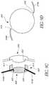
- FIG. 1is a cross-sectional view of a phakic eye containing a natural crystalline lens.
- FIG. 2is a cross-sectional view of a pseudophakic eye containing an intraocular lens.
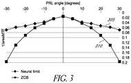
- FIG. 3illustrates a comparison of the optical image quality in the periphery of an eye implanted with different IOL configurations and the neural limit of the optical image quality in the periphery of an eye.
- FIG. 4illustrates an embodiment of an IOL placed in a capsular bag.
- FIGS. 5-7illustrate various embodiments of a piggyback lens that is positioned adjacent to an existing IOL.
- FIG. 8Aillustrates a top view of a piggyback lens comprising a soft material.
- FIG. 8Billustrates a side view of the piggyback lens illustrated in FIG. 8A .
- FIG. 9Aillustrates a top view of an embodiment of an existing IOL comprising an optic and a haptic system.
- FIG. 9Billustrates a cross-sectional view of a piggyback lens attached to the IOL illustrated in FIG. 9A .
- FIG. 9A-1illustrates a top view of an embodiment of an existing IOL comprising an optic and a haptic system, with an annular structure which is contiguous and completely surrounds the optic.
- FIG. 9B-1illustrates a cross-sectional view of a piggyback lens attached to the IOL illustrated in FIG. 9A-1 .
- FIG. 9Cillustrates a side-view of a piggyback lens attached to an embodiment of an IOL.
- FIG. 9C-1illustrates a partial cross-sectional view of an embodiment of an IOL comprising an anterior surface that includes a central portion and a peripheral region spaced apart from the central region by a recessed annular region.
- FIG. 9Dillustrates a top view of an embodiment of a piggyback lens.
- FIG. 9E-1depicts a side-view of a piggyback lens prior to implantation in the sulcus.
- FIG. 9E-2depicts a side-view of a piggyback lens after implantation in the sulcus.
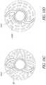
- FIG. 10A-1illustrates the top view of an IOL positioned in the capsular bag of an eye.
- FIG. 10A-2depicts a side-view of the IOL inserted into a capsular bag via capsulorhexis during which only a part of the anterior portion of the capsular bag that overlaps with the optical portion of the IOL is removed and other portions of the capsular bag are left intact.
- FIG. 10B-1illustrates the top view of an IOL positioned in a capsular bag of an eye, portions of the capsular bag being removed to increase flexibility.
- FIG. 10B-2illustrates the side view of the IOL implanted in a capsular bag portions of which have been removed.
- FIG. 10Cillustrates the top view of an IOL positioned in a perforated capsular bag of an eye.
- FIG. 10Dillustrates the top view of an IOL positioned in a capsular bag of an eye, portions of the capsular bag include a plurality of slits to increase flexibility.
- FIG. 11Aillustrates an embodiment in which a hollow space that is devoid of vitreous humour is created behind the capsular bag and the existing IOL by removing or perforating part of the posterior portion of the capsular bag and remove parts of the vitreous humour through the holes in the existing portion of the capsular bag.
- FIG. 11Billustrates a sulcus implanted piggyback lens that is used to push the existing lens into the space created in the vitreous humour.
- Peripheral aberrationsis a broad term and is intended to have its plain and ordinary meaning, including, for example, aberrations which occur outside of the central visual field, such as from light directed to peripheral or high field angle retinal areas.
- Peripheral aberrationscan include, for example and without limitation, spherical aberrations, astigmatism, coma, field curvature, distortion, defocus, and/or chromatic aberrations.
- improving or optimizing peripheral visionincludes reducing peripheral aberrations while maintaining good on-axis visual quality, or good visual quality at or near the central visual field.
- optical poweror “optical power” are used herein to indicate the ability of a lens, an optic, an optical surface, or at least a portion of an optical surface, to focus incident light for the purpose of forming a real or virtual focal point.
- Optical powermay result from reflection, refraction, diffraction, or some combination thereof and is generally expressed in units of Diopters.
- the optical power of a surface, lens, or opticis generally equal to the refractive index of the medium (n) of the medium that surrounds the surface, lens, or optic divided by the focal length of the surface, lens, or optic, when the focal length is expressed in units of meters.
- an IOL or a lensrefers to an optical component that is configured to be implanted into the eye of a patient.
- the IOL or the lenscomprises an optic, or clear portion, for focusing light, and may also include one or more haptics that are attached to the optic and serve to position the optic in the eye between the pupil and the retina along an optical axis.
- the hapticcan couple the optic to zonular fibers of the eye.
- the optichas an anterior surface and a posterior surface, each of which can have a particular shape that contributes to the refractive properties of the IOL or the lens.
- the opticcan be characterized by a shape factor that depends on the radius of curvature of the anterior and posterior surfaces and the refractive index of the material of the optic.
- the opticcan include cylindrical, aspheric, toric, or surfaces with a slope profile configured to redirect light away from the optical axis and/or a tight focus.
- the angular ranges that are provided for eccentricity of the peripheral retinal location (PRL) in this disclosurerefer to the visual field angle in object space between an object with a corresponding retinal image on the fovea and an object with a corresponding retinal image at a peripheral retinal location (PRL).
- an eye 10comprises a retina 12 that receives light in the form of an image that is produced by the combination of the optical powers of a cornea 14 and a natural crystalline lens 16 , both of which are generally disposed about an optical axis OA.
- the eyehas an axial length AL and a corneal radius CR.
- ALanterior length
- CRcorneal radius
- the natural lens 16is contained within a capsular bag 20 , which is a thin membrane that completely encloses the natural lens 16 and is attached to a ciliary muscle 22 via zonules 24 .
- An iris 26disposed between the cornea 14 and the natural lens 16 , provides a variable pupil that dilates under lower lighting conditions (mesopic or scotopic vision) and contracts under brighter lighting conditions (photopic vision).
- the ciliary muscle 22via the zonules 24 , controls the shape and position of the natural lens 16 , which allows the eye 10 to focus on both distant and near objects.
- Distant visionis provided when the ciliary muscle 22 is relaxed, wherein the zonules 24 pull the natural lens 16 so that the capsular bag 20 is generally flatter and has a longer focal length (lower optical power).
- Near visionis provided as the ciliary muscle contracts, thereby relaxing the zonules 24 and allowing the natural lens 16 to return to a more rounded, unstressed state that produces a shorter focal length (higher optical power).
- the optical performance of the eye 10also depends on the location of the natural lens 16 . This may be measured as the spacing between the cornea 14 and the natural lens which is sometimes referred to as the anterior chamber depth prior to an ocular surgical procedure, ACDpre.
- FIG. 2which is a cross-sectional view of a pseudophakic eye 10
- the natural crystalline 16 lenshas been replaced by an intraocular lens 100 .
- the intraocular lens 100comprises an optic 102 and haptics 104 , the haptics 104 being generally configured to position the optic 102 within the capsular bag 20 , where ELP refers to the actual lens position.
- ELPrefers to the actual lens position.
- the location of the intraocular lensis measured as the spacing between the iris and the anterior surface of the lens.
- a lenscan have a principal plane that is at a distance, P, behind the anterior lens surface.
- the principal plane of the lensis a distance P+L behind the iris.
- the principal plane of the lenswould then be about 1.9 mm behind the iris.
- the location of the principal plane of the lenscan vary depending on the shape factor of the IOL. Accordingly, for embodiments of lenses with different shape factors, the principal plane can be located at a distance different from 0.4 mm from the anterior surface of the lens.
- Various standard IOLs available in the marketare configured to improve on-axis optical image quality or improve quality of central vision when implanted in the eye such that the anterior surface of the standard IOL less than or equal to about 1 mm behind the iris.
- the optical image quality provided by the standard IOLs at a peripheral retinal locationmay be degraded.
- the peripheral retinal location (PRL)may be characterized by a PRL angle which is the angle between an imaginary axis passing through the iris and the PRL and the optical axis passing through the iris and the fovea.
- Optical image quality in the presence of significant aberrations, such as, for example, at peripheral retinal locationscan be measured using the area under the modulation transfer function (AUMTF) up to a neurally determined cutoff limit.
- AUMTFmodulation transfer function
- the cutoff limitcan be determined using principles and methods described in C “Topography of ganglion cells in the human retina,” by A. Curcio and K. A. Allen in J. Comp. Neurol., 300(1):5-25, 1990 which is incorporated by reference herein.
- MTFdescribes the contrast transfer function of the optical system as a function of spatial frequency of the object being viewed.
- the AUMTF curveis obtained by integrating the MTF at different spatial frequencies and for different view angles corresponding to different orientations of the eye.
- the reciprocal of the AUMTF curvecan be well correlated with visual acuity. Accordingly, the reciprocal of the AUMITF curve can also be used as a metric for optical image quality at various PRLs.
- FIG. 3illustrates the variation of the reciprocal of the area under the modulus transfer function (MTF) curve, which provides a measure of the optical image quality at various PRLs characterized by PRL angles between 0 degrees and ⁇ 30 degrees.
- MTFmodulus transfer function
- the principal plane of the existing IOLis moved posteriorly or closer to the nodal point of the eye as compared to location of the principal plane of many standard IOLs currently being implanted.
- displacing the IOL posteriorlycan improve peripheral vision by reducing peripheral aberrations.
- a reason as to why pushing the existing IOL further into the eye reduces peripheral errorscan be understood from the following optical theory.
- Aberrations of a lensdepend on shape factor (X) and conjugate factor (Y).
- oblique astigmatism ⁇ 111is equal to 1.
- Coma and oblique astigmatismcan vary depending on displacement.
- coma for an IOL disposed at a distance s from the pupilcan be obtained from equation (3a) below and astigmatism for an IOL disposed at a distance s from the pupil can be obtained from equation (3b)
- ⁇ 11 ′⁇ 11 + ⁇ 1 (3a)
- ⁇ 111 ′⁇ 111 +2 ⁇ 11 + ⁇ 2 ⁇ 1 (3b)
- An + 2 n ⁇ ( n - 1 ) 2
- B4 ⁇ ( n + 1 ) n ⁇ ( n - 1 ) 2
- C3 ⁇ n + 2 n
- Dn 2 ( n - 1 ) 2
- ⁇ En + 1 n ⁇ ( n - 1 )
- F2 ⁇ n + 1 n
- ⁇ ⁇ ⁇Fs ( 1 - Y ) ⁇ Fs - 2
- nis the index of refraction
- sthe distance between pupil and IOL
- Fthe power of the IOL
- Yconjugate factor
- Xthe shape factor
- the principal plane of an existing IOLcan be displaced posteriorly mechanically by applying a force along a direction parallel to the optical axis OA.
- the existing IOLcan be moved or displaced posteriorly by a distance, ‘d’, between about 0.5 mm to about 5.0 mm from its original location mechanically by the application of force.
- the existing IOLcan be displaced posteriorly from its original position by a by a distance, ‘d’ greater than or equal to about 0.5 mm and less than or equal to about 1.25 mm, greater than or equal to about 1.0 mm and less than or equal to about 1.75 mm, greater than or equal to about 1.5 mm and less than or equal to about 2.25 mm, greater than or equal to about 2.0 mm and less than or equal to about 2.75 mm, greater than or equal to about 2.5 mm and less than or equal to about 3.25 mm, greater than or equal to about 3.0 mm and less than or equal to about 3.75 mm, greater than or equal to about 3.5 mm and less than or equal to about 4.5 mm, or values therebetween.
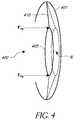
- FIG. 4illustrates an embodiment of an IOL 400 placed in a capsular bag 401 .
- the IOL 400comprises an optic 405 and a haptic 410 .
- the IOL 400can be placed in the capsular bag 401 such that the anterior surface of the optic is less than about 1.0 mm from the iris.
- the optic 405can be pushed rearward towards the retina by application of mechanical force F PB .
- the mechanical force F PBcan be provided by a piggyback lens that is implanted in the eye.
- the piggyback lenscan be implanted in the capsular bag or in the sulcus.
- Moving the existing IOL posteriorly by implanting a piggyback lens that is configured to push the existing IOL away from the iris towards the retina such that the principal plane of the existing IOL is shifted by a desired distance, ‘d’can advantageously reduce peripheral such that the IOL system including the existing IOL and the piggyback lens has reduced peripheral aberrations to improve optical image quality at a peripheral retinal location (PRL).
- the distance, ‘d’ by which the existing IOL is displacedcan be determined based on the material and optical properties of the existing IOL, the PRL angle and the amount of refractive and/or astigmatic correction desired at that PRL angle.
- the existing IOLcan be pushed rearward toward the retina by a desired distance when the piggyback lens is implanted in the eye. After the existing IOL is pushed to its desired axial location (e.g., by a distance ‘d’ from its original axial location), the connections between the add-on lens and the existing IOL in conjunction with the structure and material properties of haptic systems of the existing IOL and the piggyback lens can be relied upon to maintain the existing IOL at its desired axial location.
- Implanting the piggyback lens to push the existing IOL away from the iris by a desired distance, ‘d’can have several advantages. For example, implanting a standard IOL can bring substantial benefits to a patient suffering from cataracts and/or AMD. It is therefore possible that a surgeon would want to first try implanting a standard IOL in a patient suffering from cataracts and/or AMD and then consider extra treatment if the visual results of the first operation are unsatisfactory. As another example, while comorbidity of AMD and cataract is relatively common, a large group of patients can develop AMD long after cataract surgery. In such patients, the piggyback lens can improve the optical image quality at a peripheral retinal location of the existing lens by displacing the existing IOL rearward and simultaneously provide additional optical benefits. Furthermore, if a piggyback lens is implanted in conjunction with a standard IOL, then the range of refractive power provided by the piggyback lens can be reduced, this can advantageously limit the number of stock keeping units of the piggyback lenses.
- the piggyback lens that is used to push the existing IOL rearward towards the retinacan include an optic and a haptic system.
- the optical image quality at a peripheral retinal locationcan be improved by configuring the optical profile of the optic of the piggyback lens to provide a desired visual quality in conjunction with the displaced existing IOL.
- the optical profilecan be determined such that the optical power of the optic of the piggyback lens compensates for the change in the optical power resulting from the displacement of the existing IOL.
- the optical profile of the optic of the piggyback lenscan also be configured to correct any residual refractive errors that were not corrected by the existing IOL including but not limited to astigmatism.
- the range of optical power provided by the optic of the piggyback lenscan be low, such as, for example, between about ⁇ 5.0 D and about +5.0 D.
- the optic of the piggyback lenscan also at least partially correct some peripheral aberrations (e.g., aberrations arising due to oblique incidence of light) and thus improve optical image quality at the peripheral retinal location.
- the optic of the piggyback lenscan have a meniscus shape and/or have a surface including higher order aspheric terms to improve optical image quality at the peripheral retinal location.
- the anterior (that faces the cornea) and/or posterior surface (that faces the retina) of the optic of the piggyback lenscan be mathematically described by a polynomial function represented by equation (4) below:
- zis the sag of the surface
- cis the curvature of the surface
- rthe radial distance from the optical axis of the optic of the piggyback lens
- kthe conic constant
- Aare the Zernike coefficients
- Zare the Zernike polynomials.
- the anterior and/or posterior surfacecan be described by aspheric coefficients including upto the tenth order aspheric coefficients. In some embodiments, the anterior and/or posterior surface can be described by aspheric coefficients including aspheric coefficients with order less than ten (e.g., 2, 4, 6 or 8). In some embodiments, the anterior and/or posterior surface can be described by aspheric coefficients including aspheric coefficients with order greater than ten (e.g., 12 or 14). Alternatively, the anterior and/or posterior surface can be described by up to 34 Zernike polynomial coefficients. In some embodiments, the anterior and/or posterior surface can be described by less than 34 Zernike coefficients.
- the anterior and/or posterior surfacecan be described by more than 34 Zernike coefficients. Additionally, the anterior and/or posterior surface can be described as a combination of these aspheric and Zernike coefficients. Examples of such embodiments were described in U.S. patent application Ser. No. 14/644,107, filed on Mar. 10, 2015; U.S. patent application Ser. No. 14/692,609, filed on Apr. 21, 2015; and U.S. patent application Ser. No. 14/849,369, filed on Sep. 9, 2015, all of which are incorporated by reference herein.
- Various embodiments of the piggyback lenscan be rotationally symmetric about the optical axis of the optic of the piggyback lens (or the optical axis, OA, of the eye when the piggyback lens is implanted in the eye such that the optical axis of the optic of the piggyback lens is aligned with the optical axis, OA, of the eye) such that a patient suffering from AMD who does not have a well-developed peripheral retinal location (PRL) can view objects by orienting his/her head along a direction that provides the best visual quality.
- PRLperipheral retinal location
- the piggyback lenscan be rotationally asymmetric about the optical axis of the optic of the piggyback lens (or the optical axis, OA, of the eye when the piggyback lens is implanted in the eye such that the optical axis of the optic of the piggyback lens is aligned with the optical axis, OA, of the eye) such that a patient suffering from AMD who has a well-developed peripheral retinal location (PRL) can view objects by orienting his/her head along a direction that focuses light at the PRL.
- the piggyback lenscan be sufficiently thin such that it can be placed in the space between the iris and the existing IOL.
- the piggyback lenscan have a thickness e.g.
- the piggyback lenscan be configured such that the area under the MTF curve provided by the combination of the existing IOL and the piggyback lens is above a threshold value for PRL angles between ⁇ 30 degrees of with only limited loss of foveal performance.
- FIGS. 5-7illustrate various embodiments of a piggyback lens that is positioned adjacent to an existing IOL 510 .
- the existing IOL 510can be the SENSARTM AR40 with OptiEdgeTM lens sold by Abbot Medical Optics.
- the existing IOL 510can comprise materials including but not limited to silicone polymeric materials, acrylic polymeric materials, hydrogel polymeric materials, such as polyhydroxyethylmethacrylate, polyphosphazenes, polyurethanes, and mixtures thereof and the like.
- the existing IOL 510can comprise SENSAR® brand of acrylic.
- the surface of the existing IOL 510can comprise materials such as, for example, heparin, PEG/SiO2 or other materials that can be impervious to water, blood, or other body fluids.
- portions of the existing IOL 510e.g., the edges or peripheral portions
- portions of the surfaces of the existing IOL 510can be textured (e.g., the edges of the surfaces of the existing IOL 510 can be frosted).
- the existing IOL 510can comprise a high refractive index material. Lenses comprising higher refractive index material can be thinner than lenses comprising a lower refractive index material.
- the embodiments of piggyback lenses illustrated in FIGS. 5-7are meniscus lenses having anterior surface that receives ambient light being convex and a posterior surface opposite the anterior surface being concave.
- a meniscus piggyback lenscan be thicker at the center than at the edges.
- the meniscus lensmay be configured to reduce distortion in the image quality caused by edge effects.
- Various other embodiments of piggyback lensesneed not be meniscus lenses but can include bi-convex lenses, concave lenses, plano-convex lenses, etc.
- the piggyback lenscan be spaced apart from the existing IOL 510 in a central optical zone such that the piggyback lens and the existing do not touch each other at the optical vertex. Such an arrangement is illustrated in FIG.
- FIG. 5which depicts a piggyback lens 505 having an anterior surface 507 a and a posterior surface 507 b disposed forward of an existing IOL 510 .
- the anterior surface 507 a and the posterior surface 507 bcan meet at a peripheral region 507 c (e.g., at a peripheral edge).
- the peripheral region 507 ccan be a portion of the circumference of the piggyback lens 505 .
- the posterior surface 507 b of the piggyback lens 505is spaced apart from the anterior surface of the existing IOL 510 in a central region such that the piggyback lens 505 contacts the existing IOL 510 in a peripheral region of the existing IOL 510 .
- FIG. 5depicts a piggyback lens 505 having an anterior surface 507 a and a posterior surface 507 b disposed forward of an existing IOL 510 .
- the anterior surface 507 a and the posterior surface 507 bcan meet at a peripheral region 507 c (e.g
- the posterior surface 507 b of the piggyback lens 505is spaced apart from the vertex of the existing IOL 510 by a distance, x. Spacing the piggyback lens 505 from the existing IOL 510 at least in the region around the vertex of the existing IOL 510 can advantageously prevent cell growth as well as flattening at the optical vertex.
- FIG. 6illustrates an embodiment of a piggyback lens 605 comprising a soft material with a low refractive index.
- the piggyback lens 605comprises an anterior surface 607 a and a posterior surface 607 b .
- Such an embodiment of a piggyback lensis configured to provide the desired mechanical force F PB to displace the existing IOL 510 posteriorly towards the retina by a desired distance while maintaining the optical power of the existing IOL 510 substantially the same.
- the material of the piggyback lens 605can have a refractive index that changes the optical power of the existing IOL 510 by no more than about 10% such that the optical power of the existing IOL 510 remains substantially the same.
- the Young's modulus (E) of the optic body material of the piggyback lens 605can be about 10% of the Young's modulus of the material of the existing IOL 510 .
- the posterior surface 607 b of the embodiment of the piggyback lens 605 illustrated in FIG. 6can have a shape similar to or the same as the shape of the anterior surface of the existing IOL 510 so that the posterior surface 607 b of the piggyback lens 605 can contact the anterior surface of the existing IOL 510 . This can reduce interlenticular opacification and reflections or ghost images.
- the shape of the posterior surface of the piggyback lens 605can be configured to match the anterior surface of the existing IOL 510 .
- FIG. 7illustrates an embodiment of a piggyback lens 705 comprising an outer portion 705 a and an inner portion 705 b .
- the outer portion 705 acan comprise a material that is similar to the material of the existing IOL 510 , such as, for example, hydrophobic acrylic.
- the outer portion 705 acan include a material having a refractive index that is similar to the refractive index of the existing IOL. For example, a difference between the refractive index of the material of the outer portion 705 a and the refractive index of the material of the existing IOL 510 can be ⁇ 10%.
- the inner portion 705 bcan comprise a soft material having a refractive index that is lower than the refractive index of the material of the outer portion 705 a (and/or the refractive index of the material of the existing IOL 510 ).
- the refractive index of the material of the inner portion 705 bcan be between about 1% to about 20% lower than the refractive index of the material of the outer portion 705 a .
- the Young's modulus (E) of the soft material of the inner portion 705 bcan be about 10% of the Young's modulus (E) of the material of the existing IOL 510 and/or the material of the outer portion 705 a .
- the inner portion 705 b comprising the soft materialcan be disposed adjacent to the existing IOL 510 and the outer portion can be disposed to receive incident ambient light.
- the posterior surface of the inner portion 705 bcan have a shape similar to the shape of the anterior surface of the existing IOL 510 so that the posterior surface of the inner portion 705 b can contact the anterior surface of the existing IOL 510 with reduced interlenticular opacification and reflections or ghost images.
- the shape of the posterior surface of the inner portion 705 bcan be configured to match the anterior surface of the existing IOL 510 .
- the optical, structural and material properties of the outer portion 705 acan be similar to the optical, structural and material properties of the piggyback lens 505 .
- the optical, structural and material properties of the outer portion 705 bcan be similar to the optical, structural and material properties of the piggyback lens 605 .
- the optic of a piggyback lens configured to push the existing IOL posteriorly towards the retinacan be disposed around a frame that provides structural support to the optic.
- a frame that provides structural supportcan advantageously provide structural support to a piggyback lens that comprises a soft material (e.g., piggyback lens 605 ).
- the framecan also be configured as a posterior displacer to push the existing IOL posteriorly towards the retina.
- the framecan comprise an anchor system that is configured to anchor the piggyback lens in the eye. Such an embodiment is illustrated in FIGS. 8A and 8B .
- FIG. 8A and 8BSuch an embodiment is illustrated in FIGS. 8A and 8B .
- FIG. 8Aillustrates an optic 805 of a piggyback lens that is disposed around a frame comprising an annular structure 515 b and an anchor system including a plurality of anchor arms 515 a .
- the optic 805can be cast around the frame.
- FIG. 8Bis a cross-sectional view of optic 805 along the axis A-A′.
- the annular structure 515 bcan comprise a ring shaped structure as shown in FIG. 8A .
- the annular structure 515 bcan be discontinuous.
- the anchor arms 515 ainclude a first end that is coupled to the piggyback lens 805 and a second free end that is configured to be connected to an anatomy of the eye (e.g., sulcus or ciliary body).
- the anchor arms 515 aextend radially outward from the optic 805 as shown in FIGS. 8A and 8B .
- the first end of the anchor armscan be coupled to the annular structure 515 b as illustrated in FIGS. 8A and 8B .
- a first end of the anchor arms 515 acan be attached to the optic 805 at a region that is distinct from the annular structure 515 b .
- Various features of the frame including a central ring 515 b and one or more anchor arms 515 a illustrated in FIGS. 8A and 8Bcan be similar to the haptic systems discussed below.
- the optical characteristics (e.g., characteristics of the anterior and/or posterior surfaces, radius of curvature of the anterior and/or posterior surfaces, asphericity of the anterior and/or posterior surfaces) of various embodiments of piggyback lenses (e.g., piggyback lens 505 , piggyback lens 605 , piggyback lens 705 , optic 805 ) disclosed hereincan be determined based on dimensions of an average eye.
- the characteristics of the optical surface of the piggyback lens 505can be determined based on the average axial length (AL), average corneal radius (CR), average anterior chamber depth (ACD) and average horizontal corneal diameter.
- diagnostics specific to a patient's eyecan be obtained, such as, for example, corneal power and asphericity, retinal curvature, PRL location and/or anterior chamber depth and the optical characteristics of the piggyback lens 505 can be determined based on the obtained diagnostics.
- various embodiments of piggyback lensese.g., piggyback lens 505 , piggyback lens 605 , piggyback lens 705 , optic 805 ) disclosed herein can include a diffractive optical element to provide correction for chromatic aberrantions.
- the optical characteristics of various embodiments of piggyback lensescan be optimized using different merit functions, such as, for example, area under the modulation transfer function (MTF) curve obtained for different spatial frequencies, area under the area under the weighted MTF calculated for different defocus positions which can be calculated by the area under the product of the neural contrast sensitivity (as measured by Campbell and Green in 1965) and the MTF measured in the optical bench for a range of spatial frequencies, area under the weighted optical transfer function given by the function MTF*cos(PTF)*nCSF for a range of spatial frequencies, wherein PTF is the phase transfer function measured in the optical bench and the nCSF the neural constrast sensitivity as measured by Green and Campbell (1965) and/or the cross correlation (X-cor) metric that is obtained by performing a convolution of a reference image and the
- MTFmodulation transfer function
- the optical characteristics of the various embodiments of piggyback lensese.g., piggyback lens 505 , piggyback lens 605 , piggyback lens 705 , optic 805 ) disclosed herein and/or the displacement distance of the existing IOL 510 can be optimized using a metric that is estimated from preclinical measurements by the area under the through focus MTFa (AU MTFa) for a given spatial frequency range (e.g. from 0 cycles per mm to 50 cycles per mm; from 0 cycles per mm to 100 cycles per mm).
- the AU MTFa, calculated from the preclinical through focus MTF measurementscan provide a single value to describe the average visual performance of a pseudophakic patient implanted with an IOL over a range of defocus.
- the optical characteristics of the various embodiments of piggyback lensese.g., piggyback lens 505 , piggyback lens 605 , piggyback lens 705 , optic 805 ) disclosed herein and/or the displacement distance of the existing IOL 510 can be optimized using a metric that is based on the area under the through focus wMTF (AU wMTF) for that defocus range.
- the AU wMTFcan be calculated by integrating the wMTF over a defocus range (e.g. between ⁇ 2 D and ⁇ 0.5 D to evaluate intermediate vision).
- the optical characteristics of the various embodiments of piggyback lensescan be optimized using a metric that is based on the area under the through focus (AU wOTF) for that defocus range.
- the AU wOTFcan be calculated by integrating the wOTF over a defocus range (e.g. between ⁇ 2 D and ⁇ 0.5 D to evaluate intermediate vision).
- the optical characteristics of the piggyback IOL 505 and/or the displacement distance of the existing IOL 510can be optimized using a metric that is based on the area under the through focus X-cor (AU X-cor) for that defocus range.
- the AU X-corcan be calculated by integrating the X-cor curve over a defocus range (e.g. between ⁇ 2 D and ⁇ 0.5 D to evaluate intermediate vision).
- piggyback lensese.g., piggyback lens 505 , piggyback lens 605 , piggyback lens 705 , optic 805
- a measurement of peripheral errorcan be obtained during the surgery and a piggyback lens having optical characteristics that can reduce or eliminate the peripheral error can be selected for implantation.
- the piggyback lensneed not provide any optical correction or improvement but can be configured to only provide the mechanical force F PB that is required to push the existing IOL 510 posteriorly towards the retina.
- the piggyback lenscan be configured zero (or no) spherical and/or cylindrical power.
- IOL's 510can be configured to be expandable by providing structures that can facilitate implantation of piggyback lenses when, required. Such structures are disclosed below.
- the piggyback lenscan be mechanically connected with the existing IOL.
- Connections between the piggyback lens and the existing IOLcan advantageously provide stability to the piggyback lens, the existing IOL and/or the combined piggyback lens and existing IOL.
- the connections between the piggyback lens and the existing IOLcan also maintain the axial position of the existing IOL at the new displaced location and prevent the existing IOL from returning to its original location due to forces from various parts of the eye (e.g., vitreous humour, zonules, ciliary bodies, etc.).
- the connections between the piggyback lens and the existing IOLcan advantageously maintain a desired inter-lenticular distance between the piggyback lens and the existing IOL.
- the piggyback lenscan be held at a position that is spaced apart from the vertex of the existing IOL such that the piggyback lens and the existing IOL do not contact each other at the optical vertex.
- spacing the piggyback lens and the existing IOL such that they do not contact each other at the optical vertexcan prevent cell growth as well as flattening at the vertex in some embodiments of a piggyback lens.
- the connections between the piggyback lens and the existing IOLcan be configured to ensure a proper centration of both the piggyback lens and/or the existing IOL.
- the connections between the piggyback lens and the existing IOLcan advantageously maintain the alignment between the optical axis of the optic of the piggyback lens and/or the existing IOL and the optical axis, OA of the eye.
- the piggyback lenscan be connected to the existing IOL in a peripheral region of the existing IOL.
- connections between the piggyback lens and the existing IOLcan be made in a peripheral region of the existing IOL.
- the peripheral region of the existing IOLcan comprise a recessed annular region disposed at least partially along the periphery of the existing IOL.
- the piggyback lens and the existing IOLcan be locked in together using a ridge design.
- FIG. 9Aillustrates a top view of an embodiment of an existing IOL 910 comprising an optic 901 and a haptic system 920 that holds the optic 901 in place when implanted in the eye.
- the haptic system 920when implanted in the capsular bag 20 of the eye, can hold the optic 901 such that the principal plane of the optic is about 0.9 mm rearward of the iris.
- the haptic system 920when implanted in the capsular bag 20 of the eye, can hold the optic 901 such that the anterior surface of the optic 901 is about 0.5 mm rearward of the iris.
- the optic 901can be a lens that provides refractive and/or astigmatic power correction for central vision.
- the IOL 910can be implanted in the eye of a patient after removal of the natural lens 16 during a cataract surgery. Alternately, the IOL 910 can be implanted in addition to the natural lens 16 to provide refractive or astigmatic power correction.
- the haptic system 920can comprise a biocompatible material that is suitable to engage the capsular bag of the eye, the iris 26 , the sulcus and/or the ciliary muscles of the eye.
- the hapticcan comprise materials such as acrylic, silicone, polymethylmethacrylate (PMMA), block copolymers of styrene-ethylene-butylene-styrene (C-FLEX) or other styrene-base copolymers, polyvinyl alcohol (PVA), polystyrene, polyurethanes, hydrogels, etc.
- the haptic system 920can include one or more arms that are coupled to the optic 901 .
- the haptic system 920can include arms 920 a and 920 b that radiate outward from the periphery optic 901 .
- one or more arms of the haptic system 920can protrude into the optic 901 .
- the peripheral portions of the one or more arms of the haptic system 920can be curved (e.g., hooked or having a C, S or J shape) so as to securely engage the capsular bag, the zonules, the ciliary bodies, the sulcus or any other anatomy of the eye which the haptics are configured to engage.
- the one or more arms of the haptic system 920can be curved in the plane of the optic 901 .
- the one or more arms of the haptic system 920can be curved in a plane different from the plane including the optic 901 .
- the haptic system 920can be transmissive and have a transmissivity that is substantially equal to (e.g., within about 20%) of the transmissivity of the optic 901 .
- the material of the haptic system 920can have a refractive index that is substantially equal to (e.g., within about 20%) of the refractive index of the material of the optic 901 .
- the haptic system 920can be configured to move the optic 901 along the optical axis of the eye in response to ocular forces applied by the capsular bag and/or the ciliary muscles.
- the haptic system 920can include one or more hinges to facilitate axial movement of the optic 901 .
- the haptic system 920can include springs or be configured to be spring-like to effect movement of the optic 901 .
- the existing IOL 910can also include a structure that helps maintain the centration and/or the orientation of the existing IOL 910 with respect to various anatomical structures and/or implanted structured in the eye.
- an annular structure 925can be disposed at least partially about the periphery of the optic 901 to maintain centration and/or the orientation of the existing IOL 910 with respect to various anatomical structures and/or implanted structured in the eye.
- the annular structure 925can be disposed external to the optic 901 such that the annular structure 925 completely or at least partially surrounds the optic 901 .
- the annular structure 925can be disposed internal to the optic 901 .
- the optic 901can be cast or molded over the annular structure 925 .
- the annular structure 925can be contiguous and completely surrounds the optic 901 .
- the annular structure 925can be broken at predetermined location.
- the annular structure 925is discontiguous and comprises a first portion 925 a and a second portion 925 b .
- the portions 925 a and 925 bare spaced apart by gaps 928 a and 928 b .
- the gaps 928 a and 928 b between the two portions of the annular structure 925overlap with region where the haptic arms 920 a and 920 b are attached to the optic 901 .
- the annular structure 925 and the haptic system 920can be distinct and/or separate from each other.
- the annular structure 925can be integrated with the haptic system 920 such that the annular structure 925 is a part of the haptic system 920 .
- the annular structure 925can include grooves, pins, barbs, clips, etc. to facilitate attachment to the optic 901 .
- the annular structure 925can include a locking or a fastening mechanism that facilitates attachment to the optic 901 and helps maintain the centration and/or orientation of the optic 901 .
- the annular structure 925can be transmissive and have a transmissivity that is substantially equal to (e.g., within about 20%) of the transmissivity of the optic 901 .
- the material of the annular structure 925can have a refractive index that is substantially equal to (e.g., within about 20%) of the refractive index of the material of the optic 901 .
- the annular structurecan comprise a material having sufficient rigidity or stiffness to maintain desired centration and/or orientation of the optic 901 .
- the IOL 910can be configured such that the surface moment of inertia for bending in a plane transverse to the plane of the optic 901 can be higher than the surface moment of inertia for bending in the plane of the optic 901 .
- the moment of inertia in a plane transverse to the plane of the IOLis given by the product 1/12*width*height 3 and in the plane of the IOL is given by the product 1/12*height*width 3 . Accordingly, the axial stability will be higher if the height is greater than width.
- FIG. 9Billustrates a cross-sectional view of a piggyback lens 905 attached to the IOL 910 illustrated in FIG. 9A .
- the piggyback lens 905comprises a posterior displacer 907 that extends posteriorly from the piggyback lens 905 and is configured to contact the existing IOL 910 and push the existing IOL 910 rearward from its original location to a displaced location.
- the posterior displace 907can include one or more projections 917 .
- the projections 917 of the posterior displacercan be configured to contact one or more portions of the existing IOL 910 .
- Each projection 917has a proximal end 919 a that is coupled to the piggyback lens 905 and a distal end 919 b that is configured to be connected to the peripheral region of the optic 901 , the haptic system 920 and/or the annular structure 925 .
- the projections 917can be configured to be connected to the annular structure 925 of the IOL 910 .
- the annular structure 925can include grooves on the portion that faces the projections 917 to facilitate attachment with the piggyback lens 905 .
- the projections 917can include protrusions that can be configured to engage the grooves in the annular structure 925 .
- Locking mechanismse.g., clips, screws, etc.
- the projections 917 and the manner in which they are connected to the existing IOL 910may be at least partially responsible in pushing the existing IOL 910 posteriorly to a displaced axial location and maintain the existing IOL 910 at the displaced axial location in presence of ocular forces exerted by different anatomical part of the eye (e.g., the posterior capsule, the vitreous humour).
- FIG. 9Cillustrates a side-view of a piggyback lens 905 attached to an IOL 950 .
- Various physical and optical features of the IOL 950can be similar to the IOL 910 illustrated in FIG. 9A .
- FIG. 9C-1depicts a partial cross-sectional view of an embodiment of an IOL 950 that is configured as a foldable intraocular lens comprising an optic 9511 including an optical zone 9512 and a peripheral zone 9513 surrounding the optical zone 9512 .
- the optic 9511has an anterior surface 9514 , an opposing posterior surface 9518 , and an optic edge 9520 .
- the anterior surface 9514 and the posterior surface 9518can be intersected by an optical axis 9522 .
- the anterior surface 9514can comprise a central portion 9524 , a peripheral region 9528 , and a recessed annular region 9530 disposed between the central portion 9524 and the peripheral region 9528 .
- the intraocular lens 950can further comprise at least one haptic 9532 that is attached to the peripheral zone 9513 .
- the haptic 9532comprises a distal posterior surface 9534 , a proximal posterior surface 9538 , and a step edge 9539 disposed at a boundary therebetween.
- the hapticfurther comprises a side edge 9540 disposed between the optic edge 9520 and the step edge 9539 .
- the proximal posterior surface 9538 and the posterior surface 9518 of the optic 9511form a continuous surface 9548 .
- An edge corner 9550is formed by the intersection of the continuous surface 9548 with the optic edge 9520 , the side edge 9540 , and the step edge 9539 .
- the haptics 9532can be integrated with the peripheral zone 9513 .
- the haptics 9532can be monolithically integrated with the peripheral zone 9513 .
- the haptics 9532can be integrally formed with the peripheral zone 9513 and comprise the same material as the optic 9511 so as to form a one-piece IOL 950 .
- the haptics 9532may be integrally formed in a common mold with the optic 9511 , but comprise a different material than the optic 9511 .
- the haptics 9532can be formed of the same material as the optic 9511 , but the material of the haptics 9532 and the optic 9511 can have different properties.
- the haptics 9532may have different tensile strength than the optic 9511 .
- the haptics 9532may be formed separately from the optic 9511 and attached to the optic 9511 to provide a three-piece configuration.
- the optical zone 9512can have a center thickness Tc measured substantially along the optical axis 9522 , that is in the range of about 0.5 mm or less to about 1.0 mm or more.
- the center thickness Tccan be in the range of about 0.7 mm to about 0.9 mm.
- the center thickness Tcmay vary depending on factors such as the lens material and the dioptric power of the optical zone 9512 .
- the optic 9511can have a diameter between about 4 mm to about 7 mm or more.
- the diameter of the optic bodycan be between about 5 mm to about 6.5 mm or about 6.0 mm.
- the haptics 9532can be characterized by a haptic thickness T, that is equal to a distance, as measured along the optical axis 9522 , between the distal posterior surface 9534 of the haptic 9532 and the opposing proximal posterior surface 9558 .
- the haptic thickness Tcan be greater than or approximately equal to a thickness To of the optic edge 9520 , as measured along the optical axis 9522 .
- the thicknesses T, and Tomay be selected based on the particular material from which the intraocular lens 950 is made, the amount of rigidity desired, the optical power of the lens 10 , and other such factors.
- At least one of the haptic thickness T, and the optic edge thickness Tocan be in the range of about 0.2 mm or less to about 1 mm or more, in the range of about 0.3 mm to about 0.6 mm, or in the range of about 0.4 mm to about 0.5 mm
- the step edge 9539is disposed between the proximal posterior surface 9538 and distal posterior face 9534 of each haptic 9532 .
- the step edge 9539can be a part of the edge corner 9550 that forms a continuous boundary around the posterior surface 9518 of the optic 9511 .
- the step edge 9539has a height H that is in the range of about 0.05 mm or less to about 1 mm or more, in the range of about 0.05 mm to about 0.2 mm. In other embodiments, the step edge 9539 can have a height H that is in the range of about 0.2 mm to about 0.5 mm.
- At least a portion of the step edge 9539can be a straight line and disposed at a radius R 1 , from the optical axis 9522 .
- at least a portion of the step edge 9539may be arcuate in shape.
- the radius R 1is advantageously greater than the radius R 0 , of the optic edge 9520 so that a proximal portion of the haptic 9532 forms a buttress 9551 that is preferably thicker than a distal portion 9552 of the haptic 9532 and the edge thickness To.
- the peripheral zone 9513 and the buttress 9551can form a generally rigid structure, that allows the central portion 9524 to be recessed such that the recessed annular region 9530 of the peripheral zone 9513 is posterior to the peripheral region 9528 .
- This recessed configuration of the central portion 9524compared to an optic not having the recessed annular region 9530 , can reduce the total volume of the intraocular lens 950 by reducing the overall thickness of the optical zone 9512 .
- at least a portion of the peripheral region 9528 of the optic 9511can be disposed at an angle ⁇ relative to a plane perpendicular to the optical axis 9522 .
- the angle ⁇can be in the range of about 5 degrees or less to at least about 50 degrees, depending on the dioptric power of the optical zone 9512 and the radius of curvature of the posterior surface 9518 and the central portion 9524 of the optical zone 9512 . In some embodiments, the angle ⁇ can be in the range between about 15 degrees to about 35 degrees.
- the IOL 950can have features that are similar to embodiments of IOLs discussed in U.S. Pat. No. 8,382,832, titled “Foldable Intraocular Lens and Method of Making,” which is incorporated herein by reference in its entirety.
- the piggyback lens 905can be configured to be attached to the peripheral region 9528 of the IOL 950 .
- the projections 917 of a piggyback lens 905 that is configured to be supported by the peripheral region 9528 of the IOL 950can include protrusions, pins, etc. that are configured to engage the peripheral region 9528 of the IOL 950 .
- the piggyback lens 905can be configured to be attached to a projection or protrusion of the IOL 950 .
- the protrusioncan be configured as a ring-like projection or a plurality of spaced apart protrusion disposed about the periphery of the IOL 950 .
- the projections 917 of a piggyback lens 905 that is configured to be supported by the peripheral region 9528 of the IOL 950can include concave surfaces to receive the projection or projections.
- each projection 917can comprise a notch 927 .
- a first portion on one side of the notch 927can be configured to be disposed along a peripheral region of the existing IOL 910 (e.g., a side portion) and a second portion on another side of the notch 927 can be configured to be disposed along an anterior surface of the existing IOL 910 .
- the portion of the projection 917 that contacts the anterior surface of the existing IOL 910 and/or the peripheral region of the existing IOL 910can be configured to have refractive index that is substantially similar (e.g., within ⁇ 20%) as the refractive index of the material of the anterior surface of the existing IOL 910 and/or the peripheral region of the existing IOL 910 so as to reduce optical distortion.
- the portion of the projection 917 that contacts the anterior surface of the existing IOL 910 and/or the peripheral region of the existing IOL 910can be configured to have a surface shape that matches the shape of the anterior surface of the existing IOL 910 and/or the peripheral region of the existing IOL 910 so as to reduce surface discontinuities between the projection 917 and the existing IOL 910 .
- the portion of the projection 917 that contacts the anterior surface of the existing IOL 910can comprise an anteriorly angled surface configured to mate with a posteriorly angled region of the anterior surface of the existing IOL 910 .
- the portion of the projection 917 that contacts the anterior surface of the existing IOL 910can comprise a posteriorly angled face configured to mate with an anteriorly angled region of the anterior surface of the existing IOL 910 .
- the distal ends 919 b of the plurality of the projections 917can be connected together.
- the distal ends 919 b of the plurality of the projections 917can be connected together by arcuate segments to form a ring shaped structure.
- the ring shaped structure formed by connecting the distal ends 919 b of the plurality of the projections 917can be configured to be connected to the peripheral regions of the optic 901 (e.g., peripheral region 9528 ).
- the ring shaped structure formed by connecting the distal ends 919 b of the plurality of the projections 917can include a stiff material that can resist ocular forces and maintain the desired centration, orientation and/or the axial position of the existing IOL 910 . Accordingly, in such embodiments, the existing IOL 910 may not include the annular structure 925 .
- the proximal ends 919 a of the plurality of attachments armscan be connected together by arcuate segments to form a ring shaped structure (e.g., the annular structure 515 b illustrated in FIG. 8A ).
- the ring shaped structure formed by connecting the proximal ends 919 a of the plurality of the projections 917can provide structural stability to the piggyback lens 905 .
- one end of the haptic arms 916 a and 916 bcan be connected to the proximal ends 919 a of one or more of the projections 917 .
- the piggyback lens 905 illustrated in FIGS. 9B and 9Ccan include a haptic system 915 that holds the optic of the piggyback lens 905 in place when implanted in the eye.
- the haptic system 915can comprise a biocompatible material that is suitable to engage the capsular bag of the eye, the iris 26 , the sulcus and/or the ciliary muscles of the eye.
- the hapticcan comprise materials such as acrylic, silicone, polymethylmethacrylate (PMMA), block copolymers of styrene-ethylene-butylene-styrene (C-FLEX) or other styrene-base copolymers, polyvinyl alcohol (PVA), polystyrene, polyurethanes, hydrogels, etc.
- the haptic system 915can include a one or more arms that are coupled to the optic of the piggyback lens 905 .
- the haptic system 915can include arms 916 a and 916 b that radiate outward from the periphery optic of the piggyback lens 905 .
- the arms 916 a and 916 bcan include a first end that is coupled to the optic of the piggyback lens 905 and a second free end that is configured to be anchored with an anatomical part of the eye (e.g., sulcus, ciliary body, etc.).
- an anatomical part of the eyee.g., sulcus, ciliary body, etc.
- one or more arms of the haptic system 915can protrude into the optic of the piggyback lens 905 .
- the peripheral portions of the one or more arms of the haptic system 915can be curved (e.g., hooked or having a C, S or J shape) so as to securely engage the capsular bag, the zonules, the ciliary bodies, the sulcus or any other anatomy of the eye which the haptics are configured to engage.
- the one or more arms of the haptic system 915can be curved in the plane of the optic of the optic of the piggyback lens 905 .
- the one or more arms haptic system 915can be curved in a plane different from the plane including the optic of the piggyback lens.
- the haptic system 915can be transmissive and have a transmissivity that is substantially equal to (e.g., within about 20%) of the transmissivity of the optic of the piggyback lens 905 .
- the material of the haptic system 915can have a refractive index that is substantially equal to (e.g., within about 20%) of the refractive index of the material of the optic of the piggyback lens 905 .
- the length of the arms 916 a and 916 b either alone or in combination with other parts of the haptic system 915can be substantially equal (e.g., within about 20%) of the length of the haptic arms of a standard sulcus lens.
- the length of the arms 916 a and 916 b either alone or in combination with other parts of the haptic system 915can be around 3.5 mm.
- the length of the armscan be based on the intended position of the existing IOL 910 , the intended displacement of the existing IOL 910 and/or the intended compression of the existing IOL 910 .
- the intended compression of the existing IOL 910 and/or the elasticity of the haptic system 915can be configured to be linear as illustrated in FIG. 9E-1 prior to implantation in the sulcus and can be configured to flex or bend as shown in FIG. 9E-2 when implanted in the sulcus.
- the length of the armscan be between about 2-5 mm.
- the length of the armscan be between about 2.5 mm and about 4.5 mm, between about 2.9 mm and about 4.2 mm, between about 3.0 mm and about 4.0 mm or values in any of these ranges/sub-ranges.
- the haptic arms 916 a and 916 bcan be angulated by an amount that is sufficient to displace the IOL 910 posteriorly towards the retina when the piggyback lens 905 is implanted in the eye.
- the haptic arms 916 a and 916 bcan be disposed at a haptic angle ⁇ with respect to an axis 930 in the plane of the optic of the piggyback lens 905 and passing through the region where the haptic arms are attached to the optic of the piggyback lens 905 .
- Angulating the haptic arms 916 a and 916 bcan effectively push the existing IOL 910 rearward by an amount, ‘d’ between about 2-4 mm.
- the length of the arms 916 a and 916 bcan depend on the diameter of the sulcus which can be between about 10.0 mm and about 14.0 mm, the separation between the haptic junctions along the diameter of the sulcus and the haptic angle ⁇ . For example, if the sulcus has a diameter of 11.0 mm, and the separation between the haptic junctions along the diameter of the sulcus (which is parallel to the axis 930 ) is 5.0 mm and the haptic angle is 45 degrees, the projection of the length of arms 916 a and 916 b along the diameter of the sulcus (which is parallel to the axis 930 ) is about 3.0 mm.
- the length of arms 916 a and 916 b given by the equation (3.0/cosine(45))is about 4.25 mm if the haptics are rigid.
- the length of the arms 916 a and 916 bcan be different if the haptics comprise an elastic material and can be compressed.
- the arms 916 a and 916 bcan be compressed by about 2-4 mm. Accordingly, in such embodiments the length of the arms 916 a and 916 b can be greater than the length of arms 916 a and 916 b if they comprised a rigid material.
- the diameter of the sulcuscan be measured pre operatively by diagnostic methods, such as, for example, MRI or some other diagnostic method or determined from biometric data (e.g., eye length and thickness of the crystalline lens or age of the patient) and the length of the arms 916 a and 916 b can be sized in accordance with the measured or determined sulcus diameter so as to displace the existing IOL 910 rearward by the desired amount.
- diagnostic methodssuch as, for example, MRI or some other diagnostic method or determined from biometric data (e.g., eye length and thickness of the crystalline lens or age of the patient) and the length of the arms 916 a and 916 b can be sized in accordance with the measured or determined sulcus diameter so as to displace the existing IOL 910 rearward by the desired amount.
- the haptic angle ⁇can be greater than the haptic angle of standard sulcus lenses.
- the haptic angle ⁇can be greater than or equal to 15 degrees and less than or equal to about 50 degrees.
- the haptic angle ⁇can be greater than or equal to 20 degrees and less than or equal to about 45 degrees, can be greater than or equal to 25 degrees and less than or equal to about 40 degrees, can be greater than or equal to 30 degrees and less than or equal to about 35 degrees, or any value in the above described ranges/sub-ranges.
- the haptic angle ⁇can change after implantation of the IOL 905 in the sulcus.
- the haptic angle ⁇can increase after implantation of the IOL 905 in the sulcus. In some embodiments, the haptic angle ⁇ can increase from 0 degrees to about 45 degrees in the un-implanted configuration to about 15 degrees to about 60 degrees when implanted in the sulcus of the eye.
- a piggyback lens 905having a haptic arm with a length of 3.5 mm attached to the optic of the piggyback lens 905 at a haptic angle of 15 degrees.
- the amount of displacement that can be provided by the angulation of the haptic arms of the piggyback lenscan depend on a variety of factors including but not limited to the haptic angle, the length of the haptic arm, the length of the projections of the piggyback lens, the resilience of the IOL 910 and/or the resistance provided by portions of the posterior cavity of the eye (e.g., parts of the capsular bag, vitreous humour, etc.).
- the haptic system 915can be configured to move the optic of the piggyback lens 905 along the optical axis of the eye to displace the IOL 910 by an additional amount.
- the haptic system 915can include one or more hinges to facilitate axial movement of the piggyback lens.
- the haptic system 915can include springs or be configured to be spring-like to effect movement of the piggyback lens 905 .
- the portions of the haptic system 915can be configured to be stiff such that the piggyback lens 905 when connected to the existing IOL 910 as discussed above can displace the existing IOL 910 by virtue of the angulated haptics of the piggyback lens 905 .
- the haptic arms 916 a and 916 bcan be configured to be stiffer along axial direction 935 .
- the haptic arms 916 a and 916 bcan be configured to be stiffer by one or more of the following approaches:
- a first end of the arm 916 a and 916 b that is connected to the optic of the piggyback lens 905can be expanded such that the arm 916 a and 916 b tapers from the first end towards the second end.
- the first end of the arm 916 a and 916 bcan be expanded along the axial direction 935 .
- an axial thickness of the arm 916 a and 916 bcan be constant from the base 918 to the periphery.
- FIG. 9Dillustrates a front view of a piggyback lens 905 in which the arms 916 a and 916 b have an expanded base 918 .
- the base 918can have a triangular shape, a L-shape, an arcuate shape, a trapezoidal shape or some other shape that is compatible with an expanded base and a tapered peripheral portion.
- Embodiments of the haptics with expanded basesare described in U.S. Pat. No. 5,549,669, which is incorporated by reference herein in its entirety.
- parts of the haptic system 915can be made stiff by forming the parts of the haptic system 915 (e.g., portions of the one or more haptic arms 916 a and 916 b ) by a stiff material, such as, for example, cross linked material, rubber, PMMA, etc.
- a stiff materialsuch as, for example, cross linked material, rubber, PMMA, etc. Examples of haptics including stiff material are described in U.S. Pat. No. 6,533,814, which is incorporated by reference herein in its entirety.
- the haptic system 915can comprise materials such as, for example, PMMA, polyimide, PVDF and/or prolenes
- parts of the haptic system 915can comprise an elastic material with reduced or no viscoelastic properties.
- parts of the haptic system 915e.g., portions of the one or more haptic arms 916 a and 916 b
- parts of the haptic system 915can comprise materials such as, for example, Peek or polysulfon.
- parts of the haptic system 915e.g., portions of the one or more haptic arms 916 a and 916 b
- the parts of the haptic system 915e.g., portions of the one or more haptic arms 916 a and 916 b
- the IOL 905 comprising a memory materialcan be configured such that the in the un-implanted configuration, the arms 916 a and 916 b can be stiff when extended and have a desired vaulted shape in the implanted configuration.
- the displacement of the existing IOLcan depend on a variety of factors including but not limited to the resistance offered by portions of the posterior cavity (e.g. parts of the capsular bag 20 , vitreous humour, etc.) of the eye. Accordingly, it may be advantageous to remove portions of the posterior cavity (e.g. parts of the capsular bag 20 , vitreous humour, etc.) of the eye to reduce resistance to the displacement of the existing IOL towards the retina. Removing portions of the capsular bag can make it more flexible and reduce resistance offered by the capsular bag 20 to the posterior displacement of the IOL. Removing portions of the vitreous humour can create space posterior to the capsular bag to facilitate displacement of the IOL towards the retina. In various embodiments, the capsular bag 20 can be made more flexible by perforating the capsular bag in order to reduce resistance to the rearward displacement of the IOL.
- FIG. 10A-1illustrates the top view of an IOL 1010 positioned in the capsular bag 20 of an eye.
- the IOL 1010is inserted into the capsular bag 20 via a capsulorhexis formed in a capsulotomy during which a part of the anterior portion of the capsular bag 20 is removed.
- a capsulorhexisis formed when only a part of the anterior portion of the capsular bag 20 is removed and the posterior portion and/or the peripheral portions of the capsular bag 20 are left intact.
- the part of the anterior portion of the capsular bag 20 that is removedgenerally corresponds to the optical portion of the IOL 1010 .
- FIG. 10A-1illustrates the top view of an IOL 1010 positioned in the capsular bag 20 of an eye.
- the IOL 1010is inserted into the capsular bag 20 via a capsulorhexis formed in a capsulotomy during which a part of the anterior portion of the capsular bag 20 is removed.
- a capsulorhexisis
- FIG. 10A-2depicts a side-view of the IOL 1010 inserted into a capsular bag 20 via the capsulorhexis. As shown, only a part of the anterior portion of the capsular bag 20 that overlaps with the optical portion of the IOL 1010 has been removed and other portions of the capsular bag are left intact. The portions of the capsular bag 20 , such as, for example, the posterior portion of the capsular bag 20 can resist the posterior movement of the IOL 1010 such that a larger amount of force F PB may be required to push the IOL 1010 rearwards towards the retina.
- FIGS. 10B-1 and 10B-2portions of the anterior, posterior and/or peripheral portions of the capsular bag 20 can be removed as shown in FIGS. 10B-1 and 10B-2 to facilitate posterior movement of the IOL 1010 without requiring a large amount of force F PB .
- FIG. 10B-1illustrates the top view of an IOL 1010 positioned in a capsular bag 20 of an eye. Portions 1015 of the capsular bag are removed to reduce resistance provided by the capsular bag 20 to the positive movement of the IOL 1010 .
- FIG. 10B-2illustrates the side view of the IOL implanted in a capsular bag 20 portions of which have been removed. In FIG.
- portions of the capsular bag 20 adjacent to the arms of the haptic 1020are removed while portions of the capsular bag adjacent the posterior surface of the optical portion of the IOL 1010 are retained. It is further noted from FIG. 10B-2 that portions of the capsular bag 20 that anchor the arms of the haptic 1020 are also retained. In other embodiments, however, portions of the capsular bag adjacent to posterior surface of the optical portion of the IOL 1010 can be removed entirely or partially.
- the capsular bagcan perforated.
- the capsular bag 20can be perforated with holes as shown in FIG. 10C which illustrates the top view of an IOL 1010 positioned in a perforated capsular bag 20 of an eye.
- a plurality of slits or cutscan be made in to the capsular bag 20 to increase the flexibility of the capsular bag, as shown in FIG. 10D which illustrates the top view of an IOL 1010 positioned in a capsular bag 20 of an eye which includes a plurality of slits.
- the capsular bagcan perforated (e.g., include holes).
- FIG. 10Cillustrates the top view of an IOL 1010 positioned in a perforated capsular bag 20 of an eye.
- Portions of the capsular bagcan be removed, perforated or slits can be created therein using systems and equipments that are used to perform capsulorhexis.
- a lasere.g., a femtosecond laser or a Nd-YAG laser
- a laserused in cataract surgery to perform capsulorhexis can be used to remove parts of the capsular bag 20 , perforate the capsular bag 20 or create slits in the capsular bag 20 .
- parts of the capsular bag 20can be removed, perforated or slits can be created therein at the time of performing the capsulorhexis.
- removing parts of the capsularcan increase the flexibility of the lens capsule in the axial direction which can advantageously reduce resistance to the posterior displacement of the IOL. It is also noted that the connection between the piggyback lens and/or the structures that maintain centration/orientation of the IOL can be useful to maintain centration of the IOL and prevent tilt even when portions of the capsular bag 20 are removed.
- the vitreous humourmay block the posterior displacement of the existing IOL to its desired position. Accordingly, parts of the vitreous humour can be removed to make space for the existing IOL. Portions of the vitreous humour can be removed using systems and equipments that are used to perform capsulorhexis. For example, in various embodiments, a laser (e.g., a femtosecond laser or a Nd-YAG laser) can be used to remove parts of the vitreous and create a hollow space into which the existing IOL can be pushed.
- a lasere.g., a femtosecond laser or a Nd-YAG laser
- FIG. 11Aillustrates an embodiment in which a hollow space 1115 that is devoid of vitreous humour is created behind the capsular bag 20 (and the existing IOL 1110 ) by removing or perforating part of the posterior portion of the capsular bag and remove parts of the vitreous humour through the holes in the existing portion of the capsular bag.
- a sulcus implanted piggyback lens 1105can be used to push the existing lens 1110 into the space 1115 , as shown in FIG. 11B .
- the vitreous humourhas a refractive index that is close to the aqueous humour.
- the vitreous humourcan have sufficient consistency/viscosity such that the existing IOL 1110 can fit into the created space 1115 without the vitreous humour leaking out or without affecting the optical quality of the image produced by the IOL 1110 .
Landscapes
- Health & Medical Sciences (AREA)
- Ophthalmology & Optometry (AREA)
- Cardiology (AREA)
- Oral & Maxillofacial Surgery (AREA)
- Transplantation (AREA)
- Engineering & Computer Science (AREA)
- Biomedical Technology (AREA)
- Heart & Thoracic Surgery (AREA)
- Vascular Medicine (AREA)
- Life Sciences & Earth Sciences (AREA)
- Animal Behavior & Ethology (AREA)
- General Health & Medical Sciences (AREA)
- Public Health (AREA)
- Veterinary Medicine (AREA)
- Prostheses (AREA)
Abstract
Description
σ1=AX2+BXY+CY2+D (1)
σ11=EX+FY (2)
σ11′=σ11+τσ1 (3a)
σ111′=σ111+2τσ11+τ2σ1 (3b)
wherein n is the index of refraction, s the distance between pupil and IOL, F the power of the IOL, Y the conjugate factor and X the shape factor. As index of refraction, power, shape factor and conjugate factor cannot be changed, changing the distance s is the only parameter remaining to change for reducing peripheral errors.
where z is the sag of the surface, c is the curvature of the surface, r the radial distance from the optical axis of the optic of the piggyback lens, k the conic constant, a the aspheric coefficients, A are the Zernike coefficients and Z are the Zernike polynomials. In various embodiments, the anterior and/or posterior surface can be described by aspheric coefficients including upto the tenth order aspheric coefficients. In some embodiments, the anterior and/or posterior surface can be described by aspheric coefficients including aspheric coefficients with order less than ten (e.g., 2, 4, 6 or 8). In some embodiments, the anterior and/or posterior surface can be described by aspheric coefficients including aspheric coefficients with order greater than ten (e.g., 12 or 14). Alternatively, the anterior and/or posterior surface can be described by up to 34 Zernike polynomial coefficients. In some embodiments, the anterior and/or posterior surface can be described by less than 34 Zernike coefficients. In some embodiments, the anterior and/or posterior surface can be described by more than 34 Zernike coefficients. Additionally, the anterior and/or posterior surface can be described as a combination of these aspheric and Zernike coefficients. Examples of such embodiments were described in U.S. patent application Ser. No. 14/644,107, filed on Mar. 10, 2015; U.S. patent application Ser. No. 14/692,609, filed on Apr. 21, 2015; and U.S. patent application Ser. No. 14/849,369, filed on Sep. 9, 2015, all of which are incorporated by reference herein.
Claims (11)
Priority Applications (3)
| Application Number | Priority Date | Filing Date | Title |
|---|---|---|---|
| US15/491,843US11096778B2 (en) | 2016-04-19 | 2017-04-19 | Ophthalmic devices, system and methods that improve peripheral vision |
| US17/445,492US11877924B2 (en) | 2016-04-19 | 2021-08-19 | Ophthalmic devices, system and methods that improve peripheral vision |
| US18/393,551US20240130850A1 (en) | 2016-04-19 | 2023-12-21 | Ophthalmic devices, system and methods that improve peripheral vision |
Applications Claiming Priority (2)
| Application Number | Priority Date | Filing Date | Title |
|---|---|---|---|
| US201662324783P | 2016-04-19 | 2016-04-19 | |
| US15/491,843US11096778B2 (en) | 2016-04-19 | 2017-04-19 | Ophthalmic devices, system and methods that improve peripheral vision |
Related Child Applications (1)
| Application Number | Title | Priority Date | Filing Date |
|---|---|---|---|
| US17/445,492DivisionUS11877924B2 (en) | 2016-04-19 | 2021-08-19 | Ophthalmic devices, system and methods that improve peripheral vision |
Publications (2)
| Publication Number | Publication Date |
|---|---|
| US20170296330A1 US20170296330A1 (en) | 2017-10-19 |
| US11096778B2true US11096778B2 (en) | 2021-08-24 |
Family
ID=59031265
Family Applications (3)
| Application Number | Title | Priority Date | Filing Date |
|---|---|---|---|
| US15/491,843Active2037-06-26US11096778B2 (en) | 2016-04-19 | 2017-04-19 | Ophthalmic devices, system and methods that improve peripheral vision |
| US17/445,492ActiveUS11877924B2 (en) | 2016-04-19 | 2021-08-19 | Ophthalmic devices, system and methods that improve peripheral vision |
| US18/393,551PendingUS20240130850A1 (en) | 2016-04-19 | 2023-12-21 | Ophthalmic devices, system and methods that improve peripheral vision |
Family Applications After (2)
| Application Number | Title | Priority Date | Filing Date |
|---|---|---|---|
| US17/445,492ActiveUS11877924B2 (en) | 2016-04-19 | 2021-08-19 | Ophthalmic devices, system and methods that improve peripheral vision |
| US18/393,551PendingUS20240130850A1 (en) | 2016-04-19 | 2023-12-21 | Ophthalmic devices, system and methods that improve peripheral vision |
Country Status (5)
| Country | Link |
|---|---|
| US (3) | US11096778B2 (en) |
| EP (1) | EP3445288B1 (en) |
| AU (1) | AU2017252020B2 (en) |
| CA (1) | CA3021474A1 (en) |
| WO (1) | WO2017182878A1 (en) |
Cited By (1)
| Publication number | Priority date | Publication date | Assignee | Title |
|---|---|---|---|---|
| US11793626B2 (en) | 2016-03-11 | 2023-10-24 | Amo Groningen B.V. | Intraocular lenses that improve peripheral vision |
Families Citing this family (4)
| Publication number | Priority date | Publication date | Assignee | Title |
|---|---|---|---|---|
| JP6931349B2 (en) | 2015-07-24 | 2021-09-01 | 愛博諾徳(北京)医療科技股▲フン▼有限公司Eyebright Medical Technology(Beijing)Co.,Ltd. | How to make a vision correction lens and a vision correction lens |
| JP7698663B2 (en)* | 2020-04-16 | 2025-06-25 | アルコン インコーポレイティド | Multipart IOL with stable IOL base design supporting second optic |
| JP2024545408A (en)* | 2021-11-30 | 2024-12-06 | アルコン インコーポレイティド | Achromatic IOL with multiple layers of diffractive optics |
| CN115120386B (en)* | 2022-09-01 | 2023-04-11 | 首都医科大学附属北京同仁医院 | Artificial crystal and manufacturing method thereof |
Citations (212)
| Publication number | Priority date | Publication date | Assignee | Title |
|---|---|---|---|---|
| US3367734A (en) | 1963-02-22 | 1968-02-06 | Vockenhuber Karl | Supplementary objective with continuously variable magnification |
| US4581031A (en) | 1984-06-22 | 1986-04-08 | Koziol Jeffrey E | Prismatic intraocular lens |
| US4592630A (en) | 1979-08-24 | 1986-06-03 | Seiko Epson Corporation | Ophthalmic lenses |
| US4624538A (en) | 1985-05-28 | 1986-11-25 | The Perkin-Elmer Corporation | Coma-compensation telescope |
| US4637697A (en) | 1982-10-27 | 1987-01-20 | Pilkington P.E. Limited | Multifocal contact lenses utilizing diffraction and refraction |
| US4642112A (en) | 1981-04-29 | 1987-02-10 | Pilkington P.E. Limited | Artificial eye lenses |
| US4648878A (en) | 1985-12-23 | 1987-03-10 | Kelman Charles D | Posterior chamber lens implant |
| US4655565A (en) | 1984-02-23 | 1987-04-07 | Pilkington P.E. Limited | Ophthalmic lenses with diffractive power |
| US4666446A (en) | 1986-05-06 | 1987-05-19 | Koziol Jeffrey E | Intraocular lens with converging and diverging optical portions |
| US4778462A (en) | 1987-08-24 | 1988-10-18 | Grendahl Dennis T | Multiple element zone of focus artificial lens |
| US4795462A (en) | 1987-08-24 | 1989-01-03 | Grendahl Dennis T | Cylindrically segmented zone of focus artificial lens |
| US4798608A (en) | 1987-08-24 | 1989-01-17 | Grendahl Dennis T | Laminated zone of focus artificial lens |
| US4798609A (en) | 1987-08-24 | 1989-01-17 | Grendahl Dennis T | Radially segmented zone of focus artificial lens |
| US4828558A (en) | 1987-07-28 | 1989-05-09 | Kelman Charles D | Laminate optic with interior Fresnel lens |
| EP0343067A1 (en) | 1988-05-19 | 1989-11-23 | ESSILOR INTERNATIONAL Compagnie Générale d'Optique | Diffractive lens with a composite profile |
| US4932970A (en) | 1988-05-17 | 1990-06-12 | Allergan, Inc. | Ophthalmic lens |
| US4995714A (en) | 1988-08-26 | 1991-02-26 | Cohen Allen L | Multifocal optical device with novel phase zone plate and method for making |
| US4995715A (en) | 1988-07-20 | 1991-02-26 | Cohen Allen L | Diffractive multifocal optical device |
| US5016977A (en) | 1989-02-06 | 1991-05-21 | Essilor International-Compagnie Generale | Optical lens for correcting astigmatism |
| US5056908A (en) | 1987-11-12 | 1991-10-15 | Cohen Allen L | Optic zone phase channels |
| US5066301A (en) | 1990-10-09 | 1991-11-19 | Wiley Robert G | Variable focus lens |
| EP0457553A2 (en) | 1990-05-14 | 1991-11-21 | Iolab Corporation | Multifocal multizone diffractive ophthalmic lenses |
| EP0458508A2 (en) | 1990-05-14 | 1991-11-27 | Iolab Corporation | A tuned fresnel lens for multifocal intraocular applications including small incision surgeries |
| US5089023A (en) | 1990-03-22 | 1992-02-18 | Massachusetts Institute Of Technology | Diffractive/refractive lens implant |
| US5117306A (en) | 1990-07-17 | 1992-05-26 | Cohen Allen L | Diffraction bifocal with adjusted chromaticity |
| US5120120A (en) | 1990-07-27 | 1992-06-09 | Cohen Allen L | Multifocal optical device with spurious order suppression and method for manufacture of same |
| US5121980A (en) | 1989-04-19 | 1992-06-16 | Cohen Allen L | Small aperture multifocal |
| US5121979A (en) | 1986-05-14 | 1992-06-16 | Cohen Allen L | Diffractive multifocal optical device |
| US5144483A (en) | 1986-05-14 | 1992-09-01 | Cohen Allen L | Diffractive multifocal optical device |
| WO1992022264A1 (en) | 1991-06-18 | 1992-12-23 | Allergan, Inc. | Multifocal ophthalmic lens |
| WO1993003409A1 (en) | 1991-08-09 | 1993-02-18 | Capricornia Contact Lens Pty. Ltd. | Toric lens with axis mislocation latitude |
| US5229797A (en) | 1990-08-08 | 1993-07-20 | Minnesota Mining And Manufacturing Company | Multifocal diffractive ophthalmic lenses |
| US5354334A (en) | 1992-06-29 | 1994-10-11 | Komplex "Mikrokhirurgia Glaza" Mezhotraslevoi Nauchno-Tekhnichesky | Intraocular prosthetic lens and a method for surgical correction of diseases of the central section of the retina |
| US5549669A (en) | 1993-08-02 | 1996-08-27 | Pharmacia Ab | Intraocular lens having haptics with non-symmetrical cross-section |
| US5652638A (en) | 1995-05-04 | 1997-07-29 | Johnson & Johnson Vision Products, Inc. | Concentric annular ring lens designs for astigmatism |
| US5683457A (en) | 1996-05-09 | 1997-11-04 | Prism Opthalmics, L.L.C. | Prismatic intraocular lenses and related method of using such lenses to restore vision in patients with central field loss |
| US5699142A (en) | 1994-09-01 | 1997-12-16 | Alcon Laboratories, Inc. | Diffractive multifocal ophthalmic lens |
| US5715091A (en) | 1993-12-29 | 1998-02-03 | Eastman Kodak Company | Hybrid refractive/diffractive achromatic camera lens |
| US5728156A (en) | 1996-08-06 | 1998-03-17 | Prism Opthalmics, L.L.C. | Prismatic intraocular lenses and related methods of in situ alteration of their optical characteristics |
| US5748282A (en) | 1993-01-27 | 1998-05-05 | Pilkington Barnes Hind, Inc. | Multifocal contact lens |
| US5760871A (en) | 1993-01-06 | 1998-06-02 | Holo-Or Ltd. | Diffractive multi-focal lens |
| US5777719A (en) | 1996-12-23 | 1998-07-07 | University Of Rochester | Method and apparatus for improving vision and the resolution of retinal images |
| US5796462A (en) | 1995-05-04 | 1998-08-18 | Johnson & Johnson Vision Products, Inc. | Aspheric toric lens designs |
| EP0926531A1 (en) | 1997-12-16 | 1999-06-30 | ESSILOR INTERNATIONAL Compagnie Générale d'Optique | Multifocal ophthalmic lenses having a spherical aberration depending on the addition and the ametropia |
| EP0949529A2 (en) | 1998-04-10 | 1999-10-13 | Menicon Co., Ltd. | Toric multifocal lens having different astigmatism corrective optical powers in respective vision correction regions, and method of producing the same |
| US5968094A (en) | 1995-09-18 | 1999-10-19 | Emmetropia, Inc. | Compound intraocular lens |
| WO2000019906A1 (en) | 1998-10-05 | 2000-04-13 | Koninklijke Philips Electronics N.V. | Multiple angle needle guide |
| US6126283A (en) | 1998-10-29 | 2000-10-03 | Eastman Kodak Company | Format flexible ink jet printing |
| US6126286A (en) | 1996-05-21 | 2000-10-03 | Allergan | Enhanced monofocal ophthalmic lens |
| US6183084B1 (en) | 1998-07-30 | 2001-02-06 | Johnson & Johnson Vision Care, Inc. | Progressive addition lenses |
| US6197057B1 (en) | 1998-10-27 | 2001-03-06 | Gholam A. Peyman | Lens conversion system for teledioptic or difractive configurations |
| US6210005B1 (en) | 1999-02-04 | 2001-04-03 | Valdemar Portney | Multifocal ophthalmic lens with reduced halo size |
| WO2001063344A1 (en) | 2000-02-22 | 2001-08-30 | Holo Or Ltd. | Simultaneous multifocal contact lens and method of utilizing same for treating visual disorders |
| WO2001082839A1 (en) | 2000-05-03 | 2001-11-08 | Advanced Medical Optics, Inc. | Accommodating, reduced add power multifocal intraocular lenses |
| WO2001089424A1 (en) | 2000-05-23 | 2001-11-29 | Pharmacia Groningen Bv | Methods of obtaining ophthalmic lenses providing the eye with reduced aberrations |
| US6338559B1 (en) | 2000-04-28 | 2002-01-15 | University Of Rochester | Apparatus and method for improving vision and retinal imaging |
| WO2002021194A2 (en) | 2000-09-08 | 2002-03-14 | Florida Optical Engineering, Inc. | Multifocal ophthalmic lens with induced aperture |
| US20020044255A1 (en) | 2000-08-17 | 2002-04-18 | Ming Ye | Lens design to enhance vision quality |
| US20020101564A1 (en) | 1994-12-08 | 2002-08-01 | Herrick Robert S. | Artificial lens including a lens system having eccentric axes for use in an eye having an enlarged pupil and method |
| US20020118337A1 (en) | 1996-03-21 | 2002-08-29 | Perrott Colin Maurice | Single vision lenses |
| US6457826B1 (en) | 1998-08-06 | 2002-10-01 | John B. W. Lett | Multifocal aspheric lens |
| US6464725B2 (en)* | 2001-01-23 | 2002-10-15 | Bernt Christian Skotton | Two-lens adjustable intraocular lens system |
| US6464355B1 (en) | 1997-09-02 | 2002-10-15 | Thieberger Gil | Ophthalmic lens synthesized from its specification |
| US20020176049A1 (en) | 2001-05-28 | 2002-11-28 | Menicon Co., Ltd. | Ophthalmic lens design method and resulting ophthalmic lens |
| US6488708B2 (en) | 1999-04-09 | 2002-12-03 | Faezeh Sarfarazi | Open chamber, elliptical, accommodative intraocular lens system |
| US6491721B2 (en) | 1998-04-15 | 2002-12-10 | Alcon Manufacturing, Ltd. | Toric intraocular lens material |
| WO2003000154A2 (en) | 2001-06-22 | 2003-01-03 | David Miller | An improved accommodating intraocular lens |
| WO2003009053A1 (en) | 2001-07-20 | 2003-01-30 | Ocular Sciences, Inc. | Contact or intraocular lens and method for its preparation |
| US6527389B2 (en) | 1987-06-01 | 2003-03-04 | Advanced Medical Optics, Inc. | Multifocal ophthalmic lens |
| US6533814B1 (en) | 1998-05-05 | 2003-03-18 | Pharmacia Groningen, Bv | Intraocular lens having a design for controlling its axial displacement after implantation |
| WO2003022137A2 (en) | 2001-09-10 | 2003-03-20 | Bausch & Lomb Incorporated | Intraocular lens derviation system |
| US6536899B1 (en) | 1999-07-14 | 2003-03-25 | Bifocon Optics Gmbh | Multifocal lens exhibiting diffractive and refractive powers |
| US6537317B1 (en) | 2000-05-03 | 2003-03-25 | Advanced Medical Optics, Inc. | Binocular lens systems |
| US6547822B1 (en) | 2000-05-03 | 2003-04-15 | Advanced Medical Optics, Inc. | Opthalmic lens systems |
| US6551354B1 (en)* | 2000-03-09 | 2003-04-22 | Advanced Medical Optics, Inc. | Accommodating intraocular lens |
| US20030076478A1 (en) | 2001-10-19 | 2003-04-24 | Bausch & Lomb Incorporated | Presbyopic vision improvement |
| US6557992B1 (en) | 2001-10-26 | 2003-05-06 | Hewlett-Packard Development Company, L.P. | Method and apparatus for decorating an imaging device |
| US20030107706A1 (en) | 2001-12-12 | 2003-06-12 | Jacob Rubinstein | Ophthalmic optical elements and methods for the design thereof |
| US6609793B2 (en) | 2000-05-23 | 2003-08-26 | Pharmacia Groningen Bv | Methods of obtaining ophthalmic lenses providing the eye with reduced aberrations |
| US20030171808A1 (en) | 2002-03-05 | 2003-09-11 | Phillips Andrew F. | Accommodating intraocular lens |
| US20030214629A1 (en) | 2002-05-15 | 2003-11-20 | Luloh K. Peter | Wide field of view lens |
| US6705729B2 (en) | 2000-12-22 | 2004-03-16 | Pharmacia Groningen Bv | Methods of obtaining ophthalmic lenses providing the eye with reduced aberrations |
| WO2004034129A1 (en) | 2002-10-04 | 2004-04-22 | Carl Zeiss Ag | Method for production of a lens and lens produced thus |
| US20040085515A1 (en) | 2002-10-31 | 2004-05-06 | Roffman Jeffrey H. | Pupil regulated multifocal contact lenses |
| US20040106992A1 (en) | 2002-11-08 | 2004-06-03 | Lang Alan J. | Multi-zonal monofocal intraocular lens for correcting optical aberrations |
| US20040111153A1 (en) | 2002-10-25 | 2004-06-10 | Randall Woods | Capsular intraocular lens implant having a refractive liquid therein |
| WO2004049979A1 (en) | 2002-11-29 | 2004-06-17 | Pharmacia Groningen Bv | Multifocal ophthalmic lens |
| WO2004068214A1 (en) | 2003-01-29 | 2004-08-12 | Novartis Ag | Opththalmic lenses |
| US20040156014A1 (en) | 2002-11-29 | 2004-08-12 | Piers Patricia Ann | Multifocal ophthalmic lens |
| WO2004090611A2 (en) | 2003-03-31 | 2004-10-21 | Bausch & Lomb Incorporated | Intraocular lens and method for reducing aberrations in an ocular system |
| US6808262B2 (en) | 1998-12-16 | 2004-10-26 | Novartis Ag | Multifocal contact lens with aspheric surface |
| WO2004096014A2 (en) | 2003-04-28 | 2004-11-11 | University Of Rochester | Metrics to predict subjective impact of eye's wave aberration |
| US20040237971A1 (en) | 2003-06-02 | 2004-12-02 | Hema Radhakrishnan | Methods and apparatuses for controlling optical aberrations to alter modulation transfer functions |
| US6830332B2 (en) | 2001-04-11 | 2004-12-14 | Advanced Medical Optics, Inc. | Ophthalmic lens |
| US6846326B2 (en) | 2001-01-25 | 2005-01-25 | Visiogen, Inc. | Connection geometry for intraocular lens system |
| US6849091B1 (en)* | 2000-05-19 | 2005-02-01 | Eyeonics, Inc. | Lens assembly for depth of focus |
| US6851803B2 (en) | 2002-10-24 | 2005-02-08 | C. Benjamin Wooley | Ophthalmic lenses with reduced chromatic blur |
| US20050043794A1 (en) | 2003-03-31 | 2005-02-24 | Edward Geraghty | Aspheric intraocular lens |
| WO2005019906A1 (en) | 2003-08-20 | 2005-03-03 | Novartis Ag | Ophthalmic lens with optimal power profile |
| US20050096226A1 (en) | 2002-06-13 | 2005-05-05 | David Stock | Composition comprising a cyclohexanedione herbicide and an adjuvant |
| US20050128432A1 (en) | 2003-12-16 | 2005-06-16 | Altmann Griffith E. | Multifocal contact lens and method of manufacture thereof |
| US6913620B2 (en) | 2002-03-29 | 2005-07-05 | Isaac Lipshitz | Intraocular lens implant with mirror |
| US6923539B2 (en) | 2003-05-12 | 2005-08-02 | Alcon, Inc. | Aspheric lenses |
| US6923540B2 (en) | 2002-07-31 | 2005-08-02 | Novartis Ag | Toric multifocal contact lenses |
| US20050209692A1 (en)* | 2004-03-22 | 2005-09-22 | Xiaoxiao Zhang | Accommodative intraocular lens system |
| US6972033B2 (en)* | 2002-08-26 | 2005-12-06 | Advanced Medical Optics, Inc. | Accommodating intraocular lens assembly with multi-functional capsular bag ring |
| US20060009816A1 (en) | 1998-06-03 | 2006-01-12 | Neurocontrol Corporation | Percutaneous intramuscular stimulation system |
| US6986578B2 (en) | 2003-01-30 | 2006-01-17 | Johnson & Johnson Vision Care, Inc. | Multifocal ophthalmic lenses |
| US20060030938A1 (en) | 2003-03-31 | 2006-02-09 | Altmann Griffith E | Aspheric lenses and lens family |
| WO2006025726A1 (en) | 2004-09-02 | 2006-03-09 | Vu Medisch Centrum | Artificial intraocular lens |
| US20060058874A1 (en) | 2002-09-04 | 2006-03-16 | Eliezer Peli | Double bifocal intraocular lens-spectacle telescopic device for low vision use |
| US20060066808A1 (en) | 2004-09-27 | 2006-03-30 | Blum Ronald D | Ophthalmic lenses incorporating a diffractive element |
| US7025460B2 (en) | 2003-11-19 | 2006-04-11 | The Vision Crc Limited | Methods and apparatuses for altering relative curvature of field and positions of peripheral, off-axis focal positions |
| US7025456B2 (en) | 2004-08-20 | 2006-04-11 | Apollo Optical Systems, Llc | Diffractive lenses for vision correction |
| US7037338B2 (en)* | 2001-12-14 | 2006-05-02 | Toshiyuki Nagamoto | Intraocular ring assembly and artificial lens kit |
| WO2006047698A1 (en) | 2004-10-25 | 2006-05-04 | Advanced Medical Optics, Inc. | Ophthalmic lens with multiple phase plates |
| US7048760B2 (en) | 1995-02-15 | 2006-05-23 | Medevec Licensing B.V. | Accommodating intraocular lens having T-shaped haptics |
| US20060109421A1 (en) | 2004-11-22 | 2006-05-25 | Ming Ye | Series of aspherical contact lenses |
| US20060116763A1 (en) | 2004-12-01 | 2006-06-01 | Simpson Michael J | Contrast-enhancing aspheric intraocular lens |
| US20060116764A1 (en) | 2004-12-01 | 2006-06-01 | Simpson Michael J | Apodized aspheric diffractive lenses |
| US20060116765A1 (en) | 2000-08-04 | 2006-06-01 | Blake Larry W | Refractive corrective lens (RCL) |
| US7061693B2 (en) | 2004-08-16 | 2006-06-13 | Xceed Imaging Ltd. | Optical method and system for extended depth of focus |
| WO2006067255A1 (en) | 2004-12-22 | 2006-06-29 | Instituto Oftalmológico De Alicante, S.L. | Intraocular lens for achromatising the eye and reducing the aberrations thereof |
| US7073906B1 (en) | 2005-05-12 | 2006-07-11 | Valdemar Portney | Aspherical diffractive ophthalmic lens |
| US20060227286A1 (en) | 2005-04-05 | 2006-10-12 | Xin Hong | Optimal IOL shape factors for human eyes |
| US20060238702A1 (en) | 1999-04-30 | 2006-10-26 | Advanced Medical Optics, Inc. | Ophthalmic lens combinations |
| US20060247766A1 (en) | 2003-10-14 | 2006-11-02 | Gildas Marin | System for enlarging a retinal image |
| US7156516B2 (en) | 2004-08-20 | 2007-01-02 | Apollo Optical Systems Llc | Diffractive lenses for vision correction |
| US7186266B2 (en) | 2003-06-06 | 2007-03-06 | Teledioptic Lens System, Llc | Bifocal intraocular telescope for low vision correction |
| US20070052920A1 (en) | 1999-07-02 | 2007-03-08 | Stewart Wilber C | Electro-active ophthalmic lens having an optical power blending region |
| US7188949B2 (en) | 2004-10-25 | 2007-03-13 | Advanced Medical Optics, Inc. | Ophthalmic lens with multiple phase plates |
| US20070093891A1 (en) | 2005-10-26 | 2007-04-26 | Juan Tabernero | Intraocular lens for correcting corneal coma |
| US20070129803A1 (en) | 2005-12-06 | 2007-06-07 | C&C Vision International Limited | Accommodative Intraocular Lens |
| US7238201B2 (en) | 2003-02-13 | 2007-07-03 | Visiogen, Inc. | Accommodating intraocular lens system with enhanced range of motion |
| US20070171362A1 (en) | 2004-12-01 | 2007-07-26 | Simpson Michael J | Truncated diffractive intraocular lenses |
| US20070182924A1 (en) | 2006-02-09 | 2007-08-09 | Alcon Manufacturing, Ltd. | Pseudo-accommodative IOL having multiple diffractive patterns |
| US20070182917A1 (en) | 2006-02-09 | 2007-08-09 | Alcon Manufacturing, Ltd. | Intra-ocular device with multiple focusing powers/optics |
| US7287852B2 (en) | 2003-06-30 | 2007-10-30 | Fiala Werner J | Intra-ocular lens or contact lens exhibiting large depth of focus |
| US7293873B2 (en) | 2002-12-06 | 2007-11-13 | Visx, Incorporated | Presbyopia correction using patient data |
| WO2007133384A2 (en) | 2006-05-08 | 2007-11-22 | Valdemar Portney | Aspheric multifocal diffractive ophthalmic lens |
| US20070268453A1 (en) | 2006-05-17 | 2007-11-22 | Alcon Manufacturing, Ltd. | Correction of higher order aberrations in intraocular lenses |
| EP1310267B1 (en) | 2001-11-09 | 2008-01-16 | Optikon 2000 S.p.a. | Infusion-suction cassette with two suction-pumps |
| US20080030677A1 (en) | 2006-08-02 | 2008-02-07 | Alcon Manufacturing, Ltd. | Apodized diffractive IOL with frustrated diffractive region |
| WO2008045847A2 (en) | 2006-10-10 | 2008-04-17 | Novartis Ag | A lens having an optically controlled peripheral portion and a method for designing and manufacturing the lens |
| US7365917B2 (en) | 2004-08-16 | 2008-04-29 | Xceed Imaging Ltd. | Optical method and system for extended depth of focus |
| WO2008065362A1 (en) | 2006-11-27 | 2008-06-05 | Rayner Intraocular Lenses Limited | Intraocular lens |
| US20080161913A1 (en) | 2006-12-29 | 2008-07-03 | Advanced Medical Optics, Inc. | Haptic for accommodating intraocular lens |
| US20080161914A1 (en) | 2006-12-29 | 2008-07-03 | Advanced Medical Optics, Inc. | Pre-stressed haptic for accommodating intraocular lens |
| US7410500B2 (en) | 2001-11-30 | 2008-08-12 | Rayner Intraocular Lenses Ltd | Intraocular lens |
| US20080212024A1 (en) | 2006-09-18 | 2008-09-04 | Lai Shui T | Customized contact lenses for reducing aberrations of the eye |
| US7441894B2 (en) | 2006-02-09 | 2008-10-28 | Alcon Manufacturing, Ltd. | Pseudo-accommodative IOL having diffractive zones with varying areas |
| US20080269884A1 (en) | 2007-04-30 | 2008-10-30 | Alcon, Inc. | Graduated blue filtering intraocular lens |
| US20080269890A1 (en) | 2007-04-30 | 2008-10-30 | Alcon Universal Ltd. | Intraocular lens with peripheral region designed to reduce negative dysphotopsia |
| US20080269883A1 (en) | 2007-04-30 | 2008-10-30 | Alcon, Inc. | Ocular implant to correct dysphotopsia, glare, halos and dark shadow type phenomena |
| US20080269885A1 (en) | 2007-04-30 | 2008-10-30 | Simpson Michael J | IOL Peripheral Surface Designs to Reduce Negative Dysphotopsia |
| US20080269886A1 (en) | 2007-04-30 | 2008-10-30 | Simpson Michael J | IOL Peripheral Surface Designs to Reduce Negative Dysphotopsia |
| US20080312738A1 (en) | 2005-07-01 | 2008-12-18 | Procornea Holdings B.V. | Multifocal Iol |
| US7475986B2 (en) | 2002-12-06 | 2009-01-13 | Amo Manufacturing Usa, Llc | Compound modulation transfer function for laser surgery and other optical applications |
| US20090018652A1 (en) | 2006-12-22 | 2009-01-15 | Amo Groningen Bv | Accommodating intraocular lenses and associated systems, frames, and methods |
| US20090062911A1 (en) | 2007-08-27 | 2009-03-05 | Amo Groningen Bv | Multizonal lens with extended depth of focus |
| US7503655B2 (en) | 2003-11-19 | 2009-03-17 | Vision Crc Limited | Methods and apparatuses for altering relative curvature of field and positions of peripheral, off-axis focal positions |
| WO2009076670A1 (en) | 2007-12-13 | 2009-06-18 | Advanced Medical Optics, Inc. | Customized multifocal ophthalmic lens |
| US20090164008A1 (en) | 2007-12-21 | 2009-06-25 | Xin Hong | Lens surface with combined diffractive, toric, and aspheric components |
| US20090187242A1 (en) | 2007-08-27 | 2009-07-23 | Advanced Medical Optics, Inc. | Intraocular lens having extended depth of focus |
| US20090198326A1 (en) | 2008-01-31 | 2009-08-06 | Medennium Inc. | Accommodative intraocular lens system |
| US20090204211A1 (en) | 2008-02-07 | 2009-08-13 | Robert Angelopoulos | Accommodative IOL with Dynamic Spherical Aberration |
| US20090210054A1 (en) | 2008-02-15 | 2009-08-20 | Amo Regional Holdings | System, ophthalmic lens, and method for extending depth of focus |
| US20090234448A1 (en) | 2007-08-27 | 2009-09-17 | Advanced Medical Optics, Inc. | Intraocular lens having extended depth of focus |
| US20090268155A1 (en) | 2008-04-24 | 2009-10-29 | Amo Regional Holdings | Diffractive lens exhibiting enhanced optical performance |
| US7615073B2 (en) | 2003-12-09 | 2009-11-10 | Advanced Medical Optics, Inc. | Foldable intraocular lens and method of making |
| US20090292354A1 (en) | 2008-05-21 | 2009-11-26 | Staar Surgical Company | Optimized intraocular lens |
| US20090295295A1 (en) | 2008-05-29 | 2009-12-03 | Applied Materials, Inc. | Plasma reactor with high speed plasma load impedance tuning by modulation of different unmatched frequency sources |
| US20090323020A1 (en) | 2008-02-21 | 2009-12-31 | Abbott Medical Optics Inc. | Toric intraocular lens with modified power characteristics |
| US20100016961A1 (en) | 2008-07-15 | 2010-01-21 | Xin Hong | Extended Depth of Focus (EDOF) Lens to Increase Pseudo-Accommodation by Utilizing Pupil Dynamics |
| US7665842B2 (en) | 2006-01-12 | 2010-02-23 | Institute For Eye Research | Method and apparatus for controlling peripheral image position for reducing progression of myopia |
| US20100100177A1 (en) | 2008-10-20 | 2010-04-22 | Advanced Medical Optics, Inc. | Multifocal Intraocular Lens |
| US20100100178A1 (en) | 2008-10-20 | 2010-04-22 | Advanced Medical Optics, Inc. | Multifocal Intraocular Lens |
| US20100157240A1 (en) | 2008-12-19 | 2010-06-24 | Schmid Gregor F | Correction of peripheral defocus of an eye and control of refractive error development |
| US20100161048A1 (en) | 2008-12-19 | 2010-06-24 | Schaper Jr Dale T | Radially segmented apodized diffractive multifocal design for ocular implant |
| US20100188636A1 (en) | 2008-07-30 | 2010-07-29 | Pinto Candido D | Multifocal ophthalmic lens having reduced ghosting |
| US20100204788A1 (en)* | 2009-02-11 | 2010-08-12 | Stephen Van Noy | Single optic accommodative intraocular lens system |
| US7871162B2 (en) | 2008-04-24 | 2011-01-18 | Amo Groningen B.V. | Diffractive multifocal lens having radially varying light distribution |
| US20110130833A1 (en) | 2009-12-01 | 2011-06-02 | Scott James M | Intraocular lens having edge configured to reduce posterior capsule opacification |
| US20110153014A1 (en) | 2009-12-18 | 2011-06-23 | Xioaxioa Zhang | Intraocular devices and associated methods |
| US8057034B2 (en) | 2007-10-26 | 2011-11-15 | Brien Holden Vision Institute | Methods and apparatuses for enhancing peripheral vision |
| US20110279912A1 (en) | 2009-01-21 | 2011-11-17 | Werner Fiala | Lens Having Circular Refractive Power Profile |
| US8062361B2 (en) | 2001-01-25 | 2011-11-22 | Visiogen, Inc. | Accommodating intraocular lens system with aberration-enhanced performance |
| WO2012074742A1 (en) | 2010-11-30 | 2012-06-07 | Amo Groningen Bv | Method for designing, evaluating and optimizing ophthalmic lenses and laser vision correction |
| US8201943B2 (en) | 2009-01-15 | 2012-06-19 | Physical Sciences, Inc. | Adaptive optics line scanning ophthalmoscope |
| WO2012083143A1 (en) | 2010-12-17 | 2012-06-21 | Abbott Medical Optics Inc. | Ophthalmic lens, systems and methods having at least one rotationally asymmetric diffractive structure |
| US8206442B2 (en) | 2003-10-20 | 2012-06-26 | Philipps-Universität Marburg | Intraocular lens device for the improvement of vision in case of retinal diseases |
| US20120277857A1 (en) | 2009-11-23 | 2012-11-01 | Rayner Intraocular Lenses Limited | Intraocular Lens with Fresnel Prism |
| US20130013060A1 (en) | 2001-01-25 | 2013-01-10 | Visiogen, Inc. | Materials for use in accommodating intraocular lens system |
| US8382832B2 (en) | 2003-12-09 | 2013-02-26 | Abbott Medical Optics Inc. | Foldable intraocular lens and method of making |
| WO2013028992A1 (en) | 2011-08-24 | 2013-02-28 | Amo Groningen B.V. | Ophthalmic devices, systems, and methods for optimizing peripheral vision |
| WO2013059041A1 (en) | 2011-10-19 | 2013-04-25 | Novartis Ag | Calculating an intraocular lens (iol) power according to a directly determined iol location |
| US8430508B2 (en) | 2009-12-18 | 2013-04-30 | Amo Groningen B.V. | Single microstructure lens, systems and methods |
| WO2013105855A1 (en) | 2012-01-11 | 2013-07-18 | Procornea Holding B.V. | Intraocular lens |
| US20130211515A1 (en) | 2010-06-25 | 2013-08-15 | Elenza, Inc | Implantable ophthalmic devices with circularly asymmetric optic and methods |
| US20130226294A1 (en) | 2010-12-17 | 2013-08-29 | Amo Groningen B.V. | Ophthalmic Devices, Systems, And Methods For Optimizing Peripheral Vision |
| US8540365B2 (en) | 2007-10-23 | 2013-09-24 | Vision Crc Limited | Ophthalmic lens element |
| WO2013185855A1 (en) | 2012-06-15 | 2013-12-19 | Qatar Foundation | A method of assigning a topic tag |
| US20140022649A1 (en) | 2012-01-09 | 2014-01-23 | Eyesee360, Inc. | Panoramic optical systems |
| US20140168602A1 (en) | 2012-08-31 | 2014-06-19 | Amo Groningen B.V. | Multi-ring lens, systems and methods for extended depth of focus |
| US20140253877A1 (en) | 2013-03-11 | 2014-09-11 | Abbott Medical Optics Inc. | Intraocular lens that matches an image surface to a retinal shape, and method of designing same |
| US8862447B2 (en) | 2010-04-30 | 2014-10-14 | Amo Groningen B.V. | Apparatus, system and method for predictive modeling to design, evaluate and optimize ophthalmic lenses |
| US8894203B2 (en) | 2009-09-01 | 2014-11-25 | Arthur Bradley | Multifocal correction providing improved quality of vision |
| US20150250583A1 (en) | 2014-03-10 | 2015-09-10 | Amo Groningen B.V. | Intraocular lens that improves overall vision where there is a local loss of retinal function |
| US20150320547A1 (en) | 2014-04-21 | 2015-11-12 | Amo Groningen B.V. | Ophthalmic devices, system and methods that improve peripheral vision |
| US9345570B2 (en) | 2012-07-23 | 2016-05-24 | Karlsruher Institut Fuer Technologie | Wide-angle optical unit for ophthalmological implants |
| US20160161364A1 (en) | 2014-12-04 | 2016-06-09 | Amo Groningen B.V. | Apparatus, systems and methods for improving visual outcomes for pseudophakic patients |
| US20160193040A1 (en) | 2013-08-12 | 2016-07-07 | London Eye Hospital Pharma | Intraocular Lens System |
Family Cites Families (21)
| Publication number | Priority date | Publication date | Assignee | Title |
|---|---|---|---|---|
| US3057034A (en) | 1961-06-05 | 1962-10-09 | Donald E Helmick | Form clamping device |
| US4206969A (en) | 1979-04-11 | 1980-06-10 | Minnesota Mining And Manufacturing Company | Directional front projection screen |
| US5969790A (en) | 1996-12-20 | 1999-10-19 | Onufryk; Michael | Multi prism image enhancing lens system and method of making same |
| US6139145A (en) | 1998-11-13 | 2000-10-31 | Israel; Henry M. | Ophthalmic optical element incorporating a holographic element and use of same in cases of central field loss |
| US7198640B2 (en) | 2001-01-25 | 2007-04-03 | Visiogen, Inc. | Accommodating intraocular lens system with separation member |
| US7217289B2 (en) | 2003-09-12 | 2007-05-15 | Minas Theodore Coronco | Treatment of photic disturbances in the eye |
| IL161706A0 (en)* | 2004-04-29 | 2004-09-27 | Nulens Ltd | Intraocular lens fixation device |
| US7488069B2 (en) | 2005-02-22 | 2009-02-10 | Science & Technology Corporation @ Unm | Vision enhancing device |
| US8137399B2 (en) | 2005-04-11 | 2012-03-20 | Vision Solutions Technologies, Inc. | Implantable prismatic device, and related methods and systems |
| US20070168027A1 (en) | 2006-01-13 | 2007-07-19 | Brady Daniel G | Accommodating diffractive intraocular lens |
| US7695136B2 (en) | 2007-08-01 | 2010-04-13 | Amo Development, Llc. | Wavefront refractions and high order aberration correction when wavefront maps involve geometrical transformations |
| US7918886B2 (en)* | 2006-05-25 | 2011-04-05 | Visioncare Ophthalmic Technologies Inc. | Double insertion intraocular implant |
| US20080147185A1 (en) | 2006-05-31 | 2008-06-19 | Xin Hong | Correction of chromatic aberrations in intraocular lenses |
| WO2008107882A2 (en)* | 2007-03-05 | 2008-09-12 | Nulens Ltd | Unitary accommodating intraocular lenses (aiols) and discrete base members for use therewith |
| US20080269882A1 (en) | 2007-04-30 | 2008-10-30 | Alcon Universal Ltd. | Intraocular lens with asymmetric optics |
| WO2010011577A1 (en) | 2008-07-19 | 2010-01-28 | Volk Donald A | Real image forming eye examination lens utilizing two reflecting surfaces with non-mirrored central viewing area |
| US20100079723A1 (en) | 2008-10-01 | 2010-04-01 | Kingston Amanda C | Toric Ophthalimc Lenses Having Selected Spherical Aberration Characteristics |
| WO2010054255A1 (en) | 2008-11-07 | 2010-05-14 | Visiogen, Inc. | Accommodating intraocular lens with multiple viewing elements and enhanced depth of focus |
| US20130204364A1 (en)* | 2010-10-18 | 2013-08-08 | University Of Utah Research Foundation | Vision correction system |
| ES2472121B1 (en) | 2012-12-27 | 2015-04-13 | Consejo Superior De Investigaciones Científicas (Csic) | Refractive multifocal intraocular lens with optimized optical quality in a focus range and procedure to obtain it |
| ES2986393T3 (en) | 2016-03-11 | 2024-11-11 | Amo Groningen Bv | Intraocular lenses that improve peripheral vision |
- 2017
- 2017-04-19CACA3021474Apatent/CA3021474A1/enactivePending
- 2017-04-19USUS15/491,843patent/US11096778B2/enactiveActive
- 2017-04-19AUAU2017252020Apatent/AU2017252020B2/enactiveActive
- 2017-04-19EPEP17728925.3Apatent/EP3445288B1/enactiveActive
- 2017-04-19WOPCT/IB2017/000553patent/WO2017182878A1/ennot_activeCeased
- 2021
- 2021-08-19USUS17/445,492patent/US11877924B2/enactiveActive
- 2023
- 2023-12-21USUS18/393,551patent/US20240130850A1/enactivePending
Patent Citations (244)
| Publication number | Priority date | Publication date | Assignee | Title |
|---|---|---|---|---|
| US3367734A (en) | 1963-02-22 | 1968-02-06 | Vockenhuber Karl | Supplementary objective with continuously variable magnification |
| US4592630A (en) | 1979-08-24 | 1986-06-03 | Seiko Epson Corporation | Ophthalmic lenses |
| US4642112A (en) | 1981-04-29 | 1987-02-10 | Pilkington P.E. Limited | Artificial eye lenses |
| US4637697A (en) | 1982-10-27 | 1987-01-20 | Pilkington P.E. Limited | Multifocal contact lenses utilizing diffraction and refraction |
| US4655565A (en) | 1984-02-23 | 1987-04-07 | Pilkington P.E. Limited | Ophthalmic lenses with diffractive power |
| US4581031A (en) | 1984-06-22 | 1986-04-08 | Koziol Jeffrey E | Prismatic intraocular lens |
| US4624538A (en) | 1985-05-28 | 1986-11-25 | The Perkin-Elmer Corporation | Coma-compensation telescope |
| US4648878A (en) | 1985-12-23 | 1987-03-10 | Kelman Charles D | Posterior chamber lens implant |
| US4666446A (en) | 1986-05-06 | 1987-05-19 | Koziol Jeffrey E | Intraocular lens with converging and diverging optical portions |
| US5121979A (en) | 1986-05-14 | 1992-06-16 | Cohen Allen L | Diffractive multifocal optical device |
| US5144483A (en) | 1986-05-14 | 1992-09-01 | Cohen Allen L | Diffractive multifocal optical device |
| US6527389B2 (en) | 1987-06-01 | 2003-03-04 | Advanced Medical Optics, Inc. | Multifocal ophthalmic lens |
| US5225858A (en) | 1987-06-01 | 1993-07-06 | Valdemar Portney | Multifocal ophthalmic lens |
| US4828558A (en) | 1987-07-28 | 1989-05-09 | Kelman Charles D | Laminate optic with interior Fresnel lens |
| US4795462A (en) | 1987-08-24 | 1989-01-03 | Grendahl Dennis T | Cylindrically segmented zone of focus artificial lens |
| US4798609A (en) | 1987-08-24 | 1989-01-17 | Grendahl Dennis T | Radially segmented zone of focus artificial lens |
| US4798608A (en) | 1987-08-24 | 1989-01-17 | Grendahl Dennis T | Laminated zone of focus artificial lens |
| US4778462A (en) | 1987-08-24 | 1988-10-18 | Grendahl Dennis T | Multiple element zone of focus artificial lens |
| US5056908A (en) | 1987-11-12 | 1991-10-15 | Cohen Allen L | Optic zone phase channels |
| US4932970A (en) | 1988-05-17 | 1990-06-12 | Allergan, Inc. | Ophthalmic lens |
| US5114220A (en) | 1988-05-19 | 1992-05-19 | Essilor International, Compagnie Generale D'optique | Multiple contour diffractive lens |
| EP0343067A1 (en) | 1988-05-19 | 1989-11-23 | ESSILOR INTERNATIONAL Compagnie Générale d'Optique | Diffractive lens with a composite profile |
| EP0681198A1 (en) | 1988-07-20 | 1995-11-08 | Allen L. Dr. Cohen | Multifocal ophthalmic lens |
| US4995715A (en) | 1988-07-20 | 1991-02-26 | Cohen Allen L | Diffractive multifocal optical device |
| US4995714A (en) | 1988-08-26 | 1991-02-26 | Cohen Allen L | Multifocal optical device with novel phase zone plate and method for making |
| US5016977A (en) | 1989-02-06 | 1991-05-21 | Essilor International-Compagnie Generale | Optical lens for correcting astigmatism |
| US5121980A (en) | 1989-04-19 | 1992-06-16 | Cohen Allen L | Small aperture multifocal |
| US5089023A (en) | 1990-03-22 | 1992-02-18 | Massachusetts Institute Of Technology | Diffractive/refractive lens implant |
| EP0457553A2 (en) | 1990-05-14 | 1991-11-21 | Iolab Corporation | Multifocal multizone diffractive ophthalmic lenses |
| US5096285A (en) | 1990-05-14 | 1992-03-17 | Iolab Corporation | Multifocal multizone diffractive ophthalmic lenses |
| EP0458508A2 (en) | 1990-05-14 | 1991-11-27 | Iolab Corporation | A tuned fresnel lens for multifocal intraocular applications including small incision surgeries |
| US5117306A (en) | 1990-07-17 | 1992-05-26 | Cohen Allen L | Diffraction bifocal with adjusted chromaticity |
| US5120120A (en) | 1990-07-27 | 1992-06-09 | Cohen Allen L | Multifocal optical device with spurious order suppression and method for manufacture of same |
| US5229797A (en) | 1990-08-08 | 1993-07-20 | Minnesota Mining And Manufacturing Company | Multifocal diffractive ophthalmic lenses |
| US5066301A (en) | 1990-10-09 | 1991-11-19 | Wiley Robert G | Variable focus lens |
| WO1992022264A1 (en) | 1991-06-18 | 1992-12-23 | Allergan, Inc. | Multifocal ophthalmic lens |
| WO1993003409A1 (en) | 1991-08-09 | 1993-02-18 | Capricornia Contact Lens Pty. Ltd. | Toric lens with axis mislocation latitude |
| US5354334A (en) | 1992-06-29 | 1994-10-11 | Komplex "Mikrokhirurgia Glaza" Mezhotraslevoi Nauchno-Tekhnichesky | Intraocular prosthetic lens and a method for surgical correction of diseases of the central section of the retina |
| US5760871A (en) | 1993-01-06 | 1998-06-02 | Holo-Or Ltd. | Diffractive multi-focal lens |
| US5748282A (en) | 1993-01-27 | 1998-05-05 | Pilkington Barnes Hind, Inc. | Multifocal contact lens |
| US5549669A (en) | 1993-08-02 | 1996-08-27 | Pharmacia Ab | Intraocular lens having haptics with non-symmetrical cross-section |
| US5715091A (en) | 1993-12-29 | 1998-02-03 | Eastman Kodak Company | Hybrid refractive/diffractive achromatic camera lens |
| US5699142A (en) | 1994-09-01 | 1997-12-16 | Alcon Laboratories, Inc. | Diffractive multifocal ophthalmic lens |
| US20020101564A1 (en) | 1994-12-08 | 2002-08-01 | Herrick Robert S. | Artificial lens including a lens system having eccentric axes for use in an eye having an enlarged pupil and method |
| US7048760B2 (en) | 1995-02-15 | 2006-05-23 | Medevec Licensing B.V. | Accommodating intraocular lens having T-shaped haptics |
| US5652638A (en) | 1995-05-04 | 1997-07-29 | Johnson & Johnson Vision Products, Inc. | Concentric annular ring lens designs for astigmatism |
| US5796462A (en) | 1995-05-04 | 1998-08-18 | Johnson & Johnson Vision Products, Inc. | Aspheric toric lens designs |
| US5968094A (en) | 1995-09-18 | 1999-10-19 | Emmetropia, Inc. | Compound intraocular lens |
| US20020118337A1 (en) | 1996-03-21 | 2002-08-29 | Perrott Colin Maurice | Single vision lenses |
| US5683457A (en) | 1996-05-09 | 1997-11-04 | Prism Opthalmics, L.L.C. | Prismatic intraocular lenses and related method of using such lenses to restore vision in patients with central field loss |
| US6126286A (en) | 1996-05-21 | 2000-10-03 | Allergan | Enhanced monofocal ophthalmic lens |
| US5728156A (en) | 1996-08-06 | 1998-03-17 | Prism Opthalmics, L.L.C. | Prismatic intraocular lenses and related methods of in situ alteration of their optical characteristics |
| US5777719A (en) | 1996-12-23 | 1998-07-07 | University Of Rochester | Method and apparatus for improving vision and the resolution of retinal images |
| US6464355B1 (en) | 1997-09-02 | 2002-10-15 | Thieberger Gil | Ophthalmic lens synthesized from its specification |
| EP0926531A1 (en) | 1997-12-16 | 1999-06-30 | ESSILOR INTERNATIONAL Compagnie Générale d'Optique | Multifocal ophthalmic lenses having a spherical aberration depending on the addition and the ametropia |
| EP0949529A2 (en) | 1998-04-10 | 1999-10-13 | Menicon Co., Ltd. | Toric multifocal lens having different astigmatism corrective optical powers in respective vision correction regions, and method of producing the same |
| US6142625A (en) | 1998-04-10 | 2000-11-07 | Menicon Co., Ltd. | Toric multifocal lens having different astigmatism corrective optical powers in respective vision correction regions, and method of producing the same |
| US6491721B2 (en) | 1998-04-15 | 2002-12-10 | Alcon Manufacturing, Ltd. | Toric intraocular lens material |
| US6533814B1 (en) | 1998-05-05 | 2003-03-18 | Pharmacia Groningen, Bv | Intraocular lens having a design for controlling its axial displacement after implantation |
| US20060009816A1 (en) | 1998-06-03 | 2006-01-12 | Neurocontrol Corporation | Percutaneous intramuscular stimulation system |
| US6183084B1 (en) | 1998-07-30 | 2001-02-06 | Johnson & Johnson Vision Care, Inc. | Progressive addition lenses |
| US6457826B1 (en) | 1998-08-06 | 2002-10-01 | John B. W. Lett | Multifocal aspheric lens |
| WO2000019906A1 (en) | 1998-10-05 | 2000-04-13 | Koninklijke Philips Electronics N.V. | Multiple angle needle guide |
| US6197057B1 (en) | 1998-10-27 | 2001-03-06 | Gholam A. Peyman | Lens conversion system for teledioptic or difractive configurations |
| US6126283A (en) | 1998-10-29 | 2000-10-03 | Eastman Kodak Company | Format flexible ink jet printing |
| US6808262B2 (en) | 1998-12-16 | 2004-10-26 | Novartis Ag | Multifocal contact lens with aspheric surface |
| US6210005B1 (en) | 1999-02-04 | 2001-04-03 | Valdemar Portney | Multifocal ophthalmic lens with reduced halo size |
| US6488708B2 (en) | 1999-04-09 | 2002-12-03 | Faezeh Sarfarazi | Open chamber, elliptical, accommodative intraocular lens system |
| US20060238702A1 (en) | 1999-04-30 | 2006-10-26 | Advanced Medical Optics, Inc. | Ophthalmic lens combinations |
| US20070052920A1 (en) | 1999-07-02 | 2007-03-08 | Stewart Wilber C | Electro-active ophthalmic lens having an optical power blending region |
| US6536899B1 (en) | 1999-07-14 | 2003-03-25 | Bifocon Optics Gmbh | Multifocal lens exhibiting diffractive and refractive powers |
| WO2001063344A1 (en) | 2000-02-22 | 2001-08-30 | Holo Or Ltd. | Simultaneous multifocal contact lens and method of utilizing same for treating visual disorders |
| US6551354B1 (en)* | 2000-03-09 | 2003-04-22 | Advanced Medical Optics, Inc. | Accommodating intraocular lens |
| US6338559B1 (en) | 2000-04-28 | 2002-01-15 | University Of Rochester | Apparatus and method for improving vision and retinal imaging |
| US6554859B1 (en) | 2000-05-03 | 2003-04-29 | Advanced Medical Optics, Inc. | Accommodating, reduced ADD power multifocal intraocular lenses |
| WO2001082839A1 (en) | 2000-05-03 | 2001-11-08 | Advanced Medical Optics, Inc. | Accommodating, reduced add power multifocal intraocular lenses |
| US6547822B1 (en) | 2000-05-03 | 2003-04-15 | Advanced Medical Optics, Inc. | Opthalmic lens systems |
| US6537317B1 (en) | 2000-05-03 | 2003-03-25 | Advanced Medical Optics, Inc. | Binocular lens systems |
| US6849091B1 (en)* | 2000-05-19 | 2005-02-01 | Eyeonics, Inc. | Lens assembly for depth of focus |
| WO2001089424A1 (en) | 2000-05-23 | 2001-11-29 | Pharmacia Groningen Bv | Methods of obtaining ophthalmic lenses providing the eye with reduced aberrations |
| US6609793B2 (en) | 2000-05-23 | 2003-08-26 | Pharmacia Groningen Bv | Methods of obtaining ophthalmic lenses providing the eye with reduced aberrations |
| EP1284687B1 (en) | 2000-05-23 | 2007-12-19 | AMO Groningen B.V. | Methods of obtaining ophthalmic lenses providing the eye with reduced aberrations |
| US20060116765A1 (en) | 2000-08-04 | 2006-06-01 | Blake Larry W | Refractive corrective lens (RCL) |
| US20020044255A1 (en) | 2000-08-17 | 2002-04-18 | Ming Ye | Lens design to enhance vision quality |
| US6474814B1 (en) | 2000-09-08 | 2002-11-05 | Florida Optical Engineering, Inc | Multifocal ophthalmic lens with induced aperture |
| WO2002021194A2 (en) | 2000-09-08 | 2002-03-14 | Florida Optical Engineering, Inc. | Multifocal ophthalmic lens with induced aperture |
| US20060158611A1 (en) | 2000-12-22 | 2006-07-20 | Piers Patricia A | Methods of obtaining ophthalmic lenses providing the eye with reduced aberrations |
| US6705729B2 (en) | 2000-12-22 | 2004-03-16 | Pharmacia Groningen Bv | Methods of obtaining ophthalmic lenses providing the eye with reduced aberrations |
| US7137702B2 (en) | 2000-12-22 | 2006-11-21 | Amo Groningen B.V. | Methods of obtaining ophthalmic lenses providing the eye with reduced aberrations |
| US6464725B2 (en)* | 2001-01-23 | 2002-10-15 | Bernt Christian Skotton | Two-lens adjustable intraocular lens system |
| US8062361B2 (en) | 2001-01-25 | 2011-11-22 | Visiogen, Inc. | Accommodating intraocular lens system with aberration-enhanced performance |
| US20130013060A1 (en) | 2001-01-25 | 2013-01-10 | Visiogen, Inc. | Materials for use in accommodating intraocular lens system |
| US6846326B2 (en) | 2001-01-25 | 2005-01-25 | Visiogen, Inc. | Connection geometry for intraocular lens system |
| US6830332B2 (en) | 2001-04-11 | 2004-12-14 | Advanced Medical Optics, Inc. | Ophthalmic lens |
| US20020176049A1 (en) | 2001-05-28 | 2002-11-28 | Menicon Co., Ltd. | Ophthalmic lens design method and resulting ophthalmic lens |
| WO2003000154A2 (en) | 2001-06-22 | 2003-01-03 | David Miller | An improved accommodating intraocular lens |
| US6533416B1 (en) | 2001-07-20 | 2003-03-18 | Ocular Sciences, Inc. | Contact or intraocular lens and method for its preparation |
| WO2003009053A1 (en) | 2001-07-20 | 2003-01-30 | Ocular Sciences, Inc. | Contact or intraocular lens and method for its preparation |
| WO2003022137A2 (en) | 2001-09-10 | 2003-03-20 | Bausch & Lomb Incorporated | Intraocular lens derviation system |
| US20030076478A1 (en) | 2001-10-19 | 2003-04-24 | Bausch & Lomb Incorporated | Presbyopic vision improvement |
| US6557992B1 (en) | 2001-10-26 | 2003-05-06 | Hewlett-Packard Development Company, L.P. | Method and apparatus for decorating an imaging device |
| EP1310267B1 (en) | 2001-11-09 | 2008-01-16 | Optikon 2000 S.p.a. | Infusion-suction cassette with two suction-pumps |
| US7410500B2 (en) | 2001-11-30 | 2008-08-12 | Rayner Intraocular Lenses Ltd | Intraocular lens |
| US20030107706A1 (en) | 2001-12-12 | 2003-06-12 | Jacob Rubinstein | Ophthalmic optical elements and methods for the design thereof |
| US7037338B2 (en)* | 2001-12-14 | 2006-05-02 | Toshiyuki Nagamoto | Intraocular ring assembly and artificial lens kit |
| US20030171808A1 (en) | 2002-03-05 | 2003-09-11 | Phillips Andrew F. | Accommodating intraocular lens |
| US6913620B2 (en) | 2002-03-29 | 2005-07-05 | Isaac Lipshitz | Intraocular lens implant with mirror |
| US20030214629A1 (en) | 2002-05-15 | 2003-11-20 | Luloh K. Peter | Wide field of view lens |
| US20050096226A1 (en) | 2002-06-13 | 2005-05-05 | David Stock | Composition comprising a cyclohexanedione herbicide and an adjuvant |
| US6923540B2 (en) | 2002-07-31 | 2005-08-02 | Novartis Ag | Toric multifocal contact lenses |
| US6972033B2 (en)* | 2002-08-26 | 2005-12-06 | Advanced Medical Optics, Inc. | Accommodating intraocular lens assembly with multi-functional capsular bag ring |
| US20060058874A1 (en) | 2002-09-04 | 2006-03-16 | Eliezer Peli | Double bifocal intraocular lens-spectacle telescopic device for low vision use |
| WO2004034129A1 (en) | 2002-10-04 | 2004-04-22 | Carl Zeiss Ag | Method for production of a lens and lens produced thus |
| US6851803B2 (en) | 2002-10-24 | 2005-02-08 | C. Benjamin Wooley | Ophthalmic lenses with reduced chromatic blur |
| US20040111153A1 (en) | 2002-10-25 | 2004-06-10 | Randall Woods | Capsular intraocular lens implant having a refractive liquid therein |
| US20040085515A1 (en) | 2002-10-31 | 2004-05-06 | Roffman Jeffrey H. | Pupil regulated multifocal contact lenses |
| US20040106992A1 (en) | 2002-11-08 | 2004-06-03 | Lang Alan J. | Multi-zonal monofocal intraocular lens for correcting optical aberrations |
| EP1424049B1 (en) | 2002-11-29 | 2009-06-03 | AMO Groningen B.V. | Multifocal ophthalmic lens |
| WO2004049979A1 (en) | 2002-11-29 | 2004-06-17 | Pharmacia Groningen Bv | Multifocal ophthalmic lens |
| US20040156014A1 (en) | 2002-11-29 | 2004-08-12 | Piers Patricia Ann | Multifocal ophthalmic lens |
| US7377640B2 (en) | 2002-11-29 | 2008-05-27 | Amo Groningen, B.V. | Multifocal ophthalmic lens |
| US7293873B2 (en) | 2002-12-06 | 2007-11-13 | Visx, Incorporated | Presbyopia correction using patient data |
| US7475986B2 (en) | 2002-12-06 | 2009-01-13 | Amo Manufacturing Usa, Llc | Compound modulation transfer function for laser surgery and other optical applications |
| US7036931B2 (en) | 2003-01-29 | 2006-05-02 | Novartis Ag | Ophthalmic lenses |
| WO2004068214A1 (en) | 2003-01-29 | 2004-08-12 | Novartis Ag | Opththalmic lenses |
| US6986578B2 (en) | 2003-01-30 | 2006-01-17 | Johnson & Johnson Vision Care, Inc. | Multifocal ophthalmic lenses |
| US7238201B2 (en) | 2003-02-13 | 2007-07-03 | Visiogen, Inc. | Accommodating intraocular lens system with enhanced range of motion |
| WO2004090611A2 (en) | 2003-03-31 | 2004-10-21 | Bausch & Lomb Incorporated | Intraocular lens and method for reducing aberrations in an ocular system |
| US20060030938A1 (en) | 2003-03-31 | 2006-02-09 | Altmann Griffith E | Aspheric lenses and lens family |
| US20050203619A1 (en) | 2003-03-31 | 2005-09-15 | Altmann Griffith E. | Aspheric lenses and lens family |
| US20050043794A1 (en) | 2003-03-31 | 2005-02-24 | Edward Geraghty | Aspheric intraocular lens |
| WO2004096014A2 (en) | 2003-04-28 | 2004-11-11 | University Of Rochester | Metrics to predict subjective impact of eye's wave aberration |
| US6923539B2 (en) | 2003-05-12 | 2005-08-02 | Alcon, Inc. | Aspheric lenses |
| US20040237971A1 (en) | 2003-06-02 | 2004-12-02 | Hema Radhakrishnan | Methods and apparatuses for controlling optical aberrations to alter modulation transfer functions |
| US7186266B2 (en) | 2003-06-06 | 2007-03-06 | Teledioptic Lens System, Llc | Bifocal intraocular telescope for low vision correction |
| US7287852B2 (en) | 2003-06-30 | 2007-10-30 | Fiala Werner J | Intra-ocular lens or contact lens exhibiting large depth of focus |
| WO2005019906A1 (en) | 2003-08-20 | 2005-03-03 | Novartis Ag | Ophthalmic lens with optimal power profile |
| US20060247766A1 (en) | 2003-10-14 | 2006-11-02 | Gildas Marin | System for enlarging a retinal image |
| US8206442B2 (en) | 2003-10-20 | 2012-06-26 | Philipps-Universität Marburg | Intraocular lens device for the improvement of vision in case of retinal diseases |
| US7025460B2 (en) | 2003-11-19 | 2006-04-11 | The Vision Crc Limited | Methods and apparatuses for altering relative curvature of field and positions of peripheral, off-axis focal positions |
| US7503655B2 (en) | 2003-11-19 | 2009-03-17 | Vision Crc Limited | Methods and apparatuses for altering relative curvature of field and positions of peripheral, off-axis focal positions |
| US7766482B2 (en) | 2003-11-19 | 2010-08-03 | Vision Crc Limited | Methods and apparatuses for altering relative curvature of field and positions of peripheral, off-axis focal positions |
| US7615073B2 (en) | 2003-12-09 | 2009-11-10 | Advanced Medical Optics, Inc. | Foldable intraocular lens and method of making |
| US8382832B2 (en) | 2003-12-09 | 2013-02-26 | Abbott Medical Optics Inc. | Foldable intraocular lens and method of making |
| US20050128432A1 (en) | 2003-12-16 | 2005-06-16 | Altmann Griffith E. | Multifocal contact lens and method of manufacture thereof |
| US20050209692A1 (en)* | 2004-03-22 | 2005-09-22 | Xiaoxiao Zhang | Accommodative intraocular lens system |
| US7365917B2 (en) | 2004-08-16 | 2008-04-29 | Xceed Imaging Ltd. | Optical method and system for extended depth of focus |
| US7061693B2 (en) | 2004-08-16 | 2006-06-13 | Xceed Imaging Ltd. | Optical method and system for extended depth of focus |
| US7156516B2 (en) | 2004-08-20 | 2007-01-02 | Apollo Optical Systems Llc | Diffractive lenses for vision correction |
| US7025456B2 (en) | 2004-08-20 | 2006-04-11 | Apollo Optical Systems, Llc | Diffractive lenses for vision correction |
| WO2006025726A1 (en) | 2004-09-02 | 2006-03-09 | Vu Medisch Centrum | Artificial intraocular lens |
| US20060066808A1 (en) | 2004-09-27 | 2006-03-30 | Blum Ronald D | Ophthalmic lenses incorporating a diffractive element |
| WO2006047698A1 (en) | 2004-10-25 | 2006-05-04 | Advanced Medical Optics, Inc. | Ophthalmic lens with multiple phase plates |
| US7188949B2 (en) | 2004-10-25 | 2007-03-13 | Advanced Medical Optics, Inc. | Ophthalmic lens with multiple phase plates |
| US20060098162A1 (en) | 2004-10-25 | 2006-05-11 | Bandhauer Mark H | Ophthalmic lens with multiple phase plates |
| US20060109421A1 (en) | 2004-11-22 | 2006-05-25 | Ming Ye | Series of aspherical contact lenses |
| US20070171362A1 (en) | 2004-12-01 | 2007-07-26 | Simpson Michael J | Truncated diffractive intraocular lenses |
| WO2006060477A2 (en) | 2004-12-01 | 2006-06-08 | Alcon, Inc. | Contrast-enhancing aspheric intraocular lens |
| US20060116763A1 (en) | 2004-12-01 | 2006-06-01 | Simpson Michael J | Contrast-enhancing aspheric intraocular lens |
| US20060116764A1 (en) | 2004-12-01 | 2006-06-01 | Simpson Michael J | Apodized aspheric diffractive lenses |
| WO2006060480A2 (en) | 2004-12-01 | 2006-06-08 | Alcon, Inc. | Apodized aspheric diffractive lenses |
| WO2006067255A1 (en) | 2004-12-22 | 2006-06-29 | Instituto Oftalmológico De Alicante, S.L. | Intraocular lens for achromatising the eye and reducing the aberrations thereof |
| US20060244904A1 (en) | 2005-04-05 | 2006-11-02 | Xin Hong | Intraocular lens |
| US20060227286A1 (en) | 2005-04-05 | 2006-10-12 | Xin Hong | Optimal IOL shape factors for human eyes |
| US7073906B1 (en) | 2005-05-12 | 2006-07-11 | Valdemar Portney | Aspherical diffractive ophthalmic lens |
| US20080312738A1 (en) | 2005-07-01 | 2008-12-18 | Procornea Holdings B.V. | Multifocal Iol |
| US20070093891A1 (en) | 2005-10-26 | 2007-04-26 | Juan Tabernero | Intraocular lens for correcting corneal coma |
| US20070129803A1 (en) | 2005-12-06 | 2007-06-07 | C&C Vision International Limited | Accommodative Intraocular Lens |
| US7997727B2 (en) | 2006-01-12 | 2011-08-16 | Brien Holden Vision Institute | Method and apparatus for controlling peripheral image position for reducing progression of myopia |
| US7665842B2 (en) | 2006-01-12 | 2010-02-23 | Institute For Eye Research | Method and apparatus for controlling peripheral image position for reducing progression of myopia |
| WO2007092948A1 (en) | 2006-02-09 | 2007-08-16 | Alcon Research, Ltd. | Pseudo-accomodative iol having multiple diffractive patterns |
| US7441894B2 (en) | 2006-02-09 | 2008-10-28 | Alcon Manufacturing, Ltd. | Pseudo-accommodative IOL having diffractive zones with varying areas |
| US20070182924A1 (en) | 2006-02-09 | 2007-08-09 | Alcon Manufacturing, Ltd. | Pseudo-accommodative IOL having multiple diffractive patterns |
| US8262728B2 (en) | 2006-02-09 | 2012-09-11 | Novartis, Ag | Intra-ocular device with multiple focusing powers/optics |
| US20070182917A1 (en) | 2006-02-09 | 2007-08-09 | Alcon Manufacturing, Ltd. | Intra-ocular device with multiple focusing powers/optics |
| EP1818023A1 (en) | 2006-02-09 | 2007-08-15 | Alcon Manufacturing, Ltd. | Intra-ocular device with multiple focusing powers/optics |
| WO2007133384A2 (en) | 2006-05-08 | 2007-11-22 | Valdemar Portney | Aspheric multifocal diffractive ophthalmic lens |
| US20070268453A1 (en) | 2006-05-17 | 2007-11-22 | Alcon Manufacturing, Ltd. | Correction of higher order aberrations in intraocular lenses |
| US20080030677A1 (en) | 2006-08-02 | 2008-02-07 | Alcon Manufacturing, Ltd. | Apodized diffractive IOL with frustrated diffractive region |
| US20080212024A1 (en) | 2006-09-18 | 2008-09-04 | Lai Shui T | Customized contact lenses for reducing aberrations of the eye |
| WO2008045847A2 (en) | 2006-10-10 | 2008-04-17 | Novartis Ag | A lens having an optically controlled peripheral portion and a method for designing and manufacturing the lens |
| WO2008065362A1 (en) | 2006-11-27 | 2008-06-05 | Rayner Intraocular Lenses Limited | Intraocular lens |
| US20090018652A1 (en) | 2006-12-22 | 2009-01-15 | Amo Groningen Bv | Accommodating intraocular lenses and associated systems, frames, and methods |
| US20080161913A1 (en) | 2006-12-29 | 2008-07-03 | Advanced Medical Optics, Inc. | Haptic for accommodating intraocular lens |
| US20080161914A1 (en) | 2006-12-29 | 2008-07-03 | Advanced Medical Optics, Inc. | Pre-stressed haptic for accommodating intraocular lens |
| US20080269885A1 (en) | 2007-04-30 | 2008-10-30 | Simpson Michael J | IOL Peripheral Surface Designs to Reduce Negative Dysphotopsia |
| US20080269883A1 (en) | 2007-04-30 | 2008-10-30 | Alcon, Inc. | Ocular implant to correct dysphotopsia, glare, halos and dark shadow type phenomena |
| US20080269886A1 (en) | 2007-04-30 | 2008-10-30 | Simpson Michael J | IOL Peripheral Surface Designs to Reduce Negative Dysphotopsia |
| US20080269890A1 (en) | 2007-04-30 | 2008-10-30 | Alcon Universal Ltd. | Intraocular lens with peripheral region designed to reduce negative dysphotopsia |
| US20080269884A1 (en) | 2007-04-30 | 2008-10-30 | Alcon, Inc. | Graduated blue filtering intraocular lens |
| US20090234448A1 (en) | 2007-08-27 | 2009-09-17 | Advanced Medical Optics, Inc. | Intraocular lens having extended depth of focus |
| US20090062911A1 (en) | 2007-08-27 | 2009-03-05 | Amo Groningen Bv | Multizonal lens with extended depth of focus |
| US20090187242A1 (en) | 2007-08-27 | 2009-07-23 | Advanced Medical Optics, Inc. | Intraocular lens having extended depth of focus |
| US8540365B2 (en) | 2007-10-23 | 2013-09-24 | Vision Crc Limited | Ophthalmic lens element |
| US8057034B2 (en) | 2007-10-26 | 2011-11-15 | Brien Holden Vision Institute | Methods and apparatuses for enhancing peripheral vision |
| WO2009076670A1 (en) | 2007-12-13 | 2009-06-18 | Advanced Medical Optics, Inc. | Customized multifocal ophthalmic lens |
| US20090164008A1 (en) | 2007-12-21 | 2009-06-25 | Xin Hong | Lens surface with combined diffractive, toric, and aspheric components |
| US20090198326A1 (en) | 2008-01-31 | 2009-08-06 | Medennium Inc. | Accommodative intraocular lens system |
| US20090204211A1 (en) | 2008-02-07 | 2009-08-13 | Robert Angelopoulos | Accommodative IOL with Dynamic Spherical Aberration |
| US20090210054A1 (en) | 2008-02-15 | 2009-08-20 | Amo Regional Holdings | System, ophthalmic lens, and method for extending depth of focus |
| US20090323020A1 (en) | 2008-02-21 | 2009-12-31 | Abbott Medical Optics Inc. | Toric intraocular lens with modified power characteristics |
| US7871162B2 (en) | 2008-04-24 | 2011-01-18 | Amo Groningen B.V. | Diffractive multifocal lens having radially varying light distribution |
| US20090268155A1 (en) | 2008-04-24 | 2009-10-29 | Amo Regional Holdings | Diffractive lens exhibiting enhanced optical performance |
| WO2009142961A1 (en) | 2008-05-21 | 2009-11-26 | Staar Surgical Company | Optimized intraocular lens |
| US20090292354A1 (en) | 2008-05-21 | 2009-11-26 | Staar Surgical Company | Optimized intraocular lens |
| US20090295295A1 (en) | 2008-05-29 | 2009-12-03 | Applied Materials, Inc. | Plasma reactor with high speed plasma load impedance tuning by modulation of different unmatched frequency sources |
| US20100016961A1 (en) | 2008-07-15 | 2010-01-21 | Xin Hong | Extended Depth of Focus (EDOF) Lens to Increase Pseudo-Accommodation by Utilizing Pupil Dynamics |
| US20100188636A1 (en) | 2008-07-30 | 2010-07-29 | Pinto Candido D | Multifocal ophthalmic lens having reduced ghosting |
| US20100100178A1 (en) | 2008-10-20 | 2010-04-22 | Advanced Medical Optics, Inc. | Multifocal Intraocular Lens |
| US20100100177A1 (en) | 2008-10-20 | 2010-04-22 | Advanced Medical Optics, Inc. | Multifocal Intraocular Lens |
| US20100157240A1 (en) | 2008-12-19 | 2010-06-24 | Schmid Gregor F | Correction of peripheral defocus of an eye and control of refractive error development |
| US20100161048A1 (en) | 2008-12-19 | 2010-06-24 | Schaper Jr Dale T | Radially segmented apodized diffractive multifocal design for ocular implant |
| US8201943B2 (en) | 2009-01-15 | 2012-06-19 | Physical Sciences, Inc. | Adaptive optics line scanning ophthalmoscope |
| US20110279912A1 (en) | 2009-01-21 | 2011-11-17 | Werner Fiala | Lens Having Circular Refractive Power Profile |
| US20100204788A1 (en)* | 2009-02-11 | 2010-08-12 | Stephen Van Noy | Single optic accommodative intraocular lens system |
| US8894203B2 (en) | 2009-09-01 | 2014-11-25 | Arthur Bradley | Multifocal correction providing improved quality of vision |
| US20120277857A1 (en) | 2009-11-23 | 2012-11-01 | Rayner Intraocular Lenses Limited | Intraocular Lens with Fresnel Prism |
| US20110130833A1 (en) | 2009-12-01 | 2011-06-02 | Scott James M | Intraocular lens having edge configured to reduce posterior capsule opacification |
| US8430508B2 (en) | 2009-12-18 | 2013-04-30 | Amo Groningen B.V. | Single microstructure lens, systems and methods |
| US20110153014A1 (en) | 2009-12-18 | 2011-06-23 | Xioaxioa Zhang | Intraocular devices and associated methods |
| US8862447B2 (en) | 2010-04-30 | 2014-10-14 | Amo Groningen B.V. | Apparatus, system and method for predictive modeling to design, evaluate and optimize ophthalmic lenses |
| US20130211515A1 (en) | 2010-06-25 | 2013-08-15 | Elenza, Inc | Implantable ophthalmic devices with circularly asymmetric optic and methods |
| WO2012074742A1 (en) | 2010-11-30 | 2012-06-07 | Amo Groningen Bv | Method for designing, evaluating and optimizing ophthalmic lenses and laser vision correction |
| US20130226294A1 (en) | 2010-12-17 | 2013-08-29 | Amo Groningen B.V. | Ophthalmic Devices, Systems, And Methods For Optimizing Peripheral Vision |
| WO2012083143A1 (en) | 2010-12-17 | 2012-06-21 | Abbott Medical Optics Inc. | Ophthalmic lens, systems and methods having at least one rotationally asymmetric diffractive structure |
| WO2013028992A1 (en) | 2011-08-24 | 2013-02-28 | Amo Groningen B.V. | Ophthalmic devices, systems, and methods for optimizing peripheral vision |
| WO2013059041A1 (en) | 2011-10-19 | 2013-04-25 | Novartis Ag | Calculating an intraocular lens (iol) power according to a directly determined iol location |
| US20140022649A1 (en) | 2012-01-09 | 2014-01-23 | Eyesee360, Inc. | Panoramic optical systems |
| WO2013105855A1 (en) | 2012-01-11 | 2013-07-18 | Procornea Holding B.V. | Intraocular lens |
| US20150005877A1 (en) | 2012-01-11 | 2015-01-01 | Oculentis Holding B.V. | Intraocular lens |
| WO2013185855A1 (en) | 2012-06-15 | 2013-12-19 | Qatar Foundation | A method of assigning a topic tag |
| US9345570B2 (en) | 2012-07-23 | 2016-05-24 | Karlsruher Institut Fuer Technologie | Wide-angle optical unit for ophthalmological implants |
| US20140168602A1 (en) | 2012-08-31 | 2014-06-19 | Amo Groningen B.V. | Multi-ring lens, systems and methods for extended depth of focus |
| US20140253877A1 (en) | 2013-03-11 | 2014-09-11 | Abbott Medical Optics Inc. | Intraocular lens that matches an image surface to a retinal shape, and method of designing same |
| US20160193040A1 (en) | 2013-08-12 | 2016-07-07 | London Eye Hospital Pharma | Intraocular Lens System |
| WO2015136375A2 (en) | 2014-03-10 | 2015-09-17 | Amo Groningen B.V. | Enhanced toric lens that improves overall vision where there is a local loss of retinal function |
| WO2015136380A2 (en) | 2014-03-10 | 2015-09-17 | Amo Groningen B.V. | Piggyback intraocular lens that improves overall vision where there is a local loss of retinal function |
| US20150265399A1 (en) | 2014-03-10 | 2015-09-24 | Amo Groningen B.V. | Dual-optic intraocular lens that improves overall vision where there is a local loss of retinal function |
| US20150297342A1 (en) | 2014-03-10 | 2015-10-22 | Amo Groningen B.V. | Piggyback intraocular lens that improves overall vision where there is a local loss of retinal function |
| US20160067037A1 (en) | 2014-03-10 | 2016-03-10 | Amo Groningen B.V. | Fresnel piggyback intraocular lens that improves overall vision where there is a local loss of retinal function |
| US20150250585A1 (en) | 2014-03-10 | 2015-09-10 | Amo Groningen B.V. | Enhanced toric lens that improves overall vision where there is a local loss of retinal function |
| US20150250583A1 (en) | 2014-03-10 | 2015-09-10 | Amo Groningen B.V. | Intraocular lens that improves overall vision where there is a local loss of retinal function |
| US20150320547A1 (en) | 2014-04-21 | 2015-11-12 | Amo Groningen B.V. | Ophthalmic devices, system and methods that improve peripheral vision |
| US20160161364A1 (en) | 2014-12-04 | 2016-06-09 | Amo Groningen B.V. | Apparatus, systems and methods for improving visual outcomes for pseudophakic patients |
Non-Patent Citations (43)
| Title |
|---|
| Alfonso J.F., et al., "Prospective Study of the Acri.LISA Bifocal Intraocular Lens," Journal of Cataract Refractive Surgery, Nov. 2007, vol. 33 (11), pp. 1930-1935. |
| Atchison D.A., et al., "Shape of the Retinal Surface in Emmetropia and Myopia," Investigative Ophthalmology & Visual Science, Aug. 2005, vol. 46 (8), pp. 2698-2707. |
| Baskaran K., et al., "Benefit of Adaptive Optics Aberration Correction at Preferred Retinal Locus," Optometry and Vision Science, Sep. 2012, vol. 89 (9), pp. 1417-1423. |
| Buralli D.A., et al, "Optical Performance of Holographic Kinoforms," Applied Optics, Mar. 1989, vol. 28 (5), pp. 976-983. |
| Canovas C., et al., "Hybrid Adaptive-Optics Visual Simulator," Optical Letters, Jan. 15, 2010, vol. 35 (2), pp. 196-198. |
| Cohen A.L., "Practical Design of a Bifocal Hologram Contact Lens or Intraocular Lens," Applied Optics, Jul. 1, 1992, vol. 31 (19), pp. 3750-3754. |
| Diffractive Lenses for Extended Depth of Focus and Presbyopic Correction, Presentation from Wavefront Congress held on Feb. 15, 2008, Rochester, New York. |
| Doskolovich L.L., et al., "Special Diffractive Lenses," Lens and Optical Systems Design, Apr. 1992, vol. 1780, pp. 393-402. |
| Escudero-Sanz I., et al., "Off-Axis Aberrations of a Wide-Angle Schematic Eye Model," Journal of the Optical Society of America. A, Optics, Image Science, and Vision, Aug. 1999, vol. 16 (8), pp. 1881-1891. |
| Hoffmann, P.C., et al., "Analysis of Biometry and Prevalence Data for Corneal Astigmatism in 23 239 Eyes," Journal of Cataract and Refractive Surgery, Sep. 2010, vol. 36(9), pp. 1479-1485. |
| International Search Report and Written Opinion for Application No. PCT/IB2015/000989, dated Sep. 8, 2015, 13 pages. |
| International Search Report and Written Opinion for Application No. PCT/IB2015/001027, dated Sep. 8, 2015, 14 pages. |
| International Search Report and Written Opinion for Application No. PCT/IB2015/001244, dated Nov. 8, 2015, 14 pages. |
| International Search Report and Written Opinion for Application No. PCT/IB2015/001588, dated Oct. 15, 2015, 11 pages. |
| International Search Report and Written Opinion for Application No. PCT/IB2015/002000, dated Feb. 12, 2016, 12 pages. |
| International Search Report and Written Opinion for Application No. PCT/IB2017/000318, dated Aug. 4, 2017, 14 pages. |
| International Search Report and Written Opinion for Application No. PCT/IB2017/000553, dated Aug. 28, 2017, 19 pages. |
| International Search Report and Written Opinion for Application No. PCT/US2012/052311, dated Dec. 21, 2012, 14 pages. |
| International Search Report and Written Opinion for Application No. PCT/US2014/020343, dated May 15, 2014, 10 pages. |
| Jaeken B., et al., "Comparison of the Optical Image Quality in the Periphery of Phakic and Pseudophakic Eyes," Investigative Ophthalmology & Visual Science, May 1, 2013, vol. 54 (5), pp. 3594-3599. |
| Jafari-Nodoushan M., et al., "Control-Flow Checking Using Branch Instructions," IEEE/IFIP International Conference on Embedded and Ubiquitous Computing, Dec. 17-20, 2008, pp. 66-72. |
| Lewis P., et al., "Resolution of Static and Dynamic Stimuli in the Peripheral Visual Field," Vision Research, Aug. 15, 2011, vol. 51 (16), pp. 1829-1834. |
| Liou H.L., et al., "Anatomically Accurate, Finite Model Eye for Optical Modeling," Journal of Optical Society of America, Aug. 1997, vol. 14 (8), pp. 1684-1695. |
| Liou H.L., et al., "The Prediction of Spherical Aberration with Schematic Eyes," Ophthalmic and Physiological Optics, Jan. 1996, vol. 16 (4), pp. 348-354. |
| Lundstroma L., et al., "Symmetries in Peripheral Ocular Aberrations," Journal of Modern Optics, Mar. 16, 2011, vol. 58 (19-20), pp. 1690-1695. |
| Marsack J.D., et al., "Metrics of Optical Quality Derived from Wave Aberrations Predict Visual Performance," Journal of Vision, Apr. 2004, vol. 4 (4), pp. 322-328. |
| Monsoriu J.A., et al., "Devil's Lenses," Optics Express, Oct. 17, 2007, vol. 15 (21), pp. 13858-13864. |
| Norrby S., et al., "Model Eyes for Evaluation of Intraocular Lenses," Applied Optics, Sep. 7, 2007, vol. 46 (26), pp. 6595-6605. |
| Oh N., et al., "Control-Flow Checking by Software Signatures," IEEE Transactions on Reliability, Mar. 2, 2002, vol. 51 (2), pp. 111-122. |
| Piers P.A., et al., "Eye Models for the Prediction of Contrast Vision in Patients with New Intraocular Lens Designs," Optics Letters, Apr. 1, 2004, vol. 29 (7), pp. 733-735. |
| Piers P.A., et al., "Theoretical Comparison of Aberration-Correcting Customized and Aspheric Intraocular Lenses," Journal of Refractive Surgery, Apr. 2007, vol. 23 (4), pp. 374-384. |
| Rosen R., "Peripheral Vision: Adaptive Optics and Psychophysics," Doctoral Thesis Department of Applied Physics Royal Institute of Technology Stockholm, Sweden Apr. 2013, 86 pages. |
| Rosen R., et al., "Adaptive Optics for Peripheral Vision," Journal of Modern Optics, Jul. 10, 2012, vol. 59 (12), pp. 1064-1070. |
| Rosen R., et al., "Evaluating the Peripheral Optical Effect of Multifocal Contact Lenses," Ophthalmic and Physiological Optics, Nov. 2012, vol. 32 (6), pp. 527-534. |
| Rosen R., et al., "Have We Misinterpreted the Study of Hoogerheide Et Al. (1971)?," Optometry and Vision Science, Aug. 2012, vol. 89 (8), pp. 1235-1237. |
| Rosen R., et al., "Influence of Optical Defocus on Peripheral Vision," Visual Psychophysics and Physiological Optics, Jan. 2011, vol. 52 (1), pp. 318-323. |
| Rosen R., et al., "Sign-dependent Sensitivity to Peripheral Defocus for Myopes Due to Aberrations," Investigative Ophthalmology & Visual Science, Oct. 17, 2012, vol. 53 (11), pp. 7176-7182. |
| Shammas, J.H., "Intraocular Lens Power Calculations," Chapter 12, "Ultrasound Measurement of the Challenging Eye," Slack Incorporated, p. 117, Copyright 2004. |
| Siedlecki D., et al., "Radial Gradient index Intraocular Lens: a Theoretical Model," Journal of Modern Optics, Feb. 20-Mar. 10, 2008, vol. 55 (4-5), pp. 639-647. |
| Terwee T., et al., "Visualization of the Retinal Image in an Eye Model With Spherical and Aspheric, Diffractive, and Refractive Multifocal Intraocular Lenses," Journal of Refractive Surgery, Mar. 2008, vol. 24 (3), pp. 223-232. |
| Van Den Berg T.J., "Analysis of Intraocular Straylight, Especially in Relation to Age," Optometry and Vision Science, Feb. 1995, vol. 72 (2), pp. 52-59. |
| Van Meeteren A., "Calculations on the Optical Modulation Transfer Function of the Human Eye for White Light," Optica Acta, May 1974, vol. 21 (5), pp. 395-412. |
| Villegas E.A., et al., "Correlation between Optical and Psychophy, Sical Parameters as a Function of Defocus," Optometry and Vision Science, Jan. 1, 2002, vol. 79 (1), pp. 60-67. |
Cited By (1)
| Publication number | Priority date | Publication date | Assignee | Title |
|---|---|---|---|---|
| US11793626B2 (en) | 2016-03-11 | 2023-10-24 | Amo Groningen B.V. | Intraocular lenses that improve peripheral vision |
Also Published As
| Publication number | Publication date |
|---|---|
| US20170296330A1 (en) | 2017-10-19 |
| US20240130850A1 (en) | 2024-04-25 |
| AU2017252020B2 (en) | 2021-11-11 |
| US11877924B2 (en) | 2024-01-23 |
| WO2017182878A1 (en) | 2017-10-26 |
| US20210378816A1 (en) | 2021-12-09 |
| CA3021474A1 (en) | 2017-10-26 |
| EP3445288B1 (en) | 2020-11-04 |
| AU2017252020A1 (en) | 2018-11-01 |
| EP3445288A1 (en) | 2019-02-27 |
Similar Documents
| Publication | Publication Date | Title |
|---|---|---|
| JP7654747B2 (en) | Intraocular lens design for improved stability | |
| US11963867B2 (en) | Dual optic, curvature changing accommodative IOL | |
| US11877924B2 (en) | Ophthalmic devices, system and methods that improve peripheral vision | |
| CA2821968C (en) | Ophthalmic lens, systems and methods having at least one rotationally asymmetric diffractive structure | |
| US9987125B2 (en) | Intraocular lens with shape changing capability to provide enhanced accomodation and visual acuity | |
| CA2942202C (en) | Dual-optic intraocular lens that improves overall vision where there is a local loss of retinal function | |
| US8486141B2 (en) | Multi-zonal monofocal intraocular lens for correcting optical aberrations | |
| US8894204B2 (en) | Ophthalmic lens, systems and methods having at least one rotationally asymmetric diffractive structure | |
| US20130211515A1 (en) | Implantable ophthalmic devices with circularly asymmetric optic and methods | |
| CN110913800B (en) | Intraocular Pseudophakic Contact Lenses with Mechanisms for Anterior Leaflet Fixation Through Capsule Wall and Related Systems and Methods | |
| US20090292354A1 (en) | Optimized intraocular lens | |
| WO2008083283A2 (en) | Multifocal accommodating intraocular lens | |
| EP2747706A1 (en) | Ophthalmic devices, systems, and methods for optimizing peripheral vision | |
| US9351825B2 (en) | Semi-flexible posteriorly vaulted acrylic intraocular lens for the treatment of presbyopia | |
| JP2023158112A (en) | Accommodative lenses without glasses | |
| EP3687448B1 (en) | Intraocular lenses having an anterior-biased optical design | |
| CN112043459B (en) | Intraocular lens and method for optimizing depth of focus and peripheral image quality of field of view | |
| EP3049022B1 (en) | Accommodating intraocular lens |
Legal Events
| Date | Code | Title | Description |
|---|---|---|---|
| STPP | Information on status: patent application and granting procedure in general | Free format text:NON FINAL ACTION MAILED | |
| STPP | Information on status: patent application and granting procedure in general | Free format text:RESPONSE TO NON-FINAL OFFICE ACTION ENTERED AND FORWARDED TO EXAMINER | |
| STPP | Information on status: patent application and granting procedure in general | Free format text:FINAL REJECTION MAILED | |
| STPP | Information on status: patent application and granting procedure in general | Free format text:RESPONSE AFTER FINAL ACTION FORWARDED TO EXAMINER | |
| STPP | Information on status: patent application and granting procedure in general | Free format text:ADVISORY ACTION MAILED | |
| AS | Assignment | Owner name:AMO GRONINGEN B.V., NETHERLANDS Free format text:ASSIGNMENT OF ASSIGNORS INTEREST;ASSIGNORS:ROSEN, ROBERT;BOGAERT, THEOPHILUS;SIGNING DATES FROM 20200729 TO 20200803;REEL/FRAME:054611/0879 | |
| STPP | Information on status: patent application and granting procedure in general | Free format text:DOCKETED NEW CASE - READY FOR EXAMINATION | |
| STPP | Information on status: patent application and granting procedure in general | Free format text:NON FINAL ACTION MAILED | |
| STPP | Information on status: patent application and granting procedure in general | Free format text:RESPONSE TO NON-FINAL OFFICE ACTION ENTERED AND FORWARDED TO EXAMINER | |
| STPP | Information on status: patent application and granting procedure in general | Free format text:NOTICE OF ALLOWANCE MAILED -- APPLICATION RECEIVED IN OFFICE OF PUBLICATIONS | |
| STPP | Information on status: patent application and granting procedure in general | Free format text:PUBLICATIONS -- ISSUE FEE PAYMENT RECEIVED | |
| STCF | Information on status: patent grant | Free format text:PATENTED CASE | |
| MAFP | Maintenance fee payment | Free format text:PAYMENT OF MAINTENANCE FEE, 4TH YEAR, LARGE ENTITY (ORIGINAL EVENT CODE: M1551); ENTITY STATUS OF PATENT OWNER: LARGE ENTITY Year of fee payment:4 |