US11093012B2 - Combined power, data, and cooling delivery in a communications network - Google Patents
Combined power, data, and cooling delivery in a communications networkDownload PDFInfo
- Publication number
- US11093012B2 US11093012B2US15/910,203US201815910203AUS11093012B2US 11093012 B2US11093012 B2US 11093012B2US 201815910203 AUS201815910203 AUS 201815910203AUS 11093012 B2US11093012 B2US 11093012B2
- Authority
- US
- United States
- Prior art keywords
- power
- cooling
- communications devices
- remote communications
- data
- Prior art date
- Legal status (The legal status is an assumption and is not a legal conclusion. Google has not performed a legal analysis and makes no representation as to the accuracy of the status listed.)
- Active, expires
Links
Images


Classifications
- H—ELECTRICITY
- H04—ELECTRIC COMMUNICATION TECHNIQUE
- H04L—TRANSMISSION OF DIGITAL INFORMATION, e.g. TELEGRAPHIC COMMUNICATION
- H04L12/00—Data switching networks
- H04L12/02—Details
- H04L12/10—Current supply arrangements
- G—PHYSICS
- G06—COMPUTING OR CALCULATING; COUNTING
- G06F—ELECTRIC DIGITAL DATA PROCESSING
- G06F1/00—Details not covered by groups G06F3/00 - G06F13/00 and G06F21/00
- G06F1/26—Power supply means, e.g. regulation thereof
- G06F1/266—Arrangements to supply power to external peripherals either directly from the computer or under computer control, e.g. supply of power through the communication port, computer controlled power-strips
- G—PHYSICS
- G06—COMPUTING OR CALCULATING; COUNTING
- G06F—ELECTRIC DIGITAL DATA PROCESSING
- G06F1/00—Details not covered by groups G06F3/00 - G06F13/00 and G06F21/00
- G06F1/16—Constructional details or arrangements
- G06F1/20—Cooling means
- G06F1/206—Cooling means comprising thermal management
- G—PHYSICS
- G06—COMPUTING OR CALCULATING; COUNTING
- G06N—COMPUTING ARRANGEMENTS BASED ON SPECIFIC COMPUTATIONAL MODELS
- G06N20/00—Machine learning
- G—PHYSICS
- G06—COMPUTING OR CALCULATING; COUNTING
- G06F—ELECTRIC DIGITAL DATA PROCESSING
- G06F2200/00—Indexing scheme relating to G06F1/04 - G06F1/32
- G06F2200/20—Indexing scheme relating to G06F1/20
- G06F2200/201—Cooling arrangements using cooling fluid
- H—ELECTRICITY
- H04—ELECTRIC COMMUNICATION TECHNIQUE
- H04B—TRANSMISSION
- H04B7/00—Radio transmission systems, i.e. using radiation field
Definitions
- the present disclosurerelates generally to communications networks, and more particularly, to power, data, and cooling delivery in a communications network.
- Network devicessuch as computer peripherals, network access points, and IoT (Internet of Things) devices may have both their data connectivity and power needs met over a single combined function cable. Examples of technologies that provide this function are USB (Universal Serial Bus) and PoE (Power over Ethernet).
- USBUniversal Serial Bus
- PoEPower over Ethernet
- poweris delivered over the cables used by the data over a range from a few meters to about one hundred meters.
- a local power sourcesuch as a wall outlet due to limitations with capacity, reach and cable loss in conventional PoE.
- Today's PoE systemsalso have limited power capacity, which may be inadequate for many classes of devices. If the available power over combined function cables is increased, traditional convection cooling methods may be inadequate for high powered devices.
- FIG. 1illustrates an example of a network in which embodiments described herein may be implemented.
- FIG. 2illustrates the network of FIG. 1 with a redundant central hub.
- FIG. 3illustrates an example of power, data, and cooling delivery from a central hub to a remote device in the network of FIG. 1 .
- FIG. 4depicts an example of a network device useful in implementing embodiments described herein.
- FIG. 5is block diagram illustrating power and cooling monitoring and control at the remote device, in accordance with one embodiment.
- FIG. 6Ais a cross-sectional view of a composite cable, in accordance with one embodiment.
- FIG. 6Bis a cross-sectional view of a composite cable, in accordance with another embodiment.
- FIG. 6Cis a cross-sectional view of a composite cable, in accordance with yet another embodiment.
- FIG. 7is a flowchart illustrating an overview of a process for combined power, data, and cooling delivery in a communications network, in accordance with one embodiment.
- a methodgenerally comprises delivering power, data, and cooling from a central network device to a plurality of remote communications devices over cables connecting the central network device to the remote communications devices, each of the cables carrying said power, data, and cooling, and receiving at the central network device, power and thermal data from the remote communications devices based on monitoring of power and cooling at the remote communications devices.
- the remote communications devicesare powered by the power and cooled by the cooling delivered from the central network device.
- an apparatusgenerally comprises a connector for connecting the apparatus to a cable delivering power, data, and cooling to the apparatus, the connector comprising an optical interface for receiving optical communications signals, an electrical interface for receiving power for powering the apparatus, and a fluid interface for receiving coolant.
- the apparatusfurther comprises a cooling loop for cooling electrical components of the apparatus with the coolant and a monitoring system for monitoring the cooling loop and providing feedback to a central network device delivering the power, data, and cooling to the apparatus over the cable.
- an apparatusgenerally comprises a connector for connecting the apparatus to a cable delivering power, data, and cooling to a plurality of remote communications devices, the connector comprising an optical interface for delivering optical communications signals, an electrical interface for delivering power for powering the remote communications devices, and a fluid interface for delivering cooling to the remote communications devices.
- the apparatusfurther comprises a control system for modifying delivery of the cooling to the remote communications devices based on feedback received from the remote communications devices.
- PoEPower over Ethernet
- fiber optic cablingis used to deliver data and when larger power delivery ratings are needed power is supplied to a remote device through a local power source.
- a cable systemreferred to herein as PoE+Fiber+Cooling (PoE+F+C)
- PoE+F+Cprovides high power energy delivery, fiber delivered data, and cooling within a single cable.
- the PoE+F+C systemallows high power devices to be located in remote locations, extreme temperature environments, or noise sensitive environments, with their cooling requirements met through the same cable that carries data and power.
- coolantflows through the cable carrying the power and data to remote communications devices to provide a single multi-use cable that serves all of the functions that a high power node would need, including cooling. This use of a single cable for all interconnect functions required by a remote device can greatly simplify installation and ongoing operation of the device.
- FIG. 1an example of a network in which embodiments described herein may be implemented is shown. For simplification, only a small number of nodes are shown.
- the embodimentsoperate in the context of a data communications network including multiple network devices.
- the networkmay include any number of network devices in communication via any number of nodes (e.g., routers, switches, gateways, controllers, access points, or other network devices), which facilitate passage of data within the network.
- nodese.g., routers, switches, gateways, controllers, access points, or other network devices
- the network devicesmay communicate over or be in communication with one or more networks (e.g., local area network (LAN), metropolitan area network (MAN), wide area network (WAN), virtual private network (VPN) (e.g., Ethernet virtual private network (EVPN), layer 2 virtual private network (L2VPN)), virtual local area network (VLAN), wireless network, enterprise network, corporate network, data center, Internet of Things (IoT), optical network, Internet, intranet, or any other network).
- networkse.g., local area network (LAN), metropolitan area network (MAN), wide area network (WAN), virtual private network (VPN) (e.g., Ethernet virtual private network (EVPN), layer 2 virtual private network (L2VPN)), virtual local area network (VLAN), wireless network, enterprise network, corporate network, data center, Internet of Things (IoT), optical network, Internet, intranet, or any other network).
- networkse.g., local area network (LAN), metropolitan area network (MAN), wide area network (WAN), virtual private network (VPN) (e.g.,
- the networkis configured to provide power (e.g., power greater than 100 Watts), data (e.g., optical data), and cooling from a central network device 10 to a plurality of remote network devices 12 (e.g., switches, routers, servers, access points, computer peripherals, Internet of Things (IoT) devices, fog nodes, or other electronic components and devices). Signals may be exchanged among communications equipment and power transmitted from power sourcing equipment (e.g., central hub 10 ) to powered devices (e.g., remote communications devices 12 ).
- power sourcing equipmente.g., central hub 10
- powered devicese.g., remote communications devices 12 .
- the PoE+F+C systemdelivers power, data, and cooling to a network (e.g., switch/router system) configured to receive data, power, and cooling over a cabling system comprising optical fibers, electrical wires (e.g., copper wires), and coolant tubes.
- a networke.g., switch/router system
- a cabling systemcomprising optical fibers, electrical wires (e.g., copper wires), and coolant tubes.
- the PoE+F+C systemcomprises the central hub 10 in communication with the remote devices 12 via a plurality of cables 14 , each cable configured for delivering power, data, and cooling.
- the central hub 10may be in communication with any number of remote devices 12 .
- the central hub 10may serve anywhere from a few remote devices 12 to hundreds of remote devices (or any number in between).
- the remote devices 12may also be in communication with one or more other device (e.g., fog node, IoT device, sensor, and the like).
- the networkmay include any number or arrangement of network communications devices (e.g., switches, access points, routers, or other devices operable to route (switch, forward) data communications).
- the remote devices 12may be located at distances greater than 100 meters (e.g., 1 km, 10 km, or any other distance), and/or operate at greater power levels than 100 Watts (e.g., 250 Watts, 1000 Watts, or any other power level). In one or more embodiments, there is no need for additional electrical wiring for the communications network and all of the network communications devices operate using the power provided by the PoE+F+C system.
- One or more network devicesmay also deliver power to equipment using PoE.
- one or more of the network devices 12may deliver power using PoE to electronic components such as IP (Internet Protocol) cameras, VoIP (Voice over IP) phones, video cameras, point-of-sale devices, security access control devices, residential devices, building automation devices, industrial automation, factory equipment, lights (building lights, streetlights), traffic signals, and many other electrical components and devices.
- IPInternet Protocol
- VoIPVoice over IP
- security access control devicesresidential devices, building automation devices, industrial automation, factory equipment, lights (building lights, streetlights), traffic signals, and many other electrical components and devices.
- the central hub 10comprises a power supply unit (PSU) (power distribution module) 15 for receiving power (e.g., building power from a power grid, renewable energy source, generator or battery), a network interface (e.g., fabric, line cards) 16 for receiving data from or transmitting data to a network (e.g., Internet), and a heat exchanger 18 in fluid communication with a cooling plant.
- PSUpower supply unit
- network interfacee.g., fabric, line cards
- a heat exchanger 18in fluid communication with a cooling plant.
- the central hub 10may be operable to provide high capacity power from an internal power system (e.g., PSU providing over and including 5 kW (e.g., 10 kW, 12 kW, 14 kW, 16 kW), or PSU providing over and including 100 W (e.g., 500 W, 1 kW) of useable power or any other suitable power capacity).
- the PSU 15may provide, for example, PoE, pulsed power, DC power, or AC power.
- the central hub 10(PSE (Power Sourcing Equipment)) is operable to receive power external from a communications network and transmit the power, along with data and cooling, over the cables 14 in the communications network to the remote network devices (PDs (Powered Devices)) 12 .
- the central hub 10may comprise, for example, a router, convergence device, or any other suitable network device operable to deliver power, data, and cooling. Additional components and functions of the central hub 10 are described below with respect to FIG. 3 .
- Cables 14 extending from the central hub 10 to the remote communications devices 12are configured to transmit power, data, and cooling in a single cable (combined cable, multi-function cable, multi-use cable, hybrid cable).
- the cables 14may be formed from any material suitable to carry electrical power, data (copper, fiber), and coolant (liquid, gas, or multi-phase) and may carry any number of electrical wires, optical fibers, and cooling tubes in any arrangement. Examples of cable configurations are shown in FIGS. 6A, 6B, 6C , and described below.
- power and dataare received at an optical transceiver (optical module, optical device, optics module, transceiver, silicon photonics optical transceiver) configured to source or receive power, as described in U.S. patent application Ser. No. 15/707,976 (“Power Delivery Through an Optical System”, filed Sep. 18, 2017), incorporated herein by reference in its entirety.
- the transceiver modulesoperate as an engine that bidirectionally converts optical signals to electrical signals or in general as an interface to the network element copper wire or optical fiber.
- the optical transceivermay be a pluggable transceiver module in any form factor (e.g., SFP (Small Form-Factor Pluggable), QSFP (Quad Small Form-Factor Pluggable), CFP (C Form-Factor Pluggable), and the like), and may support data rates up to 400 Gbps, for example.
- Hosts for these pluggable optical modulesinclude line cards on the central hub 10 or network devices 12 .
- the hostmay include a printed circuit board (PCB) and electronic components and circuits operable to interface telecommunications lines in a telecommunications network.
- the hostmay be configured to perform one or more operations and receive any number or type of pluggable transceiver modules configured for transmitting and receiving signals.
- PCBprinted circuit board
- the optical transceivermay also be configured for operation with AOC (Active Optical Cable) and form factors used in UWB (Ultra-Wideband) applications, including for example, Ultra HDMI (High-Definition Multimedia Interface), serial high bandwidth cables (e.g., thunderbolt), and other form factors.
- AOCActive Optical Cable
- UWBUltra-Wideband
- the optical transceiversmay be configured for operation in point-to-multipoint or multipoint-to-point topology.
- QFSPmay breakout to SFP+.
- One or more embodimentsmay be configured to allow for load shifting.
- one or more network devicesmay comprise dual-role power ports that may be selectively configurable to operate as a PSE (Power Source Equipment) port to provide power to a connected device or as a PD (Powered Device) port to sink power from the connected device, and enable the reversal of energy flow under system control, as described in U.S. Pat. No. 9,531,551 (“Dynamically Configurable Power-Over-Ethernet Apparatus and Method”, issued Dec. 27, 2016), for example.
- PSEPower Source Equipment
- PDPowered Device
- the dual-role power portsmay be PoE or PoE+F ports, for example, enabling them to negotiate their selection of, for example, either PoE or higher power POE+F in order to match the configurations of the ports on line cards 16 with the corresponding ports on each remote network device 12 .
- the networkmay also include one or more network devices comprising conventional network devices that only process and transmit data. These network devices receive electrical power from a local power source such as a wall outlet. Similarly, one or more network devices may eliminate the data interface, and only interconnect power (e.g., moving data interconnection to wireless networks). Also, one or more devices may be configured to receive only power and data, or only power and cooling, for example.
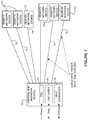
- FIG. 2illustrates an example of a redundant PoE+F+C system.
- Fault toleranceis a concern for critical remote devices. Redundant connections for power and data are needed to protect against the failure of a central hub, its data connections to the Internet, or primary power supplies. If the coolant flow stops, or the supplied coolant is too hot, a remote device's high power components could exceed their safe operating temperature in just a few seconds.
- the network shown in the example of FIG. 2provides backup power, data, and cooling in case of failure of the central hub 10 a or any single cable.
- Critical remote network devices 12may have two combined cables 14 a , 14 b serving them, as shown in FIG. 2 .
- Each cable 14 a , 14 bmay home on an independent central hub 10 a , 10 b , with each central hub providing data, power, and cooling.
- cables 14 a and 14 bmay be routed using different physical paths to each remote network device 12 , so mechanical damage at one point along the cable route will not interrupt the data, power, or coolant to the remote device.
- each heat sink or heat exchanger at the remote device 12comprises two isolated fluid channels, each linked to one of the redundant central hubs 10 a , 10 b . If the coolant flow stops from one hub, the other hub may supply enough coolant (e.g., throttled up by a control system described below) to keep the critical components operational. Isolation is essential to prevent loss of pressure incidents in one fluid loop from also affecting the pressure in the redundant loop.
- the cable's jacketmay include two small sense conductors for use in identifying a leak in the cooling system. If a coolant tube develops a leak, the coolant within the jacket causes a signal to be passed between these conductors, and a device such as a TDR (Time-Domain Reflectometer) at the central hub 10 a , 10 b may be used to locate the exact position of the cable fault, thereby facilitating repair.
- TDRTime-Domain Reflectometer
- the central hubs 10 a , 10 bmay provide additional power, bandwidth, or cooling as needed in the network. Both circuits 14 a , 14 b may be used simultaneously to provide power to an equipment power circuit to provide higher power capabilities. Similarly, redundant data fibers may provide higher network bandwidth, and redundant coolant loops may provide higher cooling capacity. The control systems (described below) manage failures and revert the data, power, and cooling to lower levels if necessary. In another example, redundant central hubs 10 a , 10 b may form a dual-star topology.
- the network devices and topologies shown in FIGS. 1 and 2are only examples and the embodiments described herein may be implemented in networks comprising different network topologies or a different number, type, or arrangement of network devices, without departing from the scope of the embodiments.
- the networkmay comprise any number or type of network communications devices that facilitate passage of data over the network (e.g., routers, switches, gateways, controllers), network elements that operate as endpoints or hosts (e.g., servers, virtual machines, clients), and any number of network sites or domains in communication with any number of networks.
- network nodesmay be used in any suitable network topology, which may include any number of servers, virtual machines, switches, routers, or other nodes interconnected to form a large and complex network, which may include cloud or fog computing.
- the PoE+F+C systemmay be used in a fog node deployment in which computation, networking, and storage are moved from the cloud to locations much closer to IoT sensors and actuators.
- the fog nodesmay provide power to PoE devices such as streetlights, traffic signals, 5G cells, access points, base stations, video cameras, or any other electronic device serving a smart building, smart city, or any other deployment.
- a central hubprovides PoE+F+C cables to a plurality of intermediate hubs, which divide the power, data, and cooling capabilities to further PoE+F+C cables that serve the remote network devices.
- FIG. 3schematically illustrates the cable 14 transmitting power, data, and cooling from the central hub 10 to the remote device 12 , in accordance with one embodiment.
- the central hub 10includes a power distribution module 30 for receiving power from a power grid, network interface 31 for receiving data from and transmitting data to a network (e.g., Internet), and a heat exchanger 32 for fluid communication with a cooling plant.
- the power distribution module 30provides power to a power supply module 33 at the remote device 12 .
- the network interface 31 at the central hub 10is in communication with the network interface 34 at the remote device 12 .
- the heat exchanger 32 at the central hub 10forms a cooling loop with one or more heat sinks 35 at the remote device 12 .
- the central hub 10may provide control logic for the cooling loop, as well as the power and data transport functions of the combined cable 14 , as described below.
- the cable 14includes two power lines (conductors) 36 , two data lines (optical fibers) 37 , and two coolant tubes (supply 38 a and return 38 b ) coupled to connectors 39 a and 39 b located at the central hub 10 and remote device 12 , respectively.
- the closed coolant loopis established through the two coolant tubes 38 a , 38 b that share the same combined cable jacket with the fibers 37 that provide bidirectional data connectivity to the network and conductors 36 that provide power from the power grid.
- various sensors 28 amonitor aggregate and individual branch coolant temperatures, pressures, and flow rate quantities at strategic points around the loop.
- Other sensors 28 bmonitor the current and voltage of the power delivery system at either end of power conductors 36 .
- One or more valvesmay be used to control the amount of cooling delivered to the remote device 12 based upon its instantaneous needs, as described below.
- the coolantmay comprise, for example, water, antifreeze, liquid or gaseous refrigerants, or mixed-phase coolants (partially changing from liquid to gas along the loop).
- the central hub 10maintains a source of low-temperature coolant that is sent through distribution plumbing (such as a manifold), through the connector 39 a , and down cable's 14 coolant supply line 38 a to the remote device 12 .
- the connector 39 b on the remote device 12is coupled to the cable 14 , and the supply coolant is routed through elements inside the device such as heat sinks 35 and heat exchangers that remove heat (described further below with respect to FIG. 5 ).
- the warmed coolantmay be aggregated through a return manifold and returned to the central hub 10 out the device's connector 39 b and through the return tube 38 b in the cable 14 .
- the cable 14returns the coolant to the central hub 10 , where the return coolant passes through the heat exchanger 32 to remove the heat from the coolant loop to an external cooling plant, and the cycle repeats.
- the heat exchanger 32may be a liquid-liquid heat exchanger, with the heat transferred to chilled water or a cooling tower circuit, for example.
- the heat exchanger 32may also be a liquid-air heat exchanger, with fans provided to expel the waste heat to the atmosphere.
- the hot coolant returning from the cable 14may be monitored by sensor 28 a for temperature, pressure, and flow. Once the coolant has released its heat, it may pass back through a pump 29 and sensor 28 a , and then sent back out to the cooling loop.
- One or more variable-speed pumps 29may be provided at the central hub 10 or remote device 12 to circulate the fluid around the cooling loop.
- only a single coolant tubeis provided within the cable 14 , and high pressure air (e.g., supplied by a central compressor with an intercooler) is used as the coolant.
- aire.g., supplied by a central compressor with an intercooler
- Coolingmay be accomplished by forced convection via the mass flow of the air and additional temperature reduction may be provided via a Joule-Thomson effect as the high pressure air expands to atmospheric pressure.
- the coolantmay be supplied above ambient temperature to warm the remote device 12 .
- Thiscan be valuable where remote devices 12 are located in cold climates or in cold parts of industrial plants, and the devices have cold-sensitive components such as optics or disk drives. This may be more energy efficient than providing electric heaters at each device, as is used in conventional systems.
- the cooling loops from all of the remote devices 12may be isolated from one another or be intermixed through a manifold and a large central heat exchanger for overall system thermal efficiency.
- the central hub 10may also include one or more support systems to filter the coolant, supply fresh coolant, adjust anti-corrosion chemicals, bleed air from the loops, or fill and drain loops as needed for installation and maintenance of cables 14 and remote devices 12 .
- the connectors 39 a and 39 b at the central hub 10 and remote device 12are configured to mate with the cable 14 for transmitting and receiving power, data, and cooling.
- the connectors 39 a , 39 bcarry power, fiber, and coolant in the same connector body.
- the connectors 39 a , 39 bare preferably configured to mate and de-mate (couple, uncouple) easily by hand or robotic manipulator.
- the coolant lines 38 a , 38 b and connectors 39 a , 39 bpreferably include valves (not shown) that automatically shut off flow into and out of the cable, and into and out of the device or hub.
- the connector 39 a , 39 bmay be configured to allow connection sequencing and feedback to occur. For example, electrical connections may not be made until a verified sealed coolant loop is established.
- the cable connectors 39 a , 39 bmay also include visual or tactile evidence of whether a line is pressurized, thereby reducing the possibility of user installation or maintenance errors.
- a distributed control systemcomprising components located on the central hub's controller and on the remote device's processor may communicate over the fiber links 37 in the combined cable 14 .
- the sensors 28 a at the central hub 10 and remote device 12may be used in the control system to monitor temperature, pressure, or flow.
- Servo valves or variable speed pumps 29may be used to insure the rate of coolant flow matches requirements of the remote thermal load.
- temperature, pressure, and flow sensors 28 amay be used to measure coolant characteristics at multiple stages of the cooling loop (e.g., at the inlet of the central hub 10 and inlet of the remote device 12 ) and a subset of these sensors may also be strategically placed at outlets and intermediate points.
- the remote device 12may include, for example, temperature sensors to monitor die temperatures of critical semiconductors, temperatures of critical components (e.g., optical modules, disk drives), or the air temperature inside a device's sealed enclosure.
- the control systemmay monitor the remote device's internal temperatures and adjust the coolant flow to maintain a set point temperature. This feedback system insures the correct coolant flow is always present. Too much coolant flow will waste energy, while too little coolant flow will cause critical components in the remote device 12 to overheat.
- Machine learningmay also be used within the control system to compensate for the potentially long response times between when coolant flow rates change and the remote device's temperatures react to the change.
- the output of a control algorithmmay be used to adjust the pumps 29 to move the correct volume of coolant to the device 12 , and may also be used to adjust valves within the remote device to direct different portions of the coolant to different internal heat sinks to properly balance the use of coolant among a plurality of thermal loads.
- the control systemmay also include one or more safety features. For example, the control system may instantly stop the coolant flow and begin a purge cycle if the coolant flow leaving the central hub 10 does not closely match the flow received at the remote devices 12 , which may indicate a leak in the system.
- the control systemmay also shut down a remote device if an internal temperature exceeds a predetermined high limit or open relief valves if pressure limits in the coolant loop are exceeded.
- the systemmay also predictively detect problems in the cooling system such as a pressure rise caused by a kink in the cable 14 , reduction in thermal transfer caused by corrosion of heat sinks 35 , or impending bearing failures in pump 29 , before they become serious.
- sensors 28 bmay be located in the power distribution module 30 of the central hub and power supply 33 of the remote device 12 .
- Initial system modeling and characterizationmay be used to provide expected power, flow properties, and thermal performance operating envelopes, which may provide an initial configuration for new devices and a reference for setting system warning and shut-down limits. This initial characteristic envelope may be improved and fine-tuned over time heuristically through machine learning and other techniques.
- control systemmay proactively increase coolant flow in anticipation of an impending increase in heat sink 35 temperature, even before the temperature sensors register it. This interlock between the various sensors and control systems helps to improve the overall responsivity and stability of the complete system.
- FIG. 4illustrates an example of a network device 40 (e.g., central hub 10 , remote device 12 in FIG. 3 ) that may be used to implement the embodiments described herein.
- the network device 40is a programmable machine that may be implemented in hardware, software, or any combination thereof.
- the network device 40includes one or more processors 42 , control system 43 , memory 44 , cooling components (pumps, valves, sensors) 45 , and interfaces (electrical, optical, fluid) 46 .
- the network device 40may include a PoE+F optical module 48 (e.g., optical module configured for receiving power from power supply 47 and data).
- the network device 40may include any number of processors 42 (e.g., single or multi-processor computing device or system), which may communicate with a forwarding engine or packet forwarder operable to process a packet or packet header.
- the processor 42may receive instructions from a software application or module, which causes the processor to perform functions of one or more embodiments described herein.
- the processor 42may also operate one or more components of the control system 43 .
- the control system (controller) 43may comprise components (modules, code, software, logic) located at the central hub 10 and remote device 12 , and interconnected through the combined cable 14 ( FIGS. 1 and 4 ).
- the cooling components 45may include any number of sensors and actuators within the cooling loop to provide input to the control system 43 and react to its commands.
- Memory 44may be a volatile memory or non-volatile storage, which stores various applications, operating systems, modules, and data for execution and use by the processor 42 .
- components of the optical module 48 , control logic for cooling components 45 , or other parts of the control system 43may be stored in the memory 44 .
- the network device 40may include any number of memory components.
- Logicmay be encoded in one or more tangible media for execution by the processor 42 .
- the processor 42may execute codes stored in a computer-readable medium such as memory 44 .
- the computer-readable mediummay be, for example, electronic (e.g., RAM (random access memory), ROM (read-only memory), EPROM (erasable programmable read-only memory)), magnetic, optical (e.g., CD, DVD), electromagnetic, semiconductor technology, or any other suitable medium.
- the computer-readable mediumcomprises a non-transitory computer-readable medium.
- Logicmay be used to perform one or more functions described below with respect to the flowchart of FIG. 7 or other functions such as power level negotiations, safety subsystems, or thermal control, as described herein.
- the network device 40may include any number of processors 42 .
- the interfaces 46may comprise any number of interfaces (e.g., power, data, and fluid connectors, line cards, ports, combined connectors 39 a , 39 b for connecting to cable 14 in FIG. 3 )) for receiving data, power, and cooling, or transmitting data, power, and cooling to other devices.
- a network interfacemay be configured to transmit or receive data using a variety of different communications protocols and may include mechanical, electrical, and signaling circuitry for communicating data over physical links coupled to the network or wireless interfaces.
- One or more of the interfaces 46may be configured for PoE+F+C, PoE+F, PoE, PoF, or similar operation.
- the optical module 48may comprise hardware or software for use in power detection, power monitor and control, or power enable/disable, as described below.
- the optical module 48may further comprise one or more of the processor or memory components, or interface for receiving power and optical data from the cable at a fiber connector, for delivering power and signal data to the network device, or transmitting control signals to the power source, for example.
- Powermay be supplied to the optical module by the power supply 47 and the optical module (e.g., PoE+F optical module) 48 may provide power to the rest of the components at the network device 40 .
- network device 40 shown in FIG. 4 and described aboveis only an example and that different configurations of network devices may be used.
- the network device 40may further include any suitable combination of hardware, software, algorithms, processors, devices, components, or elements operable to facilitate the capabilities described herein.
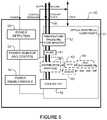
- FIG. 5is a block diagram illustrating PoE+F+C components at a remote device 50 , in accordance with one embodiment.
- the system componentsprovide for communication with the power source (e.g., network device 10 in FIG. 1 ) during power up of the powered device and may also provide fault protection and detection.
- the network device 50includes optical/electrical components 51 for receiving optical data and converting it to electrical signals (or converting electrical signals to optical data) and power components including power detection module 52 , power monitor and control unit 53 , and power enable/disable module 54 .
- the power components 52 , 53 , 54may be isolated from the optical components 51 via an isolation component (e.g., isolation material or element), which electromagnetically isolates the power circuit from the optical components to prevent interference with operation of the optics.
- an isolation componente.g., isolation material or element
- the power detection module 52may detect power, energize the optical components 51 , and return a status message to the power source. A return message may be provided via state changes on the power wires or over the optical channel.
- the poweris not enabled by the power enable/disable module 54 until the optical transceiver and the source have determined that the device is properly connected and the network device to be powered is ready to be powered.
- the device 50is configured to calculate available power and prevent the cabling system from being energized when it should not be powered (e.g., during cooling failure).
- the power detection module 52may also be operable to detect the type of power applied to the device 50 , determine if PoE or pulsed power is a more efficient power delivery method, and then use the selected power delivery mode once the power is enabled. Additional modes may support other power+data standards (e.g., USB (Universal Serial Bus)).
- USBUniversal Serial Bus
- the power monitor and control device 53continuously monitors power delivery to ensure that the system can support the needed power delivery, and no safety limits (voltage, current) are exceeded.
- the power monitor and control device 53may also monitor optical signaling and disable power if there is a lack of optical transitions or communication with the power source.
- Temperature, pressure, or flow sensors 57 , 60may also provide input to the power monitor and control module 53 so that power may be disabled if the temperature at the device 50 exceeds a specified limit.
- Coolingis supplied to the device 50 via cooling (coolant) tubes in a cooling (coolant) loop 58 , which provides cooling to the powered equipment through a cooling tap (heat sink, heat exchanger) 56 , 59 and returns warm (hot) coolant to the central hub.
- the network device 50may also include a number of components for use in managing the cooling.
- the cooling loop 58 within the network device 50may include any number of sensors 57 , 60 for monitoring aggregate and individual branch temperature, pressure, and flow rate at strategic points around the loop (e.g., entering and leaving the device, at critical component locations).
- the sensor 57may be used, for example, to check that the remote device 50 receives approximately the same amount of coolant as supplied by the central hub to help detect leaks or blockage in the cable, and confirm that the temperature and pressure are within specified limits.
- Distribution plumbingroutes the coolant in the cooling loop 58 to various thermal control elements within the network device 50 to actively regulate cooling through the individual flow paths.
- a distribution manifold 55may be included in the network device 50 to route the coolant to the cooling tap 56 and heat exchanger 59 . If the manifold has multiple outputs, each may be equipped with a valve 62 (manual or servo controlled) to regulate the individual flow paths.
- Thermal control elementsmay include liquid cooled heatsinks, heat pipes, or other devices directly attached to the hottest components (CPUs (Central Processing Units), GPUs (Graphic Processing Units), power supplies, optical components, etc.) to directly remove their heat.
- the network device 50may also include channels in cold plates or in walls of the device's enclosure to cool anything they contact.
- Air to liquid heat exchangerswhich may be augmented by a small internal fan, may be provided to cool the air inside a sealed box. Once the coolant passes through these elements and removes the device's heat, it may pass through additional temperature, pressure, or flow sensors, through another manifold, and out to the coolant return tube.
- the cooling systemincludes a pump 61 operable to help drive the coolant around the cooling loop 58 or back to the central hub.
- the distribution manifold 55may comprise any number of individual manifolds (e.g., supply and return manifolds) to provide any number of cooling branches directed to one or more components within the network device 50 .
- the cooling loop 58may include any number of pumps 61 or valves 62 to control flow in each branch of the cooling loop. This flow may be set by an active feedback loop that senses the temperature of a critical thermal load (e.g., die temperature of a high power semiconductor), and continuously adjusts the flow in the loop that serves the heat sink or heat exchanger 59 .
- the pump 61 and valve 62may be controlled by the control system and operate based on control logic received from the central hub in response to monitoring at the network device 50 .
- the network device 50 shown in FIG. 5is only an example and that the network device may include different components or arrangement of components, without departing from the scope of the embodiments.
- the cooling systemmay include any number of pumps, manifolds, valves, heat sinks, heat exchangers, or sensors located in various locations within the coolant loop or arranged to cool various elements or portions of the device.
- the network device 50may include any number of power sensors or control modules operable to communicate with the control system at the central hub to optimize power delivery and cooling at the network device.
- FIGS. 6A, 6B, and 6Cillustrate three examples of multi-function cables 14 that may be used to carry utilities (power, data, and cooling) between the central hub 10 and the remote device 12 as shown in FIGS. 1, 2, and 3 .
- the cablemay be a few kilometers long or any other suitable length.
- the cablecomprises optical fibers 65 for data (at least one in each direction for conventional systems, or at least one for bi-directional fiber systems), power conductors 66 (for each polarity) (e.g., heavy stranded wires for pulsed power), coolant tubes 67 (at least one in each direction for liquid systems, or at least one for compressed air systems), and a protective shield 68 .
- optical fibers 65 for dataat least one in each direction for conventional systems, or at least one for bi-directional fiber systems
- power conductors 66for each polarity
- coolant tubes 67at least one in each direction for liquid systems, or at least one for compressed air systems
- a protective shield 68e.g., a protective shield
- the componentsmay have various cross-sectional shapes and arrangements, as shown in FIGS. 6A-6C .
- the coolant tubes 67may be cylindrical in shape as shown in FIGS. 6A and 6C or have a semi-circle cross-sectional shape, as shown in FIG. 6B .
- the coolant tubes 67may also have more complex shaped cross-sections (e.g., “C” or “D” shape), which may yield more space and thermally efficient cables.
- the complex shaped coolant tube profilesmay also include rounded corners to reduce flow head pressure loss. Supply and return tube wall material thermal conductivity may be adjusted to optimize overall system cooling.
- the cablemay be configured to prevent heat loss through supply-return tube-tube conduction, external environment conduction, coolant tube-power wire conduction, or any combination of these or other conditions, as described below.
- a type of unwelcome counter flow heat exchangemay be created as the coolant supply tube receives heat via internal conduction in the cable from the hotter coolant return tube, which tends to equalize the two temperatures along the length of the cable (referred to as supply-return tube-tube conduction).
- the supply coolantmay be so preheated by the return coolant flowing in the opposite direction that it is much less effective in cooling the remote device.
- a thermal isolation material 69 located between the two coolant tubes 67may be used to prevent undesirable heat conduction, as shown in FIGS. 6A, 6B, and 6C .
- the insulation material 69may be, for example, a foamed elastomer or any other suitable material.
- thermal isolator material 69between the coolant tubes and the outer jacket 64 as shown in FIG. 6A may be used to control this flow. However, in some cases, it may be desired to deliberately provide one or both coolant tubes 67 with a low thermal impedance path to the outside, as shown in FIG. 6B . Regions 70 replace the thermal insulation with a thermally conductive material. This may be useful, for example in buried or undersea cables where a linear ground coupled heat exchanger is created. Heat from the device is transferred by the circulating fluid to the ground, and reduced mechanical cooling is needed at the central hub.
- a third mode of heat transfer that may be controlled by the design of the cableis between the power conductors and the coolant tubes.
- the cross-sectional size of the power conductorsis preferably minimized to reduce volume, weight, and cost of copper and improve flexibility of the cable.
- smaller conductorshave higher resistance, and I 2 R losses will heat the length of the cable (potentially hundreds of Watts in systems that deliver kilowatt levels of power over multi-kilometer distances).
- regions 71 in FIG. 6CBy providing thermally conductive paths inside the cable between the power conductors 66 and coolant tube 67 , as depicted by regions 71 in FIG. 6C , some of the cooling power of the loop may be used to keep the power conductors in the cables cool.
- the conductive thermal paths 71extend between the return coolant tube 67 and power conductors 66 .
- the selective use of insulation and thermally conductive materialsmay be used to control conduction within the cable.
- reflective materials and coatingse.g., aluminized Mylar
- tube interiorsmay be treated with hydrophobic coatings and the coolant may include surfactants.
- the supply and return coolant tubes 67may be composed of materials having different conductive properties so that the complete cable assembly may be thermally tuned to enhance system performance.
- FIGS. 6A-6Care only examples and that other configurations may be used without departing from the scope of the embodiments.
- FIG. 7is a flowchart illustrating an overview of a process for delivering combined power, data, and cooling in a communications network, in accordance with one embodiment.
- power, data, and coolingare delivered in the combined cable 14 from central network device 10 to a plurality of remote communications devices 12 ( FIGS. 1 and 7 ).
- the central network device 10receives power and thermal data from the remote devices over the cable, based on monitoring of power and cooling at the remote devices (step 76 ).
- the central network device 10adjusts delivery of power and cooling as needed at the remote devices (step 78 ).
- the remote communications devicesare powered by the power and cooled by the cooling delivered by the central network device, thereby eliminating the need for a separate power supply or external cooling.
- FIG. 7is only an example of a process for delivering combined power, data, and cooling, and that steps may be added, removed, combined, or modified, without departing from the scope of the embodiments.
Landscapes
- Engineering & Computer Science (AREA)
- Theoretical Computer Science (AREA)
- General Engineering & Computer Science (AREA)
- Physics & Mathematics (AREA)
- General Physics & Mathematics (AREA)
- Signal Processing (AREA)
- Computer Networks & Wireless Communication (AREA)
- Software Systems (AREA)
- Human Computer Interaction (AREA)
- Computer Hardware Design (AREA)
- Artificial Intelligence (AREA)
- Computer Vision & Pattern Recognition (AREA)
- Data Mining & Analysis (AREA)
- Evolutionary Computation (AREA)
- Medical Informatics (AREA)
- Computing Systems (AREA)
- Mathematical Physics (AREA)
- Remote Monitoring And Control Of Power-Distribution Networks (AREA)
Abstract
Description
Claims (28)
Priority Applications (6)
| Application Number | Priority Date | Filing Date | Title |
|---|---|---|---|
| US15/910,203US11093012B2 (en) | 2018-03-02 | 2018-03-02 | Combined power, data, and cooling delivery in a communications network |
| CA3092963ACA3092963A1 (en) | 2018-03-02 | 2019-02-22 | Combined power, data, and cooling delivery in a communications network |
| PCT/US2019/019259WO2019168761A1 (en) | 2018-03-02 | 2019-02-22 | Combined power, data, and cooling delivery in a communications network |
| CN201980016292.9ACN111971932B (en) | 2018-03-02 | 2019-02-22 | Combined power, data and cooling transfer in a communication network |
| EP19710850.9AEP3759869B1 (en) | 2018-03-02 | 2019-02-22 | Combined power, data, and cooling delivery in a communications network |
| EP22159801.4AEP4030688B1 (en) | 2018-03-02 | 2019-02-22 | Combined power, data, and cooling delivery in a communications network |
Applications Claiming Priority (1)
| Application Number | Priority Date | Filing Date | Title |
|---|---|---|---|
| US15/910,203US11093012B2 (en) | 2018-03-02 | 2018-03-02 | Combined power, data, and cooling delivery in a communications network |
Publications (2)
| Publication Number | Publication Date |
|---|---|
| US20190272011A1 US20190272011A1 (en) | 2019-09-05 |
| US11093012B2true US11093012B2 (en) | 2021-08-17 |
Family
ID=65763773
Family Applications (1)
| Application Number | Title | Priority Date | Filing Date |
|---|---|---|---|
| US15/910,203Active2039-04-05US11093012B2 (en) | 2018-03-02 | 2018-03-02 | Combined power, data, and cooling delivery in a communications network |
Country Status (5)
| Country | Link |
|---|---|
| US (1) | US11093012B2 (en) |
| EP (2) | EP4030688B1 (en) |
| CN (1) | CN111971932B (en) |
| CA (1) | CA3092963A1 (en) |
| WO (1) | WO2019168761A1 (en) |
Families Citing this family (30)
| Publication number | Priority date | Publication date | Assignee | Title |
|---|---|---|---|---|
| US10809134B2 (en) | 2017-05-24 | 2020-10-20 | Cisco Technology, Inc. | Thermal modeling for cables transmitting data and power |
| US11054457B2 (en) | 2017-05-24 | 2021-07-06 | Cisco Technology, Inc. | Safety monitoring for cables transmitting data and power |
| US10541758B2 (en) | 2017-09-18 | 2020-01-21 | Cisco Technology, Inc. | Power delivery through an optical system |
| US11431420B2 (en) | 2017-09-18 | 2022-08-30 | Cisco Technology, Inc. | Power delivery through an optical system |
| US10281513B1 (en) | 2018-03-09 | 2019-05-07 | Cisco Technology, Inc. | Verification of cable application and reduced load cable removal in power over communications systems |
| US10790997B2 (en) | 2019-01-23 | 2020-09-29 | Cisco Technology, Inc. | Transmission of pulse power and data in a communications network |
| US11061456B2 (en) | 2019-01-23 | 2021-07-13 | Cisco Technology, Inc. | Transmission of pulse power and data over a wire pair |
| US10680836B1 (en) | 2019-02-25 | 2020-06-09 | Cisco Technology, Inc. | Virtualized chassis with power-over-Ethernet for networking applications |
| US11456883B2 (en) | 2019-03-13 | 2022-09-27 | Cisco Technology, Inc. | Multiple phase pulse power in a network communications system |
| US11063630B2 (en) | 2019-11-01 | 2021-07-13 | Cisco Technology, Inc. | Initialization and synchronization for pulse power in a network system |
| US12126399B2 (en) | 2019-11-01 | 2024-10-22 | Cisco Technology, Inc. | Fault managed power with dynamic and adaptive fault sensor |
| US11252811B2 (en) | 2020-01-15 | 2022-02-15 | Cisco Technology, Inc. | Power distribution from point-of-load with cooling |
| US11853138B2 (en) | 2020-01-17 | 2023-12-26 | Cisco Technology, Inc. | Modular power controller |
| US11543844B2 (en) | 2020-02-25 | 2023-01-03 | Cisco Technology, Inc. | Method and apparatus for transmitting power and data in a multi-drop architecture |
| US11438183B2 (en) | 2020-02-25 | 2022-09-06 | Cisco Technology, Inc. | Power adapter for power supply unit |
| US11637497B2 (en) | 2020-02-28 | 2023-04-25 | Cisco Technology, Inc. | Multi-phase pulse power short reach distribution |
| US11320610B2 (en) | 2020-04-07 | 2022-05-03 | Cisco Technology, Inc. | Integration of power and optics through cold plate for delivery to electronic and photonic integrated circuits |
| US11307368B2 (en) | 2020-04-07 | 2022-04-19 | Cisco Technology, Inc. | Integration of power and optics through cold plates for delivery to electronic and photonic integrated circuits |
| US11915276B2 (en) | 2020-04-28 | 2024-02-27 | Cisco Technology, Inc. | System, method, and computer readable storage media for millimeter wave radar detection of physical actions coupled with an access point off-load control center |
| US11582048B2 (en) | 2020-07-17 | 2023-02-14 | Cisco Technology, Inc. | Bi-directional power over ethernet for digital building applications |
| US11708002B2 (en) | 2020-08-03 | 2023-07-25 | Cisco Technology, Inc. | Power distribution and communications for electric vehicle |
| US11745613B2 (en) | 2020-08-26 | 2023-09-05 | Cisco Technology, Inc. | System and method for electric vehicle charging and security |
| US11482351B2 (en)* | 2020-09-29 | 2022-10-25 | Hewlett Packard Enterprise Development Lp | Pluggable network interface port with powering for remote device |
| CN113596635A (en)* | 2021-08-03 | 2021-11-02 | 深圳市菲菱科思通信技术股份有限公司 | All-optical POE network routing switch equipment and system |
| US20240431069A1 (en)* | 2023-06-23 | 2024-12-26 | Hewlett Packard Enterprise Development Lp | Fan control for power over ethernet device based on power usage |
| US12335124B2 (en)* | 2023-07-10 | 2025-06-17 | Cisco Technology, Inc. | Subscription-based sustainable network administration |
| CN117117670B (en)* | 2023-07-17 | 2024-08-13 | 中铁四局集团有限公司 | Tunnel power supply system |
| WO2025096826A1 (en)* | 2023-10-31 | 2025-05-08 | Subsea Cloud Inc. | Systems, methods, and apparatus for placing data centers in a subsea environment |
| US20250185222A1 (en)* | 2023-11-30 | 2025-06-05 | Vertiv Corporation | Integrated rack power-cooling delivery device |
| CN119363495B (en)* | 2024-12-24 | 2025-04-01 | 中京科信技术有限公司 | Communication equipment optimization method and device based on power management |
Citations (224)
| Publication number | Priority date | Publication date | Assignee | Title |
|---|---|---|---|---|
| US3335324A (en) | 1965-10-06 | 1967-08-08 | Westinghouse Air Brake Co | Fail-safe continuous ground monitoring circuit |
| US3962529A (en)* | 1970-10-07 | 1976-06-08 | Sumitomo Electric Industries, Ltd. | Evaporative cooling power cable line |
| US4811187A (en) | 1985-02-12 | 1989-03-07 | Hitachi Metals Ltd. | DC-DC converter with saturable reactor reset circuit |
| US4997388A (en) | 1989-08-28 | 1991-03-05 | Amp Incorporated | Electrical tap connector |
| WO1993016407A1 (en) | 1992-02-18 | 1993-08-19 | Angelase, Inc. | Cooled multi-fiber medical connector |
| US5652893A (en) | 1994-12-13 | 1997-07-29 | 3Com Corporation | Switching hub intelligent power management |
| US5723848A (en)* | 1996-01-16 | 1998-03-03 | Intech 21, Inc. | Heating cable control and monitoring method and system |
| US6008631A (en) | 1999-03-18 | 1999-12-28 | International Business Machines Corporation | Synchronous voltage converter |
| US6220955B1 (en) | 1998-02-17 | 2001-04-24 | John G. Posa | Combination power and cooling cable |
| US6259745B1 (en) | 1998-10-30 | 2001-07-10 | Broadcom Corporation | Integrated Gigabit Ethernet transmitter architecture |
| US20010024373A1 (en) | 2000-03-24 | 2001-09-27 | Slobodan Cuk | Lossless switching dc to dc converter with dc transformer |
| US20020126967A1 (en) | 1996-03-29 | 2002-09-12 | Dominion Lasercom, Inc. | Hybrid electro-optic cable |
| US6636538B1 (en) | 1999-03-29 | 2003-10-21 | Cutting Edge Optronics, Inc. | Laser diode packaging |
| US20040000816A1 (en) | 2002-06-26 | 2004-01-01 | Bahman Khoshnood | Apparatus and method for distributing data and controlled temperature air to electronic equipment via electronic device power cord plug assemblies with mating wall outlets which incorporate integral signal and/or controlled temperature air supply lines |
| US6685364B1 (en) | 2001-12-05 | 2004-02-03 | International Business Machines Corporation | Enhanced folded flexible cable packaging for use in optical transceivers |
| US20040033076A1 (en) | 2002-08-06 | 2004-02-19 | Jae-Won Song | Wavelength division multiplexing passive optical network system |
| US20040043651A1 (en) | 2002-08-29 | 2004-03-04 | Dell Products L.P. | AC adapter connector assembly |
| US20040073703A1 (en) | 1997-10-14 | 2004-04-15 | Alacritech, Inc. | Fast-path apparatus for receiving data corresponding a TCP connection |
| US6784790B1 (en) | 2000-09-06 | 2004-08-31 | Marshall E. Lester | Synchronization/reference pulse-based powerline pulse position modulated communication system |
| US6826368B1 (en) | 1998-10-20 | 2004-11-30 | Lucent Technologies Inc. | Wavelength division multiplexing (WDM) with multi-frequency lasers and optical couplers |
| US20040264214A1 (en) | 2003-06-25 | 2004-12-30 | Ming Xu | Quasi-resonant DC-DC converters with reduced body diode loss |
| US6860004B2 (en) | 2000-04-26 | 2005-03-01 | Matsushita Electric Industrial Co., Ltd. | Method of manufacturing a thermally conductive circuit board with a ground pattern connected to a heat sink |
| CN1209880C (en) | 2001-11-30 | 2005-07-06 | 王德清 | Wideband access transmission entwork as assembly of power supply, telecommunication device, TV set and internet network |
| US20050197018A1 (en) | 2004-03-02 | 2005-09-08 | Charles Lord | Keyed universal power tip and power source connectors |
| US20050268120A1 (en) | 2004-05-13 | 2005-12-01 | Schindler Frederick R | Power delivery over ethernet cables |
| US20060202109A1 (en) | 2005-03-14 | 2006-09-14 | The Boeing Company | Method and apparatus for optically powering and multiplexing distributed fiber optic sensors |
| US20060209875A1 (en) | 2005-03-16 | 2006-09-21 | Cisco Technology, Inc., A California Corporation | Method and apparatus for current sharing Ethernet power across four conductor pairs |
| WO2006127916A2 (en) | 2005-05-25 | 2006-11-30 | Cisco Technology, Inc. | Method and apparatus for detecting and fixing faults in an inline-power capable ethernet system |
| US20070103168A1 (en) | 2005-11-09 | 2007-05-10 | Batten Douglas W | Loop impedance meter |
| US20070143508A1 (en) | 2003-04-14 | 2007-06-21 | Sven Linnman | Common field bus for data and energy transfer |
| US20070236853A1 (en) | 2006-04-11 | 2007-10-11 | Crawley Philip J | Network devices for separating power and data signals |
| US20070263675A1 (en) | 2006-04-13 | 2007-11-15 | Cisco Technology, Inc. | Method and apparatus for current sharing ethernet power across four conductor pairs using a midspan device |
| US20070288125A1 (en) | 2006-06-09 | 2007-12-13 | Mks Instruments, Inc. | Power Over Ethernet (Poe) - Based Measurement System |
| US20070288771A1 (en) | 2006-06-08 | 2007-12-13 | Steven Andrew Robbins | Source Separator for Power over Ethernet Systems |
| US20070284946A1 (en) | 2006-06-10 | 2007-12-13 | Steven Andrew Robbins | Passive Power Combiner for Dual Power over Ethernet Sources |
| US20070284941A1 (en) | 2006-06-08 | 2007-12-13 | Steven Andrew Robbins | Power Cross-Coupler for Power over Ethernet |
| US7325150B2 (en) | 1999-01-12 | 2008-01-29 | Microsemi Corp.—Analog Mixed Signal Group, Ltd. | Combiner for power delivery over data communication cabling infrastructure |
| US20080054720A1 (en) | 2006-09-01 | 2008-03-06 | Cisco Technology, Inc. | Method and apparatus for distributing power to a load in a powered device |
| EP1936861A1 (en) | 2006-12-19 | 2008-06-25 | Broadcom Corporation | System and method for controlling power delivered to a powered device based on cable characteristics |
| US20080198635A1 (en) | 2007-02-21 | 2008-08-21 | Broadcom Corporation | Pulse width modulated ground/return for powered device |
| US7420355B2 (en) | 2006-07-11 | 2008-09-02 | Artesyn Technologies, Inc. | DC-DC converter with over-voltage protection |
| US20080229120A1 (en) | 2007-03-12 | 2008-09-18 | Broadcom Corporation | System and method for continual cable thermal monitoring using cable resistance considerations in power over ethernet |
| US20080310067A1 (en) | 2007-06-12 | 2008-12-18 | Broadcom Corporation | System and method for using a phy to locate a thermal signature in a cable plant for diagnostic, enhanced, and higher power applications |
| US20090027033A1 (en) | 2007-07-24 | 2009-01-29 | Broadcom Corporation | System and method for integrated temperature measurement in power over ethernet applications |
| US7492059B2 (en) | 2003-10-16 | 2009-02-17 | Microsemi Corp.—Analog Mixed Signal Group Ltd. | High power architecture for power over ethernet |
| US7490996B2 (en) | 2006-08-16 | 2009-02-17 | Sigmund Sommer | Electro-optical plug and receptacle |
| US7509505B2 (en) | 2005-01-04 | 2009-03-24 | Cisco Technology, Inc. | Method and system for managing power delivery for power over Ethernet systems |
| US7566987B2 (en) | 2006-09-14 | 2009-07-28 | Lutron Electronics Co., Inc. | Method of powering up a plurality of loads in sequence |
| US7583703B2 (en) | 2003-10-23 | 2009-09-01 | Cisco Technology Inc. | System and method for power injection and out of band communications on shared medium |
| US7589435B2 (en) | 2006-08-02 | 2009-09-15 | Cisco Technology, Inc. | Reporting power requirements of a powered device |
| US7593747B1 (en) | 2005-07-01 | 2009-09-22 | Cisco Technology, Inc. | Techniques for controlling delivery of power to a remotely powerable device based on temperature |
| US7616465B1 (en) | 2004-02-24 | 2009-11-10 | Vlt, Inc. | Energy storage and hold-up method and apparatus for high density power conversion |
| EP2120443A1 (en) | 2008-05-15 | 2009-11-18 | BRITISH TELECOMMUNICATIONS public limited company | Power supply system |
| US20100117808A1 (en) | 2008-11-11 | 2010-05-13 | Cisco Technology Inc. | Powered communications interface providing low-speed communications between power-sourcing equipment and powered device in non-powered operating mode |
| WO2010053542A2 (en) | 2008-11-08 | 2010-05-14 | Sensortran, Inc. | System and method for determining characteristics of power cables using distributed temperature sensing systems |
| US20100171602A1 (en) | 2009-01-05 | 2010-07-08 | Hazem Kabbara | Intelligent Power Management of an Intermediate Network Device Switching Circuitry and PoE Delivery |
| US20100190384A1 (en) | 2004-11-12 | 2010-07-29 | Comarco Wireless Technologies, Inc. | Key coded power adapter connectors |
| US20100237846A1 (en) | 2009-03-17 | 2010-09-23 | Cisco Technology, Inc. | Controlling inline power at at powered device |
| US7813646B2 (en) | 2007-07-11 | 2010-10-12 | RLH Industries, Inc | Power over optical fiber system |
| US7835389B2 (en) | 2006-09-20 | 2010-11-16 | Broadcom Corporation | Method and system for an extended range Ethernet line code using 4B/3B mapping |
| US20100290190A1 (en) | 2009-05-12 | 2010-11-18 | Iceotope Limited | Cooled electronic system |
| EP2257009A2 (en) | 2009-05-12 | 2010-12-01 | The Alfred E Mann Foundation for Scientific Research | Pulse edge modulation and demodulation |
| US7854634B2 (en) | 2004-06-24 | 2010-12-21 | Molex Incorporated | Jack connector assembly having circuitry components integrated for providing POE-functionality |
| CN201689347U (en) | 2010-05-06 | 2010-12-29 | 谭志明 | POE (Power Over Ethernet) power supply temperature control device |
| US20110004773A1 (en) | 2007-05-01 | 2011-01-06 | Broadcom Corporation | Powered device for power over ethernet system with increased cable length |
| US20110007664A1 (en) | 2006-06-22 | 2011-01-13 | Wael Diab | Method and system for link adaptive ethernet communications |
| US7881072B2 (en) | 1999-07-15 | 2011-02-01 | Molex Incorporated | System and method for processor power delivery and thermal management |
| US20110057612A1 (en)* | 2009-09-04 | 2011-03-10 | Denso Corporation | Battery charge state transmission device and external charging system |
| US7915761B1 (en) | 2006-09-27 | 2011-03-29 | Cisco Technology, Inc. | Power injector detection |
| US7921307B2 (en) | 2007-03-27 | 2011-04-05 | Cisco Technology, Inc. | Methods and apparatus providing advanced classification for power over Ethernet |
| US7924579B2 (en) | 2008-02-05 | 2011-04-12 | Cisco Technology, Inc. | Fly-forward converter power supply |
| US20110083824A1 (en) | 2009-06-03 | 2011-04-14 | Bripco Bvba | Data Centre |
| US7940787B2 (en) | 2005-08-30 | 2011-05-10 | Cisco Technology, Inc. | Low-power ethernet device |
| US7973538B2 (en) | 2008-08-21 | 2011-07-05 | Cisco Technology, Inc. | Power over ethernet system having hazard detection circuitry to detect potentially hazardous cable conditions |
| US8020043B2 (en) | 2009-03-06 | 2011-09-13 | Cisco Technology, Inc. | Field failure data collection |
| US20110228578A1 (en) | 2010-03-18 | 2011-09-22 | Abb Research Ltd. | Non-isolated dc-dc converter for solar power plant |
| US8037324B2 (en) | 2007-03-20 | 2011-10-11 | Broadcom Corporation | Power over ethernet connector with integrated power source equipment (PSE) controller supporting high power applications |
| US20110266867A1 (en) | 2010-05-03 | 2011-11-03 | Cisco Technology Inc. | Power-sharing network communications device |
| US20110290497A1 (en) | 2010-05-28 | 2011-12-01 | Karl-Atle Stenevik | Subsea hydrocarbon production system |
| US8081589B1 (en) | 2007-08-28 | 2011-12-20 | Meru Networks | Access points using power over ethernet |
| US20120043935A1 (en)* | 2011-07-25 | 2012-02-23 | Lightening Energy | Station for rapidly charging an electric vehicle battery |
| US20120064745A1 (en) | 2007-06-05 | 2012-03-15 | Martin Ottliczky | Hybrid universal distribution system comprising electrical, fluid, and communication functions |
| EP2432134A1 (en) | 2010-09-16 | 2012-03-21 | Alfred E Mann Foundation for Scientific Research | Power and bidirectional data transmission |
| US8184525B2 (en) | 2005-05-25 | 2012-05-22 | Cisco Technology, Inc. | Method and apparatus for detecting and fixing faults in an inline-power capable ethernet system |
| US20120170927A1 (en) | 2010-12-30 | 2012-07-05 | Yuanjun Huang | Circuits, Architectures, Apparatuses, Systems, and Methods for Merging of Management and Data Signals, and for Recovery of a Management Signal |
| US20120201089A1 (en) | 1995-10-19 | 2012-08-09 | Rambus Inc. | Integrated circuit device comprises an interface to transmit a first code, a strobe signal after a delay and data to a dynamic random access memory (dram) |
| US20120231654A1 (en) | 2009-11-06 | 2012-09-13 | G.B.D. Corp. | Electrical cord and apparatus using same |
| US8276397B1 (en) | 2007-06-27 | 2012-10-02 | Exaflop Llc | Cooling and power paths for data center |
| US8279883B2 (en) | 2008-07-07 | 2012-10-02 | Broadcom Corporation | High speed isolation interface for PoE |
| US8319627B2 (en) | 2009-03-17 | 2012-11-27 | Jetlun Corporation | Method and system for intelligent energy network management control system |
| US20120317426A1 (en) | 2011-06-09 | 2012-12-13 | Andrew Llc | Distributed antenna system using power-over-ethernet |
| US20120319468A1 (en) | 2010-03-19 | 2012-12-20 | Videolarm, Inc. | Power over ethernet prioritization system and method for surveillance cameras |
| US8345439B1 (en) | 2008-11-18 | 2013-01-01 | Force10 Networks, Inc. | Modular chassis arrangement with redundant logic power delivery system |
| US8350538B2 (en) | 2009-04-11 | 2013-01-08 | Cuks, Llc | Voltage step-down switching DC-to-DC converter |
| US8358893B1 (en) | 2010-01-14 | 2013-01-22 | Sandia Corporation | Photonic-powered cable assembly |
| US20130079633A1 (en) | 2011-09-23 | 2013-03-28 | Tyco Electronics Corporation | Diagnostic System with Hybrid Cable Assembly |
| US20130077923A1 (en) | 2011-09-23 | 2013-03-28 | Tyco Electronics Corporation | Hybrid Cable Assembly |
| US20130103220A1 (en) | 2009-10-27 | 2013-04-25 | Voltserver Inc. | Safe Exposed Conductor Power Distribution System |
| US20130249292A1 (en) | 2010-11-24 | 2013-09-26 | Corning Cable Systems Llc | Power distribution module(s) capable of hot connection and/or disconnection for distributed antenna systems, and related power units, components, and methods |
| US20130272721A1 (en) | 2012-04-13 | 2013-10-17 | Alcatel-Lucent Usa, Inc. | Optical network device employing three-level duobinary modulation and method of use thereof |
| US20130329344A1 (en) | 2012-06-11 | 2013-12-12 | Commscope, Inc. Of North Carolina | Intelligent telecommunications patching system |
| CN103490907A (en) | 2013-09-24 | 2014-01-01 | 广东威创视讯科技股份有限公司 | POE power source receiving method and POE power source receiving device |
| US8638008B2 (en) | 2009-12-22 | 2014-01-28 | Direct Power Tech Ip, Llc | 380 volt direct current power distribution system for information and communication technology systems and facilities |
| EP2693688A1 (en) | 2012-08-03 | 2014-02-05 | Broadcom Corporation | Cable imbalance diagnostics between channels that include wire pairs for power over ethernet transmission |
| US8700923B2 (en) | 2000-09-27 | 2014-04-15 | Huron Ip Llc | Apparatus and method for modular dynamically power managed power supply and cooling system for computer systems, server applications, and other electronic devices |
| US20140111180A1 (en) | 2012-10-23 | 2014-04-24 | Broadcom Corporation | METHOD AND APPARATUS FOR CURRENT SENSING IN POWER OVER ETHERNET (PoE) SYSTEMS |
| US8712324B2 (en) | 2008-09-26 | 2014-04-29 | Qualcomm Incorporated | Inductive signal transfer system for computing devices |
| US20140126151A1 (en) | 2012-11-08 | 2014-05-08 | International Business Machines Corporation | Separate control of coolant flow through coolant circuits |
| US20140129850A1 (en) | 2012-11-05 | 2014-05-08 | Linear Technology Corporation | Polarity correction bridge controller for combined power over ethernet system |
| US8750710B1 (en) | 2011-07-15 | 2014-06-10 | Cisco Technology, Inc. | System and method for facilitating fiber access transport using pluggable radio frequency optics |
| US8768528B2 (en) | 2011-05-16 | 2014-07-01 | Vcharge, Inc. | Electrical thermal storage with edge-of-network tailored energy delivery systems and methods |
| US8787775B2 (en) | 2010-10-07 | 2014-07-22 | Alcatel Lucent | Opto-electronic assembly for a line card |
| US8829917B1 (en) | 2002-06-07 | 2014-09-09 | Marvell International Ltd. | Cable tester |
| US20140258813A1 (en) | 2012-07-10 | 2014-09-11 | Kent C. Lusted | Network System Configured for Resolving Forward Error Correction During A Data Mode |
| US20140258742A1 (en) | 2013-03-05 | 2014-09-11 | Ching-Yun CHIEN | Hybrid fiber optic and power over ethernet |
| US8836228B2 (en) | 2011-05-11 | 2014-09-16 | Fsp Technology Inc. | Non-isolated resonant converter |
| US20140265550A1 (en) | 2013-03-14 | 2014-09-18 | Raytheon Bbn Technologies Corp. | Redundantly powered and daisy chained power over ethernet |
| US8842430B2 (en) | 2008-12-31 | 2014-09-23 | Cirrascale Corporation | Data center |
| US8849471B2 (en) | 2008-09-13 | 2014-09-30 | Moixa Energy Holdings Limited | Systems, devices and methods for electricity provision, usage monitoring, analysis, and enabling improvements in efficiency |
| CN104081237A (en) | 2011-10-26 | 2014-10-01 | 康宁光电通信有限责任公司 | Composite cable breakout assembly |
| US20140372773A1 (en) | 2013-06-18 | 2014-12-18 | Linear Technology Corporation | Power over ethernet on data pairs and spare pairs |
| US8966747B2 (en) | 2011-05-11 | 2015-03-03 | Vlt, Inc. | Method of forming an electrical contact |
| US20150078740A1 (en) | 2013-09-19 | 2015-03-19 | RADIUS UNIVERSAL, A Limited Liability Company of the State of New York | Fiber optic communications network |
| US20150106539A1 (en) | 2013-10-10 | 2015-04-16 | Nokia Corporation | Communication control pins in a dual row connector |
| US9019895B2 (en) | 2013-01-09 | 2015-04-28 | Qualcomm Incorporated | Methods and apparatus for controlling access points coupled to a common power source |
| US20150115741A1 (en) | 2013-10-29 | 2015-04-30 | Avaya Inc. | Ac power over ethernet |
| US9024473B2 (en) | 2011-08-30 | 2015-05-05 | Linear Technology Corporation | Power combining in power over ethernet systems |
| US20150207317A1 (en) | 2012-08-29 | 2015-07-23 | Koninklijke Philips N.V. | Method and apparatus for multiplexed power and data supply via a two-wire data communication cable |
| US20150215001A1 (en) | 2014-01-26 | 2015-07-30 | VoltServer, Inc. | Packet Energy Transfer In-Line Communications |
| US20150215131A1 (en) | 2014-01-30 | 2015-07-30 | Linear Technology Corporation | Detection scheme for four wire pair power over ethernet system |
| US9189043B2 (en) | 2006-01-17 | 2015-11-17 | Broadcom Corporation | Apparatus and method for multipoint detection in power-over-ethernet detection mode |
| US9189036B2 (en) | 2005-08-19 | 2015-11-17 | Akros Silicon, Inc. | Ethernet module |
| US20150333918A1 (en) | 2014-05-15 | 2015-11-19 | Schneider Electric Buildings, Llc | Power over ethernet enabled sensor and sensor network |
| US20150340818A1 (en) | 2013-01-18 | 2015-11-26 | Christopher B. Scherer | Field-terminable traceable cables, components, kits, and methods |
| CN204836199U (en) | 2015-07-29 | 2015-12-02 | 杭州海康威视数字技术股份有限公司 | POE power module and be provided with POE power module's cable |
| US20150365003A1 (en) | 2014-06-12 | 2015-12-17 | Laurence P. Sadwick | Power Conversion System |
| US20160020911A1 (en) | 2013-09-19 | 2016-01-21 | RADIUS UNIVERSAL, A Limited Liability Company of the State of New York | Fiber optic communications and power network |
| US20160018252A1 (en) | 2013-03-04 | 2016-01-21 | International Road Dynamics, Inc. | Sensor including electrical transmission-line parameter that changes responsive to vehicular load |
| US20160053596A1 (en)* | 2014-08-21 | 2016-02-25 | Christopher M. Rey | High Power Dense Down-Hole Heating Device for Enhanced Oil, Natural Gas, Hydrocarbon, and Related Commodity Recovery |
| US9273906B2 (en) | 2012-06-14 | 2016-03-01 | International Business Machines Corporation | Modular pumping unit(s) facilitating cooling of electronic system(s) |
| US20160064938A1 (en) | 2014-08-26 | 2016-03-03 | Cisco Technology, Inc. | Dynamically Configurable Power-Over-Ethernet Apparatus and Method |
| US9319101B2 (en) | 2012-09-28 | 2016-04-19 | Siemens Industry, Inc. | System and method for ground fault detection in a transformer isolated communication channel of a network device |
| US20160111877A1 (en) | 2014-10-21 | 2016-04-21 | VoltServer, Inc. | Digital Power Receiver System |
| US9321362B2 (en) | 2014-02-05 | 2016-04-26 | Tesia Motors, Inc. | Cooling of charging cable |
| US20160120059A1 (en)* | 2014-10-27 | 2016-04-28 | Ebullient, Llc | Two-phase cooling system |
| US20160118784A1 (en) | 2014-10-23 | 2016-04-28 | Honeywell International Inc. | Non-isolated power supply output chassis ground fault detection and protection system |
| US20160134331A1 (en) | 2014-11-07 | 2016-05-12 | VoltServer, Inc. | Packet Energy Transfer Power Control Elements |
| US20160133355A1 (en) | 2014-11-07 | 2016-05-12 | Cable Components Group, Llc | Compositions for compounding, extrusion and melt processing of foamable and cellular halogen-free polymers |
| US20160142217A1 (en) | 2014-11-19 | 2016-05-19 | Linear Technology Corporation | DETECTING GROUND ISOLATION FAULT IN ETHERNET PoDL SYSTEM |
| US9373963B2 (en) | 2013-05-24 | 2016-06-21 | Raytheon Company | Energy transfer and storage apparatus for delivery of pulsed power |
| US20160188427A1 (en) | 2014-12-31 | 2016-06-30 | Servicenow, Inc. | Failure resistant distributed computing system |
| US20160197600A1 (en) | 2015-01-07 | 2016-07-07 | Raytheon Company | Method and apparatus for control of pulsed power in hybrid energy storage module |
| US20160241148A1 (en) | 2015-02-13 | 2016-08-18 | Avogy, Inc. | Method and system for integrated power supply with accessory functions |
| CN205544597U (en) | 2016-03-18 | 2016-08-31 | 江苏联宏自动化系统工程有限公司 | Multi -functional three -phase power monitoring device |
| US20160262288A1 (en) | 2015-03-03 | 2016-09-08 | International Business Machines Corporation | Active control for two-phase cooling |
| US20160273722A1 (en) | 2015-03-18 | 2016-09-22 | Iota Engineering Llc | Power over ethernet emergency lighting system |
| US20160294500A1 (en) | 2015-04-03 | 2016-10-06 | John Mezzalingua Associates, LLC | Packet energy transfer powered telecommunications system for macro antenna systems and power distribution system therefor |
| US20160294568A1 (en) | 2015-04-03 | 2016-10-06 | John Mezzalingua Associates, LLC | Packet energy transfer powered telecommunications system for distributed antenna systems and integrated wireless fidelity system |
| US20160308683A1 (en) | 2015-04-14 | 2016-10-20 | Broadcom Corporation | Power coupling circuits for single-pair ethernet with automotive applications |
| US9484771B2 (en) | 2013-11-01 | 2016-11-01 | Juniper Networks, Inc. | Uninterruptable power supply for device having power supply modules with internal automatic transfer switches |
| US9510479B2 (en) | 2011-05-27 | 2016-11-29 | Lockheed Martin Corporation | Fluid-cooled module for integrated circuit devices |
| US20160352535A1 (en) | 2014-01-29 | 2016-12-01 | Hewlett Packard Enterprise Development Lp | Managing a number of ethernet links |
| US20160365967A1 (en) | 2015-06-11 | 2016-12-15 | Broadcom Corporation | Link establishment for single pair ethernet |
| US20170041152A1 (en) | 2015-08-07 | 2017-02-09 | The Boeing Company | Coupler for power line communication and power-over-ethernet |
| US20170041153A1 (en) | 2015-08-07 | 2017-02-09 | Texas Instruments Incorporated | Turn on method without power interruption redundant power over ethernet systems |
| US9590811B2 (en) | 2010-04-02 | 2017-03-07 | Commscope Technologies Llc | Method and apparatus for distributing power over communication cabling |
| WO2017054030A1 (en) | 2015-09-29 | 2017-04-06 | Electrical Engineering Solutions Pty Ltd | A mobile power, data and lighting system |
| US9618714B2 (en) | 2014-10-14 | 2017-04-11 | David W. Murray | Optical wiring systems and methods |
| US20170110871A1 (en) | 2015-10-16 | 2017-04-20 | Frederick M. Foster | Circuit protection system and method |
| US20170123466A1 (en) | 2015-11-02 | 2017-05-04 | Thomas Craig Carnevale | System Management Device with High-Powered Power Over Ethernet |
| US20170146260A1 (en) | 2015-11-25 | 2017-05-25 | Johnson Controls Technology Company | Modular multi-function thermostat |
| US9665148B2 (en) | 2012-11-07 | 2017-05-30 | Dell Products L.P. | PoE power distribution system for PoE-powered port extender having multiple data and power inputs |
| US20170155518A1 (en) | 2015-11-30 | 2017-06-01 | Huawei Technologies Co., Ltd. | POE-Based Power Supply Method and PSE |
| US20170155517A1 (en) | 2015-11-30 | 2017-06-01 | Huawei Technologies Co., Ltd. | Power over Ethernet Method and Device |
| US20170164525A1 (en) | 2007-03-14 | 2017-06-08 | Zonit Structured Solutions, Llc | Air-based cooling for data center rack |
| US9693244B2 (en) | 2011-05-25 | 2017-06-27 | Nec Corporation | Sensor and receiving device in sensor system |
| US20170214236A1 (en) | 2016-01-24 | 2017-07-27 | VoltServer, Inc. | Method and Apparatus for Parallel Operation of Packet Energy Transfer Receivers |
| US20170229886A1 (en) | 2016-02-08 | 2017-08-10 | VoltServer, Inc. | Digital Electricity Transmission System using Reversal Sensing Packet Energy Transfer |
| US9734940B1 (en) | 2016-04-14 | 2017-08-15 | Superior Essex International LP | Communication cables incorporating twisted pair components |
| US20170234738A1 (en) | 2014-05-21 | 2017-08-17 | Amazon Technologies, Inc. | Virtual data center environmental monitoring system |
| US20170244318A1 (en) | 2011-05-05 | 2017-08-24 | Arctic Sand Technologies, Inc. | Power converter |
| US20170248976A1 (en) | 2016-02-26 | 2017-08-31 | Nel Hydrogen A/S | Communication system for a hydrogen refuelling system |
| WO2017167926A1 (en) | 2016-04-01 | 2017-10-05 | Canon Kabushiki Kaisha | Power management method of a system made of devices powered over data cable |
| US20170294966A1 (en) | 2016-04-12 | 2017-10-12 | Cable Television Laboratories, Inc | Fiber communication systems and methods |
| US20170325320A1 (en) | 2014-10-28 | 2017-11-09 | Philips Lighting Holding B.V. | Apparatus, method and system for controlling a load device via a power line by using a power negotiatiion protocol |
| US9874930B2 (en) | 2015-09-03 | 2018-01-23 | Cisco Technology, Inc. | Selection of power in power over ethernet systems |
| US20180024964A1 (en) | 2016-07-19 | 2018-01-25 | Pure Storage, Inc. | Disaggregated compute resources and storage resources in a storage system |
| WO2018017544A1 (en) | 2016-07-18 | 2018-01-25 | Commscope Technologies Llc | Systems and methods for high capacity power delivery to remote nodes |
| US9893521B2 (en) | 2014-01-19 | 2018-02-13 | VoltServer, Inc. | Digital power network method and apparatus |
| US20180053313A1 (en) | 2016-08-17 | 2018-02-22 | David M. Smith | Systems and Methods of Detecting Motion |
| US20180054083A1 (en) | 2016-08-19 | 2018-02-22 | Leviton Manufacturing Co., Inc. | Supplemental power system for power over ethernet lighting luminaries |
| US20180060269A1 (en) | 2016-08-25 | 2018-03-01 | Analog Devices, Inc. | Systems and techniques for remote bus enable |
| US20180088648A1 (en) | 2016-09-27 | 2018-03-29 | Renesas Electronics Corporation | Power feeding system and negotiation controller |
| US20180098201A1 (en) | 2016-02-08 | 2018-04-05 | Cree, Inc. | Indoor location services using a distributed lighting network |
| US20180102604A1 (en) | 2013-09-26 | 2018-04-12 | Commscope, Inc. Of North Carolina | Patch cords for reduced-pair ethernet applications having strain relief units that resist rotational loads and related strain relief units and connectors |
| US9948198B2 (en) | 2015-05-12 | 2018-04-17 | Tdk Corporation | Resonant converter and switching power supply device |
| US20180123360A1 (en) | 2016-10-31 | 2018-05-03 | VoltServer, Inc. | Digital Power Multiport Battery Charging System |
| US9979370B2 (en) | 2015-04-03 | 2018-05-22 | Foxconn Interconnect Technology Limited | Network filtering circuit for protection lightning surge |
| US9985600B2 (en) | 2015-04-03 | 2018-05-29 | Foxconn Interconnect Technology Limited | Printed circuit board assembly for filtering noise of network signal transmission |
| US20180159430A1 (en) | 2015-04-23 | 2018-06-07 | Danmarks Tekniske Universitet | A three-port direct current converter |
| US10007628B2 (en) | 2014-06-18 | 2018-06-26 | Qualcomm Incorporated | Dynamically adjustable multi-line bus shared by multi-protocol devices |
| US20180191513A1 (en)* | 2016-12-29 | 2018-07-05 | Nexans | Active Cooling Arrangement For Power Over Ethernet Arrangements |
| US20180188712A1 (en) | 2016-07-22 | 2018-07-05 | Michael T. MacKay | Relevance based digital building |
| US10028417B2 (en) | 2016-05-11 | 2018-07-17 | Facebook, Inc. | Modular network switches, associated structures, and associated methods of manufacture and use |
| US20180254624A1 (en) | 2017-03-06 | 2018-09-06 | Lsis Co., Ltd. | Apparatus for detecting fault of power relay of inverter |
| US20180313886A1 (en) | 2017-04-26 | 2018-11-01 | VoltServer, Inc. | Methods for Verifying Digital-Electricity Line Integrity |
| US10128764B1 (en) | 2015-08-10 | 2018-11-13 | Vlt, Inc. | Method and apparatus for delivering power to semiconductors |
| US20180340840A1 (en) | 2017-05-24 | 2018-11-29 | Cisco Technology, Inc. | Thermal modeling for cables transmitting data and power |
| WO2019023731A1 (en) | 2017-08-04 | 2019-02-07 | Electrical Engineering Solutions Pty Limited | A poe system for the distribution of high voltage power, data and lighting and a common mode signalling system incorporated therein |
| US20190064890A1 (en) | 2017-08-22 | 2019-02-28 | Dell Products, Lp | Power Over Ethernet Cooling System |
| US10248178B2 (en) | 2011-07-18 | 2019-04-02 | Hewlett-Packard Development Company, L.P. | Power consumption limit associated with power over ethernet (POE) computing system |
| US10263526B2 (en) | 2016-08-02 | 2019-04-16 | Smart Prong Technologies, Inc. | Electrical circuit for isolated voltage conversion |
| US20190126764A1 (en)* | 2017-10-27 | 2019-05-02 | Phoenix Contact E-Mobility Gmbh | Charging plug and charging station for a motor vehicle |
| US10281513B1 (en) | 2018-03-09 | 2019-05-07 | Cisco Technology, Inc. | Verification of cable application and reduced load cable removal in power over communications systems |
| US20190267804A1 (en) | 2014-07-04 | 2019-08-29 | Xslent Energy Technologies, Llc | Power grid saturation control with distributed grid intelligence |
| US10407995B2 (en) | 2012-07-05 | 2019-09-10 | Sdg Llc | Repetitive pulsed electric discharge drills including downhole formation evaluation |
| US20190278347A1 (en) | 2018-03-09 | 2019-09-12 | Cisco Technology, Inc. | DELIVERY OF AC POWER WITH HIGHER POWER PoE (POWER OVER ETHERNET) SYSTEMS |
| US20190304630A1 (en) | 2018-03-30 | 2019-10-03 | Cisco Technology, Inc. | Interface module for combined delivery power, data, and cooling at a network device |
| US10439432B2 (en) | 2014-06-23 | 2019-10-08 | Gridbridge, Inc. | Highly flexible, electrical distribution grid edge energy manager and router |
| US20190312751A1 (en) | 2018-04-05 | 2019-10-10 | Cisco Technology, Inc. | Wire fault and electrical imbalance detection for power over communications cabling |
| US20190342011A1 (en) | 2018-05-04 | 2019-11-07 | Cisco Technology, Inc. | High power and data delivery in a communications network with safety and fault protection |
| US20190363493A1 (en) | 2018-05-25 | 2019-11-28 | Cisco Technology, Inc. | Cable power rating identification for power distribution over communications cabling |
| US10541758B2 (en) | 2017-09-18 | 2020-01-21 | Cisco Technology, Inc. | Power delivery through an optical system |
| US10631443B2 (en) | 2018-03-12 | 2020-04-21 | Cisco Technology, Inc. | Splitting of combined delivery power, data, and cooling in a communications network |
Family Cites Families (1)
| Publication number | Priority date | Publication date | Assignee | Title |
|---|---|---|---|---|
| US9531550B2 (en)* | 2012-10-19 | 2016-12-27 | Ubiquiti Networks, Inc. | Wireless gateway adapter for a power-over-ethernet port |
- 2018
- 2018-03-02USUS15/910,203patent/US11093012B2/enactiveActive
- 2019
- 2019-02-22CACA3092963Apatent/CA3092963A1/enactivePending
- 2019-02-22WOPCT/US2019/019259patent/WO2019168761A1/ennot_activeCeased
- 2019-02-22EPEP22159801.4Apatent/EP4030688B1/enactiveActive
- 2019-02-22EPEP19710850.9Apatent/EP3759869B1/enactiveActive
- 2019-02-22CNCN201980016292.9Apatent/CN111971932B/enactiveActive
Patent Citations (249)
| Publication number | Priority date | Publication date | Assignee | Title |
|---|---|---|---|---|
| US3335324A (en) | 1965-10-06 | 1967-08-08 | Westinghouse Air Brake Co | Fail-safe continuous ground monitoring circuit |
| US3962529A (en)* | 1970-10-07 | 1976-06-08 | Sumitomo Electric Industries, Ltd. | Evaporative cooling power cable line |
| US4811187A (en) | 1985-02-12 | 1989-03-07 | Hitachi Metals Ltd. | DC-DC converter with saturable reactor reset circuit |
| US4997388A (en) | 1989-08-28 | 1991-03-05 | Amp Incorporated | Electrical tap connector |
| WO1993016407A1 (en) | 1992-02-18 | 1993-08-19 | Angelase, Inc. | Cooled multi-fiber medical connector |
| US5652893A (en) | 1994-12-13 | 1997-07-29 | 3Com Corporation | Switching hub intelligent power management |
| US20120201089A1 (en) | 1995-10-19 | 2012-08-09 | Rambus Inc. | Integrated circuit device comprises an interface to transmit a first code, a strobe signal after a delay and data to a dynamic random access memory (dram) |
| US5723848A (en)* | 1996-01-16 | 1998-03-03 | Intech 21, Inc. | Heating cable control and monitoring method and system |
| US20020126967A1 (en) | 1996-03-29 | 2002-09-12 | Dominion Lasercom, Inc. | Hybrid electro-optic cable |
| US20040073703A1 (en) | 1997-10-14 | 2004-04-15 | Alacritech, Inc. | Fast-path apparatus for receiving data corresponding a TCP connection |
| US6220955B1 (en) | 1998-02-17 | 2001-04-24 | John G. Posa | Combination power and cooling cable |
| US6826368B1 (en) | 1998-10-20 | 2004-11-30 | Lucent Technologies Inc. | Wavelength division multiplexing (WDM) with multi-frequency lasers and optical couplers |
| US6259745B1 (en) | 1998-10-30 | 2001-07-10 | Broadcom Corporation | Integrated Gigabit Ethernet transmitter architecture |
| US7325150B2 (en) | 1999-01-12 | 2008-01-29 | Microsemi Corp.—Analog Mixed Signal Group, Ltd. | Combiner for power delivery over data communication cabling infrastructure |
| US6008631A (en) | 1999-03-18 | 1999-12-28 | International Business Machines Corporation | Synchronous voltage converter |
| US6636538B1 (en) | 1999-03-29 | 2003-10-21 | Cutting Edge Optronics, Inc. | Laser diode packaging |
| US7881072B2 (en) | 1999-07-15 | 2011-02-01 | Molex Incorporated | System and method for processor power delivery and thermal management |
| US20010024373A1 (en) | 2000-03-24 | 2001-09-27 | Slobodan Cuk | Lossless switching dc to dc converter with dc transformer |
| US6860004B2 (en) | 2000-04-26 | 2005-03-01 | Matsushita Electric Industrial Co., Ltd. | Method of manufacturing a thermally conductive circuit board with a ground pattern connected to a heat sink |
| US6784790B1 (en) | 2000-09-06 | 2004-08-31 | Marshall E. Lester | Synchronization/reference pulse-based powerline pulse position modulated communication system |
| US8700923B2 (en) | 2000-09-27 | 2014-04-15 | Huron Ip Llc | Apparatus and method for modular dynamically power managed power supply and cooling system for computer systems, server applications, and other electronic devices |
| CN1209880C (en) | 2001-11-30 | 2005-07-06 | 王德清 | Wideband access transmission entwork as assembly of power supply, telecommunication device, TV set and internet network |
| US6685364B1 (en) | 2001-12-05 | 2004-02-03 | International Business Machines Corporation | Enhanced folded flexible cable packaging for use in optical transceivers |
| US8829917B1 (en) | 2002-06-07 | 2014-09-09 | Marvell International Ltd. | Cable tester |
| US20040000816A1 (en) | 2002-06-26 | 2004-01-01 | Bahman Khoshnood | Apparatus and method for distributing data and controlled temperature air to electronic equipment via electronic device power cord plug assemblies with mating wall outlets which incorporate integral signal and/or controlled temperature air supply lines |
| US6855881B2 (en)* | 2002-06-26 | 2005-02-15 | Bahman Khoshnood | Combined communication and power cable with air cooling for network systems |
| US20040033076A1 (en) | 2002-08-06 | 2004-02-19 | Jae-Won Song | Wavelength division multiplexing passive optical network system |
| US20040043651A1 (en) | 2002-08-29 | 2004-03-04 | Dell Products L.P. | AC adapter connector assembly |
| US20070143508A1 (en) | 2003-04-14 | 2007-06-21 | Sven Linnman | Common field bus for data and energy transfer |
| US20040264214A1 (en) | 2003-06-25 | 2004-12-30 | Ming Xu | Quasi-resonant DC-DC converters with reduced body diode loss |
| US7492059B2 (en) | 2003-10-16 | 2009-02-17 | Microsemi Corp.—Analog Mixed Signal Group Ltd. | High power architecture for power over ethernet |
| US7583703B2 (en) | 2003-10-23 | 2009-09-01 | Cisco Technology Inc. | System and method for power injection and out of band communications on shared medium |
| US7616465B1 (en) | 2004-02-24 | 2009-11-10 | Vlt, Inc. | Energy storage and hold-up method and apparatus for high density power conversion |
| US20050197018A1 (en) | 2004-03-02 | 2005-09-08 | Charles Lord | Keyed universal power tip and power source connectors |
| US20050268120A1 (en) | 2004-05-13 | 2005-12-01 | Schindler Frederick R | Power delivery over ethernet cables |
| US7603570B2 (en) | 2004-05-13 | 2009-10-13 | Cisco Technology, Inc. | Power delivery over ethernet cables |
| US7854634B2 (en) | 2004-06-24 | 2010-12-21 | Molex Incorporated | Jack connector assembly having circuitry components integrated for providing POE-functionality |
| US20100190384A1 (en) | 2004-11-12 | 2010-07-29 | Comarco Wireless Technologies, Inc. | Key coded power adapter connectors |
| US7509505B2 (en) | 2005-01-04 | 2009-03-24 | Cisco Technology, Inc. | Method and system for managing power delivery for power over Ethernet systems |
| US20060202109A1 (en) | 2005-03-14 | 2006-09-14 | The Boeing Company | Method and apparatus for optically powering and multiplexing distributed fiber optic sensors |
| US20060209875A1 (en) | 2005-03-16 | 2006-09-21 | Cisco Technology, Inc., A California Corporation | Method and apparatus for current sharing Ethernet power across four conductor pairs |
| US8184525B2 (en) | 2005-05-25 | 2012-05-22 | Cisco Technology, Inc. | Method and apparatus for detecting and fixing faults in an inline-power capable ethernet system |
| WO2006127916A2 (en) | 2005-05-25 | 2006-11-30 | Cisco Technology, Inc. | Method and apparatus for detecting and fixing faults in an inline-power capable ethernet system |
| US7593747B1 (en) | 2005-07-01 | 2009-09-22 | Cisco Technology, Inc. | Techniques for controlling delivery of power to a remotely powerable device based on temperature |
| US9189036B2 (en) | 2005-08-19 | 2015-11-17 | Akros Silicon, Inc. | Ethernet module |
| US7940787B2 (en) | 2005-08-30 | 2011-05-10 | Cisco Technology, Inc. | Low-power ethernet device |
| US20070103168A1 (en) | 2005-11-09 | 2007-05-10 | Batten Douglas W | Loop impedance meter |
| US9189043B2 (en) | 2006-01-17 | 2015-11-17 | Broadcom Corporation | Apparatus and method for multipoint detection in power-over-ethernet detection mode |
| US20070236853A1 (en) | 2006-04-11 | 2007-10-11 | Crawley Philip J | Network devices for separating power and data signals |
| US20070263675A1 (en) | 2006-04-13 | 2007-11-15 | Cisco Technology, Inc. | Method and apparatus for current sharing ethernet power across four conductor pairs using a midspan device |
| US20070284941A1 (en) | 2006-06-08 | 2007-12-13 | Steven Andrew Robbins | Power Cross-Coupler for Power over Ethernet |
| US20070288771A1 (en) | 2006-06-08 | 2007-12-13 | Steven Andrew Robbins | Source Separator for Power over Ethernet Systems |
| US20070288125A1 (en) | 2006-06-09 | 2007-12-13 | Mks Instruments, Inc. | Power Over Ethernet (Poe) - Based Measurement System |
| US20070284946A1 (en) | 2006-06-10 | 2007-12-13 | Steven Andrew Robbins | Passive Power Combiner for Dual Power over Ethernet Sources |
| US20110007664A1 (en) | 2006-06-22 | 2011-01-13 | Wael Diab | Method and system for link adaptive ethernet communications |
| US7420355B2 (en) | 2006-07-11 | 2008-09-02 | Artesyn Technologies, Inc. | DC-DC converter with over-voltage protection |
| US7589435B2 (en) | 2006-08-02 | 2009-09-15 | Cisco Technology, Inc. | Reporting power requirements of a powered device |
| US7490996B2 (en) | 2006-08-16 | 2009-02-17 | Sigmund Sommer | Electro-optical plug and receptacle |
| US20080054720A1 (en) | 2006-09-01 | 2008-03-06 | Cisco Technology, Inc. | Method and apparatus for distributing power to a load in a powered device |
| US7566987B2 (en) | 2006-09-14 | 2009-07-28 | Lutron Electronics Co., Inc. | Method of powering up a plurality of loads in sequence |
| US7835389B2 (en) | 2006-09-20 | 2010-11-16 | Broadcom Corporation | Method and system for an extended range Ethernet line code using 4B/3B mapping |
| US7915761B1 (en) | 2006-09-27 | 2011-03-29 | Cisco Technology, Inc. | Power injector detection |
| EP1936861A1 (en) | 2006-12-19 | 2008-06-25 | Broadcom Corporation | System and method for controlling power delivered to a powered device based on cable characteristics |
| US20100077239A1 (en) | 2006-12-19 | 2010-03-25 | Broadcom Corporation | System and Method for Controlling Power Delivered to a Powered Device Based on Cable Characteristics |
| US20080198635A1 (en) | 2007-02-21 | 2008-08-21 | Broadcom Corporation | Pulse width modulated ground/return for powered device |
| US20080229120A1 (en) | 2007-03-12 | 2008-09-18 | Broadcom Corporation | System and method for continual cable thermal monitoring using cable resistance considerations in power over ethernet |
| US20170164525A1 (en) | 2007-03-14 | 2017-06-08 | Zonit Structured Solutions, Llc | Air-based cooling for data center rack |
| US8037324B2 (en) | 2007-03-20 | 2011-10-11 | Broadcom Corporation | Power over ethernet connector with integrated power source equipment (PSE) controller supporting high power applications |
| US7921307B2 (en) | 2007-03-27 | 2011-04-05 | Cisco Technology, Inc. | Methods and apparatus providing advanced classification for power over Ethernet |
| US20110004773A1 (en) | 2007-05-01 | 2011-01-06 | Broadcom Corporation | Powered device for power over ethernet system with increased cable length |
| US20120064745A1 (en) | 2007-06-05 | 2012-03-15 | Martin Ottliczky | Hybrid universal distribution system comprising electrical, fluid, and communication functions |
| US20080310067A1 (en) | 2007-06-12 | 2008-12-18 | Broadcom Corporation | System and method for using a phy to locate a thermal signature in a cable plant for diagnostic, enhanced, and higher power applications |
| US8276397B1 (en) | 2007-06-27 | 2012-10-02 | Exaflop Llc | Cooling and power paths for data center |
| US7813646B2 (en) | 2007-07-11 | 2010-10-12 | RLH Industries, Inc | Power over optical fiber system |
| US20090027033A1 (en) | 2007-07-24 | 2009-01-29 | Broadcom Corporation | System and method for integrated temperature measurement in power over ethernet applications |
| US8386820B2 (en) | 2007-07-24 | 2013-02-26 | Broadcom Corporation | System and method for integrated temperature measurement in power over ethernet applications |
| US8081589B1 (en) | 2007-08-28 | 2011-12-20 | Meru Networks | Access points using power over ethernet |
| US7924579B2 (en) | 2008-02-05 | 2011-04-12 | Cisco Technology, Inc. | Fly-forward converter power supply |
| EP2120443A1 (en) | 2008-05-15 | 2009-11-18 | BRITISH TELECOMMUNICATIONS public limited company | Power supply system |
| US8279883B2 (en) | 2008-07-07 | 2012-10-02 | Broadcom Corporation | High speed isolation interface for PoE |
| US7973538B2 (en) | 2008-08-21 | 2011-07-05 | Cisco Technology, Inc. | Power over ethernet system having hazard detection circuitry to detect potentially hazardous cable conditions |
| US8849471B2 (en) | 2008-09-13 | 2014-09-30 | Moixa Energy Holdings Limited | Systems, devices and methods for electricity provision, usage monitoring, analysis, and enabling improvements in efficiency |
| US20170054296A1 (en) | 2008-09-13 | 2017-02-23 | Moixa Energy Holdings Limited | Systems, devices and methods for electricity provision, usage monitoring, analysis, and enabling improvements in efficiency |
| US8712324B2 (en) | 2008-09-26 | 2014-04-29 | Qualcomm Incorporated | Inductive signal transfer system for computing devices |
| WO2010053542A2 (en) | 2008-11-08 | 2010-05-14 | Sensortran, Inc. | System and method for determining characteristics of power cables using distributed temperature sensing systems |
| US20100117808A1 (en) | 2008-11-11 | 2010-05-13 | Cisco Technology Inc. | Powered communications interface providing low-speed communications between power-sourcing equipment and powered device in non-powered operating mode |
| US8345439B1 (en) | 2008-11-18 | 2013-01-01 | Force10 Networks, Inc. | Modular chassis arrangement with redundant logic power delivery system |
| US8842430B2 (en) | 2008-12-31 | 2014-09-23 | Cirrascale Corporation | Data center |
| US20100171602A1 (en) | 2009-01-05 | 2010-07-08 | Hazem Kabbara | Intelligent Power Management of an Intermediate Network Device Switching Circuitry and PoE Delivery |
| US8020043B2 (en) | 2009-03-06 | 2011-09-13 | Cisco Technology, Inc. | Field failure data collection |
| US20100237846A1 (en) | 2009-03-17 | 2010-09-23 | Cisco Technology, Inc. | Controlling inline power at at powered device |
| US8319627B2 (en) | 2009-03-17 | 2012-11-27 | Jetlun Corporation | Method and system for intelligent energy network management control system |
| US8350538B2 (en) | 2009-04-11 | 2013-01-08 | Cuks, Llc | Voltage step-down switching DC-to-DC converter |
| EP2257009A2 (en) | 2009-05-12 | 2010-12-01 | The Alfred E Mann Foundation for Scientific Research | Pulse edge modulation and demodulation |
| US20120287984A1 (en) | 2009-05-12 | 2012-11-15 | Alfred E. Mann Foundation For Scientific Research | Power and bidirectional data transmission |
| US20100290190A1 (en) | 2009-05-12 | 2010-11-18 | Iceotope Limited | Cooled electronic system |
| US20110083824A1 (en) | 2009-06-03 | 2011-04-14 | Bripco Bvba | Data Centre |
| US20110057612A1 (en)* | 2009-09-04 | 2011-03-10 | Denso Corporation | Battery charge state transmission device and external charging system |
| US8781637B2 (en) | 2009-10-27 | 2014-07-15 | Voltserver Inc. | Safe exposed conductor power distribution system |
| US20130103220A1 (en) | 2009-10-27 | 2013-04-25 | Voltserver Inc. | Safe Exposed Conductor Power Distribution System |
| US20120231654A1 (en) | 2009-11-06 | 2012-09-13 | G.B.D. Corp. | Electrical cord and apparatus using same |
| US8638008B2 (en) | 2009-12-22 | 2014-01-28 | Direct Power Tech Ip, Llc | 380 volt direct current power distribution system for information and communication technology systems and facilities |
| US8358893B1 (en) | 2010-01-14 | 2013-01-22 | Sandia Corporation | Photonic-powered cable assembly |
| US20110228578A1 (en) | 2010-03-18 | 2011-09-22 | Abb Research Ltd. | Non-isolated dc-dc converter for solar power plant |
| US20120319468A1 (en) | 2010-03-19 | 2012-12-20 | Videolarm, Inc. | Power over ethernet prioritization system and method for surveillance cameras |
| US9590811B2 (en) | 2010-04-02 | 2017-03-07 | Commscope Technologies Llc | Method and apparatus for distributing power over communication cabling |
| US20110266867A1 (en) | 2010-05-03 | 2011-11-03 | Cisco Technology Inc. | Power-sharing network communications device |
| US8310089B2 (en) | 2010-05-03 | 2012-11-13 | Cisco Technology, Inc. | Power sharing network communications device |
| CN201689347U (en) | 2010-05-06 | 2010-12-29 | 谭志明 | POE (Power Over Ethernet) power supply temperature control device |
| US20110290497A1 (en) | 2010-05-28 | 2011-12-01 | Karl-Atle Stenevik | Subsea hydrocarbon production system |
| EP2432134A1 (en) | 2010-09-16 | 2012-03-21 | Alfred E Mann Foundation for Scientific Research | Power and bidirectional data transmission |
| US8787775B2 (en) | 2010-10-07 | 2014-07-22 | Alcatel Lucent | Opto-electronic assembly for a line card |
| US20130249292A1 (en) | 2010-11-24 | 2013-09-26 | Corning Cable Systems Llc | Power distribution module(s) capable of hot connection and/or disconnection for distributed antenna systems, and related power units, components, and methods |
| US20120170927A1 (en) | 2010-12-30 | 2012-07-05 | Yuanjun Huang | Circuits, Architectures, Apparatuses, Systems, and Methods for Merging of Management and Data Signals, and for Recovery of a Management Signal |
| US20170244318A1 (en) | 2011-05-05 | 2017-08-24 | Arctic Sand Technologies, Inc. | Power converter |
| US8836228B2 (en) | 2011-05-11 | 2014-09-16 | Fsp Technology Inc. | Non-isolated resonant converter |
| US8966747B2 (en) | 2011-05-11 | 2015-03-03 | Vlt, Inc. | Method of forming an electrical contact |
| US8768528B2 (en) | 2011-05-16 | 2014-07-01 | Vcharge, Inc. | Electrical thermal storage with edge-of-network tailored energy delivery systems and methods |
| US9693244B2 (en) | 2011-05-25 | 2017-06-27 | Nec Corporation | Sensor and receiving device in sensor system |
| US9510479B2 (en) | 2011-05-27 | 2016-11-29 | Lockheed Martin Corporation | Fluid-cooled module for integrated circuit devices |
| US20120317426A1 (en) | 2011-06-09 | 2012-12-13 | Andrew Llc | Distributed antenna system using power-over-ethernet |
| US8750710B1 (en) | 2011-07-15 | 2014-06-10 | Cisco Technology, Inc. | System and method for facilitating fiber access transport using pluggable radio frequency optics |
| US10248178B2 (en) | 2011-07-18 | 2019-04-02 | Hewlett-Packard Development Company, L.P. | Power consumption limit associated with power over ethernet (POE) computing system |
| US20120043935A1 (en)* | 2011-07-25 | 2012-02-23 | Lightening Energy | Station for rapidly charging an electric vehicle battery |
| US9024473B2 (en) | 2011-08-30 | 2015-05-05 | Linear Technology Corporation | Power combining in power over ethernet systems |
| US20130077923A1 (en) | 2011-09-23 | 2013-03-28 | Tyco Electronics Corporation | Hybrid Cable Assembly |
| US20130079633A1 (en) | 2011-09-23 | 2013-03-28 | Tyco Electronics Corporation | Diagnostic System with Hybrid Cable Assembly |
| CN104081237B (en) | 2011-10-26 | 2016-10-12 | 康宁光电通信有限责任公司 | Composite cable branch assembly |
| CN104081237A (en) | 2011-10-26 | 2014-10-01 | 康宁光电通信有限责任公司 | Composite cable breakout assembly |
| US20130272721A1 (en) | 2012-04-13 | 2013-10-17 | Alcatel-Lucent Usa, Inc. | Optical network device employing three-level duobinary modulation and method of use thereof |
| US20130329344A1 (en) | 2012-06-11 | 2013-12-12 | Commscope, Inc. Of North Carolina | Intelligent telecommunications patching system |
| US9273906B2 (en) | 2012-06-14 | 2016-03-01 | International Business Machines Corporation | Modular pumping unit(s) facilitating cooling of electronic system(s) |
| US10407995B2 (en) | 2012-07-05 | 2019-09-10 | Sdg Llc | Repetitive pulsed electric discharge drills including downhole formation evaluation |
| US20140258813A1 (en) | 2012-07-10 | 2014-09-11 | Kent C. Lusted | Network System Configured for Resolving Forward Error Correction During A Data Mode |
| EP2693688A1 (en) | 2012-08-03 | 2014-02-05 | Broadcom Corporation | Cable imbalance diagnostics between channels that include wire pairs for power over ethernet transmission |
| US20150207317A1 (en) | 2012-08-29 | 2015-07-23 | Koninklijke Philips N.V. | Method and apparatus for multiplexed power and data supply via a two-wire data communication cable |
| US9319101B2 (en) | 2012-09-28 | 2016-04-19 | Siemens Industry, Inc. | System and method for ground fault detection in a transformer isolated communication channel of a network device |
| US20140111180A1 (en) | 2012-10-23 | 2014-04-24 | Broadcom Corporation | METHOD AND APPARATUS FOR CURRENT SENSING IN POWER OVER ETHERNET (PoE) SYSTEMS |
| US20140129850A1 (en) | 2012-11-05 | 2014-05-08 | Linear Technology Corporation | Polarity correction bridge controller for combined power over ethernet system |
| US9665148B2 (en) | 2012-11-07 | 2017-05-30 | Dell Products L.P. | PoE power distribution system for PoE-powered port extender having multiple data and power inputs |
| US20140126151A1 (en) | 2012-11-08 | 2014-05-08 | International Business Machines Corporation | Separate control of coolant flow through coolant circuits |
| US9019895B2 (en) | 2013-01-09 | 2015-04-28 | Qualcomm Incorporated | Methods and apparatus for controlling access points coupled to a common power source |
| US20150340818A1 (en) | 2013-01-18 | 2015-11-26 | Christopher B. Scherer | Field-terminable traceable cables, components, kits, and methods |
| US20160018252A1 (en) | 2013-03-04 | 2016-01-21 | International Road Dynamics, Inc. | Sensor including electrical transmission-line parameter that changes responsive to vehicular load |
| US20140258742A1 (en) | 2013-03-05 | 2014-09-11 | Ching-Yun CHIEN | Hybrid fiber optic and power over ethernet |
| CN104412541A (en) | 2013-03-05 | 2015-03-11 | 优倍快网络公司 | Hybrid fiber optic and power over ethernet |
| CN104412541B (en) | 2013-03-05 | 2019-05-10 | 优倍快网络公司 | Cable and Extender Units |
| US20140265550A1 (en) | 2013-03-14 | 2014-09-18 | Raytheon Bbn Technologies Corp. | Redundantly powered and daisy chained power over ethernet |
| US9373963B2 (en) | 2013-05-24 | 2016-06-21 | Raytheon Company | Energy transfer and storage apparatus for delivery of pulsed power |
| US20140372773A1 (en) | 2013-06-18 | 2014-12-18 | Linear Technology Corporation | Power over ethernet on data pairs and spare pairs |
| US20150078740A1 (en) | 2013-09-19 | 2015-03-19 | RADIUS UNIVERSAL, A Limited Liability Company of the State of New York | Fiber optic communications network |
| US20160020911A1 (en) | 2013-09-19 | 2016-01-21 | RADIUS UNIVERSAL, A Limited Liability Company of the State of New York | Fiber optic communications and power network |
| US9882656B2 (en) | 2013-09-19 | 2018-01-30 | Radius Universal Llc | Fiber optic communications and power network |
| CN103490907A (en) | 2013-09-24 | 2014-01-01 | 广东威创视讯科技股份有限公司 | POE power source receiving method and POE power source receiving device |
| CN103490907B (en) | 2013-09-24 | 2017-12-05 | 广东威创视讯科技股份有限公司 | POE power supplys method of reseptance and POE power supply receiving devices |
| US20180102604A1 (en) | 2013-09-26 | 2018-04-12 | Commscope, Inc. Of North Carolina | Patch cords for reduced-pair ethernet applications having strain relief units that resist rotational loads and related strain relief units and connectors |
| US20150106539A1 (en) | 2013-10-10 | 2015-04-16 | Nokia Corporation | Communication control pins in a dual row connector |
| US9640998B2 (en) | 2013-10-29 | 2017-05-02 | Avaya Inc. | AC power over Ethernet |
| US20150115741A1 (en) | 2013-10-29 | 2015-04-30 | Avaya Inc. | Ac power over ethernet |
| US9484771B2 (en) | 2013-11-01 | 2016-11-01 | Juniper Networks, Inc. | Uninterruptable power supply for device having power supply modules with internal automatic transfer switches |
| US9893521B2 (en) | 2014-01-19 | 2018-02-13 | VoltServer, Inc. | Digital power network method and apparatus |
| US9184795B2 (en) | 2014-01-26 | 2015-11-10 | VoltServer, Inc. | Packet energy transfer in-line communications |
| US20150215001A1 (en) | 2014-01-26 | 2015-07-30 | VoltServer, Inc. | Packet Energy Transfer In-Line Communications |
| US20160352535A1 (en) | 2014-01-29 | 2016-12-01 | Hewlett Packard Enterprise Development Lp | Managing a number of ethernet links |
| US20150215131A1 (en) | 2014-01-30 | 2015-07-30 | Linear Technology Corporation | Detection scheme for four wire pair power over ethernet system |
| US9321362B2 (en) | 2014-02-05 | 2016-04-26 | Tesia Motors, Inc. | Cooling of charging cable |
| US20150333918A1 (en) | 2014-05-15 | 2015-11-19 | Schneider Electric Buildings, Llc | Power over ethernet enabled sensor and sensor network |
| US20170234738A1 (en) | 2014-05-21 | 2017-08-17 | Amazon Technologies, Inc. | Virtual data center environmental monitoring system |
| US20150365003A1 (en) | 2014-06-12 | 2015-12-17 | Laurence P. Sadwick | Power Conversion System |
| US10007628B2 (en) | 2014-06-18 | 2018-06-26 | Qualcomm Incorporated | Dynamically adjustable multi-line bus shared by multi-protocol devices |
| US10439432B2 (en) | 2014-06-23 | 2019-10-08 | Gridbridge, Inc. | Highly flexible, electrical distribution grid edge energy manager and router |
| US20190267804A1 (en) | 2014-07-04 | 2019-08-29 | Xslent Energy Technologies, Llc | Power grid saturation control with distributed grid intelligence |
| US20160053596A1 (en)* | 2014-08-21 | 2016-02-25 | Christopher M. Rey | High Power Dense Down-Hole Heating Device for Enhanced Oil, Natural Gas, Hydrocarbon, and Related Commodity Recovery |
| US9531551B2 (en) | 2014-08-26 | 2016-12-27 | Cisco Technology, Inc. | Dynamically configurable power-over-ethernet apparatus and method |
| US20160064938A1 (en) | 2014-08-26 | 2016-03-03 | Cisco Technology, Inc. | Dynamically Configurable Power-Over-Ethernet Apparatus and Method |
| US9618714B2 (en) | 2014-10-14 | 2017-04-11 | David W. Murray | Optical wiring systems and methods |
| US9419436B2 (en) | 2014-10-21 | 2016-08-16 | VoltServer, Inc. | Digital power receiver system |
| US20160111877A1 (en) | 2014-10-21 | 2016-04-21 | VoltServer, Inc. | Digital Power Receiver System |
| US20160118784A1 (en) | 2014-10-23 | 2016-04-28 | Honeywell International Inc. | Non-isolated power supply output chassis ground fault detection and protection system |
| US20160120059A1 (en)* | 2014-10-27 | 2016-04-28 | Ebullient, Llc | Two-phase cooling system |
| US20170325320A1 (en) | 2014-10-28 | 2017-11-09 | Philips Lighting Holding B.V. | Apparatus, method and system for controlling a load device via a power line by using a power negotiatiion protocol |
| US9853689B2 (en) | 2014-11-07 | 2017-12-26 | VoltServer, Inc. | Packet energy transfer power control elements |
| US20160134331A1 (en) | 2014-11-07 | 2016-05-12 | VoltServer, Inc. | Packet Energy Transfer Power Control Elements |
| US20160133355A1 (en) | 2014-11-07 | 2016-05-12 | Cable Components Group, Llc | Compositions for compounding, extrusion and melt processing of foamable and cellular halogen-free polymers |
| US20160142217A1 (en) | 2014-11-19 | 2016-05-19 | Linear Technology Corporation | DETECTING GROUND ISOLATION FAULT IN ETHERNET PoDL SYSTEM |
| US20160188427A1 (en) | 2014-12-31 | 2016-06-30 | Servicenow, Inc. | Failure resistant distributed computing system |
| US20160197600A1 (en) | 2015-01-07 | 2016-07-07 | Raytheon Company | Method and apparatus for control of pulsed power in hybrid energy storage module |
| US20160241148A1 (en) | 2015-02-13 | 2016-08-18 | Avogy, Inc. | Method and system for integrated power supply with accessory functions |
| US20160262288A1 (en) | 2015-03-03 | 2016-09-08 | International Business Machines Corporation | Active control for two-phase cooling |
| US20160273722A1 (en) | 2015-03-18 | 2016-09-22 | Iota Engineering Llc | Power over ethernet emergency lighting system |
| US20160294568A1 (en) | 2015-04-03 | 2016-10-06 | John Mezzalingua Associates, LLC | Packet energy transfer powered telecommunications system for distributed antenna systems and integrated wireless fidelity system |
| US9985600B2 (en) | 2015-04-03 | 2018-05-29 | Foxconn Interconnect Technology Limited | Printed circuit board assembly for filtering noise of network signal transmission |
| US20160294500A1 (en) | 2015-04-03 | 2016-10-06 | John Mezzalingua Associates, LLC | Packet energy transfer powered telecommunications system for macro antenna systems and power distribution system therefor |
| US9979370B2 (en) | 2015-04-03 | 2018-05-22 | Foxconn Interconnect Technology Limited | Network filtering circuit for protection lightning surge |
| US20160308683A1 (en) | 2015-04-14 | 2016-10-20 | Broadcom Corporation | Power coupling circuits for single-pair ethernet with automotive applications |
| US20180159430A1 (en) | 2015-04-23 | 2018-06-07 | Danmarks Tekniske Universitet | A three-port direct current converter |
| US9948198B2 (en) | 2015-05-12 | 2018-04-17 | Tdk Corporation | Resonant converter and switching power supply device |
| US20160365967A1 (en) | 2015-06-11 | 2016-12-15 | Broadcom Corporation | Link establishment for single pair ethernet |
| CN204836199U (en) | 2015-07-29 | 2015-12-02 | 杭州海康威视数字技术股份有限公司 | POE power module and be provided with POE power module's cable |
| US20170041153A1 (en) | 2015-08-07 | 2017-02-09 | Texas Instruments Incorporated | Turn on method without power interruption redundant power over ethernet systems |
| US20170041152A1 (en) | 2015-08-07 | 2017-02-09 | The Boeing Company | Coupler for power line communication and power-over-ethernet |
| US10128764B1 (en) | 2015-08-10 | 2018-11-13 | Vlt, Inc. | Method and apparatus for delivering power to semiconductors |
| US9874930B2 (en) | 2015-09-03 | 2018-01-23 | Cisco Technology, Inc. | Selection of power in power over ethernet systems |
| WO2017054030A1 (en) | 2015-09-29 | 2017-04-06 | Electrical Engineering Solutions Pty Ltd | A mobile power, data and lighting system |
| US20170110871A1 (en) | 2015-10-16 | 2017-04-20 | Frederick M. Foster | Circuit protection system and method |
| US20170123466A1 (en) | 2015-11-02 | 2017-05-04 | Thomas Craig Carnevale | System Management Device with High-Powered Power Over Ethernet |
| US20170146260A1 (en) | 2015-11-25 | 2017-05-25 | Johnson Controls Technology Company | Modular multi-function thermostat |
| US20170155518A1 (en) | 2015-11-30 | 2017-06-01 | Huawei Technologies Co., Ltd. | POE-Based Power Supply Method and PSE |
| US20170155517A1 (en) | 2015-11-30 | 2017-06-01 | Huawei Technologies Co., Ltd. | Power over Ethernet Method and Device |
| US20170214236A1 (en) | 2016-01-24 | 2017-07-27 | VoltServer, Inc. | Method and Apparatus for Parallel Operation of Packet Energy Transfer Receivers |
| US20170229886A1 (en) | 2016-02-08 | 2017-08-10 | VoltServer, Inc. | Digital Electricity Transmission System using Reversal Sensing Packet Energy Transfer |
| US20180098201A1 (en) | 2016-02-08 | 2018-04-05 | Cree, Inc. | Indoor location services using a distributed lighting network |
| US20170248976A1 (en) | 2016-02-26 | 2017-08-31 | Nel Hydrogen A/S | Communication system for a hydrogen refuelling system |
| CN205544597U (en) | 2016-03-18 | 2016-08-31 | 江苏联宏自动化系统工程有限公司 | Multi -functional three -phase power monitoring device |
| WO2017167926A1 (en) | 2016-04-01 | 2017-10-05 | Canon Kabushiki Kaisha | Power management method of a system made of devices powered over data cable |
| US20170294966A1 (en) | 2016-04-12 | 2017-10-12 | Cable Television Laboratories, Inc | Fiber communication systems and methods |
| US9734940B1 (en) | 2016-04-14 | 2017-08-15 | Superior Essex International LP | Communication cables incorporating twisted pair components |
| US10028417B2 (en) | 2016-05-11 | 2018-07-17 | Facebook, Inc. | Modular network switches, associated structures, and associated methods of manufacture and use |
| WO2018017544A1 (en) | 2016-07-18 | 2018-01-25 | Commscope Technologies Llc | Systems and methods for high capacity power delivery to remote nodes |
| US20190280895A1 (en) | 2016-07-18 | 2019-09-12 | Commscope Technologies Llc | Systems and methods for high capacity power delivery to remote nodes |
| US20180024964A1 (en) | 2016-07-19 | 2018-01-25 | Pure Storage, Inc. | Disaggregated compute resources and storage resources in a storage system |
| US20180188712A1 (en) | 2016-07-22 | 2018-07-05 | Michael T. MacKay | Relevance based digital building |
| US10263526B2 (en) | 2016-08-02 | 2019-04-16 | Smart Prong Technologies, Inc. | Electrical circuit for isolated voltage conversion |
| US20180053313A1 (en) | 2016-08-17 | 2018-02-22 | David M. Smith | Systems and Methods of Detecting Motion |
| US20180054083A1 (en) | 2016-08-19 | 2018-02-22 | Leviton Manufacturing Co., Inc. | Supplemental power system for power over ethernet lighting luminaries |
| US20180060269A1 (en) | 2016-08-25 | 2018-03-01 | Analog Devices, Inc. | Systems and techniques for remote bus enable |
| US20180088648A1 (en) | 2016-09-27 | 2018-03-29 | Renesas Electronics Corporation | Power feeding system and negotiation controller |
| US20180123360A1 (en) | 2016-10-31 | 2018-05-03 | VoltServer, Inc. | Digital Power Multiport Battery Charging System |
| US10541543B2 (en) | 2016-10-31 | 2020-01-21 | VoltServer, Inc. | Digital power multiport battery charging system |
| US20180191513A1 (en)* | 2016-12-29 | 2018-07-05 | Nexans | Active Cooling Arrangement For Power Over Ethernet Arrangements |
| US20180254624A1 (en) | 2017-03-06 | 2018-09-06 | Lsis Co., Ltd. | Apparatus for detecting fault of power relay of inverter |
| US20180313886A1 (en) | 2017-04-26 | 2018-11-01 | VoltServer, Inc. | Methods for Verifying Digital-Electricity Line Integrity |
| US20180340840A1 (en) | 2017-05-24 | 2018-11-29 | Cisco Technology, Inc. | Thermal modeling for cables transmitting data and power |
| WO2019023731A1 (en) | 2017-08-04 | 2019-02-07 | Electrical Engineering Solutions Pty Limited | A poe system for the distribution of high voltage power, data and lighting and a common mode signalling system incorporated therein |
| US20190064890A1 (en) | 2017-08-22 | 2019-02-28 | Dell Products, Lp | Power Over Ethernet Cooling System |
| US20200044751A1 (en) | 2017-09-18 | 2020-02-06 | Cisco Technology, Inc. | Power delivery through an optical system |
| US10541758B2 (en) | 2017-09-18 | 2020-01-21 | Cisco Technology, Inc. | Power delivery through an optical system |
| US20190126764A1 (en)* | 2017-10-27 | 2019-05-02 | Phoenix Contact E-Mobility Gmbh | Charging plug and charging station for a motor vehicle |
| US10281513B1 (en) | 2018-03-09 | 2019-05-07 | Cisco Technology, Inc. | Verification of cable application and reduced load cable removal in power over communications systems |
| US20190278347A1 (en) | 2018-03-09 | 2019-09-12 | Cisco Technology, Inc. | DELIVERY OF AC POWER WITH HIGHER POWER PoE (POWER OVER ETHERNET) SYSTEMS |
| US20190277899A1 (en) | 2018-03-09 | 2019-09-12 | Cisco Technology, Inc. | Verification of cable application and reduced load cable removal in power over communications systems |
| US20190277900A1 (en) | 2018-03-09 | 2019-09-12 | Cisco Technology, Inc. | Verification of cable application and reduced load cable removal in power over communications systems |
| US10631443B2 (en) | 2018-03-12 | 2020-04-21 | Cisco Technology, Inc. | Splitting of combined delivery power, data, and cooling in a communications network |
| US20190304630A1 (en) | 2018-03-30 | 2019-10-03 | Cisco Technology, Inc. | Interface module for combined delivery power, data, and cooling at a network device |
| US20190312751A1 (en) | 2018-04-05 | 2019-10-10 | Cisco Technology, Inc. | Wire fault and electrical imbalance detection for power over communications cabling |
| US20190342011A1 (en) | 2018-05-04 | 2019-11-07 | Cisco Technology, Inc. | High power and data delivery in a communications network with safety and fault protection |
| WO2019212759A1 (en) | 2018-05-04 | 2019-11-07 | Cisco Technology, Inc. | High power and data delivery in a communications network with safety and fault protection |
| US10735105B2 (en) | 2018-05-04 | 2020-08-04 | Cisco Technology, Inc. | High power and data delivery in a communications network with safety and fault protection |
| US20190363493A1 (en) | 2018-05-25 | 2019-11-28 | Cisco Technology, Inc. | Cable power rating identification for power distribution over communications cabling |
Non-Patent Citations (32)
| Title |
|---|
| "Network Remote Power Using Packet Energy Transfer", Eaves et al., www.voltserver.com, Sep. 2012. |
| Alexander, C. K., Fundamentals of Electric Circuits, Indian Edition (2013) ("Alexander"). |
| Chen, Real-Time Termperature Estimation for Power MOSEFETs Conidering Thermal Aging Effects:, IEEE Trnasactions on Device and Materials Reliability, vol. 14, No. 1, Mar. 2014. |
| Cheng K W E et al: "Constant Frequency, Two-Stage Quasiresonant Convertor", IEE Proceedings B. Electrical Power Applications, 1271980 1, vol. 139, No. 3, May 1, 1992 (May 1, 1992), pp. 227-237, XP000292493, the whole document. |
| CHENG K. W. E., EVANS P. D.: "CONSTANT FREQUENCY, TWO-STAGE QUASIRESONANT CONVERTOR.", PUBLISHED IN: IEE PROCEEDINGS B - ELECTRIC POWER APPLICATIONS, vol. 139., no. 03., 1 May 1992 (1992-05-01), pages 227 - 237., XP000292493 |
| Data Center Power Equipment Thermal Guidelines and Best Practices. |
| Dynamic Thermal Rating of Substation Terminal Equipment by Rambabu Adapa, 2004. |
| Eaves, S. S., Network Remote Powering Using Packet Energy Transfer, Proceedings of IEEE International Conference on Telecommunications Energy (INTELEC) 2012, Scottsdale, AZ, Sep. 30-Oct. 4, 2012 (IEEE 2012) (EavesIEEE). |
| Edelstein S., Updated 2016 Tesla Model S also gets new 75-kWhbattery option, (Jun. 19, 2016), archived Jun. 19, 2016 by Internet Archive Wayback machine at https://web.archive.org/web/20160619001148/https://www.greencarreports.com/news/1103 782_updated-2016-tesla-model-s-also-gets-new-7 5-kwh-battery-option ("Edelstein"). |
| Hall, S. H., High-Speed Digital System Design, A Handbook of Interconnect Theory and Design Practices (2000) ("Hall"). |
| http://www.qpcfiber.com/product/connectors/e-link-hybrid-connector/. |
| http://www.strantech.com/products/tfoca-genx-hybrid-2x2-fiber-optic-copper-connector/. |
| https://www.fischerconnectors.com/us/en/products/fiberoptic. |
| https://www.lumentum.com/sites/default/files/technical-library-items/poweroverfiber-tn-pv-ae_0.pdf. |
| Implementation Guide, "Virtual Chassis Technology Best Practices", Juniper Networks, 8010018-009-EN, Jan. 2016, https://wwwjuniper.net/us/en/local/pdf/implementation-guides/8010018-en.pdf, 29 pages. |
| International Standard IEC 60947-1 Edition 5.0 (2014), ISBN 978-2-8322-1798-6 ("IEC-60947"). |
| International Standard IEC 60950-1 Edition 2.2 (2013), ISBN 978-2-8322-0820-5 ("IEC-60950"). |
| International Standard IEC 62368-1 Edition 2.0 (2014), ISBN 978-2-8322-1405-3 ("IEC-62368"). |
| International Standard IEC/TS 60479-1 Edition 4.0 (2005), ISBN 2-8318-8096-3 ("IEC-60479"). |
| Jingquan Chen et al: "Buck-boost PWM converters having two independently controlled switches", 32nd Annual IEEE Power Electronics Specialists Conference. PESC 2001. Conference Proceedings, Vancouver, Canada, Jun. 17-21, 2001; [Annual Power Electronics Specialists Conference], New York, NY: IEEE, US, vol. 2,Jun. 17, 2001 (Jun. 17, 2001), pp. 736-741, XP010559317, DOI: 10.1109/PESC.2001.954206, ISBN 978-0-7803-7067-8 paragraph [SectionII]; figure 3. |
| JINGQUAN CHEN, MAKSIMOVIC D., ERICKSON R.: "Buck-boost PWM converters having two independently controlled switches", 32ND.ANNUAL IEEE POWER ELECTRONICS SPECIALISTS CONFERENCE. PESC 2001. CONFERENCE PROCEEDINGS. VANCOUVER, CANADA, JUNE 17 - 21, 2001., NEW YORK, NY : IEEE., US, vol. 2, 17 June 2001 (2001-06-17) - 21 June 2001 (2001-06-21), US, pages 736 - 741, XP010559317, ISBN: 978-0-7803-7067-8, DOI: 10.1109/PESC.2001.954206 |
| Lathi, B. P., Modem Digital and Analog Communication Systems, Fourth Edition (2009) ("Lathi"). |
| NFPA 70 National Electrical Code, 2017 Edition (NEC). |
| Petition for Post Grant Review of U.S. Pat. No. 10,735,105 [Public] with Exhibits, filed Feb. 16, 2021, PGR 2021-00055. |
| Petition for Post Grant Review of U.S. Pat. No. 10,735,105 [Public] with Exhibits, filed Feb. 16, 2021, PGR 2021-00056. |
| Product Overview, "Pluribus VirtualWire Solution", Pluribus Networks, PN-PO-VWS-05818, https://www.pluribusnetworks.com/assets/Pluribus-VirtualWire-PO-50918.pdf, May 2018, 5 pages. |
| Sedra, A. S., Microelectronic Circuits, Seventh Edition (2014) ("Sedra"). |
| Stallings, W., Data and Computer Communications, Fourth Edition ( 1994) ("Stallings"). |
| Tanenbaum, A. S., Computer Networks, Third Edition (1996) ("Tanenbaum"). |
| Understanding 802.3at PoE Plus Standard Increases Available Power (Jun. 2011) ("Microsemi"). |
| Yencheck, Thermal Modeling of Portable Power Cables, 1993. |
| Zhang, Machine Learning-Based Temperature Prediction for Runtime Thermal Management across System Components, Mar. 2016. |
Also Published As
| Publication number | Publication date |
|---|---|
| EP3759869A1 (en) | 2021-01-06 |
| EP4030688B1 (en) | 2024-05-22 |
| EP3759869B1 (en) | 2022-08-17 |
| CA3092963A1 (en) | 2019-09-06 |
| CN111971932A (en) | 2020-11-20 |
| EP4030688A1 (en) | 2022-07-20 |
| CN111971932B (en) | 2023-02-28 |
| WO2019168761A8 (en) | 2020-10-15 |
| WO2019168761A1 (en) | 2019-09-06 |
| US20190272011A1 (en) | 2019-09-05 |
Similar Documents
| Publication | Publication Date | Title |
|---|---|---|
| US11093012B2 (en) | Combined power, data, and cooling delivery in a communications network | |
| US11191189B2 (en) | Splitting of combined delivery power, data, and cooling in a communications network | |
| EP3777051B1 (en) | Interface module for combined delivery power, data, and cooling at a network device | |
| US10849250B2 (en) | Integration of power, data, cooling, and management in a network communications system | |
| US11838060B2 (en) | Power delivery through an optical system | |
| US11431420B2 (en) | Power delivery through an optical system |
Legal Events
| Date | Code | Title | Description |
|---|---|---|---|
| AS | Assignment | Owner name:CISCO TECHNOLOGY, INC., CALIFORNIA Free format text:ASSIGNMENT OF ASSIGNORS INTEREST;ASSIGNORS:GOERGEN, JOEL RICHARD;BYERS, CHARLES CALVIN;TWISS, ROBERT GREGORY;AND OTHERS;SIGNING DATES FROM 20180228 TO 20180301;REEL/FRAME:045088/0559 | |
| FEPP | Fee payment procedure | Free format text:ENTITY STATUS SET TO UNDISCOUNTED (ORIGINAL EVENT CODE: BIG.); ENTITY STATUS OF PATENT OWNER: LARGE ENTITY | |
| STPP | Information on status: patent application and granting procedure in general | Free format text:NON FINAL ACTION MAILED | |
| STPP | Information on status: patent application and granting procedure in general | Free format text:RESPONSE TO NON-FINAL OFFICE ACTION ENTERED AND FORWARDED TO EXAMINER | |
| STPP | Information on status: patent application and granting procedure in general | Free format text:NOTICE OF ALLOWANCE MAILED -- APPLICATION RECEIVED IN OFFICE OF PUBLICATIONS | |
| STPP | Information on status: patent application and granting procedure in general | Free format text:PUBLICATIONS -- ISSUE FEE PAYMENT RECEIVED | |
| STPP | Information on status: patent application and granting procedure in general | Free format text:PUBLICATIONS -- ISSUE FEE PAYMENT VERIFIED | |
| STCF | Information on status: patent grant | Free format text:PATENTED CASE | |
| MAFP | Maintenance fee payment | Free format text:PAYMENT OF MAINTENANCE FEE, 4TH YEAR, LARGE ENTITY (ORIGINAL EVENT CODE: M1551); ENTITY STATUS OF PATENT OWNER: LARGE ENTITY Year of fee payment:4 |