US11092955B2 - Systems and methods for data collection utilizing relative phase detection - Google Patents
Systems and methods for data collection utilizing relative phase detectionDownload PDFInfo
- Publication number
- US11092955B2 US11092955B2US16/221,222US201816221222AUS11092955B2US 11092955 B2US11092955 B2US 11092955B2US 201816221222 AUS201816221222 AUS 201816221222AUS 11092955 B2US11092955 B2US 11092955B2
- Authority
- US
- United States
- Prior art keywords
- data
- detection values
- data collection
- relative phase
- circuit
- Prior art date
- Legal status (The legal status is an assumption and is not a legal conclusion. Google has not performed a legal analysis and makes no representation as to the accuracy of the status listed.)
- Active, expires
Links
Images


Classifications
- H—ELECTRICITY
- H04—ELECTRIC COMMUNICATION TECHNIQUE
- H04B—TRANSMISSION
- H04B17/00—Monitoring; Testing
- H04B17/20—Monitoring; Testing of receivers
- H04B17/29—Performance testing
- B—PERFORMING OPERATIONS; TRANSPORTING
- B62—LAND VEHICLES FOR TRAVELLING OTHERWISE THAN ON RAILS
- B62D—MOTOR VEHICLES; TRAILERS
- B62D15/00—Steering not otherwise provided for
- B62D15/02—Steering position indicators ; Steering position determination; Steering aids
- B62D15/021—Determination of steering angle
- B62D15/0215—Determination of steering angle by measuring on the steering column
- G—PHYSICS
- G01—MEASURING; TESTING
- G01M—TESTING STATIC OR DYNAMIC BALANCE OF MACHINES OR STRUCTURES; TESTING OF STRUCTURES OR APPARATUS, NOT OTHERWISE PROVIDED FOR
- G01M13/00—Testing of machine parts
- G01M13/02—Gearings; Transmission mechanisms
- G01M13/028—Acoustic or vibration analysis
- G—PHYSICS
- G01—MEASURING; TESTING
- G01M—TESTING STATIC OR DYNAMIC BALANCE OF MACHINES OR STRUCTURES; TESTING OF STRUCTURES OR APPARATUS, NOT OTHERWISE PROVIDED FOR
- G01M13/00—Testing of machine parts
- G01M13/04—Bearings
- G—PHYSICS
- G01—MEASURING; TESTING
- G01M—TESTING STATIC OR DYNAMIC BALANCE OF MACHINES OR STRUCTURES; TESTING OF STRUCTURES OR APPARATUS, NOT OTHERWISE PROVIDED FOR
- G01M13/00—Testing of machine parts
- G01M13/04—Bearings
- G01M13/045—Acoustic or vibration analysis
- G—PHYSICS
- G05—CONTROLLING; REGULATING
- G05B—CONTROL OR REGULATING SYSTEMS IN GENERAL; FUNCTIONAL ELEMENTS OF SUCH SYSTEMS; MONITORING OR TESTING ARRANGEMENTS FOR SUCH SYSTEMS OR ELEMENTS
- G05B13/00—Adaptive control systems, i.e. systems automatically adjusting themselves to have a performance which is optimum according to some preassigned criterion
- G05B13/02—Adaptive control systems, i.e. systems automatically adjusting themselves to have a performance which is optimum according to some preassigned criterion electric
- G05B13/0265—Adaptive control systems, i.e. systems automatically adjusting themselves to have a performance which is optimum according to some preassigned criterion electric the criterion being a learning criterion
- G05B13/028—Adaptive control systems, i.e. systems automatically adjusting themselves to have a performance which is optimum according to some preassigned criterion electric the criterion being a learning criterion using expert systems only
- G—PHYSICS
- G05—CONTROLLING; REGULATING
- G05B—CONTROL OR REGULATING SYSTEMS IN GENERAL; FUNCTIONAL ELEMENTS OF SUCH SYSTEMS; MONITORING OR TESTING ARRANGEMENTS FOR SUCH SYSTEMS OR ELEMENTS
- G05B19/00—Programme-control systems
- G05B19/02—Programme-control systems electric
- G05B19/418—Total factory control, i.e. centrally controlling a plurality of machines, e.g. direct or distributed numerical control [DNC], flexible manufacturing systems [FMS], integrated manufacturing systems [IMS] or computer integrated manufacturing [CIM]
- G05B19/4183—Total factory control, i.e. centrally controlling a plurality of machines, e.g. direct or distributed numerical control [DNC], flexible manufacturing systems [FMS], integrated manufacturing systems [IMS] or computer integrated manufacturing [CIM] characterised by data acquisition, e.g. workpiece identification
- G—PHYSICS
- G05—CONTROLLING; REGULATING
- G05B—CONTROL OR REGULATING SYSTEMS IN GENERAL; FUNCTIONAL ELEMENTS OF SUCH SYSTEMS; MONITORING OR TESTING ARRANGEMENTS FOR SUCH SYSTEMS OR ELEMENTS
- G05B19/00—Programme-control systems
- G05B19/02—Programme-control systems electric
- G05B19/418—Total factory control, i.e. centrally controlling a plurality of machines, e.g. direct or distributed numerical control [DNC], flexible manufacturing systems [FMS], integrated manufacturing systems [IMS] or computer integrated manufacturing [CIM]
- G05B19/4184—Total factory control, i.e. centrally controlling a plurality of machines, e.g. direct or distributed numerical control [DNC], flexible manufacturing systems [FMS], integrated manufacturing systems [IMS] or computer integrated manufacturing [CIM] characterised by fault tolerance, reliability of production system
- G—PHYSICS
- G05—CONTROLLING; REGULATING
- G05B—CONTROL OR REGULATING SYSTEMS IN GENERAL; FUNCTIONAL ELEMENTS OF SUCH SYSTEMS; MONITORING OR TESTING ARRANGEMENTS FOR SUCH SYSTEMS OR ELEMENTS
- G05B19/00—Programme-control systems
- G05B19/02—Programme-control systems electric
- G05B19/418—Total factory control, i.e. centrally controlling a plurality of machines, e.g. direct or distributed numerical control [DNC], flexible manufacturing systems [FMS], integrated manufacturing systems [IMS] or computer integrated manufacturing [CIM]
- G05B19/41845—Total factory control, i.e. centrally controlling a plurality of machines, e.g. direct or distributed numerical control [DNC], flexible manufacturing systems [FMS], integrated manufacturing systems [IMS] or computer integrated manufacturing [CIM] characterised by system universality, reconfigurability, modularity
- G—PHYSICS
- G05—CONTROLLING; REGULATING
- G05B—CONTROL OR REGULATING SYSTEMS IN GENERAL; FUNCTIONAL ELEMENTS OF SUCH SYSTEMS; MONITORING OR TESTING ARRANGEMENTS FOR SUCH SYSTEMS OR ELEMENTS
- G05B19/00—Programme-control systems
- G05B19/02—Programme-control systems electric
- G05B19/418—Total factory control, i.e. centrally controlling a plurality of machines, e.g. direct or distributed numerical control [DNC], flexible manufacturing systems [FMS], integrated manufacturing systems [IMS] or computer integrated manufacturing [CIM]
- G05B19/4185—Total factory control, i.e. centrally controlling a plurality of machines, e.g. direct or distributed numerical control [DNC], flexible manufacturing systems [FMS], integrated manufacturing systems [IMS] or computer integrated manufacturing [CIM] characterised by the network communication
- G—PHYSICS
- G05—CONTROLLING; REGULATING
- G05B—CONTROL OR REGULATING SYSTEMS IN GENERAL; FUNCTIONAL ELEMENTS OF SUCH SYSTEMS; MONITORING OR TESTING ARRANGEMENTS FOR SUCH SYSTEMS OR ELEMENTS
- G05B19/00—Programme-control systems
- G05B19/02—Programme-control systems electric
- G05B19/418—Total factory control, i.e. centrally controlling a plurality of machines, e.g. direct or distributed numerical control [DNC], flexible manufacturing systems [FMS], integrated manufacturing systems [IMS] or computer integrated manufacturing [CIM]
- G05B19/41865—Total factory control, i.e. centrally controlling a plurality of machines, e.g. direct or distributed numerical control [DNC], flexible manufacturing systems [FMS], integrated manufacturing systems [IMS] or computer integrated manufacturing [CIM] characterised by job scheduling, process planning, material flow
- G—PHYSICS
- G05—CONTROLLING; REGULATING
- G05B—CONTROL OR REGULATING SYSTEMS IN GENERAL; FUNCTIONAL ELEMENTS OF SUCH SYSTEMS; MONITORING OR TESTING ARRANGEMENTS FOR SUCH SYSTEMS OR ELEMENTS
- G05B19/00—Programme-control systems
- G05B19/02—Programme-control systems electric
- G05B19/418—Total factory control, i.e. centrally controlling a plurality of machines, e.g. direct or distributed numerical control [DNC], flexible manufacturing systems [FMS], integrated manufacturing systems [IMS] or computer integrated manufacturing [CIM]
- G05B19/41875—Total factory control, i.e. centrally controlling a plurality of machines, e.g. direct or distributed numerical control [DNC], flexible manufacturing systems [FMS], integrated manufacturing systems [IMS] or computer integrated manufacturing [CIM] characterised by quality surveillance of production
- G—PHYSICS
- G05—CONTROLLING; REGULATING
- G05B—CONTROL OR REGULATING SYSTEMS IN GENERAL; FUNCTIONAL ELEMENTS OF SUCH SYSTEMS; MONITORING OR TESTING ARRANGEMENTS FOR SUCH SYSTEMS OR ELEMENTS
- G05B23/00—Testing or monitoring of control systems or parts thereof
- G05B23/02—Electric testing or monitoring
- G05B23/0205—Electric testing or monitoring by means of a monitoring system capable of detecting and responding to faults
- G05B23/0218—Electric testing or monitoring by means of a monitoring system capable of detecting and responding to faults characterised by the fault detection method dealing with either existing or incipient faults
- G05B23/0221—Preprocessing measurements, e.g. data collection rate adjustment; Standardization of measurements; Time series or signal analysis, e.g. frequency analysis or wavelets; Trustworthiness of measurements; Indexes therefor; Measurements using easily measured parameters to estimate parameters difficult to measure; Virtual sensor creation; De-noising; Sensor fusion; Unconventional preprocessing inherently present in specific fault detection methods like PCA-based methods
- G—PHYSICS
- G05—CONTROLLING; REGULATING
- G05B—CONTROL OR REGULATING SYSTEMS IN GENERAL; FUNCTIONAL ELEMENTS OF SUCH SYSTEMS; MONITORING OR TESTING ARRANGEMENTS FOR SUCH SYSTEMS OR ELEMENTS
- G05B23/00—Testing or monitoring of control systems or parts thereof
- G05B23/02—Electric testing or monitoring
- G05B23/0205—Electric testing or monitoring by means of a monitoring system capable of detecting and responding to faults
- G05B23/0218—Electric testing or monitoring by means of a monitoring system capable of detecting and responding to faults characterised by the fault detection method dealing with either existing or incipient faults
- G05B23/0224—Process history based detection method, e.g. whereby history implies the availability of large amounts of data
- G05B23/0227—Qualitative history assessment, whereby the type of data acted upon, e.g. waveforms, images or patterns, is not relevant, e.g. rule based assessment; if-then decisions
- G05B23/0229—Qualitative history assessment, whereby the type of data acted upon, e.g. waveforms, images or patterns, is not relevant, e.g. rule based assessment; if-then decisions knowledge based, e.g. expert systems; genetic algorithms
- G—PHYSICS
- G05—CONTROLLING; REGULATING
- G05B—CONTROL OR REGULATING SYSTEMS IN GENERAL; FUNCTIONAL ELEMENTS OF SUCH SYSTEMS; MONITORING OR TESTING ARRANGEMENTS FOR SUCH SYSTEMS OR ELEMENTS
- G05B23/00—Testing or monitoring of control systems or parts thereof
- G05B23/02—Electric testing or monitoring
- G05B23/0205—Electric testing or monitoring by means of a monitoring system capable of detecting and responding to faults
- G05B23/0218—Electric testing or monitoring by means of a monitoring system capable of detecting and responding to faults characterised by the fault detection method dealing with either existing or incipient faults
- G05B23/0224—Process history based detection method, e.g. whereby history implies the availability of large amounts of data
- G05B23/024—Quantitative history assessment, e.g. mathematical relationships between available data; Functions therefor; Principal component analysis [PCA]; Partial least square [PLS]; Statistical classifiers, e.g. Bayesian networks, linear regression or correlation analysis; Neural networks
- G—PHYSICS
- G05—CONTROLLING; REGULATING
- G05B—CONTROL OR REGULATING SYSTEMS IN GENERAL; FUNCTIONAL ELEMENTS OF SUCH SYSTEMS; MONITORING OR TESTING ARRANGEMENTS FOR SUCH SYSTEMS OR ELEMENTS
- G05B23/00—Testing or monitoring of control systems or parts thereof
- G05B23/02—Electric testing or monitoring
- G05B23/0205—Electric testing or monitoring by means of a monitoring system capable of detecting and responding to faults
- G05B23/0259—Electric testing or monitoring by means of a monitoring system capable of detecting and responding to faults characterized by the response to fault detection
- G05B23/0264—Control of logging system, e.g. decision on which data to store; time-stamping measurements
- G—PHYSICS
- G05—CONTROLLING; REGULATING
- G05B—CONTROL OR REGULATING SYSTEMS IN GENERAL; FUNCTIONAL ELEMENTS OF SUCH SYSTEMS; MONITORING OR TESTING ARRANGEMENTS FOR SUCH SYSTEMS OR ELEMENTS
- G05B23/00—Testing or monitoring of control systems or parts thereof
- G05B23/02—Electric testing or monitoring
- G05B23/0205—Electric testing or monitoring by means of a monitoring system capable of detecting and responding to faults
- G05B23/0259—Electric testing or monitoring by means of a monitoring system capable of detecting and responding to faults characterized by the response to fault detection
- G05B23/0283—Predictive maintenance, e.g. involving the monitoring of a system and, based on the monitoring results, taking decisions on the maintenance schedule of the monitored system; Estimating remaining useful life [RUL]
- G—PHYSICS
- G05—CONTROLLING; REGULATING
- G05B—CONTROL OR REGULATING SYSTEMS IN GENERAL; FUNCTIONAL ELEMENTS OF SUCH SYSTEMS; MONITORING OR TESTING ARRANGEMENTS FOR SUCH SYSTEMS OR ELEMENTS
- G05B23/00—Testing or monitoring of control systems or parts thereof
- G05B23/02—Electric testing or monitoring
- G05B23/0205—Electric testing or monitoring by means of a monitoring system capable of detecting and responding to faults
- G05B23/0259—Electric testing or monitoring by means of a monitoring system capable of detecting and responding to faults characterized by the response to fault detection
- G05B23/0286—Modifications to the monitored process, e.g. stopping operation or adapting control
- G05B23/0289—Reconfiguration to prevent failure, e.g. usually as a reaction to incipient failure detection
- G—PHYSICS
- G05—CONTROLLING; REGULATING
- G05B—CONTROL OR REGULATING SYSTEMS IN GENERAL; FUNCTIONAL ELEMENTS OF SUCH SYSTEMS; MONITORING OR TESTING ARRANGEMENTS FOR SUCH SYSTEMS OR ELEMENTS
- G05B23/00—Testing or monitoring of control systems or parts thereof
- G05B23/02—Electric testing or monitoring
- G05B23/0205—Electric testing or monitoring by means of a monitoring system capable of detecting and responding to faults
- G05B23/0259—Electric testing or monitoring by means of a monitoring system capable of detecting and responding to faults characterized by the response to fault detection
- G05B23/0286—Modifications to the monitored process, e.g. stopping operation or adapting control
- G05B23/0291—Switching into safety or degraded mode, e.g. protection and supervision after failure
- G—PHYSICS
- G05—CONTROLLING; REGULATING
- G05B—CONTROL OR REGULATING SYSTEMS IN GENERAL; FUNCTIONAL ELEMENTS OF SUCH SYSTEMS; MONITORING OR TESTING ARRANGEMENTS FOR SUCH SYSTEMS OR ELEMENTS
- G05B23/00—Testing or monitoring of control systems or parts thereof
- G05B23/02—Electric testing or monitoring
- G05B23/0205—Electric testing or monitoring by means of a monitoring system capable of detecting and responding to faults
- G05B23/0259—Electric testing or monitoring by means of a monitoring system capable of detecting and responding to faults characterized by the response to fault detection
- G05B23/0286—Modifications to the monitored process, e.g. stopping operation or adapting control
- G05B23/0294—Optimizing process, e.g. process efficiency, product quality
- G—PHYSICS
- G05—CONTROLLING; REGULATING
- G05B—CONTROL OR REGULATING SYSTEMS IN GENERAL; FUNCTIONAL ELEMENTS OF SUCH SYSTEMS; MONITORING OR TESTING ARRANGEMENTS FOR SUCH SYSTEMS OR ELEMENTS
- G05B23/00—Testing or monitoring of control systems or parts thereof
- G05B23/02—Electric testing or monitoring
- G05B23/0205—Electric testing or monitoring by means of a monitoring system capable of detecting and responding to faults
- G05B23/0259—Electric testing or monitoring by means of a monitoring system capable of detecting and responding to faults characterized by the response to fault detection
- G05B23/0297—Reconfiguration of monitoring system, e.g. use of virtual sensors; change monitoring method as a response to monitoring results
- G—PHYSICS
- G06—COMPUTING OR CALCULATING; COUNTING
- G06F—ELECTRIC DIGITAL DATA PROCESSING
- G06F16/00—Information retrieval; Database structures therefor; File system structures therefor
- G06F16/20—Information retrieval; Database structures therefor; File system structures therefor of structured data, e.g. relational data
- G06F16/24—Querying
- G06F16/245—Query processing
- G06F16/2458—Special types of queries, e.g. statistical queries, fuzzy queries or distributed queries
- G06F16/2477—Temporal data queries
- G—PHYSICS
- G06—COMPUTING OR CALCULATING; COUNTING
- G06F—ELECTRIC DIGITAL DATA PROCESSING
- G06F18/00—Pattern recognition
- G06F18/20—Analysing
- G06F18/21—Design or setup of recognition systems or techniques; Extraction of features in feature space; Blind source separation
- G06F18/217—Validation; Performance evaluation; Active pattern learning techniques
- G06F18/2178—Validation; Performance evaluation; Active pattern learning techniques based on feedback of a supervisor
- G—PHYSICS
- G06—COMPUTING OR CALCULATING; COUNTING
- G06F—ELECTRIC DIGITAL DATA PROCESSING
- G06F3/00—Input arrangements for transferring data to be processed into a form capable of being handled by the computer; Output arrangements for transferring data from processing unit to output unit, e.g. interface arrangements
- G06F3/06—Digital input from, or digital output to, record carriers, e.g. RAID, emulated record carriers or networked record carriers
- G06F3/0601—Interfaces specially adapted for storage systems
- G06F3/0602—Interfaces specially adapted for storage systems specifically adapted to achieve a particular effect
- G06F3/0608—Saving storage space on storage systems
- G—PHYSICS
- G06—COMPUTING OR CALCULATING; COUNTING
- G06F—ELECTRIC DIGITAL DATA PROCESSING
- G06F3/00—Input arrangements for transferring data to be processed into a form capable of being handled by the computer; Output arrangements for transferring data from processing unit to output unit, e.g. interface arrangements
- G06F3/06—Digital input from, or digital output to, record carriers, e.g. RAID, emulated record carriers or networked record carriers
- G06F3/0601—Interfaces specially adapted for storage systems
- G06F3/0602—Interfaces specially adapted for storage systems specifically adapted to achieve a particular effect
- G06F3/0614—Improving the reliability of storage systems
- G06F3/0619—Improving the reliability of storage systems in relation to data integrity, e.g. data losses, bit errors
- G—PHYSICS
- G06—COMPUTING OR CALCULATING; COUNTING
- G06F—ELECTRIC DIGITAL DATA PROCESSING
- G06F3/00—Input arrangements for transferring data to be processed into a form capable of being handled by the computer; Output arrangements for transferring data from processing unit to output unit, e.g. interface arrangements
- G06F3/06—Digital input from, or digital output to, record carriers, e.g. RAID, emulated record carriers or networked record carriers
- G06F3/0601—Interfaces specially adapted for storage systems
- G06F3/0628—Interfaces specially adapted for storage systems making use of a particular technique
- G06F3/0629—Configuration or reconfiguration of storage systems
- G06F3/0635—Configuration or reconfiguration of storage systems by changing the path, e.g. traffic rerouting, path reconfiguration
- G—PHYSICS
- G06—COMPUTING OR CALCULATING; COUNTING
- G06F—ELECTRIC DIGITAL DATA PROCESSING
- G06F3/00—Input arrangements for transferring data to be processed into a form capable of being handled by the computer; Output arrangements for transferring data from processing unit to output unit, e.g. interface arrangements
- G06F3/06—Digital input from, or digital output to, record carriers, e.g. RAID, emulated record carriers or networked record carriers
- G06F3/0601—Interfaces specially adapted for storage systems
- G06F3/0668—Interfaces specially adapted for storage systems adopting a particular infrastructure
- G06F3/067—Distributed or networked storage systems, e.g. storage area networks [SAN], network attached storage [NAS]
- G06K9/6263—
- G—PHYSICS
- G06—COMPUTING OR CALCULATING; COUNTING
- G06N—COMPUTING ARRANGEMENTS BASED ON SPECIFIC COMPUTATIONAL MODELS
- G06N20/00—Machine learning
- G—PHYSICS
- G06—COMPUTING OR CALCULATING; COUNTING
- G06N—COMPUTING ARRANGEMENTS BASED ON SPECIFIC COMPUTATIONAL MODELS
- G06N3/00—Computing arrangements based on biological models
- G06N3/004—Artificial life, i.e. computing arrangements simulating life
- G06N3/006—Artificial life, i.e. computing arrangements simulating life based on simulated virtual individual or collective life forms, e.g. social simulations or particle swarm optimisation [PSO]
- G—PHYSICS
- G06—COMPUTING OR CALCULATING; COUNTING
- G06N—COMPUTING ARRANGEMENTS BASED ON SPECIFIC COMPUTATIONAL MODELS
- G06N3/00—Computing arrangements based on biological models
- G06N3/02—Neural networks
- G—PHYSICS
- G06—COMPUTING OR CALCULATING; COUNTING
- G06N—COMPUTING ARRANGEMENTS BASED ON SPECIFIC COMPUTATIONAL MODELS
- G06N3/00—Computing arrangements based on biological models
- G06N3/02—Neural networks
- G06N3/04—Architecture, e.g. interconnection topology
- G06N3/044—Recurrent networks, e.g. Hopfield networks
- G06N3/0445—
- G—PHYSICS
- G06—COMPUTING OR CALCULATING; COUNTING
- G06N—COMPUTING ARRANGEMENTS BASED ON SPECIFIC COMPUTATIONAL MODELS
- G06N3/00—Computing arrangements based on biological models
- G06N3/02—Neural networks
- G06N3/04—Architecture, e.g. interconnection topology
- G06N3/045—Combinations of networks
- G06N3/0454—
- G—PHYSICS
- G06—COMPUTING OR CALCULATING; COUNTING
- G06N—COMPUTING ARRANGEMENTS BASED ON SPECIFIC COMPUTATIONAL MODELS
- G06N3/00—Computing arrangements based on biological models
- G06N3/02—Neural networks
- G06N3/04—Architecture, e.g. interconnection topology
- G06N3/047—Probabilistic or stochastic networks
- G06N3/0472—
- G—PHYSICS
- G06—COMPUTING OR CALCULATING; COUNTING
- G06N—COMPUTING ARRANGEMENTS BASED ON SPECIFIC COMPUTATIONAL MODELS
- G06N3/00—Computing arrangements based on biological models
- G06N3/02—Neural networks
- G06N3/04—Architecture, e.g. interconnection topology
- G06N3/0499—Feedforward networks
- G—PHYSICS
- G06—COMPUTING OR CALCULATING; COUNTING
- G06N—COMPUTING ARRANGEMENTS BASED ON SPECIFIC COMPUTATIONAL MODELS
- G06N3/00—Computing arrangements based on biological models
- G06N3/02—Neural networks
- G06N3/08—Learning methods
- G06N3/084—Backpropagation, e.g. using gradient descent
- G—PHYSICS
- G06—COMPUTING OR CALCULATING; COUNTING
- G06N—COMPUTING ARRANGEMENTS BASED ON SPECIFIC COMPUTATIONAL MODELS
- G06N3/00—Computing arrangements based on biological models
- G06N3/02—Neural networks
- G06N3/08—Learning methods
- G06N3/088—Non-supervised learning, e.g. competitive learning
- G—PHYSICS
- G06—COMPUTING OR CALCULATING; COUNTING
- G06N—COMPUTING ARRANGEMENTS BASED ON SPECIFIC COMPUTATIONAL MODELS
- G06N5/00—Computing arrangements using knowledge-based models
- G06N5/04—Inference or reasoning models
- G06N5/046—Forward inferencing; Production systems
- G06N7/005—
- G—PHYSICS
- G06—COMPUTING OR CALCULATING; COUNTING
- G06N—COMPUTING ARRANGEMENTS BASED ON SPECIFIC COMPUTATIONAL MODELS
- G06N7/00—Computing arrangements based on specific mathematical models
- G06N7/01—Probabilistic graphical models, e.g. probabilistic networks
- G—PHYSICS
- G06—COMPUTING OR CALCULATING; COUNTING
- G06Q—INFORMATION AND COMMUNICATION TECHNOLOGY [ICT] SPECIALLY ADAPTED FOR ADMINISTRATIVE, COMMERCIAL, FINANCIAL, MANAGERIAL OR SUPERVISORY PURPOSES; SYSTEMS OR METHODS SPECIALLY ADAPTED FOR ADMINISTRATIVE, COMMERCIAL, FINANCIAL, MANAGERIAL OR SUPERVISORY PURPOSES, NOT OTHERWISE PROVIDED FOR
- G06Q10/00—Administration; Management
- G06Q10/04—Forecasting or optimisation specially adapted for administrative or management purposes, e.g. linear programming or "cutting stock problem"
- G—PHYSICS
- G06—COMPUTING OR CALCULATING; COUNTING
- G06Q—INFORMATION AND COMMUNICATION TECHNOLOGY [ICT] SPECIALLY ADAPTED FOR ADMINISTRATIVE, COMMERCIAL, FINANCIAL, MANAGERIAL OR SUPERVISORY PURPOSES; SYSTEMS OR METHODS SPECIALLY ADAPTED FOR ADMINISTRATIVE, COMMERCIAL, FINANCIAL, MANAGERIAL OR SUPERVISORY PURPOSES, NOT OTHERWISE PROVIDED FOR
- G06Q10/00—Administration; Management
- G06Q10/06—Resources, workflows, human or project management; Enterprise or organisation planning; Enterprise or organisation modelling
- G06Q10/063—Operations research, analysis or management
- G06Q10/0639—Performance analysis of employees; Performance analysis of enterprise or organisation operations
- G—PHYSICS
- G06—COMPUTING OR CALCULATING; COUNTING
- G06Q—INFORMATION AND COMMUNICATION TECHNOLOGY [ICT] SPECIALLY ADAPTED FOR ADMINISTRATIVE, COMMERCIAL, FINANCIAL, MANAGERIAL OR SUPERVISORY PURPOSES; SYSTEMS OR METHODS SPECIALLY ADAPTED FOR ADMINISTRATIVE, COMMERCIAL, FINANCIAL, MANAGERIAL OR SUPERVISORY PURPOSES, NOT OTHERWISE PROVIDED FOR
- G06Q30/00—Commerce
- G06Q30/02—Marketing; Price estimation or determination; Fundraising
- G06Q30/0278—Product appraisal
- G—PHYSICS
- G06—COMPUTING OR CALCULATING; COUNTING
- G06Q—INFORMATION AND COMMUNICATION TECHNOLOGY [ICT] SPECIALLY ADAPTED FOR ADMINISTRATIVE, COMMERCIAL, FINANCIAL, MANAGERIAL OR SUPERVISORY PURPOSES; SYSTEMS OR METHODS SPECIALLY ADAPTED FOR ADMINISTRATIVE, COMMERCIAL, FINANCIAL, MANAGERIAL OR SUPERVISORY PURPOSES, NOT OTHERWISE PROVIDED FOR
- G06Q30/00—Commerce
- G06Q30/06—Buying, selling or leasing transactions
- G—PHYSICS
- G06—COMPUTING OR CALCULATING; COUNTING
- G06Q—INFORMATION AND COMMUNICATION TECHNOLOGY [ICT] SPECIALLY ADAPTED FOR ADMINISTRATIVE, COMMERCIAL, FINANCIAL, MANAGERIAL OR SUPERVISORY PURPOSES; SYSTEMS OR METHODS SPECIALLY ADAPTED FOR ADMINISTRATIVE, COMMERCIAL, FINANCIAL, MANAGERIAL OR SUPERVISORY PURPOSES, NOT OTHERWISE PROVIDED FOR
- G06Q50/00—Information and communication technology [ICT] specially adapted for implementation of business processes of specific business sectors, e.g. utilities or tourism
- G—PHYSICS
- G06—COMPUTING OR CALCULATING; COUNTING
- G06V—IMAGE OR VIDEO RECOGNITION OR UNDERSTANDING
- G06V10/00—Arrangements for image or video recognition or understanding
- G06V10/70—Arrangements for image or video recognition or understanding using pattern recognition or machine learning
- G06V10/77—Processing image or video features in feature spaces; using data integration or data reduction, e.g. principal component analysis [PCA] or independent component analysis [ICA] or self-organising maps [SOM]; Blind source separation
- G06V10/778—Active pattern-learning, e.g. online learning of image or video features
- G06V10/7784—Active pattern-learning, e.g. online learning of image or video features based on feedback from supervisors
- G—PHYSICS
- G06—COMPUTING OR CALCULATING; COUNTING
- G06V—IMAGE OR VIDEO RECOGNITION OR UNDERSTANDING
- G06V10/00—Arrangements for image or video recognition or understanding
- G06V10/70—Arrangements for image or video recognition or understanding using pattern recognition or machine learning
- G06V10/82—Arrangements for image or video recognition or understanding using pattern recognition or machine learning using neural networks
- G—PHYSICS
- G16—INFORMATION AND COMMUNICATION TECHNOLOGY [ICT] SPECIALLY ADAPTED FOR SPECIFIC APPLICATION FIELDS
- G16Z—INFORMATION AND COMMUNICATION TECHNOLOGY [ICT] SPECIALLY ADAPTED FOR SPECIFIC APPLICATION FIELDS, NOT OTHERWISE PROVIDED FOR
- G16Z99/00—Subject matter not provided for in other main groups of this subclass
- H—ELECTRICITY
- H02—GENERATION; CONVERSION OR DISTRIBUTION OF ELECTRIC POWER
- H02M—APPARATUS FOR CONVERSION BETWEEN AC AND AC, BETWEEN AC AND DC, OR BETWEEN DC AND DC, AND FOR USE WITH MAINS OR SIMILAR POWER SUPPLY SYSTEMS; CONVERSION OF DC OR AC INPUT POWER INTO SURGE OUTPUT POWER; CONTROL OR REGULATION THEREOF
- H02M1/00—Details of apparatus for conversion
- H02M1/12—Arrangements for reducing harmonics from AC input or output
- H—ELECTRICITY
- H03—ELECTRONIC CIRCUITRY
- H03M—CODING; DECODING; CODE CONVERSION IN GENERAL
- H03M1/00—Analogue/digital conversion; Digital/analogue conversion
- H03M1/12—Analogue/digital converters
- H—ELECTRICITY
- H04—ELECTRIC COMMUNICATION TECHNIQUE
- H04B—TRANSMISSION
- H04B17/00—Monitoring; Testing
- H04B17/20—Monitoring; Testing of receivers
- H04B17/23—Indication means, e.g. displays, alarms, audible means
- H—ELECTRICITY
- H04—ELECTRIC COMMUNICATION TECHNIQUE
- H04B—TRANSMISSION
- H04B17/00—Monitoring; Testing
- H04B17/20—Monitoring; Testing of receivers
- H04B17/26—Monitoring; Testing of receivers using historical data, averaging values or statistics
- H—ELECTRICITY
- H04—ELECTRIC COMMUNICATION TECHNIQUE
- H04B—TRANSMISSION
- H04B17/00—Monitoring; Testing
- H04B17/30—Monitoring; Testing of propagation channels
- H04B17/309—Measuring or estimating channel quality parameters
- H—ELECTRICITY
- H04—ELECTRIC COMMUNICATION TECHNIQUE
- H04B—TRANSMISSION
- H04B17/00—Monitoring; Testing
- H04B17/30—Monitoring; Testing of propagation channels
- H04B17/309—Measuring or estimating channel quality parameters
- H04B17/318—Received signal strength
- H—ELECTRICITY
- H04—ELECTRIC COMMUNICATION TECHNIQUE
- H04B—TRANSMISSION
- H04B17/00—Monitoring; Testing
- H04B17/30—Monitoring; Testing of propagation channels
- H04B17/309—Measuring or estimating channel quality parameters
- H04B17/345—Interference values
- H—ELECTRICITY
- H04—ELECTRIC COMMUNICATION TECHNIQUE
- H04L—TRANSMISSION OF DIGITAL INFORMATION, e.g. TELEGRAPHIC COMMUNICATION
- H04L1/00—Arrangements for detecting or preventing errors in the information received
- H04L1/0001—Systems modifying transmission characteristics according to link quality, e.g. power backoff
- H04L1/0002—Systems modifying transmission characteristics according to link quality, e.g. power backoff by adapting the transmission rate
- H—ELECTRICITY
- H04—ELECTRIC COMMUNICATION TECHNIQUE
- H04L—TRANSMISSION OF DIGITAL INFORMATION, e.g. TELEGRAPHIC COMMUNICATION
- H04L1/00—Arrangements for detecting or preventing errors in the information received
- H04L1/004—Arrangements for detecting or preventing errors in the information received by using forward error control
- H04L1/0041—Arrangements at the transmitter end
- H—ELECTRICITY
- H04—ELECTRIC COMMUNICATION TECHNIQUE
- H04L—TRANSMISSION OF DIGITAL INFORMATION, e.g. TELEGRAPHIC COMMUNICATION
- H04L1/00—Arrangements for detecting or preventing errors in the information received
- H04L1/12—Arrangements for detecting or preventing errors in the information received by using return channel
- H04L1/16—Arrangements for detecting or preventing errors in the information received by using return channel in which the return channel carries supervisory signals, e.g. repetition request signals
- H04L1/18—Automatic repetition systems, e.g. Van Duuren systems
- H04L1/1867—Arrangements specially adapted for the transmitter end
- H04L1/1874—Buffer management
- H—ELECTRICITY
- H04—ELECTRIC COMMUNICATION TECHNIQUE
- H04L—TRANSMISSION OF DIGITAL INFORMATION, e.g. TELEGRAPHIC COMMUNICATION
- H04L67/00—Network arrangements or protocols for supporting network services or applications
- H04L67/01—Protocols
- H04L67/10—Protocols in which an application is distributed across nodes in the network
- H04L67/1097—Protocols in which an application is distributed across nodes in the network for distributed storage of data in networks, e.g. transport arrangements for network file system [NFS], storage area networks [SAN] or network attached storage [NAS]
- H—ELECTRICITY
- H04—ELECTRIC COMMUNICATION TECHNIQUE
- H04L—TRANSMISSION OF DIGITAL INFORMATION, e.g. TELEGRAPHIC COMMUNICATION
- H04L67/00—Network arrangements or protocols for supporting network services or applications
- H04L67/01—Protocols
- H04L67/12—Protocols specially adapted for proprietary or special-purpose networking environments, e.g. medical networks, sensor networks, networks in vehicles or remote metering networks
- H—ELECTRICITY
- H04—ELECTRIC COMMUNICATION TECHNIQUE
- H04W—WIRELESS COMMUNICATION NETWORKS
- H04W4/00—Services specially adapted for wireless communication networks; Facilities therefor
- H04W4/30—Services specially adapted for particular environments, situations or purposes
- H04W4/38—Services specially adapted for particular environments, situations or purposes for collecting sensor information
- H—ELECTRICITY
- H04—ELECTRIC COMMUNICATION TECHNIQUE
- H04W—WIRELESS COMMUNICATION NETWORKS
- H04W4/00—Services specially adapted for wireless communication networks; Facilities therefor
- H04W4/70—Services for machine-to-machine communication [M2M] or machine type communication [MTC]
- B—PERFORMING OPERATIONS; TRANSPORTING
- B62—LAND VEHICLES FOR TRAVELLING OTHERWISE THAN ON RAILS
- B62D—MOTOR VEHICLES; TRAILERS
- B62D5/00—Power-assisted or power-driven steering
- B62D5/04—Power-assisted or power-driven steering electrical, e.g. using an electric servo-motor connected to, or forming part of, the steering gear
- B62D5/0457—Power-assisted or power-driven steering electrical, e.g. using an electric servo-motor connected to, or forming part of, the steering gear characterised by control features of the drive means as such
- B62D5/046—Controlling the motor
- B62D5/0463—Controlling the motor calculating assisting torque from the motor based on driver input
- F—MECHANICAL ENGINEERING; LIGHTING; HEATING; WEAPONS; BLASTING
- F01—MACHINES OR ENGINES IN GENERAL; ENGINE PLANTS IN GENERAL; STEAM ENGINES
- F01D—NON-POSITIVE DISPLACEMENT MACHINES OR ENGINES, e.g. STEAM TURBINES
- F01D21/00—Shutting-down of machines or engines, e.g. in emergency; Regulating, controlling, or safety means not otherwise provided for
- F01D21/003—Arrangements for testing or measuring
- F—MECHANICAL ENGINEERING; LIGHTING; HEATING; WEAPONS; BLASTING
- F01—MACHINES OR ENGINES IN GENERAL; ENGINE PLANTS IN GENERAL; STEAM ENGINES
- F01D—NON-POSITIVE DISPLACEMENT MACHINES OR ENGINES, e.g. STEAM TURBINES
- F01D21/00—Shutting-down of machines or engines, e.g. in emergency; Regulating, controlling, or safety means not otherwise provided for
- F01D21/12—Shutting-down of machines or engines, e.g. in emergency; Regulating, controlling, or safety means not otherwise provided for responsive to temperature
- F—MECHANICAL ENGINEERING; LIGHTING; HEATING; WEAPONS; BLASTING
- F01—MACHINES OR ENGINES IN GENERAL; ENGINE PLANTS IN GENERAL; STEAM ENGINES
- F01D—NON-POSITIVE DISPLACEMENT MACHINES OR ENGINES, e.g. STEAM TURBINES
- F01D21/00—Shutting-down of machines or engines, e.g. in emergency; Regulating, controlling, or safety means not otherwise provided for
- F01D21/14—Shutting-down of machines or engines, e.g. in emergency; Regulating, controlling, or safety means not otherwise provided for responsive to other specific conditions
- G—PHYSICS
- G05—CONTROLLING; REGULATING
- G05B—CONTROL OR REGULATING SYSTEMS IN GENERAL; FUNCTIONAL ELEMENTS OF SUCH SYSTEMS; MONITORING OR TESTING ARRANGEMENTS FOR SUCH SYSTEMS OR ELEMENTS
- G05B19/00—Programme-control systems
- G05B19/02—Programme-control systems electric
- G05B19/04—Programme control other than numerical control, i.e. in sequence controllers or logic controllers
- G05B19/042—Programme control other than numerical control, i.e. in sequence controllers or logic controllers using digital processors
- G—PHYSICS
- G05—CONTROLLING; REGULATING
- G05B—CONTROL OR REGULATING SYSTEMS IN GENERAL; FUNCTIONAL ELEMENTS OF SUCH SYSTEMS; MONITORING OR TESTING ARRANGEMENTS FOR SUCH SYSTEMS OR ELEMENTS
- G05B2219/00—Program-control systems
- G05B2219/30—Nc systems
- G05B2219/32—Operator till task planning
- G05B2219/32287—Medical, chemical, biological laboratory
- G—PHYSICS
- G05—CONTROLLING; REGULATING
- G05B—CONTROL OR REGULATING SYSTEMS IN GENERAL; FUNCTIONAL ELEMENTS OF SUCH SYSTEMS; MONITORING OR TESTING ARRANGEMENTS FOR SUCH SYSTEMS OR ELEMENTS
- G05B2219/00—Program-control systems
- G05B2219/30—Nc systems
- G05B2219/35—Nc in input of data, input till input file format
- G05B2219/35001—Data input, data handling, programming, monitoring of nc
- G—PHYSICS
- G05—CONTROLLING; REGULATING
- G05B—CONTROL OR REGULATING SYSTEMS IN GENERAL; FUNCTIONAL ELEMENTS OF SUCH SYSTEMS; MONITORING OR TESTING ARRANGEMENTS FOR SUCH SYSTEMS OR ELEMENTS
- G05B2219/00—Program-control systems
- G05B2219/30—Nc systems
- G05B2219/37—Measurements
- G05B2219/37337—Noise, acoustic emission, sound
- G—PHYSICS
- G05—CONTROLLING; REGULATING
- G05B—CONTROL OR REGULATING SYSTEMS IN GENERAL; FUNCTIONAL ELEMENTS OF SUCH SYSTEMS; MONITORING OR TESTING ARRANGEMENTS FOR SUCH SYSTEMS OR ELEMENTS
- G05B2219/00—Program-control systems
- G05B2219/30—Nc systems
- G05B2219/37—Measurements
- G05B2219/37351—Detect vibration, ultrasound
- G—PHYSICS
- G05—CONTROLLING; REGULATING
- G05B—CONTROL OR REGULATING SYSTEMS IN GENERAL; FUNCTIONAL ELEMENTS OF SUCH SYSTEMS; MONITORING OR TESTING ARRANGEMENTS FOR SUCH SYSTEMS OR ELEMENTS
- G05B2219/00—Program-control systems
- G05B2219/30—Nc systems
- G05B2219/37—Measurements
- G05B2219/37434—Measuring vibration of machine or workpiece or tool
- G—PHYSICS
- G05—CONTROLLING; REGULATING
- G05B—CONTROL OR REGULATING SYSTEMS IN GENERAL; FUNCTIONAL ELEMENTS OF SUCH SYSTEMS; MONITORING OR TESTING ARRANGEMENTS FOR SUCH SYSTEMS OR ELEMENTS
- G05B2219/00—Program-control systems
- G05B2219/30—Nc systems
- G05B2219/37—Measurements
- G05B2219/37537—Virtual sensor
- G—PHYSICS
- G05—CONTROLLING; REGULATING
- G05B—CONTROL OR REGULATING SYSTEMS IN GENERAL; FUNCTIONAL ELEMENTS OF SUCH SYSTEMS; MONITORING OR TESTING ARRANGEMENTS FOR SUCH SYSTEMS OR ELEMENTS
- G05B2219/00—Program-control systems
- G05B2219/30—Nc systems
- G05B2219/40—Robotics, robotics mapping to robotics vision
- G05B2219/40115—Translate goal to task program, use of expert system
- G—PHYSICS
- G05—CONTROLLING; REGULATING
- G05B—CONTROL OR REGULATING SYSTEMS IN GENERAL; FUNCTIONAL ELEMENTS OF SUCH SYSTEMS; MONITORING OR TESTING ARRANGEMENTS FOR SUCH SYSTEMS OR ELEMENTS
- G05B2219/00—Program-control systems
- G05B2219/30—Nc systems
- G05B2219/45—Nc applications
- G05B2219/45004—Mining
- G—PHYSICS
- G05—CONTROLLING; REGULATING
- G05B—CONTROL OR REGULATING SYSTEMS IN GENERAL; FUNCTIONAL ELEMENTS OF SUCH SYSTEMS; MONITORING OR TESTING ARRANGEMENTS FOR SUCH SYSTEMS OR ELEMENTS
- G05B2219/00—Program-control systems
- G05B2219/30—Nc systems
- G05B2219/45—Nc applications
- G05B2219/45129—Boring, drilling
- G—PHYSICS
- G05—CONTROLLING; REGULATING
- G05B—CONTROL OR REGULATING SYSTEMS IN GENERAL; FUNCTIONAL ELEMENTS OF SUCH SYSTEMS; MONITORING OR TESTING ARRANGEMENTS FOR SUCH SYSTEMS OR ELEMENTS
- G05B23/00—Testing or monitoring of control systems or parts thereof
- G05B23/02—Electric testing or monitoring
- G05B23/0205—Electric testing or monitoring by means of a monitoring system capable of detecting and responding to faults
- G05B23/0208—Electric testing or monitoring by means of a monitoring system capable of detecting and responding to faults characterized by the configuration of the monitoring system
- G—PHYSICS
- G06—COMPUTING OR CALCULATING; COUNTING
- G06F—ELECTRIC DIGITAL DATA PROCESSING
- G06F17/00—Digital computing or data processing equipment or methods, specially adapted for specific functions
- G06F17/10—Complex mathematical operations
- G06F17/18—Complex mathematical operations for evaluating statistical data, e.g. average values, frequency distributions, probability functions, regression analysis
- G—PHYSICS
- G06—COMPUTING OR CALCULATING; COUNTING
- G06F—ELECTRIC DIGITAL DATA PROCESSING
- G06F18/00—Pattern recognition
- G06F18/20—Analysing
- G06F18/21—Design or setup of recognition systems or techniques; Extraction of features in feature space; Blind source separation
- G—PHYSICS
- G06—COMPUTING OR CALCULATING; COUNTING
- G06F—ELECTRIC DIGITAL DATA PROCESSING
- G06F18/00—Pattern recognition
- G06F18/20—Analysing
- G06F18/21—Design or setup of recognition systems or techniques; Extraction of features in feature space; Blind source separation
- G06F18/217—Validation; Performance evaluation; Active pattern learning techniques
- G—PHYSICS
- G06—COMPUTING OR CALCULATING; COUNTING
- G06F—ELECTRIC DIGITAL DATA PROCESSING
- G06F18/00—Pattern recognition
- G06F18/20—Analysing
- G06F18/25—Fusion techniques
- G06K9/6262—
- G06K9/6288—
- G—PHYSICS
- G06—COMPUTING OR CALCULATING; COUNTING
- G06N—COMPUTING ARRANGEMENTS BASED ON SPECIFIC COMPUTATIONAL MODELS
- G06N3/00—Computing arrangements based on biological models
- G06N3/12—Computing arrangements based on biological models using genetic models
- G06N3/126—Evolutionary algorithms, e.g. genetic algorithms or genetic programming
- H—ELECTRICITY
- H04—ELECTRIC COMMUNICATION TECHNIQUE
- H04B—TRANSMISSION
- H04B17/00—Monitoring; Testing
- H04B17/40—Monitoring; Testing of relay systems
- H—ELECTRICITY
- H04—ELECTRIC COMMUNICATION TECHNIQUE
- H04L—TRANSMISSION OF DIGITAL INFORMATION, e.g. TELEGRAPHIC COMMUNICATION
- H04L1/00—Arrangements for detecting or preventing errors in the information received
- H04L1/0001—Systems modifying transmission characteristics according to link quality, e.g. power backoff
- H04L1/0009—Systems modifying transmission characteristics according to link quality, e.g. power backoff by adapting the channel coding
- H—ELECTRICITY
- H04—ELECTRIC COMMUNICATION TECHNIQUE
- H04L—TRANSMISSION OF DIGITAL INFORMATION, e.g. TELEGRAPHIC COMMUNICATION
- H04L5/00—Arrangements affording multiple use of the transmission path
- H04L5/003—Arrangements for allocating sub-channels of the transmission path
- H04L5/0058—Allocation criteria
- H04L5/0064—Rate requirement of the data, e.g. scalable bandwidth, data priority
- H—ELECTRICITY
- H04—ELECTRIC COMMUNICATION TECHNIQUE
- H04L—TRANSMISSION OF DIGITAL INFORMATION, e.g. TELEGRAPHIC COMMUNICATION
- H04L67/00—Network arrangements or protocols for supporting network services or applications
- H04L67/2866—Architectures; Arrangements
- H04L67/30—Profiles
- H04L67/306—User profiles
- Y—GENERAL TAGGING OF NEW TECHNOLOGICAL DEVELOPMENTS; GENERAL TAGGING OF CROSS-SECTIONAL TECHNOLOGIES SPANNING OVER SEVERAL SECTIONS OF THE IPC; TECHNICAL SUBJECTS COVERED BY FORMER USPC CROSS-REFERENCE ART COLLECTIONS [XRACs] AND DIGESTS
- Y02—TECHNOLOGIES OR APPLICATIONS FOR MITIGATION OR ADAPTATION AGAINST CLIMATE CHANGE
- Y02P—CLIMATE CHANGE MITIGATION TECHNOLOGIES IN THE PRODUCTION OR PROCESSING OF GOODS
- Y02P80/00—Climate change mitigation technologies for sector-wide applications
- Y02P80/10—Efficient use of energy, e.g. using compressed air or pressurized fluid as energy carrier
- Y—GENERAL TAGGING OF NEW TECHNOLOGICAL DEVELOPMENTS; GENERAL TAGGING OF CROSS-SECTIONAL TECHNOLOGIES SPANNING OVER SEVERAL SECTIONS OF THE IPC; TECHNICAL SUBJECTS COVERED BY FORMER USPC CROSS-REFERENCE ART COLLECTIONS [XRACs] AND DIGESTS
- Y02—TECHNOLOGIES OR APPLICATIONS FOR MITIGATION OR ADAPTATION AGAINST CLIMATE CHANGE
- Y02P—CLIMATE CHANGE MITIGATION TECHNOLOGIES IN THE PRODUCTION OR PROCESSING OF GOODS
- Y02P90/00—Enabling technologies with a potential contribution to greenhouse gas [GHG] emissions mitigation
- Y02P90/02—Total factory control, e.g. smart factories, flexible manufacturing systems [FMS] or integrated manufacturing systems [IMS]
- Y—GENERAL TAGGING OF NEW TECHNOLOGICAL DEVELOPMENTS; GENERAL TAGGING OF CROSS-SECTIONAL TECHNOLOGIES SPANNING OVER SEVERAL SECTIONS OF THE IPC; TECHNICAL SUBJECTS COVERED BY FORMER USPC CROSS-REFERENCE ART COLLECTIONS [XRACs] AND DIGESTS
- Y02—TECHNOLOGIES OR APPLICATIONS FOR MITIGATION OR ADAPTATION AGAINST CLIMATE CHANGE
- Y02P—CLIMATE CHANGE MITIGATION TECHNOLOGIES IN THE PRODUCTION OR PROCESSING OF GOODS
- Y02P90/00—Enabling technologies with a potential contribution to greenhouse gas [GHG] emissions mitigation
- Y02P90/80—Management or planning
- Y—GENERAL TAGGING OF NEW TECHNOLOGICAL DEVELOPMENTS; GENERAL TAGGING OF CROSS-SECTIONAL TECHNOLOGIES SPANNING OVER SEVERAL SECTIONS OF THE IPC; TECHNICAL SUBJECTS COVERED BY FORMER USPC CROSS-REFERENCE ART COLLECTIONS [XRACs] AND DIGESTS
- Y04—INFORMATION OR COMMUNICATION TECHNOLOGIES HAVING AN IMPACT ON OTHER TECHNOLOGY AREAS
- Y04S—SYSTEMS INTEGRATING TECHNOLOGIES RELATED TO POWER NETWORK OPERATION, COMMUNICATION OR INFORMATION TECHNOLOGIES FOR IMPROVING THE ELECTRICAL POWER GENERATION, TRANSMISSION, DISTRIBUTION, MANAGEMENT OR USAGE, i.e. SMART GRIDS
- Y04S50/00—Market activities related to the operation of systems integrating technologies related to power network operation or related to communication or information technologies
- Y04S50/12—Billing, invoicing, buying or selling transactions or other related activities, e.g. cost or usage evaluation
- Y—GENERAL TAGGING OF NEW TECHNOLOGICAL DEVELOPMENTS; GENERAL TAGGING OF CROSS-SECTIONAL TECHNOLOGIES SPANNING OVER SEVERAL SECTIONS OF THE IPC; TECHNICAL SUBJECTS COVERED BY FORMER USPC CROSS-REFERENCE ART COLLECTIONS [XRACs] AND DIGESTS
- Y10—TECHNICAL SUBJECTS COVERED BY FORMER USPC
- Y10S—TECHNICAL SUBJECTS COVERED BY FORMER USPC CROSS-REFERENCE ART COLLECTIONS [XRACs] AND DIGESTS
- Y10S707/00—Data processing: database and file management or data structures
- Y10S707/99931—Database or file accessing
- Y10S707/99939—Privileged access
Definitions
- U.S. Ser. No. 15/973,406is a bypass continuation-in-part of International Application Number PCT/US17/31721, filed May 9, 2017, entitled METHODS AND SYSTEMS FOR THE INDUSTRIAL INTERNET OF THINGS, published on Nov. 16, 2017, as WO 2017/196821, which claims priority to: U.S. Provisional Patent Application Ser. No. 62/333,589, filed May 9, 2016, entitled STRONG FORCE INDUSTRIAL IOT MATRIX; U.S. Provisional Patent Application Ser. No. 62/350,672, filed Jun.
- U.S. Ser. No. 15/973,406also claims priority to: U.S. Provisional Patent Application Ser. No. 62/540,557, filed Aug. 2, 2017, entitled SMART HEATING SYSTEMS IN AN INDUSTRIAL INTERNET OF THINGS; U.S. Provisional Patent Application Ser. No. 62/562,487, filed Sep. 24, 2017, entitled METHODS AND SYSTEMS FOR THE INDUSTRIAL INTERNET OF THINGS; and U.S. Provisional Patent Application Ser. No. 62/583,487, filed Nov. 8, 2017, entitled METHODS AND SYSTEMS FOR THE INDUSTRIAL INTERNET OF THINGS.
- the present disclosurerelates to methods and systems for data collection in industrial environments, as well as methods and systems for leveraging collected data for monitoring, remote control, autonomous action, and other activities in industrial environments.
- Heavy industrial environmentssuch as environments for large scale manufacturing (such as manufacturing of aircraft, ships, trucks, automobiles, and large industrial machines), energy production environments (such as oil and gas plants, renewable energy environments, and others), energy extraction environments (such as mining, drilling, and the like), construction environments (such as for construction of large buildings), and others, involve highly complex machines, devices and systems and highly complex workflows, in which operators must account for a host of parameters, metrics, and the like in order to optimize design, development, deployment, and operation of different technologies in order to improve overall results.
- datahas been collected in heavy industrial environments by human beings using dedicated data collectors, often recording batches of specific sensor data on media, such as tape or a hard drive, for later analysis.
- Batches of datahave historically been returned to a central office for analysis, such as undertaking signal processing or other analysis on the data collected by various sensors, after which analysis can be used as a basis for diagnosing problems in an environment and/or suggesting ways to improve operations. This work has historically taken place on a time scale of weeks or months, and has been directed to limited data sets.
- IoTInternet of Things
- Most such devicesare consumer devices, such as lights, thermostats, and the like.
- More complex industrial environmentsremain more difficult, as the range of available data is often limited, and the complexity of dealing with data from multiple sensors makes it much more difficult to produce “smart” solutions that are effective for the industrial sector.
- sensing requirements for industrial processescan vary with time, operating stages of a process, age and degradation of equipment, and operating conditions.
- Previously known industrial processessuffer from sensing configurations that are conservative, detecting many parameters that are not needed during most operations of the industrial system, or that accept risk in the process, and do not detect parameters that are only occasionally utilized in characterizing the system.
- previously known industrial systemsare not flexible to configuring sensed parameters rapidly and in real-time, and in managing system variance such as intermittent network availability. Industrial systems often use similar components across systems such as pumps, mixers, tanks, and fans.
- previously known industrial systemsdo not have a mechanism to leverage data from similar components that may be used in a different type of process, and/or that may be unavailable due to competitive concerns.
- previously known industrial systemsdo not integrate data from offset systems into the sensor plan and execution in real time.
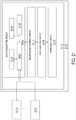
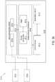
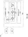
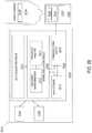
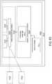
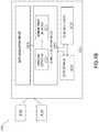
- the present disclosuredescribes a monitoring system for data collection
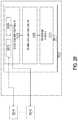
- the systemcan include a data acquisition circuit structured to interpret a plurality of detection values, each of the plurality of detection values corresponding to at least one of a plurality of input sensors communicatively coupled to the data acquisition circuit, a signal evaluation circuit including: a timer circuit structured to generate at least one timing signal, and a phase detection circuit structured to determine a relative phase difference between at least one of the plurality of detection values and the at least one timing signal from the timer circuit, and a response circuit structured to perform at least one operation in response to the relative phase difference.
- a further embodiment of any of the foregoing embodiments of the present disclosuremay include situations wherein the at least one operation is further in response to at least one of: a change in amplitude of at least one of the plurality of detection values, a change in frequency or relative phase of at least one of the plurality of detection values, a rate of change in both amplitude and relative phase of at least one the plurality of detection values, and a relative rate of change in amplitude and relative phase of at least one the plurality of detection values.
- a further embodiment of any of the foregoing embodiments of the present disclosuremay include situations wherein the at least one operation includes issuing an alert, wherein the alert includes at least one of: haptic, audible, and visual.
- a further embodiment of any of the foregoing embodiments of the present disclosuremay further include a data storage circuit structured to store the relative phase difference, at least one of the plurality of detection values, and the at least one timing signal.
- a further embodiment of any of the foregoing embodiments of the present disclosuremay include situations wherein the at least one operation further includes storing additional data in the data storage circuit.
- a further embodiment of any of the foregoing embodiments of the present disclosuremay include situations wherein storing additional data in the data storage circuit is further in response to at least one of: a change in the relative phase difference and a relative rate of change in the relative phase difference.
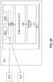
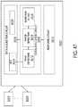
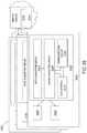
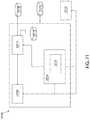
- a further embodiment of any of the foregoing embodiments of the present disclosuremay include situations wherein the data acquisition circuit further includes at least one multiplexer circuit (MUX) whereby alternative combinations of detection values are selected based on at least one of user input and a selected operating parameter for a machine, wherein each of the plurality of detection values corresponds to at least one of the plurality of input sensors.
- MUXmultiplexer circuit
- a further embodiment of any of the foregoing embodiments of the present disclosuremay include situations wherein the at least one operation includes at least one of: enabling or disabling one or more portions of a multiplexer circuit, or altering a multiplexer control line.
- a further embodiment of any of the foregoing embodiments of the present disclosuremay include situations wherein the data acquisition circuit includes at least two multiplexer circuits and the at least one operation includes changing connections between the at least two multiplexer circuits.
- a further embodiment of any of the foregoing embodiments of the present disclosuremay further include a MUX control circuit structured to interpret a subset of the plurality of detection values and provide a logical control of the MUX and a correspondence of MUX input and detected values as a result, wherein the logical control of the MUX includes adaptive scheduling of selected multiplexer control lines.
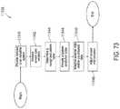
- the present disclosuredescribes a method for data collection, the method according to one disclosed non-limiting embodiment of the present disclosure can include interpreting, using a data acquisition circuit, a plurality of detection values, each of the plurality of detection values corresponding to at least one of a plurality of input sensors communicatively coupled to the data acquisition circuit, generating a timing signal based on a first detected value of the plurality of detection values, determining a relative phase difference between a second detection value of the plurality of detection values and the timing signal, and performing at least one operation in response to the relative phase difference.
- a further embodiment of any of the foregoing embodiments of the present disclosuremay include situations wherein the at least one operation is further in response to at least one of: a change in amplitude of at least one of the plurality of detection values, a change in frequency or relative phase of at least one of the plurality of detection values, a rate of change in both amplitude and relative phase of at least one the plurality of detection values, and a relative rate of change in amplitude and relative phase of at least one the plurality of detection values.
- a further embodiment of any of the foregoing embodiments of the present disclosuremay include situations wherein the at least one operation includes issuing an alert, wherein the alert includes at least one of: haptic, audible, and visual.
- a further embodiment of any of the foregoing embodiments of the present disclosuremay further include storing the relative phase difference and at least one of: the plurality of detection values or the timing signal.
- a further embodiment of any of the foregoing embodiments of the present disclosuremay further include storing additional data, in response to at least one of: a change in the relative phase difference or a rate of change in the relative phase difference.
- a further embodiment of any of the foregoing embodiments of the present disclosuremay include situations wherein additional data includes at least one of a list including: data at different sampling rates, data from a different location, data in a different direction, component loads, temperatures, pressures, and a vibration fingerprint for a component.
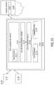
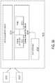
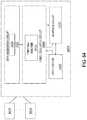
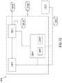
- the present disclosuredescribes a system for data collection in an industrial environment
- the systemcan include a data acquisition circuit structured to interpret a plurality of detection values, each of the plurality of detection values corresponding to at least one of a plurality of input sensors communicatively coupled to the data acquisition circuit, a signal evaluation circuit including: a timer circuit structured to generate a timing signal, and a phase detection circuit structured to determine a relative phase difference between at least one of the plurality of detection values and a signal from the timer circuit, and a response circuit structured to perform at least one operation in response to the relative phase difference.
- a further embodiment of any of the foregoing embodiments of the present disclosuremay further include a data storage facility for storing a subset of the plurality of detection values and the timing signal, a communication circuit structured to communicate at least one selected detection value and the timing signal to a remote server, and a monitoring application on the remote server structured to receive the at least one selected detection value and the timing signal, jointly analyze a subset of the at least one selected detection values received from a plurality of monitoring devices, and recommend an action.
- a further embodiment of any of the foregoing embodiments of the present disclosuremay further include a signal evaluation circuit structured to obtain at least one of a vibration amplitude, a vibration frequency, and a vibration phase location corresponding to a second detected value.
- a further embodiment of any of the foregoing embodiments of the present disclosuremay include situations wherein the response circuit is further structured to perform the at least one operation in response to at least one of the vibration amplitude, the vibration frequency, and the vibration phase location.
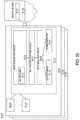
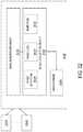
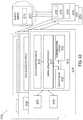
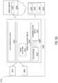
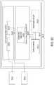
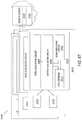
- the present disclosuredescribes a monitoring system for bearing analysis in an industrial environment
- the monitoring systemcan include a data acquisition circuit structured to interpret a plurality of detection values, each of the plurality of detection values corresponding to at least one of a plurality of input sensors communicatively coupled to the data acquisition circuit, a timer circuit structured to generate a timing signal a data storage for storing specifications and anticipated state information for a plurality of bearing types and buffering the plurality of detection values for a predetermined length of time, a timer circuit structured to generate a timing signal based on a first detected value of the plurality of detection values, and a bearing analysis circuit structured to analyze buffered detection values relative to specifications and anticipated state information resulting in a life prediction including: a phase detection circuit structured to determine a relative phase difference between a second detection value of the plurality of detection values and the timing signal, and a signal evaluation circuit structured to obtain at least one of a vibration amplitude, a vibration frequency, and a vibration phase location corresponding to
- a further embodiment of any of the foregoing embodiments of the present disclosuremay include situations wherein the at least one operation is further in response to at least one of: a change in amplitude of at least one of the plurality of detection values, a change in frequency or relative phase of at least one of the plurality of detection values, a rate of change in both amplitude and relative phase of at least one the plurality of detection values; and a relative rate of change in amplitude and relative phase of at least one the plurality of detection values.
- a further embodiment of any of the foregoing embodiments of the present disclosuremay include situations wherein the at least one operation includes issuing an alert, wherein the alert includes at least one of: haptic, audible, and visual.
- a further embodiment of any of the foregoing embodiments of the present disclosuremay further include storing the relative phase difference and at least one of: the plurality of detection values or the timing signal.
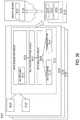
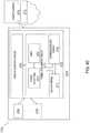
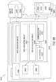
- the present disclosuredescribes a system for data collection in a vehicle
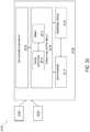
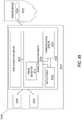
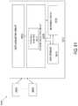
- the systemcan include a data acquisition circuit structured to interpret a plurality of detection values, each of the plurality of detection values corresponding to input received from at least one of a plurality of input sensors, each of the plurality of input sensors operatively coupled to at least one of a plurality of components of the vehicle, a data analysis circuit structured to determine a state value, wherein the data analysis circuit includes a pattern recognition circuit structured to determine the state value by analyzing a subset of the plurality of detection values and at least one external detection value using at least one of a neural net or an expert system, and an analysis response circuit structured to adjust a parameter of the vehicle in response to the state value.
- a further embodiment of any of the foregoing embodiments of the present disclosuremay include situations wherein the analysis response circuit is further structured to adjust a detection package in response to the state value, wherein the detection package includes a selection of available sensors utilized as the plurality of input sensors.
- a further embodiment of any of the foregoing embodiments of the present disclosuremay include situations wherein the detection package further includes a sensor parameter for at least one of the plurality of input sensors.
- a further embodiment of any of the foregoing embodiments of the present disclosuremay include situations wherein the state value includes at least one of: an off-nominal operation, a component failure, a component fault, and a component maintenance requirement and wherein the adjusting the detection package includes enhancing a resolution of the detection values in response to the state value.
- a further embodiment of any of the foregoing embodiments of the present disclosuremay include situations wherein enhancing the resolution of the detection values includes at least one of enhancing a sensor resolution, changing from a first input sensor to a second input sensor having a higher resolution capability than the first input sensor, and changing a data storage profile to enhance a resolution of stored data of the detection values.
- a further embodiment of any of the foregoing embodiments of the present disclosuremay include situations wherein the at least one of the neural net or the expert system performs a pattern recognition operation to determine the state value.
- a further embodiment of any of the foregoing embodiments of the present disclosuremay include situations wherein the pattern recognition operation is performed on vibration data of the plurality of detection values.
- a further embodiment of any of the foregoing embodiments of the present disclosuremay include situations wherein the at least one of the neural net or the expert system further compares the vibration data of the plurality of detection values to a library of noise patterns, wherein the library of noise patterns includes the at least one external data value.
- a further embodiment of any of the foregoing embodiments of the present disclosuremay include situations wherein the at least one of the neural net or the expert system is configured to at least intermittently access a self-organizing marketplace, and wherein the self-organizing marketplace provides the library of noise patterns.
- a further embodiment of any of the foregoing embodiments of the present disclosuremay include situations wherein the at least one of the neural net or the expert system is configured to provide at least a portion of the vibration data to the self-organizing marketplace.
- the present disclosuredescribes a method, according to one disclosed non-limiting embodiment of the present disclosure, the method can include interpreting a plurality of detection values of a vehicle, each of the plurality of detection values corresponding to input received from at least one of a plurality of input sensors, each of the plurality of input sensors operatively coupled to at least one component of the vehicle, operating at least one of a neural net or an expert system on the plurality of detection values to determine a state value for at least one of a component or the vehicle and adjusting at least one of a sensing parameter or a data storage profile in response to the state value.
- a further embodiment of any of the foregoing embodiments of the present disclosuremay include situations wherein the state value includes at least one of: an off-nominal operation, a component failure, a component fault, and a component maintenance requirement, and wherein the adjusting the at least one of the sensing parameter or the data storage profile includes enhancing a resolution of the detection values in response to the state value.
- a further embodiment of any of the foregoing embodiments of the present disclosuremay include situations wherein the at least one of the neural net or the expert system performs a pattern recognition operation to determine the state value.
- a further embodiment of any of the foregoing embodiments of the present disclosuremay include situations wherein the at least one of the neural net or the expert system accesses external data value from a self-organizing marketplace, and further determines the state value in response to the external data.
- a further embodiment of any of the foregoing embodiments of the present disclosuremay include situations wherein the external data value includes a library of noise patterns.
- a further embodiment of any of the foregoing embodiments of the present disclosuremay include situations wherein the library of noise patterns includes a vibration fingerprint for a component of the vehicle.
- the apparatuscan include a data acquisition circuit structured to interpret a plurality of detection values, each of the plurality of detection values corresponding to input received from at least one of a plurality of input sensors, each of the plurality of input sensors operatively coupled to at least one of a plurality of components of a vehicle, a data analysis circuit structured to determine a state value, wherein the data analysis circuit includes a pattern recognition circuit structured to determine the state value by performing a pattern recognition operation on a subset of the plurality of detection values and at least one external detection value using at least one of a neural net or an expert system and an analysis response circuit structured to adjust a parameter of the vehicle in response to the state value.
- a further embodiment of any of the foregoing embodiments of the present disclosuremay include situations wherein the adjusting the parameter of the vehicle includes adjusting operations of the vehicle to reduce a work load on a component of the vehicle.
- a further embodiment of any of the foregoing embodiments of the present disclosuremay include situations wherein the state value includes a normal operating state for a component of the vehicle, and wherein the adjusting the parameter of the vehicle includes reducing an amount of data of the plurality of detection values that is stored relating to the component of the vehicle.
- a further embodiment of any of the foregoing embodiments of the present disclosuremay include situations wherein the state value includes, for a component of the vehicle, at least one of: an off-nominal operation, a failure, a fault, or a maintenance requirement, and wherein the adjusting the parameter of the vehicle includes increasing an amount of data of the plurality of detection values that is stored relating to the component of the vehicle.
- Methods and systemsare provided herein for data collection in industrial environments, as well as for improved methods and systems for using collected data to provide improved monitoring, control, and intelligent diagnosis of problems and intelligent optimization of operations in various heavy industrial environments.
- These methods and systemsinclude methods, systems, components, devices, workflows, services, processes, and the like that are deployed in various configurations and locations, such as: (a) at the “edge” of the Internet of Things, such as in the local environment of a heavy industrial machine; (b) in data transport networks that move data between local environments of heavy industrial machines and other environments, such as of other machines or of remote controllers, such as enterprises that own or operate the machines or the facilities in which the machines are operated; and (c) in locations where facilities are deployed to control machines or their environments, such as cloud-computing environments and on-premises computing environments of enterprises that own or control heavy industrial environments or the machines, devices or systems deployed in them.
- These methods and systemsinclude a range of ways for providing improved data include a range of methods and systems for providing improved data collection, as well as methods and systems
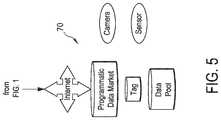
- Methods and systemsare disclosed herein for continuous ultrasonic monitoring, including providing continuous ultrasonic monitoring of rotating elements and bearings of an energy production facility; for cloud-based systems including machine pattern recognition based on the fusion of remote, analog industrial sensors or machine pattern analysis of state information from multiple analog industrial sensors to provide anticipated state information for an industrial system; for on-device sensor fusion and data storage for industrial IoT devices, including on-device sensor fusion and data storage for an Industrial IoT device, where data from multiple sensors are multiplexed at the device for storage of a fused data stream; and for self-organizing systems including a self-organizing data marketplace for industrial IoT data, including a self-organizing data marketplace for industrial IoT data, where available data elements are organized in the marketplace for consumption by consumers based on training a self-organizing facility with a training set and feedback from measures of marketplace success, for self-organizing data pools, including self-organization of data pools based on utilization and/or yield metrics, including utilization and/or yield metrics that are tracked for a plurality
- AIartificial intelligence
- an AI modelbased on industry-specific feedback that reflects a measure of utilization, yield, or impact
- the AI modeloperates on sensor data from an industrial environment
- an industrial IoT distributed ledgerincluding a distributed ledger supporting the tracking of transactions executed in an automated data marketplace for industrial IoT data
- for a network-sensitive collectorincluding a network condition-sensitive, self-organizing, multi-sensor data collector that can optimize based on bandwidth, quality of service, pricing, and/or other network conditions
- a remotely organized universal data collectorthat can power up and down sensor interfaces based on need and/or conditions identified in an industrial data collection environment
- a haptic or multi-sensory user interfaceincluding a wearable haptic or multi-sensory user interface for an industrial sensor data collector, with vibration, heat, electrical, and/or sound outputs.
- Methods and systemsare disclosed herein for a presentation layer for augmented reality and virtual reality (AR/VR) industrial glasses, where heat map elements are presented based on patterns and/or parameters in collected data; and for condition-sensitive, self-organized tuning of AR/VR interfaces based on feedback metrics and/or training in industrial environments.
- AR/VRaugmented reality and virtual reality
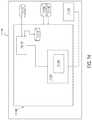
- a system for data collection, processing, and utilization of signals from at least a first element in a first machine in an industrial environmentincludes a platform including a computing environment connected to a local data collection system having at least a first sensor signal and a second sensor signal obtained from at least the first machine in the industrial environment.
- the systemincludes a first sensor in the local data collection system configured to be connected to the first machine and a second sensor in the local data collection system.
- the systemfurther includes a crosspoint switch in the local data collection system having multiple inputs and multiple outputs including a first input connected to the first sensor and a second input connected to the second sensor.
- a multi-sensor acquisition deviceincludes one or more channels configured for, or compatible with, an analog sensor input.
- the multiple outputsinclude a first output and second output configured to be switchable between a condition in which the first output is configured to switch between delivery of the first sensor signal and the second sensor signal and a condition in which there is simultaneous delivery of the first sensor signal from the first output and the second sensor signal from the second output.
- Each of multiple inputsis configured to be individually assigned to any of the multiple outputs, or combined in any subsets of the inputs to the outputs. Unassigned outputs are configured to be switched off, for example by producing a high-impedance state.
- the first sensor signal and the second sensor signalare continuous vibration data about the industrial environment.
- the second sensor in the local data collection systemis configured to be connected to the first machine.
- the second sensor in the local data collection systemis configured to be connected to a second machine in the industrial environment.
- the computing environment of the platformis configured to compare relative phases of the first and second sensor signals.
- the first sensoris a single-axis sensor and the second sensor is a three-axis sensor.
- at least one of the multiple inputs of the crosspoint switchincludes internet protocol, front-end signal conditioning, for improved signal-to-noise ratio.
- the crosspoint switchincludes a third input that is configured with a continuously monitored alarm having a pre-determined trigger condition when the third input is unassigned to or undetected at any of the multiple outputs.
- the local data collection systemincludes multiple multiplexing units and multiple data acquisition units receiving multiple data streams from multiple machines in the industrial environment.
- the local data collection systemincludes distributed complex programmable hardware device (“CPLD”) chips each dedicated to a data bus for logic control of the multiple multiplexing units and the multiple data acquisition units that receive the multiple data streams from the multiple machines in the industrial environment.
- CPLDcomplex programmable hardware device
- the local data collection systemis configured to provide high-amperage input capability using solid state relays.
- the local data collection systemis configured to power-down at least one of an analog sensor channel and a component board.
- the local data collection systemincludes a phase-lock loop band-pass tracking filter configured to obtain slow-speed revolutions per minute (“RPMs”) and phase information.
- RPMsrevolutions per minute
- the local data collection systemis configured to digitally derive phase using on-board timers relative to at least one trigger channel and at least one of the multiple inputs.
- the local data collection systemincludes a peak-detector configured to autoscale using a separate analog-to-digital converter for peak detection.
- the local data collection systemis configured to route at least one trigger channel that is raw and buffered into at least one of the multiple inputs.
- the local data collection systemincludes at least one delta-sigma analog-to-digital converter that is configured to increase input oversampling rates to reduce sampling rate outputs and to minimize anti-aliasing filter requirements.
- the distributed CPLD chips each dedicated to the data bus for logic control of the multiple multiplexing units and the multiple data acquisition unitsincludes as high-frequency crystal clock reference configured to be divided by at least one of the distributed CPLD chips for at least one delta-sigma analog-to-digital converter to achieve lower sampling rates without digital resampling.
- the local data collection systemis configured to obtain long blocks of data at a single relatively high-sampling rate as opposed to multiple sets of data taken at different sampling rates.
- the single relatively high-sampling ratecorresponds to a maximum frequency of about forty kilohertz.
- the long blocks of dataare for a duration that is in excess of one minute.
- the local data collection systemincludes multiple data acquisition units each having an onboard card set configured to store calibration information and maintenance history of a data acquisition unit in which the onboard card set is located.
- the local data collection systemis configured to plan data acquisition routes based on hierarchical templates.
- the local data collection systemis configured to manage data collection bands.
- the data collection bandsdefine a specific frequency band and at least one of a group of spectral peaks, a true-peak level, a crest factor derived from a time waveform, and an overall waveform derived from a vibration envelope.
- the local data collection systemincludes a neural net expert system using intelligent management of the data collection bands.
- the local data collection systemis configured to create data acquisition routes based on hierarchical templates that each include the data collection bands related to machines associated with the data acquisition routes. In embodiments, at least one of the hierarchical templates is associated with multiple interconnected elements of the first machine.
- At least one of the hierarchical templatesis associated with similar elements associated with at least the first machine and a second machine. In embodiments, at least one of the hierarchical templates is associated with at least the first machine being proximate in location to a second machine.
- the local data collection systemincludes a graphical user interface (“GUI”) system configured to manage the data collection bands.
- GUIgraphical user interface
- the GUI systemincludes an expert system diagnostic tool.
- the platformincludes cloud-based, machine pattern analysis of state information from multiple sensors to provide anticipated state information for the industrial environment.
- the platformis configured to provide self-organization of data pools based on at least one of the utilization metrics and yield metrics.
- the platformincludes a self-organized swarm of industrial data collectors.
- the local data collection systemincludes a wearable haptic user interface for an industrial sensor data collector with at least one of vibration, heat, electrical, and sound outputs.
- multiple inputs of the crosspoint switchinclude a third input connected to the second sensor and a fourth input connected to the second sensor.
- the first sensor signalis from a single-axis sensor at an unchanging location associated with the first machine.
- the second sensoris a three-axis sensor.
- the local data collection systemis configured to record gap-free digital waveform data simultaneously from at least the first input, the second input, the third input, and the fourth input.
- the platformis configured to determine a change in relative phase based on the simultaneously recorded gap-free digital waveform data.
- the second sensoris configured to be movable to a plurality of positions associated with the first machine while obtaining the simultaneously recorded gap-free digital waveform data.
- multiple outputs of the crosspoint switchinclude a third output and fourth output.
- the second, third, and fourth outputsare assigned together to a sequence of tri-axial sensors each located at different positions associated with the machine.
- the platformis configured to determine an operating deflection shape based on the change in relative phase and the simultaneously recorded gap-free digital waveform data.
- the unchanging locationis a position associated with the rotating shaft of the first machine.
- tri-axial sensors in the sequence of the tri-axial sensorsare each located at different positions on the first machine but are each associated with different bearings in the machine.
- tri-axial sensors in the sequence of the tri-axial sensorsare each located at similar positions associated with similar bearings but are each associated with different machines.
- the local data collection systemis configured to obtain the simultaneously recorded gap-free digital waveform data from the first machine while the first machine and a second machine are both in operation.
- the local data collection systemis configured to characterize a contribution from the first machine and the second machine in the simultaneously recorded gap-free digital waveform data from the first machine.
- the simultaneously recorded gap-free digital waveform datahas a duration that is in excess of one minute.
- a method of monitoring a machine having at least one shaft supported by a set of bearingsincludes monitoring a first data channel assigned to a single-axis sensor at an unchanging location associated with the machine.
- the methodincludes monitoring second, third, and fourth data channels each assigned to an axis of a three-axis sensor.
- the methodincludes recording gap-free digital waveform data simultaneously from all of the data channels while the machine is in operation and determining a change in relative phase based on the digital waveform data.
- the tri-axial sensoris located at a plurality of positions associated with the machine while obtaining the digital waveform.
- the second, third, and fourth channelsare assigned together to a sequence of tri-axial sensors each located at different positions associated with the machine.
- the datais received from all of the sensors simultaneously.
- the methodincludes determining an operating deflection shape based on the change in relative phase information and the waveform data.
- the unchanging locationis a position associated with the shaft of the machine.
- the tri-axial sensors in the sequence of the tri-axial sensorsare each located at different positions and are each associated with different bearings in the machine.
- the unchanging locationis a position associated with the shaft of the machine.
- the tri-axial sensors in the sequence of the tri-axial sensorsare each located at different positions and are each associated with different bearings that support the shaft in the machine.
- the methodincludes monitoring the first data channel assigned to the single-axis sensor at an unchanging location located on a second machine.
- the methodincludes monitoring the second, the third, and the fourth data channels, each assigned to the axis of a three-axis sensor that is located at the position associated with the second machine.
- the methodalso includes recording gap-free digital waveform data simultaneously from all of the data channels from the second machine while both of the machines are in operation.
- the methodincludes characterizing the contribution from each of the machines in the gap-free digital waveform data simultaneously from the second machine.
- a method for data collection, processing, and utilization of signals with a platform monitoring at least a first element in a first machine in an industrial environmentincludes obtaining, automatically with a computing environment, at least a first sensor signal and a second sensor signal with a local data collection system that monitors at least the first machine.
- the methodincludes connecting a first input of a crosspoint switch of the local data collection system to a first sensor and a second input of the crosspoint switch to a second sensor in the local data collection system.
- the methodincludes switching between a condition in which a first output of the crosspoint switch alternates between delivery of at least the first sensor signal and the second sensor signal and a condition in which there is simultaneous delivery of the first sensor signal from the first output and the second sensor signal from a second output of the crosspoint switch.
- the methodalso includes switching off unassigned outputs of the crosspoint switch into a high-impedance state.
- the first sensor signal and the second sensor signalare continuous vibration data from the industrial environment.
- the second sensor in the local data collection systemis connected to the first machine.
- the second sensor in the local data collection systemis connected to a second machine in the industrial environment.
- the methodincludes comparing, automatically with the computing environment, relative phases of the first and second sensor signals.
- the first sensoris a single-axis sensor and the second sensor is a three-axis sensor.
- at least the first input of the crosspoint switchincludes internet protocol front-end signal conditioning for improved signal-to-noise ratio.
- the methodincludes continuously monitoring at least a third input of the crosspoint switch with an alarm having a pre-determined trigger condition when the third input is unassigned to any of multiple outputs on the crosspoint switch.
- the local data collection systemincludes multiple multiplexing units and multiple data acquisition units receiving multiple data streams from multiple machines in the industrial environment.
- the local data collection systemincludes distributed CPLD chips each dedicated to a data bus for logic control of the multiple multiplexing units and the multiple data acquisition units that receive the multiple data streams from the multiple machines in the industrial environment.
- the local data collection systemprovides high-amperage input capability using solid state relays.
- the methodincludes powering down at least one of an analog sensor channel and a component board of the local data collection system.
- the local data collection systemincludes an external voltage reference for an A/D zero reference that is independent of the voltage of the first sensor and the second sensor.
- the local data collection systemincludes a phase-lock loop band-pass tracking filter that obtains slow-speed RPMs and phase information.
- the methodincludes digitally deriving phase using on-board timers relative to at least one trigger channel and at least one of multiple inputs on the crosspoint switch.
- the methodincludes auto-scaling with a peak-detector using a separate analog-to-digital converter for peak detection.
- the methodincludes routing at least one trigger channel that is raw and buffered into at least one of multiple inputs on the crosspoint switch.
- the methodincludes increasing input oversampling rates with at least one delta-sigma analog-to-digital converter to reduce sampling rate outputs and to minimize anti-aliasing filter requirements.
- the distributed CPLD chipsare each dedicated to the data bus for logic control of the multiple multiplexing units and the multiple data acquisition units and each include a high-frequency crystal clock reference divided by at least one of the distributed CPLD chips for at least one delta-sigma analog-to-digital converter to achieve lower sampling rates without digital resampling.
- the methodincludes obtaining long blocks of data at a single relatively high-sampling rate with the local data collection system as opposed to multiple sets of data taken at different sampling rates.
- the single relatively high-sampling ratecorresponds to a maximum frequency of about forty kilohertz.
- the long blocks of dataare for a duration that is in excess of one minute.
- the local data collection systemincludes multiple data acquisition units and each data acquisition unit has an onboard card set that stores calibration information and maintenance history of a data acquisition unit in which the onboard card set is located.
- the methodincludes planning data acquisition routes based on hierarchical templates associated with at least the first element in the first machine in the industrial environment.
- the local data collection systemmanages data collection bands that define a specific frequency band and at least one of a group of spectral peaks, a true-peak level, a crest factor derived from a time waveform, and an overall waveform derived from a vibration envelope.
- the local data collection systemincludes a neural net expert system using intelligent management of the data collection bands.
- the local data collection systemcreates data acquisition routes based on hierarchical templates that each include the data collection bands related to machines associated with the data acquisition routes.
- at least one of the hierarchical templatesis associated with multiple interconnected elements of the first machine.
- At least one of the hierarchical templatesis associated with similar elements associated with at least the first machine and a second machine. In embodiments, at least one of the hierarchical templates is associated with at least the first machine being proximate in location to a second machine.
- the methodincludes controlling a GUI system of the local data collection system to manage the data collection bands.
- the GUI systemincludes an expert system diagnostic tool.
- the computing environment of the platformincludes cloud-based, machine pattern analysis of state information from multiple sensors to provide anticipated state information for the industrial environment.
- the computing environment of the platformprovides self-organization of data pools based on at least one of the utilization metrics and yield metrics.
- the computing environment of the platformincludes a self-organized swarm of industrial data collectors.
- each of multiple inputs of the crosspoint switchis individually assignable to any of multiple outputs of the crosspoint switch.
- Methods and systems described herein for industrial machine sensor data streaming, collection, processing, and storagemay be configured to operate and integrate with existing data collection, processing and storage systems and may include a method for capturing a plurality of streams of sensed data from sensors deployed to monitor aspects of an industrial machine associated with at least one moving part of the machine; at least one of the streams contains a plurality of frequencies of data.
- the methodmay include identifying a subset of data in at least one of the plurality of streams that corresponds to data representing at least one predefined frequency.
- the at least one predefined frequencyis represented by a set of data collected from alternate sensors deployed to monitor aspects of the industrial machine associated with the at least one moving part of the machine.
- the methodmay further include processing the identified data with a data processing facility that processes the identified data with an algorithm configured to be applied to the set of data collected from alternate sensors. Lastly, the method may include storing the at least one of the streams of data, the identified subset of data, and a result of processing the identified data in an electronic data set.
- Methods and systems described herein for industrial machine sensor data streaming, collection, processing, and storagemay be configured to operate and integrate with existing data collection, processing, and storage systems and may include a method for applying data captured from sensors deployed to monitor aspects of an industrial machine associated with at least one moving part of the machine.
- the datais captured with predefined lines of resolution covering a predefined frequency range and is sent to a frequency matching facility that identifies a subset of data streamed from other sensors deployed to monitor aspects of the industrial machine associated with at least one moving part of the machine.
- the streamed dataincludes a plurality of lines of resolution and frequency ranges. The subset of data identified corresponds to the lines of resolution and predefined frequency range.
- This methodmay include storing the subset of data in an electronic data record in a format that corresponds to a format of the data captured with predefined lines of resolution and signaling to a data processing facility the presence of the stored subset of data.
- This methodmay, optionally, include processing the subset of data with at least one set of algorithms, models and pattern recognizers that corresponds to algorithms, models and pattern recognizers associated with processing the data captured with predefined lines of resolution covering a predefined frequency range.
- Methods and systems described herein for industrial machine sensor data streaming, collection, processing, and storagemay be configured to operate and integrate with existing data collection, processing and storage systems and may include a method for identifying a subset of streamed sensor data, the sensor data captured from sensors deployed to monitor aspects of an industrial machine associated with at least one moving part of the machine, the subset of streamed sensor data at predefined lines of resolution for a predefined frequency range, and establishing a first logical route for communicating electronically between a first computing facility performing the identifying and a second computing facility, wherein identified subset of the streamed sensor data is communicated exclusively over the established first logical route when communicating the subset of streamed sensor data from the first facility to the second facility.
- This methodmay further include establishing a second logical route for communicating electronically between the first computing facility and the second computing facility for at least one portion of the streamed sensor data that is not the identified subset. Additionally, this method may further include establishing a third logical route for communicating electronically between the first computing facility and the second computing facility for at least one portion of the streamed sensor data that includes the identified subset and at least one other portion of the data not represented by the identified subset.
- Methods and systems described herein for industrial machine sensor data streaming, collection, processing, and storagemay be configured to operate and integrate with existing data collection, processing and storage systems and may include a first data sensing and processing system that captures first data from a first set of sensors deployed to monitor aspects of an industrial machine associated with at least one moving part of the machine, the first data covering a set of lines of resolution and a frequency range.
- This systemmay include a second data sensing and processing system that captures and streams a second set of data from a second set of sensors deployed to monitor aspects of the industrial machine associated with at least one moving part of the machine, the second data covering a plurality of lines of resolution that includes the set of lines of resolution and a plurality of frequencies that includes the frequency range.
- the systemmay enable selecting a portion of the second data that corresponds to the set of lines of resolution and the frequency range of the first data, and processing the selected portion of the second data with the first data sensing and processing system.
- Methods and systems described herein for industrial machine sensor data streaming, collection, processing, and storagemay be configured to operate and integrate with existing data collection, processing and storage systems and may include a method for automatically processing a portion of a stream of sensed data.
- the sensed datais received from a first set of sensors deployed to monitor aspects of an industrial machine associated with at least one moving part of the machine.
- the sensed datais in response to an electronic data structure that facilitates extracting a subset of the stream of sensed data that corresponds to a set of sensed data received from a second set of sensors deployed to monitor the aspects of the industrial machine associated with the at least one moving part of the machine.
- the set of sensed datais constrained to a frequency range.
- the stream of sensed dataincludes a range of frequencies that exceeds the frequency range of the set of sensed data, the processing comprising executing an algorithm on a portion of the stream of sensed data that is constrained to the frequency range of the set of sensed data, the algorithm configured to process the set of sensed data.
- Methods and systems described herein for industrial machine sensor data streaming, collection, processing, and storagemay be configured to operate and integrate with existing data collection, processing and storage systems and may include a method for receiving first data from sensors deployed to monitor aspects of an industrial machine associated with at least one moving part of the machine. This method may further include detecting at least one of a frequency range and lines of resolution represented by the first data; receiving a stream of data from sensors deployed to monitor the aspects of the industrial machine associated with the at least one moving part of the machine.
- the stream of dataincludes: (1) a plurality of frequency ranges and a plurality of lines of resolution that exceeds the frequency range and the lines of resolution represented by the first data; (2) a set of data extracted from the stream of data that corresponds to at least one of the frequency range and the lines of resolution represented by the first data; and (3) the extracted set of data which is processed with a data processing algorithm that is configured to process data within the frequency range and within the lines of resolution of the first data.
- FIG. 1 through FIG. 5are diagrammatic views that each depicts portions of an overall view of an industrial Internet of Things (IoT) data collection, monitoring and control system in accordance with the present disclosure.
- IoTInternet of Things
- FIG. 6is a diagrammatic view of a platform including a local data collection system disposed in an industrial environment for collecting data from or about the elements of the environment, such as machines, components, systems, sub-systems, ambient conditions, states, workflows, processes, and other elements in accordance with the present disclosure.
- FIG. 7is a diagrammatic view that depicts elements of an industrial data collection system for collecting analog sensor data in an industrial environment in accordance with the present disclosure.
- FIG. 8is a diagrammatic view of a rotating or oscillating machine having a data acquisition module that is configured to collect waveform data in accordance with the present disclosure.
- FIG. 9is a diagrammatic view of an exemplary tri-axial sensor mounted to a motor bearing of an exemplary rotating machine in accordance with the present disclosure.
- FIG. 10 and FIG. 11are diagrammatic views of an exemplary tri-axial sensor and a single-axis sensor mounted to an exemplary rotating machine in accordance with the present disclosure.
- FIG. 12is a diagrammatic view of multiple machines under survey with ensembles of sensors in accordance with the present disclosure.
- FIG. 13is a diagrammatic view of hybrid relational metadata and a binary storage approach in accordance with the present disclosure.
- FIG. 14 through FIG. 18are diagrammatic view of components and interactions of a data collection architecture involving data channel methods and systems for data collection of industrial machines in accordance with the present disclosure.
- FIG. 19is a diagrammatic view that depicts embodiments of a data monitoring device in accordance with the present disclosure.
- FIG. 20 and FIG. 21are diagrammatic views that depict embodiments of a data monitoring device in accordance with the present disclosure.
- FIG. 22is a diagrammatic view that depicts embodiments of a data monitoring device in accordance with the present disclosure.
- FIGS. 23 and 24are diagrammatic views that depict an embodiment of a system for data collection in accordance with the present disclosure.
- FIGS. 25 and 26are diagrammatic views that depict an embodiment of a system for data collection comprising a plurality of data monitoring devices in accordance with the present disclosure.
- FIG. 27depicts an embodiment of a data monitoring device incorporating sensors in accordance with the present disclosure.
- FIGS. 28 and 29are diagrammatic views that depict embodiments of a data monitoring device in communication with external sensors in accordance with the present disclosure.
- FIG. 30is a diagrammatic view that depicts embodiments of a data monitoring device with additional detail in the signal evaluation circuit in accordance with the present disclosure.
- FIG. 31is a diagrammatic view that depicts embodiments of a data monitoring device with additional detail in the signal evaluation circuit in accordance with the present disclosure.
- FIG. 32is a diagrammatic view that depicts embodiments of a data monitoring device with additional detail in the signal evaluation circuit in accordance with the present disclosure.
- FIG. 33is a diagrammatic view that depicts embodiments of a system for data collection in accordance with the present disclosure.
- FIG. 34is a diagrammatic view that depicts embodiments of a system for data collection comprising a plurality of data monitoring devices in accordance with the present disclosure.
- FIG. 35is a diagrammatic view that depicts embodiments of a data monitoring device in accordance with the present disclosure.
- FIGS. 36 and 37are diagrammatic views that depict embodiments of a data monitoring device in accordance with the present disclosure.
- FIGS. 38 and 39are diagrammatic views that depict embodiments of a data monitoring device in accordance with the present disclosure.
- FIGS. 40 and 41are diagrammatic views that depict embodiments of a data monitoring device in accordance with the present disclosure.
- FIGS. 42 and 43is a diagrammatic view that depicts embodiments of a system for data collection comprising a plurality of data monitoring devices in accordance with the present disclosure.
- FIG. 44is a diagrammatic view that depicts embodiments of a data monitoring device in accordance with the present disclosure.
- FIGS. 45 and 46are diagrammatic views that depict embodiments of a data monitoring device in accordance with the present disclosure.
- FIG. 47is a diagrammatic view that depicts embodiments of a data monitoring device in accordance with the present disclosure.
- FIG. 48is a diagrammatic view that depicts embodiments of a data monitoring device in accordance with the present disclosure.
- FIGS. 49 and 50are diagrammatic views that depict embodiments of a system for data collection in accordance with the present disclosure.
- FIGS. 51 and 52are diagrammatic views that depict embodiments of a system for data collection comprising a plurality of data monitoring devices in accordance with the present disclosure.
- FIG. 53is a diagrammatic view that depicts embodiments of a data monitoring device in accordance with the present disclosure.
- FIGS. 54 and 55are diagrammatic views that depict embodiments of a data monitoring device in accordance with the present disclosure.
- FIG. 56is a diagrammatic view that depicts embodiments of a data monitoring device in accordance with the present disclosure.
- FIGS. 57 and 58are diagrammatic views that depict embodiments of a system for data collection in accordance with the present disclosure.
- FIGS. 59 and 60are diagrammatic views that depict embodiments of a system for data collection comprising a plurality of data monitoring devices in accordance with the present disclosure.
- FIG. 61is a diagrammatic view that depicts embodiments of a data monitoring device in accordance with the present disclosure.
- FIGS. 62 and 63are diagrammatic views that depict embodiments of a data monitoring device in accordance with the present disclosure.
- FIG. 64is a diagrammatic view that depicts embodiments of a data monitoring device in accordance with the present disclosure.
- FIGS. 65 and 66are diagrammatic views that depict embodiments of a system for data collection in accordance with the present disclosure.
- FIGS. 67 and 68are diagrammatic views that depict embodiments of a system for data collection comprising a plurality of data monitoring devices in accordance with the present disclosure.
- FIG. 69is a diagrammatic view that depicts embodiments of a data monitoring device in accordance with the present disclosure.
- FIG. 70is a diagrammatic view that depicts embodiments of a data monitoring device in accordance with the present disclosure.
- FIG. 71is a diagrammatic view that depicts a monitoring system that employs data collection bands in accordance with the present disclosure.
- FIG. 72is a diagrammatic view that depicts a system that employs vibration and other noise in predicting states and outcomes in accordance with the present disclosure.
- FIG. 73is a schematic flow diagram of a procedure for data collection in an industrial environment in accordance with the present disclosure.
- FIG. 74is a diagrammatic view that depicts industry-specific feedback in an industrial environment in accordance with the present disclosure.
- FIG. 75is a diagrammatic view that depicts an exemplary user interface for smart band configuration of a system for data collection in an industrial environment is depicted in accordance with the present disclosure.
- FIG. 76is a diagrammatic view that depicts a graphical approach 11300 for back-calculation in accordance with the present disclosure.
- FIG. 77is a diagrammatic view that depicts a wearable haptic user interface device for providing haptic stimuli to a user that is responsive to data collected in an industrial environment by a system adapted to collect data in the industrial environment in accordance with the present disclosure.
- FIG. 78is a diagrammatic view that depicts an augmented reality display of heat maps based on data collected in an industrial environment by a system adapted to collect data in the environment in accordance with the present disclosure.
- FIG. 79is a diagrammatic view that depicts an augmented reality display including real time data overlaying a view of an industrial environment in accordance with the present disclosure.
- FIG. 80is a diagrammatic view that depicts data collection system according to some aspects of the present disclosure.
- FIG. 81is a diagrammatic view that depicts embodiments of a storage time definition in accordance with the present disclosure.
- FIG. 82is a diagrammatic view that depicts embodiments of a data resolution description in accordance with the present disclosure.
- FIG. 83is a diagrammatic view of an apparatus for self-organizing network coding for data collection for an industrial system in accordance with the present disclosure.
- Methods and systems described herein for industrial machine sensor data streaming, collection, processing, and storagemay be configured to operate with existing data collection, processing, and storage systems while preserving access to existing format/frequency range/resolution compatible data. While the industrial machine sensor data streaming facilities described herein may collect a greater volume of data (e.g., longer duration of data collection) from sensors at a wider range of frequencies and with greater resolution than existing data collection systems, methods and systems may be employed to provide access to data from the stream of data that represents one or more ranges of frequency and/or one or more lines of resolution that are purposely compatible with existing systems.
- a portion of the streamed datamay be identified, extracted, stored, and/or forwarded to existing data processing systems to facilitate operation of existing data processing systems that substantively matches operation of existing data processing systems using existing collection-based data.
- a newly deployed system for sensing aspects of industrial machinessuch as aspects of moving parts of industrial machines, may facilitate continued use of existing sensed data processing facilities, algorithms, models, pattern recognizers, user interfaces, and the like.
- higher resolution streamed datamay be configured to represent a specific frequency, frequency range, format, and/or resolution.
- This configured streamed datacan be stored in a data structure that is compatible with existing sensed data structures so that existing processing systems and facilities can access and process the data substantially as if it were the existing data.
- One approach to adapting streamed data for compatibility with existing sensed datamay include aligning the streamed data with existing data so that portions of the streamed data that align with the existing data can be extracted, stored, and made available for processing with existing data processing methods.
- data processing methodsmay be configured to process portions of the streamed data that correspond, such as through alignment, to the existing data, with methods that implement functions substantially similar to the methods used to process existing data, such as methods that process data that contain a particular frequency range or a particular resolution and the like.
- Methods used to process existing datamay be associated with certain characteristics of sensed data, such as certain frequency ranges, sources of data, and the like.
- methods for processing bearing sensing information for a moving part of an industrial machinemay be capable of processing data from bearing sensors that fall into a particular frequency range. This method can thusly be at least partially identifiable by these characteristics of the data being processed. Therefore, given a set of conditions, such as moving device being sensed, industrial machine type, frequency of data being sensed, and the like, a data processing system may select an appropriate method. Also, given such a set of conditions, an industrial machine data sensing and processing facility may configure elements, such as data filters, routers, processors, and the like, to handle data meeting the conditions.
- FIGS. 1 through 5depict portions of an overall view of an industrial Internet of Things (IoT) data collection, monitoring and control system 10 .
- FIG. 2depicts a mobile ad hoc network (“MANET”) 20 , which may form a secure, temporal network connection 22 (sometimes connected and sometimes isolated), with a cloud 30 or other remote networking system, so that network functions may occur over the MANET 20 within the environment, without the need for external networks, but at other times information can be sent to and from a central location.
- MANETmobile ad hoc network
- Thisallows the industrial environment to use the benefits of networking and control technologies, while also providing security, such as preventing cyber-attacks.
- the MANET 20may use cognitive radio technologies 40 , including those that form up an equivalent to the IP protocol, such as router 42 , MAC 44 , and physical layer technologies 46 .
- the system depicted in FIGS. 1 through 5provides network-sensitive or network-aware transport of data over the network to and from a data collection device or a heavy industrial machine.
- FIGS. 3-4depict intelligent data collection technologies deployed locally, at the edge of an IoT deployment, where heavy industrial machines are located.
- Interfaces for data collectionincluding multi-sensory interfaces, tablets, smartphones 58 , and the like are shown.
- FIG. 3also shows data pools 60 that may collect data published by machines or sensors that detect conditions of machines, such as for later consumption by local or remote intelligence.
- a distributed ledger system 62may distribute storage across the local storage of various elements of the environment, or more broadly throughout the system.
- on-device sensor fusion 80such as for storing on a device data from multiple analog sensors 82 , which may be analyzed locally or in the cloud, such as by machine learning 84 , including by training a machine based on initial models created by humans that are augmented by providing feedback (such as based on measures of success) when operating the methods and systems disclosed herein.
- FIG. 1depicts a server based portion of an industrial IoT system that may be deployed in the cloud or on an enterprise owner's or operator's premises.
- the server portionincludes network coding (including self-organizing network coding and/or automated configuration) that may configure a network coding model based on feedback measures, network conditions, or the like, for highly efficient transport of large amounts of data across the network to and from data collection systems and the cloud.
- Network codingmay provide a wide range of capabilities for intelligence, analytics, remote control, remote operation, remote optimization, various storage configurations and the like, as depicted in FIG. 1 .
- the various storage configurationsmay include distributed ledger storage for supporting transactional data or other elements of the system.
- FIG. 5depicts a programmatic data marketplace 70 , which may be a self-organizing marketplace, such as for making available data that is collected in industrial environments, such as from data collectors, data pools, distributed ledgers, and other elements disclosed herein. Additional detail on the various components and sub-components of FIGS. 1 through 5 is provided throughout this disclosure.
- an embodiment of platform 100may include a local data collection system 102 , which may be disposed in an environment 104 , such as an industrial environment similar to that shown in FIG. 3 , for collecting data from or about the elements of the environment, such as machines, components, systems, sub-systems, ambient conditions, states, workflows, processes, and other elements.
- the platform 100may connect to or include portions of the industrial IoT data collection, monitoring and control system 10 depicted in FIGS. 1-5 .
- the platform 100may include a network data transport system 108 , such as for transporting data to and from the local data collection system 102 over a network 110 , such as to a host processing system 112 , such as one that is disposed in a cloud computing environment or on the premises of an enterprise, or that consists of distributed components that interact with each other to process data collected by the local data collection system 102 .
- the host processing system 112referred to for convenience in some cases as the host system 112 , may include various systems, components, methods, processes, facilities, and the like for enabling automated, or automation-assisted processing of the data, such as for monitoring one or more environments 104 or networks 110 or for remotely controlling one or more elements in a local environment 104 or in a network 110 .
- the platform 100may include one or more local autonomous systems, such as for enabling autonomous behavior, such as reflecting artificial, or machine-based intelligence or such as enabling automated action based on the applications of a set of rules or models upon input data from the local data collection system 102 or from one or more input sources 116 , which may comprise information feeds and inputs from a wide array of sources, including those in the local environment 104 , in a network 110 , in the host system 112 , or in one or more external systems, databases, or the like.
- the platform 100may include one or more intelligent systems 118 , which may be disposed in, integrated with, or acting as inputs to one or more components of the platform 100 . Details of these and other components of the platform 100 are provided throughout this disclosure.
- Intelligent systems 118may include cognitive systems 120 , such as enabling a degree of cognitive behavior as a result of the coordination of processing elements, such as mesh, peer-to-peer, ring, serial, and other architectures, where one or more node elements is coordinated with other node elements to provide collective, coordinated behavior to assist in processing, communication, data collection, or the like.
- the MANET 20 depicted in FIG. 2may also use cognitive radio technologies, including those that form up an equivalent to the IP protocol, such as router 42 , MAC 44 , and physical layer technologies 46 .
- the cognitive system technology stackcan include examples disclosed in U.S. Pat. No. 8,060,017 to Schlicht et al., issued 15 Nov. 2011 and hereby incorporated by reference as if fully set forth herein.
- Intelligent systemsmay include machine learning systems 122 , such as for learning on one or more data sets.
- the one or more data setsmay include information collected using local data collection systems 102 or other information from input sources 116 , such as to recognize states, objects, events, patterns, conditions, or the like that may, in turn, be used for processing by the host system 112 as inputs to components of the platform 100 and portions of the industrial IoT data collection, monitoring and control system 10 , or the like.
- Learningmay be human-supervised or fully-automated, such as using one or more input sources 116 to provide a data set, along with information about the item to be learned.
- Machine learningmay use one or more models, rules, semantic understandings, workflows, or other structured or semi-structured understanding of the world, such as for automated optimization of control of a system or process based on feedback or feed forward to an operating model for the system or process.
- One such machine learning technique for semantic and contextual understandings, workflows, or other structured or semi-structured understandingsis disclosed in U.S. Pat. No. 8,200,775 to Moore, issued 12 Jun. 2012, and hereby incorporated by reference as if fully set forth herein.
- Machine learningmay be used to improve the foregoing, such as by adjusting one or more weights, structures, rules, or the like (such as changing a function within a model) based on feedback (such as regarding the success of a model in a given situation) or based on iteration (such as in a recursive process).
- machine learningmay also be undertaken in the absence of an underlying model; that is, input sources may be weighted, structured, or the like within a machine learning facility without regard to any a priori understanding of structure, and outcomes (such as those based on measures of success at accomplishing various desired objectives) can be serially fed to the machine learning system to allow it to learn how to achieve the targeted objectives.
- the systemmay learn to recognize faults, to recognize patterns, to develop models or functions, to develop rules, to optimize performance, to minimize failure rates, to optimize profits, to optimize resource utilization, to optimize flow (such as flow of traffic), or to optimize many other parameters that may be relevant to successful outcomes (such as outcomes in a wide range of environments).
- Machine learningmay use genetic programming techniques, such as promoting or demoting one or more input sources, structures, data types, objects, weights, nodes, links, or other factors based on feedback (such that successful elements emerge over a series of generations).
- alternative available sensor inputs for a data collection system 102may be arranged in alternative configurations and permutations, such that the system may, using generic programming techniques over a series of data collection events, determine what permutations provide successful outcomes based on various conditions (such as conditions of components of the platform 100 , conditions of the network 110 , conditions of a data collection system 102 , conditions of an environment 104 ), or the like.
- local machine learningmay turn on or off one or more sensors in a multi-sensor data collection system 102 in permutations over time, while tracking success outcomes such as contributing to success in predicting a failure, contributing to a performance indicator (such as efficiency, effectiveness, return on investment, yield, or the like), contributing to optimization of one or more parameters, identification of a pattern (such as relating to a threat, a failure mode, a success mode, or the like) or the like.
- a systemmay learn what sets of sensors should be turned on or off under given conditions to achieve the highest value utilization of a data collection system 102 .
- similar techniquesmay be used to handle optimization of transport of data in the platform 100 (such as in the network 110 ) by using generic programming or other machine learning techniques to learn to configure network elements (such as configuring network transport paths, configuring network coding types and architectures, configuring network security elements), and the like.
- the local data collection system 102may include a high-performance, multi-sensor data collector having a number of novel features for collection and processing of analog and other sensor data.
- a local data collection system 102may be deployed to the industrial facilities depicted in FIG. 3 .
- a local data collection system 102may also be deployed monitor other machines such as the machine 2300 in FIG. 9 and FIG. 10 , the machines 2400 , 2600 , 2800 , 2950 , 3000 depicted in FIG. 12 , and the machines 3202 , 3204 depicted in FIG. 13 .
- the data collection system 102may have on-board intelligent systems 118 (such as for learning to optimize the configuration and operation of the data collector, such as configuring permutations and combinations of sensors based on contexts and conditions).
- the data collection system 102includes a crosspoint switch 130 or other analog switch.
- Automated, intelligent configuration of the local data collection system 102may be based on a variety of types of information, such as information from various input sources, including those based on available power, power requirements of sensors, the value of the data collected (such as based on feedback information from other elements of the platform 100 ), the relative value of information (such as values based on the availability of other sources of the same or similar information), power availability (such as for powering sensors), network conditions, ambient conditions, operating states, operating contexts, operating events, and many others.
- information from various input sourcesincluding those based on available power, power requirements of sensors, the value of the data collected (such as based on feedback information from other elements of the platform 100 ), the relative value of information (such as values based on the availability of other sources of the same or similar information), power availability (such as for powering sensors), network conditions, ambient conditions, operating states, operating contexts, operating events, and many others.
- FIG. 7shows elements and sub-components of a data collection and analysis system 1100 for sensor data (such as analog sensor data) collected in industrial environments.
- embodiments of the methods and systems disclosed hereinmay include hardware that has several different modules starting with the multiplexer (“MUX”) main board 1104 .
- MUXmultiplexer
- the MUX main board 1104is where the sensors connect to the system. These connections are on top to enable ease of installation.
- Mux option board 1108which attaches to the MUX main board 1104 via two headers one at either end of the board.
- the Mux option boardhas the male headers, which mesh together with the female header on the main Mux board. This enables them to be stacked on top of each other taking up less real estate.
- the main Mux board and/or the MUX option boardthen connects to the mother (e.g., with 4 simultaneous channels) and daughter (e.g., with 4 additional channels for 8 total channels) analog boards 1110 via cables where some of the signal conditioning (such as hardware integration) occurs.
- the signalsthen move from the analog boards 1110 to an anti-aliasing board (not shown) where some of the potential aliasing is removed. The rest of the aliasing removal is done on the delta sigma board 1112 .
- the delta sigma board 1112provides more aliasing protection along with other conditioning and digitizing of the signal.
- the datamoves to the JennicTM board 1114 for more digitizing as well as communication to a computer via USB or Ethernet.
- the JennicTM board 1114may be replaced with a pic board 1118 for more advanced and efficient data collection as well as communication.
- the computer software 1102can manipulate the data to show trending, spectra, waveform, statistics, and analytics.
- the systemis meant to take in all types of data from volts to 4-20 mA signals.
- open formats of data storage and communicationmay be used.
- certain portions of the systemmay be proprietary especially some of research and data associated with the analytics and reporting.
- smart band analysisis a way to break data down into easily analyzed parts that can be combined with other smart bands to make new more simplified yet sophisticated analytics.
- this unique informationis taken and graphics are used to depict the conditions because picture depictions are more helpful to the user.
- complicated programs and user interfacesare simplified so that any user can manipulate the data like an expert.
- the systemin essence, works in a big loop.
- the systemstarts in software with a general user interface (“GUI”) 1124 .
- GUIgeneral user interface
- rapid route creationmay take advantage of hierarchical templates.
- a GUIis created so any general user can populate the information itself with simple templates. Once the templates are created the user can copy and paste whatever the user needs. In addition, users can develop their own templates for future ease of use and to institutionalize the knowledge.
- the usercan then start the system acquiring data.
- Embodiments of the methods and systems disclosed hereinmay include unique electrostatic protection for trigger and vibration inputs.
- large electrostatic forceswhich can harm electrical equipment, may build up, for example rotating machinery or low-speed balancing using large belts, proper transducer and trigger input protection is required.
- a low-cost but efficient methodis described for such protection without the need for external supplemental devices.
- vibration data collectorsare not designed to handle large input voltages due to the expense and the fact that, more often than not, it is not needed.
- a methodis using the already established OptoMOSTM technology which permits the switching up front of high voltage signals rather than using more conventional reed-relay approaches.
- Many historic concerns regarding non-linear zero crossing or other non-linear solid-state behaviorshave been eliminated with regard to the passing through of weakly buffered analog signals.
- printed circuit board routing topologiesplace all of the individual channel input circuitry as close to the input connector as possible.
- a unique electrostatic protection for trigger and vibration inputsmay be placed upfront on the Mux and DAQ hardware in order to dissipate the built up electric charge as the signal passed from the sensor to the hardware.
- the Mux and analog boardmay support high-amperage input using a design topology comprising wider traces and solid state relays for upfront circuitry.
- multiplexersare afterthoughts and the quality of the signal coming from the multiplexer is not considered.
- the quality of the signalcan drop as much as 30 dB or more.
- substantial signal qualitymay be lost using a 24-bit DAQ that has a signal to noise ratio of 110 dB and if the signal to noise ratio drops to 80 dB in the Mux, it may not be much better than a 16-bit system from 20 years ago.
- an important part at the front of the Muxis upfront signal conditioning on Mux for improved signal-to-noise ratio.
- Embodimentsmay perform signal conditioning (such as range/gain control, integration, filtering, etc.) on vibration as well as other signal inputs up front before Mux switching to achieve the highest signal-to-noise ratio.
- the multiplexermay provide a continuous monitor alarming feature. Truly continuous systems monitor every sensor all the time but tend to be expensive. Typical multiplexer systems only monitor a set number of channels at one time and switch from bank to bank of a larger set of sensors. As a result, the sensors not being currently collected are not being monitored; if a level increases the user may never know.
- a multiplexermay have a continuous monitor alarming feature by placing circuitry on the multiplexer that can measure input channel levels against known alarm conditions even when the data acquisition (“DAQ”) is not monitoring the input.
- DAQdata acquisition
- continuous monitoring Mux bypassoffers a mechanism whereby channels not being currently sampled by the Mux system may be continuously monitored for significant alarm conditions via a number of trigger conditions using filtered peak-hold circuits or functionally similar that are in turn passed on to the monitoring system in an expedient manner using hardware interrupts or other means. This, in essence, makes the system continuously monitoring, although without the ability to instantly capture data on the problem like a true continuous system.
- coupling this capability to alarm with adaptive scheduling techniques for continuous monitoring and the continuous monitoring system's software adapting and adjusting the data collection sequence based on statistics, analytics, data alarms and dynamic analysismay allow the system to quickly collect dynamic spectral data on the alarming sensor very soon after the alarm sounds.
- CPLDcomplex programmable logic device
- Mux and data acquisition sectionsenables a CPLD to control multiple mux and DAQs so that there is no limit to the number of channels a system can handle.
- Interfacing to multiple types of predictive maintenance and vibration transducersrequires a great deal of switching. This includes AC/DC coupling, 4-20 interfacing, integrated electronic piezoelectric transducer, channel power-down (for conserving op-amp power), single-ended or differential grounding options, and so on. Also required is the control of digital pots for range and gain control, switches for hardware integration, AA filtering and triggering.
- a single giant CPLDrequires long circuit routes with a great deal of density at the single giant CPLD.
- distributed CPLDsnot only address these concerns but offer a great deal of flexibility.
- a busis created where each CPLD that has a fixed assignment has its own unique device address.
- multiplexers and DAQscan stack together offering additional input and output channels to the system. For multiple boards (e.g., for multiple Mux boards), jumpers are provided for setting multiple addresses. In another example, three bits permit up to 8 boards that are jumper configurable.
- a bus protocolis defined such that each CPLD on the bus can either be addressed individually or as a group.
- Typical multiplexersmay be limited to collecting only sensors in the same bank. For detailed analysis, this may be limiting as there is tremendous value in being able to simultaneously review data from sensors on the same machine.
- Current systems using conventional fixed bank multiplexerscan only compare a limited number of channels (based on the number of channels per bank) that were assigned to a particular group at the time of installation. The only way to provide some flexibility is to either overlap channels or incorporate lots of redundancy in the system both of which can add considerable expense (in some cases an exponential increase in cost versus flexibility).
- the simplest Mux designselects one of many inputs and routes it into a single output line.
- a banked designwould consist of a group of these simple building blocks, each handling a fixed group of inputs and routing to its respective output.
- a cross point Muxallows the user to assign any input to any output.
- crosspoint multiplexerswere used for specialized purposes such as RGB digital video applications and were as a practical matter too noisy for analog applications such as vibration analysis; however more recent advances in the technology now make it feasible.
- Another advantage of the crosspoint Muxis the ability to disable outputs by putting them into a high impedance state. This is ideal for an output bus so that multiple Mux cards may be stacked, and their output buses joined together without the need for bus switches.
- thismay be addressed by use of an analog crosspoint switch for collecting variable groups of vibration input channels and providing a matrix circuit so the system may access any set of eight channels from the total number of input sensors.
- the ability to control multiple multiplexers with use of distributed CPLD chips with dedicated bus for logic control of multiple Mux and data acquisition sectionsis enhanced with a hierarchical multiplexer which allows for multiple DAQ to collect data from multiple multiplexers.
- a hierarchical Muxmay allow modularly output of more channels, such as 16, 24 or more to multiple of eight channel card sets. In embodiments, this allows for faster data collection as well as more channels of simultaneous data collection for more complex analysis.
- the Muxmay be configured slightly to make it portable and use data acquisition parking features, which turns SV3X DAQ into a protected system embodiment.
- power saving techniquesmay be used such as: power-down of analog channels when not in use; powering down of component boards; power-down of analog signal processing op-amps for non-selected channels; powering down channels on the mother and the daughter analog boards.
- the ability to power down component boards and other hardware by the low-level firmware for the DAQ systemmakes high-level application control with respect to power-saving capabilities relatively easy. Explicit control of the hardware is always possible but not required by default. In embodiments, this power saving benefit may be of value to a protected system, especially if it is battery operated or solar powered.
- a peak-detector for auto-scaling routed into a separate A/Dwill provide the system the highest peak in each set of data so it can rapidly scale the data to that peak.
- the built-in A/D convertors in many microprocessorsmay be inadequate with regards to number of bits, number of channels or sampling frequency versus not slowing the microprocessor down significantly. Despite these limitations, it is useful to use them for purposes of auto-scaling.
- a separate A/Dmay be used that has reduced functionality and is cheaper.
- the signalFor each channel of input, after the signal is buffered (usually with the appropriate coupling: AC or DC) but before it is signal conditioned, the signal is fed directly into the microprocessor or low-cost A/D. Unlike the conditioned signal for which range, gain and filter switches are thrown, no switches are varied. This permits the simultaneous sampling of the auto-scaling data while the input data is signal conditioned, fed into a more robust external A/D, and directed into on-board memory using direct memory access (DMA) methods where memory is accessed without requiring a CPU. This significantly simplifies the auto-scaling process by not having to throw switches and then allow for settling time, which greatly slows down the auto-scaling process.
- DMAdirect memory access
- the datamay be collected simultaneously, which assures the best signal-to-noise ratio.
- the reduced number of bits and other featuresis usually more than adequate for auto-scaling purposes.
- improved integration using both analog and digital methodscreate an innovative hybrid integration which also improves or maintains the highest possible signal to noise ratio.
- a section of the analog boardmay allow routing of a trigger channel, either raw or buffered, into other analog channels. This may allow a user to route the trigger to any of the channels for analysis and trouble shooting.
- Systemsmay have trigger channels for the purposes of determining relative phase between various input data sets or for acquiring significant data without the needless repetition of unwanted input.
- digitally controlled relaysmay be used to switch either the raw or buffered trigger signal into one of the input channels. It may be desirable to examine the quality of the triggering pulse because it may be corrupted for a variety of reasons including inadequate placement of the trigger sensor, wiring issues, faulty setup issues such as a dirty piece of reflective tape if using an optical sensor, and so on.
- the ability to look at either the raw or buffered signalmay offer an excellent diagnostic or debugging vehicle. It also can offer some improved phase analysis capability by making use of the recorded data signal for various signal processing techniques such as variable speed filtering algorithms.
- the signalsmove into the delta-sigma board where precise voltage reference for A/D zero reference offers more accurate direct current sensor data.
- the delta sigma's high speedsalso provide for using higher input oversampling for delta-sigma A/D for lower sampling rate outputs to minimize antialiasing filter requirements.
- Lower oversampling ratescan be used for higher sampling rates. For example, a 3 rd order AA filter set for the lowest sampling requirement for 256 Hz (Fmax of 100 Hz) is then adequate for Fmax ranges of 200 and 500 Hz.
- Another higher-cutoff AA filtercan then be used for Fmax ranges from 1 kHz and higher (with a secondary filter kicking in at 2.56 ⁇ the highest sampling rate of 128 kHz).
- a CPLDmay be used as a clock-divider for a delta-sigma A/D to achieve lower sampling rates without the need for digital resampling.
- a high-frequency crystal referencecan be divided down to lower frequencies by employing a CPLD as a programmable clock divider. The accuracy of the divided down lower frequencies is even more accurate than the original source relative to their longer time periods. This also minimizes or removes the need for resampling processing by the delta-sigma A/D.
- the datathen moves from the delta-sigma board to the JennicTM board where phase relative to input and trigger channels using on-board timers may be digitally derived.
- the JennicTM boardalso has the ability to store calibration data and system maintenance repair history data in an on-board card set.
- the JennicTM boardwill enable acquiring long blocks of data at high-sampling rate as opposed to multiple sets of data taken at different sampling rates so it can stream data and acquire long blocks of data for advanced analysis in the future.
- the computer softwarewill be used to add intelligence to the system starting with an expert system GUI.
- the GUIwill offer a graphical expert system with simplified user interface for defining smart bands and diagnoses which facilitate anyone to develop complex analytics.
- this user interfacemay revolve around smart bands, which are a simplified approach to complex yet flexible analytics for the general user.
- the smart bandsmay pair with a self-learning neural network for an even more advanced analytical approach.
- this systemmay use the machine's hierarchy for additional analytical insight.
- One critical part of predictive maintenanceis the ability to learn from known information during repairs or inspections.
- graphical approaches for back calculationsmay improve the smart bands and correlations based on a known fault or problem.
- a smart routewhich adapts which sensors it collects simultaneously in order to gain additional correlative intelligence.
- smart operational data store(“ODS”) allows the system to elect to gather data to perform operational deflection shape analysis in order to further examine the machinery condition.
- adaptive scheduling techniquesallow the system to change the scheduled data collected for full spectral analysis across a number (e.g., eight), of correlative channels.
- the systemmay provide data to enable extended statistics capabilities for continuous monitoring as well as ambient local vibration for analysis that combines ambient temperature and local temperature and vibration levels changes for identifying machinery issues.
- a data acquisition devicemay be controlled by a personal computer (PC) to implement the desired data acquisition commands.
- the DAQ boxmay be self-sufficient. and can acquire, process, analyze and monitor independent of external PC control.
- Embodimentsmay include secure digital (SD) card storage.
- SDsecure digital
- significant additional storage capabilitymay be provided by utilizing an SD card. This may prove critical for monitoring applications where critical data may be stored permanently. Also, if a power failure should occur, the most recent data may be stored despite the fact that it was not off-loaded to another system.
- a DAQ systemmay comprise one or more microprocessor/microcontrollers, specialized microcontrollers/microprocessors, or dedicated processors focused primarily on the communication aspects with the outside world. These include USB, Ethernet and wireless with the ability to provide an IP address or addresses in order to host a webpage. All communications with the outside world are then accomplished using a simple text based menu. The usual array of commands (in practice more than a hundred) such as InitializeCard, AcquireData, StopAcquisition, RetrieveCalibration Info, and so on, would be provided.
- intense signal processing activitiesincluding resampling, weighting, filtering, and spectrum processing may be performed by dedicated processors such as field-programmable gate array (“FPGAs”), digital signal processor (“DSP”), microprocessors, micro-controllers, or a combination thereof.
- this subsystemmay communicate via a specialized hardware bus with the communication processing section. It will be facilitated with dual-port memory, semaphore logic, and so on. This embodiment will not only provide a marked improvement in efficiency but can significantly improve the processing capability, including the streaming of the data as well other high-end analytical techniques. This negates the need for constantly interrupting the main processes which include the control of the signal conditioning circuits, triggering, raw data acquisition using the A/D, directing the A/D output to the appropriate on-board memory and processing that data.
- Embodimentsmay include sensor overload identification.
- a monitoring systemmay identify when their system is overloading, but in embodiments, the system may look at the voltage of the sensor to determine if the overload is from the sensor, enabling the user to get another sensor better suited to the situation, or gather the data again.
- Embodimentsmay include radio frequency identification (“RFID”) and an inclinometer or accelerometer on a sensor so the sensor can indicate what machine/bearing it is attached to and what direction such that the software can automatically store the data without the user input.
- RFIDradio frequency identification
- userscould put the system on any machine or machines and the system would automatically set itself up and be ready for data collection in seconds.
- Embodimentsmay include ultrasonic online monitoring by placing ultrasonic sensors inside transformers, motor control centers, breakers and the like and monitoring, via a sound spectrum, continuously looking for patterns that identify arcing, corona and other electrical issues indicating a break down or issue.
- Embodimentsmay include providing continuous ultrasonic monitoring of rotating elements and bearings of an energy production facility.
- an analysis enginemay be used in ultrasonic online monitoring as well as identifying other faults by combining the ultrasonic data with other parameters such as vibration, temperature, pressure, heat flux, magnetic fields, electrical fields, currents, voltage, capacitance, inductance, and combinations (e.g., simple ratios) of the same, among many others.
- Embodiments of the methods and systems disclosed hereinmay include use of an analog crosspoint switch for collecting variable groups of vibration input channels.
- an analog crosspoint switchfor collecting variable groups of vibration input channels.
- Other types of cross channel analysessuch as cross-correlation, transfer functions, Operating Deflection Shape (“ODS”) may also be performed.
- ODSOperating Deflection Shape
- Embodiments of the methods and systems disclosed hereinmay include precise voltage reference for A/D zero reference.
- Some A/D chipsprovide their own internal zero voltage reference to be used as a mid-scale value for external signal conditioning circuitry to ensure that both the A/D and external op-amps use the same reference. Although this sounds reasonable in principle, there are practical complications. In many cases these references are inherently based on a supply voltage using a resistor-divider. For many current systems, especially those whose power is derived from a PC via USB or similar bus, this provides for an unreliable reference, as the supply voltage will often vary quite significantly with load. This is especially true for delta-sigma A/D chips which necessitate increased signal processing.
- the offsetsmay drift together with load, a problem arises if one wants to calibrate the readings digitally. It is typical to modify the voltage offset expressed as counts coming from the A/D digitally to compensate for the DC drift. However, for this case, if the proper calibration offset is determined for one set of loading conditions, they will not apply for other conditions. An absolute DC offset expressed in counts will no longer be applicable. As a result, it becomes necessary to calibrate for all loading conditions which becomes complex, unreliable, and ultimately unmanageable. In embodiments, an external voltage reference is used which is simply independent of the supply voltage to use as the zero offset.
- the systemprovides a phase-lock-loop band pass tracking filter method for obtaining slow-speed RPMs and phase for balancing purposes to remotely balance slow speed machinery, such as in paper mills, as well as offering additional analysis from its data. For balancing purposes, it is sometimes necessary to balance at very slow speeds.
- a typical tracking filtermay be constructed based on a phase-lock loop or PLL design; however, stability and speed range are overriding concerns.
- a number of digitally controlled switchesare used for selecting the appropriate RC and damping constants. The switching can be done all automatically after measuring the frequency of the incoming tach signal.
- Embodiments of the methods and systems disclosed hereinmay include digital derivation of phase relative to input and trigger channels using on-board timers.
- digital phase derivationuses digital timers to ascertain an exact delay from a trigger event to the precise start of data acquisition. This delay, or offset, then, is further refined using interpolation methods to obtain an even more precise offset which is then applied to the analytically determined phase of the acquired data such that the phase is “in essence” an absolute phase with precise mechanical meaning useful for among other things, one-shot balancing, alignment analysis, and so on.
- Embodiments of the methods and systems disclosed hereinmay include signal processing firmware/hardware.
- long blocks of datamay be acquired at high-sampling rate as opposed to multiple sets of data taken at different sampling rates.
- sampling rate and data lengthmay vary from route point to point based on the specific mechanical analysis requirements at hand.
- a motormay require a relatively low sampling rate with high resolution to distinguish running speed harmonics from line frequency harmonics. The practical trade-off here though is that it takes more collection time to achieve this improved resolution.
- a long data length of datacan be collected at the highest practical sampling rate (e.g., 102.4 kHz; corresponding to a 40 kHz Fmax) and stored. This long block of data can be acquired in the same amount of time as the shorter length of the lower sampling rates utilized by a priori methods so that there is no effective delay added to the sampling at the measurement point, always a concern in route collection.
- analog tape recording of datais digitally simulated with such a precision that it can be in effect considered continuous or “analog” for many purposes, including for purposes of embodiments of the present disclosure, except where context indicates otherwise.
- Embodiments of the methods and systems disclosed hereinmay include storage of calibration data and maintenance history on-board card sets.
- Many data acquisition deviceswhich rely on interfacing to a PC to function store their calibration coefficients on the PC. This is especially true for complex data acquisition devices whose signal paths are many and therefore whose calibration tables can be quite large.
- calibration coefficientsare stored in flash memory which will remember this data or any other significant information for that matter, for all practical purposes, permanently.
- This informationmay include nameplate information such as serial numbers of individual components, firmware or software version numbers, maintenance history, and the calibration tables.
- no matter which computer the box is ultimately connected to, the DAQ boxremains calibrated and continues to hold all of this critical information.
- the PC or external devicemay poll for this information at any time for implantation or information exchange purposes.
- Embodiments of the methods and systems disclosed hereinmay include rapid route creation taking advantage of hierarchical templates.
- data monitoring pointsare associated a variety of attributes including the following categories: transducer attributes, data collection settings, machinery parameters and operating parameters.
- the transducer attributeswould include probe type, probe mounting type and probe mounting direction or axis orientation.
- Data collection attributes associated with the measurementwould involve a sampling rate, data length, integrated electronic piezoelectric probe power and coupling requirements, hardware integration requirements, 4-20 or voltage interfacing, range and gain settings (if applicable), filter requirements, and so on.
- Machinery parametric requirements relative to the specific pointwould include such items as operating speed, bearing type, bearing parametric data which for a rolling element bearing includes the pitch diameter, number of balls, inner race, and outer-race diameters. For a tilting pad bearing, this would include the number of pads and so on.
- needed parameterswould include, for example, the number of gear teeth on each of the gears.
- induction motorsit would include the number of rotor bars and poles; for compressors, the number of blades and/or vanes; for fans, the number of blades.
- the number of belts as well as the relevant belt-passing frequenciesmay be calculated from the dimensions of the pulleys and pulley center-to-center distance.
- the coupling type and number of teeth in a geared couplingmay be necessary, and so on.
- Operating parametric datawould include operating load, which may be expressed in megawatts, flow (either air or fluid), percentage, horsepower, feet-per-minute, and so on.
- Operating temperaturesboth ambient and operational, pressures, humidity, and so on, may also be relevant. As can be seen, the setup information required for an individual measurement point can be quite large. It is also crucial to performing any legitimate analysis of the data.
- Hierarchical naturecan be utilized when copying data in the form of templates.
- hierarchical storage structure suitable for many purposesis defined from general to specific of company, plant or site, unit or process, machine, equipment, shaft element, bearing, and transducer. It is much easier to copy data associated with a particular machine, piece of equipment, shaft element or bearing than it is to copy only at the lowest transducer level.
- the systemnot only stores data in this hierarchical fashion, but robustly supports the rapid copying of data using these hierarchical templates.
- Similarity of elements at specific hierarchical levelslends itself to effective data storage in hierarchical format.
- machineshave common elements such as motors, gearboxes, compressors, belts, fans, and so on. More specifically, many motors can be easily classified as induction, DC, fixed or variable speed.
- Many gearboxescan be grouped into commonly occurring groupings such as input/output, input pinion/intermediate pinion/output pinion, 4-posters, and so on.
- Within a plant or companythere are many similar types of equipment purchased and standardized on for both cost and maintenance reasons. This results in an enormous overlapping of similar types of equipment and, as a result, offers a great opportunity for taking advantage of a hierarchical template approach.
- Embodiments of the methods and systems disclosed hereinmay include smart bands.
- Smart bandsrefer to any processed signal characteristics derived from any dynamic input or group of inputs for the purposes of analyzing the data and achieving the correct diagnoses.
- smart bandsmay even include mini or relatively simple diagnoses for the purposes of achieving a more robust and complex one.
- Alarm Bandshave been used to define spectral frequency bands of interest for the purposes of analyzing and/or trending significant vibration patterns.
- the Alarm Bandtypically consists of a spectral (amplitude plotted against frequency) region defined between a low and high frequency border. The amplitude between these borders is summed in the same manner for which an overall amplitude is calculated.
- a Smart Bandis more flexible in that it not only refers to a specific frequency band but can also refer to a group of spectral peaks such as the harmonics of a single peak, a true-peak level or crest factor derived from a time waveform, an overall derived from a vibration envelope spectrum or other specialized signal analysis technique or a logical combination (AND, OR, XOR, etc.) of these signal attributes.
- a myriad assortment of other parametric dataincluding system load, motor voltage and phase information, bearing temperature, flow rates, and the like, can likewise be used as the basis for forming additional smart bands.
- Smart Band symptomsmay be used as building blocks for an expert system whose engine would utilize these inputs to derive diagnoses. Some of these mini-diagnoses may then in turn be used as Smart-Band symptoms (smart bands can include even diagnoses) for more generalized diagnoses.
- Embodiments of the methods and systems disclosed hereinmay include a neural net expert system using smart bands.
- Typical vibration analysis enginesare rule-based (i.e., they use a list of expert rules which, when met, trigger specific diagnoses).
- a neural approachutilizes the weighted triggering of multiple input stimuli into smaller analytical engines or neurons which in turn feed a simplified weighted output to other neurons. The output of these neurons can be also classified as smart bands which in turn feed other neurons. This produces a more layered approach to expert diagnosing as opposed to the one-shot approach of a rule-based system.
- the expert systemutilizes this neural approach using smart bands; however, it does not preclude rule-based diagnoses being reclassified as smart bands as further stimuli to be utilized by the expert system. From this point-of-view, it can be overviewed as a hybrid approach, although at the highest level it is essentially neural.
- Embodiments of the methods and systems disclosed hereinmay include use of database hierarchy in analysis smart band symptoms and diagnoses may be assigned to various hierarchical database levels.
- a smart bandmay be called “Looseness” at the bearing level, trigger “Looseness” at the equipment level, and trigger “Looseness” at the machine level.
- Another examplewould be having a smart band diagnosis called “Horizontal Plane Phase Flip” across a coupling and generate a smart band diagnosis of “Vertical Coupling Misalignment” at the machine level.
- Embodiments of the methods and systems disclosed hereinmay include expert system GUIs.
- the systemundertakes a graphical approach to defining smart bands and diagnoses for the expert system.
- the entry of symptoms, rules, or more generally smart bands for creating a particular machine diagnosis,may be tedious and time consuming.
- One means of making the process more expedient and efficientis to provide a graphical means by use of wiring.
- the proposed graphical interfaceconsists of four major components: a symptom parts bin, diagnoses bin, tools bin, and graphical wiring area (“GWA”).
- a symptom parts binincludes various spectral, waveform, envelope and any type of signal processing characteristic or grouping of characteristics such as a spectral peak, spectral harmonic, waveform true-peak, waveform crest-factor, spectral alarm band, and so on.
- Each partmay be assigned additional properties.
- a spectral peak partmay be assigned a frequency or order (multiple) of running speed.
- Some partsmay be pre-defined or user defined such as a 1 ⁇ , 2 ⁇ , 3 ⁇ running speed, 1 ⁇ , 2 ⁇ , 3 ⁇ gear mesh, 1 ⁇ , 2 ⁇ , 3 ⁇ blade pass, number of motor rotor bars ⁇ running speed, and so on.
- the diagnoses binincludes various pre-defined as well as user-defined diagnoses such as misalignment, imbalance, looseness, bearing faults, and so on. Like parts, diagnoses may also be used as parts for the purposes of building more complex diagnoses.
- the tools binincludes logical operations such as AND, OR, XOR, etc. or other ways of combining the various parts listed above such as Find Max, Find Min, Interpolate, Average, other Statistical Operations, etc.
- a graphical wiring areaincludes parts from the parts bin or diagnoses from the diagnoses bin and may be combined using tools to create diagnoses. The various parts, tools and diagnoses will be represented with icons which are simply graphically wired together in the desired manner.
- Embodiments of the methods and systems disclosed hereinmay include a graphical approach for back-calculation definition.
- the expert systemalso provides the opportunity for the system to learn. If one already knows that a unique set of stimuli or smart bands corresponds to a specific fault or diagnosis, then it is possible to back-calculate a set of coefficients that when applied to a future set of similar stimuli would arrive at the same diagnosis.
- a best-fit approachmay be used. Unlike the smart band GUI, this embodiment will self-generate a wiring diagram.
- the usermay tailor the back-propagation approach settings and use a database browser to match specific sets of data with the desired diagnoses.
- the desired diagnosesmay be created or custom tailored with a smart band GUI.
- a usermay press the GENERATE button and a dynamic wiring of the symptom-to-diagnosis may appear on the screen as it works through the algorithms to achieve the best fit.
- a variety of statisticsare presented which detail how well the mapping process proceeded. In some cases, no mapping may be achieved if, for example, the input data was all zero or the wrong data (mistakenly assigned) and so on.
- Embodiments of the methods and systems disclosed hereinmay include bearing analysis methods.
- bearing analysis methodsmay be used in conjunction with a computer aided design (“CAD”), predictive deconvolution, minimum variance distortionless response (“MVDR”) and spectrum sum-of-harmonics.
- CADcomputer aided design
- MVDRminimum variance distortionless response
- a bearing analysis methodis provided.
- torsional vibration detection and analysisis provided utilizing transitory signal analysis to provide an advanced torsional vibration analysis for a more comprehensive way to diagnose machinery where torsional forces are relevant (such as machinery with rotating components). Due primarily to the decrease in cost of motor speed control systems, as well as the increased cost and consciousness of energy-usage, it has become more economically justifiable to take advantage of the potentially vast energy savings of load control. Unfortunately, one frequently overlooked design aspect of this issue is that of vibration.
- Embodimentsmay include identifying speed ranges in a vibration monitoring system.
- Non-torsional, structural resonancesare typically fairly easy to detect using conventional vibration analysis techniques. However, this is not the case for torsion.
- One special area of current interestis the increased incidence of torsional resonance problems, apparently due to the increased torsional stresses of speed change as well as the operation of equipment at torsional resonance speeds.
- torsional resonancesUnlike non-torsional structural resonances which generally manifest their effect with dramatically increased casing or external vibration, torsional resonances generally show no such effect. In the case of a shaft torsional resonance, the twisting motion induced by the resonance may only be discernible by looking for speed and/or phase changes.
- the current standard methodology for analyzing torsional vibrationinvolves the use of specialized instrumentation. Methods and systems disclosed herein allow analysis of torsional vibration without such specialized instrumentation. This may consist of shutting the machine down and employing the use of strain gauges and/or other special fixturing such as speed encoder plates and/or gears. Friction wheels are another alternative, but they typically require manual implementation and a specialized analyst. In general, these techniques can be prohibitively expensive and/or inconvenient. An increasing prevalence of continuous vibration monitoring systems due to decreasing costs and increasing convenience (e.g., remote access) exists. In embodiments, there is an ability to discern torsional speed and/or phase variations with just the vibration signal.
- transient analysis techniquesmay be utilized to distinguish torsionally induced vibrations from mere speed changes due to process control.
- factors for discernmentmight focus on one or more of the following aspects: the rate of speed change due to variable speed motor control would be relatively slow, sustained and deliberate; torsional speed changes would tend to be short, impulsive and not sustained; torsional speed changes would tend to be oscillatory, most likely decaying exponentially, process speed changes would not; and smaller speed changes associated with torsion relative to the shaft's rotational speed which suggest that monitoring phase behavior would show the quick or transient speed bursts in contrast to the slow phase changes historically associated with ramping a machine's speed up or down (as typified with Bode or Nyquist plots).
- Embodiments of the methods and systems disclosed hereinmay include improved integration using both analog and digital methods.
- a signalis digitally integrated using software, essentially the spectral low-end frequency data has its amplitude multiplied by a function which quickly blows up as it approaches zero and creates what is known in the industry as a “ski-slope” effect.
- the amplitude of the ski-slopeis essentially the noise floor of the instrument.
- the simple remedy for thisis the traditional hardware integrator, which can perform at signal-to-noise ratios much greater than that of an already digitized signal. It can also limit the amplification factor to a reasonable level so that multiplication by very large numbers is essentially prohibited.
- the hardware integratorhas a fixed noise floor that although low floor does not scale down with the now lower amplitude high-frequency data.
- the same digital multiplication of a digitized high-frequency signalalso scales down the noise floor proportionally.
- hardware integrationmay be used below the point of unity gain where (at a value usually determined by units and/or desired signal to noise ratio based on gain) and software integration may be used above the value of unity gain to produce an ideal result. In embodiments, this integration is performed in the frequency domain.
- the resulting hybrid datacan then be transformed back into a waveform which should be far superior in signal-to-noise ratio when compared to either hardware integrated or software integrated data.
- the strengths of hardware integrationare used in conjunction with those of digital software integration to achieve the maximum signal-to-noise ratio.
- the first order gradual hardware integrator high pass filter along with curve fittingallow some relatively low frequency data to get through while reducing or eliminating the noise, allowing very useful analytical data that steep filters kill to be salvaged.
- Embodiments of the methods and systems disclosed hereinmay include adaptive scheduling techniques for continuous monitoring. Continuous monitoring is often performed with an up-front Mux whose purpose it is to select a few channels of data among many to feed the hardware signal processing, A/D, and processing components of a DAQ system. This is done primarily out of practical cost considerations. The tradeoff is that all of the points are not monitored continuously (although they may be monitored to a lesser extent via alternative hardware methods). In embodiments, multiple scheduling levels are provided. In embodiments, at the lowest level, which is continuous for the most part, all of the measurement points will be cycled through in round-robin fashion.
- each pointis serviced once every 15 minutes; however, if a point should alarm by whatever criteria the user selects, its priority level can be increased so that it is serviced more often. As there can be multiple grades of severity for each alarm, so can there me multiple levels of priority with regards to monitoring. In embodiments, more severe alarms will be monitored more frequently. In embodiments, a number of additional high-level signal processing techniques can be applied at less frequent intervals. Embodiments may take advantage of the increased processing power of a PC and the PC can temporarily suspend the round-robin route collection (with its multiple tiers of collection) process and stream the required amount of data for a point of its choosing.
- Embodimentsmay include various advanced processing techniques such as envelope processing, wavelet analysis, as well as many other signal processing techniques.
- the DAQ card setwill continue with its route at the point it was interrupted.
- various PC scheduled data acquisitionswill follow their own schedules which will be less frequency than the DAQ card route. They may be set up hourly, daily, by number of route cycles (for example, once every 10 cycles) and also increased scheduling-wise based on their alarm severity priority or type of measurement (e.g., motors may be monitored differently than fans).
- Embodiments of the methods and systems disclosed hereinmay include data acquisition parking features.
- a data acquisition box used for route collection, real time analysis and in general as an acquisition instrumentcan be detached from its PC (tablet or otherwise) and powered by an external power supply or suitable battery.
- the data collectorstill retains continuous monitoring capability and its on-board firmware can implement dedicated monitoring functions for an extended period of time or can be controlled remotely for further analysis.
- Embodiments of the methods and systems disclosed hereinmay include extended statistical capabilities for continuous monitoring.
- Embodiments of the methods and systems disclosed hereinmay include ambient sensing plus local sensing plus vibration for analysis.
- ambient environmental temperature and pressure, sensed temperature and pressuremay be combined with long/medium term vibration analysis for prediction of any of a range of conditions or characteristics.
- Variantsmay add infrared sensing, infrared thermography, ultrasound, and many other types of sensors and input types in combination with vibration or with each other.
- Embodiments of the methods and systems disclosed hereinmay include a smart route.
- the continuous monitoring system's softwarewill adapt/adjust the data collection sequence based on statistics, analytics, data alarms and dynamic analysis. Typically, the route is set based on the channels the sensors are attached to.
- the Muxcan combine any input Mux channels to the (e.g., eight) output channels.
- the Muxcan combine any input Mux channels to the (e.g., eight) output channels.
- channelsgo into alarm or the system identifies key deviations, it will pause the normal route set in the software to gather specific simultaneous data, from the channels sharing key statistical changes, for more advanced analysis.
- Embodimentsinclude conducting a smart ODS or smart transfer function.
- Embodiments of the methods and systems disclosed hereinmay include smart ODS and one or more transfer functions.
- an ODS, a transfer function, or other special tests on all the vibration sensors attached to a machine/structurecan be performed and show exactly how the machine's points are moving in relationship to each other.
- 40-50 kHz and longer data lengthse.g., at least one minute
- the systemwill be able to determine, based on the data/statistics/analytics to use, the smart route feature that breaks from the standard route and conducts an ODS across a machine, structure or multiple machines and structures that might show a correlation because the conditions/data directs it.
- the transfer functionsthere may be an impact hammer used on one channel and then compared against other vibration sensors on the machine.
- the systemmay use the condition changes such as load, speed, temperature or other changes in the machine or system to conduct the transfer function.
- different transfer functionsmay be compared to each other over time.
- difference transfer functionsmay be strung together like a movie that may show how the machinery fault changes, such as a bearing that could show how it moves through the four stages of bearing failure and so on.
- Embodiments of the methods and systems disclosed hereinmay include a hierarchical Mux.
- the present disclosuregenerally includes digitally collecting or streaming waveform data 2010 from a machine 2020 whose operational speed can vary from relatively slow rotational or oscillational speeds to much higher speeds in different situations.
- the waveform data 2010may include data from a single-axis sensor 2030 mounted at an unchanging reference location 2040 and from a three-axis sensor 2050 mounted at changing locations (or located at multiple locations), including location 2052 .
- the waveform data 2010can be vibration data obtained simultaneously from each sensor 2030 , 2050 in a gap-free format for a duration of multiple minutes with maximum resolvable frequencies sufficiently large to capture periodic and transient impact events.
- the waveform data 2010can include vibration data that can be used to create an operational deflecting shape. It can also be used, as needed, to diagnose vibrations from which a machine repair solution can be prescribed.
- the machine 2020can further include a housing 2100 that can contain a drive motor 2110 that can drive a shaft 2120 .
- the shaft 2120can be supported for rotation or oscillation by a set of bearings 2130 , such as including a first bearing 2140 and a second bearing 2150 .
- a data collection module 2160can connect to (or be resident on) the machine 2020 .
- the data collection module 2160can be located and accessible through a cloud network facility 2170 , can collect the waveform data 2010 from the machine 2020 , and deliver the waveform data 2010 to a remote location.
- a working end 2180 of the drive shaft 2120 of the machine 2020can drive a windmill, a fan, a pump, a drill, a gear system, a drive system, or other working element, as the techniques described herein can apply to a wide range of machines, equipment, tools, or the like that include rotating or oscillating elements.
- a generatorcan be substituted for the motor 2110 , and the working end of the drive shaft 2120 can direct rotational energy to the generator to generate power, rather than consume it.
- the waveform data 2010can be obtained using a predetermined route format based on the layout of the machine 2020 .
- the waveform data 2010may include data from the single-axis sensor 2030 and the three-axis sensor 2050 .
- the single-axis sensor 2030can serve as a reference probe with its one channel of data and can be fixed at the unchanging reference location 2040 on the machine under survey.
- the three-axis sensor 2050can serve as a tri-axial probe (e.g., three orthogonal axes) with its three channels of data and can be moved along a predetermined diagnostic route format from one test point to the next test point.
- both sensors 2030 , 2050can be mounted manually to the machine 2020 and can connect to a separate portable computer in certain service examples.
- the reference probecan remain at one location while the user can move the tri-axial vibration probe along the predetermined route, such as from bearing-to-bearing on a machine.
- the useris instructed to locate the sensors at the predetermined locations to complete the survey (or portion thereof) of the machine.
- an exemplary machine 2200is shown having a tri-axial sensor 2210 mounted to a location 2220 associated with a motor bearing of the machine 2200 with an output shaft 2230 and output member 2240 in accordance with the present disclosure.
- an exemplary machine 2300is shown having a tri-axial sensor 2310 and a single-axis vibration sensor 2320 serving as the reference sensor that is attached on the machine 2300 at an unchanging location for the duration of the vibration survey in accordance with the present disclosure.
- the tri-axial sensor 2310 and the single-axis vibration sensor 2320can be connected to a data collection system 2330 .
- the sensors and data acquisition modules and equipmentcan be integral to, or resident on, the rotating machine.
- the machinecan contain many single-axis sensors and many tri-axial sensors at predetermined locations.
- the sensorscan be originally installed equipment and provided by the original equipment manufacturer or installed at a different time in a retrofit application.
- the data collection module 2160can select and use one single-axis sensor and obtain data from it exclusively during the collection of waveform data 2010 while moving to each of the tri-axial sensors.
- the data collection module 2160can be resident on the machine 2020 and/or connect via the cloud network facility 2170 .
- the various embodimentsinclude collecting the waveform data 2010 by digitally recording locally, or streaming over, the cloud network facility 2170 .
- the waveform data 2010can be collected so as to be gap-free with no interruptions and, in some respects, can be similar to an analog recording of waveform data.
- the waveform data 2010 from all of the channelscan be collected for one to two minutes depending on the rotating or oscillating speed of the machine being monitored.
- the data sampling ratecan be at a relatively high-sampling rate relative to the operating frequency of the machine 2020 .
- a second reference sensorcan be used, and a fifth channel of data can be collected.
- the single-axis sensorcan be the first channel and tri-axial vibration can occupy the second, the third, and the fourth data channels.
- This second reference sensorlike the first, can be a single-axis sensor, such as an accelerometer.
- the second reference sensorlike the first reference sensor, can remain in the same location on the machine for the entire vibration survey on that machine. The location of the first reference sensor (i.e., the single-axis sensor) may be different than the location of the second reference sensors (i.e., another single-axis sensor).
- the second reference sensorcan be used when the machine has two shafts with different operating speeds, with the two reference sensors being located on the two different shafts.
- further single-axis reference sensorscan be employed at additional but different unchanging locations associated with the rotating machine.
- the waveform datacan be transmitted electronically in a gap-free free format at a significantly high rate of sampling for a relatively longer period of time.
- the period of timeis 60 seconds to 120 seconds.
- the rate of samplingis 100 kHz with a maximum resolvable frequency (Fmax) of 40 kHz. It will be appreciated in light of this disclosure that the waveform data can be shown to approximate more closely some of the wealth of data available from previous instances of analog recording of waveform data.
- sampling, band selection, and filtering techniquescan permit one or more portions of a long stream of data (i.e., one to two minutes in duration) to be under sampled or over sampled to realize varying effective sampling rates.
- interpolation and decimationcan be used to further realize varying effective sampling rates.
- oversamplingmay be applied to frequency bands that are proximal to rotational or oscillational operating speeds of the sampled machine, or to harmonics thereof, as vibration effects may tend to be more pronounced at those frequencies across the operating range of the machine.
- the digitally-sampled data setcan be decimated to produce a lower sampling rate. It will be appreciated in light of the disclosure that decimate in this context can be the opposite of interpolate.
- decimating the data setcan include first applying a low-pass filter to the digitally-sampled data set and then undersampling the data set.
- a sample waveform at 100 Hzcan be undersampled at every tenth point of the digital waveform to produce an effective sampling rate of 10 Hz, but the remaining nine points of that portion of the waveform are effectively discarded and not included in the modeling of the sample waveform.
- this type of bare undersamplingcan create ghost frequencies due to the undersampling rate (i.e., 10 Hz) relative to the 100 Hz sample waveform.
- the sample waveform at 100 Hzcan be hardware-sampled at 10 Hz and therefore each sampling point is averaged over 100 milliseconds (e.g., a signal sampled at 100 Hz can have each point averaged over 10 milliseconds).
- the present disclosurecan include weighing adjacent data.
- the adjacent datacan refer to the sample points that were previously discarded and the one remaining point that was retained.
- a low pass filtercan average the adjacent sample data linearly, i.e., determining the sum of every ten points and then dividing that sum by ten.
- the adjacent datacan be weighted with a sinc function.
- the process of weighting the original waveform with the sinc functioncan be referred to as an impulse function, or can be referred to in the time domain as a convolution.
- the present disclosurecan be applicable to not only digitizing a waveform signal based on a detected voltage, but can also be applicable to digitizing waveform signals based on current waveforms, vibration waveforms, and image processing signals including video signal rasterization.
- the resizing of a window on a computer screencan be decimated, albeit in at least two directions.
- undersampling by itselfcan be shown to be insufficient.
- oversampling or upsampling by itselfcan similarly be shown to be insufficient, such that interpolation can be used like decimation but in lieu of only undersampling by itself.
- interpolationin this context can refer to first applying a low pass filter to the digitally-sampled waveform data and then upsampling the waveform data. It will be appreciated in light of the disclosure that real-world examples can often require the use of use non-integer factors for decimation or interpolation, or both. To that end, the present disclosure includes interpolating and decimating sequentially in order to realize a non-integer factor rate for interpolating and decimating. In one example, interpolating and decimating sequentially can define applying a low-pass filter to the sample waveform, then interpolating the waveform after the low-pass filter, and then decimating the waveform after the interpolation.
- the vibration datacan be looped to purposely emulate conventional tape recorder loops, with digital filtering techniques used with the effective splice to facilitate longer analyses. It will be appreciated in light of the disclosure that the above techniques do not preclude waveform, spectrum, and other types of analyses to be processed and displayed with a GUI of the user at the time of collection. It will be appreciated in light of the disclosure that newer systems can permit this functionality to be performed in parallel to the high-performance collection of the raw waveform data.
- the many embodimentsinclude digitally streaming the waveform data 2010 , as disclosed herein, and also enjoying the benefit of needing to load the route parameter information while setting the data acquisition hardware only once. Because the waveform data 2010 is streamed to only one file, there is no need to open and close files, or switch between loading and writing operations with the storage medium. It can be shown that the collection and storage of the waveform data 2010 , as described herein, can be shown to produce relatively more meaningful data in significantly less time than the traditional batch data acquisition approach. An example of this includes an electric motor about which waveform data can be collected with a data length of 4K points (i.e., 4,096) for sufficiently high resolution in order to, among other things, distinguish electrical sideband frequencies.
- 4K pointsi.e., 4,096
- a reduced resolution of 1K(i.e., 1,024) can be used.
- 1Kcan be the minimum waveform data length requirement.
- the sampling ratecan be 1,280 Hz and that equates to an Fmax of 500 Hz. It will be appreciated in light of the disclosure that oversampling by an industry standard factor of 2.56 can satisfy the necessary two-times (2 ⁇ ) oversampling for the Nyquist Criterion with some additional leeway that can accommodate anti-aliasing filter-rolloff.
- the time to acquire this waveform datawould be 1,024 points at 1,280 hertz, which are 800 milliseconds.
- the waveform datacan be averaged. Eight averages can be used with, for example, fifty percent overlap. This would extend the time from 800 milliseconds to 3.6 seconds, which is equal to 800 msec ⁇ 8 averages ⁇ 0.5 (overlap ratio)+0.5 ⁇ 800 msec (non-overlapped head and tail ends).
- eight averagescan be used with fifty percent (50%) overlap to collect waveform data at this higher rate that can amount to a collection time of 360 msec or 0.36 seconds.
- additional sampling ratescan be added but this can make the total amount time for the vibration survey even longer because time adds up from changeover time from one sampling rate to another and from the time to obtain additional data at different sampling rate.
- the vibration surveywould, therefore, require an additional 36 seconds for the first set of averaged data at this sampling rate, in addition to others mentioned above, and consequently the total time spent at each measurement point increases even more dramatically.
- Further embodimentsinclude using similar digital streaming of gap free waveform data as disclosed herein for use with wind turbines and other machines that can have relatively slow speed rotating or oscillating systems.
- the waveform data collectedcan include long samples of data at a relatively high-sampling rate.
- the sampling ratecan be 100 kHz and the sampling duration can be for two minutes on all of the channels being recorded.
- one channelcan be for the single-axis reference sensor and three more data channels can be for the tri-axial three channel sensor.
- the long data lengthcan be shown to facilitate detection of extremely low frequency phenomena.
- the long data lengthcan also be shown to accommodate the inherent speed variability in wind turbine operations. Additionally, the long data length can further be shown to provide the opportunity for using numerous averages such as those discussed herein, to achieve very high spectral resolution, and to make feasible tape loops for certain spectral analyses.
- Many multiple advanced analytical techniquescan now become available because such techniques can use the available long uninterrupted length of waveform data in accordance with the present disclosure.
- the simultaneous collection of waveform data from multiple channelscan facilitate performing transfer functions between multiple channels.
- the simultaneous collection of waveform data from multiple channelsfacilitates establishing phase relationships across the machine so that more sophisticated correlations can be utilized by relying on the fact that the waveforms from each of the channels are collected simultaneously.
- more channels in the data collectioncan be used to reduce the time it takes to complete the overall vibration survey by allowing for simultaneous acquisition of waveform data from multiple sensors that otherwise would have to be acquired, in a subsequent fashion, moving sensor to sensor in the vibration survey.
- the present disclosureincludes the use of at least one of the single-axis reference probe on one of the channels to allow for acquisition of relative phase comparisons between channels.
- the reference probecan be an accelerometer or other type of transducer that is not moved and, therefore, fixed at an unchanging location during the vibration survey of one machine.
- Multiple reference probescan each be deployed as at suitable locations fixed in place (i.e., at unchanging locations) throughout the acquisition of vibration data during the vibration survey. In certain examples, up to seven reference probes can be deployed depending on the capacity of the data collection module 2160 or the like.
- transfer functions or similar techniquesthe relative phases of all channels may be compared with one another at all selected frequencies.
- the one or more reference probescan provide relative phase, rather than absolute phase. It will be appreciated in light of the disclosure that relative phase may not be as valuable absolute phase for some purposes, but the relative phase the information can still be shown to be very useful.
- the sampling rates used during the vibration surveycan be digitally synchronized to predetermined operational frequencies that can relate to pertinent parameters of the machine such as rotating or oscillating speed. Doing this, permits extracting even more information using synchronized averaging techniques. It will be appreciated in light of the disclosure that this can be done without the use of a key phasor or a reference pulse from a rotating shaft, which is usually not available for route collected data. As such, non-synchronous signals can be removed from a complex signal without the need to deploy synchronous averaging using the key phasor. This can be shown to be very powerful when analyzing a particular pinion in a gearbox or generally applied to any component within a complicated mechanical mechanism.
- the key phasor or the reference pulseis rarely available with route collected data, but the techniques disclosed herein can overcome this absence.
- variable speed equipmentcan be more readily analyzed with relatively longer duration of data relative to single speed equipment.
- the vibration surveycan be conducted at several machine speeds within the same contiguous set of vibration data using the same techniques disclosed herein. These techniques can also permit the study of the change of the relationship between vibration and the change of the rate of speed that was not available before.
- the gap-free digital formatcan facilitate many paths to analyze the waveform data in many ways after the fact to identify specific problems.
- the vibration data collected in accordance with the techniques disclosed hereincan provide the analysis of transient, semi-periodic and very low frequency phenomena.
- the waveform data acquired in accordance with the present disclosurecan contain relatively longer streams of raw gap-free waveform data that can be conveniently played back as needed, and on which many and varied sophisticated analytical techniques can be performed. A large number of such techniques can provide for various forms of filtering to extract low amplitude modulations from transient impact data that can be included in the relatively longer stream of raw gap-free waveform data.
- a method of monitoring vibration of a machine having at least one shaft supported by a set of bearingsincludes monitoring a first data channel assigned to a single-axis sensor at an unchanging location associated with the machine.
- the methodalso includes monitoring a second, third, and fourth data channel assigned to a three-axis sensor.
- the methodfurther includes recording gap-free digital waveform data simultaneously from all of the data channels while the machine is in operation; and determining a change in relative phase based on the digital waveform data.
- the methodalso includes the tri-axial sensor being located at a plurality of positions associated with the machine while obtaining the digital waveform.
- the second, third, and fourth channelsare assigned together to a sequence of tri-axial sensors each located at different positions associated with the machine.
- the datais received from all of the sensors on all of their channels simultaneously.
- the methodalso includes determining an operating deflection shape based on the change in relative phase information and the waveform data.
- the unchanging location of the reference sensoris a position associated with a shaft of the machine.
- the tri-axial sensors in the sequence of the tri-axial sensorsare each located at different positions and are each associated with different bearings in the machine.
- the unchanging locationis a position associated with a shaft of the machine and, wherein, the tri-axial sensors in the sequence of the tri-axial sensors are each located at different positions and are each associated with different bearings that support the shaft in the machine.
- the various embodimentsinclude methods of sequentially monitoring vibration or similar process parameters and signals of a rotating or oscillating machine or analogous process machinery from a number of channels simultaneously, which can be known as an ensemble.
- the ensemblecan include one to eight channels.
- an ensemblecan represent a logical measurement grouping on the equipment being monitored whether those measurement locations are temporary for measurement, supplied by the original equipment manufacturer, retrofit at a later date, or one or more combinations thereof.
- an ensemblecan monitor bearing vibration in a single direction.
- an ensemblecan monitor three different directions (e.g., orthogonal directions) using a tri-axial sensor.
- an ensemblecan monitor four or more channels where the first channel can monitor a single-axis vibration sensor, and the second, the third, and the fourth channels can monitor each of the three directions of the tri-axial sensor.
- the ensemblecan be fixed to a group of adjacent bearings on the same piece of equipment or an associated shaft.
- the cooperation with the reference channelcan be shown to support a more complete correlation of the collected waveforms from the ensembles.
- the reference sensor on the reference channelcan be a single-axis vibration sensor, or a phase reference sensor that can be triggered by a reference location on a rotating shaft or the like.
- the methodscan further include recording gap-free digital waveform data simultaneously from all of the channels of each ensemble at a relatively high rate of sampling so as to include all frequencies deemed necessary for the proper analysis of the machinery being monitored while it is in operation.
- the data from the ensemblescan be streamed gap-free to a storage medium for subsequent processing that can be connected to a cloud network facility, a local data link, BluetoothTM connectivity, cellular data connectivity, or the like.
- the methods disclosed hereininclude strategies for collecting data from the various ensembles including digital signal processing techniques that can be subsequently applied to data from the ensembles to emphasize or better isolate specific frequencies or waveform phenomena. This can be in contrast with current methods that collect multiple sets of data at different sampling rates, or with different hardware filtering configurations including integration, that provide relatively less post-processing flexibility because of the commitment to these same (known as a priori hardware configurations). These same hardware configurations can also be shown to increase time of the vibration survey due to the latency delays associated with configuring the hardware for each independent test.
- the methods for collecting data from various ensemblesinclude data marker technology that can be used for classifying sections of streamed data as homogenous and belonging to a specific ensemble.
- a classificationcan be defined as operating speed. In doing so, a multitude of ensembles can be created from what conventional systems would collect as only one.
- the many embodimentsinclude post-processing analytic techniques for comparing the relative phases of all the frequencies of interest not only between each channel of the collected ensemble but also between all of the channels of all of the ensembles being monitored, when applicable.
- the many embodimentsinclude a first machine 2400 having rotating or oscillating components 2410 , or both, each supported by a set of bearings 2420 including a bearing pack 2422 , a bearing pack 2424 , a bearing pack 2426 , and more as needed.
- the first machine 2400can be monitored by a first sensor ensemble 2450 .
- the first ensemble 2450can be configured to receive signals from sensors originally installed (or added later) on the first machine 2400 .
- the sensors on the machine 2400can include single-axis sensors 2460 , such as a single-axis sensor 2462 , a single-axis sensor 2464 , and more as needed.
- the single-axis sensors 2460can be positioned in the machine 2400 at locations that allow for the sensing of one of the rotating or oscillating components 2410 of the machine 2400 .
- the machine 2400can also have tri-axial (e.g., orthogonal axes) sensors 2480 , such as a tri-axial sensor 2482 , a tri-axial sensor 2484 , and more as needed.
- the tri-axial sensors 2480can be positioned in the machine 2400 at locations that allow for the sensing of one of each of the bearing packs in the sets of bearings 2420 that is associated with the rotating or oscillating components of the machine 2400 .
- the machine 2400can also have temperature sensors 2500 , such as a temperature sensor 2502 , a temperature sensor 2504 , and more as needed.
- the machine 2400can also have a tachometer sensor 2510 or more as needed that each detail the RPMs of one of its rotating components.
- the first sensor ensemble 2450can survey the above sensors associated with the first machine 2400 .
- the first ensemble 2450can be configured to receive eight channels.
- the first sensor ensemble 2450can be configured to have more than eight channels, or less than eight channels as needed.
- the eight channelsinclude two channels that can each monitor a single-axis reference sensor signal and three channels that can monitor a tri-axial sensor signal. The remaining three channels can monitor two temperature signals and a signal from a tachometer.
- the first ensemble 2450can monitor the single-axis sensor 2462 , the single-axis sensor 2464 , the tri-axial sensor 2482 , the temperature sensor 2502 , the temperature sensor 2504 , and the tachometer sensor 2510 in accordance with the present disclosure. During a vibration survey on the machine 2400 , the first ensemble 2450 can first monitor the tri-axial sensor 2482 and then move next to the tri-axial sensor 2484 .
- the first ensemble 2450can monitor additional tri-axial sensors on the machine 2400 as needed and that are part of the predetermined route list associated with the vibration survey of the machine 2400 , in accordance with the present disclosure. During this vibration survey, the first ensemble 2450 can continually monitor the single-axis sensor 2462 , the single-axis sensor 2464 , the two temperature sensors 2502 , 2504 , and the tachometer sensor 2510 while the first ensemble 2450 can serially monitor the multiple tri-axial sensors 2480 in the pre-determined route plan for this vibration survey.
- the many embodimentsinclude a second machine 2600 having rotating or oscillating components 2610 , or both, each supported by a set of bearings 2620 including a bearing pack 2622 , a bearing pack 2624 , a bearing pack 2626 , and more as needed.
- the second machine 2600can be monitored by a second sensor ensemble 2650 .
- the second ensemble 2650can be configured to receive signals from sensors originally installed (or added later) on the second machine 2600 .
- the sensors on the machine 2600can include single-axis sensors 2660 , such as a single-axis sensor 2662 , a single-axis sensor 2664 , and more as needed.
- the single-axis sensors 2660can be positioned in the machine 2600 at locations that allow for the sensing of one of the rotating or oscillating components 2610 of the machine 2600 .
- the machine 2600can also have tri-axial (e.g., orthogonal axes) sensors 2680 , such as a tri-axial sensor 2682 , a tri-axial sensor 2684 , a tri-axial sensor 2686 , a tri-axial sensor 2688 , and more as needed.
- the tri-axial sensors 2680can be positioned in the machine 2600 at locations that allow for the sensing of one of each of the bearing packs in the sets of bearings 2620 that is associated with the rotating or oscillating components of the machine 2600 .
- the machine 2600can also have temperature sensors 2700 , such as a temperature sensor 2702 , a temperature sensor 2704 , and more as needed.
- the machine 2600can also have a tachometer sensor 2710 or more as needed that each detail the RPMs of one of its rotating components.
- the second sensor ensemble 2650can survey the above sensors associated with the second machine 2600 .
- the second ensemble 2650can be configured to receive eight channels.
- the second sensor ensemble 2650can be configured to have more than eight channels or less than eight channels as needed.
- the eight channelsinclude one channel that can monitor a single-axis reference sensor signal and six channels that can monitor two tri-axial sensor signals. The remaining channel can monitor a temperature signal.
- the second ensemble 2650can monitor the single-axis sensor 2662 , the tri-axial sensor 2682 , the tri-axial sensor 2684 , and the temperature sensor 2702 .
- the second ensemble 2650can first monitor the tri-axial sensor 2682 simultaneously with the tri-axial sensor 2684 and then move onto the tri-axial sensor 2686 simultaneously with the tri-axial sensor 2688 .
- the second ensemble 2650can monitor additional tri-axial sensors (in simultaneous pairs) on the machine 2600 as needed and that are part of the predetermined route list associated with the vibration survey of the machine 2600 in accordance with the present disclosure. During this vibration survey, the second ensemble 2650 can continually monitor the single-axis sensor 2662 at its unchanging location and the temperature sensor 2702 while the second ensemble 2650 can serially monitor the multiple tri-axial sensors in the pre-determined route plan for this vibration survey.
- the many embodimentsinclude a third machine 2800 having rotating or oscillating components 2810 , or both, each supported by a set of bearings 2820 including a bearing pack 2822 , a bearing pack 2824 , a bearing pack 2826 , and more as needed.
- the third machine 2800can be monitored by a third sensor ensemble 2850 .
- the third ensemble 2850can be configured with a single-axis sensor 2860 , and two tri-axial (e.g., orthogonal axes) sensors 2880 , 2882 .
- the single-axis sensor 2860can be secured by the user on the machine 2800 at a location that allows for the sensing of one of the rotating or oscillating components of the machine 2800 .
- the tri-axial sensors 2880 , 2882can also be located on the machine 2800 by the user at locations that allow for the sensing of one of each of the bearings in the sets of bearings that each associated with the rotating or oscillating components of the machine 2800 .
- the third ensemble 2850can also include a temperature sensor 2900 .
- the third ensemble 2850 and its sensorscan be moved to other machines unlike the first and second ensembles 2450 , 2650 .
- the many embodimentsalso include a fourth machine 2950 having rotating or oscillating components 2960 , or both, each supported by a set of bearings 2970 including a bearing pack 2972 , a bearing pack 2974 , a bearing pack 2976 , and more as needed.
- the fourth machine 2950can be also monitored by the third sensor ensemble 2850 when the user moves it to the fourth machine 2950 .
- the many embodimentsalso include a fifth machine 3000 having rotating or oscillating components 3010 , or both.
- the fifth machine 3000may not be explicitly monitored by any sensor or any sensor ensembles in operation but it can create vibrations or other impulse energy of sufficient magnitude to be recorded in the data associated with any one of the machines 2400 , 2600 , 2800 , 2950 under a vibration survey.
- the many embodimentsinclude monitoring the first sensor ensemble 2450 on the first machine 2400 through the predetermined route as disclosed herein.
- the many embodimentsalso include monitoring the second sensor ensemble 2650 on the second machine 2600 through the predetermined route.
- the locations of machine 2400 being close to machine 2600can be included in the contextual metadata of both vibration surveys.
- the third ensemble 2850can be moved between machine 2800 , machine 2950 , and other suitable machines.
- the machine 3000has no sensors onboard as configured, but could be monitored as needed by the third sensor ensemble 2850 .
- the machine 3000 and its operational characteristicscan be recorded in the metadata in relation to the vibration surveys on the other machines to note its contribution due to its proximity.
- the many embodimentsinclude hybrid database adaptation for harmonizing relational metadata and streaming raw data formats. Unlike older systems that utilized traditional database structure for associating nameplate and operational parameters (sometimes deemed metadata) with individual data measurements that are discrete and relatively simple, it will be appreciated in light of the disclosure that more modern systems can collect relatively larger quantities of raw streaming data with higher sampling rates and greater resolutions. At the same time, it will also be appreciated in light of the disclosure that the network of metadata with which to link and obtain this raw data or correlate with this raw data, or both, is expanding at ever-increasing rates.
- a single overall vibration levelcan be collected as part of a route or prescribed list of measurement points. This data collected can then be associated with database measurement location information for a point located on a surface of a bearing housing on a specific piece of the machine adjacent to a coupling in a vertical direction. Machinery analysis parameters relevant to the proper analysis can be associated with the point located on the surface. Examples of machinery analysis parameters relevant to the proper analysis can include a running speed of a shaft passing through the measurement point on the surface.
- machinery analysis parameters relevant to the proper analysiscan include one of, or a combination of: running speeds of all component shafts for that piece of equipment and/or machine, bearing types being analyzed such as sleeve or rolling element bearings, the number of gear teeth on gears should there be a gearbox, the number of poles in a motor, slip and line frequency of a motor, roller bearing element dimensions, number of fan blades, or the like.
- machinery analysis parameters relevant to the proper analysiscan further include machine operating conditions such as the load on the machines and whether load is expressed in percentage, wattage, air flow, head pressure, horsepower, and the like.
- Further examples of machinery analysis parametersinclude information relevant to adjacent machines that might influence the data obtained during the vibration study.
- the present disclosurefurther includes hierarchical relationships found in the vibrational data collected that can be used to support proper analysis of the data.
- One example of the hierarchical dataincludes the interconnection of mechanical componentry such as a bearing being measured in a vibration survey and the relationship between that bearing, including how that bearing connects to a particular shaft on which is mounted a specific pinion within a particular gearbox, and the relationship between the shaft, the pinion, and the gearbox.
- the hierarchical datacan further include in what particular spot within a machinery gear train that the bearing being monitored is located relative to other components in the machine.
- the hierarchical datacan also detail whether the bearing being measured in a machine is in close proximity to another machine whose vibrations may affect what is being measured in the machine that is the subject of the vibration study.
- the analysis of the vibration data from the bearing or other components related to one another in the hierarchical datacan use table lookups, searches for correlations between frequency patterns derived from the raw data, and specific frequencies from the metadata of the machine.
- the abovecan be stored in and retrieved from a relational database.
- National Instrument's Technical Data Management Solution (TDMS) file formatcan be used.
- the TDMS file formatcan be optimized for streaming various types of measurement data (i.e., binary digital samples of waveforms), as well as also being able to handle hierarchical metadata.
- the many embodimentsinclude a hybrid relational metadata-binary storage approach (HRM-BSA).
- the HRM-BSAcan include a structured query language (SQL) based relational database engine.
- the structured query language based relational database enginecan also include a raw data engine that can be optimized for throughput and storage density for data that is flat and relatively structureless. It will be appreciated in light of the disclosure that benefits can be shown in the cooperation between the hierarchical metadata and the SQL relational database engine.
- marker technologies and pointer sign-postscan be used to make correlations between the raw database engine and the SQL relational database engine.
- Three examples of correlations between the raw database engine and the SQL relational database engine linkagesinclude: (1) pointers from the SQL database to the raw data; (2) pointers from the ancillary metadata tables or similar grouping of the raw data to the SQL database; and (3) independent storage tables outside the domain of either the SQL database or raw data technologies.
- a plant 3200can include machine one 3202 , machine two 3204 , and many others in the plant 3200 .
- the machine one 3202can include a gearbox 3210 , a motor 3212 , and other elements.
- the machine two 3204can include a motor 3220 , and other elements.
- waveforms 3230including waveform 3240 , waveform 3242 , waveform 3244 , and additional waveforms as needed can be acquired from the machines 3202 , 3204 in the plant 3200 .
- the waveforms 3230can be associated with the local marker linking tables 3300 and the linking raw data tables 3400 .
- the machines 3202 , 3204 and their elementscan be associated with linking tables having relational databases 3500 .
- the linking raw data tables 3400 and the linking tables having relational databases 3500can be associated with the linking tables with optional independent storage tables 3600 .
- the present disclosurecan include markers that can be applied to a time mark or a sample length within the raw waveform data.
- the markersgenerally fall into two categories: preset or dynamic.
- the preset markerscan correlate to preset or existing operating conditions (e.g., load, head pressure, air flow cubic feet per minute, ambient temperature, RPMs, and the like.). These preset markers can be fed into the data acquisition system directly.
- the preset markerscan be collected on data channels in parallel with the waveform data (e.g., waveforms for vibration, current, voltage, etc.). Alternatively, the values for the preset markers can be entered manually.
- One example of the present disclosureincludes one of the parallel channel inputs being a key phasor trigger pulse from an operating shaft that can provide RPM information at the instantaneous time of collection.
- sections of collected waveform datacan be marked with appropriate speeds or speed ranges.
- the present disclosurecan also include dynamic markers that can correlate to data that can be derived from post processing and analytics performed on the sample waveform.
- the dynamic markerscan also correlate to post-collection derived parameters including RPMs, as well as other operationally derived metrics such as alarm conditions like a maximum RPM.
- RPMspost-collection derived parameters
- other operationally derived metricssuch as alarm conditions like a maximum RPM.
- many modern pieces of equipment that are candidates for a vibration survey with the portable data collection systems described hereindo not include tachometer information. This can be true because it is not always practical or cost-justifiable to add a tachometer even though the measurement of RPM can be of primary importance for the vibration survey and analysis.
- the RPM informationcan be used to mark segments of the raw waveform data over its collection history.
- Further embodimentsinclude techniques for collecting instrument data following a prescribed route of a vibration study.
- the dynamic markerscan enable analysis and trending software to utilize multiple segments of the collection interval indicated by the markers (e.g., two minutes) as multiple historical collection ensembles, rather than just one as done in previous systems where route collection systems would historically store data for only one RPM setting. This could, in turn, be extended to any other operational parameter such as load setting, ambient temperature, and the like, as previously described.
- the dynamic markersthat can be placed in a type of index file pointing to the raw data stream can classify portions of the stream in homogenous entities that can be more readily compared to previously collected portions of the raw data stream
- the many embodimentsinclude the hybrid relational metadata-binary storage approach that can use the best of pre-existing technologies for both relational and raw data streams.
- the hybrid relational metadata-binary storage approachcan marry them together with a variety of marker linkages.
- the marker linkagescan permit rapid searches through the relational metadata and can allow for more efficient analyses of the raw data using conventional SQL techniques with pre-existing technology. This can be shown to permit utilization of many of the capabilities, linkages, compatibilities, and extensions that conventional database technologies do not provide.
- the marker linkagescan also permit rapid and efficient storage of the raw data using conventional binary storage and data compression techniques. This can be shown to permit utilization of many of the capabilities, linkages, compatibilities, and extensions that conventional raw data technologies provide such as TMDS (National Instruments), UFF (Universal File Format such as UFF58), and the like.
- the marker linkagescan further permit using the marker technology links where a vastly richer set of data from the ensembles can be amassed in the same collection time as more conventional systems.
- the richer set of data from the ensemblescan store data snapshots associated with predetermined collection criterion and the proposed system can derive multiple snapshots from the collected data streams utilizing the marker technology. In doing so, it can be shown that a relatively richer analysis of the collected data can be achieved.
- One such benefitcan include more trending points of vibration at a specific frequency or order of running speed versus RPM, load, operating temperature, flow rates, and the like, which can be collected for a similar time relative to what is spent collecting data with a conventional system.
- the platform 100may include the local data collection system 102 deployed in the environment 104 to monitor signals from machines, elements of the machines and the environment of the machines including heavy duty machines deployed at a local job site or at distributed job sites under common control.
- the heavy-duty machinesmay include earthmoving equipment, heavy duty on-road industrial vehicles, heavy duty off-road industrial vehicles, industrial machines deployed in various settings such as turbines, turbomachinery, generators, pumps, pulley systems, manifold and valve systems, and the like.
- heavy industrial machinerymay also include earth-moving equipment, earth-compacting equipment, hauling equipment, hoisting equipment, conveying equipment, aggregate production equipment, equipment used in concrete construction, and piledriving equipment.
- earth moving equipmentmay include excavators, backhoes, loaders, bulldozers, skid steer loaders, trenchers, motor graders, motor scrapers, crawler loaders, and wheeled loading shovels.
- construction vehiclesmay include dumpers, tankers, tippers, and trailers.
- material handling equipmentmay include cranes, conveyors, forklift, and hoists.
- construction equipmentmay include tunnel and handling equipment, road rollers, concrete mixers, hot mix plants, road making machines (compactors), stone crashers, pavers, slurry seal machines, spraying and plastering machines, and heavy-duty pumps.
- Heavy industrial equipmentmay include different systems such as implement traction, structure, power train, control, and information.
- Heavy industrial equipmentmay include many different powertrains and combinations thereof to provide power for locomotion and to also provide power to accessories and onboard functionality.
- the platform 100may deploy the local data collection system 102 into the environment 104 in which these machines, motors, pumps, and the like, operate and directly connected integrated into each of the machines, motors, pumps, and the like.
- the platform 100may include the local data collection system 102 deployed in the environment 104 to monitor signals from machines in operation and machines in being constructed such as turbine and generator sets like SiemensTM SGT6-5000FTM gas turbine, an SST-900TM steam turbine, an SGen6-1000ATM generator, and an SGen6-100ATM generator, and the like.
- the local data collection system 102may be deployed to monitor steam turbines as they rotate in the currents caused by hot water vapor that may be directed through the turbine but otherwise generated from a different source such as from gas-fired burners, nuclear cores, molten salt loops and the like.
- the local data collection system 102may monitor the turbines and the water or other fluids in a closed loop cycle in which water condenses and is then heated until it evaporates again.
- the local data collection system 102may monitor the steam turbines separately from the fuel source deployed to heat the water to steam.
- working temperatures of steam turbinesmay be between 500 and 650° C.
- an array of steam turbinesmay be arranged and configured for high, medium, and low pressure, so they may optimally convert the respective steam pressure into rotational movement.
- the local data collection system 102may also be deployed in a gas turbines arrangement and therefore not only monitor the turbine in operation but also monitor the hot combustion gases feed into the turbine that may be in excess of 1,500° C. Because these gases are much hotter than those in steam turbines, the blades may be cooled with air that may flow out of small openings to create a protective film or boundary layer between the exhaust gases and the blades. This temperature profile may be monitored by the local data collection system 102 .
- Gas turbine enginesunlike typical steam turbines, include a compressor, a combustion chamber, and a turbine all of which are journaled for rotation with a rotating shaft. The construction and operation of each of these components may be monitored by the local data collection system 102 .
- the platform 100may include the local data collection system 102 deployed in the environment 104 to monitor signals from water turbines serving as rotary engines that may harvest energy from moving water and are used for electric power generation.
- the type of water turbine or hydro-power selected for a projectmay be based on the height of standing water, often referred to as head, and the flow (or volume of water) at the site.
- a generatormay be placed at the top of a shaft that connects to the water turbine. As the turbine catches the naturally moving water in its blade and rotates, the turbine sends rotational power to the generator to generate electrical energy.
- the platform 100may monitor signals from the generators, the turbines, the local water system, flow controls such as dam windows and sluices.
- the platform 100may monitor local conditions on the electric grid including load, predicted demand, frequency response, and the like, and include such information in the monitoring and control deployed by platform 100 in these hydroelectric settings.
- the platform 100may include the local data collection system 102 deployed in the environment 104 to monitor signals from energy production environments, such as thermal, nuclear, geothermal, chemical, biomass, carbon-based fuels, hybrid-renewable energy plants, and the like. Many of these plants may use multiple forms of energy harvesting equipment like wind turbines, hydro turbines, and steam turbines powered by heat from nuclear, gas-fired, solar, and molten salt heat sources.
- elements in such systemsmay include transmission lines, heat exchangers, desulphurization scrubbers, pumps, coolers, recuperators, chillers, and the like.
- certain implementations of turbomachinery, turbines, scroll compressors, and the likemay be configured in arrayed control so as to monitor large facilities creating electricity for consumption, providing refrigeration, creating steam for local manufacture and heating, and the like, and that arrayed control platforms may be provided by the provider of the industrial equipment such as Honeywell and their ExperionTM PKS platform.
- the platform 100may specifically communicate with and integrate the local manufacturer-specific controls and may allow equipment from one manufacturer to communicate with other equipment.
- the platform 100provides allows for the local data collection system 102 to collect information across systems from many different manufacturers.
- the platform 100may include the local data collection system 102 deployed in the environment 104 to monitor signals from marine industrial equipment, marine diesel engines, shipbuilding, oil and gas plants, refineries, petrochemical plant, ballast water treatment solutions, marine pumps and turbines, and the like.
- the platform 100may include the local data collection system 102 deployed in the environment 104 to monitor signals from heavy industrial equipment and processes including monitoring one or more sensors.
- sensorsmay be devices that may be used to detect or respond to some type of input from a physical environment, such as an electrical, heat, or optical signal.
- the local data collection system 102may include multiple sensors such as, without limitation, a temperature sensor, a pressure sensor, a torque sensor, a flow sensor, a heat sensor, a smoke sensor, an arc sensor, a radiation sensor, a position sensor, an acceleration sensor, a strain sensor, a pressure cycle sensor, a pressure sensor, an air temperature sensor, and the like.
- the torque sensormay encompass a magnetic twist angle sensor.
- the torque and speed sensors in the local data collection system 102may be similar to those discussed in U.S. Pat. No. 8,352,149 to Meachem, issued 8 Jan. 2013 and hereby incorporated by reference as if fully set forth herein.
- one or more sensorsmay be provided such as a tactile sensor, a biosensor, a chemical sensor, an image sensor, a humidity sensor, an inertial sensor, and the like.
- the platform 100may include the local data collection system 102 deployed in the environment 104 to monitor signals from sensors that may provide signals for fault detection including excessive vibration, incorrect material, incorrect material properties, trueness to the proper size, trueness to the proper shape, proper weight, trueness to balance.
- Additional fault sensorsinclude those for inventory control and for inspections such as to confirm that parts are packaged to plan, parts are to tolerance in a plan, occurrence of packaging damage or stress, and sensors that may indicate the occurrence of shock or damage in transit. Additional fault sensors may include detection of the lack of lubrication, over lubrication, the need for cleaning of the sensor detection window, the need for maintenance due to low lubrication, the need for maintenance due to blocking or reduced flow in a lubrication region, and the like.
- the platform 100may include the local data collection system 102 deployed in the environment 104 that includes aircraft operations and manufacture including monitoring signals from sensors for specialized applications such as sensors used in an aircraft's Attitude and Heading Reference System (AHRS), such as gyroscopes, accelerometers, and magnetometers.
- AHRSAttitude and Heading Reference System
- the platform 100may include the local data collection system 102 deployed in the environment 104 to monitor signals from image sensors such as semiconductor charge coupled devices (CCDs), active pixel sensors, in complementary metal-oxide-semiconductor (CMOS) or N-type metal-oxide-semiconductor (NMOS, Live MOS) technologies.
- CCDssemiconductor charge coupled devices
- CMOScomplementary metal-oxide-semiconductor
- NMOSN-type metal-oxide-semiconductor
- the platform 100may include the local data collection system 102 deployed in the environment 104 to monitor signals from sensors such as an infrared (IR) sensor, an ultraviolet (UV) sensor, a touch sensor, a proximity sensor, and the like.
- the platform 100may include the local data collection system 102 deployed in the environment 104 to monitor signals from sensors configured for optical character recognition (OCR), reading barcodes, detecting surface acoustic waves, detecting transponders, communicating with home automation systems, medical diagnostics, health monitoring, and the like.
- OCRoptical character recognition
- the platform 100may include the local data collection system 102 deployed in the environment 104 to monitor signals from sensors such as a Micro-Electro-Mechanical Systems (MEMS) sensor, such as STMicroelectronic'sTM LSM303AH smart MEMS sensor, which may include an ultra-low-power high-performance system-in-package featuring a 3D digital linear acceleration sensor and a 3D digital magnetic sensor.
- MEMSMicro-Electro-Mechanical Systems
- STMicroelectronic'sTM LSM303AH smart MEMS sensorwhich may include an ultra-low-power high-performance system-in-package featuring a 3D digital linear acceleration sensor and a 3D digital magnetic sensor.
- the platform 100may include the local data collection system 102 deployed in the environment 104 to monitor signals from additional large machines such as turbines, windmills, industrial vehicles, robots, and the like. These large mechanical machines include multiple components and elements providing multiple subsystems on each machine. To that end, the platform 100 may include the local data collection system 102 deployed in the environment 104 to monitor signals from individual elements such as axles, bearings, belts, buckets, gears, shafts, gear boxes, cams, carriages, camshafts, clutches, brakes, drums, dynamos, feeds, flywheels, gaskets, pumps, jaws, robotic arms, seals, sockets, sleeves, valves, wheels, actuators, motors, servomotor, and the like. Many of the machines and their elements may include servomotors. The local data collection system 102 may monitor the motor, the rotary encoder, and the potentiometer of the servomechanism to provide three-dimensional detail of position, placement, and progress of industrial processes.
- additional large machinesinclude
- the platform 100may include the local data collection system 102 deployed in the environment 104 to monitor signals from gear drives, powertrains, transfer cases, multispeed axles, transmissions, direct drives, chain drives, belt-drives, shaft-drives, magnetic drives, and similar meshing mechanical drives.
- the platform 100may include the local data collection system 102 deployed in the environment 104 to monitor signals from fault conditions of industrial machines that may include overheating, noise, grinding gears, locked gears, excessive vibration, wobbling, under-inflation, over-inflation, and the like. Operation faults, maintenance indicators, and interactions from other machines may cause maintenance or operational issues may occur during operation, during installation, and during maintenance.
- the faultsmay occur in the mechanisms of the industrial machines but may also occur in infrastructure that supports the machine such as its wiring and local installation platforms.
- the large industrial machinesmay face different types of fault conditions such as overheating, noise, grinding gears, excessive vibration of machine parts, fan vibration problems, problems with large industrial machines rotating parts.
- the platform 100may include the local data collection system 102 deployed in the environment 104 to monitor signals from industrial machinery including failures that may be caused by premature bearing failure that may occur due to contamination or loss of bearing lubricant.
- a mechanical defectsuch as misalignment of bearings may occur.
- the local data collection system 102may monitor cycles and local stresses.
- the platform 100may monitor the incorrect operation of machine parts, lack of maintenance and servicing of parts, corrosion of vital machine parts, such as couplings or gearboxes, misalignment of machine parts, and the like. Though the fault occurrences cannot be completely stopped, many industrial breakdowns may be mitigated to reduce operational and financial losses.
- the platform 100provides real-time monitoring and predictive maintenance in many industrial environments wherein it has been shown to present a cost-savings over regularly-scheduled maintenance processes that replace parts according to a rigid expiration of time and not actual load and wear and tear on the element or machine.
- the platform 10may provide reminders of, or perform some, preventive measures such as adhering to operating manual and mode instructions for machines, proper lubrication, and maintenance of machine parts, minimizing or eliminating overrun of machines beyond their defined capacities, replacement of worn but still functional parts as needed, properly training the personnel for machine use, and the like.
- methods and systems of data collection in an industrial environmentmay include a plurality of industrial condition sensing and acquisition modules that may include at least one programmable logic component per module that may control a portion of the sensing and acquisition functionality of its module.
- the programmable logic components on each of the modulesmay be interconnected by a dedicated logic bus that may include data and control channels.
- the dedicated logic busmay extend logically and/or physically to other programmable logic components on other sensing and acquisition modules.
- the programmable logic componentsmay be programmed via the dedicated interconnection bus, via a dedicated programming portion of the dedicated interconnection bus, via a program that is passed between programmable logic components, sensing and acquisition modules, or whole systems.
- a programmable logic component for use in an industrial environment data sensing and acquisition systemmay be a Complex Programmable Logic Device, an Application-Specific Integrated Circuit, microcontrollers, and combinations thereof.
- a programmable logic component in an industrial data collection environmentmay perform control functions associated with data collection.
- Control examplesinclude power control of analog channels, sensors, analog receivers, analog switches, portions of logic modules (e.g., a logic board, system, and the like) on which the programmable logic component is disposed, self-power-up/down, self-sleep/wake up, and the like.
- Control functionssuch as these and others, may be performed in coordination with control and operational functions of other programmable logic components, such as other components on a single data collection module and components on other such modules.
- Other functions that a programmable logic component may providemay include generation of a voltage reference, such as a precise voltage reference for input signal condition detection.
- a programmable logic componentmay generate, set, reset, adjust, calibrate, or otherwise determine the voltage of the reference, its tolerance, and the like. Other functions of a programmable logic component may include enabling a digital phase lock loop to facilitate tracking slowly transitioning input signals, and further to facilitate detecting the phase of such signals. Relative phase detection may also be implemented, including phase relative to trigger signals, other analog inputs, on-board references (e.g., on-board timers), and the like.
- a programmable logic componentmay be programmed to perform input signal peak voltage detection and control input signal circuitry, such as to implement auto-scaling of the input to an operating voltage range of the input.
- a programmable logic componentmay include determining an appropriate sampling frequency for sampling inputs independently of their operating frequencies.
- a programmable logic componentmay be programmed to detect a maximum frequency among a plurality of input signals and set a sampling frequency for each of the input signals that is greater than the detected maximum frequency.
- a programmable logic componentmay be programmed to configure and control data routing components, such as multiplexers, crosspoint switches, analog-to-digital converters, and the like, to implement a data collection template for the industrial environment.
- a data collection templatemay be included in a program for a programmable logic component.
- an algorithm that interprets a data collection template to configure and control data routing resources in the industrial environmentmay be included in the program.
- one or more programmable logic components in an industrial environmentmay be programmed to perform smart-band signal analysis and testing. Results of such analysis and testing may include triggering smart band data collection actions, that may include reconfiguring one or more data routing resources in the industrial environment.
- a programmable logic componentmay be configured to perform a portion of smart band analysis, such as collection and validation of signal activity from one or more sensors that may be local to the programmable logic component. Smart band signal analysis results from a plurality of programmable logic components may be further processed by other programmable logic components, servers, machine learning systems, and the like to determine compliance with a smart band.
- one or more programmable logic components in an industrial environmentmay be programmed to control data routing resources and sensors for outcomes, such as reducing power consumption (e.g., powering on/off resources as needed), implementing security in the industrial environment by managing user authentication, and the like.
- certain data routing resourcessuch as multiplexers and the like, may be configured to support certain input signal types.
- a programmable logic componentmay configure the resources based on the type of signals to be routed to the resources.
- the programmable logic componentmay facilitate coordination of sensor and data routing resource signal type matching by indicating to a configurable sensor a protocol or signal type to present to the routing resource.
- a programmable logic componentmay facilitate detecting a protocol of a signal being input to a data routing resource, such as an analog crosspoint switch and the like. Based on the detected protocol, the programmable logic component may configure routing resources to facilitate support and efficient processing of the protocol.
- a programmable logic component configured data collection module in an industrial environmentmay implement an intelligent sensor interface specification, such as IEEE 1451.2 intelligent sensor interface specification.
- modulesmay perform operational functions independently based on a program installed in one or more programmable logic components associated with each module.
- Two modulesmay be constructed with substantially identical physical components, but may perform different functions in the industrial environment based on the program(s) loaded into programmable logic component(s) on the modules. In this way, even if one module were to experience a fault, or be powered down, other modules may continue to perform their functions due at least in part to each having its own programmable logic component(s).
- configuring a plurality of programmable logic components distributed across a plurality of data collection modules in an industrial environmentmay facilitate scalability in terms of conditions in the environment that may be sensed, the number of data routing options for routing sensed data throughout the industrial environment, the types of conditions that may be sensed, the computing capability in the environment, and the like.
- a programmable logic controller-configured data collection and routing systemmay facilitate validation of external systems for use as storage nodes, such as for a distributed ledger, and the like.
- a programmable logic componentmay be programmed to perform validation of a protocol for communicating with such an external system, such as an external storage node.
- programming of programmable logic componentsmay be performed to accommodate a range of data sensing, collection and configuration differences.
- reprogrammingmay be performed on one or more components when adding and/or removing sensors, when changing sensor types, when changing sensor configurations or settings, when changing data storage configurations, when embedding data collection template(s) into device programs, when adding and/or removing data collection modules (e.g., scaling a system), when a lower cost device is used that may limit functionality or resources over a higher cost device, and the like.
- a programmable logic componentmay be programmed to propagate programs for other programmable components via a dedicated programmable logic device programming channel, via a daisy chain programming architecture, via a mesh of programmable logic components, via a hub-and-spoke architecture of interconnected components, via a ring configuration (e.g., using a communication token, and the like).
- a system for data collection in an industrial environmentcomprising distributed programmable logic devices connected by a dedicated control bus may be deployed with drilling machines in an oil and gas harvesting environment, such as an oil and/or gas field.
- a drilling machinehas many active portions that may be operated, monitored, and adjusted during a drilling operation.
- Sensors to monitor a crown blockmay be physically isolated from sensors for monitoring a blowout preventer and the like.
- programmable logic componentssuch as Complex Programmable Logic Devices (“CPLD”) may be distributed throughout the drilling machine.
- CPLDComplex Programmable Logic Devices
- each CPLDmay be configured with a program to facilitate operation of a limited set of sensors
- at least portions of the CPLDmay be connected by a dedicated bus for facilitating coordination of sensor control, operation and use.
- a set of sensorsmay be disposed proximal to a mud pump or the like to monitor flow, density, mud tank levels, and the like.
- One or more CPLDmay be deployed with each sensor (or a group of sensors) to operate the sensors and sensor signal routing and collection resources.
- the CPLD in this mud pump groupmay be interconnected by a dedicated control bus to facilitate coordination of sensor and data collection resource control and the like.
- This dedicated busmay extend physically and/or logically beyond the mud pump control portion of the drill machine so that CPLD of other portions (e.g., the crown block and the like) may coordinate data collection and related activity through portions of the drilling machine.
- a system for data collection in an industrial environmentcomprising distributed programmable logic devices connected by a dedicated control bus may be deployed with compressors in an oil and gas harvesting environment, such as an oil and/or gas field.
- Compressorsare used in the oil and gas industry for compressing a variety of gases and purposes include flash gas, gas lift, reinjection, boosting, vapor-recovery, casing head and the like. Collecting data from sensors for these different compressor functions may require substantively different control regimes.
- Distributing CPLDs programmed with different control regimesis an approach that may accommodate these diverse data collection requirements.
- One or more CPLDsmay be disposed with sets of sensors for the different compressor functions.
- a dedicated control busmay be used to facilitate coordination of control and/or programming of CPLDs in and across compressor instances.
- a CPLDmay be configured to manage a data collection infrastructure for sensors disposed to collect compressor-related conditions for flash gas compression;
- a second CPLD or group of CPLDsmay be configured to manage a data collection infrastructure for sensors disposed to collect compressor related conditions for vapor-recovery gas compression.
- These groups of CPLDsmay operate control programs.
- a system for data collection in an industrial environmentcomprising distributed programmable logic devices connected by a dedicated control bus may be deployed in a refinery with turbines for oil and gas production, such as with modular impulse steam turbines.
- a system for collection of data from impulse steam turbinesmay be configured with a plurality of condition sensing and collection modules adapted for specific functions of an impulse steam turbine. Distributing CPLDs along with these modules can facilitate adaptable data collection to suit individual installations.
- blade conditionssuch as tip rotational rate, temperature rise of the blades, impulse pressure, blade acceleration rate, and the like may be captured in data collection modules configured with sensors for sensing these conditions.
- modulesmay be configured to collect data associated with valves (e.g., in a multi-valve configuration, one or more modules may be configured for each valve or for a set of valves), turbine exhaust (e.g., radial exhaust data collection may be configured differently than axial exhaust data collection), turbine speed sensing may be configured differently for fixed versus variable speed implementations, and the like.
- impulse gas turbine systemsmay be installed with other systems, such as combined cycle systems, cogeneration systems, solar power generation systems, wind power generation systems, hydropower generation systems, and the like. Data collection requirements for these installations may also vary.
- a CPLD-basedmodular data collection system that uses a dedicated interconnection bus for the CPLDs may facilitate programming and/or reprogramming of each module directly in place without having to shut down or physically access each module.
- An exemplary data collection module 7200may comprise one or more CPLDs 7206 for controlling one or more data collection system resources, such as sensors 7202 and the like.
- Other data collection resources that a CPLD may controlmay include crosspoint switches, multiplexers, data converters, and the like.
- CPLDs on a modulemay be interconnected by a bus, such as a dedicated logic bus 7204 that may extend beyond a data collection module to CPLDs on other data collection modules.
- Data collection modulessuch as module 7200 may be configured in the environment, such as on an industrial machine 7208 (e.g., an impulse gas turbine) and/or 7210 (e.g., a co-generation system), and the like. Control and/or configuration of the CPLDs may be handled by a controller 7212 in the environment. Data collection and routing resources and interconnection (not shown) may also be configured within and among data collection modules 7200 as well as between and among industrial machines 7208 and 7210 , and/or with external systems, such as Internet portals, data analysis servers, and the like to facilitate data collection, routing, storage, analysis, and the like.
- industrial machine 7208e.g., an impulse gas turbine
- 7210e.g., a co-generation system
- Control and/or configuration of the CPLDsmay be handled by a controller 7212 in the environment.
- Data collection and routing resources and interconnectionmay also be configured within and among data collection modules 7200 as well as between and among industrial machines 7208 and 7210 , and/or with external
- An example system for data collection in an industrial environmentincludes a number of industrial condition sensing and acquisition modules, with a programmable logic component disposed on each of the modules, where the programmable logic component controls a portion of the sensing and acquisition functional of the corresponding module.
- the systemincludes communication bus that is dedicated to interconnecting the at least one programmable logic component disposed on at least one of the plurality of modules, wherein the communication bus extends to other programmable logic components on other sensing and acquisition modules.
- a systemincludes the programmable logic component programmed via the communication bus, the communication bus including a portion dedicated to programming of the programmable logic components, controlling a portion of the sensing and acquisition functionality of a module by a power control function such as: controlling power of a sensor, a multiplexer, a portion of the module, and/or controlling a sleep mode of the programmable logic component; controlling a portion of the sensing and acquisition functionality of a module by providing a voltage reference to a sensor and/or an analog-to-digital converter disposed on the module, by detecting a relative the phase of at least two analog signals derived from at least two sensors disposed on the module; by controlling sampling of data provided by at least one sensor disposed on the module; by detecting a peak voltage of a signal provided by a sensor disposed on the module; and/or by configuring at least one multiplexer disposed on the module by specifying to the multiplexer a mapping of at least one input and one output.
- a power control functionsuch as: controlling power of
- the communication busextends to other programmable logic components on other condition sensing and/or acquisition modules.
- a modulemay be an industrial environment condition sensing module.
- a module control programincludes an algorithm for implementing an intelligent sensor interface communication protocol, such as an IEEE1451.2 compatible intelligent sensor interface communication protocol.
- a programmable logic componentincludes configuring the programmable logic component and/or the sensing or acquisition module to implement a smart band data collection template.
- Example and non-limiting programmable logic componentsinclude field programmable gate arrays, complex programmable logic devices, and/or microcontrollers.
- An example systemincludes a drilling machine for oil and gas field use, with a condition sensing and/or acquisition module to monitor aspects of a drilling machine.
- a further example systemincludes monitoring a compressor and/or monitoring an impulse steam engine.
- a system for data collection in an industrial environmentmay include a trigger signal and at least one data signal that share a common output of a signal multiplexer and upon detection of a condition in the industrial environment, such as a state of the trigger signal, the common output is switched to propagate either the data signal or the trigger signal.
- Sharing an output between a data signal and a trigger signalmay also facilitate reducing a number of individually routed signals in an industrial environment. Benefits of reducing individually routed signals may include reducing the number of interconnections between data collection module, thereby reducing the complexity of the industrial environment. Trade-offs for reducing individually routed signals may include increasing sophistication of logic at signal switching modules to implement the detection and conditional switching of signals. A net benefit of this added localized logic complexity may be an overall reduction in the implementation complexity of such a data collection system in an industrial environment.
- Exemplary deployment environmentsmay include environments with trigger signal channel limitations, such as existing data collection systems that do not have separate trigger support for transporting an additional trigger signal to a module with sufficient computing sophistication to perform trigger detection.
- Another exemplary deploymentmay include systems that require at least some autonomous control for performing data collection.
- a system for data collection in an industrial environmentmay include an analog switch that switches between a first input, such as a trigger input and a second input, such as a data input based on a condition of the first input.
- a trigger inputmay be monitored by a portion of the analog switch to detect a change in the signal, such as from a lower voltage to a higher voltage relative to a reference or trigger threshold voltage.
- a device that may receive the switched signal from the analog switchmay monitor the trigger signal for a condition that indicates a condition for switching from the trigger input to the data input.
- the analog switchmay be reconfigured, to direct the data input to the same output that was propagating the trigger output.
- a system for data collection in an industrial environmentmay include an analog switch that directs a first input to an output of the analog switch until such time as the output of the analog switch indicates that a second input should be directed to the output of the analog switch.
- the output of the analog switchmay propagate a trigger signal to the output.
- the switchIn response to the trigger signal propagating through the switch transitioning from a first condition (e.g., a first voltage below a trigger threshold voltage value) to a second condition (e.g., a second voltage above the trigger threshold voltage value), the switch may stop propagating the trigger signal and instead propagate another input signal to the output.
- the trigger signal and the other data signalmay be related, such as the trigger signal may indicate a presence of an object being placed on a conveyer and the data signal represents a strain placed on the conveyer.
- a rate of sampling of the output of the analog switchmay be adjustable, so that, for example, the rate of sampling is higher while the trigger signal is propagated and lower when the data signal is propagated.
- a rate of samplingmay be fixed for either the trigger or the data signal.
- the rate of samplingmay be based on a predefined time from trigger occurrence to trigger detection and may be faster than a minimum sample rate to capture the data signal.
- routing a plurality of hierarchically organized triggers onto another analog channelmay facilitate implementing a hierarchical data collection triggering structure in an industrial environment.
- a data collection template to implement a hierarchical trigger signal architecturemay include signal switch configuration and function data that may facilitate a signal switch facility, such as an analog crosspoint switch or multiplexer to output a first input trigger in a hierarchy, and based on the first trigger condition being detected, output a second input trigger in the hierarchy on the same output as the first input trigger by changing an internal mapping of inputs to outputs.
- the outputmay be switched to a data signal, such as data from a sensor in an industrial environment.
- an alarmmay be generated and optionally propagated to a higher functioning device/module.
- sensors that otherwise may be disabled or powered downmay be energized/activated to begin to produce data for the newly selected data signal. Activating might alternatively include sending a reset or refresh signal to the sensor(s).
- a system for data collection in an industrial environmentmay include a system for routing a trigger signal onto a data signal path in association with a gearbox of an industrial vehicle. Combining a trigger signal onto a signal path that is also used for a data signal may be useful in gearbox applications by reducing the number of signal lines that need to be routed, while enabling advanced functions, such as data collection based on pressure changes in the hydraulic fluid and the like.
- a sensormay be configured to detect a pressure difference in the hydraulic fluid that exceeds a certain threshold as may occur when the hydraulic fluid flow is directed back into the impeller to give higher torque at low speeds. The output of such a sensor may be configured as a trigger for collecting data about the gearbox when operating at low speeds.
- a data collection system for an industrial environmentmay have a multiplexer or switch that facilitates routing either a trigger or a data channel over a single signal path. Detecting the trigger signal from the pressure sensor may result in a different signal being routed through the same line that the trigger signal was routed by switching a set of controls.
- a multiplexermay, for example, output the trigger signal until the trigger signal is detected as indicating that the output should be changed to the data signal.
- a data collection activitymay be activated so that data can be collected using the same line that was recently used by the trigger signal.
- a system for data collection in an industrial environmentmay include a system for routing a trigger signal onto a data signal path in association with a vehicle suspension for truck and car operation.
- Vehicle suspensionparticularly active suspension may include sensors for detecting road events, suspension conditions, and vehicle data, such as speed, steering, and the like. These conditions may not always need to be detected, except, for example, upon detection of a trigger condition. Therefore, combining the trigger condition signal and at least one data signal on a single physical signal routing path could be implemented. Doing so may reduce costs due to fewer physical connections required in such a data collection system.
- a sensormay be configured to detect a condition, such as a pothole, to which the suspension must react. Data from the suspension may be routed along the same signal routing path as this road condition trigger signal so that upon detection of the po hole, data may be collected that may facilitate determining aspects of the suspension's reaction to the pothole.
- a system for data collection in an industrial environmentmay include a system for routing a trigger signal onto a data signal path in association with a turbine for power generation in a power station.
- a turbine used for power generationmay be retrofitted with a data collection system that optimizes existing data signal lines to implement greater data collection functions.
- One such approachinvolves routing new sources of data over existing lines. While multiplexing signals generally satisfies this need, combining a trigger signal with a data signal via a multiplexer or the like can further improve data collection.
- a first sensormay include a thermal threshold sensor that may measure the temperature of an aspect of a power generation turbine.
- a data collection system controllermay send a different data collection signal over the same line that was used to detect the trigger condition. This may be accomplished by a controller or the like sensing the trigger signal change condition and then signaling to the multiplexer to switch from the trigger signal to a data signal to be output on the same line as the trigger signal for data collection.
- a secondary safety signalmay be routed over the trigger signal path and monitored for additional safety conditions, such as overheating and the like.
- Signal multiplexer 7400may receive a trigger signal on a first input from a sensor or other trigger source 7404 and a data signal on a second input from a sensor for detecting a temperature associated with an industrial machine in the environment.
- the multiplexer 7400may be configured to output the trigger signal onto an output signal path 7406 .
- a data collection module 7410may process the signal on the data path 7406 looking for a change in the signal indicative of a trigger condition provided from the trigger sensor 7404 through the multiplexer 7400 .
- a control output signal 7408may be changed and thereby control the multiplexer 7400 to start outputting data from the temperature probe 7402 by switching an internal switch or the like that may control one or more of the inputs that may be routed to the output 7406 .
- Data collection module 7410may activate a data collection template in response to the detected trigger that may include switching the multiplexer and collecting data into triggered data storage 7412 .
- multiplexer control output signal 7408may revert to its initial condition so that trigger sensor 7404 may be monitored again.
- An example system for data collection in an industrial environmentincludes an analog switch that directs a first input to an output of the analog switch until such time as the output of the analog switch indicates that a second input should be directed to the output of the analog switch.
- the example systemincludes: where the output of the analog switch indicated that the second input should be directed to the output based on the output transitioning from a pending condition to a triggered condition; wherein the triggered condition includes detecting the output presenting a voltage above a trigger voltage value; routing a number of signals with the analog switch from inputs on the analog switch to outputs on the analog switch in response to the output of the analog switch indicating that the second input should be directed to the output; sampling the output of the analog switch at a rate that exceeds a rate of transition for a number of signals input to the analog switch; and/or generating an alarm signal when the output of the analog switch indicates that a second input should be directed to the output of the analog switch.
- An example system for data collection in an industrial environmentincludes an analog switch that switches between a first input and a second input based on a condition of the first input.
- the condition of the first inputcomprises the first input presenting a triggered condition, and/or the triggered condition includes detecting the first input presenting a voltage above a trigger voltage value.
- the analog switchincludes routing a plurality of signals with the analog from inputs on the analog switch to outputs on the analog switch based on the condition of the first input, sampling an input of the analog switch at a rate that exceeds a rate of transition for a plurality of signals input to the analog switch, and/or generating an alarm signal based on the condition of the first input.
- An example system for data collection in an industrial environmentincludes a trigger signal and at least one data signal that share a common output of a signal multiplexer, and upon detection of a predefined state of the trigger signal, the common output is configured to propagate the at least one data signal through the signal multiplexer.
- the signal multiplexeris an analog multiplexer
- the predefined state of the trigger signalis detected on the common output
- detection of the predefined state of the trigger signalincludes detecting the common output presenting a voltage above a trigger voltage value
- the multiplexerincludes routing a plurality of signals with the multiplexer from inputs on the multiplexer to outputs on the multiplexer in response to detection of the predefined state of the trigger signal
- the multiplexerincludes sampling the output of the multiplexer at a rate that exceeds a rate of transition for a plurality of signals input to the multiplexer
- the multiplexerincludes generating an alarm in response to detection of the predefined state of the trigger signal
- the multiplexerincludes activating at least one sensor to produce the at least one data signal.
- example systemsinclude: monitoring a gearbox of an industrial vehicle by directing a trigger signal representing a condition of the gearbox to an output of the analog switch until such time as the output of the analog switch indicates that a second input representing a condition of the gearbox related to the trigger signal should be directed to the output of the analog switch; monitoring a suspension system of an industrial vehicle by directing a trigger signal representing a condition of the suspension to an output of the analog switch until such time as the output of the analog switch indicates that a second input representing a condition of the suspension related to the trigger signal should be directed to the output of the analog switch; and/or monitoring a power generation turbine by directing a trigger signal representing a condition of the power generation turbine to an output of the analog switch until such time as the output of the analog switch indicates that a second input representing a condition of the power generation turbine related to the trigger signal should be directed to the output of the analog switch.
- a system for data collection in an industrial environmentmay include a data collection system that monitors at least one signal for a set of collection band parameters and upon detection of a parameter from the set of collection band parameters in the signal, configures collection of data from a set of sensors based on the detected parameter.
- the set of selected sensors, the signal, and the set of collection band parametersmay be part of a smart bands data collection template that may be used by the system when collecting data in an industrial environment.
- a motivation for preparing a smart-bands data collection templatemay include monitoring a set of conditions of an industrial machine to facilitate improved operation, reduce down time, preventive maintenance, failure prevention, and the like.
- an actionmay be taken, such as notifying a user of a change in the condition, adjusting operating parameters, scheduling preventive maintenance, triggering data collection from additional sets of sensors, and the like.
- An example of data that may indicate a need for some actionmay include changes that may be detectable through trends present in the data from the set of sensors. Another example is trends of analysis values derived from the set of sensors.
- the set of collection band parametersmay include values received from a sensor that is configured to sense a condition of the industrial machine (e.g., bearing vibration).
- a set of collection band parametersmay instead be a trend of data received from the sensor (e.g., a trend of bearing vibration across a plurality of vibration measurements by a bearing vibration sensor).
- a set of collection band parametersmay be a composite of data and/or trends of data from a plurality of sensors (e.g., a trend of data from on-axis and off-axis vibration sensors).
- a data collection activity from the set of sensorsmay be triggered.
- a data collection activity from the set of sensorsmay be triggered when a data value derived from the one or more sensors (e.g., trends and the like) falls outside of a set of collection band parameters.
- a set of data collection band parameters for a motormay be a range of rotational speeds from 95% to 105% of a select operational rotational speed. So long as a trend of rotational speed of the motor stays within this range, a data collection activity may be deferred. However, when the trend reaches or exceeds this range, then a data collection activity, such as one defined by a smart bands data collection template may be triggered.
- triggering a data collection activitymay result in a change to a data collection system for an industrial environment that may impact aspects of the system such as data sensing, switching, routing, storage allocation, storage configuration, and the like.
- This change to the data collection systemmay occur in near real time to the detection of the condition; however, it may be scheduled to occur in the future. It may also be coordinated with other data collection activities so that active data collection activities, such as a data collection activity for a different smart bands data collection template, can complete prior to the system being reconfigured to meet the smart bands data collection template that is triggered by the sensed condition meeting the smart bands data collection trigger.
- processing of data from sensorsmay be cumulative over time, over a set of sensors, across machines in an industrial environment, and the like. While a sensed value of a condition may be sufficient to trigger a smart bands data collection template activity, data may need to be collected and processed over time from a plurality of sensors to generate a data value that may be compared to a set of data collection band parameters for conditionally triggering the data collection activity. Using data from multiple sensors and/or processing data, such as to generate a trend of data values and the like may facilitate preventing inconsequential instances of a sensed data value being outside of an acceptable range from causing unwarranted smart bands data collection activity.
- a vibration from a bearingis detected outside of an acceptable range infrequently, then trending for this value over time may be useful to detect if the frequency is increasing, decreasing, or staying substantially constant or within a range of values. If the frequency of such a value is found to be increasing, then such a trend is indicative of changes occurring in operation of the industrial machine as experienced by the bearing.
- An acceptable range of values of this trended vibration valuemay be established as a set of data collection band parameters against which vibration data for the bearing will be monitored. When the trended vibration value is outside of this range of acceptable values, a smart bands data collection activity may be activated.
- a system for data collection in an industrial environment that supports smart band data collection templatesmay be configured with data processing capability at a point of sensing of one or more conditions that may trigger a smart bands data collection template data collection activity, such as: by use of an intelligent sensor that may include data processing capabilities; by use of a programmable logic component that interfaces with a sensor and processes data from the sensor; by use of a computer processor, such as a microprocessor and the like disposed proximal to the sensor; and the like.
- processing of data collected from one or more sensors for detecting a smart bands template data collection activitymay be performed by remote processors, servers, and the like that may have access to data from a plurality of sensors, sensor modules, industrial machines, industrial environments, and the like.
- a system for data collection in an industrial environmentmay include a data collection system that monitors an industrial environment for a set of parameters, and upon detection of at least one parameter, configures the collection of data from a set of sensors and causes a data storage controller to adapt a configuration of data storage facilities to support collection of data from the set of sensors based on the detected parameter.
- the methods and systems described herein for conditionally changing a configuration of a data collection system in an industrial environment to implement a smart bands data collection templatemay further include changes to data storage architectures.
- a data storage facilitymay be disposed on a data collection module that may include one or more sensors for monitoring conditions in an industrial environment.
- This local data storage facilitymay typically be configured for rapid movement of sensed data from the module to a next level sensing or processing module or server.
- sensor data from a plurality of sensorsmay need to be captured concurrently.
- the local memorymay be reconfigured to capture data from each of the plurality of sensors in a coordinated manner, such as repeatedly sampling each of the sensors synchronously, or with a known offset, and the like, to build up a set of sensed data that may be much larger than would typically be captured and moved through the local memory.
- a storage control facility for controlling the local storagemay monitor the movement of sensor data into and out of the local data storage, thereby ensuring safe movement of data from the plurality of sensors to the local data storage and on to a destination, such as a server, networked storage facility, and the like.
- the local data storage facilitymay be configured so that data from the set of sensors associated with a smart bands data collection template are securely stored and readily accessible as a set of smart band data to facilitate processing the smart band-specific data.
- local storagemay comprise non-volatile memory (NVM). To prepare for data collection in response to a smart band data collection template being triggered, portions of the NVM may be erased to prepare the NVM to receive data as indicated in the template.
- NVMnon-volatile memory
- multiple sensorsmay be arranged into a set of sensors for condition-specific monitoring.
- Each setwhich may be a logical set of sensors, may be selected to provide information about elements in an industrial environment that may provide insight into potential problems, root causes of problems, and the like.
- Each setmay be associated with a condition that may be monitored for compliance with an acceptable range of values.
- the set of sensorsmay be based on a machine architecture, hierarchy of components, or a hierarchy of data that contributes to a finding about a machine that may usefully be applied to maintaining or improving performance in the industrial environment.
- Smart band sensor setsmay be configured based on expert system analysis of complex conditions, such as machine failures and the like. Smart band sensor sets may be arranged to facilitate knowledge gathering independent of a particular failure mode or history.
- Smart band sensor setsmay be arranged to test a suggested smart band data collection template prior to implementing it as part of an industrial machine operations program. Gathering and processing data from sets of sensors may facilitate determining which sensors contribute meaningful data to the set, and those sensors that do not contribute can be removed from the set. Smart band sensor sets may be adjusted based on external data, such as industry studies that indicate the types of sensor data that is most helpful to reduce failures in an industrial environment.
- a system for data collection in an industrial environmentmay include a data collection system that monitors at least one signal for compliance to a set of collection band conditions and upon detection of a lack of compliance, configures the collection of data from a predetermined set of sensors associated with the monitored signal.
- a collection band template associated with the monitored signalmay be accessed, and resources identified in the template may be configured to perform the data collection.
- the templatemay identify sensors to activate, data from the sensors to collect, duration of collection or quantity of data to be collected, destination (e.g., memory structure) to store the collected data, and the like.
- a smart band method for data collection in an industrial environmentmay include periodic collection of data from one or more sensors configured to sense a condition of an industrial machine in the environment.
- the collected datamay be checked against a set of criteria that define an acceptable range of the condition.
- data collectionmay commence from a smart-band group of sensors associated with the sensed condition based on a smart-band collection protocol configured as a data collection template.
- an acceptable range of the conditionis based on a history of applied analytics of the condition.
- data storage resources of a module in which the sensed condition is detectedmay be configured to facilitate capturing data from the smart band group of sensors.
- monitoring a condition to trigger a smart band data collection template data collection actionmay be: in response to: a regulation, such as a safety regulation; in response to an upcoming activity, such as a portion of the industrial environment being shut down for preventive maintenance; in response to sensor data missing from routine data collection activities; and the like.
- a regulationsuch as a safety regulation
- an upcoming activitysuch as a portion of the industrial environment being shut down for preventive maintenance
- sensor data missing from routine data collection activitiesand the like.
- one or more alternate sensorsmay be temporarily included in the set of sensors so as to provide data that may effectively substitute for the missing data in data processing algorithms.
- smart band data collection templatesmay be configured for detecting and gathering data for smart band analysis covering vibration spectra, such as vibration envelope and current signature for spectral regions or peaks that may be combinations of absolute frequency or factors of machine related parameters, vibration time waveforms for time-domain derived calculations including, without limitation: RMS overall, peak overall, true peak, crest factor, and the like; vibration vectors, spectral energy humps in various regions (e.g., low-frequency region, high frequency region, low orders, and the like); pressure-volume analysis and the like.
- vibration spectrasuch as vibration envelope and current signature for spectral regions or peaks that may be combinations of absolute frequency or factors of machine related parameters, vibration time waveforms for time-domain derived calculations including, without limitation: RMS overall, peak overall, true peak, crest factor, and the like; vibration vectors, spectral energy humps in various regions (e.g., low-frequency region, high frequency region, low orders, and the like); pressure-volume analysis and the like.
- a system for data collection that applies smart band data collection templatesmay be applied to an industrial environment, such as ball screw actuators in an automated production environment.
- Smart band analysismay be applied to ball screw actuators in industrial environments such as precision manufacturing or positioning applications (e.g., semiconductor photolithography machines, and the like).
- precision manufacturing or positioning applicationse.g., semiconductor photolithography machines, and the like.
- detection of variation in the positioning mechanismcan help avoid costly defective production runs.
- Smart bands triggering and data collectionmay help in such applications by detecting, through smart band analysis, potential variations in the positioning mechanism such as in the ball screw mechanism, a worm drive, a linear motor, and the like.
- data related to a ball screw positioning systemmay be collected with a system for data collection in an industrial environment as described herein.
- a plurality of sensorsmay be configured to collect data such as screw torque, screw direction, screw speed, screw step, screw home detection, and the like. Some portion of this data may be processed by a smart bands data analysis facility to determine if variances, such as trends in screw speed as a function of torque, approach or exceed an acceptable threshold. Upon such a determination, a data collection template for the ball screw production system may be activated to configure the data sensing, routing, and collection resources of the data collection system to perform data collection to facilitate further analysis.
- the smart band data collection templatefacilitates rapid collection of data from other sensors than screw speed and torque, such as position, direction, acceleration, and the like by routing data from corresponding sensors over one or more signal paths to a data collector. The duration and order of collection of the data from these sources may be specified in the smart bands data collection template so that data required for further analysis is effectively captured.
- a system for data collectionthat applies smart band data collection templates to configure and utilize data collection and routing infrastructure may be applied to ventilation systems in mining environments. Ventilation provides a crucial role in mining safety. Early detection of potential problems with ventilation equipment can be aided by applying a smart bands approach to data collection in such an environment. Sensors may be disposed for collecting information about ventilation operation, quality, and performance throughout a mining operation. At each ventilation device, ventilation-related elements, such as fans, motors, belts, filters, temperature gauges, voltage, current, air quality, poison detection, and the like may be configured with a corresponding sensor.
- ventilation-related elementssuch as fans, motors, belts, filters, temperature gauges, voltage, current, air quality, poison detection, and the like may be configured with a corresponding sensor.
- smart band analysismay be applied to detect trends over time that may be suggestive of potential problems with ventilation equipment.
- data from a plurality of sensorsmay be required to form a basis for analysis.
- data from a ventilation systemmay be captured.
- a smart band analysismay be indicated for a ventilation station.
- a data collection systemmay be configured to collect data by routing data from sensors disposed at the ventilation station to a central monitoring facility that may gather and analyze data from several ventilation stations.
- a system for data collection that applies smart band data collection templates to configure and utilize data collection and routing infrastructuremay be applied to drivetrain data collection and analysis in mining environments.
- a drivetrainsuch as a drivetrain for a mining vehicle, may include a range of elements that could benefit from use of the methods and systems of data collection in an industrial environment as described herein.
- smart band-based data collectionmay be used to collect data from heavy duty mining vehicle drivetrains under certain conditions that may be detectable by smart bands analysis.
- a smart bands-based data collection templatemay be used by a drivetrain data collection and routing system to configure sensors, data paths, and data collection resources to perform data collection under certain circumstances, such as those that may indicate an unacceptable trend of drivetrain performance.
- a data collection system for an industrial drivetrainmay include sensing aspects of a non-steering axle, a planetary steering axle, driveshafts, (e.g., main and wing shafts), transmissions, (e.g., standard, torque converters, long drop), and the like.
- driveshaftse.g., main and wing shafts
- transmissionse.g., standard, torque converters, long drop
- a range of data related to these operational partsmay be collected.
- data for support and structural members that support the drivetrainmay also need to be collected for thorough smart band analysis. Therefore, collection across this wide range of drivetrain-related components may be triggered based on a smart band analysis determination of a need for this data.
- a smart band analysismay indicate potential slippage between a main and wing driveshaft that may represented by an increasing trend in response delay time of the wing drive shaft to main drive shaft operation.
- data collection modules disposed throughout the mining vehicle's drive trainmay be configured to route data from local sensors to be collected and analyzed by data collectors.
- Mining vehicle drivetrain smart based data collectionmay include a range of templates based on which type of trend is detected. If a trend related to a steering axle is detected, a data collection template to be implemented may be different in sensor content, duration, and the like than for a trend related to power demand for a normalized payload. Each template could configure data sensing, routing, and collection resources throughout the vehicle drive train accordingly.
- a system for data collection in an industrial environmentmay include a smart band analysis data collection template repository 7600 in which smart band templates 7610 for data collection system configuration and collection of data may be stored and accessed by a data collection controller 7602 .
- the templates 7610may include data collection system configuration 7604 and operation information 7606 that may identify sensors, collectors, signal paths, and information for initiation and coordination of collection, and the like.
- a controller 7602may receive an indication, such as a command from a smart band analysis facility 7608 to select and implement a specific smart band template 7610 .
- the controller 7602may access the template 7610 and configure the data collection system resources based on the information in that template.
- the templatemay identify: specific sensors; a multiplexer/switch configuration, data collection trigger/initiation signals and/or conditions, time duration and/or amount of data for collection; destination of collected data; intermediate processing, if any; and any other useful information, (e.g., instance identifier, and the like).
- the controller 7602may configure and operate the data collection system to perform the collection for the smart band template and optionally return the system configuration to a previous configuration.
- An example system for data collection in an industrial environmentincludes a data collection system that monitors at least one signal for a set of collection band parameters and, upon detection of a parameter from the set of collection band parameters, configures portions of the system and performs collection of data from a set of sensors based on the detected parameter.
- the signalincludes an output of a sensor that senses a condition in the industrial environment, where the set of collection band parameters comprises values derivable from the signal that are beyond an acceptable range of values derivable from the signal; where the at least one signal includes an output of a sensor that senses a condition in the industrial environment; wherein configuring portions of the system includes configuring a storage facility to accept data collected from the set of sensors; where configuring portions of the system includes configuring a data routing portion includes at least one of: an analog crosspoint switch, a hierarchical multiplexer, an analog-to-digital converter, an intelligent sensor, and/or a programmable logic component; wherein detection of a parameter from the set of collection band parameters comprises detecting a trend value for the signal being beyond an acceptable range of trend values; and/or where configuring portions of the system includes implementing a smart band data collection template associated with the detected parameter.
- a data collection systemmonitors a signal for data values within a set of acceptable data values that represent acceptable collection band conditions for the signal and, upon detection of a data value for the at least one signal outside of the set of acceptable data values, triggers a data collection activity that causes collecting data from a predetermined set of sensors associated with the monitored signal.
- a data collection systemincludes the signal including an output of a sensor that senses a condition in the industrial environment; where the set of acceptable data value includes values derivable from the signal that are within an acceptable range of values derivable from the signal; configuring a storage facility of the system to facilitate collecting data from the predetermined set of sensors in response to the detection of a data value outside of the set of acceptable data values; configuring a data routing portion of the system including an analog crosspoint switch, a hierarchical multiplexer, an analog-to-digital converter, an intelligent sensor, and/or a programmable logic component in response to detecting a data value outside of the set of acceptable data values; where detection of a data value for the signal outside of the set of acceptable data values includes detecting a trend value for the signal being beyond an acceptable range of trend values; and/or where the data collection activity is defined by a smart band data collection template associated with the detected parameter.
- An example method for data collection in an industrial environmentcomprising includes an operation to collect data from sensor(s) configured to sense a condition of an industrial machine in the environment; an operation to check the collected data against a set of criteria that define an acceptable range of the condition; and in response to the collected data violating the acceptable range of the condition, an operation to collect data from a smart-band group of sensors associated with the sensed condition based on a smart-band collection protocol configured as a smart band data collection template.
- a methodincludes where violating the acceptable range of the condition includes a trend of the data from the sensor(s) approaching a maximum value of the acceptable range; where the smart-band group of sensors is defined by the smart band data collection template; where the smart band data collection template includes a list of sensors to activate, data from the sensors to collect, duration of collection of data from the sensors, and/or a destination location for storing the collected data; where collecting data from a smart-band group of sensors includes configuring at least one data routing resource of the industrial environment that facilitates routing data from the smart band group of sensors to a plurality of data collectors; and/or where the set of criteria includes a range of trend values derived by processing the data from sensor(s).
- an example systemmonitors a ball screw actuator in an automated production environment, and monitors at least one signal from the ball screw actuator for a set of collection band parameters and, upon detection of a parameter from the set of collection band parameters, configures portions of the system and performs collection of data from a set of sensors disposed to monitor conditions of the ball screw actuator based on the detected parameter;
- another example systemmonitors a ventilation system in a mining environment, and monitors at least one signal from the ventilation system for a set of collection band parameters and, upon detection of a parameter from the set of collection band parameters, configures portions of the system and performs collection of data from a set of sensors disposed to monitor conditions of the ventilation system based on the detected parameter;
- an example systemmonitors a drivetrain of a mining vehicle, and monitors at least one signal from the drive train for a set of collection band parameters and, upon detection of a parameter from the set of collection band parameters, configures portions of the system and performs collection of data from a set of sensors disposed to monitor conditions of the drivetrain based
- a system for data collection in an industrial environmentmay automatically configure local and remote data collection resources and may perform data collection from a plurality of system sensors that are identified as part of a group of sensors that produce data that is required to perform operational deflection shape rendering.
- the system sensorsare distributed throughout structural portions of an industrial machine in the industrial environment.
- the system sensorssense a range of system conditions including vibration, rotation, balance, friction, and the like.
- automatically configuringis in response to a condition in the environment being detected outside of an acceptable range of condition values.
- a sensor in the identified group of system sensorssenses the condition.
- a system for data collection in an industrial environmentmay configure a data collection plan, such as a template, to collect data from a plurality of system sensors distributed throughout a machine to facilitate automatically producing an operational deflection shape visualization (“ODSV”) based on machine structural information and a data set used to produce an ODSV of the machine.
- a data collection plansuch as a template
- ODSVoperational deflection shape visualization
- a system for data collection in an industrial environmentmay configure a data collection template for collecting data in an industrial environment by identifying sensors disposed for sensing conditions of preselected structural members of an industrial machine in the environment based on an ODSV of the industrial machine.
- the templatemay include an order and timing of data collection from the identified sensors.
- methods and systems for data collection in an industrial environmentmay include a method of establishing an acceptable range of sensor values for a plurality of industrial machine condition sensors by validating an operational deflection shape visualization of structural elements of the machine as exhibiting deflection within an acceptable range, wherein data from the plurality of sensors used in the validated ODSV define the acceptable range of sensor values.
- a system for data collection in an industrial environmentmay include a plurality of data sources, such as sensors, that may be grouped for coordinated data collection to provide data required to produce an ODSV. Information regarding the sensors to group, data collection coordination requirements, and the like may be retrieved from an ODSV data collection template. Coordinated data collection may include concurrent data collection. To facilitate concurrent data collection from a portion of the group of sensors, sensor routing resources of the system for data collection may be configured, such as by configuring a data multiplexer to route data from the portion of the group of sensors to which it connects to data collectors.
- each such source that connects an input of the multiplexermay be routed within the multiplexer to separate outputs so that data from all of the connected sources may be routed on to data collection elements of the industrial environment.
- the multiplexermay include data storage capabilities that may facilitate sharing a common output for at least a portion of the inputs.
- a multiplexermay include data storage capabilities and data bus-enabled outputs so that data for each source may be captured in a memory and transmitted over a data bus, such as a data bus that is common to the outputs of the multiplexer.
- sensorsmay be smart sensors that may include data storage capabilities and may send data from the data storage to the multiplexer in a coordinated manner that supports use of a common output of the multiplexer and/or use of a common data bus.
- a system for data collection in an industrial environmentmay comprise templates for configuring the data collection system to collect data from a plurality of sensors to perform ODSV for a plurality of deflection shapes.
- Individual templatesmay be configured for visualization of looseness, soft joints, bending, twisting, and the like.
- Individual deflection shape data collection templatesmay be configured for different portions of a machine in an industrial environment.
- a system for data collection in an industrial environmentmay facilitate operational deflection shape visualization that may include visualization of locations of sensors that contributed data to the visualization.
- each sensor that contributed data to generate the visualizationmay be indicated by a visual element.
- the visual elementmay facilitate user access to information about the sensor, such as location, type, representative data contributed, path of data from the sensor to a data collector, a deflection shape template identifier, a configuration of a switch or multiplexer through which the data is routed, and the like.
- the visual elementmay be determined by associating sensor identification information received from a sensor with information, such as a sensor map, that correlates sensor identification information with physical location in the environment.
- the informationmay appear in the visualization in response to the visual element representing the sensor being selected, such as by a user positioning a cursor on the sensor visual element.
- ODSVmay benefit from data satisfying a phase relationship requirement.
- a data collection system in the environmentmay be configured to facilitate collecting data that complies with the phase relationship requirement.
- the data collection systemmay be configured to collect data from a plurality of sensors that contains data that satisfies the phase relationship requirements but may also include data that does not.
- a post processing operation that may access phase detection datamay select a subset of the collected data.
- a system for data collection in an industrial environmentmay include a multiplexer receiving data from a plurality of sensors and multiplexing the received data for delivery to a data collector.
- the data collectormay process the data to facilitate ODSV.
- ODSVmay require data from several different sensors, and may benefit from using a reference signal, such as data from a sensor, when processing data from the different sensors.
- the multiplexermay be configured to provide data from the different sensors, such as by switching among its inputs over time so that data from each sensor may be received by the data collector.
- the multiplexermay include a plurality of outputs so that at least a portion of the inputs may be routed to least two of the plurality of outputs.
- a multiple output multiplexermay be configured to facilitate data collection that may be suitable for ODSV by routing a reference signal from one of its inputs (e.g., data from an accelerometer) to one of its outputs and multiplexing data from a plurality of its outputs onto one or more of its outputs while maintaining the reference signal output routing.
- a data collectormay collect the data from the reference output and use that to align the multiplexed data from the other sensors.
- a system for data collection in an industrial environmentmay facilitate ODSV through coordinated data collection related to conveyors for mining applications.
- Mining operationsmay rely on conveyor systems to move material, supplies, and equipment into and out of a mine. Mining operations may typically operate around the clock; therefore, conveyor downtime may have a substantive impact on productivity and costs.
- Advanced analysis of conveyor and related systemsthat focuses on secondary affects that may be challenging to detect merely through point observation may be more readily detected via ODSV. Capturing operational data related to vibration, stresses, and the like can facilitate ODSV.
- coordination of data captureprovides more reliable results. Therefore, a data collection system that may have sensors dispersed throughout a conveyor system can be configured to facilitate such coordinated data collection.
- a system for data collection in an industrial environmentmay include data sensing and collection modules placed throughout the conveyor at locations such as segment handoff points, drive systems, and the like.
- Each modulemay be configured by one or more controllers, such as programmable logic controllers, that may be connected through a physical or logical (e.g., wireless) communication bus that aids in performing coordinated data collection.
- a reference signalsuch as a trigger and the like, may be communicated among the modules for use when collecting data.
- data collection and storagemay be performed at each module so as to reduce the need for real-time transfer of sensed data throughout the mining environment. Transfer of data from the modules to an ODSV processing facility may be performed after collection, or as communication bandwidth between the modules and the processing facility allows.
- ODSVcan provide insight into conditions in the conveyer, such as deflection of structural members that may, over time cause premature failure. Coordinated data collection with a data collection system for use in an industrial environment, such as mining, can enable ODSV that may reduce operating costs by reducing downtime due to unexpected component failure.
- a system for data collection in an industrial environmentmay facilitate operational deflection shape visualization through coordinated data collection related to fans for mining applications.
- Fansprovide a crucial function in mining operations of moving air throughout a mine to provide ventilation, equipment cooling, combustion exhaust evacuation, and the like. Ensuring reliable and often continuous operation of fans may be critical for miner safety and cost-effective operations. Dozens or hundreds of fans may be used in large mining operations.
- Fans, such as fans for ventilation managementmay include circuit, booster, and auxiliary types. High capacity auxiliary fans may operate at high speeds, over 2500 RPMs.
- Performing ODSVmay reveal important reliability information about fans deployed in a mining environment. Collecting the range of data needed for ODSV of mining fans may be performed by a system for collecting data in industrial environments as described herein.
- sensing elementssuch as intelligent sensing and data collection modules may be deployed with fans and/or fan subsystems. These modules may exchange collection control information (e.g., over a dedicated control bus and the like) so that data collection may be coordinated in time and phase to facilitate ODSV.
- a large auxiliary fan for use in miningmay be constructed for transportability into and through the mine and therefore may include a fan body, intake and outlet ports, dilution valves, protection cage, electrical enclosure, wheels, access panels, and other structural and/or operational elements.
- the ODSV of such an auxiliary fanmay require collection of data from many different elements.
- a system for data collectionmay be configured to sense and collect data that may be combined with structural engineering data to facilitate ODSV for this type of industrial fan.
- a system for data collection in an industrial environmentmay include a ODSV data collection template repository 7800 in which ODSV templates 7810 for data collection system configuration and collection of data may be stored and accessed by a system for data collection controller 7802 .
- the templates 7810may include data collection system configuration 7804 and operation information 7806 that may identify sensors, collectors, signal paths, reference signal information, information for initiation and coordination of collection, and the like.
- a controller 7802may receive an indication, such as a command from a ODSV analysis facility 7808 to select and implement a specific ODSV template 7810 .
- the controller 7802may access the template 7810 and configure the data collection system resources based on the information in that template.
- the templatemay identify specific sensors, multiplexer/switch configuration, reference signals for coordinating data collection, data collection trigger/initiation signals and/or conditions, time duration, and/or amount of data for collection, destination of collected data, intermediate processing, if any, and any other useful information (e.g., instance identifier, and the like).
- the controller 7802may configure and operate the data collection system to perform the collection for the ODSV template and optionally return the system configuration to a previous configuration.
- An example method of data collection for performing ODSV in an industrial environmentincludes automatically configuring local and remote data collection resources and collecting data from a number of sensors using the configured resources, where the number of sensors include a group of sensors that produce data that is required to perform the ODSV.
- an example methodfurther includes where the sensors are distributed throughout structural portions of an industrial machine in the industrial environment; where the sensors sense a range of system conditions including vibration, rotation, balance, and/or friction; where the automatically configuring is in response to a condition in the environment being detected outside of an acceptable range of condition values; where the condition is sensed by a sensor in a group of system sensors; where automatically configuring includes configuring a signal switching resource to concurrently connect a portion of the group of sensors to data collection resources; and/or where the signal switching resource is configured to maintain a connection between a reference sensor and the data collection resources throughout a period of collecting data from the sensors to perform ODSV.
- An example method of data collection in an industrial environmentincludes configuring a data collection plan to collect data from a number of system sensors distributed throughout a machine in the industrial environment, the plan based on machine structural information and an indication of data needed to produce an ODSV of the machine; configuring data sensing, routing and collection resources in the environment based on the data collection plan; and collecting data based on the data collection plan.
- an example methodfurther includes: producing the ODSV; where the configuring data sensing, routing, and collection resources is in response to a condition in the environment being detected outside of an acceptable range of condition values; where the condition is sensed by a sensor identified in the data collection plan; where configuring resources includes configuring a signal switching resource to concurrently connect the plurality of system sensors to data collection resources; and/or where the signal switching resource is configured to maintain a connection between a reference sensor and the data collection resources throughout a period of collecting data from the sensors to perform ODSV.
- An example system for data collection in an industrial environmentincludes: a number of sensors disposed throughout the environment; multiplexer that connects signals from the plurality of sensors to data collection resources; and a processor for processing data collected from the number of sensors in response to the data collection template, where the processing results in an ODSV of a portion of a machine disposed in the environment.
- an example systemincludes: where the ODSV collection template further identifies a condition in the environment on which performing data collection from the identified sensors is dependent; where the condition is sensed by a sensor identified in the ODSV data collection template; where the data collection template specified inputs of the multiplexer to concurrently connect to data collection resources; where the multiplexer is configured to maintain a connection between a reference sensor and the data collection resources throughout a period of collecting data from the sensors to perform ODSV; where the ODSV data collection template specifies data collection requirements for performing ODSV for looseness, soft joints, bending, and/or twisting of a portion of a machine in the industrial environment; and/or where the ODSV collection template specifies an order and timing of data collection from a plurality of identified sensors.
- An example method of monitoring a mining conveyer for performing ODSV of the conveyerincludes automatically configuring local and remote data collection resources and collecting data from a number of sensors disposed to sense the mining conveyor using the configured resources, wherein the plurality of sensors comprise a group of sensors that produce data that is required to perform the operational deflection shape visualization of a portion of the conveyor.
- An example method of monitoring a mining fan for performing ODSV of the fanincludes automatically configuring local and remote data collection resources collecting data from a number of sensors disposed to sense the fan using the configured resources, and where the number of sensors include a group of sensors that produce data that is sufficient or required to perform ODSV of a portion of the fan.
- a system for data collection in an industrial environmentmay include a hierarchical multiplexer that facilitates successive multiplexing of input data channels according to a configurable hierarchy, such as a user configurable hierarchy.
- the system for data collection in an industrial environmentmay include the hierarchical multiplexer that facilitates successive multiplexing of a plurality of input data channels according to a configurable hierarchy.
- the hierarchymay be automatically configured by a controller based on an operational parameter in the industrial environment, such as a parameter of a machine in the industrial environment.
- a system for data collection in an industrial environmentmay include a plurality of sensors that may output data at different rates.
- the systemmay also include a multiplexer module that receives sensor outputs from a first portion of the plurality of sensors with similar output rates into separate inputs of a first hierarchical multiplexer of the multiplexer module.
- the first hierarchical multiplexer of the multiplexer modulemay provide at least one multiplexed output of a portion of its inputs to a second hierarchical multiplexer that receives sensor outputs from a second portion of the plurality of sensors with similar output rates and that provides at least one multiplexed output of a portion of its inputs.
- the output rates of the first set of sensorsmay be slower than the output rates of the second set of sensors.
- data collection rate requirements of the first set of sensorsmay be lower than the data collection rate requirements of the second set of sensors.
- the first hierarchical multiplexer outputis a time-multiplexed combination of a portion of its inputs.
- the second hierarchical multiplexerreceives sensor signals with output rates that are similar to a rate of output of the first multiplexer, wherein the first multiplexer produces time-based multiplexing of the portion of its plurality of inputs.
- a system for data collection in an industrial environmentmay include a hierarchical multiplexer that is dynamically configured based on a data acquisition template.
- the hierarchical multiplexermay include a plurality of inputs and a plurality of outputs, wherein any input can be directed to any output in response to sensor output collection requirements of the template, and wherein a subset of the inputs can be multiplexed at a first switching rate and output to at least one of the plurality of outputs.
- a system for data collection in an industrial environmentmay include a plurality of sensors for sensing conditions of a machine in the environment, a hierarchical multiplexer, a plurality of analog-to-digital converters (ADCs), a processor, local storage, and an external interface.
- the systemmay use the processor to access a data acquisition template of parameters for data collection from a portion of the plurality of sensors, configure the hierarchical multiplexer, the ADCs and the local storage to facilitate data collection based on the defined parameters, and execute the data collection with the configured elements including storing a set of data collected from a portion of the plurality of sensors into the local storage.
- the ADCsconvert analog sensor data into a digital form that is compatible with the hierarchical multiplexer.
- the processormonitors at least one signal generated by the sensors for a trigger condition and, upon detection of the trigger condition, responds by at least one of communicating an alert over the external interface and performing data acquisition according to a template that corresponds to the trigger condition.
- a system for data collection in an industrial environmentmay include a hierarchical multiplexer that may be configurable based on a data collection template of the environment.
- the multiplexermay support receiving a large number of data signals (e.g., from sensors in the environment) simultaneously.
- all sensors for a portion of an industrial machine in the environmentmay be individually connected to inputs of a first stage of the multiplexer.
- the first stage of the multiplexermay provide a plurality of outputs that may feed into a second multiplexer stage.
- the second stage multiplexermay provide multiple outputs that feed into a third stage, and so on.
- Data collection templates for the environmentmay be configured for certain data collection sets, such as a set to determine temperature throughout a machine or a set to determine vibration throughout a machine, and the like. Each template may identify a plurality of sensors in the environment from which data is to be collected, such as during a data collection event.
- mapping of inputs to outputs for each multiplexing stagemay be configured so that the required data is available at output(s) of a final multiplexing hierarchical stage for data collection.
- a data collection template to collect a set of data to determine temperature throughout a machine in the environmentmay identify many temperature sensors.
- the first stage multiplexermay respond to the template by selecting all of the available inputs that connect to temperature sensors.
- the data from these sensorsmaybe multiplexed onto multiple inputs of a second stage sensor that may perform time-based multiplexing to produce a time-multiplexed output(s) of temperature data from a portion of the sensors. These outputs may be gathered by a data collector and de-multiplexed into individual sensor temperature readings.
- time-sensitive signalssuch as triggers and the like, may connect to inputs that directly connect to a final multiplexer stage, thereby reducing any potential delay caused by routing through multiple multiplexing stages.
- a hierarchical multiplexer in a system for data collection in an industrial environmentmay comprise an array of relays, a programmable logic component, such as a CPLD, a field programmable gate array (FPGA), and the like.
- a programmable logic componentsuch as a CPLD, a field programmable gate array (FPGA), and the like.
- a system for data collection in an industrial environmentthat may include a hierarchical multiplexer for routing sensor outputs onto signal paths may be used with explosive systems in mining applications.
- Blast initiating and electronic blasting systemsmay be configured to provide computer assisted blasting systems. Ensuring that blasting occurs safely may involve effective sensing and analysis of a range of conditions.
- a system for data collection in an industrial environmentmay be deployed to sense and collect data associated with explosive systems, such as explosive systems used for mining.
- a data collection systemcan use a hierarchical multiplexer to capture data from explosive system installations automatically by aligning, for example, a deployment of the explosive system including its layout plans, integration, interconnectivity, cascading plan, and the like with the hierarchical multiplexer.
- An explosive systemmay be deployed with a form of hierarchy that starts with a primary initiator and follows detonation connections through successive layers of electronic blast control to sequenced detonation.
- Data collected from each of these layers of blast systems configurationmay be associated with stages of a hierarchical multiplexer so that data collected from bulk explosive detonation can be captured in a hierarchy that corresponds to its blast control hierarchy.
- a system for data collection in an industrial environmentmay include a hierarchical multiplexer for routing sensor outputs onto signal paths may be used with refinery blowers in oil and gas pipeline applications.
- Refinery blower applicationsinclude fired heater combustion air preheat systems and the like.
- Forced draft blowersmay include a range of moving and moveable parts that may benefit from condition sensing and monitoring.
- Sensingmay include detecting conditions of: couplings (e.g., temperature, rotational rate, and the like); motors (vibration, temperature, RPMs, torque, power usage, and the like); louver mechanics (actuators, louvers, and the like); and plenums (flow rate, blockage, back pressure, and the like).
- a system for data collection in an industrial environment that uses a hierarchical multiplexer for routing signals from sensors and the like to data collectorsmay be configured to collect data from a refinery blower.
- a plurality of sensorsmay be deployed to sense air flow into, throughout, and out of a forced draft blower used in a refinery application, such as to preheat combustion air.
- Sensorsmay be grouped based on a frequency of a signal produced by sensors. Sensors that detect louver position and control may produce data at a lower rate than sensors that detect blower RPMs. Therefore, louver position and control sensor signals can be applied to a lower stage in a multiplexer hierarchy than the blower RPM sensors because data from louvers change less often than data from RPM sensors.
- a data collection systemcould switch among a plurality of louver sensors and still capture enough information to properly detect louver position.
- properly detecting blower RPM datamay require greater bandwidth of connection between the blower RPM sensor and a data collector.
- a hierarchical multiplexermay enable capturing blower RPM data at a rate that is required for proper detection (perhaps by outputting the RPM sensor data for long durations of time), while switching among several louver sensor inputs and directing them onto (or through) an output that is different than the blower RPM output.
- louver inputsmay be time-multiplexed with the blower RPM data onto a single output that can be de-multiplexed by a data collector that is configured to determine when blower RPM data is being output and when louver position data is being output.
- a system for data collection in an industrial environmentmay include a hierarchical multiplexer for routing sensor outputs onto signal paths may be used with pipeline-related compressors (e.g., reciprocating) in oil and gas pipeline applications.
- pipeline-related compressorse.g., reciprocating
- a typical use of a reciprocating compressor for pipeline applicationis production of compressed air for pipeline testing.
- a system for data collection in an industrial environmentmay apply a hierarchical multiplexer while collecting data from a pipeline testing-based reciprocating compressor. Data from sensors deployed along a portion of a pipeline being tested may be input to the lowest stage of the hierarchical multiplexer because these sensors may be periodically sampled prior to and during testing.
- the rate of samplingmay be low relative to sensors that detect compressor operation, such as parts of the compressor that operate at higher frequencies, such as the reciprocating linkage, motor, and the like.
- the sensors that provide data at frequencies that enable reproduction of the detected motionmay be input to higher stages in the hierarchical multiplexer.
- Time multiplexing among the pipeline sensorsmay provide for coverage of a large number of sensors while capturing events such as seal leakage and the like.
- time multiplexing among reciprocating linkage sensorsmay require output signal bandwidth that may exceed the bandwidth available for routing data from the multiplexer to a data collector. Therefore, in embodiments, a plurality of pipeline sensors may be time-multiplexed onto a single multiplexer output and a compressor sensor detecting rapidly moving parts, such as the compressor motor, may be routed to separate outputs of the multiplexer.
- Outputs from a plurality of sensorsmay be input to a lowest hierarchical stage 8000 of a hierarchical multiplexer 8002 and routed to successively higher stages in the multiplexer, ultimately being output from the multiplexer, perhaps as a time-multiplexed signal comprising time-specific samples of each of the plurality of low frequency sensors.
- Outputs from a second plurality of sensorssuch as sensors that monitor motor operation that may run at more than 1000 RPMs may be input to a higher hierarchical stage 8004 of the hierarchical multiplexer and routed to outputs that support the required bandwidth.
- An example system for data collection in an industrial environmentincludes a controller for controlling data collection resources in the industrial environment and a hierarchical multiplexer that facilitates successive multiplexing of a number of input data channels according to a configurable hierarchy, wherein the hierarchy is automatically configured by the controller based on an operational parameter of a machine in the industrial environment.
- an example systemincludes: where the operational parameter of the machine is identified in a data collection template; where the hierarchy is automatically configured in response to smart band data collection activation further including an analog-to-digital converter disposed between a source of the input data channels and the hierarchical multiplexer; and/or where the operational parameter of the machine comprises a trigger condition of at least one of the data channels.
- Another example system for data collection in an industrial environmentincludes a plurality of sensors and a multiplexer module that receives sensor outputs from a first portion of the sensors with similar output rates into separate inputs of a first hierarchical multiplexer that provides at least one multiplexed output of a portion of its inputs to a second hierarchical multiplexer, the second hierarchical multiplexer receiving sensor outputs from a second portion of the sensors and providing at least one multiplexed output of a portion of its inputs.
- an example systemincludes: where the second portion of the sensors output data at rates that are higher than the output rates of the first portion of the sensors; where the first portion and the second portion of the sensors output data at different rates; where the first hierarchical multiplexer output is a time-multiplexed combination of a portion of its inputs; where the second multiplexer receives sensor signals with output rates that are similar to a rate of output of the first multiplexer; and/or where the first multiplexer produces time-based multiplexing of the portion of its inputs.
- An example system for data collection in an industrial environmentincludes a number of sensors for sensing conditions of a machine in the environment a hierarchical multiplexer, a number of analog-to-digital converters, a controller, local storage, an external interface, where the system includes using the controller to access a data acquisition template that defines parameters for data collection from a portion of the sensors, to configure the hierarchical multiplexer, the ADCs, and the local storage to facilitate data collection based on the defined parameters, and to execute the data collection with the configured elements including storing a set of data collected from a portion of the sensors into the local storage.
- an example systemincludes: where the ADCs convert analog sensor data into a digital form that is compatible with the hierarchical multiplexer; where the processor monitors at least one signal generated by the sensors for a trigger condition and, upon detection of the trigger condition, responds by communicating an alert over the external interface and/or performing data acquisition according to a template that corresponds to the trigger condition; where the hierarchical multiplexer performs successive multiplexing of data received from the sensors according to a configurable hierarchy; where the hierarchy is automatically configured by the controller based on an operational parameter of a machine in the industrial environment; where the operational parameter of the machine is identified in a data collection template; where the hierarchy is automatically configured in response to smart band data collection activation; the system further including an ADC disposed between a source of the input data channels and the hierarchical multiplexer; where the operational parameter of the machine includes a trigger condition of at least one of the data channels; where the hierarchical multiplexer performs successive multiplexing of data received from the plurality of sensors according to a configurable hierarchy
- n example systemis configured for monitoring a mining explosive system, and includes a controller for controlling data collection resources associated with the explosive system, and a hierarchical multiplexer that facilitates successive multiplexing of a number of input data channels according to a configurable hierarchy, where the hierarchy is automatically configured by the controller based on a configuration of the explosive system.
- an example systemis configured for monitoring a refinery blower in an oil and gas pipeline applications, and includes a controller for controlling data collection resources associated with the refinery blower, and a hierarchical multiplexer that facilitates successive multiplexing of a number of input data channels according to a configurable hierarchy, where the hierarchy is automatically configured by the controller based on a configuration of the refinery blower.
- an example systemis configured for monitoring a reciprocating compressor in an oil and gas pipeline applications comprising, and includes controller for controlling data collection resources associated with the reciprocating compressor, and a hierarchical multiplexer that facilitates successive multiplexing of a number of input data channels according to a configurable hierarchy, where the hierarchy is automatically configured by the controller based on a configuration of the reciprocating compressor.
- Industrial componentssuch as pumps, compressors, air conditioning units, mixers, agitators, motors, and engines may play critical roles in the operation of equipment in a variety of environments including as part of manufacturing equipment in industrial environments such as factories, gas handling systems, mining operations, automotive systems, and the like.
- Velocity or centrifugal pumpstypically comprise an impeller with curved blades which, when an impeller is immersed in a fluid, such as water or a gas, causes the fluid or gas to rotate in the same rotational direction as the impeller. As the fluid or gas rotates, centrifugal force causes it to move to the outer diameter of the pump, e.g., the pump housing, where it can be collected and further processed. The removal of the fluid or gas from the outer circumference may result in lower pressure at a pump input orifice causing new fluid or gas to be drawn into the pump.
- Positive displacement pumpsmay comprise reciprocating pumps, progressive cavity pumps, gear or screw pumps, such as reciprocating pumps typically comprise a piston which alternately creates suction, which opens an inlet valve and draws a liquid or gas into a cylinder, and pressure, which closes the inlet valve and forces the liquid or gas present out of the cylinder through an outlet valve.
- This method of pumpingmay result in periodic waves of pressurized liquid or gas being introduced into the downstream system.
- Some automotive vehiclessuch as cars and trucks may use a water cooling system to keep the engine from overheating.
- a centrifugal water pumpdriven by a belt associated with a driveshaft of the vehicle, is used to force a mixture of water and coolant through the engine to maintain an acceptable engine temperature. Overheating of the engine may be highly destructive to the engine and yet it may be difficult or costly to access a water pump installed in a vehicle.
- a vehicle water pumpmay be equipped with a plurality of sensors for measuring attributes associated with the water pump such as temperature of bearings or pump housing, vibration of a driveshaft associated with the pump, liquid leakage, and the like. These sensors may be connected either directly to a monitoring device or through an intermediary device using a mix of wired and wireless connection techniques.
- a monitoring devicemay have access to detection values corresponding to the sensors where the detection values correspond directly to the sensor output or a processed version of the data output such as a digitized or sampled version of the sensor output, and/or a virtual sensor or modeled value correlated from other sensed values.
- the monitoring devicemay access and process the detection values using methods discussed elsewhere herein to evaluate the health of the water pump and various components of the water pump prone to wear and failure, e.g., bearings or sets of bearings, drive shafts, motors, and the like.
- the monitoring devicemay process the detection values to identify a torsion of the drive shaft of the pump.
- the identified torsionmay then be evaluated relative to expected torsion based on the specific geometry of the water pump and how it is installed in the vehicle. Unexpected torsion may put undue stress on the driveshaft and may be a sign of deteriorating health of the pump.
- the monitoring devicemay process the detection values to identify unexpected vibrations in the shaft or unexpected temperature values or temperature changes in the bearings or in the housing in proximity to the bearings.
- the sensorsmay include multiple temperature sensors positioned around the water pump to identify hot spots among the bearings or across the pump housing which might indicate potential bearing failure.
- the monitoring devicemay process the detection values associated with water sensors to identify liquid leakage near the pump which may indicate a bad seal.
- the detection valuesmay be jointly analyzed to provide insight into the health of the pump.
- detection values associated with a vehicle water pumpmay show a sudden increase in vibration at a higher frequency than the operational rotation of the pump with a corresponding localized increase of temperature associated with a specific phase in the pump cycle. Together these may indicate a localized bearing failure.
- Production linesmay also include one or more pumps for moving a variety of material including acidic or corrosive materials, flammable materials, minerals, fluids comprising particulates of varying sizes, high viscosity fluids, variable viscosity fluids, or high-density fluids.
- Production line pumpsmay be designed to specifically meet the needs of the production line including pump composition to handle the various material types, or torque needed to move the fluid at the desired speed or with the desired pressure. Because these production lines may be continuous process lines, it may be desirable to perform proactive maintenance rather than wait for a component to fail. Variations in pump speed and pressure may have the potential to negatively impact the final product, and the ability to identify issues in the final product may lag the actual component deterioration by an unacceptably long period.
- an industrial pumpmay be equipped with a plurality of sensors for measuring attributes associated with the pump such as temperature of bearings or pump housing, vibration of a driveshaft associated with the pump, vibration of input or output lines, pressure, flow rate, fluid particulate measures, vibrations of the pump housing, and the like.
- sensorsmay be connected either directly to a monitoring device or through an intermediary device using a mix of wired and wireless connection techniques.
- a monitoring devicemay have access to detection values corresponding to the sensors where the detection values correspond directly to the sensor output of a processed version of the data output such as a digitized or sampled version of the sensor output.
- the monitoring devicemay access and process the detection values using methods discussed elsewhere herein to evaluate the health of the pump overall, evaluate the health of pump components, predict potential down line issues arising from atypical pump performance, or changes in fluid being pumped.
- the monitoring devicemay process the detection values to identify torsion on the drive shaft of the pump.
- the identified torsionmay then be evaluated relative to expected torsion based on the specific geometry of the pump and how it is installed in the equipment relative to other components on the assembly line. Unexpected torsion may put undue stress on the driveshaft and may be a sign of deteriorating health of the pump. Vibration of the inlet and outlet pipes may also be evaluated for unexpected or resonant vibrations which may be used to drive process controls to avoid certain pump frequencies.
- Changes in vibrationmay also be due to changes in fluid composition or density, amplifying or dampening vibrations at certain frequencies.
- the monitoring devicemay process the detection values to identify unexpected vibrations in the shaft, unexpected temperature values, or temperature changes in the bearings or in the housing in proximity to the bearings.
- the sensorsmay include multiple temperature sensors positioned around the pump to identify hot spots among the bearings or across the pump housing which might indicated potential bearing failure.
- the fluid being pumpedis corrosive or contains large amounts of particulates, there may be damage to the interior components of the pump in contact with the fluid due to cumulative exposure to the fluid. This may be reflected in unanticipated variations in output pressure. Additionally or alternatively, if a gear in a gear pump begins to corrode and no longer forces all the trapped fluid out this may result in increased pump speed, fluid cavitation, and/or unexpected vibrations in the output pipe.
- Compressorsincrease the pressure of a gas by decreasing the volume occupied by the gas or increasing the amount of the gas in a confined volume.
- Compressorsmay be used to compress various gases for use on an assembly line. Compressed air may power pneumatic equipment on an assembly line.
- flash gas compressorsmay be used to compress gas so that it leaves a hydrocarbon liquid when it enters a lower pressure environment.
- Compressorsmay be used to restore pressure in gas and oil pipelines, to mix fluids of interest, and/or to transfer or transport fluids of interest.
- Compressorsmay be used to enable the underground storage of natural gas.
- compressorsmay be equipped with a plurality of sensors for measuring attributes associated with the compressor such as temperature of bearings or compressor housing, vibration of a driveshaft, transmission, gear box and the like associated with the compressor, vessel pressure, flow rate, and the like.
- sensorsmay be connected either directly to a monitoring device or through an intermediary device using a mix of wired and wireless connection techniques.
- a monitoring devicemay have access to detection values corresponding to the sensors where the detection values correspond directly to the sensor output of a processed version of the data output such as a digitized or sampled version of the sensor output.
- the monitoring devicemay access and process the detection values using methods described elsewhere herein to evaluate the health of the compressor overall, evaluate the health of compressor components and/or predict potential down line issues arising from atypical compressor performance.
- the monitoring devicemay process the detection values to identify torsion on a driveshaft of the compressor.
- the identified torsionmay then be evaluated relative to expected torsion based on the specific geometry of the compressor and how it is installed in the equipment relative to other components and pieces of equipment. Unexpected torsion may put undue stress on the driveshaft and may be a sign of deteriorating health of the compressor. Vibration of the inlet and outlet pipes may also be evaluated for unexpected or resonant vibrations which may be used to drive process controls to avoid certain compressor frequencies.
- the monitoring devicemay process the detection values to identify unexpected vibrations in the shaft, unexpected temperature values or temperature changes in the bearings or in the housing in proximity to the bearings.
- the sensorsmay include multiple temperature sensors positioned around the compressor to identify hot spots among the bearings or across the compressor housing, which might indicate potential bearing failure.
- sensorsmay monitor the pressure in a vessel storing the compressed gas. Changes in the pressure or rate of pressure change may be indicative of problems with the compressor.
- Agitators and mixersare used in a variety of industrial environments. Agitators may be used to mix together different components such as liquids, solids, or gases. Agitators may be used to promote a more homogenous mixture of component materials. Agitators may be used to promote a chemical reaction by increasing exposure between different component materials and adding energy to the system. Agitators may be used to promote heat transfer to facilitate uniform heating or cooling of a material.
- Mixers and agitatorsare used in such diverse industries as chemical production, food production, pharmaceutical production, and the like. There are paint and coating mixers, adhesive and sealant mixers, oil and gas mixers, water treatment mixers, wastewater treatment mixers, and the like.
- Agitatorsmay comprise equipment that rotates or agitates an entire tank or vessel in which the materials to be mixed are located, such as a concrete mixer. Effective agitations may be influenced by the number and shape of baffles in the interior of the tank. Agitation by rotation of the tank or vessel may be influenced by the axis of rotation relative to the shape of the tank, direction of rotation, and external forces such as gravity acting on the material in the tank. Factors affecting the efficacy of material agitation or mixing by agitation of the tank or vessel may include axes of rotation, and amplitude and frequency of vibration along different axes.
- Agitatorslarge tank mixers, portable tank mixers, tote tank mixers, drum mixers, and mounted mixers (with various mount types) may comprise a propeller or other mechanical device such as a blade, vane, or stator inserted into a tank of materials to be mixed, while rotating a propeller or otherwise moving a mechanical device.
- a propeller or other mechanical devicesuch as a blade, vane, or stator inserted into a tank of materials to be mixed, while rotating a propeller or otherwise moving a mechanical device.
- Thesemay include airfoil impellers, fixed pitch blade impellers, variable pitch blade impellers, anti-ragging impellers, fixed radial blade impellers, marine-type propellers, collapsible airfoil impellers, collapsible pitched blade impellers, collapsible radial blade impellers, and variable pitch impellers.
- Agitatorsmay be mounted such that the mechanical agitation is centered in the tank. Agitators may be mounted such that they are angled in a tank or are vertically or horizontally offset from the center of the vessel. The agitators may enter the tank from above, below, or the side of the tank. There may be a plurality of agitators in a single tank to achieve uniform mixing throughout the tank or container of chemicals.
- Agitatorsmay include the strategic flow or introduction of component materials into the vessel including the location and direction of entry, rate of entry, pressure of entry, viscosity of material, specific gravity of the material, and the like.
- Successful agitation of mixing of materialsmay occur with a combination of techniques such as one or more propellers in a baffled tank where components are being introduced at different locations and at different rates.
- an industrial mixer or agitatormay be equipped with a plurality of sensors for measuring attributes associated with the industrial mixer such as: temperature of bearings or tank housing, vibration of driveshafts associated with a propeller or other mechanical device such as a blade, vane or stator, vibration of input or output lines, pressure, flow rate, fluid particulate measures, vibrations of the tank housing and the like.
- sensorsmay be connected either directly to a monitoring device or through an intermediary device using a mix of wired and wireless connection techniques.
- a monitoring devicemay have access to detection values corresponding to the sensors where the detection values correspond directly to the sensor output of a processed version of the data, output such as a digitized or sampled version of the sensor output, fusion of data from multiple sensors, and the like.
- the monitoring devicemay access and process the detection values using methods discussed elsewhere herein to evaluate the health of the agitator or mixer overall, evaluate the health of agitator or mixer components, predict potential down line issues arising from atypical performance or changes in composition of material being agitated. For example, the monitoring device may process the detection values to identify torsion on the driveshaft of an agitating impeller. The identified torsion may then be evaluated relative to expected torsion based on the specific geometry of the agitator and how it is installed in the equipment relative to other components and/or pieces of equipment. Unexpected torsion may put undue stress on the driveshaft and may be a sign of deteriorating health of the agitator.
- Vibration of inflow and outflow pipesmay be monitored for unexpected or resonant vibrations which may be used to drive process controls to avoid certain agitation frequencies.
- Inflow and outflow pipesmay also be monitored for unexpected flow rates, unexpected particulate content, and the like.
- Changes in vibrationmay also be due to changes in fluid composition, or density amplifying or dampening vibrations at certain frequencies.
- the monitoring devicemay distribute sensors to collect detection values which may be used to identify unexpected vibrations in the shaft, or unexpected temperature values or temperature changes in the bearings or in the housing in proximity to the bearings.
- agitatorswhen the fluid being agitated is corrosive or contains large amounts of particulates, there may be damage to the interior components of the agitator (e.g., baffles, propellers, blades, and the like) which are in contact with the materials, due to cumulative exposure to the materials.
- the interior components of the agitatore.g., baffles, propellers, blades, and the like
- HVAC, air-conditioning systems, and the likemay use a combination of compressors and fans to cool and circulate air in industrial environments. Similar to the discussion of compressors and agitators, these systems may include a number of rotating components whose failure or reduced performance might negatively impact the working environment and potentially degrade product quality.
- a monitoring devicemay be used to monitor sensors measuring various aspects of the one or more rotating components, the venting system, environmental conditions, and the like.
- Components of the HVAC/air-conditioning systemsmay include fan motors, driveshafts, bearings, compressors, and the like.
- the monitoring devicemay access and process the detection values corresponding to the sensor outputs according to methods discussed elsewhere herein to evaluate the overall health of the air-conditioning unit, HVAC system, and like as well as components of these systems, identify operational states, predict potential issues arising from atypical performance, and the like. Evaluation techniques may include bearing analysis, torsional analysis of driveshafts, rotors and stators, peak value detection, and the like. The monitoring device may process the detection values to identify issues such as torsion on a driveshaft, potential bearing failures, and the like.
- Assembly line conveyorsmay comprise a number of moving and rotating components as part of a system for moving material through a manufacturing process. These assembly line conveyors may operate over a wide range of speeds. These conveyances may also vibrate at a variety of frequencies as they convey material horizontally to facilitate screening, grading, laning for packaging, spreading, dewatering, feeding product into the next in-line process, and the like.
- Conveyance systemsmay include engines or motors, one or more driveshafts turning rollers or bearings along which a conveyor belt may move.
- a vibrating conveyormay include springs and a plurality of vibrators which vibrate the conveyor forward in a sinusoidal manner.
- conveyors and vibrating conveyorsmay be equipped with a plurality of sensors for measuring attributes associated with the conveyor such as temperature of bearings, vibration of driveshafts, vibrations of rollers along which the conveyor travels, velocity and speed associated with the conveyor, and the like.
- the monitoring devicemay access and process the detection values using methods discussed elsewhere herein to evaluate the overall health of the conveyor as well as components of the conveyor, predict potential issues arising from atypical performance, and the like.
- Techniques for evaluating the conveyorsmay include bearing analysis, torsional analysis, phase detection/phase lock loops to align detection values from different parts of the conveyor, frequency transformations and frequency analysis, peak value detection, and the like.
- the monitoring devicemay process the detection values to identify torsion on a driveshaft, potential bearing failures, uneven conveyance and like.
- a paper-mill conveyance systemmay comprise a mesh onto which the paper slurry is coated.
- the meshtransports the slurry as liquid evaporates and the paper dries.
- the papermay then be wound onto a core until the roll reaches diameters of up to three meters.
- the transport speeds of the paper-millrange from traditional equipment operating at 14-48 meters/minute to new, high-speed equipment operating at close to 2000 meters/minute.
- the papermay be winding onto the roll at 14 meters/minute which, towards the end of the roll having a diameter of approximately three meters would indicate that the take up roll may be rotating at speeds on the order of a couple of rotations a minute.
- Vibrations in the web conveyance or torsion across the take up rollermay result in damage to the paper, skewing of the paper on the web, or skewed rolls which may result in equipment downtime or product that is lower in quality or unusable. Additionally, equipment failure may result in costly machine shutdowns and loss of product. Therefore, the ability to predict problems and provide preventative maintenance and the like may be useful.
- Monitoring truck engines and steering systems to facilitate timely maintenance and avoid unexpected breakdownsmay be important. Health of the combustion chamber, rotating crankshafts, bearings, and the like may be monitored using a monitoring device structured to interpret detection values received from a plurality of sensors measuring a variety of characteristics associated with engine components including temperature, torsion, vibration, and the like. As discussed above, the monitoring device may process the detection values to identify engine bearing health, torsional vibrations on a crankshaft/driveshaft, unexpected vibrations in the combustion chambers, overheating of different components, and the like. Processing may be done locally or data may be collected across a number of vehicles and jointly analyzed. The monitoring device may process detection values associated with the engine, combustion chambers, and the like.
- Sensorsmay monitor temperature, vibration, torsion, acoustics, and the like to identify issues.
- a monitoring device or systemmay use techniques such as peak detection, bearing analysis, torsion analysis, phase detection, PLL, band pass filtering, and the like to identify potential issues with the steering system and bearing and torsion analysis to identify potential issues with rotating components on the engine. This identification of potential issues may be used to schedule timely maintenance, reduce operation prior to maintenance, and influence future component design.
- Drilling machines and screwdrivers in the oil and gas industriesmay be subjected to significant stresses. Because they are frequently situated in remote locations, an unexpected breakdown may result in extended down time due to the lead-time associated with bringing in replacement components.
- the health of a drilling machine or screwdriver and associated rotating crankshafts, bearings, and the likemay be monitored using a monitoring device structured to interpret detection values received from a plurality of sensors measuring a variety of characteristics associated with the drilling machine or screwdriver including temperature, torsion, vibration, rotational speed, vertical speed, acceleration, image sensors, and the like.
- the monitoring devicemay process the detection values to identify equipment health, torsional vibrations on a crankshaft/driveshaft, unexpected vibrations in the component, overheating of different components, and the like. Processing may be done locally or data collected across a number of machines and jointly analyzed.
- the monitoring devicemay jointly process detection values, equipment maintenance records, product records, historical data, and the like to identify correlations between detection values, current and future states of the component, anticipated lifetime of the component or piece of equipment, and the like.
- Sensorsmay monitor temperature, vibration, torsion, acoustics, and the like to identify issues such as unanticipated torsion in the drill shaft, slippage in the gears, overheating, and the like.
- a monitoring device or systemmay use techniques such as peak detection, bearing analysis, torsion analysis, phase detection, PLL, band pass filtering, and the like to identify potential issues. This identification of potential issues may be used to schedule timely maintenance, order new or replacement components, reduce operation prior to maintenance, and influence future component design.
- a monitoring devicemay be structured to interpret detection values received from a plurality of sensors measuring a variety of characteristics associated with the gearbox such as temperature, vibration, and the like.
- the monitoring devicemay process the detection values to identify gear and gearbox health and anticipated life. Processing may be done locally or data collected across a number of gearboxes and jointly analyzed.
- the monitoring devicemay jointly process detection values, equipment maintenance records, product records historical data, and the like to identify correlations between detection values, current and future states of the gearbox, anticipated lifetime of the gearbox and associated components, and the like.
- a monitoring device or systemmay use techniques such as peak detection, bearing analysis, torsion analysis, phase detection, PLL, band pass filtering, to identify potential issues. This identification of potential issues may be used to schedule timely maintenance, order new or replacement components, reduce operation prior to maintenance, and influence future equipment design.
- Refining tanks in the oil and gas industriesmay be subjected to significant stresses due to the chemical reactions occurring inside. Because a breach in a tank could result in the release of potentially toxic chemicals, it may be beneficial to monitor the condition of the refining tank and associated components. Monitoring a refining tank to collect a variety of ongoing data may be used to predict equipment wear, component wear, unexpected stress, and the like. Given predictions about equipment health, such as the status of a refining tank, may be used to schedule timely maintenance, order new or replacement components, reduce operation prior to maintenance, and influence future component design.
- a refining tankmay be monitored using a monitoring device structured to interpret detection values received from a plurality of sensors measuring a variety of characteristics associated with the refining tank such as temperature, vibration, internal and external pressure, the presence of liquid or gas at seams and ports, and the like.
- the monitoring devicemay process the detection values to identify equipment health, unexpected vibrations in the tank, overheating of the tank or uneven heating across the tank, and the like. Processing may be done locally or data collected across a number of tanks and jointly analyzed.
- the monitoring devicemay jointly process detection values, equipment maintenance records, product records historical data, and the like to identify correlations between detection values, current and future states of the tank, anticipated lifetime of the tank and associated components, and the like.
- a monitoring device or systemmay use techniques such as peak detection, bearing analysis, torsion analysis, phase detection, PLL, band pass filtering, and the like to identify potential issues.
- a monitoring devicemay be structured to interpret detection values received from a plurality of sensors measuring a variety of characteristics associated with the centrifuge such as temperature, vibration, pressure, and the like.
- the monitoring devicemay process the detection values to identify equipment health, unexpected vibrations in the centrifuge, overheating, pressure across the centrifuge, and the like. Processing may be done locally or data collected across a number of centrifuges and jointly analyzed.
- the monitoring devicemay jointly process detection values, equipment maintenance records, product records historical data, and the like to identify correlations between detection values, current and future states of the centrifuge, anticipated lifetime of the centrifuge and associated components, and the like.
- a monitoring device or systemmay use techniques such as peak detection, bearing analysis, torsion analysis, phase detection, PLL, band pass filtering, to identify potential issues. This identification of potential issues may be used to schedule timely maintenance, order new or replacement components, reduce operation prior to maintenance and influence future equipment design.
- information about the health or other status or state information of or regarding a component or piece of industrial equipmentmay be obtained by monitoring the condition of various components throughout a process. Monitoring may include monitoring the amplitude of a sensor signal measuring attributes such as temperature, humidity, acceleration, displacement, and the like.
- An embodiment of a data monitoring device 8100is shown in FIG. 19 and may include a plurality of sensors 8106 communicatively coupled to a controller 8102 .
- the controller 8102may include a data acquisition circuit 8104 , a data analysis circuit 8108 , a MUX control circuit 8114 , and a response circuit 8110 .
- the data acquisition circuit 8104may include a MUX 8112 where the inputs correspond to a subset of the detection values.
- the MUX control circuit 8114may be structured to provide adaptive scheduling of the logical control of the MUX and the correspondence of MUX input and detected values based on a subset of the plurality of detection values and/or a command from the response circuit 8110 and/or the output of the data analysis circuit 8108 .
- the data analysis circuit 8108may comprise one or more of a peak detection circuit, a phase differential circuit, a PLL circuit, a bandpass filter circuit, a frequency transformation circuit, a frequency analysis circuit, a torsional analysis circuit, a bearing analysis circuit, an overload detection circuit, a sensor fault detection circuit, a vibrational resonance circuit for the identification of unfavorable interaction among machines or components, a distortion identification circuit for the identification of unfavorable distortions such as deflections shapes upon operation, overloading of weight, excessive forces, stress and strain-based effects, and the like.
- the data analysis circuit 8108may output a component health status as a result of the analysis.
- the data analysis circuit 8108may determine a state, condition, or status of a component, part, sub-system, or the like of a machine, device, system or item of equipment (collectively referred to herein as a component health status) based on a maximum value of a MUX output for a given input or a rate of change of the value of a MUX output for a given input.
- the data analysis circuit 8108may determine a component health status based on a time integration of the value of a MUX for a given input.
- the data analysis circuit 8108may determine a component health status based on phase differential of MUX output relative to an on-board time or another sensor.
- the data analysis circuit 8108may determine a component health status based on a relationship of value, phase, phase differential, and rate of change for MUX outputs corresponding to one or more input detection values.
- the data analysis circuit 8108may determine a component health status based on process stage or component specification or component anticipated state.
- the multiplexer control circuit 8114may adapt the scheduling of the logical control of the multiplexer based on a component health status, an anticipated component health status, the type of component, the type of equipment being measured, an anticipated state of the equipment, a process stage (different parameters/sensor values) may be important at different stages in a process.
- the multiplexer control circuit 8114may adapt the scheduling of the logical control of the multiplexer based on a sequence selected by a user or a remote monitoring application, or on the basis of a user request for a specific value.
- the multiplexer control circuit 8114may adapt the scheduling of the logical control of the multiplexer based on the basis of a storage profile or plan (such as based on type and availability of storage elements and parameters as described elsewhere in this disclosure and in the documents incorporated herein by reference), network conditions or availability (also as described elsewhere in this disclosure and in the documents incorporated herein by reference), or value or cost of component or equipment.
- a storage profile or plansuch as based on type and availability of storage elements and parameters as described elsewhere in this disclosure and in the documents incorporated herein by reference
- network conditions or availabilityalso as described elsewhere in this disclosure and in the documents incorporated herein by reference
- value or cost of component or equipmentsuch as described elsewhere in this disclosure and in the documents incorporated herein by reference
- the plurality of sensors 8106may be wired to ports on the data acquisition circuit 8104 .
- the plurality of sensors 8106may be wirelessly connected to the data acquisition circuit 8104 .
- the data acquisition circuit 8104may be able to access detection values corresponding to the output of at least one of the plurality of sensors 8106 where the sensors 8106 may be capturing data on different operational aspects of a piece of equipment or an operating component.
- the selection of the plurality of sensors 8106 for a data monitoring device 8100 designed for a specific component or piece of equipmentmay depend on a variety of considerations such as accessibility for installing new sensors, incorporation of sensors in the initial design, anticipated operational and failure conditions, resolution desired at various positions in a process or plant, reliability of the sensors, and the like.
- the impact of a failure, time response of a failuree.g., warning time and/or off-nominal modes occurring before failure), likelihood of failure, and/or sensitivity required, and/or difficulty to detect failure conditions may drive the extent to which a component or piece of equipment is monitored with more sensors, and/or higher capability sensors being dedicated to systems where unexpected or undetected failure would be costly or have severe consequences.
- sensors 8106may comprise one or more of, without limitation, a vibration sensor, a thermometer, a hygrometer, a voltage sensor and/or a current sensor (for the component and/or other sensors measuring the component), an accelerometer, a velocity detector, a light or electromagnetic sensor (e.g., determining temperature, composition, and/or spectral analysis, and/or object position or movement), an image sensor, a structured light sensor, a laser-based image sensor, a thermal imager, an acoustic wave sensor, a displacement sensor, a turbidity meter, a viscosity meter, an axial load sensor, a radial load sensor, a tri-axial sensor, an accelerometer, a speedometer, a tachometer, a fluid pressure meter, an air flow meter, a horsepower meter, a flow rate meter, a fluid particle detector, an optical (laser
- the sensors 8106may provide a stream of data over time that has a phase component, such as relating to acceleration or vibration, allowing for the evaluation of phase or frequency analysis of different operational aspects of a piece of equipment or an operating component.
- the sensors 8106may provide a stream of data that is not conventionally phase-based, such as temperature, humidity, load, and the like.
- the sensors 8106may provide a continuous or near continuous stream of data over time, periodic readings, event-driven readings, and/or readings according to a selected interval or schedule.
- the sensors 8106may monitor components such as bearings, sets of bearings, motors, driveshafts, pistons, pumps, conveyors, vibrating conveyors, compressors, drills, and the like in vehicles, oil and gas equipment in the field, in assembly line components, and the like.
- the sensors 8106may be part of the data monitoring device 8100 , referred to herein in some cases as a data collector, which in some cases may comprise a mobile or portable data collector.
- a data collectorwhich in some cases may comprise a mobile or portable data collector.
- one or more external sensors 8126which are not explicitly part of a monitoring device 8120 but rather are new, previously attached to or integrated into the equipment or component, may be opportunistically connected to, or accessed by the monitoring device 8120 .
- the monitoring device 8120may include a controller 8122 .
- the controller 8122may include a data acquisition circuit 8104 , a data analysis circuit 8108 , a MUX control circuit 8114 , and a response circuit 8110 .
- the data acquisition circuit 8104may comprise a MUX 8112 where the inputs correspond to a subset of the detection values.
- the MUX control circuit 8114may be structured to provide the logical control of the MUX and the correspondence of MUX input and detected values based on a subset of the plurality of detection values and/or a command from the response circuit 8110 and/or the output of the data analysis circuit 8108 .
- the data analysis circuit 8108may comprise one or more of a peak detection circuit, a phase differential circuit, a PLL circuit, a bandpass filter circuit, a frequency transformation circuit, a frequency analysis circuit, a torsional analysis circuit, a bearing analysis circuit, an overload detection circuit, vibrational resonance circuit for the identification of unfavorable interaction among machines or components, a distortion identification circuit for the identification of unfavorable distortions such as deflections shapes upon operation, stress and strain-based effects, and the like.
- the one or more external sensors 8126may be directly connected to the one or more input ports 8128 on the data acquisition circuit 8104 of the controller 8122 or may be accessed by the data acquisition circuit 8104 wirelessly, such as by a reader, interrogator, or other wireless connection, such as over a short-distance wireless protocol.
- a data acquisition circuit 8104may further comprise a wireless communication circuit 8130 .
- the data acquisition circuit 8104may use the wireless communication circuit 8130 to access detection values corresponding to the one or more external sensors 8126 wirelessly or via a separate source or some combination of these methods.
- the controller 8134may further comprise a data storage circuit 8136 .
- the data storage circuit 8136may be structured to store one or more of sensor specifications, component specifications, anticipated state information, detected values, multiplexer output, component models, and the like.
- the data storage circuit 8136may provide specifications and anticipated state information to the data analysis circuit 8108 .
- the response circuit 8110may initiate a variety of actions based on the sensor status provided by the data analysis circuit 8108 .
- the response circuit 8110may adjust a sensor scaling value (e.g., from 100 mV/gram to 10 mV/gram).
- the response circuit 8110may select an alternate sensor from a plurality available.
- the response circuit 8110may acquire data from a plurality of sensors of different ranges.
- the response circuit 8110may recommend an alternate sensor.
- the response circuit 8110may issue an alarm or an alert.
- the response circuit 8110may cause the data acquisition circuit 8104 to enable or disable the processing of detection values corresponding to certain sensors based on the component status. This may include switching to sensors having different response rates, sensitivity, ranges, and the like; accessing new sensors or types of sensors, accessing data from multiple sensors, and the like. Switching may be undertaken based on a model, a set of rules, or the like. In embodiments, switching may be under control of a machine learning system, such that switching is controlled based on one or more metrics of success, combined with input data, over a set of trials, which may occur under supervision of a human supervisor or under control of an automated system. Switching may involve switching from one input port to another (such as to switch from one sensor to another).
- Switchingmay involve altering the multiplexing of data, such as combining different streams under different circumstances.
- Switchingmay involve activating a system to obtain additional data, such as moving a mobile system (such as a robotic or drone system), to a location where different or additional data is available, such as positioning an image sensor for a different view or positioning a sonar sensor for a different direction of collection, or to a location where different sensors can be accessed, such as moving a collector to connect up to a sensor at a location in an environment by a wired or wireless connection.
- This switchingmay be implemented by directing changes to the multiplexer (MUX) control circuit 8114 .
- MUXmultiplexer
- the response circuit 8110may make recommendations for the replacement of certain sensors in the future with sensors having different response rates, sensitivity, ranges, and the like.
- the response circuit 8110may recommend design alterations for future embodiments of the component, the piece of equipment, the operating conditions, the process, and the like.
- the response circuit 8110may recommend maintenance at an upcoming process stop or initiate a maintenance call where the maintenance may include the replacement of the sensor with the same or an alternate type of sensor having a different response rate, sensitivity, range, and the like.
- the response circuit 8110may implement or recommend process changes—for example to lower the utilization of a component that is near a maintenance interval, operating off-nominally, or failed for purpose but is still at least partially operational, to change the operating speed of a component (such as to put it in a lower-demand mode), to initiate amelioration of an issue (such as to signal for additional lubrication of a roller bearing set, or to signal for an alignment process for a system that is out of balance), and the like.
- the data analysis circuit 8108 and/or the response circuit 8110may periodically store certain detection values and/or the output of the multiplexers and/or the data corresponding to the logic control of the MUX in the data storage circuit 8136 to enable the tracking of component performance over time.
- recently measured sensor data and related operating conditionssuch as RPMs, component loads, temperatures, pressures, vibrations, or other sensor data of the types described throughout this disclosure in the data storage circuit 8136 enable the backing out of overloaded/failed sensor data.
- the data analysis circuit 8108may store data at a higher data rate for greater granularity in future processing, the ability to reprocess at different sampling rates, and/or to enable diagnosing or post-processing of system information where operational data of interest is flagged, and the like.
- a data monitoring system 8138may include at least one data monitoring device 8140 .
- the at least one data monitoring device 8140may include sensors 8106 and a controller 8142 comprising a data acquisition circuit 8104 , a data analysis circuit 8108 , a data storage circuit 8136 , and a communication circuit 8146 to allow data and analysis to be transmitted to a monitoring application 8150 on a remote server 8148 .
- the signal evaluation circuit 8108may include at least an overload detection circuit (e.g., reference FIGS. 69 and 70 ) and/or a sensor fault detection circuit (e.g., reference FIGS. 69 and 70 ).
- the signal evaluation circuit 8108may periodically share data with the communication circuit 8146 for transmittal to the remote server 8148 to enable the tracking of component and equipment performance over time and under varying conditions by a monitoring application 8150 . Based on the sensor status, the signal evaluation circuit 8108 and/or response circuit 8110 may share data with the communication circuit 8146 for transmittal to the remote server 8148 based on the fit of data relative to one or more criteria. Data may include recent sensor data and additional data such as RPMs, component loads, temperatures, pressures, vibrations, and the like for transmittal. The signal evaluation circuit 8108 may share data at a higher data rate for transmittal to enable greater granularity in processing on the remote server.
- the communication circuit 8146may communicate data directly to a remote server 8148 .
- the communication circuit 8146may communicate data to an intermediate computer 8152 which may include a processor 8154 running an operating system 8156 and a data storage circuit 8158 .
- a data collection system 8160may have a plurality of monitoring devices 8144 collecting data on multiple components in a single piece of equipment, collecting data on the same component across a plurality of pieces of equipment, (both the same and different types of equipment) in the same facility, as well as collecting data from monitoring devices in multiple facilities.
- a monitoring application 8150 on a remote server 8148may receive and store one or more of detection values, timing signals, and data coming from a plurality of the various monitoring devices 8144 .
- the communication circuit 8146may communicate data directly to a remote server 8148 .
- the communication circuit 8146may communicate data to an intermediate computer 8152 which may include a processor 8154 running an operating system 8156 and a data storage circuit 8158 .
- Communication to the remote server 8148may be streaming, batch (e.g., when a connection is available), or opportunistic.
- the monitoring application 8150may select subsets of the detection values to be jointly analyzed.
- Subsets for analysismay be selected based on a single type of sensor, component, or a single type of equipment in which a component is operating.
- Subsets for analysismay be selected or grouped based on common operating conditions such as size of load, operational condition (e.g., intermittent or continuous), operating speed or tachometer output, common ambient environmental conditions such as humidity, temperature, air or fluid particulate, and the like.
- Subsets for analysismay be selected based on the effects of other nearby equipment such as nearby machines rotating at similar frequencies, nearby equipment producing electromagnetic fields, nearby equipment producing heat, nearby equipment inducing movement or vibration, nearby equipment emitting vapors, chemicals or particulates, or other potentially interfering or intervening effects.
- the monitoring application 8150may analyze the selected subset.
- data from a single sensormay be analyzed over different time periods such as one operating cycle, several operating cycles, a month, a year, the life of the component, or the like.
- Data from multiple sensors of a common type measuring a common component typemay also be analyzed over different time periods.
- Trends in the datasuch as changing rates of change associated with start-up or different points in the process may be identified.
- Correlation of trends and values for different sensorsmay be analyzed to identify those parameters whose short-term analysis might provide the best prediction regarding expected sensor performance. This information may be transmitted back to the monitoring device to update sensor models, sensor selection, sensor range, sensor scaling, sensor sampling frequency, types of data collected, and the like, and be analyzed locally or to influence the design of future monitoring devices.
- the monitoring application 8150may have access to equipment specifications, equipment geometry, component specifications, component materials, anticipated state information for a plurality of sensors, operational history, historical detection values, sensor life models, and the like for use analyzing the selected subset using rule-based or model-based analysis.
- the monitoring application 8150may provide recommendations regarding sensor selection, additional data to collect, data to store with sensor data, and the like.
- the monitoring application 8150may provide recommendations regarding scheduling repairs and/or maintenance.
- the monitoring application 8150may provide recommendations regarding replacing a sensor.
- the replacement sensormay match the sensor being replaced or the replacement sensor may have a different range, sensitivity, sampling frequency, and the like.
- the monitoring application 8150may include a remote learning circuit structured to analyze sensor status data (e.g., sensor overload or sensor failure) together with data from other sensors, failure data on components being monitored, equipment being monitored, output being produced, and the like.
- sensor status datae.g., sensor overload or sensor failure
- the remote learning systemmay identify correlations between sensor overload and data from other sensors.
- An example monitoring system for data collection in an industrial environmentincludes a data acquisition circuit that interprets a number of detection values, each of the detection values corresponding to input received from at least one of a number of input sensors, a MUX having inputs corresponding to a subset of the detection values, a MUX control circuit that interprets a subset of the number of detection values and provides the logical control of the MUX and the correspondence of MUX input and detected values as a result, where the logic control of the MUX includes adaptive scheduling of the select lines, a data analysis circuit that receives an output from the MUX and data corresponding to the logic control of the MUX resulting in a component health status, an analysis response circuit that performs an operation in response to the component health status, where the number of sensors includes at least two sensors such as a temperature sensor, a load sensor, a vibration sensor, an acoustic wave sensor, a heat flux sensor, an infrared sensor, an accelerometer, a tri-axial vibration sensor, and/or a
- an example systemincludes: where at least one of the number of detection values may correspond to a fusion of two or more input sensors representing a virtual sensor; where the system further includes a data storage circuit that stores at least one of component specifications and anticipated component state information and buffers a subset of the number of detection values for a predetermined length of time; where the system further includes a data storage circuit that stores at least one of a component specification and anticipated component state information and buffers the output of the MUX and data corresponding to the logic control of the MUX for a predetermined length of time; where the data analysis circuit includes a peak detection circuit, a phase detection circuit, a bandpass filter circuit, a frequency transformation circuit, a frequency analysis circuit, a PLL circuit, a torsional analysis circuit, and/or a bearing analysis circuit; where operation further includes storing additional data in the data storage circuit; where the operation includes at least one of enabling or disabling one or more portions of the MUX circuit; and/or where the operation includes causing the MUX control
- the systemincludes at least two multiplexers; control of the correspondence of the multiplexer input and the detected values further includes controlling the connection of the output of a first multiplexer to an input of a second multiplexer; control of the correspondence of the multiplexer input and the detected values further comprises powering down at least a portion of one of the at least two multiplexers; and/or control of the correspondence of MUX input and detected values includes adaptive scheduling of the select lines.
- a data response circuitanalyzes the stream of data from one or both MUXes, and recommends an action in response to the analysis.
- An example testing systemincludes the testing system in communication with a number of analog and digital input sensors, a monitoring device including a data acquisition circuit that interprets a number of detection values, each of the number of detection values corresponding to at least one of the input sensors, a MUX having inputs corresponding to a subset of the detection values, a MUX control circuit that interprets a subset of the number of detection values and provides the logical control of the MUX and control of the correspondence of MUX input and detected values as a result, where the logic control of the MUX includes adaptive scheduling of the select lines, and a user interface enabled to accept scheduling input for select lines and display output of MUX and select line data.
- information about the health or other status or state information of or regarding a component or piece of industrial equipmentmay be obtained by looking at both the amplitude and phase or timing of data signals relative to related data signals, timers, reference signals or data measurements.
- An embodiment of a data monitoring device 8500is shown in FIG. 27 and may include a plurality of sensors 8506 communicatively coupled to a controller 8502 .
- the controller 8502may include a data acquisition circuit 8504 , a signal evaluation circuit 8508 and a response circuit 8510 .
- the plurality of sensors 8506may be wired to ports on the data acquisition circuit 8504 or wirelessly in communication with the data acquisition circuit 8504 .
- the plurality of sensors 8506may be wirelessly connected to the data acquisition circuit 8504 .
- the data acquisition circuit 8504may be able to access detection values corresponding to the output of at least one of the plurality of sensors 8506 where the sensors 8506 may be capturing data on different operational aspects of a piece of equipment or an operating component.
- the selection of the plurality of sensors 8506 for a data monitoring device 8500 designed for a specific component or piece of equipmentmay depend on a variety of considerations such as accessibility for installing new sensors, incorporation of sensors in the initial design, anticipated operational and failure conditions, reliability of the sensors, and the like.
- the impact of failuremay drive the extent to which a component or piece of equipment is monitored with more sensors and/or higher capability sensors being dedicated to systems where unexpected or undetected failure would be costly or have severe consequences.
- sensors 8506may comprise one or more of, without limitation, a vibration sensor, a thermometer, a hygrometer, a voltage sensor, a current sensor, an accelerometer, a velocity detector, a light or electromagnetic sensor (e.g., determining temperature, composition and/or spectral analysis, and/or object position or movement), an image sensor, a structured light sensor, a laser-based image sensor, an acoustic wave sensor, a displacement sensor, a turbidity meter, a viscosity meter, a load sensor, a tri-axial sensor, an accelerometer, a tachometer, a fluid pressure meter, an air flow meter, a horsepower meter, a flow rate meter, a fluid particle detector, an acoustical sensor, a pH sensor, and the like, including, without limitation, any of the sensors described throughout this disclosure and the documents incorporated by reference.
- the sensors 8506may provide a stream of data over time that has a phase component, such as relating to acceleration or vibration, allowing for the evaluation of phase or frequency analysis of different operational aspects of a piece of equipment or an operating component.
- the sensors 8506may provide a stream of data that is not conventionally phase-based, such as temperature, humidity, load, and the like.
- the sensors 8506may provide a continuous or near continuous stream of data over time, periodic readings, event-driven readings, and/or readings according to a selected interval or schedule.
- the sensors 8506may be part of the data monitoring device 8500 , referred to herein in some cases as a data collector, which in some cases may comprise a mobile or portable data collector.
- sensors 8518either new or previously attached to or integrated into the equipment or component, may be opportunistically connected to or accessed by a monitoring device 8512 .
- the sensors 8518may be directly connected to input ports 8520 on the data acquisition circuit 8516 of a controller 8514 or may be accessed by the data acquisition circuit 8516 wirelessly, such as by a reader, interrogator, or other wireless connection, such as over a short-distance wireless protocol.
- a data acquisition circuit 8516may access detection values corresponding to the sensors 8518 wirelessly or via a separate source or some combination of these methods.
- the data acquisition circuit 8504may include a wireless communications circuit 8522 able to wirelessly receive data opportunistically from sensors 8518 in the vicinity and route the data to the input ports 8520 on the data acquisition circuit 8516 .
- the signal evaluation circuit 8508may then process the detection values to obtain information about the component or piece of equipment being monitored.
- Information extracted by the signal evaluation circuit 8508may comprise rotational speed, vibrational data including amplitudes, frequencies, phase, and/or acoustical data, and/or non-phase sensor data such as temperature, humidity, image data, and the like.
- the signal evaluation circuit 8508may include one or more components such as a phase detection circuit 8528 to determine a phase difference between two time-based signals, a phase lock loop circuit 8530 to adjust the relative phase of a signal such that it is aligned with a second signal, timer or reference signal, and/or a band pass filter circuit 8532 which may be used to separate out signals occurring at different frequencies.
- An example band pass filter circuit 8532includes any filtering operations understood in the art, including at least a low-pass filter, a high-pass filter, and/or a band pass filter—for example to exclude or reduce frequencies that are not of interest for a particular determination, and/or to enhance the signal for frequencies of interest.
- a band pass filter circuit 8532includes one or more notch filters or other filtering mechanism to narrow ranges of frequencies (e.g., frequencies from a known source of noise). This may be used to filter out dominant frequency signals such as the overall rotation, and may help enable the evaluation of low amplitude signals at frequencies associated with torsion, bearing failure and the like.
- understanding the relative differencesmay be enabled by a phase detection circuit 8528 to determine a phase difference between two signals. It may be of value to understand a relative phase offset, if any, between signals such as when a periodic vibration occurs relative to a relative rotation of a piece of equipment. In embodiments, there may be value in understanding where in a cycle shaft vibrations occur relative to a motor control input to better balance the control of the motor. This may be particularly true for systems and components that are operating at relative slow RPMs. Understanding of the phase difference between two signals or between those signals and a timer may enable establishing a relationship between a signal value and where it occurs in a process or rotation. Understanding relative phase differences may help in evaluating the relationship between different components of a system such as in the creation of a vibrational model for an Operational Deflection Shape (ODS).
- ODSOperational Deflection Shape
- the signal evaluation circuit 8544may perform frequency analysis using techniques such as a digital Fast Fourier transform (FFT), Laplace transform, Z-transform, wavelet transform, other frequency domain transform, or other digital or analog signal analysis techniques, including, without limitation, complex analysis, including complex phase evolution analysis.
- FFTdigital Fast Fourier transform
- Laplace transformLaplace transform
- Z-transformZ-transform
- wavelet transformother frequency domain transform
- other digital or analog signal analysis techniquesincluding, without limitation, complex analysis, including complex phase evolution analysis.
- An overall rotational speed or tachometermay be derived from data from sensors such as rotational velocity meters, accelerometers, displacement meters and the like. Additional frequencies of interest may also be identified. These may include frequencies near the overall rotational speed as well as frequencies higher than that of the rotational speed. These may include frequencies that are nonsynchronous with an overall rotational speed. Signals observed at frequencies that are multiples of the rotational speed may be due to bearing induced vibrations or other behaviors or situations involving bearings.
- these frequenciesmay be in the range of one times the rotational speed, two times the rotational speed, three times the rotational speed, and the like, up to 3.15 to 15 times the rotational speed, or higher.
- the signal evaluation circuit 8544may select RC components for a band pass filter circuit 8532 based on overall rotational speed to create a band pass filter circuit 8532 to remove signals at expected frequencies such as the overall rotational speed, to facilitate identification of small amplitude signals at other frequencies.
- variable componentsmay be selected, such that adjustments may be made in keeping with changes in the rotational speed, so that the band pass filter may be a variable band pass filter. This may occur under control of automatically self-adjusting circuit elements, or under control of a processor, including automated control based on a model of the circuit behavior, where a rotational speed indicator or other data is provided as a basis for control.
- the signal evaluation circuit 8544may utilize the time-based detection values to perform transitory signal analysis. These may include identifying abrupt changes in signal amplitude including changes where the change in amplitude exceeds a predetermined value or exists for a certain duration.
- the time-based sensor datamay be aligned with a timer or reference signal allowing the time-based sensor data to be aligned with, for example, a time or location in a cycle. Additional processing to look at frequency changes over time may include the use of Short-Time Fourier Transforms (STFT) or a wavelet transform.
- STFTShort-Time Fourier Transforms
- frequency-based techniques and time-based techniquesmay be combined, such as using time-based techniques to determine discrete time periods during which given operational modes or states are occurring and using frequency-based techniques to determine behavior within one or more of the discrete time periods.
- the signal evaluation circuitmay utilize demodulation techniques for signals obtained from equipment running at slow speeds such as paper and pulp machines, mining equipment, and the like.
- a signal evaluation circuit employing a demodulation techniquemay comprise a band-pass filter circuit, a rectifier circuit, and/or a low pass circuit prior to transforming the data to the frequency domain.
- the response circuit 8510 8710may further comprise evaluating the results of the signal evaluation circuit 8508 8544 and, based on certain criteria, initiating an action. Criteria may include a predetermined maximum or minimum value for a detection value from a specific sensor, a value of a sensor's corresponding detection value over time, a change in value, a rate of change in value, and/or an accumulated value (e.g., a time spent above/below a threshold value, a weighted time spent above/below one or more threshold values, and/or an area of the detected value above/below one or more threshold values).
- Criteriamay include a predetermined maximum or minimum value for a detection value from a specific sensor, a value of a sensor's corresponding detection value over time, a change in value, a rate of change in value, and/or an accumulated value (e.g., a time spent above/below a threshold value, a weighted time spent above/below one or more threshold values, and/or an
- the criteriamay include a sensor's detection values at certain frequencies or phases where the frequencies or phases may be based on the equipment geometry, equipment control schemes, system input, historical data, current operating conditions, and/or an anticipated response.
- the criteriamay comprise combinations of data from different sensors such as relative values, relative changes in value, relative rates of change in value, relative values over time, and the like.
- the relative criteriamay change with other data or information such as process stage, type of product being processed, type of equipment, ambient temperature and humidity, external vibrations from other equipment, and the like.
- the relative criteriamay include level of synchronicity with an overall rotational speed, such as to differentiate between vibration induced by bearings and vibrations resulting from the equipment design.
- the criteriamay be reflected in one or more calculated statistics or metrics (including ones generated by further calculations on multiple criteria or statistics), which in turn may be used for processing (such as on board a data collector or by an external system), such as to be provided as an input to one or more of the machine learning capabilities described in this disclosure, to a control system (which may be an on-board data collector or remote, such as to control selection of data inputs, multiplexing of sensor data, storage, or the like), or as a data element that is an input to another system, such as a data stream or data package that may be available to a data marketplace, a SCADA system, a remote control system, a maintenance system, an analytic system, or other system.
- a control systemwhich may be an on-board data collector or remote, such as to control selection of data inputs, multiplexing of sensor data, storage, or the like
- a data elementthat is an input to another system, such as a data stream or data package that may be available to a data marketplace, a SCADA system, a
- an alertmay be issued if the vibrational amplitude and/or frequency exceeds a predetermined maximum value, if there is a change or rate of change that exceeds a predetermined acceptable range, and/or if an accumulated value based on vibrational amplitude and/or frequency exceeds a threshold.
- Certain embodimentsare described herein as detected values exceeding thresholds or predetermined values, but detected values may also fall below thresholds or predetermined values—for example where an amount of change in the detected value is expected to occur, but detected values indicate that the change may not have occurred.
- vibrational datamay indicate system agitation levels, properly operating equipment, or the like
- vibrational data below amplitude and/or frequency thresholdsmay be an indication of a process that is not operating according to expectations.
- any description herein describing a determination of a value above a threshold and/or exceeding a predetermined or expected valueis understood to include determination of a value below a threshold and/or falling below a predetermined or expected value.
- the predetermined acceptable rangemay be based on anticipated system response or vibration based on the equipment geometry and control scheme such as number of bearings, relative rotational speed, influx of power to the system at a certain frequency, and the like.
- the predetermined acceptable rangemay also be based on long term analysis of detection values across a plurality of similar equipment and components and correlation of data with equipment failure.
- vibration phase informationa physical location of a problem may be identified.
- vibration phase informationsystem design flaws, off-nominal operation, and/or component or process failures may be identified.
- an alertmay be issued based on changes or rates of change in the data over time such as increasing amplitude or shifts in the frequencies or phases at which a vibration occurs.
- an alertmay be issued based on accumulated values such as time spent over a threshold, weighted time spent over one or more thresholds, and/or an area of a curve of the detected value over one or more thresholds.
- an alertmay be issued based on a combination of data from different sensors such as relative changes in value, or relative rates of change in amplitude, frequency of phase in addition to values of non-phase sensors such as temperature, humidity and the like. For example, an increase in temperature and energy at certain frequencies may indicate a hot bearing that is starting to fail.
- the relative criteria for an alarmmay change with other data or information such as process stage, type of product being processed on equipment, ambient temperature and humidity, external vibrations from other equipment and the like.
- response circuit 8510may cause the data acquisition circuit 8504 to enable or disable the processing of detection values corresponding to certain sensors based on the some of the criteria discussed above. This may include switching to sensors having different response rates, sensitivity, ranges, and the like; accessing new sensors or types of sensors, and the like. Switching may be undertaken based on a model, a set of rules, or the like. In embodiments, switching may be under control of a machine learning system, such that switching is controlled based on one or more metrics of success, combined with input data, over a set of trials, which may occur under supervision of a human supervisor or under control of an automated system. Switching may involve switching from one input port to another (such as to switch from one sensor to another).
- Switchingmay involve altering the multiplexing of data, such as combining different streams under different circumstances. Switching may involve activating a system to obtain additional data, such as moving a mobile system (such as a robotic or drone system), to a location where different or additional data is available (such as positioning an image sensor for a different view or positioning a sonar sensor for a different direction of collection) or to a location where different sensors can be accessed (such as moving a collector to connect up to a sensor that is disposed at a location in an environment by a wired or wireless connection).
- the response circuit 8510may make recommendations for the replacement of certain sensors in the future with sensors having different response rates, sensitivity, ranges, and the like.
- the response circuit 8510may recommend design alterations for future embodiments of the component, the piece of equipment, the operating conditions, the process, and the like.
- the response circuit 8510may recommend maintenance at an upcoming process stop or initiate a maintenance call.
- the response circuit 8510may recommend changes in process or operating parameters to remotely balance the piece of equipment.
- the response circuit 8510may implement or recommend process changes—for example to lower the utilization of a component that is near a maintenance interval, operating off-nominally, or failed for purpose but still at least partially operational, to change the operating speed of a component (such as to put it in a lower-demand mode), to initiate amelioration of an issue (such as to signal for additional lubrication of a roller bearing set, or to signal for an alignment process for a system that is out of balance), and the like.
- the data monitoring device 8540may further comprise a data storage circuit 8542 , memory, and the like.
- the signal evaluation circuit 8544may periodically store certain detection values to enable the tracking of component performance over time.
- the signal evaluation circuit 8544may store data in the data storage circuit 8542 based on the fit of data relative to one or more criteria, such as those described throughout this disclosure. Based on one sensor input meeting or approaching specified criteria or range, the signal evaluation circuit 8544 may store additional data such as RPMs, component loads, temperatures, pressures, vibrations or other sensor data of the types described throughout this disclosure. The signal evaluation circuit 8544 may store data at a higher data rate for greater granularity in future processing, the ability to reprocess at different sampling rates, and/or to enable diagnosing or post-processing of system information where operational data of interest is flagged, and the like.
- a data monitoring system 8546may comprise at least one data monitoring device 8548 .
- the at least one data monitoring device 8548comprising sensors 8506 , a controller 8550 comprising a data acquisition circuit 8504 , a signal evaluation circuit 8538 , a data storage circuit 8542 , and a communications circuit 8552 to allow data and analysis to be transmitted to a monitoring application 8556 on a remote server 8554 .
- the signal evaluation circuit 8538may comprise at least one of a phase detection circuit 8528 , a phase lock loop circuit 8530 , and/or a band pass circuit 8532 .
- the signal evaluation circuit 8538may periodically share data with the communication circuit 8552 for transmittal to the remote server 8554 to enable the tracking of component and equipment performance over time and under varying conditions by a monitoring application 8556 . Because relevant operating conditions and/or failure modes may occur as sensor values approach one or more criteria, the signal evaluation circuit 8538 may share data with the communication circuit 8552 for transmittal to the remote server 8554 based on the fit of data relative to one or more criteria. Based on one sensor input meeting or approaching specified criteria or range, the signal evaluation circuit 8538 may share additional data such as RPMs, component loads, temperatures, pressures, vibrations, and the like for transmittal. The signal evaluation circuit 8538 may share data at a higher data rate for transmittal to enable greater granularity in processing on the remote server.
- a data collection system 8560may have a plurality of monitoring devices 8558 collecting data on multiple components in a single piece of equipment, collecting data on the same component across a plurality of pieces of equipment (both the same and different types of equipment) in the same facility, as well as collecting data from monitoring devices in multiple facilities.
- a monitoring application on a remote servermay receive and store the data coming from a plurality of the various monitoring devices. The monitoring application may then select subsets of data which may be jointly analyzed. Subsets of monitoring data may be selected based on data from a single type of component or data from a single type of equipment in which the component is operating.
- Monitoring datamay be selected or grouped based on common operating conditions such as size of load, operational condition (e.g., intermittent, continuous), operating speed or tachometer, common ambient environmental conditions such as humidity, temperature, air or fluid particulate, and the like. Monitoring data may be selected based on the effects of other nearby equipment, such as nearby machines rotating at similar frequencies, nearby equipment producing electromagnetic fields, nearby equipment producing heat, nearby equipment inducing movement or vibration, nearby equipment emitting vapors, chemicals or particulates, or other potentially interfering or intervening effects.
- common operating conditionssuch as size of load, operational condition (e.g., intermittent, continuous), operating speed or tachometer, common ambient environmental conditions such as humidity, temperature, air or fluid particulate, and the like.
- Monitoring datamay be selected based on the effects of other nearby equipment, such as nearby machines rotating at similar frequencies, nearby equipment producing electromagnetic fields, nearby equipment producing heat, nearby equipment inducing movement or vibration, nearby equipment emitting vapors, chemicals or particulates, or other potentially interfering or intervening effects.
- the monitoring applicationmay then analyze the selected data set. For example, data from a single component may be analyzed over different time periods such as one operating cycle, several operating cycles, a month, a year, or the like. Data from multiple components of the same type may also be analyzed over different time periods. Trends in the data such as changes in frequency or amplitude may be correlated with failure and maintenance records associated with the same component or piece of equipment. Trends in the data such as changing rates of change associated with start-up or different points in the process may be identified. Additional data may be introduced into the analysis such as output product quality, output quantity (such as per unit of time), indicated success or failure of a process, and the like.
- Correlation of trends and values for different types of datamay be analyzed to identify those parameters whose short-term analysis might provide the best prediction regarding expected performance. This information may be transmitted back to the monitoring device to update types of data collected and analyzed locally or to influence the design of future monitoring devices.
- the monitoring devicemay be used to collect and process sensor data to measure mechanical torque.
- the monitoring devicemay be in communication with or include a high resolution, high speed vibration sensor to collect data over an extended period of time, enough to measure multiple cycles of rotation.
- the sampling resolutionshould be such that the number of samples taken per cycle is at least equal to the number of gear teeth driving the component. It will be understood that a lower sampling resolution may also be utilized, which may result in a lower confidence determination and/or taking data over a longer period of time to develop sufficient statistical confidence. This data may then be used in the generation of a phase reference (relative probe) or tachometer signal for a piece of equipment.
- This phase referencemay be used to align phase data such as vibrational data or acceleration data from multiple sensors located at different positions on a component or on different components within a system.
- This informationmay facilitate the determination of torque for different components or the generation of an Operational Deflection Shape (ODS), indicating the extent of mechanical deflection of one or more components during an operational mode, which in turn may be used to measure mechanical torque in the component.
- ODSOperational Deflection Shape
- the higher resolution data streammay provide additional data for the detection of transitory signals in low speed operations.
- the identification of transitory signalsmay enable the identification of defects in a piece of equipment or component
- the monitoring devicemay be used to identify mechanical jitter for use in failure prediction models.
- the monitoring devicemay begin acquiring data when the piece of equipment starts up through ramping up to operating speed and then during operation. Once at operating speed, it is anticipated that the torsional jitter should be minimal and changes in torsion during this phase may be indicative of cracks, bearing faults and the like.
- known torsionsmay be removed from the signal to facilitate in the identification of unanticipated torsions resulting from system design flaws or component wear. Having phase information associated with the data collected at operating speed may facilitate identification of a location of vibration and potential component wear. Relative phase information for a plurality of sensors located throughout a machine may facilitate the evaluation of torsion as it is propagated through a piece of equipment.
- An example system data collection in an industrial environmentincludes a data acquisition circuit that interprets a number of detection values from a number of input sensors communicatively coupled to the data acquisition circuit, each of the number of detection values corresponding to at least one of the input sensors, a signal evaluation circuit that obtains at least one of a vibration amplitude, a vibration frequency and a vibration phase location corresponding to at least one of the input sensors in response to the number of detection values, and a response circuit that performs at least one operation in response to at the at least one of the vibration amplitude, the vibration frequency and the vibration phase location.
- Certain further embodiments of an example systeminclude: where the signal evaluation circuit includes a phase detection circuit, or a phase detection circuit and a phase lock loop circuit and/or a band pass filter; where the number of input sensors includes at least two input sensors providing phase information and at least one input sensor providing non-phase sensor information; the signal evaluation circuit further aligning the phase information provided by the at least two of the input sensors; where the at least one operation is further in response to at least one of: a change in magnitude of the vibration amplitude; a change in frequency or phase of vibration; a rate of change in at least one of vibration amplitude, vibration frequency and vibration phase; a relative change in value between at least two of vibration amplitude, vibration frequency and vibration phase; and/or a relative rate of change between at least two of vibration amplitude, vibration frequency, and vibration phase; the system further including an alert circuit, where the at least one operation includes providing an alert and where the alert may be one of haptic, audible and visual; a data storage circuit, where at least one of the vibration amplitude, vibration
- An example method of monitoring a componentincludes receiving time-based data from at least one sensor, phase-locking the received data with a reference signal, transforming the received time-based data to frequency data, filtering the frequency data to remove tachometer frequencies, identifying low amplitude signals occurring at high frequencies, and activating an alarm if a low amplitude signal exceeds a threshold.
- An example system for data collection, processing, and utilization of signals in an industrial environmentincludes a plurality of monitoring devices, each monitoring device comprising a data acquisition circuit structured to interpret a plurality of detection values from a plurality of input sensors communicatively coupled to the data acquisition circuit, each of the plurality of detection values corresponding to at least one of the input sensors; a signal evaluation circuit structured to obtain at least one of vibration amplitude, vibration frequency and a vibration phase location corresponding to at least one of the input sensors in response to the corresponding at least one of the plurality of detection values; a data storage facility for storing a subset of the plurality of detection values; a communication circuit structured to communicate at least one selected detection value to a remote server; and a monitoring application on the remote server structured to: receive the at least one selected detection value; jointly analyze a subset of the detection values received from the plurality of monitoring devices; and recommend an action.
- an example systemincludes: for each monitoring device, the plurality of input sensors include at least one input sensor providing phase information and at least one input sensor providing non-phase input sensor information and where joint analysis includes using the phase information from the plurality of monitoring devices to align the information from the plurality of monitoring devices; where the subset of detection values is selected based on data associated with a detection value including at least one: common type of component, common type of equipment, and common operating conditions and further selected based on one of anticipated life of a component associated with detection values, type of the equipment associated with detection values, and operational conditions under which detection values were measured; and/or where the analysis of the subset of detection values includes feeding a neural net with the subset of detection values and supplemental information to learn to recognize various operating states, health states, life expectancies and fault states utilizing deep learning techniques, wherein the supplemental information comprises one of component specification, component performance, equipment specification, equipment performance, maintenance records, repair records and an anticipated state model.
- An example system for data collection in an industrial environmentincludes a data acquisition circuit structured to interpret a plurality of detection values from a plurality of input sensors communicatively coupled to the data acquisition circuit, each of the plurality of detection values corresponding to at least one of the input sensors; a signal evaluation circuit structured to obtain at least one of vibration amplitude, vibration frequency and vibration phase location corresponding to at least one of the input sensors in response to the corresponding at least one of a plurality of detection values; a multiplexing circuit whereby alternative combinations of the detection values may be selected based on at least one of user input, a detected state and a selected operating parameter for a machine, each of the plurality of detection values corresponding to at least one of the input sensors; and a response circuit structured to perform at least one operation in response to at the at least one of the vibration amplitude, vibration frequency and vibration phase location.
- An example system for data collection in a piece of equipmentincludes a data acquisition circuit structured to interpret a plurality of detection values from a plurality of input sensors communicatively coupled to the data acquisition circuit, each of the plurality of detection values corresponding to at least one of the input sensors; a timer circuit structured to generate a timing signal based on a first detected value of the plurality of detection values; a signal evaluation circuit structured to obtain at least one of vibration amplitude, vibration frequency and vibration phase location corresponding to a second detected value comprising: a phase detection circuit structured to determine a relative phase difference between a second detection value of the plurality of detection values and the timing signal; and a response circuit structured to perform at least one operation in response to at the at least one of the vibration amplitude, vibration frequency and vibration phase location.
- An example system for bearing analysis in an industrial environmentincludes a data acquisition circuit structured to interpret a plurality of detection values from a plurality of input sensors communicatively coupled to the data acquisition circuit, each of the plurality of detection values corresponding to at least one of the input sensors; a data storage for storing specifications and anticipated state information for a plurality of bearing types and buffering the plurality of detection values for a predetermined length of time; a timer circuit structured to generate a timing signal based on a first detected value of the plurality of detection values; a bearing analysis circuit structured to analyze buffered detection values relative to specifications and anticipated state information resulting in a life prediction comprising: a phase detection circuit structured to determine a relative phase difference between a second detection value of the plurality of detection values and the timing signal; and a signal evaluation circuit structured to obtain at least one of vibration amplitude, vibration frequency and vibration phase location corresponding to a second detected value: and a response circuit structured to perform at least one operation in response to at the at least one of the vibration amplitude, vibration frequency and
- An example motor monitoring systemincludes: a data acquisition circuit structured to interpret a plurality of detection values from a plurality of input sensors communicatively coupled to the data acquisition circuit, each of the plurality of detection values corresponding to at least one of the input sensors; a data storage circuit structured to store specifications, system geometry, and anticipated state information for the motor and motor components, store historical motor performance and buffer the plurality of detection values for a predetermined length of time; a timer circuit structured to generate a timing signal based on a first detected value of the plurality of detection values; a motor analysis circuit structured to analyze buffered detection values relative to specifications and anticipated state information resulting in a motor performance parameter comprising: a phase detection circuit structured to determine a relative phase difference between a second detection value of the plurality of detection values and the timing signal; and a signal evaluation circuit structured to obtain at least one of vibration amplitude, vibration frequency and vibration phase location corresponding to a second detected value and analyze the at least one of vibration amplitude, vibration frequency and vibration phase location relative to buffered detection values, specifications
- An example system for estimating a vehicle steering system performance parameterincludes: a data acquisition circuit structured to interpret a plurality of detection values from a plurality of input sensors communicatively coupled to the data acquisition circuit, each of the plurality of detection values corresponding to at least one of the input sensors; a data storage circuit structured to store specifications, system geometry, and anticipated state information for the vehicle steering system, the rack, the pinion, and the steering column, store historical steering system performance and buffer the plurality of detection values for a predetermined length of time; a timer circuit structured to generate a timing signal based on a first detected value of the plurality of detection values; a steering system analysis circuit structured to analyze buffered detection values relative to specifications and anticipated state information resulting in a steering system performance parameter comprising: a phase detection circuit structured to determine a relative phase difference between a second detection value of the plurality of detection values and the timing signal; and a signal evaluation circuit structured to obtain at least one of vibration amplitude, vibration frequency and vibration phase location corresponding to a second detected value and analyze the at least
- An example system for estimating a health parameter a pump performance parameterincludes a data acquisition circuit structured to interpret a plurality of detection values from a plurality of input sensors communicatively coupled to the data acquisition circuit, each of the plurality of detection values corresponding to at least one of the input sensors; a data storage circuit structured to store specifications, system geometry, and anticipated state information for the pump and pump components associated with the detection values, store historical pump performance and buffer the plurality of detection values for a predetermined length of time; a timer circuit structured to generate a timing signal based on a first detected value of the plurality of detection values; a pump analysis circuit structured to analyze buffered detection values relative to specifications and anticipated state information resulting in a pump performance parameter comprising: a phase detection circuit structured to determine a relative phase difference between a second detection value of the plurality of detection values and the timing signal; and a signal evaluation circuit structured to obtain at least one of vibration amplitude, vibration frequency and vibration phase location corresponding to a second detected value and analyze the at least one of vibration amplitude, vibration
- An example system for estimating a drill performance parameter for a drilling machineincludes: a data acquisition circuit structured to interpret a plurality of detection values from a plurality of input sensors communicatively coupled to the data acquisition circuit, each of the plurality of detection values corresponding to at least one of the input sensors; a data storage circuit structured to store specifications, system geometry, and anticipated state information for the drill and drill components associated with the detection values, store historical drill performance and buffer the plurality of detection values for a predetermined length of time; a timer circuit structured to generate a timing signal based on a first detected value of the plurality of detection values; a drill analysis circuit structured to analyze buffered detection values relative to specifications and anticipated state information resulting in a drill performance parameter comprising: a phase detection circuit structured to determine a relative phase difference between a second detection value of the plurality of detection values and the timing signal; and a signal evaluation circuit structured to obtain at least one of vibration amplitude, vibration frequency and vibration phase location corresponding to a second detected value and analyze the at least one of vibration amplitude
- An example system for estimating a conveyor health parameterincludes: a data acquisition circuit structured to interpret a plurality of detection values from a plurality of input sensors communicatively coupled to the data acquisition circuit, each of the plurality of detection values corresponding to at least one of the input sensors; a data storage circuit structured to store specifications, system geometry, and anticipated state information for a conveyor and conveyor components associated with the detection values, store historical conveyor performance and buffer the plurality of detection values for a predetermined length of time; a timer circuit structured to generate a timing signal based on a first detected value of the plurality of detection values; a conveyor analysis circuit structured to analyze buffered detection values relative to specifications and anticipated state information resulting in a conveyor performance parameter comprising: a phase detection circuit structured to determine a relative phase difference between a second detection value of the plurality of detection values and the timing signal; and a signal evaluation circuit structured to obtain at least one of vibration amplitude, vibration frequency and vibration phase location corresponding to a second detected value and analyze the at least one of vibration amplitude, vibration frequency and
- An example system for estimating an agitator health parameterincludes: a data acquisition circuit structured to interpret a plurality of detection values from a plurality of input sensors communicatively coupled to the data acquisition circuit, each of the plurality of detection values corresponding to at least one of the input sensors; a data storage circuit structured to store specifications, system geometry, and anticipated state information for an agitator and agitator components associated with the detection values, store historical agitator performance and buffer the plurality of detection values for a predetermined length of time; a timer circuit structured to generate a timing signal based on a first detected value of the plurality of detection values; an agitator analysis circuit structured to analyze buffered detection values relative to specifications and anticipated state information resulting in an agitator performance parameter comprising: a phase detection circuit structured to determine a relative phase difference between a second detection value of the plurality of detection values and the timing signal; and a signal evaluation circuit structured to obtain at least one of vibration amplitude, vibration frequency and vibration phase location corresponding to a second detected value and analyze the at least one of
- An example system for estimating a compressor health parameterincludes: a data acquisition circuit structured to interpret a plurality of detection values from a plurality of input sensors communicatively coupled to the data acquisition circuit, each of the plurality of detection values corresponding to at least one of the input sensors; a data storage circuit structured to store specifications, system geometry, and anticipated state information for a compressor and compressor components associated with the detection values, store historical compressor performance and buffer the plurality of detection values for a predetermined length of time; a timer circuit structured to generate a timing signal based on a first detected value of the plurality of detection values; a compressor analysis circuit structured to analyze buffered detection values relative to specifications and anticipated state information resulting in a compressor performance parameter comprising: a phase detection circuit structured to determine a relative phase difference between a second detection value of the plurality of detection values and the timing signal; and a signal evaluation circuit structured to obtain at least one of vibration amplitude, vibration frequency and vibration phase location corresponding to a second detected value and analyze the at least one of vibration amplitude, vibration frequency and
- An example system for estimating an air conditioner health parameterincludes: a data acquisition circuit structured to interpret a plurality of detection values from a plurality of input sensors communicatively coupled to the data acquisition circuit, each of the plurality of detection values corresponding to at least one of the input sensors; a data storage circuit structured to store specifications, system geometry, and anticipated state information for an air conditioner and air conditioner components associated with the detection values, store historical air conditioner performance and buffer the plurality of detection values for a predetermined length of time; a timer circuit structured to generate a timing signal based on a first detected value of the plurality of detection values; an air conditioner analysis circuit structured to analyze buffered detection values relative to specifications and anticipated state information resulting in an air conditioner performance parameter comprising: a phase detection circuit structured to determine a relative phase difference between a second detection value of the plurality of detection values and the timing signal; and a signal evaluation circuit structured to obtain at least one of vibration amplitude, vibration frequency and vibration phase location corresponding to a second detected value and analyze the at least one of vibration amplitude, vibration
- An example system for estimating a centrifuge health parameterincludes: a data acquisition circuit structured to interpret a plurality of detection values from a plurality of input sensors communicatively coupled to the data acquisition circuit, each of the plurality of detection values corresponding to at least one of the input sensors; a data storage circuit structured to store specifications, system geometry, and anticipated state information for a centrifuge and centrifuge components associated with the detection values, store historical centrifuge performance and buffer the plurality of detection values for a predetermined length of time; a timer circuit structured to generate a timing signal based on a first detected value of the plurality of detection values; a centrifuge analysis circuit structured to analyze buffered detection values relative to specifications and anticipated state information resulting in a centrifuge performance parameter comprising: a phase detection circuit structured to determine a relative phase difference between a second detection value of the plurality of detection values and the timing signal; and a signal evaluation circuit structured to obtain at least one of vibration amplitude, vibration frequency and vibration phase location corresponding to a second detected value and analyze the
- information about the health of a component or piece of industrial equipmentmay be obtained by comparing the values of multiple signals at the same point in a process. This may be accomplished by aligning a signal relative to other related data signals, timers, or reference signals.
- An embodiment of a data monitoring device 8700 , 8718is shown in FIGS. 35-37 and may include a controller 8702 , 8720 .
- the controllermay include a data acquisition circuit 8704 , 8722 , a signal evaluation circuit 8708 , a data storage circuit 8716 and an optional response circuit 8710 .
- the signal evaluation circuit 8708may comprise a timer circuit 8714 and, optionally, a phase detection circuit 8712 .
- the data monitoring devicemay include a plurality of sensors 8706 communicatively coupled to a controller 8702 .
- the plurality of sensors 8706may be wired to ports on the data acquisition circuit 8704 .
- the plurality of sensors 8706may be wirelessly connected to the data acquisition circuit 8704 which may be able to access detection values corresponding to the output of at least one of the plurality of sensors 8706 where the sensors 8706 may be capturing data on different operational aspects of a piece of equipment or an operating component.
- one or more external sensors 8724which are not explicitly part of a monitoring device 8718 may be opportunistically connected to or accessed by the monitoring device 8718 .
- the data acquisition circuit 8722may include one or more input ports 8726 .
- the one or more external sensors 8724may be directly connected to the one or more input ports 8726 on the data acquisition circuit 8722 of the controller 8720 .
- a data acquisition circuit 8722may further comprise a wireless communications circuit 8728 to access detection values corresponding to the one or more external sensors 8724 wirelessly or via a separate source or some combination of these methods.
- the selection of the plurality of sensors 8706 8724 for connection to a data monitoring device 8700 8718 designed for a specific component or piece of equipmentmay depend on a variety of considerations such as accessibility for installing new sensors, incorporation of sensors in the initial design, anticipated operational and failure conditions, resolution desired at various positions in a process or plant, reliability of the sensors, and the like.
- the impact of a failure, time response of a failure (e.g., warning time and/or off-nominal modes occurring before failure), likelihood of failure, and/or sensitivity required and/or difficulty to detect failed conditionsmay drive the extent to which a component or piece of equipment is monitored with more sensors and/or higher capability sensors being dedicated to systems where unexpected or undetected failure would be costly or have severe consequences.
- the signal evaluation circuit 8708may process the detection values to obtain information about a component or piece of equipment being monitored.
- Information extracted by the signal evaluation circuit 8708may comprise information regarding what point or time in a process corresponds with a detection value where the point in time is based on a timing signal generated by the timer circuit 8714 .
- the start of the timing signalmay be generated by detecting an edge of a control signal such as a rising edge, falling edge or both where the control signal may be associated with the start of a process.
- the start of the timing signalmay be triggered by an initial movement of a component or piece of equipment.
- the start of the timing signalmay be triggered by an initial flow through a pipe or opening or by a flow achieving a predetermined rate.
- the start of the timing signalmay be triggered by a state value indicating a process has commenced—for example the state of a switch, button, data value provided to indicate the process has commenced, or the like.
- Information extractedmay comprise information regarding a difference in phase, determined by the phase detection circuit 8712 , between a stream of detection value and the time signal generated by the timer circuit 8714 .
- Information extractedmay comprise information regarding a difference in phase between one stream of detection values and a second stream of detection values where the first stream of detection values is used as a basis or trigger for a timing signal generated by the timer circuit.
- sensors 8706 8724may comprise one or more of, without limitation, a thermometer, a hygrometer, a voltage sensor, a current sensor, an accelerometer, a velocity detector, a light or electromagnetic sensor (e.g., determining temperature, composition and/or spectral analysis, and/or object position or movement), an image sensor, a displacement sensor, a turbidity meter, a viscosity meter, a load sensor, a tri-axial sensor, a tachometer, a fluid pressure meter, an air flow meter, a horsepower meter, a flow rate meter, a fluid particle detector, an acoustical sensor, a pH sensor, and the like.
- a thermometere.g., a thermometer, a hygrometer, a voltage sensor, a current sensor, an accelerometer, a velocity detector, a light or electromagnetic sensor (e.g., determining temperature, composition and/or spectral analysis, and/or object position or movement
- the sensors 8706 8724may provide a stream of data over time that has a phase component, such as acceleration or vibration, allowing for the evaluation of phase or frequency analysis of different operational aspects of a piece of equipment or an operating component.
- the sensors 8706 8724may provide a stream of data that is not phase based such as temperature, humidity, load, and the like.
- the sensors 8706 8724may provide a continuous or near continuous stream of data over time, periodic readings, event-driven readings, and/or readings according to a selected interval or schedule.
- the data acquisition circuit 8734may further comprise a multiplexer circuit 8736 as described elsewhere herein. Outputs from the multiplexer circuit 8736 may be utilized by the signal evaluation circuit 8708 .
- the response circuit 8710may have the ability to turn on and off portions of the multiplexer circuit 8736 .
- the response circuit 8710may have the ability to control the control channels of the multiplexer circuit 8736
- the response circuit 8710may further comprise evaluating the results of the signal evaluation circuit 8708 and, based on certain criteria, initiating an action.
- the criteriamay include a sensor's detection values at certain frequencies or phases relative to the timer signal where the frequencies or phases of interest may be based on the equipment geometry, equipment control schemes, system input, historical data, current operating conditions, and/or an anticipated response.
- Criteriamay include a predetermined maximum or minimum value for a detection value from a specific sensor, a cumulative value of a sensor's corresponding detection value over time, a change in value, a rate of change in value, and/or an accumulated value (e.g., a time spent above/below a threshold value, a weighted time spent above/below one or more threshold values, and/or an area of the detected value above/below one or more threshold values).
- the criteriamay comprise combinations of data from different sensors such as relative values, relative changes in value, relative rates of change in value, relative values over time, and the like.
- the relative criteriamay change with other data or information such as process stage, type of product being processed, type of equipment, ambient temperature and humidity, external vibrations from other equipment, and the like.
- vibrational datamay indicate system agitation levels, properly operating equipment, or the like
- vibrational data below amplitude and/or frequency thresholdsmay be an indication of a process that is not operating according to expectations.
- the predetermined acceptable rangemay be based on anticipated system response or vibration based on the equipment geometry and control scheme such as number of bearings, relative rotational speed, influx of power to the system at a certain frequency, and the like.
- the predetermined acceptable rangemay also be based on long term analysis of detection values across a plurality of similar equipment and components and correlation of data with equipment failure.
- an alertmay be issued based on the some of the criteria discussed above.
- an increase in temperature and energy at certain frequenciesmay indicate a hot bearing that is starting to fail.
- the relative criteria for an alarmmay change with other data or information such as process stage, type of product being processed on equipment, ambient temperature and humidity, external vibrations from other equipment and the like.
- the response circuit 8710may initiate an alert if a vibrational amplitude and/or frequency exceeds a predetermined maximum value, if there is a change or rate of change that exceeds a predetermined acceptable range, and/or if an accumulated value based on vibrational amplitude and/or frequency exceeds a threshold.
- response circuit 8710may cause the data acquisition circuit 8704 to enable or disable the processing of detection values corresponding to certain sensors based on the some of the criteria discussed above. This may include switching to sensors having different response rates, sensitivity, ranges, and the like; accessing new sensors or types of sensors, and the like. This switching may be implemented by changing the control signals for a multiplexer circuit 8736 and/or by turning on or off certain input sections of the multiplexer circuit 8736 .
- the response circuit 8710may make recommendations for the replacement of certain sensors in the future with sensors having different response rates, sensitivity, ranges, and the like.
- the response circuit 8710may recommend design alterations for future embodiments of the component, the piece of equipment, the operating conditions, the process, and the like.
- the response circuit 8710may recommend maintenance at an upcoming process stop or initiate a maintenance call.
- the response circuit 8710may recommend changes in process or operating parameters to remotely balance the piece of equipment.
- the response circuit 8710may implement or recommend process changes—for example to lower the utilization of a component that is near a maintenance interval, operating off-nominally, or failed for purpose but still at least partially operational.
- vibration phase informationderived by the phase detection circuit 8712 relative to a timer signal from the timer circuit 8714 , may be indicative of a physical location of a problem. Based on the vibration phase information, system design flaws, off-nominal operation, and/or component or process failures may be identified.
- the signal evaluation circuit 8708may store data in the data storage circuit 8716 based on the fit of data relative to one or more criteria. Based on one sensor input meeting or approaching specified criteria or range, the signal evaluation circuit 8708 may store additional data such as RPMs, component loads, temperatures, pressures, vibrations in the data storage circuit 8716 . The signal evaluation circuit 8708 may store data at a higher data rate for greater granularity in future processing, the ability to reprocess at different sampling rates, and/or to enable diagnosing or post-processing of system information where operational data of interest is flagged, and the like.
- a data monitoring system 8762may include at least one data monitoring device 8768 .
- the at least one data monitoring device 8768may include sensors 8706 and a controller 8770 comprising a data acquisition circuit 8704 , a signal evaluation circuit 8772 , a data storage circuit 8742 , and a communications circuit 8752 to allow data and analysis to be transmitted to a monitoring application 8776 on a remote server 8774 .
- the signal evaluation circuit 8772may include at least one of a phase detection circuit 8712 and a timer circuit 8714 .
- the signal evaluation circuit 8772may periodically share data with the communication circuit 8752 for transmittal to the remote server 8774 to enable the tracking of component and equipment performance over time and under varying conditions by a monitoring application 8776 . Because relevant operating conditions and/or failure modes may occur as sensor values approach one or more criteria, the signal evaluation circuit 8708 may share data with the communication circuit 8752 for transmittal to the remote server 8774 based on the fit of data relative to one or more criteria. Based on one sensor input meeting or approaching specified criteria or range, the signal evaluation circuit 8708 may share additional data such as RPMs, component loads, temperatures, pressures, vibrations, and the like for transmittal. The signal evaluation circuit 8772 may share data at a higher data rate for transmittal to enable greater granularity in processing on the remote server.
- the communications circuit 8752may communicated data directly to a remote server 8774 .
- the communications circuit 8752may communicate data to an intermediate computer 8754 which may include a processor 8756 running an operating system 8758 and a data storage circuit 8760 .
- the intermediate computer 8754may collect data from a plurality of data monitoring devices and send the cumulative data to the remote server 8774 .
- a data monitoring system 8762may have a plurality of monitoring devices 8768 collecting data on multiple components in a single piece of equipment, collecting data on the same component across a plurality of pieces of equipment, (both the same and different types of equipment) in the same facility as well as collecting data from monitoring devices in multiple facilities.
- the communications circuit 8752may communicated data directly to a remote server 8774 .
- the communications circuit 8752may communicate data to an intermediate computer 8754 which may include a processor 8756 running an operating system 8758 and a data storage circuit 8760 .
- the intermediate computer 8754may collect data from a plurality of data monitoring devices and send the cumulative data to the remote server 8774 .
- a monitoring application 8776 on a remote server 8774may receive and store one or more of detection values, timing signals and data coming from a plurality of the various monitoring devices 8768 . The monitoring application 8776 may then select subsets of the detection values, timing signals and data to be jointly analyzed. Subsets for analysis may be selected based on a single type of component or a single type of equipment in which a component is operating. Subsets for analysis may be selected or grouped based on common operating conditions such as size of load, operational condition (e.g., intermittent, continuous, process stage), operating speed or tachometer, common ambient environmental conditions such as humidity, temperature, air or fluid particulate, and the like. Subsets for analysis may be selected based on the effects of other nearby equipment such as nearby machines rotating at similar frequencies.
- the monitoring application 8776may then analyze the selected subset.
- data from a single componentmay be analyzed over different time periods such as one operating cycle, several operating cycles, a month, a year, the life of the component or the like.
- Data from multiple components of the same typemay also be analyzed over different time periods.
- Trends in the datasuch as changes in frequency or amplitude may be correlated with failure and maintenance records associated with the same or a related component or piece of equipment.
- Trends in the datasuch as changing rates of change associated with start-up or different points in the process may be identified. Additional data may be introduced into the analysis such as output product quality, indicated success or failure of a process, and the like.
- Correlation of trends and values for different types of datamay be analyzed to identify those parameters whose short-term analysis might provide the best prediction regarding expected performance. This information may be transmitted back to the monitoring device to update types of data collected and analyzed locally or to influence the design of future monitoring devices.
- a monitoring device 8768may be used to collect and process sensor data to measure mechanical torque.
- the monitoring device 8768may be in communication with or include a high resolution, high speed vibration sensor to collect data over a period of time sufficient to measure multiple cycles of rotation.
- the sampling resolution of the sensorshould be such that the number of samples taken per cycle is at least equal to the number of gear teeth driving the component. It will be understood that a lower sampling resolution may also be utilized, which may result in a lower confidence determination and/or taking data over a longer period of time to develop sufficient statistical confidence. This data may then be used in the generation of a phase reference (relative probe) or tachometer signal for a piece of equipment.
- This phase referencemay be used directly or used by the timer circuit 8714 to generate a timing signal to align phase data such as vibrational data or acceleration data from multiple sensors located at different positions on a component or on different components within a system. This information may facilitate the determination of torque for different components or the generation of an Operational Deflection Shape (ODS).
- ODSOperational Deflection Shape
- a higher resolution data streammay also provide additional data for the detection of transitory signals in low speed operations.
- the identification of transitory signalsmay enable the identification of defects in a piece of equipment or component operating a low RPMs.
- the monitoring devicemay be used to identify mechanical jitter for use in failure prediction models.
- the monitoring devicemay begin acquiring data when the piece of equipment starts up, through ramping up to operating speed, and then during operation. Once at operating speed, it is anticipated that the torsional jitter should be minimal or within expected ranges, and changes in torsion during this phase may be indicative of cracks, bearing faults, and the like. Additionally, known torsions may be removed from the signal to facilitate in the identification of unanticipated torsions resulting from system design flaws, component wear, or unexpected process events.
- phase information associated with the data collected at operating speedmay facilitate identification of a location of vibration and potential component wear, and/or may be further correlated to a type of failure for a component.
- Relative phase information for a plurality of sensors located throughout a machinemay facilitate the evaluation of torsion as it is propagated through a piece of equipment.
- the monitoring application 8776may have access to equipment specifications, equipment geometry, component specifications, component materials, anticipated state information for plurality of component types, operational history, historical detection values, component life models, and the like for use in analyzing the selected subset using rule-based or model-based analysis.
- the monitoring application 8776may feed a neural net with the selected subset to learn to recognize various operating state, health states (e.g., lifetime predictions) and fault states utilizing deep learning techniques.
- a hybrid of the two techniquesmodel-based learning and deep learning may be used.
- component health of: conveyors and lifters in an assembly line; water pumps on industrial vehicles; factory air conditioning units; drilling machines, screw drivers, compressors, pumps, gearboxes, vibrating conveyors, mixers and motors situated in the oil and gas fields; factory mineral pumps; centrifuges, and refining tanks situated in oil and gas refineries; and compressors in gas handling systemsmay be monitored using the phase detection and alignment techniques, data monitoring devices and data collection systems described herein.
- the component health of equipment to promote chemical reactions deployed in chemical and pharmaceutical production linesmay be evaluated using the phase detection and alignment techniques, data monitoring devices and data collection systems described herein.
- the component health of vehicle steering mechanisms and/or vehicle enginesmay be evaluated using the phase detection and alignment techniques, data monitoring devices and data collection systems described herein.
- An example monitoring system for data collectionincludes a data acquisition circuit structured to interpret a plurality of detection values, each of the plurality of detection values corresponding to at least one of a plurality of input sensors communicatively coupled to the data acquisition circuit; a signal evaluation circuit comprising: a timer circuit structured to generate at least one timing signal; and a phase detection circuit structured to determine a relative phase difference between at least one of the plurality of detection values and at least one of the timing signals from the timer circuit; and a response circuit structured to perform at least one operation in response to the relative phase difference.
- an example systemincludes:
- the at least one operationis further in response to at least one of: a change in amplitude of at least one of the plurality of detection values; a change in frequency or relative phase of at least one of the plurality of detection values; a rate of change in both amplitude and relative phase of at least one the plurality of detection values; and a relative rate of change in amplitude and relative phase of at least one the plurality of detection values; wherein the at least one operation comprises issuing an alert; wherein the alert may be one of haptic, audible and visual; a data storage circuit, wherein the relative phase difference and at least one of the detection values and the timing signal are stored; wherein the at least one operation further comprises storing additional data in the data storage circuit; wherein the storing additional data in the data storage circuit is further in response to at least one of: a change in the relative phase difference and a relative rate of change in the relative phase difference; wherein the data acquisition circuit further comprises at least one multiplexer circuit (MUX) whereby alternative combinations of detection values may be selected MU
- An example system for data collectionincludes: a data acquisition circuit structured to interpret a plurality of detection values, each of the plurality of detection values corresponding to at least one of a plurality of input sensors communicatively coupled to the data acquisition circuit; a signal evaluation circuit comprising: a timer circuit structured to generate a timing signal based on a first detected value of the plurality of detection values; and a phase detection circuit structured to determine a relative phase difference between a second detection value of the plurality of detection values and the timing signal; and a phase response circuit structured to perform at least one operation in response to the phase difference.
- an example systemincludes wherein the at least one operation is further in response to at least one of: a change in amplitude of at least one of the plurality of detection values; a change in frequency or relative phase of at least one of the plurality of detection values; a rate of change in both amplitude and relative phase of at least one the plurality of detection values and a relative rate of change in amplitude and relative phase of at least one the plurality of detection values; wherein the at least one operation comprises issuing an alert; wherein the alert may be one of haptic, audible and visual; where the system, further includes a data storage circuit; wherein the relative phase difference and at least one of the detection values and the timing signal are stored; wherein the at least one operation further includes storing additional data in the data storage circuit; wherein the storing additional data in the data storage circuit is further in response to at least one of: a change in the relative phase difference and a relative rate of change in the relative phase difference; wherein the data acquisition circuit further includes at least one multiplexer (
- An example system for data collection, processing, and utilization of signals in an industrial environmentincludes a data acquisition circuit structured to interpret a plurality of detection values, each of the plurality of detection values corresponding to at least one of a plurality of input sensors communicatively coupled to the data acquisition circuit; a signal evaluation circuit comprising: a timer circuit structured to generate a timing signal based on a first detected value of the plurality of detection values; and a phase detection circuit structured to determine a relative phase difference between a second detection value of the plurality of detection values and the timing signal; a data storage facility for storing a subset of the plurality of detection values and the timing signal; a communication circuit structured to communicate at least one selected detection value and the timing signal to a remote server; and a monitoring application on the remote server structured to receive the at least one selected detection value and the timing signal; jointly analyze a subset of the detection values received from the plurality of monitoring devices; and recommend an action.
- the example systemfurther includes wherein joint analysis comprises using the timing signal from each of the plurality of monitoring devices to align the detection values from the plurality of monitoring devices and/or wherein the subset of detection values is selected based on data associated with a detection value comprising at least one: common type of component, common type of equipment, and common operating conditions.
- An example system for data collection in an industrial environmentincludes: a data acquisition circuit structured to interpret a plurality of detection values, each of the plurality of detection values corresponding to at least one of a plurality of input sensors communicatively coupled to the data acquisition circuit, the data acquisition circuit comprising a multiplexer circuit whereby alternative combinations of the detection values may be selected based on at least one of user input, a detected state and a selected operating parameter for a machine, each of the plurality of detection values corresponding to at least one of the input sensors; a signal evaluation circuit comprising: a timer circuit structured to generate a timing signal; and a phase detection circuit structured to determine a relative phase difference between at least one of the plurality of detection values and a signal from the timer circuit; and a response circuit structured to perform at least one operation in response to the phase difference.
- An example monitoring system for data collection in a piece of equipmentincludes a data acquisition circuit structured to interpret a plurality of detection values, each of the plurality of detection values corresponding to at least one of a plurality of input sensors communicatively coupled to the data acquisition circuit; a timer circuit structured to generate a timing signal based on a first detected value of the plurality of detection values; a signal evaluation circuit structured to obtain at least one of vibration amplitude, vibration frequency and vibration phase location corresponding to a second detected value comprising: a phase detection circuit structured to determine a relative phase difference between a second detection value of the plurality of detection values and the timing signal; and a response circuit structured to perform at least one operation in response to at the at least one of the vibration amplitude, vibration frequency and vibration phase location.
- a monitoring system for bearing analysis in an industrial environmentincludes: a data acquisition circuit structured to interpret a plurality of detection values, each of the plurality of detection values corresponding to at least one of a plurality of input sensors communicatively coupled to the data acquisition circuit; a timer circuit structured to generate a timing signal a data storage for storing specifications and anticipated state information for a plurality of bearing types and buffering the plurality of detection values for a predetermined length of time; a timer circuit structured to generate a timing signal based on a first detected value of the plurality of detection values; a bearing analysis circuit structured to analyze buffered detection values relative to specifications and anticipated state information resulting in a life prediction comprising: a phase detection circuit structured to determine a relative phase difference between a second detection value of the plurality of detection values and the timing signal; a signal evaluation circuit structured to obtain at least one of vibration amplitude, vibration frequency and vibration phase location corresponding to a second detected value: and a response circuit structured to perform at least one operation in response to at the at least
- information about the health or other status or state information of or regarding a component or piece of industrial equipmentmay be obtained by monitoring the condition of various components throughout a process. Monitoring may include monitoring the amplitude of a sensor signal measuring attributes such as temperature, humidity, acceleration, displacement and the like.
- An embodiment of a data monitoring device 9000is shown in FIG. 44 and may include a plurality of sensors 9006 communicatively coupled to a controller 9002 .
- the controller 9002which may be part of a data collection device, such as a mobile data collector, or part of a system, such as a network-deployed or cloud-deployed system, may include a data acquisition circuit 9004 , a signal evaluation circuit 9008 and a response circuit 9010 .
- the signal evaluation circuit 9008may comprise a peak detection circuit 9012 . Additionally, the signal evaluation circuit 9008 may optionally comprise one or more of a phase detection circuit 9016 , a bandpass filter circuit 9018 , a phase lock loop circuit, a torsional analysis circuit, a bearing analysis circuit, and the like.
- the bandpass filter 9018may be used to filter a stream of detection values such that values, such as peaks and valleys, are detected only at or within bands of interest, such as frequencies of interest.
- the data acquisition circuit 9004may include one or more analog-to-digital converter circuits 9014 . A peak amplitude detected by the peak detection circuit 9012 may be input into one or more analog-to-digital converter circuits 9014 to provide a reference value for scaling output of the analog-to-digital converter circuits 9014 appropriately.
- the plurality of sensors 9006may be wired to ports on the data acquisition circuit 9004 .
- the plurality of sensors 9006may be wirelessly connected to the data acquisition circuit 9004 .
- the data acquisition circuit 9004may be able to access detection values corresponding to the output of at least one of the plurality of sensors 9006 where the sensors 9006 may be capturing data on different operational aspects of a piece of equipment or an operating component.
- the selection of the plurality of sensors 9006 for a data monitoring device 9000 designed for a specific component or piece of equipmentmay depend on a variety of considerations such as accessibility for installing new sensors, incorporation of sensors in the initial design, anticipated operational and failure conditions, resolution desired at various positions in a process or plant, reliability of the sensors, power availability, power utilization, storage utilization, and the like.
- the impact of a failure, time response of a failuree.g., warning time and/or off-optimal modes occurring before failure
- likelihood of failureextent of impact of failure, and/or sensitivity required and/or difficulty to detection failure conditions
- the signal evaluation circuit 9008may process the detection values to obtain information about a component or piece of equipment being monitored.
- Information extracted by the signal evaluation circuit 9008may comprise information regarding a peak value of a signal such as a peak temperature, peak acceleration, peak velocity, peak pressure, peak weight bearing, peak strain, peak bending, or peak displacement.
- the peak detectionmay be done using analog or digital circuits.
- the peak detection circuit 9012may be able to distinguish between “local” or short term peaks in a stream of detection values and a “global” or longer term peak.
- the peak detection circuit 9012may be able to identify peak shapes (not just a single peak value) such as flat tops, asymptotic approaches, discrete jumps in the peak value or rapid/steep climbs in peak value, sinusoidal behavior within ranges and the like.
- Flat topped peaksmay indicate saturation at of a sensor.
- Asymptotic approaches to a peakmay indicate linear system behavior.
- Discrete jumps in value or steep changes in peak valuemay indicate quantized or nonlinear behavior of either the sensor doing the measurement or the behavior of the component.
- the systemmay be able to identify sinusoidal variations in the peak value within an envelope, such as an envelope established by line or curve connecting a series of peak values. It should be noted that references to “peaks” should be understood to encompass one or more “valleys,” representing a series of low points in measurement, except where context indicates otherwise.
- a peak valuemay be used as a reference for an analog-to-digital converter circuit 9014 .
- a temperature probemay measure the temperature of a gear as it rotates in a machine.
- the peak temperaturemay be detected by a peak detection circuit 9012 .
- the peak temperaturemay be fed into an analog-to-digital converter circuit 9014 to appropriately scale a stream of detection values corresponding to temperature readings of the gear as it rotates in a machine.
- the phase of the stream of detection values corresponding to temperature relative to an orientation of the gearmay be determined by the phase detection circuit 9016 . Knowing where in the rotation of the gear a peak temperature is occurring may allow the identification of a bad gear tooth.
- two or more sets of detection valuesmay be fused to create detection values for a virtual sensor.
- a peak detection circuitmay be used to verify consistency in timing of peak values between at least one of the two or more sets of detection values and the detection values for the virtual sensor.
- the signal evaluation circuit 9008may be able to reset the peak detection circuit 9012 upon start-up of the monitoring device 9000 , upon edge detection of a control signal of the system being monitored, based on a user input, after a system error and the like. In embodiments, the signal evaluation circuit 9008 may discard an initial portion of the output of the peak detection circuit 9012 prior to using the peak value as a reference value for an analog-to-digital conversion circuit to allow the system to fully come online.
- sensors 9006may comprise one or more of, without limitation, a vibration sensor, a thermometer, a hygrometer, a voltage sensor, a current sensor, an accelerometer, a velocity detector, a light or electromagnetic sensor (e.g., determining temperature, composition and/or spectral analysis, and/or object position or movement), an image sensor, a structured light sensor, a laser-based image sensor, an acoustic wave sensor, a displacement sensor, a turbidity meter, a viscosity meter, a load sensor, a tri-axial sensor, an accelerometer, a tachometer, a fluid pressure meter, an air flow meter, a horsepower meter, a flow rate meter, a fluid particle detector, an acoustical sensor, a pH sensor, and the like, including, without limitation, any of the sensors described throughout this disclosure and the documents incorporated by reference.
- the sensors 9006may provide a stream of data over time that has a phase component, such as relating to acceleration or vibration, allowing for the evaluation of phase or frequency analysis of different operational aspects of a piece of equipment or an operating component.
- the sensors 9006may provide a stream of data that is not conventionally phase-based, such as temperature, humidity, load, and the like.
- the sensors 9006may provide a continuous or near continuous stream of data over time, periodic readings, event-driven readings, and/or readings according to a selected interval or schedule.
- the sensors 9006may be part of the data monitoring device 9000 , referred to herein in some cases as a data collector, which in some cases may comprise a mobile or portable data collector.
- a data collectorwhich in some cases may comprise a mobile or portable data collector.
- one or more external sensors 9026which are not explicitly part of a monitoring device 9020 but rather are new, previously attached to or integrated into the equipment or component, may be opportunistically connected to or accessed by the monitoring device 9020 .
- the monitoring device 9020may include a controller 9022 .
- the controller 9022may include a response circuit 9010 , a signal evaluation circuit 9008 and a data acquisition circuit 9024 .
- the signal evaluation circuit 9008may include a peak detection circuit 9012 and optionally a phase detection circuit 9016 and/or a bandpass filter circuit 9018 .
- the data acquisition circuit 9024may include one or more input ports 9028 .
- the one or more external sensors 9026may be directly connected to the one or more input ports 9028 on the data acquisition circuit 9024 of the controller 9022 or may be accessed by the data acquisition circuit 9004 wirelessly, such as by a reader, interrogator, or other wireless connection, such as over a short-distance wireless protocol.
- a data acquisition circuit 9024may further comprise a wireless communication circuit 9030 .
- the data acquisition circuit 9024may use the wireless communication circuit 9030 to access detection values corresponding to the one or more external sensors 9026 wirelessly or via a separate source or some combination of these methods.
- the data acquisition circuit 9036may further comprise a multiplexer circuit 9038 as described elsewhere herein. Outputs from the multiplexer circuit 9038 may be utilized by the signal evaluation circuit 9008 .
- the response circuit 9010may have the ability to turn on and off portions of the multiplexor circuit 9038 .
- the response circuit 9010may have the ability to control the control channels of the multiplexor circuit 9038
- the response circuit 9010may evaluate the results of the signal evaluation circuit 9008 and, based on certain criteria, initiate an action.
- the criteriamay include a predetermined peak value for a detection value from a specific sensor, a cumulative value of a sensor's corresponding detection value over time, a change in peak value, a rate of change in a peak value, and/or an accumulated value (e.g., a time spent above/below a threshold value, a weighted time spent above/below one or more threshold values, and/or an area of the detected value above/below one or more threshold values).
- the criteriamay comprise combinations of data from different sensors such as relative values, relative changes in value, relative rates of change in value, relative values over time, and the like.
- the relative criteriamay change with other data or information such as process stage, type of product being processed, type of equipment, ambient temperature and humidity, external vibrations from other equipment, and the like.
- the relative criteriamay be reflected in one or more calculated statistics or metrics (including ones generated by further calculations on multiple criteria or statistics), which in turn may be used for processing (such as an on-board a data collector or by an external system), such as to be provided as an input to one or more of the machine learning capabilities described in this disclosure, to a control system (which may be on-board a data collector or remote, such as to control selection of data inputs, multiplexing of sensor data, storage, or the like), or as a data element that is an input to another system, such as a data stream or data package that may be available to a data marketplace, a SCADA system, a remote control system, a maintenance system, an analytic system, or other system.
- a control systemwhich may be on-board a data collector or remote, such as to control selection of data inputs, multiplexing of sensor
- vibrational datamay indicate system agitation levels, properly operating equipment, or the like
- vibrational data below amplitude and/or frequency thresholdsmay be an indication of a process that is not operating according to expectations.
- the absence of vibrationmay indicate that a blade, fin, vane or other working element is unable to move adequately, such as, for example, as a result of a working material being excessively viscous or as a result of a problem in gears (e.g., stripped gears, seizing in gears, or the like (a clutch, or the like).
- gearse.g., stripped gears, seizing in gears, or the like (a clutch, or the like.
- the predetermined acceptable rangemay be based on anticipated system response or vibration based on the equipment geometry and control scheme such as number of bearings, relative rotational speed, influx of power to the system at a certain frequency, and the like.
- the predetermined acceptable rangemay also be based on long term analysis of detection values across a plurality of similar equipment and components and correlation of data with equipment failure.
- the response circuit 9010may issue an alert based on one or more of the criteria discussed above.
- an increase in peak temperature beyond a predetermined valuemay indicate a hot bearing that is starting to fail.
- the relative criteria for an alarmmay change with other data or information such as process stage, type of product being processed on equipment, ambient temperature and humidity, external vibrations from other equipment and the like.
- the response circuit 9010may initiate an alert if an amplitude, such as a vibrational amplitude and/or frequency, exceeds a predetermined maximum value, if there is a change or rate of change that exceeds a predetermined acceptable range, and/or if an accumulated value based on such amplitude and/or frequency exceeds a threshold.
- an amplitudesuch as a vibrational amplitude and/or frequency
- the response circuit 9010may cause the data acquisition circuit 9004 to enable or disable the processing of detection values corresponding to certain sensors based on one or more of the criteria discussed above. This may include switching to sensors having different response rates, sensitivity, ranges, and the like; accessing new sensors or types of sensors, accessing data from multiple sensors, and the like. Switching may be based on a detected peak value for the sensor being switched or based on the peak value of another sensor. Switching may be undertaken based on a model, a set of rules, or the like.
- switchingmay be under control of a machine learning system, such that switching is controlled based on one or more metrics of success, combined with input data, over a set of trials, which may occur under supervision of a human supervisor or under control of an automated system.
- Switchingmay involve switching from one input port to another (such as to switch from one sensor to another). Switching may involve altering the multiplexing of data, such as combining different streams under different circumstances.
- Switchingmay involve activating a system to obtain additional data, such as moving a mobile system (such as a robotic or drone system), to a location where different or additional data is available (such as positioning an image sensor for a different view or positioning a sonar sensor for a different direction of collection) or to a location where different sensors can be accessed (such as moving a collector to connect up to a sensor that is disposed at a location in an environment by a wired or wireless connection).
- This switchingmay be implemented by changing the control signals for a multiplexor circuit 9038 and/or by turning on or off certain input sections of the multiplexor circuit 9038 .
- the response circuit 9010may adjust a sensor scaling value using the detected peak as a reference voltage.
- the response circuit 9010may adjust a sensor sampling rate such that the peak value is captured.
- the response circuit 9010may identify sensor overload. In embodiments, the response circuit 9010 may make recommendations for the replacement of certain sensors in the future with sensors having different response rates, sensitivity, ranges, and the like. The response circuit 9010 may recommend design alterations for future embodiments of the component, the piece of equipment, the operating conditions, the process, and the like.
- the response circuit 9010may recommend maintenance at an upcoming process stop or initiate a maintenance call where the maintenance may include the replacement of the sensor with the same or an alternate type of sensor having a different response rate, sensitivity, range and the like.
- the response circuit 9010may implement or recommend process changes—for example, to lower the utilization of a component that is near a maintenance interval, operating off-nominally, or failed for purpose but still at least partially operational, to change the operating speed of a component (such as to put it in a lower-demand mode), to initiate amelioration of an issue (such as to signal for additional lubrication of a roller bearing set, or to signal for an alignment process for a system that is out of balance), and the like.
- the data monitoring device 9040may include sensors 9006 and a controller 9042 which may include a data acquisition circuit 9004 , and a signal evaluation circuit 9008 .
- the signal evaluation circuit 9008may include a peak detection circuit 9012 and, optionally, a phased detection circuit 9016 and/or a bandpass filter circuit 9018 .
- the controller 9042may further include a data storage circuit 9044 , memory, and the like.
- the controller 9042may further include a response circuit 9010 .
- the signal evaluation circuit 9008may periodically store certain detection values in the data storage circuit 9044 to enable the tracking of component performance over time.
- the signal evaluation circuit 9008may store data in the data storage circuit 9044 based on the fit of data relative to one or more criteria, such as those described throughout this disclosure. Based on one sensor input meeting or approaching specified criteria or range, the signal evaluation circuit 9008 may store additional data such as RPMs, component loads, temperatures, pressures, vibrations or other sensor data of the types described throughout this disclosure in the data storage circuit 9068 .
- the signal evaluation circuit 9008may store data at a higher data rate for greater granularity in future processing, the ability to reprocess at different sampling rates, and/or to enable diagnosing or post-processing of system information where operational data of interest is flagged, and the like.
- the signal evaluation circuit 9008may store new peaks that indicate changes in overall scaling over a long duration (e.g., scaling a data stream based on historical peaks over months of analysis).
- the signal evaluation circuit 9008may store data when historical peak values are approached (e.g., as temperatures, pressures, vibrations, velocities, accelerations and the like approach historical peaks).
- a data monitoring system 9046may include at least one data monitoring device 9048 .
- At least one data monitoring device 9048may include sensors 9006 and a controller 9050 comprising a data acquisition circuit 9004 , a signal evaluation circuit 9008 , a data storage circuit 9044 , and a communication circuit 9052 to allow data and analysis to be transmitted to a monitoring application 9056 on a remote server 9054 .
- the signal evaluation circuit 9008may include at least one of a peak detection circuit 9012 .
- the signal evaluation circuit 9008may periodically share data with the communication circuit 9052 for transmittal to the remote server 9054 to enable the tracking of component and equipment performance over time and under varying conditions by a monitoring application 9056 .
- the signal evaluation circuit 9008may share data with the communication circuit 9052 for transmittal to the remote server 9054 based on the fit of data relative to one or more criteria. Based on one sensor input meeting or approaching specified criteria or range, the signal evaluation circuit 9008 may share additional data such as RPMs, component loads, temperatures, pressures, vibrations, and the like for transmittal. The signal evaluation circuit 9008 may share data at a higher data rate for transmittal to enable greater granularity in processing on the remote server.
- the communication circuit 9052may communicate data directly to a remote server 9054 .
- the communication circuit 9052may communicate data to an intermediate computer 9058 which may include a processor 9060 running an operating system 9062 and a data storage circuit 9064 .
- a data collection system 9066may have a plurality of monitoring devices 9048 collecting data on multiple components in a single piece of equipment, collecting data on the same component across a plurality of pieces of equipment (both the same and different types of equipment) in the same facility as well as collecting data from monitoring devices in multiple facilities.
- a monitoring application 9056 on a remote server 9054may receive and store one or more of detection values, timing signals or data coming from a plurality of the various monitoring devices 9048 .
- the communication circuit 9052may communicate data directly to a remote server 9054 .
- the communication circuit 9052may communicate data to an intermediate computer 9058 which may include a processor 9060 running an operating system 9062 and a data storage circuit 9064 .
- the monitoring application 9056may select subsets of the detection values, timing signals and data to be jointly analyzed.
- Subsets for analysismay be selected based on a single type of component or a single type of equipment in which a component is operating.
- Subsets for analysismay be selected or grouped based on common operating conditions such as size of load, operational condition (e.g., intermittent, continuous), operating speed or tachometer, common ambient environmental conditions such as humidity, temperature, air or fluid particulate, and the like.
- Subsets for analysismay be selected based on the effects of other nearby equipment such as nearby machines rotating at similar frequencies, nearby equipment producing electromagnetic fields, nearby equipment producing heat, nearby equipment inducing movement or vibration, nearby equipment emitting vapors, chemicals or particulates, or other potentially interfering or intervening effects.
- the monitoring application 9056may then analyze the selected subset.
- data from a single componentmay be analyzed over different time periods such as one operating cycle, several operating cycles, a month, a year, the life of the component or the like.
- Data from multiple components of the same typemay also be analyzed over different time periods.
- Trends in the datasuch as changes in frequency or amplitude may be correlated with failure and maintenance records associated with the same or a related component or piece of equipment.
- Trends in the datasuch as changing rates of change associated with start-up or different points in the process, may be identified.
- Additional datamay be introduced into the analysis such as output product quality, output quantity (such as per unit of time), indicated success or failure of a process, and the like.
- Correlation of trends and values for different types of datamay be analyzed to identify those parameters whose short-term analysis might provide the best prediction regarding expected performance. This information may be transmitted back to the monitoring device to update types of data collected and analyzed locally or to influence the design of future monitoring devices.
- the monitoring application 9056may have access to equipment specifications, equipment geometry, component specifications, component materials, anticipated state information for a plurality of component types, operational history, historical detection values, component life models and the like for use analyzing the selected subset using rule-based or model-based analysis.
- the monitoring application 9056may feed a neural net with the selected subset to learn to recognize peaks in waveform patterns by feeding a large data set sample of waveform behavior of a given type within which peaks are designated (such as by human analysts).
- a monitoring system for data collection in an industrial environmentcomprising: a data acquisition circuit structured to interpret a plurality of detection values from a plurality of input sensors communicatively coupled to the data acquisition circuit, each of the plurality of detection values corresponding to at least one of the input sensors; a peak detection circuit structured to determine at least one peak value in response to the plurality of detection values; and a peak response circuit structured to perform at least one operation in response to the at least one peak value.
- An example monitoring systemfurther includes: wherein the at least one operation is further in response to at least one of: a change in amplitude of at least one of the plurality of detection values; a change in frequency or relative phase of at least one of the plurality of detection values; a rate of change in both amplitude and relative phase of at least one of the plurality of detection values; and a relative rate of change in amplitude and relative phase of at least one of the plurality of detection values' wherein the at least one operation comprises issuing an alert; wherein the alert may be one of haptic, audible or visual; further comprising a data storage circuit, wherein the relative phase difference and at least one of the detection values and the timing signal are stored wherein the at least one operation further comprises storing additional data in the data storage circuit wherein the storing additional data in the data storage circuit is further in response to at least one of: a change in the relative phase difference and a relative rate of change in the relative phase difference wherein the data acquisition circuit further comprises at least one multiplexer circuit whereby alternative combinations of
- a monitoring system for data collection in an industrial environmentincludes a data acquisition circuit structured to interpret a plurality of detection values, each of the plurality of detection values corresponding to at least one of the input sensors; a peak detection circuit structured to determine at least one peak value in response to the plurality of detection values; and a peak response circuit structured to perform at least one operation in response to the at least one peak value.
- An example monitoring systemfurther includes: wherein the at least one operation is further in response to at least one of: a change in amplitude of at least one of the plurality of detection values; a change in frequency or relative phase of at least one of the plurality of detection values; a rate of change in both amplitude and relative phase of at least one of the plurality of detection values; and a relative rate of change in amplitude and relative phase of at least one of the plurality of detection values wherein the at least one operation comprises issuing an alert wherein the alert may be one of haptic, audible or visual further comprising a data storage circuit, wherein the relative phase difference and at least one of the detection values and the timing signal are stored wherein the at least one operation further comprises storing additional data in the data storage circuit wherein the storing additional data in the data storage circuit is further in response to at least one of: a change in the relative phase difference and a relative rate of change in the relative phase difference wherein the data acquisition circuit further comprises at least one multiplexer circuit whereby alternative combinations of detection values may
- An example system for data collection, processing, and utilization of signals in an industrial environmentincludes: a plurality of monitoring devices, each monitoring device comprising: a data acquisition circuit structured to interpret a plurality of detection values from a plurality of input sensors communicatively coupled to the data acquisition circuit, each of the plurality of detection values corresponding to at least one of the input sensors; a peak detection circuit structured to determine at least one peak value in response to the plurality of detection values; a peak response circuit structured to select at least one detection value in response to the at least one peak value; a communication circuit structured to communicate the at least one selected detection value to a remote server; and a monitoring application on the remote server structured to: receive the at least one selected detection value; jointly analyze received detection values from a subset of the plurality of monitoring devices; and recommend an action.
- An example systemfurther includes: the system further structured to subset detection values based on one of anticipated life of a component associated with detection values, type of the equipment associated with detection values, and operational conditions under which detection values were measured; wherein the analysis of the subset of detection values comprises feeding a neural net with the subset of detection values and supplemental information to learn to recognize various operating states, health states, life expectancies and fault states utilizing deep learning techniques; wherein the supplemental information comprises one of component specification, component performance, equipment specification, equipment performance, maintenance records, repair records and an anticipated state model wherein the at least one operation is further in response to at least one of: a change in amplitude of at least one of the plurality of detection values; a change in frequency or relative phase of at least one of the plurality of detection values; a rate of change in both amplitude and relative phase of at least one the plurality of detection values; and a relative rate of change in amplitude and relative phase of at least one the plurality of detection values wherein the at least one operation comprises issuing an alert wherein the alert may be
- An example motor monitoring systemincludes: a data acquisition circuit structured to interpret a plurality of detection values from a plurality of input sensors communicatively coupled to the data acquisition circuit, each of the plurality of detection values corresponding to at least one of the input sensors; a data storage circuit structured to store specifications, system geometry, and anticipated state information for the motor and motor components, store historical motor performance and buffer the plurality of detection values for a predetermined length of time; a peak detection circuit structured to determine a plurality of peak values comprising at least a temperature peak value, a speed peak value and a vibration peak value in response to the plurality of detection values and analyze the peak values relative to buffered detection values, specifications and anticipated state information resulting in a motor performance parameter; and a peak response circuit structured to perform at least one operation in response to one of a peak value and a motor system performance parameter.
- An example system for estimating a vehicle steering system performance parameterincludes: a data acquisition circuit structured to interpret a plurality of detection values from a plurality of input sensors communicatively coupled to the data acquisition circuit, each of the plurality of detection values corresponding to at least one of the input sensors; a data storage circuit structured to store specifications, system geometry, and anticipated state information for the vehicle steering system, the rack, the pinion, and the steering column, store historical steering system performance and buffer the plurality of detection values for a predetermined length of time; a peak detection circuit structured to determine a plurality of peak values comprising at least a temperature peak value, a speed peak value and a vibration peak value in response to the plurality of detection values and analyze the peak values relative to buffered detection values, specifications and anticipated state information resulting in a vehicle steering system performance parameter; and a peak response circuit structured to perform at least one operation in response to one of a peak value and a vehicle steering system performance parameter.
- An example system for estimating a pump performance parameterincludes: a data acquisition circuit structured to interpret a plurality of detection values from a plurality of input sensors communicatively coupled to the data acquisition circuit, each of the plurality of detection values corresponding to at least one of the input sensors; a data storage circuit structured to store specifications, system geometry, and anticipated state information for the pump and pump components associated with the detection values, store historical pump performance and buffer the plurality of detection values for a predetermined length of time; a peak detection circuit structured to determine a plurality of peak values comprising at least a temperature peak value, a speed peak value and a vibration peak value in response to the plurality of detection values and analyze the peak values relative to buffered detection values, specifications and anticipated state information resulting in a pump performance parameter; and a peak response circuit structured to perform at least one operation in response to one of a peak value and a pump performance parameter.
- the example systemincludes wherein the pump is a water pump in a car and wherein the pump is a mineral pump.
- An example system for estimating a drill performance parameter for a drilling machineincludes a data acquisition circuit structured to interpret a plurality of detection values from a plurality of input sensors communicatively coupled to the data acquisition circuit, each of the plurality of detection values corresponding to at least one of the input sensors; a data storage circuit structured to store specifications, system geometry, and anticipated state information for the drill and drill components associated with the detection values, store historical drill performance and buffer the plurality of detection values for a predetermined length of time; a peak detection circuit structured to determine a plurality of peak values comprising at least a temperature peak value, a speed peak value and a vibration peak value in response to the plurality of detection values and analyze the peak values relative to buffered detection values, specifications and anticipated state information resulting in a drill performance parameter; and a peak response circuit structured to perform at least one operation in response to one of a peak value and a drill performance parameter.
- An example systemfurther includes wherein the drilling machine is one of an oil drilling machine and a gas drilling machine.
- An example system for estimating a conveyor health parameterincludes: a data acquisition circuit structured to interpret a plurality of detection values from a plurality of input sensors communicatively coupled to the data acquisition circuit, each of the plurality of detection values corresponding to at least one of the input sensors; a data storage circuit structured to store specifications, system geometry, and anticipated state information for a conveyor and conveyor components associated with the detection values, store historical conveyor performance and buffer the plurality of detection values for a predetermined length of time; a peak detection circuit structured to determine a plurality of peak values comprising at least a temperature peak value, a speed peak value and a vibration peak value in response to the plurality of detection values and analyze the peak values relative to buffered detection values, specifications and anticipated state information resulting in a conveyor performance parameter; and a peak response circuit structured to perform at least one operation in response to one of a peak value and a conveyor performance parameter.
- An example system for estimating an agitator health parameterincludes: a data acquisition circuit structured to interpret a plurality of detection values from a plurality of input sensors communicatively coupled to the data acquisition circuit, each of the plurality of detection values corresponding to at least one of the input sensors; a data storage circuit structured to store specifications, system geometry, and anticipated state information for an agitator and agitator components associated with the detection values, store historical agitator performance and buffer the plurality of detection values for a predetermined length of time; a peak detection circuit structured to determine a plurality of peak values comprising at least a temperature peak value, a speed peak value and a vibration peak value in response to the plurality of detection values and analyze the peak values relative to buffered detection values, specifications and anticipated state information resulting in an agitator performance parameter; and a peak response circuit structured to perform at least one operation in response to one of a peak value and an agitator performance parameter.
- a systemfurther includes where the agitator is one of a rotating tank mixer, a
- An example system for estimating a compressor health parameterincludes: a data acquisition circuit structured to interpret a plurality of detection values from a plurality of input sensors communicatively coupled to the data acquisition circuit, each of the plurality of detection values corresponding to at least one of the input sensors; a data storage circuit structured to store specifications, system geometry, and anticipated state information for a compressor and compressor components associated with the detection values, store historical compressor performance and buffer the plurality of detection values for a predetermined length of time; a peak detection circuit structured to determine a plurality of peak values comprising at least a temperature peak value, a speed peak value and a vibration peak value in response to the plurality of detection values and analyze the peak values relative to buffered detection values, specifications and anticipated state information resulting in a compressor performance parameter; and a peak response circuit structured to perform at least one operation in response to one of a peak value and a compressor performance parameter.
- An example system for estimating an air conditioner health parameterincludes: a data acquisition circuit structured to interpret a plurality of detection values from a plurality of input sensors communicatively coupled to the data acquisition circuit, each of the plurality of detection values corresponding to at least one of the input sensors; a data storage circuit structured to store specifications, system geometry, and anticipated state information for an air conditioner and air conditioner components associated with the detection values, store historical air conditioner performance and buffer the plurality of detection values for a predetermined length of time; a peak detection circuit structured to determine a plurality of peak values comprising at least a temperature peak value, a speed peak value, a pressure value and a vibration peak value in response to the plurality of detection values and analyze the peak values relative to buffered detection values, specifications and anticipated state information resulting in an air conditioner performance parameter; and a peak response circuit structured to perform at least one operation in response to one of a peak value and an air conditioner performance parameter.
- An example system for estimating a centrifuge health parameterincludes: a data acquisition circuit structured to interpret a plurality of detection values from a plurality of input sensors communicatively coupled to the data acquisition circuit, each of the plurality of detection values corresponding to at least one of the input sensors; a data storage circuit structured to store specifications, system geometry, and anticipated state information for a centrifuge and centrifuge components associated with the detection values, store historical centrifuge performance and buffer the plurality of detection values for a predetermined length of time; a peak detection circuit structured to determine a plurality of peak values comprising at least a temperature peak value, a speed peak value and a vibration peak value in response to the plurality of detection values and analyze the peak values relative to buffered detection values, specifications and anticipated state information resulting in a centrifuge performance parameter; and a peak response circuit structured to perform at least one operation in response to one of a peak value and a centrifuge performance parameter.
- Bearingsare used throughout many different types of equipment and applications. Bearings may be present in or supporting shafts, motors, rotors, stators, housings, frames, suspension systems and components, gears, gear sets of various types, other bearings, and other elements. Bearings may be used as support for high speed vehicles such as maglev trains. Bearings are used to support rotating shafts for engines, motors, generators, fans, compressors, turbines and the like. Giant roller bearings may be used to support buildings and physical infrastructure. Different types of bearings may be used to support conventional, planetary and other types of gears. Bearings may be used to support transmissions and gear boxes such as roller thrust bearings, for example. Bearings may be used to support wheels, wheel hubs and other rolling parts using tapered roller bearings.
- bearingsthere are many different types of bearings such as roller bearings, needle bearings, sleeve bearings, ball bearings, radial bearings, thrust load bearings including ball thrust bearings used in low speed applications and roller thrust bearings, taper bearings and tapered roller bearings, specialized bearings, magnetic bearings, giant roller bearings, jewel bearings (e.g., Sapphire), fluid bearings, flexure bearings to support bending element loads, and the like.
- bearingsthroughout this disclosure is intended to include, but not be limited by, the terms listed above.
- information about the health or other status or state information of or regarding a bearing in a piece of industrial equipment or in an industrial processmay be obtained by monitoring the condition of various components of the industrial equipment or industrial process. Monitoring may include monitoring the amplitude and/or frequency and/or phase of a sensor signal measuring attributes such as temperature, humidity, acceleration, displacement and the like.
- FIG. 53An embodiment of a data monitoring device 9200 is shown in FIG. 53 and may include a plurality of sensors 9206 communicatively coupled to a controller 9202 .
- the controller 9202may include a data acquisition circuit 9204 , a data storage circuit 9216 , a signal evaluation circuit 9208 and, optionally, a response circuit 9210 .
- the signal evaluation circuit 9208may comprise a frequency transformation circuit 9212 and a frequency evaluation circuit 9214 .
- the plurality of sensors 9206may be wired to ports 9226 (reference FIG. 54 ) on the data acquisition circuit 9204 .
- the plurality of sensors 9206may be wirelessly connected to the data acquisition circuit 9204 .
- the data acquisition circuit 9204may be able to access detection values corresponding to the output of at least one of the plurality of sensors 9206 where the sensors 9206 may be capturing data on different operational aspects of a bearing or piece of equipment or infrastructure.
- the selection of the plurality of sensors 9206 for a data monitoring device 9200 designed for a specific bearing or piece of equipmentmay depend on a variety of considerations such as accessibility for installing new sensors, incorporation of sensors in the initial design, anticipated operational and failure conditions, reliability of the sensors, and the like.
- the impact of failuremay drive the extent to which a bearing or piece of equipment is monitored with more sensors and/or higher capability sensors being dedicated to systems where unexpected or undetected bearing failure would be costly or have severe consequences.
- the signal evaluation circuit 9208may process the detection values to obtain information about a bearing being monitored.
- the frequency transformation circuit 9212may transform one or more time-based detection values to frequency information.
- the transformationmay be accomplished using techniques such as a digital Fast Fourier transform (“FFT”), Laplace transform, Z-transform, wavelet transform, other frequency domain transform, or other digital or analog signal analysis techniques, including, without limitation, complex analysis, including complex phase evolution analysis.
- FFTdigital Fast Fourier transform
- Laplace transformLaplace transform
- Z-transformZ-transform
- wavelet transformother frequency domain transform
- other digital or analog signal analysis techniquesincluding, without limitation, complex analysis, including complex phase evolution analysis.
- the frequency evaluation circuit 9214may be structured to detect signals at frequencies of interest.
- Frequencies of interestmay include frequencies higher than the frequency at which the equipment rotates (as measured by a tachometer, for instance), various harmonics and/or resonant frequencies associated with the equipment design and operating conditions such as multiples of shaft rotation velocities or other rotating components for the equipment that is borne by the bearings.
- Changes in energy at frequencies close to the operating frequencymay be an indicator of balance/imbalance in the system.
- Changes in energy at frequencies on the order of twice the operating frequencymay be indicative of a system misalignment—for example, on the coupling, or a looseness in the system, (e.g., rattling at harmonics of the operating frequency).
- Changes in energy at frequencies close to three or four times the operating frequency, corresponding to the number of bolts on a coupling,may indicate wear of on one of the couplings. Changes in energy at frequencies of four, five, or more times the operating frequency may relate back to something that has a corresponding number of elements, such as if there are energy peaks or activity around five times the operating frequency there may be wear or an imbalance in a five-vane pump or the like.
- frequencies of interestmay include ball spin frequencies, cage spin frequencies, inner race frequency (as bearings often sit on a race inside a cage), outer race frequency and the like. Bearings that are damaged or beginning to fail may show humps of energy at the frequencies mentioned above and elsewhere in this disclosure. The energy at these frequencies may increase over time as the bearings wear more and become more damaged due to more variations in rotational acceleration and pings.
- bad bearingsmay show humps of energy and the intensity of high frequency measurements may start to grow over time as bearings wear and become imperfect (greater acceleration and pings may show up in high frequency measurement domains). Those measurements may be indicators of air gaps in the bearing system. As bearings begin to wear, harder hits may cause the energy signal to move to higher frequencies.
- the signal evaluation circuit 9208may also include one or more of a phase detection circuit, a phase lock loop circuit, a bandpass filter circuit, a peak detection circuit, and the like.
- the signal evaluation circuit 9208may include a transitory signal analysis circuit. Transient signals may cause small amplitude vibrations. However, the challenge in bearing analysis is that you may receive a signal associated with a single or non-periodic impact and an exponential decay. Thus, the oscillation of the bearing may not be represented by a single sine wave, but rather by a spectrum of many high frequency sine waves. For example, a signal from a failing bearing may only be seen, in a time-based signal, as a low amplitude spike for a short amount of time. A signal from a failing bearing may be lower in amplitude than a signal associated with an imbalance even though the consequences of a failed bearing may be more significant. It is important to be able to identify these signals.
- This type of low amplitude, transient signalmay be best analyzed using transient analysis rather than a conventional frequency transformation, such as an FFT, which would treat the signal like a low frequency sine wave.
- a higher resolution data streammay also provide additional data for the detection of transitory signals in low speed operations.
- the identification of transitory signalsmay enable the identification of defects in a piece of equipment or component operating at low RPMs.
- the transitory signal analysis circuit for bearing analysismay include envelope modulation analysis and other transitory signal analysis techniques.
- the signal evaluation circuit 9208may store long stream of detection values to the data storage circuit 9216 .
- the transitory signal analysis circuitmay use envelope analysis techniques on those long streams of detection values to identify transient effects (such as impacts) which may not be identified by conventional sine wave analysis (such as FFTs).
- the signal evaluation circuit 9208may utilize transitory signal analysis models optimized for the type of component being measured such as bearings, gears, variable speed machinery and the like.
- a gearmay resonate close to its average rotational speed.
- a bearingmay resonate close to the bearing rotation frequency and produce a ringing in amplitude around that frequency. For example, if the shaft inner race is wearing there may be chatter between the inner race and the shaft resulting in amplitude modulation to the left and right of the bearing frequency. The amplitude modulation may demonstrate its own sine wave characteristics with its own side bands.
- Various signal processing techniquesmay be used to eliminate the sinusoidal component, resulting in a modulation envelope for analysis.
- the signal evaluation circuit 9208may be optimized for variable speed machinery. Historically, variable speed machinery was expensive to make, and it was common to use DC motors and variable sheaves, such that flow could be controlled using vanes. Variable speed motors became more common with solid-state drive advances (“SCR devices”). The base operating frequency of equipment may be varied from the 50-60 Hz provided by standard utility companies and either and slowed down or sped up to run the equipment at different speeds depending on the application. The ability to run the equipment at varying speeds may result in energy savings. However, depending on the equipment geometry, there may be some speeds which create vibrations at resonant frequencies, reducing the life of the components. Variable speed motors may also emit electricity into bearings which may damage the bearings.
- the analysis of long data streams for envelope modulation analysis and other transitory signal analysis techniques as described hereinmay be useful in identifying these frequencies such that control schemes for the equipment may be designed to avoid those speeds which result in unacceptable vibrations and/or damage to the bearings.
- HVACheating, ventilation and air conditioning
- variable speed motorsmay be used in fan pumps for building air circulation.
- Variable speed motorsmay be used to vary the speed of conveyors—for example, in manufacturing assembly lines or steel mills.
- Variable speed motorsmay be used for fans in a pharmaceutical process, such as where it may be critical to avoid vibration.
- sleeve bearingsmay be analyzed for defects.
- Sleeve bearingstypically have an oil system. If the oil flow stops or the oil becomes severely contaminated, failure can occur very quickly. Therefore, a fluid particulate sensor or fluid pressure sensors may be an important source of detection values.
- fan integritymay be evaluated by measuring air pulsations related to blade pass frequencies. For example, if a fan has 12 blades, 12 air pulsations may be measured. Variations in the amplitude of the pulsations associated with the different blades may be indicative of changes in a fan blade. Changes in frequencies associated with the air pulsations may be indicative of bearing problems.
- compressors used in in the gas and oil field or in gas handling equipment on an assembly linemay be evaluated by measuring the periodic increases in energy/pressure in the storage vessel as gas is pumped into the vessel. Periodic variations in the amplitude of the energy increases may be associated with piston wear or damage to a portion of a rotary screw. Phase evaluation of the energy signal relative to timing signals may be helpful in identifying which piston or portion of the rotary screw has damage. Changes in frequencies associated with the energy pulsations may be indicative of bearing problems.
- cavitation/air pockets in pumpsmay create shuttering in the pump housing and the output flow which may be identified with the frequency transformation and frequency analysis techniques described above and elsewhere herein.
- the frequency transformation and frequency analysis techniques described above and elsewhere hereinmay assist in the identification of problems in components of building HVAC systems such as big fans. If the dampers of the system are set poorly it may result in ducts pulsing or vibrating as air is pushed through the system. Monitoring of vibration sensors on the ducts may assist in the balancing of the system. If there are defects in the blades of the big fan this may also result in uneven air flow and resulting pulsation in the buildings ductwork.
- detection values from acoustical sensors located close to the bearingsmay assist in the identification of issues in the engagement between gears or bad bearings.
- gear ratiossuch as the “in” and “out” gear ratios
- detection valuesmay be evaluated for energy occurring at those ratios, which in turn may be used to identify bad bearings. This could be done with simple off the shelf motors rather than requiring extensive retrofitting of the motor with sensors.
- the signal evaluation circuit 9208may make a bearing life prediction, identify a bearing health parameter, identify a bearing performance parameter, determine a bearing health parameter (e.g., fault conditions), and the like.
- the signal evaluation circuit 9208may identify wear on a bearing, identify the presence of foreign matter (e.g., particulates) in the bearings, identify air gaps or a loss of fluid in oil/fluid coated bearings, identify a loss of lubrication in a set of bearings, identify a loss of power for magnetic bearings and the like, identify strain/stress of flexure bearings, and the like.
- the signal evaluation circuit 9208may identify optimal operation parameters for a piece of equipment to extend bearing life.
- the signal evaluation circuit 9208may identify behavior (resonant wobble) at a selected operational frequency (e.g., shaft rotation rate).
- the signal evaluation circuit 9208may communicate with the data storage circuit 9216 to access equipment specifications, equipment geometry, bearing specifications, bearing materials, anticipated state information for a plurality of bearing types, operational history, historical detection values, and the like for use in assessing the output of its various components.
- the signal evaluation circuit 9208may buffer a subset of the plurality of detection values, intermediate data such as time-based detection values transformed to frequency information, filtered detection values, identified frequencies of interest, and the like for a predetermined length of time.
- the signal evaluation circuit 9208may periodically store certain detection values in the data storage circuit 9216 to enable the tracking of component performance over time.
- the signal evaluation circuit 9208may store data in the data storage circuit 9216 based on the fit of data relative to one or more criteria, such as those described throughout this disclosure. Based on one sensor input meeting or approaching specified criteria or range, the signal evaluation circuit 9208 may store additional data such as RPMs, component loads, temperatures, pressures, vibrations or other sensor data of the types described throughout this disclosure in the data storage circuit 9216 . The signal evaluation circuit 9208 may store data at a higher data rate for greater granularity in future processing, the ability to reprocess at different sampling rates, and/or to enable diagnosing or post-processing of system information where operational data of interest is flagged, and the like.
- sensors 9206may comprise one or more of, without limitation, a vibration sensor, an optical vibration sensor, a thermometer, a hygrometer, a voltage sensor, a current sensor, an accelerometer, a velocity detector, a light or electromagnetic sensor (e.g., determining temperature, composition and/or spectral analysis, and/or object position or movement), an image sensor, a structured light sensor, a laser-based image sensor, an infrared sensor, an acoustic wave sensor, a heat flux sensor, a displacement sensor, a turbidity meter, a viscosity meter, a load sensor, a tri-axial vibration sensor, an accelerometer, a tachometer, a fluid pressure meter, an air flow meter, a horsepower meter, a flow rate meter, a fluid particle detector, an acoustical sensor, a pH sensor, and the like, including, without limitation,
- the sensors 9206may provide a stream of data over time that has a phase component, such as relating to acceleration or vibration, allowing for the evaluation of phase or frequency analysis of different operational aspects of a piece of equipment or an operating component.
- the sensors 9206may provide a stream of data that is not conventionally phase-based, such as temperature, humidity, load, and the like.
- the sensors 9206may provide a continuous or near continuous stream of data over time, periodic readings, event-driven readings, and/or readings according to a selected interval or schedule.
- the sensors 9206may be part of the data monitoring device 9200 , referred to herein in some cases as a data collector, which in some cases may comprise a mobile or portable data collector.
- a data collectorwhich in some cases may comprise a mobile or portable data collector.
- one or more external sensors 9224which are not explicitly part of a monitoring device 9218 but rather are new, previously attached to or integrated into the equipment or component, may be opportunistically connected to or accessed by the monitoring device 9218 .
- the monitoring device 9218may include a controller 9220 .
- the controller 9202may include a data acquisition circuit 9222 , a data storage circuit 9216 , a signal evaluation circuit 9208 and, optionally, a response circuit 9210 .
- the signal evaluation circuit 9208may comprise a frequency transformation circuit 9212 and a frequency analysis circuit 9214 .
- the data acquisition circuit 9222may include one or more input ports 9226 .
- the one or more external sensors 9224may be directly connected to the one or more input ports 9226 on the data acquisition circuit 9222 of the controller 9220 or may be accessed by the data acquisition circuit 9222 wirelessly, such as by a reader, interrogator, or other wireless connection, such as over a short-distance wireless protocol.
- a data acquisition circuit 9222may further comprise a wireless communications circuit 9262 .
- the data acquisition circuit 9222may use the wireless communications circuit 9262 to access detection values corresponding to the one or more external sensors 9224 wirelessly or via a separate source or some combination of these methods.
- the data acquisition circuit 9222may further comprise a multiplexer circuit 9236 as described elsewhere herein. Outputs from the multiplexer circuit 9236 may be utilized by the signal evaluation circuit 9208 .
- the response circuit 9210may have the ability to turn on and off portions of the multiplexor circuit 9236 .
- the response circuit 9210may have the ability to control the control channels of the multiplexor circuit 9236 .
- the response circuit 9210may initiate actions based on a bearing performance parameter, a bearing health value, a bearing life prediction parameter, and the like.
- the response circuit 9210may evaluate the results of the signal evaluation circuit 9208 and, based on certain criteria or the output from various components of the signal evaluation circuit 9208 , initiate an action.
- the criteriamay include a sensor's detection values at certain frequencies or phases relative to a timer signal where the frequencies or phases of interest may be based on the equipment geometry, equipment control schemes, system input, historical data, current operating conditions, and/or an anticipated response.
- the criteriamay include a sensor's detection values at certain frequencies or phases relative to detection values of a second sensor.
- the criteriamay include signal strength at certain resonant frequencies/harmonics relative to detection values associated with a system tachometer or anticipated based on equipment geometry and operation conditions. Criteria may include a predetermined peak value for a detection value from a specific sensor, a cumulative value of a sensor's corresponding detection value over time, a change in peak value, a rate of change in a peak value, and/or an accumulated value (e.g., a time spent above/below a threshold value, a weighted time spent above/below one or more threshold values, and/or an area of the detected value above/below one or more threshold values).
- the criteriamay comprise combinations of data from different sensors such as relative values, relative changes in value, relative rates of change in value, relative values over time, and the like.
- the relative criteriamay change with other data or information such as process stage, type of product being processed, type of equipment, ambient temperature and humidity, external vibrations from other equipment, and the like.
- the relative criteriamay be reflected in one or more calculated statistics or metrics (including ones generated by further calculations on multiple criteria or statistics), which in turn may be used for processing (such as on-board a data collector or by an external system), such as to be provided as an input to one or more of the machine learning capabilities described in this disclosure, to a control system (which may be on board a data collector or remote, such as to control selection of data inputs, multiplexing of sensor data, storage, or the like), or as a data element that is an input to another system, such as a data stream or data package that may be available to a data marketplace, a SCADA system, a remote control system, a maintenance system, an analytic system, or other system.
- a control systemwhich may be on board a data collector or remote, such as to control selection of data inputs, multiplexing of sensor data, storage, or the like
- a data elementthat is an input to another system, such as a data stream or data package that may be available to a data marketplace, a SCADA system,
- vibrational datamay indicate system agitation levels, properly operating equipment, or the like
- vibrational data below amplitude and/or frequency thresholdsmay be an indication of a process that is not operating according to expectations.
- the predetermined acceptable rangemay be based on anticipated system response or vibration based on the equipment geometry and control scheme such as number of bearings, relative rotational speed, influx of power to the system at a certain frequency, and the like.
- the predetermined acceptable rangemay also be based on long term analysis of detection values across a plurality of similar equipment and components and correlation of data with equipment failure.
- an alertmay be issued based on some of the criteria discussed above.
- an increase in temperature and energy at certain frequenciesmay indicate a hot bearing that is starting to fail.
- the relative criteria for an alarmmay change with other data or information such as process stage, type of product being processed on equipment, ambient temperature and humidity, external vibrations from other equipment and the like.
- the response circuit 9210may initiate an alert if a vibrational amplitude and/or frequency exceeds a predetermined maximum value, if there is a change or rate of change that exceeds a predetermined acceptable range, and/or if an accumulated value based on vibrational amplitude and/or frequency exceeds a threshold.
- response circuit 9210may cause the data acquisition circuit 9204 to enable or disable the processing of detection values corresponding to certain sensors based on some of the criteria discussed above. This may include switching to sensors having different response rates, sensitivity, ranges, and the like, or accessing new sensors or types of sensors, and the like. Switching may be undertaken based on a model, a set of rules, or the like. In embodiments, switching may be under control of a machine learning system, such that switching is controlled based on one or more metrics of success, combined with input data, over a set of trials, which may occur under supervision of a human supervisor or under control of an automated system. Switching may involve switching from one input port to another (such as to switch from one sensor to another).
- Switchingmay involve altering the multiplexing of data, such as combining different streams under different circumstances. Switching may also involve activating a system to obtain additional data, such as moving a mobile system (such as a robotic or drone system), to a location where different or additional data is available (such as positioning an image sensor for a different view or positioning a sonar sensor for a different direction of collection) or to a location where different sensors can be accessed (such as moving a collector to connect up to a sensor that is disposed at a location in an environment by a wired or wireless connection).
- This switchingmay be implemented by changing the control signals for a multiplexor circuit 9236 and/or by turning on or off certain input sections of the multiplexor circuit 9236 .
- the response circuit 9210may make recommendations for the replacement of certain sensors in the future with sensors having different response rates, sensitivity, ranges, and the like.
- the response circuit 9210may recommend design alterations for future embodiments of the component, the piece of equipment, the operating conditions, the process, and the like.
- the response circuit 9210may recommend maintenance at an upcoming process stop or initiate a maintenance call.
- the response circuit 9210may recommend changes in process or operating parameters to remotely balance the piece of equipment.
- the response circuit 9210may implement or recommend process changes—for example to lower the utilization of a component that is near a maintenance interval, operating off-nominally, or failed for purpose but still at least partially operational, to change the operating speed of a component (such as to put it in a lower-demand mode), to initiate amelioration of an issue (such as to signal for additional lubrication of a roller bearing set, or to signal for an alignment process for a system that is out of balance), and the like.
- a data monitoring system 9240may include at least one data monitoring device 9250 .
- the at least one data monitoring device 9250may include sensors 9206 and a controller 9242 comprising a data acquisition circuit 9204 , a signal evaluation circuit 9208 , a data storage circuit 9216 , and a communications circuit 9246 .
- the signal evaluation circuit 9208may include at least one of a frequency detection circuit 9212 and a frequency analysis circuit 9214 . There may also be an optional response circuit as described above and elsewhere herein.
- the signal evaluation circuit 9208may periodically share data with the communication circuit 9246 for transmittal to a remote server 9244 to enable the tracking of component and equipment performance over time and under varying conditions by a monitoring application 9248 . Because relevant operating conditions and/or failure modes may occur as sensor values approach one or more criteria, the signal evaluation circuit 9208 may share data with the communication circuit 9246 for transmittal to the remote server 9244 based on the fit of data relative to one or more criteria. Based on one sensor input meeting or approaching specified criteria or range, the signal evaluation circuit 9208 may share additional data such as RPMs, component loads, temperatures, pressures, vibrations, and the like for transmittal. The signal evaluation circuit 9208 may share data at a higher data rate for transmittal to enable greater granularity in processing on the remote server.
- the communications circuit 9246may communicate data directly to a remote server 9244 .
- the communications circuit 9246may communicate data to an intermediate computer 9252 , which may include a processor 9254 running an operating system 9256 and a data storage circuit 9258 .
- the intermediate computer 9252may collect data from a plurality of data monitoring devices and send the cumulative data to the remote server 9244 .
- a data collection system 9260may have a plurality of monitoring devices 9250 collecting data on multiple components in a single piece of equipment, collecting data on the same component across a plurality of pieces of equipment, (both the same and different types of equipment) in the same facility as well as collecting data from monitoring devices in multiple facilities.
- a monitoring application 9248 on a remote server 9244may receive and store one or more of the following: detection values, timing signals and data coming from a plurality of the various monitoring devices 9250 .
- the communications circuit 9246may communicate data directly to a remote server 9244 .
- FIG. 59the communications circuit 9246 may communicate data directly to a remote server 9244 .
- the communications circuit 9246may communicate data to an intermediate computer 9252 , which may include a processor 9254 running an operating system 9256 and a data storage circuit 9258 .
- an individual intermediate computer 9252associated with each monitoring device 9264 or an individual intermediate computer 9252 may be associated with a plurality of monitoring devices 9250 where the intermediate computer 9252 may collect data from a plurality of data monitoring devices and send the cumulative data to the remote server 9244 .
- the monitoring application 9248may select subsets of the detection values, timing signals and data to be jointly analyzed.
- Subsets for analysismay be selected based on a bearing type, bearing materials, or a single type of equipment in which a bearing is operating.
- Subsets for analysismay be selected or grouped based on common operating conditions or operational history such as size of load, operational condition (e.g., intermittent, continuous), operating speed or tachometer, common ambient environmental conditions such as humidity, temperature, air or fluid particulate, and the like.
- Subsets for analysismay be selected based on common anticipated state information.
- Subsets for analysismay be selected based on the effects of other nearby equipment such as nearby machines rotating at similar frequencies, nearby equipment producing electromagnetic fields, nearby equipment producing heat, nearby equipment inducing movement or vibration, nearby equipment emitting vapors, chemicals or particulates, or other potentially interfering or intervening effects.
- nearby equipmentsuch as nearby machines rotating at similar frequencies, nearby equipment producing electromagnetic fields, nearby equipment producing heat, nearby equipment inducing movement or vibration, nearby equipment emitting vapors, chemicals or particulates, or other potentially interfering or intervening effects.
- the monitoring application 9248may analyze a selected subset.
- data from a single componentmay be analyzed over different time periods, such as one operating cycle, cycle-to-cycle comparisons, trends over several operating cycles/times such as a month, a year, the life of the component, or the like.
- Data from multiple components of the same typemay also be analyzed over different time periods.
- Trends in the datasuch as changes in frequency or amplitude may be correlated with failure and maintenance records associated with the same component or piece of equipment.
- Trends in the datasuch as changing rates of change associated with start-up or different points in the process may be identified.
- Additional datamay be introduced into the analysis such as output product quality, output quantity (such as per unit of time), indicated success or failure of a process, and the like. Correlation of trends and values for different types of data may be analyzed to identify those parameters whose short-term analysis might provide the best prediction regarding expected performance.
- the analysismay identify model improvements to the model for anticipated state information, recommendations around sensors to be used, positioning of sensors and the like.
- the analysismay identify additional data to collect and store.
- the analysismay identify recommendations regarding needed maintenance and repair and/or the scheduling of preventative maintenance.
- the analysismay identify recommendations around purchasing replacement bearings and the timing of the replacement of the bearings. The analysis may result in warning regarding the dangers of catastrophic failure conditions. This information may be transmitted back to the monitoring device to update types of data collected and analyzed locally or to influence the design of future monitoring devices.
- the monitoring application 9248may have access to equipment specifications, equipment geometry, bearing specifications, bearing materials, anticipated state information for a plurality of bearing types, operational history, historical detection values, bearing life models and the like for use analyzing the selected subset using rule-based or model-based analysis.
- the monitoring application 9248may feed a neural net with the selected subset to learn to recognize various operating state, health states (e.g., lifetime predictions) and fault states utilizing deep learning techniques.
- a hybrid of the two techniquesmodel-based learning and deep learning may be used.
- the health of bearings on conveyors and lifters in an assembly line, in water pumps on industrial vehicles and in compressors in gas handling systems, in compressors situated out in the gas and oil fields, in factory air conditioning units and in factory mineral pumpsmay be monitored using the frequency transformation and frequency analysis techniques, data monitoring devices and data collection systems described herein.
- the health of one or more of bearings, gears, blades, screws and associated shafts, motors, rotors, stators, gears, and other components of gear boxes, motors, pumps, vibrating conveyors, mixers, centrifuges, drilling machines, screw drivers and refining tanks situated in the oil and gas fieldsmay be evaluated using the frequency transformation and frequency analysis techniques, data monitoring devices and data collection systems described herein.
- the health of bearings and associated shafts, motors, rotors, stators, gears, and other components of rotating tank/mixer agitators, mechanical/rotating agitators, and propeller agitators, to promote chemical reactions deployed in chemical and pharmaceutical production linesmay be evaluated using the frequency transformation and frequency analysis techniques, data monitoring devices and data collection systems described herein.
- the health of bearings and associated shafts, motors, rotors, stators, gears, and other components of vehicle systemsmay be evaluated using the frequency transformation and frequency analysis techniques, data monitoring devices and data collection systems described herein.
- An example monitoring device for bearing analysis in an industrial environmentincludes: a data acquisition circuit structured to interpret a plurality of detection values, each of the plurality of detection values corresponding to at least one of a plurality of input sensors communicatively coupled to the data acquisition circuit; a data storage for storing specifications and anticipated state information for a plurality of bearing types and buffering the plurality of detection values for a predetermined length of time; and a bearing analysis circuit structured to analyze buffered detection values relative to specifications and anticipated state information resulting in a bearing performance parameter.
- an example monitoring deviceincludes one or more of: a response circuit to perform at least one operation in response to the bearing performance parameter, wherein the plurality of input sensors includes at least two sensors selected from the group consisting of a temperature sensor, a load sensor, an optical vibration sensor, an acoustic wave sensor, a heat flux sensor, an infrared sensor, an accelerometer, a tri-axial vibration sensor and a tachometer; wherein the at least one operation is further in response to at least one of: a change in amplitude of at least one of the plurality of detection values; a change in frequency or relative phase of at least one of the plurality of detection values; a rate of change in both amplitude and relative phase of at least one of the plurality of detection values; and a relative rate of change in amplitude and relative phase of at least one of the plurality of detection values; wherein the at least one operation comprises issuing an alert; wherein the alert may be one of haptic, audible and visual; wherein the at least one operation
- An example monitoring device for bearing analysis in an industrial environmentincludes: a data acquisition circuit structured to interpret a plurality of detection values, each of the plurality of detection values corresponding to at least one of a plurality of input sensors communicatively coupled to the data acquisition circuit; a data storage for storing specifications and anticipated state information for a plurality of bearing types and buffering the plurality of detection values for a predetermined length of time; and a bearing analysis circuit structured to analyze buffered detection values relative to specifications and anticipated state information resulting in a bearing health value.
- an example monitoring devicefurther includes one or more of: a response circuit to perform at least one operation in response to the bearing health value
- the plurality of input sensorsincludes at least two sensors selected from the group consisting of a temperature sensor, a load sensor, an optical vibration sensor, an acoustic wave sensor, a heat flux sensor, an infrared sensor, an accelerometer, a tri-axial vibration sensor and a tachometer; wherein the at least one operation is further in response to at least one of: a change in amplitude of at least one of the plurality of detection values; a change in frequency or relative phase of at least one of the plurality of detection values; a rate of change in both amplitude and relative phase of at least one of the plurality of detection values; and a relative rate of change in amplitude and relative phase of at least one of the plurality of detection values; wherein the at least one operation comprises issuing an alert; wherein the alert may be one of haptic, audible and visual; wherein the at least one operation
- An example monitoring device for bearing analysis in an industrial environmentincludes: a data acquisition circuit structured to interpret a plurality of detection values, each of the plurality of detection values corresponding to at least one of a plurality of input sensors communicatively coupled to the data acquisition circuit; a data storage for storing specifications and anticipated state information for a plurality of bearing types and buffering the plurality of detection values for a predetermined length of time; and a bearing analysis circuit structured to analyze buffered detection values relative to specifications and anticipated state information resulting in a bearing life prediction parameter.
- a monitoring devicefurther includes one or more of: a response circuit to perform at least one operation in response to the bearing life prediction parameter, wherein the plurality of input sensors includes at least two sensors selected from the group consisting of a temperature sensor, a load sensor, an optical vibration sensor, an acoustic wave sensor, a heat flux sensor, an infrared sensor, an accelerometer, a tri-axial vibration sensor and a tachometer; wherein the at least one operation is further in response to at least one of: a change in amplitude of at least one of the plurality of detection values; a change in frequency or relative phase of at least one of the plurality of detection values; a rate of change in both amplitude and relative phase of at least one of the plurality of detection values; and a relative rate of change in amplitude and relative phase of at least one of the plurality of detection values; wherein the at least one operation comprises issuing an alert; wherein the alert may be one of haptic, audible and visual; wherein the at least one
- An example monitoring device for bearing analysis in an industrial environmentincludes: a data acquisition circuit structured to interpret a plurality of detection values, each of the plurality of detection values corresponding to at least one of a plurality of input sensors communicatively coupled to the data acquisition circuit; a data storage for storing specifications and anticipated state information for a plurality of bearing types and buffering the plurality of detection values for a predetermined length of time; and a bearing analysis circuit structured to analyze buffered detection values relative to specifications and anticipated state information resulting in a bearing performance parameter, wherein the data acquisition circuit comprises a multiplexer circuit whereby alternative combinations of the detection values may be selected based on at least one of user input, a detected state and a selected operating parameter for a machine.
- an example monitoring devicefurther includes one or more of: a response circuit to perform at least one operation in response to the bearing performance parameter, wherein the plurality of input sensors includes at least two sensors selected from the group consisting of a temperature sensor, a load sensor, an optical vibration sensor, an acoustic wave sensor, a heat flux sensor, an infrared sensor, an accelerometer, a tri-axial vibration sensor and a tachometer; a change in amplitude of at least one of the plurality of detection values; a change in frequency or relative phase of at least one of the plurality of detection values; a rate of change in both amplitude and relative phase of at least one of the plurality of detection values; and a relative rate of change in amplitude and relative phase of at least one of the plurality of detection values; wherein the at least one operation comprises issuing an alert; wherein the alert may be one of haptic, audible and visual; wherein the at least one operation further comprises storing additional data in the data storage circuit; wherein the
- An example system for data collection, processing, and bearing analysis in an industrial environmentincludes: a plurality of monitoring devices, each monitoring device comprising: a data acquisition circuit structured to interpret a plurality of detection values, each of the plurality of detection values corresponding to at least one of a plurality of input sensors communicatively coupled to the data acquisition circuit; a data storage for storing specifications and anticipated state information for a plurality of bearing types and buffering the plurality of detection values for a predetermined length of time; a bearing analysis circuit structured to analyze buffered detection values relative to specifications and anticipated state information resulting in a bearing life prediction; a communication circuit structured to communicate with a remote server providing the bearing life prediction and a portion of the buffered detection values to the remote server; and a monitoring application on the remote server structured to receive, store and jointly analyze a subset of the detection values from the plurality of monitoring devices.
- an example monitoring deviceincludes one or more of: a response circuit to perform at least one operation in response to the bearing life prediction, wherein the plurality of input sensors includes at least two sensors selected from the group consisting of a temperature sensor, a load sensor, an optical vibration sensor, an acoustic wave sensor, a heat flux sensor, an infrared sensor, an accelerometer, a tri-axial vibration sensor and a tachometer; wherein the at least one operation is further in response to at least one of: a change in amplitude of at least one of the plurality of detection values; a change in frequency or relative phase of at least one of the plurality of detection values; a rate of change in both amplitude and relative phase of at least one of the plurality of detection values; and a relative rate of change in amplitude and relative phase of at least one of the plurality of detection values; wherein the at least one operation comprises issuing an alert; wherein the alert may be one of haptic, audible and visual; wherein the at least one operation
- An example system for data collection, processing, and bearing analysis in an industrial environmentcomprising: a plurality of monitoring devices, each comprising: a data acquisition circuit structured to interpret a plurality of detection values, each of the plurality of detection values corresponding to at least one of a plurality of input sensors communicatively coupled to the data acquisition circuit; a data storage for storing specifications and anticipated state information for a plurality of bearing types and buffering the plurality of detection values for a predetermined length of time; a bearing analysis circuit structured to analyze buffered detection values relative to specifications and anticipated state information resulting in a bearing performance parameter; a communication circuit structured to communicate with a remote server providing the life prediction and a portion of the buffered detection values to the remote server; and a monitoring application on the remote server structured to receive, store and jointly analyze a subset of the detection values from the plurality of monitoring devices.
- an example monitoring devicefurther includes one or more of: a response circuit to perform at least one operation in response to the bearing performance parameter, wherein the plurality of input sensors includes at least two sensors selected from the group consisting of a temperature sensor, a load sensor, an optical vibration sensor, an acoustic wave sensor, a heat flux sensor, an infrared sensor, an accelerometer, a tri-axial vibration sensor and a tachometer; wherein the at least one operation is further in response to at least one of: a change in amplitude of at least one of the plurality of detection values; a change in frequency or relative phase of at least one of the plurality of detection values; a rate of change in both amplitude and relative phase of at least one the plurality of detection values; and a relative rate of change in amplitude and relative phase of at least one the plurality of detection values; wherein the at least one operation comprises issuing an alert; wherein the alert may be one of haptic, audible and visual; wherein the at least one operation further
- An example system for data collection, processing, and bearing analysis in an industrial environmentincludes: a plurality of monitoring devices, each monitoring device comprising: a data acquisition circuit structured to interpret a plurality of detection values, each of the plurality of detection values corresponding to at least one of a plurality of input sensors communicatively coupled to the data acquisition circuit; a streaming circuit for streaming at least a subset of the acquired detection values to a remote learning system; and a remote learning system including a bearing analysis circuit structured to analyze the detection values relative to a machine-based understanding of the state of the at least one bearing.
- an example systemfurther includes one or more of: wherein the machine-based understanding is developed based on a model of the bearing that determines a state of the at least one bearing based at least in part on the relationship of the behavior of the bearing to an operating frequency of a component of the industrial machine; wherein the state of the at least one bearing is at least one of an operating state, a health state, a predicted lifetime state and a fault state; wherein the machine-based understanding is developed based by providing inputs to a deep learning machine, wherein the inputs comprise a plurality of streams of detection values for a plurality of bearings and a plurality of measured state values for the plurality of bearings; wherein the state of the at least one bearing is at least one of an operating state, a health state, a predicted lifetime state and a fault state.
- An example method of analyzing bearings and sets of bearingsincludes: receiving a plurality of detection values corresponding to data from a temperature sensor, a vibration sensor positioned near the bearing or set of bearings and a tachometer to measure rotation of a shaft associated with the bearing or set of bearings; comparing the detection values corresponding to the temperature sensor to a predetermined maximum level; filtering the detection values corresponding to the vibration sensor through a high pass filter where the filter is selected to eliminate vibrations associated with detection values associated with the tachometer; identifying rapid changes in at least one of a temperature peak and a vibration peak; identifying frequencies at which spikes in the filtered detection values corresponding to the vibration sensor occur and comparing frequencies and spikes in amplitude relative to an anticipated state information and specification associated with the bearing or set of bearings; and determining a bearing health parameter.
- An example device for monitoring roller bearings in an industrial environmentincludes: a data acquisition circuit structured to interpret a plurality of detection values, each of the plurality of detection values corresponding to at least one of a plurality of input sensors communicatively coupled to the data acquisition circuit; a data storage circuit structured to store specifications and anticipated state information for a plurality of types of roller bearings and buffering the plurality of detection values for a predetermined length of time; a bearing analysis circuit structured to analyze buffered detection values relative to specifications and anticipated state information resulting in a bearing performance parameter; and a response circuit to perform at least one operation in response to the bearing performance prediction, wherein the plurality of input sensors includes at least two sensors selected from the group consisting of a temperature sensor, a load sensor, an optical vibration sensor, an acoustic wave sensor, a heat flux sensor, an infrared sensor, an accelerometer, a tri-axial vibration sensor and a tachometer.
- An example device for monitoring sleeve bearings in an industrial environmentincludes: a data acquisition circuit structured to interpret a plurality of detection values, each of the plurality of detection values corresponding to at least one of a plurality of input sensors communicatively coupled to the data acquisition circuit; a data storage for storing sleeve bearing specifications and anticipated state information for types of sleeve bearings and buffering the plurality of detection values for a predetermined length of time; a bearing analysis circuit structured to analyze buffered detection values relative to specifications and anticipated state information resulting in a bearing performance parameter; and a response circuit to perform at least one operation in response to the bearing performance parameter, wherein the plurality of input sensors includes at least two sensors selected from the group consisting of a temperature sensor, a load sensor, an optical vibration sensor, an acoustic wave sensor, a heat flux sensor, an infrared sensor, an accelerometer, a tri-axial vibration sensor and a tachometer.
- An example system for monitoring pump bearings in an industrial environmentincludes: a data acquisition circuit structured to interpret a plurality of detection values, each of the plurality of detection values corresponding to at least one of a plurality of input sensors communicatively coupled to the data acquisition circuit; a data storage for storing pump specifications, bearing specifications, anticipated state information for pump bearings and buffering the plurality of detection values for a predetermined length of time; a bearing analysis circuit structured to analyze buffered detection values relative to specifications and anticipated state information resulting in a bearing performance parameter; and a response circuit to perform at least one operation in response to the bearing performance parameter, wherein the plurality of input sensors includes at least two sensors selected from the group consisting of a temperature sensor, a load sensor, an optical vibration sensor, an acoustic wave sensor, a heat flux sensor, an infrared sensor, an accelerometer, a tri-axial vibration sensor and a tachometer.
- An example system for collection, processing, and analyzing pump bearings in an industrial environmentincludes: a plurality of monitoring devices, each comprising: a data acquisition circuit structured to interpret a plurality of detection values, each of the plurality of detection values corresponding to at least one of a plurality of input sensors communicatively coupled to the data acquisition circuit; a data storage for storing pump specifications, bearing specifications, anticipated state information for pump bearings and buffering the plurality of detection values for a predetermined length of time; a bearing analysis circuit structured to analyze buffered detection values relative to the pump and bearing specifications and anticipated state information resulting in a bearing performance parameter; a communication circuit structured to communicate with a remote server providing the bearing performance parameter and a portion of the buffered detection values to the remote server; and a monitoring application on the remote server structured to receive, store and jointly analyze a subset of the detection values from the plurality of monitoring devices.
- An example system for estimating a conveyor health parameterincludes: a data acquisition circuit structured to interpret a plurality of detection values, each of the plurality of detection values corresponding to at least one of a plurality of input sensors, wherein the plurality of input sensors comprises at least one of an angular position sensor, an angular velocity sensor and an angular acceleration sensor positioned to measure the rotating component; a data storage circuit structured to store specifications, system geometry, and anticipated state information for the conveyor and associated rotating components, store historical conveyor and component performance and buffer the plurality of detection values for a predetermined length of time; a bearing analysis circuit structured to analyze buffered detection values relative to specifications and anticipated state information resulting in a bearing performance parameter; and
- a system analysis circuitstructured to utilize the bearing performance and at least one of an anticipated state, historical data and a system geometry to estimate a conveyor health performance.
- An example system for estimating an agitator health parameterincludes: a data acquisition circuit structured to interpret a plurality of detection values, each of the plurality of detection values corresponding to at least one of a plurality of input sensors, wherein the plurality of input sensors comprises at least one of an angular position sensor, an angular velocity sensor and an angular acceleration sensor positioned to measure the rotating component; a data storage circuit structured to store specifications, system geometry, and anticipated state information for the agitator and associated components, store historical agitator and component performance and buffer the plurality of detection values for a predetermined length of time; a bearing analysis circuit structured to analyze buffered detection values relative to specifications and anticipated state information resulting in a bearing performance parameter; and a system analysis circuit structured to utilize the bearing performance and at least one of an anticipated state, historical data and a system geometry to estimate an agitation health parameter.
- an example devicefurther includes where the agitator is one of a rotating tank mixer, a large tank mixer, a portable tank mixers, a tote
- An example system for estimating a vehicle steering system performance parameterincludes: a data acquisition circuit structured to interpret a plurality of detection values, each of the plurality of detection values corresponding to at least one of a plurality of input sensors, wherein the plurality of input sensors comprises at least one of an angular position sensor, an angular velocity sensor and an angular acceleration sensor positioned to measure the rotating component; a data storage circuit structured to store specifications, system geometry, and anticipated state information for the vehicle steering system, the rack, the pinion, and the steering column, store historical steering system performance and buffer the plurality of detection values for a predetermined length of time; a bearing analysis circuit structured to analyze buffered detection values relative to specifications and anticipated state information resulting in a bearing performance parameter; and a system analysis circuit structured to utilize the bearing performance and at least one of an anticipated state, historical data and a system geometry to estimate a vehicle steering system performance parameter.
- An example system for estimating a pump performance parameterincludes: a data acquisition circuit structured to interpret a plurality of detection values, each of the plurality of detection values corresponding to at least one of a plurality of input sensors, wherein the plurality of input sensors comprises at least one of an angular position sensor, an angular velocity sensor and an angular acceleration sensor positioned to measure the rotating component; a data storage circuit structured to store specifications, system geometry, and anticipated state information for the pump and pump components, store historical steering system performance and buffer the plurality of detection values for a predetermined length of time; a bearing analysis circuit structured to analyze buffered detection values relative to specifications and anticipated state information resulting in a bearing performance parameter; a system analysis circuit structured to utilize the bearing performance and at least one of an anticipated state, historical data and a system geometry to estimate a pump performance parameter.
- the pumpis a water pump in a car, and/or wherein the pump is a mineral pump.
- An example system for estimating a performance parameter for a drilling machineincludes: a data acquisition circuit structured to interpret a plurality of detection values, each of the plurality of detection values corresponding to at least one of a plurality of input sensors, wherein the plurality of input sensors comprises at least one of an angular position sensor, an angular velocity sensor and an angular acceleration sensor positioned to measure the rotating component; a data storage circuit structured to store specifications, system geometry, and anticipated state information for the drilling machine and drilling machine components, store historical drilling machine performance and buffer the plurality of detection values for a predetermined length of time; a bearing analysis circuit structured to analyze buffered detection values relative to specifications and anticipated state information resulting in a bearing performance parameter; and a system analysis circuit structured to utilize the bearing performance and at least one of an anticipated state, historical data and a system geometry to estimate a performance parameter for the drilling machine.
- the drilling machineis one of an oil drilling machine and a gas drilling machine.
- An example system for estimating a performance parameter for a drilling machineincludes: a data acquisition circuit structured to interpret a plurality of detection values, each of the plurality of detection values corresponding to at least one of a plurality of input sensors, wherein the plurality of input sensors comprises at least one of an angular position sensor, an angular velocity sensor and an angular acceleration sensor positioned to measure the rotating component; a data storage circuit structured to store specifications, system geometry, and anticipated state information for the drilling machine and drilling machine components, store historical drilling machine performance and buffer the plurality of detection values for a predetermined length of time; a bearing analysis circuit structured to analyze buffered detection values relative to specifications and anticipated state information resulting in a bearing performance parameter; and a system analysis circuit structured to utilize bearing performance and at least one of an anticipated state, historical data and a system geometry to estimate a performance parameter for the drilling machine.
- Rotating componentsare used throughout many different types of equipment and applications.
- Rotating componentsmay include shafts, motors, rotors, stators, bearings, fins, vanes, wings, blades, fans, bearings, wheels, hubs, spokes, balls, rollers, pins, gears and the like.
- information about the health or other status or state information of or regarding a rotating component in a piece of industrial equipment or in an industrial processmay be obtained by monitoring the condition of the component or various other components of the industrial equipment or industrial process and identifying torsion on the component.
- Monitoringmay include monitoring the amplitude and phase of a sensor signal, such as one measuring attributes such as angular position, angular velocity, angular acceleration, and the like.
- FIG. 61An embodiment of a data monitoring device 9400 is shown in FIG. 61 and may include a plurality of sensors 9406 communicatively coupled to a controller 9402 .
- the controller 9402may include a data acquisition circuit 9404 , a data storage circuit 9414 , a system evaluation circuit 9408 and, optionally, a response circuit 9410 .
- the system evaluation circuit 9408may comprise a torsion analysis circuit 9412 .
- the plurality of sensors 9406may be wired to ports on the data acquisition circuit 9404 .
- the plurality of sensors 9406may be wirelessly connected to the data acquisition circuit 9404 .
- the data acquisition circuit 9404may be able to access detection values corresponding to the output of at least one of the plurality of sensors 9406 where the sensors 9406 may be capturing data on different operational aspects of a bearing or piece of equipment or infrastructure.
- the selection of the plurality of sensors 9406 for a data monitoring device 9400 designed to assess torsion on a component, such as a shaft, motor, rotor, stator, bearing or gear, or other component described herein, or a combination of components, such as within or comprising a drive train or piece of equipment or system,may depend on a variety of considerations such as accessibility for installing new sensors, incorporation of sensors in the initial design, anticipated operational and failure conditions, reliability of the sensors, and the like. The impact of failure may drive the extent to which a bearing or piece of equipment is monitored with more sensors and/or higher capability sensors being dedicated to systems where unexpected or undetected bearing failure would be costly or have severe consequences.
- the sensorsmay include, among other options, an angular position sensor and/or an angular velocity sensor and/or an angular acceleration sensor.
- the system evaluation circuit 9408may process the detection values to obtain information about one or more rotating components being monitored.
- the torsional analysis circuit 9412may be structured to identify torsion in a component or system, such as based on anticipated state, historical state, system geometry and the like, such as that which is available from the data storage circuit 9414 .
- the torsional analysis circuit 9412may be structured to identify torsion using a variety of techniques such as amplitude, phase and frequency differences in the detection values from two linear accelerometers positioned at different locations on a shaft.
- the torsional analysis circuit 9412may identify torsion using the difference in amplitude and phase between an angular accelerometer on a shaft and an angular accelerometer on a slip ring on the end of the shaft.
- the torsional analysis circuit 9412may identify shear stress/elongation on a component using two strain gauges in a half bridge configuration or four strain gauges in a full bridge configuration.
- the torsional analysis circuit 9412may use coder based techniques such as markers to identify the rotation of a shaft, bearing, rotor, stator, gear or other rotating component.
- the markers being assessedmay include visual markers such as gear teeth or stripes on a shaft captured by an image sensor, light detector or the like.
- the markers being assessedmay include magnetic components located on the rotating component and sensed by an electromagnetic pickup.
- the sensormay be a Hall Effect sensor.
- Additional input sensorsmay include a thermometer, a heat flux sensor, a magnetometer, an axial load sensor, a radial load sensor, an accelerometer, a shear-stress torque sensor, a twist angle sensor and the like. Twist angle may include rotational information at two positions on shaft or an angular velocity or angular acceleration at two positions on a shaft. In embodiments, the sensors may be positioned at different ends of the shaft.
- the torsional analysis circuit 9412may include one or more of a transient signal analysis circuit and/or a frequency transformation circuit and/or a frequency analysis circuit as described elsewhere herein.
- the transitory signal analysis circuit for torsional analysismay include envelope modulation analysis, and other transitory signal analysis techniques.
- the system evaluation circuit 9408may store long stream of detection values to the data storage circuit 9414 .
- the transitory signal analysis circuitmay use envelope analysis techniques on those long streams of detection values to identify transient effects (such as impacts) which may not be identified by conventional sine wave analysis (such as FFTs).
- the frequencies of interestmay include identifying energy at relation-order bandwidths for rotating equipment.
- the maximum order observedmay comprise a function of the bandwidth of the system and the rotational speed of the component. For varying speeds (run-ups, run-downs, etc.), the minimum RPM may determine the maximum-observed order.
- the monitoring devicemay be used to collect and process sensor data to measure torsion on a component.
- the monitoring devicemay be in communication with or include a high resolution, high speed vibration sensor to collect data over an extended period of time, enough to measure multiple cycles of rotation.
- the sampling resolutionshould be such that the number of samples taken per cycle is at least equal to the number of gear teeth driving the component. It will be understood that a lower sampling resolution may also be utilized, which may result in a lower confidence determination and/or taking data over a longer period of time to develop sufficient statistical confidence. This data may then be used in the generation of a phase reference (relative probe) or tachometer signal for a piece of equipment.
- This phase referencemay be used to align phase data such as velocity and/or positional and/or acceleration data from multiple sensors located at different positions on a component or on different components within a system. This information may facilitate the determination of torsion for different components or the generation of an Operational Deflection Shape (“ODS”), indicating the extent of torsion on one or more components during an operational mode.
- ODSOperational Deflection Shape
- the higher resolution data streammay provide additional data for the detection of transitory signals in low speed operations.
- the identification of transitory signalsmay enable the identification of defects in a piece of equipment or component.
- the monitoring devicemay be used to identify mechanical jitter for use in failure prediction models.
- the monitoring devicemay begin acquiring data when the piece of equipment starts up through ramping up to operating speed or during operation. Once at operating speed, it is anticipated that the torsional jitter should be minimal and changes in torsion during this phase may be indicative of cracks, bearing faults and the like.
- known torsionsmay be removed from the signal to facilitate the identification of unanticipated torsions resulting from system design flaws or component wear. Having phase information associated with the data collected at operating speed may facilitate identification of a location of vibration and potential component wear. Relative phase information for a plurality of sensors located throughout a machine may facilitate the evaluation of torsion as it is propagated through a piece of equipment.
- the system evaluation circuit 9408may make a component life prediction, identify a component health parameter, identify a component performance parameter, and the like.
- the system evaluation circuit 9408may identify unexpected torsion on a rotating component, identify strain/stress of flexure bearings, and the like.
- the system evaluation circuit 9408may identify optimal operation parameters for a piece of equipment to reduce torsion and extend component life.
- the system evaluation circuit 9408may identify torsion at selected operational frequencies (e.g., shaft rotation rates). Information about operational frequencies causing torsion may facilitate equipment operational balance in the future.
- the system evaluation circuit 9408may communicate with the data storage circuit 9414 to access equipment specifications, equipment geometry, bearing specifications, component materials, anticipated state information for a plurality of component types, operational history, historical detection values, and the like for use in assessing the output of its various components.
- the system evaluation circuit 9408may buffer a subset of the plurality of detection values, intermediate data such as time-based detection values, time-based detection values transformed to frequency information, filtered detection values, identified frequencies of interest, and the like for a predetermined length of time.
- the system evaluation circuit 9408may periodically store certain detection values in the data storage circuit 9414 to enable the tracking of component performance over time.
- the system evaluation circuit 9408may store data in the data storage circuit 9414 based on the fit of data relative to one or more criteria, such as those described throughout this disclosure. Based on one sensor input meeting or approaching specified criteria or range, the system evaluation circuit 9408 may store additional data such as RPM information, component loads, temperatures, pressures, vibrations or other sensor data of the types described throughout this disclosure in the data storage circuit 9414 .
- the system evaluation circuit 9408may store data in the data storage circuit at a higher data rate for greater granularity in future processing, the ability to reprocess at different sampling rates, and/or to enable diagnosing or post-processing of system information where operational data of interest is flagged, and the like.
- sensors 9406may comprise, without limitation, one or more of the following: a displacement sensor, an angular velocity sensor, an angular accelerometer, a vibration sensor, an optical vibration sensor, a thermometer, a hygrometer, a voltage sensor, a current sensor, an accelerometer, a velocity detector, a light or electromagnetic sensor (e.g., determining temperature, composition and/or spectral analysis, and/or object position or movement), an image sensor, a structured light sensor, a laser-based image sensor, an infrared sensor, an acoustic wave sensor, a heat flux sensor, a displacement sensor, a turbidity meter, a viscosity meter, a load sensor, a tri-axial vibration sensor, an accelerometer, a tachometer, a fluid pressure meter, an air flow meter, a horsepower meter, a flow rate meter, a fluid particle detector,
- the sensors 9406may provide a stream of data over time that has a phase component, such as relating to angular velocity, angular acceleration or vibration, allowing for the evaluation of phase or frequency analysis of different operational aspects of a piece of equipment or an operating component.
- the sensors 9406may provide a stream of data that is not conventionally phase-based, such as temperature, humidity, load, and the like.
- the sensors 9406may provide a continuous or near continuous stream of data over time, periodic readings, event-driven readings, and/or readings according to a selected interval or schedule.
- torsional analysis and the identification of variations in torsionmay assist in the identification of stick-slip in a gear or transfer system. In some cases, this may only occur once per cycle, and phase information may be as important as or more important than the amplitude of the signal in determining system state or behavior.
- torsional analysismay assist in the identification, prediction (e.g., timing) and evaluation of lash in a drive train and the follow-on torsion resulting from a change in direction or start up, which in turn may be used for controlling a system, assessing needs for maintenance, assessing needs for balancing or otherwise re-setting components, or the like.
- compressorswhen assessing compressors, it may be desirable to remove vibrations due to the timing of piston vibrations or anticipated vibrational input associated with the techniques and geometry used for positive displacement compressors to assist in identifying other torsional forces on a component. This may assist in assessing the health of compressors in such diverse environments as air conditioning units in factories, compressors in gas handling systems in an industrial environment, compressors in oil fields, and other environments as described elsewhere herein.
- torsional analysismay facilitate the understanding of the health and expected life of various components associated with the drive trains of vehicles, such as cranes, bulldozers, tractors, haulers, backhoes, forklifts, agricultural equipment, mining equipment, boring and drilling machines, digging machines, lifting machines, mixers (e.g., cement mixers), tank trucks, refrigeration trucks, security vehicles (e.g., including safes and similar facilities for preserving valuables), underwater vehicles, watercraft, aircraft, automobiles, trucks, trains and the like, as well as drive trains of moving apparatus, such as assembly lines, lifts, cranes, conveyors, hauling systems, and others.
- the evaluation of the sensor data with the model of the system geometry and operating conditionsmay be useful in identifying unexpected torsion and the transmission of that torsion from the motor and drive shaft, from the drive shaft to the universal joint and from the universal joint to one or more wheel axles.
- torsional analysismay facilitate in the understanding of the health and expected life of various components associated with train/tram wheels and wheel sets. As discussed above, torsional analysis may facilitate in the identification of stick-slip between the wheels or wheel sets and the rail. The torsional analysis in view of the system geometry may facilitate the identification of torsional vibration due to stick-slip as opposed to the torsional vibration due to the driving geometry connecting the engine to the drive shaft to the wheel axle.
- the sensors 9406may be part of the data monitoring device 9400 , referred to herein in some cases as a data collector, which in some cases may comprise a mobile or portable data collector.
- a data collectorwhich in some cases may comprise a mobile or portable data collector.
- one or more external sensors 9422which are not explicitly part of a monitoring device 9416 but rather are new, previously attached to or integrated into the equipment or component, may be opportunistically connected to or accessed by the monitoring device 9416 .
- the monitoring device 9416may include a controller 9418 .
- the controller 9418may include a data acquisition circuit 9420 , a data storage circuit 9414 , a system evaluation circuit 9408 and, optionally, a response circuit 9410 .
- the system evaluation circuit 9408may comprise a torsional analysis circuit 9412 .
- the data acquisition circuit 9420may include one or more input ports 9424 . In embodiments as shown in FIG. 63 , a data acquisition circuit 9420 may further comprise a wireless communications circuit 9426 .
- the one or more external sensors 9422may be directly connected to the one or more input ports 9424 on the data acquisition circuit 9420 of the controller 9418 or may be accessed by the data acquisition circuit 9420 wirelessly using the wireless communications circuit 9426 , such as by a reader, interrogator, or other wireless connection, such as over a short-distance wireless protocol.
- the data acquisition circuit 9420may use the wireless communications circuit 9426 to access detection values corresponding to the one or more external sensors 9422 wirelessly or via a separate source or some combination of these methods.
- the data acquisition circuit 9432may further comprise a multiplexer circuit 9434 as described elsewhere herein. Outputs from the multiplexer circuit 9434 may be utilized by the system evaluation circuit 9408 .
- the response circuit 9410may have the ability to turn on or off portions of the multiplexor circuit 9434 .
- the response circuit 9410may have the ability to control the control channels of the multiplexor circuit 9434
- the response circuit 9410may initiate actions based on a component performance parameter, a component health value, a component life prediction parameter, and the like.
- the response circuit 9410may evaluate the results of the system evaluation circuit 9408 and, based on certain criteria or the output from various components of the system evaluation circuit 9408 , may initiate an action.
- the criteriamay include identification of torsion on a component by the torsional analysis circuit.
- the criteriamay include a sensor's detection values at certain frequencies or phases relative to a timer signal where the frequencies or phases of interest may be based on the equipment geometry, equipment control schemes, system input, historical data, current operating conditions, and/or an anticipated response.
- the criteriamay include a sensor's detection values at certain frequencies or phases relative to detection values of a second sensor.
- the criteriamay include signal strength at certain resonant frequencies/harmonics relative to detection values associated with a system tachometer or anticipated based on equipment geometry and operation conditions. Criteria may include a predetermined peak value for a detection value from a specific sensor, a cumulative value of a sensor's corresponding detection value over time, a change in peak value, a rate of change in a peak value, and/or an accumulated value (e.g., a time spent above/below a threshold value, a weighted time spent above/below one or more threshold values, and/or an area of the detected value above/below one or more threshold values).
- the criteriamay comprise combinations of data from different sensors such as relative values, relative changes in value, relative rates of change in value, relative values over time, and the like.
- the relative criteriamay change with other data or information such as process stage, type of product being processed, type of equipment, ambient temperature and humidity, external vibrations from other equipment, and the like.
- the relative criteriamay be reflected in one or more calculated statistics or metrics (including ones generated by further calculations on multiple criteria or statistics), which in turn may be used for processing (such as on board a data collector or by an external system), such as to be provided as an input to one or more of the machine learning capabilities described in this disclosure, to a control system (which may be on board a data collector or remote, such as to control selection of data inputs, multiplexing of sensor data, storage, or the like), or as a data element that is an input to another system, such as a data stream or data package that may be available to a data marketplace, a SCADA system, a remote control system, a maintenance system, an analytic system, or other system.
- a control systemwhich may be on board a data collector or remote, such as to control selection of data inputs, multiplexing of sensor data, storage, or the like
- a data elementthat is an input to another system, such as a data stream or data package that may be available to a data marketplace, a SCADA system,
- detected values exceeding thresholds or predetermined valuesare described herein as detected values exceeding thresholds or predetermined values, but detected values may also fall below thresholds or predetermined values—for example where an amount of change in the detected value is expected to occur, but detected values indicate that the change may not have occurred. Except where the context clearly indicates otherwise, any description herein describing a determination of a value above a threshold and/or exceeding a predetermined or expected value is understood to include determination of a value below a threshold and/or falling below a predetermined or expected value.
- the predetermined acceptable rangemay be based on anticipated torsion based on equipment geometry, the geometry of a transfer system, an equipment configuration or control scheme, such as a piston firing sequence, and the like.
- the predetermined acceptable rangemay also be based on historical performance or predicted performance, such as long term analysis of signals and performance both from the past run and from the past several runs.
- the predetermined acceptable rangemay also be based on historical performance or predicted performance, or based on long term analysis of signals and performance across a plurality of similar equipment and components (both within a specific environment, within an individual company, within multiple companies in the same industry and across industries).
- the predetermined acceptable rangemay also be based on a correlation of sensor data with actual equipment and component performance.
- an alertmay be issued based on some of the criteria discussed above.
- the relative criteria for an alarmmay change with other data or information, such as process stage, type of product being processed on equipment, ambient temperature and humidity, external vibrations from other equipment and the like.
- the response circuit 9410may initiate an alert if a torsion in a component across a plurality of components exceeds a predetermined maximum value, if there is a change or rate of change that exceeds a predetermined acceptable range, and/or if an accumulated value based on torsion amplitude and/or frequency exceeds a threshold.
- response circuit 9410may cause the data acquisition circuit 9432 to enable or disable the processing of detection values corresponding to certain sensors based on some of the criteria discussed above. This may include switching to sensors having different response rates, sensitivity, ranges, and the like; accessing new sensors or types of sensors, and the like. Switching may be undertaken based on a model, a set of rules, or the like. In embodiments, switching may be under control of a machine learning system, such that switching is controlled based on one or more metrics of success, combined with input data, over a set of trials, which may occur under supervision of a human supervisor or under control of an automated system. Switching may involve switching from one input port to another (such as to switch from one sensor to another).
- Switchingmay involve altering the multiplexing of data, such as combining different streams under different circumstances.
- Switchingmay involve activating a system to obtain additional data, such as moving a mobile system (such as a robotic or drone system), to a location where different or additional data is available (such as positioning an image sensor for a different view or positioning a sonar sensor for a different direction of collection) or to a location where different sensors can be accessed (such as moving a collector to connect up to a sensor that is disposed at a location in an environment by a wired or wireless connection).
- This switchingmay be implemented by changing the control signals for a multiplexor circuit 9434 and/or by turning on or off certain input sections of the multiplexor circuit 9434 .
- the response circuit 9410may calculate transmission effectiveness based on differences between a measured and theoretical angular position and velocity of an output shaft after accounting for the gear ration and any phase differential between input and output.
- the response circuit 9410may identify equipment or components that are due for maintenance.
- the response circuit 9410may make recommendations for the replacement of certain sensors in the future with sensors having different response rates, sensitivity, ranges, and the like.
- the response circuit 9410may recommend design alterations for future embodiments of the component, the piece of equipment, the operating conditions, the process, and the like.
- the response circuit 9410may recommend maintenance at an upcoming process stop or initiate a maintenance call.
- the response circuit 9410may recommend changes in process or operating parameters to remotely balance the piece of equipment.
- the response circuit 9410may implement or recommend process changes—for example to lower the utilization of a component that is near a maintenance interval, operating off-nominally, or failed for purpose but still at least partially operational, to change the operating speed of a component (such as to put it in a lower-demand mode), to initiate amelioration of an issue (such as to signal for additional lubrication of a roller bearing set, or to signal for an alignment process for a system that is out of balance), and the like.
- a data monitoring system 9460may include at least one data monitoring device 9448 .
- At least one data monitoring device 9448may include sensors 9406 and a controller 9438 comprising a data acquisition circuit 9404 , a system evaluation circuit 9408 , a data storage circuit 9414 , and a communications circuit 9442 .
- the system evaluation circuit 9408may include a torsional analysis circuit 9412 . There may also be an optional response circuit as described above and elsewhere herein.
- the system evaluation circuit 9408may periodically share data with the communication circuit 9442 for transmittal to the remote server 9440 to enable the tracking of component and equipment performance over time and under varying conditions by a monitoring application 9446 . Because relevant operating conditions and/or failure modes may occur as sensor values approach one or more criteria, the system evaluation circuit 9408 may share data with the communication circuit 9462 for transmittal to the remote server 9440 based on the fit of data relative to one or more criteria. Based on one sensor input meeting or approaching specified criteria or range, the system evaluation circuit 9408 may share additional data such as RPMs, component loads, temperatures, pressures, vibrations, and the like for transmittal.
- the system evaluation circuit 9408may share data at a higher data rate for transmittal to enable greater granularity in processing on the remote server.
- the communications circuit 9442may communicate data directly to a remote server 9440 .
- the communications circuit 9442may communicate data to an intermediate computer 9450 which may include a processor 9452 running an operating system 9454 and a data storage circuit 9456 .
- a data collection system 9458may have a plurality of monitoring devices 9448 collecting data on multiple components in a single piece of equipment, collecting data on the same component across a plurality of pieces of equipment (both the same and different types of equipment) in the same facility as well as collecting data from monitoring devices in multiple facilities.
- a monitoring application 9446 on a remote server 9440may receive and store one or more of detection values, timing signals and data coming from a plurality of the various monitoring devices 9448 .
- the communications circuit 9442may communicate data directly to a remote server 9440 .
- FIG. 67the communications circuit 9442 may communicate data directly to a remote server 9440 .
- the communications circuit 9442may communicate data to an intermediate computer 9450 , which may include a processor 9452 running an operating system 9454 and a data storage circuit 9456 .
- an individual intermediate computer 9450associated with each monitoring device 9264 or an individual intermediate computer 9450 may be associated with a plurality of monitoring devices 9448 where the intermediate computer 9450 may collect data from a plurality of data monitoring devices and send the cumulative data to the remote server 9440 .
- the monitoring application 9446may select subsets of detection values, timing signals, data, product performance and the like to be jointly analyzed.
- Subsets for analysismay be selected based on component type, component materials, or a single type of equipment in which a component is operating.
- Subsets for analysismay be selected or grouped based on common operating conditions or operational history such as size of load, operational condition (e.g., intermittent, continuous), operating speed or tachometer, common ambient environmental conditions such as humidity, temperature, air or fluid particulate, and the like.
- Subsets for analysismay be selected based on common anticipated state information.
- Subsets for analysismay be selected based on the effects of other nearby equipment such as nearby machines rotating at similar frequencies, nearby equipment producing electromagnetic fields, nearby equipment producing heat, nearby equipment inducing movement or vibration, nearby equipment emitting vapors, chemicals or particulates, or other potentially interfering or intervening effects.
- nearby equipmentsuch as nearby machines rotating at similar frequencies, nearby equipment producing electromagnetic fields, nearby equipment producing heat, nearby equipment inducing movement or vibration, nearby equipment emitting vapors, chemicals or particulates, or other potentially interfering or intervening effects.
- the monitoring application 9446may analyze a selected subset.
- data from a single componentmay be analyzed over different time periods such as one operating cycle, cycle to cycle comparisons, trends over several operating cycles/time such as a month, a year, the life of the component or the like.
- Data from multiple components of the same typemay also be analyzed over different time periods.
- Trends in the datasuch as changes in frequency or amplitude may be correlated with failure and maintenance records associated with the same component or piece of equipment.
- Trends in the datasuch as changing rates of change associated with start-up or different points in the process may be identified. Additional data may be introduced into the analysis such as output product quality, output quantity (such as per unit of time), indicated success or failure of a process, and the like.
- Correlation of trends and values for different types of datamay be analyzed to identify those parameters whose short-term analysis might provide the best prediction regarding expected performance.
- the analysismay identify model improvements to the model for anticipated state information, recommendations around sensors to be used, positioning of sensors and the like.
- the analysismay identify additional data to collect and store.
- the analysismay identify recommendations regarding needed maintenance and repair and/or the scheduling of preventative maintenance.
- the analysismay identify recommendations around purchasing replacement components and the timing of the replacement of the components.
- the analysismay identify recommendations regarding future geometry changes to reduce torsion on components.
- the analysismay result in warning regarding dangers of catastrophic failure conditions. This information may be transmitted back to the monitoring device to update types of data collected and analyzed locally or to influence the design of future monitoring devices.
- the monitoring application 9446may have access to equipment specifications, equipment geometry, component specifications, component materials, anticipated state information for a plurality of component types, operational history, historical detection values, component life models and the like for use analyzing the selected subset using rule-based or model-based analysis.
- the monitoring application 9446may feed a neural net with the selected subset to learn to recognize various operating states, health states (e.g., lifetime predictions) and fault states utilizing deep learning techniques.
- a hybrid of the two techniquesmodel-based learning and deep learning may be used.
- the health of the rotating components on conveyors and lifters in an assembly linemay be monitored using the torsional analysis techniques, data monitoring devices and data collection systems described herein.
- the health the rotating components in water pumps on industrial vehiclesmay be monitored using the torsional analysis techniques, data monitoring devices and data collection systems described herein.
- the health of rotating components in compressors in gas handling systemsmay be monitored using the data monitoring devices and data collection systems described herein.
- the health of the rotating components in compressors situated in the gas and oil fieldsmay be monitored using the data monitoring devices and data collection systems described herein.
- the health of the rotating components in factory air conditioning unitsmay be evaluated using the techniques, data monitoring devices and data collection systems described herein.
- the health of the rotating components in factory mineral pumpsmay be evaluated using the techniques, data monitoring devices and data collection systems described herein.
- the health of the rotating componentssuch as shafts, bearings, and gears in drilling machines and screw drivers situated in the oil and gas fields may be evaluated using the torsional analysis techniques, data monitoring devices and data collection systems described herein.
- the health of rotating componentssuch as shafts, bearings, gears, and rotors of motors situated in the oil and gas fields may be evaluated using the torsional analysis techniques, data monitoring devices and data collection systems described herein.
- the health of rotating componentssuch as blades, screws and other components of pumps situated in the oil and gas fields may be evaluated using the torsional analysis techniques, data monitoring devices and data collection systems described herein.
- the health of rotating componentssuch as shafts, bearings, motors, rotors, stators, gears, and other components of vibrating conveyors situated in the oil and gas fields may be evaluated using the torsional analysis techniques, data monitoring devices and data collection systems described herein.
- the health of rotating componentssuch as bearings, shafts, motors, rotors, stators, gears, and other components of mixers situated in the oil and gas fields may be evaluated using the torsional analysis techniques, data monitoring devices and data collection systems described herein.
- the health of rotating componentssuch as bearings, shafts, motors, rotors, stators, gears, and other components of centrifuges situated in oil and gas refineries may be evaluated using the torsional analysis techniques, data monitoring devices and data collection systems described herein.
- the health of rotating componentssuch as bearings, shafts, motors, rotors, stators, gears, and other components of refining tanks situated in oil and gas refineries may be evaluated using the torsional analysis techniques, data monitoring devices and data collection systems described herein.
- the health of rotating componentssuch as bearings, shafts, motors, rotors, stators, gears, and other components of rotating tank/mixer agitators to promote chemical reactions deployed in chemical and pharmaceutical production lines may be evaluated using the torsional analysis techniques, data monitoring devices and data collection systems described herein.
- the health of rotating componentssuch as bearings, shafts, motors, rotors, stators, gears, and other components of mechanical/rotating agitators to promote chemical reactions deployed in chemical and pharmaceutical production lines may be evaluated using the torsional analysis techniques, data monitoring devices and data collection systems described herein.
- the health of rotating componentssuch as bearings, shafts, motors, rotors, stators, gears, and other components of propeller agitators to promote chemical reactions deployed in chemical and pharmaceutical production lines may be evaluated using the torsional analysis techniques, data monitoring devices and data collection systems described herein.
- the health of bearings and associated shafts, motors, rotors, stators, gears, and other components of vehicle steering mechanismsmay be evaluated using the torsional analysis techniques, data monitoring devices and data collection systems described herein.
- the health of bearings and associated shafts, motors, rotors, stators, gears, and other components of vehicle enginesmay be evaluated using the torsional analysis techniques, data monitoring devices and data collection systems described herein.
- a monitoring device for estimating an anticipated lifetime of a rotating component in an industrial machinemay comprise a data acquisition circuit structured to interpret a plurality of detection values, each of the plurality of detection values corresponding to at least one of a plurality of input sensors, wherein the plurality of input sensors comprises at least one of an angular position sensor, an angular velocity sensor and an angular acceleration sensor positioned to measure the rotating component; a data storage circuit structured to store specifications, system geometry, and anticipated state information for a plurality of rotating components, store historical component performance and buffer the plurality of detection values for a predetermined length of time; and a torsional analysis circuit structured to utilize transitory signal analysis to analyze the buffered detection values relative to the rotating component specifications and anticipated state information resulting in the identification of torsional vibration; and a system analysis circuit structured to utilize the identified torsional vibration and at least one of an anticipated state, historical data and a system geometry to identify an anticipated lifetime of the rotating component.
- the monitoring devicemay further comprise a response circuit to perform at least one operation in response to the anticipated lifetime of the rotating component
- the plurality of input sensorsincludes at least two sensors selected from the group consisting of a temperature sensor, a load sensor, an optical vibration sensor, an acoustic wave sensor, a heat flux sensor, an infrared sensor, an accelerometer, a tri-axial vibration sensor, a tachometer, and the like.
- At least one operationmay comprise issuing at least one of an alert and a warning, storing additional data in the data storage circuit, ordering a replacement of the rotating component, scheduling replacement of the rotating component, recommending alternatives to the rotating component, and the like.
- a monitoring device for evaluating the health of a rotating component in an industrial machinemay comprise a data acquisition circuit structured to interpret a plurality of detection values, each of the plurality of detection values corresponding to at least one of a plurality of input sensors, wherein the plurality of input sensors comprises at least one of an angular position sensor, an angular velocity sensor and an angular acceleration sensor positioned to measure the rotating component; a data storage circuit structured to store specifications, system geometry, and anticipated state information for a plurality of rotating components, store historical component performance and buffer the plurality of detection values for a predetermined length of time; and a torsional analysis circuit structured to utilize transitory signal analysis to analyze the buffered detection values relative to the rotating component specifications and anticipated state information resulting in the identification of torsional vibration; and a system analysis circuit structured to utilize the identified torsional vibration and at least one of an anticipated state, historical data and a system geometry to identify the health of the rotating component.
- the monitoring devicemay further comprise a response circuit to perform at least one operation in response to the health of the rotating component.
- the plurality of input sensorsmay include at least two sensors selected from the group consisting of a temperature sensor, a load sensor, an optical vibration sensor, an acoustic wave sensor, a heat flux sensor, an infrared sensor, an accelerometer, a tri-axial vibration sensor a tachometer, and the like.
- the monitoring devicemay issue an alert and an alarm, such as the at least one operation storing additional data in the data storage circuit, ordering a replacement of the rotating component, scheduling replacement of the rotating component, recommending alternatives to the rotating component, and the like.
- a monitoring device for evaluating the operational state of a rotating component in an industrial machinemay comprise a data acquisition circuit structured to interpret a plurality of detection values, each of the plurality of detection values corresponding to at least one of a plurality of input sensors, wherein the plurality of input sensors comprises at least one of an angular position sensor, an angular velocity sensor and an angular acceleration sensor positioned to measure the rotating component; a data storage circuit structured to store specifications, system geometry, and anticipated state information for a plurality of rotating components, store historical component performance and buffer the plurality of detection values for a predetermined length of time; and a torsional analysis circuit structured to utilize transitory signal analysis to analyze the buffered detection values relative to the rotating component specifications and anticipated state information resulting in the identification of torsional vibration; and a system analysis circuit structured to utilize the identified torsional vibration and at least one of an anticipated state, historical data and a system geometry to identify the operational state of the rotating component.
- the operational statemay be a current or future operational state.
- a response circuitmay perform at least one operation in response to the operational state of the rotating component.
- the at least one operationmay store additional data in the data storage circuit, order a replacement of the rotating component, schedule a replacement of the rotating component, recommending alternatives to the rotating component, and the like.
- s monitoring device for evaluating the operational state of a rotating component in an industrial machinemay include a data acquisition circuit structured to interpret a plurality of detection values, each of the plurality of detection values corresponding to at least one of a plurality of input sensors, wherein the plurality of input sensors comprises at least one of an angular position sensor, an angular velocity sensor and an angular acceleration sensor positioned to measure the rotating component; a data storage circuit structured to store specifications, system geometry, and anticipated state information for a plurality of rotating components, store historical component performance and buffer the plurality of detection values for a predetermined length of time; and a torsional analysis circuit structured to utilize transitory signal analysis to analyze the buffered detection values relative to the rotating component specifications and anticipated state information resulting in the identification of torsional vibration; and a system analysis circuit structured to utilize the identified torsional vibration and at least one of an anticipated state, historical data and a system geometry to identify the operational state of the rotating component, wherein the data acquisition circuit comprises a multiplexer circuit whereby alternative combinations
- the operational statemay be a current or future operational state.
- the at least one operationmay enable or disable one or more portions of the multiplexer circuit, or altering the multiplexer control lines.
- the data acquisition circuitmay include at least two multiplexer circuits and the at least one operation comprises changing connections between the at least two multiplexer circuits.
- a system for evaluating an operational state a rotating component in a piece of equipmentmay comprise a data acquisition circuit structured to interpret a plurality of detection values, each of the plurality of detection values corresponding to at least one of a plurality of input sensors, wherein the plurality of input sensors comprises at least one of an angular position sensor, an angular velocity sensor and an angular acceleration sensor positioned to measure the rotating component; a data storage circuit structured to store specifications, system geometry, and anticipated state information for a plurality of rotating components, store historical component performance and buffer the plurality of detection values for a predetermined length of time; and a torsional analysis circuit structured to utilize transitory signal analysis to analyze the buffered detection values relative to the rotating component specifications and anticipated state information resulting in identification of any torsional vibration; a system analysis circuit structured to utilize the torsional vibration and at least one of an anticipated state, historical data and a system geometry to identify the operational state of the rotating component; and a communication module enabled to communicate the operational state of the rotating component, the tors
- the analysis of the subset of detection valuesmay include transitory signal analysis to identify the presence of high frequency torsional vibration.
- the monitoring applicationmay be structured to subset detection values based on one of: operational state, torsional vibration, type of the rotating component, operational conditions under which detection values were measured, and type or equipment.
- the analysis of the subset of detection valuesmay include feeding a neural net with the subset of detection values and supplemental information to learn to recognize various operating states, health states and fault states utilizing deep learning techniques.
- the supplemental informationmay include one of component specification, component performance, equipment specification, equipment performance, maintenance records, repair records an anticipated state model, and the like.
- the operational statemay include a current or future operational state.
- the monitoring devicemay include a response circuit to perform at least one operation in response to the operational state of the rotating component. The at least one operation may include storing additional data in the data storage circuit.
- a system for evaluating the health of a rotating component in a piece of equipmentmay comprise a data acquisition circuit structured to interpret a plurality of detection values, each of the plurality of detection values corresponding to at least one of a plurality of input sensors, wherein the plurality of input sensors comprises at least one of: an angular position sensor, an angular velocity sensor and an angular acceleration sensor positioned to measure the rotating component; a data storage circuit structured to store specifications, system geometry, and anticipated state information for a plurality of rotating components, store historical component performance and buffer the plurality of detection values for a predetermined length of time; and a torsional analysis circuit structured to utilize transitory signal analysis to analyze the buffered detection values relative to the rotating component specifications and anticipated state information resulting in identification of torsional vibration; a system analysis circuit structured to utilize the torsional vibration and at least one of an anticipated state, historical data and a system geometry to identify the health of the rotating component; and a communication module enabled to communicate the health of the rotating component, the torsional vibration
- the analysis of the subset of detection valuesmay include transitory signal analysis to identify the presence of high frequency torsional vibration.
- the monitoring applicationmay be structured to subset detection values.
- the analysis of the subset of detection valuesmay include feeding a neural net with the subset of detection values and supplemental information to learn to recognize various operating states, health states and fault states utilizing deep learning techniques.
- the supplemental informationmay include one of component specification, component performance, equipment specification, equipment performance, maintenance records, repair records and an anticipated state model.
- the operational statemay be a current or future operational state.
- a response circuitmay perform at least one operation in response to the health of the rotating component.
- a system for estimating an anticipated lifetime of a rotating component in a piece of equipmentmay comprise a data acquisition circuit structured to interpret a plurality of detection values, each of the plurality of detection values corresponding to at least one of a plurality of input sensors, wherein the plurality of input sensors comprises at least one of an angular position sensor, an angular velocity sensor and an angular acceleration sensor positioned to measure the rotating component; a data storage circuit structured to store specifications, system geometry, and anticipated state information for a plurality of rotating components, store historical component performance and buffer the plurality of detection values for a predetermined length of time; and a torsional analysis circuit structured to utilize transitory signal analysis to analyze the buffered detection values relative to the rotating component specifications and anticipated state information resulting in identification of torsional vibration; a system analysis circuit structured to utilize the torsional vibration and at least one of an anticipated state, historical data and a system geometry to identify an anticipated life the rotating component; and a communication module enabled to communicate the anticipated life of the rotating component, the torsional
- the analysis of the subset of detection valuesmay include transitory signal analysis to identify the presence of high frequency torsional vibration.
- the monitoring applicationmay be structured to subset detection values based on one of anticipated life of the rotating component, torsional vibration, type of the rotating component, operational conditions under which detection values were measured, and type of equipment.
- the analysis of the subset of detection valuesmay include feeding a neural net with the subset of detection values and supplemental information to learn to recognize various operating states, health states, life expectancies and fault states utilizing deep learning techniques.
- the supplemental informationmay include one of component specification, component performance, equipment specification, equipment performance, maintenance records, repair records and an anticipated state model.
- the monitoring devicemay include a response circuit to perform at least one operation in response to the anticipated life of the rotating component.
- the at least one operationmay include one of ordering a replacement of the rotating component, scheduling replacement of the rotating component, and recommending alternatives to the rotating component.
- a system for evaluating the health of a variable frequency motor in an industrial environmentmay comprise a data acquisition circuit structured to interpret a plurality of detection values, each of the plurality of detection values corresponding to at least one of a plurality of input sensors, wherein the plurality of input sensors comprises at least one of an angular position sensor, an angular velocity sensor and an angular acceleration sensor positioned to measure the rotating component; a data storage circuit structured to store specifications, system geometry, and anticipated state information for a plurality of rotating components, store historical component performance and buffer the plurality of detection values for a predetermined length of time; and a torsional analysis circuit structured to utilize transitory signal analysis to analyze the buffered detection values relative to the rotating component specifications and anticipated state information resulting in identification of torsional vibration; a system analysis circuit structured to utilize the torsional vibration and at least one of an anticipated state, historical data and a system geometry to identify a motor health parameter; and a communication module enabled to communicate the motor health parameter, the torsional vibrations and detection values to
- a system for data collection, processing, and torsional analysis of a rotating component in an industrial environmentmay comprise a data acquisition circuit structured to interpret a plurality of detection values, each of the plurality of detection values corresponding to at least one of a plurality of input sensors, wherein the plurality of input sensors comprises at least one of an angular position sensor, an angular velocity sensor and an angular acceleration sensor positioned to measure the rotating component; a streaming circuit for streaming at least a subset of the acquired detection values to a remote learning system; and a remote learning system including a torsional analysis circuit structured to analyze the detection values relative to a machine-based understanding of the state of the at least one rotating component.
- the machine-based understandingmay be developed based on a model of the rotating component that determines a state of the at least one rotating component based at least in part on the relationship of the behavior of the rotating component to an operating frequency of a component of the industrial machine.
- the state of the at least one rotating componentmay be at least one of an operating state, a health state, a predicted lifetime state and a fault state.
- the machine-based understandingmay be developed based by providing inputs to a deep learning machine, wherein the inputs comprise a plurality of streams of detection values for a plurality of rotating components and a plurality of measured state values for the plurality of rotating components.
- the state of the at least one rotating componentmay be at least one of an operating state, a health state, a predicted lifetime state and a fault state.
- information about the health or other status or state information of or regarding a component or piece of industrial equipmentmay be obtained by monitoring the condition of various components throughout a process. Monitoring may include monitoring the amplitude of a sensor signal measuring attributes such as temperature, humidity, acceleration, displacement and the like.
- An embodiment of a data monitoring device 9700is shown in FIG. 69 and may include a plurality of sensors 9706 communicatively coupled to a controller 9702 .
- the controller 9702may include a data acquisition circuit 9704 , a signal evaluation circuit 9708 , a data storage circuit 9716 and a response circuit 9710 .
- the signal evaluation circuit 9708may comprise a circuit for detecting a fault in one or more sensors, or a set of sensors, such as an overload detection circuit 9712 , a sensor fault detection circuit 9714 , or both. Additionally, the signal evaluation circuit 9708 may optionally comprise one or more of a peak detection circuit, a phase detection circuit, a bandpass filter circuit, a frequency transformation circuit, a frequency analysis circuit, a phase lock loop circuit, a torsional analysis circuit, a bearing analysis circuit, and the like.
- the plurality of sensors 9706may be wired to ports on the data acquisition circuit 9704 .
- the plurality of sensors 9706may be wirelessly connected to the data acquisition circuit 9704 .
- the data acquisition circuit 9704may be able to access detection values corresponding to the output of at least one of the plurality of sensors 9706 where the sensors 9706 may be capturing data on different operational aspects of a piece of equipment or an operating component.
- the selection of the plurality of sensors 9706 for a data monitoring device 9700 designed for a specific component or piece of equipmentmay depend on a variety of considerations such as accessibility for installing new sensors, incorporation of sensors in the initial design, anticipated operational and failure conditions, resolution desired at various positions in a process or plant, reliability of the sensors, and the like.
- the impact of a failure, time response of a failure (e.g., warning time and/or off-nominal modes occurring before failure), likelihood of failure, and/or sensitivity required and/or difficulty to detection failure conditionsmay drive the extent to which a component or piece of equipment is monitored with more sensors and/or higher capability sensors being dedicated to systems where unexpected or undetected failure would be costly or have severe consequences.
- sensors 9706may comprise, without limitation, one or more of the following: a vibration sensor, a thermometer, a hygrometer, a voltage sensor and/or a current sensor (for the component and/or other sensors measuring the component), an accelerometer, a velocity detector, a light or electromagnetic sensor (e.g., determining temperature, composition and/or spectral analysis, and/or object position or movement), an image sensor, a structured light sensor, a laser-based image sensor, a thermal imager, an acoustic wave sensor, a displacement sensor, a turbidity meter, a viscosity meter, a axial load sensor, a radial load sensor, a tri-axial sensor, an accelerometer, a speedometer, a tachometer, a fluid pressure meter, an air flow meter, a horsepower meter, a flow rate meter, a fluid particle detector, an optical (
- the sensors 9706may provide a stream of data over time that has a phase component, such as relating to acceleration or vibration, allowing for the evaluation of phase or frequency analysis of different operational aspects of a piece of equipment or an operating component.
- the sensors 9706may provide a stream of data that is not conventionally phase-based, such as temperature, humidity, load, and the like.
- the sensors 9706may provide a continuous or near continuous stream of data over time, periodic readings, event-driven readings, and/or readings according to a selected interval or schedule.
- Smart bandsmay facilitate intelligent, situational, context-aware collection of data, such as by a data collector (such as any of the wide range of data collector embodiments described throughout this disclosure).
- Intelligent management of data collection via smart bandsmay improve various parameters of data collection, as well as parameters of the processes, applications, and products that depend on data collection, such as data quality parameters, consistency parameters, efficiency parameters, comprehensiveness parameters, reliability parameters, effectiveness parameters, storage utilization parameters, yield parameters (including financial yield, output yield, and reduction of adverse events), energy consumption parameters, bandwidth utilization parameters, input/output speed parameters, redundancy parameters, security parameters, safety parameters, interference parameters, signal-to-noise parameters, statistical relevancy parameters, and others.
- Intelligent management of smart bandsmay optimize across one or more such parameters, such as based on a weighting of the value of the parameters; for example, a smart band may be managed to provide a given level of redundancy for critical data, while not exceeding a specified level of energy usage. This may include using a variety of optimization techniques described throughout this disclosure and the documents incorporated herein by reference.
- such methods and systems for intelligent management of smart bandsinclude an expert system and supporting technology components, services, processes, modules, applications and interfaces, for managing the smart bands (collectively referred to in some cases as a smart band platform 10722 ), which may include a model-based expert system, a rule-based expert system, an expert system using artificial intelligence (such as a machine learning system, which may include a neural net expert system, a self-organizing map system, a human-supervised machine learning system, a state determination system, a classification system, or other artificial intelligence system), or various hybrids or combinations of any of the above.
- a machine learning systemwhich may include a neural net expert system, a self-organizing map system, a human-supervised machine learning system, a state determination system, a classification system, or other artificial intelligence system
- References to an expert systemshould be understood to encompass utilization of any one of the foregoing or suitable combinations, except where context indicates otherwise.
- Intelligent managementmay be of data collection of various types of data (e.g., vibration data, noise data and other sensor data of the types described throughout this disclosure) for event detection, state detection, and the like.
- Intelligent managementmay include managing a plurality of smart bands each directed at supporting an identified application, process or workflow, such as confirming progress toward or alignment with one or more objectives, goals, rules, policies, or guidelines.
- Intelligent managementmay also involve managing data collection bands targeted to backing out an unknown variable based on collection of other data (such as based on a model of the behavior of a system that involves the variable), selecting preferred inputs among available inputs (including specifying combinations, fusions, or multiplexing of inputs), and/or specifying an input band among available input bands.
- Data collection bands, or smart bandsmay include any number of items such as sensors, input channels, data locations, data streams, data protocols, data extraction techniques, data transformation techniques, data loading techniques, data types, frequency of sampling, placement of sensors, static data points, metadata, fusion of data, multiplexing of data, and the like as described herein.
- Smart band settingswhich may be used interchangeably with smart band and data collection band, may describe the configuration and makeup of the smart band, such as by specifying the parameters that define the smart band.
- data collection bands, or smart bandsmay include one or more frequencies to measure.
- Frequency datamay further include at least one of a group of spectral peaks, a true-peak level, a crest factor derived from a time waveform, and an overall waveform derived from a vibration envelope, as well as other signal characteristics described throughout this disclosure.
- Smart bandsmay include sensors measuring or data regarding one or more wavelengths, one or more spectra, and/or one or more types of data from various sensors and metadata.
- Smart bandsmay include one or more sensors or types of sensors of a wide range of types, such as described throughout this disclosure and the documents incorporated by reference herein. Indeed, the sensors described herein may be used in any of the methods or systems described throughout this disclosure.
- one sensormay be an accelerometer, such as one that measures voltage per G (“V/G”) of acceleration (e.g., 100 mV/G, 500 mV/G, 1 V/G, 5 V/G, 10 V/G, and the like).
- V/Gvoltage per G
- the data collection band circuitmay alter the makeup of the subset of the plurality of sensors used in a smart band based on optimizing the responsiveness of the sensor, such as for example choosing an accelerometer better suited for measuring acceleration of a low speed mixer versus one better suited for measuring acceleration of a high speed industrial centrifuge.
- Choosingmay be done intelligently, such as for example with a proximity probe and multiple accelerometers disposed on a centrifuge where while at low speed, one accelerometer is used for measuring in the smart band and another is used at high speeds.
- Accelerometerscome in various types, such as piezo-electric crystal, low frequency (e.g., 10 V/G), high speed compressors (10 MV/G), MEMS, and the like.
- one sensormay be a proximity probe which can be used for sleeve or tilt-pad bearings (e.g., oil bath), or a velocity probe.
- one sensormay be a solid-state relay (SSR) that is structured to automatically interface with a routed data collector (such as a mobile or portable data collector) to obtain or deliver data.
- a routed data collectorsuch as a mobile or portable data collector
- a mobile or portable data collectormay be routed to alter the makeup of the plurality of available sensors, such as by bringing an appropriate accelerometer to a point of sensing, such as on or near a component of a machine.
- one sensormay be a triax probe (e.g., a 100 MV/G triax probe), that in embodiments is used for portable data collection.
- a vertical element on one axis of the probemay have a high frequency response while the ones mounted horizontally may influence the frequency response of the whole triax.
- one sensormay be a temperature sensor and may include a probe with a temperature sensor built inside, such as to obtain a bearing temperature.
- sensorsmay be ultrasonic, microphone, touch, capacitive, vibration, acoustic, pressure, strain gauges, thermographic (e.g., camera), imaging (e.g., camera, laser, IR, structured light), a field detector, an EMF meter to measure an AC electromagnetic field, a gaussmeter, a motion detector, a chemical detector, a gas detector, a CBRNE detector, a vibration transducer, a magnetometer, positional, location-based, a velocity sensor, a displacement sensor, a tachometer, a flow sensor, a level sensor, a proximity sensor, a pH sensor, a hygrometer/moisture sensor, a densitometric sensor, an anemometer, a viscometer, or any analog industrial sensor and/or digital industrial sensor.
- thermographice.g., camera
- imaginge.g., camera, laser, IR, structured light
- a field detectore.g., an EMF meter to measure an
- sensorsmay be directed at detecting or measuring ambient noise, such as a sound sensor or microphone, an ultrasound sensor, an acoustic wave sensor, and an optical vibration sensor (e.g., using a camera to see oscillations that produce noise).
- ambient noisesuch as a sound sensor or microphone, an ultrasound sensor, an acoustic wave sensor, and an optical vibration sensor (e.g., using a camera to see oscillations that produce noise).
- one sensormay be a motion detector.
- Data collection bandsmay be of or may be configured to encompass one or more frequencies, wavelengths, or spectra for particular sensors, for particular groups of sensors, or for combined signals from multiple sensors (such as involving multiplexing or sensor fusion).
- Data collection bandsmay be of or may be configured to encompass one or more sensors or sensor data (including groups of sensors and combined signals) from one or more pieces of equipment/components, areas of an installation, disparate but interconnected areas of an installation (e.g., a machine assembly line and a boiler room used to power the line), or locations (e.g., a building in Cambridge and a building in Boston).
- Smart band settings, configurations, instructions, or specificationsmay include where to place a sensor, how frequently to sample a data point or points, the granularity at which a sample is taken (e.g., a number of sampling points per fraction of a second), which sensor of a set of redundant sensors to sample, an average sampling protocol for redundant sensors, and any other aspect that would affect data acquisition.
- an expert systemwhich may comprise a neural net, a model-based system, a rule-based system, a machine learning data analysis circuit, and/or a hybrid of any of those, may begin iteration towards convergence on a smart band that is optimized for a particular goal or outcome, such as predicting and managing performance, health, or other characteristics of a piece of equipment, a component, or a system of equipment or components. Based on continuous or periodic analysis of sensor data, as patterns/trends are identified, or outliers appear, or a group of sensor readings begin to change, etc., the expert system may modify its data collection bands intelligently.
- Thismay occur by triggering a rule that reflects a model or understanding of system behavior (e.g., recognizing a shift in operating mode that calls for different sensors as velocity of a shaft increases) or it may occur under control of a neural net (either in combination with a rule-based approach or on its own), where inputs are provided such that the neural net over time learns to select appropriate collection modes based on feedback as to successful outcomes (e.g., successful classification of the state of a system, successful prediction, successful operation relative to a metric, or the like).
- the machine learning data analysis circuitmay begin to iterate to determine if a new data collection band is better at predicting a state.
- offset system datasuch as from a library or other data structure
- certain sensors, frequency bands or other smart band membersmay be used in the smart band initially and data may be collected to assess performance.
- other sensors/frequency bandsmay be accessed to determine their relative weight in identifying performance metrics.
- a new frequency bandmay be identified (or a new collection of sensors, a new set of configurations for sensors, or the like) as a better gauge of performance in the system and the expert system may modify its data collection band based on this iteration. For example, perhaps a slightly different or older associated turbine agitator in a chemical reaction facility dampens one or more vibration frequencies while a different frequency is of higher amplitude and present during optimal performance than what was seen in the offset system. In this example, the smart band may be altered from what was suggested by the corresponding offset system to capture the higher amplitude frequency that is present in the current system.
- the expert systemin embodiments involving a neural net or other machine learning system, may be seeded and may iterate, such as towards convergence on a smart band, based on feedback and operation parameters, such as described herein.
- Certain feedbackmay include utilization measures, efficiency measures (e.g., power or energy utilization, use of storage, use of bandwidth, use of input/output use of perishable materials, use of fuel, and/or financial efficiency), measures of success in prediction or anticipation of states (e.g., avoidance and mitigation of faults), productivity measures (e.g., workflow), yield measures, and profit measures.
- Certain parametersmay include: storage parameters (e.g., data storage, fuel storage, storage of inventory and the like); network parameters (e.g., network bandwidth, input/output speeds, network utilization, network cost, network speed, network availability and the like); transmission parameters (e.g., quality of transmission of data, speed of transmission of data, error rates in transmission, cost of transmission and the like); security parameters (e.g., number and/or type of exposure events; vulnerability to attack, data loss, data breach, access parameters, and the like); location and positioning parameters (e.g., location of data collectors, location of workers, location of machines and equipment, location of inventory units, location of parts and materials, location of network access points, location of ingress and egress points, location of landing positions, location of sensor sets, location of network infrastructure, location of power sources and the like); input selection parameters, data combination parameters (e.g., for multiplexing, extraction, transformation, loading, and the like); power parameters; states (e.g., operating modes, availability states, environmental states, fault modes, maintenance modes, anticipated
- operating modesmay include mobility modes (direction, speed, acceleration, and the like), type of mobility modes (e.g., rolling, flying, sliding, levitation, hovering, floating, and the like), performance modes (e.g., gears, rotational speeds, heat levels, assembly line speeds, voltage levels, frequency levels, and the like), output modes, fuel conversion modes, resource consumption modes, and financial performance modes (e.g., yield, profitability, and the like).
- Availability statesmay refer to anticipating conditions that could cause machine to go offline or require backup.
- Environmental statesmay refer to ambient temperature, ambient humidity/moisture, ambient pressure, ambient wind/fluid flow, presence of pollution or contaminants, presence of interfering elements (e.g., electrical noise, vibration), power availability, and power quality.
- Anticipated statesmay include: achieving or not achieving a desired goal, such as a specified/threshold output production rate, a specified/threshold generation rate, an operational efficiency/failure rate, a financial efficiency/profit goal, a power efficiency/resource utilization; an avoidance of a fault condition (e.g., overheating, slow performance, excessive speed, excessive motion, excessive vibration/oscillation, excessive acceleration, expansion/contraction, electrical failure, running out of stored power/fuel, overpressure, excessive radiation/melt down, fire, freezing, failure of fluid flow (e.g., stuck valves, frozen fluids); mechanical failures (e.g., broken component, worn component, faulty coupling, misalignment, asymmetries/deflection, damaged component (e.g., deflection, strain, stress, cracking], imbalances, collisions, jammed elements, and lost or slipping chain or belt); avoidance of a dangerous condition or catastrophic failure; and availability (online status).
- a fault condition
- the expert systemmay comprise or be seeded with a model that predicts an outcome or state given a set of data (which may comprise inputs from sensors, such as via a data collector, as well as other data, such as from system components, from external systems and from external data sources).
- the modelmay be an operating model for an industrial environment, machine, or workflow.
- the modelmay be for anticipating states, for predicting fault and optimizing maintenance, for self-organizing storage (e.g., on devices, in data pools and/or in the cloud), for optimizing data transport (such as for optimizing network coding, network-condition-sensitive routing, and the like), for optimizing data marketplaces, and the like.
- the iteration of the expert systemmay result in any number of downstream actions based on analysis of data from the smart band.
- the expert systemmay determine that the system should either keep or modify operational parameters, equipment or a weighting of a neural net model given a desired goal, such as a specified/threshold output production rate, specified/threshold generation rate, an operational efficiency/failure rate, a financial efficiency/profit goal, a power efficiency/resource utilization, an avoidance of a fault condition, an avoidance of a dangerous condition or catastrophic failure, and the like.
- the adjustmentsmay be based on determining context of an industrial system, such as understanding a type of equipment, its purpose, its typical operating modes, the functional specifications for the equipment, the relationship of the equipment to other features of the environment (including any other systems that provide input to or take input from the equipment), the presence and role of operators (including humans and automated control systems), and ambient or environmental conditions. For example, in order to achieve a profit goal, a pipeline in a refinery may need to operate for a certain amount of time a day and/or at a certain flow rate.
- the expert systemmay be seeded with a model for operation of the pipeline in a manner that results in a specified profit goal, such as indicating a given flow rate of material through the pipeline based on the current market sale price for the material and the cost of getting the material into the pipeline.
- a specified profit goalsuch as indicating a given flow rate of material through the pipeline based on the current market sale price for the material and the cost of getting the material into the pipeline.
- the modelwill predict whether the profit goal will be achieved given the current data.
- a recommendationmay be made (or a control instruction may be automatically provided) to operate the pipeline at a higher flow rate, to keep it operational for longer or the like.
- one or more additional sensorsmay be sampled in the model to determine if their addition to the smart band would improve predicting a state.
- the expert systemmay determine that the system should either keep or modify operational parameters, equipment or a weighting of a neural net or other model given a constraint of operation (e.g., meeting a required endpoint (e.g., delivery date, amount, cost, coordination with another system), operating with a limited resource (e.g., power, fuel, battery), storage (e.g., data storage), bandwidth (e.g., local network, p2p, WAN, internet bandwidth, availability, or input/output capacity), authorization (e.g., role-based)), a warranty limitation, a manufacturer's guideline, a maintenance guideline).
- a constraint of operatione.g., meeting a required endpoint (e.g., delivery date, amount, cost, coordination with another system), operating with a limited resource (e.g., power, fuel, battery), storage (e.g., data storage), bandwidth (e.g., local network, p2p, WAN, internet bandwidth, availability, or input/output capacity), authorization (
- a constraint of operating a boiler in a refineryis that the aeration of the boiler feedwater needs to be reduced in the cycle; therefore, the boiler must coordinate with the deaerator.
- the expert systemis seeded with a model for operation of the boiler in coordination with the de-aerator that results in a specified overall performance. As sensor data from the system is acquired, the expert system may determine that an aspect of one or both of the boiler and aerator must be changed to continue to achieve the specific overall performance. In a further embodiment, the expert system may determine that the system should either keep or modify operational parameters, equipment or a weighting of a neural net model given an identified choke point.
- the expert systemmay determine that the system should either keep or modify operational parameters, equipment or a weighting of a neural net model given an off-nominal operation.
- a reciprocating compressor in a refinery that delivers gases at high pressuremay be measured as having an off-nominal operation by sensors that feed their data into an expert system (optionally including a neural net or other machine learning system).
- the expert systemmay predict that the refinery will not achieve a specified goal and will recommend an action, such as taking the reciprocating compressor offline for maintenance.
- the expert systemmay determine that the system should collect more/fewer data points from one or more sensors.
- an anchor agitator in a pharmaceutical processing plantmay be programmed to agitate the contents of a tank until a certain level of viscosity (e.g., as measured in centipoise) is obtained.
- the expert systemmay recommend collecting additional data points to confirm a predicted state in the face of the increased strain on the plant systems from the viscosity.
- the expert systemmay determine that the system should change a data storage technique.
- the expert systemmay determine that the system should change a data presentation mode or manner.
- the expert systemmay determine that the system should apply one or more filters (low pass, high pass, band pass, etc.) to collected data.
- the expert systemmay determine that the system should collect data from a new smart band/new set of sensors and/or begin measuring a new aspect that the neural net identified itself.
- various measurementsmay be made of paddle-type agitator mixers operating in a pharmaceutical plant, such as mixing times, temperature, homogeneous substrate distribution, heat exchange with internal structures and the tank wall or oxygen transfer rate, mechanical stress, forces and torques on agitator vessels and internal structures, and the like.
- Various sensor data streamsmay be included in a smart band monitoring these various aspects of the paddle-type agitator mixer, such as a flow meter, a thermometer, and others.
- a new aspect of the operationmay become apparent, such as the impact of pH on the state of the run.
- a new smart bandwill be identified by the expert system that includes sensor data from a pH meter.
- the expert systemmay determine that the system should discontinue collection of data from a smart band, one or more sensors, or the like.
- the expert systemmay determine that the system should initiate data collection from a new smart band, such as a new smart band identified by the neural net itself.
- the expert systemmay determine that the system should adjust the weights/biases of a model used by the expert system.
- the expert systemmay determine that the system should remove/re-task under-utilized equipment. For example, a plurality of agitators working with a pump blasting liquid in a pharmaceutical processing plant may be monitored during operation of the plant by the expert system. Through iteration of the expert system seeded with data from a run of the plant with the agitators, the expert system may predict that a state will be achieved even if one or more agitators are taken out of service.
- a monitoring system for data collection in an industrial environmentmay include a plurality of input sensors, such as any of those described herein, communicatively coupled to a data collector having a controller.
- the monitoring systemmay include a data collection band circuit structured to determine at least one subset of the plurality of sensors from which to process output data.
- the monitoring systemmay also include a machine learning data analysis circuit structured to receive output data from the at least one subset of the plurality of sensors and learn received output data patterns indicative of a state.
- the data collection band circuitmay alter the at least one subset of the plurality of sensors, or an aspect thereof, based on one or more of the learned received output data patterns and the state.
- the machine learning data analysis circuitis seeded with a model that enables it to learn data patterns.
- the modelmay be a physical model, an operational model, a system model, and the like.
- the machine learning data analysis circuitis structured for deep learning wherein input data is fed to the circuit with no or minimal seeding and the machine learning data analysis circuit learns based on output feedback.
- a static mixer in a chemical processing plant producing polymersmay be used to facilitate the polymerization reaction.
- the static mixermay employ turbulent or laminar flow in its operation.
- Minimal data, such as heat transfer, velocity of flow out of the mixer, Reynolds number or pressure drop, acquired during the operation of the static mixermay be fed into the expert system which may iterate towards a prediction based on initial feedback (e.g., viscosity of the polymer, color of the polymer, reactivity of the polymer).
- a repair and maintenance organizationmay have operating parameters designed for maintenance of a storage tank in a refinery, while the owner of the refinery may have particular operating parameters for the storage tank that are designed for meeting a production goal.
- RMOrepair and maintenance organization
- These goalsin this example relating to a maintenance goal or a production output, may be tracked by a different data collection bands.
- maintenance of a storage tankmay be tracked by sensors including a vibration transducer and a strain gauge
- the production goal of a storage tankmay be tracked by sensors including a temperature sensor and a flow meter.
- the expert systemmay (optionally using a neural net, machine learning system, deep learning system, or the like, which may occur under supervision by one or more supervisors (human or automated)) intelligently manage bands aligned with different goals and assign weights, parameter modifications, or recommendations based on a factor, such as a bias towards one goal or a compromise to allow better alignment with all goals being tracked, for example. Compromises among the goals delivered to the expert system may be based on one or more hierarchies or rules (relating to the authority, role, criticality, or the like) of the applicable goals. In embodiments, compromises among goals may be optimized using machine learning, such as a neural net, deep learning system, or other artificial intelligence system as described throughout this disclosure.
- the expert systemmay manage multiple smart bands, such as one directed to detecting the operational status of the gas-powered agitator, one directed at identifying a probability of hitting a production goal, and one directed at determining if the operation of the gas-powered agitator is meeting a fuel efficiency goal.
- Each of these smart bandsmay be populated with different sensors or data from different sensors (e.g., a vibration transducer to indicate operational status, a flow meter to indicate production goal, and a fuel gauge to indicate a fuel efficiency) whose output data are indicative of an aspect of the particular goal.
- overlapping smart bandsmay take input from that sensor or set of sensors, as managed by the smart band platform 10722 .
- a rulemay indicate that one goal (e.g., a fuel utilization goal or a pollution reduction goal that is mandated by law or regulation) takes precedence, such that the data collection for the smart bands associated with that goal are maintained as others are paused or shut down.
- Management of prioritization of goalsmay be hierarchical or may occur by machine learning.
- the expert systemmay be seeded with models, or may not be seeded at all, in iterating towards a predicted state (i.e., meeting the goal) given the current data it has acquired.
- the plant ownermay decide to bias the system towards fuel efficiency. All of the bands may still be monitored, but as the expert system iterates and predicts that the system will not meet or is not meeting a particular goal, and then offers recommended changes directed at increasing the chance of meeting the goal, the plant owner may structure the system with a bias towards fuel efficiency so that the recommended changes to parameters affecting fuel efficiency are made in favor of making other recommended changes.
- the expert systemmay continue iterating in a deep-learning fashion to arrive at a single smart band, after being seeded with more than one smart band, that optimizes meeting more than one goal.
- a thermic heating systemin a chemical processing or a food processing plant, such as thermal efficiency and economic efficiency.
- Thermal efficiency for the thermic heating systemmay be expressed by comparing BTUs put in to the system, which can be obtained by knowing the amount of and quality of the fuel being used, and the BTUs out of the system, which is calculated using the flow out of the system and the temperature differential of materials in and out of the system.
- Economic efficiency of the thermic heating systemmay be expressed as the ratio between costs to run the system (including fuel, labor, materials, and services) and energy output from the system for a period of time.
- Data used to track thermal efficiencymay include data from a flow meter, quality data point(s), and a thermometer, and data used to track economic efficiency may be an energy output from the system (e.g., kWh) and costs data.
- These datamay be used in smart bands by the expert system to predict states, however, the expert system may iterate toward a smart band that is optimized to predict states related to both thermal and economic efficiency.
- the new smart bandmay include data used previously in the individual smart bands but may also use new data from different sensors or data sources.
- the expert systemmay be seeded with a plurality of smart bands and iterate to predict various states, but may also iterate towards reducing the number of smart bands needed to predict the same set of states.
- the expert systemmay be structured to collect data for seeding at a pre-determined frequency.
- the expert systemmay be structured to iterate at least a number of times, such as when a new component/equipment/fuel source is added, when a sensor goes off-line, or as standard practice. For example, when a sensor measuring the rotation of a stirrer in a food processing line goes off-line and the expert system begins acquiring data from a new sensor measuring the same data points, the expert system may be structured to iterate for a number of times before the state is utilized in or allowed to affect any downstream actions.
- the expert systemmay be structured to train off-line or train in situ/online.
- the expert systemmay be structured to include static and/or manually input data in its smart bands.
- an expert system managing smart bands associated with a mixer in a food processing plantmay be structured to iterate towards predicting a duration of mixing before the food being processed achieves a particular viscosity, wherein the smart band includes data regarding the speed of the mixer, temperature of its contents, viscometric measurements and the required endpoint for viscosity and temperature of the food.
- the expert systemmay be structured to include a minimum/maximum number of variables.
- the expert systemmay be overruled. In embodiments, the expert system may revert to prior band settings, such as in the event the expert system fails, such as if a neural network fails in a neural net expert system, if uncertainty is too high in a model-based system, if the system is unable to resolve conflicting rules in rule-based system, or the system cannot converge on a solution in any of the foregoing.
- sensor data on an irrigation system used by the expert system in a smart bandmay indicate a massive leak in the field, but visual inspection, such as by a drone, indicates no such leak. In this event, the expert system will revert to an original smart band for seeding the expert system.
- one or more point sensors on an industrial pressure cookerindicates imminent failure in a seal, but the data collection band that the expert system converged to with a weighting towards a performance metric did not identify the failure.
- the smart bandwill revert to an original setting or a version of the smart band that would have also identified the imminent failure of the pressure cooker seal.
- the expert systemmay change smart band settings in the event that a new component is added that makes the system closer to a different offset system. For example, a vacuum distillation unit is added to an oil & gas refinery to distill naphthalene, but the current smart band settings for the expert system are derived from a refinery that distills kerosene.
- a data structure with smart band settings for various offset systemsmay be searched for a system that is more closely matched to the current system.
- the new smart band settingse.g., which sensors to use, where to place them, how frequently to sample, what static data points are needed, etc. as described herein
- the expert systemmay change smart band settings in the event that a new set of offset data is available from a third-party library.
- a pharmaceutical processing plantmay have optimized a catalytic reactor to operate in a highly efficient way and deposited the smart band settings in a data structure.
- the data structuremay be continuously scanned for new smart bands that better aid in monitoring catalytic reactions and thus, result in optimizing the operation of the reactor.
- the expert systemmay be used to uncover unknown variables. For example, the expert system may iterate to identify a missing variable to be used for further iterations, such as further neural net iterations.
- an under-utilized tank in a legacy condensate/make-up water system of a power stationmay have an unknown capacity because it is inaccessible and no documentation exists on the tank.
- Various aspects of the tankmay be measured by a swarm of sensors to arrive at an estimated volume (e.g., flow into a downstream space, duration of a dye traced solution to work through the system), then that volume can be fed into the neural net as a new variable in the smart band.
- the location of expert system node locationsmay be on a machine, on a data collector (or a group of them), in a network infrastructure (enterprise or other), or in the cloud. In embodiments, there may be distributed neurons across nodes (e.g., machine, data collector, network, cloud).
- a monitoring system 10700 for data collection in an industrial environmentcomprising a plurality of input sensors 10702 communicatively coupled to a data collector 10704 having a controller 10706 , a data collection band circuit 10708 structured to determine at least one collection parameter for at least one of the plurality of sensors 10702 from which to process output data 10710 , and a machine learning data analysis circuit 10712 structured to receive output data 10710 from the at least one of the plurality of sensors 10702 and learn received output data patterns 10718 indicative of a state.
- the data collection band circuit 10708alters the at least one collection parameter for the at least one of the plurality of sensors 10702 based on one or more of the learned received output data patterns 10718 and the state.
- the statemay correspond to an outcome relating to a machine in the environment, an anticipated outcome relating to a machine in the environment, an outcome relating to a process in the environment, an anticipated outcome relating to a process in the environment, and the like.
- the collection parametermay be a bandwidth parameter, may be used to govern the multiplexing of a plurality of the input sensors, may be a timing parameter, may relate to a frequency range, may relate to the granularity of collection of sensor data, is a storage parameter for the collected data.
- the machine learning data analysis circuitmay be structured to learn received output data patterns 10718 by being seeded with a model 10720 , which may be a physical model, an operational model, or a system model.
- the machine learning data analysis circuitmay be structured to learn received output data patterns 10718 based on the state.
- the data collection band circuitmay alter the subset of the plurality of sensors when the learned received output data pattern does not reliably predict the state, which may include discontinuing collection of data from the at least one subset.
- the monitoring system 10700may keep or modify operational parameters of an item of equipment in the environment based on the determined state.
- the controller 10706may adjust the weighting of the machine learning data analysis circuit 10712 based on the learned received output data patterns 10718 or the state.
- the controller 10706may collect more/fewer data points from one or more members of the at least one subset of plurality of sensors 10702 based on the learned received output data patterns 10718 or the state.
- the controller 10706may change a data storage technique for the output data 10710 based on the learned received output data patterns 10718 or the state.
- the controller 10706may change a data presentation mode or manner based on the learned received output data patterns 10718 or the state.
- the controller 10706may apply one or more filters to the output data 10710 .
- the controller 10706may identify a new data collection band circuit 10708 based on one or more of the learned received output data patterns 10718 and the state.
- the controller 10706may adjust the weights/biases of the machine learning data analysis circuit 10712 , such as in response to the learned received output data patterns 10718 , in response to the accuracy of the prediction of an anticipated state by the machine learning data analysis circuit, in response to the accuracy of a classification of a state by the machine learning data analysis circuit, and the like.
- the monitoring device 10700may remove or re-task under-utilized equipment based on one or more of the learned received output data patterns 10718 and the state.
- the machine learning data analysis circuit 10712may include a neural network expert system. At least one subset of the plurality of sensors measures vibration and noise data.
- the machine learning data analysis circuit 10712may be structured to learn received output data patterns 10718 indicative of progress/alignment with one or more goals/guidelines, wherein progress/alignment of each goal/guideline may be determined by a different subset of the plurality of sensors.
- the machine learning data analysis circuit 10712may be structured to learn received output data patterns 10718 indicative of an unknown variable.
- the machine learning data analysis circuit 10712may be structured to learn received output data patterns 10718 indicative of a preferred input among available inputs.
- the machine learning data analysis circuit 10712may be structured to learn received output data patterns 10718 indicative of a preferred input data collection band among available input data collection bands.
- the machine learning data analysis circuit 10712may be disposed in part on a machine, on one or more data collectors, in network infrastructure, in the cloud, or any combination thereof.
- a monitoring device for data collection in an industrial environmentmay include a plurality of input sensors 10702 communicatively coupled to a controller 10706 , the controller 10706 including a data collection band circuit 10708 structured to determine at least one subset of the plurality of sensors 10702 from which to process output data 10710 ; and a machine learning data analysis circuit 10712 structured to receive output data from the at least one subset of the plurality of sensors 10702 and learn received output data patterns 10718 indicative of a state, wherein the data collection band circuit 10708 alters an aspect of the at least one subset of the plurality of sensors 10702 based on one or more of the learned received output data patterns 10718 and the state.
- the aspect that the data collection band circuit 10708 altersis a number or a frequency of data points collected from one or more members of the at least one subset of plurality of sensors 10702 .
- the aspect that the data collection band circuit 10708 altersis a bandwidth parameter, a timing parameter, a frequency range, a granularity of collection of sensor data, a storage parameter for the collected data, and the like.
- a monitoring system 10700 for data collection in an industrial environmentmay include a plurality of input sensors 10702 communicatively coupled to a data collector 10704 having a controller 10706 , a data collection band circuit 10708 structured to determine at least one collection parameter for at least one of the plurality of sensors 10702 from which to process output data 10710 , and a machine learning data analysis circuit 10712 structured to receive output data 10710 from the at least one of the plurality of sensors 10702 and learn received output data patterns indicative of a state, wherein the data collection band circuit 10708 alters the at least one collection parameter for the at least one of the plurality of sensors 10702 based on one or more of the learned received output data patterns 10718 and the state, and wherein the data collection band circuit 10708 alters the at least one of the plurality of sensors 10702 when the learned received output data pattern 10718 does not reliably predict the state.
- a monitoring system 10700 for data collection in an industrial environmentmay include a plurality of input sensors 10702 communicatively coupled to a data collector 10704 having a controller 10706 , a data collection band circuit 10708 structured to determine at least one collection parameter for at least one of the plurality of sensors 10702 from which to process output data 10710 , and a machine learning data analysis circuit 10712 structured to receive output data 10710 from the at least one of the plurality of sensors 10702 and learn received output data patterns 10718 indicative of a state, wherein the data collection band circuit 10708 alters the at least one collection parameter for the at least one of the plurality of sensors 10702 based on one or more of the learned received output data patterns 10718 and the state, and wherein the data collector 10704 collects more or fewer data points from the at least one of the plurality of sensors 10702 based on the learned received output data patterns 10718 or the state.
- a monitoring system 10700 for data collection in an industrial environmentmay include a plurality of input sensors 10702 communicatively coupled to a data collector 10704 having a controller 10706 , a data collection band circuit 10708 structured to determine at least one collection parameter for at least one of the plurality of sensors 10702 from which to process output data 10710 , and a machine learning data analysis circuit 10712 structured to receive output data 10710 from the at least one of the plurality of sensors 10702 and learn received output data 10710 patterns indicative of a state, wherein the data collection band circuit 10708 alters the at least one collection parameter for the at least one of the plurality of sensors 10702 based on one or more of the learned received output data patterns 10718 and the state, and wherein the controller 10706 changes a data storage technique for the output data 10710 based on the learned received output data patterns 10718 or the state.
- a monitoring system 10700 for data collection in an industrial environmentmay include a plurality of input sensors 10702 communicatively coupled to a data collector 10704 having a controller 10706 , a data collection band circuit 10708 structured to determine at least one collection parameter for at least one of the plurality of sensors 10702 from which to process output data 10710 , and a machine learning data analysis circuit 10712 structured to receive output data 10710 from the at least one of the plurality of sensors 10702 and learn received output data patterns 10718 indicative of a state, wherein the data collection band circuit 10708 alters the at least one collection parameter for the at least one of the plurality of sensors 10702 based on one or more of the learned received output data patterns 10718 and the state, and wherein the controller 10706 changes a data presentation mode or manner based on the learned received output data patterns 10718 or the state.
- a monitoring system 10700 for data collection in an industrial environmentmay include a plurality of input sensors 10702 communicatively coupled to a data collector 10704 having a controller 10706 , a data collection band circuit 10708 structured to determine at least one collection parameter for at least one of the plurality of sensors 10702 from which to process output data 10710 , and a machine learning data analysis circuit 10712 structured to receive output data 10710 from the at least one of the plurality of sensors 10702 and learn received output data patterns 10718 indicative of a state, wherein the data collection band circuit 10708 alters the at least one collection parameter for the at least one of the plurality of sensors 10702 based on one or more of the learned received output data patterns 10718 and the state, and wherein the controller 10706 identifies a new data collection band circuit 10708 based on one or more of the learned received output data patterns 10718 and the state.
- a monitoring system 10700 for data collection in an industrial environmentmay include a plurality of input sensors 10702 communicatively coupled to a data collector 10704 having a controller 10706 , a data collection band circuit 10708 structured to determine at least one collection parameter for at least one of the plurality of sensors 10702 from which to process output data 10710 , and a machine learning data analysis circuit 10712 structured to receive output data 10710 from the at least one of the plurality of sensors 10702 and learn received output data patterns 10718 indicative of a state, wherein the data collection band circuit 10708 alters the at least one collection parameter for the at least one of the plurality of sensors 10702 based on one or more of the learned received output data patterns 10718 and the state, and wherein the controller 10706 adjusts the weights/biases of the machine learning data analysis circuit 10712 .
- the adjustmentmay be in response to the learned received output data patterns, in response to the accuracy of the prediction of an anticipated state by the machine learning data analysis circuit, in
- a monitoring system 10700 for data collection in an industrial environmentmay include a plurality of input sensors 10702 communicatively coupled to a data collector 10704 having a controller 10706 , a data collection band circuit 10708 structured to determine at least one collection parameter for at least one of the plurality of sensors 10702 from which to process output data 10710 , and a machine learning data analysis circuit 10712 .
- This machine learning data analysis circuitis structured to receive output data 10710 from the at least one of the plurality of sensors 10702 and learn received output data patterns 10718 indicative of a state, wherein the data collection band circuit 10708 alters the at least one collection parameter for the at least one of the plurality of sensors 10702 based on one or more of the learned received output data patterns 10718 and the state, and wherein the machine learning data analysis circuit 10712 is structured to learn received output data patterns 10718 indicative of progress or alignment with one or more goals or guidelines.
- a monitoring system for data collection in an industrial environmentcomprising: a plurality of input sensors communicatively coupled to a data collector having a controller; a data collection band circuit structured to determine at least one collection parameter for at least one of the plurality of sensors from which to process output data; and a machine learning data analysis circuit structured to receive output data from the at least one of the plurality of sensors and learn received output data patterns indicative of a state, wherein the data collection band circuit alters the at least one collection parameter for the at least one of the plurality of sensors based on one or more of the learned received output data patterns and the state.
- the statecorresponds to an outcome relating to a machine in the environment. 3.
- the collection parameteris a storage parameter for the collected data.
- the machine learning data analysis circuitis structured to learn received output data patterns by being seeded with a model.
- the modelis a physical model, an operational model, or a system model.
- the machine learning data analysis circuitis structured to learn received output data patterns based on the state.
- the data collection band circuitalters the subset of the plurality of sensors when the learned received output data pattern does not reliably predict the state.
- altering at least one subsetcomprises discontinuing collection of data from the at least one subset. 17.
- the controlleridentifies a new data collection band circuit based on one or more of the learned received output data patterns and the state.
- the controlleradjusts the weights/biases of the machine learning data analysis circuit.
- the adjustmentis in response to the learned received output data patterns.
- the adjustmentis in response to the accuracy of the prediction of an anticipated state by the machine learning data analysis circuit.
- the adjustmentis in response to the accuracy of a classification of a state by the machine learning data analysis circuit. 28.
- the machine learning data analysis circuitcomprises a neural network expert system.
- the at least one subset of the plurality of sensorsmeasure vibration and noise data.
- the machine learning data analysis circuitis structured to learn received output data patterns indicative of progress/alignment with one or more goals/guidelines.
- progress/alignment of each goal/guidelineis determined by a different subset of the plurality of sensors.
- the machine learning data analysis circuitis structured to learn received output data patterns indicative of a preferred input among available inputs.
- the machine learning data analysis circuitis structured to learn received output data patterns indicative of a preferred input data collection band among available input data collection bands.
- the machine learning data analysis circuitis disposed in part on a machine, on one or more data collectors, in network infrastructure, in the cloud, or any combination thereof. 37.
- a monitoring device for data collection in an industrial environmentcomprising: a plurality of input sensors communicatively coupled to a controller, the controller comprising: a data collection band circuit structured to determine at least one subset of the plurality of sensors from which to process output data; and a machine learning data analysis circuit structured to receive output data from the at least one subset of the plurality of sensors and learn received output data patterns indicative of a state, wherein the data collection band circuit alters an aspect of the at least one subset of the plurality of sensors based on one or more of the learned received output data patterns and the state. 38. The system of clause 37, wherein the aspect that the data collection band circuit alters is a number of data points collected from one or more members of the at least one subset of plurality of sensors. 39.
- the aspect that the data collection band circuit altersis a frequency of data points collected from one or more members of the at least one subset of plurality of sensors. 40. The system of clause 37, wherein the aspect that the data collection band circuit alters is a bandwidth parameter. 41. The system of clause 37, wherein the aspect that the data collection band circuit alters is a timing parameter. 42. The system of clause 37, wherein the aspect that the data collection band circuit alters relates to a frequency range. 43. The system of clause 37, wherein the aspect that the data collection band circuit alters relates to the granularity of collection of sensor data. 44. The system of clause 37, wherein the collection parameter is a storage parameter for the collected data. 45.
- a monitoring system for data collection in an industrial environmentcomprising: a plurality of input sensors communicatively coupled to a data collector having a controller; a data collection band circuit structured to determine at least one collection parameter for at least one of the plurality of sensors from which to process output data; and a machine learning data analysis circuit structured to receive output data from the at least one of the plurality of sensors and learn received output data patterns indicative of a state, wherein the data collection band circuit alters the at least one collection parameter for the at least one of the plurality of sensors based on one or more of the learned received output data patterns and the state, and wherein the data collection band circuit alters the at least one of the plurality of sensors when the learned received output data pattern does not reliably predict the state.
- a monitoring system for data collection in an industrial environmentcomprising: a plurality of input sensors communicatively coupled to a data collector having a controller; a data collection band circuit structured to determine at least one collection parameter for at least one of the plurality of sensors from which to process output data; and a machine learning data analysis circuit structured to receive output data from the at least one of the plurality of sensors and learn received output data patterns indicative of a state, wherein the data collection band circuit alters the at least one collection parameter for the at least one of the plurality of sensors based on one or more of the learned received output data patterns and the state, and wherein the data collector collects more or fewer data points from the at least one of the plurality of sensors based on the learned received output data patterns or the state. 47.
- a monitoring system for data collection in an industrial environmentcomprising: a plurality of input sensors communicatively coupled to a data collector having a controller; a data collection band circuit structured to determine at least one collection parameter for at least one of the plurality of sensors from which to process output data; and a machine learning data analysis circuit structured to receive output data from the at least one of the plurality of sensors and learn received output data patterns indicative of a state, wherein the data collection band circuit alters the at least one collection parameter for the at least one of the plurality of sensors based on one or more of the learned received output data patterns and the state, and wherein the controller changes a data storage technique for the output data based on the learned received output data patterns or the state.
- a monitoring system for data collection in an industrial environmentcomprising: a plurality of input sensors communicatively coupled to a data collector having a controller; a data collection band circuit structured to determine at least one collection parameter for at least one of the plurality of sensors from which to process output data; and a machine learning data analysis circuit structured to receive output data from the at least one of the plurality of sensors and learn received output data patterns indicative of a state, wherein the data collection band circuit alters the at least one collection parameter for the at least one of the plurality of sensors based on one or more of the learned received output data patterns and the state, and wherein the controller changes a data presentation mode or manner based on the learned received output data patterns or the state.
- a monitoring system for data collection in an industrial environmentcomprising: a plurality of input sensors communicatively coupled to a data collector having a controller; a data collection band circuit structured to determine at least one collection parameter for at least one of the plurality of sensors from which to process output data; and a machine learning data analysis circuit structured to receive output data from the at least one of the plurality of sensors and learn received output data patterns indicative of a state, wherein the data collection band circuit alters the at least one collection parameter for the at least one of the plurality of sensors based on one or more of the learned received output data patterns and the state, and wherein the controller identifies a new data collection band circuit based on one or more of the learned received output data patterns and the state. 50.
- a monitoring system for data collection in an industrial environmentcomprising: a plurality of input sensors communicatively coupled to a data collector having a controller; a data collection band circuit structured to determine at least one collection parameter for at least one of the plurality of sensors from which to process output data; and a machine learning data analysis circuit structured to receive output data from the at least one of the plurality of sensors and learn received output data patterns indicative of a state, wherein the data collection band circuit alters the at least one collection parameter for the at least one of the plurality of sensors based on one or more of the learned received output data patterns and the state, and wherein the controller adjusts the weights/biases of the machine learning data analysis circuit. 51. The system of clause 50, wherein the adjustment is in response to the learned received output data patterns. 52.
- a monitoring system for data collection in an industrial environmentcomprising: a plurality of input sensors communicatively coupled to a data collector having a controller; a data collection band circuit structured to determine at least one collection parameter for at least one of the plurality of sensors from which to process output data; and a machine learning data analysis circuit structured to receive output data from the at least one of the plurality of sensors and learn received output data patterns indicative of a state, wherein the data collection band circuit alters the at least one collection parameter for the at least one of the plurality of sensors based on one or more of the learned received output data patterns and the state, and wherein the machine learning data analysis circuit is structured to learn received output data patterns indicative of progress or alignment with one or more goals or guidelines.
- an expert system in an industrial environmentmay use sensor data to make predictions about outcomes or states of the environment or items in the environment.
- Data collectionmay be of various types of data (e.g., vibration data, noise data and other sensor data of the types described throughout this disclosure) for event detection, state detection, and the like.
- the expert systemmay utilize ambient noise, or the overall sound environment of the area and/or overall vibration of the device of interest, optionally in conjunction with other sensor data, in detecting or predicting events or states.
- a reciprocating compressor in a refinerywhich may generate its own vibration, may also have an ambient vibration through contact with other aspects of the system.
- all three types of noisemay be organized into large data sets, along with measured results, that are processed by a “deep learning” machine/expert system that learns to predict one or more states (e.g., maintenance, failure, or operational) or overall outcomes, such as by learning from human supervision or from other feedback, such as feedback from one or more of the systems described throughout this disclosure and the documents incorporated by reference herein.
- statese.g., maintenance, failure, or operational
- overall outcomessuch as by learning from human supervision or from other feedback, such as feedback from one or more of the systems described throughout this disclosure and the documents incorporated by reference herein.
- Vibration sensorsmay be mounted to the machine, such as permanently or temporarily (e.g., adhesive, hook-and-loop, or magnetic attachment), or may be disposed on a mobile or portable data collector. Sensed conditions may be compared to historical data to identify or predict a state, condition or outcome.
- Typical faults that can be identified using vibration analysisinclude: machine out of balance, machine out of alignment, resonance, bent shafts, gear mesh disturbances, blade pass disturbances, vane pass disturbances, recirculation & cavitation, motor faults (rotor & stator), bearing failures, mechanical looseness, critical machine speeds, and the like, as well as excessive friction, clutch slipping, belt problems, suspension and shock absorption problems, valve and other fluid leaks, under-pressure states in lubrication and other fluid systems, overheating (such as due to many of the above), blockage or freezing of engagement of mechanical systems, interference effects, and other faults described throughout this disclosure and in the documents incorporated by reference.
- measuring the vibration of the machinemay be complicated by the presence of various noise components in the environment or associated vibrations that the machine may be subjected to.
- the ambient and/or local environmentmay have its own vibration and/or noise pattern that may be known.
- the combination of vibration data with ambient and/or local noise or other ambient sensed conditionsmay form its own pattern, as will be further described herein.
- measuring vibration noisemay involve one or more vibration sensors on or in a machine to measure vibration noise of the machine that occurs continuously or periodically.
- Analysis of the vibration noisemay be performed, such as filtering, signal conditioning, spectral analysis, trend analysis, and the like. Analysis may be performed on aggregate or individual sensor measurements to isolate vibration noise of equipment to obtain a characteristic vibration, vibration pattern or “vibration fingerprint” of the machine.
- the vibration fingerprintsmay be stored in a data structure, or library, of vibration fingerprints.
- the vibration fingerprintsmay include frequencies, spectra (i.e., frequency vs. amplitude), velocities, peak locations, wave peak shapes, waveform shapes, wave envelope shapes, accelerations, phase information, phase shifts (including complex phase measurements) and the like.
- Vibration fingerprintsmay be stored in the library in association with a parameter by which it may be searched or sorted.
- the parametersmay include a brand or type of machine/component/equipment, location of sensor(s) attachment or placement, duty cycle of the equipment/machine, load sharing of the equipment/machine, dynamic interactions with other devices, RPM, flow rate, pressure, other vibration driving characteristic, voltage of line power, age of equipment, time of operation, known neighboring equipment, associated auxiliary equipment/components, size of space equipment is in, material of platform for equipment, heat flux, magnetic fields, electrical fields, currents, voltage, capacitance, inductance, aspect of a product, and combinations (e.g., simple ratios) of the same.
- Vibration fingerprintsmay be obtained for machines under normal operation or for other periods of operation (e.g., off-nominal operation, malfunction, maintenance needed, faulty component, incorrect parameters of operation, other conditions, etc.) and can be stored in the library for comparison to current data.
- the library of vibration fingerprintsmay be stored as indicators with associated predictions, states, outcomes and/or events. Trend analysis data of measured vibration fingerprints can indicate time between maintenance events/failure events.
- vibration noisemay be used by the expert system to confirm the status of a machine, such as a favorable operation, a production rate, a generation rate, an operational efficiency, a financial efficiency (e.g., output per cost), a power efficiency, and the like.
- the expert systemmay make a comparison of the vibration noise with a stored vibration fingerprint.
- the expert systemmay be seeded with vibration noise and initial feedback on states and outcomes in order to learn to predict other states and outcomes. For example, a center pivot irrigation system may be remotely monitored by attached vibration sensors to provide a measured vibration noise that can be compared to a library of vibration fingerprints to confirm that the system is operating normally. If the system is not operating normally, the expert system may automatically dispatch a field crew or drone to investigate.
- the vibration noisemay be compared, such as by the expert system, to stored vibration fingerprints in a library to confirm a production rate of diesel.
- the expert systemmay be seeded with vibration noise for a pipeline under conditions of a normal production rate and as the expert system iterates with current data (e.g., altered vibration noise, and possibly other altered parameters), it may predict that the production rate has increased as caused by the alterations. Measurements may be continually analyzed in this way to remotely monitor operation.
- vibration noisemay be compared, such as by the expert system, to stored vibration fingerprints and associated states and outcomes in the library, or alternatively, may be used to seed an expert system to predict when maintenance is required (e.g., off-nominal measurement, artifacts in signal, etc.), such as when vibration noise is matched to a condition when the equipment/component required maintenance, vibration noise exceeds a threshold/limit, vibration noise exceeds a threshold/limit or matches a library vibration fingerprint together with one or more additional parameters, as described herein.
- maintenancee.g., off-nominal measurement, artifacts in signal, etc.
- the expert systemmay cause an action to occur, such as immediately shutting down the agitator or scheduling its shutdown and maintenance.
- vibration noisemay be compared, such as by the expert system, to stored vibration fingerprints and associated states and outcomes in the library, or alternatively, may be used to seed an expert system to predict a failure or an imminent failure.
- vibration noise from a gas agitator in a pharmaceutical processing plantmay be matched to a condition when the agitator previously failed or was about to fail.
- the expert systemmay immediately shut down the agitator, schedule its shutdown, or cause a backup agitator to come online.
- vibration noise from a pump blasting liquid agitator in a chemical processing plantmay exceed a threshold or limit and the expert system may cause an investigation into the cause of the excess vibration noise, shut down the agitator, or the like.
- vibration noise from an anchor agitator in a pharmaceutical processing plantmay exceed a threshold/limit or match a library vibration fingerprint together with one or more additional parameters (see parameters herein), such as a decreased flow rate, increased temperature, or the like.
- additional parameterssuch as a decreased flow rate, increased temperature, or the like.
- vibration noisemay be compared, such as by the expert system, to stored vibration fingerprints and associated states and outcomes in the library, or alternatively, may be used to seed an expert system to predict or diagnose a problem (e.g., unbalanced, misaligned, worn, or damaged) with the equipment or an external source contributing vibration noise to the equipment.
- a probleme.g., unbalanced, misaligned, worn, or damaged
- the expert systemmay immediately shut down the mixer.
- the expert systemwhen the expert system makes a prediction of an outcome or state using vibration noise, the expert system may perform a downstream action, or cause it to be performed. Downstream actions may include: triggering an alert of a failure, imminent failure, or maintenance event; shutting down equipment/component; initiating maintenance/lubrication/alignment; deploying a field technician; recommending a vibration absorption/dampening device; modifying a process to utilize backup equipment/component; modifying a process to preserve products/reactants, etc.; generating/modifying a maintenance schedule; coupling the vibration fingerprint with duty cycle of the equipment, RPM, flow rate, pressure, temperature or other vibration-driving characteristic to obtain equipment/component status and generate a report, and the like. For example, vibration noise for a catalytic reactor in a chemical processing plant may be matched to a condition when the catalytic reactor required maintenance. Based on this predicted state of required maintenance, the expert system may deploy a field technician to perform the maintenance.
- the librarymay be updated if a changed parameter resulted in a new vibration fingerprint, or if a predicted outcome or state did not occur in the absence of mitigation.
- the librarymay be updated if a vibration fingerprint was associated with an alternative state than what was predicted by the library. The update may occur after just one time that the state that actually occurred did not match the predicted state from the library. In other embodiments, it may occur after a threshold number of times.
- the librarymay be updated to apply one or more rules for comparison, such as rules that govern how many parameters to match along with the vibration fingerprint, or the standard deviation for the match in order to accept the predicted outcome.
- vibration noisemay be compared, such as by the expert system, to stored vibration fingerprints and associated states and outcomes in the library, or alternatively, may be used to seed an expert system to determine if a change in a system parameter external or internal to the machine has an effect on its intrinsic operation.
- a change in one or more of a temperature, flow rate, materials in use, duration of use, power source, installation, or other parametermay alter the vibration fingerprint of a machine. For example, in a pressure reactor in a chemical processing plant, the flow rate and a reactant may be changed. The changes may alter the vibration fingerprint of the machine such that the vibration fingerprint stored in the library for normal operation is no longer correct.
- Ambient noiseor the overall sound environment of the area and/or overall vibration of the device of interest, optionally in conjunction with other ambient sensed conditions, may be used in detecting or predicting events, outcomes, or states.
- Ambient noisemay be measured by a microphone, ultrasound sensors, acoustic wave sensors, optical vibration sensors (e.g., using a camera to see oscillations that produce noise), or “deep learning” neural networks involving various sensor arrays that learn, using large data sets, to identify patterns, sounds types, noise types, etc.
- the ambient sensed conditionmay relate to motion detection.
- the motionmay be a platform motion (e.g., vehicle, oil platform, suspended platform on land, etc.) or an object motion (e.g., moving equipment, people, robots, parts (e.g., fan blades or turbine blades), etc.).
- the ambient sensed conditionmay be sensed by imaging, such as to detect a location and nature of various machines, equipment, and other objects, such as ones that might impact local vibration.
- the ambient sensed conditionmay be sensed by thermal detection and imaging (e.g., for presence of people; presence of heat sources that may affect performance parameters, etc.).
- the ambient sensed conditionmay be sensed by field detection (e.g., electrical, magnetic, etc.).
- the ambient sensed conditionmay be sensed by chemical detection (e.g., smoke, other conditions). Any sensor data may be used by the expert system to provide an ambient sensed condition for analysis along with the vibration fingerprint to predict an outcome, event, or state.
- an ambient sensed condition near a stirrer or mixer in a food processing plantmay be the operation of a space heater during winter months, wherein the ambient sensed condition may include an ambient noise and an ambient temperature.
- local noisemay be the noise or vibration environment which is ambient, but known to be locally generated.
- the expert systemmay filter out ambient noise, employ common mode noise removal, and/or physically isolate the sensing environment.
- a system for data collection in an industrial environmentmay use ambient, local and vibration noise for prediction of outcomes, events, and states.
- a librarymay be populated with each of the three noise types for various conditions (e.g., start up, shut down, normal operation, other periods of operation as described elsewhere herein).
- the librarymay be populated with noise patterns representing the aggregate ambient, local, and/or vibration noise.
- Analysise.g., filtering, signal conditioning, spectral analysis, trend analysis
- a library of noise patternsmay be generated with established vibration fingerprints and local and ambient noise that can be sorted by a parameter (see parameters herein), or other parameters/features of the local and ambient environment (e.g., company type, industry type, products, robotic handling unit present/not present, operating environment, flow rates, production rates, brand or type of auxiliary equipment (e.g., filters, seals, coupled machinery)).
- the library of noise patternsmay be used by an expert system, such as one with machine learning capacity, to confirm a status of a machine, predict when maintenance is required (e.g., off-nominal measurement, artifacts in signal), predict a failure or an imminent failure, predict/diagnose a problem, and the like.
- the librarymay be consulted or used to seed an expert system to predict an outcome, event, or state based on the noise pattern.
- the expert systemmay one or more of trigger an alert of a failure, imminent failure, or maintenance event, shut down equipment/component/line, initiate maintenance/lubrication/alignment, deploy a field technician, recommend a vibration absorption/dampening device, modify a process to utilize backup equipment/component, modify a process to preserve products/reactants, etc., generate/modify a maintenance schedule, or the like.
- a noise pattern for a thermic heating system in a pharmaceutical plant or cooking systemmay include local, ambient, and vibration noise.
- the ambient noisemay be a result of, for example, various pumps to pump fuel into the system.
- Local noisemay be a result of a local security camera chirping with every detection of motion.
- Vibration noisemay result from the combustion machinery used to heat the thermal fluid.
- These noise sourcesmay form a noise pattern which may be associated with a state of the thermic system.
- the noise pattern and associated statemay be stored in a library.
- An expert system used to monitor the state of the thermic heating systemmay be seeded with noise patterns and associated states from the library. As current data are received into the expert system, it may predict a state based on having learned noise patterns and associated states.
- a noise pattern for boiler feed water in a refinerymay include local and ambient noise.
- the local noisemay be attributed to the operation of, for example, a feed pump feeding the feed water into a steam drum.
- the ambient noisemay be attributed to nearby fans.
- These noise sourcesmay form a noise pattern which may be associated with a state of the boiler feed water.
- the noise pattern and associated statemay be stored in a library.
- An expert system used to monitor the state of the boilermay be seeded with noise patterns and associated states from the library. As current data are received into the expert system, it may predict a state based on having learned noise patterns and associated states.
- a noise pattern for a storage tank in a refinerymay include local, ambient, and vibration noise.
- the ambient noisemay be a result of, for example, a pump that pumps a product into the tank.
- Local noisemay be a result of a fan ventilating the tank room.
- Vibration noisemay result from line noise of a power supply into the storage tank.
- These noise sourcesmay form a noise pattern which may be associated with a state of the storage tank.
- the noise pattern and associated statemay be stored in a library.
- An expert system used to monitor the state of the storage tankmay be seeded with noise patterns and associated states from the library. As current data are received into the expert system, it may predict a state based on having learned noise patterns and associated states.
- a noise pattern for condensate/make-up water system in a power stationmay include vibration and ambient noise.
- the ambient noisemay be attributed to nearby fans.
- the vibration noisemay be attributed to the operation of the condenser.
- These noise sourcesmay form a noise pattern which may be associated with a state of the condensate/make-up water system.
- the noise pattern and associated statemay be stored in a library.
- An expert system used to monitor the state of the condensate/make-up water systemmay be seeded with noise patterns and associated states from the library. As current data are received into the expert system, it may predict a state based on having learned noise patterns and associated states.
- a library of noise patternsmay be updated if a changed parameter resulted in a new noise pattern or if a predicted outcome or state did not occur in the absence of mitigation of a diagnosed problem.
- a library of noise patternsmay be updated if a noise pattern resulted in an alternative state than what was predicted by the library. The update may occur after just one time that the state that actually occurred did not match the predicted state from the library. In other embodiments, it may occur after a threshold number of times.
- the librarymay be updated to apply one or more rules for comparison, such as rules that govern how many parameters to match along with the noise pattern, or the standard deviation for the match in order to accept the predicted outcome.
- a bafflemay be replaced in a static agitator in a pharmaceutical processing plant which may result in a changed noise pattern.
- the noise pattern associated with the pressure cookermay change.
- the library of vibration fingerprints, noise sources and/or noise patternsmay be available for subscription.
- the librariesmay be used in offset systems to improve operation of the local system.
- Subscribersmay subscribe at any level (e.g., component, machinery, installation, etc.) in order to access data that would normally not be available to them, such as because it is from a competitor, or is from an installation of the machinery in a different industry not typically considered.
- Subscribersmay search on indicators/predictors based on or filtered by system conditions, or update an indicator/predictor with proprietary data to customize the library.
- the librarymay further include parameters and metadata auto-generated by deployed sensors throughout an installation, onboard diagnostic systems and instrumentation and sensors, ambient sensors in the environment, sensors (e.g., in flexible sets) that can be put into place temporarily, such as in one or more mobile data collectors, sensors that can be put into place for longer term use, such as being attached to points of interest on devices or systems, and the like.
- a third partycan aggregate data at the component level, equipment level, factory/installation level and provide a statistically valid data set against which to optimize their own systems. For example, when a new installation of a machine is contemplated, it may be beneficial to review a library for best data points to acquire in making state predictions. For example, a particular sensor package may be recommended to reliably determine if there will be a failure. For example, if vibration noise of equipment coupled with particular levels of local noise or other ambient sensed conditions reliably is an indicator of imminent failure, a given vibration transducer/temp/microphone package observing those elements may be recommended for the installation. Knowing such information may inform the choice to rent or buy a piece of machinery or associated warranties and service plans, such as based on knowing the quantity and depth of information that may be needed to reliably maintain the machinery.
- manufacturersmay utilize the library to rapidly collect in-service information for machines to draft engineering specifications for new customers.
- noise and vibration datamay be used to remotely monitor installs and automatically dispatch a field crew.
- noise and vibration datamay be used to audit a system.
- equipment running outside the range of a licensed duty cyclemay be detected by a suite of vibration sensors and/or ambient/local noise sensors.
- alertsmay be triggered of potential out-of-warranty violations based on data from vibration sensors and/or ambient/local noise sensors.
- noise and vibration datamay be used in maintenance. This may be particularly useful where multiple machines are deployed that may vibrationally interact with the environment, such as two large generating machines on the same floor or platform with each other, such as in power generation plants.
- a monitoring system 10800 for data collection in an industrial environmentmay include a plurality of sensors 10802 selected among vibration sensors, ambient environment condition sensors and local sensors for collecting non-vibration data proximal to a machine in the environment, the plurality of sensors 10802 communicatively coupled to a data collector 10804 , a data collection circuit 10808 structured to collect output data 10810 from the plurality of sensors 10802 , and a machine learning data analysis circuit 10812 structured to receive the output data 10810 and learn received output data patterns 10814 predictive of at least one of an outcome and a state.
- the statemay correspond to an outcome relating to a machine in the environment, an anticipated outcome relating to a machine in the environment, an outcome relating to a process in the environment, or an anticipated outcome relating to a process in the environment.
- the systemmay be deployed on the data collector 10804 or distributed between the data collector 10804 and a remote infrastructure.
- the data collector 10804may include the data collection circuit 10808 .
- the ambient environment condition or local sensorsinclude one or more of a noise sensor, a temperature sensor, a flow sensor, a pressure sensor, a chemical sensor, a vibration sensor, an acceleration sensor, an accelerometer, a Pressure sensor, a force sensor, a position sensor, a location sensor, a velocity sensor, a displacement sensor, a temperature sensor, a thermographic sensor, a heat flux sensor, a tachometer sensor, a motion sensor, a magnetic field sensor, an electrical field sensor, a galvanic sensor, a current sensor, a flow sensor, a gaseous flow sensor, a non-gaseous fluid flow sensor, a heat flow sensor, a particulate flow sensor, a level sensor, a proximity sensor, a toxic gas sensor, a chemical sensor, a CBRNE sensor, a pH sensor, a hygrometer, a moisture sensor, a densitometer, an imaging sensor, a camera, an SSR, a triax probe, an ultrasonic sensor, a touch sensor,
- a monitoring system 10800 for data collection in an industrial environmentmay include a data collection circuit 10808 structured to collect output data 10810 from a plurality of sensors 10802 selected among vibration sensors, ambient environment condition sensors and local sensors for collecting non-vibration data proximal to a machine in the environment, the plurality of sensors 10802 communicatively coupled to a data collection circuit 10808 , and a machine learning data analysis circuit 10812 structured to receive the output data 10810 and learn received output data patterns 10814 predictive of at least one of an outcome and a state, wherein the monitoring system 10800 is structured to determine if the output data matches a learned received output data pattern.
- the machine learning data analysis circuit 10812may be structured to learn received output data patterns 10814 by being seeded with a model 10816 .
- the model 10816may be a physical model, an operational model, or a system model.
- the machine learning data analysis circuit 10812may be structured to learn received output data patterns 10814 based on the outcome or the state.
- the monitoring system 10700keeps or modifies operational parameters or equipment based on the predicted outcome or the state.
- the data collection circuit 10808collects more or fewer data points from one or more of the plurality of sensors 10802 based on the learned received output data patterns 10814 , the outcome or the state.
- the data collection circuit 10808changes a data storage technique for the output data based on the learned received output data patterns 10814 , the outcome, or the state.
- the data collector 10804changes a data presentation mode or manner based on the learned received output data patterns 10814 , the outcome, or the state.
- the data collection circuit 10808applies one or more filters (low pass, high pass, band pass, etc.) to the output data.
- the data collection circuit 10808adjusts the weights/biases of the machine learning data analysis circuit 10812 , such as in response to the learned received output data patterns 10814 .
- the monitoring system 10800removes/re-tasks under-utilized equipment based on one or more of the learned received output data patterns 10814 , the outcome, or the state.
- the machine learning data analysis circuit 10812may include a neural network expert system.
- the machine learning data analysis circuit 10812may be structured to learn received output data patterns 10814 indicative of progress/alignment with one or more goals/guidelines, wherein progress/alignment of each goal/guideline is determined by a different subset of the plurality of sensors 10802 .
- the machine learning data analysis circuit 10812may be structured to learn received output data patterns 10814 indicative of an unknown variable.
- the machine learning data analysis circuit 10812may be structured to learn received output data patterns 10814 indicative of a preferred input sensor among available input sensors.
- the machine learning data analysis circuit 10812may be disposed in part on a machine, on one or more data collection circuits 10808 , in network infrastructure, in the cloud, or any combination thereof.
- the output data 10810 from the vibration sensorsforms a vibration fingerprint, which may include one or more of a frequency, a spectrum, a velocity, a peak location, a wave peak shape, a waveform shape, a wave envelope shape, an acceleration, a phase information, and a phase shift.
- the data collection circuit 10808may apply a rule regarding how many parameters of the vibration fingerprint to match or the standard deviation for the match in order to identify a match between the output data 10810 and the learned received output data pattern.
Landscapes
- Engineering & Computer Science (AREA)
- Physics & Mathematics (AREA)
- General Physics & Mathematics (AREA)
- Theoretical Computer Science (AREA)
- General Engineering & Computer Science (AREA)
- Artificial Intelligence (AREA)
- Automation & Control Theory (AREA)
- Evolutionary Computation (AREA)
- Software Systems (AREA)
- Computing Systems (AREA)
- Business, Economics & Management (AREA)
- Computer Networks & Wireless Communication (AREA)
- Signal Processing (AREA)
- Health & Medical Sciences (AREA)
- Data Mining & Analysis (AREA)
- Mathematical Physics (AREA)
- General Health & Medical Sciences (AREA)
- Quality & Reliability (AREA)
- Life Sciences & Earth Sciences (AREA)
- Computational Linguistics (AREA)
- Biomedical Technology (AREA)
- Biophysics (AREA)
- Molecular Biology (AREA)
- Strategic Management (AREA)
- Development Economics (AREA)
- Manufacturing & Machinery (AREA)
- Economics (AREA)
- Accounting & Taxation (AREA)
- Finance (AREA)
- Medical Informatics (AREA)
- Computer Vision & Pattern Recognition (AREA)
- Marketing (AREA)
- General Business, Economics & Management (AREA)
- Electromagnetism (AREA)
- Human Resources & Organizations (AREA)
- Entrepreneurship & Innovation (AREA)
- Databases & Information Systems (AREA)
- Game Theory and Decision Science (AREA)
- Probability & Statistics with Applications (AREA)
- Multimedia (AREA)
Abstract
Description
Claims (47)
Priority Applications (1)
| Application Number | Priority Date | Filing Date | Title |
|---|---|---|---|
| US16/221,222US11092955B2 (en) | 2016-05-09 | 2018-12-14 | Systems and methods for data collection utilizing relative phase detection |
Applications Claiming Priority (13)
| Application Number | Priority Date | Filing Date | Title |
|---|---|---|---|
| US201662333589P | 2016-05-09 | 2016-05-09 | |
| US201662350672P | 2016-06-15 | 2016-06-15 | |
| US201662412843P | 2016-10-26 | 2016-10-26 | |
| US201662427141P | 2016-11-28 | 2016-11-28 | |
| PCT/US2017/031721WO2017196821A1 (en) | 2016-05-09 | 2017-05-09 | Methods and systems for the industrial internet of things |
| US201762540513P | 2017-08-02 | 2017-08-02 | |
| US201762540557P | 2017-08-02 | 2017-08-02 | |
| US201762562487P | 2017-09-24 | 2017-09-24 | |
| US201762583487P | 2017-11-08 | 2017-11-08 | |
| US15/973,406US11838036B2 (en) | 2016-05-09 | 2018-05-07 | Methods and systems for detection in an industrial internet of things data collection environment |
| PCT/US2018/045036WO2019028269A2 (en) | 2017-08-02 | 2018-08-02 | Methods and systems for detection in an industrial internet of things data collection environment with large data sets |
| US16/143,347US11327475B2 (en) | 2016-05-09 | 2018-09-26 | Methods and systems for intelligent collection and analysis of vehicle data |
| US16/221,222US11092955B2 (en) | 2016-05-09 | 2018-12-14 | Systems and methods for data collection utilizing relative phase detection |
Related Parent Applications (1)
| Application Number | Title | Priority Date | Filing Date |
|---|---|---|---|
| US16/143,347ContinuationUS11327475B2 (en) | 2016-05-09 | 2018-09-26 | Methods and systems for intelligent collection and analysis of vehicle data |
Publications (2)
| Publication Number | Publication Date |
|---|---|
| US20190121342A1 US20190121342A1 (en) | 2019-04-25 |
| US11092955B2true US11092955B2 (en) | 2021-08-17 |
Family
ID=63669288
Family Applications (108)
| Application Number | Title | Priority Date | Filing Date |
|---|---|---|---|
| US15/973,388Active2038-08-13US10983514B2 (en) | 2016-05-09 | 2018-05-07 | Methods and systems for equipment monitoring in an Internet of Things mining environment |
| US15/973,301Active2038-08-31US11048248B2 (en) | 2016-05-09 | 2018-05-07 | Methods and systems for industrial internet of things data collection in a network sensitive mining environment |
| US15/973,310AbandonedUS20180284735A1 (en) | 2016-05-09 | 2018-05-07 | Methods and systems for industrial internet of things data collection in a network sensitive upstream oil and gas environment |
| US15/973,205Active2037-05-23US10754334B2 (en) | 2016-05-09 | 2018-05-07 | Methods and systems for industrial internet of things data collection for process adjustment in an upstream oil and gas environment |
| US15/973,229Active2037-07-18US10732621B2 (en) | 2016-05-09 | 2018-05-07 | Methods and systems for process adaptation in an internet of things downstream oil and gas environment |
| US15/973,336Active2038-04-21US11003179B2 (en) | 2016-05-09 | 2018-05-07 | Methods and systems for a data marketplace in an industrial internet of things environment |
| US15/973,341Active2039-11-28US11366455B2 (en) | 2016-05-09 | 2018-05-07 | Methods and systems for optimization of data collection and storage using 3rd party data from a data marketplace in an industrial internet of things environment |
| US15/973,320AbandonedUS20180284745A1 (en) | 2016-05-09 | 2018-05-07 | Methods and systems for self-organization of collected data using 3rd party data from a data marketplace in an industrial internet of things environment |
| US15/973,334Active2039-03-23US11646808B2 (en) | 2016-05-09 | 2018-05-07 | Methods and systems for adaption of data storage and communication in an internet of things downstream oil and gas environment |
| US15/973,216Active2039-07-19US11507064B2 (en) | 2016-05-09 | 2018-05-07 | Methods and systems for industrial internet of things data collection in downstream oil and gas environment |
| US15/973,371Active2038-02-08US11009865B2 (en) | 2016-05-09 | 2018-05-07 | Methods and systems for a noise pattern data marketplace in an industrial internet of things environment |
| US15/973,397Active2038-05-20US10866584B2 (en) | 2016-05-09 | 2018-05-07 | Methods and systems for data processing in an industrial internet of things data collection environment with large data sets |
| US15/973,188Active2038-04-06US11156998B2 (en) | 2016-05-09 | 2018-05-07 | Methods and systems for process adjustments in an internet of things chemical production process |
| US15/973,339AbandonedUS20180284746A1 (en) | 2016-05-09 | 2018-05-07 | Methods and systems for data collection optimization in an industrial internet of things environment |
| US15/973,399ActiveUS11112784B2 (en) | 2016-05-09 | 2018-05-07 | Methods and systems for communications in an industrial internet of things data collection environment with large data sets |
| US15/973,356AbandonedUS20180284755A1 (en) | 2016-05-09 | 2018-05-07 | Methods and systems for data storage in an industrial internet of things data collection environment with large data sets |
| US15/973,309AbandonedUS20180284758A1 (en) | 2016-05-09 | 2018-05-07 | Methods and systems for industrial internet of things data collection for equipment analysis in an upstream oil and gas environment |
| US15/973,297AbandonedUS20180284753A1 (en) | 2016-05-09 | 2018-05-07 | Methods and systems for data storage and communication in an internet of things chemical production process |
| US15/973,179AbandonedUS20180284741A1 (en) | 2016-05-09 | 2018-05-07 | Methods and systems for industrial internet of things data collection for a chemical production process |
| US15/973,197AbandonedUS20180284756A1 (en) | 2016-05-09 | 2018-05-07 | Methods and systems for adaption of data collection under anomalous conditions in an internet of things mining environment |
| US15/973,406Active2037-06-12US11838036B2 (en) | 2016-05-09 | 2018-05-07 | Methods and systems for detection in an industrial internet of things data collection environment |
| US15/973,333Active2037-07-27US10712738B2 (en) | 2016-05-09 | 2018-05-07 | Methods and systems for industrial internet of things data collection for vibration sensitive equipment |
| US16/143,318Active2039-09-13US11372394B2 (en) | 2016-05-09 | 2018-09-26 | Methods and systems for detection in an industrial internet of things data collection environment with self-organizing expert system detection for complex industrial, chemical process |
| US16/143,328AbandonedUS20190137987A1 (en) | 2016-05-09 | 2018-09-26 | Methods and systems for intelligent management of data collection bands in a high volume industrial environment |
| US16/143,286Active2038-03-29US11029680B2 (en) | 2016-05-09 | 2018-09-26 | Methods and systems for detection in an industrial internet of things data collection environment with frequency band adjustments for diagnosing oil and gas production equipment |
| US16/143,360AbandonedUS20190033847A1 (en) | 2016-05-09 | 2018-09-26 | Methods and systems for detection in an industrial internet of things data collection environment with a self-organizing adaptive sensor swarm for industrial processes |
| US16/143,290AbandonedUS20190025805A1 (en) | 2016-05-09 | 2018-09-26 | Methods and systems for detection in an industrial internet of things data collection environment with intelligent data collection and process adjustment for an industrial power station |
| US16/143,324AbandonedUS20190025806A1 (en) | 2016-05-09 | 2018-09-26 | Methods and systems for optimization of network-sensitive data collection in an industrial drilling environment |
| US16/143,298AbandonedUS20190033846A1 (en) | 2016-05-09 | 2018-09-26 | Methods and systems for detection in an industrial internet of things data collection environment with adjustment of detection parameters for continuous vibration data |
| US16/143,354Active2039-11-22US11791914B2 (en) | 2016-05-09 | 2018-09-26 | Methods and systems for detection in an industrial Internet of Things data collection environment with a self-organizing data marketplace and notifications for industrial processes |
| US16/143,305PendingUS20190025812A1 (en) | 2016-05-09 | 2018-09-26 | Methods and systems for detection in an industrial internet of things data collection environment with noise pattern recognition for boiler and pipeline systems |
| US16/150,148Active2038-12-28US11372395B2 (en) | 2016-05-09 | 2018-10-02 | Methods and systems for detection in an industrial Internet of Things data collection environment with expert systems diagnostics for vibrating components |
| US16/151,191Active2038-06-08US12191926B2 (en) | 2016-05-09 | 2018-10-03 | Methods and systems for detection in an industrial internet of things data collection environment with noise detection and system response for vibrating components |
| US16/151,177Active2039-08-06US11728910B2 (en) | 2016-05-09 | 2018-10-03 | Methods and systems for detection in an industrial internet of things data collection environment with expert systems to predict failures and system state for slow rotating components |
| US16/151,198AbandonedUS20190041843A1 (en) | 2016-05-09 | 2018-10-03 | Methods and systems for detection in an industrial internet of things data collection environment with expert system detection and process response for oil and gas processing operations |
| US16/152,141Active2037-12-08US11054817B2 (en) | 2016-05-09 | 2018-10-04 | Methods and systems for data collection and intelligent process adjustment in an industrial environment |
| US16/152,084AbandonedUS20190041844A1 (en) | 2016-05-09 | 2018-10-04 | Methods and systems for detection in an industrial internet of things data collection environment with noise pattern recognition with hierarchical data storage for boiler and pipeline systems |
| US16/152,230Active2038-12-16US11366456B2 (en) | 2016-05-09 | 2018-10-04 | Methods and systems for detection in an industrial internet of things data collection environment with intelligent data management for industrial processes including analog sensors |
| US16/152,166Active2038-10-23US11169511B2 (en) | 2016-05-09 | 2018-10-04 | Methods and systems for network-sensitive data collection and intelligent process adjustment in an industrial environment |
| US16/152,660Active2039-07-29US11586188B2 (en) | 2016-05-09 | 2018-10-05 | Methods and systems for a data marketplace for high volume industrial processes |
| US16/216,028Active2038-04-16US11385622B2 (en) | 2016-05-09 | 2018-12-11 | Systems and methods for characterizing an industrial system |
| US16/218,339Active2037-11-10US11112785B2 (en) | 2016-05-09 | 2018-12-12 | Systems and methods for data collection and signal conditioning in an industrial environment |
| US16/218,824Active2037-11-11US11119473B2 (en) | 2016-05-09 | 2018-12-13 | Systems and methods for data collection and processing with IP front-end signal conditioning |
| US16/219,107Active2038-01-04US11086311B2 (en) | 2016-05-09 | 2018-12-13 | Systems and methods for data collection having intelligent data collection bands |
| US16/219,186Active2038-07-08US11353850B2 (en) | 2016-05-09 | 2018-12-13 | Systems and methods for data collection and signal evaluation to determine sensor status |
| US16/221,260Active2038-08-08US11385623B2 (en) | 2016-05-09 | 2018-12-14 | Systems and methods of data collection and analysis of data from a plurality of monitoring devices |
| US16/221,222Active2038-01-18US11092955B2 (en) | 2016-05-09 | 2018-12-14 | Systems and methods for data collection utilizing relative phase detection |
| US16/221,275Active2038-11-17US11397421B2 (en) | 2016-05-09 | 2018-12-14 | Systems, devices and methods for bearing analysis in an industrial environment |
| US16/221,250Active2038-06-07US11353851B2 (en) | 2016-05-09 | 2018-12-14 | Systems and methods of data collection monitoring utilizing a peak detection circuit |
| US16/221,235Active2040-02-07US11996900B2 (en) | 2016-05-09 | 2018-12-14 | Systems and methods for processing data collected in an industrial environment using neural networks |
| US16/222,578AbandonedUS20190137989A1 (en) | 2016-05-09 | 2018-12-17 | Systems and methods for data collection system including a data marketplace |
| US16/224,724Active2038-03-04US11073826B2 (en) | 2016-05-09 | 2018-12-18 | Systems and methods for data collection providing a haptic user interface |
| US16/226,572Active2038-02-09US11360459B2 (en) | 2016-05-09 | 2018-12-19 | Method and system for adjusting an operating parameter in a marginal network |
| US16/226,556Active2037-10-02US11402826B2 (en) | 2016-05-09 | 2018-12-19 | Methods and systems of industrial production line with self organizing data collectors and neural networks |
| US16/226,566AbandonedUS20190146482A1 (en) | 2016-05-09 | 2018-12-19 | Method and system for adjusting an operating parameter for a power station |
| US16/226,563Active2038-01-04US11573557B2 (en) | 2016-05-09 | 2018-12-19 | Methods and systems of industrial processes with self organizing data collectors and neural networks |
| US16/226,552Active2037-08-05US11609552B2 (en) | 2016-05-09 | 2018-12-19 | Method and system for adjusting an operating parameter on a production line |
| US16/230,366Active2038-04-15US11507075B2 (en) | 2016-05-09 | 2018-12-21 | Method and system of a noise pattern data marketplace for a power station |
| US16/230,447Active2038-01-05US11353852B2 (en) | 2016-05-09 | 2018-12-21 | Method and system of modifying a data collection trajectory for pumps and fans |
| US16/230,379Active2038-03-27US11126171B2 (en) | 2016-05-09 | 2018-12-21 | Methods and systems of diagnosing machine components using neural networks and having bandwidth allocation |
| US16/230,397Active2038-08-12US11392109B2 (en) | 2016-05-09 | 2018-12-21 | Methods and systems for data collection in an industrial refining environment with haptic feedback and data storage control |
| US16/236,033AbandonedUS20190187683A1 (en) | 2016-05-09 | 2018-12-28 | Methods and systems for data collection in chemical or pharmaceutical process with future status prediction and load balancing |
| US16/235,981AbandonedUS20190187680A1 (en) | 2016-05-09 | 2018-12-28 | Methods and systems for data collection in an industrial environment with haptic feedback and control of data storage and bandwidth |
| US16/236,061Active2038-04-20US11181893B2 (en) | 2016-05-09 | 2018-12-28 | Systems and methods for data communication over a plurality of data paths |
| US16/236,066AbandonedUS20190187685A1 (en) | 2016-05-09 | 2018-12-28 | Methods and systems for data collection in tanks with future status prediction and load balancing |
| US16/236,046AbandonedUS20190187684A1 (en) | 2016-05-09 | 2018-12-28 | Methods and systems for data collection in mining environment with haptic feedback and continuously monitored alarm |
| US16/235,999AbandonedUS20190187681A1 (en) | 2016-05-09 | 2018-12-28 | Methods and systems for data collection in downstream oil and gas environment with haptic feedback and continuously monitored alarm |
| US16/236,020AbandonedUS20190187682A1 (en) | 2016-05-09 | 2018-12-28 | Methods and systems for data collection in production line with future status prediction and load balancing |
| US16/237,480AbandonedUS20190187687A1 (en) | 2016-05-09 | 2018-12-31 | Systems and methods for data collection and phase detection |
| US16/237,473AbandonedUS20190187686A1 (en) | 2016-05-09 | 2018-12-31 | Systems and methods for data collection and analysis utilizing a neural network |
| US16/237,499AbandonedUS20190155272A1 (en) | 2016-05-09 | 2018-12-31 | Methods and device for self-organization of data collection |
| US16/237,538AbandonedUS20190179300A1 (en) | 2016-05-09 | 2018-12-31 | Systems and methods for data collection and prediction of future states of components |
| US16/237,487AbandonedUS20190187688A1 (en) | 2016-05-09 | 2018-12-31 | Systems and methods for data collection and frequency analysis |
| US16/237,507AbandonedUS20190187689A1 (en) | 2016-05-09 | 2018-12-31 | Methods and devices for user directed data collection |
| US16/248,424AbandonedUS20190179301A1 (en) | 2016-05-09 | 2019-01-15 | Data collection device with an analog switch |
| US16/366,566AbandonedUS20190219996A1 (en) | 2016-05-09 | 2019-03-27 | Systems and methods for data collection utilizing selective coupling of an analog switch |
| US16/366,522Active2037-07-20US11137752B2 (en) | 2016-05-09 | 2019-03-27 | Systems, methods and apparatus for data collection and storage according to a data storage profile |
| US16/369,087PendingUS20190339685A1 (en) | 2016-05-09 | 2019-03-29 | Methods and systems for data collection, learning, and streaming of machine signals for analytics and maintenance using the industrial internet of things |
| US16/369,962Active2037-11-17US11106199B2 (en) | 2016-05-09 | 2019-03-29 | Systems, methods and apparatus for providing a reduced dimensionality view of data collected on a self-organizing network |
| US16/369,063PendingUS20190339684A1 (en) | 2016-05-09 | 2019-03-29 | Methods and systems for data collection, learning, and streaming of machine signals for analytics and maintenance using the industrial internet of things |
| US16/369,130AbandonedUS20190339686A1 (en) | 2016-05-09 | 2019-03-29 | Methods and systems for data collection, learning, and streaming of machine signals for analytics and maintenance using the industrial internet of things |
| US16/369,170AbandonedUS20190339687A1 (en) | 2016-05-09 | 2019-03-29 | Methods and systems for data collection, learning, and streaming of machine signals for analytics and maintenance using the industrial internet of things |
| US16/371,553AbandonedUS20190227537A1 (en) | 2016-05-09 | 2019-04-01 | Methods and devices for altering data collection in a food processing system |
| US16/523,536Active2039-07-30US12244359B2 (en) | 2016-05-09 | 2019-07-26 | Systems and methods for monitoring pumps and fans |
| US16/523,381AbandonedUS20200019154A1 (en) | 2016-05-09 | 2019-07-26 | Systems and methods for monitoring and remotely balancing motors |
| US16/523,335Active2038-06-12US11609553B2 (en) | 2016-05-09 | 2019-07-26 | Systems and methods for data collection and frequency evaluation for pumps and fans |
| US16/694,818AbandonedUS20200096986A1 (en) | 2016-05-09 | 2019-11-25 | Methods and systems for detection in an industrial internet of things data collection and production environment with a distributed ledger |
| US16/694,794AbandonedUS20200103890A1 (en) | 2016-05-09 | 2019-11-25 | Methods and systems for detection in an industrial internet of things data collection and production environment with a distributed ledger |
| US16/696,434Active2037-06-23US11194318B2 (en) | 2016-05-09 | 2019-11-26 | Systems and methods utilizing noise analysis to determine conveyor performance |
| US16/697,024AbandonedUS20200096989A1 (en) | 2016-05-09 | 2019-11-26 | Methods and systems for detection in an industrial internet of things data collection environment with distributed data processing for long blocks of high resolution data |
| US16/697,026ActiveUS11770196B2 (en) | 2016-05-09 | 2019-11-26 | Systems and methods for removing background noise in an industrial pump environment |
| US16/696,428AbandonedUS20200096987A1 (en) | 2016-05-09 | 2019-11-26 | Systems and methods for data collection and frequency evaluation for a mixer or an agitator |
| US16/698,747ActiveUS11397422B2 (en) | 2016-05-09 | 2019-11-27 | System, method, and apparatus for changing a sensed parameter group for a mixer or agitator |
| US16/698,593AbandonedUS20200096992A1 (en) | 2016-05-09 | 2019-11-27 | Systems and methods for adjusting process parameters in a pharmaceutical production process |
| US16/698,717ActiveUS11194319B2 (en) | 2016-05-09 | 2019-11-27 | Systems and methods for data collection in a vehicle steering system utilizing relative phase detection |
| US16/698,606ActiveUS11586181B2 (en) | 2016-05-09 | 2019-11-27 | Systems and methods for adjusting process parameters in a production environment |
| US16/698,643ActiveUS11378938B2 (en) | 2016-05-09 | 2019-11-27 | System, method, and apparatus for changing a sensed parameter group for a pump or fan |
| US16/698,668ActiveUS11409266B2 (en) | 2016-05-09 | 2019-11-27 | System, method, and apparatus for changing a sensed parameter group for a motor |
| US16/698,759AbandonedUS20200110398A1 (en) | 2016-05-09 | 2019-11-27 | System, method, and apparatus for changing a sensed parameter group for oil and gas production equipment |
| US16/698,599ActiveUS11392111B2 (en) | 2016-05-09 | 2019-11-27 | Methods and systems for intelligent data collection for a production line |
| US16/698,688Active2037-09-19US11493903B2 (en) | 2016-05-09 | 2019-11-27 | Methods and systems for a data marketplace in a conveyor environment |
| US16/698,707AbandonedUS20200096998A1 (en) | 2016-05-09 | 2019-11-27 | Methods and systems for detection in an industrial internet of things data collection environment with distributed data processing in a marginal network |
| US16/698,619AbandonedUS20200096995A1 (en) | 2016-05-09 | 2019-11-27 | Methods and systems for detection in an industrial internet of things data collection environment with a distributed ledger for long blocks of high res data |
| US16/706,235Active2039-03-02US12237873B2 (en) | 2016-05-09 | 2019-12-06 | Systems and methods for balancing remote oil and gas equipment |
| US16/706,249AbandonedUS20200110401A1 (en) | 2016-05-09 | 2019-12-06 | Systems and methods for data collection and frequency evaluation for a vehicle steering system |
| US16/706,198AbandonedUS20200117180A1 (en) | 2016-05-09 | 2019-12-06 | Methods and systems for noise detection and removal in a mixer or agitator |
| US16/706,207ActiveUS11573558B2 (en) | 2016-05-09 | 2019-12-06 | Methods and systems for sensor fusion in a production line environment |
| US18/525,180PendingUS20250181253A1 (en) | 2016-05-09 | 2023-11-30 | Methods and systems for adaptation of data storage and communication in a fluid conveyance environment |
Family Applications Before (46)
| Application Number | Title | Priority Date | Filing Date |
|---|---|---|---|
| US15/973,388Active2038-08-13US10983514B2 (en) | 2016-05-09 | 2018-05-07 | Methods and systems for equipment monitoring in an Internet of Things mining environment |
| US15/973,301Active2038-08-31US11048248B2 (en) | 2016-05-09 | 2018-05-07 | Methods and systems for industrial internet of things data collection in a network sensitive mining environment |
| US15/973,310AbandonedUS20180284735A1 (en) | 2016-05-09 | 2018-05-07 | Methods and systems for industrial internet of things data collection in a network sensitive upstream oil and gas environment |
| US15/973,205Active2037-05-23US10754334B2 (en) | 2016-05-09 | 2018-05-07 | Methods and systems for industrial internet of things data collection for process adjustment in an upstream oil and gas environment |
| US15/973,229Active2037-07-18US10732621B2 (en) | 2016-05-09 | 2018-05-07 | Methods and systems for process adaptation in an internet of things downstream oil and gas environment |
| US15/973,336Active2038-04-21US11003179B2 (en) | 2016-05-09 | 2018-05-07 | Methods and systems for a data marketplace in an industrial internet of things environment |
| US15/973,341Active2039-11-28US11366455B2 (en) | 2016-05-09 | 2018-05-07 | Methods and systems for optimization of data collection and storage using 3rd party data from a data marketplace in an industrial internet of things environment |
| US15/973,320AbandonedUS20180284745A1 (en) | 2016-05-09 | 2018-05-07 | Methods and systems for self-organization of collected data using 3rd party data from a data marketplace in an industrial internet of things environment |
| US15/973,334Active2039-03-23US11646808B2 (en) | 2016-05-09 | 2018-05-07 | Methods and systems for adaption of data storage and communication in an internet of things downstream oil and gas environment |
| US15/973,216Active2039-07-19US11507064B2 (en) | 2016-05-09 | 2018-05-07 | Methods and systems for industrial internet of things data collection in downstream oil and gas environment |
| US15/973,371Active2038-02-08US11009865B2 (en) | 2016-05-09 | 2018-05-07 | Methods and systems for a noise pattern data marketplace in an industrial internet of things environment |
| US15/973,397Active2038-05-20US10866584B2 (en) | 2016-05-09 | 2018-05-07 | Methods and systems for data processing in an industrial internet of things data collection environment with large data sets |
| US15/973,188Active2038-04-06US11156998B2 (en) | 2016-05-09 | 2018-05-07 | Methods and systems for process adjustments in an internet of things chemical production process |
| US15/973,339AbandonedUS20180284746A1 (en) | 2016-05-09 | 2018-05-07 | Methods and systems for data collection optimization in an industrial internet of things environment |
| US15/973,399ActiveUS11112784B2 (en) | 2016-05-09 | 2018-05-07 | Methods and systems for communications in an industrial internet of things data collection environment with large data sets |
| US15/973,356AbandonedUS20180284755A1 (en) | 2016-05-09 | 2018-05-07 | Methods and systems for data storage in an industrial internet of things data collection environment with large data sets |
| US15/973,309AbandonedUS20180284758A1 (en) | 2016-05-09 | 2018-05-07 | Methods and systems for industrial internet of things data collection for equipment analysis in an upstream oil and gas environment |
| US15/973,297AbandonedUS20180284753A1 (en) | 2016-05-09 | 2018-05-07 | Methods and systems for data storage and communication in an internet of things chemical production process |
| US15/973,179AbandonedUS20180284741A1 (en) | 2016-05-09 | 2018-05-07 | Methods and systems for industrial internet of things data collection for a chemical production process |
| US15/973,197AbandonedUS20180284756A1 (en) | 2016-05-09 | 2018-05-07 | Methods and systems for adaption of data collection under anomalous conditions in an internet of things mining environment |
| US15/973,406Active2037-06-12US11838036B2 (en) | 2016-05-09 | 2018-05-07 | Methods and systems for detection in an industrial internet of things data collection environment |
| US15/973,333Active2037-07-27US10712738B2 (en) | 2016-05-09 | 2018-05-07 | Methods and systems for industrial internet of things data collection for vibration sensitive equipment |
| US16/143,318Active2039-09-13US11372394B2 (en) | 2016-05-09 | 2018-09-26 | Methods and systems for detection in an industrial internet of things data collection environment with self-organizing expert system detection for complex industrial, chemical process |
| US16/143,328AbandonedUS20190137987A1 (en) | 2016-05-09 | 2018-09-26 | Methods and systems for intelligent management of data collection bands in a high volume industrial environment |
| US16/143,286Active2038-03-29US11029680B2 (en) | 2016-05-09 | 2018-09-26 | Methods and systems for detection in an industrial internet of things data collection environment with frequency band adjustments for diagnosing oil and gas production equipment |
| US16/143,360AbandonedUS20190033847A1 (en) | 2016-05-09 | 2018-09-26 | Methods and systems for detection in an industrial internet of things data collection environment with a self-organizing adaptive sensor swarm for industrial processes |
| US16/143,290AbandonedUS20190025805A1 (en) | 2016-05-09 | 2018-09-26 | Methods and systems for detection in an industrial internet of things data collection environment with intelligent data collection and process adjustment for an industrial power station |
| US16/143,324AbandonedUS20190025806A1 (en) | 2016-05-09 | 2018-09-26 | Methods and systems for optimization of network-sensitive data collection in an industrial drilling environment |
| US16/143,298AbandonedUS20190033846A1 (en) | 2016-05-09 | 2018-09-26 | Methods and systems for detection in an industrial internet of things data collection environment with adjustment of detection parameters for continuous vibration data |
| US16/143,354Active2039-11-22US11791914B2 (en) | 2016-05-09 | 2018-09-26 | Methods and systems for detection in an industrial Internet of Things data collection environment with a self-organizing data marketplace and notifications for industrial processes |
| US16/143,305PendingUS20190025812A1 (en) | 2016-05-09 | 2018-09-26 | Methods and systems for detection in an industrial internet of things data collection environment with noise pattern recognition for boiler and pipeline systems |
| US16/150,148Active2038-12-28US11372395B2 (en) | 2016-05-09 | 2018-10-02 | Methods and systems for detection in an industrial Internet of Things data collection environment with expert systems diagnostics for vibrating components |
| US16/151,191Active2038-06-08US12191926B2 (en) | 2016-05-09 | 2018-10-03 | Methods and systems for detection in an industrial internet of things data collection environment with noise detection and system response for vibrating components |
| US16/151,177Active2039-08-06US11728910B2 (en) | 2016-05-09 | 2018-10-03 | Methods and systems for detection in an industrial internet of things data collection environment with expert systems to predict failures and system state for slow rotating components |
| US16/151,198AbandonedUS20190041843A1 (en) | 2016-05-09 | 2018-10-03 | Methods and systems for detection in an industrial internet of things data collection environment with expert system detection and process response for oil and gas processing operations |
| US16/152,141Active2037-12-08US11054817B2 (en) | 2016-05-09 | 2018-10-04 | Methods and systems for data collection and intelligent process adjustment in an industrial environment |
| US16/152,084AbandonedUS20190041844A1 (en) | 2016-05-09 | 2018-10-04 | Methods and systems for detection in an industrial internet of things data collection environment with noise pattern recognition with hierarchical data storage for boiler and pipeline systems |
| US16/152,230Active2038-12-16US11366456B2 (en) | 2016-05-09 | 2018-10-04 | Methods and systems for detection in an industrial internet of things data collection environment with intelligent data management for industrial processes including analog sensors |
| US16/152,166Active2038-10-23US11169511B2 (en) | 2016-05-09 | 2018-10-04 | Methods and systems for network-sensitive data collection and intelligent process adjustment in an industrial environment |
| US16/152,660Active2039-07-29US11586188B2 (en) | 2016-05-09 | 2018-10-05 | Methods and systems for a data marketplace for high volume industrial processes |
| US16/216,028Active2038-04-16US11385622B2 (en) | 2016-05-09 | 2018-12-11 | Systems and methods for characterizing an industrial system |
| US16/218,339Active2037-11-10US11112785B2 (en) | 2016-05-09 | 2018-12-12 | Systems and methods for data collection and signal conditioning in an industrial environment |
| US16/218,824Active2037-11-11US11119473B2 (en) | 2016-05-09 | 2018-12-13 | Systems and methods for data collection and processing with IP front-end signal conditioning |
| US16/219,107Active2038-01-04US11086311B2 (en) | 2016-05-09 | 2018-12-13 | Systems and methods for data collection having intelligent data collection bands |
| US16/219,186Active2038-07-08US11353850B2 (en) | 2016-05-09 | 2018-12-13 | Systems and methods for data collection and signal evaluation to determine sensor status |
| US16/221,260Active2038-08-08US11385623B2 (en) | 2016-05-09 | 2018-12-14 | Systems and methods of data collection and analysis of data from a plurality of monitoring devices |
Family Applications After (61)
| Application Number | Title | Priority Date | Filing Date |
|---|---|---|---|
| US16/221,275Active2038-11-17US11397421B2 (en) | 2016-05-09 | 2018-12-14 | Systems, devices and methods for bearing analysis in an industrial environment |
| US16/221,250Active2038-06-07US11353851B2 (en) | 2016-05-09 | 2018-12-14 | Systems and methods of data collection monitoring utilizing a peak detection circuit |
| US16/221,235Active2040-02-07US11996900B2 (en) | 2016-05-09 | 2018-12-14 | Systems and methods for processing data collected in an industrial environment using neural networks |
| US16/222,578AbandonedUS20190137989A1 (en) | 2016-05-09 | 2018-12-17 | Systems and methods for data collection system including a data marketplace |
| US16/224,724Active2038-03-04US11073826B2 (en) | 2016-05-09 | 2018-12-18 | Systems and methods for data collection providing a haptic user interface |
| US16/226,572Active2038-02-09US11360459B2 (en) | 2016-05-09 | 2018-12-19 | Method and system for adjusting an operating parameter in a marginal network |
| US16/226,556Active2037-10-02US11402826B2 (en) | 2016-05-09 | 2018-12-19 | Methods and systems of industrial production line with self organizing data collectors and neural networks |
| US16/226,566AbandonedUS20190146482A1 (en) | 2016-05-09 | 2018-12-19 | Method and system for adjusting an operating parameter for a power station |
| US16/226,563Active2038-01-04US11573557B2 (en) | 2016-05-09 | 2018-12-19 | Methods and systems of industrial processes with self organizing data collectors and neural networks |
| US16/226,552Active2037-08-05US11609552B2 (en) | 2016-05-09 | 2018-12-19 | Method and system for adjusting an operating parameter on a production line |
| US16/230,366Active2038-04-15US11507075B2 (en) | 2016-05-09 | 2018-12-21 | Method and system of a noise pattern data marketplace for a power station |
| US16/230,447Active2038-01-05US11353852B2 (en) | 2016-05-09 | 2018-12-21 | Method and system of modifying a data collection trajectory for pumps and fans |
| US16/230,379Active2038-03-27US11126171B2 (en) | 2016-05-09 | 2018-12-21 | Methods and systems of diagnosing machine components using neural networks and having bandwidth allocation |
| US16/230,397Active2038-08-12US11392109B2 (en) | 2016-05-09 | 2018-12-21 | Methods and systems for data collection in an industrial refining environment with haptic feedback and data storage control |
| US16/236,033AbandonedUS20190187683A1 (en) | 2016-05-09 | 2018-12-28 | Methods and systems for data collection in chemical or pharmaceutical process with future status prediction and load balancing |
| US16/235,981AbandonedUS20190187680A1 (en) | 2016-05-09 | 2018-12-28 | Methods and systems for data collection in an industrial environment with haptic feedback and control of data storage and bandwidth |
| US16/236,061Active2038-04-20US11181893B2 (en) | 2016-05-09 | 2018-12-28 | Systems and methods for data communication over a plurality of data paths |
| US16/236,066AbandonedUS20190187685A1 (en) | 2016-05-09 | 2018-12-28 | Methods and systems for data collection in tanks with future status prediction and load balancing |
| US16/236,046AbandonedUS20190187684A1 (en) | 2016-05-09 | 2018-12-28 | Methods and systems for data collection in mining environment with haptic feedback and continuously monitored alarm |
| US16/235,999AbandonedUS20190187681A1 (en) | 2016-05-09 | 2018-12-28 | Methods and systems for data collection in downstream oil and gas environment with haptic feedback and continuously monitored alarm |
| US16/236,020AbandonedUS20190187682A1 (en) | 2016-05-09 | 2018-12-28 | Methods and systems for data collection in production line with future status prediction and load balancing |
| US16/237,480AbandonedUS20190187687A1 (en) | 2016-05-09 | 2018-12-31 | Systems and methods for data collection and phase detection |
| US16/237,473AbandonedUS20190187686A1 (en) | 2016-05-09 | 2018-12-31 | Systems and methods for data collection and analysis utilizing a neural network |
| US16/237,499AbandonedUS20190155272A1 (en) | 2016-05-09 | 2018-12-31 | Methods and device for self-organization of data collection |
| US16/237,538AbandonedUS20190179300A1 (en) | 2016-05-09 | 2018-12-31 | Systems and methods for data collection and prediction of future states of components |
| US16/237,487AbandonedUS20190187688A1 (en) | 2016-05-09 | 2018-12-31 | Systems and methods for data collection and frequency analysis |
| US16/237,507AbandonedUS20190187689A1 (en) | 2016-05-09 | 2018-12-31 | Methods and devices for user directed data collection |
| US16/248,424AbandonedUS20190179301A1 (en) | 2016-05-09 | 2019-01-15 | Data collection device with an analog switch |
| US16/366,566AbandonedUS20190219996A1 (en) | 2016-05-09 | 2019-03-27 | Systems and methods for data collection utilizing selective coupling of an analog switch |
| US16/366,522Active2037-07-20US11137752B2 (en) | 2016-05-09 | 2019-03-27 | Systems, methods and apparatus for data collection and storage according to a data storage profile |
| US16/369,087PendingUS20190339685A1 (en) | 2016-05-09 | 2019-03-29 | Methods and systems for data collection, learning, and streaming of machine signals for analytics and maintenance using the industrial internet of things |
| US16/369,962Active2037-11-17US11106199B2 (en) | 2016-05-09 | 2019-03-29 | Systems, methods and apparatus for providing a reduced dimensionality view of data collected on a self-organizing network |
| US16/369,063PendingUS20190339684A1 (en) | 2016-05-09 | 2019-03-29 | Methods and systems for data collection, learning, and streaming of machine signals for analytics and maintenance using the industrial internet of things |
| US16/369,130AbandonedUS20190339686A1 (en) | 2016-05-09 | 2019-03-29 | Methods and systems for data collection, learning, and streaming of machine signals for analytics and maintenance using the industrial internet of things |
| US16/369,170AbandonedUS20190339687A1 (en) | 2016-05-09 | 2019-03-29 | Methods and systems for data collection, learning, and streaming of machine signals for analytics and maintenance using the industrial internet of things |
| US16/371,553AbandonedUS20190227537A1 (en) | 2016-05-09 | 2019-04-01 | Methods and devices for altering data collection in a food processing system |
| US16/523,536Active2039-07-30US12244359B2 (en) | 2016-05-09 | 2019-07-26 | Systems and methods for monitoring pumps and fans |
| US16/523,381AbandonedUS20200019154A1 (en) | 2016-05-09 | 2019-07-26 | Systems and methods for monitoring and remotely balancing motors |
| US16/523,335Active2038-06-12US11609553B2 (en) | 2016-05-09 | 2019-07-26 | Systems and methods for data collection and frequency evaluation for pumps and fans |
| US16/694,818AbandonedUS20200096986A1 (en) | 2016-05-09 | 2019-11-25 | Methods and systems for detection in an industrial internet of things data collection and production environment with a distributed ledger |
| US16/694,794AbandonedUS20200103890A1 (en) | 2016-05-09 | 2019-11-25 | Methods and systems for detection in an industrial internet of things data collection and production environment with a distributed ledger |
| US16/696,434Active2037-06-23US11194318B2 (en) | 2016-05-09 | 2019-11-26 | Systems and methods utilizing noise analysis to determine conveyor performance |
| US16/697,024AbandonedUS20200096989A1 (en) | 2016-05-09 | 2019-11-26 | Methods and systems for detection in an industrial internet of things data collection environment with distributed data processing for long blocks of high resolution data |
| US16/697,026ActiveUS11770196B2 (en) | 2016-05-09 | 2019-11-26 | Systems and methods for removing background noise in an industrial pump environment |
| US16/696,428AbandonedUS20200096987A1 (en) | 2016-05-09 | 2019-11-26 | Systems and methods for data collection and frequency evaluation for a mixer or an agitator |
| US16/698,747ActiveUS11397422B2 (en) | 2016-05-09 | 2019-11-27 | System, method, and apparatus for changing a sensed parameter group for a mixer or agitator |
| US16/698,593AbandonedUS20200096992A1 (en) | 2016-05-09 | 2019-11-27 | Systems and methods for adjusting process parameters in a pharmaceutical production process |
| US16/698,717ActiveUS11194319B2 (en) | 2016-05-09 | 2019-11-27 | Systems and methods for data collection in a vehicle steering system utilizing relative phase detection |
| US16/698,606ActiveUS11586181B2 (en) | 2016-05-09 | 2019-11-27 | Systems and methods for adjusting process parameters in a production environment |
| US16/698,643ActiveUS11378938B2 (en) | 2016-05-09 | 2019-11-27 | System, method, and apparatus for changing a sensed parameter group for a pump or fan |
| US16/698,668ActiveUS11409266B2 (en) | 2016-05-09 | 2019-11-27 | System, method, and apparatus for changing a sensed parameter group for a motor |
| US16/698,759AbandonedUS20200110398A1 (en) | 2016-05-09 | 2019-11-27 | System, method, and apparatus for changing a sensed parameter group for oil and gas production equipment |
| US16/698,599ActiveUS11392111B2 (en) | 2016-05-09 | 2019-11-27 | Methods and systems for intelligent data collection for a production line |
| US16/698,688Active2037-09-19US11493903B2 (en) | 2016-05-09 | 2019-11-27 | Methods and systems for a data marketplace in a conveyor environment |
| US16/698,707AbandonedUS20200096998A1 (en) | 2016-05-09 | 2019-11-27 | Methods and systems for detection in an industrial internet of things data collection environment with distributed data processing in a marginal network |
| US16/698,619AbandonedUS20200096995A1 (en) | 2016-05-09 | 2019-11-27 | Methods and systems for detection in an industrial internet of things data collection environment with a distributed ledger for long blocks of high res data |
| US16/706,235Active2039-03-02US12237873B2 (en) | 2016-05-09 | 2019-12-06 | Systems and methods for balancing remote oil and gas equipment |
| US16/706,249AbandonedUS20200110401A1 (en) | 2016-05-09 | 2019-12-06 | Systems and methods for data collection and frequency evaluation for a vehicle steering system |
| US16/706,198AbandonedUS20200117180A1 (en) | 2016-05-09 | 2019-12-06 | Methods and systems for noise detection and removal in a mixer or agitator |
| US16/706,207ActiveUS11573558B2 (en) | 2016-05-09 | 2019-12-06 | Methods and systems for sensor fusion in a production line environment |
| US18/525,180PendingUS20250181253A1 (en) | 2016-05-09 | 2023-11-30 | Methods and systems for adaptation of data storage and communication in a fluid conveyance environment |
Country Status (1)
| Country | Link |
|---|---|
| US (108) | US10983514B2 (en) |
Cited By (3)
| Publication number | Priority date | Publication date | Assignee | Title |
|---|---|---|---|---|
| US20200092182A1 (en)* | 2018-09-14 | 2020-03-19 | Kabushiki Kaisha Yaskawa Denki | Resource monitoring system, resource monitoring method, and information storage medium |
| US11677230B2 (en) | 2019-08-30 | 2023-06-13 | Eaton Intelligent Power Limited | Motor protection relay interface using magnetometer-based sensors |
| TWI874971B (en)* | 2022-12-15 | 2025-03-01 | 大陸商立訊精密組件(蘇州)有限公司 | Data processing method, device, electronic equipment, and storage medium |
Families Citing this family (1930)
| Publication number | Priority date | Publication date | Assignee | Title |
|---|---|---|---|---|
| US9318108B2 (en) | 2010-01-18 | 2016-04-19 | Apple Inc. | Intelligent automated assistant |
| US8977255B2 (en) | 2007-04-03 | 2015-03-10 | Apple Inc. | Method and system for operating a multi-function portable electronic device using voice-activation |
| US8676904B2 (en) | 2008-10-02 | 2014-03-18 | Apple Inc. | Electronic devices with voice command and contextual data processing capabilities |
| US10565229B2 (en)* | 2018-05-24 | 2020-02-18 | People.ai, Inc. | Systems and methods for matching electronic activities directly to record objects of systems of record |
| US8560604B2 (en) | 2009-10-08 | 2013-10-15 | Hola Networks Ltd. | System and method for providing faster and more efficient data communication |
| US10852069B2 (en) | 2010-05-04 | 2020-12-01 | Fractal Heatsink Technologies, LLC | System and method for maintaining efficiency of a fractal heat sink |
| US11255173B2 (en) | 2011-04-07 | 2022-02-22 | Typhon Technology Solutions, Llc | Mobile, modular, electrically powered system for use in fracturing underground formations using liquid petroleum gas |
| US9140110B2 (en) | 2012-10-05 | 2015-09-22 | Evolution Well Services, Llc | Mobile, modular, electrically powered system for use in fracturing underground formations using liquid petroleum gas |
| US11708752B2 (en) | 2011-04-07 | 2023-07-25 | Typhon Technology Solutions (U.S.), Llc | Multiple generator mobile electric powered fracturing system |
| CN107754631A (en)* | 2012-02-28 | 2018-03-06 | Gudpod公司 | Nutrient and healthcare products mixing system and its method |
| US10417037B2 (en) | 2012-05-15 | 2019-09-17 | Apple Inc. | Systems and methods for integrating third party services with a digital assistant |
| US9243186B2 (en) | 2012-08-17 | 2016-01-26 | Suncoke Technology And Development Llc. | Coke plant including exhaust gas sharing |
| US9359554B2 (en) | 2012-08-17 | 2016-06-07 | Suncoke Technology And Development Llc | Automatic draft control system for coke plants |
| US10860683B2 (en)* | 2012-10-25 | 2020-12-08 | The Research Foundation For The State University Of New York | Pattern change discovery between high dimensional data sets |
| US10760002B2 (en) | 2012-12-28 | 2020-09-01 | Suncoke Technology And Development Llc | Systems and methods for maintaining a hot car in a coke plant |
| CA2896475C (en) | 2012-12-28 | 2020-03-31 | Suncoke Technology And Development Llc. | Systems and methods for removing mercury from emissions |
| US9476547B2 (en) | 2012-12-28 | 2016-10-25 | Suncoke Technology And Development Llc | Exhaust flow modifier, duct intersection incorporating the same, and methods therefor |
| US10047295B2 (en) | 2012-12-28 | 2018-08-14 | Suncoke Technology And Development Llc | Non-perpendicular connections between coke oven uptakes and a hot common tunnel, and associated systems and methods |
| US10883051B2 (en) | 2012-12-28 | 2021-01-05 | Suncoke Technology And Development Llc | Methods and systems for improved coke quenching |
| CA2896478C (en) | 2012-12-28 | 2016-06-07 | Suncoke Technology And Development Llc. | Vent stack lids and associated systems and methods |
| KR102746303B1 (en) | 2013-02-07 | 2024-12-26 | 애플 인크. | Voice trigger for a digital assistant |
| US10257728B2 (en) | 2013-03-15 | 2019-04-09 | DGS Global Systems, Inc. | Systems, methods, and devices for electronic spectrum management |
| US12256233B2 (en) | 2013-03-15 | 2025-03-18 | Digital Global Systems, Inc. | Systems and methods for automated financial settlements for dynamic spectrum sharing |
| US12356206B2 (en) | 2013-03-15 | 2025-07-08 | Digital Global Systems, Inc. | Systems and methods for automated financial settlements for dynamic spectrum sharing |
| US10299149B2 (en) | 2013-03-15 | 2019-05-21 | DGS Global Systems, Inc. | Systems, methods, and devices for electronic spectrum management |
| US10271233B2 (en) | 2013-03-15 | 2019-04-23 | DGS Global Systems, Inc. | Systems, methods, and devices for automatic signal detection with temporal feature extraction within a spectrum |
| US9273250B2 (en) | 2013-03-15 | 2016-03-01 | Suncoke Technology And Development Llc. | Methods and systems for improved quench tower design |
| US11646918B2 (en) | 2013-03-15 | 2023-05-09 | Digital Global Systems, Inc. | Systems, methods, and devices for electronic spectrum management for identifying open space |
| US10237770B2 (en) | 2013-03-15 | 2019-03-19 | DGS Global Systems, Inc. | Systems, methods, and devices having databases and automated reports for electronic spectrum management |
| US10231206B2 (en) | 2013-03-15 | 2019-03-12 | DGS Global Systems, Inc. | Systems, methods, and devices for electronic spectrum management for identifying signal-emitting devices |
| US9622041B2 (en) | 2013-03-15 | 2017-04-11 | DGS Global Systems, Inc. | Systems, methods, and devices for electronic spectrum management |
| US10257729B2 (en) | 2013-03-15 | 2019-04-09 | DGS Global Systems, Inc. | Systems, methods, and devices having databases for electronic spectrum management |
| US10219163B2 (en) | 2013-03-15 | 2019-02-26 | DGS Global Systems, Inc. | Systems, methods, and devices for electronic spectrum management |
| US10257727B2 (en) | 2013-03-15 | 2019-04-09 | DGS Global Systems, Inc. | Systems methods, and devices having databases and automated reports for electronic spectrum management |
| CN110442699A (en) | 2013-06-09 | 2019-11-12 | 苹果公司 | Operate method, computer-readable medium, electronic equipment and the system of digital assistants |
| US9241044B2 (en) | 2013-08-28 | 2016-01-19 | Hola Networks, Ltd. | System and method for improving internet communication by using intermediate nodes |
| US9984348B2 (en) | 2013-11-29 | 2018-05-29 | Fedex Corporate Services, Inc. | Context management of a wireless node network |
| US10619101B2 (en) | 2013-12-31 | 2020-04-14 | Suncoke Technology And Development Llc | Methods for decarbonizing coking ovens, and associated systems and devices |
| US10170123B2 (en) | 2014-05-30 | 2019-01-01 | Apple Inc. | Intelligent assistant for home automation |
| US9715875B2 (en) | 2014-05-30 | 2017-07-25 | Apple Inc. | Reducing the need for manual start/end-pointing and trigger phrases |
| US9338493B2 (en) | 2014-06-30 | 2016-05-10 | Apple Inc. | Intelligent automated assistant for TV user interactions |
| US10339544B2 (en)* | 2014-07-02 | 2019-07-02 | WaitTime, LLC | Techniques for automatic real-time calculation of user wait times |
| US11745975B2 (en) | 2014-07-28 | 2023-09-05 | Wire Pulse, Inc. | Material tracking system and method |
| UA121396C2 (en) | 2014-08-28 | 2020-05-25 | Санкоук Текнолоджі Енд Дівелепмент Ллк | Coke oven charging system |
| AU2015317909B2 (en) | 2014-09-15 | 2020-11-05 | Suncoke Technology And Development Llc | Coke ovens having monolith component construction |
| US9378461B1 (en) | 2014-09-26 | 2016-06-28 | Oracle International Corporation | Rule based continuous drift and consistency management for complex systems |
| BR112017014233A2 (en) | 2014-12-31 | 2018-03-27 | Suncoke Tech & Development Llc | coke material multimodal beds |
| KR102531894B1 (en) | 2015-01-02 | 2023-05-11 | 선코크 테크놀러지 앤드 디벨로프먼트 엘엘씨 | Integrated coke plant automation and optimization using advanced control and optimization technology |
| AU2016205934B2 (en)* | 2015-01-09 | 2020-02-27 | Bae Systems Plc | Monitoring energy usage of a surface maritime vessel |
| US10949785B2 (en)* | 2015-01-28 | 2021-03-16 | Micro Focus Llc | Product portfolio rationalization |
| US10409961B2 (en)* | 2015-02-04 | 2019-09-10 | Nike, Inc. | Predictable and adaptive personal fitness planning |
| EP3062103B1 (en)* | 2015-02-27 | 2024-07-17 | Alpha M.O.S. | Portable fluid sensory device with learning capabilities |
| US9886953B2 (en) | 2015-03-08 | 2018-02-06 | Apple Inc. | Virtual assistant activation |
| US11023846B2 (en) | 2015-04-24 | 2021-06-01 | United Parcel Service Of America, Inc. | Location-based pick up and delivery services |
| US11057446B2 (en) | 2015-05-14 | 2021-07-06 | Bright Data Ltd. | System and method for streaming content from multiple servers |
| US10460227B2 (en) | 2015-05-15 | 2019-10-29 | Apple Inc. | Virtual assistant in a communication session |
| US10575235B2 (en) | 2015-06-10 | 2020-02-25 | At&T Intellectual Property I, L.P. | Facilitation of network resource routing and resource optimization |
| US20160378747A1 (en) | 2015-06-29 | 2016-12-29 | Apple Inc. | Virtual assistant for media playback |
| US11202215B2 (en)* | 2015-07-17 | 2021-12-14 | Origin Wireless, Inc. | Method, apparatus, and system for providing automatic assistance based on wireless monitoring |
| US11113274B1 (en)* | 2015-08-31 | 2021-09-07 | Pointillist, Inc. | System and method for enhanced data analytics and presentation thereof |
| GB201515615D0 (en)* | 2015-09-03 | 2015-10-21 | Functional Technologies Ltd | Clustering images based on camera fingerprints |
| US10747498B2 (en) | 2015-09-08 | 2020-08-18 | Apple Inc. | Zero latency digital assistant |
| US10740384B2 (en) | 2015-09-08 | 2020-08-11 | Apple Inc. | Intelligent automated assistant for media search and playback |
| US10331312B2 (en) | 2015-09-08 | 2019-06-25 | Apple Inc. | Intelligent automated assistant in a media environment |
| US10671428B2 (en) | 2015-09-08 | 2020-06-02 | Apple Inc. | Distributed personal assistant |
| US11587559B2 (en) | 2015-09-30 | 2023-02-21 | Apple Inc. | Intelligent device identification |
| US10691473B2 (en) | 2015-11-06 | 2020-06-23 | Apple Inc. | Intelligent automated assistant in a messaging environment |
| JP6285403B2 (en)* | 2015-11-30 | 2018-02-28 | ファナック株式会社 | Cell control device and production system for predicting failure of manufacturing machine |
| US10622940B2 (en)* | 2015-12-18 | 2020-04-14 | Locus Energy, Inc. | Time interval production measurement and energy storage performance analytics in renewable DC energy systems |
| US10223066B2 (en) | 2015-12-23 | 2019-03-05 | Apple Inc. | Proactive assistance based on dialog communication between devices |
| MX395403B (en) | 2015-12-28 | 2025-03-21 | Suncoke Tech & Development Llc | METHOD AND SYSTEM FOR DYNAMIC LOADING OF A COKE OVEN. |
| US12276420B2 (en) | 2016-02-03 | 2025-04-15 | Strong Force Iot Portfolio 2016, Llc | Industrial internet of things smart heating systems and methods that produce and use hydrogen fuel |
| US11178166B2 (en)* | 2016-02-22 | 2021-11-16 | The Regents Of The University Of California | Information leakage-aware computer aided cyber-physical manufacturing |
| US10728336B2 (en)* | 2016-03-04 | 2020-07-28 | Sabrina Akhtar | Integrated IoT (Internet of Things) system solution for smart agriculture management |
| CA3014870A1 (en) | 2016-03-23 | 2017-09-28 | Fedex Corporate Services, Inc. | Systems, apparatus, and methods for self-adjusting a broadcast setting of a node in a wireless node network |
| US10039113B2 (en) | 2016-03-28 | 2018-07-31 | Bank Of America Corporation | Intelligent resource procurement system based on physical proximity to related resources |
| BR112018070577A2 (en) | 2016-04-07 | 2019-02-12 | Bp Exploration Operating Company Limited | detection of downhole sand ingress locations |
| CA3020223A1 (en) | 2016-04-07 | 2017-10-12 | Bp Exploration Operating Company Limited | Detecting downhole sand ingress locations |
| JP2017200122A (en)* | 2016-04-28 | 2017-11-02 | 日立ジョンソンコントロールズ空調株式会社 | Facility device and facility communication system including the same |
| US11327475B2 (en) | 2016-05-09 | 2022-05-10 | Strong Force Iot Portfolio 2016, Llc | Methods and systems for intelligent collection and analysis of vehicle data |
| US10983514B2 (en) | 2016-05-09 | 2021-04-20 | Strong Force Iot Portfolio 2016, Llc | Methods and systems for equipment monitoring in an Internet of Things mining environment |
| US10983507B2 (en) | 2016-05-09 | 2021-04-20 | Strong Force Iot Portfolio 2016, Llc | Method for data collection and frequency analysis with self-organization functionality |
| CN109478057B (en) | 2016-05-09 | 2022-02-25 | 强力物联网投资组合2016有限公司 | Method and system for the Industrial Internet of Things |
| US11774944B2 (en) | 2016-05-09 | 2023-10-03 | Strong Force Iot Portfolio 2016, Llc | Methods and systems for the industrial internet of things |
| CN105827638A (en)* | 2016-05-10 | 2016-08-03 | 腾讯科技(深圳)有限公司 | Data transmission method, device and system |
| DE112017002409T5 (en)* | 2016-05-11 | 2019-01-24 | Mitsubishi Electric Corporation | INFORMATION PROCESSING DEVICE, INFORMATION PROCESSING SYSTEM AND INFORMATION PROCESSING METHOD |
| JP6890382B2 (en) | 2016-05-23 | 2021-06-18 | ルネサスエレクトロニクス株式会社 | Production system |
| US10556485B2 (en)* | 2016-05-31 | 2020-02-11 | Ge Global Sourcing Llc | Systems and methods for blower control |
| JP7109380B2 (en) | 2016-06-03 | 2022-07-29 | サンコーク テクノロジー アンド ディベロップメント リミテッド ライアビリティ カンパニー | Method and system for automatically generating remedial actions in industrial facilities |
| US12223282B2 (en) | 2016-06-09 | 2025-02-11 | Apple Inc. | Intelligent automated assistant in a home environment |
| US10586535B2 (en) | 2016-06-10 | 2020-03-10 | Apple Inc. | Intelligent digital assistant in a multi-tasking environment |
| US12197817B2 (en) | 2016-06-11 | 2025-01-14 | Apple Inc. | Intelligent device arbitration and control |
| DK179415B1 (en) | 2016-06-11 | 2018-06-14 | Apple Inc | Intelligent device arbitration and control |
| DK201670540A1 (en) | 2016-06-11 | 2018-01-08 | Apple Inc | Application integration with a digital assistant |
| US11237546B2 (en) | 2016-06-15 | 2022-02-01 | Strong Force loT Portfolio 2016, LLC | Method and system of modifying a data collection trajectory for vehicles |
| US10796253B2 (en) | 2016-06-17 | 2020-10-06 | Bank Of America Corporation | System for resource use allocation and distribution |
| DE102016111097A1 (en)* | 2016-06-17 | 2017-12-21 | Knorr-Bremse Systeme für Nutzfahrzeuge GmbH | Sensor arrangement for angle detection and manual transmission |
| US10482345B2 (en)* | 2016-06-23 | 2019-11-19 | Capital One Services, Llc | Systems and methods for automated object recognition |
| US10515079B2 (en)* | 2016-06-23 | 2019-12-24 | Airwatch Llc | Auto tuning data anomaly detection |
| US10346289B2 (en) | 2016-06-30 | 2019-07-09 | International Business Machines Corporation | Run time workload threshold alerts for customer profiling visualization |
| US10540265B2 (en)* | 2016-06-30 | 2020-01-21 | International Business Machines Corporation | Using test workload run facts and problem discovery data as input for business analytics to determine test effectiveness |
| US10380010B2 (en) | 2016-06-30 | 2019-08-13 | International Business Machines Corporation | Run time and historical workload report scores for customer profiling visualization |
| US10439913B2 (en)* | 2016-07-01 | 2019-10-08 | Bank Of America Corporation | Dynamic replacement and upgrade of existing resources based on resource utilization |
| US10521897B2 (en) | 2016-07-22 | 2019-12-31 | International Business Machines Corporation | Using photonic emission to develop electromagnetic emission models |
| US11082471B2 (en)* | 2016-07-27 | 2021-08-03 | R-Stor Inc. | Method and apparatus for bonding communication technologies |
| EP3279428B1 (en)* | 2016-08-04 | 2024-06-12 | Cameron Technologies Limited | Modular blowout preventer control system |
| DE102016215914A1 (en)* | 2016-08-24 | 2018-03-01 | Siemens Aktiengesellschaft | Securing a device usage information of a device |
| EP3391559B1 (en) | 2016-08-31 | 2019-11-27 | Horizon Technologies Consultants, Ltd. | Satellite telephone monitoring |
| US10042595B2 (en) | 2016-09-06 | 2018-08-07 | Apple Inc. | Devices, methods, and graphical user interfaces for wireless pairing with peripheral devices and displaying status information concerning the peripheral devices |
| US10643168B2 (en) | 2016-09-08 | 2020-05-05 | International Business Machines Corporation | Using customer and workload profiling and analytics to determine, score, and report portability of customer and test environments and workloads |
| US10467128B2 (en) | 2016-09-08 | 2019-11-05 | International Business Machines Corporation | Measuring and optimizing test resources and test coverage effectiveness through run time customer profiling and analytics |
| US10521751B2 (en) | 2016-09-08 | 2019-12-31 | International Business Machines Corporation | Using customer profiling and analytics to understand, rank, score, and visualize best practices |
| US10664786B2 (en) | 2016-09-08 | 2020-05-26 | International Business Machines Corporation | Using run time and historical customer profiling and analytics to determine customer test vs. production differences, and to enhance customer test effectiveness |
| US10423579B2 (en)* | 2016-09-08 | 2019-09-24 | International Business Machines Corporation | Z/OS SMF record navigation visualization tooling |
| US10684939B2 (en) | 2016-09-08 | 2020-06-16 | International Business Machines Corporation | Using workload profiling and analytics to understand and score complexity of test environments and workloads |
| US10592911B2 (en) | 2016-09-08 | 2020-03-17 | International Business Machines Corporation | Determining if customer characteristics by customer geography, country, culture or industry may be further applicable to a wider customer set |
| US10586242B2 (en) | 2016-09-08 | 2020-03-10 | International Business Machines Corporation | Using customer profiling and analytics to understand customer workload complexity and characteristics by customer geography, country and culture |
| US10628840B2 (en) | 2016-09-14 | 2020-04-21 | International Business Machines Corporation | Using run-time and historical customer profiling and analytics to determine and score customer adoption levels of platform technologies |
| US10643228B2 (en) | 2016-09-14 | 2020-05-05 | International Business Machines Corporation | Standardizing customer and test data and information collection for run time and historical profiling environments and workload comparisons |
| US10394701B2 (en) | 2016-09-14 | 2019-08-27 | International Business Machines Corporation | Using run time and historical customer profiling and analytics to iteratively design, develop, test, tune, and maintain a customer-like test workload |
| US10621072B2 (en) | 2016-09-14 | 2020-04-14 | International Business Machines Corporation | Using customer profiling and analytics to more accurately estimate and generate an agile bill of requirements and sprints for customer or test workload port |
| US20180083485A1 (en)* | 2016-09-16 | 2018-03-22 | Honeywell International Inc. | Non-contact power transfer in electronic volume correctors |
| US10504004B2 (en)* | 2016-09-16 | 2019-12-10 | General Dynamics Mission Systems, Inc. | Systems and methods for deep model translation generation |
| US11645952B2 (en) | 2016-09-19 | 2023-05-09 | Peter W. Cheung | Apparatus and system for a universally mountable digit-roll display unit |
| DE102016217883A1 (en)* | 2016-09-19 | 2018-03-22 | Siemens Aktiengesellschaft | Monitoring of infrastructure facilities by means of geoclustering |
| US10565570B2 (en)* | 2016-09-27 | 2020-02-18 | The Toronto-Dominion Bank | Processing network architecture with companion database |
| DE102016118612A1 (en)* | 2016-09-30 | 2018-04-05 | Endress+Hauser Gmbh+Co. Kg | Method for verifying a value stream along a transport route or in a stock |
| US10858053B2 (en) | 2016-10-07 | 2020-12-08 | Phillips Connect Technologies Llc | Smart trailer system |
| FR3057352B1 (en)* | 2016-10-12 | 2018-10-12 | Enerbee | AUTONOMOUS DEVICE FOR MEASURING THE CHARACTERISTICS OF A FLUID CIRCULATING IN A DUCT AND A VENTILATION, AIR CONDITIONING AND / OR HEATING CONTROL SYSTEM USING SUCH A DEVICE |
| US10579751B2 (en) | 2016-10-14 | 2020-03-03 | International Business Machines Corporation | System and method for conducting computing experiments |
| CN106656689B (en)* | 2016-10-17 | 2018-10-30 | 珠海格力电器股份有限公司 | Terminal-based smart home control method and terminal |
| US10839329B2 (en)* | 2016-10-25 | 2020-11-17 | Sap Se | Process execution using rules framework flexibly incorporating predictive modeling |
| US20180115464A1 (en)* | 2016-10-26 | 2018-04-26 | SignifAI Inc. | Systems and methods for monitoring and analyzing computer and network activity |
| US11556871B2 (en) | 2016-10-26 | 2023-01-17 | New Relic, Inc. | Systems and methods for escalation policy activation |
| US10984666B1 (en)* | 2016-11-03 | 2021-04-20 | Massachusetts Mutual Life Insurance Company | Learning engine application |
| DE102016121623A1 (en)* | 2016-11-11 | 2018-05-17 | Endress+Hauser Process Solutions Ag | Method for analyzing malfunctions in a process automation plant |
| US10012566B2 (en)* | 2016-11-14 | 2018-07-03 | United Technologies Corporation | Parametric trending architecture concept and design |
| US10635509B2 (en) | 2016-11-17 | 2020-04-28 | Sung Jin Cho | System and method for creating and managing an interactive network of applications |
| US10741078B2 (en)* | 2016-11-23 | 2020-08-11 | Electronics And Telecommunications Research Institute | Method and apparatus for providing traffic safety service based on decision layer model |
| US10637964B2 (en)* | 2016-11-23 | 2020-04-28 | Sap Se | Mutual reinforcement of edge devices with dynamic triggering conditions |
| US20180152319A1 (en)* | 2016-11-28 | 2018-05-31 | Schlumberger Technology Corporation | Well Construction Site Communications Network |
| WO2018101967A1 (en)* | 2016-12-02 | 2018-06-07 | Halliburton Energy Services, Inc. | Reducing noise produced by well operations |
| US11281993B2 (en)* | 2016-12-05 | 2022-03-22 | Apple Inc. | Model and ensemble compression for metric learning |
| US11138490B2 (en) | 2016-12-14 | 2021-10-05 | Ajay Khoche | Hierarchical combination of distributed statistics in a monitoring network |
| US11003978B2 (en) | 2016-12-14 | 2021-05-11 | Ajay Khoche | Programmable network node roles in hierarchical communications network |
| US10902310B2 (en) | 2016-12-14 | 2021-01-26 | Trackonomy Systems, Inc. | Wireless communications and transducer based event detection platform |
| US10782679B2 (en) | 2016-12-15 | 2020-09-22 | Schlumberger Technology Corporation | Relationship tagging of data in well construction |
| US10812613B2 (en)* | 2016-12-19 | 2020-10-20 | Chicago Mercantile Exchange Inc. | Optimization of encoding cycles for object recovery feed |
| US10346450B2 (en) | 2016-12-21 | 2019-07-09 | Ca, Inc. | Automatic datacenter state summarization |
| US10423647B2 (en)* | 2016-12-21 | 2019-09-24 | Ca, Inc. | Descriptive datacenter state comparison |
| US10320636B2 (en) | 2016-12-21 | 2019-06-11 | Ca, Inc. | State information completion using context graphs |
| EP3559453B1 (en)* | 2016-12-22 | 2021-11-17 | Vestas Wind Systems A/S | Wind turbine generator controller and method |
| EP4068142A1 (en)* | 2016-12-23 | 2022-10-05 | Google LLC | Integrated circuit design system and method |
| US11204787B2 (en) | 2017-01-09 | 2021-12-21 | Apple Inc. | Application integration with a digital assistant |
| US10461780B2 (en)* | 2017-01-13 | 2019-10-29 | Cisco Technology, Inc. | Malleable error control code structures suitable for adaptive error protection |
| US12205477B2 (en) | 2017-01-23 | 2025-01-21 | Digital Global Systems, Inc. | Unmanned vehicle recognition and threat management |
| US10700794B2 (en) | 2017-01-23 | 2020-06-30 | Digital Global Systems, Inc. | Systems, methods, and devices for automatic signal detection based on power distribution by frequency over time within an electromagnetic spectrum |
| US12183213B1 (en) | 2017-01-23 | 2024-12-31 | Digital Global Systems, Inc. | Unmanned vehicle recognition and threat management |
| US10459020B2 (en) | 2017-01-23 | 2019-10-29 | DGS Global Systems, Inc. | Systems, methods, and devices for automatic signal detection based on power distribution by frequency over time within a spectrum |
| US10498951B2 (en) | 2017-01-23 | 2019-12-03 | Digital Global Systems, Inc. | Systems, methods, and devices for unmanned vehicle detection |
| US10529241B2 (en) | 2017-01-23 | 2020-01-07 | Digital Global Systems, Inc. | Unmanned vehicle recognition and threat management |
| US10324466B2 (en)* | 2017-01-27 | 2019-06-18 | International Business Machines Corporation | Personality sharing among drone swarm |
| KR102304309B1 (en)* | 2017-02-02 | 2021-09-23 | 삼성전자주식회사 | System and method for providing sensing data to electronic device |
| US10812605B2 (en)* | 2017-02-10 | 2020-10-20 | General Electric Company | Message queue-based systems and methods for establishing data communications with industrial machines in multiple locations |
| JP2018137575A (en)* | 2017-02-21 | 2018-08-30 | ソニー株式会社 | Control device and method |
| JP6869755B2 (en)* | 2017-03-07 | 2021-05-12 | オークマ株式会社 | Condition diagnostic device |
| US20180265043A1 (en)* | 2017-03-14 | 2018-09-20 | Ford Global Technologies, Llc | Proximity switch and humidity sensor assembly |
| CN108168034B (en)* | 2017-03-17 | 2020-02-21 | 青岛海尔空调器有限总公司 | Air conditioner control method |
| US10678244B2 (en) | 2017-03-23 | 2020-06-09 | Tesla, Inc. | Data synthesis for autonomous control systems |
| EP3608848A4 (en)* | 2017-03-28 | 2020-12-23 | Siemens Aktiengesellschaft | METHOD AND APPARATUS FOR USE IN ESTIMATING THE LIFE OF A COMPONENT |
| JP7290571B2 (en) | 2017-03-31 | 2023-06-13 | ベロダイン ライダー ユーエスエー,インコーポレイテッド | Integrated LIDAR lighting output control |
| EA038373B1 (en) | 2017-03-31 | 2021-08-17 | Бп Эксплорейшн Оперейтинг Компани Лимитед | Well and overburden monitoring using distributed acoustic sensors |
| US10963493B1 (en) | 2017-04-06 | 2021-03-30 | AIBrain Corporation | Interactive game with robot system |
| US10810371B2 (en) | 2017-04-06 | 2020-10-20 | AIBrain Corporation | Adaptive, interactive, and cognitive reasoner of an autonomous robotic system |
| US11151992B2 (en) | 2017-04-06 | 2021-10-19 | AIBrain Corporation | Context aware interactive robot |
| US10839017B2 (en)* | 2017-04-06 | 2020-11-17 | AIBrain Corporation | Adaptive, interactive, and cognitive reasoner of an autonomous robotic system utilizing an advanced memory graph structure |
| US10929759B2 (en) | 2017-04-06 | 2021-02-23 | AIBrain Corporation | Intelligent robot software platform |
| US20220381584A1 (en)* | 2017-04-07 | 2022-12-01 | Graywolf Sensing Solutions Llc | Extensible environmental data collection pack |
| US12105579B2 (en)* | 2017-04-13 | 2024-10-01 | Texas Tech University System | System and method for automated prediction and detection of component and system failures |
| WO2018189855A1 (en)* | 2017-04-13 | 2018-10-18 | オリンパス株式会社 | Stiffness variable apparatus and endoscope |
| US10499066B2 (en)* | 2017-04-14 | 2019-12-03 | Nokia Technologies Oy | Method and apparatus for improving efficiency of content delivery based on consumption data relative to spatial data |
| US10528700B2 (en) | 2017-04-17 | 2020-01-07 | Rockwell Automation Technologies, Inc. | Industrial automation information contextualization method and system |
| US11215363B2 (en)* | 2017-04-24 | 2022-01-04 | Honeywell International Inc. | Apparatus and method for two-stage detection of furnace flooding or other conditions |
| US11915159B1 (en)* | 2017-05-01 | 2024-02-27 | Pivotal Software, Inc. | Parallelized and distributed Bayesian regression analysis |
| US11823017B2 (en)* | 2017-05-08 | 2023-11-21 | British Telecommunications Public Limited Company | Interoperation of machine learning algorithms |
| EP3622448A1 (en) | 2017-05-08 | 2020-03-18 | British Telecommunications Public Limited Company | Adaptation of machine learning algorithms |
| WO2018206408A1 (en)* | 2017-05-08 | 2018-11-15 | British Telecommunications Public Limited Company | Management of interoperating machine leaning algorithms |
| DK180048B1 (en) | 2017-05-11 | 2020-02-04 | Apple Inc. | MAINTAINING THE DATA PROTECTION OF PERSONAL INFORMATION |
| US20180330438A1 (en)* | 2017-05-11 | 2018-11-15 | Vipul Divyanshu | Trading System with Natural Strategy Processing, Validation, Deployment, and Order Management in Financial Markets |
| DK179496B1 (en) | 2017-05-12 | 2019-01-15 | Apple Inc. | USER-SPECIFIC Acoustic Models |
| DK201770427A1 (en) | 2017-05-12 | 2018-12-20 | Apple Inc. | Low-latency intelligent automated assistant |
| DK201770411A1 (en) | 2017-05-15 | 2018-12-20 | Apple Inc. | MULTI-MODAL INTERFACES |
| DK179560B1 (en) | 2017-05-16 | 2019-02-18 | Apple Inc. | Far-field extension for digital assistant services |
| US10303715B2 (en) | 2017-05-16 | 2019-05-28 | Apple Inc. | Intelligent automated assistant for media exploration |
| US10959148B2 (en)* | 2017-05-17 | 2021-03-23 | Arris Enterprises Llc | Wireless steering controller |
| CA3064430C (en) | 2017-05-23 | 2022-04-26 | Suncoke Technology And Development Llc | System and method for repairing a coke oven |
| US10216974B2 (en)* | 2017-06-02 | 2019-02-26 | Sunasic Technologies Limited | Noise-reduced capacitive image sensor and method operating the same |
| CN116957055A (en)* | 2017-06-05 | 2023-10-27 | 渊慧科技有限公司 | Select actions using multimodal input |
| US10574777B2 (en)* | 2017-06-06 | 2020-02-25 | International Business Machines Corporation | Edge caching for cognitive applications |
| US10620612B2 (en) | 2017-06-08 | 2020-04-14 | Rockwell Automation Technologies, Inc. | Predictive maintenance and process supervision using a scalable industrial analytics platform |
| US10679068B2 (en)* | 2017-06-13 | 2020-06-09 | Google Llc | Media contextual information from buffered media data |
| US10594661B1 (en)* | 2017-06-13 | 2020-03-17 | Parallels International Gmbh | System and method for recovery of data packets transmitted over an unreliable network |
| US11231281B2 (en)* | 2017-06-16 | 2022-01-25 | Honda Motor Co., Ltd. | Information-processing device, information-processing method, and program |
| US11054164B2 (en)* | 2017-06-30 | 2021-07-06 | Robert Bosch Llc | Environmental control unit including maintenance prediction |
| CN109218794B (en)* | 2017-06-30 | 2022-06-10 | 全球能源互联网研究院 | Remote work instruction method and system |
| US10365182B2 (en)* | 2017-07-05 | 2019-07-30 | Hiwin Technologies Corp. | Method for performing vibration detection on a machine tool |
| US10580228B2 (en)* | 2017-07-07 | 2020-03-03 | The Boeing Company | Fault detection system and method for vehicle system prognosis |
| JP2019020831A (en)* | 2017-07-12 | 2019-02-07 | アズビル金門株式会社 | Tank delivery planning device of lp gas and tank delivery planning method of lp gas |
| US10853428B2 (en)* | 2017-07-14 | 2020-12-01 | Facebook, Inc. | Computing a ranked feature list for content distribution in a first categorization stage and second ranking stage via machine learning |
| US10656983B2 (en)* | 2017-07-20 | 2020-05-19 | Nicira, Inc. | Methods and apparatus to generate a shadow setup based on a cloud environment and upgrade the shadow setup to identify upgrade-related errors |
| DE102017006927A1 (en)* | 2017-07-20 | 2019-01-24 | Daimler Ag | Communication network |
| US11157441B2 (en) | 2017-07-24 | 2021-10-26 | Tesla, Inc. | Computational array microprocessor system using non-consecutive data formatting |
| US10541944B1 (en)* | 2017-07-24 | 2020-01-21 | Rockwell Collins, Inc. | High integrity AFDX switches |
| US11409692B2 (en) | 2017-07-24 | 2022-08-09 | Tesla, Inc. | Vector computational unit |
| US10671349B2 (en) | 2017-07-24 | 2020-06-02 | Tesla, Inc. | Accelerated mathematical engine |
| US11893393B2 (en) | 2017-07-24 | 2024-02-06 | Tesla, Inc. | Computational array microprocessor system with hardware arbiter managing memory requests |
| US10613525B1 (en)* | 2017-07-26 | 2020-04-07 | Numerify, Inc. | Automated health assessment and outage prediction system |
| US10713633B2 (en)* | 2017-07-26 | 2020-07-14 | The Toronto-Dominion Bank | Computing device and method to perform a data transfer using a document |
| US10379547B2 (en) | 2017-07-26 | 2019-08-13 | Cnh Industrial Canada, Ltd. | System and method for calibrating a material metering system |
| US20190035020A1 (en)* | 2017-07-27 | 2019-01-31 | Hcl Technologies Limited | Method for assigning a trade instruction to a trading system belonging to a financial institution |
| EP3662331A4 (en) | 2017-08-02 | 2021-04-28 | Strong Force Iot Portfolio 2016, LLC | METHODS AND SYSTEMS FOR DETECTION IN AN INDUSTRIAL INTERNET OF THINGS DATA COLLECTION ENVIRONMENT WITH LARGE AMOUNTS OF DATA |
| EP3664056B1 (en)* | 2017-08-02 | 2023-09-06 | Omron Corporation | Sensor device, background noise data transmission method, and background noise data transmission program |
| US10678233B2 (en) | 2017-08-02 | 2020-06-09 | Strong Force Iot Portfolio 2016, Llc | Systems and methods for data collection and data sharing in an industrial environment |
| CN110998820B (en)* | 2017-08-17 | 2023-10-20 | 东京毅力科创株式会社 | Apparatus and method for sensing attributes in industrial manufacturing equipment in real time |
| US20190057180A1 (en)* | 2017-08-18 | 2019-02-21 | International Business Machines Corporation | System and method for design optimization using augmented reality |
| KR102374111B1 (en)* | 2017-08-21 | 2022-03-14 | 삼성전자주식회사 | System and method of manufacturing image sensor |
| US10686806B2 (en)* | 2017-08-21 | 2020-06-16 | General Electric Company | Multi-class decision system for categorizing industrial asset attack and fault types |
| AU2018321150A1 (en) | 2017-08-23 | 2020-03-12 | Bp Exploration Operating Company Limited | Detecting downhole sand ingress locations |
| EP4311204A3 (en) | 2017-08-28 | 2024-04-10 | Bright Data Ltd. | Method for improving content fetching by selecting tunnel devices |
| US11190374B2 (en) | 2017-08-28 | 2021-11-30 | Bright Data Ltd. | System and method for improving content fetching by selecting tunnel devices |
| CN107578104B (en)* | 2017-08-31 | 2018-11-06 | 江苏康缘药业股份有限公司 | A kind of Chinese Traditional Medicine knowledge system |
| KR102132785B1 (en)* | 2017-08-31 | 2020-07-13 | 가부시끼가이샤 히다치 세이사꾸쇼 | Calculator, method of determining control parameters of processing, substitute sample, measuring system, and measuring method |
| EP3676622A4 (en) | 2017-09-02 | 2021-04-28 | Proxxi Technology Corporation | Haptic electrical injury prevention systems and methods |
| JP6897438B2 (en)* | 2017-09-06 | 2021-06-30 | 富士通株式会社 | Information processing equipment, information processing systems and programs |
| CN111406145B (en) | 2017-09-11 | 2024-09-24 | 斯伦贝谢技术有限公司 | System and method for an automated drilling network |
| US11165372B2 (en)* | 2017-09-13 | 2021-11-02 | Rockwell Automation Technologies, Inc. | Method and apparatus to characterize loads in a linear synchronous motor system |
| US11928616B2 (en)* | 2017-09-18 | 2024-03-12 | Kinaxis Inc. | Method and system for hierarchical forecasting |
| US10901812B2 (en)* | 2017-09-18 | 2021-01-26 | Rapyuta Robotics Co., Ltd. | Managing communication between cloud and heterogeneous devices across networks |
| CN109521725A (en)* | 2017-09-20 | 2019-03-26 | 西门子公司 | The method, apparatus and equipment and machine readable media of detection abnormal data |
| CN107705817B (en)* | 2017-09-22 | 2020-09-08 | 山东存储之翼电子科技有限公司 | Decoding method and device using flash memory channel characteristics and data storage system |
| US11451957B2 (en)* | 2017-10-09 | 2022-09-20 | Phillips Connect Technologies Llc | Traffic management of proprietary data in a network |
| JP7277059B2 (en) | 2017-10-11 | 2023-05-18 | ビーピー エクスプロレーション オペレーティング カンパニー リミテッド | Event detection using acoustic frequency domain features |
| US11143532B2 (en)* | 2017-10-19 | 2021-10-12 | International Business Machines Corporation | Adaptive calibration of sensors through cognitive learning |
| WO2019084151A1 (en)* | 2017-10-24 | 2019-05-02 | Baker Hughes, A Ge Company, Llc | Advisory system for industrial plants |
| US11922377B2 (en)* | 2017-10-24 | 2024-03-05 | Sap Se | Determining failure modes of devices based on text analysis |
| CN107733321B (en)* | 2017-10-26 | 2020-09-25 | 江苏大学 | Monitoring system and monitoring method for seeder |
| US11095502B2 (en)* | 2017-11-03 | 2021-08-17 | Otis Elevator Company | Adhoc protocol for commissioning connected devices in the field |
| CA3023880A1 (en)* | 2017-11-13 | 2019-05-13 | Royal Bank Of Canada | System, methods, and devices for visual construction of operations for data querying |
| US11281169B2 (en) | 2017-11-15 | 2022-03-22 | Johnson Controls Tyco IP Holdings LLP | Building management system with point virtualization for online meters |
| US10564616B2 (en)* | 2017-11-15 | 2020-02-18 | Johnson Controls Technology Company | Building management system with automatic point mapping validation |
| US10809682B2 (en) | 2017-11-15 | 2020-10-20 | Johnson Controls Technology Company | Building management system with optimized processing of building system data |
| US11105528B2 (en) | 2017-11-15 | 2021-08-31 | Johnson Controls Tyco IP Holdings LLP | Building management system with automatic synchronization of point read frequency |
| US11150622B2 (en)* | 2017-11-16 | 2021-10-19 | Bentley Systems, Incorporated | Quality control isometric for inspection of field welds and flange bolt-up connections |
| DE102017127024B4 (en)* | 2017-11-16 | 2024-12-12 | Endress+Hauser Conducta Gmbh+Co. Kg | Method for supporting at least one field device of process automation technology |
| US10776760B2 (en)* | 2017-11-17 | 2020-09-15 | The Boeing Company | Machine learning based repair forecasting |
| EP3715820B1 (en)* | 2017-11-22 | 2023-10-18 | Kawasaki Jukogyo Kabushiki Kaisha | Deterioration diagnosis device for machine device, deterioration diagnosis method for machine device which is executed in said deterioration diagnosis device, and deterioration diagnosis method for machine device |
| DE102017221227B4 (en)* | 2017-11-27 | 2025-04-10 | Lenze Se | Method for determining a state of one of several machine components of a machine and state determination system |
| US10931587B2 (en)* | 2017-12-08 | 2021-02-23 | Reniac, Inc. | Systems and methods for congestion control in a network |
| US10812596B2 (en) | 2017-12-20 | 2020-10-20 | Bullhead Innovations Ltd. | In-room device control system |
| EP3505236B1 (en)* | 2017-12-27 | 2020-09-30 | Xylem Europe GmbH | Monitoring and controlling mixer operation |
| CN109982363A (en)* | 2017-12-28 | 2019-07-05 | 株式会社Ntt都科摩 | Wireless communications method and corresponding communication equipment |
| US12307350B2 (en) | 2018-01-04 | 2025-05-20 | Tesla, Inc. | Systems and methods for hardware-based pooling |
| EP3511685A1 (en)* | 2018-01-16 | 2019-07-17 | Ovinto cvba | Improved evaluation of filling state in cargo transport |
| US11010233B1 (en) | 2018-01-18 | 2021-05-18 | Pure Storage, Inc | Hardware-based system monitoring |
| EP3514741A1 (en)* | 2018-01-19 | 2019-07-24 | Siemens Aktiengesellschaft | A method and apparatus for dynamically optimizing industrial production processes |
| US11528165B2 (en)* | 2018-01-19 | 2022-12-13 | Textron Innovations, Inc. | Remote sensor data acquisition |
| US20190228110A1 (en)* | 2018-01-19 | 2019-07-25 | General Electric Company | System and method for abstracting characteristics of cyber-physical systems |
| US10225360B1 (en)* | 2018-01-24 | 2019-03-05 | Veeva Systems Inc. | System and method for distributing AR content |
| EP3743370A1 (en)* | 2018-01-26 | 2020-12-02 | Bumblebee Spaces Inc. | Hoist system with household object payload motion control utilizing ambient depth data |
| JP6930448B2 (en)* | 2018-02-01 | 2021-09-01 | オムロン株式会社 | Data sampling device and data sampling method |
| US11561791B2 (en) | 2018-02-01 | 2023-01-24 | Tesla, Inc. | Vector computational unit receiving data elements in parallel from a last row of a computational array |
| JP6919997B2 (en)* | 2018-02-06 | 2021-08-18 | 株式会社日立製作所 | Control devices, control methods, and control programs |
| US10743226B2 (en)* | 2018-02-08 | 2020-08-11 | Cisco Technology, Inc. | Radar shield client assurance in wireless networks |
| JP6683746B2 (en)* | 2018-02-08 | 2020-04-22 | ファナック株式会社 | Monitoring device and monitoring method |
| WO2019158181A1 (en)* | 2018-02-13 | 2019-08-22 | Abb Schweiz Ag | Packet detection in a wireless communication network for power grid control |
| US10755201B2 (en) | 2018-02-14 | 2020-08-25 | Lucid Circuit, Inc. | Systems and methods for data collection and analysis at the edge |
| US11245520B2 (en) | 2018-02-14 | 2022-02-08 | Lucid Circuit, Inc. | Systems and methods for generating identifying information based on semiconductor manufacturing process variations |
| KR102445112B1 (en)* | 2018-02-14 | 2022-09-20 | 삼성전자 주식회사 | Method and electronic device for controlling an external electronic device based on an electromagnetic wave signal |
| KR102613604B1 (en) | 2018-02-19 | 2023-12-15 | 브라운 게엠베하 | Apparatus and method for performing location of a movable processing device |
| US10642262B2 (en)* | 2018-02-27 | 2020-05-05 | Woodward, Inc. | Anomaly detection and anomaly-based control |
| US11238414B2 (en)* | 2018-02-28 | 2022-02-01 | Dropbox, Inc. | Generating digital associations between documents and digital calendar events based on content connections |
| CN110224970B (en)* | 2018-03-01 | 2021-11-23 | 西门子公司 | Safety monitoring method and device for industrial control system |
| US10754346B2 (en)* | 2018-03-03 | 2020-08-25 | Fetch Robotics, Inc. | System and method for preventing depletion of a robotic energy source |
| US10705985B1 (en)* | 2018-03-12 | 2020-07-07 | Amazon Technologies, Inc. | Integrated circuit with rate limiting |
| KR102103143B1 (en)* | 2018-03-14 | 2020-04-22 | (주)아이티공간 | Predictive maintenance method of driving device |
| TW201938418A (en)* | 2018-03-19 | 2019-10-01 | 光陽工業股份有限公司 | Method for charging batteries and energy station wherein the method for charging batteries is performed by the energy station |
| US10818288B2 (en) | 2018-03-26 | 2020-10-27 | Apple Inc. | Natural assistant interaction |
| US11275991B2 (en)* | 2018-04-04 | 2022-03-15 | Nokia Technologies Oy | Coordinated heterogeneous processing of training data for deep neural networks |
| EP3554050A1 (en)* | 2018-04-09 | 2019-10-16 | Siemens Aktiengesellschaft | Method for securing an automation component |
| US11393084B2 (en)* | 2018-04-10 | 2022-07-19 | Hitachi, Ltd. | Processing recipe generation device |
| CN108599811B (en)* | 2018-04-13 | 2019-11-08 | 珠海格力电器股份有限公司 | Channel switching processing method, device, system, storage medium and electronic device |
| EP4048573A4 (en) | 2018-04-17 | 2024-03-20 | Amsted Rail Company, Inc. | AUTONOMOUS OPTIMIZATION OF INTRA-TRAIN COMMUNICATION NETWORK |
| CN108447183A (en)* | 2018-04-17 | 2018-08-24 | 赫普科技发展(北京)有限公司 | A kind of intelligent electric meter system of the light wallet of band |
| CN111788587B (en)* | 2018-04-17 | 2023-06-23 | 赫尔实验室有限公司 | A programming model for a Bayesian neuromorphic compiler |
| US11163707B2 (en)* | 2018-04-23 | 2021-11-02 | International Business Machines Corporation | Virtualization in hierarchical cortical emulation frameworks |
| US12001945B2 (en)* | 2018-04-26 | 2024-06-04 | Aistorm Inc. | Event driven mathematical engine and method |
| US20200088202A1 (en)* | 2018-04-27 | 2020-03-19 | Axel Michael Sigmar | Integrated MVDC Electric Hydraulic Fracturing Systems and Methods for Control and Machine Health Management |
| US11012696B2 (en)* | 2018-05-03 | 2021-05-18 | Dell Products L.P. | Reducing an amount of storage used to store surveillance videos |
| IT201800005091A1 (en)* | 2018-05-04 | 2019-11-04 | "Procedure for monitoring the operating status of a processing station, its monitoring system and IT product" | |
| US11544782B2 (en) | 2018-05-06 | 2023-01-03 | Strong Force TX Portfolio 2018, LLC | System and method of a smart contract and distributed ledger platform with blockchain custody service |
| JP2021523504A (en) | 2018-05-06 | 2021-09-02 | ストロング フォース ティエクス ポートフォリオ 2018,エルエルシーStrong Force Tx Portfolio 2018,Llc | Methods and systems for improving machines and systems that automate the execution of distributed ledgers and other transactions in the spot and futures markets for energy, computers, storage, and other resources. |
| US11669914B2 (en) | 2018-05-06 | 2023-06-06 | Strong Force TX Portfolio 2018, LLC | Adaptive intelligence and shared infrastructure lending transaction enablement platform responsive to crowd sourced information |
| US12412120B2 (en) | 2018-05-06 | 2025-09-09 | Strong Force TX Portfolio 2018, LLC | Systems and methods for controlling rights related to digital knowledge |
| US11550299B2 (en) | 2020-02-03 | 2023-01-10 | Strong Force TX Portfolio 2018, LLC | Automated robotic process selection and configuration |
| US20200133254A1 (en) | 2018-05-07 | 2020-04-30 | Strong Force Iot Portfolio 2016, Llc | Methods and systems for data collection, learning, and streaming of machine signals for part identification and operating characteristics determination using the industrial internet of things |
| US11145294B2 (en) | 2018-05-07 | 2021-10-12 | Apple Inc. | Intelligent automated assistant for delivering content from user experiences |
| US10928918B2 (en) | 2018-05-07 | 2021-02-23 | Apple Inc. | Raise to speak |
| US11150633B2 (en)* | 2018-05-14 | 2021-10-19 | Purdue Research Foundation | System and method for automated geometric shape deviation modeling for additive manufacturing |
| US11221905B2 (en)* | 2018-05-17 | 2022-01-11 | International Business Machines Corporation | System to monitor computing hardware in a computing infrastructure facility |
| US10663372B2 (en)* | 2018-05-21 | 2020-05-26 | Caterpillar Inc. | Bearing failure detection in a hydraulic fracturing rig |
| WO2020065392A2 (en)* | 2018-05-22 | 2020-04-02 | Arx Nimbus Llc | Cybersecurity quantitative analysis software as a service |
| JP7122159B2 (en)* | 2018-05-25 | 2022-08-19 | 三菱重工業株式会社 | Data processing system, data processing method and program |
| US11200591B2 (en)* | 2018-05-30 | 2021-12-14 | Paypal, Inc. | Electronic content based on neural networks |
| US10756965B2 (en)* | 2018-05-31 | 2020-08-25 | Verizon Patent And Licensing Inc. | System and method for managing devices in a local network |
| US11353967B2 (en) | 2018-05-31 | 2022-06-07 | Arkh Litho Holdings, LLC | Interacting with a virtual environment using a pointing controller |
| US10853930B2 (en)* | 2018-05-31 | 2020-12-01 | Rdi Technologies, Inc. | Monitoring of objects based on frequency spectrum of motion and frequency filtering |
| DK179822B1 (en) | 2018-06-01 | 2019-07-12 | Apple Inc. | Voice interaction at a primary device to access call functionality of a companion device |
| DK201870355A1 (en) | 2018-06-01 | 2019-12-16 | Apple Inc. | Virtual assistant operation in multi-device environments |
| US11831166B2 (en)* | 2018-06-01 | 2023-11-28 | Schlumberger Technology Corporation | Rig power management system |
| DK180639B1 (en) | 2018-06-01 | 2021-11-04 | Apple Inc | DISABILITY OF ATTENTION-ATTENTIVE VIRTUAL ASSISTANT |
| WO2019236287A1 (en) | 2018-06-04 | 2019-12-12 | Schlumberger Technology Corporation | Well construction workstation and control |
| WO2019236476A1 (en)* | 2018-06-04 | 2019-12-12 | SparkMeter, Inc. | Wireless mesh data network with increased transmission capacity |
| US11775857B2 (en)* | 2018-06-05 | 2023-10-03 | Wipro Limited | Method and system for tracing a learning source of an explainable artificial intelligence model |
| US11091280B1 (en)* | 2018-06-05 | 2021-08-17 | United States Of America As Represented By The Administrator Of Nasa | Modelling and analyzing inter-satellite relative motion |
| JP7031502B2 (en)* | 2018-06-07 | 2022-03-08 | オムロン株式会社 | Control system, control method, learning device, control device, learning method and learning program |
| DE102018113786A1 (en)* | 2018-06-08 | 2019-12-12 | Vat Holding Ag | Wafer transfer unit and wafer transfer system |
| WO2019241061A1 (en)* | 2018-06-11 | 2019-12-19 | Apex.AI, Inc. | Management of data and software for autonomous vehicles |
| WO2019241084A1 (en)* | 2018-06-11 | 2019-12-19 | Lucid Circuit, Inc. | Systems and methods for autonomous hardware compute resiliency |
| US10249293B1 (en) | 2018-06-11 | 2019-04-02 | Capital One Services, Llc | Listening devices for obtaining metrics from ambient noise |
| US10789785B2 (en)* | 2018-06-11 | 2020-09-29 | Honeywell International Inc. | Systems and methods for data collection from maintenance-prone vehicle components |
| CN108550034A (en)* | 2018-06-14 | 2018-09-18 | 赫普科技发展(北京)有限公司 | A kind of intelligent water meter system of the light wallet of band |
| JP6591133B1 (en)* | 2018-06-14 | 2019-10-16 | 三菱電機株式会社 | Power management system |
| CN108470401A (en)* | 2018-06-14 | 2018-08-31 | 赫普科技发展(北京)有限公司 | A kind of intelligent gas meter system of the light wallet of band |
| EP3809647B1 (en)* | 2018-06-15 | 2024-05-08 | Nippon Telegraph And Telephone Corporation | Network management device, method and program |
| US10628906B2 (en)* | 2018-06-18 | 2020-04-21 | General Motors Llc | Embedding blockchain information in digital images |
| US11215999B2 (en) | 2018-06-20 | 2022-01-04 | Tesla, Inc. | Data pipeline and deep learning system for autonomous driving |
| TWI684080B (en)* | 2018-06-21 | 2020-02-01 | 高聖精密機電股份有限公司 | Smart adjustment system and method thereof |
| US11347213B2 (en)* | 2018-06-22 | 2022-05-31 | Siemens Industry, Inc. | Deep-learning-based fault detection in building automation systems |
| US11412041B2 (en)* | 2018-06-25 | 2022-08-09 | International Business Machines Corporation | Automatic intervention of global coordinator |
| EP3588211A1 (en)* | 2018-06-27 | 2020-01-01 | Siemens Aktiengesellschaft | Control system for controlling a technical system and method for configuring the control device |
| US10719392B1 (en)* | 2018-06-27 | 2020-07-21 | Seagate Technology Llc | Selective sampling for data recovery |
| US10764058B2 (en)* | 2018-06-29 | 2020-09-01 | Intel Corporation | Secure aggregation of IoT messages |
| US11755791B2 (en)* | 2018-07-03 | 2023-09-12 | Rtx Corporation | Aircraft component qualification system and process |
| US11042423B2 (en)* | 2018-07-09 | 2021-06-22 | Sap Se | Non-disruptive explicit feedback system |
| US11727070B2 (en)* | 2018-07-09 | 2023-08-15 | 7262591 Canada Ltd. | On-line system and method for searching recipes for meal planning |
| US11144042B2 (en) | 2018-07-09 | 2021-10-12 | Rockwell Automation Technologies, Inc. | Industrial automation information contextualization method and system |
| CN109032961B (en)* | 2018-07-11 | 2019-10-01 | 中国科学院地质与地球物理研究所 | A kind of underground vibrating impact data record method |
| US11645029B2 (en) | 2018-07-12 | 2023-05-09 | Manufacturing Resources International, Inc. | Systems and methods for remotely monitoring electronic displays |
| US11088568B2 (en)* | 2018-07-16 | 2021-08-10 | Cable Television Laboratories, Inc. | System and method for distributed, secure, power grid data collection, consensual voting analysis, and situational awareness and anomaly detection |
| US11108268B2 (en) | 2018-07-16 | 2021-08-31 | Cable Television Laboratories, Inc. | System and method for distributed, secure, power grid data collection, consensual voting analysis, and situational awareness and anomaly detection |
| US12034299B1 (en) | 2018-07-16 | 2024-07-09 | Cable Television Laboratories, Inc. | System and method for remote monitoring |
| US10868773B2 (en)* | 2018-07-17 | 2020-12-15 | Sap Se | Distributed multi-tenant network real-time model for cloud based enterprise resource planning solutions |
| GB201811773D0 (en)* | 2018-07-19 | 2018-09-05 | Nchain Holdings Ltd | Computer-implemented system and method |
| US10678611B2 (en)* | 2018-07-19 | 2020-06-09 | AVTECH Software, Inc. | Facility monitoring sensor |
| US11361457B2 (en) | 2018-07-20 | 2022-06-14 | Tesla, Inc. | Annotation cross-labeling for autonomous control systems |
| CN113596763A (en)* | 2018-07-22 | 2021-11-02 | 王铁军 | Multi-mode heterogeneous IOT network |
| US11662698B2 (en)* | 2018-07-23 | 2023-05-30 | CACI, Inc.—Federal | Methods and apparatuses for detecting tamper using machine learning models |
| WO2020023337A1 (en)* | 2018-07-23 | 2020-01-30 | The Wireless Registry, Inc. | Systems and methods for generating and updating proximal groupings of electronic devices |
| US20210140815A1 (en)* | 2018-07-23 | 2021-05-13 | Future Technologies In Sport, Inc. | System and method for sensing vibrations in equipment |
| US20200023846A1 (en)* | 2018-07-23 | 2020-01-23 | SparkCognition, Inc. | Artificial intelligence-based systems and methods for vehicle operation |
| US10768629B2 (en)* | 2018-07-24 | 2020-09-08 | Pony Ai Inc. | Generative adversarial network enriched driving simulation |
| US10877781B2 (en)* | 2018-07-25 | 2020-12-29 | Sony Corporation | Information processing apparatus and information processing method |
| US10685282B2 (en)* | 2018-07-25 | 2020-06-16 | WaveOne Inc. | Machine-learning based video compression |
| CN110755727B (en)* | 2018-07-26 | 2023-11-28 | 林信涌 | Hydrogen generator capable of being electrically coupled with cloud monitoring system and cloud monitoring system thereof |
| US11636333B2 (en) | 2018-07-26 | 2023-04-25 | Tesla, Inc. | Optimizing neural network structures for embedded systems |
| FR3084489B1 (en)* | 2018-07-26 | 2020-09-11 | Etat Francais Represente Par Le Delegue General Pour Larmement | PROCESS FOR DETECTION OF AT LEAST ONE COMPUTER EQUIPMENT COMPROMISED WITHIN AN INFORMATION SYSTEM |
| JP6903609B2 (en)* | 2018-07-30 | 2021-07-14 | 株式会社日立製作所 | Sensor system, data collection device and data collection method |
| US12205348B2 (en)* | 2018-08-02 | 2025-01-21 | Veritone, Inc. | Neural network orchestration |
| JP7079420B2 (en)* | 2018-08-06 | 2022-06-02 | 日産自動車株式会社 | Abnormality diagnosis device and abnormality diagnosis method |
| US10637563B2 (en) | 2018-08-06 | 2020-04-28 | At&T Intellectual Property I, L.P. | Dynamic adjustment of integrated access and backhaul link partition for emergency communications |
| US10826762B2 (en)* | 2018-08-06 | 2020-11-03 | Cisco Technology, Inc. | Configuring resource-constrained devices in a network |
| US10869187B1 (en)* | 2018-08-07 | 2020-12-15 | State Farm Mutual Automobile Insurance Company | System and method for generating consumer mobility profile |
| US10977109B2 (en)* | 2018-08-07 | 2021-04-13 | Samsung Electronics Co., Ltd. | Apparatus including safety logic |
| US11755975B2 (en)* | 2018-08-10 | 2023-09-12 | Visa International Service Association | System, method, and computer program product for implementing a hybrid deep neural network model to determine a market strategy |
| DE112019004082T5 (en)* | 2018-08-12 | 2021-06-10 | Skf Ai, Ltd. | System and method for predicting failure of industrial machines |
| US11015576B2 (en)* | 2018-08-13 | 2021-05-25 | Inventus Holdings, Llc | Wind turbine control system including an artificial intelligence ensemble engine |
| US11371976B2 (en) | 2018-08-22 | 2022-06-28 | AerNos, Inc. | Systems and methods for an SoC based electronic system for detecting multiple low concentration gas levels |
| US10708266B2 (en)* | 2018-08-22 | 2020-07-07 | Hewlett Packard Enterprise Development Lp | Wireless network device fingerprinting and identification using packet reception success probabilities |
| US20200064291A1 (en)* | 2018-08-22 | 2020-02-27 | AerNos, Inc. | Pattern recognition algorithm for identifying and quantifying single and mixed contaminants in air with an array of nanomaterial-based gas sensors |
| US10943461B2 (en) | 2018-08-24 | 2021-03-09 | Digital Global Systems, Inc. | Systems, methods, and devices for automatic signal detection based on power distribution by frequency over time |
| US11169514B2 (en)* | 2018-08-27 | 2021-11-09 | Nec Corporation | Unsupervised anomaly detection, diagnosis, and correction in multivariate time series data |
| US20190050732A1 (en)* | 2018-08-28 | 2019-02-14 | Intel Corporation | Dynamic responsiveness prediction |
| US10871444B2 (en)* | 2018-08-30 | 2020-12-22 | Saudi Arabian Oil Company | Inspection and failure detection of corrosion under fireproofing insulation using a hybrid sensory system |
| TWI703566B (en)* | 2018-08-30 | 2020-09-01 | 大陸商合肥沛睿微電子股份有限公司 | Flash memory controller and associated accessing method and electronic device |
| US10643324B2 (en) | 2018-08-30 | 2020-05-05 | Saudi Arabian Oil Company | Machine learning system and data fusion for optimization of deployment conditions for detection of corrosion under insulation |
| US10533937B1 (en) | 2018-08-30 | 2020-01-14 | Saudi Arabian Oil Company | Cloud-based machine learning system and data fusion for the prediction and detection of corrosion under insulation |
| TWI698874B (en)* | 2018-08-31 | 2020-07-11 | 大陸商合肥沛睿微電子股份有限公司 | Flash memory controller and associated accessing method and electronic device |
| US11676000B2 (en)* | 2018-08-31 | 2023-06-13 | Halliburton Energy Services, Inc. | Drill bit repair type prediction using machine learning |
| JP7147712B2 (en)* | 2018-08-31 | 2022-10-05 | 株式会社デンソー | VEHICLE-SIDE DEVICE, METHOD AND STORAGE MEDIUM |
| US11562231B2 (en) | 2018-09-03 | 2023-01-24 | Tesla, Inc. | Neural networks for embedded devices |
| EP3620983B1 (en) | 2018-09-05 | 2023-10-25 | Sartorius Stedim Data Analytics AB | Computer-implemented method, computer program product and system for data analysis |
| WO2020056585A1 (en)* | 2018-09-18 | 2020-03-26 | 西门子股份公司 | Program file writing and running processing method, device and system |
| US10768982B2 (en) | 2018-09-19 | 2020-09-08 | Oracle International Corporation | Engine for reactive execution of massively concurrent heterogeneous accelerated scripted streaming analyses |
| US11086711B2 (en)* | 2018-09-24 | 2021-08-10 | International Business Machines Corporation | Machine-trainable automated-script customization |
| US10956584B1 (en)* | 2018-09-25 | 2021-03-23 | Amazon Technologies, Inc. | Secure data processing |
| DK180144B1 (en)* | 2018-09-25 | 2020-06-24 | Scada Int A/S | A method for improving reporting of operational data of a wind turbine |
| US10809732B2 (en)* | 2018-09-25 | 2020-10-20 | Mitsubishi Electric Research Laboratories, Inc. | Deterministic path planning for controlling vehicle movement |
| CN109359767B (en)* | 2018-09-25 | 2022-03-25 | 佛山科学技术学院 | Intelligent expression method and device for fault recognition result in intelligent manufacturing process |
| US10524461B1 (en)* | 2018-09-25 | 2020-01-07 | Jace W. Files | Pest detector to identify a type of pest using machine learning |
| US11126167B2 (en)* | 2018-09-28 | 2021-09-21 | Rockwell Automation Technologies, Inc. | Systems and methods for encrypting data between modules of a control system |
| JP7239291B2 (en)* | 2018-09-28 | 2023-03-14 | 株式会社小松製作所 | Work vehicle surroundings monitoring system and work vehicle surroundings monitoring method |
| JP6631746B1 (en)* | 2018-09-28 | 2020-01-15 | ダイキン工業株式会社 | Cluster classification device, environment generation device, and environment generation system |
| US11462215B2 (en) | 2018-09-28 | 2022-10-04 | Apple Inc. | Multi-modal inputs for voice commands |
| US11281200B2 (en)* | 2018-10-01 | 2022-03-22 | Fisher-Rosemount Systems, Inc. | Drone-enabled operator rounds |
| US11681929B2 (en)* | 2018-10-02 | 2023-06-20 | Honeywell International Inc. | Methods and systems for predicting a remaining useful life of a component using an accelerated failure time model |
| US11151118B2 (en)* | 2018-10-02 | 2021-10-19 | Servicenow, Inc. | Dynamic threshold adjustment based on performance trend data |
| US11171976B2 (en)* | 2018-10-03 | 2021-11-09 | Raytheon Technologies Corporation | Cyber monitor segmented processing for control systems |
| JP7190502B2 (en)* | 2018-10-10 | 2022-12-15 | 旭化成株式会社 | Planning equipment, planning methods and planning programs |
| US20200117788A1 (en)* | 2018-10-11 | 2020-04-16 | Ncr Corporation | Gesture Based Authentication for Payment in Virtual Reality |
| KR20250078625A (en) | 2018-10-11 | 2025-06-02 | 테슬라, 인크. | Systems and methods for training machine models with augmented data |
| US10812581B2 (en)* | 2018-10-12 | 2020-10-20 | Bank Of America Corporation | Heterogeneous distributed ledger data curator |
| CN111050330B (en)* | 2018-10-12 | 2023-04-28 | 中兴通讯股份有限公司 | Mobile network self-optimization method, system, terminal and computer readable storage medium |
| TWI669617B (en)* | 2018-10-12 | 2019-08-21 | 財團法人工業技術研究院 | Health monitor method for an equipment and system thereof |
| EP3637211B1 (en)* | 2018-10-14 | 2023-11-29 | Siemens Aktiengesellschaft | Method for operating an installation and installation |
| CN109522600B (en)* | 2018-10-16 | 2020-10-16 | 浙江大学 | Complex equipment residual service life prediction method based on combined deep neural network |
| US11115409B2 (en)* | 2018-10-18 | 2021-09-07 | International Business Machines Corporation | User authentication by emotional response |
| DE102018125908A1 (en)* | 2018-10-18 | 2020-04-23 | Endress+Hauser Conducta Gmbh+Co. Kg | Method for determining a process variable with a classifier for selecting a measuring method |
| US10481379B1 (en)* | 2018-10-19 | 2019-11-19 | Nanotronics Imaging, Inc. | Method and system for automatically mapping fluid objects on a substrate |
| US10855587B2 (en) | 2018-10-19 | 2020-12-01 | Oracle International Corporation | Client connection failover |
| US20200125078A1 (en)* | 2018-10-19 | 2020-04-23 | General Electric Company | Method and system for engineer-to-order planning and materials flow control and optimization |
| US10747642B2 (en)* | 2018-10-20 | 2020-08-18 | Oracle International Corporation | Automatic behavior detection and characterization in software systems |
| US11537720B1 (en)* | 2018-10-22 | 2022-12-27 | HashiCorp, Inc. | Security configuration optimizer systems and methods |
| CN109213001B (en)* | 2018-10-24 | 2021-08-17 | 陕西航空电气有限责任公司 | Aircraft primary distribution network simulator and simulation equivalent test verification device |
| CN109446639B (en)* | 2018-10-25 | 2023-05-12 | 重庆大学 | An autonomous optimization method of detonating cord crimping parameters based on convolutional neural network |
| CN109598504B (en)* | 2018-10-25 | 2020-09-01 | 阿里巴巴集团控股有限公司 | Blockchain-based transaction processing method and device, and electronic equipment |
| US11196678B2 (en) | 2018-10-25 | 2021-12-07 | Tesla, Inc. | QOS manager for system on a chip communications |
| US11126612B2 (en)* | 2018-10-29 | 2021-09-21 | EMC IP Holding Company LLC | Identifying anomalies in user internet of things activity profile using analytic engine |
| AU2019370273A1 (en)* | 2018-10-29 | 2021-05-27 | Strong Force TX Portfolio 2018, LLC | Methods and systems for improving machines and systems that automate execution of distributed ledger and other transactions in spot and forward markets for energy, compute, storage and other resources |
| US11194331B2 (en)* | 2018-10-30 | 2021-12-07 | The Regents Of The University Of Michigan | Unsupervised classification of encountering scenarios using connected vehicle datasets |
| US10795690B2 (en) | 2018-10-30 | 2020-10-06 | Oracle International Corporation | Automated mechanisms for ensuring correctness of evolving datacenter configurations |
| CN109286458A (en)* | 2018-10-31 | 2019-01-29 | 天津大学 | Cooperative Spectrum Sensing Method Based on Fuzzy Support Vector Machine |
| CN109344319B (en)* | 2018-11-01 | 2021-08-24 | 中国搜索信息科技股份有限公司 | Online content popularity prediction method based on ensemble learning |
| KR102223531B1 (en)* | 2018-11-01 | 2021-03-05 | 베스핀글로벌 주식회사 | Measurement method for operating performance of intelligent information system |
| WO2020095321A2 (en)* | 2018-11-06 | 2020-05-14 | Vishwajeet Singh Thakur | Dynamic structure neural machine for solving prediction problems with uses in machine learning |
| US12008503B2 (en)* | 2018-11-07 | 2024-06-11 | International Business Machines Corporation | Sensor risk assessment database |
| CN109617947A (en)* | 2018-11-07 | 2019-04-12 | 重庆光电信息研究院有限公司 | The heterologous Internet of Things edge calculations system and method in city being arranged according to management category |
| US11178223B2 (en)* | 2018-11-07 | 2021-11-16 | Phacil, Llc | System and method for non-network dependent cybersecurity |
| CA3119273A1 (en) | 2018-11-09 | 2020-05-14 | Iocurrents, Inc. | Machine learning-based prediction, planning, and optimization of trip time, trip cost, and/or pollutant emission during navigation |
| US10957032B2 (en)* | 2018-11-09 | 2021-03-23 | International Business Machines Corporation | Flexible visual inspection model composition and model instance scheduling |
| CN109255713B (en)* | 2018-11-12 | 2022-02-01 | 裴若含 | Method for acquiring accounting right in block chain network within certain time period |
| KR102709222B1 (en)* | 2018-11-13 | 2024-09-25 | 한국전력공사 | Method for predicting gas turbine abnormality and gas turbine abnormality prediction device using the same |
| JP7483703B2 (en)* | 2018-11-13 | 2024-05-15 | バンティック インコーポレイテッド | A Mesh-Based Event Broker for Distributed Computing |
| US10634558B1 (en) | 2018-11-13 | 2020-04-28 | Anna Ailene Scott | Air quality monitoring system and enhanced spectrophotometric chemical sensor |
| CN109710636B (en)* | 2018-11-13 | 2022-10-21 | 广东工业大学 | Unsupervised industrial system anomaly detection method based on deep transfer learning |
| US11493908B2 (en)* | 2018-11-13 | 2022-11-08 | Rockwell Automation Technologies, Inc. | Industrial safety monitoring configuration using a digital twin |
| CN109598367B (en)* | 2018-11-14 | 2023-05-09 | 创新先进技术有限公司 | Multipath processing method and device |
| CN109444740B (en)* | 2018-11-14 | 2020-10-02 | 湖南大学 | Intelligent fault state monitoring and diagnosing method for wind turbine generator |
| US10997375B2 (en)* | 2018-11-14 | 2021-05-04 | Bank Of America Corporation | System for selective data capture and translation |
| US11550755B2 (en) | 2018-11-15 | 2023-01-10 | Red Hat, Inc. | High performance space efficient distributed storage |
| US10939349B2 (en)* | 2018-11-16 | 2021-03-02 | Arris Enterprises Llc | Method and apparatus to configure access points in a home network controller protocol |
| US11218376B2 (en)* | 2018-11-16 | 2022-01-04 | Cisco Technology, Inc. | Algorithmic problem identification and resolution in fabric networks by software defined operations, administration, and maintenance |
| TWI678858B (en)* | 2018-11-19 | 2019-12-01 | 光茂有限公司 | Remote battery monitoring and maintenance system and test method for backup equipment |
| CN109462821B (en)* | 2018-11-19 | 2021-07-30 | 东软集团股份有限公司 | Method, device, storage medium and electronic equipment for predicting position |
| US11102236B2 (en)* | 2018-11-19 | 2021-08-24 | Cisco Technology, Inc. | Systems and methods for remediating internet of things devices |
| US11262743B2 (en)* | 2018-11-21 | 2022-03-01 | Sap Se | Predicting leading indicators of an event |
| CN109474316B (en)* | 2018-11-22 | 2021-11-09 | 东南大学 | Channel information compression feedback method based on deep cycle neural network |
| CN109766745B (en)* | 2018-11-22 | 2022-12-13 | 四川大学 | Reinforced learning tri-state combined long-time and short-time memory neural network system and training and predicting method |
| CN109709951A (en)* | 2018-11-23 | 2019-05-03 | 华南师范大学 | An intelligent storage trolley system based on machine learning |
| CN109655259B (en)* | 2018-11-23 | 2021-02-19 | 华南理工大学 | Compound fault diagnosis method and device based on deep decoupling convolutional neural network |
| US10542582B1 (en)* | 2018-11-27 | 2020-01-21 | Honeywell International Inc. | Wireless communication with adaptive responsiveness |
| DE102018130175A1 (en)* | 2018-11-28 | 2020-05-28 | Endress+Hauser SE+Co. KG | Interface of measurement and automation technology |
| CN109783529B (en)* | 2018-11-28 | 2023-08-15 | 中国辐射防护研究院 | Statistical analysis method and system for nuclear facility environment monitoring data |
| US11056098B1 (en) | 2018-11-28 | 2021-07-06 | Amazon Technologies, Inc. | Silent phonemes for tracking end of speech |
| CN109582963A (en)* | 2018-11-29 | 2019-04-05 | 福建南威软件有限公司 | A kind of archives automatic classification method based on extreme learning machine |
| CN109579931B (en)* | 2018-11-29 | 2020-12-01 | 中国航空工业集团公司沈阳飞机设计研究所 | Landing critical oil quantity warning method and system |
| JP7032661B2 (en)* | 2018-11-29 | 2022-03-09 | 日本電信電話株式会社 | Transmission device and transmission method |
| CA3120164A1 (en) | 2018-11-29 | 2020-06-04 | Bp Exploration Operating Company Limited | Event detection using das features with machine learning |
| CN109710500A (en)* | 2018-11-29 | 2019-05-03 | 西安工程大学 | A Combination Prediction Method Based on Automatic Scaling of Docker Clusters |
| CN109583570B (en)* | 2018-11-30 | 2022-11-29 | 重庆大学 | Method for determining abnormal data source of bridge health monitoring system based on deep learning |
| EP3660607A1 (en) | 2018-11-30 | 2020-06-03 | Siemens Aktiengesellschaft | Method and system of monitoring the operation of at least one drive component |
| US11816585B2 (en) | 2018-12-03 | 2023-11-14 | Tesla, Inc. | Machine learning models operating at different frequencies for autonomous vehicles |
| US10854007B2 (en) | 2018-12-03 | 2020-12-01 | Microsoft Technology Licensing, Llc | Space models for mixed reality |
| TWI682337B (en) | 2018-12-03 | 2020-01-11 | 元進莊企業股份有限公司 | Food safety quality and efficiency monitoring system and method |
| US11669713B2 (en) | 2018-12-04 | 2023-06-06 | Bank Of America Corporation | System and method for online reconfiguration of a neural network system |
| US10838573B2 (en)* | 2018-12-04 | 2020-11-17 | GE Sensing & Inspection Technologies, GmbH | Precise value selection within large value ranges |
| US12093827B2 (en) | 2018-12-04 | 2024-09-17 | Bank Of America Corporation | System and method for self constructing deep neural network design through adversarial learning |
| US11537811B2 (en) | 2018-12-04 | 2022-12-27 | Tesla, Inc. | Enhanced object detection for autonomous vehicles based on field view |
| CN109657941B (en)* | 2018-12-05 | 2020-10-09 | 上海华力集成电路制造有限公司 | Goods arranging method for wafer manufacturing production line |
| US11176230B2 (en) | 2018-12-05 | 2021-11-16 | Bank Of America Corporation | Processing authentication requests to secured information systems based on user behavior profiles |
| JP7558636B2 (en)* | 2018-12-05 | 2024-10-01 | Juki株式会社 | Surveillance system |
| US11159510B2 (en) | 2018-12-05 | 2021-10-26 | Bank Of America Corporation | Utilizing federated user identifiers to enable secure information sharing |
| US11120109B2 (en) | 2018-12-05 | 2021-09-14 | Bank Of America Corporation | Processing authentication requests to secured information systems based on machine-learned event profiles |
| US11048793B2 (en) | 2018-12-05 | 2021-06-29 | Bank Of America Corporation | Dynamically generating activity prompts to build and refine machine learning authentication models |
| US11036838B2 (en) | 2018-12-05 | 2021-06-15 | Bank Of America Corporation | Processing authentication requests to secured information systems using machine-learned user-account behavior profiles |
| US11113370B2 (en) | 2018-12-05 | 2021-09-07 | Bank Of America Corporation | Processing authentication requests to secured information systems using machine-learned user-account behavior profiles |
| JP7175731B2 (en) | 2018-12-06 | 2022-11-21 | エヌ・ティ・ティ・コミュニケーションズ株式会社 | Storage management device, method and program |
| CN109254530B (en)* | 2018-12-06 | 2021-08-10 | 河北工业大学 | Model-free self-adaptive control method based on basic loop of ore grinding process |
| JP7150585B2 (en)* | 2018-12-06 | 2022-10-11 | エヌ・ティ・ティ・コミュニケーションズ株式会社 | Data retrieval device, its data retrieval method and program, edge server and its program |
| JP7150584B2 (en) | 2018-12-06 | 2022-10-11 | エヌ・ティ・ティ・コミュニケーションズ株式会社 | Edge server and its program |
| FR3089501B1 (en)* | 2018-12-07 | 2021-09-17 | Safran Aircraft Engines | COMPUTER ENVIRONMENT SYSTEM FOR AIRCRAFT ENGINE MONITORING |
| BR102018075445A2 (en)* | 2018-12-07 | 2020-06-16 | Moka Mind Software Ltda | INTELLIGENT ENVIRONMENTAL MANAGEMENT PROCESS AND SYSTEM |
| DK180555B1 (en) | 2018-12-10 | 2021-06-17 | Motional Ad Llc | Systems and methods for validating and calibrating sensors |
| CN109709911B (en)* | 2018-12-11 | 2021-06-22 | 上海电力学院 | On-line measuring method and system for leakage of circulating working medium of thermal power generating unit |
| DE102019218270A1 (en)* | 2018-12-11 | 2020-06-18 | Aktiebolaget Skf | A system and method for determining angular displacement, speed and acceleration of a rotating member attached to a platform |
| CN113168137A (en)* | 2018-12-12 | 2021-07-23 | 日本电信电话株式会社 | Multi-equipment cooperative control device, multi-equipment cooperative control method, and multi-equipment cooperative control program, as well as learning device, learning method, and learning program |
| CN109657716B (en)* | 2018-12-12 | 2020-12-29 | 中汽数据(天津)有限公司 | A Deep Learning-Based Appearance Damage Recognition Method for Vehicles |
| CN109753048B (en)* | 2018-12-12 | 2020-12-29 | 中国铁道科学研究院集团有限公司通信信号研究所 | High-speed rail signal equipment automatic test drive engine system |
| GB201820331D0 (en)* | 2018-12-13 | 2019-01-30 | Bp Exploration Operating Co Ltd | Distributed acoustic sensing autocalibration |
| TWI700939B (en)* | 2018-12-13 | 2020-08-01 | 中華電信股份有限公司 | Quality monitoring server and method thereof for network equipment |
| DE102018009823A1 (en)* | 2018-12-14 | 2020-06-18 | Diehl Metering S.A.S. | Process for collecting data, sensor and supply network |
| US10928828B2 (en)* | 2018-12-14 | 2021-02-23 | Waymo Llc | Detecting unfamiliar signs |
| DE102018009825A1 (en)* | 2018-12-14 | 2020-06-18 | Diehl Metering S.A.S. | Process for collecting data as well as sensor and supply network |
| DE102018009806A1 (en)* | 2018-12-14 | 2020-06-18 | Diehl Metering S.A.S. | Process for collecting data as well as sensor, data collector and measurement data information network |
| DE102018009821A1 (en)* | 2018-12-14 | 2020-06-18 | Diehl Metering S.A.S. | Process for collecting data as well as sensor, data collector and measurement data information network |
| CN109779604B (en)* | 2018-12-17 | 2021-09-07 | 中国石油大学(北京) | Modeling method for diagnosing lost circulation and method for diagnosing lost circulation |
| US10997784B2 (en) | 2018-12-18 | 2021-05-04 | Microsoft Technology Licensing, Llc | Generating space models from map files |
| US10728633B2 (en)* | 2018-12-19 | 2020-07-28 | Simmonds Precision Products, Inc. | Configurable distributed smart sensor system |
| CN111340250A (en)* | 2018-12-19 | 2020-06-26 | 富泰华工业(深圳)有限公司 | Equipment maintenance device, method and computer readable storage medium |
| US10986768B2 (en)* | 2018-12-20 | 2021-04-27 | Cnh Industrial Canada, Ltd. | Agricultural product application in overlap areas |
| JP6694048B1 (en)* | 2018-12-20 | 2020-05-13 | ぷらっとホーム株式会社 | Data trading system |
| US11057240B2 (en) | 2018-12-20 | 2021-07-06 | Rolls-Royce North American Technologies Inc. | Method and process for securing an executable image |
| FR3090851B1 (en)* | 2018-12-20 | 2021-03-19 | Thales Sa | AUTOMATIC LEARNING IN AVIONICS |
| CN109784549A (en)* | 2018-12-21 | 2019-05-21 | 重庆邮电大学 | A kind of colony intelligence dynamic logistics knapsack optimization method |
| US11062233B2 (en) | 2018-12-21 | 2021-07-13 | The Nielsen Company (Us), Llc | Methods and apparatus to analyze performance of watermark encoding devices |
| US11636422B2 (en)* | 2018-12-21 | 2023-04-25 | At&T Intellectual Property I, L.P. | Data validation in a mobile communication network |
| CN109657147B (en)* | 2018-12-21 | 2022-11-11 | 岭南师范学院 | Detection method of abnormal users of microblog based on firefly and weighted extreme learning machine |
| US10936974B2 (en) | 2018-12-24 | 2021-03-02 | Icertis, Inc. | Automated training and selection of models for document analysis |
| CN109636061B (en)* | 2018-12-25 | 2023-04-18 | 深圳市南山区人民医院 | Training method, device and equipment for medical insurance fraud prediction network and storage medium |
| CN109685174B (en)* | 2018-12-26 | 2021-09-21 | 天津市农业科学院信息研究所 | Automatic analysis device and method for cucumber high yield |
| US11589935B2 (en)* | 2018-12-26 | 2023-02-28 | Kawasaki Jukogyo Kabushiki Kaisha | Operation device for surgical manipulator and robotically-assisted surgical system |
| US11531901B2 (en)* | 2018-12-26 | 2022-12-20 | General Electric Company | Imaging modality smart find maintenance systems and methods |
| CN111371822B (en)* | 2018-12-26 | 2023-04-25 | 网联科技股份有限公司 | Industrial Internet of things system and data processing device thereof |
| CN109767090B (en)* | 2018-12-27 | 2020-09-29 | 浙江省天正设计工程有限公司 | Chemical dangerous process risk intelligent monitoring method |
| US11610117B2 (en) | 2018-12-27 | 2023-03-21 | Tesla, Inc. | System and method for adapting a neural network model on a hardware platform |
| CN109489977B (en)* | 2018-12-28 | 2021-03-05 | 西安工程大学 | Bearing fault diagnosis method based on KNN-AdaBoost |
| WO2020140092A1 (en) | 2018-12-28 | 2020-07-02 | Suncoke Technology And Development Llc | Heat recovery oven foundation |
| US11825391B2 (en)* | 2018-12-28 | 2023-11-21 | Prysmian S.P.A. | Tracking drum rotations |
| US11098252B2 (en) | 2018-12-28 | 2021-08-24 | Suncoke Technology And Development Llc | Spring-loaded heat recovery oven system and method |
| CA3125332C (en) | 2018-12-28 | 2022-04-26 | Suncoke Technology And Development Llc | Decarbonization of coke ovens, and associated systems and methods |
| US11365355B2 (en) | 2018-12-28 | 2022-06-21 | Suncoke Technology And Development Llc | Systems and methods for treating a surface of a coke plant |
| WO2020140086A1 (en)* | 2018-12-28 | 2020-07-02 | Suncoke Technology And Development Llc | Particulate detection for industrial facilities, and associated systems and methods |
| CN109587519B (en)* | 2018-12-28 | 2021-11-23 | 南京邮电大学 | Heterogeneous network multipath video transmission control system and method based on Q learning |
| CA3125279A1 (en) | 2018-12-28 | 2020-07-02 | Suncoke Technology And Development Llc | Improved oven uptakes |
| BR112021012412A2 (en) | 2018-12-31 | 2021-09-08 | Suncoke Technology And Development Llc | IMPROVED SYSTEMS AND METHODS TO USE COMBUSTION GAS |
| US11395989B2 (en) | 2018-12-31 | 2022-07-26 | Suncoke Technology And Development Llc | Methods and systems for providing corrosion resistant surfaces in contaminant treatment systems |
| CN112334917A (en)* | 2018-12-31 | 2021-02-05 | 英特尔公司 | Safeguarding systems powered by artificial intelligence |
| US11157469B2 (en)* | 2018-12-31 | 2021-10-26 | T-Mobile Usa, Inc. | Automated audit balance and control processes for data stores |
| US20200210804A1 (en)* | 2018-12-31 | 2020-07-02 | Qi Lu | Intelligent enclosure systems and computing methods |
| CN109441548B (en)* | 2019-01-03 | 2024-02-20 | 兖矿能源集团股份有限公司 | Intelligent comprehensive mining equipment |
| US11421656B2 (en)* | 2019-01-03 | 2022-08-23 | Lucomm Technologies, Inc. | Generative system |
| CN109831801B (en)* | 2019-01-04 | 2021-09-28 | 东南大学 | Base station caching method for user behavior prediction based on deep learning neural network |
| CN109738519B (en)* | 2019-01-04 | 2021-08-17 | 国网四川省电力公司广安供电公司 | A denoising method for ultrasonic testing of transformer high-voltage bushing leads |
| US11563644B2 (en) | 2019-01-04 | 2023-01-24 | GoTenna, Inc. | Method and apparatus for modeling mobility and dynamic connectivity on a stationary wireless testbed |
| US11327490B2 (en)* | 2019-01-07 | 2022-05-10 | Velodyne Lidar Usa, Inc. | Dynamic control and configuration of autonomous navigation systems |
| KR102169049B1 (en)* | 2019-01-08 | 2020-10-28 | 한국과학기술원 | Optimal initial condition design Method and Apparatus for barrier system with regard to thermal behavior in a high-level radioactive waste repository |
| IL264166B (en)* | 2019-01-09 | 2019-07-31 | Hayman Meir | Remotely activated capacitive sensor for gauging fluid volume in fuel tanks |
| CN109782594B (en)* | 2019-01-11 | 2021-10-08 | 杭州电子科技大学 | A design method of safe water supply controller for water system |
| WO2020146749A1 (en)* | 2019-01-11 | 2020-07-16 | Metafyre, Inc. | Systems, devices, and methods for internet of things integrated automation and control architectures |
| EP3909223B1 (en) | 2019-01-13 | 2024-08-21 | Strong Force Iot Portfolio 2016, LLC | Monitoring and managing industrial settings |
| CN109739197A (en)* | 2019-01-15 | 2019-05-10 | 广东石油化工学院 | A multi-condition fault prediction method for chemical waste treatment equipment |
| US10697947B1 (en)* | 2019-01-23 | 2020-06-30 | Project Canary, Inc. | Apparatus and methods for reducing fugitive gas emissions at oil facilities |
| CN109783962B (en)* | 2019-01-23 | 2023-05-26 | 太原理工大学 | Fully-mechanized coal mining equipment collaborative propulsion simulation method based on virtual reality physical engine |
| CN109714086B (en)* | 2019-01-23 | 2021-09-14 | 上海大学 | Optimized MIMO detection method based on deep learning |
| CN109886472B (en)* | 2019-01-23 | 2022-12-02 | 天津大学 | A distribution area capacity method for distributed photovoltaic and electric vehicle access uncertainties |
| US20200242900A1 (en)* | 2019-01-24 | 2020-07-30 | Square Robot, Inc. | Systems, methods and apparatus for in-service tank inspections |
| US11334057B2 (en)* | 2019-01-25 | 2022-05-17 | Waygate Technologies Usa, Lp | Anomaly detection for predictive maintenance and deriving outcomes and workflows based on data quality |
| CN109598345B (en)* | 2019-01-25 | 2022-04-29 | 浙江大学 | A Neural Network Modeling Method of Overhead Crane with Membrane Calculation of Object Age Characteristic |
| CN109752590B (en)* | 2019-01-28 | 2020-06-23 | 北京航空航天大学 | A data-driven energy consumption estimation method for electric bus |
| US11711429B2 (en)* | 2019-01-30 | 2023-07-25 | Aeroqual Ltd. | Method for calibrating networks of environmental sensors |
| US10887246B2 (en)* | 2019-01-30 | 2021-01-05 | International Business Machines Corporation | Adaptive data packing |
| US10979281B2 (en)* | 2019-01-31 | 2021-04-13 | Rubrik, Inc. | Adaptive alert monitoring |
| US10887158B2 (en)* | 2019-01-31 | 2021-01-05 | Rubrik, Inc. | Alert dependency checking |
| US11099963B2 (en) | 2019-01-31 | 2021-08-24 | Rubrik, Inc. | Alert dependency discovery |
| US11310028B2 (en)* | 2019-01-31 | 2022-04-19 | The Boeing Company | Tamper resistant counters |
| US10739755B1 (en)* | 2019-01-31 | 2020-08-11 | Baker Hughes Oilfield Operations Llc | Industrial machine optimization |
| US10997461B2 (en) | 2019-02-01 | 2021-05-04 | Tesla, Inc. | Generating ground truth for machine learning from time series elements |
| US11150664B2 (en) | 2019-02-01 | 2021-10-19 | Tesla, Inc. | Predicting three-dimensional features for autonomous driving |
| JP7283096B2 (en) | 2019-02-04 | 2023-05-30 | 株式会社ジェイテクト | Inspection device and learning model generation device for inspection |
| US20210332953A1 (en)* | 2019-02-04 | 2021-10-28 | Halliburton Energy Services, Inc. | Remotely locating a blockage in a pipeline for transporting hydrocarbon fluids |
| US10820068B2 (en)* | 2019-02-07 | 2020-10-27 | Simmonds Precision Products, Inc. | Configurable sensing systems and methods for configuration |
| US10892961B2 (en)* | 2019-02-08 | 2021-01-12 | Oracle International Corporation | Application- and infrastructure-aware orchestration for cloud monitoring applications |
| CN112970312A (en)* | 2019-02-11 | 2021-06-15 | Oppo广东移动通信有限公司 | Resource indication method, terminal equipment and network equipment |
| US11567514B2 (en) | 2019-02-11 | 2023-01-31 | Tesla, Inc. | Autonomous and user controlled vehicle summon to a target |
| US11403541B2 (en) | 2019-02-14 | 2022-08-02 | Rockwell Automation Technologies, Inc. | AI extensions and intelligent model validation for an industrial digital twin |
| US11477266B1 (en) | 2019-02-14 | 2022-10-18 | Sprint Communications Company L.P. | Data communication system to selectively and securely couple distributed ledgers with artificial intelligence (AI) engines |
| US11237277B2 (en) | 2019-02-15 | 2022-02-01 | Horizon Technologies Consultants, Ltd. | Techniques for determining geolocations |
| US11368848B2 (en)* | 2019-02-18 | 2022-06-21 | Cisco Technology, Inc. | Sensor fusion for trustworthy device identification and monitoring |
| US20220128980A1 (en)* | 2019-02-18 | 2022-04-28 | Siemens Aktiengesellschaft | Automation code generator for interoperability across industrial ecosystems |
| KR20210136043A (en) | 2019-02-18 | 2021-11-16 | 에이알케이에이치 리쏘 홀딩스, 엘엘씨 | Interacting with smart devices using pointing controllers |
| US10726374B1 (en)* | 2019-02-19 | 2020-07-28 | Icertis, Inc. | Risk prediction based on automated analysis of documents |
| US10956755B2 (en) | 2019-02-19 | 2021-03-23 | Tesla, Inc. | Estimating object properties using visual image data |
| US11700270B2 (en)* | 2019-02-19 | 2023-07-11 | The Aerospace Corporation | Systems and methods for detecting a communication anomaly |
| CN109905473B (en)* | 2019-02-21 | 2023-05-26 | 厦门理工学院 | IPv6 and context awareness-based PM2.5 monitoring system and method |
| WO2020174460A2 (en)* | 2019-02-25 | 2020-09-03 | Luminati Networks Ltd. | System and method for url fetching retry mechanism |
| EP3702776A3 (en)* | 2019-02-26 | 2020-09-16 | Pentair Water Pool and Spa, Inc. | Water quality monitor system and method |
| EP3744352B1 (en)* | 2019-02-26 | 2024-07-10 | Germitec | Independent monitoring circuit for a disinfection system |
| CN109903251B (en)* | 2019-02-27 | 2022-02-01 | 湖北工业大学 | Method for carrying out image enhancement optimization through serial fusion of drosophila algorithm and rhododendron search algorithm |
| CN109948194B (en)* | 2019-02-27 | 2020-07-03 | 北京航空航天大学 | High-voltage circuit breaker mechanical defect integrated learning diagnosis method |
| US11755926B2 (en)* | 2019-02-28 | 2023-09-12 | International Business Machines Corporation | Prioritization and prediction of jobs using cognitive rules engine |
| US11044444B2 (en)* | 2019-02-28 | 2021-06-22 | Jvckenwood Corporation | Image capturing device and image capturing method |
| US11209795B2 (en) | 2019-02-28 | 2021-12-28 | Nanotronics Imaging, Inc. | Assembly error correction for assembly lines |
| CN110012068B (en)* | 2019-03-01 | 2022-02-11 | 北京奇艺世纪科技有限公司 | Download control method, device and storage medium |
| US11553346B2 (en)* | 2019-03-01 | 2023-01-10 | Intel Corporation | Misbehavior detection in autonomous driving communications |
| US11475169B2 (en)* | 2019-03-04 | 2022-10-18 | Hewlett Packard Enterprise Development Lp | Security and anomaly detection for Internet-of-Things devices |
| US11574238B2 (en) | 2019-03-04 | 2023-02-07 | Accenture Global Solutions Limited | Machine learning (ML)-based auto-visualization of plant assets |
| US11444845B1 (en)* | 2019-03-05 | 2022-09-13 | Amazon Technologies, Inc. | Processing requests using compressed and complete machine learning models |
| CN110007644B (en)* | 2019-03-07 | 2022-02-11 | 中南大学 | Machining comprehensive error modeling method |
| JP7218624B2 (en)* | 2019-03-08 | 2023-02-07 | 富士通株式会社 | Data processing program and data processing method |
| US11185735B2 (en) | 2019-03-11 | 2021-11-30 | Rom Technologies, Inc. | System, method and apparatus for adjustable pedal crank |
| US11356537B2 (en)* | 2019-03-11 | 2022-06-07 | At&T Intellectual Property I, L.P. | Self-learning connected-device network |
| US11904202B2 (en) | 2019-03-11 | 2024-02-20 | Rom Technolgies, Inc. | Monitoring joint extension and flexion using a sensor device securable to an upper and lower limb |
| US11541274B2 (en) | 2019-03-11 | 2023-01-03 | Rom Technologies, Inc. | System, method and apparatus for electrically actuated pedal for an exercise or rehabilitation machine |
| CN110008520B (en)* | 2019-03-11 | 2022-05-17 | 暨南大学 | Structural damage identification method based on displacement response covariance parameters and Bayesian fusion |
| US11704447B2 (en)* | 2019-03-12 | 2023-07-18 | Mitsubishi Electric Research Laboratories, Inc. | Method and system for circuiting in heat exchangers |
| EP3709111B1 (en)* | 2019-03-14 | 2023-08-16 | Hi-Man Lee | Integrated management system for production history of concrete product |
| GB2582300A (en)* | 2019-03-14 | 2020-09-23 | Univ York | Methods and apparatus for coherent signal amplification and detection |
| US11150099B2 (en)* | 2019-03-18 | 2021-10-19 | International Business Machines Corporation | Detecting vehicular deviation from a specified path |
| IT201900003909A1 (en)* | 2019-03-18 | 2020-09-18 | Mac Srl Con Unico Socio | COMPUTATIONAL PERFORMANCE IMPROVEMENT SYSTEM FOR ARTIFICIAL INTELLIGENCE APPLICATIONS |
| CN111722594B (en)* | 2019-03-18 | 2022-03-11 | 中南大学 | Industrial process monitoring method, device, equipment and readable storage medium |
| CN110033128B (en)* | 2019-03-18 | 2023-01-31 | 西安科技大学 | Adaptive load prediction method for scraper conveyor based on restricted Boltzmann machine |
| CN109766522B (en)* | 2019-03-18 | 2022-12-09 | 西安科技大学 | A Non-probabilistic Reliability Sensitivity Analysis Method for Scraper Conveyor Sprocket |
| US11348573B2 (en) | 2019-03-18 | 2022-05-31 | Apple Inc. | Multimodality in digital assistant systems |
| CN109883635A (en)* | 2019-03-20 | 2019-06-14 | 苏州环邦检测科技有限公司 | Vibration test is equipped health management system arranged |
| US20220050623A1 (en)* | 2019-03-21 | 2022-02-17 | Hewlett-Packard Development Company, L.P. | Saliency-based hierarchical sensor data storage |
| US11729406B2 (en)* | 2019-03-21 | 2023-08-15 | Qualcomm Incorporated | Video compression using deep generative models |
| US11704573B2 (en) | 2019-03-25 | 2023-07-18 | Here Global B.V. | Method, apparatus, and computer program product for identifying and compensating content contributors |
| US11599782B2 (en)* | 2019-03-25 | 2023-03-07 | Northeastern University | Self-powered analog computing architecture with energy monitoring to enable machine-learning vision at the edge |
| US12039561B2 (en)* | 2019-03-25 | 2024-07-16 | Here Global B.V. | Method, apparatus, and computer program product for identifying and compensating content contributors |
| CN109864467A (en)* | 2019-03-26 | 2019-06-11 | 广东万和电气有限公司 | A kind of mounting structure of integrated kitchen range master control borad |
| WO2020192893A1 (en)* | 2019-03-26 | 2020-10-01 | Rosemount Tank Radar Ab | Leakage detection system and method |
| CN109946987A (en)* | 2019-03-27 | 2019-06-28 | 吉林建筑大学 | An Internet-based optimization monitoring method for the living environment of the elderly |
| US12244612B2 (en)* | 2019-03-27 | 2025-03-04 | Schlumberger Technology Corporation | Automated incident response process and automated actions |
| US11433555B2 (en)* | 2019-03-29 | 2022-09-06 | Rios Intelligent Machines, Inc. | Robotic gripper with integrated tactile sensor arrays |
| US11383390B2 (en)* | 2019-03-29 | 2022-07-12 | Rios Intelligent Machines, Inc. | Robotic work cell and network |
| WO2020202135A2 (en) | 2019-04-02 | 2020-10-08 | Luminati Networks Ltd. | System and method for managing non-direct url fetching service |
| HUE065179T2 (en) | 2019-04-02 | 2024-05-28 | Gamma Digital Kft | Method for communicating in a network-distributed process control system and network-distributed process control system |
| WO2020204916A1 (en)* | 2019-04-03 | 2020-10-08 | Siemens Energy, Inc. | Data acquisition system including nodes and a hub |
| CA3135848A1 (en) | 2019-04-03 | 2020-10-08 | Schlumberger Canada Limited | Local/hybrid blockchain for oil and gas operations integrity |
| US11111032B2 (en)* | 2019-04-04 | 2021-09-07 | Honeywell International Inc. | Systems and methods for monitoring the health of a rotating machine |
| US11225334B2 (en)* | 2019-04-04 | 2022-01-18 | Honeywell International Inc. | Systems and methods for monitoring the health of a rotating machine |
| US11447271B2 (en)* | 2019-04-05 | 2022-09-20 | Raytheon Technologies Corporation | Aircraft component repair scheduling system and process |
| US11002460B2 (en)* | 2019-04-05 | 2021-05-11 | Johnson Controls Technology Company | Building control system with oversized equipment control and performance display |
| US12162627B2 (en)* | 2019-04-05 | 2024-12-10 | Rtx Corporation | Aircraft component repair system and process |
| US11188671B2 (en) | 2019-04-11 | 2021-11-30 | Bank Of America Corporation | Distributed data chamber system |
| CN111818286A (en)* | 2019-04-11 | 2020-10-23 | 上海朋盛网络科技有限公司 | Video monitoring equipment fault detection system |
| US11834305B1 (en)* | 2019-04-12 | 2023-12-05 | Vita Inclinata Ip Holdings Llc | Apparatus, system, and method to control torque or lateral thrust applied to a load suspended on a suspension cable |
| US11909594B2 (en)* | 2019-04-12 | 2024-02-20 | T-Mobile Usa, Inc. | Purging IoT devices in a cellular network |
| EP3723444A1 (en)* | 2019-04-12 | 2020-10-14 | Samsung Electronics Co., Ltd. | Electronic device supporting dual connectivity and method of operating the same |
| DE102019205359B4 (en)* | 2019-04-12 | 2022-05-05 | Robert Bosch Gmbh | Method and device for controlling a technical device |
| US20200327411A1 (en)* | 2019-04-14 | 2020-10-15 | Di Shi | Systems and Method on Deriving Real-time Coordinated Voltage Control Strategies Using Deep Reinforcement Learning |
| US11153147B2 (en)* | 2019-04-15 | 2021-10-19 | Motorola Mobility Llc | Dynamic event notification routing and delivery device and corresponding systems and methods |
| US11086298B2 (en) | 2019-04-15 | 2021-08-10 | Rockwell Automation Technologies, Inc. | Smart gateway platform for industrial internet of things |
| CN110032156B (en)* | 2019-04-19 | 2021-07-02 | 维沃移动通信有限公司 | Control and adjustment method of household equipment, terminal and household equipment |
| US10558937B1 (en)* | 2019-04-22 | 2020-02-11 | Lineage Logistics Llc | Scheduled thermal control system |
| TWI877164B (en)* | 2019-04-23 | 2025-03-21 | 美商3M新設資產公司 | Systems and methods for monitoring the condition of an air filter and of an hvac system |
| US11146287B2 (en)* | 2019-04-23 | 2021-10-12 | Samsjung Electronics Co., Ltd. | Apparatus and method for optimizing physical layer parameter |
| US20200342291A1 (en)* | 2019-04-23 | 2020-10-29 | Apical Limited | Neural network processing |
| US20200341444A1 (en)* | 2019-04-24 | 2020-10-29 | Rob Dusseault | Systems and methods for wireless monitoring and control of machinery |
| CN110069690B (en)* | 2019-04-24 | 2021-12-07 | 成都映潮科技股份有限公司 | Method, device and medium for topic web crawler |
| EP3731156B1 (en)* | 2019-04-25 | 2025-07-09 | ABB Schweiz AG | System for action determination |
| CN110085090B (en)* | 2019-04-25 | 2021-05-18 | 中国民航大学 | An airborne weather radar system teaching test bench |
| AU2020264938B2 (en) | 2019-04-29 | 2022-12-01 | Cornell Pump Company LLC | Remote equipment monitoring system |
| USD910465S1 (en) | 2019-04-29 | 2021-02-16 | Cornell Pump Company | Monitoring device enclosure |
| CN110163755B (en)* | 2019-04-30 | 2020-11-24 | 创新先进技术有限公司 | Blockchain-based data compression, query method and device and electronic equipment |
| US11416285B1 (en) | 2019-04-30 | 2022-08-16 | Splunk Inc. | Efficient and secure scalable-two-stage data collection |
| JP2022531919A (en) | 2019-05-06 | 2022-07-12 | ストロング フォース アイオーティ ポートフォリオ 2016,エルエルシー | A platform to accelerate the development of intelligence in the Internet of Things industrial system |
| US11307752B2 (en) | 2019-05-06 | 2022-04-19 | Apple Inc. | User configurable task triggers |
| CN114424167A (en)* | 2019-05-06 | 2022-04-29 | 强力物联网投资组合2016有限公司 | A platform to facilitate intelligent development of industrial IoT systems |
| DK201970509A1 (en) | 2019-05-06 | 2021-01-15 | Apple Inc | Spoken notifications |
| US10623975B1 (en) | 2019-05-08 | 2020-04-14 | OptConnect Management, LLC | Electronics providing monitoring capability |
| EP3748562A1 (en) | 2019-05-08 | 2020-12-09 | EXFO Solutions SAS | Timeline visualization & investigation systems and methods for time lasting events |
| US11401033B2 (en)* | 2019-05-09 | 2022-08-02 | Noa, Inc. | Remote sensor data acquisition using autonomous drones |
| US11433276B2 (en)* | 2019-05-10 | 2022-09-06 | Rehab2Fit Technologies, Inc. | Method and system for using artificial intelligence to independently adjust resistance of pedals based on leg strength |
| US11801423B2 (en) | 2019-05-10 | 2023-10-31 | Rehab2Fit Technologies, Inc. | Method and system for using artificial intelligence to interact with a user of an exercise device during an exercise session |
| FR3095831B1 (en)* | 2019-05-10 | 2023-09-01 | Safran Aircraft Engines | improved turbomachine module ventilation device |
| US11904207B2 (en) | 2019-05-10 | 2024-02-20 | Rehab2Fit Technologies, Inc. | Method and system for using artificial intelligence to present a user interface representing a user's progress in various domains |
| US11957960B2 (en)* | 2019-05-10 | 2024-04-16 | Rehab2Fit Technologies Inc. | Method and system for using artificial intelligence to adjust pedal resistance |
| US12102878B2 (en) | 2019-05-10 | 2024-10-01 | Rehab2Fit Technologies, Inc. | Method and system for using artificial intelligence to determine a user's progress during interval training |
| US11247695B2 (en)* | 2019-05-14 | 2022-02-15 | Kyndryl, Inc. | Autonomous vehicle detection |
| CN110278242A (en)* | 2019-05-14 | 2019-09-24 | 广东博通科技服务有限公司 | Network collaborative manufacturing-oriented industrial internet public service platform |
| RU2731744C1 (en)* | 2019-05-15 | 2020-09-08 | Акционерное общество "ПКК МИЛАНДР" | System for controlling devices in iot networks using self-learning machine learning models |
| US11490453B2 (en) | 2019-05-16 | 2022-11-01 | Apple Inc. | Self-organizing device |
| US11156996B2 (en)* | 2019-05-16 | 2021-10-26 | Johnson Controls Tyco IP Holdings LLP | Building analysis system with machine learning based interpretations |
| US20220237225A1 (en)* | 2019-05-20 | 2022-07-28 | Konica Minolta, Inc. | Inspection data management system, management device, management method, and terminal device |
| CN110138873A (en)* | 2019-05-21 | 2019-08-16 | 利姆斯(北京)区块链技术有限公司 | Environment measuring sampled data accesses system |
| US11631493B2 (en) | 2020-05-27 | 2023-04-18 | View Operating Corporation | Systems and methods for managing building wellness |
| US11140099B2 (en) | 2019-05-21 | 2021-10-05 | Apple Inc. | Providing message response suggestions |
| WO2020236270A1 (en) | 2019-05-23 | 2020-11-26 | Cray Inc. | System and method for facilitating self-managing reduction engines |
| CN110276442B (en)* | 2019-05-24 | 2022-05-17 | 西安电子科技大学 | Searching method and device of neural network architecture |
| US11082521B2 (en)* | 2019-05-24 | 2021-08-03 | California Eastern Laboratories, Inc. | Single source of information apparatuses, methods, and systems |
| JP7037235B2 (en)* | 2019-05-24 | 2022-03-16 | 株式会社ナイルワークス | Industrial machinery system, industrial machinery, control device, control method of industrial machinery system, and control program of industrial machinery system. |
| US11575777B2 (en) | 2019-05-27 | 2023-02-07 | Massachusetts Institute Of Technology | Adaptive causal network coding with feedback |
| DE102019207790A1 (en)* | 2019-05-28 | 2020-12-03 | Siemens Mobility GmbH | Plant component, safety-relevant plant and operating procedure |
| EP3977349A1 (en)* | 2019-05-28 | 2022-04-06 | Google LLC | Methods and systems for encoding images |
| WO2020240937A1 (en)* | 2019-05-29 | 2020-12-03 | 新東工業株式会社 | Information processing system, gateway, server, and information processing method |
| CA3139017A1 (en)* | 2019-05-29 | 2020-12-03 | Legic Identsystems Ag | System and method of facilitating data communication between an internet of things device and a cloud-based computer system |
| CN110095788A (en)* | 2019-05-29 | 2019-08-06 | 电子科技大学 | A kind of RBPF-SLAM improved method based on grey wolf optimization algorithm |
| CN113892067B (en) | 2019-05-29 | 2024-09-17 | 新东工业株式会社 | Information processing apparatus and information processing method |
| US11823016B2 (en)* | 2019-05-29 | 2023-11-21 | Bank Of America Corporation | Optimized IoT data processing for real-time decision support systems |
| IT201900007581A1 (en)* | 2019-05-30 | 2020-11-30 | Gd Spa | Procedure for restoring the functional state of an automatic machine for the production or packaging of consumer products |
| US11138328B2 (en) | 2019-05-30 | 2021-10-05 | Bank Of America Corporation | Controlling access to secure information resources using rotational datasets and dynamically configurable data containers |
| US11165777B2 (en) | 2019-05-30 | 2021-11-02 | Bank Of America Corporation | Controlling access to secure information resources using rotational datasets and dynamically configurable data containers |
| US11153315B2 (en) | 2019-05-30 | 2021-10-19 | Bank Of America Corporation | Controlling access to secure information resources using rotational datasets and dynamically configurable data containers |
| CN110175425B (en)* | 2019-05-31 | 2023-02-21 | 重庆大学 | Prediction method of residual life of gear based on MMALSTM |
| DK180129B1 (en) | 2019-05-31 | 2020-06-02 | Apple Inc. | USER ACTIVITY SHORTCUT SUGGESTIONS |
| TWI691964B (en)* | 2019-05-31 | 2020-04-21 | 華邦電子股份有限公司 | Memory apparatus |
| US11468890B2 (en) | 2019-06-01 | 2022-10-11 | Apple Inc. | Methods and user interfaces for voice-based control of electronic devices |
| EP3981131A4 (en)* | 2019-06-04 | 2022-12-14 | Phantom Auto Inc. | PLATFORM FOR REDUNDANT WIRELESS COMMUNICATION OPTIMIZATION |
| CN110364141B (en)* | 2019-06-04 | 2021-09-28 | 杭州电子科技大学 | Elevator typical abnormal sound alarm method based on depth single classifier |
| US20220327405A1 (en)* | 2019-06-05 | 2022-10-13 | Nippon Telegraph And Telephone Corporation | Inference Processing Apparatus and Inference Processing Method |
| CN110334740A (en)* | 2019-06-05 | 2019-10-15 | 武汉大学 | Power equipment fault detection and location method based on artificial intelligence inference fusion |
| US11441443B2 (en) | 2019-06-06 | 2022-09-13 | Raytheon Technologies Corporation | Systems and methods for monitoring and controlling a gas turbine engine |
| JP6988859B2 (en)* | 2019-06-07 | 2022-01-05 | トヨタ自動車株式会社 | Self-location sharing system, vehicle and terminal |
| WO2020247904A1 (en)* | 2019-06-07 | 2020-12-10 | Valmont Industries, Inc. | System and method for the integrated use of predictive and machine learning analytics for a center pivot irrigation system |
| CN110490218B (en)* | 2019-06-10 | 2022-11-29 | 内蒙古工业大学 | A self-learning method for rolling bearing faults based on two-stage DBN |
| US11335021B1 (en) | 2019-06-11 | 2022-05-17 | Cognex Corporation | System and method for refining dimensions of a generally cuboidal 3D object imaged by 3D vision system and controls for the same |
| US10920356B2 (en)* | 2019-06-11 | 2021-02-16 | International Business Machines Corporation | Optimizing processing methods of multiple batched articles having different characteristics |
| WO2020250007A1 (en)* | 2019-06-11 | 2020-12-17 | Garcia Da Costa Raphael | Environmental management system |
| US11605177B2 (en) | 2019-06-11 | 2023-03-14 | Cognex Corporation | System and method for refining dimensions of a generally cuboidal 3D object imaged by 3D vision system and controls for the same |
| US11231712B2 (en) | 2019-06-12 | 2022-01-25 | Ford Global Technologies, Llc | Digital model rectification with sensing robot |
| EP3751532B1 (en)* | 2019-06-13 | 2025-07-30 | Rohde & Schwarz GmbH & Co. KG | Remote access and control system and corresponding method |
| US11624621B2 (en)* | 2019-06-14 | 2023-04-11 | Toyota Motor North America, Inc. | Re-routing context determination |
| US10861037B1 (en)* | 2019-06-14 | 2020-12-08 | Comcast Spectacor, LLC | System and method for incorporating cross platform metrics for increased user engagement |
| US11463462B2 (en)* | 2019-06-17 | 2022-10-04 | Microsoft Technology Licensing, Llc | Bot behavior detection |
| US12025972B2 (en)* | 2019-06-17 | 2024-07-02 | Grundfos Holding A/S | Computer implemented system and method for controlling and monitoring a pump |
| US11351682B2 (en)* | 2019-06-19 | 2022-06-07 | International Business Machines Corporation | Environment monitoring and associated monitoring device |
| TWI761859B (en)* | 2019-06-19 | 2022-04-21 | 鑽盈股份有限公司 | Intelligent information collection system |
| CN110262574B (en)* | 2019-06-19 | 2022-03-11 | 中丝营口化工品港储有限公司 | Tank car operation flow rate integrated monitoring system |
| CN110621002A (en)* | 2019-06-20 | 2019-12-27 | 南京铁道职业技术学院 | Platform and method for detecting railway power supply |
| US11880196B2 (en)* | 2019-06-20 | 2024-01-23 | Karl F. Hirsch | Multi-sensor suite and interactive software platform for real-time visualization and analysis of distributed environment conditions |
| CN112115335B (en)* | 2019-06-20 | 2024-05-28 | 百度(中国)有限公司 | Data fusion processing method, device, equipment and storage medium |
| US11039530B2 (en)* | 2019-06-21 | 2021-06-15 | Taro06 Llc | Communication device |
| US11220006B2 (en)* | 2019-06-24 | 2022-01-11 | Ford Global Technologies, Llc | Digital model rectification |
| US11156991B2 (en) | 2019-06-24 | 2021-10-26 | Nanotronics Imaging, Inc. | Predictive process control for a manufacturing process |
| CN110286661A (en)* | 2019-06-25 | 2019-09-27 | 南京传业环保科技有限公司 | Intelligent monitoring and operation management system for sewage treatment |
| GB2585043B (en)* | 2019-06-25 | 2021-12-22 | Perkins Engines Co Ltd | Method and apparatus for predicting turbocharger failure modes |
| CN110189131B (en)* | 2019-06-26 | 2020-11-06 | 创新先进技术有限公司 | Method and device for realizing confidential blockchain transaction by adopting ring signature |
| US11238447B2 (en) | 2019-06-26 | 2022-02-01 | Advanced New Technologies Co., Ltd. | Blockchain transactions with ring signatures |
| US10790990B2 (en) | 2019-06-26 | 2020-09-29 | Alibaba Group Holding Limited | Ring signature-based anonymous transaction |
| CN112488703B (en)* | 2019-06-26 | 2025-02-21 | 蚂蚁链技术有限公司 | Anonymous transaction method and device based on ring signature |
| CN110442626A (en)* | 2019-06-27 | 2019-11-12 | 中国石油天然气集团有限公司 | Seismic data junction method and device |
| EP3669522B1 (en)* | 2019-06-27 | 2021-11-24 | Advanced New Technologies Co., Ltd. | Managing cybersecurity vulnerabilities using blockchain networks |
| US11102030B2 (en)* | 2019-06-27 | 2021-08-24 | Rockwell Automation Technologies, Inc. | Daisy chaining point-to-point link sensors |
| CN110286695B (en)* | 2019-06-27 | 2022-02-22 | 中国石油化工集团有限公司 | Unmanned aerial vehicle node instrument data recovery method based on zigbee and WiFi |
| TWI744909B (en)* | 2019-06-28 | 2021-11-01 | 日商住友重機械工業股份有限公司 | A prediction system for predicting the operating state of the target device, its prediction, its prediction program, and a display device for grasping the operating state of the target device |
| US11150623B2 (en)* | 2019-06-28 | 2021-10-19 | GM Global Technology Operations LLC | Data-driven approach for effective system change identification |
| CN110336993B (en)* | 2019-07-02 | 2021-07-09 | Oppo广东移动通信有限公司 | Depth camera control method, device, electronic device and storage medium |
| US11334036B2 (en)* | 2019-07-02 | 2022-05-17 | Microsoft Technology Licensing, Llc | Power grid aware machine learning device |
| US11741851B2 (en)* | 2019-07-02 | 2023-08-29 | Gettysburg College | Cognitive aid device and method for assisting |
| IT201900010698A1 (en)* | 2019-07-02 | 2021-01-02 | St Microelectronics Srl | SYSTEM AND METHOD OF DIAGNOSIS OF THE WORKING STATE OF A MICROELECTROMECHANICAL SENSOR |
| US11450165B2 (en)* | 2019-07-03 | 2022-09-20 | Sebastien de Ghellinck | Blockchain-based system and method for securing transactions and controlling access to worksites |
| CN110287124B (en)* | 2019-07-03 | 2023-04-25 | 大连海事大学 | A Method for Automatically Flagging Software Bug Reports and Severity Identification |
| CN110310094A (en)* | 2019-07-03 | 2019-10-08 | 广东投盟科技有限公司 | Talent's sharing method and system, block chain network based on block chain |
| CN112180847A (en)* | 2019-07-04 | 2021-01-05 | 广东伊之密精密机械股份有限公司 | Data acquisition device and data acquisition system of injection molding machine |
| US11172298B2 (en) | 2019-07-08 | 2021-11-09 | Apple Inc. | Systems, methods, and user interfaces for headphone fit adjustment and audio output control |
| EP3764311A1 (en)* | 2019-07-08 | 2021-01-13 | Siemens Aktiengesellschaft | Method for planning an electrical power transmission network, planning system and computer program product |
| CN110334452B (en)* | 2019-07-09 | 2021-03-16 | 中南大学 | A hierarchical early warning method for the concentration of air pollutants in smart agriculture |
| US11960263B2 (en)* | 2019-07-10 | 2024-04-16 | Honeywell International Inc. | Building automation system monitoring |
| US11651274B2 (en)* | 2019-07-10 | 2023-05-16 | Here Global B.V. | Method, apparatus, and system for providing semantic filtering |
| CN110334879A (en)* | 2019-07-11 | 2019-10-15 | 华北电力大学 | Power Grid Bus Reactive Load Prediction Method and Device |
| US11690320B2 (en)* | 2019-07-11 | 2023-07-04 | Deere & Company | Work machine control based on machine capabilities relative to work assignment criteria |
| TWI773907B (en)* | 2019-07-11 | 2022-08-11 | 緯創資通股份有限公司 | Data capturing apparatus and data calculation system and method |
| AT16972U1 (en)* | 2019-07-12 | 2021-01-15 | Siemens Ag Oesterreich | |
| US12050041B2 (en) | 2019-07-15 | 2024-07-30 | Tyco Fire & Security Gmbh | Alternative defrost mode of HVAC system |
| US11221155B2 (en)* | 2019-07-15 | 2022-01-11 | Johnson Controls Technology Company | Alternative feedback usage for HVAC system |
| US10838061B1 (en)* | 2019-07-16 | 2020-11-17 | Blackmore Sensors & Analytics, LLC. | Method and system for enhanced velocity resolution and signal to noise ratio in optical phase-encoded range detection |
| CN110401705B (en)* | 2019-07-19 | 2022-03-08 | 国网山东省电力公司昌邑市供电公司 | A system for processing electricity bills |
| US12256294B2 (en)* | 2019-07-19 | 2025-03-18 | Blind InSites, LLC | Systems and methods for wireless physical condition instruction generation |
| CN110417766B (en)* | 2019-07-22 | 2021-10-22 | 深圳市酷达通讯有限公司 | Protocol analysis method and device |
| US20210027359A1 (en)* | 2019-07-23 | 2021-01-28 | Honeywell International Inc. | Method and system for part selection and order management in an energy distribution system |
| US11489736B2 (en)* | 2019-07-23 | 2022-11-01 | Core Scientific, Inc. | System and method for managing computing devices |
| US11748674B2 (en) | 2019-07-23 | 2023-09-05 | Core Scientific Operating Company | System and method for health reporting in a data center |
| CN110401710A (en)* | 2019-07-24 | 2019-11-01 | 广州万物智联科技有限公司 | General Internet of things system |
| US12148052B2 (en)* | 2019-07-24 | 2024-11-19 | Smarta Industrial Pty Ltd | Local productivity prediction and management system |
| CN110532612A (en)* | 2019-07-26 | 2019-12-03 | 中国船舶重工集团公司第七一九研究所 | The operation data processing method and processing device of ship power system |
| US11927087B2 (en) | 2019-07-26 | 2024-03-12 | Typhon Technology Solutions (U.S.), Llc | Artificial intelligence based hydraulic fracturing system monitoring and control |
| US11604448B2 (en)* | 2019-07-29 | 2023-03-14 | Pacific Gas And Electric Company | Electric power grid inspection and management system |
| FR3099572B1 (en)* | 2019-07-29 | 2021-08-27 | Safran | Measuring device comprising an optical fiber connection and measuring equipment for the instrumentation of an aeronautical apparatus, and an aeronautical apparatus comprising such a measuring device |
| US11302125B2 (en)* | 2019-07-30 | 2022-04-12 | Bendix Commercial Vehicle Systems Llc | Information-enhanced off-vehicle event identification |
| US11665189B2 (en)* | 2019-07-31 | 2023-05-30 | Ioxt, Llc | Method for attack protection in IoT devices |
| US10826801B1 (en) | 2019-07-31 | 2020-11-03 | Bank Of America Corporation | Multi-level data channel and inspection architectures |
| US11603854B2 (en) | 2019-07-31 | 2023-03-14 | Baker Hughes Oilfield Operations Llc | Electrical submersible pump seal section reduced leakage features |
| US11250350B2 (en)* | 2019-07-31 | 2022-02-15 | Rohde & Schwarz Gmbh & Co. Kg | Measurement apparatus |
| CN110458219B (en)* | 2019-08-01 | 2021-04-27 | 北京邮电大学 | phi-OTDR vibration signal identification algorithm based on STFT-CNN-RVFL |
| CN110472540B (en)* | 2019-08-01 | 2020-12-29 | 北京邮电大学 | A Φ-OTDR vibration signal classification algorithm based on LMD-ICA-PNN |
| US12061709B2 (en)* | 2019-08-01 | 2024-08-13 | Palantir Technologies Inc. | Systems and methods for conducting data extraction using dedicated data extraction devices |
| US11475526B2 (en)* | 2019-08-02 | 2022-10-18 | John F. Groom | Multi-dimensional interaction with data stores related to tangible property |
| CN112333222A (en)* | 2019-08-05 | 2021-02-05 | 中润普达(深圳)大数据技术有限公司 | Cloud computing service system based on big data |
| CN110428573A (en)* | 2019-08-05 | 2019-11-08 | 国家电网有限公司 | High-rise direct-furnish cell cable shaft security against fire based on Beidou technology monitors system |
| US20210041400A1 (en)* | 2019-08-05 | 2021-02-11 | Conocophillips Company | Portable articulating ultrasonic inspection |
| US11115310B2 (en) | 2019-08-06 | 2021-09-07 | Bank Of America Corporation | Multi-level data channel and inspection architectures having data pipes in parallel connections |
| CN110474663B (en)* | 2019-08-08 | 2021-05-18 | 广州大学 | Iterative intelligent signal detection method based on neural network |
| JP7156208B2 (en)* | 2019-08-08 | 2022-10-19 | トヨタ自動車株式会社 | Vehicle remote indication system and remote indication device |
| CN110456217B (en)* | 2019-08-08 | 2021-06-01 | 辽宁工程技术大学 | A MMC fault location method based on WPD-FOA-LSSVM dual model |
| US11586943B2 (en) | 2019-08-12 | 2023-02-21 | Micron Technology, Inc. | Storage and access of neural network inputs in automotive predictive maintenance |
| US11775816B2 (en) | 2019-08-12 | 2023-10-03 | Micron Technology, Inc. | Storage and access of neural network outputs in automotive predictive maintenance |
| US12061971B2 (en) | 2019-08-12 | 2024-08-13 | Micron Technology, Inc. | Predictive maintenance of automotive engines |
| US11853863B2 (en) | 2019-08-12 | 2023-12-26 | Micron Technology, Inc. | Predictive maintenance of automotive tires |
| US11586194B2 (en) | 2019-08-12 | 2023-02-21 | Micron Technology, Inc. | Storage and access of neural network models of automotive predictive maintenance |
| US11635893B2 (en) | 2019-08-12 | 2023-04-25 | Micron Technology, Inc. | Communications between processors and storage devices in automotive predictive maintenance implemented via artificial neural networks |
| US11748626B2 (en) | 2019-08-12 | 2023-09-05 | Micron Technology, Inc. | Storage devices with neural network accelerators for automotive predictive maintenance |
| US12249189B2 (en) | 2019-08-12 | 2025-03-11 | Micron Technology, Inc. | Predictive maintenance of automotive lighting |
| CN110647116A (en)* | 2019-08-13 | 2020-01-03 | 宁波沙泰智能科技有限公司 | Machine operation on duty-based supervisory system |
| EP3779623A1 (en)* | 2019-08-13 | 2021-02-17 | Siemens Aktiengesellschaft | A system for generation of a holistic digital twin |
| CN110851912A (en)* | 2019-08-14 | 2020-02-28 | 湖南云顶智能科技有限公司 | Multi-target pneumatic design method for hypersonic aircraft |
| EP4013297A4 (en) | 2019-08-16 | 2023-12-13 | Poltorak Technologies, LLC | DEVICE AND METHOD FOR MEDICAL DIAGNOSTICS |
| US11340594B2 (en)* | 2019-08-16 | 2022-05-24 | Rockwell Automation Technologies, Inc. | Synchronization of industrial automation process subsystems |
| US11119895B2 (en)* | 2019-08-19 | 2021-09-14 | International Business Machines Corporation | Risk-focused testing |
| CN110472587B (en)* | 2019-08-19 | 2022-02-08 | 四川大学 | Micro vibration motor defect identification method and device based on CNN and sound time-frequency characteristic diagram |
| US11755884B2 (en) | 2019-08-20 | 2023-09-12 | Micron Technology, Inc. | Distributed machine learning with privacy protection |
| US11392796B2 (en)* | 2019-08-20 | 2022-07-19 | Micron Technology, Inc. | Feature dictionary for bandwidth enhancement |
| CN110610258B (en)* | 2019-08-20 | 2022-05-10 | 中国地质大学(武汉) | Urban air quality refined estimation method and device fusing multi-source space-time data |
| US11636334B2 (en) | 2019-08-20 | 2023-04-25 | Micron Technology, Inc. | Machine learning with feature obfuscation |
| CN110535845A (en)* | 2019-08-21 | 2019-12-03 | 四川中鼎科技有限公司 | A kind of GROUP OF HYDROPOWER STATIONS remote date transmission method, system, terminal and storage medium based on Internet of Things |
| US11702086B2 (en) | 2019-08-21 | 2023-07-18 | Micron Technology, Inc. | Intelligent recording of errant vehicle behaviors |
| CN110569571A (en)* | 2019-08-21 | 2019-12-13 | 天津大学 | Early warning method of urban water supply network pipe burst based on extreme learning machine |
| US11498388B2 (en) | 2019-08-21 | 2022-11-15 | Micron Technology, Inc. | Intelligent climate control in vehicles |
| US11616850B1 (en) | 2019-08-23 | 2023-03-28 | Fitbit, Inc. | Connection management techniques |
| US11562446B2 (en) | 2019-08-23 | 2023-01-24 | International Business Machines Corporation | Smart meal preparation using a wearable device for accommodating consumer requests |
| US11470046B2 (en) | 2019-08-26 | 2022-10-11 | Bank Of America Corporation | Multi-level data channel and inspection architecture including security-level-based filters for diverting network traffic |
| CN110769024B (en)* | 2019-08-26 | 2022-12-06 | 计算力(江苏)智能技术有限公司 | Synchronous storage method and system of electronic test data |
| CN112449381B (en)* | 2019-08-28 | 2022-09-16 | 中国联合网络通信集团有限公司 | Data transmission method and UE |
| CN110532414B (en)* | 2019-08-29 | 2022-06-21 | 深圳市商汤科技有限公司 | A kind of picture retrieval method and device |
| WO2021038598A1 (en) | 2019-08-29 | 2021-03-04 | Vemuri Ramana Somasurya | Smart, portable device to sample, measure, analyse, report & stabilise parameters |
| EP3786783A1 (en)* | 2019-08-30 | 2021-03-03 | Bull SAS | System to assist with the design of an artificial intelligence application, executable on distributed computer platforms |
| US20210065140A1 (en)* | 2019-08-30 | 2021-03-04 | Illinois Tool Works Inc. | System and methods for using drones in dispersed welding environments |
| CN110647396A (en)* | 2019-09-02 | 2020-01-03 | 上海科技大学 | Device-cloud collaboration implementation method for low-power and bandwidth-limited intelligent applications |
| TWI751643B (en)* | 2019-09-03 | 2022-01-01 | 財團法人工業技術研究院 | Material property rating system and material property rating method |
| US10976068B2 (en) | 2019-09-03 | 2021-04-13 | Resolute Building Intelligence, LLC | System and method for configuring analytic rules to equipment based upon building data |
| JP7347517B2 (en)* | 2019-09-03 | 2023-09-20 | 日本電信電話株式会社 | Data analysis equipment, methods and programs |
| CN110750095A (en)* | 2019-09-04 | 2020-02-04 | 北京洛必德科技有限公司 | Robot cluster motion control optimization method and system based on 5G communication |
| CN110534377A (en)* | 2019-09-04 | 2019-12-03 | 上海乐研电气有限公司 | A kind of non-maintaining gas density relay |
| CN110675370A (en)* | 2019-09-04 | 2020-01-10 | 武汉理工大学 | A virtual weld defect detection method for welding simulator based on deep learning |
| US12210401B2 (en) | 2019-09-05 | 2025-01-28 | Micron Technology, Inc. | Temperature based optimization of data storage operations |
| US11693562B2 (en)* | 2019-09-05 | 2023-07-04 | Micron Technology, Inc. | Bandwidth optimization for different types of operations scheduled in a data storage device |
| US11650746B2 (en)* | 2019-09-05 | 2023-05-16 | Micron Technology, Inc. | Intelligent write-amplification reduction for data storage devices configured on autonomous vehicles |
| CN110648248B (en)* | 2019-09-05 | 2023-04-07 | 广东电网有限责任公司 | Control method, device and equipment for power station |
| US11836656B2 (en)* | 2019-09-06 | 2023-12-05 | International Business Machines Corporation | Cognitive enabled blockchain based resource prediction |
| US11378934B2 (en)* | 2019-09-09 | 2022-07-05 | Baker Hughes Oilfield Operations Llc | Shadow function for protection monitoring systems |
| CN110753085A (en)* | 2019-09-09 | 2020-02-04 | 中国人民解放军第五七一九工厂 | Oil granularity detection network based on information sharing |
| ES2986316T3 (en) | 2019-09-09 | 2024-11-11 | Alisea Srl | Systems and methods for artificial intelligence-based maintenance of an air conditioning system |
| CN110708134B (en)* | 2019-09-09 | 2021-03-16 | 南京林业大学 | Four-wheel independent steering time synchronization method |
| MX2022002892A (en)* | 2019-09-12 | 2022-04-06 | Valmont Industries | System and method for analysis of current and voltage levels within a center pivot irrigation system. |
| US11514383B2 (en) | 2019-09-13 | 2022-11-29 | Schlumberger Technology Corporation | Method and system for integrated well construction |
| CN110533007B (en)* | 2019-09-13 | 2022-03-11 | 东南大学 | Intelligent identification and extraction method for bridge vehicle-mounted strain influence line features |
| US12402804B2 (en) | 2019-09-17 | 2025-09-02 | Rom Technologies, Inc. | Wearable device for coupling to a user, and measuring and monitoring user activity |
| US11071597B2 (en) | 2019-10-03 | 2021-07-27 | Rom Technologies, Inc. | Telemedicine for orthopedic treatment |
| US11701548B2 (en) | 2019-10-07 | 2023-07-18 | Rom Technologies, Inc. | Computer-implemented questionnaire for orthopedic treatment |
| JP7436169B2 (en)* | 2019-09-18 | 2024-02-21 | ファナック株式会社 | Diagnostic equipment and method |
| US11958183B2 (en) | 2019-09-19 | 2024-04-16 | The Research Foundation For The State University Of New York | Negotiation-based human-robot collaboration via augmented reality |
| US12196074B2 (en) | 2019-09-20 | 2025-01-14 | Lytt Limited | Systems and methods for sand ingress prediction for subterranean wellbores |
| CN110674124B (en)* | 2019-09-23 | 2022-04-12 | 珠海格力电器股份有限公司 | Abnormal data detection method and system and intelligent router |
| CN110610054B (en)* | 2019-09-23 | 2021-03-23 | 北京师范大学 | A method and system for constructing a soil moisture cuboid inversion model |
| WO2021061275A1 (en) | 2019-09-24 | 2021-04-01 | Arkh, Llc | Smart ring |
| US11083026B2 (en)* | 2019-09-25 | 2021-08-03 | Nokia Technologies Oy | Determining coverage availability estimates of mobile non-terrestrial access node |
| WO2021056349A1 (en)* | 2019-09-26 | 2021-04-01 | 西门子股份公司 | Method, apparatus, electronic device, medium, and program product for monitoring status of production order |
| US11144038B2 (en)* | 2019-09-27 | 2021-10-12 | Rockwell Automation Technologies, Inc. | System and method for industrial automation troubleshooting |
| US11449578B2 (en)* | 2019-09-27 | 2022-09-20 | Botty Todorov DIMANOV | Method for inspecting a neural network |
| US20200026289A1 (en)* | 2019-09-28 | 2020-01-23 | Ignacio J. Alvarez | Distributed traffic safety consensus |
| CN110708116B (en)* | 2019-09-29 | 2022-04-19 | 深圳市星火云科技有限公司 | Optical path management system and method for rapidly positioning and analyzing same route of optical path |
| US11435726B2 (en) | 2019-09-30 | 2022-09-06 | Rockwell Automation Technologies, Inc. | Contextualization of industrial data at the device level |
| US11841699B2 (en)* | 2019-09-30 | 2023-12-12 | Rockwell Automation Technologies, Inc. | Artificial intelligence channel for industrial automation |
| US20210096971A1 (en)* | 2019-10-01 | 2021-04-01 | Tektronix, Inc. | Bus autodetect |
| US11528342B2 (en)* | 2019-10-02 | 2022-12-13 | APS Technology 1 LLC | Invoking a random linear network coding communications protocol |
| US12191018B2 (en) | 2019-10-03 | 2025-01-07 | Rom Technologies, Inc. | System and method for using artificial intelligence in telemedicine-enabled hardware to optimize rehabilitative routines capable of enabling remote rehabilitative compliance |
| US12150792B2 (en) | 2019-10-03 | 2024-11-26 | Rom Technologies, Inc. | Augmented reality placement of goniometer or other sensors |
| US12380984B2 (en) | 2019-10-03 | 2025-08-05 | Rom Technologies, Inc. | Systems and methods for using artificial intelligence and machine learning to generate treatment plans having dynamically tailored cardiac protocols for users to manage a state of an electromechanical machine |
| US12176089B2 (en) | 2019-10-03 | 2024-12-24 | Rom Technologies, Inc. | System and method for using AI ML and telemedicine for cardio-oncologic rehabilitation via an electromechanical machine |
| US12327623B2 (en) | 2019-10-03 | 2025-06-10 | Rom Technologies, Inc. | System and method for processing medical claims |
| US11515028B2 (en) | 2019-10-03 | 2022-11-29 | Rom Technologies, Inc. | Method and system for using artificial intelligence and machine learning to create optimal treatment plans based on monetary value amount generated and/or patient outcome |
| US11270795B2 (en) | 2019-10-03 | 2022-03-08 | Rom Technologies, Inc. | Method and system for enabling physician-smart virtual conference rooms for use in a telehealth context |
| US11265234B2 (en) | 2019-10-03 | 2022-03-01 | Rom Technologies, Inc. | System and method for transmitting data and ordering asynchronous data |
| US11069436B2 (en) | 2019-10-03 | 2021-07-20 | Rom Technologies, Inc. | System and method for use of telemedicine-enabled rehabilitative hardware and for encouraging rehabilitative compliance through patient-based virtual shared sessions with patient-enabled mutual encouragement across simulated social networks |
| US11101028B2 (en) | 2019-10-03 | 2021-08-24 | Rom Technologies, Inc. | Method and system using artificial intelligence to monitor user characteristics during a telemedicine session |
| US11887717B2 (en) | 2019-10-03 | 2024-01-30 | Rom Technologies, Inc. | System and method for using AI, machine learning and telemedicine to perform pulmonary rehabilitation via an electromechanical machine |
| US12420143B1 (en) | 2019-10-03 | 2025-09-23 | Rom Technologies, Inc. | System and method for enabling residentially-based cardiac rehabilitation by using an electromechanical machine and educational content to mitigate risk factors and optimize user behavior |
| US12230381B2 (en) | 2019-10-03 | 2025-02-18 | Rom Technologies, Inc. | System and method for an enhanced healthcare professional user interface displaying measurement information for a plurality of users |
| US11830601B2 (en) | 2019-10-03 | 2023-11-28 | Rom Technologies, Inc. | System and method for facilitating cardiac rehabilitation among eligible users |
| US20230245750A1 (en) | 2019-10-03 | 2023-08-03 | Rom Technologies, Inc. | Systems and methods for using elliptical machine to perform cardiovascular rehabilitation |
| US12220201B2 (en) | 2019-10-03 | 2025-02-11 | Rom Technologies, Inc. | Remote examination through augmented reality |
| US11282599B2 (en) | 2019-10-03 | 2022-03-22 | Rom Technologies, Inc. | System and method for use of telemedicine-enabled rehabilitative hardware and for encouragement of rehabilitative compliance through patient-based virtual shared sessions |
| US11955223B2 (en) | 2019-10-03 | 2024-04-09 | Rom Technologies, Inc. | System and method for using artificial intelligence and machine learning to provide an enhanced user interface presenting data pertaining to cardiac health, bariatric health, pulmonary health, and/or cardio-oncologic health for the purpose of performing preventative actions |
| US11282608B2 (en) | 2019-10-03 | 2022-03-22 | Rom Technologies, Inc. | Method and system for using artificial intelligence and machine learning to provide recommendations to a healthcare provider in or near real-time during a telemedicine session |
| US12020799B2 (en) | 2019-10-03 | 2024-06-25 | Rom Technologies, Inc. | Rowing machines, systems including rowing machines, and methods for using rowing machines to perform treatment plans for rehabilitation |
| US11915815B2 (en) | 2019-10-03 | 2024-02-27 | Rom Technologies, Inc. | System and method for using artificial intelligence and machine learning and generic risk factors to improve cardiovascular health such that the need for additional cardiac interventions is mitigated |
| US11317975B2 (en) | 2019-10-03 | 2022-05-03 | Rom Technologies, Inc. | Method and system for treating patients via telemedicine using sensor data from rehabilitation or exercise equipment |
| US12420145B2 (en) | 2019-10-03 | 2025-09-23 | Rom Technologies, Inc. | Systems and methods of using artificial intelligence and machine learning for generating alignment plans to align a user with an imaging sensor during a treatment session |
| US11955221B2 (en) | 2019-10-03 | 2024-04-09 | Rom Technologies, Inc. | System and method for using AI/ML to generate treatment plans to stimulate preferred angiogenesis |
| US11955220B2 (en) | 2019-10-03 | 2024-04-09 | Rom Technologies, Inc. | System and method for using AI/ML and telemedicine for invasive surgical treatment to determine a cardiac treatment plan that uses an electromechanical machine |
| US11075000B2 (en) | 2019-10-03 | 2021-07-27 | Rom Technologies, Inc. | Method and system for using virtual avatars associated with medical professionals during exercise sessions |
| US12347543B2 (en) | 2019-10-03 | 2025-07-01 | Rom Technologies, Inc. | Systems and methods for using artificial intelligence to implement a cardio protocol via a relay-based system |
| JP7392370B2 (en)* | 2019-10-03 | 2023-12-06 | オムロン株式会社 | Control systems, support equipment and support programs |
| US11474828B2 (en) | 2019-10-03 | 2022-10-18 | Micron Technology, Inc. | Initial data distribution for different application processes |
| US12246222B2 (en) | 2019-10-03 | 2025-03-11 | Rom Technologies, Inc. | Method and system for using artificial intelligence to assign patients to cohorts and dynamically controlling a treatment apparatus based on the assignment during an adaptive telemedical session |
| US11087865B2 (en) | 2019-10-03 | 2021-08-10 | Rom Technologies, Inc. | System and method for use of treatment device to reduce pain medication dependency |
| US11139060B2 (en) | 2019-10-03 | 2021-10-05 | Rom Technologies, Inc. | Method and system for creating an immersive enhanced reality-driven exercise experience for a user |
| US12020800B2 (en) | 2019-10-03 | 2024-06-25 | Rom Technologies, Inc. | System and method for using AI/ML and telemedicine to integrate rehabilitation for a plurality of comorbid conditions |
| US11915816B2 (en) | 2019-10-03 | 2024-02-27 | Rom Technologies, Inc. | Systems and methods of using artificial intelligence and machine learning in a telemedical environment to predict user disease states |
| US11978559B2 (en) | 2019-10-03 | 2024-05-07 | Rom Technologies, Inc. | Systems and methods for remotely-enabled identification of a user infection |
| US11599384B2 (en) | 2019-10-03 | 2023-03-07 | Micron Technology, Inc. | Customized root processes for individual applications |
| US20210134412A1 (en) | 2019-10-03 | 2021-05-06 | Rom Technologies, Inc. | System and method for processing medical claims using biometric signatures |
| US11515021B2 (en) | 2019-10-03 | 2022-11-29 | Rom Technologies, Inc. | Method and system to analytically optimize telehealth practice-based billing processes and revenue while enabling regulatory compliance |
| US11961603B2 (en) | 2019-10-03 | 2024-04-16 | Rom Technologies, Inc. | System and method for using AI ML and telemedicine to perform bariatric rehabilitation via an electromechanical machine |
| US12230382B2 (en) | 2019-10-03 | 2025-02-18 | Rom Technologies, Inc. | Systems and methods for using artificial intelligence and machine learning to predict a probability of an undesired medical event occurring during a treatment plan |
| US12100499B2 (en) | 2020-08-06 | 2024-09-24 | Rom Technologies, Inc. | Method and system for using artificial intelligence and machine learning to create optimal treatment plans based on monetary value amount generated and/or patient outcome |
| US12224052B2 (en) | 2019-10-03 | 2025-02-11 | Rom Technologies, Inc. | System and method for using AI, machine learning and telemedicine for long-term care via an electromechanical machine |
| US12062425B2 (en) | 2019-10-03 | 2024-08-13 | Rom Technologies, Inc. | System and method for implementing a cardiac rehabilitation protocol by using artificial intelligence and standardized measurements |
| US12154672B2 (en) | 2019-10-03 | 2024-11-26 | Rom Technologies, Inc. | Method and system for implementing dynamic treatment environments based on patient information |
| US11923065B2 (en) | 2019-10-03 | 2024-03-05 | Rom Technologies, Inc. | Systems and methods for using artificial intelligence and machine learning to detect abnormal heart rhythms of a user performing a treatment plan with an electromechanical machine |
| US11955222B2 (en) | 2019-10-03 | 2024-04-09 | Rom Technologies, Inc. | System and method for determining, based on advanced metrics of actual performance of an electromechanical machine, medical procedure eligibility in order to ascertain survivability rates and measures of quality-of-life criteria |
| US11436041B2 (en) | 2019-10-03 | 2022-09-06 | Micron Technology, Inc. | Customized root processes for groups of applications |
| US12087426B2 (en) | 2019-10-03 | 2024-09-10 | Rom Technologies, Inc. | Systems and methods for using AI ML to predict, based on data analytics or big data, an optimal number or range of rehabilitation sessions for a user |
| US11756666B2 (en) | 2019-10-03 | 2023-09-12 | Rom Technologies, Inc. | Systems and methods to enable communication detection between devices and performance of a preventative action |
| US11282604B2 (en) | 2019-10-03 | 2022-03-22 | Rom Technologies, Inc. | Method and system for use of telemedicine-enabled rehabilitative equipment for prediction of secondary disease |
| US12427376B2 (en) | 2019-10-03 | 2025-09-30 | Rom Technologies, Inc. | Systems and methods for an artificial intelligence engine to optimize a peak performance |
| US11119462B2 (en)* | 2019-10-08 | 2021-09-14 | Global Energy Interconnection Research Institute (Gelrina) | Systems and methods for hybrid dynamic state estimation |
| US11063965B1 (en) | 2019-12-19 | 2021-07-13 | Nanotronics Imaging, Inc. | Dynamic monitoring and securing of factory processes, equipment and automated systems |
| US11100221B2 (en) | 2019-10-08 | 2021-08-24 | Nanotronics Imaging, Inc. | Dynamic monitoring and securing of factory processes, equipment and automated systems |
| JP2022552827A (en)* | 2019-10-09 | 2022-12-20 | コベストロ・エルエルシー | Methods, systems, and computer program products for manufacturing polyurethane foam products using optical and infrared imaging |
| CN110851321B (en)* | 2019-10-10 | 2022-06-28 | 平安科技(深圳)有限公司 | Service alarm method, equipment and storage medium |
| CN110703646B (en)* | 2019-10-10 | 2021-11-19 | 上海联之承电子系统集成有限公司 | An automatic control type single chip data acquisition control system and method |
| US11391142B2 (en) | 2019-10-11 | 2022-07-19 | Schlumberger Technology Corporation | Supervisory control system for a well construction rig |
| BR112022007091A2 (en)* | 2019-10-15 | 2022-07-05 | Braskem Sa | METHOD AND SYSTEM FOR MODELING POLYPROPYLENE AND POLYPROPYLENE ARTICLE PRODUCTION USING ARTIFICIAL INTELLIGENCE ALGORITHMS |
| DE202019105667U1 (en) | 2019-10-15 | 2021-01-19 | Otto Christ Ag | Camera-based protection for vehicle treatment systems |
| CN112528718B (en)* | 2019-10-15 | 2022-03-01 | 北京金山顶尖科技股份有限公司 | Parameter big data analysis system |
| CA3154435C (en) | 2019-10-17 | 2023-03-28 | Lytt Limited | Inflow detection using dts features |
| WO2021073741A1 (en) | 2019-10-17 | 2021-04-22 | Lytt Limited | Fluid inflow characterization using hybrid das/dts measurements |
| CA3153912A1 (en)* | 2019-10-21 | 2021-04-29 | Baker Hughes Oilfield Operations Llc | Workflow for self provisioning smart well controller |
| US11826613B2 (en) | 2019-10-21 | 2023-11-28 | Rom Technologies, Inc. | Persuasive motivation for orthopedic treatment |
| US11266019B2 (en)* | 2019-10-22 | 2022-03-01 | Hayward Industries, Inc. | Modular wiring system for actuators |
| CN110795892B (en)* | 2019-10-23 | 2021-10-01 | 北京邮电大学 | A channel simulation method and device based on generative adversarial network |
| US12088473B2 (en) | 2019-10-23 | 2024-09-10 | Aryaka Networks, Inc. | Method, device and system for enhancing predictive classification of anomalous events in a cloud-based application acceleration as a service environment |
| US11070440B2 (en) | 2019-10-23 | 2021-07-20 | Aryaka Networks, Inc. | Efficient detection and prediction of data pattern changes in a cloud-based application acceleration as a service environment |
| CN110837891B (en)* | 2019-10-23 | 2022-05-17 | 南京大学 | Self-organizing mapping method and system based on SIMD (Single instruction multiple data) architecture |
| US12095639B2 (en) | 2019-10-23 | 2024-09-17 | Aryaka Networks, Inc. | Method, device and system for improving performance of point anomaly based data pattern change detection associated with network entity features in a cloud-based application acceleration as a service environment |
| EP4033169B1 (en)* | 2019-10-23 | 2023-07-19 | Mitsubishi Electric Corporation | Air-conditioning control device, air-conditioning system, air-conditioning control method, and air-conditioning control program |
| US11916765B2 (en) | 2019-10-23 | 2024-02-27 | Aryaka Networks, Inc. | Correlation score based commonness indication associated with a point anomaly pertinent to data pattern changes in a cloud-based application acceleration as a service environment |
| DE102019216393A1 (en)* | 2019-10-24 | 2021-04-29 | Vega Grieshaber Kg | FIELD DEVICE FOR PROCESS AUTOMATION IN THE INDUSTRIAL ENVIRONMENT |
| US11755999B2 (en) | 2019-10-24 | 2023-09-12 | Accenture Global Solutions Limited | Artificial intelligence based project implementation |
| JP7037533B2 (en)* | 2019-10-25 | 2022-03-16 | 株式会社日立製作所 | Systems and methods to support manufacturing control |
| JP2021068370A (en)* | 2019-10-28 | 2021-04-30 | ソニー株式会社 | Information processor, information processing method, and program |
| KR20220091459A (en)* | 2019-10-28 | 2022-06-30 | 도호쿠 다이가쿠 | Vibration control device, vibration control program and vibration control method |
| US11852148B2 (en) | 2019-10-29 | 2023-12-26 | Gpm, Inc. | Real-time pump monitoring with prescriptive analytics |
| US20210125069A1 (en)* | 2019-10-29 | 2021-04-29 | Washington University | Secure and private neural computation with error correcting codes |
| CN110880020B (en)* | 2019-10-30 | 2022-10-25 | 西安交通大学 | Self-adaptive trans-regional base station energy consumption model migration and compensation method |
| US11924312B2 (en) | 2019-10-30 | 2024-03-05 | Microchip Technology Incorporated | EtherCAT controllers |
| CN115699050A (en)* | 2019-11-05 | 2023-02-03 | 强力价值链网络投资组合2019有限公司 | Value chain network control tower and enterprise management platform |
| WO2021092263A1 (en)* | 2019-11-05 | 2021-05-14 | Strong Force Vcn Portfolio 2019, Llc | Control tower and enterprise management platform for value chain networks |
| US20210133670A1 (en) | 2019-11-05 | 2021-05-06 | Strong Force Vcn Portfolio 2019, Llc | Control tower and enterprise management platform with a machine learning/artificial intelligence managing sensor and the camera feeds into digital twin |
| US20220187847A1 (en)* | 2019-11-05 | 2022-06-16 | Strong Force Vcn Portfolio 2019, Llc | Robot Fleet Management for Value Chain Networks |
| US12165353B2 (en) | 2019-11-06 | 2024-12-10 | Nanotronics Imaging, Inc. | Systems, methods, and media for manufacturing processes |
| CN114585981B (en) | 2019-11-06 | 2025-02-25 | 纳米电子成像有限公司 | Systems, methods and media for manufacturing processes |
| US12424319B2 (en) | 2019-11-06 | 2025-09-23 | Rom Technologies, Inc. | System for remote treatment utilizing privacy controls |
| DE102019217147A1 (en)* | 2019-11-06 | 2021-05-06 | Robert Bosch Gmbh | Using cost maps and convergence maps for localization and mapping |
| CN110907720B (en)* | 2019-11-06 | 2022-01-18 | 国网天津市电力公司电力科学研究院 | Complete parameter identification method for short-circuit same-tower double-circuit line based on PMU measurement |
| JP7364431B2 (en)* | 2019-11-06 | 2023-10-18 | ファナック株式会社 | Machine learning devices, prediction devices, and control devices |
| US12153408B2 (en) | 2019-11-06 | 2024-11-26 | Nanotronics Imaging, Inc. | Systems, methods, and media for manufacturing processes |
| US11800405B2 (en) | 2019-11-06 | 2023-10-24 | Apple Inc. | Systems and methods for cooperative communication using interfering signals |
| US11780610B2 (en)* | 2019-11-07 | 2023-10-10 | Ge Aviation Systems Limited | Monitoring of a revolving component employing time-synchronized multiple detectors |
| AU2020377496A1 (en) | 2019-11-08 | 2022-05-05 | Kubota Corporation | System for measuring and interpreting a force |
| EP3818802B1 (en)* | 2019-11-08 | 2024-04-24 | Kverneland Group Operations Norway AS | System for measuring and interpreting a force |
| JP7294443B2 (en)* | 2019-11-08 | 2023-06-20 | 日本電信電話株式会社 | INFORMATION DISTRIBUTION SYSTEM, MONITORING DEVICE AND INFORMATION DISTRIBUTION METHOD |
| US12061845B2 (en) | 2019-11-11 | 2024-08-13 | Rockwell Automation Technologies, Inc. | Creation of a digital twin from a mechanical model |
| ES2824840A1 (en)* | 2019-11-13 | 2021-05-13 | Digitalia Soluciones Integrales Sl | Device and procedure for comprehensive monitoring of wind turbines: multiplier and foundation (Machine-translation by Google Translate, not legally binding) |
| CN114616156B (en)* | 2019-11-14 | 2025-04-25 | Zf腓德烈斯哈芬股份公司 | Determine a discrete representation of the lane segment ahead of the vehicle |
| WO2021093974A1 (en) | 2019-11-15 | 2021-05-20 | Lytt Limited | Systems and methods for draw down improvements across wellbores |
| CN111163530A (en)* | 2019-11-18 | 2020-05-15 | 浙江万胜智能科技股份有限公司 | Wireless local area network performance enhancing method based on neural network algorithm |
| CN111027752B (en)* | 2019-11-19 | 2022-06-21 | 浙江大学 | Crop yield estimation method based on deep spatiotemporal feature joint learning |
| US10819923B1 (en) | 2019-11-19 | 2020-10-27 | Waymo Llc | Thermal imaging for self-driving cars |
| US11335131B2 (en) | 2019-11-19 | 2022-05-17 | International Business Machines Corporation | Unmanned aerial vehicle maintenance and utility plan |
| US11843525B2 (en)* | 2019-11-19 | 2023-12-12 | Vmware, Inc. | System and method for automatically scaling virtual machine vertically using a forecast system within the computing environment |
| CN110794792B (en)* | 2019-11-20 | 2020-12-04 | 广汽乘用车有限公司 | A Statistical Method Applied to the Automatic Statistical System of Production Stopping Faults in Stamping Workshop |
| CN110889218B (en)* | 2019-11-20 | 2023-09-01 | 天生桥二级水力发电有限公司天生桥水力发电总厂 | Nonlinear modeling method of water turbine based on neural network |
| WO2021102223A1 (en) | 2019-11-20 | 2021-05-27 | Nanotronics Imaging, Inc. | Securing industrial production from sophisticated attacks |
| US20210150386A1 (en)* | 2019-11-20 | 2021-05-20 | International Business Machines Corporation | Utilizing vehicle sensors and machine learning training to target confident responses to user queries |
| CN111222638B (en)* | 2019-11-21 | 2023-05-12 | 湖南大学 | A neural network-based network anomaly detection method and device |
| CN111061151B (en)* | 2019-11-21 | 2021-06-01 | 东北大学 | A Distributed Energy Condition Monitoring Method Based on Multivariate Convolutional Neural Networks |
| US11625481B2 (en) | 2019-11-22 | 2023-04-11 | Pure Storage, Inc. | Selective throttling of operations potentially related to a security threat to a storage system |
| US11520907B1 (en) | 2019-11-22 | 2022-12-06 | Pure Storage, Inc. | Storage system snapshot retention based on encrypted data |
| US11720714B2 (en) | 2019-11-22 | 2023-08-08 | Pure Storage, Inc. | Inter-I/O relationship based detection of a security threat to a storage system |
| US11645162B2 (en) | 2019-11-22 | 2023-05-09 | Pure Storage, Inc. | Recovery point determination for data restoration in a storage system |
| US11657155B2 (en) | 2019-11-22 | 2023-05-23 | Pure Storage, Inc | Snapshot delta metric based determination of a possible ransomware attack against data maintained by a storage system |
| US12067118B2 (en) | 2019-11-22 | 2024-08-20 | Pure Storage, Inc. | Detection of writing to a non-header portion of a file as an indicator of a possible ransomware attack against a storage system |
| US11755751B2 (en) | 2019-11-22 | 2023-09-12 | Pure Storage, Inc. | Modify access restrictions in response to a possible attack against data stored by a storage system |
| US12050689B2 (en) | 2019-11-22 | 2024-07-30 | Pure Storage, Inc. | Host anomaly-based generation of snapshots |
| US11500788B2 (en) | 2019-11-22 | 2022-11-15 | Pure Storage, Inc. | Logical address based authorization of operations with respect to a storage system |
| US11341236B2 (en) | 2019-11-22 | 2022-05-24 | Pure Storage, Inc. | Traffic-based detection of a security threat to a storage system |
| US11687418B2 (en) | 2019-11-22 | 2023-06-27 | Pure Storage, Inc. | Automatic generation of recovery plans specific to individual storage elements |
| US11720692B2 (en) | 2019-11-22 | 2023-08-08 | Pure Storage, Inc. | Hardware token based management of recovery datasets for a storage system |
| US12204657B2 (en) | 2019-11-22 | 2025-01-21 | Pure Storage, Inc. | Similar block detection-based detection of a ransomware attack |
| US11651075B2 (en) | 2019-11-22 | 2023-05-16 | Pure Storage, Inc. | Extensible attack monitoring by a storage system |
| US11941116B2 (en) | 2019-11-22 | 2024-03-26 | Pure Storage, Inc. | Ransomware-based data protection parameter modification |
| US12079502B2 (en) | 2019-11-22 | 2024-09-03 | Pure Storage, Inc. | Storage element attribute-based determination of a data protection policy for use within a storage system |
| US12153670B2 (en) | 2019-11-22 | 2024-11-26 | Pure Storage, Inc. | Host-driven threat detection-based protection of storage elements within a storage system |
| US12411962B2 (en) | 2019-11-22 | 2025-09-09 | Pure Storage, Inc. | Managed run-time environment-based detection of a ransomware attack |
| US12248566B2 (en) | 2019-11-22 | 2025-03-11 | Pure Storage, Inc. | Snapshot deletion pattern-based determination of ransomware attack against data maintained by a storage system |
| US12079356B2 (en) | 2019-11-22 | 2024-09-03 | Pure Storage, Inc. | Measurement interval anomaly detection-based generation of snapshots |
| US11615185B2 (en) | 2019-11-22 | 2023-03-28 | Pure Storage, Inc. | Multi-layer security threat detection for a storage system |
| US11675898B2 (en) | 2019-11-22 | 2023-06-13 | Pure Storage, Inc. | Recovery dataset management for security threat monitoring |
| US12079333B2 (en) | 2019-11-22 | 2024-09-03 | Pure Storage, Inc. | Independent security threat detection and remediation by storage systems in a synchronous replication arrangement |
| US12050683B2 (en)* | 2019-11-22 | 2024-07-30 | Pure Storage, Inc. | Selective control of a data synchronization setting of a storage system based on a possible ransomware attack against the storage system |
| CN110910372B (en)* | 2019-11-23 | 2021-06-18 | 郑州智利信信息技术有限公司 | Deep convolutional neural network-based uniform light plate defect detection method |
| US11445570B1 (en)* | 2019-11-25 | 2022-09-13 | Sprint Communications Company L.P. | Transmission control protocol (TCP) control over radio communications |
| US11429445B2 (en) | 2019-11-25 | 2022-08-30 | Micron Technology, Inc. | User interface based page migration for performance enhancement |
| EP3825553B1 (en)* | 2019-11-25 | 2024-01-10 | Grundfos Holding A/S | Method for controlling a water utility system using a user perception of noise |
| US11301348B2 (en)* | 2019-11-26 | 2022-04-12 | Microsoft Technology Licensing, Llc | Computer network with time series seasonality-based performance alerts |
| US11793111B2 (en)* | 2019-11-27 | 2023-10-24 | Cnh Industrial America Llc | Harvesting head reel-mounted laser measurement |
| CN110992205A (en)* | 2019-11-28 | 2020-04-10 | 中国船舶重工集团海装风电股份有限公司 | State detection method and system for generator winding of wind turbine generator and related components |
| CN110995694B (en)* | 2019-11-28 | 2021-10-12 | 新华三半导体技术有限公司 | Network message detection method, device, network security equipment and storage medium |
| US10848567B1 (en)* | 2019-11-29 | 2020-11-24 | Cygnus, LLC | Remote support for IoT devices |
| CN110996287B (en)* | 2019-12-04 | 2022-02-01 | 上海工程技术大学 | Network node selection method, system and storage medium based on whale optimization algorithm |
| US20220156548A1 (en)* | 2019-12-04 | 2022-05-19 | Marvell Asia Pte Ltd | System and Method for Improving a Processing System |
| TWI738139B (en)* | 2019-12-04 | 2021-09-01 | 財團法人資訊工業策進會 | Device, system, and method for data acquisition |
| CN110906481B (en)* | 2019-12-05 | 2021-09-17 | 浙江大学 | Heat pump system using evaporative cooling |
| US20210212035A1 (en)* | 2019-12-05 | 2021-07-08 | Wilus Institute Of Standards And Technology Inc. | Signalling method through resource allocation in wireless communication system and wireless communication terminal |
| CN110888867B (en)* | 2019-12-09 | 2023-08-22 | 中国航空工业集团公司沈阳飞机设计研究所 | Method and device for realizing unmanned aerial vehicle redundancy management data structure |
| CN111079226B (en)* | 2019-12-11 | 2023-04-28 | 麦格纳动力总成(江西)有限公司 | CFD-based automobile transmission lubricating oil liquid level simulation method |
| US11521124B2 (en)* | 2019-12-13 | 2022-12-06 | Robert Bosch Gmbh | Reciprocating generative models |
| US11852404B2 (en) | 2019-12-13 | 2023-12-26 | Viking Range, Llc | Refrigeration appliance system including object identification |
| CN111047732B (en)* | 2019-12-16 | 2022-04-12 | 青岛海信网络科技股份有限公司 | Equipment abnormity diagnosis method and device based on energy consumption model and data interaction |
| CN110958187B (en)* | 2019-12-17 | 2021-05-18 | 电子科技大学 | A Synchronous Differential Data Transmission Method for Distributed Machine Learning Parameters |
| CN111060815B (en)* | 2019-12-17 | 2021-09-14 | 西安工程大学 | GA-Bi-RNN-based high-voltage circuit breaker fault diagnosis method |
| US11669760B2 (en)* | 2019-12-17 | 2023-06-06 | Palo Alto Research Center Incorporated | Weight assignment for fusion of prognostic estimators |
| CN111028064B (en)* | 2019-12-17 | 2023-07-21 | 中国科学院计算技术研究所 | A blockchain-based Internet of Things platform transaction system, method and device |
| EP4010848A1 (en)* | 2019-12-18 | 2022-06-15 | Google LLC | Parameter caching for neural network accelerators |
| US11250648B2 (en) | 2019-12-18 | 2022-02-15 | Micron Technology, Inc. | Predictive maintenance of automotive transmission |
| CN111210000B (en)* | 2019-12-18 | 2021-11-23 | 浙江工业大学 | Modulation signal increment learning method based on fixed features |
| GB202305331D0 (en)* | 2019-12-18 | 2023-05-24 | Motional Ad Llc | Camera-to-lidar calibration and validation |
| FR3105050B1 (en)* | 2019-12-19 | 2021-12-10 | Renault Georges Ets | Method for controlling a screwdriver quality level for a screwdriver, associated device and program implementing the method. |
| US11409275B2 (en)* | 2019-12-19 | 2022-08-09 | Talal Ali Ahmad | Systems and methods for predicting environmental conditions |
| CN111078755B (en)* | 2019-12-19 | 2023-07-28 | 远景智能国际私人投资有限公司 | Time sequence data storage query method and device, server and storage medium |
| CN111064792A (en)* | 2019-12-19 | 2020-04-24 | 北京航天云路有限公司 | Method for accelerating data acquisition of sensor equipment based on QUIC protocol |
| DE102019135493A1 (en)* | 2019-12-20 | 2021-06-24 | Trumpf Werkzeugmaschinen Gmbh + Co. Kg | Method and system for synchronization of signals |
| US11444961B2 (en)* | 2019-12-20 | 2022-09-13 | Intel Corporation | Active attack detection in autonomous vehicle networks |
| CN113010125B (en)* | 2019-12-20 | 2024-03-19 | 托比股份公司 | Method, computer program product, and binocular headset controller |
| US11582304B2 (en)* | 2019-12-20 | 2023-02-14 | Simmonds Precision Products, Inc. | Distributed sensing processing systems |
| US11562274B2 (en) | 2019-12-23 | 2023-01-24 | United States Of America As Represented By The Secretary Of The Navy | Method for improving maintenance of complex systems |
| US11651278B2 (en)* | 2019-12-23 | 2023-05-16 | Saudi Arabian Oil Company | Pipeline sensor integration for product mapping |
| DE102020200503A1 (en)* | 2019-12-23 | 2021-06-24 | Robert Bosch Gesellschaft mit beschränkter Haftung | Method for generating labeled data, in particular for training a neural network, by improving initial labels |
| CN111007823B (en)* | 2019-12-25 | 2021-01-22 | 北京理工大学 | Flexible job shop dynamic scheduling method and device |
| CN111240279B (en)* | 2019-12-26 | 2021-04-06 | 浙江大学 | An Adversarial Enhanced Fault Classification Method for Industrial Imbalanced Data |
| CN111144649B (en)* | 2019-12-26 | 2023-04-07 | 哈尔滨工程大学 | Urban gas daily load combined prediction method based on information fusion |
| WO2021134071A1 (en) | 2019-12-26 | 2021-07-01 | Suncoke Technology And Development Llc | Oven health optimization systems and methods |
| CN111017260B (en)* | 2019-12-27 | 2021-12-28 | 沈阳航空航天大学 | Synchronous coordination loading control system for hydraulic and gas load loading equipment |
| CN111472751B (en)* | 2019-12-27 | 2020-11-13 | 北京国双科技有限公司 | Logging interpretation method, knowledge graph construction method and related device |
| KR20210083935A (en) | 2019-12-27 | 2021-07-07 | 삼성전자주식회사 | Method and apparatus for quantizing parameters of neural network |
| CN111209475B (en)* | 2019-12-27 | 2022-03-15 | 武汉大学 | Interest point recommendation method and device based on space-time sequence and social embedded ranking |
| WO2021133265A1 (en)* | 2019-12-27 | 2021-07-01 | Ptt Exploration And Production Public Company Limited | A method and system for predicting pipeline corrosion |
| US11765067B1 (en)* | 2019-12-28 | 2023-09-19 | Waymo Llc | Methods and apparatus for monitoring a sensor validator |
| CN111210133A (en)* | 2019-12-30 | 2020-05-29 | 卡斯柯信号有限公司 | An urban rail transit operation control operation and maintenance coordination system and method |
| TWI719786B (en)* | 2019-12-30 | 2021-02-21 | 財團法人工業技術研究院 | Data processing system and method |
| TWI734335B (en)* | 2019-12-31 | 2021-07-21 | 鍾國誠 | Control device and method for controlling variable physical parameter |
| TWI741471B (en)* | 2019-12-31 | 2021-10-01 | 鍾國誠 | Control target device and method for controlling variable physical parameter |
| US11106832B1 (en) | 2019-12-31 | 2021-08-31 | Management Services Group, Inc. | Secure compute device housing with sensors, and methods and systems for the same |
| EP4085574A1 (en) | 2019-12-31 | 2022-11-09 | Hughes Network Systems, LLC | Traffic flow classification using machine learning |
| TWI742502B (en)* | 2019-12-31 | 2021-10-11 | 鍾國誠 | Control device and method for controlling variable physical parameter |
| TWI734334B (en)* | 2019-12-31 | 2021-07-21 | 鍾國誠 | Control target device and method for controlling variable physical parameter |
| US11503615B2 (en) | 2019-12-31 | 2022-11-15 | Hughes Network Systems, Llc | Bandwidth allocation using machine learning |
| CN111049006A (en)* | 2019-12-31 | 2020-04-21 | 贵州中广电气有限公司 | Special control cabinet for data acquisition, analysis and remote transmission of 10 kV-level power equipment |
| TWI775592B (en)* | 2019-12-31 | 2022-08-21 | 鍾國誠 | Control device and method for controlling illuminating device |
| US11556820B2 (en)* | 2020-01-03 | 2023-01-17 | Blackberry Limited | Method and system for a dynamic data collection and context-driven actions |
| US11249462B2 (en) | 2020-01-06 | 2022-02-15 | Rockwell Automation Technologies, Inc. | Industrial data services platform |
| US11374823B2 (en)* | 2020-01-09 | 2022-06-28 | Mitel Networks Corp. | Telemetry-based method and system for predictive resource scaling |
| US12175680B2 (en) | 2020-01-13 | 2024-12-24 | Tata Consultancy Services Limited | System and method for monitoring health of low-cost sensors used in soil moisture measurement |
| CN111260640B (en)* | 2020-01-13 | 2023-03-31 | 重庆大学 | Tree generator network gear pitting image measuring method and device based on cyclean |
| GB2602771B (en)* | 2020-01-14 | 2025-01-29 | Dubai Electricity & Water Authority | A system for monitoring and controlling a dynamic network |
| CN111258295A (en)* | 2020-01-15 | 2020-06-09 | 重庆长安汽车股份有限公司 | System and method for verifying big data acquisition and uploading accuracy |
| CN111274087B (en)* | 2020-01-15 | 2023-04-07 | 国网湖南省电力有限公司 | Health degree evaluation method of IT centralized monitoring business system |
| US11379595B2 (en)* | 2020-01-16 | 2022-07-05 | EMC IP Holding Company LLC | Zero-knowledge protection for side channels in data protection to the cloud |
| CN111257827B (en)* | 2020-01-16 | 2023-07-14 | 玉林师范学院 | A high-precision non-line-of-sight tracking and positioning method |
| CN111089726B (en)* | 2020-01-16 | 2021-12-03 | 东南大学 | Rolling bearing fault diagnosis method based on optimal dimension singular spectrum decomposition |
| CN111275638B (en)* | 2020-01-16 | 2022-10-28 | 湖南大学 | Face repairing method for generating confrontation network based on multichannel attention selection |
| CN111208345B (en)* | 2020-01-19 | 2021-12-21 | 合肥巨一动力系统有限公司 | Bus current estimation method and system for electric drive system of electric vehicle |
| CN111259834A (en)* | 2020-01-20 | 2020-06-09 | 武汉大学 | Transformer fault diagnosis method and system based on integrated deep belief network |
| CN113222307A (en)* | 2020-01-21 | 2021-08-06 | 厦门邑通软件科技有限公司 | Simulation method, system and equipment for generating operation behavior record set |
| US11505474B2 (en)* | 2020-01-21 | 2022-11-22 | Calpine Corporation | System and method to improve control of conductivity, free residual chlorine, level, and pH in large cooling towers |
| US11959816B2 (en)* | 2020-01-22 | 2024-04-16 | DropWater Solutions | Multi-bandwidth communication for fluid distribution network |
| CN111294255B (en)* | 2020-01-22 | 2022-12-27 | 上海极熵数据科技有限公司 | Gateway testing method and storage medium |
| US11792885B2 (en) | 2020-01-22 | 2023-10-17 | DropWater Solutions | Wireless mesh for fluid distribution network |
| KR102357212B1 (en)* | 2020-01-23 | 2022-01-27 | 충북대학교 산학협력단 | Method and Apparatus for Auto-focusing Based on Random Forest |
| US11392870B2 (en)* | 2020-01-23 | 2022-07-19 | EMC IP Holding Company LLC | Maintenance cost estimation |
| US11445035B2 (en)* | 2020-01-24 | 2022-09-13 | Enterpriseweb, Llc | Graph knowledge base for modeling and processing stateful cloud-native applications |
| US11341525B1 (en) | 2020-01-24 | 2022-05-24 | BlueOwl, LLC | Systems and methods for telematics data marketplace |
| US11330414B2 (en)* | 2020-01-24 | 2022-05-10 | Qualcomm Incorporated | Proximity determination to a geo-fence |
| JP7403332B2 (en)* | 2020-01-28 | 2023-12-22 | 本田技研工業株式会社 | operating device |
| US11288494B2 (en) | 2020-01-29 | 2022-03-29 | Bank Of America Corporation | Monitoring devices at enterprise locations using machine-learning models to protect enterprise-managed information and resources |
| US11586964B2 (en)* | 2020-01-30 | 2023-02-21 | Dell Products L.P. | Device component management using deep learning techniques |
| US11599793B2 (en)* | 2020-01-30 | 2023-03-07 | Dell Products L.P. | Data integration demand management using artificial intelligence |
| US11789059B2 (en) | 2020-01-30 | 2023-10-17 | Hitachi Energy Switzerland Ag | Parameter independent traveling wave-based fault location using unsynchronized measurements |
| US11438841B2 (en) | 2020-01-31 | 2022-09-06 | Dell Products, Lp | Energy savings system based machine learning of wireless performance activity for mobile information handling system connected to plural wireless networks |
| US12099997B1 (en) | 2020-01-31 | 2024-09-24 | Steven Mark Hoffberg | Tokenized fungible liabilities |
| US20210240179A1 (en)* | 2020-01-31 | 2021-08-05 | Saudi Arabian Oil Company | Automated maintenance method and system for plant assets |
| US11982993B2 (en) | 2020-02-03 | 2024-05-14 | Strong Force TX Portfolio 2018, LLC | AI solution selection for an automated robotic process |
| JP7583749B2 (en)* | 2020-02-04 | 2024-11-14 | 株式会社ダイセル | Prediction device, prediction method, and program |
| DE102020201329A1 (en) | 2020-02-04 | 2021-08-05 | Siemens Aktiengesellschaft | Method for determining asymmetrical vibrations when operating an electrical device connected to a high-voltage network |
| DE102020102863A1 (en) | 2020-02-05 | 2021-08-05 | Festo Se & Co. Kg | Parameterization of a component in the automation system |
| US11003433B1 (en)* | 2020-02-05 | 2021-05-11 | Dell Products L.P. | System and method for improved peer-to-peer software distribution |
| RU201419U1 (en)* | 2020-02-10 | 2020-12-14 | Федеральное государственное бюджетное учреждение "4 Центральный научно-исследовательский институт" Министерства обороны Российской Федерации | Device for accounting and control of storage and operation periods of radio-technical products of automated control systems |
| CN111259397B (en)* | 2020-02-12 | 2022-04-19 | 四川大学 | Malware classification method based on Markov graph and deep learning |
| US11531339B2 (en) | 2020-02-14 | 2022-12-20 | Micron Technology, Inc. | Monitoring of drive by wire sensors in vehicles |
| CN111256943A (en)* | 2020-02-14 | 2020-06-09 | 湖南长海现代实验室设备有限公司 | Laboratory ventilation abnormity detection method and system |
| US12066947B2 (en) | 2020-02-14 | 2024-08-20 | Micron Technology, Inc. | Optimization of quality of service of data storage devices |
| US11709625B2 (en) | 2020-02-14 | 2023-07-25 | Micron Technology, Inc. | Optimization of power usage of data storage devices |
| US11526159B2 (en)* | 2020-02-14 | 2022-12-13 | Rockwell Automation Technologies, Inc. | Augmented reality human machine interface testing |
| IT202000003152A1 (en)* | 2020-02-17 | 2021-08-17 | St Microelectronics Srl | METHOD OF ANALYSIS OF A DEVICE, CARRIED OUT THROUGH A MEMS SENSOR, AND RELATIVE SYSTEM INCLUDING THE DEVICE AND THE MEMS SENSOR |
| CN111294357A (en)* | 2020-02-17 | 2020-06-16 | 武汉轻工大学 | Grain processing product data acquisition system and method |
| CN111308972B (en)* | 2020-02-19 | 2021-09-24 | 深圳市智物联网络有限公司 | Data processing method, device and equipment |
| CN111371658A (en)* | 2020-02-21 | 2020-07-03 | 深圳市海弘装备技术有限公司 | EtherCAT bus control system |
| CN111275004B (en)* | 2020-02-21 | 2022-10-11 | 电子科技大学 | Bearing fault diagnosis method based on LMD and impulse neural network |
| CN111291936B (en)* | 2020-02-21 | 2023-10-17 | 北京金山安全软件有限公司 | Product life cycle prediction model generation method and device and electronic equipment |
| CN111131333B (en)* | 2020-02-24 | 2022-10-28 | 广州虎牙科技有限公司 | Business data pushing method and server cluster |
| CN111309770B (en)* | 2020-02-24 | 2023-03-28 | 电子科技大学 | Automatic rule generating system and method based on unsupervised machine learning |
| CN111238001B (en)* | 2020-02-25 | 2021-09-24 | 珠海格力电器股份有限公司 | Control method and device for air supply of air conditioner, storage medium and processor |
| CN111339948B (en)* | 2020-02-25 | 2022-02-01 | 武汉大学 | Automatic identification method for newly-added buildings of high-resolution remote sensing images |
| US11036981B1 (en)* | 2020-02-26 | 2021-06-15 | Sas Institute Inc. | Data monitoring system |
| US11423305B2 (en) | 2020-02-26 | 2022-08-23 | Deere & Company | Network-based work machine software optimization |
| US11499547B2 (en) | 2020-02-27 | 2022-11-15 | Caterpillar Inc. | Hydraulic fracturing pump health monitor |
| US11067970B1 (en)* | 2020-02-27 | 2021-07-20 | Guangdong University Of Technology | Method for designing production line based on digital twin |
| CN111258222B (en)* | 2020-02-27 | 2021-06-25 | 西南大学 | Autoregressive moving average system adaptive state estimation method and closed-loop control system |
| US11086988B1 (en) | 2020-02-28 | 2021-08-10 | Nanotronics Imaging, Inc. | Method, systems and apparatus for intelligently emulating factory control systems and simulating response data |
| US20210279633A1 (en)* | 2020-03-04 | 2021-09-09 | Tibco Software Inc. | Algorithmic learning engine for dynamically generating predictive analytics from high volume, high velocity streaming data |
| JP7256766B2 (en)* | 2020-03-04 | 2023-04-12 | 株式会社日立製作所 | Inference basis analysis device and inference basis analysis method |
| JP7352494B2 (en)* | 2020-03-05 | 2023-09-28 | 堺ディスプレイプロダクト株式会社 | Production information management system |
| DE102020202878A1 (en)* | 2020-03-06 | 2021-09-09 | Robert Bosch Gesellschaft mit beschränkter Haftung | Method for monitoring the operation of at least one fuel cell device and fuel cell device |
| US12403921B2 (en) | 2020-03-06 | 2025-09-02 | Sonatus, Inc. | System, method, and apparatus for managing vehicle automation |
| DE102020202881A1 (en)* | 2020-03-06 | 2021-09-09 | Robert Bosch Gesellschaft mit beschränkter Haftung | Method for monitoring the operation of at least one fuel cell device and fuel cell device |
| US20220297635A1 (en) | 2020-03-06 | 2022-09-22 | Sonatus, Inc. | System, method, and apparatus for managing vehicle data collection |
| US12375543B2 (en)* | 2020-03-09 | 2025-07-29 | Everysight Ltd. | Systems and methods for distributed data detection and data preprocessing for data detection tasks |
| CN111308979B (en)* | 2020-03-09 | 2020-11-24 | 常熟理工学院 | U control system based on multi-rate delay state space model |
| WO2021183256A1 (en)* | 2020-03-10 | 2021-09-16 | Sri International | Physics-guided deep multimodal embeddings for task-specific data exploitation |
| TWI717227B (en)* | 2020-03-11 | 2021-01-21 | 英業達股份有限公司 | Auxiliary detection and failure analysis system for large mechanical device and method thereof |
| CN111383056B (en)* | 2020-03-13 | 2022-09-16 | 成都魔力百聚科技有限公司 | Service information analysis processing method |
| CN111427264B (en)* | 2020-03-15 | 2021-12-14 | 中国地质大学(武汉) | A Neural Adaptive Fixed Time Control Method for Complex Telemanipulation Technology |
| US11755111B2 (en) | 2020-03-16 | 2023-09-12 | Arkh, Inc. | Spatially aware computing hub and environment |
| US11698628B2 (en)* | 2020-03-16 | 2023-07-11 | Vitro Flat Glass Llc | System, method, and computer program product for optimizing a manufacturing process |
| US12416967B2 (en) | 2020-03-16 | 2025-09-16 | Arkh, Inc. | Spatially aware computing hub and environment |
| US11751360B2 (en)* | 2020-03-17 | 2023-09-05 | International Business Machines Corporation | Intelligently deployed cooling fins |
| US11244262B2 (en) | 2020-03-17 | 2022-02-08 | Freeport-Mcmoran Inc. | Methods and systems for deploying equipment required to meet defined production targets |
| US12318035B2 (en) | 2020-03-18 | 2025-06-03 | Duke Manufacturing Co. | Networked food preparation apparatus |
| CN111444801A (en)* | 2020-03-18 | 2020-07-24 | 成都理工大学 | A real-time detection method for infrared target of unmanned aerial vehicle |
| US12223383B2 (en) | 2020-03-18 | 2025-02-11 | Duke Manufacturing Co. | Smart food pan system |
| WO2021188775A1 (en) | 2020-03-18 | 2021-09-23 | Duke Manufacturing Co. | Networked food preparation apparatus |
| JP7541442B2 (en)* | 2020-03-19 | 2024-08-28 | Lineヤフー株式会社 | GENERATION APPARATUS, GENERATION METHOD, AND GENERATION PROGRAM |
| US20210406385A1 (en)* | 2020-03-20 | 2021-12-30 | 5thColumn LLC | Analysis unit for analyzing a system or portion thereof |
| US11480603B2 (en)* | 2020-03-20 | 2022-10-25 | The Boeing Company | Secondary monitoring system for a machine under test |
| CN111460637B (en)* | 2020-03-20 | 2023-07-21 | 成都市环境保护科学研究院 | Urban ventilation potential quantitative evaluation method based on numerical method |
| CN111426344B (en)* | 2020-03-20 | 2021-10-12 | 淮阴工学院 | An intelligent detection system for building energy consumption |
| CN111488208B (en)* | 2020-03-22 | 2023-10-31 | 浙江工业大学 | Edge-cloud collaborative computing node scheduling optimization method based on variable step size bat algorithm |
| DE102020203716B4 (en)* | 2020-03-23 | 2025-07-24 | Zf Friedrichshafen Ag | Computer-implemented method for production planning and/or control of a production system and production planning and/or control system |
| WO2021194466A1 (en)* | 2020-03-23 | 2021-09-30 | Hewlett-Packard Development Company, L.P. | Device failure prediction based on autoencoders |
| TW202137078A (en)* | 2020-03-24 | 2021-10-01 | 廣達電腦股份有限公司 | Data processing system and data processing method |
| CN111404590B (en)* | 2020-03-24 | 2022-02-01 | 青岛大学 | Wireless energy-carrying relay cooperative communication system containing eavesdropping node and resource allocation method thereof |
| US11592359B2 (en)* | 2020-03-26 | 2023-02-28 | Tata Consultancy Services Limited | System and method for calculating risk associated with failures in process plants |
| CN111309828B (en)* | 2020-03-27 | 2024-02-20 | 广东省智能制造研究所 | Knowledge graph construction method and device for large-scale equipment |
| WO2021195077A1 (en)* | 2020-03-27 | 2021-09-30 | BlueOwl, LLC | Systems and methods for determining historical amount of carbon emissions produced by vehicles |
| CN113452541B (en)* | 2020-03-27 | 2023-02-03 | 上海商汤智能科技有限公司 | Network bandwidth adjustment method and related products |
| CN111475976B (en)* | 2020-03-30 | 2022-07-26 | 浙江大学 | Robust topology optimization method for particle reinforced material member considering mixing uncertainty |
| US11290396B1 (en)* | 2020-03-30 | 2022-03-29 | Amazon Technologies, Inc. | Dynamic determination of parity packets for data transmissions |
| US11628848B2 (en) | 2020-03-31 | 2023-04-18 | Toyota Research Institute, Inc. | Systems and methods for training a neural network for estimating a trajectory of a vehicle |
| CN111611744B (en)* | 2020-03-31 | 2023-05-02 | 华电电力科学研究院有限公司 | Rolling bearing service life prediction method based on cyclic convolution network and variation reasoning |
| CN111462487B (en)* | 2020-03-31 | 2021-01-22 | 长安大学 | Optimized edge computing node selection method and system in Internet of vehicles environment |
| WO2021198357A1 (en)* | 2020-03-31 | 2021-10-07 | Abb Schweiz Ag | Method of transfer learning for a specific production process of an industrial plant |
| US11506575B2 (en)* | 2020-04-02 | 2022-11-22 | Rheem Manufacturing Company | Systems and methods for probabilistic and deterministic boiler networks |
| US11150167B1 (en) | 2020-04-03 | 2021-10-19 | Project Canary, Pbc | Air sampling actuator and associated method |
| CN115428368A (en)* | 2020-04-07 | 2022-12-02 | 阿西亚Spe有限责任公司 | System and method for remote collaboration |
| US11481413B2 (en)* | 2020-04-07 | 2022-10-25 | Saudi Arabian Oil Company | Systems and methods for evaluating petroleum data for automated processes |
| US11526486B2 (en)* | 2020-04-08 | 2022-12-13 | Paypal, Inc. | Time-based data retrieval prediction |
| US11543808B2 (en)* | 2020-04-08 | 2023-01-03 | Nec Corporation | Sensor attribution for anomaly detection |
| CN111586607B (en)* | 2020-04-15 | 2022-02-22 | 杭州电力设备制造有限公司 | Intelligent electric meter wireless sensor network layout method based on improved wolf algorithm |
| CN111428443B (en)* | 2020-04-15 | 2022-09-13 | 中国电子科技网络信息安全有限公司 | Entity linking method based on entity context semantic interaction |
| CN111564821B (en)* | 2020-04-17 | 2022-10-11 | 许昌许继软件技术有限公司 | A kind of automatic configuration method of in-place management unit |
| US11531328B2 (en)* | 2020-04-17 | 2022-12-20 | Accenture Global Solutions Limited | Monitoring and controlling an operation of a distillation column |
| CN111481842A (en)* | 2020-04-21 | 2020-08-04 | 重庆邮电大学 | A wearable ultrasonic therapeutic apparatus based on dynamic matching |
| CN113537264B (en)* | 2020-04-21 | 2022-09-20 | 阿里巴巴集团控股有限公司 | Space application state detection method, management method, device and equipment |
| WO2021216298A1 (en)* | 2020-04-21 | 2021-10-28 | Duplicent, Llc | Internet storage |
| EP3901595B1 (en)* | 2020-04-22 | 2025-06-04 | ABB Schweiz AG | A fault state detection apparatus |
| US11107591B1 (en) | 2020-04-23 | 2021-08-31 | Rom Technologies, Inc. | Method and system for describing and recommending optimal treatment plans in adaptive telemedical or other contexts |
| US11489761B2 (en)* | 2020-04-23 | 2022-11-01 | Code On Network Coding, Llc | Method and apparatus for coded multipath network communication |
| CN115428405B (en)* | 2020-04-24 | 2024-07-19 | 三菱电机株式会社 | Communication device, communication system, communication method, and recording medium |
| US11416796B2 (en)* | 2020-04-28 | 2022-08-16 | Johnson Controls Tyco IP Holdings LLP | Control system for generating and distributing energy resources and operating building equipment accounting for resource provider contraints |
| CN111474911B (en)* | 2020-04-28 | 2021-03-16 | 浙江浙能技术研究院有限公司 | Gaussian non-Gaussian characteristic collaborative analysis and monitoring method for non-steady operation of high-end coal-fired power generation equipment |
| CN115461771A (en)* | 2020-04-28 | 2022-12-09 | 巴克曼实验室国际公司 | System and method for contextual modeling and proactive inventory management for industrial plants |
| US11507785B2 (en)* | 2020-04-30 | 2022-11-22 | Bae Systems Information And Electronic Systems Integration Inc. | Anomaly detection system using multi-layer support vector machines and method thereof |
| EP3904572B1 (en) | 2020-04-30 | 2022-04-06 | Maschinenfabrik Rieter AG | Device and method for detecting a fault in a spinning mill and for estimating one or more sources of the fault |
| US20210342430A1 (en)* | 2020-05-01 | 2021-11-04 | Capital One Services, Llc | Identity verification using task-based behavioral biometrics |
| CN111523081B (en)* | 2020-05-01 | 2023-09-12 | 西北工业大学 | Aeroengine fault diagnosis method based on enhanced gate control circulating neural network |
| US12130908B2 (en)* | 2020-05-01 | 2024-10-29 | Forcepoint Llc | Progressive trigger data and detection model |
| WO2021225988A1 (en) | 2020-05-03 | 2021-11-11 | Suncoke Technology And Development Llc | High-quality coke products |
| US11341094B2 (en)* | 2020-05-06 | 2022-05-24 | Sap Se | Intelligent cloud operations |
| US11687793B2 (en)* | 2020-05-06 | 2023-06-27 | EMC IP Holding Company LLC | Using machine learning to dynamically determine a protocol for collecting system state information from enterprise devices |
| US11482341B2 (en)* | 2020-05-07 | 2022-10-25 | Carrier Corporation | System and a method for uniformly characterizing equipment category |
| US11061543B1 (en) | 2020-05-11 | 2021-07-13 | Apple Inc. | Providing relevant data items based on context |
| US11038934B1 (en) | 2020-05-11 | 2021-06-15 | Apple Inc. | Digital assistant hardware abstraction |
| US12301635B2 (en) | 2020-05-11 | 2025-05-13 | Apple Inc. | Digital assistant hardware abstraction |
| CN111562036B (en)* | 2020-05-14 | 2022-01-21 | 广东电网有限责任公司 | Online calibration method for transformer oil temperature gauge |
| CN112292655B (en)* | 2020-05-15 | 2025-02-11 | 北京小米移动软件有限公司 | Method and device for positioning IoT device |
| US11493906B2 (en) | 2020-05-19 | 2022-11-08 | Mistras Group, Inc. | Online monitoring of additive manufacturing using acoustic emission methods |
| IT202000011545A1 (en)* | 2020-05-19 | 2021-11-19 | Ultrafab S R L | METHOD FOR MANAGING A MACHINE IN AN INDUSTRIAL PLANT |
| US12175352B2 (en)* | 2020-05-20 | 2024-12-24 | State Grid Hebei Electric Power Research Institute | Method for evaluating mechanical state of high-voltage shunt reactor based on vibration characteristics |
| CN111613340A (en)* | 2020-05-21 | 2020-09-01 | 安徽理工大学 | Miner health assessment method and system |
| CN111610765B (en)* | 2020-05-25 | 2022-09-30 | 珠海格力电器股份有限公司 | Distributed message control device and method and building control system |
| CN113742989B (en)* | 2020-05-27 | 2024-07-26 | 国家能源投资集团有限责任公司 | Combustion optimization control method, device, storage medium and electronic equipment |
| CN111615077A (en)* | 2020-05-27 | 2020-09-01 | 神华新朔铁路有限责任公司 | A rail transit vehicle data collection terminal, system and networking method |
| US11842269B2 (en) | 2020-05-28 | 2023-12-12 | Hitachi, Ltd. | AI enabled sensor data acquisition |
| US20210374776A1 (en)* | 2020-05-28 | 2021-12-02 | Nielsen Consumer Llc | Methods, systems, articles of manufacture, and apparatus to enhance market research data collection quality |
| CN111649808B (en)* | 2020-05-29 | 2022-07-01 | 江苏德高物联技术有限公司 | SCADA-based water supply network flow instrument adaptation rationality analysis method |
| US12117974B2 (en) | 2020-05-29 | 2024-10-15 | Constellation Energy Generation, Llc | Methods and systems for construct identification and analysis |
| WO2021239973A1 (en)* | 2020-05-29 | 2021-12-02 | Konux Gmbh | Automatic real-time data generation |
| CN111694827B (en)* | 2020-05-31 | 2023-04-07 | 重庆大学 | Classification interpolation method and system for missing values of power equipment state monitoring data |
| US11722178B2 (en)* | 2020-06-01 | 2023-08-08 | Apple Inc. | Systems, methods, and graphical user interfaces for automatic audio routing |
| DE102020206916A1 (en)* | 2020-06-03 | 2021-12-09 | Robert Bosch Gesellschaft mit beschränkter Haftung | Control device and method for selecting evaluation points for a Bayesian optimization method |
| CA3180994A1 (en) | 2020-06-05 | 2021-12-09 | Gautam Narang | Method and system for data-driven and modular decision making and trajectory generation of an autonomous agent |
| US11539719B2 (en)* | 2020-06-08 | 2022-12-27 | Bank Of America Corporation | Target aware adaptive application for anomaly detection at the network edge |
| CN111917418B (en)* | 2020-06-10 | 2023-09-15 | 北京市腾河智慧能源科技有限公司 | Compression method, device, medium and equipment for working condition data |
| CN111432347B (en)* | 2020-06-11 | 2020-09-08 | 腾讯科技(深圳)有限公司 | Information processing method, information processing apparatus, storage medium, and electronic device |
| WO2021249643A1 (en) | 2020-06-11 | 2021-12-16 | Lytt Limited | Systems and methods for subterranean fluid flow characterization |
| US11409015B2 (en) | 2020-06-12 | 2022-08-09 | Saudi Arabian Oil Company | Methods and systems for generating graph neural networks for reservoir grid models |
| CN111859288B (en)* | 2020-06-12 | 2023-06-23 | 中煤科工集团沈阳研究院有限公司 | Goaf spontaneous combustion risk prediction method |
| CN111818521B (en)* | 2020-06-14 | 2022-05-06 | 苏州浪潮智能科技有限公司 | A method and system for authorization authentication based on encrypted multicast of 5G network in data center |
| US11769332B2 (en)* | 2020-06-15 | 2023-09-26 | Lytx, Inc. | Sensor fusion for collision detection |
| US11048717B1 (en) | 2020-06-16 | 2021-06-29 | Geotab Inc. | Dataset simplification of N-dimensional signals captured for asset tracking |
| GB202009197D0 (en)* | 2020-06-17 | 2020-07-29 | Rolls Royce Plc | Computer-implemented method |
| EP4168647A1 (en) | 2020-06-18 | 2023-04-26 | Lytt Limited | Event model training using in situ data |
| US11726459B2 (en) | 2020-06-18 | 2023-08-15 | Rockwell Automation Technologies, Inc. | Industrial automation control program generation from computer-aided design |
| CN112015081B (en)* | 2020-06-18 | 2021-12-17 | 浙江大学 | Parameter Self-tuning Method for SISO Compact Model-Free Controller Based on PSO-LSTM Collaborative Algorithm |
| CN111947626A (en)* | 2020-06-19 | 2020-11-17 | 湖南拓比科技有限公司 | Water environment monitoring method and system based on block chain |
| US11574100B2 (en)* | 2020-06-19 | 2023-02-07 | Micron Technology, Inc. | Integrated sensor device with deep learning accelerator and random access memory |
| JP7241718B2 (en)* | 2020-06-22 | 2023-03-17 | 株式会社日立ソリューションズ | data collection system |
| KR20210158697A (en)* | 2020-06-24 | 2021-12-31 | 삼성전자주식회사 | A neuromorphic apparatus and a method for implementing a neural network using the neuromorphic apparatus |
| TR202009944A1 (en)* | 2020-06-25 | 2022-01-21 | Loodos Bilisim Teknolojileri Sanayi Ve Ticaret Ltd Sirketi | Cache update system and method. |
| US12357195B2 (en) | 2020-06-26 | 2025-07-15 | Rom Technologies, Inc. | System, method and apparatus for anchoring an electronic device and measuring a joint angle |
| CN111665848B (en)* | 2020-06-28 | 2020-12-11 | 北京航空航天大学 | Formation tracking control method for heterogeneous swarms of unmanned aerial vehicles and unmanned vehicles under topology switching |
| CN111935811A (en)* | 2020-06-28 | 2020-11-13 | 北京遥测技术研究所 | Airborne swarm terminal adaptive power control method based on temperature sensor |
| CN111698445A (en)* | 2020-06-29 | 2020-09-22 | 上饶师范学院 | Mechanical device for recording camera |
| KR20230031206A (en)* | 2020-06-30 | 2023-03-07 | 노쓰이스트 가스 어쏘시에이션 | Improved robotic in-line pipe inspection system and device |
| CN111782799B (en)* | 2020-06-30 | 2023-11-10 | 湖南大学 | Enhanced text abstract generation method based on replication mechanism and variational neural reasoning |
| CN111817767B (en)* | 2020-06-30 | 2022-07-26 | 山西省信息产业技术研究院有限公司 | MVDR beam forming method based on dynamic optimization strategy |
| CN111737635B (en)* | 2020-07-01 | 2024-03-19 | 华电潍坊发电有限公司 | Method for predicting future data curve trend based on data track curve |
| KR102282898B1 (en)* | 2020-07-02 | 2021-07-28 | 주식회사 지에스아이티엠 | Cloud system for design of petrochemical process |
| CN111751253B (en)* | 2020-07-06 | 2022-10-14 | 重庆理工大学 | Forming method and quality detection method of concrete aggregate detection model |
| CN111741007B (en)* | 2020-07-06 | 2022-03-01 | 桦蓥(上海)信息科技有限责任公司 | Financial business real-time monitoring system and method based on network layer message analysis |
| US11308431B2 (en)* | 2020-07-07 | 2022-04-19 | Intuit Inc. | Hierarchical optimization for processing objectives sequentially and/or iteratively |
| CN111709192B (en)* | 2020-07-07 | 2024-03-01 | 江苏科技大学 | Planar inverted F antenna resonant frequency prediction method based on semi-supervised learning |
| WO2022010774A1 (en) | 2020-07-07 | 2022-01-13 | BlueOwl, LLC | Systems and methods for managing vehicle operator profiles based on universal telematics inferences via a telematics marketplace |
| US20220012666A1 (en)* | 2020-07-09 | 2022-01-13 | International Business Machines Corporation | System and Method for Optimum Alternative Recommendation for Personal Productivity Efficiency |
| US11683348B2 (en) | 2020-07-10 | 2023-06-20 | International Business Machines Corporation | Bypassing security vulnerable and anomalous devices in multi-device workflow |
| CN111563561A (en)* | 2020-07-13 | 2020-08-21 | 支付宝(杭州)信息技术有限公司 | Fingerprint image processing method and device |
| CN112000330B (en)* | 2020-07-15 | 2023-12-22 | 北京百度网讯科技有限公司 | Configuration method, device, equipment and computer storage medium of modeling parameters |
| CN114095519B (en)* | 2020-07-19 | 2023-10-24 | 智强通达科技(北京)有限公司 | Oil depot Internet of things equipment state monitoring and automatic switching method |
| US11941319B2 (en) | 2020-07-20 | 2024-03-26 | Apple Inc. | Systems, methods, and graphical user interfaces for selecting audio output modes of wearable audio output devices |
| US11490204B2 (en) | 2020-07-20 | 2022-11-01 | Apple Inc. | Multi-device audio adjustment coordination |
| US11392577B2 (en)* | 2020-07-20 | 2022-07-19 | Intuit Inc. | Real-time anomaly detection |
| US12197809B2 (en) | 2020-07-20 | 2025-01-14 | Apple Inc. | Systems, methods, and graphical user interfaces for selecting audio output modes of wearable audio output devices |
| US11438683B2 (en) | 2020-07-21 | 2022-09-06 | Apple Inc. | User identification using headphones |
| CN111866601B (en)* | 2020-07-21 | 2021-10-22 | 中国科学技术大学 | A Video Bit Rate Decision Method in Mobile Edge Scenarios Based on Cooperative Game |
| RU202238U1 (en)* | 2020-07-22 | 2021-02-08 | Федеральное государственное казенное военное образовательное учреждение высшего образования "ВОЕННАЯ АКАДЕМИЯ МАТЕРИАЛЬНО-ТЕХНИЧЕСКОГО ОБЕСПЕЧЕНИЯ имени генерала армии А.В. Хрулева" Министерства обороны Российской Федерации | Gas turbine engine bearing residual life prediction device |
| US20220027762A1 (en) | 2020-07-22 | 2022-01-27 | The Boeing Company | Predictive maintenance model design system |
| US12000260B2 (en) | 2020-07-27 | 2024-06-04 | Schlumberger Technology Corporation | Monitoring and diagnosis of equipment health |
| US20220036238A1 (en)* | 2020-07-30 | 2022-02-03 | Tektronix, Inc. | Mono channel burst classification using machine learning |
| CN112003834B (en)* | 2020-07-30 | 2022-09-23 | 瑞数信息技术(上海)有限公司 | Abnormal behavior detection method and device |
| US11609888B2 (en) | 2020-07-31 | 2023-03-21 | Geotab Inc. | Methods and systems for fixed interpolation error data simplification processes for telematics |
| US11593329B2 (en) | 2020-07-31 | 2023-02-28 | Geotab Inc. | Methods and devices for fixed extrapolation error data simplification processes for telematics |
| US12229092B2 (en)* | 2020-07-31 | 2025-02-18 | Geotab Inc. | Methods and systems for fixed extrapolation error data simplification processes for telematics |
| US11556509B1 (en) | 2020-07-31 | 2023-01-17 | Geotab Inc. | Methods and devices for fixed interpolation error data simplification processes for telematic |
| CN111976389B (en)* | 2020-08-03 | 2021-09-21 | 清华大学 | Tire wear degree identification method and device |
| US11196841B1 (en)* | 2020-08-04 | 2021-12-07 | Charter Communications Operating, Llc | Smart remote agent on an access CPE with an agile OpenWrt software architecture |
| US11397427B2 (en)* | 2020-08-04 | 2022-07-26 | Arch Systems Inc. | Methods and systems for predictive analysis and/or process control |
| US11226725B1 (en)* | 2020-08-04 | 2022-01-18 | Kaskada, Inc. | User interface for machine learning feature engineering studio |
| WO2022031757A1 (en) | 2020-08-04 | 2022-02-10 | Gigamon Inc. | Optimal control of network traffic visibility resources and distributed traffic processing resource control system |
| US20240027278A1 (en)* | 2020-08-07 | 2024-01-25 | Blustream Corporation | Artificial environment monitoring |
| EP3955033A1 (en)* | 2020-08-11 | 2022-02-16 | Infineon Technologies AG | Image sensor and device for an image sensor |
| KR20220020720A (en)* | 2020-08-12 | 2022-02-21 | 삼성전자주식회사 | Semiconductor device and electronic system |
| CN111796173B (en)* | 2020-08-13 | 2022-01-21 | 广东电网有限责任公司 | Partial discharge pattern recognition method, computer device, and storage medium |
| KR102602273B1 (en)* | 2020-08-13 | 2023-11-16 | 한국전자통신연구원 | System and method for recognizing dynamic anomalies of multiple livestock equipment in a smart farm system |
| CN111913154B (en)* | 2020-08-14 | 2021-09-14 | 成都亘波雷达科技有限公司 | Magnetron radar receiving phase parameter word processing method |
| US12165037B2 (en) | 2020-08-14 | 2024-12-10 | Stmicroelectronics S.R.L. | Data processing method, corresponding processing system, sensor device and computer program product |
| US11909482B2 (en)* | 2020-08-18 | 2024-02-20 | Qualcomm Incorporated | Federated learning for client-specific neural network parameter generation for wireless communication |
| EP3958458A1 (en)* | 2020-08-19 | 2022-02-23 | Siemens Aktiengesellschaft | Software based condition monitoring for machines |
| CN111953703B (en)* | 2020-08-19 | 2023-03-17 | 上海发电设备成套设计研究院有限责任公司 | Gas turbine remote transmission system and method based on satellite communication |
| CN115885295A (en)* | 2020-08-21 | 2023-03-31 | Abb瑞士股份有限公司 | Outlier detection based on process fingerprints from robot cycle data |
| JP7458268B2 (en)* | 2020-08-21 | 2024-03-29 | 株式会社東芝 | Information processing device, information processing method, computer program and information processing system |
| US11852480B2 (en) | 2020-08-21 | 2023-12-26 | Vocis Limited | Methods and system for self-checking sensor network |
| US11553618B2 (en)* | 2020-08-26 | 2023-01-10 | PassiveLogic, Inc. | Methods and systems of building automation state load and user preference via network systems activity |
| JP7537947B2 (en)* | 2020-08-27 | 2024-08-21 | 株式会社Subaru | In-vehicle systems |
| KR20220029802A (en)* | 2020-08-27 | 2022-03-10 | 현대자동차주식회사 | Apparatus for detecting error of actuator in vehicle and method thereof |
| WO2022043976A1 (en)* | 2020-08-28 | 2022-03-03 | Robert Bosch Gmbh | A system for optimizing power consumption of an industrial facility and a method thereof |
| CN112101536A (en)* | 2020-08-30 | 2020-12-18 | 西南电子技术研究所(中国电子科技集团公司第十研究所) | Lightweight distributed multi-task collaboration framework |
| US11966677B1 (en)* | 2020-08-31 | 2024-04-23 | Synopsys, Inc. | Emulation performance analysis using abstract timing graph representation |
| CN112003872B (en)* | 2020-08-31 | 2022-07-08 | 中国信息通信研究院 | Method and device for detecting and calling secondary node capability of industrial internet identifier |
| CN111967688B (en)* | 2020-09-02 | 2024-02-23 | 沈阳工程学院 | Power load prediction method based on Kalman filter and convolutional neural network |
| CN112051834B (en)* | 2020-09-02 | 2021-10-08 | 柏科智能(厦门)科技有限公司 | Universal vehicle data acquisition/simulation method and system |
| CN112149799B (en)* | 2020-09-03 | 2024-08-20 | 北京首创股份有限公司 | Combined neural network model for water quality parameter prediction and training method thereof |
| CN112149364B (en)* | 2020-09-04 | 2022-11-29 | 同济大学 | Intelligent human residential environment airflow organization optimization method |
| EP4200583A1 (en) | 2020-09-10 | 2023-06-28 | Project Canary, PBC | Air quality monitoring system and method |
| CN112073247B (en)* | 2020-09-10 | 2023-03-24 | 中国工商银行股份有限公司 | Block chain network deployment method, device, computer system and medium |
| US12367960B2 (en) | 2020-09-15 | 2025-07-22 | Rom Technologies, Inc. | System and method for using AI ML and telemedicine to perform bariatric rehabilitation via an electromechanical machine |
| CN112231126A (en)* | 2020-09-15 | 2021-01-15 | 华北电力大学 | A method for determining redundant structure of core components of domestically produced relay protection |
| CN112327903B (en)* | 2020-09-15 | 2021-09-17 | 南京航空航天大学 | Aircraft trajectory generation method based on deep mixed density network |
| CN112083254B (en)* | 2020-09-18 | 2021-06-29 | 西南交通大学 | Electrical injury damage evaluation method considering differentiation of human body pressure |
| CN112084095B (en)* | 2020-09-18 | 2021-12-21 | 广域铭岛数字科技有限公司 | Energy network connection monitoring method and system based on block chain and storage medium |
| EP3971661A1 (en)* | 2020-09-18 | 2022-03-23 | Dometic Sweden AB | System and method for controlling at least one function of a vehicle |
| US11308101B2 (en)* | 2020-09-19 | 2022-04-19 | Bonnie Berger Leighton | Multi-resolution modeling of discrete stochastic processes for computationally-efficient information search and retrieval |
| US12047841B2 (en) | 2020-09-21 | 2024-07-23 | Trackonomy Systems, Inc. | Detecting special events and strategically important areas in an IoT tracking system |
| US11599527B2 (en) | 2020-09-21 | 2023-03-07 | International Business Machines Corporation | Optimizing distributed ledger storage and battery usage in iot devices |
| EP3971800A1 (en)* | 2020-09-21 | 2022-03-23 | ABB Schweiz AG | Safety interlock recommendation system |
| CN112287136B (en)* | 2020-09-25 | 2024-07-19 | 北京沃东天骏信息技术有限公司 | Image feature index library establishment method and similar image determination method |
| USD1009861S1 (en) | 2020-09-25 | 2024-01-02 | Arkh, Inc. | Smart ring |
| WO2022067327A1 (en)* | 2020-09-25 | 2022-03-31 | Digital Realty Trust, Inc. | Pervasive data center architecture systems and methods |
| US11523243B2 (en) | 2020-09-25 | 2022-12-06 | Apple Inc. | Systems, methods, and graphical user interfaces for using spatialized audio during communication sessions |
| US20220101966A1 (en)* | 2020-09-28 | 2022-03-31 | Medicom Technologies Inc. | Systems and methods for securely sharing electronic health information |
| CN112200032B (en)* | 2020-09-28 | 2023-05-30 | 辽宁石油化工大学 | An Attention Mechanism-Based On-Line Monitoring Method for the Mechanical Status of High-Voltage Circuit Breakers |
| US20220101269A1 (en)* | 2020-09-30 | 2022-03-31 | Rockwell Automation Technologies, Inc. | Data driven remote support |
| CN112180826A (en)* | 2020-09-30 | 2021-01-05 | 苏州艾隆科技股份有限公司 | Operation and maintenance monitoring method and device and storage medium |
| CN112147916A (en)* | 2020-09-30 | 2020-12-29 | 浙江海水湾电气科技有限公司 | Intelligent renewable energy control system |
| JP7152678B2 (en)* | 2020-09-30 | 2022-10-13 | ダイキン工業株式会社 | Power control system and program |
| CN112269314A (en)* | 2020-09-30 | 2021-01-26 | 南京航空航天大学 | A vehicle chassis decoupling control method based on LSTM neural network |
| EP4205053A4 (en)* | 2020-10-03 | 2024-09-18 | Trackonomy Systems, Inc. | SYSTEM AND METHOD FOR GENERATING ENVIRONMENTAL PROFILES TO DETERMINE ASSET LOGISTICS |
| US11527148B1 (en) | 2020-10-04 | 2022-12-13 | Trackonomy Systems, Inc. | Augmented reality for guiding users to assets in IOT applications |
| US11935077B2 (en) | 2020-10-04 | 2024-03-19 | Vunet Systems Private Limited | Operational predictive scoring of components and services of an information technology system |
| US11924903B2 (en)* | 2020-10-06 | 2024-03-05 | Saudi Arabian Oil Company | Prevention of collateral process safety risks utilizing highly reliable communication through cloud IoT |
| US11973566B2 (en)* | 2020-10-09 | 2024-04-30 | Schweitzer Engineering Laboratories, Inc. | Wireless radio repeater for electric power distribution system |
| CN112231982B (en)* | 2020-10-13 | 2024-02-02 | 广东光美能源科技有限公司 | Photovoltaic panel fault detection method based on distributed soft measurement model |
| CN112230603B (en)* | 2020-10-14 | 2021-08-13 | 深圳吉兰丁智能科技有限公司 | Multi-sensor data acquisition method and system based on numerical control machine tool |
| EP3985377A1 (en)* | 2020-10-15 | 2022-04-20 | Siemens Aktiengesellschaft | Method for detecting faults in a drive |
| CN112078333B (en)* | 2020-10-15 | 2024-07-12 | 哈尔滨盛世康虹生物技术有限公司 | Intelligent water-wind integrated vehicle-mounted heater |
| US12155657B2 (en) | 2020-10-16 | 2024-11-26 | Somos, Inc. | Systems and methods for an internet of things device registry display |
| CN112291577B (en)* | 2020-10-16 | 2023-05-05 | 北京金山云网络技术有限公司 | Live video sending method and device, storage medium and electronic device |
| JP7342833B2 (en)* | 2020-10-16 | 2023-09-12 | 横河電機株式会社 | Control device, controller, control system, control method, and control program |
| CN112425149B (en)* | 2020-10-19 | 2022-01-28 | 深圳市锐明技术股份有限公司 | Image information processing method, terminal device, and computer-readable storage medium |
| KR20220051750A (en)* | 2020-10-19 | 2022-04-26 | 삼성전자주식회사 | Apparatus and method for training device-to-device physical interface |
| US12079097B2 (en)* | 2020-10-20 | 2024-09-03 | Nvidia Corporation | Techniques for testing semiconductor devices |
| US11423051B2 (en) | 2020-10-20 | 2022-08-23 | International Business Machines Corporation | Sensor signal prediction at unreported time periods |
| EP4207857A4 (en)* | 2020-10-21 | 2023-10-18 | Huawei Technologies Co., Ltd. | Data transmission method and communication apparatus |
| CN112528461B (en)* | 2020-10-22 | 2023-10-13 | 国网浙江省电力有限公司嘉兴供电公司 | A method for outage evaluation of transformers based on oil and gas content and gas production rate |
| CN112288154B (en)* | 2020-10-22 | 2023-11-03 | 汕头大学 | Block chain service reliability prediction method based on improved neural collaborative filtering |
| US11671320B2 (en)* | 2020-10-22 | 2023-06-06 | Ut-Battelle, Llc | Virtual supervisory control and data acquisition (SCADA) automation controller |
| US11520397B2 (en) | 2020-10-23 | 2022-12-06 | Microsoft Technology Licensing, Llc | Power management of artificial intelligence (AI) models |
| US12379707B2 (en) | 2020-10-23 | 2025-08-05 | Schlumberger Technology Corporation | Monitoring equipment health |
| KR102852835B1 (en) | 2020-10-26 | 2025-09-02 | 에스케이텔레콤 주식회사 | Apparatus for clock operation in a communication system including a plurality of network devices connected in a cascade manner |
| CN112272074B (en)* | 2020-10-27 | 2022-11-25 | 国网内蒙古东部电力有限公司电力科学研究院 | Information transmission rate control method and system based on neural network |
| US20230392978A1 (en)* | 2020-10-28 | 2023-12-07 | Itt Manufacturing Enterprises Llc | Modular monitor |
| CN112326287B (en)* | 2020-10-29 | 2021-09-21 | 工业互联网创新中心(上海)有限公司 | Engineering machinery remote operation and maintenance system based on Internet of things |
| US11429091B2 (en)* | 2020-10-29 | 2022-08-30 | Kla Corporation | Method of manufacturing a semiconductor device and process control system for a semiconductor manufacturing assembly |
| CA3200145A1 (en)* | 2020-10-30 | 2022-05-05 | Schlumberger Canada Limited | Well construction workflow selection and execution |
| CN112348829B (en)* | 2020-11-02 | 2022-06-28 | 东华理工大学 | Method for separating branches and leaves of ground LiDAR point cloud based on modal point evolution |
| CN112417994B (en)* | 2020-11-03 | 2021-11-19 | 华北电力大学 | Vibration and sound detection signal filtering method and system using regularization factor |
| US12165311B2 (en)* | 2020-11-04 | 2024-12-10 | Samsung Sds America, Inc. | Unsupervised representation learning and active learning to improve data efficiency |
| CN114449551A (en)* | 2020-11-05 | 2022-05-06 | 华为技术有限公司 | A kind of channel listening method and related device |
| US12081979B2 (en)* | 2020-11-05 | 2024-09-03 | Visa International Service Association | One-time wireless authentication of an Internet-of-Things device |
| CN112329637B (en)* | 2020-11-06 | 2021-12-10 | 华北电力大学 | A load switch event detection method and system using pattern features |
| CN116888610A (en)* | 2020-11-06 | 2023-10-13 | 公牛山有限公司 | System and method for scalable automated maintenance optimization |
| CN112365577B (en)* | 2020-11-09 | 2022-08-23 | 重庆邮电大学 | Mechanical part augmented reality tracking registration method based on convolutional neural network |
| US11671261B2 (en)* | 2020-11-10 | 2023-06-06 | Seagate Technology Llc | Ledger-based artificial intelligence data storing |
| US11995111B2 (en)* | 2020-11-13 | 2024-05-28 | Tencent America LLC | Efficient and compact text matching system for sentence pairs |
| DE102020130236B4 (en) | 2020-11-16 | 2022-06-09 | Gestra Ag | Unmanned aircraft and related aircraft system |
| CN112427266B (en)* | 2020-11-19 | 2021-09-28 | 中国科学院沈阳自动化研究所 | High-precision intelligent glue coating method and device for ultrahigh-viscosity glue solution |
| US11410519B2 (en) | 2020-11-19 | 2022-08-09 | General Electric Company | Systems and methods for generating hazard alerts using quantitative scoring |
| US11410525B2 (en)* | 2020-11-19 | 2022-08-09 | General Electric Company | Systems and methods for generating hazard alerts for a site using wearable sensors |
| CN112417761B (en)* | 2020-11-20 | 2023-01-03 | 哈尔滨工程大学 | Mooring truncation design method based on multi-objective cuckoo optimization algorithm |
| KR20220069674A (en)* | 2020-11-20 | 2022-05-27 | 주식회사 그렉터 | System and method for electronic document issuing using blockchain and computer program for the same |
| US11546395B2 (en) | 2020-11-24 | 2023-01-03 | Geotab Inc. | Extrema-retentive data buffering and simplification |
| US11838364B2 (en) | 2020-11-24 | 2023-12-05 | Geotab Inc. | Extrema-retentive data buffering and simplification |
| CN112504437A (en)* | 2020-11-25 | 2021-03-16 | 杭州爱华仪器有限公司 | High-performance sound level meter based on linux operating system |
| US11785431B1 (en) | 2020-11-25 | 2023-10-10 | Amazon Technologies, Inc. | Industrial monitoring system device connection |
| KR102311372B1 (en)* | 2020-11-25 | 2021-10-13 | 한국건설기술연구원 | the blasting vibration simulation system based on virtual reality and the blasting vibration simulation method using the same |
| US11656605B1 (en)* | 2020-11-25 | 2023-05-23 | Amazon Technologies, Inc. | Industrial monitoring system device dislodgement detection |
| US20220164648A1 (en)* | 2020-11-26 | 2022-05-26 | Zecang Gu | Clustering method based on self-discipline learning sdl model |
| CN112395797B (en)* | 2020-11-27 | 2023-03-10 | 四川石油天然气建设工程有限责任公司 | Oil-gas pipe suspension cable crossing simulation analysis method |
| CN112562702B (en)* | 2020-11-30 | 2022-12-13 | 哈尔滨工程大学 | Speech Super-resolution Method Based on Recurrent Frame Sequence Gated Recurrent Unit Network |
| CN112731805B (en)* | 2020-12-01 | 2022-04-08 | 南京航空航天大学 | A sensorless robust control method for wind turbine maximum power tracking based on wind speed estimation |
| US12346087B2 (en)* | 2020-12-04 | 2025-07-01 | Machinemetrics, Inc. | System and method for continuous machine monitoring at a KHz-scale |
| US12346115B2 (en)* | 2020-12-04 | 2025-07-01 | Mitsubishi Electric Research Laboratories, Inc. | Method and system for modelling and control partially measurable systems |
| ES2980833T3 (en)* | 2020-12-04 | 2024-10-03 | United Grinding Group Man Ag | Method of operation of a machine for a production plant |
| CN112417623B (en)* | 2020-12-04 | 2023-05-09 | 成都数模码科技有限公司 | Human-computer interaction intelligent design method for injection mold |
| US20220188844A1 (en)* | 2020-12-10 | 2022-06-16 | Jpmorgan Chase Bank, N.A. | System and method for cloud-first streaming and market data utility |
| CN112487697B (en)* | 2020-12-10 | 2022-06-24 | 佛山科学技术学院 | An Optimal Control Method for Wastewater Treatment Based on Improved Particle Swarm Optimization |
| KR102423632B1 (en)* | 2020-12-10 | 2022-07-22 | 국방과학연구소 | Electronic apparatus for controlling sensor and operating method thereof |
| JP2023554006A (en)* | 2020-12-14 | 2023-12-26 | ビーエーエスエフ ソシエタス・ヨーロピア | chemical product production |
| CN112631139B (en)* | 2020-12-14 | 2022-04-22 | 山东大学 | Real-time detection system and method for rationality of smart home instruction |
| CN112615699A (en)* | 2020-12-14 | 2021-04-06 | 珠海格力电器股份有限公司 | Energy information sensor, energy management system, control method thereof, and storage medium |
| US20240061403A1 (en)* | 2020-12-14 | 2024-02-22 | Basf Se | Chemical Production |
| CN112681182B (en)* | 2020-12-16 | 2022-10-18 | 山东大学齐鲁医院 | A kind of barrier gate for temperature control personnel to enter and exit and use method thereof |
| CN112710914B (en)* | 2020-12-16 | 2022-06-17 | 西华大学 | Fault diagnosis method of intelligent substation considering control center fault information tampering |
| CN112668847B (en)* | 2020-12-17 | 2023-11-24 | 国网山西省电力公司运城供电公司 | Autonomous inspection integrated management system for distribution network line unmanned aerial vehicle |
| WO2022159214A2 (en)* | 2020-12-17 | 2022-07-28 | Trustees Of Tufts College | Fusion-based sensing intelligence and reporting |
| CN114647449B (en)* | 2020-12-17 | 2024-02-20 | 航天科工惯性技术有限公司 | Data processing method, device and system of terminal equipment |
| CN112633131B (en)* | 2020-12-18 | 2022-09-13 | 宁波长壁流体动力科技有限公司 | Underground automatic tracking method based on deep learning video identification |
| MX2020014275A (en)* | 2020-12-18 | 2022-06-20 | De La Garza Jesus Eduardo Jimenez | Portable alignment system for machinery. |
| US12236537B2 (en) | 2020-12-18 | 2025-02-25 | Arkh, Inc. | Spatially aware environment relocalization |
| US20220197270A1 (en)* | 2020-12-21 | 2022-06-23 | Bernhard TME | Systems and methods for data analytics and fault detection in equipment |
| TWI769634B (en)* | 2020-12-22 | 2022-07-01 | 台灣積體電路製造股份有限公司 | Chiller water supply control system and control method thereof |
| CN112507567B (en)* | 2020-12-22 | 2022-08-05 | 重庆科技学院 | Method for predicting instability defect of forged microstructure of titanium alloy forging |
| WO2022140548A1 (en)* | 2020-12-22 | 2022-06-30 | Heartland Ag Tech, Inc. | Modular kinematic and telemetry system for an irrigation system |
| US11875687B2 (en)* | 2020-12-22 | 2024-01-16 | Verizon Patent And Licensing Inc. | Multipathing for unmanned aerial vehicle traffic |
| US12118677B2 (en) | 2020-12-22 | 2024-10-15 | Arkh, Inc. | Spatially aware environment interaction |
| EP4020106A1 (en)* | 2020-12-23 | 2022-06-29 | ABB Schweiz AG | Custom logic engineering of an industrial modular plant |
| US20240046190A1 (en)* | 2020-12-23 | 2024-02-08 | Topsoe A/S | Computer-implemented monitoring methods and systems for a renewables plant |
| EP4020109B1 (en)* | 2020-12-23 | 2024-09-11 | Hach Lange GmbH | Method for verifying the plausibility of sensor information in a plant process |
| CN113051705B (en)* | 2020-12-24 | 2022-04-26 | 华东交通大学 | Method for accurately predicting rail temperature of steel rail |
| CN112686512B (en)* | 2020-12-24 | 2021-11-26 | 江苏首擎软件科技有限公司 | System and method for identifying variation amplitude bearing degree |
| CN112613431B (en)* | 2020-12-28 | 2021-06-29 | 中北大学 | Automatic identification method, system and device for leaked gas |
| US12056671B2 (en)* | 2020-12-29 | 2024-08-06 | VisualK | Method for calculating a maintenance asset health index (MAHI) for industrial equipment |
| CN112711912B (en)* | 2020-12-30 | 2024-03-19 | 许昌学院 | Air quality monitoring and alarming method, system, device and medium based on cloud computing and machine learning algorithm |
| PE20231980A1 (en)* | 2020-12-30 | 2023-12-12 | Abb Schweiz Ag | INDUSTRIAL PROCESSING METHOD OF A BULK MATERIAL |
| CN112770153B (en)* | 2020-12-31 | 2023-04-21 | 深圳市锐锐科电子有限公司 | Digital set top box wireless sharing device capable of increasing signals |
| US20220202375A1 (en)* | 2020-12-31 | 2022-06-30 | International Business Machines Corporation | Wearable measurement management |
| KR102728646B1 (en)* | 2021-01-07 | 2024-11-11 | 한국전자통신연구원 | Data sharing learning system and method for the same |
| CN112886036B (en)* | 2021-01-08 | 2022-07-12 | 南京航空航天大学 | PEMFC air supply system control strategy based on improved wolf optimization |
| CN112881006B (en)* | 2021-01-12 | 2022-09-09 | 北华大学 | A method of gear fault diagnosis |
| WO2022155527A1 (en)* | 2021-01-15 | 2022-07-21 | Oshkosh Corporation | Systems and methods for fleet connectivity |
| CN113496046B (en)* | 2021-01-18 | 2024-05-10 | 华翼(广东)电商科技有限公司 | E-commerce logistics system and method based on block chain |
| CN112881463B (en)* | 2021-01-19 | 2022-02-22 | 西安交通大学 | Method for visually processing temperature change of liquid in container |
| US12086759B2 (en)* | 2021-01-20 | 2024-09-10 | Dell Products L.P. | Electronic device management utilizing a distributed ledger |
| CN112925289B (en)* | 2021-01-20 | 2022-03-11 | 大连海事大学 | An intelligent ship construction inspection and test system for a smart shipyard |
| DE102021101102A1 (en)* | 2021-01-20 | 2022-07-21 | Thyssenkrupp Ag | Aircraft and procedures for inspecting coke oven facilities to detect sources of error |
| US20240097486A1 (en)* | 2021-01-21 | 2024-03-21 | Vestas Wind Systems A/S | Methods and systems for enhanced active power control during frequency deviation |
| CN112965870B (en)* | 2021-01-26 | 2022-06-14 | 浙江吉利控股集团有限公司 | Compensation method and device, Internet of things equipment, terminal and storage medium |
| CN112560806B (en)* | 2021-01-26 | 2022-06-21 | 华东交通大学 | A kind of artificial intelligence identification method of natural gas pipeline leakage signal |
| CA3206800A1 (en) | 2021-01-28 | 2022-08-04 | Amir Govrin | Systems and methods for monitoring potential failure in a machine or a component thereof |
| RU2755879C1 (en)* | 2021-02-01 | 2021-09-22 | Публичное акционерное общество "Татнефть" имени В.Д. Шашина | Automated process control system |
| WO2022168561A1 (en)* | 2021-02-02 | 2022-08-11 | Agc株式会社 | Replenishment plan creation method, replenishment plan creation program, and replenishment plan creation system |
| CN112991765B (en)* | 2021-02-03 | 2022-05-10 | 合肥综合性国家科学中心人工智能研究院(安徽省人工智能实验室) | Method, terminal and storage medium for updating road high-emission source recognition model |
| CN112995939B (en)* | 2021-02-05 | 2023-02-28 | 浙江工贸职业技术学院 | Wireless sensor network transmission and cloud service access control system |
| EP4291963A1 (en)* | 2021-02-11 | 2023-12-20 | BP Corporation North America Inc. | Systems and methods for facilitating the management of energy production or processing facilities |
| EP4043699B1 (en)* | 2021-02-12 | 2025-01-08 | Accenture Global Solutions Limited | System and method for automated failure mode detection of rotating machinery |
| US12094207B2 (en) | 2021-02-15 | 2024-09-17 | Baker Hughes Oilfield Operations Llc | Operation identification of sequential events |
| IL280926A (en)* | 2021-02-16 | 2022-09-01 | Shiratech Solutions Ltd | Multi-layered predictive maintenance system and method |
| EP4047879B1 (en)* | 2021-02-18 | 2024-09-04 | Nokia Technologies Oy | Mechanism for registration, discovery and retrieval of data in a communication network |
| TWI797561B (en)* | 2021-02-23 | 2023-04-01 | 中國醫藥大學 | Hearing aid fine-tuning method using acoustic spectrum-block map |
| CN112651107B (en)* | 2021-02-23 | 2023-06-20 | 西安工业大学 | A method for evaluating target damage strategies in confrontation games |
| CN113157728B (en)* | 2021-02-23 | 2024-03-19 | 北京科技大学 | Method for identifying circulation working conditions of underground diesel scraper |
| CN112995597B (en)* | 2021-02-24 | 2022-09-06 | 四川腾盾科技有限公司 | System and method for real-time target locking of high-speed unmanned aerial vehicle |
| US11670855B2 (en)* | 2021-02-24 | 2023-06-06 | Bluehalo, Llc | System and method for a digitally beamformed phased array feed |
| US11480358B2 (en) | 2021-02-25 | 2022-10-25 | Synapse Wireless, Inc. | Machine learning systems for modeling and balancing the activity of air quality devices in industrial applications |
| US20220269784A1 (en) | 2021-02-25 | 2022-08-25 | Quantum Star Technologies Inc. | N-dimensional model techniques and architectures for data protection |
| CN113015222B (en)* | 2021-02-25 | 2023-03-14 | 国网重庆市电力公司营销服务中心 | Relay node and communication mode selection method, communication transmission method and system |
| US12242783B1 (en)* | 2021-02-26 | 2025-03-04 | Synopsys, Inc. | Data-driven clock port and clock signal recognition |
| CN112819097B (en)* | 2021-02-26 | 2022-07-26 | 浙大城市学院 | A risk assessment method for hydrogen energy equipment in a hydrogen refueling station |
| CN113033772A (en)* | 2021-03-05 | 2021-06-25 | 中国石油大学(华东) | Multi-equipment state monitoring method based on federal learning |
| CN113128555B (en)* | 2021-03-09 | 2022-05-31 | 西南交通大学 | A method for abnormal detection of train brake pad components |
| US20240151608A1 (en)* | 2021-03-10 | 2024-05-09 | KSB SE & Co. KGaA | Method of detecting vibration anomalies in an electronic device and associated system |
| US11713077B2 (en) | 2021-03-11 | 2023-08-01 | Vortrex LLC | Systems and methods for electric track vehicle control |
| EP4305565A1 (en)* | 2021-03-12 | 2024-01-17 | Abb Schweiz Ag | Computer-implemented methods referring to an industrial process for manufacturing a product and system for performing said methods |
| CN112948897B (en)* | 2021-03-15 | 2022-08-26 | 东北农业大学 | Webpage tamper-proofing detection method based on combination of DRAE and SVM |
| CN113038475B (en) | 2021-03-15 | 2023-01-20 | 中山大学 | Malicious anchor node detection and target node positioning method based on sparse item recovery |
| US11556696B2 (en)* | 2021-03-15 | 2023-01-17 | Avaya Management L.P. | Systems and methods for processing and displaying messages in digital communications |
| CN113011731B (en)* | 2021-03-16 | 2022-08-02 | 西华大学 | Reliability assessment method of small independent power system based on OSNPS system |
| CN113055650B (en)* | 2021-03-18 | 2022-03-25 | 四川大学 | Power distribution uninterrupted operation field audio and video cooperative auxiliary system |
| US11677770B2 (en)* | 2021-03-19 | 2023-06-13 | International Business Machines Corporation | Data retrieval for anomaly detection |
| WO2022204213A1 (en)* | 2021-03-23 | 2022-09-29 | Ectron Corporation | Software to industrial device interface |
| CN113127464B (en)* | 2021-03-24 | 2022-11-18 | 防城港市动物疫病预防控制中心 | Agricultural big data environment feature processing method and device and electronic equipment |
| CN113065755B (en)* | 2021-03-25 | 2023-01-20 | 广东电网有限责任公司广州供电局 | Medium-low voltage fuse model selection method, device, equipment and medium |
| CN113115230B (en)* | 2021-03-26 | 2023-08-18 | 北京工业大学 | A vehicle broadcast communication control method based on a cyber-physical system |
| CN112989133B (en)* | 2021-03-29 | 2022-10-04 | 广州水沐青华科技有限公司 | Graph data modeling power fingerprint identification method, storage medium and system for electrical equipment |
| US11721133B2 (en)* | 2021-03-30 | 2023-08-08 | International Business Machines Corporation | Augmented generation of vehicular diagnostics |
| CN113098586B (en)* | 2021-03-30 | 2022-04-29 | 中国电子信息产业集团有限公司第六研究所 | Satellite measurement and control safety communication method |
| US20220334575A1 (en)* | 2021-03-30 | 2022-10-20 | Aquila Engineering LLC | Real-time remote equipment monitoring and data analytics systems and methods |
| US12330329B2 (en) | 2021-03-30 | 2025-06-17 | Maxcess Americas, Inc. | Rotary die cutting device and method for setting a gap dimension of a gap between a die cutting cylinder and a counter pressure cylinder of the rotary die cutting device |
| KR20230159868A (en)* | 2021-03-31 | 2023-11-22 | 후아웨이 테크놀러지 컴퍼니 리미티드 | Systems, methods, and apparatus for wireless network architecture and air interface |
| CN113111577B (en)* | 2021-04-01 | 2023-05-05 | 燕山大学 | Cement mill operation index decision method based on multi-target cuckoo search |
| CN113515826B (en)* | 2021-04-09 | 2022-11-25 | 云南电网有限责任公司昆明供电局 | Power distribution network loop closing circuit topology searching method and system |
| US20220329595A1 (en)* | 2021-04-12 | 2022-10-13 | International Business Machines Corporation | System and method for secure valuation and access of data streams |
| US12022358B2 (en)* | 2021-04-13 | 2024-06-25 | Qualcomm Incorporated | Self-supervised passive positioning using wireless data |
| CN113077236A (en)* | 2021-04-13 | 2021-07-06 | 国网新疆电力有限公司电力科学研究院 | Multi-system electric secondary equipment standing book data association fusion method and device |
| CA3216835A1 (en) | 2021-04-16 | 2022-10-20 | Somos, Inc. | Device management platform |
| FR3122013A1 (en)* | 2021-04-16 | 2022-10-21 | Etablissements Georges Renault | Method for controlling the quality of screwing or drilling operations including unsupervised automatic learning |
| CN113268047B (en)* | 2021-04-21 | 2022-09-02 | 深圳市道通科技股份有限公司 | Automobile diagnosis system and method and cloud server |
| CN113239979B (en)* | 2021-04-23 | 2024-01-09 | 广州市祺能电子科技有限公司 | Method and device for acquiring data of sensor of Internet of things |
| US11757995B2 (en) | 2021-04-27 | 2023-09-12 | Stmicroelectronics S.R.L. | Sensors with enhanced time division multiplexing frames |
| CN113162632B (en)* | 2021-04-29 | 2022-08-09 | 东方红卫星移动通信有限公司 | Intelligent QC-LDPC decoding method, decoder and low-orbit satellite communication system |
| US11511772B2 (en) | 2021-04-30 | 2022-11-29 | Deepx Co., Ltd. | NPU implemented for artificial neural networks to process fusion of heterogeneous data received from heterogeneous sensors |
| CA3177620A1 (en)* | 2021-05-06 | 2022-11-06 | Strong Force Iot Portfolio 2016, Llc | Quantum, biological, computer vision, and neural network systems for industrial internet of things |
| CN113219871B (en)* | 2021-05-07 | 2022-04-01 | 淮阴工学院 | Curing room environmental parameter detecting system |
| CN113240000B (en)* | 2021-05-10 | 2022-08-23 | 北京航空航天大学 | Machine state monitoring method, readable storage medium and electronic device |
| US11895809B2 (en)* | 2021-05-12 | 2024-02-06 | Nvidia Corporation | Intelligent leak sensor system for datacenter cooling systems |
| JP2022174938A (en)* | 2021-05-12 | 2022-11-25 | ソニーセミコンダクタソリューションズ株式会社 | Radar system, signal processing method, and program |
| US20220363128A1 (en)* | 2021-05-17 | 2022-11-17 | Invacare Corp. | Configurable power wheelchair systems and methods |
| CN113257556B (en)* | 2021-05-17 | 2022-08-12 | 广安华讯电子有限公司 | Automatic production line of network transformer |
| US11477288B1 (en)* | 2021-05-18 | 2022-10-18 | Juniper Networks, Inc. | High availability for streaming telemetry |
| EP4092582A1 (en)* | 2021-05-21 | 2022-11-23 | Multiverse Computing S.L. | Hybrid quantum classification and detection of anomalies in apparatuses and processes |
| JP7519955B2 (en)* | 2021-05-21 | 2024-07-22 | アンリツ株式会社 | X-ray inspection equipment |
| CN113406864B (en)* | 2021-05-24 | 2022-10-28 | 上海顺灏新材料科技股份有限公司 | Integrated monitoring system and monitoring method for peripheral equipment of photoetching machine |
| GB202107378D0 (en)* | 2021-05-24 | 2021-07-07 | Ocado Innovation Ltd | Apparatus & method |
| CN113325821B (en)* | 2021-05-25 | 2022-02-01 | 四川大学 | Network control system fault detection method based on saturation constraint and dynamic event trigger mechanism |
| US20220382257A1 (en)* | 2021-05-28 | 2022-12-01 | Phillips 66 Company | Industrial controls with a combination of wireless and direct connection |
| CN113248025B (en)* | 2021-05-31 | 2021-11-23 | 大唐融合通信股份有限公司 | Control method, cloud server and system for rural domestic sewage treatment |
| CN113642757B (en)* | 2021-06-01 | 2024-02-27 | 北京慧辰资道资讯股份有限公司 | Method and system for planning construction of charging pile of Internet of things based on artificial intelligence |
| CN113358825B (en)* | 2021-06-02 | 2023-03-24 | 重庆大学 | Indoor air quality detector with assimilation algorithm |
| CN113255545B (en)* | 2021-06-03 | 2021-09-21 | 中国人民解放军国防科技大学 | Communication radiation source individual identification method combining artificial features and depth features |
| US11682010B2 (en)* | 2021-06-03 | 2023-06-20 | Fidelity Information Services, Llc | Systems and methods for executing real-time reconciliation and notification of electronic transactions |
| CN113252467B (en)* | 2021-06-07 | 2022-04-15 | 西南石油大学 | Rock drilling experimental device and method for simulating true triaxial condition of deep well drilling |
| US20230030955A1 (en)* | 2021-06-08 | 2023-02-02 | Kurt Peter Gilson | Recording, sharing, and trading industrial process-related information via distributed ledgers |
| CN113592216A (en)* | 2021-06-09 | 2021-11-02 | 瑞祥集团(河北)科技材料有限公司 | Production management method and system applied to intelligent factory |
| CN113377850B (en)* | 2021-06-09 | 2022-04-22 | 深圳前海墨斯科技有限公司 | Big data technology platform of cognitive Internet of things |
| CN113240098B (en)* | 2021-06-16 | 2022-05-17 | 湖北工业大学 | Fault prediction method and device based on hybrid gated neural network and storage medium |
| CN113259483B (en)* | 2021-06-21 | 2021-10-12 | 成都秦川物联网科技股份有限公司 | Intelligent gas cross-regional data interaction method and system |
| US20220413590A1 (en)* | 2021-06-23 | 2022-12-29 | Maxim Integrated Products, Inc. | Systems and methods for reducing power consumption in compute circuits |
| CN113486503B (en)* | 2021-06-24 | 2023-05-23 | 西南交通大学 | Gravity and gradient abnormal forward modeling method |
| US20240181498A1 (en)* | 2021-06-24 | 2024-06-06 | Triad National Security, LLC. | Method of detecting wear and tear in a rotating object |
| US12007230B2 (en) | 2021-06-24 | 2024-06-11 | China University Of Geosciences (Wuhan) | Packaging structure of flexible sensing strip for monitoring large deformation at deep position of sliding mass and monitoring method |
| US12231297B2 (en)* | 2021-06-28 | 2025-02-18 | Northeastern University | Distributed deep reinforcement learning framework for software-defined unmanned aerial vehicle network control |
| EP4113176A1 (en) | 2021-06-29 | 2023-01-04 | Tata Consultancy Services Limited | Method and system for micro-climate management |
| CN113485261B (en)* | 2021-06-29 | 2022-06-28 | 西北师范大学 | A Soft Sensing Modeling Method Based on CAEs-ACNN |
| CN113343711B (en)* | 2021-06-29 | 2024-05-10 | 南方电网数字电网研究院有限公司 | Work order generation method, device, equipment and storage medium |
| WO2023277873A1 (en)* | 2021-06-29 | 2023-01-05 | Landmark Graphics Corporation | Calculating pull for a stuck drill string |
| US20220414126A1 (en)* | 2021-06-29 | 2022-12-29 | International Business Machines Corporation | Virtual assistant feedback adjustment |
| CN113538347B (en)* | 2021-06-29 | 2023-10-27 | 中国电子科技集团公司电子科学研究院 | Image detection method and system based on efficient bidirectional path aggregation attention network |
| US11293808B1 (en)* | 2021-06-30 | 2022-04-05 | Delphi Technologies Ip Limited | Integrated circuit and method for capturing baseline die temperature data |
| CN113359645B (en)* | 2021-06-30 | 2023-04-21 | 四川交达预应力工程检测科技有限公司 | Prestress construction monitoring and early warning system and method based on engineering Internet of things |
| CN113344450B (en)* | 2021-07-02 | 2023-01-20 | 广东电网有限责任公司 | Low-voltage station area subscriber identification method, system, terminal equipment and storage medium |
| CN113573324B (en)* | 2021-07-06 | 2022-08-12 | 河海大学 | A Joint Optimization Approach for Collaborative Task Offloading and Resource Allocation in Industrial Internet of Things |
| US20230008014A1 (en)* | 2021-07-07 | 2023-01-12 | Renesas Electronics Corporation | Data processing device, data-processing method and recording media |
| US11808779B2 (en)* | 2021-07-07 | 2023-11-07 | Nxp B.V. | Method for identifying an object having a replaceable accessary and an object therefor |
| US12079112B2 (en) | 2021-07-08 | 2024-09-03 | Bank Of America Corporation | Intelligent dynamic web service testing apparatus in a continuous integration and delivery environment |
| US11687441B2 (en) | 2021-07-08 | 2023-06-27 | Bank Of America Corporation | Intelligent dynamic web service testing apparatus in a continuous integration and delivery environment |
| US12423507B2 (en) | 2021-07-12 | 2025-09-23 | International Business Machines Corporation | Elucidated natural language artifact recombination with contextual awareness |
| US11475211B1 (en) | 2021-07-12 | 2022-10-18 | International Business Machines Corporation | Elucidated natural language artifact recombination with contextual awareness |
| CN113449815B (en)* | 2021-07-20 | 2023-01-24 | 四川大学 | A method and system for abnormal packet detection based on deep packet analysis |
| CN113282376B (en)* | 2021-07-22 | 2021-11-12 | 北京关键科技股份有限公司 | UKey virtual machine penetration method applied to cloud platform architecture |
| CN113536020B (en)* | 2021-07-23 | 2022-05-24 | 贝壳找房(北京)科技有限公司 | Method, storage medium and computer program product for data query |
| US11898895B2 (en) | 2021-07-26 | 2024-02-13 | Chengdu Qinchuan Iot Technology Co., Ltd. | Methods and systems for natural gas data computation outside gas internet of things based on energy measuring |
| CN113300960B (en)* | 2021-07-27 | 2021-11-23 | 南京中网卫星通信股份有限公司 | Delay deterministic transmission method based on routing scheduling and joint optimization |
| CN113298061B (en)* | 2021-07-27 | 2021-10-19 | 成都智元汇信息技术股份有限公司 | Method for accurately calculating number of transfer persons |
| US11663216B2 (en)* | 2021-07-28 | 2023-05-30 | Bank Of America Corporation | Delta database data provisioning |
| CN113591363B (en)* | 2021-07-29 | 2023-12-12 | 云南电网有限责任公司保山供电局 | Multi-frequency ultrasonic detection-based transformer oil dielectric loss regression prediction method |
| US20230034985A1 (en)* | 2021-07-30 | 2023-02-02 | FLIR Belgium BVBA | Autopilot drive release based on steering wheel torque systems and methods |
| US11898441B2 (en) | 2021-08-04 | 2024-02-13 | Saudi Arabian Oil Company | Method and system for optimizing rig energy efficiency using machine learning |
| US20230038034A1 (en)* | 2021-08-05 | 2023-02-09 | Haier Us Appliance Solutions, Inc. | System and method for cloud-based fault code diagnostics |
| CN113610296B (en)* | 2021-08-05 | 2022-03-11 | 国网黑龙江省电力有限公司经济技术研究院 | A method for predicting the peak value of electricity consumption in a region and a method for grid investment planning |
| US12384568B1 (en)* | 2021-08-09 | 2025-08-12 | Bluehalo, Llc | System and apparatus for a high-power microwave sensor using an unmanned aerial vehicle |
| US11932396B1 (en)* | 2021-08-09 | 2024-03-19 | Bluehalo, Llc | System and apparatus for a high-power microwave sensor using an unmanned aerial vehicle |
| CN113361498B (en)* | 2021-08-09 | 2021-11-09 | 景网技术有限公司 | Remote judgment and repair method and system for smart city front-end fault equipment |
| EP4384360A4 (en) | 2021-08-10 | 2025-07-02 | Tangram Robotics Inc | SYSTEM REPRESENTATION AND METHOD OF USE |
| CN113807005B (en)* | 2021-08-12 | 2024-06-21 | 北京工业大学 | Bearing residual life prediction method based on improved FPA-DBN |
| CN113381669B (en)* | 2021-08-13 | 2021-11-05 | 湖北傲云电气有限公司 | Variable-frequency drive independent self-learning control device and method |
| US11983156B2 (en)* | 2021-08-17 | 2024-05-14 | Janak Babaji Alford | System and method for indexing large volumes and durations of temporally-based sensor datasets |
| US11556474B1 (en) | 2021-08-19 | 2023-01-17 | International Business Machines Corporation | Integrated semi-inclusive hierarchical metadata predictor |
| US11782919B2 (en) | 2021-08-19 | 2023-10-10 | International Business Machines Corporation | Using metadata presence information to determine when to access a higher-level metadata table |
| CN113705405B (en)* | 2021-08-19 | 2023-04-18 | 电子科技大学 | Nuclear pipeline fault diagnosis method |
| US11335203B1 (en) | 2021-08-20 | 2022-05-17 | Beta Air, Llc | Methods and systems for voice recognition in autonomous flight of an electric aircraft |
| KR102412885B1 (en)* | 2021-08-24 | 2022-06-27 | 주식회사 알에스코리아 | Portable apparatus for pre-treatmenting gas |
| US12061458B2 (en)* | 2021-08-27 | 2024-08-13 | Applied Materials, Inc. | Systems and methods for adaptive troubleshooting of semiconductor manufacturing equipment |
| CN113779086B (en)* | 2021-08-27 | 2024-04-30 | 深圳百斯特控制技术有限公司 | Power station equipment data acquisition method, device, equipment and storage medium |
| US11558239B1 (en)* | 2021-08-31 | 2023-01-17 | Cerner Innovation, Inc. | Intelligent system for network and device performance improvement |
| CN113959477A (en)* | 2021-09-01 | 2022-01-21 | 海南君麟环境科技有限公司 | Environmental control monitoring reminding method and system based on Internet of things |
| CN113688773B (en)* | 2021-09-03 | 2023-09-26 | 重庆大学 | A method and device for repairing tank dome displacement data based on deep learning |
| US11980120B2 (en) | 2021-09-03 | 2024-05-14 | Cnh Industrial Canada, Ltd. | Agricultural product storage compartment assembly having a weight monitoring system |
| CN113850481B (en)* | 2021-09-07 | 2022-12-16 | 华南理工大学 | Power system dispatching service auxiliary decision-making method, system, device and storage medium |
| US12228916B2 (en)* | 2021-09-08 | 2025-02-18 | Honeywell International Inc. | Autonomous instrument management |
| CN113778054B (en)* | 2021-09-09 | 2022-06-14 | 大连理工大学 | A Two-Stage Detection Method for Industrial Control System Attacks |
| CN113743345B (en)* | 2021-09-09 | 2024-02-02 | 安徽理工大学 | Miners suspected occupational disease identification method based on CEEMDAN-SAE |
| CN113935124B (en)* | 2021-09-09 | 2022-05-31 | 西华大学 | Multi-objective performance optimization method for diesel engine fueled with biodiesel |
| WO2023039193A1 (en)* | 2021-09-09 | 2023-03-16 | Motional Ad Llc | Search algorithms and safety verification for compliant domain volumes |
| US11606267B1 (en)* | 2021-09-10 | 2023-03-14 | Microsoft Technology Licensing, Llc | Detecting and quantifying latency components in accessing cloud services |
| WO2023043425A1 (en)* | 2021-09-14 | 2023-03-23 | Hewlett-Packard Development Company, L.P. | Components deviation determinations |
| US11403426B1 (en) | 2021-09-14 | 2022-08-02 | Intercom, Inc. | Single path prioritization for a communication system |
| CN114810566B (en)* | 2021-09-15 | 2024-11-15 | 珠海横琴能源发展有限公司 | A pump group control method, system and device |
| EP4152282A1 (en)* | 2021-09-21 | 2023-03-22 | Zenseact AB | Method and system for evaluation and development of automated driving system features or functions |
| DE102021124582A1 (en)* | 2021-09-22 | 2023-03-23 | Balluff Gmbh | Method for parameterizing at least one device |
| CN113836199B (en)* | 2021-09-22 | 2024-04-09 | 芜湖雄狮汽车科技有限公司 | Method and device for processing sensing data of vehicle, electronic equipment and storage medium |
| CN113792811B (en)* | 2021-09-22 | 2024-04-30 | 湖南大学 | Flame combustion stability identification method based on chaos characteristic analysis |
| US11898930B2 (en)* | 2021-09-23 | 2024-02-13 | Saudi Arabian Oil Company | Systems and methods for measuring shaft-relative vibration |
| US11982585B2 (en) | 2021-09-23 | 2024-05-14 | Rockwell Automation Technologies, Inc. | System and method for strain and acceleration based analytics in an independent cart system |
| CN113852808B (en)* | 2021-09-24 | 2024-03-29 | 杭州国芯科技股份有限公司 | Automatic testing method for set top box channel |
| CN113971477B (en)* | 2021-09-26 | 2025-04-08 | 浙江大学 | PM based on time sequence and deep learning framework2.5Estimation method |
| CN114035912B (en)* | 2021-09-28 | 2024-05-31 | 西安空间无线电技术研究所 | An autonomous operation method for agile satellite data transmission task sequence |
| CN113933351B (en)* | 2021-09-30 | 2023-12-22 | 深圳市中金岭南有色金属股份有限公司凡口铅锌矿 | Pulp pH value detection method and device and computer readable storage medium |
| EP4409370A1 (en)* | 2021-10-01 | 2024-08-07 | Basf Se | Method for operating a chemical production system |
| KR20230047844A (en)* | 2021-10-01 | 2023-04-10 | 삼성전자주식회사 | Method for providing video and electronic device supporting the same |
| US12307509B1 (en) | 2021-10-04 | 2025-05-20 | Quanata, Llc | Systems and methods for managing vehicle operator profiles based on telematics inferences via an auction telematics marketplace with conditional bidding |
| US12056722B1 (en) | 2021-10-04 | 2024-08-06 | Quanata, Llc | Systems and methods for managing vehicle operator profiles based on relative telematics inferences via a telematics marketplace |
| US12373853B2 (en) | 2021-10-04 | 2025-07-29 | Quanata, Llc | Systems and methods for managing vehicle operator profiles based on telematics inferences via an auction telematics marketplace with a bid profit predictive model |
| US12026729B1 (en) | 2021-10-04 | 2024-07-02 | BlueOwl, LLC | Systems and methods for match evaluation based on change in telematics inferences via a telematics marketplace |
| WO2023059627A1 (en)* | 2021-10-05 | 2023-04-13 | Foshey Michael J | Learning closed-loop control policies for manufacturing |
| US12184343B2 (en) | 2021-10-08 | 2024-12-31 | Schweitzer Engineering Laboratories, Inc. | Systems and methods to communicate data between devices of an electric power delivery system |
| US11907207B1 (en)* | 2021-10-12 | 2024-02-20 | Chicago Mercantile Exchange Inc. | Compression of fluctuating data |
| TWI798864B (en)* | 2021-10-12 | 2023-04-11 | 維特熱傳有限公司 | Turbine control system with safety monitoring and boosting efficiency |
| TWI809527B (en)* | 2021-10-14 | 2023-07-21 | 清源智慧健康醫學科技股份有限公司 | Method of Constructing PDCA Expert System Using Natural Language Data and Artificial Intelligence and Its Application Method of PDCA Expert System |
| CN113850532B (en)* | 2021-10-15 | 2022-05-20 | 深圳市宝龙辉鞋业有限公司 | Online continuous monitoring method and system for production of massage shoes |
| KR102601072B1 (en)* | 2021-10-21 | 2023-11-09 | 서울대학교산학협력단 | Method and apparatus for generating an image for motor fault diagnosis, and method and apparatus for motor fault diagnosis using said image |
| CN113992281B (en)* | 2021-10-22 | 2023-07-14 | 中国科学院新疆天文台 | A resident signal detection and identification method |
| CN114070679B (en)* | 2021-10-25 | 2023-05-23 | 中国电子科技集团公司第二十九研究所 | Pulse intelligent classification-oriented frequency-phase characteristic analysis method |
| US11946108B2 (en) | 2021-11-04 | 2024-04-02 | Suncoke Technology And Development Llc | Foundry coke products and associated processing methods via cupolas |
| US20230140623A1 (en)* | 2021-11-04 | 2023-05-04 | Mastercard International Incorporated | Method and system for tamper-resistant event sourcing using a distributed ledger |
| US11851724B2 (en) | 2021-11-04 | 2023-12-26 | Suncoke Technology And Development Llc. | Foundry coke products, and associated systems, devices, and methods |
| US11611527B1 (en) | 2021-11-09 | 2023-03-21 | State Farm Mutual Automobile Insurance Company | Systems and methods for multiple channel message handling and routing |
| US12143664B2 (en) | 2021-11-11 | 2024-11-12 | International Business Machines Corporation | Dynamically creating and playing a scenario replication for an activity on visual and audio devices |
| US11816231B2 (en) | 2021-11-22 | 2023-11-14 | Bank Of America Corporation | Using machine-learning models to determine graduated levels of access to secured data for remote devices |
| TWI805089B (en)* | 2021-11-22 | 2023-06-11 | 迅得機械股份有限公司 | Board production efficiency evaluation system |
| TWI777861B (en)* | 2021-11-23 | 2022-09-11 | 英業達股份有限公司 | Scheduling device and method |
| US20230160834A1 (en)* | 2021-11-23 | 2023-05-25 | Raytheon Technologies Corporation | Optical turbine engine blade damage detector |
| KR20240128684A (en) | 2021-11-23 | 2024-08-26 | 스트롱 포스 이이 포트폴리오 2022, 엘엘씨 | AI-based energy edge platform, system and method |
| CA3238747A1 (en)* | 2021-11-23 | 2023-06-01 | Charles Howard CELLA | Transaction platforms where systems include sets of other systems |
| CN114089691B (en)* | 2021-11-24 | 2023-11-07 | 歌尔股份有限公司 | Machining information interaction verification method, electronic equipment and readable storage medium |
| KR102711253B1 (en)* | 2021-11-26 | 2024-09-26 | 배재대학교 산학협력단 | Method and apparatus for constructing dataset and training model for manufacturing worker safety management |
| WO2023095078A1 (en)* | 2021-11-26 | 2023-06-01 | Jio Platforms Limited | System and method for providing a customized solution for a predefined problem |
| US12437235B2 (en) | 2021-11-29 | 2025-10-07 | International Business Machines Corporation | Auto sampling in internet-of-things analytics system via cached recycle BINS753634 |
| KR20230081501A (en)* | 2021-11-30 | 2023-06-07 | 주식회사 엘지에너지솔루션 | Apparatus and method for estabilishing production plan |
| US11361034B1 (en) | 2021-11-30 | 2022-06-14 | Icertis, Inc. | Representing documents using document keys |
| EP4191451A1 (en)* | 2021-12-01 | 2023-06-07 | Nxp B.V. | Architecture for monitoring, analyzing, and reacting to safety and cybersecurity events |
| US20230176888A1 (en)* | 2021-12-02 | 2023-06-08 | Microsoft Technology Licensing, Llc | Hybrid cloud data control |
| CN114140002B (en)* | 2021-12-07 | 2023-10-24 | 国网江苏省电力有限公司扬州供电分公司 | Vulnerability assessment method for comprehensive energy system |
| US11516308B1 (en)* | 2021-12-07 | 2022-11-29 | Microsoft Technology Licensing, Llc | Adaptive telemetry sampling |
| CN114416520B (en)* | 2021-12-08 | 2024-09-13 | 中国人民解放军战略支援部队信息工程大学 | Fuzzy test method and device for Windows program graphical interface bypass |
| EP4445289A4 (en)* | 2021-12-08 | 2025-04-09 | Visa International Service Association | System, method, and computer program product for cleaning noisy data from unlabeled datasets using autoencoders |
| US12028355B2 (en)* | 2021-12-14 | 2024-07-02 | Bank Of America Corporation | Enhancing hybrid traditional neural networks with liquid neural network units for cyber security and offense protection |
| WO2023114810A1 (en)* | 2021-12-15 | 2023-06-22 | University Of Florida Research Foundation, Inc. | Multi-access edge computing for remote locations |
| US20250276811A1 (en)* | 2021-12-15 | 2025-09-04 | Boom Technology, Inc. | Telemetry visualization system for fast display of aircraft data and associated systems and methods |
| US20230196480A1 (en)* | 2021-12-16 | 2023-06-22 | Halliburton Energy Services, Inc. | Assisted business intelligence on performance of complex assets with taxonomy of real time systems |
| US12415270B2 (en) | 2021-12-17 | 2025-09-16 | Nvidia Corporation | Neural networks to generate robotic task demonstrations |
| US12202147B2 (en)* | 2021-12-17 | 2025-01-21 | Nvidia Corporation | Neural networks to generate robotic task demonstrations |
| CN114236314A (en)* | 2021-12-17 | 2022-03-25 | 瀚云科技有限公司 | Fault detection method, device, equipment and storage medium |
| CN114347018B (en)* | 2021-12-20 | 2024-04-16 | 上海大学 | A disturbance compensation method for manipulator based on wavelet neural network |
| WO2023117521A1 (en)* | 2021-12-23 | 2023-06-29 | Interroll Holding Ag | Method for operating a conveyor assembly |
| EP4201849A1 (en)* | 2021-12-23 | 2023-06-28 | Interroll Holding AG | Method for operating a conveyor |
| CN114595622B (en)* | 2021-12-24 | 2025-05-23 | 华能吉林发电有限公司 | Double-layer intelligent optimization method and device for wind farm under environmental influence |
| CN114298219A (en)* | 2021-12-27 | 2022-04-08 | 江苏国科智能电气有限公司 | A fault diagnosis method for wind turbines based on deep spatiotemporal feature extraction |
| CN114364217B (en)* | 2021-12-28 | 2025-04-08 | 广东海悟科技有限公司 | Data center and control method of machine room air conditioner |
| US11743211B2 (en)* | 2021-12-28 | 2023-08-29 | Oracle International Corporation | Bot omni channel auto expansion |
| CN114422875B (en)* | 2021-12-29 | 2024-03-15 | 广东柯内特环境科技有限公司 | Environment information acquisition terminal |
| US12114175B2 (en) | 2021-12-30 | 2024-10-08 | ITRA Wireless Ai, LLC | Intelligent wireless network design system |
| US12373755B2 (en)* | 2021-12-31 | 2025-07-29 | Microsoft Technology Licensing, Llc | Generating a mitigation workflow for mitigating a technical issue of a computing service using historical mitigation workflows |
| US12113747B2 (en) | 2022-01-03 | 2024-10-08 | Saudi Arabian Oil Company | Dynamic frequency assignment based on GPS location |
| CN114355356B (en)* | 2022-01-04 | 2024-03-15 | 河北省人工影响天气中心 | Lamellar cloud melting layer identification method based on airplane and dual-polarization weather radar |
| CN114358638B (en)* | 2022-01-11 | 2024-09-06 | 西安理工大学 | Method for identifying cascade fault accident chain of wind power-containing alternating current/direct current series-parallel power grid |
| CN114047770B (en)* | 2022-01-13 | 2022-03-29 | 中国人民解放军陆军装甲兵学院 | Mobile robot path planning method for multi-inner-center search and improvement of wolf algorithm |
| US20230230424A1 (en)* | 2022-01-20 | 2023-07-20 | Pratt & Whitney Canada Corp. | Method and system for data transmission from an aircraft engine |
| CN114343641A (en)* | 2022-01-24 | 2022-04-15 | 广州熠华教育咨询服务有限公司 | Learning difficulty intervention training guidance method and system thereof |
| CN114116596A (en)* | 2022-01-26 | 2022-03-01 | 之江实验室 | Dynamic Relay Based Infinite Routing Method and Architecture for On-Chip Neural Networks |
| CN114485760B (en)* | 2022-01-26 | 2023-10-31 | 震坤行工业超市(上海)有限公司 | Sensor calibration method, electronic device, medium and system |
| CN114547605B (en)* | 2022-01-26 | 2025-07-29 | 中国人民解放军网络空间部队信息工程大学 | Dynamic detection method and system for malicious application of android system |
| WO2023147017A1 (en)* | 2022-01-27 | 2023-08-03 | Tangram Robotics, Inc. | Component management system and method |
| WO2023144586A1 (en)* | 2022-01-28 | 2023-08-03 | Remorides S.R.L. | System and method for monitoring of plants or machinery using a mobile sensor device |
| CN114448911B (en)* | 2022-01-28 | 2023-09-22 | 重庆邮电大学 | Multi-objective-based industrial communication protocol test case priority ordering method |
| US11999377B2 (en) | 2022-02-03 | 2024-06-04 | International Business Machines Corporation | Mobile robots enabled wind flow pattern analysis through wavelets |
| CN114139270B (en)* | 2022-02-07 | 2022-04-15 | 湖南大学 | Proximity engineering construction load test method and system based on digital twinning |
| EP4227853B1 (en)* | 2022-02-09 | 2025-07-23 | Mitsubishi Electric R&D Centre Europe BV | User equipment for implementing a control in a set of user equipments |
| CN114155495B (en)* | 2022-02-10 | 2022-05-06 | 西南交通大学 | Safety monitoring method, device, equipment and medium for vehicle operation in sea-crossing bridge |
| US20230256979A1 (en)* | 2022-02-11 | 2023-08-17 | Robert Bosch Gmbh | Automated vibration based component wear and failure detection for vehicles |
| US11841758B1 (en) | 2022-02-14 | 2023-12-12 | GE Precision Healthcare LLC | Systems and methods for repairing a component of a device |
| CN114756888A (en)* | 2022-02-21 | 2022-07-15 | 北京交通大学 | Flight plan data protection method and device and electronic equipment |
| JP2023122222A (en) | 2022-02-22 | 2023-09-01 | 株式会社Screenホールディングス | Substrate processing device, substrate processing system, and substrate processing method |
| CN114237159B (en)* | 2022-02-24 | 2022-07-12 | 深圳市大族封测科技股份有限公司 | Welding arc automatic generation method and device, computer equipment and storage medium |
| KR20240155289A (en)* | 2022-02-24 | 2024-10-28 | 듀크 매뉴팩쳐링 코. | Networked food preparation devices |
| US12177684B2 (en)* | 2022-02-25 | 2024-12-24 | International Business Machines Corporation | Dynamic positioning of relay devices for machine-to-machine wireless communication |
| CN114676978B (en)* | 2022-03-03 | 2024-11-29 | 北京中科智上科技有限公司 | Intelligent production decision-making system and method for oil and gas field |
| EP4487104A2 (en)* | 2022-03-03 | 2025-01-08 | University of Notre Dame du Lac | Intelligent electronic nose system |
| US11725991B1 (en) | 2022-03-07 | 2023-08-15 | Beta Air, Llc | Systems and methods for determining a confidence level of a sensor measurement by a sensor of an electric aircraft |
| TWI790938B (en)* | 2022-03-09 | 2023-01-21 | 英業達股份有限公司 | Creating method of a classifying model of a efficiency problem of a hard disk, analyzing method of an efficiency problem of a hard disk and classifying model creating system of the efficiency problem of a hard disk |
| DE102022105681A1 (en) | 2022-03-10 | 2023-09-14 | Ebm-Papst Mulfingen Gmbh & Co. Kg | Method for determining vibration of a ventilation system |
| US20230315655A1 (en)* | 2022-03-10 | 2023-10-05 | Nvidia Corporation | Fast data synchronization in processors and memory |
| CN114637263B (en)* | 2022-03-15 | 2024-01-12 | 中国石油大学(北京) | A real-time monitoring method, device, equipment and storage medium for abnormal working conditions |
| US12228336B2 (en) | 2022-03-21 | 2025-02-18 | Saudi Arabian Oil Company | AI-enabled gas plant monitoring and optimization through computer vision |
| CN114384885B (en)* | 2022-03-23 | 2022-06-03 | 希望知舟技术(深圳)有限公司 | Process parameter adjusting method, device, equipment and medium based on abnormal working conditions |
| CN114692552B (en)* | 2022-03-24 | 2025-09-05 | 中国长城科技集团股份有限公司 | A three-dimensional chip layout method, device and terminal equipment |
| EP4500285A1 (en)* | 2022-03-24 | 2025-02-05 | Buckman Laboratories International, Inc. | System and method for retroactive and automated validation or corrective action with respect to online sensors |
| US11802860B1 (en) | 2022-03-25 | 2023-10-31 | Project Canary, Pbc | Emissions detection system and methods |
| US12346731B2 (en)* | 2022-03-29 | 2025-07-01 | Jpmorgan Chase Bank, N.A. | Method and system for implementing an automation stack module to manage a seeding process |
| CN114755240A (en)* | 2022-03-29 | 2022-07-15 | 慧之安信息技术股份有限公司 | Environmental sanitation detection method based on deep learning |
| CN114862449B (en)* | 2022-04-12 | 2024-08-09 | 上海虎瑾信息技术有限公司 | Method, device, electronic equipment and storage medium for calculating unique natural person identification |
| KR102810427B1 (en)* | 2022-04-12 | 2025-05-23 | (주)심플랫폼 | A System and Method for Collecting Equipment and Facility Data using RPA |
| CN114861528B (en)* | 2022-04-18 | 2024-04-16 | 湖北工业大学 | Improved wolf algorithm-based wireless power transmission system parameter optimization method |
| CN114743269B (en)* | 2022-04-19 | 2022-12-02 | 国网湖北省电力有限公司黄石供电公司 | Method and system for identifying nonstandard operation of transformer substation worker |
| US12012012B2 (en)* | 2022-04-28 | 2024-06-18 | Beta Air, Llc | Assembly for authenticated communication of data during recharge of an electric aircraft |
| US20230359963A1 (en)* | 2022-05-05 | 2023-11-09 | The Boeing Company | Validation of cost-optimal minimum turn times |
| DE102022204494A1 (en)* | 2022-05-06 | 2023-11-09 | Robert Bosch Gesellschaft mit beschränkter Haftung | Data processing system for efficient communication of large amounts of data |
| CN114629940B (en) | 2022-05-13 | 2022-07-22 | 成都秦川物联网科技股份有限公司 | Industrial Internet of things system beneficial to system expansibility and control method |
| US20230375381A1 (en)* | 2022-05-17 | 2023-11-23 | Sens Thys, Inc. | Monitoring tag device systems and methods |
| CN114971983B (en)* | 2022-05-18 | 2024-06-04 | 国网安徽省电力有限公司安庆供电公司 | Electric power marketing operation scene management and control system based on intelligent helmet |
| US11626731B1 (en)* | 2022-05-19 | 2023-04-11 | The Florida International University Board Of Trustees | Hybrid renewable energy source systems |
| DE102022205084B3 (en)* | 2022-05-20 | 2023-10-12 | Volkswagen Aktiengesellschaft | Method, computer program and device for perceiving the environment in the vehicle and corresponding vehicle |
| US12052378B2 (en)* | 2022-05-20 | 2024-07-30 | Optum Services (Ireland) Limited | Network-wide supervision in a hierarchically-segmented blockchain network |
| CN115203216B (en)* | 2022-05-23 | 2023-02-07 | 中国测绘科学研究院 | A method and system for classification, grading and protection of geographic information data for automatic driving map online update scenarios |
| CN114661017B (en)* | 2022-05-24 | 2022-08-26 | 深圳市德航智能技术有限公司 | Industrial field acquisition system with 5G transmission |
| WO2023227927A1 (en)* | 2022-05-26 | 2023-11-30 | Carboil S.R.L. | Environmental monitoring system for fuel pumps |
| CN114925612B (en)* | 2022-05-27 | 2025-08-01 | 江苏大学 | Transformer fault diagnosis method for optimizing hybrid kernel extreme learning machine based on sparrow search algorithm |
| CN115016341B (en)* | 2022-05-27 | 2024-07-30 | 武汉理工大学 | Ship remote driving fault-tolerant control method and system in communication delay state |
| CN114971027B (en)* | 2022-05-30 | 2024-09-03 | 福州大学 | Power load interval forecasting method based on high performance CIG hybrid model |
| TWI822072B (en)* | 2022-06-01 | 2023-11-11 | 崑山科技大學 | Optimal state feedback controller based on ant colony optimization |
| US12436906B1 (en)* | 2022-06-03 | 2025-10-07 | Amazon Technologies, Inc. | Multi-threaded data movement request handling |
| US20230392826A1 (en)* | 2022-06-06 | 2023-12-07 | Tom Richards aka Process Technology | Heating system |
| CN115080919A (en) | 2022-06-07 | 2022-09-20 | 武汉大学 | Transformer fault diagnosis method based on deep coupling dense convolution neural network |
| CN114723181B (en)* | 2022-06-07 | 2022-09-02 | 常州云燕医疗科技有限公司 | Digital integrated operating room signal transmission system and method based on block chain |
| CN114867052B (en)* | 2022-06-10 | 2023-11-07 | 中国电信股份有限公司 | Wireless network fault diagnosis method, device, electronic equipment and medium |
| CN114938530B (en)* | 2022-06-10 | 2023-03-21 | 电子科技大学 | Intelligent Networking Method for Wireless Ad Hoc Networks Based on Deep Reinforcement Learning |
| US12393859B2 (en)* | 2022-06-13 | 2025-08-19 | Bank Of America Corporation | Non-linear data dependency detection in machine learning using hybrid quantum computing |
| CN114936607B (en)* | 2022-06-14 | 2023-04-07 | 山东大学 | Load spectrum synthesis method and system based on mixed particle swarm and wolf algorithm |
| US11606434B1 (en)* | 2022-06-14 | 2023-03-14 | Chengdu Qinchuan Iot Technology Co., Ltd. | Industrial internet of things with independent sensor network platform and control methods thereof |
| TW202401343A (en)* | 2022-06-15 | 2024-01-01 | 聯華電子股份有限公司 | Execution method of online discussion board and server using the same |
| US11971845B2 (en)* | 2022-06-16 | 2024-04-30 | Bae Systems Information And Electronic Systems Integration Inc. | DSP encapsulation |
| CN115049259B (en)* | 2022-06-16 | 2024-04-05 | 国网重庆市电力公司电力科学研究院 | A method for calculating the pre-scheduled outage rate based on the influence of multiple factors |
| CN115016417B (en)* | 2022-06-22 | 2024-12-03 | 南京澳博工业智能科技研究院有限公司 | Intelligent monitoring system for process industrial pipe network |
| CN114961685B (en)* | 2022-06-23 | 2023-02-21 | 同济大学 | Method for mining underground resources by adopting negative thixotropic fluid |
| CN114817375B (en)* | 2022-06-24 | 2022-11-01 | 深圳市智联物联科技有限公司 | Industrial internet data acquisition management system |
| CN114816771B (en)* | 2022-06-27 | 2022-09-13 | 深圳市乐易网络股份有限公司 | Multi-channel hybrid cloud computing system |
| CN115134307B (en)* | 2022-06-27 | 2024-01-26 | 长沙理工大学 | Load balancing method based on packet loss rate coding in cloud computing |
| US11770224B1 (en) | 2022-06-28 | 2023-09-26 | Preddio Technologies Inc. | Guaranteed feed observance window for telecommunication |
| US12210340B2 (en) | 2022-06-28 | 2025-01-28 | Saudi Arabian Oil Company | Method for vibration measurement and diagnostics using single vibration measurement probe |
| CN115314492B (en)* | 2022-06-29 | 2024-01-26 | 中科星云物连科技(北京)有限公司 | A data cabin based on multi-network converged communication and edge computing platform |
| CN115150315B (en)* | 2022-07-01 | 2024-04-16 | 中国银行股份有限公司 | ATM (automatic teller machine) site selection method and device based on ant colony algorithm |
| US20240014657A1 (en)* | 2022-07-07 | 2024-01-11 | Sherif ABDELRAZEK | Method and software to aid in creating dispatch profiles of energy storage systems and to model performance of energy storage systems |
| EP4551013A1 (en)* | 2022-07-07 | 2025-05-14 | Oceaneering International, Inc. | Highly available multimedia ocean perception system |
| CN115229484B (en)* | 2022-07-08 | 2024-06-07 | 深圳市越疆科技股份有限公司 | Screw locking system, screw locking method and computer storage medium |
| CN114884753B (en)* | 2022-07-11 | 2022-09-30 | 成都信息工程大学 | Data access processing method applied to industrial internet cloud service platform |
| CN114897448B (en)* | 2022-07-12 | 2022-12-13 | 成都飞机工业(集团)有限责任公司 | Airplane movable part evaluation method and device, storage medium and equipment |
| CN115290860A (en)* | 2022-07-13 | 2022-11-04 | 江苏徐工工程机械研究院有限公司 | Portable construction machinery oil monitoring system and method based on intelligent mobile terminal |
| US11669058B1 (en)* | 2022-07-15 | 2023-06-06 | Nanotronics Imaging, Inc. | Dynamic monitoring and securing of factory processes, equipment and automated systems |
| CN115225643A (en)* | 2022-07-18 | 2022-10-21 | 福州黄金网络科技有限公司 | Point cloud platform big data distributed management method, device and system |
| US20240029883A1 (en) | 2022-07-19 | 2024-01-25 | Xeba Technologies, LLC | Ai-based system and method for prediction of medical diagnosis |
| US12436232B2 (en) | 2022-07-20 | 2025-10-07 | Applied Concepts, Inc. | Adaptive fan noise suppression for traffic radar systems |
| EP4558923A4 (en)* | 2022-07-27 | 2025-08-13 | Huawei Tech Co Ltd | METHODS AND SYSTEMS FOR DATA FEATURE EXTRACTION |
| EP4566047A1 (en)* | 2022-08-01 | 2025-06-11 | Odysight.AI Ltd | Monitoring a moving element |
| WO2024028869A1 (en)* | 2022-08-01 | 2024-02-08 | Odysight.Ai Ltd. | Monitoring a mechanism containing a spring |
| CN114997545B (en)* | 2022-08-04 | 2022-11-25 | 深圳市城市交通规划设计研究中心股份有限公司 | Track connection optimization method, electronic equipment and storage medium |
| US12405173B2 (en)* | 2022-08-05 | 2025-09-02 | Maverick Industries, Inc. | Digital cooking thermometers having dynamo assemblies incorporated therein for generating electrical power utilized for operating the thermometers |
| US12404763B2 (en)* | 2022-08-05 | 2025-09-02 | Saudi Arabian Oil Company | Wireless hydrogen subsurface sensing framework for reservoir optimization |
| CN115314424B (en)* | 2022-08-08 | 2024-03-26 | 湖南三湘银行股份有限公司 | Method and device for rapidly detecting network signals |
| CN115277784B (en)* | 2022-08-09 | 2023-06-20 | 成都秦川物联网科技股份有限公司 | Industrial Internet of things system convenient for realizing local authority control and control method |
| WO2024033771A1 (en)* | 2022-08-12 | 2024-02-15 | Visa International Service Association | Method, system, and computer program product for synthetic oversampling for boosting supervised anomaly detection |
| CN115036993B (en)* | 2022-08-12 | 2022-10-28 | 国网信息通信产业集团有限公司 | Energy device control method, device, electronic apparatus, and computer-readable medium |
| WO2024032917A1 (en)* | 2022-08-12 | 2024-02-15 | Advantest Corporation | Automated test equipment, method for testing a device under test and computer program using an iterative approach to obtain temperature control instructions |
| US12060148B2 (en) | 2022-08-16 | 2024-08-13 | Honeywell International Inc. | Ground resonance detection and warning system and method |
| US12333043B2 (en) | 2022-08-16 | 2025-06-17 | Bank Of America Corporation | Event based network micro-segmentation modeling for user authenticated access to distributed network system segments |
| CN115049907B (en)* | 2022-08-17 | 2022-10-28 | 四川迪晟新达类脑智能技术有限公司 | FPGA-based YOLOV4 target detection network implementation method |
| US12316354B2 (en)* | 2022-08-18 | 2025-05-27 | Prasanna Kumar Daram | Smart FFT measurement for reconfigurable sensor using a wideband digital receiver |
| US20240069968A1 (en)* | 2022-08-26 | 2024-02-29 | Apple Inc. | Electronic Devices with Distributed Computing Capabilities |
| US11949500B2 (en)* | 2022-08-29 | 2024-04-02 | Stmicroelectronics S.R.L. | Time division multiplexing hub |
| JP2024034529A (en)* | 2022-08-31 | 2024-03-13 | 富士フイルム株式会社 | Information processing device, information processing method, and information processing program |
| AU2023336051A1 (en)* | 2022-08-31 | 2025-02-20 | PharmaCCX, Inc. | System and methods for implementing an exchange to expedite negotiations |
| US20240084681A1 (en)* | 2022-09-08 | 2024-03-14 | Halliburton Energy Services, Inc. | Cloud-based management of a hydraulic fracturing operation in a wellbore |
| CN115184228B (en)* | 2022-09-08 | 2023-01-17 | 江西珉轩智能科技有限公司 | Security situation sensing method and system based on machine learning |
| US11909583B1 (en) | 2022-09-09 | 2024-02-20 | International Business Machines Corporation | Predictive dynamic caching in edge devices when connectivity may be potentially lost |
| JP7634571B2 (en)* | 2022-09-13 | 2025-02-21 | エーエーシー アコースティック テクノロジーズ (シャンハイ) カンパニー リミテッド | Method for generating haptic feedback signal, electronic device and storage medium |
| DE102022123797A1 (en)* | 2022-09-16 | 2024-03-21 | TRUMPF Werkzeugmaschinen SE + Co. KG | Method and system for generating a production plan for an order for the production of components using at least one production system |
| EP4339738A1 (en)* | 2022-09-16 | 2024-03-20 | Rohde & Schwarz GmbH & Co. KG | Measurement application device, measurement application setup and method |
| EP4342826A1 (en)* | 2022-09-20 | 2024-03-27 | Schneider Electric Industries SAS | Method for creating a control for a transport system |
| US20240095598A1 (en)* | 2022-09-20 | 2024-03-21 | Deep Labs, Inc. | Data processing methods and computer systems for wavelakes signal intelligence |
| CN115222165B (en)* | 2022-09-20 | 2022-12-27 | 国能大渡河大数据服务有限公司 | Drainage system running state prediction method and system based on Transformer model |
| US12299997B1 (en)* | 2022-09-26 | 2025-05-13 | Zoox, Inc. | Multi-attention machine learning for object detection and classification |
| CN115396476B (en)* | 2022-09-28 | 2023-06-06 | 广西自贸区见炬科技有限公司 | Thermoelectric internet of things system with high accuracy |
| KR102650607B1 (en)* | 2022-09-29 | 2024-03-26 | 김동완 | Method for controlling power used in dc-dc converter employing hybrid parallel for increasing of generation quantity for increasing of generation quantity |
| EP4591149A2 (en)* | 2022-10-06 | 2025-07-30 | University of Utah Research Foundation | Wearable haptic feedback device |
| CN115293467B (en)* | 2022-10-08 | 2023-01-31 | 成都飞机工业(集团)有限责任公司 | Method, device, equipment and medium for predicting out-of-date risk of product manufacturing |
| KR102843176B1 (en)* | 2022-10-12 | 2025-08-06 | 주식회사 자이솜 | System and method for management of field equipment based on artificial intelligence using equipment data, and operating sever supporting the same |
| CN115564680B (en)* | 2022-10-17 | 2023-03-28 | 陕西师范大学 | Image denoising method based on two-dimensional multipath matching pursuit algorithm |
| US20240125741A1 (en)* | 2022-10-17 | 2024-04-18 | Saudi Arabian Oil Company | System and method for automated detection, classification, and remediation of defects using ultrasound testing |
| CN116361379B (en)* | 2022-10-17 | 2025-07-25 | 武汉大学 | Flux imaging method and device for two-dimensional large-scale soil water experiment system |
| CN115549546A (en)* | 2022-10-25 | 2022-12-30 | 武汉中科医疗科技工业技术研究院有限公司 | Motor control method, device and system |
| US11870660B1 (en)* | 2022-10-25 | 2024-01-09 | Zoom Video Communications, Inc. | Dynamic and configurable local mesh network for video conference |
| US11972672B1 (en) | 2022-10-26 | 2024-04-30 | Manufacturing Resources International, Inc. | Display assemblies providing open and unlatched alerts, systems and methods for the same |
| US11955782B1 (en) | 2022-11-01 | 2024-04-09 | Typhon Technology Solutions (U.S.), Llc | System and method for fracturing of underground formations using electric grid power |
| WO2024097971A1 (en) | 2022-11-04 | 2024-05-10 | Suncoke Technology And Development Llc | Coal blends, foundry coke products, and associated systems, devices, and methods |
| US20240160175A1 (en)* | 2022-11-11 | 2024-05-16 | Rockwell Automation Technologies, Inc. | High availability redundant power module with i/o input monitoring |
| CN115456315B (en) | 2022-11-11 | 2023-02-24 | 成都秦川物联网科技股份有限公司 | Gas pipe network preset management method for intelligent gas and Internet of things system |
| TWI839948B (en)* | 2022-11-14 | 2024-04-21 | 財團法人工業技術研究院 | Method for facilitating analysis of causes of machining defects |
| CN115857441B (en)* | 2022-11-16 | 2023-07-21 | 淮北矿业股份有限公司煤炭运销分公司 | Coal type control information transmission system in coking coal washing and selecting process |
| US12353747B2 (en)* | 2022-11-16 | 2025-07-08 | Samsung Electronics Co., Ltd. | Prepopulating commands at a storage device for accelerated host-issued live migration of storage data |
| CN115734185B (en)* | 2022-11-21 | 2024-06-11 | 深圳大学 | Flight track and bandwidth allocation optimization method of unmanned aerial vehicle Internet of things underwater detection system |
| CN115592789B (en)* | 2022-11-24 | 2023-03-17 | 深圳市星耀福实业有限公司 | ALC plate static temperature control method, device and system |
| TWI831484B (en)* | 2022-11-24 | 2024-02-01 | 財團法人精密機械研究發展中心 | Viscosity learning and prediction system |
| US12423328B2 (en) | 2022-11-29 | 2025-09-23 | Bank Of America Corporation | Systems, methods, and apparatuses for automatically classifying data based on data usage and accessing patterns in an electronic network |
| CN115543856B (en)* | 2022-12-02 | 2023-03-24 | 中国汽车技术研究中心有限公司 | Bluetooth protocol fuzzy test case screening method, device, equipment and storage medium |
| TWI841092B (en)* | 2022-12-05 | 2024-05-01 | 台灣松下電器股份有限公司 | Refrigerator monitoring system and monitoring host |
| US12350834B2 (en)* | 2022-12-13 | 2025-07-08 | Acumino | System for testing and training robot control |
| CN115600774B (en)* | 2022-12-14 | 2023-03-10 | 安徽大学绿色产业创新研究院 | A multi-objective production scheduling optimization method for a prefabricated building component production line |
| TWI841510B (en)* | 2022-12-19 | 2024-05-01 | 天擎積體電路股份有限公司 | Transportation mode decision system, method and transportation |
| TWI841509B (en)* | 2022-12-19 | 2024-05-01 | 天擎積體電路股份有限公司 | Transportation mode decision system, method and transportation |
| TWI840025B (en)* | 2022-12-19 | 2024-04-21 | 天擎積體電路股份有限公司 | Transportation mode decision system, method and transportation |
| US20240201675A1 (en)* | 2022-12-20 | 2024-06-20 | Honeywell International Inc. | Emission optimization for industrial processes |
| US12332062B2 (en) | 2022-12-28 | 2025-06-17 | HERE Global B. V. | Apparatus and methods providing a map layer noise levels |
| CN115967501A (en)* | 2022-12-29 | 2023-04-14 | 国网辽宁省电力有限公司信息通信分公司 | Web service combination generation method based on intelligent contract of block chain |
| CN116015424B (en)* | 2023-01-10 | 2025-05-02 | 广州大学 | Artificial bee colony low-orbit satellite network routing method, system, device and medium |
| CN116124461B (en)* | 2023-01-13 | 2025-07-15 | 中国航空工业集团公司北京长城航空测控技术研究所 | PHM-based rolling bearing health state prediction method |
| US12010003B1 (en) | 2023-01-26 | 2024-06-11 | Bank Of America Corporation | Systems and methods for deploying automated diagnostic engines for identification of network controls status |
| CN116094974B (en)* | 2023-01-28 | 2024-06-25 | 北京京航计算通讯研究所 | Method and device for generating test case of network communication parameter configuration and test method |
| US11887203B1 (en) | 2023-02-01 | 2024-01-30 | Project Canary, Pbc | Air quality monitors minimization system and methods |
| US11861753B1 (en) | 2023-02-01 | 2024-01-02 | Project Canary, Pbc | Air quality monitors minimization system and methods |
| US11727519B1 (en) | 2023-02-01 | 2023-08-15 | Project Canary, Pbc | Air quality monitors minimization system and methods |
| US12363012B2 (en) | 2023-02-08 | 2025-07-15 | Cisco Technology, Inc. | Using device behavior knowledge across peers to remove commonalities and reduce telemetry collection |
| CN115879913B (en)* | 2023-02-13 | 2023-05-05 | 成都秦川物联网科技股份有限公司 | Intelligent gas pipe network maintenance material prediction method, internet of things system and medium |
| US12117805B2 (en)* | 2023-02-13 | 2024-10-15 | Retrocausal, Inc. | System and method for generating industrial processes in a computing environment |
| US20240273453A1 (en) | 2023-02-14 | 2024-08-15 | Sensified, LLC | Environmental sensor device, system, and methods |
| CN115834411B (en)* | 2023-02-16 | 2023-06-27 | 北京派网软件有限公司 | Network performance analysis method and system |
| CN116165490B (en)* | 2023-02-20 | 2025-02-28 | 广东电网有限责任公司 | Insulator classification method, device, equipment and storage medium |
| CN115983718B (en)* | 2023-02-22 | 2023-06-13 | 青岛鼎诺信科工贸有限公司 | Automobile air suspension production quality inspection control method and system |
| CN115858946A (en)* | 2023-02-22 | 2023-03-28 | 昆明理工大学 | Graph theory-based clue reasoning and intelligence prediction method |
| CN115842848B (en)* | 2023-03-01 | 2023-04-28 | 成都远峰科技发展有限公司 | Dynamic monitoring system based on industrial Internet of things and control method thereof |
| US20240303668A1 (en)* | 2023-03-08 | 2024-09-12 | Devices-Unlimited Corp. | System and method for an instrumentation node for measuring and tracking carbon footprint of manufactured goods |
| EP4432032A1 (en)* | 2023-03-13 | 2024-09-18 | Abb Schweiz Ag | Identifying and/or analyzing operating states of an industrial process |
| CN116384074B (en)* | 2023-03-16 | 2023-12-05 | 华中科技大学 | Self-adaptive assembly method and wear calculation method for shield cutter head and cutter |
| US12316398B2 (en)* | 2023-03-30 | 2025-05-27 | Qualcomm Incorporated | Efficient initial acquisition with gain state prediction using machine learning |
| WO2024211290A1 (en)* | 2023-04-02 | 2024-10-10 | Stratos Perception, Llc | Systems and methods for dynamical system state and parameter estimation |
| WO2024211810A1 (en)* | 2023-04-05 | 2024-10-10 | Rappoport Kevin J | A remote sensor rf receiver system |
| US12277137B2 (en)* | 2023-04-12 | 2025-04-15 | Accenture Global Solutions Limited | Framework for analyzing, filtering, and prioritizing computing platform alerts using feedback |
| TWI855636B (en)* | 2023-04-13 | 2024-09-11 | 力晶積成電子製造股份有限公司 | Pressure regulating system and failure control method using same |
| WO2024220444A2 (en)* | 2023-04-16 | 2024-10-24 | Tulip Interfaces, Inc. | Generative ai for control and management of manufacturing processes |
| US11953161B1 (en) | 2023-04-18 | 2024-04-09 | Intelcon System C.A. | Monitoring and detecting pipeline leaks and spills |
| US12367127B2 (en) | 2023-04-18 | 2025-07-22 | Bank Of America Corporation | Dynamic response generation based on an anomaly associated with a software application |
| CN116186595B (en)* | 2023-04-26 | 2023-08-18 | 深圳市中科云科技开发有限公司 | Data processing method and device based on industrial Internet of things and computer equipment |
| US20240364430A1 (en)* | 2023-04-26 | 2024-10-31 | Apple Inc. | Audio communication |
| CN116409593B (en)* | 2023-04-27 | 2024-01-02 | 新正源机器人(苏州)有限公司 | Logistics robot for hospitals |
| DE102023203999A1 (en) | 2023-04-28 | 2024-10-31 | Robert Bosch Gesellschaft mit beschränkter Haftung | Method for extracting data from a data store |
| TWI853549B (en)* | 2023-04-28 | 2024-08-21 | 國立勤益科技大學 | Processing condition monitoring method based on sound signal and system thereof |
| CN116227543B (en)* | 2023-05-09 | 2023-08-04 | 南方电网科学研究院有限责任公司 | Detection method and detection device for abnormal electricity consumption, electronic device and electronic equipment |
| CN116320042B (en)* | 2023-05-16 | 2023-08-04 | 陕西思极科技有限公司 | Internet of things terminal monitoring control system for edge calculation |
| CN116257318B (en)* | 2023-05-17 | 2023-07-21 | 湖南一特医疗股份有限公司 | Oxygen supply visual construction method and system based on Internet of things |
| US20240395125A1 (en)* | 2023-05-24 | 2024-11-28 | Wesley Cheng | Bandwidth and power-optimized hybrid high-resolution/low-resolution sensor method for a predictive analytics system |
| CN116336398B (en)* | 2023-05-24 | 2023-07-25 | 成都秦川物联网科技股份有限公司 | Intelligent gas leakage safety monitoring method, system and medium based on Internet of things |
| EP4490666A4 (en)* | 2023-05-26 | 2025-08-20 | Gigantor Tech Inc | COMPOSITION OF ARBITRARY CONVOLUTIONAL NEURAL NETWORK MODELS FROM A FIXED SET OF DUPLICATED PIPELINE COMPONENTS |
| WO2024249264A2 (en)* | 2023-05-26 | 2024-12-05 | Schneider Electric USA, Inc. | Process plant trip or perturbation prevention |
| US20240406072A1 (en)* | 2023-05-30 | 2024-12-05 | Microsoft Technology Licensing, Llc | Systems and methods for reconfigurable networks |
| DE102023114652A1 (en)* | 2023-06-05 | 2024-12-05 | Qlar Europe Gmbh | Computer-implemented method for processing machine-related data of a component of a device |
| TWI859915B (en)* | 2023-06-07 | 2024-10-21 | 劉志能 | Smart factory system |
| US20240407605A1 (en)* | 2023-06-09 | 2024-12-12 | Sharkninja Operating Llc | Blender food item texture control |
| CN116405532B (en)* | 2023-06-09 | 2023-08-18 | 深圳市乗名科技有限公司 | Industrial control and automation method and device based on Internet of things and electronic equipment |
| CN116484267B (en)* | 2023-06-20 | 2023-09-19 | 南方电网科学研究院有限责任公司 | Transformer fault feature extraction, determination method, computer equipment and storage medium |
| CN116484268B (en)* | 2023-06-21 | 2023-09-05 | 西安黑石智能科技有限公司 | Intelligent industrial equipment fault diagnosis system based on machine learning |
| US12425809B2 (en) | 2023-06-26 | 2025-09-23 | Therma-Stor LLC | System and method to dynamically monitor jobsite assignments for an asset |
| US12279177B2 (en) | 2023-06-26 | 2025-04-15 | Therma-Stor LLC | System and method to dynamically monitor location information of assets in a predefined area |
| US12027132B1 (en) | 2023-06-27 | 2024-07-02 | Manufacturing Resources International, Inc. | Display units with automated power governing |
| US12332771B2 (en) | 2023-06-28 | 2025-06-17 | Bank Of America Corporation | System for automated intelligent testing of desktop applications through machine learning |
| WO2025008879A1 (en)* | 2023-07-04 | 2025-01-09 | Jio Platforms Limited | Method and system for optimization of device triggering procedure for iot devices |
| DE102023120025A1 (en) | 2023-07-27 | 2025-01-30 | Ecoclean Gmbh | Process and system for drying workpieces |
| CN116954123B (en)* | 2023-07-28 | 2025-01-07 | 中印云端(深圳)科技有限公司 | Industrial equipment monitoring system based on Internet of things |
| US20250037851A1 (en)* | 2023-07-28 | 2025-01-30 | Sean Earl SWIEDOM | Method, system, and user interface for artificial intelligence based troubleshooting, error analysis, providing repair solutions, and ranking |
| CN116678381B (en)* | 2023-07-31 | 2023-10-24 | 江西飞尚科技有限公司 | Measurement method, system, readable storage medium and computer equipment |
| CN116663434B (en)* | 2023-07-31 | 2023-12-05 | 江铃汽车股份有限公司 | Whole vehicle load decomposition method based on LSTM deep neural network |
| USD1075401S1 (en) | 2023-08-01 | 2025-05-20 | Sharkninja Operating Llc | Blender |
| CN116720167B (en)* | 2023-08-02 | 2023-12-19 | 深圳市吉斯凯达智慧科技有限公司 | Role management system for multiple isolation management |
| CN116720837B (en) | 2023-08-04 | 2023-11-14 | 成都秦川物联网科技股份有限公司 | Information interaction management method based on intelligent gas data center and Internet of things system |
| US12178360B1 (en) | 2023-08-08 | 2024-12-31 | Sharkninja Operating Llc | Intelligent blending and user interface |
| CN116708135B (en)* | 2023-08-08 | 2023-11-07 | 中国电信股份有限公司 | Network service fault monitoring method and device, electronic equipment and storage medium |
| CN116719984B (en)* | 2023-08-10 | 2023-11-17 | 成都秦川物联网科技股份有限公司 | Intelligent fuel gas data management method, internet of things system and storage medium |
| CN116739314B (en)* | 2023-08-14 | 2023-11-17 | 成都秦川物联网科技股份有限公司 | Intelligent fuel gas-based industrial fuel gas demand regulation and control method and Internet of things system |
| CN117056686B (en)* | 2023-08-14 | 2024-02-02 | 嘉兴市安得特种设备科技有限公司 | Alarming method and system for detecting surface defects of pressure container |
| CN116756225B (en)* | 2023-08-14 | 2023-11-07 | 南京展研信息技术有限公司 | Situation data information processing method based on computer network security |
| CN116740662B (en)* | 2023-08-15 | 2023-11-21 | 贵州中南锦天科技有限责任公司 | Axle recognition method and system based on laser radar |
| CN116795066B (en)* | 2023-08-16 | 2023-10-27 | 南京德克威尔自动化有限公司 | Communication data processing method, system, server and media of remote IO module |
| CN116760772B (en)* | 2023-08-21 | 2023-10-27 | 北京中科网芯科技有限公司 | Control system and method for converging flow divider |
| US20250068996A1 (en)* | 2023-08-25 | 2025-02-27 | Zebra Technologies Corporation | System and Method for Automated Task Allocation |
| CN116822928B (en)* | 2023-08-29 | 2023-11-21 | 四川众鹏科技有限公司 | Power transmission line maintenance method and device, computer equipment and storage medium |
| CN116866112B (en)* | 2023-08-31 | 2023-12-01 | 南京德克威尔自动化有限公司 | Communication method and system based on bus coupler |
| AU2024220202A1 (en)* | 2023-08-31 | 2025-03-13 | Strong Force Vcn Portfolio 2019, Llc | Systems, methods, kits, and apparatuses for specialized chips for robotic intelligence layers |
| CN116881851B (en)* | 2023-09-04 | 2023-12-19 | 成都无声讯通科技有限责任公司 | Internet of things data processing method and device based on machine learning and server |
| US20250076106A1 (en)* | 2023-09-05 | 2025-03-06 | BotBuilt, Inc. | Fastener driving operation result detector |
| US12148271B1 (en) | 2023-09-06 | 2024-11-19 | Bank Of America Corporation | System and method for detecting anomalous dispensing devices |
| US12436759B2 (en) | 2023-09-18 | 2025-10-07 | Bank Of America Corporation | System and method for dynamic switching between an old version and a new version of a software code |
| US12423092B2 (en) | 2023-09-18 | 2025-09-23 | Bank Of America Corporation | System and method for classifying software code based on functionality and criticality |
| US12407682B2 (en) | 2023-10-03 | 2025-09-02 | Bank Of America Corporation | System, device, and method for performing secured operations |
| US12399470B2 (en)* | 2023-10-06 | 2025-08-26 | PXiSE Energy Solutions, LLC | Universal power data exchange (UPDE) for electrical power grid |
| CN117031930B (en)* | 2023-10-09 | 2023-12-15 | 江苏银家不锈钢管业有限公司 | Anti-corrosion optimization method and system for stainless steel pipes |
| CN117273379B (en)* | 2023-10-24 | 2024-02-02 | 成都秦川物联网科技股份有限公司 | Intelligent gas emergency equipment presetting method, internet of things system and medium |
| CN117113282B (en)* | 2023-10-24 | 2024-02-02 | 福建阿古电务数据科技有限公司 | Multi-data fusion equipment health prediction diagnosis method |
| US12248475B1 (en) | 2023-10-25 | 2025-03-11 | Bank Of America Corporation | System for intelligent and integrated preservation of multiple electronic data records within a distributed electronic data register |
| CN117142630B (en)* | 2023-10-26 | 2024-02-20 | 北京华科仪科技股份有限公司 | Automatic control method and system of rotary disc type biological reaction device |
| WO2025091027A1 (en)* | 2023-10-27 | 2025-05-01 | Finoptsys, Inc. | Collateral management |
| WO2025096112A1 (en)* | 2023-10-31 | 2025-05-08 | Rohm And Haas Company | Production analysis modeling for product quality detection |
| CN117193668B (en)* | 2023-11-02 | 2024-01-30 | 南京凯奥思数据技术有限公司 | High-frequency vibration data dilution method and device and electronic equipment |
| KR102681978B1 (en)* | 2023-11-02 | 2024-07-05 | 화인시스템(주) | Water supply and sewage facility control system automatic operation recovery apparatus |
| DE102023130355A1 (en)* | 2023-11-02 | 2025-05-08 | Gemü Gebr. Müller Apparatebau Gmbh & Co. Kommanditgesellschaft | Method and device for processing data associated with a product |
| EP4553709A1 (en) | 2023-11-08 | 2025-05-14 | Cumulocity GmbH | A method for training a machine learning model and a method for healing and/or completing and/or accuracy-increasing of sensor data |
| CN117389742B (en)* | 2023-11-10 | 2024-05-31 | 深圳市天鹤科技有限公司 | Edge computing method, device and storage medium for machine vision |
| CN117473872B (en)* | 2023-11-10 | 2024-06-11 | 广东石油化工学院 | A rolling bearing fault diagnosis method based on FFT coding and L-CNN |
| CN117560372B (en)* | 2023-11-13 | 2024-11-08 | 吾盛(上海)能源科技有限公司 | A patrol inspection data processing method and system based on the Internet of Things |
| KR102718826B1 (en)* | 2023-11-16 | 2024-10-17 | (주)현성에프에이 | Smart factory system for IoT-based parts manufacturing and assembly |
| WO2025111437A1 (en) | 2023-11-21 | 2025-05-30 | Suncoke Technology And Development Llc | Flat push hot car for foundry coke and associated systems and methods |
| US20250171156A1 (en)* | 2023-11-28 | 2025-05-29 | The Boeing Company | Aerospace turbomachine adaptive machine learning controls with health monitoring capability |
| WO2025116451A1 (en)* | 2023-11-28 | 2025-06-05 | 주식회사 엘지에너지솔루션 | Failure prediction model generation method, monitoring method, and battery manufacturing method |
| KR102689969B1 (en)* | 2023-12-06 | 2024-08-05 | (주)젠텍 | Smart factory monitoring system and monitoring method using it |
| WO2025125226A1 (en)* | 2023-12-12 | 2025-06-19 | Koninklijke Kpn N.V. | Sensor function system and sensor device for use in such a system |
| CN117401578B (en)* | 2023-12-15 | 2024-04-19 | 姜文涛 | Intelligent management system for lifting weight weighing signals |
| KR102696597B1 (en)* | 2023-12-15 | 2024-08-20 | (주) 네오포스 | Method for generating failure data by vibration cause of power plant rotating equipment |
| US20250199518A1 (en)* | 2023-12-18 | 2025-06-19 | Solar Turbines Incorporated | Systems and methods for data synchronization via edge computing |
| CN117490809B (en)* | 2023-12-19 | 2024-03-26 | 成都秦川物联网科技股份有限公司 | Ultrasonic gas meter testing method for intelligent production and industrial Internet of things system |
| US12339020B1 (en) | 2023-12-21 | 2025-06-24 | Barry Richard Brooks | Smart controls for hybrid refrigeration cycles |
| DE102023136494A1 (en) | 2023-12-22 | 2025-06-26 | Ebm-Papst Mulfingen Gmbh & Co. Kg | Flow generation system and method for its operation |
| WO2025151143A1 (en)* | 2024-01-10 | 2025-07-17 | BadVR, Inc. | Novel systems and methods regarding location and operation of an intangible attribute source using extended reality |
| CN117556332B (en)* | 2024-01-11 | 2024-03-15 | 北京佰能蓝天科技股份有限公司 | Heating furnace waste heat utilization management method, system and storage medium based on Internet of Things |
| CN117555307B (en)* | 2024-01-11 | 2024-04-09 | 中南大学 | Multi-source heterogeneous production data acquisition system for aluminum alloy components |
| SE2450026A1 (en)* | 2024-01-11 | 2025-07-12 | Vocify Ab | Intelligent Gas Sensor Array System for Enhanced Scent Profile Detection and Analysis |
| WO2025156013A1 (en)* | 2024-01-25 | 2025-07-31 | Fenwick Ty David | Data communications network and method for identifying and remediating issues with networked devices |
| KR102731385B1 (en)* | 2024-01-29 | 2024-11-18 | 주식회사 인터엑스 | Hierarchical structure and standardized data collection method of manufacturing process data |
| CN117690273B (en)* | 2024-02-01 | 2024-04-09 | 领航技术股份有限公司 | Method, device, equipment and storage medium for resetting smoke alarm |
| EP4597067A1 (en)* | 2024-02-05 | 2025-08-06 | Siemens Gamesa Renewable Energy A/S | Condition monitoring arrangement |
| US20250273062A1 (en)* | 2024-02-28 | 2025-08-28 | Saudi Arabian Oil Company | Predictive portable device |
| WO2025183314A1 (en)* | 2024-02-28 | 2025-09-04 | Samsung Electronics Co., Ltd. | Systems and methods for remote surveillance in an internet of things (iot) environment |
| WO2025188291A1 (en)* | 2024-03-04 | 2025-09-12 | Bgc Partners, L.P. | System and method for simultaneously reporting trade data of a trading event to participating client devices |
| US20250286780A1 (en)* | 2024-03-05 | 2025-09-11 | Ciena Corporation | Apparatuses and methods for facilitating modifications in networks and systems, accounting for the cost of enacting change across multiple time scales |
| CN117829791B (en)* | 2024-03-05 | 2024-05-14 | 成都秦川物联网科技股份有限公司 | Intelligent gas monitoring information processing method and system based on monitoring Internet of things |
| US20250286928A1 (en)* | 2024-03-07 | 2025-09-11 | Honeywell International Inc. | System and method of managing operation of wireless sockets |
| CN117875720B (en)* | 2024-03-11 | 2024-05-24 | 成都秦川物联网科技股份有限公司 | Intelligent gas pipe network station personnel safety management method and system based on Internet of things |
| KR102747489B1 (en)* | 2024-03-12 | 2024-12-31 | 주식회사 인터엑스 | Artificial intelligence system capable of continuous process operation |
| CN117890440B (en)* | 2024-03-14 | 2024-06-11 | 东北大学 | A method for optimizing temperature control voltage of semiconductor gas sensor based on information entropy |
| CN117914629B (en)* | 2024-03-18 | 2024-05-28 | 台州市大数据发展有限公司 | Network security detection method and system |
| CN117915222B (en)* | 2024-03-20 | 2024-06-04 | 宏大爆破工程集团有限责任公司 | Wireless blasting linkage communication method |
| US12269163B1 (en)* | 2024-03-20 | 2025-04-08 | William Brubaker | Robotic surgical system with artificial intelligence and feedback loops |
| WO2025195737A1 (en)* | 2024-03-22 | 2025-09-25 | Koninklijke Kpn N.V. | File delivery to ambient internet of things devices |
| CN117932278B (en)* | 2024-03-22 | 2024-06-21 | 四川省生态环境科学研究院 | Smart city environment-friendly monitoring system and method |
| US12184687B1 (en) | 2024-03-27 | 2024-12-31 | Zafran Security LTD | Techniques for mapping security controls to cyber threats |
| US12223062B1 (en) | 2024-03-27 | 2025-02-11 | Zafran Security LTD | Techniques for identifying gaps in security controls |
| WO2025212305A1 (en) | 2024-04-04 | 2025-10-09 | Manufacturing Resources International, Inc. | Display assembly using air characteristic data to verify display assembly operating conditions, systems and methods for the same |
| US12125190B1 (en) | 2024-04-08 | 2024-10-22 | Sybridge Technologies U.S. Inc. | Conformance testing of manufactured parts via neural networks |
| CN118052456B (en)* | 2024-04-11 | 2024-07-30 | 四川省铁路建设有限公司 | Method and device for determining detection strategy for treated sewage |
| CN118427749B (en)* | 2024-04-25 | 2025-04-18 | 国网福建省电力有限公司信息通信分公司 | Multidimensional data collection method and system for power distribution communication control |
| US12347283B1 (en) | 2024-05-03 | 2025-07-01 | Bank Of America Corporation | Generative artificial intelligence-based automated teller machine process generation |
| US12394283B1 (en) | 2024-05-03 | 2025-08-19 | Bank Of America Corporation | Generative artifical intelligence-based automated teller machine operation control |
| CN118297482B (en)* | 2024-06-03 | 2024-09-13 | 衢州光明电力设计有限公司 | Intelligent power grid design quality review system and method based on big data |
| KR102763989B1 (en)* | 2024-06-03 | 2025-02-07 | 대흥산업가스 주식회사 | Intelligent wireless sensor devices to optimize sensor battery use and the method using it |
| US12298950B1 (en) | 2024-06-06 | 2025-05-13 | IP Holdings 2017 LLC | Centralized data platform for disparate applications |
| CN118690641B (en)* | 2024-06-07 | 2025-03-25 | 西南石油大学 | Drilling parameter optimization method to improve speed and efficiency |
| CN118365476B (en)* | 2024-06-17 | 2024-08-20 | 成都秦川物联网科技股份有限公司 | Intelligent gas-based enterprise information supervision method and device and Internet of things system |
| CN118395388B (en)* | 2024-06-27 | 2024-09-24 | 广东海洋大学 | ICDO-RBF multi-sensor data fusion method oriented to agricultural greenhouse environment |
| KR102761968B1 (en)* | 2024-07-02 | 2025-02-05 | (주)주인정보시스템 | Intelligent automatic control system that predicts failures |
| CN118503636B (en)* | 2024-07-22 | 2024-11-19 | 温州职业技术学院 | Power distribution equipment health state assessment method and system |
| CN118534883B (en)* | 2024-07-29 | 2024-10-01 | 成都秦川物联网科技股份有限公司 | Intelligent diagnosis method, system and medium for equipment failure based on industrial Internet of Things |
| CN118944887B (en)* | 2024-08-12 | 2025-06-10 | 深圳市云希谷科技有限公司 | Test data management method and system for embedded product |
| CN118645166B (en)* | 2024-08-12 | 2024-10-25 | 南京先维信息技术有限公司 | Aluminum smelting equipment health status monitoring system based on Internet of things and big data |
| CN118777538B (en)* | 2024-08-19 | 2025-06-20 | 罗定市宝捷电子有限公司 | Smoke monitoring method and related equipment based on MEMS multi-channel intelligent gas sensor |
| CN118708980B (en)* | 2024-08-30 | 2024-11-05 | 南通泰胜蓝岛海洋工程有限公司 | Method and system for predicting inclined deformation of offshore wind tower |
| CN119619703B (en)* | 2024-09-06 | 2025-06-20 | 北京石禾科技有限公司 | A circuit short circuit fault monitoring system and method based on the Internet of Things |
| CN119126563B (en)* | 2024-09-09 | 2025-04-15 | 博罗县和盛农牧有限公司 | A poultry breeding environment adaptive intelligent control method and system |
| CN118820923B (en)* | 2024-09-18 | 2024-12-27 | 合肥天源迪科信息技术有限公司 | An intelligent optimization method for heterogeneous data-driven models |
| CN118846581B (en)* | 2024-09-24 | 2024-11-22 | 怀化恒安石化有限公司 | Nickel nitrate separating and impurity removing device and impurity removing method |
| KR102823008B1 (en)* | 2024-09-27 | 2025-06-24 | 주식회사 아진 | Method for Operating an Instrumentation Control System Which Automatically Recovers the Failure of the Field Control Module |
| CN118970961B (en)* | 2024-10-18 | 2025-04-25 | 深圳大学 | Method, device, apparatus, storage medium and program product for predicting power generation of photovoltaic panel |
| CN119052815B (en)* | 2024-10-22 | 2025-01-24 | 山东工商学院 | Sensor node arrangement method for forest monitoring |
| KR102866575B1 (en)* | 2024-10-30 | 2025-09-30 | (주)아와소프트 | System and metohd for monitoring production lines |
| CN119024907B (en)* | 2024-10-31 | 2025-01-24 | 凉山彝族自治州农业科学研究院 | Edible fungus drying chamber temperature control system and method |
| CN119378924B (en)* | 2024-12-11 | 2025-04-15 | 成都九观智慧能源科技有限公司 | A distributed energy pipeline natural gas demand management method, system and medium |
| US12314346B2 (en)* | 2024-12-19 | 2025-05-27 | Digital Global Systems, Inc. | Systems and methods of sensor data fusion |
| CN119537983B (en)* | 2025-01-23 | 2025-05-16 | 四川警察学院 | Cartridge case primer measurement abnormal region detection method based on self-adaptive DBSCAN clustering |
| CN119720066B (en)* | 2025-02-27 | 2025-05-27 | 中国人民解放军总医院第六医学中心 | Old person stands up and beats back of body auxiliary system based on artificial intelligence |
| CN119886839B (en)* | 2025-03-25 | 2025-06-24 | 国网浙江省电力有限公司宁波供电公司 | Power transmission line meshing risk analysis method, system and storage medium |
| CN119882610B (en)* | 2025-03-26 | 2025-07-15 | 德清县浙工大莫干山研究院 | Non-circular contour part position domain high-precision turning method, device and medium |
| CN119918191B (en)* | 2025-04-01 | 2025-07-15 | 成都飞机工业(集团)有限责任公司 | Aviation part technical specification reasoning method and system based on template |
| CN120103803B (en)* | 2025-04-16 | 2025-07-18 | 深圳市秦丝科技有限公司 | Flexible production line self-adaptive scheduling control method integrating multi-agent reinforcement learning |
| CN120101213B (en)* | 2025-05-09 | 2025-07-15 | 铁岭天信公用事业集团股份有限公司 | Data storage and display method of intelligent temperature compensation system |
| CN120148064B (en)* | 2025-05-16 | 2025-07-15 | 上海帮图信息科技有限公司 | Method and device for identifying shaft net in building drawing |
| CN120179714B (en)* | 2025-05-22 | 2025-07-15 | 南京英德利汽车有限公司 | Remote visual monitoring shelter data management system based on cloud platform |
| CN120408166A (en)* | 2025-07-04 | 2025-08-01 | 杭州市北京航空航天大学国际创新研究院(北京航空航天大学国际创新学院) | Physical data driven aircraft oil temperature fault diagnosis and prediction method and system |
Citations (548)
| Publication number | Priority date | Publication date | Assignee | Title |
|---|---|---|---|---|
| US3706982A (en)* | 1968-07-01 | 1972-12-19 | Gen Dynamics Corp | Intrusion detection system |
| US3714822A (en) | 1969-11-12 | 1973-02-06 | Petroles D Aquitaire Soc Nat D | Process for measuring wear on a drilling tool |
| US3731526A (en) | 1971-08-05 | 1973-05-08 | United Aircraft Corp | Variable center frequency filter |
| US3758764A (en) | 1970-10-29 | 1973-09-11 | United Aircraft Corp | Turbine power plant control with an on-line optimization control |
| US4074142A (en) | 1975-09-10 | 1978-02-14 | Jackson Albert S | Optical cross-point switch |
| US4620304A (en) | 1982-09-13 | 1986-10-28 | Gen Rad, Inc. | Method of and apparatus for multiplexed automatic testing of electronic circuits and the like |
| US4740736A (en) | 1986-07-10 | 1988-04-26 | Advanced Micro Devices, Inc. | Servo data decoder for any amplitude dependent servo data encoding scheme |
| US4852083A (en) | 1987-06-22 | 1989-07-25 | Texas Instruments Incorporated | Digital crossbar switch |
| US4881071A (en) | 1986-07-24 | 1989-11-14 | Nicotra Sistemi S.P.A. | Transducer for measuring one or more physical quantities or electric variables |
| US4945540A (en) | 1987-06-30 | 1990-07-31 | Mitsubishi Denki Kabushiki Kaisha | Gate circuit for bus signal lines |
| US4980844A (en) | 1988-05-27 | 1990-12-25 | Victor Demjanenko | Method and apparatus for diagnosing the state of a machine |
| US5045851A (en) | 1988-12-21 | 1991-09-03 | General Signal Corporation | Analog signal multiplexer with noise rejection |
| US5123011A (en) | 1989-09-27 | 1992-06-16 | General Electric Company | Modular multistage switch for a parallel computing system |
| US5155802A (en) | 1987-12-03 | 1992-10-13 | Trustees Of The Univ. Of Penna. | General purpose neural computer |
| US5157629A (en) | 1985-11-22 | 1992-10-20 | Hitachi, Ltd. | Selective application of voltages for testing storage cells in semiconductor memory arrangements |
| US5182760A (en) | 1990-12-26 | 1993-01-26 | Atlantic Richfield Company | Demodulation system for phase shift keyed modulated data transmission |
| US5276620A (en) | 1991-03-25 | 1994-01-04 | Bottesch H Werner | Automatic countersteering system for motor vehicles |
| US5311562A (en) | 1992-12-01 | 1994-05-10 | Westinghouse Electric Corp. | Plant maintenance with predictive diagnostics |
| WO1994012917A1 (en) | 1992-11-23 | 1994-06-09 | Architectural Energy Corporation | Automated diagnostic system having temporally coordinated wireless sensors |
| US5386373A (en) | 1993-08-05 | 1995-01-31 | Pavilion Technologies, Inc. | Virtual continuous emission monitoring system with sensor validation |
| US5407265A (en) | 1992-07-06 | 1995-04-18 | Ford Motor Company | System and method for detecting cutting tool failure |
| US5465162A (en) | 1991-05-13 | 1995-11-07 | Canon Kabushiki Kaisha | Image receiving apparatus |
| US5469150A (en) | 1992-12-18 | 1995-11-21 | Honeywell Inc. | Sensor actuator bus system |
| US5541914A (en) | 1994-01-19 | 1996-07-30 | Krishnamoorthy; Ashok V. | Packet-switched self-routing multistage interconnection network having contention-free fanout, low-loss routing, and fanin buffering to efficiently realize arbitrarily low packet loss |
| US5543245A (en) | 1993-03-15 | 1996-08-06 | Alcatel Converters | System and method for monitoring battery aging |
| US5548584A (en) | 1993-05-20 | 1996-08-20 | Northern Telecom Limited | Telephone switching system with switched line circuits |
| US5566092A (en) | 1993-12-30 | 1996-10-15 | Caterpillar Inc. | Machine fault diagnostics system and method |
| US5629870A (en) | 1994-05-31 | 1997-05-13 | Siemens Energy & Automation, Inc. | Method and apparatus for predicting electric induction machine failure during operation |
| US5650951A (en) | 1995-06-02 | 1997-07-22 | General Electric Compay | Programmable data acquisition system with a microprocessor for correcting magnitude and phase of quantized signals while providing a substantially linear phase response |
| US5663894A (en) | 1995-09-06 | 1997-09-02 | Ford Global Technologies, Inc. | System and method for machining process characterization using mechanical signature analysis |
| US5701394A (en) | 1989-12-18 | 1997-12-23 | Hitachi, Ltd. | Information processing apparatus having a neural network and an expert system |
| US5715821A (en) | 1994-12-09 | 1998-02-10 | Biofield Corp. | Neural network method and apparatus for disease, injury and bodily condition screening or sensing |
| US5788789A (en) | 1995-06-08 | 1998-08-04 | George Fischer Sloane, Inc. | Power device for fusing plastic pipe joints |
| US5794224A (en) | 1994-09-30 | 1998-08-11 | Yufik; Yan M. | Probabilistic resource allocation system with self-adaptive capability |
| US5809490A (en) | 1996-05-03 | 1998-09-15 | Aspen Technology Inc. | Apparatus and method for selecting a working data set for model development |
| US5842034A (en) | 1996-12-20 | 1998-11-24 | Raytheon Company | Two dimensional crossbar mesh for multi-processor interconnect |
| US5874790A (en) | 1997-04-18 | 1999-02-23 | Ford Motor Company | Method and apparatus for a plurality of modules to independently read a single sensor |
| US5884224A (en) | 1997-03-07 | 1999-03-16 | J.R. Simplot Company | Mobile mounted remote sensing/application apparatus for interacting with selected areas of interest within a field |
| US5924499A (en) | 1997-04-21 | 1999-07-20 | Halliburton Energy Services, Inc. | Acoustic data link and formation property sensor for downhole MWD system |
| US5941305A (en) | 1998-01-29 | 1999-08-24 | Patton Enterprises, Inc. | Real-time pump optimization system |
| US5991308A (en) | 1995-08-25 | 1999-11-23 | Terayon Communication Systems, Inc. | Lower overhead method for data transmission using ATM and SCDMA over hybrid fiber coax cable plant |
| US6034662A (en) | 1997-01-17 | 2000-03-07 | Samsung Electronics Co., Ltd. | Method for transmitting remote controller pointing data and method for processing received data |
| US6078847A (en) | 1997-11-24 | 2000-06-20 | Hewlett-Packard Company | Self-organizing materials handling systems |
| US6084911A (en) | 1996-02-20 | 2000-07-04 | International Business Machines Corporation | Transmission of coded and compressed voice and image data in fixed bit length data packets |
| US6141355A (en) | 1998-11-06 | 2000-10-31 | Path 1 Network Technologies, Inc. | Time-synchronized multi-layer network switch for providing quality of service guarantees in computer networks |
| US6184713B1 (en) | 1999-06-06 | 2001-02-06 | Lattice Semiconductor Corporation | Scalable architecture for high density CPLDS having two-level hierarchy of routing resources |
| US6198246B1 (en) | 1999-08-19 | 2001-03-06 | Siemens Energy & Automation, Inc. | Method and apparatus for tuning control system parameters |
| US20010015918A1 (en) | 2000-01-07 | 2001-08-23 | Rajiv Bhatnagar | Configurable electronic controller for appliances |
| US6298454B1 (en) | 1999-02-22 | 2001-10-02 | Fisher-Rosemount Systems, Inc. | Diagnostics in a process control system |
| US6298308B1 (en) | 1999-05-20 | 2001-10-02 | Reid Asset Management Company | Diagnostic network with automated proactive local experts |
| US6330525B1 (en) | 1997-12-31 | 2001-12-11 | Innovation Management Group, Inc. | Method and apparatus for diagnosing a pump system |
| US20020004694A1 (en) | 1997-12-05 | 2002-01-10 | Cameron Mcleod | Modular automotive diagnostic system |
| US20020013664A1 (en) | 2000-06-19 | 2002-01-31 | Jens Strackeljan | Rotating equipment diagnostic system and adaptive controller |
| US6344747B1 (en) | 1999-03-11 | 2002-02-05 | Accutru International | Device and method for monitoring the condition of a thermocouple |
| US20020018545A1 (en) | 2000-06-21 | 2002-02-14 | Henry Crichlow | Method and apparatus for reading a meter and providing customer service via the internet |
| US6385513B1 (en) | 1998-12-08 | 2002-05-07 | Honeywell International, Inc. | Satellite emergency voice/data downlink |
| US6388597B1 (en) | 2001-02-28 | 2002-05-14 | Nagoya Industrial Science Research Institute | Δ-Σ modulator and Δ-Σ A/D converter |
| US20020075883A1 (en) | 2000-12-15 | 2002-06-20 | Dell Martin S. | Three-stage switch fabric with input device features |
| US20020077711A1 (en) | 1999-02-22 | 2002-06-20 | Nixon Mark J. | Fusion of process performance monitoring with process equipment monitoring and control |
| US20020084815A1 (en) | 2001-01-03 | 2002-07-04 | Seagate Technology Llc | Phase frequency detector circuit having reduced dead band |
| US6421341B1 (en) | 1997-10-16 | 2002-07-16 | Korea Telecommunication Authority | High speed packet switching controller for telephone switching system |
| US6434512B1 (en) | 1998-04-02 | 2002-08-13 | Reliance Electric Technologies, Llc | Modular data collection and analysis system |
| US20020109568A1 (en) | 2001-02-14 | 2002-08-15 | Wohlfarth Paul D. | Floating contactor relay |
| US6446058B1 (en) | 1999-04-26 | 2002-09-03 | At&T Corp. | Computer platform alarm and control system |
| US6448758B1 (en) | 2000-01-07 | 2002-09-10 | General Electric Company | Method for determining wear and other characteristics of electrodes in high voltage equipment |
| EP1248216A1 (en) | 2001-01-19 | 2002-10-09 | Cognos Incorporated | Data warehouse model and methodology |
| US20020152037A1 (en) | 1999-06-17 | 2002-10-17 | Cyrano Sciences, Inc. | Multiple sensing system and device |
| US6484109B1 (en) | 1998-05-20 | 2002-11-19 | Dli Engineering Coporation | Diagnostic vibration data collector and analyzer |
| US20020178277A1 (en) | 2001-05-24 | 2002-11-28 | Indra Laksono | Method and apparatus for multimedia system |
| US20020174708A1 (en) | 2001-05-15 | 2002-11-28 | Bernhard Mattes | Sensor device for detecting mechanical deformation |
| US20020177878A1 (en) | 2001-03-13 | 2002-11-28 | Poore John W. | Implantable cardiac stimulation device having a programmable reconfigurable sequencer |
| US20020181799A1 (en) | 2001-03-28 | 2002-12-05 | Masakazu Matsugu | Dynamically reconfigurable signal processing circuit, pattern recognition apparatus, and image processing apparatus |
| US6502042B1 (en) | 2000-10-26 | 2002-12-31 | Bfgoodrich Aerospace Fuel And Utility Systems | Fault tolerant liquid measurement system using multiple-model state estimators |
| US20030028268A1 (en) | 2001-03-01 | 2003-02-06 | Evren Eryurek | Data sharing in a process plant |
| US20030054960A1 (en) | 2001-07-23 | 2003-03-20 | Bedard Fernand D. | Superconductive crossbar switch |
| US20030070059A1 (en) | 2001-05-30 | 2003-04-10 | Dally William J. | System and method for performing efficient conditional vector operations for data parallel architectures |
| US20030069648A1 (en) | 2001-09-10 | 2003-04-10 | Barry Douglas | System and method for monitoring and managing equipment |
| US6554978B1 (en) | 1998-10-12 | 2003-04-29 | Vandenborre Technologies Nv | High pressure electrolyzer module |
| US20030083756A1 (en) | 2000-03-10 | 2003-05-01 | Cyrano Sciences, Inc. | Temporary expanding integrated monitoring network |
| US20030088529A1 (en) | 2001-11-02 | 2003-05-08 | Netvmg, Inc. | Data network controller |
| US20030094992A1 (en) | 1999-01-06 | 2003-05-22 | Geysen H. Mario | Electronic array having nodes and methods |
| US20030101575A1 (en) | 2001-12-05 | 2003-06-05 | Green Alan E. | Manufacturing system incorporating telemetry and/or remote control |
| US6581048B1 (en) | 1996-06-04 | 2003-06-17 | Paul J. Werbos | 3-brain architecture for an intelligent decision and control system |
| US20030137648A1 (en) | 2002-01-23 | 2003-07-24 | Van Voorhis J. Brent | Optical speed sensing system |
| US20030147351A1 (en) | 2001-11-30 | 2003-08-07 | Greenlee Terrill L. | Equipment condition and performance monitoring using comprehensive process model based upon mass and energy conservation |
| US20030149456A1 (en) | 2002-02-01 | 2003-08-07 | Rottenberg William B. | Multi-electrode cardiac lead adapter with multiplexer |
| US20030151397A1 (en) | 2002-02-13 | 2003-08-14 | Murphy Martin J. | Lightning detection and data acquisition system |
| US20030158795A1 (en) | 2001-12-28 | 2003-08-21 | Kimberly-Clark Worldwide, Inc. | Quality management and intelligent manufacturing with labels and smart tags in event-based product manufacturing |
| US20030174681A1 (en) | 2002-03-18 | 2003-09-18 | Philippe Gilberton | Method and apparatus for indicating the presence of a wireless local area network by detecting energy fluctuations |
| US6633782B1 (en) | 1999-02-22 | 2003-10-14 | Fisher-Rosemount Systems, Inc. | Diagnostic expert in a process control system |
| US20030200022A1 (en) | 2002-02-05 | 2003-10-23 | Michael Streichsbier | Apparatus and method for simultaneous monitoring, logging, and controlling of an industrial process |
| US6678268B1 (en) | 1998-09-18 | 2004-01-13 | The United States Of America As Represented By The Secretary Of The Navy | Multi-interface point-to-point switching system (MIPPSS) with rapid fault recovery capability |
| US20040019461A1 (en) | 2002-04-22 | 2004-01-29 | Kai Bouse | Machine fault information detection and reporting |
| US20040024568A1 (en) | 1999-06-25 | 2004-02-05 | Evren Eryurek | Process device diagnostics using process variable sensor signal |
| US6694049B1 (en) | 2000-08-17 | 2004-02-17 | The United States Of America As Represented By The Secretary Of The Navy | Multimode invariant processor |
| US20040068416A1 (en) | 2002-04-22 | 2004-04-08 | Neal Solomon | System, method and apparatus for implementing a mobile sensor network |
| US6735579B1 (en) | 2000-01-05 | 2004-05-11 | The United States Of America As Represented By The Secretary Of The Navy | Static memory processor |
| US20040093516A1 (en) | 2002-11-12 | 2004-05-13 | Hornbeek Marc William Anthony | System for enabling secure remote switching, robotic operation and monitoring of multi-vendor equipment |
| US6737958B1 (en) | 2000-11-16 | 2004-05-18 | Free Electron Technology Inc. | Crosspoint switch with reduced power consumption |
| US20040102924A1 (en) | 2002-11-27 | 2004-05-27 | Jarrell Donald B. | Decision support for operations and maintenance (DSOM) system |
| US20040109065A1 (en) | 2002-11-19 | 2004-06-10 | Tatsuyuki Tokunaga | Image sensing apparatus and control method thereof |
| US20040120359A1 (en) | 2001-03-01 | 2004-06-24 | Rudi Frenzel | Method and system for conducting digital real time data processing |
| US20040172147A1 (en) | 2003-02-28 | 2004-09-02 | Fisher-Rosemount Systems Inc. | Delivery of process plant notifications |
| US6789030B1 (en) | 2000-06-23 | 2004-09-07 | Bently Nevada, Llc | Portable data collector and analyzer: apparatus and method |
| US6795794B2 (en) | 2002-03-01 | 2004-09-21 | The Board Of Trustees Of The University Of Illinois | Method for determination of spatial target probability using a model of multisensory processing by the brain |
| US20040186927A1 (en) | 2003-03-18 | 2004-09-23 | Evren Eryurek | Asset optimization reporting in a process plant |
| US20040205097A1 (en) | 2001-08-17 | 2004-10-14 | Christofer Toumazou | Hybrid digital/analog processing circuit |
| US20040259563A1 (en) | 2002-11-21 | 2004-12-23 | Morton John Jack | Method and apparatus for sector channelization and polarization for reduced interference in wireless networks |
| US20040267395A1 (en) | 2001-08-10 | 2004-12-30 | Discenzo Frederick M. | System and method for dynamic multi-objective optimization of machine selection, integration and utilization |
| US20050010958A1 (en) | 2002-07-08 | 2005-01-13 | Rakib Shlomo Selim | Upstream only linecard with front end multiplexer for CMTS |
| US20050010462A1 (en) | 2003-07-07 | 2005-01-13 | Mark Dausch | Knowledge management system and methods for crude oil refining |
| US20050007249A1 (en) | 1999-02-22 | 2005-01-13 | Evren Eryurek | Integrated alert generation in a process plant |
| US20050011278A1 (en) | 2003-07-18 | 2005-01-20 | Brown Gregory C. | Process diagnostics |
| US20050011266A1 (en) | 2003-07-16 | 2005-01-20 | Robinson James C. | Method and apparatus for vibration sensing and analysis |
| US6856600B1 (en) | 2000-01-04 | 2005-02-15 | Cisco Technology, Inc. | Method and apparatus for isolating faults in a switching matrix |
| US20050090756A1 (en) | 2003-10-23 | 2005-04-28 | Duke University | Apparatus for acquiring and transmitting neural signals and related methods |
| US20050100172A1 (en) | 2000-12-22 | 2005-05-12 | Michael Schliep | Method and arrangement for processing a noise signal from a noise source |
| US20050132808A1 (en) | 2003-12-23 | 2005-06-23 | Brown Gregory C. | Diagnostics of impulse piping in an industrial process |
| US20050165581A1 (en) | 2002-03-20 | 2005-07-28 | Thierry Roba | Method and device for monitoring the performance of industrial equipment |
| US20050162258A1 (en) | 2002-04-05 | 2005-07-28 | Quentin King | System for providing a tactile stimulation in response to a predetermined alarm condition |
| US20050204820A1 (en) | 2004-03-19 | 2005-09-22 | Mark Treiber | Configurable vibration sensor |
| US20050240289A1 (en) | 2004-04-22 | 2005-10-27 | Hoyte Scott M | Methods and systems for monitoring machinery |
| US20050246140A1 (en) | 2004-04-29 | 2005-11-03 | O'connor Paul | Method and apparatus for signal processing in a sensor system for use in spectroscopy |
| US6970758B1 (en) | 2001-07-12 | 2005-11-29 | Advanced Micro Devices, Inc. | System and software for data collection and process control in semiconductor manufacturing and method thereof |
| US6977889B1 (en) | 1998-12-24 | 2005-12-20 | Fujitsu Limited | Cross-connect method and cross-connect apparatus |
| US6982974B1 (en) | 1999-01-15 | 2006-01-03 | Cisco Technology, Inc. | Method and apparatus for a rearrangeably non-blocking switching matrix |
| US20060006997A1 (en) | 2000-06-16 | 2006-01-12 | U.S. Government In The Name Of The Secretary Of Navy | Probabilistic neural network for multi-criteria fire detector |
| US20060010230A1 (en) | 2004-06-08 | 2006-01-12 | Gregory Karklins | System for accessing and browsing a PLC provided within a network |
| US20060020202A1 (en) | 2004-07-06 | 2006-01-26 | Mathew Prakash P | Method and appartus for controlling ultrasound system display |
| WO2006014479A2 (en) | 2004-07-07 | 2006-02-09 | Sensarray Corporation | Data collection and analysis system |
| US20060028993A1 (en) | 2004-08-06 | 2006-02-09 | Dell Products L.P. | Apparatus, method and system for selectively coupling a LAN controller to a platform management controller |
| US20060034569A1 (en) | 2004-08-11 | 2006-02-16 | General Electric Company | Novel folded Mach-Zehnder interferometers and optical sensor arrays |
| US20060056372A1 (en) | 2004-09-10 | 2006-03-16 | Broadcom Corporation | Method and apparatus for using multiple data-stream pathways |
| US20060069689A1 (en) | 2004-06-08 | 2006-03-30 | Gregory Karklins | Method for accessing and browsing a PLC provided within a network |
| US20060073013A1 (en) | 2004-09-10 | 2006-04-06 | Emigholz Kenneth F | Application of abnormal event detection technology to fluidized catalytic cracking unit |
| US7027981B2 (en) | 1999-11-29 | 2006-04-11 | Bizjak Karl M | System output control method and apparatus |
| US7043728B1 (en) | 1999-06-08 | 2006-05-09 | Invensys Systems, Inc. | Methods and apparatus for fault-detecting and fault-tolerant process control |
| US7072295B1 (en) | 1999-09-15 | 2006-07-04 | Tellabs Operations, Inc. | Allocating network bandwidth |
| US20060152636A1 (en) | 2003-10-20 | 2006-07-13 | Matsushita Electric Industrial Co | Multimedia data recording apparatus, monitor system, and multimedia data recording method |
| US20060150738A1 (en) | 2004-12-16 | 2006-07-13 | Nigel Leigh | Vibration analysis |
| US20060155900A1 (en) | 2001-02-14 | 2006-07-13 | Paul Sagues | System for programmed control of signal input and output to and from cable conductors |
| US20060167638A1 (en) | 2004-11-04 | 2006-07-27 | Murphy Jonathan D M | Data collector with wireless server connection |
| US20060223634A1 (en) | 2005-04-04 | 2006-10-05 | Philip Feldman | Game controller connection system and method of selectively connecting a game controller with a plurality of different video gaming systems |
| US20060224545A1 (en) | 2005-03-04 | 2006-10-05 | Keith Robert O Jr | Computer hardware and software diagnostic and report system |
| US20060224254A1 (en) | 2005-03-29 | 2006-10-05 | Zarpac, Inc. | Industrial process data acquisition and analysis |
| US20060241907A1 (en) | 2005-04-08 | 2006-10-26 | Stephen Armstrong | Method and apparatus for performing a function in a process plant using monitoring data with criticality evaluation data |
| US20060250959A1 (en) | 2005-02-23 | 2006-11-09 | Haim Porat | Quality of service network and method |
| US7135888B1 (en) | 2004-07-22 | 2006-11-14 | Altera Corporation | Programmable routing structures providing shorter timing delays for input/output signals |
| US20060271617A1 (en) | 2005-05-05 | 2006-11-30 | Hughes George L Jr | Network data distribution system and method |
| US20060279279A1 (en) | 2005-06-14 | 2006-12-14 | Equipmake Limited | Rotation Sensing |
| US20070025382A1 (en) | 2005-07-26 | 2007-02-01 | Ambric, Inc. | System of virtual data channels in an integrated circuit |
| US7174176B1 (en) | 2004-07-12 | 2007-02-06 | Frank Kung Fu Liu | Cordless security system and method |
| US20070034019A1 (en) | 2003-05-12 | 2007-02-15 | Ryoji Doihara | Coriolis flowmeter |
| US20070047444A1 (en) | 2005-07-14 | 2007-03-01 | Anthony Leroy | Method for managing a plurality of virtual links shared on a communication line and network implementing the method |
| US20070056379A1 (en) | 2005-09-09 | 2007-03-15 | Sayed Nassar | Conveyor diagnostic system having local positioning system |
| US20070078802A1 (en) | 2005-09-30 | 2007-04-05 | International Business Machines Corporation | Apparatus and method for real-time mining and reduction of streamed data |
| US20070111661A1 (en) | 2002-12-11 | 2007-05-17 | Rf Magic, Inc. | Integrated Crosspoint Switch with Band Translation |
| US20070118286A1 (en) | 2005-11-23 | 2007-05-24 | The Boeing Company | Ultra-tightly coupled GPS and inertial navigation system for agile platforms |
| US7225037B2 (en) | 2003-09-03 | 2007-05-29 | Unitronics (1989) (R″G) Ltd. | System and method for implementing logic control in programmable controllers in distributed control systems |
| US7228241B1 (en) | 2005-06-13 | 2007-06-05 | The United States Of America As Represented By The Administrator Of The National Aeronautics And Space Administration | Systems, methods and apparatus for determining physical properties of fluids |
| US20070135984A1 (en)* | 1992-05-05 | 2007-06-14 | Automotive Technologies International, Inc. | Arrangement and Method for Obtaining Information Using Phase Difference of Modulated Illumination |
| US7249284B2 (en) | 2003-03-28 | 2007-07-24 | Ge Medical Systems, Inc. | Complex system serviceability design evaluation method and apparatus |
| US20070204023A1 (en) | 2006-02-24 | 2007-08-30 | Fujitsu Limited | Storage system |
| US20070208483A1 (en) | 2006-03-02 | 2007-09-06 | Amihud Rabin | Safety control system for electric vehicle |
| US20070270671A1 (en) | 2006-04-10 | 2007-11-22 | Vivometrics, Inc. | Physiological signal processing devices and associated processing methods |
| US20070280332A1 (en) | 2006-06-05 | 2007-12-06 | Srikathyayani Srikanteswara | Systems and Techniques for Radio Frequency Environment Awareness and Adaptation |
| US20080049747A1 (en) | 2006-08-22 | 2008-02-28 | Mcnaughton James L | System and method for handling reservation requests with a connection admission control engine |
| US20080079029A1 (en) | 2006-10-03 | 2008-04-03 | Williams R S | Multi-terminal electrically actuated switch |
| US20080101683A1 (en) | 1999-12-22 | 2008-05-01 | Siemens Power Generation, Inc. | System and method of evaluating uncoated turbine engine components |
| US20080112140A1 (en) | 2006-11-09 | 2008-05-15 | King Wai Wong | I/o module with configurable asics that include a matrix switch |
| US20080141072A1 (en) | 2006-09-21 | 2008-06-12 | Impact Technologies, Llc | Systems and methods for predicting failure of electronic systems and assessing level of degradation and remaining useful life |
| US20080162302A1 (en) | 2006-12-29 | 2008-07-03 | Ebay Inc. | Method and system for listing categorization |
| US20080169914A1 (en) | 2007-01-12 | 2008-07-17 | Jacob C Albertson | Warning a vehicle operator of unsafe operation behavior based on a 3d captured image stream |
| US20080170853A1 (en) | 2004-06-04 | 2008-07-17 | Shlomo Selim Rakib | System for low noise aggregation in DOCSIS contention slots in a shared upstream receiver environment |
| US20080194975A1 (en) | 2007-02-08 | 2008-08-14 | Heart Force Medical Inc. | Monitoring physiological condition and detecting abnormalities |
| US20080209046A1 (en) | 2007-02-28 | 2008-08-28 | Microsoft Corporation | Health-related opportunistic networking |
| US20080224845A1 (en) | 2007-03-13 | 2008-09-18 | United Technologies Corporation | Multi-transmitter telemetry system |
| US20080262759A1 (en) | 2007-04-18 | 2008-10-23 | Bosl Dustin D | System and method for testing information handling system components |
| US20080278197A1 (en) | 2002-07-12 | 2008-11-13 | Sca Technica, Inc. | Programmable logic device with embedded switch fabric |
| US20080288321A1 (en) | 2007-05-15 | 2008-11-20 | Fisher-Rosemount Systems, Inc. | Automatic maintenance estimation in a plant environment |
| US20080320182A1 (en) | 2007-06-19 | 2008-12-25 | Schneider Electric Industries Sas | Module with isolated analogue inputs having low leakage current |
| US20080319279A1 (en) | 2007-06-21 | 2008-12-25 | Immersion Corporation | Haptic Health Feedback Monitoring |
| US20090003599A1 (en) | 2007-06-29 | 2009-01-01 | Honeywell International, Inc. | Systems and methods for publishing selectively altered sensor data in real time |
| US20090031419A1 (en) | 2001-05-24 | 2009-01-29 | Indra Laksono | Multimedia system and server and methods for use therewith |
| US20090055126A1 (en) | 2007-08-23 | 2009-02-26 | Aleksey Yanovich | Virtual sensors |
| US20090063739A1 (en) | 2007-08-31 | 2009-03-05 | Siemens Energy & Automation, Inc. | Systems, and/or Devices to Control the Synchronization of Diagnostic Cycles and Data Conversion for Redundant I/O Applications |
| US20090061775A1 (en) | 2006-07-05 | 2009-03-05 | Warren Robert W | Systems and methods for multiport communication distribution |
| US20090064250A1 (en) | 2006-02-03 | 2009-03-05 | Canon Kabushiki Kaisha | Transmission system and method for assigning transmission channel |
| US20090063026A1 (en) | 2007-09-05 | 2009-03-05 | Jochen Laubender | Method and device for reducing vibrations during the shutdown or startup of engines, in particular internal combustion engines |
| US20090066505A1 (en) | 2006-02-28 | 2009-03-12 | Paksense, Inc. | Environmental data collection |
| US20090071264A1 (en) | 2007-07-26 | 2009-03-19 | Abb Limited | Flowmeter |
| US20090083019A1 (en) | 2007-09-25 | 2009-03-26 | Edsa Micro Corporation | Systems and methods for intuitive modeling of complex networks in a digital environment |
| US20090084657A1 (en) | 2007-09-27 | 2009-04-02 | Rockwell Automation Technologies, Inc. | Modular wireless conveyor interconnection method and system |
| US20090089682A1 (en) | 2007-09-27 | 2009-04-02 | Rockwell Automation Technologies, Inc. | Collaborative environment for sharing visualizations of industrial automation data |
| US7525360B1 (en) | 2006-04-21 | 2009-04-28 | Altera Corporation | I/O duty cycle and skew control |
| US7539549B1 (en) | 1999-09-28 | 2009-05-26 | Rockwell Automation Technologies, Inc. | Motorized system integrated control and diagnostics using vibration, pressure, temperature, speed, and/or current analysis |
| US20090135761A1 (en) | 2007-11-16 | 2009-05-28 | Qualcomm Incorporated | Preamble design for a wireless signal |
| US20090171950A1 (en) | 2000-02-22 | 2009-07-02 | Harvey Lunenfeld | Metasearching A Client's Request For Displaying Different Order Books On The Client |
| US20090204245A1 (en) | 2001-08-10 | 2009-08-13 | Rockwell Automation Technologies, Inc. | System and method for dynamic multi-objective optimization of machine selection, integration and utilization |
| US20090204234A1 (en) | 2001-08-10 | 2009-08-13 | Rockwell Automation Technologies, Inc. | System and method for dynamic multi-objective optimization of machine selection, integration and utilization |
| US20090204237A1 (en) | 2001-08-10 | 2009-08-13 | Rockwell Automation Technologies, Inc. | System and method for dynamic multi-objective optimization of machine selection, integration and utilization |
| US20090204232A1 (en) | 2008-02-08 | 2009-08-13 | Rockwell Automation Technologies, Inc. | Self sensing component interface system |
| US20090210081A1 (en) | 2001-08-10 | 2009-08-20 | Rockwell Automation Technologies, Inc. | System and method for dynamic multi-objective optimization of machine selection, integration and utilization |
| US7581434B1 (en) | 2003-09-25 | 2009-09-01 | Rockwell Automation Technologies, Inc. | Intelligent fluid sensor for machinery diagnostics, prognostics, and control |
| US20090222541A1 (en) | 2005-11-08 | 2009-09-03 | Nortel Networks Limited | Dynamic sensor network registry |
| US20090222921A1 (en) | 2008-02-29 | 2009-09-03 | Utah State University | Technique and Architecture for Cognitive Coordination of Resources in a Distributed Network |
| US7591183B2 (en) | 2005-09-13 | 2009-09-22 | Rolls-Royce Plc | Gas turbine engine with a plurality of bleed valves |
| US7596803B1 (en) | 2004-07-12 | 2009-09-29 | Advanced Micro Devices, Inc. | Method and system for generating access policies |
| US20090243732A1 (en) | 2006-08-05 | 2009-10-01 | Min Ming Tarng | SDOC with FPHA & FPXC: System Design On Chip with Field Programmable Hybrid Array of FPAA, FPGA, FPLA, FPMA, FPRA, FPTA and Frequency Programmable Xtaless ClockChip with Trimless/Trimfree Self-Adaptive Bandgap Reference Xtaless ClockChip |
| US20090256817A1 (en) | 2008-02-28 | 2009-10-15 | New York University | Method and apparatus for providing input to a processor, and a sensor pad |
| US20090256734A1 (en) | 2008-04-15 | 2009-10-15 | Novatek Microelectronics Corp. | Time-interleaved analog-to-digital conversion apparatus |
| US20090303197A1 (en) | 2008-05-02 | 2009-12-10 | Bonczek Bryan S | Touch sensitive video signal display for a programmable multimedia controller |
| US20100027426A1 (en) | 2008-07-30 | 2010-02-04 | Rahul Nair | Bandwidth and cost management for ad hoc networks |
| US20100060296A1 (en) | 2006-10-13 | 2010-03-11 | Zheng-Yu Jiang | Method and device for checking a sensor signal |
| US20100064026A1 (en) | 2003-09-25 | 2010-03-11 | Roy-G-Biv Corporation | Database event driven motion systems |
| US20100082126A1 (en) | 2008-10-01 | 2010-04-01 | Fujitsu Limited | Control device, control program, and control method |
| US20100094981A1 (en) | 2005-07-07 | 2010-04-15 | Cordray Christopher G | Dynamically Deployable Self Configuring Distributed Network Management System |
| US20100101860A1 (en) | 2008-10-29 | 2010-04-29 | Baker Hughes Incorporated | Phase Estimation From Rotating Sensors To Get a Toolface |
| US7710153B1 (en) | 2006-06-30 | 2010-05-04 | Masleid Robert P | Cross point switch |
| US20100114806A1 (en) | 2008-10-17 | 2010-05-06 | Lockheed Martin Corporation | Condition-Based Monitoring System For Machinery And Associated Methods |
| US20100148940A1 (en) | 1999-10-06 | 2010-06-17 | Gelvin David C | Apparatus for internetworked wireless integrated network sensors (wins) |
| US20100156632A1 (en) | 2008-10-27 | 2010-06-24 | Mueller International, Inc. | Infrastructure monitoring system and method |
| US20100216523A1 (en) | 2007-10-03 | 2010-08-26 | Nxp B.V. | Method and system for impulse radio wakeup |
| US20100241601A1 (en) | 2009-03-20 | 2010-09-23 | Irvine Sensors Corporation | Apparatus comprising artificial neuronal assembly |
| US20100249976A1 (en) | 2009-03-31 | 2010-09-30 | International Business Machines Corporation | Method and system for evaluating a machine tool operating characteristics |
| US20100256795A1 (en) | 2009-04-01 | 2010-10-07 | Honeywell International Inc. | Cloud computing as a basis for equipment health monitoring service |
| US20100262401A1 (en) | 2007-10-26 | 2010-10-14 | Uwe Pfeifer | Method for analysis of the operation of a gas turbine |
| US20100262398A1 (en) | 2009-04-14 | 2010-10-14 | Samsung Electronics Co., Ltd. | Methods of Selecting Sensors for Detecting Abnormalities in Semiconductor Manufacturing Processes |
| US20100268470A1 (en) | 2009-03-13 | 2010-10-21 | Saudi Arabian Oil Company | System, Method, and Nanorobot to Explore Subterranean Geophysical Formations |
| US20100278086A1 (en) | 2009-01-15 | 2010-11-04 | Kishore Pochiraju | Method and apparatus for adaptive transmission of sensor data with latency controls |
| WO2010138831A2 (en) | 2009-05-29 | 2010-12-02 | Emerson Retail Services, Inc. | System and method for monitoring and evaluating equipment operating parameter modifications |
| US20100318641A1 (en) | 2009-06-15 | 2010-12-16 | Qualcomm Incorporated | Sensor network management |
| US20110061015A1 (en) | 2009-06-22 | 2011-03-10 | Johnson Controls Technology Company | Systems and methods for statistical control and fault detection in a building management system |
| US20110071794A1 (en) | 2009-09-22 | 2011-03-24 | Bronczyk Andrew J | Industrial process control transmitter with multiple sensors |
| US20110071963A1 (en) | 2009-09-18 | 2011-03-24 | Piovesan Carol M | Method, System and Apparatus for Intelligent Management of Oil and Gas Platform Surface Equipment |
| US20110078089A1 (en) | 2009-09-25 | 2011-03-31 | Hamm Mark D | Sensor zone management |
| US20110092164A1 (en) | 2008-03-11 | 2011-04-21 | The Regents Of The University Of California | Wireless sensors and applications |
| US20110126047A1 (en) | 2009-11-25 | 2011-05-26 | Novell, Inc. | System and method for managing information technology models in an intelligent workload management system |
| US20110157077A1 (en) | 2008-06-25 | 2011-06-30 | Bradley Martin | Capacitive sensor system with noise reduction |
| US20110181437A1 (en) | 2010-01-25 | 2011-07-28 | International Business Machines Corporation | Data reduction in a multi-node system |
| US20110184547A1 (en) | 2010-01-28 | 2011-07-28 | Holcim (US), Inc. | System for monitoring plant equipment |
| US20110208361A1 (en) | 2008-09-06 | 2011-08-25 | Hildebrand Stephen F | Motion control system with digital processing link |
| US8057646B2 (en) | 2004-12-07 | 2011-11-15 | Hydrogenics Corporation | Electrolyser and components therefor |
| US8060017B2 (en) | 2008-04-04 | 2011-11-15 | Powerwave Cognition, Inc. | Methods and systems for a mobile, broadband, routable internet |
| US20110282508A1 (en) | 2010-05-12 | 2011-11-17 | Alstom Grid | Generalized grid security framework |
| US20110288796A1 (en) | 2010-05-24 | 2011-11-24 | Honeywell International Inc. | Condition based monitoring system based on radar sensor |
| US20120013497A1 (en) | 2009-05-11 | 2012-01-19 | Renesas Electronics Corporation | A/D conversion circuit and test method |
| US8102188B1 (en) | 2008-01-11 | 2012-01-24 | Xilinx, Inc. | Method of and system for implementing a circuit in a device having programmable logic |
| US20120028577A1 (en) | 2010-07-09 | 2012-02-02 | Rodriguez Tony R | Mobile devices and methods employing haptics |
| US20120025526A1 (en) | 2010-07-30 | 2012-02-02 | General Electric Company | System and method for monitoring wind turbine gearbox health and performance |
| US20120065901A1 (en) | 2009-11-16 | 2012-03-15 | Nrg Systems, Inc. | Data acquisition system for condition-based maintenance |
| US20120095574A1 (en) | 2001-11-30 | 2012-04-19 | Invensys Systems Inc. | Equipment condition and performance monitoring using comprehensive process model based upon mass and energy conservation |
| US20120101912A1 (en) | 2010-10-20 | 2012-04-26 | Cisco Technology, Inc. | Providing a Marketplace for Sensor Data |
| US20120109851A1 (en) | 2010-10-29 | 2012-05-03 | Cisco Technology, Inc. | Providing Sensor-Application Services |
| US20120111978A1 (en) | 2010-11-08 | 2012-05-10 | Alstom Technology Ltd. | System and method for monitoring operational characteristics of pulverizers |
| US20120130659A1 (en) | 2010-11-22 | 2012-05-24 | Sap Ag | Analysis of Large Data Sets Using Distributed Polynomial Interpolation |
| US8200775B2 (en) | 2005-02-01 | 2012-06-12 | Newsilike Media Group, Inc | Enhanced syndication |
| US20120166363A1 (en) | 2010-12-23 | 2012-06-28 | Hongbo He | Neural network fault detection system and associated methods |
| US20120219089A1 (en) | 2011-02-28 | 2012-08-30 | Yutaka Murakami | Transmission method and transmission apparatus |
| US20120232847A1 (en) | 2011-03-09 | 2012-09-13 | Crossbow Technology, Inc. | High Accuracy And High Dynamic Range MEMS Inertial Measurement Unit With Automatic Dynamic Range Control |
| US20120239317A1 (en) | 2011-03-14 | 2012-09-20 | Cheng-Wei Lin | Controlling device and method for abnormality prediction of semiconductor processing equipment |
| US20120245436A1 (en) | 2009-08-21 | 2012-09-27 | Beth Israel Deaconess Medical Center Inc. | hand-held device for electrical impedance myography |
| US20120246055A1 (en) | 2005-08-12 | 2012-09-27 | Boulder Capital Trading | Method for customized market data dissemination in support of hidden-book order placement and execution |
| US20120254803A1 (en) | 2011-03-29 | 2012-10-04 | Intersil Americas Inc. | Switch multiplexer devices with embedded digital sequencers |
| KR20120111514A (en) | 2011-04-01 | 2012-10-10 | 재단법인대구경북과학기술원 | Apparatus for recognition of vehicle's acceleration and deceleration information by pattern recognition and thereof method |
| US20120265359A1 (en) | 2011-04-13 | 2012-10-18 | GM Global Technology Operations LLC | Reconfigurable interface-based electrical architecture |
| US20120296899A1 (en) | 2011-05-16 | 2012-11-22 | Adams Bruce W | Decision Management System to Define, Validate and Extract Data for Predictive Models |
| CN202583862U (en) | 2012-06-05 | 2012-12-05 | 绥中安泰科技有限公司 | Monitoring device for solar panel laminating machines |
| US20120323741A1 (en) | 2011-06-17 | 2012-12-20 | International Business Machines Corporation | Open data marketplace for municipal services |
| US20120330495A1 (en) | 2011-06-23 | 2012-12-27 | United Technologies Corporation | Mfcc and celp to detect turbine engine faults |
| US20130003238A1 (en) | 2011-06-30 | 2013-01-03 | General Electric Company | System and method for automated fault control and restoration of smart grids |
| US8352149B2 (en) | 2008-10-02 | 2013-01-08 | Honeywell International Inc. | System and method for providing gas turbine engine output torque sensor validation and sensor backup using a speed sensor |
| US20130027561A1 (en) | 2011-07-29 | 2013-01-31 | Panasonic Corporation | System and method for improving site operations by detecting abnormalities |
| US20130060524A1 (en) | 2010-12-01 | 2013-03-07 | Siemens Corporation | Machine Anomaly Detection and Diagnosis Incorporating Operational Data |
| US20130117438A1 (en) | 2011-11-09 | 2013-05-09 | Infosys Limited | Methods for adapting application services based on current server usage and devices thereof |
| US20130115535A1 (en) | 2010-06-29 | 2013-05-09 | Michelin Recherche Et Technique S.A. | System for Producing and Supplying Hydrogen and Sodium Chlorate, Comprising a Sodium Chloride Electrolyser for Producing Sodium Chlorate |
| US20130124719A1 (en) | 2011-11-16 | 2013-05-16 | Alcatel-Lucent Usa Inc. | Determining a bandwidth throughput requirement |
| CN103164516A (en) | 2013-03-01 | 2013-06-19 | 无锡挪瑞电子技术有限公司 | Electronic chart data conversion device and electronic chart data conversion method |
| US20130164092A1 (en) | 2010-09-10 | 2013-06-27 | Makino Milling Machine Co., Ltd. | Chatter vibration detection method, chatter viberation avoidance method, and machine tool |
| US20130163619A1 (en) | 2011-12-22 | 2013-06-27 | Cory J. Stephanson | Sensor event assessor input/output controller |
| US20130184928A1 (en) | 2010-09-01 | 2013-07-18 | Bram Kerkhof | Driver behavior diagnostic method and system |
| US20130184927A1 (en) | 2012-01-18 | 2013-07-18 | Harnischfeger Technologies, Inc. | System and method for vibration monitoring of a mining machine |
| US8506656B1 (en) | 2002-07-23 | 2013-08-13 | Gregory Turocy | Systems and methods for producing fuel compositions |
| US20130212613A1 (en) | 2012-02-10 | 2013-08-15 | Crestron Electronics, Inc. | Devices, Systems and Methods for Reducing Switching Time in a Video Distribution Network |
| US20130211559A1 (en) | 2012-02-09 | 2013-08-15 | Rockwell Automation Technologies, Inc. | Cloud-based operator interface for industrial automation |
| US20130211555A1 (en) | 2012-02-09 | 2013-08-15 | Rockwell Automation Technologies, Inc. | Transformation of industrial data into useful cloud informaton |
| US20130218493A1 (en) | 2012-02-17 | 2013-08-22 | Siemens Industry Inc. | Diagnostics for a programmable logic controller |
| US20130218451A1 (en) | 2011-06-13 | 2013-08-22 | Kazunori Yamada | Noise pattern acquisition device and position detection apparatus provided therewith |
| US20130218521A1 (en) | 2012-02-17 | 2013-08-22 | Siemens Industry Inc. | Detection of inductive commutation for programmable logic controller diagnosis |
| US20130217598A1 (en) | 2012-02-06 | 2013-08-22 | Lester F. Ludwig | Microprocessor-controlled microfluidic platform for pathogen, toxin, biomarker, and chemical detection with removable updatable sensor array for food and water safety, medical, and laboratory applications |
| CN203202640U (en) | 2013-03-18 | 2013-09-18 | 王平 | Remote gas pipeline leakage detecting system based on wireless sensing network |
| US20130245795A1 (en) | 2008-08-12 | 2013-09-19 | Rockwell Automation Technologies, Inc. | Visualization employing heat maps to convey quality, prognostics, or diagnostics information |
| US20130243963A1 (en) | 2010-09-21 | 2013-09-19 | Vincenzo Rina | Apparatus and method for the painting of hulls of boats or the like |
| US20130282149A1 (en) | 2012-04-03 | 2013-10-24 | Accenture Global Services Limited | Adaptive sensor data selection and sampling based on current and future context |
| US20130297377A1 (en) | 2008-07-23 | 2013-11-07 | Accenture Global Services Limited | Integrated production loss managment |
| US20130311832A1 (en) | 2012-05-21 | 2013-11-21 | Thousands Eyes, Inc. | Cross-layer troubleshooting of application delivery |
| US20130326053A1 (en) | 2012-06-04 | 2013-12-05 | Alcatel-Lucent Usa Inc. | Method And Apparatus For Single Point Of Failure Elimination For Cloud-Based Applications |
| US8615374B1 (en) | 2006-06-09 | 2013-12-24 | Rockwell Automation Technologies, Inc. | Modular, configurable, intelligent sensor system |
| US20140018999A1 (en) | 2011-03-21 | 2014-01-16 | Purdue Research Foundation | Extended smart diagnostic cleat |
| US20140032605A1 (en) | 2012-07-27 | 2014-01-30 | Burcu Aydin | Selection of data paths |
| US20140047064A1 (en) | 2012-08-09 | 2014-02-13 | Rockwell Automation Technologies, Inc. | Remote industrial monitoring using a cloud infrastructure |
| US20140067289A1 (en) | 2010-08-16 | 2014-03-06 | Csi Technology, Inc. | Integrated vibration measurement and analysis system |
| US20140074433A1 (en) | 2012-09-12 | 2014-03-13 | Alstom Technology Ltd. | Devices and methods for diagnosis of electronic based products |
| US20140079248A1 (en) | 2012-05-04 | 2014-03-20 | Kaonyx Labs LLC | Systems and Methods for Source Signal Separation |
| US8682930B2 (en) | 2011-08-12 | 2014-03-25 | Splunk Inc. | Data volume management |
| US20140097691A1 (en) | 2012-10-08 | 2014-04-10 | Tyco Electronics Corporation | Intelligent power sensing device |
| US20140100912A1 (en) | 2007-09-28 | 2014-04-10 | Great Circle Technologies, Inc. | Bundling of automated work flow |
| US20140100738A1 (en) | 2012-10-08 | 2014-04-10 | Toyota Motor Engineering & Manufacturing North America, Inc. | Enhanced vehicle onboard diagnostic system and method |
| US8700360B2 (en)* | 2010-12-31 | 2014-04-15 | Cummins Intellectual Properties, Inc. | System and method for monitoring and detecting faults in a closed-loop system |
| US20140120972A1 (en) | 2011-11-01 | 2014-05-01 | Reinoud Jacob HARTMAN | Remote sensing device and system for agricultural and other applications |
| US20140143579A1 (en) | 2012-11-19 | 2014-05-22 | Qualcomm Incorporated | Sequential feature computation for power efficient classification |
| US20140155751A1 (en) | 2012-12-05 | 2014-06-05 | Kabushiki Kaisha Toshiba | Method and system for element-by-element flexible subarray beamforming |
| US20140161135A1 (en) | 2012-12-07 | 2014-06-12 | Cisco Technology, Inc. | Output Queue Latency Behavior For Input Queue Based Device |
| US20140167810A1 (en) | 2012-12-17 | 2014-06-19 | General Electric Company | Fault detection system and associated method |
| US20140176203A1 (en) | 2012-10-26 | 2014-06-26 | California Institute Of Technology | Synchronization of nanomechanical oscillators |
| US20140201571A1 (en) | 2005-07-11 | 2014-07-17 | Brooks Automation, Inc. | Intelligent condition monitoring and fault diagnostic system for preventative maintenance |
| US20140198615A1 (en) | 2003-11-21 | 2014-07-17 | Fairfield Industries Incorporated | Method and system for transmission of seismic data |
| US8799800B2 (en) | 2005-05-13 | 2014-08-05 | Rockwell Automation Technologies, Inc. | Automatic user interface generation |
| US20140222971A1 (en) | 2010-12-16 | 2014-08-07 | General Electric Company | Method and system for data processing |
| US20140251836A1 (en) | 2013-03-08 | 2014-09-11 | Magellan Diagnostics, Inc. | Apparatus and method for analyzing multiple samples |
| US20140278312A1 (en) | 2013-03-15 | 2014-09-18 | Fisher-Rosemonunt Systems, Inc. | Data modeling studio |
| JP2014170552A (en) | 2013-03-04 | 2014-09-18 | Fisher Rosemount Systems Inc | Big data in process control system |
| US20140262392A1 (en) | 2013-03-15 | 2014-09-18 | Haas Automation, Inc. | Machine tool with vibration detection |
| US20140282257A1 (en) | 2013-03-15 | 2014-09-18 | Fisher-Rosemount Systems, Inc. | Generating checklists in a process control environment |
| US20140279574A1 (en) | 2013-03-15 | 2014-09-18 | Leeo, Inc. | Environmental measurement display system and method |
| US20140271449A1 (en) | 2013-03-14 | 2014-09-18 | Mcalister Technologies, Llc | Method and apparatus for generating hydrogen from metal |
| US20140288876A1 (en) | 2013-03-15 | 2014-09-25 | Aliphcom | Dynamic control of sampling rate of motion to modify power consumption |
| US20140304201A1 (en) | 2011-11-15 | 2014-10-09 | Kim Hyldgaard | System And Method For Identifying Suggestions To Remedy Wind Turbine Faults |
| US20140309821A1 (en) | 2013-04-11 | 2014-10-16 | Airbus Operations SAS (France) | Aircraft flight management devices, systems, computer readable media and related methods |
| US20140314099A1 (en) | 2012-03-21 | 2014-10-23 | Lightfleet Corporation | Packet-flow interconnect fabric |
| JP2014203274A (en) | 2013-04-05 | 2014-10-27 | 株式会社日立製作所 | Photovoltaic power generation system equipped with hydrogen producing means |
| US20140324367A1 (en) | 2013-04-29 | 2014-10-30 | Emerson Electric (Us) Holding Corporation (Chile) Limitada | Selective Decimation and Analysis of Oversampled Data |
| US20140324389A1 (en) | 2013-04-29 | 2014-10-30 | Emerson Electric (Us) Holding Corporation (Chile) Limitada | Dynamic transducer with digital output and method for use |
| US20140336878A1 (en) | 2011-11-24 | 2014-11-13 | Toyota Jidosha Kabushiki Kaisha | Rotational-angle detection device and electric power-steering device provided with rotational-angle detection device |
| US20140337277A1 (en) | 2013-05-09 | 2014-11-13 | Rockwell Automation Technologies, Inc. | Industrial device and system attestation in a cloud platform |
| US20140376405A1 (en) | 2013-06-25 | 2014-12-25 | Nest Labs, Inc. | Efficient Communication for Devices of a Home Network |
| US20140379102A1 (en) | 2013-06-25 | 2014-12-25 | Linestream Technologies | Method for automatically setting controller bandwidth |
| US20150020088A1 (en) | 2013-02-11 | 2015-01-15 | Crestron Electronics, Inc. | Systems, Devices and Methods for Reducing Switching Time in a Video Distribution Network |
| US20150046127A1 (en) | 2013-08-07 | 2015-02-12 | Broadcom Corporation | Industrial Cooperative and Compressive Sensing System |
| US20150046697A1 (en) | 2013-08-06 | 2015-02-12 | Bedrock Automation Platforms Inc. | Operator action authentication in an industrial control system |
| US20150055633A1 (en) | 2013-08-26 | 2015-02-26 | National Chiao Tung University | Access point and communication system for resource allocation |
| US20150059442A1 (en) | 2000-07-14 | 2015-03-05 | Acosense Ab | Active acoustic spectroscopy |
| US20150067119A1 (en) | 2013-08-30 | 2015-03-05 | Texas Instruments Incorporated | Dynamic Programming and Control of Networked Sensors and Microcontrollers |
| US8977578B1 (en) | 2012-06-27 | 2015-03-10 | Hrl Laboratories, Llc | Synaptic time multiplexing neuromorphic network that forms subsets of connections during different time slots |
| US20150070145A1 (en) | 2013-09-09 | 2015-03-12 | Immersion Corporation | Electrical stimulation haptic feedback interface |
| US20150080044A1 (en) | 2013-09-13 | 2015-03-19 | Shared Spectrum Company | Distributed spectrum monitor |
| US20150097707A1 (en) | 2013-08-21 | 2015-04-09 | Robert Leonard Nelson, Jr. | Non-visual navigation feedback system and method |
| US20150112488A1 (en) | 2013-10-23 | 2015-04-23 | Baker Hughes Incorporated | Semi-autonomous drilling control |
| US20150120230A1 (en) | 2007-03-27 | 2015-04-30 | Electro Industries/Gauge Tech | Intelligent electronic device with broad-range high accuracy |
| US20150134954A1 (en) | 2013-11-14 | 2015-05-14 | Broadcom Corporation | Sensor management system in an iot network |
| US20150142384A1 (en) | 2012-06-12 | 2015-05-21 | Siemens Aktiengesellschaft | Discriminative hidden kalman filters for classification of streaming sensor data in condition monitoring |
| US20150154136A1 (en) | 2011-12-30 | 2015-06-04 | Bedrock Automation Platforms Inc. | Input/output module with multi-channel switching capability |
| US20150151960A1 (en) | 2013-12-03 | 2015-06-04 | Barry John Mc CLELAND | Sensor probe and related systems and methods |
| US20150153757A1 (en) | 2009-10-01 | 2015-06-04 | Power Analytics Corporation | Microgrid Model Based Automated Real Time Simulation for Market Based Electric Power System Optimization |
| US20150180760A1 (en) | 2013-12-23 | 2015-06-25 | Bae Systems Information And Electronic Systems Integration Inc. | Network test system |
| US20150180986A1 (en) | 2013-12-20 | 2015-06-25 | International Business Machines Corporation | Providing a Sensor Composite Service Based on Operational and Spatial Constraints |
| US20150186483A1 (en) | 2013-12-27 | 2015-07-02 | General Electric Company | Systems and methods for dynamically grouping data analysis content |
| US20150185716A1 (en) | 2013-12-31 | 2015-07-02 | General Electric Company | Methods and systems for enhancing control of power plant generating units |
| US20150192439A1 (en) | 2014-01-03 | 2015-07-09 | Motorola Mobility Llc | Methods and Systems for Calibrating Sensors of a Computing Device |
| US9104271B1 (en) | 2011-06-03 | 2015-08-11 | Richard Adams | Gloved human-machine interface |
| US20150233731A1 (en) | 2011-07-08 | 2015-08-20 | Landis & Gyr Pty Ltd. | Method and apparatus for monitoring a condition of a meter |
| US20150271106A1 (en) | 2014-03-19 | 2015-09-24 | xCelor LLC | System and Method for Low-Latency Network Data Switching |
| US20150278839A1 (en) | 2000-06-28 | 2015-10-01 | Buymetrics, Inc. | Automated system for adapting market data and evaluating the market value of items |
| US20150277399A1 (en) | 2014-03-26 | 2015-10-01 | Rockwell Automation Technologies, Inc. | Cloud-level control loop tuning analytics |
| US20150277406A1 (en) | 2014-03-26 | 2015-10-01 | Rockwell Automation Technologies, Inc. | Multiple controllers configuration management interface for system connectivity |
| US20150288257A1 (en) | 2014-04-02 | 2015-10-08 | Rockwell Automation Technologies, Inc. | System and Method for Detection of Motor Vibration |
| US20150302664A1 (en) | 2014-04-18 | 2015-10-22 | Magic Leap, Inc. | Avatar rendering for augmented or virtual reality |
| US20150317197A1 (en) | 2014-05-05 | 2015-11-05 | Ciena Corporation | Proactive operations, administration, and maintenance systems and methods in networks using data analytics |
| US20150323510A1 (en) | 2014-05-08 | 2015-11-12 | Active-Semi, Inc. | Olfactory Application Controller Integrated Circuit |
| US20150331928A1 (en) | 2014-05-19 | 2015-11-19 | Houman Ghaemi | User-created members positioning for olap databases |
| US20150330950A1 (en) | 2014-05-16 | 2015-11-19 | Eric Robert Bechhoefer | Structural fatigue crack monitoring system and method |
| US20150355245A1 (en) | 2013-01-25 | 2015-12-10 | Circuitmeter Inc. | System and method for monitoring an electrical network |
| US20150354607A1 (en) | 2013-01-31 | 2015-12-10 | Benzion Avni | Hydromechanical continuously variable transmission |
| US20150379510A1 (en) | 2012-07-10 | 2015-12-31 | Stanley Benjamin Smith | Method and system to use a block chain infrastructure and Smart Contracts to monetize data transactions involving changes to data included into a data supply chain. |
| US20160007102A1 (en) | 2014-07-03 | 2016-01-07 | Fiber Mountain, Inc. | Data center path switch with improved path interconnection architecture |
| US20160011692A1 (en) | 2014-07-10 | 2016-01-14 | Microchip Technology Incorporated | Method And System For Gesture Detection And Touch Detection |
| US20160028605A1 (en) | 2014-05-30 | 2016-01-28 | Reylabs Inc. | Systems and methods involving mobile linear asset efficiency, exploration, monitoring and/or display aspects |
| US20160026729A1 (en) | 2014-05-30 | 2016-01-28 | Reylabs Inc | Systems and methods involving mobile indoor energy efficiency exploration, monitoring and/or display aspects |
| US20160026172A1 (en) | 2014-07-28 | 2016-01-28 | Computational Systems, Inc. | Intelligent Configuration of a User Interface of a Machinery Health Monitoring System |
| US20160048399A1 (en) | 2014-08-15 | 2016-02-18 | At&T Intellectual Property I, L.P. | Orchestrated sensor set |
| US20160047204A1 (en) | 2013-12-30 | 2016-02-18 | Halliburton Energy Services, Inc. | Ferrofluid tool for providing modifiable structures in boreholes |
| US20160054284A1 (en) | 2014-08-19 | 2016-02-25 | Ingrain, Inc. | Method And System For Obtaining Geochemistry Information From Pyrolysis Induced By Laser Induced Breakdown Spectroscopy |
| US20160054951A1 (en) | 2013-03-18 | 2016-02-25 | Ge Intelligent Platforms, Inc. | Apparatus and method for optimizing time series data storage |
| US20160078695A1 (en) | 2000-05-01 | 2016-03-17 | General Electric Company | Method and system for managing a fleet of remote assets and/or ascertaining a repair for an asset |
| US20160098647A1 (en) | 2014-10-06 | 2016-04-07 | Fisher-Rosemount Systems, Inc. | Automatic signal processing-based learning in a process plant |
| US20160097674A1 (en) | 2014-10-01 | 2016-04-07 | Vicont, Inc. | Piezoelectric vibration sensor for monitoring machinery |
| US20160104330A1 (en) | 2014-10-09 | 2016-04-14 | The Boeing Company | Systems and methods for monitoring operative sub-systems of a vehicle |
| US9314190B1 (en) | 2006-05-11 | 2016-04-19 | Great Lakes Neurotechnologies Inc. | Movement disorder recovery system and method |
| WO2016068929A1 (en) | 2014-10-30 | 2016-05-06 | Siemens Aktiengesellschaft | Using soft-sensors in a programmable logic controller |
| US20160130928A1 (en) | 2014-11-12 | 2016-05-12 | Covar Applied Technologies, Inc. | System and method for measuring characteristics of cuttings and fluid front location during drilling operations with computer vision |
| US20160135109A1 (en) | 2014-11-12 | 2016-05-12 | Qualcomm Incorporated | Opportunistic ioe message delivery via wan-triggered forwarding |
| US20160142160A1 (en) | 2014-11-03 | 2016-05-19 | Fujitsu Limited | Method of managing sensor network |
| US20160138492A1 (en) | 2014-11-13 | 2016-05-19 | Infineon Technologies Ag | Reduced Power Consumption with Sensors Transmitting Data Using Current Modulation |
| US20160143541A1 (en) | 2014-11-20 | 2016-05-26 | Bin He | System and Method For Acousto-Electromagnetic Neuroimaging |
| US20160153806A1 (en) | 2014-12-01 | 2016-06-02 | Uptake, LLC | Asset Health Score |
| CN205301926U (en) | 2016-01-22 | 2016-06-08 | 重庆远通电子技术开发有限公司 | Embedded high -speed water pump vibrations data acquisition system based on DSP |
| US20160163186A1 (en) | 2014-12-09 | 2016-06-09 | Edison Global Circuits, Llc | Integrated hazard risk management and mitigation system |
| US20160171846A1 (en) | 2014-12-11 | 2016-06-16 | Elwha Llc | Wearable haptic feedback devices and methods of fabricating wearable haptic feedback devices |
| US20160182309A1 (en) | 2014-12-22 | 2016-06-23 | Rockwell Automation Technologies, Inc. | Cloud-based emulation and modeling for automation systems |
| US20160187864A1 (en) | 2013-08-12 | 2016-06-30 | Encored Technologies, Inc. | Apparatus and System for Providing Energy Information |
| US20160196124A1 (en) | 2015-01-06 | 2016-07-07 | Oracle International Corporation | Incremental provisioning of cloud-based modules |
| US20160196375A1 (en) | 2006-02-14 | 2016-07-07 | Power Analytics Corporation | System And Methods For Intuitive Modeling Of Complex Networks In A Digital Environment |
| US20160196758A1 (en) | 2015-01-05 | 2016-07-07 | Skullcandy, Inc. | Human performance optimization and training methods and systems |
| US20160210834A1 (en) | 2015-01-21 | 2016-07-21 | Toyota Motor Engineering & Manufacturing North America, Inc. | Wearable smart device for hazard detection and warning based on image and audio data |
| US20160209831A1 (en) | 2014-11-18 | 2016-07-21 | Biplab Pal | IoT-ENABLED PROCESS CONTROL AND PREDECTIVE MAINTENANCE USING MACHINE WEARABLES |
| US20160215614A1 (en) | 2014-08-07 | 2016-07-28 | Halliburton Energy Services, Inc. | Fault detection for active damping of a wellbore logging tool |
| US20160219024A1 (en) | 2015-01-26 | 2016-07-28 | Listal Ltd. | Secure Dynamic Communication Network And Protocol |
| US20160245027A1 (en) | 2015-02-23 | 2016-08-25 | Weatherford Technology Holdings, Llc | Automatic Event Detection and Control while Drilling in Closed Loop Systems |
| US9432298B1 (en) | 2011-12-09 | 2016-08-30 | P4tents1, LLC | System, method, and computer program product for improving memory systems |
| US20160255420A1 (en) | 2015-02-26 | 2016-09-01 | Barry John McCleland | Monitoring device and systems and methods related thereto |
| WO2016137848A1 (en) | 2015-02-23 | 2016-09-01 | Prophecy Sensors, Llc | Internet of things based determination of machine reliability and automated maintainenace, repair and operation (mro) logs |
| US20160262687A1 (en) | 2013-11-04 | 2016-09-15 | Imperial Innovations Limited | Biomechanical activity monitoring |
| US20160275376A1 (en) | 2015-03-20 | 2016-09-22 | Netra, Inc. | Object detection and classification |
| US20160273354A1 (en) | 2014-01-27 | 2016-09-22 | Halliburton Energy Services, Inc. | Optical fluid model base construction and use |
| US20160275414A1 (en) | 2015-03-17 | 2016-09-22 | Qualcomm Incorporated | Feature selection for retraining classifiers |
| US20160282872A1 (en) | 2015-03-25 | 2016-09-29 | Yokogawa Electric Corporation | System and method of monitoring an industrial plant |
| US20160301991A1 (en) | 2015-04-08 | 2016-10-13 | Itt Manufacturing Enterprises Llc. | Nodal dynamic data acquisition and dissemination |
| US20160310062A1 (en) | 2015-04-25 | 2016-10-27 | Leaf Healthcare, Inc. | Sensor-Based Systems And Methods For Monitoring Maternal Position And Other Parameters |
| US20160330137A1 (en) | 2014-01-02 | 2016-11-10 | Sky Atlas Iletisim Sanayi Ve Ticaret Anonim Sirketi | Method and system for allocating resources to resource consumers in a cloud computing environment |
| US20160334306A1 (en) | 2015-05-14 | 2016-11-17 | Conocophillips Company | System and method for determining drill string motions using acceleration data |
| US20160337127A1 (en) | 2015-05-14 | 2016-11-17 | Verizon Patent And Licensing Inc. | IoT COMMUNICATION UTILIZING SECURE ASYNCHRONOUS P2P COMMUNICATION AND DATA EXCHANGE |
| WO2016187112A1 (en) | 2015-05-15 | 2016-11-24 | Airfusion, Inc. | Portable apparatus and method for decision support for real time automated multisensor data fusion and analysis |
| US20160350671A1 (en) | 2015-05-28 | 2016-12-01 | Predikto, Inc | Dynamically updated predictive modeling of systems and processes |
| US20160356125A1 (en) | 2015-06-02 | 2016-12-08 | Baker Hughes Incorporated | System and method for real-time monitoring and estimation of well system production performance |
| US9518459B1 (en) | 2012-06-15 | 2016-12-13 | Petrolink International | Logging and correlation prediction plot in real-time |
| US20160378086A1 (en) | 2014-02-28 | 2016-12-29 | Clayton L. Plymill | Control System Used for Precision Agriculture and Method of Use |
| US20170004697A1 (en) | 2015-07-02 | 2017-01-05 | Aktiebolaget Skf | Machine condition measurement system with haptic feedback |
| US20170006135A1 (en) | 2015-01-23 | 2017-01-05 | C3, Inc. | Systems, methods, and devices for an enterprise internet-of-things application development platform |
| US20170012884A1 (en) | 2015-07-07 | 2017-01-12 | Speedy Packets, Inc. | Message reordering timers |
| US9557438B2 (en) | 2012-10-26 | 2017-01-31 | Baker Hughes Incorporated | System and method for well data analysis |
| US20170032281A1 (en) | 2015-07-29 | 2017-02-02 | Illinois Tool Works Inc. | System and Method to Facilitate Welding Software as a Service |
| US20170031348A1 (en) | 2015-07-23 | 2017-02-02 | Computational Systems, Inc. | Universal Sensor Interface for Machinery Monitoring System |
| US20170030349A1 (en) | 2015-07-28 | 2017-02-02 | Computational Systems, Inc. | Compressor Valve Health Monitor |
| US20170037721A1 (en) | 2013-12-30 | 2017-02-09 | Halliburton Energy Serices, Inc. | Apparatus and methods using drillability exponents |
| US20170037691A1 (en) | 2014-04-15 | 2017-02-09 | Managed Pressure Operations Pte. Ltd. | Drilling system and method of operating a drilling system |
| US20170046458A1 (en) | 2006-02-14 | 2017-02-16 | Power Analytics Corporation | Systems and methods for real-time dc microgrid power analytics for mission-critical power systems |
| US20170053461A1 (en) | 2015-08-20 | 2017-02-23 | Zendrive, Inc. | Method for smartphone-based accident detection |
| US20170074715A1 (en) | 2014-05-02 | 2017-03-16 | TE Connectivity Sensors Germany GmbH | Measuring Device and Method for Measuring the Level of a Liquid in a Container |
| US20170075552A1 (en) | 2015-09-15 | 2017-03-16 | Simmonds Precision Products, Inc. | Highly flexible, user friendly widgets for health and usage management systems |
| US9604649B1 (en) | 2016-02-12 | 2017-03-28 | GM Global Technology Operations LLC | Hands-off detection enhancement by means of a synthetic signal |
| US20170097617A1 (en) | 2015-10-01 | 2017-04-06 | Invensys Systems, Inc. | Multi-core device with separate redundancy schemes in a process control system |
| US9617914B2 (en) | 2013-06-28 | 2017-04-11 | General Electric Company | Systems and methods for monitoring gas turbine systems having exhaust gas recirculation |
| US9621173B1 (en) | 2015-11-19 | 2017-04-11 | Liming Xiu | Circuits and methods of implementing time-average-frequency direct period synthesizer on programmable logic chip and driving applications using the same |
| US20170102693A1 (en) | 2013-03-04 | 2017-04-13 | Fisher-Rosemount Systems, Inc. | Data analytic services for distributed industrial performance monitoring |
| US20170114626A1 (en) | 2014-09-22 | 2017-04-27 | Halliburton Energy Services, Inc. | Monitoring cement sheath integrity using acoustic emissions |
| US9645575B2 (en) | 2013-11-27 | 2017-05-09 | Adept Ai Systems Inc. | Method and apparatus for artificially intelligent model-based control of dynamic processes using probabilistic agents |
| US20170132910A1 (en) | 2015-11-10 | 2017-05-11 | Industrial Technology Research Institute | Method, apparatus, and system for monitoring manufacturing equipment |
| US20170130700A1 (en) | 2014-06-24 | 2017-05-11 | Tomoya Sakaguchi | Condition monitoring system and wind power generation system using the same |
| US20170149605A1 (en) | 2015-07-15 | 2017-05-25 | Radioled Holding Ag | Method And Electronics For Setting Up A Local Broadband Network |
| US20170147674A1 (en) | 2015-11-23 | 2017-05-25 | Ab Initio Technology Llc | Storing and retrieving data of a data cube |
| US20170152729A1 (en) | 2014-06-13 | 2017-06-01 | Landmark Graphics Corporation | Monitoring hydrocarbon recovery operations using wearable computer machines |
| US20170163436A1 (en) | 2015-12-08 | 2017-06-08 | Honeywell International Inc. | Apparatus and method for using a distributed systems architecture (dsa) in an internet of things (iot) edge appliance |
| CN106855492A (en) | 2016-12-02 | 2017-06-16 | 山东科技大学 | Mine Dust Concentration dynamic detection system and Dust Concentration dynamic monitoring method |
| US20170175645A1 (en) | 2015-12-17 | 2017-06-22 | General Electric Company | Enhanced performance of a gas turbine |
| US20170173458A1 (en) | 2014-12-22 | 2017-06-22 | Immersion Corporation | Haptic Actuators Having Magnetic Elements and At Least One Electromagnet |
| US20170180221A1 (en) | 2015-12-18 | 2017-06-22 | International Business Machines Corporation | Method and system for temporal sampling in evolving network |
| US20170176033A1 (en) | 2015-12-18 | 2017-06-22 | Archimedes Controls Corp. | Intelligent mission critical environmental monitoring and energy management system |
| US9696198B2 (en) | 2010-02-01 | 2017-07-04 | Aps Technology, Inc. | System and method for monitoring and controlling underground drilling |
| US20170200092A1 (en) | 2016-01-11 | 2017-07-13 | International Business Machines Corporation | Creating deep learning models using feature augmentation |
| US20170205451A1 (en) | 2016-01-14 | 2017-07-20 | Syed Imran Mahmood Moinuddin | Systems and methods for monitoring power consumption |
| US20170206464A1 (en) | 2016-01-14 | 2017-07-20 | Preferred Networks, Inc. | Time series data adaptation and sensor fusion systems, methods, and apparatus |
| US20170207926A1 (en) | 2014-05-30 | 2017-07-20 | Reylabs Inc. | Mobile sensor data collection |
| US9721210B1 (en) | 2013-11-26 | 2017-08-01 | Invent.ly LLC | Predictive power management in a wireless sensor network |
| US20170222999A1 (en) | 2016-01-29 | 2017-08-03 | General Electric Company | Method, system, and program storage device for managing tenants in an industrial internet of things |
| US9729639B2 (en) | 2001-08-10 | 2017-08-08 | Rockwell Automation Technologies, Inc. | System and method for dynamic multi-objective optimization of machine selection, integration and utilization |
| WO2017136489A1 (en) | 2016-02-03 | 2017-08-10 | Caspo, Llc | Smart cooking system that produces and uses hydrogen fuel |
| US20170238072A1 (en) | 2016-02-15 | 2017-08-17 | Olea Networks, Inc. | Analysis Of Pipe Systems With Sensor Devices |
| US20170239594A1 (en) | 2014-10-02 | 2017-08-24 | Emerson Electric (Us) Holding Corporation (Chile) Limitada | Monitoring and Controlling Hydrocyclones Using Vibration Data |
| US9755984B1 (en) | 2005-02-08 | 2017-09-05 | Symantec Corporation | Aggregate network resource utilization control scheme |
| US20170284902A1 (en) | 2016-03-30 | 2017-10-05 | Intel Corporation | Internet of things device for monitoring the motion of oscillating equipment |
| US20170284186A1 (en) | 2014-10-08 | 2017-10-05 | Landmark Graphics Corporation | Predicting temperature-cycling-induced downhole tool failure |
| US20170300753A1 (en) | 2016-04-19 | 2017-10-19 | Rockwell Automation Technologies, Inc. | Analyzing video streams in an industrial environment to identify potential problems and select recipients for a display of video streams related to the potential problems |
| US9800646B1 (en) | 2014-05-13 | 2017-10-24 | Senseware, Inc. | Modification of a sensor data management system to enable sensors as a service |
| US20170310747A1 (en) | 2016-04-26 | 2017-10-26 | International Business Machines Corporation | Autonomous decentralized peer-to-peer telemetry |
| US20170307466A1 (en) | 2016-04-21 | 2017-10-26 | Neptune Technology Group Inc. | Ultrasonic Flow Meter Leak Detection System and Method |
| US20170310338A1 (en) | 2014-09-30 | 2017-10-26 | Nec Corporation | Digital modulation device, and digital modulation method |
| US9804588B2 (en) | 2014-03-14 | 2017-10-31 | Fisher-Rosemount Systems, Inc. | Determining associations and alignments of process elements and measurements in a process |
| US20170312614A1 (en) | 2016-05-02 | 2017-11-02 | Bao Tran | Smart device |
| WO2017196821A1 (en) | 2016-05-09 | 2017-11-16 | Strong Force Iot Portfolio 2016, Llc | Methods and systems for the industrial internet of things |
| US20170332049A1 (en) | 2016-05-13 | 2017-11-16 | Tijee Corporation | Intelligent sensor network |
| US9824311B1 (en) | 2014-04-23 | 2017-11-21 | Hrl Laboratories, Llc | Asynchronous pulse domain processor with adaptive circuit and reconfigurable routing |
| US20170339022A1 (en) | 2016-05-17 | 2017-11-23 | Brocade Communications Systems, Inc. | Anomaly detection and prediction in a packet broker |
| US20170336447A1 (en) | 2016-05-17 | 2017-11-23 | V Square/R Llc | Systems and Methods for Determining a Load Condition of an Electric Device |
| US20170338835A1 (en) | 2014-10-23 | 2017-11-23 | Avl List Gmbh | Method for Reconstructing a Data Packet Incorrectly Received in a Wireless Sensor Network |
| US20170352010A1 (en) | 2016-06-02 | 2017-12-07 | Doosan Heavy Industries & Construction Co., Ltd. | Wind farm supervision monitoring system |
| US9843536B2 (en) | 2015-02-27 | 2017-12-12 | Netapp, Inc. | Techniques for dynamically allocating resources in a storage cluster system |
| US20170372534A1 (en) | 2015-01-15 | 2017-12-28 | Modustri Llc | Configurable monitor and parts management system |
| US20180007055A1 (en) | 2016-06-29 | 2018-01-04 | Gabriel G. Infante-Lopez | Technologies for distributed acting and knowledge for the internet of things |
| US9874923B1 (en) | 2005-05-30 | 2018-01-23 | Invent.Ly, Llc | Power management for a self-powered device scheduling a dynamic process |
| US20180035134A1 (en) | 2015-04-15 | 2018-02-01 | Lytro, Inc. | Encoding and decoding virtual reality video |
| US20180052428A1 (en) | 2015-04-12 | 2018-02-22 | Andrey Abramov | A wearable smart watch with a control-ring and a user feedback mechanism |
| US20180059685A1 (en) | 2016-08-23 | 2018-03-01 | King Fahd University Of Petroleum And Minerals | Gps-free robots |
| US9912733B2 (en) | 2014-07-31 | 2018-03-06 | General Electric Company | System and method for maintaining the health of a control system |
| US20180096243A1 (en) | 2016-09-30 | 2018-04-05 | General Electric Company | Deep learning for data driven feature representation and anomaly detection |
| US20180124547A1 (en) | 2016-11-02 | 2018-05-03 | Wipro Limited | Methods and systems for node selection in multihop wireless sensor networks |
| US20180135401A1 (en) | 2016-02-18 | 2018-05-17 | Landmark Graphics Corporation | Game theoretic control architecture for drilling system automation |
| US9976986B2 (en) | 2013-10-14 | 2018-05-22 | Advanced Engineering Solutions Ltd. | Pipeline condition detecting apparatus and method |
| US20180142905A1 (en) | 2016-11-18 | 2018-05-24 | Wts Llc | Digital fluid heating system |
| US9992088B1 (en) | 2014-11-07 | 2018-06-05 | Speedy Packets, Inc. | Packet coding based network communication |
| US20180183874A1 (en) | 2016-12-23 | 2018-06-28 | Centurylink Intellectual Property Llc | Internet of Things (IOT) Self-organizing Network |
| US10045373B2 (en) | 2013-07-12 | 2018-08-07 | Convida Wireless, Llc | Peer-to-peer communications enhancements |
| US20180247515A1 (en) | 2015-09-25 | 2018-08-30 | Intel Corporation | Alert system for internet of things (iot) devices |
| US10073447B2 (en) | 2013-09-13 | 2018-09-11 | Hitachi, Ltd. | Abnormality diagnosis method and device therefor |
| US20180284741A1 (en) | 2016-05-09 | 2018-10-04 | StrongForce IoT Portfolio 2016, LLC | Methods and systems for industrial internet of things data collection for a chemical production process |
| US20180288158A1 (en) | 2015-09-25 | 2018-10-04 | Intel Corporation | Sensor lifecycle management system |
| US20180281191A1 (en) | 2017-03-30 | 2018-10-04 | Brain Corporation | Systems and methods for robotic path planning |
| US10097403B2 (en) | 2014-09-16 | 2018-10-09 | CloudGenix, Inc. | Methods and systems for controller-based data forwarding rules without routing protocols |
| US20180292811A1 (en) | 2017-04-11 | 2018-10-11 | International Business Machines Corporation | Controlling multi-stage manufacturing process based on internet of things (iot) sensors and cognitive rule induction |
| US20180300610A1 (en) | 2015-05-22 | 2018-10-18 | Longsand Limited | Select one of plurality of neural networks |
| US20180349508A1 (en) | 2016-02-05 | 2018-12-06 | Sas Institute Inc. | Automated transfer of neural network definitions among federated areas |
| US20180364785A1 (en) | 2015-12-18 | 2018-12-20 | Hewlett Packard Enterprise Development Lp | Memristor crossbar arrays to activate processors |
| US20180375743A1 (en) | 2015-12-26 | 2018-12-27 | Intel Corporation | Dynamic sampling of sensor data |
| US10168248B1 (en) | 2015-03-27 | 2019-01-01 | Tensor Systems Pty Ltd | Vibration measurement and analysis |
| US20190021039A1 (en) | 2017-07-13 | 2019-01-17 | Nokia Solutions And Networks Oy | Selecting communication paths for application server queries of devices |
| US20190020741A1 (en) | 2017-07-14 | 2019-01-17 | Silicon Laboratories Inc. | Systems And Methods For Adaptive Scanning And/Or Advertising |
| US20190025813A1 (en) | 2016-05-09 | 2019-01-24 | Strong Force Iot Portfolio 2016, Llc | Methods and systems for intelligent collection and analysis of vehicle data |
| US20190024495A1 (en) | 2016-04-14 | 2019-01-24 | Landmark Graphics Corporation | Parameter based roadmap generation for downhole operations |
| US20190036946A1 (en) | 2015-09-17 | 2019-01-31 | Tower-Sec Ltd | Systems and methods for detection of malicious activity in vehicle data communication networks |
| WO2019028269A2 (en) | 2017-08-02 | 2019-02-07 | Strong Force Iot Portfolio 2016, Llc | Methods and systems for detection in an industrial internet of things data collection environment with large data sets |
| US20190056107A1 (en) | 2016-02-03 | 2019-02-21 | Strong Force Iot Portfolio 2016, Llc | Industrial internet of things smart heating systems and methods that produce and use hydrogen fuel |
| US20190098377A1 (en) | 2016-03-08 | 2019-03-28 | Telefonaktiebolaget Lm Ericsson (Publ) | Optimized smart meter reporting schedule |
| US10268191B1 (en) | 2017-07-07 | 2019-04-23 | Zoox, Inc. | Predictive teleoperator situational awareness |
| WO2019094721A2 (en) | 2017-11-09 | 2019-05-16 | Strong Force Iot Portfolio 2016, Llc | Methods and systems for the industrial internet of things |
| WO2019094729A1 (en) | 2017-11-09 | 2019-05-16 | Strong Force Iot Portfolio 2016, Llc | Methods and systems for the industrial internet of things |
| US20190163848A1 (en) | 2016-05-18 | 2019-05-30 | Sigsense Technologies, Inc. | Systems and methods for equipment performance modeling |
| US20190174207A1 (en) | 2016-05-09 | 2019-06-06 | StrongForce IoT Portfolio 2016, LLC | Methods and systems for the industrial internet of things |
| US20190171187A1 (en) | 2016-05-09 | 2019-06-06 | StrongForce IoT Portfolio 2016, LLC | Methods and systems for the industrial internet of things |
| US20190203653A1 (en) | 2017-12-28 | 2019-07-04 | Gas Activated Systems, Inc. | Fugitive Gas Detection System |
| US10382556B2 (en) | 2013-06-27 | 2019-08-13 | International Business Machines Corporation | Iterative learning for reliable sensor sourcing systems |
| US20190326906A1 (en) | 2016-06-30 | 2019-10-24 | Schlumberger Technology Corporation | Shaft proximity sensors |
| US20190324431A1 (en) | 2017-08-02 | 2019-10-24 | Strong Force Iot Portfolio 2016, Llc | Data collection systems and methods with alternate routing of input channels |
| US20190339688A1 (en) | 2016-05-09 | 2019-11-07 | Strong Force Iot Portfolio 2016, Llc | Methods and systems for data collection, learning, and streaming of machine signals for analytics and maintenance using the industrial internet of things |
| US20190354096A1 (en) | 2014-11-18 | 2019-11-21 | Machinesense, Llc | System for rule management, predictive maintenance and quality assurance of a process and machine using reconfigurable sensor networks and big data machine learning |
| US20200034538A1 (en) | 2018-07-30 | 2020-01-30 | Mcafee, Llc | Remediation of flush reload attacks |
| US20200034638A1 (en) | 2017-07-28 | 2020-01-30 | Google Llc | Need-sensitive image and location capture system and method |
| US20200045146A1 (en) | 2016-09-30 | 2020-02-06 | Toku Industry | Method and apparatus for remote data monitoring |
| US10564638B1 (en) | 2017-07-07 | 2020-02-18 | Zoox, Inc. | Teleoperator situational awareness |
| US20200067789A1 (en) | 2016-06-24 | 2020-02-27 | QiO Technologies Ltd. | Systems and methods for distributed systemic anticipatory industrial asset intelligence |
| US20200103894A1 (en) | 2018-05-07 | 2020-04-02 | Strong Force Iot Portfolio 2016, Llc | Methods and systems for data collection, learning, and streaming of machine signals for computerized maintenance management system using the industrial internet of things |
| US20200133257A1 (en) | 2018-05-07 | 2020-04-30 | Strong Force Iot Portfolio 2016, Llc | Methods and systems for detecting operating conditions of an industrial machine using the industrial internet of things |
| US20200201292A1 (en) | 2016-05-09 | 2020-06-25 | Strong Force Iot Portfolio 2016, Llc | Method for data collection and frequency analysis with self-organization functionality |
| US10706693B1 (en) | 2018-01-11 | 2020-07-07 | Facebook Technologies, Llc. | Haptic device for creating vibration-, pressure-, and shear-based haptic cues |
| US20200244297A1 (en) | 2015-07-25 | 2020-07-30 | Gary M. Zalewski | Wireless Coded Communication (WCC) Devices with Power Harvesting Power Sources |
| US10732582B2 (en) | 2015-12-26 | 2020-08-04 | Intel Corporation | Technologies for managing sensor malfunctions |
| US20200304376A1 (en) | 2015-03-26 | 2020-09-24 | Utopus Insights, Inc. | Network management using hierarchical and multi-scenario graphs |
| US20200301408A1 (en) | 2017-05-25 | 2020-09-24 | Johnson Controls Technology Company | Model predictive maintenance system with degradation impact model |
| US20200311559A1 (en) | 2017-06-20 | 2020-10-01 | Rita Chattopadhyay | Optimized decision tree machine learning for resource-constrained devices |
| US20200359233A1 (en) | 2004-07-22 | 2020-11-12 | Strong Force Iot Portfolio 2016, Llc | Wireless repeater with arbitrary programmable selectivity |
Family Cites Families (431)
| Publication number | Priority date | Publication date | Assignee | Title |
|---|---|---|---|---|
| GB1548001A (en)* | 1975-04-11 | 1979-07-04 | Marconi Co Ltd | Error measurement for digital systems |
| US4060716A (en) | 1975-05-19 | 1977-11-29 | Rockwell International Corporation | Method and apparatus for automatic abnormal events monitor in operating plants |
| US4144768A (en)* | 1978-01-03 | 1979-03-20 | The Boeing Company | Apparatus for analyzing complex acoustic fields within a duct |
| GB2076049B (en) | 1980-05-17 | 1983-10-26 | Rolls Royce | Variable acoustic impedance lining |
| JPS5913084U (en) | 1982-07-16 | 1984-01-26 | ミサワホ−ム株式会社 | Electromagnetic reciprocating device |
| US4605928A (en) | 1983-10-24 | 1986-08-12 | International Business Machines Corporation | Fault-tolerant array of cross-point switching matrices |
| US4665398A (en) | 1985-05-06 | 1987-05-12 | Halliburton Company | Method of sampling and recording information pertaining to a physical condition detected in a well bore |
| US5455778A (en) | 1987-05-29 | 1995-10-03 | Ide; Russell D. | Bearing design analysis apparatus and method |
| US5072366A (en) | 1987-08-04 | 1991-12-10 | Digital Equipment Corporation | Data crossbar switch |
| US5051981A (en)* | 1988-01-21 | 1991-09-24 | Codex Corporation | Digital filtering |
| US4985857A (en) | 1988-08-19 | 1991-01-15 | General Motors Corporation | Method and apparatus for diagnosing machines |
| US4991429A (en) | 1989-12-28 | 1991-02-12 | Westinghouse Electric Corp. | Torque angle and peak current detector for synchronous motors |
| US5065819A (en)* | 1990-03-09 | 1991-11-19 | Kai Technologies | Electromagnetic apparatus and method for in situ heating and recovery of organic and inorganic materials |
| CN1016945B (en) | 1990-04-03 | 1992-06-10 | 唐山钢铁公司耐火材料厂 | Lining material for molten iron pretreatment ladle and manufacturing process thereof |
| JP3053304B2 (en) | 1992-10-28 | 2000-06-19 | ヤンマーディーゼル株式会社 | Failure prediction device for internal combustion engine |
| US5825646A (en) | 1993-03-02 | 1998-10-20 | Pavilion Technologies, Inc. | Method and apparatus for determining the sensitivity of inputs to a neural network on output parameters |
| US6469741B2 (en) | 1993-07-26 | 2002-10-22 | Pixel Instruments Corp. | Apparatus and method for processing television signals |
| US5892468A (en)* | 1993-09-13 | 1999-04-06 | Analog Devices, Inc. | Digital-to-digital conversion using nonuniform sample rates |
| DE4331574C2 (en)* | 1993-09-16 | 1997-07-10 | Heimann Optoelectronics Gmbh | Infrared sensor module |
| JP3221184B2 (en) | 1993-10-13 | 2001-10-22 | 株式会社日立製作所 | Failure diagnosis apparatus and method |
| US5602761A (en) | 1993-12-30 | 1997-02-11 | Caterpillar Inc. | Machine performance monitoring and fault classification using an exponentially weighted moving average scheme |
| WO1995034127A1 (en) | 1994-06-03 | 1995-12-14 | Sierra Semiconductor Corporation | A three-state phase-detector/charge pump circuit with no dead-band region |
| US5710723A (en) | 1995-04-05 | 1998-01-20 | Dayton T. Brown | Method and apparatus for performing pre-emptive maintenance on operating equipment |
| US5621345A (en)* | 1995-04-07 | 1997-04-15 | Analog Devices, Inc. | In-phase and quadrature sampling circuit |
| US5568356A (en) | 1995-04-18 | 1996-10-22 | Hughes Aircraft Company | Stacked module assembly including electrically interconnected switching module and plural electronic modules |
| US5724475A (en) | 1995-05-18 | 1998-03-03 | Kirsten; Jeff P. | Compressed digital video reload and playback system |
| US6003030A (en) | 1995-06-07 | 1999-12-14 | Intervu, Inc. | System and method for optimized storage and retrieval of data on a distributed computer network |
| EP0767544A3 (en) | 1995-10-04 | 2002-02-27 | Interuniversitair Micro-Elektronica Centrum Vzw | Programmable modem using spread spectrum communication |
| US5864773A (en) | 1995-11-03 | 1999-01-26 | Texas Instruments Incorporated | Virtual sensor based monitoring and fault detection/classification system and method for semiconductor processing equipment |
| US5895857A (en) | 1995-11-08 | 1999-04-20 | Csi Technology, Inc. | Machine fault detection using vibration signal peak detector |
| US7744122B2 (en) | 1995-12-12 | 2010-06-29 | Automotive Technologies International, Inc. | Driver side aspirated airbags |
| US5809427A (en) | 1996-03-28 | 1998-09-15 | Motorola Inc. | Apparatus and method for channel acquisition in a communication system |
| US20050049801A1 (en)* | 1996-07-05 | 2005-03-03 | Stefan Lindberg | Analysis system |
| US5854994A (en) | 1996-08-23 | 1998-12-29 | Csi Technology, Inc. | Vibration monitor and transmission system |
| US6301514B1 (en)* | 1996-08-23 | 2001-10-09 | Csi Technology, Inc. | Method and apparatus for configuring and synchronizing a wireless machine monitoring and communication system |
| US5917428A (en) | 1996-11-07 | 1999-06-29 | Reliance Electric Industrial Company | Integrated motor and diagnostic apparatus and method of operating same |
| JP3342328B2 (en) | 1996-11-21 | 2002-11-05 | 三菱重工業株式会社 | 6-axis load device |
| US5852793A (en) | 1997-02-18 | 1998-12-22 | Dme Corporation | Method and apparatus for predictive diagnosis of moving machine parts |
| WO1999004329A2 (en) | 1997-07-21 | 1999-01-28 | Kristin Ann Farry | Method of evolving classifier programs for signal processing and control |
| KR100307271B1 (en) | 1997-08-13 | 2001-12-17 | 미즈노 마사루 | Material testing machine |
| JPH1186178A (en) | 1997-09-10 | 1999-03-30 | Mitsubishi Electric Corp | Data collection system equipment |
| US5974150A (en) | 1997-09-30 | 1999-10-26 | Tracer Detection Technology Corp. | System and method for authentication of goods |
| JPH11118661A (en) | 1997-10-20 | 1999-04-30 | Isuzu Motors Ltd | Vibration characteristics analyzer |
| US6078891A (en) | 1997-11-24 | 2000-06-20 | Riordan; John | Method and system for collecting and processing marketing data |
| US5978389A (en) | 1998-03-12 | 1999-11-02 | Aten International Co., Ltd. | Multiplex device for monitoring computer video signals |
| JPH11257352A (en) | 1998-03-13 | 1999-09-21 | Hitachi Ltd | Magnetic bearing, rotating machine equipped with the same, and method of operating rotating machine |
| US5965819A (en) | 1998-07-06 | 1999-10-12 | Csi Technology | Parallel processing in a vibration analyzer |
| US6222456B1 (en) | 1998-10-01 | 2001-04-24 | Pittway Corporation | Detector with variable sample rate |
| US6661427B1 (en)* | 1998-11-09 | 2003-12-09 | Broadcom Corporation | Graphics display system with video scaler |
| US6480497B1 (en) | 1998-11-23 | 2002-11-12 | Ricochet Networks, Inc. | Method and apparatus for maximizing data throughput in a packet radio mesh network |
| US6301572B1 (en) | 1998-12-02 | 2001-10-09 | Lockheed Martin Corporation | Neural network based analysis system for vibration analysis and condition monitoring |
| CA2302000A1 (en) | 1999-03-25 | 2000-09-25 | Nortel Networks Corporation | Distributed aggregation |
| US7068361B2 (en) | 1999-06-03 | 2006-06-27 | Baxter International | Apparatus, systems and methods for processing and treating a biological fluid with light |
| US6628567B1 (en) | 1999-06-15 | 2003-09-30 | The United States Of America As Represented By The Administrator Of The National Aeronautics And Space Administration | System for multiplexing acoustic emission (AE) instrumentation |
| JP2001041853A (en) | 1999-07-30 | 2001-02-16 | Tsubakimoto Chain Co | Method and filter for deciding sensitivity for maintenance of optical sensor |
| US6313772B1 (en)* | 1999-08-24 | 2001-11-06 | Thomson Licensing S.A. | Complex carrier signal generator for determining cyclic wave shape |
| US6466277B1 (en)* | 1999-08-24 | 2002-10-15 | Thomson Licensing S.A. | VSB digital modulator |
| US6229464B1 (en)* | 1999-08-24 | 2001-05-08 | Thomson Licensing S.A. | Pulse code modulated to DC centered VSB converter |
| WO2001014952A2 (en) | 1999-08-26 | 2001-03-01 | Memetrics Inc. | On-line experimentation |
| EP1219014A4 (en) | 1999-09-16 | 2007-08-15 | Delphi Tech Inc | Minimization of motor torque ripple due to unbalanced conditions |
| JP2001133364A (en) | 1999-11-08 | 2001-05-18 | Mitsubishi Heavy Ind Ltd | Contact detecting and monitoring device |
| US7257328B2 (en)* | 1999-12-13 | 2007-08-14 | Finisar Corporation | System and method for transmitting data on return path of a cable television system |
| JP3731435B2 (en) | 2000-02-09 | 2006-01-05 | 三菱電機株式会社 | Decision path control system and decision path control method |
| CN1319967A (en) | 2000-03-09 | 2001-10-31 | 三星电子株式会社 | Method and device for providing facilities and module redundancy in telecommunication exchange equipment |
| GB0019459D0 (en) | 2000-07-28 | 2000-09-27 | Symbian Ltd | Computing device with improved user interface for applications |
| US7089293B2 (en) | 2000-11-02 | 2006-08-08 | Sun Microsystems, Inc. | Switching system method for discovering and accessing SCSI devices in response to query |
| WO2002037754A2 (en) | 2000-11-03 | 2002-05-10 | At & T Corp. | Tiered contention multiple access (tcma): a method for priority-based shared channel access |
| CA2363253C (en)* | 2000-11-07 | 2007-01-09 | Research In Motion Limited | Communication channel detector and channel detection method |
| JP2002155985A (en) | 2000-11-17 | 2002-05-31 | Tokai Rubber Ind Ltd | Active vibration controlling device |
| US6439840B1 (en)* | 2000-11-30 | 2002-08-27 | Pratt & Whitney Canada Corp. | Bypass duct fan noise reduction assembly |
| DE10062049A1 (en) | 2000-12-13 | 2002-06-27 | Witec Wissenschaftliche Instr | Process for imaging a sample surface using a scanning probe and scanning probe microscope |
| US6993445B2 (en) | 2001-01-16 | 2006-01-31 | Invensys Systems, Inc. | Vortex flowmeter |
| US7099273B2 (en) | 2001-04-12 | 2006-08-29 | Bytemobile, Inc. | Data transport acceleration and management within a network communication system |
| US20030128672A1 (en) | 2001-06-19 | 2003-07-10 | Sridhar Komandur | Transmission and flow control |
| US6847353B1 (en) | 2001-07-31 | 2005-01-25 | Logitech Europe S.A. | Multiple sensor device and method |
| US6847854B2 (en) | 2001-08-10 | 2005-01-25 | Rockwell Automation Technologies, Inc. | System and method for dynamic multi-objective optimization of machine selection, integration and utilization |
| JP2003083352A (en)* | 2001-09-11 | 2003-03-19 | Nsk Ltd | Rolling bearing unit with sensor |
| US7302102B2 (en) | 2001-09-26 | 2007-11-27 | Reynolds Jodie L | System and method for dynamically switching quality settings of a codec to maintain a target data rate |
| JP2003133938A (en) | 2001-10-26 | 2003-05-09 | Mitsubishi Electric Corp | Output circuit |
| US7356548B1 (en) | 2001-12-03 | 2008-04-08 | The Texas A&M University System | System and method for remote monitoring and controlling of facility energy consumption |
| US7552030B2 (en) | 2002-01-22 | 2009-06-23 | Honeywell International Inc. | System and method for learning patterns of behavior and operating a monitoring and response system based thereon |
| CN2545752Y (en) | 2002-03-08 | 2003-04-16 | 马建南 | Electronic switch with inter-mittent output voltage |
| US20040134337A1 (en)* | 2002-04-22 | 2004-07-15 | Neal Solomon | System, methods and apparatus for mobile software agents applied to mobile robotic vehicles |
| JP4085691B2 (en) | 2002-05-17 | 2008-05-14 | セイコーエプソン株式会社 | Image processing device |
| JP2003345435A (en) | 2002-05-24 | 2003-12-05 | Mitsubishi Heavy Ind Ltd | Robot and robot system |
| US7836168B1 (en) | 2002-06-04 | 2010-11-16 | Rockwell Automation Technologies, Inc. | System and methodology providing flexible and distributed processing in an industrial controller environment |
| US7058712B1 (en) | 2002-06-04 | 2006-06-06 | Rockwell Automation Technologies, Inc. | System and methodology providing flexible and distributed processing in an industrial controller environment |
| US10618168B2 (en) | 2016-05-13 | 2020-04-14 | General Electric Company | Robot system path planning for asset health management |
| US7783423B2 (en)* | 2002-08-15 | 2010-08-24 | Trimble Navigation Limited | Position determination system and method |
| US6763312B1 (en) | 2003-01-11 | 2004-07-13 | Dynamic Measurement Consultants, Llc | Multiple discriminate analysis and data integration of vibration in rotation machinery |
| US7304587B2 (en) | 2003-02-14 | 2007-12-04 | Energy Technology Group, Inc. | Automated meter reading system, communication and control network for automated meter reading, meter data collector program product, and associated methods |
| US7216282B2 (en) | 2003-02-19 | 2007-05-08 | Harris Corporation | Mobile ad-hoc network (MANET) including forward error correction (FEC), interleaving, and multi-route communication features and related methods |
| US20040193871A1 (en) | 2003-03-28 | 2004-09-30 | Broadcom Corporation | System and method for transmitting data using selective partial encryption |
| GB0307406D0 (en) | 2003-03-31 | 2003-05-07 | British Telecomm | Data analysis system and method |
| JP4107134B2 (en) | 2003-04-02 | 2008-06-25 | 株式会社ジェイテクト | Torque sensor |
| US8081308B2 (en) | 2003-05-27 | 2011-12-20 | Optotrace Technologies, Inc. | Detecting chemical and biological impurities by nano-structure based spectral sensing |
| US7222002B2 (en)* | 2003-05-30 | 2007-05-22 | The Boeing Company | Vibration engine monitoring neural network object monitoring |
| US20040252761A1 (en) | 2003-06-16 | 2004-12-16 | Dilithium Networks Pty Limited (An Australian Corporation) | Method and apparatus for handling video communication errors |
| CN101568160B (en) | 2003-06-19 | 2016-09-14 | 三菱电机株式会社 | Radio base station apparatus and mobile communication system |
| CN1567869B (en) | 2003-06-30 | 2010-05-05 | 叶启祥 | Interference control method capable of avoiding interference damage and increasing space reuse rate |
| US8839417B1 (en) | 2003-11-17 | 2014-09-16 | Mcafee, Inc. | Device, system and method for defending a computer network |
| GB2412033B (en) | 2004-02-12 | 2006-11-15 | Parc Technologies Ltd | Traffic flow determination in communications networks |
| WO2005083531A1 (en) | 2004-02-27 | 2005-09-09 | Matsushita Electric Industrial Co., Ltd. | Device control method and device control apparatus |
| US6995683B2 (en) | 2004-03-12 | 2006-02-07 | Welldynamics, Inc. | System and method for transmitting downhole data to the surface |
| US7536388B2 (en) | 2004-03-31 | 2009-05-19 | Searete, Llc | Data storage for distributed sensor networks |
| JP4504065B2 (en) | 2004-03-31 | 2010-07-14 | 中国電力株式会社 | Rolling bearing remaining life diagnosis method |
| US7623028B2 (en)* | 2004-05-27 | 2009-11-24 | Lawrence Kates | System and method for high-sensitivity sensor |
| JP2005346463A (en) | 2004-06-03 | 2005-12-15 | Toshiba Corp | Power generation facility remote monitoring device and remote monitoring method |
| US7466922B2 (en) | 2004-06-28 | 2008-12-16 | Jds Uniphase Corporation | Flexible control and status architecture for optical modules |
| US20080144493A1 (en) | 2004-06-30 | 2008-06-19 | Chi-Hsiang Yeh | Method of interference management for interference/collision prevention/avoidance and spatial reuse enhancement |
| CN2751314Y (en) | 2004-07-16 | 2006-01-11 | 陈超 | Digital video-audio optical fiber transmission system |
| US7558687B1 (en) | 2004-09-02 | 2009-07-07 | Advanced Micro Devices, Inc. | Method and apparatus for dynamic adjustment of a sensor sampling rate |
| US7860663B2 (en) | 2004-09-13 | 2010-12-28 | Nsk Ltd. | Abnormality diagnosing apparatus and abnormality diagnosing method |
| US7386352B2 (en) | 2004-10-06 | 2008-06-10 | Sandia Corporation | Modular sensor network node |
| SE0402922L (en)* | 2004-11-24 | 2005-07-26 | Electrotech Ab | Measuring device for condition control during patrol |
| US7340356B2 (en) | 2004-12-13 | 2008-03-04 | Hewlett-Packard Development Company, L.P. | Method and system for reading the resistance state of junctions in crossbar memory |
| US8644296B1 (en) | 2004-12-28 | 2014-02-04 | At&T Intellectual Property Ii, L.P. | Method and apparatus for establishing a media path between a gateway system and a border element |
| SE0403218D0 (en) | 2004-12-30 | 2004-12-30 | Ericsson Telefon Ab L M | Method and apparatus related to communication |
| US8121801B2 (en)* | 2005-01-27 | 2012-02-21 | Electro Industries/Gauge Tech | System and method for multi-rate concurrent waveform capture and storage for power quality metering |
| US8190381B2 (en) | 2005-01-27 | 2012-05-29 | Electro Industries/Gauge Tech | Intelligent electronic device with enhanced power quality monitoring and communications capabilities |
| CN2911636Y (en) | 2005-01-28 | 2007-06-13 | 武汉科技大学 | Super-low rotating large machinery initial fault analyzer |
| US7584024B2 (en) | 2005-02-08 | 2009-09-01 | Pegasus Technologies, Inc. | Method and apparatus for optimizing operation of a power generating plant using artificial intelligence techniques |
| US7477960B2 (en)* | 2005-02-16 | 2009-01-13 | Tokyo Electron Limited | Fault detection and classification (FDC) using a run-to-run controller |
| EP1705799A1 (en) | 2005-03-22 | 2006-09-27 | Fondazione Torino Wireless | A method and system for information processing |
| US7889654B2 (en) | 2005-03-30 | 2011-02-15 | At&T Intellectual Property Ii, L.P. | Loss tolerant transmission control protocol |
| US7970087B2 (en)* | 2005-04-06 | 2011-06-28 | Freescale Semiconductor, Inc. | Eye center determination system and method |
| US7222048B2 (en) | 2005-04-21 | 2007-05-22 | General Electric Company | Methods and systems for diagnosing machinery |
| US20060271677A1 (en) | 2005-05-24 | 2006-11-30 | Mercier Christina W | Policy based data path management, asset management, and monitoring |
| US20060274153A1 (en) | 2005-06-02 | 2006-12-07 | Searete Llc, A Limited Liability Corporation Of The State Of Delaware | Third party storage of captured data |
| JP2006338519A (en) | 2005-06-03 | 2006-12-14 | Nsk Ltd | Bearing device monitoring system |
| US7604072B2 (en) | 2005-06-07 | 2009-10-20 | Baker Hughes Incorporated | Method and apparatus for collecting drill bit performance data |
| WO2007008123A1 (en) | 2005-07-07 | 2007-01-18 | Telefonaktiebolaget Lm Ericsson (Publ) | Method and arrangement for coding and scheduling in packet data communication systems |
| KR101322434B1 (en) | 2005-07-11 | 2013-10-28 | 브룩스 오토메이션 인코퍼레이티드 | Intelligent condition-monitoring and fault diagnostic system |
| US7688712B2 (en) | 2005-10-04 | 2010-03-30 | Invensys Systems, Inc. | Selecting one of multiple redundant network access points on a node within an industrial process control network |
| US20070091926A1 (en) | 2005-10-21 | 2007-04-26 | Apostolopoulos John G | Method for optimizing portions of data from a plurality of data streams at a transcoding node |
| US7676733B2 (en) | 2006-01-04 | 2010-03-09 | Intel Corporation | Techniques to perform forward error correction for an electrical backplane |
| US20070180207A1 (en)* | 2006-01-18 | 2007-08-02 | International Business Machines Corporation | Secure RFID backup/restore for computing/pervasive devices |
| WO2008013578A2 (en) | 2006-02-03 | 2008-01-31 | Bae Systems Land & Armaments L.P. | High speed motor control |
| US10331136B2 (en)* | 2006-02-27 | 2019-06-25 | Perrone Robotics, Inc. | General purpose robotics operating system with unmanned and autonomous vehicle extensions |
| US7623550B2 (en)* | 2006-03-01 | 2009-11-24 | Microsoft Corporation | Adjusting CODEC parameters during emergency calls |
| US8121564B2 (en) | 2006-03-06 | 2012-02-21 | Broadcom Corporation | Radio receiver with shared low noise amplifier for multi-standard operation in a single antenna system with loft isolation and flexible gain control |
| US9219686B2 (en) | 2006-03-31 | 2015-12-22 | Alcatel Lucent | Network load balancing and overload control |
| US7435982B2 (en) | 2006-03-31 | 2008-10-14 | Energetiq Technology, Inc. | Laser-driven light source |
| US7606673B2 (en) | 2006-05-01 | 2009-10-20 | Dynamic Measurement Consultants, Llc | Rotating bearing analysis and monitoring system |
| FR2900745B1 (en) | 2006-05-05 | 2008-10-10 | Eurocopter France | METHOD AND DEVICE FOR DIAGNOSING A MECHANISM |
| US7900089B2 (en)* | 2006-06-12 | 2011-03-01 | International Business Machines Corporation | Method for creating error tolerant and adaptive graphical user interface test automation |
| US7298296B1 (en)* | 2006-09-02 | 2007-11-20 | Cirrus Logic, Inc. | Real-time sample rate converter having a non-polynomial convolution kernel |
| US20080065890A1 (en) | 2006-09-11 | 2008-03-13 | Motorola, Inc. | Secure support for hop-by-hop encrypted messaging |
| US20080082345A1 (en) | 2006-09-29 | 2008-04-03 | Caterpillar Inc. | System and method for evaluating risks associated with delaying machine maintenance |
| CN101162922A (en)* | 2006-10-13 | 2008-04-16 | 国际商业机器公司 | Method and apparatus for compensating time delay of a plurality of communication channels |
| EP2103026B1 (en) | 2006-12-21 | 2014-02-26 | Thomson Licensing | A method to support forward error correction for real-time audio and video data over internet protocol networks |
| US7551519B2 (en)* | 2006-12-21 | 2009-06-23 | Dan Slater | Passive long range acoustic sensor |
| US20080156094A1 (en) | 2006-12-27 | 2008-07-03 | General Electric Company | Systems and methods for detecting out-of-balance conditions in electronically controlled motors |
| US8203971B2 (en) | 2007-01-12 | 2012-06-19 | Samsung Electronics Co., Ltd. | Group communication in a mobile ad-hoc network |
| US8036999B2 (en) | 2007-02-14 | 2011-10-11 | Isagacity | Method for analyzing and classifying process data that operates a knowledge base in an open-book mode before defining any clusters |
| JP2008232934A (en) | 2007-03-22 | 2008-10-02 | Jfe Advantech Co Ltd | Facility diagnosis system |
| US20080243439A1 (en) | 2007-03-28 | 2008-10-02 | Runkle Paul R | Sensor exploration and management through adaptive sensing framework |
| US7577542B2 (en) | 2007-04-11 | 2009-08-18 | Sun Microsystems, Inc. | Method and apparatus for dynamically adjusting the resolution of telemetry signals |
| US20100169030A1 (en) | 2007-05-24 | 2010-07-01 | Alexander George Parlos | Machine condition assessment through power distribution networks |
| US8792512B2 (en) | 2007-06-07 | 2014-07-29 | Intel Corporation | Reliable message transport network |
| GB2464002B (en)* | 2007-06-15 | 2012-03-07 | Shell Int Research | Remote monitoring system |
| CN100501608C (en) | 2007-06-28 | 2009-06-17 | 北京工业大学 | Posterior control and multi-sensor fusion method and central air-conditioning energy-saving control device |
| EP2015497A3 (en) | 2007-07-13 | 2013-07-03 | Hitachi, Ltd. | Radio communication system, mobile station, and radio base station |
| DE102007039788A1 (en)* | 2007-08-23 | 2009-02-26 | Testo Ag | detector |
| US8259728B2 (en) | 2007-09-25 | 2012-09-04 | Broadcom Corporation | Method and system for a fast drop recovery for a TCP connection |
| US7657333B2 (en) | 2007-09-27 | 2010-02-02 | Rockwell Automation Technologies, Inc. | Adjustment of data collection rate based on anomaly detection |
| US8154417B2 (en) | 2007-10-05 | 2012-04-10 | Itt Manufacturing Enterprises, Inc. | Compact self-contained condition monitoring device |
| JP4607942B2 (en) | 2007-12-05 | 2011-01-05 | 富士通株式会社 | Storage system and root switch |
| EP2075659A1 (en) | 2007-12-31 | 2009-07-01 | Tetra Laval Holdings & Finance SA | Integrated packaging system architecture |
| CN201138454Y (en) | 2008-01-04 | 2008-10-22 | 沈翠凤 | Automatic controlling apparatus for measuring temperature, humidity of grain and ventilating the same |
| GB0801395D0 (en) | 2008-01-25 | 2008-03-05 | Qinetiq Ltd | Network having quantum key distribution |
| US7894991B2 (en) | 2008-02-01 | 2011-02-22 | Schlumberger Technology Corp. | Statistical determination of historical oilfield data |
| US8483223B2 (en) | 2008-02-01 | 2013-07-09 | Qualcomm Incorporated | Packet transmission via multiple links in a wireless communication system |
| US8396582B2 (en) | 2008-03-08 | 2013-03-12 | Tokyo Electron Limited | Method and apparatus for self-learning and self-improving a semiconductor manufacturing tool |
| WO2009114738A2 (en)* | 2008-03-12 | 2009-09-17 | Hypres, Inc. | Digital radio-frequency tranceiver system and method |
| KR100950423B1 (en) | 2008-03-27 | 2010-03-29 | 성균관대학교산학협력단 | Routing Path Searching Method Using Multi-Object Genetic Algorithm and Its Sensor Network System |
| KR101671804B1 (en) | 2008-04-25 | 2016-11-16 | 인텔렉추얼디스커버리 주식회사 | Method for transmitting and receiving TCP ACK packet, and apparatus supporting the same |
| US10831093B1 (en) | 2008-05-19 | 2020-11-10 | Spatial Cam Llc | Focus control for a plurality of cameras in a smartphone |
| US7896012B1 (en) | 2008-05-29 | 2011-03-01 | Lee Sang M | Shoe washer |
| EP2291792B1 (en) | 2008-06-17 | 2018-06-13 | Exxonmobil Upstream Research Company | Methods and systems for mitigating drilling vibrations |
| US8619585B2 (en) | 2008-09-26 | 2013-12-31 | Hewlett-Packard Development Company, L.P. | Determining link costs |
| CN101403684A (en) | 2008-11-06 | 2009-04-08 | 上海交通大学 | Diagnosis method for combined failure of rotating machinery based on blind source analysis technology |
| GB0820920D0 (en)* | 2008-11-14 | 2008-12-24 | Wolfson Microelectronics Plc | Codec apparatus |
| JP4592796B2 (en) | 2008-12-15 | 2010-12-08 | 三菱電機株式会社 | Electronic control unit with analog input signal |
| EP2485399B1 (en)* | 2009-01-26 | 2013-11-13 | Fujitsu Semiconductor Limited | Sampling |
| US8051709B2 (en) | 2009-02-25 | 2011-11-08 | General Electric Company | Method and apparatus for pre-spinning rotor forgings |
| US8516312B2 (en) | 2009-03-16 | 2013-08-20 | Peter Beasley | Behavior-based invention for predicting and avoiding network downtime |
| US8077050B2 (en) | 2009-03-24 | 2011-12-13 | United Parcel Service Of America, Inc. | Transport system evaluator |
| US8966090B2 (en) | 2009-04-15 | 2015-02-24 | Nokia Corporation | Method, apparatus and computer program product for providing an indication of device to device communication availability |
| US8618934B2 (en) | 2009-04-27 | 2013-12-31 | Kolos International LLC | Autonomous sensing module, a system and a method of long-term condition monitoring of structures |
| US20100280343A1 (en) | 2009-04-30 | 2010-11-04 | General Electric Company | Multiple wavelength physiological measuring apparatus, sensor and interface unit for determination of blood parameters |
| WO2010128928A1 (en) | 2009-05-05 | 2010-11-11 | S.P.M. Instrument Ab | An apparatus and a method for analysing the vibration of a machine having a rotating part |
| WO2010142029A1 (en)* | 2009-06-09 | 2010-12-16 | Tca Technologies Inc. | Systems and methods for monitoring rollers for conveyors |
| US8339244B2 (en)* | 2009-06-15 | 2012-12-25 | Trapeze Networks, Inc. | Asset tag power optimization |
| US8351589B2 (en) | 2009-06-16 | 2013-01-08 | Microsoft Corporation | Spatial audio for audio conferencing |
| WO2011002735A1 (en) | 2009-07-01 | 2011-01-06 | Carnegie Mellon University | Methods and apparatuses for monitoring energy consumption and related operations |
| KR20110009615A (en) | 2009-07-22 | 2011-01-28 | 제이에프이 메커니컬 가부시키가이샤 | Data collection device and diagnostic device of the equipment equipped with the data collection device |
| US20110019693A1 (en) | 2009-07-23 | 2011-01-27 | Sanyo North America Corporation | Adaptive network system with online learning and autonomous cross-layer optimization for delay-sensitive applications |
| US8229682B2 (en) | 2009-08-17 | 2012-07-24 | General Electric Company | Apparatus and method for bearing condition monitoring |
| US8130776B1 (en) | 2009-08-28 | 2012-03-06 | Massachusetts Institute Of Technology | Method and apparatus providing network coding based flow control |
| US9760914B2 (en) | 2009-08-31 | 2017-09-12 | International Business Machines Corporation | Determining cost and processing of sensed data |
| ES2651438T3 (en) | 2009-09-04 | 2018-01-26 | Pulsar Vascular, Inc. | Systems to enclose an anatomical opening |
| EE01079U1 (en) | 2009-09-17 | 2012-01-16 | Smartdust Solutions OÜ | Tracking system for the territory and its perimeter |
| CN102754078B (en) | 2009-09-30 | 2015-05-20 | 阿尔特拉公司 | Enhanced multi-processor waveform data exchange using compression and decompression |
| GB0918038D0 (en) | 2009-10-14 | 2009-12-02 | Univ Strathclyde | Condition monitoring system |
| CN101694577B (en) | 2009-10-20 | 2011-07-20 | 大连捷成实业发展有限公司 | Cross-point switch matrix on-line monitoring system |
| KR101680868B1 (en) | 2009-11-18 | 2016-11-30 | 삼성전자주식회사 | Apparatus and method for controlling data transmition in an wireless communication system |
| US8489722B2 (en) | 2009-11-24 | 2013-07-16 | International Business Machines Corporation | System and method for providing quality of service in wide area messaging fabric |
| RU2523191C2 (en) | 2009-12-31 | 2014-07-20 | Абб Рисерч Лтд | Method and control system for power plant load planning |
| US8478548B2 (en) | 2010-01-15 | 2013-07-02 | Fluke Corporation | User interface system and method for diagnosing a rotating machine condition not based upon prior measurement history |
| US8316375B2 (en) | 2010-01-26 | 2012-11-20 | International Business Machines Corporation | Load-balancing of processes based on inertia |
| JP2011164027A (en)* | 2010-02-12 | 2011-08-25 | Alps Green Devices Co Ltd | Current sensor and battery with current sensor |
| US8575915B2 (en) | 2010-02-16 | 2013-11-05 | Rockwell Automation Technologies, Inc. | Power control system and method |
| US8886980B2 (en)* | 2010-03-29 | 2014-11-11 | Qualcomm Incorporated | Power efficient way of operating motion sensors |
| US8432119B2 (en) | 2010-04-14 | 2013-04-30 | Babcock & Wilcox Technical Services Y-12, Llc | Method and apparatus for characterizing and enhancing the functional performance of machine tools |
| US8761910B1 (en) | 2010-04-23 | 2014-06-24 | Ashford Technical Software, Inc. | Method for remotely monitoring a site for anticipated failure and maintenance with a plurality of controls |
| EA033063B1 (en) | 2010-04-26 | 2019-08-30 | Белкин Интернэшнл, Инк. | Electrical event detection device and method of detecting and classifying electrical power usage |
| JP5888747B2 (en)* | 2010-09-09 | 2016-03-22 | 学校法人東北学院 | Specific gas concentration sensor |
| JP4898948B1 (en) | 2010-09-10 | 2012-03-21 | 株式会社フジクラ | Data transmission device, data transmission method, and data transmission device control program |
| DE102010040811A1 (en) | 2010-09-15 | 2012-03-15 | Carl Zeiss Smt Gmbh | Imaging optics |
| CN102445604B (en) | 2010-09-30 | 2013-12-04 | 中国科学院电子学研究所 | Miniature electric field sensor with special-shaped electrodes |
| FR2966578B1 (en)* | 2010-10-20 | 2014-11-28 | Technip France | A SIMPLIFIED PROCESS FOR THE PRODUCTION OF METHANE RICH CURRENT AND A C2 + HYDROCARBON RICH CUT FROM NATURAL LOAD GAS CURRENT, AND ASSOCIATED PLANT. |
| JP5873802B2 (en) | 2010-11-10 | 2016-03-01 | ニッコー株式会社 | Vibration wave motor and sound generator using the motor as a drive source |
| CN102052963A (en) | 2010-11-16 | 2011-05-11 | 郑州大学 | Data acquisition device for vector spectrum analysis on vibration signals |
| US8693501B2 (en) | 2010-11-23 | 2014-04-08 | The Chinese University Of Hong Kong | Subset coding for communication systems |
| CN102023627B (en) | 2010-11-24 | 2013-08-28 | 中国电力科学研究院 | Monitoring system for high-voltage sub-module test |
| CN201945429U (en) | 2011-01-14 | 2011-08-24 | 长沙理工大学 | Device for analyzing vibration characteristic of wind turbine blade |
| US20120188949A1 (en) | 2011-01-20 | 2012-07-26 | Motorola-Mobility, Inc. | Wireless communication device, wireless communication system, and method of routing data in a wireless communication system |
| US8615082B1 (en) | 2011-01-27 | 2013-12-24 | Selman and Associates, Ltd. | System for real-time streaming of well logging data with self-aligning satellites |
| US8589119B2 (en) | 2011-01-31 | 2013-11-19 | Raytheon Company | System and method for distributed processing |
| US8745467B2 (en) | 2011-02-16 | 2014-06-03 | Invensys Systems, Inc. | System and method for fault tolerant computing using generic hardware |
| EP2498076A1 (en) | 2011-03-11 | 2012-09-12 | Hexagon Technology Center GmbH | Wear-Monitoring of a Gearbox in a Power Station |
| US8908701B2 (en) | 2011-03-14 | 2014-12-09 | Broadcom Corporation | Stream path selection within convergent networks |
| US8831788B2 (en) | 2011-04-20 | 2014-09-09 | General Electric Company | Systems, methods, and apparatus for maintaining stable conditions within a power grid |
| CN102298364B (en) | 2011-05-10 | 2013-03-27 | 沈阳新一代信息技术有限公司 | Electric control system and control method for mixing station |
| US8700632B2 (en) | 2011-05-26 | 2014-04-15 | Ixia | Managing heterogeneous data |
| US20120310559A1 (en)* | 2011-05-31 | 2012-12-06 | Cisco Technology, Inc. | Distributed data collection for utility grids |
| US20120331160A1 (en) | 2011-06-22 | 2012-12-27 | Telefonaktiebolaget L M Ericsson (Publ) | Multi-path transmission control protocol proxy service |
| US8478890B2 (en) | 2011-07-15 | 2013-07-02 | Damaka, Inc. | System and method for reliable virtual bi-directional data stream communications with single socket point-to-multipoint capability |
| US8963530B2 (en) | 2011-07-15 | 2015-02-24 | Autonics Corporation | Multi input circuit |
| US8867510B2 (en) | 2011-08-26 | 2014-10-21 | At&T Intellectual Property I, L.P. | Methods and apparatus to utilize network coding in a wireless network |
| US9217662B2 (en) | 2011-08-31 | 2015-12-22 | Hamilton Sundstrand Corporation | Vibration signal compensation |
| WO2013031169A1 (en) | 2011-08-31 | 2013-03-07 | パナソニック株式会社 | Ultrasound diagnostic device |
| US9077183B2 (en) | 2011-09-06 | 2015-07-07 | Portland State University | Distributed low-power wireless monitoring |
| WO2013040083A2 (en) | 2011-09-15 | 2013-03-21 | The Regents Of The University Of California | Electro-mechanical diode non-volatile memory cell for cross-point memory arrays |
| JP2013073414A (en) | 2011-09-28 | 2013-04-22 | Hitachi-Ge Nuclear Energy Ltd | Sensor diagnostic device and sensor diagnostic method for plant |
| US9596971B2 (en) | 2011-10-21 | 2017-03-21 | Samsung Electronics Co., Ltd. | Robot cleaner and control method for the same |
| US8604960B2 (en)* | 2011-10-28 | 2013-12-10 | Lsi Corporation | Oversampled data processing circuit with multiple detectors |
| CN102970315A (en) | 2011-11-08 | 2013-03-13 | 李宗诚 | Information communication technology (ICT) support design of market allocation body of enterprise value chain |
| CN102565198B (en) | 2011-12-27 | 2014-07-02 | 华南理工大学 | Wireless ultrasonic probe assembly for flaw detection of crawler-type steel rail and flaw detection method of wireless ultrasonic probe assembly |
| FR2986070B1 (en) | 2012-01-24 | 2014-11-28 | Snecma | SYSTEM FOR ACQUIRING A VIBRATORY SIGNAL OF A ROTARY ENGINE |
| US9537759B2 (en) | 2012-01-31 | 2017-01-03 | Massachusetts Institute Of Technology | Multi-path data transfer using network coding |
| WO2013123445A1 (en) | 2012-02-17 | 2013-08-22 | Interdigital Patent Holdings, Inc. | Smart internet of things services |
| US8912892B2 (en) | 2012-02-23 | 2014-12-16 | California Institute Of Technology | Autonomous and controllable systems of sensors and methods of using such systems |
| US8914563B2 (en) | 2012-02-28 | 2014-12-16 | Silicon Laboratories Inc. | Integrated circuit, system, and method including a shared synchronization bus |
| CN202539063U (en) | 2012-04-01 | 2012-11-21 | 徐州大禹重科矿山设备有限公司 | Heavy multi-step banana screening equipment |
| CN202539064U (en) | 2012-04-01 | 2012-11-21 | 徐州大禹重科矿山设备有限公司 | Heavy-duty multi-stage screening equipment |
| WO2013159282A1 (en) | 2012-04-24 | 2013-10-31 | 北京英福生科技有限公司 | Customized self-learning identification system and method |
| KR101242282B1 (en) | 2012-05-08 | 2013-03-11 | 주식회사 글로스컴 | Method for securing physical layer in wireless lan system, and wireless lan system using the same |
| US9115690B2 (en) | 2012-05-24 | 2015-08-25 | Ogin, Inc. | Thermal protection of electrical generating components under continuous active power generation |
| JP5892867B2 (en) | 2012-06-04 | 2016-03-23 | 三菱電機ビルテクノサービス株式会社 | Equipment inspection plan support device and program |
| JP6077649B2 (en) | 2012-06-12 | 2017-02-08 | エーエスエムエル ネザーランズ ビー.ブイ. | Photon source, measurement apparatus, lithography system, and device manufacturing method |
| US20140012791A1 (en) | 2012-07-05 | 2014-01-09 | Caterpillar Inc. | Systems and methods for sensor error detection and compensation |
| JP6217148B2 (en) | 2012-07-18 | 2017-10-25 | 日立工機株式会社 | Centrifuge |
| BR112015005786A2 (en) | 2012-09-14 | 2017-07-04 | Silversmith Inc | data packet transport and delivery system and method |
| FR2996302B1 (en) | 2012-10-01 | 2014-10-17 | Snecma | METHOD AND SYSTEM FOR MULTI-SENSOR MEASUREMENT |
| US9894421B2 (en) | 2012-10-22 | 2018-02-13 | Huawei Technologies Co., Ltd. | Systems and methods for data representation and transportation |
| CN102914432A (en) | 2012-10-24 | 2013-02-06 | 宣化钢铁集团有限责任公司 | Vibration and acoustic transmission signal regulation instrument for detecting mechanical faults |
| US9515775B2 (en) | 2012-11-08 | 2016-12-06 | Instart Logic, Inc. | Method and apparatus for improving the performance of TCP and other network protocols in a communication network |
| US8874283B1 (en) | 2012-12-04 | 2014-10-28 | United Dynamics Advanced Technologies Corporation | Drone for inspection of enclosed space and method thereof |
| CA2893601C (en) | 2012-12-04 | 2023-01-24 | Ingo Stork Genannt Wersborg | Heat treatment monitoring system |
| US20140157009A1 (en) | 2012-12-05 | 2014-06-05 | Broadcom Corporation | Opportunistic Modem Wakeup |
| US10080158B2 (en) | 2012-12-06 | 2018-09-18 | Verizon Patent And Licensing Inc. | Providing multiple interfaces for traffic |
| EP2939495A4 (en) | 2012-12-26 | 2016-08-17 | Ict Res Llc | Mobility extensions to industrial-strength wireless sensor networks |
| US10667438B2 (en) | 2012-12-27 | 2020-05-26 | Intel Corporation | Maintenance prediction of electronic devices using periodic thermal evaluation |
| US20140313316A1 (en) | 2013-01-30 | 2014-10-23 | SeeScan, Inc. | Adjustable variable resolution inspection systems and methods using multiple image sensors |
| US10504339B2 (en) | 2013-02-21 | 2019-12-10 | Immersion Corporation | Mobile device with instinctive alerts |
| CN105164370B (en) | 2013-02-25 | 2019-11-01 | 开拓工程股份有限公司 | Integrated downhole system with multiple telemetry subsystems |
| JP5841293B2 (en) | 2013-02-28 | 2016-01-13 | クラリオン株式会社 | Digital amplifier, ternary signal output method, and speaker |
| US10649424B2 (en) | 2013-03-04 | 2020-05-12 | Fisher-Rosemount Systems, Inc. | Distributed industrial performance monitoring and analytics |
| US10223327B2 (en) | 2013-03-14 | 2019-03-05 | Fisher-Rosemount Systems, Inc. | Collecting and delivering data to a big data machine in a process control system |
| US10324424B2 (en) | 2013-03-11 | 2019-06-18 | Johnson Controls Technology Company | Control system with response time estimation and automatic operating parameter adjustment |
| US9398875B2 (en) | 2013-11-07 | 2016-07-26 | Honda Motor Co., Ltd. | Method and system for biological signal analysis |
| US9646121B2 (en) | 2013-03-21 | 2017-05-09 | Renesas Electronics Corporation | Semiconductor device simulator, simulation method, and non-transitory computer readable medium |
| EP2782281A1 (en) | 2013-03-22 | 2014-09-24 | Alcatel Lucent | Data transmission using rateless coding |
| US20140378810A1 (en) | 2013-04-18 | 2014-12-25 | Digimarc Corporation | Physiologic data acquisition and analysis |
| US20140313303A1 (en) | 2013-04-18 | 2014-10-23 | Digimarc Corporation | Longitudinal dermoscopic study employing smartphone-based image registration |
| US20140336791A1 (en) | 2013-05-09 | 2014-11-13 | Rockwell Automation Technologies, Inc. | Predictive maintenance for industrial products using big data |
| US9438648B2 (en) | 2013-05-09 | 2016-09-06 | Rockwell Automation Technologies, Inc. | Industrial data analytics in a cloud platform |
| CN103220552A (en) | 2013-05-14 | 2013-07-24 | 无锡北斗星通信息科技有限公司 | Enhanced digital broadcasting transmitter |
| US20140338235A1 (en) | 2013-05-16 | 2014-11-20 | Caterpillar Global Mining Llc | Load release height control system for excavators |
| US9316758B2 (en) | 2013-05-29 | 2016-04-19 | Liquid Robotics Oil and Gas LLC | Earth surveying for improved drilling applications |
| US9403279B2 (en) | 2013-06-13 | 2016-08-02 | The Boeing Company | Robotic system with verbal interaction |
| US9993197B2 (en) | 2013-06-21 | 2018-06-12 | Fitbit, Inc. | Patient monitoring systems and messages that send alerts to patients only when the patient is awake |
| US10003536B2 (en) | 2013-07-25 | 2018-06-19 | Grigore Raileanu | System and method for managing bandwidth usage rates in a packet-switched network |
| US9507004B2 (en) | 2013-07-31 | 2016-11-29 | The Government Of The United States Of America, As Represented By The Secretary Of Commerce | Electron spin resonance spectrometer and method for using same |
| US9195384B2 (en) | 2013-08-02 | 2015-11-24 | General Electric Company | System and method for presenting information in an industrial monitoring system |
| CN105452512B (en) | 2013-08-06 | 2017-07-04 | 新日铁住金株式会社 | Line-pipes seamless steel pipe and its manufacture method |
| US9842302B2 (en)* | 2013-08-26 | 2017-12-12 | Mtelligence Corporation | Population-based learning with deep belief networks |
| EP3044770A4 (en) | 2013-09-10 | 2017-05-17 | Telefonaktiebolaget LM Ericsson (publ) | Method and monitoring centre for supporting supervision of events |
| EP3048965A4 (en) | 2013-09-27 | 2017-05-31 | Mayo Foundation for Medical Education and Research | Analyte assessment and arrhythmia risk prediction using physiological electrical data |
| US9936916B2 (en) | 2013-10-09 | 2018-04-10 | Nedim T. SAHIN | Systems, environment and methods for identification and analysis of recurring transitory physiological states and events using a portable data collection device |
| EP2860928B1 (en) | 2013-10-10 | 2016-12-07 | Rockwell Automation Limited | Hart sampling |
| WO2015057730A1 (en) | 2013-10-14 | 2015-04-23 | E-Gatematrix, Llc | Dynamic rule based aircraft catering logistics system |
| KR20150049052A (en) | 2013-10-29 | 2015-05-08 | 삼성에스디에스 주식회사 | Apparatus and method for transmissing data |
| US10409926B2 (en) | 2013-11-27 | 2019-09-10 | Falkonry Inc. | Learning expected operational behavior of machines from generic definitions and past behavior |
| US9396443B2 (en) | 2013-12-05 | 2016-07-19 | Tokyo Electron Limited | System and method for learning and/or optimizing manufacturing processes |
| US9471206B2 (en)* | 2013-12-12 | 2016-10-18 | Uptime Solutions | System and method for multi-dimensional modeling of an industrial facility |
| US9282443B2 (en) | 2013-12-18 | 2016-03-08 | Apple Inc. | Short message service (SMS) message segmentation |
| US9232433B2 (en) | 2013-12-20 | 2016-01-05 | Cisco Technology, Inc. | Dynamic coding for network traffic by fog computing node |
| US10956014B2 (en) | 2013-12-27 | 2021-03-23 | Baker Hughes, A Ge Company, Llc | Systems and methods for dynamically grouping data analysis content |
| US20150189009A1 (en) | 2013-12-30 | 2015-07-02 | Alcatel-Lucent Canada Inc. | Distributed multi-level stateless load balancing |
| US9596298B1 (en) | 2013-12-31 | 2017-03-14 | Google Inc. | Load balancing in a distributed processing system |
| JP6348285B2 (en) | 2014-01-08 | 2018-06-27 | 日野自動車株式会社 | Steering control device |
| AU2015209212A1 (en) | 2014-01-24 | 2016-08-11 | Schneider Electric Buildings, Llc | Dynamic adaptable environment resource management controller apparatuses, methods and systems |
| JP5991329B2 (en)* | 2014-01-28 | 2016-09-14 | 横河電機株式会社 | Control device, management device, plant control system, and data processing method |
| EP2908491A1 (en) | 2014-02-12 | 2015-08-19 | HOB GmbH & Co. KG | A communication system for transmitting data under a tunnel protocol |
| EP3105546B1 (en)* | 2014-02-14 | 2021-09-22 | Fraunhofer Portugal Research | Position tracking for a bearer of mobile device |
| US10412654B2 (en) | 2014-02-17 | 2019-09-10 | Telefonaktiebolaget Lm Ericsson (Publ) | Method for improving data throughput in wireless networks |
| DE102014002599B3 (en) | 2014-02-24 | 2015-08-20 | Mobotix Ag | CAMERA ARRANGEMENT |
| WO2015130786A1 (en) | 2014-02-28 | 2015-09-03 | Delos Living Llc | Systems, methods and articles for enhancing wellness associated with habitable environments |
| KR101654815B1 (en) | 2014-03-27 | 2016-09-06 | 윤영기 | Data processing system and data processing method |
| BR112016022547A2 (en) | 2014-03-28 | 2017-08-15 | Schlumberger Technology Bv | METHOD FOR DETECTING EQUIPMENT FAILURES OR STRESS CONDITIONS THAT MAY RESULT IN EQUIPMENT FAILURES IN A HYDROCARBON INDUSTRY PROCESS, AND HYDROCARBON PROCESS CONTROL SYSTEM |
| US9723703B2 (en) | 2014-04-01 | 2017-08-01 | Kla-Tencor Corporation | System and method for transverse pumping of laser-sustained plasma |
| KR101406207B1 (en)* | 2014-04-04 | 2014-06-16 | 영백씨엠 주식회사 | Brushless direct current vibrational motor |
| CN103928836B (en) | 2014-04-08 | 2016-07-27 | 中国科学院武汉物理与数学研究所 | The all solid state laser of exportable three kinds of frequencies |
| ES2996700T3 (en) | 2014-04-23 | 2025-02-13 | Bequant S L | Apparatus for network congestion control based on transmission rate gradients |
| CN105094025B (en) | 2014-04-30 | 2018-03-20 | 台达电子企业管理(上海)有限公司 | Transmitter and its monitoring system |
| US10244300B2 (en) | 2014-04-30 | 2019-03-26 | Oticon A/S | Instrument with remote object detection unit |
| US9651941B2 (en) | 2014-05-01 | 2017-05-16 | Rockwell Automation Technologies, Inc. | Systems and methods for operating industrial automation devices based on hierarchical level awareness |
| US9752599B2 (en) | 2014-05-07 | 2017-09-05 | Fisher Controls International Llc | Methods and apparatus to partial stroke test valves using pressure control |
| EP2945053B1 (en) | 2014-05-16 | 2021-10-20 | EM Microelectronic-Marin SA | Operating a FIFO memory |
| US20150357948A1 (en) | 2014-06-05 | 2015-12-10 | Kevin W. Goldstein | Hand Worn Wireless Remote Controller For Motors |
| US20160202760A1 (en) | 2014-06-06 | 2016-07-14 | Microsoft Technology Licensing Llc | Systems and methods for controlling feedback for multiple haptic zones |
| US9847032B2 (en) | 2014-07-15 | 2017-12-19 | Richard Postrel | System and method for automated traffic management of intelligent unmanned aerial vehicles |
| US9524629B2 (en) | 2014-08-13 | 2016-12-20 | Computational Systems, Inc. | Adaptive and state driven data collection |
| CN104156831A (en) | 2014-08-25 | 2014-11-19 | 孙军 | Method for monitoring shopping center business type development |
| US20160061476A1 (en) | 2014-09-03 | 2016-03-03 | Oberon, Inc. | Environmental Sensor Device |
| US9641964B2 (en) | 2014-09-03 | 2017-05-02 | CloudLeaf, Inc. | Systems, methods and devices for asset status determination |
| JP6242772B2 (en)* | 2014-09-12 | 2017-12-06 | 株式会社神戸製鋼所 | Rotating machine abnormality detecting device, rotating machine abnormality detecting method, and rotating machine |
| US20160077501A1 (en)* | 2014-09-15 | 2016-03-17 | KCF Technologies Incorporated | Wireless sensor network |
| US9945755B2 (en) | 2014-09-30 | 2018-04-17 | Marquip, Llc | Methods for using digitized sound patterns to monitor operation of automated machinery |
| CN106796467A (en) | 2014-10-07 | 2017-05-31 | 美国亚德诺半导体公司 | The capacitance sensing of aggregation |
| US20170249282A1 (en) | 2014-10-08 | 2017-08-31 | Analog Devices, Inc. | Configurable pre-processing array |
| CN204178215U (en) | 2014-10-24 | 2015-02-25 | 江苏理工学院 | Data acquisition node network server based on multiple channels |
| US20160147204A1 (en) | 2014-11-26 | 2016-05-26 | General Electric Company | Methods and systems for enhancing control of power plant generating units |
| CA2875774A1 (en) | 2014-12-19 | 2016-06-19 | Brian Gregory NIXON | Network-accessible resource management system, method and platform, and distributable resource governance method and system associated therewith |
| EP3234870A1 (en)* | 2014-12-19 | 2017-10-25 | United Technologies Corporation | Sensor data fusion for prognostics and health monitoring |
| US20160245686A1 (en) | 2015-02-23 | 2016-08-25 | Biplab Pal | Fault detection in rotor driven equipment using rotational invariant transform of sub-sampled 3-axis vibrational data |
| US9418339B1 (en) | 2015-01-26 | 2016-08-16 | Sas Institute, Inc. | Systems and methods for time series analysis techniques utilizing count data sets |
| US9813385B2 (en) | 2015-02-10 | 2017-11-07 | DeNA Co., Ltd. | Method and system for load balancing |
| US10378994B2 (en) | 2015-03-05 | 2019-08-13 | Ai Alpine Us Bidco Inc. | Wireless vibration monitoring of movable engine parts |
| US11243505B2 (en) | 2015-03-16 | 2022-02-08 | Rockwell Automation Technologies, Inc. | Cloud-based analytics for industrial automation |
| GB2536461A (en) | 2015-03-18 | 2016-09-21 | Edwards Ltd | Pump monitoring apparatus and method |
| US10713594B2 (en) | 2015-03-20 | 2020-07-14 | Salesforce.Com, Inc. | Systems, methods, and apparatuses for implementing machine learning model training and deployment with a rollback mechanism |
| US10911574B2 (en) | 2015-03-25 | 2021-02-02 | Amazon Technologies, Inc. | Using multiple protocols in a virtual desktop infrastructure |
| US9461976B1 (en) | 2015-03-25 | 2016-10-04 | Mcafee, Inc. | Goal-driven provisioning in IoT systems |
| CN104807594A (en) | 2015-03-31 | 2015-07-29 | 广西智通节能环保科技有限公司 | Automatic measuring system based on matrix switch |
| US9955274B2 (en) | 2015-04-08 | 2018-04-24 | The Boeing Company | Vibration monitoring systems |
| US9644475B2 (en) | 2015-04-15 | 2017-05-09 | Baker Hughes Incorporated | Communications protocol for downhole data collection |
| US10698390B2 (en) | 2015-05-05 | 2020-06-30 | The Lake Companies, Inc. | System and method for monitoring and controlling a manufacturing environment |
| US20170023659A1 (en) | 2015-05-08 | 2017-01-26 | 5D Robotics, Inc. | Adaptive positioning system |
| US9349098B1 (en)* | 2015-05-14 | 2016-05-24 | James Albert Ionson | Cognitive medical and industrial inspection system and method |
| JP6546000B2 (en) | 2015-05-15 | 2019-07-17 | ルネサスエレクトロニクス株式会社 | Pulse meter and method of adjusting pulse meter |
| US10536357B2 (en) | 2015-06-05 | 2020-01-14 | Cisco Technology, Inc. | Late data detection in data center |
| US9589287B2 (en) | 2015-06-29 | 2017-03-07 | Miq Llc | User community generated analytics and marketplace data for modular systems |
| US9588504B2 (en) | 2015-06-29 | 2017-03-07 | Miq Llc | Modular control system |
| TWI587110B (en) | 2015-07-03 | 2017-06-11 | 元智大學 | Real time monitoring system and mothod thereof of optical film manufacturing process |
| US11287411B2 (en) | 2015-07-30 | 2022-03-29 | Ecoation Innovative Solutions Inc. | Systems and methods for crop health monitoring, assessment and prediction |
| CA2997381C (en) | 2015-09-11 | 2019-11-12 | Motorola Solutions, Inc. | Method, system and apparatus for controlling a plurality of mobile-radio equipped robots in a talkgroup |
| US10474119B2 (en) | 2015-09-15 | 2019-11-12 | Rockwell Automation Technologies, Inc. | Industrial automation packaged power solution for intelligent motor control and intelligent switchgear with energy management |
| US10303127B2 (en) | 2015-09-15 | 2019-05-28 | Rockwell Automation Technologies, Inc. | Apparatus to interface process automation and electrical automation systems |
| US9797395B2 (en) | 2015-09-17 | 2017-10-24 | Schlumberger Technology Corporation | Apparatus and methods for identifying defective pumps |
| US10657450B2 (en) | 2015-09-30 | 2020-05-19 | Deere & Company | Systems and methods for machine diagnostics based on stored machine data and available machine telematic data |
| US9680809B2 (en) | 2015-10-12 | 2017-06-13 | International Business Machines Corporation | Secure data storage on a cloud environment |
| WO2017068571A1 (en) | 2015-10-20 | 2017-04-27 | Lifebeam Technologies Ltd. | Wired audio headset with physiological monitoring |
| US20170353537A1 (en) | 2015-10-28 | 2017-12-07 | Fractal Industries, Inc. | Predictive load balancing for a digital environment |
| WO2017098193A1 (en) | 2015-12-11 | 2017-06-15 | Toshiba Research Europe Limited | Configuration of a wireless connection used to transmit sensor readings from a sensor to a data collection facility |
| US10230491B2 (en) | 2015-12-15 | 2019-03-12 | General Electric Company | System and method for communication in a body area network system |
| CA3008800A1 (en)* | 2015-12-16 | 2017-06-22 | Pillar Technologies, Inc. | Systems and methods for providing environmental monitoring and response measures in connection with remote sites |
| US9652962B1 (en) | 2015-12-21 | 2017-05-16 | General Electric Company | Systems and methods for safety and proximity sensing in industrial environments |
| CN105427138A (en) | 2015-12-30 | 2016-03-23 | 芜湖乐锐思信息咨询有限公司 | Neural network model-based product market share analysis method and system |
| JP2019504322A (en) | 2016-01-22 | 2019-02-14 | ブリュエル アンド ケアー ブイティーエス リミティド | Vibration test equipment with inductive position sensing |
| EP3405629A4 (en) | 2016-01-22 | 2020-01-22 | Hayward Industries, Inc. | SYSTEMS AND METHODS FOR PROVIDING NETWORK CONNECTIVITY AND REMOTE MONITORING, OPTIMIZATION AND CONTROL OF A POOL / SPA EQUIPMENT |
| US10230745B2 (en) | 2016-01-29 | 2019-03-12 | Acalvio Technologies, Inc. | Using high-interaction networks for targeted threat intelligence |
| WO2017138935A1 (en) | 2016-02-10 | 2017-08-17 | Harman International Industries, Incorporated | Systems and methods for vehicle assistance |
| US10430531B2 (en) | 2016-02-12 | 2019-10-01 | United Technologies Corporation | Model based system monitoring |
| US10469523B2 (en) | 2016-02-24 | 2019-11-05 | Imperva, Inc. | Techniques for detecting compromises of enterprise end stations utilizing noisy tokens |
| US9912974B2 (en) | 2016-03-01 | 2018-03-06 | Disney Enterprises, Inc. | Shot structure of online video as a predictor of success |
| US9865447B2 (en) | 2016-03-28 | 2018-01-09 | Kla-Tencor Corporation | High brightness laser-sustained plasma broadband source |
| WO2017178539A1 (en) | 2016-04-14 | 2017-10-19 | Dimon Systems Ab | Apparatus for vertically closing an opening and method for identifying a service need and/or a safety issue for the same |
| US10568019B2 (en) | 2016-04-19 | 2020-02-18 | Industrial Scientific Corporation | Worker safety system |
| US10476985B1 (en) | 2016-04-29 | 2019-11-12 | V2Com S.A. | System and method for resource management and resource allocation in a self-optimizing network of heterogeneous processing nodes |
| EP3242118A1 (en)* | 2016-05-06 | 2017-11-08 | DANA ITALIA S.r.l. | Sensor system for monitoring a vehicle axle and for discriminating between a plurality of axle failure modes |
| US10630410B2 (en) | 2016-05-13 | 2020-04-21 | Telefonaktiebolaget Lm Ericsson (Publ) | Network architecture, methods, and devices for a wireless communications network |
| US10367677B2 (en) | 2016-05-13 | 2019-07-30 | Telefonaktiebolaget Lm Ericsson (Publ) | Network architecture, methods, and devices for a wireless communications network |
| EP3246688A1 (en) | 2016-05-19 | 2017-11-22 | ABB Schweiz AG | A condition monitoring device and a system for the condition monitoring of industrial machinery |
| US9836931B1 (en) | 2016-06-07 | 2017-12-05 | Ciena Corporation | Haptic strength responsive to motion detection |
| US10079881B2 (en) | 2016-06-30 | 2018-09-18 | International Business Machines Corporation | Device self-servicing in an autonomous decentralized peer-to-peer environment |
| US9760174B1 (en) | 2016-07-07 | 2017-09-12 | Echostar Technologies International Corporation | Haptic feedback as accessibility mode in home automation systems |
| EE05811B1 (en) | 2016-07-19 | 2018-10-15 | Tallinna Tehnikaülikool | Device and method for measuring the parameters of fluid flow |
| CA3034841A1 (en) | 2016-08-22 | 2018-03-01 | fybr | System for distributed intelligent remote sensing systems |
| US10256761B2 (en) | 2016-08-31 | 2019-04-09 | Intel Corporation | Monitoring health of electrical equipment |
| US20180082501A1 (en) | 2016-09-16 | 2018-03-22 | Ford Global Technologies, Llc | Integrated on-board data collection |
| US20180095455A1 (en) | 2016-10-03 | 2018-04-05 | Fmc Technologies, Inc. | Maintenance condition sensing device |
| JP6716423B2 (en) | 2016-10-26 | 2020-07-01 | 三菱ケミカルエンジニアリング株式会社 | Production process analysis method |
| US20180128093A1 (en)* | 2016-11-08 | 2018-05-10 | Schlumberger Technology Corporation | Method and apparatus for drill string control |
| US20190349676A1 (en)* | 2016-11-08 | 2019-11-14 | Knowles Electronics, Llc | Stream synchronization |
| JP6675014B2 (en) | 2016-11-30 | 2020-04-01 | 株式会社日立製作所 | Data collection system, abnormality detection method, and gateway device |
| LU93350B1 (en)* | 2016-12-12 | 2018-07-03 | Phoenix Contact Gmbh & Co Kg Intellectual Property Licenses & Standards | Method for monitoring an electromechanical component of an automation system |
| US10132723B2 (en) | 2016-12-28 | 2018-11-20 | Dynamic Scientific Production Center USA, Inc. | System for automatic real-time diagnostics for equipment that generates vibration and static equipment |
| US11296935B2 (en) | 2016-12-30 | 2022-04-05 | Intel Corporation | Service provision to IoT devices |
| US11113636B2 (en) | 2016-12-30 | 2021-09-07 | Stubhub, Inc. | Automated generation of a package data object |
| JP6677828B2 (en) | 2017-02-03 | 2020-04-08 | 株式会社日立製作所 | Sensor network management system and sensor network management method |
| WO2018174889A1 (en) | 2017-03-23 | 2018-09-27 | Brentwood Industries, Inc. | Conveyor chain and transverse member monitoring apparatus |
| US10462541B2 (en) | 2017-03-24 | 2019-10-29 | Keithley Instruments, Llc | Determination and rendering of scan groups |
| US10844290B2 (en) | 2017-03-28 | 2020-11-24 | Uop Llc | Rotating equipment in a petrochemical plant or refinery |
| WO2018183768A1 (en) | 2017-03-29 | 2018-10-04 | Innit International S.C.A. | Trusted food traceability system and method and sensor network |
| DE102017108539A1 (en) | 2017-04-21 | 2018-10-25 | Endress+Hauser Process Solutions Ag | Method and cloud gateway for monitoring a plant of automation technology |
| US10520919B2 (en) | 2017-05-01 | 2019-12-31 | General Electric Company | Systems and methods for receiving sensor data for an operating additive manufacturing machine and mapping the sensor data with process data which controls the operation of the machine |
| EP3435184B1 (en) | 2017-07-28 | 2024-04-17 | Siemens Aktiengesellschaft | System, method and control unit for controlling a technical system |
| US20190140906A1 (en) | 2017-11-09 | 2019-05-09 | International Business Machines Corporation | Dynamically optimizing internet of things device configuration rules via a gateway |
| US10837866B2 (en)* | 2018-04-19 | 2020-11-17 | Delphisonic, Inc. | Self-learning malfunction monitoring and early warning system |
| US10970089B2 (en) | 2018-06-28 | 2021-04-06 | Radiology Partners, Inc. | User interface for determining real-time changes to content entered into the user interface to provide to a classifier program and rules engine to generate results for the content |
| GB2578289A (en)* | 2018-10-15 | 2020-05-06 | Q Bot Ltd | Sensor apparatus |
| CA3124067A1 (en) | 2018-12-17 | 2020-06-25 | Co-Exist Ltd | System and method for directing livestock animal |
| US11989780B2 (en) | 2019-06-25 | 2024-05-21 | Waterwais Inc. | Business method, apparatus and system for managing data, analytics and associated financial transactions for environmental, engineered and natural systems |
| MX2022000669A (en) | 2019-07-16 | 2022-08-22 | Beta Bionics Inc | BLOOD GLUCOSE CONTROL SYSTEM. |
| US11841699B2 (en) | 2019-09-30 | 2023-12-12 | Rockwell Automation Technologies, Inc. | Artificial intelligence channel for industrial automation |
| US20210109917A1 (en) | 2019-10-10 | 2021-04-15 | The Hong Kong Polytechnic University | System and Method for Processing a Database Query |
| US11892924B2 (en) | 2020-03-20 | 2024-02-06 | UncommonX Inc. | Generation of an issue detection evaluation regarding a system aspect of a system |
- 2018
- 2018-05-07USUS15/973,388patent/US10983514B2/enactiveActive
- 2018-05-07USUS15/973,301patent/US11048248B2/enactiveActive
- 2018-05-07USUS15/973,310patent/US20180284735A1/ennot_activeAbandoned
- 2018-05-07USUS15/973,205patent/US10754334B2/enactiveActive
- 2018-05-07USUS15/973,229patent/US10732621B2/enactiveActive
- 2018-05-07USUS15/973,336patent/US11003179B2/enactiveActive
- 2018-05-07USUS15/973,341patent/US11366455B2/enactiveActive
- 2018-05-07USUS15/973,320patent/US20180284745A1/ennot_activeAbandoned
- 2018-05-07USUS15/973,334patent/US11646808B2/enactiveActive
- 2018-05-07USUS15/973,216patent/US11507064B2/enactiveActive
- 2018-05-07USUS15/973,371patent/US11009865B2/enactiveActive
- 2018-05-07USUS15/973,397patent/US10866584B2/enactiveActive
- 2018-05-07USUS15/973,188patent/US11156998B2/enactiveActive
- 2018-05-07USUS15/973,339patent/US20180284746A1/ennot_activeAbandoned
- 2018-05-07USUS15/973,399patent/US11112784B2/enactiveActive
- 2018-05-07USUS15/973,356patent/US20180284755A1/ennot_activeAbandoned
- 2018-05-07USUS15/973,309patent/US20180284758A1/ennot_activeAbandoned
- 2018-05-07USUS15/973,297patent/US20180284753A1/ennot_activeAbandoned
- 2018-05-07USUS15/973,179patent/US20180284741A1/ennot_activeAbandoned
- 2018-05-07USUS15/973,197patent/US20180284756A1/ennot_activeAbandoned
- 2018-05-07USUS15/973,406patent/US11838036B2/enactiveActive
- 2018-05-07USUS15/973,333patent/US10712738B2/enactiveActive
- 2018-09-26USUS16/143,318patent/US11372394B2/enactiveActive
- 2018-09-26USUS16/143,328patent/US20190137987A1/ennot_activeAbandoned
- 2018-09-26USUS16/143,286patent/US11029680B2/enactiveActive
- 2018-09-26USUS16/143,360patent/US20190033847A1/ennot_activeAbandoned
- 2018-09-26USUS16/143,290patent/US20190025805A1/ennot_activeAbandoned
- 2018-09-26USUS16/143,324patent/US20190025806A1/ennot_activeAbandoned
- 2018-09-26USUS16/143,298patent/US20190033846A1/ennot_activeAbandoned
- 2018-09-26USUS16/143,354patent/US11791914B2/enactiveActive
- 2018-09-26USUS16/143,305patent/US20190025812A1/enactivePending
- 2018-10-02USUS16/150,148patent/US11372395B2/enactiveActive
- 2018-10-03USUS16/151,191patent/US12191926B2/enactiveActive
- 2018-10-03USUS16/151,177patent/US11728910B2/enactiveActive
- 2018-10-03USUS16/151,198patent/US20190041843A1/ennot_activeAbandoned
- 2018-10-04USUS16/152,141patent/US11054817B2/enactiveActive
- 2018-10-04USUS16/152,084patent/US20190041844A1/ennot_activeAbandoned
- 2018-10-04USUS16/152,230patent/US11366456B2/enactiveActive
- 2018-10-04USUS16/152,166patent/US11169511B2/enactiveActive
- 2018-10-05USUS16/152,660patent/US11586188B2/enactiveActive
- 2018-12-11USUS16/216,028patent/US11385622B2/enactiveActive
- 2018-12-12USUS16/218,339patent/US11112785B2/enactiveActive
- 2018-12-13USUS16/218,824patent/US11119473B2/enactiveActive
- 2018-12-13USUS16/219,107patent/US11086311B2/enactiveActive
- 2018-12-13USUS16/219,186patent/US11353850B2/enactiveActive
- 2018-12-14USUS16/221,260patent/US11385623B2/enactiveActive
- 2018-12-14USUS16/221,222patent/US11092955B2/enactiveActive
- 2018-12-14USUS16/221,275patent/US11397421B2/enactiveActive
- 2018-12-14USUS16/221,250patent/US11353851B2/enactiveActive
- 2018-12-14USUS16/221,235patent/US11996900B2/enactiveActive
- 2018-12-17USUS16/222,578patent/US20190137989A1/ennot_activeAbandoned
- 2018-12-18USUS16/224,724patent/US11073826B2/enactiveActive
- 2018-12-19USUS16/226,572patent/US11360459B2/enactiveActive
- 2018-12-19USUS16/226,556patent/US11402826B2/enactiveActive
- 2018-12-19USUS16/226,566patent/US20190146482A1/ennot_activeAbandoned
- 2018-12-19USUS16/226,563patent/US11573557B2/enactiveActive
- 2018-12-19USUS16/226,552patent/US11609552B2/enactiveActive
- 2018-12-21USUS16/230,366patent/US11507075B2/enactiveActive
- 2018-12-21USUS16/230,447patent/US11353852B2/enactiveActive
- 2018-12-21USUS16/230,379patent/US11126171B2/enactiveActive
- 2018-12-21USUS16/230,397patent/US11392109B2/enactiveActive
- 2018-12-28USUS16/236,033patent/US20190187683A1/ennot_activeAbandoned
- 2018-12-28USUS16/235,981patent/US20190187680A1/ennot_activeAbandoned
- 2018-12-28USUS16/236,061patent/US11181893B2/enactiveActive
- 2018-12-28USUS16/236,066patent/US20190187685A1/ennot_activeAbandoned
- 2018-12-28USUS16/236,046patent/US20190187684A1/ennot_activeAbandoned
- 2018-12-28USUS16/235,999patent/US20190187681A1/ennot_activeAbandoned
- 2018-12-28USUS16/236,020patent/US20190187682A1/ennot_activeAbandoned
- 2018-12-31USUS16/237,480patent/US20190187687A1/ennot_activeAbandoned
- 2018-12-31USUS16/237,473patent/US20190187686A1/ennot_activeAbandoned
- 2018-12-31USUS16/237,499patent/US20190155272A1/ennot_activeAbandoned
- 2018-12-31USUS16/237,538patent/US20190179300A1/ennot_activeAbandoned
- 2018-12-31USUS16/237,487patent/US20190187688A1/ennot_activeAbandoned
- 2018-12-31USUS16/237,507patent/US20190187689A1/ennot_activeAbandoned
- 2019
- 2019-01-15USUS16/248,424patent/US20190179301A1/ennot_activeAbandoned
- 2019-03-27USUS16/366,566patent/US20190219996A1/ennot_activeAbandoned
- 2019-03-27USUS16/366,522patent/US11137752B2/enactiveActive
- 2019-03-29USUS16/369,087patent/US20190339685A1/enactivePending
- 2019-03-29USUS16/369,962patent/US11106199B2/enactiveActive
- 2019-03-29USUS16/369,063patent/US20190339684A1/enactivePending
- 2019-03-29USUS16/369,130patent/US20190339686A1/ennot_activeAbandoned
- 2019-03-29USUS16/369,170patent/US20190339687A1/ennot_activeAbandoned
- 2019-04-01USUS16/371,553patent/US20190227537A1/ennot_activeAbandoned
- 2019-07-26USUS16/523,536patent/US12244359B2/enactiveActive
- 2019-07-26USUS16/523,381patent/US20200019154A1/ennot_activeAbandoned
- 2019-07-26USUS16/523,335patent/US11609553B2/enactiveActive
- 2019-11-25USUS16/694,818patent/US20200096986A1/ennot_activeAbandoned
- 2019-11-25USUS16/694,794patent/US20200103890A1/ennot_activeAbandoned
- 2019-11-26USUS16/696,434patent/US11194318B2/enactiveActive
- 2019-11-26USUS16/697,024patent/US20200096989A1/ennot_activeAbandoned
- 2019-11-26USUS16/697,026patent/US11770196B2/enactiveActive
- 2019-11-26USUS16/696,428patent/US20200096987A1/ennot_activeAbandoned
- 2019-11-27USUS16/698,747patent/US11397422B2/enactiveActive
- 2019-11-27USUS16/698,593patent/US20200096992A1/ennot_activeAbandoned
- 2019-11-27USUS16/698,717patent/US11194319B2/enactiveActive
- 2019-11-27USUS16/698,606patent/US11586181B2/enactiveActive
- 2019-11-27USUS16/698,643patent/US11378938B2/enactiveActive
- 2019-11-27USUS16/698,668patent/US11409266B2/enactiveActive
- 2019-11-27USUS16/698,759patent/US20200110398A1/ennot_activeAbandoned
- 2019-11-27USUS16/698,599patent/US11392111B2/enactiveActive
- 2019-11-27USUS16/698,688patent/US11493903B2/enactiveActive
- 2019-11-27USUS16/698,707patent/US20200096998A1/ennot_activeAbandoned
- 2019-11-27USUS16/698,619patent/US20200096995A1/ennot_activeAbandoned
- 2019-12-06USUS16/706,235patent/US12237873B2/enactiveActive
- 2019-12-06USUS16/706,249patent/US20200110401A1/ennot_activeAbandoned
- 2019-12-06USUS16/706,198patent/US20200117180A1/ennot_activeAbandoned
- 2019-12-06USUS16/706,207patent/US11573558B2/enactiveActive
- 2023
- 2023-11-30USUS18/525,180patent/US20250181253A1/enactivePending
Patent Citations (599)
| Publication number | Priority date | Publication date | Assignee | Title |
|---|---|---|---|---|
| US3706982A (en)* | 1968-07-01 | 1972-12-19 | Gen Dynamics Corp | Intrusion detection system |
| US3714822A (en) | 1969-11-12 | 1973-02-06 | Petroles D Aquitaire Soc Nat D | Process for measuring wear on a drilling tool |
| US3758764A (en) | 1970-10-29 | 1973-09-11 | United Aircraft Corp | Turbine power plant control with an on-line optimization control |
| US3731526A (en) | 1971-08-05 | 1973-05-08 | United Aircraft Corp | Variable center frequency filter |
| US4074142A (en) | 1975-09-10 | 1978-02-14 | Jackson Albert S | Optical cross-point switch |
| US4620304A (en) | 1982-09-13 | 1986-10-28 | Gen Rad, Inc. | Method of and apparatus for multiplexed automatic testing of electronic circuits and the like |
| US5157629A (en) | 1985-11-22 | 1992-10-20 | Hitachi, Ltd. | Selective application of voltages for testing storage cells in semiconductor memory arrangements |
| US4740736A (en) | 1986-07-10 | 1988-04-26 | Advanced Micro Devices, Inc. | Servo data decoder for any amplitude dependent servo data encoding scheme |
| US4881071A (en) | 1986-07-24 | 1989-11-14 | Nicotra Sistemi S.P.A. | Transducer for measuring one or more physical quantities or electric variables |
| US4852083A (en) | 1987-06-22 | 1989-07-25 | Texas Instruments Incorporated | Digital crossbar switch |
| US4945540A (en) | 1987-06-30 | 1990-07-31 | Mitsubishi Denki Kabushiki Kaisha | Gate circuit for bus signal lines |
| US5155802A (en) | 1987-12-03 | 1992-10-13 | Trustees Of The Univ. Of Penna. | General purpose neural computer |
| US4980844A (en) | 1988-05-27 | 1990-12-25 | Victor Demjanenko | Method and apparatus for diagnosing the state of a machine |
| US5045851A (en) | 1988-12-21 | 1991-09-03 | General Signal Corporation | Analog signal multiplexer with noise rejection |
| US5123011A (en) | 1989-09-27 | 1992-06-16 | General Electric Company | Modular multistage switch for a parallel computing system |
| US5701394A (en) | 1989-12-18 | 1997-12-23 | Hitachi, Ltd. | Information processing apparatus having a neural network and an expert system |
| US5182760A (en) | 1990-12-26 | 1993-01-26 | Atlantic Richfield Company | Demodulation system for phase shift keyed modulated data transmission |
| US5276620A (en) | 1991-03-25 | 1994-01-04 | Bottesch H Werner | Automatic countersteering system for motor vehicles |
| US5465162A (en) | 1991-05-13 | 1995-11-07 | Canon Kabushiki Kaisha | Image receiving apparatus |
| US20070135984A1 (en)* | 1992-05-05 | 2007-06-14 | Automotive Technologies International, Inc. | Arrangement and Method for Obtaining Information Using Phase Difference of Modulated Illumination |
| US5407265A (en) | 1992-07-06 | 1995-04-18 | Ford Motor Company | System and method for detecting cutting tool failure |
| WO1994012917A1 (en) | 1992-11-23 | 1994-06-09 | Architectural Energy Corporation | Automated diagnostic system having temporally coordinated wireless sensors |
| US5311562A (en) | 1992-12-01 | 1994-05-10 | Westinghouse Electric Corp. | Plant maintenance with predictive diagnostics |
| US5469150A (en) | 1992-12-18 | 1995-11-21 | Honeywell Inc. | Sensor actuator bus system |
| US5543245A (en) | 1993-03-15 | 1996-08-06 | Alcatel Converters | System and method for monitoring battery aging |
| US5548584A (en) | 1993-05-20 | 1996-08-20 | Northern Telecom Limited | Telephone switching system with switched line circuits |
| US5386373A (en) | 1993-08-05 | 1995-01-31 | Pavilion Technologies, Inc. | Virtual continuous emission monitoring system with sensor validation |
| US5566092A (en) | 1993-12-30 | 1996-10-15 | Caterpillar Inc. | Machine fault diagnostics system and method |
| US5541914A (en) | 1994-01-19 | 1996-07-30 | Krishnamoorthy; Ashok V. | Packet-switched self-routing multistage interconnection network having contention-free fanout, low-loss routing, and fanin buffering to efficiently realize arbitrarily low packet loss |
| US5629870A (en) | 1994-05-31 | 1997-05-13 | Siemens Energy & Automation, Inc. | Method and apparatus for predicting electric induction machine failure during operation |
| US5794224A (en) | 1994-09-30 | 1998-08-11 | Yufik; Yan M. | Probabilistic resource allocation system with self-adaptive capability |
| US5715821A (en) | 1994-12-09 | 1998-02-10 | Biofield Corp. | Neural network method and apparatus for disease, injury and bodily condition screening or sensing |
| US5650951A (en) | 1995-06-02 | 1997-07-22 | General Electric Compay | Programmable data acquisition system with a microprocessor for correcting magnitude and phase of quantized signals while providing a substantially linear phase response |
| US5788789A (en) | 1995-06-08 | 1998-08-04 | George Fischer Sloane, Inc. | Power device for fusing plastic pipe joints |
| US5991308A (en) | 1995-08-25 | 1999-11-23 | Terayon Communication Systems, Inc. | Lower overhead method for data transmission using ATM and SCDMA over hybrid fiber coax cable plant |
| US5663894A (en) | 1995-09-06 | 1997-09-02 | Ford Global Technologies, Inc. | System and method for machining process characterization using mechanical signature analysis |
| US6084911A (en) | 1996-02-20 | 2000-07-04 | International Business Machines Corporation | Transmission of coded and compressed voice and image data in fixed bit length data packets |
| US5809490A (en) | 1996-05-03 | 1998-09-15 | Aspen Technology Inc. | Apparatus and method for selecting a working data set for model development |
| US6581048B1 (en) | 1996-06-04 | 2003-06-17 | Paul J. Werbos | 3-brain architecture for an intelligent decision and control system |
| US5842034A (en) | 1996-12-20 | 1998-11-24 | Raytheon Company | Two dimensional crossbar mesh for multi-processor interconnect |
| US6034662A (en) | 1997-01-17 | 2000-03-07 | Samsung Electronics Co., Ltd. | Method for transmitting remote controller pointing data and method for processing received data |
| US5884224A (en) | 1997-03-07 | 1999-03-16 | J.R. Simplot Company | Mobile mounted remote sensing/application apparatus for interacting with selected areas of interest within a field |
| US5874790A (en) | 1997-04-18 | 1999-02-23 | Ford Motor Company | Method and apparatus for a plurality of modules to independently read a single sensor |
| US5924499A (en) | 1997-04-21 | 1999-07-20 | Halliburton Energy Services, Inc. | Acoustic data link and formation property sensor for downhole MWD system |
| US6421341B1 (en) | 1997-10-16 | 2002-07-16 | Korea Telecommunication Authority | High speed packet switching controller for telephone switching system |
| US6078847A (en) | 1997-11-24 | 2000-06-20 | Hewlett-Packard Company | Self-organizing materials handling systems |
| US20020004694A1 (en) | 1997-12-05 | 2002-01-10 | Cameron Mcleod | Modular automotive diagnostic system |
| US6330525B1 (en) | 1997-12-31 | 2001-12-11 | Innovation Management Group, Inc. | Method and apparatus for diagnosing a pump system |
| US5941305A (en) | 1998-01-29 | 1999-08-24 | Patton Enterprises, Inc. | Real-time pump optimization system |
| US6434512B1 (en) | 1998-04-02 | 2002-08-13 | Reliance Electric Technologies, Llc | Modular data collection and analysis system |
| US6484109B1 (en) | 1998-05-20 | 2002-11-19 | Dli Engineering Coporation | Diagnostic vibration data collector and analyzer |
| US6678268B1 (en) | 1998-09-18 | 2004-01-13 | The United States Of America As Represented By The Secretary Of The Navy | Multi-interface point-to-point switching system (MIPPSS) with rapid fault recovery capability |
| US6554978B1 (en) | 1998-10-12 | 2003-04-29 | Vandenborre Technologies Nv | High pressure electrolyzer module |
| US6141355A (en) | 1998-11-06 | 2000-10-31 | Path 1 Network Technologies, Inc. | Time-synchronized multi-layer network switch for providing quality of service guarantees in computer networks |
| US6385513B1 (en) | 1998-12-08 | 2002-05-07 | Honeywell International, Inc. | Satellite emergency voice/data downlink |
| US6977889B1 (en) | 1998-12-24 | 2005-12-20 | Fujitsu Limited | Cross-connect method and cross-connect apparatus |
| US20030094992A1 (en) | 1999-01-06 | 2003-05-22 | Geysen H. Mario | Electronic array having nodes and methods |
| US6982974B1 (en) | 1999-01-15 | 2006-01-03 | Cisco Technology, Inc. | Method and apparatus for a rearrangeably non-blocking switching matrix |
| US6298454B1 (en) | 1999-02-22 | 2001-10-02 | Fisher-Rosemount Systems, Inc. | Diagnostics in a process control system |
| US7206646B2 (en) | 1999-02-22 | 2007-04-17 | Fisher-Rosemount Systems, Inc. | Method and apparatus for performing a function in a plant using process performance monitoring with process equipment monitoring and control |
| US6633782B1 (en) | 1999-02-22 | 2003-10-14 | Fisher-Rosemount Systems, Inc. | Diagnostic expert in a process control system |
| US7557702B2 (en) | 1999-02-22 | 2009-07-07 | Evren Eryurek | Integrated alert generation in a process plant |
| US20050007249A1 (en) | 1999-02-22 | 2005-01-13 | Evren Eryurek | Integrated alert generation in a process plant |
| US20020077711A1 (en) | 1999-02-22 | 2002-06-20 | Nixon Mark J. | Fusion of process performance monitoring with process equipment monitoring and control |
| US6344747B1 (en) | 1999-03-11 | 2002-02-05 | Accutru International | Device and method for monitoring the condition of a thermocouple |
| US6446058B1 (en) | 1999-04-26 | 2002-09-03 | At&T Corp. | Computer platform alarm and control system |
| US20020032544A1 (en) | 1999-05-20 | 2002-03-14 | Reid Alan J. | Diagnostic network with automated proactive local experts |
| US6298308B1 (en) | 1999-05-20 | 2001-10-02 | Reid Asset Management Company | Diagnostic network with automated proactive local experts |
| US6184713B1 (en) | 1999-06-06 | 2001-02-06 | Lattice Semiconductor Corporation | Scalable architecture for high density CPLDS having two-level hierarchy of routing resources |
| US7043728B1 (en) | 1999-06-08 | 2006-05-09 | Invensys Systems, Inc. | Methods and apparatus for fault-detecting and fault-tolerant process control |
| US20020152037A1 (en) | 1999-06-17 | 2002-10-17 | Cyrano Sciences, Inc. | Multiple sensing system and device |
| US20040024568A1 (en) | 1999-06-25 | 2004-02-05 | Evren Eryurek | Process device diagnostics using process variable sensor signal |
| US6198246B1 (en) | 1999-08-19 | 2001-03-06 | Siemens Energy & Automation, Inc. | Method and apparatus for tuning control system parameters |
| US7072295B1 (en) | 1999-09-15 | 2006-07-04 | Tellabs Operations, Inc. | Allocating network bandwidth |
| US7539549B1 (en) | 1999-09-28 | 2009-05-26 | Rockwell Automation Technologies, Inc. | Motorized system integrated control and diagnostics using vibration, pressure, temperature, speed, and/or current analysis |
| US20100148940A1 (en) | 1999-10-06 | 2010-06-17 | Gelvin David C | Apparatus for internetworked wireless integrated network sensors (wins) |
| US7027981B2 (en) | 1999-11-29 | 2006-04-11 | Bizjak Karl M | System output control method and apparatus |
| US20080101683A1 (en) | 1999-12-22 | 2008-05-01 | Siemens Power Generation, Inc. | System and method of evaluating uncoated turbine engine components |
| US6856600B1 (en) | 2000-01-04 | 2005-02-15 | Cisco Technology, Inc. | Method and apparatus for isolating faults in a switching matrix |
| US6735579B1 (en) | 2000-01-05 | 2004-05-11 | The United States Of America As Represented By The Secretary Of The Navy | Static memory processor |
| US20010015918A1 (en) | 2000-01-07 | 2001-08-23 | Rajiv Bhatnagar | Configurable electronic controller for appliances |
| US6448758B1 (en) | 2000-01-07 | 2002-09-10 | General Electric Company | Method for determining wear and other characteristics of electrodes in high voltage equipment |
| US20090171950A1 (en) | 2000-02-22 | 2009-07-02 | Harvey Lunenfeld | Metasearching A Client's Request For Displaying Different Order Books On The Client |
| US20030083756A1 (en) | 2000-03-10 | 2003-05-01 | Cyrano Sciences, Inc. | Temporary expanding integrated monitoring network |
| US6865509B1 (en) | 2000-03-10 | 2005-03-08 | Smiths Detection - Pasadena, Inc. | System for providing control to an industrial process using one or more multidimensional variables |
| US6853920B2 (en) | 2000-03-10 | 2005-02-08 | Smiths Detection-Pasadena, Inc. | Control for an industrial process using one or more multidimensional variables |
| US20060259163A1 (en) | 2000-03-10 | 2006-11-16 | Smiths Detection Inc. | Temporary expanding integrated monitoring network |
| US20160078695A1 (en) | 2000-05-01 | 2016-03-17 | General Electric Company | Method and system for managing a fleet of remote assets and/or ascertaining a repair for an asset |
| US20060006997A1 (en) | 2000-06-16 | 2006-01-12 | U.S. Government In The Name Of The Secretary Of Navy | Probabilistic neural network for multi-criteria fire detector |
| US20020013664A1 (en) | 2000-06-19 | 2002-01-31 | Jens Strackeljan | Rotating equipment diagnostic system and adaptive controller |
| US20020018545A1 (en) | 2000-06-21 | 2002-02-14 | Henry Crichlow | Method and apparatus for reading a meter and providing customer service via the internet |
| US6789030B1 (en) | 2000-06-23 | 2004-09-07 | Bently Nevada, Llc | Portable data collector and analyzer: apparatus and method |
| US20150278839A1 (en) | 2000-06-28 | 2015-10-01 | Buymetrics, Inc. | Automated system for adapting market data and evaluating the market value of items |
| US20150059442A1 (en) | 2000-07-14 | 2015-03-05 | Acosense Ab | Active acoustic spectroscopy |
| US6694049B1 (en) | 2000-08-17 | 2004-02-17 | The United States Of America As Represented By The Secretary Of The Navy | Multimode invariant processor |
| US6502042B1 (en) | 2000-10-26 | 2002-12-31 | Bfgoodrich Aerospace Fuel And Utility Systems | Fault tolerant liquid measurement system using multiple-model state estimators |
| US6737958B1 (en) | 2000-11-16 | 2004-05-18 | Free Electron Technology Inc. | Crosspoint switch with reduced power consumption |
| US20020075883A1 (en) | 2000-12-15 | 2002-06-20 | Dell Martin S. | Three-stage switch fabric with input device features |
| US20050100172A1 (en) | 2000-12-22 | 2005-05-12 | Michael Schliep | Method and arrangement for processing a noise signal from a noise source |
| US20020084815A1 (en) | 2001-01-03 | 2002-07-04 | Seagate Technology Llc | Phase frequency detector circuit having reduced dead band |
| EP1248216A1 (en) | 2001-01-19 | 2002-10-09 | Cognos Incorporated | Data warehouse model and methodology |
| US20060155900A1 (en) | 2001-02-14 | 2006-07-13 | Paul Sagues | System for programmed control of signal input and output to and from cable conductors |
| US20020109568A1 (en) | 2001-02-14 | 2002-08-15 | Wohlfarth Paul D. | Floating contactor relay |
| US6388597B1 (en) | 2001-02-28 | 2002-05-14 | Nagoya Industrial Science Research Institute | Δ-Σ modulator and Δ-Σ A/D converter |
| US20040120359A1 (en) | 2001-03-01 | 2004-06-24 | Rudi Frenzel | Method and system for conducting digital real time data processing |
| US8044793B2 (en) | 2001-03-01 | 2011-10-25 | Fisher-Rosemount Systems, Inc. | Integrated device alerts in a process control system |
| US20030028268A1 (en) | 2001-03-01 | 2003-02-06 | Evren Eryurek | Data sharing in a process plant |
| US20020177878A1 (en) | 2001-03-13 | 2002-11-28 | Poore John W. | Implantable cardiac stimulation device having a programmable reconfigurable sequencer |
| US20020181799A1 (en) | 2001-03-28 | 2002-12-05 | Masakazu Matsugu | Dynamically reconfigurable signal processing circuit, pattern recognition apparatus, and image processing apparatus |
| US20020174708A1 (en) | 2001-05-15 | 2002-11-28 | Bernhard Mattes | Sensor device for detecting mechanical deformation |
| US20090031419A1 (en) | 2001-05-24 | 2009-01-29 | Indra Laksono | Multimedia system and server and methods for use therewith |
| US20020178277A1 (en) | 2001-05-24 | 2002-11-28 | Indra Laksono | Method and apparatus for multimedia system |
| US20030070059A1 (en) | 2001-05-30 | 2003-04-10 | Dally William J. | System and method for performing efficient conditional vector operations for data parallel architectures |
| US6970758B1 (en) | 2001-07-12 | 2005-11-29 | Advanced Micro Devices, Inc. | System and software for data collection and process control in semiconductor manufacturing and method thereof |
| US20030054960A1 (en) | 2001-07-23 | 2003-03-20 | Bedard Fernand D. | Superconductive crossbar switch |
| US20090210081A1 (en) | 2001-08-10 | 2009-08-20 | Rockwell Automation Technologies, Inc. | System and method for dynamic multi-objective optimization of machine selection, integration and utilization |
| US20090204234A1 (en) | 2001-08-10 | 2009-08-13 | Rockwell Automation Technologies, Inc. | System and method for dynamic multi-objective optimization of machine selection, integration and utilization |
| US20090204245A1 (en) | 2001-08-10 | 2009-08-13 | Rockwell Automation Technologies, Inc. | System and method for dynamic multi-objective optimization of machine selection, integration and utilization |
| US20090204237A1 (en) | 2001-08-10 | 2009-08-13 | Rockwell Automation Technologies, Inc. | System and method for dynamic multi-objective optimization of machine selection, integration and utilization |
| US20040267395A1 (en) | 2001-08-10 | 2004-12-30 | Discenzo Frederick M. | System and method for dynamic multi-objective optimization of machine selection, integration and utilization |
| US9729639B2 (en) | 2001-08-10 | 2017-08-08 | Rockwell Automation Technologies, Inc. | System and method for dynamic multi-objective optimization of machine selection, integration and utilization |
| US20040205097A1 (en) | 2001-08-17 | 2004-10-14 | Christofer Toumazou | Hybrid digital/analog processing circuit |
| US20030069648A1 (en) | 2001-09-10 | 2003-04-10 | Barry Douglas | System and method for monitoring and managing equipment |
| US20030088529A1 (en) | 2001-11-02 | 2003-05-08 | Netvmg, Inc. | Data network controller |
| US20030147351A1 (en) | 2001-11-30 | 2003-08-07 | Greenlee Terrill L. | Equipment condition and performance monitoring using comprehensive process model based upon mass and energy conservation |
| US20120095574A1 (en) | 2001-11-30 | 2012-04-19 | Invensys Systems Inc. | Equipment condition and performance monitoring using comprehensive process model based upon mass and energy conservation |
| US20030101575A1 (en) | 2001-12-05 | 2003-06-05 | Green Alan E. | Manufacturing system incorporating telemetry and/or remote control |
| US20030158795A1 (en) | 2001-12-28 | 2003-08-21 | Kimberly-Clark Worldwide, Inc. | Quality management and intelligent manufacturing with labels and smart tags in event-based product manufacturing |
| US20030137648A1 (en) | 2002-01-23 | 2003-07-24 | Van Voorhis J. Brent | Optical speed sensing system |
| US20030149456A1 (en) | 2002-02-01 | 2003-08-07 | Rottenberg William B. | Multi-electrode cardiac lead adapter with multiplexer |
| US20030200022A1 (en) | 2002-02-05 | 2003-10-23 | Michael Streichsbier | Apparatus and method for simultaneous monitoring, logging, and controlling of an industrial process |
| US20030151397A1 (en) | 2002-02-13 | 2003-08-14 | Murphy Martin J. | Lightning detection and data acquisition system |
| US6795794B2 (en) | 2002-03-01 | 2004-09-21 | The Board Of Trustees Of The University Of Illinois | Method for determination of spatial target probability using a model of multisensory processing by the brain |
| US20030174681A1 (en) | 2002-03-18 | 2003-09-18 | Philippe Gilberton | Method and apparatus for indicating the presence of a wireless local area network by detecting energy fluctuations |
| US20050165581A1 (en) | 2002-03-20 | 2005-07-28 | Thierry Roba | Method and device for monitoring the performance of industrial equipment |
| US20050162258A1 (en) | 2002-04-05 | 2005-07-28 | Quentin King | System for providing a tactile stimulation in response to a predetermined alarm condition |
| US7142990B2 (en) | 2002-04-22 | 2006-11-28 | Csi Technology, Inc. | Machine fault information detection and reporting |
| US20040019461A1 (en) | 2002-04-22 | 2004-01-29 | Kai Bouse | Machine fault information detection and reporting |
| US20040068416A1 (en) | 2002-04-22 | 2004-04-08 | Neal Solomon | System, method and apparatus for implementing a mobile sensor network |
| US20050010958A1 (en) | 2002-07-08 | 2005-01-13 | Rakib Shlomo Selim | Upstream only linecard with front end multiplexer for CMTS |
| US20080278197A1 (en) | 2002-07-12 | 2008-11-13 | Sca Technica, Inc. | Programmable logic device with embedded switch fabric |
| US8506656B1 (en) | 2002-07-23 | 2013-08-13 | Gregory Turocy | Systems and methods for producing fuel compositions |
| US20040093516A1 (en) | 2002-11-12 | 2004-05-13 | Hornbeek Marc William Anthony | System for enabling secure remote switching, robotic operation and monitoring of multi-vendor equipment |
| US20040109065A1 (en) | 2002-11-19 | 2004-06-10 | Tatsuyuki Tokunaga | Image sensing apparatus and control method thereof |
| US20040259563A1 (en) | 2002-11-21 | 2004-12-23 | Morton John Jack | Method and apparatus for sector channelization and polarization for reduced interference in wireless networks |
| US20040102924A1 (en) | 2002-11-27 | 2004-05-27 | Jarrell Donald B. | Decision support for operations and maintenance (DSOM) system |
| US20070111661A1 (en) | 2002-12-11 | 2007-05-17 | Rf Magic, Inc. | Integrated Crosspoint Switch with Band Translation |
| US20040172147A1 (en) | 2003-02-28 | 2004-09-02 | Fisher-Rosemount Systems Inc. | Delivery of process plant notifications |
| US20040186927A1 (en) | 2003-03-18 | 2004-09-23 | Evren Eryurek | Asset optimization reporting in a process plant |
| US7249284B2 (en) | 2003-03-28 | 2007-07-24 | Ge Medical Systems, Inc. | Complex system serviceability design evaluation method and apparatus |
| US20070034019A1 (en) | 2003-05-12 | 2007-02-15 | Ryoji Doihara | Coriolis flowmeter |
| US20050010462A1 (en) | 2003-07-07 | 2005-01-13 | Mark Dausch | Knowledge management system and methods for crude oil refining |
| US20050011266A1 (en) | 2003-07-16 | 2005-01-20 | Robinson James C. | Method and apparatus for vibration sensing and analysis |
| US20050011278A1 (en) | 2003-07-18 | 2005-01-20 | Brown Gregory C. | Process diagnostics |
| US7225037B2 (en) | 2003-09-03 | 2007-05-29 | Unitronics (1989) (R″G) Ltd. | System and method for implementing logic control in programmable controllers in distributed control systems |
| US20100064026A1 (en) | 2003-09-25 | 2010-03-11 | Roy-G-Biv Corporation | Database event driven motion systems |
| US7581434B1 (en) | 2003-09-25 | 2009-09-01 | Rockwell Automation Technologies, Inc. | Intelligent fluid sensor for machinery diagnostics, prognostics, and control |
| US20060152636A1 (en) | 2003-10-20 | 2006-07-13 | Matsushita Electric Industrial Co | Multimedia data recording apparatus, monitor system, and multimedia data recording method |
| US20050090756A1 (en) | 2003-10-23 | 2005-04-28 | Duke University | Apparatus for acquiring and transmitting neural signals and related methods |
| US20140198615A1 (en) | 2003-11-21 | 2014-07-17 | Fairfield Industries Incorporated | Method and system for transmission of seismic data |
| US20050132808A1 (en) | 2003-12-23 | 2005-06-23 | Brown Gregory C. | Diagnostics of impulse piping in an industrial process |
| US20050204820A1 (en) | 2004-03-19 | 2005-09-22 | Mark Treiber | Configurable vibration sensor |
| US20050240289A1 (en) | 2004-04-22 | 2005-10-27 | Hoyte Scott M | Methods and systems for monitoring machinery |
| US20050246140A1 (en) | 2004-04-29 | 2005-11-03 | O'connor Paul | Method and apparatus for signal processing in a sensor system for use in spectroscopy |
| US20080170853A1 (en) | 2004-06-04 | 2008-07-17 | Shlomo Selim Rakib | System for low noise aggregation in DOCSIS contention slots in a shared upstream receiver environment |
| US20060010230A1 (en) | 2004-06-08 | 2006-01-12 | Gregory Karklins | System for accessing and browsing a PLC provided within a network |
| US20060069689A1 (en) | 2004-06-08 | 2006-03-30 | Gregory Karklins | Method for accessing and browsing a PLC provided within a network |
| US20060020202A1 (en) | 2004-07-06 | 2006-01-26 | Mathew Prakash P | Method and appartus for controlling ultrasound system display |
| WO2006014479A2 (en) | 2004-07-07 | 2006-02-09 | Sensarray Corporation | Data collection and analysis system |
| US7174176B1 (en) | 2004-07-12 | 2007-02-06 | Frank Kung Fu Liu | Cordless security system and method |
| US7596803B1 (en) | 2004-07-12 | 2009-09-29 | Advanced Micro Devices, Inc. | Method and system for generating access policies |
| US20200359233A1 (en) | 2004-07-22 | 2020-11-12 | Strong Force Iot Portfolio 2016, Llc | Wireless repeater with arbitrary programmable selectivity |
| US7135888B1 (en) | 2004-07-22 | 2006-11-14 | Altera Corporation | Programmable routing structures providing shorter timing delays for input/output signals |
| US20060028993A1 (en) | 2004-08-06 | 2006-02-09 | Dell Products L.P. | Apparatus, method and system for selectively coupling a LAN controller to a platform management controller |
| US20060034569A1 (en) | 2004-08-11 | 2006-02-16 | General Electric Company | Novel folded Mach-Zehnder interferometers and optical sensor arrays |
| US20060056372A1 (en) | 2004-09-10 | 2006-03-16 | Broadcom Corporation | Method and apparatus for using multiple data-stream pathways |
| US20060073013A1 (en) | 2004-09-10 | 2006-04-06 | Emigholz Kenneth F | Application of abnormal event detection technology to fluidized catalytic cracking unit |
| US20060167638A1 (en) | 2004-11-04 | 2006-07-27 | Murphy Jonathan D M | Data collector with wireless server connection |
| US8057646B2 (en) | 2004-12-07 | 2011-11-15 | Hydrogenics Corporation | Electrolyser and components therefor |
| US20060150738A1 (en) | 2004-12-16 | 2006-07-13 | Nigel Leigh | Vibration analysis |
| US8200775B2 (en) | 2005-02-01 | 2012-06-12 | Newsilike Media Group, Inc | Enhanced syndication |
| US9755984B1 (en) | 2005-02-08 | 2017-09-05 | Symantec Corporation | Aggregate network resource utilization control scheme |
| US20060250959A1 (en) | 2005-02-23 | 2006-11-09 | Haim Porat | Quality of service network and method |
| US20060224545A1 (en) | 2005-03-04 | 2006-10-05 | Keith Robert O Jr | Computer hardware and software diagnostic and report system |
| US20060224254A1 (en) | 2005-03-29 | 2006-10-05 | Zarpac, Inc. | Industrial process data acquisition and analysis |
| US20060223634A1 (en) | 2005-04-04 | 2006-10-05 | Philip Feldman | Game controller connection system and method of selectively connecting a game controller with a plurality of different video gaming systems |
| US20060241907A1 (en) | 2005-04-08 | 2006-10-26 | Stephen Armstrong | Method and apparatus for performing a function in a process plant using monitoring data with criticality evaluation data |
| US20060271617A1 (en) | 2005-05-05 | 2006-11-30 | Hughes George L Jr | Network data distribution system and method |
| US8799800B2 (en) | 2005-05-13 | 2014-08-05 | Rockwell Automation Technologies, Inc. | Automatic user interface generation |
| US9874923B1 (en) | 2005-05-30 | 2018-01-23 | Invent.Ly, Llc | Power management for a self-powered device scheduling a dynamic process |
| US7228241B1 (en) | 2005-06-13 | 2007-06-05 | The United States Of America As Represented By The Administrator Of The National Aeronautics And Space Administration | Systems, methods and apparatus for determining physical properties of fluids |
| US20060279279A1 (en) | 2005-06-14 | 2006-12-14 | Equipmake Limited | Rotation Sensing |
| US20100094981A1 (en) | 2005-07-07 | 2010-04-15 | Cordray Christopher G | Dynamically Deployable Self Configuring Distributed Network Management System |
| US20140201571A1 (en) | 2005-07-11 | 2014-07-17 | Brooks Automation, Inc. | Intelligent condition monitoring and fault diagnostic system for preventative maintenance |
| US20070047444A1 (en) | 2005-07-14 | 2007-03-01 | Anthony Leroy | Method for managing a plurality of virtual links shared on a communication line and network implementing the method |
| US20070025382A1 (en) | 2005-07-26 | 2007-02-01 | Ambric, Inc. | System of virtual data channels in an integrated circuit |
| US20120246055A1 (en) | 2005-08-12 | 2012-09-27 | Boulder Capital Trading | Method for customized market data dissemination in support of hidden-book order placement and execution |
| US20070056379A1 (en) | 2005-09-09 | 2007-03-15 | Sayed Nassar | Conveyor diagnostic system having local positioning system |
| US7591183B2 (en) | 2005-09-13 | 2009-09-22 | Rolls-Royce Plc | Gas turbine engine with a plurality of bleed valves |
| US20070078802A1 (en) | 2005-09-30 | 2007-04-05 | International Business Machines Corporation | Apparatus and method for real-time mining and reduction of streamed data |
| US20090222541A1 (en) | 2005-11-08 | 2009-09-03 | Nortel Networks Limited | Dynamic sensor network registry |
| US20070118286A1 (en) | 2005-11-23 | 2007-05-24 | The Boeing Company | Ultra-tightly coupled GPS and inertial navigation system for agile platforms |
| US20090064250A1 (en) | 2006-02-03 | 2009-03-05 | Canon Kabushiki Kaisha | Transmission system and method for assigning transmission channel |
| US20160196375A1 (en) | 2006-02-14 | 2016-07-07 | Power Analytics Corporation | System And Methods For Intuitive Modeling Of Complex Networks In A Digital Environment |
| US20170046458A1 (en) | 2006-02-14 | 2017-02-16 | Power Analytics Corporation | Systems and methods for real-time dc microgrid power analytics for mission-critical power systems |
| US9846752B2 (en) | 2006-02-14 | 2017-12-19 | Power Analytics Corporation | System and methods for intuitive modeling of complex networks in a digital environment |
| US20070204023A1 (en) | 2006-02-24 | 2007-08-30 | Fujitsu Limited | Storage system |
| US20090066505A1 (en) | 2006-02-28 | 2009-03-12 | Paksense, Inc. | Environmental data collection |
| US20070208483A1 (en) | 2006-03-02 | 2007-09-06 | Amihud Rabin | Safety control system for electric vehicle |
| US20070270671A1 (en) | 2006-04-10 | 2007-11-22 | Vivometrics, Inc. | Physiological signal processing devices and associated processing methods |
| US7525360B1 (en) | 2006-04-21 | 2009-04-28 | Altera Corporation | I/O duty cycle and skew control |
| US9314190B1 (en) | 2006-05-11 | 2016-04-19 | Great Lakes Neurotechnologies Inc. | Movement disorder recovery system and method |
| US20070280332A1 (en) | 2006-06-05 | 2007-12-06 | Srikathyayani Srikanteswara | Systems and Techniques for Radio Frequency Environment Awareness and Adaptation |
| US8615374B1 (en) | 2006-06-09 | 2013-12-24 | Rockwell Automation Technologies, Inc. | Modular, configurable, intelligent sensor system |
| US7710153B1 (en) | 2006-06-30 | 2010-05-04 | Masleid Robert P | Cross point switch |
| US20090061775A1 (en) | 2006-07-05 | 2009-03-05 | Warren Robert W | Systems and methods for multiport communication distribution |
| US20090243732A1 (en) | 2006-08-05 | 2009-10-01 | Min Ming Tarng | SDOC with FPHA & FPXC: System Design On Chip with Field Programmable Hybrid Array of FPAA, FPGA, FPLA, FPMA, FPRA, FPTA and Frequency Programmable Xtaless ClockChip with Trimless/Trimfree Self-Adaptive Bandgap Reference Xtaless ClockChip |
| US20080049747A1 (en) | 2006-08-22 | 2008-02-28 | Mcnaughton James L | System and method for handling reservation requests with a connection admission control engine |
| US20080141072A1 (en) | 2006-09-21 | 2008-06-12 | Impact Technologies, Llc | Systems and methods for predicting failure of electronic systems and assessing level of degradation and remaining useful life |
| US20080079029A1 (en) | 2006-10-03 | 2008-04-03 | Williams R S | Multi-terminal electrically actuated switch |
| US20100060296A1 (en) | 2006-10-13 | 2010-03-11 | Zheng-Yu Jiang | Method and device for checking a sensor signal |
| US20080112140A1 (en) | 2006-11-09 | 2008-05-15 | King Wai Wong | I/o module with configurable asics that include a matrix switch |
| US20080162302A1 (en) | 2006-12-29 | 2008-07-03 | Ebay Inc. | Method and system for listing categorization |
| US20080169914A1 (en) | 2007-01-12 | 2008-07-17 | Jacob C Albertson | Warning a vehicle operator of unsafe operation behavior based on a 3d captured image stream |
| US20080194975A1 (en) | 2007-02-08 | 2008-08-14 | Heart Force Medical Inc. | Monitoring physiological condition and detecting abnormalities |
| US20080209046A1 (en) | 2007-02-28 | 2008-08-28 | Microsoft Corporation | Health-related opportunistic networking |
| US20080224845A1 (en) | 2007-03-13 | 2008-09-18 | United Technologies Corporation | Multi-transmitter telemetry system |
| US20150120230A1 (en) | 2007-03-27 | 2015-04-30 | Electro Industries/Gauge Tech | Intelligent electronic device with broad-range high accuracy |
| US20080262759A1 (en) | 2007-04-18 | 2008-10-23 | Bosl Dustin D | System and method for testing information handling system components |
| US20080288321A1 (en) | 2007-05-15 | 2008-11-20 | Fisher-Rosemount Systems, Inc. | Automatic maintenance estimation in a plant environment |
| US20080320182A1 (en) | 2007-06-19 | 2008-12-25 | Schneider Electric Industries Sas | Module with isolated analogue inputs having low leakage current |
| US20080319279A1 (en) | 2007-06-21 | 2008-12-25 | Immersion Corporation | Haptic Health Feedback Monitoring |
| US20090003599A1 (en) | 2007-06-29 | 2009-01-01 | Honeywell International, Inc. | Systems and methods for publishing selectively altered sensor data in real time |
| US20090071264A1 (en) | 2007-07-26 | 2009-03-19 | Abb Limited | Flowmeter |
| US20090055126A1 (en) | 2007-08-23 | 2009-02-26 | Aleksey Yanovich | Virtual sensors |
| US20090063739A1 (en) | 2007-08-31 | 2009-03-05 | Siemens Energy & Automation, Inc. | Systems, and/or Devices to Control the Synchronization of Diagnostic Cycles and Data Conversion for Redundant I/O Applications |
| US20090063026A1 (en) | 2007-09-05 | 2009-03-05 | Jochen Laubender | Method and device for reducing vibrations during the shutdown or startup of engines, in particular internal combustion engines |
| US9092593B2 (en) | 2007-09-25 | 2015-07-28 | Power Analytics Corporation | Systems and methods for intuitive modeling of complex networks in a digital environment |
| US20090083019A1 (en) | 2007-09-25 | 2009-03-26 | Edsa Micro Corporation | Systems and methods for intuitive modeling of complex networks in a digital environment |
| US20090089682A1 (en) | 2007-09-27 | 2009-04-02 | Rockwell Automation Technologies, Inc. | Collaborative environment for sharing visualizations of industrial automation data |
| US20090084657A1 (en) | 2007-09-27 | 2009-04-02 | Rockwell Automation Technologies, Inc. | Modular wireless conveyor interconnection method and system |
| US20140100912A1 (en) | 2007-09-28 | 2014-04-10 | Great Circle Technologies, Inc. | Bundling of automated work flow |
| US20100216523A1 (en) | 2007-10-03 | 2010-08-26 | Nxp B.V. | Method and system for impulse radio wakeup |
| US20100262401A1 (en) | 2007-10-26 | 2010-10-14 | Uwe Pfeifer | Method for analysis of the operation of a gas turbine |
| US20090135761A1 (en) | 2007-11-16 | 2009-05-28 | Qualcomm Incorporated | Preamble design for a wireless signal |
| US8102188B1 (en) | 2008-01-11 | 2012-01-24 | Xilinx, Inc. | Method of and system for implementing a circuit in a device having programmable logic |
| US20090204232A1 (en) | 2008-02-08 | 2009-08-13 | Rockwell Automation Technologies, Inc. | Self sensing component interface system |
| US8571904B2 (en) | 2008-02-08 | 2013-10-29 | Rockwell Automation Technologies, Inc. | Self sensing component interface system |
| US8766925B2 (en) | 2008-02-28 | 2014-07-01 | New York University | Method and apparatus for providing input to a processor, and a sensor pad |
| US20090256817A1 (en) | 2008-02-28 | 2009-10-15 | New York University | Method and apparatus for providing input to a processor, and a sensor pad |
| US20090222921A1 (en) | 2008-02-29 | 2009-09-03 | Utah State University | Technique and Architecture for Cognitive Coordination of Resources in a Distributed Network |
| US20110092164A1 (en) | 2008-03-11 | 2011-04-21 | The Regents Of The University Of California | Wireless sensors and applications |
| US8060017B2 (en) | 2008-04-04 | 2011-11-15 | Powerwave Cognition, Inc. | Methods and systems for a mobile, broadband, routable internet |
| US20090256734A1 (en) | 2008-04-15 | 2009-10-15 | Novatek Microelectronics Corp. | Time-interleaved analog-to-digital conversion apparatus |
| US20090303197A1 (en) | 2008-05-02 | 2009-12-10 | Bonczek Bryan S | Touch sensitive video signal display for a programmable multimedia controller |
| US20110157077A1 (en) | 2008-06-25 | 2011-06-30 | Bradley Martin | Capacitive sensor system with noise reduction |
| US20130297377A1 (en) | 2008-07-23 | 2013-11-07 | Accenture Global Services Limited | Integrated production loss managment |
| US20100027426A1 (en) | 2008-07-30 | 2010-02-04 | Rahul Nair | Bandwidth and cost management for ad hoc networks |
| US20130245795A1 (en) | 2008-08-12 | 2013-09-19 | Rockwell Automation Technologies, Inc. | Visualization employing heat maps to convey quality, prognostics, or diagnostics information |
| US20110208361A1 (en) | 2008-09-06 | 2011-08-25 | Hildebrand Stephen F | Motion control system with digital processing link |
| US20100082126A1 (en) | 2008-10-01 | 2010-04-01 | Fujitsu Limited | Control device, control program, and control method |
| US8352149B2 (en) | 2008-10-02 | 2013-01-08 | Honeywell International Inc. | System and method for providing gas turbine engine output torque sensor validation and sensor backup using a speed sensor |
| US20100114806A1 (en) | 2008-10-17 | 2010-05-06 | Lockheed Martin Corporation | Condition-Based Monitoring System For Machinery And Associated Methods |
| US20100156632A1 (en) | 2008-10-27 | 2010-06-24 | Mueller International, Inc. | Infrastructure monitoring system and method |
| US20100101860A1 (en) | 2008-10-29 | 2010-04-29 | Baker Hughes Incorporated | Phase Estimation From Rotating Sensors To Get a Toolface |
| US20100278086A1 (en) | 2009-01-15 | 2010-11-04 | Kishore Pochiraju | Method and apparatus for adaptive transmission of sensor data with latency controls |
| US20100268470A1 (en) | 2009-03-13 | 2010-10-21 | Saudi Arabian Oil Company | System, Method, and Nanorobot to Explore Subterranean Geophysical Formations |
| US20100241601A1 (en) | 2009-03-20 | 2010-09-23 | Irvine Sensors Corporation | Apparatus comprising artificial neuronal assembly |
| US20100249976A1 (en) | 2009-03-31 | 2010-09-30 | International Business Machines Corporation | Method and system for evaluating a machine tool operating characteristics |
| US20100256795A1 (en) | 2009-04-01 | 2010-10-07 | Honeywell International Inc. | Cloud computing as a basis for equipment health monitoring service |
| US20100262398A1 (en) | 2009-04-14 | 2010-10-14 | Samsung Electronics Co., Ltd. | Methods of Selecting Sensors for Detecting Abnormalities in Semiconductor Manufacturing Processes |
| US20120013497A1 (en) | 2009-05-11 | 2012-01-19 | Renesas Electronics Corporation | A/D conversion circuit and test method |
| WO2010138831A2 (en) | 2009-05-29 | 2010-12-02 | Emerson Retail Services, Inc. | System and method for monitoring and evaluating equipment operating parameter modifications |
| US20100318641A1 (en) | 2009-06-15 | 2010-12-16 | Qualcomm Incorporated | Sensor network management |
| US20110061015A1 (en) | 2009-06-22 | 2011-03-10 | Johnson Controls Technology Company | Systems and methods for statistical control and fault detection in a building management system |
| US20120245436A1 (en) | 2009-08-21 | 2012-09-27 | Beth Israel Deaconess Medical Center Inc. | hand-held device for electrical impedance myography |
| US20110071963A1 (en) | 2009-09-18 | 2011-03-24 | Piovesan Carol M | Method, System and Apparatus for Intelligent Management of Oil and Gas Platform Surface Equipment |
| US20110071794A1 (en) | 2009-09-22 | 2011-03-24 | Bronczyk Andrew J | Industrial process control transmitter with multiple sensors |
| US20110078089A1 (en) | 2009-09-25 | 2011-03-31 | Hamm Mark D | Sensor zone management |
| US20150153757A1 (en) | 2009-10-01 | 2015-06-04 | Power Analytics Corporation | Microgrid Model Based Automated Real Time Simulation for Market Based Electric Power System Optimization |
| US20120065901A1 (en) | 2009-11-16 | 2012-03-15 | Nrg Systems, Inc. | Data acquisition system for condition-based maintenance |
| US20110126047A1 (en) | 2009-11-25 | 2011-05-26 | Novell, Inc. | System and method for managing information technology models in an intelligent workload management system |
| US20110181437A1 (en) | 2010-01-25 | 2011-07-28 | International Business Machines Corporation | Data reduction in a multi-node system |
| US20110184547A1 (en) | 2010-01-28 | 2011-07-28 | Holcim (US), Inc. | System for monitoring plant equipment |
| US9696198B2 (en) | 2010-02-01 | 2017-07-04 | Aps Technology, Inc. | System and method for monitoring and controlling underground drilling |
| US8924033B2 (en) | 2010-05-12 | 2014-12-30 | Alstom Grid Inc. | Generalized grid security framework |
| US20110282508A1 (en) | 2010-05-12 | 2011-11-17 | Alstom Grid | Generalized grid security framework |
| US20110288796A1 (en) | 2010-05-24 | 2011-11-24 | Honeywell International Inc. | Condition based monitoring system based on radar sensor |
| US20130115535A1 (en) | 2010-06-29 | 2013-05-09 | Michelin Recherche Et Technique S.A. | System for Producing and Supplying Hydrogen and Sodium Chlorate, Comprising a Sodium Chloride Electrolyser for Producing Sodium Chlorate |
| US20120028577A1 (en) | 2010-07-09 | 2012-02-02 | Rodriguez Tony R | Mobile devices and methods employing haptics |
| US20120025526A1 (en) | 2010-07-30 | 2012-02-02 | General Electric Company | System and method for monitoring wind turbine gearbox health and performance |
| US9435684B2 (en) | 2010-08-16 | 2016-09-06 | Computational Systems, Inc. | Integrated vibration measurement and analysis system |
| US20140067289A1 (en) | 2010-08-16 | 2014-03-06 | Csi Technology, Inc. | Integrated vibration measurement and analysis system |
| US20130184928A1 (en) | 2010-09-01 | 2013-07-18 | Bram Kerkhof | Driver behavior diagnostic method and system |
| US20130164092A1 (en) | 2010-09-10 | 2013-06-27 | Makino Milling Machine Co., Ltd. | Chatter vibration detection method, chatter viberation avoidance method, and machine tool |
| US20130243963A1 (en) | 2010-09-21 | 2013-09-19 | Vincenzo Rina | Apparatus and method for the painting of hulls of boats or the like |
| US20120101912A1 (en) | 2010-10-20 | 2012-04-26 | Cisco Technology, Inc. | Providing a Marketplace for Sensor Data |
| US20120109851A1 (en) | 2010-10-29 | 2012-05-03 | Cisco Technology, Inc. | Providing Sensor-Application Services |
| US20120111978A1 (en) | 2010-11-08 | 2012-05-10 | Alstom Technology Ltd. | System and method for monitoring operational characteristics of pulverizers |
| US20120130659A1 (en) | 2010-11-22 | 2012-05-24 | Sap Ag | Analysis of Large Data Sets Using Distributed Polynomial Interpolation |
| US20130060524A1 (en) | 2010-12-01 | 2013-03-07 | Siemens Corporation | Machine Anomaly Detection and Diagnosis Incorporating Operational Data |
| US20140222971A1 (en) | 2010-12-16 | 2014-08-07 | General Electric Company | Method and system for data processing |
| US20120166363A1 (en) | 2010-12-23 | 2012-06-28 | Hongbo He | Neural network fault detection system and associated methods |
| US8700360B2 (en)* | 2010-12-31 | 2014-04-15 | Cummins Intellectual Properties, Inc. | System and method for monitoring and detecting faults in a closed-loop system |
| US20120219089A1 (en) | 2011-02-28 | 2012-08-30 | Yutaka Murakami | Transmission method and transmission apparatus |
| US20120232847A1 (en) | 2011-03-09 | 2012-09-13 | Crossbow Technology, Inc. | High Accuracy And High Dynamic Range MEMS Inertial Measurement Unit With Automatic Dynamic Range Control |
| US20120239317A1 (en) | 2011-03-14 | 2012-09-20 | Cheng-Wei Lin | Controlling device and method for abnormality prediction of semiconductor processing equipment |
| US20140018999A1 (en) | 2011-03-21 | 2014-01-16 | Purdue Research Foundation | Extended smart diagnostic cleat |
| US20120254803A1 (en) | 2011-03-29 | 2012-10-04 | Intersil Americas Inc. | Switch multiplexer devices with embedded digital sequencers |
| KR20120111514A (en) | 2011-04-01 | 2012-10-10 | 재단법인대구경북과학기술원 | Apparatus for recognition of vehicle's acceleration and deceleration information by pattern recognition and thereof method |
| US20120265359A1 (en) | 2011-04-13 | 2012-10-18 | GM Global Technology Operations LLC | Reconfigurable interface-based electrical architecture |
| US20120296899A1 (en) | 2011-05-16 | 2012-11-22 | Adams Bruce W | Decision Management System to Define, Validate and Extract Data for Predictive Models |
| US9104271B1 (en) | 2011-06-03 | 2015-08-11 | Richard Adams | Gloved human-machine interface |
| US20130218451A1 (en) | 2011-06-13 | 2013-08-22 | Kazunori Yamada | Noise pattern acquisition device and position detection apparatus provided therewith |
| US20120323741A1 (en) | 2011-06-17 | 2012-12-20 | International Business Machines Corporation | Open data marketplace for municipal services |
| US20120330495A1 (en) | 2011-06-23 | 2012-12-27 | United Technologies Corporation | Mfcc and celp to detect turbine engine faults |
| US20130003238A1 (en) | 2011-06-30 | 2013-01-03 | General Electric Company | System and method for automated fault control and restoration of smart grids |
| US20150233731A1 (en) | 2011-07-08 | 2015-08-20 | Landis & Gyr Pty Ltd. | Method and apparatus for monitoring a condition of a meter |
| US20130027561A1 (en) | 2011-07-29 | 2013-01-31 | Panasonic Corporation | System and method for improving site operations by detecting abnormalities |
| US8682930B2 (en) | 2011-08-12 | 2014-03-25 | Splunk Inc. | Data volume management |
| US20140120972A1 (en) | 2011-11-01 | 2014-05-01 | Reinoud Jacob HARTMAN | Remote sensing device and system for agricultural and other applications |
| US20130117438A1 (en) | 2011-11-09 | 2013-05-09 | Infosys Limited | Methods for adapting application services based on current server usage and devices thereof |
| US20140304201A1 (en) | 2011-11-15 | 2014-10-09 | Kim Hyldgaard | System And Method For Identifying Suggestions To Remedy Wind Turbine Faults |
| US20130124719A1 (en) | 2011-11-16 | 2013-05-16 | Alcatel-Lucent Usa Inc. | Determining a bandwidth throughput requirement |
| US20140336878A1 (en) | 2011-11-24 | 2014-11-13 | Toyota Jidosha Kabushiki Kaisha | Rotational-angle detection device and electric power-steering device provided with rotational-angle detection device |
| US9432298B1 (en) | 2011-12-09 | 2016-08-30 | P4tents1, LLC | System, method, and computer program product for improving memory systems |
| US9225783B2 (en) | 2011-12-22 | 2015-12-29 | Cory J. Stephanson | Sensor event assessor input/output controller |
| US9619999B2 (en) | 2011-12-22 | 2017-04-11 | Broadband Discovery Systems, Inc. | Sensor event assessor input/output controller |
| US20130163619A1 (en) | 2011-12-22 | 2013-06-27 | Cory J. Stephanson | Sensor event assessor input/output controller |
| US20150154136A1 (en) | 2011-12-30 | 2015-06-04 | Bedrock Automation Platforms Inc. | Input/output module with multi-channel switching capability |
| US20130184927A1 (en) | 2012-01-18 | 2013-07-18 | Harnischfeger Technologies, Inc. | System and method for vibration monitoring of a mining machine |
| US20130217598A1 (en) | 2012-02-06 | 2013-08-22 | Lester F. Ludwig | Microprocessor-controlled microfluidic platform for pathogen, toxin, biomarker, and chemical detection with removable updatable sensor array for food and water safety, medical, and laboratory applications |
| US20130211559A1 (en) | 2012-02-09 | 2013-08-15 | Rockwell Automation Technologies, Inc. | Cloud-based operator interface for industrial automation |
| US20130211555A1 (en) | 2012-02-09 | 2013-08-15 | Rockwell Automation Technologies, Inc. | Transformation of industrial data into useful cloud informaton |
| US20130212613A1 (en) | 2012-02-10 | 2013-08-15 | Crestron Electronics, Inc. | Devices, Systems and Methods for Reducing Switching Time in a Video Distribution Network |
| US20130218521A1 (en) | 2012-02-17 | 2013-08-22 | Siemens Industry Inc. | Detection of inductive commutation for programmable logic controller diagnosis |
| US20130218493A1 (en) | 2012-02-17 | 2013-08-22 | Siemens Industry Inc. | Diagnostics for a programmable logic controller |
| US20140314099A1 (en) | 2012-03-21 | 2014-10-23 | Lightfleet Corporation | Packet-flow interconnect fabric |
| US20130282149A1 (en) | 2012-04-03 | 2013-10-24 | Accenture Global Services Limited | Adaptive sensor data selection and sampling based on current and future context |
| US20140079248A1 (en) | 2012-05-04 | 2014-03-20 | Kaonyx Labs LLC | Systems and Methods for Source Signal Separation |
| US20130311832A1 (en) | 2012-05-21 | 2013-11-21 | Thousands Eyes, Inc. | Cross-layer troubleshooting of application delivery |
| US20130326053A1 (en) | 2012-06-04 | 2013-12-05 | Alcatel-Lucent Usa Inc. | Method And Apparatus For Single Point Of Failure Elimination For Cloud-Based Applications |
| CN202583862U (en) | 2012-06-05 | 2012-12-05 | 绥中安泰科技有限公司 | Monitoring device for solar panel laminating machines |
| US20150142384A1 (en) | 2012-06-12 | 2015-05-21 | Siemens Aktiengesellschaft | Discriminative hidden kalman filters for classification of streaming sensor data in condition monitoring |
| US9518459B1 (en) | 2012-06-15 | 2016-12-13 | Petrolink International | Logging and correlation prediction plot in real-time |
| US8977578B1 (en) | 2012-06-27 | 2015-03-10 | Hrl Laboratories, Llc | Synaptic time multiplexing neuromorphic network that forms subsets of connections during different time slots |
| US20150379510A1 (en) | 2012-07-10 | 2015-12-31 | Stanley Benjamin Smith | Method and system to use a block chain infrastructure and Smart Contracts to monetize data transactions involving changes to data included into a data supply chain. |
| US20140032605A1 (en) | 2012-07-27 | 2014-01-30 | Burcu Aydin | Selection of data paths |
| US20140047064A1 (en) | 2012-08-09 | 2014-02-13 | Rockwell Automation Technologies, Inc. | Remote industrial monitoring using a cloud infrastructure |
| US20140074433A1 (en) | 2012-09-12 | 2014-03-13 | Alstom Technology Ltd. | Devices and methods for diagnosis of electronic based products |
| US20140097691A1 (en) | 2012-10-08 | 2014-04-10 | Tyco Electronics Corporation | Intelligent power sensing device |
| US20140100738A1 (en) | 2012-10-08 | 2014-04-10 | Toyota Motor Engineering & Manufacturing North America, Inc. | Enhanced vehicle onboard diagnostic system and method |
| US9557438B2 (en) | 2012-10-26 | 2017-01-31 | Baker Hughes Incorporated | System and method for well data analysis |
| US20140176203A1 (en) | 2012-10-26 | 2014-06-26 | California Institute Of Technology | Synchronization of nanomechanical oscillators |
| US20140143579A1 (en) | 2012-11-19 | 2014-05-22 | Qualcomm Incorporated | Sequential feature computation for power efficient classification |
| US20140155751A1 (en) | 2012-12-05 | 2014-06-05 | Kabushiki Kaisha Toshiba | Method and system for element-by-element flexible subarray beamforming |
| US20140161135A1 (en) | 2012-12-07 | 2014-06-12 | Cisco Technology, Inc. | Output Queue Latency Behavior For Input Queue Based Device |
| US20140167810A1 (en) | 2012-12-17 | 2014-06-19 | General Electric Company | Fault detection system and associated method |
| US20150355245A1 (en) | 2013-01-25 | 2015-12-10 | Circuitmeter Inc. | System and method for monitoring an electrical network |
| US20150354607A1 (en) | 2013-01-31 | 2015-12-10 | Benzion Avni | Hydromechanical continuously variable transmission |
| US20150020088A1 (en) | 2013-02-11 | 2015-01-15 | Crestron Electronics, Inc. | Systems, Devices and Methods for Reducing Switching Time in a Video Distribution Network |
| CN103164516A (en) | 2013-03-01 | 2013-06-19 | 无锡挪瑞电子技术有限公司 | Electronic chart data conversion device and electronic chart data conversion method |
| JP2014170552A (en) | 2013-03-04 | 2014-09-18 | Fisher Rosemount Systems Inc | Big data in process control system |
| US20170102693A1 (en) | 2013-03-04 | 2017-04-13 | Fisher-Rosemount Systems, Inc. | Data analytic services for distributed industrial performance monitoring |
| US10678225B2 (en) | 2013-03-04 | 2020-06-09 | Fisher-Rosemount Systems, Inc. | Data analytic services for distributed industrial performance monitoring |
| US20140251836A1 (en) | 2013-03-08 | 2014-09-11 | Magellan Diagnostics, Inc. | Apparatus and method for analyzing multiple samples |
| US20140271449A1 (en) | 2013-03-14 | 2014-09-18 | Mcalister Technologies, Llc | Method and apparatus for generating hydrogen from metal |
| US20140279574A1 (en) | 2013-03-15 | 2014-09-18 | Leeo, Inc. | Environmental measurement display system and method |
| US20140278312A1 (en) | 2013-03-15 | 2014-09-18 | Fisher-Rosemonunt Systems, Inc. | Data modeling studio |
| US20140282257A1 (en) | 2013-03-15 | 2014-09-18 | Fisher-Rosemount Systems, Inc. | Generating checklists in a process control environment |
| US20140262392A1 (en) | 2013-03-15 | 2014-09-18 | Haas Automation, Inc. | Machine tool with vibration detection |
| US20140288876A1 (en) | 2013-03-15 | 2014-09-25 | Aliphcom | Dynamic control of sampling rate of motion to modify power consumption |
| CN203202640U (en) | 2013-03-18 | 2013-09-18 | 王平 | Remote gas pipeline leakage detecting system based on wireless sensing network |
| US20160054951A1 (en) | 2013-03-18 | 2016-02-25 | Ge Intelligent Platforms, Inc. | Apparatus and method for optimizing time series data storage |
| EP2983056A1 (en) | 2013-04-05 | 2016-02-10 | Hitachi, Ltd. | Solar photovoltaic power generation system provided with hydrogen production means |
| JP2014203274A (en) | 2013-04-05 | 2014-10-27 | 株式会社日立製作所 | Photovoltaic power generation system equipped with hydrogen producing means |
| US20140309821A1 (en) | 2013-04-11 | 2014-10-16 | Airbus Operations SAS (France) | Aircraft flight management devices, systems, computer readable media and related methods |
| US20140324367A1 (en) | 2013-04-29 | 2014-10-30 | Emerson Electric (Us) Holding Corporation (Chile) Limitada | Selective Decimation and Analysis of Oversampled Data |
| US20140324389A1 (en) | 2013-04-29 | 2014-10-30 | Emerson Electric (Us) Holding Corporation (Chile) Limitada | Dynamic transducer with digital output and method for use |
| US20140337277A1 (en) | 2013-05-09 | 2014-11-13 | Rockwell Automation Technologies, Inc. | Industrial device and system attestation in a cloud platform |
| US20140379102A1 (en) | 2013-06-25 | 2014-12-25 | Linestream Technologies | Method for automatically setting controller bandwidth |
| US20140376405A1 (en) | 2013-06-25 | 2014-12-25 | Nest Labs, Inc. | Efficient Communication for Devices of a Home Network |
| US10382556B2 (en) | 2013-06-27 | 2019-08-13 | International Business Machines Corporation | Iterative learning for reliable sensor sourcing systems |
| US9617914B2 (en) | 2013-06-28 | 2017-04-11 | General Electric Company | Systems and methods for monitoring gas turbine systems having exhaust gas recirculation |
| US10045373B2 (en) | 2013-07-12 | 2018-08-07 | Convida Wireless, Llc | Peer-to-peer communications enhancements |
| US20150046697A1 (en) | 2013-08-06 | 2015-02-12 | Bedrock Automation Platforms Inc. | Operator action authentication in an industrial control system |
| US20150046127A1 (en) | 2013-08-07 | 2015-02-12 | Broadcom Corporation | Industrial Cooperative and Compressive Sensing System |
| US20160187864A1 (en) | 2013-08-12 | 2016-06-30 | Encored Technologies, Inc. | Apparatus and System for Providing Energy Information |
| US20150097707A1 (en) | 2013-08-21 | 2015-04-09 | Robert Leonard Nelson, Jr. | Non-visual navigation feedback system and method |
| US20150055633A1 (en) | 2013-08-26 | 2015-02-26 | National Chiao Tung University | Access point and communication system for resource allocation |
| US20150067119A1 (en) | 2013-08-30 | 2015-03-05 | Texas Instruments Incorporated | Dynamic Programming and Control of Networked Sensors and Microcontrollers |
| US20150070145A1 (en) | 2013-09-09 | 2015-03-12 | Immersion Corporation | Electrical stimulation haptic feedback interface |
| US10073447B2 (en) | 2013-09-13 | 2018-09-11 | Hitachi, Ltd. | Abnormality diagnosis method and device therefor |
| US20150080044A1 (en) | 2013-09-13 | 2015-03-19 | Shared Spectrum Company | Distributed spectrum monitor |
| US9976986B2 (en) | 2013-10-14 | 2018-05-22 | Advanced Engineering Solutions Ltd. | Pipeline condition detecting apparatus and method |
| US20150112488A1 (en) | 2013-10-23 | 2015-04-23 | Baker Hughes Incorporated | Semi-autonomous drilling control |
| US20160262687A1 (en) | 2013-11-04 | 2016-09-15 | Imperial Innovations Limited | Biomechanical activity monitoring |
| US20150134954A1 (en) | 2013-11-14 | 2015-05-14 | Broadcom Corporation | Sensor management system in an iot network |
| US9721210B1 (en) | 2013-11-26 | 2017-08-01 | Invent.ly LLC | Predictive power management in a wireless sensor network |
| US9645575B2 (en) | 2013-11-27 | 2017-05-09 | Adept Ai Systems Inc. | Method and apparatus for artificially intelligent model-based control of dynamic processes using probabilistic agents |
| US20150151960A1 (en) | 2013-12-03 | 2015-06-04 | Barry John Mc CLELAND | Sensor probe and related systems and methods |
| US20150180986A1 (en) | 2013-12-20 | 2015-06-25 | International Business Machines Corporation | Providing a Sensor Composite Service Based on Operational and Spatial Constraints |
| US20150180760A1 (en) | 2013-12-23 | 2015-06-25 | Bae Systems Information And Electronic Systems Integration Inc. | Network test system |
| US20150186483A1 (en) | 2013-12-27 | 2015-07-02 | General Electric Company | Systems and methods for dynamically grouping data analysis content |
| US20160047204A1 (en) | 2013-12-30 | 2016-02-18 | Halliburton Energy Services, Inc. | Ferrofluid tool for providing modifiable structures in boreholes |
| US20170037721A1 (en) | 2013-12-30 | 2017-02-09 | Halliburton Energy Serices, Inc. | Apparatus and methods using drillability exponents |
| US20150185716A1 (en) | 2013-12-31 | 2015-07-02 | General Electric Company | Methods and systems for enhancing control of power plant generating units |
| US20160330137A1 (en) | 2014-01-02 | 2016-11-10 | Sky Atlas Iletisim Sanayi Ve Ticaret Anonim Sirketi | Method and system for allocating resources to resource consumers in a cloud computing environment |
| US20150192439A1 (en) | 2014-01-03 | 2015-07-09 | Motorola Mobility Llc | Methods and Systems for Calibrating Sensors of a Computing Device |
| US20160273354A1 (en) | 2014-01-27 | 2016-09-22 | Halliburton Energy Services, Inc. | Optical fluid model base construction and use |
| US20160378086A1 (en) | 2014-02-28 | 2016-12-29 | Clayton L. Plymill | Control System Used for Precision Agriculture and Method of Use |
| US9804588B2 (en) | 2014-03-14 | 2017-10-31 | Fisher-Rosemount Systems, Inc. | Determining associations and alignments of process elements and measurements in a process |
| US20150271106A1 (en) | 2014-03-19 | 2015-09-24 | xCelor LLC | System and Method for Low-Latency Network Data Switching |
| US20150277399A1 (en) | 2014-03-26 | 2015-10-01 | Rockwell Automation Technologies, Inc. | Cloud-level control loop tuning analytics |
| US20150277406A1 (en) | 2014-03-26 | 2015-10-01 | Rockwell Automation Technologies, Inc. | Multiple controllers configuration management interface for system connectivity |
| US20150288257A1 (en) | 2014-04-02 | 2015-10-08 | Rockwell Automation Technologies, Inc. | System and Method for Detection of Motor Vibration |
| US20170037691A1 (en) | 2014-04-15 | 2017-02-09 | Managed Pressure Operations Pte. Ltd. | Drilling system and method of operating a drilling system |
| US20150302664A1 (en) | 2014-04-18 | 2015-10-22 | Magic Leap, Inc. | Avatar rendering for augmented or virtual reality |
| US9824311B1 (en) | 2014-04-23 | 2017-11-21 | Hrl Laboratories, Llc | Asynchronous pulse domain processor with adaptive circuit and reconfigurable routing |
| US20170074715A1 (en) | 2014-05-02 | 2017-03-16 | TE Connectivity Sensors Germany GmbH | Measuring Device and Method for Measuring the Level of a Liquid in a Container |
| US20150317197A1 (en) | 2014-05-05 | 2015-11-05 | Ciena Corporation | Proactive operations, administration, and maintenance systems and methods in networks using data analytics |
| US20150323510A1 (en) | 2014-05-08 | 2015-11-12 | Active-Semi, Inc. | Olfactory Application Controller Integrated Circuit |
| US9800646B1 (en) | 2014-05-13 | 2017-10-24 | Senseware, Inc. | Modification of a sensor data management system to enable sensors as a service |
| US20150330950A1 (en) | 2014-05-16 | 2015-11-19 | Eric Robert Bechhoefer | Structural fatigue crack monitoring system and method |
| US20150331928A1 (en) | 2014-05-19 | 2015-11-19 | Houman Ghaemi | User-created members positioning for olap databases |
| US20160026729A1 (en) | 2014-05-30 | 2016-01-28 | Reylabs Inc | Systems and methods involving mobile indoor energy efficiency exploration, monitoring and/or display aspects |
| US20160028605A1 (en) | 2014-05-30 | 2016-01-28 | Reylabs Inc. | Systems and methods involving mobile linear asset efficiency, exploration, monitoring and/or display aspects |
| US20170207926A1 (en) | 2014-05-30 | 2017-07-20 | Reylabs Inc. | Mobile sensor data collection |
| US20170152729A1 (en) | 2014-06-13 | 2017-06-01 | Landmark Graphics Corporation | Monitoring hydrocarbon recovery operations using wearable computer machines |
| US20170130700A1 (en) | 2014-06-24 | 2017-05-11 | Tomoya Sakaguchi | Condition monitoring system and wind power generation system using the same |
| US20160007102A1 (en) | 2014-07-03 | 2016-01-07 | Fiber Mountain, Inc. | Data center path switch with improved path interconnection architecture |
| US20160011692A1 (en) | 2014-07-10 | 2016-01-14 | Microchip Technology Incorporated | Method And System For Gesture Detection And Touch Detection |
| US20160026172A1 (en) | 2014-07-28 | 2016-01-28 | Computational Systems, Inc. | Intelligent Configuration of a User Interface of a Machinery Health Monitoring System |
| US20160026173A1 (en) | 2014-07-28 | 2016-01-28 | Computational Systems, Inc. | Processing Machinery Protection and Fault Prediction Data Natively in a Distributed Control System |
| US9912733B2 (en) | 2014-07-31 | 2018-03-06 | General Electric Company | System and method for maintaining the health of a control system |
| US20160215614A1 (en) | 2014-08-07 | 2016-07-28 | Halliburton Energy Services, Inc. | Fault detection for active damping of a wellbore logging tool |
| US20160048399A1 (en) | 2014-08-15 | 2016-02-18 | At&T Intellectual Property I, L.P. | Orchestrated sensor set |
| US20160054284A1 (en) | 2014-08-19 | 2016-02-25 | Ingrain, Inc. | Method And System For Obtaining Geochemistry Information From Pyrolysis Induced By Laser Induced Breakdown Spectroscopy |
| US10097403B2 (en) | 2014-09-16 | 2018-10-09 | CloudGenix, Inc. | Methods and systems for controller-based data forwarding rules without routing protocols |
| US20170114626A1 (en) | 2014-09-22 | 2017-04-27 | Halliburton Energy Services, Inc. | Monitoring cement sheath integrity using acoustic emissions |
| US20170310338A1 (en) | 2014-09-30 | 2017-10-26 | Nec Corporation | Digital modulation device, and digital modulation method |
| US20160097674A1 (en) | 2014-10-01 | 2016-04-07 | Vicont, Inc. | Piezoelectric vibration sensor for monitoring machinery |
| US20170239594A1 (en) | 2014-10-02 | 2017-08-24 | Emerson Electric (Us) Holding Corporation (Chile) Limitada | Monitoring and Controlling Hydrocyclones Using Vibration Data |
| US20160098647A1 (en) | 2014-10-06 | 2016-04-07 | Fisher-Rosemount Systems, Inc. | Automatic signal processing-based learning in a process plant |
| US20170284186A1 (en) | 2014-10-08 | 2017-10-05 | Landmark Graphics Corporation | Predicting temperature-cycling-induced downhole tool failure |
| US20160104330A1 (en) | 2014-10-09 | 2016-04-14 | The Boeing Company | Systems and methods for monitoring operative sub-systems of a vehicle |
| US9916702B2 (en) | 2014-10-09 | 2018-03-13 | The Boeing Company | Systems and methods for monitoring operative sub-systems of a vehicle |
| US20170338835A1 (en) | 2014-10-23 | 2017-11-23 | Avl List Gmbh | Method for Reconstructing a Data Packet Incorrectly Received in a Wireless Sensor Network |
| WO2016068929A1 (en) | 2014-10-30 | 2016-05-06 | Siemens Aktiengesellschaft | Using soft-sensors in a programmable logic controller |
| US20170371311A1 (en) | 2014-10-30 | 2017-12-28 | Siemens Aktiengesellschaft | Using soft-sensors in a programmable logic controller |
| US20160142160A1 (en) | 2014-11-03 | 2016-05-19 | Fujitsu Limited | Method of managing sensor network |
| US9992088B1 (en) | 2014-11-07 | 2018-06-05 | Speedy Packets, Inc. | Packet coding based network communication |
| US20160130928A1 (en) | 2014-11-12 | 2016-05-12 | Covar Applied Technologies, Inc. | System and method for measuring characteristics of cuttings and fluid front location during drilling operations with computer vision |
| US20160135109A1 (en) | 2014-11-12 | 2016-05-12 | Qualcomm Incorporated | Opportunistic ioe message delivery via wan-triggered forwarding |
| US20160138492A1 (en) | 2014-11-13 | 2016-05-19 | Infineon Technologies Ag | Reduced Power Consumption with Sensors Transmitting Data Using Current Modulation |
| US20160209831A1 (en) | 2014-11-18 | 2016-07-21 | Biplab Pal | IoT-ENABLED PROCESS CONTROL AND PREDECTIVE MAINTENANCE USING MACHINE WEARABLES |
| US20190354096A1 (en) | 2014-11-18 | 2019-11-21 | Machinesense, Llc | System for rule management, predictive maintenance and quality assurance of a process and machine using reconfigurable sensor networks and big data machine learning |
| US20160143541A1 (en) | 2014-11-20 | 2016-05-26 | Bin He | System and Method For Acousto-Electromagnetic Neuroimaging |
| US20160153806A1 (en) | 2014-12-01 | 2016-06-02 | Uptake, LLC | Asset Health Score |
| US20160163186A1 (en) | 2014-12-09 | 2016-06-09 | Edison Global Circuits, Llc | Integrated hazard risk management and mitigation system |
| US20160171846A1 (en) | 2014-12-11 | 2016-06-16 | Elwha Llc | Wearable haptic feedback devices and methods of fabricating wearable haptic feedback devices |
| US20160182309A1 (en) | 2014-12-22 | 2016-06-23 | Rockwell Automation Technologies, Inc. | Cloud-based emulation and modeling for automation systems |
| US20170173458A1 (en) | 2014-12-22 | 2017-06-22 | Immersion Corporation | Haptic Actuators Having Magnetic Elements and At Least One Electromagnet |
| US20160196758A1 (en) | 2015-01-05 | 2016-07-07 | Skullcandy, Inc. | Human performance optimization and training methods and systems |
| US20160196124A1 (en) | 2015-01-06 | 2016-07-07 | Oracle International Corporation | Incremental provisioning of cloud-based modules |
| US20170372534A1 (en) | 2015-01-15 | 2017-12-28 | Modustri Llc | Configurable monitor and parts management system |
| US20160210834A1 (en) | 2015-01-21 | 2016-07-21 | Toyota Motor Engineering & Manufacturing North America, Inc. | Wearable smart device for hazard detection and warning based on image and audio data |
| US20180191867A1 (en) | 2015-01-23 | 2018-07-05 | C3 loT, Inc. | Systems, methods, and devices for an enterprise ai and internet-of-things platform |
| US20170006135A1 (en) | 2015-01-23 | 2017-01-05 | C3, Inc. | Systems, methods, and devices for an enterprise internet-of-things application development platform |
| US20160219024A1 (en) | 2015-01-26 | 2016-07-28 | Listal Ltd. | Secure Dynamic Communication Network And Protocol |
| US20160245027A1 (en) | 2015-02-23 | 2016-08-25 | Weatherford Technology Holdings, Llc | Automatic Event Detection and Control while Drilling in Closed Loop Systems |
| WO2016137848A1 (en) | 2015-02-23 | 2016-09-01 | Prophecy Sensors, Llc | Internet of things based determination of machine reliability and automated maintainenace, repair and operation (mro) logs |
| US20160255420A1 (en) | 2015-02-26 | 2016-09-01 | Barry John McCleland | Monitoring device and systems and methods related thereto |
| US9843536B2 (en) | 2015-02-27 | 2017-12-12 | Netapp, Inc. | Techniques for dynamically allocating resources in a storage cluster system |
| US20160275414A1 (en) | 2015-03-17 | 2016-09-22 | Qualcomm Incorporated | Feature selection for retraining classifiers |
| US20160275376A1 (en) | 2015-03-20 | 2016-09-22 | Netra, Inc. | Object detection and classification |
| US20160282872A1 (en) | 2015-03-25 | 2016-09-29 | Yokogawa Electric Corporation | System and method of monitoring an industrial plant |
| US20200304376A1 (en) | 2015-03-26 | 2020-09-24 | Utopus Insights, Inc. | Network management using hierarchical and multi-scenario graphs |
| US10168248B1 (en) | 2015-03-27 | 2019-01-01 | Tensor Systems Pty Ltd | Vibration measurement and analysis |
| US20160301991A1 (en) | 2015-04-08 | 2016-10-13 | Itt Manufacturing Enterprises Llc. | Nodal dynamic data acquisition and dissemination |
| US20180052428A1 (en) | 2015-04-12 | 2018-02-22 | Andrey Abramov | A wearable smart watch with a control-ring and a user feedback mechanism |
| US20180035134A1 (en) | 2015-04-15 | 2018-02-01 | Lytro, Inc. | Encoding and decoding virtual reality video |
| US20160310062A1 (en) | 2015-04-25 | 2016-10-27 | Leaf Healthcare, Inc. | Sensor-Based Systems And Methods For Monitoring Maternal Position And Other Parameters |
| US20160334306A1 (en) | 2015-05-14 | 2016-11-17 | Conocophillips Company | System and method for determining drill string motions using acceleration data |
| US20160337127A1 (en) | 2015-05-14 | 2016-11-17 | Verizon Patent And Licensing Inc. | IoT COMMUNICATION UTILIZING SECURE ASYNCHRONOUS P2P COMMUNICATION AND DATA EXCHANGE |
| WO2016187112A1 (en) | 2015-05-15 | 2016-11-24 | Airfusion, Inc. | Portable apparatus and method for decision support for real time automated multisensor data fusion and analysis |
| US20180300610A1 (en) | 2015-05-22 | 2018-10-18 | Longsand Limited | Select one of plurality of neural networks |
| US20160350671A1 (en) | 2015-05-28 | 2016-12-01 | Predikto, Inc | Dynamically updated predictive modeling of systems and processes |
| US20160356125A1 (en) | 2015-06-02 | 2016-12-08 | Baker Hughes Incorporated | System and method for real-time monitoring and estimation of well system production performance |
| US20170004697A1 (en) | 2015-07-02 | 2017-01-05 | Aktiebolaget Skf | Machine condition measurement system with haptic feedback |
| US9979664B2 (en) | 2015-07-07 | 2018-05-22 | Speedy Packets, Inc. | Multiple protocol network communication |
| US20170012885A1 (en) | 2015-07-07 | 2017-01-12 | Speedy Packets, Inc. | Network communication recoding node |
| US20170012868A1 (en) | 2015-07-07 | 2017-01-12 | Speedy Packets, Inc. | Multiple protocol network communication |
| US20170012861A1 (en) | 2015-07-07 | 2017-01-12 | Speedy Packets, Inc. | Multi-path network communication |
| US20170012905A1 (en) | 2015-07-07 | 2017-01-12 | Speedy Packets, Inc. | Error correction optimization |
| US20170012884A1 (en) | 2015-07-07 | 2017-01-12 | Speedy Packets, Inc. | Message reordering timers |
| US20170149605A1 (en) | 2015-07-15 | 2017-05-25 | Radioled Holding Ag | Method And Electronics For Setting Up A Local Broadband Network |
| US20170031348A1 (en) | 2015-07-23 | 2017-02-02 | Computational Systems, Inc. | Universal Sensor Interface for Machinery Monitoring System |
| US20200244297A1 (en) | 2015-07-25 | 2020-07-30 | Gary M. Zalewski | Wireless Coded Communication (WCC) Devices with Power Harvesting Power Sources |
| US20170030349A1 (en) | 2015-07-28 | 2017-02-02 | Computational Systems, Inc. | Compressor Valve Health Monitor |
| US20170032281A1 (en) | 2015-07-29 | 2017-02-02 | Illinois Tool Works Inc. | System and Method to Facilitate Welding Software as a Service |
| US20170053461A1 (en) | 2015-08-20 | 2017-02-23 | Zendrive, Inc. | Method for smartphone-based accident detection |
| US20170075552A1 (en) | 2015-09-15 | 2017-03-16 | Simmonds Precision Products, Inc. | Highly flexible, user friendly widgets for health and usage management systems |
| US20190036946A1 (en) | 2015-09-17 | 2019-01-31 | Tower-Sec Ltd | Systems and methods for detection of malicious activity in vehicle data communication networks |
| US20180288158A1 (en) | 2015-09-25 | 2018-10-04 | Intel Corporation | Sensor lifecycle management system |
| US20180247515A1 (en) | 2015-09-25 | 2018-08-30 | Intel Corporation | Alert system for internet of things (iot) devices |
| US20170097617A1 (en) | 2015-10-01 | 2017-04-06 | Invensys Systems, Inc. | Multi-core device with separate redundancy schemes in a process control system |
| US20170132910A1 (en) | 2015-11-10 | 2017-05-11 | Industrial Technology Research Institute | Method, apparatus, and system for monitoring manufacturing equipment |
| US9621173B1 (en) | 2015-11-19 | 2017-04-11 | Liming Xiu | Circuits and methods of implementing time-average-frequency direct period synthesizer on programmable logic chip and driving applications using the same |
| US20170147674A1 (en) | 2015-11-23 | 2017-05-25 | Ab Initio Technology Llc | Storing and retrieving data of a data cube |
| US20170163436A1 (en) | 2015-12-08 | 2017-06-08 | Honeywell International Inc. | Apparatus and method for using a distributed systems architecture (dsa) in an internet of things (iot) edge appliance |
| US20170175645A1 (en) | 2015-12-17 | 2017-06-22 | General Electric Company | Enhanced performance of a gas turbine |
| US20180364785A1 (en) | 2015-12-18 | 2018-12-20 | Hewlett Packard Enterprise Development Lp | Memristor crossbar arrays to activate processors |
| US20170180221A1 (en) | 2015-12-18 | 2017-06-22 | International Business Machines Corporation | Method and system for temporal sampling in evolving network |
| US20170176033A1 (en) | 2015-12-18 | 2017-06-22 | Archimedes Controls Corp. | Intelligent mission critical environmental monitoring and energy management system |
| US10732582B2 (en) | 2015-12-26 | 2020-08-04 | Intel Corporation | Technologies for managing sensor malfunctions |
| US20180375743A1 (en) | 2015-12-26 | 2018-12-27 | Intel Corporation | Dynamic sampling of sensor data |
| US20170200092A1 (en) | 2016-01-11 | 2017-07-13 | International Business Machines Corporation | Creating deep learning models using feature augmentation |
| US20170206464A1 (en) | 2016-01-14 | 2017-07-20 | Preferred Networks, Inc. | Time series data adaptation and sensor fusion systems, methods, and apparatus |
| US20170205451A1 (en) | 2016-01-14 | 2017-07-20 | Syed Imran Mahmood Moinuddin | Systems and methods for monitoring power consumption |
| CN205301926U (en) | 2016-01-22 | 2016-06-08 | 重庆远通电子技术开发有限公司 | Embedded high -speed water pump vibrations data acquisition system based on DSP |
| US20170222999A1 (en) | 2016-01-29 | 2017-08-03 | General Electric Company | Method, system, and program storage device for managing tenants in an industrial internet of things |
| US20190056107A1 (en) | 2016-02-03 | 2019-02-21 | Strong Force Iot Portfolio 2016, Llc | Industrial internet of things smart heating systems and methods that produce and use hydrogen fuel |
| WO2017136489A1 (en) | 2016-02-03 | 2017-08-10 | Caspo, Llc | Smart cooking system that produces and uses hydrogen fuel |
| US20180349508A1 (en) | 2016-02-05 | 2018-12-06 | Sas Institute Inc. | Automated transfer of neural network definitions among federated areas |
| US9604649B1 (en) | 2016-02-12 | 2017-03-28 | GM Global Technology Operations LLC | Hands-off detection enhancement by means of a synthetic signal |
| US20170238072A1 (en) | 2016-02-15 | 2017-08-17 | Olea Networks, Inc. | Analysis Of Pipe Systems With Sensor Devices |
| US20180135401A1 (en) | 2016-02-18 | 2018-05-17 | Landmark Graphics Corporation | Game theoretic control architecture for drilling system automation |
| US20190098377A1 (en) | 2016-03-08 | 2019-03-28 | Telefonaktiebolaget Lm Ericsson (Publ) | Optimized smart meter reporting schedule |
| US20170284902A1 (en) | 2016-03-30 | 2017-10-05 | Intel Corporation | Internet of things device for monitoring the motion of oscillating equipment |
| US20190024495A1 (en) | 2016-04-14 | 2019-01-24 | Landmark Graphics Corporation | Parameter based roadmap generation for downhole operations |
| US20170300753A1 (en) | 2016-04-19 | 2017-10-19 | Rockwell Automation Technologies, Inc. | Analyzing video streams in an industrial environment to identify potential problems and select recipients for a display of video streams related to the potential problems |
| US20170307466A1 (en) | 2016-04-21 | 2017-10-26 | Neptune Technology Group Inc. | Ultrasonic Flow Meter Leak Detection System and Method |
| US20170310747A1 (en) | 2016-04-26 | 2017-10-26 | International Business Machines Corporation | Autonomous decentralized peer-to-peer telemetry |
| US20170312614A1 (en) | 2016-05-02 | 2017-11-02 | Bao Tran | Smart device |
| US20190041840A1 (en) | 2016-05-09 | 2019-02-07 | Strong Force Iot Portfolio 2016, Llc | Methods and systems for detection in an industrial internet of things data collection environment with self-organizing expert system detection for complex industrial chemical processes |
| US20190137987A1 (en) | 2016-05-09 | 2019-05-09 | Strong Force Iot Portfolio 2016, Llc | Methods and systems for intelligent management of data collection bands in a high volume industrial environment |
| US20180255381A1 (en) | 2016-05-09 | 2018-09-06 | Strong Force Iot Portfolio 2016, Llc | Methods and systems for the industrial internet of things |
| US20180210425A1 (en) | 2016-05-09 | 2018-07-26 | Strong Force Iot Portfolio 2016, Llc | Methods and systems for the industrial internet of things |
| US20200201292A1 (en) | 2016-05-09 | 2020-06-25 | Strong Force Iot Portfolio 2016, Llc | Method for data collection and frequency analysis with self-organization functionality |
| US10545473B2 (en) | 2016-05-09 | 2020-01-28 | Strong Force Iot Portfolio 2016, Llc | Methods and systems for the industrial internet of things |
| US20190171187A1 (en) | 2016-05-09 | 2019-06-06 | StrongForce IoT Portfolio 2016, LLC | Methods and systems for the industrial internet of things |
| WO2017196821A4 (en) | 2016-05-09 | 2017-12-07 | Strong Force Iot Portfolio 2016, Llc | Methods and systems for the industrial internet of things |
| US20190174207A1 (en) | 2016-05-09 | 2019-06-06 | StrongForce IoT Portfolio 2016, LLC | Methods and systems for the industrial internet of things |
| US10545474B2 (en) | 2016-05-09 | 2020-01-28 | Strong Force Iot Portfolio 2016, Llc | Methods and systems for the industrial internet of things |
| US10545472B2 (en) | 2016-05-09 | 2020-01-28 | Strong Force Iot Portfolio 2016, Llc | Methods and systems for the industrial Internet of Things |
| US20190025812A1 (en) | 2016-05-09 | 2019-01-24 | Strong Force Iot Portfolio 2016, Llc | Methods and systems for detection in an industrial internet of things data collection environment with noise pattern recognition for boiler and pipeline systems |
| US20190025813A1 (en) | 2016-05-09 | 2019-01-24 | Strong Force Iot Portfolio 2016, Llc | Methods and systems for intelligent collection and analysis of vehicle data |
| US20180188704A1 (en) | 2016-05-09 | 2018-07-05 | Strong Force Iot Portfolio 2016, Llc | Methods and systems for the industrial internet of things |
| US20190025805A1 (en) | 2016-05-09 | 2019-01-24 | Strong Force Iot Portfolio 2016, Llc | Methods and systems for detection in an industrial internet of things data collection environment with intelligent data collection and process adjustment for an industrial power station |
| US20190025806A1 (en) | 2016-05-09 | 2019-01-24 | Strong Force Iot Portfolio 2016, Llc | Methods and systems for optimization of network-sensitive data collection in an industrial drilling environment |
| US20190033846A1 (en) | 2016-05-09 | 2019-01-31 | Strong Force Iot Portfolio 2016, Llc | Methods and systems for detection in an industrial internet of things data collection environment with adjustment of detection parameters for continuous vibration data |
| WO2017196821A1 (en) | 2016-05-09 | 2017-11-16 | Strong Force Iot Portfolio 2016, Llc | Methods and systems for the industrial internet of things |
| US20190033847A1 (en) | 2016-05-09 | 2019-01-31 | Strong Force Iot Portfolio 2016, Llc | Methods and systems for detection in an industrial internet of things data collection environment with a self-organizing adaptive sensor swarm for industrial processes |
| US20190033845A1 (en) | 2016-05-09 | 2019-01-31 | Strong Force Iot Portfolio 2016, Llc | Methods and systems for detection in an industrial internet of things data collection environment with frequency band adjustments for diagnosing oil and gas production equipment |
| US20190339688A1 (en) | 2016-05-09 | 2019-11-07 | Strong Force Iot Portfolio 2016, Llc | Methods and systems for data collection, learning, and streaming of machine signals for analytics and maintenance using the industrial internet of things |
| US20180284741A1 (en) | 2016-05-09 | 2018-10-04 | StrongForce IoT Portfolio 2016, LLC | Methods and systems for industrial internet of things data collection for a chemical production process |
| US10394210B2 (en) | 2016-05-09 | 2019-08-27 | Strong Force Iot Portfolio 2016, Llc | Methods and systems for the industrial internet of things |
| US20190137988A1 (en) | 2016-05-09 | 2019-05-09 | Strong Force Iot Portfolio 2016, Llc | Methods and systems for detection in an industrial internet of things data collection environment with a self-organizing data marketplace and notifications for industrial processes |
| US20180188714A1 (en) | 2016-05-09 | 2018-07-05 | Strong Force Iot Portfolio 2016, Llc | Methods and systems for the industrial internet of things |
| US10338553B2 (en) | 2016-05-09 | 2019-07-02 | Strong Force Iot Portfolio 2016, Llc | Methods and systems for the industrial internet of things |
| US20170332049A1 (en) | 2016-05-13 | 2017-11-16 | Tijee Corporation | Intelligent sensor network |
| US20170339022A1 (en) | 2016-05-17 | 2017-11-23 | Brocade Communications Systems, Inc. | Anomaly detection and prediction in a packet broker |
| US20170336447A1 (en) | 2016-05-17 | 2017-11-23 | V Square/R Llc | Systems and Methods for Determining a Load Condition of an Electric Device |
| US20190163848A1 (en) | 2016-05-18 | 2019-05-30 | Sigsense Technologies, Inc. | Systems and methods for equipment performance modeling |
| US20170352010A1 (en) | 2016-06-02 | 2017-12-07 | Doosan Heavy Industries & Construction Co., Ltd. | Wind farm supervision monitoring system |
| US20200067789A1 (en) | 2016-06-24 | 2020-02-27 | QiO Technologies Ltd. | Systems and methods for distributed systemic anticipatory industrial asset intelligence |
| US20180007055A1 (en) | 2016-06-29 | 2018-01-04 | Gabriel G. Infante-Lopez | Technologies for distributed acting and knowledge for the internet of things |
| US20190326906A1 (en) | 2016-06-30 | 2019-10-24 | Schlumberger Technology Corporation | Shaft proximity sensors |
| US20180059685A1 (en) | 2016-08-23 | 2018-03-01 | King Fahd University Of Petroleum And Minerals | Gps-free robots |
| US20200045146A1 (en) | 2016-09-30 | 2020-02-06 | Toku Industry | Method and apparatus for remote data monitoring |
| US20180096243A1 (en) | 2016-09-30 | 2018-04-05 | General Electric Company | Deep learning for data driven feature representation and anomaly detection |
| US20180124547A1 (en) | 2016-11-02 | 2018-05-03 | Wipro Limited | Methods and systems for node selection in multihop wireless sensor networks |
| US20180142905A1 (en) | 2016-11-18 | 2018-05-24 | Wts Llc | Digital fluid heating system |
| CN106855492A (en) | 2016-12-02 | 2017-06-16 | 山东科技大学 | Mine Dust Concentration dynamic detection system and Dust Concentration dynamic monitoring method |
| US20180183874A1 (en) | 2016-12-23 | 2018-06-28 | Centurylink Intellectual Property Llc | Internet of Things (IOT) Self-organizing Network |
| US20180281191A1 (en) | 2017-03-30 | 2018-10-04 | Brain Corporation | Systems and methods for robotic path planning |
| US20180292811A1 (en) | 2017-04-11 | 2018-10-11 | International Business Machines Corporation | Controlling multi-stage manufacturing process based on internet of things (iot) sensors and cognitive rule induction |
| US20200301408A1 (en) | 2017-05-25 | 2020-09-24 | Johnson Controls Technology Company | Model predictive maintenance system with degradation impact model |
| US20200311559A1 (en) | 2017-06-20 | 2020-10-01 | Rita Chattopadhyay | Optimized decision tree machine learning for resource-constrained devices |
| US10268191B1 (en) | 2017-07-07 | 2019-04-23 | Zoox, Inc. | Predictive teleoperator situational awareness |
| US10564638B1 (en) | 2017-07-07 | 2020-02-18 | Zoox, Inc. | Teleoperator situational awareness |
| US20190021039A1 (en) | 2017-07-13 | 2019-01-17 | Nokia Solutions And Networks Oy | Selecting communication paths for application server queries of devices |
| US20190020741A1 (en) | 2017-07-14 | 2019-01-17 | Silicon Laboratories Inc. | Systems And Methods For Adaptive Scanning And/Or Advertising |
| US20200034638A1 (en) | 2017-07-28 | 2020-01-30 | Google Llc | Need-sensitive image and location capture system and method |
| US20190324431A1 (en) | 2017-08-02 | 2019-10-24 | Strong Force Iot Portfolio 2016, Llc | Data collection systems and methods with alternate routing of input channels |
| WO2019028269A2 (en) | 2017-08-02 | 2019-02-07 | Strong Force Iot Portfolio 2016, Llc | Methods and systems for detection in an industrial internet of things data collection environment with large data sets |
| US10824140B2 (en) | 2017-08-02 | 2020-11-03 | Strong Force Iot Portfolio 2016, Llc | Systems and methods for network-sensitive data collection |
| WO2019094721A2 (en) | 2017-11-09 | 2019-05-16 | Strong Force Iot Portfolio 2016, Llc | Methods and systems for the industrial internet of things |
| WO2019094729A1 (en) | 2017-11-09 | 2019-05-16 | Strong Force Iot Portfolio 2016, Llc | Methods and systems for the industrial internet of things |
| WO2019094721A3 (en) | 2017-11-09 | 2019-06-27 | Strong Force Iot Portfolio 2016, Llc | Methods and systems for the industrial internet of things |
| US20190203653A1 (en) | 2017-12-28 | 2019-07-04 | Gas Activated Systems, Inc. | Fugitive Gas Detection System |
| US10706693B1 (en) | 2018-01-11 | 2020-07-07 | Facebook Technologies, Llc. | Haptic device for creating vibration-, pressure-, and shear-based haptic cues |
| US20200133257A1 (en) | 2018-05-07 | 2020-04-30 | Strong Force Iot Portfolio 2016, Llc | Methods and systems for detecting operating conditions of an industrial machine using the industrial internet of things |
| US20200103894A1 (en) | 2018-05-07 | 2020-04-02 | Strong Force Iot Portfolio 2016, Llc | Methods and systems for data collection, learning, and streaming of machine signals for computerized maintenance management system using the industrial internet of things |
| US20200150645A1 (en) | 2018-05-07 | 2020-05-14 | Strong Force Iot Portfolio 2016, Llc | Methods and systems for data collection, learning, and streaming of machine signals for analytics and maintenance using the industrial internet of things |
| US20200150644A1 (en) | 2018-05-07 | 2020-05-14 | Strong Force Iot Portfolio 2016, Llc | Methods and systems for determining a normalized severity measure of an impact of vibration of a component of an industrial machine using the industrial internet of things |
| US20200150643A1 (en) | 2018-05-07 | 2020-05-14 | Strong Force Iot Portfolio 2016, Llc | Methods and systems for data collection, learning, and streaming of machine signals for analytics and maintenance using the industrial internet of things |
| US20200034538A1 (en) | 2018-07-30 | 2020-01-30 | Mcafee, Llc | Remediation of flush reload attacks |
Non-Patent Citations (49)
| Title |
|---|
| "Maxi High-Current, 25Q, SPDT, CMOS Analog Switches", 2007, 12 pages. |
| Azad, A.K.M. , et al., "Energy-Balanced Transmission Policies for Wireless Sensor Networks", IEEE Transactions on Mobile Computing vol. 10, Issue 7, 2011, pp. 927-940. |
| Bal, Mert , "An Industrial Wireless Sensor Networks Framework for Production Monitoring", IEEE, 2014, 6 pages. |
| Behere, Sagar , "A Generic Framework for Robot Motor Planning and Control", Master's Thesis in Computer Science, at the Systems, Control and Robotics Master's Program Royal Institute of Technology, 2010, 71 pages. |
| Bouchoucha, et al., "Distributed Estimation Based on Observations Prediction in Wireless Sensor Networks", IEEE Signal Processing Letters, vol. 22, No. 10, 2015, pp. 1530-1533. |
| Carey, W.M. , et al., "Abstract of Carey", IEEE Xplore_Search_Results, 1977, 1 page. |
| Carey, W.M. , et al., "The Acoustic Background Noise of an Operating Liquid Metal Fast Breeder Reactor", EBR-II, 1977, ICASSP 77, IEEE International Conference on Acoustics, Speech, and Signal Processing, vol. 2, 1977, pp. 393-396. |
| Chaudhary, et al., "Energy Efficient Techniques for Data aggregation and collection in WSN", International Journal of Computer Science, Engineering and Applications (IJCSEA) vol. 2, No. 4, 11 pages. |
| Chudasama, Shaktising R., et al., "Packet size optimization in wireless sensor network using cross-layer design approach", 2014 International Conference on Advances in Computing, Communications and Informatics (ICACCI), Delhi, India,, 2014, pp. 2506-2511. |
| Dagar, et al., "Data Aggregation in Wireless Sensor Network: A Survey", International Journal of Information and Computation Technology. ISSN 0974-2239 vol. 3, No. 3, 2013, pp. 167-174. |
| Dang, Quoc Khanh , et al., "Sensor Saturation Compensated Smoothing Algorithm for Inertial Sensor Based Motion Tracking", Sensors 2014, 14, 2014, pp. 8167-8188. |
| Dasarathy, Belur V., "Industrial Applications of Multi-Sensor Multi-Source Information Fusion", IEEE, 2000, 7 pages. |
| Di Maio, et al., "Fault Detection in Nuclear Power Plants Components by a Combination of Statistical Methods", IEEE Transactions on Reliability, vol. 62, No. 4, 2013, pp. 833-845. |
| Dimakis, et al., "Network Coding for Distributed Storage System", IEEE Transactions on Information Theory, vol. 56, No. 9, 2010, 13 pages. |
| Ferry, et al., "Towards a Big Data Platform for Managing Machine Generated Data in the Cloud", 2017 IEEE 15th International Conference on Industrial Informatics (INDIN), Emden, 2017, pp. 263-270. |
| Geeta, D.D , et al., "Fault tolerance in wireless sensor network using hand-off and dynamic power adjustment approach", Journal of Network and Computer Applications 36, 2013, pp. 1174-1185. |
| Gelenbe, "Users and Services in Intelligent Networks", IEE Proc. Intell. Transp. Syst., vol. 153, No. 3, 2006, pp. 213-220. |
| Gelenbe, et al., "Abstract of Gelenbe", Oct. 28, 2008, pp. 1. |
| Gelenbe, et al., "Adaptive QoS Routing for Significant Events in Wireless Sensor Networks", 2008 5th IEEE International Conference on Mobile Ad Hoc and Sensor Systems, Atlanta, GA,, Oct. 28, 2008, pp. 410-415. |
| Goundar, et al., "Real Time Condition Monitoring System for Industrial Motors", 2nd Asia-Pacific World Congress on Computer Science and Engineering (APWC on CSE), 2015, 9 pages. |
| Goundar, et al., Abstract of: "Real Time Condition Monitoring System for Industrial Motors", 2nd Asia-Pacific World Congress on Computer Science and Engineering (APWC on CSE), https://ieeexplore.ieee.org/document/7476232 (accessed Apr. 24, 2020), 2015, 1 page. |
| Kalore, Sushil Vilas , et al., "A Review on Efficient Routing Techniques in Wireless Sensor Networks", 2015 International Conference on Advances in Computer Engineering and Applications (ICACEA) IMS Engineering College, Ghaziabad, India, 2015, 5 pages. |
| Koushanfar, Farinza , et al., "Fault Tolerance Techniques for Wireless Ad Hoc Sensor Networks", IEEE, 2002, 6 pages. |
| Kreibich, et al., "Quality-Based Multiple-Sensor Fusion in an Industrial Wireless Sensor Network for MCM", Sep. 2014, IEEE Transaction on Industrial Electronics, vol. 61, No. 9,, 2014, pp. 4903-4911. |
| Lincoln, Adrian , "What is operating deflection shape (ODS) analysis", Prosig Noise & Vibration Blog, https://blog.prosig.com/2014/09/01 /what-is-operating-deflection-shape-ods-analysis/, Sep. 1, 2014, 2 pages. |
| NGAI, et al., "Information-Aware Traffic Reduction for Wireless Sensor Networks", 2009 IEEE 34th Conference on Local Computer Networks (LCN 2009), Zurich, Switzerland, 2009, pp. 451-458. |
| Niazi, et al., "A Novel Agent-Based Simulation Framework for Sensing in Complex Adaptive Environments", Feb. 2011, IEEE Sensors Journal, vol. 11, No. 2, 2011, pp. 404-412. |
| Orfanus, et al., "An Approach for Systematic Design of Emergent Self-Organization in Wireless Sensor Networks", 2009 IEEE, 2009 Computation World: Future Computing, Service Computation, Cognitive, Adaptive, Content, Patterns, 2009, pp. 92-98. |
| PCT/US17/31721, "International Application Serial No. PCT/US17/31721, International Search Report and Written Opinion dated Sep. 11, 2017", 23 pages. |
| PCT/US18/45036, "International Application Serial No. PCT/US18/45036, International Preliminary Report on Patentability dated Feb. 13, 2020", Strong Force IoT Portfolio 2016, LLC, 164 pages. |
| PCT/US18/45036, "International Application Serial No. PCT/US18/45036, International Search Report and Written Opinion dated Mar. 21, 2019", Strong Force IoT Portfolio 2016, LLC, 186 pages. |
| PCT/US18/45036, "International Application Serial No. PCT/US18/45036, Invitation to Pay Additional Fees and, Where Applicable, Protest Fee dated Jan. 14, 2019", Strong Force IOT Portfolio 2016, LLC, 7 pages. |
| PCT/US18/60034, "International Application Serial No. PCT/US18/60034, International Preliminary Report on Patentability dated May 22, 2020", Strong Force IoT Portfolio 2016, LLC, 17 pages. |
| PCT/US18/60034, "International Application Serial No. PCT/US18/60034, International Search Report and Written Opinion dated May 16, 2019", Strong Force IoT Portfolio 2016, LLC, 23 pages. |
| PCT/US18/60034, "International Application Serial No. PCT/US18/60034, Invitation to Pay Additional Fees and, Where Applicable, Protest Fee dated Mar. 26, 2019", Strong Force IoT Portfolio 2016, LLC, 7 pages. |
| PCT/US18/60043, "International Application Serial No. PCT/US18/60043, International Preliminary Report on Patentability dated May 22, 2020", Strong Force IoT Portfolio 2016, LLC, 23 pages. |
| PCT/US18/60043, "International Application Serial No. PCT/US18/60043, Invitation to Pay Additional Fees and, Where Applicable, Protest Fee dated Feb. 13, 2019", Strong Force IoT Portfolio 2016, LLC, 7 pages. |
| PCT/US2018/060043, "International Application Serial No. PCT/US2018/060043, International Search Report and Written Opinion dated Apr. 2, 2019", Strong Force IoT Portfolio 2016, LLC, 29 pages. |
| Pereira, et al., "A New Alternative Real-Time Method to Monitoring Dough Behavior During Processing Using Wireless Sensor", International Journal of Food Engineering, vol. 9, Issue 4, 2013, pp. 505-509. |
| Prandi, Luciano , et al., "A Low-Power 3-Axis Digital-Output MEMS Gyroscope with Single Drive and Multiplexed Angular Rate Readout", ISSCC 2011 / Session 6 / Sensors & Energy Harvesting, 2011, 3 pages. |
| Raghunandan, G.H. , et al., "A Comparative Analysis of Routing Techniques for Wireless Sensor Networks", Proceedings of the National Conference on Innovations in Emerging Technology-2011 Kongu Engineering College, Perundurai, Erode, Tamilnadu, India.17 & 18, 2011, pp. 17-22. |
| Reinhardt, "Designing Sensor Networks for Smart Spaces, Unified Interfacing and Energy-Efficient Communication Between Wireless Sensor and Actuator Nodes", Vom Fachbereich Elektrotechnik und Informationstechnik der Technischen Universitat Darmstadt, 2011, 165 pages. |
| Rodrigues, et al., "Reload/CoAP Architecture with Resource Aggregation/Disaggregation Service", IEEE 27th Annual International Symposium on Personal, Indoor, and Mobile Radio Communications (PIMRC), Workshop: From M2M Communications to Internet of Things, 2016, 6 pages. |
| Roselin, J. , et al., "Energy Balanced Dynamic Deployment Optimization to Enhance Reliable Lifetime of Wireless Sensor Network International Journal of Engineering and Technology (IJET)", vol. 5 No. 4, 2013, 11 pages. |
| Saavedra, et al., "Vibration analysis of rotors for the identification of shaft misalignment Part 2: experimental validation", Instn Meeh. Engrs vol. 218 Part C: J. Mechanical Engineering Science, 2004, 13 pages. |
| Soleimani, et al., "Abstract of Soleimani Reference", 2016, 1 page. |
| Soleimani, et al., "RF Channel Modelling and Multi-Hop Routing for Wireless Sensor Networks Located on Oil Rigs", IET Wireless Sensor Systems, vol. 6, Issue 5, 2016, pp. 173-179. |
| Sorensen, "Sigma-Delta Conversion Used for Motor Control", Analog Devices technical articl, 2015, 6 pages. |
| Wikipedia Entry , "Petroleum Product", (snapshot taken of Jan. 21, 2016 entry taken using Wayback machine; web.archive.org/web/ 20160121063510/https://en.wikipedia.org/wiki/Petroleum_product), 2016, 3 pages. |
Cited By (4)
| Publication number | Priority date | Publication date | Assignee | Title |
|---|---|---|---|---|
| US20200092182A1 (en)* | 2018-09-14 | 2020-03-19 | Kabushiki Kaisha Yaskawa Denki | Resource monitoring system, resource monitoring method, and information storage medium |
| US11516099B2 (en)* | 2018-09-14 | 2022-11-29 | Kabushiki Kaisha Yaskawa Denki | Resource monitoring system, resource monitoring method, and information storage medium |
| US11677230B2 (en) | 2019-08-30 | 2023-06-13 | Eaton Intelligent Power Limited | Motor protection relay interface using magnetometer-based sensors |
| TWI874971B (en)* | 2022-12-15 | 2025-03-01 | 大陸商立訊精密組件(蘇州)有限公司 | Data processing method, device, electronic equipment, and storage medium |
Also Published As
Similar Documents
| Publication | Publication Date | Title |
|---|---|---|
| US12079701B2 (en) | System, methods and apparatus for modifying a data collection trajectory for conveyors | |
| US11194318B2 (en) | Systems and methods utilizing noise analysis to determine conveyor performance | |
| US11237546B2 (en) | Method and system of modifying a data collection trajectory for vehicles | |
| EP3966695B1 (en) | Platform for facilitating development of intelligence in an industrial internet of things system | |
| US12259711B2 (en) | Methods and systems for the industrial internet of things | |
| US12140930B2 (en) | Method for determining service event of machine from sensor data | |
| CA3177392A1 (en) | Industrial digital twin systems and methods with echelons of executive, advisory and operations messaging and visualization | |
| AU2020267490A1 (en) | Platform for facilitating development of intelligence in an industrial internet of things system | |
| CA3072045A1 (en) | Methods and systems for detection in an industrial internet of things data collection environment with large data sets | |
| CA3158765A1 (en) | Intelligent vibration digital twin systems and methods for industrial environments | |
| WO2019094729A1 (en) | Methods and systems for the industrial internet of things | |
| EP4066073A1 (en) | Intelligent vibration digital twin systems and methods for industrial environments |
Legal Events
| Date | Code | Title | Description |
|---|---|---|---|
| FEPP | Fee payment procedure | Free format text:ENTITY STATUS SET TO UNDISCOUNTED (ORIGINAL EVENT CODE: BIG.); ENTITY STATUS OF PATENT OWNER: SMALL ENTITY | |
| FEPP | Fee payment procedure | Free format text:ENTITY STATUS SET TO SMALL (ORIGINAL EVENT CODE: SMAL); ENTITY STATUS OF PATENT OWNER: SMALL ENTITY | |
| STPP | Information on status: patent application and granting procedure in general | Free format text:DOCKETED NEW CASE - READY FOR EXAMINATION | |
| AS | Assignment | Owner name:STRONG FORCE IOT PORTFOLIO 2016, LLC, CALIFORNIA Free format text:ASSIGNMENT OF ASSIGNORS INTEREST;ASSIGNORS:CELLA, CHARLES HOWARD;DUFFY, GERALD WILLIAM, JR;MCGUCKIN, JEFFREY P.;AND OTHERS;SIGNING DATES FROM 20180727 TO 20180801;REEL/FRAME:052486/0898 | |
| STPP | Information on status: patent application and granting procedure in general | Free format text:NON FINAL ACTION MAILED | |
| STPP | Information on status: patent application and granting procedure in general | Free format text:RESPONSE TO NON-FINAL OFFICE ACTION ENTERED AND FORWARDED TO EXAMINER | |
| STPP | Information on status: patent application and granting procedure in general | Free format text:NOTICE OF ALLOWANCE MAILED -- APPLICATION RECEIVED IN OFFICE OF PUBLICATIONS | |
| STPP | Information on status: patent application and granting procedure in general | Free format text:AWAITING TC RESP., ISSUE FEE NOT PAID | |
| STPP | Information on status: patent application and granting procedure in general | Free format text:NOTICE OF ALLOWANCE MAILED -- APPLICATION RECEIVED IN OFFICE OF PUBLICATIONS | |
| STPP | Information on status: patent application and granting procedure in general | Free format text:PUBLICATIONS -- ISSUE FEE PAYMENT RECEIVED | |
| STPP | Information on status: patent application and granting procedure in general | Free format text:PUBLICATIONS -- ISSUE FEE PAYMENT VERIFIED | |
| STCF | Information on status: patent grant | Free format text:PATENTED CASE | |
| CC | Certificate of correction | ||
| MAFP | Maintenance fee payment | Free format text:PAYMENT OF MAINTENANCE FEE, 4TH YR, SMALL ENTITY (ORIGINAL EVENT CODE: M2551); ENTITY STATUS OF PATENT OWNER: SMALL ENTITY Year of fee payment:4 |