US11092795B2 - Systems and methods for coded-aperture-based correction of aberration obtained from Fourier ptychography - Google Patents
Systems and methods for coded-aperture-based correction of aberration obtained from Fourier ptychographyDownload PDFInfo
- Publication number
- US11092795B2 US11092795B2US16/552,948US201916552948AUS11092795B2US 11092795 B2US11092795 B2US 11092795B2US 201916552948 AUS201916552948 AUS 201916552948AUS 11092795 B2US11092795 B2US 11092795B2
- Authority
- US
- United States
- Prior art keywords
- aperture
- images
- image
- imager
- pupil
- Prior art date
- Legal status (The legal status is an assumption and is not a legal conclusion. Google has not performed a legal analysis and makes no representation as to the accuracy of the status listed.)
- Active
Links
Images


Classifications
- G—PHYSICS
- G02—OPTICS
- G02B—OPTICAL ELEMENTS, SYSTEMS OR APPARATUS
- G02B27/00—Optical systems or apparatus not provided for by any of the groups G02B1/00 - G02B26/00, G02B30/00
- G02B27/58—Optics for apodization or superresolution; Optical synthetic aperture systems
- G—PHYSICS
- G01—MEASURING; TESTING
- G01N—INVESTIGATING OR ANALYSING MATERIALS BY DETERMINING THEIR CHEMICAL OR PHYSICAL PROPERTIES
- G01N21/00—Investigating or analysing materials by the use of optical means, i.e. using sub-millimetre waves, infrared, visible or ultraviolet light
- G01N21/62—Systems in which the material investigated is excited whereby it emits light or causes a change in wavelength of the incident light
- G01N21/63—Systems in which the material investigated is excited whereby it emits light or causes a change in wavelength of the incident light optically excited
- G01N21/64—Fluorescence; Phosphorescence
- G01N21/645—Specially adapted constructive features of fluorimeters
- G01N21/6456—Spatial resolved fluorescence measurements; Imaging
- G01N21/6458—Fluorescence microscopy
- G—PHYSICS
- G02—OPTICS
- G02B—OPTICAL ELEMENTS, SYSTEMS OR APPARATUS
- G02B21/00—Microscopes
- G02B21/0004—Microscopes specially adapted for specific applications
- G02B21/002—Scanning microscopes
- G02B21/0024—Confocal scanning microscopes (CSOMs) or confocal "macroscopes"; Accessories which are not restricted to use with CSOMs, e.g. sample holders
- G02B21/0052—Optical details of the image generation
- G02B21/0072—Optical details of the image generation details concerning resolution or correction, including general design of CSOM objectives
- G—PHYSICS
- G02—OPTICS
- G02B—OPTICAL ELEMENTS, SYSTEMS OR APPARATUS
- G02B21/00—Microscopes
- G02B21/36—Microscopes arranged for photographic purposes or projection purposes or digital imaging or video purposes including associated control and data processing arrangements
- G02B21/365—Control or image processing arrangements for digital or video microscopes
- G02B21/367—Control or image processing arrangements for digital or video microscopes providing an output produced by processing a plurality of individual source images, e.g. image tiling, montage, composite images, depth sectioning, image comparison
- G—PHYSICS
- G02—OPTICS
- G02B—OPTICAL ELEMENTS, SYSTEMS OR APPARATUS
- G02B27/00—Optical systems or apparatus not provided for by any of the groups G02B1/00 - G02B26/00, G02B30/00
- G02B27/0025—Optical systems or apparatus not provided for by any of the groups G02B1/00 - G02B26/00, G02B30/00 for optical correction, e.g. distorsion, aberration
- G—PHYSICS
- G06—COMPUTING OR CALCULATING; COUNTING
- G06F—ELECTRIC DIGITAL DATA PROCESSING
- G06F17/00—Digital computing or data processing equipment or methods, specially adapted for specific functions
- G06F17/10—Complex mathematical operations
- G06F17/14—Fourier, Walsh or analogous domain transformations, e.g. Laplace, Hilbert, Karhunen-Loeve, transforms
Definitions
- Certain embodiments described hereinare generally related to digital imaging, and more specifically, to coded-aperture-based aberration correction in optical imaging.
- a perfect aberration-free optical lenssimply does not exist. Broadly speaking, much of optical imaging system design tends to focus on selecting specialized optical elements and their spatial relationships to minimize aberrations to provide an acceptable image resolution over a desired field-of-view. The more optical surfaces that are available, the greater the extent to which the aberrations can be minimized. There are, however, limitations to the number of optical elements that can be supported within the confines of an objective. Moreover, this design strategy for minimizing aberration cannot be expected to accomplish completely zeroing out aberrations. The issue of aberrations in simpler optical systems with fewer optical surfaces is even more pronounced. The eye is a good example of such an optical system where the optical quality of the human eye lens and cornea is rather poor. The aberrations in the eye lens and cornea need to be corrected or compensated for in order to get an image of the retinal layer with high enough resolution for diagnostic purposes.
- Implementationspertain to a computationally aberration compensating imaging system comprising an imager, an optical system, and one or more processors and memory.
- the optical systemcomprises an aperture modulator configured to modulate apertures at the Fourier plane of the imager, and one or more optical elements configured to propagate incoherent light from a sample being imaged to the aperture modulator and propagate light from the aperture modulator to the imager.
- the imageris configured to acquire a plurality of coded-aperture images, a plurality of limited-apertures, and a full pupil image.
- the one or more processors and memoryare configured to use the plurality of limited-aperture images to recover a pupil function of the optical system and correct for sample-induced and system-induced aberration by deconvolving the full pupil image and the plurality of coded-aperture images using the recovered pupil function to determine a substantially aberration-free image.
- Implementationspertain to a computationally aberration compensating imaging method comprising receiving, from an imager, a plurality of coded-aperture images, a plurality of limited-aperture images, and a full pupil image, using the plurality of limited-aperture images to recover a pupil function of a system in an optical path between a sample being imaged and the imager, and correcting for sample-induced and system-induced aberration by deconvolving the full pupil image and the plurality of coded-aperture images using the recovered pupil function to determine a substantially aberration-free image.
- FIG. 1illustrates a simplified block diagram of a pupil ptychography imaging system, according to various implementations.
- FIG. 2is a schematic diagram of components of a pupil ptychography imaging system implemented for retinal imaging, according to embodiments.
- FIG. 3is a schematic diagram of components of a pupil ptychography imaging system implemented for retinal imaging, according to embodiments.
- FIG. 4is a schematic diagram of components of a pupil ptychography imaging system implemented for imaging of a natural scene, according to embodiments.
- FIG. 5depicts a flowchart of operations of a pupil ptychography method, according to various implementations.
- FIG. 6depicts a flowchart of operations of an aberration characterization process of a pupil ptychography method, according to an implementation.
- FIG. 7is a simplified block diagram of a CACAO-FP system, according to various implementations.
- FIG. 8is a schematic diagram of certain optical elements of a CACAO-FP system, according to various implementations, and an unknown lens and a sample being imaged by the CACAO-FP system.
- FIG. 9is the general imaging pipeline for a CACAO-FP imaging method, according to various implementations.
- FIG. 10is a schematic diagram of components of a CACAO-FP system, according to one implementation.
- FIG. 11is a schematic diagram of components of a CACAO-FP system, according to a light sheet fluorescence microscopy implementation.
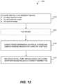
- FIG. 12depicts a flowchart of operations of a CACAO-FP imaging method performed by a CACAO-FP system, according to various implementations.
- FIG. 13depicts a flowchart of operations of an example of a deconvolution process with iterative Tikhonov regularization, according to one aspect.
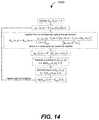
- FIG. 14depicts a flowchart of operations of an example of a blur estimation process for determining local PSFs from limited-aperture images, according to one aspect.
- High-resolution retinal imagingcan significantly improve the quality of diagnosis, disease progression tracking and assessment of therapy in a broad range of retinal diseases including, for example, retinal degenerations (retinitis pigmentosa), macular telangiectasis, macular dystrophies, age-related macular degeneration (AMD), and inflammatory diseases.
- retinal degenerationsretinitis pigmentosa
- macular telangiectasismacular dystrophies
- AMDage-related macular degeneration
- inflammatory diseasesSome of these diseases are prevalent (AMD afflicts 12% of the population aged 80+, and retinitis pigmentosa is the most common cause of blindness/low-vision in adults 20-60 years old) and progress slowly, which drives the need for a cost-effective imaging solution that can be broadly deployed for screening and tracking purposes.
- the availability of new therapeuticsfurther drives this need for a cost-effective imaging solution since the ability to discern the exact impact of the drugs at the cell level is highly useful in informing
- an imaging systemshould be able to focus light to a diffraction-limited spot of size of 1.9 microns on the retina (630 nm wavelength) except that aberrations in the eye actually result in a much poorer focus spot.
- Some retinal imaging techniquescorrect for aberrations by including a corrective physical optical arrangement to compensate for the aberrations before acquiring images. This conventional strategy is the basis of the adaptive optics work that was first started in astronomy and that has been applied to ophthalmic imaging systems, in particular confocal scanning laser ophthalmoscopes (cSLO).
- AOSLOadaptive optics scanning laser ophthalmoscopes
- Fourier ptychographyis a resolution-enhancement imaging technique that can be applied to a conventional 4f optical arrangement to increase the system's effective numerical aperture, remove the inherent optical aberrations in the system, and allow for quantitative phase measurement of a sample. Details of the Fourier ptychography imaging technique are described in G. Zheng, R. Horstmeyer and C. Yang, “Wide-field, high-resolution Fourier ptychographic microscopy,” Nature Photonics, 2013, which is hereby incorporated by reference in its entirety. Fourier ptychography typically uses the aberration characterization technique referred to as the Embedded Pupil Function Recovery (EPRY) method, which is described in X. Ou, G. Zheng and C.
- EPRYEmbedded Pupil Function Recovery
- the EPRY methodis based on images acquired using coherent illumination, such as from light-emitting diodes (LEDs) placed sufficiently far away from the sample or a collimated laser beam, to provide coherent illumination with a consistent beam profile to the sample at varied illumination angles sequentially (i.e. at different sample times).
- coherent illuminationsuch as from light-emitting diodes (LEDs) placed sufficiently far away from the sample or a collimated laser beam, to provide coherent illumination with a consistent beam profile to the sample at varied illumination angles sequentially (i.e. at different sample times).
- the EPRY methoduses the sequence of images captured when the sample is illuminated by various angles with coherent illumination to reconstruct the system's aberration function, also known as the pupil function, while simultaneously reconstructing the sample's complex function.
- pupil ptychography techniquescapture a plurality of limited-aperture images and a full aperture image of a sample of interest that is illuminated by monochromatic, spatially-incoherent illumination, computationally determine the aberration of the optical system, and deconvolve the full aperture image to remove the aberration.
- unmodulated imagesare also captured in parallel with the limited-aperture images to be able to correct for the sample's motion.
- the aberration of the optical system and, by extension, the pupil functioncan be expected to show spatial variations and the aberration may not be the same for different regions within the field-of-view.
- the entire field-of view of each of the captured imagesis segmented into smaller tiles (also referred to herein as “tile images”).
- the aberrationcan be assumed to be constant and the aberration characterization procedure is applied to each tile.
- the pupil ptychography techniquesuse either one of the limited-aperture images, or a slightly expanded limited aperture image, as ground-truth.
- the ground truth imageis then used to deconvolve all the limited-aperture images to recover a point-spread function (PSF) associated with each limited aperture.
- PSFs of the limited aperture imagesare the intensity information of the various low-pass filtered versions of the actual complex PSF of the system with the full aperture opened.
- the pupil ptychography techniquesuse a phase retrieval process to synthesize these low-pass PSFs into the full-sized complex pupil function.
- An example of a phase retrieval process that can be usedis described with respect to the flowchart shown in FIG. 6 .
- the PSF associated with the complex pupil functioncan be easily calculated, which can then be used to deconvolve from the full-aperture image to obtain an aberration-removed image of the sample of interest.
- deconvolutioncan be sensitive to noise and suffer from the PSFs having zeros inside their passband, a robust deconvolution process can be used and/or multiple images taken to reduce the artifacts resulting from deconvolution according to certain implementations.
- an optical systemincludes one or more optical elements in the optical path between the sample being imaged and the imaging sensor of the imager.
- the optical systemincludes an aperture modulator.
- the imaging methodsdetermine an aberration in the optical system. According to one aspect, the portions of the eye between the retina being imaged and the outer surface of the first lens are considered part of the optical system when determining the aberration.
- Certain examples hereinpertain to pupil ptychography techniques that can be used to characterize aberration of an optical system using monochromatic, spatially-incoherent illumination from the sample.
- these pupil ptychography techniquescan use the reconstructed aberration to deconvolve from an image captured with the optical system to remove the aberration to generate an image (e.g., a fluorescence image) that is aberration-free or substantially free of aberration.
- Pupil ptychography techniquescan be implemented, for example, in retinal imaging or imaging of natural scenes.
- a pupil ptychography imaging systemincludes an aperture modulator, one or more optical components, and at least one imager.
- the pupil ptychography imaging systemincludes an aperture modulator, optical components, and an imager configured to acquire a sequence of N limited-aperture images of a sample being imaged, a full aperture image of the sample with the entire pupil region open, and optionally a slightly larger than limited-aperture image i.e. one based on a slightly larger pupil region than the limited aperture images. If the sample is moving, a second imager (with unmodulated pupil i.e. full aperture) is implemented to keep track of the motion of the sample.
- the pupil ptychography imaging systemincludes an aperture modulator, optical components, a first imager, and a second imager.
- the first imageris configured to acquire a sequence of N limited-aperture images of the moving sample, a full aperture image of the sample with the entire pupil region open, and optionally a slightly larger than limited-aperture image i.e. one based on a slightly larger pupil region than the limited aperture images.
- the second imageris configured to acquire unmodulated images of the moving sample in parallel with the first imager capturing images of the sample to account for relative movement of the sample for any of the images that the first imager is acquiring.
- a light source(also referred to as an “illumination source”) illuminates the sample being imaged.
- the light sourceis an incoherent light source.
- the light sourceis a coherent source with some finite coherence length.
- the field incident on the samplecan be scrambled (e.g. with a long multimode fiber, diffuser, etc.) so that it is spatially incoherent.
- an illumination sourceis used to illuminate the sample.
- illuminationis provided by ambient light and/or by a separate light source.
- the one or more optical components of a pupil ptychography systemare configured to propagate light reflected from the sample to the aperture modulator, and from the aperture modulator to the first imager. In the case of a moving sample, the optical components also propagate light from the sample directly to a second imager.
- the first imager and the aperture modulatorare synced (synchronized) so that the first imager captures one of a sequence of N limited-aperture images at the same time as the aperture modulator provides an aperture at one of the N different locations at the Fourier plane of the first imager.
- the same procedureapplies to the full aperture and slightly-bigger-limited-aperture images, with the first imager synchronized to capture an image when the aperture modulator, e.g., a spatial light modulator (also referred to herein as “SLM”), displays the associated aperture.
- the aperture modulatore.g., a spatial light modulator (also referred to herein as “SLM”)
- the first imager, the second imager, and the aperture modulatorare synced so that the first imager capture a limited aperture image and the second imager capture an unmodulated image at the same time as the aperture modulator provides an aperture at one of the N different locations at the Fourier plane of the first imager.
- the aperture modulatormay be an SLM that displays an aperture on the first imager's Fourier plane for each image capture.
- these intensity measurements taken by the imager(s)can have long durations or performed quickly for cases such as retinal imaging of an in-vivo eye.
- the pupil ptychography imaging systemalso includes one or more processors for executing instructions for implementing the pupil ptychography imaging method described with respect to FIGS. 5 and 6 to reconstruct the pupil function of the optical system and an aberration-removed image of the surface of interest.
- Some embodiments of the pupil ptychography methods and systemsmay provide one or more technical advantages. For example, certain embodiments can correct for the optical distortions of the eye or a poor camera lens (since images of natural scenes are generally taken with cameras) image acquisition which provides a simpler (simpler to use and simpler optics) and less expensive scheme than conventional methods.
- pupil ptychography methods and systemsuse spatially incoherent illumination, which is immune to speckle noise.
- the pupil ptychography methodis robust since the aberration correction process and image acquisition process are separated. Aberration correction can be done and the image rendering can be finessed at a later time after image acquisition, without imposing additional time during the acquisition process.
- pupil ptychography techniquescan be used to refocus the corrected image after image acquisition, which also allows for the ability to generate a topological profile of the sample.
- the refocusingcan be done digitally by deconvolving the captured full-aperture sample image with the associated defocus and finding the plane with the sharpest contrast in the image. The location of such plane represents the topological height of that region; doing this for multiple regions in the retina can generate the topological map of the retina.
- FIG. 1illustrates a simplified block diagram of a pupil ptychography imaging system 10 , according to various implementations.
- the pupil ptychography imaging system 10includes a computing device 20 with one or more processors 22 and an internal memory 24 in electrical communication with the one or more processors 22 .
- the pupil ptychography imaging system 10further includes an aperture modulator 32 , optical components 34 , and at least one imager 36 .
- the pupil ptychography imaging system 10implements a first imager.
- the pupil ptychography imaging system 10further implements a second imager for tracking motion of the moving sample.
- the optical components 34are configured to propagate light reflected from the sample being imaged to the aperture modulator 32 and from the aperture modulator 32 to a first imager of the imagers 36 .
- the optical components 34are further configured to propagate light reflected from the sample to a second imager of the imagers 36 .
- the second imageris configured to acquire unmodulated images of the moving sample in parallel with the first imager capturing images of the sample to account for relative movement of the sample for any of the images that the first imager is acquiring.
- the pupil ptychography imaging 10further includes a communication interface 52 and a display 50 in communication with the communication interface 52 .
- the computing device 20is configured or configurable to output raw data, processed data such as image data, and/or other data over the communication interface 52 for display on the display 50 .
- the pupil ptychography imaging 10may further comprise one or more of a communication interface 62 and an external computing device 60 in communication with the communication interface 62 , a communication interface 72 and an external memory device 70 in communication with the communication interface 72 for optional storage of data to the external memory device 70 , and a communication interface 82 in communication with a user interface 80 for receiving input from an operator of the system 10 .
- the optional user interface 80is in electrical communication with the computing device 20 through the communication interface 82 to be able to send a control signal to the computing device 20 based on input received at the user interface.
- an imaging systemincludes an aperture modulator, which is a device that can pass (or reflect) light selectively through (or from) one or more regions at a plane.
- An example of a suitable aperture modulatoris a spatial light modulator (also referred herein to an “SLM) that can selectively block/reflect light or transmit light from one or more aperture region(s).
- An example of a commercially-available spatial light modulatoris the reflective HOLOEYE® spatial light modulator sold by Pluto, which is a phase only liquid-crystal-on-silicon (LCoS) spatial light modulator with 8 ⁇ m pixel size and a 1080 ⁇ 1920 pixels display.
- LOCliquid-crystal-on-silicon
- LCOSferroelectric liquid-crystal-on-silicon
- LCOSferroelectric liquid-crystal-on-silicon
- LCOSferroelectric liquid-crystal-on-silicon
- a suitable aperture modulatoris a digital micromirror device.
- An example of a suitable commercially-available digital micromirror deviceis the DLP9000/DLP9000X DLP® device by Texas Instruments®.
- the aperture modulatoris configured to generate transmissive or reflective apertures (in some cases with different sizes) at different times at various locations along a surface at the Fourier (pupil) plane of the imager.
- a first aperturemay be located at a position x 1 , y 1 at time t 1 and a second aperture may be located at a position x 2 , y 2 at time t 2 .
- the locations of the modulated apertures and the exposure times of the first imagercan be synchronized so that the first imager can take a plurality of limited aperture images based on the different locations of the modulated apertures at the Fourier plane.
- the aperture modulatormay modulate an aperture with a first size at a first location during the exposure time needed to capture a first, limited aperture image, and then modulate an aperture with the first size at a second location during the exposure time needed to capture a second, limited aperture image, and so on until a plurality of limited aperture images based on apertures having the first size has been captured.
- the aperture modulatorcan also modulate an aperture equivalent to the desired system numerical aperture (NA) during an exposure time needed to capture a full aperture image.
- NAnumerical aperture
- the aperture modulator 32is configured to modulate apertures having a first size sequentially to N different locations at a surface placed at the Fourier plane of the first imager of the imagers 36 . While the apertures having the first size are modulated sequentially to N different locations, the first imager acquires a sequence of N limited-aperture images (i.e. limited by the aperture of the first size) of the sample.
- the aperture modulator 32may also be configured to modulate an aperture of a second size to the surface at the Fourier plane of the first imager of the imagers 36 at another sample time. In this implementation, while the aperture having the second size is modulated to the Fourier plane, the first imager acquires a limited aperture image based on the second size.
- a first size of an aperturethat may be used include 10%, 20%, and 30% of the optical system's numerical aperture (NA).
- NAnumerical aperture
- the second sizemay be larger than the first size, for example, at least 5% larger, at least 10% larger or at least 15% larger.
- a pupil ptychography imaging systemincludes at least one imager configured to be activated during various exposure (sample) times to capture images of the sample during an image acquisition cycle.
- the pupil ptychography imaging systemimplements a first imager and a second imager for tracking motion.
- the pupil ptychography imaging system 10 shown in FIG. 1includes a first imager for capturing limited aperture images and a full aperture image.
- the pupil ptychography imaging system 10may further implement a second imager for capturing unmodulated images used to track relative motion of the sample.
- the pupil ptychography imaging system 10may comprise both the first imager and second imager and then only use the unmodulated images taken by the second imager for motion correction or may only capture unmodulated images by the second imager if it is determined that that the sample is moving.
- the limited aperture images captured by the first imagerare based on apertures modulated at a surface at the Fourier plane of the first imager by the aperture modulator 32 .
- the first imageris generally configured to capture a sequence of N limited-aperture images (also referred herein as “a series of N limited-aperture images”) and a full aperture image.
- the second imageris generally configured to capture a series of unmodulated-aperture images in parallel with the first imager for the correction of the sample's motion.
- a “limited aperture image”refers to an image acquired based on a limited pupil function, which is a portion of the full pupil function of the optical system.
- the limited pupil functionis defined by the aperture size at the Fourier plane as modulated by the aperture modulator.
- the size of an aperture at the Fourier planecorresponds to a spatial frequency range of the complex image and the pupil function being captured.
- the image data of each limited aperture imageincludes intensity information of the full aperture image, low-pass filtered by the restricted region of the full pupil function.
- a “full aperture image”refers to an image acquired based on the full pupil function.
- the full aperture imageis captured while the aperture modulator displays an aperture equivalent to the desired system numerical aperture.
- an “unmodulated image”refers to an image that is not modulated by the aperture modulator.
- an image acquired by the second imager of the pupil ptychography system in FIG. 3is not modulated by an aperture modulator and is only modulated by spatial shifts of the moving sample.
- the parallel sequence of unmodulated-aperture imagesis used for image registration of first imager's images for motion correction.
- the first imager of a pupil ptychographyis configured to capture limited-aperture images based on different apertures sizes.
- the first imager of a pupil ptychography systemmay capture a sequence of N limited-aperture images based on a first aperture size, capture a slightly larger limited-aperture image based on a second aperture size that is slightly larger than the first aperture size, and capture a full aperture image.
- the slightly larger limited-aperture imagehas a slightly larger frequency range.
- the second aperturemay have an aperture size that is one of 5%, 10%, or 15% larger than the first aperture size.
- a sample being imagedis illuminated by monochromatic, spatially-incoherent light.
- Light reflected from the surface(s) of the sampleis collected to the aperture modulator 32 by the optical components 34 .
- the pupil ptychography imaging system 10has a second imager and the optical components 34 are further configured to propagate light reflected from the surface(s) of the sample to the second imager of the imagers 36 .
- the computing device 20also sends one or more signals to the second imager to synchronize the exposure times with the first imager so that the second imager captures unmodulated images of the sample for motion registration.
- the aperture modulator 32also modulates a second aperture at the Fourier plane of a first imager where the second aperture is larger than the first aperture and the first imager captures a limited aperture image based on the larger aperture size.
- the processor(s) 22receives one or more signals with the image data from the images captured by the imager(s) 36 .
- the processor(s) 22executes instructions to perform functions of the pupil ptychography imaging method.
- the processor(s) 22performs a tiling procedure which segments the field-of view of the captured images into smaller tiles (also referred to herein as “tile images”) within which the aberration is assumed to be constant.
- the processor(s) 22recovers the pupil function of the optical system given the spatially incoherent images in an aberration characterization procedure. For a wide field-of-view, this procedure recovers a pupil function for each tile region.
- a phase retrieval processis used to synthesize the intensity information of the low-passed point spread functions (PSFs) of the N limited aperture images into a full-sized complex pupil function of the optical system.
- PSFslow-passed point spread functions
- the point spread function of the optical systemcan be calculated from the complex pupil function.
- the processor(s) 22deconvolve the full aperture image to generate a substantially aberration free or aberration free complex image (e.g., a fluorescence image) of the sample.
- a substantially aberration free or aberration free complex imagee.g., a fluorescence image
- the deconvolving proceduredeconvolves each of the tile images to generate aberration-free or substantially aberration free tile images and then combines (mosaics) together the images to form a full field of view image.
- pupil ptychography imaging systems described hereinare configured to acquire a sequence of N limited-aperture images of a sample, a full aperture image with the entire pupil region open, and optionally an image with a slightly larger aperture than the N limited-aperture images.
- the pupil ptychography imaging systemis further configured to acquire a parallel sequence unmodulated-pupil images.
- Each pupil ptychography imaging systemincludes an aperture modulator, optical components, and at least one imager.
- the pupil ptychography imaging systemsalso include an illumination source which provides monochromatic, spatially-incoherent illumination to the surface of the sample being imaged. In other cases, such as an implementation used to image natural scenes, incoherent illumination can be provided by ambient sunlight or an illumination source separate from the system.
- an illumination sourceis configured to provide monochromatic, spatially-incoherent illumination to the surface of a sample being imaged.
- a monochromatic, spatially-incoherent illumination sourceincludes a diffuse laser emitting diode (LED) or a superluminescent diode (SLD).
- the illumination sourceincludes one or more extended LEDs or SLDs coupled to a multimode optical fiber for directing the illumination to the sample being imaged.
- the LED/SLDis also in electrical communication with a power source or in electrical communication with a computing device that controls power to the LED/SLD.
- the LED/SLDmay be triggered to be switched on only for the duration of the camera's exposure window to reduce the sample's exposure to light.
- a fiber coupled LEDe.g. M530F2 from Thorlabs
- an LED driverDC2200 from Thorlabs
- an illumination sourceis configured to generate monochromatic, coherent illumination and the refractive entities between the illumination source and the surface of interest make the illumination to the surface incoherent.
- a laser diode coupled to a long multimode fibercan provide a spatially incoherent light provided that the different optical modes in the fiber are sufficiently temporally separated to reduce the temporal coherence.
- the illumination sourceis a broadband light source, such as a mercury lamp or the sun, with a bandpass filter HO nm bandpass region).
- a pupil ptychography imaging systemincludes an aperture modulator which modulates apertures to N different locations at a surface located at the Fourier plane of an imager.
- the aperture modulatoris configured to shift the transmissive (reflective) aperture(s) to N different locations in 1 second.
- the aperture modulatoris configured to shift the transmissive (reflective) aperture(s) to N different locations in 0.5 seconds.
- the aperture modulatoris configured to shift the transmissive (reflective) aperture(s) to N different locations in 0.1 seconds.
- a pupil ptychography imaging systemincludes a first imager that acquires a sequence of N limited aperture images.
- Nis in a range of 30-60.
- Nis in a range of about 100-200.
- a pupil ptychography imaging systemincludes a second imager that acquires, in parallel (i.e. during image acquisition cycle), unmodulated images.
- the aperture modulatoris in the form of an SLM that be digitally addressed to quickly shift a transmissive (reflective) aperture(s) across its display.
- SLMtransmissive (reflective) aperture(s)
- Nis the number of total shifted SLM admittance functions.
- an SLMincludes an SLM display with discrete display elements. Each discrete SLM element can be set to function as an aperture (aperture setting) or to function as the area surrounding the aperture (field setting).
- an SLM display element in an aperture settingis transparent or nearly transparent to pass incident light and a display element in a field setting may block/reflect or nearly bock/reflect incident light.
- certain SLM display elementsmay be reflective.
- a display element in the aperture settingis oriented at a (first) angle to reflect incident light to the next optical element in the optical arrangement and a display element in a field setting is oriented at a different (second) angle that reflects incident light away from the next optical element.
- the SLM displaycan generate an aperture at one or more SLM display elements by setting these display elements in an aperture setting and/or setting the surrounding display elements in a field setting.
- the SLM displaymay have a refresh rate in the range of 30 per second to 100 per second. In another case, the SLM display may have a refresh rate in the range of 100 per second to 200 per second.
- the aperture modulatoris the form of an LCoS display.
- the LCoS displayis a reflective display having a plurality of reflective display elements.
- An example of a commercially-available LCoS displayis the reflective SLM, Pluto, phase-only LCoS, 8 ⁇ m pixel size, 1080 ⁇ 1920 pixels display by HOLOEYE®.
- the aperture modulatoris the form of a digital micromirror device.
- the digital micromirror deviceincludes an optical semiconductor chip having on its surface multiple microscopic micromirrors.
- each micromirrorcan be individually rotated to an angle, ⁇ . In this way, each micromirror can be transitioned to either an aperture setting at angle, ⁇ , or to a field setting at no rotation, or vice versa.
- these micromirrorsare usually arranged in a rectangular array (dimensions o ⁇ p), other arrangements may be used.
- each micromirror of the digital micromirror devicemay correspond to one or more light detector pixels.
- one or more of the micromirrors in the aperture settingmay be oriented so that an optical axis orthogonal to the surface of the micromirror is oriented at an angle, ⁇ , from the Fourier plane.
- An imager of a pupil ptychography imaging systemgenerally includes at least one image sensor configured to detect light and output a data signal with image data of the intensity distribution (also referred to herein as a “light intensity distribution,” or simply as an “image”) over the sensing surface of the image sensor.
- the image data output from an image sensoris transmitted (or “sent” or “communicated”) in a signal to image sensor(s) to one or more processors.
- the image sensor(s)acquire an image by measuring an intensity distribution of light incident its sensing area during an exposure time.
- suitable image sensorsare CMOS sensors, a charge-coupled device (CCD), and other similar devices.
- an image sensoris a CMOS having a pixel size 11 ⁇ m such as the pco dimax HS4.
- each image sensor of the first imager and/or second imageris a monochromic light detector.
- one of the imagers of the systemmay be capable of high-speed capturing of a sequence of images, which may be particularly useful in retinal imaging, for example.
- an imagermay be configured to acquire images at about 200 frames/second.
- an imagermay be configured to acquire images at about 100 frames/second.
- an imagermay be configured to acquire images at about 500 frames/second.
- An example of an imager capable of high-speed capturingis a high-speed digital camera such as, for example, the 340M-CL Fast Frame Rate CCD Camera made by Thorlabs®.
- the pupil ptychography imaging systemincludes as first imager and a second imager.
- the image sensor(s) of the first imagerare configured to acquire limited-aperture images and a full aperture image of the sample, and the second imager is configured to acquire an unmodulated image of the sample during an image acquisition cycle.
- the image sensor(s) of the first imagerare configured to acquire a sequence of N limited-aperture images based on a first aperture size and capture a limited aperture image of the aperture based on a second aperture size that is larger than the first aperture size.
- the pupil ptychography imaging systemincludes optical components (e.g., beam splitters, objective lenses and/or other lenses, etc.) configured to propagate light reflected from the sample to the aperture modulator, from the aperture modulator to a first imager.
- the optical componentsmay also propagate light reflected from the sample to a second imager.
- the optical componentsmay be in a 4f or 6f arrangement that will allow for the modulation of the spatial spectrum using an aperture modulator that modulates aperture(s) at the Fourier plane of an imager. Examples of optical components are described with respect to FIGS. 3 and 4 .
- the one or more processor(s) 22 of the computing device 20 and, additionally or alternatively, other processor(s) of the pupil ptychography imaging system 10execute instructions stored on a computer readable memory (e.g., the internal memory 24 or external memory 70 ) to perform operations of the pupil ptychography imaging system 10 .
- the one or more processor(s) 22 of the computing device 20may send control signals to the aperture modulator 32 to modulate apertures at different locations and may send control signals to the imager(s) 36 to activate exposure times to take intensity measurements to capture images during image acquisition.
- the one or more processor(s) 22 of the computing system 20may also perform operations of the pupil ptychography imaging method to process the intensity measurements to determine the aberration of the optical system and an aberration-free image of the sample.
- An example of pupil ptychography imaging methodis described with respect to FIG. 5 .
- FIG. 6illustrates an example of a phase retrieval procedure that can be used by the pupil ptychography imaging method in FIG. 5 .
- the computing device of a pupil ptychography imaging systemcan perform parallel image processing.
- the computing devicegenerally includes at least one processor (or “processing unit”).
- processorsinclude, for example, one or more of a general purpose processor (CPU), an application-specific integrated circuit, an programmable logic device (PLD) such as a field-programmable gate array (FPGA), or a System-on-Chip (SoC) that includes one or more of a CPU, application-specific integrated circuit, PLD as well as a memory and various interfaces.
- the computing deviceis in communication with at least one internal memory device.
- the internal memory devicecan include a non-volatile memory array for storing processor-executable code (or “instructions”) that is retrieved by the processor to perform various functions or operations described herein for carrying out various logic or other operations on the image data.
- the internal memory devicealso can store raw and/or processed image data (including acquired images and aberration free images).
- the internal memory device or a separate memory devicecan additionally or alternatively include a volatile memory array for temporarily storing code to be executed as well as image data to be processed, stored, or displayed.
- the computing device itselfcan include volatile and in some instances also non-volatile memory.
- Each of the communication interfaces 52 , 62 , 72 , and 82is in electrical communication with the computing device 20 .
- the described electrical communication between components of the pupil ptychography imaging system 10may be able to provide power and/or communicate data.
- the electrical communication between components of the pupil ptychography imaging system 10 described hereinmay be in wired form and/or wireless form.
- the computing device 20is in communication with the communication interface 52 which is in communication with the display 50 .
- the computing device 20is configured or configurable by a user (also referred to herein as an “operator”) to output raw data or processed data over the communication interface 52 for display on the display 50 .
- the computing device 20also can be configured or configurable to output raw data as well as processed data (for example, after image processing) over a communication interface 62 to an external computing system 60 . Indeed, in some implementations, one or more of the pupil ptychography imaging operations can be performed by such an external computing system 60 .
- the computing device 20also can be configured or configurable by a user to output raw data as well as processed data over a communication interface 72 for storage in an external memory device 70 .
- FIG. 2is a schematic diagram of components of a pupil ptychography imaging system 200 implemented for retinal imaging, according to embodiments.
- the illustrated pupil ptychography imaging systemis configured for imaging a retinal surface of a moving in-vivo eye.
- the pupil ptychography imaging system 200is configured to illuminate the retina of an eye with monochromatic, spatially-incoherent illumination, capture a sequence of N limited-aperture retinal images during an image acquisition process, capture a full pupil image, capture unmodulated retinal images during an image acquisition process, determine the pupil function of the optical system based on the image data, and correct the full pupil image to generate a substantially aberration-free or aberration-free complex image of the retina.
- the optical system in this implementationincludes the portion of the eye to the retina.
- pupil ptychography imaging system 200is shown with a person 201 positioned during the image acquisition process.
- the pupil ptychography imaging system 200includes a casing 210 that contains components of the pupil ptychography imaging system 200 including, for example, an illumination source, optical components, an aperture modulator, and a first and second imager.
- the casing 210has a transparent region 212 for allowing light from the illumination source inside the casing 210 to illuminate the retina of the eye of the person 201 .
- the casing 210is shown here in the shape of a cylinder and the transparent region 212 is circular. Other shapes can be used.
- the transparent region 212may be an aperture filled with a transparent material or may be an open aperture.
- the electronic communication between components of pupil ptychography imaging systems described hereincan be in wired form, wireless form, or a combination thereof.
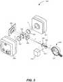
- FIG. 3is a schematic diagram of components of a pupil ptychography imaging system 300 implemented for retinal imaging, according to embodiments.
- the illustrated pupil ptychography imaging systemis configured for imaging a retinal surface of a moving in-vivo eye.
- the components of pupil ptychography imaging system 300may be an example of components that are contained in the casing of the system 200 shown in FIG. 2 .
- the pupil ptychography imaging system 300includes an illumination source 310 , various optical components, a first imager 350 (e.g., high speed digital camera) for acquiring limited-aperture images and a full aperture image, a second imager 351 (e.g., high speed digital camera) for acquiring unmodulated image(s), and an aperture modulator 360 (e.g. spatial light modulator) for modulating apertures at the Fourier plane of the first imager 350 .
- the pupil ptychography imaging system 300is shown at an instant in time when the illumination source 310 is providing monochromatic, spatially-incoherent illumination 312 to the retinal surface 321 of the eye 320 .
- the pupil ptychography imaging system 300also includes various optical components that are configured to propagate light reflected from the retinal surface 321 and passing out the eye 320 to the second imager 351 and to the aperture modulator 360 .
- the optical componentsare also configured to propagate light from the aperture modulator 360 to the first imager 350 .
- the illumination source 310includes an extended diffuse LED or an extended SLD coupled to a first end of a multimode fiber.
- the extended diffuse LED or extended SLDis designed to generate monochromatic, spatially-incoherent light.
- the multimode fibermay then be manipulated to point the opposing second end of the multimode fiber to direct monochromatic, spatially-incoherent illumination from the second end.
- other illumination sourcesmay be used.
- An extended broadband light sourcesuch as a mercury lamp may be bandpass filtered to provide a short bandwidth ( ⁇ 10 nm), spatially incoherent illumination on the sample.
- the optical componentsfurther comprise a first beam splitter 322 , a first lens 324 has a focal length, f 2 , a second lens 330 having a focal length, f 3 , a second beam splitter 332 , and a third lens 336 having a focal length, f 3 , and a fourth lens 337 having a focal length, f 4 .
- the optical components shown in FIG. 3are in a 6f arrangement.
- the first beam splitter 322is configured to reflect monochromatic, spatially incoherent light 312 from the illumination source 310 to the eye 320 .
- the lightpropagates through the eye's media (e.g., cornea, aqueous, lens, and vitreous) and is reflected from the retinal surface 321 at the back of the eye 320 .
- the reflected light from the retinal surface 321is propagated back through the eye's media and to the first beam splitter 322 .
- the first beam splitter 322is further configured to transmit the part of the light reflected from the retinal surface 321 that is depolarized.
- An example of a commercially-available beam splitter that can be usedis the polarizing beam splitter: PBS251 from Thorlabs.
- Some suitable beam splittersare polarizing beam splitters designed to reflect the component of the light with a particular polarization direction (e.g.
- Suitable beam splittersare commercially available.
- Light from the eye 320is transmitted through the first beam splitter 322 to the first lens 324 (e.g., objective lens) and to the second lens 330 which collimates the light.
- the second beam splitter 332reflects a component of the light propagated from the second lens 330 to the third lens 336 , which focuses the light at the second imager 351 .
- the second beam splitter 332transmits another component of the collimated light from the second lens 320 to the aperture modulator 360 which has a display surface at the Fourier plane of the first imager 350 .
- Light incident the aperture modulator 360 within the admittance circular pupil functionis reflected to the second beam splitter 332 .
- the second beam splitter 332reflects the light from the aperture modulator 360 to the fourth lens 337 which focuses the light to the first imager 350 .
- the pupil ptychography imaging system 300may include an adjustable focusing lens between the first beam splitter 322 and the eye 320 .
- the lens 324may be translated axially to move the system's focal plane around the eye's retinal plane.
- the eye 320 of the patientis positioned in front of the first beam splitter 322 or the first beam splitter 322 is positioned in front of the eye 320 .
- the illumination source 310receives a control signal to turn on the monochromatic spatially-incoherent illumination 312 .
- Control signalsare sent to the first imager 350 , the second imager 351 , and the aperture modulator 360 to synchronize image acquisition of the various limited aperture images and full aperture image taken by the first imager 350 and the unmodulated images taken by the second imager 351 .
- the first imager 350 and second imager 350are generally configured to capture aberrated images emerging from the retinal surface 321 of the eye 320 through the optical system of the eye 320 .
- the second imager 351captures unmodulated images.
- the first imager 350captures a sequence of N limited-aperture images with the pupil reduced by the aperture modulator 360 in the Fourier plane of the first imager 350 .
- the second imager 351also captures a full aperture image with an aperture equivalent to the desired system NA.
- the first imager 350 , the second imager 351 , and the aperture modulator 360are synchronized to capture images at the same time while the aperture modulator 360 displays shifted apertures on the Fourier plane of the first imager 350 for each limited aperture image being captured.
- a sequence of N limited-aperture imagesis captured by the first imager 350 corresponding to N different aperture locations at the Fourier plane, at least one full pupil image is captured by the first imager, and a sequence of unmodulated images is captured by the second imager 351 .
- Ncan be in a range of 30 to 60. In another example, N can be from 100 to 200.
- the first imager 350may capture N limited-aperture images based on a first aperture size and captures another limited-aperture image based on a second aperture size larger than the first aperture size.
- a pupil ptychography imaging systemimplements one or more processors (internal/external) to interpret and process the image data sampled during an image acquisition cycle to generate processed image data.
- the processor(s)are configured or configurable to perform operations on the image data of a sequence of intensity images to reconstruct a pupil function of the optical system and corresponding aberration, and remove the aberration from a full pupil image of the sample to generate a substantially aberration-free or aberration-free complex image.
- a pupil ptychography imaging systemis configured to image a moving sample.
- the pupil ptychography imaging systemincludes two imagers (e.g., cameras) that are configured to capture the aberrated image emerging from the retinal surface of the eye through the optical system of the eye, or any other optical system and a surface of interest such as a natural scene imaged through a camera lens.
- One of the imagerscaptures unmodulated images.
- the other imagercaptures modulated images either a full aperture image or images with the pupil reduced by the aperture modulator, e.g., SLM, in the Fourier plane of the other imager.
- the aperture modulatore.g., SLM
- These two imagersare synced to captures images at the same time while the aperture modulator displays a variably shifted aperture on the Fourier plane for each modulated image captured.
- these measurementscan have long durations or they need to be performed quickly for cases such as imaging an in-vivo eye.
- the images captured in a sequencemay have relative shifts with respect to one another due to the eye's movement. This shift can be correctly registered by using the full-aperture images since these images are not modulated in any way other than by the eye's movement.
- These full-aperture imagesare then processed using the pupil ptychography imaging method as described below with reference to FIG. 5 to reconstruct the pupil function of the optical system and an aberration-removed image of the surface of interest.
- FIG. 4is a schematic diagram of components of a pupil ptychography imaging system 400 implemented for imaging of a natural scene 422 , according to embodiments.
- the pupil ptychography imaging system 400includes various optical components, a first imager 450 (e.g., high speed digital camera) for acquiring N limited-aperture images and a full aperture image, a second imager 451 (e.g., high speed digital camera) for acquiring unmodulated images, an aperture modulator 460 (e.g. spatial light modulator) for modulating apertures at the Fourier plane of the first imager 450 .
- a first imager 450e.g., high speed digital camera
- second imager 451e.g., high speed digital camera
- an aperture modulator 460e.g. spatial light modulator
- the pupil ptychography imaging system 400is shown at an instant in time when spatially-incoherent illumination 412 is provided to the natural scene 422 being imaged by the system 400 .
- the various optical componentsare configured to propagate light reflected from the natural scene 422 to the second imager 451 , propagate light reflected from the natural scene 422 to the aperture modulator 460 , and propagate light from the aperture modulator 460 to the first imager 450 .
- the optical componentsfurther include a bandpass filter configured to filter the light reflected from the natural scene. A bandpass filter with a bandwidth of about 10 nm would be suitable.
- the optical componentscomprise a first lens 424 , a second lens 430 , a beam splitter 432 , and a third lens 436 , and a fourth lens 437 .
- spatially-incoherent illumination 412illuminates the surface(s) of interest of the natural scene 422 . Flight reflected from the surface(s) propagate to the first lens 424 (e.g., objective lens) and to the second lens 430 which collimates the light.
- the beam splitter 432reflects a component of the collimated light from the second lens 420 to the third lens 436 , which focuses the light to the second imager 451 .
- the beam splitter 432transmits another component of the collimated light from the second lens 420 to the aperture modulator 360 which has a display surface at the Fourier plane of the first imager 450 .
- Light incident the aperture modulator 440 within the admittance circular pupil functionis reflected to the beam splitter 432 .
- the beam splitter 432reflects light from the aperture modulator 440 to the fourth lens 437 , which focuses light propagated from the beam splitter 432 to the first imager 450 .
- one or more control signalsare sent by a processor(s) to the first imager 350 , the second imager 351 , and the aperture modulator 460 to synchronize image acquisition of the various limited aperture images and full aperture image taken by the first imager 450 and the unmodulated images taken by the second imager 451 .
- the first imager 450 and second imager 450are generally configured to capture aberrated images emerging from the surfaces of the natural scene 422 through the optical system of the natural scene.
- the second imager 351captures one or more unmodulated images of the natural scene 422 , and in parallel, the first imager 350 captures a sequence of N limited-aperture images of the natural scene 422 with the pupil reduced by the aperture modulator 360 in the Fourier plane of the first imager 450 .
- the second imager 451also captures a full aperture image of the natural scene 422 with an aperture equivalent to the desired system NA.
- the first imager 450 , the second imager 451 , and the aperture modulator 460are synchronized to capture images at the same time while the aperture modulator 460 displays shifted apertures on the Fourier plane of the first imager 450 for each limited aperture image being captured.
- a sequence of N limited-aperture images of the natural scene 422is captured by the first imager 450 corresponding to N different aperture locations at the Fourier plane, at least one full pupil image is captured of the natural scene 422 by the first imager, and unmodulated images of the natural scene 422 is captured by the second imager 451 .
- Ncan be from 30 to 60.
- Ncan be from 100 to 200.
- the first imager 450may capture N limited-aperture images based on a first aperture size and captures another limited-aperture image based on a second aperture size larger than the first aperture size.
- the second imagercaptures one or more unmodulated images. In one implementation, the second imager captures N unmodulated images. In another implementation, the second imager captures one unmodulated image. In another implementation, the second imager captures two unmodulated images. In another implementation, the second imager captures less than N unmodulated images.
- pupil ptychography methodscapture a sequence of N limited-aperture images and a full aperture image of a sample that is illuminated by monochromatic, spatially-incoherent illumination, computationally determine the aberration of the optical system, and deconvolve the full aperture image to remove the aberration.
- unmodulated aperture imagesare also captured in parallel in order to correct for the sample's motion.
- the aberration of the optical system and, by extension, the pupil functioncan be expected to show spatial variations and the aberration may not be the same for different regions within the field-of-view.
- a field-of-viewis considered to be wide if larger than 1 degree of visual field. In this case, the entire field-of view of each of the captured images is segmented into smaller tile images and the aberration within each tile is assumed to be constant.
- imagesmay shift spatially between sample times of a sequence of images.
- the shifts in the N limited-aperture images and the full aperture imagecan be correctly registered using the corresponding unmodulated images since these images not modulated in any way other than by sample movement.
- Registrationis an optional operation implemented prior to characterizing the aberration of the optical system since shifting of the captured images may incorrectly encode aberration information in the reconstruction process.
- the pupil ptychography methodsuse either one of the N limited-aperture images or a slightly expanded limited aperture image as ground-truth. The ground truth image is then used to deconvolve all the limited-aperture images to recover a point-spread function (PSF) associated with each limited aperture. These recovered PSFs are of intensity information of the various low-pass filtered versions of the actual complex PSF of the system with the full aperture opened.
- the pupil ptychography methodsuse a phase retrieval process to synthesize these low-pass PSFs into the full-sized complex pupil function. After reconstructing the complex pupil function, the PSF associated with the complex pupil function can calculated, which can then be used to deconvolve from the full-aperture image to obtain an aberration-removed image of the sample.
- FIG. 5depicts a flowchart 500 of operations of a pupil ptychography method, according to various implementations.
- the pupil ptychography methodcaptures aberrated images of the sample illuminated with monochromatic, spatially-incoherent illumination during each image acquisition cycle.
- the samplemay be continuously illuminated or the sample may be illuminated during the exposure times during each image capture.
- a first sequence of N limited-aperture images of the sample and a full aperture image of the sampleis captured.
- the full-aperture imageis the image from which the optical system aberration will be removed.
- the N limited aperture image and the full aperture imageare captured by a first imager synchronized with an aperture modulator that forms apertures at different locations on the Fourier plane of the first imager.
- the first imageralso captures an additional limited-aperture image corresponding to a second aperture size of the aperture modulator that is larger than the first aperture size of the aperture modulator corresponding to the N limited aperture images.
- a sequence of N unmodulated imagesis also captured in parallel with the N limited-aperture images.
- the N limited-aperture images and the N unmodulated imagesare captured by the first imager and a second imager respectively, which are synchronized to capture the different sequences of images in parallel. That is, the first imager captures a modulated image during the same exposure time as the second imager captures an unmodulated image.
- the pupil ptychography systemincludes a first imager and a second imager and implements the first imager to take modulated images if the sample is not moving and implements the first imager to take modulated images and the second imager to take unmodulated images in parallel if the sample being imaged is moving.
- both the first imager to take modulated images and second imager to take unmodulated images and then the methodonly uses the unmodulated images to correct for motion if the method makes a determination that the sample is moving.
- the pupil ptychography methodsegments the image data of each of the full field-of-view images captured during operation 510 into a matrix of tile images using one or more processors.
- the full field-of-viewmay be segmented into equivalent portions based on keeping each portion less than a size within which the aberration can be assumed to be constant.
- the full field-of-viewmay be segmented to keep the field of view of each tile image within a predetermined size.
- the predetermined sizemay be, for example, 1 degree, 2 degrees, or 3 degrees of visual field.
- operation 520may be invoked if the method determines that the field-of-view is greater than a threshold size. Some examples of threshold sizes are 1 degree, 2 degrees, or 3 degrees of visual field etc.
- the limited-aperture images captured at different sample timesmay have relative spatial shifts with respect to one another due to the sample's movement. These shifts can be correctly registered by using the unmodulated images since these images are not modulated in any way other than by the movement of the sample.
- the pupil ptychography methodregisters the motion of the sample using the unmodulated images captured during operation 510 . To register the motion of the sample, a spatial shift of each one of the sequence of N limited-aperture images is determined by comparing the spatial location of the corresponding unmodulated image taken at the same sample time to the unmodulated image taken at the first sample time.
- the pupil ptychography methodcan then correct each limited-aperture image based on the determined spatial shift.
- the pupil ptychography methodcompares two or more of the unmodulated images to determine whether the sample is moving. If movement exists, then the method proceed with operation 530 to correct the limited-aperture images for motion. In other implementations, the pupil ptychography method may always correct for movement.
- the pupil ptychography methoduses one or more processors to characterize the aberration of the optical system using image data of the spatially incoherent images collected in operation 510 . If each of the captured images were tiled in the optional operation 520 , then operation 540 is performed to determine an aberration based on each of the tile regions.
- FIG. 6depicts a flowchart that describes details of an example of sub-operations of operation 540 .
- the pupil ptychography methoduses one or more processors to deconvolve the full pupil (full aperture) image captured in operation 510 to correct for the aberration determined in operation 540 . If each of the captured images were tiled in the optional operation 520 , then operation 550 decolvolves each of the tile images of the full aperture image to correct for aberration in each tile region. Then, the pupil ptychography method mosaics the aberration-free or substantially aberration free tile images together to form a full field-of-view image that is aberration-free or substantially aberration free. In one aspect, the aberration-free or substantially aberration free image is a fluorescence image.
- a deconvolution operationis used.
- a blind deconvolution operationcan be used when the pupil function of the system.
- Non-blind deconvolutionis used when you have knowledge of the pupil function.
- Some examples of non-blind deconvolution techniques that can be usedinclude Tikhonov regularization, Wiener deconvolution, block matching and 3D filtering (BR3D).
- FIG. 6depicts a flowchart 600 of sub-operations of aberration characterization process of a pupil ptychography method, according to an implementation.
- the ground truth imageis one of the limited-aperture images based on the first aperture size.
- the ground truth imageis the limited-aperture image based on the second aperture size larger than the first aperture size.
- the pupil ptychography methodinitializes a full-aperture pupil function, P(k x ,k y ), with is inside the passband and 0s outside the passband.
- the pass bandis defined by the full aperture's NA in the Fourier domain.
- the incoherent point-spread-functions, o i (x, y), of the N limited aperture imagesare the intensity information of the various low-pass filtered versions of the actual complex point spread function of the optical system with the full aperture opened.
- the incoherent PSFis the absolute squared of the coherent point spread function.
- the methodupdates the corresponding region of the full-aperture pupil function, P(k x ,k y ), with P i .
- Imaging a sample with an uneven surface or a thick sample with two-dimensional features present at different depths across the field-of-viewcan result in parts of the image being in focus while other parts are out of focus.
- a specimen in clinical cytopathologymay contain stained cells present at different depth levels, and require a microscopist to capture multiple images while scanning the specimen through the depth.
- An example of microscopy that captures multiple images at different depthsis described in Evered, A., Dudding, N. “Accuracy and perceptions of virtual microscopy compared with glass slide microscopy in cervical cytology,” Cytopathology 22:82-7 (2011), which is hereby incorporated by reference in its entirety.
- the region of interest in the samplemay be embedded in a transparent medium that causes variations in the refractive index.
- an imaging lenssuch as a microscope objective lens
- any refractive index mismatchwill cause aberrations in the image.
- CLARITYis typically used to homogenize the refractive index of a mouse brain specimen to be able to image with light sheet fluorescence microscopy.
- some residual refractive index mismatchexists after the CLARITY process, which may cause aberrations when imaging through a thick layer of the tissue.
- CACAO-FPcoded-aperture-based correction of aberration obtained from Fourier ptychography
- CACAO-FP systems and methodsare adapted to correct or compensate for sample-induced aberration, along with aberration in the optical system.
- a CACAO-FP systemis configured to capture a plurality of incoherent (e.g., fluorescence) images of a sample of a sample being imaged with coded-apertures (also referred to herein as “large masks”) at its pupil plane, synthesize the spatially varying system- and sample-induced aberration using Fourier ptychography techniques, and remove the aberration using deconvolution to obtain substantially aberration-free images of the sample.
- incoherente.g., fluorescence
- the CACAO-FP systemis configured to provide coded-aperture-based correction of aberration obtained from Fourier Ptychography.
- a substantially aberration-free imagerefers to an image having less than a predefined degree of system- and sample-induced aberration, e.g., resolution degradation from the theoretical performance defined by the system's numerical aperture (i.e. lambda/(2NA)) of less than 1%, less than 2%, less than 3%, less than 4%, or less than 5%.
- a CACAO-FP systemincludes an aperture modulator that can modulate different apertures at the Fourier plane of the imager so that the imager can capture aperture modulated images.
- the aperture modulatoris configured to modulate one or more of a plurality of limited apertures (also sometimes referred to herein as “small masks”), a plurality of coded apertures (also sometimes referred to herein as “large masks”), and a full aperture.
- Each coded apertureis a mask corresponding to the full pupil size passing/reflecting light and including one or more regions that block/absorb light to form a pattern. This pattern encodes the pupil function and is used to assist in a latent image recovery by deconvolution.
- an aperture modulatorcan generate a coded aperture by modulating a full aperture (e.g., circular region) equivalent to the desired system numerical aperture (NA) and overlaying light blocking regions to pass light through the unblocked regions of the full aperture according to a pattern created by these regions.
- a full aperturee.g., circular region
- NAnumerical aperture
- patternsinclude a crescent shape, a binary pattern, a Hadamard pattern, a gradient pattern, etc.
- Each limited aperture of the plurality ofis a smaller region of the full aperture.
- the limited aperturesare overlapping regions (e.g., more than 20% overlap between adjacent regions, more than 25% overlap between adjacent regions, more than 30% overlap between adjacent regions) that when combined cover the full aperture.
- the CACAO-FP systemsynchronizes the imager and aperture modulator so that the imager captures images while the aperture modulator modulates apertures.
- the aperture modulatorgenerates variably-coded apertures (i.e. apertures based on different patterns) during which a corresponding variably-coded aperture images are acquired. In these cases, each coded aperture image corresponds to one of the plurality of variably-coded apertures being generated.
- the aperture modulatoralso generates a plurality of limited apertures during which the imager captures a corresponding plurality of limited aperture images.
- the aperture modulatoralso generates a full aperture during which the imager captures a full aperture image i.e., the aperture does not have any blocking/absorbing regions.
- a full aperture imagemay be generated from the plurality of limited-aperture images.
- a CACAO-FP systemmay include an aperture modulator configured to modulate at the Fourier plane: (i) a plurality of variably-coded apertures, (ii) a full aperture corresponding to the pupil function of the desired numerical aperture, (iii) and a plurality of limited apertures of the full aperture.
- an imageris synchronized to acquire: (i) a plurality of variably-coded aperture images, (ii) a full aperture image, and (iii) and a plurality of limited aperture images, respectively.
- a CACAO-FP systemmay include an aperture modulator configured to modulate at the Fourier plane: (i) a plurality of variably-coded apertures, and (ii) a plurality of limited apertures of the full aperture.
- an imageris synchronized to acquire: (i) a plurality of variably-coded aperture images, and (ii) a plurality of limited aperture images, respectively.
- defocus parameters and other parameters used to construct the aberration mapcan be modified between iterations.
- the image resulting from a particular iterationmay be determined to lack sharpness of features and defocus parameters modified before the next iteration to generate a sharper image.
- the imagemay be retiled between iterations to have a finer tile size.
- CACAO-FP systems described in Section Imay be similar to components of the pupil ptychography systems described in Section II.
- FIG. 7is a simplified block diagram of a CACAO-FP system 700 , according to various implementations. Certain system components are optional (denoted by dashed line) and any combination of these components is included according to various implementations.
- the CACAO-FP system 700includes a computing device 720 with one or more processors 722 and an internal memory 724 in electrical communication with the one or more processors 722 .
- the CACAO-FP system 700further includes an optical system 730 with an aperture modulator 732 that can modulate light and one or more imagers 749 in communication with the optical system 730 to receive propagated light from the optical system 730 and to acquire images.
- the CACAO-FP system 700is shown with a sample 711 being imaged at this instance during operation.
- the sample 711is providing incoherent light such as, e.g., fluorescence emissions from fluorophores activated by excitation light from a light source.
- the aperture modulator 732is configured to modulate to provide a plurality of variably-coded apertures and a plurality of limited apertures that are portions of a full aperture equivalent to the desired system numerical aperture.
- the aperture modulator 732is also configured to modulate to provide the full aperture.
- the aperture modulator 732is configured to provide the apertures at the pupil plane of the imager 740 .
- the CACAO-FP system 700synchronizes the aperture modulator 732 with the imager(s) 740 so that the imager(s) captures images while the aperture modulator 732 modulates the apertures, e.g., to capture one image for each aperture.
- the optical system 730also includes one or more optical components configured to propagate light transmitted through the sample 711 (in the transmission mode) or reflected from the sample 711 (in the reflection mode) to the aperture modulator 732 and from the aperture modulator 732 to the imager(s) 740 .
- a suitable aperture modulatoris a spatial light modulator that can selectively block/reflect light and transmit light from one or more aperture region(s).
- An example of a commercially-available spatial light modulatoris the reflective HOLOEYE® spatial light modulator sold by Pluto®, which is a phase-only LCoS with 8 ⁇ m pixel size and a 1080 ⁇ 1920 pixels display.
- Another example of a suitable aperture modulatoris a digital micromirror device.
- An example of a suitable commercially-available digital micromirror deviceis the DLP9000/DLP9000X DLP® Digital micromirror device by Texas Instruments®.
- the CACAO-FP system 700further includes an optional communication interface 752 and an optional display 750 in communication with the communication interface 752 .
- the computing device 720is configured or configurable to output raw data, processed data such as image data, and/or other data over the communication interface 752 for display on the display 750 .
- the CACAO-FP system 700also includes an optional communication interface 762 and an optional external computing device 760 in communication with the communication interface 762 , an optional communication interface 772 and an optional external memory device 770 in communication with the communication interface 772 for optional storage of data to the external memory device 770 , and an optional communication interface 782 in communication with an optional user interface 780 for receiving input from an operator of the CACAO-FP system 700 .
- the user interface 780is in electrical communication with the computing device 720 through the communication interface 782 to be able to send a control signal to the computing device 720 based on input received at the user interface.
- a CACAO-FP systemis configured to capture a plurality of limited-aperture images based on apertures of the same size. According to another aspect, a CACAO-FP system is configured to capture a plurality of limited-aperture images based on different aperture sizes.
- the sample 711 being imagedis illuminated, e.g., by a light source.
- the CACAO-FP system 700operates in a transmission mode with the light source and collection optical element configured so that the collection optical element receives light transmitted through the sample being imaged.
- the CACAO-FP system 700operates in a reflection mode with the light source and collection optical element configured so that the collection optical element receives light reflected from the sample being imaged.
- light from the illuminated sample 711is received by one or more optical components of the optical system 730 , light propagated to the aperture modulator 732 is filtered by the aperture at the aperture modulator 732 , and light is propagated to the imager(s) 740 .
- the computing device 720sends one or more signals to the aperture modulator 732 and the imager(s) 740 to synchronize exposure times for capturing images with the aperture modulator 732 modulating apertures (also called windows) at the Fourier plane of the imager(s) 740 .
- the aperture modulator 732modulates to provide: (i) a plurality of variably-coded apertures, (ii) a full aperture corresponding to the pupil function of the desired numerical aperture, and (iii) a plurality of limited apertures of the full aperture and the imager 740 , synchronized with the aperture modulator 732 , acquires respectively: (i) a plurality of variably-coded aperture images, (ii) a full aperture image, and (iii) a plurality of limited aperture images.
- the aperture modulator 732modulates to provide: (i) a plurality of variably-coded apertures and (ii) a plurality of limited apertures of the full aperture and the imager 740 , synchronized with the aperture modulator 732 , acquires respectively: (i) a plurality of variably-coded aperture images, and (ii) a plurality of limited aperture images.
- the processor(s) 722receives one or more signals with the image data captured by the imager(s) 36 .
- the processor(s) 722executes instructions to perform functions of the CACAO-FP system 700 such as described with respect to FIG. 12 .
- the processor(s) 722performs a tiling procedure, which segments captured images of the entire field-of-view into tile images within which the aberration is assumed to be constant.
- the processor(s) 722recovers the pupil function for each tile image in an aberration characterization procedure.
- a phase retrieval processis used to synthesize the intensity information of the low-passed point spread functions (PSFs) of the limited aperture images into a full complex pupil function of the optical system.
- the point spread function of the optical systemcan be calculated from the complex pupil function.
- the processor(s) 22deconvolve each of the tile images to generate a substantially aberration free or aberration free tile image.
- the sample being imaged by a CACAO-FP systemis illuminated by a light source.
- the light sourceis configured to provide monochromatic, spatially incoherent illumination.
- Some examples of light sources that can provide a monochromatic, spatially-incoherent illuminationare a diffuse laser emitting diode (LED) and a superluminescent diode (SLD).
- the light sourceincludes one or more extended LEDs or SLDs coupled to a multimode optical fiber for directing the illumination to the sample being imaged.
- the LED/SLDis also in electrical communication with a power source or in electrical communication with a computing device that controls power to the LED/SLD.
- the LED/SLDmay be triggered to be switched on only for the duration of the camera's exposure window to reduce the sample's exposure to light.
- a fiber coupled LEDe.g. M530F2 from Thorlabs
- an LED driverDC2200 from Thorlabs
- the light sourceis configured to generate monochromatic, coherent illumination and the refractive entities between the illumination source and the surface of interest make the illumination to the surface incoherent.
- a laser diode coupled to a long multimode fibercan provide a spatially incoherent light provided that the different optical modes in the fiber are sufficiently temporally separated to reduce the temporal coherence.
- the light sourceis a broadband light source, such as a mercury lamp or the sun, with a bandpass filter HO nm bandpass region).
- the sample plane of interesthas fluorescent targets that emit light upon activation by an excitation source such as light or ultrasound, to name a few. Fluorescence from the targets produce the incoherent light to be imaged by a CACAO-FP system.
- a CACAO-FP systemincludes an aperture modulator which modulates an aperture at different locations at a surface located at the Fourier plane of an imager.
- the aperture modulatoris configured to modulate to provide apertures at 10 frames per second.
- the aperture modulatoris configured to modulate to provide apertures at 1000 frames per second.
- the aperture modulatoris configured to display multiple apertures per frame.
- a CACAO-FP systemincludes an imager that acquires one or more of: (i) a plurality of M variably-coded aperture images, (ii) a full aperture image, and (iii) a plurality of N limited aperture images.
- Nis in a range between about 30 and about 60.
- Nis in a range between about 100 and about 200.
- Nis greater than 100.
- the number Nis selected based on the severity of the aberration.
- Mis in a range between about 2 and about 10.
- Mis in a range between about 10 and about 20.
- Mis greater than 20.
- Mis greater than 2.
- Mis about 4.
- Mis 1.
- the aperture modulator of a CACAO-FP systemis a spatial light modulator that can be digitally addressed to generate transmissive or reflective regions on its display to generate a coded aperture, a limited aperture, or a full aperture.
- a commercially-available example of an SLMis the LC-R 720 made by HOLOEYE®.
- an SLMincludes a display with discrete display elements. Each discrete display element can be set to function as an aperture (aperture setting) that allows light to pass or to function as the light blocking area surrounding the aperture (field setting).
- a display element in an aperture settingis transparent or nearly transparent to pass light and a display element in a field setting substantially blocks/reflects incident light.
- the displaymay have a refresh rate in the range between about 30 per second and 100 per second. In another aspect, the display may have a refresh rate in the range between about 100 per second and 200 per second.
- the aperture modulator of a CACAO-FP systemis an LCoS display with reflective display elements.
- An example of a commercially-available LCoS displayis the reflective SLM, Pluto, phase-only LCoS, 8 ⁇ m pixel size, 1080 ⁇ 1920 pixels display by HOLOEYE®.
- the aperture modulator of a CACAO-FP systemis a digital micromirror device.
- the digital micromirror deviceincludes an optical semiconductor chip having on its surface multiple microscopic micromirrors.
- each micromirrorcan be individually rotated to an angle, ⁇ . In this way, each micromirror can be transitioned to either an aperture setting at angle, ⁇ , or to a field setting at no rotation, or vice versa.
- these micromirrorsare usually arranged in a rectangular array (dimensions o ⁇ p), other arrangements may be used.
- each micromirror of the DMDmay correspond to one or more light detector pixels.
- one or more of the micromirrors in the aperture settingmay be oriented so that an optical axis orthogonal to the surface of the micromirror is oriented at an angle, ⁇ , from the Fourier plane.
- a CACAO-FP systemincludes one or more imagers, each imager with one or more image sensors.
- Each image sensoris configured to detect light and output a data signal with image data of the intensity distribution (also referred to herein as a “light intensity distribution,” or simply as an “image”) over the sensing surface of the image sensor.
- the image data output from an image sensoris transmitted (or “sent” or “communicated”) in a signal to image sensor(s) to one or more processors.
- the image sensor(s)acquire an image by measuring an intensity distribution of light incident its sensing area during an exposure time.
- suitable image sensorsare CMOS sensors, a charge-coupled device (CCD), and other similar devices.
- an image sensoris a CMOS having a pixel size 11 ⁇ m (e.g. an image sensor of the pco.dimax HS4 ® camera available from pco Inc.®).
- each image sensor of the first imageris a monochromic light detector.
- an imagermay be capable of high-speed capturing of images.
- an imagercan acquire images in a range between about 100 and about 200 frames/second.
- an imagercan acquire images in a range between about 100 and 500 frames/second.
- an imagercan acquire images in a range between about 200 and about 400 frames/second.
- an imagercan acquire images at greater than about 200 frames/second.
- an imagercan acquire images greater at than about 300 frames/second. In one aspect, an imager can acquire images at greater than about 400 frames/second. In one aspect, an imager can acquire images at greater than about 500 frames/second.
- An example of an imager capable of high-speed capturingis a high-speed digital camera such as, for example, the 340M-CL Fast Frame Rate CCD Camera made by Thorlabs®.
- a CACAO-FP systemincludes an optical system with one or more optical components (e.g., beam splitters, objective lenses and/or other lenses, etc.) configured to propagate light reflected from the sample to the aperture modulator and from the aperture modulator to an imager.
- the optical componentsmay be in a 4f or 6f arrangement that allows for the modulation of the spatial spectrum using an aperture modulator that modulates aperture(s) at the Fourier plane of the imager.
- the processor(s) 722 of the computing device 720 and, additionally or alternatively, other processor(s) of the CACAO-FP system 700execute instructions stored on a computer readable memory (e.g., the internal memory 724 or external memory 770 ) to perform operations of the CACAO-FP system 700 .
- the processor(s) 722 of the computing device 720may send control signals to the aperture modulator 732 to modulate apertures and may send control signals to the imager(s) 736 to activate exposure times to capture images.
- the one or more processor(s) 720 of the computing system 720may also perform operations of the CACAO-FP as described in FIG. 8 to determine the aberration of the optical system and sample-induced aberration and generate a substantially aberration-free image of the sample.
- the aberration-free or substantially aberration free imageis a fluorescence image.
- a CACAO-FP systemincludes a computing device that can perform parallel image processing.
- the computing devicegenerally includes at least one processor (or “processing unit”).
- processorsinclude, for example, one or more of a general purpose processor (CPU), an application-specific integrated circuit, an programmable logic device (PLD) such as a field-programmable gate array (FPGA), or a System-on-Chip (SoC) that includes one or more of a CPU, application-specific integrated circuit, PLD as well as a memory and various interfaces.
- the computing deviceis in communication with at least one internal memory device.
- the internal memory devicecan include a non-volatile memory array for storing processor-executable code (or “instructions”) that is retrieved by the processor to perform various functions or operations described herein for carrying out various logic or other operations on the image data.
- the internal memory devicealso can store raw and/or processed image data (including acquired images and aberration free images).
- the internal memory device or a separate memory devicecan additionally or alternatively include a volatile memory array for temporarily storing code to be executed as well as image data to be processed, stored, or displayed.
- the computing device itselfcan include volatile and in some instances also non-volatile memory.
- Each of the communication interfaces 752 , 762 , 772 , and 782is in electrical communication with the computing device 720 .
- the described electrical communication between components of the CACAO-FP system 700may be able to provide power and/or communicate data.
- the electrical communication between components of the CACAO-FP system 700 described hereinmay be in wired form and/or wireless form.
- the computing device 720is in communication with the communication interface 752 which is in communication with the display 750 .
- the computing device 720is configured or configurable by a user (also referred to herein as an “operator”) to output raw data or processed data over the communication interface 752 for display on the display 750 .
- the computing device 720also can be configured or configurable to output raw data as well as processed data (for example, after image processing) over a communication interface 762 to an external computing system 760 . Indeed, in some implementations, one or more of the CACAO-FP imaging operations can be performed by such an external computing system 760 .
- the computing device 720also can be configured or configurable by a user to output raw data as well as processed data over a communication interface 720 for storage in an external memory device 770 .
- the CACAO-FP system 700further includes one or more additional interfaces such as, for example, various Universal Serial Bus (USB) interfaces or other communication interfaces.
- additional interfacescan be used, for example, to connect various peripherals and input/output (I/O) devices such as a wired keyboard or mouse or to connect a dongle for use in wirelessly connecting various wireless-enabled peripherals.
- I/Oinput/output
- additional interfacesalso can include serial interfaces such as, for example, an interface to connect to a ribbon cable.
- the various system componentscan be electrically coupled to communicate with the computing device 720 over one or more of a variety of suitable interfaces and cables such as, for example, USB interfaces and cables, ribbon cables, Ethernet cables, among other suitable interfaces and cables.
- the data signals output by the image sensorsmay in some implementations be multiplexed, serialized or otherwise combined by a multiplexer, serializer or other electrical component of the imaging system before being communicated to the computing device.
- the computing devicecan further include a demultiplexer, deserializer or other device or component for separating the image data from each of the image sensors so that the image frames can be processed in parallel by the one or more processors.
- CACAO-FP systems shown in FIGS. 8, 10, and 11have one or more components that are similar to those described with respect to CACAO-FP system 700 in FIG. 7 .
- a CACAO-FP systeme.g., the CACAO-FP system 700 , the CACAO-FP system 1000 , or CACAO-FP system 1100 , also includes a motion correction arm for tracking motion of a moving sample.
- the motion correction armincludes an additional imager and optical components of the optical system that are configured to propagate light reflected from the sample to the additional imager.
- An example of a motion correction armis the second imager 351 and lens 336 of the pupil ptychography imaging system 300 shown in FIG. 3 .
- the optical systemfurther includes one or more optical components configured to propagate light from the illuminated sample to the additional imager.
- the additional imageris then configured to acquire a plurality of unmodulated images of the moving sample.
- the unmodulated imagescan be acquired in parallel with acquiring the plurality of modulated images (limited aperture images and/or variably-coded aperture images) based on apertures at the Fourier domain.
- the parallel sequence of unmodulated-aperture imagesis used for image registration of the modulated images for motion correction.
- a motion registration operation that can be usedis operation 530 in FIG. 5 .
- FIG. 8is a schematic diagram of certain optical elements of a CACAO-FP system 800 , according to various implementations, and an unknown lens 814 with a focal length f 0 and a sample with a spatially incoherent field 812 at a sample plane 811 . It would be understood that the schematic diagram is simplified for the purpose of illustrating the general optical scheme of the CACAO-FP system 800 , and does not show all system components.
- the CACAO-FP system 800includes an optical system having a first lens 830 a with a focal length f 1 , a second lens 830 b with a focal length f 2 , and a third lens 830 c with a focal length f 3 .
- the CACAO-FP system 800also includes a first image plane 831 a .
- the first lens 830 a , second lens 830 b , and third lens 830 care configured to relay the image from the unknown lens 814 and sample to an imager (not shown) at the second image plane 831 b .
- the distance dis an arbitrary distance smaller than f 3 .
- the images captured by the imagerare intensity only images.
- the unknown lens 814is a representation of aberrating medium between the sample plane and the first lens 830 a . In a retinal imaging example, the unknown lens 814 would represent the lens and cornea.
- the CACAO-FP system 800also includes an aperture modulator 832 , shown at this instant providing a limited aperture 833 at the pupil plane.
- the CACAO-FP system 800is configured to determine the sample-induced aberration characteristics of the unknown lens 814 and the aberration in the optical system and to correct for both.
- FIG. 9is the general imaging pipeline for a CACAO-FP imaging method, according to various implementations.
- the sample planewhich has coordinates (x,y) is divided into a plurality of tiles.
- the tilesare considered to be isoplanatic patches with aberration assumed to be spatially invariant within each of the tiles.
- Each of the tilesis processes on its image plane, which has coordinates ( ⁇ , ⁇ ), to recover a higher resolution tile image i.e. having higher resolution than the raw intensity images captured by the imager.
- the imager of a CACAO-FP systemcaptures: (i) a plurality of limited-aperture images while the aperture modulator generates smaller limited apertures which collectively span the desired full pupil, (ii) a plurality of variably-coded aperture images while the aperture modulator modulates a plurality of coded apertures with different patterns (also sometimes referred to herein as “variably-coded apertures”) at the pupil plane; and (iii) a full circular aperture while the aperture modulator generates the desired full pupil.
- the images capturedencode the sample-induced and optical system aberration in their point spread function.
- the point spread functionscan be extracted, e.g., using a blur estimation operation as known to those of skill in the art.
- These intensity values of the spatially filtered pupil functionare synthesized into a full pupil function with a Fourier ptychographic process described in FIG. 6 .
- the m th small mask(also referred to herein as m th limited aperture) is labeled W m (u, v)
- the point spread function (PSF) associated with the m th small mask for the isoplanatic patch tis labeled b m,t ( ⁇ , ⁇ )
- the associated limited-aperture tile image captured with the m th small maskis i m,t ( ⁇ , ⁇ ), respectively.
- n th large mask(also referred to herein as n th coded aperture) is labeled A n (u, v)
- the point spread function (PSF) associated with the n th large mask for the isoplanatic patch tis labeled h m,t ( ⁇ , ⁇ )
- the associated coded-aperture tile image captured with the n th large maskis ⁇ n,t ( ⁇ , ⁇ ), respectively.
- the CACAO-FP imaging methodperforms a portion of the data acquisition process by acquiring a plurality of m limited-aperture images as illustratively represented by the row of three limited-aperture images being acquired at the top for the purpose of illustration.
- Each of the limited-aperture imagesis tiled into a plurality of limited-aperture tile images, i m,t ( ⁇ , ⁇ ).
- the imagercaptures the plurality of m limited-aperture images while the aperture modulator generates a plurality of circular apertures, which collectively span the full pupil e.g. full pupil of the unknown lens 814 shown in FIG. 8 .
- the CACAO-FP imaging methodalso performs a portion of the image reconstruction process by determining the local point spread functions (PSFs) of the m limited-aperture images b m,t ( ⁇ , ⁇ ), e.g., using the blur estimation procedure illustrated by the flowchart 1400 shown in FIG. 14 , and then the PSFs of the m limited-aperture images are synthesized into a full-aperture pupil function using the Fourier ptychographic process described in FIG. 6 .
- PSFslocal point spread functions
- the CACAO-FP imaging methodperforms the operations of the data acquisition process and then the operations of the image reconstruction process in certain implementations described herein.
- the data acquisition process of certain implementationsis described in certain orders, e.g., first acquiring a plurality of limited-aperture images, then a plurality of coded-aperture images, and then a full aperture image, the disclosure is not so limiting and other orders are included e.g., a full aperture image, the limited-aperture images, and then the coded-aperture images or the full aperture image, the coded-aperture images, and then the limited-aperture images, etc.
- the CACAO-FP imaging methodperforms a portion of the data acquisition process by acquiring a full aperture image (illustratively represented by top row, left image) and a plurality of n variably-coded-aperture images (illustratively represented by top row, right image).
- the imagercaptures the variably-coded-aperture images while the aperture modulator generates code apertures with various patterns.
- Each of the variably-coded-aperture imagesis tiled into a plurality of variably-coded-aperture tile images, ⁇ n,t ( ⁇ , ⁇ ).
- the imagercaptures the plurality of n coded-aperture images while the aperture modulator generates a plurality of coded apertures respectively.
- the CACAO-FP imaging methodalso performs a portion of the image reconstruction process by using the recovered pupil function from operation 920 and the coded-aperture images to recover the aberration-free intensity distribution of the sample o t (x,y) using a deconvolution operation such as, e.g., described in FIG. 13 .
- a deconvolution operationsuch as, e.g., described in FIG. 13 .
- FIG. 10is a schematic diagram of components of a CACAO-FP system 1000 , according to one implementation.
- the CACAO-FP system 1000is shown at an instant during operation when imaging an uneven 2D sample 1011 on a slide 1016 .
- illuminationis provided by a condenser 1005 for incoherent illumination (e.g., monochromatic LED) at a desired wavelength (e.g., 520 nm).
- the illuminationis at the excitation wavelength of the fluorophores.
- a light sheet beamcan be used as the excitation illumination to allow a plane of fluorophores to fluoresce, one plane at a time.
- the CACAO-FP system 1000includes an optical system with an objective lens 1030 a , a first relay lens 1030 b , a second relay lens 1030 c , a polarized beam-splitter 1030 d , a polarizer 1030 e , and a tube lens 1030 f .
- the CACAO-FP system 1000also includes an imager 1040 (e.g., camera) and an aperture modulator 1032 in the form of a reflective spatial light modulator.
- the aperture modulator 1032is configured to modulate reflective apertures at the Fourier plane of the imager 1040 and the imager is synchronized to capture modulated images.
- the aperture modulator 1032 and imager 1040are configured so that the imager 1040 acquires: (i) a plurality of limited-aperture images and (ii) a plurality of coded-aperture images. In one case, the aperture modulator 1032 and imager 1040 are further configured so that the imager 1040 acquires (iii) a full aperture image.
- the optical systemis configured to propagate light transmitted through the sample 1011 to the aperture modulator 1032 and from the aperture modulator 1032 to the first imager 1040 .
- the first relay lens 1030 b and the second relay lens 1030 chave the same focal length (e.g., 100 mm).
- An example of a suitable pair of relay lensesare the AC508-100-A lenses from Thorlabs Inc.®.
- An example of a suitable beam splitteris the polarized beam splitter AC508-100-A from Thorlabs Inc.®.
- the polarized beam splitter 1030 dlies in front of the aperture modulator 1032 to enable binary modulation of the aperture modulator 1032 .
- a polarizer 1030 eis placed after the polarized beam-splitter 1030 d to filter the polarized light to compensate for the low extinction ratio in reflection of the polarized beam-splitter 1030 d .
- the tube lens 1030 fFourier transforms the modulated light and images it on the imager 1040 .
- An example of a commercially-available polarized beam splitter that can be usedis the polarizing beam splitter PBS251 available from Thorlabs Inc.®.
- a polarizing beam splitteris designed to reflect a component of the light with a particular polarization direction (e.g. 0 degrees) while transmitting a component with the perpendicular polarization direction (e.g. 90 degrees).
- the imager 1040captures the image of the sample 1011 with the pupil (aperture) defined by the patterns on the display of the aperture modulator 1032 in the imager's Fourier plane.
- the aperture modulator 1032displays an aperture on the camera's Fourier plane during each image capture.
- the imagesare processed using Fourier Ptychography as described in the following section C to construct the pupil function that contains aberration induced by the sample and the optical system. Deconvolution is performed on the plurality of coded-aperture images captured while various coded apertures are displayed on the aperture modulator 1032 to produce an aberration-removed image of the sample.
- the condenser 1005 in FIG. 10can be placed on the same side of the slide 1016 as the collection lens 1030 a for an implementation in reflection mode.
- the sampleis illuminated by a light source.
- the sampleis illuminated by a monochromatic light source such as an LED light source (e.g., 520 nm, UHB-Microscope-LED-520 made by Prizmatrix®) filtered with a 10 nm bandpass filter.
- the aperture modulator 1032displays a full aperture, a plurality of coded apertures, e.g., rotated at 0 degrees, 45 degrees, 90 degrees, and 135 degrees with the maximum diameter matching the full aperture, and a plurality of limited apertures (e.g., circular apertures) shifted to different positions within the full aperture dimension.
- the limited aperturesmay be shifted in a spiraling-out pattern.
- the exposure of the imager 1040is synchronized with the aperture modulator 1032 to take a full aperture image, a plurality of m coded-aperture images, and a plurality of n limited-aperture images.
- nis in a range between about 30 to about 60.
- nis in a range between about 100 to about 200.
- nis greater than 100.
- mcan be in a range between about 30 to about 60.
- mcan be in a range between about 100 to about 200.
- mis greater than 100.
- a CACAO-FP systemimplements one or more processors (internal/external) to interpret and process the image data sampled during an image acquisition cycle to generate processed image data.
- the processor(s)are configured or configurable to perform operations on the image data to synthesize the spatially varying system- and sample-induced aberration using Fourier ptychography techniques, and remove the aberration using deconvolution to obtain substantially aberration-free images of the sample.
- the aberration-free or substantially aberration free imageis a fluorescence image.
- FIG. 11is a schematic diagram of components of a CACAO-FP system 1100 , according to a light sheet fluorescence microscopy implementation.
- the CACAO-FP system 1100is shown at an instant during operation when imaging a clarity sample 1111 .
- a galvo and laser system 1105 and lens 1108e.g. lens with a focal length of 40 mm
- the light sheet beamcan cause a plane of fluorophores to fluoresce, one plane at a time.
- the CACAO-FP system 1100includes an optical system having an a first lens 1130 a which is an objective lens, a filter wheel 1130 b , a second lens 1130 c (e.g. lens with a focal length of 150 mm), a mirror 1130 d , a third lens 1130 e (e.g. lens with a focal length of 100 mm), a polarized beam splitter 1130 f , an aperture modulator 1132 , a polarizer 1130 g , and a fourth lens 1130 h (e.g. lens with a focal length of 300 mm).
- the CACAO-FP system 1100also includes an imager 1140 (e.g., light sheet camera such as Hamamatsu Flash 4.0 ®).
- the first lens 1130 ais configured to receive fluorescence emissions from the clarity sample 1111 .
- the filter wheel 1130 bis configured to allow for selecting different emission filters to be placed in the optical path between the second lens 1130 c and the first lens 1130 a to selectively pass emissions of a particular wavelength, for example, to capture multiple fluorescence color images.
- the second lens 1130 c , the mirror 1130 d , and the third lens 1130 epropagate the emissions to the aperture modulator 1132 .
- the aperture modulator 1132is configured to modulate reflective apertures at the Fourier plane of the imager 1140 and the imager is synchronized to capture modulated images.
- the aperture modulator 1132 and imager 1140are configured so that the imager 1140 acquires: (i) a plurality of limited-aperture images and (ii) a plurality of coded-aperture images. In one case, the aperture modulator 1132 and imager 1140 are further configured so that the imager 1140 acquires (iii) a full aperture image.
- the polarized beam splitter 1130 flies in front of the aperture modulator 1132 to enable binary modulation of the aperture modulator 1132 .
- a polarizer 1130 gis placed after the polarized beam-splitter 1130 f to filter the polarized light to compensate for the low extinction ratio in reflection of the polarized beam-splitter 1130 f .
- the fourth lens 1130h Fourier transforms the modulated light and images it on the imager 1140 .
- a polarizing beam splitteris designed to reflect a component of the light with a particular polarization direction (e.g. 0 degrees) while transmitting a component with the perpendicular polarization direction (e.g. 90 degrees).
- the imager 1140captures the image of the sample 1111 with the pupil (aperture) defined by the patterns on the display of the aperture modulator 1032 in the imager's Fourier plane.
- the aperture modulator 1032displays an aperture on the camera's Fourier plane during each image capture.
- the imagesare processed using Fourier Ptychography as described in the following section C to construct the pupil function that contains aberration induced by the sample and the optical system. Deconvolution is performed on the plurality of coded-aperture images captured while various coded apertures are displayed on the aperture modulator 1032 to produce an aberration-removed image of the sample.
- a point on the sample s(x,y)propagates to the imager plane.
- a unit amplitude point source at (x 0 , y 0 )can be described by:
- ⁇is the wavelength of the field and (u, v) are the coordinates of both the plane right after the end lens and the aperture plane of the CACAO-FP system as these planes are conjugate to each other.
- the aperture planeis sometimes referred to herein as the pupil plane for this reason.
- the spatially varying nature of the aberration of the unknown lensi.e., the sample-induced aberration is captured by the pupil function's dependence on (x 0 , y 0 ).
- the field emerging from the unknown lensis essentially its pupil function with the additional phase gradient terms defined by point sources location on the sample plane.
- the coded aperture (aperture mask) M(u, v)is applied to produce:
- b t ( ⁇ , ⁇ )
- 2is the intensity of the PSF of the combined system in FIG. 8 for a given coded aperture M(u, v) and within the isoplanatic patch t.
- PSFs for different point source locationsare related to each other by simple lateral shifts such that image i( ⁇ , ⁇ ) captured by the system with the unknown sample-induced aberration within the isoplanatic patch s t (x,y) be represented by:
- a CACAO-FP imaging methodincludes one or both of a data acquisition phase and an image reconstruction phase.
- a discussion of the general imaging pipeline of a CACAO-FP imaging method of various implementationsis described above with reference to FIG. 9 .
- the imagercaptures: (i) a plurality of limited-aperture images while the aperture modulator generates limited apertures which collectively span the desired full pupil, (ii) a plurality of coded-aperture images while the aperture modulator modulates a plurality of variably-coded apertures with different patterns at the pupil plane; and (iii) a full aperture while the aperture modulator generates the full pupil.
- the image reconstruction phasethe plurality of limited-aperture images are used for pupil function reconstruction and the sample- and system-induced aberration is removed from the full- and coded-aperture images.
- the aberration induced by a sampleis not the same for different regions in the field-of-view, e.g., when 1) the sample is uneven, 2) the features of interest are embedded behind the refractive index inhomogeneity that is different from features located in other regions, or 3) both 1 and 2. For this reason, the field-of-view is divided into tiled regions in certain implementations described herein.
- the image reconstruction phaseincludes a tiling operation during which all the captured images ((i) the plurality of limited-aperture images, (ii) the plurality of coded-aperture images, and (iii) the full aperture) are divided into tile images within which the aberration is assumed constant and the aberration characterization procedure described below is applied for each tile image.
- One of the limited-aperture imagesis used as a ground-truth.
- This limited-aperture imageis used to deconvolve all the limited-aperture images to recover the point-spread function (PSF) associated with each limited aperture.
- PSFsare the intensity information of the variously low-pass filtered versions of the actual complex PSF of the system with the full aperture opened.
- phase retrieval algorithmis used to synthesize the low-passed PSFs into the full-sized complex pupil function.
- Various phase retrieval algorithmscan be used to solve this problem such as the one mentioned in Zheng, G., Horstmeyer, R. and Yang, C., “Wide-field, high-resolution Fourier ptychographic microscopy,” Nature Photonics, (2013), which is hereby incorporated by reference in its entirety.
- phase retrievalthat can be used to recover the pupil function of the optical system of a CACAO-FP system given the spatially incoherent images captured by the system is described in the flowchart 600 shown in FIG. 6 .
- FIG. 13depicts a flowchart 1300 of operations of an example of a deconvolution process with iterative Tikhonov regularization, according to one aspect.
- FIG. 12depicts a flowchart 1200 of operations of a CACAO-FP imaging method performed by a CACAO-FP system such as any of the CACAO-FP systems described herein, according to various implementations.
- a CACAO-FP systemsuch as any of the CACAO-FP systems described herein, according to various implementations.
- one or more processors and memory of a CACAO-FP systemmay perform certain image reconstruction operations.
- the CACAO-FP methodcaptures: (i) a plurality of m limited-aperture images while the aperture modulator generates m limited apertures which collectively span the full pupil (e.g., overlapping circular apertures which collectively cover the full pupil), (ii) a plurality of n coded-aperture images while the aperture modulator modulates a plurality of variably-coded apertures with n different patterns at the pupil plane; and (iii) a full aperture while the aperture modulator generates the full pupil.
- These acquisition operationscan be performed in any order.
- Nis in a range between about 30 and about 60.
- Nis in a range between about 100 and about 200.
- Nis greater than 100.
- the number Nis selected based on the severity of the aberration.
- Mis in a range between about 2 and about 10. In another implementation, M is in a range between about 20 and about 100. In another implementation, M is greater than 10. In another implementation, M is greater than 100. In another implementation, M is 1.
- the aperture modulatoris a LCoS device that can provided a plurality of coded apertures by rotating at different degrees, e.g., at 0 degrees, 45 degrees, 90 degrees, and 135 degrees. In other implementations, the aperture modulator may be another fast switching amplitude modulation device (e.g., a DMD, if the incidence and reflection angle is normal to the DMD surface). In one implementation, the aperture modulator provides a plurality of limited apertures by providing a circular aperture at different locations covering, by overlapping aperture regions, the full aperture dimension in a spiraling-out pattern.
- the coded aperturesare designed to maximize the OTF's spatial frequency content's modulus.
- the coded aperture patternsare selected depending on the amount of noise in the imaging condition.
- the CACAO-FP methodperforms an optional tiling operation (denoted by dashed line).
- the image data of each of the full field-of-view images captured in operation 1210 at the sample planeis divided into a plurality of tile images.
- Each of the images captured in operation 1210is tiled into a plurality of limited-aperture tile images.
- the tilesare considered to be isoplanatic patches and the aberration within each of the tile images assumed to be spatially invariant.
- Each of the tilesis processed on its image plane to recover a higher resolution tile image in the following operations.
- the field-of-viewmay be segmented into equivalent tile portions based on keeping each portion less than a size within which the aberration can be assumed to be constant. In one implementation, the field-of-view may be segmented to keep the field of view of each tile image within a predetermined size (e.g., 1 degree, 2 degrees, or 3 degrees of visual field).
- the number of tilesis in a range between about 30 and about 60. In another implementation, the number of tiles is greater than about 100. In another implementation, the number of tiles is greater than about 200. In another implementation, the number of tiles is less than 30.
- the images acquired in operation 1210can be assumed to have a constant aberration and this operation 1220 can be omitted and each image the operations below recover a single higher resolution image.
- this operation 1220is employed and the operations below recover higher resolution tile images.
- the below operations 1240 and 1250are discussed as though the optional tiling operation has been performed.
- the CACAO-FP imaging methodalso performs a portion of the image reconstruction process by determining the local point spread functions (PSFs) of the m limited-aperture images b m,t ( ⁇ , ⁇ ), e.g., using the blur estimation procedure illustrated by the flowchart shown in FIG. 14 , and then the PSFs of the m limited-aperture images are synthesized into a full-aperture pupil function using the Fourier ptychographic process described in FIG. 6 .
- PSFslocal point spread functions
- the CACAO-FP methodcharacterizes the sample-induced and system-induced aberration using image data of the images collected in operation 1230 . If each of the captured images were tiled in the optional operation 1220 , then operation 1230 is performed to determine an aberration based on each of the tile regions.
- the local point spread functions (PSFs) of the m limited-aperture images b m,t ( ⁇ , ⁇ )is recovered and then the recovered PSFs of the m limited-aperture images are synthesized into a full-aperture pupil function using a Fourier Ptychography-based alternating projections process described in FIG. 6 .
- FIG. 14depicts a flowchart of operations of an example of a blur estimation process for determining local PSFs from limited-aperture images, according to one aspect.
- FIG. 6depicts a flowchart 600 that describes details of an example of sub-operations of operation 1230 .
- the flowchart 600is described with reference to a pupil ptychography example. It would be understood that these sub-operations can also be employed by a CACAO-FP example where n is the number of limited-aperture images.
- the CACAO-FP methoddeconvolves each of the plurality of n limited-aperture images based on a ground truth image to obtain an incoherent point-spread-function PSF. In one case, one of the limited-aperture images is used as the ground truth image.
- the CACAO-FP methodinitializes a full-aperture pupil function e.g., with is inside the passband and 0s outside the passband.
- the pass bandis defined by the full aperture NA in the Fourier domain.
- the incoherent point-spread-functions of the M limited aperture imagesare the intensity information of the various low-pass filtered versions of the actual complex point spread function of the optical system with the full aperture opened.
- the incoherent PSFis the absolute squared of the coherent point spread function.
- the methodreplaces the amplitude of p i (x, y) with the square root of the incoherent point-spread-function value, o i (x, y) using:
- the methodupdates the corresponding region of the full-aperture pupil function, P(k x ,k y ), with P i .
- the methodreturns to repeat operations 608 , 610 , 612 , 614 until i is greater than N. If i is greater than Nat operation 610 , then the method goes on to operation 618 to determine whether the solution has converged.
- the CACAO-FP methoddeconvolves the full aperture image to correct for the sample-induced and system-induced aberration.
- the recovered pupil function from operation 1230 and the n coded-aperture images acquired at operation 1210are used to recover the aberration-free intensity distribution of the sample o t (x,y) using a deconvolution process such as, e.g., the deconvolution process in the flowchart 1300 described in described in FIG. 13 .
- the aberration-free or substantially aberration-free tile imagesare moscaiced together to form a full field-of-view image that is aberration-free or substantially aberration free.
- operation 1240decolvolves each of the tile images of the full aperture image to correct for aberration in each tile region.
- the aberration-free or substantially aberration free imageis a fluorescence image.
- sample movementis also accounted for in the CACAO-FP method.
- the CACAO-FP methodincludes the operations of flowchart 1200 and additionally includes the motion correction operation 530 shown in FIG. 5 as applied to a CACAO-FP system that includes the motion correction arm and also includes an addition acquisition of unmodulated images at operation 1210 .
- Certain implementationspertain to computationally aberration compensating imaging systems and methods such as, e.g., pupil Ptychography systems and methods and CACAO-FP method systems and methods.
- Any of the software components or functions described in this applicationmay be implemented as software code to be executed by a processor using any suitable computer language such as, for example, Java, C++ or Perl using, for example, conventional or object-oriented techniques.
- the software codemay be stored as a series of instructions, or commands on a CRM such as a random access memory (RAM), a read only memory (ROM), a magnetic medium such as a hard-drive or a floppy disk, or an optical medium such as a CD-ROM.
- a CRMsuch as a random access memory (RAM), a read only memory (ROM), a magnetic medium such as a hard-drive or a floppy disk, or an optical medium such as a CD-ROM.
- Any such CRMmay reside on or within a single computational apparatus, and may be present on or within different computational apparatuses within a system or network.
Landscapes
- Physics & Mathematics (AREA)
- General Physics & Mathematics (AREA)
- Engineering & Computer Science (AREA)
- Optics & Photonics (AREA)
- Chemical & Material Sciences (AREA)
- Analytical Chemistry (AREA)
- Mathematical Physics (AREA)
- Multimedia (AREA)
- Mathematical Analysis (AREA)
- Health & Medical Sciences (AREA)
- Theoretical Computer Science (AREA)
- Data Mining & Analysis (AREA)
- Pure & Applied Mathematics (AREA)
- Mathematical Optimization (AREA)
- Computational Mathematics (AREA)
- Computer Vision & Pattern Recognition (AREA)
- General Health & Medical Sciences (AREA)
- Pathology (AREA)
- Immunology (AREA)
- Biochemistry (AREA)
- Algebra (AREA)
- Life Sciences & Earth Sciences (AREA)
- Databases & Information Systems (AREA)
- Software Systems (AREA)
- General Engineering & Computer Science (AREA)
- Nuclear Medicine, Radiotherapy & Molecular Imaging (AREA)
- Microscoopes, Condenser (AREA)
Abstract
Description
At
Claims (17)
Priority Applications (1)
| Application Number | Priority Date | Filing Date | Title |
|---|---|---|---|
| US16/552,948US11092795B2 (en) | 2016-06-10 | 2019-08-27 | Systems and methods for coded-aperture-based correction of aberration obtained from Fourier ptychography |
Applications Claiming Priority (4)
| Application Number | Priority Date | Filing Date | Title |
|---|---|---|---|
| US201662348433P | 2016-06-10 | 2016-06-10 | |
| US15/620,674US10568507B2 (en) | 2016-06-10 | 2017-06-12 | Pupil ptychography methods and systems |
| US201862723374P | 2018-08-27 | 2018-08-27 | |
| US16/552,948US11092795B2 (en) | 2016-06-10 | 2019-08-27 | Systems and methods for coded-aperture-based correction of aberration obtained from Fourier ptychography |
Related Parent Applications (1)
| Application Number | Title | Priority Date | Filing Date |
|---|---|---|---|
| US15/620,674Continuation-In-PartUS10568507B2 (en) | 2016-06-10 | 2017-06-12 | Pupil ptychography methods and systems |
Publications (2)
| Publication Number | Publication Date |
|---|---|
| US20190391382A1 US20190391382A1 (en) | 2019-12-26 |
| US11092795B2true US11092795B2 (en) | 2021-08-17 |
Family
ID=68981636
Family Applications (1)
| Application Number | Title | Priority Date | Filing Date |
|---|---|---|---|
| US16/552,948ActiveUS11092795B2 (en) | 2016-06-10 | 2019-08-27 | Systems and methods for coded-aperture-based correction of aberration obtained from Fourier ptychography |
Country Status (1)
| Country | Link |
|---|---|
| US (1) | US11092795B2 (en) |
Cited By (6)
| Publication number | Priority date | Publication date | Assignee | Title |
|---|---|---|---|---|
| US11275034B2 (en)* | 2019-12-02 | 2022-03-15 | Samsung Electronics Co., Ltd. | Inspection apparatus and method based on coherent diffraction imaging (CDI) |
| US20220205913A1 (en)* | 2017-07-11 | 2022-06-30 | Hamamatsu Photonics K.K. | Sample observation device and sample observation method |
| US20220254538A1 (en)* | 2012-10-30 | 2022-08-11 | California Institute Of Technology | Fourier ptychographic imaging systems, devices, and methods |
| US11468557B2 (en) | 2014-03-13 | 2022-10-11 | California Institute Of Technology | Free orientation fourier camera |
| US12198300B2 (en) | 2021-02-25 | 2025-01-14 | California Institute Of Technology | Computational refocusing-assisted deep learning |
| EP4451223A4 (en)* | 2023-03-07 | 2025-02-12 | Tsinghua University | Frequency domain phase retrieval method and device for two-photon synthetic aperture microscope |
Families Citing this family (16)
| Publication number | Priority date | Publication date | Assignee | Title |
|---|---|---|---|---|
| US10652444B2 (en) | 2012-10-30 | 2020-05-12 | California Institute Of Technology | Multiplexed Fourier ptychography imaging systems and methods |
| EP3028088B1 (en) | 2013-07-31 | 2022-01-19 | California Institute of Technology | Aperture scanning fourier ptychographic imaging |
| CN107111118B (en) | 2014-12-22 | 2019-12-10 | 加州理工学院 | EPI illumination Fourier ptychographic imaging for thick samples |
| CN107209362B (en) | 2015-01-21 | 2020-11-06 | 加州理工学院 | Fourier overlap correlation tomography |
| AU2016211635A1 (en) | 2015-01-26 | 2017-06-29 | California Institute Of Technology | Multi-well fourier ptychographic and fluorescence imaging |
| AU2016233588A1 (en) | 2015-03-13 | 2017-10-26 | California Institute Of Technology | Correcting for aberrations in incoherent imaging system using fourier ptychographic techniques |
| WO2019090149A1 (en) | 2017-11-03 | 2019-05-09 | California Institute Of Technology | Parallel digital imaging acquisition and restoration methods and systems |
| DE102019102231A1 (en)* | 2019-01-29 | 2020-08-13 | Senswork Gmbh | Device for detecting a three-dimensional structure |
| JP7582675B2 (en) | 2019-11-06 | 2024-11-13 | ヒーズ アイピー ホールディングス エルエルシー | System and method for displaying objects with depth |
| CN111179371B (en)* | 2019-12-31 | 2022-05-17 | 南京大学 | A scanning electron microscopy imaging method |
| JP7449389B2 (en)* | 2020-01-13 | 2024-03-13 | ハーグ-シュトライト アクチェンゲゼルシャフト | Micromirror balanced ophthalmological microscope |
| US11726043B2 (en)* | 2020-03-13 | 2023-08-15 | University Of Idaho | Integrated imaging assembly and method for using |
| US20230179876A1 (en)* | 2021-12-02 | 2023-06-08 | Duke University | Method and system of polarization microscopy imaging |
| DE102022116099B3 (en)* | 2022-06-28 | 2023-12-28 | Carl Zeiss Industrielle Messtechnik Gmbh | Surface inspection system and method for detecting surface defects |
| CN116225639B (en)* | 2022-12-13 | 2023-10-27 | 深圳市迈科龙电子有限公司 | Task allocation method and device, electronic equipment and readable storage medium |
| US12352946B1 (en)* | 2022-12-15 | 2025-07-08 | United States Of America As Represented By The Administrator Of Nasa | Fourier ptychographic microscope systems and methods |
Citations (163)
| Publication number | Priority date | Publication date | Assignee | Title |
|---|---|---|---|---|
| US4873653A (en) | 1986-04-09 | 1989-10-10 | Carl-Zeiss-Stiftung | Microscope system for providing three-dimensional resolution |
| US4917494A (en) | 1987-07-28 | 1990-04-17 | Amherst Process Instruments, Inc. | Beam forming apparatus for aerodynamic particle sizing system |
| US5475527A (en) | 1994-09-26 | 1995-12-12 | The Regents Of The University Of California | Fourier plane image amplifier |
| WO1996028751A1 (en) | 1995-03-16 | 1996-09-19 | Philips Electronics N.V. | Method for particle wave reconstruction in a particle-optical apparatus |
| KR19980075050A (en) | 1997-03-28 | 1998-11-05 | 윤종용 | Variable aperture of scanning electron microscope |
| WO1999053469A1 (en) | 1998-04-15 | 1999-10-21 | S3 Incorporated | A system and method for performing blending using an over sampling buffer |
| US6154196A (en) | 1998-06-08 | 2000-11-28 | Wacom Co., Ltd. | Coordinate input device convertible between right-handed and left-handed modes |
| US6320174B1 (en) | 1999-11-16 | 2001-11-20 | Ikonisys Inc. | Composing microscope |
| US6320648B1 (en) | 1998-10-12 | 2001-11-20 | Steven R. J. Brueck | Method and apparatus for improving pattern fidelity in diffraction-limited imaging |
| US20010055062A1 (en) | 2000-04-20 | 2001-12-27 | Keiji Shioda | Operation microscope |
| US20020141051A1 (en) | 2001-03-27 | 2002-10-03 | Vogt William I. | Single and multi-aperture, translationally-coupled confocal microscope |
| WO2002102128A1 (en) | 2001-06-12 | 2002-12-19 | Siemens Aktiengesellschaft | Optical sensor device |
| US20030118223A1 (en) | 2001-08-10 | 2003-06-26 | Rahn J. Richard | Method and apparatus for three-dimensional imaging in the fourier domain |
| US20030116436A1 (en) | 2001-10-19 | 2003-06-26 | Varouj Amirkhanian | Multi-color multiplexed analysis in a bio-separation system |
| WO2003062744A1 (en) | 2002-01-16 | 2003-07-31 | Faro Technologies, Inc. | Laser-based coordinate measuring device and laser-based method for measuring coordinates |
| US20040057094A1 (en) | 2002-09-23 | 2004-03-25 | Olszak Artur G. | Multi-mode scanning imaging system |
| US6747781B2 (en) | 2001-06-25 | 2004-06-08 | Silicon Light Machines, Inc. | Method, apparatus, and diffuser for reducing laser speckle |
| US6759949B2 (en) | 2002-05-23 | 2004-07-06 | Visteon Global Technologies, Inc. | Image enhancement in far infrared camera |
| US20040146196A1 (en) | 2001-06-21 | 2004-07-29 | Van Heel Marin G | Three-dimensional imaging of single particles |
| US20040190762A1 (en) | 2003-03-31 | 2004-09-30 | Dowski Edward Raymond | Systems and methods for minimizing aberrating effects in imaging systems |
| US6905838B1 (en) | 1999-10-11 | 2005-06-14 | Innovatis Ag | Method and device for characterizing a culture liquid |
| US20050211912A1 (en) | 2004-03-26 | 2005-09-29 | Fox John S | Fluorescent image calibration step wedge, and use thereof in illumination for fluorescent imaging and automatic exposure |
| CN1688254A (en) | 2002-10-18 | 2005-10-26 | 株式会社日立医药 | X-ray tomograph |
| EP1640706A1 (en) | 2004-09-22 | 2006-03-29 | Eldim Sa | Wavelength and incidence angle resolved ellipsometer or reflectometer |
| US20060098293A1 (en) | 2004-09-08 | 2006-05-11 | John Garoutte | Wearable display system |
| US20060158754A1 (en) | 2003-07-15 | 2006-07-20 | Tdk Corporation | Space optical modulator |
| US20060173313A1 (en) | 2005-01-27 | 2006-08-03 | Siemens Medical Solutions Usa, Inc. | Coherence factor adaptive ultrasound imaging |
| US20060291707A1 (en) | 2005-01-28 | 2006-12-28 | Sri-Rajasekhar Kothapalli | Phase based digital imaging |
| US20070057184A1 (en) | 2005-09-09 | 2007-03-15 | Sachio Uto | Method and apparatus for reviewing defects |
| CN1932565A (en) | 2006-09-29 | 2007-03-21 | 李志扬 | Active optical phase conjugating method and apparatus |
| US20070133113A1 (en) | 2005-12-12 | 2007-06-14 | Fuji Xerox Co., Ltd. | Hologram recording method and hologram recording device |
| US20070159639A1 (en) | 2006-01-11 | 2007-07-12 | Fujifilm Corporation | Light source apparatus and optical tomography imaging apparatus |
| US20070171430A1 (en) | 2006-01-20 | 2007-07-26 | The General Hospital Corporation | Systems and methods for providing mirror tunnel micropscopy |
| US20070189436A1 (en) | 2004-06-16 | 2007-08-16 | Hitachi Medical Corporation | Radiotomography apparatus |
| US20070206200A1 (en) | 2004-04-05 | 2007-09-06 | Michael Lindner | Interferometric Measuring Device |
| JP2007299604A (en) | 2006-04-28 | 2007-11-15 | Jeol Ltd | Transmission electron microscope |
| US20070269826A1 (en) | 2006-05-17 | 2007-11-22 | University Of Maryland Biotechnology Institute | Angular-dependent metal-enhanced fluorescence |
| US20080101664A1 (en) | 2004-08-09 | 2008-05-01 | Asher Perez | Non-Contact Optical Means And Method For 3D Fingerprint Recognition |
| JP2008147629A (en) | 2006-12-05 | 2008-06-26 | Korea Electronics Telecommun | Optical microscope system for nano-line sensing using polarizing plate and fast Fourier transform |
| US20080182336A1 (en) | 2006-08-07 | 2008-07-31 | President And Fellows Of Harvard College | Sub-diffraction limit image resolution and other imaging techniques |
| US20080192343A1 (en) | 2007-02-09 | 2008-08-14 | Sony Corporation | Three-dimensional image display apparatus |
| WO2008116070A2 (en) | 2007-03-20 | 2008-09-25 | Chroma Technology Corporation | Light source |
| US7436503B1 (en) | 2004-08-03 | 2008-10-14 | Kla-Tencor Technologies Corp. | Dark field inspection apparatus and methods |
| US7460248B2 (en) | 2006-05-15 | 2008-12-02 | Carestream Health, Inc. | Tissue imaging system |
| US20090046164A1 (en) | 2007-04-10 | 2009-02-19 | University Of Rochester | Structured illumination for imaging of stationary and non-stationary, fluorescent and non-fluorescent, objects |
| CN101372179A (en) | 2007-08-20 | 2009-02-25 | 精工爱普生株式会社 | Line scanning head and image forming device using the same |
| US20090079987A1 (en) | 2007-09-25 | 2009-03-26 | Microsoft Corporation | Photodiode-based Bi-Directional Reflectance Distribution Function (BRDF) Measurement |
| CN101408623A (en) | 2008-01-23 | 2009-04-15 | 北京航空航天大学 | Up-conversion imaging system of broad band synthetic aperture |
| US20090125242A1 (en) | 2007-07-10 | 2009-05-14 | Massachusetts Institute Of Technology | Tomographic phase microscopy |
| US20090284831A1 (en) | 2006-06-16 | 2009-11-19 | Carl Zeiss Smt Ag | Projection objective of a microlithographic projection exposure apparatus |
| US20090316141A1 (en) | 2008-06-16 | 2009-12-24 | The Regents Of The University Of Colorado, A Body Corporate | Fourier domain sensing |
| JP2010012222A (en) | 2008-06-06 | 2010-01-21 | Olympus Medical Systems Corp | Medical apparatus |
| CN101680848A (en) | 2007-06-13 | 2010-03-24 | 株式会社尼康 | Inspection device, inspection method, and program |
| US7706419B2 (en) | 2005-06-03 | 2010-04-27 | Capitalbio Corporation | Optical systems for microarray scanning |
| US20100135547A1 (en) | 2008-12-03 | 2010-06-03 | Academia Sinica | Optical sectioning microscopy |
| CN101726366A (en) | 2009-12-02 | 2010-06-09 | 山东师范大学 | Wavefront measurement method and device based on multiple-pinhole plate |
| US7738095B2 (en) | 2003-07-18 | 2010-06-15 | Chemimage Corporation | Method and apparatus for compact spectrometer for detecting hazardous agents |
| CN101743519A (en) | 2007-05-16 | 2010-06-16 | 视瑞尔技术公司 | Holographic display |
| US7787588B1 (en) | 2008-07-21 | 2010-08-31 | Xradia, Inc. | System and method for quantitative reconstruction of Zernike phase-contrast images |
| CN101868740A (en) | 2007-11-23 | 2010-10-20 | 皇家飞利浦电子股份有限公司 | The many spot scanning microscope of multi-mode hot spot generator and multi-mode |
| CN101872033A (en) | 2009-04-24 | 2010-10-27 | 鸿富锦精密工业(深圳)有限公司 | Light-shielding sheet array, manufacturing method of light-shielding sheet array, and lens module array |
| CN101957183A (en) | 2010-09-26 | 2011-01-26 | 深圳大学 | Structured light projection-based high-speed three-dimensional measurement system |
| US20110075928A1 (en) | 2009-09-25 | 2011-03-31 | Jeong Hwan J | High-resolution, common-path interferometric imaging systems and methods |
| US20110181869A1 (en) | 2008-09-26 | 2011-07-28 | Horiba, Ltd. | Particle characterization device |
| WO2011093043A1 (en) | 2010-01-27 | 2011-08-04 | 国立大学法人北海道大学 | Diffraction microscopy |
| US20110192976A1 (en) | 2010-02-10 | 2011-08-11 | Halcyon Molecular, Inc. | Aberration-correcting dark-field electron microscopy |
| US20110235863A1 (en) | 2008-12-04 | 2011-09-29 | Phase Focus Limited | Provision of image data |
| US20110255163A1 (en) | 2008-12-22 | 2011-10-20 | William Ward Merrill | Internally patterned multilayer optical films using spatially selective birefringence reduction |
| CN102292662A (en) | 2009-01-21 | 2011-12-21 | 加州理工学院 | Quantitative Differential Interference Contrast (DIC) Device for Computing Depth Slices |
| US20120069344A1 (en) | 2009-01-29 | 2012-03-22 | The Regents Of The University Of California | High resolution structured illumination microscopy |
| WO2012037182A1 (en) | 2010-09-14 | 2012-03-22 | Applied Precision, Inc. | Oblique-illumination systems and methods |
| US20120099803A1 (en) | 2005-04-05 | 2012-04-26 | The Board Of Trustees Of The Leland Stanford Junior University | Optical image processing using maximum or minimum phase functions |
| US20120105618A1 (en) | 2007-12-31 | 2012-05-03 | Stc.Unm | Structural illumination and evanescent coupling for the extension of imaging interfermetric microscopy |
| US20120118967A1 (en) | 2003-10-24 | 2012-05-17 | Gerst Iii Carl W | Light Pipe Illumination System and Method |
| US20120157160A1 (en) | 2010-12-21 | 2012-06-21 | The Regents Of The University Of California | Compact wide-field fluorescent imaging on a mobile device |
| US20120176673A1 (en) | 2011-01-12 | 2012-07-12 | Applied Precision, Inc. | Systems for fluorescence illumination using superimposed polarization states |
| US20120182541A1 (en) | 2010-08-04 | 2012-07-19 | Alliant Techsystems Inc. | Apparatus and methods for obtaining multi-dimensional spatial and spectral data with lidar detection |
| CN102608597A (en) | 2012-03-19 | 2012-07-25 | 西安电子科技大学 | Method for imaging actual aperture foresight on basis of incomplete data deconvolution |
| CN102629371A (en) | 2012-02-22 | 2012-08-08 | 中国科学院光电技术研究所 | Video image quality improving system based on real-time blind image restoration technology |
| US20120218379A1 (en) | 2009-10-20 | 2012-08-30 | The Regents Of The University Of California | Incoherent lensfree cell holography and microscopy on a chip |
| CN102652680A (en) | 2011-03-01 | 2012-09-05 | 贺宁 | Ultrasound computed tomography method on basis of non uniform fast Fourier transform (NUFFT) |
| US8271251B2 (en) | 2004-02-09 | 2012-09-18 | Wisconsin Alumni Research Foundation | Automated imaging system for single molecules |
| US20120250032A1 (en) | 2011-04-04 | 2012-10-04 | Wilde Jeffrey P | Grating-enhanced optical imaging |
| US20120248292A1 (en) | 2011-03-31 | 2012-10-04 | The Regents Of The University Of California | Lens-free wide-field super-resolution imaging device |
| CN102753935A (en) | 2010-02-10 | 2012-10-24 | 佳能株式会社 | Analyzing method of phase information, analyzing program of the phase information, storage medium, and x-ray imaging apparatus |
| US20120281929A1 (en) | 2011-05-05 | 2012-11-08 | Matthew Brand | Method for Performing Image Processing Applications Using Quadratic Programming |
| US8313031B2 (en) | 2007-03-30 | 2012-11-20 | Symbol Technologies, Inc. | Adaptive aperture for an imaging scanner |
| US20130057748A1 (en) | 2009-12-01 | 2013-03-07 | Jacques Duparre | Device for Optical Imaging |
| US20130083886A1 (en) | 2010-06-21 | 2013-04-04 | Koninklijke Philips Electronics N.V. | Method and system for performing low-dose ct imaging |
| US20130093871A1 (en) | 2011-10-18 | 2013-04-18 | Andreas G. Nowatzyk | Omnidirectional super-resolution microscopy |
| US20130094077A1 (en) | 2007-12-31 | 2013-04-18 | Stc.Unm | Structural illumination and evanescent coupling for the extension of imaging interferometric microscopy |
| US20130100525A1 (en) | 2011-10-19 | 2013-04-25 | Su Yu CHIANG | Optical imaging system using structured illumination |
| CN103096804A (en) | 2010-07-13 | 2013-05-08 | 株式会社电视系统 | X-ray tomogram imaging device |
| CN103154662A (en) | 2010-10-26 | 2013-06-12 | 加州理工学院 | Scanning projective lensless microscope system |
| US20130170767A1 (en) | 2012-01-04 | 2013-07-04 | Anustup Kumar CHOUDHURY | Image content enhancement using a dictionary technique |
| CN103201648A (en) | 2010-06-28 | 2013-07-10 | 相位聚焦有限公司 | Calibration of a probe in ptychography |
| US20130182096A1 (en) | 2010-09-17 | 2013-07-18 | Lltech Management | Optical tissue sectioning using full field optical coherence tomography |
| US8497934B2 (en) | 2009-11-25 | 2013-07-30 | Massachusetts Institute Of Technology | Actively addressable aperture light field camera |
| CN103377746A (en) | 2012-04-14 | 2013-10-30 | 中国科学技术大学 | A method to realize super-resolution imaging of microscope system |
| US20140007307A1 (en) | 2012-06-29 | 2014-01-02 | Fei Company | Method of preparing and imaging a lamella in a particle-optical apparatus |
| US8624968B1 (en) | 2007-04-25 | 2014-01-07 | Stc.Unm | Lens-less digital microscope |
| US20140029824A1 (en) | 2012-07-26 | 2014-01-30 | William Marsh Rice University | Methods and systems for video compressive sensing for dynamic imaging |
| US20140043616A1 (en) | 2011-04-27 | 2014-02-13 | Phase Focus Limited | Method and apparatus for providing image data for constructing an image of a region of a target object |
| US8654201B2 (en) | 2005-02-23 | 2014-02-18 | Hewlett-Packard Development Company, L.P. | Method for deblurring an image |
| US20140050382A1 (en) | 2011-01-24 | 2014-02-20 | The Board Of Trustees Of The University Of Illinois | Computational Adaptive Optics for Interferometric Synthetic Aperture Microscopy and Other Interferometric Imaging |
| WO2014033459A1 (en) | 2012-08-31 | 2014-03-06 | Phase Focus Limited | Improvements in phase retrieval from ptychography |
| US20140085629A1 (en) | 2012-09-27 | 2014-03-27 | Bodkin Design & Engineering, Llc | Active Hyperspectral Imaging Systems |
| US20140118529A1 (en) | 2012-10-30 | 2014-05-01 | California Institute Of Technology | Fourier Ptychographic Imaging Systems, Devices, and Methods |
| US20140133702A1 (en) | 2010-10-26 | 2014-05-15 | California Institute Of Technology | Methods for Rapid Distinction between Debris and Growing Cells |
| US20140139840A1 (en) | 2012-11-01 | 2014-05-22 | California Institute Of Technology | Spatial Frequency Swept Interference Illumination |
| CN103842799A (en) | 2011-09-30 | 2014-06-04 | 通用电气公司 | Systems and methods for self-referenced detection and imaging of sample arrays |
| US20140152801A1 (en) | 2009-10-28 | 2014-06-05 | Alentic Microscience Inc. | Detecting and Using Light Representative of a Sample |
| US20140153692A1 (en) | 2012-11-30 | 2014-06-05 | Canon Kabushiki Kaisha | Combining Differential Images by Inverse Riesz Transformation |
| US20140160488A1 (en) | 2012-12-06 | 2014-06-12 | Lehigh University | Apparatus and method for space-division multiplexing optical coherence tomography |
| US20140160236A1 (en) | 2011-07-29 | 2014-06-12 | The Regents Of The University Of California | Lensfree holographic microscopy using wetting films |
| US20140217268A1 (en) | 2011-09-06 | 2014-08-07 | Koninklijke Philips N.V. | Optical biosensor with a plurality of sensors regions |
| US20140267674A1 (en) | 2012-07-24 | 2014-09-18 | Trustees Of Boston University | Partitioned aperture wavefront imaging method and system |
| CN104101993A (en) | 2014-07-10 | 2014-10-15 | 深圳职业技术学院 | Fourier microscope device and information sharing system and method |
| US20140347672A1 (en) | 2011-07-29 | 2014-11-27 | Ecole Polytechnique Federale De Lausanne (Epfl) | Apparatus and method for quantitive phase tomography through linear scanning with coherent and non-coherent detection |
| CN104181686A (en) | 2014-08-25 | 2014-12-03 | 清华大学深圳研究生院 | Light field microscopical method based on FPM |
| CN104200449A (en) | 2014-08-25 | 2014-12-10 | 清华大学深圳研究生院 | Compressed sensing-based FPM (Fourier ptychographic microscopy) algorithm |
| US20140368812A1 (en) | 2012-01-24 | 2014-12-18 | Phase Focus Limited | Method and apparatus for determining object characteristics |
| US20150003714A1 (en) | 2013-06-28 | 2015-01-01 | Oregon Health & Science University | Tomographic bright field imaging (tbfi) |
| WO2015017730A1 (en) | 2013-07-31 | 2015-02-05 | California Institute Of Technoloby | Aperture scanning fourier ptychographic imaging |
| US20150044098A1 (en) | 2012-01-30 | 2015-02-12 | Scanadu Incorporated | Hyperspectral imaging systems, units, and methods |
| US20150054979A1 (en) | 2013-08-22 | 2015-02-26 | California Institute Of Technology | Variable-illumination fourier ptychographic imaging devices, systems, and methods |
| US9029745B2 (en) | 2010-12-03 | 2015-05-12 | Phase Focus Limited | Method and apparatus for providing image data |
| US20150160450A1 (en) | 2012-10-30 | 2015-06-11 | California Institute Of Technology | Embedded pupil function recovery for fourier ptychographic imaging devices |
| US20150264250A1 (en)* | 2014-03-13 | 2015-09-17 | California Institute Of Technology | Free orientation fourier camera |
| US20150286042A1 (en) | 2012-10-12 | 2015-10-08 | Carl Zeiss Microscopy Gmbh | Microscope and method for spim microscopy |
| US20150331228A1 (en) | 2014-05-13 | 2015-11-19 | California Institute Of Technology | Ptychography imaging systems and methods with convex relaxation |
| US20160088205A1 (en) | 2012-10-30 | 2016-03-24 | California Institute Of Technology | Multiplexed fourier ptychography imaging systems and methods |
| US20160110584A1 (en) | 2014-10-17 | 2016-04-21 | Cireca Theranostics, Llc | Methods and systems for classifying biological samples, including optimization of analyses and use of correlation |
| US20160156880A1 (en) | 2009-06-03 | 2016-06-02 | Flir Systems, Inc. | Durable compact multisensor observation devices |
| WO2016090331A1 (en) | 2014-12-04 | 2016-06-09 | California Institute Of Technology | Multiplexed fourier ptychography imaging systems and methods |
| US20160178883A1 (en) | 2014-12-22 | 2016-06-23 | California Institute Of Technology | Epi-illumination fourier ptychographic imaging for thick samples |
| US20160202460A1 (en) | 2015-01-13 | 2016-07-14 | University Of Connecticut | 3D Microscopy With Illumination Engineering |
| US20160210763A1 (en) | 2015-01-21 | 2016-07-21 | California Institute Of Technology | Fourier ptychographic tomography |
| US20160216503A1 (en) | 2015-01-26 | 2016-07-28 | California Institute Of Technology | Array level fourier ptychographic imaging |
| US20160266366A1 (en) | 2015-03-13 | 2016-09-15 | California Institute Of Technology | Correcting for aberrations in incoherent imaging systems using fourier ptychographic techniques |
| WO2016187591A1 (en) | 2015-05-21 | 2016-11-24 | California Institute Of Technology | Laser-based fourier ptychographic imaging systems and methods |
| US20170061599A1 (en) | 2010-06-25 | 2017-03-02 | Cireca Theranostics, Llc | Method for analyzing biological specimens by spectral imaging |
| WO2017066198A1 (en) | 2015-10-12 | 2017-04-20 | The Regents Of The University Of California | Spectroscopy imaging and analysis of live cells |
| WO2017081540A1 (en) | 2015-11-11 | 2017-05-18 | Scopio Lab Ltd. | Scanning microscope with real time response |
| WO2017081539A1 (en) | 2015-11-11 | 2017-05-18 | Scopio Lab Ltd. | Autofocus system for a computational microscope |
| US20170146788A1 (en) | 2014-05-19 | 2017-05-25 | The Regents Of The University Of California | Fourier ptychographic microscopy with multiplexed illumination |
| US20170178317A1 (en) | 2015-12-21 | 2017-06-22 | Canon Kabushiki Kaisha | Physical registration of images acquired by fourier ptychography |
| US20170188853A1 (en) | 2014-05-30 | 2017-07-06 | Sony Corporation | Imaging apparatus, imaging method and medical imaging system |
| US20170273551A1 (en) | 2015-03-25 | 2017-09-28 | California Institute Of Technology | Fourier ptychographic retinal imaging methods and systems |
| US20170354329A1 (en) | 2016-06-10 | 2017-12-14 | California Institute Of Technology | Pupil ptychography methods and systems |
| US20170363853A1 (en) | 2014-12-23 | 2017-12-21 | Canon Kabushiki Kaisha | Reconstruction algorithm for fourier ptychographic imaging |
| US20170371141A1 (en) | 2014-12-23 | 2017-12-28 | Canon Kabushiki Kaisha | Illumination systems and devices for fourier ptychographic imaging |
| US20180045569A1 (en) | 2016-08-12 | 2018-02-15 | Spectral Insights Private Limited | Spectral imaging system |
| US20180048811A1 (en) | 2015-01-29 | 2018-02-15 | The Regents Of The University Of California | Patterned-illumination systems adopting a computational illumination |
| US20180078447A1 (en) | 2016-07-01 | 2018-03-22 | Victor Viner | Heated Rolling Massager |
| US20180078448A9 (en) | 2014-10-07 | 2018-03-22 | International Biophysics Corporation | Method of clearing a biological airway using a self-contained portable positionable oscillating motor array |
| US20180120553A1 (en) | 2016-10-27 | 2018-05-03 | Scopio Labs Ltd. | System for image reconstruction using a known pattern |
| US20180231761A1 (en) | 2017-02-13 | 2018-08-16 | Tsinghua University | Wavelength multiplexed fourier ptychographic microscopy system and method |
| US20180373016A1 (en) | 2015-11-11 | 2018-12-27 | Scopio Labs Ltd. | Microscope having a refractive index matching material |
| US20190077610A1 (en) | 2017-09-08 | 2019-03-14 | Vemag Maschinenbau Gmbh | Method and apparatus for the grouped arrangement, orientation and packaging of individual food products such as patty stacks |
| US20190097523A1 (en) | 2017-09-26 | 2019-03-28 | Bender Gmbh & Co. Kg | Electric circuit arrangement for the input protection circuit of a switching power supply and a switching power supply |
| US20190097524A1 (en) | 2011-09-13 | 2019-03-28 | Fsp Technology Inc. | Circuit having snubber circuit in power supply device |
| US20190137753A1 (en) | 2017-11-03 | 2019-05-09 | California Institute Of Technology | Parallel imaging acquisition and restoration methods and systems |
- 2019
- 2019-08-27USUS16/552,948patent/US11092795B2/enactiveActive
Patent Citations (221)
| Publication number | Priority date | Publication date | Assignee | Title |
|---|---|---|---|---|
| US4873653A (en) | 1986-04-09 | 1989-10-10 | Carl-Zeiss-Stiftung | Microscope system for providing three-dimensional resolution |
| US4917494A (en) | 1987-07-28 | 1990-04-17 | Amherst Process Instruments, Inc. | Beam forming apparatus for aerodynamic particle sizing system |
| US5475527A (en) | 1994-09-26 | 1995-12-12 | The Regents Of The University Of California | Fourier plane image amplifier |
| WO1996028751A1 (en) | 1995-03-16 | 1996-09-19 | Philips Electronics N.V. | Method for particle wave reconstruction in a particle-optical apparatus |
| EP0760109B1 (en) | 1995-03-16 | 2007-04-11 | Fei Company | Method for particle wave reconstruction in a particle-optical apparatus |
| KR19980075050A (en) | 1997-03-28 | 1998-11-05 | 윤종용 | Variable aperture of scanning electron microscope |
| US6144365A (en) | 1998-04-15 | 2000-11-07 | S3 Incorporated | System and method for performing blending using an over sampling buffer |
| WO1999053469A1 (en) | 1998-04-15 | 1999-10-21 | S3 Incorporated | A system and method for performing blending using an over sampling buffer |
| US6154196A (en) | 1998-06-08 | 2000-11-28 | Wacom Co., Ltd. | Coordinate input device convertible between right-handed and left-handed modes |
| US6320648B1 (en) | 1998-10-12 | 2001-11-20 | Steven R. J. Brueck | Method and apparatus for improving pattern fidelity in diffraction-limited imaging |
| US6905838B1 (en) | 1999-10-11 | 2005-06-14 | Innovatis Ag | Method and device for characterizing a culture liquid |
| US6320174B1 (en) | 1999-11-16 | 2001-11-20 | Ikonisys Inc. | Composing microscope |
| US20010055062A1 (en) | 2000-04-20 | 2001-12-27 | Keiji Shioda | Operation microscope |
| US20020141051A1 (en) | 2001-03-27 | 2002-10-03 | Vogt William I. | Single and multi-aperture, translationally-coupled confocal microscope |
| WO2002102128A1 (en) | 2001-06-12 | 2002-12-19 | Siemens Aktiengesellschaft | Optical sensor device |
| US20040146196A1 (en) | 2001-06-21 | 2004-07-29 | Van Heel Marin G | Three-dimensional imaging of single particles |
| US6747781B2 (en) | 2001-06-25 | 2004-06-08 | Silicon Light Machines, Inc. | Method, apparatus, and diffuser for reducing laser speckle |
| US20030118223A1 (en) | 2001-08-10 | 2003-06-26 | Rahn J. Richard | Method and apparatus for three-dimensional imaging in the fourier domain |
| US20030116436A1 (en) | 2001-10-19 | 2003-06-26 | Varouj Amirkhanian | Multi-color multiplexed analysis in a bio-separation system |
| WO2003062744A1 (en) | 2002-01-16 | 2003-07-31 | Faro Technologies, Inc. | Laser-based coordinate measuring device and laser-based method for measuring coordinates |
| US6759949B2 (en) | 2002-05-23 | 2004-07-06 | Visteon Global Technologies, Inc. | Image enhancement in far infrared camera |
| WO2004034121A2 (en) | 2002-09-23 | 2004-04-22 | Dmetrix, Inc. | Multi-mode scanning imaging system |
| US20040057094A1 (en) | 2002-09-23 | 2004-03-25 | Olszak Artur G. | Multi-mode scanning imaging system |
| CN1688254A (en) | 2002-10-18 | 2005-10-26 | 株式会社日立医药 | X-ray tomograph |
| CN1311392C (en) | 2002-12-02 | 2007-04-18 | 维森盖特有限公司 | Method and apparatus for three-dimensional imaging in the Fourier domain |
| US20040190762A1 (en) | 2003-03-31 | 2004-09-30 | Dowski Edward Raymond | Systems and methods for minimizing aberrating effects in imaging systems |
| US20060158754A1 (en) | 2003-07-15 | 2006-07-20 | Tdk Corporation | Space optical modulator |
| US7738095B2 (en) | 2003-07-18 | 2010-06-15 | Chemimage Corporation | Method and apparatus for compact spectrometer for detecting hazardous agents |
| US20120118967A1 (en) | 2003-10-24 | 2012-05-17 | Gerst Iii Carl W | Light Pipe Illumination System and Method |
| US8271251B2 (en) | 2004-02-09 | 2012-09-18 | Wisconsin Alumni Research Foundation | Automated imaging system for single molecules |
| US20050211912A1 (en) | 2004-03-26 | 2005-09-29 | Fox John S | Fluorescent image calibration step wedge, and use thereof in illumination for fluorescent imaging and automatic exposure |
| US20070206200A1 (en) | 2004-04-05 | 2007-09-06 | Michael Lindner | Interferometric Measuring Device |
| US20070189436A1 (en) | 2004-06-16 | 2007-08-16 | Hitachi Medical Corporation | Radiotomography apparatus |
| US7436503B1 (en) | 2004-08-03 | 2008-10-14 | Kla-Tencor Technologies Corp. | Dark field inspection apparatus and methods |
| US20080101664A1 (en) | 2004-08-09 | 2008-05-01 | Asher Perez | Non-Contact Optical Means And Method For 3D Fingerprint Recognition |
| US20060098293A1 (en) | 2004-09-08 | 2006-05-11 | John Garoutte | Wearable display system |
| EP1640706A1 (en) | 2004-09-22 | 2006-03-29 | Eldim Sa | Wavelength and incidence angle resolved ellipsometer or reflectometer |
| US20060173313A1 (en) | 2005-01-27 | 2006-08-03 | Siemens Medical Solutions Usa, Inc. | Coherence factor adaptive ultrasound imaging |
| US20060291707A1 (en) | 2005-01-28 | 2006-12-28 | Sri-Rajasekhar Kothapalli | Phase based digital imaging |
| US8654201B2 (en) | 2005-02-23 | 2014-02-18 | Hewlett-Packard Development Company, L.P. | Method for deblurring an image |
| US20120099803A1 (en) | 2005-04-05 | 2012-04-26 | The Board Of Trustees Of The Leland Stanford Junior University | Optical image processing using maximum or minimum phase functions |
| US7706419B2 (en) | 2005-06-03 | 2010-04-27 | Capitalbio Corporation | Optical systems for microarray scanning |
| US20070057184A1 (en) | 2005-09-09 | 2007-03-15 | Sachio Uto | Method and apparatus for reviewing defects |
| US20070133113A1 (en) | 2005-12-12 | 2007-06-14 | Fuji Xerox Co., Ltd. | Hologram recording method and hologram recording device |
| US20070159639A1 (en) | 2006-01-11 | 2007-07-12 | Fujifilm Corporation | Light source apparatus and optical tomography imaging apparatus |
| US20070171430A1 (en) | 2006-01-20 | 2007-07-26 | The General Hospital Corporation | Systems and methods for providing mirror tunnel micropscopy |
| JP2007299604A (en) | 2006-04-28 | 2007-11-15 | Jeol Ltd | Transmission electron microscope |
| US7460248B2 (en) | 2006-05-15 | 2008-12-02 | Carestream Health, Inc. | Tissue imaging system |
| US20070269826A1 (en) | 2006-05-17 | 2007-11-22 | University Of Maryland Biotechnology Institute | Angular-dependent metal-enhanced fluorescence |
| US20090284831A1 (en) | 2006-06-16 | 2009-11-19 | Carl Zeiss Smt Ag | Projection objective of a microlithographic projection exposure apparatus |
| US20080182336A1 (en) | 2006-08-07 | 2008-07-31 | President And Fellows Of Harvard College | Sub-diffraction limit image resolution and other imaging techniques |
| CN1932565A (en) | 2006-09-29 | 2007-03-21 | 李志扬 | Active optical phase conjugating method and apparatus |
| JP2008147629A (en) | 2006-12-05 | 2008-06-26 | Korea Electronics Telecommun | Optical microscope system for nano-line sensing using polarizing plate and fast Fourier transform |
| US20080192343A1 (en) | 2007-02-09 | 2008-08-14 | Sony Corporation | Three-dimensional image display apparatus |
| WO2008116070A2 (en) | 2007-03-20 | 2008-09-25 | Chroma Technology Corporation | Light source |
| US8313031B2 (en) | 2007-03-30 | 2012-11-20 | Symbol Technologies, Inc. | Adaptive aperture for an imaging scanner |
| US20090046164A1 (en) | 2007-04-10 | 2009-02-19 | University Of Rochester | Structured illumination for imaging of stationary and non-stationary, fluorescent and non-fluorescent, objects |
| US8624968B1 (en) | 2007-04-25 | 2014-01-07 | Stc.Unm | Lens-less digital microscope |
| CN101743519A (en) | 2007-05-16 | 2010-06-16 | 视瑞尔技术公司 | Holographic display |
| CN101680848A (en) | 2007-06-13 | 2010-03-24 | 株式会社尼康 | Inspection device, inspection method, and program |
| US20090125242A1 (en) | 2007-07-10 | 2009-05-14 | Massachusetts Institute Of Technology | Tomographic phase microscopy |
| CN101372179A (en) | 2007-08-20 | 2009-02-25 | 精工爱普生株式会社 | Line scanning head and image forming device using the same |
| US20090079987A1 (en) | 2007-09-25 | 2009-03-26 | Microsoft Corporation | Photodiode-based Bi-Directional Reflectance Distribution Function (BRDF) Measurement |
| CN101868740A (en) | 2007-11-23 | 2010-10-20 | 皇家飞利浦电子股份有限公司 | The many spot scanning microscope of multi-mode hot spot generator and multi-mode |
| US20120105618A1 (en) | 2007-12-31 | 2012-05-03 | Stc.Unm | Structural illumination and evanescent coupling for the extension of imaging interfermetric microscopy |
| US20130094077A1 (en) | 2007-12-31 | 2013-04-18 | Stc.Unm | Structural illumination and evanescent coupling for the extension of imaging interferometric microscopy |
| CN101408623A (en) | 2008-01-23 | 2009-04-15 | 北京航空航天大学 | Up-conversion imaging system of broad band synthetic aperture |
| JP2010012222A (en) | 2008-06-06 | 2010-01-21 | Olympus Medical Systems Corp | Medical apparatus |
| US20090316141A1 (en) | 2008-06-16 | 2009-12-24 | The Regents Of The University Of Colorado, A Body Corporate | Fourier domain sensing |
| US7787588B1 (en) | 2008-07-21 | 2010-08-31 | Xradia, Inc. | System and method for quantitative reconstruction of Zernike phase-contrast images |
| US20110181869A1 (en) | 2008-09-26 | 2011-07-28 | Horiba, Ltd. | Particle characterization device |
| US20100135547A1 (en) | 2008-12-03 | 2010-06-03 | Academia Sinica | Optical sectioning microscopy |
| US20110235863A1 (en) | 2008-12-04 | 2011-09-29 | Phase Focus Limited | Provision of image data |
| US20110255163A1 (en) | 2008-12-22 | 2011-10-20 | William Ward Merrill | Internally patterned multilayer optical films using spatially selective birefringence reduction |
| CN102292662A (en) | 2009-01-21 | 2011-12-21 | 加州理工学院 | Quantitative Differential Interference Contrast (DIC) Device for Computing Depth Slices |
| US20120069344A1 (en) | 2009-01-29 | 2012-03-22 | The Regents Of The University Of California | High resolution structured illumination microscopy |
| US20100271705A1 (en) | 2009-04-24 | 2010-10-28 | Hon Hai Precision Industry Co., Ltd. | Light blocking plate array, and lens module array with same |
| CN101872033A (en) | 2009-04-24 | 2010-10-27 | 鸿富锦精密工业(深圳)有限公司 | Light-shielding sheet array, manufacturing method of light-shielding sheet array, and lens module array |
| US20160156880A1 (en) | 2009-06-03 | 2016-06-02 | Flir Systems, Inc. | Durable compact multisensor observation devices |
| US20110075928A1 (en) | 2009-09-25 | 2011-03-31 | Jeong Hwan J | High-resolution, common-path interferometric imaging systems and methods |
| US20120218379A1 (en) | 2009-10-20 | 2012-08-30 | The Regents Of The University Of California | Incoherent lensfree cell holography and microscopy on a chip |
| US20140152801A1 (en) | 2009-10-28 | 2014-06-05 | Alentic Microscience Inc. | Detecting and Using Light Representative of a Sample |
| US8497934B2 (en) | 2009-11-25 | 2013-07-30 | Massachusetts Institute Of Technology | Actively addressable aperture light field camera |
| US20130057748A1 (en) | 2009-12-01 | 2013-03-07 | Jacques Duparre | Device for Optical Imaging |
| CN101726366A (en) | 2009-12-02 | 2010-06-09 | 山东师范大学 | Wavefront measurement method and device based on multiple-pinhole plate |
| WO2011093043A1 (en) | 2010-01-27 | 2011-08-04 | 国立大学法人北海道大学 | Diffraction microscopy |
| CN102753935A (en) | 2010-02-10 | 2012-10-24 | 佳能株式会社 | Analyzing method of phase information, analyzing program of the phase information, storage medium, and x-ray imaging apparatus |
| US20110192976A1 (en) | 2010-02-10 | 2011-08-11 | Halcyon Molecular, Inc. | Aberration-correcting dark-field electron microscopy |
| US20130083886A1 (en) | 2010-06-21 | 2013-04-04 | Koninklijke Philips Electronics N.V. | Method and system for performing low-dose ct imaging |
| US20170061599A1 (en) | 2010-06-25 | 2017-03-02 | Cireca Theranostics, Llc | Method for analyzing biological specimens by spectral imaging |
| US8942449B2 (en) | 2010-06-28 | 2015-01-27 | Phase Focus Limited | Calibration of a probe in ptychography |
| US20130223685A1 (en) | 2010-06-28 | 2013-08-29 | Phase Focus Limited | Calibration of a probe in ptychography |
| CN103201648A (en) | 2010-06-28 | 2013-07-10 | 相位聚焦有限公司 | Calibration of a probe in ptychography |
| CN103096804A (en) | 2010-07-13 | 2013-05-08 | 株式会社电视系统 | X-ray tomogram imaging device |
| US20120182541A1 (en) | 2010-08-04 | 2012-07-19 | Alliant Techsystems Inc. | Apparatus and methods for obtaining multi-dimensional spatial and spectral data with lidar detection |
| WO2012037182A1 (en) | 2010-09-14 | 2012-03-22 | Applied Precision, Inc. | Oblique-illumination systems and methods |
| US20130182096A1 (en) | 2010-09-17 | 2013-07-18 | Lltech Management | Optical tissue sectioning using full field optical coherence tomography |
| CN101957183A (en) | 2010-09-26 | 2011-01-26 | 深圳大学 | Structured light projection-based high-speed three-dimensional measurement system |
| US20140133702A1 (en) | 2010-10-26 | 2014-05-15 | California Institute Of Technology | Methods for Rapid Distinction between Debris and Growing Cells |
| CN103154662A (en) | 2010-10-26 | 2013-06-12 | 加州理工学院 | Scanning projective lensless microscope system |
| US9029745B2 (en) | 2010-12-03 | 2015-05-12 | Phase Focus Limited | Method and apparatus for providing image data |
| US20120157160A1 (en) | 2010-12-21 | 2012-06-21 | The Regents Of The University Of California | Compact wide-field fluorescent imaging on a mobile device |
| US20120176673A1 (en) | 2011-01-12 | 2012-07-12 | Applied Precision, Inc. | Systems for fluorescence illumination using superimposed polarization states |
| US20140050382A1 (en) | 2011-01-24 | 2014-02-20 | The Board Of Trustees Of The University Of Illinois | Computational Adaptive Optics for Interferometric Synthetic Aperture Microscopy and Other Interferometric Imaging |
| CN102652680A (en) | 2011-03-01 | 2012-09-05 | 贺宁 | Ultrasound computed tomography method on basis of non uniform fast Fourier transform (NUFFT) |
| US20120248292A1 (en) | 2011-03-31 | 2012-10-04 | The Regents Of The University Of California | Lens-free wide-field super-resolution imaging device |
| US20120250032A1 (en) | 2011-04-04 | 2012-10-04 | Wilde Jeffrey P | Grating-enhanced optical imaging |
| US20140043616A1 (en) | 2011-04-27 | 2014-02-13 | Phase Focus Limited | Method and apparatus for providing image data for constructing an image of a region of a target object |
| US20120281929A1 (en) | 2011-05-05 | 2012-11-08 | Matthew Brand | Method for Performing Image Processing Applications Using Quadratic Programming |
| US20140160236A1 (en) | 2011-07-29 | 2014-06-12 | The Regents Of The University Of California | Lensfree holographic microscopy using wetting films |
| US20140347672A1 (en) | 2011-07-29 | 2014-11-27 | Ecole Polytechnique Federale De Lausanne (Epfl) | Apparatus and method for quantitive phase tomography through linear scanning with coherent and non-coherent detection |
| US20140217268A1 (en) | 2011-09-06 | 2014-08-07 | Koninklijke Philips N.V. | Optical biosensor with a plurality of sensors regions |
| US20190097524A1 (en) | 2011-09-13 | 2019-03-28 | Fsp Technology Inc. | Circuit having snubber circuit in power supply device |
| CN103842799A (en) | 2011-09-30 | 2014-06-04 | 通用电气公司 | Systems and methods for self-referenced detection and imaging of sample arrays |
| US20130093871A1 (en) | 2011-10-18 | 2013-04-18 | Andreas G. Nowatzyk | Omnidirectional super-resolution microscopy |
| US20130100525A1 (en) | 2011-10-19 | 2013-04-25 | Su Yu CHIANG | Optical imaging system using structured illumination |
| US20130170767A1 (en) | 2012-01-04 | 2013-07-04 | Anustup Kumar CHOUDHURY | Image content enhancement using a dictionary technique |
| US20140368812A1 (en) | 2012-01-24 | 2014-12-18 | Phase Focus Limited | Method and apparatus for determining object characteristics |
| US20150044098A1 (en) | 2012-01-30 | 2015-02-12 | Scanadu Incorporated | Hyperspectral imaging systems, units, and methods |
| CN102629371A (en) | 2012-02-22 | 2012-08-08 | 中国科学院光电技术研究所 | Video image quality improving system based on real-time blind image restoration technology |
| CN102608597A (en) | 2012-03-19 | 2012-07-25 | 西安电子科技大学 | Method for imaging actual aperture foresight on basis of incomplete data deconvolution |
| CN103377746A (en) | 2012-04-14 | 2013-10-30 | 中国科学技术大学 | A method to realize super-resolution imaging of microscope system |
| US20140007307A1 (en) | 2012-06-29 | 2014-01-02 | Fei Company | Method of preparing and imaging a lamella in a particle-optical apparatus |
| US20140267674A1 (en) | 2012-07-24 | 2014-09-18 | Trustees Of Boston University | Partitioned aperture wavefront imaging method and system |
| US20140029824A1 (en) | 2012-07-26 | 2014-01-30 | William Marsh Rice University | Methods and systems for video compressive sensing for dynamic imaging |
| WO2014033459A1 (en) | 2012-08-31 | 2014-03-06 | Phase Focus Limited | Improvements in phase retrieval from ptychography |
| US20140085629A1 (en) | 2012-09-27 | 2014-03-27 | Bodkin Design & Engineering, Llc | Active Hyperspectral Imaging Systems |
| US20150286042A1 (en) | 2012-10-12 | 2015-10-08 | Carl Zeiss Microscopy Gmbh | Microscope and method for spim microscopy |
| US20200186705A1 (en) | 2012-10-30 | 2020-06-11 | California Institute Of Technology | Variable-illumination fourier ptychographic imaging devices, systems, and methods |
| TW201428339A (en) | 2012-10-30 | 2014-07-16 | California Inst Of Techn | Fourier overlap correlation imaging system, device and method |
| US20140118529A1 (en) | 2012-10-30 | 2014-05-01 | California Institute Of Technology | Fourier Ptychographic Imaging Systems, Devices, and Methods |
| US9864184B2 (en) | 2012-10-30 | 2018-01-09 | California Institute Of Technology | Embedded pupil function recovery for fourier ptychographic imaging devices |
| US20210082595A1 (en) | 2012-10-30 | 2021-03-18 | California Institute Of Technology | Fourier ptychographic imaging systems, devices, and methods |
| US9892812B2 (en) | 2012-10-30 | 2018-02-13 | California Institute Of Technology | Fourier ptychographic x-ray imaging systems, devices, and methods |
| US20180088309A1 (en) | 2012-10-30 | 2018-03-29 | California Institute Of Technology | Embedded pupil function recovery for fourier ptychographic imaging devices |
| US20160088205A1 (en) | 2012-10-30 | 2016-03-24 | California Institute Of Technology | Multiplexed fourier ptychography imaging systems and methods |
| US10652444B2 (en) | 2012-10-30 | 2020-05-12 | California Institute Of Technology | Multiplexed Fourier ptychography imaging systems and methods |
| US20140126691A1 (en) | 2012-10-30 | 2014-05-08 | California Institute Of Technology | Fourier Ptychographic X-ray Imaging Systems, Devices, and Methods |
| WO2014070656A1 (en) | 2012-10-30 | 2014-05-08 | California Institute Of Technology | Fourier ptychographic imaging systems, devices, and methods |
| US20150160450A1 (en) | 2012-10-30 | 2015-06-11 | California Institute Of Technology | Embedded pupil function recovery for fourier ptychographic imaging devices |
| US10401609B2 (en) | 2012-10-30 | 2019-09-03 | California Institute Of Technology | Embedded pupil function recovery for fourier ptychographic imaging devices |
| US10679763B2 (en) | 2012-10-30 | 2020-06-09 | California Institute Of Technology | Fourier ptychographic imaging systems, devices, and methods |
| US20140139840A1 (en) | 2012-11-01 | 2014-05-22 | California Institute Of Technology | Spatial Frequency Swept Interference Illumination |
| US20140153692A1 (en) | 2012-11-30 | 2014-06-05 | Canon Kabushiki Kaisha | Combining Differential Images by Inverse Riesz Transformation |
| US20140160488A1 (en) | 2012-12-06 | 2014-06-12 | Lehigh University | Apparatus and method for space-division multiplexing optical coherence tomography |
| US20150003714A1 (en) | 2013-06-28 | 2015-01-01 | Oregon Health & Science University | Tomographic bright field imaging (tbfi) |
| US10606055B2 (en) | 2013-07-31 | 2020-03-31 | California Institute Of Technology | Aperture scanning Fourier ptychographic imaging |
| US20180307017A1 (en) | 2013-07-31 | 2018-10-25 | California Institute Of Technology | Aperture scanning fourier ptychographic imaging |
| US9983397B2 (en) | 2013-07-31 | 2018-05-29 | California Institute Of Technology | Aperture scanning fourier ptychographic imaging |
| US20150036038A1 (en) | 2013-07-31 | 2015-02-05 | California Institute Of Technology | Aperture scanning fourier ptychographic imaging |
| WO2015017730A1 (en) | 2013-07-31 | 2015-02-05 | California Institute Of Technoloby | Aperture scanning fourier ptychographic imaging |
| US9426455B2 (en) | 2013-07-31 | 2016-08-23 | California Institute Of Technology | Aperture scanning fourier ptychographic imaging |
| US20160320595A1 (en) | 2013-07-31 | 2016-11-03 | California Institute Of Technology | Aperture scanning fourier ptychographic imaging |
| US20180316855A1 (en) | 2013-08-22 | 2018-11-01 | California Institute Of Technology | Variable-illumination fourier ptychographic imaging devices, systems, and methods |
| WO2015027188A1 (en) | 2013-08-22 | 2015-02-26 | California Institute Of Technoloby | Variable-illumination fourier ptychographic imaging devices, systems, and methods |
| US20160320605A1 (en) | 2013-08-22 | 2016-11-03 | California Institute Of Technology | Variable-illumination fourier ptychographic imaging devices, systems, and methods |
| US9497379B2 (en) | 2013-08-22 | 2016-11-15 | California Institute Of Technology | Variable-illumination fourier ptychographic imaging devices, systems, and methods |
| US10419665B2 (en) | 2013-08-22 | 2019-09-17 | California Institute Of Technology | Variable-illumination fourier ptychographic imaging devices, systems, and methods |
| US9998658B2 (en) | 2013-08-22 | 2018-06-12 | California Institute Of Technology | Variable-illumination fourier ptychographic imaging devices, systems, and methods |
| US20150054979A1 (en) | 2013-08-22 | 2015-02-26 | California Institute Of Technology | Variable-illumination fourier ptychographic imaging devices, systems, and methods |
| US20150264250A1 (en)* | 2014-03-13 | 2015-09-17 | California Institute Of Technology | Free orientation fourier camera |
| US20190056578A1 (en) | 2014-05-13 | 2019-02-21 | California Institute Of Technology | Ptychography imaging systems and methods with convex relaxation |
| US10162161B2 (en) | 2014-05-13 | 2018-12-25 | California Institute Of Technology | Ptychography imaging systems and methods with convex relaxation |
| US20150331228A1 (en) | 2014-05-13 | 2015-11-19 | California Institute Of Technology | Ptychography imaging systems and methods with convex relaxation |
| US20170146788A1 (en) | 2014-05-19 | 2017-05-25 | The Regents Of The University Of California | Fourier ptychographic microscopy with multiplexed illumination |
| US20170188853A1 (en) | 2014-05-30 | 2017-07-06 | Sony Corporation | Imaging apparatus, imaging method and medical imaging system |
| CN104101993A (en) | 2014-07-10 | 2014-10-15 | 深圳职业技术学院 | Fourier microscope device and information sharing system and method |
| CN104181686A (en) | 2014-08-25 | 2014-12-03 | 清华大学深圳研究生院 | Light field microscopical method based on FPM |
| CN104200449A (en) | 2014-08-25 | 2014-12-10 | 清华大学深圳研究生院 | Compressed sensing-based FPM (Fourier ptychographic microscopy) algorithm |
| US20180078448A9 (en) | 2014-10-07 | 2018-03-22 | International Biophysics Corporation | Method of clearing a biological airway using a self-contained portable positionable oscillating motor array |
| US20160110584A1 (en) | 2014-10-17 | 2016-04-21 | Cireca Theranostics, Llc | Methods and systems for classifying biological samples, including optimization of analyses and use of correlation |
| WO2016090331A1 (en) | 2014-12-04 | 2016-06-09 | California Institute Of Technology | Multiplexed fourier ptychography imaging systems and methods |
| US10718934B2 (en) | 2014-12-22 | 2020-07-21 | California Institute Of Technology | Epi-illumination Fourier ptychographic imaging for thick samples |
| WO2016106379A1 (en) | 2014-12-22 | 2016-06-30 | California Institute Of Technology | Epi-illumination fourier ptychographic imaging for thick samples |
| US20160178883A1 (en) | 2014-12-22 | 2016-06-23 | California Institute Of Technology | Epi-illumination fourier ptychographic imaging for thick samples |
| US20170363853A1 (en) | 2014-12-23 | 2017-12-21 | Canon Kabushiki Kaisha | Reconstruction algorithm for fourier ptychographic imaging |
| US20170371141A1 (en) | 2014-12-23 | 2017-12-28 | Canon Kabushiki Kaisha | Illumination systems and devices for fourier ptychographic imaging |
| US20160202460A1 (en) | 2015-01-13 | 2016-07-14 | University Of Connecticut | 3D Microscopy With Illumination Engineering |
| WO2016118761A1 (en) | 2015-01-21 | 2016-07-28 | California Institute Of Technology | Fourier ptychographic tomography |
| US10665001B2 (en) | 2015-01-21 | 2020-05-26 | California Institute Of Technology | Fourier ptychographic tomography |
| US20160210763A1 (en) | 2015-01-21 | 2016-07-21 | California Institute Of Technology | Fourier ptychographic tomography |
| WO2016123157A1 (en) | 2015-01-26 | 2016-08-04 | California Institute Of Technology | Multi-well fourier ptychographic and fluorescence imaging |
| US20160216208A1 (en) | 2015-01-26 | 2016-07-28 | California Institute Of Technology | Multi-well fourier ptychographic and fluorescence imaging |
| US20170299854A1 (en) | 2015-01-26 | 2017-10-19 | California Institute Of Technology | Array level fourier ptychographic imaging |
| US20190317311A1 (en) | 2015-01-26 | 2019-10-17 | California Institute Of Technology | Array level fourier ptychographic imaging |
| US10732396B2 (en) | 2015-01-26 | 2020-08-04 | California Institute Of Technology | Array level Fourier ptychographic imaging |
| US9829695B2 (en) | 2015-01-26 | 2017-11-28 | California Institute Of Technology | Array level Fourier ptychographic imaging |
| US20190049712A1 (en) | 2015-01-26 | 2019-02-14 | California Institute Of Technology | Multi-well fourier ptychographic and fluorescence imaging |
| US10754138B2 (en) | 2015-01-26 | 2020-08-25 | California Institute Of Technology | Multi-well fourier ptychographic and fluorescence imaging |
| US20160216503A1 (en) | 2015-01-26 | 2016-07-28 | California Institute Of Technology | Array level fourier ptychographic imaging |
| US10168525B2 (en) | 2015-01-26 | 2019-01-01 | California Institute Of Technology | Multi-well fourier ptychographic and fluorescence imaging |
| WO2016123156A1 (en) | 2015-01-26 | 2016-08-04 | California Institute Of Technology | Array level fourier ptychographic imaging |
| US10222605B2 (en) | 2015-01-26 | 2019-03-05 | California Institute Of Technology | Array level fourier ptychographic imaging |
| US20180048811A1 (en) | 2015-01-29 | 2018-02-15 | The Regents Of The University Of California | Patterned-illumination systems adopting a computational illumination |
| US10684458B2 (en) | 2015-03-13 | 2020-06-16 | California Institute Of Technology | Correcting for aberrations in incoherent imaging systems using fourier ptychographic techniques |
| US20160266366A1 (en) | 2015-03-13 | 2016-09-15 | California Institute Of Technology | Correcting for aberrations in incoherent imaging systems using fourier ptychographic techniques |
| WO2016149120A1 (en) | 2015-03-13 | 2016-09-22 | California Institute Of Technology | Correcting for aberrations in incoherent imaging system using fourier ptychographic techniques |
| US9993149B2 (en) | 2015-03-25 | 2018-06-12 | California Institute Of Technology | Fourier ptychographic retinal imaging methods and systems |
| US20170273551A1 (en) | 2015-03-25 | 2017-09-28 | California Institute Of Technology | Fourier ptychographic retinal imaging methods and systems |
| US20190331902A1 (en) | 2015-05-21 | 2019-10-31 | California Institute Of Technology | Laser-based fourier ptychographic imaging systems and methods |
| WO2016187591A1 (en) | 2015-05-21 | 2016-11-24 | California Institute Of Technology | Laser-based fourier ptychographic imaging systems and methods |
| US10228550B2 (en) | 2015-05-21 | 2019-03-12 | California Institute Of Technology | Laser-based Fourier ptychographic imaging systems and methods |
| US20160341945A1 (en) | 2015-05-21 | 2016-11-24 | California Institute Of Technology | Laser-based fourier ptychographic imaging systems and methods |
| WO2017066198A1 (en) | 2015-10-12 | 2017-04-20 | The Regents Of The University Of California | Spectroscopy imaging and analysis of live cells |
| US20180329194A1 (en) | 2015-11-11 | 2018-11-15 | Scopio Labs Ltd. | Autofocus system for a computational microscope |
| US20180373016A1 (en) | 2015-11-11 | 2018-12-27 | Scopio Labs Ltd. | Microscope having a refractive index matching material |
| US20180348500A1 (en) | 2015-11-11 | 2018-12-06 | Scopio Labs Ltd. | Scanning microscope with real time response |
| WO2017081540A1 (en) | 2015-11-11 | 2017-05-18 | Scopio Lab Ltd. | Scanning microscope with real time response |
| WO2017081539A1 (en) | 2015-11-11 | 2017-05-18 | Scopio Lab Ltd. | Autofocus system for a computational microscope |
| WO2017081542A2 (en) | 2015-11-11 | 2017-05-18 | Scopio Lab Ltd. | Computational microscopes and methods for generating an image under different illumination conditions |
| US20170178317A1 (en) | 2015-12-21 | 2017-06-22 | Canon Kabushiki Kaisha | Physical registration of images acquired by fourier ptychography |
| US10568507B2 (en) | 2016-06-10 | 2020-02-25 | California Institute Of Technology | Pupil ptychography methods and systems |
| US20170354329A1 (en) | 2016-06-10 | 2017-12-14 | California Institute Of Technology | Pupil ptychography methods and systems |
| US20180078447A1 (en) | 2016-07-01 | 2018-03-22 | Victor Viner | Heated Rolling Massager |
| US20180045569A1 (en) | 2016-08-12 | 2018-02-15 | Spectral Insights Private Limited | Spectral imaging system |
| US20180120553A1 (en) | 2016-10-27 | 2018-05-03 | Scopio Labs Ltd. | System for image reconstruction using a known pattern |
| US20180231761A1 (en) | 2017-02-13 | 2018-08-16 | Tsinghua University | Wavelength multiplexed fourier ptychographic microscopy system and method |
| US20190077610A1 (en) | 2017-09-08 | 2019-03-14 | Vemag Maschinenbau Gmbh | Method and apparatus for the grouped arrangement, orientation and packaging of individual food products such as patty stacks |
| US20190097523A1 (en) | 2017-09-26 | 2019-03-28 | Bender Gmbh & Co. Kg | Electric circuit arrangement for the input protection circuit of a switching power supply and a switching power supply |
| US20190137753A1 (en) | 2017-11-03 | 2019-05-09 | California Institute Of Technology | Parallel imaging acquisition and restoration methods and systems |
| US10754140B2 (en) | 2017-11-03 | 2020-08-25 | California Institute Of Technology | Parallel imaging acquisition and restoration methods and systems |
Non-Patent Citations (427)
| Title |
|---|
| About Molemap, About Us-Skin Cancer Mole Check NZ, pp. 1-2. [retrieved Oct. 23, 2015 ] <URL:http://molemap.net.au/about-us/>. |
| Abrahamsson, S., et al., "Fast multicolor 3D imaging using aberration-corrected mulitfocus microscopy," Brief Communications: Nature Methods, vol. 10, No. 1, Jan. 2013, pp. 60-65. <doi:10.1038/nmeth.2277>. |
| Abramowitz, M. et al, "Immersion Media," Olympus Microscopy Resource Center: Microscope Optical Components, Published 2012, pp. 1-6.[retrieved on Feb. 6, 2012] <URL: http://www.olympusmicro.com/primer/anatomy/immersion.html>. |
| Abramowitz, M., et al, "Field Curvature,"Olympus Microscopy Resource Center, 2012 Olympus America Inc., pp. 1-3. [retrieved on Feb. 24, 2016] <URL:http://www.olympusmicro.com/primer/anatomy/fieldcurvature.html>. |
| Adie, et al., "Computational adaptive optics for broadband optical interferometric tomography of biological tissue," Proc. Natl. Acad. Sci. USA 109, 7175-7180 (May 8, 2012). |
| Age-Related Macular Degeneration (AMD) | National Eye Institute. 2010 Table, pp. 1-8. [retrieved Apr. 5, 2016] <URL: https://www.nei.nih.gov/eyedata/amd#top>. |
| Alexandrov, S., et al, "Spatial information transmission beyond a system's diffraction limit using optical spectral encoding of the spatial frequency," Journal of Optics A: Pure and Applied Optics 10, Feb. 4, 2008, 025304, pp. 1-5. <doi:10.1088/1464-4258/10/2/025304> [retrieved Dec. 2, 2015] <URL: http://www.stacks.iop.org/JOptA/10/025304>. |
| Alexandrov, S.A., et al, "Synthetic Aperture Fourier Holographic Optical Microscopy," Physical Review Letters, vol. 97, No. 16, Oct. 20, 2006, pp. 168102-1-168102-4. <doi: 0.1103/PhysRevLett.97.168102>. |
| Arimoto, H., et al, "Integral three-dimensional imaging with digital reconstruction," Optics Letters, Optical Society of America, Feb. 1, 2001, vol. 26, No. 3, pp. 157-159. <doi: 10.1364/OL.26.000157>. |
| Australian Examination Report No. 1, dated Jan. 18, 2018 issued in AU 2014308673. |
| Australian Office Action dated Sep. 18, 2017 issued in Application No. AU 2014296034. |
| Balan, R., et al, "On signal reconstruction without phase," Applied and Computational Harmonic Analysis, vol. 20, Issue 3, May 2006, pp. 345-356. <doi:10.1016/j.acha.2005.07.001>. |
| Balan, R., et al, "Painless Reconstruction from Magnitudes of Frame Coefficients," Journal Fourier Analysis and Applications, vol. 15, Issue 4, Mar. 25, 2009, pp. 488-501. <doi:10.1007/s00041-009-9065-1>. |
| Bauschke, H., et al, "Phase retrieval, error reduction algorithm, and Fienup variants: a view from convex optimization," Journal of the Optical Society America, A., vol. 19, No. 7, Jul. 2002, pp. 1334-1345. <doi: 10.1364/JOSAA.19.001334>. |
| Becker, S.R., et al, "Templates for Convex Cone Problems with Applications to Sparse Signal Recovery," Mathematical Programming Computation, Sep. 2010, vol. 3, No. 3, pp. 1-49. <doi: 10.1007/s12532-011-0029-5>. |
| Betti, R., et al, "Observational study on the mitotic rate and other prognostic factors in cutaneous primary melanoma arising from naevi and from melanoma de novo," Journal of the European Academy of Dermatology and Venereology (JEADV), Dec. 2014, vol. 28, No. 12, pp. 1738-1741. <doi: 10.1111/jdv.12395>. |
| Bian, et al., "Content adaptive illumination for Fourier ptychography," Opt. Lett., vol. 39, (Aug. 2014) pp. 6648-6651. |
| Bian, L., et al, "Fourier ptychographic reconstruction using Poisson maximum likelihood and truncated Wirtinger gradient," Nature Publishing Group; Scientific Reports, vol. 6, No. 27384, Jun. 10, 2016, pp. 1-10. <doi: 10.1038/srep27384>. |
| Bian, L., et al, "Fourier ptychographic reconstruction using Wirtinger flow optimization," Optics Express, vol. 23, No. 4, Feb. 23, 2015, pp. 4856-4866. <doi: 10.1364/OE.23.004856>. |
| Bian, Z., et al, "Adaptive system correction for robust Fourier ptychographic imaging," Optics express, Dec. 30, 2013, vol. 21, No. 26, pp. 32400-32410. <doi: 10.1364/OE.21.032400>. |
| BioTek® Brochure: BioTek's Multi-Mode Microplate Reading Technologies, BioTek Instruments, Inc. pp. 2. [retrieved on Mar. 14, 2016] <URL: http://www.biotek.com>. |
| Bioucas-Dias, et al., "Total variation-based image deconvolution: a majorization-minimization approach," ICASSP (2), pp. 861-864 (May 14, 2006). |
| Bishara, W., et al, "Holographic pixel super-resolution in portable lensless on-chip microscopy using a fiber-optic array," NIH-PA, Lab Chip, Author manuscript; available in PMC Aug. 8, 2011, pp. 1-9. (Published in final edited form as: Lab Chip. Apr. 7, 2011; 11(7): 1276-1279. <doi:10.1039/c01c00684j>). |
| Bishara, W., et al, "Lensfree on-chip microscopy over a wide field-of-view using pixel super-resolution," Optics Express, vol. 18, No. 11, May 24, 2010, pp. 11181-11191. <doi: 10.1364/OE.18.011181>. |
| Blum, A., et al, "Clear differences in hand-held dermoscopes," Journal der Deutschen Dermatologischen Gesellschaft (JDDG); Case Reports, Dec. 2006, vol. 4, No. 12, pp. 1054-1057. <doi:10.1111/j.1610-0387.2006.06128.x>. |
| Blum, A., et al, "Dermatoskopisch sichtbare Strukturen," Chapter 4.1 Grundlagen, Dermatoskopie von Hauttumoren: Auflichtmikroskopie; Dermoskopie; Digitale Bildanalyse; mit 28 Tabellen. Springer-Verlag Berlin Heidelberg 2003, pp. 15-66. (English Translation of Summary) <doi: 10.1007/978-3-642-57446-7_4>. |
| Booth, "Adaptive optical microscopy: the ongoing quest for a perfect image," Light Sci. Appl. 3, e165 (Apr. 25, 2014 ). |
| Born, M., et al, "Principles of Optics: Electromagnetic theory of propagation, interference and diffraction of light," Seventh (Expanded) Edition, Cambridge University Press, England 1999, pp. 1-31. [ISBN 0 521 642221 hardback]. |
| Brady, D. et al., "Multiscale gigapixel photography," Nature, vol. 486, Jun. 21, 2012, pp. 386-389. <doi:10.1038/nature11150>. |
| Bunk, O., et al, "Influence of the overlap parameter on the convergence of the ptychographical iterative engine," Ultramicroscopy, vol. 108, (2008), pp. 481-487. <doi: 10.1016/j.ultramic.2007.08.003>. |
| Burer, S., et al, "A nonlinear programming algorithm for solving semidefinite programs via low-rank factorization," Mathematical Programming, Series B., vol. 95, No. 2, Feb. 2003, pp. 329-357. <doi:10.1007/s10107-002-0352-8>. |
| Burer, S., et al, "Local Minima and Convergence in Low-Rank Semidefinite Programming," Mathematical Programming, Series A., vol. 103, Issue 3, Jul. 1, 2005, pp. 427-444. <doi:10.1007/s10107-004-0564-1>. |
| Candes, E.J., et al, "Phase Retrieval via Wirtinger Flow: Theory and Algorithms," IEEE Transaction on Information Theory, vol. 61, No. 4, Apr. 2015, pp. 1985-2007. <doi: 10.1109/TIT.2015.2399924>. |
| Candes, E.J., et al, pre-published manuscript of"Phase Retrieval via Matrix Completion," ArXiv e-prints, 24 pages (Submitted on Sep. 2, 2011 (v1), last revised Sep. 20, 2011 (this version, v2)). [retrieved Nov. 9, 2015] <URL: arXiv:1109.0573v2 [cs.IT] Sep. 20, 2011>. |
| Candes, E.J., et al, pre-published Manuscript of"PhaseLift: Exact and Stable Signal Recovery from Magnitude Measurements via Convex Programming," ArXiv e-prints, 31 pages (Submitted Sep. 2011 (v1)). [retrieved Nov. 9, 2015] <URL: arXiv:1109.4499v1 [cs.IT] Sep. 21, 2011>. |
| Carroll, J., "Adaptive Optics Retinal Imaging: Applications for Studying Retinal Degeneration," Archives of Ophthalmology, vol. 126, No. 6, Jun. 9, 2008, pp. 857-858. [retrieved Feb. 24, 2016] <doi:10.1001/archopht.126.6.857>. |
| Chai, A., et al, "Array imaging using intensity-only measurements," IOP Publishing: Inverse Problems, vol. 27, No. 1, Jan. 2011, pp. 1-16. <doi:10.1088/0266-5611/27/1/015005>. |
| Chao, W. et al, "Soft X-ray microscopy at a spatial resolution better than 15 nm," Nature Letters, vol. 435, Jun. 30, 2005, pp. 1210-1213. <doi:10.1038/nature03719>. |
| Chen, T., et al, "Polarization and Phase-Shifting for 3D Scanning of Translucent Objects," 2007 IEEE Conference on Computer Vision and Pattern Recognition; on Jun. 17-22, 2007, pp. 1-8. <doi:10.1109/CVPR.2007.383209>. |
| Chin, L., et al, "Malignant melanoma: genetics and therapeutics in the genomic era," CSH Press: Genes & Development, Aug. 15, 2006, vol. 20, pp. 2149-2182. <doi:10.1101/gad.1437206> [retrieved Sep. 9, 2015] <URL:http://genesdev.cshlp.org/content/20/16/2149>. |
| Chinese First Office Action [translation pending] dated Oct. 11, 2020 issued in CN 201811184731.0. |
| Chinese First Office Action dated Apr. 16, 2020 issued in Application No. CN 201810576437.8. |
| Chinese First Office Action dated Apr. 19, 2019 issued in Application No. CN 201680006738.6. |
| Chinese First Office Action dated Apr. 19, 2019 issued in Application No. CN 201680014898.5. |
| Chinese First Office Action dated Aug. 2, 2017 issued in Application No. CN 201480054301.0. |
| Chinese First Office Action dated Dec. 13, 2016 issued in Application No. CN201480057911.6. |
| Chinese First Office Action dated Dec. 26, 2018 issued in Application No. CN 201580067354.0. |
| Chinese First Office Action dated Dec. 28, 2018 issued in Application No. CN 201680005491.6. |
| Chinese First Office Action dated Feb. 24, 2018 issued in CN 201680003937.1. |
| Chinese First Office Action dated Jan. 28, 2019 issued in CN 201580072950.8. |
| Chinese First Office Action dated Jan. 28, 2021 issued in Application No. CN 201910181199.5. |
| Chinese First Office Action dated Jan. 4, 2021 issued in Application No. CN 201811585066.6. |
| Chinese Office Action [Description in English] dated May 31, 2016 issued in Application No. CN 201380068831.6. |
| Chinese Second Office Action [Description in English] dated Jan. 22, 2017 issued in Application No. CN201380068831.6. |
| Chinese Second Office Action dated Dec. 31, 2019 issued in CN 201580072950.8. |
| Chinese Second Office Action dated Jul. 3, 2018 issued in Application No. CN 201480054301.0. |
| Chinese Second Office Action dated Mar. 19, 2020 issued in Application No. CN 201680014898.5. |
| Chinese Second Office Action dated Nov. 12, 2019 issued in Application No. CN 201680005491.6. |
| Chinese Second Office Action dated Nov. 28, 2019 issued in Application No. CN 201680006738.6. |
| Chinese Second Office Action dated Oct. 26, 2017 issued in CN 201480057911.6. |
| Chinese Third Office Action [Summary in English] dated Jul. 24, 2017 issued in Application No. 201380068831.6. |
| Chinese Third Office Action dated Jul. 13, 2018 issued in CN 201480057911.6. |
| Chinese Third Office Action dated May 15, 2020 issued in Application No. CN 201680005491.6. |
| Choi, W., et al, "Tomographic phase microscopy," NPG: Nature Methods | Advance Online Publication, Aug. 12, 2007, pp. 1-3. <doi:10.1038/NMETH1078>. |
| Chung, et al., "Computational aberration compensation by coded-aperture-based correction of aberration obtained from optical Fourier coding and blur estimation," Optica, vol. 6, May 10, 2019, pp. 647-661. |
| Chung, J., et al, "Counting White Blood Cells from a Blood Smear Using Fourier Ptychographic Microscopy," PLoS ONE, vol. 10, No. 7, Jul. 17, 2015, pp. 1-10. <doi:10.1371/journal.pone.0133489>. |
| Chung, J., et al, "Wide field-of-view fluorescence image deconvolution with aberration-estimation from Fourier ptychography," Biomedical Optics Express, vol. 7, No. 2, Feb. 1, 2016, pp. 352-368. <doi: 10.1364/BOE.7.000352>. |
| Chung, J., et al, pre-published manuscript of"Wide-field Fourier ptychographic microscopy using laser illumination source," ArXiv e-prints (Submitted on Feb. 9, 2016 (v1), last revised Mar. 23, 2016 (this version, v2)). [retrieved on May 20, 2016] <URL:arXiv:1602.02901v2 [physics. Optics] Mar. 23, 2016>. |
| Colomb, T., et al, "Automatic procedure for aberration compensation in digital holographic microscopy and applications to specimen shape compensation," Applied Optics, vol. 45, No. 5, Feb. 10, 2006, pp. 851-863. <doi: 10.1364/AO.45.000851>. |
| De Sa, C., et al, "Global Convergence of Stochastic Gradient Descent for Some Non-convex Matrix Problems," Proceedings of the 32nd International Conference on Machine Learning, Lille, France, 2015. JMLR: W&CP, vol. 37, pp. 10. [retrieved on Nov. 9, 2015]<URL: https://arxiv.org/abs/1411.1134>. |
| Debailleul, M., et al, "High-resolution three-dimensional tomographic diffractive microscopy of transparent inorganic and biological samples," Optics Letters, Optical Society of America, vol. 34, No. 1, Jan. 1, 2009, pp. 79-81. <doi: 10.1364/OL.34.000079>. |
| Denis, L., et al, "Inline hologram reconstruction with sparsity constraints," Optics Letters, Optical Society of America, vol. 34, No. 22, Oct. 12, 2009, pp. 3475-3477. <doi:10.1364/OL.34.003475> <ujm-00397994v2>. |
| Desjardins, et al., "Angle-resolved Optical Coherence Tomography with sequential selectivity for speckle reduction" Optics Express, vol. 15, No. 10, May 14, 2007, pp. 6200-6209. |
| Di, J., et al, "High resolution digital holographic microscopy with a wide field of view based on a synthetic aperture technique and use of linear CCD scanning," Applied Optics, vol. 47, No. 30, Oct. 20, 2008, pp. 5654-5659. <doi: 10.1364/AO.47.005654>. |
| Dierolf, M., et al, "Ptychographic coherent diffractive imaging of weakly scattering specimens," New Journal of Physics, vol. 12, Mar. 31, 2010, 035017, pp. 14. <doi:10.1088/1367-2630/12/3/035017>. |
| Dierolf, M., et al, "Ptychographic X-ray computed tomography at the nanoscale," Nature Letter, vol. 467, Sep. 23, 2010, pp. 436-439. <doi:10.1038/nature09419>. |
| Doctor Mole—Skin Cancer App, App to check skin cancer by Dr. Mole, p. 1. (Webpage) [retrieved on Oct. 23, 2015] <URL: http://www.doctormole.com>. |
| Dong, S., et al, "Aperture-scanning Fourier ptychography for 3D refocusing and super-resolution macroscopic imaging," Optics Express, vol. 22, No. 11, Jun. 2, 2014, pp. 13586-13599. <doi:10.1364/OE.22.013586>. |
| Dong, S., et al, "FPscope: a field-portable high-resolution microscope using a cellphone lens," Biomedical Optics Express, vol. 5, No. 10, Oct. 1, 2014, pp. 3305-3310. <doi:10.1364/BOE.5.003305>. |
| Dong, S., et al, "High-resolution fluorescence imaging via pattern-illuminated Fourier ptychography," Optics Express, vol. 22, No. 17, Aug. 25, 2014, pp. 20856-20870. <doi:10.1364/OE.22.020856>. |
| Dowski, et al., "Extended depth of field through wavefront coding," Appl. Opt., vol. 34, Apr. 10, 1995, pp. 1859-1866. |
| Eldar, Y.C., et al, "Sparse Phase Retrieval from Short-Time Fourier Measurements," IEEE Signal Processing Letters, vol. 22, No. 5, May 2015, pp. 638-642. <doi:10.1109/LSP.2014.2364225>. |
| Emile, O., et al, "Rotating polarization imaging in turbid media," Optics Letters, vol. 21, No. 20, Oct. 15, 1996, pp. 1706-1708. <doi: 10.1364/OL.21.001706>. |
| Essen BioScience, "Real-time, quantitative live-cell analysis, IncuCyte® Zoom System," IncuCyte Zoom System Brochure 2016, pp. 1-4. [retrieved Feb. 25, 2016] [URL: http://www.essenbioscience.com/IncuCyte]. |
| European Extended Search Report dated Aug. 14, 2018 issued in EP 16744003.1. |
| European Extended Search Report dated Jun. 6, 2018 issued in Application No. 15865492.1. |
| European Extended Search Report dated Mar. 31, 2016 in EP Application No. 13851670.3. |
| European First Examination Report dated Jan. 21, 2021 issued in Application No. EP 16744002.3. |
| European First Examination Report dated Jan. 27, 2021 issued in EP 16744003.1. |
| European First Examination Report dated Sep. 28, 2020 issued in Application No. 14837844.1. |
| European Office Action dated May 16, 2017 issued in European Patent Application No. 13851670.3. |
| European Third-Party Observations, dated Jan. 20, 2016 in EP Application No. 13851670.3. |
| Evered, et al., "Accuracy and perceptions of virtual microscopy compared with glass slide microscopy in cervical cytology," Cytopathology, vol. 22, Feb. 2, 2010, pp. 82-87. |
| Extended European Search Report dated Aug. 8, 2018 issued in Application No. EP 16744002.3. |
| Extended European Search Report dated Feb. 15, 2017 issued in Application No. 14832857.8. |
| Extended European Search Report dated Feb. 16, 2017 issued in Application No. 14837844.1. |
| Extended European Search Report dated Jul. 3, 2018 issued in Application No. EP 15874344.3. |
| Extended European Search Report dated Oct. 25, 2018 issued in Application No. EP 16765505.9. |
| Extended European Search Report dated Sep. 12, 2018 issued in Application No. EP 16740769.1. |
| Faulkner, H.M.L., et al, "Error tolerance of an iterative phase retrieval algorithm for moveable illumination microscopy," Ultramicroscopy, vol. 103, No. 2, May 2005, pp. 153-164. <doi:10.1016/j.ultramic.2004.11.006>. |
| Faulkner, H.M.L., et al., "Movable Aperture Lensless Transmission Microscopy: A Novel Phase Retrieval Algorithm," Physical Review Letters, vol. 93, No. 2, Jul. 9, 2004, pp. 023903-1-023903-4. <doi:10.1103/PhysRevLett.93.023903>. |
| Fazel, M., "Matrix rank minimization with applications," PhD dissertation submitted to the Dept. of Electrical Engineering and Committee on Graduate Studies of Stanford University, Mar. 2002, pp. 1-117. [retrieved on Nov. 9, 2015] <URL:http://faculty.washington.edu/mfazel/thesis-final.pdf>. |
| Feng, P., et al, "Long-working-distance synthetic aperture Fresnel off-axis digital holography," Optics Express, vol. 17, No. 7, Mar. 30, 2009, pp. 5473-5480. <doi: 10.1364/0E.17.005473>. |
| Fergus, et al., "Removing camera shake from a single photograph," ACM Trans. Graph. 25, 787-794 (2006). |
| Fienup and Miller, "Aberration correction by maximizing generalized sharpness metrics," J. Opt. Soc. Am. A 20, pp. 609-620 (Apr. 2003). |
| Fienup, J. R., "Invariant error metrics for image reconstruction," Applied Optics, vol. 36, No. 32, Nov. 10, 1997, pp. 8352-8357. <doi: 10.1364/AO.36.008352>. |
| Fienup, J. R., "Lensless coherent imaging by phase retrieval with an illumination pattern constraint," Optics Express, vol. 14, No. 2, Jan. 23, 2006, pp. 498-508. <doi: 10.1364/OPEX.14.000498>. |
| Fienup, J. R., "Phase retrieval algorithms: a comparison," Applied Optics, vol. 21, No. 15, Aug. 1, 1982, pp. 2758-2769. <doi: 10.1364/AO.21.002758>. |
| Fienup, J. R., "Reconstruction of a complex-valued object from the modulus of its Fourier transform using a support constraint," Journal of the Optical Society of America A, vol. 4, No. 1, Jan. 1987, pp. 118-123. <doi: 10.1364/JOSAA.4.000118>. |
| Fienup, J. R., "Reconstruction of an object from the modulus of its Fourier transform," Optics Letter, vol. 3, No. 1, Jul. 1978, pp. 27-29. <doi: 10.1364/OL.3.000027>. |
| Fried, D.L.,"Anisoplanatism in adaptive optics," J. Opt. Soc. Am. 72, pp. 52-61 (Jan. 1982). |
| G. Gunjala, S. Sherwin, A. Shanker, and L. Waller, "Aberration recovery by imaging a weak diffuser," Opt. Express 26, 21054-21068 (Aug. 6, 2018). |
| G. McConnell, J. Trägårdh, R. Amor, J. Dempster, E. Reid, and W. B. Amos, "A novel optical microscope for imaging large embryos and tissue volumes with sub-cellular resolution throughout," eLife 5, el8659 (Sep. 23, 2016). |
| G. Muyo and A. R. Harvey, "Wavefront coding for athermalization of infrared imaging systems," Proc. SPIE 5612, 227-235 (Dec. 2004). |
| G. Muyo, et al., "Infrared imaging with a wavefront-coded singlet lens," Opt. Express, vol. 17, Nov. 5, 2009, pp. 21118-21123. |
| Gan, X., et al, "Image enhancement through turbid media under a microscope by use of polarization gating methods," Journal of the Optical Society of America A, vol. 16, No. 9, Sep. 1999, pp. 2177-2184. <doi: 10.1364/JOSAA.16.002177>. |
| Gerke T.D., et al, "Aperiodic volume optics," Nature Photonics, vol. 4, Feb. 7, 2010, pp. 188-193. <doi:10.1038/nphoton.2009.290>. |
| Ghosh, A., et al, pre-published manuscript of"Multiview Face Capture using Polarized Spherical Gradient Illumination," via USC Institute for Creative Technologies; To appear in ACM Transactions on Graphics (TOG), vol. 30, No. 6, Dec. 2011, pp. 1-10. [Retrieved Sep. 28, 2011] <URL:http://doi.acm.org/10.1145/2024156.2024163>. |
| Ginner, et al., "Holographic line field en-face OCT with digital adaptive optics in the retina in vivo," Biomed. Opt. Express 9, 472-485 (Feb. 1, 2018). |
| Ginner, et al., "Noniterative digital aberration correction for cellular resolution retinal optical coherence tomography in vivo," Optica, vol. 4, Aug. 2017, pp. 924-931. |
| Godara, P., et al, "Adaptive Optics Retinal Imaging: Emerging Clinical Applications," NIH-PA Author Manuscript; available in PMC Dec. 1, 2011. Published in final edited form as: Optom. Vis. Sci . . . Dec. 2010; 87(12): 930-941. <doi: 10.1097/OPX.0b013e3181ff9a8b>. |
| Godden, T.M. et al., "Ptychographic microscope for three-dimensional imaging," Optics Express, vol. 22, No. 10, May 19, 2014, pp. 12513-12523. |
| Goodman, J.W., "Introduction to Fourier Optics," Third Ed., Roberts & Company Publishers (Englewood, Colorado 2005) pp. 1-172. <ISBN 0-9747077-2-4>. |
| Goodson, A.G., et al, "Comparative analysis of total body vs. dermatoscopic photographic monitoring of nevi in similar patient populations at risk for cutaneous melanoma," NIH-PA Author Manuscript; available in PMC Jul. 1, 2011. Published in final edited form as: Dermatol. Surg. Jul. 2010; 36(7): 1087-1098. <doi: 10.1111/j.1524-4725.2010.01589.x>. |
| Granero, L., et al, "Synthetic aperture superresolved microscopy in digital lensless Fourier holography by time and angular multiplexing of the object information," Applied Optics, vol. 49, No. 5, Feb. 10, 2010, pp. 845-857. <doi: 10.1364/AO.49.000845>. |
| Grant, M., et al, "CVX: Matlab Software for Disciplined Convex Programming," CVX Research Inc., pp. 1-3. [Webpage] [retrieved on Dec. 18, 2015] <URL: http://cvxr.com/cvx>. |
| Greenbaum, A., et al, "Field-portable wide-field microscopy of dense samples using multi-height pixel super-resolution based lensfree imaging," Lab Chip, The Royal Society of Chemistry, vol. 12, No. 7, Jan. 31, 2012, pp. 1242-1245. [retrieved on Feb. 27, 2016] <Url:http://dx.doi.org/10.1039/C2LC21072J>. |
| Greenbaum, A., et al, "Increased space—bandwidth product in pixel super-resolved lensfree on-chip microscopy," Scientific Reports, vol. 3, No. 1717, Apr. 24, 2013, pp. 1-8. [doi: 10.1038/srep01717]. |
| Gruev, V., et al, "Dual-tier thin film polymer polarization imaging sensor," Optics Express, vol. 18, No. 18, Aug. 30, 2010, pp. 19292-19303. <doi: 10.1364/OE.18.019292>. |
| Guizar-Sicairos, M., and Fienup, J.R.,"Phase retrieval with transverse translation diversity: a nonlinear optimization approach," Optics Express, vol. 16, No. 10, May 12, 2008, pp. 7264-7278. <doi: 10.1364/OE.16.007264>. |
| Gunturk, B.K., et al, "Restoration in the Presence of Unknown Spatially Varying Blur," Image Restoration: Fundamentals and Advances (CRC Press 2012), vol. 7, Chapter 3, Sep. 11, 2012, pp. 63-68. <ISBN 978-1-4398-6955-0>. |
| Guo, K., et al, "Optimization of sampling pattern and the design of Fourier ptychographic illuminator," Optics Express, vol. 23, No. 5, Mar. 9, 2015, pp. 6171-6180. <doi: 10.1364/OE.23.006171>. |
| Gustafsson, M.,"Nonlinear structured-illumination microscopy: wide-field fluorescence imaging with theoretically unlimited resolution," Proc. Natl. Acad. Sci. USA 102, 13081-13086 (Sep. 13, 2005). |
| Gustafsson, M.G.L., "Surpassing the lateral resolution limit by a factor of two using structured illumination microscopy," Journal of Microscopy, vol. 198, Pt. 2, May 2000, pp. 82-87. <doi:10.1046/j.1365-2818.2000.00710.x>. |
| Gutzler, T., et al, "Coherent aperture-synthesis, wide-field, high-resolution holographic microscopy of biological tissue," Optics Letters, vol. 35, No. 8, Apr. 15, 2010, pp. 1136-1138. <doi: 10.1364/OL.35.001136>. |
| H. Hofer, L. Chen, G. Y. Yoon, B. Singer, Y. Yamauchi, and D. R. Williams, "Improvement in retinal image quality with dynamic correction of the eye's aberrations," Opt. Express 8, 631-643 (May 21, 2001). |
| Haigh, S. J., et al, "Atomic Structure Imaging beyond Conventional Resolution Limits in the Transmission Electron Microscope," Physical Review Letters, vol. 103, Issue 12, Sep. 18, 2009, pp. 126101.1-126101.4. <doi:10.1103/PhysRevLett.103.126101>. |
| Han, C., et al, "Wide Field-of-View On-Chip Talbot Fluorescence Microscopy for Longitudinal Cell Culture Monitoring from within the Incubator" Analytical Chemistry, vol. 85, No. 4, Jan. 28, 2013, pp. 2356-2360. <doi:10.1021/ac303356v>. |
| Hillman, T.R., et al, "High-resolution, wide-field object reconstruction with synthetic aperture Fourier holographic optical microscopy," Optics Express, vol. 17, No. 10, May 11, 2009, pp. 7873-7892. <doi:10.1364/OE.17.007873>. |
| Hillmann, et al., "Aberration-free volumetric high-speed imaging of in vivo retina," Sci. Rep. 6, 35209 (Oct. 20, 2016). |
| Hofer, H., et al, "Dynamics of the eye's wave aberration," Journal of Optical Society of America A., vol. 18, No. 3, Mar. 2001, pp. 497-506. <doi: 10.1364/JOSAA.18.000497>. |
| Hofer, H., et al, "Organization of the Human Trichromatic Cone Mosaic," The Journal of Neuroscience, vol. 25, No. 42, Oct. 19, 2005, pp. 9669-9679. <doi: 10.1523/JNEUROSCI.2414-05.2005>. |
| Holloway, J., et al. "SAVI: Synthetic apertures for long-range, subdiffraction-limited visible imaging using Fourier ptychography," Science Advances | Research Article, vol. 3, No. 4, Apr. 14, 2017, pp. 1-11. <doi:10.1126/sciadv.1602564> [retrieved on Nov. 28, 2017] <URL:http://advances.sciencemag.org/>. |
| Hong, S-H., et al, "Three-dimensional volumetric object reconstruction using computational integral imaging," OSA Publishing: Optics Express, vol. 12, No. 3, Feb. 9, 2004, pp. 483-491. <doi:10.1364/OPEX.12.000483>. |
| Hoppe, W., "Diffraction in inhomogeneous primary wave fields. 1. Principle of phase determination from electron diffraction interference." Acta Crystallographica Section a—Crystal Physics Diffraction Theoretical and General Crystallography, A25, Jan. 1, 1969, pp. 495-501. (English Machine Translation Incl.). |
| Horstmeyer, R., et al, "A phase space model of Fourier ptychographic microscopy," Optics Express, vol. 22, No. 1, Jan. 13, 2014, pp. 338-358. <doi:10.1364/OE.22.000338>. |
| Horstmeyer, R., et al, "Diffraction tomography with Fourier ptychography," Optica, Optical Society of America, vol. 3, No. 8, Aug. 2016, pp. 827-835. <doi:10.1364/OPTICA.3.000827>. |
| Horstmeyer, R., et al, "Digital pathology with Fourier Ptychography," Computerized Medical Imaging and Graphics, vol. 42, Jun. 2015, pp. 38-43. <doi: 10.1016/j.compmedimag.2014.11.005>. |
| Horstmeyer, R., et al, "Overlapped Fourier coding for optical aberration removal," Optics Express, vol. 22, No. 20, Oct. 6, 2014, pp. 24062-24080. <doi: 10.1364/OE.22.024062>. |
| Horstmeyer, R., et al, "Solving ptychography with a convex relaxation," New Journal of Physics, vol. 17, May 27, 2015, pp. 1-14. <doi: 10.1088/1367-2630/17/5/053044> [URL: http://iopscience.iop.org/1367-2630/17/5/053044]. |
| Horstmeyer, R., et al, "Standardizing the resolution claims for coherent microscopy," Nature Photonics | Commentary, vol. 10, No. 2, Feb. 2016, pp. 68-71. <doi:10.1038/nphoton.2015.279> [URL: http://dx.doi.org/10.1038/nphoton.2015.279]. |
| Hüe, F., et al, "Wave-front phase retrieval in transmission electron microscopy via ptychography," Rapid Communications: Physical Review B, vol. 82, No. 12, Sep. 15, 2010, pp. 121415-1-121415-4. <doi:10.1103/PhysRevB.82.121415>. |
| Humphry, M., et al, "Ptychographic electron microscopy using high-angle dark-field scattering for sub-nanometre resolution imaging," Nature Communications, vol. 3, Mar. 6, 2012, pp. 1-7. <doi: 10.1038/ncomms1733>. |
| International Preliminary Report on Patentability dated Aug. 10, 2017 issued in Application No. PCT/US2016/015001. |
| International Preliminary Report on Patentability dated Aug. 10, 2017 issued in Application No. PCT/US2016/015002. |
| International Preliminary Report on Patentability dated Aug. 3, 2017 issued in Application No. PCT/US2016/014343. |
| International Preliminary Report on Patentability dated Feb. 11, 2016 issued in PCT/US2014/049297. |
| International Preliminary Report on Patentability dated Jul. 6, 2017 issued in Application No. PCT/US2015/067498. |
| International Preliminary Report on Patentability dated Jun. 15, 2017 issued in Application No. PCT/US2015/064126. |
| International Preliminary Report on Patentability dated Mar. 3, 2016 issued in PCT/US2014/052351. |
| International Preliminary Report on Patentability dated May 14, 2015 in PCT/US2013/067068. |
| International Preliminary Report on Patentability dated May 14, 2020 issued in PCT/US2018/059059. |
| International Preliminary Report on Patentability dated Nov. 30, 2017 issued in PCT/US2016/033638. |
| International Preliminary Report on Patentability dated Sep. 28, 2017 issued in Application No. PCT/US2016/022116. |
| International Search Report and Written Opinion dated Apr. 19, 2016 issued in PCT/US2015/067498. |
| International Search Report and Written Opinion dated Dec. 5, 2014 issued in PCT/US2014/052351. |
| International Search Report and Written Opinion dated Feb. 21, 2014 in PCT/US2013/067068. |
| International Search Report and Written Opinion dated Feb. 22, 2016 issued in PCT/US2015/064126. |
| International Search Report and Written Opinion dated Feb. 22, 2019 issued in PCT/US2018/059059. |
| International Search Report and Written Opinion dated Jun. 27, 2016 issued in PCT/US2016/022116. |
| International Search Report and Written Opinion dated Jun. 30, 2016 issued in PCT/US2016/014343. |
| International Search Report and Written Opinion dated May 11, 2016 issued in PCT/US2016/015002. |
| International Search Report and Written Opinion dated May 4, 2016 issued in PCT/US2016/015001. |
| International Search Report and Written Opinion dated Nov. 13, 2014 issued in PCT/US2014/049297. |
| International Search Report and Written Opinion dated Sep. 5, 2016 issued in PCT/US2016/033638. |
| Jacques, et al., "Imaging Superficial Tissues With Polarized Light," Lasers in Surgery and Medicine, vol. 26, No. 2, Apr. 25, 2000, pp. 119-129. |
| Jaganathan, K., et al, "Phase retrieval with masks using convex optimization," 2015 IEEE International Symposium on Information Theory (ISIT), Hong Kong, 2015, pp. 1655-1659. <doi: 10.1109/ISIT.2015.7282737>. |
| Jaganathan, K., et al, "Recovery of sparse 1-D signals from the magnitudes of their Fourier transform," 2012 IEEE International Symposium on Information Theory Proceedings, Cambridge, MA, 2012, pp. 1473-1477. <doi: 10.1109/ISIT.2012.6283508.>. |
| Jaganathan, K., et al, pre-published manuscript of"STFT Phase retrieval: uniqueness guarantees and recovery algorithms," ArXiv e-prints, 10 pages, (Submitted on Aug. 12, 2015 (v1). <doi: 10.1109/JSTSP.2016.2549507> [retrieved Nov. 9, 2015] <URL: https://arxiv.org/abs/1508.02820v1>. |
| Japanese First Office Action dated Aug. 7, 2018 issued in Application No. JP 2016-531919. |
| Japanese Office Action dated Oct. 17, 2017 issued in Application No. 2015-539884. |
| Jensen, et al. "Types of imaging, Part 2: An Overview of Fluorescence Microscopy." The Anatomical Record, vol. 295, No. 10, Oct. 1, 2012, pp. 1621-1627. |
| Joeres, S., et al, "Retinal Imaging With Adaptive Optics Scanning Laser Ophthalmoscopy in Unexplained Central Ring Scotoma," Arch. Ophthalmol., vol. 126, No. 4, Apr. 2008, pp. 543-547. [retrieved Jun. 10, 2015] [URL: http://archopht.jamanetwork.com/]. |
| Jung, J.H., et al, Author Manuscript of"Microfluidic-integrated laser-controlled microactuators with on-chip microscopy imaging functionality," Published in final edited form as: Lab Chip, Oct. 7, 2014, vol. 14, No. 19, pp. 3781-3789. <doi: 10.1039/c41c00790e>. |
| Kamal, et al., "In situ retrieval and correction of aberrations in moldless lenses using Fourier ptychography," Opt. Express, vol. 26, No. 3, pp. 2708-2719 (Feb. 5, 2018). |
| Kawata, S. et al, "Optical microscope tomography. I. Support constraint," Journal Optical Society America A, vol. 4, No. 1, Jan. 1987, pp. 292-297. <doi:10.1364/JOSAA.4.000292>. |
| Kay, D. B., et al, Author Manuscript of"Outer Retinal Structure in Best Vitelliform Macular Dystrophy," Published in final edited form as: JAMA Ophthalmol., Sep. 2013, vol. 131, No. 9, pp. 1207-1215. <doi: 10.1001/jamaophthalmol.2013.387>. |
| Kim, J., et al, "Incubator embedded cell culture imaging system (EmSight) based on Fourier ptychographic microscopy," Biomedical Optics Express, vol. 7, No. 8, Aug. 1, 2016, pp. 3097-3110. <doi: 10.1364/BOE.7.003097>. |
| Kim, M., et al, "High-speed synthetic aperture microscopy for live cell imaging," NIH-PA, Author Manuscript available in PMC Mar. 30, 2011. Published in final edited form as: Opt Lett. Jan. 15, 2011; 36(2): pp. 148-150. <PMCID: PMC3068016>. |
| Kim, M., et al, "High-speed synthetic aperture microscopy for live cell imaging," Optics Letters, vol. 36, No. 2, Jan. 15, 2011, pp. 148-150. <doi:10.1364/OL.36.000148>. |
| Kirkland, A.I., et al, "Multiple beam tilt microscopy for super resolved imaging," Journal of Electron Microscopy (Tokyo) Jan. 1, 1997, vol. 46, No. 1, pp. 11-22. [doi: 10.1093/oxfordjournals.jmicro.a023486]. |
| Kirkland, A.I., et al, "Super-resolution by aperture synthesis: tilt series reconstruction in CTEM," Elsevier Science B.V., Ultramicroscopy 57, Mar. 1995, pp. 355-374. <doi:10.1016/0304-3991(94)00191-O>. |
| Kittler, H., et al, "Morphologic changes of pigmented skin lesions: A useful extension of the ABCD rule for dermatoscopy," Journal of the American Academy of Dermatology (JAAD), Apr. 1999. vol. 40, No. 4, pp. 558-562. <doi: 10.1016/S0190-9622(99)70437-8>. |
| Kner, P., "Phase diversity for three-dimensional imaging," Journal of the Optical Society of America A, vol. 30, No. 10, Oct. 1, 2013, pp. 1980-1987. <doi:10.1364/JOSAA.30.001980>. |
| Kozak, I., "Retinal imaging using adaptive optics technology," Saudi Journal of Ophthalmology, vol. 28, No. 2, Feb. 25, 2014, pp. 117-122. <doi:10.1016/j.sjopt.2014.02.005>. |
| Kuang, et al., "Digital micromirror device-based laserillumination Fourier ptychographic microscopy," Opt. Express 23, 26999-27010 (Oct. 19, 2015). |
| Kubala, et al., "Reducing complexity in computational imaging systems," Opt. Express 11, 2102-2108 (2003). |
| Kumar, et al., "Subaperture correlation based digital adaptive optics for full field optical coherence tomography," Opt. Express, vol. 21, May 6, 2013, pp. 10850-10866. |
| Kundur, et al., "Blind Image Deconvolution," IEEE Signal Process. Mag. 13(3), pp. 43-64 (May 1996). |
| Lauer, V., "New Approach to optical diffraction tomography yielding a vector equation of diffraction tomography and a novel tomographic microscope," Journal of Microscopy, Feb. 2002, vol. 205, No. 2, pp. 165-176. <doi: 10.1046/j.0022-2720.2001.00980.x>. |
| Lee, K., et al, "Synthetic Fourier transform light scattering," Optics Express, vol. 21, No. 19, Sep. 23, 2013, pp. 22453-22463. <doi:10.1364/OE.21.022453>. |
| Levin et al., "Image and depth from a conventional camera with a coded aperture," ACM Trans. Graph. 26, 70 (2007). |
| Levin, et al., "Understanding blind deconvolution algorithms," IEEE Trans. Pattern Anal. Mach. Intell., vol. 33, No. 12, Dec. 2011, pp. 2354-2367. |
| Levoy, M., et al, "Light field microscopy," ACM Transactions Graphics, vol. 25, No. 3, proceedings of ACM SIGGRAPH Jul. 2006, pp. 1-11. [doi: 10.1145/1141911.1141976]. |
| Levoy, M., et al, "Recording and controlling the 4D light field in a microscope using microlens arrays," Journal of Microscopy, vol. 235, Pt. 2, Aug. 2009, pp. 144-162. <doi: 10.1111/j.1365-2818.2009.03195.x>. |
| Li, et al., "GPU accelerated parallel FFT processing for Fourier transform hyperspectral imaging," Applied Optics, vol. 54, No. 13, May 1, 2015, pp. D91-D98. |
| Li, et al., "Separation of threedimensional scattering effects in tilt-series Fourier ptychography," Ultramicroscopy 158, 1-7 (Jun. 14, 2015). |
| Li, X., et al, "Sparse Signal Recovery from Quadratic Measurements via Convex Programming," SIAM Journal on Mathematical Analysis, vol. 45, No. 5, Sep. 26, 2013, pp. 3019-3033. [doi:10.1137/120893707] [retrieved Feb. 13, 2014] <URL: http://dx.doi.org/10.1137/120893707>. |
| Lohmann, A. W., et al, "Space-bandwidth product of optical signals and systems," Journal of the Optical Society of America A, vol. 13, No. 3, Mar. 1996, pp. 470-473. <doi: 10.1364/JOSAA.13.000470>. |
| Lu, H., et al, "Quantitative phase imaging and complex field reconstruction by pupil modulation differential phase contrast," Optics Express, vol. 24, No. 22, Oct. 31, 2016, pp. 25345-25361. <doi:10.1364/OE.24.025345>. |
| Lue, N., et al, "Live Cell Refractometry Using Hilbert Phase Microscopy and Confocal Reflectance Microscopy," NIH-PA Author Manuscript, available in PMC Apr. 22, 2010. Published in final edited form as: J Phys Chem A. Nov. 26, 2009; 113(47); 13327-13330. <PMCID: PMC2858636>. |
| Luxexcel® Brochure, "Luxexcel: 3D Printing Service Description" pp. 1-5. [retrieved on Mar. 7, 2016] <URL: http://www.luxexcel.com>. |
| Lytro | Illum, Lytro-Products [webpages], pp. 1-6. [Online] [retrieved Oct. 23, 2015] <URL:https://www.lytro.com/>. |
| Ma, W., et al, "Rapid Acquisition of Specular and Diffuse Normal Maps from Polarized Spherical Gradient Illumination," EGSR'07 Proceedings of the 18th Eurographics conference on Rendering Techniques, Eurographics Association, Aire-la-Ville, Switzerland 2007, pp. 183-194. <doi: 10.2312/EGWR/EGSR07/183-194>. |
| Mahajan, V.N., "Zernike Circle Polynomials and Optical Aberrations of Systems with Circular Pupils," Engineering Laboratory Notes: Supplemental to Applied Optics, vol. 33 No. 34, Dec. 1, 1994, pp. 8121-8124. <doi:10.1364/AO.33.008121>. |
| Maiden, A.M., et al, "A new method of high resolution, quantitative phase scanning microscopy," in Proceedings of SPIE, Jun. 2, 2010, vol. 7729, pp. 77291I-1-77291I-8. <doi: 10.1117/12.853339> [retrieved on Dec. 16, 2015] <URL: proceedings.spiedigitallibrary.org>. |
| Maiden, A.M., et al, "An improved ptychographical phase retrieval algorithm for diffractive imaging," Ultramicroscopy, vol. 109, No. 10, Sep. 2009, pp. 1256-1262. <doi: 10.1016/j.ultramic.2009.05.012>. |
| Maiden, A.M., et al, "Optical ptychography: a practical implementation with useful resolution," Optics Letters, vol. 35, No. 15, Aug. 1, 2010, pp. 2585-2587. <doi: 10.1364/OL.35.002585>. |
| Maiden, A.M., et al, "Superresolution imaging via ptychography," Journal of the Optical Society of America A. (JOSAA), vol. 28, No. 4, Apr. 1, 2011, pp. 604-612. <doi: 10.1364/JOSAA.28.000604>. |
| Maiden, A.M., et al., "Ptychographic transmission microscopy in three dimensions using a multi-slice approach," Journal of the Optical Society of America A., vol. 29, No. 8, Aug. 1, 2012, pp. 1606-1614. |
| Marchesini S., "Invited Article: A unified evaluation of iterative projection algorithms for phase retrieval," Review of Scientific Instruments, vol. 78, No. 1, Apr. 19, 2007, pp. 011301-1-011301-10. <doi: 10.1063/1.2403783> [retrieved May 7, 2014] <URL: http://dx.doi.org/10.1063/1.2403783>. |
| Marchesini S., et al, pre published manuscript of"Augmented projections for ptychographic imaging," (Submitted on Sep. 21, 2012 (v1), last revised Aug. 29, 2013 (this version, v5)) pp. 1-18. Published in Inverse Problems vol. 29, No. 11 (2013). [retrieved on Nov. 9, 2015] <URL: https://arxiv.org/pdf/1209.4924>. |
| Marcos, et al., "Vision science and adaptive optics, the state of the field," Vis. Res. 132, 3-33 (Mar. 2017). |
| Marrison, J., et al, "Ptychography—a label free, high-contrast imaging technique for live cells using quantitative phase information," Scientific Reports, vol. 3, No. 2369, Aug. 6, 2013, pp. 1-7. <doi: 10.1038/srep02369>. |
| Martins da Silva et al., "Photosensitivity and epilepsy: current concepts and perspectives—a narrative review," Seizure 50, 209-218 (2017). |
| Medoff, B.P., et al, "Iterative convolution backprojection algorithms for image reconstruction from limited data," Journal of the Optical Society of America, vol. 73, No. 11, Nov. 1, 1983, pp. 1493-1500. <doi: 10.1364/JOSA.73.001493>. |
| Melafind, Optics by Carl Zeiss, MELA Sciences 2015, pp. 1-4. [Webpage] [retrieved Oct. 23, 2015] <URL: http://www.melafind.com/>. |
| Meyer, R.R., et al, "A new method for the determination of the wave aberration function of high-resolution TEM. 2. Measurement of the antisymmetric aberrations," Ultramicroscopy, vol. 99, No. 2-3, May 2004, pp. 115-123. <doi: 10.1016/j.ultramic.2003.11.001>. |
| Miao, J., et al, "High Resolution 3D X-Ray Diffraction Microscopy," Physical Review Letters, vol. 89, No. 8, Aug. 19, 2002, pp. 088303-1-088303-4. <doi: 10.1103/PhysRevLett.89.088303>. |
| Mico, V., et al, "Synthetic aperture microscopy using off-axis illumination and polarization coding," Optics Communications, vol. 276, No. 2, Aug. 15, 2007, pp. 209-217. <doi:10.1016/j.optcom.2007.04.020>. |
| Mico, V., et al, "Synthetic aperture superresolution with multiple off-axis holograms," Journal of the Optical Society of America A, vol. 23, No. 12, Dec. 1, 2006, pp. 3162-3170. <doi:10.1364/JOSAA.23.003162>. |
| Mir, M. et al, "Optical measurement of cycle-dependent cell growth," Proceedings of the National Academy of Sciences (PNAS) vol. 108, No. 32, Aug. 9, 2011, pp. 13124-13129. <doi:10.1073/pnas.1100506108>. |
| Mir, M., et al, "Blood screening using diffraction phase cytometry," Journal of Biomedical Optics: vol. 15, No. 2, Mar./Apr. 2010, pp. 027016-1-027014-4. <doi:10.1117/1.3369965> [retrieved on Feb. 6, 2015] <URL:http://dx.doi.org/10.1117/1.3369965>. |
| Moreno, I., "Creating a desired lighting pattern with an LED array," Proceedings of SPIE, Eighth International Conference on Solid State Lighting, vol. 705811, Sep. 2, 2008, pp. 9. <doi:10.1117/12.795673>. |
| Mrejen, S., et al, "Adaptive Optics Imaging of Cone Mosaic Abnormalities in Acute Macular Neuroretinopathy," Ophthalmic Surgery, Lasers & Imaging Retina, vol. 45, No. 6, Nov./Dec. 2014, pp. 562-569. <doi:10.3928/23258160-20141118-12>. |
| Nayar, S. K., et al, pre-published manuscript of"Fast separation of direct and global components of a scene using high frequency illumination," (Submitted 2006, this one (v.1)), Published in: ACM SIGGRAPH 2006 Papers, Boston, Massachusetts Jul.-Aug. 3, 2006, pp. 935-944. <doi: http://dx.doi.org/10.1145/1179352.1141977>. |
| Neumaier, "Solving ill-conditioned and singular linear systems: a tutorial on regularization," SIAM Rev. 40, 636-666 (1998). |
| Ng, R., et al, "Light Field Photography with a Hand-held Plenoptic Camera," Stanford Tech Report, Computer Science Technical Report (CSTR) Apr. 20, 2005, vol. 2, No. 11, pp. 1-11. <URL: https://classes.soe.ucsc.edu/cmps290b/Fall05/readings/lfcamera-150dpi.pdf>. |
| Nomura, H., et al., "Techniques for measuring aberrations in lenses used in photolithography with printed patterns," Applied Optics, vol. 38, No. 13, May 1, 1999, pp. 2800-2807. <doi:10.1364/AO.38.002800>. |
| Ohlsson, H., et al, "Compressive Phase Retrieval From Squared Output Measurements via Semidefinite Programming," arXiv:1111.6323, Technical Report; Nov. 28, 2011, pp. 6. <URL:http://cds.cern.ch/record/1402765>. |
| Ou, X., et al, "Aperture scanning Fourier ptychographic microscopy," Biomedical Optics Express, vol. 7, No. 8, Aug. 1, 2016, pp. 3140-3150. <doi:10.1364/BOE.7.003140>. |
| Ou, X., et al, "High numerical aperture Fourier ptychography: principle, implementation and characterization," Optics Express, vol. 23, No. 3, Feb. 9, 2015, pp. 3472-3491. <doi: 10.1364/oe.23.003472>. |
| Ou, X., et al, "Quantitative phase imaging via Fourier ptychographic microscopy," NIH-PA Author Manuscript; available in PMC Dec. 26, 2014. Published in final edited form as: Opt Lett. Nov. 15, 2013; 38(22): 4845-4848. <doi: 10.1364/OL.38.004845>. |
| Ou. X., et al, "Embedded pupil function recovery for Fourier ptychographic microscopy," Optics Express, vol. 22, No. 5, Mar. 10, 2014, pp. 4960-4972. <doi:10.1364/OE.22.004960> Erratum Attached, dated Dec. 28, 2015, vol. 23, No. 26, p. 33027. <doi:10.1364/OE.23.033027>. |
| Ou. X., et al, pre-published manuscript of"Embedded pupil function recovery for Fourier ptychographic microscopy," (submitted on Dec. 26, 2013 (this version, v1); revised Feb. 12, 2014; accepted Feb. 17, 2014; published Feb. 24, 2014) pp. 1-13. <doi: 10.1364/OE.22.004960>. |
| Pacheco, S., et al, "Reflective Fourier Ptychography," Journal of Biomedical Optics, vol. 21, No. 2, Feb. 18, 2016, pp. 026010-1-026010-7. <doi: 10.1117/1.JBO.21.2.026010> [retrieved on Mar. 8, 2016] <URL: http://biomedicaloptics.spiedigitallibrary.org>. |
| Pan, et al., "Subwavelength resolution Fourier ptychography with hemispherical digital condensers," Opt. Express 26, 23119-23131 (Sep. 3, 2018). |
| Pan, et al., "System calibration method for Fourier ptychographic microscopy," J. Biomed. Opt. 22, 096005 (Sep. 12, 2017). |
| Pan, et al., "Three-dimensional space optimization for near-field ptychography," Opt. Express 27, 5433-5446 (Feb. 18, 2019). |
| Pankajakshan, P., "Blind Deconvolution for Confocal Laser Scanning Microscopy," Doctoral dissertation, Universite Nice Sophia Antipolis, 2009. <URL: https://tel.archives-ouvertes.fr/tel-00474264>. |
| Phillips, et al., "Multi-Contrast Imaging and Digital Refocusing on a Mobile Microscope with a Domed LED Array," PLoS One, vol. 10, No. 5, May 13, 2015, pp. 1-13. <doi:10.1371/journal.pone.0124938>. |
| Preliminary Amendment dated Jun. 13, 2018 filed in U.S. Appl. No. 15/820,295. |
| Preliminary Amendment dated Mar. 17, 2014 filed in U.S. Appl. No. 14/065,280. |
| Qian, et al., "Large-scale 3D imaging of insects with natural color," Opt. Express 27, 4845-4857 (Feb. 18, 2019). |
| Recht, B., et al, "Guaranteed Minimum-Rank Solutions of Linear Matrix Equations via Nuclear Norm Minimization," SIAM Review, vol. 52, No. 3, Aug. 5, 2010, pp. 471-501. <doi: 10.1137/070697835> [retrieved on Nov. 20, 2015] <URL: https://doi.org/10.1137/070697835>. |
| Reinhard, et al, "High Dynamic Range Imaging: Acquisition, Display, and Image-based Lighting" Second Edition § 5.2 HDR Image Capture: Morgan Kaufmann, May 28, 2010, pp. 148-151. <ISBN: 9780123749147>. |
| Reinig, et al., "Adaptative optics microscopy enhances image quality in deep layers of Clarity processed brains of YFP-H mice" Proc., of SPIE, vol. 9690, (Mar. 9, 2016) pp. 969008-1-969008-12. <doi:10.1117/12.2213283>. |
| Rha, et al., "Adaptive optics flood-illumination camera for high speed retinal imaging," Opt. Express 14, 4552-4569 (2006). |
| Rodenburg, J. M., et al, "A phase retrieval algorithm for shifting illumination," Applied Physics Letters, vol. 85, No. 20, Nov. 15, 2004, pp. 4795-4797. <doi: 10.1063/1.1823034>. |
| Rodenburg, J. M., et al, "Hard-X-ray Lensless Imaging of Extended Objects," Physical Review Letters, vol. 98, No. 3, Jan. 19, 2007, pp. 034801-1-034801-4. <doi: 10.1103/PhysRevLett.98.034801>. |
| Rodenburg, J. M., et al, "The Theory of Super-Resolution Electron Microscopy via Wigner-Distribution Deconvolution," Philosophical Transactions of the Royal Society A, vol. 339, No. 1655, Jun. 15, 1992, pp. 521-553. <doi: 10.1098/rsta.1992.0050>. |
| Rodenburg, J.M., "Ptychography and related Diffractive Imaging Methods," Adv. Imaging Electron Phys., vol. 150, Dec. 31, 2008, pp. 87-184. <doi: 10.1016/S1076-5670(07)00003-1>. |
| Rossi, E.A., et al, "In vivo imaging of retinal pigment epithelium cells in age related macular degeneration," Biomedical Optics Express, vol. 4, No. 11, Nov. 1, 2013, pp. 2527-2539. <doi: 10./1364/BOE.4.002527]. |
| Rowe, M., et al, "Polarization-difference imaging: a biologically inspired technique for observation through scattering media," Optics Letters, vol. 20, No. 6, Mar. 15, 1995, pp. 608-610. <doi:10.1364/OL.20.000608>. |
| Sankaranarayanan, Aswin C., et al, "CS-MUVI: Video Compressive Sensing for Spatial-Multiplexing Cameras," Proceedings of the IEEE International Conference Computational Photography (ICCP), Apr. 2012, pp. 11. <doi:10.1109/ICCPhot.2012.6215212>. |
| Sarder, et al. "Deconvolution Methods for 3-D Fluorescence Microscopy Images," IEEE Signal Processing Magazine, vol. 23, No. 3, May 2006, pp. 32-45. |
| Schechner, Y., "Multiplexing for Optimal Lighting," IEEE Transactions on Pattern Analysis and Machine Intelligence, vol. 29, No. 8, Aug. 2007, pp. 1339-1354. <doi: 10.1109/TPAMI.2007.1151.>. |
| Schnars, U., et al, "Digital recording and numerical reconstruction of holograms," Measurement Science and Technology, vol. 13, No. 9, Aug. 7, 2002, pp. R85-R101. <doi: 10.1088/0957-0233/13/9/201>. |
| Schwarz, C., et al, "Imaging interferometric microscopy," Optics letters, vol. 28, No. 16, Aug. 15, 2003, pp. 1424-1426. <doi: 10.1364/OL.28.001424>. |
| Shechner, Y., et al, "Polarization-based vision through haze," Applied Optics, vol. 42, No. 3, Jan. 20, 2003, pp. 511-525. <doi: 10.1364/AO.42.000511>. |
| Shechtman, Y., et al, "Sparsity based sub-wavelength imaging with partially incoherent light via quadratic compressed sensing," Optics Express, vol. 19, No. 16, Aug. 1, 2011, pp. 14807-14822. <doi:10.1364/OE.19.014807>. |
| Shemonski, et al., "Computational high-resolution optical imaging of the living human retina," Nat. Photonics 9, 440-443 (Jun. 22, 2015). |
| Siegel, R., et al, "Cancer Statistics 2013," CA: A Cancer Journal for Clinicians, vol. 63, No. 1, Jan. 1, 2013, pp. 11-30. <doi:10.3322/caac.21166>. |
| Soulez, et al., "Blind deconvolution of 3D data in wide field fluorescence microscopy" In 2012 9th IEEE International Symposium on Biomedical Imaging (ISBI) May 2, 2012, pp. 1735-1738. |
| Stoecker, W., et al, "Diagnostic Inaccuracy of Smartphone Applications for Melanoma Detection: Representative Lesion Sets and the Role for Adjunctive Technologies," JAMA Dermatology, vol. 149, No. 7, Jul. 1, 2013, pp. 884-884. <doi:10.1001/jamadermatol.2013.4334>. |
| Sun, D., et al, "Estimating a signal from a magnitude spectrogram via convex optimization," arXiv preprint arXiv:1209.2076, Sep. 10, 2012, pp. 1-7. [retrieved Nov. 9, 2015] <URL: https://arxiv.org/abs/1209.2076>. |
| Sun, et al., "Efficient positional misalignment correction method for Fourier ptychographic microscopy," Biomed. Opt. Express 7, 1336-1350 (Mar. 17, 2016). |
| Sun, et al., "Resolution-enhanced Fourier ptychographic microscopy based on high-numerical-aperture illuminations," Sci. Rep. 7, 1187 (Apr. 26, 2017). |
| Sun, et al., "Sampling criteria for Fourier ptychographic microscopy in object space and frequency space," Opt. Express 24, 15765-15781 (Jul. 11, 2016). |
| Sun, J., "Coded multi-angular illumination for Fourier ptychography based on Hadamard codes," In Proc. SPIE, vol. 9524, Jul. 17, 2015, pp. 95242C-1-94242C-5. <doi:10.1117/12.2189655> [retrieved Jul. 23, 2015] <URL: http://proceedings.spiedigitallibrary.org>. |
| Tam, K., et al, "Tomographical imaging with limited-angle input," Journal of the Optical Society of America, vol. 71, No. 5, May 1981, pp. 582-592. <doi:doi.org/10.1364/JOSA.71.000582>. |
| Thibault, P. et al, "Probe retrieval in ptychographic coherent diffractive imaging," Ultramicroscopy, vol. 109, No. 4, Mar. 2009, pp. 338-343. <doi:10.1016/j.ultramic.2008.12.011>. |
| Thibault, P., et al, "High-resolution scanning X-ray diffraction microscopy," Science AAAS, vol. 321, No. 5887, Jul. 18, 2008, pp. 379-382. <doi:10.1126/science.1158573>. |
| Thiébaut and Conan, "Strict a priori constraints for maximumlikelihood blind deconvolution," J. Opt. Soc. Am. A, vol. 12, No. 3, Mar. 1995, pp. 485-492. |
| Thomas, L., et al, "Semiological Value of ABCDE Criteria in the Diagnosis of Cutaneous Pigmented Tumors," Dermatology, vol. 197, No. 1, Jul. 13, 1998, p. 11-17. <doi:10.1159/000017969>. |
| Tian and Waller, "3D intensity and phase imaging from light field measurements in an LED array microscope," Optica 2, 104-111 (Jan. 28, 2015). |
| Tian, L., et al, "3D differential phase-contrast microscopy with computational illumination using an LED array," Optics Letters, vol. 39, No. 5, Mar. 1, 2014, pp. 1326-1329. <doi:10.1364/OL39.001326>. |
| Tian, L., et al, "Computational illumination for high-speed in vitro Fourier ptychographic microscopy," Optica: Research Article, vol. 2, No. 10, Oct. 14, 2015, pp. 904-911. <doi:10.1364/OPTICA.2.000904>. |
| Tian, L., et al, "Multiplexed Coded Illumination for Fourier Ptychography with an LED Array Microscope," Biomedical Optics Express, vol. 5, No. 7, Jul. 1, 2014, pp. 14. <doi:10.1364/BOE.5.002376>. |
| Tippie, A.E., et al, "High-resolution synthetic-aperture digital holography with digital phase and pupil correction," Optics Express, vol. 19, No. 13, Jun. 20, 2011, pp. 12027-12038. <doi:10.1364/OE.19.012027>. |
| Tomer et al., "Advanced Clarity for rapid and high-resolution imaging of intact tissues," Nat. Protoc., vol. 9, No. 7, Jul. 2014, pp. 1682-1697. |
| Turpin, T., et al, "Theory of the synthetic aperture microscope," SPIE Proceedings, vol. 2566: Advanced Imaging Technologies and Commercial Applications, Aug. 23, 1995, pp. 230-240. [retrieved Mar. 16, 2015] <URL: http://dx.doi.org/10.1117/12.217378>. |
| Tyson, R., "Principles of Adaptive Optics" Third Ed., Series in Optics and Optoelectronics, CRC Press, Sep. 14, 2010, pp. 1-299. <ISBN: 13: 978-1-4398-0859-7>. |
| U.S Final Office Action dated Dec. 28, 2017 in U.S. Appl. No. 14/710,947. |
| U.S Office Action dated Apr. 13, 2018 issued in U.S. Appl. No. 15/160,941. |
| U.S. Appl. No. 16/242,934, filed Jan. 8. 2019, Kim et al. |
| U.S. Appl. No. 16/252,465, filed Jan. 18, 2019, Ou et al. |
| U.S. Appl. No. 16/864,618, filed May 1, 2020, Zheng et al. |
| U.S. Final Office Action dated Apr. 3, 2017 in U.S. Appl. No. 14/065,280. |
| U.S. Final Office Action dated Dec. 10, 2018 issued in U.S. Appl. No. 15/003,559. |
| U.S. Final Office Action dated Dec. 14, 2017 in U.S. Appl. No. 14/960,252. |
| U.S. Final Office Action dated Jan. 17, 2018 in U.S. Appl. No. 14/658,019. |
| U.S. Final Office Action dated Jan. 23, 2017 in U.S. Appl. No. 15/007,196. |
| U.S. Final Office Action dated Jul. 27, 2017 in U.S. Appl. No. 15/003,559. |
| U.S. Final Office Action dated Jun. 19, 2019 issued in U.S. Appl. No. 15/068,389. |
| U.S. Final Office Action dated Jun. 3, 2019 in U.S. Appl. No. 15/959,050. |
| U.S. Final Office Action dated Jun. 6, 2018 issued in U.S. Appl. No. 15/068,389. |
| U.S. Final Office Action dated May 1, 2020 issued in U.S. Appl. No. 16/252,465. |
| U.S. Final Office Action dated May 30, 2019 in U.S. Appl. No. 14/658,019. |
| U.S. Final Office Action dated May 30, 2019 in U.S. Appl. No. 14/979,154. |
| U.S. Final Office Action dated Nov. 29, 2018 in U.S. Appl. No. 14/065,280. |
| U.S. Final Office Action dated Oct. 29, 2020 in U.S. Appl. No. 14/658,019. |
| U.S. Notice of Allowance dated Apr. 13, 2016 in U.S. Appl. No. 14/448,850. |
| U.S. Notice of Allowance dated Apr. 16, 2019 in U.S. Appl. No. 15/820,295. |
| U.S. Notice of Allowance dated Apr. 19, 2019 in U.S. Appl. No. 15/963,966. |
| U.S. Notice of Allowance dated Apr. 22, 2016 in U.S. Appl. No. 14/466,481. |
| U.S. Notice of Allowance dated Apr. 29, 2019 issued in U.S. Appl. No. 15/620,674. |
| U.S. Notice of Allowance dated Apr. 3, 2020 in U.S. Appl. No. 16/162,271. |
| U.S. Notice of Allowance dated Apr. 7, 2020 issued in U.S. Appl. No. 16/179,688. |
| U.S. Notice of Allowance dated Aug. 12, 2019 in U.S. Appl. No. 14/960,252. |
| U.S. Notice of Allowance dated Aug. 14, 2019 issued in U.S. Appl. No. 15/620,674. |
| U.S. Notice of Allowance dated Aug. 16, 2017 in U.S. Appl. No. 15/209,604. |
| U.S. Notice of Allowance dated Aug. 23, 2016 in U.S. Appl. No. 14/466,481. |
| U.S. Notice of Allowance dated Dec. 4, 2015 in U.S. Appl. No. 14/065,305. |
| U.S. Notice of Allowance dated Dec. 4, 2017 in U.S. Appl. No. 14/065,305. |
| U.S. Notice of Allowance dated Dec. 9, 2019 in U.S. Appl. No. 16/162,271. |
| U.S. Notice of Allowance dated Feb. 9, 2018 in U.S. Appl. No. 15/081,659. |
| U.S. Notice of Allowance dated Jan. 13, 2017 in U.S. Appl. No. 14/065,305. |
| U.S. Notice of Allowance dated Jan. 14, 2016 in U.S. Appl. No. 14/448,850. |
| U.S. Notice of Allowance dated Jan. 14, 2019 in U.S. Appl. No. 15/820,295. |
| U.S. Notice of Allowance dated Jan. 15, 2019 issued in U.S. Appl. No. 15/620,674. |
| U.S. Notice of Allowance dated Jan. 17, 2020 issued in U.S. Appl. No. 15/003,559. |
| U.S. Notice of Allowance dated Jan. 22, 2016 in U.S. Appl. No. 14/466,481. |
| U.S. Notice of Allowance dated Jan. 23, 2018 in U.S. Appl. No. 15/206,859. |
| U.S. Notice of Allowance dated Jan. 24, 2020 issued in U.S. Appl. No. 15/068,389. |
| U.S. Notice of Allowance dated Jan. 26, 2018 in U.S. Appl. No. 15/209,604. |
| U.S. Notice of Allowance dated Jan. 29, 2020 issued in U.S. Appl. No. 14/065,280. |
| U.S. Notice of Allowance dated Jan. 6, 2020 in U.S. Appl. No. 14/960,252. |
| U.S. Notice of Allowance dated Jul. 16, 2018 in U.S. Appl. No. 15/007,159. |
| U.S. Notice of Allowance dated Jul. 25, 2018 in U.S. Appl. No. 14/710,947. |
| U.S. Notice of Allowance dated Jun. 20, 2017 in U.S. Appl. No. 14/572,493. |
| U.S. Notice of Allowance dated Jun. 27, 2018 in U.S. Appl. No. 15/636,494. |
| U.S. Notice of Allowance dated Jun. 9, 2017 in U.S. Appl. No. 14/065,305. |
| U.S. Notice of Allowance dated Jun. 9, 2017 in U.S. Appl. No. 15/007,196. |
| U.S. Notice of Allowance dated Jun. 9, 2017 in U.S. Appl. No. 15/206,859. |
| U.S. Notice of Allowance dated Mar. 2, 2020 in U.S. Appl. No. 14/797,154. |
| U.S. Notice of Allowance dated Mar. 22, 2017 in U.S. Appl. No. 15/007,196. |
| U.S. Notice of Allowance dated Mar. 31, 2017 in U.S. Appl. No. 14/572,493. |
| U.S. Notice of Allowance dated Mar. 8, 2017 in U.S. Appl. No. 14/572,493. |
| U.S. Notice of Allowance dated Nov. 2, 2016 in U.S. Appl. No. 14/572,493. |
| U.S. Notice of Allowance dated Nov. 20, 2019 in U.S. Appl. No. 15/959,050. |
| U.S. Notice of Allowance dated Oct. 11, 2017 in U.S. Appl. No. 14/572,493. |
| U.S. Notice of Allowance dated Oct. 19, 2018 issued in U.S. Appl. No. 15/160,941. |
| U.S. Notice of Allowance dated Oct. 20, 2017 in U.S. Appl. No. 15/081,659. |
| U.S. Notice of Allowance dated Oct. 5, 2018 in U.S. Appl. No. 15/636,494. |
| U.S. Notice of Allowance dated Sep. 1, 2017 in U.S. Appl. No. 15/206,859. |
| U.S. Notice of Allowance dated Sep. 16, 2019 issued in U.S. Appl. No. 15/068,389. |
| U.S. Notice of Allowance dated Sep. 17, 2018 in U.S. Appl. No. 15/820,295. |
| U.S. Notice of Allowance dated Sep. 17, 2019 in U.S. Appl. No. 14/960,252. |
| U.S. Notice of Allowance dated Sep. 20, 2017 in U.S. Appl. No. 15/007,196. |
| U.S. Notice of Allowance dated Sep. 25, 2019 issued in U.S. Appl. No. 15/620,674. |
| U.S. Office Action dated Apr. 4, 2018 issued in U.S. Appl. No. 15/003,559. |
| U.S. Office Action dated Apr. 4, 2019 in U.S. Appl. No. 16/162,271. |
| U.S. Office Action dated Aug. 16, 2016 in U.S. Appl. No. 14/065,280. |
| U.S. Office Action dated Aug. 28, 2020 in U.S. Appl. No. 16/572,497. |
| U.S. Office Action dated Aug. 31, 2017 in U.S. Appl. No. 15/636,494. |
| U.S. Office Action dated Dec. 13, 2018 in U.S. Appl. No. 14/960,252. |
| U.S. Office Action dated Dec. 26, 2018 in U.S. Appl. No. 15/959,050. |
| U.S. Office Action dated Dec. 26, 2018 in U.S. Appl. No. 15/963,966. |
| U.S. Office Action dated Feb. 21, 2017 in U.S. Appl. No. 14/960,252. |
| U.S. Office Action dated Jan. 17, 2019 issued in U.S. Appl. No. 15/068,389. |
| U.S. Office Action dated Jan. 25, 2018 in U.S. Appl. No. 14/065,280. |
| U.S. Office Action dated Jan. 9, 2020 in U.S. Appl. No. 14/658,019. |
| U.S. Office Action dated Jul. 14, 2016 in U.S. Appl. No. 15/007,196. |
| U.S. Office Action dated Jun. 10, 2021 in U.S. Appl. No. 14/658,019. |
| U.S. Office Action dated Jun. 26, 2019 issued in U.S. Appl. No. 14/065,280. |
| U.S. Office Action dated Jun. 26, 2019 issued in U.S. Appl. No. 15/003,559. |
| U.S. Office Action dated Mar. 13, 2017 in U.S. Appl. No. 14/658,019. |
| U.S. Office Action dated Mar. 24, 2017 in U.S. Appl. No. 14/710,947. |
| U.S. Office Action dated Mar. 8, 2019 in U.S. Appl. No. 16/171,270. |
| U.S. Office Action dated May 19, 2017 in U.S. Appl. No. 15/081,659. |
| U.S. Office Action dated May 25, 2021 issued in U.S. Appl. No. 16/864,618. |
| U.S. Office Action dated Nov. 22, 2016 in U.S. Appl. No. 15/003,559. |
| U.S. Office Action dated Nov. 3, 2017 in U.S. Appl. No. 15/068,389. |
| U.S. Office Action dated Nov. 30, 2017 in U.S. Appl. No. 15/007,159. |
| U.S. Office Action dated Oct. 11, 2019 issued in U.S. Appl. No. 16/179,688. |
| U.S. Office Action dated Oct. 4, 2018 in U.S. Appl. No. 14/658,019. |
| U.S. Office Action dated Oct. 5, 2015 in U.S. Appl. No. 14/065,305. |
| U.S. Office Action dated Sep. 16, 2016 in U.S. Appl. No. 14/065,305. |
| U.S. Office Action dated Sep. 23, 2019 issued in U.S. Appl. No. 16/252,465. |
| U.S. Office Action dated Sep. 7, 2018 in U.S. Appl. No. 14/979,154. |
| U.S. Office Action Interview Summary dated May 3, 2018 in U.S. Appl. No. 15/068,389. |
| US Ex Parte Quayle Action dated Aug. 8, 2019 issued in U.S. Appl. No. 16/242,934. |
| US Notice of Allowance dated Feb. 18, 2020 issued in U.S. Appl. No. 16/242,934. |
| US Notice of Allowance dated Nov. 4, 2019 issued in U.S. Appl. No. 16/242,934. |
| Vulovic, M., et al, "When to use the projection assumption and the weak-phase object approximation in phase contrast cryo-EM," Ultramicroscopy, vol. 136, Jan. 2014, pp. 61-66.<doi:10.1016/j.ultramic.2013.08.002>. |
| Wade, et al., "A fast, robust pattern recognition system for low light level image registration and its application to retinal imaging," Opt. Express 3, 190-197 (1998). |
| Waldspurger, I., et al, "Phase recovery, MaxCut and complex semidefinite programming," Mathematical Programming, vol. 149, No. 1-2, Feb. 2015, pp. 47-81. <doi:10.1007/s10107-013-0738-9>. |
| Wang, Q., et al, "Adaptive Optics Microperimetry and OCT Images Show Preserved Function and Recovery of Cone Visibility in Macular Telangiectasia Type 2 Retinal Lesions," Investigative Ophthalmology Visual Science, vol. 56, No. 2, Feb. 2015, pp. 778-786. <doi:10.1167/iovs.14-15576> [retrieved on Apr. 5, 2016] [URL: http://iovs.arvojournals.org]. |
| Wang, Z., et al, "Tissue refractive index as marker of disease," Journal of Biomedical Optics, vol. 16, No. 11, Nov. 2011, pp. 116017-1-16017-7. <doi.10.1117/1.3656732>. |
| Watanabe, M., et al, "Telecentric optics for focus analysis," IEEE Transactions on Pattern Analysis and Machine Intelligence: Short Papers, vol. 19, No. 12, Dec. 1997, pp. 1360-1365. <doi:10.1109/34.643894>. |
| Wesner, J., et al, "Reconstructing the pupil function of microscope objectives from the intensity PSF," Proc. SPIE 4767, Current Developments in Lens Design and Optical Engineering III, 32 (Oct. 1, 2002), pp. 32-43. <doi:10.1117/12.451320> [retrieved Dec. 16, 2015] <URL:http://proceedings.spiedigitallibrary.org>. |
| Williams, A., et al, "Fourier ptychographic microscopy for filtration-based circulating tumor cell enumeration and analysis," Journal of Biomedical Optics, vol. 19, No. 6, Jun. 20, 2014, pp. 066007.1-66007.8. <doi:10.1117/1.JBO.19.6.066007> [retrieved Feb. 10, 2016] <URL:http://biomedicaloptics.spiedigitallibrary.org>. |
| Williams, D., "Imaging Single Cells in the Living Retina," Vis. Res. 51, pp. 1379-1396 (Jul. 1, 2011). |
| Wills, S., "Synthetic Apertures for the Optical Domain," Optics & Photonics News Article [webpage], The Optical Society (OSA), Apr. 18, 2017, pp. 2. <URL:https://www.osa-opn.org/home/newsroom/2017/april/synthetic_apertures_for_the_optical_domain/>. |
| Wolf, J., et al, "Diagnostic Inaccuracy of Smartphone Applications for Melanoma Detection," JAMA Dermatol. Author Manuscript; available in PMC May 13, 2014. Published in final edited form as: JAMA Dermatol. Apr. 2013; 149(4): 422-426. <doi:10.1001/jamadermatol.2013.2382>. |
| Wu, J., et al, "Focal plane tuning in wide-field-of-view microscope with Talbot pattern illumination," Optics Letters, vol. 36, No. 12, Jun. 15, 2011, pp. 2179-2181. <doi: 145985>. |
| Wu, J., et al, "Harmonically matched grating-based full-field quantitative high-resolution phase microscope for observing dynamics of transparent biological samples," Optics Express, vol. 15, No. 26, Dec. 24, 2007, pp. 18141-18155. <doi:10.1364/OE.15.018141>. |
| Wu, J., et al, "Paired-angle-rotation scanning optical coherence tomography forward-imaging probe," Optics Letters, vol. 31, No. 9, May 1, 2006, pp. 1265-1267. <doi:10.1364/OL.31.001265>. |
| Wu, J., et al, "Wide field-of-view microscope based on holographic focus grid illumination," Optics Letters, vol. 35, No. 13, Jul. 1, 2010, pp. 2188-2190. <doi:10.1364/OL.35.002188>. |
| Xu, W., et al, "Digital in-line holography for biological applications," Proceedings of the National Academy of Sciences of the USA (PNAS), vol. 98, No. 20, Sep. 25, 2001, pp. 11301-11305. <doi:10.1073/pnas.191361398>. |
| Yaroslavsky, "Image Resampling and Building Continuous Image Models", Chapter 6, Theoretical Foundations of Digital Imaging Using MATLAB , pp. 293-342 (CRC Press, 1 edition, Nov. 26, 2012). |
| Yeh, et al., "Experimental robustness of Fourier ptychography phase retrieval algorithms," Optics Express, vol. 23, No. 26, Dec. 28, 2015, pp. 33214-33240. <doi: 10.1364/OE.23.033214>. |
| Yuan, C., et al, "Angular multiplexing in pulsed digital holography for aperture synthesis," Optics Letters, vol. 33, No. 20, Oct. 15, 2008, pp. 2356-2358. <doi:10.1364/OL.33.002356>. |
| Yuan, et al., "Image deblurring with blurred/noisy image pairs," ACM Trans. Graph. 26, 1 (2007). |
| Zeiss, C., "Microscopy: Cells Need the Perfect Climate. System Solutions for Live Cell Imaging under Physiological Conditions," Zeiss Product Brochure, Carl Zeiss Microscopy GmbH Co., Feb. 2008, pp. 42. <URL: http://www.zeiss.de/incubation>. |
| Zhang, Y., et al, "Photoreceptor perturbation around subretinal drusenoid deposits as revealed by adaptive optics scanning laser ophthalmoscopy," HHS Public Access, Am J Ophthalmol. Author Manuscript, Sep. 1, 2015, pp. 22. (Published in final edited form as: Am J Ophthalmol. Sep. 2014; 158(3): 584-96.e1.). |
| Zhang, Y., et al, "Self-learning based Fourier ptychographic microscopy," Optics Express, vol. 23, No. 14, Jul. 13, 2015, pp. 18471-18486. <doi: 10.1364/OE.23.018471>. |
| Zheng, G. "The ePetri dish, an on-chip cell imaging platform based on subpixel perspective sweeping microscopy (SPSM)," PNAS Early Edition, Published online before print Oct. 3, 2011, pp. 6. <doi:10.1073/pnas.1110681108>. |
| Zheng, G., "Fourier Ptychographic Imaging: A MATLAB tutorial," IOP Concise Physics, Morgan & Claypool Publication, San Rafael, CA., May 2016, pp. 96. <ISBN: 978-1-6817-4272-4 (ebook)> <doi: 10.1088/978-1-6817-4273-1>. |
| Zheng, G., et al, "0.5 gigapixel microscopy using a flatbed scanner," Biomedical Optics Express, vo1. 5, No. 1, Jan. 1, 2014, pp. 1-8. <doi: 10.1364/BOE.5.000001>. |
| Zheng, G., et al, "Characterization of spatially varying aberrations for wide field-of-view microscopy," Optics Express, vol. 21, No. 13, Jul. 1, 2013, pp. 15131-15143. <doi:10.1364/OE.21.015131>. |
| Zheng, G., et al, "Microscopy refocusing and dark-field imaging by using a simple LED array," Optics Letters, vol. 36, No. 20, Oct. 15, 2011, pp. 3987-3989. <doi: 10.1364/OL.36.003987>. |
| Zheng, G., et al, "Sub-pixel resolving optofluidic microscope for on-chip cell imaging," Lab Chip, vol. 10, Sep. 29, 2010, pp. 3125-3129. <doi:10.1039/c0Lc00213e> [retrieved on Oct. 4, 2010] <URL: http://pubs.rsc.org>. |
| Zheng, G., et al, "Wide-field, high-resolution Fourier ptychographic microscopy," HHS Public Access, Nat. Photonics. Author Manuscript; available in PMC Sep. 19, 2014, pp. 1-16. (Published in final edited form as: Nat Photonics. Sep. 1, 2013; 7(9): 739-745. <doi:10.1038/nphoton.2013.187>). |
| Zheng, G., et al, "Wide-field, high-resolution Fourier ptychographic microscopy," Nature Photonics, vol. 7, Sep. 2013, Published Online Jul. 28, 2013, pp. 739-746. <doi:10.1038/NPHOTON.2013.187>. |
| Zhou, et al., "What are good apertures for defocus deblurring?" in 2009 IEEE International Conference on Computational Photography (IEEE, Apr. 16-17, 2009), pp. 1-8. |
Cited By (8)
| Publication number | Priority date | Publication date | Assignee | Title |
|---|---|---|---|---|
| US20220254538A1 (en)* | 2012-10-30 | 2022-08-11 | California Institute Of Technology | Fourier ptychographic imaging systems, devices, and methods |
| US12237094B2 (en)* | 2012-10-30 | 2025-02-25 | California Institute Of Technology | Fourier ptychographic imaging systems, devices, and methods |
| US11468557B2 (en) | 2014-03-13 | 2022-10-11 | California Institute Of Technology | Free orientation fourier camera |
| US20220205913A1 (en)* | 2017-07-11 | 2022-06-30 | Hamamatsu Photonics K.K. | Sample observation device and sample observation method |
| US12031911B2 (en)* | 2017-07-11 | 2024-07-09 | Hamamatsu Photonics K.K. | Sample observation device and sample observation method |
| US11275034B2 (en)* | 2019-12-02 | 2022-03-15 | Samsung Electronics Co., Ltd. | Inspection apparatus and method based on coherent diffraction imaging (CDI) |
| US12198300B2 (en) | 2021-02-25 | 2025-01-14 | California Institute Of Technology | Computational refocusing-assisted deep learning |
| EP4451223A4 (en)* | 2023-03-07 | 2025-02-12 | Tsinghua University | Frequency domain phase retrieval method and device for two-photon synthetic aperture microscope |
Also Published As
| Publication number | Publication date |
|---|---|
| US20190391382A1 (en) | 2019-12-26 |
Similar Documents
| Publication | Publication Date | Title |
|---|---|---|
| US11092795B2 (en) | Systems and methods for coded-aperture-based correction of aberration obtained from Fourier ptychography | |
| US10568507B2 (en) | Pupil ptychography methods and systems | |
| US9993149B2 (en) | Fourier ptychographic retinal imaging methods and systems | |
| JP7688925B2 (en) | Systems, methods, and apparatus for retinal absorption, phase, and dark-field imaging with oblique illumination - Patents.com | |
| US11468557B2 (en) | Free orientation fourier camera | |
| EP2527901B1 (en) | Confocal imaging device using spatially modulated illumination with electronic rolling shutter detection | |
| US8998411B2 (en) | Light field camera for fundus photography | |
| JP4157839B2 (en) | Retinal region imaging method and system for living eye | |
| JP4660047B2 (en) | Rapid automatic measurement of eye wave aberration | |
| KR101787973B1 (en) | Image processing apparatus and image processing method | |
| US20140347628A1 (en) | Multi-view fundus camera | |
| KR20140105816A (en) | Method for combining a plurality of eye images into a plenoptic multifocal image | |
| JP2017522066A (en) | Imaging system and method with improved frequency domain interferometry | |
| KR101453327B1 (en) | Fundus imaging method, fundus imaging apparatus, and storage medium | |
| WO2004021050A3 (en) | Hyperspectral imaging of the human retina | |
| CN109073461B (en) | Spectrum-space imaging device and method and imaging system | |
| Muller et al. | Non-mydriatic confocal retinal imaging using a digital light projector | |
| WO2017090361A1 (en) | Cornea inspection device | |
| Muller et al. | Non-mydriatic confocal retinal imaging using a digital light projector | |
| US20160089027A1 (en) | Method for photographically observing and/or documenting the fundus of an eye, and fundus camera | |
| Bartczak et al. | Spectrally tunable light source based on a digital micromirror device for retinal image contrast enhancement | |
| WO2019226664A1 (en) | Noninvasive three-dimensional fluorescence microscopy for skin disease detection | |
| JP7584983B2 (en) | Medical image processing apparatus, its control method, and program | |
| Muller | A pico projector source for confocal fluorescence and ophthalmic imaging | |
| ES2635064B1 (en) | INSTRUMENT FOR OBTAINING IMAGES OF THE EYE AND ASSOCIATED METHOD |
Legal Events
| Date | Code | Title | Description |
|---|---|---|---|
| FEPP | Fee payment procedure | Free format text:ENTITY STATUS SET TO UNDISCOUNTED (ORIGINAL EVENT CODE: BIG.); ENTITY STATUS OF PATENT OWNER: SMALL ENTITY | |
| FEPP | Fee payment procedure | Free format text:ENTITY STATUS SET TO SMALL (ORIGINAL EVENT CODE: SMAL); ENTITY STATUS OF PATENT OWNER: SMALL ENTITY | |
| AS | Assignment | Owner name:CALIFORNIA INSTITUTE OF TECHNOLOGY, CALIFORNIA Free format text:ASSIGNMENT OF ASSIGNORS INTEREST;ASSIGNORS:CHUNG, JAEBUM;YANG, CHANGHUEI;REEL/FRAME:050464/0741 Effective date:20190917 | |
| STPP | Information on status: patent application and granting procedure in general | Free format text:DOCKETED NEW CASE - READY FOR EXAMINATION | |
| STPP | Information on status: patent application and granting procedure in general | Free format text:RESPONSE TO NON-FINAL OFFICE ACTION ENTERED AND FORWARDED TO EXAMINER | |
| STPP | Information on status: patent application and granting procedure in general | Free format text:NOTICE OF ALLOWANCE MAILED -- APPLICATION RECEIVED IN OFFICE OF PUBLICATIONS | |
| STPP | Information on status: patent application and granting procedure in general | Free format text:AWAITING TC RESP., ISSUE FEE NOT PAID | |
| STPP | Information on status: patent application and granting procedure in general | Free format text:PUBLICATIONS -- ISSUE FEE PAYMENT RECEIVED | |
| STPP | Information on status: patent application and granting procedure in general | Free format text:PUBLICATIONS -- ISSUE FEE PAYMENT VERIFIED | |
| STPP | Information on status: patent application and granting procedure in general | Free format text:AWAITING TC RESP, ISSUE FEE PAYMENT VERIFIED | |
| STPP | Information on status: patent application and granting procedure in general | Free format text:PUBLICATIONS -- ISSUE FEE PAYMENT VERIFIED | |
| STCF | Information on status: patent grant | Free format text:PATENTED CASE | |
| MAFP | Maintenance fee payment | Free format text:PAYMENT OF MAINTENANCE FEE, 4TH YR, SMALL ENTITY (ORIGINAL EVENT CODE: M2551); ENTITY STATUS OF PATENT OWNER: SMALL ENTITY Year of fee payment:4 |