US11091919B2 - Floor panel and method for manufacturing a floor panel - Google Patents
Floor panel and method for manufacturing a floor panelDownload PDFInfo
- Publication number
- US11091919B2 US11091919B2US16/345,865US201716345865AUS11091919B2US 11091919 B2US11091919 B2US 11091919B2US 201716345865 AUS201716345865 AUS 201716345865AUS 11091919 B2US11091919 B2US 11091919B2
- Authority
- US
- United States
- Prior art keywords
- layer
- floor panel
- substrate
- foamed
- foamed layer
- Prior art date
- Legal status (The legal status is an assumption and is not a legal conclusion. Google has not performed a legal analysis and makes no representation as to the accuracy of the status listed.)
- Active
Links
Images


Classifications
- E—FIXED CONSTRUCTIONS
- E04—BUILDING
- E04F—FINISHING WORK ON BUILDINGS, e.g. STAIRS, FLOORS
- E04F15/00—Flooring
- E04F15/02—Flooring or floor layers composed of a number of similar elements
- E04F15/02038—Flooring or floor layers composed of a number of similar elements characterised by tongue and groove connections between neighbouring flooring elements
- B—PERFORMING OPERATIONS; TRANSPORTING
- B29—WORKING OF PLASTICS; WORKING OF SUBSTANCES IN A PLASTIC STATE IN GENERAL
- B29C—SHAPING OR JOINING OF PLASTICS; SHAPING OF MATERIAL IN A PLASTIC STATE, NOT OTHERWISE PROVIDED FOR; AFTER-TREATMENT OF THE SHAPED PRODUCTS, e.g. REPAIRING
- B29C70/00—Shaping composites, i.e. plastics material comprising reinforcements, fillers or preformed parts, e.g. inserts
- B29C70/04—Shaping composites, i.e. plastics material comprising reinforcements, fillers or preformed parts, e.g. inserts comprising reinforcements only, e.g. self-reinforcing plastics
- B29C70/06—Fibrous reinforcements only
- B29C70/08—Fibrous reinforcements only comprising combinations of different forms of fibrous reinforcements incorporated in matrix material, forming one or more layers, and with or without non-reinforced layers
- B29C70/086—Fibrous reinforcements only comprising combinations of different forms of fibrous reinforcements incorporated in matrix material, forming one or more layers, and with or without non-reinforced layers and with one or more layers of pure plastics material, e.g. foam layers
- B—PERFORMING OPERATIONS; TRANSPORTING
- B29—WORKING OF PLASTICS; WORKING OF SUBSTANCES IN A PLASTIC STATE IN GENERAL
- B29D—PRODUCING PARTICULAR ARTICLES FROM PLASTICS OR FROM SUBSTANCES IN A PLASTIC STATE
- B29D99/00—Subject matter not provided for in other groups of this subclass
- B29D99/0057—Producing floor coverings
- B—PERFORMING OPERATIONS; TRANSPORTING
- B32—LAYERED PRODUCTS
- B32B—LAYERED PRODUCTS, i.e. PRODUCTS BUILT-UP OF STRATA OF FLAT OR NON-FLAT, e.g. CELLULAR OR HONEYCOMB, FORM
- B32B17/00—Layered products essentially comprising sheet glass, or glass, slag, or like fibres
- B32B17/02—Layered products essentially comprising sheet glass, or glass, slag, or like fibres in the form of fibres or filaments
- B—PERFORMING OPERATIONS; TRANSPORTING
- B32—LAYERED PRODUCTS
- B32B—LAYERED PRODUCTS, i.e. PRODUCTS BUILT-UP OF STRATA OF FLAT OR NON-FLAT, e.g. CELLULAR OR HONEYCOMB, FORM
- B32B25/00—Layered products comprising a layer of natural or synthetic rubber
- B32B25/04—Layered products comprising a layer of natural or synthetic rubber comprising rubber as the main or only constituent of a layer, which is next to another layer of the same or of a different material
- B32B25/08—Layered products comprising a layer of natural or synthetic rubber comprising rubber as the main or only constituent of a layer, which is next to another layer of the same or of a different material of synthetic resin
- B—PERFORMING OPERATIONS; TRANSPORTING
- B32—LAYERED PRODUCTS
- B32B—LAYERED PRODUCTS, i.e. PRODUCTS BUILT-UP OF STRATA OF FLAT OR NON-FLAT, e.g. CELLULAR OR HONEYCOMB, FORM
- B32B27/00—Layered products comprising a layer of synthetic resin
- B32B27/06—Layered products comprising a layer of synthetic resin as the main or only constituent of a layer, which is next to another layer of the same or of a different material
- B32B27/065—Layered products comprising a layer of synthetic resin as the main or only constituent of a layer, which is next to another layer of the same or of a different material of foam
- B—PERFORMING OPERATIONS; TRANSPORTING
- B32—LAYERED PRODUCTS
- B32B—LAYERED PRODUCTS, i.e. PRODUCTS BUILT-UP OF STRATA OF FLAT OR NON-FLAT, e.g. CELLULAR OR HONEYCOMB, FORM
- B32B27/00—Layered products comprising a layer of synthetic resin
- B32B27/06—Layered products comprising a layer of synthetic resin as the main or only constituent of a layer, which is next to another layer of the same or of a different material
- B32B27/08—Layered products comprising a layer of synthetic resin as the main or only constituent of a layer, which is next to another layer of the same or of a different material of synthetic resin
- B—PERFORMING OPERATIONS; TRANSPORTING
- B32—LAYERED PRODUCTS
- B32B—LAYERED PRODUCTS, i.e. PRODUCTS BUILT-UP OF STRATA OF FLAT OR NON-FLAT, e.g. CELLULAR OR HONEYCOMB, FORM
- B32B27/00—Layered products comprising a layer of synthetic resin
- B32B27/12—Layered products comprising a layer of synthetic resin next to a fibrous or filamentary layer
- B—PERFORMING OPERATIONS; TRANSPORTING
- B32—LAYERED PRODUCTS
- B32B—LAYERED PRODUCTS, i.e. PRODUCTS BUILT-UP OF STRATA OF FLAT OR NON-FLAT, e.g. CELLULAR OR HONEYCOMB, FORM
- B32B27/00—Layered products comprising a layer of synthetic resin
- B32B27/18—Layered products comprising a layer of synthetic resin characterised by the use of special additives
- B32B27/20—Layered products comprising a layer of synthetic resin characterised by the use of special additives using fillers, pigments, thixotroping agents
- B—PERFORMING OPERATIONS; TRANSPORTING
- B32—LAYERED PRODUCTS
- B32B—LAYERED PRODUCTS, i.e. PRODUCTS BUILT-UP OF STRATA OF FLAT OR NON-FLAT, e.g. CELLULAR OR HONEYCOMB, FORM
- B32B27/00—Layered products comprising a layer of synthetic resin
- B32B27/18—Layered products comprising a layer of synthetic resin characterised by the use of special additives
- B32B27/22—Layered products comprising a layer of synthetic resin characterised by the use of special additives using plasticisers
- B—PERFORMING OPERATIONS; TRANSPORTING
- B32—LAYERED PRODUCTS
- B32B—LAYERED PRODUCTS, i.e. PRODUCTS BUILT-UP OF STRATA OF FLAT OR NON-FLAT, e.g. CELLULAR OR HONEYCOMB, FORM
- B32B27/00—Layered products comprising a layer of synthetic resin
- B32B27/30—Layered products comprising a layer of synthetic resin comprising vinyl (co)polymers; comprising acrylic (co)polymers
- B32B27/304—Layered products comprising a layer of synthetic resin comprising vinyl (co)polymers; comprising acrylic (co)polymers comprising vinyl halide (co)polymers, e.g. PVC, PVDC, PVF, PVDF
- B—PERFORMING OPERATIONS; TRANSPORTING
- B32—LAYERED PRODUCTS
- B32B—LAYERED PRODUCTS, i.e. PRODUCTS BUILT-UP OF STRATA OF FLAT OR NON-FLAT, e.g. CELLULAR OR HONEYCOMB, FORM
- B32B27/00—Layered products comprising a layer of synthetic resin
- B32B27/32—Layered products comprising a layer of synthetic resin comprising polyolefins
- B—PERFORMING OPERATIONS; TRANSPORTING
- B32—LAYERED PRODUCTS
- B32B—LAYERED PRODUCTS, i.e. PRODUCTS BUILT-UP OF STRATA OF FLAT OR NON-FLAT, e.g. CELLULAR OR HONEYCOMB, FORM
- B32B27/00—Layered products comprising a layer of synthetic resin
- B32B27/36—Layered products comprising a layer of synthetic resin comprising polyesters
- B—PERFORMING OPERATIONS; TRANSPORTING
- B32—LAYERED PRODUCTS
- B32B—LAYERED PRODUCTS, i.e. PRODUCTS BUILT-UP OF STRATA OF FLAT OR NON-FLAT, e.g. CELLULAR OR HONEYCOMB, FORM
- B32B27/00—Layered products comprising a layer of synthetic resin
- B32B27/40—Layered products comprising a layer of synthetic resin comprising polyurethanes
- B—PERFORMING OPERATIONS; TRANSPORTING
- B32—LAYERED PRODUCTS
- B32B—LAYERED PRODUCTS, i.e. PRODUCTS BUILT-UP OF STRATA OF FLAT OR NON-FLAT, e.g. CELLULAR OR HONEYCOMB, FORM
- B32B29/00—Layered products comprising a layer of paper or cardboard
- B32B29/002—Layered products comprising a layer of paper or cardboard as the main or only constituent of a layer, which is next to another layer of the same or of a different material
- B32B29/005—Layered products comprising a layer of paper or cardboard as the main or only constituent of a layer, which is next to another layer of the same or of a different material next to another layer of paper or cardboard layer
- B—PERFORMING OPERATIONS; TRANSPORTING
- B32—LAYERED PRODUCTS
- B32B—LAYERED PRODUCTS, i.e. PRODUCTS BUILT-UP OF STRATA OF FLAT OR NON-FLAT, e.g. CELLULAR OR HONEYCOMB, FORM
- B32B3/00—Layered products comprising a layer with external or internal discontinuities or unevennesses, or a layer of non-planar shape; Layered products comprising a layer having particular features of form
- B32B3/02—Layered products comprising a layer with external or internal discontinuities or unevennesses, or a layer of non-planar shape; Layered products comprising a layer having particular features of form characterised by features of form at particular places, e.g. in edge regions
- B32B3/06—Layered products comprising a layer with external or internal discontinuities or unevennesses, or a layer of non-planar shape; Layered products comprising a layer having particular features of form characterised by features of form at particular places, e.g. in edge regions for securing layers together; for attaching the product to another member, e.g. to a support, or to another product, e.g. groove/tongue, interlocking
- B—PERFORMING OPERATIONS; TRANSPORTING
- B32—LAYERED PRODUCTS
- B32B—LAYERED PRODUCTS, i.e. PRODUCTS BUILT-UP OF STRATA OF FLAT OR NON-FLAT, e.g. CELLULAR OR HONEYCOMB, FORM
- B32B5/00—Layered products characterised by the non- homogeneity or physical structure, i.e. comprising a fibrous, filamentary, particulate or foam layer; Layered products characterised by having a layer differing constitutionally or physically in different parts
- B32B5/02—Layered products characterised by the non- homogeneity or physical structure, i.e. comprising a fibrous, filamentary, particulate or foam layer; Layered products characterised by having a layer differing constitutionally or physically in different parts characterised by structural features of a fibrous or filamentary layer
- B32B5/022—Non-woven fabric
- B—PERFORMING OPERATIONS; TRANSPORTING
- B32—LAYERED PRODUCTS
- B32B—LAYERED PRODUCTS, i.e. PRODUCTS BUILT-UP OF STRATA OF FLAT OR NON-FLAT, e.g. CELLULAR OR HONEYCOMB, FORM
- B32B5/00—Layered products characterised by the non- homogeneity or physical structure, i.e. comprising a fibrous, filamentary, particulate or foam layer; Layered products characterised by having a layer differing constitutionally or physically in different parts
- B32B5/02—Layered products characterised by the non- homogeneity or physical structure, i.e. comprising a fibrous, filamentary, particulate or foam layer; Layered products characterised by having a layer differing constitutionally or physically in different parts characterised by structural features of a fibrous or filamentary layer
- B32B5/024—Woven fabric
- B—PERFORMING OPERATIONS; TRANSPORTING
- B32—LAYERED PRODUCTS
- B32B—LAYERED PRODUCTS, i.e. PRODUCTS BUILT-UP OF STRATA OF FLAT OR NON-FLAT, e.g. CELLULAR OR HONEYCOMB, FORM
- B32B5/00—Layered products characterised by the non- homogeneity or physical structure, i.e. comprising a fibrous, filamentary, particulate or foam layer; Layered products characterised by having a layer differing constitutionally or physically in different parts
- B32B5/02—Layered products characterised by the non- homogeneity or physical structure, i.e. comprising a fibrous, filamentary, particulate or foam layer; Layered products characterised by having a layer differing constitutionally or physically in different parts characterised by structural features of a fibrous or filamentary layer
- B32B5/028—Net structure, e.g. spaced apart filaments bonded at the crossing points
- B—PERFORMING OPERATIONS; TRANSPORTING
- B32—LAYERED PRODUCTS
- B32B—LAYERED PRODUCTS, i.e. PRODUCTS BUILT-UP OF STRATA OF FLAT OR NON-FLAT, e.g. CELLULAR OR HONEYCOMB, FORM
- B32B5/00—Layered products characterised by the non- homogeneity or physical structure, i.e. comprising a fibrous, filamentary, particulate or foam layer; Layered products characterised by having a layer differing constitutionally or physically in different parts
- B32B5/16—Layered products characterised by the non- homogeneity or physical structure, i.e. comprising a fibrous, filamentary, particulate or foam layer; Layered products characterised by having a layer differing constitutionally or physically in different parts characterised by features of a layer formed of particles, e.g. chips, powder or granules
- B—PERFORMING OPERATIONS; TRANSPORTING
- B32—LAYERED PRODUCTS
- B32B—LAYERED PRODUCTS, i.e. PRODUCTS BUILT-UP OF STRATA OF FLAT OR NON-FLAT, e.g. CELLULAR OR HONEYCOMB, FORM
- B32B5/00—Layered products characterised by the non- homogeneity or physical structure, i.e. comprising a fibrous, filamentary, particulate or foam layer; Layered products characterised by having a layer differing constitutionally or physically in different parts
- B32B5/18—Layered products characterised by the non- homogeneity or physical structure, i.e. comprising a fibrous, filamentary, particulate or foam layer; Layered products characterised by having a layer differing constitutionally or physically in different parts characterised by features of a layer of foamed material
- B—PERFORMING OPERATIONS; TRANSPORTING
- B32—LAYERED PRODUCTS
- B32B—LAYERED PRODUCTS, i.e. PRODUCTS BUILT-UP OF STRATA OF FLAT OR NON-FLAT, e.g. CELLULAR OR HONEYCOMB, FORM
- B32B5/00—Layered products characterised by the non- homogeneity or physical structure, i.e. comprising a fibrous, filamentary, particulate or foam layer; Layered products characterised by having a layer differing constitutionally or physically in different parts
- B32B5/22—Layered products characterised by the non- homogeneity or physical structure, i.e. comprising a fibrous, filamentary, particulate or foam layer; Layered products characterised by having a layer differing constitutionally or physically in different parts characterised by the presence of two or more layers which are next to each other and are fibrous, filamentary, formed of particles or foamed
- B32B5/24—Layered products characterised by the non- homogeneity or physical structure, i.e. comprising a fibrous, filamentary, particulate or foam layer; Layered products characterised by having a layer differing constitutionally or physically in different parts characterised by the presence of two or more layers which are next to each other and are fibrous, filamentary, formed of particles or foamed one layer being a fibrous or filamentary layer
- B32B5/245—Layered products characterised by the non- homogeneity or physical structure, i.e. comprising a fibrous, filamentary, particulate or foam layer; Layered products characterised by having a layer differing constitutionally or physically in different parts characterised by the presence of two or more layers which are next to each other and are fibrous, filamentary, formed of particles or foamed one layer being a fibrous or filamentary layer another layer next to it being a foam layer
- B—PERFORMING OPERATIONS; TRANSPORTING
- B32—LAYERED PRODUCTS
- B32B—LAYERED PRODUCTS, i.e. PRODUCTS BUILT-UP OF STRATA OF FLAT OR NON-FLAT, e.g. CELLULAR OR HONEYCOMB, FORM
- B32B7/00—Layered products characterised by the relation between layers; Layered products characterised by the relative orientation of features between layers, or by the relative values of a measurable parameter between layers, i.e. products comprising layers having different physical, chemical or physicochemical properties; Layered products characterised by the interconnection of layers
- B32B7/04—Interconnection of layers
- B32B7/12—Interconnection of layers using interposed adhesives or interposed materials with bonding properties
- B—PERFORMING OPERATIONS; TRANSPORTING
- B32—LAYERED PRODUCTS
- B32B—LAYERED PRODUCTS, i.e. PRODUCTS BUILT-UP OF STRATA OF FLAT OR NON-FLAT, e.g. CELLULAR OR HONEYCOMB, FORM
- B32B9/00—Layered products comprising a layer of a particular substance not covered by groups B32B11/00 - B32B29/00
- B32B9/02—Layered products comprising a layer of a particular substance not covered by groups B32B11/00 - B32B29/00 comprising animal or vegetable substances, e.g. cork, bamboo, starch
- B—PERFORMING OPERATIONS; TRANSPORTING
- B32—LAYERED PRODUCTS
- B32B—LAYERED PRODUCTS, i.e. PRODUCTS BUILT-UP OF STRATA OF FLAT OR NON-FLAT, e.g. CELLULAR OR HONEYCOMB, FORM
- B32B9/00—Layered products comprising a layer of a particular substance not covered by groups B32B11/00 - B32B29/00
- B32B9/04—Layered products comprising a layer of a particular substance not covered by groups B32B11/00 - B32B29/00 comprising such particular substance as the main or only constituent of a layer, which is next to another layer of the same or of a different material
- B32B9/045—Layered products comprising a layer of a particular substance not covered by groups B32B11/00 - B32B29/00 comprising such particular substance as the main or only constituent of a layer, which is next to another layer of the same or of a different material of synthetic resin
- B—PERFORMING OPERATIONS; TRANSPORTING
- B44—DECORATIVE ARTS
- B44C—PRODUCING DECORATIVE EFFECTS; MOSAICS; TARSIA WORK; PAPERHANGING
- B44C5/00—Processes for producing special ornamental bodies
- B44C5/04—Ornamental plaques, e.g. decorative panels, decorative veneers
- B44C5/0407—Ornamental plaques, e.g. decorative panels, decorative veneers containing glass elements
- E—FIXED CONSTRUCTIONS
- E04—BUILDING
- E04F—FINISHING WORK ON BUILDINGS, e.g. STAIRS, FLOORS
- E04F15/00—Flooring
- E04F15/02—Flooring or floor layers composed of a number of similar elements
- E04F15/10—Flooring or floor layers composed of a number of similar elements of other materials, e.g. fibrous or chipped materials, organic plastics, magnesite tiles, hardboard, or with a top layer of other materials
- E04F15/105—Flooring or floor layers composed of a number of similar elements of other materials, e.g. fibrous or chipped materials, organic plastics, magnesite tiles, hardboard, or with a top layer of other materials of organic plastics with or without reinforcements or filling materials
- E—FIXED CONSTRUCTIONS
- E04—BUILDING
- E04F—FINISHING WORK ON BUILDINGS, e.g. STAIRS, FLOORS
- E04F15/00—Flooring
- E04F15/02—Flooring or floor layers composed of a number of similar elements
- E04F15/10—Flooring or floor layers composed of a number of similar elements of other materials, e.g. fibrous or chipped materials, organic plastics, magnesite tiles, hardboard, or with a top layer of other materials
- E04F15/107—Flooring or floor layers composed of a number of similar elements of other materials, e.g. fibrous or chipped materials, organic plastics, magnesite tiles, hardboard, or with a top layer of other materials composed of several layers, e.g. sandwich panels
- B—PERFORMING OPERATIONS; TRANSPORTING
- B29—WORKING OF PLASTICS; WORKING OF SUBSTANCES IN A PLASTIC STATE IN GENERAL
- B29K—INDEXING SCHEME ASSOCIATED WITH SUBCLASSES B29B, B29C OR B29D, RELATING TO MOULDING MATERIALS OR TO MATERIALS FOR MOULDS, REINFORCEMENTS, FILLERS OR PREFORMED PARTS, e.g. INSERTS
- B29K2027/00—Use of polyvinylhalogenides or derivatives thereof as moulding material
- B29K2027/06—PVC, i.e. polyvinylchloride
- B—PERFORMING OPERATIONS; TRANSPORTING
- B29—WORKING OF PLASTICS; WORKING OF SUBSTANCES IN A PLASTIC STATE IN GENERAL
- B29K—INDEXING SCHEME ASSOCIATED WITH SUBCLASSES B29B, B29C OR B29D, RELATING TO MOULDING MATERIALS OR TO MATERIALS FOR MOULDS, REINFORCEMENTS, FILLERS OR PREFORMED PARTS, e.g. INSERTS
- B29K2105/00—Condition, form or state of moulded material or of the material to be shaped
- B29K2105/04—Condition, form or state of moulded material or of the material to be shaped cellular or porous
- B—PERFORMING OPERATIONS; TRANSPORTING
- B29—WORKING OF PLASTICS; WORKING OF SUBSTANCES IN A PLASTIC STATE IN GENERAL
- B29K—INDEXING SCHEME ASSOCIATED WITH SUBCLASSES B29B, B29C OR B29D, RELATING TO MOULDING MATERIALS OR TO MATERIALS FOR MOULDS, REINFORCEMENTS, FILLERS OR PREFORMED PARTS, e.g. INSERTS
- B29K2309/00—Use of inorganic materials not provided for in groups B29K2303/00 - B29K2307/00, as reinforcement
- B29K2309/08—Glass
- B—PERFORMING OPERATIONS; TRANSPORTING
- B29—WORKING OF PLASTICS; WORKING OF SUBSTANCES IN A PLASTIC STATE IN GENERAL
- B29L—INDEXING SCHEME ASSOCIATED WITH SUBCLASS B29C, RELATING TO PARTICULAR ARTICLES
- B29L2031/00—Other particular articles
- B29L2031/732—Floor coverings
- B—PERFORMING OPERATIONS; TRANSPORTING
- B32—LAYERED PRODUCTS
- B32B—LAYERED PRODUCTS, i.e. PRODUCTS BUILT-UP OF STRATA OF FLAT OR NON-FLAT, e.g. CELLULAR OR HONEYCOMB, FORM
- B32B2255/00—Coating on the layer surface
- B32B2255/10—Coating on the layer surface on synthetic resin layer or on natural or synthetic rubber layer
- B—PERFORMING OPERATIONS; TRANSPORTING
- B32—LAYERED PRODUCTS
- B32B—LAYERED PRODUCTS, i.e. PRODUCTS BUILT-UP OF STRATA OF FLAT OR NON-FLAT, e.g. CELLULAR OR HONEYCOMB, FORM
- B32B2260/00—Layered product comprising an impregnated, embedded, or bonded layer wherein the layer comprises an impregnation, embedding, or binder material
- B32B2260/02—Composition of the impregnated, bonded or embedded layer
- B32B2260/021—Fibrous or filamentary layer
- B—PERFORMING OPERATIONS; TRANSPORTING
- B32—LAYERED PRODUCTS
- B32B—LAYERED PRODUCTS, i.e. PRODUCTS BUILT-UP OF STRATA OF FLAT OR NON-FLAT, e.g. CELLULAR OR HONEYCOMB, FORM
- B32B2260/00—Layered product comprising an impregnated, embedded, or bonded layer wherein the layer comprises an impregnation, embedding, or binder material
- B32B2260/02—Composition of the impregnated, bonded or embedded layer
- B32B2260/028—Paper layer
- B—PERFORMING OPERATIONS; TRANSPORTING
- B32—LAYERED PRODUCTS
- B32B—LAYERED PRODUCTS, i.e. PRODUCTS BUILT-UP OF STRATA OF FLAT OR NON-FLAT, e.g. CELLULAR OR HONEYCOMB, FORM
- B32B2260/00—Layered product comprising an impregnated, embedded, or bonded layer wherein the layer comprises an impregnation, embedding, or binder material
- B32B2260/04—Impregnation, embedding, or binder material
- B32B2260/046—Synthetic resin
- B—PERFORMING OPERATIONS; TRANSPORTING
- B32—LAYERED PRODUCTS
- B32B—LAYERED PRODUCTS, i.e. PRODUCTS BUILT-UP OF STRATA OF FLAT OR NON-FLAT, e.g. CELLULAR OR HONEYCOMB, FORM
- B32B2262/00—Composition or structural features of fibres which form a fibrous or filamentary layer or are present as additives
- B32B2262/10—Inorganic fibres
- B32B2262/101—Glass fibres
- B—PERFORMING OPERATIONS; TRANSPORTING
- B32—LAYERED PRODUCTS
- B32B—LAYERED PRODUCTS, i.e. PRODUCTS BUILT-UP OF STRATA OF FLAT OR NON-FLAT, e.g. CELLULAR OR HONEYCOMB, FORM
- B32B2264/00—Composition or properties of particles which form a particulate layer or are present as additives
- B32B2264/02—Synthetic macromolecular particles
- B32B2264/0214—Particles made of materials belonging to B32B27/00
- B32B2264/0228—Vinyl resin particles, e.g. polyvinyl acetate, polyvinyl alcohol polymers or ethylene-vinyl acetate copolymers
- B32B2264/0242—Vinyl halide, e.g. PVC, PVDC, PVF or PVDF (co)polymers
- B—PERFORMING OPERATIONS; TRANSPORTING
- B32—LAYERED PRODUCTS
- B32B—LAYERED PRODUCTS, i.e. PRODUCTS BUILT-UP OF STRATA OF FLAT OR NON-FLAT, e.g. CELLULAR OR HONEYCOMB, FORM
- B32B2264/00—Composition or properties of particles which form a particulate layer or are present as additives
- B32B2264/06—Vegetal particles
- B32B2264/062—Cellulose particles, e.g. cotton
- B32B2264/067—Wood particles
- B—PERFORMING OPERATIONS; TRANSPORTING
- B32—LAYERED PRODUCTS
- B32B—LAYERED PRODUCTS, i.e. PRODUCTS BUILT-UP OF STRATA OF FLAT OR NON-FLAT, e.g. CELLULAR OR HONEYCOMB, FORM
- B32B2264/00—Composition or properties of particles which form a particulate layer or are present as additives
- B32B2264/10—Inorganic particles
- B32B2264/102—Oxide or hydroxide
- B—PERFORMING OPERATIONS; TRANSPORTING
- B32—LAYERED PRODUCTS
- B32B—LAYERED PRODUCTS, i.e. PRODUCTS BUILT-UP OF STRATA OF FLAT OR NON-FLAT, e.g. CELLULAR OR HONEYCOMB, FORM
- B32B2264/00—Composition or properties of particles which form a particulate layer or are present as additives
- B32B2264/10—Inorganic particles
- B32B2264/107—Ceramic
- B32B2264/108—Carbon, e.g. graphite particles
- B—PERFORMING OPERATIONS; TRANSPORTING
- B32—LAYERED PRODUCTS
- B32B—LAYERED PRODUCTS, i.e. PRODUCTS BUILT-UP OF STRATA OF FLAT OR NON-FLAT, e.g. CELLULAR OR HONEYCOMB, FORM
- B32B2266/00—Composition of foam
- B32B2266/02—Organic
- B32B2266/0214—Materials belonging to B32B27/00
- B32B2266/0221—Vinyl resin
- B32B2266/0235—Vinyl halide, e.g. PVC, PVDC, PVF, PVDF
- B—PERFORMING OPERATIONS; TRANSPORTING
- B32—LAYERED PRODUCTS
- B32B—LAYERED PRODUCTS, i.e. PRODUCTS BUILT-UP OF STRATA OF FLAT OR NON-FLAT, e.g. CELLULAR OR HONEYCOMB, FORM
- B32B2266/00—Composition of foam
- B32B2266/02—Organic
- B32B2266/0214—Materials belonging to B32B27/00
- B32B2266/025—Polyolefin
- B—PERFORMING OPERATIONS; TRANSPORTING
- B32—LAYERED PRODUCTS
- B32B—LAYERED PRODUCTS, i.e. PRODUCTS BUILT-UP OF STRATA OF FLAT OR NON-FLAT, e.g. CELLULAR OR HONEYCOMB, FORM
- B32B2307/00—Properties of the layers or laminate
- B32B2307/10—Properties of the layers or laminate having particular acoustical properties
- B32B2307/102—Insulating
- B—PERFORMING OPERATIONS; TRANSPORTING
- B32—LAYERED PRODUCTS
- B32B—LAYERED PRODUCTS, i.e. PRODUCTS BUILT-UP OF STRATA OF FLAT OR NON-FLAT, e.g. CELLULAR OR HONEYCOMB, FORM
- B32B2307/00—Properties of the layers or laminate
- B32B2307/40—Properties of the layers or laminate having particular optical properties
- B32B2307/412—Transparent
- B—PERFORMING OPERATIONS; TRANSPORTING
- B32—LAYERED PRODUCTS
- B32B—LAYERED PRODUCTS, i.e. PRODUCTS BUILT-UP OF STRATA OF FLAT OR NON-FLAT, e.g. CELLULAR OR HONEYCOMB, FORM
- B32B2307/00—Properties of the layers or laminate
- B32B2307/50—Properties of the layers or laminate having particular mechanical properties
- B32B2307/51—Elastic
- B—PERFORMING OPERATIONS; TRANSPORTING
- B32—LAYERED PRODUCTS
- B32B—LAYERED PRODUCTS, i.e. PRODUCTS BUILT-UP OF STRATA OF FLAT OR NON-FLAT, e.g. CELLULAR OR HONEYCOMB, FORM
- B32B2307/00—Properties of the layers or laminate
- B32B2307/50—Properties of the layers or laminate having particular mechanical properties
- B32B2307/546—Flexural strength; Flexion stiffness
- B—PERFORMING OPERATIONS; TRANSPORTING
- B32—LAYERED PRODUCTS
- B32B—LAYERED PRODUCTS, i.e. PRODUCTS BUILT-UP OF STRATA OF FLAT OR NON-FLAT, e.g. CELLULAR OR HONEYCOMB, FORM
- B32B2307/00—Properties of the layers or laminate
- B32B2307/50—Properties of the layers or laminate having particular mechanical properties
- B32B2307/554—Wear resistance
- B—PERFORMING OPERATIONS; TRANSPORTING
- B32—LAYERED PRODUCTS
- B32B—LAYERED PRODUCTS, i.e. PRODUCTS BUILT-UP OF STRATA OF FLAT OR NON-FLAT, e.g. CELLULAR OR HONEYCOMB, FORM
- B32B2307/00—Properties of the layers or laminate
- B32B2307/70—Other properties
- B32B2307/718—Weight, e.g. weight per square meter
- B—PERFORMING OPERATIONS; TRANSPORTING
- B32—LAYERED PRODUCTS
- B32B—LAYERED PRODUCTS, i.e. PRODUCTS BUILT-UP OF STRATA OF FLAT OR NON-FLAT, e.g. CELLULAR OR HONEYCOMB, FORM
- B32B2307/00—Properties of the layers or laminate
- B32B2307/70—Other properties
- B32B2307/72—Density
- B—PERFORMING OPERATIONS; TRANSPORTING
- B32—LAYERED PRODUCTS
- B32B—LAYERED PRODUCTS, i.e. PRODUCTS BUILT-UP OF STRATA OF FLAT OR NON-FLAT, e.g. CELLULAR OR HONEYCOMB, FORM
- B32B2419/00—Buildings or parts thereof
- B32B2419/04—Tiles for floors or walls
- B—PERFORMING OPERATIONS; TRANSPORTING
- B32—LAYERED PRODUCTS
- B32B—LAYERED PRODUCTS, i.e. PRODUCTS BUILT-UP OF STRATA OF FLAT OR NON-FLAT, e.g. CELLULAR OR HONEYCOMB, FORM
- B32B2471/00—Floor coverings
- B—PERFORMING OPERATIONS; TRANSPORTING
- B32—LAYERED PRODUCTS
- B32B—LAYERED PRODUCTS, i.e. PRODUCTS BUILT-UP OF STRATA OF FLAT OR NON-FLAT, e.g. CELLULAR OR HONEYCOMB, FORM
- B32B2607/00—Walls, panels
- B—PERFORMING OPERATIONS; TRANSPORTING
- B32—LAYERED PRODUCTS
- B32B—LAYERED PRODUCTS, i.e. PRODUCTS BUILT-UP OF STRATA OF FLAT OR NON-FLAT, e.g. CELLULAR OR HONEYCOMB, FORM
- B32B27/00—Layered products comprising a layer of synthetic resin
- B32B27/30—Layered products comprising a layer of synthetic resin comprising vinyl (co)polymers; comprising acrylic (co)polymers
- E—FIXED CONSTRUCTIONS
- E04—BUILDING
- E04F—FINISHING WORK ON BUILDINGS, e.g. STAIRS, FLOORS
- E04F2201/00—Joining sheets or plates or panels
- E04F2201/01—Joining sheets, plates or panels with edges in abutting relationship
- E04F2201/0138—Joining sheets, plates or panels with edges in abutting relationship by moving the sheets, plates or panels perpendicular to the main plane
- E04F2201/0146—Joining sheets, plates or panels with edges in abutting relationship by moving the sheets, plates or panels perpendicular to the main plane with snap action of the edge connectors
- E—FIXED CONSTRUCTIONS
- E04—BUILDING
- E04F—FINISHING WORK ON BUILDINGS, e.g. STAIRS, FLOORS
- E04F2201/00—Joining sheets or plates or panels
- E04F2201/01—Joining sheets, plates or panels with edges in abutting relationship
- E04F2201/0153—Joining sheets, plates or panels with edges in abutting relationship by rotating the sheets, plates or panels around an axis which is parallel to the abutting edges, possibly combined with a sliding movement
- E—FIXED CONSTRUCTIONS
- E04—BUILDING
- E04F—FINISHING WORK ON BUILDINGS, e.g. STAIRS, FLOORS
- E04F2201/00—Joining sheets or plates or panels
- E04F2201/02—Non-undercut connections, e.g. tongue and groove connections
- E04F2201/023—Non-undercut connections, e.g. tongue and groove connections with a continuous tongue or groove
- E—FIXED CONSTRUCTIONS
- E04—BUILDING
- E04F—FINISHING WORK ON BUILDINGS, e.g. STAIRS, FLOORS
- E04F2201/00—Joining sheets or plates or panels
- E04F2201/02—Non-undercut connections, e.g. tongue and groove connections
- E04F2201/027—Non-undercut connections, e.g. tongue and groove connections connected by tongues and grooves, the centerline of the connection being inclined to the top surface
- E—FIXED CONSTRUCTIONS
- E04—BUILDING
- E04F—FINISHING WORK ON BUILDINGS, e.g. STAIRS, FLOORS
- E04F2201/00—Joining sheets or plates or panels
- E04F2201/05—Separate connectors or inserts, e.g. pegs, pins, keys or strips
- E04F2201/0523—Separate tongues; Interlocking keys, e.g. joining mouldings of circular, square or rectangular shape
- E04F2201/0552—Separate tongues; Interlocking keys, e.g. joining mouldings of circular, square or rectangular shape adapted to be rotated around an axis parallel to the joint edge
- E—FIXED CONSTRUCTIONS
- E04—BUILDING
- E04F—FINISHING WORK ON BUILDINGS, e.g. STAIRS, FLOORS
- E04F2290/00—Specially adapted covering, lining or flooring elements not otherwise provided for
- E04F2290/04—Specially adapted covering, lining or flooring elements not otherwise provided for for insulation or surface protection, e.g. against noise, impact or fire
- E04F2290/041—Specially adapted covering, lining or flooring elements not otherwise provided for for insulation or surface protection, e.g. against noise, impact or fire against noise
- E04F2290/042—Specially adapted covering, lining or flooring elements not otherwise provided for for insulation or surface protection, e.g. against noise, impact or fire against noise with a facing or top layer for sound insulation
Definitions
- the present inventionrelates to a floor panel and to a method for manufacturing a floor panel.
- the inventionrelates to a floor panel with a substrate and a decoration provided thereon.
- floor panelsare widely known as such, for example, in the form of MDF or HDF panels with a printed decoration, such as the laminate panels of WO 97/47834, in the form of vinyl panels, such as in WO 2013/026559, or in the form of so-called WPC (Wood Plastic Composite) panels with a vinyl top layer, such as in WO 2014/065953.
- WO 2013/026559offers a solution to the problems with the dimensional stability of a substrate of soft PVC.
- a reinforcement layer soaked in PVCmore particularly a glass fiber mat having a weight of 65 grams per square meter, soaked in soft PVC, an improved interaction between the substrate and the glass fiber layer is obtained, as well as a limited improvement of the dimensional stability due to temperature variations.
- floor panelsare concerned with a substrate of an extruded synthetic material composite with a veneer layer, for example, a vinyl top layer, as a decoration.
- the synthetic material compositemay be obtained, for example, from, on the one hand, high-density polyethylene (HDPE), or PVC and, on the other hand, powder of bamboo, wood and/or cork.
- the substrateis stiff and offers a reduced risk of said telegraphy effects. Moreover, possible coupling parts may be provided in this stronger substrate.
- extruded substratestend to deform or warp, and the dimensional stability is of the same level as with the vinyl panels of the above-mentioned WO'559.
- the present inventionprimarily aims at an alternative floor panel, wherein, corresponding to the preferred embodiments, a solution is offered to one or more problems with the floor panels of the state of the art.
- the inventionrelates to a floor panel having a substrate and a decoration provided thereon, with the characteristic that the substrate comprises at least a foamed layer of thermoplastic material and at least a reinforcement layer.
- the substratecomprises at least a foamed layer of thermoplastic material and at least a reinforcement layer.
- a foamed layerhas a better dimensional stability than a non-foamed layer of the same thermoplastic material.
- a reinforcement layerhas a more effective result for restricting possible dimensional expansions due to temperature variations.
- a layeris intended which comprises hollow spaces, preferably in such an amount that the density of the material is reduced by at least 10% and preferably at least 25%.
- thisrelates to so-called “closed cell” foam.
- non-foamed layera layer is meant without hollow spaces, or anyhow at most with an amount of hollow spaces such that the density is not or not more than 10% reduced, and preferably even not more than 2%.
- a foamed layerdoes not necessarily have to be foamed in a uniform manner. It is possible that the foamed layer, across its thickness, comprises a varying proportion of hollow spaces. So, for example, the highest proportion may be achieved centrally in the layer, whereas on one or more of the surfaces of such layer less foamed or even non-foamed zones may be present.
- the respective foamed layerpreferably is positioned centrally in the substrate or, in other words, forms at least a substrate portion present in the center of the thickness of the substrate.
- the respective foamed layerpreferably forms at least 30 percent of the thickness of said substrate. Preferably, it even forms 40 percent or more of the thickness of the substrate.
- the overall thickness of the foamed layerspreferably is between 30 and 70 percent of the thickness of the floor panel, or between 25 and 65 percent of the thickness of the substrate.
- said foamed layerconcerns a foamed polyvinyl chloride (PVC) layer.
- PVCpolyvinyl chloride
- thisrelates to so-called rigid PVC, namely PVC which is free from plasticizers or contains a content of plasticizers of 12 phr or less.
- the content of plasticizersis between 1 and 6 phr.
- the stiffness of a layer of such hard foamis comparable to that of a non-foamed layer; however, due to its lower weight it offers ergonomic advantages during installation.
- the inventionis not limited to foamed layers of PVC, but is also applied in floor panels where the foamed layer is formed of another thermoplastic material, such as a phenol foam, polyurethane foam, polypropylene foam, polyethylene foam or polyethylene terephthalate foam.
- the foamed layercomprises filler materials, such as chalk or talc.
- filler materialssuch as chalk or talc.
- the inventorhas found that talk moreover results in an increased dimensional stability.
- at least 30 phr mineral fillersare applied in said foamed layer.
- the foamed layercan be obtained in various possible manners, of which herein below the three most important possibilities are listed.
- the foamed layeris obtained at least by means of a mechanical foaming process.
- hollow spacesare formed by pushing the thermoplastic material away by means of a foreign material.
- Thismay relate, for example, to the use of expanding granules in a PVC-based layer. More particularly, use can be made of the microspheres known from WO 2013/178561. It is evident that a floor panel, which is at least obtained according to this first possibility, will show the feature that the foamed layer contains hollow spaces, the walls of which are coated by means of the walls of the respective expanded granules.
- the foamed layeris obtained at least by means of a chemical foaming process.
- a chemical foaming processBy this is meant that in the respective layer hollow spaces are formed by means of a gaseous reaction product.
- a gaseous reaction productFor example, use can be made of azodicarbonamide. This material, when warming up, releases nitrogen gas which remains present in the foamed layer in the form of bubbles.
- the foamed layeris obtained at least by means of fillers, wherein these fillers as such comprise one or more hollow spaces.
- these fillersas such comprise one or more hollow spaces.
- usecan be made of the expanded condition of the already mentioned microspheres.
- the aforementioned reinforcement layerrelates to a glass fiber layer, such as a woven or non-woven glass fiber layer.
- a glass fiber layersuch as a woven or non-woven glass fiber layer.
- such reinforcement layer or glass fiber layerhas a weight of at least 30 g/m 2 , and preferably less than 100 g/m 2 .
- the weight of the reinforcement layer of glass fiber layerconcerns a weight between 35 and 65 grams per square meter, wherein 50 g/m 2 is a good value.
- the aforementioned reinforcement layerpreferably is situated on one of the surfaces of the foamed layer. At that position, it may limit the risk of perforation or deformation of the respective surface of the foamed layer, and it results in an increased resistance against bulging of the respective surface.
- the respective reinforcement layeris situated on the surface of the foamed layer directed towards the aforementioned decoration. In this manner, an increased resistance is obtained against indentation, for example, by chair or table legs.
- said substratefurther also encloses a second reinforcement layer.
- the two reinforcement layerspreferably enclose at least a portion of said foamed layer and in this manner offer said effects of deformation resistance on both surfaces.
- the two reinforcement layersare of the same kind, for example, both are glass fiber layers with a weight situated between 30 and 75 grams per square meter.
- the inventorhas found that, in view of an improvement of the dimensional stability, it is more important to apply two reinforcement layers than choosing the weight or the strength of the separate reinforcement layers as high as possible.
- two reinforcement layers of a limited weightmay be used, which is economically advantageous. So, for example, two glass fiber layers of 50 grams per square meter, or approximately 50 grams per square meter, may be used.
- the overall weight of the present reinforcement layerspreferably is less than 150 grams per square meter.
- said substratepreferably further also comprises at least a not yet foamed layer of a thermoplastic material.
- Such non-foamed layerpreferably is situated at such a position in the substrate that it is entirely situated out of the center. As aforementioned, it is preferably the foamed layer that is positioned centrally in the substrate.
- the aforementioned non-foamed layeris adjacent to one of the surfaces of the aforementioned foamed layer and/or to the reinforcement layer possibly provided on that surface of the foamed layer.
- the respective surfaceis directed towards said decoration, by means of said non-foamed layer additional resistance against indentation is obtained.
- the decoration in this manneris provided on a more stable underlying surface, the impact resistance of the floor panel as a whole is improved.
- the non-foamed layerpreferably is positioned off the center of the substrate. In this manner, an increased bending stiffness of the substrate, and thus the entire floor panel, is obtained.
- the aforementioned non-foamed layercontains the same thermoplastic material as the aforementioned foamed layer or is based on the same thermoplastic material.
- itmay have a different content of additives, such as plasticizers and/or fillers.
- said non-foamed layeris free from plasticizers of comprises a content of plasticizers which is smaller than 12 phr, and still better is smaller than 7 phr.
- Suitable plasticizers for polyvinylchlorideconcern, amongst others, DINP, DOTP and DINCH.
- the aforementioned substratefurther also comprises at least a second non-foamed layer of thermoplastic material, wherein the respective non-foamed layers enclose at least a portion of said foamed layer.
- an interesting composition of the substrateis obtained, which is light-weight and still shows a high bending stiffness. Moreover, such composition results in a stable substrate or substrate portion.
- said substratefurther comprises at least a third non-foamed layer of thermoplastic material, wherein this third non-foamed layer is situated between the decoration and at least one of the aforementioned first and second non-foamed layers.
- the third non-foamed layeris situated between the decoration and the whole of the foamed layer and the first and second non-foamed layers.
- the features of the aforementioned third non-foamed layer, and more particularly the softness or compressibility thereof,can be matched to the desired function of this third non-foamed layer. So, for example, it may comprise a content of plasticizer which is higher than the content of plasticizer which possibly is present in said first and/or second non-foamed layer.
- plasticizerwhich is higher than the content of plasticizer which possibly is present in said first and/or second non-foamed layer.
- indentationswhich are provided on the surface of the floor panel, may continue up into this third non-foamed layer, whereby indentations can be obtained with a depth of more than 0.1 mm or even of 0.4 mm or more.
- the aforementioned third non-foamed layerpreferably is situated directly underneath the aforementioned decoration, or at least at a distance of less than 0.15 mm underneath the decoration.
- said decorationitself also is brought out of the plane, such that very lively imitations of, for example, wood or stone surfaces can be obtained.
- said substratepreferably further also comprises at least another layer of thermoplastic material, wherein this thermoplastic material contains plasticizers with a content that is larger than the possible plasticizer content in said foamed layer.
- thispossibly may concern said third non-foamed layer.
- the layer with the higher plasticizer contentpossibly may be foamed, however, not necessarily.
- said layer with the higher plasticizer contentis situated between said foamed layer and said decoration.
- said layer with the higher plasticizer contentcontains the same thermoplastic material as said foamed layer, namely preferably polyvinyl chloride (PVC).
- PVCpolyvinyl chloride
- said layer with the higher plasticizer contentis not foamed.
- the substratecomprises a foamed layer of a thermoplastic material, preferably of PVC with a plasticizer content of less than 12 phr or without plasticizer, wherein the substrate further also comprises one or more non-foamed layers on both surfaces of the foamed layer, also each time preferably of PVC with a plasticizer content of less than 12 phr, wherein the ratio of the thickness of all non-foamed layers on the one surface to the thickness of the non-foamed layers on the other surface of the foamed layer is between 0.6 and 1.70 or still better between 0.75 and 1.33.
- the substratealso encloses at least a reinforcement layer.
- at least two reinforcement layersare applied, namely preferably each time one per surface of the aforementioned foamed layer. These reinforcement layers then preferably each time form the separation between the foamed layer and the aforementioned whole of non-foamed layers.
- said decorationcomprises a printed motif.
- a printed motifcan be provided on a thermoplastic foil, for example, a PVC foil.
- a thermoplastic foilfor example, a PVC foil.
- such foilin the present case, is seen as a component of the aforementioned decoration and thus not as a part of the substrate.
- a printmay be used, which is performed on the substrate, with the intermediary of primer layers, for example, obtained by means of white PVC plastisol, wherein these primer layers, in the scope of the present invention and in the present case, thus are also considered as forming part of said decoration.
- the printed motifconcerns a pattern of wood nerves and/or stone.
- the floor panelshows the motif of just one wood plank.
- the decorationmight be formed by, for example, veneer of real wood or veneer of real stone, or by a consolidated mixture of powders, for example, PVC powders or PVC granulates.
- the floor panelfurther also comprises a translucent or transparent wear layer which is provided above said decoration.
- wear layersubstantially consists of thermoplastic material, preferably PVC, for example, with a thickness between 0.15 and 0.75 millimeter.
- wear layerpreferably also shows a superficial lacquer layer.
- suitable lacquer layersare lacquer layers based on urethane acrylates, polyester acrylates and/or epoxide acrylates.
- lacquer layerswhich are cured by means of UV radiation or excimer radiation.
- the respective lacquer layermay comprise hard particles, for example, of aluminum oxide and/or silica in order to achieve an increased wear resistance.
- the embodiments of the present inventionwherein one or more layers with a low plasticizer content or without a plasticizer are situated between the reinforcement layer and the decoration, offer particular advantages in respect to the choice of the lacquer layer. To wit, it may be chosen for a more efficient lacquer layer, whereas the risk of undesired side effects remains limited. To wit, more effective lacquer layers will show a certain shrinkage and as a result may lead to raised edges in the case that soft substrates are applied.
- the presence of the layers without plasticizer or with a limited content of plasticizerfor example, less than 12 phr or less than 7 phr close to the surface of the floor panel, limits this risk.
- a good choice for an efficient lacqueris a lacquer based on urethane acrylate, with a content of hard particles, such as aluminum oxide and/or silica, of more than 15 percent by weight, or even of 25 percent by weight or more.
- the lacquer layermay be made thicker than usual, for example, with a thickness larger than 20 micrometers, such that it will longer stay effective.
- a larger thickness of the lacquer layeralso allows applying coarser hard particles, which then is advantageous in respect to wear resistance.
- hard particlesare applied having an average particle size of more than 10 micrometer.
- the floor panel, and preferably the substrate, viewed in thicknesscomprises at least 2 millimeters of thermoplastic material that is free from plasticizers or shows a plasticizer content of less than 12 phr or still better of less than 7 phr.
- this amount of hard thermoplastic materialis sufficient to exclude the most important telegraphy effects. It is clear that, according to the invention, this thickness can be formed by foamed or non-foamed layers.
- the floor panelviewed in thickness, comprises maximum 5 or still better maximum 3 millimeters of foamed thermoplastic material.
- the foamed layer of the inventionshows a thickness of maximum 4 millimeters, wherein said foamed layer then, as aforementioned, preferably is present centrally in the substrate.
- said substrateconsists, for at least 40 percent of its thickness, of said foamed layer, wherein the remaining substrate material preferably is unfoamed.
- the substrateclose to its lower surface, may also show an additional foamed layer, such independent from the thickness of the first foamed layer, which preferably, as aforementioned, is positioned centrally in the substrate.
- Said additional foamed layerpreferably also comprises thermoplastic material. Although it is not excluded that it consists of the same thermoplastic material as the foamed layer, it is preferably, independent from the material of the foamed layer, based on polyethylene. This may relate, for example, to a layer of cross-linked or interconnected polyethylene (XPE) having a thickness of 0.7 to 3 mm.
- XPEcross-linked or interconnected polyethylene
- the various substrate layerscan be realized in many different manners and can be attached on top of each other by means of a thermal laminating process.
- this layerpreferably is attached to the remaining substrate portions by means of a glue connection.
- thermoplastic layers of the substrateare obtained by means of strewing and consolidating at least the aforementioned thermoplastic material, whether or not in granulate form.
- Strewing treatments for manufacturing floor panelsare known as such, for example, from WO 2013/179261.
- the floor panels of the inventionpreferably can be applied for realizing a floating floor covering. To this aim, they may be provided with profiles on one or more edges.
- the layer composition of the floor panels of the inventionmay show various synergetic effects with the actual form of such profiles. Below, a number of preferred characteristics of such profiles will be listed.
- the floor panel of the inventionshows the characteristic that, on at least two opposite edges, it is provided with coupling means which allow coupling two such floor panels together, wherein at the respective edges a locking is effected at least in a vertical direction perpendicular to the plane of the panels, wherein at least one of the aforementioned edges is provided with a groove, the deepest point of which is situated in said foamed layer.
- a groovethe deepest point of which is situated in said foamed layer.
- said reinforcement layerextends uninterruptedly in one of the lips which border the aforementioned groove.
- the substrateshows two reinforcement layers
- thosepreferably each extend in at least a portion of one of these lips, namely one in the upper groove lip and one in the lower groove lip.
- the reinforcement layersare at least uninterrupted up to the groove opening, namely there, where the distal end of the shortest of the respective lips is situated. According to this last possibility, a very stable vertical locking is obtained between the floor panels, and the risk of raised edges on the surface of the floor panels is minimized.
- the respective groovepreferably cooperates with a tongue on an opposite edge of a similar floor panel or with a separate connection piece which also cooperates with an opposite edge of a similar floor panel.
- one or more pairs of vertically active locking surfacesare created.
- at least one such pairis situated in the aforementioned groove, namely on one or both groove lips, wherein said reinforcement layer or reinforcement layers then preferably extend uninterruptedly up to underneath the respective pair of vertically active locking surfaces.
- at least one of said pairs, and still better both pairs of vertically active locking surfacesare formed on the material of the aforementioned foamed layer.
- Usecan be made of a certain tension on the respective contact surfaces, by which a very stable connection is obtained. Such tension may be realized, for example, by providing an excess of material at the location of these contact surfaces.
- the floor panel of the inventionshows the characteristic that, on at least two opposite edges, it is provided with coupling means which allow coupling two of such floor panels to each other, wherein at the respective edges a locking is effected at least in a horizontal direction in the plane of the panels and perpendicular to the edges, wherein at least one of the aforementioned edges is provided with an upward-directed hook-shaped locking part, wherein said locking part extends at least partially in a portion of the substrate which is free from said foamed layer.
- coupling meanswhich allow coupling two of such floor panels to each other, wherein at the respective edges a locking is effected at least in a horizontal direction in the plane of the panels and perpendicular to the edges, wherein at least one of the aforementioned edges is provided with an upward-directed hook-shaped locking part, wherein said locking part extends at least partially in a portion of the substrate which is free from said foamed layer.
- the floor panel of the inventionshows the characteristic that, on at least two opposite edges, it is provided with coupling means which allow coupling two of such floor panels to each other, wherein at the respective edges a locking is effected at least in a vertical direction perpendicular to the plane of the panels, wherein at least one of the aforementioned edges is provided with a groove, wherein this groove is bordered by an upper lip and a lower lip, and wherein the upper surface of the lower lip is at least partially formed in said foamed layer.
- the lower lip in this materialshows a good dimensional stability. This characteristic leads to an improved mechanical coupling, wherein the risk of gap formation between the coupled edges is restricted.
- the aforementioned upper surface of the lower lipalso is at least partially formed in a portion of the substrate that is free from said foamed layer, for example, a portion of the upper surface which participates in a possible locking in horizontal direction.
- the floor panel of the inventionshows the characteristic that, on at least two opposite edges, it is provided with coupling means which allow coupling two of such floor panels to each other, wherein at the respective edges a locking is effected at least in a vertical direction perpendicular to the plane of the panels, wherein at least one of the aforementioned edges is provided with a groove, wherein this groove is bordered by an upper lip and a lower lip and wherein the lower surface of the upper lip is at least partially formed in said foamed layer.
- the floor panel of the inventionshows the characteristic that, on at least two opposite edges, it is provided with coupling means which allow coupling two of such floor panels to each other, wherein at the respective edges a locking is effected at least in a vertical direction perpendicular to the plane of the panels, wherein at least one of the aforementioned edges is provided with a groove, wherein this groove is bordered by an upper lip and a lower lip and wherein the lower surface of the upper lip is at least partially formed in a portion of the substrate that is free from said foamed layer.
- the floor panel of the inventionshows the characteristic that, on at least two opposite edges, it is provided with coupling means which allow coupling two of such floor panels to each other, wherein at the respective edges a locking is effected at least in a vertical direction perpendicular to the plane of the panels, as well as in a horizontal direction in the plane of the floor panels and perpendicular to the respective edges, wherein said locking in vertical direction is provided by at least a pair of cooperating contact surfaces formed in said foamed layer, whereas said locking in horizontal direction is provided by at least a pair of cooperating contact surfaces formed by a portion of the substrate that is free from said foamed layer.
- the floor panel of the inventionshows the characteristic that, on at least two opposite edges, it is provided with coupling means which allow coupling two of such floor panels to each other, wherein at the respective edges a locking is effected at least in a vertical direction perpendicular to the plane of the panels, as well as in a horizontal direction in the plane of the floor panels and perpendicular to the respective edges, wherein said locking in vertical direction is provided by two pairs of cooperating contact surfaces, wherein a first pair is formed in said foamed layer, whereas a second pair is formed by a portion of the substrate that is free from said foamed layer.
- the floor panel of the inventionshows the characteristic that, on at least two opposite edges, it is provided with coupling means which allow coupling two of such floor panels to each other, wherein at the respective edges a locking is effected at least in a vertical direction perpendicular to the plane of the panels, wherein at least one of the aforementioned edges is provided with a groove, wherein this groove is bordered by an upper lip and a lower lip and wherein said reinforcement layer extends in said upper lip.
- the inventionpreferably is applied with floor panels which, on at least one pair of edges, are provided with mechanical coupling means allowing to couple two of such floor panels to each other, in such a manner that a locking is created in a vertical direction perpendicular to the plane of the coupled panels, as well as in a horizontal direction perpendicular to the coupled edge and in the plane of the panels.
- the coupling meansalso show one or a combination of two or more of the following features:
- the substrate of the floor panel of the inventionhas a thickness of 4 to 8 millimeters.
- the inventionaccording to an independent second aspect thereof, relates to a method for manufacturing a floor panel, wherein this floor panel comprises at least a substrate and a provided thereon decoration, wherein the method for forming the substrate comprises at least the following steps:
- said step of providing thermoplastic materialcomprises at least a strewing treatment.
- the strewing treatmentis performed with a so-called dry-blend, rather than with granulates.
- the step of foamingis performed between the pressing belts of a continuous press.
- the thickness of the obtained substrate or substrate portioncan be kept under control to a certain extent.
- a consolidationis performed of the material of the respective layer, and/or the prefabricated sheet is connected to the respective substrate or substrate portion.
- At least the foaming and consolidatingis performed in the same press treatment.
- the prefabricated sheetpreferably relates to a glass fiber layer.
- thismay relate to a woven or non-woven.
- the reinforcement layer or glass fiber layerhas a weight of at least 30 grams per square meter, however, preferably less than 100 grams per square meter.
- the prefabricated sheetmay perform various possible functions, some of which are listed up below, without striving to be exhaustive.
- said prefabricated sheetforms a carrier for the respective thermoplastic material and/or for the thermoplastic material of another substrate portion.
- the prefabricated sheetallows for a simple production, which possibly may be performed in a continuous manner.
- said prefabricated sheetforms a separation between said thermoplastic material of the foamed layer and a further layer of thermoplastic material.
- This embodimentis of particular importance when one or more of these layers are provided by means of a strewing treatment or in liquid phase.
- the prefabricated sheetat least to a certain extent prevents the mixing of the material of the layers it is separating. This is relevant for reliably setting the thickness of the substrate portions above and underneath the respective prefabricated sheet, and for maintaining the possibly different compositions of the respective substrate portions.
- the foamed layer as well as said further layerinitially is provided as a strewn thermoplastic material and are they consolidated together in the presence of the prefabricated sheet.
- the composition of the thermoplastic material of said further layercan differ from the composition of said foamed layer.
- said prefabricated sheetrelates to a reinforcement layer, which is in particular the case with a glass fiber layer.
- said prefabricated sheetis connected under tension to said thermoplastic material.
- various advantageous effectscan be achieved in the production. So, for example, during foaming, consolidating and/or connecting at least a shrinkage may arise in said foamed layer.
- shrinkageresults in a compression of the prefabricated sheet, such that this sheet, with a possible expansion of the substrate due to temperature variations, only becomes active when the compression has been withdrawn again.
- the prefabricated sheetbecomes active with a delay only and not during the first expansion.
- a tensionthe prefabricated sheet already can become active with a much smaller expansion of the substrate.
- said tension in the prefabricated sheetleads to an expansion in this sheet which is at least 20% of the aforementioned shrinkage.
- the prefabricated sheetis already active as a stabilizer in the obtained substrate or substrate portion with the occurrence of expansion values which are 80% of said shrinkage.
- the methodfurther also comprises the step of providing at least another substrate layer of thermoplastic material, wherein this thermoplastic material comprises plasticizers with a content higher than the possible content of plasticizer in said foamed layer.
- this thermoplastic materialcomprises plasticizers with a content higher than the possible content of plasticizer in said foamed layer.
- the respective substrate layeris provided in liquid form on the aforementioned, already formed substrate portion with the foamed layer.
- the method of the second aspectfurther also comprises the step of providing a decoration on said substrate or substrate portion.
- a decorationmay comprise, for example, a printed foil.
- the method of the second aspectcan be excellently used for manufacturing the floor panels of the first aspect and the preferred embodiments thereof.
- the composition of the various substrate portions of the first aspectcan correspond to the composition of the thermoplastic material of the second aspect.
- FIG. 1represents a floor panel having the characteristics of the invention
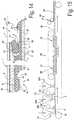
- FIG. 2at a larger scale, represents a cross-section according to the line II-II indicated in FIG. 1 ;
- FIG. 3represents the coupled condition of two of such floor panels
- FIGS. 4 to 10in a similar view, represent variants
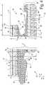
- FIG. 11at a larger scale, represents a cross-section according to the line XI-XI indicated in FIG. 1 ;
- FIGS. 12 to 14in a similar view, represent variants.
- FIG. 15schematically represents some steps in a method according to the invention.
- FIG. 1represents a rectangular floor panel 1 .
- FIG. 2clearly shows that the floor panel 1 comprises a substrate 2 and a decoration 3 provided thereon.
- the substrate 2comprises a foamed layer 4 of thermoplastic material, in this case polyvinyl chloride (PVC).
- PVCpolyvinyl chloride
- This foamed layer 4is positioned such that it is at least centrally present in the substrate 2 , namely on the central line C.
- the thickness T 1 of the foamed layerforms more than 40 percent of the thickness T 2 of the substrate.
- the substrate 2in this case only comprises not yet foamed layers 5 - 6 - 7 .
- the substrate 2 of the floor panel 1 from the example of FIGS. 1 and 2comprises a first and a second reinforcement layer 8 - 9 , in this case glass fiber layers, more particularly glass fiber mats (nonwoven).
- a first reinforcement layer 8is situated on the surface 10 , which is directed towards the decoration 3 , of the foamed layer 4 and, together with the second reinforcement layer 9 , it encloses the foamed layer 4 .
- Said second reinforcement layer 9 hereinis situated on the opposite surface 11 of the foamed layer 4 .
- Said decoration 3comprises a printed motif and represents a single wooden plank.
- the printed motifis provided on a thermoplastic foil 12 , namely a PVC foil.
- the floor panel 1comprises a transparent or translucent wear layer 13 , which is provided above said decoration 3 .
- said non-foamed layers 5 - 6 - 7comprise a first non-foamed layer 5 and a second non-foamed layer 6 , which respectively are adjacent to said surfaces 10 - 11 of the foamed layer 4 , and, in this case, also to the reinforcement layers 8 - 9 present there.
- These first and second non-foamed layers 5 - 6consist of the same thermoplastic material, namely PVC, as the foamed layer 4 , however, preferably contain a higher content of fillers, such as chalk or talc.
- the floor panel of FIG. 2forms an example of a substrate 2 where the respective non-foamed layers 5 - 6 enclose the foamed layer 4 .
- the substrate 2 of FIG. 2further also comprises a third non-foamed layer 7 of thermoplastic material.
- This third non-foamed layer 7is situated between the decoration 3 and said first non-foamed layer 5 and contains a content of plasticizer which is higher than the plasticizer content possibly present in the foamed layer 4 and/or is higher than the plasticizer content possibly present in the first and/or second non-foamed layer 5 - 6 .
- the non-foamed layer 6 on the lower surface 11 of the foamed layer 4namely the second non-foamed layer 6
- the sum of the thickness T 5 of the first non-foamed layer 5 and the thickness T 7 of the third non-foamed layer 7is approximately equal to, equal to or larger than the thickness T 6 of the second non-foamed layer 6 , preferably at least 10 percent larger, however, less than 50 percent larger.
- the second foamed layer 6can counteract possibly remaining tensions in the first and third foamed layers 5 - 7 in an optimum manner.
- the substrate 2 of the floor panel 1 of FIG. 4forms an example of the most preferred embodiment mentioned in the introduction, wherein the substrate 2 comprises a foamed layer 4 of thermoplastic material, preferably of PVC with a plasticizer content lower than 12 phr or without plasticizer, and wherein the substrate 2 further also shows one or more non-foamed layers 5 - 6 - 7 on both surfaces 10 - 11 of the foamed layer 4 , which non-foamed layers respectively also being preferably of PVC with a plasticizer content of less than 12 phr.
- the ratio of the overall thickness of all non-foamed layers 6 on the one surface 11 to the thickness of the non-foamed layers 5 - 7 on the other surface 10 of the foamed layer 4is between 0.75 and 1.33, namely, in this case approximately 0.8.
- the whole of non-foamed layers 6 in this caseis thinner on the lower surface 11 than the whole of non-foamed layers 5 - 7 on the upper surface 10 of the foamed layer 4 ; however, within said ratio.
- the average plasticizer content of the non-foamed layers 5 - 7 on the upper surface 10is higher than the average plasticizer content of the non-foamed layers 6 on the lower surface 11 , as the aforementioned third non-foamed layer 7 contains a higher plasticizer content than the possible plasticizer content in the first and second non-foamed layer 5 - 6 .
- said reinforcement layers 8 , 9respectively form the separation between the foamed layer 4 and said whole of non-foamed layers.
- the floor panel 1 from the exampleis, at least on the two opposite long edges 14 - 15 , provided with coupling means 16 allowing to couple two of such floor panels 1 to each other, wherein, as represented in FIG. 3 , a locking is effected at the respective edges 14 - 15 in a vertical direction V perpendicular to the plane of the panels 1 , as well as in a horizontal direction H perpendicular to the respective edges and in the plane of the panels 1 .
- the panel 1on at least one of its long edges 15 , is provided with a groove 17 , wherein the deepest point 18 of this groove 17 is situated in said foamed layer 4 .
- the groove 17is provided for cooperation with a tongue 19 on the opposite edge 14 and is bordered by an upper lip 20 and a lower lip 21 , wherein the lower lip 21 , in distal direction, extends to beyond the upper lip 20 , or, in other words, beyond the groove opening 22 .
- FIG. 2represents that the tongue 19 can be inserted into the groove 18 by means of a turning movement W around the respective edges 14 - 15 .
- the upper surface 23 of the lower lip 21is entirely formed of the material of said foamed layer 4
- the lower lip 21in the proximity of its distal end 24 , is provided with a hook-shaped locking part 25 , which in this case also consists of material of the foamed layer 4 .
- the hook-shaped part 25is intended for, in coupled condition, cooperating with a locking groove 26 on the lower side of the edge 14 which is provided with said tongue 19 , and effects said locking in horizontal direction H.
- a pair of horizontally active contact surfaces 27 - 28is formed between said hook-shaped part 25 and the locking groove 26 .
- the contact surfaces 27 - 28are formed on the material of the foamed layer 4 .
- the lower surface 29 of the upper lip 20is practically completely formed in a portion of the substrate 2 which is free from said foamed layer 4 .
- a first pair of vertically active contact surfaces 30 - 31is formed on this portion which is free from the material of the foamed layer 4 .
- a second pair of vertically active contact surfaces 32 - 33is formed on the upper surface 23 of the lower lip 21 and on the material of the foamed layer 4 .
- the second pair of vertically active contact surfaces 32 - 33is at least partially situated underneath the upper lip 20 , namely, in the actual groove 17 , thus, proximally in respect to the groove opening 22 .
- One of the reinforcement layers 9extends uninterruptedly in said lower lip 21 , whereas the second of said reinforcement layers 8 extends in the material of said tongue 19 . In this manner, material portions which protrude from the edges 14 - 15 will be additionally supported.
- the presence of a portion of a non-foamed layer 5 - 6 - 7 in the tongue 19 as well as in the lower lip 21is advantageous.
- the stability of the upper lip 20is guaranteed by the non-foamed layers 5 - 7 present there.
- the foamed layer 4as well as the first and second non-foamed layers 5 - 6 , are free from plasticizer or contain a plasticizer content of less than 12 phr.
- the third non-foamed layer 7too, contains a plasticizer content of less than 12 phr.
- the substrate 2consists entirely of layers 4 - 5 - 6 - 7 having a plasticizer content of less than 12 phr, if plasticizer were present at all in the respective layers 4 - 5 - 6 .
- the layers of the substrate 2 represented hereare attached to each other by means of a thermal laminating process.
- the foamed layer 4 and the first and second non-foamed layers 5 - 6are obtained by means of strewing and consolidating thermoplastic material, whether or not in the form of granulate or so-called dry-blend.
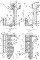
- FIG. 4represents an example of a floor panel 1 according to the invention, which shows the same layer composition as the floor panel 1 of the FIGS. 1 to 3 , with the exception of an additional foam layer 34 on the lower side of the substrate.
- thisrelates to a foam layer 34 of cross-linked or interconnected polyethylene (XPE), which by means of glue is attached to the remaining substrate portions, in particular to the non-foamed layer 6 .
- XPEcross-linked or interconnected polyethylene
- FIG. 4further clearly shows that in this case the lower surface 29 of the upper lip 20 is formed entirely from the foamed layer 4 , including the pair of vertically active contact surfaces 30 - 31 present there.
- a space 35is present on the lower side of the tongue 19 , which space extends at least from the tip of the tongue 19 to beyond the upper lip 20 .
- the reinforcement layers 8 , 9are situated in the upper lip 20 as well as in the lower lip 21 and extend uninterruptedly in these.
- the locking groove 26extends up into the upper half of the substrate, namely up to above the level C.
- the substrate 2comprises at least one reinforcement layer 8 , which, as is the case here, extends uninterruptedly above said locking groove 26 , whereas the possible other one of the reinforcement layers 9 , at least at the location of said locking groove 26 , is omitted or is removed.
- FIG. 5represents an example with similar substrate portions as FIG. 4 .
- the edge profileis different.
- the upper surface 23 of the lower lip 21is formed partially in the material of the foamed layer 4 , as well as in the material of the underlying non-foamed layer 6 .
- the reinforcement layer 9 on the lower surface 11 of the foamed layer 4is interrupted at the location of the deepest zone 36 in said upper surface 23 .
- at the location of this deepest zone 36at least half of the thickness of the whole of non-foamed layers 6 remains conserved at the lower surface 11 .
- the horizontally active contact surfaces 27 - 28 for the major partare formed on the material of the foamed layer 4 , however, for a part are also formed on the material of the underlying non-foamed layer 6 .
- the reinforcement layer 9is interrupted in said lower lip 21 , however, intersects the aforementioned horizontally active contact surfaces 27 - 28 .
- the lower surface 29 of the upper lip 20is formed practically entirely in the foamed portion 4 of the substrate 2 .
- a first pair of vertically active contact surfaces 30 - 31is formed on this portion.
- a second pair of vertically active contact surfaces 32 - 33is formed on the upper surface 23 of the lower lip 20 , also on the material of the foamed layer 4 .
- the second pair of vertically active contact surfaces 32 - 33is situated at least partially, and here even entirely, underneath the upper lip 21 , namely, in the actual groove 17 , or, in other words, proximally in respect to the groove opening 22 .
- FIG. 6 for the substrate 2shows a similar layer construction as the FIGS. 4 and 5 .
- a wear layer 13is applied, which also comprises a superficial lacquer layer 37 .
- Possibly remaining tensions in the respective lacquer layer 37hardly have any effect on the upper lip 21 , as this shows portions of non-foamed layers 5 - 7 , which are free from plasticizers or have a plasticizer content of less than 12 phr or still better of less than 7 phr.
- a reinforcement layers 8extends uninterruptedly in this upper lip 20 .
- a superficial lacquer layer 37may form part of the wear layer 13 of any embodiment of floor panels 1 according to the present invention.
- the edge profilecomprises coupling means 16 with, at the tongue side 14 , a convex lower side, and a cooperating therewith concave upper surface 23 of the lower lip 20 at the groove side 15 .
- an overlap 38is provided in the contour of the coupling means 16 , such that in the coupled condition a tension is created at least on these horizontally active contact surfaces 27 - 28 .
- a tensionmay be created as well, either by a local overlap in the contour at that position, or that said overlap 38 at the location of the horizontally active contact surfaces 27 - 28 creates a tension which has an effect on the vertically active contact surfaces 30 - 31 .
- This latterpreferably is achieved by somewhat inclining the vertically active contact surfaces 30 - 31 , as it is the case here.
- these vertically active contact surfaces 30 - 31in such case and globally seen, enclose an angle A in the range of 2° to 15°.
- FIGS. 1 to 9moreover all form examples of the application of a slighter inclination, namely of less than 10°.
- a stronger inclination than 10°is applied, however, still less than 45°, namely in the example approximately 30°.
- FIG. 7represents an example wherein the substrate 2 is constructed similarly as in FIG. 6 , however, with the exception of the additional foamed layer 34 on the lower side of the substrate 2 .
- the vertically active contact surfaces 30 - 31 and the horizontally active contact surfaces 27 - 28are formed on the material of the foamed layer 4
- the vertically active contact surfaces 30 - 31are formed on a non-foamed layer 5 present on the upper surface 10 of the foamed layer 4
- the reinforcement layer 9 in the lower lip 21is interrupted, it extends uninterruptedly in the lower lip 21 of the embodiment of FIG. 7 .
- the overlap 38 of the contours, realized on the hook-shaped part 25 in FIG. 7is more limited than in the case of FIG. 6 .
- FIG. 8represents an example with approximately the same substrate portions as the example of FIG. 2 , however, wherein the third foamed layer 7 mentioned there is omitted.
- the edge profilesshow the same shape as those of FIG. 4 , however, here they are realized such that the upper surface of the upper lip 20 for the major part is formed in the non-foamed layer 6 present on the lower surface 11 of the foam layer 4 .
- the horizontally active contact surfaces 27 - 28 on the hook-shaped part 25are formed in the material of said foam layer 4 , as well as in the material of the underlying non-foamed layer 6 .
- the reinforcement layer 9is interrupted in said lower lip 21 , however, intersects said horizontally active contact surfaces 27 - 28 , in this case, approximately in the middle.
- at the location of the deepest zone 36 in the upper surface of the lower lip 21at least half of the thickness of the whole of non-foamed layers 6 is maintained on the lower surface 11 of the foamed layer 4 .
- FIG. 9shows an example wherein the substrate 2 comprises a foamed layer 4 with a reinforcement layer 8 situated on the upper surface 10 of the foamed layer 4 , and wherein the substrate 2 further also comprises a not yet foamed layer 7 A on said upper surface 10 .
- the applied non-foamed layer 7 Ashows the composition of the third non-foamed layer 7 mentioned within the scope of the preceding examples, namely a plasticizer content of more than the possible plasticizer content in the foamed layer 4 .
- the foamed layer 4is obtained by means of consolidating and foaming strewn powders of thermoplastic material, whereas the non-foamed layer 7 A is obtained by liquid application or calendering of thermoplastic material onto the already formed foamed layer 4 .
- the substrate 2comprises only one reinforcement layer 8 , namely on the upper surface 10 of said foamed layer 4 .
- the edge profiles represented in the example of FIG. 9are formed in the foamed layer 4 .
- a space 35is present on the lower side of the tongue 19 , which space extends at least from the tip of the tongue 19 to beyond the upper lip 20 .
- the reinforcement layer 8is situated in the upper lip 20 .
- On the upper surface 23 of the lower lip 20however, more distally than the upper lip 21 , namely beyond the groove opening, vertically active contact surfaces 32 - 33 are situated. In this case, even the upper surface of the hook-shaped part 25 forms a vertically active contact surface 39 . This latter is not necessarily so.
- FIG. 10represents another embodiment wherein a similar construction of the substrate 2 is applied as in FIG. 9 , however, wherein the, in this case single, reinforcement layer 8 is embedded in the foamed layer 4 , in this case centrally or approximately central, in the foamed layer 4 .
- a pair of vertically active contact surfaces 30 - 31 on the lower side 29 of the upper lip 20partially is formed on said foamed layer 4 and partially on said non-foamed layer 6 .
- a space 35 Ais present on the lower side of the tongue 19 , which space extends from the tip of the tongue 19 up to a position underneath the upper lip 21 .
- a pair of vertically active contact surfaces 32 - 33is formed, which extends from in the actual groove 17 to beyond the upper lip 20 .
- a space 40is provided between this pair of vertically active contact surfaces 32 - 33 and the horizontally active contact surfaces 27 - 28 formed on the hook-shaped part 25 .
- FIG. 10further also shows that deep embossments 41 can be formed on the surface of the floor panel 1 .
- thisrelates at least to embossments 41 with a depth D of approximately 0.4 mm for forming a chamfer.
- FIG. 10clearly shows that the non-foamed layer 7 A receives a portion of the embossment 41 , as in this case a non-foamed layer 7 A has been chosen for, with a higher plasticizer content than the foamed layer 4 .
- the decoration 3which is present follows the embossment 41 .
- contour overlaps 38represented in FIGS. 6 and 7 , it is noted again that similar contour overlaps of course are possible in all embodiments.
- contour overlaps 38may lead to the presence of a bent-out lower lip 21 , as mentioned in the introduction, or to a material compression at least at the location of the horizontally active contact surfaces 27 - 28 .
- the depth G of the groove 17is less than the thickness T 1 of the foamed layer 4 .
- Such profileis preferred in view of stability of the coupling and, in particular, of the upper lip 20 , however, it is not indispensable. This is of particular importance when use is made of a superficial lacquer layer 37 as a part of the wear layer 13 .
- the vertically active contact surfaces 30 - 31 on the upper side of the tongue 19 and the lower surface 29 of the upper lipare made inclined.
- FIGS. 1 to 9rather limited, namely with an angle between 2° and 15°, or even between 2 and 7° in the cases of the FIGS. 1 to 8 .
- an inclinationis applied which is larger than 15°, namely in this case approximately 30°.
- the lower lip 21 of the groove 17protrudes to beyond the upper lip 20 over a distance E which is at least two times the thickness T 1 of the foamed layer A.
- the lower lip 21does not necessarily has to protrude, and also coupling means 16 can be applied with a shorter or equally long lower lip, such as, for example, the coupling means of WO 97/47834 or WO 01/98603, a protruding lower lip 21 is preferred.
- the extent of protrusion of the lower lip, or the distance Epreferably is at least one time the thickness T 1 of the foamed layer 4 .
- the extent of protrusionpreferably is less than one and a half time the overall thickness T of the floor panel 1 , and preferably is more than half of the thickness T of the floor panel 1 , as it here is the case in all examples.
- a chamferis represented in the form of an inclination at the upper edge of the floor panels 1 , this is not indispensable within the scope of the invention.
- the respective upper edgescan also be realized without a chamfer or with another type of chamfer.
- usecan be made of a chamfer performed through said decoration 3 up into the underlying substrate portion.
- the respective substrate portionas such then possibly can be provided with a matching or possibly contrasting uniform coloration, or the surface of the inclination can be provided with a separate decorative covering, for example, a lacquer layer or a print.
- a separate decorative coveringfor example, a lacquer layer or a print.
- FIG. 11represents the short edges 42 - 43 of the floor panel 1 of FIGS. 1 to 3 .
- an edge profile with a male part 44 and a female part 45is applied, which allows coupling two of such floor panels 1 at the respective edges 42 - 43 by means of a downward movement M of the male part 44 in the female part 45 , wherein in coupled condition a locking is effected in a horizontal direction H as well as in a vertical direction V.
- the combination of a turnable profile at the long edges 14 - 15for example, according to any of the FIGS. 2 to 10
- a downward coupleable profile at the short edges 44 - 45for example, according to any of the FIGS.
- the example of such downward coupleable profile represented hereis made in one piece with the material of the floor panel 1 and comprises, in order to effect the locking, a cooperating snap hook 46 and undercut 47 , as well as a hook-shaped part 25 on the lower lip 21 , which in this case also comprises an undercut 47 A.
- the undercut 47 A at the hook-shaped part 25is made such that it forms an angle A 1 with the vertical of 1° to 10°, and preferably approximately 5°.
- the locking groove 26 which cooperates with the aforementioned hook-shaped part 25is entirely positioned underneath the reinforcement layer 8 at the upper surface 10 of the foamed layer 4 .
- the aforementioned cooperating snap hook 46 and undercut 47 in this case in the coupled conditioncomprise cooperating vertically active contact surfaces 30 - 31 , which are partially realized in the foamed layer 4 and partially in the non-foamed layer 5 situated there above.
- the horizontally as well as vertically active contact surfaces 27 A- 28 A of the hook-shaped part 25are realized entirely in the material of the foamed layer 4 .
- the upper surface 23 of the lower lip 21consists entirely of material of the foamed layer 4 .
- the edge profilesalso have vertically active contact surfaces 32 - 33 formed on this upper surface 23 . Between these vertically active contact surfaces 32 - 33 and horizontally active contact surfaces 27 A- 28 A, a space 40 is present.
- the lower reinforcement layer 9extends in one piece in the lower lip 21
- the upper reinforcement layer 8extends in one piece over the aforementioned locking groove 26 .
- a recess 48is realized which extends at least partially underneath said space 40 . This latter provides for a smoother coupling, even with the represented overlap 38 in the contours.
- FIG. 12represents a variant of profiles which can be coupled into each other with a downward movement M, wherein the snap hook 46 is situated at the distal end 24 of the lower lip 21 of the female part 45 , whereas the undercut 47 is provided in the male part 44 .
- the upper surface 23 of the lower lip 21is formed entirely from the material of the foamed layer 4 , and in coupled condition the edge profiles comprise vertically active contact surfaces 32 - 33 formed on this upper surface 23 . Between these vertically active contact surfaces 32 - 33 and horizontally active contact surfaces 27 A- 28 A, a space 40 is present.
- the lower reinforcement layer 9extends in one piece in the lower lip 21
- the upper reinforcement layer 8extends in one piece over said locking groove 26 .
- the hook-shaped part 25is realized with an undercut 47 A, wherein this undercut 47 A is realized such that it forms an angle A 1 with the vertical of 1° to 10°, and preferably approximately 5°. It is evident that in FIG. 11 as well as in FIG. 12 such undercut 47 A at the location of the horizontally active contact surfaces 27 A- 28 A on the hook-shaped part 25 is not necessary and that just as well contact surfaces 27 - 28 can be used which are vertical or which are inclined less steeply than the vertical, for example, with an inclination comparable to that of the horizontally active contact surfaces 27 - 28 of FIGS. 1 to 10 , namely an inclination wherein the respective contact surfaces 27 - 28 enclose an angle with the horizontal of 45° to 90°.
- FIG. 13represents a variant of downwardly coupleable profiles, wherein the snap hook 46 is formed by a separate insert 49 , which, in this case, is provided in the male part 44 .
- a separate insert 49preferably is also formed of thermoplastic material, for example, at least of PVC or ABS (Acrylonitrile butadiene styrene), and in coupled condition preferably, such as here, comprises a vertically active contact surface 50 with the material of a non-foamed layer 7 of the female part 45 .
- said separate insert 49is situated in a seat with upper walls 51 which are formed of non-foamed material, and lower walls 52 which are formed of foamed material.
- FIG. 14represents still another example of profiles which can be coupled into each other in downward direction, wherein in this example the undercut 47 is formed by a separate insert 49 , which to this aim, in this case, is provided in the female part 45 .
- a separate insert 49preferably is also formed of thermoplastic material, for example, at least of PVC or ABS (Acrylonitrile butadiene styrene) and, in coupled condition, such as here, preferably comprises a vertically active contact surface 50 with the material of a foamed layer of the male part 44 .
- Said separate insert 49is situated in a seat with upper walls 51 which are formed of non-foamed material, and lower walls 52 which are formed of foamed material.
- FIGS. 11 to 14can be realized in various alternative manners, wherein the contact surfaces present can be realized on different substrate portions, similar to the in the introduction herein above-mentioned possibilities for tongues and/or grooves, however, wherein the tongue 19 is replaced by a whether or not one-piece snap hook 46 , and the groove 17 is formed by an undercut 47 , whether or not provided by a separate insert 49 .
- edge profiles from FIGS. 2 through 10can also be applied on the short edges 42 - 43 , wherein then the same or not the same profile is applied at the long edges 14 - 15 as well as at the short edges 42 - 43 .
- edge profilessuch as those of FIGS. 11 to 14
- edge profilescan be applied in other substrates 2 with the characteristics of the invention, such as, for example, in the substrates 2 of FIGS. 4 to 6 and 8 to 10 .
- FIG. 15schematically represents some steps in a possible method for manufacturing floor panels 1 .
- the methodcomprises the step S 1 of providing a thermoplastic material 53 .
- this step S 1is performed three times by means of three separate strewing treatments 54 A- 54 B- 54 C.
- the methodfurther also comprises the step S 2 of providing a prefabricated sheet, in this case two glass fiber mats 8 - 9 , which respectively are situated between two of the aforementioned three strewn materials.
- a first strewing treatment 54 Athe material is strewn for a first layer which is not to be foamed.
- a second strewing treatment 54 Bthe material is strewn for a first layer which is to be foamed.
- a third strewing treatment 54 Cthe material is strewn for a second layer which is not to be foamed.
- Said glass fleeces 8 - 9form an effective separation between these materials.
- the strewing treatments 54 A- 54 B- 54 C described herein abovecan be applied for obtaining a substrate portion with a central foamed layer 4 , which, on both surfaces 10 - 11 , is provided with a glass fiber mat 8 - 9 and an adjacent thereto non-foamed layer 5 - 6 , similar to the foamed layer 4 , reinforcement layers 8 - 9 and a first and second non-foamed layer 5 - 6 from the examples of FIGS. 2 to 8 and 11 to 14 .
- a subsequent step S 3at least the material of the second strewing treatment 54 B is foamed in the presence of the aforementioned glass fiber mats 8 - 9 .
- Thisis performed between the belts of a double-belt press 56 .
- the double-belt press 56is heated in a first part 57 and cooled in a second part 58 .
- the obtained foamcan have an impact on the heat transfer in the press, considering that it can function as an insulator.
- the strewn materialpreferably is pre-heated before being treated in the press.
- a further substrate layer 60can be deposited on the surface of the obtained substrate portion 59 , in liquid condition, for example by means of a so-called calendering treatment 61 .
- this further substrate layer 60may relate to the mentioned there third, non-foamed layer 7 .
- the methodcan be continued by applying a decoration 3 , possibly in the form of a printed foil 12 , and a wear layer 13 , which possibly can comprises a lacquer layer 37 .
- thermoplastic material 53it is possible to connect one or more of the prefabricated sheets, namely, the glass fiber mats 8 - 9 , to the thermoplastic material 53 under tension, for example, by pulling at it in longitudinal direction.
- Floor panelwith a substrate ( 2 ) and a decoration ( 3 ) provided thereon, characterized in that the substrate ( 2 ) comprises at least a foamed layer ( 4 ) of thermoplastic material and at least a reinforcement layer ( 8 ).
- said reinforcement layer ( 8 )relates to a glass fiber layer having a weight of at least 30 g/m 2 and preferably less than 100 g/m 2 .
- said substrate ( 2 )further also encloses a second reinforcement layer ( 9 ), wherein the respective reinforcement layers ( 8 - 9 ) enclose at least a portion of said foamed layer ( 4 ).
- said substrate ( 2 )further also comprises at least a non-foamed layer ( 5 - 6 ) of thermoplastic material.
- the aforementioned substrate ( 2 )further also comprises at least a second non-foamed layer ( 5 - 6 ) of thermoplastic material, wherein the respective non-foamed layers ( 5 - 6 ) enclose at least a portion of said foamed layer ( 4 ).
- said substrate ( 2 )further also comprises at least a third non-foamed layer ( 7 ) of thermoplastic material, wherein this third non-foamed layer ( 7 ) is situated between the decoration ( 3 ) and at least one of the aforementioned first and second non-foamed layers ( 5 - 6 ).
- said substrate ( 2 )further also comprises at least a layer ( 7 ) of thermoplastic material, wherein this thermoplastic material contains plasticizer with a content higher than the possible plasticizer content in said foamed layer.
- the floor panel ( 1 )further also comprises a translucent or transparent wear layer ( 13 ), which is provided above said decoration ( 3 ).
- the floor panel ( 1 ), seen in thicknesscomprises at least 2 millimeters of thermoplastic material which is free from plasticizer or has a plasticizer content of less than 12 phr.
- thermoplastic layer of the substrate ( 2 )are obtained by means of strewing and consolidating at least said thermoplastic material ( 53 ), whether or not in granulate form.
- Method for manufacturing a floor panelwherein this floor panel comprises at least a substrate ( 2 ) and a decoration ( 3 ) provided thereon, wherein the method for forming the substrate ( 2 ) comprises at least the following steps:
- thermoplastic materialcomprises at least a strewing treatment ( 54 B).
- thermoplastic material ( 53 ) of said further layerdiffers from the composition of said foamed layer.
- Method 47Method according to any of the paragraphs 38 to 46, characterized in that the method further also comprises the step (S 4 ) of providing at least another substrate layer ( 60 ) of thermoplastic material, wherein this thermoplastic material contains plasticizer with a content higher than the possible plasticizer content in said foamed layer.
- Method according to any of the paragraphs 38 to 48characterized in that it further also comprises the step of providing a decoration ( 3 ) on said substrate or substrate portion ( 59 ).
Landscapes
- Engineering & Computer Science (AREA)
- Architecture (AREA)
- Civil Engineering (AREA)
- Structural Engineering (AREA)
- Mechanical Engineering (AREA)
- Composite Materials (AREA)
- Chemical & Material Sciences (AREA)
- Textile Engineering (AREA)
- Ceramic Engineering (AREA)
- Life Sciences & Earth Sciences (AREA)
- Wood Science & Technology (AREA)
- Floor Finish (AREA)
- Laminated Bodies (AREA)
Abstract
Description
- the feature that the mechanical coupling means or coupling parts substantially are realized as a tongue and a groove bordered by an upper lip and a lower lip, wherein this tongue and groove substantially are responsible for the locking in said vertical direction, and wherein the tongue and the groove are provided with additional locking parts, substantially responsible for the locking in said horizontal direction. Preferably, the locking parts comprise a locking groove on the lower side of the edge with the tongue, and a hook-shaped part provided on the lower groove lip. Such coupling means and locking parts are known, for example, from WO 97/47834;
- the feature that the mechanical coupling means or coupling parts press the coupled floor panels against each other, for example, in that these mechanical coupling means are realized with a so-called pretension, as is known as such from
EP 1 026 341. The tensioning force with which the floor panels are pressed against each other or towards each other may be obtained, for example, in combination with the above-mentioned feature, by means of a lower lip which is bent out in coupled position, which, in an attempt to spring back, presses against the lower side of the tongue; - the feature that the mechanical coupling means allow a coupling by means of a horizontal, or quasi horizontal, shifting movement of the panels towards each other;
- the feature that the mechanical coupling means allow a coupling by means of a turning movement W along the respective edges;
- the feature that the mechanical coupling means allow a coupling by means of a downward-directed movement of a male coupling part, for example, with a tongue, into a female coupling part, for example, with a groove;
- the feature that the mechanical coupling means, or at least the pertaining upper edge, is realized by means of a milling treatment with rotating milling tools.
- the step of providing a prefabricated sheet, preferably a glass fiber layer;
- the step of providing thermoplastic material;
- the step of foaming said thermoplastic material for forming a foamed substrate or substrate portion, wherein the foaming takes place in the presence of said prefabricated sheet.
- the step (S2) of providing a prefabricated sheet, preferably a glass fiber layer (8-9)
- the step (S1) of providing a thermoplastic material (53);
- the step (S3) of foaming said thermoplastic material (53) for forming a foamed substrate or substrate portion (59), wherein the foaming takes place in the presence of said prefabricated sheet (8-9).
Claims (19)
Priority Applications (1)
| Application Number | Priority Date | Filing Date | Title |
|---|---|---|---|
| US16/345,865US11091919B2 (en) | 2016-11-10 | 2017-11-03 | Floor panel and method for manufacturing a floor panel |
Applications Claiming Priority (5)
| Application Number | Priority Date | Filing Date | Title |
|---|---|---|---|
| US201662420094P | 2016-11-10 | 2016-11-10 | |
| BE20165869ABE1024734B1 (en) | 2016-11-10 | 2016-11-22 | FLOOR PANEL AND METHOD FOR MANUFACTURING A FLOOR PANEL |
| BE2016/5869 | 2016-11-22 | ||
| PCT/IB2017/056856WO2018087638A1 (en) | 2016-11-10 | 2017-11-03 | Floor panel and method for manufacturing a floor panel |
| US16/345,865US11091919B2 (en) | 2016-11-10 | 2017-11-03 | Floor panel and method for manufacturing a floor panel |
Related Parent Applications (1)
| Application Number | Title | Priority Date | Filing Date |
|---|---|---|---|
| PCT/IB2017/056856A-371-Of-InternationalWO2018087638A1 (en) | 2016-11-10 | 2017-11-03 | Floor panel and method for manufacturing a floor panel |
Related Child Applications (1)
| Application Number | Title | Priority Date | Filing Date |
|---|---|---|---|
| US17/361,895ContinuationUS11668105B2 (en) | 2016-11-10 | 2021-06-29 | Floor panel and method for manufacturing a floor panel |
Publications (2)
| Publication Number | Publication Date |
|---|---|
| US20200048915A1 US20200048915A1 (en) | 2020-02-13 |
| US11091919B2true US11091919B2 (en) | 2021-08-17 |
Family
ID=57442403
Family Applications (17)
| Application Number | Title | Priority Date | Filing Date |
|---|---|---|---|
| US16/345,855ActiveUS10988939B2 (en) | 2016-11-10 | 2017-11-03 | Floor panel and method for manufacturing a floor panel |
| US16/345,865ActiveUS11091919B2 (en) | 2016-11-10 | 2017-11-03 | Floor panel and method for manufacturing a floor panel |
| US17/205,475ActiveUS11993939B2 (en) | 2016-11-10 | 2021-03-18 | Floor panel |
| US17/361,895Active2037-11-13US11668105B2 (en) | 2016-11-10 | 2021-06-29 | Floor panel and method for manufacturing a floor panel |
| US17/701,434ActiveUS12116785B2 (en) | 2016-11-10 | 2022-03-22 | Floor panel |
| US17/701,440ActiveUS12116786B2 (en) | 2016-11-10 | 2022-03-22 | Floor panel |
| US17/701,432ActiveUS12006702B2 (en) | 2016-11-10 | 2022-03-22 | Floor panel |
| US18/300,600Active2038-02-16US12410619B2 (en) | 2016-11-10 | 2023-04-14 | Floor panel |
| US18/673,759PendingUS20240309652A1 (en) | 2016-11-10 | 2024-05-24 | Floor panel |
| US18/830,756PendingUS20250003233A1 (en) | 2016-11-10 | 2024-09-11 | Floor panel and method for manufacturing a floor panel |
| US18/830,746PendingUS20250003232A1 (en) | 2016-11-10 | 2024-09-11 | Floor panel |
| US18/830,741PendingUS20250003230A1 (en) | 2016-11-10 | 2024-09-11 | Floor panel |
| US18/830,751PendingUS20240426113A1 (en) | 2016-11-10 | 2024-09-11 | Floor panel and method for manufacturing a floor panel |
| US18/830,727PendingUS20250003228A1 (en) | 2016-11-10 | 2024-09-11 | Floor panel |
| US18/830,734PendingUS20250003229A1 (en) | 2016-11-10 | 2024-09-11 | Floor panel |
| US18/830,723PendingUS20250003227A1 (en) | 2016-11-10 | 2024-09-11 | Floor panel |
| US18/830,744PendingUS20250003231A1 (en) | 2016-11-10 | 2024-09-11 | Floor panel |
Family Applications Before (1)
| Application Number | Title | Priority Date | Filing Date |
|---|---|---|---|
| US16/345,855ActiveUS10988939B2 (en) | 2016-11-10 | 2017-11-03 | Floor panel and method for manufacturing a floor panel |
Family Applications After (15)
| Application Number | Title | Priority Date | Filing Date |
|---|---|---|---|
| US17/205,475ActiveUS11993939B2 (en) | 2016-11-10 | 2021-03-18 | Floor panel |
| US17/361,895Active2037-11-13US11668105B2 (en) | 2016-11-10 | 2021-06-29 | Floor panel and method for manufacturing a floor panel |
| US17/701,434ActiveUS12116785B2 (en) | 2016-11-10 | 2022-03-22 | Floor panel |
| US17/701,440ActiveUS12116786B2 (en) | 2016-11-10 | 2022-03-22 | Floor panel |
| US17/701,432ActiveUS12006702B2 (en) | 2016-11-10 | 2022-03-22 | Floor panel |
| US18/300,600Active2038-02-16US12410619B2 (en) | 2016-11-10 | 2023-04-14 | Floor panel |
| US18/673,759PendingUS20240309652A1 (en) | 2016-11-10 | 2024-05-24 | Floor panel |
| US18/830,756PendingUS20250003233A1 (en) | 2016-11-10 | 2024-09-11 | Floor panel and method for manufacturing a floor panel |
| US18/830,746PendingUS20250003232A1 (en) | 2016-11-10 | 2024-09-11 | Floor panel |
| US18/830,741PendingUS20250003230A1 (en) | 2016-11-10 | 2024-09-11 | Floor panel |
| US18/830,751PendingUS20240426113A1 (en) | 2016-11-10 | 2024-09-11 | Floor panel and method for manufacturing a floor panel |
| US18/830,727PendingUS20250003228A1 (en) | 2016-11-10 | 2024-09-11 | Floor panel |
| US18/830,734PendingUS20250003229A1 (en) | 2016-11-10 | 2024-09-11 | Floor panel |
| US18/830,723PendingUS20250003227A1 (en) | 2016-11-10 | 2024-09-11 | Floor panel |
| US18/830,744PendingUS20250003231A1 (en) | 2016-11-10 | 2024-09-11 | Floor panel |
Country Status (10)
| Country | Link |
|---|---|
| US (17) | US10988939B2 (en) |
| EP (7) | EP4458565A3 (en) |
| KR (5) | KR102478410B1 (en) |
| CN (5) | CN110036161A (en) |
| BE (2) | BE1024723B1 (en) |
| BR (1) | BR112019009389B1 (en) |
| CA (2) | CA3040811A1 (en) |
| CO (2) | CO2019007200A2 (en) |
| EA (3) | EA201991148A1 (en) |
| WO (2) | WO2018087638A1 (en) |
Cited By (7)
| Publication number | Priority date | Publication date | Assignee | Title |
|---|---|---|---|---|
| US11325347B2 (en)* | 2018-06-06 | 2022-05-10 | Flooring Industries Limited, Sarl | Floor panels |
| US20230007825A1 (en)* | 2019-12-19 | 2023-01-12 | Flooring Industries Limited, Sarl | Floor element |
| US11603667B2 (en)* | 2019-01-10 | 2023-03-14 | Champion Link International Corporation | Panel suitable for assembling a floor covering |
| US11975526B2 (en) | 2019-09-25 | 2024-05-07 | Unilin, Bv | On-line synchronous registering co-extrusion SPC floor and production process therefor |
| US20240227350A1 (en)* | 2018-06-06 | 2024-07-11 | Unilin, Bv | Floor panel and method for manufacturing a floor panel |
| US12410619B2 (en) | 2016-11-10 | 2025-09-09 | Unilin Bv | Floor panel |
| US12441082B2 (en) | 2018-06-06 | 2025-10-14 | Unilin Bv | Floor panels |
Families Citing this family (62)
| Publication number | Priority date | Publication date | Assignee | Title |
|---|---|---|---|---|
| PL4092213T3 (en) | 2010-01-11 | 2024-03-25 | Välinge Innovation AB | Floor covering with interlocking design |
| BE1020722A3 (en)* | 2012-06-01 | 2014-04-01 | Unilin Bvba | PANEL FOR FORMING A FLOOR COVERING AND METHOD FOR MANUFACTURING SUCH PANELS. |
| BE1021929B1 (en) | 2014-07-04 | 2016-01-27 | Unilin Bvba | FLOOR PANEL |
| EP3943687B1 (en)* | 2015-01-16 | 2025-03-05 | Unilin, BV | Floor covering system |
| EP3526422B1 (en)* | 2016-10-17 | 2023-07-26 | Novalis Holdings Limited | A dimensionally stable floor panel |
| BE1024909B1 (en) | 2017-01-11 | 2018-08-16 | Ivc Bvba | Method for manufacturing a substrate for a floor panel |
| BE1025188B1 (en)* | 2017-04-24 | 2018-12-03 | Kreafin Group Sa | METHOD FOR FORMING A VOLTAGE-FREE MULTI-LAYER PVC PLATE MATERIAL |
| ES2902394T3 (en)* | 2017-05-15 | 2022-03-28 | Flooring Ind Ltd Sarl | A floor element for forming a floor covering and a floor covering |
| CN108442642A (en)* | 2018-04-12 | 2018-08-24 | 安徽森泰木塑集团股份有限公司 | A kind of outdoor flooring and its preparation process |
| US11752661B2 (en)* | 2018-05-21 | 2023-09-12 | 5R Technologies Sdn. Bhd. | Natural effect panel and method of fabricating the same |
| NL2020972B1 (en)* | 2018-05-23 | 2019-12-02 | Innovations4Flooring Holding N V | Multi-purpose tile system, tile covering, and tile |
| PT3581731T (en)* | 2018-06-15 | 2023-03-03 | Akzenta Paneele Profile Gmbh | Panel |
| EP3590709B1 (en) | 2018-07-02 | 2022-09-07 | Flooring Industries Limited, SARL | Methods to provide a pvc floor covering |
| MX2021004663A (en) | 2018-10-23 | 2021-05-28 | Carlisle Construction Mat Llc | Insulation board with improved performance. |
| NL2021887B1 (en) | 2018-10-26 | 2020-05-13 | I4F Licensing Nv | Multi-purpose tile system, tile covering, and tile |
| BE1027024B1 (en)* | 2019-02-04 | 2020-09-02 | Flooring Ind Ltd Sarl | Floor panel and method for its manufacture |
| CN216380107U (en)* | 2019-02-26 | 2022-04-26 | 科林·费尔顿 | Interlocking composite building block |
| KR102824603B1 (en) | 2019-03-05 | 2025-06-23 | 세라록 이노베이션 에이비 | Method for forming a home in a board element and associated panels |
| US11377855B2 (en) | 2019-03-25 | 2022-07-05 | Ceraloc Innovation Ab | Mineral-based panel comprising grooves and a method for forming grooves |
| CN113874206A (en)* | 2019-05-20 | 2021-12-31 | 肖氏工业集团公司 | Cellulose-based composite board |
| CN110626027B (en) | 2019-08-16 | 2021-03-16 | 浙江永裕家居股份有限公司 | Co-extrusion SPC foamed floor and preparation method thereof |
| US20220403670A1 (en) | 2019-10-10 | 2022-12-22 | Flooring Industries Limited, Sarl | Floor covering and set of components for such a floor covering |
| WO2021094625A1 (en)* | 2019-11-15 | 2021-05-20 | Beaulieu International Group Nv | Multilayer floor panel based on a pvc plastisol |
| EP4100249A1 (en) | 2019-12-10 | 2022-12-14 | Flooring Industries Limited, SARL | Floor element |
| BE1027841B1 (en) | 2019-12-10 | 2021-07-08 | Unilin Bv | FLOOR ELEMENT |
| BE1027843B1 (en)* | 2019-12-10 | 2021-07-08 | Ivc Bv | Floor element |
| EP3835027A1 (en)* | 2019-12-11 | 2021-06-16 | Akzenta Paneele + Profile GmbH | Method and apparatus for producing a decorated wall or floor panel |
| CN114829126B (en) | 2019-12-27 | 2024-10-29 | 塞拉洛克创新股份有限公司 | Thermoplastic-based building panel comprising a balancing layer |
| CN111572161B (en)* | 2019-12-30 | 2022-06-03 | 绿城装饰工程集团有限公司 | Angle-foldable PVC rigid-flexible composite board and preparation method thereof |
| US11927020B2 (en) | 2020-01-31 | 2024-03-12 | Champion Link International Corporation | Floor panel and method of manufacturing a floor panel |
| US11391049B2 (en)* | 2020-01-31 | 2022-07-19 | Champion Link International Corporation | Panel and method of producing such a panel |
| US11718565B2 (en) | 2020-01-31 | 2023-08-08 | Champion Link International Corporation | Panel for forming a floor covering and such floor covering |
| NL2025684B1 (en) | 2020-05-26 | 2021-12-14 | Champion Link Int Corp | Panel and method for producing a panel |
| US11724537B2 (en) | 2020-05-26 | 2023-08-15 | Champion Link International Corporation | Panel and method for producing a panel |
| BE1028395B1 (en)* | 2020-06-12 | 2022-01-17 | Flooring Ind Ltd Sarl | Decorative panel with antimicrobial properties |
| BE1028427B1 (en)* | 2020-06-24 | 2022-02-01 | Flooring Ind Ltd Sarl | Floor panels and method for manufacturing floor panels and cutting tools used herein |
| US11326356B2 (en) | 2020-07-15 | 2022-05-10 | Champion Link International Corporation | Floor or wall panel |
| US11530536B2 (en) | 2020-07-15 | 2022-12-20 | Champion Link International Corporation | Panel |
| US20230287690A1 (en)* | 2020-07-17 | 2023-09-14 | Flooring Industries Limited, Sarl | Coated panel |
| BE1028493B1 (en)* | 2020-07-17 | 2022-02-15 | Unilin | Clad panel, method for its manufacture and milling tool used |
| EP4232655A4 (en)* | 2020-10-23 | 2024-10-16 | Välinge Innovation AB | BUILDING PLATE WITH FIRST AND SECOND LOCKING SYSTEM |
| US12180702B2 (en)* | 2020-11-04 | 2024-12-31 | ROM Development Corp. | Fire-resistant composite structural building panels |
| PL4001546T3 (en)* | 2020-11-18 | 2024-12-16 | Unilin, Bv | FLOOR PANEL |
| WO2022139664A1 (en)* | 2020-12-21 | 2022-06-30 | Ceraloc Innovation Ab | Underlay element for flooring and floor assembly |
| CN113322683B (en)* | 2021-04-25 | 2022-11-22 | 佛山市高明尚昂科技有限公司 | Hard composite artificial leather capable of being embossed and preparation method thereof |
| EP4086408B1 (en)* | 2021-05-05 | 2024-10-16 | Bart Oerlemans BV | Panel |
| BE1030080B1 (en) | 2021-12-23 | 2023-07-24 | Flooring Ind Ltd Sarl | Panel |
| BE1030234B1 (en)* | 2022-01-31 | 2023-08-29 | Kreafin Group Sa | METHOD FOR FORMING A MULTI-LAYER PVC SHEET MATERIAL WITH A FOAMED BACKING |
| LU501429B1 (en) | 2022-02-09 | 2023-08-09 | Tarkett Gdl Sa | Hybrid acoustic floor panel |
| CN114770975B (en)* | 2022-04-20 | 2023-04-11 | 航天特种材料及工艺技术研究所 | Bionic composite material airfoil and manufacturing method thereof |
| EP4519521A1 (en) | 2022-05-05 | 2025-03-12 | Unilin, BV | Panel and method for manufacturing a panel |
| EP4565758A1 (en) | 2022-08-05 | 2025-06-11 | Unilin, BV | Decorative panel and method for manufacturing decorative panels |
| KR20250067139A (en)* | 2022-09-07 | 2025-05-14 | 뵈린게 이노베이션 에이비이 | Slopes on building panels and methods for manufacturing such building panels |
| EP4360874A1 (en) | 2022-10-25 | 2024-05-01 | Unilin, BV | Decorative panel and method for manufacturing such panel |
| WO2024089516A1 (en) | 2022-10-25 | 2024-05-02 | Unilin, Bv | Decorative panel and method for manufacturing such panel. |
| WO2024127269A1 (en) | 2022-12-14 | 2024-06-20 | Unilin, Bv | Decorative panel and method for manufacturing such panel |
| WO2024127294A1 (en) | 2022-12-16 | 2024-06-20 | Unilin, Bv | Method for manufacturing panels; and panels obtained by this method |
| EP4431274A1 (en)* | 2023-03-14 | 2024-09-18 | Unilin, BV | Decorative panel and method for manufacturing decorative panels |
| US20250263935A1 (en)* | 2023-03-27 | 2025-08-21 | Shaw Industries Group, Inc. | Decorative Article with Multilayered Porosity Base |
| WO2025111062A1 (en)* | 2023-11-22 | 2025-05-30 | Shaw Industries Group, Inc. | Decorative article with multilayered porosity base |
| NL2036706B1 (en)* | 2023-12-28 | 2025-07-11 | I4F Licensing Nv | Floor board and method for manufacturing such floor board |
| WO2025151059A1 (en)* | 2024-01-10 | 2025-07-17 | Välinge Innovation AB | A method to produce a board element and a panel |
Citations (27)
| Publication number | Priority date | Publication date | Assignee | Title |
|---|---|---|---|---|
| GB1248060A (en) | 1968-12-18 | 1971-09-29 | Ici Ltd | Reinforced thermoplastic materials |
| US4546024A (en)* | 1980-03-18 | 1985-10-08 | Brown J Gale | Modular-accessible-tiles providing accessibility to conductors and piping with improved sound isolation |
| JPH06185181A (en)* | 1993-09-01 | 1994-07-05 | Kanegafuchi Chem Ind Co Ltd | Manufacture of underlay panel |
| WO1997047834A1 (en) | 1996-06-11 | 1997-12-18 | Unilin Beheer B.V. | Floor covering, consisting of hard floor panels and method for manufacturing such floor panels |
| WO2001098603A2 (en) | 2000-06-20 | 2001-12-27 | Flooring Industries Ltd. | Floor covering |
| US20040055705A1 (en)* | 2002-09-20 | 2004-03-25 | Shutic Jeffrey R. | Hybrid spray booth for powder coating systems |
| US20060052497A1 (en)* | 2003-01-17 | 2006-03-09 | Crompton Vinyl Additives Gmbh | Stabilizer system for stabilizing pvc |
| DE102005021662A1 (en) | 2005-05-06 | 2006-11-16 | Johannes Schulte | Floor tile has insulating layer located between backing plate and wear layer and formed by heavy foil |
| US20070260006A1 (en)* | 2006-05-03 | 2007-11-08 | Whitson Russell L | Rigid polyvinyl chloride polymer compositions having improved impact properties |
| WO2011141849A2 (en) | 2010-05-10 | 2011-11-17 | Flooring Industries Limited, Sarl | Floor panel and methods for manufacturing floor panels |
| US20110296780A1 (en)* | 2006-12-11 | 2011-12-08 | Ulrich Windmöller Consulting GmbH | Floor Panel |
| EP2402155A1 (en) | 2010-06-30 | 2012-01-04 | Spanolux N.V. Div. Balterio | A panel comprising a polymeric composite layer and a reinforcement layer |
| WO2012004701A2 (en) | 2010-07-09 | 2012-01-12 | Flooring Industries Limited, Sarl | Floor panel |
| US8171691B1 (en)* | 2011-03-03 | 2012-05-08 | Tower Ipco Company Limited | Floor member with cork substrate |
| WO2013178561A2 (en) | 2012-05-30 | 2013-12-05 | Akzo Nobel Chemicals International B.V. | Microspheres |
| WO2013179261A1 (en) | 2012-06-01 | 2013-12-05 | Unilin, Bvba | Panel for forming a floor covering and method for manufacturing such panels. |
| WO2014006593A1 (en) | 2012-07-06 | 2014-01-09 | Anest Iwata Europe S.R.L. | Paint-spray gun |
| WO2014065953A1 (en) | 2012-10-22 | 2014-05-01 | Us Floors, Inc. | Engineered waterproof flooring and wall covering planks |
| US20140147585A1 (en)* | 2012-11-23 | 2014-05-29 | James Halstead Plc | Method of manufacturing a floor covering |
| US20150267025A1 (en)* | 2014-03-21 | 2015-09-24 | Zhejiang Tianzhen Bamboo & Wood Development Co., Ltd. | Pvc composite material, foam board, production method and apparatus thereof, and flooring |
| WO2015170274A1 (en) | 2014-05-07 | 2015-11-12 | Berryalloc Nv | Panel and method for manufacturing panels |
| US20150375471A1 (en)* | 2013-05-02 | 2015-12-31 | Tower Ipco Company Limited | Floor plank with foam core |
| US20160083965A1 (en)* | 2014-09-18 | 2016-03-24 | Chinafloors Holding Limited | Panel Suitable for Assembling a Waterproof Floor or Wall Covering, Method of Producing a Panel |
| CN105908946A (en) | 2016-06-01 | 2016-08-31 | 惠州伟康新型建材有限公司 | Co-extruded composite stone-plastic polyvinyl chloride (PVC) floor |
| US20170050408A1 (en)* | 2015-07-31 | 2017-02-23 | Yune Seo Park | Thermoplastic sheets and articles with variable lofting capacity |
| US20190016865A1 (en)* | 2017-07-17 | 2019-01-17 | Qingdao Sanyi Plastic Machinery Co., Ltd. | Composition for producing foamed layer of sheet, sheet containing the same, and production method thereof |
| US20190153734A1 (en)* | 2015-09-14 | 2019-05-23 | Ivc, Bvba | Method for manufacturing floor panels and floor panel for forming a floor covering |
Family Cites Families (257)
| Publication number | Priority date | Publication date | Assignee | Title |
|---|---|---|---|---|
| US360422A (en) | 1887-04-05 | Beer-pumping or air-pressure apparatus | ||
| US213740A (en) | 1879-04-01 | Improvement in wooden roofs | ||
| US1615096A (en) | 1925-09-21 | 1927-01-18 | Joseph J R Meyers | Floor and ceiling construction |
| US1778069A (en) | 1928-03-07 | 1930-10-14 | Bruce E L Co | Wood-block flooring |
| US1943663A (en) | 1929-10-30 | 1934-01-16 | United States Gypsum Co | Tile board and method of manufacturing same |
| US2111113A (en) | 1931-01-20 | 1938-03-15 | Albert C Fischer | Sponged sheet material |
| US2269926A (en) | 1939-01-06 | 1942-01-13 | Kenneth E Crooks | Composite board flooring |
| US2694025A (en) | 1951-06-27 | 1954-11-09 | Owens Corning Fiberglass Corp | Structural panel |
| US2811906A (en) | 1955-02-21 | 1957-11-05 | Clifford P Chappell | Method of forming a floor or surface covering |
| US2944622A (en)* | 1957-01-28 | 1960-07-12 | Fenestra Inc | Sound absorbing structure |
| US3215225A (en) | 1961-11-29 | 1965-11-02 | Korfund Dynamics Corp | Laminated acoustic panels with outer metal layers, fibrous core and viscoelastic damping layer |
| US3230375A (en)* | 1961-12-04 | 1966-01-18 | Mark B Van Wagoner | Laminated radiation resistant panels |
| US3139371A (en)* | 1963-05-24 | 1964-06-30 | John M Sisko | Core block construction |
| US3284980A (en) | 1964-07-15 | 1966-11-15 | Paul E Dinkel | Hydraulic cement panel with low density core and fiber reinforced high density surface layers |
| US3360422A (en)* | 1965-10-19 | 1967-12-26 | Armstrong Cork Co | Reinforced cellular floor covering |
| US3373072A (en)* | 1965-12-16 | 1968-03-12 | Armstrong Cork Co | Chemical embossing method and product |
| US3988098A (en) | 1968-12-30 | 1976-10-26 | Mitsubishi Rayon Co., Ltd. | Apparatus for continuously casting a sheet and the like |
| US3849174A (en)* | 1969-07-07 | 1974-11-19 | Union Carbide Corp | Calendering of laminated polymeric materials |
| US3616112A (en)* | 1969-08-29 | 1971-10-26 | Balsa Dev Corp | Balsa wood core in a laminated structural sandwich |
| DE2108141A1 (en) | 1970-02-20 | 1971-09-30 | Bruun & Soerensen A/S, Aarhus (Dänemark) | Floor construction |
| US3694983A (en) | 1970-05-19 | 1972-10-03 | Pierre Jean Couquet | Pile or plastic tiles for flooring and like applications |
| US3806567A (en)* | 1971-03-12 | 1974-04-23 | R Sitler | Method for producing reinforced, cellular slabs by extrusion |
| US3936391A (en) | 1971-06-16 | 1976-02-03 | Drackett Company | Hydrated polyglycerol ester composition |
| US3712846A (en)* | 1971-06-23 | 1973-01-23 | Carpenter L & Co | Acoustical panel |
| IT987642B (en) | 1972-06-01 | 1975-03-20 | Kahr Clof | COMPONENT PART OF LAMI NATO PANEL AND MANUFACTURING PROCESS OF THIS COMPONENT PART |
| US4068030A (en)* | 1972-07-18 | 1978-01-10 | Armstrong Cork Company | Multilevel embossing by printing with a reactive monomer |
| US4195713A (en) | 1974-05-29 | 1980-04-01 | Reduc Acoustics Ab | Sandwich structures with partial damping layers |
| FR2286305A1 (en) | 1974-09-27 | 1976-04-23 | Technigaz | METHOD FOR ASSEMBLING A COMPOSITE WALL STRUCTURE AND CORRESPONDING COMPOSITE WALL STRUCTURE |
| US4018957A (en)* | 1975-04-01 | 1977-04-19 | Gaf Corporation | Coated fabric sheet-type material having resilient backing and process for making same |
| US4113487A (en)* | 1975-10-31 | 1978-09-12 | Toppan Printing Co., Ltd. | Method for manufacture of expanded articles having an embossed surface |
| US4292364A (en) | 1977-04-27 | 1981-09-29 | Heidelberger Zement Aktiengesellschaft | Multi-layer board |
| US4198456A (en)* | 1978-07-19 | 1980-04-15 | Armstrong Cork Company | Multi-level embossed cellular surface covering and process for producing same |
| IT1119928B (en)* | 1978-09-25 | 1986-03-19 | Ugine Kuhlmann | COMPOSITE MATERIAL OF VINYLIDENE POLYFLUORIDE AND INCOMPATIBLE THERMOPLASTIC POLYMER AND PROCEDURE FOR ITS MANUFACTURE |
| US4230521A (en)* | 1979-04-26 | 1980-10-28 | Composite Technology Corporation | Foam impregnating apparatus |
| US4283457A (en) | 1979-11-05 | 1981-08-11 | Huyck Corporation | Laminate structures for acoustical applications and method of making them |
| US4273819A (en) | 1980-07-10 | 1981-06-16 | Congoleum Corporation | Differential gloss products and methods of making the same |
| US4504538A (en)* | 1983-07-05 | 1985-03-12 | No-Muv Corporation, Inc. | Rug underlay of fibers needled into mesh |
| DE3560797D1 (en)* | 1984-03-26 | 1987-11-26 | Gilbert O Rousseau | Decorative panel |
| US4844849A (en) | 1985-02-21 | 1989-07-04 | Congoleum Corporation | Method of making embossed decorative sheets |
| DE3546215A1 (en) | 1985-12-27 | 1987-07-02 | Dynamit Nobel Ag | METHOD FOR PRODUCING COLORED HOMOGENEOUS SURFACES FROM THERMOPLASTIC PLASTICS |
| US4710415A (en)* | 1986-09-11 | 1987-12-01 | Compo Industries, Inc. | Reinforced foam anti-fatigue floor tile module and method of making same |
| JPH0652006B2 (en)* | 1988-07-12 | 1994-07-06 | 日東紡績株式会社 | Floor tiles |
| US5073425A (en) | 1988-10-07 | 1991-12-17 | Armstrong World Industries, Inc. | Polyvinyl chloride surface covering compositions having reduced electrical resistivities |
| US5643677A (en)* | 1989-09-15 | 1997-07-01 | Armstrong World Industries, Inc. | Aminoplast/polyurethane wear layer for PVC support surface |
| ATE155076T1 (en)* | 1989-10-19 | 1997-07-15 | Avery Dennison Corp | METHOD FOR PRODUCING PLASTIC PANELS WITH OUTER WEATHERPROOF EMBOSSED AND OUTER WEATHERPROOF PLASTIC PANELS |
| US5271200A (en)* | 1990-11-05 | 1993-12-21 | Permagrain Products, Inc. | Title display system |
| US5169704A (en) | 1990-12-27 | 1992-12-08 | Tarkett Inc. | Decorative inlaid sheet materials having multiple printed layers |
| US5589243A (en)* | 1992-05-04 | 1996-12-31 | Webcore Technologies, Inc. | Reinforced foam cores and method and apparatus of production |
| ATE143448T1 (en) | 1992-05-26 | 1996-10-15 | Guenter Tesch | CORK COVERING, ESPECIALLY CORK FLOOR COVERING |
| US5501895A (en) | 1992-07-23 | 1996-03-26 | Finley; Brenda L. | Floor covering underlayment |
| US5318832A (en)* | 1992-11-02 | 1994-06-07 | Gencorp Inc. | Anti-fracture, water-resistant, masonry-bondable membrane |
| JPH08508687A (en)* | 1993-01-21 | 1996-09-17 | ユナイテッド・テクノロジー・コーポレーション | Pressure resistant fuel tank panel |
| US5344704A (en)* | 1993-04-07 | 1994-09-06 | Nevamar Corporation | Abrasion-resistant, aesthetic surface layer laminate |
| AU686205B2 (en)* | 1993-06-28 | 1998-02-05 | Thomas C. Hudson Jr. | Mechanical transfer ceramic panel |
| CA2113667A1 (en) | 1993-12-30 | 1995-07-01 | Rudolf Frisch | Multi-level, expanded resinous product |
| US5512233A (en)* | 1994-10-26 | 1996-04-30 | Davidson Textron Inc. | Method of making a panel with a spray formed skin |
| US5780147A (en) | 1995-03-14 | 1998-07-14 | Daiso Co., Ltd. | Laminate having improved dimensional stability and heat resistance |
| US5830549A (en)* | 1995-11-03 | 1998-11-03 | Triangle Pacific Corporation | Glue-down prefinished flooring product |
| US5755068A (en) | 1995-11-17 | 1998-05-26 | Ormiston; Fred I. | Veneer panels and method of making |
| US5776582A (en)* | 1996-08-05 | 1998-07-07 | Polyplus, Inc. | Load-bearing structures with interlockable edges |
| US6455127B1 (en)* | 1996-10-18 | 2002-09-24 | Variform Oy | Protective structure |
| US5836128A (en) | 1996-11-21 | 1998-11-17 | Crane Plastics Company Limited Partnership | Deck plank |
| US6228463B1 (en)* | 1997-02-20 | 2001-05-08 | Mannington Mills, Inc. | Contrasting gloss surface coverings optionally containing dispersed wear-resistant particles and methods of making the same |
| US6114008A (en) | 1997-02-20 | 2000-09-05 | Mannington Mills, Inc. | Surface coverings having a natural appearance and methods to make a surface covering having a natural appearance |
| US5925211A (en)* | 1997-04-21 | 1999-07-20 | International Paper Company | Low pressure melamine/veneer panel and method of making the same |
| AT405560B (en)* | 1997-06-18 | 1999-09-27 | Kaindl M | ARRANGEMENT OF COMPONENTS AND COMPONENTS |
| US6345481B1 (en) | 1997-11-25 | 2002-02-12 | Premark Rwp Holdings, Inc. | Article with interlocking edges and covering product prepared therefrom |
| US6324809B1 (en)* | 1997-11-25 | 2001-12-04 | Premark Rwp Holdings, Inc. | Article with interlocking edges and covering product prepared therefrom |
| US6344268B1 (en) | 1998-04-03 | 2002-02-05 | Certainteed Corporation | Foamed polymer-fiber composite |
| BR9909585A (en)* | 1998-05-12 | 2001-01-30 | Rieter Automotive Int Ag | Acoustic insulation component for vehicles |
| US7386963B2 (en)* | 1998-06-03 | 2008-06-17 | Valinge Innovation Ab | Locking system and flooring board |
| BE1012141A6 (en) | 1998-07-24 | 2000-05-02 | Unilin Beheer Bv | FLOOR COVERING, FLOOR PANEL THEREFOR AND METHOD for the realization of such floor panel. |
| US6271156B1 (en)* | 1998-09-22 | 2001-08-07 | Lydall, Inc. | Fire-resistant core for a combustible fire-rated panel |
| DE19851200C1 (en)* | 1998-11-06 | 2000-03-30 | Kronotex Gmbh Holz Und Kunstha | Floor panel has a tongue and groove joint between panels with additional projections and recesses at the underside of the tongue and the lower leg of the groove for a sealed joint with easy laying |
| SE517478C2 (en)* | 1999-04-30 | 2002-06-11 | Valinge Aluminium Ab | Locking system for mechanical hoisting of floorboards, floorboard provided with the locking system and method for producing mechanically foldable floorboards |
| TR200103546T2 (en)* | 1999-06-18 | 2002-05-21 | Henkel Kgaa | Use of a film with fasteners for mechanical fastening |
| KR100409016B1 (en) | 1999-06-26 | 2003-12-11 | 주식회사 엘지화학 | Decorative flooring with polyester film as surface layer and method of preparing the same |
| EP1243721A3 (en)* | 1999-06-30 | 2003-07-09 | Akzenta Paneele + Profile GmbH | Floor covering, panel and panel fastening system |
| US6182413B1 (en) | 1999-07-27 | 2001-02-06 | Award Hardwood Floors, L.L.P. | Engineered hardwood flooring system having acoustic attenuation characteristics |
| US6641926B1 (en) | 1999-08-13 | 2003-11-04 | Premark Rwp Holdings, Inc. | Liquid resistant laminate with strong backer |
| CN1248848C (en)* | 1999-10-08 | 2006-04-05 | 密尔沃基合成物公司 | Panels utilizing precured reinforced core and method of manufacturing the same |
| US7169460B1 (en) | 1999-12-14 | 2007-01-30 | Mannington Mills, Inc. | Thermoplastic planks and methods for making the same |
| SE522860C2 (en) | 2000-03-10 | 2004-03-09 | Pergo Europ Ab | Vertically joined floor elements comprising a combination of different floor elements |
| US6586066B1 (en) | 2000-03-21 | 2003-07-01 | Awi Licensing Company | Preglued underlayment composite and associated flooring installation system |
| US6440538B1 (en)* | 2000-04-03 | 2002-08-27 | Lg Chem Ltd. | Abrasion resistant laminate |
| JP2001295454A (en) | 2000-04-07 | 2001-10-26 | Three M Innovative Properties Co | Adhesive sheet and floor surface covering structure |
| DE10046877A1 (en) | 2000-09-22 | 2002-04-11 | Basell Polypropylen Gmbh | Layered composite material with different resin layers |
| JP4061014B2 (en)* | 2000-09-28 | 2008-03-12 | 大日本印刷株式会社 | Cosmetic material |
| SE520926C2 (en) | 2000-12-11 | 2003-09-16 | Pergo Ab | Process for making a decorative laminate with sound-absorbing elastomeric layer |
| DE10101912C1 (en) | 2001-01-16 | 2002-03-14 | Johannes Schulte | Rectangular floor panel laying method uses fitting wedge for movement of floor panel in longitudinal and transverse directions for interlocking with adjacent floor panel and previous floor panel row |
| DE10103505B4 (en)* | 2001-01-26 | 2008-06-26 | Pergo (Europe) Ab | Floor or wall panel |
| US20020100231A1 (en) | 2001-01-26 | 2002-08-01 | Miller Robert J. | Textured laminate flooring |
| ITGE20010013A1 (en)* | 2001-02-09 | 2002-08-09 | Impresa Marinoni S R L | STRUCTURES SUITABLE FOR THE INSTALLATION OF WET ROOMS AND RELATED ASSEMBLY PROCEDURE. |
| EP1233453A3 (en) | 2001-02-19 | 2005-03-23 | Kawasaki Microelectronics, Inc. | Semiconductor integrated circuit having anti-fuse, method of fabricating, and method of writing data in the same |
| DE20108668U1 (en) | 2001-05-22 | 2001-08-16 | Kronospan Technical Co. Ltd., Nikosia | Laminate flooring with two-layer impact sound absorption |
| US20020189183A1 (en) | 2001-06-19 | 2002-12-19 | Ricciardelli Thomas E. | Decorative interlocking tile |
| US8028486B2 (en)* | 2001-07-27 | 2011-10-04 | Valinge Innovation Ab | Floor panel with sealing means |
| BE1014345A3 (en) | 2001-08-14 | 2003-09-02 | Unilin Beheer Bv | Floor panel and method for manufacturing it. |
| US6759096B2 (en)* | 2001-09-24 | 2004-07-06 | Congoleum Corporation | Method for making differential gloss coverings |
| DE10151614C1 (en)* | 2001-10-23 | 2003-04-24 | Kaindl Wals M | Floor panel has a sound-improving layer provided on its bottom side which is attached by means of an amino plastic material |
| CA2369602A1 (en) | 2002-01-29 | 2003-07-29 | Levanna Schwartz | Floor panel for finished floors |
| US20030203152A1 (en) | 2002-04-08 | 2003-10-30 | Higgins Kenneth B. | Flooring systems and methods |
| SE525657C2 (en)* | 2002-04-08 | 2005-03-29 | Vaelinge Innovation Ab | Flooring boards for floating floors made of at least two different layers of material and semi-finished products for the manufacture of floorboards |
| US8850769B2 (en) | 2002-04-15 | 2014-10-07 | Valinge Innovation Ab | Floorboards for floating floors |
| US6855402B2 (en) | 2002-05-07 | 2005-02-15 | Polyone Corporation | Weather resistant plastic composites capped with polyethylene terephthalate glycol (PETG) for outdoor exposures |
| US6818282B2 (en)* | 2002-05-14 | 2004-11-16 | Awi Licensing Company | Resilient flooring structure with encapsulated fabric |
| PL191233B1 (en)* | 2002-12-31 | 2006-04-28 | Barlinek Sa | Floor panel |
| DE10302727B4 (en)* | 2003-01-23 | 2005-04-14 | E.F.P. Floor Products Fussböden GmbH | Panel, in particular floor panel |
| US20040206036A1 (en)* | 2003-02-24 | 2004-10-21 | Valinge Aluminium Ab | Floorboard and method for manufacturing thereof |
| US7507464B2 (en)* | 2003-07-01 | 2009-03-24 | Certainteed Corporation | Extruded variegated plastic siding panels |
| EP1512807B9 (en) | 2003-09-05 | 2008-09-10 | tilo GmbH | Element with thin middle layer for floor covering |
| US20050136276A1 (en)* | 2003-12-23 | 2005-06-23 | Dynea Overlays, Inc. | Synthetic crossband |
| US20050166516A1 (en)* | 2004-01-13 | 2005-08-04 | Valinge Aluminium Ab | Floor covering and locking systems |
| US20060032175A1 (en)* | 2004-07-30 | 2006-02-16 | Mannington Mills, Inc. | Flooring products and methods of making the same |
| US20060024465A1 (en)* | 2004-07-30 | 2006-02-02 | Jean Briere | Laminate flooring members |
| US8495851B2 (en)* | 2004-09-10 | 2013-07-30 | Serious Energy, Inc. | Acoustical sound proofing material and methods for manufacturing same |
| KR100716404B1 (en)* | 2004-09-21 | 2007-05-11 | 주식회사 엘지화학 | Reinforced ondol floor laminated laminated wood veneer on base material layer |
| BE1016216A5 (en)* | 2004-09-24 | 2006-05-02 | Flooring Ind Ltd | FLOOR PANEL AND FLOOR COVERING COMPOSED OF SUCH FLOOR PANELS. |
| US7841144B2 (en) | 2005-03-30 | 2010-11-30 | Valinge Innovation Ab | Mechanical locking system for panels and method of installing same |
| ES2378330T3 (en) | 2004-10-22 | 2012-04-11 | Välinge Innovation AB | A method of providing floor panels with a mechanical locking system |
| US8201377B2 (en)* | 2004-11-05 | 2012-06-19 | Faus Group, Inc. | Flooring system having multiple alignment points |
| US7473722B2 (en) | 2004-11-08 | 2009-01-06 | Certain Teed Corp. | Polymer-fiber composite building material with bulk and aesthetically functional fillers |
| BE1016394A3 (en)* | 2004-12-23 | 2006-10-03 | Flooring Ind Ltd | FLOOR PANEL, AND METHOD, DEVICE AND ACCESSORIES FOR MANUFACTURING SUCH FLOOR PANEL. |
| US7849648B2 (en) | 2004-12-30 | 2010-12-14 | United States Gypsum Company | Non-combustible reinforced cementitious lightweight panels and metal frame system for flooring |
| EP1681405A1 (en)* | 2005-01-13 | 2006-07-19 | Berry Finance Nv | Floor panel |
| BE1016938A6 (en)* | 2005-03-31 | 2007-10-02 | Flooring Ind Ltd | Floor panel manufacturing method, involves providing panels at lower side with guiding groove and providing two opposite sides with profiled edge regions that comprise coupling parts |
| DE102005023661B4 (en) | 2005-05-23 | 2024-05-23 | Pergo (Europe) Ab | Floor panel |
| EP1734202A1 (en)* | 2005-06-14 | 2006-12-20 | Tarkett SAS | Panel provided with a repositionable adhesive, in particular to cover floors, walls or ceilings |
| US20090162651A1 (en)* | 2005-08-02 | 2009-06-25 | World Properties, Inc. | Silicone compositions, methods of manufacture, and articles formed therefrom |
| CN2793206Y (en) | 2005-08-31 | 2006-07-05 | 森阳木业(天津)有限公司 | Composite wooden sandwich floor |
| US7504159B1 (en) | 2005-11-04 | 2009-03-17 | 3Form, Inc. | Resin-based panels having thin or brittle veneer layers and methods of making same |
| US20120073225A1 (en)* | 2005-11-24 | 2012-03-29 | James Edward Douglass | Planks and/or boards |
| SE528583C2 (en)* | 2006-03-27 | 2006-12-19 | Tarkett Ab | Floorboard production method, comprises bevelling length edges of surface layer and then machining these edges to form tongue and groove profiles |
| KR100881006B1 (en) | 2006-03-30 | 2009-02-03 | 다이니폰 인사츠 가부시키가이샤 | Method of manufacturing a cosmetic sheet for flooring |
| BE1017157A3 (en) | 2006-06-02 | 2008-03-04 | Flooring Ind Ltd | FLOOR COVERING, FLOOR ELEMENT AND METHOD FOR MANUFACTURING FLOOR ELEMENTS. |
| EP2066854B1 (en)* | 2006-09-11 | 2017-04-12 | Spanolux N.V.- DIV. Balterio | Apparatus and method of making a covering panel with bevelled edges having varying cross-section |
| ES2325425T3 (en) | 2006-10-12 | 2009-09-03 | Flooring Technologies Ltd. | PROCEDURE FOR MANUFACTURING A CONSTRUCTION PLATE AND CONSTRUCTION PLATE MANUFACTURED ACCORDING TO IT. |
| DE102006057491A1 (en) | 2006-12-06 | 2008-06-12 | Akzenta Paneele + Profile Gmbh | Panel and flooring |
| BE1017403A5 (en)* | 2006-12-21 | 2008-08-05 | Flooring Ind Ltd | FLOOR ELEMENT, LOCKING SYSTEM FOR FLOOR ELEMENTS, FLOOR COVERING AND METHOD FOR COMPOSING SUCH FLOOR ELEMENTS TO A FLOOR COVERING. |
| US7726088B2 (en)* | 2007-07-20 | 2010-06-01 | Moritz Andre Muehlebach | Flooring system |
| CN101878113B (en)* | 2007-07-25 | 2015-06-03 | 普瑞尼尔巴西木材贸易有限公司 | Multi-ply platforms and panels using such a platform |
| JP4858544B2 (en)* | 2007-09-11 | 2012-01-18 | 東レ株式会社 | Composite molded article and manufacturing method thereof |
| US9783996B2 (en) | 2007-11-19 | 2017-10-10 | Valinge Innovation Ab | Fibre based panels with a wear resistance surface |
| PL3072653T3 (en) | 2007-11-19 | 2022-08-22 | Välinge Innovation AB | Method of manufacturing a building panel |
| BE1018600A5 (en) | 2007-11-23 | 2011-04-05 | Flooring Ind Ltd Sarl | FLOOR PANEL. |
| DK2072713T3 (en) | 2007-12-20 | 2016-03-29 | Deceuninck Nv | FLOOR PANEL |
| AR070957A1 (en) | 2008-01-11 | 2010-05-19 | Nova Chem Inc | METHOD FOR PRODUCING THERMOPLASTIC COMPOUND MATERIALS OF A COPOLYMER CONTAINING LOADED ANHYDRID WITH CELLULOSICAL MATERIALS |
| US20090226662A1 (en) | 2008-03-06 | 2009-09-10 | Mannington Mills, Inc. | Surface Coverings Containing Reclaimed VCT Material, and Methods and Systems For Making and Using Them |
| KR20110018887A (en) | 2008-04-30 | 2011-02-24 | 암스트롱 월드 인더스트리이즈, 인코포레이티드 | Bio based elastic floor tile |
| CN101294439B (en)* | 2008-06-16 | 2011-12-21 | 吴绍元 | Multifunctional energy-saving decorative board |
| FR2934601B1 (en) | 2008-07-29 | 2010-10-22 | Gerflor | METHOD FOR VERNING FLOORING OF SOILS AND SOFT PVC WALLS |
| KR101069501B1 (en)* | 2008-10-14 | 2011-09-30 | (주)엘지하우시스 | Energy-saving flooring and manufacturing method |
| BE1018382A3 (en)* | 2008-12-22 | 2010-09-07 | Wybo Carlos | UPHOLSTERY PANEL. |
| DE102009009646A1 (en) | 2009-02-19 | 2010-09-30 | SÜDDEKOR GmbH | A decorative product, a method for producing a decorative product and use of a decorative product for producing a decorated support surface |
| BE1018728A3 (en)* | 2009-04-22 | 2011-07-05 | Flooring Ind Ltd Sarl | FLOOR PANEL. |
| DE102009035275A1 (en)* | 2009-06-08 | 2010-12-09 | Fritz Egger Gmbh & Co. | Panel of a floor system |
| KR101302335B1 (en) | 2009-09-23 | 2013-08-30 | (주)엘지하우시스 | Flooring material and preparation method thereof |
| PT2339092T (en) | 2009-12-22 | 2019-07-19 | Flooring Ind Ltd Sarl | Method for producing covering panels |
| CN101881076B (en) | 2010-06-09 | 2014-07-09 | 黄焕文 | Combined floor capable of being paved conveniently |
| PL4092213T3 (en)* | 2010-01-11 | 2024-03-25 | Välinge Innovation AB | Floor covering with interlocking design |
| JP2011236733A (en)* | 2010-04-30 | 2011-11-24 | Shaw Industries Group Inc | Non-vinyl elastic floor product and manufacturing method thereof |
| US8925275B2 (en)* | 2010-05-10 | 2015-01-06 | Flooring Industries Limited, Sarl | Floor panel |
| US9217251B2 (en)* | 2010-06-15 | 2015-12-22 | Joseph D. D'Agostino | Articles and methods for laying ceramic tile floor |
| ES2853675T3 (en)* | 2010-06-30 | 2021-09-17 | Flooring Ind Ltd Sarl | A panel comprising a layer of polymeric composite material and a method of manufacturing such a panel |
| CA3117806A1 (en)* | 2010-07-09 | 2012-01-12 | Flooring Industries Limited, Sarl | Floor panel with a substrate and a top layer |
| EP2447063A1 (en) | 2010-10-26 | 2012-05-02 | Rodolfo Comerio S.r.l. | Method and apparatus for registered embossing of a laminate |
| US20120128967A1 (en)* | 2010-11-18 | 2012-05-24 | Viking Polymers, Llc | Pvc and styrenic alloy decking with reduced surface stress accumulation |
| KR101320265B1 (en)* | 2010-12-24 | 2013-10-29 | (주)엘지하우시스 | Composite board including polylacticacid cover |
| DE102011002131A1 (en)* | 2011-04-18 | 2012-10-18 | Guido Schulte | floor element |
| US8631622B2 (en)* | 2011-07-07 | 2014-01-21 | Chinafloors Holding Limited | Non-squeaking wood flooring systems and methods |
| EP2763850B1 (en)* | 2011-10-03 | 2018-07-18 | Unilin, BVBA | Floor panel |
| ES2735995T3 (en)* | 2011-10-28 | 2019-12-23 | U Windmoeller Consulting Gmbh & Co Kg | Floor covering |
| EP2812510B1 (en) | 2012-02-07 | 2018-03-07 | Flooring Industries Limited, SARL | Floor panel for forming a floor covering, floor covering formed from such floor panels and method for manufacturing such floor panels |
| EP2636524B1 (en) | 2012-03-05 | 2014-12-31 | Rodolfo Comerio S.r.l. | Process and apparatus for registered embossing of extensible printed film or of a laminate comprising an extensible printed film |
| US9057193B2 (en)* | 2012-03-05 | 2015-06-16 | Victor Amend | Subfloor component and method of manufacturing same |
| UA111997C2 (en)* | 2012-04-02 | 2016-07-11 | Кроноплюс Текнікал Аг | PANEL WITH COVER DIRECTED BY DIRECT PRINTING METHOD |
| US8640824B2 (en)* | 2012-05-10 | 2014-02-04 | Michael Freedman & Associates, Inc. | Acoustical vinyl flooring and methods of manufacture |
| CN103072346B (en) | 2012-06-19 | 2015-06-03 | 厦门朝富人造革有限公司 | Thermoplastic foaming polyurethane fiber board, production method and uses thereof |
| US9140010B2 (en) | 2012-07-02 | 2015-09-22 | Valinge Flooring Technology Ab | Panel forming |
| US9295748B2 (en) | 2012-07-31 | 2016-03-29 | Exos Llc | Foam core sandwich splint |
| US8993049B2 (en) | 2012-08-09 | 2015-03-31 | Valinge Flooring Technology Ab | Single layer scattering of powder surfaces |
| US9572505B2 (en) | 2012-10-11 | 2017-02-21 | Medtronic, Inc. | Determining onsets and offsets of cardiac depolarization and repolarization waves |
| US9409382B2 (en)* | 2012-11-28 | 2016-08-09 | Valinge Innovation Ab | Method of producing a building panel |
| MX2015009766A (en) | 2013-01-28 | 2015-10-29 | Armstrong World Ind Inc | Flooring underlayment and apparatus, flooring system and floor installation method using the same. |
| EP2969564B1 (en) | 2013-03-15 | 2019-06-19 | Arkema France | Multilayer composite |
| KR20150133216A (en) | 2013-03-22 | 2015-11-27 | 스미또모 베이크라이트 가부시키가이샤 | Melamine resin metal decorative plate and method for manufacturing melamine resin metal decorative plate |
| US9133626B2 (en) | 2013-05-02 | 2015-09-15 | Tower Ipco Company Limited | Multi-purpose tile |
| PL226409B1 (en) | 2013-05-15 | 2017-07-31 | Ap Plast Spółka Z Ograniczoną Odpowiedzialnością | Composite molding board |
| BR202013014633Y8 (en) | 2013-06-12 | 2022-05-17 | Plaslatina Ind Plastica Ltda Me | Thermoplastic tile board for architectural coating |
| US9744707B2 (en) | 2013-10-18 | 2017-08-29 | Eastman Chemical Company | Extrusion-coated structural members having extruded profile members |
| EP3060400B1 (en)* | 2013-10-23 | 2020-03-11 | Ceraloc Innovation AB | Method of forming a decorative wear resistant layer |
| CA2861259C (en) | 2013-11-01 | 2016-06-14 | Groupe Isolofoam Inc. | Rigid insulating panel and rigid insulation panel assembly |
| WO2015070890A1 (en)* | 2013-11-12 | 2015-05-21 | Grigorij Wagner | Flooring component |
| US9303354B2 (en) | 2013-12-31 | 2016-04-05 | Awi Licensing Company | Linoleum flooring |
| US9744753B2 (en)* | 2014-02-12 | 2017-08-29 | Wabash National, L.P. | Composite wood flooring and method of making the same |
| WO2015130169A1 (en) | 2014-02-26 | 2015-09-03 | Innovations 4 Flooring Holding N.V. | Panel interconnectable with similar panels for forming a covering |
| DE102014108885A1 (en) | 2014-03-07 | 2015-09-10 | Hamberger Industriewerke Gmbh | Wear layer for a panel, panel and method of making a wear layer and a panel |
| CN106103096B (en)* | 2014-03-31 | 2018-08-24 | 塞拉洛克创新股份有限公司 | Composite panels and panels |
| ES2551632B1 (en)* | 2014-05-20 | 2016-09-08 | Euro Trade Flooring, S.L. | Multi-layer cladding plate for horizontal support surfaces and manufacturing process |
| NL2013046B1 (en)* | 2014-06-20 | 2016-07-06 | Champion Link Int Corp | Panel suitable for assembling a waterproof floor or wall covering, method of producing a panel. |
| BE1021929B1 (en)* | 2014-07-04 | 2016-01-27 | Unilin Bvba | FLOOR PANEL |
| PT3169532T (en) | 2014-07-16 | 2023-10-27 | Vaelinge Innovation Ab | Method to produce a thermoplastic wear resistant foil |
| US10940680B2 (en)* | 2014-07-31 | 2021-03-09 | Unilin Bv | Method and installation for manufacturing a floor covering product and floor covering product obtained hereby |
| EP3194684B1 (en) | 2014-09-18 | 2021-11-10 | Tarkett G.D.L. S.a. | Thin decorative surface covering |
| KR102014555B1 (en)* | 2014-09-19 | 2019-08-27 | (주)엘지하우시스 | Cushion flooing sheet and manufacturing method thereof |
| US20160129299A1 (en)* | 2014-11-11 | 2016-05-12 | Howard Hancock Newman | Hinged interlocking tiles |
| US9249582B1 (en) | 2014-11-14 | 2016-02-02 | Awi Licensing Company | Interlocking floor panels with high performance locking profiles |
| US10821714B2 (en) | 2014-11-20 | 2020-11-03 | Ivc B.V. | Method for manufacturing a panel including a reinforcement sheet, and a floor panel |
| BR112017012681B1 (en)* | 2014-12-22 | 2022-05-03 | Ceraloc Innovation Ab | Set of essentially identical floor panels |
| US9567755B2 (en)* | 2014-12-23 | 2017-02-14 | Afi Licensing Llc | Sound-absorbing interlocking floor panels and system |
| US9650792B2 (en)* | 2014-12-23 | 2017-05-16 | Afi Licensing Llc | Interlocking floor panels and floor system |
| US20160288447A1 (en) | 2015-01-05 | 2016-10-06 | Eurico Januario Cordeiro | Waterproof composite core |
| ES2769238T3 (en)* | 2015-01-15 | 2020-06-25 | Flooring Ind Ltd Sarl | Floor panel to form a ground cover |
| ES2826556T3 (en) | 2015-01-15 | 2021-05-18 | Flooring Ind Ltd Sarl | Floor panel to form a floor covering |
| CN107206758A (en)* | 2015-01-16 | 2017-09-26 | 博优国际集团公司 | Mulch and method for making mulch |
| US10309113B2 (en)* | 2015-01-16 | 2019-06-04 | Flooring Industries Limited, Sarl | Floor panel for forming a floor covering |
| US10480120B2 (en)* | 2015-01-16 | 2019-11-19 | Beaulieu International Group Nv | Covering for floors, walls or ceilings, and method for obtaining a covering |
| ES2958085T3 (en) | 2015-01-16 | 2024-02-01 | Beaulieu Int Group Nv | Covering panel |
| US9861220B2 (en)* | 2015-03-04 | 2018-01-09 | John Charles BURKHALTER | Slidable anti-fatigue mat |
| KR20160109549A (en)* | 2015-03-12 | 2016-09-21 | (주)엘지하우시스 | A flame retarding flooring materials and the manufacturing method thereof |
| AU2016243412A1 (en)* | 2015-03-27 | 2017-11-16 | Golconda Holdings Llc | System, method, and apparatus for magnetic surface coverings |
| DE202016009050U1 (en)* | 2015-05-12 | 2021-10-07 | Aladdin Manufacturing Corporation | Floor board |
| CN106280060A (en) | 2015-05-22 | 2017-01-04 | 江苏森茂竹木业有限公司 | Plastics composite, the composite floor board including this plastics composite and preparation method thereof |
| BE1023310B1 (en)* | 2015-07-02 | 2017-01-31 | Unilin, Bvba | Floor panel and method for manufacturing floor panels. |
| US20170044778A1 (en)* | 2015-08-12 | 2017-02-16 | Armstrong World Industries, Inc. | Impact resistant wear layer |
| KR101626470B1 (en) | 2015-09-16 | 2016-06-01 | (주)계림건축사사무소 | Non-foam type materials for reducing noise and floor system comprising the same |
| CN105133818A (en) | 2015-09-25 | 2015-12-09 | 江苏贝尔装饰材料有限公司 | High-strength PVC sheet floor and manufacturing method thereof |
| US10974488B2 (en)* | 2015-11-17 | 2021-04-13 | Wellmade Floor Covering Int'l Inc. | Engineered plank and its manufacturing method |
| US20170138062A1 (en) | 2015-11-17 | 2017-05-18 | Wellmade Floor Covering Int'l Inc. | Flooring Plank Fasteners |
| CN105587103A (en)* | 2015-11-20 | 2016-05-18 | 大块建材开发(江苏)有限公司 | Hard board plastic floor and making method thereof |
| CN108431343A (en)* | 2015-12-23 | 2018-08-21 | 克诺那普雷斯技术股份公司 | Floor with discharge protrusion |
| BE1023817B1 (en)* | 2016-01-15 | 2017-08-01 | Unilin Bvba | Floor panel for forming a floor covering, and substrate for a panel |
| BE1023818B1 (en)* | 2016-01-15 | 2017-08-01 | Flooring Industries Limited Sarl | Floor panel for forming a floor covering |
| WO2017132477A1 (en)* | 2016-01-28 | 2017-08-03 | American Aquawood, Inc. | Floor and wall covering assembly |
| US9677284B1 (en) | 2016-02-02 | 2017-06-13 | Barrett Aerospace Technologies, LLC | Thermally adaptive wall covering |
| NL2016223B1 (en) | 2016-02-04 | 2017-08-14 | Champion Link Int Corp | Panel suitable for constructing a waterproof floor or wall covering, process for producing a panel, panel obtainable by said process. |
| US10094124B2 (en)* | 2016-05-04 | 2018-10-09 | Wellmade Floor Covering Int'l Inc. | Engineered plank material having waterproofed veneer and its manufacturing method |
| US11248380B2 (en)* | 2016-06-28 | 2022-02-15 | Sunrise Spc Technology, Llc | Glueless dustless composite flooring material system |
| US10343381B2 (en) | 2016-06-28 | 2019-07-09 | John B. Troendle | Method of producing a glueless dustless composite flooring material system |
| US10889040B2 (en) | 2016-06-28 | 2021-01-12 | John B. Troendle | Method of producing a glueless dustless composite flooring material system |
| US10220599B2 (en) | 2016-06-28 | 2019-03-05 | John B. Troendle | Glueless dustless composite flooring material system |
| WO2018007932A2 (en) | 2016-07-07 | 2018-01-11 | Unilin, Bvba | Floor panel |
| WO2018030705A1 (en)* | 2016-08-10 | 2018-02-15 | 주식회사 녹수 | High-strength multilayered tile and manufacturing method therefor |
| US10544595B2 (en)* | 2016-08-26 | 2020-01-28 | Quickstyle Industries Inc. | Tile with protected imitation grout line |
| US10132088B2 (en)* | 2016-08-26 | 2018-11-20 | Quickstyle Industries Inc. | Stone plastic composite (SPC) tile with imitation grout line |
| US10233656B2 (en) | 2016-08-26 | 2019-03-19 | Quickstyle Industries Inc. | Densified foam core (DFC) tile with imitation grout line |
| US20190316363A1 (en)* | 2016-08-26 | 2019-10-17 | Stephen Courey | Tile with imitation grout line |
| US10266303B1 (en)* | 2016-09-06 | 2019-04-23 | Charles D. Kownacki | Light-weight structural panel construction |
| BE1024617B1 (en) | 2016-10-03 | 2018-05-02 | Ivc Bvba | Floor panel and method for manufacturing a floor panel. |
| EP3526422B1 (en) | 2016-10-17 | 2023-07-26 | Novalis Holdings Limited | A dimensionally stable floor panel |
| BE1024723B1 (en) | 2016-11-10 | 2018-06-11 | Ivc Bvba | Floor panel and method for manufacturing a floor panel. |
| CN106587720B (en) | 2016-12-02 | 2019-10-15 | 江苏贝尔装饰材料有限公司 | A kind of stone plastic floor and preparation method thereof |
| CN113356508A (en)* | 2017-03-21 | 2021-09-07 | 地板工业有限公司 | Panel panel |
| US20180283014A1 (en)* | 2017-04-03 | 2018-10-04 | Columbia Insurance Company | Rigid composite board floor coverings |
| BE1025188B1 (en) | 2017-04-24 | 2018-12-03 | Kreafin Group Sa | METHOD FOR FORMING A VOLTAGE-FREE MULTI-LAYER PVC PLATE MATERIAL |
| US11149446B2 (en)* | 2018-09-10 | 2021-10-19 | Champion Link International Corporation | Floor panel comprising a ceramic material or a natural stone |
| US11939762B2 (en)* | 2021-04-27 | 2024-03-26 | Ge Infrastructure Technology Llc | System and method for manufacturing a tower structure |
- 2016
- 2016-11-22BEBE20165868Apatent/BE1024723B1/enactiveIP Right Grant
- 2016-11-22BEBE20165869Apatent/BE1024734B1/enactiveIP Right Grant
- 2017
- 2017-11-03CNCN201780069726.2Apatent/CN110036161A/enactivePending
- 2017-11-03CACA3040811Apatent/CA3040811A1/enactivePending
- 2017-11-03WOPCT/IB2017/056856patent/WO2018087638A1/ennot_activeCeased
- 2017-11-03WOPCT/IB2017/056855patent/WO2018087637A1/ennot_activeCeased
- 2017-11-03EPEP24200858.9Apatent/EP4458565A3/enactivePending
- 2017-11-03KRKR1020197016130Apatent/KR102478410B1/enactiveActive
- 2017-11-03CNCN202210304095.0Apatent/CN114575551B/enactiveActive
- 2017-11-03EAEA201991148Apatent/EA201991148A1/enunknown
- 2017-11-03EPEP17805266.8Apatent/EP3538720B1/enactiveActive
- 2017-11-03KRKR1020247010400Apatent/KR20240046299A/enactivePending
- 2017-11-03EPEP17805267.6Apatent/EP3538721B1/enactiveActive
- 2017-11-03EPEP22166945.0Apatent/EP4043664B1/enactiveActive
- 2017-11-03BRBR112019009389-3Apatent/BR112019009389B1/enactiveIP Right Grant
- 2017-11-03USUS16/345,855patent/US10988939B2/enactiveActive
- 2017-11-03KRKR1020197016129Apatent/KR20190085007A/ennot_activeCeased
- 2017-11-03EPEP22166950.0Apatent/EP4043665A1/enactivePending
- 2017-11-03CNCN202210304104.6Apatent/CN114482454B/enactiveActive
- 2017-11-03CNCN201780069578.4Apatent/CN110023573B/enactiveActive
- 2017-11-03CNCN202210304127.7Apatent/CN114482455B/enactiveActive
- 2017-11-03CACA3040624Apatent/CA3040624A1/enactivePending
- 2017-11-03EAEA202190239Apatent/EA202190239A3/enunknown
- 2017-11-03EPEP25198327.6Apatent/EP4631704A2/enactivePending
- 2017-11-03EPEP22166973.2Apatent/EP4043666A1/enactivePending
- 2017-11-03USUS16/345,865patent/US11091919B2/enactiveActive
- 2017-11-03EAEA201991159Apatent/EA037589B1/enunknown
- 2017-11-03KRKR1020247010399Apatent/KR20240046624A/enactivePending
- 2017-11-03KRKR1020237000618Apatent/KR102770537B1/enactiveActive
- 2019
- 2019-07-03COCONC2019/0007200Apatent/CO2019007200A2/enunknown
- 2019-07-03COCONC2019/0007196Apatent/CO2019007196A2/enunknown
- 2021
- 2021-03-18USUS17/205,475patent/US11993939B2/enactiveActive
- 2021-06-29USUS17/361,895patent/US11668105B2/enactiveActive
- 2022
- 2022-03-22USUS17/701,434patent/US12116785B2/enactiveActive
- 2022-03-22USUS17/701,440patent/US12116786B2/enactiveActive
- 2022-03-22USUS17/701,432patent/US12006702B2/enactiveActive
- 2023
- 2023-04-14USUS18/300,600patent/US12410619B2/enactiveActive
- 2024
- 2024-05-24USUS18/673,759patent/US20240309652A1/enactivePending
- 2024-09-11USUS18/830,756patent/US20250003233A1/enactivePending
- 2024-09-11USUS18/830,746patent/US20250003232A1/enactivePending
- 2024-09-11USUS18/830,741patent/US20250003230A1/enactivePending
- 2024-09-11USUS18/830,751patent/US20240426113A1/enactivePending
- 2024-09-11USUS18/830,727patent/US20250003228A1/enactivePending
- 2024-09-11USUS18/830,734patent/US20250003229A1/enactivePending
- 2024-09-11USUS18/830,723patent/US20250003227A1/enactivePending
- 2024-09-11USUS18/830,744patent/US20250003231A1/enactivePending
Patent Citations (55)
| Publication number | Priority date | Publication date | Assignee | Title |
|---|---|---|---|---|
| GB1248060A (en) | 1968-12-18 | 1971-09-29 | Ici Ltd | Reinforced thermoplastic materials |
| US4546024A (en)* | 1980-03-18 | 1985-10-08 | Brown J Gale | Modular-accessible-tiles providing accessibility to conductors and piping with improved sound isolation |
| JPH06185181A (en)* | 1993-09-01 | 1994-07-05 | Kanegafuchi Chem Ind Co Ltd | Manufacture of underlay panel |
| WO1997047834A1 (en) | 1996-06-11 | 1997-12-18 | Unilin Beheer B.V. | Floor covering, consisting of hard floor panels and method for manufacturing such floor panels |
| EP1026341A2 (en) | 1996-06-11 | 2000-08-09 | Unilin Beheer B.V. | Floor covering, consisting of hard floor panels and method for manufacturing such floor panels |
| WO2001098603A2 (en) | 2000-06-20 | 2001-12-27 | Flooring Industries Ltd. | Floor covering |
| US20040055705A1 (en)* | 2002-09-20 | 2004-03-25 | Shutic Jeffrey R. | Hybrid spray booth for powder coating systems |
| US20060052497A1 (en)* | 2003-01-17 | 2006-03-09 | Crompton Vinyl Additives Gmbh | Stabilizer system for stabilizing pvc |
| US7358286B2 (en)* | 2003-01-17 | 2008-04-15 | Chemtura Vinyl Additives Gmbh | Stabilizer system for stabilizing PVC |
| DE102005021662A1 (en) | 2005-05-06 | 2006-11-16 | Johannes Schulte | Floor tile has insulating layer located between backing plate and wear layer and formed by heavy foil |
| US20070260006A1 (en)* | 2006-05-03 | 2007-11-08 | Whitson Russell L | Rigid polyvinyl chloride polymer compositions having improved impact properties |
| US20110296780A1 (en)* | 2006-12-11 | 2011-12-08 | Ulrich Windmöller Consulting GmbH | Floor Panel |
| US20190063078A1 (en)* | 2010-05-10 | 2019-02-28 | Flooring Industries Limited, Sarl | Floor panel |
| US10094123B2 (en)* | 2010-05-10 | 2018-10-09 | Flooring Industries Limited, Sarl | Floor panel |
| US10301831B2 (en)* | 2010-05-10 | 2019-05-28 | Flooring Industries Limited, Sarl | Floor panel |
| US10233655B2 (en)* | 2010-05-10 | 2019-03-19 | Flooring Industries Limited, Sarl | Floor panel |
| US9322184B2 (en)* | 2010-05-10 | 2016-04-26 | Flooring Industries Limited, Sarl | Methods for manufacturing floor panels |
| US20130067842A1 (en)* | 2010-05-10 | 2013-03-21 | Flooring Industries Limited, Sarl | Floor panel and methods for manufacturing floor panels |
| US8549807B2 (en)* | 2010-05-10 | 2013-10-08 | Flooring Industries Limited, Sarl | Floor panel and methods for manufacturing floor panels |
| US20190063079A1 (en)* | 2010-05-10 | 2019-02-28 | Flooring Industries Limited, Sarl | Floor panel |
| US20190040634A1 (en)* | 2010-05-10 | 2019-02-07 | Flooring Industries Limited, Sarl | Floor panel |
| US10100533B2 (en)* | 2010-05-10 | 2018-10-16 | Flooring Industries Limited, Sarl | Floor panel |
| US20140020820A1 (en)* | 2010-05-10 | 2014-01-23 | Flooring Industries Limited, Sarl | Methods for manufacturing floor panels |
| WO2011141849A2 (en) | 2010-05-10 | 2011-11-17 | Flooring Industries Limited, Sarl | Floor panel and methods for manufacturing floor panels |
| US20180245353A1 (en)* | 2010-05-10 | 2018-08-30 | Flooring Industries Limited, Sarl | Floor panel |
| US20140290158A1 (en)* | 2010-05-10 | 2014-10-02 | Flooring Industries Limited, Sarl | Floor panel |
| US20180245354A1 (en)* | 2010-05-10 | 2018-08-30 | Flooring Industries Limited, Sarl | Floor panel |
| US20150167320A1 (en)* | 2010-05-10 | 2015-06-18 | Flooring Industries Limited, Sarl | Floor panel |
| US20170362833A1 (en)* | 2010-05-10 | 2017-12-21 | Flooring Industries Limited, Sarl | Floor panel |
| US9163414B2 (en)* | 2010-05-10 | 2015-10-20 | Flooring Industries Limited, Sarl | Floor panel |
| US9783995B2 (en)* | 2010-05-10 | 2017-10-10 | Flooring Industries Limited, Sarl | Floor panel |
| US9212494B2 (en)* | 2010-05-10 | 2015-12-15 | Flooring Industries Limited, Sarl | Floor panel |
| US20160160508A1 (en)* | 2010-05-10 | 2016-06-09 | Flooring Industries Limited, Sarl | Floor panel |
| EP2402155A1 (en) | 2010-06-30 | 2012-01-04 | Spanolux N.V. Div. Balterio | A panel comprising a polymeric composite layer and a reinforcement layer |
| WO2012004701A2 (en) | 2010-07-09 | 2012-01-12 | Flooring Industries Limited, Sarl | Floor panel |
| US8171691B1 (en)* | 2011-03-03 | 2012-05-08 | Tower Ipco Company Limited | Floor member with cork substrate |
| WO2013026559A2 (en) | 2011-08-20 | 2013-02-28 | Ulrich Windmöller Consulting GmbH | Floor panel |
| WO2013178561A2 (en) | 2012-05-30 | 2013-12-05 | Akzo Nobel Chemicals International B.V. | Microspheres |
| WO2013179261A1 (en) | 2012-06-01 | 2013-12-05 | Unilin, Bvba | Panel for forming a floor covering and method for manufacturing such panels. |
| US20150121793A1 (en)* | 2012-06-01 | 2015-05-07 | Unilin, Bvba | Panel for forming a floor covering and method for manufacturing such panels |
| WO2014006593A1 (en) | 2012-07-06 | 2014-01-09 | Anest Iwata Europe S.R.L. | Paint-spray gun |
| WO2014065953A1 (en) | 2012-10-22 | 2014-05-01 | Us Floors, Inc. | Engineered waterproof flooring and wall covering planks |
| US20140147585A1 (en)* | 2012-11-23 | 2014-05-29 | James Halstead Plc | Method of manufacturing a floor covering |
| US20150375471A1 (en)* | 2013-05-02 | 2015-12-31 | Tower Ipco Company Limited | Floor plank with foam core |
| US9643377B2 (en)* | 2013-05-02 | 2017-05-09 | Tower Ipco Company Limited | Floor plank with foam core |
| US9527975B2 (en)* | 2014-03-21 | 2016-12-27 | Zhejiang Tianzhen Bamboo & Wood Development Co., Ltd. | PVC composite material, foam board, production method and apparatus thereof, and flooring |
| US20150267025A1 (en)* | 2014-03-21 | 2015-09-24 | Zhejiang Tianzhen Bamboo & Wood Development Co., Ltd. | Pvc composite material, foam board, production method and apparatus thereof, and flooring |
| WO2015170274A1 (en) | 2014-05-07 | 2015-11-12 | Berryalloc Nv | Panel and method for manufacturing panels |
| US20160083965A1 (en)* | 2014-09-18 | 2016-03-24 | Chinafloors Holding Limited | Panel Suitable for Assembling a Waterproof Floor or Wall Covering, Method of Producing a Panel |
| US9745758B2 (en)* | 2014-09-18 | 2017-08-29 | Champion Link International Corporation | Panel suitable for assembling a waterproof floor or wall covering, method of producing a panel |
| US20170050408A1 (en)* | 2015-07-31 | 2017-02-23 | Yune Seo Park | Thermoplastic sheets and articles with variable lofting capacity |
| US20190153734A1 (en)* | 2015-09-14 | 2019-05-23 | Ivc, Bvba | Method for manufacturing floor panels and floor panel for forming a floor covering |
| CN105908946B (en) | 2016-06-01 | 2018-07-24 | 惠州伟康新型建材有限公司 | Coextru-lamination stone moulds PVC floor |
| CN105908946A (en) | 2016-06-01 | 2016-08-31 | 惠州伟康新型建材有限公司 | Co-extruded composite stone-plastic polyvinyl chloride (PVC) floor |
| US20190016865A1 (en)* | 2017-07-17 | 2019-01-17 | Qingdao Sanyi Plastic Machinery Co., Ltd. | Composition for producing foamed layer of sheet, sheet containing the same, and production method thereof |
Non-Patent Citations (3)
| Title |
|---|
| Belgium Search report for BE 201605869 dated Jun. 30, 2017. |
| International Search Report in related PCT Application No. PCT/IB2017/056856, dated Feb. 26, 2018. |
| Written Opinion in related PCT Application No. PCT/IB2017/056856, dated Feb. 26, 2018. |
Cited By (9)
| Publication number | Priority date | Publication date | Assignee | Title |
|---|---|---|---|---|
| US12410619B2 (en) | 2016-11-10 | 2025-09-09 | Unilin Bv | Floor panel |
| US11325347B2 (en)* | 2018-06-06 | 2022-05-10 | Flooring Industries Limited, Sarl | Floor panels |
| US11904594B2 (en) | 2018-06-06 | 2024-02-20 | Flooring Industries Limited, Sarl | Floor panels |
| US20240227350A1 (en)* | 2018-06-06 | 2024-07-11 | Unilin, Bv | Floor panel and method for manufacturing a floor panel |
| US12365161B2 (en)* | 2018-06-06 | 2025-07-22 | Unilin, Bv | Floor panel and method for manufacturing a floor panel |
| US12441082B2 (en) | 2018-06-06 | 2025-10-14 | Unilin Bv | Floor panels |
| US11603667B2 (en)* | 2019-01-10 | 2023-03-14 | Champion Link International Corporation | Panel suitable for assembling a floor covering |
| US11975526B2 (en) | 2019-09-25 | 2024-05-07 | Unilin, Bv | On-line synchronous registering co-extrusion SPC floor and production process therefor |
| US20230007825A1 (en)* | 2019-12-19 | 2023-01-12 | Flooring Industries Limited, Sarl | Floor element |
Also Published As
Similar Documents
| Publication | Publication Date | Title |
|---|---|---|
| US12410619B2 (en) | Floor panel | |
| US12442196B2 (en) | Floor panel | |
| EA040239B1 (en) | FLOOR PANEL AND METHOD FOR PRODUCING A FLOOR PANEL | |
| BR112019009372B1 (en) | FLOOR PANEL AND METHOD FOR MANUFACTURING A FLOOR PANEL |
Legal Events
| Date | Code | Title | Description |
|---|---|---|---|
| FEPP | Fee payment procedure | Free format text:ENTITY STATUS SET TO UNDISCOUNTED (ORIGINAL EVENT CODE: BIG.); ENTITY STATUS OF PATENT OWNER: LARGE ENTITY | |
| AS | Assignment | Owner name:IVC BVBA, BELGIUM Free format text:ASSIGNMENT OF ASSIGNORS INTEREST;ASSIGNORS:VAN VLASSENRODE, KRISTOF;BRUSSEEL, PAUL;VANHULLE, NICK;AND OTHERS;SIGNING DATES FROM 20190430 TO 20190520;REEL/FRAME:049392/0940 | |
| STPP | Information on status: patent application and granting procedure in general | Free format text:RESPONSE TO NON-FINAL OFFICE ACTION ENTERED AND FORWARDED TO EXAMINER | |
| STPP | Information on status: patent application and granting procedure in general | Free format text:RESPONSE AFTER FINAL ACTION FORWARDED TO EXAMINER | |
| AS | Assignment | Owner name:IVC BV, BELGIUM Free format text:CHANGE OF NAME;ASSIGNOR:IVC BVBA;REEL/FRAME:054073/0166 Effective date:20191219 | |
| STPP | Information on status: patent application and granting procedure in general | Free format text:FINAL REJECTION MAILED | |
| STPP | Information on status: patent application and granting procedure in general | Free format text:RESPONSE AFTER FINAL ACTION FORWARDED TO EXAMINER | |
| STPP | Information on status: patent application and granting procedure in general | Free format text:NOTICE OF ALLOWANCE MAILED -- APPLICATION RECEIVED IN OFFICE OF PUBLICATIONS | |
| AS | Assignment | Owner name:FLOORING INDUSTRIES LIMITED, SARL, LUXEMBOURG Free format text:NUNC PRO TUNC ASSIGNMENT;ASSIGNOR:IVC, BV;REEL/FRAME:056450/0245 Effective date:20201101 | |
| STPP | Information on status: patent application and granting procedure in general | Free format text:AWAITING TC RESP., ISSUE FEE NOT PAID | |
| STPP | Information on status: patent application and granting procedure in general | Free format text:NOTICE OF ALLOWANCE MAILED -- APPLICATION RECEIVED IN OFFICE OF PUBLICATIONS | |
| STPP | Information on status: patent application and granting procedure in general | Free format text:PUBLICATIONS -- ISSUE FEE PAYMENT RECEIVED | |
| STPP | Information on status: patent application and granting procedure in general | Free format text:PUBLICATIONS -- ISSUE FEE PAYMENT VERIFIED | |
| STCF | Information on status: patent grant | Free format text:PATENTED CASE | |
| AS | Assignment | Owner name:FLOORING INDUSTRIES LIMITED, SARL, LUXEMBOURG Free format text:CORRECTIVE ASSIGNMENT TO CORRECT THE RECEIVING PARTY DATA PREVIOUSLY RECORDED AT REEL: 056450 FRAME: 0245. ASSIGNOR(S) HEREBY CONFIRMS THE NUNC PRO TUNC ASSIGNMENT;ASSIGNOR:IVC, BV;REEL/FRAME:057182/0458 Effective date:20210720 | |
| AS | Assignment | Owner name:UNILIN BV, BELGIUM Free format text:NUNC PRO TUNC ASSIGNMENT;ASSIGNOR:FLOORING INDUSTRIES LIMITED, SARL;REEL/FRAME:066805/0445 Effective date:20240318 | |
| MAFP | Maintenance fee payment | Free format text:PAYMENT OF MAINTENANCE FEE, 4TH YEAR, LARGE ENTITY (ORIGINAL EVENT CODE: M1551); ENTITY STATUS OF PATENT OWNER: LARGE ENTITY Year of fee payment:4 |