US11090223B2 - Integrated resuscitation - Google Patents
Integrated resuscitationDownload PDFInfo
- Publication number
- US11090223B2 US11090223B2US11/391,708US39170806AUS11090223B2US 11090223 B2US11090223 B2US 11090223B2US 39170806 AUS39170806 AUS 39170806AUS 11090223 B2US11090223 B2US 11090223B2
- Authority
- US
- United States
- Prior art keywords
- cpr
- cell phone
- patient
- rescuer
- handheld
- Prior art date
- Legal status (The legal status is an assumption and is not a legal conclusion. Google has not performed a legal analysis and makes no representation as to the accuracy of the status listed.)
- Active, expires
Links
- 238000004891communicationMethods0.000claimsabstractdescription36
- 230000001133accelerationEffects0.000claimsabstractdescription8
- 238000002680cardiopulmonary resuscitationMethods0.000claimsdescription113
- 238000007906compressionMethods0.000claimsdescription81
- 230000006835compressionEffects0.000claimsdescription81
- 210000000038chestAnatomy0.000claimsdescription79
- 230000029058respiratory gaseous exchangeEffects0.000claimsdescription21
- 238000000034methodMethods0.000claimsdescription16
- 238000012545processingMethods0.000claimsdescription15
- 238000009423ventilationMethods0.000claimsdescription13
- 210000001562sternumAnatomy0.000claimsdescription10
- 238000001514detection methodMethods0.000claimsdescription8
- 230000004044responseEffects0.000claimsdescription7
- 230000008569processEffects0.000claimsdescription6
- 238000012549trainingMethods0.000claimsdescription5
- 230000004043responsivenessEffects0.000claimsdescription4
- 230000008878couplingEffects0.000claims7
- 238000010168coupling processMethods0.000claims7
- 238000005859coupling reactionMethods0.000claims7
- 230000000977initiatory effectEffects0.000claims2
- 230000001755vocal effectEffects0.000claims2
- 230000035939shockEffects0.000description36
- 230000033764rhythmic processEffects0.000description26
- 238000005259measurementMethods0.000description20
- 238000002560therapeutic procedureMethods0.000description20
- 238000002106pulse oximetryMethods0.000description17
- 239000000853adhesiveSubstances0.000description15
- 230000000694effectsEffects0.000description15
- 230000006870functionEffects0.000description13
- 208000010496Heart ArrestDiseases0.000description12
- 230000001070adhesive effectEffects0.000description11
- 230000004087circulationEffects0.000description11
- 238000004458analytical methodMethods0.000description9
- 238000004364calculation methodMethods0.000description9
- 230000036772blood pressureEffects0.000description7
- 239000004033plasticSubstances0.000description7
- 229920000728polyesterPolymers0.000description7
- 239000000758substrateSubstances0.000description7
- 238000006073displacement reactionMethods0.000description6
- 238000012544monitoring processMethods0.000description6
- 208000010125myocardial infarctionDiseases0.000description6
- 229910021607Silver chlorideInorganic materials0.000description5
- 229960003965antiepilepticsDrugs0.000description5
- 229910052709silverInorganic materials0.000description5
- 239000004332silverSubstances0.000description5
- HKZLPVFGJNLROG-UHFFFAOYSA-Msilver monochlorideChemical compound[Cl-].[Ag+]HKZLPVFGJNLROG-UHFFFAOYSA-M0.000description5
- 230000004083survival effectEffects0.000description5
- 208000003443UnconsciousnessDiseases0.000description4
- 230000002159abnormal effectEffects0.000description4
- 230000036471bradycardiaEffects0.000description4
- 208000006218bradycardiaDiseases0.000description4
- 238000004422calculation algorithmMethods0.000description4
- 230000000747cardiac effectEffects0.000description4
- 230000006837decompressionEffects0.000description4
- 238000010586diagramMethods0.000description4
- 210000002837heart atriumAnatomy0.000description4
- 238000002847impedance measurementMethods0.000description4
- 239000000463materialSubstances0.000description4
- 230000000007visual effectEffects0.000description4
- 206010047281Ventricular arrhythmiaDiseases0.000description3
- 230000017531blood circulationEffects0.000description3
- 238000009530blood pressure measurementMethods0.000description3
- 230000008859changeEffects0.000description3
- 238000005516engineering processMethods0.000description3
- 229920000642polymerPolymers0.000description3
- 238000003825pressingMethods0.000description3
- 238000012360testing methodMethods0.000description3
- 208000003663ventricular fibrillationDiseases0.000description3
- 206010058151Pulseless electrical activityDiseases0.000description2
- 208000037656Respiratory SoundsDiseases0.000description2
- 208000008131Ventricular FlutterDiseases0.000description2
- 230000004913activationEffects0.000description2
- 230000009910autonomic responseEffects0.000description2
- 239000008280bloodSubstances0.000description2
- 210000004369bloodAnatomy0.000description2
- 239000004744fabricSubstances0.000description2
- 230000010354integrationEffects0.000description2
- 230000007774longtermEffects0.000description2
- 230000000541pulsatile effectEffects0.000description2
- 239000007787solidSubstances0.000description2
- 230000002792vascularEffects0.000description2
- 206010047302ventricular tachycardiaDiseases0.000description2
- 241000723353ChrysanthemumSpecies0.000description1
- 235000005633Chrysanthemum balsamitaNutrition0.000description1
- 239000004593EpoxySubstances0.000description1
- 239000004677NylonSubstances0.000description1
- 102100026827Protein associated with UVRAG as autophagy enhancerHuman genes0.000description1
- 101710102978Protein associated with UVRAG as autophagy enhancerProteins0.000description1
- 206010047284Ventricular asystoleDiseases0.000description1
- 230000003213activating effectEffects0.000description1
- 206010003119arrhythmiaDiseases0.000description1
- 230000006793arrhythmiaEffects0.000description1
- 230000004872arterial blood pressureEffects0.000description1
- 238000010009beatingMethods0.000description1
- 230000008901benefitEffects0.000description1
- 210000004556brainAnatomy0.000description1
- 230000000981bystanderEffects0.000description1
- 239000003990capacitorSubstances0.000description1
- 230000001413cellular effectEffects0.000description1
- 238000010276constructionMethods0.000description1
- 230000008602contractionEffects0.000description1
- 238000013500data storageMethods0.000description1
- 230000003247decreasing effectEffects0.000description1
- 230000000994depressogenic effectEffects0.000description1
- 230000001627detrimental effectEffects0.000description1
- 229940079593drugDrugs0.000description1
- 239000003814drugSubstances0.000description1
- 238000002651drug therapyMethods0.000description1
- 230000007613environmental effectEffects0.000description1
- 238000011156evaluationMethods0.000description1
- 238000001914filtrationMethods0.000description1
- 239000006260foamSubstances0.000description1
- 231100001261hazardousToxicity0.000description1
- 230000036541healthEffects0.000description1
- 208000014674injuryDiseases0.000description1
- 238000012417linear regressionMethods0.000description1
- 238000007477logistic regressionMethods0.000description1
- 238000012423maintenanceMethods0.000description1
- 230000014759maintenance of locationEffects0.000description1
- 229910052751metalInorganic materials0.000description1
- 239000002184metalSubstances0.000description1
- 239000002991molded plasticSubstances0.000description1
- 210000004165myocardiumAnatomy0.000description1
- 238000005312nonlinear dynamicMethods0.000description1
- 229920001778nylonPolymers0.000description1
- 230000003287optical effectEffects0.000description1
- 210000000056organAnatomy0.000description1
- 238000002496oximetryMethods0.000description1
- 230000037081physical activityEffects0.000description1
- 230000004962physiological conditionEffects0.000description1
- 230000035790physiological processes and functionsEffects0.000description1
- 229920000515polycarbonatePolymers0.000description1
- 239000004417polycarbonateSubstances0.000description1
- 230000002028prematureEffects0.000description1
- 238000000718qrs complexMethods0.000description1
- 230000000630rising effectEffects0.000description1
- 238000007650screen-printingMethods0.000description1
- 239000004065semiconductorSubstances0.000description1
- 239000000725suspensionSubstances0.000description1
- 230000001360synchronised effectEffects0.000description1
- 210000001519tissueAnatomy0.000description1
- 230000008733traumaEffects0.000description1
- 230000001960triggered effectEffects0.000description1
- 238000002604ultrasonographyMethods0.000description1
- 230000002861ventricularEffects0.000description1
Images


Classifications
- A—HUMAN NECESSITIES
- A61—MEDICAL OR VETERINARY SCIENCE; HYGIENE
- A61H—PHYSICAL THERAPY APPARATUS, e.g. DEVICES FOR LOCATING OR STIMULATING REFLEX POINTS IN THE BODY; ARTIFICIAL RESPIRATION; MASSAGE; BATHING DEVICES FOR SPECIAL THERAPEUTIC OR HYGIENIC PURPOSES OR SPECIFIC PARTS OF THE BODY
- A61H31/00—Artificial respiration by a force applied to the chest; Heart stimulation, e.g. heart massage
- A61H31/004—Heart stimulation
- A61H31/007—Manual driven
- A—HUMAN NECESSITIES
- A61—MEDICAL OR VETERINARY SCIENCE; HYGIENE
- A61H—PHYSICAL THERAPY APPARATUS, e.g. DEVICES FOR LOCATING OR STIMULATING REFLEX POINTS IN THE BODY; ARTIFICIAL RESPIRATION; MASSAGE; BATHING DEVICES FOR SPECIAL THERAPEUTIC OR HYGIENIC PURPOSES OR SPECIFIC PARTS OF THE BODY
- A61H31/00—Artificial respiration by a force applied to the chest; Heart stimulation, e.g. heart massage
- A61H31/004—Heart stimulation
- A61H31/005—Heart stimulation with feedback for the user
- A—HUMAN NECESSITIES
- A61—MEDICAL OR VETERINARY SCIENCE; HYGIENE
- A61N—ELECTROTHERAPY; MAGNETOTHERAPY; RADIATION THERAPY; ULTRASOUND THERAPY
- A61N1/00—Electrotherapy; Circuits therefor
- A61N1/18—Applying electric currents by contact electrodes
- A61N1/32—Applying electric currents by contact electrodes alternating or intermittent currents
- A61N1/38—Applying electric currents by contact electrodes alternating or intermittent currents for producing shock effects
- A61N1/39—Heart defibrillators
- A61N1/3904—External heart defibrillators [EHD]
- A61N1/39044—External heart defibrillators [EHD] in combination with cardiopulmonary resuscitation [CPR] therapy
- A—HUMAN NECESSITIES
- A61—MEDICAL OR VETERINARY SCIENCE; HYGIENE
- A61B—DIAGNOSIS; SURGERY; IDENTIFICATION
- A61B5/00—Measuring for diagnostic purposes; Identification of persons
- A61B5/103—Measuring devices for testing the shape, pattern, colour, size or movement of the body or parts thereof, for diagnostic purposes
- A61B5/11—Measuring movement of the entire body or parts thereof, e.g. head or hand tremor or mobility of a limb
- A—HUMAN NECESSITIES
- A61—MEDICAL OR VETERINARY SCIENCE; HYGIENE
- A61H—PHYSICAL THERAPY APPARATUS, e.g. DEVICES FOR LOCATING OR STIMULATING REFLEX POINTS IN THE BODY; ARTIFICIAL RESPIRATION; MASSAGE; BATHING DEVICES FOR SPECIAL THERAPEUTIC OR HYGIENIC PURPOSES OR SPECIFIC PARTS OF THE BODY
- A61H31/00—Artificial respiration by a force applied to the chest; Heart stimulation, e.g. heart massage
- A61H2031/002—Artificial respiration by a force applied to the chest; Heart stimulation, e.g. heart massage fixed on the chest by adhesives
- A—HUMAN NECESSITIES
- A61—MEDICAL OR VETERINARY SCIENCE; HYGIENE
- A61H—PHYSICAL THERAPY APPARATUS, e.g. DEVICES FOR LOCATING OR STIMULATING REFLEX POINTS IN THE BODY; ARTIFICIAL RESPIRATION; MASSAGE; BATHING DEVICES FOR SPECIAL THERAPEUTIC OR HYGIENIC PURPOSES OR SPECIFIC PARTS OF THE BODY
- A61H2201/00—Characteristics of apparatus not provided for in the preceding codes
- A61H2201/50—Control means thereof
- A61H2201/5007—Control means thereof computer controlled
- A—HUMAN NECESSITIES
- A61—MEDICAL OR VETERINARY SCIENCE; HYGIENE
- A61H—PHYSICAL THERAPY APPARATUS, e.g. DEVICES FOR LOCATING OR STIMULATING REFLEX POINTS IN THE BODY; ARTIFICIAL RESPIRATION; MASSAGE; BATHING DEVICES FOR SPECIAL THERAPEUTIC OR HYGIENIC PURPOSES OR SPECIFIC PARTS OF THE BODY
- A61H2201/00—Characteristics of apparatus not provided for in the preceding codes
- A61H2201/50—Control means thereof
- A61H2201/5023—Interfaces to the user
- A61H2201/5043—Displays
- A—HUMAN NECESSITIES
- A61—MEDICAL OR VETERINARY SCIENCE; HYGIENE
- A61H—PHYSICAL THERAPY APPARATUS, e.g. DEVICES FOR LOCATING OR STIMULATING REFLEX POINTS IN THE BODY; ARTIFICIAL RESPIRATION; MASSAGE; BATHING DEVICES FOR SPECIAL THERAPEUTIC OR HYGIENIC PURPOSES OR SPECIFIC PARTS OF THE BODY
- A61H2201/00—Characteristics of apparatus not provided for in the preceding codes
- A61H2201/50—Control means thereof
- A61H2201/5023—Interfaces to the user
- A61H2201/5048—Audio interfaces, e.g. voice or music controlled
- A—HUMAN NECESSITIES
- A61—MEDICAL OR VETERINARY SCIENCE; HYGIENE
- A61H—PHYSICAL THERAPY APPARATUS, e.g. DEVICES FOR LOCATING OR STIMULATING REFLEX POINTS IN THE BODY; ARTIFICIAL RESPIRATION; MASSAGE; BATHING DEVICES FOR SPECIAL THERAPEUTIC OR HYGIENIC PURPOSES OR SPECIFIC PARTS OF THE BODY
- A61H2201/00—Characteristics of apparatus not provided for in the preceding codes
- A61H2201/50—Control means thereof
- A61H2201/5058—Sensors or detectors
- A61H2201/5071—Pressure sensors
- A—HUMAN NECESSITIES
- A61—MEDICAL OR VETERINARY SCIENCE; HYGIENE
- A61H—PHYSICAL THERAPY APPARATUS, e.g. DEVICES FOR LOCATING OR STIMULATING REFLEX POINTS IN THE BODY; ARTIFICIAL RESPIRATION; MASSAGE; BATHING DEVICES FOR SPECIAL THERAPEUTIC OR HYGIENIC PURPOSES OR SPECIFIC PARTS OF THE BODY
- A61H2201/00—Characteristics of apparatus not provided for in the preceding codes
- A61H2201/50—Control means thereof
- A61H2201/5058—Sensors or detectors
- A61H2201/5084—Acceleration sensors
- A—HUMAN NECESSITIES
- A61—MEDICAL OR VETERINARY SCIENCE; HYGIENE
- A61H—PHYSICAL THERAPY APPARATUS, e.g. DEVICES FOR LOCATING OR STIMULATING REFLEX POINTS IN THE BODY; ARTIFICIAL RESPIRATION; MASSAGE; BATHING DEVICES FOR SPECIAL THERAPEUTIC OR HYGIENIC PURPOSES OR SPECIFIC PARTS OF THE BODY
- A61H2201/00—Characteristics of apparatus not provided for in the preceding codes
- A61H2201/50—Control means thereof
- A61H2201/5097—Control means thereof wireless
- A—HUMAN NECESSITIES
- A61—MEDICAL OR VETERINARY SCIENCE; HYGIENE
- A61H—PHYSICAL THERAPY APPARATUS, e.g. DEVICES FOR LOCATING OR STIMULATING REFLEX POINTS IN THE BODY; ARTIFICIAL RESPIRATION; MASSAGE; BATHING DEVICES FOR SPECIAL THERAPEUTIC OR HYGIENIC PURPOSES OR SPECIFIC PARTS OF THE BODY
- A61H2230/00—Measuring physical parameters of the user
- A61H2230/04—Heartbeat characteristics, e.g. E.G.C., blood pressure modulation
- A—HUMAN NECESSITIES
- A61—MEDICAL OR VETERINARY SCIENCE; HYGIENE
- A61H—PHYSICAL THERAPY APPARATUS, e.g. DEVICES FOR LOCATING OR STIMULATING REFLEX POINTS IN THE BODY; ARTIFICIAL RESPIRATION; MASSAGE; BATHING DEVICES FOR SPECIAL THERAPEUTIC OR HYGIENIC PURPOSES OR SPECIFIC PARTS OF THE BODY
- A61H2230/00—Measuring physical parameters of the user
- A61H2230/08—Other bio-electrical signals
- A61H2230/10—Electroencephalographic signals
- A—HUMAN NECESSITIES
- A61—MEDICAL OR VETERINARY SCIENCE; HYGIENE
- A61H—PHYSICAL THERAPY APPARATUS, e.g. DEVICES FOR LOCATING OR STIMULATING REFLEX POINTS IN THE BODY; ARTIFICIAL RESPIRATION; MASSAGE; BATHING DEVICES FOR SPECIAL THERAPEUTIC OR HYGIENIC PURPOSES OR SPECIFIC PARTS OF THE BODY
- A61H2230/00—Measuring physical parameters of the user
- A61H2230/20—Blood composition characteristics
- A61H2230/207—Blood composition characteristics partial O2-value
- A—HUMAN NECESSITIES
- A61—MEDICAL OR VETERINARY SCIENCE; HYGIENE
- A61H—PHYSICAL THERAPY APPARATUS, e.g. DEVICES FOR LOCATING OR STIMULATING REFLEX POINTS IN THE BODY; ARTIFICIAL RESPIRATION; MASSAGE; BATHING DEVICES FOR SPECIAL THERAPEUTIC OR HYGIENIC PURPOSES OR SPECIFIC PARTS OF THE BODY
- A61H2230/00—Measuring physical parameters of the user
- A61H2230/40—Respiratory characteristics
- A—HUMAN NECESSITIES
- A61—MEDICAL OR VETERINARY SCIENCE; HYGIENE
- A61N—ELECTROTHERAPY; MAGNETOTHERAPY; RADIATION THERAPY; ULTRASOUND THERAPY
- A61N1/00—Electrotherapy; Circuits therefor
- A61N1/18—Applying electric currents by contact electrodes
- A61N1/32—Applying electric currents by contact electrodes alternating or intermittent currents
- A61N1/38—Applying electric currents by contact electrodes alternating or intermittent currents for producing shock effects
- A61N1/39—Heart defibrillators
- A61N1/3925—Monitoring; Protecting
Definitions
- This inventionrelates to resuscitation systems incorporating defibrillation therapy and resuscitation prompts.
- Resuscitationcan generally include clearing a patient's airway, assisting the patient's breathing, chest compressions, and defibrillation.
- AEDautomatic external defibrillator
- SAEDsemi-automatic external defibrillators
- Both types of defibrillatorstypically provide an oral stand clear warning before the application of each shock, and then the clinician is expected to stand clear of the patient and may be required to press a button indicating that the clinician is standing clear of the patient.
- the controls for automatic external defibrillatorsare typically located on a resuscitation control box.
- AEDsare used typically by trained providers such as physicians, nurses, fire department personnel, and police officers. There might be one or two people at a given facility that has an AED who have been designated for defibrillation resuscitation before an ambulance service arrives.
- the availability of on-site AEDs along with rescuers trained to operate themis important because if the patient experiences a delay of more than 4 minutes before receiving a defibrillation shock the patient's chance of survival can drop dramatically.
- Many large cities and rural areashave low survival rates for defibrillation because the ambulance response time is slow, although many suburbs have higher survival rates because of the faster ambulance response time due to lack of traffic and availability of hospitals and advanced life support.
- Trained lay providersare a new group of AED operators, but they rarely have opportunities to defibrillate. For example, spouses of heart attack victims may become lay providers, but these lay providers can be easily intimidated by an AED during a medical emergency. Consequently, such lay providers can be reluctant to purchase AEDs, or might tend to wait for an ambulance to arrive rather than use an available AED, out of concern that the lay provider might do something wrong.
- Heart rhythmsThere are many different kinds of heart rhythms, some of which are considered shockable and some of them are not.
- a normal rhythmis considered non-shockable, and there are also many abnormal non-shockable rhythms.
- There are also some abnormal non-viable non-shockablewhich means that the patient cannot remain alive with the rhythm, but yet applying shocks will not help convert the rhythm.
- a non-shockable rhythmif a patient experiences asystole, the heart will not be beating and application of shocks will be ineffective. Pacing is recommended for asystole, and there are other things that an advanced life support team can do to assist such patient, such as the use of drugs.
- the job of the first responderis simply to keep the patient alive, through the use of CPR and possibly defibrillation, until an advanced life support team arrives. Bradycardias, during which the heart beats too slowly, are non-shockable and also possibly non-viable. If the patient is unconscious during bradycardia, it can be helpful to perform chest compressions until pacing becomes available.
- Electro-mechanical dissociationin which there is electrical activity in the heart but it is not making the heart muscle contract, is non-shockable and non-viable, and would require CPR as a first response.
- Idio-ventricular rhythmsin which the normal electrical activity occurs in the ventricles but not the atria, can also be non-shockable and non-viable (usually, abnormal electrical patterns begin in the atria).
- Idio-ventricular rhythmstypically result in slow heart rhythms of 30 or 40 beats per minute, often causing the patient to lose consciousness. The slow heart rhythm occurs because the ventricles ordinarily respond to the activity of the atria, but when the atria stop their electrical activity, a slower, backup rhythm occurs in the ventricles.
- shockable rhythmsfor which a first responder should perform defibrillation, include ventricular fibrillation, ventricular tachycardia, and ventricular flutter.
- the rescuermay then resort to chest compressions (alternatively, chest compressions may be applied prior to the initial delivery of a shock). As long as the patient remains unconscious, the rescuer can alternate between use of the defibrillator (for analyzing the electrical rhythm and possibly applying a shock) and performing cardio-pulmonary resuscitation (CPR).
- CPRcardio-pulmonary resuscitation
- CPRgenerally involves a repeating pattern of five or fifteen chest compressions followed by a pause.
- CPRis generally ineffective against abnormal rhythms, but it does keep some level of blood flow going to the patient's vital organs until an advanced life support team arrives. It is difficult to perform CPR over an extended period of time. Certain studies have shown that over a course of minutes, rescuers tend to perform chest compressions with less-than-sufficient strength to cause an adequate supply of blood to flow to the brain. CPR prompting devices can assist a rescuer by prompting each chest compression and breath.
- PCT Patent Publication No. WO 99/24114filed by Heartstream, Inc., discloses an external defibrillator having PCR and ACLS (advanced cardiac life support) prompts.
- U.S. Patent Application 2005/0037730discloses a wireless phone with a motion sensor used to detect an emergency situation such as an automobile crash.
- the inventionfeatures a resuscitation device for assisting a rescuer in resuscitating a patient, comprising a handheld computing/communication device configured for performing a non-resuscitation function during time periods when resuscitation is not required; the handheld device being further configured to provide CPR prompts during time periods when used by a rescuer to assist in resuscitation, and the handheld device including a sensor configured to measure a parameter relevant to the performance of cardiac resuscitation.
- the devicemay comprise circuitry for functioning as a cell phone.
- the devicemay comprise circuitry for functioning as a personal digital assistant (PDA).
- PDApersonal digital assistant
- the devicemay further comprise a dedicated button for activating a CPR prompting function.
- the sensormay comprise a motion sensor and may be configured to sense chest motion from which chest compression is estimated by the device.
- the cell phonemay be configured so that it may be placed between the rescuers hands and the patient's chest, with the force delivered for chest compression being delivered through the cell phone.
- the devicemay further comprise circuit elements for providing spatial location.
- the circuit element for providing spatial locationmay comprise GPS circuitry.
- the sensormay comprise a sensor for making one or more of the following measurements: ECG measurements, circulation measurements, ventilation measurements.
- a sensor for circulation measurementsmay comprise one or more of the following: pulse oximetry, ultrasound, impedance, heart or blood flow sounds.
- the sensor for ventilation measurementsmay comprise a sensor for making one or more of the following measurements: transthoracic impedance, airway pressure, or breathing sounds.
- the sensormay comprise elements for making one or more of the following measurements: ECG, oximetry, or transthoracic impedance measurements.
- the handheld computing/communication devicemay have the capability of communicating with an EMS service.
- the handheld devicemay have speaker phone capability to allow a lay rescuer to speak to the EMS service during a rescue.
- the devicemay be configured to communicate with a therapy delivery device.
- the therapy delivery devicemay comprise a defibrillator.
- the handheld computing/communication devicecomprises a structural element surrounding some portion of it to permit force to be applied through the device to the chest.
- the inventionfeatures a resuscitation device for assisting a rescuer in resuscitating a patient, comprising a CPR-assistance element configured to be applied to the patient's chest during resuscitation, wherein the CPR-assistance element is configured to communicate with a handheld computing/communication device configured for performing a non-resuscitation function during time periods when resuscitation is not required.
- the CPR-assistance elementmay communicate data relating to the patient to the handheld computing/communication device, which may be further configured to provide CPR prompts based at least in part on the data received from the CPR-assistance element.
- the CPR-assistance elementmay further comprise a motion sensor and may be configured to be placed on the patient's chest to sense chest motion from which chest compression may be estimated.
- the CPR-assistance elementmay further comprise one or more sensors for making one or more of the following measurements: ECG measurements, circulation measurements, ventilation measurements.
- the CPR-assistance elementmay comprise circuitry for communicating wirelessly with the handheld computing/communication device.
- the CPR-assistance elementmay be configured to automatically activate the handheld computing/communication device.
- the CPR-assistance elementmay be a thin, card-like device.
- the CPR-assistance elementmay be configured to be activated by peeling away a release layer.
- Adhesivemay be exposed by peeling away the release layer from the CPR-assistance element, and the exposed adhesive may be configured to be used to adhere the element to the patient's chest.
- Electrodesmay be exposed in peeling away the release layer, and the electrodes and circuitry in the CPR-assistance element may be configured to be used to detect ECG or make other measurements of the patient.
- the CPR-assistance elementmay be configured to be positioned on the patient's chest so that chest compression forces are applied to it by a rescuer.
- the handheld computing/communication device to which the CPR-assistance element communicatesmay be a cell phone.
- the CPR-assistance elementmay be configured to be wearable by the patient.
- the CPR-assistance elementmay be adhered by adhesive to the sternum during CPR, and chest compression forces may be applied to it.
- the inventionfeatures a resuscitation device for assisting a rescuer in resuscitating a patient or for training a rescuer to resuscitate a patient, comprising a handheld device configured to be placed on the patient's chest during resuscitation so that the user presses down on the device to convey compressive force to the patient's chest; an accelerometer supported within the device for measuring acceleration of the patient's chest; processing circuitry within the device for estimating chest displacement from measured acceleration and for delivering spoken prompts to the user to assist the user in delivering chest compressions, a speaker for conveying the prompts to the user.
- the promptsmay inform the user either that he is delivering good compressions or that he should press harder.
- the devicemay further provides a repeating tone to provide the user with timing for delivery of compressions.
- the devicefurther provides one or more visual indicators to provide the user with feedback as to whether the proper compression depth was achieved in delivering a compression.
- the devicemay further comprise an ECG electrode for measuring the patient's ECG, and the processing circuitry may be configured to determine whether a defibrillator should be used to treat the patient.
- the devicemay be configured to communicate with an external device (e.g., with a cell phone or other handheld computing/communication device).
- Some implementations of the inventionmay permit wider distribution and availability of a unit capable of resuscitation prompting. Wider distribution of resuscitation units may mean more successful rescues, as a patient can be stabilized and prepared for defibrillation using the widely available unit.
- FIG. 1is a drawing of a defibrillation electrode pad positioned over the chest of a patient.
- FIG. 2is a view of the front display panel of a resuscitation control box that houses electronic circuitry and provides audible and visual prompting.
- FIG. 3is a cross-sectional drawing of the defibrillation electrode pad of FIG. 1 taken along line 3 - 3 .
- FIG. 4is a cross-sectional drawing of the defibrillation pad of FIG. 1 taken along line 4 - 4 .
- FIG. 5is a circuit diagram illustrating the circuit interconnections between the defibrillation electrode pad of FIG. 1 and the resuscitation control box of FIG. 2 .
- FIGS. 6A and 6Bare a flowchart illustrating an initial routine of a resuscitation system.
- FIGS. 7A, 7B, and 7Care a flowcharts illustrating the “circulation help” routine of the resuscitation system.
- FIG. 8is a flowchart illustrating the “breathing help” routine of the resuscitation system.
- FIGS. 9A and 9Bare a flowchart illustrating the “airway help” routine of the resuscitation system.
- FIG. 10is a block diagram of the electronic circuitry of a resuscitation system.
- FIG. 11is a drawing of a defibrillation electrode assembly.
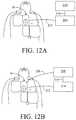
- FIGS. 12A -12Care diagrammatic views of three possible implementations of first and second units.
- FIGS. 13A and 13Bare drawings of two alternative implementations of the electrode pad assembly in which a handle is provided for the rescuer.
- FIG. 14is a block diagram of the electronic circuitry of an implementation including a cell phone.
- FIGS. 15A-15Bare perspective views of the exterior of the implementation of FIG. 14 .
- FIG. 16is a perspective view of a further implementation.
- FIG. 17is a perspective view of a further implementation.
- FIGS. 1 through 9Bshow implementations disclosed in commonly owned applications, Ser. No. 09/794,320, filed on Feb. 27, 2001, and Ser. No. 09/498,306, filed on Feb. 4, 2000. They provide useful background and context for the discussion of implementations shown in FIGS. 10 through 16 .
- a defibrillation electrode pad 10which includes high-voltage apex defibrillation electrode 12 and high-voltage sternum defibrillation electrode 14 , is placed on the patient's chest 16 and includes a region 18 on which a user may press to perform CPR.
- Legends on pad 10indicate proper placement of the pad with respect to the patient's collarbones and the chest centerline and the proper placement of the heel of the rescuer's hand.
- buttons 22are provided on the electrode assembly.
- Button panel 20has buttons 22 , including buttons A (Airway Help), B (Breathing Help), C (Circulation Help) and PAUSE, and may also include adjacent light emitting diodes (LEDs) 24 that indicate which button has been most recently pressed.
- Button panel 20is connected by a cable 23 to a remote resuscitation control box 26 , shown in FIG. 2 .
- Button panel 20provides rigid support underneath buttons A, B, C, and PAUSE against which the switches can be pushed in order to ensure good switch closure while the electrode rests on a patient.
- Button panel 20includes components that make electrical contact with silver/silver-chloride electrical circuit components screen-printed on a polyester base of defibrillation electrode pad 10 , as is described in detail below.
- a pulse detection system based on shining light through the patient's vascular bede.g., a pulse oximetry system 52
- Pulse oximetry system 52includes a red light-emitting diode, a near-infrared light-emitting diode, and a photodetector diode (see FIG. 5 ) incorporated into defibrillation electrode pad 10 in a manner so as to contact the surface of the patient's chest 16 .
- the red and near-infrared light-emitting diodesemit light at two different wavelengths, which is diffusely scattered through the patient's tissue and detected by the photodetector diode.
- the information obtained from the photodetector diodecan be used to determine whether the patient's blood is oxygenated, according to known noninvasive optical monitoring techniques.
- the pulse detection systemis a phonocardiogram system for listening to the sound of the victim's heart, rather than a pulse oximetry system.
- the phonocardiogram systemincludes a microphone and an amplifier incorporated within the electrode pad. Because a heart sound can be confused with microphone noise, the signal processing that must be performed by the microprocessor inside the control box will be more difficult in connection with a phonocardiogram system than in connection with a pulse oximetry system. Nevertheless, there are programs available that can enable the microprocessor to determine whether an ECG signal is present as opposed to microphone noise.
- Pulse oximetryis a well-developed, established technology, but it requires good contact between the light sources and the victim's skin so that light can shine down into the victim's vascular bed. Many victims have lots of chest hair, which can interfere with good contact. It may be desirable for different types of electrode pads to be available at a given location (one having a pulse oximetry system and one having a phonocardiogram system) so that a rescuer can select an appropriate electrode pad depending on the nature of the victim.
- a button housingcan be provided that is affixed to an edge of the defibrillation electrode.
- the housingmay be in the form of a clamshell formed of single molded plastic element having a hinge at an edge of the clamshell around which the plastic bends. The two halves of the clamshell can be snapped together around the electrode assembly.
- the resuscitation control box( FIG. 2 ) includes an internal charge storage capacitor and associated circuitry including a microprocessor, an further includes off/on dial 28 , and a “READY” button 30 that the resucer presses immediately prior to application of a defibrillation shock in order to ensure that the rescuer is not in physical contact with the patient.
- the microprocessormay be a RISC processor such as a Hitachi SH-3, which can interface well with displays and keyboards, or more generally a processor capable of handling DSP-type (digital signal processing) operations.
- the resuscitation control boxhas printed instructions 32 on its front face listing the basic steps A, B, and C for resuscitating a patient and giving basic instructions for positioning the defibrillation electrode pad on the patient.
- a speaker 32orally prompts the user to perform various steps, as is described in detail below.
- the resuscitation control boxinstructs the user, by audible instructions and also through a display 34 on the resuscitation control box, to check the patient's airway and perform mouth-to-mouth resuscitation, and if the patient's airway is still blocked, to press the A (Airway Help) button on the button panel ( FIG. 1 ), upon which the resuscitation control box gives detailed prompts for clearing the patient's airway.
- AAirway Help
- the resuscitation control boxinstructs the user press the B (Breathing Help) button, upon which the resuscitation control box gives detailed mouth-to-mouth resuscitation prompts. If, during the detailed mouth-to-mouth resuscitation procedure, the rescuer checks the patient's pulse and discovers that the patient has no pulse, the resuscitation control box instructs the user to press the C (Circulation Help) button.
- the resuscitation control boxreceives electrical signals from the defibrillation electrodes and determines whether defibrillation or CPR should be performed. If the resuscitation control box determines that defibrillation is desirable, the resuscitation control box instructs the user to press the “ready” button on the resuscitation control box and to stand clear of the patient. After a short pause, the resuscitation control box causes a defibrillation pulse to be applied between the electrodes. If at any point the resuscitation control box determines, based on the electrical signals received from the electrodes, that CPR is desirable, it will instruct the user to perform CPR.
- the key controls for the systemare on the electrodes attached to the patient rather than the resuscitation control box. This is important because it enables the rescuer to remain focused on the patient rather than the control box.
- the resuscitation control boxgets its information directly from the electrodes and the controls on the electrodes.
- the resuscitation control boxcan sense electrical signals from the patient's body during pauses between CPR compressions. Also, as is described below, a compression-sensing element such as an accelerometer or a force-sensing element is provided in the region of the defibrillation electrode pad on which the user presses to perform CPR. The purpose of the compression-sensing or force-sensing element is to allow the resuscitation control box to prompt the user to apply additional compression or force, or to prompt the user to cease CPR if the user is performing CPR at an inappropriate point in time.
- a compression-sensing elementsuch as an accelerometer or a force-sensing element is provided in the region of the defibrillation electrode pad on which the user presses to perform CPR.
- the purpose of the compression-sensing or force-sensing elementis to allow the resuscitation control box to prompt the user to apply additional compression or force, or to prompt the user to cease CPR if
- each electrode 12 , 14(only electrode 12 is shown) of defibrillation electrode pad 10 includes a polymer-based ink containing a silver/silver-chloride suspension, which is screen-printed on a polyester or plastic base 36 .
- the inkis used to carry the defibrillation current.
- the screen-printing processfirst involves applying a resist layer to the polyester base 36 .
- the resist layeris basically a loose mesh of nylon or the like, in which the holes have been filled in at some locations in the mesh.
- the silver/silver-chloride inkis applied as a paste through the resist layer in a squeegee-like manner.
- the inksqueezes through the screen and becomes a solid layer.
- the inkmay then be cured or dried.
- the silver/silver-chloride inkprovides good conductivity and good monitoring capabilities.
- the inkcan be applied as pattern, as opposed to a solid sheet covering the entire polyester base.
- U.S. Pat. No. 5,330,526describes an electrode in which the conductive portion has a scalloped or daisy shape that increases the circumference of the conductive portion and reduces burning of the patient.
- a conductive adhesive gel 38covers the exposed surface of each electrode.
- electrical circuit componentsare also be screen printed on the base, in the same manner as flat circuit components of membrane-covered, laminated panel controls.
- buttons A, B, C, and PAUSEconsist of small metal dome snap-action switches that make contact between an upper conductive ink trace 42 and lower conductive ink traces 44 , 46 , 48 , and 50 .
- Buttons A, B, C, and PAUSEserve as controls that can be activated by the user that are physically located either on or immediately adjacent to the electrode assembly itself.
- Each of buttons A, B, C, and PAUSEmay be associated with an adjacent light-emitting diode (LED).
- LEDsmay be glued, using conductive epoxy, onto silver/silver-chloride traces on substrate 36 .
- An embossed polyester laminate layer 54covers conductive ink trace 42 of buttons A, B, C, and PAUSE, and a foam layer 56 is laminated beneath rigid plastic piece 40 .
- defibrillation electrode pad 10includes an extension piece that is placed directly over the location on the patient's body where the rescuer performs chest compressions.
- This extension pieceincludes substrate 36 , and a semi-rigid plastic supporting member 58 laminated underneath substrate 36 that covers the chest compression area.
- Semi-rigid supporting member 58provides somewhat less rigidity than rigid plastic piece 409 provided at the location of buttons A, B, C, and PAUSE (illustrated in FIG. 3 ).
- a force-sensing elementhaving a force-sensing element, a polyester laminate 60 , and a force-sensing resistor having two layers of carbon-plated material 62 and 64 , are laminated between polyester substrate 36 and semi-rigid supporting member 58 .
- a suitable construction of the force-sensing resistoris illustrated in the FSR Integration Guide & Evaluation Parts Catalog with Suggested Electrical Interfaces, from Interlink Electronics.
- the electrical contact between the two carbon-plated layers of materialincreases with increased pressure, and the layers of force-sensing resistive material can provide a generally linear relationship between resistance and force.
- Conductive ink traces 66 and 68provide electrical connections to the two layers of the force-sensing resistor.
- the rescuer's handsare placed over the extension piece, and the force-sensing resistor of the extension piece is used to sense the force and the timing of the chest compressions.
- the force-sensing resistorprovides information to the resuscitation control box so that the resuscitation control box can provide the rescuer with feedback if the rescuer is applying insufficient force.
- the resuscitation control boxalso provides coaching as to the rate at which CPR is performed.
- the resuscitation control boxindicates to the rescuer that CPR should be halted because it is being performed at an inappropriate time, such as immediately prior to application of a defibrillation shock when the rescuer's hands should not be touching the patient, in which case the resuscitation control box will also indicate that the rescuer should stay clear of the patient because the patient is going to experience a defibrillation shock.
- the resuscitation control boxcan perform an electrocardiogram (ECG) analysis.
- ECGelectrocardiogram
- the resuscitation control boxmight discover, for example, that the patient who is undergoing CPR is experiencing a non-shockable rhythm such as bradycardia, in which case the CPR is required in order to keep the patient alive, but then the resuscitation control box may discover that the rhythm has changed to ventricular fibrillation in the midst of CPR, in which case the resuscitation control box would instruct the rescuer to stop performing CPR so as to allow the resuscitation control box to perform more analysis and possibly apply one or more shocks to the patient.
- the rescueris integrated into a sophisticated scheme that allows complex combinations of therapy.
- a compression-sensing elementsuch as an accelerometer may be used in place of a force-sensing element.
- the accelerometersuch as a solid-state ADXL202 accelerometer, is positioned at the location where the rescuer performs chest compressions.
- the microprocessorobtains acceleration readings from the accelerometer at fixed time intervals such as one-millisecond intervals, and the microprocessor integrates the acceleration readings to provide a measurement of chest compression.
- the use of an accelerometeris based on the discovery that it is more important to measure how deeply the rescuer is compressing the chest than to measure how hard the rescuer is pressing. In fact, every victim's chest will have a different compliance, and it is important that the chest be compressed about an inch and a half to two inches in a normal sized adult regardless of the victim's chest compliance.
- FIG. 5is a circuit diagram illustrating the circuit interconnections between the defibrillation electrode pad of FIG. 1 through the cable to the resuscitation control box of FIG. 2 .
- Sternum electrode 14is connected to HV+ at the resuscitation control box, and apex electrode 12 is connected to HV ⁇ .
- a ground GNDis connected to the upper conductive ink trace of buttons A, B, C, and PAUSE and to one of the layers of the force-sensing resistor.
- the other layer of the force-sensing resistoris connected to CPR_FORCE, and the lower conductive ink traces associated with buttons A, B, C, and PAUSE are connected to BUTTON_DETECT through resistors R 1 , R 2 , R 3 , and R 4 .
- a compression-sensing accelerometer 76may be employed, in which case CPR_FORCE is replaced by CPR_ACCEL connected to accelerometer 76 .
- Red light-emitting diode 70 , near-infrared light-emitting diode 72 , and photodetector diode 74 of the pulse oximetry systemare connected to RLED, ILED, and ISENSE respectively, as well as ground AGND.
- a phonocardiogram systemmay be employed, in which case RLED, ILED, and ISENSE is replaced by SENSE connected to microphone 78 and amplifier 80 .
- FIGS. 6-9illustrate the routine of the resuscitation system, which is based on steps A, B, and C (airway, breathing, and circulation). Because step C includes defibrillation as well as chest compressions, all of the aspects of resuscitation are tied together in one protocol (actually, if defibrillation were considered to be a step D distinct from step C, the sequence of steps would be A, B, D, C).
- the first thing the rescuer must do upon arriving at the patientis to determine whether the patient is unconscious and breathing.
- the rescueropens the patient's airway, administers breaths to the patient if the patient is not breathing, and checks to determine whether a pulse is present. If there is no pulse, rather than perform chest compressions as in standard CPR, the rescuer allows the resuscitation control box to analyze the patient's electrical rhythm, and if the resuscitation control box determines that the rhythm is shockable, the resuscitation control box causes one or more shocks to be applied to the patient, and then the rescuer performs chest compressions.
- a first response systemthat can keep the patient viable until an advanced life support time arrives to perform advanced techniques including pacing, further defibrillation, and drug therapy.
- the resuscitation control boxdetermines that it should apply one or more defibrillation shocks to the patient, it is important that the rescuer not be anywhere near the patient when the shocks are applied to the patient. Prior to application of each shock, the resuscitation control box instructs the rescuer to please press the “ready” button when everybody is clear of the patient. The pressing of the “ready” button verifies that the rescuer's hands are off of the patient.
- the resuscitation control boxWhen the resuscitation control box detects a shockable rhythm, the resuscitation control box provides shocks of appropriate duration and energy (such as a sequence of shocks of increasing energy from 200 Joules to 300 Joules to the highest setting, 360 Joules, with the resuscitation control box performing analysis after each shock to determine whether another shock is required). If the defibrillation therapy is successful, the patient's rhythm is typically converted from ventricular fibrillation, ventricular tachycardia, or ventricular flutter to bradycardia, idio-ventricular rhythm, or asystole, all of which require CPR. It is rare to convert to a normal rhythm.
- the resuscitation control boxautomatically senses the patient's condition, and depending on the patient's condition will either prompt the responder to perform CPR or will not prompt the respond to perform CPR.
- Defibrillation equipmentcan be somewhat intimidating to rescuers who are not medical professionals because the equipment can lead the rescuer to feel responsibility for having to save a loved one's life. It is important that the defibrillation equipment reduce this sense of responsibility.
- the rescuer presses the “ready” buttonrather than apply a shock immediately that will cause the patient's body to jump dramatically, the resuscitation control box will thank the rescuer and instruct the rescuer to remain clear of the patient and then wait for about two seconds (the resuscitation control box may describe this period)to the rescuer as being an internal safety check, even if no substantial safety check is being performed).
- This processhas an effect similar to a conversation that hands responsibility to the resuscitation control box, which makes the decision whether to apply the shock.
- the systemmaintains the rescuer safety features of a semi-automatic external defibrillator, because the rescuer must press the “ready” button before each shock, while appearing to operate more as a fully automatic external defibrillator because the time delay immediately prior to each shock leaves the rescuer with the impression that operation of the equipment is out of the hands of the rescuer.
- the use of CPR prompts in combination with the defibrillationalso adds to the sense that the rescuer is simply following instructions from the resuscitation control box.
- the resuscitation control boxwhen the rescuer turns the resuscitation control box on (step 101 ), the resuscitation control box first informs the rescuer that the rescuer can temporarily halt prompting by pressing the PAUSE button (step 102 ), and then, after a pause, instructs the rescuer to check responsiveness of patient, and if the patient is non-responsive to call an emergency medical service (EMS) (steps 103 , 104 ). The resuscitation control box then instructs the rescuer to check the patient's airway to determine whether the patient is breathing (steps 105 - 107 ).
- EMSemergency medical service
- the resuscitation control boxthen instructs the rescuer that if the patient is breathing the patient should be placed on the patient's side, unless trauma is suspected, and that the rescuer should press the PAUSE button (steps 108 - 109 ). Then the resuscitation control box instructs the rescuer to perform mouth-to-mouth resuscitation if the patient is not breathing (steps 110 - 114 ). Then the resuscitation control box instructs the rescuer to press an Airway Help button A if the patient's airway is blocked, so that the resuscitation control box can give prompts for clearing obstructed airways (steps 115 of FIG. 6B and 147-158 of FIGS. 9A-9B ).
- step 116 aif the resuscitation control box does not include pulse oximetry or phonocardiogram capability (step 116 b ), the resuscitation control box instructs the rescuer to check the patient's pulse (step 117 ).
- the resuscitation control boxinstructs the rescuer to press a Breathing Help button B if the patient's pulse is okay but the patient is not breathing, so that the resuscitation control box can give prompts for assisting the patient's breathing (steps 118 and 119 of FIG. 7A and 140-146 of FIG. 8 ).
- the resuscitation control boxnext prompts the rescuer to contact an emergency medical system (step 120 ) and to open the patient's shirt or blouse and attach the adhesive pads (steps 122 f - 122 h ).
- the resuscitation control boxIf the resuscitation control box does include pulse oximetry or phonocardiogram capability (step and 116 b ), the resuscitation control box prompts the rescuer to open the patient's shirt or blouse and attach the adhesive pads (steps 121 and 122 a ). If the pulse oximetry or phonocardiogram system does not provide a valid pulsatile reading (step 122 b ), then the flow chart proceeds to step 117 . If the pulse oximetry or phonocardiogram system does provide a valid pulsatile reading and detects a pulse (steps 122 b and 122 c ), then the resuscitation control box begins the breathing help routine (steps 122 d of FIG. 7B and step 140 of FIG. 8 ).
- the resuscitation controlprompts the rescuer to contact an emergency medical system (step 122 e ), measures the impedance of the patient to determine whether it is within an acceptable range for application of shocks (step 123 ) and determines whether the patient's rhythm is shockable (steps 124 ). If the rhythm is shockable, the resuscitation control box causes a sequence of shocks to be applied to the patient, each shock requiring the rescuer first to press the “READY” button on the resuscitation control box (steps 124 - 131 ). After the last shock in the sequence, or if the rhythm is non-shockable, the resuscitation control box prompts the rescuer in CPR (steps 132 - 139 ). The flowchart then returns to step 117 .
- FIG. 8shows the steps 140 - 146 for prompting the rescuer to assist the patient's breathing.
- the pulse oximetry or phonocardiogram systemattempts to detect a pulse (step 145 a ), or, if the system does not include a pulse oximetry or phonocardiogram system, the resuscitation control box prompts the rescuer to check the patient's pulse. If no pulse is present, the resuscitation control box prompts the rescuer to press a Circulation Help button C (step 145 b ) that brings the rescuer back to the circulation portion of the flowchart. Otherwise, if a pulse is detected, then the flow chart of FIG. 8 returns to step 142 .
- the combined defibrillation and CPR resuscitation assembly providedcan be less intimidating than conventional AEDs because the assembly is not devoted solely to defibrillation. Moreover, the resuscitation assembly is less intimidating because it accomodates common skill retention problems with respect to necessary techniques ancillary to defibrillation such as mouth-to-mouth resuscitation and CPR, including the appropriate rates of chest compression, the proper location for performing compressions, the proper manner of tilting the patient's head.
- the rescuermay be more comfortable using the resuscitation assembly for mouth-to-mouth resuscitation and CPR. Unlike previous CPR prompting devices, the rescuer would be required to place the electrode assembly on top of the patient, but the rescuer would do this with the belief that the resuscitation assembly will be sensing the patient's condition and that the likelihood that the resuscitation assembly is actually going to apply a shock is low.
- the resuscitation control boxinstructs the rescuer to press the “READY” button so that a defibrillation shock can be applied
- the rescuerwill likely feel comfortable allowing the shock to be applied to the patient.
- the resuscitation assemblysimply tells the rescuer what to do, and by that point, given that the rescuer is already using the assembly, the rescuer is likely simply to do what the rescuer is told to do.
- the rescuerwill be likely to view the resuscitation assembly as simply being a sophisticated CPR prompting device with an additional feature incorporated into it, and since rescuers are less likely to be intimidated by CPR prompting devices than AEDs, they will be likely to use the resuscitation assembly when it is needed.
- FIGS. 10, 11, and 12A-12Cshow alternative implementations in which an electrode pad assembly 10 is connected by a cable 212 to a first unit 214 containing the electronics for CPR prompting and resuscitation control.
- Another cable 216connects the first unit to a second unit 218 containing the electronics for defibrillation and pacing therapy.
- a third cable 220could be provided for making a direct connection from the second unit to the electrodes ( FIG. 12B ).
- the first unit 214could be configured to receive the second unit 218 as an inserted module ( FIG. 12C ), in which case the electrical connection between the units are made internally without the use of cable 216 .
- the primary function of the first unit 214is to provide processing and control for CPR functions such as CPR prompts.
- the primary function of the second unit 218is to provide processing and control of electrical therapy functions.
- the first unitincludes a CPR processor 170 , a battery 178 , ECG circuitry 177 for amplifying and filtering the ECG signal obtained from the defibrillation pads 12 , 14 , a microphone 78 for recording the rescuer's voice as well as ambient sounds, an accelerometer 76 , a real time clock 187 , and a speaker 182 for delivering prompts to the rescuer.
- the second unitincludes a therapy processor 171 , a battery 179 , buttons and controls 180 , and memory 191 .
- the first unitcould also be incorporated into the electrode pad assembly rather than being a separate box.
- the electronicscould be provided on the rigid substrate 40 of the electrode pad assembly ( FIG. 1 ).
- Separate batteries 178 , 179 and controls 180 , 181may be provided for the first (CPR) and second (therapy) units, thereby allowing the electronics in the first unit to provide CPR prompting to the operator without the need for the second unit.
- the cable 216 that connects the first and second unitsmay be detachable.
- Memory 189is provided in the first unit for storing information such as voice recording, ECG data, chest compression data, or electronic system status such as device failures that occur during daily self checks of the electronics initiated by a real time clock circuit.
- the defibrillation electrode pad assembly 10may incorporate defibrillation electrodes composed of a material that can be held against a patient's skin for extended periods of time (e.g., up to 30 days).
- the pad assembly 10may also incorporate features on its upper surface facing the rescuer that provide a handle 195 for the rescuer during performance of CPR.
- the handlecould take the form of a fabric loop ( FIG. 13B ) or a more rigid polymer member ( FIG. 13A ).
- the fabriccould be sewn or adhered by adhesive or ultrasonic bonding to the pad 10 ( FIG. 13B ).
- the polymer handlecould also be bonded by adhesive or ultrasonic bonding to the pad ( FIG. 13A ). It has been shown in studies that the maintenance of pressure on the chest during the decompression phase of chest compression results in a significant decrease in the effectiveness of the chest compressions.
- the handle 195motivates the rescuer to pull up at least slightly during the decompression phase.
- the adhesive gel of the electrode pad, or other adhesivecan extend under the region where the rescuer's hands are placed during compression thus providing adhesion of the pad to the skin while the rescuer pulls on the handle during the decompression phase. Pulling up on the chest during the decompression phase has been shown to heighten negative intrathoracic pressure, increasing venous return and thus increasing blood flow during chest compressions.
- the first unitmay be adapted to be supported by the patient for long periods of time.
- the unitcould be incorporated into the electrode pad assembly as suggested above, or it could be a separate unit configured to be worn by the patient.
- the electronics of the first unitare designed to allow for long term monitoring of the patient's condition via the ECG 177 and physiological monitoring 176 circuitry. If a physiological condition is detected that is deemed hazardous to the patient by the CPR processor 170 , based on analysis of the ECG and other physiological parameters, an alarm is sounded to the patient via the speaker 182 .
- An activity sensor and associated circuitrycan inform the CPR processor of whether the patient is moving.
- accelerometer 76could serve as the activity sensor, and detect whether or not the patient is moving.
- Patient motionmay be detected using a variety of different algorithms, including, for example the following:
- the acceleration signalis integrated over one-second intervals to provide an estimate of velocity.
- Velocityis integrated over the same one-second intervals to provide an estimate of displacement.
- the rootmeans square velocity is calculated for each one-second interval. If either the RMS velocity exceeds 0.2 cm/s or the peak displacement exceeds 0.5 cm, the patient is determined to be moving.
- the first unitcan send a message directly to a medical emergency response system, such as 911.
- a medical emergency response systemsuch as 911.
- Thiscan be done using a variety of known communication techniques, e.g., Bluetooth, cellular phone, Ultra Wideband (UWB).
- UWBUltra Wideband
- the unitcould also issue a prompt indicating, “Call 911 Immediately!”
- the first unitwill be able to determine the orientation of the patient, e.g., based on the accelerometer output. It can detect if a patient has fallen down and initiate a message to the emergency system. It can also determine whether the patient is lying on his back, the proper orientation for doing CPR. Thus, a specific prompt can be provided to the rescuer that tells them to roll the patient on their back prior to beginning CPR, should the device detect an improper orientation of the patient.
- Other implementationsmay include signal analysis software for predicting the risk of a heart attack.
- a voice promptmay be provided to the patient via the speaker 182 to contact the medical emergency system.
- the motion detection capabilities of the accelerometerto measure and track a patient's activity level (PAL), and combining the activity level calculation with measurements of the ECG 177 , e.g., ST-segment elevation (STE)
- the first unitis able to provide a predictor of the risk of an impending heart attack or cardiac arrest.
- An ST segment elevation exceeding a thresholdsuch as 300 microvolts on the ECG provides an indicator of impending heart attack.
- ST segment elevation in the presence of increased physical activityis an indication of further risk of potential cardiac arrest.
- the calculation of risk probabilitymay be accomplished by first performing a logistic regression of variables such as STE and PAL as predictors of cardiac arrest within 24 hours.
- the multiplicative termheightens the importance of STE in the presence of PAL.
- Parameters such as STE, PAL and RISKmay additionally be stored in memory and multiple readings and calculations performed over time. The sequence of readings may then be analyzed for trends in the physiological state of the patient that can augment the RISK calculation taken at a single point in time. For instance, if STE is found to be steadily rising over a series of readings, the voice prompt may be triggered sooner than at a fixed threshold of 300 microvolts.
- the ECGmay be analyzed to determine the interval between adjacent R-waves of the QRS complexes and using this interval to calculate heart rate variability as a running difference between adjacent R-R intervals. It is known that the R-R interval will vary following an ectopic beat or ventricular premature contraction (VPC). In a healthy heart, the R-R interval will decrease immediately following the VPC followed by a gradual return to steady state; a heart with an increased risk of heart attack will show a decreased level of variability. This effect is sometimes called heart rate turbulence.
- VPCventricular premature contraction
- the defibrillation electrode pad 10may include circuitry to stimulate the patient with a single pulse of low enough amplitude to cause a VPB without undue discomfort to the patient, under the patient's control.
- An additional controlis provided on the low-profile button panel 20 so that the patient may initiate the pulse under their control.
- the deviceis programmed to automatically deliver the pulse at regular intervals such as at 24-hour intervals, at a time of day when the patient may conveniently have access to the device, such as in the morning.
- the pulse generator 186may be located in the second (therapy) unit, it is preferably contained as part of the first (CPR) unit.
- the activity monitoring capability of the first unitmay be utilized so that the activity state of the patient is continuously monitored.
- the first unitmay detect when a patient has woken up in the morning. After there has been 10 minutes of regular motion detected, the unit may prompt the patient that it would like to perform a test. If the patient assents to the test indicated by a press of the TEST button on the low-profile button panel 20 , the unit will send out a small current pulse, preferably a 40 millisecond pulse of 75 mA amplitude that is synchronized to the patient's ECG so that it occurs approximately 200 mS prior to the R-wave and after the T-wave so as not to introduce any arrhythmias.
- the pulsewill safely cause a VPB in the patient which can then be used to measure the autonomic response to a VPB to provide regular calculations of the autonomic response to a VPB as measured by such parameters, though not limited to, STE and PAL, and providing a daily update to the RISK calculation.
- the blood pressure measurement devicewould be a handheld, inflated cuff blood pressure device 188 .
- the blood pressure cuff 188would have wireless communication capability with the CPR Processor 170 and at the conclusion of each measurement, the blood pressure reading along with a date and time stamp would be stored in memory 189 of the CPR Processor 170 for subsequent use in calculating RISK. This scheme would allow the patient to carry the small blood pressure cuff along with them during their daily activities and take blood pressure measurements at regular intervals without having to return home.
- the blood pressure measurement devicemay communicate with the therapy processor and may additionally get power from and be physically connected to the second (therapy) unit by a cable.
- the patientwill then be required to take regular blood pressure readings at the second unit, typically a larger device that may or may not be portable.
- Communication of the blood pressure readingsmay be accomplished over a cable between the first (CPR) and second units (therapy) units, e.g., cable 216 , or wirelessly, using such technology as Bluetooth.
- the second unit 218may in some implementations be thought of as an energy delivery unit (EDU), in which case it would incorporate a defibrillator 172 , pacer 173 , or other electrical therapy 174 .
- the EDUwould be small and light enough to be worn in a harness or belt to be carried around continuously by the patient.
- the EDU 218may in some cases not contain a therapy processor 171 , but be a “dumb” device that requires the controls provided by connection to the processor in the first (CPR) unit, e.g., on the defibrillator pad 10 , in order to deliver electrical therapy to the patient.
- the patientmay not even own an EDU due to the significant costs inherent in the high-voltage components necessary.
- the patientwould only own the first unit and defibrillator pad, as the components incorporated in them are less expensive, e.g., they can be manufactured from less-expensive, consumer-type electronics.
- a bystander or family member who encountered the cardiac arrest victimwould be prompted to begin CPR. It has been shown now in several studies that performing good CPR for extended periods prior to delivery of a shock are not only not detrimental to long term survival, but in fact increase survival rates.
- the CPRwould thus begin with built-in prompting and when the paramedic arrives with the defibrillator it can be connected to the pads to deliver the electrical therapy. If the first (CPR) unit is separate from the electrode pad assembly, the EDU connection to the electrodes could be direct, or via a cable connected to the first (CPR) unit. If the defibrillator is an EDU or other compatible device, patient and performance data stored by the first (CPR) unit may be downloaded to the defibrillator.
- the defibrillation pads 10 , 12may be separable from the CPR-prompting first unit and be connected at the time that the EDU is brought to the scene; the defibrillation pads may be connected both electrically and mechanically to the CPR-prompting first unit at that time. A greater amount of the control functionality may be put into the first unit, leaving essentially only the circuitry for providing the defibrillation pulses in the second unit.
- the first unitmay be incorporated into the defibrillation electrode pad assembly, or made a separate unit connected to the pad assembly by one or more cables.
- the second unitmay connect to the first unit by one or more cables, or by a wireless connection.
- the defibrillation pulsesmay pass through the first unit ( FIG.
- the second unitmay connect to the first unit by being plugged into the first unit ( FIG. 12C ), without the need for a cable (e.g., the second unit could be a defibrillation module that plugs into the first unit).
- the second (therapy) unitcan provide pacing therapy as well as defibrillation therapy.
- Pulse detection methodsother than pulse oximetry and phonocardiogram may be employed. Any method capable of detecting a victim's pulse can be used for pulse detection.
- FIGS. 14-16describe other implementations, including implementations in which the CPR-prompting first unit is configured for connection to a defibrillation unit, as well as implementations in which the first unit is not configured for connection to a defibrillation unit. In the latter case, the defibrillation unit may be used without being connected to the CPR-prompting unit.
- the CPR-prompting unitmay be a cell phone or other handheld computing/communication device such as a personal digital assistant (PDA) or a wireless e-mail handset (e.g., a Blackberry).
- the handheld computing/communication devicemay incorporate a motion detection element (e.g., a MEMS-based semiconductor inertial sensing system such as that manufactured by Analog Devices, of Massachusetts) along with the processing, data storage, and speaker elements.
- the handheld devicemay also incorporate RF communications circuitry and a microphone, as would be the case if the device is a cell phone.
- the motion detection elementmay comprise an accelerometer and or a pressure-sensing element (e.g., a piezoelectric strain gauge or pressure-sensitive resistor)
- the same DSP processing unit used to handle speech and baseband signal processingmay be used to process the output of the accelerometer or pressure sensor, e.g., to derive a displacement measurement of chest compressions.
- the cell phone 400itself, is placed on the patient's sternum during CPR, and the rescuer's hands are placed on top of the phone to apply force to the patient's chest.
- Structural elementsmay be incorporated into or adjacent the cell phone 400 to allow the rescuer to exert the force necessary for an effective chest compression.
- the structural elementsmay take the form of an external storage case for the phone, or they may be internal elements 410 within the phone, e.g., struts 409 and rigid sidewalls 411 ( FIG. 15A ), or the phone may be supported within a rigid clamshell 408 slid over the phone ( FIG. 15B ).
- a dedicated cardiac arrest key 412may be provided on the cell phone, or CPR prompting functions may be activated by using the phone's standard scrolling and menu functionality. Activation of CPR prompting, may also initiate a call to emergency medical services, e.g., “911”. On activation of the emergency and connection to 911, a speakerphone may be engaged on the cell phone, to facilitate communication between the rescuer and emergency services.
- emergency medical servicese.g., “911”.
- 911On activation of the emergency and connection to 911, a speakerphone may be engaged on the cell phone, to facilitate communication between the rescuer and emergency services.
- Light emitting diodes and sensors 70 , 72 , 74 or ECG electrodes 12 , 14may be incorporated into the surface of the phone so that when the phone is placed on the patient's sternum, the presence or absence of a pulse may be detected.
- the ECG systemmay incorporate a transthoracic impedance measurement method such as by using a small high frequency signal (preferably 2 microamps in amplitude and 60-100 kilohertz in frequency) By synchronously demodulating the signal and measuring both current and voltage, an impedance measurement can be made. Utilizing the impedance measurement, the breathing rate and duty cycle can be determined.
- the cell phonemay include geolocator technology such as GPS (global positioning system).
- the CPR prompting and feedback function of the cell phonemay also be used in conjunction with a separate CPR-assistance element worn or applied to the patient.
- the CPR-assistance elementcommunicates (e.g., wirelessly) with the cell phone.
- the CPR-assistance elementmay be applied to the patient at the time of cardiac arrest or earlier (it could also be worn continuously by the patient).
- the elementmay be a watch (e.g., as manufactured by Polar Heart Rate Monitors, of New York) or a flat element incorporated into a self-adhesive strip adhered (e.g., vertically) along a patient's sternum.
- FIG. 16shows one possible implementation of such a CPR-assistance element—a thin card 414 , approximately the thickness of a credit card (0.04 inches), which houses an accelerometer, processor and necessary memory, battery, and wireless communication (e.g., Bluetooth for communication with the cell phone).
- a self-adhesive label 415that when removed turns the device on (e.g., via a set of contacts 416 on the card and a shorting strip 417 located on the facing surface of the self-adhesive release liner).
- the self-adhesive surfaceis exposed, the card is affixed to the patient's sternum, and serves as the location at which chest compression forces are applied to the patient.
- CPR-assistance element 414may incorporate a wireless communication capability (e.g., Bluetooth) that, when a cardiac arrest or impending cardiac arrest is detected or predicted, communicates with the cell phone and begins a protocol for CPR.
- a wireless communication capabilitye.g., Bluetooth
- the bulky element of the CPR prompting unite.g., the speaker, power hungry DSP signal processor, RF communication circuitry, and larger battery
- the CPR-assistance element applied to the patient's chestwith, e.g., an accelerometer or pressure sensor, and an ECG sensor
- the CPR-assistance element applied to the patient's chestcan be much thinner. This allows for the possibility of the CPR feedback function being small enough to be stored in a wallet.
- the handheld computing/communication devicemay communicate with a separate defibrillation unit (or the CPR-assistance element may communicate with the defibrillation unit).
- ECG analysismay be performed in the defibrillation unit, in the handheld device, or in the CPR-assistance element.
- the defibrillation unitmay be controlled by the handheld device.
- FIG. 17shows another implementation in which at least some of the functions of the CPR-assistance element and at least some of the resuscitation functions of the handheld computing/communication device are combined in one handheld resuscitation device 600 .
- the deviceis battery powered, and can be used for both CPR training and as a CPR coaching device during rescues. Circuit elements similar to those described in connection with the implementations of FIGS. 14-16 would be provided in the device, including a microprocessor, memory, speaker, visual display elements, and accelerometer.
- the deviceprovides spoken reminders of proper CPR technique and real time feedback on the rate and depth of chest compressions.
- An on/off switch 602is pressed to activate the device. Initially, the device delivers a series of prompts reminding the user of the appropriate resuscitation steps. These include:
- the devicethen produces a series of beeping sounds at a rate of 100 per minute to assist the user in timing chest compressions.
- chest compressionsare detected by an accelerometer built into the device, the device performs integration operations on the output of the accelerometer to estimate the depth of chest compressions. After ten seconds of compressions, the device delivers one of the following messages:
- An algorithm in the processing performed by the devicesets a standard for the number of good compressions (e.g., a minimum of 3.75 cm of chest displacement) as a percentage of the number of total compressions. If the percentage exceeds the minimum for good CPR, the message “Good Compressions” will be played. Otherwise, “Push Harder: will be played. After twenty seconds, the message “Give Breaths” will be played. The device then returns to the same state that followed the message “Start CPR”. Each time the beeper sounds, a number of lights 604 will be turned on to indicate the depth of the last compression. E.g., if the last compression was a good compression, all four lights could be turned on. If not, only one light might be turned on (or anywhere from one to three lights could be turned on to show the degree by which the compression failed to qualify as a good compression).
- a standard for the number of good compressionse.g., a minimum of 3.75 cm of chest displacement
- Switch 602could also be used to switch modes; e.g., if the switch button is depressed more than two seconds, a voice prompt would allow selection of adult mode, pediatric mode, training mode or some other mode. Labels could be placed on the device (e.g., indicating how to use the device, and the need to call for help. A disposable sticky adhesive pad could be provided to enable placement on the patient. A GPS circuit could provide location of rescue and aid in locating the device. A mechanical dome switch could be included on the top or bottom surface to provide the user with tactile feedback of proper release of the chest (e.g., hearing a snapping sound would indicate release). The device could be configured to determine whether chest release was correct, and prompt the user accordingly.
- Labelscould be placed on the device (e.g., indicating how to use the device, and the need to call for help.
- a disposable sticky adhesive padcould be provided to enable placement on the patient.
- a GPS circuitcould provide location of rescue and aid in locating the device.
- a mechanical dome switchcould be included on the top or bottom
- Wireless communicatione.g., Bluetooth
- ECGcould be sensed through an electrode on surface of device (as described in connection with the implementation of FIG. 16 ), and ECG processing could provide a prompt to “Call for AED”.
- a graphic displaye.g., LCD
- the compression rate beeping reminder tonecould be user disabled.
- Data recording capabilitycould be included, for later playback.
- a microphonecould be added to record voice and environmental sounds during a rescue.
- a connectorcould be provided for making a wired connection to an AED or other device. Processing could determine that compressions exceeded a safe displacement (e.g., greater than 2 inches), and an appropriate warning prompt issued. The visual indication of compression depth could be maintained for a short period (e.g., 10 seconds) after compression stops to enable a user to observe their performance during a break from compressions.
- a headphone jackcould be provided for the user to hear prompts over a headphone. Additional processing and different chest compression prompts could be provided, e.g., “too slow”, “too fast”, “too shallow”, “too deep”, and “incomplete release”.
- a ventilation sensorcould provide information on ventilation to assist in resuscitation (e.g., providing signals to the cell phone).
- the ventilation sensorcould be a sensor configured to make measurements of transthoracic impedance, breathing sounds, or airway pressure (e.g., a pressure sensor connected by tubing to a breathing tube or adapter, as described in the commonly owned U.S. application Ser. No. 11/384,218, filed on Mar. 17, 2006, entitled “Automated Resuscitation Device with Ventilation Sensing and Prompting,” and issued as U.S. Pat. No. 7,747,319.
- Various other types of handheld computing/communication devicescould be used instead of the specific examples given, so long as the device is of a handheld size and is configured to perform some type of non-resuscitation function involving computing or communication.
Landscapes
- Health & Medical Sciences (AREA)
- Cardiology (AREA)
- Heart & Thoracic Surgery (AREA)
- General Health & Medical Sciences (AREA)
- Veterinary Medicine (AREA)
- Public Health (AREA)
- Life Sciences & Earth Sciences (AREA)
- Animal Behavior & Ethology (AREA)
- Emergency Medicine (AREA)
- Epidemiology (AREA)
- Pulmonology (AREA)
- Rehabilitation Therapy (AREA)
- Physical Education & Sports Medicine (AREA)
- Pain & Pain Management (AREA)
- Biomedical Technology (AREA)
- Engineering & Computer Science (AREA)
- Radiology & Medical Imaging (AREA)
- Nuclear Medicine, Radiotherapy & Molecular Imaging (AREA)
- Critical Care (AREA)
- Electrotherapy Devices (AREA)
- Percussion Or Vibration Massage (AREA)
- Measuring Pulse, Heart Rate, Blood Pressure Or Blood Flow (AREA)
- Measurement Of The Respiration, Hearing Ability, Form, And Blood Characteristics Of Living Organisms (AREA)
Abstract
Description
0.24STE+0.12PAL=RISK.
Alternatively, nonlinear regression may be performed to allow for a multiplicative term such as
0.24STE+0.12PAL+0.54(STE*PAL)=RISK.
The multiplicative term heightens the importance of STE in the presence of PAL.
RCRR=(R-Rpre-VPB-R-Rpost-VPB)/R-Rpre-VPB
and (2) the slope of the change of R-R interval (SRR) while it is undergoing its post-VPB decrease. If the RCRR is non-negative and the slope SRR does not steeper than −2 ms/ R-R interval then the patient is considered as at risk. Alternatively, the individual calculations may be included along with STE and PAL to create an integrated measurement vector as discussed in the preceding paragraphs. Other signal analysis algorithms may incorporate analysis of heart rate variability in the frequency domain, wavelet domain or using non-linear dynamics-based methods.
Claims (34)
Priority Applications (2)
| Application Number | Priority Date | Filing Date | Title |
|---|---|---|---|
| US11/391,708US11090223B2 (en) | 2005-03-25 | 2006-03-27 | Integrated resuscitation |
| US17/354,074US11666507B2 (en) | 2005-03-25 | 2021-06-22 | Integrated resuscitation |
Applications Claiming Priority (2)
| Application Number | Priority Date | Filing Date | Title |
|---|---|---|---|
| US66515705P | 2005-03-25 | 2005-03-25 | |
| US11/391,708US11090223B2 (en) | 2005-03-25 | 2006-03-27 | Integrated resuscitation |
Related Child Applications (1)
| Application Number | Title | Priority Date | Filing Date |
|---|---|---|---|
| US17/354,074ContinuationUS11666507B2 (en) | 2005-03-25 | 2021-06-22 | Integrated resuscitation |
Publications (2)
| Publication Number | Publication Date |
|---|---|
| US20060270952A1 US20060270952A1 (en) | 2006-11-30 |
| US11090223B2true US11090223B2 (en) | 2021-08-17 |
Family
ID=36685842
Family Applications (2)
| Application Number | Title | Priority Date | Filing Date |
|---|---|---|---|
| US11/391,708Active2030-03-04US11090223B2 (en) | 2005-03-25 | 2006-03-27 | Integrated resuscitation |
| US17/354,074Active2026-05-05US11666507B2 (en) | 2005-03-25 | 2021-06-22 | Integrated resuscitation |
Family Applications After (1)
| Application Number | Title | Priority Date | Filing Date |
|---|---|---|---|
| US17/354,074Active2026-05-05US11666507B2 (en) | 2005-03-25 | 2021-06-22 | Integrated resuscitation |
Country Status (5)
| Country | Link |
|---|---|
| US (2) | US11090223B2 (en) |
| EP (3) | EP1866030B1 (en) |
| JP (2) | JP5269584B2 (en) |
| CN (2) | CN106137718A (en) |
| WO (1) | WO2006104977A2 (en) |
Families Citing this family (135)
| Publication number | Priority date | Publication date | Assignee | Title |
|---|---|---|---|---|
| US9248306B2 (en) | 1999-09-30 | 2016-02-02 | Physio-Control, Inc. | Pulse detection apparatus, software, and methods using patient physiological signals |
| US20050131465A1 (en) | 2000-02-04 | 2005-06-16 | Freeman Gary A. | Integrated resuscitation |
| EP3064242A1 (en) | 2003-04-28 | 2016-09-07 | Advanced Circulatory Systems Inc. | Ventilator and methods for treating head trauma and low blood circulation |
| US7220235B2 (en)* | 2003-06-27 | 2007-05-22 | Zoll Medical Corporation | Method and apparatus for enhancement of chest compressions during CPR |
| WO2006104977A2 (en)* | 2005-03-25 | 2006-10-05 | Zoll Medical Corporation | Integrated resuscitation |
| JP5281011B2 (en)* | 2006-11-14 | 2013-09-04 | コーニンクレッカ フィリップス エレクトロニクス エヌ ヴィ | Cardiopulmonary resuscitation guidance device with reduced motion sensitivity |
| US20080176199A1 (en)* | 2007-01-11 | 2008-07-24 | Physio-Control, Inc. | Prompting System For CPR Delivery |
| US9028259B2 (en)* | 2007-01-16 | 2015-05-12 | Physio-Control, Inc. | Wearable CPR assist, training and testing device |
| US8151790B2 (en) | 2007-04-19 | 2012-04-10 | Advanced Circulatory Systems, Inc. | Volume exchanger valve system and method to increase circulation during CPR |
| US9352111B2 (en) | 2007-04-19 | 2016-05-31 | Advanced Circulatory Systems, Inc. | Systems and methods to increase survival with favorable neurological function after cardiac arrest |
| US8369944B2 (en) | 2007-06-06 | 2013-02-05 | Zoll Medical Corporation | Wearable defibrillator with audio input/output |
| US8271082B2 (en) | 2007-06-07 | 2012-09-18 | Zoll Medical Corporation | Medical device configured to test for user responsiveness |
| US7974689B2 (en)* | 2007-06-13 | 2011-07-05 | Zoll Medical Corporation | Wearable medical treatment device with motion/position detection |
| US8140154B2 (en) | 2007-06-13 | 2012-03-20 | Zoll Medical Corporation | Wearable medical treatment device |
| US8034006B2 (en) | 2007-06-15 | 2011-10-11 | Board Of Regents, The University Of Texas System | Cardiopulmonary resuscitation sensor |
| US8994528B2 (en) | 2007-06-15 | 2015-03-31 | Board Of Regents, The University Of Texas System | Thin flexible sensor |
| US8579841B2 (en)* | 2007-10-09 | 2013-11-12 | Sitara R. Khan | Blood clot prevention device |
| US8317519B1 (en)* | 2008-05-09 | 2012-11-27 | Rapid Response Solutions, LLC | Resuscitation metronome |
| US20110166411A1 (en)* | 2008-09-19 | 2011-07-07 | Draeger Medical Systems, Inc. | Warming therapy device including resuscitation control system |
| BRPI1006684A2 (en)* | 2009-02-18 | 2016-04-12 | Koninkl Philips Electronics Nv | rcp qye device tracks progress of cardiopulmonary resuscitation (rcp) during an rcp interval |
| CN101496767B (en)* | 2009-02-27 | 2010-08-18 | 武汉依瑞德医疗设备新技术有限公司 | External cardiac massage rhythm prompting device and method thereof |
| EP2228097B1 (en)* | 2009-03-11 | 2016-01-27 | Schiller Medical S.A.S. | Defibrillator, rescue kit of parts and process for controlling the quality of chest compressions |
| US10335346B2 (en) | 2009-07-22 | 2019-07-02 | Physio-Control Canada Sales Ltd. | Optical techniques for the measurement of chest compression depth and other parameters during CPR |
| US9498152B2 (en)* | 2009-10-23 | 2016-11-22 | Scion Medical Limited | Method and system for expediting the rescue of victims experiencing sudden cardiac arrest (SCA) when used in conjunction with an automated external defibrillator (AED) |
| US20110112423A1 (en)* | 2009-11-11 | 2011-05-12 | Physio-Control, Inc. | Increasing cpr effectiveness using phonocardiogram analysis |
| EP2499628A4 (en) | 2009-11-13 | 2014-11-05 | Zoll Medical Corp | Cpr competition system |
| US12016820B2 (en) | 2010-02-12 | 2024-06-25 | Zoll Medical Corporation | Enhanced guided active compression decompression cardiopulmonary resuscitation systems and methods |
| CN102781512B (en) | 2010-02-12 | 2016-06-01 | Zoll医疗公司 | Defibrillator display |
| US8725253B2 (en)* | 2010-02-12 | 2014-05-13 | Zoll Medical Corporation | Defibrillator display including CPR depth information |
| US9724266B2 (en) | 2010-02-12 | 2017-08-08 | Zoll Medical Corporation | Enhanced guided active compression decompression cardiopulmonary resuscitation systems and methods |
| US8702633B2 (en)* | 2010-02-12 | 2014-04-22 | Advanced Circulatory Systems, Inc. | Guided active compression decompression cardiopulmonary resuscitation systems and methods |
| US12064391B2 (en) | 2010-02-12 | 2024-08-20 | Zoll Medical Corporation | Defibrillator display including CPR depth information |
| US8706215B2 (en) | 2010-05-18 | 2014-04-22 | Zoll Medical Corporation | Wearable ambulatory medical device with multiple sensing electrodes |
| US9008801B2 (en) | 2010-05-18 | 2015-04-14 | Zoll Medical Corporation | Wearable therapeutic device |
| US8527043B2 (en) | 2010-05-28 | 2013-09-03 | Zoll Medical Corporation | Systems and methods for enhanced venous return flow during cardiac event |
| US8380305B2 (en)* | 2010-07-01 | 2013-02-19 | DynaDx Corporation | System and method for predicting successful defibrillation for ventricular fibrillation cardiac arrest |
| US9937355B2 (en) | 2010-11-08 | 2018-04-10 | Zoll Medical Corporation | Remote medical device alarm |
| EP2638511A4 (en) | 2010-11-11 | 2014-09-03 | Zoll Medical Corp | DASHBOARD OF SHORT-TERM CARE TREATMENT SYSTEM |
| WO2012065167A1 (en) | 2010-11-12 | 2012-05-18 | Zoll Medical Corporation | Real-time evaluation of cpr performance |
| US20120184882A1 (en)* | 2010-11-12 | 2012-07-19 | Zoll Medical Corporation | Hand Mounted CPR Chest Compression Monitor |
| US9149411B2 (en)* | 2010-11-29 | 2015-10-06 | Physio-Control, Inc. | Programmable cardiopulmonary resuscitation (CPR) detection device |
| JP5963767B2 (en) | 2010-12-09 | 2016-08-03 | ゾール メディカル コーポレイションZOLL Medical Corporation | Electrode assembly |
| JP5988991B2 (en) | 2010-12-10 | 2016-09-07 | ゾール メディカル コーポレイションZOLL Medical Corporation | Wearable treatment device |
| US9427564B2 (en) | 2010-12-16 | 2016-08-30 | Zoll Medical Corporation | Water resistant wearable medical device |
| US8721557B2 (en) | 2011-02-18 | 2014-05-13 | Covidien Lp | Pattern of cuff inflation and deflation for non-invasive blood pressure measurement |
| US9072433B2 (en) | 2011-02-18 | 2015-07-07 | Covidien Lp | Method and apparatus for noninvasive blood pressure measurement using pulse oximetry |
| JP5568037B2 (en)* | 2011-03-11 | 2014-08-06 | 日本光電工業株式会社 | Cardiopulmonary resuscitation monitoring device |
| WO2012135028A1 (en) | 2011-03-25 | 2012-10-04 | Zoll Medical Corporation | Method of detecting signal clipping in a wearable ambulatory medical device |
| US9135398B2 (en) | 2011-03-25 | 2015-09-15 | Zoll Medical Corporation | System and method for adapting alarms in a wearable medical device |
| US9684767B2 (en) | 2011-03-25 | 2017-06-20 | Zoll Medical Corporation | System and method for adapting alarms in a wearable medical device |
| WO2012135062A1 (en) | 2011-03-25 | 2012-10-04 | Zoll Medical Corporation | Selection of optimal channel for rate determination |
| US8781577B2 (en) | 2011-04-08 | 2014-07-15 | Zoll Medical Corporation | Coordinated resuscitation perfusion support |
| US10238574B2 (en) | 2011-04-08 | 2019-03-26 | Zoll Medical Corporation | System for assisting rescuers in performing cardio-pulmonary resuscitation (CPR) on a patient |
| JP2014516654A (en) | 2011-05-02 | 2014-07-17 | ゾール メディカル コーポレイション | Patient-worn energy supply device and technology for adjusting its size |
| CN103764222B (en) | 2011-09-01 | 2016-02-10 | 佐尔医药公司 | Wearable monitoring and treatment equipment |
| KR20140116878A (en) | 2011-12-19 | 2014-10-06 | 레스큐시스템스 아이엔씨 | Systems and methods for therapeutic intrathoracic pressure regulation |
| US10433767B2 (en)* | 2011-12-21 | 2019-10-08 | Koninklijke Philips N.V. | Peel and stick CPR assistance device |
| EP3610919A1 (en) | 2012-03-02 | 2020-02-19 | Zoll Medical Corporation | A system comprising a wearable therapeutic device |
| FR2987748B1 (en)* | 2012-03-12 | 2014-03-07 | Sodamed | EXTERNAL CARDIAC DEFIBRILLATOR SYSTEM FOR DOMESTIC USE |
| JP6590438B2 (en)* | 2012-03-13 | 2019-10-16 | コーニンクレッカ フィリップス エヌ ヴェKoninklijke Philips N.V. | Cardiopulmonary resuscitation device with physiological sensor |
| IN2014DN09567A (en)* | 2012-05-07 | 2015-07-17 | Zoll Medical Corp | |
| CN104428034A (en) | 2012-05-31 | 2015-03-18 | 佐尔医药公司 | Systems and methods for detecting health disorders |
| CN104870050A (en) | 2012-05-31 | 2015-08-26 | 佐尔医药公司 | Medical monitoring and treatment device with external pacing |
| US11097107B2 (en) | 2012-05-31 | 2021-08-24 | Zoll Medical Corporation | External pacing device with discomfort management |
| US10328266B2 (en) | 2012-05-31 | 2019-06-25 | Zoll Medical Corporation | External pacing device with discomfort management |
| EP2861150B1 (en)* | 2012-06-18 | 2016-12-07 | Acarix A/S | A monitoring system for monitoring of heart signals |
| CN102750801A (en)* | 2012-07-24 | 2012-10-24 | 浙江宇安消防装备有限公司 | Intelligent firemen's special call unit |
| US9999393B2 (en) | 2013-01-29 | 2018-06-19 | Zoll Medical Corporation | Delivery of electrode gel using CPR puck |
| US8880196B2 (en) | 2013-03-04 | 2014-11-04 | Zoll Medical Corporation | Flexible therapy electrode |
| EP2969034A4 (en)* | 2013-03-15 | 2016-11-30 | Zoll Medical Corp | IMPEDANCE SIGNAL PROCESSING FOR BREATHING DETECTION |
| US9811634B2 (en) | 2013-04-25 | 2017-11-07 | Zoll Medical Corporation | Systems and methods to predict the chances of neurologically intact survival while performing CPR |
| US20140323928A1 (en)* | 2013-04-30 | 2014-10-30 | Zoll Medical Corporation | Compression Depth Monitor with Variable Release Velocity Feedback |
| EP2996750B1 (en)* | 2013-05-13 | 2018-09-19 | Karl Küfner GmbH & Co. KG | Device for artificial respiration in emergencies |
| US20140358047A1 (en) | 2013-05-30 | 2014-12-04 | ResQSystems, Inc. | End-tidal carbon dioxide and amplitude spectral area as non-invasive markers of coronary perfusion pressure and arterial pressure |
| CN105491987A (en)* | 2013-06-25 | 2016-04-13 | 卓尔医疗公司 | Integrated resuscitation apparatus including perfusion monitor |
| WO2014210510A1 (en) | 2013-06-28 | 2014-12-31 | Zoll Medical Corporation | Systems and methods of delivering therapy using an ambulatory medical device |
| US20150088016A1 (en) | 2013-09-25 | 2015-03-26 | Zoll Medical Corporation | Mobile Device Control |
| WO2015068053A1 (en)* | 2013-11-08 | 2015-05-14 | Koninklijke Philips N.V. | Apparatus for tracking a specific blood pressure |
| US10265495B2 (en) | 2013-11-22 | 2019-04-23 | Zoll Medical Corporation | Pressure actuated valve systems and methods |
| KR101606096B1 (en)* | 2014-01-17 | 2016-03-24 | 주식회사 이노소니언 | Cardiopulmonary resuscitation training device |
| DE102014102590B4 (en)* | 2014-01-22 | 2022-12-22 | Michael Müller | System to assist a lay rescuer in resuscitation of a patient in cardiac arrest |
| WO2015123198A1 (en) | 2014-02-12 | 2015-08-20 | Zoll Medical Corporation | System and method for adapting alarms in a wearable medical device |
| US9352166B2 (en)* | 2014-03-19 | 2016-05-31 | West Affum Holdings Corp. | Wearable cardiac defibrillator system sounding to bystanders in patient's own voice |
| US9743882B2 (en)* | 2014-04-04 | 2017-08-29 | Los Angeles Biomedical Research Institute At Harbor-Ucla Medical Center | Systems, apparatus, and methods for documenting code blue scenarios |
| US11141599B2 (en) | 2014-04-04 | 2021-10-12 | Los Angeles Biomedical Research Institute At Harbor-Ucla Medical Center | Systems, apparatus, and methods for documenting code blue scenarios |
| JP6342267B2 (en)* | 2014-09-04 | 2018-06-13 | 日本光電工業株式会社 | Medical device communication system, medical device |
| US9924902B2 (en)* | 2014-09-11 | 2018-03-27 | Tosense, Inc. | Neck-worn physiological monitor |
| SG11201610065UA (en) | 2014-09-23 | 2016-12-29 | Rr Sequences Inc | Contactless electric cardiogram system |
| CN104434079B (en)* | 2014-11-28 | 2017-02-22 | 台州云门工业设计有限公司 | Heart detection and treatment system |
| US10201711B2 (en) | 2014-12-18 | 2019-02-12 | Zoll Medical Corporation | Pacing device with acoustic sensor |
| US10321877B2 (en) | 2015-03-18 | 2019-06-18 | Zoll Medical Corporation | Medical device with acoustic sensor |
| US10835449B2 (en) | 2015-03-30 | 2020-11-17 | Zoll Medical Corporation | Modular components for medical devices |
| DE102015111346A1 (en) | 2015-05-06 | 2016-11-10 | Michael Müller | Device configuration to assist in cardiopulmonary resuscitation |
| WO2017013278A1 (en)* | 2015-07-23 | 2017-01-26 | Betancourt Almachi Evelyn Jacqueline | Recognition and treatment system for cardiac resuscitation |
| CN108136192A (en)* | 2015-10-16 | 2018-06-08 | Zoll医疗公司 | For providing the dual sensor electrode of the recovery feedback of enhancing |
| CN105232308A (en)* | 2015-10-30 | 2016-01-13 | 湖南省肿瘤医院 | Cardio-pulmonary resuscitation system |
| PL3693057T3 (en) | 2015-11-23 | 2023-02-20 | Zoll Medical Corporation | Garments for wearable medical devices |
| US10376441B2 (en) | 2015-12-28 | 2019-08-13 | Ximio Health Inc. | Electronic devices for assisting performance of medical procedures |
| US11617538B2 (en) | 2016-03-14 | 2023-04-04 | Zoll Medical Corporation | Proximity based processing systems and methods |
| US10561575B2 (en)* | 2016-03-31 | 2020-02-18 | Zoll Medical Corporation | Monitoring CPR by a wearable medical device |
| WO2017211814A1 (en)* | 2016-06-06 | 2017-12-14 | Koninklijke Philips N.V. | System and methods for photoplethysmography-based pulse detection support during interruptions in chest compressions |
| US10780020B2 (en) | 2016-09-30 | 2020-09-22 | Zoll Medical Corporation | Maintaining active compression decompression device adherence |
| CN106726437A (en)* | 2016-12-06 | 2017-05-31 | 汕头大学 | CPR assistor |
| US11235143B2 (en)* | 2017-02-03 | 2022-02-01 | West Affum Holdings Corp. | Wearable cardiac defibrillator systems and methods and software for contacting non-witnessing responders |
| US11213691B2 (en) | 2017-02-27 | 2022-01-04 | Zoll Medical Corporation | Ambulatory medical device interaction |
| EP3589258B1 (en)* | 2017-02-28 | 2022-02-23 | Zoll Medical Corporation | Force sensing implementations in cardiopulmonary resuscitation |
| US11311457B2 (en) | 2017-03-09 | 2022-04-26 | Zoll Medical Corporation | Automated detection of cardiopulmonary resuscitation chest compressions |
| US10832594B2 (en) | 2017-03-09 | 2020-11-10 | Zoll Medical Corporation | Automated detection of cardiopulmonary resuscitation chest compressions |
| CN107041839B (en)* | 2017-04-06 | 2024-04-05 | 秦非 | With chest compressions auxiliary function wrist wearing device and auxiliary system |
| US11009870B2 (en) | 2017-06-06 | 2021-05-18 | Zoll Medical Corporation | Vehicle compatible ambulatory defibrillator |
| WO2019015727A1 (en) | 2017-07-20 | 2019-01-24 | Mueller Michael | SENSOR DEVICE FOR SUPPORTING A HELPER FOR A HEART-LUNG REVIVAL |
| US11179293B2 (en) | 2017-07-28 | 2021-11-23 | Stryker Corporation | Patient support system with chest compression system and harness assembly with sensor system |
| CN110368286A (en)* | 2018-04-12 | 2019-10-25 | 西安瑞新康达医疗科技有限公司 | A kind of wireless CPR guiding device |
| CN108785051B (en)* | 2018-06-01 | 2020-08-14 | 大连理工大学 | A parametric monitoring device and method for cardiopulmonary resuscitation |
| CN109034776A (en)* | 2018-07-15 | 2018-12-18 | 谭诗涵 | A kind of financial payment systems and method of the physician guidance first aid of false alarm prevention wechat video |
| WO2020069308A1 (en) | 2018-09-28 | 2020-04-02 | Zoll Medical Corporation | Adhesively coupled wearable medical device |
| US11568984B2 (en) | 2018-09-28 | 2023-01-31 | Zoll Medical Corporation | Systems and methods for device inventory management and tracking |
| CN109567781B (en)* | 2018-11-13 | 2021-06-18 | 中国人民解放军陆军军医大学 | Device for automatically detecting pulse in cardio-pulmonary resuscitation process and detection method thereof |
| EP3902598B1 (en) | 2018-12-28 | 2024-12-04 | ZOLL Medical Corporation | Wearable medical device response mechanisms |
| DE102019119855B4 (en) | 2019-04-23 | 2024-10-10 | SmartResQ ApS | Device to assist a first responder during cardiopulmonary resuscitation |
| EP3735954A1 (en)* | 2019-05-06 | 2020-11-11 | Koninklijke Philips N.V. | Cardiopulmonary resuscitation device, control method and computer program |
| EP3735955A1 (en)* | 2019-05-06 | 2020-11-11 | Koninklijke Philips N.V. | Cardiopulmonary resuscitation device, control method and computer program |
| CN112642061A (en) | 2019-10-09 | 2021-04-13 | Zoll医疗公司 | Modular electrotherapy device |
| US11810595B2 (en) | 2020-04-16 | 2023-11-07 | At&T Intellectual Property I, L.P. | Identification of life events for virtual reality data and content collection |
| US11537999B2 (en) | 2020-04-16 | 2022-12-27 | At&T Intellectual Property I, L.P. | Facilitation of automated property management |
| US11568987B2 (en)* | 2020-04-17 | 2023-01-31 | At&T Intellectual Property I, L.P. | Facilitation of conditional do not resuscitate orders |
| US11568456B2 (en) | 2020-04-17 | 2023-01-31 | At&T Intellectual Property I, L.P. | Facilitation of valuation of objects |
| WO2022051672A1 (en) | 2020-09-04 | 2022-03-10 | Zoll Medical Corporation | Medical treatment system with companion device |
| US12121737B2 (en) | 2020-09-23 | 2024-10-22 | West Affum Holdings Dac | Wearable cardioverter defibrillator system with remote alerts based on proximity |
| US11938084B2 (en) | 2020-10-19 | 2024-03-26 | Koninklijke Philips N.V. | External defibrillator pads with visual CPR feedback indicator |
| AU2021366274A1 (en) | 2020-10-24 | 2023-06-01 | Spectronix Inc. | Optical device, system and method for monitoring blood-borne chromophores |
| US12403322B2 (en) | 2021-02-08 | 2025-09-02 | Zoll Medical Corporation | Modular ingress protected electrode system for a wearable defibrillator |
| CN113679945B (en)* | 2021-08-23 | 2024-04-09 | 苏州晟智医疗科技有限公司 | Cardiopulmonary resuscitation device based on multi-sign parameter feedback |
| CN114983791B (en)* | 2022-04-28 | 2024-07-05 | 东南大学 | Cardiopulmonary resuscitation auxiliary system and method for collaborative monitoring of wearable medical behaviors |
| TWI849788B (en)* | 2023-03-09 | 2024-07-21 | 皇芯全球國際股份有限公司 | Membrane pressure sensing unit and cardiopulmonary resuscitation assisting device having the same |
Citations (50)
| Publication number | Priority date | Publication date | Assignee | Title |
|---|---|---|---|---|
| WO1991015267A1 (en) | 1990-04-02 | 1991-10-17 | K.J. Mellet Nominees Pty. Ltd. | Cpr prompting apparatus |
| JPH0514985A (en) | 1991-06-27 | 1993-01-22 | Toshiba Corp | Digital exchange |
| US5239988A (en) | 1987-08-19 | 1993-08-31 | John L. Swanson | Cardio-pulmonary resuscitation aid |
| US5330526A (en) | 1992-05-01 | 1994-07-19 | Zmd Corporation | Combined defibrillation and pacing electrode |
| US5496257A (en)* | 1994-04-22 | 1996-03-05 | Kelly Medical Products, Inc. | Apparatus for assisting in the application of cardiopulmonary resuscitation |
| US5544661A (en)* | 1994-01-13 | 1996-08-13 | Charles L. Davis | Real time ambulatory patient monitor |
| US5617853A (en)* | 1993-05-18 | 1997-04-08 | Heartstream, Inc. | Defibrillator electrode system using a flexible substrate and having electrode test features |
| WO1999004687A1 (en) | 1997-07-25 | 1999-02-04 | Harry Louis Platt | Remote monitoring apparatus for medical conditions |
| WO1999024114A1 (en) | 1997-11-06 | 1999-05-20 | Heartstream, Inc. | External defibrillator with cpr prompts and acls prompts and method of use |
| US5944018A (en) | 1997-10-20 | 1999-08-31 | Dexide, Inc. | Compact and disposable rescue pacing unit |
| WO2001013791A1 (en) | 1999-08-23 | 2001-03-01 | Shl Telemedicine International Ltd. | Compact electrode assembly for a portable ecg signaling device |
| WO2001056652A1 (en) | 2000-02-04 | 2001-08-09 | Zmd Corporation | Integrated resuscitation |
| US6306107B1 (en)* | 1999-05-31 | 2001-10-23 | Laerdal Medical As | System for measuring and using parameters during chest compression in a life-saving situation or a practice situation, and also application thereof |
| US6351671B1 (en) | 1998-12-11 | 2002-02-26 | Laerdal Medical As | System for measuring and analyzing cardio-pulmonary-resuscitation (CPR) parameters for use with and by an external defibrillator (AED) or a training defibrillator |
| WO2002030279A1 (en) | 2000-10-10 | 2002-04-18 | Alan Remy Magill | Health monitoring |
| US20020055694A1 (en)* | 1998-11-09 | 2002-05-09 | Halperin Henry R. | CPR chest compression monitor and method of use |
| US20020143576A1 (en) | 2001-03-28 | 2002-10-03 | Rainer Nolvak | Remote patient health management system |
| US20030025602A1 (en)* | 2001-07-31 | 2003-02-06 | Medtronic Physio-Control Manufacturing Corp | Method and system for locating a portable medical device |
| US20030036044A1 (en)* | 1999-01-29 | 2003-02-20 | Pastrick John J. | Programmable aed-cpr training device |
| US20030055458A1 (en)* | 2001-09-14 | 2003-03-20 | Ward Hamilton | Defibrillators |
| US6546232B1 (en) | 1997-02-26 | 2003-04-08 | Vita Phone Gmbh | Mobile telephone with a GPS receiver and EKG electrodes |
| US20030069510A1 (en) | 2001-10-04 | 2003-04-10 | Semler Herbert J. | Disposable vital signs monitor |
| US20030109904A1 (en)* | 2001-12-10 | 2003-06-12 | Medtronic Physio-Control Manufacturing Corp. | Enhanced interface for a medical device and a terminal |
| US6599258B1 (en)* | 1997-08-27 | 2003-07-29 | Revivant Corporation | Resuscitation device |
| US20030144699A1 (en) | 2002-01-25 | 2003-07-31 | Koninkilijke Philips Electronics N.V. | System and method for determining a condition of a patient |
| US20030192547A1 (en) | 1993-11-09 | 2003-10-16 | Cprx Llc | CPR mask with compression timing metronome and methods |
| US20040133244A1 (en)* | 2001-09-21 | 2004-07-08 | Vaisnys Gintaras A. | Automatic external defibrillator with active status indicator |
| US20040172069A1 (en)* | 2003-02-28 | 2004-09-02 | Hakala Douglas T. | Recording information for emergency call by defibrillator apparatus |
| US6807442B1 (en)* | 1999-08-27 | 2004-10-19 | Laerdal Medical As | System for reducing signal disturbances in ECG, which disturbances are caused by cardio-pulmonary resuscitation |
| US20040210171A1 (en)* | 2002-10-25 | 2004-10-21 | Revivant Corporation | Devices for determining depth of chest compressions during CPR |
| US20040214148A1 (en) | 2003-04-22 | 2004-10-28 | Salvino Robert J. | Updating health care protocols |
| US20040267325A1 (en)* | 2003-06-27 | 2004-12-30 | Frederick Geheb | Method and apparatus for enhancement of chest compressions during CPR |
| US20050013957A1 (en)* | 2003-07-15 | 2005-01-20 | Boris Leschinsky | Disposable medical article with multiple adhesives for skin attachment |
| US20050037730A1 (en) | 2003-08-12 | 2005-02-17 | Albert Montague | Mobile wireless phone with impact sensor, detects vehicle accidents/thefts, transmits medical exigency-automatically notifies authorities |
| US6861946B2 (en)* | 2000-05-17 | 2005-03-01 | Caveo Technology Llc. | Motion-based input system for handheld devices |
| US20050131465A1 (en)* | 2000-02-04 | 2005-06-16 | Freeman Gary A. | Integrated resuscitation |
| US20050212749A1 (en)* | 2004-03-23 | 2005-09-29 | Marvit David L | Motion sensor engagement for a handheld device |
| US20050251213A1 (en)* | 2004-05-07 | 2005-11-10 | Freeman Gary A | Automated caregiving device with prompting based on caregiver progress |
| US20060094949A1 (en)* | 2004-10-29 | 2006-05-04 | Coonce Charles K | Methods and systems for real time response to medical emergencies |
| US20060129191A1 (en)* | 2004-12-15 | 2006-06-15 | Medtronic Emergency Response Systems, Inc. | Medical device with resuscitation prompts depending on elapsed time |
| US20060178041A1 (en)* | 2005-02-10 | 2006-08-10 | Lund Peter A | Medical system including a cable retainer |
| US7131953B2 (en)* | 2001-05-25 | 2006-11-07 | Zoll Circulation, Inc. | CPR assist device adapted for anterior/posterior compressions |
| US20060270952A1 (en)* | 2005-03-25 | 2006-11-30 | Freeman Gary A | Integrated resuscitation |
| US7289029B2 (en)* | 2002-12-31 | 2007-10-30 | Medtronic Physio-Control Corp. | Communication between emergency medical device and safety agency |
| US7565194B2 (en)* | 2004-05-12 | 2009-07-21 | Zoll Medical Corporation | ECG rhythm advisory method |
| US7567180B2 (en)* | 2005-12-29 | 2009-07-28 | Daniel Allen Blevins | Facilitating medical emergency assistance |
| US7645247B2 (en)* | 2004-10-25 | 2010-01-12 | Norman A. Paradis | Non-invasive device for synchronizing chest compression and ventilation parameters to residual myocardial activity during cardiopulmonary resuscitation |
| US7650181B2 (en)* | 2005-09-14 | 2010-01-19 | Zoll Medical Corporation | Synchronization of repetitive therapeutic interventions |
| US7774060B2 (en)* | 2002-12-20 | 2010-08-10 | University Of Utah Research Foundation | System for providing emergency medical care with real-time instructions and associated methods |
| US7774054B2 (en)* | 2004-07-15 | 2010-08-10 | Laerdal Medical As | Method and system to determine correct tube placement during resuscitation |
Family Cites Families (3)
| Publication number | Priority date | Publication date | Assignee | Title |
|---|---|---|---|---|
| JPH0514985U (en)* | 1991-08-02 | 1993-02-26 | シチズン時計株式会社 | Electronic clock with cardiopulmonary resuscitation function |
| US6141584A (en)* | 1998-09-30 | 2000-10-31 | Agilent Technologies, Inc. | Defibrillator with wireless communications |
| US6125299A (en) | 1998-10-29 | 2000-09-26 | Survivalink Corporation | AED with force sensor |
- 2006
- 2006-03-27WOPCT/US2006/011030patent/WO2006104977A2/enactiveApplication Filing
- 2006-03-27CNCN201610629735.XApatent/CN106137718A/enactivePending
- 2006-03-27EPEP06739681Apatent/EP1866030B1/enactiveActive
- 2006-03-27CNCNA2006800182200Apatent/CN101184525A/enactivePending
- 2006-03-27EPEP10075443.1Apatent/EP2266661B1/ennot_activeNot-in-force
- 2006-03-27JPJP2008503273Apatent/JP5269584B2/ennot_activeExpired - Fee Related
- 2006-03-27USUS11/391,708patent/US11090223B2/enactiveActive
- 2006-03-27EPEP10075444.9Apatent/EP2266662B1/ennot_activeNot-in-force
- 2012
- 2012-11-22JPJP2012256614Apatent/JP5659215B2/ennot_activeExpired - Fee Related
- 2021
- 2021-06-22USUS17/354,074patent/US11666507B2/enactiveActive
Patent Citations (62)
| Publication number | Priority date | Publication date | Assignee | Title |
|---|---|---|---|---|
| US5239988A (en) | 1987-08-19 | 1993-08-31 | John L. Swanson | Cardio-pulmonary resuscitation aid |
| WO1991015267A1 (en) | 1990-04-02 | 1991-10-17 | K.J. Mellet Nominees Pty. Ltd. | Cpr prompting apparatus |
| JPH0514985A (en) | 1991-06-27 | 1993-01-22 | Toshiba Corp | Digital exchange |
| US5330526A (en) | 1992-05-01 | 1994-07-19 | Zmd Corporation | Combined defibrillation and pacing electrode |
| US5617853A (en)* | 1993-05-18 | 1997-04-08 | Heartstream, Inc. | Defibrillator electrode system using a flexible substrate and having electrode test features |
| US20030192547A1 (en) | 1993-11-09 | 2003-10-16 | Cprx Llc | CPR mask with compression timing metronome and methods |
| US5544661A (en)* | 1994-01-13 | 1996-08-13 | Charles L. Davis | Real time ambulatory patient monitor |
| US5496257A (en)* | 1994-04-22 | 1996-03-05 | Kelly Medical Products, Inc. | Apparatus for assisting in the application of cardiopulmonary resuscitation |
| US6546232B1 (en) | 1997-02-26 | 2003-04-08 | Vita Phone Gmbh | Mobile telephone with a GPS receiver and EKG electrodes |
| WO1999004687A1 (en) | 1997-07-25 | 1999-02-04 | Harry Louis Platt | Remote monitoring apparatus for medical conditions |
| US6485416B1 (en)* | 1997-07-25 | 2002-11-26 | Harry Louis Platt | Remote monitoring apparatus for medical conditions |
| US6599258B1 (en)* | 1997-08-27 | 2003-07-29 | Revivant Corporation | Resuscitation device |
| US5944018A (en) | 1997-10-20 | 1999-08-31 | Dexide, Inc. | Compact and disposable rescue pacing unit |
| US6356785B1 (en) | 1997-11-06 | 2002-03-12 | Cecily Anne Snyder | External defibrillator with CPR prompts and ACLS prompts and methods of use |
| WO1999024114A1 (en) | 1997-11-06 | 1999-05-20 | Heartstream, Inc. | External defibrillator with cpr prompts and acls prompts and method of use |
| US20020055694A1 (en)* | 1998-11-09 | 2002-05-09 | Halperin Henry R. | CPR chest compression monitor and method of use |
| US7074199B2 (en)* | 1998-11-09 | 2006-07-11 | Revivant Corporation | CPR chest compression monitor and method of use |
| US6351671B1 (en) | 1998-12-11 | 2002-02-26 | Laerdal Medical As | System for measuring and analyzing cardio-pulmonary-resuscitation (CPR) parameters for use with and by an external defibrillator (AED) or a training defibrillator |
| US6969259B2 (en)* | 1999-01-29 | 2005-11-29 | Cardiac Science, Inc. | Programmable AED-CPR training device |
| US20030036044A1 (en)* | 1999-01-29 | 2003-02-20 | Pastrick John J. | Programmable aed-cpr training device |
| US6306107B1 (en)* | 1999-05-31 | 2001-10-23 | Laerdal Medical As | System for measuring and using parameters during chest compression in a life-saving situation or a practice situation, and also application thereof |
| WO2001013791A1 (en) | 1999-08-23 | 2001-03-01 | Shl Telemedicine International Ltd. | Compact electrode assembly for a portable ecg signaling device |
| US6807442B1 (en)* | 1999-08-27 | 2004-10-19 | Laerdal Medical As | System for reducing signal disturbances in ECG, which disturbances are caused by cardio-pulmonary resuscitation |
| US7310553B2 (en)* | 2000-02-04 | 2007-12-18 | Zoll Medical Corporation | Integrated resuscitation |
| US20010047140A1 (en) | 2000-02-04 | 2001-11-29 | Freeman Gary A. | Integrated resuscitation |
| WO2001056652A1 (en) | 2000-02-04 | 2001-08-09 | Zmd Corporation | Integrated resuscitation |
| US20050131465A1 (en)* | 2000-02-04 | 2005-06-16 | Freeman Gary A. | Integrated resuscitation |
| US6861946B2 (en)* | 2000-05-17 | 2005-03-01 | Caveo Technology Llc. | Motion-based input system for handheld devices |
| WO2002030279A1 (en) | 2000-10-10 | 2002-04-18 | Alan Remy Magill | Health monitoring |
| US20020143576A1 (en) | 2001-03-28 | 2002-10-03 | Rainer Nolvak | Remote patient health management system |
| US7131953B2 (en)* | 2001-05-25 | 2006-11-07 | Zoll Circulation, Inc. | CPR assist device adapted for anterior/posterior compressions |
| US20030025602A1 (en)* | 2001-07-31 | 2003-02-06 | Medtronic Physio-Control Manufacturing Corp | Method and system for locating a portable medical device |
| US20040155772A1 (en) | 2001-07-31 | 2004-08-12 | Medtronic Physio-Control Manufacturing Corp. | Method and system for locating a portable medical device |
| US20030055458A1 (en)* | 2001-09-14 | 2003-03-20 | Ward Hamilton | Defibrillators |
| US20040133244A1 (en)* | 2001-09-21 | 2004-07-08 | Vaisnys Gintaras A. | Automatic external defibrillator with active status indicator |
| US20030069510A1 (en) | 2001-10-04 | 2003-04-10 | Semler Herbert J. | Disposable vital signs monitor |
| US20030109904A1 (en)* | 2001-12-10 | 2003-06-12 | Medtronic Physio-Control Manufacturing Corp. | Enhanced interface for a medical device and a terminal |
| US20030144699A1 (en) | 2002-01-25 | 2003-07-31 | Koninkilijke Philips Electronics N.V. | System and method for determining a condition of a patient |
| US7122014B2 (en)* | 2002-10-25 | 2006-10-17 | Zoll Circulation, Inc. | Method of determining depth of chest compressions during CPR |
| US20040210171A1 (en)* | 2002-10-25 | 2004-10-21 | Revivant Corporation | Devices for determining depth of chest compressions during CPR |
| US9125793B2 (en)* | 2002-10-25 | 2015-09-08 | Zoll Circulation, Inc. | System for determining depth of chest compressions during CPR |
| US7774060B2 (en)* | 2002-12-20 | 2010-08-10 | University Of Utah Research Foundation | System for providing emergency medical care with real-time instructions and associated methods |
| US7289029B2 (en)* | 2002-12-31 | 2007-10-30 | Medtronic Physio-Control Corp. | Communication between emergency medical device and safety agency |
| US20040172069A1 (en)* | 2003-02-28 | 2004-09-02 | Hakala Douglas T. | Recording information for emergency call by defibrillator apparatus |
| US20040214148A1 (en) | 2003-04-22 | 2004-10-28 | Salvino Robert J. | Updating health care protocols |
| US20040267325A1 (en)* | 2003-06-27 | 2004-12-30 | Frederick Geheb | Method and apparatus for enhancement of chest compressions during CPR |
| US7220235B2 (en)* | 2003-06-27 | 2007-05-22 | Zoll Medical Corporation | Method and apparatus for enhancement of chest compressions during CPR |
| US20050013957A1 (en)* | 2003-07-15 | 2005-01-20 | Boris Leschinsky | Disposable medical article with multiple adhesives for skin attachment |
| US20050037730A1 (en) | 2003-08-12 | 2005-02-17 | Albert Montague | Mobile wireless phone with impact sensor, detects vehicle accidents/thefts, transmits medical exigency-automatically notifies authorities |
| US20050212749A1 (en)* | 2004-03-23 | 2005-09-29 | Marvit David L | Motion sensor engagement for a handheld device |
| US20050251213A1 (en)* | 2004-05-07 | 2005-11-10 | Freeman Gary A | Automated caregiving device with prompting based on caregiver progress |
| US7706878B2 (en)* | 2004-05-07 | 2010-04-27 | Zoll Medical Corporation | Automated caregiving device with prompting based on caregiver progress |
| US7565194B2 (en)* | 2004-05-12 | 2009-07-21 | Zoll Medical Corporation | ECG rhythm advisory method |
| US7774054B2 (en)* | 2004-07-15 | 2010-08-10 | Laerdal Medical As | Method and system to determine correct tube placement during resuscitation |
| US7645247B2 (en)* | 2004-10-25 | 2010-01-12 | Norman A. Paradis | Non-invasive device for synchronizing chest compression and ventilation parameters to residual myocardial activity during cardiopulmonary resuscitation |
| US20060094949A1 (en)* | 2004-10-29 | 2006-05-04 | Coonce Charles K | Methods and systems for real time response to medical emergencies |
| US20060129191A1 (en)* | 2004-12-15 | 2006-06-15 | Medtronic Emergency Response Systems, Inc. | Medical device with resuscitation prompts depending on elapsed time |
| US20060178041A1 (en)* | 2005-02-10 | 2006-08-10 | Lund Peter A | Medical system including a cable retainer |
| US7530840B2 (en)* | 2005-02-10 | 2009-05-12 | Zoll Medical Corporation | Medical system including a cable retainer |
| US20060270952A1 (en)* | 2005-03-25 | 2006-11-30 | Freeman Gary A | Integrated resuscitation |
| US7650181B2 (en)* | 2005-09-14 | 2010-01-19 | Zoll Medical Corporation | Synchronization of repetitive therapeutic interventions |
| US7567180B2 (en)* | 2005-12-29 | 2009-07-28 | Daniel Allen Blevins | Facilitating medical emergency assistance |
Non-Patent Citations (2)
| Title |
|---|
| Circulation. 2005;112:IV-19-IV-34. |
| FSR Integration Guide & Evaluation Parts Catalog with Suggested Electrical Interfaces from Interlink Electronics. |
Also Published As
| Publication number | Publication date |
|---|---|
| JP2013056203A (en) | 2013-03-28 |
| WO2006104977A2 (en) | 2006-10-05 |
| EP2266662B1 (en) | 2016-08-03 |
| EP2266661B1 (en) | 2016-08-10 |
| EP1866030B1 (en) | 2012-08-01 |
| EP2266662A1 (en) | 2010-12-29 |
| JP5659215B2 (en) | 2015-01-28 |
| EP1866030A2 (en) | 2007-12-19 |
| CN106137718A (en) | 2016-11-23 |
| US20220008286A1 (en) | 2022-01-13 |
| EP2266661A1 (en) | 2010-12-29 |
| WO2006104977A3 (en) | 2007-03-01 |
| JP2008534083A (en) | 2008-08-28 |
| US20060270952A1 (en) | 2006-11-30 |
| US11666507B2 (en) | 2023-06-06 |
| JP5269584B2 (en) | 2013-08-21 |
| CN101184525A (en) | 2008-05-21 |
Similar Documents
| Publication | Publication Date | Title |
|---|---|---|
| US11666507B2 (en) | Integrated resuscitation | |
| US20220362567A1 (en) | Integrated resuscitation | |
| US11690781B2 (en) | Mobile device control | |
| US10213124B2 (en) | Electrocardiogram package |
Legal Events
| Date | Code | Title | Description |
|---|---|---|---|
| AS | Assignment | Owner name:ZOLL MEDICAL CORPORATION, MASSACHUSETTS Free format text:ASSIGNMENT OF ASSIGNORS INTEREST;ASSIGNORS:FREEMAN, GARY A.;TOTMAN, MARK;BARASH, DAVID;SIGNING DATES FROM 20060419 TO 20060426;REEL/FRAME:018019/0108 Owner name:ZOLL MEDICAL CORPORATION, MASSACHUSETTS Free format text:ASSIGNMENT OF ASSIGNORS INTEREST;ASSIGNORS:FREEMAN, GARY A.;TOTMAN, MARK;BARASH, DAVID;REEL/FRAME:018019/0108;SIGNING DATES FROM 20060419 TO 20060426 | |
| STPP | Information on status: patent application and granting procedure in general | Free format text:NON FINAL ACTION MAILED | |
| STPP | Information on status: patent application and granting procedure in general | Free format text:RESPONSE TO NON-FINAL OFFICE ACTION ENTERED AND FORWARDED TO EXAMINER | |
| STPP | Information on status: patent application and granting procedure in general | Free format text:FINAL REJECTION MAILED | |
| STPP | Information on status: patent application and granting procedure in general | Free format text:DOCKETED NEW CASE - READY FOR EXAMINATION | |
| STPP | Information on status: patent application and granting procedure in general | Free format text:NON FINAL ACTION MAILED | |
| STPP | Information on status: patent application and granting procedure in general | Free format text:FINAL REJECTION MAILED | |
| STPP | Information on status: patent application and granting procedure in general | Free format text:DOCKETED NEW CASE - READY FOR EXAMINATION | |
| STPP | Information on status: patent application and granting procedure in general | Free format text:NOTICE OF ALLOWANCE MAILED -- APPLICATION RECEIVED IN OFFICE OF PUBLICATIONS | |
| STPP | Information on status: patent application and granting procedure in general | Free format text:AWAITING TC RESP., ISSUE FEE NOT PAID | |
| STPP | Information on status: patent application and granting procedure in general | Free format text:AWAITING TC RESP, ISSUE FEE PAYMENT RECEIVED | |
| STPP | Information on status: patent application and granting procedure in general | Free format text:PUBLICATIONS -- ISSUE FEE PAYMENT VERIFIED | |
| STCF | Information on status: patent grant | Free format text:PATENTED CASE | |
| MAFP | Maintenance fee payment | Free format text:PAYMENT OF MAINTENANCE FEE, 4TH YEAR, LARGE ENTITY (ORIGINAL EVENT CODE: M1551); ENTITY STATUS OF PATENT OWNER: LARGE ENTITY Year of fee payment:4 |