US11090108B2 - Shaped circuit boards suitable for use in electrosurgical devices and rotatable assemblies including same - Google Patents
Shaped circuit boards suitable for use in electrosurgical devices and rotatable assemblies including sameDownload PDFInfo
- Publication number
- US11090108B2 US11090108B2US15/971,527US201815971527AUS11090108B2US 11090108 B2US11090108 B2US 11090108B2US 201815971527 AUS201815971527 AUS 201815971527AUS 11090108 B2US11090108 B2US 11090108B2
- Authority
- US
- United States
- Prior art keywords
- rotatable
- printed circuit
- circuit board
- assembly
- elongated shaft
- Prior art date
- Legal status (The legal status is an assumption and is not a legal conclusion. Google has not performed a legal analysis and makes no representation as to the accuracy of the status listed.)
- Expired - Fee Related, expires
Links
Images


Classifications
- A—HUMAN NECESSITIES
- A61—MEDICAL OR VETERINARY SCIENCE; HYGIENE
- A61B—DIAGNOSIS; SURGERY; IDENTIFICATION
- A61B18/00—Surgical instruments, devices or methods for transferring non-mechanical forms of energy to or from the body
- A61B18/04—Surgical instruments, devices or methods for transferring non-mechanical forms of energy to or from the body by heating
- A61B18/12—Surgical instruments, devices or methods for transferring non-mechanical forms of energy to or from the body by heating by passing a current through the tissue to be heated, e.g. high-frequency current
- A61B18/14—Probes or electrodes therefor
- A—HUMAN NECESSITIES
- A61—MEDICAL OR VETERINARY SCIENCE; HYGIENE
- A61B—DIAGNOSIS; SURGERY; IDENTIFICATION
- A61B17/00—Surgical instruments, devices or methods
- G—PHYSICS
- G02—OPTICS
- G02B—OPTICAL ELEMENTS, SYSTEMS OR APPARATUS
- G02B6/00—Light guides; Structural details of arrangements comprising light guides and other optical elements, e.g. couplings
- G02B6/0001—Light guides; Structural details of arrangements comprising light guides and other optical elements, e.g. couplings specially adapted for lighting devices or systems
- G02B6/0011—Light guides; Structural details of arrangements comprising light guides and other optical elements, e.g. couplings specially adapted for lighting devices or systems the light guides being planar or of plate-like form
- G02B6/0033—Means for improving the coupling-out of light from the light guide
- G02B6/005—Means for improving the coupling-out of light from the light guide provided by one optical element, or plurality thereof, placed on the light output side of the light guide
- G02B6/0053—Prismatic sheet or layer; Brightness enhancement element, sheet or layer
- G—PHYSICS
- G02—OPTICS
- G02B—OPTICAL ELEMENTS, SYSTEMS OR APPARATUS
- G02B6/00—Light guides; Structural details of arrangements comprising light guides and other optical elements, e.g. couplings
- G02B6/0001—Light guides; Structural details of arrangements comprising light guides and other optical elements, e.g. couplings specially adapted for lighting devices or systems
- G02B6/0011—Light guides; Structural details of arrangements comprising light guides and other optical elements, e.g. couplings specially adapted for lighting devices or systems the light guides being planar or of plate-like form
- G02B6/0033—Means for improving the coupling-out of light from the light guide
- G02B6/0056—Means for improving the coupling-out of light from the light guide for producing polarisation effects, e.g. by a surface with polarizing properties or by an additional polarizing elements
- G—PHYSICS
- G02—OPTICS
- G02F—OPTICAL DEVICES OR ARRANGEMENTS FOR THE CONTROL OF LIGHT BY MODIFICATION OF THE OPTICAL PROPERTIES OF THE MEDIA OF THE ELEMENTS INVOLVED THEREIN; NON-LINEAR OPTICS; FREQUENCY-CHANGING OF LIGHT; OPTICAL LOGIC ELEMENTS; OPTICAL ANALOGUE/DIGITAL CONVERTERS
- G02F1/00—Devices or arrangements for the control of the intensity, colour, phase, polarisation or direction of light arriving from an independent light source, e.g. switching, gating or modulating; Non-linear optics
- G02F1/01—Devices or arrangements for the control of the intensity, colour, phase, polarisation or direction of light arriving from an independent light source, e.g. switching, gating or modulating; Non-linear optics for the control of the intensity, phase, polarisation or colour
- G02F1/13—Devices or arrangements for the control of the intensity, colour, phase, polarisation or direction of light arriving from an independent light source, e.g. switching, gating or modulating; Non-linear optics for the control of the intensity, phase, polarisation or colour based on liquid crystals, e.g. single liquid crystal display cells
- G02F1/133—Constructional arrangements; Operation of liquid crystal cells; Circuit arrangements
- G02F1/1333—Constructional arrangements; Manufacturing methods
- G02F1/1335—Structural association of cells with optical devices, e.g. polarisers or reflectors
- G02F1/133528—Polarisers
- A—HUMAN NECESSITIES
- A61—MEDICAL OR VETERINARY SCIENCE; HYGIENE
- A61B—DIAGNOSIS; SURGERY; IDENTIFICATION
- A61B18/00—Surgical instruments, devices or methods for transferring non-mechanical forms of energy to or from the body
- A61B18/04—Surgical instruments, devices or methods for transferring non-mechanical forms of energy to or from the body by heating
- A61B18/12—Surgical instruments, devices or methods for transferring non-mechanical forms of energy to or from the body by heating by passing a current through the tissue to be heated, e.g. high-frequency current
- A61B18/14—Probes or electrodes therefor
- A61B18/1442—Probes having pivoting end effectors, e.g. forceps
- A61B18/1445—Probes having pivoting end effectors, e.g. forceps at the distal end of a shaft, e.g. forceps or scissors at the end of a rigid rod
- A—HUMAN NECESSITIES
- A61—MEDICAL OR VETERINARY SCIENCE; HYGIENE
- A61B—DIAGNOSIS; SURGERY; IDENTIFICATION
- A61B17/00—Surgical instruments, devices or methods
- A61B2017/00017—Electrical control of surgical instruments
- A—HUMAN NECESSITIES
- A61—MEDICAL OR VETERINARY SCIENCE; HYGIENE
- A61B—DIAGNOSIS; SURGERY; IDENTIFICATION
- A61B17/00—Surgical instruments, devices or methods
- A61B2017/00367—Details of actuation of instruments, e.g. relations between pushing buttons, or the like, and activation of the tool, working tip, or the like
- A—HUMAN NECESSITIES
- A61—MEDICAL OR VETERINARY SCIENCE; HYGIENE
- A61B—DIAGNOSIS; SURGERY; IDENTIFICATION
- A61B18/00—Surgical instruments, devices or methods for transferring non-mechanical forms of energy to or from the body
- A61B2018/00571—Surgical instruments, devices or methods for transferring non-mechanical forms of energy to or from the body for achieving a particular surgical effect
- A61B2018/00577—Ablation
- A—HUMAN NECESSITIES
- A61—MEDICAL OR VETERINARY SCIENCE; HYGIENE
- A61B—DIAGNOSIS; SURGERY; IDENTIFICATION
- A61B18/00—Surgical instruments, devices or methods for transferring non-mechanical forms of energy to or from the body
- A61B2018/00571—Surgical instruments, devices or methods for transferring non-mechanical forms of energy to or from the body for achieving a particular surgical effect
- A61B2018/00589—Coagulation
- A—HUMAN NECESSITIES
- A61—MEDICAL OR VETERINARY SCIENCE; HYGIENE
- A61B—DIAGNOSIS; SURGERY; IDENTIFICATION
- A61B18/00—Surgical instruments, devices or methods for transferring non-mechanical forms of energy to or from the body
- A61B2018/00571—Surgical instruments, devices or methods for transferring non-mechanical forms of energy to or from the body for achieving a particular surgical effect
- A61B2018/00595—Cauterization
- A—HUMAN NECESSITIES
- A61—MEDICAL OR VETERINARY SCIENCE; HYGIENE
- A61B—DIAGNOSIS; SURGERY; IDENTIFICATION
- A61B18/00—Surgical instruments, devices or methods for transferring non-mechanical forms of energy to or from the body
- A61B2018/00571—Surgical instruments, devices or methods for transferring non-mechanical forms of energy to or from the body for achieving a particular surgical effect
- A61B2018/00601—Cutting
- A—HUMAN NECESSITIES
- A61—MEDICAL OR VETERINARY SCIENCE; HYGIENE
- A61B—DIAGNOSIS; SURGERY; IDENTIFICATION
- A61B18/00—Surgical instruments, devices or methods for transferring non-mechanical forms of energy to or from the body
- A61B2018/00571—Surgical instruments, devices or methods for transferring non-mechanical forms of energy to or from the body for achieving a particular surgical effect
- A61B2018/0063—Sealing
- A—HUMAN NECESSITIES
- A61—MEDICAL OR VETERINARY SCIENCE; HYGIENE
- A61B—DIAGNOSIS; SURGERY; IDENTIFICATION
- A61B18/00—Surgical instruments, devices or methods for transferring non-mechanical forms of energy to or from the body
- A61B2018/0091—Handpieces of the surgical instrument or device
- A61B2018/00916—Handpieces of the surgical instrument or device with means for switching or controlling the main function of the instrument or device
- A—HUMAN NECESSITIES
- A61—MEDICAL OR VETERINARY SCIENCE; HYGIENE
- A61B—DIAGNOSIS; SURGERY; IDENTIFICATION
- A61B18/00—Surgical instruments, devices or methods for transferring non-mechanical forms of energy to or from the body
- A61B18/18—Surgical instruments, devices or methods for transferring non-mechanical forms of energy to or from the body by applying electromagnetic radiation, e.g. microwaves
- A61B18/1815—Surgical instruments, devices or methods for transferring non-mechanical forms of energy to or from the body by applying electromagnetic radiation, e.g. microwaves using microwaves
- A61B2018/1861—Surgical instruments, devices or methods for transferring non-mechanical forms of energy to or from the body by applying electromagnetic radiation, e.g. microwaves using microwaves with an instrument inserted into a body lumen or cavity, e.g. a catheter
Definitions
- the present disclosurerelates to electrosurgical devices and, more particularly, to shaped printed circuit boards suitable for use in electrosurgical devices and rotatable assemblies including the same.
- PCBsPrinted circuit boards
- PWBsprinted wiring boards
- etched wiring boardsare widely used in the assembly of discrete electrical components into operating circuits. PCBs are available in a variety of different types.
- PCBsare generally used to mechanically support and electrically connect electronic components using electrically-conductive pathways or traces that conduct signals on the PCB.
- a typical PCBincludes one or more layers of insulating material upon which patterns of electrical conductors are formed. The insulating layers are generally configured to resist or substantially resist the flow of electricity and to provide physical support for, among other things, conductive layers and electrical components.
- a patterned array of holesmay be formed to allow for layer-to-layer interconnections between various conductive features.
- PCBsmay have circuits that perform a single function or multiple functions.
- a typical PCBmay include a variety of electrical components.
- the electrical componentsare typically processors, memory devices, clock generators, resistors, cooling units, capacitors, light-emitting diodes (LEDs) or other types of electrical components.
- a PCB on which electrical components are mountedis sometimes referred to as a printed circuit assembly (PCA) or a printed circuit board assembly (PCBA).
- PCBsmay be generally classified into single-sided PCBs, double-sided PCBs and multi-layer PCBs according to the number of circuit pattern surfaces.
- PCBsmay employ a broad range of technologies to support the electrical components (e.g., through-hole, surface-mount, mixed-technology, components mounted on one or both sides, etc.) and may include a wide range of single or multilayer constructions (e.g., single-sided, double-sided, multilayer, flexible, rigid-flex, stripline, etc.).
- Electrical signalsmay be used on PCBs for controlling and/or monitoring the delivery of electromagnetic energy from an energy source to an energy applicator for applying electromagnetic radiation to heat, ablate, cut and/or coagulate tissue.
- Electrosurgical forceps that employ PCBsmay utilize both mechanical clamping action and electrical energy to effect hemostasis by heating the tissue and blood vessels to coagulate, cauterize and/or seal tissue.
- PCBsVarious kinds of electrosurgical devices that employ PCBs have become thin and/or compact.
- the amount of space needed to accommodate the PCBsmay make it difficult to reduce the size of the devices.
- PCB layouts large enough to accommodate the electrical components needed to provide desired functionality and/or performancemay increase the overall size of the device and potentially hinder usability.
- the present disclosurerelates to an electrosurgical instrument including a housing having an elongated shaft extending therefrom and a rotatable member disposed on the housing and operably connected to the elongated shaft.
- the elongated shaftdefines a longitudinal axis extending therealong.
- the rotatable memberis configured to rotate the elongated shaft about the longitudinal axis upon actuation thereof.
- the rotatable memberincludes an inner surface defining an interior space therein configured to house one or more printed circuit boards about the elongated shaft.
- the present disclosurealso relates to an electrosurgical instrument including a housing having an elongated shaft extending therefrom.
- the elongated shaftincludes a proximal end portion and a laterally-oriented slot disposed in the proximal end portion.
- a rotatable assemblydisposed on the housing and operably connected to the elongated shaft.
- the rotatable assemblyincludes one or more protrusions configured to engage the slot disposed in the proximal end portion of the elongated shaft.
- the rotatable assemblyalso includes a rotatable member and one or more printed circuit boards disposed within the rotatable member about the elongated shaft.
- the present disclosurealso relates to a rotatable assembly suitable for use in electrosurgical devices including a housing having an elongated shaft extending therefrom, the elongated shaft defining a longitudinal axis extending therealong.
- the rotatable assemblyincludes a rotatable member operably connected to the elongated shaft.
- the rotatable memberincludes an inner surface defining an interior space therein configured to house one or more printed circuit boards about the elongated shaft.
- FIG. 1is a left, side view of an endoscopic bipolar forceps showing a housing, a rotatable member, a shaft and an end effector assembly according to an embodiment of the present disclosure
- FIG. 2is an enlarged, perspective view of a rotatable assembly including the rotatable member and shaft of the forceps shown in FIG. 1 according to an embodiment of the present disclosure
- FIG. 3Ais an enlarged, perspective view of a rotatable assembly with parts separated according to an embodiment of the present disclosure
- FIG. 3Bis an enlarged, perspective, assembled view of the rotatable assembly shown in FIG. 3A according to an embodiment of the present disclosure
- FIG. 3Cis an enlarged, perspective, partially-assembled view of the rotatable assembly shown in FIG. 3A according to an embodiment of the present disclosure
- FIG. 4Ais an enlarged, perspective view of a rotatable assembly with parts separated according to another embodiment of the present disclosure
- FIG. 4Bis an enlarged, perspective, assembled view of the rotatable assembly shown in FIG. 3A according to an embodiment of the present disclosure
- FIG. 4Cis an enlarged, perspective, partially-assembled view of the rotatable assembly shown in FIG. 4A according to an embodiment of the present disclosure
- FIG. 5is an enlarged, perspective view of a rotatable assembly with parts separated according to yet another embodiment of the present disclosure
- FIG. 6is an enlarged, perspective view of an assembled portion of the rotatable assembly shown in FIG. 5 according to an embodiment of the present disclosure
- FIG. 7is an enlarged, perspective view of a rotatable assembly with parts separated according to still another embodiment of the present disclosure.
- FIG. 8is an enlarged, perspective view of an assembled portion of the rotatable assembly shown in FIG. 7 according to an embodiment of the present disclosure
- FIG. 9is a schematic view of shaped printed circuit board according to an embodiment of the present disclosure.
- FIG. 10is a schematic view of another embodiment of a shaped printed circuit board in accordance with the present disclosure.
- FIG. 11is an enlarged, perspective view of a rotatable assembly including the printed circuit board shown in FIG. 9 according to an embodiment of the present disclosure
- FIG. 12is an enlarged, perspective view of a portion of the rotatable assembly shown in FIG. 11 according to an embodiment of the present disclosure
- FIG. 13is an enlarged, perspective view of a rotatable assembly including the printed circuit board shown in FIG. 10 according to an embodiment of the present disclosure.
- FIG. 14is an enlarged, perspective view of a portion of the rotatable assembly shown in FIG. 13 according to an embodiment of the present disclosure.
- proximalrefers to that portion of the device, or component thereof, closer to the user and the term “distal” refers to that portion of the device, or component thereof, farther from the user.
- a phrase in the form “A/B”means A or B.
- a phrase in the form “A and/or B”means “(A), (B), or (A and B)”.
- a phrase in the form “at least one of A, B, or C”means “(A), (B), (C), (A and B), (A and C), (B and C), or (A, B and C)”.
- printed circuit boardgenerally refers to any and all systems that provide, among other things, mechanical support to electrical components, electrical connection to and between these electrical components, combinations thereof, and the like.
- PCBprinted circuit board
- the term “printed circuit board”is interchangeable with the term “printed wiring board” and either is represented herein by the acronym PCB.
- the PCBs described hereinmay include electrical components.
- the term “printed circuit board”is interchangeable, in this disclosure, with the terms “printed circuit assembly” and “printed circuit board assembly”.
- the “PCBs” and “circuit boards” described hereinare not limited to electrical component-populated boards, but also include non-populated circuit traced substrates of all types.
- Electromagnetic energyis generally classified by increasing energy or decreasing wavelength into radio waves, microwaves, infrared, visible light, ultraviolet, X-rays and gamma-rays.
- microwavegenerally refers to electromagnetic waves in the frequency range of 300 megahertz (MHz) (3 ⁇ 10 8 cycles/second) to 300 gigahertz (GHz) (3 ⁇ 10 11 cycles/second).
- energy applicatorgenerally refers to any device that can be used to transfer energy from a power generating source, such as a microwave or RF electrosurgical generator, to tissue.
- transmission linegenerally refers to any transmission medium that can be used for the propagation of signals from one point to another.
- a rotatable assemblyconfigured with one or more shaped PCBs.
- the presently-disclosed shaped PCBsmay have a generally circular shape (e.g., PCBs 565 and 566 shown in FIG. 5 ), a generally half-circular shape (e.g., PCBs 360 a , 360 b , 361 a and 361 b shown in FIG. 3A ), or other shapes (e.g., PCBs 965 and 1065 shown in FIGS. 9 and 10 , respectively).
- the shaped PCBs described hereinmay be manufactured from a wide range of materials including FR4 (flame retardant 4) and polyamide base laminated materials.
- one or more shaped PCBsmay be rigid, such as those having a substrate made of alumina or FR-4 glass/epoxy laminate. In embodiments, one or more shaped PCBs may be relatively flexible, such as those having a substrate made of polyimide, polyester, and the like. In embodiments, one or more shaped PCBs (e.g., 965 shown in FIG. 9 ) may be adapted to releasably engage with embodiments of the presently-disclosed rotatable assembly.
- Various embodiments of the presently-disclosed rotatable assemblyinclude a generally circular rotatable member, and may include a substantially hollow body coupled to the rotatable member.
- the presently-disclosed rotatable assemblymay include one or more receptacle assemblies (e.g., 581 shown in FIG. 5 ) and/or grooves (e.g., 370 a shown in FIG. 3A ) and/or slots (e.g., 773 b shown in FIG. 7 ) recessed into, or otherwise associated with, inner surfaces of the rotatable member and/or the hollow body.
- the presently-disclosed receptacle assemblies, grooves and/or slots associated with inner surfaces of the rotatable member and/or the hollow bodymay be configured to receive therein a portion, e.g., a peripheral edge portion (e.g., 364 a shown in FIG. 3A and 564 shown in FIG. 5 ) or a protruding tab (e.g., “T” shown in FIGS. 7 and 8 ), of one or more shaped PCBs.
- the presently-disclosed rotatable assemblymay be adapted to releasably house one or more shaped PCBs.
- rotatable assemblyconfigured with one or more shaped PCBs may be suitable for use in wired and/or wireless devices.
- electrosurgical devicesthat include an interior space within a rotatable component, e.g., clamping devices, such as electrosurgical forceps and surgical staplers with jaw clamping mechanisms, and devices utilizing electromagnetic radiation to heat, ablate, cut, coagulate, cauterize and/or seal tissue.
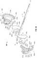
- an embodiment of an endoscopic bipolar forceps 10is shown for use with various surgical procedures and generally includes a housing 20 , a handle assembly 30 , a rotatable assembly 80 , a trigger assembly 70 , a shaft 12 and an end effector assembly 100 , which mutually cooperate to grasp, seal and divide tubular vessels and vascular tissue.
- the end effector assembly 100is rotatable about a longitudinal axis “A-A” through rotation, either manually or otherwise, of the rotatable assembly 80 .
- Rotatable assembly 80generally includes two halves, which, when assembled, form a generally circular rotatable member 82 (as well as other components described herein).
- Forceps 10may include a switch 200 configured to permit the user to selectively activate the forceps 10 in a variety of different orientations, i.e., multi-oriented activation. In embodiments, when the switch 200 is depressed, electrosurgical energy is transferred to the jaw members 110 and 120 . It is envisioned that the switch 200 may be disposed on another part of the forceps 10 , e.g., the handle 50 , rotatable member 82 , housing 20 , etc.
- FIG. 1depicts a bipolar forceps 10 for use in connection with endoscopic surgical procedures
- teachings of the present disclosuremay also apply to more traditional open surgical procedures.
- the forceps 10is described in terms of an endoscopic instrument. It is contemplated that an open version of the forceps may also include the same or similar operating components and features as described herein.
- End effector assembly 100generally includes a pair of opposing jaw members 110 and 120 .
- Shaft 12generally includes a distal end 16 configured to mechanically engage the end effector assembly 100 , and a proximal end 14 configured to mechanically engage the housing 20 .
- Examples of end effector assembly embodiments, details of how the shaft 12 connects to the end effector 100 , as well as details of how the shaft 12 is received within the housing 20 and connections relating thereto,are disclosed in commonly-assigned U.S. Pat. No. 7,150,097 entitled “METHOD OF MANUFACTURING JAW ASSEMBLY FOR VESSEL SEALER AND DIVIDER”, the disclosure of which is incorporated herein by reference in its entirety.
- the forceps 10includes an electrosurgical cable 310 .
- Electrosurgical cable 310may be formed from a suitable flexible, semi-rigid or rigid microwave conductive cable, and may connect directly to an electrosurgical power generating source, e.g., an electrosurgical generator (not shown).
- the power generating sourcemay be any generator suitable for use with electrosurgical devices, and may be configured to provide various frequencies of electromagnetic energy. Examples of electrosurgical generators that may be suitable for use as a source of electrosurgical energy are commercially available under the trademarks FORCE EZTM, FORCE FXTM, SURGISTATTM II, and FORCE TRIADTM offered by Covidien.
- Electrosurgical cable 310may additionally, or alternatively, provide a conduit (not shown) configured to provide coolant fluid from a coolant source (not shown) to one or more components of the forceps 10 .
- the forceps 10may alternatively be configured as a wireless device.
- the forceps 10may include a sensor or feedback mechanism (not shown) which automatically selects the appropriate amount of electrosurgical energy to effectively seal the particularly-sized tissue grasped between the jaw members 110 and 120 .
- the sensor or feedback mechanismmay also measure the impedance across the tissue during sealing and provide an indicator (visual and/or audible) that an effective seal has been created between the jaw members 110 and 120 . Examples of sensor system embodiments are described in commonly-assigned U.S. patent application Ser. No. 10/427,832 entitled “METHOD AND SYSTEM FOR CONTROLLING OUTPUT OF RF MEDICAL GENERATOR” filed on May 1, 2003, the disclosure of which is incorporated herein by reference in its entirety.
- the forceps 10may be designed such that it is fully or partially disposable depending upon a particular purpose or to achieve a particular result.
- end effector assembly 100may be selectively and releasably engageable with the distal end 16 of the shaft 12 and/or the proximal end 14 of the shaft 12 may be selectively and releasably engageable with the housing 20 and the handle assembly 30 .
- the forceps 10would be considered “partially disposable” or “reposable”, e.g., a new or different end effector assembly 100 (or end effector assembly 100 and shaft 12 ) selectively replaces the old end effector assembly 100 as needed.
- some of the presently-disclosed electrical and/or mechanical connectionsmay have to be altered to modify the instrument to a reposable forceps.
- Handle assembly 30includes a fixed handle 50 and a movable handle 40 .
- the fixed handle 50is integrally associated with the housing 20 and the handle 40 is movable relative to the fixed handle 50 .
- the rotatable assembly 80is integrally associated with the housing 20 and is rotatable approximately 180 degrees in both the clockwise and counterclockwise direction about a longitudinal axis “A-A” of rotation.
- the housing 20is formed from two housing halves (not shown). Each half of the housing 20 may include a series of mechanical interfacing components (not shown) configured to matingly engage with a corresponding series of mechanical interfaces (not shown) to align the two housing halves about the inner components and assemblies of the forceps 10 .
- the fixed handle 50takes shape upon the assembly of the housing halves. It is contemplated that the housing halves (as well as other components described herein) may be assembled together with the aid of alignment pins, snap-like interfaces, tongue and groove interfaces, locking tabs, adhesive ports, etc., utilized either alone or in combination for assembly purposes. Examples of housing embodiments and connections relating thereto are disclosed in the above-mentioned, commonly-assigned U.S. Pat. No. 7,150,097.
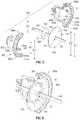
- FIG. 2shows an embodiment of the rotatable assembly 80 in accordance with the present disclosure that includes a rotatable tube 160 and a generally circular rotatable member 82 .
- the rotatable member 82includes inner surfaces defining an interior space 87 within the rotatable member 82 .
- the rotatable member 82includes two generally C-shaped halves 82 a and 82 b , which, when assembled about the tube 160 , define an opening in the rotatable assembly 80 .
- the jaw member 120is designed to be fixed to the end of the rotatable tube 160 , which is part of the shaft 12 , such that rotation of the tube 160 will impart rotation to the end effector assembly 100 (shown in FIG. 1 ).
- Rotatable assembly 80includes a hollow body 83 coupled to and extending proximally from the rotatable member 82 . Additionally, or alternatively, the rotatable assembly 80 may include a hollow body coupled to and extending distally from the rotatable member 82 . Hollow body 83 may take a variety of shapes, e.g., a substantially cylindrical shape. An interior space 87 defined by the rotatable member 82 is in communication with an interior space 88 defined by the hollow body 83 . Rotatable assembly 80 is configured to house one or more shaped PCBs within the interior space 87 defined by the rotatable member 82 and/or within the interior space 88 defined by the hollow body 83 .
- the rotatable assembly 80may be configured to house a drive assembly and/or a knife assembly, or components thereof.
- Hollow body 83defines an interior space 88 , in which components of a drive assembly and/or a knife assembly (or other components) may be accommodated, entirely or in part. Examples of drive assembly embodiments and knife assembly embodiments of the forceps 10 are described in the above-mentioned, commonly-assigned U.S. Pat. No. 7,150,097.
- FIGS. 3A through 3Cshow a rotatable assembly 380 according to an embodiment of the present disclosure that includes a first portion 380 a and a second portion 380 b , which, when assembled about the tube 160 , form the rotatable assembly 380 .
- the proximal end portion of the tube 160includes a laterally-oriented slot 168 , which is designed to interface with the rotatable assembly 380 as described below.
- Rotatable assembly 380includes a rotatable member 382 , and may include a hollow body 383 coupled to and extending proximally from the rotatable member 382 , e.g., as shown in FIG. 3B .
- Rotatable assembly 380is configured to house one or more shaped PCBs within the interior space defined by inner surfaces (e.g., 74 a and 74 b shown in FIG. 3A ) of the rotatable member 382 and/or within the interior space defined by inner surfaces (e.g., 84 a and 84 b shown in FIG. 3A ) of the hollow body 383 .
- Rotatable assembly 380includes a plurality of grooves, e.g., 370 a , 370 b , 371 a and 371 b , recessed into inner surfaces, e.g., 74 a and 74 b , of the rotatable member 382 and configured to receive therein a peripheral edge portion of one or more shaped PCBs.
- the shaped PCBsmay have a generally circular shape, a generally half-circular shape, or other shapes (e.g., PCB 1065 shown in 10 ).
- Second portion 380 b of the rotatable assembly 380may include a series of mechanical interfaces, e.g., detents/flanges 375 a , 375 b , 375 c and 375 d shown in FIGS. 3A and 3C , which generally matingly engage a corresponding series of sockets or other mechanical interfaces in the first portion 380 a to form the rotatable assembly 380 .
- Second portion 380 bincludes a tab 89 b , which together with a corresponding tab 89 a (phantomly illustrated in FIG. 3A ) disposed on the first portion 380 a cooperate to matingly engage the slot 168 formed in the tube 160 .
- thispermits selective rotation of the tube 160 about a longitudinal axis “A-A” of the shaft 12 by manipulating the rotatable member 382 in the clockwise or counterclockwise direction.
- the rotatable assembly 380is configured to house four, generally half circular-shaped PCBs, 360 a , 360 b , 361 a and 361 b , which are aligned with respect to one another about the tube 160 to form two, generally circular-shaped (split) PCBs.
- the first, second, third and fourth PCBs 360 a , 360 b , 361 a and 361 brespectively, include a curved peripheral edge portion 364 a , 364 b , 365 a and 365 b , respectively, and a generally C-shaped opening “O” having a radius larger than the radius of the tube 160 .
- the shape, size and relative positions of the first, second, third and fourth PCBs 360 a , 360 b , 361 a and 361 bmay be varied from the configuration depicted in FIG. 3A .
- the first portion 380 a of the rotatable assembly 380includes a first rotatable-member portion 382 a
- the second portion 380 b of the rotatable assembly 380includes a second rotatable-member portion 382 b , which, when assembled about the tube 160 , form a generally circular rotatable member 382
- First portion 380 a of the rotatable assembly 380includes a first hollow-body portion 83 a
- the second portion 380 b of the rotatable assembly 380includes a second hollow-body portion 83 b , which, when assembled about the tube 160 , form a hollow body 383 (shown in FIG. 3B ) coupled to and extending proximally from the rotatable member 382 .
- First rotatable-member portion 382 aincludes a first groove 370 a and a second groove 371 a defined therein, and the second rotatable-member portion 382 b includes a third groove 370 b and a fourth groove 371 b .
- First groove 370 ais configured to receive a peripheral edge portion 364 a of the first PCB 360 a
- the second groove 371 ais configured to receive a peripheral edge portion 365 a of the third PCB 361 a
- the third groove 370 bis configured to receive a peripheral edge portion 364 b of the second PCB 360 b
- the fourth groove 371 bis configured to receive a peripheral edge portion 365 b of the fourth PCB 361 b .
- the first, second, third and fourth grooves 370 a , 371 a , 370 b and 371 bmay be provided with a suitable adhesive material for affixing permanently or releasably the generally half circular-shaped PCBs.
- Providing generally half circular-shaped PCBs (e.g., 360 a , 360 b , 361 a and 361 b ) to the first rotatable-member portion 382 a and the second rotatable-member portion 382 bmay allow for modularity in the design of the rotatable assembly 380 , e.g., by allowing the first rotatable-member portion 382 a and the second rotatable-member portion 382 b to accommodate various configurations of PCBs, and/or may allow for ease of assembly of the first rotatable-member portion 382 a and the second rotatable-member portion 382 b about the tube 160 .
- FIG. 3Cshows an embodiment of the second portion 380 b of the rotatable assembly 380 in accordance with the present disclosure that includes the second and fourth PCBs 360 b and 361 b , respectively, with edge portions thereof disposed in the third and fourth grooves 370 b and 371 b , respectively.
- the shape, size and relative positions of the first, second, third and fourth grooves 370 a , 371 a , 370 b and 371 b , respectively,may be varied from the configuration depicted in FIGS. 3A and 3C .
- FIGS. 4A through 4Cshow a rotatable assembly 480 according to another embodiment of the present disclosure that includes a rotatable member 482 and a hollow body 483 coupled to and extending proximally from the rotatable member 482 .
- Rotatable assembly 480includes a first portion 480 a and a second portion 480 b , which, when assembled about the tube 160 , form the rotatable assembly 480 .
- First portion 480 a and the second portion 480 b of the rotatable assembly 480are similar to the first portion 380 a and the second portion 380 b , respectively, of the rotatable assembly 380 shown in FIG. 3A , except for the grooves in the inner surfaces 484 a and 484 b of the hollow body 483 and the inner surfaces 474 a and 474 b of the rotatable member 482 .
- First portion 480 a of the rotatable assembly 480includes a first rotatable-member portion 482 a
- the second portion 480 b of the rotatable assembly 480includes a second rotatable-member portion 482 b , which, when assembled about the tube 160 , form the generally circular rotatable member 482
- First portion 480 a of the rotatable assembly 480includes a first hollow-body portion 483 a
- the second portion 480 b of the rotatable assembly 480includes a second hollow-body portion 483 b , which, when assembled about the tube 160 , form the hollow body 483 .
- the rotatable assembly 480may be configured to house one or more shaped PCBs within the interior space defined by inner surfaces 474 a and 474 b of the rotatable member 482 and within the interior space defined by inner surfaces 484 a and 484 b of the hollow body 483 .
- Rotatable member 482is configured to house one or more generally circular-shaped PCBs or generally half circular-shaped PCBs (e.g., 460 a and 460 B), and the hollow body 483 is configured to house one or more generally circular-shaped PCBs or generally half circular-shaped PCBs (e.g., 461 a , 461 b , 462 a and 462 b ).
- Rotatable assembly 480includes six, generally half circular-shaped PCBs 460 a , 460 b , 461 a , 461 b , 462 a and 462 b , which are aligned with respect to one another about the tube 160 to form three, generally circular-shaped (split) PCBs.
- the PCBs 460 a , 460 b , 461 a , 461 b , 462 a and 462 binclude a curved peripheral edge portion (e.g., 464 a and 464 b shown in FIG. 4A ) and a generally C-shaped opening “O” having a radius larger than the radius of the tube 160 .
- the shape, size and relative positions of the PCBs 460 a , 460 b , 461 a , 461 b , 462 a and 462 bmay be varied from the configuration depicted in FIG. 4A .
- the rotatable member 482is provided with two grooves 470 a and 470 b configured to receive a peripheral edge portion 465 a and 464 b , respectively, of two, generally half circular-shaped PCBs 460 a and 460 b , respectively, and the hollow body 483 is provided with four grooves 471 a , 471 b , 472 a and 472 b configured to receive a peripheral edge portion of four, generally half circular-shaped PCBs 461 a , 461 b , 462 a and 462 b , respectively.
- Hollow body 483may be provided with additional grooves (e.g., 473 a and 474 a ) for receiving one or more additional PCBs (not shown), which may be used to offer additional functionality.
- additional groovese.g., 473 a and 474 a
- the shape, size and relative locations of the grooves 470 a , 470 b , 471 a , 471 b , 472 a and 472 bmay be varied from the configuration depicted in FIGS. 4A and 4C . Although six grooves are shown in FIG. 4A , it is to be understood that any various numbers of grooves (and/or slots, pockets, channels or other recesses) may be utilized.
- Rotatable assembly 480includes a wall 489 disposed at the proximal end of the hollow body 483 .
- PCBs located within the hollow body 483may be disposed in a proximal portion of the hollow body 483 , e.g., in relatively close proximity to the wall 489 .
- one or more PCBsmay be disposed in a proximal portion of the hollow body 483 , and spaced apart, by a length “L”, from PCBs located within the rotatable member 482 , defining an interior cavity 490 .
- Length “L”may be any suitable length. Length “L” may be selected so that the interior cavity 490 is utilizable to house a drive assembly and/or a knife assembly, or components thereof.
- FIGS. 5 and 6show a rotatable assembly 580 according to another embodiment of the present disclosure that includes a first portion 580 a and a second portion 580 b , which, when assembled about the tube 160 , form the rotatable assembly 580 .
- Rotatable assembly 580according to various embodiments is configured to house one or more shaped PCBs.
- First portion 580 a of the rotatable assembly 580includes a first rotatable-member portion 582 a and a first hollow-body portion 583 a
- the second portion 580 b of the rotatable assembly 580includes a second rotatable-member portion 582 b and a second hollow-body portion 583 b
- Inner surfaces of the first rotatable-member portion 582 a and/or the second rotatable-member portion 582 bmay include one or more grooves, slots, pockets, channels or other recesses configured to receive at least portions of a shaped PCB.
- inner surfaces of the first hollow-body portion 583 a and/or the second hollow-body portion 583 bmay include one or more grooves (e.g., 471 a , 471 b , 472 a and 472 b shown in FIG. 4A ), slots, pockets, channels or other recesses configured to receive at least portions of a shaped PCB.
- groovese.g., 471 a , 471 b , 472 a and 472 b shown in FIG. 4A
- slots, pockets, channels or other recessesconfigured to receive at least portions of a shaped PCB.
- Inner surfaces of the first hollow-body portion 583 a and the second hollow-body portion 583 bmay be provided with one or more receptacle assemblies 581 configured to receive at least portions of a PCB.
- the presently-disclosed receptacle assemblies 581may be configured to include an electrical connector part “E” adapted to provide electrical connection to a PCB.
- First rotatable-member portion 582 a and the second rotatable-member portion 582 bwhen assembled about the tube 160 , form a rotatable member 582 .
- Inner surfaces 574 a and 574 b of the rotatable member 582generally define a chamber, or interior cavity, having a diameter “D 2 ”.
- First hollow-body portion 583 a and the second hollow-body portion 583 bwhen assembled about the tube 160 , form a hollow body 583 coupled to and extending proximally from the rotatable member 582 .
- Inner surfaces 584 a and 584 b of the hollow body 583generally define a chamber, or interior cavity, having a diameter “D 1 ”.
- the rotatable assembly 580includes two, generally circular-shaped PCBs 565 and 566 , which include a generally circular-shaped opening “O” having a diameter larger than the diameter of the tube 160 .
- the shape, size and relative positions of the PCBs 565 and 566may be varied from the configuration depicted in FIGS. 5 and 6 .
- First PCB 565generally includes an outer diameter “D 3 ” and an inner diameter “D 2 ”.
- the inner diameter “D 2 ”is indicated by the dashed circle in FIG. 5 .
- An interior region 563 of the first PCB 565is defined by the inner diameter “D 2 ” and the opening “O”.
- An outer peripheral edge portion 564 surrounding the interior region 563is defined between the outer and inner diameters “D 3 ” and “D 2 ”, respectively.
- First rotatable-member portion 582 aincludes a first groove 575 a and the second rotatable-member portion 582 b includes a second groove 575 b .
- the first groove 575 a and the second groove 575 bare configured to receive the peripheral edge portion 564 of the first PCB 565 .
- Second PCB 566includes an outer diameter “D 1 ” and an outer diametrical edge 567 , and may include one or more electrically-conductive portions 562 , e.g., metal pads, disposed along the outer diametrical edge 567 .
- the receptacle assemblies 581are configured to receive at least portions of the second PCB 566 , and may be configured to include electrical connector parts “E” adapted to provide electrical connection to electrically-conductive portions 562 of the second PCB 566 .
- Electrically-conductive portions 562may be configured to align with and electrically connect with the electrical connector parts “E” of the receptacle assemblies 581 disposed within, or otherwise associated with, the hollow body 583 and/or the rotatable member 582 .
- the electrically-conductive portions 562may be used as grounding pads, or for electrically interconnecting circuit members, e.g., PCBs, and/or for providing electrical connection to and between electrical components.
- FIGS. 7 and 8show a rotatable assembly 780 according to an embodiment of the present disclosure that includes a first portion 780 a and a second portion 780 b , which, when assembled about the tube 160 , form the rotatable assembly 780 .
- Rotatable assembly 780according to various embodiments is configured to house one or more shaped PCBs.
- the first portion 780 a of the rotatable assembly 780includes a first rotatable-member portion 782 a
- the second portion 780 b of the rotatable assembly 780includes a second rotatable-member portion 782 b , which, when assembled about the tube 160 , form rotatable member 782 .
- the presently-disclosed rotatable member 782may be configured to house one or more generally circular-shaped PCBs or generally half circular-shaped PCBs.
- the inner surfaces 774 a and 774 b of the rotatable member 782may include a first groove 770 a and a second groove 770 b , respectively.
- Rotatable member 782is similar to the rotatable member 582 shown in FIG. 5 , and further description thereof is omitted in the interests of brevity.
- First portion 780 a of the rotatable assembly 780includes a first hollow-body portion 783 a
- the second portion 780 b of the rotatable assembly 780includes a second hollow-body portion 783 b , which, when assembled about the tube 160 , form a hollow body 783 .
- the hollow body 783is configured to house two, shaped PCBs 763 and 764 .
- PCBs 763 and 764include a generally circular-shaped opening “O” having a diameter larger than the diameter of the tube 160 .
- PCBs 763 and 764according to embodiments include two tab portions “T” protruding from opposite sides of a generally circular-shaped interior portion 712 .
- Inner surfaces 784 a and 784 b of the first hollow-body portion 783 a and the second hollow-body portion 783 b , respectively,are provided with slots or channels (e.g., 773 b and 774 b shown in FIG. 7 ) configured to receive therein the tab portions “T” of the PCBs 763 and 764 .
- the shape and size of the tab portions “T” and the slots or channels for engagement with the tab portions “T”may be varied from the configuration depicted in FIGS. 7 and 8 .
- One or more groovesmay additionally, or alternatively be provided to the inner surfaces 784 a and 784 b of the hollow body 783 and configured to receive therein portions of one or more generally circular-shaped PCBs and/or generally half circular-shaped PCBs (e.g., similar to the grooves 471 b and 472 b shown in FIG. 4A ), and/or one or more slots or channels may be provided to the inner surfaces 774 a and 774 b of the rotatable member 782 (e.g., similar to the slots or channels 773 b and 774 b shown in FIG. 7 ) configured to receive tab portions of PCBs (e.g., similar to the tab portions “T” of the PCBs 763 and 764 ).
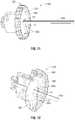
- FIG. 9shows an embodiment of a generally circular-shaped PCB 965 according to the present disclosure that includes an outer diametrical edge 967 and a generally circular-shaped opening “O” having a diameter larger than the diameter of the tube 160 .
- PCB 965includes a cut-out portion “C” defining a void that extends from the opening “O” to the outer diametrical edge 967 .
- Cut-out portion “C”generally has a width “W” that is larger than the diameter of the tube 160 .
- Cut-out “C” portionis configured to allow the tube 160 to be passed through the cut-out portion “C” into the opening “O” and may allow for ease of installation of the PCB 965 about the tube 160 .
- PCB 965includes a plurality of fastener holes 982 , which may be spaced apart from each other and disposed substantially adjacent to the outer diametrical edge 967 .
- the PCB 965generally includes a first surface “S 1 ” and a second surface “S 2 ”.
- PCB 965may include one or more electrically-conductive portions 962 , e.g., metal pads, disposed on the first surface “S 1 ”, which may be used as grounding pads, or for electrically interconnecting circuit members, e.g., PCBs, and/or for providing electrical connection to and between electrical components.
- Electrically-conductive portions 962may take a variety of shapes and sizes. Electrically-conductive portions 962 may have a ring-like shape, and may be coaxially-disposed about one or more of the fastener holes 982 , e.g., as shown in FIG. 9 .
- FIG. 10shows an embodiment of a shaped PCB 1065 according to the present disclosure that includes two concave-outward edges 1011 and 1012 , two concave-inward edges 1016 and 1017 , and two peripheral edge portions 1064 associated with the two concave-inward edges 1016 and 1017 .
- the peripheral edge portions 1064are indicated by the two dashed concave-inward lines in FIG. 10 .
- PCB 1065includes a generally circular-shaped opening “O” having a diameter larger than the diameter of the tube 160 .
- Embodiments of the presently-disclosed rotatable assemblymay be configured for receiving the peripheral edge portions 1064 of the shaped PCB 1065 in one or more grooves recessed into inner surfaces of a rotatable member.
- the concave-outward edges 1011 and 1012define open spaces (e.g., 1021 and 1022 shown in FIG.
- the concave-outward edges 1011 and 1012 , the concave-inward edges 1016 and 1017 , the peripheral edge portions 1064 , and the opening “O”may be varied from the configuration depicted in FIG. 10 .
- FIG. 11shows a rotatable assembly 1180 according to another embodiment of the present disclosure that includes a rotatable member 1182 configured to house the PCB 965 shown in FIG. 9 .
- the interior space defined within the rotatable member 1182is configured to receive the PCB 965 therein.
- the presently-disclosed rotatable member 1182according to various embodiments includes a backing member 985 .
- Shaped PCBs according to the present disclosuremay be fixedly and/or removably secured to the backing member 985 .
- a plurality of support pegs 981may be disposed on the backing member 985 in a spaced relation corresponding to the pattern of fastener holes 982 of the PCB 965 .
- the PCB 965is coupled to the support pegs 981 .
- a plurality of fasteners 983may extend through the fastener holes into the plurality of pegs 983 .
- Fasteners 983may be any suitable fastener used to fixedly secure the PCB 965 to the support pegs 981 .
- fasteners 983examples include pins and threaded fasteners, e.g., screws, which may be formed of metal, plastic or any other suitable material. It will be appreciated that other suitable fasteners may be used such as adhesively-bonded fasteners.
- the PCB 965may be removably secured to the support pegs 981 .
- the shaft 12e.g., shown in FIGS. 1, 2, 3A and 4A
- the end effector assembly 100may be disposable and, therefore, selectively and/or releasably engagable with the housing 20 and the rotating assembly 80 to form a partially disposable forceps 10 and/or the entire forceps 10 may be disposable after use.
- the PCB 965may be disposable and, therefore, removable (e.g., removably secured to the support pegs 981 or the backing member 985 ) from the presently-disclosed rotatable assembly.
- FIG. 13shows a rotatable assembly 1380 according to another embodiment of the present disclosure that includes a rotatable member 1382 .
- Rotatable member 1382includes one or more grooves (e.g., similar to the grooves 370 a , 370 b , 371 a and 371 b shown in FIG. 3 ) recessed into inner surfaces of the rotatable member 1182 and configured to receive therein a peripheral edge portion of one or more shaped PCBs.
- groovese.g., similar to the grooves 370 a , 370 b , 371 a and 371 b shown in FIG. 3
- the rotatable member 1182is configured to house the PCB 1065 of FIG. 10 .
- the concave-outward edges 1011 and 1012 of the PCBdefine open spaces 1021 and 1022 , respectively, which may allow airflow to pass the edges 1011 and 1012 into interior portions of the rotatable assembly 1380 , e.g., for cooling electrical components of the PCB 1065 and/or other components housed within the rotatable assembly 1380 .
- rotatable assemblyinclude a rotatable member configured to house one or more shaped PCBs within an interior space defined by inner surfaces of the rotatable member.
- the above-described rotatable assemblymay include a hollow body configured to house one or more shaped PCBs within an interior space defined by inner surfaces of the hollow body.
- the hollow bodyis coupled to the rotatable member and extends proximally and/or distally therefrom.
- the above-described rotatable assemblymay include one or more receptacle assemblies (e.g., 581 shown in FIG. 5 ) and/or grooves (e.g., 370 a shown in FIG. 3A ) and/or slots (e.g., 773 b shown in FIG. 7 ) recessed into, or otherwise associated with, inner surfaces of the rotatable member and/or the hollow body, configured to receive therein portions of the presently-disclosed shaped PCBs.
- the above-described electrosurgical devices including the presently-disclosed rotatable assemblymay be wired or wireless devices.
Landscapes
- Health & Medical Sciences (AREA)
- Physics & Mathematics (AREA)
- Surgery (AREA)
- Life Sciences & Earth Sciences (AREA)
- Engineering & Computer Science (AREA)
- Veterinary Medicine (AREA)
- Public Health (AREA)
- Nuclear Medicine, Radiotherapy & Molecular Imaging (AREA)
- Biomedical Technology (AREA)
- Heart & Thoracic Surgery (AREA)
- Medical Informatics (AREA)
- Molecular Biology (AREA)
- Animal Behavior & Ethology (AREA)
- General Health & Medical Sciences (AREA)
- General Physics & Mathematics (AREA)
- Optics & Photonics (AREA)
- Otolaryngology (AREA)
- Plasma & Fusion (AREA)
- Nonlinear Science (AREA)
- Mathematical Physics (AREA)
- Chemical & Material Sciences (AREA)
- Crystallography & Structural Chemistry (AREA)
- Surgical Instruments (AREA)
Abstract
Description
Claims (18)
Priority Applications (1)
| Application Number | Priority Date | Filing Date | Title |
|---|---|---|---|
| US15/971,527US11090108B2 (en) | 2010-03-25 | 2018-05-04 | Shaped circuit boards suitable for use in electrosurgical devices and rotatable assemblies including same |
Applications Claiming Priority (3)
| Application Number | Priority Date | Filing Date | Title |
|---|---|---|---|
| US12/731,247US9023032B2 (en) | 2010-03-25 | 2010-03-25 | Shaped circuit boards suitable for use in electrosurgical devices and rotatable assemblies including same |
| US14/691,658US9974527B2 (en) | 2010-03-25 | 2015-04-21 | Shaped circuit boards suitable for use in electrosurgical devices and rotatable assemblies including same |
| US15/971,527US11090108B2 (en) | 2010-03-25 | 2018-05-04 | Shaped circuit boards suitable for use in electrosurgical devices and rotatable assemblies including same |
Related Parent Applications (1)
| Application Number | Title | Priority Date | Filing Date |
|---|---|---|---|
| US14/691,658ContinuationUS9974527B2 (en) | 2010-03-25 | 2015-04-21 | Shaped circuit boards suitable for use in electrosurgical devices and rotatable assemblies including same |
Publications (2)
| Publication Number | Publication Date |
|---|---|
| US20180249990A1 US20180249990A1 (en) | 2018-09-06 |
| US11090108B2true US11090108B2 (en) | 2021-08-17 |
Family
ID=44318248
Family Applications (3)
| Application Number | Title | Priority Date | Filing Date |
|---|---|---|---|
| US12/731,247Expired - Fee RelatedUS9023032B2 (en) | 2010-03-25 | 2010-03-25 | Shaped circuit boards suitable for use in electrosurgical devices and rotatable assemblies including same |
| US14/691,658Active2031-07-06US9974527B2 (en) | 2010-03-25 | 2015-04-21 | Shaped circuit boards suitable for use in electrosurgical devices and rotatable assemblies including same |
| US15/971,527Expired - Fee RelatedUS11090108B2 (en) | 2010-03-25 | 2018-05-04 | Shaped circuit boards suitable for use in electrosurgical devices and rotatable assemblies including same |
Family Applications Before (2)
| Application Number | Title | Priority Date | Filing Date |
|---|---|---|---|
| US12/731,247Expired - Fee RelatedUS9023032B2 (en) | 2010-03-25 | 2010-03-25 | Shaped circuit boards suitable for use in electrosurgical devices and rotatable assemblies including same |
| US14/691,658Active2031-07-06US9974527B2 (en) | 2010-03-25 | 2015-04-21 | Shaped circuit boards suitable for use in electrosurgical devices and rotatable assemblies including same |
Country Status (4)
| Country | Link |
|---|---|
| US (3) | US9023032B2 (en) |
| EP (1) | EP2368511B1 (en) |
| AU (1) | AU2011201395B2 (en) |
| CA (1) | CA2735071A1 (en) |
Families Citing this family (123)
| Publication number | Priority date | Publication date | Assignee | Title |
|---|---|---|---|---|
| US9023032B2 (en)* | 2010-03-25 | 2015-05-05 | Covidien Lp | Shaped circuit boards suitable for use in electrosurgical devices and rotatable assemblies including same |
| US10624664B2 (en)* | 2011-09-28 | 2020-04-21 | Evalve, Inc. | Apparatuses and methods for cutting a tissue bridge and/or removing a heart valve clip or suture |
| US11871901B2 (en) | 2012-05-20 | 2024-01-16 | Cilag Gmbh International | Method for situational awareness for surgical network or surgical network connected device capable of adjusting function based on a sensed situation or usage |
| US9572666B2 (en) | 2014-03-17 | 2017-02-21 | Evalve, Inc. | Mitral valve fixation device removal devices and methods |
| US11504192B2 (en) | 2014-10-30 | 2022-11-22 | Cilag Gmbh International | Method of hub communication with surgical instrument systems |
| CN107771060B (en) | 2015-06-18 | 2021-06-04 | 伊西康有限责任公司 | Dual-articulation drive system structure for articulating surgical instruments |
| US10154841B2 (en) | 2015-06-18 | 2018-12-18 | Ethicon Llc | Surgical stapling instruments with lockout arrangements for preventing firing system actuation when a cartridge is spent or missing |
| EP3868306A1 (en) | 2016-06-20 | 2021-08-25 | Evalve, Inc. | Transapical removal device |
| US10736632B2 (en) | 2016-07-06 | 2020-08-11 | Evalve, Inc. | Methods and devices for valve clip excision |
| US11071564B2 (en) | 2016-10-05 | 2021-07-27 | Evalve, Inc. | Cardiac valve cutting device |
| US20180333194A1 (en)* | 2017-05-16 | 2018-11-22 | Megadyne Medical Products, Inc. | Swivel instrument with flex circuit |
| US11317919B2 (en) | 2017-10-30 | 2022-05-03 | Cilag Gmbh International | Clip applier comprising a clip crimping system |
| US11564756B2 (en) | 2017-10-30 | 2023-01-31 | Cilag Gmbh International | Method of hub communication with surgical instrument systems |
| US11911045B2 (en) | 2017-10-30 | 2024-02-27 | Cllag GmbH International | Method for operating a powered articulating multi-clip applier |
| US11291510B2 (en) | 2017-10-30 | 2022-04-05 | Cilag Gmbh International | Method of hub communication with surgical instrument systems |
| US11801098B2 (en) | 2017-10-30 | 2023-10-31 | Cilag Gmbh International | Method of hub communication with surgical instrument systems |
| US11510741B2 (en) | 2017-10-30 | 2022-11-29 | Cilag Gmbh International | Method for producing a surgical instrument comprising a smart electrical system |
| US11925373B2 (en) | 2017-10-30 | 2024-03-12 | Cilag Gmbh International | Surgical suturing instrument comprising a non-circular needle |
| US11026687B2 (en) | 2017-10-30 | 2021-06-08 | Cilag Gmbh International | Clip applier comprising clip advancing systems |
| US11311342B2 (en) | 2017-10-30 | 2022-04-26 | Cilag Gmbh International | Method for communicating with surgical instrument systems |
| US10892995B2 (en) | 2017-12-28 | 2021-01-12 | Ethicon Llc | Surgical network determination of prioritization of communication, interaction, or processing based on system or device needs |
| US11304699B2 (en) | 2017-12-28 | 2022-04-19 | Cilag Gmbh International | Method for adaptive control schemes for surgical network control and interaction |
| US11389164B2 (en) | 2017-12-28 | 2022-07-19 | Cilag Gmbh International | Method of using reinforced flexible circuits with multiple sensors to optimize performance of radio frequency devices |
| US11559308B2 (en) | 2017-12-28 | 2023-01-24 | Cilag Gmbh International | Method for smart energy device infrastructure |
| US11026751B2 (en) | 2017-12-28 | 2021-06-08 | Cilag Gmbh International | Display of alignment of staple cartridge to prior linear staple line |
| US20190201112A1 (en) | 2017-12-28 | 2019-07-04 | Ethicon Llc | Computer implemented interactive surgical systems |
| US11013563B2 (en) | 2017-12-28 | 2021-05-25 | Ethicon Llc | Drive arrangements for robot-assisted surgical platforms |
| US11308075B2 (en) | 2017-12-28 | 2022-04-19 | Cilag Gmbh International | Surgical network, instrument, and cloud responses based on validation of received dataset and authentication of its source and integrity |
| US11273001B2 (en) | 2017-12-28 | 2022-03-15 | Cilag Gmbh International | Surgical hub and modular device response adjustment based on situational awareness |
| US10918310B2 (en) | 2018-01-03 | 2021-02-16 | Biosense Webster (Israel) Ltd. | Fast anatomical mapping (FAM) using volume filling |
| US11633237B2 (en) | 2017-12-28 | 2023-04-25 | Cilag Gmbh International | Usage and technique analysis of surgeon / staff performance against a baseline to optimize device utilization and performance for both current and future procedures |
| US11864728B2 (en) | 2017-12-28 | 2024-01-09 | Cilag Gmbh International | Characterization of tissue irregularities through the use of mono-chromatic light refractivity |
| US11179175B2 (en) | 2017-12-28 | 2021-11-23 | Cilag Gmbh International | Controlling an ultrasonic surgical instrument according to tissue location |
| US11696760B2 (en) | 2017-12-28 | 2023-07-11 | Cilag Gmbh International | Safety systems for smart powered surgical stapling |
| US11464535B2 (en) | 2017-12-28 | 2022-10-11 | Cilag Gmbh International | Detection of end effector emersion in liquid |
| US11234756B2 (en) | 2017-12-28 | 2022-02-01 | Cilag Gmbh International | Powered surgical tool with predefined adjustable control algorithm for controlling end effector parameter |
| US20190201142A1 (en) | 2017-12-28 | 2019-07-04 | Ethicon Llc | Automatic tool adjustments for robot-assisted surgical platforms |
| US11202570B2 (en) | 2017-12-28 | 2021-12-21 | Cilag Gmbh International | Communication hub and storage device for storing parameters and status of a surgical device to be shared with cloud based analytics systems |
| US20190201090A1 (en) | 2017-12-28 | 2019-07-04 | Ethicon Llc | Capacitive coupled return path pad with separable array elements |
| US11076921B2 (en) | 2017-12-28 | 2021-08-03 | Cilag Gmbh International | Adaptive control program updates for surgical hubs |
| US11659023B2 (en) | 2017-12-28 | 2023-05-23 | Cilag Gmbh International | Method of hub communication |
| US10758310B2 (en) | 2017-12-28 | 2020-09-01 | Ethicon Llc | Wireless pairing of a surgical device with another device within a sterile surgical field based on the usage and situational awareness of devices |
| US11571234B2 (en) | 2017-12-28 | 2023-02-07 | Cilag Gmbh International | Temperature control of ultrasonic end effector and control system therefor |
| US11291495B2 (en) | 2017-12-28 | 2022-04-05 | Cilag Gmbh International | Interruption of energy due to inadvertent capacitive coupling |
| US11786251B2 (en) | 2017-12-28 | 2023-10-17 | Cilag Gmbh International | Method for adaptive control schemes for surgical network control and interaction |
| US11786245B2 (en) | 2017-12-28 | 2023-10-17 | Cilag Gmbh International | Surgical systems with prioritized data transmission capabilities |
| US11364075B2 (en) | 2017-12-28 | 2022-06-21 | Cilag Gmbh International | Radio frequency energy device for delivering combined electrical signals |
| US11464559B2 (en) | 2017-12-28 | 2022-10-11 | Cilag Gmbh International | Estimating state of ultrasonic end effector and control system therefor |
| US20190206569A1 (en) | 2017-12-28 | 2019-07-04 | Ethicon Llc | Method of cloud based data analytics for use with the hub |
| US11903601B2 (en) | 2017-12-28 | 2024-02-20 | Cilag Gmbh International | Surgical instrument comprising a plurality of drive systems |
| US11529187B2 (en) | 2017-12-28 | 2022-12-20 | Cilag Gmbh International | Surgical evacuation sensor arrangements |
| US11602393B2 (en) | 2017-12-28 | 2023-03-14 | Cilag Gmbh International | Surgical evacuation sensing and generator control |
| US11410259B2 (en) | 2017-12-28 | 2022-08-09 | Cilag Gmbh International | Adaptive control program updates for surgical devices |
| US11832899B2 (en) | 2017-12-28 | 2023-12-05 | Cilag Gmbh International | Surgical systems with autonomously adjustable control programs |
| US11304763B2 (en) | 2017-12-28 | 2022-04-19 | Cilag Gmbh International | Image capturing of the areas outside the abdomen to improve placement and control of a surgical device in use |
| US11540855B2 (en) | 2017-12-28 | 2023-01-03 | Cilag Gmbh International | Controlling activation of an ultrasonic surgical instrument according to the presence of tissue |
| US12396806B2 (en) | 2017-12-28 | 2025-08-26 | Cilag Gmbh International | Adjustment of a surgical device function based on situational awareness |
| US11419667B2 (en) | 2017-12-28 | 2022-08-23 | Cilag Gmbh International | Ultrasonic energy device which varies pressure applied by clamp arm to provide threshold control pressure at a cut progression location |
| US11832840B2 (en) | 2017-12-28 | 2023-12-05 | Cilag Gmbh International | Surgical instrument having a flexible circuit |
| US11304745B2 (en) | 2017-12-28 | 2022-04-19 | Cilag Gmbh International | Surgical evacuation sensing and display |
| US11666331B2 (en) | 2017-12-28 | 2023-06-06 | Cilag Gmbh International | Systems for detecting proximity of surgical end effector to cancerous tissue |
| US11744604B2 (en) | 2017-12-28 | 2023-09-05 | Cilag Gmbh International | Surgical instrument with a hardware-only control circuit |
| US12376855B2 (en) | 2017-12-28 | 2025-08-05 | Cilag Gmbh International | Safety systems for smart powered surgical stapling |
| US11896322B2 (en) | 2017-12-28 | 2024-02-13 | Cilag Gmbh International | Sensing the patient position and contact utilizing the mono-polar return pad electrode to provide situational awareness to the hub |
| US11969216B2 (en) | 2017-12-28 | 2024-04-30 | Cilag Gmbh International | Surgical network recommendations from real time analysis of procedure variables against a baseline highlighting differences from the optimal solution |
| US11132462B2 (en) | 2017-12-28 | 2021-09-28 | Cilag Gmbh International | Data stripping method to interrogate patient records and create anonymized record |
| US12062442B2 (en) | 2017-12-28 | 2024-08-13 | Cilag Gmbh International | Method for operating surgical instrument systems |
| US11324557B2 (en) | 2017-12-28 | 2022-05-10 | Cilag Gmbh International | Surgical instrument with a sensing array |
| US11253315B2 (en) | 2017-12-28 | 2022-02-22 | Cilag Gmbh International | Increasing radio frequency to create pad-less monopolar loop |
| US11419630B2 (en) | 2017-12-28 | 2022-08-23 | Cilag Gmbh International | Surgical system distributed processing |
| US11266468B2 (en) | 2017-12-28 | 2022-03-08 | Cilag Gmbh International | Cooperative utilization of data derived from secondary sources by intelligent surgical hubs |
| US12096916B2 (en) | 2017-12-28 | 2024-09-24 | Cilag Gmbh International | Method of sensing particulate from smoke evacuated from a patient, adjusting the pump speed based on the sensed information, and communicating the functional parameters of the system to the hub |
| US11424027B2 (en) | 2017-12-28 | 2022-08-23 | Cilag Gmbh International | Method for operating surgical instrument systems |
| US11937769B2 (en) | 2017-12-28 | 2024-03-26 | Cilag Gmbh International | Method of hub communication, processing, storage and display |
| US11857152B2 (en) | 2017-12-28 | 2024-01-02 | Cilag Gmbh International | Surgical hub spatial awareness to determine devices in operating theater |
| US11998193B2 (en) | 2017-12-28 | 2024-06-04 | Cilag Gmbh International | Method for usage of the shroud as an aspect of sensing or controlling a powered surgical device, and a control algorithm to adjust its default operation |
| US11818052B2 (en) | 2017-12-28 | 2023-11-14 | Cilag Gmbh International | Surgical network determination of prioritization of communication, interaction, or processing based on system or device needs |
| US11559307B2 (en) | 2017-12-28 | 2023-01-24 | Cilag Gmbh International | Method of robotic hub communication, detection, and control |
| WO2019133144A1 (en) | 2017-12-28 | 2019-07-04 | Ethicon Llc | Detection and escalation of security responses of surgical instruments to increasing severity threats |
| US11576677B2 (en) | 2017-12-28 | 2023-02-14 | Cilag Gmbh International | Method of hub communication, processing, display, and cloud analytics |
| US11376002B2 (en) | 2017-12-28 | 2022-07-05 | Cilag Gmbh International | Surgical instrument cartridge sensor assemblies |
| US11896443B2 (en) | 2017-12-28 | 2024-02-13 | Cilag Gmbh International | Control of a surgical system through a surgical barrier |
| US11284936B2 (en) | 2017-12-28 | 2022-03-29 | Cilag Gmbh International | Surgical instrument having a flexible electrode |
| US11423007B2 (en) | 2017-12-28 | 2022-08-23 | Cilag Gmbh International | Adjustment of device control programs based on stratified contextual data in addition to the data |
| US11589888B2 (en) | 2017-12-28 | 2023-02-28 | Cilag Gmbh International | Method for controlling smart energy devices |
| US11166772B2 (en) | 2017-12-28 | 2021-11-09 | Cilag Gmbh International | Surgical hub coordination of control and communication of operating room devices |
| US11678881B2 (en) | 2017-12-28 | 2023-06-20 | Cilag Gmbh International | Spatial awareness of surgical hubs in operating rooms |
| CN111787865B (en)* | 2017-12-28 | 2024-12-03 | 爱惜康有限责任公司 | Surgical instrument including push button circuit |
| US11278281B2 (en) | 2017-12-28 | 2022-03-22 | Cilag Gmbh International | Interactive surgical system |
| US11612444B2 (en) | 2017-12-28 | 2023-03-28 | Cilag Gmbh International | Adjustment of a surgical device function based on situational awareness |
| US12127729B2 (en) | 2017-12-28 | 2024-10-29 | Cilag Gmbh International | Method for smoke evacuation for surgical hub |
| US20190201039A1 (en) | 2017-12-28 | 2019-07-04 | Ethicon Llc | Situational awareness of electrosurgical systems |
| US11446052B2 (en) | 2017-12-28 | 2022-09-20 | Cilag Gmbh International | Variation of radio frequency and ultrasonic power level in cooperation with varying clamp arm pressure to achieve predefined heat flux or power applied to tissue |
| US11257589B2 (en) | 2017-12-28 | 2022-02-22 | Cilag Gmbh International | Real-time analysis of comprehensive cost of all instrumentation used in surgery utilizing data fluidity to track instruments through stocking and in-house processes |
| US11304720B2 (en) | 2017-12-28 | 2022-04-19 | Cilag Gmbh International | Activation of energy devices |
| US11109866B2 (en) | 2017-12-28 | 2021-09-07 | Cilag Gmbh International | Method for circular stapler control algorithm adjustment based on situational awareness |
| US11969142B2 (en) | 2017-12-28 | 2024-04-30 | Cilag Gmbh International | Method of compressing tissue within a stapling device and simultaneously displaying the location of the tissue within the jaws |
| US11432885B2 (en) | 2017-12-28 | 2022-09-06 | Cilag Gmbh International | Sensing arrangements for robot-assisted surgical platforms |
| US11311306B2 (en) | 2017-12-28 | 2022-04-26 | Cilag Gmbh International | Surgical systems for detecting end effector tissue distribution irregularities |
| US11317937B2 (en) | 2018-03-08 | 2022-05-03 | Cilag Gmbh International | Determining the state of an ultrasonic end effector |
| US11534196B2 (en) | 2018-03-08 | 2022-12-27 | Cilag Gmbh International | Using spectroscopy to determine device use state in combo instrument |
| US12303159B2 (en) | 2018-03-08 | 2025-05-20 | Cilag Gmbh International | Methods for estimating and controlling state of ultrasonic end effector |
| US11986233B2 (en) | 2018-03-08 | 2024-05-21 | Cilag Gmbh International | Adjustment of complex impedance to compensate for lost power in an articulating ultrasonic device |
| US11259830B2 (en) | 2018-03-08 | 2022-03-01 | Cilag Gmbh International | Methods for controlling temperature in ultrasonic device |
| US11589865B2 (en) | 2018-03-28 | 2023-02-28 | Cilag Gmbh International | Methods for controlling a powered surgical stapler that has separate rotary closure and firing systems |
| US11471156B2 (en) | 2018-03-28 | 2022-10-18 | Cilag Gmbh International | Surgical stapling devices with improved rotary driven closure systems |
| US11213294B2 (en) | 2018-03-28 | 2022-01-04 | Cilag Gmbh International | Surgical instrument comprising co-operating lockout features |
| US11278280B2 (en) | 2018-03-28 | 2022-03-22 | Cilag Gmbh International | Surgical instrument comprising a jaw closure lockout |
| US11090047B2 (en) | 2018-03-28 | 2021-08-17 | Cilag Gmbh International | Surgical instrument comprising an adaptive control system |
| US12102531B2 (en) | 2018-10-22 | 2024-10-01 | Evalve, Inc. | Tissue cutting systems, devices and methods |
| US11357503B2 (en) | 2019-02-19 | 2022-06-14 | Cilag Gmbh International | Staple cartridge retainers with frangible retention features and methods of using same |
| US11317915B2 (en) | 2019-02-19 | 2022-05-03 | Cilag Gmbh International | Universal cartridge based key feature that unlocks multiple lockout arrangements in different surgical staplers |
| US11464511B2 (en) | 2019-02-19 | 2022-10-11 | Cilag Gmbh International | Surgical staple cartridges with movable authentication key arrangements |
| US11331100B2 (en) | 2019-02-19 | 2022-05-17 | Cilag Gmbh International | Staple cartridge retainer system with authentication keys |
| US11369377B2 (en) | 2019-02-19 | 2022-06-28 | Cilag Gmbh International | Surgical stapling assembly with cartridge based retainer configured to unlock a firing lockout |
| USD964564S1 (en) | 2019-06-25 | 2022-09-20 | Cilag Gmbh International | Surgical staple cartridge retainer with a closure system authentication key |
| USD950728S1 (en) | 2019-06-25 | 2022-05-03 | Cilag Gmbh International | Surgical staple cartridge |
| USD952144S1 (en) | 2019-06-25 | 2022-05-17 | Cilag Gmbh International | Surgical staple cartridge retainer with firing system authentication key |
| US12171486B2 (en) | 2020-05-06 | 2024-12-24 | Evalve, Inc. | Devices and methods for clip separation |
| US12178444B2 (en) | 2020-05-06 | 2024-12-31 | Evalve, Inc. | Clip removal systems and methods |
| US12048448B2 (en) | 2020-05-06 | 2024-07-30 | Evalve, Inc. | Leaflet grasping and cutting device |
| US12414811B2 (en) | 2020-05-06 | 2025-09-16 | Evalve, Inc. | Devices and methods for leaflet cutting |
| US12171485B2 (en) | 2020-05-06 | 2024-12-24 | Evalve, Inc. | Systems and methods for leaflet cutting using a hook catheter |
Citations (24)
| Publication number | Priority date | Publication date | Assignee | Title |
|---|---|---|---|---|
| US3648001A (en) | 1969-12-11 | 1972-03-07 | Robert K Anderson | Compact hand held switching device with insertable switching means |
| US3801766A (en)* | 1973-01-22 | 1974-04-02 | Valleylab Inc | Switching means for an electro-surgical device including particular contact means and particular printed-circuit mounting means |
| US4034761A (en) | 1975-12-15 | 1977-07-12 | The Birtcher Corporation | Disposable electrosurgical switching assembly |
| US4427006A (en) | 1982-01-18 | 1984-01-24 | Medical Research Associates, Ltd. #1 | Electrosurgical instruments |
| US4492832A (en) | 1982-12-23 | 1985-01-08 | Neomed, Incorporated | Hand-controllable switching device for electrosurgical instruments |
| US4688569A (en)* | 1986-06-09 | 1987-08-25 | Medi-Tech, Inc. | Finger actuated surgical electrode holder |
| US4823791A (en)* | 1987-05-08 | 1989-04-25 | Circon Acmi Division Of Circon Corporation | Electrosurgical probe apparatus |
| US5275166A (en) | 1992-11-16 | 1994-01-04 | Ethicon, Inc. | Method and apparatus for performing ultrasonic assisted surgical procedures |
| US5312327A (en) | 1992-10-09 | 1994-05-17 | Symbiosis Corporation | Cautery override safety systems endoscopic electrosurgical suction-irrigation instrument |
| US6214001B1 (en) | 1997-09-19 | 2001-04-10 | Oratec Interventions, Inc. | Electrocauterizing tool for orthopedic shave devices |
| US6500169B1 (en) | 2000-05-15 | 2002-12-31 | Stryker Corporation | Powered surgical handpiece with membrane switch |
| US6623500B1 (en)* | 2000-10-20 | 2003-09-23 | Ethicon Endo-Surgery, Inc. | Ring contact for rotatable connection of switch assembly for use in a surgical system |
| US6809508B2 (en) | 2000-10-20 | 2004-10-26 | Ethicon Endo-Surgery, Inc. | Detection circuitry for surgical handpiece system |
| US20060084973A1 (en) | 2004-10-14 | 2006-04-20 | Dylan Hushka | Momentary rocker switch for use with vessel sealing instruments |
| WO2007070919A1 (en) | 2005-12-23 | 2007-06-28 | Cathrx Ltd | A pressure feedback unit for a catheter |
| US20070156139A1 (en) | 2003-03-13 | 2007-07-05 | Schechter David A | Bipolar concentric electrode assembly for soft tissue fusion |
| WO2007089876A2 (en) | 2006-01-31 | 2007-08-09 | Anabolic Laboratories, Inc. | Preparation for gastric buoyant sustained drug release dosage form |
| US20070287999A1 (en) | 2004-06-21 | 2007-12-13 | Cierra, Inc. | Energy based devices and methods for treatment of anatomic tissue defects |
| US7674262B2 (en) | 2005-02-09 | 2010-03-09 | Hoya Corporation | High-frequency treatment tool for endoscope |
| US7722607B2 (en) | 2005-09-30 | 2010-05-25 | Covidien Ag | In-line vessel sealer and divider |
| US7846155B2 (en) | 2004-10-08 | 2010-12-07 | Ethicon Endo-Surgery, Inc. | Handle assembly having hand activation for use with an ultrasonic surgical instrument |
| US8022327B2 (en) | 2009-06-19 | 2011-09-20 | Michael Blomeyer | Switch, circuitry, and method of assembly for electrosurgical pencil |
| US8319134B2 (en) | 2009-06-19 | 2012-11-27 | E Surgical, Llc | Electrosurgical pencil switch, circuitry, and method of assembly |
| US9023032B2 (en)* | 2010-03-25 | 2015-05-05 | Covidien Lp | Shaped circuit boards suitable for use in electrosurgical devices and rotatable assemblies including same |
Family Cites Families (2)
| Publication number | Priority date | Publication date | Assignee | Title |
|---|---|---|---|---|
| US7150097B2 (en) | 2003-06-13 | 2006-12-19 | Sherwood Services Ag | Method of manufacturing jaw assembly for vessel sealer and divider |
| WO2007089676A1 (en)* | 2006-01-27 | 2007-08-09 | Medtronic, Inc. | Device and system for surgical dissection and or guidance of other medical devices into body |
- 2010
- 2010-03-25USUS12/731,247patent/US9023032B2/ennot_activeExpired - Fee Related
- 2011
- 2011-03-24CACA2735071Apatent/CA2735071A1/ennot_activeAbandoned
- 2011-03-25AUAU2011201395Apatent/AU2011201395B2/ennot_activeCeased
- 2011-03-25EPEP11159769.6Apatent/EP2368511B1/ennot_activeNot-in-force
- 2015
- 2015-04-21USUS14/691,658patent/US9974527B2/enactiveActive
- 2018
- 2018-05-04USUS15/971,527patent/US11090108B2/ennot_activeExpired - Fee Related
Patent Citations (27)
| Publication number | Priority date | Publication date | Assignee | Title |
|---|---|---|---|---|
| US3648001A (en) | 1969-12-11 | 1972-03-07 | Robert K Anderson | Compact hand held switching device with insertable switching means |
| US3801766A (en)* | 1973-01-22 | 1974-04-02 | Valleylab Inc | Switching means for an electro-surgical device including particular contact means and particular printed-circuit mounting means |
| US4034761A (en) | 1975-12-15 | 1977-07-12 | The Birtcher Corporation | Disposable electrosurgical switching assembly |
| US4427006A (en) | 1982-01-18 | 1984-01-24 | Medical Research Associates, Ltd. #1 | Electrosurgical instruments |
| US4492832A (en) | 1982-12-23 | 1985-01-08 | Neomed, Incorporated | Hand-controllable switching device for electrosurgical instruments |
| US4688569A (en)* | 1986-06-09 | 1987-08-25 | Medi-Tech, Inc. | Finger actuated surgical electrode holder |
| US4823791A (en)* | 1987-05-08 | 1989-04-25 | Circon Acmi Division Of Circon Corporation | Electrosurgical probe apparatus |
| US5312327A (en) | 1992-10-09 | 1994-05-17 | Symbiosis Corporation | Cautery override safety systems endoscopic electrosurgical suction-irrigation instrument |
| US5275166A (en) | 1992-11-16 | 1994-01-04 | Ethicon, Inc. | Method and apparatus for performing ultrasonic assisted surgical procedures |
| US6214001B1 (en) | 1997-09-19 | 2001-04-10 | Oratec Interventions, Inc. | Electrocauterizing tool for orthopedic shave devices |
| US6500169B1 (en) | 2000-05-15 | 2002-12-31 | Stryker Corporation | Powered surgical handpiece with membrane switch |
| US6809508B2 (en) | 2000-10-20 | 2004-10-26 | Ethicon Endo-Surgery, Inc. | Detection circuitry for surgical handpiece system |
| US6977495B2 (en) | 2000-10-20 | 2005-12-20 | Ethicon Endo-Surgery, Inc. | Detection circuitry for surgical handpiece system |
| US6623500B1 (en)* | 2000-10-20 | 2003-09-23 | Ethicon Endo-Surgery, Inc. | Ring contact for rotatable connection of switch assembly for use in a surgical system |
| US20070156139A1 (en) | 2003-03-13 | 2007-07-05 | Schechter David A | Bipolar concentric electrode assembly for soft tissue fusion |
| US20070287999A1 (en) | 2004-06-21 | 2007-12-13 | Cierra, Inc. | Energy based devices and methods for treatment of anatomic tissue defects |
| US7367975B2 (en) | 2004-06-21 | 2008-05-06 | Cierra, Inc. | Energy based devices and methods for treatment of anatomic tissue defects |
| US7846155B2 (en) | 2004-10-08 | 2010-12-07 | Ethicon Endo-Surgery, Inc. | Handle assembly having hand activation for use with an ultrasonic surgical instrument |
| US20060084973A1 (en) | 2004-10-14 | 2006-04-20 | Dylan Hushka | Momentary rocker switch for use with vessel sealing instruments |
| US7674262B2 (en) | 2005-02-09 | 2010-03-09 | Hoya Corporation | High-frequency treatment tool for endoscope |
| US7722607B2 (en) | 2005-09-30 | 2010-05-25 | Covidien Ag | In-line vessel sealer and divider |
| WO2007070919A1 (en) | 2005-12-23 | 2007-06-28 | Cathrx Ltd | A pressure feedback unit for a catheter |
| WO2007089876A2 (en) | 2006-01-31 | 2007-08-09 | Anabolic Laboratories, Inc. | Preparation for gastric buoyant sustained drug release dosage form |
| US8022327B2 (en) | 2009-06-19 | 2011-09-20 | Michael Blomeyer | Switch, circuitry, and method of assembly for electrosurgical pencil |
| US8319134B2 (en) | 2009-06-19 | 2012-11-27 | E Surgical, Llc | Electrosurgical pencil switch, circuitry, and method of assembly |
| US9023032B2 (en)* | 2010-03-25 | 2015-05-05 | Covidien Lp | Shaped circuit boards suitable for use in electrosurgical devices and rotatable assemblies including same |
| US9974527B2 (en)* | 2010-03-25 | 2018-05-22 | Covidien Lp | Shaped circuit boards suitable for use in electrosurgical devices and rotatable assemblies including same |
Non-Patent Citations (3)
| Title |
|---|
| Australian Examination Report issued in Appl. No. AU 2011201395 dated Nov. 21, 2013 (3 pages). |
| European Office Action dated Jul. 28, 2016, issued in EP Application No. 11 159 769. |
| European Search Report for European Application No. 11159769 dated Aug. 22, 2011. |
Also Published As
| Publication number | Publication date |
|---|---|
| EP2368511A1 (en) | 2011-09-28 |
| AU2011201395B2 (en) | 2014-05-29 |
| CA2735071A1 (en) | 2011-09-25 |
| US20110238052A1 (en) | 2011-09-29 |
| US9023032B2 (en) | 2015-05-05 |
| US20150223789A1 (en) | 2015-08-13 |
| EP2368511B1 (en) | 2017-10-25 |
| AU2011201395A1 (en) | 2011-10-13 |
| US9974527B2 (en) | 2018-05-22 |
| US20180249990A1 (en) | 2018-09-06 |
Similar Documents
| Publication | Publication Date | Title |
|---|---|---|
| US11090108B2 (en) | Shaped circuit boards suitable for use in electrosurgical devices and rotatable assemblies including same | |
| EP3694436B1 (en) | Electrosurgical apparatus | |
| EP3050592B1 (en) | Microwave ablation system using a field-detecting needle | |
| CN109276309B (en) | Electrosurgical apparatus for delivering RF and/or microwave energy to biological tissue | |
| JP2012139501A (en) | Energy-delivery device with flexible fluid-cooled shaft, inflow/outflow junction portion suitable for use with the same, and system including the same | |
| EP2904984A1 (en) | Temperature-sensing electrically-conductive tissue-contacting plate and methods of manufacturing same | |
| RU2772044C2 (en) | Electrosurgical device | |
| HK40026002A (en) | Electrosurgical apparatus |
Legal Events
| Date | Code | Title | Description |
|---|---|---|---|
| AS | Assignment | Owner name:TYCO HEALTHCARE GROUP LP, COLORADO Free format text:ASSIGNMENT OF ASSIGNORS INTEREST;ASSIGNOR:ROBINSON, WILLIAM;REEL/FRAME:045720/0447 Effective date:20100324 Owner name:COVIDIEN LP, MASSACHUSETTS Free format text:CHANGE OF NAME;ASSIGNOR:TYCO HEALTHCARE GROUP LP;REEL/FRAME:046080/0552 Effective date:20120928 | |
| FEPP | Fee payment procedure | Free format text:ENTITY STATUS SET TO UNDISCOUNTED (ORIGINAL EVENT CODE: BIG.); ENTITY STATUS OF PATENT OWNER: LARGE ENTITY | |
| STPP | Information on status: patent application and granting procedure in general | Free format text:DOCKETED NEW CASE - READY FOR EXAMINATION | |
| STPP | Information on status: patent application and granting procedure in general | Free format text:RESPONSE TO NON-FINAL OFFICE ACTION ENTERED AND FORWARDED TO EXAMINER | |
| STPP | Information on status: patent application and granting procedure in general | Free format text:FINAL REJECTION MAILED | |
| STPP | Information on status: patent application and granting procedure in general | Free format text:RESPONSE AFTER FINAL ACTION FORWARDED TO EXAMINER | |
| STPP | Information on status: patent application and granting procedure in general | Free format text:NOTICE OF ALLOWANCE MAILED -- APPLICATION RECEIVED IN OFFICE OF PUBLICATIONS | |
| STPP | Information on status: patent application and granting procedure in general | Free format text:PUBLICATIONS -- ISSUE FEE PAYMENT RECEIVED | |
| STPP | Information on status: patent application and granting procedure in general | Free format text:PUBLICATIONS -- ISSUE FEE PAYMENT VERIFIED | |
| STCF | Information on status: patent grant | Free format text:PATENTED CASE | |
| FEPP | Fee payment procedure | Free format text:MAINTENANCE FEE REMINDER MAILED (ORIGINAL EVENT CODE: REM.); ENTITY STATUS OF PATENT OWNER: LARGE ENTITY | |
| LAPS | Lapse for failure to pay maintenance fees | Free format text:PATENT EXPIRED FOR FAILURE TO PAY MAINTENANCE FEES (ORIGINAL EVENT CODE: EXP.); ENTITY STATUS OF PATENT OWNER: LARGE ENTITY | |
| STCH | Information on status: patent discontinuation | Free format text:PATENT EXPIRED DUE TO NONPAYMENT OF MAINTENANCE FEES UNDER 37 CFR 1.362 |