US11090055B2 - Devices and methods for delivering an implant to a vascular disorder - Google Patents
Devices and methods for delivering an implant to a vascular disorderDownload PDFInfo
- Publication number
- US11090055B2 US11090055B2US15/946,936US201815946936AUS11090055B2US 11090055 B2US11090055 B2US 11090055B2US 201815946936 AUS201815946936 AUS 201815946936AUS 11090055 B2US11090055 B2US 11090055B2
- Authority
- US
- United States
- Prior art keywords
- implant
- elongate member
- delivery pusher
- coil
- proximal
- Prior art date
- Legal status (The legal status is an assumption and is not a legal conclusion. Google has not performed a legal analysis and makes no representation as to the accuracy of the status listed.)
- Active, expires
Links
- 239000007943implantSubstances0.000titleclaimsabstractdescription106
- 208000019553vascular diseaseDiseases0.000titleclaimsabstractdescription26
- 206010059245AngiopathyDiseases0.000titleclaimsabstractdescription25
- 238000000034methodMethods0.000titleclaimsdescription33
- 230000003073embolic effectEffects0.000claimsabstractdescription33
- 201000008450Intracranial aneurysmDiseases0.000claimsdescription16
- 238000007667floatingMethods0.000abstractdescription8
- 230000007246mechanismEffects0.000description32
- 239000000853adhesiveSubstances0.000description6
- 230000001070adhesive effectEffects0.000description6
- 238000002560therapeutic procedureMethods0.000description6
- 230000008901benefitEffects0.000description4
- 230000008878couplingEffects0.000description4
- 238000010168coupling processMethods0.000description4
- 238000005859coupling reactionMethods0.000description4
- 230000003902lesionEffects0.000description3
- 230000014759maintenance of locationEffects0.000description3
- 239000002184metalSubstances0.000description3
- 208000027418Wounds and injuryDiseases0.000description2
- 230000001154acute effectEffects0.000description2
- 239000008280bloodSubstances0.000description2
- 210000004369bloodAnatomy0.000description2
- 210000004556brainAnatomy0.000description2
- 208000037265diseases, disorders, signs and symptomsDiseases0.000description2
- 208000035475disorderDiseases0.000description2
- 230000010102embolizationEffects0.000description2
- 210000003811fingerAnatomy0.000description2
- 239000000463materialSubstances0.000description2
- 229920000642polymerPolymers0.000description2
- -1polytetrafluoroethylenePolymers0.000description2
- 229920001343polytetrafluoroethylenePolymers0.000description2
- 239000004810polytetrafluoroethyleneSubstances0.000description2
- 229910001220stainless steelInorganic materials0.000description2
- 239000010935stainless steelSubstances0.000description2
- 230000002792vascularEffects0.000description2
- 206010002329AneurysmDiseases0.000description1
- 206010003210ArteriosclerosisDiseases0.000description1
- 208000035143Bacterial infectionDiseases0.000description1
- 239000004696Poly ether ether ketoneSubstances0.000description1
- 239000004743PolypropyleneSubstances0.000description1
- 208000004717Ruptured AneurysmDiseases0.000description1
- FAPWRFPIFSIZLT-UHFFFAOYSA-MSodium chlorideChemical compound[Na+].[Cl-]FAPWRFPIFSIZLT-UHFFFAOYSA-M0.000description1
- 208000032851Subarachnoid HemorrhageDiseases0.000description1
- 208000011775arteriosclerosis diseaseDiseases0.000description1
- 210000001367arteryAnatomy0.000description1
- 208000022362bacterial infectious diseaseDiseases0.000description1
- 238000005452bendingMethods0.000description1
- 230000009286beneficial effectEffects0.000description1
- JUPQTSLXMOCDHR-UHFFFAOYSA-Nbenzene-1,4-diol;bis(4-fluorophenyl)methanoneChemical compoundOC1=CC=C(O)C=C1.C1=CC(F)=CC=C1C(=O)C1=CC=C(F)C=C1JUPQTSLXMOCDHR-UHFFFAOYSA-N0.000description1
- 210000001627cerebral arteryAnatomy0.000description1
- 238000010276constructionMethods0.000description1
- 230000007423decreaseEffects0.000description1
- 230000003247decreasing effectEffects0.000description1
- 230000000694effectsEffects0.000description1
- 210000001105femoral arteryAnatomy0.000description1
- 238000002594fluoroscopyMethods0.000description1
- 210000004013groinAnatomy0.000description1
- 230000000977initiatory effectEffects0.000description1
- 230000003993interactionEffects0.000description1
- 230000002093peripheral effectEffects0.000description1
- 229920002530polyetherether ketonePolymers0.000description1
- 239000002861polymer materialSubstances0.000description1
- 229920001155polypropylenePolymers0.000description1
- 230000008569processEffects0.000description1
- 239000011780sodium chlorideSubstances0.000description1
- 238000001356surgical procedureMethods0.000description1
- 230000008961swellingEffects0.000description1
- 208000024891symptomDiseases0.000description1
- 208000006379syphilisDiseases0.000description1
- 210000003813thumbAnatomy0.000description1
- 230000007704transitionEffects0.000description1
- 210000005166vasculatureAnatomy0.000description1
Images


Classifications
- A—HUMAN NECESSITIES
- A61—MEDICAL OR VETERINARY SCIENCE; HYGIENE
- A61B—DIAGNOSIS; SURGERY; IDENTIFICATION
- A61B17/00—Surgical instruments, devices or methods
- A61B17/12—Surgical instruments, devices or methods for ligaturing or otherwise compressing tubular parts of the body, e.g. blood vessels or umbilical cord
- A61B17/12022—Occluding by internal devices, e.g. balloons or releasable wires
- A61B17/12099—Occluding by internal devices, e.g. balloons or releasable wires characterised by the location of the occluder
- A61B17/12109—Occluding by internal devices, e.g. balloons or releasable wires characterised by the location of the occluder in a blood vessel
- A61B17/12113—Occluding by internal devices, e.g. balloons or releasable wires characterised by the location of the occluder in a blood vessel within an aneurysm
- A—HUMAN NECESSITIES
- A61—MEDICAL OR VETERINARY SCIENCE; HYGIENE
- A61B—DIAGNOSIS; SURGERY; IDENTIFICATION
- A61B17/00—Surgical instruments, devices or methods
- A61B17/12—Surgical instruments, devices or methods for ligaturing or otherwise compressing tubular parts of the body, e.g. blood vessels or umbilical cord
- A61B17/12022—Occluding by internal devices, e.g. balloons or releasable wires
- A61B17/12131—Occluding by internal devices, e.g. balloons or releasable wires characterised by the type of occluding device
- A61B17/1214—Coils or wires
- A61B17/1215—Coils or wires comprising additional materials, e.g. thrombogenic, having filaments, having fibers, being coated
- A—HUMAN NECESSITIES
- A61—MEDICAL OR VETERINARY SCIENCE; HYGIENE
- A61B—DIAGNOSIS; SURGERY; IDENTIFICATION
- A61B17/00—Surgical instruments, devices or methods
- A61B17/34—Trocars; Puncturing needles
- A61B17/3468—Trocars; Puncturing needles for implanting or removing devices, e.g. prostheses, implants, seeds, wires
- A—HUMAN NECESSITIES
- A61—MEDICAL OR VETERINARY SCIENCE; HYGIENE
- A61B—DIAGNOSIS; SURGERY; IDENTIFICATION
- A61B17/00—Surgical instruments, devices or methods
- A61B17/12—Surgical instruments, devices or methods for ligaturing or otherwise compressing tubular parts of the body, e.g. blood vessels or umbilical cord
- A61B17/12022—Occluding by internal devices, e.g. balloons or releasable wires
- A61B2017/1205—Introduction devices
- A61B2017/12054—Details concerning the detachment of the occluding device from the introduction device
Definitions
- the present inventionrelates to devices and methods for providing therapy to cerebral aneurysms and other similar vascular disorders of a patient in which an implant (e.g., an embolic micro-coil) is controllably delivered to the disorder and mechanically detached from the delivery mechanism for placement within or near the disorder.
- an implante.g., an embolic micro-coil
- a cerebral aneurysmi.e., an acute subarachnoid hemorrhage
- the cerebral aneurysmmay develop suddenly without initial symptoms and can cause extreme pain.
- the patientdies suddenly upon development of the cerebral aneurysm.
- the patientdies under medical treatment and, in 30% of cerebral aneurysm cases, the patient survives after treatment but feels an acute aftereffect.
- a cerebral aneurysmis a very concerning development.
- a cerebral aneurysmmay be treated through either an invasive therapy or a non-invasive therapy.
- the non-invasive therapytypically fills the cerebral aneurysm with a micro-coil.
- filling the cerebral aneurysm with the micro-coilcauses blood to clot, prevents an additional inflow of blood, and decreases the risk of a ruptured aneurysm (i.e., an embolization).
- the non-invasive therapycan ease the aftereffects of brain surgery and can shorten hospitalization time.
- the system used in non-invasive therapytypically includes a micro-coil and a delivery pusher for carrying the micro-coil to the patient's cerebral aneurysm.
- a delivery pusherfor carrying the micro-coil to the patient's cerebral aneurysm.
- an operatore.g., a physician
- current micro-coil systemsgenerally require a power supply (for thermal or electrolytic detachment) or a mechanical detachment handle that is attached to the proximal end of the delivery pusher after the coil is positioned in the aneurysm.
- Certain mechanical detachment systemsemploy the use of a wire to retract an element that holds some component of the coil.
- Certain other mechanical detachment systemsuse interlocking arms that disengage when advanced beyond a micro-catheter tip, or a ball-screw mechanism that unscrews the coil from a tip of the delivery pusher when the pusher is rotated, or a hydraulic system that ejects the coil from the delivery pusher tip when pressurized with saline.
- an implantsuch as an embolic micro-coil
- a vascular disorder of a patientsuch as a cerebral aneurysm.
- embodiments of the delivery devices described hereinfeature an improved retention and detachment mechanism having a locked mode and an unlocked mode, to provide reliable retention and prevent inadvertent release of the micro-coil.
- embodiments of the inventionfeature a delivery device having two elongate members (e.g., core wires). An initial retraction of a first elongate member transitions the detachment mechanism from a locked configuration to an unlocked configuration. Further retraction of the first elongate member results in a retraction of the second elongate member.
- the second elongate membermay include a structure at its distal end that urges or positively displaces, as the second elongate member is retracted, the micro-coil or other implant from the delivery device.
- embodiments of the inventionfeature a device for delivering an implant to a vascular disorder of a patient.
- the deviceincludes a delivery pusher that has a proximal end and distal end and that defines a lumen between the proximal and distal ends, a moveable element defining a passageway therethrough (e.g., a floating tube or a floating coil) that is disposed within the lumen of the delivery pusher, and first and second elongate members (e.g., core wires) that are also disposed within the lumen of the delivery pusher. At least a portion of each of the first and second elongate members passes through the passageway of the moveable element. Movement of the first elongate member in a first direction causes a time-delayed movement of the second elongate member in the same (i.e., first) direction using, for example, a lost motion coupling or mechanism.
- the first elongate membermay be configured to lock the implant to prevent release of the implant from the delivery pusher. Movement of the first elongate member in the first direction may unlock the implant, thereby permitting release of the implant from the delivery pusher. Movement of the first elongate member in the first direction may also cause a movement of the moveable element in the first direction.
- a bumper elemente.g., a tube or a coil
- the bumper elementmay be adapted to move the moveable element in the first direction when the first elongate member is moved in the first direction.
- a bumper elemente.g., a tube or a coil
- the moveable elementmay be adapted to move the bumper element (and, thus, the second elongate member) in the first direction when the first elongate member is moved in the first direction.
- an element for displacing the implant from the delivery pusheris coupled to a distal end of the second elongate member.
- the displacing elementmay have a tapered or curved surface.
- at least one of the first and second elongate membersextends into a portion of a coil lumen defined by an embolic coil of the implant.
- the portion of the coil lumencan have at least one of: (i) a length defined by up to 10 coil loops, (ii) a length defined by up to 5 coil loops, and (iii) a length of up to 1 mm.
- embodiments of the inventionfeature a method for delivering an implant (e.g., an embolic coil) to a vascular disorder of a patient.
- the implantmay be advanced in proximity to the vascular disorder via a delivery pusher that has a proximal end and a distal end and that defines a lumen between the proximal and distal ends.
- a first elongate membere.g., a core wire
- a first elongate membere.g., a core wire
- each of the first elongate member and a second elongate membermay pass through a passageway of a moveable element (e.g., a floating tube or a floating coil) disposed within the lumen of the delivery pusher.
- a moveable elemente.g., a floating tube or a floating coil
- the movement of the first elongate member in the first directioncauses a time-delayed movement of the second elongate member in the same (i.e., first) direction with the lumen of the delivery pusher so as to release the implant from the delivery pusher.
- the implantis locked to the delivery pusher prior to the step of moving the first elongate member in the first direction. Moving the first elongate member in the first direction then unlocks the implant, thereby permitting release of the implant from the delivery pusher. As before, moving the first elongate member in the first direction also moves the moveable element in the first direction, and movement of the moveable element in the first direction operates to move the second elongate member in the first direction.
- the implantalso includes a proximal tab or a suture loop that is adapted to couple a proximal end of the implant's embolic coil to the distal end of the delivery pusher.
- embodiments of the inventionfeature a device for delivering an implant to a vascular disorder of a patient.
- the deviceincludes a delivery pusher that has a proximal end and distal end and that defines a lumen between the proximal and distal ends, a detachment handle, and a first elongate member (e.g. a core wire).
- the detachment handleis coupled to the proximal end of the delivery pusher and may be used to initiate a mechanical release of an implant coupled to the distal end of the delivery pusher when the implant is placed in proximity to a vascular disorder using, for example, a lost motion coupling or mechanism.
- the detachment handlemay also include an engagement mechanism that defines a second lumen (e.g., a hypotube).
- a second lumene.g., a hypotube
- the first elongate memberextends from a distal end of the first lumen, along the first and second lumens, and beyond a proximal end of the engagement mechanism by a first distance, thereby allowing the engagement mechanism to move towards a proximal end of the first elongate member by the first distance prior to engaging the proximal end of the first elongate member.
- the detachment handlealso includes a handle slider.
- the engagement mechanismmay be disposed within the handle slider.
- an engagement membere.g., a coil or a tube
- the first elongate memberextends into a portion of a coil lumen defined by an embolic coil of the implant.
- the portion of the coil lumencan have at least one of: (i) a length defined by up to 10 coil loops, (ii) a length defined by up to 5 coil loops, and (iii) a length of up to 1 mm.
- embodiments of the inventionfeature a method for delivering an implant (e.g., an embolic coil) to a vascular disorder of a patient.
- the implantmay be advanced in proximity to the vascular disorder via a delivery pusher that has a proximal end and a distal end and that defines a lumen between the proximal and distal ends.
- the delivery pushermay also be coupled at its proximal end to a detachment handle and at its distal end to the implant.
- the detachment handlemay include an engagement mechanism that defines a second lumen (e.g., a hypotube).
- At least a portion of the detachment handlemay be manipulated so that the engagement mechanism engages a proximal end of a first elongate member (e.g., a core wire), thereby initiating a mechanical release of the implant from the distal end of the delivery pusher.
- the first elongate memberextends from a distal end of the first lumen, along the first and second lumens, and beyond a proximal end of the engagement mechanism by a first distance prior to being engaged by the engagement mechanism, thereby allowing the engagement mechanism to move towards the proximal end of the first elongate member by the first distance prior to engaging the proximal end of the first elongate member.
- the engagement mechanismis disposed within the handle slider.
- the implantincludes a proximal tab or a suture loop that is adapted to couple a proximal end of the implant's embolic coil to the distal end of the delivery pusher.
- FIG. 1schematically illustrates a device for delivering an implant to a vascular disorder of a patient in accordance with one embodiment of the invention
- FIG. 2schematically illustrates a distal end portion of the delivery device depicted in FIG. 1 in accordance with one embodiment of the invention
- FIG. 3is a schematic front end view of a proximal tab for coupling an implant to a device for delivering the implant to a vascular disorder of a patient in accordance with one embodiment of the invention
- FIGS. 4A-4Fschematically illustrate the steps in one exemplary method for releasing an implant from a device that has delivered the implant to a vascular disorder of a patient in accordance with one embodiment of the invention
- FIGS. 5A-5Fschematically illustrate perspective views of the exemplary steps of the method depicted in FIGS. 4A-4F , respectively;
- FIG. 6schematically illustrates a distal end portion of the delivery device depicted in FIG. 1 in accordance with another embodiment of the invention
- FIG. 7schematically illustrates a distal end portion of the delivery device depicted in FIG. 1 in accordance with yet another embodiment of the invention
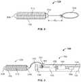
- FIG. 8schematically illustrates an implant in accordance with one embodiment of the invention.
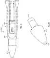
- FIG. 9schematically illustrates a distal end portion of the delivery device depicted in FIG. 1 in accordance with still another embodiment of the invention.
- FIG. 10is a schematic side view of a detachment handle of the delivery device depicted in FIG. 1 in accordance with one embodiment of the invention.
- FIG. 11is a schematic perspective view of a handle body nose of the detachment handle depicted in FIG. 10 in accordance with one embodiment of the invention.
- FIG. 12Ais a schematic top view of a handle body of the detachment handle depicted in FIG. 10 in accordance with one embodiment of the invention.
- FIG. 12Bis a schematic cross-sectional view taken along line A-A of the handle body depicted in FIG. 12A ;
- FIG. 13Ais a schematic side view of a handle slider of the detachment handle depicted in FIG. 10 in accordance with one embodiment of the invention.
- FIG. 13Bis a schematic cross-sectional view taken along line B-B of the handle slider depicted in FIG. 13A ;
- FIG. 14schematically illustrates additional components assembled within the handle slider depicted in FIGS. 13A and 13B in accordance with one embodiment of the invention
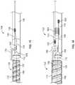
- FIG. 15schematically illustrates a distal end portion of the delivery device depicted in FIG. 1 in accordance with another embodiment of the invention.
- FIG. 16schematically illustrates a distal end portion of the delivery device depicted in FIG. 1 in accordance with yet another embodiment of the invention.
- FIGS. 17A-Dschematically illustrate a technique for maintaining an elongate member in a fixed position, in accordance with one embodiment of the invention.
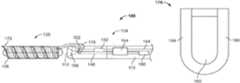
- FIG. 1schematically depicts the delivery device 100 in accordance with one embodiment of the invention.
- the delivery device 100includes a delivery pusher 104 having a proximal end 108 and a distal end 112 .
- the delivery pusher 104defines a lumen 116 (see FIG. 2 ) between the proximal and distal ends 108 , 112 .
- the delivery device 100also includes a detachment handle 118 having a proximal end 120 (i.e., an end 120 closest to an operator of the delivery device 100 ) and a distal end 124 .
- the distal end 124 of the detachment handle 118is coupled to the proximal end 108 of the delivery pusher 104 .
- an implant 128is coupled to the distal end 112 of the delivery pusher 104 in, for example, one of the manners described below.
- the detachment handle 118is operated by a user to mechanically release the implant 128 from the delivery pusher 104 when the implant 128 is placed in proximity to (e.g., near or within) the vascular disorder to be treated.
- the delivery pusher 104includes a rigid proximal shaft 132 and a flexible distal shaft that includes a flexible inner shaft 136 and a flexible outer shaft 140 .
- the proximal shaft 132may be made from rigid, metal hypotube, for example 300 series stainless steel with a wall thickness of about 0.002′′ to provide good structural integrity during implant 128 delivery and stability during detachment actuation.
- the flexible inner shaft 136 and flexible outer shaft 140may each be made from a rigid thin-walled polymer (e.g., PEEK with a wall thickness of about 0.001′′), to permit bending and deflection to properly position the implant 128 proximate the vascular disorder.
- FIG. 2schematically illustrates a distal end portion of the delivery device 100 in accordance with one embodiment of the invention.
- the delivery device 100includes first and second elongate members 144 , 148 disposed within the lumen 116 of the delivery pusher 104 .
- Each elongate member 144 , 148may be, for example, a core wire (e.g., 300 series stainless steel).
- Each core wire 144 , 148may be ground on its distal end and be coated on its unground section with, for example, polytetrafluoroethylene (PTFE) to reduce friction.
- PTFEpolytetrafluoroethylene
- Each core wire 144 , 148may be about 0.006′′ in diameter, and ground to about 0.002′′ at its distal tip.
- the first elongate member 144extends from a distal end of the lumen 116 defined by the delivery pusher 104 , along the lumen 116 , out the proximal end 108 of the delivery pusher 104 , and into and through a lumen defined within the detachment handle 118 , as further described below.
- a first bumper element 152may be coupled (e.g., soldered, welded, adhered using an ultraviolet (uv) light curing or other adhesive, swaged, crimped, or otherwise fixed using a known technique) to the first elongate member 144 near its distal end.
- the first bumper element 152may be, for example, a tube, a coil, or any other structure capable of transmitting force and motion to additional component(s), as further described herein.
- the second elongate member 148is shorter in length than the first elongate member 144 .
- a displacing element 156e.g., a conical or bell-shaped tip having a tapered surface
- the second elongate member 148may extend proximally from the displacing element 156 and may terminate within the distal portion of the delivery device 100 .
- the second elongate member 148may be coupled (e.g., soldered, welded, adhered using an ultraviolet (uv) light curing or other adhesive, swaged, crimped, or otherwise fixed using a known technique) at its proximal end to a second bumper element 160 .
- the second bumper element 160may be a tube, a coil, or any other structure capable of receiving force from additional component(s) to cause motion of the second elongate member 148 , as further described herein.
- the displacing element 156 and the second bumper element 160are sized to fit snugly against the inner wall of the delivery pusher 104 that defines the lumen 116 (i.e., the displacing element 156 and the second bumper element 160 may each have an outer diameter approximately equal to (or just slightly less than) an inner diameter of the delivery pusher 104 ).
- a moveable element 164may also be disposed within the lumen 116 of the delivery pusher 104 .
- the moveable element 164may be a floating tube, a floating coil, or any other structure capable of receiving and transmitting force and motion as described herein.
- a passagewaye.g., a lumen
- the moveable element 164is defined through the moveable element 164 from its distal to proximal ends, and at least a portion of each of the first and second elongate members 144 , 148 passes through that passageway.
- the implant 128is coupled to the distal end 112 of the delivery pusher 104 .
- the exemplary implant 128 depicted in FIG. 2is a covered embolic coil.
- the implant 128includes an embolic micro-coil 168 and a cover 172 that is wound around the micro-coil 168 .
- the covered embolic coil 128may be, for example, of the type described in commonly-owned U.S. patent application Ser. No. 14/808,550 entitled “Covered Embolic Coils,” the disclosure of which is hereby incorporated herein by reference in its entirety.
- other implantsmay also be delivered using the delivery device 100 .
- a proximal tab 176 of the cover 172couples the covered embolic coil 128 to the distal end 112 of the delivery pusher 104 .
- the proximal tab 176is shown from its side in FIG. 2 .
- a front end view of one embodiment of the proximal tab 176is depicted in FIG. 3
- FIGS. 5A-5Fdepict perspective views of the proximal tab 176 .
- the proximal tab 176may be generally U-shaped, and may include an aperture 180 formed between its two legs 184 , 188 .
- a notch 192is formed within a sidewall of the delivery pusher 104 at its distal end 112 .
- the covered embolic coil 128may thus be attached to the delivery pusher 104 by, for example, positioning the proximal tab 176 within the notch 192 and locking the proximal tab 176 in place by passing the first elongate member 144 through the aperture 180 of the proximal tab 176 . Once it passes through the aperture 180 , the distal end of the first elongate member 144 may itself be secured in place by being tucked under a distal edge of the notch 192 .
- the distal end of the first elongate member 144may be secured in place by being wedged between the displacing element 156 and an inner surface of the delivery pusher 104 .
- the first elongate member 144is configured to lock the covered embolic coil 128 (or another implant 128 featuring a connecting member similar in function to the proximal tab 176 ) in place to prevent inadvertent release of the covered embolic coil 128 from the delivery pusher 104 .
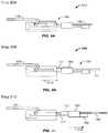
- FIGS. 4A-4Fschematically illustrate the steps in one exemplary method for releasing the implant 128 from the delivery pusher 104 of the delivery device 100
- FIGS. 5A-5Fschematically illustrate perspective views of those same steps.
- the remainder of the implant 128e.g., the embolic micro-coil 168 and its cover 172
- would also be presente.g., with the proximal tab 176 coupled to and extending from the cover 172 ).
- the implant 128is locked to the delivery pusher 104 via a coupling of the proximal tab 176 with the first elongate member 144 , as just described.
- the first elongate member 144is moved in a first direction within the lumen 116 of the delivery pusher 104 .
- the first elongate member 144is retracted in the direction indicated by arrow 210 until the first bumper element 152 abuts the moveable element 164 .
- This movement of the first elongate member 144unlocks the first elongate member 144 from the implant 128 (e.g., withdraws the distal end of the first elongate member 144 from the aperture 180 of the proximal tab 176 ), thereby readying the implant 128 for release from the delivery pusher 104 .
- Movement of the first elongate member 144 in the direction indicated by the arrow 210may be accomplished through operator (e.g., physician) manipulation of the detachment handle 118 , as further described below.
- the second elongate member 148is also caused to retract in the direction of the arrow 210 .
- This resulting movement of the second elongate member 148 in the direction indicated by the arrow 210causes the conical or bell-shaped displacing element 156 to engage a bottom edge of the proximal tab 176 of the implant 128 .
- step 220continued retraction of the first elongate member 144 (and, consequently, of the second elongate member 148 ) in the direction of the arrow 210 pushes radially outwardly the proximal tab 176 of the implant 128 along the angled slope of the conical or bell-shaped displacing element 156 until, as illustrated at step 224 , the proximal tab 176 (and thus the implant 128 ) is released from the distal end 112 of the delivery pusher 104 .
- movement of the first elongate member 144 in the direction indicated by the arrow 210 within the lumen 116 of the delivery pusher 104results in a consequent time-delayed movement of the second elongate member 148 in the same direction within the lumen 116 of the delivery pusher 104 , so as to release the implant 128 from the delivery pusher 104 .
- the initial longitudinal gaps or spacings between the first bumper element 152 , the moveable element 164 , and the second bumper element 160provide the lost motion sequence of unlocking the proximal tab 176 and thereafter forcefully displacing the proximal tab 176 to release the implant 128 , but only after moving the first elongate member 144 a distance sufficient to eliminate all of the gaps between the abutting elements 152 , 164 , 160 .
- the interaction of the first and second elongate members 144 , 148 through the first bumper element 152 , the moveable element 164 , and the second bumper element 160is entirely transparent to the operator, who focuses solely on retracting the first elongate member 144 in the direction indicated by the arrow 210 .
- the moveable element 164is eliminated and the first bumper element 152 may contact the second bumper element 160 directly, after the gap therebetween is eliminated.
- the implant 128may be attached to (and released from) the delivery pusher 104 of the above-described delivery device 100 via any of a variety of other structures.
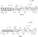
- One such structureis illustrated in FIGS. 6 and 7 .
- the implant 128 depicted in FIG. 6is the covered embolic coil mentioned above (i.e., including the cover 172 wound around the embolic micro-coil 168 ), while the implant 128 depicted in FIG. 7 features the embolic micro-coil 168 without a corresponding cover.
- the implant 128includes a suture loop 304 held in place in the notch 192 at the distal end 112 of the delivery pusher 104 by the first elongate member 144 . More specifically, both implants 128 depicted in FIGS.
- 6 and 7include a ball of suture 308 secured (e.g., melted or knotted) to a distal end of the embolic micro-coil 168 , a length of suture 312 extending between the distal and proximal ends of the embolic micro-coil 168 , a proximal fixation of suture 316 secured (e.g., melted or knotted) to the proximal end of the embolic micro-coil 168 , and the suture loop 304 adjacent to and extending from the proximal fixation of suture 316 .
- the ball of suture 308 , the length of suture 312 , the proximal fixation of suture 316 , and the suture loop 304may be made from a polymer material, such as polypropylene.
- the release of the suture loop 304 from the notch 192 at the distal end 112 of the delivery pusher 104is accomplished by following the same steps described above with reference to FIGS. 4A-4F and 5A-5F .
- FIG. 8schematically depicts an alternative embodiment of the implant 128 .
- the suture loop 304is created by knotting the suture at a distance d 1 from the proximal fixation of suture 316 , rather than beginning the suture loop 304 adjacent to the proximal fixation of suture 316 as in the embodiments depicted in FIGS. 6 and 7 .
- the suture loop 304can be created in a variety of locations, sizes, and manners.
- FIG. 9depicts yet another embodiment in which a small suture loop 304 is knotted and locked to the distal end 112 of the delivery pusher 104 by being placed around the first elongate member 144 .
- FIGS. 15 and 16illustrate additional structures that can be used to couple the implant 128 to the delivery pusher 104 , according to various embodiments.
- FIG. 15schematically depicts a metallic wire loop 178 held in place by a notch 192 at the distal end 112 of the delivery pusher 104 .
- the metallic wire loop 178can be attached directly to the coil 168 or to the cover 172 .
- FIG. 16schematically depicts a hypotube lock 186 located in the notch 192 .
- the hypotube lock 186can be attached directly to the coil 168 or to the cover 172 .
- the release of the metallic wire loop 178 and/or the hypotube lock 186 from the notch 192 at the distal end 112 of the delivery pusher 104is accomplished by following the steps described above with reference to FIGS. 4A-4F and 5A-5F .
- the elongate members 144 , 148can be arranged differently than described above.
- the first elongate element 144 and the second elongate element 148can be bonded or joined at a joint 190 .
- the device 100need not include the first bumper element 152 , the movable element 164 , and the second bumper element 160 . Rather, retraction of the first elongate element 144 will automatically cause retraction of the second elongate element 148 as a result on the elements 144 , 148 being joined.
- the risk of inadvertent release of the microcoilis reduced, by leaving a space d 2 between the proximal end 484 of the first elongate member 144 and engagement mechanism 464 of the handle slider 404 (discussed in greater detail below with respect to FIG. 14 ).
- a distal end 194 of the second elongate member 148can extend beyond the distal end 112 of the delivery pusher 104 and into the coil 168 . This extension of the second elongate member 148 can help align the implant 128 on the end of the delivery pusher 104 .
- a distal end 196 of the first elongate member 144extends into the coil 168 ( FIG. 16 ). In other embodiments, the distal end 196 of the first elongate member 144 remains within the delivery pusher 104 and only the distal end 194 of the second elongate member 148 extends into the coil 168 ( FIG. 15 ).
- the elongate members 144 , 148may only extend into the coil 168 (i) up to a distance defined by 10 coil loops, (ii) up to a distance defined by 5 coil loops, and (iii) up to 1 mm.
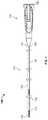
- FIG. 10is a side view of the detachment handle 118 according to one embodiment of the invention.
- the detachment handle 118includes a handle slider 404 , a handle body 408 , and a handle body nose 412 .
- FIG. 11is a perspective view of the handle body nose 412 according to one embodiment of the invention.
- the handle body nose 412includes a proximal end 416 and a distal end 420 , and defines a lumen between the proximal and distal ends 416 , 420 .
- the proximal shaft 132 of the delivery pusher 104(see FIG. 1 ) is connected to the handle body nose 412 by inserting the proximal shaft 132 into the lumen of the handle body nose 412 at its distal end 420 and by applying an adhesive, press fitting the connection, securing the connection with a mechanical fastener (e.g., a set screw), employing a threaded connection, etc.
- a mechanical fastenere.g., a set screw
- FIG. 12Ais a top view of the handle body 408 (i.e., a view of the handle body 408 looking in the direction of arrow 424 in FIG. 10 ) according to one embodiment of the invention
- FIG. 12Bis a cross-sectional view of the handle body 408 taken along line A-A depicted in FIG. 12A
- the handle body 408includes a proximal end 428 , a distal end 432 , a cavity 436 at the distal end 432 for receiving the proximal end 416 of the handle body nose 412 , and a track 440 running the majority of the handle body 408 to the proximal end 428 and along which the handle slider 404 may be moved.
- the handle body 408also includes detent features 444 , which hold the handle slider 404 in place prior to the handle slider 404 being manipulated (e.g., retracted) by the operator of the delivery device 100 .
- FIG. 13Ais a side view of the handle slider 404 according to one embodiment of the invention
- FIG. 13Bis a cross-sectional view of the handle slider 404 taken along line B-B depicted in FIG. 13A
- the handle slider 404includes a proximal end 448 and a distal end 452 , and defines a lumen 456 that extends between the proximal and distal ends 448 , 452 .
- the handle slider 404defines a side slot 460 into which an adhesive may be inserted to secure an additional structure placed within the lumen 456 .
- FIG. 14depicts an engagement mechanism 464 housed within the lumen 456 of the handle slider 404 and secured to the handle slider 404 by an ultraviolet (uv) light curing or other adhesive 468 inserted into the side slot 460 .
- the engagement mechanism 464may be, for example, a hypotube that includes a proximal end 472 and a distal end 476 , and that defines a lumen 480 between the proximal and distal ends 472 , 476 .
- the lumen 480may be sized to receive therethrough the first elongate member 144 in a sliding fit.
- the first elongate member 144extends through the lumens 456 , 480 of the handle slider 404 and engagement mechanism 464 .
- the first elongate member 144extends from a distal end of the delivery pusher lumen 116 , along the delivery pusher lumen 116 , out the proximal end 108 of delivery pusher 104 , into the distal end 420 of the handle body nose 412 , out the proximal end 416 of the handle body nose, into the lumens 456 , 480 of the handle slider 404 and engagement mechanism 464 at their distal ends 452 , 476 , along the lumens 456 , 480 of the handle slider 404 and engagement mechanism 464 , and out the proximal ends 472 , 448 of the engagement mechanism 464 and handle slider 404 .
- a proximal end 484 of the first elongate member 144extends beyond the proximal end 472 of the
- an engagement member 488is coupled to or formed at the proximal end 484 of the first elongate member 144 .
- the engagement member 488may be a coil (as illustrated), a tube, a disc, or any other enlarged structure adapted to abut the proximal end 172 of the engagement mechanism 464 .
- the engagement member 488may be, for example, soldered, welded, adhered using an ultraviolet (uv) light curing or other adhesive, swaged, crimped, or otherwise coupled using a known technique to or formed at the proximal end 484 of the elongate member 144 .
- an outer diameter or dimension of the engagement member 488is less than an inner diameter of the lumen 456 of the handle slider 404 , but greater than an inner diameter of the lumen 480 of the engagement mechanism 464 . In this way, the engagement member 488 is free to slide into the lumen 456 of the handle slider 404 (or, equivalently, the handle slider 404 is free to slide over the first elongate member 144 and engagement member 488 ) until the engagement member 488 abuts the engagement mechanism 464 .
- the flexible inner shaft 136 and flexible outer shaft 140utilize relatively rigid polymer members (for stability during mechanical detachment of the implant 128 ), they also need to provide enough flexibility and low-friction to access the desired neurovascular site through a tortuous micro-catheter. As such, the flexible inner shaft 136 and flexible outer shaft 140 are more susceptible to elongation than the metal proximal shaft 132 or the first elongate member 144 .
- the distal end of the first elongate member 144is secured in place by being tucked under the distal edge of the notch 192 and/or wedged between the displacing element 156 and the inner surface of the delivery pusher 104 (and, thus, the first elongate member 144 and delivery pusher 104 are connected during delivery of the implant 128 ), if the delivery device 100 encounters friction during access to the vascular disorder, the metal proximal shaft 132 and the first elongate member 144 will likely retract at the same rate, but the assembly of the flexible inner shaft 136 and flexible outer shaft 140 will elongate at a greater rate.
- the detachment handle 118will in effect move proximally, towards the engagement member 488 depicted in FIG. 14 .
- the proximal end 484 of the first elongate member 144is designed to extend beyond the proximal end 472 of the engagement mechanism 464 by the distance d 2 illustrated in FIG. 14 when the delivery device 100 is at rest (i.e., outside a patient's body and prior to being used in a delivery procedure).
- the distance d 2is selected to be greater than the maximum elongation the flexible inner shaft 136 /flexible outer shaft 140 assembly is expected to experience during delivery of the implant 128 under normal operating conditions, with additional margin for safety.
- the distance d 2is typically chosen to be between about 0.03′′ and about 0.04′′ (i.e., about 0.76 mm and about 1.02 mm).
- this distance d 2may be increased or decreased when a delivery pusher 104 of a different length is employed, when different materials with different material properties and associated elongation characteristics are used in the construction of the delivery device 100 , when (depending on the application) a greater amount of friction is expected to be encountered during delivery of the implant 128 , or for other reasons.
- the operatormust retract (e.g., pull) the handle slider 404 in the direction of arrow 492 by a distance equal to the difference between the distance d 2 and the amount of elongation present in the flexible inner shaft 136 /flexible outer shaft 140 assembly in order to abut the proximal end 472 of the engagement mechanism 464 and the engagement member 488 at the proximal end 484 of the first elongate member 144 and in order to initiate mechanical release of the implant 128 from the distal end 112 of the delivery pusher 104 .
- Movement of the handle slider 404may be accomplished by any of a variety of techniques, including by sliding with thumb or finger pressure, by pulling or pushing a protrusion or finger loop, by squeezing or rotating a pivoting lever, by turning a knob, etc.
- the device 100includes a removable lock 414 configured to engage with the handle body 408 , handle slider 404 , and first elongate member 144 .
- the lock 414can fit within the track 440 of the handle body 408 to prevent proximal translation of the handle slider 404 and the elongate member 144 .
- the removable lock 414can be held in place using any of a variety of techniques.
- the lock 414can include a tab 418 that engages a corresponding notch 426 on the handle body 408 .
- the lock 414can also interact with the elongate member 144 to prevent proximal translation of the elongate member 144 .
- the lock 414can include a cavity 422 sized to accept the elongate member 144 and have a depth of a predetermined dimension, such that when the lock 414 is fully engaged with the handle body 408 , the base of the cavity 422 prevents proximal translation of the elongate member 144 .
- FIG. 17Adepicts the lock 414 in a locked position, as it may be configured during delivery of the implant 128 with the delivery pusher 104 .
- FIG. 17Bdepicts the lock 414 after being unlocked from the handle body, e.g., upon a user releasing tab 418 from notch 426 , but before the lock 414 is fully removed from the track 440 .
- FIG. 17Cis an enlarged view of a portion of FIG. 17B , showing the elongate member 144 extending past the proximal end 448 of the handle slider 404 .
- FIG. 17Ddepicts the lock 414 after being fully removed from the track 440 . Once the lock 414 is removed, a user can freely retract handle slider 404 and elongate element 144 (e.g., via engagement of engagement mechanism 464 with engagement member 488 ) to release the implant 128 in the various manners described above.
- the removable lock 414 and the technique depicted in FIGS. 17A-Dcan be useful in maintaining the first elongate member 144 in a fixed position in embodiments in which the first elongate member 144 extends into the coil 168 , as discussed with respect to FIG. 16 .
- the removable lock 414can be particularly beneficial, because the first elongate member 144 may not be secured in place by being tucked under a distal edge of notch 192 or wedged between displacing element 156 and an inner surface of the delivery pusher 104 , as described above with respect to certain other embodiments.
- the removable lock 414can be used in addition to these other securing techniques to provide additional securing support.
- the implant 128may be introduced, delivered, positioned, and implanted at the desired site within the patient's vasculature using a micro-catheter.
- the sitesmay be first accessed by the micro-catheter, which is a flexible, small diameter catheter (typically with an inside diameter between 0.016′′ to 0.021′′), through an introducer sheath/guiding catheter combination that is placed in the femoral artery or groin area of the patient.
- the micro-cathetermay be guided to the site through the use of guidewires.
- Guidewiresare typically long, torqueable proximal wire sections with more flexible distal wire sections designed to be advanced within tortuous vessels. A guidewire is visible using fluoroscopy and is typically used to first access the desired site, thereby allowing the micro-catheter to be reliably advanced over the guidewire to the target site.
- the catheter lumenis cleared by removing the guidewire, and the locked implant 128 is placed into the proximal open end of the micro-catheter and advanced by its delivery pusher 104 through the micro-catheter.
- the implant 128reaches the distal end of the micro-catheter, it is deployed from the micro-catheter and positioned by the delivery pusher 104 into the target vascular site.
- the operatore.g., a physician
- the detachment handle 118is actuated to mechanically release the implant 128 into the lesion, as described above. Then, once detachment of the implant 128 has been confirmed, the delivery pusher 104 is removed from the micro-catheter, and additional implants 128 may be placed in the same manner, as necessary for proper treatment.
Landscapes
- Health & Medical Sciences (AREA)
- Surgery (AREA)
- Life Sciences & Earth Sciences (AREA)
- Biomedical Technology (AREA)
- Medical Informatics (AREA)
- Vascular Medicine (AREA)
- Reproductive Health (AREA)
- Engineering & Computer Science (AREA)
- Veterinary Medicine (AREA)
- Heart & Thoracic Surgery (AREA)
- Nuclear Medicine, Radiotherapy & Molecular Imaging (AREA)
- Molecular Biology (AREA)
- Animal Behavior & Ethology (AREA)
- General Health & Medical Sciences (AREA)
- Public Health (AREA)
- Neurosurgery (AREA)
- Surgical Instruments (AREA)
Abstract
Description
Claims (20)
Priority Applications (2)
| Application Number | Priority Date | Filing Date | Title |
|---|---|---|---|
| US15/946,936US11090055B2 (en) | 2015-10-30 | 2018-04-06 | Devices and methods for delivering an implant to a vascular disorder |
| US17/377,860US11849956B2 (en) | 2015-10-30 | 2021-07-16 | Devices and methods for delivering an implant to a vascular disorder |
Applications Claiming Priority (3)
| Application Number | Priority Date | Filing Date | Title |
|---|---|---|---|
| US14/928,212US10052108B2 (en) | 2015-10-30 | 2015-10-30 | Devices and methods for delivering an implant to a vascular disorder |
| PCT/US2016/059331WO2017075358A2 (en) | 2015-10-30 | 2016-10-28 | Devices and methods for delivering an implant to a vascular disorder |
| US15/946,936US11090055B2 (en) | 2015-10-30 | 2018-04-06 | Devices and methods for delivering an implant to a vascular disorder |
Related Parent Applications (1)
| Application Number | Title | Priority Date | Filing Date |
|---|---|---|---|
| PCT/US2016/059331ContinuationWO2017075358A2 (en) | 2015-10-30 | 2016-10-28 | Devices and methods for delivering an implant to a vascular disorder |
Related Child Applications (1)
| Application Number | Title | Priority Date | Filing Date |
|---|---|---|---|
| US17/377,860ContinuationUS11849956B2 (en) | 2015-10-30 | 2021-07-16 | Devices and methods for delivering an implant to a vascular disorder |
Publications (2)
| Publication Number | Publication Date |
|---|---|
| US20180228493A1 US20180228493A1 (en) | 2018-08-16 |
| US11090055B2true US11090055B2 (en) | 2021-08-17 |
Family
ID=63106533
Family Applications (2)
| Application Number | Title | Priority Date | Filing Date |
|---|---|---|---|
| US15/946,936Active2036-07-20US11090055B2 (en) | 2015-10-30 | 2018-04-06 | Devices and methods for delivering an implant to a vascular disorder |
| US17/377,860Active2036-10-05US11849956B2 (en) | 2015-10-30 | 2021-07-16 | Devices and methods for delivering an implant to a vascular disorder |
Family Applications After (1)
| Application Number | Title | Priority Date | Filing Date |
|---|---|---|---|
| US17/377,860Active2036-10-05US11849956B2 (en) | 2015-10-30 | 2021-07-16 | Devices and methods for delivering an implant to a vascular disorder |
Country Status (1)
| Country | Link |
|---|---|
| US (2) | US11090055B2 (en) |
Families Citing this family (28)
| Publication number | Priority date | Publication date | Assignee | Title |
|---|---|---|---|---|
| US9918718B2 (en) | 2014-08-08 | 2018-03-20 | DePuy Synthes Products, Inc. | Embolic coil delivery system with retractable mechanical release mechanism |
| US11116509B2 (en) | 2017-11-10 | 2021-09-14 | Avantec Vascular Corporation | System and method for delivering an embolic device |
| US10806462B2 (en) | 2017-12-21 | 2020-10-20 | DePuy Synthes Products, Inc. | Implantable medical device detachment system with split tube and cylindrical coupling |
| US11266481B2 (en)* | 2018-10-12 | 2022-03-08 | Hologic, Inc. | Tissue localization marker with D-shaped cross-section |
| US11147562B2 (en) | 2018-12-12 | 2021-10-19 | DePuy Synthes Products, Inc. | Systems and methods for embolic implant detachment |
| US11253265B2 (en) | 2019-06-18 | 2022-02-22 | DePuy Synthes Products, Inc. | Pull wire detachment for intravascular devices |
| US11426174B2 (en) | 2019-10-03 | 2022-08-30 | DePuy Synthes Products, Inc. | Medical device delivery member with flexible stretch resistant mechanical release |
| US11207494B2 (en) | 2019-07-03 | 2021-12-28 | DePuy Synthes Products, Inc. | Medical device delivery member with flexible stretch resistant distal portion |
| US12376859B2 (en) | 2019-09-17 | 2025-08-05 | DePuy Synthes Products, Inc. | Embolic coil proximal connecting element and stretch resistant fiber |
| US11672946B2 (en) | 2019-09-24 | 2023-06-13 | Boston Scientific Scimed, Inc. | Protection and actuation mechanism for controlled release of implantable embolic devices |
| EP4033998B1 (en)* | 2019-09-24 | 2025-05-14 | Boston Scientific Scimed, Inc. | Medical device release system |
| US11376013B2 (en) | 2019-11-18 | 2022-07-05 | DePuy Synthes Products, Inc. | Implant delivery system with braid cup formation |
| US11382634B2 (en) | 2019-12-18 | 2022-07-12 | Avantec Vascular Corporation | Embolic device suited for ease of delivery and placement |
| JP7379703B2 (en)* | 2020-01-17 | 2023-11-14 | ボストン サイエンティフィック サイムド,インコーポレイテッド | medical device release system |
| US11457922B2 (en) | 2020-01-22 | 2022-10-04 | DePuy Synthes Products, Inc. | Medical device delivery member with flexible stretch resistant distal portion |
| US11432822B2 (en)* | 2020-02-14 | 2022-09-06 | DePuy Synthes Products, Inc. | Intravascular implant deployment system |
| US11951026B2 (en) | 2020-06-30 | 2024-04-09 | DePuy Synthes Products, Inc. | Implantable medical device detachment system with flexible braid section |
| CN116158799B (en)* | 2021-11-24 | 2025-07-25 | 上海微创心脉医疗科技(集团)股份有限公司 | Release mechanism and plug device |
| US11937824B2 (en) | 2021-12-30 | 2024-03-26 | DePuy Synthes Products, Inc. | Implant detachment systems with a modified pull wire |
| US11844490B2 (en) | 2021-12-30 | 2023-12-19 | DePuy Synthes Products, Inc. | Suture linkage for inhibiting premature embolic implant deployment |
| US12011171B2 (en) | 2022-01-06 | 2024-06-18 | DePuy Synthes Products, Inc. | Systems and methods for inhibiting premature embolic implant deployment |
| US11937825B2 (en) | 2022-03-02 | 2024-03-26 | DePuy Synthes Products, Inc. | Hook wire for preventing premature embolic implant detachment |
| US12137915B2 (en) | 2022-03-03 | 2024-11-12 | DePuy Synthes Products, Inc. | Elongating wires for inhibiting premature implant detachment |
| US11937826B2 (en) | 2022-03-14 | 2024-03-26 | DePuy Synthes Products, Inc. | Proximal link wire for preventing premature implant detachment |
| US12402886B2 (en) | 2022-06-23 | 2025-09-02 | DePuy Synthes Products, Inc. | Detachment indicator for implant deployment |
| CN115462855B (en)* | 2022-08-16 | 2024-01-16 | 惠州市顺美医疗科技有限公司 | Release structure of intracranial spring ring and use method |
| US12396730B2 (en)* | 2022-09-28 | 2025-08-26 | DePuy Synthes Products, Inc. | Braided implant with detachment mechanism |
| WO2025093977A1 (en)* | 2023-10-31 | 2025-05-08 | Medtronic, Inc. | Tether assemblies for medical device delivery systems |
Citations (83)
| Publication number | Priority date | Publication date | Assignee | Title |
|---|---|---|---|---|
| US5250071A (en) | 1992-09-22 | 1993-10-05 | Target Therapeutics, Inc. | Detachable embolic coil assembly using interlocking clasps and method of use |
| US5261916A (en) | 1991-12-12 | 1993-11-16 | Target Therapeutics | Detachable pusher-vasoocclusive coil assembly with interlocking ball and keyway coupling |
| US5263964A (en) | 1992-05-06 | 1993-11-23 | Coil Partners Ltd. | Coaxial traction detachment apparatus and method |
| US5290230A (en) | 1992-05-11 | 1994-03-01 | Advanced Cardiovascular Systems, Inc. | Intraluminal catheter with a composite shaft |
| WO1994006503A1 (en) | 1992-09-22 | 1994-03-31 | Target Therapeutics, Inc. | Detachable embolic coil assembly |
| US5304195A (en) | 1991-12-12 | 1994-04-19 | Target Therapeutics, Inc. | Detachable pusher-vasoocclusive coil assembly with interlocking coupling |
| US5312415A (en) | 1992-09-22 | 1994-05-17 | Target Therapeutics, Inc. | Assembly for placement of embolic coils using frictional placement |
| US5350397A (en) | 1992-11-13 | 1994-09-27 | Target Therapeutics, Inc. | Axially detachable embolic coil assembly |
| US5582619A (en) | 1995-06-30 | 1996-12-10 | Target Therapeutics, Inc. | Stretch resistant vaso-occlusive coils |
| US5690667A (en) | 1996-09-26 | 1997-11-25 | Target Therapeutics | Vasoocclusion coil having a polymer tip |
| US5725546A (en) | 1994-06-24 | 1998-03-10 | Target Therapeutics, Inc. | Detachable microcoil delivery catheter |
| US5792154A (en) | 1996-04-10 | 1998-08-11 | Target Therapeutics, Inc. | Soft-ended fibered micro vaso-occlusive devices |
| US5797928A (en) | 1995-01-20 | 1998-08-25 | Olympus Optical Co., Ltd. | Ligating apparatus |
| US5814062A (en) | 1994-12-22 | 1998-09-29 | Target Therapeutics, Inc. | Implant delivery assembly with expandable coupling/decoupling mechanism |
| US5833705A (en) | 1995-06-30 | 1998-11-10 | Target Therapeutics, Inc. | Stretch resistant vaso-occlusive coils |
| US5853418A (en) | 1995-06-30 | 1998-12-29 | Target Therapeutics, Inc. | Stretch resistant vaso-occlusive coils (II) |
| US5868754A (en) | 1996-06-12 | 1999-02-09 | Target Therapeutics, Inc. | Medical retrieval device |
| US5911737A (en) | 1997-02-28 | 1999-06-15 | The Regents Of The University Of California | Microfabricated therapeutic actuators |
| US5944733A (en) | 1997-07-14 | 1999-08-31 | Target Therapeutics, Inc. | Controlled detachable vasoocclusive member using mechanical junction and friction-enhancing member |
| US6013084A (en) | 1995-06-30 | 2000-01-11 | Target Therapeutics, Inc. | Stretch resistant vaso-occlusive coils (II) |
| US6022369A (en) | 1998-02-13 | 2000-02-08 | Precision Vascular Systems, Inc. | Wire device with detachable end |
| US6068644A (en) | 1998-03-10 | 2000-05-30 | Cordis Corporation | Embolic coil hydraulic deployment system having improved catheter |
| EP1010396A1 (en) | 1998-12-16 | 2000-06-21 | Arthesys | Catheter system for release of embolization coils by hydraulic pressure |
| US6168570B1 (en)* | 1997-12-05 | 2001-01-02 | Micrus Corporation | Micro-strand cable with enhanced radiopacity |
| US6221066B1 (en) | 1999-03-09 | 2001-04-24 | Micrus Corporation | Shape memory segmented detachable coil |
| WO2001058366A1 (en) | 2000-02-09 | 2001-08-16 | Micrus Corporation | Intraluminal delivery device |
| US6280457B1 (en) | 1999-06-04 | 2001-08-28 | Scimed Life Systems, Inc. | Polymer covered vaso-occlusive devices and methods of producing such devices |
| US6296622B1 (en) | 1998-12-21 | 2001-10-02 | Micrus Corporation | Endoluminal device delivery system using axially recovering shape memory material |
| US20020165569A1 (en) | 1998-12-21 | 2002-11-07 | Kamal Ramzipoor | Intravascular device deployment mechanism incorporating mechanical detachment |
| US6562021B1 (en) | 1997-12-22 | 2003-05-13 | Micrus Corporation | Variable stiffness electrically conductive composite, resistive heating catheter shaft |
| US20040002732A1 (en) | 2002-06-27 | 2004-01-01 | Clifford Teoh | Stretch-resistant vaso-occlusive assembly with multiple detaching points |
| WO2005032337A2 (en) | 2002-07-23 | 2005-04-14 | Micrus Corporation | Vasoocclusive coil with enhanced therapeutic strand structure |
| US6887235B2 (en) | 1999-03-24 | 2005-05-03 | Micrus Corporation | Variable stiffness heating catheter |
| US20050149108A1 (en) | 2003-12-17 | 2005-07-07 | Microvention, Inc. | Implant delivery and detachment system and method |
| JP2005296657A (en) | 2004-04-08 | 2005-10-27 | Cordis Neurovascular Inc | Physiologically-active type blood vessel blocking system which can be activated |
| EP1621149A1 (en) | 2004-07-30 | 2006-02-01 | Cordis Neurovascular, Inc. | Embolic coil delivery system with u-shaped fiber release mechanism |
| US20060116714A1 (en) | 2004-11-26 | 2006-06-01 | Ivan Sepetka | Coupling and release devices and methods for their assembly and use |
| US20060259044A1 (en) | 2003-10-08 | 2006-11-16 | Yoshio Onuki | Medical procedure tool |
| US7137990B2 (en) | 2000-08-21 | 2006-11-21 | Micrus Endovascular Corporation | Manipulatable delivery catheter for occlusive devices (II) |
| US20060276824A1 (en) | 2005-06-02 | 2006-12-07 | Vladimir Mitelberg | Stretch resistant embolic coil delivery system with mechanical release mechanism |
| US20070005081A1 (en) | 2005-06-30 | 2007-01-04 | Findlay Thomas R Iii | System, apparatus, and method for fastening tissue |
| WO2007070792A2 (en) | 2005-12-13 | 2007-06-21 | Cordis Development Corporation | Actuator handle for use with medical device deployment systems |
| EP1806106A2 (en) | 1998-04-28 | 2007-07-11 | MicroVention, Inc. | Apparatus and method for vascular embolization |
| JP2008049118A (en) | 2006-07-28 | 2008-03-06 | Terumo Corp | Elongate medical device |
| US7377932B2 (en) | 2005-06-02 | 2008-05-27 | Cordis Neurovascular, Inc. | Embolic coil delivery system with mechanical release mechanism |
| JP2008252257A (en) | 2007-03-29 | 2008-10-16 | Renesas Technology Corp | Transmission circuit |
| WO2009052438A2 (en) | 2007-10-19 | 2009-04-23 | Guided Delivery Systems Inc. | Devices for termination of tethers |
| US7608089B2 (en) | 2004-12-22 | 2009-10-27 | Boston Scientific Scimed, Inc. | Vaso-occlusive device having pivotable coupling |
| US20090270901A1 (en) | 2007-10-30 | 2009-10-29 | Boston Scientific Scimed, Inc. | Degradable detachment mechanisms for implantable devices |
| US20090297582A1 (en) | 2004-11-26 | 2009-12-03 | Biomerix Corporation | Vascular occlusion devices and methods |
| JP2010012282A (en) | 2001-05-29 | 2010-01-21 | Boston Scientific Ltd | Absorbable implantable vaso-occlusive member |
| US20100121350A1 (en) | 2007-04-12 | 2010-05-13 | Greg Mirigian | Instantaneous mechanical detachment mechanism for vaso-occlusive devices |
| US7722636B2 (en) | 2005-11-30 | 2010-05-25 | Codman & Shurtleff, Inc. | Embolic device delivery system with torque fracture characteristic |
| US20100268201A1 (en) | 2009-04-15 | 2010-10-21 | Microvention, Inc. | Implant Delivery System |
| WO2010121037A1 (en) | 2009-04-15 | 2010-10-21 | Microvention, Inc. | Implant delivery system |
| US7901444B2 (en) | 2006-09-29 | 2011-03-08 | Codman & Shurtleff, Inc. | Embolic coil delivery system with mechanical release mechanism |
| US20110092997A1 (en) | 2009-10-16 | 2011-04-21 | Kang Ho Chang | Micro-coil assembly |
| US7942894B2 (en) | 2006-01-31 | 2011-05-17 | Codman & Shurtleff, Inc. | Embolic device delivery system |
| US7985238B2 (en) | 2005-06-02 | 2011-07-26 | Codman & Shurtleff, Inc. | Embolic coil delivery system with spring wire release mechanism |
| US8062325B2 (en) | 2006-07-31 | 2011-11-22 | Codman & Shurtleff, Inc. | Implantable medical device detachment system and methods of using the same |
| US20120071916A1 (en) | 2002-03-08 | 2012-03-22 | Tyco Healthcare Group Lp | Distal protection devices having controllable wire motion |
| US20120143231A1 (en) | 2007-01-18 | 2012-06-07 | Ron French | Systems, methods and devices for removing obstructions from a blood vessel |
| CN102670273A (en) | 2011-02-25 | 2012-09-19 | Thd股份公司 | A device for implanting a prosthesis in a tissue |
| US8328860B2 (en) | 2007-03-13 | 2012-12-11 | Covidien Lp | Implant including a coil and a stretch-resistant member |
| US8333796B2 (en) | 2008-07-15 | 2012-12-18 | Penumbra, Inc. | Embolic coil implant system and implantation method |
| WO2013081227A1 (en) | 2011-12-02 | 2013-06-06 | 인큐메덱스 엘엘씨 | Microcoil assembly |
| CN103200907A (en) | 2010-09-17 | 2013-07-10 | 冈徳森路德会保健系统公司 | Internal gastric bander for obesity |
| US20130261657A1 (en) | 2012-03-30 | 2013-10-03 | Micrus Endovascular Llc | Embolic coil detachment mechanism with heating element and kicker |
| US8597323B1 (en) | 2012-11-16 | 2013-12-03 | Sequent Medical, Inc. | Delivery and detachment systems and methods for vascular implants |
| US20130325054A1 (en) | 2012-06-01 | 2013-12-05 | Acandis Gmbh & Co. Kg | System for delivering a stretch resistant vaso-occlusive device and a method of producing same |
| US20140058435A1 (en) | 2012-08-21 | 2014-02-27 | Donald K. Jones | Implant delivery and release system |
| US20140058434A1 (en) | 2012-08-21 | 2014-02-27 | Donald K. Jones | Releasable device system |
| CN103826548A (en) | 2011-09-13 | 2014-05-28 | 艾博特心脏血管系统公司 | Independent gripper |
| CA2895799A1 (en) | 2012-12-21 | 2014-06-26 | The Regents Of The University Of California | In vivo positionable filtration devices and methods related thereto |
| US8777978B2 (en) | 2006-04-17 | 2014-07-15 | Covidien Lp | System and method for mechanically positioning intravascular implants |
| US8795316B2 (en) | 2007-04-25 | 2014-08-05 | DePuy Syntheses Products, LLC | Implantable medical device delivery system with a frangible portion and methods of making and using the same |
| JP2014522263A (en) | 2011-05-11 | 2014-09-04 | マイクロベンション インコーポレイテッド | Device for occluding a lumen |
| EP2777545A2 (en) | 2013-03-13 | 2014-09-17 | DePuy Synthes Products, LLC | Occlusive device delivery system with mechanical detachment |
| US20140277084A1 (en)* | 2013-03-14 | 2014-09-18 | Incumedx Llc | Implants, methods of manufacturing the same, and devices and methods for delivering the implants to a vascular disorder of a patient |
| US8940011B2 (en) | 2008-09-09 | 2015-01-27 | Boston Scientific Scimed, Inc. | Composite detachment mechanisms |
| US8945171B2 (en) | 2011-09-29 | 2015-02-03 | Covidien Lp | Delivery system for implantable devices |
| CN204192688U (en) | 2014-09-28 | 2015-03-11 | 上海君联医疗设备有限公司 | The structure of blood vessel implant freed by a kind of machinery |
| US20200229957A1 (en) | 2016-07-29 | 2020-07-23 | Wallaby Medical, Inc. | Implant delivery systems and methods |
Family Cites Families (5)
| Publication number | Priority date | Publication date | Assignee | Title |
|---|---|---|---|---|
| US20060276830A1 (en) | 2005-06-02 | 2006-12-07 | Keith Balgobin | Stretch resistant embolic coil delivery system with mechanical release mechanism |
| US20090312748A1 (en) | 2008-06-11 | 2009-12-17 | Johnson Kirk L | Rotational detachment mechanism |
| CA2861336C (en) | 2012-01-26 | 2020-06-16 | Endoshape, Inc. | Systems, devices, and methods for delivering a lumen occlusion device using distal and/or proximal control |
| CN110169802B (en) | 2013-03-15 | 2022-07-08 | 柯惠有限合伙公司 | Delivery and detachment mechanism for vascular implants |
| US9375333B1 (en) | 2015-03-06 | 2016-06-28 | Covidien Lp | Implantable device detachment systems and associated devices and methods |
- 2018
- 2018-04-06USUS15/946,936patent/US11090055B2/enactiveActive
- 2021
- 2021-07-16USUS17/377,860patent/US11849956B2/enactiveActive
Patent Citations (107)
| Publication number | Priority date | Publication date | Assignee | Title |
|---|---|---|---|---|
| US5304195A (en) | 1991-12-12 | 1994-04-19 | Target Therapeutics, Inc. | Detachable pusher-vasoocclusive coil assembly with interlocking coupling |
| US5261916A (en) | 1991-12-12 | 1993-11-16 | Target Therapeutics | Detachable pusher-vasoocclusive coil assembly with interlocking ball and keyway coupling |
| US5263964A (en) | 1992-05-06 | 1993-11-23 | Coil Partners Ltd. | Coaxial traction detachment apparatus and method |
| US5290230A (en) | 1992-05-11 | 1994-03-01 | Advanced Cardiovascular Systems, Inc. | Intraluminal catheter with a composite shaft |
| US5451209A (en) | 1992-05-11 | 1995-09-19 | Advanced Cardiovascular Systems, Inc. | Intraluminal catheter with a composite shaft |
| WO1994006503A1 (en) | 1992-09-22 | 1994-03-31 | Target Therapeutics, Inc. | Detachable embolic coil assembly |
| US5250071A (en) | 1992-09-22 | 1993-10-05 | Target Therapeutics, Inc. | Detachable embolic coil assembly using interlocking clasps and method of use |
| US5312415A (en) | 1992-09-22 | 1994-05-17 | Target Therapeutics, Inc. | Assembly for placement of embolic coils using frictional placement |
| US5350397A (en) | 1992-11-13 | 1994-09-27 | Target Therapeutics, Inc. | Axially detachable embolic coil assembly |
| US5725546A (en) | 1994-06-24 | 1998-03-10 | Target Therapeutics, Inc. | Detachable microcoil delivery catheter |
| US5814062A (en) | 1994-12-22 | 1998-09-29 | Target Therapeutics, Inc. | Implant delivery assembly with expandable coupling/decoupling mechanism |
| US6238415B1 (en) | 1994-12-22 | 2001-05-29 | Target Therapeutics, Inc | Implant delivery assembly with expandable coupling/decoupling mechanism |
| US5797928A (en) | 1995-01-20 | 1998-08-25 | Olympus Optical Co., Ltd. | Ligating apparatus |
| US5582619A (en) | 1995-06-30 | 1996-12-10 | Target Therapeutics, Inc. | Stretch resistant vaso-occlusive coils |
| US6193728B1 (en) | 1995-06-30 | 2001-02-27 | Target Therapeutics, Inc. | Stretch resistant vaso-occlusive coils (II) |
| US5833705A (en) | 1995-06-30 | 1998-11-10 | Target Therapeutics, Inc. | Stretch resistant vaso-occlusive coils |
| US5853418A (en) | 1995-06-30 | 1998-12-29 | Target Therapeutics, Inc. | Stretch resistant vaso-occlusive coils (II) |
| US6004338A (en) | 1995-06-30 | 1999-12-21 | Target Therapeutics Inc. | Stretch resistant vaso-occlusive coils |
| US6013084A (en) | 1995-06-30 | 2000-01-11 | Target Therapeutics, Inc. | Stretch resistant vaso-occlusive coils (II) |
| US5792154A (en) | 1996-04-10 | 1998-08-11 | Target Therapeutics, Inc. | Soft-ended fibered micro vaso-occlusive devices |
| US5868754A (en) | 1996-06-12 | 1999-02-09 | Target Therapeutics, Inc. | Medical retrieval device |
| US5690667A (en) | 1996-09-26 | 1997-11-25 | Target Therapeutics | Vasoocclusion coil having a polymer tip |
| US5911737A (en) | 1997-02-28 | 1999-06-15 | The Regents Of The University Of California | Microfabricated therapeutic actuators |
| US5944733A (en) | 1997-07-14 | 1999-08-31 | Target Therapeutics, Inc. | Controlled detachable vasoocclusive member using mechanical junction and friction-enhancing member |
| US6168570B1 (en)* | 1997-12-05 | 2001-01-02 | Micrus Corporation | Micro-strand cable with enhanced radiopacity |
| US6562021B1 (en) | 1997-12-22 | 2003-05-13 | Micrus Corporation | Variable stiffness electrically conductive composite, resistive heating catheter shaft |
| US6022369A (en) | 1998-02-13 | 2000-02-08 | Precision Vascular Systems, Inc. | Wire device with detachable end |
| US6068644A (en) | 1998-03-10 | 2000-05-30 | Cordis Corporation | Embolic coil hydraulic deployment system having improved catheter |
| EP1806106A2 (en) | 1998-04-28 | 2007-07-11 | MicroVention, Inc. | Apparatus and method for vascular embolization |
| EP1010396A1 (en) | 1998-12-16 | 2000-06-21 | Arthesys | Catheter system for release of embolization coils by hydraulic pressure |
| US7255707B2 (en) | 1998-12-21 | 2007-08-14 | Micrus Endovascular Corporation | Intravascular device deployment mechanism incorporating mechanical detachment |
| US6296622B1 (en) | 1998-12-21 | 2001-10-02 | Micrus Corporation | Endoluminal device delivery system using axially recovering shape memory material |
| US20020165569A1 (en) | 1998-12-21 | 2002-11-07 | Kamal Ramzipoor | Intravascular device deployment mechanism incorporating mechanical detachment |
| US6478773B1 (en) | 1998-12-21 | 2002-11-12 | Micrus Corporation | Apparatus for deployment of micro-coil using a catheter |
| US6966892B2 (en) | 1998-12-21 | 2005-11-22 | Micrus Corporation | Apparatus for deployment of micro-coil using a catheter |
| US6835185B2 (en) | 1998-12-21 | 2004-12-28 | Micrus Corporation | Intravascular device deployment mechanism incorporating mechanical detachment |
| US6551305B2 (en) | 1999-03-09 | 2003-04-22 | Micrus Corporation | Shape memory segmented detachable coil |
| US6221066B1 (en) | 1999-03-09 | 2001-04-24 | Micrus Corporation | Shape memory segmented detachable coil |
| US6887235B2 (en) | 1999-03-24 | 2005-05-03 | Micrus Corporation | Variable stiffness heating catheter |
| US7695484B2 (en) | 1999-06-04 | 2010-04-13 | Boston Scientific Scimed, Inc. | Polymer covered vaso-occlusive devices and methods of producing such devices |
| US20020002382A1 (en) | 1999-06-04 | 2002-01-03 | Wallace Michael P. | Polymer covered vaso-occlusive devices and methods of producing such devices |
| US6280457B1 (en) | 1999-06-04 | 2001-08-28 | Scimed Life Systems, Inc. | Polymer covered vaso-occlusive devices and methods of producing such devices |
| US7972342B2 (en) | 2000-02-09 | 2011-07-05 | Micrus Corporation | Apparatus for deployment of micro-coil using a catheter |
| US7198613B2 (en) | 2000-02-09 | 2007-04-03 | Micrus Endovascular Corporation | Apparatus for deployment of micro-coil using a catheter |
| WO2001058366A1 (en) | 2000-02-09 | 2001-08-16 | Micrus Corporation | Intraluminal delivery device |
| US7137990B2 (en) | 2000-08-21 | 2006-11-21 | Micrus Endovascular Corporation | Manipulatable delivery catheter for occlusive devices (II) |
| JP2010012282A (en) | 2001-05-29 | 2010-01-21 | Boston Scientific Ltd | Absorbable implantable vaso-occlusive member |
| US20120071916A1 (en) | 2002-03-08 | 2012-03-22 | Tyco Healthcare Group Lp | Distal protection devices having controllable wire motion |
| US7166122B2 (en) | 2002-06-27 | 2007-01-23 | Boston Scientific Scimed, Inc. | Anchor assemblies in stretch-resistant vaso-occlusive coils |
| US20040002732A1 (en) | 2002-06-27 | 2004-01-01 | Clifford Teoh | Stretch-resistant vaso-occlusive assembly with multiple detaching points |
| US20110213406A1 (en) | 2002-06-27 | 2011-09-01 | Stryker Corporation | Anchor assemblies in stretch-resistant vaso-occlusive coils |
| US7485122B2 (en) | 2002-06-27 | 2009-02-03 | Boston Scientific Scimed, Inc. | Integrated anchor coil in stretch-resistant vaso-occlusive coils |
| US7938845B2 (en) | 2002-06-27 | 2011-05-10 | Stryker Corporation | Anchor assemblies in stretch-resistant vaso-occlusive coils |
| US7422569B2 (en) | 2002-07-23 | 2008-09-09 | Micrus Endovascular Corporation | Vasoocclusive coil with enhanced therapeutic strand structure |
| WO2005032337A2 (en) | 2002-07-23 | 2005-04-14 | Micrus Corporation | Vasoocclusive coil with enhanced therapeutic strand structure |
| US20060259044A1 (en) | 2003-10-08 | 2006-11-16 | Yoshio Onuki | Medical procedure tool |
| US20050149108A1 (en) | 2003-12-17 | 2005-07-07 | Microvention, Inc. | Implant delivery and detachment system and method |
| JP2005296657A (en) | 2004-04-08 | 2005-10-27 | Cordis Neurovascular Inc | Physiologically-active type blood vessel blocking system which can be activated |
| EP1621149A1 (en) | 2004-07-30 | 2006-02-01 | Cordis Neurovascular, Inc. | Embolic coil delivery system with u-shaped fiber release mechanism |
| US20060025802A1 (en) | 2004-07-30 | 2006-02-02 | Sowers William W | Embolic coil delivery system with U-shaped fiber release mechanism |
| US20090297582A1 (en) | 2004-11-26 | 2009-12-03 | Biomerix Corporation | Vascular occlusion devices and methods |
| US20060116714A1 (en) | 2004-11-26 | 2006-06-01 | Ivan Sepetka | Coupling and release devices and methods for their assembly and use |
| US7608089B2 (en) | 2004-12-22 | 2009-10-27 | Boston Scientific Scimed, Inc. | Vaso-occlusive device having pivotable coupling |
| US7985238B2 (en) | 2005-06-02 | 2011-07-26 | Codman & Shurtleff, Inc. | Embolic coil delivery system with spring wire release mechanism |
| US20060276824A1 (en) | 2005-06-02 | 2006-12-07 | Vladimir Mitelberg | Stretch resistant embolic coil delivery system with mechanical release mechanism |
| US7377932B2 (en) | 2005-06-02 | 2008-05-27 | Cordis Neurovascular, Inc. | Embolic coil delivery system with mechanical release mechanism |
| US20070005081A1 (en) | 2005-06-30 | 2007-01-04 | Findlay Thomas R Iii | System, apparatus, and method for fastening tissue |
| US7722636B2 (en) | 2005-11-30 | 2010-05-25 | Codman & Shurtleff, Inc. | Embolic device delivery system with torque fracture characteristic |
| WO2007070792A2 (en) | 2005-12-13 | 2007-06-21 | Cordis Development Corporation | Actuator handle for use with medical device deployment systems |
| US7942894B2 (en) | 2006-01-31 | 2011-05-17 | Codman & Shurtleff, Inc. | Embolic device delivery system |
| US8777978B2 (en) | 2006-04-17 | 2014-07-15 | Covidien Lp | System and method for mechanically positioning intravascular implants |
| JP2008049118A (en) | 2006-07-28 | 2008-03-06 | Terumo Corp | Elongate medical device |
| US8062325B2 (en) | 2006-07-31 | 2011-11-22 | Codman & Shurtleff, Inc. | Implantable medical device detachment system and methods of using the same |
| US7901444B2 (en) | 2006-09-29 | 2011-03-08 | Codman & Shurtleff, Inc. | Embolic coil delivery system with mechanical release mechanism |
| US20120143231A1 (en) | 2007-01-18 | 2012-06-07 | Ron French | Systems, methods and devices for removing obstructions from a blood vessel |
| US8328860B2 (en) | 2007-03-13 | 2012-12-11 | Covidien Lp | Implant including a coil and a stretch-resistant member |
| JP2008252257A (en) | 2007-03-29 | 2008-10-16 | Renesas Technology Corp | Transmission circuit |
| US20100121350A1 (en) | 2007-04-12 | 2010-05-13 | Greg Mirigian | Instantaneous mechanical detachment mechanism for vaso-occlusive devices |
| US8795316B2 (en) | 2007-04-25 | 2014-08-05 | DePuy Syntheses Products, LLC | Implantable medical device delivery system with a frangible portion and methods of making and using the same |
| WO2009052438A2 (en) | 2007-10-19 | 2009-04-23 | Guided Delivery Systems Inc. | Devices for termination of tethers |
| US20090270901A1 (en) | 2007-10-30 | 2009-10-29 | Boston Scientific Scimed, Inc. | Degradable detachment mechanisms for implantable devices |
| US8333796B2 (en) | 2008-07-15 | 2012-12-18 | Penumbra, Inc. | Embolic coil implant system and implantation method |
| US8940011B2 (en) | 2008-09-09 | 2015-01-27 | Boston Scientific Scimed, Inc. | Composite detachment mechanisms |
| US20100268201A1 (en) | 2009-04-15 | 2010-10-21 | Microvention, Inc. | Implant Delivery System |
| WO2010121037A1 (en) | 2009-04-15 | 2010-10-21 | Microvention, Inc. | Implant delivery system |
| US20110092997A1 (en) | 2009-10-16 | 2011-04-21 | Kang Ho Chang | Micro-coil assembly |
| CN103200907A (en) | 2010-09-17 | 2013-07-10 | 冈徳森路德会保健系统公司 | Internal gastric bander for obesity |
| CN102670273A (en) | 2011-02-25 | 2012-09-19 | Thd股份公司 | A device for implanting a prosthesis in a tissue |
| JP2014522263A (en) | 2011-05-11 | 2014-09-04 | マイクロベンション インコーポレイテッド | Device for occluding a lumen |
| CN103826548A (en) | 2011-09-13 | 2014-05-28 | 艾博特心脏血管系统公司 | Independent gripper |
| US8945171B2 (en) | 2011-09-29 | 2015-02-03 | Covidien Lp | Delivery system for implantable devices |
| WO2013081227A1 (en) | 2011-12-02 | 2013-06-06 | 인큐메덱스 엘엘씨 | Microcoil assembly |
| US20130261657A1 (en) | 2012-03-30 | 2013-10-03 | Micrus Endovascular Llc | Embolic coil detachment mechanism with heating element and kicker |
| US20130325054A1 (en) | 2012-06-01 | 2013-12-05 | Acandis Gmbh & Co. Kg | System for delivering a stretch resistant vaso-occlusive device and a method of producing same |
| US20140058434A1 (en) | 2012-08-21 | 2014-02-27 | Donald K. Jones | Releasable device system |
| US20140058435A1 (en) | 2012-08-21 | 2014-02-27 | Donald K. Jones | Implant delivery and release system |
| US8597323B1 (en) | 2012-11-16 | 2013-12-03 | Sequent Medical, Inc. | Delivery and detachment systems and methods for vascular implants |
| CA2895799A1 (en) | 2012-12-21 | 2014-06-26 | The Regents Of The University Of California | In vivo positionable filtration devices and methods related thereto |
| EP2777545A2 (en) | 2013-03-13 | 2014-09-17 | DePuy Synthes Products, LLC | Occlusive device delivery system with mechanical detachment |
| US20140277078A1 (en) | 2013-03-13 | 2014-09-18 | DePuy Synthes Products, LLC | Occlusive Device Delivery System With Mechanical Detachment |
| US20140277085A1 (en) | 2013-03-14 | 2014-09-18 | Incumedx Llc | Implants, methods of manufacturing the same, and devices and methods for delivering the implants to a vascular disorder of a patient |
| WO2014158790A2 (en) | 2013-03-14 | 2014-10-02 | Incumedx Inc. | Implants, methods of manufacturing the same, and devices and methods for delivering the implants to a vascular disorder of a patient |
| US20140277084A1 (en)* | 2013-03-14 | 2014-09-18 | Incumedx Llc | Implants, methods of manufacturing the same, and devices and methods for delivering the implants to a vascular disorder of a patient |
| JP2016511065A (en) | 2013-03-14 | 2016-04-14 | インキュメデックス インコーポレイテッド | Device for delivering an implant to a vascular disorder in a patient |
| CN204192688U (en) | 2014-09-28 | 2015-03-11 | 上海君联医疗设备有限公司 | The structure of blood vessel implant freed by a kind of machinery |
| US20200229957A1 (en) | 2016-07-29 | 2020-07-23 | Wallaby Medical, Inc. | Implant delivery systems and methods |
| US10932933B2 (en) | 2016-07-29 | 2021-03-02 | Shanghai Wallaby Medical Technologies Co., Inc. | Implant delivery systems and methods |
Non-Patent Citations (11)
| Title |
|---|
| Chinese Office Action for Chinese Patent Application No. 201680063491.1, dated Aug. 14, 2020 (9 pages). |
| Chinese Office Action for Chinese Patent Application Number 201680063491.1, dated Mar. 15, 2021 (9 pages). |
| European Examination Report for European Patent Application Number 16834138.6, dated Mar. 31, 2021, 5 pages. |
| Extended European Search Report for EP 11876854.8, dated May 22, 2015, 6 pages. |
| International Search Report and Written Opinion for International Application No. PCT/US2014/020157, dated Sep. 30, 2014, 16 pages. |
| International Search Report and Written Opinion for International Application No. PCT/US2016/059331, dated Jun. 6, 2017, 22 pages. |
| International Search Report for PCT/KR2011/009384, dated Dec. 3, 2012, 4 pages. |
| Invitation to Pay Additional Fees and, Where Applicable, Protest Fee for PCT/US2014/020157, dated Jul. 2, 2014, 7 pages. |
| Japanese Office Action for Japanese Patent Application No. 2018-521664, dated Oct. 14, 2020 (9 pages). |
| Japanese Office Action for Japanese Patent Application Number 2018-521664, dated Mar. 1, 2021 (7 pages). |
| Written Opinion for International Application No. PCT/KR2011/009384, dated Dec. 3, 2012, 5 pages. |
Also Published As
| Publication number | Publication date |
|---|---|
| US20180228493A1 (en) | 2018-08-16 |
| US11849956B2 (en) | 2023-12-26 |
| US20220000487A1 (en) | 2022-01-06 |
Similar Documents
| Publication | Publication Date | Title |
|---|---|---|
| US11849956B2 (en) | Devices and methods for delivering an implant to a vascular disorder | |
| US10966727B2 (en) | Devices and methods for delivering an implant to a vascular disorder | |
| US12194258B2 (en) | Guide catheter extension system with a delivery micro-catheter configured to facilitate percutaneous coronary intervention | |
| US11871931B2 (en) | Embolic coil delivery system with retractable mechanical release mechanism | |
| US5895391A (en) | Ball lock joint and introducer for vaso-occlusive member | |
| US9700322B2 (en) | Mechanical embolization delivery apparatus and methods | |
| US8926650B2 (en) | Mechanically detachable vaso-occlusive device | |
| US7708755B2 (en) | Stretch resistant embolic coil delivery system with combined mechanical and pressure release mechanism | |
| DE602005002502T2 (en) | Depositing system for embolic device with retractable partially fiber wound release | |
| US10159489B2 (en) | Systems and methods for delivering multiple embolization coils | |
| JP2009513274A (en) | CONNECTING AND RELEASE DEVICE AND METHOD FOR ASSEMBLING AND USING THE SAME | |
| EP3542737B1 (en) | Medical device delivery system | |
| US20180161550A1 (en) | Methods and devices for vascular access | |
| EP4103105B1 (en) | System for the implantation of a medical implant in the human or animal body | |
| US20220338878A1 (en) | Mechanical detachment system with a lever structure for deployment of endovascular devices | |
| HK40051689A (en) | Devices and methods for delivering an implant to a vascular disorder |
Legal Events
| Date | Code | Title | Description |
|---|---|---|---|
| FEPP | Fee payment procedure | Free format text:ENTITY STATUS SET TO UNDISCOUNTED (ORIGINAL EVENT CODE: BIG.); ENTITY STATUS OF PATENT OWNER: LARGE ENTITY | |
| AS | Assignment | Owner name:INCUMEDX, INC., CALIFORNIA Free format text:ASSIGNMENT OF ASSIGNORS INTEREST;ASSIGNORS:AGUILAR, AMIEL RICHARD;SEIN-LWIN, CRYSTAL KAY;DOAN, NGA;AND OTHERS;REEL/FRAME:045710/0259 Effective date:20180424 | |
| STPP | Information on status: patent application and granting procedure in general | Free format text:DOCKETED NEW CASE - READY FOR EXAMINATION | |
| STPP | Information on status: patent application and granting procedure in general | Free format text:NON FINAL ACTION MAILED | |
| STPP | Information on status: patent application and granting procedure in general | Free format text:RESPONSE TO NON-FINAL OFFICE ACTION ENTERED AND FORWARDED TO EXAMINER | |
| STPP | Information on status: patent application and granting procedure in general | Free format text:NOTICE OF ALLOWANCE MAILED -- APPLICATION RECEIVED IN OFFICE OF PUBLICATIONS | |
| STPP | Information on status: patent application and granting procedure in general | Free format text:AWAITING TC RESP., ISSUE FEE NOT PAID | |
| STPP | Information on status: patent application and granting procedure in general | Free format text:NOTICE OF ALLOWANCE MAILED -- APPLICATION RECEIVED IN OFFICE OF PUBLICATIONS | |
| STPP | Information on status: patent application and granting procedure in general | Free format text:PUBLICATIONS -- ISSUE FEE PAYMENT RECEIVED | |
| STPP | Information on status: patent application and granting procedure in general | Free format text:PUBLICATIONS -- ISSUE FEE PAYMENT VERIFIED | |
| STCF | Information on status: patent grant | Free format text:PATENTED CASE | |
| AS | Assignment | Owner name:ARISSA MEDICAL, INC., CALIFORNIA Free format text:ASSIGNMENT OF ASSIGNORS INTEREST;ASSIGNOR:INCUMEDX INC.;REEL/FRAME:060888/0873 Effective date:20220811 | |
| MAFP | Maintenance fee payment | Free format text:PAYMENT OF MAINTENANCE FEE, 4TH YEAR, LARGE ENTITY (ORIGINAL EVENT CODE: M1551); ENTITY STATUS OF PATENT OWNER: LARGE ENTITY Year of fee payment:4 |