US11089840B2 - Article of footwear having a polygon lug sole pattern - Google Patents
Article of footwear having a polygon lug sole patternDownload PDFInfo
- Publication number
- US11089840B2 US11089840B2US16/404,222US201916404222AUS11089840B2US 11089840 B2US11089840 B2US 11089840B2US 201916404222 AUS201916404222 AUS 201916404222AUS 11089840 B2US11089840 B2US 11089840B2
- Authority
- US
- United States
- Prior art keywords
- lugs
- polygonal
- outsole
- lug
- region
- Prior art date
- Legal status (The legal status is an assumption and is not a legal conclusion. Google has not performed a legal analysis and makes no representation as to the accuracy of the status listed.)
- Active
Links
Images


Classifications
- A—HUMAN NECESSITIES
- A43—FOOTWEAR
- A43D—MACHINES, TOOLS, EQUIPMENT OR METHODS FOR MANUFACTURING OR REPAIRING FOOTWEAR
- A43D86/00—Machines for assembling soles or heels onto uppers, not provided for in groups A43D25/00 - A43D83/00, e.g. by welding
- A—HUMAN NECESSITIES
- A43—FOOTWEAR
- A43B—CHARACTERISTIC FEATURES OF FOOTWEAR; PARTS OF FOOTWEAR
- A43B1/00—Footwear characterised by the material
- A43B1/0009—Footwear characterised by the material made at least partially of alveolar or honeycomb material
- A—HUMAN NECESSITIES
- A43—FOOTWEAR
- A43B—CHARACTERISTIC FEATURES OF FOOTWEAR; PARTS OF FOOTWEAR
- A43B13/00—Soles; Sole-and-heel integral units
- A43B13/14—Soles; Sole-and-heel integral units characterised by the constructive form
- A43B13/141—Soles; Sole-and-heel integral units characterised by the constructive form with a part of the sole being flexible, e.g. permitting articulation or torsion
- A—HUMAN NECESSITIES
- A43—FOOTWEAR
- A43B—CHARACTERISTIC FEATURES OF FOOTWEAR; PARTS OF FOOTWEAR
- A43B13/00—Soles; Sole-and-heel integral units
- A43B13/14—Soles; Sole-and-heel integral units characterised by the constructive form
- A43B13/16—Pieced soles
- A—HUMAN NECESSITIES
- A43—FOOTWEAR
- A43B—CHARACTERISTIC FEATURES OF FOOTWEAR; PARTS OF FOOTWEAR
- A43B13/00—Soles; Sole-and-heel integral units
- A43B13/14—Soles; Sole-and-heel integral units characterised by the constructive form
- A43B13/18—Resilient soles
- A43B13/181—Resiliency achieved by the structure of the sole
- A43B13/184—Resiliency achieved by the structure of the sole the structure protruding from the outsole
- A—HUMAN NECESSITIES
- A43—FOOTWEAR
- A43B—CHARACTERISTIC FEATURES OF FOOTWEAR; PARTS OF FOOTWEAR
- A43B13/00—Soles; Sole-and-heel integral units
- A43B13/14—Soles; Sole-and-heel integral units characterised by the constructive form
- A43B13/18—Resilient soles
- A43B13/181—Resiliency achieved by the structure of the sole
- A43B13/186—Differential cushioning region, e.g. cushioning located under the ball of the foot
- A—HUMAN NECESSITIES
- A43—FOOTWEAR
- A43B—CHARACTERISTIC FEATURES OF FOOTWEAR; PARTS OF FOOTWEAR
- A43B13/00—Soles; Sole-and-heel integral units
- A43B13/14—Soles; Sole-and-heel integral units characterised by the constructive form
- A43B13/22—Soles made slip-preventing or wear-resisting, e.g. by impregnation or spreading a wear-resisting layer
- A43B13/223—Profiled soles
- A—HUMAN NECESSITIES
- A43—FOOTWEAR
- A43B—CHARACTERISTIC FEATURES OF FOOTWEAR; PARTS OF FOOTWEAR
- A43B13/00—Soles; Sole-and-heel integral units
- A43B13/14—Soles; Sole-and-heel integral units characterised by the constructive form
- A43B13/22—Soles made slip-preventing or wear-resisting, e.g. by impregnation or spreading a wear-resisting layer
- A43B13/24—Soles made slip-preventing or wear-resisting, e.g. by impregnation or spreading a wear-resisting layer by use of insertions
- A43B13/26—Soles made slip-preventing or wear-resisting, e.g. by impregnation or spreading a wear-resisting layer by use of insertions projecting beyond the sole surface
- B—PERFORMING OPERATIONS; TRANSPORTING
- B29—WORKING OF PLASTICS; WORKING OF SUBSTANCES IN A PLASTIC STATE IN GENERAL
- B29D—PRODUCING PARTICULAR ARTICLES FROM PLASTICS OR FROM SUBSTANCES IN A PLASTIC STATE
- B29D35/00—Producing footwear
- B29D35/06—Producing footwear having soles or heels formed and joined on to preformed uppers using a moulding technique, e.g. by injection moulding, pressing and vulcanising
- B—PERFORMING OPERATIONS; TRANSPORTING
- B29—WORKING OF PLASTICS; WORKING OF SUBSTANCES IN A PLASTIC STATE IN GENERAL
- B29D—PRODUCING PARTICULAR ARTICLES FROM PLASTICS OR FROM SUBSTANCES IN A PLASTIC STATE
- B29D35/00—Producing footwear
- B29D35/12—Producing parts thereof, e.g. soles, heels, uppers, by a moulding technique
- B29D35/122—Soles
Definitions
- aspects of the inventionrelate to articles of footwear. More specifically, aspects of the invention relate to articles of footwear having a sole structure with polygonal protrusions extending downward forming a ground contacting surface.
- Conventional articles of athletic footweargenerally include two primary elements, an upper and a sole structure.
- the upperis secured to the sole structure and forms a void on the interior of the footwear for comfortably and securely receiving a foot.
- the upperin at least some footwear structures, generally extends over the instep and toe areas of the foot, along the medial and lateral sides of the foot, and around the heel area of the foot.
- the uppermay extend upward and around the ankle to provide support for the ankle.
- Access to the void in the interior of the footwearis generally provided by an access opening.
- a lacing or other footwear securing systemoften is incorporated into the upper to selectively increase the size of the access opening and to permit the wearer to modify certain dimensions of the upper, particularly girth, to accommodate feet with varying dimensions and to allow for easy foot insertion and removal.
- the upperfurther may include a tongue that extends under the lacing system to enhance comfort of the footwear and a heel counter to limit movement of the heel.
- the upper of athletic footwearmay be formed from multiple material layers that include an exterior layer, an intermediate layer, and an interior layer.
- the materials forming the exterior layer of the uppermay be selected based upon the properties of wear-resistance, flexibility, and air-permeability, for example.
- the exterior layerthe toe area and the heel area may be formed of leather, synthetic leather, or a rubber material to impart a relatively high degree of wear-resistance.
- Leather, synthetic leather, and rubber materialsmay not exhibit the desired degree of flexibility and air-permeability for various other areas of the exterior layer of the upper. Accordingly, the other areas of the exterior layer may be formed from a synthetic textile, for example.
- the exterior layer of the uppermay be formed, therefore, from numerous material elements that each imparts different properties to the upper.
- the intermediate layer of the upperis conventionally formed from a lightweight polymer foam material that provides impact force attenuation and enhances comfort.
- the interior layer of the uppermay be formed of a comfortable and moisture-wicking textile that removes perspiration from the area immediately surrounding the foot.
- the various layersmay be joined with an adhesive, and stitching may be utilized to join elements within a single layer or to reinforce specific areas of the upper.
- the sole structureis positioned between the upper and the ground, and it may include a polymer foam midsole and an outsole.
- the midsoleis arranged between the upper and the outsole and attenuates ground (or other contact surface) reaction forces to lessen stresses upon the foot and leg.
- the outsoleforms a ground-engaging portion (or other contact surface-engaging portion) of the sole structure and is formed from a durable and wear-resistant material.
- the outsoleis generally connected to a bottom surface of the midsole and provides cushioning and traction to the wearer.
- the soleis formed of a flexible material to allow the article of footwear to flex with the motion of the foot.
- the sole structurealso may include a sockliner or an insole member that is positioned within the void and proximal a lower surface of the foot to enhance footwear comfort.
- the sole structureincludes a midsole connected to the upper and an outsole having a base surface engaged with the midsole and a plurality of lugs protruding generally perpendicularly therefrom.
- the lugsmay be polygonal in shape and may have a uniform shape from a distal end to a proximal end.
- the lugsmay be arranged such that they are not in contact with each other, at least at their distal ends.
- Some examples of different shapes that may be used for the polygonal lugsare hexagonal, pentagonal, octagonal, and triangular.
- Articles of footwear in accordance with at least some examples of this inventionmay include one or more of: (a) an upper; and (b) a sole structure connected to the upper, the sole structure including a midsole and an outsole.
- the outsoleincludes a plurality of polygonal lugs protruding downward from a bottom surface of the outsole.
- the plurality of polygonal lugsmay have a uniform shape.
- the outsolemay also include one or more regions wherein the characteristics of the lugs in a first region may differ from the characteristics of the lugs in other regions. Some examples of characteristics that may differ between lugs of various regions include: (a) width; (b) wall thickness; and (c) spacing between the lugs.
- Such methodsmay include, for example: (a) forming a mold of an outsole defining a base surface and including openings corresponding to a plurality of polygonal lugs; (b) filling the mold with polyurethane or other desired material; (c) removing excess polyurethane or other material; (d) adding textile or leather (or other desired material) to the mold; and (e) applying heat and/or pressure to form the final molded product.
- One or more additional elements, structures, and/or featuresmay be incorporated into the overall footwear structure and/or footwear production method without departing from this invention.
- FIG. 1is a lateral side elevational view of an example article of footwear having an outsole in accordance with aspects of the invention.
- FIG. 2is a medial side elevational view of this example article of footwear.
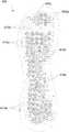
- FIG. 3is a top plan view of one example outsole of the article of footwear having a polygon lug pattern.
- FIG. 4is a cross-sectional view of the example outsole shown in FIG. 3 taken along line A-A.
- FIG. 5is a cross-sectional view of one example polygonal lug of the outsole shown in FIG. 3 illustrating various dimensions of the lug.
- FIGS. 6A-6Care cross-sectional views taken along a vertical plane of example lugs illustrating various configurations.
- FIGS. 7A-7Dillustrate portions of outsoles having various alternate cross-sectional configurations for example lugs of the outsole of the article of footwear.
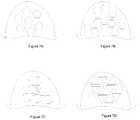
- FIG. 8is a top plan view of another example outsole of the article of footwear.
- FIG. 9is a top plan view of yet another example outsole of the article of footwear.
- the following discussion and accompanying figuresdisclose various articles of footwear having uppers with a polygonal lug pattern in the outsole in accordance with examples and aspects of the present invention.
- Concepts related to the polygonal lug sole patternare disclosed with reference to various articles of athletic footwear having configurations suitable, for example, for sports such as running, walking, and the like.
- the polygonal lug sole structureis not solely limited to footwear designed for these activities. Rather, they may be incorporated into a wide range of athletic footwear styles, including shoes that are suitable for basketball, baseball, cross-training, football, rugby, soccer, tennis, and volleyball, for example.
- polygonal lug sole structuremay be incorporated into footwear that is generally considered to be non-athletic, including a variety of casual shoes, sandals, boots, shower shoes, beach/water shoes, shoes for water sports and/or for use in wet conditions, etc.
- footwearthat is generally considered to be non-athletic, including a variety of casual shoes, sandals, boots, shower shoes, beach/water shoes, shoes for water sports and/or for use in wet conditions, etc.
- aspects of this inventionrelate to articles of footwear, including athletic footwear or other types of footwear, that include: (a) an upper forming a void for receiving a foot; (b) a sole structure having a midsole connected to an upper and an outsole, the outsole including a plurality of polygonal lugs; and (c) one or more regions within the outsole that include lugs having varying size and performance characteristics. Further aspects of the invention relate to methods of manufacturing articles of footwear according to the structural aspects described.
- Articles of footwear in accordance with at least some examples of the inventionmay include additional or alternative features.
- the outsolemay be connected to a midsole having a plurality of incisions or sipes formed in the sidewall of the midsole.
- the polygonal lugswhen present, may take on a variety of forms without departing from this invention.
- the polygonal lugsmay comprise various shapes.
- the polygonal lugsmay be formed as (a) hexagonal; (b) pentagonal; (c) octagonal; and (d) triangular.
- the lugsmay also be formed in various sizes and may be formed with differing wall thicknesses to provide additional support in various regions of the outsole.
- the polygonal lugsmay also be formed in various configurations, including (a) uniform; (b) stepped; and (c) tapered configurations.
- Articles of footwear in accordance with at least some aspects of the inventionmay include an outsole having one or more regions.
- the regionsmay be identified based on characteristics of at least a portion of the lugs within a region.
- the size and/or configuration of the lugs within a regionmay be different from the sizes and/or configurations of the lugs in another region.
- the lugs in a given regionmay be spaced more or less closely than the lugs in other regions.
- Articles of footwear in accordance with at least some aspects of the inventionmay include some or all of the above described features, alone or in combination.
- Articles of footwear in accordance with the inventionalso may have additional features described herein that may be used in combination with the features described above.
- Such methodsmay include, for example: (a) forming a mold of an outsole defining a base surface and including a plurality of open spaces corresponding to plural polygonal lugs; (b) filling the mold with polyurethane (or other desired material); (c) removing excess polyurethane (or other desired material); (d) adding textile or leather (or other desired material) to the mold and (e) applying heat and/or pressure to form the final molded product.
- Methods in accordance with examples of this inventionmay include additional steps, the above-noted steps may be changed in order, and/or various steps may be omitted or modified, without departing from this invention.
- FIGS. 1-2An article of footwear 100 is depicted in FIGS. 1-2 as including an upper 120 and a sole structure 130 .
- footwear 100may be divided into three general regions: a forefoot region 111 , a midfoot region 112 , and a heel region 113 , as illustrated in FIG. 1 .
- Regions 111 - 113are not intended to demarcate precise areas of footwear 100 . Rather, regions 111 - 113 are intended to represent general areas of footwear 100 that provide a frame of reference during the following discussion. Although regions 111 - 113 apply generally to footwear 100 , references to regions 111 - 113 also may apply specifically to upper 120 , sole structure 130 , or individual components included within and/or formed as part of either upper 120 or sole structure 130 .
- Upper 120is secured to sole structure 130 and defines a void or chamber for receiving a foot.
- upper 120includes a lateral side 121 , an opposite medial side 122 , and a vamp or instep area 123 .
- Lateral side 121is positioned to extend along a lateral side of the foot (i.e., the outside) and generally passes through each of regions 111 - 113 .
- medial side 122is positioned to extend along an opposite medial side of the foot (i.e., the inside) and generally passes through each of regions 111 - 113 .
- Vamp area 123is positioned between lateral side 121 and medial side 122 to correspond with an upper surface or instep area of the foot.
- Vamp area 123in this illustrated example, includes a throat 124 having a lace 125 or other desired closure mechanism that is utilized in a conventional manner to modify the dimensions of upper 120 relative the foot, thereby adjusting the fit of footwear 100 .
- Upper 120also includes an ankle opening 126 that provides the foot with access to the void within upper 120 .
- a variety of materialsmay be used for constructing upper 120 , including materials that are conventionally utilized in footwear uppers. Accordingly, upper 120 may be formed from one or more portions of leather, synthetic leather, natural or synthetic textiles, polymer sheets, polymer foams, mesh textiles, felts, non-woven polymers, or rubber materials, for example. The upper 120 may be formed from one or more of these materials wherein the materials or portions thereof are stitched or adhesively bonded together, e.g., in manners that are conventionally known and used in the art.
- Upper 120may also include a heel element (not shown) and a toe element (not shown).
- the heel elementwhen present, may extend upward and along the interior surface of upper 120 in the heel region 113 to enhance the comfort of footwear 100 .
- the toe elementwhen present, may be located in forefoot region 111 and on an exterior surface of upper 120 to provide wear-resistance, protect the wearer's toes, and assist with positioning of the foot.
- one or both of the heel element and the toe elementmay be absent, or the heel element may be positioned on an exterior surface of the upper 120 , for example.
- upper 120may exhibit the configuration of any desired conventional or non-conventional upper structure without departing from this invention.
- Sole structure 130is secured to a lower surface of upper 120 and may have a generally conventional shape.
- the sole structure 130may have a multipiece structure, e.g., one that includes a midsole 131 , an outsole 132 , and a sockliner or insole member (not shown).
- Midsole 131may be formed of polymer foam material, such as polyurethane, ethylvinylacetate, or other materials (such as phylon, phylite, etc.) that compress to attenuate ground or other contact surface reaction forces during walking, running, jumping, or other activities.
- the polymer foam materialmay encapsulate or include various elements, such as a fluid-filled bladder or moderator, that enhance the comfort, motion-control, stability, and/or ground or other contact surface reaction force attenuation properties of footwear 100 .
- the midsole 131may include additional elements that compress to attenuate ground or other contact surface reaction forces.
- the midsolemay include column type elements to aid in cushioning and absorption of forces.
- Outsole 132is secured to a lower surface of midsole 131 in this illustrated example footwear structure 100 and is formed of a wear-resistant material, such as rubber or a flexible synthetic material, such as polyurethane, that contacts the ground or other surface during ambulatory or other activities.
- the material forming outsole 132may be manufactured of suitable materials and/or textured to impart enhanced traction and slip resistance. The structure and methods of manufacturing the outsole 132 will be discussed further below.
- An insole or socklineris a thin, compressible member that may be located within the void in upper 120 and adjacent to a lower surface of the foot (or between the upper 120 and midsole 131 ) to enhance the comfort of footwear 100 . In some arrangements, the insole or sockliner may be absent.
- the outsole 132 shown in FIGS. 1 and 2includes a plurality of incisions or sipes 136 in either or both sides of the outsole 132 .
- These sipes 136may extend from the bottom of the outsole 132 to an upper portion thereof or to the midsole 131 .
- the sipes 136may extend from a bottom surface of the outsole 132 to a point halfway between the bottom of the outsole 132 and the top of the outsole 132 .
- the sipes 136may extend from the bottom of the outsole 132 to a point greater than halfway to the top of the outsole 132 .
- the sipes 136may extend from the bottom of the outsole 132 to a point where the outsole 132 meets the midsole 131 .
- the sipes 136may provide additional flexibility to the outsole 132 , and thereby allow the outsole to more freely flex in the natural directions in which the wearer's foot flexes.
- the sipes 136may aid in providing traction for the wearer.
- FIGS. 3 and 4illustrate various aspects of one example embodiment of an outsole 200 having a polygon lug pattern in accordance with this invention.
- this example outsole 200includes a periphery 202 , and at least a portion of the outsole 200 includes a plurality of protrusions or lugs 210 protruding outward from a base surface of the outsole 200 .
- the outsole 200is generally connected to the midsole (not shown in FIGS. 3 and 4 ) such that a top surface 204 of the outsole 200 is in contact with the midsole and a base surface 206 of the outsole 200 is in contact with the ground or other external contact surface.
- the plurality of lugs 210may be formed in the bottom surface 206 of the outsole 200 such that the plurality of lugs 210 are arranged to protrude downward from the base surface 206 to contact the ground or other surface during use.
- the lugs 210may be arranged so that a distal end 211 of each lug 210 contacts the ground or other surface during use.
- FIG. 4is a cross-sectional view of an outsole 200 like that shown in FIG. 3 taken along line A-A.
- the top surface 204 of the outsole 200may be generally flat and may be connected to the midsole of the article of footwear.
- the outsole 200may be connected to the midsole or other portion of the footwear structure by stitching, bonding, adhesive or any other generally known method of attachment.
- the base surface 206 of the outsole 200may be generally flat and, when the article of footwear is placed on a contact surface, may be substantially parallel to the contact surface.
- the outsole 200may include a slight upward curve 208 or other structure, toward the midsole, e.g., to aid in attachment and provide a more pleasing appearance.
- the outsole 200 and/or midsole surfacesmay take on any desired shapes and/or constructions, including shapes and/or constructions that are generally known or used in the art.
- the outsole 200includes a plurality of protrusions or lugs 210 formed therein.
- the lugs 210 in this example structure 200are generally uniform in shape and may have a polygonal cross-section.
- the plurality of lugs 210protrude generally perpendicularly outward from the base surface 206 of the outsole 200 .
- the lugs 210generally protrude downward with the proximal end 213 of each lug 210 extending from or connected to the base surface 206 of the outsole 200 and with the distal end 211 of each lug 210 forming a portion of a ground contacting surface.
- the outsole 200may be connected at a bottom portion of the midsole such that the lugs 210 may protrude downward to a point at which the distal end 211 of the lug 210 remains past the bottom surface of the midsole.
- the height (H in FIG. 5 ) of each of the lugs 210may be generally uniform across the surface of the outsole 200 , if desired, to provide an even ground contacting surface.
- the plurality of lugs 210may be a height suitable to allow for cushioning and traction for the wearer and may also provide ample flexibility when the outsole 200 flexes.
- the plurality of lugs 210may be between 1 mm and 50 mm, and in some examples between 3 mm and 35 mm or even between 5 mm and 30 mm in height. This depth to the base surface 206 may provide traction to the user and may also allow for flexibility of the outsole 200 during use because the outsole can flex between the lugs 210 .
- the lugs 210may be uniform in height, other size and construction characteristics of the lugs 210 may vary. For instance, the lugs 210 may vary in width or wall thickness. In some arrangements, the configuration of the lugs 210 may also vary. The lugs 210 also may vary in height over the area of the shoe sole (e.g., as shown in FIGS. 1 and 2 ), to provide a comfortable surface for walking, running, jumping, or other activities.
- the lugs 210may vary in width (W in FIG. 5 ) from approximately 1 mm to 40 mm, and in some examples between 3 mm and 30 mm or even between 5 mm and 25 mm.
- the size of each of the lugs 210may depend on the position of the lug 210 on the outsole 200 . For instance, some larger lugs, such as lug 210 a in FIG. 4 , (e.g., those having a relatively wider width) may be positioned in regions of the outsole 200 where additional support is needed (i.e., areas where the foot strikes the ground with greater force). However, smaller lugs, such as lug 210 b in FIG. 4 , (e.g., those having a relatively narrower width) may be positioned in regions where ground contact is minimized and/or the contact force is somewhat less.
- the lugs 210may also vary in wall thickness (T in FIG. 5 ).
- T in FIG. 5wall thickness
- at least a portion of the lugs 210 , or even the entire lug 210may be solid structures.
- the lugs 210may be formed as hollow structures.
- the hollow constructionmay aid in flexibility of each of the lugs 210 of the outsole 200 .
- the wall thickness (T in FIG. 5 )may vary, e.g., depending on the position of the lug 210 on the outsole 200 , the size of the lug 210 , the expected impact force on the lug 210 , or the like.
- the lugs 210may be of a heartier construction which includes a wall thickness between 1 mm and 20 mm, and in some examples between 3 mm and 15 mm or even between 4 mm and 12 mm. In areas where less support may be needed, the lugs 210 may be formed with thinner walls to aid in flexibility of the lugs 210 and to reduce weight. Not all walls of a lug 210 need to have the same thickness (although they may have the same thicknesses).
- a polygon lug solemay include various lug configurations.
- the lugs 210may vary in size but may have a generally uniform cross-sectional area.
- each individual lugmay have a generally constant width from the proximal end 213 to the distal end 211 .
- a close-up view of one example lug according to this arrangementis shown in FIG. 6A .
- a portion of the outsole 200 ′is shown having a top surface 204 ′ to be connected to the midsole and a base surface 206 ′ from which the lug 210 ′ protrudes or extends generally perpendicular to the surface.
- the lug 210 ′is shown having a constant width and wall thickness from the proximal end 213 ′ to the distal end 211 ′.
- FIG. 6Bis a close-up view of an alternate arrangement of another example lug 210 ′′.
- a portion of the outsole 200 ′′is shown with the lug 210 ′′ protruding or extending downward, generally perpendicular to the base surface 206 ′′ of the outsole 200 ′′.
- the lug 210 ′′includes a stepped configuration wherein a base portion 215 ′′ is formed at the proximal end 213 ′′ of the lug 210 ′′.
- the lug 210 ′′may have a different cross-sectional area at the base portion 215 ′′ than at the distal end 211 ′′ of the lug 210 ′′.
- the base portion 215 ′′ of the lug 210 ′′may be wider than the distal portion 217 ′′.
- the distal portion 217 ′′may be somewhat narrower than the base portion 215 ′′.
- the base portion 215 ′′may extend from the bottom surface 206 ′′ of the outsole to a point about halfway to the distal end 211 ′′ of the lug 210 ′′.
- the base portion 215 ′′ of the lug 210 ′′may extend from the bottom surface 206 ′′ of the outsole 200 ′′ to a point more than halfway to the distal end 211 ′′ of the lug 210 ′′.
- the shape of the lug 210 ′′still may be uniform from the proximal end 213 ′′ of the lug 210 ′′ to the distal end 211 ′′.
- the base portion 215 ′′ and the distal portion 217 ′′may be the same polygonal shape.
- This stepped configurationmay provide additional flexibility to the lug and may reduce weight associated with the outsole.
- the different size for the distal portion 217 ′′may be provided by adding a traction element to the bottom of the base portion 215 ′′.
- FIG. 6Cillustrates a close-up view of yet another example configuration of a lug 210 ′′.
- the outsole 200 ′′′is shown with the lug 210 ′′′ protruding or extending downward, generally perpendicular to the base surface 206 ′′′ of the outsole 200 ′′.
- the lug 210 ′′′includes a tapered configuration wherein the proximal end 213 ′′′ of the lug 210 ′′′ is wider than the distal end 211 ′′′.
- the cross-sectional area of the lug 210 ′′′narrows from the proximal end 213 ′′′ to the distal end 211 ′′.
- This tapered configurationmay provide additional stability to the lug 210 ′′′ and may reduce weight associated with the outsole.
- embodiments of the polygonal lug sole patterninclude lugs that are generally uniform in shape.
- each lugmay be constructed to have a shape substantially similar to the other lugs in the outsole, as shown in FIGS. 3, 8 and 9 .
- the lugsmay be identical in size and shape.
- the lugsmay be substantially similar in shape and may differ only in size or other performance characteristics.
- the lugsmay all be the same shape polygon (i.e., triangular, hexagonal, pentagonal, etc.) but may differ in height, width, wall thickness or another size based characteristic, as discussed above.
- FIGS. 8 and 9Further examples of the polygon lug sole pattern in accordance with the invention are shown in FIGS. 8 and 9 .
- the polygonal lugshave a hexagonal cross section.
- the hexagonal shapemay allow the lugs to be closely nested together in certain regions of the outsole.
- hexagonal lugs of various sizes and performance characteristicsmay be used in different regions of the outsole. Examples of the arrangements of the lugs will be discussed more fully below.
- hexagonal lugswill be used throughout this specification as one example embodiment of the polygonal lug sole structure, the hexagonal shape is one example.
- the lugsmay be constructed in various shapes. Some examples of alternate shapes are shown in the portions of outsoles shown in FIGS. 7A-7D .
- the lugsmay have a pentagonal cross section, as shown in FIG. 7A , an octagonal cross section, as shown in FIG. 7C , a triangular cross section, as shown in FIG. 7D , and the like.
- FIGS. 8 and 9illustrate alternate example embodiments of a polygon lug sole structure having hexagonal polygons.
- FIG. 8illustrates an outsole 300 having one example arrangement.
- the outsole 300includes a substantially flat top surface (not shown) and a substantially flat base surface 306 .
- a plurality of lugs 310protrudes or extends downward, generally perpendicular to the base surface 306 .
- the lugs 310are arranged to cover at least a portion of the outsole 300 (i.e., at least 50%).
- the lugs 310are arranged to cover substantially most of the base surface 306 of the outsole 300 (i.e., at least 70% or at least 80%).
- An outer edge or perimeter 302is shown on which no lugs are formed. This area 302 may be flat or may include a slight upward curve for ease of attachment of the outsole 300 to the midsole or to provide a more pleasing appearance for the outsole 300 .
- the outsoles shown in FIGS. 8 and 9may include one or more regions. Each region may include lugs having performance characteristics suitable for that region and, in some arrangements, different from other regions.
- the motion of the foot during runningproceeds as follows: Initially, the heel strikes the ground, followed by the ball of the foot. As the heel leaves the ground, the foot rolls forward so that the toes make contact, and finally the entire foot leaves the ground to begin another cycle (with this portion of the step, the toes can receive a substantial amount of force).
- the characteristics of the lugsmay vary depending on the position of the lug on the outsole.
- the lugsmay be larger or may have thicker walls to accommodate the forces incident on these regions. Additionally or alternatively, the lugs in the high pressure areas may be more closely packed. Other areas of the outsole could be considered low pressure areas. These areas may include the arch of the foot, some areas along the lateral side of the outsole connected to the heel area or the toe area and/or generally around the perimeter of the foot. The lugs in these low pressure areas may be smaller or may be made with somewhat thinner walls. Additionally or alternatively, the lugs in the low pressure areas may be less closely packed that the lugs in the high pressure areas.
- FIG. 8illustrates one polygon lug sole arrangement wherein the outsole 300 includes more than one region and wherein characteristics of the lugs 310 within a region vary depending on the location or position of the region.
- the lugs 310 of FIG. 8are sectioned into at least two regions, a high pressure or force bearing region, identified by lugs 310 a shown with cross-hatch, and a low pressure or force bearing region, identified by lugs 310 b without cross-hatch.
- the high pressure or force bearing region of FIG. 8generally includes a portion of the central region of the outsole 300 .
- the low pressure or force bearing region of FIG. 8includes the lugs 310 b around the central portion or at a periphery of the central portion.
- the lugs 310 a in the high pressure or force bearing regionmay include some that are larger in size (i.e., have a greater width) than others within that region and/or than others in the low pressure region. Additionally or alternatively, at least a portion of the lugs 310 a within this high pressure region may be constructed having a greater wall thickness than other lugs in the outsole. The increased size and/or wall thickness may provide a heartier lug having increased stability and impact attenuation properties in these areas where the foot strikes the ground with a high degree of force.
- the lugs 310 b in the low pressure or force bearing regionmay have physical and performance characteristics that differ from the lugs 310 a of the high pressure or force bearing region. For instance, at least a portion of the lugs 310 b in the low pressure or force bearing region may be smaller in size than at least a portion of the lugs 310 a in the high pressure or force bearing region. In addition, at least a portion of the lugs 310 b of the low pressure region may have a wall thickness somewhat less than the wall thickness of at least a portion of the lugs 310 a in the high pressure or force bearing region. The construction of the lugs 310 b in the low pressure or force bearing region may provide increased flexibility of the outsole 300 and may reduce weight associated with the outsole.
- the positioning or spacing of the lugs relative to each othermay also differ based on the region. For instance, at least a portion of the lugs 310 a in the high pressure or force bearing region may be closely packed. In one example, the distance between neighboring lugs 310 a in the high pressure or force bearing region may be between 1 mm and 15 mm, or even 1 mm and 8 mm. Arranging the lugs 310 a in the high pressure region in a tightly packed configuration may increase stability and cushioning in that portion of the outsole 300 .
- the lugs 310 b of the low pressure or force bearing regionmay be placed further apart than at least a portion of those in the high pressure or force bearing region.
- the spacing in the low pressure or force bearing region between neighboring lugs 310 bmay be between 1.5 mm and 20 mm, or even between 2 mm and 12 mm.
- Providing increased spacing between the lugs 310 b of the low pressure or force bearing regionmay provide increased flexibility in that region of the outsole 300 .
- the increased spacing between the lugs 310 b around the periphery of the outsolemay aid in permitting the outsole 300 to bend more freely between the lugs 310 b.
- the spacing of the lugsmay differ depending on the position of the lug on the outsole or the region, in the arrangements shown, the lugs are generally not in direct contact with each other. For instance, when the outsole is in a non-flexed position (i.e., resting flat on a contact surface) neighboring lugs will have at least a minimal gap between them. The spacing between the lugs may permit the outsole to bend more freely and conform to foot flexation during movement.
- the example spacing and sizing arrangement shown in FIG. 8may also aid in attenuating the impact forces of the foot striking the ground by spreading the load across the surface of the foot.
- the larger or thicker walled lugsmay provide additional support in high pressure or force bearing areas, while the smaller or thinner walled lugs may provide less support but may aid in flexibility. This arrangement allows for increased load support in high pressure or force bearing areas to provide an even impact-attenuating and traction arrangement for the outsole.
- FIG. 9illustrates an alternate arrangement of an outsole 400 having polygonal lugs 410 with different physical and performance characteristics based on the position of the lug 410 on the outsole 400 .
- the outsole 400 of FIG. 9includes multiple regions with lugs 410 having varying characteristics.
- the outsolemay include a high pressure or force bearing region (having lugs 410 a shown in cross-hatch).
- the high pressure or force bearing regionmay include the heel area as well as a lateral side of the foot in a central area, i.e., opposite the arch of the foot.
- the outsole 400may include a high pressure or force bearing area in the toe region (i.e., beneath the first toe of the wearer).
- the outsole 400may include a low pressure or force bearing region (having lugs 410 b shown without cross-hatch).
- the low pressure or force bearing regionmay include the periphery of the outsole 400 and the area just above the ball of the foot. These regions may receive the lowest degree of force exerted on the foot during use.
- the outsole 400 of FIG. 9also includes a third region (having lugs 410 c shown with stippling).
- the third regionmay include the central area of the foot (i.e., adjacent the arch) and may also include the region beneath the second through fifth toes of the user.
- the third regionmay receive a moderate degree of force during use. For example, the third region may receive less force than the high pressure or force bearing region but more force than the low pressure or force bearing region.
- the lugs 410 a , 410 b of the high and low pressure or force bearing regions in FIG. 9may be substantially similar in construction and physical characteristics to those of similar regions in FIG. 8 .
- the characteristics of the lugs 410 c of the third regionmay differ from those of the lugs 410 a , 410 b in the high pressure and low pressure or force bearing regions.
- at least a portion of the lugs 410 c of the third regionmay be sized between at least a portion of those in the high pressure or force bearing region and those in the low pressure or force bearing region.
- the lugs 410 c of the third regionmay have a wall thickness between at least a portion of those in the high pressure or force bearing region and those in the low pressure or force bearing region. Still further, the lugs 410 c of the third region may be spaced more closely than those of the low pressure or force bearing region but not as tightly as those of the high pressure or force bearing region.
- a portion of the lugs 410may also include characteristics that are a combination of the characteristics of lugs in different regions.
- at least a portion of the lugsmay be constructed having a stepped configuration, as shown in FIG. 6B .
- This configurationallows the distal portion to have characteristics that differ from those of the base portion.
- the base portionmay have characteristics similar to those of the lugs 410 c in the third region of FIG. 9 , i.e., medium sized with wall thickness between that of lugs 410 a , 410 b in the high and low pressure or force bearing regions.
- the distal portionmay have some characteristics similar to those of the high pressure or force bearing region, i.e., increased wall thickness.
- This composite type arrangementmay allow for increased flexibility, stability and impact-attenuation in certain lugs.
- FIGS. 8 and 9indicate distinct regions for the lugs, it should be noted that lugs of a certain size or structure are not limited to use within a single region. Rather, lugs of varying sizes may be used in all regions to more fully distribute the load across the foot. In addition, although outsoles illustrating two and three regions are shown, other embodiments may be considered having more than three different regions with lugs having still other characteristics.
- the outsolemay be formed of any suitable material that may provide traction for the user, as well as at least a minimal level of impact-attenuation and/or flexibility.
- the outsolemay be formed of rubber or a synthetic material having the desired properties, such as polyurethane and/or other suitable materials as are known and used in the art.
- the outsolemay be constructed using any of several known methods including methods that are known and/or used in the art.
- the outsolemay be formed using a cast polyurethane process.
- the cast polyurethane processmay include forming a mold having the desired outsole shape.
- the moldmay include the substantially flat upper surface as well as polygonal portions for forming the lugs of the outsole.
- the outsolemay then be filled with polyurethane.
- the excess polyurethanemay be removed, e.g., by scraping or squeegeeing it off the top of the mold.
- a second materiale.g., textile or leather forming the upper or the midsole
- heat and pressuremay be applied to the form the final molded product.
- Cast polyurethane molding processesare conventional and known to those skilled in the art.
Landscapes
- Engineering & Computer Science (AREA)
- Mechanical Engineering (AREA)
- Footwear And Its Accessory, Manufacturing Method And Apparatuses (AREA)
Abstract
Description
Claims (8)
Priority Applications (1)
| Application Number | Priority Date | Filing Date | Title |
|---|---|---|---|
| US16/404,222US11089840B2 (en) | 2007-02-28 | 2019-05-06 | Article of footwear having a polygon lug sole pattern |
Applications Claiming Priority (5)
| Application Number | Priority Date | Filing Date | Title |
|---|---|---|---|
| US89212907P | 2007-02-28 | 2007-02-28 | |
| US12/039,072US8186078B2 (en) | 2007-02-28 | 2008-02-28 | Article of footwear having a polygon lug sole pattern |
| US13/456,612US8832970B2 (en) | 2007-02-28 | 2012-04-26 | Article of footwear having a polygon lug sole pattern |
| US14/459,689US10278456B2 (en) | 2007-02-28 | 2014-08-14 | Article of footwear having a polygon lug sole pattern |
| US16/404,222US11089840B2 (en) | 2007-02-28 | 2019-05-06 | Article of footwear having a polygon lug sole pattern |
Related Parent Applications (1)
| Application Number | Title | Priority Date | Filing Date |
|---|---|---|---|
| US14/459,689ContinuationUS10278456B2 (en) | 2007-02-28 | 2014-08-14 | Article of footwear having a polygon lug sole pattern |
Publications (2)
| Publication Number | Publication Date |
|---|---|
| US20190328087A1 US20190328087A1 (en) | 2019-10-31 |
| US11089840B2true US11089840B2 (en) | 2021-08-17 |
Family
ID=39469553
Family Applications (4)
| Application Number | Title | Priority Date | Filing Date |
|---|---|---|---|
| US12/039,072Active2031-02-05US8186078B2 (en) | 2007-02-28 | 2008-02-28 | Article of footwear having a polygon lug sole pattern |
| US13/456,612ActiveUS8832970B2 (en) | 2007-02-28 | 2012-04-26 | Article of footwear having a polygon lug sole pattern |
| US14/459,689Active2028-06-30US10278456B2 (en) | 2007-02-28 | 2014-08-14 | Article of footwear having a polygon lug sole pattern |
| US16/404,222ActiveUS11089840B2 (en) | 2007-02-28 | 2019-05-06 | Article of footwear having a polygon lug sole pattern |
Family Applications Before (3)
| Application Number | Title | Priority Date | Filing Date |
|---|---|---|---|
| US12/039,072Active2031-02-05US8186078B2 (en) | 2007-02-28 | 2008-02-28 | Article of footwear having a polygon lug sole pattern |
| US13/456,612ActiveUS8832970B2 (en) | 2007-02-28 | 2012-04-26 | Article of footwear having a polygon lug sole pattern |
| US14/459,689Active2028-06-30US10278456B2 (en) | 2007-02-28 | 2014-08-14 | Article of footwear having a polygon lug sole pattern |
Country Status (4)
| Country | Link |
|---|---|
| US (4) | US8186078B2 (en) |
| EP (4) | EP2674050B1 (en) |
| CN (2) | CN101278772B (en) |
| WO (1) | WO2008106427A2 (en) |
Families Citing this family (77)
| Publication number | Priority date | Publication date | Assignee | Title |
|---|---|---|---|---|
| US8474155B2 (en) | 2004-06-04 | 2013-07-02 | Nike, Inc. | Article of footwear with outsole web and midsole protrusions |
| WO2008106427A2 (en)* | 2007-02-28 | 2008-09-04 | Nike, Inc. | Article of footwear having a polygon lug sole pattern |
| US10238170B2 (en)* | 2007-02-28 | 2019-03-26 | Nike, Inc. | Article of footwear having a polygon lug sole pattern |
| US7941941B2 (en) | 2007-07-13 | 2011-05-17 | Nike, Inc. | Article of footwear incorporating foam-filled elements and methods for manufacturing the foam-filled elements |
| US8286371B2 (en)* | 2009-08-26 | 2012-10-16 | Nike, Inc. | Article of footwear with cleat members |
| US8533979B2 (en) | 2010-02-18 | 2013-09-17 | Nike, Inc. | Self-adjusting studs |
| US8490303B2 (en)* | 2010-04-14 | 2013-07-23 | Ecco Sko A/S | Sole for a golf shoe |
| US9210967B2 (en) | 2010-08-13 | 2015-12-15 | Nike, Inc. | Sole structure with traction elements |
| US9144264B2 (en)* | 2010-09-24 | 2015-09-29 | Reebok International Limited | Sole with projections and article of footwear |
| CH703926A1 (en)* | 2010-10-07 | 2012-04-13 | Glide N Lock Gmbh | Outsole. |
| USD675002S1 (en) | 2010-11-02 | 2013-01-29 | Reebok International Limited | Shoe sole |
| GB2487367A (en)* | 2011-01-18 | 2012-07-25 | Walk Ltd J | Flexible sole for footwear |
| USD679487S1 (en)* | 2011-03-10 | 2013-04-09 | New Balance Athletic Shoe, Inc. | Shoe sole |
| USD656722S1 (en)* | 2011-03-10 | 2012-04-03 | New Balance Athletic Shoe, Inc. | Shoe sole |
| USD683118S1 (en)* | 2011-03-10 | 2013-05-28 | New Balance Athletic Shoe, Inc. | Shoe sole |
| USD643602S1 (en) | 2011-03-30 | 2011-08-23 | Skechers U.S.A., Inc. Ii | Periphery of an outsole |
| DE102011051444A1 (en)* | 2011-06-29 | 2013-01-03 | Deeluxe Sportartikel Handels Gmbh | Sole for a shoe, especially a running shoe |
| US20130152428A1 (en)* | 2011-12-15 | 2013-06-20 | Nike, Inc. | Articulated sole structure with rearwardly angled mediolateral midfoot sipes |
| USD688856S1 (en) | 2012-02-29 | 2013-09-03 | Nike, Inc. | Shoe outsole |
| US9609912B2 (en)* | 2012-03-23 | 2017-04-04 | Nike, Inc. | Article of footwear having a sole structure with a fluid-filled chamber |
| US9402442B2 (en)* | 2012-04-27 | 2016-08-02 | Nike, Inc. | Sole structure and article of footwear including same |
| USD712125S1 (en) | 2012-07-03 | 2014-09-02 | New Balance Athletic Shoe, Inc. | Shoe sole |
| US9943134B2 (en) | 2012-12-04 | 2018-04-17 | Nike, Inc. | Article of footwear |
| US11612209B2 (en)* | 2012-12-19 | 2023-03-28 | New Balance Athletics, Inc. | Footwear with traction elements |
| US9301566B2 (en) | 2013-03-15 | 2016-04-05 | Nike, Inc. | Sole structures and articles of footwear having a lightweight midsole member with protective elements |
| US9504289B2 (en) | 2013-03-15 | 2016-11-29 | Nike, Inc. | Sole structures and articles of footwear having a lightweight midsole member with protective elements |
| US9510635B2 (en)* | 2013-03-15 | 2016-12-06 | Nike, Inc. | Sole structures and articles of footwear having a lightweight midsole member with protective elements |
| USD719336S1 (en)* | 2013-07-26 | 2014-12-16 | Nike, Inc. | Sole for a cleated shoe |
| US9554624B2 (en) | 2013-09-18 | 2017-01-31 | Nike, Inc. | Footwear soles with auxetic material |
| US9554622B2 (en) | 2013-09-18 | 2017-01-31 | Nike, Inc. | Multi-component sole structure having an auxetic configuration |
| US10716360B2 (en) | 2013-09-18 | 2020-07-21 | Nike, Inc. | Sole structure with holes arranged to form an auxetic structure |
| US9538811B2 (en) | 2013-09-18 | 2017-01-10 | Nike, Inc. | Sole structure with holes arranged in auxetic configuration |
| US9456656B2 (en) | 2013-09-18 | 2016-10-04 | Nike, Inc. | Midsole component and outer sole members with auxetic structure |
| US9549590B2 (en) | 2013-09-18 | 2017-01-24 | Nike, Inc. | Auxetic structures and footwear with soles having auxetic structures |
| US9402439B2 (en)* | 2013-09-18 | 2016-08-02 | Nike, Inc. | Auxetic structures and footwear with soles having auxetic structures |
| US9554620B2 (en) | 2013-09-18 | 2017-01-31 | Nike, Inc. | Auxetic soles with corresponding inner or outer liners |
| US9999274B2 (en)* | 2013-10-10 | 2018-06-19 | Cole Haan Llc | Shoe having multiple sole members |
| USD707935S1 (en)* | 2013-11-12 | 2014-07-01 | Nike, Inc. | Shoe outsole |
| USD704424S1 (en)* | 2013-11-12 | 2014-05-13 | Nike, Inc. | Shoe outsole |
| US9648924B2 (en) | 2013-11-12 | 2017-05-16 | Nike, Inc. | Articulated sole structure with sipes forming hexagonal sole elements |
| USD708830S1 (en)* | 2013-11-12 | 2014-07-15 | Nike, Inc. | Shoe outsole |
| USD707934S1 (en)* | 2013-11-30 | 2014-07-01 | Nike, Inc. | Shoe outsole |
| USD701027S1 (en)* | 2013-11-30 | 2014-03-18 | Nike, Inc. | Shoe outsole |
| USD744735S1 (en)* | 2014-02-07 | 2015-12-08 | New Balance Athletic Shoe, Inc. | Shoe sole |
| JP7046488B2 (en) | 2014-02-12 | 2022-04-04 | ニュー バランス アスレティックス,インコーポレイテッド | Sole for footwear and systems and methods for designing and manufacturing soles |
| USD708831S1 (en)* | 2014-02-28 | 2014-07-15 | Nike, Inc. | Shoe outsole |
| USD713629S1 (en)* | 2014-02-28 | 2014-09-23 | Nike, Inc. | Shoe outsole |
| US9872537B2 (en) | 2014-04-08 | 2018-01-23 | Nike, Inc. | Components for articles of footwear including lightweight, selectively supported textile components |
| US9861162B2 (en) | 2014-04-08 | 2018-01-09 | Nike, Inc. | Components for articles of footwear including lightweight, selectively supported textile components |
| USD748386S1 (en)* | 2014-05-13 | 2016-02-02 | Cole Haan Llc | Shoe sole |
| USD725882S1 (en)* | 2014-05-31 | 2015-04-07 | Nike, Inc. | Shoe outsole |
| USD723777S1 (en)* | 2014-07-02 | 2015-03-10 | Nike, Inc. | Shoe outsole |
| US9474326B2 (en) | 2014-07-11 | 2016-10-25 | Nike, Inc. | Footwear having auxetic structures with controlled properties |
| US10342291B2 (en) | 2014-08-25 | 2019-07-09 | Nike, Inc. | Article with sole structure having multiple components |
| US10064448B2 (en) | 2014-08-27 | 2018-09-04 | Nike, Inc. | Auxetic sole with upper cabling |
| US9854869B2 (en) | 2014-10-01 | 2018-01-02 | Nike, Inc. | Article of footwear with one or more auxetic bladders |
| USD740007S1 (en) | 2015-02-07 | 2015-10-06 | Cole Haan Llc | Shoe sole |
| EP3744202B1 (en)* | 2015-03-10 | 2025-07-30 | Nike Innovate C.V. | Midsole component and outer sole members with auxetic structure |
| WO2016191269A1 (en) | 2015-05-22 | 2016-12-01 | Nike, Inc. | Ground-engaging structures for articles of footwear |
| US10070688B2 (en) | 2015-08-14 | 2018-09-11 | Nike, Inc. | Sole structures with regionally applied auxetic openings and siping |
| US9668542B2 (en) | 2015-08-14 | 2017-06-06 | Nike, Inc. | Sole structure including sipes |
| US9635903B2 (en) | 2015-08-14 | 2017-05-02 | Nike, Inc. | Sole structure having auxetic structures and sipes |
| US10278450B2 (en) | 2015-10-07 | 2019-05-07 | Nike, Inc. | Sole structures and articles of footwear having an elongated hexagonal siping pattern and/or a heel pocket structure |
| US10251446B2 (en)* | 2015-10-30 | 2019-04-09 | Reebok International Limited | Pressure mapped midsoles, articles of footwear including the same, and methods of making the same |
| CN115413860A (en)* | 2015-11-20 | 2022-12-02 | 耐克创新有限合伙公司 | Ground engaging structure for an article of footwear |
| US10206454B2 (en) | 2016-02-24 | 2019-02-19 | Nike, Inc. | Dual layer sole system with auxetic structure |
| US9867425B2 (en) | 2016-02-26 | 2018-01-16 | Nike, Inc. | Method of customizing forefoot cushioning in articles of footwear |
| US10327511B2 (en) | 2016-07-08 | 2019-06-25 | Cole Haan Llc | Shoe having knit wingtip upper |
| US10321736B2 (en)* | 2016-07-15 | 2019-06-18 | Cole Haan Llc | Shoe having sole with transverse grooves and tread members |
| USD811062S1 (en)* | 2016-11-17 | 2018-02-27 | Nike, Inc. | Shoe outsole |
| USD811707S1 (en)* | 2016-11-17 | 2018-03-06 | Nike, Inc. | Shoe outsole |
| CN210611192U (en)* | 2019-04-03 | 2020-05-26 | 霍尼韦尔国际公司 | Footwear outsole with resistance elements |
| KR102221319B1 (en)* | 2019-10-04 | 2021-03-03 | 주식회사 프럼이스 | Ergonomic shoe insole |
| US12102174B2 (en)* | 2019-11-05 | 2024-10-01 | Nike, Inc. | Foot support components for articles of footwear including multiple flexible projections at the ground-facing surface |
| CN110959958B (en)* | 2019-12-02 | 2022-07-19 | 东莞理工学院 | A manufacturing method of a convex cushion structure for unstable walking and an orthopedic insole |
| USD1055461S1 (en)* | 2021-03-25 | 2024-12-31 | Converse Inc. | Shoe |
| US20230151517A1 (en)* | 2021-11-18 | 2023-05-18 | Hurdle Apparel Inc. | Sock and a method of knitting a sock |
Citations (60)
| Publication number | Priority date | Publication date | Assignee | Title |
|---|---|---|---|---|
| US500386A (en) | 1893-06-27 | Iron-notch for blast-furnaces | ||
| US1594056A (en) | 1926-02-26 | 1926-07-27 | Wright & Ditsonvictor Co | Football shoe |
| US2553616A (en)* | 1946-12-26 | 1951-05-22 | George V Walls | Rubber shoe sole |
| US2627676A (en)* | 1949-12-10 | 1953-02-10 | Hack Shoe Company | Corrugated sole and heel tread for shoes |
| DE1714335U (en) | 1953-12-14 | 1956-01-05 | Erwin O Haberfeld | MOUNTING BAR FOR LOOSE LEAF FILING BOOKS. |
| DE1202976B (en) | 1960-12-05 | 1965-10-14 | Tretorn Gummiwerke G M B H | Method and device for the manufacture of footwear by spraying a compound |
| US3306964A (en) | 1963-11-27 | 1967-02-28 | Goodrich Co B F | Method of injection molding and apparatus therefor |
| US3793750A (en)* | 1972-08-30 | 1974-02-26 | Brs Inc | Athletic shoe for artificial turf |
| FR2261721A1 (en) | 1974-02-22 | 1975-09-19 | Beneteau Charles | Sole of sports shoe for outdoor use - has deformable protuberances on the base of the sole |
| US4098011A (en) | 1977-04-27 | 1978-07-04 | Brs, Inc. | Cleated sole for athletic shoe |
| USD248897S (en) | 1976-10-08 | 1978-08-15 | Uniroyal, Inc. | Sole for footwear |
| US4107858A (en) | 1977-04-15 | 1978-08-22 | Brs, Inc. | Athletic shoe having laterally elongated metatarsal cleat |
| US4194310A (en)* | 1978-10-30 | 1980-03-25 | Brs, Inc. | Athletic shoe for artificial turf with molded cleats on the sides thereof |
| US4241524A (en) | 1979-05-07 | 1980-12-30 | Sink Jeffrey A | Athletic shoe with flexible sole |
| GB2068707A (en) | 1980-02-07 | 1981-08-19 | Brs Inc | Sole tread patterns for running shoes |
| US4309831A (en) | 1980-01-24 | 1982-01-12 | Pritt Donald S | Flexible athletic shoe |
| US4316335A (en) | 1979-04-05 | 1982-02-23 | Comfort Products, Inc. | Athletic shoe construction |
| US4327503A (en) | 1980-01-17 | 1982-05-04 | Brs, Inc. | Outer sole structure for athletic shoe |
| USD264268S (en) | 1979-03-03 | 1982-05-11 | Dunlop Limited | Shoe |
| US4377041A (en)* | 1980-06-26 | 1983-03-22 | Alchermes Stephen L | Athletic shoe sole |
| US4439936A (en) | 1982-06-03 | 1984-04-03 | Nike, Inc. | Shock attenuating outer sole |
| USD281462S (en) | 1982-11-12 | 1985-11-26 | Dunlop Limited | Shoe sole |
| US4562651A (en) | 1983-11-08 | 1986-01-07 | Nike, Inc. | Sole with V-oriented flex grooves |
| DE3521141A1 (en) | 1985-02-20 | 1986-08-21 | adidas Sportschuhfabriken Adi Dassler Stiftung & Co KG, 8522 Herzogenaurach | Outsole for sports shoes |
| US4641438A (en) | 1984-11-15 | 1987-02-10 | Laird Bruce A | Athletic shoe for runner and joggers |
| US4642917A (en) | 1985-02-05 | 1987-02-17 | Hyde Athletic Industries, Inc. | Athletic shoe having improved sole construction |
| JPH01310601A (en) | 1988-06-08 | 1989-12-14 | Asics Corp | Production of shoe sole |
| GB2223394A (en) | 1988-08-27 | 1990-04-11 | Crook And Sons Limited Benjami | Sports shoe |
| AU607634B2 (en) | 1988-09-16 | 1991-03-07 | Pacific Dunlop Limited | Safety footwear |
| US5035068A (en) | 1989-11-09 | 1991-07-30 | The Wind Pro Corporation | Shoe and removable shoe insole system |
| US5048203A (en) | 1990-04-05 | 1991-09-17 | Kling Robert J | Athletic shoe with an enhanced mechanical advantage |
| US5375346A (en) | 1993-04-02 | 1994-12-27 | Energaire Corporation | Thrust producing shoe sole and heel improved stability |
| US5384973A (en) | 1992-12-11 | 1995-01-31 | Nike, Inc. | Sole with articulated forefoot |
| USD356885S (en) | 1993-09-01 | 1995-04-04 | Sperry Top-Sider, a Massachusetts Corporation | Slip resistant sole |
| USD359385S (en) | 1993-08-02 | 1995-06-20 | Meraw Leonard J | Shoe outsole and midsole |
| USD378472S (en) | 1995-05-31 | 1997-03-18 | Vibram S.P.A. | Combined tread surface and periphery of a shoe sole |
| US5775005A (en) | 1995-06-21 | 1998-07-07 | Wolverine World Wide Inc. | Footwear sole with cleated window |
| USD421832S (en) | 1998-12-02 | 2000-03-28 | Wolverine World Wide, Inc. | Sole for a boot or shoe |
| US6065230A (en) | 1994-06-10 | 2000-05-23 | Brocks Sports, Inc. | Shoe having cushioning means localized in high impact zones |
| US6115945A (en) | 1990-02-08 | 2000-09-12 | Anatomic Research, Inc. | Shoe sole structures with deformation sipes |
| US6178662B1 (en) | 1999-02-02 | 2001-01-30 | David K. Legatzke | Dispersed-air footpad |
| US6230501B1 (en) | 1994-04-14 | 2001-05-15 | Promxd Technology, Inc. | Ergonomic systems and methods providing intelligent adaptive surfaces and temperature control |
| USD444293S1 (en) | 2000-11-22 | 2001-07-03 | American Sporting Goods Corporation | Shoe sole |
| US6321468B1 (en) | 1998-07-10 | 2001-11-27 | Payless Shoesource, Inc. | Footwear outsole having arcuate inner-structure |
| US20030009912A1 (en) | 2000-08-17 | 2003-01-16 | Jerry Stubblefield | Support structure for a shoe |
| US6519797B1 (en) | 1999-08-10 | 2003-02-18 | Dynamic Contours Llc | Self adjusting, contouring cushioning system |
| USD470999S1 (en) | 2002-03-14 | 2003-03-04 | Global Brand Marketing, Inc. | Shoe bottom |
| US20040046274A1 (en) | 2002-09-06 | 2004-03-11 | Chi-Kung Wu | Method for producing a wear-resisting outsole |
| US20050076536A1 (en) | 2003-10-09 | 2005-04-14 | Nike, Inc. | Article of footwear with a stretchable upper and an articulated sole structure |
| US6915594B2 (en) | 2003-04-02 | 2005-07-12 | Busan Techno-Park | Air cushion shoe for indoor exercise |
| US20050188562A1 (en) | 2004-02-27 | 2005-09-01 | Nike, Inc. | Article of footwear with perforated covering and removable components |
| USD512821S1 (en) | 2003-10-03 | 2005-12-20 | Hyi | Shoe outsole |
| US20060156579A1 (en) | 2005-01-18 | 2006-07-20 | Nike, Inc. | Article of footwear with a perforated midsole |
| US7290357B2 (en) | 2003-10-09 | 2007-11-06 | Nike, Inc. | Article of footwear with an articulated sole structure |
| USD564191S1 (en) | 2005-02-01 | 2008-03-18 | Keuka Footwear, Inc. | Shoe sole |
| US20080307679A1 (en) | 2007-06-13 | 2008-12-18 | Ming-Chung Chiang | Insole with ventilation arrangement |
| CN201270830Y (en) | 2007-02-28 | 2009-07-15 | 耐克国际有限公司 | Footwear article with polygon protrusion sole style |
| USD714039S1 (en) | 2013-11-27 | 2014-09-30 | Nike, Inc. | Shoe outsole |
| USD738601S1 (en) | 2012-11-28 | 2015-09-15 | Baffin Inc. | Footwear sole |
| US10238170B2 (en)* | 2007-02-28 | 2019-03-26 | Nike, Inc. | Article of footwear having a polygon lug sole pattern |
Family Cites Families (1)
| Publication number | Priority date | Publication date | Assignee | Title |
|---|---|---|---|---|
| DE7714335U1 (en)* | 1977-05-06 | 1977-09-22 | Laugomer, David, 8500 Nuernberg | Shoe sole for sports shoes |
- 2008
- 2008-02-26WOPCT/US2008/054965patent/WO2008106427A2/enactiveApplication Filing
- 2008-02-26EPEP13183551.4Apatent/EP2674050B1/enactiveActive
- 2008-02-26EPEP18211880.2Apatent/EP3476238B1/enactiveActive
- 2008-02-26EPEP08730715.3Apatent/EP2129252B1/enactiveActive
- 2008-02-26EPEP13183552.2Apatent/EP2674051B1/enactiveActive
- 2008-02-28CNCN200810006527XApatent/CN101278772B/enactiveActive
- 2008-02-28USUS12/039,072patent/US8186078B2/enactiveActive
- 2008-02-28CNCNU2008200008234Upatent/CN201270830Y/ennot_activeExpired - Lifetime
- 2012
- 2012-04-26USUS13/456,612patent/US8832970B2/enactiveActive
- 2014
- 2014-08-14USUS14/459,689patent/US10278456B2/enactiveActive
- 2019
- 2019-05-06USUS16/404,222patent/US11089840B2/enactiveActive
Patent Citations (64)
| Publication number | Priority date | Publication date | Assignee | Title |
|---|---|---|---|---|
| US500386A (en) | 1893-06-27 | Iron-notch for blast-furnaces | ||
| US1594056A (en) | 1926-02-26 | 1926-07-27 | Wright & Ditsonvictor Co | Football shoe |
| US2553616A (en)* | 1946-12-26 | 1951-05-22 | George V Walls | Rubber shoe sole |
| US2627676A (en)* | 1949-12-10 | 1953-02-10 | Hack Shoe Company | Corrugated sole and heel tread for shoes |
| DE1714335U (en) | 1953-12-14 | 1956-01-05 | Erwin O Haberfeld | MOUNTING BAR FOR LOOSE LEAF FILING BOOKS. |
| DE1202976B (en) | 1960-12-05 | 1965-10-14 | Tretorn Gummiwerke G M B H | Method and device for the manufacture of footwear by spraying a compound |
| US3306964A (en) | 1963-11-27 | 1967-02-28 | Goodrich Co B F | Method of injection molding and apparatus therefor |
| US3793750A (en)* | 1972-08-30 | 1974-02-26 | Brs Inc | Athletic shoe for artificial turf |
| FR2261721A1 (en) | 1974-02-22 | 1975-09-19 | Beneteau Charles | Sole of sports shoe for outdoor use - has deformable protuberances on the base of the sole |
| USD248897S (en) | 1976-10-08 | 1978-08-15 | Uniroyal, Inc. | Sole for footwear |
| US4107858A (en) | 1977-04-15 | 1978-08-22 | Brs, Inc. | Athletic shoe having laterally elongated metatarsal cleat |
| US4098011A (en) | 1977-04-27 | 1978-07-04 | Brs, Inc. | Cleated sole for athletic shoe |
| US4194310A (en)* | 1978-10-30 | 1980-03-25 | Brs, Inc. | Athletic shoe for artificial turf with molded cleats on the sides thereof |
| USD264268S (en) | 1979-03-03 | 1982-05-11 | Dunlop Limited | Shoe |
| US4316335A (en) | 1979-04-05 | 1982-02-23 | Comfort Products, Inc. | Athletic shoe construction |
| US4241524A (en) | 1979-05-07 | 1980-12-30 | Sink Jeffrey A | Athletic shoe with flexible sole |
| US4327503A (en) | 1980-01-17 | 1982-05-04 | Brs, Inc. | Outer sole structure for athletic shoe |
| US4378643A (en) | 1980-01-17 | 1983-04-05 | Brs, Inc. | Sole with skewed cleating arrangement |
| US4309831A (en) | 1980-01-24 | 1982-01-12 | Pritt Donald S | Flexible athletic shoe |
| GB2068707A (en) | 1980-02-07 | 1981-08-19 | Brs Inc | Sole tread patterns for running shoes |
| US4377041A (en)* | 1980-06-26 | 1983-03-22 | Alchermes Stephen L | Athletic shoe sole |
| US4439936A (en) | 1982-06-03 | 1984-04-03 | Nike, Inc. | Shock attenuating outer sole |
| USD281462S (en) | 1982-11-12 | 1985-11-26 | Dunlop Limited | Shoe sole |
| US4562651A (en) | 1983-11-08 | 1986-01-07 | Nike, Inc. | Sole with V-oriented flex grooves |
| US4641438A (en) | 1984-11-15 | 1987-02-10 | Laird Bruce A | Athletic shoe for runner and joggers |
| US4642917A (en) | 1985-02-05 | 1987-02-17 | Hyde Athletic Industries, Inc. | Athletic shoe having improved sole construction |
| DE3521141A1 (en) | 1985-02-20 | 1986-08-21 | adidas Sportschuhfabriken Adi Dassler Stiftung & Co KG, 8522 Herzogenaurach | Outsole for sports shoes |
| JPH01310601A (en) | 1988-06-08 | 1989-12-14 | Asics Corp | Production of shoe sole |
| GB2223394A (en) | 1988-08-27 | 1990-04-11 | Crook And Sons Limited Benjami | Sports shoe |
| AU607634B2 (en) | 1988-09-16 | 1991-03-07 | Pacific Dunlop Limited | Safety footwear |
| US5035068A (en) | 1989-11-09 | 1991-07-30 | The Wind Pro Corporation | Shoe and removable shoe insole system |
| US6115945A (en) | 1990-02-08 | 2000-09-12 | Anatomic Research, Inc. | Shoe sole structures with deformation sipes |
| US5048203A (en) | 1990-04-05 | 1991-09-17 | Kling Robert J | Athletic shoe with an enhanced mechanical advantage |
| US5384973A (en) | 1992-12-11 | 1995-01-31 | Nike, Inc. | Sole with articulated forefoot |
| US5375346A (en) | 1993-04-02 | 1994-12-27 | Energaire Corporation | Thrust producing shoe sole and heel improved stability |
| USD359385S (en) | 1993-08-02 | 1995-06-20 | Meraw Leonard J | Shoe outsole and midsole |
| USD356885S (en) | 1993-09-01 | 1995-04-04 | Sperry Top-Sider, a Massachusetts Corporation | Slip resistant sole |
| US6230501B1 (en) | 1994-04-14 | 2001-05-15 | Promxd Technology, Inc. | Ergonomic systems and methods providing intelligent adaptive surfaces and temperature control |
| US6065230A (en) | 1994-06-10 | 2000-05-23 | Brocks Sports, Inc. | Shoe having cushioning means localized in high impact zones |
| USD378472S (en) | 1995-05-31 | 1997-03-18 | Vibram S.P.A. | Combined tread surface and periphery of a shoe sole |
| US5775005A (en) | 1995-06-21 | 1998-07-07 | Wolverine World Wide Inc. | Footwear sole with cleated window |
| US6321468B1 (en) | 1998-07-10 | 2001-11-27 | Payless Shoesource, Inc. | Footwear outsole having arcuate inner-structure |
| USD421832S (en) | 1998-12-02 | 2000-03-28 | Wolverine World Wide, Inc. | Sole for a boot or shoe |
| US6178662B1 (en) | 1999-02-02 | 2001-01-30 | David K. Legatzke | Dispersed-air footpad |
| US6519797B1 (en) | 1999-08-10 | 2003-02-18 | Dynamic Contours Llc | Self adjusting, contouring cushioning system |
| US20030009912A1 (en) | 2000-08-17 | 2003-01-16 | Jerry Stubblefield | Support structure for a shoe |
| USD444293S1 (en) | 2000-11-22 | 2001-07-03 | American Sporting Goods Corporation | Shoe sole |
| USD470999S1 (en) | 2002-03-14 | 2003-03-04 | Global Brand Marketing, Inc. | Shoe bottom |
| US20040046274A1 (en) | 2002-09-06 | 2004-03-11 | Chi-Kung Wu | Method for producing a wear-resisting outsole |
| US6915594B2 (en) | 2003-04-02 | 2005-07-12 | Busan Techno-Park | Air cushion shoe for indoor exercise |
| USD512821S1 (en) | 2003-10-03 | 2005-12-20 | Hyi | Shoe outsole |
| US7290357B2 (en) | 2003-10-09 | 2007-11-06 | Nike, Inc. | Article of footwear with an articulated sole structure |
| US6990755B2 (en) | 2003-10-09 | 2006-01-31 | Nike, Inc. | Article of footwear with a stretchable upper and an articulated sole structure |
| US20050076536A1 (en) | 2003-10-09 | 2005-04-14 | Nike, Inc. | Article of footwear with a stretchable upper and an articulated sole structure |
| US20050188562A1 (en) | 2004-02-27 | 2005-09-01 | Nike, Inc. | Article of footwear with perforated covering and removable components |
| US20060156579A1 (en) | 2005-01-18 | 2006-07-20 | Nike, Inc. | Article of footwear with a perforated midsole |
| USD564191S1 (en) | 2005-02-01 | 2008-03-18 | Keuka Footwear, Inc. | Shoe sole |
| CN201270830Y (en) | 2007-02-28 | 2009-07-15 | 耐克国际有限公司 | Footwear article with polygon protrusion sole style |
| US8186078B2 (en)* | 2007-02-28 | 2012-05-29 | Nike, Inc. | Article of footwear having a polygon lug sole pattern |
| US8832970B2 (en)* | 2007-02-28 | 2014-09-16 | Nike, Inc. | Article of footwear having a polygon lug sole pattern |
| US10238170B2 (en)* | 2007-02-28 | 2019-03-26 | Nike, Inc. | Article of footwear having a polygon lug sole pattern |
| US20080307679A1 (en) | 2007-06-13 | 2008-12-18 | Ming-Chung Chiang | Insole with ventilation arrangement |
| USD738601S1 (en) | 2012-11-28 | 2015-09-15 | Baffin Inc. | Footwear sole |
| USD714039S1 (en) | 2013-11-27 | 2014-09-30 | Nike, Inc. | Shoe outsole |
Non-Patent Citations (18)
| Title |
|---|
| Dec. 28, 2016—U.S. Office Action—U.S. Appl. No. 14/459,689. |
| International Preliminary Exam Report dated Sep. 11, 2009 in PCT Application No. PCT/US2008/054965. |
| Jan. 22, 2018—U.S. Office Action—U.S. Appl. No. 14/459,689. |
| Jul. 10, 2017—U.S. Office Action—U.S. Appl. No. 14/459,689. |
| Jul. 3, 2018—U.S. Office Action—U.S. Appl. No. 14/459,689. |
| Jun. 26, 2016—(EP) Office Action—Apr 13183552.2. |
| Jun. 6, 2018—U.S. Office Action—U.S. Appl. No. 14/980,647. |
| Mar. 29, 2019—(EP) ESR—App. 18211880.2. |
| May 16, 2017—U.S. Office Action—U.S. Appl. No. 14/980,647. |
| May 8, 2017—(EP) Office Action—Apr 13183552.2. |
| Nov. 6, 2013—(EP) Extended Search Report—App. 13183551.4. |
| Nov. 6, 2013—(EP) Extended Search Report—App. 13183552.2. |
| Nov. 8, 2013—(EP) Office Action—Apr 08730715.3. |
| Office Action dated Feb. 28, 2011 in Chinese Patent Application 200810006527.X. |
| Office Action dated Oct. 20, 2011 in European Patent Application No. 08 730 715.3. |
| Sep. 29, 2008—(WO) International Search Report—App. PCT/US2008/054965. |
| Sep. 29, 2008—(WO) Written Opinion—App. PCT/US2008/054965. |
| Translation of DE3521141, Inventor:Robert Vogler, Adidas, publ:Aug. 21, 1986.* |
Also Published As
| Publication number | Publication date |
|---|---|
| WO2008106427A3 (en) | 2008-12-04 |
| EP2129252B1 (en) | 2015-10-21 |
| US10278456B2 (en) | 2019-05-07 |
| CN101278772A (en) | 2008-10-08 |
| CN201270830Y (en) | 2009-07-15 |
| CN101278772B (en) | 2013-02-27 |
| EP2129252A2 (en) | 2009-12-09 |
| US20080201992A1 (en) | 2008-08-28 |
| EP2674051A1 (en) | 2013-12-18 |
| EP3476238A1 (en) | 2019-05-01 |
| US20120210607A1 (en) | 2012-08-23 |
| EP2674051B1 (en) | 2018-12-26 |
| EP2674050A1 (en) | 2013-12-18 |
| US20190328087A1 (en) | 2019-10-31 |
| WO2008106427A2 (en) | 2008-09-04 |
| US8186078B2 (en) | 2012-05-29 |
| US20140352083A1 (en) | 2014-12-04 |
| EP2674050B1 (en) | 2016-12-07 |
| EP3476238B1 (en) | 2022-12-28 |
| US8832970B2 (en) | 2014-09-16 |
Similar Documents
| Publication | Publication Date | Title |
|---|---|---|
| US11089840B2 (en) | Article of footwear having a polygon lug sole pattern | |
| US10238170B2 (en) | Article of footwear having a polygon lug sole pattern | |
| US7334349B2 (en) | Midsole element for an article of footwear | |
| US9072337B2 (en) | Article of footwear incorporating an impact absorber and having an upper decoupled from its sole in a midfoot region | |
| CN110652065B (en) | Sole structure and article of footwear including the same | |
| US8615902B2 (en) | Article of footwear with a sole structure having support elements and an indented plate | |
| US9668542B2 (en) | Sole structure including sipes | |
| US8215032B2 (en) | Article of footwear having an upper with a structured intermediate layer | |
| US7946058B2 (en) | Article of footwear having a sole structure with an articulated midsole and outsole | |
| US9468257B2 (en) | Article of footwear with support members having portions with different resiliencies and method of making same |
Legal Events
| Date | Code | Title | Description |
|---|---|---|---|
| FEPP | Fee payment procedure | Free format text:ENTITY STATUS SET TO UNDISCOUNTED (ORIGINAL EVENT CODE: BIG.); ENTITY STATUS OF PATENT OWNER: LARGE ENTITY | |
| STPP | Information on status: patent application and granting procedure in general | Free format text:APPLICATION DISPATCHED FROM PREEXAM, NOT YET DOCKETED | |
| STPP | Information on status: patent application and granting procedure in general | Free format text:DOCKETED NEW CASE - READY FOR EXAMINATION | |
| STPP | Information on status: patent application and granting procedure in general | Free format text:NON FINAL ACTION MAILED | |
| STPP | Information on status: patent application and granting procedure in general | Free format text:RESPONSE TO NON-FINAL OFFICE ACTION ENTERED AND FORWARDED TO EXAMINER | |
| STPP | Information on status: patent application and granting procedure in general | Free format text:FINAL REJECTION MAILED | |
| AS | Assignment | Owner name:NIKE, INC., OREGON Free format text:ASSIGNMENT OF ASSIGNORS INTEREST;ASSIGNORS:AVAR, ERIC P.;HOFFER, KEVIN W.;HATFIELD, TOBIE D.;REEL/FRAME:054920/0626 Effective date:20080226 | |
| STPP | Information on status: patent application and granting procedure in general | Free format text:RESPONSE AFTER FINAL ACTION FORWARDED TO EXAMINER | |
| STPP | Information on status: patent application and granting procedure in general | Free format text:NOTICE OF ALLOWANCE MAILED -- APPLICATION RECEIVED IN OFFICE OF PUBLICATIONS | |
| STPP | Information on status: patent application and granting procedure in general | Free format text:PUBLICATIONS -- ISSUE FEE PAYMENT RECEIVED | |
| STPP | Information on status: patent application and granting procedure in general | Free format text:PUBLICATIONS -- ISSUE FEE PAYMENT VERIFIED | |
| STCF | Information on status: patent grant | Free format text:PATENTED CASE | |
| MAFP | Maintenance fee payment | Free format text:PAYMENT OF MAINTENANCE FEE, 4TH YEAR, LARGE ENTITY (ORIGINAL EVENT CODE: M1551); ENTITY STATUS OF PATENT OWNER: LARGE ENTITY Year of fee payment:4 |