US11088756B2 - Active repeater device for operational mode based beam pattern changes for communication with a plurality of user equipment - Google Patents
Active repeater device for operational mode based beam pattern changes for communication with a plurality of user equipmentDownload PDFInfo
- Publication number
- US11088756B2 US11088756B2US16/666,680US201916666680AUS11088756B2US 11088756 B2US11088756 B2US 11088756B2US 201916666680 AUS201916666680 AUS 201916666680AUS 11088756 B2US11088756 B2US 11088756B2
- Authority
- US
- United States
- Prior art keywords
- signals
- ues
- input
- output
- communication device
- Prior art date
- Legal status (The legal status is an assumption and is not a legal conclusion. Google has not performed a legal analysis and makes no representation as to the accuracy of the status listed.)
- Active
Links
Images


Classifications
- H—ELECTRICITY
- H04—ELECTRIC COMMUNICATION TECHNIQUE
- H04B—TRANSMISSION
- H04B7/00—Radio transmission systems, i.e. using radiation field
- H04B7/14—Relay systems
- H04B7/15—Active relay systems
- H04B7/155—Ground-based stations
- H04B7/15507—Relay station based processing for cell extension or control of coverage area
- H04B7/15514—Relay station based processing for cell extension or control of coverage area for shadowing compensation
- H—ELECTRICITY
- H04—ELECTRIC COMMUNICATION TECHNIQUE
- H04B—TRANSMISSION
- H04B7/00—Radio transmission systems, i.e. using radiation field
- H04B7/14—Relay systems
- H04B7/15—Active relay systems
- H04B7/155—Ground-based stations
- H04B7/15528—Control of operation parameters of a relay station to exploit the physical medium
- H—ELECTRICITY
- H04—ELECTRIC COMMUNICATION TECHNIQUE
- H04B—TRANSMISSION
- H04B17/00—Monitoring; Testing
- H04B17/30—Monitoring; Testing of propagation channels
- H04B17/309—Measuring or estimating channel quality parameters
- H04B17/318—Received signal strength
- H—ELECTRICITY
- H04—ELECTRIC COMMUNICATION TECHNIQUE
- H04B—TRANSMISSION
- H04B7/00—Radio transmission systems, i.e. using radiation field
- H04B7/02—Diversity systems; Multi-antenna system, i.e. transmission or reception using multiple antennas
- H04B7/04—Diversity systems; Multi-antenna system, i.e. transmission or reception using multiple antennas using two or more spaced independent antennas
- H04B7/0413—MIMO systems
- H—ELECTRICITY
- H04—ELECTRIC COMMUNICATION TECHNIQUE
- H04B—TRANSMISSION
- H04B7/00—Radio transmission systems, i.e. using radiation field
- H04B7/02—Diversity systems; Multi-antenna system, i.e. transmission or reception using multiple antennas
- H04B7/04—Diversity systems; Multi-antenna system, i.e. transmission or reception using multiple antennas using two or more spaced independent antennas
- H04B7/06—Diversity systems; Multi-antenna system, i.e. transmission or reception using multiple antennas using two or more spaced independent antennas at the transmitting station
- H04B7/0613—Diversity systems; Multi-antenna system, i.e. transmission or reception using multiple antennas using two or more spaced independent antennas at the transmitting station using simultaneous transmission
- H04B7/0615—Diversity systems; Multi-antenna system, i.e. transmission or reception using multiple antennas using two or more spaced independent antennas at the transmitting station using simultaneous transmission of weighted versions of same signal
- H04B7/0617—Diversity systems; Multi-antenna system, i.e. transmission or reception using multiple antennas using two or more spaced independent antennas at the transmitting station using simultaneous transmission of weighted versions of same signal for beam forming
- H—ELECTRICITY
- H04—ELECTRIC COMMUNICATION TECHNIQUE
- H04B—TRANSMISSION
- H04B7/00—Radio transmission systems, i.e. using radiation field
- H04B7/14—Relay systems
- H04B7/15—Active relay systems
- H—ELECTRICITY
- H04—ELECTRIC COMMUNICATION TECHNIQUE
- H04B—TRANSMISSION
- H04B7/00—Radio transmission systems, i.e. using radiation field
- H04B7/14—Relay systems
- H04B7/15—Active relay systems
- H04B7/155—Ground-based stations
- H04B7/15528—Control of operation parameters of a relay station to exploit the physical medium
- H04B7/1555—Selecting relay station antenna mode, e.g. selecting omnidirectional -, directional beams, selecting polarizations
- H—ELECTRICITY
- H04—ELECTRIC COMMUNICATION TECHNIQUE
- H04B—TRANSMISSION
- H04B7/00—Radio transmission systems, i.e. using radiation field
- H04B7/14—Relay systems
- H04B7/15—Active relay systems
- H04B7/155—Ground-based stations
- H04B7/165—Ground-based stations employing angle modulation
- H—ELECTRICITY
- H04—ELECTRIC COMMUNICATION TECHNIQUE
- H04B—TRANSMISSION
- H04B7/00—Radio transmission systems, i.e. using radiation field
- H04B7/14—Relay systems
- H04B7/15—Active relay systems
- H04B7/204—Multiple access
- H04B7/2041—Spot beam multiple access
- H—ELECTRICITY
- H04—ELECTRIC COMMUNICATION TECHNIQUE
- H04W—WIRELESS COMMUNICATION NETWORKS
- H04W52/00—Power management, e.g. Transmission Power Control [TPC] or power classes
- H04W52/04—Transmission power control [TPC]
- H04W52/18—TPC being performed according to specific parameters
- H04W52/24—TPC being performed according to specific parameters using SIR [Signal to Interference Ratio] or other wireless path parameters
- H04W52/245—TPC being performed according to specific parameters using SIR [Signal to Interference Ratio] or other wireless path parameters taking into account received signal strength
- H—ELECTRICITY
- H04—ELECTRIC COMMUNICATION TECHNIQUE
- H04W—WIRELESS COMMUNICATION NETWORKS
- H04W52/00—Power management, e.g. Transmission Power Control [TPC] or power classes
- H04W52/04—Transmission power control [TPC]
- H04W52/38—TPC being performed in particular situations
- H04W52/46—TPC being performed in particular situations in multi-hop networks, e.g. wireless relay networks
- H—ELECTRICITY
- H04—ELECTRIC COMMUNICATION TECHNIQUE
- H04L—TRANSMISSION OF DIGITAL INFORMATION, e.g. TELEGRAPHIC COMMUNICATION
- H04L5/00—Arrangements affording multiple use of the transmission path
- H04L5/0001—Arrangements for dividing the transmission path
- H04L5/0014—Three-dimensional division
- H04L5/0023—Time-frequency-space
- H—ELECTRICITY
- H04—ELECTRIC COMMUNICATION TECHNIQUE
- H04L—TRANSMISSION OF DIGITAL INFORMATION, e.g. TELEGRAPHIC COMMUNICATION
- H04L5/00—Arrangements affording multiple use of the transmission path
- H04L5/14—Two-way operation using the same type of signal, i.e. duplex
Definitions
- Certain embodiments of the disclosurerelate to an active repeater device in a wireless system. More specifically, certain embodiments of the disclosure relate to an active repeater device for beam widening to communicate with a plurality of user equipment.
- a radio frequency (RF) transmitter devicemay be configured to radiate radio waves in form of beams of RF signals to a variety of RF receiver devices.
- a base stationmay transmit RF signals to a user equipment (UE) via a pencil-beam.
- the pencil-beammay be highly directional, have limited coverage area, and may only support line-of-sight (LOS) communication. Therefore, the base station may be required to constantly track a location of the UE in order to provide continued communication. Further, the base station may be required to frequently steer the pencil beam to the tracked location of the UE.
- LOSline-of-sight
- the UEmay be in motion in a certain trajectory of motion. Therefore, the location of the UE may vary frequently. In such cases, it may be difficult for the base station to track the constantly varying location of the UE accurately. The base station may thus fail to steer the pencil beam frequently and accurately towards the UE.
- the UEmay intermittently move out of the coverage area of the pencil beam and the UE may not receive the RF signals transmitted by the base station.
- signal-obstructing physical objects or materialsmay partially block or impair the pencil beam of RF signals communicated between the base station and the UE. Such signal-obstructing physical objects may obstruct the pencil beam from passing through it even in the LOS transmission path.
- the RF signals transmitted by the base stationmay bounce off the obstructing physical objects, such as tall buildings and hills, and may scatter.
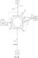
- FIG. 1Ais a network environment diagram that illustrates an exemplary active repeater device communicatively coupled to a base station and a plurality of user equipment, in accordance with an exemplary embodiment of the disclosure.
- FIG. 1Bis another network environment diagram that illustrates the active repeater device of FIG. 1A in communication with a base station and a plurality of customer premises equipment, in accordance with an exemplary embodiment of the disclosure.
- FIG. 1Cillustrates a timing profile of resource block utilization of an exemplary active repeater device for switching multi-beam to communicate with a plurality of customer premises equipment (CPEs), in accordance with an exemplary embodiment of the disclosure.
- CPEscustomer premises equipment
- FIG. 1Dillustrates a timing profile of beams of an exemplary active repeater device for switching multi-beam to communicate with a plurality of CPEs, in accordance with an exemplary embodiment of the disclosure.
- FIG. 1Eillustrates a timing profile of resource block utilization of an exemplary active repeater device for concurrent multi-beam transmission with a plurality of customer premises equipment (CPEs), in accordance with an exemplary embodiment of the disclosure.
- CPEscustomer premises equipment
- FIG. 1Fillustrates a timing profile of beams of an exemplary active repeater device for concurrent multi-beam transmission to communicate with a plurality of CPEs, in accordance with an exemplary embodiment of the disclosure.
- FIG. 2Ais a block diagram illustrating an exemplary one-sector active repeater device, in accordance with an exemplary embodiment of the disclosure.
- FIG. 2Bis a block diagram illustrating an exemplary two-sector active repeater device, in accordance with an exemplary embodiment of the disclosure.
- FIG. 2Cis a block diagram illustrating an exemplary three-sector active repeater device, in accordance with an exemplary embodiment of the disclosure.
- FIG. 3depicts a circuit diagram illustrating various components of an exemplary radio head unit in an exemplary active repeater device for beam widening to communicate with a plurality of user equipment, in accordance with an exemplary embodiment of the disclosure.
- FIG. 4depicts a block diagram illustrating various components of an exemplary baseband signal processor in an exemplary active repeater device for beam widening to communicate with a plurality of user equipment, in accordance with an exemplary embodiment of the disclosure.
- FIG. 5Adepicts a block diagram illustrating a second antenna array in a secondary sector of an exemplary active repeater device, configured to generate a second beam based on superposition of antenna sub-arrays, in accordance with an exemplary embodiment of the disclosure.
- FIG. 5Bdepicts a first graph illustrating variation of effective isotropic radiated power (EIRP) with respect to azimuth angle of a second antenna array in an exemplary active repeater device for beam widening to communicate with a plurality of user equipment, in accordance with an exemplary embodiment of the disclosure.
- EIRPeffective isotropic radiated power
- FIG. 5Cdepicts a second graph illustrating variation of effective isotropic radiated power (EIRP) with respect to azimuth angle of a second antenna array in an exemplary active repeater device for beam widening to communicate with a plurality of user equipment, in accordance with an exemplary embodiment of the disclosure.
- EIRPeffective isotropic radiated power
- FIG. 5Ddepicts a block diagram illustrating a second antenna array of an exemplary active repeater device configured to generate a second beam based on phase-only excitation of antenna elements, in accordance with an exemplary embodiment of the disclosure.
- FIG. 6Aillustrates a first exemplary scenario for implementation of the active repeater device, in accordance with an embodiment of the disclosure.
- FIG. 6Billustrates a second exemplary scenario for implementation of the active repeater device, in accordance with an embodiment of the disclosure.
- FIG. 6Cillustrates an exemplary training of uplink/downlink beam patterns of an exemplary active repeater device, in accordance with an embodiment of the disclosure.
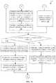
- FIGS. 7A, 7B, and 7Ccollectively, depict a flow chart that illustrates an exemplary method of operating an exemplary active repeater device for beam widening to communicate with a plurality of user equipment, in accordance with an embodiment of the disclosure.
- 5G networksmay be found in an active repeater device for beam widening to communicate with a plurality of user equipment.
- 5G networksEmergence of 5G networks in cm-wave and mm-wave bands is introducing new opportunities as well as new technical challenges.
- 5G networksmay provide orders of magnitude improvement in throughput and capacity complimented by the availability of wider spectrum bands, for example, in 28/39/60 GHz frequencies (or between 28-300 GHz) and massive frequency reuse through utilization of highly directional antennas.
- deployment of 5G networksis conditioned on overcoming certain challenges, for example:
- the disclosed active repeater devicemitigates at least the two remaining challenges.
- the disclosed active repeater devicesignificantly saves communication bandwidth by avoiding constant tracking of the location of the plurality of user equipment as a result of widened beam used to communicate with the plurality of user equipment.
- the base stationmay communicate with each of the plurality of UEs based on a time division multiple access (TDMA) scheme.
- TDMAtime division multiple access
- each of the plurality of UEsmay be allotted with different timeslots of a plurality of available timeslots of a transmission time period.
- a UE of the plurality of UEsmay receive the beam of RF signals exclusively during a timeslot which may be allotted to the respective UE.
- the base stationmay transmit the beam of RF signals to the plurality of UEs continuously throughout the transmission time period irrespective of timeslots allotted to the plurality of UEs.
- the base stationmay waste power by transmitting the beam of RF signals to the UE at timeslots which may not be allotted for the UE.
- the disclosed active repeater devicealso saves power by avoiding transmission of RF signals to UEs at timeslots which may not be assigned to the respective UEs in accordance with a particular TDMA based signal transmission scheme used by the base station.
- a radio frequency (RF) transmitter devicemay be configured to radiate radio waves in form of beams of RF signals to a plurality of RF receiver devices.
- the plurality of UEsmay be scattered within a geographical area which may be significantly larger than the coverage area that may be covered by one beam of RF signals.
- one or more UEs, which may be located outside the coverage area of the beam of RF signalsmay fail to receive the beam of RF signals.
- the disclosed active repeater devicesignificantly increases transmission range by concurrent multi-beam transmission with the plurality of UEs.
- the disclosed active repeater devicenot only mitigates the two remaining challenges as discussed above, but also can re-configure its beamforming engine resources within the active repeater device to support various new operating modes, such as a static beam mode, a beam widening mode, a switching multi-beam mode, a concurrent multi-beam mode, or one or more specified combination of the static beam mode, the beam widening mode, the switching multi-beam mode, the concurrent multi-beam mode.
- Such re-configurationmay be applied at installation time or at runtime (i.e, during operation of the active repeater device).
- FIG. 1Ais a network environment diagram that illustrates an exemplary active repeater device in communication with a base station and a plurality of user equipment, in accordance with an exemplary embodiment of the disclosure.
- a network environment 100 Amay include an active repeater device 102 , a base station 104 and a plurality of user equipment (UEs) 106 A and UE 106 B.
- the base station 104may be located at a certain distance from the UE 106 A and the UE 106 B.
- the plurality of UEs 106 A and 106 Bmay be in movement in accordance with a certain trajectory of motion.
- the active repeater device 102may be installed at a defined location and may be stationary.
- the active repeater device 102may have a modular architecture that includes a primary sector and one or more secondary sectors.
- the primary sectormay include a baseband signal processor and a first radio head (RH) unit.
- RHradio head
- Each of the one or more secondary sectorsmay include a second RH unit.
- the baseband signal processormay also be referred to as a light baseband unit (LBU) or a simplified baseband unit (BBU) that may be smaller in size as compared to a conventional BBU to be housed in the primary sector of the active repeater device 102 .
- Each of the one or more secondary sectorsmay be communicatively coupled to the primary sector via one or more analog baseband (IQ) signal cables and a control signal cable.
- IQanalog baseband
- the primary sector and one or more secondary sectors including the at least one secondary sectormay be configured to cover a portion of a 360-degree scan range for communication among the base station 104 , the plurality of UEs 106 A and 106 B, or another active repeater device, after installation at the defined location.
- the active repeater device 102may support multiple and a wide range of frequency spectrum, for example, 1G, 2G, 3G, 4G, and 5G. Alternatively stated, the active repeater device 102 may facilitate communication in both sub 30 gigahertz to above 30 gigahertz.
- the band of radio frequencies in the electromagnetic spectrum from 30 to 300 gigahertzis usually referred to as extremely high frequency (EHF) communication. Such radio frequencies have wavelengths from ten to one millimeter, referred to as millimeter wave (mmW).
- EHFextremely high frequency
- the active repeater device 102may comprise a plurality of RH units including the first RH unit in the primary sector, and the second RH unit in the secondary sector. Each of the plurality of RH units may comprise a first antenna array and a second antenna array. Therefore, the active repeater device 102 may comprise a plurality of first antenna arrays and a plurality of second antenna arrays. Each of the plurality of first antenna arrays may be configured to receive beams of input RF signals from one or more signal transmitters, such as transmitters in the base station 104 , the plurality of UEs 106 A and 106 B, and other active repeater devices.
- Each of the plurality of second antenna arraysmay be configured to transmit beams of output RF signals to one or more signal receivers, such as receivers in the base station 104 , the plurality of UEs 106 A and 106 B, and other active repeater devices.
- the plurality of first antenna arraysmay be configured to receive different input RF signals from the plurality of UEs 106 A and 106 B through different beam patterns and distances.
- the active repeater device 102may be positioned in a vicinity of a signal obstructing object, such as a tall building which may partially block the path of the input RF signals.
- the active repeater device 102may be realized by various components, such as transmitter front-ends, receiver front-ends, a plurality of low-noise amplifiers, a plurality of phase shifters, a plurality of power combiners, a plurality of power dividers, and a plurality of power amplifiers, logical control units, controllers and mixers.
- the base station 104may be a fixed point of communication that may relay information, in form of a plurality of beams of RF signals, to and from communication devices, such as the active repeater device 102 and the plurality of UEs 106 A and 106 B.
- Multiple base stations corresponding to one service providermay be geographically positioned to cover specific geographical areas.
- bandwidth requirementsserve as a guideline for a location of the base station 104 based on relative distance between the plurality of UEs 106 A and 106 B and the base station 104 .
- the count of base stationsdepends on population density and geographic irregularities, such as buildings and mountain ranges, which may interfere with the plurality of beams of RF signals.
- the base station 104may be configured to transmit a first beam of input RF signals to the active repeater device 102 .
- the first beam having a first beam pattern, such as a narrow beammay be received by the active repeater device 102 .
- the base station 104may be configured to generate the narrow beam of the input RF signals to achieve a high transmission range so that the narrow beam of the input RF signals reaches the known location of the active repeater device 102 . Since the active repeater device 102 may be stationary at the defined location, the base station 104 may not need to track location of the active repeater device 102 periodically or constantly.
- Each of the plurality of UEs 106 A and 106 Bmay correspond to a telecommunication hardware used by an end-user to communicate.
- the plurality of UEs 106 A and 106 Bmay refer to a combination of mobile equipment and subscriber identity module (SIM).
- SIMsubscriber identity module
- Each of the plurality of UEs 106 A and 106 Bmay be configured to communicate with the active repeater device 102 by use of RF signals.
- each of the plurality of UEs 106 A and 106 Bmay be a telecommunication hardware (e.g., a customer-premises equipment (CPE)) present at the premises of a subscriber and communicatively coupled to a carrier's telecommunication channel at certain interface point.
- CPEcustomer-premises equipment
- the interface pointis usually situated established in a building to separate the CPE from the equipment located in either the distribution infrastructure or central office of the communications service provider.
- Other examples of the plurality of UEs 106 A and 106 Bmay include, but are not limited to a smartphone, a wireless modem, a home router, a cable or satellite television set-top box, a VoIP base station, or any other customized hardware for telecommunication.
- the active repeater device 102may be deployed between the base station 104 (e.g. an eNB) and the plurality of UEs 106 A and 106 B to mitigate lack of line-of-sight (LOS) between the base station 104 and the plurality of UEs 106 A and 106 B.
- LOSline-of-sight
- At least one operating mode of a plurality of operating modesmay be set in the active repeater device 102 .
- the plurality of operating modesincludes a beam widening mode, a switching multi-beam mode, a concurrent multi-beam mode, and a static beam mode, or an operating mode that includes one or more specified combination of the static beam mode, the beam widening mode, the switching multi-beam mode, and the concurrent multi-beam mode.
- an operating modemay be a combination of the beam widening mode and the switching multi-beam mode, where the beams that are switched are wider beams in comparison to the beam received from the base station 104 .
- the selectionmay be made by at least one of a control command received from a control server (or the base station 104 ) from a remote location that may be different than an installation location of the active repeater device, a user-input to change a configuration setting at the active repeater device, or an automatic estimation of a number, distances, and a spatial distribution of the plurality of UEs 106 A and 106 B, to be serviced.
- a first operating modefor example, the beam widening mode of the plurality of operating modes
- the switching multi-beam modeis discussed, for example, in FIGS. 1B, 1C, and 1D .
- the concurrent multi-beam modeis discussed, for example, also in FIGS. 1B, 1E, and 1F .
- the plurality of operating modes and their operationsare discussed, for example, in FIGS. 6A, 6B, 7A, 7B, and 7C .
- the active repeater device 102may be configured to receive a first beam of input RF signals having a first beam pattern.
- the first beammay be received by the active repeater device 102 from the base station 104 .
- the first beam of input RF signals having the first beam patternmay corresponds to a narrow beam, such as a pencil beam, which may cover a first geographical area.
- the base station 104may be configured to detect a location of the active repeater device 102 and then direct the narrow beam towards the detected location of the active repeater device 102 .
- the base station 104may be configured to transmit the narrow beam to the active repeater device 102 without constant tracking of location of the active repeater device 102 .
- the active repeater device 102may be configured to receive the first beam via a first antenna array comprising a first set of antenna elements.
- the active repeater device 102may be configured to receive the first beam of input RF signals from another active repeater device which may be a part of a non-line-of-sight (NLOS) transmission path.
- NLOSnon-line-of-sight
- the active repeater device 102exhibits a demodulator-less architecture to avoid introduction of latency through the active repeater device 102 .
- one or more beams of output RF signalsmay be transmitted by one or more antenna arrays of the active repeater device 102 to the plurality of UEs 106 A and 106 B without demodulation of data portion of the received first beam of input RF signals to minimize the latency for transmission of the one or more beams of output RF signals while maintaining a final error vector magnitude (EVM) target at end destination point (i.e. the plurality of UEs 106 A and 106 B).
- EVMerror vector magnitude
- the active repeater device 102may comprise a digital modem circuitry, for example, an embedded 5G modem.
- the digital modem circuitrymay utilize the received signal (i.e. the received first beam of input RF signals) for control and monitoring operations, such as configuring and monitoring beamforming functions.
- the active repeater device 102does not process (i.e., demodulate) data stream in the received signal intended for end destination (i.e. the plurality of UEs 106 A and 106 B).
- the data streammay also be referred to as the data portion of the received first beam of input RF signals.
- some subcarriers in the waveform of the received signali.e.
- the received first beam of input RF signalsmay be dedicated for active repeater device 102 internal consumption, while the rest of subcarriers are assigned to other end users (i.e. the plurality of UEs 106 A and 106 B).
- the digital modem circuitryselectively decodes only the subcarriers assigned for the consumption of the active repeater device 102 and the full received RF signal is still relayed towards the destination without demodulation of full waveform to achieve near-zero-latency while maintaining a final error vector magnitude (EVM) target at end destination point (i.e.
- EVMerror vector magnitude
- the active repeater device 102without relying on demodulation or re-modulation at an intermediate point, such as the deployment location of the active repeater device 102 , for boosting EVM.
- SNRsignal-to-noise ratio
- the active repeater device 102still achieves target final RX SNR (i.e. signal quality at the plurality of UEs 106 A and 106 B is greater than a defined threshold SNR, for example, ⁇ 22 dB).
- Conventional active repeatersare simply digital signal amplifiers, which may decode both the header portion and the data portion for amplification, which adds to latency in communication.
- the active repeater device 102is configured to only decode the header portion of the received signal to extract control information without demodulation of the data portion of the first set of coded data signals to achieve near-zero-latency.
- a conventional baseband unitBBU
- BBUbaseband unit
- RRUremote radio head unit
- a baseband signal processor of the primary sector of the active repeater device 102may be implemented as the baseband signal processor card or chip, which is smaller in size and consumes less power in comparison with the conventional BBU.
- the baseband signal processor of the primary sectormay also be referred to as a light baseband unit (LBU) or a simplified baseband unit (BBU) that may be smaller in size as compared to a conventional BBU.
- LBUlight baseband unit
- BBUsimplified baseband unit
- the active repeater device 102may be configured to generate a first set of analogue baseband (IQ) signals based on the received first beam of input RF signals.
- the first set of IQ signalsmay comprise signals which may be processed in accordance with a defined or particular phase modulation scheme.
- An example of the phase modulation schememay include, but is not limited to a Quadrature Phase Shift Keying (QPSK) based modulation scheme and a Quadrature Amplitude modulation (QAM) scheme.
- QPSKQuadrature Phase Shift Keying
- QAMQuadrature Amplitude modulation
- the active repeater device 102may be configured to convert the received first set of IQ signals to a first set of coded data signals.
- the first set of coded data signalsmay comprise a plurality of data packets, arranged as a sequence of frames.
- Each of the sequence of framesmay comprise a header portion and a data portion.
- the sequence of framesmay comprise data frames provided in the data portion and control frames provided in the header portion.
- the active repeater device 102may be configured to decode the header portion of the first set of coded signals.
- the active repeater device 102may be configured to extract control information from the first set of coded data signals based on the header portion of the first set of coded data signals.
- the extracted control informationmay include Time Division Duplex (TDD) time slot information and beamforming information.
- the beamforming informationmay include beam training information between the base station 104 and the plurality of UEs 106 A and 106 B.
- the control informationmay further include frame structure and frame length information of the first set of coded data signals accessed from the header portion of the first set of coded data signals.
- the active repeater device 102may be configured to receive a plurality of RF signals from the plurality of UEs 106 A and 106 B.
- the active repeater device 102may be configured to measure Received Signal Strength Indicator (RSSI) associated with each of the plurality of RF signals received from the plurality of UEs 106 A and 106 B.
- RSSIReceived Signal Strength Indicator
- the active repeater device 102may be configured to estimate a relative position of each of the plurality of UEs 106 A and 106 B with respect to the active repeater device 102 .
- the active repeater device 102may not be required to constantly or too frequently (such as less than a specified time period) measure the RSSI associated with each of the plurality of RF signals received from the plurality of UEs 106 A and 106 B.
- the active repeater device 102may be configured to generate beamforming coefficients to convert the first beam pattern of the first beam to a second beam pattern based on the extracted control information and the measured RSSI.
- the beamforming coefficientsmay be generated based on the measured RSSI and the estimated relative positions of each of the plurality of UEs 106 A and 106 B from the active repeater device 102 .
- a second beam having the second beam patternmay cover a second geographical area.
- the second beam patternmay be wider than the first beam pattern.
- the second geographical areamay be larger than the first geographical area covered by the first beam.
- the second geographical areamay cover locations of the plurality of UEs 106 A and 106 B.
- part of trajectory of motion of each of the plurality of UEs 106 A and 106 Bmay be within coverage area (i.e. the second geographical area) of the second beam.
- the second beammay be transmitted to the plurality of UEs 106 A and 106 B without requiring to constantly track locations of each of the plurality of UEs 106 A and 106 B.
- the pencil-beamsmay have higher transmission range but provides less coverage as compared to the widened beam that have comparatively lesser transmission range but provide greater coverage.
- a process of constantly tracking location and orientation of each of the plurality of UEs 106 A and 106 Bmay consume communication bandwidth.
- the active repeater device 102mitigates need for constantly tracking location and orientation of each of the plurality of UEs 106 A and 106 B. Therefore, transmission of the second beam of output RF signals in the second beam pattern to the plurality of UEs 106 A and 106 B may be independent of or devoid of constant tracking of locations and orientations of the plurality of UEs 106 A and 106 B to save communication bandwidth and power.
- the active repeater device 102may be configured to generate output RF signals based on the first set of IQ signals. Further, the active repeater device 102 may be configured to generate the second beam of the second beam pattern based on the generated beamforming coefficients. Further, the active repeater device 102 may be configured to transmit the generated output RF signals in the second beam pattern to the plurality of UEs 106 A and 106 B based on the generated beamforming coefficients and the received first beam of input RF signals. The active repeater device 102 may be configured to transmit the second beam via at least a second antenna array among the plurality of second antenna arrays in the secondary sectors.
- the transmission of the second beam of output RF signals in the second beam pattern to the plurality of UEs 106 A and 106 Bmay be done without (or independent of) constant tracking of locations and orientations of the plurality of UEs 106 A and 106 B to save communication bandwidth.
- the active repeater device 102may establish the MIMO communication in a non-line-of-sight (NLOS) transmission path based on the receipt of the first beam of input RF signals having the first beam pattern from the base station 104 . Further, the active repeater device 102 may be configured to establish the MIMO communication based on transmission of the second beam of output RF signals in the second beam pattern to the plurality of UEs 106 A and 106 B.
- NLOSnon-line-of-sight
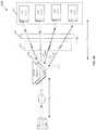
- FIG. 1Bis a network environment diagram that illustrates the active repeater device of FIG. 1A in communication with a base station and a plurality of customer premises equipment, in accordance with an exemplary embodiment of the disclosure.
- a network environment 100 Bmay include the active repeater device 102 , the base station 104 and a plurality of customer premises equipment (CPEs) 107 (such as a first CPE 107 A, a second CPE 107 B, a third CPE 107 C and a fourth CPE 107 D).
- the plurality of CPEs 107may correspond to the plurality of UEs of FIG. 1A .
- the base station 104may be located at a certain distance from each CPE of the plurality of CPEs 107 .
- the active repeater device 102may be installed at a defined location and may be stationary. There is also shown a signal-obstructing physical object 108 that may partially block or impair a plurality of beams 110 (such as a first beam 110 A, a second beam 110 B, a third beam 110 C, and a fourth beam 110 D) of output RF signals communicated between the active repeater device 102 and the plurality of CPEs 107 .
- Each of the plurality of CPEs 107may correspond to a telecommunication hardware present at the premises of a subscriber and communicatively coupled to a carrier's telecommunication channel at certain interface point.
- the interface pointis usually situated or established in a building to separate the CPE from the equipment located in either the distribution infrastructure or central office of the communications service provider.
- the CPEmay also be alternatively referred to as user equipment, such as the plurality of UEs 106 A and 106 B, such as a combination of mobile equipment and subscriber identity module (SIM), used by an end-user to communicate.
- SIMsubscriber identity module
- Each of the plurality of CPEs 107may be configured to communicate with the active repeater device 102 by use of RF signals.
- Examples of the plurality of CPEs 107may include, but are not limited to a wireless modem, a home router, a fixed mobile convergence hardware, a telecommunication gateway device, a cable or satellite television set-top box, a VoIP base station, or any other customized hardware for telecommunication.
- the active repeater device 102may be deployed between the base station 104 (e.g. an eNB) and the plurality of CPEs 107 to mitigate lack of line-of-sight (LOS) between the base station 104 and the plurality of CPEs 107 .
- LOSline-of-sight
- the active repeater device 102may be configured to receive a first beam of input RF signals having a first beam pattern.
- the first beammay be received by the active repeater device 102 from the base station 104 .
- the first beam of input RF signals having the first beam patternmay correspond to a narrow beam such as a pencil beam which may cover a first geographical area. Since the active repeater device 102 and the base station 104 may be stationary, the base station 104 may be configured to direct the narrow beam to the active repeater device 102 without constant tracking of location of the active repeater device 102 .
- the active repeater device 102may be configured to receive the first beam via a first antenna array comprising a first set of antenna elements. In certain scenarios, the active repeater device 102 may be configured to receive the first beam of input RF signals from another active repeater device which may be a part of a non-line-of-sight (NLOS) transmission path.
- the NLOS transmission pathmay be between the base station 104 and the plurality of CPEs 107 .
- the active repeater device 102exhibits a demodulator-less architecture to avoid introduction of latency through the active repeater device 102 .
- one or more beams of output RF signalsmay be transmitted by one or more antenna arrays of the active repeater device 102 to the plurality of CPEs 107 without demodulation of data portion of the received first beam of input RF signals to minimize the latency for transmission of the one or more beams of output RF signals while maintaining a final error vector magnitude (EVM) target at end destination point (i.e. the plurality of CPEs 107 ).
- EVMerror vector magnitude
- the first beam of input RF signalsmay comprise input RF signals intended for each of the plurality of CPEs 107 .
- the first beam of the input RF signalsmay comprise a first input RF signal intended for the first CPE 107 A.
- the first beam of the input RF signalsmay further comprise a second input RF signal, a third input RF signal, and a fourth RF input signal, intended for the second CPE 107 B, the third CPE 107 C, and the fourth CPE 107 D respectively.
- the first beam of input RF signalsmay comprise a single stream which may have been generated by a superimposition of the first input RF signal, the second input RF signal, the third RF input RF signal, and the fourth input RF signal by the base station 104 .
- the first input RF signal, the second input RF signal, the third RF input RF signal, and the fourth input RF signalmay have been superimposed by the base station 104 in accordance with a Time Division Multiple Access (TDMA) or an Orthogonal Frequency Multiple Access (OFDMA) scheme.
- the first beam of the received first beam of input RF signalsmay comprise a single reference stream comprising scheduling information associated with the TDMA based wireless signal transmission scheme.
- the base station 104may be configured to communicate with the plurality of CPEs 107 via the active repeater device 102 , based on the TDMA based wireless signal transmission scheme.
- the base station 104may be configured to communicate with each of the plurality of CPEs 107 at a different timeslot of a plurality of timeslots in a transmission time period, based on the TDMA based wireless signal transmission system.
- the active repeater device 102may be configured to generate a first set of analogue baseband (IQ) signals based on the received first beam of input RF signals.
- the first set of IQ signalsmay comprise signals which may be processed in accordance with a defined or particular phase modulation scheme.
- An example of the phase modulation schememay include, but is not limited to a Quadrature Phase Shift Keying (QPSK) based modulation scheme and a Quadrature Amplitude modulation (QAM) scheme.
- QPSKQuadrature Phase Shift Keying
- QAMQuadrature Amplitude modulation
- the active repeater device 102may be configured to convert the received first set of IQ signals to a first set of coded data signals.
- the first set of coded data signalsmay comprise a plurality of data packets, arranged as a sequence of frames. Each of the sequence of frames may comprise a header portion and a data portion. The sequence of frames may comprise data frames provided in the data portion and control frames provided in the header portion.
- the active repeater device 102may be configured to decode only the header portion of the first set of coded signals without demodulation of data stream in the received signal intended for end destination (i.e. the plurality of CPEs 107 ).
- the active repeater device 102may be configured to extract control information from the first set of coded data signals based on the header portion of the first set of coded data signals. In accordance with an embodiment, the extracted control information may include Time Division Duplex (TDD) time slot information and beamforming information.
- the control informationmay further include frame structure and frame length information of the first set of coded data signals accessed from the header portion of the first set of coded data signals.
- TDDTime Division Duplex
- the active repeater device 102may be configured to receive a plurality of RF signals from each of the plurality of CPEs 107 .
- the active repeater device 102may be configured to measure Received Signal Strength Indicator (RSSI) associated with each of the plurality of RF signals received from the plurality of CPEs 107 .
- RSSIReceived Signal Strength Indicator
- the active repeater device 102may be configured to estimate a location of each of the plurality of CPEs 107 with respect to the active repeater device 102 .
- the active repeater device 102may be further configured to estimate a distance of each of the plurality of CPEs 107 based on the measured RSSI.
- the active repeater device 102may not be required to constantly or too frequently (such as less than a specified time period) measure the RSSI associated with each of the plurality of RF signals received from the plurality of CPEs 107 .
- the measured RSSI associated with the plurality of CPEs 107in combination with the location or a distance of each of the plurality of CPEs 107 from the active repeater device 102 , may be also referred to as one or more signal parameters associated with the plurality of CPEs 107 .
- the active repeater device 102may be configured to process the single reference stream of the first beam of input RF signals to extract the scheduling information associated with the TDMA based wireless signal transmission system.
- the active repeater device 102may be configured to assign a different timeslot from a plurality of available timeslots to each of the plurality of CPEs 107 , based on the scheduling information extracted from the received first beam of input RF signals.
- the plurality of available timeslotsmay comprise a first timeslot Ts 1 , a second timeslot Ts 2 , a third timeslot Ts 3 , and a fourth time slot Ts 4 .
- the first timeslot Ts 1 , the second timeslot Ts 2 , the third timeslot Ts 3 , and the fourth time slot Ts 4may be assigned to the first CPE 107 A, the second CPE 107 B, the third CPE 107 C, and the fourth CPE 107 D respectively.
- Assignment of the plurality of timeslots to the plurality of CPEs 107has been discussed in detail, for example, in FIGS. 1C and 1D .
- Each CPE of the plurality of CPE 107may be configured to communicate with the active repeater device 102 exclusively or only during a corresponding timeslot assigned to the respective CPE, and may not communicate with the active repeater device 102 at other timeslots.
- the active repeater device 102may be configured to store a database comprising a plurality of beam settings.
- Each of the plurality of beam settingsmay correspond to a different beam profile of a plurality of different beams which may be generated by a second antenna array of a second RH unit of the active repeater device 102 .
- timing of the generation and communication of the beams, shape of a beam or beam pattern, direction of beam, length of beammay depend on the selected (or set) operating mode of the plurality of operating mode, and the distribution of the UEs or CPEs to be serviced.
- Each of the plurality of beam settingscomprises a set of beamforming coefficients.
- the active repeater device 102may be configured to assign a different beam setting from the plurality of beam settings to each of the plurality of CPEs 107 , based on the one or more signal parameters associated with the plurality of CPEs 107 . For example, a first beam setting, a second beam setting, a third beam setting, and a fourth beam setting of the plurality of beam settings, may be assigned to the first CPE 107 A, the second CPE 107 B, the third CPE 107 C, and the fourth CPE 107 D of the plurality of CPEs 107 respectively.
- the active repeater device 102may be configured to generate output RF signals based on the first set of IQ signals. Further, the active repeater device 102 may be configured to generate a plurality of beams 110 which may correspond to the plurality of beam settings, based on the assignment of the plurality of beam setting to the plurality of CPEs 107 .
- the generated plurality of beams 110 of output RF signalsmay comprise the first beam 110 A, the second beam 110 B, the third beam 110 C, and the fourth beam 110 D of output RF signals.
- the first beam 110 A, the second beam 110 B, the third beam 110 C and the fourth beam 110 D of output RF signalsmay be generated based on the first beam setting, the second beam setting, the third beam setting and the fourth beam setting respectively.
- a second antenna array of the plurality of second antenna arrays of the second RH unitmay be configured to transmit the plurality of beams 110 of output RF signals to the plurality of CPEs 107 by switching the plurality of beams 110 of output RF signals.
- the second antenna arraymay be configured to switch the plurality of beams 110 based on the assigned different timeslot and the assigned different beam setting to each of the plurality of CPEs 107 .
- the second antenna array of the second RH unitmay be configured to transmit the first beam 110 A of output RF signals to the first CPE 107 A of the plurality of CPEs 107 , exclusively during the first timeslot Ts 1 assigned to the first CPE 107 A, based the first beam setting assigned to the first CPE 107 A, and based on the received first beam of input RF signals.
- the second beam 110 B, the third beam 110 C and the fourth beam 110 D of output RF signalsmay be transmitted exclusively to the second CPE 107 B, the third CPE 107 C, and the fourth CPE 107 D respectively at the second timeslot Ts 2 , the third timeslot Ts 3 , and the fourth timeslot Ts 4 respectively. Therefore, the active repeater device 102 may be configured to transmit a beam of output RF signals to a CPE of the plurality of CPEs 107 exclusively at a timeslot allotted to the respective CPE.
- the switching of the plurality of beams 110 based on the assigned different timeslot and the assigned different beam settingmay reduce power wastage by the active repeater device 102 .
- the active repeater device 102may not transmit beams of output RF signals to CPEs of the plurality of CPEs 107 , at timeslots which may not be assigned to the respective CPE, the active repeater device 102 may reduce the power wastage.
- each beam of the plurality of beams 110which may have been assigned to the plurality of CPEs 107 , may be a narrow beam. Narrow beams may have larger transmission range in comparison to wide beams.
- Each beam of the plurality of beams 110may be transmitted exclusively to a corresponding CPE of the plurality of CPEs 107 .
- the active repeater device 102may have larger transmission range in comparison to a conventional system (for example, a conventional base station) which may transmit a single wide beam of output RF signals to the plurality of CPEs 107 .
- the active repeater device 102may be configured to concurrently transmit the plurality of beams 110 of output RF signals to the plurality of CPEs 107 .
- the full-bandwidth signal received from the base station 104may be re-transmitted concurrently to the plurality of CPEs 107 over the plurality of beams 110 of output RF signals.
- the active repeater device 102may be configured to concurrently transmit the plurality of beams 110 based on the assigned different beam setting to each of the plurality of CPEs 107 .
- the plurality of beams 110may be generated by a second antenna array of the plurality of second antenna arrays.
- the plurality of beams 110may be generated by a set of second antenna arrays of the plurality of second antenna arrays.
- An example of a timing profile of resource block utilization in the active repeater device 102 for concurrent multi-beam transmission with the plurality of CPEs 107is described, for example, in FIG. 1E .
- an example of a timing profile of beams from the active repeater device 102 for concurrent multi-beam transmission with the plurality of CPEs 107is described, for example, in FIG. 1F .
- the active repeater device 102may be configured to transmit each beam of the plurality of beams 110 of output RF signals exclusively to a corresponding CPE of the plurality of CPEs 107 .
- the active repeater device 102may be configured to transmit the first beam 110 A exclusively to the first CPE 107 A.
- the active repeater device 102may be configured to transmit the second beam 110 B, the third beam 110 C, and the fourth beam 110 D to the second CPE 107 B, the third CPE 107 C and the fourth CPE 107 D respectively.
- a conventional active repeater devicemay transmit a single beam of RF signals to communicate with the plurality of CPEs 107 .
- the plurality of CPEs 107may be scattered within a geographical area which may be significantly larger than a coverage area that may be covered by the single beam of RF signals transmitted by the conventional active repeater device. In such cases, one or more of the plurality of CPEs 107 , which may be located outside the coverage area of the single beam of RF signals may fail to receive the single beam of RF signals transmitted by the conventional active repeater device.
- Each of the plurality of beams 110 of output RF signals transmitted by the active repeater device 102may be generated by the active repeater device 102 to cover a corresponding location of a CPE to which the respective beam is transmitted.
- Each of the plurality of beams 110 of output RF signals transmitted by the active repeater device 102may have a transmission range which may be larger in comparison with transmission range of the single beam transmitted by the conventional active repeater device. Hence, the active repeater device 102 may have significantly larger transmission range in comparison to the conventional active repeater device.
- the active repeater device 102may comprise a cascading receiver chain comprising a first set of power dividers, a first set of phase shifters, a first set of low noise amplifiers, and the first antenna array.
- the active repeater device 102may comprise a cascading transmitter chain comprising a first set of power combiners, a second set of phase shifters, a first set of power amplifiers, and the second antenna array.
- the first antenna arraymay comprise a first set of antenna elements.
- the second antenna arraymay comprise a second set of antenna elements.
- the active repeater device 102may be configured to partition the second set of antenna elements of the second antenna array into a plurality of spatially separated antenna sub-arrays.
- the second antenna arraymay be configured to generate a first set of beams of output RF signals based on the partition.
- Each of the plurality of spatially separated antenna sub-arraysmay generate one or more of the first set of beams.
- each beam of the plurality of beams 110may be generated by super-position of the first set of beams of output RF signals with each other.
- a multiple-input multiple-output (MIMO) based communicationmay be established between the base station 104 and the plurality of UE) by the active repeater device 102 .
- MIMOmultiple-input multiple-output
- the active repeater device 102may establish the MIMO communication in a non-line-of-sight (NLOS) transmission path based on the receipt of the first beam of input RF signals having the first beam pattern from the base station 104 . Further, the active repeater device 102 may be configured to establish the MIMO communication based on transmission of the plurality of beams 110 of output RF signals to the plurality of CPEs 107 .
- NLOSnon-line-of-sight
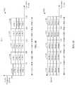
- FIG. 1Cillustrates a timing profile of resource block utilization of an exemplary active repeater device for switching multi-beam to communicate with a plurality of customer premises equipment (CPEs), in accordance with an exemplary embodiment of the disclosure.
- FIG. 1Cis explained in conjunction with elements from FIG. 1B .
- a graphical representation 100 Cwhich depicts resource block allocation to each CPE of the plurality of CPEs 107 in frequency domain, with respect to the plurality of timeslots (such as the first timeslot Ts 1 , the second timeslot Ts 2 , the third timeslot Ts 3 , the fourth timeslot Ts 4 and the fifth timeslot Ts 5 ) in a transmission time period as discussed in FIG. 1 .
- Time withmay be represented by the “X” axis of the graphical representation 100 C, as shown.
- Frequency spectrum corresponding to a plurality of resource blocks allocated to each of the plurality of CPEs 107 at different timeslots(such as the first timeslot Ts 1 , the second timeslot Ts 2 , the third timeslot Ts 3 , the fourth timeslot Ts 4 and the fifth timeslot Ts 5 ) may be represented by the “Y” axis of the first graphical representation 100 C.
- the active repeater device 102may be configured to switch the plurality of beams 110 based on the assigned different timeslot and the assigned different beam setting to each of the plurality of CPEs 107 .
- the active repeater device 102may be configured to allocate a first set of resource blocks to the first CPE 107 A at the first timeslot Ts 1 (frequency spectrum allocated to the first CPE 107 A as the first set of resource blocks is represented as graph component 112 A).
- the active repeater device 102may be configured to allocate a second set of resource blocks to the second CPE 107 B at the second timeslot Ts 2 (frequency spectrum allocated to the second CPE 107 B as the second of resource blocks is represented as graph component 112 B).
- the active repeater device 102may be configured to allocate a third set of resource blocks to the third CPE 107 C at the third timeslot Ts 3 (frequency spectrum allocated to the third CPE 107 C as the third set of resource blocks is represented as graph component 112 C).
- the active repeater device 102may be configured to allocate a fourth set of resource blocks to the fourth CPE 107 D at the first timeslot Ts 1 (frequency spectrum allocated as the fourth set of resource blocks is represented as graph component 112 D).
- the active repeater device 102may be configured to then allocate a fifth set of resource blocks to the first CPE 107 A at a fifth timeslot Ts 5 (frequency spectrum allocated as the fifth set of resource blocks is represented as graph component 112 E), and thus the cycle may continue until all data is communicated.
- FIG. 1Dillustrates a timing profile of beams of an exemplary active repeater device for switching multi-beam to communicate with a plurality of CPEs, in accordance with an exemplary embodiment of the disclosure.
- FIG. 1Dis explained in conjunction with elements from FIGS. 1B , and 1 C.
- a graphical representation 100 Dwhich depicts beam allocation to each CPE of the plurality of CPEs 107 , with respect to the plurality of timeslots (such as the first timeslot Ts 1 , the second timeslot Ts 2 , the third timeslot Ts 3 , the fourth timeslot Ts 4 and the fifth timeslot Ts 5 ) in the transmission time period as discussed in FIGS. 1B and 1C .
- Timemay be represented by the “X” axis of the graphical representation 100 D, as shown.
- Beams allocated to each of the plurality of CPEs 107may be represented by the “Y” axis of the graphical representation 100 D.
- the active repeater device 102may be configured to transmit the first beam 110 A (Beam 1 ) of output RF signals to the first CPE 107 A of the plurality of CPEs 107 , during the first timeslot Ts 1 (as represented by graph component 114 A).
- the active repeater device 102may be configured to transmit the second beam 110 B (Beam 2 ) of output RF signals to the second CPE 107 B of the plurality of CPEs 107 , during the second timeslot Ts 2 (as represented by graph component 114 B).
- the active repeater device 102may be configured to transmit the third beam 110 C (Beam 3 ) of output RF signals to the third CPE 107 C of the plurality of CPEs 107 , during the third timeslot Ts 3 (as represented by graph component 114 C).
- the active repeater device 102may be configured to transmit the fourth beam 110 D (beam 4 ) of output RF signals to the fourth CPE 107 D of the plurality of CPEs 107 , during the fourth timeslot Ts 4 (as represented by graph component 114 D). Thereafter, the active repeater device 102 may be configured to transmit the first beam 110 A (Beam 1 ) of output RF signals to the first CPE 107 A of the plurality of CPEs 107 , during the fifth timeslot Ts 5 (as represented by graph component 114 E). Thus, as shown for example, the active repeater device 102 may be configured to transmit a beam of output RF signals to a CPE of the plurality of CPEs 107 exclusively at a timeslot allotted to the respective CPE.
- the active repeater device 102may not transmit beams of output RF signals to CPEs of the plurality of CPEs 107 , at timeslots which may not be assigned to the respective CPE. Thus, the active repeater device 102 may reduce power wastage.
- Each beam of the plurality of beams 110which may have been assigned to the plurality of CPEs 107 , may be a narrow beam. Narrow beams may have larger transmission range in comparison to wide beams.
- Each beam of the plurality of beams 110may be transmitted exclusively to a corresponding CPE of the plurality of CPEs 107 .
- the active repeater device 102may have larger transmission range in comparison to a conventional system (for example, a conventional base station) which may transmit a single wide beam of output RF signals to the plurality of CPEs 107 .
- FIG. 1Eillustrates a timing profile of resource block utilization of an exemplary active repeater device for concurrent multi-beam transmission with a plurality of customer premises equipment (CPEs), in accordance with an exemplary embodiment of the disclosure.
- CPEscustomer premises equipment
- FIG. 1Ethere is shown a graphical representation 100 E which depicts resource block allocation to each CPE (also represented as CPE 1 , CPE 2 , CPE 3 , and CPE 4 ) of the plurality of CPEs 107 in frequency domain, with respect to the plurality of timeslots (such as the first timeslot Ts 1 , the second timeslot Ts 2 , the third timeslot Ts 3 , the fourth timeslot Ts 4 and the fifth timeslot Ts 5 ) in the transmission time period as discussed in FIG.
- the plurality of timeslotssuch as the first timeslot Ts 1 , the second timeslot Ts 2 , the third timeslot Ts 3 , the fourth timeslot Ts 4 and the fifth timeslot Ts 5
- Time with respect tomay be represented by the “X” axis of the graphical representation 100 E, as shown.
- Frequency spectrum corresponding to a plurality of resource blocks allocated to each of the plurality of CPEs 107 at different timeslots(such as the first timeslot Ts 1 , the second timeslot Ts 2 , the third timeslot Ts 3 , the fourth timeslot Ts 4 and the fifth timeslot Ts 5 ) may be represented by the “Y” axis of the graphical representation 100 E.
- the active repeater device 102may be configured to allocate one or more of a first set of resource blocks to the plurality of CPEs 107 , for the first timeslot Ts 1 (frequency spectrum allocated to the plurality of CPEs 107 as the first set of resource blocks is represented as graph component 116 A).
- the active repeater device 102may be configured to allocate one or more of a second set of resource blocks to the plurality of CPEs 107 , for the second timeslot Ts 2 (frequency spectrum allocated to the plurality of CPEs 107 as the first set of resource blocks is represented as graph component 116 B).
- the active repeater device 102may be configured to allocate one or more of a third set of resource blocks to the plurality of CPEs 107 , for the third timeslot Ts 3 (frequency spectrum allocated to the plurality of CPEs 107 as the third set of resource blocks is represented as graph component 116 C).
- the active repeater device 102may be configured to allocate one or more of a fourth set of resource blocks to the plurality of CPEs 107 , for the fourth timeslot Ts 1 (frequency spectrum allocated to the plurality of CPEs 107 as the fourth set of resource blocks is represented as graph component 116 D).
- the active repeater device 102may be configured to allocate one or more of a fifth set of resource blocks to the plurality of CPEs 107 , for the fifth timeslot Ts 5 (frequency spectrum allocated to the plurality of CPEs 107 as the fifth set of resource blocks is represented as graph component 116 E).
- FIG. 1Fillustrates a timing profile of beams of an exemplary active repeater device for concurrent multi-beam transmission to communicate with a plurality of CPEs, in accordance with an exemplary embodiment of the disclosure.
- a second graphical representation 100 Fwhich depicts beam allocation to each CPE (also represented as CPE 1 , CPE 2 , CPE 3 , and CPE 4 ) of the plurality of CPEs 107 , with respect to the plurality of available timeslots (such as the first timeslot Ts 1 , the second timeslot Ts 2 , the third timeslot Ts 3 , the fourth timeslot Ts 4 and the fifth timeslot Ts 5 ) in the transmission time period as discussed in FIG. 1B .
- Timemay be represented by the “X” axis of the graphical representation 100 F, as shown.
- Beams allocated to each of the plurality of CPEs 107may be represented by the “Y” axis of the graphical representation 100 F.
- the active repeater device 102may be configured to transmit the plurality of beams 110 of output RF signals to the plurality of CPEs 107 based on the first set of beam settings during the first timeslot Ts 1 (as represented by graph component 118 A).
- the active repeater device 102may be configured to transmit the plurality of beams 110 of output RF signals to the plurality of CPEs 107 based on the second set of beam settings during the second timeslot Ts 2 (as represented by graph component 118 B).
- the active repeater device 102may be configured to transmit the plurality of beams 110 of output RF signals to the plurality of CPEs 107 based on the third set of beam settings during the third timeslot Ts 3 (as represented by graph component 118 C).
- the active repeater device 102may be configured to transmit the plurality of beams 110 of output RF signals to the plurality of CPEs 107 based on the fourth set of beam settings during the fourth timeslot Ts 4 (as represented by graph component 118 D).
- the active repeater device 102may be configured to transmit the plurality of beams 110 of output RF signals to the plurality of CPEs 107 based on the first set of beam settings during the fifth timeslot Ts 5 (as represented by graph component 118 E), and thus the cycle may continue until all data is communicated).
- FIG. 2Ais a block diagram illustrating an exemplary one-sector active repeater device, in accordance with an exemplary embodiment of the disclosure.
- FIG. 2Ais explained in conjunction with elements from FIG. 1 .
- a one-sector active repeater devicethat includes a primary sector 202 of the active repeater device 102 .
- the primary sector 202 of the active repeater device 102comprises a first radio head (RH) unit 204 and a baseband signal processor 206 .
- RHradio head
- the first RH unit 204may be implemented in the active repeater device 102 as a radio head (RH) card.
- the baseband signal processor 206may be implemented in the active repeater device 102 as a baseband signal processing card or chip.
- Other examples of implementations of the RH card and the baseband signal processor cardmay include, but is not limited to an integrated circuit using a single or separate printed circuit boards (PCBs) as substrates, a radio frequency integrated chip (RFIC) and a system on a chip (SoC) device.
- the first RH unit 204 and the baseband signal processor 206may be housed within the primary sector 202 of the active repeater device 102 .
- the first RH unit 204 and the baseband signal processor 206may be communicatively coupled with each other via a wired or wireless communication medium.
- the first RH unit 204 and the baseband signal processor 206may communicate control signals and analog baseband signals with each other.
- FIG. 2Bis a block diagram illustrating an exemplary two-sector active repeater device, in accordance with an exemplary embodiment of the disclosure.
- FIG. 2Bis explained in conjunction with elements from FIGS. 1 and 2A .
- the secondary sector 208may include a second RH unit 210 .
- the second RH unit 210may be similar to the first RH unit 204 .
- the secondary sector 208may be communicatively coupled with the primary sector 202 via one or more signal cables (e.g. a control signal cable and two baseband (IQ) signal cables).
- IQbaseband
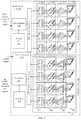
- FIG. 2Cis a block diagram illustrating an exemplary three-sector active repeater device, in accordance with an exemplary embodiment of the disclosure.
- FIG. 2Cis explained in conjunction with elements from FIGS. 1, 2A, and 2B .
- a three-sector active repeater devicethat includes an additional secondary sector, such as a secondary sector 212 , connected to the two-sector active repeater device of FIG. 2B .
- the secondary sector 212may include a second RH unit 214 similar to the second RH unit 210 .
- the secondary sector 212may be communicatively coupled to the primary sector 202 via the one or more signal cables.
- the active repeater device 102may be upgradable or re-configurable to at least one of a base station (gNB), a small cell access point, or a remote radio head (RRH).
- the active repeater device 102may be upgraded by replacing the baseband signal processor 206 with a suitable baseband unit (BBU) known in the art.
- BBUbaseband unit
- the baseband signal processor 206 of the primary sector 202may be configured to support multi-band millimeter wave (mm Wave) spectrum and sub-30 GHz spectrum concomitantly.
- mm Wavemillimeter wave
- the baseband signal processor 206 of the primary sector 202 of the active repeater device 102does not process (i.e., demodulate) data stream in the received signal intended for end destination (i.e. the plurality of UEs 106 A and 106 B).
- the data streammay also be referred to as the data portion of the received first beam of input RF signals.
- the baseband signal processor 206may decode only the header portion of the received signal to extract control information without demodulation of data portion of the received signal.
- Conventional active repeatersare simply digital signal amplifiers, which may decode both the header portion and the data portion for amplification, which adds to latency in communication.
- a conventional baseband unitis voluminous, and is typically placed in an equipment room in mobile telecommunications systems and connected with the remote radio head unit (RRU), via optical fiber.
- the baseband signal processor 206 of the primary sector 202 of the active repeater device 102may be implemented as the baseband signal processor card or chip, which is smaller in size in comparison to the conventional BBU and consumes less power in comparison to the conventional BBU.
- the baseband signal processor 206may also be referred to as a light baseband unit (LBU) or a simplified baseband unit (BBU) that may be smaller in size as compared to a conventional BBU.
- the baseband signal processor 206may thus be housed in the primary sector 202 of the active repeater device 102 , as shown.
- FIG. 3depict circuit diagrams illustrating various components of an exemplary radio head unit in the active repeater device, in accordance with an exemplary embodiment of the disclosure.
- FIG. 3is explained in conjunction with elements from FIGS. 1, 2A, 2B, and 2C .
- a radio head (RH) unit 302there is shown a radio head (RH) unit 302 .
- the RH unit 302may be one of the first RH unit 204 , the second RH unit 210 , the second RH unit 214 or any other radio head units in the active repeater device 102 .
- the RH unit 302comprises a receiver (Rx) phased array 338 and a transmitter (TX) phased array 340 .
- the Rx phased array 338may include a cascading receiver chain 334 comprising a first antenna array 304 , a first set of low noise amplifiers (LNA) 306 , a first set of phase shifters 308 , and a first set of power combiners 310 .
- the Tx phased array 340may include a cascading transmitter chain 336 comprising a first set of power dividers 326 , a first set of phase shifters 328 , a first set of power amplifiers (PA) 330 , and a second antenna array 332 .
- first power combiner 312There are is also shown a first power combiner 312 , a first mixer 318 , a second mixer 320 , a first phase locked loop (PLL) 314 , a second PLL 316 , a first controller 322 , and a first power divider 324 in the RH unit 302 .
- PLLphase locked loop
- the first antenna array 304may be configured to receive the first beam of input RF signals having the first beam pattern from the base station 104 .
- the first antenna array 304may comprise a first set of antenna elements.
- the first antenna array 304may be configured to receive the first beam of input RF signals using the first set of antenna elements. Examples of implementations of the first antenna array 304 may include, but is not limited to a planar phased array antenna, a frequency scanning phased array antenna, or a dynamic phased array antenna.
- the plurality of antenna elements in the first antenna array 304may be communicatively coupled to one or more LNAs in the first set of LNAs 306 .
- the first set of LNAs 306may be configured to amplify input RF signals received at the first antenna array 304 .
- the first set of LNAs 306may be configured to amplify input RF signals, which may have low-power, without significantly degrading corresponding signal-to-noise (SNR) ratio.
- SNRsignal-to-noise
- Each of the first set of LNAs 306may be communicatively coupled to phase shifters in the first set of phase shifters 308 .
- the first set of phase shifters 308may perform an adjustment in phase values of the input RF signals, till combined signal strength value of the received input RF signals, is maximized. In one example, the first set of phase shifters 308 may perform an adjustment in the phase value till each of the received input RF signals are in-phase with each other.
- Phase shifters in the first set of phase shifters 308may be communicatively coupled to power combiners, such as a 4 : 1 power combiner, in the first set of power combiners 310 . Further, each of the first set of power combiners 310 may be coupled to the first power combiner 312 .
- Each of the first set of power combiners 310may be configured to combine each of the phase shifted input RF signals into a first set of RF signals.
- the first set of power combiners 310may be configured to transmit the first set of RF signals to the first power combiner 312 .
- the first power combiner 312may be configured to combine the first set of RF signals to a first RF signal.
- the first power combiner 312 and the first set of power combiners 310may comprise both active and passive combiners. Examples of implementation of the first power combiner 312 and the first set of power combiners 310 may include, but is not limited to resistive power combiners, and solid-state power combiners.
- the first power combiner 312may be further configured to communicate the first RF signal to the first mixer 318 .
- the first mixer 318may be configured to down convert the first RF signal to an output analogue baseband (IQ) signal.
- the first mixer 318may be configured to down convert the first RF signal with a first frequency to the baseband signal based on mixing of a second frequency generated by a local oscillator with the first RF signal.
- the first mixer 318may be communicatively coupled with the first PLL 314 .
- the first PLL 314 in combination with the first mixer 318may be configured to down convert the first Signal into an analog baseband quadrature (IQ) output signal.
- the first mixer 318may be configured to communicate the IQ output signal to the baseband signal processor 206 via a first IQ signal cable.
- the second mixer 320may be configured to receive an analog baseband (IQ) input signal from the baseband signal processor 206 via the second IQ signal cable. Further, the second mixer 320 and the second PLL 316 may be configured to up convert the received IQ input signal to a second RF signal. The second mixer 320 may be configured to up convert the IQ input signal to the second RF signal based on mixing of a third frequency generated by a local oscillator (provided by the second PLL 3160 with the IQ input signal. The second mixer 320 may be communicatively coupled to the first power divider 324 . Further, each of the first set of power dividers 326 may be communicatively coupled to the first power divider 324 . The combination of the second mixer 320 and the second PLL 316 may be configured to transmit the second RF signal to the first power divider 324 .
- IQanalog baseband
- the first controller 322may be communicatively coupled to the baseband signal processor 206 via a control signal cable.
- the first controller 322may be configured to receive one or more control signals from the baseband signal processor 206 .
- the first controller 322may be configured to adjust one or more parameters (e.g., amplifier gains, and phase responses) associated with the receiver (Rx) phased array 338 and the transmitter (Tx) phased array 340 based on the received one or more control signals.
- the first controller 322may be configured to adjust amplifier gains of each of the first set of LNAs 306 and the first set of PAs 330 in the active repeater device 102 .
- the first controller 322may be configured to control each of the first set of phase shifters 308 and the second set of phase shifters 328 , based on the received control signal. Further, the first controller 322 may be configured to receive beamforming coefficients from the baseband signal processor 206 . The first controller 322 , in association with the first set of phase shifters 308 and the first antenna array 304 may be configured to receive the first beam of input RF signals having the first beam pattern. The first controller 322 in association with the second set of phase shifters 328 and the second antenna array 332 may be configured to generate the second beam pattern to be communicated by the second antenna array 332 based on the received beamforming coefficients.
- the first controller 322may be configured to adjust phase shifts of a plurality of output RF signals using the second set of phase shifters 328 to generate a second beam of the plurality of output RF signals, based on the received control signal from the baseband signal processor 206 ( FIG. 4 ).
- the first power divider 324may be configured to split the second RF signal received from the second mixer 320 .
- the first power divider 324may comprise one or more input differential pair and two cascode pairs that may split output current into two or more branches.
- the first power divider 324may further compensate for RF signal loss to achieve an efficient RF power transfer.
- the first power divider 324may be configured to split the second RF signal into a second set of RF signals.
- the first power divider 324may be configured to communicate the second set of RF signals into the first set of power dividers 326 .
- the first set of power dividers 326may be configured to further split the second set of RF signals into a plurality of RF signals.
- the first set of power dividers 326may be communicatively coupled to the second set of phase shifters 328 .
- the second set of phase shifters 328may be configured to receive the plurality of RF signals from the first set of power dividers 326 .
- the second set of phase shifters 328may be configured to perform a phase shift on each of the plurality of RF signals for beam forming (e.g. synthesis of a wider beam) of the plurality of RF signals based on beamforming coefficients received from the baseband signal processor 206 .
- the control informationmay be received by the first controller 322 and processed in conjunction with the second set of phase shifters 328 .
- the second set of phase shifters 328may be configured to transmit the plurality of phase shifted RF signals to the first set of PAs 330 .
- the second set of phase shifters 328may be configured to transmit the plurality of phase shifted RF signals to the first set of PAs 330 .
- the first set of PAs 330may be configured to adjust an amplification gain of each of the plurality of RF signals on which phase shift has been performed by the second set of phase shifters 328 .
- the amplification gain of each of the plurality of RF signalsmay be adjusted based on the control signal received from the first controller 322 .
- the amplification gain of each of the plurality of RF signalsmay be adjusted based on the control signal received from the first controller 322 .
- the first set of PAs 330may be configured to transmit the plurality of RF signals to the second antenna array 332 .
- the second antenna array 332may be configured to transmit one or more beams having the second beam patterns (i.e. the widened beams) of the plurality of output RF signals to the plurality of UEs 106 A, and 106 B (downlink communication).
- the second antenna array 332may be a phased array antenna.
- the second antenna array 332may comprise a second set of antenna elements.
- the second antenna array 332may be configured to transmit the plurality of output RF signals by use of the second set of antenna elements.
- the second antenna array 332may be configured to relay the plurality of output RF signals to the base station 104 in a first beam pattern in the uplink communication.
- Examples of implementations of the first antenna array 304may include, but is not limited to a linear phased array antenna, a planar phased array antenna, a frequency scanning phased array antenna, a dynamic phased array antenna, and a passive phased array antenna.
- the first antenna array 304may be configured to receive a first beam of input RF signals.
- the first antenna array 304may be configured to receive the first beam of input RF signals from the base station 104 .
- the active repeater device 102may be configured to be activated when the first antenna array 304 receives the first beam of input RF signals from the base station 104 (or another active repeater device 102 ).
- the active repeater device 102may transmit a second beam of one or more output RF signals based on the received input RF signals, to the plurality of UEs 106 A and 106 B by the second antenna array 332 of the TX phased array 340 .
- the first beammay have a first beam pattern and the second beam may have a second beam pattern.
- the first beammay be a narrow beam or a pencil beam, which may cover a first geographical area.
- the second beam having the second beam patternmay cover a second geographical area.
- the second beam patternmay be wider than the first beam pattern.
- the second geographical areamay be larger than the first geographical area covered by the first beam.
- the second geographical areamay cover locations of the plurality of UEs 106 A and 106 B.
- a narrow beam(such as the first beam) may have higher transmission range but provides less coverage as compared to a widened beam (such as the second beam) that have comparatively lesser transmission range but provide greater coverage.
- the second antenna array 332 of the TX phased array 340may transmit the plurality of beams 110 of one or more output RF signals to the plurality of CPEs 107 by switching the plurality of beams 110 of output RF signals based on the assigned different timeslot and the assigned different beam setting to each of the plurality of CPEs 107 , and the received first beam of input RF signals from the base station 104 .
- the second antenna array 332 of the TX phased array 340may be configured to concurrently transmit the plurality of beams 110 of output RF signals to the plurality of CPEs 107 based on the assigned different beam setting to each of the plurality of CPEs 107 .
- a full-bandwidth signal received from the base station 104is re-transmitted concurrently to the plurality of CPEs 107 over the plurality of beams 110 of output RF signals.
- the second antenna array 332 of the TX phased array 340under the control of a controller (such as the second controller 404 of FIG.
- the first beam of input RF signalsthat received as a single narrow stream that covers a full frequency channel, over a single narrow beam of output RF signals in the first beam pattern (a narrow beam same as the received narrow beam from base station 104 ). This may be done when the single beam of output RF signals is expected or known to cover all the plurality of CPEs 107 (or UEs).
- the first set of LNAs 306 in the RH unit 302may be configured to adjust a first amplification gain of each of the received input RF signals.
- the first set of phase shifters 308may be configured to perform a first phase shift on each of the input RF signals with the adjusted first amplification gain.
- the first amplification gain of the first set of LNAs 306may be adjusted by the first controller 322 based on the received control signal from the baseband signal processor 206 .
- the first phase shifts of input RF signalsmay be adjusted by the first controller 322 using the first set of phase shifters 308 based on the received control signal from the baseband signal processor 206 .
- the first set of power combiners 310 , and the first power combiner 312 in combinationmay be configured to combine the input RF signals to generate the first RF signal.
- the first RF signalmay be down converted by the combination of the first mixer 318 and the first PLL 314 to an IQ output signal.
- the IQ output signalmay be communicated by the combination of the first mixer 318 and the first PLL 314 to the baseband signal processor 206 via an IQ signal cable.
- the second mixer 320may be configured to receive the IQ input signal from the baseband signal processor 206 via a second IQ signal cable.
- the IQ input signalmay be up converted by the combination of the second mixer 320 and the second PLL 316 to a second RF signal.
- the first power divider 324may be configured to split the second RF signal into a second set of RF signals.
- the first set of power dividers 326may be configured to further split the second set of RF signals into one or more output RF signals.
- the second set of phase shifters 328may be configured to adjust phase values of each of the output RF signals.
- the first set of PAs 330may be configured to adjust an amplification gain of each of the output RF signals on which phase shift has been performed by the second set of phase shifters 328 .
- the second antenna array 332may be configured to generate the second beam having the second beam pattern, based on the adjusted phase shifts and the adjusted amplification gains of each of the output RF signals.
- the second antenna array 332may be configured to transmit the second beam of the output RF signals having the second beam pattern to the plurality of UEs 106 A and 106 B.
- the second beam of the output RF signals having the second beam patterncorresponds to a wider beam as compared to the narrow beam (such as the first beam) received from the base station 104 .
- the active repeater device 102may function in a phase-only excitation beamforming mode.
- the generation of the second beam pattern by the second antenna array 332may be based on the adjustment of the phase shifts of the output RF signals using the second set of phase shifters 328 by the first controller 322 .
- the first controller 322may be configured to generate the second beam pattern independent of amplitude tapering of the second antenna array 332 .
- the active repeater device 102may be configured to generate the second beam pattern exclusively based on adjusting phase shifts of output RF signals using the second set of phase shifters 328 and independent of changes in amplitude of the RF output signals.
- the first controller 322may be configured to adjust the phase shifts based on a quadratic phase distribution scheme.
- the active repeater device 102may function in an antenna sub-array superposition mode.
- the first controller 322may be configured to partition the second set of antenna elements of the second antenna array 332 into a plurality of spatially separated antenna sub-arrays.
- the second antenna array 332may be configured to generate a first set of beams of output RF signals based on the partition.
- Each of the plurality of spatially separated antenna sub-arraysmay generate one or more of the first set of beams.
- the second beam patternmay be generated by super-position of the first set of beams of output RF signals with each other.
- the second beam having the second beam patternmay be wider than the first beam having the first beam pattern.
- the second beam having the second beam patternmay cover a second geographical area.
- the second geographical areamay be larger than the first geographical area covered by the first beam.
- the second geographical areamay cover locations of the plurality of UEs 106 A and 106 B.
- part of trajectory of motion of each of the plurality of UEs 106 A and 106 Bmay be within coverage area (i.e. the second geographical area) of the second beam.
- the second beammay be transmitted to the plurality of UEs 106 A and 106 B independent of constantly tracking locations of each of the plurality of UEs 106 A and 106 B.
- a process of constantly tracking location and orientation of each of the plurality of UEs 106 A and 106 Bmay consume communication bandwidth.
- the active repeater device 102mitigates need for constantly tracking location and orientation of each of the plurality of UEs 106 A and 106 B to save communication bandwidth. Therefore, the active repeater device 102 may be configured to convert a narrow beam or a pencil-beam (such as the first beam having the first beam pattern) into a widened beam (such as the second beam having the second beam pattern).
- FIG. 4depicts a block diagram illustrating various components of an exemplary baseband signal processor in the active repeater device, in accordance with an exemplary embodiment of the disclosure.
- FIG. 4is explained in conjunction with elements from FIGS. 1, 2A, 2B, 2C, and 3 .
- the baseband signal processor 206there is shown the baseband signal processor 206 .
- the baseband signal processor 206comprises a first set of analogs to digital converters (ADC) 402 , a second controller 404 , a memory 406 , a transmitter receiver control sector-sector routing multiplexer logic control unit (hereafter referred to as Logical control unit 408 (LCU)), a channel-select filter bank 410 , a digital modem circuitry 412 , and a first set of digital to analog circuitry (DAC) 414 .
- the baseband signal processor 206may also include a Long Term Evolution (LTE) modem 416 . In some embodiments, the baseband signal processor 206 may not include the LTE modem 416 .
- LTELong Term Evolution
- the second controller 404may be a digital signal processor.
- the memory 406may store code and logic which may correspond to a plurality of digital filters, a plurality of signal processing algorithms, a plurality of signal encoding algorithms, and a plurality of signal decoding algorithms.
- the channel select filter bank 410may comprise a plurality of channel select filters.
- the baseband signal processor 206may be communicatively coupled with one or more RH units (referred to as a first set of RH units) based on the implementation of the active repeater device 102 as the one-, two-, or three-sectored active repeater device as discussed in FIGS. 2A, 2B , and 2 C.
- RH units in the first set of RH unitsmay include, but is not limited to the first RH unit 204 , the second RH unit 210 , and the second RH unit 214 .
- the baseband signal processor 206may be communicatively coupled to RH units in the first set of RH units via one or more IQ signal cables and control signal cables.
- the baseband signal processor 206may be configured to receive a first set of IQ analog signals from the first set of RH units. Each IQ signal of the first set of IQ signals may be received by the baseband signal processor 206 , from a corresponding RH unit in the first set of RH units. Thereafter, the first set of ADCs 402 may be configured to convert the first set of analog IQ signals to the first set of coded data signals.
- the first set of coded data signalsmay correspond to input RF signals received from the base station 104 and the plurality of UEs 106 A and 106 B.
- the digital modem circuitry 412may be configured to extract control information from the first set of coded data signals.
- the first set of coded data signalcomprises a sequence of frames.
- the sequence of framesmay comprise data frames and control frames.
- the digital modem circuitry 412may be configured to demodulate only the header portions of frames in the first set of coded data signals to extract the control information, as discussed in FIG. 1 .
- the second controller 404may be configured to analyze the extracted control information to determine destination receivers for each of the first set of coded data signals.
- the destination receiversmay be receivers of RF devices, to which the input RF signals associated with the first set of coded data signals are intended to be transmitted from a source transmitter. Examples of such RF devices may include, but is not limited to the plurality of UEs 106 A and 106 B, the base station 104 , and/or any other active repeater devices.
- the LCU 408may be configured to assign each of the first set of coded data signals to one or more of the first set of RH units (the first RH unit 204 , the second RH unit 210 , and the second RH unit 214 ) based on the determined destination receivers.
- the first set of DACs 414may be configured to convert the first set of coded data signals to a second set of IQ analog signals.
- Each of the second set of IQ analog signalsmay correspond to a coded data signal in the first set of coded data signals.
- the baseband signal processor 206may be configured to transmit each of the second set of IQ analog signals to one or more of the first set of RH units based on assignment of the first set of coded data signals by the LCU 408 .
- a first set of coded data signalsmay be generated similar to input RF signals received from the base station 104 , as discussed.
- the second controller 404 in the baseband signal processor 206may be configured to measure a received signal strength indicator (RSSI) of each of the first set of coded digital signals in digital domain.
- the second controller 404may be further configured to filter the first set of coded data signals based on one or more channel select filters in the channel-select filter bank 410 .
- the second controller 404may be configured to suppress adjacent channel signals in the first set of coded data signals by applying the channel select filters on the first set of coded data signals. By suppression of the adjacent channel signals in the first set of coded data signals, the second controller 404 may be configured to increase accuracy of the RSSI measurement in digital domain.
- the second controller 404may generate one or more control signals based on the extracted control information and the measured RSSI.
- the second controller 404may transmit the generated control signals to one or more of the first set of RH units (the first RH unit 204 , the second RH unit 210 , and the second RH unit 214 ).
- the one or more control signalsmay be received by the first controller 322 in an RH unit (such as the RH unit 302 ) in the first set of RH units (the first RH unit 204 , the second RH unit 210 , and the second RH unit 214 ).
- the first controller 322may be configured to adjust amplification gains of the first set of LNAs 306 of the Rx phased array 338 based on the received one or more control signals from the second controller 404 .
- the second controller 404may thereby, adjust gain distribution within the Rx phased array 338 based on the measured RSSI.
- the first controller 322may be configured to adjust amplitude gains of the first set of PAs 330 in the cascading transmitter chain 336 , based on the received one or more control signals from the second controller 404 .
- the second controller 404 in association with the first controller 322may adjust gain distribution within the cascading receiver chain 334 based on the measured RSSI.
- the second controller 404may generate one or more beamforming coefficients based on the extracted control information and the measured RSSI.
- the second controller 404may transmit the generated beamforming coefficients to one or more of the first set of RH units (the first RH unit 204 , the second RH unit 210 , and the second RH unit 214 ).
- the generated beamforming coefficientsmay be received by the first controller 322 in an RH unit (such as the RH unit 302 ) in the first set of RH units (the first RH unit 204 , the second RH unit 210 , and the second RH unit 214 ).
- the first controller 322 in association with the first set of phase shifters 308 and the first antenna array 304may be configured to generate a first beam pattern in the first antenna array 304 based on the generated beamforming coefficients.
- the first controller 322 in association with the second set of phase shifters 328 and the second antenna array 332may be configured to generate the second beam pattern in the second antenna array 332 based on the generated beamforming coefficients.
- the second beam generated at the second antenna array 332 based on the generated beamforming coefficientsmay be wider than the first beam generated at the first antenna array 304 .
- a first geographical area covered by the first beammay be smaller than a second geographical area covered by the second beam.
- the second geographical areamay cover locations of the plurality of UEs 106 A and 106 B. In cases where the plurality of UEs 106 A and 106 B may be in motion, part of trajectory of motion of each of the plurality of UEs 106 A and 106 B may be within coverage area (i.e. the second geographical area) of the second beam.
- the second beammay be transmitted to the plurality of UEs 106 A and 106 B independent of constantly tracking locations of each of the plurality of UEs 106 A and 106 B. Therefore, the active repeater device 102 may be configured to convert a narrow beam or a pencil-beam (such as the first beam having the first beam pattern) into a widened beam (such as the second beam having the second beam pattern).
- the first controller 322may be configured to adjust phase shifts of a plurality of output RF signals using the second set of phase shifters 328 to generate a second beam of the plurality of output RF signals, based on the received beamforming coefficients.
- the first controller 322may be configured to partition a second set of antenna elements of the second antenna array 332 into a plurality of spatially separated antenna sub-arrays, based on the received one or more control signals.
- the second controller 404in association with the first controller 322 , may be configured to partition the second set of antenna elements of the second antenna array 332 into the plurality of spatially separated antenna sub-arrays.
- the second antenna array 332may be configured to generate a first set of beams of output RF signals based on the partition.
- the second beam patternmay be generated by super-position of the first set of beams of output RF signals with each other.
- the second controller 404 and the first controller 322may be implemented as a single controller.
- the LTE modem 416may be configured to perform one or more tasks such as configuring and monitoring beamforming functions of the active repeater device 102 .
- the LTE modem 416may be further configured to perform timing synchronization and frequency synchronization with the base station 104 and the plurality of UEs 106 A and 106 B.
- FIG. 5Aillustrates an exemplary antenna array in an exemplary active repeater device, in accordance with an exemplary embodiment of the disclosure.
- FIG. 5Ais explained in conjunction with elements from FIGS. 1, 2A, 2B, 2C, 3, and 4 .
- an antenna array 502 of the active repeater device 102there is shown an antenna array 502 of the active repeater device 102 .
- the antenna array 502may correspond to the second antenna array 332 ( FIG. 3 ).
- the antenna array 502may comprise a set of antenna elements.
- the first controller 322may be configured to partition the set of antenna elements of the antenna array 502 into a plurality of spatially separated antenna sub-arrays 504 A, 504 B, 504 C, 504 D.
- the plurality of spatially separated antenna sub-arrays 504 A, 504 B, 504 C, 504 Dmay comprise a first antenna sub-array 504 A, a second antenna sub-array 504 B, a third antenna sub-array 504 C, and a fourth antenna sub-array 504 D.
- the partitionmay be done dynamically and may be a logical partition.
- the antenna array 502may comprise 256 antenna elements and has 16 rows and 16 columns.
- each of the plurality of spatially separated antenna sub-arrays 504 A, 504 B, 504 C, 504 Dmay comprise 64 elements each.
- the antenna array 502may be configured to generate a first set of beams of output RF signals based on the partition.
- Each of the first set of beamsmay be generated by a corresponding antenna sub array (i.e. the first antenna sub-array 504 A, the second antenna sub-array 504 B, the third antenna sub-array 504 C, and the fourth antenna sub-array 504 D) of the plurality of spatially separated antenna sub-arrays 504 .
- the second beam patternis generated by super-position of the first set of beams of output RF signals with each other. Generation of the second beam pattern has been explained in detail, for example, in FIG. 5B and FIG. 5C .
- FIG. 5Bis a first graph illustrating effective isotropic radiated power (EIRP) of an exemplary antenna array in an exemplary active repeater device, in accordance with an exemplary embodiment of the disclosure.
- EIRPeffective isotropic radiated power
- the antenna array 502may be configured to generate a narrow beam (as represented by graph component 506 ).
- the first controller 322may be configured to partition the antenna array 502 into the plurality of spatially separated antenna sub-arrays 504 .
- the antenna array 502may be configured to generate the first set of beams 508 A, 508 B, 508 C, and 508 D based on the partition.
- the first antenna sub-array 504 A( FIG. 5A ) may be configured to generate a beam (EIRP of the generated beam is represented by graph component 508 A) of the first set of beams.
- the second antenna sub-array 504 B, the third antenna sub-array 504 C, and the fourth antenna sub-array 504 Dmay be configured to generate respective beams (EIRP of the respective beams are represented by graph components 508 B, 508 C, and 508 D respectively) of the first set of beams.
- each of the plurality of beams 110 of output RF signalsmay be generated by super-position of one or more of the first set of beams.
- the antenna array 502may be configured to concurrently transmit the plurality of beams 110 of output RF signals to the plurality of CPEs 107 based on an assigned different beam setting to each of the plurality of CPEs 107 .
- FIG. 5Cis a second graph illustrating effective isotropic radiated power (EIRP) of an exemplary antenna array in an exemplary active repeater device, in accordance with an exemplary embodiment of the disclosure.
- the first set of beams(represented by graph components 508 A, 508 B, 508 C, and 508 D ( FIG. 5B ) may superpose with each other to generate the second beam having the second beam pattern (a widened beam as represented by graph component 510 ).
- the antenna array 502may be configured to concurrently transmit the plurality of beams 110 of output RF signals to the plurality of CPEs 106 based on an assigned different beam setting to each of the plurality of CPEs 107 .
- FIG. 5Dillustrates an exemplary antenna array in an exemplary active repeater device, in accordance with an exemplary embodiment of the disclosure.
- FIG. 5Dis explained in conjunction with elements from FIGS. 1, 2A, 2B, 2C, 3, and 4 .
- the antenna array 502 of the active repeater device 102may comprise a plurality of antenna elements 512 .
- Each of the plurality of antenna elements 512may be coupled with the second set of phase shifters 328 .
- the first controller 322may be configured to adjust phase shifts of output RF signals using the second set of phase shifters 328 to generate the second beam of output RF signals, based on a predefined criterion.
- the generation of the second beam pattern by the second antenna array 332is based on the adjustment of the phase shifts of the output RF signals using the second set of phase shifters 328 independent of changes in amplitude of the output RF signals.
- the antenna array 502may be configured to concurrently transmit the plurality of beams 110 of output RF signals to the plurality of CPEs 106 based on an assigned different beam setting to each of the plurality of CPEs 106 .
- FIG. 6Aillustrates a first exemplary scenario for implementation of the active repeater device, in accordance with an embodiment of the disclosure.
- FIG. 6Ais explained in conjunction with elements from FIGS. 1, 2A, 2B, 2C, 3, 4, 5A, 5B, 5C, and 5D .
- the active repeater device 102may comprise one or more sectors, such as, a primary sector 602 , and one or more secondary sectors 604 , 606 , and 608 .
- the primary sector 602may correspond to the primary sector 202 .
- the one or more secondary sectors 604 , 606 , and 608may correspond to the secondary sectors 208 and 212 . ( FIGS. 2B and 2C ).
- the primary sector 602 and each of the one or more secondary sectors 604 , 606 , and 608after installation at a defined location (e.g. around a post or pillar), may be configured to cover a portion of a 360-degree scan range for communication among the base station 104 , the plurality of UEs 106 A, 106 B, and 106 C, or another repeater device, as shown.
- the active repeater device 102may receive a first beam of input RF signals having a first beam pattern 610 from the base station 104 .
- the first beam of input RF signalsmay be a narrow beam or a pencil-beam.
- the second controller 404 of the baseband signal processor 206may be configured to select at least one of the static beam mode, the beam widening mode, the switching multi-beam mode, the concurrent multi-beam mode, or one or more specified combination of the static beam mode, the beam widening mode, the switching multi-beam mode, and the concurrent multi-beam mode based on a change in the configuration setting in the memory 406 .
- the selectionmay be based on a user-input to change the configuration setting at the active repeater device 102 , or an automatic estimation of a number, distances, and a spatial distribution of the plurality of UEs or CPEs to be serviced, or a control command received from a control server (not shown or a base station 104 ) from a remote location that is different than an installation location of the active repeater device 102 .
- the second controller 404 of the baseband signal processor 206may be configured to reconfigure a beamforming function of the active repeater device 102 to switch between a first operating mode (e.g., a switching multi-beam mode) to a second operating mode (e.g., a concurrent multi-beam mode or other operating modes) of the plurality of operating modes based on the control command received from the control server or base station 104 from a remote location that is different than an installation location of the active repeater device 102 .
- a first operating modee.g., a switching multi-beam mode
- a second operating modee.g., a concurrent multi-beam mode or other operating modes
- the second controller 404 of the baseband signal processor 206may be configured to generate beamforming coefficients to convert the first beam pattern of the first beam of input RF signals to the second beam pattern for downlink communication.
- Each of the one or more secondary sectors 604 , 606 , and 608may be configured to transmit a second beam of output RF signals in the second beam pattern 612 to a plurality of UEs based on the generated beamforming coefficients.
- the second beam pattern 612may be wider than the first beam pattern 610 .
- the second beam pattern 612provides wider coverage than the first beam pattern 610 .
- the second controller 404 of the baseband signal processor 206may be configured to assign a different timeslot from a plurality of available timeslots to each of the plurality of UEs 106 A, 106 B, and 106 C (or plurality of CPEs 107 FIG. 1B ), based on scheduling information in the received first beam of input RF signals.
- the second controller 404 of the baseband signal processor 206may be configured to assign a different beam setting from the plurality of beam settings to each of the plurality of UEs 106 A, 106 B, and 106 C (or plurality of CPEs 107 FIG.
- Each of the one or more secondary sectors 604 , 606 , and 608may be communicatively coupled to the primary sector 602 .
- the different beam settingmay cause or lead to different beam shapes of a plurality of beams 616 A, 616 B, 616 C of output RF signals (which corresponds to the plurality of beams 110 of output RF signals ( FIG. 1B )) which may be generated by the one or more secondary sectors 604 , 606 , and 608 .
- the plurality of beams 616 A, 616 B, 616 C of output RF signalsmay comprise a first beam 616 A, a second beam 616 B, and a third beam 616 C.
- the second controller 404may be configured to assign the different beam setting to each of the plurality of UEs 106 A, 106 B, and 106 C (or plurality of CPEs 107 FIG. 1B ) based on one or more parameters, such as location or RSSI, associated with each CPE of the plurality of CPEs 106 .
- the second controller 404may assign beam settings to each UE (or CPE) of the plurality of UEs 106 A, 106 B, and 106 C (or plurality of CPEs 107 FIG. 1B ) based on a particular distance of the respective UE (or CPE) from the active repeater device 102 .
- a beam of output RF signals which may be generated based on the assigned beam settingmay have a coverage area comprising a location of the respective UE (or CPE). Therefore, it is advantageous that the active repeater device 102 may be configured to optimally transmit the output RF signals to the different UEs (or CPEs) in different beam shapes or beam patterns based on the assigned beam setting to each of the plurality of UEs 106 A, 106 B, and 106 C (or plurality of CPEs 107 FIG. 1B ).
- the second controller 404may assign the beam settings to each CPE of the plurality of UEs 106 A, 106 B, and 106 C (or plurality of CPEs 107 FIG.
- the beam of output RF signals to the respective UE (or CPE)may be optimized by the active repeater device 102 based on the assigned beam settings, to improve an overall spectral efficiency of transmission of the output RF signals to the respective UE (or CPE).
- the one or more secondary sectors 604 , 606 , and 608may be configured to generate the plurality of beams 616 A, 616 B, 616 C of output RF signals based on the received input RF signals.
- the one or more secondary sectors 604 , 606 , and 608may be configured to transmit the plurality of beams 616 A, 616 B, 616 C of output RF signals to the plurality of UEs 106 A, 106 B, and 106 C (or plurality of CPEs 107 FIG.
- each of the plurality of beams 616 A, 616 B, 616 Cmay have a second beam pattern 612 .
- the second beam pattern 612may be of same beam shape.
- each beam pattern resulting from a different beam settingmay have different beam shapes (shown in FIG. 6B ).
- the one or more secondary sectors 604 , 606 , and 608may be configured to switch the plurality of beams 616 A, 616 B, 616 C of output RF signals based on the assigned different timeslot and the assigned different beam setting to each of the plurality of UEs 106 A, 106 B, and 106 C (or plurality of CPEs 107 FIG. 1B ).
- the one or more secondary sectors 604 , 606 , and 608may be configured to transmit the first beam 616 A of output RF signals to the UE 106 A of the plurality of UEs 106 A, 106 B, and 106 C (or plurality of CPEs 107 FIG.
- the first beam 616 A of output RF signalsmay be transmitted based the first beam setting assigned to the UE 106 A, and based on the received first beam of input RF signals.
- the second beam 616 B, and the third beam 616 C of output RF signalsmay be transmitted exclusively to the UE 106 B and the UE 106 C, respectively at the second timeslot “Ts 2 ” and the third timeslot “Ts 3 ” respectively.
- the active repeater device 102may be configured to transmit a beam of output RF signals to a UE (or CPE) of the plurality of UEs 106 A, 106 B, and 106 C (or plurality of CPEs 107 FIG. 1B ) exclusively at a timeslot allotted to the respective UE (or CPE).
- the active repeater device 102may not transmit beams of output RF signals to UEs (or CPEs) of the plurality of UEs 106 A, 106 B, and 106 C (or plurality of CPEs 107 FIG. 1B ), at timeslots which may not be assigned to the respective UE (or CPE). Thus, the active repeater device 102 may reduce power wastage. Further, the second beam pattern of each of the plurality of beams 616 A, 616 B, 616 C may be narrow beam in comparison with wide beams used in conventional systems. Narrow beams may have larger transmission range in comparison to wide beams.
- Each beam of the plurality of beams 616 A, 616 B, 616 Cmay be transmitted exclusively to a corresponding UE (or CPE) of the plurality of UEs 106 A, 106 B, and 106 C (or plurality of CPEs 107 FIG. 1B ).
- the active repeater device 102may have larger transmission range in comparison to a conventional system (for example, a conventional base station), which may transmit a single wide beam of output RF signals to the plurality of UEs 106 A, 106 B, and 106 C (or plurality of CPEs 107 FIG. 1B ).
- the plurality of beams 616 A, 616 B, 616 C of the output RF signalsmay be concurrently transmitted to the plurality of UEs 106 A, 106 B, and 106 C (or plurality of CPEs 107 FIG. 1B ) based on the assigned different beam setting to each of the plurality of UEs 106 A, 106 B, and 106 C (or plurality of CPEs 107 FIG. 1B ).
- the second antenna arraye.g.
- the second antenna array 332 ) in the one or more secondary sectorsmay be configured to generate each beam of the plurality of beams 616 A, 616 B, 616 C in the second beam pattern based on the generated beamforming coefficients and the received first beam of input RF signals.
- the full-bandwidth signal received from the base station 104may be re-transmitted concurrently to the plurality of UEs 106 A, 106 B, and 106 C (or plurality of CPEs 107 FIG. 1B ) over the plurality of beams 616 A, 616 B, 616 C of output RF signals.
- FIG. 6Billustrates a second exemplary scenario for implementation of the active repeater device, in accordance with an embodiment of the disclosure.
- the active repeater devices 102may comprise a plurality of first antenna arrays (e.g. the first antenna array 304 in FIG. 3 ) and a plurality of second antenna arrays (e.g. the second antenna array 332 in FIG. 3 ) in primary sector 602 and the one or more secondary sectors (such as the secondary sector 604 , the secondary sector 606 , and the secondary sector 608 ).
- the plurality of first antenna arrays in the one or more secondary sectors 604 , 606 , and 608may be configured to receive different input RF signals 618 A, 618 B, and 618 C from the plurality of UEs 106 A, 106 B, and 106 C (or plurality of CPEs 107 FIG. 1B ) through different beam patterns and distances in an uplink communication, as shown.
- the received different input RF signals 618 A, 618 B, and 618 C from the plurality of UEs 106 A, 106 B, and 106 Cmay be superimposed by the primary sector 602 .
- the primary sector 602(e.g.
- the second antenna array 332 in the primary sector 602may be configured to transmit the received different input RF signals to the base station 104 in the uplink communication as a single stream in the first beam pattern to achieve higher transmission range between the base station 104 and the active repeater device 102 .
- the single streammay include full frequency channel that corresponds to the different input RF signals 618 A, 618 B, and 618 C received from the plurality of UEs 106 A 106 B, and 106 C.
- FIG. 6Cillustrates an exemplary training of uplink/downlink beam patterns of an exemplary active repeater device, in accordance with an embodiment of the disclosure.
- the active repeater device 102there is shown the active repeater device 102 , an eNB 620 , and the UE 106 A.
- the eNB 620corresponds to the base station 104 .
- the complexity of beam search and refinement at the active repeater device 102may be manageable, due to the fact the beam configurations for the link between the eNB 620 and the active repeater device 102 (also represented as “RE”) are static.
- RErepeater equipment
- the beams between the eNB 620 and the active repeater device 102are optimized and fine-tuned (at power up, or periodically at slow rate)
- there are only two beams to be optimized dynamicallynamely the beams between the active repeater device 102 (also represented as “RE”) and the UE 106 A.
- the beams that are to be frequently trained and tunedmay be demonstrated.
- the beams corresponding to TX-eNB, RX-eNB, TX-RE-eNB, and RX-RE-eNBmay require infrequent training/tuning as this link will experience infrequent changes.
- the only beams to be trained frequentlywill be TX-RE-UE, RX-RE-UE, TX-UE, and RX-UE.
- the same number of beamswould have required frequent training if the UE 106 A were connected to the eNB 620 directly.
- the RSSI and TSSImay be utilized by the active repeater device 102 to improve various aspects of both uplink/downlink connections.
- RSSImay be measured in analog domain and/or in digital domain depending on the type of implementation.
- RSSI measurementsmay be utilized for two purposes. Firstly, the RSSI is used to configure the optimal gain distribution within the receiver chain (e.g., cascading receiver chain 334 ). Secondly, it is used as part of transmit power control flow to adjust the transmit power of the cascading transmitter chain (e.g., the cascading transmitter chain 336 ). TSSI measurements may be performed by coupling onto the output of last stage power amplifiers in the transmitter chain (e.g., the cascading transmitter chain 336 ).
- TSSIis primarily used to calibrate absolute TX power levels and facilitate transmit power control (TPC) flows.
- Another utilization of RSSIis to adjust the relative power of signals corresponding to different UEs in uplink.
- Multiple-access based on Orthogonal frequency-division multiple access (OFDMA) in uplinkrequires careful control on relative power of signals associated with different UEs to ensure a user's adjacent leakage does not degrade the neighboring users within the same channel. This becomes particularly significant in the case of “concurrent multi-beam mode” implementation during uplink slots.
- OFDMAOrthogonal frequency-division multiple access
- the active repeater device 102may use the RSSI measurements of signals received from different UEs to first equalize for gain differences (due to differences in distances and beam gains) before superimposing the signals and transporting them up to the eNB 620 (or the base station 104 ).
- FIGS. 7A, 7B, and 7Ccollectively, depict a flow chart that illustrates an exemplary method of operating an active repeater device, in accordance with an embodiment of the disclosure.
- FIG. 7Athere is shown a flow chart 700 .
- the flow chart 700is described in conjunction with FIGS. 1, 2A, 2B, 2C, 3, 4, 5A to 5D, 6A, and 6B .
- FIG. 7Athere is shown a flow chart 700 comprising exemplary operations 702 through 746 .
- the first beam of input RF signals having the first beam pattern 610may be received from the base station 104 at a first antenna array (e.g. the first antenna array 304 of the first RH unit 204 ) of the primary sector 202 .
- One or more operations 704 and 706may be executed concurrently to one or more operations 708 and 710 , as shown. Therefore, the control may pass concurrently to 704 and 708 .
- the first set of analog baseband (IQ) signalsmay be generated based on the received first beam of input RF signals.
- the first RH unit 204 in the primary sector 202may be configured to generate the first set of IQ signals.
- the first RH unit 204may down convert the input RF signal to generate the first set of IQ signals.
- the first set of IQ signalsmay be received by the baseband signal processor 206 in the primary sector 202 .
- the first set of IQ signals received from the first RH unit 204may be converted to a first set of coded data signals by the baseband signal processor 206 .
- the baseband signal processor 206 unitmay be configured to convert the first set of coded data signals to the second set of IQ signals using the first set of DACs 414 .
- one or more output RF signalsmay be generated based on the first set of IQ signals.
- the one or more output RF signalsmay be generated by a second RH unit (such as the second RH unit 210 and the second RH unit 214 ).
- the second RH unitmay be configured to up convert the second set of IQ signals to generate the one or more output RF signals.
- one or more RF signalsmay be received by the active repeater device 102 from the plurality of UEs 106 A and 106 B.
- the active repeater device 102may be configured to receive different input RF signals from the plurality of UEs 106 A and 106 B through different beam patterns and distances.
- RSSI of the one or more RF signals received from each of the plurality of UEs 106 A and 106 Bmay be measured in digital domain.
- the baseband signal processor 206may be configured to measure the RSSI in digital domain using the second controller 404 . Further, the second controller 404 may be configured to detect a location of each of the plurality of UEs 106 A and 106 B (or the plurality of CPEs 107 ) based on the measured RSSI.
- At 712at least one of the static beam mode, the beam widening mode, the switching multi-beam mode, or the concurrent multi-beam mode, may be selected.
- one or more specified combination of the static beam mode, the beam widening mode, the switching multi-beam mode, and the concurrent multi-beam modemay be configured and set in the active repeater device 102 .
- an operating modemay be a combination of the beam widening mode and the switching multi-beam mode, where the beams that are switched are wider beams in comparison to the beam received from the base station 104 . The selection may be made based on a change in the configuration setting in the memory 406 .
- the selectionmay be made by at least one of a control command received from a control server (or the base station 104 from a remote location that is different than an installation location of the active repeater device, a user-input to change the configuration setting at the active repeater device, or an automatic estimation of a number, distances, and a spatial distribution of the plurality of UEs 106 A, 106 B, 106 C (or the plurality of CPEs 107 ) to be serviced.
- a control commandreceived from a control server (or the base station 104 from a remote location that is different than an installation location of the active repeater device, a user-input to change the configuration setting at the active repeater device, or an automatic estimation of a number, distances, and a spatial distribution of the plurality of UEs 106 A, 106 B, 106 C (or the plurality of CPEs 107 ) to be serviced.
- the controlmay pass to 714 A and then move to 722 ( FIG. 7B ).
- the controlmay pass to 714 B and then move to 716 (of FIG. 7B ).
- the controlmay pass to 714 C and then move to 720 ( FIG. 7B ).
- the controlmay pass to 714 D (of FIG. 7C ).
- beamforming coefficientsmay be generated to convert first beam pattern of the first beam to the second beam pattern 612 .
- the second controller 404 in the baseband signal processor 206may be configured to generate the beamforming coefficients based on the detected location of each of the plurality of UEs 106 A and 106 B.
- a second beam having the second beam patternmay be wider than the first beam having the first beam pattern.
- the second beam having the second beam patternmay cover a second geographical area.
- the second geographical areamay be larger than a first geographical area covered by the first beam.
- the second geographical areamay cover locations of the plurality of UEs 106 A and 106 B.
- part of trajectory of motion of each of the plurality of UEs 106 A and 106 Bmay be within coverage area (i.e. the second geographical area) of the second beam.
- the second beammay be transmitted to the plurality of UEs 106 A and 106 B independent of constantly tracking locations of each of the plurality of UEs 106 A and 106 B.
- a process of constantly tracking location and orientation of each of the plurality of UEs 106 A and 106 Bmay consume communication bandwidth.
- the active repeater device 102mitigates need for constantly tracking location and orientation of each of the plurality of UEs 106 A and 106 B to save communication bandwidth. Therefore, the active repeater device 102 may be configured to convert a narrow beam or a pencil-beam (such as the first beam having the first beam pattern) into a widened beam (such as the second beam having the second beam pattern). The control may then pass to 722 .
- a narrow beam or a pencil-beamsuch as the first beam having the first beam pattern
- a widened beamsuch as the second beam having the second beam pattern
- a different timeslot from a plurality of available timeslotsmay be assigned to each of the plurality of UEs 106 A, 106 B, and 106 C ( FIG. 6A ) (or the plurality of CPEs 107 ), based on the scheduling information extracted from the received first beam of input RF signals.
- the second controller 404may be configured to assign the different timeslot to each of the plurality of UEs 106 A, 106 B, and 106 C (or the plurality of CPEs 107 ).
- a first timeslot “Ts 1 ”, a second timeslot “Ts 2 ”, a third timeslot “Ts 3 ”, and a fourth time slot “Ts 4 ” of the plurality of available timeslots, which may be assigned to the plurality of CPEs 107has been discussed in detail, for example, in FIGS. 1C and 1D .
- Each CPE of the plurality of CPE 107may be configured to communicate with the active repeater device 102 exclusively during a corresponding timeslot assigned to the respective CPE (or UE), and may not communicate with the active repeater device 102 at other timeslots.
- a different beam setting from the plurality of beam settingsmay be assigned to each of the plurality of UEs 106 A, 106 B, and 106 C (or the plurality of CPEs 107 ), based on the one or more signal parameters associated with the plurality of UEs 106 A, 106 B, and 106 C (or the plurality of CPEs 107 ).
- the second controller 404may be configured to assign the different beam setting for each of the plurality of UEs 106 A, 106 B, and 106 C (or the plurality of CPEs 107 ). For example, a first beam setting, a second beam setting, and a third beam setting, of the plurality of beam settings, may be assigned to the UE 106 A, the UE 106 B, the UE 106 C respectively.
- beamforming coefficientsmay be generated based on the plurality of beam settings.
- the second controller 404 in the baseband signal processor 206may be configured to generate the beamforming coefficients based on the detected location of each of the plurality of UEs 106 A, 106 B, and 106 C (or the plurality of CPEs 107 ). The control may then pass to 722 .
- a different beam setting from the plurality of beam settingsmay be assigned to each of the plurality of UEs 106 A, 106 B, and 106 C (or the plurality of CPEs 107 ), based on the one or more signal parameters associated with the plurality of UEs 106 A, 106 B, and 106 C (or the plurality of CPEs 107 ).
- Each of the plurality of beam settingsmay correspond to a different beam profile of the plurality of beams 110 which may be generated by a second antenna array of a second RH unit of the active repeater device 102 .
- Each of the plurality of beam settingscomprises a set of beamforming coefficients.
- the active repeater device 102may be configured to assign a first set of beam settings (comprising a first beam setting, a second beam setting, and a third beam setting) to the plurality of UEs 106 A, 106 B, and 106 C (or the plurality of CPEs 107 ).
- a first set of beam settingscomprising a first beam setting, a second beam setting, and a third beam setting
- the first beam setting, the second beam setting, the third beam setting, and the fourth beam setting of the plurality of beam settingsmay be assigned to the first CPE 107 A, the second CPE 107 B, the third CPE 107 C, and the fourth CPE 107 D of the plurality of CPEs 107 respectively ( FIG. 1B ).
- the active repeater device 102may be configured to transmit the plurality of beams 110 of output RF signals during a plurality of available timeslots of a particular transmission time period.
- the active repeater device 102may be configured to assign a different set of beam settings (such as the first set of beam settings) to the plurality of UEs 106 A, 106 B, and 106 C (or the plurality of CPEs 107 ) for each of the plurality of available timeslots. For example, at a first timeslot “Ts 1 ” of the plurality of available timeslots, the one or more second antenna arrays may be configured to transmit the plurality of beams 110 of output RF signals based on the first set of beam settings.
- the one or more second antenna arraysmay be configured to transmit the plurality of beams 110 of output RF signals at a second timeslot “Ts 2 ”, a third timeslot “Ts 3 ”, a fourth timeslot “Ts 4 ”, and a fifth timeslot “Ts 5 ”, based on a second set of beam settings, a third set of beam settings, a fourth set of beam settings, and a fifth set of beam settings respectively.
- beamforming coefficientsmay be generated based on the plurality of beam settings.
- the second controller 404 in the baseband signal processor 206may be configured to generate the beamforming coefficients based on the detected location of each of the plurality of UEs 106 A, 106 B, and 106 C (or the plurality of CPEs 107 ). The control may then pass to 722 .
- a beamforming mode of the active repeater device 102may be checked.
- the beamforming mode of the active repeater device 102may be checked by the second controller 404 .
- the controlpasses to 724 .
- the controlpasses to 730 .
- the second set of antenna elements of the second antenna array 332may be partitioned into a plurality of spatially separated antenna sub-arrays.
- the second controller 404 of the baseband signal processor 206may partition the second antenna array 332 into the plurality of spatially separated antenna sub-arrays.
- the second set of antenna elementsmay comprise 256 elements.
- each of the plurality of spatially separated antenna sub-arraysmay comprise 64 elements each. An example of the partitioning is shown in FIG. 5A .
- the first set of beams of RF output signalsmay be generated based on the partition.
- the second antenna arraye.g. the second antenna array 332
- the first RH unit 204 , the second RH unit 210 or the second RH unit 214may be configured to generate the first set of beams of RF output signals.
- Each of the first set of beamsmay be generated by a corresponding antenna sub-array in the plurality of spatially separated antenna sub-arrays.
- An example of the first set of beams of RF output signals by partitioningis shown in FIG. 5B .
- the second beam pattern 612may be generated based on superposition of the first set of beams of RF output signals.
- An example of the generation of the second beam pattern 612 by superposition of the first set of beams of RF output signalsis shown in FIG. 5B , and described in FIGS. 1, 3, and 4 .
- phase shifts of the output RF signalsmay be adjusted.
- a first controllere.g. the first controller 322 ) of the first RH unit 204 , the second RH unit 210 or the second RH unit 214 may be configured to adjust phase shifts of the output RF signals using the second set of phase shifters (e.g. the second set of phase shifters 328 ) of the second RH unit 210 or the second RH unit 214 .
- phase shifts of output RF signalsmay be adjusted based on a quadratic phase distribution scheme. Further, the phase shifts of the output RF signals may be adjusted based on the generated beamforming coefficients.
- the second beam pattern 612may be generated based on the adjustment of phase shifts of the output RF signals.
- the second antenna arraye.g. the second antenna array 332 in the one or more secondary sectors (such as the secondary sector 208 , 212 , 604 , 606 , or 608 ) may be configured to generate the second beam pattern 612 .
- the second beam pattern 612may be generated by the cascading transmitter chain (e.g., the cascading transmitter chain 336 ) in the one or more secondary sectors (such as the secondary sector 208 , and the secondary sector 212 ).
- the second beam of the output RF signalsmay be transmitted in the second beam pattern 612 to the plurality of UEs 106 A, 106 B, and 106 C.
- the second antenna arraye.g. the second antenna array 332
- the one or more secondary sectorssuch as the secondary sector 208 , and the secondary sector 212
- the second beam pattern 612may be wider than the first beam pattern 610 and may cover a second geographical area greater than the first geographical area.
- the plurality of beams of output RF signalsmay be transmitted to the plurality of UEs 106 A, 106 B, and 106 C (or the plurality of CPEs 107 ) by switching the plurality of beams 110 of output RF signals based on the assigned different timeslot and the assigned different beam setting to each of the plurality of UEs 106 A, 106 B, and 106 C (or the plurality of CPEs 107 ), and the received first beam of input RF signals from the base station 104 .
- the second antenna arraye.g.
- the second antenna array 332 ) in the one or more secondary sectorsmay be configured to generate each beam of the plurality of beams 110 in the second beam pattern 612 based on the generated beamforming coefficients and the received first beam of input RF signals.
- the plurality of beams 110 of the output RF signalsmay be concurrently transmitted to the plurality of UEs 106 A, 106 B, and 106 C (or the plurality of CPEs 107 ) based on the assigned different beam setting to each of the plurality of UEs 106 A, 106 B, and 106 C (or the plurality of CPEs 107 ).
- the second antenna arraye.g. the second antenna array 332 in the one or more secondary sectors (such as the secondary sector 208 , and the secondary sector 212 ) may be configured to generate each beam of the plurality of beams 110 in the second beam pattern based on the generated beamforming coefficients and the received first beam of input RF signals.
- the full-bandwidth signal received from the base station 104may be re-transmitted concurrently to the plurality of UEs 106 A, 106 B, and 106 C (or the plurality of CPEs 107 ) over the plurality of beams 110 of output RF signals.
- the first beam of input RF signals that is received as a single stream covering a full frequency channelmay be re-transmitted over a single beam of output RF signals in a first beam pattern, when the single beam of output RF signals is expected or known to cover all the plurality UEs 106 A, 106 B, and 106 C (or the plurality of CPEs 107 ).
- the control from 714 Dmay pass to 740 .
- different input RF signals from the plurality of UEs 106 A, 106 B, and 106 Cmay be received by through different beam patterns and distances.
- the first antenna arraye.g. the first antenna array 304 in the primary sector 202 and the one or more secondary sectors (such as the secondary sector 208 , and the secondary sector 212 ) may be configured to receive different input RF signals from the plurality of UEs 106 A, 106 B, and 106 C (or the plurality of CPEs 107 ).
- the received different input RF signals(e.g., input RF signals 618 A, 618 B, and 618 C ( FIG. 6B ) from the plurality of UEs 106 A, 106 B, and 106 C (or the plurality of CPEs 107 ) may be superimposed to a single stream.
- the primary sector 202may be configured to superimpose the received different input RF signals as the single stream having first beam pattern 610 for uplink transmission.
- the single streammay include full frequency channel that corresponds to the different input RF signals received from the plurality of UEs 106 A, 106 B, and 106 C (or the plurality of CPEs 107 ).
- the superimposed input RF signalsmay be transmitted to the base station 104 in an uplink communication in the first beam pattern 610 by the second antenna array (e.g. the second antenna array 332 ) in the primary sector 202 .
- the second antenna arraye.g. the second antenna array 332
- a MIMO based communicationmay be established between the base station 104 and the plurality of UEs 106 A, 106 B, and 106 C (or the plurality of CPEs 107 ) in an NLOS transmission path.
- the active repeater device 102may be configured to establish the MIMO based communication.
- the MIMO based communicationmay be established based on the receipt of the first beam of input RF signals having the first beam pattern 610 from the base station 104 and transmission of the second beam of output RF signals in the second beam pattern 612 to the plurality of the plurality of UEs 106 A, 106 B, and 106 C (or the plurality of CPEs 107 ).
- Various embodiments of the disclosuremay provide a non-transitory computer-readable medium having stored thereon, computer implemented instruction that when executed by one or more circuits causes an active repeater device to receive, by a first antenna array in a primary sector of the active repeater device, a first beam of input RF signals having a first beam pattern from a base station.
- the first beam patternmay cover a first geographical area.
- Beamforming coefficientsare generated to convert the first beam pattern of the first beam of input RF signals to a second beam pattern.
- a second beam of output RF signals in the second beam patternis transmitted to a plurality of user equipment (UEs) based on the generated beamforming coefficients and the received first beam of input RF signals.
- the second beam patternmay be wider than the first beam pattern and covers a second geographical area greater than the first geographical area.
- implementationsmay also be embodied in software (e.g. computer readable code, program code, and/or instructions disposed in any form, such as source, object or machine language) disposed for example in a non-transitory computer-readable medium configured to store the software.
- softwaree.g. computer readable code, program code, and/or instructions disposed in any form, such as source, object or machine language
- Such softwarecan enable, for example, the function, fabrication, modeling, simulation, description and/or testing of the apparatus and methods describe herein. For example, this can be accomplished through the use of general program languages (e.g., C, C++), hardware description languages (HDL) including Verilog HDL, VHDL, and so on, or other available programs.
- Such softwarecan be disposed in any known non-transitory computer-readable medium, such as semiconductor, magnetic disc, or optical disc (e.g., CD-ROM, DVD-ROM, etc.).
- the softwarecan also be disposed as computer data embodied in a non-transitory computer-readable transmission medium (e.g., solid state memory any other non-transitory medium including digital, optical, analogue-based medium, such as removable storage media).
- Embodiments of the present disclosuremay include methods of providing the apparatus described herein by providing software describing the apparatus and subsequently transmitting the software as a computer data signal over a communication network including the internet and intranets.
- system described hereinmay be included in a semiconductor intellectual property core, such as a microprocessor core (e.g., embodied in HDL) and transformed to hardware in the production of integrated circuits. Additionally, the system described herein may be embodied as a combination of hardware and software. Thus, the present disclosure should not be limited by any of the above-described exemplary embodiments, but should be defined only in accordance with the following claims and their equivalents.
Landscapes
- Engineering & Computer Science (AREA)
- Signal Processing (AREA)
- Computer Networks & Wireless Communication (AREA)
- Quality & Reliability (AREA)
- Physics & Mathematics (AREA)
- Electromagnetism (AREA)
- Mobile Radio Communication Systems (AREA)
- Radio Relay Systems (AREA)
Abstract
Description
- 1. Higher propagation loss at high frequencies with a single antenna of size ˜λ/2. This is a well understood challenge with a well-analyzed solution, where use of steerable phased arrays may overcome this challenge by building large antenna apertures through co-phasing of many small antenna elements.
- 2. Need for trackable line-of-sight (LOS) path or strong reflective path between transmitter and receiver. Lack of refraction and diffraction in high radio frequencies also limits availability of links to LOS path or strong mirror-like reflective paths. This may be a constraint to deliver wireless connections that are to be made available anywhere and anytime.
- 3. High transmittance loss through the signal-obstructing physical objects or material at high radio frequencies. The high radio frequencies, such as the cm-wave and mm-wave radio signals, demonstrate high transmittance losses when propagating through typical signal-obstructing physical objects or materials, such as tinted glass, wood, drywall, other glasses etc, when compared to sub-5 GHz radio signals. This may be a constraint to availability of connections, anywhere and anytime.
Claims (24)
Priority Applications (4)
| Application Number | Priority Date | Filing Date | Title |
|---|---|---|---|
| US16/666,680US11088756B2 (en) | 2017-07-11 | 2019-10-29 | Active repeater device for operational mode based beam pattern changes for communication with a plurality of user equipment |
| US17/011,042US12368497B2 (en) | 2017-07-11 | 2020-09-03 | Repeater device for 5G new radio communication |
| US17/337,529US11558105B2 (en) | 2017-07-11 | 2021-06-03 | Active repeater device for operational mode based beam pattern changes for communication with a plurality of user equipment |
| US17/887,672US11990978B2 (en) | 2017-07-11 | 2022-08-15 | Active repeater device for operational mode based beam pattern changes for communication with a plurality of user equipment |
Applications Claiming Priority (3)
| Application Number | Priority Date | Filing Date | Title |
|---|---|---|---|
| US201762531161P | 2017-07-11 | 2017-07-11 | |
| US16/032,617US10560179B2 (en) | 2017-07-11 | 2018-07-11 | Active repeater device for operational mode based beam pattern changes for communication with a plurality of user equipment |
| US16/666,680US11088756B2 (en) | 2017-07-11 | 2019-10-29 | Active repeater device for operational mode based beam pattern changes for communication with a plurality of user equipment |
Related Parent Applications (1)
| Application Number | Title | Priority Date | Filing Date |
|---|---|---|---|
| US16/032,617ContinuationUS10560179B2 (en) | 2017-07-11 | 2018-07-11 | Active repeater device for operational mode based beam pattern changes for communication with a plurality of user equipment |
Related Child Applications (2)
| Application Number | Title | Priority Date | Filing Date |
|---|---|---|---|
| US17/011,042Continuation-In-PartUS12368497B2 (en) | 2017-07-11 | 2020-09-03 | Repeater device for 5G new radio communication |
| US17/337,529ContinuationUS11558105B2 (en) | 2017-07-11 | 2021-06-03 | Active repeater device for operational mode based beam pattern changes for communication with a plurality of user equipment |
Publications (2)
| Publication Number | Publication Date |
|---|---|
| US20200067593A1 US20200067593A1 (en) | 2020-02-27 |
| US11088756B2true US11088756B2 (en) | 2021-08-10 |
Family
ID=64999292
Family Applications (12)
| Application Number | Title | Priority Date | Filing Date |
|---|---|---|---|
| US16/031,007ActiveUS10484078B2 (en) | 2017-07-11 | 2018-07-10 | Reconfigurable and modular active repeater device |
| US16/032,617ActiveUS10560179B2 (en) | 2017-07-11 | 2018-07-11 | Active repeater device for operational mode based beam pattern changes for communication with a plurality of user equipment |
| US16/032,668ActiveUS10630373B2 (en) | 2017-07-11 | 2018-07-11 | Active repeater device shared by multiple service providers to facilitate communication with customer premises equipment |
| US16/526,544ActiveUS10819415B2 (en) | 2017-07-11 | 2019-07-30 | Reconfigurable and modular active repeater device |
| US16/666,680ActiveUS11088756B2 (en) | 2017-07-11 | 2019-10-29 | Active repeater device for operational mode based beam pattern changes for communication with a plurality of user equipment |
| US16/689,758ActiveUS11082123B2 (en) | 2017-07-11 | 2019-11-20 | Active repeater device shared by multiple service providers to facilitate communication with customer premises equipment |
| US16/927,470ActiveUS11018752B2 (en) | 2017-07-11 | 2020-07-13 | Reconfigurable and modular active repeater device |
| US17/171,521ActiveUS11463154B2 (en) | 2017-07-11 | 2021-02-09 | Reconfigurable and modular active repeater device |
| US17/209,030ActiveUS11728881B2 (en) | 2017-07-11 | 2021-03-22 | Active repeater device shared by multiple service providers to facilitate communication with customer premises equipment |
| US17/337,529ActiveUS11558105B2 (en) | 2017-07-11 | 2021-06-03 | Active repeater device for operational mode based beam pattern changes for communication with a plurality of user equipment |
| US17/863,874ActiveUS11695467B2 (en) | 2017-07-11 | 2022-07-13 | Reconfigurable and modular active repeater device |
| US17/887,672ActiveUS11990978B2 (en) | 2017-07-11 | 2022-08-15 | Active repeater device for operational mode based beam pattern changes for communication with a plurality of user equipment |
Family Applications Before (4)
| Application Number | Title | Priority Date | Filing Date |
|---|---|---|---|
| US16/031,007ActiveUS10484078B2 (en) | 2017-07-11 | 2018-07-10 | Reconfigurable and modular active repeater device |
| US16/032,617ActiveUS10560179B2 (en) | 2017-07-11 | 2018-07-11 | Active repeater device for operational mode based beam pattern changes for communication with a plurality of user equipment |
| US16/032,668ActiveUS10630373B2 (en) | 2017-07-11 | 2018-07-11 | Active repeater device shared by multiple service providers to facilitate communication with customer premises equipment |
| US16/526,544ActiveUS10819415B2 (en) | 2017-07-11 | 2019-07-30 | Reconfigurable and modular active repeater device |
Family Applications After (7)
| Application Number | Title | Priority Date | Filing Date |
|---|---|---|---|
| US16/689,758ActiveUS11082123B2 (en) | 2017-07-11 | 2019-11-20 | Active repeater device shared by multiple service providers to facilitate communication with customer premises equipment |
| US16/927,470ActiveUS11018752B2 (en) | 2017-07-11 | 2020-07-13 | Reconfigurable and modular active repeater device |
| US17/171,521ActiveUS11463154B2 (en) | 2017-07-11 | 2021-02-09 | Reconfigurable and modular active repeater device |
| US17/209,030ActiveUS11728881B2 (en) | 2017-07-11 | 2021-03-22 | Active repeater device shared by multiple service providers to facilitate communication with customer premises equipment |
| US17/337,529ActiveUS11558105B2 (en) | 2017-07-11 | 2021-06-03 | Active repeater device for operational mode based beam pattern changes for communication with a plurality of user equipment |
| US17/863,874ActiveUS11695467B2 (en) | 2017-07-11 | 2022-07-13 | Reconfigurable and modular active repeater device |
| US17/887,672ActiveUS11990978B2 (en) | 2017-07-11 | 2022-08-15 | Active repeater device for operational mode based beam pattern changes for communication with a plurality of user equipment |
Country Status (2)
| Country | Link |
|---|---|
| US (12) | US10484078B2 (en) |
| WO (1) | WO2020013878A1 (en) |
Cited By (15)
| Publication number | Priority date | Publication date | Assignee | Title |
|---|---|---|---|---|
| US20210243622A1 (en)* | 2020-01-30 | 2021-08-05 | Qualcomm Incorporated | Techniques for coordinating scheduling wireless communications using a repeater |
| US20210351516A1 (en) | 2018-12-26 | 2021-11-11 | Movandi Corporation | Lens-enhanced communication device |
| US20220085851A1 (en) | 2017-12-07 | 2022-03-17 | Movandi Corporation | Optimized multi-beam antenna array network with an extended radio frequency range |
| US11394128B2 (en) | 2016-09-02 | 2022-07-19 | Silicon Valley Bank | Wireless transceiver having receive antennas and transmit antennas with orthogonal polarizations in a phased array antenna panel |
| US11463154B2 (en) | 2017-07-11 | 2022-10-04 | Movandi Corporation | Reconfigurable and modular active repeater device |
| US11509066B2 (en) | 2017-05-30 | 2022-11-22 | Silicon Valley Bank | Three dimensional antenna array module |
| US11552401B2 (en) | 2018-02-26 | 2023-01-10 | Movandi Corporation | Waveguide antenna element based beam forming phased array antenna system for millimeter wave communication |
| US20230051891A1 (en) | 2018-02-26 | 2023-02-16 | Movandi Corporation | Waveguide antenna element based beam forming phased array antenna system for millimeter wave communication |
| US11637664B2 (en) | 2011-10-17 | 2023-04-25 | Golba Llc | Method and system for a repeater network that utilizes distributed transceivers with array processing |
| US11659409B2 (en) | 2017-05-30 | 2023-05-23 | Movandi Corporation | Non-line-of-sight (NLOS) coverage for millimeter wave communication |
| US11664582B2 (en) | 2016-11-18 | 2023-05-30 | Movandi Corporation | Phased array antenna panel having reduced passive loss of received signals |
| US11677450B2 (en) | 2017-12-08 | 2023-06-13 | Movandi Corporation | Signal cancellation in radio frequency (RF) device network |
| US11721910B2 (en) | 2018-12-26 | 2023-08-08 | Movandi Corporation | Lens-enhanced communication device |
| US11742895B2 (en) | 2017-12-08 | 2023-08-29 | Movandi Corporation | Controlled power transmission in radio frequency (RF) device network |
| US12368497B2 (en) | 2017-07-11 | 2025-07-22 | Movandi Corporation | Repeater device for 5G new radio communication |
Families Citing this family (62)
| Publication number | Priority date | Publication date | Assignee | Title |
|---|---|---|---|---|
| US9548805B2 (en) | 2012-08-08 | 2017-01-17 | Golba Llc | Method and system for optimizing communication in leaky wave distributed transceiver environments |
| US11452173B2 (en)* | 2017-10-04 | 2022-09-20 | Nec Corporation | Remote radio head, beamforming method and storage medium |
| US10389420B1 (en)* | 2018-04-26 | 2019-08-20 | Wistron Neweb Corporation | Antenna switching system |
| WO2019223865A1 (en)* | 2018-05-23 | 2019-11-28 | Huawei Technologies Co., Ltd. | Antenna controller for antenna with linearized power amplifiers |
| EP3609088A1 (en)* | 2018-08-06 | 2020-02-12 | Intel Corporation | Techniques for analog beamforming |
| US10588089B1 (en)* | 2018-09-21 | 2020-03-10 | Qualcomm Incorporated | Mitigation of calibration errors |
| US10784952B2 (en)* | 2018-11-02 | 2020-09-22 | Wistron Neweb Corporation | Repeater |
| US11005538B2 (en)* | 2018-12-14 | 2021-05-11 | Qualcomm Incorporated | Millimeter wave repeater |
| US11038542B2 (en)* | 2018-12-31 | 2021-06-15 | Wilson Electronics, Llc | Active multiplexer repeater accessory |
| US10992364B2 (en)* | 2019-01-18 | 2021-04-27 | Verizon Patent And Licensing Inc. | Systems and methods for adaptive beamforming management |
| US10686521B1 (en) | 2019-01-23 | 2020-06-16 | X Development Llc | Beam divergence adjustment of a communication beam based on state disturbance estimations |
| DE102019104458B4 (en)* | 2019-02-21 | 2025-08-28 | Telefonaktiebolaget Lm Ericsson (Publ) | Repeater system |
| US11005559B2 (en)* | 2019-02-27 | 2021-05-11 | Wistron Neweb Corporation | Repeater and radiation pattern forming method for the same |
| US11811146B2 (en)* | 2019-02-28 | 2023-11-07 | Qualcomm Incorporated | Configurable beamforming repeater |
| US11848898B2 (en) | 2019-03-12 | 2023-12-19 | Qualcomm Incorporated | UE with an integrated repeater function |
| US11564064B2 (en)* | 2019-03-27 | 2023-01-24 | Qualcomm Incorporated | Beamforming multicast repeater |
| US11463156B2 (en)* | 2019-04-05 | 2022-10-04 | Qualcomm Incorporated | Repeater communication system with power measurement capability |
| EP3956999A1 (en)* | 2019-04-18 | 2022-02-23 | FRAUNHOFER-GESELLSCHAFT zur Förderung der angewandten Forschung e.V. | Low complexity multichannel gnss and dsss receiver |
| US11296764B2 (en)* | 2019-05-08 | 2022-04-05 | Qualcomm Incorporated | Beamforming repeaters with digitally assisted interference mitigation |
| US11411641B2 (en) | 2019-05-31 | 2022-08-09 | Qualcomm Incorporated | Radio frequency domain beamforming router |
| US10608678B1 (en)* | 2019-05-31 | 2020-03-31 | Qualcomm Incorporated | Bidirectional repeaters for time division duplexed millimeter wave systems |
| GB2638039A (en)* | 2019-07-05 | 2025-08-13 | Visban Co Ltd | Wireless transceiver |
| US11304066B1 (en)* | 2019-07-15 | 2022-04-12 | T-Mobile Innovations Llc | Dynamic radio architecture beam pattern control |
| US11166222B2 (en)* | 2019-08-02 | 2021-11-02 | AR & NS Investment, LLC | Communication by a repeater system including a network of radio frequency (RF) repeater devices |
| US11451944B2 (en)* | 2019-08-02 | 2022-09-20 | MEAWAVE Corporation | In-vehicle communication system |
| US11774592B2 (en)* | 2019-09-18 | 2023-10-03 | Infineon Technologies Ag | Multimode communication and radar system resource allocation |
| US11736953B2 (en)* | 2019-09-30 | 2023-08-22 | Corning Research & Development Corporation | Antenna array sharing in a multi-operator radio node in a communication system |
| US11512683B2 (en) | 2019-10-08 | 2022-11-29 | Typhon Technology Solutions (U.S.), Llc | Chilled intake air for increased power generation |
| US11985515B2 (en) | 2019-11-04 | 2024-05-14 | Qualcomm Incorporated | Methods and apparatuses for dynamic antenna array reconfiguration and signaling in millimeter wave bands |
| EP4082125A4 (en)* | 2019-12-26 | 2023-09-27 | Intel Corporation | Apparatus, system and method of wireless communication by an integrated radio head |
| CN120301498A (en) | 2020-01-09 | 2025-07-11 | 维尔塞特公司 | Multibeam phased array antenna with disjoint subarray groups |
| US12040860B2 (en)* | 2020-01-21 | 2024-07-16 | Qualcomm Incorporated | Techniques for antenna subset selection in upper millimeter wave bands |
| US11855692B2 (en) | 2020-01-28 | 2023-12-26 | Phase Sensitive Innovations, Inc. | Phased-array mapping for beamspace processing and beamspace processor |
| CN113382423B (en)* | 2020-03-09 | 2023-08-22 | 维沃移动通信有限公司 | Signal transmission method, information indication method and related equipment |
| US20210297142A1 (en)* | 2020-03-18 | 2021-09-23 | Qualcomm Incorporated | Determining beam directions of a repeater |
| WO2021211189A1 (en)* | 2020-04-17 | 2021-10-21 | Commscope Technologies Llc | Millimeter wave repeater systems and methods |
| US20230199681A1 (en)* | 2020-05-08 | 2023-06-22 | Lg Electronics Inc. | Method and apparatus for initial beam alignment in wireless communication system |
| US11943038B2 (en) | 2020-06-19 | 2024-03-26 | Rutgers, The State University Of New Jersey | Relay beamforming with predictive relay selection for millimeter wave communications |
| US11700035B2 (en) | 2020-07-02 | 2023-07-11 | Apple Inc. | Dielectric resonator antenna modules |
| EP4162287A1 (en)* | 2020-07-17 | 2023-04-12 | Google LLC | Determining a position of user equipment by using adaptive phase-changing devices |
| US12273862B2 (en)* | 2020-08-04 | 2025-04-08 | Qualcomm Incorporated | Techniques for time and/or frequency domain reconfiguration of a forwarded signal using a repeater node |
| US11967781B2 (en)* | 2020-09-23 | 2024-04-23 | Apple Inc. | Electronic devices having compact dielectric resonator antennas |
| US20220159478A1 (en)* | 2020-11-13 | 2022-05-19 | L3Vel, Llc | Mesh relay module |
| US11696226B2 (en)* | 2020-12-18 | 2023-07-04 | Intel Corporation | Radio communication devices and methods for performing radio communication |
| JP7502685B2 (en)* | 2020-12-24 | 2024-06-19 | 日本電信電話株式会社 | Wireless communication system, relay device, wireless communication method and program |
| GB2630249A (en)* | 2021-01-22 | 2024-11-20 | Visban Co Ltd | Wireless transceiver |
| GB2602991A (en)* | 2021-01-22 | 2022-07-27 | Visban Networks Ltd | Wireless transceiver |
| US11705960B2 (en)* | 2021-06-10 | 2023-07-18 | Adrf Korea, Inc. | Millimeter-wave repeater for intermediate frequency band transmission |
| US12047788B2 (en)* | 2021-08-03 | 2024-07-23 | Qualcomm Incorporated | Transfer/federated learning approaches to mitigate blockage in millimeter wave systems |
| US12176951B1 (en) | 2021-08-23 | 2024-12-24 | Phase Sensitive Innovations, Inc. | Imaging receivers and related methods of operation mapping space-division multiplexing to wavelength-division multiplexing |
| JP7565892B2 (en) | 2021-09-02 | 2024-10-11 | 株式会社Kddi総合研究所 | Base station device, terminal device, control method, and program for selecting beams to be used for communication |
| JP2023036367A (en)* | 2021-09-02 | 2023-03-14 | 株式会社Kddi総合研究所 | Base station device, relay device, terminal device, control method, and program for selecting beam used for communication |
| US12323960B2 (en)* | 2021-09-08 | 2025-06-03 | Qualcomm Incorporated | Dynamic quasi co-location mapping for multiple links with assistive communication nodes |
| KR20240087650A (en)* | 2021-10-08 | 2024-06-19 | 삼성전자주식회사 | Data relay method and device |
| US11770177B2 (en)* | 2021-10-20 | 2023-09-26 | Qualcomm Incorporated | Phase noise management of out-of-band repeater |
| US12289147B2 (en) | 2021-11-18 | 2025-04-29 | California Institute Of Technology | Array shape reconstruction for distributed systems |
| CN119404536A (en)* | 2022-04-22 | 2025-02-07 | 京瓷株式会社 | Control terminal, base station and communication method |
| WO2023227596A1 (en)* | 2022-05-27 | 2023-11-30 | Sony Group Corporation | Multi-device transmission using in-phase and quadrature components of signal |
| US20240121625A1 (en)* | 2022-10-07 | 2024-04-11 | Samsung Electronics Co., Ltd. | Adaptive beamforming based on jpta frequency selective systems for smart repeaters |
| WO2024133305A1 (en)* | 2022-12-19 | 2024-06-27 | Sony Group Corporation | Coverage enhancing device with variable gain |
| US12362789B2 (en)* | 2022-12-22 | 2025-07-15 | Red Hat, Inc. | Wireless network for object and pattern detection |
| US12150050B1 (en)* | 2024-05-03 | 2024-11-19 | Peltbeam Inc. | Access repeater device and method of detecting distribution of UEs based on induced UE response |
Citations (94)
| Publication number | Priority date | Publication date | Assignee | Title |
|---|---|---|---|---|
| US3835469A (en) | 1972-11-02 | 1974-09-10 | Hughes Aircraft Co | Optical limited scan antenna system |
| US4799062A (en) | 1987-04-27 | 1989-01-17 | Axonn Corporation | Radio position determination method and apparatus |
| US5473602A (en) | 1994-03-04 | 1995-12-05 | Nova-Net Communications, Inc. | Wireless radio packet switching network |
| US5479651A (en) | 1993-03-24 | 1995-12-26 | Fujitsu Limited | Disc drive controller to detect defects in read/write circuits for a disc drive |
| US5598173A (en)* | 1994-05-17 | 1997-01-28 | Space Engineering S.P.A. | Shaped-beam or scanned beams reflector or lens antenna |
| US5883602A (en) | 1996-06-05 | 1999-03-16 | Apti, Inc. | Wideband flat short foci lens antenna |
| US5905473A (en) | 1997-03-31 | 1999-05-18 | Resound Corporation | Adjustable array antenna |
| US5940033A (en) | 1998-01-20 | 1999-08-17 | The United States Of America As Represented By The Secretary Of The Army | Apparatus, methods and computer program for evaluating multiple null forming antenna processors and jammers |
| US6405018B1 (en) | 1999-01-11 | 2002-06-11 | Metawave Communications Corporation | Indoor distributed microcell |
| US20030090418A1 (en) | 2001-11-09 | 2003-05-15 | Howell James M. | Beamformer for multi-beam broadcast antenna |
| US6577631B1 (en) | 1998-06-10 | 2003-06-10 | Merlot Communications, Inc. | Communication switching module for the transmission and control of audio, video, and computer data over a single network fabric |
| US20040077379A1 (en) | 2002-06-27 | 2004-04-22 | Martin Smith | Wireless transmitter, transceiver and method |
| US20040082356A1 (en) | 2002-10-25 | 2004-04-29 | Walton J. Rodney | MIMO WLAN system |
| US20040095907A1 (en) | 2000-06-13 | 2004-05-20 | Agee Brian G. | Method and apparatus for optimization of wireless multipoint electromagnetic communication networks |
| US20040204114A1 (en)* | 2002-11-04 | 2004-10-14 | James Brennan | Forced beam switching in wireless communication systems having smart antennas |
| US7020482B2 (en) | 2002-01-23 | 2006-03-28 | Qualcomm Incorporated | Reallocation of excess power for full channel-state information (CSI) multiple-input, multiple-output (MIMO) systems |
| US20060205342A1 (en) | 2005-03-11 | 2006-09-14 | Mckay David L Sr | Remotely controllable and reconfigurable wireless repeater |
| US20070115800A1 (en) | 2005-10-20 | 2007-05-24 | Fonseka John P | Uplink modulation and receiver structures for asymmetric OFDMA systems |
| US20070127360A1 (en) | 2005-12-05 | 2007-06-07 | Song Hyung-Kyu | Method of adaptive transmission in an orthogonal frequency division multiplexing system with multiple antennas |
| US20070160014A1 (en) | 2003-12-30 | 2007-07-12 | Telefonaktiebolaget Lm Ericsson (Publ) | Method and system for wireless communication networks using cooperative relaying |
| US20080025208A1 (en) | 2006-07-28 | 2008-01-31 | Michael Tin Yau Chan | Wide-area wireless network topology |
| US20080026763A1 (en)* | 2006-07-25 | 2008-01-31 | Samsung Electronics Co., Ltd. | System and method for providing SOHO BTS coverage based on angle of arrival of mobile station signals |
| WO2008027531A2 (en) | 2006-09-01 | 2008-03-06 | Qualcomm Incorporated | Repeater having dual receiver or transmitter antenna configuration with adaptation for increased isolation |
| US20080167049A1 (en) | 1996-09-09 | 2008-07-10 | Tracbeam Llc | Wireless location using signal fingerprinting and other location estimators |
| US20080303701A1 (en) | 2007-06-08 | 2008-12-11 | Jianzhong Zhang | CDD precoding for open loop su mimo |
| US20090010215A1 (en) | 2007-07-02 | 2009-01-08 | Samsung Electronics Co., Ltd. | Method of allocating wireless resource for space division multiple access communication and wireless resource allocation system of enabling the method |
| US20090009392A1 (en) | 2005-04-29 | 2009-01-08 | Lockheed Martin Corporation | Shared phased array cluster beamformer |
| US7480486B1 (en) | 2003-09-10 | 2009-01-20 | Sprint Spectrum L.P. | Wireless repeater and method for managing air interface communications |
| US20090028120A1 (en) | 2007-07-26 | 2009-01-29 | Lg-Nortel Co., Ltd. | Method and apparatus for providing neighborhood ap information in a wireless lan system |
| US20090092120A1 (en) | 2007-10-09 | 2009-04-09 | Ntt Docomo, Inc. | Radio communication system, radio communication method and base station |
| US20090136227A1 (en) | 2007-11-15 | 2009-05-28 | Hugh Lambert | Mirror |
| US20090156227A1 (en) | 2007-12-18 | 2009-06-18 | At&T Mobility Ii Llc | Optimal utilization of multiple transceivers in a wireless environment |
| US20090175214A1 (en) | 2008-01-02 | 2009-07-09 | Interdigital Technology Corporation | Method and apparatus for cooperative wireless communications |
| US20090191910A1 (en) | 2008-01-25 | 2009-07-30 | Qualcomm, Incorporated | Power headroom management in wireless communication systems |
| US20090195455A1 (en) | 2008-02-04 | 2009-08-06 | Samsung Electronics Co., Ltd. | Apparatus and method for beamforming in a multi-antenna system |
| US20090296846A1 (en) | 2006-11-17 | 2009-12-03 | Tsuguo Maru | Mimo communication system having deterministic channels and method |
| US20100042881A1 (en) | 2008-08-15 | 2010-02-18 | Freescale Semiconductor, Inc. | Management of ARQ Detection Threshold in Communication Networks |
| US20100046655A1 (en) | 2008-08-19 | 2010-02-25 | Samsung Electronics Co., Ltd. | Apparatus and method for transmitting and receiving in a multi-antenna system |
| US20100265925A1 (en) | 2009-04-17 | 2010-10-21 | Yong Liu | Segmented Beamforming |
| US20100267415A1 (en) | 2007-11-12 | 2010-10-21 | Panasonic Corporation | Portable wireless device |
| US20100266061A1 (en) | 2007-12-28 | 2010-10-21 | Samsung Electronics Co., Ltd. | Method and device for pre-coding in multiple input multiple output system |
| US20100284446A1 (en)* | 2009-05-06 | 2010-11-11 | Fenghao Mu | Method and Apparatus for MIMO Repeater Chains in a Wireless Communication Network |
| US20110002410A1 (en) | 2004-04-02 | 2011-01-06 | Antonio Forenza | System and method for power control and antenna grouping in a distributed-input-distributed-output (DIDO) network |
| US7920889B2 (en) | 2005-06-01 | 2011-04-05 | Panasonic Corporation | Transmitting apparatus, receiving apparatus and transmission power control method |
| US20110142104A1 (en)* | 2008-07-16 | 2011-06-16 | Telefonaktiebolaget L M Ericsson (Publ) | Base and Repeater Stations |
| US20110149835A1 (en) | 2008-02-26 | 2011-06-23 | Shusaku Shimada | Multi-hop wireless communication system |
| US20110164510A1 (en) | 2010-01-05 | 2011-07-07 | Jun Zheng | Method and system for selecting a user group using quantized channel state information feedbacks from mimo capable mobile devices |
| US20110190005A1 (en) | 2010-01-29 | 2011-08-04 | Samsung Electronics Co., Ltd. | Method and apparatus for determining location of user equipment in a communication system |
| US8014366B2 (en) | 2003-08-27 | 2011-09-06 | Wavion Ltd. | WLAN capacity enhancement using SDM |
| US8045638B2 (en) | 2004-03-05 | 2011-10-25 | Telefonaktiebolaget Lm Ericsson (Publ) | Method and apparatus for impairment correlation estimation in a wireless communication receiver |
| US8121235B1 (en) | 2008-04-01 | 2012-02-21 | Marvell International Ltd. | Dimension reduction for codebook search |
| US8190102B2 (en)* | 2009-05-19 | 2012-05-29 | Broadcom Corporation | Programmable antenna with configuration control and methods for use therewith |
| US20120149300A1 (en) | 2010-12-13 | 2012-06-14 | Avery Dennison Corporation | Portable radio-frequency repeater |
| US20120224651A1 (en) | 2011-03-03 | 2012-09-06 | Yutaka Murakami | Signal generation method and signal generation apparatus |
| US20120257516A1 (en) | 2011-04-05 | 2012-10-11 | Cisco Technology, Inc. | Multi-Receiver Combining for Distributed Antenna Systems with Code Division Multiple Access Radio Frequency Uplink Sources |
| US8314736B2 (en) | 2008-03-31 | 2012-11-20 | Golba Llc | Determining the position of a mobile device using the characteristics of received signals and a reference database |
| US20130039342A1 (en) | 2011-08-12 | 2013-02-14 | Telefonaktiebolaget L M Ericsson (Publ) | User Equipment, Network Node, Second Network Node and Methods Therein |
| US20130072113A1 (en) | 2010-03-19 | 2013-03-21 | Kt Corporation | Power control method in two-way relay network |
| US20130072112A1 (en) | 2011-09-21 | 2013-03-21 | Fredrik Gunnarsson | System and method for operating a repeater |
| US8457798B2 (en) | 2006-03-14 | 2013-06-04 | Jamie Hackett | Long-range radio frequency receiver-controller module and wireless control system comprising same |
| US8588193B1 (en) | 2009-02-03 | 2013-11-19 | Sibeam, Inc. | Enhanced wireless data rates using multiple beams |
| US20140077875A1 (en) | 2012-09-14 | 2014-03-20 | Aviacomm Inc. | High efficiency and high linearity adaptive power amplifier for signals with high papr |
| US20140079165A1 (en) | 2012-05-29 | 2014-03-20 | Magnolia Broadband Inc. | System and method for discrete gain control in hybrid mimo rf beamforming for multi layer mimo base station |
| US20140104124A1 (en) | 2012-10-17 | 2014-04-17 | Samsung Electronics Co., Ltd. | Controlled lens antenna apparatus and system |
| US20140125539A1 (en) | 2012-11-05 | 2014-05-08 | Alcatel-Lucent Usa Inc. | Low Band And High Band Dipole Designs For Triple Band Antenna Systems And Related Methods |
| US8744513B2 (en) | 2010-06-29 | 2014-06-03 | Qualcomm Incorporated | Interaction between maximum power reduction and power scaling in wireless networks |
| US20140161018A1 (en) | 2014-02-18 | 2014-06-12 | Juo-Yu Lee | Multi-user mimo via frequency re-use in smart antennas |
| US20140266866A1 (en) | 2013-03-12 | 2014-09-18 | Nokia Corporation | Steerable transmit, steerable receive frequency modulated continuous wave radar transceiver |
| US20150296344A1 (en) | 2014-04-09 | 2015-10-15 | Telefonaktiebolaget L M Ericsson (Publ) | Determining position of a wireless device using remote radio head devices |
| US9252908B1 (en) | 2012-04-12 | 2016-02-02 | Tarana Wireless, Inc. | Non-line of sight wireless communication system and method |
| US9277510B2 (en) | 2009-10-23 | 2016-03-01 | Telefonaktiebolaget L M Ericsson (Publ) | Methods and arrangements in a communication network system |
| US20170062944A1 (en) | 2015-08-27 | 2017-03-02 | Commscope Technologies Llc | Lensed antennas for use in cellular and other communications systems |
| US20170264014A1 (en) | 2016-03-11 | 2017-09-14 | Huawei Technologies Canada Co., Ltd. | Antenna array structures |
| US20170332249A1 (en)* | 2016-05-11 | 2017-11-16 | Mediatek Inc. | Methods and Apparatus for Generating Beam Pattern with Wider Beam Width in Phased Antenna Array |
| US20170353338A1 (en) | 2016-06-06 | 2017-12-07 | Intel Corporation | Phased array antenna cell with adaptive quad polarization |
| US20180027471A1 (en) | 2015-08-13 | 2018-01-25 | Huawei Technologies Co., Ltd. | Communication method and communications device |
| US20180041270A1 (en)* | 2015-04-10 | 2018-02-08 | Viasat, Inc. | Beamformer for end-to-end beamforming communications system |
| US20180063139A1 (en)* | 2016-08-23 | 2018-03-01 | Guardtime Ip Holdings Limited | System and Method for Secure Transmission of Streamed Data Frames |
| US20180109303A1 (en) | 2015-07-01 | 2018-04-19 | Samsung Electronics Co., Ltd | Apparatus and method for selecting beam in wireless communication system |
| US20180115305A1 (en)* | 2016-10-25 | 2018-04-26 | Qualcomm Incorporated | Methods and apparatus supporting controlled transmission and reception of messages |
| US20180176799A1 (en) | 2015-06-16 | 2018-06-21 | Andrew Wireless Systems Gmbh | Telecommunication systems with distributed base station functionality |
| US20180183152A1 (en) | 2016-12-22 | 2018-06-28 | Isotropic Systems Ltd | System and method for providing a compact, flat, microwave lens with wide angular field of regard and wideband operation |
| US10090887B1 (en) | 2017-12-08 | 2018-10-02 | Movandi Corporation | Controlled power transmission in radio frequency (RF) device network |
| US10103853B2 (en) | 2011-10-17 | 2018-10-16 | Golba Llc | Method and system for a repeater network that utilizes distributed transceivers with array processing |
| US20190020402A1 (en) | 2017-07-11 | 2019-01-17 | Movandi Corporation | Active repeater device for operational mode based beam pattern changes for communication with a plurality of user equipment |
| US10199717B2 (en) | 2016-11-18 | 2019-02-05 | Movandi Corporation | Phased array antenna panel having reduced passive loss of received signals |
| US10320090B2 (en) | 2014-03-21 | 2019-06-11 | Huawei Technologies Co., Ltd. | Array antenna |
| US10348371B2 (en) | 2017-12-07 | 2019-07-09 | Movandi Corporation | Optimized multi-beam antenna array network with an extended radio frequency range |
| US10355720B2 (en) | 2001-04-26 | 2019-07-16 | Genghiscomm Holdings, LLC | Distributed software-defined radio |
| US20190230626A1 (en)* | 2016-10-13 | 2019-07-25 | Telefonaktiebolaget Lm Ericsson (Publ) | A wireless device, a network node and methods therein for optimizing paging in a communications network |
| US20200076491A1 (en) | 2017-03-17 | 2020-03-05 | Guangdong Oppo Mobile Telecommunications Corp., Ltd. | Wireless communication method and device |
| US20200145079A1 (en) | 2016-05-11 | 2020-05-07 | Idac Holdings, Inc. | Systems and methods for beamformed uplink transmission |
| US20200204249A1 (en) | 2017-04-28 | 2020-06-25 | Kt Corporation | Radio relay apparatus and operating method therefor |
| US20200412519A1 (en) | 2019-06-30 | 2020-12-31 | Mixcomm, Inc. | Repeater methods and apparatus |
Family Cites Families (350)
| Publication number | Priority date | Publication date | Assignee | Title |
|---|---|---|---|---|
| US2579324A (en) | 1947-05-16 | 1951-12-18 | Bell Telephone Labor Inc | Metallic structure for delaying propagated waves |
| US2652189A (en) | 1949-06-04 | 1953-09-15 | Westinghouse Air Brake Co | Control apparatus for fluid compressors |
| US3618097A (en) | 1963-06-17 | 1971-11-02 | Raytheon Co | Antenna array system |
| US3836973A (en) | 1972-09-29 | 1974-09-17 | Maxson Electronics Corp | Polarimeter apparatus |
| US4380013A (en) | 1981-02-17 | 1983-04-12 | General Dynamics Corp./Convair Division | Expandable panel and truss system/antenna/solar panel |
| US5525990A (en) | 1983-03-17 | 1996-06-11 | The United States Of America As Represented By The Secretary Of The Navy | Coherent antenna sidelobe suppression system |
| FR2592233B1 (en) | 1985-12-20 | 1988-02-12 | Radiotechnique Compelec | PLANE ANTENNA HYPERFREQUENCES RECEIVING SIMULTANEOUSLY TWO POLARIZATIONS. |
| AU603103B2 (en) | 1986-06-05 | 1990-11-08 | Sony Corporation | Microwave antenna |
| US4739334A (en) | 1986-09-30 | 1988-04-19 | The United States Of America As Represented By The Secretary Of The Air Force | Electro-optical beamforming network for phased array antennas |
| SE514000C2 (en) | 1992-04-29 | 2000-12-11 | Telia Ab | Method and apparatus for reducing fading between base station and mobile units |
| GB2281176B (en) | 1993-08-12 | 1998-04-08 | Northern Telecom Ltd | Base station antenna arrangement |
| US5724337A (en) | 1993-10-29 | 1998-03-03 | Tdk Corporation | Optical pickup with a compact design |
| US5677796A (en) | 1995-08-25 | 1997-10-14 | Ems Technologies, Inc. | Luneberg lens and method of constructing same |
| US5666124A (en) | 1995-12-14 | 1997-09-09 | Loral Aerospace Corp. | High gain array antenna system |
| JP3816162B2 (en) | 1996-10-18 | 2006-08-30 | 株式会社東芝 | Beamwidth control method for adaptive antenna |
| US6018316A (en) | 1997-01-24 | 2000-01-25 | Ail Systems, Inc. | Multiple beam antenna system and method |
| WO1998037654A2 (en) | 1997-02-24 | 1998-08-27 | At & T Wireless Services, Inc. | Vertical adaptive antenna array for a discrete multitone spread spectrum communications system |
| US6297774B1 (en) | 1997-03-12 | 2001-10-02 | Hsin- Hsien Chung | Low cost high performance portable phased array antenna system for satellite communication |
| US5936588A (en) | 1998-06-05 | 1999-08-10 | Rao; Sudhakar K. | Reconfigurable multiple beam satellite phased array antenna |
| US6329649B1 (en) | 1998-10-07 | 2001-12-11 | Raytheon Company | Mm-wave/IR monolithically integrated focal plane array |
| CA2355189C (en) | 1998-12-16 | 2009-05-12 | Siemens Aktiengesellschaft | Method for polarizaton transformation without any dc voltage drift, and a polarization transformer without any dc voltage drift |
| FR2788133B1 (en) | 1998-12-30 | 2003-05-02 | Agence Spatiale Europeenne | RADIOMETRIC SYSTEM COMPRISING AN ANTENNA OF THE OPENING SYNTHESIS TYPE AND ITS APPLICATION IN MICROWAVE IMAGING |
| JP3430057B2 (en) | 1999-02-03 | 2003-07-28 | 松下電器産業株式会社 | Wireless communication system |
| JP3544890B2 (en) | 1999-03-31 | 2004-07-21 | 松下電器産業株式会社 | Mobile communication system |
| US6731904B1 (en) | 1999-07-20 | 2004-05-04 | Andrew Corporation | Side-to-side repeater |
| US6487417B1 (en) | 1999-11-24 | 2002-11-26 | Verizon Laboratories Inc. | Method and system for characterizing propagation of radiofrequency signal |
| CA2397430A1 (en) | 2000-01-14 | 2001-07-19 | Breck W. Lovinggood | Repeaters for wireless communication systems |
| US6307507B1 (en) | 2000-03-07 | 2001-10-23 | Motorola, Inc. | System and method for multi-mode operation of satellite phased-array antenna |
| US6952454B1 (en) | 2000-03-22 | 2005-10-04 | Qualcomm, Incorporated | Multiplexing of real time services and non-real time services for OFDM systems |
| EP1148583A1 (en) | 2000-04-18 | 2001-10-24 | Era Patents Limited | Planar array antenna |
| US6433920B1 (en) | 2000-04-27 | 2002-08-13 | Jds Uniphase Corporation | Raman-based utility optical amplifier |
| EP1830488A1 (en) | 2000-06-05 | 2007-09-05 | Sony Deutschland GmbH | Indoor wireless communication system using active reflector |
| US6937592B1 (en) | 2000-09-01 | 2005-08-30 | Intel Corporation | Wireless communications system that supports multiple modes of operation |
| US6802035B2 (en) | 2000-09-19 | 2004-10-05 | Intel Corporation | System and method of dynamically optimizing a transmission mode of wirelessly transmitted information |
| US6456252B1 (en) | 2000-10-23 | 2002-09-24 | The Boeing Company | Phase-only reconfigurable multi-feed reflector antenna for shaped beams |
| DE10054152C1 (en) | 2000-11-02 | 2002-03-28 | Knorr Bremse Systeme | Air compressor management method for rail vehicle has different compressors switched into operation in fixed or variable priority sequence |
| US8670390B2 (en) | 2000-11-22 | 2014-03-11 | Genghiscomm Holdings, LLC | Cooperative beam-forming in wireless networks |
| US6801790B2 (en) | 2001-01-17 | 2004-10-05 | Lucent Technologies Inc. | Structure for multiple antenna configurations |
| US7187949B2 (en) | 2001-01-19 | 2007-03-06 | The Directv Group, Inc. | Multiple basestation communication system having adaptive antennas |
| WO2002069443A1 (en) | 2001-02-28 | 2002-09-06 | Itt Manufacturing Enterprises, Inc. | Integrated beamformer/method architecture |
| US10931338B2 (en) | 2001-04-26 | 2021-02-23 | Genghiscomm Holdings, LLC | Coordinated multipoint systems |
| US20020165001A1 (en) | 2001-05-02 | 2002-11-07 | Chester Phillips | Wireless communication network with tracking flat-panel antenna |
| GB2376600B (en) | 2001-06-14 | 2004-08-04 | Hewlett Packard Co | Service system usage control |
| US6522296B2 (en) | 2001-06-25 | 2003-02-18 | Harris Corporation | Method and system for calibrating wireless location systems |
| US7173915B2 (en) | 2001-06-29 | 2007-02-06 | Harris Corporation | System and method for virtual sector provisioning and network configuration |
| US7206294B2 (en) | 2001-08-15 | 2007-04-17 | Meshnetworks, Inc. | Movable access points and repeaters for minimizing coverage and capacity constraints in a wireless communications network and a method for using the same |
| US7170442B2 (en) | 2001-09-28 | 2007-01-30 | Trex Enterprises Corp. | Video rate passive millimeter wave imaging system |
| US20030125040A1 (en) | 2001-11-06 | 2003-07-03 | Walton Jay R. | Multiple-access multiple-input multiple-output (MIMO) communication system |
| US7711363B2 (en) | 2002-01-08 | 2010-05-04 | Qualcomm Incorporated | Method and apparatus for controlling communications of data from multiple base stations to a mobile station in a communication system |
| US7715466B1 (en) | 2002-02-27 | 2010-05-11 | Sprint Spectrum L.P. | Interference cancellation system and method for wireless antenna configuration |
| JP2003309513A (en) | 2002-04-16 | 2003-10-31 | Matsushita Electric Ind Co Ltd | Adaptive array antenna receiver and antenna array calibration method |
| JP4172198B2 (en) | 2002-04-17 | 2008-10-29 | 日本電気株式会社 | Mobile phone |
| JP3851842B2 (en) | 2002-05-10 | 2006-11-29 | ミツミ電機株式会社 | Array antenna |
| US7453413B2 (en) | 2002-07-29 | 2008-11-18 | Toyon Research Corporation | Reconfigurable parasitic control for antenna arrays and subarrays |
| PT1404066E (en) | 2002-09-27 | 2007-02-28 | Samsung Electronics Co Ltd | Telecommunication system with transmit diversity and multi-user diversity |
| US7127255B2 (en) | 2002-10-01 | 2006-10-24 | Trango Systems, Inc. | Wireless point to multipoint system |
| US7366519B2 (en) | 2002-10-21 | 2008-04-29 | Hong Kong Applied Science And Technology Research Institute Co., Ltd. | Systems and methods for managing wireless communications using link space information |
| US7705782B2 (en) | 2002-10-23 | 2010-04-27 | Southern Methodist University | Microstrip array antenna |
| US7986742B2 (en) | 2002-10-25 | 2011-07-26 | Qualcomm Incorporated | Pilots for MIMO communication system |
| US8570988B2 (en) | 2002-10-25 | 2013-10-29 | Qualcomm Incorporated | Channel calibration for a time division duplexed communication system |
| US7324429B2 (en) | 2002-10-25 | 2008-01-29 | Qualcomm, Incorporated | Multi-mode terminal in a wireless MIMO system |
| US6891511B1 (en) | 2002-11-07 | 2005-05-10 | Lockheed Martin Corporation | Method of fabricating a radar array |
| US7471931B2 (en) | 2002-12-13 | 2008-12-30 | Adtran, Inc. | System and method for controlling transceivers based on a location indicator |
| US7272364B2 (en) | 2002-12-30 | 2007-09-18 | Motorola, Inc. | Method and system for minimizing overlap nulling in switched beams |
| US7058367B1 (en) | 2003-01-31 | 2006-06-06 | At&T Corp. | Rate-adaptive methods for communicating over multiple input/multiple output wireless systems |
| US7339979B1 (en) | 2003-02-11 | 2008-03-04 | Calamp Corp. | Adaptive beamforming methods and systems that enhance performance and reduce computations |
| US20040196184A1 (en) | 2003-04-07 | 2004-10-07 | Kevin Hollander | Method and apparatus for determining the position and orientation of an object using a doppler shift of electromagnetic signals |
| US7315275B2 (en) | 2003-07-03 | 2008-01-01 | Navcom Technology, Inc. | Positioning system with intentional multi-path signal |
| AU2004262052B2 (en) | 2003-08-04 | 2009-06-04 | Locata Corporation Pty Ltd | A system and method for determining attitude using spatial shift key (SSK) modulation signatures |
| US20080100504A1 (en) | 2003-08-12 | 2008-05-01 | Trex Enterprises Corp. | Video rate millimeter wave imaging system |
| US7676194B2 (en) | 2003-08-22 | 2010-03-09 | Rappaport Theodore S | Broadband repeater with security for ultrawideband technologies |
| US7254389B2 (en) | 2003-08-25 | 2007-08-07 | Cohen Alain J | Wireless link simulation with generic caching |
| JP2005086603A (en) | 2003-09-10 | 2005-03-31 | Tdk Corp | Electronic component module and its manufacturing method |
| KR100539877B1 (en) | 2003-09-30 | 2005-12-28 | 삼성전자주식회사 | Dual-port broadband light source with independently controllable output powers |
| US7333774B2 (en) | 2003-10-07 | 2008-02-19 | The Board Of Trustees Of The Leland Stanford Junior University | Method of optimizing wireless communication links using stored channel characteristics of different locations |
| US7424225B1 (en) | 2003-11-17 | 2008-09-09 | Bbn Technologies Corp. | Systems and methods for implementing contention-based optical channel access |
| US7132995B2 (en) | 2003-12-18 | 2006-11-07 | Kathrein-Werke Kg | Antenna having at least one dipole or an antenna element arrangement similar to a dipole |
| JP2005229391A (en) | 2004-02-13 | 2005-08-25 | Pioneer Electronic Corp | Receiver, receiving method, program for reception control, and recording medium |
| GB2411328B (en) | 2004-02-23 | 2007-05-16 | Toshiba Res Europ Ltd | Adaptive MIMO systems |
| US7233844B2 (en) | 2004-03-22 | 2007-06-19 | General Electric Company | Locomotive remote control system with diagnostic display |
| US9312929B2 (en) | 2004-04-02 | 2016-04-12 | Rearden, Llc | System and methods to compensate for Doppler effects in multi-user (MU) multiple antenna systems (MAS) |
| US7633994B2 (en) | 2004-07-30 | 2009-12-15 | Rearden, LLC. | System and method for distributed input-distributed output wireless communications |
| US8654815B1 (en) | 2004-04-02 | 2014-02-18 | Rearden, Llc | System and method for distributed antenna wireless communications |
| JP4568755B2 (en) | 2004-04-05 | 2010-10-27 | ワイアレス オーディオ アイピー ビー.ブイ. | Wireless voice transmission system and method using dynamic slot assignment |
| WO2005107117A1 (en) | 2004-04-14 | 2005-11-10 | Conexant Systems, Inc. | Dual mode communication systems and methods |
| US7333455B1 (en) | 2004-04-27 | 2008-02-19 | Piping Hot Networks Ltd | Multiple input multiple output (MIMO) wireless communications system |
| US7483406B2 (en) | 2004-04-30 | 2009-01-27 | Samsung Electronics Co., Ltd. | Apparatus and method for implementing virtual MIMO antennas in a mobile ad hoc network |
| US7079079B2 (en) | 2004-06-30 | 2006-07-18 | Skycross, Inc. | Low profile compact multi-band meanderline loaded antenna |
| US7526249B2 (en) | 2004-07-13 | 2009-04-28 | Mediaur Technologies, Inc. | Satellite ground station to receive signals with different polarization modes |
| US8280443B2 (en) | 2004-07-30 | 2012-10-02 | Hong Kong Applied Science And Technology Research Institute Co., Ltd. | WLAN access point with extended coverage area |
| US7697958B2 (en) | 2004-08-16 | 2010-04-13 | Farrokh Mohamadi | Wireless repeater |
| US7764925B2 (en) | 2004-09-07 | 2010-07-27 | Samsung Electronics Co., Ltd. | Wireless repeater using cross-polarized signals to reduce feedback in an FDD wireless network |
| US20060063494A1 (en) | 2004-10-04 | 2006-03-23 | Xiangdon Zhang | Remote front-end for a multi-antenna station |
| US6992622B1 (en) | 2004-10-15 | 2006-01-31 | Interdigital Technology Corporation | Wireless communication method and antenna system for determining direction of arrival information to form a three-dimensional beam used by a transceiver |
| US7457641B1 (en)* | 2004-11-24 | 2008-11-25 | Nortel Networks Limited | Method and apparatus for increasing capacity for wireless data transmissions |
| US7600681B2 (en) | 2004-12-20 | 2009-10-13 | Altierre Corporation | Low power wireless display tag systems and methods |
| US7647830B2 (en) | 2005-01-03 | 2010-01-19 | Soreq NRC | Method and apparatus for the detection of objects under a light obstructing barrier |
| US7499713B2 (en) | 2005-04-28 | 2009-03-03 | Northrop Grumann Corporation | Systems and methods for condition and location monitoring of mobile entities |
| JP4478606B2 (en) | 2005-05-19 | 2010-06-09 | 富士通株式会社 | Calibration apparatus and calibration method for linear array antenna |
| FI20055245A0 (en) | 2005-05-24 | 2005-05-24 | Nokia Corp | Control of a radiation pattern in a wireless telecommunication system |
| WO2006126655A1 (en) | 2005-05-25 | 2006-11-30 | Matsushita Electric Industrial Co., Ltd. | Radio transmitting apparatus, radio receiving apparatus and radio transmitting method |
| JP4345719B2 (en) | 2005-06-30 | 2009-10-14 | ソニー株式会社 | ANTENNA DEVICE AND WIRELESS COMMUNICATION DEVICE |
| JP4612489B2 (en) | 2005-07-07 | 2011-01-12 | 富士通株式会社 | Wireless communication system, wireless communication method, wireless transmitter, and wireless receiver |
| US8885628B2 (en) | 2005-08-08 | 2014-11-11 | Qualcomm Incorporated | Code division multiplexing in a single-carrier frequency division multiple access system |
| US7904117B2 (en) | 2005-08-12 | 2011-03-08 | Sibeam | Wireless communication device using adaptive beamforming |
| US7248217B2 (en) | 2005-08-31 | 2007-07-24 | Tzero Technologies, Inc. | Average EIRP control of multiple antenna transmission signals |
| WO2007027869A2 (en) | 2005-09-02 | 2007-03-08 | Gm Global Technology Operations, Inc. | Wireless sensing system |
| MY163773A (en) | 2005-09-13 | 2017-10-31 | Taiwan Semiconductor Mfg Co Ltd | Position determination of mobile stations in a wireless network |
| US20070066254A1 (en) | 2005-09-16 | 2007-03-22 | Kabushiki Kaisha Toshiba | Analog signal processing circuit and communication device therewith |
| US7443573B2 (en) | 2005-09-20 | 2008-10-28 | Raytheon Company | Spatially-fed high-power amplifier with shaped reflectors |
| KR100874152B1 (en) | 2005-10-14 | 2008-12-15 | 삼성전자주식회사 | Apparatus and method for simultaneous data service using multiple heterogeneous wireless networks |
| US7561904B2 (en) | 2005-10-26 | 2009-07-14 | Hewlett-Packard Development Company, L.P. | Systems and methods for managing antenna use |
| US7689216B2 (en) | 2005-11-16 | 2010-03-30 | Research In Motion Limited | Scanning and decoding methods and apparatus for mobile communication devices |
| US7710319B2 (en) | 2006-02-14 | 2010-05-04 | Sibeam, Inc. | Adaptive beam-steering methods to maximize wireless link budget and reduce delay-spread using multiple transmit and receive antennas |
| US7564880B2 (en) | 2006-06-02 | 2009-07-21 | The Boeing Company | Laser intra-cavity electronic wavelength tuner |
| US7574236B1 (en) | 2006-06-06 | 2009-08-11 | Nextel Communications Inc. | System and method of operating an antenna in MIMO and beamforming modes |
| US8709872B2 (en) | 2006-06-21 | 2014-04-29 | Broadcom Corporation | Integrated circuit with electromagnetic intrachip communication and methods for use therewith |
| DE102006037517A1 (en) | 2006-08-10 | 2008-02-21 | Kathrein-Werke Kg | Antenna arrangement, in particular for a mobile radio base station |
| JP4907260B2 (en) | 2006-08-18 | 2012-03-28 | 富士通株式会社 | Radio relay system, radio relay station apparatus, and radio communication method |
| US8374650B2 (en) | 2006-09-27 | 2013-02-12 | Apple, Inc. | Methods for optimal collaborative MIMO-SDMA |
| US7729445B2 (en) | 2006-09-27 | 2010-06-01 | Intel Corporation | Digital outphasing transmitter architecture |
| US20100220012A1 (en) | 2006-10-05 | 2010-09-02 | Ivan Reede | System and method to range using multi-carrier phasing synchronization |
| KR100842619B1 (en) | 2006-11-22 | 2008-06-30 | 삼성전자주식회사 | Adaptive Transmission Power Allocation Method for Orthogonal Space-Time Block Code and Beamforming Based on Symbol Error Rate in Distributed Wireless Communication Systems |
| KR100930524B1 (en) | 2007-01-09 | 2009-12-09 | 삼성전자주식회사 | Apparatus and method for performing cooperative transmission in a multi-antenna relay type wireless communication system |
| EP2119282A4 (en) | 2007-02-16 | 2012-12-05 | Ericsson Telefon Ab L M | Method for repetitive transmissions |
| US20080207259A1 (en) | 2007-02-26 | 2008-08-28 | Broadcom Corporation, A California Corporation | Dual RF transceiver system with interference cancellation and methods for use therewith |
| RU2451412C2 (en) | 2007-03-02 | 2012-05-20 | Квэлкомм Инкорпорейтед | Automatic gain control and filtering techniques for use in channel repeater |
| TW200843201A (en) | 2007-03-16 | 2008-11-01 | Rayspan Corp | Metamaterial antenna arrays with radiation pattern shaping and beam switching |
| US8787469B2 (en) | 2007-04-04 | 2014-07-22 | Samsung Electronics Co., Ltd. | Method for codebook design and beamforming vector selection in per-user unitary rate control (PU2RC) system |
| KR100880892B1 (en) | 2007-04-11 | 2009-01-30 | 한국전자통신연구원 | Multi-mode antenna and method of controlling mode of the same antenna |
| US8254847B2 (en) | 2007-04-23 | 2012-08-28 | Department 13, LLC | Distributed wireless communications for tactical network dominance |
| US7675465B2 (en) | 2007-05-22 | 2010-03-09 | Sibeam, Inc. | Surface mountable integrated circuit packaging scheme |
| US8482462B2 (en) | 2007-05-25 | 2013-07-09 | Rambus Inc. | Multi-antenna beam-forming system for transmitting constant envelope signals decomposed from a variable envelope signal |
| US8620301B1 (en) | 2007-05-30 | 2013-12-31 | Steven Ray Hessel | Radiated wave measurement with supporting calibration |
| US7853280B2 (en) | 2007-06-07 | 2010-12-14 | Motorola Mobility, Inc. | Method and apparatus for arbitrating one or more media streams within a single PoC session |
| TWI355112B (en) | 2007-06-14 | 2011-12-21 | Asustek Comp Inc | Method and system for setting smart antenna |
| US8160601B2 (en) | 2007-06-21 | 2012-04-17 | Elektrobit Wireless Communications Ltd. | Method for optimizing spatial modulation in a wireless link and network element thereto |
| US20090029645A1 (en) | 2007-07-25 | 2009-01-29 | Teenay Wireless, Inc. | Multi-Tier Backhaul Network System with Traffic Differentiation and Advanced Processing Capabilities and Methods Therefor |
| KR20090013140A (en) | 2007-07-31 | 2009-02-04 | 삼성전자주식회사 | Apparatus and method for supporting multiple multiple input multiple output modes in wireless communication system |
| KR100904295B1 (en) | 2007-08-07 | 2009-06-25 | 한국전자통신연구원 | Connection Method of Base Station and Repeater for Space Division Multiple Access and Its Repeating Method |
| US20090046624A1 (en) | 2007-08-14 | 2009-02-19 | Canam Technology Incorporated | System and method for inserting break-in signals in communication systems |
| US7852270B2 (en) | 2007-09-07 | 2010-12-14 | Sharp Kabushiki Kaisha | Wireless communication device |
| US8942646B2 (en) | 2010-09-30 | 2015-01-27 | Broadcom Corporation | Method and system for a 60 GHz communication device comprising multi-location antennas for pseudo-beamforming |
| US8942647B2 (en) | 2010-09-30 | 2015-01-27 | Broadcom Corporation | Method and system for antenna switching for 60 GHz distributed communication |
| US8942645B2 (en) | 2010-09-30 | 2015-01-27 | Broadcom Corporation | Method and system for communication via subbands in a 60 GHZ distributed communication system |
| US9008593B2 (en) | 2010-09-30 | 2015-04-14 | Broadcom Corporation | Method and system for 60 GHz distributed communication |
| KR101349827B1 (en) | 2007-11-05 | 2014-01-09 | 엘지전자 주식회사 | A method for transmitting beam forming information and a method for tracking position of a mobile station in multiple input multiple output system using codebook based beam forming scheme |
| JP5337432B2 (en) | 2007-11-30 | 2013-11-06 | 株式会社エヌ・ティ・ティ・ドコモ | Wireless communication system |
| US7616393B2 (en) | 2007-12-20 | 2009-11-10 | Eastman Kodak Company | Compact folded thin lens |
| CN105721034B (en) | 2008-01-18 | 2017-11-24 | 华为技术有限公司 | Wireless communication system, receiving device, mobile station equipment, transmission equipment, base station equipment, transmission/receiving device control method and transmission/receiving device control program |
| US8126408B2 (en) | 2008-01-22 | 2012-02-28 | Provigent Ltd | Multi-mode wireless communication link |
| DE202008001122U1 (en) | 2008-01-25 | 2009-06-18 | Marantec Antriebs- Und Steuerungstechnik Gmbh & Co. Kg | photocell |
| US8843069B2 (en) | 2008-02-01 | 2014-09-23 | Qualcomm Incorporated | Interference reduction request in a wireless communication system |
| US8280445B2 (en) | 2008-02-13 | 2012-10-02 | Samsung Electronics Co., Ltd. | System and method for antenna training of beamforming vectors by selective use of beam level training |
| GB2458139A (en) | 2008-03-06 | 2009-09-09 | Toumaz Technology Ltd | Monitoring and tracking of wireless sensor devices in a healthcare monitoring system |
| US8626080B2 (en) | 2008-03-11 | 2014-01-07 | Intel Corporation | Bidirectional iterative beam forming |
| US7982555B2 (en) | 2008-03-28 | 2011-07-19 | Broadcom Corporation | Method and system for processing signals via power splitters embedded in an integrated circuit package |
| EP2120063A1 (en) | 2008-05-15 | 2009-11-18 | The European Community, represented by the European Commission | Radar-imaging of a scene in the far-field of a one-or two-dimensional radar array |
| US9009796B2 (en) | 2010-11-18 | 2015-04-14 | The Boeing Company | Spot beam based authentication |
| US8384596B2 (en) | 2008-06-19 | 2013-02-26 | Broadcom Corporation | Method and system for inter-chip communication via integrated circuit package antennas |
| CN101610607B (en) | 2008-06-20 | 2012-08-08 | 电信科学技术研究院 | Method for sending and receiving uplink sounding reference signals, base station and mobile terminal |
| US20090325479A1 (en) | 2008-06-25 | 2009-12-31 | Qualcomm Incorporated | Relay antenna indexing for shared antenna communication |
| WO2010007717A1 (en) | 2008-07-16 | 2010-01-21 | 日本電気株式会社 | Control method of wireless communication system, wireless communication system, transmitter, and receiver |
| US20100074367A1 (en) | 2008-09-19 | 2010-03-25 | Samsung Electro-Mechanics Company, Ltd. | Adaptive combiner error calibration algorithms in all-digital outphasing transmitter |
| WO2010032385A1 (en) | 2008-09-22 | 2010-03-25 | パナソニック株式会社 | Radio communication device, radio communication system, and radio communication method |
| US20100080197A1 (en) | 2008-09-29 | 2010-04-01 | Nortel Networks Limited | Method and system for gigabit wireless transmission |
| US8264101B2 (en) | 2008-09-30 | 2012-09-11 | The Invention Science Fund I, Llc | Beam power with multiple power zones |
| US7973713B2 (en) | 2008-10-15 | 2011-07-05 | Lockheed Martin Corporation | Element independent routerless beamforming |
| US8385452B2 (en) | 2008-10-24 | 2013-02-26 | Qualcomm Incorporated | Method and apparatus for separable channel state feedback in a wireless communication system |
| WO2010050785A2 (en) | 2008-10-30 | 2010-05-06 | 한국전자통신연구원 | Data transmission and reception method in cooperative communication system |
| US8102325B2 (en) | 2008-11-10 | 2012-01-24 | Hemisphere Gps Llc | GNSS antenna with selectable gain pattern, method of receiving GNSS signals and antenna manufacturing method |
| US8193971B2 (en) | 2008-11-10 | 2012-06-05 | Motorola Mobility, Inc. | Antenna reciprocity calibration |
| US7970365B2 (en) | 2008-11-19 | 2011-06-28 | Harris Corporation | Systems and methods for compensating for transmission phasing errors in a communications system using a receive signal |
| US8121557B2 (en) | 2008-12-02 | 2012-02-21 | Broadcom Corporation | Configurable RF sections for receiver and transmitter and methods for use therewith |
| KR101513528B1 (en) | 2008-12-04 | 2015-04-21 | 삼성전자주식회사 | Method Apparatus and System for transmit data in multi hop relay system |
| US8090315B2 (en) | 2008-12-24 | 2012-01-03 | Broadcom Corporation | Method and system for frequency control in a frequency shifting repeater |
| US8135339B2 (en) | 2008-12-31 | 2012-03-13 | Andrew Llc | System and method for feedback cancellation in repeaters |
| JP4587004B2 (en) | 2009-01-07 | 2010-11-24 | 岩崎通信機株式会社 | Wireless communication method, wireless communication system, and wireless communication apparatus using multi-antenna |
| JP5445866B2 (en)* | 2009-01-30 | 2014-03-19 | 株式会社日立製作所 | Wireless communication system and communication control method |
| GB2467771B (en) | 2009-02-13 | 2011-03-30 | Socowave Technologies Ltd | Communication system, network element and method for antenna array beam-forming |
| KR101528782B1 (en) | 2009-02-26 | 2015-06-15 | 삼성전자주식회사 | Apparatus and method for changing communication method according to channel environment in multi-antenna system |
| US8013784B2 (en) | 2009-03-03 | 2011-09-06 | Toyota Motor Engineering & Manufacturing North America, Inc. | Butler matrix for 3D integrated RF front-ends |
| US8274443B2 (en) | 2009-03-16 | 2012-09-25 | Raytheon Company | Light weight stowable phased array lens antenna assembly |
| WO2010105699A1 (en) | 2009-03-20 | 2010-09-23 | Telefonaktiebolaget L M Ericsson (Publ) | An improved repeater |
| US8228232B2 (en) | 2009-04-13 | 2012-07-24 | Viasat, Inc. | Active phased array architecture |
| US10516219B2 (en) | 2009-04-13 | 2019-12-24 | Viasat, Inc. | Multi-beam active phased array architecture with independent polarization control |
| US8213957B2 (en) | 2009-04-22 | 2012-07-03 | Trueposition, Inc. | Network autonomous wireless location system |
| US8396157B2 (en) | 2009-05-14 | 2013-03-12 | Futurewei Technologies, Inc. | Probability based MIMO mode selection and switching system and method for wireless systems |
| US8254844B2 (en) | 2009-05-29 | 2012-08-28 | Motorola Solutions, Inc. | Method and apparatus for utilizing a transmission polarization to reduce interference with a primary incumbent signal |
| US9148889B2 (en) | 2009-06-01 | 2015-09-29 | Qualcomm Incorporated | Control of multiple radios using a database of interference-related information |
| US8289203B2 (en) | 2009-06-26 | 2012-10-16 | Src, Inc. | Radar architecture |
| US8325093B2 (en) | 2009-07-31 | 2012-12-04 | University Of Massachusetts | Planar ultrawideband modular antenna array |
| US8482475B2 (en) | 2009-07-31 | 2013-07-09 | Viasat, Inc. | Method and apparatus for a compact modular phased array element |
| US8743000B2 (en) | 2009-07-31 | 2014-06-03 | Her Majesty The Queen In Right Of Canada, As Represented By The Minister Of Industry, Through The Communications Research Centre Canada | Phase element comprising a stack of alternating conductive patterns and dielectric layers providing phase shift through capacitive and inductive couplings |
| WO2011016819A1 (en) | 2009-08-03 | 2011-02-10 | Tele Atlas North America | Method of verifying attribute information of a digital transport network database using interpolation and probe traces |
| US20110194504A1 (en) | 2009-08-12 | 2011-08-11 | Qualcomm Incorporated | Method and apparatus for supporting single-user multiple-input multiple-output (su-mimo) and multi-user mimo (mu-mimo) |
| US9083481B2 (en) | 2009-08-17 | 2015-07-14 | Joseph Chueh | System, method and computer-readable medium for actively cancelling interfernce signals |
| US8618983B2 (en) | 2009-09-13 | 2013-12-31 | International Business Machines Corporation | Phased-array transceiver for millimeter-wave frequencies |
| US20110063181A1 (en) | 2009-09-16 | 2011-03-17 | Michael Clyde Walker | Passive repeater for wireless communications |
| US8369791B2 (en) | 2009-09-22 | 2013-02-05 | Telefonaktiebolaget L M Ericsson (Publ) | Multi-user beamforming with inter-cell interference suppression |
| US8411783B2 (en) | 2009-09-23 | 2013-04-02 | Intel Corporation | Method of identifying a precoding matrix corresponding to a wireless network channel and method of approximating a capacity of a wireless network channel in a wireless network |
| US9059749B2 (en) | 2009-10-02 | 2015-06-16 | Sharp Kabushiki Kaisha | Antenna port mode and transmission mode transitions |
| US20130173094A1 (en) | 2011-12-28 | 2013-07-04 | Jared K. Cooper | System and method for rail vehicle control |
| US8589003B2 (en) | 2009-10-22 | 2013-11-19 | General Electric Company | System and method for controlling operations of a vehicle consist based on location data |
| US8903574B2 (en) | 2009-10-22 | 2014-12-02 | General Electric Company | System and method for vehicle communication, vehicle control, and/or route inspection |
| US8872719B2 (en) | 2009-11-09 | 2014-10-28 | Linear Signal, Inc. | Apparatus, system, and method for integrated modular phased array tile configuration |
| KR101646265B1 (en) | 2009-11-16 | 2016-08-08 | 엘지전자 주식회사 | Method for transmitting data in relay station |
| US8385900B2 (en) | 2009-12-09 | 2013-02-26 | Reverb Networks | Self-optimizing networks for fixed wireless access |
| US8290086B2 (en) | 2009-12-09 | 2012-10-16 | Tamal Bose | Efficient outphasing transmitter |
| EP2337235B1 (en) | 2009-12-21 | 2013-04-17 | Fujitsu Limited | Feedback interval control in MIMO-systems |
| US11205926B2 (en) | 2009-12-22 | 2021-12-21 | View, Inc. | Window antennas for emitting radio frequency signals |
| US8295335B2 (en) | 2009-12-31 | 2012-10-23 | Intel Corporation | Techniques to control uplink power |
| US8633858B2 (en) | 2010-01-29 | 2014-01-21 | E I Du Pont De Nemours And Company | Method of manufacturing high frequency receiving and/or transmitting devices from low temperature co-fired ceramic materials and devices made therefrom |
| JP2013521508A (en) | 2010-03-05 | 2013-06-10 | ユニバーシティ・オブ・ウィンザー | Radar system and manufacturing method thereof |
| US8571127B2 (en) | 2010-03-11 | 2013-10-29 | Nec Laboratories America, Inc. | MIMO transmission with rank adaptation for multi-gigabit 60 GHz wireless |
| WO2011116289A1 (en) | 2010-03-18 | 2011-09-22 | Drexel University | Reconfigurable antennas and configuration selection methods for ad-hoc networks |
| EP2372837B1 (en) | 2010-03-18 | 2016-01-06 | Alcatel Lucent | Calibration of active antenna arrays for mobile telecommunications |
| US8644262B1 (en) | 2010-05-20 | 2014-02-04 | Marvell International Ltd. | Method and apparatus for estimating a channel quality indicator (CQI) for multiple input multiple output (MIMO) systems |
| EP2388931B1 (en) | 2010-05-21 | 2017-09-13 | Imec | Method and system for mixed analog/digital beamforming in wireless communication systems |
| US8364188B2 (en) | 2010-06-04 | 2013-01-29 | Alcatel Lucent | Method and controller for allocating whitespace spectrum |
| US8320304B2 (en) | 2010-06-04 | 2012-11-27 | Alcatel Lucent | Method and access point for allocating whitespace spectrum |
| US10050680B2 (en) | 2010-06-07 | 2018-08-14 | Entropic Communications, Llc | Method and apparatus for real time multiplexing with transmitter and antenna array elements |
| US8532214B2 (en) | 2010-07-01 | 2013-09-10 | Telefonaktiebolaget L M Ericsson (Publ) | MIMO channel state information estimation with coupled iterative two-stage ranking |
| US8787248B2 (en) | 2010-07-14 | 2014-07-22 | Qualcomm Incorporated | Method in a wireless repeater employing an antenna array including vertical and horizontal feeds for interference reduction |
| US8483692B2 (en) | 2010-08-06 | 2013-07-09 | Kyocera Corporation | Method and systems for allocating transmission of common control information from multiple base stations |
| US8660057B2 (en) | 2010-08-26 | 2014-02-25 | Golba, Llc | Method and system for distributed communication |
| CN101950198A (en) | 2010-09-30 | 2011-01-19 | 鸿富锦精密工业(深圳)有限公司 | Electronic reader with wireless internet access function and resource saving method thereof |
| US8570920B2 (en) | 2010-09-30 | 2013-10-29 | Aviat U.S., Inc. | Systems and methods for combining signals from multiple active wireless receivers |
| US8908571B2 (en) | 2010-10-01 | 2014-12-09 | Clearwire Ip Holdings Llc | Enabling coexistence between wireless networks |
| EP2469731B1 (en) | 2010-10-04 | 2017-12-27 | Vodafone España, S.A.U. | Method and system for enhanced transmission in mobile communication networks |
| US8599961B2 (en) | 2010-10-14 | 2013-12-03 | KATREIN-Werke KG | Crest factor reduction method and circuit for a multi-carrier signal |
| EP2633637B1 (en) | 2010-10-29 | 2016-11-16 | Telefonaktiebolaget LM Ericsson (publ) | Self-interference suppression control for a relay node |
| US9084079B2 (en) | 2010-11-19 | 2015-07-14 | Qualcomm Incorporated | Selectively formatting media during a group communication session |
| US20120143407A1 (en) | 2010-12-04 | 2012-06-07 | Murthy Srinand Sridhara | Method and system for rail vehicle control |
| WO2012096611A2 (en) | 2011-01-14 | 2012-07-19 | Telefonaktiebolaget L M Ericsson (Publ) | Method and device for distinguish between relay types |
| US20120184219A1 (en) | 2011-01-19 | 2012-07-19 | Qualcomm Incorporated | Method and apparatus for learning of the parameters of a fingerprint prediction map model |
| US8867984B2 (en) | 2011-01-19 | 2014-10-21 | Alcatel Lucent | Interference coordination for communication network |
| US9306270B2 (en) | 2011-01-28 | 2016-04-05 | Kathrein-Werke Kg | Antenna array and method for operating antenna array |
| US8797211B2 (en) | 2011-02-10 | 2014-08-05 | International Business Machines Corporation | Millimeter-wave communications using a reflector |
| US8988299B2 (en) | 2011-02-17 | 2015-03-24 | International Business Machines Corporation | Integrated antenna for RFIC package applications |
| US8896652B2 (en) | 2011-02-28 | 2014-11-25 | Soryn Technologies Llc | System and method for real-time video communications |
| US8854255B1 (en) | 2011-03-28 | 2014-10-07 | Lockheed Martin Corporation | Ground moving target indicating radar |
| ITTO20110301A1 (en) | 2011-04-01 | 2012-10-02 | Telecom Italia Spa | DOUBLE-POLARIZED ANTENNA AND SWITCHED-BAND ANTENNA FOR RADIO-COMMUNICATION DEVICES |
| US8897267B2 (en) | 2011-04-04 | 2014-11-25 | Qualcomm Incorporated | System and method for enabling softer handover by user equipment in a non-dedicated channel state |
| EP2699936B1 (en) | 2011-04-20 | 2018-03-07 | NXP USA, Inc. | Antenna device, amplifier and receiver circuit, and radar circuit |
| US9302682B2 (en) | 2011-04-26 | 2016-04-05 | Norfolk Southern Corporation | Multiple compressor system and method for locomotives |
| US20130288686A1 (en) | 2011-04-29 | 2013-10-31 | Joey Chou | Techniques to manage energy savings for interoperable radio access technology networks |
| NO333567B1 (en) | 2011-05-16 | 2013-07-08 | Kongsberg Seatex As | Method and system for maritime, high-speed broadband communications network construction |
| US9337913B2 (en) | 2011-06-15 | 2016-05-10 | Celeno Communications Ltd. | Repeater for enhancing performance of a wireless LAN network |
| EP2722722A4 (en) | 2011-06-16 | 2014-04-23 | Huawei Tech Co Ltd | Phased-array antenna aiming method and device and phased-array antenna |
| US9585083B2 (en) | 2011-06-17 | 2017-02-28 | Samsung Electronics Co., Ltd. | Apparatus and method for supporting network entry in a millimeter-wave mobile broadband communication system |
| US20130034128A1 (en) | 2011-08-05 | 2013-02-07 | Qualcomm Incorporated | Echo cancellation repeater operation in the absence of an input signal |
| US8385305B1 (en) | 2012-04-16 | 2013-02-26 | CBF Networks, Inc | Hybrid band intelligent backhaul radio |
| US8467363B2 (en)* | 2011-08-17 | 2013-06-18 | CBF Networks, Inc. | Intelligent backhaul radio and antenna system |
| US9203159B2 (en) | 2011-09-16 | 2015-12-01 | International Business Machines Corporation | Phased-array transceiver |
| US20130149300A1 (en) | 2011-09-27 | 2013-06-13 | Icon Genetics Gmbh | MONOCLONAL ANTIBODIES WITH ALTERED AFFINITIES FOR HUMAN FCyRI, FCyRIIIa, AND C1q PROTEINS |
| US20130088393A1 (en) | 2011-10-06 | 2013-04-11 | Toyota Motor Engineering & Manufacturing North America, Inc. | Transmit and receive phased array for automotive radar improvement |
| US9203480B2 (en) | 2011-10-06 | 2015-12-01 | Massachusetts Institute Of Technology | Coherent transmission from distributed wireless transmitters using legacy receivers |
| EP2764639A1 (en) | 2011-10-06 | 2014-08-13 | Massachusetts Institute of Technology | Coherent transmission from distributed wireless transmitters |
| US9019849B2 (en) | 2011-11-07 | 2015-04-28 | Telefonaktiebolaget L M Ericsson (Publ) | Dynamic space division duplex (SDD) wireless communications with multiple antennas using self-interference cancellation |
| US8774708B2 (en) | 2011-11-10 | 2014-07-08 | Qualcomm Incorporated | Estimation of repeater loop delay for repeater gain control |
| US8879496B2 (en) | 2011-12-19 | 2014-11-04 | Ofinno Technologies, Llc | Beamforming codeword exchange between base stations |
| FR2985096B1 (en) | 2011-12-21 | 2014-01-24 | Centre Nat Rech Scient | ELEMENTARY ANTENNA AND CORRESPONDING TWO-DIMENSIONAL NETWORK ANTENNA |
| WO2013147744A1 (en) | 2012-03-26 | 2013-10-03 | Intel Corporation | Integration of millimeter wave antennas on microelectronic substrates |
| US9456354B2 (en) | 2012-04-12 | 2016-09-27 | Tarana Wireless, Inc. | Non-line of sight wireless communication system and method |
| US8737511B2 (en) | 2012-04-13 | 2014-05-27 | Xr Communications, Llc | Directed MIMO communications |
| US9380582B2 (en) | 2012-04-16 | 2016-06-28 | Samsung Electronics Co., Ltd. | Methods and apparatus for flexible beam communications in random access in system with large number of antennas |
| EP2538578A4 (en) | 2012-04-20 | 2013-09-04 | Huawei Tech Co Ltd | Antenna, base station and beam processing method |
| US8842765B2 (en) | 2012-05-29 | 2014-09-23 | Magnolia Broadband Inc. | Beamformer configurable for connecting a variable number of antennas and radio circuits |
| US8767862B2 (en) | 2012-05-29 | 2014-07-01 | Magnolia Broadband Inc. | Beamformer phase optimization for a multi-layer MIMO system augmented by radio distribution network |
| KR101908063B1 (en) | 2012-06-25 | 2018-10-15 | 한국전자통신연구원 | Direction control antenna and method for controlling of the same |
| US9520914B2 (en) | 2012-06-25 | 2016-12-13 | Samsung Electronics Co., Ltd. | Full-duplex wireless communication system using polarization |
| US8869949B2 (en) | 2012-06-26 | 2014-10-28 | Sram, Llc | Rim brake |
| US9787103B1 (en) | 2013-08-06 | 2017-10-10 | Energous Corporation | Systems and methods for wirelessly delivering power to electronic devices that are unable to communicate with a transmitter |
| US9882427B2 (en) | 2013-05-10 | 2018-01-30 | Energous Corporation | Wireless power delivery using a base station to control operations of a plurality of wireless power transmitters |
| US8971438B2 (en) | 2012-07-09 | 2015-03-03 | Qualcomm Incorporated | Methods and apparatus for simplified beamforming |
| US9699811B2 (en) | 2012-07-12 | 2017-07-04 | Samsung Electronics Co., Ltd. | Apparatus and method for random access with multiple antennas in a wireless network |
| US20140022109A1 (en) | 2012-07-23 | 2014-01-23 | Toyota Motor Engineering & Manufacturing North America, Inc. | Radar field of view expansion with phased array transceiver |
| US9000894B2 (en) | 2012-07-31 | 2015-04-07 | Symbol Technologies, Inc. | Method and apparatus for improving reception of an RFID tag response |
| US9548805B2 (en) | 2012-08-08 | 2017-01-17 | Golba Llc | Method and system for optimizing communication in leaky wave distributed transceiver environments |
| WO2014035281A1 (en) | 2012-08-29 | 2014-03-06 | Intel Corporation | Device, system and method of wireless communication utilizing one or more antenna arrays |
| KR101360568B1 (en) | 2012-09-14 | 2014-02-11 | 엘지이노텍 주식회사 | Optical member and display device having the same |
| US9800059B2 (en) | 2012-09-19 | 2017-10-24 | Duke University | Subscription based MISO and MIMO wireless energy transfer |
| US9112549B2 (en) | 2012-10-05 | 2015-08-18 | Dali Systems Co. Ltd. | DAS integrated digital off-air repeater |
| WO2014056172A1 (en) | 2012-10-08 | 2014-04-17 | 华为技术有限公司 | Positioning method and apparatus |
| WO2014058415A1 (en) | 2012-10-09 | 2014-04-17 | Adaptive Spectrum And Signal Alignment, Inc. | Method and system for connectivity diagnostics in communication systems |
| EP2923412B1 (en) | 2012-11-26 | 2019-07-03 | Agence Spatiale Européenne | Beam-forming network for an array antenna and array antenna comprising the same |
| DE102012223696A1 (en) | 2012-12-19 | 2014-06-26 | Rohde & Schwarz Gmbh & Co. Kg | Apparatus for measuring microwave signals and method of configuring same |
| US9191057B2 (en) | 2012-12-28 | 2015-11-17 | International Business Machines Corporation | Scalable polarimetric phased array transceiver |
| US9204395B2 (en) | 2013-01-15 | 2015-12-01 | Samsung Electronics Co., Ltd. | Apparatus and method for discontinuous receive in communication systems with large number of antennas |
| US9813129B2 (en) | 2013-01-28 | 2017-11-07 | Tubis Technology | Hierarchically elaborated phased-array antenna modules and faster beam steering method of operation |
| US9197465B2 (en) | 2013-03-15 | 2015-11-24 | Futurewei Technologies, Inc. | Apparatus and method for a digital transmitter architecture with outphasing power amplifier |
| US8995933B2 (en) | 2013-06-21 | 2015-03-31 | Motorola Solutions, Inc. | Radio frequency transistor and matching circuit grounding and thermal management apparatus |
| US9088305B2 (en) | 2013-07-08 | 2015-07-21 | Blackberry Limited | Docking station connectivity monitor/controller |
| WO2015009476A1 (en) | 2013-07-16 | 2015-01-22 | 3M Innovative Properties Company | Broadband planar antenna |
| US10644400B2 (en) | 2013-08-05 | 2020-05-05 | Tubis Technology Inc | Hierarchically elaborated phased-array antenna modules and faster beam steering method of operation by a host processor |
| US9806422B2 (en) | 2013-09-11 | 2017-10-31 | International Business Machines Corporation | Antenna-in-package structures with broadside and end-fire radiations |
| US9754139B2 (en) | 2013-09-30 | 2017-09-05 | Ricoh Co., Ltd | Real-time wireless power transfer control for passive backscattering devices |
| US9137067B1 (en) | 2013-12-17 | 2015-09-15 | Rockwell Collins, Inc. | High efficiency outphasing transmitter for electronically scanned arrays |
| TWI675559B (en) | 2014-01-10 | 2019-10-21 | 美商八河資本有限公司 | Diverged-beam communications apparatus and method |
| US20150222230A1 (en) | 2014-02-03 | 2015-08-06 | Auriga Measurement Systems, LLC | Output power tuning using pulse position and pulse width control in a pulse position, pulse width modulation amplifier |
| GB2525869A (en) | 2014-05-06 | 2015-11-11 | Johnson Electric Sa | Smart card module |
| US9472859B2 (en) | 2014-05-20 | 2016-10-18 | International Business Machines Corporation | Integration of area efficient antennas for phased array or wafer scale array antenna applications |
| US11751068B2 (en) | 2014-06-30 | 2023-09-05 | Ubiquiti Inc. | Methods and tools for assisting in the configuration of a wireless radio network |
| US9620464B2 (en) | 2014-08-13 | 2017-04-11 | International Business Machines Corporation | Wireless communications package with integrated antennas and air cavity |
| US9178546B1 (en) | 2014-08-15 | 2015-11-03 | Futurewei Technologies, Inc. | Phase-noise cancellation apparatus and method |
| US9847865B2 (en)* | 2014-08-20 | 2017-12-19 | Huawei Technologies Co., Ltd. | System and method for digital cancellation of self-interference in full-duplex communications |
| CN107076842B (en) | 2014-08-25 | 2021-03-05 | 兰普洛克斯公司 | Indoor position location using a delayed scanning directional reflector |
| US20160093957A1 (en) | 2014-09-25 | 2016-03-31 | Lothar Benedikt Moeller | Arrayed antenna for millimeter-wave and terahertz applications |
| WO2016049448A1 (en) | 2014-09-25 | 2016-03-31 | Supply, Inc. | Wireless power transmission |
| DE102014018393A1 (en) | 2014-10-14 | 2016-04-14 | Infineon Technologies Ag | Chip card module arrangement, chip card arrangement and method for producing a chip card arrangement |
| GB201421014D0 (en) | 2014-11-26 | 2015-01-07 | Univ Leeds | Data centre networks |
| US20160192400A1 (en) | 2014-12-30 | 2016-06-30 | Electronics And Telecommunications Research Institute | Method for transmitting and receiving random access channel signal in wireless communication system |
| US9785806B2 (en) | 2015-01-09 | 2017-10-10 | Imsar Llc | Low-frequency receiving for radio frequency identification |
| CN107251618B (en) | 2015-01-16 | 2021-05-14 | 梁平 | Beamforming in a multi-user multiple-input multiple-output wireless communication system with repeaters |
| KR101554839B1 (en) | 2015-01-22 | 2015-09-21 | 한국과학기술원 | Method for joint pattern beam sectorization, and apparatuses operating the same |
| US10148012B2 (en) | 2015-02-13 | 2018-12-04 | Commscope Technologies Llc | Base station antenna with dummy elements between subarrays |
| US10027354B2 (en) | 2015-03-25 | 2018-07-17 | Intel IP Corporation | Phased array weighting for power efficiency improvement with high peak-to-average power ratio signals |
| JP2016184372A (en) | 2015-03-27 | 2016-10-20 | 富士通株式会社 | Storage system, information processing device, parity generation program, and parity generation method |
| US9742367B2 (en) | 2015-07-29 | 2017-08-22 | Avago Technologies General Ip (Singapore) Pte. Ltd. | Outphasing transmitter systems and methods |
| US10490893B2 (en) | 2015-08-19 | 2019-11-26 | Phase Sensitive Innovations, Inc. | Optically fed antenna and optically fed antenna array |
| EP3322998B1 (en) | 2015-09-14 | 2020-02-26 | Red Point Positioning Corporation | Method to estimate and compensate for nlos bias in time difference of arrival estimate |
| US20180231651A1 (en) | 2015-11-11 | 2018-08-16 | Humatics Corporation | Microwave radar system on a substrate |
| CA3009842C (en) | 2015-12-29 | 2024-05-28 | Blue Danube Systems, Inc. | A low thermal impedance structure in a phased array |
| KR102412960B1 (en) | 2016-01-25 | 2022-06-27 | 삼성전자주식회사 | The apparatus and method for determining properties of channel |
| US10601256B2 (en) | 2016-02-17 | 2020-03-24 | Integrated Device Technology, Inc. | Wireless power transfers with frequency range scanning |
| JP2017157955A (en)* | 2016-02-29 | 2017-09-07 | 富士通株式会社 | Communication device, communication method, and communication system |
| CN109155643A (en) | 2016-03-07 | 2019-01-04 | 萨迪斯飞英国有限公司 | Digital beamforming systems and methods |
| JP2019047141A (en) | 2016-03-29 | 2019-03-22 | 日本電産エレシス株式会社 | Microwave IC waveguide device module, radar device and radar system |
| US11088747B2 (en) | 2016-04-13 | 2021-08-10 | Qualcomm Incorporated | System and method for beam management |
| EP3242358B1 (en) | 2016-05-06 | 2020-06-17 | Amphenol Antenna Solutions, Inc. | High gain, multi-beam antenna for 5g wireless communications |
| US11569146B2 (en) | 2016-06-24 | 2023-01-31 | Agency For Science, Technology And Research | Semiconductor package and method of forming the same |
| US9923524B2 (en) | 2016-07-20 | 2018-03-20 | Qualcomm Incorporated | Digital pre-distortion for multi-antenna systems |
| US9692489B1 (en) | 2016-09-02 | 2017-06-27 | Movandi Corporation | Transceiver using novel phased array antenna panel for concurrently transmitting and receiving wireless signals |
| US10854995B2 (en) | 2016-09-02 | 2020-12-01 | Movandi Corporation | Wireless transceiver having receive antennas and transmit antennas with orthogonal polarizations in a phased array antenna panel |
| US10080274B2 (en) | 2016-09-09 | 2018-09-18 | Abl Ip Holding Llc | Control modules having integral antenna components for luminaires and wireless intelligent lighting systems containing the same |
| US20180090814A1 (en) | 2016-09-28 | 2018-03-29 | Movandi Corporation | Phased Array Antenna Panel Having Cavities with RF Shields for Antenna Probes |
| US10389041B2 (en) | 2016-11-18 | 2019-08-20 | Movandi Corporation | Phased array antenna panel with enhanced isolation and reduced loss |
| DE102017200127A1 (en) | 2017-01-05 | 2018-07-05 | Fraunhofer-Gesellschaft zur Förderung der angewandten Forschung e.V. | Module assembly with embedded components and an integrated antenna, device with modular arrangements and method of manufacture |
| DE102017200124A1 (en) | 2017-01-05 | 2018-07-05 | Fraunhofer-Gesellschaft zur Förderung der angewandten Forschung e.V. | Wafer Level Packages with integrated or embedded antenna |
| US10116051B2 (en) | 2017-03-17 | 2018-10-30 | Isotropic Systems Ltd. | Lens antenna system |
| US9819410B1 (en) | 2017-04-13 | 2017-11-14 | QB Technology Partners, LLC | Super speed satellite system (S4) |
| US10211532B2 (en) | 2017-05-01 | 2019-02-19 | Huawei Technologies Co., Ltd. | Liquid-crystal reconfigurable multi-beam phased array |
| GB2578388A (en) | 2017-06-20 | 2020-05-06 | Cubic Corp | Broadband antenna array |
| US10382112B2 (en) | 2017-07-14 | 2019-08-13 | Facebook, Inc. | Beamforming using passive time-delay structures |
| US10854994B2 (en) | 2017-09-21 | 2020-12-01 | Peraso Technolgies Inc. | Broadband phased array antenna system with hybrid radiating elements |
| US10764932B2 (en) | 2018-03-23 | 2020-09-01 | Qualcomm Incorporated | Beam switch and beam failure recovery |
| KR102650668B1 (en) | 2018-06-22 | 2024-03-25 | 프라운호퍼 게젤샤프트 쭈르 푀르데룽 데어 안겐반텐 포르슝 에. 베. | Method and measurement environment, device to be tested |
| KR102604991B1 (en) | 2019-04-02 | 2023-11-23 | 삼성전자 주식회사 | Electronic device for controlling beam based on data obtained by a camera and method for the same |
| US11637620B2 (en) | 2019-08-21 | 2023-04-25 | Commscope Technologies Llc | Coverage enhancement for distributed antenna systems and repeaters by time-division beamforming |
- 2018
- 2018-07-10USUS16/031,007patent/US10484078B2/enactiveActive
- 2018-07-11USUS16/032,617patent/US10560179B2/enactiveActive
- 2018-07-11USUS16/032,668patent/US10630373B2/enactiveActive
- 2018-12-06WOPCT/US2018/064184patent/WO2020013878A1/ennot_activeCeased
- 2019
- 2019-07-30USUS16/526,544patent/US10819415B2/enactiveActive
- 2019-10-29USUS16/666,680patent/US11088756B2/enactiveActive
- 2019-11-20USUS16/689,758patent/US11082123B2/enactiveActive
- 2020
- 2020-07-13USUS16/927,470patent/US11018752B2/enactiveActive
- 2021
- 2021-02-09USUS17/171,521patent/US11463154B2/enactiveActive
- 2021-03-22USUS17/209,030patent/US11728881B2/enactiveActive
- 2021-06-03USUS17/337,529patent/US11558105B2/enactiveActive
- 2022
- 2022-07-13USUS17/863,874patent/US11695467B2/enactiveActive
- 2022-08-15USUS17/887,672patent/US11990978B2/enactiveActive
Patent Citations (104)
| Publication number | Priority date | Publication date | Assignee | Title |
|---|---|---|---|---|
| US3835469A (en) | 1972-11-02 | 1974-09-10 | Hughes Aircraft Co | Optical limited scan antenna system |
| US4799062A (en) | 1987-04-27 | 1989-01-17 | Axonn Corporation | Radio position determination method and apparatus |
| US5479651A (en) | 1993-03-24 | 1995-12-26 | Fujitsu Limited | Disc drive controller to detect defects in read/write circuits for a disc drive |
| US5473602A (en) | 1994-03-04 | 1995-12-05 | Nova-Net Communications, Inc. | Wireless radio packet switching network |
| US5598173A (en)* | 1994-05-17 | 1997-01-28 | Space Engineering S.P.A. | Shaped-beam or scanned beams reflector or lens antenna |
| US5883602A (en) | 1996-06-05 | 1999-03-16 | Apti, Inc. | Wideband flat short foci lens antenna |
| US20080167049A1 (en) | 1996-09-09 | 2008-07-10 | Tracbeam Llc | Wireless location using signal fingerprinting and other location estimators |
| US5905473A (en) | 1997-03-31 | 1999-05-18 | Resound Corporation | Adjustable array antenna |
| US5940033A (en) | 1998-01-20 | 1999-08-17 | The United States Of America As Represented By The Secretary Of The Army | Apparatus, methods and computer program for evaluating multiple null forming antenna processors and jammers |
| US6577631B1 (en) | 1998-06-10 | 2003-06-10 | Merlot Communications, Inc. | Communication switching module for the transmission and control of audio, video, and computer data over a single network fabric |
| US6405018B1 (en) | 1999-01-11 | 2002-06-11 | Metawave Communications Corporation | Indoor distributed microcell |
| US7248841B2 (en) | 2000-06-13 | 2007-07-24 | Agee Brian G | Method and apparatus for optimization of wireless multipoint electromagnetic communication networks |
| US20040095907A1 (en) | 2000-06-13 | 2004-05-20 | Agee Brian G. | Method and apparatus for optimization of wireless multipoint electromagnetic communication networks |
| US10355720B2 (en) | 2001-04-26 | 2019-07-16 | Genghiscomm Holdings, LLC | Distributed software-defined radio |
| US20030090418A1 (en) | 2001-11-09 | 2003-05-15 | Howell James M. | Beamformer for multi-beam broadcast antenna |
| US7020482B2 (en) | 2002-01-23 | 2006-03-28 | Qualcomm Incorporated | Reallocation of excess power for full channel-state information (CSI) multiple-input, multiple-output (MIMO) systems |
| US20040077379A1 (en) | 2002-06-27 | 2004-04-22 | Martin Smith | Wireless transmitter, transceiver and method |
| US20040082356A1 (en) | 2002-10-25 | 2004-04-29 | Walton J. Rodney | MIMO WLAN system |
| US20040204114A1 (en)* | 2002-11-04 | 2004-10-14 | James Brennan | Forced beam switching in wireless communication systems having smart antennas |
| US8014366B2 (en) | 2003-08-27 | 2011-09-06 | Wavion Ltd. | WLAN capacity enhancement using SDM |
| US7480486B1 (en) | 2003-09-10 | 2009-01-20 | Sprint Spectrum L.P. | Wireless repeater and method for managing air interface communications |
| US20070160014A1 (en) | 2003-12-30 | 2007-07-12 | Telefonaktiebolaget Lm Ericsson (Publ) | Method and system for wireless communication networks using cooperative relaying |
| US8045638B2 (en) | 2004-03-05 | 2011-10-25 | Telefonaktiebolaget Lm Ericsson (Publ) | Method and apparatus for impairment correlation estimation in a wireless communication receiver |
| US20110002410A1 (en) | 2004-04-02 | 2011-01-06 | Antonio Forenza | System and method for power control and antenna grouping in a distributed-input-distributed-output (DIDO) network |
| US20060205342A1 (en) | 2005-03-11 | 2006-09-14 | Mckay David L Sr | Remotely controllable and reconfigurable wireless repeater |
| US20090009392A1 (en) | 2005-04-29 | 2009-01-08 | Lockheed Martin Corporation | Shared phased array cluster beamformer |
| US7920889B2 (en) | 2005-06-01 | 2011-04-05 | Panasonic Corporation | Transmitting apparatus, receiving apparatus and transmission power control method |
| US20070115800A1 (en) | 2005-10-20 | 2007-05-24 | Fonseka John P | Uplink modulation and receiver structures for asymmetric OFDMA systems |
| US20070127360A1 (en) | 2005-12-05 | 2007-06-07 | Song Hyung-Kyu | Method of adaptive transmission in an orthogonal frequency division multiplexing system with multiple antennas |
| US8457798B2 (en) | 2006-03-14 | 2013-06-04 | Jamie Hackett | Long-range radio frequency receiver-controller module and wireless control system comprising same |
| US20080026763A1 (en)* | 2006-07-25 | 2008-01-31 | Samsung Electronics Co., Ltd. | System and method for providing SOHO BTS coverage based on angle of arrival of mobile station signals |
| US20080025208A1 (en) | 2006-07-28 | 2008-01-31 | Michael Tin Yau Chan | Wide-area wireless network topology |
| WO2008027531A3 (en) | 2006-09-01 | 2008-12-04 | Qualcomm Inc | Repeater having dual receiver or transmitter antenna configuration with adaptation for increased isolation |
| WO2008027531A2 (en) | 2006-09-01 | 2008-03-06 | Qualcomm Incorporated | Repeater having dual receiver or transmitter antenna configuration with adaptation for increased isolation |
| US20090296846A1 (en) | 2006-11-17 | 2009-12-03 | Tsuguo Maru | Mimo communication system having deterministic channels and method |
| US20080303701A1 (en) | 2007-06-08 | 2008-12-11 | Jianzhong Zhang | CDD precoding for open loop su mimo |
| US20090010215A1 (en) | 2007-07-02 | 2009-01-08 | Samsung Electronics Co., Ltd. | Method of allocating wireless resource for space division multiple access communication and wireless resource allocation system of enabling the method |
| US20090028120A1 (en) | 2007-07-26 | 2009-01-29 | Lg-Nortel Co., Ltd. | Method and apparatus for providing neighborhood ap information in a wireless lan system |
| US20090092120A1 (en) | 2007-10-09 | 2009-04-09 | Ntt Docomo, Inc. | Radio communication system, radio communication method and base station |
| US20100267415A1 (en) | 2007-11-12 | 2010-10-21 | Panasonic Corporation | Portable wireless device |
| US20090136227A1 (en) | 2007-11-15 | 2009-05-28 | Hugh Lambert | Mirror |
| US20090156227A1 (en) | 2007-12-18 | 2009-06-18 | At&T Mobility Ii Llc | Optimal utilization of multiple transceivers in a wireless environment |
| US20100266061A1 (en) | 2007-12-28 | 2010-10-21 | Samsung Electronics Co., Ltd. | Method and device for pre-coding in multiple input multiple output system |
| US20090175214A1 (en) | 2008-01-02 | 2009-07-09 | Interdigital Technology Corporation | Method and apparatus for cooperative wireless communications |
| US20090191910A1 (en) | 2008-01-25 | 2009-07-30 | Qualcomm, Incorporated | Power headroom management in wireless communication systems |
| US20090195455A1 (en) | 2008-02-04 | 2009-08-06 | Samsung Electronics Co., Ltd. | Apparatus and method for beamforming in a multi-antenna system |
| US20110149835A1 (en) | 2008-02-26 | 2011-06-23 | Shusaku Shimada | Multi-hop wireless communication system |
| US8314736B2 (en) | 2008-03-31 | 2012-11-20 | Golba Llc | Determining the position of a mobile device using the characteristics of received signals and a reference database |
| US8121235B1 (en) | 2008-04-01 | 2012-02-21 | Marvell International Ltd. | Dimension reduction for codebook search |
| US20110142104A1 (en)* | 2008-07-16 | 2011-06-16 | Telefonaktiebolaget L M Ericsson (Publ) | Base and Repeater Stations |
| US20100042881A1 (en) | 2008-08-15 | 2010-02-18 | Freescale Semiconductor, Inc. | Management of ARQ Detection Threshold in Communication Networks |
| US20100046655A1 (en) | 2008-08-19 | 2010-02-25 | Samsung Electronics Co., Ltd. | Apparatus and method for transmitting and receiving in a multi-antenna system |
| US8588193B1 (en) | 2009-02-03 | 2013-11-19 | Sibeam, Inc. | Enhanced wireless data rates using multiple beams |
| US20100265925A1 (en) | 2009-04-17 | 2010-10-21 | Yong Liu | Segmented Beamforming |
| US20100284446A1 (en)* | 2009-05-06 | 2010-11-11 | Fenghao Mu | Method and Apparatus for MIMO Repeater Chains in a Wireless Communication Network |
| US8190102B2 (en)* | 2009-05-19 | 2012-05-29 | Broadcom Corporation | Programmable antenna with configuration control and methods for use therewith |
| US9277510B2 (en) | 2009-10-23 | 2016-03-01 | Telefonaktiebolaget L M Ericsson (Publ) | Methods and arrangements in a communication network system |
| US20110164510A1 (en) | 2010-01-05 | 2011-07-07 | Jun Zheng | Method and system for selecting a user group using quantized channel state information feedbacks from mimo capable mobile devices |
| US20110190005A1 (en) | 2010-01-29 | 2011-08-04 | Samsung Electronics Co., Ltd. | Method and apparatus for determining location of user equipment in a communication system |
| US20130072113A1 (en) | 2010-03-19 | 2013-03-21 | Kt Corporation | Power control method in two-way relay network |
| US8744513B2 (en) | 2010-06-29 | 2014-06-03 | Qualcomm Incorporated | Interaction between maximum power reduction and power scaling in wireless networks |
| US20120149300A1 (en) | 2010-12-13 | 2012-06-14 | Avery Dennison Corporation | Portable radio-frequency repeater |
| US20120224651A1 (en) | 2011-03-03 | 2012-09-06 | Yutaka Murakami | Signal generation method and signal generation apparatus |
| US20120257516A1 (en) | 2011-04-05 | 2012-10-11 | Cisco Technology, Inc. | Multi-Receiver Combining for Distributed Antenna Systems with Code Division Multiple Access Radio Frequency Uplink Sources |
| US20130039342A1 (en) | 2011-08-12 | 2013-02-14 | Telefonaktiebolaget L M Ericsson (Publ) | User Equipment, Network Node, Second Network Node and Methods Therein |
| US20130072112A1 (en) | 2011-09-21 | 2013-03-21 | Fredrik Gunnarsson | System and method for operating a repeater |
| US10277370B2 (en) | 2011-10-17 | 2019-04-30 | Golba Llc | Method and system for utilizing multiplexing to increase throughput in a network of distributed transceivers with array processing |
| US20190319756A1 (en) | 2011-10-17 | 2019-10-17 | Golba Llc | Method and System for a Repeater Network That Utilizes Distributed Transceivers With Array Processing |
| US20190319754A1 (en) | 2011-10-17 | 2019-10-17 | Golba Llc | Method and System for a Repeater Network That Utilizes Distributed Transceivers With Array Processing |
| US20190319755A1 (en) | 2011-10-17 | 2019-10-17 | Golba Llc | Method and System for a Repeater Network That Utilizes Distributed Transceivers With Array Processing |
| US20190123866A1 (en) | 2011-10-17 | 2019-04-25 | Golba Llc | Method and system for a repeater network that utilizes distributed transceivers with array processing |
| US10103853B2 (en) | 2011-10-17 | 2018-10-16 | Golba Llc | Method and system for a repeater network that utilizes distributed transceivers with array processing |
| US9252908B1 (en) | 2012-04-12 | 2016-02-02 | Tarana Wireless, Inc. | Non-line of sight wireless communication system and method |
| US20140079165A1 (en) | 2012-05-29 | 2014-03-20 | Magnolia Broadband Inc. | System and method for discrete gain control in hybrid mimo rf beamforming for multi layer mimo base station |
| US20140077875A1 (en) | 2012-09-14 | 2014-03-20 | Aviacomm Inc. | High efficiency and high linearity adaptive power amplifier for signals with high papr |
| US20140104124A1 (en) | 2012-10-17 | 2014-04-17 | Samsung Electronics Co., Ltd. | Controlled lens antenna apparatus and system |
| US20140125539A1 (en) | 2012-11-05 | 2014-05-08 | Alcatel-Lucent Usa Inc. | Low Band And High Band Dipole Designs For Triple Band Antenna Systems And Related Methods |
| US20140266866A1 (en) | 2013-03-12 | 2014-09-18 | Nokia Corporation | Steerable transmit, steerable receive frequency modulated continuous wave radar transceiver |
| US20140161018A1 (en) | 2014-02-18 | 2014-06-12 | Juo-Yu Lee | Multi-user mimo via frequency re-use in smart antennas |
| US10320090B2 (en) | 2014-03-21 | 2019-06-11 | Huawei Technologies Co., Ltd. | Array antenna |
| US20150296344A1 (en) | 2014-04-09 | 2015-10-15 | Telefonaktiebolaget L M Ericsson (Publ) | Determining position of a wireless device using remote radio head devices |
| US20180041270A1 (en)* | 2015-04-10 | 2018-02-08 | Viasat, Inc. | Beamformer for end-to-end beamforming communications system |
| US20180176799A1 (en) | 2015-06-16 | 2018-06-21 | Andrew Wireless Systems Gmbh | Telecommunication systems with distributed base station functionality |
| US20180109303A1 (en) | 2015-07-01 | 2018-04-19 | Samsung Electronics Co., Ltd | Apparatus and method for selecting beam in wireless communication system |
| US20180027471A1 (en) | 2015-08-13 | 2018-01-25 | Huawei Technologies Co., Ltd. | Communication method and communications device |
| US20170062944A1 (en) | 2015-08-27 | 2017-03-02 | Commscope Technologies Llc | Lensed antennas for use in cellular and other communications systems |
| US20170264014A1 (en) | 2016-03-11 | 2017-09-14 | Huawei Technologies Canada Co., Ltd. | Antenna array structures |
| US20200145079A1 (en) | 2016-05-11 | 2020-05-07 | Idac Holdings, Inc. | Systems and methods for beamformed uplink transmission |
| US20170332249A1 (en)* | 2016-05-11 | 2017-11-16 | Mediatek Inc. | Methods and Apparatus for Generating Beam Pattern with Wider Beam Width in Phased Antenna Array |
| US20170353338A1 (en) | 2016-06-06 | 2017-12-07 | Intel Corporation | Phased array antenna cell with adaptive quad polarization |
| US20180063139A1 (en)* | 2016-08-23 | 2018-03-01 | Guardtime Ip Holdings Limited | System and Method for Secure Transmission of Streamed Data Frames |
| US20190230626A1 (en)* | 2016-10-13 | 2019-07-25 | Telefonaktiebolaget Lm Ericsson (Publ) | A wireless device, a network node and methods therein for optimizing paging in a communications network |
| US20180115305A1 (en)* | 2016-10-25 | 2018-04-26 | Qualcomm Incorporated | Methods and apparatus supporting controlled transmission and reception of messages |
| US10199717B2 (en) | 2016-11-18 | 2019-02-05 | Movandi Corporation | Phased array antenna panel having reduced passive loss of received signals |
| US20180183152A1 (en) | 2016-12-22 | 2018-06-28 | Isotropic Systems Ltd | System and method for providing a compact, flat, microwave lens with wide angular field of regard and wideband operation |
| US20200076491A1 (en) | 2017-03-17 | 2020-03-05 | Guangdong Oppo Mobile Telecommunications Corp., Ltd. | Wireless communication method and device |
| US20200204249A1 (en) | 2017-04-28 | 2020-06-25 | Kt Corporation | Radio relay apparatus and operating method therefor |
| US20190020402A1 (en) | 2017-07-11 | 2019-01-17 | Movandi Corporation | Active repeater device for operational mode based beam pattern changes for communication with a plurality of user equipment |
| US10560179B2 (en)* | 2017-07-11 | 2020-02-11 | Movandi Corporation | Active repeater device for operational mode based beam pattern changes for communication with a plurality of user equipment |
| US10587313B2 (en) | 2017-12-07 | 2020-03-10 | Movandi Corporation | Optimized multi-beam antenna array network with an extended radio frequency range |
| US10348371B2 (en) | 2017-12-07 | 2019-07-09 | Movandi Corporation | Optimized multi-beam antenna array network with an extended radio frequency range |
| US10666326B2 (en) | 2017-12-08 | 2020-05-26 | Movandi Corporation | Controlled power transmission in radio frequency (RF) device network |
| US10090887B1 (en) | 2017-12-08 | 2018-10-02 | Movandi Corporation | Controlled power transmission in radio frequency (RF) device network |
| US20200412519A1 (en) | 2019-06-30 | 2020-12-31 | Mixcomm, Inc. | Repeater methods and apparatus |
Non-Patent Citations (145)
| Title |
|---|
| Corrected Notice of Allowability for U.S. Appl. No. 15/256,222 dated Jul. 10, 2020. |
| Corrected Notice of Allowability for U.S. Appl. No. 16/111,326 dated Mar. 9, 2020. |
| Corrected Notice of Allowability for U.S. Appl. No. 16/125,757 dated Mar. 11, 2021. |
| Corrected Notice of Allowability for U.S. Appl. No. 16/204,397 dated Mar. 11, 2021. |
| Corrected Notice of Allowability for U.S. Appl. No. 16/377,980 dated Jul. 22, 2020. |
| Corrected Notice of Allowability for U.S. Appl. No. 16/526,544 dated Jul. 16, 2020. |
| Corrected Notice of Allowability for U.S. Appl. No. 16/684,789 dated Jan. 11, 2021. |
| Corrected Notice of Allowance for U.S. Appl. No. 15/256,222 dated Oct. 28, 2020. |
| Corrected Notice of Allowance for U.S. Appl. No. 15/616,911 dated Dec. 12, 2019. |
| Corrected Notice of Allowance for U.S. Appl. No. 15/616,911 dated Jan. 24, 2020. |
| Corrected Notice of Allowance for U.S. Appl. No. 15/616,911 dated Oct. 31, 2019. |
| Corrected Notice of Allowance for U.S. Appl. No. 15/836,198 dated May 22, 2020. |
| Corrected Notice of Allowance for U.S. Appl. No. 15/836,198 dated Oct. 2, 2020. |
| Corrected Notice of Allowance for U.S. Appl. No. 15/904,521 dated Jan. 8, 2020. |
| Corrected Notice of Allowance for U.S. Appl. No. 15/904,521 dated Mar. 12, 2020. |
| Corrected Notice of Allowance for U.S. Appl. No. 16/032,617 dated Jan. 9, 2020. |
| Corrected Notice of Allowance for U.S. Appl. No. 16/032,668 dated Dec. 30, 2019. |
| Corrected Notice of Allowance for U.S. Appl. No. 16/032,668 dated Mar. 23, 2020. |
| Corrected Notice of Allowance for U.S. Appl. No. 16/111,326 dated Apr. 23, 2020. |
| Corrected Notice of Allowance for U.S. Appl. No. 16/125,757 dated Dec. 31, 2020. |
| Corrected Notice of Allowance for U.S. Appl. No. 16/125,757 dated Feb. 1, 2021. |
| Corrected Notice of Allowance for U.S. Appl. No. 16/125,757 dated Jun. 28, 2021. |
| Corrected Notice of Allowance for U.S. Appl. No. 16/129,413 dated Nov. 27, 2020. |
| Corrected Notice of Allowance for U.S. Appl. No. 16/129,423 dated Jan. 23, 2020. |
| Corrected Notice of Allowance for U.S. Appl. No. 16/129,423 dated Nov. 7, 2019. |
| Corrected Notice of Allowance for U.S. Appl. No. 16/153,735 dated Nov. 18, 2020. |
| Corrected Notice of Allowance for U.S. Appl. No. 16/204,397 dated Apr. 28, 2021. |
| Corrected Notice of Allowance for U.S. Appl. No. 16/204,397 dated Jun. 7, 2021. |
| Corrected Notice of Allowance for U.S. Appl. No. 16/233,044 dated Jun. 11, 2021. |
| Corrected Notice of Allowance for U.S. Appl. No. 16/294,025 dated May 18, 2020. |
| Corrected Notice of Allowance for U.S. Appl. No. 16/354,390 dated Apr. 9, 2021. |
| Corrected Notice of Allowance for U.S. Appl. No. 16/364,956 dated Jan. 6, 2021. |
| Corrected Notice of Allowance for U.S. Appl. No. 16/364,956 dated Jun. 23, 2021. |
| Corrected Notice of Allowance for U.S. Appl. No. 16/364,956 dated May 6, 2021. |
| Corrected Notice of Allowance for U.S. Appl. No. 16/377,980 dated Oct. 5, 2020. |
| Corrected Notice of Allowance for U.S. Appl. No. 16/382,386 dated Dec. 30, 2019. |
| Corrected Notice of Allowance for U.S. Appl. No. 16/382,386 dated Feb. 6, 2020. |
| Corrected Notice of Allowance for U.S. Appl. No. 16/388,043 dated Apr. 15, 2021. |
| Corrected Notice of Allowance for U.S. Appl. No. 16/388,043 dated Dec. 24, 2020. |
| Corrected Notice of Allowance for U.S. Appl. No. 16/388,043 dated Dec. 30, 2020. |
| Corrected Notice of Allowance for U.S. Appl. No. 16/388,043 dated Feb. 8, 2021. |
| Corrected Notice of Allowance for U.S. Appl. No. 16/391,628 dated Jun. 29, 2021. |
| Corrected Notice of Allowance for U.S. Appl. No. 16/526,544 dated Aug. 25, 2020. |
| Corrected Notice of Allowance for U.S. Appl. No. 16/526,544 dated May 13, 2020. |
| Corrected Notice of Allowance for U.S. Appl. No. 16/526,544 dated Sep. 25, 2020. |
| Corrected Notice of Allowance for U.S. Appl. No. 16/675,290 dated Dec. 16, 2020. |
| Corrected Notice of Allowance for U.S. Appl. No. 16/684,789 dated Nov. 20, 2020. |
| Corrected Notice of Allowance for U.S. Appl. No. 16/689,758 dated Apr. 29, 2021. |
| Corrected Notice of Allowance for U.S. Appl. No. 16/689,758 dated Apr. 7, 2021. |
| Corrected Notice of Allowance for U.S. Appl. No. 16/689,758 dated May 27, 2021. |
| Corrected Notice of Allowance for U.S. Appl. No. 16/866,536 dated Apr. 29, 2021. |
| Corrected Notice of Allowance for U.S. Appl. No. 16/927,470 dated Apr. 26, 2021. |
| Corrected Notice of Allowance for U.S. Appl. No. 16/927,470 dated Feb. 2, 2021. |
| Corrected Notice of Allowance for U.S. Appl. No. 16/927,470 dated Jan. 26, 2021. |
| Final Office Action for U.S. Appl. No. 15/256,222 dated Oct. 4, 2019. |
| Final Office Action for U.S. Appl. No. 16/125,757 dated Dec. 2, 2019. |
| Final Office Action for U.S. Appl. No. 16/125,757 dated Jul. 15, 2020. |
| Final Office Action for U.S. Appl. No. 16/233,044 dated Apr. 19, 2021. |
| Final Office Action for U.S. Appl. No. 16/364,956 dated Oct. 2, 2020. |
| Final Office Action for U.S. Appl. No. 16/377,847 dated Jul. 13, 2020. |
| Final Office Action for U.S. Appl. No. 16/377,980 dated Mar. 4, 2020. |
| Final Office Action for U.S. Appl. No. 16/388,043 dated Apr. 15, 2020. |
| Final Office Action for U.S. Appl. No. 16/398,156 dated Apr. 19, 2021. |
| Final Office Action for U.S. Appl. No. 16/526,544 dated Feb. 12, 2020. |
| Final Office Action for U.S. Appl. No. 17/011,042 dated Jul. 2, 2021. |
| International Preliminary Report on Patentability for International Application No. PCT/US2018/064184 dated Jan. 21, 2021. |
| Morgan et al., "A Same-Frequency Cellular Repeater Using Adaptive Feedback Cancellation," IEEE, Mar. 12, 2012, pp. 3825-3830. |
| Non-Final Office Action for U.S. Appl. No. 15/256,222 dated Aug. 27, 2018. |
| Non-Final Office Action for U.S. Appl. No. 15/256,222 dated Mar. 21, 2019. |
| Non-Final Office Action for U.S. Appl. No. 16/125,757 dated Mar. 23, 2020. |
| Non-Final Office Action for U.S. Appl. No. 16/129,413 dated Feb. 12, 2020. |
| Non-Final Office Action for U.S. Appl. No. 16/153,735 dated May 13, 2020. |
| Non-Final Office Action for U.S. Appl. No. 16/204,397 dated Sep. 17, 2020. |
| Non-Final Office Action for U.S. Appl. No. 16/233,044 dated Oct. 14, 2020. |
| Non-Final Office Action for U.S. Appl. No. 16/364,956 dated Apr. 10, 2020. |
| Non-Final Office Action for U.S. Appl. No. 16/377,847 dated Apr. 20, 2020. |
| Non-Final Office Action for U.S. Appl. No. 16/377,847 dated Dec. 14, 2020. |
| Non-Final Office Action for U.S. Appl. No. 16/388,043 dated Aug. 3, 2020. |
| Non-Final Office Action for U.S. Appl. No. 16/388,043 dated Dec. 27, 2019. |
| Non-Final Office Action for U.S. Appl. No. 16/398,156 dated Oct. 15, 2020. |
| Non-Final Office Action for U.S. Appl. No. 16/451,998 dated Sep. 11, 2020. |
| Non-Final Office Action for U.S. Appl. No. 16/452,023 dated Sep. 9, 2020. |
| Non-Final Office Action for U.S. Appl. No. 16/461,980 dated Sep. 21, 2020. |
| Non-Final Office Action for U.S. Appl. No. 16/675,290 dated Apr. 30, 2020. |
| Non-Final Office Action for U.S. Appl. No. 16/689,758 dated Sep. 29, 2020. |
| Non-Final Office Action for U.S. Appl. No. 16/819,388 dated Jul. 2, 2020. |
| Non-Final Office Action for U.S. Appl. No. 16/866,536 dated Sep. 1, 2020. |
| Non-Final Office Action for U.S. Appl. No. 16/941,690 dated Nov. 12, 2020. |
| Non-Final Office Action for U.S. Appl. No. 17/011,042 dated Mar. 23, 2021. |
| Non-Final Office Action in U.S. Appl. No. 15/836,198 dated Oct. 31, 2019. |
| Notice of Allowability for U.S. Appl. No. 15/607,750 dated Jan. 11, 2021. |
| Notice of Allowability for U.S. Appl. No. 16/129,413 dated Feb. 18, 2021. |
| Notice of Allowability for U.S. Appl. No. 16/129,413 dated Jan. 6, 2021. |
| Notice of Allowability for U.S. Appl. No. 16/129,413 dated Nov. 9, 2020. |
| Notice of Allowability for U.S. Appl. No. 16/388,043 dated Mar. 11, 2021. |
| Notice of Allowability for U.S. Appl. No. 16/819,388 dated Apr. 28, 2021. |
| Notice of Allowability for U.S. Appl. No. 16/819,388 dated Apr. 5, 2021. |
| Notice of Allowability for U.S. Appl. No. 16/819,388 dated May 27, 2021. |
| Notice of Allowance for U.S. Appl. No. 15/256,222 dated Apr. 3, 2020. |
| Notice of Allowance for U.S. Appl. No. 15/607,750 dated Jun. 1, 2020. |
| Notice of Allowance for U.S. Appl. No. 15/836,198 dated Apr. 17, 2020. |
| Notice of Allowance for U.S. Appl. No. 16/125,757 dated Oct. 28, 2020. |
| Notice of Allowance for U.S. Appl. No. 16/129,413 dated Aug. 12, 2020. |
| Notice of Allowance for U.S. Appl. No. 16/129,423 dated Nov. 27, 2019. |
| Notice of Allowance for U.S. Appl. No. 16/153,735 dated Jul. 2, 2020. |
| Notice of Allowance for U.S. Appl. No. 16/204,397 dated Jan. 12, 2021. |
| Notice of Allowance for U.S. Appl. No. 16/231,903 dated Mar. 24, 2020. |
| Notice of Allowance for U.S. Appl. No. 16/233,044 dated Jun. 4, 2021. |
| Notice of Allowance for U.S. Appl. No. 16/294,025 dated Jan. 13, 2020. |
| Notice of Allowance for U.S. Appl. No. 16/354,390 dated Feb. 25, 2021. |
| Notice of Allowance for U.S. Appl. No. 16/364,956 dated Dec. 11, 2020. |
| Notice of Allowance for U.S. Appl. No. 16/377,847 dated Apr. 5, 2021. |
| Notice of Allowance for U.S. Appl. No. 16/377,980 dated Apr. 14, 2020. |
| Notice of Allowance for U.S. Appl. No. 16/388,043 dated May 7, 2021. |
| Notice of Allowance for U.S. Appl. No. 16/388,043 dated Nov. 5, 2020. |
| Notice of Allowance for U.S. Appl. No. 16/391,628 dated Mar. 17, 2021. |
| Notice of Allowance for U.S. Appl. No. 16/451,980 dated Mar. 23, 2021. |
| Notice of Allowance for U.S. Appl. No. 16/451,998 dated Jan. 14, 2021. |
| Notice of Allowance for U.S. Appl. No. 16/452,023 dated Nov. 16, 2020. |
| Notice of Allowance for U.S. Appl. No. 16/526,544 dated Apr. 9, 2020. |
| Notice of Allowance for U.S. Appl. No. 16/684,789 dated Jul. 10, 2020. |
| Notice of Allowance for U.S. Appl. No. 16/689,758 dated Jan. 22, 2021. |
| Notice of Allowance for U.S. Appl. No. 16/819,388 dated Jan. 25, 2021. |
| Notice of Allowance for U.S. Appl. No. 16/866,536 dated Jan. 29, 2021. |
| Notice of Allowance for U.S. Appl. No. 16/927,470 dated Oct. 29, 2020. |
| Notice of Allowance for U.S. Appl. No. 16/941,690 dated May 5, 2021. |
| Supplemental Notice of Allowability for U.S. Appl. No. 16/153,735 dated Jan. 11, 2021. |
| Supplemental Notice of Allowability for U.S. Appl. No. 16/153,735 dated Jul. 22, 2020. |
| Supplemental Notice of Allowance for U.S. Appl. No. 16/032,668 dated Feb. 14, 2020. |
| Supplemental Notice of Allowance for U.S. Appl. No. 16/129,423 dated Mar. 3, 2020. |
| Supplemental Notice of Allowance for U.S. Appl. No. 16/153,735 dated Feb. 24, 2021. |
| Supplemental Notice of Allowance for U.S. Appl. No. 16/153,735 dated Oct. 9, 2020. |
| Supplemental Notice of Allowance for U.S. Appl. No. 16/231,903 dated Apr. 30, 2020. |
| Supplemental Notice of Allowance for U.S. Appl. No. 16/231,903 dated Jul. 1, 2020. |
| Supplemental Notice of Allowance for U.S. Appl. No. 16/294,025 dated Mar. 25, 2020. |
| Supplemental Notice of Allowance for U.S. Appl. No. 16/451,980 dated Jun. 30, 2021. |
| Supplemental Notice of Allowance for U.S. Appl. No. 16/451,980 dated May 18, 2021. |
| Supplemental Notice of Allowance for U.S. Appl. No. 16/451,998 dated Jun. 24, 2021. |
| Supplemental Notice of Allowance for U.S. Appl. No. 16/451,998 dated Mar. 2, 2021. |
| Supplemental Notice of Allowance for U.S. Appl. No. 16/451,998 dated May 18, 2021. |
| Supplemental Notice of Allowance for U.S. Appl. No. 16/452,023 dated Apr. 30, 2021. |
| Supplemental Notice of Allowance for U.S. Appl. No. 16/452,023 dated Feb. 18, 2021. |
| Supplemental Notice of Allowance for U.S. Appl. No. 16/866,536 dated Jun. 7, 2021. |
| Supplemental Notice of Allowance for U.S. Appl. No. 16/866,536 dated Mar. 17, 2021. |
| Supplemental Notice of Allowance for U.S. Appl. No. 16/941,690 dated May 18, 2021. |
Cited By (42)
| Publication number | Priority date | Publication date | Assignee | Title |
|---|---|---|---|---|
| US11637664B2 (en) | 2011-10-17 | 2023-04-25 | Golba Llc | Method and system for a repeater network that utilizes distributed transceivers with array processing |
| US12113726B1 (en) | 2011-10-17 | 2024-10-08 | Peltbeam, Inc | Method and system for a repeater network that utilizes distributed transceivers with array processing |
| US11838226B2 (en) | 2011-10-17 | 2023-12-05 | Golba Llc | Method and system for a repeater network that utilizes distributed transceivers with array processing |
| US11799601B2 (en) | 2011-10-17 | 2023-10-24 | Golba Llc | Method and system for a repeater network that utilizes distributed transceivers with array processing |
| US11652584B2 (en) | 2011-10-17 | 2023-05-16 | Golba Llc | Method and system for a repeater network that utilizes distributed transceivers with array processing |
| US12341255B2 (en) | 2016-09-02 | 2025-06-24 | Movandi Corporation | Wireless transceiver having receive antennas and transmit antennas with orthogonal polarizations in a phased array antenna panel |
| US12149001B2 (en) | 2016-09-02 | 2024-11-19 | Movandi Corporation | Wireless transceiver having receive antennas and transmit antennas with orthogonal polarizations in a phased array antenna panel |
| US11394128B2 (en) | 2016-09-02 | 2022-07-19 | Silicon Valley Bank | Wireless transceiver having receive antennas and transmit antennas with orthogonal polarizations in a phased array antenna panel |
| US11502425B2 (en) | 2016-09-02 | 2022-11-15 | Silicon Valley Bank | Wireless transceiver having receive antennas and transmit antennas with orthogonal polarizations in a phased array antenna panel |
| US11502424B2 (en) | 2016-09-02 | 2022-11-15 | Silicon Valley Bank | Wireless transceiver having receive antennas and transmit antennas with orthogonal polarizations in a phased array antenna panel |
| US11715890B2 (en) | 2016-09-02 | 2023-08-01 | Movandi Corporation | Wireless transceiver having receive antennas and transmit antennas with orthogonal polarizations in a phased array antenna panel |
| US11664582B2 (en) | 2016-11-18 | 2023-05-30 | Movandi Corporation | Phased array antenna panel having reduced passive loss of received signals |
| US11659409B2 (en) | 2017-05-30 | 2023-05-23 | Movandi Corporation | Non-line-of-sight (NLOS) coverage for millimeter wave communication |
| US11509067B2 (en) | 2017-05-30 | 2022-11-22 | Movandi Corporation | Three-dimensional antenna array module |
| US12095164B2 (en) | 2017-05-30 | 2024-09-17 | Movandi Corporation | Three dimensional antenna array module |
| US11509066B2 (en) | 2017-05-30 | 2022-11-22 | Silicon Valley Bank | Three dimensional antenna array module |
| US12095165B2 (en) | 2017-05-30 | 2024-09-17 | Movandi Corporation | Three dimensional antenna array module |
| US11695467B2 (en) | 2017-07-11 | 2023-07-04 | Movandi Corporation | Reconfigurable and modular active repeater device |
| US20220368407A1 (en) | 2017-07-11 | 2022-11-17 | Movandi Corporation | Reconfigurable and modular active repeater device |
| US20220393757A1 (en)* | 2017-07-11 | 2022-12-08 | Movandi Corporation | Active repeater device for operational mode based beam pattern changes for communication with a plurality of user equipment |
| US11990978B2 (en)* | 2017-07-11 | 2024-05-21 | Movandi Corporation | Active repeater device for operational mode based beam pattern changes for communication with a plurality of user equipment |
| US11558105B2 (en)* | 2017-07-11 | 2023-01-17 | Movandi Corporation | Active repeater device for operational mode based beam pattern changes for communication with a plurality of user equipment |
| US11463154B2 (en) | 2017-07-11 | 2022-10-04 | Movandi Corporation | Reconfigurable and modular active repeater device |
| US12368497B2 (en) | 2017-07-11 | 2025-07-22 | Movandi Corporation | Repeater device for 5G new radio communication |
| US11728881B2 (en) | 2017-07-11 | 2023-08-15 | Movandi Corporation | Active repeater device shared by multiple service providers to facilitate communication with customer premises equipment |
| US20220085851A1 (en) | 2017-12-07 | 2022-03-17 | Movandi Corporation | Optimized multi-beam antenna array network with an extended radio frequency range |
| US11811468B2 (en) | 2017-12-07 | 2023-11-07 | Movandi Corporation | Optimized multi-beam antenna array network with an extended radio frequency range |
| US11342968B2 (en) | 2017-12-07 | 2022-05-24 | Movandi Corporation | Optimized multi-beam antenna array network with an extended radio frequency range |
| US11677450B2 (en) | 2017-12-08 | 2023-06-13 | Movandi Corporation | Signal cancellation in radio frequency (RF) device network |
| US11742895B2 (en) | 2017-12-08 | 2023-08-29 | Movandi Corporation | Controlled power transmission in radio frequency (RF) device network |
| US11764486B2 (en) | 2018-02-26 | 2023-09-19 | Movandi Corporation | Waveguide antenna element based beam forming phased array antenna system for millimeter wave communication |
| US20230014090A1 (en) | 2018-02-26 | 2023-01-19 | Movandi Corporation | Beam forming phased array antenna system for millimeter wave communication |
| US11721906B2 (en) | 2018-02-26 | 2023-08-08 | Movandi Corporation | Beam forming phased array antenna system for millimeter wave communication |
| US20230051891A1 (en) | 2018-02-26 | 2023-02-16 | Movandi Corporation | Waveguide antenna element based beam forming phased array antenna system for millimeter wave communication |
| US11552401B2 (en) | 2018-02-26 | 2023-01-10 | Movandi Corporation | Waveguide antenna element based beam forming phased array antenna system for millimeter wave communication |
| US11588254B2 (en) | 2018-02-26 | 2023-02-21 | Movandi Corporation | Waveguide antenna element-based beam forming phased array antenna system for millimeter wave communication |
| US11848496B2 (en) | 2018-12-26 | 2023-12-19 | Movandi Corporation | Lens-enhanced communication device |
| US11742586B2 (en) | 2018-12-26 | 2023-08-29 | Movandi Corporation | Lens-enhanced communication device |
| US11721910B2 (en) | 2018-12-26 | 2023-08-08 | Movandi Corporation | Lens-enhanced communication device |
| US20210351516A1 (en) | 2018-12-26 | 2021-11-11 | Movandi Corporation | Lens-enhanced communication device |
| US20210243622A1 (en)* | 2020-01-30 | 2021-08-05 | Qualcomm Incorporated | Techniques for coordinating scheduling wireless communications using a repeater |
| US11570640B2 (en)* | 2020-01-30 | 2023-01-31 | Qualcomm Incorporated | Techniques for coordinating scheduling wireless communications using a repeater |
Also Published As
| Publication number | Publication date |
|---|---|
| US20210167843A1 (en) | 2021-06-03 |
| US10560179B2 (en) | 2020-02-11 |
| US10484078B2 (en) | 2019-11-19 |
| US20210288713A1 (en) | 2021-09-16 |
| US11463154B2 (en) | 2022-10-04 |
| US20190020402A1 (en) | 2019-01-17 |
| US20190020407A1 (en) | 2019-01-17 |
| US11558105B2 (en) | 2023-01-17 |
| US11082123B2 (en) | 2021-08-03 |
| US20200343963A1 (en) | 2020-10-29 |
| US20210211183A1 (en) | 2021-07-08 |
| US11018752B2 (en) | 2021-05-25 |
| US10630373B2 (en) | 2020-04-21 |
| US11990978B2 (en) | 2024-05-21 |
| US20200067593A1 (en) | 2020-02-27 |
| US20220368407A1 (en) | 2022-11-17 |
| US20220393757A1 (en) | 2022-12-08 |
| US20200091992A1 (en) | 2020-03-19 |
| US20190356381A1 (en) | 2019-11-21 |
| US11728881B2 (en) | 2023-08-15 |
| WO2020013878A1 (en) | 2020-01-16 |
| US10819415B2 (en) | 2020-10-27 |
| US11695467B2 (en) | 2023-07-04 |
| US20190020401A1 (en) | 2019-01-17 |
Similar Documents
| Publication | Publication Date | Title |
|---|---|---|
| US11990978B2 (en) | Active repeater device for operational mode based beam pattern changes for communication with a plurality of user equipment | |
| US12368497B2 (en) | Repeater device for 5G new radio communication | |
| US11811468B2 (en) | Optimized multi-beam antenna array network with an extended radio frequency range | |
| US11659409B2 (en) | Non-line-of-sight (NLOS) coverage for millimeter wave communication | |
| US20130053079A1 (en) | Mobile terminal and communication method thereof, base station controller and control method thereof, and multi-cooperative transmission system using the same and method thereof | |
| CN109417423B (en) | Wireless communication using wireless active antenna | |
| US11728862B1 (en) | Communication system and method for remote antenna array-based high-speed low-latency 5G cellular connectivity |
Legal Events
| Date | Code | Title | Description |
|---|---|---|---|
| FEPP | Fee payment procedure | Free format text:ENTITY STATUS SET TO UNDISCOUNTED (ORIGINAL EVENT CODE: BIG.); ENTITY STATUS OF PATENT OWNER: SMALL ENTITY | |
| FEPP | Fee payment procedure | Free format text:ENTITY STATUS SET TO SMALL (ORIGINAL EVENT CODE: SMAL); ENTITY STATUS OF PATENT OWNER: SMALL ENTITY | |
| STPP | Information on status: patent application and granting procedure in general | Free format text:NON FINAL ACTION MAILED | |
| STPP | Information on status: patent application and granting procedure in general | Free format text:RESPONSE TO NON-FINAL OFFICE ACTION ENTERED AND FORWARDED TO EXAMINER | |
| STPP | Information on status: patent application and granting procedure in general | Free format text:FINAL REJECTION MAILED | |
| STPP | Information on status: patent application and granting procedure in general | Free format text:DOCKETED NEW CASE - READY FOR EXAMINATION | |
| AS | Assignment | Owner name:SILICON VALLEY BANK, CALIFORNIA Free format text:SECURITY INTEREST;ASSIGNOR:MOVANDI CORPORATION;REEL/FRAME:054053/0042 Effective date:20201009 | |
| STPP | Information on status: patent application and granting procedure in general | Free format text:NON FINAL ACTION MAILED | |
| STPP | Information on status: patent application and granting procedure in general | Free format text:NOTICE OF ALLOWANCE MAILED -- APPLICATION RECEIVED IN OFFICE OF PUBLICATIONS | |
| STPP | Information on status: patent application and granting procedure in general | Free format text:PUBLICATIONS -- ISSUE FEE PAYMENT RECEIVED | |
| STPP | Information on status: patent application and granting procedure in general | Free format text:PUBLICATIONS -- ISSUE FEE PAYMENT VERIFIED Free format text:AWAITING TC RESP, ISSUE FEE PAYMENT VERIFIED | |
| STPP | Information on status: patent application and granting procedure in general | Free format text:PUBLICATIONS -- ISSUE FEE PAYMENT VERIFIED | |
| STCF | Information on status: patent grant | Free format text:PATENTED CASE | |
| STPP | Information on status: patent application and granting procedure in general | Free format text:AWAITING TC RESP., ISSUE FEE NOT PAID Free format text:NOTICE OF ALLOWANCE MAILED -- APPLICATION RECEIVED IN OFFICE OF PUBLICATIONS | |
| STPP | Information on status: patent application and granting procedure in general | Free format text:PUBLICATIONS -- ISSUE FEE PAYMENT VERIFIED | |
| STCF | Information on status: patent grant | Free format text:PATENTED CASE | |
| AS | Assignment | Owner name:SILICON VALLEY BANK, AS AGENT, CALIFORNIA Free format text:SECURITY INTEREST;ASSIGNOR:MOVANDI CORPORATION;REEL/FRAME:059310/0035 Effective date:20220302 Owner name:SILICON VALLEY BANK, CALIFORNIA Free format text:SECURITY INTEREST;ASSIGNOR:MOVANDI CORPORATION;REEL/FRAME:059310/0021 Effective date:20220302 | |
| AS | Assignment | Owner name:FIRST-CITIZENS BANK & TRUST COMPANY. AS BANK, CALIFORNIA Free format text:AMENDMENT TO AMENDED AND RESTATED INTELLECTUAL PROPERTY SECURITY AGREEMENT;ASSIGNOR:MOVANDI CORPORATION;REEL/FRAME:067806/0520 Effective date:20240618 Owner name:FIRST-CITIZENS BANK & TRUST COMPANY, AS AGENT, CALIFORNIA Free format text:AMENDMENT TO INTELLECTUAL PROPERTY SECURITY AGREEMENT;ASSIGNOR:MOVANDI CORPORATION;REEL/FRAME:067806/0508 Effective date:20240618 | |
| MAFP | Maintenance fee payment | Free format text:PAYMENT OF MAINTENANCE FEE, 4TH YR, SMALL ENTITY (ORIGINAL EVENT CODE: M2551); ENTITY STATUS OF PATENT OWNER: SMALL ENTITY Year of fee payment:4 |