US11088244B2 - Devices having substrates with selective airgap regions - Google Patents
Devices having substrates with selective airgap regionsDownload PDFInfo
- Publication number
- US11088244B2 US11088244B2US16/082,268US201616082268AUS11088244B2US 11088244 B2US11088244 B2US 11088244B2US 201616082268 AUS201616082268 AUS 201616082268AUS 11088244 B2US11088244 B2US 11088244B2
- Authority
- US
- United States
- Prior art keywords
- semiconductor layer
- substrate
- selective
- airgap
- layer
- Prior art date
- Legal status (The legal status is an assumption and is not a legal conclusion. Google has not performed a legal analysis and makes no representation as to the accuracy of the status listed.)
- Active
Links
Images


Classifications
- H01L29/0649—
- H—ELECTRICITY
- H10—SEMICONDUCTOR DEVICES; ELECTRIC SOLID-STATE DEVICES NOT OTHERWISE PROVIDED FOR
- H10D—INORGANIC ELECTRIC SEMICONDUCTOR DEVICES
- H10D62/00—Semiconductor bodies, or regions thereof, of devices having potential barriers
- H10D62/10—Shapes, relative sizes or dispositions of the regions of the semiconductor bodies; Shapes of the semiconductor bodies
- H10D62/113—Isolations within a component, i.e. internal isolations
- H10D62/115—Dielectric isolations, e.g. air gaps
- H—ELECTRICITY
- H01—ELECTRIC ELEMENTS
- H01L—SEMICONDUCTOR DEVICES NOT COVERED BY CLASS H10
- H01L21/00—Processes or apparatus adapted for the manufacture or treatment of semiconductor or solid state devices or of parts thereof
- H01L21/02—Manufacture or treatment of semiconductor devices or of parts thereof
- H01L21/02104—Forming layers
- H01L21/02365—Forming inorganic semiconducting materials on a substrate
- H01L21/02612—Formation types
- H01L21/02617—Deposition types
- H01L21/02636—Selective deposition, e.g. simultaneous growth of mono- and non-monocrystalline semiconductor materials
- H01L21/02639—Preparation of substrate for selective deposition
- H—ELECTRICITY
- H01—ELECTRIC ELEMENTS
- H01L—SEMICONDUCTOR DEVICES NOT COVERED BY CLASS H10
- H01L21/00—Processes or apparatus adapted for the manufacture or treatment of semiconductor or solid state devices or of parts thereof
- H01L21/02—Manufacture or treatment of semiconductor devices or of parts thereof
- H01L21/027—Making masks on semiconductor bodies for further photolithographic processing not provided for in group H01L21/18 or H01L21/34
- H01L21/033—Making masks on semiconductor bodies for further photolithographic processing not provided for in group H01L21/18 or H01L21/34 comprising inorganic layers
- H01L21/0334—Making masks on semiconductor bodies for further photolithographic processing not provided for in group H01L21/18 or H01L21/34 comprising inorganic layers characterised by their size, orientation, disposition, behaviour, shape, in horizontal or vertical plane
- H01L21/0337—Making masks on semiconductor bodies for further photolithographic processing not provided for in group H01L21/18 or H01L21/34 comprising inorganic layers characterised by their size, orientation, disposition, behaviour, shape, in horizontal or vertical plane characterised by the process involved to create the mask, e.g. lift-off masks, sidewalls, or to modify the mask, e.g. pre-treatment, post-treatment
- H—ELECTRICITY
- H01—ELECTRIC ELEMENTS
- H01L—SEMICONDUCTOR DEVICES NOT COVERED BY CLASS H10
- H01L21/00—Processes or apparatus adapted for the manufacture or treatment of semiconductor or solid state devices or of parts thereof
- H01L21/02—Manufacture or treatment of semiconductor devices or of parts thereof
- H01L21/04—Manufacture or treatment of semiconductor devices or of parts thereof the devices having potential barriers, e.g. a PN junction, depletion layer or carrier concentration layer
- H01L21/18—Manufacture or treatment of semiconductor devices or of parts thereof the devices having potential barriers, e.g. a PN junction, depletion layer or carrier concentration layer the devices having semiconductor bodies comprising elements of Group IV of the Periodic Table or AIIIBV compounds with or without impurities, e.g. doping materials
- H01L21/20—Deposition of semiconductor materials on a substrate, e.g. epitaxial growth solid phase epitaxy
- H01L21/2003—Deposition of semiconductor materials on a substrate, e.g. epitaxial growth solid phase epitaxy characterised by the substrate
- H01L21/2015—Deposition of semiconductor materials on a substrate, e.g. epitaxial growth solid phase epitaxy characterised by the substrate the substrate being of crystalline semiconductor material, e.g. lattice adaptation, heteroepitaxy
- H—ELECTRICITY
- H01—ELECTRIC ELEMENTS
- H01L—SEMICONDUCTOR DEVICES NOT COVERED BY CLASS H10
- H01L21/00—Processes or apparatus adapted for the manufacture or treatment of semiconductor or solid state devices or of parts thereof
- H01L21/70—Manufacture or treatment of devices consisting of a plurality of solid state components formed in or on a common substrate or of parts thereof; Manufacture of integrated circuit devices or of parts thereof
- H01L21/71—Manufacture of specific parts of devices defined in group H01L21/70
- H01L21/76—Making of isolation regions between components
- H01L21/762—Dielectric regions, e.g. EPIC dielectric isolation, LOCOS; Trench refilling techniques, SOI technology, use of channel stoppers
- H—ELECTRICITY
- H01—ELECTRIC ELEMENTS
- H01L—SEMICONDUCTOR DEVICES NOT COVERED BY CLASS H10
- H01L21/00—Processes or apparatus adapted for the manufacture or treatment of semiconductor or solid state devices or of parts thereof
- H01L21/70—Manufacture or treatment of devices consisting of a plurality of solid state components formed in or on a common substrate or of parts thereof; Manufacture of integrated circuit devices or of parts thereof
- H01L21/71—Manufacture of specific parts of devices defined in group H01L21/70
- H01L21/76—Making of isolation regions between components
- H01L21/764—Air gaps
- H—ELECTRICITY
- H01—ELECTRIC ELEMENTS
- H01L—SEMICONDUCTOR DEVICES NOT COVERED BY CLASS H10
- H01L21/00—Processes or apparatus adapted for the manufacture or treatment of semiconductor or solid state devices or of parts thereof
- H01L21/70—Manufacture or treatment of devices consisting of a plurality of solid state components formed in or on a common substrate or of parts thereof; Manufacture of integrated circuit devices or of parts thereof
- H01L21/71—Manufacture of specific parts of devices defined in group H01L21/70
- H01L21/768—Applying interconnections to be used for carrying current between separate components within a device comprising conductors and dielectrics
- H01L21/76801—Applying interconnections to be used for carrying current between separate components within a device comprising conductors and dielectrics characterised by the formation and the after-treatment of the dielectrics, e.g. smoothing
- H01L21/7682—Applying interconnections to be used for carrying current between separate components within a device comprising conductors and dielectrics characterised by the formation and the after-treatment of the dielectrics, e.g. smoothing the dielectric comprising air gaps
Definitions
- Optical communicationis becoming more prevalent in computer systems and network communications.
- Optical signalscan propagate in a variety of different media, such as optical waveguides, between different computer systems and network devices.
- Modern Integrated Circuits (ICs) designed to facilitate optical deviceshave a profound impact on computing, electronics, and photonics.
- Heteroepitaxyalso referred to as monolithic integration, is a powerful technique to integrate different materials on a same substrate for special functionalities or enhanced device performance. Heteroepitaxy is often used to grow crystalline films of materials for which crystals cannot otherwise be easily obtained and to fabricate integrated crystalline layers of different materials. Heteroepitaxy can be used to grow device materials in electronic and photonic devices.
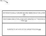
- FIG. 1is a conceptual cross-sectional view of an example device having a substrate with a selective airgap region;
- FIG. 2Ais a cross-sectional view of an example device having a substrate with a selective airgap region
- FIG. 2Bis a top-down view of an example device having a substrate with a selective airgap region
- FIG. 3is a flowchart of an example method for manufacturing a device having a substrate with a selective airgap region
- FIG. 4are cross-sectional and top-down illustrations of the example method for manufacturing illustrated by FIG. 3 ;
- FIG. 5is a flowchart of an example method for manufacturing a device having a substrate with a plurality of selective airgap regions
- FIG. 6is a cross-sectional and top-down illustrations of the example method for manufacturing illustrated by FIG. 5 .
- Heteroepitaxyis a powerful technique to integrate different materials together on a substrate for special functionalities or enhanced device performance. Heteroepitaxy is useful technique for the manufacture of various devices used in photonic and electronic computing applications. However, material property incompatibilities like differing lattice constants or thermal expansion coefficients (CTE) can result in defects in heteroepitaxially grown materials. Those defects may have a detrimental effect on microelectronic and photonic devices. These challenges contribute to the difficulty of manufacturing high-performance, reliable devices using direct bandgap compound semiconductors heteroepitaxially grown on silicon.
- CTEthermal expansion coefficients
- Example devicesmay include a first semiconductor layer disposed on a substrate.
- the first semiconductor layermay have a window cut through a face, where etching a selective airgap region in the substrate is enabled via the window.
- a second semiconductor layermay be heteroepitaxially grown on the face of the first semiconductor layer so that at least a portion of the second semiconductor layer is aligned over the selective air gap region.
- the first semiconductor layermay be elastic enough, due to the selective air gap region, to allow elastic deformation caused by the heteroepitaxial (i.e. monolithic) growth of the second semiconductor layer, thereby mitigating the strain experienced by the second semiconductor layer.
- example devicesprovide for mitigating of defects caused by heteroepitaxial growth of the second semiconductor layer without the use of wafer bonding and other limiting processes.
- FIG. 1illustrates a conceptual cross-sectional view of an example device 100 having a substrate with a selective airgap region 110 .
- Device 100may include substrate 110 , a first semiconductor layer 120 disposed on the substrate 110 , and a second semiconductor layer 130 heteroepitaxially grown on the first semiconductor layer 120 .
- Device 100may be a device or system that can be implemented in a variety of computer or network systems, such as optical computing and communications.
- Substrate 110may be a wafer or solid substance onto which other substances are adhered. Substrate 110 may serve as a foundation for microelectronic and photonic devices, and may be the base that electronic and photonic devices are deposited. Substrate 110 may, in some examples, be a thin slice of material, which may include semiconductors such as silicon and germanium, compound semiconductors such as gallium arsenide (GaAs) and indium phosphide (InP), or dielectric insulators such as silicon oxide and aluminum oxide. In some examples, substrate 110 may include multiple materials, including but not limited to the examples listed above. Furthermore, in some examples, substrate 110 may include multiple layers, with each layer having a different material.
- First semiconductor layer 120may be disposed on the substrate 110 .
- First semiconductor layer 120may be a relatively thin device layer and may have a window cut through a face of the first semiconductor layer 120 to the substrate 110 .
- the windowmay allow access to the underlying substrate 110 through the first semiconductor layer 120 , and may be defined, for example, by lithography and cut out by etching.
- the etchingmay be a chemical hydrofluoric acid (HF) etch or it may be, for example, an anisotropic deep reactive ion etch (DRIE).
- HFchemical hydrofluoric acid
- DRIEanisotropic deep reactive ion etch
- the first semiconductor layer 120can be anisotropically etched with one or more plasma gases, such as carbon tetrafloride (CF 4 ) containing fluorine ions, in a commercially available etcher, such as a parallel plate DRIE apparatus or, alternatively, an electron cyclotron resonance (ECR) plasma reactor to replicate the mask pattern of the window in first semiconductor layer 120 .
- the first semiconductor layermay comprise a variety of semiconducting materials, including but not limited to silicon, germanium, and compound semiconductors such as GaAs and InP.
- a selective airgap regionmay be etched out of the substrate 110 material between a portion of the substrate 110 and a portion of first semiconductor layer 120 .
- the selective airgap regionmay be etched out of the portion of the substrate 110 that is directly coupled to first semiconductor layer 120 .
- the selective airgapis significantly larger across the width of the substrate 110 than it is deep into the substrate 110 .
- the etching of the selective airgap regionmay be enabled by the window in first semiconductor layer 120 .
- the windowmay allow etchants used in wet etching to access the substrate 110 to etch out the selective airgap region.
- substrate 110may have a base layer and a dielectric layer.
- the first semiconductor layer 120 and the substrate 110 togethermay represent a semiconductor-on-insulator substrate, such as silicon-on-insulator (SOI).
- SOIsilicon-on-insulator
- the base layer of substrate 110 and the first semiconductor layer 120may sandwich the dielectric layer of substrate 110 .
- the selective airgap regionmay be etched out of the dielectric layer of the substrate 110 .
- Example material configurations in such examplesinclude GaAs—AlAs—GaAs, Si—SiO 2 —Si, and Si—Ge—GaAs.
- a dielectric layer of the substrate 110may have a lower refractive index than the first semiconductor layer 120 .
- the first semiconductor layer 120which is directly disposed on the dielectric layer of substrate 110 , may act as a waveguide layer for photonic communications. Because the first semiconductor layer 120 may have a higher refractive index than the dielectric layer of the substrate, an optical signal propagating within first semiconductor layer 120 above a total internal reflection angle associated with the first semiconductor layer 120 and the dielectric layer of substrate 110 may experience total internal reflection within first semiconductor layer 120 , which thereby serves as a waveguide.
- a second semiconductor layer 130may be heteroepitaxially grown on a face of the first semiconductor layer 120 so that a portion of the second semiconductor layer 130 is aligned over a selective airgap region of substrate 110 .
- Second semiconductor layer 130may be, for example, an active region of device 100 .
- second semiconductor layer 130may provide various functions for the device, including optical signal production, modulation, absorption, transport, etc.
- second semiconductor layer 130may be an electronic device such as a high speed transistor.
- Example materials for second semiconductor layer 130include GaAs and InP.
- the second semiconductor layer 130may include a stack of multiple layers, such as Ge—GaAs or Ge—GaAs—AlGaAs—GaAs. Additional example materials for the second semiconductor layer 130 include other group III-V and group II-VI direct bandgap semiconductors.
- the presence of the selective airgap region aligned with the second semiconductor layer 130may mitigate the formation and propagation of defects in the second semiconductor layer 130 .
- selective airgap regionmay allow the freestanding portions of the first semiconductor layer 120 to elastically deform to accommodate for stress generated by mismatch between first semiconductor layer 120 and second semiconductor layer 130 .
- the mismatchmay be between lattice constants and CTEs.
- first semiconductor layer 120may, in some examples, be below a critical thickness, under which defect formation is largely reduced. As a result, defect formation within first semiconductor 120 may also be mitigated.
- FIG. 2Ashows a cross-sectional view of an example device 200 having a substrate 210 with a selective airgap region 215 .
- Device 200may be analogous to device 100 of FIG. 1 .
- Device 200may be a device or system that can be implemented in a variety of computer or network systems, such as optical computing and communications.
- Substrate 210may be a foundation on which electronic and photonic devices are deposited. As illustrated by FIG. 2A , substrate 210 may include a base layer 212 and a dielectric layer 214 .
- base layer 212may include a semiconductor such as Si, Ge, GaAs, and InP.
- Dielectric layermay include example electrically insulating materials such as Al 2 O 3 , SiO 2 , SiN x , etc.
- First semiconductor layer 220may be disposed on the dielectric layer 214 of substrate 210 .
- First semiconductor layer 220may be a relatively thin device layer comprising a semiconductor such as Si, Ge, GaAs, and InP.
- base layer 212 of substrate 210 , dielectric layer 214 of substrate 210 , and first semiconductor layer 220may represent a semiconductor-on-insulator substrate.
- first semiconductor layer 220may have a window cut into a face of first semiconductor layer 220 .
- the facemay be cut through to the dielectric layer 214 of substrate 210 .
- the windowmay enable the etching of a selective airgap region 215 in the dielectric layer 214 .
- the windowmay allow access by a chemical etchant, such as HF, to the dielectric layer 214 .
- Second semiconductor layer 230may be heteroepitaxially grown on a face of the first semiconductor layer 220 so that a portion of the second semiconductor layer 230 is aligned over selective airgap region 215 of substrate 210 .
- Example materials for second semiconductor layer 130include GaAs and InP.
- the second semiconductor layer 130may include a layered stack of multiple layers, such as Ge—GaAs or Ge—GaAs—AlGaAs—GaAs. Additional example materials for the second semiconductor layer 130 include other group III-V and II-VI direct bandgap semiconductors.
- the presence of the selective airgap region 215 aligned with the second semiconductor layer 230may mitigate the formation and propagation of defects 232 in a freestanding region 235 of first semiconductor layer 220 and second semiconductor layer 230 .
- selective airgap region 215may allow the freestanding portions of the first semiconductor layer 220 to elastically deform to accommodate for stress generated by mismatch between first semiconductor layer 220 and second semiconductor layer 230 .
- the freestanding portions of second semiconductor layer 230may be less prone to defect formation and propagation.
- defects 232may form and propagate in the regions of second semiconductor layer 230 that is not part of freestanding region 235 .
- first semiconductor layer 220may be below a critical thickness, under which defect formation is largely reduced. As a result, defect formation within first semiconductor 220 may also be mitigated.
- FIG. 2Bshows top-down view of an example device 250 having a substrate with a selective airgap region.
- FIG. 2Bmay represent a top-down view of the example device 200 of FIG. 2A .
- Device 250is shown without a second semiconductor layer to illustrate the first semiconductor layer 220 .
- first semiconductor layer 220may be disposed on top of a substrate.
- the substratemay include a base layer and a dielectric layer, where the dielectric layer is directly coupled to the first semiconductor layer 220 .
- First semiconductor layer 220may have a plurality of windows 225 cut into its face.
- the windows 225may allow access to the underlying dielectric layer of the substrate through the first semiconductor layer 220 .
- first semiconductor layer 220may have one window, while in other examples, such as that shown in FIG. 2B , the first semiconductor layer 220 may have multiple windows 225 .
- the windows 225may be defined by lithography and cut out by etching.
- the windows 225may enable the etching of the selective airgap region in the dielectric layer of the substrate underneath.
- the selective airgap region 215 under first semiconductor layer 220may be emphasized in FIG. 2B by the dotted line.
- the windows 225may allow etchants used in wet etching to access the substrate below to etch out the selective airgap region 215 .
- FIG. 3depicts a flowchart of an example method 300 for manufacturing a device having a substrate with a selective airgap region.
- FIG. 3is illustrated in the examples of FIG. 4 . Accordingly, the description of FIG. 3 herein makes references to FIG. 4 . However, other suitable candidates for illustration of method 300 should be apparent, including the examples provided in FIGS. 1, 2A, and 2B .
- a first semiconductor layermay be deposited on a substrate.
- first semiconductor layer 420may be deposited on substrate 410 , which itself may include a base layer 412 and a dielectric layer 414 .
- the first semiconductor layer 420may be deposited on the substrate 410 by a variety of methods, including wafer bonding, ion beam assisted deposition, sputtering, atomic layer deposition, evaporation, and chemical vapor deposition.
- a windowmay be cut through a face of the first semiconductor layer to the substrate.
- windows 425are cut through a face of first semiconductor layer 420 .
- the windows 425may allow access to the underlying dielectric layer 414 of substrate 410 through the first semiconductor layer 420 .
- windows 425may be defined by lithography and cut out by etching.
- a selective airgap regionmay be etched, via the window, between a portion of the substrate and a portion of the first semiconductor layer.
- a selective airgap region 415may be etched in dielectric layer 414 of substrate 410 via windows 425 .
- a dielectric maskmay be deposited on portions of the first semiconductor layer where the first semiconductor layer is directly coupled to the substrate.
- the dielectric maskis deposited on the portions of the first semiconductor layer where there is no selective airgap region in the parts of the substrate directly below the portions of the first semiconductor layer.
- Dielectric mask 440is deposited on first semiconductor layer 420 where selective airgap region 415 is not underneath the first semiconductor layer.
- the dielectric mask 440may include a material that inhibits epitaxial growth, such as that to take place in operation 350 .
- dielectric mask 440may extend over a small portion of the selective airgap region 415 . This may be done for redundancy to counteract any potential defect formation in the material layers to be formed.
- a second semiconductor layermay be heteroepitaxially grown on the face of the first semiconductor layer.
- a second semiconductor layer 430is heteroepitaxially grown on the first semiconductor layer 420 .
- the second semiconductor layer 430may grow on the exposed surface of the first semiconductor layer 420 , while growth of the second semiconductor layer 430 may be inhibited in areas covered by the dielectric mask 440 . Due to the elasticity provided by the first semiconductor layer 420 , second semiconductor layer 430 , which may be completely within freestanding region 435 in this example, may be heteroepitaxially grown with mitigated defect formation.
- FIG. 5illustrates a flowchart of an example method 500 for manufacturing a device having a substrate with a plurality of selective airgap regions.
- FIG. 5is illustrated in the examples of FIG. 6 . Accordingly, the description of FIG. 5 herein makes references to FIG. 6 . However, other suitable candidates for illustration of method 500 should be apparent, including the examples provided in FIGS. 1, 2A, and 2B .
- a first semiconductor layeris deposited on a substrate.
- a plurality of windowsmay be cut through a face of the first semiconductor layer to the substrate.
- a plurality of selective airgap regionsmay be etched in the substrate via the windows cut in operation 520 .
- a dielectric maskmay be deposited on portions of the first semiconductor layer where a second semiconductor layer is not to be grown. This is illustrated in FIG. 6 step ( 540 A- 550 A). Dielectric mask 640 is deposited on the first semiconductor layer of the device to cover the areas where the second semiconductor layer 630 A is not to be grown.
- the second semiconductor layeris heteroepitaxially grown on the face of the first semiconductor layer.
- second semiconductor layer 630 Ais grown on the first semiconductor surface.
- Second semiconductor layer 630 Amay be an active device, such as a photonic device like a laser or the like.
- second semiconductor layer 630 Amay be an active electronic device such as a high speed transistor.
- FIG. 6illustrates that the defect formation in second semiconductor layer 630 A is mitigated in the areas aligned with a selective airgap region, whereas the defects are concentrated in the regions of second semiconductor layer 630 A that is directly coupled to the first semiconductor layer.
- a dielectric maskmay be deposited on portions of the first semiconductor layer where a third semiconductor layer is not to be grown. This is illustrated in FIG. 6 step ( 540 B- 550 B).
- Dielectric mask 640is deposited on the first semiconductor layer of the device to cover the areas where the third semiconductor layer 630 B is not to be grown.
- the dielectric mask 640is also deposited on top of the second semiconductor layer 630 A grown in operation 550 A so as to prevent growth of the third semiconductor layer 630 B on top of the second semiconductor layer 630 A. It should be noted that in some instances, an additional step of removing the dielectric mask 640 may be taken between the growths of subsequent semiconductor layers.
- the third semiconductor layeris heteroepitaxially grown on the face of the first semiconductor layer.
- third semiconductor layer 630 Bis grown on the first semiconductor surface.
- Third semiconductor layer 630 Bmay be an active device, such as a photonic device like a laser, modulator, waveguide, or the like.
- third semiconductor layer 630 Bmay be an active electronic device such as a high speed transistor.
- FIG. 6illustrates that the defect formation in third semiconductor layer 630 B is mitigated in the areas aligned with a selective airgap region, whereas the defects are concentrated in the regions of third semiconductor layer 630 B that is directly coupled to the first semiconductor layer.
- the final diagram in FIG. 6illustrates a top-down view of an example device manufactured by method 500 of FIG. 5 .
- a first active layer(such as what is referred to as second semiconductor layer 630 A) may be grown directly adjacent to a second active layer (such as what is referred to as third semiconductor layer 630 B).
- the active layersmay be devices of a photonic or electronic system.
- the first active layermay be an optical signal generator
- the second active layermay be a modulator that converts the optical signal produced by the first active layer into photonic communication.
Landscapes
- Engineering & Computer Science (AREA)
- Microelectronics & Electronic Packaging (AREA)
- Condensed Matter Physics & Semiconductors (AREA)
- General Physics & Mathematics (AREA)
- Manufacturing & Machinery (AREA)
- Computer Hardware Design (AREA)
- Physics & Mathematics (AREA)
- Power Engineering (AREA)
- Chemical & Material Sciences (AREA)
- Inorganic Chemistry (AREA)
- Crystallography & Structural Chemistry (AREA)
- Optical Integrated Circuits (AREA)
- Semiconductor Lasers (AREA)
Abstract
Description
Claims (20)
Applications Claiming Priority (1)
| Application Number | Priority Date | Filing Date | Title |
|---|---|---|---|
| PCT/US2016/024823WO2017171737A1 (en) | 2016-03-30 | 2016-03-30 | Devices having substrates with selective airgap regions |
Publications (2)
| Publication Number | Publication Date |
|---|---|
| US20190081139A1 US20190081139A1 (en) | 2019-03-14 |
| US11088244B2true US11088244B2 (en) | 2021-08-10 |
Family
ID=59966284
Family Applications (1)
| Application Number | Title | Priority Date | Filing Date |
|---|---|---|---|
| US16/082,268ActiveUS11088244B2 (en) | 2016-03-30 | 2016-03-30 | Devices having substrates with selective airgap regions |
Country Status (2)
| Country | Link |
|---|---|
| US (1) | US11088244B2 (en) |
| WO (1) | WO2017171737A1 (en) |
Families Citing this family (1)
| Publication number | Priority date | Publication date | Assignee | Title |
|---|---|---|---|---|
| US10541214B2 (en)* | 2018-04-27 | 2020-01-21 | Juniper Networks, Inc. | Enhanced bonding between III-V material and oxide material |
Citations (151)
| Publication number | Priority date | Publication date | Assignee | Title |
|---|---|---|---|---|
| US4408330A (en) | 1979-12-07 | 1983-10-04 | Kabushiki Kaisha Towa Giken | Field effect semiconductor laser, method of modulation thereof |
| US5294808A (en) | 1992-10-23 | 1994-03-15 | Cornell Research Foundation, Inc. | Pseudomorphic and dislocation free heteroepitaxial structures |
| US5512375A (en) | 1993-10-14 | 1996-04-30 | Intevac, Inc. | Pseudomorphic substrates |
| US5764670A (en) | 1995-02-27 | 1998-06-09 | Canon Kabushiki Kaisha | Semiconductor laser apparatus requiring no external modulator, method of driving semiconductor laser device, and optical communication system using the semiconductor laser apparatus |
| US5883009A (en) | 1996-07-31 | 1999-03-16 | Sgs-Thomson Microelectronics S.R.L. | Method of fabricating integrated semiconductor devices comprising a chemoresistive gas microsensor |
| US5981400A (en) | 1997-09-18 | 1999-11-09 | Cornell Research Foundation, Inc. | Compliant universal substrate for epitaxial growth |
| US6265321B1 (en)* | 2000-04-17 | 2001-07-24 | Chartered Semiconductor Manufacturing Ltd. | Air bridge process for forming air gaps |
| US6288426B1 (en) | 2000-02-28 | 2001-09-11 | International Business Machines Corp. | Thermal conductivity enhanced semiconductor structures and fabrication processes |
| US20020081793A1 (en)* | 2000-12-26 | 2002-06-27 | Kuk-Seung Yang | Method for fabricating a semiconductor device |
| US20020094661A1 (en) | 1999-10-01 | 2002-07-18 | Ziptronix | Three dimensional device intergration method and intergrated device |
| US6437372B1 (en) | 2000-01-07 | 2002-08-20 | Agere Systems Guardian Corp. | Diffusion barrier spikes for III-V structures |
| US20020113288A1 (en) | 1999-07-28 | 2002-08-22 | Lawrence A. Clevenger | Method and structure for providing improved thermal conduction for silicon semiconductor devices |
| US20020121337A1 (en) | 2000-07-11 | 2002-09-05 | Whatmore Roger W. | Filters |
| US6475873B1 (en) | 2000-08-04 | 2002-11-05 | Maxim Integrated Products, Inc. | Method of forming laser trimmable thin-film resistors in a fully planarized integrated circuit technology |
| US20020168837A1 (en) | 2001-05-09 | 2002-11-14 | Ibm | Method of fabricating silicon devices on sapphire with wafer bonding |
| US6492283B2 (en) | 2000-02-22 | 2002-12-10 | Asm Microchemistry Oy | Method of forming ultrathin oxide layer |
| US6493476B2 (en) | 2000-11-27 | 2002-12-10 | Teem Photonics | Apparatus and method for integrated photonic devices having gain and wavelength-selectivity |
| US20030006407A1 (en) | 1996-10-16 | 2003-01-09 | Taylor Geoff W. | Apparatus and a method of fabricating inversion channel devices with precision gate doping for a monolithic integrated circuit |
| US6515333B1 (en) | 2001-04-27 | 2003-02-04 | Advanced Micro Devices, Inc. | Removal of heat from SOI device |
| US20030025976A1 (en) | 2001-07-31 | 2003-02-06 | Torsten Wipiejewski | Tunable electro-absorption modulator |
| US6526083B1 (en) | 2001-10-09 | 2003-02-25 | Xerox Corporation | Two section blue laser diode with reduced output power droop |
| US20030058902A1 (en) | 2001-09-27 | 2003-03-27 | Wupen Yuen | Method for improving thermal efficiency of a semiconductor laser |
| US20030081642A1 (en) | 2001-10-31 | 2003-05-01 | Applied Optoelectronics, Inc. | Tunable vertical-cavity surface-emitting laser with tuning junction |
| US6585424B2 (en) | 2001-07-25 | 2003-07-01 | Motorola, Inc. | Structure and method for fabricating an electro-rheological lens |
| US20030134446A1 (en) | 2000-03-14 | 2003-07-17 | Masayoshi Koike | Production method of III nitride compound semiconductor and III nitride compound semiconductor element |
| US20030169786A1 (en) | 2001-03-15 | 2003-09-11 | Elyahou Kapon | Micro-electromechanically tunable vertical cavity photonic device and a method of fabrication thereof |
| US20030203550A1 (en) | 2002-04-25 | 2003-10-30 | Chartered Semiconductor Manufacturing Ltd. | Method of angle implant to improve transistor reverse narrow width effect |
| US20040028092A1 (en) | 2002-08-07 | 2004-02-12 | Samsung Electronics Co., Ltd. | Wavelength tunable VCSEL |
| US6706581B1 (en) | 2002-10-29 | 2004-03-16 | Taiwan Semiconductor Manufacturing Company | Dual gate dielectric scheme: SiON for high performance devices and high k for low power devices |
| US6705681B2 (en) | 2002-03-01 | 2004-03-16 | William E. Russ | Trap-door forage wagon |
| US20040081386A1 (en) | 2002-10-25 | 2004-04-29 | Morse Michael T. | Method and apparatus for modulating an optical beam with a ring resonator having a charge modulated region |
| US20040152272A1 (en) | 2001-03-23 | 2004-08-05 | Denis Fladre | Fabrication method of so1 semiconductor devices |
| US20040184502A1 (en) | 2002-12-25 | 2004-09-23 | Mamoru Miyachi | Semiconductor laser device and method of manufacturing the same |
| US20040206299A1 (en) | 1999-03-17 | 2004-10-21 | Mitsubishi Cable Industries, Ltd. | Semiconductor base and its manufacturing method, and semiconductor crystal manufacturing method |
| US20040248334A1 (en) | 2003-03-19 | 2004-12-09 | Osram Opto Semiconductors Gmbh | Method for fabricating at least one mesa or ridge structure or at least one electrically pumped region in a layer or layer sequence |
| US20040257171A1 (en) | 2003-04-18 | 2004-12-23 | Samsung Electronics Co., Ltd. | Air-gap type FBAR, duplexer using the FBAR, and fabricating methods thereof |
| US20040264530A1 (en) | 2003-06-27 | 2004-12-30 | Honeywell International Inc. | VCSEL having thermal management |
| JP2005093742A (en) | 2003-09-18 | 2005-04-07 | Nec Corp | Surface emitting laser and laser module using it |
| US20050081958A1 (en) | 2002-10-22 | 2005-04-21 | Sumitomo Mitsubishi Silicon Corporation | Pasted soi substrate, process for producing the same and semiconductor device |
| US20050106790A1 (en) | 2003-11-13 | 2005-05-19 | Kangguo Cheng | Strained silicon on a SiGe on SOI substrate |
| US6902987B1 (en) | 2000-02-16 | 2005-06-07 | Ziptronix, Inc. | Method for low temperature bonding and bonded structure |
| US20050139857A1 (en) | 2003-12-31 | 2005-06-30 | Lg Electronics Inc. | Nitride semicounductor thin film having fewer defects and method of growing the same |
| US20050207704A1 (en) | 2004-03-18 | 2005-09-22 | Honeywell International Inc. | Low loss contact structures for silicon based optical modulators and methods of manufacture |
| US20060035450A1 (en) | 2004-08-12 | 2006-02-16 | International Business Machines Corporation | Semiconductor-dielectric-semiconductor device structure fabricated by wafer bonding |
| US20060063679A1 (en) | 2004-09-17 | 2006-03-23 | Honeywell International Inc. | Semiconductor-insulator-semiconductor structure for high speed applications |
| US7087452B2 (en) | 2003-04-22 | 2006-08-08 | Intel Corporation | Edge arrangements for integrated circuit chips |
| US20060181542A1 (en) | 2005-02-15 | 2006-08-17 | Granger Edward M | Equivalent primary display |
| US7217584B2 (en) | 2004-03-18 | 2007-05-15 | Honeywell International Inc. | Bonded thin-film structures for optical modulators and methods of manufacture |
| US7231123B2 (en) | 2003-12-26 | 2007-06-12 | Canon Kabushiki Kaisha | Photonic crystal optical element and manufacturing method therefor |
| US20070275505A1 (en) | 2002-09-17 | 2007-11-29 | Wolterink Edwin M | Camera device, method of manufacturing a camera device, wafer scale package |
| US20080012145A1 (en) | 2006-07-12 | 2008-01-17 | Jeong Yel Jang | Semiconductor Device and Method for Manufacturing the Same |
| US20080018983A1 (en) | 2006-07-12 | 2008-01-24 | Fusao Ishii | Color display system for reducing a false color between each color pixel |
| US7368816B2 (en) | 2004-10-08 | 2008-05-06 | Samsung Electro-Mechanics Co., Ltd. | Micro-electro-mechanical system (MEMS) package having metal sealing member |
| US20080175294A1 (en) | 2007-01-18 | 2008-07-24 | Samsung Electronics Co., Ltd. | Semiconductor optical devices, systems and methods of manufacturing the same |
| US20080265377A1 (en)* | 2007-04-30 | 2008-10-30 | International Business Machines Corporation | Air gap with selective pinchoff using an anti-nucleation layer |
| US20080283877A1 (en)* | 2007-05-15 | 2008-11-20 | Commissariat A L'energie Atomique | Strained-channel transistor device |
| US20090080488A1 (en) | 2007-09-26 | 2009-03-26 | Nec Corporation | Surface emitting laser |
| US20090101997A1 (en) | 2005-12-20 | 2009-04-23 | Gerhard Lammel | Micromechanical Capacitive Pressure Transducer and Production Method |
| US20090110342A1 (en) | 2006-06-15 | 2009-04-30 | Lightwire, Inc. | Silicon modulator offset tuning arrangement |
| CN101467083A (en) | 2006-06-15 | 2009-06-24 | 斯欧普迪克尔股份有限公司 | Silicon modulator offset tuning arrangement |
| US20090168821A1 (en) | 2007-12-31 | 2009-07-02 | Alexander Fang | Thermal shunt for active devices on silicon-on-insulator wafers |
| CN100514099C (en) | 2006-08-30 | 2009-07-15 | 中国科学院半导体研究所 | Double electric capacity metal oxide semiconductor silicon based high speed high modulate efficiency electro optic modulator |
| US20090194152A1 (en) | 2008-02-04 | 2009-08-06 | National Taiwan University | Thin-film solar cell having hetero-junction of semiconductor and method for fabricating the same |
| US20090200636A1 (en) | 2008-02-12 | 2009-08-13 | International Business Machines Corporation | Sub-lithographic dimensioned air gap formation and related structure |
| US7579263B2 (en) | 2003-09-09 | 2009-08-25 | Stc.Unm | Threading-dislocation-free nanoheteroepitaxy of Ge on Si using self-directed touch-down of Ge through a thin SiO2 layer |
| US20090238515A1 (en) | 2008-03-19 | 2009-09-24 | David Fattal | Tunable Ring Resonator |
| US20090242935A1 (en) | 2005-11-01 | 2009-10-01 | Massachusetts Institute Of Technology | Monolithically integrated photodetectors |
| US20090263076A1 (en) | 2008-04-18 | 2009-10-22 | Sagi Mathai | Charge-Based Memory Cell For Optical Resonator Tuning |
| US20090302415A1 (en) | 2008-06-04 | 2009-12-10 | Karl-Heinz Mueller | Micro-Electromechanical System Devices |
| EP2146243A1 (en) | 2008-07-17 | 2010-01-20 | Osram Gesellschaft mit beschränkter Haftung | LED effect headlight |
| US20100060970A1 (en) | 2008-09-06 | 2010-03-11 | Sifotonics Technologies (Usa) Inc. | Electro-optic silicon modulator |
| US20100098372A1 (en) | 2006-08-24 | 2010-04-22 | Cornell Research Foundation, Inc | Electro-optical modulator |
| US20100119231A1 (en) | 2006-12-05 | 2010-05-13 | Electronics And Telecommunications Research Institute | Planar lightwave circuit (plc) device wavelength tunable light source comprising the same device and wavelength division multiplexing-passive optical network (wdm-pon) using the same light source |
| US20100140629A1 (en) | 2008-12-04 | 2010-06-10 | Lee Chi-Shen | Light-emitting diode and method for fabricating the same |
| US20100140739A1 (en) | 2008-12-04 | 2010-06-10 | Nam Joo Kim | Semiconductor Device and Fabricating Method Thereof |
| US20100215309A1 (en) | 2009-02-20 | 2010-08-26 | Sun Microsystems, Inc. | electrical contacts on top of waveguide structures for efficient optical modulation in silicon photonic devices |
| US7817881B2 (en) | 2006-06-01 | 2010-10-19 | Bing Li | Circuit architecture for electro-optic modulation based on free carrier dispersion effect and the waveguide capacitor structures for such modulator circuitry using CMOS or Bi-CMOS process |
| US7838314B2 (en) | 2005-10-21 | 2010-11-23 | Samsung Mobile Display Co., Ltd. | Organic light emitting display and method of fabricating the same |
| US20100295083A1 (en) | 2008-03-19 | 2010-11-25 | Celler George K | Substrates for monolithic optical circuits and electronic circuits |
| JP2010278396A (en) | 2009-06-01 | 2010-12-09 | Nippon Telegr & Teleph Corp <Ntt> | Direct modulation semiconductor laser |
| US7869473B2 (en) | 2008-03-21 | 2011-01-11 | Finisar Corporation | Directly modulated laser with isolated modulated gain electrode for improved frequency modulation |
| US20110026879A1 (en) | 2006-12-29 | 2011-02-03 | Massachusetts Institute Of Technology | Fabrication-tolerant waveguides and resonators |
| US20110045644A1 (en) | 2009-07-24 | 2011-02-24 | International Business Machines Corporation | Fuse link structures using film stress for programming and methods of manufacture |
| US20110064099A1 (en) | 2009-09-11 | 2011-03-17 | Coherent, Inc. | Optically-pumped external-cavity surface-emitting semiconductor lasers with front-cooled gain-structures |
| US20110073989A1 (en) | 2009-09-25 | 2011-03-31 | Haisheng Rong | Optical modulator utilizing wafer bonding technology |
| US7935559B1 (en) | 2009-12-22 | 2011-05-03 | Commissariat A L'energie Atomique Et Aux Energies Alternatives | Method for producing a non-planar microelectronic component using a cavity |
| US7949210B2 (en) | 2006-10-09 | 2011-05-24 | Colorado School Of Mines | Silicon-compatible surface plasmon optical elements |
| US20110176762A1 (en) | 2008-11-13 | 2011-07-21 | Junichi Fujikata | Optical modulator and optical modulator fabrication method |
| US20110180795A1 (en) | 2007-08-08 | 2011-07-28 | Guo-Qiang Patrick Lo | electro-optic device and a method for manufacturing the same |
| US20110188112A1 (en) | 2009-09-11 | 2011-08-04 | Stievater Todd H | Nonlinear Frequency Conversion in Nanoslot Optical Waveguides |
| US20110211786A1 (en) | 2010-03-01 | 2011-09-01 | Nec Corporation | Silicon-based electro-optic device |
| US20110293216A1 (en) | 2010-03-16 | 2011-12-01 | Cornell University | Semiconductor high-speed integrated electro-optic devices and methods |
| US8078018B2 (en) | 2006-08-31 | 2011-12-13 | Micron Technology, Inc. | Communication methods, methods of forming an interconnect, signal interconnects, integrated circuit structures, circuits, and data apparatuses |
| US20120002285A1 (en) | 2009-03-30 | 2012-01-05 | Fujitsu Limited | Optical element and method for manufacturing the same |
| CN102314057A (en) | 2010-07-05 | 2012-01-11 | 宏碁股份有限公司 | Device and method for improving rainbow effect and color sequential display |
| US20120008658A1 (en) | 2009-02-11 | 2012-01-12 | Il-Sug Chung | Hybrid vertical-cavity laser |
| US8106468B2 (en) | 2008-06-20 | 2012-01-31 | Taiwan Semiconductor Manufacturing Company, Ltd. | Process for fabricating silicon-on-nothing MOSFETs |
| US20120091463A1 (en)* | 2009-12-08 | 2012-04-19 | Panasonic Corporation | Nitride semiconductor light-emitting element and manufacturing method therefor |
| US20120119258A1 (en) | 2008-01-14 | 2012-05-17 | The Regents Of The University Of California | Vertical outgassing channels |
| US20120189239A1 (en) | 2010-12-29 | 2012-07-26 | Agency For Science, Technology And Research | Optical modulator and a method of forming the same |
| US20120257850A1 (en) | 2009-09-10 | 2012-10-11 | Nec Corporation | Electro-optical modulator |
| US8344453B2 (en) | 2007-10-18 | 2013-01-01 | Nxp B.V. | Method of manufacturing localized semiconductor-on-insulator (SOI) structures in a bulk semiconductor wafer |
| US20130009321A1 (en) | 2011-07-05 | 2013-01-10 | Sony Corporation | Semiconductor device, fabrication method for a semiconductor device and electronic apparatus |
| US20130009182A1 (en) | 2011-07-05 | 2013-01-10 | Jung Sukkoo | Non-polar substrate having hetero-structure and method for manufacturing the same, and nitride-based light emitting device using the same |
| US20130029449A1 (en) | 2008-09-24 | 2013-01-31 | Taiwan Semiconductor Manufacturing Company, Ltd. | Semiconductor Sensor Structures with Reduced Dislocation Defect Densities and Related Methods for the Same |
| US8372673B2 (en) | 2007-10-16 | 2013-02-12 | Epistar Corporation | Method of seperating two material systems |
| US20130049203A1 (en) | 2011-08-29 | 2013-02-28 | Infineon Technologies Austria Ag | Semiconductor Device with Buried Electrode |
| US20130063226A1 (en) | 2011-09-14 | 2013-03-14 | Avago Technologies Wireless Ip (Singapore) Pte. Ltd. | Double film bulk acoustic resonator having electrode edge alignments providing improved quality factor or electromechanical coupling coefficient |
| WO2013066318A1 (en) | 2011-11-01 | 2013-05-10 | Hewlett-Packard Development Company, L.P. | Direct modulated laser |
| US20130137202A1 (en) | 2009-07-07 | 2013-05-30 | International Business Machines Corporation | Temperature control device for optoelectronic devices |
| US20130147021A1 (en) | 2010-06-22 | 2013-06-13 | Teknologian Tutkimuskeskus Vtt | Multi-layer substrate structure and manufacturing method for the same |
| US20130152694A1 (en) | 2011-11-01 | 2013-06-20 | Ilkka Urvas | Sensor with vacuum cavity and method of fabrication |
| US20130155484A1 (en) | 2011-12-15 | 2013-06-20 | Luke Sweatlock | Plasmonic modulator incorporating a solid-state phase change material |
| US20130168776A1 (en) | 2012-01-03 | 2013-07-04 | International Business Machines Corporation | Complementary Metal Oxide Semiconductor (CMOS) Device Having Gate Structures Connected By A Metal Gate Conductor |
| US8488917B2 (en) | 2008-09-24 | 2013-07-16 | Cornell University | Electro-optic modulator |
| US8502279B2 (en) | 2011-05-16 | 2013-08-06 | Globalfoundries Singapore Pte. Ltd. | Nano-electro-mechanical system (NEMS) structures with actuatable semiconductor fin on bulk substrates |
| US8538206B1 (en) | 2010-05-05 | 2013-09-17 | Aurrion, Llc | Hybrid silicon electro-optic modulator |
| WO2013165376A1 (en) | 2012-04-30 | 2013-11-07 | Hewlett-Packard Development Company, L.P. | Hybrid mos optical modulator |
| WO2014021781A1 (en) | 2012-07-31 | 2014-02-06 | Agency For Science, Technology And Research | Optical light source and optical transmitter |
| US8664087B2 (en) | 2010-12-02 | 2014-03-04 | Epistar Corporation | Method of manufacturing a semiconductor structure and separating the semiconductor from a substrate |
| US8716852B2 (en) | 2012-02-17 | 2014-05-06 | Taiwan Semiconductor Manufacturing Company, Ltd. | Micro-electro mechanical systems (MEMS) having outgasing prevention structures and methods of forming the same |
| US20140141546A1 (en) | 2012-11-21 | 2014-05-22 | Samsung Electronics Co., Ltd. | Method of fabricating optoelectronic integrated circuit substrate |
| US20140177994A1 (en) | 2012-12-21 | 2014-06-26 | Alcatel-Lucent, Usa Inc. | Hybrid optical modulator for photonic integrated circuit devices |
| US20140264723A1 (en) | 2011-10-28 | 2014-09-18 | Di Liang | Devices including a diamond layer |
| US20140307997A1 (en) | 2011-12-20 | 2014-10-16 | Hanan Bar | Hybrid integration of group iii-v semiconductor devices on silicon |
| WO2014209398A1 (en) | 2013-06-28 | 2014-12-31 | Intel Corporation | Making a defect free fin based device in lateral epitaxy overgrowth region |
| US20150069418A1 (en)* | 2012-03-19 | 2015-03-12 | Seoul Viosys Co., Ltd. | Method for separating epitaxial layers and growth substrates, and semiconductor device using same |
| US9018675B2 (en) | 2009-06-09 | 2015-04-28 | International Business Machines Corporation | Heterojunction III-V photovoltaic cell fabrication |
| US20150140720A1 (en) | 2012-07-13 | 2015-05-21 | Huawei Technologies Co., Ltd. | Process for Manufacturing a Photonic Circuit with Active and Passive Structures |
| US20150144928A1 (en)* | 2013-11-26 | 2015-05-28 | The Regents Of The University Of Michigan | BURIED GRID FOR OUTCOUPLING WAVEGUIDED LIGHT IN OLEDs |
| US9059252B1 (en) | 2014-02-10 | 2015-06-16 | International Business Machines Corporation | Silicon waveguide on bulk silicon substrate and methods of forming |
| US20150179447A1 (en) | 2013-12-23 | 2015-06-25 | University Of Houston System | Flexible Single-Crystalline Semiconductor Device and Fabrication Methods Thereof |
| US20150177458A1 (en) | 2013-12-20 | 2015-06-25 | The Regents Of The University Of California | Bonding of heterogeneous material grown on silicon to a silicon photonic circuit |
| US9093428B2 (en) | 2011-08-31 | 2015-07-28 | Hewlett-Packard Development Company, L.P. | Thermal shunt |
| US20150212266A1 (en) | 2014-01-28 | 2015-07-30 | International Business Machines Corporation | Semiconductor device |
| US9240406B2 (en) | 2014-04-21 | 2016-01-19 | Globalfoundries Inc. | Precision trench capacitor |
| WO2016018285A1 (en) | 2014-07-30 | 2016-02-04 | Hewlett-Packard Development Company, L.P. | Optical waveguide resonators |
| US9269724B2 (en) | 2011-04-26 | 2016-02-23 | Stc.Unm | Semiconductor device comprising epitaxially grown semiconductor material and an air gap |
| US20160094014A1 (en) | 2014-09-30 | 2016-03-31 | Dong-Jae Shin | Hybrid Silicon Lasers on Bulk Silicon Substrates |
| US20160126381A1 (en) | 2013-05-22 | 2016-05-05 | Shih-Yuan Wang | Microstructure enhanced absorption photosensitive devices |
| US20160202504A1 (en) | 2015-01-14 | 2016-07-14 | Electronics And Telecommunications Research Institute | Electro-absorption optical modulation device and method of fabricating the same |
| WO2016122547A1 (en) | 2015-01-29 | 2016-08-04 | Hewlett Packard Enterprise Development Lp | Foster twin data structure |
| US20160238860A1 (en) | 2013-10-15 | 2016-08-18 | Hewlett-Packard Development Company, L.P. | Coupling-modulated optical resonator |
| US9509122B1 (en) | 2012-08-29 | 2016-11-29 | Aurrion, Inc. | Optical cladding layer design |
| US9570351B2 (en) | 2015-07-09 | 2017-02-14 | Hewlett Packard Enterprise Development Lp | Reusable semiconductor substrates |
| US9640531B1 (en) | 2014-01-28 | 2017-05-02 | Monolithic 3D Inc. | Semiconductor device, structure and methods |
| US20170139132A1 (en) | 2015-11-13 | 2017-05-18 | Cisco Technology ,Inc. | Silicon photonic chip with through vias |
| US20170146740A1 (en) | 2013-10-22 | 2017-05-25 | Massachusetts Institute Of Technology | Waveguide formation using cmos fabrication techniques |
| WO2017123245A1 (en) | 2016-01-15 | 2017-07-20 | Hewlett Packard Enterprise Development Lp | Multilayer device |
| US9773906B2 (en) | 2015-04-28 | 2017-09-26 | Samsung Electronics Co., Ltd. | Relaxed semiconductor layers with reduced defects and methods of forming the same |
| US20170358607A1 (en) | 2016-06-09 | 2017-12-14 | International Business Machines Corporation | Methods for forming hybrid vertical transistors |
- 2016
- 2016-03-30USUS16/082,268patent/US11088244B2/enactiveActive
- 2016-03-30WOPCT/US2016/024823patent/WO2017171737A1/ennot_activeCeased
Patent Citations (160)
| Publication number | Priority date | Publication date | Assignee | Title |
|---|---|---|---|---|
| US4408330A (en) | 1979-12-07 | 1983-10-04 | Kabushiki Kaisha Towa Giken | Field effect semiconductor laser, method of modulation thereof |
| US5294808A (en) | 1992-10-23 | 1994-03-15 | Cornell Research Foundation, Inc. | Pseudomorphic and dislocation free heteroepitaxial structures |
| US5512375A (en) | 1993-10-14 | 1996-04-30 | Intevac, Inc. | Pseudomorphic substrates |
| US5764670A (en) | 1995-02-27 | 1998-06-09 | Canon Kabushiki Kaisha | Semiconductor laser apparatus requiring no external modulator, method of driving semiconductor laser device, and optical communication system using the semiconductor laser apparatus |
| US5883009A (en) | 1996-07-31 | 1999-03-16 | Sgs-Thomson Microelectronics S.R.L. | Method of fabricating integrated semiconductor devices comprising a chemoresistive gas microsensor |
| US6849866B2 (en) | 1996-10-16 | 2005-02-01 | The University Of Connecticut | High performance optoelectronic and electronic inversion channel quantum well devices suitable for monolithic integration |
| US20030006407A1 (en) | 1996-10-16 | 2003-01-09 | Taylor Geoff W. | Apparatus and a method of fabricating inversion channel devices with precision gate doping for a monolithic integrated circuit |
| US5981400A (en) | 1997-09-18 | 1999-11-09 | Cornell Research Foundation, Inc. | Compliant universal substrate for epitaxial growth |
| US20040206299A1 (en) | 1999-03-17 | 2004-10-21 | Mitsubishi Cable Industries, Ltd. | Semiconductor base and its manufacturing method, and semiconductor crystal manufacturing method |
| US20020113288A1 (en) | 1999-07-28 | 2002-08-22 | Lawrence A. Clevenger | Method and structure for providing improved thermal conduction for silicon semiconductor devices |
| US20020094661A1 (en) | 1999-10-01 | 2002-07-18 | Ziptronix | Three dimensional device intergration method and intergrated device |
| US6437372B1 (en) | 2000-01-07 | 2002-08-20 | Agere Systems Guardian Corp. | Diffusion barrier spikes for III-V structures |
| US6902987B1 (en) | 2000-02-16 | 2005-06-07 | Ziptronix, Inc. | Method for low temperature bonding and bonded structure |
| US6492283B2 (en) | 2000-02-22 | 2002-12-10 | Asm Microchemistry Oy | Method of forming ultrathin oxide layer |
| US6288426B1 (en) | 2000-02-28 | 2001-09-11 | International Business Machines Corp. | Thermal conductivity enhanced semiconductor structures and fabrication processes |
| US20030134446A1 (en) | 2000-03-14 | 2003-07-17 | Masayoshi Koike | Production method of III nitride compound semiconductor and III nitride compound semiconductor element |
| US6265321B1 (en)* | 2000-04-17 | 2001-07-24 | Chartered Semiconductor Manufacturing Ltd. | Air bridge process for forming air gaps |
| US20020121337A1 (en) | 2000-07-11 | 2002-09-05 | Whatmore Roger W. | Filters |
| US6475873B1 (en) | 2000-08-04 | 2002-11-05 | Maxim Integrated Products, Inc. | Method of forming laser trimmable thin-film resistors in a fully planarized integrated circuit technology |
| US6493476B2 (en) | 2000-11-27 | 2002-12-10 | Teem Photonics | Apparatus and method for integrated photonic devices having gain and wavelength-selectivity |
| US20020081793A1 (en)* | 2000-12-26 | 2002-06-27 | Kuk-Seung Yang | Method for fabricating a semiconductor device |
| US20030169786A1 (en) | 2001-03-15 | 2003-09-11 | Elyahou Kapon | Micro-electromechanically tunable vertical cavity photonic device and a method of fabrication thereof |
| US20040152272A1 (en) | 2001-03-23 | 2004-08-05 | Denis Fladre | Fabrication method of so1 semiconductor devices |
| US6515333B1 (en) | 2001-04-27 | 2003-02-04 | Advanced Micro Devices, Inc. | Removal of heat from SOI device |
| US20020168837A1 (en) | 2001-05-09 | 2002-11-14 | Ibm | Method of fabricating silicon devices on sapphire with wafer bonding |
| US6585424B2 (en) | 2001-07-25 | 2003-07-01 | Motorola, Inc. | Structure and method for fabricating an electro-rheological lens |
| US20030025976A1 (en) | 2001-07-31 | 2003-02-06 | Torsten Wipiejewski | Tunable electro-absorption modulator |
| US20030058902A1 (en) | 2001-09-27 | 2003-03-27 | Wupen Yuen | Method for improving thermal efficiency of a semiconductor laser |
| US6526083B1 (en) | 2001-10-09 | 2003-02-25 | Xerox Corporation | Two section blue laser diode with reduced output power droop |
| US20030081642A1 (en) | 2001-10-31 | 2003-05-01 | Applied Optoelectronics, Inc. | Tunable vertical-cavity surface-emitting laser with tuning junction |
| US6705681B2 (en) | 2002-03-01 | 2004-03-16 | William E. Russ | Trap-door forage wagon |
| US20030203550A1 (en) | 2002-04-25 | 2003-10-30 | Chartered Semiconductor Manufacturing Ltd. | Method of angle implant to improve transistor reverse narrow width effect |
| CN1476132A (en) | 2002-08-07 | 2004-02-18 | ���ǵ�����ʽ���� | Wavelength Tunable Vertical Cavity Surface Emitting Laser Diodes |
| US20040028092A1 (en) | 2002-08-07 | 2004-02-12 | Samsung Electronics Co., Ltd. | Wavelength tunable VCSEL |
| US20070275505A1 (en) | 2002-09-17 | 2007-11-29 | Wolterink Edwin M | Camera device, method of manufacturing a camera device, wafer scale package |
| US20050081958A1 (en) | 2002-10-22 | 2005-04-21 | Sumitomo Mitsubishi Silicon Corporation | Pasted soi substrate, process for producing the same and semiconductor device |
| US20040081386A1 (en) | 2002-10-25 | 2004-04-29 | Morse Michael T. | Method and apparatus for modulating an optical beam with a ring resonator having a charge modulated region |
| US6706581B1 (en) | 2002-10-29 | 2004-03-16 | Taiwan Semiconductor Manufacturing Company | Dual gate dielectric scheme: SiON for high performance devices and high k for low power devices |
| US20040184502A1 (en) | 2002-12-25 | 2004-09-23 | Mamoru Miyachi | Semiconductor laser device and method of manufacturing the same |
| US20040248334A1 (en) | 2003-03-19 | 2004-12-09 | Osram Opto Semiconductors Gmbh | Method for fabricating at least one mesa or ridge structure or at least one electrically pumped region in a layer or layer sequence |
| US20040257171A1 (en) | 2003-04-18 | 2004-12-23 | Samsung Electronics Co., Ltd. | Air-gap type FBAR, duplexer using the FBAR, and fabricating methods thereof |
| US7087452B2 (en) | 2003-04-22 | 2006-08-08 | Intel Corporation | Edge arrangements for integrated circuit chips |
| US20040264530A1 (en) | 2003-06-27 | 2004-12-30 | Honeywell International Inc. | VCSEL having thermal management |
| US7579263B2 (en) | 2003-09-09 | 2009-08-25 | Stc.Unm | Threading-dislocation-free nanoheteroepitaxy of Ge on Si using self-directed touch-down of Ge through a thin SiO2 layer |
| JP2005093742A (en) | 2003-09-18 | 2005-04-07 | Nec Corp | Surface emitting laser and laser module using it |
| US20050106790A1 (en) | 2003-11-13 | 2005-05-19 | Kangguo Cheng | Strained silicon on a SiGe on SOI substrate |
| US7231123B2 (en) | 2003-12-26 | 2007-06-12 | Canon Kabushiki Kaisha | Photonic crystal optical element and manufacturing method therefor |
| US20050139857A1 (en) | 2003-12-31 | 2005-06-30 | Lg Electronics Inc. | Nitride semicounductor thin film having fewer defects and method of growing the same |
| US20050207704A1 (en) | 2004-03-18 | 2005-09-22 | Honeywell International Inc. | Low loss contact structures for silicon based optical modulators and methods of manufacture |
| US7217584B2 (en) | 2004-03-18 | 2007-05-15 | Honeywell International Inc. | Bonded thin-film structures for optical modulators and methods of manufacture |
| US20060035450A1 (en) | 2004-08-12 | 2006-02-16 | International Business Machines Corporation | Semiconductor-dielectric-semiconductor device structure fabricated by wafer bonding |
| US7560361B2 (en) | 2004-08-12 | 2009-07-14 | International Business Machines Corporation | Method of forming gate stack for semiconductor electronic device |
| US20060063679A1 (en) | 2004-09-17 | 2006-03-23 | Honeywell International Inc. | Semiconductor-insulator-semiconductor structure for high speed applications |
| US7368816B2 (en) | 2004-10-08 | 2008-05-06 | Samsung Electro-Mechanics Co., Ltd. | Micro-electro-mechanical system (MEMS) package having metal sealing member |
| US20060181542A1 (en) | 2005-02-15 | 2006-08-17 | Granger Edward M | Equivalent primary display |
| US7838314B2 (en) | 2005-10-21 | 2010-11-23 | Samsung Mobile Display Co., Ltd. | Organic light emitting display and method of fabricating the same |
| US20090242935A1 (en) | 2005-11-01 | 2009-10-01 | Massachusetts Institute Of Technology | Monolithically integrated photodetectors |
| US20090101997A1 (en) | 2005-12-20 | 2009-04-23 | Gerhard Lammel | Micromechanical Capacitive Pressure Transducer and Production Method |
| US7817881B2 (en) | 2006-06-01 | 2010-10-19 | Bing Li | Circuit architecture for electro-optic modulation based on free carrier dispersion effect and the waveguide capacitor structures for such modulator circuitry using CMOS or Bi-CMOS process |
| US20090110342A1 (en) | 2006-06-15 | 2009-04-30 | Lightwire, Inc. | Silicon modulator offset tuning arrangement |
| CN101467083A (en) | 2006-06-15 | 2009-06-24 | 斯欧普迪克尔股份有限公司 | Silicon modulator offset tuning arrangement |
| US20080018983A1 (en) | 2006-07-12 | 2008-01-24 | Fusao Ishii | Color display system for reducing a false color between each color pixel |
| US20080012145A1 (en) | 2006-07-12 | 2008-01-17 | Jeong Yel Jang | Semiconductor Device and Method for Manufacturing the Same |
| US20100098372A1 (en) | 2006-08-24 | 2010-04-22 | Cornell Research Foundation, Inc | Electro-optical modulator |
| CN100514099C (en) | 2006-08-30 | 2009-07-15 | 中国科学院半导体研究所 | Double electric capacity metal oxide semiconductor silicon based high speed high modulate efficiency electro optic modulator |
| US8078018B2 (en) | 2006-08-31 | 2011-12-13 | Micron Technology, Inc. | Communication methods, methods of forming an interconnect, signal interconnects, integrated circuit structures, circuits, and data apparatuses |
| US7949210B2 (en) | 2006-10-09 | 2011-05-24 | Colorado School Of Mines | Silicon-compatible surface plasmon optical elements |
| US20100119231A1 (en) | 2006-12-05 | 2010-05-13 | Electronics And Telecommunications Research Institute | Planar lightwave circuit (plc) device wavelength tunable light source comprising the same device and wavelength division multiplexing-passive optical network (wdm-pon) using the same light source |
| US20110026879A1 (en) | 2006-12-29 | 2011-02-03 | Massachusetts Institute Of Technology | Fabrication-tolerant waveguides and resonators |
| US20080175294A1 (en) | 2007-01-18 | 2008-07-24 | Samsung Electronics Co., Ltd. | Semiconductor optical devices, systems and methods of manufacturing the same |
| US20080265377A1 (en)* | 2007-04-30 | 2008-10-30 | International Business Machines Corporation | Air gap with selective pinchoff using an anti-nucleation layer |
| US20080283877A1 (en)* | 2007-05-15 | 2008-11-20 | Commissariat A L'energie Atomique | Strained-channel transistor device |
| US20110180795A1 (en) | 2007-08-08 | 2011-07-28 | Guo-Qiang Patrick Lo | electro-optic device and a method for manufacturing the same |
| US20090080488A1 (en) | 2007-09-26 | 2009-03-26 | Nec Corporation | Surface emitting laser |
| US8372673B2 (en) | 2007-10-16 | 2013-02-12 | Epistar Corporation | Method of seperating two material systems |
| US8344453B2 (en) | 2007-10-18 | 2013-01-01 | Nxp B.V. | Method of manufacturing localized semiconductor-on-insulator (SOI) structures in a bulk semiconductor wafer |
| US7639719B2 (en) | 2007-12-31 | 2009-12-29 | Intel Corporation | Thermal shunt for active devices on silicon-on-insulator wafers |
| US20090168821A1 (en) | 2007-12-31 | 2009-07-02 | Alexander Fang | Thermal shunt for active devices on silicon-on-insulator wafers |
| US20120119258A1 (en) | 2008-01-14 | 2012-05-17 | The Regents Of The University Of California | Vertical outgassing channels |
| US20090194152A1 (en) | 2008-02-04 | 2009-08-06 | National Taiwan University | Thin-film solar cell having hetero-junction of semiconductor and method for fabricating the same |
| US20090200636A1 (en) | 2008-02-12 | 2009-08-13 | International Business Machines Corporation | Sub-lithographic dimensioned air gap formation and related structure |
| US20100295083A1 (en) | 2008-03-19 | 2010-11-25 | Celler George K | Substrates for monolithic optical circuits and electronic circuits |
| US20090238515A1 (en) | 2008-03-19 | 2009-09-24 | David Fattal | Tunable Ring Resonator |
| US7869473B2 (en) | 2008-03-21 | 2011-01-11 | Finisar Corporation | Directly modulated laser with isolated modulated gain electrode for improved frequency modulation |
| US20090263076A1 (en) | 2008-04-18 | 2009-10-22 | Sagi Mathai | Charge-Based Memory Cell For Optical Resonator Tuning |
| US20090302415A1 (en) | 2008-06-04 | 2009-12-10 | Karl-Heinz Mueller | Micro-Electromechanical System Devices |
| US8106468B2 (en) | 2008-06-20 | 2012-01-31 | Taiwan Semiconductor Manufacturing Company, Ltd. | Process for fabricating silicon-on-nothing MOSFETs |
| EP2146243A1 (en) | 2008-07-17 | 2010-01-20 | Osram Gesellschaft mit beschränkter Haftung | LED effect headlight |
| US20100060970A1 (en) | 2008-09-06 | 2010-03-11 | Sifotonics Technologies (Usa) Inc. | Electro-optic silicon modulator |
| US20130029449A1 (en) | 2008-09-24 | 2013-01-31 | Taiwan Semiconductor Manufacturing Company, Ltd. | Semiconductor Sensor Structures with Reduced Dislocation Defect Densities and Related Methods for the Same |
| US8488917B2 (en) | 2008-09-24 | 2013-07-16 | Cornell University | Electro-optic modulator |
| US20110176762A1 (en) | 2008-11-13 | 2011-07-21 | Junichi Fujikata | Optical modulator and optical modulator fabrication method |
| US20100140629A1 (en) | 2008-12-04 | 2010-06-10 | Lee Chi-Shen | Light-emitting diode and method for fabricating the same |
| US20100140739A1 (en) | 2008-12-04 | 2010-06-10 | Nam Joo Kim | Semiconductor Device and Fabricating Method Thereof |
| US20120008658A1 (en) | 2009-02-11 | 2012-01-12 | Il-Sug Chung | Hybrid vertical-cavity laser |
| US20100215309A1 (en) | 2009-02-20 | 2010-08-26 | Sun Microsystems, Inc. | electrical contacts on top of waveguide structures for efficient optical modulation in silicon photonic devices |
| US20120002285A1 (en) | 2009-03-30 | 2012-01-05 | Fujitsu Limited | Optical element and method for manufacturing the same |
| JP2010278396A (en) | 2009-06-01 | 2010-12-09 | Nippon Telegr & Teleph Corp <Ntt> | Direct modulation semiconductor laser |
| US9018675B2 (en) | 2009-06-09 | 2015-04-28 | International Business Machines Corporation | Heterojunction III-V photovoltaic cell fabrication |
| US20130137202A1 (en) | 2009-07-07 | 2013-05-30 | International Business Machines Corporation | Temperature control device for optoelectronic devices |
| US20110045644A1 (en) | 2009-07-24 | 2011-02-24 | International Business Machines Corporation | Fuse link structures using film stress for programming and methods of manufacture |
| US20120257850A1 (en) | 2009-09-10 | 2012-10-11 | Nec Corporation | Electro-optical modulator |
| US20110188112A1 (en) | 2009-09-11 | 2011-08-04 | Stievater Todd H | Nonlinear Frequency Conversion in Nanoslot Optical Waveguides |
| US20110064099A1 (en) | 2009-09-11 | 2011-03-17 | Coherent, Inc. | Optically-pumped external-cavity surface-emitting semiconductor lasers with front-cooled gain-structures |
| US20110073989A1 (en) | 2009-09-25 | 2011-03-31 | Haisheng Rong | Optical modulator utilizing wafer bonding technology |
| US20120091463A1 (en)* | 2009-12-08 | 2012-04-19 | Panasonic Corporation | Nitride semiconductor light-emitting element and manufacturing method therefor |
| US7935559B1 (en) | 2009-12-22 | 2011-05-03 | Commissariat A L'energie Atomique Et Aux Energies Alternatives | Method for producing a non-planar microelectronic component using a cavity |
| US20110211786A1 (en) | 2010-03-01 | 2011-09-01 | Nec Corporation | Silicon-based electro-optic device |
| US20110293216A1 (en) | 2010-03-16 | 2011-12-01 | Cornell University | Semiconductor high-speed integrated electro-optic devices and methods |
| US8538206B1 (en) | 2010-05-05 | 2013-09-17 | Aurrion, Llc | Hybrid silicon electro-optic modulator |
| US20130147021A1 (en) | 2010-06-22 | 2013-06-13 | Teknologian Tutkimuskeskus Vtt | Multi-layer substrate structure and manufacturing method for the same |
| CN102314057B (en) | 2010-07-05 | 2014-05-07 | 宏碁股份有限公司 | Device and method for improving rainbow effect and color sequential display |
| CN102314057A (en) | 2010-07-05 | 2012-01-11 | 宏碁股份有限公司 | Device and method for improving rainbow effect and color sequential display |
| US8664087B2 (en) | 2010-12-02 | 2014-03-04 | Epistar Corporation | Method of manufacturing a semiconductor structure and separating the semiconductor from a substrate |
| US20120189239A1 (en) | 2010-12-29 | 2012-07-26 | Agency For Science, Technology And Research | Optical modulator and a method of forming the same |
| US9110314B2 (en) | 2010-12-29 | 2015-08-18 | Agency For Science, Technology And Research | Optical modulator and a method of forming the same |
| US9269724B2 (en) | 2011-04-26 | 2016-02-23 | Stc.Unm | Semiconductor device comprising epitaxially grown semiconductor material and an air gap |
| US8502279B2 (en) | 2011-05-16 | 2013-08-06 | Globalfoundries Singapore Pte. Ltd. | Nano-electro-mechanical system (NEMS) structures with actuatable semiconductor fin on bulk substrates |
| US20130009321A1 (en) | 2011-07-05 | 2013-01-10 | Sony Corporation | Semiconductor device, fabrication method for a semiconductor device and electronic apparatus |
| US20130009182A1 (en) | 2011-07-05 | 2013-01-10 | Jung Sukkoo | Non-polar substrate having hetero-structure and method for manufacturing the same, and nitride-based light emitting device using the same |
| US20130049203A1 (en) | 2011-08-29 | 2013-02-28 | Infineon Technologies Austria Ag | Semiconductor Device with Buried Electrode |
| US9093428B2 (en) | 2011-08-31 | 2015-07-28 | Hewlett-Packard Development Company, L.P. | Thermal shunt |
| US20130063226A1 (en) | 2011-09-14 | 2013-03-14 | Avago Technologies Wireless Ip (Singapore) Pte. Ltd. | Double film bulk acoustic resonator having electrode edge alignments providing improved quality factor or electromechanical coupling coefficient |
| US20140264723A1 (en) | 2011-10-28 | 2014-09-18 | Di Liang | Devices including a diamond layer |
| US8937981B2 (en) | 2011-11-01 | 2015-01-20 | Hewlett-Packard Development Company, L.P. | Direct modulated laser |
| WO2013066318A1 (en) | 2011-11-01 | 2013-05-10 | Hewlett-Packard Development Company, L.P. | Direct modulated laser |
| US20130152694A1 (en) | 2011-11-01 | 2013-06-20 | Ilkka Urvas | Sensor with vacuum cavity and method of fabrication |
| US20130155484A1 (en) | 2011-12-15 | 2013-06-20 | Luke Sweatlock | Plasmonic modulator incorporating a solid-state phase change material |
| US20140307997A1 (en) | 2011-12-20 | 2014-10-16 | Hanan Bar | Hybrid integration of group iii-v semiconductor devices on silicon |
| US20130168776A1 (en) | 2012-01-03 | 2013-07-04 | International Business Machines Corporation | Complementary Metal Oxide Semiconductor (CMOS) Device Having Gate Structures Connected By A Metal Gate Conductor |
| US8716852B2 (en) | 2012-02-17 | 2014-05-06 | Taiwan Semiconductor Manufacturing Company, Ltd. | Micro-electro mechanical systems (MEMS) having outgasing prevention structures and methods of forming the same |
| US20150069418A1 (en)* | 2012-03-19 | 2015-03-12 | Seoul Viosys Co., Ltd. | Method for separating epitaxial layers and growth substrates, and semiconductor device using same |
| WO2013165376A1 (en) | 2012-04-30 | 2013-11-07 | Hewlett-Packard Development Company, L.P. | Hybrid mos optical modulator |
| US20150055910A1 (en) | 2012-04-30 | 2015-02-26 | Hewlett-Packard Development Company, L.P. | Hybrid mos optical modulator |
| US20150140720A1 (en) | 2012-07-13 | 2015-05-21 | Huawei Technologies Co., Ltd. | Process for Manufacturing a Photonic Circuit with Active and Passive Structures |
| WO2014021781A1 (en) | 2012-07-31 | 2014-02-06 | Agency For Science, Technology And Research | Optical light source and optical transmitter |
| US20170077325A1 (en) | 2012-08-29 | 2017-03-16 | Erik Johan Norberg | Optical cladding layer design |
| US9509122B1 (en) | 2012-08-29 | 2016-11-29 | Aurrion, Inc. | Optical cladding layer design |
| US20140141546A1 (en) | 2012-11-21 | 2014-05-22 | Samsung Electronics Co., Ltd. | Method of fabricating optoelectronic integrated circuit substrate |
| US20140177994A1 (en) | 2012-12-21 | 2014-06-26 | Alcatel-Lucent, Usa Inc. | Hybrid optical modulator for photonic integrated circuit devices |
| US20160126381A1 (en) | 2013-05-22 | 2016-05-05 | Shih-Yuan Wang | Microstructure enhanced absorption photosensitive devices |
| WO2014209398A1 (en) | 2013-06-28 | 2014-12-31 | Intel Corporation | Making a defect free fin based device in lateral epitaxy overgrowth region |
| US20160238860A1 (en) | 2013-10-15 | 2016-08-18 | Hewlett-Packard Development Company, L.P. | Coupling-modulated optical resonator |
| US20170146740A1 (en) | 2013-10-22 | 2017-05-25 | Massachusetts Institute Of Technology | Waveguide formation using cmos fabrication techniques |
| US20150144928A1 (en)* | 2013-11-26 | 2015-05-28 | The Regents Of The University Of Michigan | BURIED GRID FOR OUTCOUPLING WAVEGUIDED LIGHT IN OLEDs |
| US20150177458A1 (en) | 2013-12-20 | 2015-06-25 | The Regents Of The University Of California | Bonding of heterogeneous material grown on silicon to a silicon photonic circuit |
| US20150179447A1 (en) | 2013-12-23 | 2015-06-25 | University Of Houston System | Flexible Single-Crystalline Semiconductor Device and Fabrication Methods Thereof |
| US20150212266A1 (en) | 2014-01-28 | 2015-07-30 | International Business Machines Corporation | Semiconductor device |
| US9640531B1 (en) | 2014-01-28 | 2017-05-02 | Monolithic 3D Inc. | Semiconductor device, structure and methods |
| US9059252B1 (en) | 2014-02-10 | 2015-06-16 | International Business Machines Corporation | Silicon waveguide on bulk silicon substrate and methods of forming |
| US9240406B2 (en) | 2014-04-21 | 2016-01-19 | Globalfoundries Inc. | Precision trench capacitor |
| WO2016018285A1 (en) | 2014-07-30 | 2016-02-04 | Hewlett-Packard Development Company, L.P. | Optical waveguide resonators |
| US20160094014A1 (en) | 2014-09-30 | 2016-03-31 | Dong-Jae Shin | Hybrid Silicon Lasers on Bulk Silicon Substrates |
| US20160202504A1 (en) | 2015-01-14 | 2016-07-14 | Electronics And Telecommunications Research Institute | Electro-absorption optical modulation device and method of fabricating the same |
| WO2016122547A1 (en) | 2015-01-29 | 2016-08-04 | Hewlett Packard Enterprise Development Lp | Foster twin data structure |
| US9773906B2 (en) | 2015-04-28 | 2017-09-26 | Samsung Electronics Co., Ltd. | Relaxed semiconductor layers with reduced defects and methods of forming the same |
| US9570351B2 (en) | 2015-07-09 | 2017-02-14 | Hewlett Packard Enterprise Development Lp | Reusable semiconductor substrates |
| US20170139132A1 (en) | 2015-11-13 | 2017-05-18 | Cisco Technology ,Inc. | Silicon photonic chip with through vias |
| WO2017123245A1 (en) | 2016-01-15 | 2017-07-20 | Hewlett Packard Enterprise Development Lp | Multilayer device |
| US20170358607A1 (en) | 2016-06-09 | 2017-12-14 | International Business Machines Corporation | Methods for forming hybrid vertical transistors |
Non-Patent Citations (51)
| Title |
|---|
| A. Liu et al., Optics Express, Jan. 22, 2007, vol. 15, No. 2, pp. 660-668. |
| Alexander W. Fang "Electrically pumped hybrid AlGalnAs-silicon evanescent laser" Optical Society of America, Oct. 2, 2016/ vol. 14, No. 20/Optics Express, pp. 9203-9210. |
| Ansheng Liu et al, "A High-Speed Silicon Optical Modulator Based on a Metal-Oxide-Semiconductor Capacitor," Nature-427, Feb. 12, 2004, Nature Publishing Group, pp. 615-618. |
| Basak, J. et al., Developments in Gigascale Silicon Optical Modulators Using Free Carrier Dispersion Mechanisms, Apr. 15, 2008, Advances in Optical Technologies, vol. 2008, 10 pages. |
| Caglar Duman etl al. "Comparative modeling results for ridge waveguide MOW and hybrid Si/III-V lasers" Journal of radiation research and applied sciences, Nov. 17, 2017, pp. 1-5. |
| D. Dai et al., High speed modulation of hybrid silicon evanescent lasers, IPNRA, Jul. 12 2009. paper IMC1. |
| Delphine Marris-Morini et al., "D006—State of the art on Photonics on CMOS," Nov. 30, 2009, pp. 1-70, Available at: <helios-project.eu/content/download/326/2147/tile/HELIOS.sub.—D006.pd- f>. |
| European Search Report and Search Opinion Received for EP Application No. 11871524.2, dated Jul. 16, 2015, 8 pages. |
| European Search Report and Search Opinion Received for EP Application No. 118751110, dated Jul. 30, 2015, 3 pages. |
| G. Morthier et al., "Microdisk Lasers Heterogeneously Integrated on Silicon for Low-Power, High-Speed Optical Switching," Photonics Society Newsletter, Jun. 2010, vol. 24, Issue 3, pp. 5-10, IEEE, Available at: <lecture.ecc.u-tokyo.ac.jp/.about.tlecwada/Optics%20&%20Photonics/pres- entation%20files/paper9.pdf>. |
| Google search (hybrid laser, waveguide, substrate) pp. 1-2. |
| Gosh, S., et al; "Experimental and Theoretical Investigation of Thermal Stress Relief During Epitaxial Growth of Ge on Si Using Air-gapped Sio2 Nanotemplates"; Oct. 2011; 9 pages. |
| Gosh, S., et al; "Investigations on Thermal Stress Relief Mechanism Using Air-gapped Sio2 Nanotemplates During Epitaxial Growth of Ge on Si and Corresponding Hole Mobility Improvement"; Apr. 20, 2012; 4 pages. |
| Haataja, M. et at: "Dislocations and Morphological Instabilities: Continuum Modeling of Misfitting Heteroepitaxial Films"; Apr. 5, 2002; 20 pages. |
| Hirakawa. K. et al., High Resolution Subpixel and Subframe Rendering for Color Flatpanel and Projector Displays, 2011 18th IEEE International Conference, Sep. 11-14, 2011, pp. 1725-1728. |
| Impact of Interfacial Layer and Transition Region on Gate Current Performance for High-K Gate Dielectric Stack: Its Trade off With Gate Capacitance, (Research Paper), Electron Devices, IEEE Transacfons on 50.2, Mar. 2003, pp, 433-439. |
| International Preliminary Report on Patentability received for PCT Application No. PCT/US2012/035893, dated Nov. 13, 2014, 7 pages. |
| International Preliminary Report on Patentability received for PCT Application No. PCT/US2016/013605, dated Jul. 26, 2018, 9 pages. |
| International Preliminary Report on Patentability received for PCT Patent Application No. PCT/US16/24823, dated Oct. 11, 2018, 9 pages. |
| International Preliminary Report on Patentability received for PCT Patent Application No. PCT/US2011/050083, dated Mar. 13, 2014, 6 pages. |
| International Preliminary Report on Patentability received for PCT Patent Application No. PCT/US2011/058756, dated May 15, 2014, 5 pages. |
| International Preliminary Report on Patentability received for PCT Patent Application No. PCT/US2014/048818, dated Feb. 9, 2017, 10 pages. |
| International Preliminary Report on Patentability received for PCT Patent Application No. PCT/US2014/048833, dated Feb. 9, 2017, 7 pages. |
| International Preliminary Report on Patentability received for PCT Patent Application No. PCT/US2015/048365, dated Mar. 15, 2018, 10 pages. |
| International Search Report and Written Opinion received for PCT Application No. PCT/US2016/013605, dated Oct. 13, 2016, 10 pages. |
| International Search Report and Written Opinion received for PCT Patent Application No. PCT/US16/24823, dated Dec. 26, 2016, 10 pages. |
| International Search Report and Written Opinion received for PCT Patent Application No. PCT/US19/29478, dated Aug. 27, 2019, 13 pages. |
| International Search Report and Written Opinion received for PCT Patent Application No. PCT/US2011/050083, dated May 1, 2012, 7 pages. |
| International Search Report and Written Opinion received for PCT Patent Application No. PCT/US2011/058756, dated Aug. 27, 2012, 6 pages. |
| International Search Report and Written Opinion received for PCT Patent Application No. PCT/US2012/035893, dated Dec. 26, 2012, 8 pages. |
| International Search Report and Written Opinion received for PCT Patent Application No. PCT/US2014/048818, dated Apr. 22, 2015, 11 pages. |
| International Search Report and Written Opinion received for PCT Patent Application No. PCT/US2014/048833, dated Apr. 29, 2015, 9 pages. |
| International Search Report and Written Opinion received for PCT Patent Application No. PCT/US2015/048365, dated May 30, 2016, 11 pages. |
| Jeong, Y-K et al.; "High Quality High-k MIM Capacitor by Ta2O5/HfO2/Ta2O5 Multi-layered Dielectric and NH3 Plasma Interface Treatments for Mixed-Signal/RF Applications,"; Jun. 15-17, 2004: pp. 222-223. |
| Kissinger et al., "Void-free silicon-wafer-bond strengthening in the 200-400 ° C. range", Sens. Actuators. A 36, 1993, pp. 149-156. |
| Kuldeep Amarnath, "Active Microring and Microdisk Optical Resonators on Indium Phosphide," Dissertation, 2006, pp. 1-163, Available at: <drum.lib.umd.edu/bitstream/1903/3513/1/umi-umd-3343.pdf>. |
| Li, J., "Wafer Scale Fiexible Interconnect Fabrication for Heierogeneous Integration," (Doctoral Dissertation), TU Delft, Deifl University of Technology, Oct. 26, 2015, 94 pages. |
| Liang D et al: "Optimization of Hybrid Silicon Microring Lasers", IEEE Photonics Journal, IEEE, USA, vol. 3, No. 3, Jun. 28, 2011 (Jun. 28, 2011), pp. 580-587. |
| Liang et al, "Highly efficient vertical outgassing channels for low-temperature InP-to-silicon direct wafer bonding on the silicon-on-insulator substrate"; 2008; pp. 1560-1568. |
| Liang, D., "III-V-on-Silicon Hybrid Integration, Materials, Devices, and Applications," IEEE Winter Topicals, 2011, pp. 151-152. |
| Martijn J.R. Heck et ,al., "Hybrid Silicon Photonics for Optical Interconnects," IEEE Journal of Selected Topics in Quantum Electronics, Aug. 13, 2010, pp. 1-14. |
| Masahiro Yanagisawa et al. "Film-Level hybrid integration of AlGaAs laser diode with glass waveguide on Si substrate" IEEEPhotonics Technology Letters, vol. 4, No. 1, Jan. 1992, pp. 21-23. |
| Partial Supplementary European Search Report received in EP Application No. 12875835.6, dated Oct. 11, 2015, 6 pages. |
| Supplementary European Search Report and Search Opinion Received for EP Application No. 12875835.6, dated Feb. 18, 2016, 14 pages. |
| Sysak et al., "Hybrid Silicon Laser Technology: A Thermal Perspective," Selected Topics in Quantum Electronics, IEEE Journal of 17.6, 2011, pp. 1490-1498. |
| Xianshu Luo et al. "High-throughput multiple dies-to-wafer bonding technology and III/V-on-Si hybrid laser for heterogeneous integration of optoelectronic integrated circuits" www.Frontiersin.org published Apr. 7, 2015, pp. 1-22. |
| Xiaonan Chen et al., "Active Transmission Control Based on Photonic-Crystal MOS Capacitor," Photonic Crystal Materials and Devices VI, Jan. 23, 2007, Proc. of SPIE vol. 6480 pp. 1-9. |
| Y. Tang et al., Optics Express, Mar. 28, 2011, vol. 9, No. 7, pp. 5811-5816. |
| Youngho Jung et al. "Hybrid integration of III-V semiconductor lasers on silicon waveguides using optofluidic microbubble manipulation" Scientific Reports www.nature.com/scientificreports, published Jul. 19, 2016, pp. 1-7. |
| Yu Xia, "Tetracene air-gap single-crystal field-effect transistors." Applied Physics Letters 90, 162106, 2007, 3 pages, <http://rogers.matse.illinois.edu/files/2007/tetraceneapl.pdf>. |
| Zhiping Zhou et al. "On-chip light sources for silicon photonics" Light: Science & Applications, www.natrure.com/lsa Aug. 5, 2015, pp. 1-13. |
Also Published As
| Publication number | Publication date |
|---|---|
| US20190081139A1 (en) | 2019-03-14 |
| WO2017171737A1 (en) | 2017-10-05 |
Similar Documents
| Publication | Publication Date | Title |
|---|---|---|
| US20200194559A1 (en) | Lattice-Mismatched Semiconductor Structures with Reduced Dislocation Defect Densities and Related Methods for Device Fabrication | |
| US10690853B2 (en) | Optoelectronics integration using semiconductor on insulator substrate | |
| US9379204B2 (en) | Lattice matched aspect ratio trapping to reduce defects in III-V layer directly grown on silicon | |
| US8664084B2 (en) | Method for making a thin-film element | |
| US7687378B2 (en) | Fabricating method of nitride semiconductor substrate and composite material substrate | |
| EP3785294B1 (en) | Device including structure over airgap | |
| US20130105860A1 (en) | Lattice-Mismatched Semiconductor Structures with Reduced Dislocation Defect Densities and Related Methods for Device Fabrication | |
| US20210265528A1 (en) | Silicon-based substrate, substrate, manufacturing method thereof, and optoelectronic device | |
| KR20030045936A (en) | Method of forming soi type substrate | |
| JP6264675B2 (en) | Silicon-on-insulator (SOI) substrate manufacturing method and SOI substrate | |
| WO2008076171A1 (en) | Method of transferring strained semiconductor structures | |
| US20150130017A1 (en) | Semiconductor device and method of making the device | |
| US11088244B2 (en) | Devices having substrates with selective airgap regions | |
| US8263984B2 (en) | Process for making a GaN substrate | |
| US20240282775A1 (en) | Method for forming semiconductor-on-insulator (soi) substrate | |
| Turala et al. | Isolation of III‐V/Ge Multijunction Solar Cells by Wet Etching | |
| CN105745737B (en) | Planar Heterogeneous Devices | |
| CN103021812B (en) | A kind of preparation method of III-V OI structure | |
| TWI755529B (en) | Atomic layer deposition bonding for heterogeneous integration of photonics and electronics | |
| KR20020055475A (en) | Method of fusion for heteroepitaxial layers and overgrowth thereon | |
| JP2000058454A (en) | Forming method of mask for lateral direction epitaxial growth and lateral direction epitaxial growth method | |
| US20190296181A1 (en) | Aluminum gallium arsenide and indium gallium phosphide power converter on silicon | |
| CN118712885A (en) | A method for preparing silicon-based thin film crystal based on silicon wafer heteroepitaxial growth | |
| Huangfu et al. | Monolithic integration of III–V devices with silicon photonics on a modified SOI platform | |
| Turala et al. | Research Article Isolation of III-V/Ge Multijunction Solar Cells by Wet Etching |
Legal Events
| Date | Code | Title | Description |
|---|---|---|---|
| AS | Assignment | Owner name:HEWLETT PACKARD ENTERPRISE DEVELOPMENT LP, TEXAS Free format text:ASSIGNMENT OF ASSIGNORS INTEREST;ASSIGNOR:LIANG, DI;REEL/FRAME:046783/0684 Effective date:20160329 | |
| FEPP | Fee payment procedure | Free format text:ENTITY STATUS SET TO UNDISCOUNTED (ORIGINAL EVENT CODE: BIG.); ENTITY STATUS OF PATENT OWNER: LARGE ENTITY | |
| STPP | Information on status: patent application and granting procedure in general | Free format text:DOCKETED NEW CASE - READY FOR EXAMINATION | |
| STPP | Information on status: patent application and granting procedure in general | Free format text:NON FINAL ACTION MAILED | |
| STPP | Information on status: patent application and granting procedure in general | Free format text:RESPONSE TO NON-FINAL OFFICE ACTION ENTERED AND FORWARDED TO EXAMINER | |
| STPP | Information on status: patent application and granting procedure in general | Free format text:RESPONSE TO NON-FINAL OFFICE ACTION ENTERED AND FORWARDED TO EXAMINER | |
| STPP | Information on status: patent application and granting procedure in general | Free format text:NOTICE OF ALLOWANCE MAILED -- APPLICATION RECEIVED IN OFFICE OF PUBLICATIONS | |
| STPP | Information on status: patent application and granting procedure in general | Free format text:PUBLICATIONS -- ISSUE FEE PAYMENT VERIFIED | |
| STCF | Information on status: patent grant | Free format text:PATENTED CASE | |
| MAFP | Maintenance fee payment | Free format text:PAYMENT OF MAINTENANCE FEE, 4TH YEAR, LARGE ENTITY (ORIGINAL EVENT CODE: M1551); ENTITY STATUS OF PATENT OWNER: LARGE ENTITY Year of fee payment:4 |