US11086725B2 - Orchestration of heterogeneous multi-role applications - Google Patents
Orchestration of heterogeneous multi-role applicationsDownload PDFInfo
- Publication number
- US11086725B2 US11086725B2US16/363,907US201916363907AUS11086725B2US 11086725 B2US11086725 B2US 11086725B2US 201916363907 AUS201916363907 AUS 201916363907AUS 11086725 B2US11086725 B2US 11086725B2
- Authority
- US
- United States
- Prior art keywords
- snapshot
- objects
- application
- clone
- storage
- Prior art date
- Legal status (The legal status is an assumption and is not a legal conclusion. Google has not performed a legal analysis and makes no representation as to the accuracy of the status listed.)
- Active, expires
Links
Images


Classifications
- G—PHYSICS
- G06—COMPUTING OR CALCULATING; COUNTING
- G06F—ELECTRIC DIGITAL DATA PROCESSING
- G06F16/00—Information retrieval; Database structures therefor; File system structures therefor
- G06F16/10—File systems; File servers
- G06F16/11—File system administration, e.g. details of archiving or snapshots
- G06F16/128—Details of file system snapshots on the file-level, e.g. snapshot creation, administration, deletion
- G—PHYSICS
- G06—COMPUTING OR CALCULATING; COUNTING
- G06F—ELECTRIC DIGITAL DATA PROCESSING
- G06F11/00—Error detection; Error correction; Monitoring
- G06F11/07—Responding to the occurrence of a fault, e.g. fault tolerance
- G06F11/14—Error detection or correction of the data by redundancy in operation
- G06F11/1402—Saving, restoring, recovering or retrying
- G06F11/1446—Point-in-time backing up or restoration of persistent data
- G06F11/1448—Management of the data involved in backup or backup restore
- G06F11/1451—Management of the data involved in backup or backup restore by selection of backup contents
- G—PHYSICS
- G06—COMPUTING OR CALCULATING; COUNTING
- G06F—ELECTRIC DIGITAL DATA PROCESSING
- G06F11/00—Error detection; Error correction; Monitoring
- G06F11/07—Responding to the occurrence of a fault, e.g. fault tolerance
- G06F11/14—Error detection or correction of the data by redundancy in operation
- G06F11/1402—Saving, restoring, recovering or retrying
- G06F11/1446—Point-in-time backing up or restoration of persistent data
- G06F11/1458—Management of the backup or restore process
- G06F11/1464—Management of the backup or restore process for networked environments
- G—PHYSICS
- G06—COMPUTING OR CALCULATING; COUNTING
- G06F—ELECTRIC DIGITAL DATA PROCESSING
- G06F11/00—Error detection; Error correction; Monitoring
- G06F11/07—Responding to the occurrence of a fault, e.g. fault tolerance
- G06F11/14—Error detection or correction of the data by redundancy in operation
- G06F11/1402—Saving, restoring, recovering or retrying
- G06F11/1446—Point-in-time backing up or restoration of persistent data
- G06F11/1458—Management of the backup or restore process
- G06F11/1469—Backup restoration techniques
- G—PHYSICS
- G06—COMPUTING OR CALCULATING; COUNTING
- G06F—ELECTRIC DIGITAL DATA PROCESSING
- G06F3/00—Input arrangements for transferring data to be processed into a form capable of being handled by the computer; Output arrangements for transferring data from processing unit to output unit, e.g. interface arrangements
- G06F3/06—Digital input from, or digital output to, record carriers, e.g. RAID, emulated record carriers or networked record carriers
- G06F3/0601—Interfaces specially adapted for storage systems
- G06F3/0602—Interfaces specially adapted for storage systems specifically adapted to achieve a particular effect
- G06F3/0614—Improving the reliability of storage systems
- G06F3/0619—Improving the reliability of storage systems in relation to data integrity, e.g. data losses, bit errors
- G—PHYSICS
- G06—COMPUTING OR CALCULATING; COUNTING
- G06F—ELECTRIC DIGITAL DATA PROCESSING
- G06F3/00—Input arrangements for transferring data to be processed into a form capable of being handled by the computer; Output arrangements for transferring data from processing unit to output unit, e.g. interface arrangements
- G06F3/06—Digital input from, or digital output to, record carriers, e.g. RAID, emulated record carriers or networked record carriers
- G06F3/0601—Interfaces specially adapted for storage systems
- G06F3/0628—Interfaces specially adapted for storage systems making use of a particular technique
- G06F3/0629—Configuration or reconfiguration of storage systems
- G06F3/0631—Configuration or reconfiguration of storage systems by allocating resources to storage systems
- G—PHYSICS
- G06—COMPUTING OR CALCULATING; COUNTING
- G06F—ELECTRIC DIGITAL DATA PROCESSING
- G06F3/00—Input arrangements for transferring data to be processed into a form capable of being handled by the computer; Output arrangements for transferring data from processing unit to output unit, e.g. interface arrangements
- G06F3/06—Digital input from, or digital output to, record carriers, e.g. RAID, emulated record carriers or networked record carriers
- G06F3/0601—Interfaces specially adapted for storage systems
- G06F3/0628—Interfaces specially adapted for storage systems making use of a particular technique
- G06F3/0646—Horizontal data movement in storage systems, i.e. moving data in between storage devices or systems
- G06F3/0647—Migration mechanisms
- G—PHYSICS
- G06—COMPUTING OR CALCULATING; COUNTING
- G06F—ELECTRIC DIGITAL DATA PROCESSING
- G06F3/00—Input arrangements for transferring data to be processed into a form capable of being handled by the computer; Output arrangements for transferring data from processing unit to output unit, e.g. interface arrangements
- G06F3/06—Digital input from, or digital output to, record carriers, e.g. RAID, emulated record carriers or networked record carriers
- G06F3/0601—Interfaces specially adapted for storage systems
- G06F3/0628—Interfaces specially adapted for storage systems making use of a particular technique
- G06F3/0646—Horizontal data movement in storage systems, i.e. moving data in between storage devices or systems
- G06F3/065—Replication mechanisms
- G—PHYSICS
- G06—COMPUTING OR CALCULATING; COUNTING
- G06F—ELECTRIC DIGITAL DATA PROCESSING
- G06F3/00—Input arrangements for transferring data to be processed into a form capable of being handled by the computer; Output arrangements for transferring data from processing unit to output unit, e.g. interface arrangements
- G06F3/06—Digital input from, or digital output to, record carriers, e.g. RAID, emulated record carriers or networked record carriers
- G06F3/0601—Interfaces specially adapted for storage systems
- G06F3/0668—Interfaces specially adapted for storage systems adopting a particular infrastructure
- G06F3/067—Distributed or networked storage systems, e.g. storage area networks [SAN], network attached storage [NAS]
- G—PHYSICS
- G06—COMPUTING OR CALCULATING; COUNTING
- G06F—ELECTRIC DIGITAL DATA PROCESSING
- G06F9/00—Arrangements for program control, e.g. control units
- G06F9/06—Arrangements for program control, e.g. control units using stored programs, i.e. using an internal store of processing equipment to receive or retain programs
- G06F9/46—Multiprogramming arrangements
- G06F9/50—Allocation of resources, e.g. of the central processing unit [CPU]
- G06F9/5061—Partitioning or combining of resources
- G06F9/5077—Logical partitioning of resources; Management or configuration of virtualized resources
- G—PHYSICS
- G06—COMPUTING OR CALCULATING; COUNTING
- G06F—ELECTRIC DIGITAL DATA PROCESSING
- G06F11/00—Error detection; Error correction; Monitoring
- G06F11/07—Responding to the occurrence of a fault, e.g. fault tolerance
- G06F11/14—Error detection or correction of the data by redundancy in operation
- G06F11/1402—Saving, restoring, recovering or retrying
- G06F11/1471—Saving, restoring, recovering or retrying involving logging of persistent data for recovery
- G—PHYSICS
- G06—COMPUTING OR CALCULATING; COUNTING
- G06F—ELECTRIC DIGITAL DATA PROCESSING
- G06F9/00—Arrangements for program control, e.g. control units
- G06F9/06—Arrangements for program control, e.g. control units using stored programs, i.e. using an internal store of processing equipment to receive or retain programs
- G06F9/44—Arrangements for executing specific programs
- G06F9/455—Emulation; Interpretation; Software simulation, e.g. virtualisation or emulation of application or operating system execution engines
- G06F9/45533—Hypervisors; Virtual machine monitors
- G06F9/45558—Hypervisor-specific management and integration aspects
- G06F2009/45562—Creating, deleting, cloning virtual machine instances
- G—PHYSICS
- G06—COMPUTING OR CALCULATING; COUNTING
- G06F—ELECTRIC DIGITAL DATA PROCESSING
- G06F9/00—Arrangements for program control, e.g. control units
- G06F9/06—Arrangements for program control, e.g. control units using stored programs, i.e. using an internal store of processing equipment to receive or retain programs
- G06F9/44—Arrangements for executing specific programs
- G06F9/455—Emulation; Interpretation; Software simulation, e.g. virtualisation or emulation of application or operating system execution engines
- G06F9/45533—Hypervisors; Virtual machine monitors
- G06F9/45558—Hypervisor-specific management and integration aspects
- G06F2009/4557—Distribution of virtual machine instances; Migration and load balancing
- G—PHYSICS
- G06—COMPUTING OR CALCULATING; COUNTING
- G06F—ELECTRIC DIGITAL DATA PROCESSING
- G06F9/00—Arrangements for program control, e.g. control units
- G06F9/06—Arrangements for program control, e.g. control units using stored programs, i.e. using an internal store of processing equipment to receive or retain programs
- G06F9/44—Arrangements for executing specific programs
- G06F9/455—Emulation; Interpretation; Software simulation, e.g. virtualisation or emulation of application or operating system execution engines
- G06F9/45533—Hypervisors; Virtual machine monitors
- G06F9/45558—Hypervisor-specific management and integration aspects
- G06F2009/45575—Starting, stopping, suspending or resuming virtual machine instances
- G—PHYSICS
- G06—COMPUTING OR CALCULATING; COUNTING
- G06F—ELECTRIC DIGITAL DATA PROCESSING
- G06F2201/00—Indexing scheme relating to error detection, to error correction, and to monitoring
- G06F2201/84—Using snapshots, i.e. a logical point-in-time copy of the data
Definitions
- This inventionrelates to orchestration of a multi-role application.
- a multi-role applicationmay include many objects providing different roles of the application. These objects may be application implementing services, storage volumes, databases, web servers, and the like.
- One environment that facilitates deployment of such applicationsis KUBERNETES, which was originally developed by GOOGLE.
- FIG. 1is a schematic block diagram of a network environment for implementing methods in accordance with an embodiment of the present invention
- FIG. 2is a process flow diagram of a method for coordinating snapshot creation with compute nodes and storage nodes in accordance with an embodiment of the present invention
- FIG. 3is a schematic diagram illustrating the storage of data within a storage node in accordance with an embodiment of the present invention
- FIG. 4is a process flow diagram of a method for processing write requests in a storage node in accordance with an embodiment of the present invention
- FIG. 5is a process flow diagram of a method for processing a snapshot instruction by a storage node in accordance with an embodiment of the present invention
- FIG. 6is a process flow diagram of a method for performing garbage collection on segments in accordance with an embodiment of the present invention.
- FIG. 7is a process flow diagram of a method for reading data from a snapshot in accordance with an embodiment of the present invention.
- FIG. 8is a process flow diagram of a method for cloning a snapshot in accordance with an embodiment of the present invention.
- FIG. 9illustrates a snapshot hierarchy created in accordance with an embodiment of the present invention.
- FIG. 10is a process flow diagram of a method for rolling back to a prior snapshot in accordance with an embodiment of the present invention.
- FIG. 11illustrates the snapshot hierarchy of FIG. 9 as modified according to the method of FIG. 10 in accordance with an embodiment of the present invention
- FIG. 12is a process flow diagram of a method for reading from a clone snapshot in accordance with an embodiment of the present invention.
- FIG. 13is a schematic block diagram of components for implementing orchestration of multi-role applications in accordance with an embodiment of the present invention
- FIG. 14is a process flow diagram of a method for orchestrating the deployment of a multi-role application in accordance with an embodiment of the present invention
- FIG. 15is a process flow diagram of a method for implementing provisioning constraints in accordance with an embodiment of the present invention.
- FIG. 16is a process flow diagram of a method for creating a snapshot of a multi-role application in accordance with an embodiment of the present invention.
- FIG. 17is a process flow diagram of a method for rolling back a multi-role application in accordance with an embodiment of the present invention.
- FIG. 18Ais a diagram illustrating a thin clone in accordance with an embodiment of the present invention.
- FIG. 18Bis a diagram illustrating a thick clone in accordance with an embodiment of the present invention.
- FIGS. 19A to 19Eare process flow diagrams of methods for implementing a deferred thick clone in accordance with an embodiment of the present invention.
- FIG. 20is a diagram illustrating use of a test master clone in accordance with an embodiment of the present invention.
- FIG. 21is a process flow diagram of a method for implementing a test master clone in accordance with an embodiment of the present invention.
- FIG. 22is a schematic diagram of an approach for implementing multiple instances of a same executable using thin clones in accordance with an embodiment of the present invention
- FIG. 23is a process flow diagram of a method for creating a bundle template in accordance with an embodiment of the present invention.
- FIG. 24is a process flow diagram of a method for implementing bundle dependencies in accordance with an embodiment of the present invention.
- FIG. 25is a diagram illustrating an operating environment in which methods according to an embodiment of the invention may be practiced.
- FIG. 26is a schematic block diagram of components of different orchestration platforms that may be coordinated in accordance with an embodiment of the present invention.
- FIG. 27is diagram illustrating data of an application definition in accordance with an embodiment of the present invention.
- FIG. 28is a diagram illustrating a system for coordination of storage volume management among different orchestration platforms in accordance with an embodiment of the present invention
- FIG. 29is a process flow diagram of a method for generating an application definition of a deployed multi-role application
- FIG. 30is a process flow diagram of a method for performing operations on an application definition in accordance with an embodiment of the present invention.
- FIG. 31is a process flow diagram of a method for generating a snapshot according to an application definition in accordance with an embodiment of the present invention.
- FIG. 32is a process flow diagram of a method for creating snapshots of storage volumes using an application definition in accordance with an embodiment of the present invention
- FIG. 33is a process flow diagram of a method for cloning a multi-role application using an application definition in accordance with an embodiment of the present invention
- FIG. 34is a process flow diagram of a method for creating clone volumes in accordance with an embodiment of the present invention.
- FIG. 35is a process flow diagram of a method for rolling back a multi-role application according to a snapshot of an application definition in accordance with an embodiment of the present invention
- FIG. 36is a process flow diagram of a method for creating a backup of a multi-role application according to an application definition in accordance with an embodiment of the present invention
- FIG. 37is a process flow diagram of a method for migrating a multi-role application according to a snapshot application definition in accordance with an embodiment of the present invention
- FIG. 38is a process flow diagram of a method for migrating volumes of a multi-role application using a snapshot application definition in accordance with an embodiment of the present invention.
- FIG. 39is a schematic block diagram of an example computing device suitable for implementing methods in accordance with embodiments of the invention.
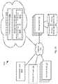
- the network environment 100includes a storage manager 102 that coordinates the creation of snapshots of storage volumes and maintains records of where snapshots are stored within the network environment 100 .
- the storage manager 102may be connected by way of a network 104 to one or more storage nodes 106 , each storage node having one or more storage devices 108 , e.g. hard disk drives, flash memory, or other persistent or transitory memory.
- the network 104may be a local area network (LAN), wide area network (WAN), or any other type of network including wired, fireless, fiber optic, or any other type of network connections.
- One or more compute nodes 110are also coupled to the network 104 and host user applications that generate read and write requests with respect to storage volumes managed by the storage manager 102 and stored within the memory devices 108 of the storage nodes 108 .
- the methods disclosed hereinascribe certain functions to the storage manager 102 , storage nodes 106 , and compute node 110 .
- the methods disclosed hereinare particularly useful for large scale deployment including large amounts of data distributed over many storage nodes 106 and accessed by many compute nodes 110 .
- the methods disclosed hereinmay also be implemented using a single computer implementing the functions ascribed herein to some or all of the storage manager 102 , storage nodes 106 , and compute node 110 .
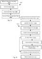
- the illustrated method 200may be performed in order to invoke the creation of a new snapshot.
- a snapshotcaptures the state of a storage volume at a moment in time and is not altered in response to subsequent writes to the storage volume.
- the method 200includes receiving, by the storage manager 102 a request to create a new snapshot for a storage volume.
- a storage volume as referred to hereinmay be a virtual storage volume that may divided into individual slices.
- storage volumes as described hereinmay be 1 TB and be divided into 1 GB slices.
- a slice and its snapshotare stored on a single storage node 106 , whereas a storage volume may have the slices thereof stored by multiple storage nodes 106 .
- the request received at step 202may be received from a human operator or generated automatically, such as according to backup scheduler executing on the storage manager 102 or some other computing device.
- the subsequent steps of the method 200may be executed in response to receiving 202 the request
- the method 200may include transmitting 204 a quiesce instruction to all compute nodes 110 that are associated with the storage volume. For example, all compute nodes 110 that have pending write requests to the storage volume.
- the storage manager 102may store a mapping of compute nodes 110 to a particular storage volume used by the compute nodes 110 . Accordingly, step 204 may include sending 204 the quiesce instruction to all of these compute nodes.
- the instructionmay be transmitted 204 to all compute nodes 110 and include an identifier of the storage volume. The compute nodes 110 may then suppress any write instructions referencing that storage volume.
- the quiesce instructioninstructs the compute nodes 110 that receive it to suppress 206 transmitting write requests to the storage nodes 106 for the storage volume referenced by the quiesce instruction.
- the quiesce instructionmay further cause the compute nodes 110 that receive it to report 208 to the storage manager 102 when no write requests are pending for that storage volume, i.e. all write requests issued to one or more storage nodes 106 and referencing slices of that storage volume have been acknowledged by the one or more storage nodes 106 .
- the storage manager 102transmits 210 an instruction to the storage nodes 106 associated with the storage volume to create a new snapshot of that storage volume.
- Step 210may further include transmitting 210 an instruction to the compute nodes 110 associated with the storage volume to commence issuing write commands to the storage nodes 106 associated with the storage volume.
- the instruction of step 110may include an identifier of the new snapshot. Accordingly, subsequent input/output operations (IOPs) transmitted 214 from the compute nodes may reference that snapshot identifier.
- the storage node 106may associate the snapshot identifier with data subsequently written to the storage volume, as described in greater detail below.
- each storage node 106finalizes 212 segments associated with the current snapshot, which may include performing garbage collection, as described in greater detail below.
- subsequent IOPs received by the storage nodemay also be processed 216 using the new snapshot as the current snapshot, as is also described in greater detail below.
- the data of the storage schememay be stored in transitory or persistent memory of the storage node 106 , such as in the storage devices 108 .
- the storage manager 102may store and maintain a volume map 300 .
- the volume mapmay include an entry including a node identifier 302 identifying the storage node 106 to which the slice is assigned and an offset 304 within the logical volume at which the slice begins.
- slicesare assigned both to a storage node 106 and a specific storage device hosted by the storage node 106 . Accordingly, the entry may further include a disk identifier of the storage node 106 referencing the specific storage device to which the slice is assigned.
- the remaining data structures of FIG. 3are stored on each storage node 106 .
- the storage node 106may store a slice map 308 .
- the slice map 308may include entries including a local slice identifier 310 that uniquely identifies each slice of the storage node 106 , e.g. each slice of each storage device hosted by the storage node 106 .
- the entrymay further include a volume identifier 312 that identifies the logical volume to which the local slice identifier 310 is assigned.
- the entrymay further include the offset 304 within the logical volume of the slice of the logical volume assigned to the storage node 106 .
- an entry in the slice map 308is created for a slice of the logical volume only after a write request is received that references the offset 304 for that slice. This further supports the implementation of overprovisioning such that slices may be assigned to a storage node 106 in excess of its actual capacity since the slice is only tied up in the slice map 308 when it is actually used.
- the storage node 106may further store and maintain a segment map 314 .
- the segment map 314includes entries either including or corresponding to a particular physical segment identifier (PSID) 316 .
- PSIDphysical segment identifier
- the segment map 314may be in an area of memory such that each address in that area corresponds to one PSID 316 such that the entry does not actually need to include the PSID 316 .
- the entries of the segment map 314may further include a slice identifier 310 that identifies a local slice of the storage node 106 to which the PSID 316 has been assigned.
- the entrymay further include a virtual segment identifier (VSID) 318 .
- VSIDvirtual segment identifier
- each time a segment is assigned to logical volume and a slice of a logical volumeit may be assigned a VSID 318 such that the VSIDs 318 increase in value monotonically in order of assignment.
- the most recent PSID 316 assigned to a logical volume and slice of a logical volumemay easily be determined by the magnitude of the VSIDs 318 mapped to the PSIDs 316 .
- VSIDs 318are assigned in a monotonically increasing series for all segments assigned to volume ID 312 .
- each offset 304 and its corresponding slice ID 310is assigned VSIDs separately, such that each slice ID 310 has its own corresponding series of monotonically increasing VSIDs 318 assigned to segments allocated to that slice ID 310 .
- the entries of the segment map 314may further include a data offset 320 for the PSID 316 of that entry.
- a data offset 320for the PSID 316 of that entry.
- the data offset 320may indicate the location of this first open position in the segment.
- the data offset 320 for a segmentmay therefore be updated each time data is written to the segment to indicate where the new first open position is.
- the entries of the segment map 314may further include a metadata offset 322 .
- a metadata entrymay be stored in that segment at a first open position from a second end of the segment opposite the first end. Accordingly, the metadata offset 322 in an entry of the segment map 314 may indicate a location of this first open position of the segment corresponding to the entry.
- Each PSID 316corresponds to a physical segment 324 on a device hosted by the storage node 106 . As shown, data payloads 326 from various write requests are written to the physical segment 324 starting from a first end (left) of the physical segment.
- the physical segmentmay further store index pages 328 such that index pages are written starting from a second end (right) of the physical segment 324 .
- Each index page 328may include a header 330 .
- the header 330may be coded data that enables identification of a start of an index page 328 .
- the entries of the index page 328each correspond to one of the data payloads 326 and are written in the same order as the data payloads 326 .
- Each entrymay include a logical block address (LBA) 332 .
- the LBA 332indicates an offset within the logical volume to which the data payload corresponds.
- the LBA 332may indicate an offset within a slice of the logical volume.
- maps 308 and 314 , and an LBA 332 within the slicemay be mapped to the corresponding offset 304 to obtain a fully resolved address within the logical volume.
- the entries of the index page 328may further include a physical offset 334 of the data payload 326 corresponding to that entry.
- the entries of the index page 328may include a size 336 of the data payload 326 corresponding to the entry. In this manner, the offset to the start of a data payload 326 for an entry may be obtained by adding up the sizes 336 of previously written entries in the index pages 328 .
- the metadata offset 322may point to the last index page 328 (furthest from right in illustrated example) and may further point to the first open entry in the last index page 328 . In this manner, for each write request, the metadata entry for that request may be written to the first open position in the last index page 328 . If all of the index pages 328 are full, a new index page 328 may be created and stored at the first open position from the second end and the metadata for the write request may be added at the first open position in that index page 328 .
- the storage node 106may further store and maintain a block map 338 .
- a block map 338may be maintained for each logical volume and/or for each slice offset of each logical volume, e.g. for each local slice ID 310 which is mapped to a slice offset and logical volume by slice map 308 .
- the entries of the block map 338 mapinclude entries corresponding to each LBA 332 within the logical volume or slice of the logical volume.
- the entriesmay include the LBA 332 itself or may be stored at a location within the block map corresponding to an LBA 332 .
- the entry for each LBA 332may include the PSID 316 identifying the physical segment 324 to which a write request referencing that LBA was last written.
- the entry for each LBA 332may further indicate the physical offset 334 within that physical segment 324 to which the data for that LBA was written.
- the physical offset 324may be obtained from the index pages 328 of that physical segment. As data is written to an LBA 332 , the entry for that LBA 332 may be overwritten to indicate the physical segment 324 and physical offset 334 within that segment 324 to which the most recent data was written.
- the segment map 314may additionally include a snapshot ID 340 identifying the snapshot to which the PSID 316 has been assigned.
- the current snapshot identifier for that volume and slice of a volumewill be included as the snapshot ID 340 for that PSID 316 .
- the storage node 106In response to an instruction to create a new snapshot for a volume and slice of a volume, the storage node 106 will store the new current snapshot identifier, e.g. increment the previously stored current snapshot ID 340 , and subsequently allocated segments will include the current snapshot ID 340 .
- PSIDs 316 that are not filled and are allocated to the previous snapshot ID 340may no longer be written to. Instead, they may be finalized or subject to garbage collection (see FIGS. 5 and 6 ).
- FIG. 4illustrates a method 400 for executing write instructions by a storage node 106 , such as write instructions received from an application executing on a compute node 110 .
- the method 400includes receiving 402 a write request.
- the write requestmay include payload data, payload data size, and an LBA as well as fields such as a slice identifier, a volume identifier, and a snapshot identifier.
- the LBAmay be an offset within the slice, otherwise the LBA may be an address within the storage volume.
- the method 400may include evaluating 404 whether a PSID 316 is allocated to the snapshot referenced in the write request and whether the physical segment 324 corresponding to the PSID 316 (“the current segment”) has space for the payload data.
- the amount of data written as data 326 and index pages 328may be tracked, such as by way of the data offset 320 and metadata offset 322 pointers. Accordingly, if the amount of previously-written data 326 and the number of allocated index pages 328 plus the size of the payload data and its corresponding metadata entry exceeds the capacity of the current segment it may be determined to be full at step 404 .
- the method 400may include allocating 406 a new PSID 316 as the current PSID 316 and its corresponding physical segment 324 as the current segment for the snapshot referenced in the write request.
- the status of PSIDs 316 of the physical storage devices 108may be flagged in the segment map 314 as allocated or free as a result of allocation and garbage collection, which is discussed below. Accordingly, a free PSID 316 may be identified in the segment map 314 and flagged as allocated.
- the segment map 314may also be updated 408 to include a slice ID 310 and snapshot ID 340 mapping the current PSID 316 to the snapshot ID, volume ID 312 , and offset 304 included in the write request.
- the current PSID 316may also be mapped to a VSID (virtual segment identifier) 318 that will be a number higher than previously VSIDs 318 such that the VSIDs increase monotonically, subject, of course, to the size limit of the field used to store the VSID 318 .
- the size of the fieldmay be sufficiently large that it is not limiting in most situations.
- the method 400may include writing 410 the payload data to the current segment. As described above, this may include writing 410 payload data 326 to the free location closest to the first end of the current segment.
- the method 400may further include writing 412 a metadata entry to the current segment. This may include writing the metadata entry (LBA, size) to the first free location closest to the second end of the current segment. Alternatively, this may include writing the metadata entry to the first free location in an index page 328 that has room for it or creating a new index page 328 located adjacent a previous index page 328 .
- Steps 410 , 412may include updating one or more pointers or table that indicates an amount of space available in the physical segment, such as a pointer 320 to the first free address closest to the first end and a pointer 322 to the first free address closest to the second end, which may be the first free address before the last index page 328 and/or the first free address in the last index page. In particular, these pointers may be maintained as the data offset 320 and metadata offset in the segment map 314 for the current PSID 316 .
- the method 400may further include updating 416 the block map 338 for the current snapshot.
- an entry in the block map 338 for that LBA 332may be updated to reference the current PSID 316 .
- a write requestmay write to a range of LBAs 332 . Accordingly, the entry for each LBA 332 in that range may be updated to refer to the current PSID 316 .
- Updating the block map 338may include evaluating 414 whether an entry for a given LBA 332 referenced in the write request already exists in the block map 338 . If so, then that entry is overwritten 418 to refer to the current PSID 316 . If not, an entry is updated 416 in the block map 318 that maps the LBA 332 to the current PSID 316 . In this manner, the block map 338 only references LBAs 332 that are actually written to, which may be less than all of the LBAs 332 of a storage volume or slice. In other embodiments, the block map 338 is of fixed size and includes and entry for each LBA 332 regardless of whether it has been written to previously. The block map 338 may also be updated to include the physical offset 334 within the current segment to which the data 326 from the write request was written.
- the storage node 106may execute multiple write requests in parallel for the same LBA 332 . Accordingly, it is possible that a later write can complete first and update the block map 338 whereas a previous write request to the same LBA 332 completes later. The data of the previous write request is therefore stale and the block map 338 should not be updated.
- Suppressing of updating the block map 338may be achieved by using the VSIDs 318 and physical offset 334 .
- the VSID 318 mapped to the segment 324 and the physical offset 334 to which the data is to be, or was, writtenmay be compared to the VSID 318 and offset 334 corresponding to the entry in the block map 338 for the LBA 332 . If the VSID 318 mapped in the segment map 314 to the PSID 316 in the entry of the block map 338 corresponding to the LBA 332 , then the block map 338 will not be updated.
- the block map 338will not be updated for the write request.
- the block map 338only lists the PSID 316 where the valid data for a given LBA 332 is stored. Accordingly, only the index pages 328 of the physical segment 324 mapped to the PSID 316 listed in the block map 338 need be searched to find the data for a given LBA 332 . In instances where the physical offset 334 is stored in the block map 338 , no searching is required.
- FIG. 5illustrates a method 500 executed by a storage node 106 in response to the new snapshot instruction of step 210 for a storage volume.
- the method 500may be executed in response to an explicit instruction to create a new snapshot or in response to a write request that includes a new snapshot ID 340 .
- the method 500may also be executed with respect to a current snapshot that is still being addressed by new write requests. For example, the method 500 may be executed periodically or be triggered based on usage.
- the method 500may include allocating 502 a new PSID 316 and its corresponding physical segment 324 as the current PSID 316 and current segment for the storage volume, e.g., by including a slice ID 310 corresponding to a volume ID 312 and offset 304 included in the new snapshot instruction or the write request referencing the new snapshot ID 340 .
- Allocating 502 a new segmentmay include updating 504 an entry in the segment map 314 that maps the current PSID 316 to the snapshot ID 340 and a slice ID 310 corresponding to a volume ID 312 and offset 304 included in the new snapshot instruction.
- the VSID 318 for that PSID 316may be a number higher than all VSIDs 318 previously assigned to that volume ID 312 , and possibly to that slice ID 310 (where slices have separate series of VSIDs 318 ).
- the snapshot ID 340 of the new snapshotmay be included in the new snapshot instruction or the storage node 106 may simply assign a new snapshot ID that is the previous snapshot ID 340 p 1 us one.
- the method 500may further include finalizing 506 and performing garbage collection with respect to PSIDs 316 mapped to one or more previous snapshots IDs 340 for the volume ID 312 in the segment map 314 , e.g., PSIDs 316 assigned to the snapshot ID 340 that was the current snapshot immediately before the new snapshot instruction was received.
- FIG. 6illustrates a method 600 for finalizing and performing garbage collection with respect to segment IDs 340 for a snapshot (“the subject snapshot”), which may include the current snapshot or a previous snapshot.
- the method 600may include marking 602 as valid latest-written data for an LBA 332 in the PSID 316 having the highest VSID 318 in the segment map 314 and to which data was written for that LBA 332 .
- Marking 602 data as validmay include making an entry in a separate table that lists the location of valid data or entries for metadata in a given physical segment 324 or setting a flag in the metadata entries stored in the index pages 328 of a physical segment 324 , e.g., a flag that indicates that the data referenced by that metadata is invalid or valid.
- the block map 338records the PSID 316 for the latest version of the data written to a given LBA 332 . Accordingly, any references to that LBA 332 in the physical segment 324 of a PSID 316 mapped to a lower-numbered VSID 318 may be marked 604 as invalid.
- the last metadata entry for that LBA 332may be found and marked as valid, i.e. the last entry referencing the LBA 332 in the index page 328 that is the last index page 328 including a reference to the LBA 332 . Any other references to the LBA 332 in the physical segment 324 may be marked 604 as invalid.
- the physical offset 334 for the LBA 332may be included in the block map 334 , so all metadata entries not corresponding to that physical offset 334 may be marked as invalid.
- the method 600may then include processing 606 each segment ID S of the PSIDs 316 mapped to the subject snapshot according to steps 608 - 620 .
- the processing of step 606may exclude a current PSID 316 , i.e. the last PSID 302 assigned to the subject snapshot.
- garbage collectionmay include writing valid data from a segment to a new segment. Accordingly, step 606 may commence with the PSID 316 having the lowest-valued VSID 318 for the subject snapshot. As any segments 324 are filled according to the garbage collection process, they may also be evaluated to be finalized or subject to garbage collection as described below.
- the method 600may include evaluating 608 whether garbage collection is needed for the segment ID S. This may include comparing the amount of valid data in the physical segment 324 for the segment ID S to a threshold. For example, if only 40% of the data stored in the physical segment 324 for the segment ID S has been marked valid, then garbage collection may be determined to be necessary. Other thresholds may be used, such as value between 30% and 80%. In other embodiments, the amount of valid data is compared to the size of the physical segment 324 , e.g., the segment ID S is determined to need garbage collection if the amount of valid data is less than X % of the size of the physical segment 324 , where X is a value between 30 and 80, such as 40.
- the method 600may include finalizing 610 the segment ID S.
- Finalizingmay include flagging the segment ID S in the segment map 314 as full and no longer available to be written to. This flag may be stored in another table that lists finalized PSIDs 316 .
- the method 600may include writing 612 the valid data to a new segment. For example, if the valid data may be written to a current PSID 316 , i.e. the most-recently allocated PSID 316 for the subject snapshot, until its corresponding physical segment 324 full. If there is no room in the physical segment 324 for the current PSID 316 , step 612 may include assigning a new PSID 316 as the current PSID 316 for the subject snapshot. The valid data, or remaining valid data, may then be written to the physical segment 324 corresponding to the current PSID 316 for the subject snapshot.
- a current PSID 316i.e. the most-recently allocated PSID 316 for the subject snapshot
- writing 612 the valid data to the new segmentmaybe processed in the same manner as for any other write request (see FIG. 4 ) except that the snapshot ID used will be the snapshot ID 340 of the subject snapshot, which may not be the current snapshot ID.
- the manner in which the new PSID 316 is allocated to the subject snapshotmay be performed in the same manner described above with respect to steps 406 - 48 of FIG. 4 .
- the manner in which the valid data is written to the current segmentmay be performed in the same manner as for steps 410 - 412 of FIG. 4 .
- writing of valid data to a new segment as part of garbage collectionmay also include updating the block map with the new location of the data for an LBA 332 , such as according to steps 414 - 418 of FIG. 4 .
- the physical segment 324 of the current PSID 316may itself be subject to the process 600 by which it is finalized or subject to garbage collection.
- the method 600may further include freeing 614 the PSID S in the segment map 314 , e.g., marking the entry in segment map 314 corresponding to PSID S as free.
- the process of garbage collectionmay be simplified for PSIDs 316 that are associated with the subject snapshot in the segment map 314 but are not listed in the block map 338 with respect to any LBA 332 .
- the physical segments 324 of such PSIDs 316do not store any valid data. Entries for such PSIDs 316 in the segment map 314 may therefore simply be deleted and marked as free in the segment map 314
- FIG. 7illustrates a method 700 that may be executed by a storage node 106 in response to a read request.
- the read requestmay be received from an application executing on a compute node 110 .
- the read requestmay include such information as a snapshot ID, volume ID (and/or slice ID), LBA, and size (e.g. number of 4 KB blocks to read).
- the following steps of the method 700may be initially executed using the snapshot ID 340 included in the read request as “the subject snapshot,” i.e., the snapshot that is currently being processed to search for requested data.
- the method 700includes receiving 702 the read request by the storage node 106 and identifying 704 one or more PSIDs 316 in the segment map 314 assigned to the subject snapshot and searching 706 the metadata entries for these PSIDs 316 for references to the LBA 332 included in the read request.
- the searching of step 706may be performed in order of decreasing VSID 318 , i.e. such that the metadata entries for the last allocated PSID 316 is searched first. In this manner, if reference to the LBA 332 is found, the metadata of any previously-allocated PSIDs 316 does not need to be searched.
- Searching 706 the metadata for a PSID 316may include searching one or more index pages 328 of the physical segment 324 corresponding to the PSID 316 .
- one or more index pages 328are stored at the second end of the physical segment 324 and entries are added to the index pages 328 in the order they are received. Accordingly, the last-written metadata including the LBA 332 in the last index page 328 (furthest from the second end of the physical segment 324 ) in which the LBA 332 is found will correspond to the valid data for that LBA 332 .
- the sizes 336 for all previously-written metadata entriesmay be summed to find a start address in the physical segment 324 for the data 326 .
- the data 326 corresponding to the metadatamay be located without summing the sizes 336 .
- the data 326 corresponding to the last-written metadata entry including that LBA 332 in the physical segment 324 mapped to the PSID 316 having the highest VSID 318 of all PSIDs 316 in which the LBA is foundwill be returned 710 to the application that issued the read request.
- the method 700may include evaluating 712 whether the subject snapshot is the earliest snapshot for the storage volume of the read request on the storage node 106 . If so, then the data requested is not available to be read and the method 700 may include returning 714 a “data not found” message or otherwise indicating to the requesting application that the data is not available.
- an earlier snapshot than the subject snapshotis present for the storage volume on the storage node 106 , e.g., there exists at least one PSID 316 mapped to a snapshot ID 340 that is lower than the snapshot ID 340 of the subject snapshot ID, then the immediately preceding snapshot ID 340 will be set 716 to be the subject snapshot and processing will continue at step 704 , i.e. the PSIDs 316 mapped to the subject snapshot will be searched for the LBA 332 in the read request as described above.
- the method 700is particularly suited for reading data from snapshots other than the current snapshot that is currently being written to.
- the block map 338may map each LBA 332 to the PSID 316 in which the valid data for that LBA 332 is written.
- step 704may include retrieving the PSID 332 for the LBA 332 in the write request from the block map 338 and only searching 706 the metadata corresponding to that PSID 316 .
- the block map 338stores a physical offset 334 , then the data is retrieved from that physical offset within the physical segment 314 of the PSID 336 mapped to the LBA 332 of the read request.
- the block map 332may be generated for a snapshot other than the current snapshot in order to facilitate executing read requests, such as where a large number of read requests are anticipated in order to reduce latency. This may include searching the index pages 328 of the segments 324 allocated to the subject snapshot and its preceding snapshots to identify, for each LBA 332 to which data has been written, the PSID 316 having the highest VSID 318 of the PSIDs 316 having physical segments 324 storing data written to the each LBA 332 . This PSID 316 may then be written to the block map 318 for the each LBA 332 . Likewise, the physical offset 334 of the last-written data for that LBA 332 within the physical segment 324 for that PSID 316 may be identified as described above (e.g., as described above with respect to steps 704 - 716 ).
- a “principal copy” or “principal snapshot” of a storage volumerefers to an actual production copy that is part of a series of snapshots that is considered by the user to be the current, official, or most up-to-date copy of the storage volume.
- a clone snapshotis a snapshot created for experimentation or evaluation but changes to it are not intended by the user to become part of the production copy of the storage volume.
- only one snapshotmay be a principal snapshot with respect to an immediately preceding snapshot, independent of the purpose of the snapshot. Any other snapshots that are immediate descendants of the immediately preceding snapshot are clone snapshots.
- the illustrated method 800may be executed by the storage manager 102 and one or more storage nodes 106 in order to implement this functionality.
- the method 800may include receiving 802 a clone instruction and executing the remaining steps of the method 800 in response to the clone instruction.
- the clone instructionmay be received by the storage manager 102 from a user or be generated according to a script or other program executing on the storage manager 102 or a remote computing device in communication with the storage manager 102 .
- the method 800may include recording 804 a clone branch in a snapshot tree.
- the storage manager 102may create a node S 1 -S 5 in a snapshot hierarchy 900 .
- the storage manager 102may create a clone snapshot and branch to a node A 1 representing the clone snapshot.
- a clone instructionwas received with respect to the snapshot of node S 2 . This resulted in the creation of clone snapshot represented by node A 1 that branches from node S 2 . Note node S 3 and its descendants are also connected to node S 2 in the hierarchy.
- the clone instructionmay specify which snapshot the clone snapshot is of
- the clone instructionmay be inferred to be a snapshot of a current snapshot.
- a new principal snapshotmay be created and become the current snapshot.
- the previous snapshotwill then be finalized and be subject to garbage collection as described above.
- the clonewill then branch from the previous snapshot.
- node S 2represented the current snapshot
- node S 3would be created.
- the snapshot of node S 2would then be finalized and subject to garbage collection and clone snapshot represented by A 1 would be created and node A 1 would be added to the hierarchy as a descendant of node S 2 .
- the clone node A 1and possibly its descendants A 2 to A 4 (representing subsequent snapshots of the clone snapshot), may be distinguished from the nodes S 1 to S 5 representing principal snapshots, such as by means of a flag, a classification of the connection between the node A 1 and node S 2 that is its immediate ancestor, or by storing data defining node A 1 in a separate data structure.
- node B 1represents a clone snapshot of the snapshot represented by node S 4 .
- Subsequent snapshots of the clone snapshotare represented by nodes B 1 to B 3 .
- the creation of a clone snapshot on the storage node 106may be performed in the identical manner as for any other snapshot, such as according to the methods of FIGS. 2 through 6 .
- one or more segments 806may be allocated to the clone snapshot on storage nodes 106 storing slices of the cloned storage volume and mapped to the clone snapshot.
- IOPs referencing the clone snapshotmay be executed 808 , such as according to the method 400 of FIG. 4 .
- the method 800may include allocating 806 segments to the clone snapshot on the different storage node 106 . This may be invoked by sending a new snapshot instruction referencing the clone snapshot (i.e., an identifier of the clone snapshot) to the different storage node 106 and instructing one or more compute nodes 110 to route IOPs for the clone snapshot to the different storage node 106 .
- a new snapshot instruction referencing the clone snapshoti.e., an identifier of the clone snapshot
- the storage node 102may store in each node of the hierarchy, data identifying one or more storage nodes 106 that store data for the snapshot represented by that node of the hierarchy. For example, each node may store or have associated therewith one or more identifiers of storage nodes 106 that store a particular snapshot ID for a particular volume ID. The node may further map one or more slice IDs (e.g., slice offsets) of a storage volume to one storage nodes 106 storing data for that slice ID and the snapshots for that slice ID.
- slice IDse.g., slice offsets
- FIG. 10illustrates a method 1000 for rolling back a storage volume to a previous snapshot, particularly for a storage volume having one or more clone snapshots.
- the method 1000includes receiving 1002 , by the storage manager 102 , an instruction to rollback a storage volume to a particular snapshot SN.
- the method 1000may then include processing 1004 each snapshot that is a represented by a descendant node of the node representing snapshot SN in the snapshot hierarchy, i.e. snapshots SN+1 to SMAX, where SMAX is the last principal snapshot that is a descendant of snapshot SN (each “descendant snapshot”).
- processing 1004may include evaluating 1006 whether the each descendant is an ancestor of a node representing a clone snapshot. If not, then the storage manager 102 may instruct all storage nodes 106 storing segments mapped to the descendant snapshot to free 1008 these segments, i.e. delete entries from the segment map referencing the descendant snapshot and marking corresponding PSIDs 316 as free in the segment map 314 .
- step 1008is not performed and the snapshot and any segments allocated to it are retained.
- FIG. 11illustrates the snapshot hierarchy following execution of the method 1000 with respect to the snapshot represented by node S 3 .
- snapshot S 5has been removed from the hierarchy and any segments corresponding to these snapshots will have been freed on one or more storage nodes 106 .
- node S 4is an ancestor of clone node B 1 , it is not removed and segments corresponding to it are not freed on one or more storage nodes in response to the roll back instruction. Inasmuch as each snapshot contains only data written to the storage volume after it was created, previous snapshots may be required to recreate the storage volume. Accordingly, the snapshots of nodes S 3 to S 1 are needed to create the snapshot of the storage volume corresponding to node B 1 .
- Subsequent principal snapshots of the storage volumewill be added as descendants of the node to which the storage volume was rolled back.
- a new principal snapshotis represented by node S 6 that is an immediate descendant of node S 3 .
- Node S 4is only present due to clone node B 1 and therefore may itself be classified as a clone node in the hierarchy in response to the rollback instruction of step 1002 .
- FIG. 11is a simple representation of a hierarchy. There could be any number of clone snapshots, clones of clone snapshots and descendant snapshots of any of these snapshots represented by nodes of a hierarchy. Accordingly, to roll back to a particular snapshot of a clone, the method 1000 is the same, except that descendants of the clone snapshot are treated the same as principal snapshots and clones of any of these descendants are treated the same as a clone snapshot.
- the illustrated method 1200may be used to execute a read request with respect to a storage volume that is represented by a hierarchy generated as described above with respect to FIGS. 8 through 11 .
- the illustrated method 1200may also be executed with respect to a storage volume that includes only principal snapshots that are distributed across multiple storage nodes, i.e., all the segments corresponding to snapshots of the same slice of the storage volume are not located on the same storage node 106 .
- the hierarchy stored on the storage manager 102stores the location of the segments for each snapshot and therefore enables them to be located.
- the method 1200may be executed by a storage node 106 (“the current storage node”) with information retrieved from the storage manager 102 as noted below.
- the method 1200may include receiving 1202 a read request, which may include such information as a snapshot ID, volume ID (and/or slice ID), LBA, and size (e.g. number of 4 KB blocks to read).
- the read requestmay be issued by an application executing on a compute node 110 .
- the compute node 110may determine which storage node 106 to transmit the read request using information from the storage manager 102 .
- the compute node 110may transmit a request to obtain an identifier for the storage node 102 storing data for a particular slice and snapshot of a storage volume.
- the storage managermay then obtain an identifier and/or address for the storage node 106 storing that snapshot and slice of the storage volume from the hierarchical representation of the storage volume and return it to the requesting compute node 110 .
- the storage manager 102may retrieve this information from the node in the hierarchy representing the snapshot included in the read request.
- the current storage nodeperforms the algorithm illustrated by subsequent steps of the method 1200 .
- the method 1200may include identifying 1204 segments assigned to the snapshot ID of the read request in the segment (“the subject snapshot”).
- the method 1200may include searching 1206 the metadata of the segments identified in step 1204 for the LBA of the read request. If the LBA is found, the data from the highest numbered segment having the LBA in its metadata is returned, i.e. the data that corresponds to the last-written metadata entry including the LBA.
- the method 1200may include evaluating 1212 whether the subject snapshot is the earliest snapshot on the current storage node. If not, then steps processing continues at step 1204 with the previous snapshot set 1214 as the subject snapshot.
- Steps 1204 - 1214may be performed in the same manner as for steps 704 - 714 of the method 700 , including the various modifications and variations described above with respect to the method 700 .
- the method 1200may include requesting 1216 a location, e.g. storage node identifier, where an earlier snapshot for the volume ID or slice ID is stored.
- the storage manager 102determines an identifier of a storage node 106 storing the snapshot corresponding to the immediate ancestor of the earliest snapshot stored on the current storage node in the hierarchy.
- the storage manager 102may determine an identifier of the storage node 106 relating to the immediate-ancestor snapshot and that stores data for a slice ID and volume ID of the read request as recorded for the ancestor nearest ancestor node in the hierarchy of the node corresponding to the earliest snapshot stored on the current storage node.
- the data the storage manager 102may report this fact to the storage node, which will then return 1220 a message indicating that the requested LBA is not available for reading, such as in the same manner as step 714 of the method 700 .
- the read requestmay be transmitted 1222 to this next storage node by either the current storage node or the storage manager 102 .
- the processingmay then continue at step 1202 with the next storage node as the current storage node.
- the read request transmitted at step 1222may have a snapshot ID set to the latest snapshot ID for the storage volume ID and or slice ID of the original read request.
- the method 1200may be performed repeatedly across multiple storage nodes 106 until the earliest snapshot is encountered or the LBA of the read request is located.
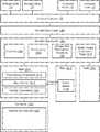
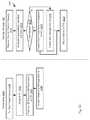
- an orchestration layer 1300implements a bundled application 1302 including a plurality of roles.
- bundled applicationrefers to a bundle of applications as implemented using the orchestration layer.
- a “role”is an instance of an executable that is managed by the orchestration layer as described herein as part of the bundled application. Accordingly, a “role” may itself be a standalone application, such as a database, observer, blogging application, or any other application.
- rolesinclude the roles used to implement multi-role applications such as CASSANDRA, HADOOP, SPARK, DRUID, SQL database, ORACLE database, MONGODB database, WORDPRESS, and the like.
- rolesmay include one or more of a named node, data node, zookeeper, and AMBARI server.
- the orchestration layer 1300may implement a bundled application 1302 defining roles and relationships between roles as described in greater detail below.
- the orchestration layer 1300may execute on a computing device of a distributed computing system (see e.g., FIG. 1 ), such as on a compute node 110 , storage node 106 , a computing device executing the functions of the storage manager 102 , or some other computing device. Accordingly, actions performed by the orchestration layer may be interpreted as being performed by the computing device executing the orchestration layer 1300 .
- the bundled application 1302may include a manifest 1304 that defines the roles of the bundled application 1302 , which may include identifiers of roles and possibly a number of instances for each role identified.
- the manifest 1304may define dynamic functions define how the number of instances of particular role may grow or shrink depending on usage.
- the orchestration layer 1300may then create or remove instances for a role as described below as indicated by usage and one or more functions for that role.
- the manifest 1304may define a topology of the bundled application 1302 , i.e. the relationship between roles, such as services of a role that are accessed by another role.
- the bundled application 1302may include provisioning 1306 .
- the provisioning 1306defines the resources of storage nodes 106 and compute nodes 110 required to implement the bundle.
- the provisioning 1306may define resources for the bundle as a whole or for individual roles. Resources may include a number of processors (e.g., processing cores), an amount of memory (e.g., RAM (random access memory), an amount of storage (e.g., GB (gigabytes) on a HDD (Hard Disk Drive) or SSD (Solid State Drive)). As described below, these resources may be provisioned in a virtualized manner such that the bundled application 1302 and individual roles 1312 are not informed of the actual location or processing and storage resources and are relieved from any responsibility for managing such resources.
- processorse.g., processing cores
- RAMrandom access memory
- an amount of storagee.g., GB (gigabytes) on a HDD (Hard Disk Drive) or SSD (Solid State Drive)
- storage resourcesmay be virtualized by the storage manager 102 using the methods described above such that storage volumes are allocated and used without requiring the bundled application 1302 or roles to manage the underlying storage nodes 106 and storage device 108 on which the data of the storage volumes is written.
- Provisioning 1306may include static specification of resources and may also include dynamic provisioning functions that will invoke allocation of resources in response to usage of the bundled application. For example, as a database fills up, additional storage volumes may be allocated. As usage of a bundled application increases, additional processing cores and memory may be allocated to reduce latency.
- a bundled application 1302may further include configuration parameters 1308 .
- Configuration parametersmay include variables and settings for each role of the bundle.
- the configuration parametersare defined by the developer of the role and therefore may include any example of such parameters for any application known in the art.
- the configuration parametersmay be dynamic or static. For example, some parameters may be dependent on resources such as an amount of memory, processing cores, or storage. Accordingly, these parameters may be defined as a function of these resources.
- the orchestration layerwill then update such parameters according to the function in response to changes in provisioning of those resources that are inputs to the function.
- CASSANDRAdefines a variable Max_Heap_Size that is normally set to half the memory limit. Accordingly, as the memory provisioned for a CASSANDRA role increases, the value of Max_Heap_Size may be increased to half the increased memory.
- the bundled application 1302may further include action hooks 1310 for various actions that may be taken with respect to the bundled application and/or particular roles of the bundled applications.
- Actionsmay include some or all of stopping, starting, restarting, taking snapshots, cloning, and rolling back to a prior snapshot.
- a hookis a programmable routine that is executed by the orchestration layer when the corresponding action is invoked.
- the bundled application 1302may define a plurality of roles 1312 .
- Each rolemay include one or more provisioning constraints.
- the bundled application 1302 and roles 1312are not aware of the underlying storage nodes 106 and compute nodes 110 inasmuch as these are virtualized by the storage manager 102 and orchestration layer 1300 . Accordingly, any constraints on allocation of hardware resources may be included in the provisioning constraints 1314 . As described in greater detail below, this may include constraints to create separate fault domains in order to implement redundancy and constraints on latency.
- the role 1312may define a name space 1316 .
- a name space 1316may include variables, functions, services, and the like implemented by a role. In particular, interfaces and services exposed by a role may be included in the name space.
- the name spacemay be referenced through the orchestration layer 1300 by an addressing scheme, e.g. ⁇ Bundle ID>. ⁇ Role ID>. ⁇ Name>.
- references to the namespace 1316 of another rolemay be formatted and processed according to the JINJA template engine or some other syntax. Accordingly, each role 1312 may access the variables, functions, services, etc. in the name space 1316 of another role 1312 on order to implement a complex application topology.
- credentials for authorizing access to a role 1312may be shared by accessing the namespace 1316 of that role.
- a role 1312may further include various configuration parameters 1318 defined by the role, i.e. as defined by the developer that created the executable for the role. As noted above, these parameters 1318 may be set by the orchestration layer 1300 according to the static or dynamic configuration parameters 1308 . Configuration parameters may also be referenced in the name space 1316 and be accessible (for reading and/or writing) by other roles 1312 .
- Each role 1312may include a container 1320 executing an instance 1322 of the application for that role.
- the container 1320may be a virtualization container, such as a virtual machine, that defines a context within which the application instance 1322 executes, facilitating starting, stopping, restarting, and other management of the execution of the application instance 1322 .
- Containers 1320may include any container technology known in the art such as DOCKER, LXC, LCS, KVM, or the like.
- one role 1312 of a bundled application 1302may execute a DOCKER container 1320 and another role 1312 of the same bundled application 1302 may execute an LCS container 1320 .
- a bundled application 1302 as configured in the foregoing descriptionmay be instantiated and used or may be saved as a template that can be used and modified later.
- FIG. 14illustrates a method 1400 for executing a bundled application 1302 using the orchestration layer 1300 .
- the method 1400may include provisioning 1402 storage and computation resources according to the provisioning 1306 . This may include allocating storage volumes according to the storage requirements, assigning the storage volumes to storage nodes 106 , and selecting a compute node 110 or storage node 106 providing the required computational resources (processor cores and memory).
- the method 1400may include creating 1404 role instances for the roles 1312 defined by the bundled application 1302 . As described above, this may include creating a container 1320 and instantiating the application instance 1322 of the role 1312 within the container 1320 . The order in which instances 1322 are created and started may be defined in the manifest 1304 .
- the method 1400may include configuring 1406 each role according to the configuration parameters 1308 , including executing any included functions to determine values for dynamic parameters.
- starting a bundled application 1302may further include setting up 1408 the roles 1312 to reference resources in the name space 1316 of another role 1312 .
- a observermay be configured to access a database by referencing configuration parameters and services implemented by the database.
- the method 1400may further include executing 1410 any hooks 1310 defined for the initial startup of the bundled applications. Accordingly, pre-startup, startup, and post startup hooks may be executed. Some or all of the functions of steps 1402 - 1410 may be defined as part of the pre-startup hook. Other functions may also be performed prior to steps 1402 - 1408 as defined by a pre-startup hook.
- the actual commencement of execution of the instances 1322 of the bundled application 1302may be performed in an order specified by the startup hook and may include performing any attendant functions of these instances 1322 as specified by the startup hook.
- one or more other actionsmay be performed as specified by the developer in the post-startup hook. These actions may invoke functions of the instances 1322 themselves or executed by the orchestration layer 1300 outside of the instances 1322 , such as with respect to an operating system executing the containers 1320 for the instances 1322 .
- the bundled application 1302may then be accessed 1412 in order to perform the programmed functionality of the application instances 1322 . As usage occurs, processing resources will be loaded and storage may be filled.
- the method 1400may further include adjusting 1414 provisioning according to this usage and may performed adjustment to configuration parameters of the roles 1312 according to this provisioning as defined by the provisioning 1306 and configuration functions 1308 .
- instances of rolesmay also be created or removed according to usage. Accordingly, where indicate by the manifest 1304 , instances 1322 for a role 1312 may be created according to steps 1402 - 1410 throughout execution of the bundled application 1302 as defined by one or more dynamic functions in the manifest 1304 for that role 1312 .
- the illustrated method 1500may be used to implement provisioning constraints 1314 for a role 1312 or constraints for an entire bundled application 1302 .
- the method 1500may be executed by the orchestration layer 1300 , storage manager 102 , or a combination of the two.
- the method 1500may include receiving 1502 the provisioning constraint 1314 for one or more roles 1312 of the bundled application 1302 and determining 1504 whether the constraint 1314 specify one or both of a fault domain constraint and a latency constraint.
- latencymay be specified in terms of (a) a minimum network delay, (b) a minimum network throughput, (c) an explicit constraint to place computation and storage resources in the same subnetwork, or (d) an explicit constraint to place computation and storage resources on the same node, i.e. a hybrid compute and storage node 110 , 106 that performs the functions of both types of nodes with a single computer.
- This constraintmay be used by the orchestration layer to assign computing and storage resources to roles 1312 and storage volumes of the bundled application. For example, one or more storage volumes for the role 1312 will be assigned to storage nodes 106 that can either (a) meet the latency requirement with respect to compute nodes 110 allocated to the role 1312 (b) also provide the computational resources required for the role 1312 .
- the orchestration layer 1300may include a resource manager in that accounts for all of the compute storage requirements and constraints and creates a resource allocation plan. This plan describes the virtual nodes (containers 1320 ) that make up the bundled application 1302 . Each virtual node has allocations of processor cores, memory and storage volumes.
- the resource managerdetermines the compute host (compute node 110 or hybrid node) for each virtual node and a set of devices for each storage volume of the virtual node.
- the orchestration layer 1300sends this mapping of the storage volumes to physical devices to the storage manager 102 , which implements the storage allocation.
- storage volumes for the role 1312may be distributed 1512 among the storage nodes 106 of the distributed storage system 100 according to this requirement. For example, if storage volume B is a redundant (e.g., replica or backup) copy of storage volume A, the fault domain constraint may indicate this fact. Accordingly, the storage manager 102 may assign storage volume B to a different storage node 106 than storage volume A.
- Various degrees of constraintmay be specified. For example, a fault domain constraint may simply require a different storage device 108 but not require a different storage node 106 .
- a fault domain constraintmay require that storage nodes 106 to which storage volumes are assigned by in separate subnetworks, different geographic locations, or have some other degree of separation. Similar fault domain constraints may be specified for roles 1312 , which may be constrained to execute on different compute nodes 110 in order to provide redundant services and reduce downtime.
- the provisioning constraints 1502 based on fault domains and/or latencymay be combined with one or more other constraints. For example, a performance constraint (IOPs/second) for a storage node may be imposed. Accordingly, only those compute nodes meeting the performance requirement and the fault domain and/or latency requirements will be selected for provisioning.
- IOPs/secondperformance constraint
- provisioning 1306may define a processing requirement, such as a number of processing cores and an amount of storage for a role. Accordingly, compute nodes 110 may be selected at step 1508 such that both the latency requirement and processing requirement are met.
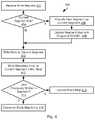
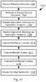
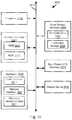
- the illustrated method 1600may be executed by the orchestration layer 1302 with respect to a bundled application 1302 in order to create a snapshot of the bundled application 1302 that can be later restored (see the method 1700 of FIG. 17 ).
- the method 1600may include flushing 1602 application buffers to disk.
- performance of an applicationis accelerated by maintaining data in a cache in memory, such that data in the cache is accessed and updated without requiring writing to a disk in many instances, as known in the art.
- this buffermay be flushed 1602 to disk by writing all valid data (i.e., not outdated due to a subsequent write) in the cache to the storage device 108 to which that data is addressed, e.g., to which the storage volume referenced by the data is assigned.
- a file system flushmay be performed 1604 .
- Performing a file system flushmay include ensuring that all IOPs pending to be performed by the file system have been executed, i.e. written to disk.
- data written to a cache for the file system this is validmay be written to a storage device 108 to which the data is addressed, e.g., to which the storage volume referenced by the data is assigned.
- the method 1600may then include freezing 1606 the application instances 1322 of each role 1312 .
- the containers 1320 for the roles 1312may be instructed to pause execution of each instance 1322 . This may include stopping execution and saving a state of execution of each instance 1322 (state variables, register contents, program pointers, function stack, etc.).
- the method 1600may further include creating 1608 a snapshot of storage volumes provisioned for the bundled application. This may include executing the method 200 of FIG. 2 or any of the above-described approaches for implementing a snapshot of a storage volume.
- the method 1600may further include creating 1610 a topology snapshot for the bundled application 1302 .
- the topology of an applicationmay include some or all of the following information as constituted at the time of executing step 1610 a listing of the roles 1312 , which may include one or more instances 1322 of the same role 1322 , relationships between application instances 1322 of roles 1312 (name space cross-references, configuration parameters), storage volumes assigned to roles 1312 , or other information that describes the topology of the bundled application 1302 .
- Applicationsmay create metadata describing their state of operation. This data may also be saved as part of the topology snapshot.
- the application instancesmay be resumed, with the application itself not suffering any down time in some embodiments.
- the bundled application 1302may then continue to operate. If desired, the application may then be rolled back to the snapshot created according to the method 1600 , as described below with respect to FIG. 17 .
- FIG. 17illustrates a method 1700 for rolling back a bundled application 1302 to a snapshot, such as a snapshot created according to the method 1600 .
- the method 1700may be executed by one or both of the orchestration layer 1300 and the storage manager 102 .
- the method 1700includes receiving 1702 a rollback instruction, such as from an administrator desiring to return to a stable version of the bundled application 1302 .
- the remaining steps of the method 1300may be executed in response to the rollback instruction.
- the method 1700may include rolling 1704 back storage volumes assigned to the bundled application 1302 to the snapshots created for the snapshot of the bundled application 1302 (e.g., at step 1608 of the method 1600 ). This may include executing the method 1000 of FIG. 10 or performing any other approach for rolling back a storage volume to a prior state.
- the method 1700may include restoring 1706 application instances from the application snapshot.
- an application instance 1322may be frozen. Accordingly, data describing a state of execution of the application instance 1322 may be reloaded into a container 1302 for that instance. If needed, the container for that application instance 1322 may be created and the instance 1322 loaded into it prior to loading the state of execution. This is particularly the case where the number of application instances has changed since the application snapshot was created.
- the method 1700may further include restoring 1708 the application topology saved for the bundled application at step 1610 . Accordingly, relationships between application instances 1322 of roles 1312 (name space cross-references, configuration parameters), storage volumes assigned to roles 1312 , or other information that describes the topology of the bundled application 1302 may be restored as it was at the time the application snapshot was created
- the method 1700further include executing 1710 , 1712 , 1714 a pre-restart hook, restart hook, and post restart hook defined for the bundled application.
- each hookmay be a routine defined by a developer to be executed for a particular action, restarting in this case.
- execution of the instances 1322 for the roles 1322may be restarted, along with any other actions specified by the developer in the restart hook.
- the bundled application 1302 as restored at steps 1704 - 1714may then be accessed 1716 as defined by the programming of the application instances and the restored application topology.
- the snapshot of the bundled application 1302may be restarted on different storage and compute nodes 106 , 110 than those on which the bundled application 1302 was executing when the snapshot was created. Accordingly, the application snapshot may be restarted as a clone of the bundled application 1302 or moved to different hardware when executing the method 1700 .
- the hooks of steps 1710 , 1712 , 1714may be different when the application snapshot is being restarted as a clone as desired by a developer.
- a developermay desire to scale the clone application to increase or decrease a number of databases, number of partitions of a database, or other aspect of the clone application. Accordingly, the hooks of steps 1710 , 1712 , 1714 may implement routines to implement this increase or decrease.
- some applicationsare able to automatically detect the number of partitions of a database.
- some or all of the hooks 1710 , 1712 , 1714may reduce the number of partitions in a database of the clone applications and rely on the application to discover this change.
- some or all of the hooks 1710 , 1712 , 1714may be programmed to configure an application to access the database with the reduced number of partitions where the application is unable to configure itself
- a storage volumemay be cloned in the form of a clone snapshot, such as according to the approach described above with respect to FIGS. 8 through 12 .
- FIG. 18Aillustrates the approach of FIGS. 8 through 12 , which is referred to herein as a “thin” clone.
- a segment E allocated to the clone snapshot S 2 after creation of the clone snapshotis written only to the clone snapshot.
- Segments A-D that were written to snapshot 51 prior to creation of clone snapshot S 2are not copied to snapshot 51 .
- snapshot S 2may be on a different storage node than snapshot 51 .
- reads from an application 1800 for segments A-Dwill therefore be routed to the storage node storing snapshot 51 . Reads for segment E can be processed locally.
- snapshot 51is a production snapshot and snapshot S 2 is only for testing, this loading may be undesirable. However, copying the segments A-D to snapshot S 2 will also result in loading of the storage node 106 storing snapshot 51 .
- FIG. 18Billustrates a “thick” clone wherein the segments A-D are copied to snapshot S 2 .
- all readsare handled by the storage node 106 storing the snapshot S 2 and the production storage node 106 storing S 1 is not loaded.
- the process of copying the segments A-D to snapshot S 2will also result in loading of the storage node 106 storing snapshot S 1 .
- FIG. 19Aillustrates a method 1900 a for implementing a “deferred thick clone” snapshot wherein segments of snapshot S 1 are gradually copied to snapshot S 2 while avoiding impacting performance of the production storage node 106 storing snapshot S 1 .
- the method 1900 amay be executed by the storage node 106 storing the snapshot S 2 (“the clone node”) in cooperation with the storage node 106 storing the snapshot S 1 (“the primary node”).
- the segments that are copiedmay have corresponding VSIDs as described above with respect to FIG. 3 .
- the association of a VSID to a segmentmay maintained for the copy of the segment on the clone node.
- a storage volumemay be divided into slices that may reside on different storage nodes 106 . Accordingly, the method 1900 a may be executed separately for each slice of the storage volume.
- the method 1900 amay include creating 1902 a deferred thick clone snapshot. This may include creating a thin clone snapshot ( FIG. 8 , FIG. 18A ) S 2 . Creating 1902 a deferred thick clone snapshot may include allocating physical segments 324 and corresponding PSIDs 316 for each segment to be copied, such as prior to the segments being copied. In some embodiments, a user may instruct that a pre-existing thin clone snapshot is to be converted to a deferred thick clone snapshot according to the method 1900 a.
- the segment map 314may be updated to include the slice ID 310 (mapped to offset within cloned storage volume per slice map 308 ), and VSID 318 , and possibly other information shown in FIG. 3 , for each segment to be copied.
- the snapshot ID 340 in the segment map 340may be set equal to S 2 , i.e. the snapshot identifier for the clone snapshot.
- the segment map 314may be updated either prior to copying or each PSID 316 entry may be updated when the corresponding segment is copied to the physical segment 324 for that PSID 316 .
- the method 1900 amay include setting 1904 a load limit, e.g., a limit on how much copying traffic the clone node may impose on the primary node.
- the load limitmay be specified in terms of a number of bytes per second, a number of segments that may be copied at any one time, or other limits.
- the load limitmay be time dependent. For example, at night or other periods of low usage, the load limit may be raised since production usage of the clone node will not be significantly impaired.
- the load limitmay also specify a maximum number of read IOPs that may be requested from the primary node in a given time period, e.g., maximum IOPs/second limit.
- the method 1900 amay include evaluating 1906 whether there is a hit imbalance for any of the segments that remain to be copied from the primary node to the clone node. In particular, if a large number of read requests are being routed to the primary node for a particular segment, then copying of that segment will reduce loading of the primary node and reduce latency for the clone node.
- reads routed to the primary nodemay be tabulated for each segment referenced. Copying of segments may then be ordered according to the number of reads, with a segment having a higher number of reads being copied before a segment with a lower number. Where N segments may be in process of being copied simultaneously, then the N segments with the N highest read counts may be selected 1908 for copying first. Where no read imbalance exists, e.g., there is no significant difference in the number of reads per segment, the segments may be copied in order, e.g. in order of increasing VSIDs. What is significant may be a predetermined value. For example, where the highest read count is less than X percent of the average read count, the imbalance may be deemed insignificant, where X is a value between 1.1 and 2 or some other predetermined value greater than one.
- heavily used storage volumes and segments of a storage volumemay be known by a developer based on the application topology, e.g., log files with heavy write usage and low read usage may be copied last whereas heavily read data may be read first. Accordingly, the ordering of copying of segments may be specified by a developer in order to copy those segments with a high hit rate first.
- the method 1900 amay include evaluating 1910 whether the primary node 1910 has spare capacity.
- the primary node 1910may transmit loading information, e.g. IOPs per second, to the clone node. For example, where this loading falls below a predetermined threshold, e.g. less than Y percent of the total IOP/second capacity of the primary node, then the load limit for copying segments may be increased 1912 , where Y is predetermined value less than 100, such as 70.
- the load limitmay be decreased, e.g. decreased such that the amount of unused capacity of the primary remains below an acceptable value, e.g., such that the load limit plus production loading of the primary node is less than Z percent.
- steps 1910 - 1916may be performed at the storage device 108 level. Accordingly, loading of a storage device 108 is evaluated 1910 , 1914 and the load limit increased 1912 or decreased 1916 based on the loading in the same manner described above.
- steps 1906 , 1910 , 1914may be performed at the container 1320 level.
- storage volumes allocated to instances 1322 that are generating higher read traffic relative to other instances 1322may be copied before storage volumes allocated to the other instances 1322 .
- Copying of segments according to the load limitmay be performed 1918 . Steps 1906 - 1918 may be performed repeatedly until all segments are found 1920 to have been copied.
- the block map 338may be rebuilt 1922 according to the copied segments.
- metadatae.g., index pages 328
- the entry for each LBAmay then be updated to include the PSID 316 where the copied segments was written and the physical offset 334 for that LBA.
- a block map 338may be maintained for each slice of a logical storage volume. Accordingly, updating 1922 the block map may be performed for each slice referenced by the copied segments.
- the block map 338indicates the location of the latest written data addressed to an LBA. Accordingly, references to an LBA 332 in a copied segment will not cause updating of the entry in the block map 338 for that LBA 332 where a later version of data has been written to that LBA 332 .
- the method 1900 amay be performed in the context of cloning a bundled application 1302 . Accordingly, the rollback method of FIG. 17 may be performed on different hardware then that on which the bundled application 1302 was executing when an application snapshot was created in order to create a clone of the bundled application. In such instances, storage volumes may be cloned as either thin clones, thick clones, or deferred thick clones. The clone application may therefore continue to access storage nodes 106 provisioned for the original bundled application 1302 until a deferred thick clone has completed copying of data from the original bundled application.
- a deferred thick clone snapshotmay be implemented according to the method 1900 b.
- the method 1900 bmay include creating 1902 a deferred thick clone snapshot (“the subject snapshot”) of a storage volume (“the subject volume”), such as in the same manner as for the method 1900 a.
- the subject snapshotmay be on a different storage node 106 (“the clone node”) than the storage node 106 (“the parent node”) storing the parent snapshot of the subject volume of which the subject snapshot is a deferred thick clone snapshot.
- the method 1900 bmay include evaluating 1926 whether an address (e.g., LBA and slice offset) referenced by the read request has been previously written to after creation of the subject snapshot. If so, then the read request is executed 1928 with respect to the subject snapshot by the clone node (e.g., see FIG. 12 ).
- an addresse.g., LBA and slice offset
- the read requestis transmitted 1930 to the parent node, which then processes the read request and returns the read data to a source of the read request from step 1924 .
- Steps 1926 - 1930may be executed according to the approach described above with respect to FIG. 12 .
- the parent nodemay further include a component that intercepts 1932 the read data and writes 1934 the read data to the clone node, e.g., issues a write request to the subject snapshot, the write request including the read data and the address (e.g., LBA and slice offset) from the read request.
- This write requestis referred to herein has an internal clone write (ICW) and may be flagged or otherwise be distinguishable from other types of writes, such as writes from user applications.
- ICWinternal clone write
- the read request that is transmitted at step 1930may include an indication that it is a pass through read request from the subject snapshot. Accordingly, the parent node may determine based on this indication that writing 1934 of the read data is required as an ICW.
- the clone nodeUpon receiving the ICW, the clone node writes 1934 the read data to the clone snapshot (e.g., see FIG. 4 ). Note that there is a possibility that the data may be written to the same LBA and slice offset of the subject snapshot before the ICW is received. In such cases, the ICW is discarded, since the data written to the subject snapshot at the same LBA and slice offset referenced by the ICW is more current.
- FIG. 19Cillustrates an alternative method 1900 c for implementing a deferred thick clone.
- the method 1900 cmay include performing steps 1902 - 1930 according to any of the variations for performing these steps described above with respect to the method 1900 c.
- the method 1900 cmay further include incrementing 1936 , by the clone node, a slice counter for a slice referenced by the read request of step 1924 for each read request that is found 1926 to not reference data written to the subject snapshot after creation of the subject snapshot.
- Copying 1940may include individually copying all of the segments of the slice from the parent node to the clone node.
- the thresholdis not met, then one of two approaches may be used. In a first approach, no copying is performed. In a second approach, the read data of the parent snapshot is intercepted 1932 and written 1934 to the clone snapshot in the same manner as for the method 1900 b.
- FIGS. 19D and 19Edescribe approaches for executing write requests for a deferred thick clone implemented according to FIG. 19C .
- the illustrated method 1900 dmay include receiving 1942 , by the clone node, a user write request to the subject snapshot, i.e. a write request from a user application that is other than a write request performed as part of copying a segment or slice (an internal clone write (ICW)) from the parent snapshot.
- a user write request to the subject snapshoti.e. a write request from a user application that is other than a write request performed as part of copying a segment or slice (an internal clone write (ICW)) from the parent snapshot.
- ICWinternal clone write
- the method 1900 dmay include evaluating 1944 whether an ICW is in process that references the same LBA and slice offset as the write request of step 1942 . If so, the write request is held 1946 and is not executed until no conflicting ICW is in process. In this manner, writes are executed in the proper order and the data of the write request of step 1942 is not overwritten by the ICW.
- the write requestmay be executed.
- the write requestmay be executed in the manner described above with respect to FIG. 4 with the changes indicated in FIG. 19D .
- a current segmentis found 1948 to be full, a new segment is allocated 1950 and assigned 1952 a VSID in a clone ID range.
- the write requestmay then be executed 1954 .
- FIG. 19Eillustrates a method 1900 e for processing internal clone writes (ICW) of segments from the parent snapshot.
- the ICWis received 1956 and one or more segments are allocated 1958 to the subject snapshot for storing the data from the ICW.
- the allocated segmentsmay then each be assigned 1960 a unique VSID from a parent ID range that does not overlap the clone ID range (see FIG. 4 ). Accordingly, where data referencing the LBA is found in segments with VSIDs in the clone ID range and the parent ID range, the valid data can readily be determined to be in the VSIDs in the clone ID range.
- the clone ID rangeis higher than the parent ID range such that segment with the highest VSID of those segments containing data for an LBA will contain the most current data for that LBA.
- the parent ID rangeis for a range of values sufficiently large such that no overlap with the dine ID range will occur, e.g. some multiple of the total number of segments in a slice, e.g. a multiple between 1 and 2.
- the new VSIDs assigned at step 1960may preserve the ordering of the VSIDs from the parent snapshot, i.e. where a first segment has a higher VSID than a second segment in the parent snapshot the VSIDs assigned to the first segment at step 1960 will also be higher than the VSID assigned to the second segment at step 1960 .
- the segments of the parent snapshot received at step 1956may then be written 1962 to the segments allocated at step 1912 .
- the segment map 314may be updated to map the copied segments to the PSIDs 316 to which they were written as well as the other information shown in FIG. 3 for an entry in the segment map 314 .
- the block map 338 for each slice referenced in the ICWmay then be updated for each LBA referenced in the one or more segments of the ICW. Where an entry already exists in the block map 338 for an LBA referenced in an ICW, the entry is not overwritten in some embodiments, since this indicates that a user write has occurred after creation of the subject snapshot and should not be overwritten by data from the parent snapshot.
- current data for an LBAmay be identified by identifying the most current data in the segments assigned VSIDs in the clone ID range (the last written data to the segment with the highest VSID). If an LBA is not referenced in segments assigned VSIDs in the clone ID range, then the most current data in the segments of the subject snapshot assigned VSIDs in the parent ID range is the current data for that LBA (the last written data to the segment with the highest VSID).
- FIG. 20illustrates an example application of a deferred thick clone snapshot.
- a production database 2000may store segments A-D.
- the production databasemay be implemented according to the virtualization approach described with respect to FIGS. 1 through 12 or may be any other type of database, such as SQL (structured query language), MYSQL, ORACLE database, or any other database approach known in the art.
- SQLstructured query language
- MYSQLMYSQL
- ORACLE databaseor any other database approach known in the art.
- a test master 2002may be created for the database 2000 , where the test master 2002 is a deferred thick clone snapshot according to the method 1900 a. Accordingly, the segments A-D are copied to the test master 2002 over time and according to load limits.
- test master 2002may thereafter make thin clone snapshots 2004 of the test master 2002 .
- read requestswill be routed to the test master 2002 and not the production database 2000 if the requested data has not been written to the thin clone snapshot 2004 .
- Any number of thin clone snapshots 2004may be created.
- the test master 2002may be maintained current, i.e. be updated according to all changes to the production database rather than simply copying data written previous to creation of the test master 2002 .
- an application 1800 accessing the thin clone snapshot 2004may have reads routed to the clone node hosting the test master 2002 or to the node hosting the production database 2000 if the segments corresponding to the reads are located there. Once all segments are copied to the test master 2002 , reads from the application 1800 will then be forwarded only to the clone node hosting the test master 2002 .
- FIG. 21illustrates a method 2100 for using a test master 2002 .
- the method 2100may be executed by the storage nodes implementing the test master 2002 and clone snapshot 2004 .
- the method 2100may include receiving 2102 a first namespace specification for a production database 2000 .
- the namespace of a databasemay define data labels that may be used to search and request data in the database.
- a namespacemay also refer to a “tablespace” or “schema” as used in other database terminology or implementations.
- the first namespace specificationmay include a specification of less than all of the namespaces of the production database 2000 .
- a databasemay define various shards of data. The first namespace specification may therefore reference less than all of the shards of the production database 2000 .
- the method 2100may then include creating 2104 a test master 2002 that is a deferred thick clone of the production database 2000 that is limited to the first namespace specification and then populating 2106 the test master 2002 as a deferred thick clone. Creating a deferred thick clone may be performed according to the approach described above with respect to some or all of FIGS. 19A-19E .
- the first namespace specificationwill include an entirety of the production database 2000 .
- the method 2100may then include receiving 2108 a second namespace specification and creating 2110 a thin clone snapshot 2004 of the test master 2002 for data according to the second namespace specification.
- the thin clonewill write new data addressed to the thin clone snapshot 2004 to the clone node hosting the snapshot 2004 .
- the second namespace specificationmay be the same as or different from the first namespace specification. Accordingly, only data in the second namespace will be accessible by reading and writing to the thin clone snapshot 2004 .
- Read requests for the thin clone snapshot 2004may then be processed 2112 .
- read requests for data written prior to creation 2110 of the snapshot 2004will be routed to the clone node hosting the test master 2002 .
- read requests addressed to themwill be routed to the host of the production database 2000 until those segments are copied to the test master subject to load limits.
- Read requests for data written to the thin clone snapshot 2004 after its creationwill be read from the clone node hosting the snapshot 2004 , which may be the same as or different from the clone node hosting the test master 2002 .
- a thick clone or deferred thick clone of the test master 2002may be created. This is particularly the case where the test master 2002 needs to be moved to a higher performance device. For example, a clone of the test master 2002 may be created on a higher performance device and an original instance of the test master 2002 may be shut down.
- the method 2100may be executed in the context of cloning a bundled application 1302 , which includes cloning its storage volumes (see description of FIG. 17 ). Accordingly, the method 2100 may be implemented by some or all of the hooks 1710 , 1712 , 1714 during the process of cloning application instances 1322 , the storage volumes, and topology of the bundled application 1302 .
- the illustrated configurationmay be used in bundled applications including many, e.g. 10s, 100s, or 1000s, instances of the same executable.
- persistent data that is used and updated by each instancemay be identical upon instantiation.
- Thismay include a root file system for the instance that is initially populated with files.
- containers 2200 a - 2200 cmay execute instances 2202 a - 2202 c of the same executable.
- the containers 2200 a - 2200 bmay be created and managed as part of a bundled application according to any of the embodiments disclosed herein.
- one instance 2202 amay be provisioned with a storage volume that is a primary snapshot 2204 a for the storage volume.
- the primary snapshot 2204 amay be populated with an initial image of a root file system for the executable corresponding to the instance 2202 a.
- the remaining instances 2202 b - 2202 cmay be provisioned with clone snapshots 2204 b - 2204 c of the storage volume.
- the snapshots 2204 b - 2204 cmay be thin clone snapshots. In this manner, reads for data in the initial image in a clone snapshot 2204 b - 2204 c that has not been overwritten by an instances 2202 b - 2202 c will be routed to the storage node 106 storing the primary snapshot 2204 c, such as in the manner described with respect to the method 1200 of FIG. 12 . The initial image therefore does not need to be copied into the storage provisioned for each instance 2202 b - 2202 c.
- the clone snapshots 2204 b - 2204 cmay also be deferred thick clones (see discussion of some or all of FIGS. 19A-19E ) such that loading of the storage node 106 storing the primary snapshot 2204 a will eventually be eliminated.
- a bundled application 1302may be parameterized.
- roles 1312may be defined and one or more parameters may define the number of instances of each role 1312 (i.e., the number of containers executing an instance of a role 1312 ) and the amount of resources (storage, memory, cores) assigned to each instance of each role 1312 .
- an application instance 1322may include various user configurable parameters. Other user configurable parameters may include default passwords, or other user-configurable settings.
- the illustrated method 2300may include receiving 2302 a bundled application and configuring 2304 some or all of these parameters. If a user is found 2306 to instruct saving of the bundled application as a template, then the bundled application is saved 2308 . In particular, the bundled application and any parameters configured by a user at step 2304 are saved. In this manner, any number of instances of the bundled application as configured at step 2304 may be deployed at any number of locations without having to repeatedly specify the parameters.
- a usermay create multiple templates, each with a different set of parameters. For example, a bundled application with a certain number of instances of various roles and corresponding resources may be saved as a “small” template. The bundled application with a greater number of instances of the various roles and corresponding resources may be saved as a “large” template. Of course, any number of templates with any number of variation in the number of instances may be saved.
- the bundled application as configured at step 2304may then be deployed 2310 , such as according to the approach described above with respect to FIG. 14 .
- deployment of a bundled application 1302may include processing the manifest 1304 that defines the instances of each role 1312 and the dependency between roles 1312 .
- Dependencymay be specified at various stages of deployment, such as creation of roles, e.g., instantiation of containers 1320 and loading of application instances 1322 into containers 1320 , starting of roles 1312 , e.g., commencement of execution of containers 1320 , or the like. Other actions for which dependency may be specified may include stopping and restarting of roles 1312 .
- the dependencymay be specified by a developer of the bundled application 1302 .
- the manifest 1304may have various forms as specified by a developer. For example, an order of creation and starting of roles may be specified explicitly, which is referred to herein as a “serialized” ordering. Accordingly, a manifest 1304 may include a listing of roles and an instruction to create them that is preceded by a “serialized” tag indicating that the roles are to be created in series. In a like manner, a listing roles with an instruction to start them could be associated with a “parallelized” tag and therefore be started in that order. Where instructions are tagged as “serialized,” each instruction may be permitted to execute only after a preceding instruction has completed execution.
- instructions to take an action with respect to multiple rolesmay be specified to be “parallelized,” such as by associating a tag with a listing of instructions.
- the instructionmay be processed in parallel.
- Constraints on parallel execution of instructionsmay be specified by defining a dependency. For example, for roles RA and RB, a dependency may be specified as RA: depends on(RB). In this case, an action (create, start, stop, restart, etc.) will not be performed for RA until this action is completed for RB.
- a bundled application 1302may include multiple roles and each role may itself include multiple components or multiple actions that are part of a given application-wide action (create, start, stop, restart, etc.). Creation of a container for a role may likewise include multiple components or multiple actions that are part of implementing a given application-wide action. A bundled application 1302 may likewise define sub-bundles of roles.
- the manifest 1304may therefore define a dependency map that defines a hierarchy wherein each node of the hierarchy specifies performance of an action (create, start, stop, restart) with respect to one or more entities as being serialized, parallelized, and possibly subject to dependency among entities.
- the type of ordering (serialized or parallelized) for a nodemay be the same as or different from the type of ordering for a parent node in the hierarchy.
- Each entitymay then itself be a specific executable instance or a sub node for which the action is to be performed subject to the specified ordering.
- An entity that is a sub-nodemay include the specification of an action with respect to multiple other entities as being serialized, parallelized, and possibly imposes dependency.
- a sub nodemay therefore include a specification of an order of execution (serialized, parallelized, subject to dependency) of an action for an entire application, a bundle of roles, a specific role, multiple instances of the same role, or components of an individual container.
- the specification of an application-wide action 2400may include a parameter 2402 indicating whether the application-wide action 2400 is serialized or parallel.
- the specification 2400may further include one or more roles 2404 for which the action will be taken.
- a role 2404may define one or more dependencies 2406 with respect to one or more others of the roles 2404 . Accordingly, the action will be taken with respect to each role 2404 either (a) in the order specified where the parameters 2402 indicates serialized execution or (b) in parallel subject to dependency constraints 2406 .
- Taking the action with respect to a role 2404may include executing a role-specific action 2408 .
- the role specific action 2408may be creating the role 2404 .
- the specification 2408may include a parameters 2410 indicating that the action 2408 is serialized or parallel, which may be the same as or different from the parameter 2402 .
- the specification 2408may further include a listing of one or more components 2412 .
- One or more components 2412may include a dependency 2414 on one or more others of the components 2412 .
- Componentsmay include different executable components of an application instance, different instances of the same application (e.g. where a role includes multiple instances of the same application), containers, or a component of a container.
- a container-specific action 2406may be executed for that component 2412 , which may include its own parameter 2412 specifying whether it is serialized or parallel and one or more components 2412 of the container for which the action is to be performed. As for other levels of the hierarchy, dependency 2412 between components of the container may be specified.
- execution of a manifest 1304 or a hook 1310 defining an actionmay include traversing a hierarchy, such as that illustrated in FIG. 24 .
- the application-wide specification 2402may be executed, which may include executing the role-specific actions 2408 in the order specified or in parallel subject to the dependencies 2414 .
- Executing role-specific actions 2408may include executing the container-specific actions 2416 for each component 2412 subject to the dependencies 2414 or in series where specified.
- Executing the container specific actions 2416may include executing them for one or more components 2420 of the container in an order (serialized/parallelized) specified by a parameter 2418 , possibly subject to one or more dependencies 2422 among components.
- FIG. 25illustrates a network environment 2500 that is an extension of the network environment 100 .
- a cloud computing platform 2502may be coupled to the network 104 and include cloud computing resources 2504 and storage resources 2506 .
- the storage resources 2506may include various types of storage including object storage 2508 in which data is stored as unstructured data and which is generally less expensive and has higher latency.
- the storage resourcesmay include file system storage 2510 that is implemented as a virtual disk in which data is stored in a structured format, such as within a hierarchical file system or according to the storage scheme described above with respect to FIGS. 1 through 12 .
- the cloud computing platform 2502 and corresponding resources 2504 , 2506may be implemented using any cloud computing platform known in the art such as AMAZON WEB SERVICES (AWS), MICROSOFT AZURE, GOOGLE CLOUD, or the like.
- AWSAMAZON WEB SERVICES
- AzureMICROSOFT AZURE
- GOOGLE CLOUDGOOGLE CLOUD
- one orchestration layermay be an orchestration layer 1300 as described above that implements a bundled application 1302 with its corresponding manifest 1304 in order to instantiate various containers 1320 , role instances executing within containers 1320 .
- the orchestration layer 1300may further request allocation of logical storage volumes by a storage manager 102 that implements storage volume 2604 that are mounted to containers 1320 , such as according to the methods disclosed herein below.
- a Kubernetes installationmay include a Kubernetes master 2606 that receives instructions in the form of a helm chart 2608 , StatefulSet, or operators 2610 received from a user or script.
- the instructionsmay instruct the Kubernetes master 2606 to allocate a Kubernetes node 2612 , which is a computer or virtual (e.g., cloud) computing resource that is allocated for providing a service.
- the Kubernetes master 2606may invoke installation of a Kubelet 2614 on the node 2612 , which is an agent that implements instructions from the master 2606 as well as reports the status of components executing on the node 2612 .
- a node 2612may execute one or more pods 2616 , which is a group of one or more containers 2618 with shared resources, such as storage resources, network resources, or the like.
- the pod 2616may further define a virtual machine in which all containers 2618 of the pod 1616 execute.
- the pod 2616may define a common name space that is accessible by all of the containers 2618 of the pod 1216 .
- the container 2618may implement one or more services 2620 , such as a database (MONGO DB, SQL, POSTGRE SQL ORACLE, etc.), webserver, CASSANDRA server, HADOOP component, or any other service known in the art.
- the service 2620may be configured to provide 2624 services to another service 2620 of the Kubernetes installation 2600 or role instance 1322 of the orchestration layer 1300 or use 2622 another service 2620 of the Kubernetes installation 2600 or role instance 1322 orchestration layer 1300 .
- the configuration of a service to use or provide a servicemay be in response to instructions from the Kubernetes master 2606 interpreting instructions from the helm chart 2608 , StatefulSet, or user operators 2610 .
- the Kubernetes master 2606may instruct the Kubelet 2614 to implement these instructions to configure the services 2620 .
- a pod 2616may have storage resources associated therewith such as in the form of one or more PVCs (persistent volume claim 2626 that associated with the pod 2616 .
- the PVC 2628may implement a CSI (container storage interface) 2628 that interfaces with a storage resource, such as a storage device local to the Kubernetes node 2612 , a storage volume implemented by the storage manager 102 , a cloud storage resource 2506 , or other storage implementation.
- the illustrated Kubernetes installation 2600is greatly simplified and an installation 2600 may include many nodes 2612 , pods 2616 , containers 2618 , and services 2620 implementing a multi-role application.
- the Kubernetes master 2606may interface with the Kubelets 2614 to determine loading of each service 2620 and may automatically perform function such instantiating new nodes 2612 , pods 2616 , containers 2618 , and services 2620 in response to loading and may further autonomously replace failed nodes 2612 , pods 2616 , containers 2618 , and services 2620 .
- an application definition 2700may be defined for a heterogeneously-orchestrated multi-role application.
- This definition 2700may include information describing objects (nodes 2612 , pods 2616 , containers 2618 , services 2620 , PVCs 2626 , containers 1320 , role instances 1322 , storage volumes 2604 ) of the multi-role application.
- Each objectmay have an identifier that uniquely identifies it within a name space of the multi-role application.
- This informationmay come from programmed resources such as the manifest 1304 of a bundled application 1302 and the helm chart 2608 or StatefulSet of a Kubernetes installation 2600 .
- Each of thesemay be further augmented with state data 2702 , 2704 describing automated changes to the objects of the multi-role application implemented autonomously by the orchestration layer 1300 or Kubernetes master 2606 .
- the orchestration layer 1300 or Kubernetes master 2606may create a log of automated instantiation or dis-instantiation of objects such that this log describes a state of the multi-role application in combination with any initial specification of the manifest 1304 , helm chart 2608 , StatefulSet, or other source of configuration instructions.
- the state data 2702 , 2704may further record a state of objects created according to the manifest 1304 , helm chart 260 , StatefulSet, or other source.
- the application definition 2700may further include identifiers of other objects 2706 that are created outside of operation of the manifest 1304 , helm chart 2608 , or StatefulSet, such as in response to manually entered user instruction to the orchestration layer to create objects or user operators 2610 input to the Kubernetes master 2606 to invoke creation of objects.
- a log of autonomously created objectsmay not be available and the identity of such objects 2706 may be discovered in other ways, such as using the approach described below with respect to FIG. 29 .
- the application definition 2700may further include state data 2708 describing the state of such objects.
- the application definition 2700may further include identifiers 2710 of volumes allocated to the multi-role application by the storage manager or other storage resource.
- the application definitionmay further include volume relationship information 2712 describing any role of a volume identifier with respect to one or more other volume identifiers, e.g. a snapshot, clone (thin or thick), back up copy, etc. of another volume identifier.
- the states or configuration data of other objects in the application definitionmay then reference these volume identifiers to indicate mounting of the storage volume to that object.
- the data 2712may identify objects to which the storage volume is mounted.
- FIG. 28illustrates an example workflow by which the application definition may be used to coordinate the mounting and creation of storage volumes 2604 with the Kubernetes installation 2600 that lacks the orchestration functions of the orchestration layer 1300 .
- a Kubernetes master 2606may be instructed to create or mount a storage volume corresponding to volume ID 2710 and having a volume definition 2710 .
- the instructionmay include the volume identifier 2710 and one or more other parameters from the definition 2710 .
- This instructionmay come from the application definition 2700 , such as by way of the orchestration layer 1300 .
- the instructionis passed to a PVC 2626 executing a CSI 2628 that is programmed to interface with the storage manager 102 .
- the storage manager 102receives the instruction and parameters and mounts an appropriate storage volume 2604 in order to implement a clone, rollback, restore from back up, migration to a different computing platform, or other operation as described herein.
- the storage managermay evaluate the volume definition 2712 corresponding to the volume ID 2710 when creating the storage volume 2604 in order to implement the operation.
- storage volumes 2604may be mounted to a service implemented by the Kubernetes installation 2600 in order to implement an operation being performed with respect to both the Kubernetes installation 2600 and the orchestration layer 1300 . Examples of how such operations may be performed are described below with respect to FIGS. 30 through 38 .
- FIG. 29illustrates a method 2900 that may be executed by the orchestration layer 1300 or some other entity in order to create an initial application definition 2700 for a heterogeneously-orchestrated multi-role application.
- the method 2700may include retrieving 2902 , 2904 , 2906 sources of instructions for instructing creation of objects. These may include one or more helm charts 2608 , YAML (YAML Ain't Markup Language) script, orchestration manifest 1304 , StatefulSet, or scripts according to any orchestration approach known in the art. Other objects defining a Kubernetes installation 2600 may include a StatefulSet and a secret.
- references to objects referenced in any of these filesmay then be added to the application definition 2700 .
- a reference to an objectmay be in the form of entries including such information as an object identifier, object type (executable or an application orchestration approach (Kubernetes, orchestration layer 1300 , etc.), parameters in the file defining the object, relationships between objects indicated by the file, or other information defining the object.
- the method 2900may further include augmenting the information from step 2908 with additional information.
- each identified at step 2908may be evaluated 2910 as “the subject object” to identify additional objects that may be linked to that object, such as by providing a service to the subject object or using a service of the subject object.
- thismay include evaluating 2912 , 2914 , 2916 a configuration map of the subject object, an owner reference of the subject object (i.e. an identifier of an owner object of the subject object), and other reference to other objects in files or parameters of the object such as log files, input arguments, environment variables, or other sources of configuration data of the subject object.
- a reference to the new objectmay be added 2920 to the application definition. This may include an entry including some or all of the information noted above with respect to step 2908 .
- steps 2912 - 2918may be performed for each new object identified in order to further augment the application definition 2700 .
- the method 2900may further include labeling 2922 each object identified at step 2908 or steps 2912 - 2916 with an identifier corresponding to the application definition, i.e. an identifier of a particular heterogeneously-orchestrated multi-role application. Labeling may include assigning the identifier to each object by any means such as (a) adding the identifier as a prefix or suffix to an identifier already associated with the object, (b) adding the identifier as an environment variable of the object, (c) or some other form of labeling
- the method 2900may be repeated periodically to detect new objects that are added to the multi-role application.
- FIG. 30illustrates a generalized method 3000 for performing an operation with respect to a particular heterogeneously-orchestrated multi-role application for which an application definition 2700 has been created, such as according to the method 2900 .
- the method 3000may be executed by a computer system in the network environment 100 or 2500 , such as a computer system executing the orchestration layer 1300 .
- the method 3000may include receiving 3002 an operation instruction, such as in the form of a manually entered command from a human operator, a script instructing the performance of the operation at a prescribed interval or upon a condition being met, or some other manner.
- operation instructionsmay include instructions to create, for the multi-role application represented by the application definition 2700 , a snapshot, a clone application, or a backup copy.
- Another operation typemay include instructions to migrate the multi-role application to a different computing platform according to the application definition 2700 , such as to a cloud computing platform 2502 , a different cloud computing platform 2502 , or different premise computing equipment.
- Other operation typesmay include instructions to rollback the multi-role application to an earlier snapshot or restore from a backup copy of the multi-role application.
- Another operationmay include an instruction to upgrade some or all of the objects of the multi-role application to new versions.
- the method 3000may then include performing 3004 for each object in the application definition, determining 3006 a type of the object an executing a plugin corresponding to the operation instruction and the object type.
- steps 3006 - 3008may be confined to objects that meet a class or other definition received with the operation at step 3002 .
- FIG. 31illustrates a method 3100 for creating a snapshot of a heterogeneously-orchestrated multi-role application for which an application definition 2700 has been created, such as according to the method 2900 .
- the method 3100may be executed by a computer system in the network environment 100 or 2500 , such as a computer system executing the orchestration layer 1300 .
- the method 3100may include receiving 3102 an operation instruction (see step 3002 ) to create a snapshot according to the application definition 2700 .
- the remaining steps of the method 3100may be performed subsequent to and in response to receiving 3102 the instruction.
- the method 3100may include quiescing 3104 the objects of the application other than storage volumes, e.g. services or other applications or roles executing within containers 1320 , 2618 .
- Quiescing 3104may include instructing the object to pause execution or enter a wait state.
- Quiescing 3104may be accomplished by instructing a container 1320 , 2618 to pause execution of one or more objects executing within it.
- the method 3100may include quiescing 3106 storage volumes referenced in the application definition 2700 .
- step 3106is constrained to be performed only after step 3104 has completed.
- Step 3106may be performed only after any IOPs from the other application objects (the objects quiesced at step 3104 ) have completed execution.
- the method 3100may include creating 3108 snapshots of the storage volumes referenced in the application definition. The manner in which this is performed is described below with respect to FIG. 32 .
- the method 3100may further include capturing the topology of the multi-role application referenced by the application definition 2700 . This may include performing 3110 , for each object (“the subject object”) referenced in the application definition 2700 , capturing 3112 a state of the subject object and storing 3114 the state of the subject object in the application snapshot.
- the state of the subject objectmay include a complete state of execution, i.e. a specific instruction at which the subject object was stopped, a state of variables, registers, function call stack, and other parameters such that the subject object may be restarted at its same state.
- the state of the subject objectmay be less granular and include current environment variables and configuration (identifiers of objects implementing services being used by or using a service implemented by the subject object).
- the method 3100may include un-quiescing 3116 (e.g., restarting) the storage volumes, e.g., for each storage volume, restarting a process programmed to process IOPs addressed to the each storage volume.
- un-quiescing 3116e.g., restarting
- the applicationmay be restarted 3118 , e.g., objects that are containers, services, or other executables referenced in the application definition may be restarted.
- each step performed with respect to an objectmay be accomplished by or along with execution of “hooks,” i.e. scripts or executable code that defines actions performed prior to, during, and/or after performing that action for that object.
- hooksi.e. scripts or executable code that defines actions performed prior to, during, and/or after performing that action for that object.
- some or all types of objectsmay have hooks defined for some or all operation instructions, for some or all steps involved in executing an operation instruction, and for some or all relative times (before, during, after) in performance of some or all steps.
- a snapshotmay be a partial snapshot such that the steps of the method 3100 are performed only for those objects implicated by the instruction, e.g. specific classes of objects, objects in a particular domain or workgroup, objects in some other subset of objects of the application as defined by a human operator, or objects for a single orchestrator (e.g., orchestration layer 1300 or Kubernetes installation 2600 ).
- objects implicated by the instructione.g. specific classes of objects, objects in a particular domain or workgroup, objects in some other subset of objects of the application as defined by a human operator, or objects for a single orchestrator (e.g., orchestration layer 1300 or Kubernetes installation 2600 ).
- FIG. 32illustrates a method 3200 for creating snapshots of storage volumes of a heterogeneously-orchestrated multi-role application for which an application definition 2700 has been created, such as according to the method 2900 .
- the method 3200may be executed for storage volumes that are mounted to PVCs 2626 of pods 2616 .
- Storage volumes created and managed by the orchestration layer 1300 and/or storage manager 102may be processed according to the approach for creating snapshots described above with respect to FIG. 2 .
- the method 3200may include performing 3202 , for each volume group of the application definition, some or all of steps 3024 - 3210 .
- a volume groupmay be a group of storage volumes for which a constraint is defined in the application definition, such as that one storage volume is a replica for another storage volume or that consistency between storage volumes of a group is to be preserved. These relationships may be specified in a manifest 1304 or other data of a bundled application 1300 , a helm chart 2608 , StatefulSet, a manually entered instruction, or some other source.
- the method 3200may include creating 3204 PVC snapshot objects that instruct the PVC 2626 that receives it to create snapshots of storage volumes mounted to it. Note that in some implementations of Kubernetes, PVCs 2626 are permitted to create snapshots only one at a time, e.g. over time in series such that one snapshot volume is created only after creation of a previous snapshot volume is complete.
- the PVC 2626 that receives itmay perform 3206 calling 3208 a CSI 2628 of that PVC 2626 to create the snapshot.
- the CSI 2628will invoke 3210 creation of a snapshot by the storage manager 102 .
- the CSI 2628may provide a volume ID from the PVC snapshot object and possibly other parameters such as a parameter of flag that indicates that a snapshot is to be created for that volume ID.
- the storage managerreceives 3212 the snapshot creation instruction from the CSI 2628 and evaluates 3214 whether any volume group definitions of the application definition include the volume ID from the instruction. If the volume ID belongs to a volume group, then the storage manager creates 3216 snapshots substantially simultaneously for all storage volumes with storage volume IDs of that volume group.
- substantially simultaneouslymay mean that snapshots are created such that no write operations are executed during a time window during which the snapshots for all of the storage volumes of the group are created.
- “Substantially simultaneously”may mean that snapshots are created such that no write operations are executed or issued to the storage volumes (other objects with storage volume mounted to them are quiesced prior to creating snapshots) during a time window during which the snapshots for all of the storage volumes of the group are created.
- creating 3216 snapshotsmay be performed as described above with respect to FIG. 2 .
- the storage manager 102may invoke creation of snapshots as defined for that storage scheme. Accordingly, the manner in which snapshots are created 3216 may be according to any approach known in the art.
- creating a snapshotmay include creating a record of when the snapshot was created such that data written to the storage volume prior to creation of the snapshot is associated with the snapshot and is not overwritten or deleted in response to subsequent write operations to the storage volume, even if the write operation references an address that was written to prior to creation of the snapshot.
- the storage manager 102may further include adding 3218 data describing the snapshot volumes to the application snapshot, e.g., augmenting the object state information and application topology from step 3114 .
- the data added 3218may indicate that a particular snapshot ID of a particular storage volume ID created at step 3216 belongs to the application snapshot, i.e. associated with an application snapshot ID.
- the snapshot application following execution of the methods 3100 and 3200may include the following information:
- the application definition 2700may be reviewed and updated per the method 2900 as part of creating a snapshot to identify objects that were added since the application definition 2700 was last updated. This updated application definition 2700 may then be part of the application snapshot.
- FIG. 33illustrates a method 3300 for creating a clone of a heterogeneously-orchestrated multi-role application for which an application snapshot has been created, such as according to the method 3100 .
- the method 3300may be executed by a computer system in the network environment 100 or 2500 , such as a computer system executing the orchestration layer 1300 .
- the method 3300may include receiving 3302 an instruction to clone an application.
- the instructionmay reference an identifier associated with an application definition 2700 or a snapshot application created according to the method 3100 . Some or all of the remaining steps of the method 3300 may be performed in response to receiving 3302 the clone instruction.
- the method 3300may include creating 3304 a clone application definition.
- an application snapshotmay include a copy of the application definition.
- the clone application definitionmay be created as a transformation of this application definition. For example:
- Object namesmay be changed to a clone object names, such as by adding or modifying a suffix or prefix to an object name.
- the method 3300may further include processing 3306 each object (“the subject object”), excluding storage volumes, referenced in the clone application definition according to steps 3308 and 3310 .
- the method 3300may include creating 3308 an instance of the subject object as indicated in the clone application definition, e.g. being an instance of an executable, application, role, or other source data identified in the clone application definition. This instance may be assigned the clone object identifier as created at step 3304 for the subject object.
- the method 3300may include restoring 3310 a state of the subject object from state data of the clone application definition, i.e. the state data of the object identifier in the application snapshot used to create the clone application definition and of which the object identifier of the subject identifier is a transformation per step 3304 .
- Restoring 3110 the statemay include performing transformations as part of this step.
- references to other objectsmay be translated to the corresponding transformed object identifiers from step 3304 .
- Network addresses, names from name spaces, and other data that was transformed at step 3304may be replaced with the transformed version of this data.
- the method 3300may further include creating 3312 clone storage volumes.
- the clone storage volumesmay be thick clones (data from snapshot of storage volume copied to clone storage volume on creation) or thin clones (data from snapshot of storage volume copied to clone storage volume on demand).
- the clone storage volumemay also be a deferred thick clone. The manner in which thin, thick, or deferred thick clones are implemented may be as described above with respect to some or all of FIGS. 18A to 22 .
- the clone storage volumesmay then be mounted 3314 to the object instances created at step 3308 according to the clone application definition.
- the clone volume IDmay be mapped to clone object IDs to which it is to be mounted in the clone application definition.
- the manner in which clone storage volumes are created 3312 and mountedbe performed according to the approach described below with respect to FIG. 34 .
- the clone applicationmay then be started 3316 , e.g. the clone storage volumes may be started (process for processing IOPs referencing them started) followed by starting execution of the objects created at step 3308 and 3310 .
- FIG. 34illustrates a method 3400 for creating clone storage volumes.
- the method 3400may be used to create clone storage volumes to be mounted to PVCs 2626 of a Kubernetes installation 2600 .
- Clone storage volumes for roles 1322 of a bundled application 1302may be created directly by the orchestration layer 1300 as described below with respect to some or all of FIGS. 1 through 22 .
- the method 3400may include performing 3402 , for each clone storage volume in the clone application definition to be mounted to a PVC 2626 , creating 3404 the PVC 2628 in the pod 2616 to which the clone storage volume is to be mounted if this step has not already been performed.
- the clone volume ID and other parameterssuch as a volume ID and snapshot ID of the storage volume of which the clone volume is a clone may also be passed 3406 to the CSI 2628 .
- Other informationmay include an identifier of the clone application.
- a size of the logical storage volumemay be included or may be inferred to be a size of the storage volume corresponding to the volume ID of the storage volume of which the clone volume is a clone.
- the CSI 2628may then instruct 3408 the storage manager 102 to create a clone storage volume according to the parameters passed at step 3406 .
- the storage manager 102receives 3410 the volume creation instruction and evaluates 3412 the parameters and the clone application definition included in the parameters or corresponding to the parameters to determine 3414 whether the storage volume to be created is a clone volume.
- the clone application definitionmay indicate that the volume ID of the clone volume is a clone volume and further indicate the volume ID and snapshot ID from which the clone volume is to be created.
- the storage volumecreates 3416 a clone of the snapshot volume corresponding to the volume ID and snapshot ID indicated in the clone application definition or the passed parameters.
- the clone volumemay be a thin, thick, or deferred thick clone as described above with respect to FIGS. 18A to 22 .
- the type of clone volumemay be specified in the clone application definition, such as according to a predefined default preference or explicit type specified for the clone volume or according to usage of the original storage volume (e.g., usage above a threshold will result in thick or deferred thick otherwise a thin clone).
- the clone volume created at step 3416may then be mounted 3418 to the PVC 2626 that issued the instruction at steps 3406 and 3408 .
- a new storage volumeis created 3420 , such as described below with respect to some or all of FIGS. 1-12 and the new storage volume is mounted 3418 to the PVC that created it.
- FIG. 35illustrates a method 3500 for rolling back a heterogeneously-orchestrated multi-role application for which an application snapshot has been created, such as according to the method 3100 .
- the method 3500may be executed by a computer system in the network environment 100 or 2500 , such as a computer system executing the orchestration layer 1300 .
- the method 3500may include receiving 3502 an instruction to rollback an application to a snapshot application.
- the instructionmay reference an identifier associated with a snapshot application created according to the method 3100 . Some or all of the remaining steps of the method 3500 may be performed in response to receiving 3502 the clone instruction.
- the method 3500may include retrieving 3504 the snapshot application referenced by the instruction, such as from archival storage or other storage location where it is located.
- the method 3500may further include stopping and deleting 3506 all objects (other than PVCs and storage volumes).
- the storage volumes of the applicationmay be rolled 3508 back to the snapshots created upon creation of the application snapshot and included in the application snapshot.
- the rolled back storage volumesmay also be mounted to the PVCs or containers 1320 as indicated in the snapshot application. Rolling back may be performed according to any approach known in the art for rolling back to a snapshot, such as the approaches described herein below.
- the method 3500may further include recreating 3510 the objects referenced in the snapshot application. This may include instantiating all of the objects identified in the snapshot application, with the exception of PVCs and storage volumes.
- the states of execution of the objects instantiated at step 3508may also be restored from the states for these objects saved in the application snapshot. These objects may then be restarted such that the rolled back application may begin to execute.
- FIG. 36illustrates a method 3600 for creating a backup copy of a heterogeneously-orchestrated multi-role application for which an application snapshot has been created, such as according to the method 3100 .
- the method 3600may be executed by a computer system in the network environment 100 or 2500 , such as a computer system executing the orchestration layer 1300 .
- the method 3600may include copying 3602 an application snapshot according to the method 3100 to a backup target and copying 3604 snapshots of storage volumes referenced by the application snapshot to the application target.
- the backup targetmay be one or more storage devices 108 of premise equipment, cloud storage resources 2506 .
- object storage 2508 of a cloud computing platform 2502may be a suitable backup target.
- the method 3600may further include mapping 3606 , on the backup target, each copy of a snapshot of a storage volume on the backup target to the volume IDs and snapshot ID of which the copy is a copy.
- a mappingmay indicate that copy storage volume V N is a copy of snapshot SM of storage volume V Q .
- references to a first volume ID and snapshot ID in the application snapshotmay be replaced with a reference to a second volume ID of the copy of that snapshot of the first volume ID on the backup target.
- FIG. 37illustrates a method 3700 for migrating a heterogeneously-orchestrated multi-role application for which an application snapshot has been created, such as according to the method 3100 and for which a backup copy has been created according to the method 3600 .
- the method 3700may be used to make a backup copy the current executing copy on the backup target to the replacement of the original instance of the multi-role application.
- the method 3700may be executed by a computer system in the network environment 100 or 2500 , such as a computer system executing the orchestration layer 1300 . Migration may be performed from premise computing equipment to a cloud computing platform 2502 or between different cloud computing platforms 2502 .
- the method 3700may include deleting 3702 the original instance of the multi-role application. This may include deleting all objects other than storage volumes or including storage volumes referenced in the application snapshot. Note that the methods 3600 and 3700 may be performed after creating a snapshot for a multi-role application but before the multi-role application is restarted. Accordingly, further disruption of the application does not result from the deletion 3702 .
- the method 3700may further include installing 3704 orchestration software on the backup target if not already installed. This may include installing software such as an orchestration layer 1300 , storage manager 102 , Kubernetes master 2600 , one or more Kubernetes nodes 2612 , or other orchestration software.
- the method 3700may further include creating 3706 instances of objects referenced in the application snapshot, such as objects other than storage volumes, on the backup target and restoring 3708 the states of these objects according to the states thereof stored in the application snapshot.
- Restoring 3708 the statesmay include performing translation to refer to resources on the backup target, e.g., network addresses of resources (which may be virtual in a cloud computing platform 2502 ) allocated to execute the objects in the place of resources on which objects were executing in the original installation of the multi-tier application.
- the method 3700may further include restarting 3712 and mounting 3710 storage volumes as defined in the application snapshot.
- copies of the snapshots of storage volumes of the application snapshotmay already be copied to the backup target such that step 3712 includes mounting these copies to PVCs 2626 as indicated in the application snapshot, i.e. a given volume ID is mounted to a PVC 2626 having an ID with which it is associated in the application snapshot.
- the copies of snapshots of the storage volumes of the application snapshotare either (a) stored in archival storage (e.g., object storage 2508 or other type of storage that cannot be mounted directly) or (b) not present on the backup target.
- archival storagee.g., object storage 2508 or other type of storage that cannot be mounted directly
- copying snapshots of storage volumes to the backup target or to a mountable type of storage on the backup targetmay be omitted with the intent of implementing thin clones on the new instance of the multi-role application on the backup target. Accordingly, in such embodiments, steps 3710 and 3712 may be replaced with executing the method 3800 of FIG. 38 , described below.
- the applicationmay then be restarted 3714 in the same manner as for other embodiments disclosed herein, i.e. execution of the objects of the new instance of the multi-role application on the backup target may be initiated, except for the storage volumes which may have already been restarted.
- FIG. 38illustrates a method 3800 for migrating storage volumes to a backup (e.g., migration) target.
- the method 3800may be used to create clones (thin, thick, deferred thick) of storage volumes to be mounted to PVCs 2626 of a Kubernetes installation 2600 that are part of a migrated instance of a heterogeneously-orchestrated multi-role application.
- Copies of storage volumes for roles 1322 of a bundled application 1302 implemented by the orchestration layer 1300may be created directly as thin, thick, or deferred thick clones as described below with respect to some or all of FIGS. 1 through 22 .
- the method 3800may be executed on the backup target, such as by an orchestration layer 130 and/or storage manager 102 executing on the backup target.
- the method 3800may include performing 3802 , for each clone storage volume in the application snapshot to be mounted to a PVC 2628 , creating 3804 the PVC 2628 in the pod 2616 to which the clone of the storage volume is to be mounted if this step has not already been performed.
- the clone volume ID and other parameterssuch as a volume ID and snapshot ID of the storage volume of which the clone volume is a clone may also be passed 3806 to the CSI 2628 of the PVC 2628 .
- Other informationmay include an identifier of the clone application, i.e., the identifier of the new instance of the multi-role application being instantiated on the backup target.
- a size of the logical storage volumemay be included or may be inferred to be a size of the storage volume corresponding to the volume ID of the storage volume of which the clone volume is a clone.
- the CSI 2628may then instruct 3608 the storage manager 102 to create a clone storage volume according to the parameters passed at step 3806 .
- the storage manager 102receives 3810 the volume creation instruction and evaluates 3812 the parameters and the clone application definition included in the parameters or corresponding to the parameters to determine 3814 whether the storage volume to be created is a clone volume.
- the clone application definitionmay indicate that the volume ID of the clone volume is a clone volume and further indicate the volume ID and snapshot ID from which the clone volume is to be created.
- the storage volumecreates 3816 a clone of the snapshot corresponding to the volume ID and snapshot ID indicated in the clone application definition or the passed parameters.
- the clone volumemay be a thin, thick, or deferred thick clone as described above with respect to FIGS. 18A to 22 .
- the type of clone volumemay be specified in the clone application definition, such as according to a predefined default preference or explicit type specified for the clone volume or according to usage of the original storage volume (e.g., usage above a threshold will result in thick or deferred thick otherwise a thin clone).
- a thin, thick, or deferred thick clonemay be a clone of a storage volume stored on the new computing platform, such as in object storage 2508 of the computing platform.
- the copy of the snapshot application on the backup targetmay be modified to map a volume ID and snapshot ID to an object or collection of objects in the object storage 2508 .
- segment for a volume ID and snapshot IDmay be objects in the object storage 2508 .
- the thin, thick, or deferred thick clonemay reference these objects and retrieve them from object storage as needed or in the process of populating a thick or deferred thick clone according to the approach described above with respect to FIGS. 18A to 22 .
- the clone volume created at step 3816may then be mounted 3818 to the PVC that issued the instruction at steps 3806 and 3808 .
- a new storage volumeis created 3820 , such as described below with respect to some or all of FIGS. 1-12 and the new storage volume is mounted 3818 to the PVC that created it.
- FIG. 39is a block diagram illustrating an example computing device 3900 .
- Computing device 3900may be used to perform various procedures, such as those discussed herein.
- the storage manager 102 , storage nodes 106 , compute nodes 110 , and hybrid nodes,may have some or all of the attributes of the computing device 3900 .
- Computing device 3900includes one or more processor(s) 3902 , one or more memory device(s) 3904 , one or more interface(s) 3906 , one or more mass storage device(s) 3908 , one or more Input/output (I/O) device(s) 3910 , and a display device 3930 all of which are coupled to a bus 3912 .
- Processor(s) 3902include one or more processors or controllers that execute instructions stored in memory device(s) 3904 and/or mass storage device(s) 3908 .
- Processor(s) 3902may also include various types of computer-readable media, such as cache memory.
- Memory device(s) 3904include various computer-readable media, such as volatile memory (e.g., random access memory (RAM) 3914 ) and/or nonvolatile memory (e.g., read-only memory (ROM) 3916 ). Memory device(s) 3904 may also include rewritable ROM, such as Flash memory.
- volatile memorye.g., random access memory (RAM) 3914
- ROMread-only memory
- Memory device(s) 3904may also include rewritable ROM, such as Flash memory.
- Mass storage device(s) 3908include various computer readable media, such as magnetic tapes, magnetic disks, optical disks, solid-state memory (e.g., Flash memory), and so forth. As shown in FIG. 39 , a particular mass storage device is a hard disk drive 3924 . Various drives may also be included in mass storage device(s) 3908 to enable reading from and/or writing to the various computer readable media. Mass storage device(s) 3908 include removable media 3926 and/or non-removable media.
- I/O device(s) 3910include various devices that allow data and/or other information to be input to or retrieved from computing device 3900 .
- Example I/O device(s) 3910include cursor control devices, keyboards, keypads, microphones, monitors or other display devices, speakers, printers, network interface cards, modems, lenses, CCDs or other image capture devices, and the like.
- Display device 3930includes any type of device capable of displaying information to one or more users of computing device 3900 .
- Examples of display device 3930include a monitor, display terminal, video projection device, and the like.
- Interface(s) 3906include various interfaces that allow computing device 3900 to interact with other systems, devices, or computing environments.
- Example interface(s) 3906include any number of different network interfaces 3920 , such as interfaces to local area networks (LANs), wide area networks (WANs), wireless networks, and the Internet.
- Other interface(s)include user interface 3918 and peripheral device interface 3922 .
- the interface(s) 3906may also include one or more peripheral interfaces such as interfaces for printers, pointing devices (mice, track pad, etc.), keyboards, and the like.
- Bus 3912allows processor(s) 3902 , memory device(s) 3904 , interface(s) 3906 , mass storage device(s) 3908 , I/O device(s) 3910 , and display device 3930 to communicate with one another, as well as other devices or components coupled to bus 3912 .
- Bus 3912represents one or more of several types of bus structures, such as a system bus, PCI bus, IEEE 1394 bus, USB bus, and so forth.
- programs and other executable program componentsare shown herein as discrete blocks, although it is understood that such programs and components may reside at various times in different storage components of computing device 3900 , and are executed by processor(s) 3902 .
- the systems and procedures described hereincan be implemented in hardware, or a combination of hardware, software, and/or firmware.
- one or more application specific integrated circuits (ASICs)can be programmed to carry out one or more of the systems and procedures described herein.
- Implementations of the systems, devices, and methods disclosed hereinmay comprise or utilize a special purpose or general-purpose computer including computer hardware, such as, for example, one or more processors and system memory, as discussed herein. Implementations within the scope of the present disclosure may also include physical and other computer-readable media for carrying or storing computer-executable instructions and/or data structures. Such computer-readable media can be any available media that can be accessed by a general purpose or special purpose computer system. Computer-readable media that store computer-executable instructions are computer storage media (devices). Computer-readable media that carry computer-executable instructions are transmission media. Thus, by way of example, and not limitation, implementations of the disclosure can comprise at least two distinctly different kinds of computer-readable media: computer storage media (devices) and transmission media.
- Computer storage mediaincludes RAM, ROM, EEPROM, CD-ROM, solid state drives (“SSDs”) (e.g., based on RAM), Flash memory, phase-change memory (“PCM”), other types of memory, other optical disk storage, magnetic disk storage or other magnetic storage devices, or any other medium which can be used to store desired program code means in the form of computer-executable instructions or data structures and which can be accessed by a general purpose or special purpose computer.
- SSDssolid state drives
- PCMphase-change memory
- An implementation of the devices, systems, and methods disclosed hereinmay communicate over a computer network.
- a “network”is defined as one or more data links that enable the transport of electronic data between computer systems and/or modules and/or other electronic devices.
- Transmissions mediacan include a network and/or data links, which can be used to carry desired program code means in the form of computer-executable instructions or data structures and which can be accessed by a general purpose or special purpose computer. Combinations of the above should also be included within the scope of computer-readable media.
- Computer-executable instructionscomprise, for example, instructions and data which, when executed at a processor, cause a general purpose computer, special purpose computer, or special purpose processing device to perform a certain function or group of functions.
- the computer executable instructionsmay be, for example, binaries, intermediate format instructions such as assembly language, or even source code.
- the disclosuremay be practiced in network computing environments with many types of computer system configurations, including, an in-dash vehicle computer, personal computers, desktop computers, laptop computers, message processors, hand-held devices, multi-processor systems, microprocessor-based or programmable consumer electronics, network PCs, minicomputers, mainframe computers, mobile telephones, PDAs, tablets, pagers, routers, switches, various storage devices, and the like.
- the disclosuremay also be practiced in distributed system environments where local and remote computer systems, which are linked (either by hardwired data links, wireless data links, or by a combination of hardwired and wireless data links) through a network, both perform tasks.
- program modulesmay be located in both local and remote memory storage devices.
- ASICsapplication specific integrated circuits
- a sensormay include computer code configured to be executed in one or more processors, and may include hardware logic/electrical circuitry controlled by the computer code.
- processorsmay include hardware logic/electrical circuitry controlled by the computer code.
- At least some embodiments of the disclosurehave been directed to computer program products comprising such logic (e.g., in the form of software) stored on any computer usable medium.
- Such softwarewhen executed in one or more data processing devices, causes a device to operate as described herein.
Landscapes
- Engineering & Computer Science (AREA)
- Theoretical Computer Science (AREA)
- Physics & Mathematics (AREA)
- General Engineering & Computer Science (AREA)
- General Physics & Mathematics (AREA)
- Human Computer Interaction (AREA)
- Quality & Reliability (AREA)
- Software Systems (AREA)
- Data Mining & Analysis (AREA)
- Databases & Information Systems (AREA)
- Computer Security & Cryptography (AREA)
- Information Retrieval, Db Structures And Fs Structures Therefor (AREA)
Abstract
Description
- The
application definition 2700 as of creation of the application snapshot, e.g.
- The
- The volume snapshot data from
step 3218.
- The volume snapshot data from
- A clone namespace may be created and substituted for an original namespace in the application definition such that names in the original namespace are mapped to clone names in the clone namespace.
- Network addresses may be changed to new network addresses acquired for objects of the clone application.
- Volume IDs may be substituted with new volume IDs of volumes to be created as part of the clone application. A mapping between the new volume ID and the snapshot ID and volume ID of which it is a clone may also be added to the clone application definition.
- The clone application definition may be assigned an identifier and all objects of the clone application may be labeled with this identifier.
Claims (20)
Priority Applications (1)
| Application Number | Priority Date | Filing Date | Title |
|---|---|---|---|
| US16/363,907US11086725B2 (en) | 2019-03-25 | 2019-03-25 | Orchestration of heterogeneous multi-role applications |
Applications Claiming Priority (1)
| Application Number | Priority Date | Filing Date | Title |
|---|---|---|---|
| US16/363,907US11086725B2 (en) | 2019-03-25 | 2019-03-25 | Orchestration of heterogeneous multi-role applications |
Publications (2)
| Publication Number | Publication Date |
|---|---|
| US20200310915A1 US20200310915A1 (en) | 2020-10-01 |
| US11086725B2true US11086725B2 (en) | 2021-08-10 |
Family
ID=72608019
Family Applications (1)
| Application Number | Title | Priority Date | Filing Date |
|---|---|---|---|
| US16/363,907Active2040-03-23US11086725B2 (en) | 2019-03-25 | 2019-03-25 | Orchestration of heterogeneous multi-role applications |
Country Status (1)
| Country | Link |
|---|---|
| US (1) | US11086725B2 (en) |
Cited By (2)
| Publication number | Priority date | Publication date | Assignee | Title |
|---|---|---|---|---|
| US20230121924A1 (en)* | 2020-03-04 | 2023-04-20 | Metaswitch Networks Ltd | Performing lifecycle management |
| US20230142198A1 (en)* | 2021-11-05 | 2023-05-11 | Microsoft Technology Licensing, Llc | Exposure and de-duplication of input parameters for complex helm chart deployment |
Families Citing this family (32)
| Publication number | Priority date | Publication date | Assignee | Title |
|---|---|---|---|---|
| US11947489B2 (en) | 2017-09-05 | 2024-04-02 | Robin Systems, Inc. | Creating snapshots of a storage volume in a distributed storage system |
| US11582168B2 (en) | 2018-01-11 | 2023-02-14 | Robin Systems, Inc. | Fenced clone applications |
| US11392363B2 (en) | 2018-01-11 | 2022-07-19 | Robin Systems, Inc. | Implementing application entrypoints with containers of a bundled application |
| US11748203B2 (en) | 2018-01-11 | 2023-09-05 | Robin Systems, Inc. | Multi-role application orchestration in a distributed storage system |
| US20200310859A1 (en)* | 2019-04-01 | 2020-10-01 | Nutanix, Inc. | System and method for an object layer |
| US11256434B2 (en) | 2019-04-17 | 2022-02-22 | Robin Systems, Inc. | Data de-duplication |
| US11588698B2 (en)* | 2019-06-19 | 2023-02-21 | Hewlett Packard Enterprise Development Lp | Pod migration across nodes of a cluster |
| US11586507B2 (en)* | 2019-07-12 | 2023-02-21 | Trilio Data, Inc. | Scalable cloud-based backup method |
| US11249851B2 (en) | 2019-09-05 | 2022-02-15 | Robin Systems, Inc. | Creating snapshots of a storage volume in a distributed storage system |
| US11520650B2 (en) | 2019-09-05 | 2022-12-06 | Robin Systems, Inc. | Performing root cause analysis in a multi-role application |
| US11528194B2 (en)* | 2019-09-06 | 2022-12-13 | Jpmorgan Chase Bank, N.A. | Enterprise control plane for data streaming service |
| US11347684B2 (en) | 2019-10-04 | 2022-05-31 | Robin Systems, Inc. | Rolling back KUBERNETES applications including custom resources |
| US11403188B2 (en) | 2019-12-04 | 2022-08-02 | Robin Systems, Inc. | Operation-level consistency points and rollback |
| US11528186B2 (en) | 2020-06-16 | 2022-12-13 | Robin Systems, Inc. | Automated initialization of bare metal servers |
| US11740980B2 (en) | 2020-09-22 | 2023-08-29 | Robin Systems, Inc. | Managing snapshot metadata following backup |
| US11743188B2 (en) | 2020-10-01 | 2023-08-29 | Robin Systems, Inc. | Check-in monitoring for workflows |
| US11271895B1 (en) | 2020-10-07 | 2022-03-08 | Robin Systems, Inc. | Implementing advanced networking capabilities using helm charts |
| US11456914B2 (en)* | 2020-10-07 | 2022-09-27 | Robin Systems, Inc. | Implementing affinity and anti-affinity with KUBERNETES |
| US11750451B2 (en) | 2020-11-04 | 2023-09-05 | Robin Systems, Inc. | Batch manager for complex workflows |
| CN112468463B (en)* | 2020-11-13 | 2023-04-11 | 福建福诺移动通信技术有限公司 | Device and method for arranging scene capacity based on cloud native capacity gateway |
| US11556361B2 (en) | 2020-12-09 | 2023-01-17 | Robin Systems, Inc. | Monitoring and managing of complex multi-role applications |
| US11729111B2 (en)* | 2020-12-11 | 2023-08-15 | Netapp, Inc. | Pluggable data resource management controller |
| US11989159B2 (en)* | 2020-12-18 | 2024-05-21 | EMC IP Holding Company LLC | Hybrid snapshot of a global namespace |
| CN112506713B (en)* | 2020-12-25 | 2023-11-24 | 北京字跳网络技术有限公司 | Multistage disaster recovery system and method |
| US11762807B2 (en)* | 2021-01-21 | 2023-09-19 | Dell Products, L.P. | Method and apparatus for deterministically identifying sets of snapshots on a storage system |
| EP4281873A4 (en)* | 2021-01-25 | 2025-03-19 | Volumez Technologies Ltd. | Consistency group distributed snapshot method and system |
| US11860742B2 (en)* | 2021-01-29 | 2024-01-02 | Rubrik, Inc. | Cross-platform data migration and management |
| US12307279B2 (en) | 2021-02-01 | 2025-05-20 | Nutanix, Inc. | System and method of VM recovery on S3 compatible object storage |
| CN114138408B (en)* | 2021-11-12 | 2024-05-03 | 苏州浪潮智能科技有限公司 | Method, device, computer equipment and storage medium for creating clone volume |
| US12032857B2 (en) | 2021-11-22 | 2024-07-09 | Nutanix, Inc. | System and method for shallow copy |
| WO2024102132A1 (en)* | 2022-11-10 | 2024-05-16 | Robin Systems, Inc | Mounting persistent data volumes in multiple bundle applications |
| US12393360B1 (en)* | 2024-04-24 | 2025-08-19 | Netapp, Inc. | Identification of storage backends to higher-level processes to perform storage volume management |
Citations (261)
| Publication number | Priority date | Publication date | Assignee | Title |
|---|---|---|---|---|
| US3715573A (en) | 1971-04-14 | 1973-02-06 | Ibm | Failure activity determination technique in fault simulation |
| US4310883A (en) | 1978-02-13 | 1982-01-12 | International Business Machines Corporation | Method and apparatus for assigning data sets to virtual volumes in a mass store |
| US5602993A (en) | 1991-06-12 | 1997-02-11 | Icl Systems Ab | Method and system for revising data in a distributed data communication system |
| US5680513A (en) | 1994-08-19 | 1997-10-21 | Hyland; David C. | Series parallel approach to identification of dynamic systems |
| US5796290A (en) | 1995-10-26 | 1998-08-18 | Nec Corporation | Temperature detection method and circuit using MOSFET |
| US6014669A (en) | 1997-10-01 | 2000-01-11 | Sun Microsystems, Inc. | Highly-available distributed cluster configuration database |
| US6052797A (en) | 1996-05-28 | 2000-04-18 | Emc Corporation | Remotely mirrored data storage system with a count indicative of data consistency |
| US6119214A (en) | 1994-04-25 | 2000-09-12 | Apple Computer, Inc. | Method for allocation of address space in a virtual memory system |
| US6157963A (en) | 1998-03-24 | 2000-12-05 | Lsi Logic Corp. | System controller with plurality of memory queues for prioritized scheduling of I/O requests from priority assigned clients |
| US6161191A (en) | 1998-05-12 | 2000-12-12 | Sun Microsystems, Inc. | Mechanism for reliable update of virtual disk device mappings without corrupting data |
| US6298478B1 (en) | 1998-12-31 | 2001-10-02 | International Business Machines Corporation | Technique for managing enterprise JavaBeans (™) which are the target of multiple concurrent and/or nested transactions |
| US6301707B1 (en) | 1997-09-30 | 2001-10-09 | Pitney Bowes Inc. | Installing software based on a profile |
| US6311193B1 (en) | 1997-10-13 | 2001-10-30 | Kabushiki Kaisha Toshiba | Computer system |
| US20020141390A1 (en) | 2001-04-03 | 2002-10-03 | Fangman Richard E. | System and method for performing IP telephony |
| US20040153703A1 (en) | 2002-04-23 | 2004-08-05 | Secure Resolutions, Inc. | Fault tolerant distributed computing applications |
| US20040221125A1 (en) | 2003-04-29 | 2004-11-04 | International Business Machines Corporation | Method, system and computer program product for implementing copy-on-write of a file |
| US6851034B2 (en) | 2000-02-15 | 2005-02-01 | International Business Machines Corporaiton | System and method for persistent and robust storage allocation |
| US20050065986A1 (en) | 2003-09-23 | 2005-03-24 | Peter Bixby | Maintenance of a file version set including read-only and read-write snapshot copies of a production file |
| US6886160B1 (en) | 2000-11-29 | 2005-04-26 | Hyung Sup Lee | Distribution of mainframe data in the PC environment |
| US6895485B1 (en) | 2000-12-07 | 2005-05-17 | Lsi Logic Corporation | Configuring and monitoring data volumes in a consolidated storage array using one storage array to configure the other storage arrays |
| US20050216895A1 (en) | 2004-03-23 | 2005-09-29 | Tran Hieu T | Method and apparatus for remote debugging of kernel and application software |
| US6957221B1 (en) | 2002-09-05 | 2005-10-18 | Unisys Corporation | Method for capturing a physically consistent mirrored snapshot of an online database from a remote database backup system |
| US20050256948A1 (en) | 2004-05-14 | 2005-11-17 | Shaotang Hu | Methods and systems for testing a cluster management station |
| US20060025908A1 (en) | 2004-07-27 | 2006-02-02 | Rachlin Elliott H | Impact assessment system and method for determining emergent criticality |
| US20060053357A1 (en) | 2004-09-06 | 2006-03-09 | Janusz Rajski | Integrated circuit yield and quality analysis methods and systems |
| US20060085674A1 (en) | 2004-10-02 | 2006-04-20 | Hewlett-Packard Development Company, L.P. | Method and system for storing data |
| US7096465B1 (en) | 1999-05-17 | 2006-08-22 | Invensys Systems, Inc. | Process control configuration system with parameterized objects |
| US7111055B2 (en) | 2001-08-30 | 2006-09-19 | Sun Microsystems, Inc. | Method and apparatus to facilitate automated software installation on remote computers over a network |
| US20060259686A1 (en) | 2005-05-13 | 2006-11-16 | Fujitsu Limited | Storage control method, program, and apparatus |
| US20070006015A1 (en) | 2005-06-29 | 2007-01-04 | Rao Sudhir G | Fault-tolerance and fault-containment models for zoning clustered application silos into continuous availability and high availability zones in clustered systems during recovery and maintenance |
| US20070016786A1 (en) | 2005-07-13 | 2007-01-18 | Lenovo Pte Ltd. | System and method for ISO image update and ISO image deconstruction into modular components |
| US7171659B2 (en) | 2002-03-19 | 2007-01-30 | Sun Microsystems, Inc. | System and method for configurable software provisioning |
| US20070067583A1 (en) | 2005-09-19 | 2007-03-22 | Xiv Ltd. | Managing snapshot history in a data storage system |
| US7246351B2 (en) | 2001-02-20 | 2007-07-17 | Jargon Software | System and method for deploying and implementing software applications over a distributed network |
| US20070165625A1 (en) | 2005-12-01 | 2007-07-19 | Firestar Software, Inc. | System and method for exchanging information among exchange applications |
| US20070260842A1 (en) | 2006-05-08 | 2007-11-08 | Sorin Faibish | Pre-allocation and hierarchical mapping of data blocks distributed from a first processor to a second processor for use in a file system |
| US20070277056A1 (en) | 2003-11-17 | 2007-11-29 | Virginia Tech Intellectual Properties, Inc. | Transparent checkpointing and process migration in a distributed system |
| US7305671B2 (en) | 2002-03-22 | 2007-12-04 | Sun Microsystems, Inc. | Conversion of an object model to a source file generation model |
| US20070288791A1 (en) | 2006-05-03 | 2007-12-13 | Cassatt Corporation | Autonomous system state tolerance adjustment for autonomous management systems |
| US20080010421A1 (en) | 2006-07-10 | 2008-01-10 | Inventec Corporation | Snapshot expansion system and method thereof |
| US20080068899A1 (en) | 2006-09-15 | 2008-03-20 | Fujitsu Limited | Storage management process, storage management apparatus, and computer-readable medium storing storage management program |
| US20080189468A1 (en) | 2007-02-02 | 2008-08-07 | Vmware, Inc. | High Availability Virtual Machine Cluster |
| US20080235544A1 (en) | 2007-03-23 | 2008-09-25 | Mentor Graphics Corporation | Built-in self-test of integrated circuits using selectable weighting of test patterns |
| US20080263400A1 (en) | 2007-04-23 | 2008-10-23 | Microsoft Corporation | Fault insertion system |
| US20080270592A1 (en) | 2004-04-30 | 2008-10-30 | International Business Machines Corporation | Managing Introspectable Objects in an Enterprise |
| US7461374B1 (en) | 2003-12-01 | 2008-12-02 | Cisco Technology, Inc. | Dynamic installation and activation of software packages in a distributed networking device |
| US7535854B2 (en) | 2002-10-01 | 2009-05-19 | Huawei Technologies Co., Ltd. | Method for adding devices to management system |
| US20090144497A1 (en) | 2006-05-24 | 2009-06-04 | Oxford Semiconductor Limited | Redundant Storage of Data on an Array of Storage Devices |
| US20090172335A1 (en) | 2007-12-31 | 2009-07-02 | Anand Krishnamurthi Kulkarni | Flash devices with raid |
| US7590620B1 (en) | 2004-06-18 | 2009-09-15 | Google Inc. | System and method for analyzing data records |
| US20090240809A1 (en) | 2008-03-24 | 2009-09-24 | International Business Machines Corporation | Thin-provisioning adviser for storage devices |
| US20090254701A1 (en) | 2007-08-08 | 2009-10-08 | Hitachi, Ltd. | Storage system and access count equalization method therefor |
| US20090307249A1 (en) | 2006-05-31 | 2009-12-10 | Storwize Ltd. | Method and system for transformation of logical data objects for storage |
| US7698698B2 (en) | 2004-09-30 | 2010-04-13 | Smith Micro Software, Inc. | Method for over-the-air firmware update of NAND flash memory based mobile devices |
| US20100100251A1 (en) | 2008-10-16 | 2010-04-22 | Chun-Chang Chao | Fault Tree Analysis System for the Instrument Control Process for Nuclear Power Plant with Advanced Boiling Water Reactor Background |
| US7721283B2 (en) | 2004-05-24 | 2010-05-18 | Sap Ag | Deploying a variety of containers in a Java 2 enterprise edition-based architecture |
| US7734859B2 (en) | 2007-04-20 | 2010-06-08 | Nuon, Inc | Virtualization of a host computer's native I/O system architecture via the internet and LANs |
| US7738457B2 (en) | 2006-12-20 | 2010-06-15 | Oracle America, Inc. | Method and system for virtual routing using containers |
| US20100162233A1 (en) | 2008-12-19 | 2010-06-24 | Electronics And Telecommunications Research Institute | Method and system for distributing bundled applications |
| US20100161941A1 (en) | 2008-12-19 | 2010-06-24 | Nvidia Corporation | Method and system for improved flash controller commands selection |
| US7779091B2 (en) | 2005-12-19 | 2010-08-17 | Vmware, Inc. | Method and system for providing virtualized application workspaces |
| US20100211815A1 (en) | 2009-01-09 | 2010-08-19 | Computer Associates Think, Inc. | System and method for modifying execution of scripts for a job scheduler using deontic logic |
| US7797693B1 (en) | 2003-12-12 | 2010-09-14 | Hewlett-Packard Development Company, L.P. | NAND mobile devices capable of updating firmware or software in a manner analogous to NOR mobile devices |
| US20100274984A1 (en) | 2009-04-22 | 2010-10-28 | Hitachi, Ltd. | Management server device for managing virtual storage device, and method for managing virtual storage device |
| US20100299309A1 (en) | 2009-05-21 | 2010-11-25 | Hitachi, Ltd. | Backup management method |
| US20100306495A1 (en) | 2009-05-28 | 2010-12-02 | Fujitsu Limited | Recording medium storing management program, management device and management method |
| US20100332730A1 (en) | 2009-06-30 | 2010-12-30 | Royer Jr Robert J | Method and system for managing a nand flash memory |
| US20110083126A1 (en) | 2009-10-06 | 2011-04-07 | International Business Machines | Detecting Impact of Operating System Upgrades |
| US20110119664A1 (en) | 2007-06-25 | 2011-05-19 | Yoshihiro Kimura | Firmware distributing device, program, and method |
| US7984485B1 (en) | 2004-01-29 | 2011-07-19 | Hewlett-Packard Development Company, L.P. | Ingestion interface for transferring update package containers into a distribution network |
| US20110188506A1 (en) | 2008-10-03 | 2011-08-04 | Telefonaktiebolaget Lm Ericsson (Publ) | Distributed Master Election |
| US20110208928A1 (en) | 2010-02-22 | 2011-08-25 | Computer Associates Think, Inc. | System and Method for Improving Performance of Data Container Backups |
| US20110246420A1 (en) | 2008-12-23 | 2011-10-06 | Fenglai Wang | Database system based on web application and data management method thereof |
| US8037471B2 (en) | 2006-11-16 | 2011-10-11 | International Business Machines Corporation | Systems and methods for constructing relationship specifications from component interactions |
| US8046450B1 (en) | 2009-03-13 | 2011-10-25 | Hewlett-Packard Development Company, L.P. | Associating network ports of a computer system with network ports of a network device |
| US20110276951A1 (en) | 2010-05-05 | 2011-11-10 | Microsoft Corporation | Managing runtime execution of applications on cloud computing systems |
| US8060522B2 (en) | 1999-09-28 | 2011-11-15 | University Of Tennessee Research Foundation | Parallel data processing system |
| US20120005557A1 (en) | 2010-06-30 | 2012-01-05 | Eitan Mardiks | Virtual copy and virtual write of data in a storage device |
| US8121874B1 (en) | 1999-05-27 | 2012-02-21 | Accenture Global Services Limited | Phase delivery of components of a system required for implementation technology |
| US20120066449A1 (en) | 2010-09-15 | 2012-03-15 | John Colgrove | Scheduling of reconstructive i/o read operations in a storage environment |
| US20120102369A1 (en) | 2010-10-25 | 2012-04-26 | Matti Hiltunen | Dynamically Allocating Multitier Applications Based Upon Application Requirements and Performance and Reliability of Resources |
| US8171141B1 (en) | 2009-04-02 | 2012-05-01 | Vmware, Inc. | Provisioning system including stack manager |
| US8219821B2 (en) | 2007-03-27 | 2012-07-10 | Netapp, Inc. | System and method for signature based data container recognition |
| US8250033B1 (en) | 2008-09-29 | 2012-08-21 | Emc Corporation | Replication of a data set using differential snapshots |
| US20120216052A1 (en) | 2011-01-11 | 2012-08-23 | Safenet, Inc. | Efficient volume encryption |
| US8261295B1 (en) | 2011-03-16 | 2012-09-04 | Google Inc. | High-level language for specifying configurations of cloud-based deployments |
| US20120226667A1 (en) | 2011-03-02 | 2012-09-06 | Cleversafe, Inc. | Determining a staleness state of a dispersed storage network local directory |
| US20120240012A1 (en) | 2010-07-07 | 2012-09-20 | Stec, Inc. | Apparatus and method for multi-mode operation of a flash memory device |
| US20120259819A1 (en) | 2011-04-08 | 2012-10-11 | Symantec Corporation | Method and system for performing a clean file lock recovery during a network filesystem server migration or failover |
| US20120265976A1 (en) | 2011-04-18 | 2012-10-18 | Bank Of America Corporation | Secure Network Cloud Architecture |
| US20120303348A1 (en) | 2011-05-23 | 2012-11-29 | Gm Global Technology Operation Llc | System and methods for fault-isolation and fault-mitigation based on network modeling |
| US8326883B2 (en) | 2000-09-01 | 2012-12-04 | OP40 Holdings, Inc | System and method for distributing assets to multi-tiered network nodes |
| US20120311671A1 (en) | 2011-05-31 | 2012-12-06 | Thomas Alexander Wood | Systems and methods for a security delegate module to select appropriate security services for web applications |
| US20120331113A1 (en) | 2011-06-27 | 2012-12-27 | Microsoft Corporation | Resource management for cloud computing platforms |
| US20130054932A1 (en) | 2011-08-26 | 2013-02-28 | Vmware, Inc. | Object storage system |
| US20130054552A1 (en) | 2011-08-25 | 2013-02-28 | Numenta, Inc. | Automated search for detecting patterns and sequences in data using a spatial and temporal memory system |
| US8392498B2 (en) | 2010-10-08 | 2013-03-05 | Lumi Technologies Limited | Distribution of content and behavior to disparate platforms |
| US20130080723A1 (en) | 2011-09-27 | 2013-03-28 | Kenichi Sawa | Management server and data migration method |
| US8429346B1 (en) | 2009-12-28 | 2013-04-23 | Emc Corporation | Automated data relocation among storage tiers based on storage load |
| US8464241B2 (en) | 2008-05-20 | 2013-06-11 | Citrix Systems, Inc. | Methods and systems for patching multiple disk images derived from a common base disk image |
| US8505003B2 (en) | 2010-04-28 | 2013-08-06 | Novell, Inc. | System and method for upgrading kernels in cloud computing environments |
| US8527544B1 (en) | 2011-08-11 | 2013-09-03 | Pure Storage Inc. | Garbage collection in a storage system |
| US20130254521A1 (en) | 2012-03-22 | 2013-09-26 | International Business Machines Corporation | Simulated Network Boot Environment for Bootstrap Redirection |
| US20130282662A1 (en) | 2012-04-23 | 2013-10-24 | Commvault Systems, Inc. | Integrated snapshot interface for a data storage system |
| US8601467B2 (en) | 2006-10-03 | 2013-12-03 | Salesforce.Com, Inc. | Methods and systems for upgrading and installing application packages to an application platform |
| US20130332688A1 (en) | 2007-03-29 | 2013-12-12 | Netapp, Inc. | File system capable of generating snapshots and providing fast sequential read access |
| US20130339659A1 (en) | 2012-06-14 | 2013-12-19 | International Business Machines Corporation | Managing accessing page table entries |
| US20130346709A1 (en) | 2012-06-21 | 2013-12-26 | Ca, Inc. | Data recovery using conversion of backup to virtual disk |
| US8620973B1 (en) | 2012-09-25 | 2013-12-31 | Emc Corporation | Creating point-in-time copies of file maps for multiple versions of a production file to preserve file map allocations for the production file |
| US20140006465A1 (en) | 2011-11-14 | 2014-01-02 | Panzura, Inc. | Managing a global namespace for a distributed filesystem |
| US20140047342A1 (en) | 2012-08-07 | 2014-02-13 | Advanced Micro Devices, Inc. | System and method for allocating a cluster of nodes for a cloud computing system based on hardware characteristics |
| US20140047263A1 (en) | 2012-08-08 | 2014-02-13 | Susan Coatney | Synchronous local and cross-site failover in clustered storage systems |
| US20140047341A1 (en) | 2012-08-07 | 2014-02-13 | Advanced Micro Devices, Inc. | System and method for configuring cloud computing systems |
| US20140058871A1 (en) | 2012-08-23 | 2014-02-27 | Amazon Technologies, Inc. | Scaling a virtual machine instance |
| US20140059527A1 (en) | 2012-08-24 | 2014-02-27 | Ca, Inc. | Injection of updated classes for a java agent |
| US20140059528A1 (en) | 2012-08-24 | 2014-02-27 | Ca, Inc. | Hot rollback of updated agent |
| US8666933B2 (en) | 2000-09-01 | 2014-03-04 | Op40 Holdings, Inc. | System and method for distributing assets to multi-tiered network nodes |
| US20140108483A1 (en) | 2012-10-16 | 2014-04-17 | Microsoft Corporation | Distributed application optimization using service groups |
| US20140130040A1 (en) | 2012-11-02 | 2014-05-08 | The Boeing Company | Systems and methods for migrating virtual machines |
| US8745003B1 (en) | 2011-05-13 | 2014-06-03 | Emc Corporation | Synchronization of storage using comparisons of fingerprints of blocks |
| US8775751B1 (en) | 2010-12-07 | 2014-07-08 | Symantec Corporation | Aggressive reclamation of tier-1 storage space in presence of copy-on-write-snapshots |
| US20140195847A1 (en) | 2011-08-17 | 2014-07-10 | ScalelO LLC | Methods and systems of managing a distributed replica based storage |
| US8782632B1 (en) | 2012-06-18 | 2014-07-15 | Tellabs Operations, Inc. | Methods and apparatus for performing in-service software upgrade for a network device using system virtualization |
| US8788634B2 (en) | 2008-02-28 | 2014-07-22 | Broadcom Corporation | Portable device upgrade via a content transfer protocol |
| US20140245319A1 (en) | 2013-02-27 | 2014-08-28 | Greenbutton Limited | Method for enabling an application to run on a cloud computing system |
| US8832324B1 (en) | 2013-03-15 | 2014-09-09 | International Business Machines Corporation | First-in-first-out queue-based command spreading |
| US20140282596A1 (en) | 2013-03-14 | 2014-09-18 | International Business Machines Corporation | Achieving continuous availability for planned workload and site switches with no data loss |
| US20140281449A1 (en) | 2013-03-14 | 2014-09-18 | American Megatrends, Inc. | Method of installing virtual service processor (vsp) to computing device and application of the same |
| US8886806B2 (en) | 2010-04-07 | 2014-11-11 | Accenture Global Services Limited | Generic control layer in a cloud environment |
| US8954383B1 (en) | 2012-06-29 | 2015-02-10 | Emc Corporation | Analyzing mapping objects of file systems |
| US8954568B2 (en) | 2011-07-21 | 2015-02-10 | Yahoo! Inc. | Method and system for building an elastic cloud web server farm |
| US20150046644A1 (en) | 2012-03-02 | 2015-02-12 | Alan H. Karp | Shiftable memory defragmentation |
| US8966198B1 (en) | 2011-09-01 | 2015-02-24 | Google Inc. | Providing snapshots of virtual storage devices |
| US20150067031A1 (en) | 2013-09-04 | 2015-03-05 | AppDynamics, Inc. | Business transaction correlation with client request monitoring data |
| US20150074358A1 (en) | 2013-09-06 | 2015-03-12 | Skyera, Inc. | High performance system providing selective merging of dataframe segments in hardware |
| US20150112951A1 (en) | 2013-10-23 | 2015-04-23 | Netapp, Inc. | Data management in distributed file systems |
| US20150134857A1 (en) | 2013-11-14 | 2015-05-14 | Sandisk Technologies Inc. | System and Method for I/O Optimization in a Multi-Queued Environment |
| US20150149605A1 (en) | 2013-11-25 | 2015-05-28 | Violin Memory Inc. | Method and apparatus for data migration |
| US20150186217A1 (en) | 2013-12-31 | 2015-07-02 | Netapp, Inc. | Snapshot- protected consistency checking file systems |
| US9134992B2 (en) | 2011-08-31 | 2015-09-15 | Vmware, Inc. | Interactive and visual planning tool for managing installs and upgrades |
| US9146769B1 (en) | 2015-04-02 | 2015-09-29 | Shiva Shankar | Systems and methods for copying a source machine to a target virtual machine |
| US9148465B2 (en) | 2013-04-01 | 2015-09-29 | Oracle International Corporation | Update management for a distributed computing system |
| US20150278333A1 (en) | 2014-03-28 | 2015-10-01 | Fujitsu Limited | Information processing apparatus and control method |
| US9152337B2 (en) | 2012-12-03 | 2015-10-06 | Hitachi, Ltd. | Storage apparatus and storage apparatus migration method |
| US9167028B1 (en) | 2009-09-10 | 2015-10-20 | AppDynamics, Inc. | Monitoring distributed web application transactions |
| US20150317212A1 (en) | 2014-05-05 | 2015-11-05 | Oracle International Corporation | Time-based checkpoint target for database media recovery |
| US20150326481A1 (en) | 2014-05-09 | 2015-11-12 | Nexgen Storage, Inc. | Adaptive bandwidth throttling |
| US20150379287A1 (en) | 2014-06-25 | 2015-12-31 | defend7, Inc. | Containerized applications with security layers |
| US20160011816A1 (en) | 2014-07-09 | 2016-01-14 | Nexenta Systems, Inc. | Method to optimize inline i/o processing in tiered distributed storage systems |
| US20160026667A1 (en) | 2014-07-22 | 2016-01-28 | Oracle International Corporation | Memory-aware joins based in a database cluster |
| US20160042005A1 (en) | 2013-06-28 | 2016-02-11 | Vmware, Inc. | Techniques for implementing hybrid flash/hdd-based virtual disk files |
| US9280591B1 (en) | 2013-09-20 | 2016-03-08 | Amazon Technologies, Inc. | Efficient replication of system transactions for read-only nodes of a distributed database |
| US9330155B1 (en) | 2013-09-30 | 2016-05-03 | Emc Corporation | Unified management of sync and async replication for block and file objects |
| US20160124775A1 (en) | 2014-10-31 | 2016-05-05 | Microsoft Technology Licensing, Llc | Resource allocation control with improved interface |
| US9336060B2 (en) | 2011-06-17 | 2016-05-10 | Microsoft Technology Licensing, Llc | Middleware services framework for on-premises and cloud deployment |
| US9342444B2 (en) | 2014-05-30 | 2016-05-17 | Netapp, Inc. | Log-structured filed system with file branching |
| US9367301B1 (en) | 2013-03-06 | 2016-06-14 | Attivio Inc. | Dynamic update of a distributed message processing system |
| US20160197995A1 (en) | 2015-01-04 | 2016-07-07 | Emc Corporation | Providing storage service to tenant in cloud storage environment |
| US9390128B1 (en) | 2010-03-25 | 2016-07-12 | Symantec Corporation | Datastore for storing file access event data |
| US20160239412A1 (en) | 2015-02-17 | 2016-08-18 | Kabushiki Kaisha Toshiba | Storage apparatus and information processing system including storage apparatus |
| US9436693B1 (en) | 2013-08-01 | 2016-09-06 | Emc Corporation | Dynamic network access of snapshotted versions of a clustered file system |
| US20160259597A1 (en) | 2015-03-02 | 2016-09-08 | Fred WORLEY | Solid state drive multi-card adapter with integrated processing |
| US20160283261A1 (en) | 2015-03-24 | 2016-09-29 | Fujitsu Limited | Information processing system, managing device, and computer readable medium |
| US9514160B2 (en) | 2013-03-11 | 2016-12-06 | Oracle International Corporation | Automatic recovery of a failed standby database in a cluster |
| US20160357456A1 (en) | 2015-06-03 | 2016-12-08 | Kabushiki Kaisha Toshiba | Memory device that divides write data into a plurality of data portions for data writing |
| US20160357548A1 (en) | 2015-06-05 | 2016-12-08 | Unisys Corporation | Dynamic replacement of software components |
| US9521198B1 (en) | 2012-12-19 | 2016-12-13 | Springpath, Inc. | Systems and methods for implementing an enterprise-class converged compute-network-storage appliance |
| US20160373327A1 (en) | 2015-06-22 | 2016-12-22 | Draios Inc. | Communication between independent containers |
| WO2017008675A1 (en) | 2015-07-16 | 2017-01-19 | 阿里巴巴集团控股有限公司 | Method and device for transmitting data in virtual environment |
| US9569480B2 (en) | 2013-05-02 | 2017-02-14 | Aspen Technology, Inc. | Method and system for stateful recovery and self-healing |
| US20170060710A1 (en) | 2015-08-28 | 2017-03-02 | Netapp Inc. | Trust relationship migration for data mirroring |
| US20170060975A1 (en) | 2015-08-25 | 2017-03-02 | International Business Machines Corporation | Orchestrated disaster recovery |
| US9600193B2 (en) | 2015-02-04 | 2017-03-21 | Delphix Corporation | Replicating snapshots from a source storage system to a target storage system |
| US9613119B1 (en) | 2013-03-14 | 2017-04-04 | Nutanix, Inc. | Unique identifiers for data replication, migration, failover operations and failback operations |
| US9619389B1 (en) | 2013-07-11 | 2017-04-11 | Unigen Corporation | System for a backward and forward application environment compatible distributed shared coherent storage |
| US9635132B1 (en) | 2011-12-15 | 2017-04-25 | Amazon Technologies, Inc. | Service and APIs for remote volume-based block storage |
| US20170139645A1 (en) | 2015-11-13 | 2017-05-18 | SK Hynix Inc. | Memory system and operating method thereof |
| US20170149843A1 (en) | 2015-11-20 | 2017-05-25 | International Business Machines Corporation | Facilitating software-defined networking communications in a container-based networked computing environment |
| US9667470B2 (en) | 2012-09-07 | 2017-05-30 | Oracle International Corporation | Failure handling in the execution flow of provisioning operations in a cloud environment |
| US20170168903A1 (en) | 2015-12-09 | 2017-06-15 | Commvault Systems, Inc. | Live synchronization and management of virtual machines across computing and virtualization platforms and using live synchronization to support disaster recovery |
| US20170192889A1 (en) | 2016-01-04 | 2017-07-06 | Kabushiki Kaisha Toshiba | Parallel processing of a series of data units for writing |
| US20170214550A1 (en) | 2016-01-22 | 2017-07-27 | Equinix, Inc. | Virtual network for containers |
| US20170235649A1 (en) | 2015-12-14 | 2017-08-17 | Jignesh Kaushik Shah | Container aware networked data layer |
| US20170242617A1 (en) | 2016-02-23 | 2017-08-24 | Red Hat, Inc. | Size adjustable volumes for containers |
| US20170242719A1 (en) | 2016-02-23 | 2017-08-24 | Red Hat Israel, Ltd. | Securing code loading in a virtual environment |
| US20170244557A1 (en) | 2016-02-23 | 2017-08-24 | Red Hat, Inc. | Multiple encryption keys for a virtual machine |
| US9747096B2 (en) | 2014-07-07 | 2017-08-29 | Harman Connected Services, Inc. | Remote embedded device update platform apparatuses, methods and systems |
| US20170322954A1 (en) | 2015-12-15 | 2017-11-09 | Mongodb, Inc. | Systems and methods for automating management of distributed databases |
| US20170337492A1 (en) | 2016-05-20 | 2017-11-23 | International Business Machines Corporation | Workflow scheduling and optimization tools |
| US20170371551A1 (en) | 2016-06-23 | 2017-12-28 | Linkedin Corporation | Capturing snapshots of variable-length data sequentially stored and indexed to facilitate reverse reading |
| US20180006896A1 (en) | 2016-07-01 | 2018-01-04 | Intel Corporation | Techniques to enable live migration of virtual environments |
| US9870366B1 (en) | 2015-09-18 | 2018-01-16 | EMC IP Holding Company LLC | Processing storage capacity events in connection with file systems |
| US20180024889A1 (en) | 2016-07-21 | 2018-01-25 | International Business Machines Corporation | Automatic restarting of containers |
| US9880933B1 (en) | 2013-11-20 | 2018-01-30 | Amazon Technologies, Inc. | Distributed in-memory buffer cache system using buffer cache nodes |
| US9892265B1 (en) | 2015-03-31 | 2018-02-13 | Veritas Technologies Llc | Protecting virtual machine data in cloud environments |
| US20180046553A1 (en) | 2016-08-15 | 2018-02-15 | Fujitsu Limited | Storage control device and storage system |
| US20180082053A1 (en) | 2016-09-21 | 2018-03-22 | Telefonaktiebolaget Lm Ericsson (Publ) | Application token through associated container |
| US9929916B1 (en) | 2013-05-02 | 2018-03-27 | Aspen Technology, Inc. | Achieving stateful application software service behavior in distributed stateless systems |
| US20180107419A1 (en) | 2016-10-14 | 2018-04-19 | Linkedin Corporation | Performing updates on variable-length data sequentially stored and indexed to facilitate reverse reading |
| US20180113770A1 (en) | 2016-10-21 | 2018-04-26 | International Business Machines Corporation | Scalable fault tolerant support in a containerized environment |
| US20180113625A1 (en) | 2016-10-25 | 2018-04-26 | Commvault Systems, Inc. | Targeted snapshot based on virtual machine location |
| US20180137306A1 (en) | 2016-11-17 | 2018-05-17 | International Business Machines Corporation | Container update system |
| US20180136931A1 (en) | 2016-11-14 | 2018-05-17 | Ca, Inc. | Affinity of microservice containers |
| US20180150306A1 (en) | 2016-11-29 | 2018-05-31 | Microsoft Technology Licensing, Llc | Systems and methods for eliminating reboot during initial machine configuration of operating systems |
| US20180159745A1 (en) | 2016-12-06 | 2018-06-07 | Cisco Technology, Inc. | Orchestration of cloud and fog interactions |
| US9998955B1 (en) | 2015-06-10 | 2018-06-12 | Amazon Technologies, Inc. | Multi-tier stateful network flow management architecture |
| US20180165170A1 (en) | 2016-12-14 | 2018-06-14 | Vmware, Inc. | Fault tolerant application storage volumes for ensuring application availability and preventing data loss using forking techniques |
| US20180218000A1 (en) | 2017-01-31 | 2018-08-02 | Microsoft Technology Licensing, Llc | Systems, methods, and computer-readable media for a fast snapshot of application data in storage |
| US10042628B2 (en) | 2016-06-29 | 2018-08-07 | Vmware, Inc. | Automated upgrade system for a service-based distributed computer system |
| US20180225216A1 (en) | 2017-02-08 | 2018-08-09 | Arm Limited | Data processing |
| US10061520B1 (en) | 2016-06-22 | 2018-08-28 | EMC IP Holding Company LLC | Accelerated data access operations |
| US20180246745A1 (en) | 2017-02-24 | 2018-08-30 | International Business Machines Corporation | Portable aggregated information calculation and injection for application containers |
| US20180247064A1 (en) | 2017-02-24 | 2018-08-30 | International Business Machines Corporation | Applying host access control rules for data used in application containers |
| US20180246670A1 (en) | 2017-02-28 | 2018-08-30 | International Business Machines Corporation | Storing data sequentially in zones in a dispersed storage network |
| US20180276215A1 (en) | 2017-03-21 | 2018-09-27 | International Business Machines Corporation | Sharing container images between mulitple hosts through container orchestration |
| US20180285164A1 (en) | 2017-03-28 | 2018-10-04 | International Business Machines Corporation | Managing system resources in containers and virtual machines in a coexisting environment |
| US20180287883A1 (en) | 2017-03-29 | 2018-10-04 | Ca, Inc. | Composing monolithic applications based on multi-container applications |
| US20180285353A1 (en) | 2017-03-28 | 2018-10-04 | Commvault Systems, Inc. | Migration of a database management system to cloud storage |
| US20180285223A1 (en) | 2017-03-29 | 2018-10-04 | International Business Machines Corporation | Switching over from using a first primary storage to using a second primary storage when the first primary storage is in a mirror relationship |
| US20180302335A1 (en) | 2017-04-18 | 2018-10-18 | International Business Machines Corporation | Orchestrating computing resources between different computing environments |
| US20180329981A1 (en) | 2017-05-09 | 2018-11-15 | Entit Software Llc | Managing service instances |
| US20180364917A1 (en) | 2017-06-20 | 2018-12-20 | Samsung Electronics Co., Ltd. | Deduplication of objects by fundamental data identification |
| US20180375728A1 (en) | 2017-06-22 | 2018-12-27 | Nicira, Inc. | Translating paas/caas abstractions to logical network topologies |
| US10191778B1 (en) | 2015-11-16 | 2019-01-29 | Turbonomic, Inc. | Systems, apparatus and methods for management of software containers |
| US20190065061A1 (en) | 2017-08-30 | 2019-02-28 | Electronics And Telecommunications Research Institute | Apparatus and method for providing storage for providing cloud services |
| US20190065323A1 (en)* | 2017-08-25 | 2019-02-28 | Vmware, Inc. | Containerized application snapshots |
| US20190073132A1 (en) | 2017-09-05 | 2019-03-07 | Alibaba Group Holding Limited | Method and system for active persistent storage via a memory bus |
| US20190073372A1 (en) | 2017-09-05 | 2019-03-07 | Robin Systems, Inc. | Creating Snapshots Of A Storage Volume In A Distributed Storage System |
| US20190079928A1 (en) | 2017-09-14 | 2019-03-14 | Commvault Systems, Inc. | Distributed architecture for content indexing emails |
| US20190089651A1 (en) | 2017-09-19 | 2019-03-21 | Cisco Technology, Inc. | Systems and methods for providing container attributes as part of oam techniques |
| US10241774B2 (en) | 2011-04-12 | 2019-03-26 | Pivotal Software, Inc. | Release lifecycle management system for multi-node application |
| US20190102226A1 (en) | 2017-09-30 | 2019-04-04 | Oracle International Corporation | Dynamic node rebalancing between container platforms |
| US20190109756A1 (en) | 2016-05-09 | 2019-04-11 | Telefonaktiebolaget Lm Ericsson (Publ) | Orchestrator for a virtual network platform as a service (vnpaas) |
| US20190116690A1 (en) | 2017-10-12 | 2019-04-18 | Quanta Computer Inc. | Dynamically adjust maximum fan duty in a server system |
| US10282229B2 (en) | 2016-06-28 | 2019-05-07 | Amazon Technologies, Inc. | Asynchronous task management in an on-demand network code execution environment |
| US20190148932A1 (en) | 2016-04-20 | 2019-05-16 | Siemens Aktiengesellschaft | Method and device for detecting phase failures, in particular network faults, in a converter |
| US20190156023A1 (en) | 2017-11-22 | 2019-05-23 | Amir Gerebe | System for securing software containers with embedded agent |
| US20190163460A1 (en) | 2017-11-29 | 2019-05-30 | Citrix Systems, Inc. | Cloud Service Automation of Common Image Management |
| US20190188094A1 (en) | 2017-12-19 | 2019-06-20 | Hewlett Packard Enterprise Development Lp | Disaster recovery of containers |
| US20190190803A1 (en) | 2017-03-29 | 2019-06-20 | Ca, Inc. | Introspection driven monitoring of multi-container applications |
| US20190199601A1 (en) | 2017-12-26 | 2019-06-27 | International Business Machines Corporation | Data-centric predictive container migration based on cognitive modelling |
| US20190215313A1 (en) | 2018-01-11 | 2019-07-11 | Robin Systems, Inc. | Implementing Secure Communication In A Distributed Computing System |
| US20190213085A1 (en) | 2018-01-11 | 2019-07-11 | Robin Systems, Inc. | Implementing Fault Domain And Latency Requirements In A Virtualized Distributed Storage System |
| US10353634B1 (en) | 2016-03-28 | 2019-07-16 | Amazon Technologies, Inc. | Storage tier-based volume placement |
| US20190220315A1 (en) | 2018-01-12 | 2019-07-18 | Robin Systems, Inc. | Dynamic Adjustment Of Application Resources In A Distributed Computing System |
| US20190220266A1 (en) | 2018-01-12 | 2019-07-18 | Robin Systems, Inc. | Upgrading Bundled Applications In A Distributed Computing System |
| US20190235895A1 (en) | 2018-01-29 | 2019-08-01 | Salesforce.Com, Inc. | Orchestration engine |
| US20190250849A1 (en) | 2018-02-15 | 2019-08-15 | International Business Machines Corporation | Enhanced soft fence of devices |
| US20190272205A1 (en) | 2016-11-25 | 2019-09-05 | Huawei Technologies Co., Ltd. | Container deployment method, communication method between services, and related apparatus |
| US20190278624A1 (en) | 2018-03-07 | 2019-09-12 | Microsoft Technology Licensing, Llc | Live migration of virtual machines in distributed computing systems |
| US10430434B2 (en) | 2016-01-20 | 2019-10-01 | Delphix Corporation | Managing transformed snapshots in a storage system |
| US20190324666A1 (en) | 2016-12-28 | 2019-10-24 | Amazon Technologies, Inc. | Data storage system |
| US20190369273A1 (en) | 2016-10-31 | 2019-12-05 | Atomic Energy Of Canada Limited/ Énergie Atomique Du Canada Limitée | System and method for indirectly monitoring one or more environmental conditions |
| US20200019414A1 (en) | 2018-07-12 | 2020-01-16 | Vmware, Inc. | Runtime extension system for bundled web application |
| US20200034193A1 (en) | 2018-07-24 | 2020-01-30 | Hewlett Packard Enterprise Development Lp | Migration of containerized applications |
| US20200034254A1 (en)* | 2018-07-30 | 2020-01-30 | EMC IP Holding Company LLC | Seamless mobility for kubernetes based stateful pods using moving target defense |
| US20200083909A1 (en) | 2016-12-28 | 2020-03-12 | Amazon Technologies, Inc. | Data storage system with enforced fencing |
| US20200150977A1 (en) | 2017-09-05 | 2020-05-14 | Huawei Technologies Co., Ltd. | Request processing method, system on chip, and public cloud management component |
| US20200257519A1 (en) | 2017-11-01 | 2020-08-13 | Huawei Technologies Co., Ltd. | Method for discovering hardware attribute of bare metal server and system |
| US20210042151A1 (en)* | 2018-02-01 | 2021-02-11 | Siemens Aktiengesellschaft | Method and system for migration of containers in a container orchestration platform between compute nodes |
| US10956246B1 (en) | 2018-07-16 | 2021-03-23 | Amazon Technologies, Inc. | Isolated read channel management interfaces at streaming data service |
- 2019
- 2019-03-25USUS16/363,907patent/US11086725B2/enactiveActive
Patent Citations (265)
| Publication number | Priority date | Publication date | Assignee | Title |
|---|---|---|---|---|
| US3715573A (en) | 1971-04-14 | 1973-02-06 | Ibm | Failure activity determination technique in fault simulation |
| US4310883A (en) | 1978-02-13 | 1982-01-12 | International Business Machines Corporation | Method and apparatus for assigning data sets to virtual volumes in a mass store |
| US5602993A (en) | 1991-06-12 | 1997-02-11 | Icl Systems Ab | Method and system for revising data in a distributed data communication system |
| US6119214A (en) | 1994-04-25 | 2000-09-12 | Apple Computer, Inc. | Method for allocation of address space in a virtual memory system |
| US5680513A (en) | 1994-08-19 | 1997-10-21 | Hyland; David C. | Series parallel approach to identification of dynamic systems |
| US5796290A (en) | 1995-10-26 | 1998-08-18 | Nec Corporation | Temperature detection method and circuit using MOSFET |
| US6052797A (en) | 1996-05-28 | 2000-04-18 | Emc Corporation | Remotely mirrored data storage system with a count indicative of data consistency |
| US6301707B1 (en) | 1997-09-30 | 2001-10-09 | Pitney Bowes Inc. | Installing software based on a profile |
| US6014669A (en) | 1997-10-01 | 2000-01-11 | Sun Microsystems, Inc. | Highly-available distributed cluster configuration database |
| US6311193B1 (en) | 1997-10-13 | 2001-10-30 | Kabushiki Kaisha Toshiba | Computer system |
| US6157963A (en) | 1998-03-24 | 2000-12-05 | Lsi Logic Corp. | System controller with plurality of memory queues for prioritized scheduling of I/O requests from priority assigned clients |
| US6161191A (en) | 1998-05-12 | 2000-12-12 | Sun Microsystems, Inc. | Mechanism for reliable update of virtual disk device mappings without corrupting data |
| US6298478B1 (en) | 1998-12-31 | 2001-10-02 | International Business Machines Corporation | Technique for managing enterprise JavaBeans (™) which are the target of multiple concurrent and/or nested transactions |
| US7096465B1 (en) | 1999-05-17 | 2006-08-22 | Invensys Systems, Inc. | Process control configuration system with parameterized objects |
| US8121874B1 (en) | 1999-05-27 | 2012-02-21 | Accenture Global Services Limited | Phase delivery of components of a system required for implementation technology |
| US8060522B2 (en) | 1999-09-28 | 2011-11-15 | University Of Tennessee Research Foundation | Parallel data processing system |
| US6851034B2 (en) | 2000-02-15 | 2005-02-01 | International Business Machines Corporaiton | System and method for persistent and robust storage allocation |
| US8666933B2 (en) | 2000-09-01 | 2014-03-04 | Op40 Holdings, Inc. | System and method for distributing assets to multi-tiered network nodes |
| US8326883B2 (en) | 2000-09-01 | 2012-12-04 | OP40 Holdings, Inc | System and method for distributing assets to multi-tiered network nodes |
| US6886160B1 (en) | 2000-11-29 | 2005-04-26 | Hyung Sup Lee | Distribution of mainframe data in the PC environment |
| US6895485B1 (en) | 2000-12-07 | 2005-05-17 | Lsi Logic Corporation | Configuring and monitoring data volumes in a consolidated storage array using one storage array to configure the other storage arrays |
| US7246351B2 (en) | 2001-02-20 | 2007-07-17 | Jargon Software | System and method for deploying and implementing software applications over a distributed network |
| US20020141390A1 (en) | 2001-04-03 | 2002-10-03 | Fangman Richard E. | System and method for performing IP telephony |
| US7111055B2 (en) | 2001-08-30 | 2006-09-19 | Sun Microsystems, Inc. | Method and apparatus to facilitate automated software installation on remote computers over a network |
| US7171659B2 (en) | 2002-03-19 | 2007-01-30 | Sun Microsystems, Inc. | System and method for configurable software provisioning |
| US7305671B2 (en) | 2002-03-22 | 2007-12-04 | Sun Microsystems, Inc. | Conversion of an object model to a source file generation model |
| US20040153703A1 (en) | 2002-04-23 | 2004-08-05 | Secure Resolutions, Inc. | Fault tolerant distributed computing applications |
| US6957221B1 (en) | 2002-09-05 | 2005-10-18 | Unisys Corporation | Method for capturing a physically consistent mirrored snapshot of an online database from a remote database backup system |
| US7535854B2 (en) | 2002-10-01 | 2009-05-19 | Huawei Technologies Co., Ltd. | Method for adding devices to management system |
| US20040221125A1 (en) | 2003-04-29 | 2004-11-04 | International Business Machines Corporation | Method, system and computer program product for implementing copy-on-write of a file |
| US20050065986A1 (en) | 2003-09-23 | 2005-03-24 | Peter Bixby | Maintenance of a file version set including read-only and read-write snapshot copies of a production file |
| US20070277056A1 (en) | 2003-11-17 | 2007-11-29 | Virginia Tech Intellectual Properties, Inc. | Transparent checkpointing and process migration in a distributed system |
| US7461374B1 (en) | 2003-12-01 | 2008-12-02 | Cisco Technology, Inc. | Dynamic installation and activation of software packages in a distributed networking device |
| US7797693B1 (en) | 2003-12-12 | 2010-09-14 | Hewlett-Packard Development Company, L.P. | NAND mobile devices capable of updating firmware or software in a manner analogous to NOR mobile devices |
| US7984485B1 (en) | 2004-01-29 | 2011-07-19 | Hewlett-Packard Development Company, L.P. | Ingestion interface for transferring update package containers into a distribution network |
| US20050216895A1 (en) | 2004-03-23 | 2005-09-29 | Tran Hieu T | Method and apparatus for remote debugging of kernel and application software |
| US20080270592A1 (en) | 2004-04-30 | 2008-10-30 | International Business Machines Corporation | Managing Introspectable Objects in an Enterprise |
| US20050256948A1 (en) | 2004-05-14 | 2005-11-17 | Shaotang Hu | Methods and systems for testing a cluster management station |
| US7721283B2 (en) | 2004-05-24 | 2010-05-18 | Sap Ag | Deploying a variety of containers in a Java 2 enterprise edition-based architecture |
| US7590620B1 (en) | 2004-06-18 | 2009-09-15 | Google Inc. | System and method for analyzing data records |
| US20060025908A1 (en) | 2004-07-27 | 2006-02-02 | Rachlin Elliott H | Impact assessment system and method for determining emergent criticality |
| US20060053357A1 (en) | 2004-09-06 | 2006-03-09 | Janusz Rajski | Integrated circuit yield and quality analysis methods and systems |
| US7698698B2 (en) | 2004-09-30 | 2010-04-13 | Smith Micro Software, Inc. | Method for over-the-air firmware update of NAND flash memory based mobile devices |
| US20060085674A1 (en) | 2004-10-02 | 2006-04-20 | Hewlett-Packard Development Company, L.P. | Method and system for storing data |
| US20060259686A1 (en) | 2005-05-13 | 2006-11-16 | Fujitsu Limited | Storage control method, program, and apparatus |
| US20070006015A1 (en) | 2005-06-29 | 2007-01-04 | Rao Sudhir G | Fault-tolerance and fault-containment models for zoning clustered application silos into continuous availability and high availability zones in clustered systems during recovery and maintenance |
| US20070016786A1 (en) | 2005-07-13 | 2007-01-18 | Lenovo Pte Ltd. | System and method for ISO image update and ISO image deconstruction into modular components |
| US20070067583A1 (en) | 2005-09-19 | 2007-03-22 | Xiv Ltd. | Managing snapshot history in a data storage system |
| US20070165625A1 (en) | 2005-12-01 | 2007-07-19 | Firestar Software, Inc. | System and method for exchanging information among exchange applications |
| US7779091B2 (en) | 2005-12-19 | 2010-08-17 | Vmware, Inc. | Method and system for providing virtualized application workspaces |
| US20070288791A1 (en) | 2006-05-03 | 2007-12-13 | Cassatt Corporation | Autonomous system state tolerance adjustment for autonomous management systems |
| US20070260842A1 (en) | 2006-05-08 | 2007-11-08 | Sorin Faibish | Pre-allocation and hierarchical mapping of data blocks distributed from a first processor to a second processor for use in a file system |
| US20090144497A1 (en) | 2006-05-24 | 2009-06-04 | Oxford Semiconductor Limited | Redundant Storage of Data on an Array of Storage Devices |
| US20090307249A1 (en) | 2006-05-31 | 2009-12-10 | Storwize Ltd. | Method and system for transformation of logical data objects for storage |
| US20080010421A1 (en) | 2006-07-10 | 2008-01-10 | Inventec Corporation | Snapshot expansion system and method thereof |
| US20080068899A1 (en) | 2006-09-15 | 2008-03-20 | Fujitsu Limited | Storage management process, storage management apparatus, and computer-readable medium storing storage management program |
| US8601467B2 (en) | 2006-10-03 | 2013-12-03 | Salesforce.Com, Inc. | Methods and systems for upgrading and installing application packages to an application platform |
| US8037471B2 (en) | 2006-11-16 | 2011-10-11 | International Business Machines Corporation | Systems and methods for constructing relationship specifications from component interactions |
| US7738457B2 (en) | 2006-12-20 | 2010-06-15 | Oracle America, Inc. | Method and system for virtual routing using containers |
| US20080189468A1 (en) | 2007-02-02 | 2008-08-07 | Vmware, Inc. | High Availability Virtual Machine Cluster |
| US20080235544A1 (en) | 2007-03-23 | 2008-09-25 | Mentor Graphics Corporation | Built-in self-test of integrated circuits using selectable weighting of test patterns |
| US8219821B2 (en) | 2007-03-27 | 2012-07-10 | Netapp, Inc. | System and method for signature based data container recognition |
| US20130332688A1 (en) | 2007-03-29 | 2013-12-12 | Netapp, Inc. | File system capable of generating snapshots and providing fast sequential read access |
| US8909885B2 (en) | 2007-03-29 | 2014-12-09 | Netapp, Inc. | File system capable of generating snapshots and providing fast sequential read access |
| US7734859B2 (en) | 2007-04-20 | 2010-06-08 | Nuon, Inc | Virtualization of a host computer's native I/O system architecture via the internet and LANs |
| US20080263400A1 (en) | 2007-04-23 | 2008-10-23 | Microsoft Corporation | Fault insertion system |
| US20110119664A1 (en) | 2007-06-25 | 2011-05-19 | Yoshihiro Kimura | Firmware distributing device, program, and method |
| US20090254701A1 (en) | 2007-08-08 | 2009-10-08 | Hitachi, Ltd. | Storage system and access count equalization method therefor |
| US20090172335A1 (en) | 2007-12-31 | 2009-07-02 | Anand Krishnamurthi Kulkarni | Flash devices with raid |
| US8788634B2 (en) | 2008-02-28 | 2014-07-22 | Broadcom Corporation | Portable device upgrade via a content transfer protocol |
| US20090240809A1 (en) | 2008-03-24 | 2009-09-24 | International Business Machines Corporation | Thin-provisioning adviser for storage devices |
| US8464241B2 (en) | 2008-05-20 | 2013-06-11 | Citrix Systems, Inc. | Methods and systems for patching multiple disk images derived from a common base disk image |
| US8250033B1 (en) | 2008-09-29 | 2012-08-21 | Emc Corporation | Replication of a data set using differential snapshots |
| US20110188506A1 (en) | 2008-10-03 | 2011-08-04 | Telefonaktiebolaget Lm Ericsson (Publ) | Distributed Master Election |
| US20100100251A1 (en) | 2008-10-16 | 2010-04-22 | Chun-Chang Chao | Fault Tree Analysis System for the Instrument Control Process for Nuclear Power Plant with Advanced Boiling Water Reactor Background |
| US20100162233A1 (en) | 2008-12-19 | 2010-06-24 | Electronics And Telecommunications Research Institute | Method and system for distributing bundled applications |
| US20100161941A1 (en) | 2008-12-19 | 2010-06-24 | Nvidia Corporation | Method and system for improved flash controller commands selection |
| US20110246420A1 (en) | 2008-12-23 | 2011-10-06 | Fenglai Wang | Database system based on web application and data management method thereof |
| US20100211815A1 (en) | 2009-01-09 | 2010-08-19 | Computer Associates Think, Inc. | System and method for modifying execution of scripts for a job scheduler using deontic logic |
| US8046450B1 (en) | 2009-03-13 | 2011-10-25 | Hewlett-Packard Development Company, L.P. | Associating network ports of a computer system with network ports of a network device |
| US8171141B1 (en) | 2009-04-02 | 2012-05-01 | Vmware, Inc. | Provisioning system including stack manager |
| US20100274984A1 (en) | 2009-04-22 | 2010-10-28 | Hitachi, Ltd. | Management server device for managing virtual storage device, and method for managing virtual storage device |
| US20100299309A1 (en) | 2009-05-21 | 2010-11-25 | Hitachi, Ltd. | Backup management method |
| US20100306495A1 (en) | 2009-05-28 | 2010-12-02 | Fujitsu Limited | Recording medium storing management program, management device and management method |
| US20100332730A1 (en) | 2009-06-30 | 2010-12-30 | Royer Jr Robert J | Method and system for managing a nand flash memory |
| US9167028B1 (en) | 2009-09-10 | 2015-10-20 | AppDynamics, Inc. | Monitoring distributed web application transactions |
| US20110083126A1 (en) | 2009-10-06 | 2011-04-07 | International Business Machines | Detecting Impact of Operating System Upgrades |
| US8429346B1 (en) | 2009-12-28 | 2013-04-23 | Emc Corporation | Automated data relocation among storage tiers based on storage load |
| US20110208928A1 (en) | 2010-02-22 | 2011-08-25 | Computer Associates Think, Inc. | System and Method for Improving Performance of Data Container Backups |
| US9390128B1 (en) | 2010-03-25 | 2016-07-12 | Symantec Corporation | Datastore for storing file access event data |
| US8886806B2 (en) | 2010-04-07 | 2014-11-11 | Accenture Global Services Limited | Generic control layer in a cloud environment |
| US8505003B2 (en) | 2010-04-28 | 2013-08-06 | Novell, Inc. | System and method for upgrading kernels in cloud computing environments |
| US20110276951A1 (en) | 2010-05-05 | 2011-11-10 | Microsoft Corporation | Managing runtime execution of applications on cloud computing systems |
| US20120005557A1 (en) | 2010-06-30 | 2012-01-05 | Eitan Mardiks | Virtual copy and virtual write of data in a storage device |
| US20120240012A1 (en) | 2010-07-07 | 2012-09-20 | Stec, Inc. | Apparatus and method for multi-mode operation of a flash memory device |
| US20120066449A1 (en) | 2010-09-15 | 2012-03-15 | John Colgrove | Scheduling of reconstructive i/o read operations in a storage environment |
| US8392498B2 (en) | 2010-10-08 | 2013-03-05 | Lumi Technologies Limited | Distribution of content and behavior to disparate platforms |
| US20120102369A1 (en) | 2010-10-25 | 2012-04-26 | Matti Hiltunen | Dynamically Allocating Multitier Applications Based Upon Application Requirements and Performance and Reliability of Resources |
| US8775751B1 (en) | 2010-12-07 | 2014-07-08 | Symantec Corporation | Aggressive reclamation of tier-1 storage space in presence of copy-on-write-snapshots |
| US20120216052A1 (en) | 2011-01-11 | 2012-08-23 | Safenet, Inc. | Efficient volume encryption |
| US20120226667A1 (en) | 2011-03-02 | 2012-09-06 | Cleversafe, Inc. | Determining a staleness state of a dispersed storage network local directory |
| US8261295B1 (en) | 2011-03-16 | 2012-09-04 | Google Inc. | High-level language for specifying configurations of cloud-based deployments |
| US20120259819A1 (en) | 2011-04-08 | 2012-10-11 | Symantec Corporation | Method and system for performing a clean file lock recovery during a network filesystem server migration or failover |
| US10241774B2 (en) | 2011-04-12 | 2019-03-26 | Pivotal Software, Inc. | Release lifecycle management system for multi-node application |
| US20120265976A1 (en) | 2011-04-18 | 2012-10-18 | Bank Of America Corporation | Secure Network Cloud Architecture |
| US8745003B1 (en) | 2011-05-13 | 2014-06-03 | Emc Corporation | Synchronization of storage using comparisons of fingerprints of blocks |
| US20120303348A1 (en) | 2011-05-23 | 2012-11-29 | Gm Global Technology Operation Llc | System and methods for fault-isolation and fault-mitigation based on network modeling |
| US20120311671A1 (en) | 2011-05-31 | 2012-12-06 | Thomas Alexander Wood | Systems and methods for a security delegate module to select appropriate security services for web applications |
| US9336060B2 (en) | 2011-06-17 | 2016-05-10 | Microsoft Technology Licensing, Llc | Middleware services framework for on-premises and cloud deployment |
| US20120331113A1 (en) | 2011-06-27 | 2012-12-27 | Microsoft Corporation | Resource management for cloud computing platforms |
| US8954568B2 (en) | 2011-07-21 | 2015-02-10 | Yahoo! Inc. | Method and system for building an elastic cloud web server farm |
| US8527544B1 (en) | 2011-08-11 | 2013-09-03 | Pure Storage Inc. | Garbage collection in a storage system |
| US20140195847A1 (en) | 2011-08-17 | 2014-07-10 | ScalelO LLC | Methods and systems of managing a distributed replica based storage |
| US20130054552A1 (en) | 2011-08-25 | 2013-02-28 | Numenta, Inc. | Automated search for detecting patterns and sequences in data using a spatial and temporal memory system |
| US20130054932A1 (en) | 2011-08-26 | 2013-02-28 | Vmware, Inc. | Object storage system |
| US9134992B2 (en) | 2011-08-31 | 2015-09-15 | Vmware, Inc. | Interactive and visual planning tool for managing installs and upgrades |
| US8966198B1 (en) | 2011-09-01 | 2015-02-24 | Google Inc. | Providing snapshots of virtual storage devices |
| US20130080723A1 (en) | 2011-09-27 | 2013-03-28 | Kenichi Sawa | Management server and data migration method |
| US20140006465A1 (en) | 2011-11-14 | 2014-01-02 | Panzura, Inc. | Managing a global namespace for a distributed filesystem |
| US9635132B1 (en) | 2011-12-15 | 2017-04-25 | Amazon Technologies, Inc. | Service and APIs for remote volume-based block storage |
| US20150046644A1 (en) | 2012-03-02 | 2015-02-12 | Alan H. Karp | Shiftable memory defragmentation |
| US20130254521A1 (en) | 2012-03-22 | 2013-09-26 | International Business Machines Corporation | Simulated Network Boot Environment for Bootstrap Redirection |
| US20130282662A1 (en) | 2012-04-23 | 2013-10-24 | Commvault Systems, Inc. | Integrated snapshot interface for a data storage system |
| US20130339659A1 (en) | 2012-06-14 | 2013-12-19 | International Business Machines Corporation | Managing accessing page table entries |
| US8782632B1 (en) | 2012-06-18 | 2014-07-15 | Tellabs Operations, Inc. | Methods and apparatus for performing in-service software upgrade for a network device using system virtualization |
| US20130346709A1 (en) | 2012-06-21 | 2013-12-26 | Ca, Inc. | Data recovery using conversion of backup to virtual disk |
| US8954383B1 (en) | 2012-06-29 | 2015-02-10 | Emc Corporation | Analyzing mapping objects of file systems |
| US20140047342A1 (en) | 2012-08-07 | 2014-02-13 | Advanced Micro Devices, Inc. | System and method for allocating a cluster of nodes for a cloud computing system based on hardware characteristics |
| US20140047341A1 (en) | 2012-08-07 | 2014-02-13 | Advanced Micro Devices, Inc. | System and method for configuring cloud computing systems |
| US20140047263A1 (en) | 2012-08-08 | 2014-02-13 | Susan Coatney | Synchronous local and cross-site failover in clustered storage systems |
| US20140058871A1 (en) | 2012-08-23 | 2014-02-27 | Amazon Technologies, Inc. | Scaling a virtual machine instance |
| US20140059528A1 (en) | 2012-08-24 | 2014-02-27 | Ca, Inc. | Hot rollback of updated agent |
| US20140059527A1 (en) | 2012-08-24 | 2014-02-27 | Ca, Inc. | Injection of updated classes for a java agent |
| US9667470B2 (en) | 2012-09-07 | 2017-05-30 | Oracle International Corporation | Failure handling in the execution flow of provisioning operations in a cloud environment |
| US8620973B1 (en) | 2012-09-25 | 2013-12-31 | Emc Corporation | Creating point-in-time copies of file maps for multiple versions of a production file to preserve file map allocations for the production file |
| US20140108483A1 (en) | 2012-10-16 | 2014-04-17 | Microsoft Corporation | Distributed application optimization using service groups |
| US9569274B2 (en) | 2012-10-16 | 2017-02-14 | Microsoft Technology Licensing, Llc | Distributed application optimization using service groups |
| US20140130040A1 (en) | 2012-11-02 | 2014-05-08 | The Boeing Company | Systems and methods for migrating virtual machines |
| US9152337B2 (en) | 2012-12-03 | 2015-10-06 | Hitachi, Ltd. | Storage apparatus and storage apparatus migration method |
| US9521198B1 (en) | 2012-12-19 | 2016-12-13 | Springpath, Inc. | Systems and methods for implementing an enterprise-class converged compute-network-storage appliance |
| US10019459B1 (en) | 2012-12-19 | 2018-07-10 | Springpath, LLC | Distributed deduplication in a distributed system of hybrid storage and compute nodes |
| US20140245319A1 (en) | 2013-02-27 | 2014-08-28 | Greenbutton Limited | Method for enabling an application to run on a cloud computing system |
| US9367301B1 (en) | 2013-03-06 | 2016-06-14 | Attivio Inc. | Dynamic update of a distributed message processing system |
| US9514160B2 (en) | 2013-03-11 | 2016-12-06 | Oracle International Corporation | Automatic recovery of a failed standby database in a cluster |
| US9613119B1 (en) | 2013-03-14 | 2017-04-04 | Nutanix, Inc. | Unique identifiers for data replication, migration, failover operations and failback operations |
| US20140281449A1 (en) | 2013-03-14 | 2014-09-18 | American Megatrends, Inc. | Method of installing virtual service processor (vsp) to computing device and application of the same |
| US20140282596A1 (en) | 2013-03-14 | 2014-09-18 | International Business Machines Corporation | Achieving continuous availability for planned workload and site switches with no data loss |
| US8832324B1 (en) | 2013-03-15 | 2014-09-09 | International Business Machines Corporation | First-in-first-out queue-based command spreading |
| US9148465B2 (en) | 2013-04-01 | 2015-09-29 | Oracle International Corporation | Update management for a distributed computing system |
| US9569480B2 (en) | 2013-05-02 | 2017-02-14 | Aspen Technology, Inc. | Method and system for stateful recovery and self-healing |
| US9929916B1 (en) | 2013-05-02 | 2018-03-27 | Aspen Technology, Inc. | Achieving stateful application software service behavior in distributed stateless systems |
| US20160042005A1 (en) | 2013-06-28 | 2016-02-11 | Vmware, Inc. | Techniques for implementing hybrid flash/hdd-based virtual disk files |
| US9619389B1 (en) | 2013-07-11 | 2017-04-11 | Unigen Corporation | System for a backward and forward application environment compatible distributed shared coherent storage |
| US9436693B1 (en) | 2013-08-01 | 2016-09-06 | Emc Corporation | Dynamic network access of snapshotted versions of a clustered file system |
| US20150067031A1 (en) | 2013-09-04 | 2015-03-05 | AppDynamics, Inc. | Business transaction correlation with client request monitoring data |
| US20150074358A1 (en) | 2013-09-06 | 2015-03-12 | Skyera, Inc. | High performance system providing selective merging of dataframe segments in hardware |
| US9280591B1 (en) | 2013-09-20 | 2016-03-08 | Amazon Technologies, Inc. | Efficient replication of system transactions for read-only nodes of a distributed database |
| US9330155B1 (en) | 2013-09-30 | 2016-05-03 | Emc Corporation | Unified management of sync and async replication for block and file objects |
| US20150112951A1 (en) | 2013-10-23 | 2015-04-23 | Netapp, Inc. | Data management in distributed file systems |
| US20150134857A1 (en) | 2013-11-14 | 2015-05-14 | Sandisk Technologies Inc. | System and Method for I/O Optimization in a Multi-Queued Environment |
| US9880933B1 (en) | 2013-11-20 | 2018-01-30 | Amazon Technologies, Inc. | Distributed in-memory buffer cache system using buffer cache nodes |
| US20150149605A1 (en) | 2013-11-25 | 2015-05-28 | Violin Memory Inc. | Method and apparatus for data migration |
| US20150186217A1 (en) | 2013-12-31 | 2015-07-02 | Netapp, Inc. | Snapshot- protected consistency checking file systems |
| US20150278333A1 (en) | 2014-03-28 | 2015-10-01 | Fujitsu Limited | Information processing apparatus and control method |
| US20150317212A1 (en) | 2014-05-05 | 2015-11-05 | Oracle International Corporation | Time-based checkpoint target for database media recovery |
| US20150326481A1 (en) | 2014-05-09 | 2015-11-12 | Nexgen Storage, Inc. | Adaptive bandwidth throttling |
| US9342444B2 (en) | 2014-05-30 | 2016-05-17 | Netapp, Inc. | Log-structured filed system with file branching |
| US20150379287A1 (en) | 2014-06-25 | 2015-12-31 | defend7, Inc. | Containerized applications with security layers |
| US9747096B2 (en) | 2014-07-07 | 2017-08-29 | Harman Connected Services, Inc. | Remote embedded device update platform apparatuses, methods and systems |
| US20160011816A1 (en) | 2014-07-09 | 2016-01-14 | Nexenta Systems, Inc. | Method to optimize inline i/o processing in tiered distributed storage systems |
| US20160026667A1 (en) | 2014-07-22 | 2016-01-28 | Oracle International Corporation | Memory-aware joins based in a database cluster |
| US20160124775A1 (en) | 2014-10-31 | 2016-05-05 | Microsoft Technology Licensing, Llc | Resource allocation control with improved interface |
| US20160197995A1 (en) | 2015-01-04 | 2016-07-07 | Emc Corporation | Providing storage service to tenant in cloud storage environment |
| US9600193B2 (en) | 2015-02-04 | 2017-03-21 | Delphix Corporation | Replicating snapshots from a source storage system to a target storage system |
| US20160239412A1 (en) | 2015-02-17 | 2016-08-18 | Kabushiki Kaisha Toshiba | Storage apparatus and information processing system including storage apparatus |
| US20160259597A1 (en) | 2015-03-02 | 2016-09-08 | Fred WORLEY | Solid state drive multi-card adapter with integrated processing |
| US20160283261A1 (en) | 2015-03-24 | 2016-09-29 | Fujitsu Limited | Information processing system, managing device, and computer readable medium |
| US9892265B1 (en) | 2015-03-31 | 2018-02-13 | Veritas Technologies Llc | Protecting virtual machine data in cloud environments |
| US9146769B1 (en) | 2015-04-02 | 2015-09-29 | Shiva Shankar | Systems and methods for copying a source machine to a target virtual machine |
| US20160357456A1 (en) | 2015-06-03 | 2016-12-08 | Kabushiki Kaisha Toshiba | Memory device that divides write data into a plurality of data portions for data writing |
| US20160357548A1 (en) | 2015-06-05 | 2016-12-08 | Unisys Corporation | Dynamic replacement of software components |
| US9998955B1 (en) | 2015-06-10 | 2018-06-12 | Amazon Technologies, Inc. | Multi-tier stateful network flow management architecture |
| US20160373327A1 (en) | 2015-06-22 | 2016-12-22 | Draios Inc. | Communication between independent containers |
| WO2017008675A1 (en) | 2015-07-16 | 2017-01-19 | 阿里巴巴集团控股有限公司 | Method and device for transmitting data in virtual environment |
| US20170060975A1 (en) | 2015-08-25 | 2017-03-02 | International Business Machines Corporation | Orchestrated disaster recovery |
| US20170060710A1 (en) | 2015-08-28 | 2017-03-02 | Netapp Inc. | Trust relationship migration for data mirroring |
| US9870366B1 (en) | 2015-09-18 | 2018-01-16 | EMC IP Holding Company LLC | Processing storage capacity events in connection with file systems |
| US20170139645A1 (en) | 2015-11-13 | 2017-05-18 | SK Hynix Inc. | Memory system and operating method thereof |
| US10191778B1 (en) | 2015-11-16 | 2019-01-29 | Turbonomic, Inc. | Systems, apparatus and methods for management of software containers |
| US20170149843A1 (en) | 2015-11-20 | 2017-05-25 | International Business Machines Corporation | Facilitating software-defined networking communications in a container-based networked computing environment |
| US20170168903A1 (en) | 2015-12-09 | 2017-06-15 | Commvault Systems, Inc. | Live synchronization and management of virtual machines across computing and virtualization platforms and using live synchronization to support disaster recovery |
| US20170235649A1 (en) | 2015-12-14 | 2017-08-17 | Jignesh Kaushik Shah | Container aware networked data layer |
| US20170322954A1 (en) | 2015-12-15 | 2017-11-09 | Mongodb, Inc. | Systems and methods for automating management of distributed databases |
| US20170192889A1 (en) | 2016-01-04 | 2017-07-06 | Kabushiki Kaisha Toshiba | Parallel processing of a series of data units for writing |
| US10430434B2 (en) | 2016-01-20 | 2019-10-01 | Delphix Corporation | Managing transformed snapshots in a storage system |
| US20170244787A1 (en) | 2016-01-22 | 2017-08-24 | Equinix, Inc. | Hot swapping and hot scaling containers |
| US20170214550A1 (en) | 2016-01-22 | 2017-07-27 | Equinix, Inc. | Virtual network for containers |
| US20170242617A1 (en) | 2016-02-23 | 2017-08-24 | Red Hat, Inc. | Size adjustable volumes for containers |
| US20170244557A1 (en) | 2016-02-23 | 2017-08-24 | Red Hat, Inc. | Multiple encryption keys for a virtual machine |
| US20170242719A1 (en) | 2016-02-23 | 2017-08-24 | Red Hat Israel, Ltd. | Securing code loading in a virtual environment |
| US10353634B1 (en) | 2016-03-28 | 2019-07-16 | Amazon Technologies, Inc. | Storage tier-based volume placement |
| US20190148932A1 (en) | 2016-04-20 | 2019-05-16 | Siemens Aktiengesellschaft | Method and device for detecting phase failures, in particular network faults, in a converter |
| US20190109756A1 (en) | 2016-05-09 | 2019-04-11 | Telefonaktiebolaget Lm Ericsson (Publ) | Orchestrator for a virtual network platform as a service (vnpaas) |
| US20170337492A1 (en) | 2016-05-20 | 2017-11-23 | International Business Machines Corporation | Workflow scheduling and optimization tools |
| US10061520B1 (en) | 2016-06-22 | 2018-08-28 | EMC IP Holding Company LLC | Accelerated data access operations |
| US20170371551A1 (en) | 2016-06-23 | 2017-12-28 | Linkedin Corporation | Capturing snapshots of variable-length data sequentially stored and indexed to facilitate reverse reading |
| US10282229B2 (en) | 2016-06-28 | 2019-05-07 | Amazon Technologies, Inc. | Asynchronous task management in an on-demand network code execution environment |
| US10042628B2 (en) | 2016-06-29 | 2018-08-07 | Vmware, Inc. | Automated upgrade system for a service-based distributed computer system |
| US20180006896A1 (en) | 2016-07-01 | 2018-01-04 | Intel Corporation | Techniques to enable live migration of virtual environments |
| US20180024889A1 (en) | 2016-07-21 | 2018-01-25 | International Business Machines Corporation | Automatic restarting of containers |
| US20180046553A1 (en) | 2016-08-15 | 2018-02-15 | Fujitsu Limited | Storage control device and storage system |
| US20180082053A1 (en) | 2016-09-21 | 2018-03-22 | Telefonaktiebolaget Lm Ericsson (Publ) | Application token through associated container |
| US20180107419A1 (en) | 2016-10-14 | 2018-04-19 | Linkedin Corporation | Performing updates on variable-length data sequentially stored and indexed to facilitate reverse reading |
| US20180113770A1 (en) | 2016-10-21 | 2018-04-26 | International Business Machines Corporation | Scalable fault tolerant support in a containerized environment |
| US20180113625A1 (en) | 2016-10-25 | 2018-04-26 | Commvault Systems, Inc. | Targeted snapshot based on virtual machine location |
| US20190369273A1 (en) | 2016-10-31 | 2019-12-05 | Atomic Energy Of Canada Limited/ Énergie Atomique Du Canada Limitée | System and method for indirectly monitoring one or more environmental conditions |
| US20180136931A1 (en) | 2016-11-14 | 2018-05-17 | Ca, Inc. | Affinity of microservice containers |
| US20180137306A1 (en) | 2016-11-17 | 2018-05-17 | International Business Machines Corporation | Container update system |
| US20190272205A1 (en) | 2016-11-25 | 2019-09-05 | Huawei Technologies Co., Ltd. | Container deployment method, communication method between services, and related apparatus |
| US20180150306A1 (en) | 2016-11-29 | 2018-05-31 | Microsoft Technology Licensing, Llc | Systems and methods for eliminating reboot during initial machine configuration of operating systems |
| US20180159745A1 (en) | 2016-12-06 | 2018-06-07 | Cisco Technology, Inc. | Orchestration of cloud and fog interactions |
| US20180165170A1 (en) | 2016-12-14 | 2018-06-14 | Vmware, Inc. | Fault tolerant application storage volumes for ensuring application availability and preventing data loss using forking techniques |
| US20200083909A1 (en) | 2016-12-28 | 2020-03-12 | Amazon Technologies, Inc. | Data storage system with enforced fencing |
| US20190324666A1 (en) | 2016-12-28 | 2019-10-24 | Amazon Technologies, Inc. | Data storage system |
| US20180218000A1 (en) | 2017-01-31 | 2018-08-02 | Microsoft Technology Licensing, Llc | Systems, methods, and computer-readable media for a fast snapshot of application data in storage |
| US20180225216A1 (en) | 2017-02-08 | 2018-08-09 | Arm Limited | Data processing |
| US20180247064A1 (en) | 2017-02-24 | 2018-08-30 | International Business Machines Corporation | Applying host access control rules for data used in application containers |
| US20180246745A1 (en) | 2017-02-24 | 2018-08-30 | International Business Machines Corporation | Portable aggregated information calculation and injection for application containers |
| US20180246670A1 (en) | 2017-02-28 | 2018-08-30 | International Business Machines Corporation | Storing data sequentially in zones in a dispersed storage network |
| US20180276215A1 (en) | 2017-03-21 | 2018-09-27 | International Business Machines Corporation | Sharing container images between mulitple hosts through container orchestration |
| US20180285164A1 (en) | 2017-03-28 | 2018-10-04 | International Business Machines Corporation | Managing system resources in containers and virtual machines in a coexisting environment |
| US20180285353A1 (en) | 2017-03-28 | 2018-10-04 | Commvault Systems, Inc. | Migration of a database management system to cloud storage |
| US20180287883A1 (en) | 2017-03-29 | 2018-10-04 | Ca, Inc. | Composing monolithic applications based on multi-container applications |
| US20190190803A1 (en) | 2017-03-29 | 2019-06-20 | Ca, Inc. | Introspection driven monitoring of multi-container applications |
| US20180285223A1 (en) | 2017-03-29 | 2018-10-04 | International Business Machines Corporation | Switching over from using a first primary storage to using a second primary storage when the first primary storage is in a mirror relationship |
| US20180302335A1 (en) | 2017-04-18 | 2018-10-18 | International Business Machines Corporation | Orchestrating computing resources between different computing environments |
| US20180329981A1 (en) | 2017-05-09 | 2018-11-15 | Entit Software Llc | Managing service instances |
| US20180364917A1 (en) | 2017-06-20 | 2018-12-20 | Samsung Electronics Co., Ltd. | Deduplication of objects by fundamental data identification |
| US20180375728A1 (en) | 2017-06-22 | 2018-12-27 | Nicira, Inc. | Translating paas/caas abstractions to logical network topologies |
| US20190065323A1 (en)* | 2017-08-25 | 2019-02-28 | Vmware, Inc. | Containerized application snapshots |
| US20190065061A1 (en) | 2017-08-30 | 2019-02-28 | Electronics And Telecommunications Research Institute | Apparatus and method for providing storage for providing cloud services |
| US20190073372A1 (en) | 2017-09-05 | 2019-03-07 | Robin Systems, Inc. | Creating Snapshots Of A Storage Volume In A Distributed Storage System |
| US20200150977A1 (en) | 2017-09-05 | 2020-05-14 | Huawei Technologies Co., Ltd. | Request processing method, system on chip, and public cloud management component |
| US20190073132A1 (en) | 2017-09-05 | 2019-03-07 | Alibaba Group Holding Limited | Method and system for active persistent storage via a memory bus |
| US20190079928A1 (en) | 2017-09-14 | 2019-03-14 | Commvault Systems, Inc. | Distributed architecture for content indexing emails |
| US20190089651A1 (en) | 2017-09-19 | 2019-03-21 | Cisco Technology, Inc. | Systems and methods for providing container attributes as part of oam techniques |
| US20190102226A1 (en) | 2017-09-30 | 2019-04-04 | Oracle International Corporation | Dynamic node rebalancing between container platforms |
| US20190116690A1 (en) | 2017-10-12 | 2019-04-18 | Quanta Computer Inc. | Dynamically adjust maximum fan duty in a server system |
| US20200257519A1 (en) | 2017-11-01 | 2020-08-13 | Huawei Technologies Co., Ltd. | Method for discovering hardware attribute of bare metal server and system |
| US20190156023A1 (en) | 2017-11-22 | 2019-05-23 | Amir Gerebe | System for securing software containers with embedded agent |
| US20190163460A1 (en) | 2017-11-29 | 2019-05-30 | Citrix Systems, Inc. | Cloud Service Automation of Common Image Management |
| US20190188094A1 (en) | 2017-12-19 | 2019-06-20 | Hewlett Packard Enterprise Development Lp | Disaster recovery of containers |
| US20190199601A1 (en) | 2017-12-26 | 2019-06-27 | International Business Machines Corporation | Data-centric predictive container migration based on cognitive modelling |
| US20190215313A1 (en) | 2018-01-11 | 2019-07-11 | Robin Systems, Inc. | Implementing Secure Communication In A Distributed Computing System |
| US20190213085A1 (en) | 2018-01-11 | 2019-07-11 | Robin Systems, Inc. | Implementing Fault Domain And Latency Requirements In A Virtualized Distributed Storage System |
| US20190220315A1 (en) | 2018-01-12 | 2019-07-18 | Robin Systems, Inc. | Dynamic Adjustment Of Application Resources In A Distributed Computing System |
| US20190220266A1 (en) | 2018-01-12 | 2019-07-18 | Robin Systems, Inc. | Upgrading Bundled Applications In A Distributed Computing System |
| US20190235895A1 (en) | 2018-01-29 | 2019-08-01 | Salesforce.Com, Inc. | Orchestration engine |
| US20210042151A1 (en)* | 2018-02-01 | 2021-02-11 | Siemens Aktiengesellschaft | Method and system for migration of containers in a container orchestration platform between compute nodes |
| US20190250849A1 (en) | 2018-02-15 | 2019-08-15 | International Business Machines Corporation | Enhanced soft fence of devices |
| US20190278624A1 (en) | 2018-03-07 | 2019-09-12 | Microsoft Technology Licensing, Llc | Live migration of virtual machines in distributed computing systems |
| US20200019414A1 (en) | 2018-07-12 | 2020-01-16 | Vmware, Inc. | Runtime extension system for bundled web application |
| US10956246B1 (en) | 2018-07-16 | 2021-03-23 | Amazon Technologies, Inc. | Isolated read channel management interfaces at streaming data service |
| US20200034193A1 (en) | 2018-07-24 | 2020-01-30 | Hewlett Packard Enterprise Development Lp | Migration of containerized applications |
| US20200034254A1 (en)* | 2018-07-30 | 2020-01-30 | EMC IP Holding Company LLC | Seamless mobility for kubernetes based stateful pods using moving target defense |
Non-Patent Citations (20)
| Title |
|---|
| Awada et al, " Improving Resource Efficiency of Container-instance Clusters on Clouds", IEEE, pp. 929-934 (Year 2017). |
| Burg et al, "Atomic Upgrading of Distributed Systems", ACM, pp. 1-5 (Year: 2008). |
| Cosmo et al, "Packages Upgrades in FOSS Distributions: Details and Challenges", ACM 2008). |
| Crameri et al, "Staged Deployment in Mirage, an Integrated Software Upgrade Testing and Distribution System", ACM, pp. 221-236 (Year: 2007). |
| Dhakate et al, "Distributed Cloud Monitoring Using Docker as Next Generation Container Virtualization Technology" IEEE, pp. 1-5 (Year 2015). |
| Fast and Secure Append-Only storage with Infinite Capacity, Zheng, Aug. 27, 2003. |
| Fast and Secure Append-Only storage with Infinite Capacity, Zheng. |
| Implementing time critical functionalities with a distributed adaptive container architecture, Stankovski. |
| Mogi et al., "Dynamic Parity Stripe Reorganizations for RAID5 Disk Arrays," 1994, IEEE, pp. 17-26. |
| Precise memory leak detection for java software using container profiling, Xu, Jul. 2013. |
| Precise memory leak detection for java software using container profiling, Xu. |
| Rehmann et al., "Performance of Containerized Database Management Systems", ACM, pp. 1-6 (Year 2018). |
| Segment map, Google, Feb. 4, 2019. |
| Segment map. |
| Souer et al, "Component Based Architecture forWeb Content Management: Runtime Deployable Web Manager Component Bundles", IEEE, pp. 366-369 (Year: 2008). |
| Stankovski et al, "Implementing Time-Critical Functionalities with a Distributed Adaptive Container Architecture", ACM, pp. 1-5 (Year 2016). |
| Syed et al, "The Container Manager Pattern", ACM, pp. 1-9 (Year 2017). |
| User Mode and Kernel Mode, Microsoft, Apr. 19, 2017. |
| User Mode and Kernel Mode, Microsoft. |
| Weingartner et al, "A distributed autonomic management framework for cloud computing orchestration." In 2016 IEEE World Congress on Services (Year: 2016). |
Cited By (3)
| Publication number | Priority date | Publication date | Assignee | Title |
|---|---|---|---|---|
| US20230121924A1 (en)* | 2020-03-04 | 2023-04-20 | Metaswitch Networks Ltd | Performing lifecycle management |
| US20230142198A1 (en)* | 2021-11-05 | 2023-05-11 | Microsoft Technology Licensing, Llc | Exposure and de-duplication of input parameters for complex helm chart deployment |
| US11893373B2 (en)* | 2021-11-05 | 2024-02-06 | Microsoft Technology Licensing, Llc | Exposure and de-duplication of input parameters for complex Helm chart deployment |
Also Published As
| Publication number | Publication date |
|---|---|
| US20200310915A1 (en) | 2020-10-01 |
Similar Documents
| Publication | Publication Date | Title |
|---|---|---|
| US11086725B2 (en) | Orchestration of heterogeneous multi-role applications | |
| US11113158B2 (en) | Rolling back kubernetes applications | |
| US10579364B2 (en) | Upgrading bundled applications in a distributed computing system | |
| US11099937B2 (en) | Implementing clone snapshots in a distributed storage system | |
| US20190213085A1 (en) | Implementing Fault Domain And Latency Requirements In A Virtualized Distributed Storage System | |
| US11347684B2 (en) | Rolling back KUBERNETES applications including custom resources | |
| US10846137B2 (en) | Dynamic adjustment of application resources in a distributed computing system | |
| US11226847B2 (en) | Implementing an application manifest in a node-specific manner using an intent-based orchestrator | |
| US10896102B2 (en) | Implementing secure communication in a distributed computing system | |
| US10642694B2 (en) | Monitoring containers in a distributed computing system | |
| US11392363B2 (en) | Implementing application entrypoints with containers of a bundled application | |
| US10628235B2 (en) | Accessing log files of a distributed computing system using a simulated file system | |
| US10599622B2 (en) | Implementing storage volumes over multiple tiers | |
| US9135033B1 (en) | Virtual machine storage | |
| US10620871B1 (en) | Storage scheme for a distributed storage system | |
| US10817380B2 (en) | Implementing affinity and anti-affinity constraints in a bundled application | |
| US11256434B2 (en) | Data de-duplication | |
| US10642697B2 (en) | Implementing containers for a stateful application in a distributed computing system | |
| US10877684B2 (en) | Changing a distributed storage volume from non-replicated to replicated | |
| US10845997B2 (en) | Job manager for deploying a bundled application | |
| US20200034475A1 (en) | Relocation Of A Primary Copy Of A Replicated Volume | |
| US11582168B2 (en) | Fenced clone applications | |
| US11748203B2 (en) | Multi-role application orchestration in a distributed storage system | |
| US10908848B2 (en) | Automated management of bundled applications | |
| US11036439B2 (en) | Automated management of bundled applications |
Legal Events
| Date | Code | Title | Description |
|---|---|---|---|
| AS | Assignment | Owner name:ROBIN SYSTEMS, INC., CALIFORNIA Free format text:ASSIGNMENT OF ASSIGNORS INTEREST;ASSIGNORS:ALLUBOYINA, RAVI KUMAR;DOSHI, TUSHAR;SEETALA, PARTHA SARATHI;AND OTHERS;SIGNING DATES FROM 20190322 TO 20190325;REEL/FRAME:048692/0669 | |
| FEPP | Fee payment procedure | Free format text:ENTITY STATUS SET TO UNDISCOUNTED (ORIGINAL EVENT CODE: BIG.); ENTITY STATUS OF PATENT OWNER: SMALL ENTITY | |
| FEPP | Fee payment procedure | Free format text:ENTITY STATUS SET TO SMALL (ORIGINAL EVENT CODE: SMAL); ENTITY STATUS OF PATENT OWNER: SMALL ENTITY | |
| STPP | Information on status: patent application and granting procedure in general | Free format text:NOTICE OF ALLOWANCE MAILED -- APPLICATION RECEIVED IN OFFICE OF PUBLICATIONS | |
| STPP | Information on status: patent application and granting procedure in general | Free format text:DOCKETED NEW CASE - READY FOR EXAMINATION | |
| STPP | Information on status: patent application and granting procedure in general | Free format text:NOTICE OF ALLOWANCE MAILED -- APPLICATION RECEIVED IN OFFICE OF PUBLICATIONS | |
| STPP | Information on status: patent application and granting procedure in general | Free format text:PUBLICATIONS -- ISSUE FEE PAYMENT RECEIVED | |
| STPP | Information on status: patent application and granting procedure in general | Free format text:PUBLICATIONS -- ISSUE FEE PAYMENT VERIFIED | |
| STPP | Information on status: patent application and granting procedure in general | Free format text:AWAITING TC RESP, ISSUE FEE PAYMENT VERIFIED | |
| STPP | Information on status: patent application and granting procedure in general | Free format text:PUBLICATIONS -- ISSUE FEE PAYMENT VERIFIED | |
| STCF | Information on status: patent grant | Free format text:PATENTED CASE | |
| FEPP | Fee payment procedure | Free format text:ENTITY STATUS SET TO UNDISCOUNTED (ORIGINAL EVENT CODE: BIG.); ENTITY STATUS OF PATENT OWNER: LARGE ENTITY | |
| AS | Assignment | Owner name:RAKUTEN SYMPHONY, INC., JAPAN Free format text:ASSIGNMENT OF ASSIGNORS INTEREST;ASSIGNOR:ROBIN SYSTEMS, INC.;REEL/FRAME:068193/0367 Effective date:20240704 | |
| MAFP | Maintenance fee payment | Free format text:PAYMENT OF MAINTENANCE FEE, 4TH YEAR, LARGE ENTITY (ORIGINAL EVENT CODE: M1551); ENTITY STATUS OF PATENT OWNER: LARGE ENTITY Year of fee payment:4 |