US11084367B2 - Mining machine and energy storage system for same - Google Patents
Mining machine and energy storage system for sameDownload PDFInfo
- Publication number
- US11084367B2 US11084367B2US16/659,028US201916659028AUS11084367B2US 11084367 B2US11084367 B2US 11084367B2US 201916659028 AUS201916659028 AUS 201916659028AUS 11084367 B2US11084367 B2US 11084367B2
- Authority
- US
- United States
- Prior art keywords
- energy storage
- flywheel
- motors
- storage system
- energy
- Prior art date
- Legal status (The legal status is an assumption and is not a legal conclusion. Google has not performed a legal analysis and makes no representation as to the accuracy of the status listed.)
- Active
Links
Images


Classifications
- B—PERFORMING OPERATIONS; TRANSPORTING
- B60—VEHICLES IN GENERAL
- B60L—PROPULSION OF ELECTRICALLY-PROPELLED VEHICLES; SUPPLYING ELECTRIC POWER FOR AUXILIARY EQUIPMENT OF ELECTRICALLY-PROPELLED VEHICLES; ELECTRODYNAMIC BRAKE SYSTEMS FOR VEHICLES IN GENERAL; MAGNETIC SUSPENSION OR LEVITATION FOR VEHICLES; MONITORING OPERATING VARIABLES OF ELECTRICALLY-PROPELLED VEHICLES; ELECTRIC SAFETY DEVICES FOR ELECTRICALLY-PROPELLED VEHICLES
- B60L50/00—Electric propulsion with power supplied within the vehicle
- B60L50/30—Electric propulsion with power supplied within the vehicle using propulsion power stored mechanically, e.g. in fly-wheels
- B—PERFORMING OPERATIONS; TRANSPORTING
- B60—VEHICLES IN GENERAL
- B60K—ARRANGEMENT OR MOUNTING OF PROPULSION UNITS OR OF TRANSMISSIONS IN VEHICLES; ARRANGEMENT OR MOUNTING OF PLURAL DIVERSE PRIME-MOVERS IN VEHICLES; AUXILIARY DRIVES FOR VEHICLES; INSTRUMENTATION OR DASHBOARDS FOR VEHICLES; ARRANGEMENTS IN CONNECTION WITH COOLING, AIR INTAKE, GAS EXHAUST OR FUEL SUPPLY OF PROPULSION UNITS IN VEHICLES
- B60K6/00—Arrangement or mounting of plural diverse prime-movers for mutual or common propulsion, e.g. hybrid propulsion systems comprising electric motors and internal combustion engines
- B60K6/20—Arrangement or mounting of plural diverse prime-movers for mutual or common propulsion, e.g. hybrid propulsion systems comprising electric motors and internal combustion engines the prime-movers consisting of electric motors and internal combustion engines, e.g. HEVs
- B60K6/22—Arrangement or mounting of plural diverse prime-movers for mutual or common propulsion, e.g. hybrid propulsion systems comprising electric motors and internal combustion engines the prime-movers consisting of electric motors and internal combustion engines, e.g. HEVs characterised by apparatus, components or means specially adapted for HEVs
- B60K6/30—Arrangement or mounting of plural diverse prime-movers for mutual or common propulsion, e.g. hybrid propulsion systems comprising electric motors and internal combustion engines the prime-movers consisting of electric motors and internal combustion engines, e.g. HEVs characterised by apparatus, components or means specially adapted for HEVs characterised by chargeable mechanical accumulators, e.g. flywheels
- B—PERFORMING OPERATIONS; TRANSPORTING
- B60—VEHICLES IN GENERAL
- B60K—ARRANGEMENT OR MOUNTING OF PROPULSION UNITS OR OF TRANSMISSIONS IN VEHICLES; ARRANGEMENT OR MOUNTING OF PLURAL DIVERSE PRIME-MOVERS IN VEHICLES; AUXILIARY DRIVES FOR VEHICLES; INSTRUMENTATION OR DASHBOARDS FOR VEHICLES; ARRANGEMENTS IN CONNECTION WITH COOLING, AIR INTAKE, GAS EXHAUST OR FUEL SUPPLY OF PROPULSION UNITS IN VEHICLES
- B60K7/00—Disposition of motor in, or adjacent to, traction wheel
- B60K7/0007—Disposition of motor in, or adjacent to, traction wheel the motor being electric
- B—PERFORMING OPERATIONS; TRANSPORTING
- B60—VEHICLES IN GENERAL
- B60L—PROPULSION OF ELECTRICALLY-PROPELLED VEHICLES; SUPPLYING ELECTRIC POWER FOR AUXILIARY EQUIPMENT OF ELECTRICALLY-PROPELLED VEHICLES; ELECTRODYNAMIC BRAKE SYSTEMS FOR VEHICLES IN GENERAL; MAGNETIC SUSPENSION OR LEVITATION FOR VEHICLES; MONITORING OPERATING VARIABLES OF ELECTRICALLY-PROPELLED VEHICLES; ELECTRIC SAFETY DEVICES FOR ELECTRICALLY-PROPELLED VEHICLES
- B60L15/00—Methods, circuits, or devices for controlling the traction-motor speed of electrically-propelled vehicles
- B60L15/20—Methods, circuits, or devices for controlling the traction-motor speed of electrically-propelled vehicles for control of the vehicle or its driving motor to achieve a desired performance, e.g. speed, torque, programmed variation of speed
- B60L15/2009—Methods, circuits, or devices for controlling the traction-motor speed of electrically-propelled vehicles for control of the vehicle or its driving motor to achieve a desired performance, e.g. speed, torque, programmed variation of speed for braking
- B60L15/2018—Methods, circuits, or devices for controlling the traction-motor speed of electrically-propelled vehicles for control of the vehicle or its driving motor to achieve a desired performance, e.g. speed, torque, programmed variation of speed for braking for braking on a slope
- B—PERFORMING OPERATIONS; TRANSPORTING
- B60—VEHICLES IN GENERAL
- B60L—PROPULSION OF ELECTRICALLY-PROPELLED VEHICLES; SUPPLYING ELECTRIC POWER FOR AUXILIARY EQUIPMENT OF ELECTRICALLY-PROPELLED VEHICLES; ELECTRODYNAMIC BRAKE SYSTEMS FOR VEHICLES IN GENERAL; MAGNETIC SUSPENSION OR LEVITATION FOR VEHICLES; MONITORING OPERATING VARIABLES OF ELECTRICALLY-PROPELLED VEHICLES; ELECTRIC SAFETY DEVICES FOR ELECTRICALLY-PROPELLED VEHICLES
- B60L50/00—Electric propulsion with power supplied within the vehicle
- B60L50/10—Electric propulsion with power supplied within the vehicle using propulsion power supplied by engine-driven generators, e.g. generators driven by combustion engines
- B60L50/15—Electric propulsion with power supplied within the vehicle using propulsion power supplied by engine-driven generators, e.g. generators driven by combustion engines with additional electric power supply
- B—PERFORMING OPERATIONS; TRANSPORTING
- B60—VEHICLES IN GENERAL
- B60L—PROPULSION OF ELECTRICALLY-PROPELLED VEHICLES; SUPPLYING ELECTRIC POWER FOR AUXILIARY EQUIPMENT OF ELECTRICALLY-PROPELLED VEHICLES; ELECTRODYNAMIC BRAKE SYSTEMS FOR VEHICLES IN GENERAL; MAGNETIC SUSPENSION OR LEVITATION FOR VEHICLES; MONITORING OPERATING VARIABLES OF ELECTRICALLY-PROPELLED VEHICLES; ELECTRIC SAFETY DEVICES FOR ELECTRICALLY-PROPELLED VEHICLES
- B60L50/00—Electric propulsion with power supplied within the vehicle
- B60L50/10—Electric propulsion with power supplied within the vehicle using propulsion power supplied by engine-driven generators, e.g. generators driven by combustion engines
- B60L50/16—Electric propulsion with power supplied within the vehicle using propulsion power supplied by engine-driven generators, e.g. generators driven by combustion engines with provision for separate direct mechanical propulsion
- B—PERFORMING OPERATIONS; TRANSPORTING
- B60—VEHICLES IN GENERAL
- B60L—PROPULSION OF ELECTRICALLY-PROPELLED VEHICLES; SUPPLYING ELECTRIC POWER FOR AUXILIARY EQUIPMENT OF ELECTRICALLY-PROPELLED VEHICLES; ELECTRODYNAMIC BRAKE SYSTEMS FOR VEHICLES IN GENERAL; MAGNETIC SUSPENSION OR LEVITATION FOR VEHICLES; MONITORING OPERATING VARIABLES OF ELECTRICALLY-PROPELLED VEHICLES; ELECTRIC SAFETY DEVICES FOR ELECTRICALLY-PROPELLED VEHICLES
- B60L50/00—Electric propulsion with power supplied within the vehicle
- B60L50/50—Electric propulsion with power supplied within the vehicle using propulsion power supplied by batteries or fuel cells
- B60L50/60—Electric propulsion with power supplied within the vehicle using propulsion power supplied by batteries or fuel cells using power supplied by batteries
- B—PERFORMING OPERATIONS; TRANSPORTING
- B60—VEHICLES IN GENERAL
- B60L—PROPULSION OF ELECTRICALLY-PROPELLED VEHICLES; SUPPLYING ELECTRIC POWER FOR AUXILIARY EQUIPMENT OF ELECTRICALLY-PROPELLED VEHICLES; ELECTRODYNAMIC BRAKE SYSTEMS FOR VEHICLES IN GENERAL; MAGNETIC SUSPENSION OR LEVITATION FOR VEHICLES; MONITORING OPERATING VARIABLES OF ELECTRICALLY-PROPELLED VEHICLES; ELECTRIC SAFETY DEVICES FOR ELECTRICALLY-PROPELLED VEHICLES
- B60L7/00—Electrodynamic brake systems for vehicles in general
- B60L7/02—Dynamic electric resistor braking
- B60L7/08—Controlling the braking effect
- B—PERFORMING OPERATIONS; TRANSPORTING
- B60—VEHICLES IN GENERAL
- B60T—VEHICLE BRAKE CONTROL SYSTEMS OR PARTS THEREOF; BRAKE CONTROL SYSTEMS OR PARTS THEREOF, IN GENERAL; ARRANGEMENT OF BRAKING ELEMENTS ON VEHICLES IN GENERAL; PORTABLE DEVICES FOR PREVENTING UNWANTED MOVEMENT OF VEHICLES; VEHICLE MODIFICATIONS TO FACILITATE COOLING OF BRAKES
- B60T1/00—Arrangements of braking elements, i.e. of those parts where braking effect occurs specially for vehicles
- B60T1/02—Arrangements of braking elements, i.e. of those parts where braking effect occurs specially for vehicles acting by retarding wheels
- B60T1/10—Arrangements of braking elements, i.e. of those parts where braking effect occurs specially for vehicles acting by retarding wheels by utilising wheel movement for accumulating energy, e.g. driving air compressors
- B—PERFORMING OPERATIONS; TRANSPORTING
- B60—VEHICLES IN GENERAL
- B60T—VEHICLE BRAKE CONTROL SYSTEMS OR PARTS THEREOF; BRAKE CONTROL SYSTEMS OR PARTS THEREOF, IN GENERAL; ARRANGEMENT OF BRAKING ELEMENTS ON VEHICLES IN GENERAL; PORTABLE DEVICES FOR PREVENTING UNWANTED MOVEMENT OF VEHICLES; VEHICLE MODIFICATIONS TO FACILITATE COOLING OF BRAKES
- B60T13/00—Transmitting braking action from initiating means to ultimate brake actuator with power assistance or drive; Brake systems incorporating such transmitting means, e.g. air-pressure brake systems
- B60T13/10—Transmitting braking action from initiating means to ultimate brake actuator with power assistance or drive; Brake systems incorporating such transmitting means, e.g. air-pressure brake systems with fluid assistance, drive, or release
- B60T13/58—Combined or convertible systems
- B60T13/585—Combined or convertible systems comprising friction brakes and retarders
- B60T13/586—Combined or convertible systems comprising friction brakes and retarders the retarders being of the electric type
- B—PERFORMING OPERATIONS; TRANSPORTING
- B60—VEHICLES IN GENERAL
- B60W—CONJOINT CONTROL OF VEHICLE SUB-UNITS OF DIFFERENT TYPE OR DIFFERENT FUNCTION; CONTROL SYSTEMS SPECIALLY ADAPTED FOR HYBRID VEHICLES; ROAD VEHICLE DRIVE CONTROL SYSTEMS FOR PURPOSES NOT RELATED TO THE CONTROL OF A PARTICULAR SUB-UNIT
- B60W20/00—Control systems specially adapted for hybrid vehicles
- B60W20/10—Controlling the power contribution of each of the prime movers to meet required power demand
- E—FIXED CONSTRUCTIONS
- E02—HYDRAULIC ENGINEERING; FOUNDATIONS; SOIL SHIFTING
- E02F—DREDGING; SOIL-SHIFTING
- E02F9/00—Component parts of dredgers or soil-shifting machines, not restricted to one of the kinds covered by groups E02F3/00 - E02F7/00
- E02F9/20—Drives; Control devices
- E02F9/2025—Particular purposes of control systems not otherwise provided for
- E02F9/2041—Automatic repositioning of implements, i.e. memorising determined positions of the implement
- E—FIXED CONSTRUCTIONS
- E02—HYDRAULIC ENGINEERING; FOUNDATIONS; SOIL SHIFTING
- E02F—DREDGING; SOIL-SHIFTING
- E02F9/00—Component parts of dredgers or soil-shifting machines, not restricted to one of the kinds covered by groups E02F3/00 - E02F7/00
- E02F9/20—Drives; Control devices
- E02F9/2058—Electric or electro-mechanical or mechanical control devices of vehicle sub-units
- E02F9/2062—Control of propulsion units
- E02F9/2075—Control of propulsion units of the hybrid type
- E—FIXED CONSTRUCTIONS
- E02—HYDRAULIC ENGINEERING; FOUNDATIONS; SOIL SHIFTING
- E02F—DREDGING; SOIL-SHIFTING
- E02F9/00—Component parts of dredgers or soil-shifting machines, not restricted to one of the kinds covered by groups E02F3/00 - E02F7/00
- E02F9/20—Drives; Control devices
- E02F9/2058—Electric or electro-mechanical or mechanical control devices of vehicle sub-units
- E02F9/2091—Control of energy storage means for electrical energy, e.g. battery or capacitors
- E—FIXED CONSTRUCTIONS
- E21—EARTH OR ROCK DRILLING; MINING
- E21C—MINING OR QUARRYING
- E21C33/00—Trucks or other devices for transporting machines for slitting or completely freeing the mineral from the seam
- E21C33/02—Trucks or other devices for transporting machines for slitting or completely freeing the mineral from the seam with equipment for loading or unloading the machine on to or from the truck
- F—MECHANICAL ENGINEERING; LIGHTING; HEATING; WEAPONS; BLASTING
- F16—ENGINEERING ELEMENTS AND UNITS; GENERAL MEASURES FOR PRODUCING AND MAINTAINING EFFECTIVE FUNCTIONING OF MACHINES OR INSTALLATIONS; THERMAL INSULATION IN GENERAL
- F16D—COUPLINGS FOR TRANSMITTING ROTATION; CLUTCHES; BRAKES
- F16D61/00—Brakes with means for making the energy absorbed available for use
- H—ELECTRICITY
- H02—GENERATION; CONVERSION OR DISTRIBUTION OF ELECTRIC POWER
- H02K—DYNAMO-ELECTRIC MACHINES
- H02K7/00—Arrangements for handling mechanical energy structurally associated with dynamo-electric machines, e.g. structural association with mechanical driving motors or auxiliary dynamo-electric machines
- H02K7/02—Additional mass for increasing inertia, e.g. flywheels
- H02K7/025—Additional mass for increasing inertia, e.g. flywheels for power storage
- B—PERFORMING OPERATIONS; TRANSPORTING
- B60—VEHICLES IN GENERAL
- B60K—ARRANGEMENT OR MOUNTING OF PROPULSION UNITS OR OF TRANSMISSIONS IN VEHICLES; ARRANGEMENT OR MOUNTING OF PLURAL DIVERSE PRIME-MOVERS IN VEHICLES; AUXILIARY DRIVES FOR VEHICLES; INSTRUMENTATION OR DASHBOARDS FOR VEHICLES; ARRANGEMENTS IN CONNECTION WITH COOLING, AIR INTAKE, GAS EXHAUST OR FUEL SUPPLY OF PROPULSION UNITS IN VEHICLES
- B60K6/00—Arrangement or mounting of plural diverse prime-movers for mutual or common propulsion, e.g. hybrid propulsion systems comprising electric motors and internal combustion engines
- B60K6/20—Arrangement or mounting of plural diverse prime-movers for mutual or common propulsion, e.g. hybrid propulsion systems comprising electric motors and internal combustion engines the prime-movers consisting of electric motors and internal combustion engines, e.g. HEVs
- B60K6/42—Arrangement or mounting of plural diverse prime-movers for mutual or common propulsion, e.g. hybrid propulsion systems comprising electric motors and internal combustion engines the prime-movers consisting of electric motors and internal combustion engines, e.g. HEVs characterised by the architecture of the hybrid electric vehicle
- B60K6/46—Series type
- B—PERFORMING OPERATIONS; TRANSPORTING
- B60—VEHICLES IN GENERAL
- B60L—PROPULSION OF ELECTRICALLY-PROPELLED VEHICLES; SUPPLYING ELECTRIC POWER FOR AUXILIARY EQUIPMENT OF ELECTRICALLY-PROPELLED VEHICLES; ELECTRODYNAMIC BRAKE SYSTEMS FOR VEHICLES IN GENERAL; MAGNETIC SUSPENSION OR LEVITATION FOR VEHICLES; MONITORING OPERATING VARIABLES OF ELECTRICALLY-PROPELLED VEHICLES; ELECTRIC SAFETY DEVICES FOR ELECTRICALLY-PROPELLED VEHICLES
- B60L2200/00—Type of vehicles
- B60L2200/40—Working vehicles
- B60L2200/42—Fork lift trucks
- B—PERFORMING OPERATIONS; TRANSPORTING
- B60—VEHICLES IN GENERAL
- B60L—PROPULSION OF ELECTRICALLY-PROPELLED VEHICLES; SUPPLYING ELECTRIC POWER FOR AUXILIARY EQUIPMENT OF ELECTRICALLY-PROPELLED VEHICLES; ELECTRODYNAMIC BRAKE SYSTEMS FOR VEHICLES IN GENERAL; MAGNETIC SUSPENSION OR LEVITATION FOR VEHICLES; MONITORING OPERATING VARIABLES OF ELECTRICALLY-PROPELLED VEHICLES; ELECTRIC SAFETY DEVICES FOR ELECTRICALLY-PROPELLED VEHICLES
- B60L2220/00—Electrical machine types; Structures or applications thereof
- B60L2220/40—Electrical machine applications
- B60L2220/42—Electrical machine applications with use of more than one motor
- B—PERFORMING OPERATIONS; TRANSPORTING
- B60—VEHICLES IN GENERAL
- B60L—PROPULSION OF ELECTRICALLY-PROPELLED VEHICLES; SUPPLYING ELECTRIC POWER FOR AUXILIARY EQUIPMENT OF ELECTRICALLY-PROPELLED VEHICLES; ELECTRODYNAMIC BRAKE SYSTEMS FOR VEHICLES IN GENERAL; MAGNETIC SUSPENSION OR LEVITATION FOR VEHICLES; MONITORING OPERATING VARIABLES OF ELECTRICALLY-PROPELLED VEHICLES; ELECTRIC SAFETY DEVICES FOR ELECTRICALLY-PROPELLED VEHICLES
- B60L2220/00—Electrical machine types; Structures or applications thereof
- B60L2220/40—Electrical machine applications
- B60L2220/46—Wheel motors, i.e. motor connected to only one wheel
- B—PERFORMING OPERATIONS; TRANSPORTING
- B60—VEHICLES IN GENERAL
- B60L—PROPULSION OF ELECTRICALLY-PROPELLED VEHICLES; SUPPLYING ELECTRIC POWER FOR AUXILIARY EQUIPMENT OF ELECTRICALLY-PROPELLED VEHICLES; ELECTRODYNAMIC BRAKE SYSTEMS FOR VEHICLES IN GENERAL; MAGNETIC SUSPENSION OR LEVITATION FOR VEHICLES; MONITORING OPERATING VARIABLES OF ELECTRICALLY-PROPELLED VEHICLES; ELECTRIC SAFETY DEVICES FOR ELECTRICALLY-PROPELLED VEHICLES
- B60L2240/00—Control parameters of input or output; Target parameters
- B60L2240/40—Drive Train control parameters
- B60L2240/42—Drive Train control parameters related to electric machines
- B60L2240/421—Speed
- B—PERFORMING OPERATIONS; TRANSPORTING
- B60—VEHICLES IN GENERAL
- B60L—PROPULSION OF ELECTRICALLY-PROPELLED VEHICLES; SUPPLYING ELECTRIC POWER FOR AUXILIARY EQUIPMENT OF ELECTRICALLY-PROPELLED VEHICLES; ELECTRODYNAMIC BRAKE SYSTEMS FOR VEHICLES IN GENERAL; MAGNETIC SUSPENSION OR LEVITATION FOR VEHICLES; MONITORING OPERATING VARIABLES OF ELECTRICALLY-PROPELLED VEHICLES; ELECTRIC SAFETY DEVICES FOR ELECTRICALLY-PROPELLED VEHICLES
- B60L2240/00—Control parameters of input or output; Target parameters
- B60L2240/40—Drive Train control parameters
- B60L2240/44—Drive Train control parameters related to combustion engines
- B60L2240/441—Speed
- B—PERFORMING OPERATIONS; TRANSPORTING
- B60—VEHICLES IN GENERAL
- B60T—VEHICLE BRAKE CONTROL SYSTEMS OR PARTS THEREOF; BRAKE CONTROL SYSTEMS OR PARTS THEREOF, IN GENERAL; ARRANGEMENT OF BRAKING ELEMENTS ON VEHICLES IN GENERAL; PORTABLE DEVICES FOR PREVENTING UNWANTED MOVEMENT OF VEHICLES; VEHICLE MODIFICATIONS TO FACILITATE COOLING OF BRAKES
- B60T2270/00—Further aspects of brake control systems not otherwise provided for
- B60T2270/60—Regenerative braking
- B—PERFORMING OPERATIONS; TRANSPORTING
- B60—VEHICLES IN GENERAL
- B60W—CONJOINT CONTROL OF VEHICLE SUB-UNITS OF DIFFERENT TYPE OR DIFFERENT FUNCTION; CONTROL SYSTEMS SPECIALLY ADAPTED FOR HYBRID VEHICLES; ROAD VEHICLE DRIVE CONTROL SYSTEMS FOR PURPOSES NOT RELATED TO THE CONTROL OF A PARTICULAR SUB-UNIT
- B60W20/00—Control systems specially adapted for hybrid vehicles
- B—PERFORMING OPERATIONS; TRANSPORTING
- B60—VEHICLES IN GENERAL
- B60Y—INDEXING SCHEME RELATING TO ASPECTS CROSS-CUTTING VEHICLE TECHNOLOGY
- B60Y2200/00—Type of vehicle
- B60Y2200/40—Special vehicles
- B60Y2200/41—Construction vehicles, e.g. graders, excavators
- B60Y2200/415—Wheel loaders
- B—PERFORMING OPERATIONS; TRANSPORTING
- B60—VEHICLES IN GENERAL
- B60Y—INDEXING SCHEME RELATING TO ASPECTS CROSS-CUTTING VEHICLE TECHNOLOGY
- B60Y2200/00—Type of vehicle
- B60Y2200/90—Vehicles comprising electric prime movers
- B60Y2200/92—Hybrid vehicles
- E—FIXED CONSTRUCTIONS
- E02—HYDRAULIC ENGINEERING; FOUNDATIONS; SOIL SHIFTING
- E02F—DREDGING; SOIL-SHIFTING
- E02F3/00—Dredgers; Soil-shifting machines
- E02F3/04—Dredgers; Soil-shifting machines mechanically-driven
- E02F3/28—Dredgers; Soil-shifting machines mechanically-driven with digging tools mounted on a dipper- or bucket-arm, i.e. there is either one arm or a pair of arms, e.g. dippers, buckets
- E02F3/34—Dredgers; Soil-shifting machines mechanically-driven with digging tools mounted on a dipper- or bucket-arm, i.e. there is either one arm or a pair of arms, e.g. dippers, buckets with bucket-arms, i.e. a pair of arms, e.g. manufacturing processes, form, geometry, material of bucket-arms directly pivoted on the frames of tractors or self-propelled machines
- E02F3/3417—Buckets emptying by tilting
- E—FIXED CONSTRUCTIONS
- E02—HYDRAULIC ENGINEERING; FOUNDATIONS; SOIL SHIFTING
- E02F—DREDGING; SOIL-SHIFTING
- E02F3/00—Dredgers; Soil-shifting machines
- E02F3/04—Dredgers; Soil-shifting machines mechanically-driven
- E02F3/28—Dredgers; Soil-shifting machines mechanically-driven with digging tools mounted on a dipper- or bucket-arm, i.e. there is either one arm or a pair of arms, e.g. dippers, buckets
- E02F3/36—Component parts
- E02F3/42—Drives for dippers, buckets, dipper-arms or bucket-arms
- E02F3/43—Control of dipper or bucket position; Control of sequence of drive operations
- E02F3/431—Control of dipper or bucket position; Control of sequence of drive operations for bucket-arms, front-end loaders, dumpers or the like
- E—FIXED CONSTRUCTIONS
- E02—HYDRAULIC ENGINEERING; FOUNDATIONS; SOIL SHIFTING
- E02F—DREDGING; SOIL-SHIFTING
- E02F9/00—Component parts of dredgers or soil-shifting machines, not restricted to one of the kinds covered by groups E02F3/00 - E02F7/00
- E02F9/20—Drives; Control devices
- E02F9/2025—Particular purposes of control systems not otherwise provided for
- E02F9/205—Remotely operated machines, e.g. unmanned vehicles
- E—FIXED CONSTRUCTIONS
- E02—HYDRAULIC ENGINEERING; FOUNDATIONS; SOIL SHIFTING
- E02F—DREDGING; SOIL-SHIFTING
- E02F9/00—Component parts of dredgers or soil-shifting machines, not restricted to one of the kinds covered by groups E02F3/00 - E02F7/00
- E02F9/20—Drives; Control devices
- E02F9/22—Hydraulic or pneumatic drives
- E02F9/2217—Hydraulic or pneumatic drives with energy recovery arrangements, e.g. using accumulators, flywheels
- Y—GENERAL TAGGING OF NEW TECHNOLOGICAL DEVELOPMENTS; GENERAL TAGGING OF CROSS-SECTIONAL TECHNOLOGIES SPANNING OVER SEVERAL SECTIONS OF THE IPC; TECHNICAL SUBJECTS COVERED BY FORMER USPC CROSS-REFERENCE ART COLLECTIONS [XRACs] AND DIGESTS
- Y02—TECHNOLOGIES OR APPLICATIONS FOR MITIGATION OR ADAPTATION AGAINST CLIMATE CHANGE
- Y02T—CLIMATE CHANGE MITIGATION TECHNOLOGIES RELATED TO TRANSPORTATION
- Y02T10/00—Road transport of goods or passengers
- Y02T10/60—Other road transportation technologies with climate change mitigation effect
- Y02T10/62—Hybrid vehicles
- Y—GENERAL TAGGING OF NEW TECHNOLOGICAL DEVELOPMENTS; GENERAL TAGGING OF CROSS-SECTIONAL TECHNOLOGIES SPANNING OVER SEVERAL SECTIONS OF THE IPC; TECHNICAL SUBJECTS COVERED BY FORMER USPC CROSS-REFERENCE ART COLLECTIONS [XRACs] AND DIGESTS
- Y02—TECHNOLOGIES OR APPLICATIONS FOR MITIGATION OR ADAPTATION AGAINST CLIMATE CHANGE
- Y02T—CLIMATE CHANGE MITIGATION TECHNOLOGIES RELATED TO TRANSPORTATION
- Y02T10/00—Road transport of goods or passengers
- Y02T10/60—Other road transportation technologies with climate change mitigation effect
- Y02T10/64—Electric machine technologies in electromobility
- Y—GENERAL TAGGING OF NEW TECHNOLOGICAL DEVELOPMENTS; GENERAL TAGGING OF CROSS-SECTIONAL TECHNOLOGIES SPANNING OVER SEVERAL SECTIONS OF THE IPC; TECHNICAL SUBJECTS COVERED BY FORMER USPC CROSS-REFERENCE ART COLLECTIONS [XRACs] AND DIGESTS
- Y02—TECHNOLOGIES OR APPLICATIONS FOR MITIGATION OR ADAPTATION AGAINST CLIMATE CHANGE
- Y02T—CLIMATE CHANGE MITIGATION TECHNOLOGIES RELATED TO TRANSPORTATION
- Y02T90/00—Enabling technologies or technologies with a potential or indirect contribution to GHG emissions mitigation
- Y02T90/10—Technologies relating to charging of electric vehicles
- Y02T90/16—Information or communication technologies improving the operation of electric vehicles
- Y—GENERAL TAGGING OF NEW TECHNOLOGICAL DEVELOPMENTS; GENERAL TAGGING OF CROSS-SECTIONAL TECHNOLOGIES SPANNING OVER SEVERAL SECTIONS OF THE IPC; TECHNICAL SUBJECTS COVERED BY FORMER USPC CROSS-REFERENCE ART COLLECTIONS [XRACs] AND DIGESTS
- Y10—TECHNICAL SUBJECTS COVERED BY FORMER USPC
- Y10S—TECHNICAL SUBJECTS COVERED BY FORMER USPC CROSS-REFERENCE ART COLLECTIONS [XRACs] AND DIGESTS
- Y10S903/00—Hybrid electric vehicles, HEVS
- Y10S903/902—Prime movers comprising electrical and internal combustion motors
- Y10S903/903—Prime movers comprising electrical and internal combustion motors having energy storing means, e.g. battery, capacitor
- Y10S903/96—Prime movers comprising electrical and internal combustion motors having energy storing means, e.g. battery, capacitor having chargeable mechanical accumulator
Definitions
- the present disclosuregenerally relates to mining machines, and specifically energy storage devices for mining machines.
- Diesel electric mining machinestypically include generators for producing electrical energy.
- One or more generatorsmay be powered by one or more engines, which produce air pollution emissions.
- the generatorscan also function as motors and can increase the speed of one or more engines.
- Rotating components of an enginecan store energy during an off-peak phase of a mining operation and discharge the energy during a peak phase in order to reduce overall energy requirements.
- a mining machineincludes an engine and an energy storage device having a flywheel or another form of kinetic energy storage system (“KESS”).
- KESScan be used with switched reluctance (“SR”) technology to store energy in a kinetic form for later use.
- SRswitched reluctance
- One or more KESSsmay be implemented in a high power, mining traction application, and may be used on surface machines and/or underground machines incorporating SR technology.
- the flywheelstores kinetic energy proportional to the rotational moment of inertia of the flywheel. In one embodiment, this is represented by an increase in voltage on a capacitive DC bus and occurs when braking or torque opposite to a direction of rotation is applied to a motor or element of the traction system.
- the energy storage deviceincludes a housing, a rotor shaft extending through the housing, each end of the rotor shaft supported for rotation by a bearing.
- the energy storage devicefurther includes a stator extending around a portion of the rotor shaft.
- a flywheelis coupled to the rotor shaft between the bearings such that the flywheel is offset from the stator along an axis of the rotor shaft.
- a mobile mining machineincludes a plurality of traction elements, a plurality of motors, a power source in electrical communication with the plurality of motors, and an energy storage system in electrical communication with the plurality of motors and the power source.
- Each of the motorsis coupled to an associated one of the plurality of traction elements.
- Each of the motorsis configured to be driven by the associated traction element in a first mode, and each of the motors is configured to drive the associated traction element in a second mode.
- the energy storage systemincludes a shaft defining a shaft axis, a rotor secured to the shaft, a stator extending around the rotor and around the shaft axis, and a flywheel coupled to the shaft for rotation therewith. In the first mode, rotation of the plurality of motors causes rotation of the flywheel to store kinetic energy. In the second mode, rotation of the rotor and the flywheel discharges kinetic energy to drive the plurality of motors.
- Each motoris configured to be driven by the associated traction element in a first mode, and each motor is configured to drive the associated traction element in a second mode.
- the energy storage systemincludes a housing secured to the chassis, a shaft, a rotor secured to the shaft, a stator, and a flywheel coupled to the shaft for rotation therewith.
- the shaftdefines a shaft axis and is supported for rotation relative to the housing.
- the statorextends around the rotor and around the shaft axis.
- rotation of the plurality of motorstransmits electrical energy to the energy storage system via the bus, the electrical energy driving rotation of the flywheel to store kinetic energy.
- rotation of the rotor and the flywheeltransmits electrical energy to the motors via the bus, driving the plurality of motors.
- a drive system for a haulage vehicleincludes a bi-directional electrical bus, a plurality of wheels, a plurality of motors, a plurality of power converters, a switched reluctance motor in electrical communication with the plurality of motors via the bus, an engine coupled to the switched reluctance motor, and an energy storage system in electrical communication with the plurality of motors and the switched reluctance motor via the bus.
- Each motoris coupled to an associated one of the plurality of wheels and is in electrical communication with the bus.
- Each motoris configured to be driven by the associated wheel in a first mode, and each motor is configured to drive the associated wheel in a second mode.
- Each power converterprovides electrical communication between the bus and one of the motors.
- the switched reluctance motoris coupled to at least one hydraulic pump for driving at least one auxiliary actuator.
- the energy storage systemincludes a housing, a shaft defining a shaft axis and supported for rotation relative to the housing, a rotor secured to the shaft, a stator, and a flywheel coupled to the shaft for rotation about the shaft axis.
- the statorextends around the rotor and around the shaft axis.
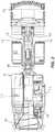
- FIG. 2is a perspective view of a portion of the mining machine of FIG. 1 .
- FIG. 3is a plan view of the mining machine of FIG. 1 .
- FIG. 4is a plan view of a drive train of the mining machine of FIG. 1 .
- FIG. 5Ais a schematic view of a drive train.
- FIG. 5Bis a schematic view of potential power transmission paths in the drive train of FIG. 2A .
- FIG. 5Cis a schematic view of a drive train during a charging mode.
- FIG. 5Dis a schematic view of a drive train during a discharge mode of an energy storage device.
- FIG. 5Eis a schematic view of a drive train during a drive mode.
- FIG. 5Fis a schematic view of a drive train during a light braking mode.
- FIG. 5Gis a schematic view of a drive train during a heavy braking and charging mode.
- FIG. 5His a schematic view of a drive train during a heavy braking mode without charging an energy storage device.
- FIG. 6is a perspective view of an energy storage system.
- FIG. 7is a side section view of the energy storage system of FIG. 6 viewed along section 7 - 7 .
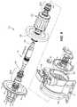
- FIG. 8is an exploded view of the energy storage system of FIG. 6 .
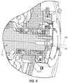
- FIG. 9is an enlarged view of section 9 - 9 of the side section view of FIG. 7 .
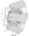
- FIG. 10is an enlarged view of section 10 - 10 of the side section view of FIG. 7 .
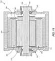
- FIG. 11is a side view of an energy storage device according to another embodiment.
- FIG. 12is a side view of an energy storage device according to another embodiment.
- FIG. 13is an end view of the energy storage device of FIG. 12 .
- embodimentsmay include hardware, software, and electronic components or modules that, for purposes of discussion, may be illustrated and described as if the majority of the components were implemented solely in hardware.
- aspectsmay be implemented in software (e.g., stored on non-transitory computer-readable medium) executable by one or more processing units, such as a microprocessor and/or an application specific integrated circuits (“ASICs”).
- processing unitssuch as a microprocessor and/or an application specific integrated circuits (“ASICs”).
- ASICsapplication specific integrated circuits
- a plurality of hardware and software based devices, as well as a plurality of different structural componentsmay be utilized to implement the invention.
- “controllers” described in the specificationcan include one or more processing units, one or more computer-readable medium modules, one or more input/output interfaces, and various connections (e.g., a system bus) connecting the components.
- FIGS. 1-3illustrate a mining machine 100 according to one embodiment.
- the mining machine 100is a load-haul-dump (“LHD”) machine.
- the machine 100can be an underground mining machine (e.g., a continuous miner, a haulage system, a longwall shearer, a loader, etc.) or a surface mining machine (e.g., a wheel loader, a hybrid shovel, a dragline miner, etc.).
- the mining machine 100further includes a chassis 102 , boom 104 having a first end 106 coupled to the chassis 102 and a second end 108 coupled to an attachment 112 (e.g., a bucket).
- an attachment 112e.g., a bucket
- the chassis 102also includes an operator cab 114 .
- the mining machine 100further includes traction elements, such as wheels 110 , rotatably coupled to the chassis 102 and supporting the chassis 102 for movement over the ground.
- traction elementssuch as wheels 110
- a kinetic energy storage system (“KESS”) or energy storage device 135is supported on the chassis 102 .
- the energy storage device 135is positioned proximate an end of the chassis 102 opposite the attachment 112 .
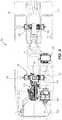
- FIG. 4illustrates the primary components of the drive system or drive train 118 of the mining machine 100 .
- the drive train 118may include an engine 115 , a generator 120 , a power converter 125 , motors 130 , and the energy storage device 135 .
- the machine 10may include multiple power converters, multiple motors, and/or multiple energy storage devices.
- the engine 115provides power, in the form of mechanical energy, to the generator 120 .
- the engine 115is a diesel engine.
- the engine 115provides an average power output of 180 horsepower (“Hp”) and a peak power output of 300 Hp.
- the energy storage device 135can be used as a power averaging device, discharging stored energy during periods of peak power demand.
- the energy storage device 135may supplement power supplied by the engine 115 in order to reduce the need to operate the engine 115 at peak power output.
- the generator 120converts mechanical energy received from the engine 115 into electrical energy.
- the generator 120is a switched reluctance (“SR”) motor/generator.
- the generator 120is another type of direct current (“DC”) motor/generator.
- the generator 120is an alternating current (“AC”) motor/generator.
- the generator 120can also be used as a motor that increases the revolutions per minute (“RPM”) of the engine 115 (e.g., as an energy storage mechanism used separately or in combination with the energy storage device 135 described below).
- RPMrevolutions per minute
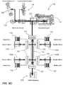
- FIG. 5Aschematically illustrates the components of a drive train for the mining machine 100 .
- the generator 120transmits power to a converter 125 that converts a received energy into a second energy via a bus 140 (e.g., a DC bus).
- the bus 140is in communication with additional converters 125 , each of which transmits the second energy output to a traction motor 130 .
- the converters 125can be configured to transmit energy through the bus 140 or to receive power from the bus 140 .
- the traction motors 130convert electrical energy into rotational energy or torque to drive the wheels 110 ( FIG. 2A ) or other components of the mining machine 100 .
- the motors 130include a motor for each wheel 110 of the machine 100 .
- Each traction motor 130is associated with a braking grid 142 that converts kinetic energy from the traction motor 130 into thermal energy when brakes are applied to slow down the machine 100 .
- the motors 130include a left-front (“LF”) motor 130 a , a right-front motor (“RF”) 130 b , a left-rear (“LR”) motor 130 c , and a right-rear (“RR”) motor 130 d .
- the motors 130are used to propel (forward and reverse), brake (forward and reverse), and control tire slip.
- one or more of the motors 130are switched-reluctance (“SR”) motors.
- the SR motormay provide full torque at stall (i.e., when the output rotational speed is zero) while consuming a small percentage of the power output of the engine 115 , which saves fuel consumption and reduces emissions.
- the mining machine 100can include fewer or additional motors.
- the generator 120is also in communication with one or more components of the mining machine 100 . These components may operate other aspects of the machine 100 (e.g., actuating a loading bucket or driving a cutter head).
- the generator 120converts electrical energy to mechanical energy that drives one or more hydraulic components 132 (e.g., pumps and/or valves).
- the hydraulic components 132supply hydraulic energy to the hydraulic systems such as actuators 134 .
- the hydraulic systemscan perform hoisting, steering, rotating, and/or other auxiliary functions of the mining machine 100 .
- the hydraulic components 132may also operate parasitic components 136 , such as a cooling fan.
- the energy storage device 135may be charged by capturing braking energy from the traction system and/or by receiving power from the engine 115 and generator 120 during times of low power demand.
- the energy storage device 135receives and stores electrical energy from the generator 120 via the bus 140 .
- the energy storage device 135also outputs stored electrical energy to other components of the mining machine 100 (e.g., the converters 125 , the motors 130 , a hydraulic system, etc.).
- each energy storage device 135is configured to store electrical energy when there is available (i.e., excess) power from the engine 115 and output stored energy when energy demand is greater than the engine 115 can provide.
- the energy storage device 135includes a SR motor/generator (e.g., variable speed SR motor/generator).
- the primary energy source for the energy storage device 135is the traction system.
- the components (e.g., the wheels 110 and motors 130 ) of the traction systemare braking or slowing down, the energy of the slowing wheels is transmitted to the energy storage device 135 and stored as rotational energy in an inertial mass (i.e., flywheel 180 ).
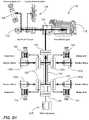
- FIG. 5Billustrates various potential power transmission paths through the drive train 118 .
- the generator 120 and engine 115can provide power to the hydraulic pumps 132 , and the generator 120 can also receive energy from the bus 140 (e.g., when the traction system is braking).
- each motor 130can receive energy from the bus 140 and supply energy to the bus 140 .
- the energy storage device 135can receive energy from the bus 140 and supply energy to the bus 140 .
- each motor 130may include a mechanical brake (not shown). When a controller detects that the mechanical brake of the motor 130 is engaged, the speed of the motor 130 is retarded or reduced to inhibit propulsion of the machine.
- Braking mechanismse.g., braking grid resistors 142 ) may receive energy from the bus 140 and dissipate the energy as heat.
- FIG. 5Cillustrates a power flow path through the drive train 118 when the energy storage system 135 is charged.
- Power supplied by the generator 120is provided to the bus 140 , which transmits power to the energy storage device 135 .
- the energy storage device 135is charged during start-up of the machine 100 .
- the energy storage device 135may be charged during times of low load on the generator 120 (i.e., the generator 120 receives surplus energy from the engine 115 than is required to operate the traction motors 130 or the other components of the machine 100 ).
- FIG. 5Dillustrates a power flow path through the drive train 118 when the traction motors 130 are driven to propel the machine 100 .
- the energy storage device 135can discharge and transmit power to the bus 140 , which transmits the power to the motors 130 to drive the wheels 110 .
- the energy storage device 135acts as the primary or master power source for the motors 130 and provides all of the energy required to drive the motors 130 . If the energy storage device 135 cannot supply all of the energy required by the motors 130 , the generator 120 and engine 115 supply additional power to the bus 140 that can be consumed by the motors 130 . In this arrangement the energy storage device 135 is the primary power supply for the motors 130 and the generator 120 provides auxiliary or backup power.
- the energy storage device 135is a more responsive power source than the generator 120 .
- the drive train 118relies on the most responsive power source first, allowing the traction system to accelerate and decelerate faster than a conventional drive system.
- using the energy storage system 135 as the primary energy sourcereduces the need to operate the engine 115 at its full output. Rather, using the energy storage device 135 as the primary power source to the traction system allows the engine 115 to operate at a steadier output, thereby reducing fuel consumption, engine output requirements, and engine wear 115 .
- the drive train 118may operate the traction motors 130 without using the energy storage device 135 . That is, the energy supplied to the motors 130 via the bus 140 is supplied solely by the generator 120 . This mode may be implemented when the energy storage device 135 is not charged, is malfunctioning, or is not present.
- FIGS. 5F-5Hillustrate power flow paths when the machine 100 is braking and the motors 130 act as generators supplying electrical energy to the bus 140 .
- the energy supplied by the motors 108can be supplied to the generator 120 .
- the generator 120can use the received energy to speed up the drive line between the generator 120 and the hydraulic pumps 132 (e.g., to speed up the engine 115 to a set speed at which fuel injectors are programmed to cease delivering fuel to the engine 115 ). In some situations, this mode of operation reduces engine fuel consumption (e.g., to operate at zero fuel or near-zero fuel levels).
- the motors 130may generate more energy than the energy generated during light braking. Therefore, the energy generated by the motors 130 and supplied to the bus 140 may be transmitted to both the generator 120 and to charging the energy storage device 135 .
- the motors 130may perform heavy braking without charging the energy storage device 135 (e.g., the energy storage device 135 is full, malfunctioning, or not present). Although some of the power supplied to the bus 140 from the motors 130 is transmitted to the generator 120 , additional or excess energy can be supplied to one or more of the braking grids 142 to dissipate the energy as heat.
- the generator 120can be used as the primary power source of the traction system and the energy storage device 135 can provide backup power.
- a controllercan be incorporated and programmed to control the energy storage device 135 based on the operating speed of the traction system.
- the energy storage device 135includes a housing 165 having feet 170 mounted on the chassis 102 ( FIG. 1 ).
- the housing 165also includes a junction box 168 in communication with the generator 102 ( FIG. 4 ).
- the energy storage device 135further includes a shaft 175 , a flywheel 180 coupled to the shaft 175 , and a motor stator 185 including coils 188 .
- the shaft 175extends through the housing 165 and includes a first end 190 and a second end 195 .
- a shaft axis 200extends between the first end 190 and the second end 195 .
- Each end 190 , 195 of the shaft 175is supported for rotation relative to the housing 165 by bearings 205 (see also FIGS. 9 and 10 ).
- the bearings 205are double ball bearings.
- a lamination stack 210forms a rotor and is secured to the outer surface of the shaft 175 proximate the first end 190 .
- the flywheel 180is axially spaced apart from the rotor 210 .
- the motor stator 185is secured within the housing 165 and extends around the lamination stack 210 .
- the flywheel 180is positioned within the housing 165 .
- the flywheel 180is secured to the shaft 175 proximate the second end 195 , such that the flywheel 180 is spaced apart from the stator 185 along the axis 200 .
- the flywheel 180is positioned between the bearings 205 . That is, the second end 195 of the shaft 175 extends beyond the flywheel 180 and is supported for rotation by a bearing 205 b .
- the rotation of the flywheel 180 and the operation of the machineinduces a gyroscopic load on the bearings, and this load is related to the distance between the bearings and the gyroscopic load. Increasing the distance between the flywheel and the bearings reduces the resultant load on the bearings.
- flywheel 180In conventional energy storage systems, larger energy storage capacity requires larger masses for the flywheel/storage component. Increasing the mass of the flywheel 180 increases the gyroscopic loads on the bearings. The configuration of the flywheel 180 with respect to the bearings 205 reduces the gyroscopic loads applied to the bearings 205 during operation. This allows a larger inertial mass, which in turn increases the energy storage capacity of the device 135 . Increasing the energy storage capacity reduces the demand for engine power. In some embodiments, the increased storage capacity reduces the required engine output power by 50%.
- the flywheel 180stores kinetic energy in the form of rotational energy.
- the energy storage device 135is configured to receive electrical energy and output rotational energy, as well as to receive rotational energy and output electrical energy.
- the flywheel 180is capable of rotating at speeds between approximately 0 revolutions per minute (rpm) and approximately 6,500 rpm.
- the maximum rotational speed of the flywheel 180is between approximately 3,000 rpm and approximately 10,000 rpm.
- the maximum rotational speed of the flywheel 180is between approximately 5,000 rpm and approximately 8,000 rpm.
- the maximum rotational speed of the flywheelis approximately 6,500 rpm.
- the maximum energy storage and discharge capacity of the energy storage device 135is between approximately 1 megajoule and approximately 15 megajoules. In some embodiments, the maximum energy storage and discharge capacity of the energy storage device 135 is between approximately 2 megajoules and approximately 7 megajoules. In some embodiments, the maximum energy storage and discharge capacity of the energy storage device 135 is approximately 3 megajoules.
- the energy storage device 135may receive electrical energy from, e.g., the generator 120 .
- the electrical energy in the stator 185induces the rotor shaft 175 to rotate about the shaft axis 200 , thereby rotating the flywheel 180 and storing kinetic energy in the form of rotational energy in the flywheel 165 .
- the rotation of flywheel 180is used to rotate the rotor shaft 175 . Rotation of the rotor 175 in this manner acts as a generator to induce a current in the stator 185 , thereby converting rotational energy into electrical energy.
- the electrical energycan be provided to other components of the mining machine 100 , such as the motors 130 .
- the energy storage device 135when used in the mining machine 100 , one of the converters 125 that would normally serve the generator 120 becomes the converter for the energy storage device 135 .
- FIG. 11illustrates an energy storage device 535 according to another embodiment.
- a flywheel 580is formed as a cylindrical member, such that the flywheel 580 includes a first or web portion 582 coupled to the shaft 175 and extending radially outwardly from the axis 200 of the shaft 175 .
- the web portion 582includes an outer periphery.
- the flywheel 580further includes a cylindrical portion 584 extending from the periphery of web portion 582 along the axis 200 of the shaft 175 .
- the cylindrical portion 584extends around the rotor lamination stack 610 and the stator 585 , and the cylindrical portion 584 extends along the length of the rotor and stator assembly.
- the cylindrical portion 584may have a different length compared to the rotor and stator assembly.
- the stator 585is secured to an end wall 172 of the housing 165 . This configuration increases the power density of the energy storage device per unit of mass.
- FIGS. 12 and 13illustrate an energy storage device 935 according to another embodiment.
- the rotor and flywheelare formed as a single assembly 975 rotating about a stationary stator core 985 .
- the stator core 985is positioned circumferentially within the rotor/flywheel assembly 975 .
- the stator core 985is supported on a shaft 982 , and the rotor/flywheel assembly 975 is supported for rotation relative to the shaft 982 by bearings 1005 .
- This configurationconcentrates the inertial mass at an outer perimeter of the motor, thereby providing, among other things, more efficient energy storage per unit of mass and volume.
Landscapes
- Engineering & Computer Science (AREA)
- Mechanical Engineering (AREA)
- Transportation (AREA)
- Power Engineering (AREA)
- Mining & Mineral Resources (AREA)
- General Engineering & Computer Science (AREA)
- Structural Engineering (AREA)
- Civil Engineering (AREA)
- Combustion & Propulsion (AREA)
- Chemical & Material Sciences (AREA)
- Life Sciences & Earth Sciences (AREA)
- Geochemistry & Mineralogy (AREA)
- Geology (AREA)
- General Life Sciences & Earth Sciences (AREA)
- Automation & Control Theory (AREA)
- Sustainable Development (AREA)
- Sustainable Energy (AREA)
- Electric Propulsion And Braking For Vehicles (AREA)
- Hybrid Electric Vehicles (AREA)
- Connection Of Motors, Electrical Generators, Mechanical Devices, And The Like (AREA)
- Charge And Discharge Circuits For Batteries Or The Like (AREA)
- Operation Control Of Excavators (AREA)
- Arrangement Or Mounting Of Propulsion Units For Vehicles (AREA)
- Supply And Distribution Of Alternating Current (AREA)
Abstract
Description
Claims (19)
Priority Applications (1)
| Application Number | Priority Date | Filing Date | Title |
|---|---|---|---|
| US16/659,028US11084367B2 (en) | 2015-05-28 | 2019-10-21 | Mining machine and energy storage system for same |
Applications Claiming Priority (5)
| Application Number | Priority Date | Filing Date | Title |
|---|---|---|---|
| US201562167808P | 2015-05-28 | 2015-05-28 | |
| US201562167814P | 2015-05-28 | 2015-05-28 | |
| US15/166,976US9764634B2 (en) | 2015-05-28 | 2016-05-27 | Mining machine and energy storage system for same |
| US15/676,466US10449849B2 (en) | 2015-05-28 | 2017-08-14 | Mining machine and energy storage system for same |
| US16/659,028US11084367B2 (en) | 2015-05-28 | 2019-10-21 | Mining machine and energy storage system for same |
Related Parent Applications (1)
| Application Number | Title | Priority Date | Filing Date |
|---|---|---|---|
| US15/676,466ContinuationUS10449849B2 (en) | 2015-05-28 | 2017-08-14 | Mining machine and energy storage system for same |
Publications (2)
| Publication Number | Publication Date |
|---|---|
| US20200047604A1 US20200047604A1 (en) | 2020-02-13 |
| US11084367B2true US11084367B2 (en) | 2021-08-10 |
Family
ID=57393358
Family Applications (6)
| Application Number | Title | Priority Date | Filing Date |
|---|---|---|---|
| US15/167,600AbandonedUS20160348336A1 (en) | 2015-05-28 | 2016-05-27 | Systems, methods, and apparatus for performing automatic positioning of a haulage vehicle |
| US15/167,608Active2036-07-14US9873318B2 (en) | 2015-05-28 | 2016-05-27 | Systems, methods, and apparatuses for storing energy in a mining machine |
| US15/166,976ActiveUS9764634B2 (en) | 2015-05-28 | 2016-05-27 | Mining machine and energy storage system for same |
| US15/676,466ActiveUS10449849B2 (en) | 2015-05-28 | 2017-08-14 | Mining machine and energy storage system for same |
| US15/873,748ActiveUS10377225B2 (en) | 2015-05-28 | 2018-01-17 | Systems, methods, and apparatuses for storing energy in a mining machine |
| US16/659,028ActiveUS11084367B2 (en) | 2015-05-28 | 2019-10-21 | Mining machine and energy storage system for same |
Family Applications Before (5)
| Application Number | Title | Priority Date | Filing Date |
|---|---|---|---|
| US15/167,600AbandonedUS20160348336A1 (en) | 2015-05-28 | 2016-05-27 | Systems, methods, and apparatus for performing automatic positioning of a haulage vehicle |
| US15/167,608Active2036-07-14US9873318B2 (en) | 2015-05-28 | 2016-05-27 | Systems, methods, and apparatuses for storing energy in a mining machine |
| US15/166,976ActiveUS9764634B2 (en) | 2015-05-28 | 2016-05-27 | Mining machine and energy storage system for same |
| US15/676,466ActiveUS10449849B2 (en) | 2015-05-28 | 2017-08-14 | Mining machine and energy storage system for same |
| US15/873,748ActiveUS10377225B2 (en) | 2015-05-28 | 2018-01-17 | Systems, methods, and apparatuses for storing energy in a mining machine |
Country Status (13)
| Country | Link |
|---|---|
| US (6) | US20160348336A1 (en) |
| EP (3) | EP3303046B1 (en) |
| CN (3) | CN113799623A (en) |
| AU (4) | AU2016267252B2 (en) |
| BR (2) | BR112017025487B1 (en) |
| CA (2) | CA2987594A1 (en) |
| CL (2) | CL2017003001A1 (en) |
| ES (2) | ES2996510T3 (en) |
| MX (5) | MX370181B (en) |
| PE (3) | PE20181372A1 (en) |
| RU (4) | RU2722775C2 (en) |
| WO (3) | WO2016191733A1 (en) |
| ZA (1) | ZA201708188B (en) |
Cited By (3)
| Publication number | Priority date | Publication date | Assignee | Title |
|---|---|---|---|---|
| US20210277629A1 (en)* | 2020-02-20 | 2021-09-09 | Terex Gb Limited | Material processing apparatus with hybrid power system |
| US20220416563A1 (en)* | 2020-03-30 | 2022-12-29 | Mitsubishi Electric Corporation | Elevator |
| US12304329B2 (en) | 2022-11-07 | 2025-05-20 | Caterpillar Inc. | Electrical architecture for battery powered machine |
Families Citing this family (20)
| Publication number | Priority date | Publication date | Assignee | Title |
|---|---|---|---|---|
| KR102181294B1 (en)* | 2014-05-27 | 2020-11-20 | 두산인프라코어 주식회사 | Wheel driving system for construction machinery |
| US10246094B2 (en)* | 2014-12-09 | 2019-04-02 | Ford Global Technologies, Llc | Autonomous vehicle cornering maneuver |
| PE20181372A1 (en) | 2015-05-28 | 2018-08-28 | Joy Global Longview Operations Llc | MINING MACHINE AND ENERGY STORAGE SYSTEM FOR THE SAME |
| US11035095B2 (en)* | 2016-09-23 | 2021-06-15 | Artisan Vehicle Systems, Inc. | Electrically powered mining vehicle |
| US10730394B2 (en)* | 2016-10-04 | 2020-08-04 | Ford Global Technologies, Llc | Electromechanical integrated machine for electrified vehicles |
| DE102017106619A1 (en)* | 2017-03-28 | 2018-10-04 | Ghh Fahrzeuge Gmbh | Electrically driven underground vehicle, in particular loader |
| JP6794960B2 (en)* | 2017-08-22 | 2020-12-02 | トヨタ自動車株式会社 | Power system |
| IT201800003793A1 (en) | 2018-03-20 | 2019-09-20 | Soilmec Spa | DRILLING MACHINE EQUIPPED WITH A DEVICE FOR HANDLING THE DRILLING BATTERY WITH ELECTRIC BRAKING. |
| CN108612138B (en)* | 2018-06-27 | 2024-06-14 | 大连理工高邮研究院有限公司 | Green new energy scraper |
| SE543007C2 (en) | 2018-07-04 | 2020-09-22 | Epiroc Rock Drills Ab | Methods and devices for power control in mining machines |
| US20200157769A1 (en)* | 2018-09-06 | 2020-05-21 | Artisan Vehicle Systems, Inc. | Electric Load-Haul-Dump Mining Machine |
| GB201815260D0 (en)* | 2018-09-19 | 2018-10-31 | Oxto Ltd | Energy storage system |
| RU2688563C1 (en)* | 2018-10-05 | 2019-05-21 | Владимир Андреевич Коровин | Electromechanical transmission of self-propelled machine with internal combustion engine |
| US11459725B2 (en)* | 2018-11-29 | 2022-10-04 | Caterpillar Inc. | Control system for a grading machine |
| GB2583721B (en) | 2019-05-02 | 2021-11-03 | Ricardo Uk Ltd | Electric machine |
| RU2726814C1 (en)* | 2020-01-10 | 2020-07-15 | Владимир Андреевич Коровин | Self-propelled machine with electromechanical transmission and power takeoff system |
| US11821166B2 (en)* | 2020-07-22 | 2023-11-21 | Caterpillar Underground Mining Pty. Ltd. | Internal support structure for underground battery machines |
| ES2946361A1 (en)* | 2022-01-14 | 2023-07-17 | H2Vector Energy Technoligies Sl | Mixed hydrogen transmission system for driving hydraulic cranes (Machine-translation by Google Translate, not legally binding) |
| CN114483287A (en)* | 2022-01-24 | 2022-05-13 | 浙江吉利控股集团有限公司 | A kind of vehicle oxygenation device and control method thereof |
| USD1088056S1 (en)* | 2022-09-20 | 2025-08-12 | Sandvik Mining And Construction Oy | Drill rig |
Citations (188)
| Publication number | Priority date | Publication date | Assignee | Title |
|---|---|---|---|---|
| US2589454A (en) | 1948-10-15 | 1952-03-18 | Oerlikon Maschf | Flywheel energy storage system, particularly for electric vehicles |
| US3623771A (en) | 1970-06-25 | 1971-11-30 | Du Pont | Drill-and-blast excavating apparatus and method |
| US3915325A (en) | 1972-11-09 | 1975-10-28 | Int Harvester Co | Electronic control device |
| US3979650A (en) | 1974-12-04 | 1976-09-07 | Consolidation Coal Company | Energy conversion apparatus for supplying variable voltage direct current power to an electrically propelled vehicle |
| US4320814A (en) | 1979-07-31 | 1982-03-23 | Paccar Inc. | Electric-hydrostatic drive modules for vehicles |
| US4358719A (en) | 1980-07-18 | 1982-11-09 | Bucyrus-Erie Company | Peak power limiter system for excavator |
| US4495451A (en) | 1981-01-06 | 1985-01-22 | Barnard Maxwell K | Inertial energy interchange system with energy makeup by combustion engine on demand |
| DE3411021A1 (en) | 1984-03-24 | 1985-10-03 | Neuhäuser GmbH + Co, 4670 Lünen | Flywheel drive for machines and vehicles, especially mine vehicles |
| US5404661A (en) | 1994-05-10 | 1995-04-11 | Caterpillar Inc. | Method and apparatus for determining the location of a work implement |
| US5515937A (en) | 1991-10-04 | 1996-05-14 | Mannesmann Aktiengesellschaft | Non-trackbound vehicle with an electric transducer |
| US5769503A (en) | 1996-07-23 | 1998-06-23 | Stolar, Inc. | Method and apparatus for a rotating cutting drum or arm mounted with paired opposite circular polarity antennas and resonant microstrip patch transceiver for measuring coal, trona and potash layers forward, side and around a continuous mining machine |
| US5789896A (en) | 1997-01-03 | 1998-08-04 | Fischer; George A. | Apparatus and method for controlling an electric motor having an armature and a series-wound, series-connected field coil that can be separately controlled during regenerative braking |
| US6220377B1 (en) | 1998-04-17 | 2001-04-24 | Lansberry Tractor Company, Inc. | Load support shifting vehicle |
| US6308639B1 (en) | 2000-04-26 | 2001-10-30 | Railpower Technologies Corp. | Hybrid battery/gas turbine locomotive |
| US20020037211A1 (en) | 1999-10-15 | 2002-03-28 | George Korycan | Work vehicle |
| CN1356222A (en) | 2001-03-24 | 2002-07-03 | 许金鲁 | Constraint energy accumulating technique for controlling and self-controlling reaction of electric vehicle |
| US6469638B1 (en) | 2000-09-30 | 2002-10-22 | Modular Mining Systems, Inc. | Intra-vehicle communications system in a mining vehicle monitoring system |
| US6529812B1 (en) | 2001-08-28 | 2003-03-04 | Caterpillar Inc | Method and system for efficient processor usage |
| US6591758B2 (en) | 2001-03-27 | 2003-07-15 | General Electric Company | Hybrid energy locomotive electrical power storage system |
| US20030150352A1 (en) | 2001-03-27 | 2003-08-14 | General Electric Company | Hybrid energy off highway vehicle electric power storage system and method |
| US20030151387A1 (en) | 2001-03-27 | 2003-08-14 | General Electric Company | Hybrid energy off highway vehicle electric power management system and method |
| US6612246B2 (en) | 2001-03-27 | 2003-09-02 | General Electric Company | Hybrid energy locomotive system and method |
| US6612245B2 (en) | 2001-03-27 | 2003-09-02 | General Electric Company | Locomotive energy tender |
| US6633800B1 (en) | 2001-01-31 | 2003-10-14 | Ainsworth Inc. | Remote control system |
| US20030233959A1 (en) | 2001-03-27 | 2003-12-25 | General Electric Company | Multimode hybrid energy railway vehicle system and method |
| US20040133315A1 (en) | 2003-01-06 | 2004-07-08 | General Electric Company | Multi-level railway operations optimization system and method |
| JP2004229394A (en) | 2003-01-22 | 2004-08-12 | Honda Motor Co Ltd | Control device for hybrid vehicle |
| EP1505213A1 (en) | 2003-08-08 | 2005-02-09 | Eickhoff Bergbautechnik GmbH | Hydraulic milling device with flywheel |
| US20050052080A1 (en) | 2002-07-31 | 2005-03-10 | Maslov Boris A. | Adaptive electric car |
| US20050139399A1 (en) | 2003-12-30 | 2005-06-30 | Hydrogenics Corporation | Hybrid electric propulsion system, hybrid electric power pack and method of optimizing duty cycle |
| US6922619B2 (en) | 2002-02-28 | 2005-07-26 | General Electric Company | System and method for selectively limiting tractive effort to facilitate train control |
| US6922990B2 (en) | 2002-11-21 | 2005-08-02 | Komatsu Ltd. | Device arrangement structure for hybrid construction equipment |
| US20050206331A1 (en) | 2004-03-08 | 2005-09-22 | Railpower Technologies Corp. | Hybrid locomotive configuration |
| US20050235865A1 (en) | 2001-03-27 | 2005-10-27 | Ajith Kuttannair Kumar | Electrical energy capture system with circuitry for blocking flow of undesirable electrical currents therein |
| US20050251299A1 (en) | 2004-03-30 | 2005-11-10 | Railpower Technologies Corp. | Emission management for a hybrid locomotive |
| WO2005119894A1 (en) | 2004-05-27 | 2005-12-15 | Siemens Energy & Automation, Inc. | Ac/ac converter for hybrid vehicles |
| US20050279243A1 (en) | 2004-06-16 | 2005-12-22 | General Electric Company | Locomotive propulsion system module for refurbishment of used locomotives |
| US20050279242A1 (en) | 2004-03-01 | 2005-12-22 | Railpower Technologies Corp. | Cabless hybrid locomotive |
| US20060005737A1 (en) | 2001-03-27 | 2006-01-12 | General Electric Company | Hybrid energy off highway vehicle electric power storage system and method |
| JP2006025489A (en) | 2004-07-06 | 2006-01-26 | Railway Technical Res Inst | Flywheel power storage device |
| US20060061213A1 (en) | 2004-08-24 | 2006-03-23 | Honeywell International | Electrical starting, generation, conversion and distribution system architecture for a more electric vehicle |
| US20060076171A1 (en) | 2004-08-09 | 2006-04-13 | Donnelly Frank W | Regenerative braking methods for a hybrid locomotive |
| US7061131B2 (en) | 2003-06-13 | 2006-06-13 | General Electric Company | Method and system for optimizing energy storage in hybrid off-highway vehicle systems and trolley connected OHV systems |
| US7078877B2 (en) | 2003-08-18 | 2006-07-18 | General Electric Company | Vehicle energy storage system control methods and method for determining battery cycle life projection for heavy duty hybrid vehicle applications |
| US7124691B2 (en) | 2003-08-26 | 2006-10-24 | Railpower Technologies Corp. | Method for monitoring and controlling locomotives |
| US7131614B2 (en) | 2003-05-22 | 2006-11-07 | General Electric Company | Locomotive control system and method |
| US20060250902A1 (en) | 2005-05-05 | 2006-11-09 | Afs Trinity Power Corporation | Plug-in hybrid vehicle with fast energy storage |
| US7137344B2 (en) | 2001-03-27 | 2006-11-21 | General Electric Company | Hybrid energy off highway vehicle load control system and method |
| CN1906050A (en) | 2004-08-09 | 2007-01-31 | 通用电气公司 | Hybrid energy off-highway vehicle propulsion circuits |
| US7190133B2 (en) | 2004-06-28 | 2007-03-13 | General Electric Company | Energy storage system and method for hybrid propulsion |
| US7304445B2 (en) | 2004-08-09 | 2007-12-04 | Railpower Technologies Corp. | Locomotive power train architecture |
| US7302895B2 (en) | 2002-02-28 | 2007-12-04 | General Electric Company | Configurable locomotive |
| US7309929B2 (en) | 2005-04-25 | 2007-12-18 | Railpower Technologies Corporation | Locomotive engine start method |
| JP2008062822A (en) | 2006-09-08 | 2008-03-21 | Shin Caterpillar Mitsubishi Ltd | Hybrid system |
| US7350876B2 (en) | 2003-09-30 | 2008-04-01 | J.H. Fletcher & Co. | Combination panline and utility drilling or bolting unit |
| US20080121448A1 (en) | 2006-09-29 | 2008-05-29 | Betz Michael D | Energy storage and recovery for a tracked machine |
| WO2008076694A2 (en) | 2006-12-14 | 2008-06-26 | Williams Kevin R | Flywheel system for use with motorized wheels in a hybrid vehicle |
| US7430967B2 (en) | 2001-03-27 | 2008-10-07 | General Electric Company | Multimode hybrid energy railway vehicle system and method |
| US20090033148A1 (en) | 2007-07-31 | 2009-02-05 | Caterpillar Inc. | Electrical system architecture having high voltage bus |
| US7500436B2 (en) | 2003-05-22 | 2009-03-10 | General Electric Company | System and method for managing emissions from mobile vehicles |
| US7516244B2 (en) | 2003-07-02 | 2009-04-07 | Caterpillar Inc. | Systems and methods for providing server operations in a work machine |
| US7532640B2 (en) | 2003-07-02 | 2009-05-12 | Caterpillar Inc. | Systems and methods for performing protocol conversions in a machine |
| US7552787B1 (en)* | 2005-10-07 | 2009-06-30 | Williams Kevin R | Energy recoverable wheel motor |
| US7565867B2 (en) | 2004-09-03 | 2009-07-28 | Frank Wegner Donnelly | Multiple engine locomotive configuration |
| WO2009103119A1 (en) | 2008-02-21 | 2009-08-27 | Gregory James Moore | Underground mining vehicle |
| US7596893B2 (en) | 2005-06-06 | 2009-10-06 | Caterpillar Japan Ltd. | Work machine |
| US7656342B2 (en) | 2006-10-23 | 2010-02-02 | Stolar, Inc. | Double-sideband suppressed-carrier radar to null near-field reflections from a first interface between media layers |
| US7659847B2 (en) | 2006-06-29 | 2010-02-09 | Stolar, Inc. | Radar mining guidance control system |
| US20100039054A1 (en) | 2008-08-14 | 2010-02-18 | General Electric Company | Vehicle, system and method |
| US7667347B2 (en) | 2007-01-24 | 2010-02-23 | Railpower, Llc | Multi-power source locomotive control method and system |
| US7673713B2 (en) | 2006-10-26 | 2010-03-09 | Caterpillar Inc. | Multi-purpose mobile power generating machine |
| KR20100035265A (en) | 2008-09-26 | 2010-04-05 | 한국철도기술연구원 | Series hybrid driving system using flywheel and driving method |
| US20100114404A1 (en) | 2008-10-17 | 2010-05-06 | Frank Wegner Donnelly | Rail Conveyance system for mining |
| US7770673B2 (en) | 2000-09-13 | 2010-08-10 | Phillips Machine Service, Inc. | Battery powered shuttle car |
| US7779616B2 (en) | 2008-06-03 | 2010-08-24 | Deere & Company | Vehicle with electric hybrid powering of external loads and engine-off capability |
| US20100221071A1 (en) | 2006-09-15 | 2010-09-02 | J. H. Fletcher & Co | Remotely controlled mining machines, control systems, and related methods |
| US7795825B2 (en) | 2008-09-15 | 2010-09-14 | Caterpillar Inc | Over-voltage and under-voltage management for electric drive system |
| US20100289443A1 (en) | 2009-05-15 | 2010-11-18 | Joy Mazumdar | Limiting Peak Electrical Power Drawn By Mining Excavators |
| US20100308939A1 (en) | 2008-09-27 | 2010-12-09 | Kurs Andre B | Integrated resonator-shield structures |
| US7853388B2 (en) | 2006-02-23 | 2010-12-14 | Siemens Industry, Inc. | Devices, systems, and methods for controlling a braking system |
| WO2010145021A1 (en) | 2009-06-15 | 2010-12-23 | Universite Laval | Energy storage system and method |
| US7882789B2 (en) | 2001-03-27 | 2011-02-08 | General Electric Company | System and method for managing emissions from diesel powered systems |
| US7893658B2 (en) | 2007-06-25 | 2011-02-22 | General Electric Company | Methods and systems for battery charging management |
| US7928597B2 (en) | 2008-12-12 | 2011-04-19 | General Electric Company | Power system and method for driving an electromotive traction system and auxiliary equipment through a common power bus |
| US20110094808A1 (en) | 2009-10-23 | 2011-04-28 | Siemens Industry, Inc. | Peak Demand Reduction in Mining Haul Trucks Utilizing an On-Board Energy Storage System |
| CN102071718A (en) | 2011-03-01 | 2011-05-25 | 湖南山河智能机械股份有限公司 | System for recovering energy of excavator |
| US7950481B2 (en) | 2005-09-29 | 2011-05-31 | Caterpillar Inc. | Electric powertrain for machine |
| US20110130906A1 (en) | 2009-12-01 | 2011-06-02 | Ise Corporation | Location Based Vehicle Data Logging and Diagnostic System and Method |
| US7956762B2 (en) | 2008-09-15 | 2011-06-07 | Caterpillar Inc. | Method and apparatus for power generation failure diagnostics |
| US7983820B2 (en) | 2003-07-02 | 2011-07-19 | Caterpillar Inc. | Systems and methods for providing proxy control functions in a work machine |
| US20110175579A1 (en) | 2009-05-15 | 2011-07-21 | Siemens Industry, Inc. | System and method for providing auxiliary power by regeneration power management in mobile mining equipment |
| US7996163B2 (en) | 2008-09-15 | 2011-08-09 | Caterpillar Inc. | Method and apparatus for detecting a short circuit in a DC link |
| US8013548B2 (en) | 2008-10-14 | 2011-09-06 | General Electric Company | System, vehicle and related method |
| US20110224859A1 (en) | 2008-11-26 | 2011-09-15 | Sandvik Mining And Construction Oy | Method for using mining vehicle, arrangement in mine, rock drilling rig, and mining vehicle |
| DE102010013670A1 (en) | 2010-04-01 | 2011-10-06 | Wacker Neuson Se | Double hybrid storage system |
| US8047317B2 (en) | 2008-11-05 | 2011-11-01 | General Electric Company | System, vehicle, and method |
| US20110301794A1 (en) | 2010-03-04 | 2011-12-08 | Bertrand Bastien | Electric drive vehicle, system and method |
| US20110307127A1 (en) | 2010-06-15 | 2011-12-15 | Kendall Roger Swenson | Method and system for controlling engine performance |
| DE202011108033U1 (en) | 2011-11-17 | 2011-12-28 | Schaeffler Technologies Gmbh & Co. Kg | Device with energy recovery system |
| US20120001743A1 (en) | 2010-07-03 | 2012-01-05 | Raytheon Company | Mine Personnel Carrier Integrated Information Display |
| US8095285B2 (en) | 2007-06-29 | 2012-01-10 | Caterpillar Inc. | Method for derating a power source to limit damage |
| US8112191B2 (en) | 2007-04-25 | 2012-02-07 | General Electric Company | System and method for monitoring the effectiveness of a brake function in a powered system |
| US8140206B2 (en) | 2008-09-15 | 2012-03-20 | Caterpillar Inc. | Engine load management for traction vehicles |
| US8136454B2 (en) | 2009-05-01 | 2012-03-20 | Norfolk Southern Corporation | Battery-powered all-electric locomotive and related locomotive and train configurations |
| US8180544B2 (en) | 2007-04-25 | 2012-05-15 | General Electric Company | System and method for optimizing a braking schedule of a powered system traveling along a route |
| US8186154B2 (en) | 2008-10-31 | 2012-05-29 | Caterpillar Inc. | Rotary flow control valve with energy recovery |
| US20120146387A1 (en) | 2010-12-14 | 2012-06-14 | Shatters Aaron R | Autonomous mobile conveyor system |
| US20120161497A1 (en) | 2011-12-30 | 2012-06-28 | Jing He | Wheel hub flywheel-motor kinetic hybrid system and method |
| US8220572B2 (en) | 2006-06-15 | 2012-07-17 | Railpower, Llc | Multi-power source locomotive selection |
| US8253357B2 (en) | 2008-09-15 | 2012-08-28 | Caterpillar Inc. | Load demand and power generation balancing in direct series electric drive system |
| US20120217079A1 (en)* | 2011-02-25 | 2012-08-30 | Besler Mark J | Interface for a motor and drive assembly |
| US8280569B2 (en) | 2004-12-09 | 2012-10-02 | General Electric Company | Methods and systems for improved throttle control and coupling control for locomotive and associated train |
| US8280566B2 (en) | 2006-04-17 | 2012-10-02 | General Electric Company | Method, system, and computer software code for automated establishment of a distributed power train |
| US8285434B2 (en) | 2007-12-28 | 2012-10-09 | Sumitomo Heavy Industries, Ltd. | Hybrid-type construction machine having an output condition calculating unit to calculate output conditions of an engine and an electric storage device |
| US8286740B2 (en) | 2008-10-29 | 2012-10-16 | Kobelco Construction Machinery Co., Ltd. | Hybrid working machine |
| US8292015B2 (en) | 2010-07-21 | 2012-10-23 | Caterpillar Global Mining America Llc | Battery-powered mining vehicle |
| US8294285B2 (en) | 2008-08-14 | 2012-10-23 | F3 & I2, Llc | Power packaging with railcars |
| US20120273285A1 (en) | 2011-04-27 | 2012-11-01 | Caterpillar Inc. | Method of converting, storing and utilizing potential energy at a worksite and system using the same |
| US20120298004A1 (en) | 2009-12-28 | 2012-11-29 | Jukka Osara | Mining vehicle and method for its energy supply |
| US8326499B2 (en) | 2008-12-02 | 2012-12-04 | Caterpillar Inc. | Retarding control of a machine through power dissipation through power source and parasitic loads |
| US20120305025A1 (en) | 2011-06-06 | 2012-12-06 | Courtland Joshua Helbig | Cleaning vehicle, vehicle system and method |
| US8330291B2 (en) | 2009-10-02 | 2012-12-11 | General Electric Company | Power generation apparatus |
| US20120316717A1 (en) | 2011-06-13 | 2012-12-13 | Wolfgang Daum | System and method for controlling and powering a vehicle |
| CN102848895A (en) | 2012-03-22 | 2013-01-02 | 山东蓬翔汽车有限公司 | Power assembly rear suspension support mechanism for mining vehicle |
| US8348804B2 (en) | 2008-01-18 | 2013-01-08 | Caterpillar Inc. | Hybrid engine system with transient load assistance |
| US8362786B2 (en) | 2008-03-21 | 2013-01-29 | Komatsu Ltd. | Method and device for determining degradation state of electrical storage device in hybrid construction equipment |
| US8371233B2 (en) | 2007-10-12 | 2013-02-12 | General Electric Company | System and method for dynamically affecting a force applied through a rail vehicle axle |
| US8371230B2 (en) | 2001-03-27 | 2013-02-12 | General Electric Company | Rail vehicle system |
| US8408144B2 (en) | 2006-10-04 | 2013-04-02 | The United States Of America, As Represented By The Administrator Of The U.S. Environmental Protection Agency | Hybrid locomotive regenerative energy storage system and method |
| US20130099561A1 (en) | 2009-12-23 | 2013-04-25 | General Electric Company | Method and system for utilization of regenerative braking electrical energy for operating auxiliary system in a vehicle |
| US20130115064A1 (en) | 2011-03-31 | 2013-05-09 | Takaaki Kimura | Insulator, and stator and motor provided with same |
| US20130154523A1 (en) | 2011-12-15 | 2013-06-20 | Caterpillar Inc. | Resistor grid assembly |
| CN103174185A (en) | 2007-12-26 | 2013-06-26 | 住友重机械工业株式会社 | Hybrid construction machine and control method of hybrid construction machine |
| US8505464B2 (en) | 2011-12-01 | 2013-08-13 | Caterpillar Inc. | Control strategy for providing regenerative electrical power to trolley line in trolley capable mining truck |
| US20130206490A1 (en) | 2009-12-28 | 2013-08-15 | Mikko Kouvo | Mining vehicle and method for its energy supply |
| US8511449B2 (en) | 2010-06-29 | 2013-08-20 | General Electric Company | Propulsion system for a powered rail vehicle and method of adapting the propulsion system between different configurations |
| US20130226419A1 (en) | 2012-02-29 | 2013-08-29 | Caterpillar, Inc. | Kinetic Energy System and Method for Hybrid Machine |
| US20130220720A1 (en) | 2011-03-31 | 2013-08-29 | Kouya Iizuka | Construction machine |
| US20130220714A1 (en) | 2012-02-23 | 2013-08-29 | Stephen A. Rudinec | All-electric powered anfo vehicle |
| US20130228377A1 (en) | 2010-11-04 | 2013-09-05 | Sandvik Mining And Constructin Oy | Rock drilling rig and method for transmission of rock drilling rig |
| US8534198B2 (en) | 2011-06-28 | 2013-09-17 | Progress Rail Services Corp | Locomotive engine enclosure and method for servicing locomotive engine |
| US20130241366A1 (en)* | 2012-02-27 | 2013-09-19 | Daniel Kee Young Kim | High torque/high efficiency winding motor |
| US20130248262A1 (en) | 2009-07-27 | 2013-09-26 | General Electric Company | Hoist system and method |
| US8550007B2 (en) | 2009-10-23 | 2013-10-08 | Siemens Industry, Inc. | System and method for reinjection of retard energy in a trolley-based electric mining haul truck |
| RU2495266C2 (en) | 2012-01-10 | 2013-10-10 | Федеральное государственное бюджетное образовательное учреждение высшего профессионального образования "Вологодский государственный технический университет" (ВоГТУ) | Method to minimise fuel consumption of automotive ice with power accumulation system and device to this end |
| US8571763B2 (en) | 2009-03-12 | 2013-10-29 | Komatsu Ltd. | Construction vehicle provided with work equipment |
| US8577530B2 (en) | 2011-12-01 | 2013-11-05 | Caterpillar Inc. | Steering system and operating method for mining truck |
| US8587260B2 (en) | 2008-07-24 | 2013-11-19 | General Electric Company | Method and system for control of a vehicle energy storage device |
| US20130307489A1 (en) | 2012-05-21 | 2013-11-21 | Ruediger Soeren Kusch | Method and apparatus for charging multiple energy storage devices |
| US20130307443A1 (en) | 2011-02-02 | 2013-11-21 | Kobelco Construction Machinery Co., Ltd. | Slewing-type working machine |
| US20130325269A1 (en) | 2011-03-01 | 2013-12-05 | Hitachi Construction Machinery Co., Ltd. | Hybrid-type construction machine |
| US8606448B2 (en) | 2011-06-29 | 2013-12-10 | Caterpillar Inc. | System and method for managing power in machine having electric and/or hydraulic devices |
| US8606451B2 (en) | 2010-10-06 | 2013-12-10 | Caterpillar Global Mining Llc | Energy system for heavy equipment |
| US8606444B2 (en) | 2010-12-29 | 2013-12-10 | Caterpillar Inc. | Machine and power system with electrical energy storage device |
| US8610382B2 (en) | 2010-12-23 | 2013-12-17 | Caterpillar Inc. | Active high voltage bus bleed down |
| US20130338885A1 (en) | 2012-06-15 | 2013-12-19 | John B. Kirk | Management system embedded in an industrial vehicle |
| US8622860B2 (en) | 2011-08-01 | 2014-01-07 | Spicer Off-Highway Belgium N.V. | Method and apparatus for transferring power between a flywheel and a vehicle |
| US8626403B2 (en) | 2010-10-06 | 2014-01-07 | Caterpillar Global Mining Llc | Energy management and storage system |
| US8631890B2 (en) | 2010-06-15 | 2014-01-21 | Hitachi Construction Machinery Co., Ltd. | Electric construction machine |
| US20140021779A1 (en) | 2012-07-18 | 2014-01-23 | General Electric Company | Systems and methods for mobile power conditioning platform |
| US20140032006A1 (en) | 2011-05-10 | 2014-01-30 | Komatsu Ltd. | Mine power management system |
| US8649963B2 (en) | 2008-01-08 | 2014-02-11 | General Electric Company | System, method, and computer software code for optimizing performance of a powered system |
| US20140046538A1 (en) | 2012-08-09 | 2014-02-13 | Caterpillar, Inc. | System and Method for Efficiently Operating Multiple Flywheels |
| US8662277B2 (en) | 2011-12-22 | 2014-03-04 | Fairfield Manufacturing Company, Inc. | Planetary gearbox with integral service brake |
| US8672069B2 (en) | 2009-08-25 | 2014-03-18 | Deere & Company | Hybrid vehicle with multiple electric drive systems |
| US20140084666A1 (en) | 2012-09-21 | 2014-03-27 | Joy Mm Delaware, Inc. | Lump breaker for mining machine |
| US8684150B2 (en) | 2010-06-15 | 2014-04-01 | General Electric Company | Control assembly and control method for supplying power to electrified rail vehicles |
| CN103826904A (en) | 2011-09-26 | 2014-05-28 | 本田技研工业株式会社 | drive unit for vehicle |
| US8768578B2 (en) | 2009-06-09 | 2014-07-01 | Sumitomo Heavy Industries, Ltd. | Hybrid excavator and method of controlling hybrid excavator |
| US20140203760A1 (en) | 2013-01-18 | 2014-07-24 | Caterpillar Inc. | Turbine engine hybrid power supply |
| WO2014120930A1 (en) | 2013-01-30 | 2014-08-07 | Parker-Hannifin Corporation | Hydraulic hybrid swing drive system for excavators |
| CN104002656A (en) | 2013-02-25 | 2014-08-27 | 费尔菲尔德制造公司 | Hybrid electric vehicle |
| CN104196079A (en) | 2014-07-25 | 2014-12-10 | 昆山三一数字科技有限公司 | Hydraulic excavator hybrid power system and hydraulic excavator thereof |
| US8935019B2 (en) | 2011-08-23 | 2015-01-13 | Sygnet Rail Technologies, Llc | Apparatus and method for power production, control, and/or telematics, suitable for use with locomotives |
| WO2015019789A1 (en) | 2013-08-08 | 2015-02-12 | ジヤトコ株式会社 | Flywheel regeneration system, and method of controlling same |
| US20150060172A1 (en)* | 2010-05-14 | 2015-03-05 | Carl Manganaro | Drive system for a motor vehicle |
| US20150081147A1 (en) | 2012-05-23 | 2015-03-19 | Komatsu Ltd. | Hybrid working machine and method of controlling hybrid working machine |
| US20150086315A1 (en) | 2013-09-24 | 2015-03-26 | Kobelco Construction Machinery Co., Ltd. | Hybrid construction machine |
| US9003977B2 (en) | 2012-08-31 | 2015-04-14 | General Electric Company | Vehicle system and method |
| US9162560B2 (en) | 2012-08-09 | 2015-10-20 | Caterpillar Inc. | Flywheel assembly for a powertrain |
| US9180770B1 (en)* | 2010-07-21 | 2015-11-10 | Sonic Blue Aerospace, Inc. | Turbo electromagnetic radial ramgenerator automotive jet electric turbine (TERRAJET) |
| US9415781B2 (en) | 2008-12-23 | 2016-08-16 | Progress Rail Services Corporation | Dual engine locomotive |
| US20160347167A1 (en) | 2015-05-28 | 2016-12-01 | Joy Global Longview Operations Llc | Mining machine and energy storage system for same |
| US9616903B2 (en) | 2012-08-31 | 2017-04-11 | General Electric Company | Vehicle system and method |
| US9669851B2 (en) | 2012-11-21 | 2017-06-06 | General Electric Company | Route examination system and method |
| US20190061504A1 (en)* | 2017-08-29 | 2019-02-28 | Nio Usa, Inc. | Compact Side-by-Side Motor Gearbox Unit |
| US20200047599A1 (en)* | 2017-01-31 | 2020-02-13 | Punch Flybrid Limited | An energy storage and recovery system |
| US10807466B1 (en)* | 2016-03-28 | 2020-10-20 | Dana Heavy Vehicle Systems Group, Llc | Electric drivetrain axles with multi-speed gearboxes |
Family Cites Families (21)
| Publication number | Priority date | Publication date | Assignee | Title |
|---|---|---|---|---|
| DE2943563A1 (en)* | 1979-10-27 | 1981-05-07 | Volkswagenwerk Ag | DRIVE, ESPECIALLY FOR MOTOR VEHICLES, WITH AN INTERNAL COMBUSTION ENGINE AND AN AUTOMATIC TRANSMISSION |
| US4511974A (en)* | 1981-02-04 | 1985-04-16 | Kabushiki Kaisha Toyoda Jidoshokki Seisakusho | Load condition indicating method and apparatus for forklift truck |
| WO1999047759A1 (en)* | 1998-03-18 | 1999-09-23 | Hitachi Construction Machinery Co., Ltd. | Automatically operated shovel and stone crushing system comprising the same |
| DE60102403T2 (en)* | 2000-01-24 | 2005-03-10 | Hino Jidosha K.K., Hino | hybrid vehicle |
| US7379797B2 (en)* | 2001-01-31 | 2008-05-27 | Oshkosh Truck Corporation | System and method for braking in an electric vehicle |
| US9193268B2 (en)* | 2001-03-27 | 2015-11-24 | General Electric Company | Hybrid energy power management system and method |
| SE524541C2 (en)* | 2002-11-18 | 2004-08-24 | Uppsala Power Man Consultants | Power storage systems and vehicles fitted with such |
| US7344351B2 (en)* | 2003-09-12 | 2008-03-18 | Deere & Company | Electronic boom height sensor |
| CN100386221C (en)* | 2003-12-22 | 2008-05-07 | 西安交通大学 | Construction method of electric vehicle flywheel battery auxiliary power supply system |
| US7740092B2 (en)* | 2005-09-23 | 2010-06-22 | Afs Trinity Power Corporation | Method and apparatus for power electronics and control of plug-in hybrid propulsion with fast energy storage |
| US7723932B2 (en)* | 2007-05-07 | 2010-05-25 | General Electric Company | Propulsion system |
| JP2009143485A (en)* | 2007-12-17 | 2009-07-02 | Fuji Heavy Ind Ltd | Hybrid vehicle |
| NL2002375B1 (en)* | 2008-10-21 | 2022-05-30 | Dti Group Bv | Flywheel module, as well as method for storing and releasing energy in the flywheel module. |
| GB2466429B8 (en)* | 2008-12-16 | 2014-08-06 | Ford Global Tech Llc | A flywheel driveline and control arrangement |
| WO2010144462A2 (en) | 2009-06-08 | 2010-12-16 | Phillips Machine Service, Inc. | Battery powered hauling car operated by remote control |
| JP5281489B2 (en) | 2009-06-09 | 2013-09-04 | 太陽誘電株式会社 | Surface acoustic wave device |
| FI20095712L (en)* | 2009-06-24 | 2010-12-25 | Sandvik Mining & Constr Oy | Defining control data for automatic control of a mobile mining machine |
| US8544575B1 (en)* | 2009-12-02 | 2013-10-01 | Mainstream Engineering Corporation | Lightweight internal combustion/electric hybrid power source for vehicles |
| US20130214585A1 (en)* | 2010-07-09 | 2013-08-22 | Joy Mm Delaware, Inc. | Continuous-extraction mining system |
| US9234329B2 (en)* | 2014-02-21 | 2016-01-12 | Caterpillar Inc. | Adaptive control system and method for machine implements |
| US10017912B2 (en)* | 2014-10-21 | 2018-07-10 | Cnh Industrial America Llc | Work vehicle with improved loader/implement position control and return-to-position functionality |
- 2016
- 2016-05-27PEPE2018000498Apatent/PE20181372A1/enunknown
- 2016-05-27MXMX2017015234Apatent/MX370181B/enactiveIP Right Grant
- 2016-05-27EPEP16800802.7Apatent/EP3303046B1/enactiveActive
- 2016-05-27PEPE2022001059Apatent/PE20230969A1/enunknown
- 2016-05-27USUS15/167,600patent/US20160348336A1/ennot_activeAbandoned
- 2016-05-27ESES16800802Tpatent/ES2996510T3/enactiveActive
- 2016-05-27CACA2987594Apatent/CA2987594A1/enactivePending
- 2016-05-27CACA2987320Apatent/CA2987320A1/enactivePending
- 2016-05-27EPEP16800832.4Apatent/EP3303047B1/enactiveActive
- 2016-05-27EPEP24199519.0Apatent/EP4450319A3/enactivePending
- 2016-05-27USUS15/167,608patent/US9873318B2/enactiveActive
- 2016-05-27RURU2017146047Apatent/RU2722775C2/enactive
- 2016-05-27WOPCT/US2016/034795patent/WO2016191733A1/ennot_activeCeased
- 2016-05-27CNCN202111110768.0Apatent/CN113799623A/enactivePending
- 2016-05-27PEPE2018000499Apatent/PE20181391A1/enunknown
- 2016-05-27MXMX2019009990Apatent/MX385474B/enunknown
- 2016-05-27CNCN201680041854.1Apatent/CN108136922B/enactiveActive
- 2016-05-27MXMX2019014362Apatent/MX392918B/enunknown
- 2016-05-27RURU2017146006Apatent/RU2720393C2/enactive
- 2016-05-27CNCN201680041898.4Apatent/CN108136923B/enactiveActive
- 2016-05-27RURU2020114102Apatent/RU2732674C2/enactive
- 2016-05-27AUAU2016267252Apatent/AU2016267252B2/enactiveActive
- 2016-05-27USUS15/166,976patent/US9764634B2/enactiveActive
- 2016-05-27AUAU2016268856Apatent/AU2016268856B2/enactiveActive
- 2016-05-27BRBR112017025487-5Apatent/BR112017025487B1/enactiveIP Right Grant
- 2016-05-27ESES16800832Tpatent/ES2943118T3/enactiveActive
- 2016-05-27MXMX2017015307Apatent/MX367496B/enactiveIP Right Grant
- 2016-05-27RURU2020116580Apatent/RU2020116580A/enunknown
- 2016-05-27WOPCT/US2016/034792patent/WO2016191732A1/ennot_activeCeased
- 2016-05-27BRBR112017025457-3Apatent/BR112017025457B1/enactiveIP Right Grant
- 2016-05-27WOPCT/US2016/034670patent/WO2016191686A1/ennot_activeCeased
- 2017
- 2017-08-14USUS15/676,466patent/US10449849B2/enactiveActive
- 2017-11-27MXMX2022006819Apatent/MX2022006819A/enunknown
- 2017-11-27CLCL2017003001Apatent/CL2017003001A1/enunknown
- 2017-11-28CLCL2017003022Apatent/CL2017003022A1/enunknown
- 2017-12-01ZAZA2017/08188Apatent/ZA201708188B/enunknown
- 2018
- 2018-01-17USUS15/873,748patent/US10377225B2/enactiveActive
- 2019
- 2019-10-21USUS16/659,028patent/US11084367B2/enactiveActive
- 2021
- 2021-01-29AUAU2021200592Apatent/AU2021200592B2/enactiveActive
- 2021-09-30AUAU2021240281Apatent/AU2021240281B2/enactiveActive
Patent Citations (227)
| Publication number | Priority date | Publication date | Assignee | Title |
|---|---|---|---|---|
| US2589454A (en) | 1948-10-15 | 1952-03-18 | Oerlikon Maschf | Flywheel energy storage system, particularly for electric vehicles |
| US3623771A (en) | 1970-06-25 | 1971-11-30 | Du Pont | Drill-and-blast excavating apparatus and method |
| US3915325A (en) | 1972-11-09 | 1975-10-28 | Int Harvester Co | Electronic control device |
| US3979650A (en) | 1974-12-04 | 1976-09-07 | Consolidation Coal Company | Energy conversion apparatus for supplying variable voltage direct current power to an electrically propelled vehicle |
| US4320814A (en) | 1979-07-31 | 1982-03-23 | Paccar Inc. | Electric-hydrostatic drive modules for vehicles |
| US4358719A (en) | 1980-07-18 | 1982-11-09 | Bucyrus-Erie Company | Peak power limiter system for excavator |
| US4495451A (en) | 1981-01-06 | 1985-01-22 | Barnard Maxwell K | Inertial energy interchange system with energy makeup by combustion engine on demand |
| DE3411021A1 (en) | 1984-03-24 | 1985-10-03 | Neuhäuser GmbH + Co, 4670 Lünen | Flywheel drive for machines and vehicles, especially mine vehicles |
| US5515937A (en) | 1991-10-04 | 1996-05-14 | Mannesmann Aktiengesellschaft | Non-trackbound vehicle with an electric transducer |
| US5404661A (en) | 1994-05-10 | 1995-04-11 | Caterpillar Inc. | Method and apparatus for determining the location of a work implement |
| US5769503A (en) | 1996-07-23 | 1998-06-23 | Stolar, Inc. | Method and apparatus for a rotating cutting drum or arm mounted with paired opposite circular polarity antennas and resonant microstrip patch transceiver for measuring coal, trona and potash layers forward, side and around a continuous mining machine |
| US5789896A (en) | 1997-01-03 | 1998-08-04 | Fischer; George A. | Apparatus and method for controlling an electric motor having an armature and a series-wound, series-connected field coil that can be separately controlled during regenerative braking |
| US6220377B1 (en) | 1998-04-17 | 2001-04-24 | Lansberry Tractor Company, Inc. | Load support shifting vehicle |
| US20020037211A1 (en) | 1999-10-15 | 2002-03-28 | George Korycan | Work vehicle |
| US6308639B1 (en) | 2000-04-26 | 2001-10-30 | Railpower Technologies Corp. | Hybrid battery/gas turbine locomotive |
| US7770673B2 (en) | 2000-09-13 | 2010-08-10 | Phillips Machine Service, Inc. | Battery powered shuttle car |
| US6469638B1 (en) | 2000-09-30 | 2002-10-22 | Modular Mining Systems, Inc. | Intra-vehicle communications system in a mining vehicle monitoring system |
| US6633800B1 (en) | 2001-01-31 | 2003-10-14 | Ainsworth Inc. | Remote control system |
| CN1356222A (en) | 2001-03-24 | 2002-07-03 | 许金鲁 | Constraint energy accumulating technique for controlling and self-controlling reaction of electric vehicle |
| US6615118B2 (en) | 2001-03-27 | 2003-09-02 | General Electric Company | Hybrid energy power management system and method |
| US7532960B2 (en) | 2001-03-27 | 2009-05-12 | General Electric Company | Hybrid energy off highway vehicle electric power management system and method |
| US6612246B2 (en) | 2001-03-27 | 2003-09-02 | General Electric Company | Hybrid energy locomotive system and method |
| US7854203B2 (en) | 2001-03-27 | 2010-12-21 | General Electric Company | Electrical energy capture system with circuitry for blocking flow of undesirable electrical currents therein |
| US6612245B2 (en) | 2001-03-27 | 2003-09-02 | General Electric Company | Locomotive energy tender |
| US20030150352A1 (en) | 2001-03-27 | 2003-08-14 | General Electric Company | Hybrid energy off highway vehicle electric power storage system and method |
| US20030233959A1 (en) | 2001-03-27 | 2003-12-25 | General Electric Company | Multimode hybrid energy railway vehicle system and method |
| US7430967B2 (en) | 2001-03-27 | 2008-10-07 | General Electric Company | Multimode hybrid energy railway vehicle system and method |
| US7448328B2 (en) | 2001-03-27 | 2008-11-11 | General Electric Company | Hybrid energy off highway vehicle electric power storage system and method |
| US7325498B2 (en) | 2001-03-27 | 2008-02-05 | General Electric Company | Hybrid energy off highway vehicle propulsion circuit |
| US7137344B2 (en) | 2001-03-27 | 2006-11-21 | General Electric Company | Hybrid energy off highway vehicle load control system and method |
| US7231877B2 (en) | 2001-03-27 | 2007-06-19 | General Electric Company | Multimode hybrid energy railway vehicle system and method |
| US8534199B2 (en) | 2001-03-27 | 2013-09-17 | General Electric Company | Method for controlling a powered system |
| US20030151387A1 (en) | 2001-03-27 | 2003-08-14 | General Electric Company | Hybrid energy off highway vehicle electric power management system and method |
| US7571683B2 (en) | 2001-03-27 | 2009-08-11 | General Electric Company | Electrical energy capture system with circuitry for blocking flow of undesirable electrical currents therein |
| US20050235865A1 (en) | 2001-03-27 | 2005-10-27 | Ajith Kuttannair Kumar | Electrical energy capture system with circuitry for blocking flow of undesirable electrical currents therein |
| US6591758B2 (en) | 2001-03-27 | 2003-07-15 | General Electric Company | Hybrid energy locomotive electrical power storage system |
| US6973880B2 (en) | 2001-03-27 | 2005-12-13 | General Electric Company | Hybrid energy off highway vehicle electric power storage system and method |
| US7185591B2 (en) | 2001-03-27 | 2007-03-06 | General Electric Company | Hybrid energy off highway vehicle propulsion circuit |
| US8371230B2 (en) | 2001-03-27 | 2013-02-12 | General Electric Company | Rail vehicle system |
| US7669534B2 (en) | 2001-03-27 | 2010-03-02 | General Electric Company | Hybrid energy off highway vehicle propulsion circuit |
| US20060005737A1 (en) | 2001-03-27 | 2006-01-12 | General Electric Company | Hybrid energy off highway vehicle electric power storage system and method |
| US7882789B2 (en) | 2001-03-27 | 2011-02-08 | General Electric Company | System and method for managing emissions from diesel powered systems |
| US6529812B1 (en) | 2001-08-28 | 2003-03-04 | Caterpillar Inc | Method and system for efficient processor usage |
| US7949441B2 (en) | 2002-02-28 | 2011-05-24 | General Electric Company | System and method for selectively limiting tractive effort to facilitate train control |
| US6922619B2 (en) | 2002-02-28 | 2005-07-26 | General Electric Company | System and method for selectively limiting tractive effort to facilitate train control |
| US7302895B2 (en) | 2002-02-28 | 2007-12-04 | General Electric Company | Configurable locomotive |
| US20050052080A1 (en) | 2002-07-31 | 2005-03-10 | Maslov Boris A. | Adaptive electric car |
| US6922990B2 (en) | 2002-11-21 | 2005-08-02 | Komatsu Ltd. | Device arrangement structure for hybrid construction equipment |
| US20040133315A1 (en) | 2003-01-06 | 2004-07-08 | General Electric Company | Multi-level railway operations optimization system and method |
| JP2004229394A (en) | 2003-01-22 | 2004-08-12 | Honda Motor Co Ltd | Control device for hybrid vehicle |
| US7131614B2 (en) | 2003-05-22 | 2006-11-07 | General Electric Company | Locomotive control system and method |
| US7500436B2 (en) | 2003-05-22 | 2009-03-10 | General Electric Company | System and method for managing emissions from mobile vehicles |
| US7061131B2 (en) | 2003-06-13 | 2006-06-13 | General Electric Company | Method and system for optimizing energy storage in hybrid off-highway vehicle systems and trolley connected OHV systems |
| US7983820B2 (en) | 2003-07-02 | 2011-07-19 | Caterpillar Inc. | Systems and methods for providing proxy control functions in a work machine |
| US7532640B2 (en) | 2003-07-02 | 2009-05-12 | Caterpillar Inc. | Systems and methods for performing protocol conversions in a machine |
| US7516244B2 (en) | 2003-07-02 | 2009-04-07 | Caterpillar Inc. | Systems and methods for providing server operations in a work machine |
| EP1505213A1 (en) | 2003-08-08 | 2005-02-09 | Eickhoff Bergbautechnik GmbH | Hydraulic milling device with flywheel |
| US7078877B2 (en) | 2003-08-18 | 2006-07-18 | General Electric Company | Vehicle energy storage system control methods and method for determining battery cycle life projection for heavy duty hybrid vehicle applications |
| US7124691B2 (en) | 2003-08-26 | 2006-10-24 | Railpower Technologies Corp. | Method for monitoring and controlling locomotives |
| US7350876B2 (en) | 2003-09-30 | 2008-04-01 | J.H. Fletcher & Co. | Combination panline and utility drilling or bolting unit |
| US20050139399A1 (en) | 2003-12-30 | 2005-06-30 | Hydrogenics Corporation | Hybrid electric propulsion system, hybrid electric power pack and method of optimizing duty cycle |
| US20050279242A1 (en) | 2004-03-01 | 2005-12-22 | Railpower Technologies Corp. | Cabless hybrid locomotive |
| US20050206331A1 (en) | 2004-03-08 | 2005-09-22 | Railpower Technologies Corp. | Hybrid locomotive configuration |
| US7349797B2 (en) | 2004-03-30 | 2008-03-25 | Railpower Technologies Corp | Emission management for a hybrid locomotive |
| US20050251299A1 (en) | 2004-03-30 | 2005-11-10 | Railpower Technologies Corp. | Emission management for a hybrid locomotive |
| US7227273B2 (en) | 2004-05-27 | 2007-06-05 | Siemens Energy & Automation, Inc. | High frequency bus method |
| US7609024B2 (en) | 2004-05-27 | 2009-10-27 | Siemens Energy & Automation, Inc. | Auxiliary bus method |
| WO2005119894A1 (en) | 2004-05-27 | 2005-12-15 | Siemens Energy & Automation, Inc. | Ac/ac converter for hybrid vehicles |
| US7385372B2 (en) | 2004-05-27 | 2008-06-10 | Siemens Energy & Automation, Inc. | Auxiliary bus system |
| US7479757B2 (en) | 2004-05-27 | 2009-01-20 | Siemens Energy & Automation, Inc. | System and method for a cooling system |
| US7330012B2 (en) | 2004-05-27 | 2008-02-12 | Siemens Aktiengesellschaft | High frequency bus system |
| US20050279243A1 (en) | 2004-06-16 | 2005-12-22 | General Electric Company | Locomotive propulsion system module for refurbishment of used locomotives |
| US7190133B2 (en) | 2004-06-28 | 2007-03-13 | General Electric Company | Energy storage system and method for hybrid propulsion |
| JP2006025489A (en) | 2004-07-06 | 2006-01-26 | Railway Technical Res Inst | Flywheel power storage device |
| US20060076171A1 (en) | 2004-08-09 | 2006-04-13 | Donnelly Frank W | Regenerative braking methods for a hybrid locomotive |
| US7304445B2 (en) | 2004-08-09 | 2007-12-04 | Railpower Technologies Corp. | Locomotive power train architecture |
| CN1906050A (en) | 2004-08-09 | 2007-01-31 | 通用电气公司 | Hybrid energy off-highway vehicle propulsion circuits |
| US20060061213A1 (en) | 2004-08-24 | 2006-03-23 | Honeywell International | Electrical starting, generation, conversion and distribution system architecture for a more electric vehicle |
| US7565867B2 (en) | 2004-09-03 | 2009-07-28 | Frank Wegner Donnelly | Multiple engine locomotive configuration |
| US8280569B2 (en) | 2004-12-09 | 2012-10-02 | General Electric Company | Methods and systems for improved throttle control and coupling control for locomotive and associated train |
| US7309929B2 (en) | 2005-04-25 | 2007-12-18 | Railpower Technologies Corporation | Locomotive engine start method |
| WO2006121761A2 (en) | 2005-05-05 | 2006-11-16 | Afs Trinity Power Corporation | Plug-in hybrid vehicle with fast energy storage |
| US20060250902A1 (en) | 2005-05-05 | 2006-11-09 | Afs Trinity Power Corporation | Plug-in hybrid vehicle with fast energy storage |
| US7596893B2 (en) | 2005-06-06 | 2009-10-06 | Caterpillar Japan Ltd. | Work machine |
| US7950481B2 (en) | 2005-09-29 | 2011-05-31 | Caterpillar Inc. | Electric powertrain for machine |
| US7552787B1 (en)* | 2005-10-07 | 2009-06-30 | Williams Kevin R | Energy recoverable wheel motor |
| US7853388B2 (en) | 2006-02-23 | 2010-12-14 | Siemens Industry, Inc. | Devices, systems, and methods for controlling a braking system |
| US8280566B2 (en) | 2006-04-17 | 2012-10-02 | General Electric Company | Method, system, and computer software code for automated establishment of a distributed power train |
| US8220572B2 (en) | 2006-06-15 | 2012-07-17 | Railpower, Llc | Multi-power source locomotive selection |
| US7659847B2 (en) | 2006-06-29 | 2010-02-09 | Stolar, Inc. | Radar mining guidance control system |
| JP2008062822A (en) | 2006-09-08 | 2008-03-21 | Shin Caterpillar Mitsubishi Ltd | Hybrid system |
| US20100221071A1 (en) | 2006-09-15 | 2010-09-02 | J. H. Fletcher & Co | Remotely controlled mining machines, control systems, and related methods |
| US20080121448A1 (en) | 2006-09-29 | 2008-05-29 | Betz Michael D | Energy storage and recovery for a tracked machine |
| US7658250B2 (en) | 2006-09-29 | 2010-02-09 | Caterpillar Inc. | Energy storage and recovery for a tracked machine |
| US8408144B2 (en) | 2006-10-04 | 2013-04-02 | The United States Of America, As Represented By The Administrator Of The U.S. Environmental Protection Agency | Hybrid locomotive regenerative energy storage system and method |
| US7656342B2 (en) | 2006-10-23 | 2010-02-02 | Stolar, Inc. | Double-sideband suppressed-carrier radar to null near-field reflections from a first interface between media layers |
| US7673713B2 (en) | 2006-10-26 | 2010-03-09 | Caterpillar Inc. | Multi-purpose mobile power generating machine |
| WO2008076694A2 (en) | 2006-12-14 | 2008-06-26 | Williams Kevin R | Flywheel system for use with motorized wheels in a hybrid vehicle |
| US7667347B2 (en) | 2007-01-24 | 2010-02-23 | Railpower, Llc | Multi-power source locomotive control method and system |
| US7944081B2 (en) | 2007-01-24 | 2011-05-17 | Railpower, Llc | Multi-power source locomotive control method and system |
| US8112191B2 (en) | 2007-04-25 | 2012-02-07 | General Electric Company | System and method for monitoring the effectiveness of a brake function in a powered system |
| US8180544B2 (en) | 2007-04-25 | 2012-05-15 | General Electric Company | System and method for optimizing a braking schedule of a powered system traveling along a route |
| US7893658B2 (en) | 2007-06-25 | 2011-02-22 | General Electric Company | Methods and systems for battery charging management |
| US8095285B2 (en) | 2007-06-29 | 2012-01-10 | Caterpillar Inc. | Method for derating a power source to limit damage |
| US20090033148A1 (en) | 2007-07-31 | 2009-02-05 | Caterpillar Inc. | Electrical system architecture having high voltage bus |
| US8371233B2 (en) | 2007-10-12 | 2013-02-12 | General Electric Company | System and method for dynamically affecting a force applied through a rail vehicle axle |
| CN103174185A (en) | 2007-12-26 | 2013-06-26 | 住友重机械工业株式会社 | Hybrid construction machine and control method of hybrid construction machine |
| US8285434B2 (en) | 2007-12-28 | 2012-10-09 | Sumitomo Heavy Industries, Ltd. | Hybrid-type construction machine having an output condition calculating unit to calculate output conditions of an engine and an electric storage device |
| US8649963B2 (en) | 2008-01-08 | 2014-02-11 | General Electric Company | System, method, and computer software code for optimizing performance of a powered system |
| US8348804B2 (en) | 2008-01-18 | 2013-01-08 | Caterpillar Inc. | Hybrid engine system with transient load assistance |
| WO2009103119A1 (en) | 2008-02-21 | 2009-08-27 | Gregory James Moore | Underground mining vehicle |
| US8362786B2 (en) | 2008-03-21 | 2013-01-29 | Komatsu Ltd. | Method and device for determining degradation state of electrical storage device in hybrid construction equipment |
| US7779616B2 (en) | 2008-06-03 | 2010-08-24 | Deere & Company | Vehicle with electric hybrid powering of external loads and engine-off capability |
| US8587260B2 (en) | 2008-07-24 | 2013-11-19 | General Electric Company | Method and system for control of a vehicle energy storage device |
| US20100039054A1 (en) | 2008-08-14 | 2010-02-18 | General Electric Company | Vehicle, system and method |
| US8294285B2 (en) | 2008-08-14 | 2012-10-23 | F3 & I2, Llc | Power packaging with railcars |
| US8253357B2 (en) | 2008-09-15 | 2012-08-28 | Caterpillar Inc. | Load demand and power generation balancing in direct series electric drive system |
| US7956762B2 (en) | 2008-09-15 | 2011-06-07 | Caterpillar Inc. | Method and apparatus for power generation failure diagnostics |
| US8428805B2 (en) | 2008-09-15 | 2013-04-23 | Caterpillar Inc. | Engine load management for traction vehicles |
| US7795825B2 (en) | 2008-09-15 | 2010-09-14 | Caterpillar Inc | Over-voltage and under-voltage management for electric drive system |
| US8140206B2 (en) | 2008-09-15 | 2012-03-20 | Caterpillar Inc. | Engine load management for traction vehicles |
| US7996163B2 (en) | 2008-09-15 | 2011-08-09 | Caterpillar Inc. | Method and apparatus for detecting a short circuit in a DC link |
| KR20100035265A (en) | 2008-09-26 | 2010-04-05 | 한국철도기술연구원 | Series hybrid driving system using flywheel and driving method |
| US20100308939A1 (en) | 2008-09-27 | 2010-12-09 | Kurs Andre B | Integrated resonator-shield structures |
| US8013548B2 (en) | 2008-10-14 | 2011-09-06 | General Electric Company | System, vehicle and related method |
| US20100114404A1 (en) | 2008-10-17 | 2010-05-06 | Frank Wegner Donnelly | Rail Conveyance system for mining |
| US8428796B2 (en) | 2008-10-17 | 2013-04-23 | Frank Wegner Donnelly | Rail conveyance system for mining |
| US8286740B2 (en) | 2008-10-29 | 2012-10-16 | Kobelco Construction Machinery Co., Ltd. | Hybrid working machine |
| US8186154B2 (en) | 2008-10-31 | 2012-05-29 | Caterpillar Inc. | Rotary flow control valve with energy recovery |
| US8047317B2 (en) | 2008-11-05 | 2011-11-01 | General Electric Company | System, vehicle, and method |
| US20110224859A1 (en) | 2008-11-26 | 2011-09-15 | Sandvik Mining And Construction Oy | Method for using mining vehicle, arrangement in mine, rock drilling rig, and mining vehicle |
| US8660760B2 (en) | 2008-11-26 | 2014-02-25 | Sandvik Mining And Construction Oy | Method for using mining vehicle, arrangement in mine, rock drilling rig, and mining vehicle |
| US8326499B2 (en) | 2008-12-02 | 2012-12-04 | Caterpillar Inc. | Retarding control of a machine through power dissipation through power source and parasitic loads |
| US7928597B2 (en) | 2008-12-12 | 2011-04-19 | General Electric Company | Power system and method for driving an electromotive traction system and auxiliary equipment through a common power bus |
| US9415781B2 (en) | 2008-12-23 | 2016-08-16 | Progress Rail Services Corporation | Dual engine locomotive |
| US8571763B2 (en) | 2009-03-12 | 2013-10-29 | Komatsu Ltd. | Construction vehicle provided with work equipment |
| US8342103B2 (en) | 2009-05-01 | 2013-01-01 | Norfolk Southern Corporation | Battery-powered all-electric locomotive and related locomotive and train configurations |
| US8136454B2 (en) | 2009-05-01 | 2012-03-20 | Norfolk Southern Corporation | Battery-powered all-electric locomotive and related locomotive and train configurations |
| US20120257424A1 (en) | 2009-05-15 | 2012-10-11 | Joy Mazumdar | Limiting Peak Electrical Power Drawn by Mining Excavators |
| US8536814B2 (en) | 2009-05-15 | 2013-09-17 | Siemens Industry, Inc. | Limiting peak electrical power drawn by mining excavators |
| US8174225B2 (en) | 2009-05-15 | 2012-05-08 | Siemens Industry, Inc. | Limiting peak electrical power drawn by mining excavators |
| US20100289443A1 (en) | 2009-05-15 | 2010-11-18 | Joy Mazumdar | Limiting Peak Electrical Power Drawn By Mining Excavators |
| US20110175579A1 (en) | 2009-05-15 | 2011-07-21 | Siemens Industry, Inc. | System and method for providing auxiliary power by regeneration power management in mobile mining equipment |
| US8768578B2 (en) | 2009-06-09 | 2014-07-01 | Sumitomo Heavy Industries, Ltd. | Hybrid excavator and method of controlling hybrid excavator |
| WO2010145021A1 (en) | 2009-06-15 | 2010-12-23 | Universite Laval | Energy storage system and method |
| US20130248262A1 (en) | 2009-07-27 | 2013-09-26 | General Electric Company | Hoist system and method |
| US8672069B2 (en) | 2009-08-25 | 2014-03-18 | Deere & Company | Hybrid vehicle with multiple electric drive systems |
| US8330291B2 (en) | 2009-10-02 | 2012-12-11 | General Electric Company | Power generation apparatus |
| US8550008B2 (en) | 2009-10-23 | 2013-10-08 | Siemens Industry, Inc. | System and method for reinjection of retard energy in a trolley-based electric mining haul truck |
| US8550007B2 (en) | 2009-10-23 | 2013-10-08 | Siemens Industry, Inc. | System and method for reinjection of retard energy in a trolley-based electric mining haul truck |
| US20110094808A1 (en) | 2009-10-23 | 2011-04-28 | Siemens Industry, Inc. | Peak Demand Reduction in Mining Haul Trucks Utilizing an On-Board Energy Storage System |
| US8499909B2 (en) | 2009-10-23 | 2013-08-06 | Siemens Industry, Inc. | Peak demand reduction in mining haul trucks utilizing an on-board energy storage system |
| US20110130906A1 (en) | 2009-12-01 | 2011-06-02 | Ise Corporation | Location Based Vehicle Data Logging and Diagnostic System and Method |
| US20130099561A1 (en) | 2009-12-23 | 2013-04-25 | General Electric Company | Method and system for utilization of regenerative braking electrical energy for operating auxiliary system in a vehicle |
| US20130206490A1 (en) | 2009-12-28 | 2013-08-15 | Mikko Kouvo | Mining vehicle and method for its energy supply |
| US20120298004A1 (en) | 2009-12-28 | 2012-11-29 | Jukka Osara | Mining vehicle and method for its energy supply |
| US8583303B2 (en) | 2010-03-04 | 2013-11-12 | General Electric Company | Electric drive vehicle, system and method |
| US20110301794A1 (en) | 2010-03-04 | 2011-12-08 | Bertrand Bastien | Electric drive vehicle, system and method |
| DE102010013670A1 (en) | 2010-04-01 | 2011-10-06 | Wacker Neuson Se | Double hybrid storage system |
| US20150060172A1 (en)* | 2010-05-14 | 2015-03-05 | Carl Manganaro | Drive system for a motor vehicle |
| US8631890B2 (en) | 2010-06-15 | 2014-01-21 | Hitachi Construction Machinery Co., Ltd. | Electric construction machine |
| US20130231806A1 (en) | 2010-06-15 | 2013-09-05 | General Electric Company | Method and system for controlling engine performance |
| US8684150B2 (en) | 2010-06-15 | 2014-04-01 | General Electric Company | Control assembly and control method for supplying power to electrified rail vehicles |
| US20110307127A1 (en) | 2010-06-15 | 2011-12-15 | Kendall Roger Swenson | Method and system for controlling engine performance |
| US8511449B2 (en) | 2010-06-29 | 2013-08-20 | General Electric Company | Propulsion system for a powered rail vehicle and method of adapting the propulsion system between different configurations |
| US20120001743A1 (en) | 2010-07-03 | 2012-01-05 | Raytheon Company | Mine Personnel Carrier Integrated Information Display |
| US9180770B1 (en)* | 2010-07-21 | 2015-11-10 | Sonic Blue Aerospace, Inc. | Turbo electromagnetic radial ramgenerator automotive jet electric turbine (TERRAJET) |
| US8292015B2 (en) | 2010-07-21 | 2012-10-23 | Caterpillar Global Mining America Llc | Battery-powered mining vehicle |
| US8626403B2 (en) | 2010-10-06 | 2014-01-07 | Caterpillar Global Mining Llc | Energy management and storage system |
| US8606451B2 (en) | 2010-10-06 | 2013-12-10 | Caterpillar Global Mining Llc | Energy system for heavy equipment |
| US20130228377A1 (en) | 2010-11-04 | 2013-09-05 | Sandvik Mining And Constructin Oy | Rock drilling rig and method for transmission of rock drilling rig |
| US20120146387A1 (en) | 2010-12-14 | 2012-06-14 | Shatters Aaron R | Autonomous mobile conveyor system |
| US8610382B2 (en) | 2010-12-23 | 2013-12-17 | Caterpillar Inc. | Active high voltage bus bleed down |
| US8606444B2 (en) | 2010-12-29 | 2013-12-10 | Caterpillar Inc. | Machine and power system with electrical energy storage device |
| US20130307443A1 (en) | 2011-02-02 | 2013-11-21 | Kobelco Construction Machinery Co., Ltd. | Slewing-type working machine |
| US20120217079A1 (en)* | 2011-02-25 | 2012-08-30 | Besler Mark J | Interface for a motor and drive assembly |
| CN102071718A (en) | 2011-03-01 | 2011-05-25 | 湖南山河智能机械股份有限公司 | System for recovering energy of excavator |
| US20130325269A1 (en) | 2011-03-01 | 2013-12-05 | Hitachi Construction Machinery Co., Ltd. | Hybrid-type construction machine |
| US20130115064A1 (en) | 2011-03-31 | 2013-05-09 | Takaaki Kimura | Insulator, and stator and motor provided with same |
| US20130220720A1 (en) | 2011-03-31 | 2013-08-29 | Kouya Iizuka | Construction machine |
| US20120273285A1 (en) | 2011-04-27 | 2012-11-01 | Caterpillar Inc. | Method of converting, storing and utilizing potential energy at a worksite and system using the same |
| US20140032006A1 (en) | 2011-05-10 | 2014-01-30 | Komatsu Ltd. | Mine power management system |
| US20120305025A1 (en) | 2011-06-06 | 2012-12-06 | Courtland Joshua Helbig | Cleaning vehicle, vehicle system and method |
| US20120316717A1 (en) | 2011-06-13 | 2012-12-13 | Wolfgang Daum | System and method for controlling and powering a vehicle |
| US8534198B2 (en) | 2011-06-28 | 2013-09-17 | Progress Rail Services Corp | Locomotive engine enclosure and method for servicing locomotive engine |
| US8606448B2 (en) | 2011-06-29 | 2013-12-10 | Caterpillar Inc. | System and method for managing power in machine having electric and/or hydraulic devices |
| US8622860B2 (en) | 2011-08-01 | 2014-01-07 | Spicer Off-Highway Belgium N.V. | Method and apparatus for transferring power between a flywheel and a vehicle |
| US8935019B2 (en) | 2011-08-23 | 2015-01-13 | Sygnet Rail Technologies, Llc | Apparatus and method for power production, control, and/or telematics, suitable for use with locomotives |
| US9108646B2 (en) | 2011-08-23 | 2015-08-18 | Sygnet Rail Technologies, Llc | Apparatus and method for power production, control, and/or telematics, suitable for use with locomotives |
| CN103826904A (en) | 2011-09-26 | 2014-05-28 | 本田技研工业株式会社 | drive unit for vehicle |
| DE202011108033U1 (en) | 2011-11-17 | 2011-12-28 | Schaeffler Technologies Gmbh & Co. Kg | Device with energy recovery system |
| US8577530B2 (en) | 2011-12-01 | 2013-11-05 | Caterpillar Inc. | Steering system and operating method for mining truck |
| US8505464B2 (en) | 2011-12-01 | 2013-08-13 | Caterpillar Inc. | Control strategy for providing regenerative electrical power to trolley line in trolley capable mining truck |
| US20130154523A1 (en) | 2011-12-15 | 2013-06-20 | Caterpillar Inc. | Resistor grid assembly |
| US8692647B2 (en) | 2011-12-15 | 2014-04-08 | Caterpillar Inc. | Resistor grid assembly |
| US8662277B2 (en) | 2011-12-22 | 2014-03-04 | Fairfield Manufacturing Company, Inc. | Planetary gearbox with integral service brake |
| US20120161497A1 (en) | 2011-12-30 | 2012-06-28 | Jing He | Wheel hub flywheel-motor kinetic hybrid system and method |
| RU2495266C2 (en) | 2012-01-10 | 2013-10-10 | Федеральное государственное бюджетное образовательное учреждение высшего профессионального образования "Вологодский государственный технический университет" (ВоГТУ) | Method to minimise fuel consumption of automotive ice with power accumulation system and device to this end |
| US20130220714A1 (en) | 2012-02-23 | 2013-08-29 | Stephen A. Rudinec | All-electric powered anfo vehicle |
| US20130241366A1 (en)* | 2012-02-27 | 2013-09-19 | Daniel Kee Young Kim | High torque/high efficiency winding motor |
| US20130226419A1 (en) | 2012-02-29 | 2013-08-29 | Caterpillar, Inc. | Kinetic Energy System and Method for Hybrid Machine |
| US8718889B2 (en) | 2012-02-29 | 2014-05-06 | Caterpillar Inc. | Kinetic energy system and method for hybrid machine |
| CN102848895A (en) | 2012-03-22 | 2013-01-02 | 山东蓬翔汽车有限公司 | Power assembly rear suspension support mechanism for mining vehicle |
| US20130307489A1 (en) | 2012-05-21 | 2013-11-21 | Ruediger Soeren Kusch | Method and apparatus for charging multiple energy storage devices |
| US20150081147A1 (en) | 2012-05-23 | 2015-03-19 | Komatsu Ltd. | Hybrid working machine and method of controlling hybrid working machine |
| US20130338885A1 (en) | 2012-06-15 | 2013-12-19 | John B. Kirk | Management system embedded in an industrial vehicle |
| US20140021779A1 (en) | 2012-07-18 | 2014-01-23 | General Electric Company | Systems and methods for mobile power conditioning platform |
| US20140046538A1 (en) | 2012-08-09 | 2014-02-13 | Caterpillar, Inc. | System and Method for Efficiently Operating Multiple Flywheels |
| US9162560B2 (en) | 2012-08-09 | 2015-10-20 | Caterpillar Inc. | Flywheel assembly for a powertrain |
| US9616903B2 (en) | 2012-08-31 | 2017-04-11 | General Electric Company | Vehicle system and method |
| US9003977B2 (en) | 2012-08-31 | 2015-04-14 | General Electric Company | Vehicle system and method |
| US20140084666A1 (en) | 2012-09-21 | 2014-03-27 | Joy Mm Delaware, Inc. | Lump breaker for mining machine |
| US9669851B2 (en) | 2012-11-21 | 2017-06-06 | General Electric Company | Route examination system and method |
| US20140203760A1 (en) | 2013-01-18 | 2014-07-24 | Caterpillar Inc. | Turbine engine hybrid power supply |
| US9099882B2 (en) | 2013-01-18 | 2015-08-04 | Caterpillar Inc. | Turbine engine hybrid power supply |
| WO2014120930A1 (en) | 2013-01-30 | 2014-08-07 | Parker-Hannifin Corporation | Hydraulic hybrid swing drive system for excavators |
| CN104002656A (en) | 2013-02-25 | 2014-08-27 | 费尔菲尔德制造公司 | Hybrid electric vehicle |
| US20140244082A1 (en) | 2013-02-25 | 2014-08-28 | Fairfield Manufacturing Company, Inc. | Hybrid electric vehicle |
| WO2015019789A1 (en) | 2013-08-08 | 2015-02-12 | ジヤトコ株式会社 | Flywheel regeneration system, and method of controlling same |
| US20150086315A1 (en) | 2013-09-24 | 2015-03-26 | Kobelco Construction Machinery Co., Ltd. | Hybrid construction machine |
| CN104196079A (en) | 2014-07-25 | 2014-12-10 | 昆山三一数字科技有限公司 | Hydraulic excavator hybrid power system and hydraulic excavator thereof |
| US20160347163A1 (en) | 2015-05-28 | 2016-12-01 | Joy Global Longview Operations Llc | Systems, methods, and apparatuses for storing energy in a mining machine |
| US20160347167A1 (en) | 2015-05-28 | 2016-12-01 | Joy Global Longview Operations Llc | Mining machine and energy storage system for same |
| US9764634B2 (en) | 2015-05-28 | 2017-09-19 | Joy Global Longview Operations Llc | Mining machine and energy storage system for same |
| US10807466B1 (en)* | 2016-03-28 | 2020-10-20 | Dana Heavy Vehicle Systems Group, Llc | Electric drivetrain axles with multi-speed gearboxes |
| US20200047599A1 (en)* | 2017-01-31 | 2020-02-13 | Punch Flybrid Limited | An energy storage and recovery system |
| US20190061504A1 (en)* | 2017-08-29 | 2019-02-28 | Nio Usa, Inc. | Compact Side-by-Side Motor Gearbox Unit |
Non-Patent Citations (11)
| Title |
|---|
| Chinese Patent Office Action for Application No. 201680041854.1 dated May 27, 2021 (11 pages including English summary). |
| Examination Report issued by the Chile Patent Office for related Application No. 201703001 dated Dec. 11, 2018 (12 pages including the Statement of Relevance). |
| Examination Report No. 1 issued by the Australian Government for Application No. 2016267252 dated Jun. 2, 2020 (4 pages). |
| Office Action issued by the Chinese Patent Office for Application No. 201680041854.1 dated Jul. 21, 2020 (16 pages including English summary). |
| Office Action issued by the Russian Patent Office for related Application No. 2017146047 dated Nov. 28, 2019 (11 pages including English translation). |
| PCT/US2016/034670 International Preliminary Report on Patentability of the International Searching Authority dated Dec. 7, 2017(9 pages). |
| PCT/US2016/034670 International Search Report and Written Opinion of the International Searching Authority dated Aug. 30, 2016 (10 pages). |
| PCT/US2016/034795 International Search Report and Written Opinion of the International Searching Authority dated Sep. 8, 2016 (12 pages). |
| Schepmann, "Ultracapacitor Heavy Hybrid Vehicle: Model Predictive Control Using Future Information to Improve Fuel Consumption," theses (2010) 179 pages, Clemson University. |
| Search Report issued by the European Patent Office for related Applciation No. 16800802.7 dated Jan. 14, 2019 (20 pages). |
| Search Report issued by the European Patent Office for related Applciation No. 16800832.4 dated Jan. 14, 2019 (21 pages). |
Cited By (5)
| Publication number | Priority date | Publication date | Assignee | Title |
|---|---|---|---|---|
| US20210277629A1 (en)* | 2020-02-20 | 2021-09-09 | Terex Gb Limited | Material processing apparatus with hybrid power system |
| US11834029B2 (en)* | 2020-02-20 | 2023-12-05 | Terex Gb Limited | Material processing apparatus with hybrid power system |
| US12168433B2 (en)* | 2020-02-20 | 2024-12-17 | Terex Gb Limited | Material processing apparatus with hybrid power system |
| US20220416563A1 (en)* | 2020-03-30 | 2022-12-29 | Mitsubishi Electric Corporation | Elevator |
| US12304329B2 (en) | 2022-11-07 | 2025-05-20 | Caterpillar Inc. | Electrical architecture for battery powered machine |
Also Published As
Similar Documents
| Publication | Publication Date | Title |
|---|---|---|
| US11084367B2 (en) | Mining machine and energy storage system for same | |
| CN102947114B (en) | The method that rock drill and descending drive | |
| JP4864778B2 (en) | Tunnel work vehicle | |
| US20050001567A1 (en) | Actuator driving device of working machine | |
| EP2836409B1 (en) | Hybrid vehicle drive idle reduction system and method | |
| US20170274756A1 (en) | Hybrid power module | |
| US20070199744A1 (en) | Power generating and storage system having a common stator |
Legal Events
| Date | Code | Title | Description |
|---|---|---|---|
| AS | Assignment | Owner name:JOY GLOBAL LONGVIEW OPERATIONS LLC, TEXAS Free format text:ASSIGNMENT OF ASSIGNORS INTEREST;ASSIGNORS:DORSETT, WILLIAM A.;DILLINGER, JAMES B.;LYTEN, MICHAEL JOHN;AND OTHERS;SIGNING DATES FROM 20170525 TO 20170814;REEL/FRAME:050780/0954 | |
| FEPP | Fee payment procedure | Free format text:ENTITY STATUS SET TO UNDISCOUNTED (ORIGINAL EVENT CODE: BIG.); ENTITY STATUS OF PATENT OWNER: LARGE ENTITY | |
| STPP | Information on status: patent application and granting procedure in general | Free format text:DOCKETED NEW CASE - READY FOR EXAMINATION | |
| STPP | Information on status: patent application and granting procedure in general | Free format text:NON FINAL ACTION MAILED | |
| STPP | Information on status: patent application and granting procedure in general | Free format text:RESPONSE TO NON-FINAL OFFICE ACTION ENTERED AND FORWARDED TO EXAMINER | |
| STPP | Information on status: patent application and granting procedure in general | Free format text:NOTICE OF ALLOWANCE MAILED -- APPLICATION RECEIVED IN OFFICE OF PUBLICATIONS | |
| STPP | Information on status: patent application and granting procedure in general | Free format text:PUBLICATIONS -- ISSUE FEE PAYMENT VERIFIED | |
| STPP | Information on status: patent application and granting procedure in general | Free format text:AWAITING TC RESP, ISSUE FEE PAYMENT VERIFIED | |
| STPP | Information on status: patent application and granting procedure in general | Free format text:PUBLICATIONS -- ISSUE FEE PAYMENT VERIFIED | |
| STCF | Information on status: patent grant | Free format text:PATENTED CASE | |
| MAFP | Maintenance fee payment | Free format text:PAYMENT OF MAINTENANCE FEE, 4TH YEAR, LARGE ENTITY (ORIGINAL EVENT CODE: M1551); ENTITY STATUS OF PATENT OWNER: LARGE ENTITY Year of fee payment:4 |