US11084096B2 - Movable wall for additive powder bed - Google Patents
Movable wall for additive powder bedDownload PDFInfo
- Publication number
- US11084096B2 US11084096B2US15/679,945US201715679945AUS11084096B2US 11084096 B2US11084096 B2US 11084096B2US 201715679945 AUS201715679945 AUS 201715679945AUS 11084096 B2US11084096 B2US 11084096B2
- Authority
- US
- United States
- Prior art keywords
- powder bed
- powder
- build
- chamber
- platform
- Prior art date
- Legal status (The legal status is an assumption and is not a legal conclusion. Google has not performed a legal analysis and makes no representation as to the accuracy of the status listed.)
- Active, expires
Links
Images


Classifications
- B—PERFORMING OPERATIONS; TRANSPORTING
- B22—CASTING; POWDER METALLURGY
- B22F—WORKING METALLIC POWDER; MANUFACTURE OF ARTICLES FROM METALLIC POWDER; MAKING METALLIC POWDER; APPARATUS OR DEVICES SPECIALLY ADAPTED FOR METALLIC POWDER
- B22F10/00—Additive manufacturing of workpieces or articles from metallic powder
- B—PERFORMING OPERATIONS; TRANSPORTING
- B29—WORKING OF PLASTICS; WORKING OF SUBSTANCES IN A PLASTIC STATE IN GENERAL
- B29C—SHAPING OR JOINING OF PLASTICS; SHAPING OF MATERIAL IN A PLASTIC STATE, NOT OTHERWISE PROVIDED FOR; AFTER-TREATMENT OF THE SHAPED PRODUCTS, e.g. REPAIRING
- B29C64/00—Additive manufacturing, i.e. manufacturing of three-dimensional [3D] objects by additive deposition, additive agglomeration or additive layering, e.g. by 3D printing, stereolithography or selective laser sintering
- B29C64/10—Processes of additive manufacturing
- B29C64/141—Processes of additive manufacturing using only solid materials
- B29C64/153—Processes of additive manufacturing using only solid materials using layers of powder being selectively joined, e.g. by selective laser sintering or melting
- B—PERFORMING OPERATIONS; TRANSPORTING
- B22—CASTING; POWDER METALLURGY
- B22F—WORKING METALLIC POWDER; MANUFACTURE OF ARTICLES FROM METALLIC POWDER; MAKING METALLIC POWDER; APPARATUS OR DEVICES SPECIALLY ADAPTED FOR METALLIC POWDER
- B22F10/00—Additive manufacturing of workpieces or articles from metallic powder
- B22F10/20—Direct sintering or melting
- B22F10/28—Powder bed fusion, e.g. selective laser melting [SLM] or electron beam melting [EBM]
- B—PERFORMING OPERATIONS; TRANSPORTING
- B22—CASTING; POWDER METALLURGY
- B22F—WORKING METALLIC POWDER; MANUFACTURE OF ARTICLES FROM METALLIC POWDER; MAKING METALLIC POWDER; APPARATUS OR DEVICES SPECIALLY ADAPTED FOR METALLIC POWDER
- B22F12/00—Apparatus or devices specially adapted for additive manufacturing; Auxiliary means for additive manufacturing; Combinations of additive manufacturing apparatus or devices with other processing apparatus or devices
- B22F12/50—Means for feeding of material, e.g. heads
- B—PERFORMING OPERATIONS; TRANSPORTING
- B22—CASTING; POWDER METALLURGY
- B22F—WORKING METALLIC POWDER; MANUFACTURE OF ARTICLES FROM METALLIC POWDER; MAKING METALLIC POWDER; APPARATUS OR DEVICES SPECIALLY ADAPTED FOR METALLIC POWDER
- B22F12/00—Apparatus or devices specially adapted for additive manufacturing; Auxiliary means for additive manufacturing; Combinations of additive manufacturing apparatus or devices with other processing apparatus or devices
- B22F12/60—Planarisation devices; Compression devices
- B22F12/67—Blades
- B—PERFORMING OPERATIONS; TRANSPORTING
- B22—CASTING; POWDER METALLURGY
- B22F—WORKING METALLIC POWDER; MANUFACTURE OF ARTICLES FROM METALLIC POWDER; MAKING METALLIC POWDER; APPARATUS OR DEVICES SPECIALLY ADAPTED FOR METALLIC POWDER
- B22F5/00—Manufacture of workpieces or articles from metallic powder characterised by the special shape of the product
- B—PERFORMING OPERATIONS; TRANSPORTING
- B29—WORKING OF PLASTICS; WORKING OF SUBSTANCES IN A PLASTIC STATE IN GENERAL
- B29C—SHAPING OR JOINING OF PLASTICS; SHAPING OF MATERIAL IN A PLASTIC STATE, NOT OTHERWISE PROVIDED FOR; AFTER-TREATMENT OF THE SHAPED PRODUCTS, e.g. REPAIRING
- B29C64/00—Additive manufacturing, i.e. manufacturing of three-dimensional [3D] objects by additive deposition, additive agglomeration or additive layering, e.g. by 3D printing, stereolithography or selective laser sintering
- B29C64/20—Apparatus for additive manufacturing; Details thereof or accessories therefor
- B29C64/245—Platforms or substrates
- B—PERFORMING OPERATIONS; TRANSPORTING
- B29—WORKING OF PLASTICS; WORKING OF SUBSTANCES IN A PLASTIC STATE IN GENERAL
- B29C—SHAPING OR JOINING OF PLASTICS; SHAPING OF MATERIAL IN A PLASTIC STATE, NOT OTHERWISE PROVIDED FOR; AFTER-TREATMENT OF THE SHAPED PRODUCTS, e.g. REPAIRING
- B29C64/00—Additive manufacturing, i.e. manufacturing of three-dimensional [3D] objects by additive deposition, additive agglomeration or additive layering, e.g. by 3D printing, stereolithography or selective laser sintering
- B29C64/20—Apparatus for additive manufacturing; Details thereof or accessories therefor
- B29C64/25—Housings, e.g. machine housings
- B—PERFORMING OPERATIONS; TRANSPORTING
- B33—ADDITIVE MANUFACTURING TECHNOLOGY
- B33Y—ADDITIVE MANUFACTURING, i.e. MANUFACTURING OF THREE-DIMENSIONAL [3-D] OBJECTS BY ADDITIVE DEPOSITION, ADDITIVE AGGLOMERATION OR ADDITIVE LAYERING, e.g. BY 3-D PRINTING, STEREOLITHOGRAPHY OR SELECTIVE LASER SINTERING
- B33Y10/00—Processes of additive manufacturing
- B—PERFORMING OPERATIONS; TRANSPORTING
- B33—ADDITIVE MANUFACTURING TECHNOLOGY
- B33Y—ADDITIVE MANUFACTURING, i.e. MANUFACTURING OF THREE-DIMENSIONAL [3-D] OBJECTS BY ADDITIVE DEPOSITION, ADDITIVE AGGLOMERATION OR ADDITIVE LAYERING, e.g. BY 3-D PRINTING, STEREOLITHOGRAPHY OR SELECTIVE LASER SINTERING
- B33Y30/00—Apparatus for additive manufacturing; Details thereof or accessories therefor
- B—PERFORMING OPERATIONS; TRANSPORTING
- B22—CASTING; POWDER METALLURGY
- B22F—WORKING METALLIC POWDER; MANUFACTURE OF ARTICLES FROM METALLIC POWDER; MAKING METALLIC POWDER; APPARATUS OR DEVICES SPECIALLY ADAPTED FOR METALLIC POWDER
- B22F10/00—Additive manufacturing of workpieces or articles from metallic powder
- B22F10/20—Direct sintering or melting
- B—PERFORMING OPERATIONS; TRANSPORTING
- B22—CASTING; POWDER METALLURGY
- B22F—WORKING METALLIC POWDER; MANUFACTURE OF ARTICLES FROM METALLIC POWDER; MAKING METALLIC POWDER; APPARATUS OR DEVICES SPECIALLY ADAPTED FOR METALLIC POWDER
- B22F10/00—Additive manufacturing of workpieces or articles from metallic powder
- B22F10/30—Process control
- B—PERFORMING OPERATIONS; TRANSPORTING
- B22—CASTING; POWDER METALLURGY
- B22F—WORKING METALLIC POWDER; MANUFACTURE OF ARTICLES FROM METALLIC POWDER; MAKING METALLIC POWDER; APPARATUS OR DEVICES SPECIALLY ADAPTED FOR METALLIC POWDER
- B22F2203/00—Controlling
- B22F2203/03—Controlling for feed-back
- B—PERFORMING OPERATIONS; TRANSPORTING
- B22—CASTING; POWDER METALLURGY
- B22F—WORKING METALLIC POWDER; MANUFACTURE OF ARTICLES FROM METALLIC POWDER; MAKING METALLIC POWDER; APPARATUS OR DEVICES SPECIALLY ADAPTED FOR METALLIC POWDER
- B22F2999/00—Aspects linked to processes or compositions used in powder metallurgy
- Y—GENERAL TAGGING OF NEW TECHNOLOGICAL DEVELOPMENTS; GENERAL TAGGING OF CROSS-SECTIONAL TECHNOLOGIES SPANNING OVER SEVERAL SECTIONS OF THE IPC; TECHNICAL SUBJECTS COVERED BY FORMER USPC CROSS-REFERENCE ART COLLECTIONS [XRACs] AND DIGESTS
- Y02—TECHNOLOGIES OR APPLICATIONS FOR MITIGATION OR ADAPTATION AGAINST CLIMATE CHANGE
- Y02P—CLIMATE CHANGE MITIGATION TECHNOLOGIES IN THE PRODUCTION OR PROCESSING OF GOODS
- Y02P10/00—Technologies related to metal processing
- Y02P10/25—Process efficiency
Definitions
- the present disclosuregenerally relates to additive manufacturing (AM) apparatuses and methods to perform additive manufacturing processes. More specifically, the present disclosure relates to apparatuses and methods that enable a continuous process of additively manufacturing a large annular object or multiple smaller objects simultaneously, such as but not limited to components of an aircraft engine.
- AMadditive manufacturing
- AM processesgenerally involve the buildup of one or more materials to make a net or near net shape (NNS) object, in contrast to subtractive manufacturing methods.
- NPSnet or near net shape
- additive manufacturingis an industry standard term (ASTM F2792)
- AMencompasses various manufacturing and prototyping techniques known under a variety of names, including freeform fabrication, 3D printing, rapid prototyping/tooling, etc.
- AM techniquesare capable of fabricating complex components from a wide variety of materials.
- a freestanding objectcan be fabricated from a computer aided design (CAD) model.
- CADcomputer aided design
- a particular type of AM processuses an irradiation emission directing device that directs an energy beam, for example, an electron beam or a laser beam, to sinter or melt a powder material, creating a solid three-dimensional object in which particles of the powder material are bonded together.
- an energy beamfor example, an electron beam or a laser beam
- Different material systemsfor example, engineering plastics, thermoplastic elastomers, metals, and ceramics are in use.
- Laser sintering or meltingis a notable AM process for rapid fabrication of functional prototypes and tools.
- Applicationsinclude direct manufacturing of complex workpieces, patterns for investment casting, metal molds for injection molding and die casting, and molds and cores for sand casting. Fabrication of prototype objects to enhance communication and testing of concepts during the design cycle are other common usages of AM processes.
- Selective laser sintering, direct laser sintering, selective laser melting, and direct laser meltingare common industry terms used to refer to producing three-dimensional (3D) objects by using a laser beam to sinter or melt a fine powder.
- 3Dthree-dimensional
- U.S. Pat. No. 4,863,538 and U.S. Pat. No. 5,460,758, which are incorporated herein by reference,describe conventional laser sintering techniques. More accurately, sintering entails fusing (agglomerating) particles of a powder at a temperature below the melting point of the powder material, whereas melting entails fully melting particles of a powder to form a solid homogeneous mass.
- the physical processes associated with laser sintering or laser meltinginclude heat transfer to a powder material and then either sintering or melting the powder material.
- the laser sintering and melting processescan be applied to a broad range of powder materials, the scientific and technical aspects of the production route, for example, sintering or melting rate and the effects of processing parameters on the microstructural evolution during the layer manufacturing process have not been well understood.
- This method of fabricationis accompanied by multiple modes of heat, mass and momentum transfer, and chemical reactions that make the process very complex.
- FIG. 1is a diagram showing a cross-sectional view of an exemplary conventional system 100 for direct metal laser sintering (“DMLS”) or direct metal laser melting (DMLM).
- the apparatus 100builds objects, for example, the part 122 , in a layer-by-layer manner by sintering or melting a powder material (not shown) using an energy beam 136 generated by a source 120 , which can be, for example, a laser for producing a laser beam, or a filament that emits electrons when a current flows through it.
- a source 120can be, for example, a laser for producing a laser beam, or a filament that emits electrons when a current flows through it.
- the powder to be melted by the energy beamis supplied by reservoir 126 and spread evenly over a powder bed 112 using a recoater arm 116 travelling in direction 134 to maintain the powder at a level 118 and remove excess powder material extending above the powder level 118 to waste container 128 .
- the energy beam 136sinters or melts a cross sectional layer of the object being built under control of an irradiation emission directing device, such as a galvo scanner 132 .
- the galvo scanner 132may include, for example, a plurality of movable mirrors or scanning lenses.
- the speed at which the laser is scannedis a critical controllable process parameter, impacting how long the laser power is applied to a particular spot.
- Typical laser scan speedsare on the order of 10 to 100 millimeters per second.
- the build platform 114is lowered and another layer of powder is spread over the powder bed and object being built, followed by successive melting/sintering of the powder by the laser 120 .
- the powder layeris typically, for example, 10 to 100 microns.
- the processis repeated until the part 122 is completely built up from the melted/sintered powder material.
- the laser 120may be controlled by a computer system including a processor and a memory.
- the computer systemmay determine a scan pattern for each layer and control laser 120 to irradiate the powder material according to the scan pattern.
- various post-processing proceduresmay be applied to the part 122 .
- Post processing proceduresinclude removal of excess powder by, for example, blowing or vacuuming.
- Other post processing proceduresinclude a stress release process.
- thermal and chemical post processing procedurescan be used to finish the part 122 .
- FIG. 2is a diagram of a conventional powder bed 204 . It may be understood by those skilled in the art that the powder bed 204 may be configured, for example, similarly to the powder bed 112 of the conventional apparatus for DMLM as illustrated in FIG. 1 . While the other mechanical components of the conventional apparatus are not shown, FIG. 2 shows a build platform 208 on which an object 202 is built. A layer of powder is spread over the powder bed 204 as the object 202 is being built, followed by successive melting/sintering of the powder by the laser 120 (see FIG. 1 ). The process is repeated until the part (object 202 ) is completely built up from the melted/sintered powder material.
- powder bed additively manufactured partsfracture or distort because the powder bed, due to part shrinkage, exerts excessive pressure on the growing part.
- Powder trapped within a growing part, or between the part and the powder box walls,can exert excessive pressure on the part causing part fractures and distortion.
- powder trapped between the powder chamber floor and grown partlimits the ability of the part to shrink as it cools which can result in part fractures and distortion.
- the apparatusincludes a build chamber having at least one chamber wall, a powder delivery mechanism, and a build platform.
- the build chamber and build platformdefines while in operation a powder bed.
- At least one surface of the build chamber or build platformis moveable in a manner that is capable of adjusting forces on the object in the powder bed.
- the apparatusincludes a powder dispenser, an irradiation source, and a platform on which the object may be built.
- the apparatusalso includes a recoater providing layers of powder over the platform and a powder bed having chamber walls. At least one of the chamber walls having a movable portion to control powder surrounding the object being built in the powder bed.
- the methodincludes (a) depositing a given layer of powder onto a build platform in a build chamber of a powder bed; (b) fusing the given layer of powder in the powder bed to form a given fused region; (c) depositing a subsequent layer of powder; and (d) repeating steps (b) and (c) until the object is formed in the powder bed. At least one surface of the build chamber or a portion of the build platform is moved to adjust forces on the object in the powder bed.
- FIG. 1is a diagram of a conventional apparatus for DMLM using a powder bed.
- FIG. 2is a diagram of a conventional powder bed box.
- FIGS. 3A and 3Bare diagrams of a powder bed box, according to an embodiment of the present invention.
- FIGS. 4A and 4Bare diagrams of a powder bed box, according to another embodiment of the present invention.
- FIGS. 5A and 5Bare diagrams of a powder bed box, according to another embodiment of the present invention.
- FIGS. 6A and 6Bare diagrams of a powder bed box, according to another embodiment of the present invention.
- the present inventionprovides a preferred method for additively manufacturing metallic components or objects, and preferably these components or objects are used in the manufacture of jet aircraft engines.
- large, annular components of jet aircraft enginescan be advantageously produced in accordance with this invention.
- other components of an aircraft and other non-aircraft componentsmay be prepared using the apparatuses and methods described herein.
- the present inventionprovides a large-scale additive manufacturing apparatus and embodiments of the apparatus that can be used to perform powder bed based additive manufacturing, including but not limited to selective laser sintering (SLS), selective laser melting (SLM), direct metal laser sintering (DMLS), direct metal laser melting (DMLM) and electron beam melting (EBM) processes.
- SLSselective laser sintering
- SLMselective laser melting
- DMLSdirect metal laser sintering
- DMLMdirect metal laser melting
- EBMelectron beam melting
- the present inventionalso includes methods for utilizing the apparatus or an embodiment thereof to additively manufacture objects.
- an apparatus of the present inventionmay provide a powder bed configured to limit structural loading on a built component via trapped powder either within the confines of the part or between the part and the walls of a build chamber.
- the powder bedmay be configured to accommodate dimensional differences resulting from the thermal state of the constructed part and/or confined powder and/or the build chamber during or after the build process.
- the apparatus of the present inventionmay also provide a powder bed with chamber walls configured with soft self-compensating features that can move to increase chamber volume during a high thermal state and decrease the chamber volume during a low thermal state.
- the present inventionmay provide a chamber system that uses energy absorbing components such as, for example, springs to create a load-limiting powder bed with automatic volume compensation.
- the present inventionmay be configured such that the build chamber and a build platform on which the object is built, may be moveable in a manner capable of adjusting forces or relieving stress on the object in the powder bed.
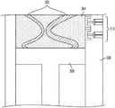
- FIGS. 3A and 3Bare diagrams of a powder bed box, according to an embodiment of the present invention.
- a build platform 308is lowered and then, another layer of powder is spread over a powder bed 304 to grow part 302 . The process is repeated until the part 302 is completely built up from melted or sintered powder material.
- the powder bed 304may include a chamber wall 306 which may be segmented. Each segmented portion of the chamber wall 306 may be loaded with springs 310 to apply force to the chamber wall 306 .
- the chamber wall 306may be spring loaded with springs 310 so that the wall 306 may give way as needed to allow powder in the powder bed 304 to move. As such, the part 302 may shrink as needed.
- the present inventionis not limited to a spring loaded wall.
- FIG. 3Bshows an exemplary embodiment in which the build platform 308 may be segmented to load the springs 310 at segmented sections along the build platform 308 .
- FIGS. 4A and 4Bare diagrams of a powder bed box, according to another embodiment of the present invention.
- a build platform 408is lowered and then, another layer of powder is spread over a powder bed 404 to grow part 402 . The process is repeated until the part 402 is completely built up from melted or sintered powder material.
- the powder bed 404may include a segmented chamber wall 406 . Each segmented portion of the chamber wall 406 may be loaded with actuators 410 .
- the actuators 410may be, but are not limited to, pneumatic, hydraulic, or electrical type actuators.
- the build platform 408may be segmented with the actuators 410 .
- FIGS. 5A and 5Bare diagrams of a powder bed box, according to another embodiment of the present invention.
- a build platform 508is lowered and then, another layer of powder is spread over a powder bed 504 to grow part 502 . The process is repeated until the part 502 is completely built up from melted or sintered powder material.
- the powder bed 504may include a segmented chamber wall 506 . Each segmented portion of the chamber wall 506 may be loaded with fluid pressure valves 510 .
- the valves 510may be, but are not limited to, pneumatic, hydraulic, or electrical type valves.
- FIG. 5Bshows an exemplary embodiment in which the build platform 508 may be segmented with valves 510 .
- FIGS. 6A and 6Bare diagrams of a powder bed box, according to another embodiment of the present invention.
- a build platform 608is lowered and then, another layer of powder is spread over a powder bed 604 to grow part 602 . The process is repeated until the part 602 is completely built up from melted or sintered powder material.
- the powder bed 604may include a chamber wall 606 configured to deflect or bend ( 610 ) and compensate for the structural loading placed on the part 602 in the powder bed 604 .
- the build platform 608may be configured to deflect or bend ( 610 ).
Landscapes
- Engineering & Computer Science (AREA)
- Chemical & Material Sciences (AREA)
- Materials Engineering (AREA)
- Manufacturing & Machinery (AREA)
- Physics & Mathematics (AREA)
- Optics & Photonics (AREA)
- Mechanical Engineering (AREA)
- Plasma & Fusion (AREA)
- Powder Metallurgy (AREA)
Abstract
Description
Claims (10)
Priority Applications (5)
| Application Number | Priority Date | Filing Date | Title |
|---|---|---|---|
| US15/679,945US11084096B2 (en) | 2017-08-17 | 2017-08-17 | Movable wall for additive powder bed |
| EP18187789.5AEP3444051B1 (en) | 2017-08-17 | 2018-08-07 | Movable wall for additive powder bed |
| JP2018152836AJP6878364B2 (en) | 2017-08-17 | 2018-08-15 | Movable wall for additional powder floor |
| CN201810933287.1ACN109396431B (en) | 2017-08-17 | 2018-08-16 | Movable wall for additive powder bed |
| ZA2018/05471AZA201805471B (en) | 2017-08-17 | 2018-08-16 | Movable wall for additive powder bed |
Applications Claiming Priority (1)
| Application Number | Priority Date | Filing Date | Title |
|---|---|---|---|
| US15/679,945US11084096B2 (en) | 2017-08-17 | 2017-08-17 | Movable wall for additive powder bed |
Publications (2)
| Publication Number | Publication Date |
|---|---|
| US20190054531A1 US20190054531A1 (en) | 2019-02-21 |
| US11084096B2true US11084096B2 (en) | 2021-08-10 |
Family
ID=63173979
Family Applications (1)
| Application Number | Title | Priority Date | Filing Date |
|---|---|---|---|
| US15/679,945Active2038-10-20US11084096B2 (en) | 2017-08-17 | 2017-08-17 | Movable wall for additive powder bed |
Country Status (5)
| Country | Link |
|---|---|
| US (1) | US11084096B2 (en) |
| EP (1) | EP3444051B1 (en) |
| JP (1) | JP6878364B2 (en) |
| CN (1) | CN109396431B (en) |
| ZA (1) | ZA201805471B (en) |
Families Citing this family (2)
| Publication number | Priority date | Publication date | Assignee | Title |
|---|---|---|---|---|
| US11123925B2 (en)* | 2018-09-06 | 2021-09-21 | Ford Motor Company | Methods for making 3D printed parts using a dynamic build platform and 3D printed parts formed therefrom |
| US20230013204A1 (en)* | 2021-07-15 | 2023-01-19 | General Electric Company | Additive manufacturing system with partially flexible build platform |
Citations (23)
| Publication number | Priority date | Publication date | Assignee | Title |
|---|---|---|---|---|
| US4811564A (en)* | 1988-01-11 | 1989-03-14 | Palmer Mark D | Double action spring actuator |
| US4863538A (en) | 1986-10-17 | 1989-09-05 | Board Of Regents, The University Of Texas System | Method and apparatus for producing parts by selective sintering |
| US5354414A (en)* | 1988-10-05 | 1994-10-11 | Michael Feygin | Apparatus and method for forming an integral object from laminations |
| US5460758A (en) | 1990-12-21 | 1995-10-24 | Eos Gmbh Electro Optical Systems | Method and apparatus for production of a three-dimensional object |
| US6355086B2 (en) | 1997-08-12 | 2002-03-12 | Rolls-Royce Corporation | Method and apparatus for making components by direct laser processing |
| US20090267269A1 (en)* | 2008-04-25 | 2009-10-29 | Jin Hong Lim | Selective Deposition Modeling Using CW UV LED Curing |
| US20100090374A1 (en)* | 2008-10-14 | 2010-04-15 | David Michael Dietrich | Geometry adaptive laser sintering system |
| US20120009073A1 (en) | 2010-07-06 | 2012-01-12 | Huang Chin Hsieh | Pump |
| JP2012224906A (en) | 2011-04-19 | 2012-11-15 | Panasonic Corp | Method for manufacturing three-dimensionally shaped article |
| CN102950285A (en) | 2012-11-02 | 2013-03-06 | 华中科技大学 | Quick manufacture method and device for metal part under action of magnetic field. |
| US20140302188A1 (en) | 2011-11-03 | 2014-10-09 | Snecma | Installation for fabricating parts by selective melting of powder |
| US8875392B2 (en) | 2006-10-18 | 2014-11-04 | MTU Aero Engines AG | High-pressure turbine blade and procedure for repair of high-pressure turbine blades |
| DE102013018031A1 (en)* | 2013-12-02 | 2015-06-03 | Voxeljet Ag | Swap body with movable side wall |
| US9174392B2 (en) | 2009-06-22 | 2015-11-03 | Voxeljet Ag | Method and device for switching a particulate material flow in the construction of models in layers |
| US20160059308A1 (en)* | 2014-08-28 | 2016-03-03 | Incodema3D, LLC | Additive manufacturing device |
| US9327450B2 (en) | 2006-11-10 | 2016-05-03 | Eos Gmbh Electro Optical Systems | Device and method for manufacturing a three-dimensional object by means of an application device for building material in powder form |
| US9498848B2 (en) | 2013-01-30 | 2016-11-22 | Rolls-Royce Plc | Method of manufacturing a wall |
| US20160368214A1 (en) | 2015-06-22 | 2016-12-22 | Ricoh Company, Ltd. | Method and apparatus for fabricating three-dimensional object |
| US9533372B2 (en) | 2013-05-03 | 2017-01-03 | United Technologies Corporation | Method of eliminating sub-surface porosity |
| US9550325B2 (en) | 2001-05-21 | 2017-01-24 | BU:ST GmbH | Method and apparatus for the production of a workpiece of exact geometry |
| US20170037674A1 (en) | 2015-08-07 | 2017-02-09 | Alcoa Inc. | Architectural manufactures, apparatus and methods using additive manufacturing techniques |
| US9597730B2 (en) | 2013-04-19 | 2017-03-21 | United Technologies Corporation | Build plate and apparatus for additive manufacturing |
| JP2017087529A (en)* | 2015-11-09 | 2017-05-25 | トヨタ自動車株式会社 | Lamination molding apparatus |
Family Cites Families (3)
| Publication number | Priority date | Publication date | Assignee | Title |
|---|---|---|---|---|
| DE102005030854B3 (en)* | 2005-07-01 | 2007-03-08 | Eos Gmbh Electro Optical Systems | Device for producing a three-dimensional object |
| GB2500412A (en)* | 2012-03-21 | 2013-09-25 | Eads Uk Ltd | Build Plate for an additive manufacturing process |
| JP6565486B2 (en)* | 2015-06-22 | 2019-08-28 | 株式会社リコー | 3D modeling apparatus, 3D modeling method, program |
- 2017
- 2017-08-17USUS15/679,945patent/US11084096B2/enactiveActive
- 2018
- 2018-08-07EPEP18187789.5Apatent/EP3444051B1/enactiveActive
- 2018-08-15JPJP2018152836Apatent/JP6878364B2/enactiveActive
- 2018-08-16ZAZA2018/05471Apatent/ZA201805471B/enunknown
- 2018-08-16CNCN201810933287.1Apatent/CN109396431B/enactiveActive
Patent Citations (25)
| Publication number | Priority date | Publication date | Assignee | Title |
|---|---|---|---|---|
| US4863538A (en) | 1986-10-17 | 1989-09-05 | Board Of Regents, The University Of Texas System | Method and apparatus for producing parts by selective sintering |
| US4811564A (en)* | 1988-01-11 | 1989-03-14 | Palmer Mark D | Double action spring actuator |
| US5354414A (en)* | 1988-10-05 | 1994-10-11 | Michael Feygin | Apparatus and method for forming an integral object from laminations |
| US5460758A (en) | 1990-12-21 | 1995-10-24 | Eos Gmbh Electro Optical Systems | Method and apparatus for production of a three-dimensional object |
| US6355086B2 (en) | 1997-08-12 | 2002-03-12 | Rolls-Royce Corporation | Method and apparatus for making components by direct laser processing |
| US9550325B2 (en) | 2001-05-21 | 2017-01-24 | BU:ST GmbH | Method and apparatus for the production of a workpiece of exact geometry |
| US8875392B2 (en) | 2006-10-18 | 2014-11-04 | MTU Aero Engines AG | High-pressure turbine blade and procedure for repair of high-pressure turbine blades |
| US9327450B2 (en) | 2006-11-10 | 2016-05-03 | Eos Gmbh Electro Optical Systems | Device and method for manufacturing a three-dimensional object by means of an application device for building material in powder form |
| US20090267269A1 (en)* | 2008-04-25 | 2009-10-29 | Jin Hong Lim | Selective Deposition Modeling Using CW UV LED Curing |
| US20100090374A1 (en)* | 2008-10-14 | 2010-04-15 | David Michael Dietrich | Geometry adaptive laser sintering system |
| US9174392B2 (en) | 2009-06-22 | 2015-11-03 | Voxeljet Ag | Method and device for switching a particulate material flow in the construction of models in layers |
| US20120009073A1 (en) | 2010-07-06 | 2012-01-12 | Huang Chin Hsieh | Pump |
| JP2012224906A (en) | 2011-04-19 | 2012-11-15 | Panasonic Corp | Method for manufacturing three-dimensionally shaped article |
| JP2015501245A (en) | 2011-11-03 | 2015-01-15 | スネクマ | Equipment for producing parts by selective melting of powders |
| US20140302188A1 (en) | 2011-11-03 | 2014-10-09 | Snecma | Installation for fabricating parts by selective melting of powder |
| CN102950285A (en) | 2012-11-02 | 2013-03-06 | 华中科技大学 | Quick manufacture method and device for metal part under action of magnetic field. |
| US9498848B2 (en) | 2013-01-30 | 2016-11-22 | Rolls-Royce Plc | Method of manufacturing a wall |
| US9597730B2 (en) | 2013-04-19 | 2017-03-21 | United Technologies Corporation | Build plate and apparatus for additive manufacturing |
| US9533372B2 (en) | 2013-05-03 | 2017-01-03 | United Technologies Corporation | Method of eliminating sub-surface porosity |
| DE102013018031A1 (en)* | 2013-12-02 | 2015-06-03 | Voxeljet Ag | Swap body with movable side wall |
| US20170050378A1 (en)* | 2013-12-02 | 2017-02-23 | Voxeljet Ag | Interchangeable container wiht moveable side walls |
| US20160059308A1 (en)* | 2014-08-28 | 2016-03-03 | Incodema3D, LLC | Additive manufacturing device |
| US20160368214A1 (en) | 2015-06-22 | 2016-12-22 | Ricoh Company, Ltd. | Method and apparatus for fabricating three-dimensional object |
| US20170037674A1 (en) | 2015-08-07 | 2017-02-09 | Alcoa Inc. | Architectural manufactures, apparatus and methods using additive manufacturing techniques |
| JP2017087529A (en)* | 2015-11-09 | 2017-05-25 | トヨタ自動車株式会社 | Lamination molding apparatus |
Non-Patent Citations (3)
| Title |
|---|
| English Translation of Chinese office action for application 201810933287.1 dated Jun. 2, 2020 (19 pages). |
| English Translation of Japanese office action for application JP2018-152836 dated Jan. 7, 2020 (9 pages). |
| Extended European Search Report and Opinion issued in connection with corresponding EP Application No. 18187789.5 dated Nov. 28, 2018. |
Also Published As
| Publication number | Publication date |
|---|---|
| EP3444051A1 (en) | 2019-02-20 |
| JP2019081947A (en) | 2019-05-30 |
| ZA201805471B (en) | 2019-06-26 |
| US20190054531A1 (en) | 2019-02-21 |
| JP6878364B2 (en) | 2021-05-26 |
| CN109396431B (en) | 2021-08-24 |
| CN109396431A (en) | 2019-03-01 |
| EP3444051B1 (en) | 2021-05-26 |
Similar Documents
| Publication | Publication Date | Title |
|---|---|---|
| EP3205424B1 (en) | Method and connecting supports for additive manufacturing | |
| EP2962789B1 (en) | Additive manufacturing method and system with fiber reinforcement | |
| CN109475940B (en) | Method of using phantom supports for additive manufacturing | |
| EP3486008B1 (en) | Powder reduction apparatus | |
| US20180200791A1 (en) | Dynamically damped recoater | |
| US20160318129A1 (en) | System and method for multi-laser additive manufacturing | |
| CN115673337A (en) | Method and leading edge support for additive manufacturing | |
| EP3476504B1 (en) | Applying electric pulses through a laser induced plasma channel for use in a 3-d metal printing process | |
| CN108971486B (en) | Method and apparatus for growing compression chambers in powder-based additive manufacturing to reduce powder loading on growing parts | |
| US20190134891A1 (en) | Dmlm build platform and surface flattening | |
| US10919114B2 (en) | Methods and support structures leveraging grown build envelope | |
| EP3437765B1 (en) | Continuous additive manufacture of high pressure turbine | |
| EP3444051B1 (en) | Movable wall for additive powder bed |
Legal Events
| Date | Code | Title | Description |
|---|---|---|---|
| AS | Assignment | Owner name:GENERAL ELECTRIC COMPANY, NEW YORK Free format text:ASSIGNMENT OF ASSIGNORS INTEREST;ASSIGNOR:CORSMEIER, DONALD MICHAEL;REEL/FRAME:043331/0364 Effective date:20170803 | |
| STPP | Information on status: patent application and granting procedure in general | Free format text:DOCKETED NEW CASE - READY FOR EXAMINATION | |
| STPP | Information on status: patent application and granting procedure in general | Free format text:NON FINAL ACTION MAILED | |
| STPP | Information on status: patent application and granting procedure in general | Free format text:RESPONSE TO NON-FINAL OFFICE ACTION ENTERED AND FORWARDED TO EXAMINER | |
| STPP | Information on status: patent application and granting procedure in general | Free format text:FINAL REJECTION MAILED | |
| STPP | Information on status: patent application and granting procedure in general | Free format text:ADVISORY ACTION MAILED | |
| STPP | Information on status: patent application and granting procedure in general | Free format text:DOCKETED NEW CASE - READY FOR EXAMINATION | |
| STPP | Information on status: patent application and granting procedure in general | Free format text:NON FINAL ACTION MAILED | |
| STPP | Information on status: patent application and granting procedure in general | Free format text:RESPONSE TO NON-FINAL OFFICE ACTION ENTERED AND FORWARDED TO EXAMINER | |
| STPP | Information on status: patent application and granting procedure in general | Free format text:NOTICE OF ALLOWANCE MAILED -- APPLICATION RECEIVED IN OFFICE OF PUBLICATIONS | |
| STPP | Information on status: patent application and granting procedure in general | Free format text:PUBLICATIONS -- ISSUE FEE PAYMENT RECEIVED | |
| STPP | Information on status: patent application and granting procedure in general | Free format text:PUBLICATIONS -- ISSUE FEE PAYMENT VERIFIED | |
| STCF | Information on status: patent grant | Free format text:PATENTED CASE | |
| MAFP | Maintenance fee payment | Free format text:PAYMENT OF MAINTENANCE FEE, 4TH YEAR, LARGE ENTITY (ORIGINAL EVENT CODE: M1551); ENTITY STATUS OF PATENT OWNER: LARGE ENTITY Year of fee payment:4 |