US11083870B2 - Hypotube based support catheter - Google Patents
Hypotube based support catheterDownload PDFInfo
- Publication number
- US11083870B2 US11083870B2US13/390,140US201113390140AUS11083870B2US 11083870 B2US11083870 B2US 11083870B2US 201113390140 AUS201113390140 AUS 201113390140AUS 11083870 B2US11083870 B2US 11083870B2
- Authority
- US
- United States
- Prior art keywords
- hypotube
- support catheter
- cuts
- pair
- axial
- Prior art date
- Legal status (The legal status is an assumption and is not a legal conclusion. Google has not performed a legal analysis and makes no representation as to the accuracy of the status listed.)
- Active
Links
Images


Classifications
- A—HUMAN NECESSITIES
- A61—MEDICAL OR VETERINARY SCIENCE; HYGIENE
- A61B—DIAGNOSIS; SURGERY; IDENTIFICATION
- A61B17/00—Surgical instruments, devices or methods
- A61B17/22—Implements for squeezing-off ulcers or the like on inner organs of the body; Implements for scraping-out cavities of body organs, e.g. bones; for invasive removal or destruction of calculus using mechanical vibrations; for removing obstructions in blood vessels, not otherwise provided for
- A61B17/221—Gripping devices in the form of loops or baskets for gripping calculi or similar types of obstructions
- A—HUMAN NECESSITIES
- A61—MEDICAL OR VETERINARY SCIENCE; HYGIENE
- A61M—DEVICES FOR INTRODUCING MEDIA INTO, OR ONTO, THE BODY; DEVICES FOR TRANSDUCING BODY MEDIA OR FOR TAKING MEDIA FROM THE BODY; DEVICES FOR PRODUCING OR ENDING SLEEP OR STUPOR
- A61M25/00—Catheters; Hollow probes
- A61M25/0043—Catheters; Hollow probes characterised by structural features
- A61M25/0054—Catheters; Hollow probes characterised by structural features with regions for increasing flexibility
- A—HUMAN NECESSITIES
- A61—MEDICAL OR VETERINARY SCIENCE; HYGIENE
- A61M—DEVICES FOR INTRODUCING MEDIA INTO, OR ONTO, THE BODY; DEVICES FOR TRANSDUCING BODY MEDIA OR FOR TAKING MEDIA FROM THE BODY; DEVICES FOR PRODUCING OR ENDING SLEEP OR STUPOR
- A61M25/00—Catheters; Hollow probes
- A61M25/01—Introducing, guiding, advancing, emplacing or holding catheters
- A61M25/0105—Steering means as part of the catheter or advancing means; Markers for positioning
- A61M25/0133—Tip steering devices
- A61M25/0138—Tip steering devices having flexible regions as a result of weakened outer material, e.g. slots, slits, cuts, joints or coils
- A—HUMAN NECESSITIES
- A61—MEDICAL OR VETERINARY SCIENCE; HYGIENE
- A61M—DEVICES FOR INTRODUCING MEDIA INTO, OR ONTO, THE BODY; DEVICES FOR TRANSDUCING BODY MEDIA OR FOR TAKING MEDIA FROM THE BODY; DEVICES FOR PRODUCING OR ENDING SLEEP OR STUPOR
- A61M25/00—Catheters; Hollow probes
- A61M25/01—Introducing, guiding, advancing, emplacing or holding catheters
- A61M25/06—Body-piercing guide needles or the like
- A61M25/065—Guide needles
- A—HUMAN NECESSITIES
- A61—MEDICAL OR VETERINARY SCIENCE; HYGIENE
- A61M—DEVICES FOR INTRODUCING MEDIA INTO, OR ONTO, THE BODY; DEVICES FOR TRANSDUCING BODY MEDIA OR FOR TAKING MEDIA FROM THE BODY; DEVICES FOR PRODUCING OR ENDING SLEEP OR STUPOR
- A61M25/00—Catheters; Hollow probes
- A61M25/01—Introducing, guiding, advancing, emplacing or holding catheters
- A61M25/09—Guide wires
- A61M25/09041—Mechanisms for insertion of guide wires
- A—HUMAN NECESSITIES
- A61—MEDICAL OR VETERINARY SCIENCE; HYGIENE
- A61B—DIAGNOSIS; SURGERY; IDENTIFICATION
- A61B17/00—Surgical instruments, devices or methods
- A61B17/22—Implements for squeezing-off ulcers or the like on inner organs of the body; Implements for scraping-out cavities of body organs, e.g. bones; for invasive removal or destruction of calculus using mechanical vibrations; for removing obstructions in blood vessels, not otherwise provided for
- A61B2017/22001—Angioplasty, e.g. PCTA
- A—HUMAN NECESSITIES
- A61—MEDICAL OR VETERINARY SCIENCE; HYGIENE
- A61B—DIAGNOSIS; SURGERY; IDENTIFICATION
- A61B17/00—Surgical instruments, devices or methods
- A61B17/22—Implements for squeezing-off ulcers or the like on inner organs of the body; Implements for scraping-out cavities of body organs, e.g. bones; for invasive removal or destruction of calculus using mechanical vibrations; for removing obstructions in blood vessels, not otherwise provided for
- A61B17/22031—Gripping instruments, e.g. forceps, for removing or smashing calculi
- A61B2017/22035—Gripping instruments, e.g. forceps, for removing or smashing calculi for retrieving or repositioning foreign objects
- A—HUMAN NECESSITIES
- A61—MEDICAL OR VETERINARY SCIENCE; HYGIENE
- A61B—DIAGNOSIS; SURGERY; IDENTIFICATION
- A61B17/00—Surgical instruments, devices or methods
- A61B17/22—Implements for squeezing-off ulcers or the like on inner organs of the body; Implements for scraping-out cavities of body organs, e.g. bones; for invasive removal or destruction of calculus using mechanical vibrations; for removing obstructions in blood vessels, not otherwise provided for
- A61B2017/22038—Implements for squeezing-off ulcers or the like on inner organs of the body; Implements for scraping-out cavities of body organs, e.g. bones; for invasive removal or destruction of calculus using mechanical vibrations; for removing obstructions in blood vessels, not otherwise provided for with a guide wire
- A—HUMAN NECESSITIES
- A61—MEDICAL OR VETERINARY SCIENCE; HYGIENE
- A61B—DIAGNOSIS; SURGERY; IDENTIFICATION
- A61B17/00—Surgical instruments, devices or methods
- A61B17/22—Implements for squeezing-off ulcers or the like on inner organs of the body; Implements for scraping-out cavities of body organs, e.g. bones; for invasive removal or destruction of calculus using mechanical vibrations; for removing obstructions in blood vessels, not otherwise provided for
- A61B2017/22051—Implements for squeezing-off ulcers or the like on inner organs of the body; Implements for scraping-out cavities of body organs, e.g. bones; for invasive removal or destruction of calculus using mechanical vibrations; for removing obstructions in blood vessels, not otherwise provided for with an inflatable part, e.g. balloon, for positioning, blocking, or immobilisation
- A61B2017/22065—Functions of balloons
- A61B2017/22069—Immobilising; Stabilising
- A—HUMAN NECESSITIES
- A61—MEDICAL OR VETERINARY SCIENCE; HYGIENE
- A61B—DIAGNOSIS; SURGERY; IDENTIFICATION
- A61B17/00—Surgical instruments, devices or methods
- A61B17/22—Implements for squeezing-off ulcers or the like on inner organs of the body; Implements for scraping-out cavities of body organs, e.g. bones; for invasive removal or destruction of calculus using mechanical vibrations; for removing obstructions in blood vessels, not otherwise provided for
- A61B2017/22094—Implements for squeezing-off ulcers or the like on inner organs of the body; Implements for scraping-out cavities of body organs, e.g. bones; for invasive removal or destruction of calculus using mechanical vibrations; for removing obstructions in blood vessels, not otherwise provided for for crossing total occlusions, i.e. piercing
- A—HUMAN NECESSITIES
- A61—MEDICAL OR VETERINARY SCIENCE; HYGIENE
- A61M—DEVICES FOR INTRODUCING MEDIA INTO, OR ONTO, THE BODY; DEVICES FOR TRANSDUCING BODY MEDIA OR FOR TAKING MEDIA FROM THE BODY; DEVICES FOR PRODUCING OR ENDING SLEEP OR STUPOR
- A61M25/00—Catheters; Hollow probes
- A61M25/01—Introducing, guiding, advancing, emplacing or holding catheters
- A61M25/09—Guide wires
- A61M2025/09116—Design of handles or shafts or gripping surfaces thereof for manipulating guide wires
- A—HUMAN NECESSITIES
- A61—MEDICAL OR VETERINARY SCIENCE; HYGIENE
- A61M—DEVICES FOR INTRODUCING MEDIA INTO, OR ONTO, THE BODY; DEVICES FOR TRANSDUCING BODY MEDIA OR FOR TAKING MEDIA FROM THE BODY; DEVICES FOR PRODUCING OR ENDING SLEEP OR STUPOR
- A61M25/00—Catheters; Hollow probes
- A61M25/01—Introducing, guiding, advancing, emplacing or holding catheters
- A61M25/09—Guide wires
- A61M2025/09125—Device for locking a guide wire in a fixed position with respect to the catheter or the human body
Definitions
- the present inventiongenerally relates to support catheters for treating blood vessels, mainly small blood vessels, such as below the knee (BTK) blood vessels and other small blood vessels (e.g., coronary, pediatric), which are partially or totally occluded.
- blood vesselsmainly small blood vessels, such as below the knee (BTK) blood vessels and other small blood vessels (e.g., coronary, pediatric), which are partially or totally occluded.
- BTKbelow the knee
- other small blood vesselse.g., coronary, pediatric
- CTOchronic total occlusion
- This approachhas high success rates, but is technically challenging to perform and has its own complications, especially the danger of vessel perforation.
- Flexible, small support catheterscan be used to support the guidewire crossing the plaque from that direction as well. These support catheters may have straight tips or pre-curved tips suitable for maneuvering through side branched or curved blood vessels.
- a support cathetercan be inserted over the guidewire to support and aim the guidewire tip to the occlusion.
- the support catheter distal tipis usually straight. Sometimes a pre-curved tip is used, especially if a sharp bend is just before the plaque or the plaque is in a side branch which is hard to enter.
- the antegrade approachis abandoned in favor of the retrograde approach when the combined support catheter and guidewire technique are ineffective in crossing the plaque.
- the retrograde approachis the last percutaneous alternative before referring the patient to traditional open surgery.
- support cathetersare commercially available. All accommodate different sizes of guidewires, usually 0.014′′, 0.018′′ or 0.035′′ diameter, and have lumens designed to accommodate the specific guidewire size.
- Most support cathetersare made from polymer tubes, sometimes braided reinforced tubes.
- One advantage of such cathetersis their low production cost.
- Another advantageis they provide good flexibility which is required to pass through tortuous and curved small vessels.
- a disadvantageis the pushability of the catheter is relatively low due to the polymer-based structure and small diameters (usual OD range is 0.5-1.5 mm). This is a serious shortcoming as good pushability of the support catheter is required to help the guidewire pass through hard calcified plaques.
- Another disadvantageis that polymer tubing, even when reinforced, does not generally attain the torqueability required to aim the guidewire as it exits from the pre-curved tip of a support catheter.
- the ability of the guidewire to exit at an angle to the main catheter shaftis required many times, due to the curvature of typical blood vessels and tendency of plaques to accumulate at such locations.
- hypotube-based support catheterssuch as the TORNUS support catheter from ASAHI.
- This catheterhas a spiral cut (like a spring), to provide very good flexibility, but this comes at the expense of lower pushability.
- the torqueability of such hypotube-based cathetersis usually good in one rotational direction only, but when the spring-cut hypotube rotates, it tends to reduce its diameter, and might lock the guidewire inside.
- US Patent Application 2009/0125097describes a slotted hypotube-based catheter, where slots can be made by laser cuts or other cutting means.
- the slotsare cut alternatively from one direction and then from the other direction, opposite to the first direction, such that every slot is cut 180° from the adjacent cut.
- Such laser cutshave combined properties of strength and compression resistance, together with very good torqueability, while flexible enough to deal with turns of about 10 mm radius.
- these designsprovide flexibility only in one plane, and the catheter must be rotated to its proper position to allow slots width changes (i.e., close at one side and open in other side) when bent in the curve plane.
- such a laser cut profileis not flexible in multi-directions, and can not deal with multiple curves or 3D curves as is in the human vasculature, especially when treating small blood vessels.
- U.S. Pat. No. 5,741,429describes another symmetrical slot cutting approach. This design has more than two rows of slots, so flexibility is in more than one axis. However, the design is still not flexible in every direction, and does not have multi-axis flexibility.
- US Patent Application 20090270975describes a different laser-cut profile, which aims to provide good pushability and torqueability, while keeping multi-axis flexibility and potentially the ability to deal with multiple and 3D curves.
- This designis based on cut and uncut segments of a general spiral profile.
- This applicationdescribes a hypotube-based catheter which is formed with a plurality of cuts which are not perpendicular to the longitudinal axis of the catheter. The cuts are formed by intermittent cutting of the hypotube, while rotating and advancing it at the same time.
- Such a designovercomes some of the limitations of previous slotted hypotube-based support catheters, by providing very good pushability and torqueability. However it has limited flexibility due to the spiral nature of the cut-uncut profile, and therefore will have difficulty crossing small diameters curvatures as is explained in detail below.
- the present inventionis directed to a hypotube support catheter with a shapeable tip, such as for treating BTK, coronary, pediatric and other small blood vessels, from both antegrade and retrograde approaches. Such support catheters can also be used in larger blood vessels.
- the present inventionprovides a unique support catheter for supporting guidewire penetration through plaque inside blood vessels, during angioplasty procedures, to be followed by support catheter plaque penetration.
- the device of the inventionis aimed to improve the physician's technique and success in treating totally or partially blocked blood vessels, by providing a very flexible support catheter that provides high pushability and high torqueability, and allows tip bending and shaping to fit a patient-specific anatomy.
- the above combined characteristicsare achieved by cutting the hypotube with a series of cuts that result in multi-axis flexibility with very high pushability and torqueability, together with tip shaping and minimal risk of hypotube breaking.
- the cutting profileis achieved by intermittent cutting of the hypotube, while rotating and then advancing it, but not at the same time.
- the metal hypotubeis rotated at a desired rotational speed.
- cutting and un-cuttingis performed intermittently, preferably at least twice in one full 360° hypotube rotation.
- the hypotubeis then advanced axially to a second axial location and a second series of intermittent cutting and un-cutting is performed.
- This second circular cuttingstarts only after a phase shift of, for example, 45°.
- the next circular intermittent cuttingstarts again after another axial step and another phase shift. This phase shift provides multi-axis flexibility of the hypotube.
- the hypotubeis preferably covered by a thin polymer jacket made from materials, such as PTFE (polytetrafluoroethylene), PEBAX (trade name for a polyether block amide) or nylon on its exterior, interior, or both.
- PTFEpolytetrafluoroethylene
- PEBAXtrade name for a polyether block amide
- nylonnylon on its exterior, interior, or both.
- Such jacketscan prevent blood leakage from the laser-cuts, and provide reduced friction for the passage of the guidewire through the support catheter.
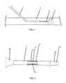
- FIG. 1is a simplified illustration of the support catheter of the invention inserted into an artery.
- FIG. 2is a simplified illustration of a preferred embodiment of the support catheter of the invention.
- FIG. 3is a simplified side view illustration of a preferred embodiment of few consecutives circular hypotube laser cuts, shifted by 45 degrees from each other.
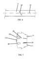
- FIGS. 4A, 4B and 4Care frontal cross sectional views of different embodiments of a few consecutive circular hypotube laser cuts, shifted by 45° from each other.
- FIG. 5is a simplified illustration of a circular intermittent laser cut done perpendicularly to the hypotube longitudinal axis.
- FIG. 6is a simplified illustration of a circular intermittent laser cut done at an angle (spiral cut) to the hypotube longitudinal axis.
- FIG. 7is a simplified illustration of limited plastic reshaping the distal tip of the hypotube of the support catheter of the invention.
- FIG. 1illustrates a support catheter 1 , constructed and operative in accordance with an embodiment of the present invention.
- Support catheter 1can improve the physician's technique in treating blood vessel occlusions including BTK occlusions, and can be used to cross both new, soft plaque and old, hard plaque.
- Support catheter 1supports a guidewire 2 for penetration through plaque 3 inside a blood vessel 4 , such as but not limited to, the femoral artery, during angioplasty procedures.
- Support catheter 1has a shapeable tip 10 , which can be bent and otherwise shaped to fit any specific anatomy.
- Support catheter 1has good multi-axis flexibility, which is required to lead the guidewire through tortuous and curved blood vessels.
- Support catheter 1has good pushability to help the guidewire pass through hard calcified plaques, after which the support catheter also passes through.
- Support catheter 1has good torqueability, which is required whenever the support catheter tip is not fully straight, and the guidewire protrusion needs to be aimed towards the plaque.
- the above combination of characteristicsis achieved by constructing support catheter 1 of a hypotube 11 that has a plurality of cuts 20 and an inner lumen 12 and distal tip 10 .
- Cuts 20are cut in a special profile, as described below, which achieves multi-axis flexibility with very high pushability and torqueability, together with the ability to shape distal tip 10 with minimal risk of hypotube breakage.
- hypotube 11is thin-walled, having an outside diameter of up to 6 Fr (2.0 mm), made from metal, such as, but not limited to, stainless steel, which can readily be cut by laser or other cutting tools.
- Hypotube 11may be covered by thin non-metal (e.g., polymer) jackets 13 and 14 , made from materials, such as, but not limited to, PTFE, PEBAX or nylon on its exterior, interior, or both. Such jackets help prevent blood leakage from cuts 20 , and provide reduced friction for the passage of the guidewire 2 through support catheter 1 .
- jackets 13 and 14may be formed into a distal tapered tip 15 , preferably, but not necessarily, having a length of less than 2 mm.
- a female luer connector 16is connected to a proximal end of support catheter 1 , which provides easy guidewire access and the possibility of using a standard injection syringe for contrast media injection and the like.
- the cutting profileis based on intermittent cutting of hypotube 11 , while rotating and advancing it, but not at the same time.
- hypotube 11is rotated at a desired rotational speed, while intermittently cuts 20 are made by a cutting operation (e.g., laser cuts) and an uncut portion 22 is left.
- the uncut portion 22is preferably, but not necessarily, smaller than the cut section 20 .
- Cut and uncut segmentsare made more than once in a full 360° circle, and preferably twice on every circle. For example, a cut of 120° and an uncut portion of 60°, performed twice in one full hypotube rotation, complete a full 360° circle.
- Hypotube 11is then advanced axially by a small axial increment, for example, 0.2 mm, and another intermittent circular cutting operation is performed (e.g., 120° cut/60° uncut, done twice in full circle, in the above example).
- This second circular cuttingstarts only after a phase shift of preferably smaller than 90°, e.g., 45°.
- Subsequent intermittent circular cutting/uncutting operations with phase shiftare then performed at a series of axial increments.
- FIGS. 4A, 4B and 4Cillustrate different embodiments of a few consecutive circular hypotube laser cuts, shifted by 45° from each other. This phase shift provides multi-axis cutting and therefore multi-axis flexibility of the hypotube.
- the intermittent circular cuttingcan have three, four or more cut slots and uncut sections instead of two, in one full hypotube circle.
- the inventioncan be carried out with a 90° cut and 30° uncut performed three times in one circle, before an axial step, a phase shift and the start of new circular cut.
- the intermittent cuts and uncut portionscan extend over some or all of the total axial length of the hypotube 11 .
- the catheter of the inventionComparing the support catheter of the invention to catheters cut/uncut in spiral advancement (like the one described in US Patent Application 2009/0275795), the catheter of the invention provides similar pushability and torqueability, but provides much better multi-axis flexibility, and safer tip bending, as is now explained with reference to FIGS. 5 and 6 .
- the bending moment needed to bend a beam or a baris directly related to its moment of inertia “I” of the beam or bar.
- the material left to resist the bending moment length Bis only the length of the uncut sections in the specific cross section.
- the cut 20is not perpendicular to the tube axis 23 , as in FIG. 6 , only a small portion of the cut section is reduced from the length B, increasing the moment of inertia “I”, and therefore the catheter stiffness and the resistance to bending, which means reduced flexibility.
- Each segment with the same phase shift(in the above example with 45° phase shift, every 0.8 mm there will be the same circular cutting with same phase shift) can easily bend plastically until the gap made by the cut 20 between the two consecutive segments is closed.
- the gap sizemay be, for example, between 20 to 50 microns, such as when cut by laser.
- the size of the gap and the structure of the uncut sectioncan provide a safety mechanism to bend the tip, creating plastic strain in the two uncut sections in every identical circle.
- the structureensures that this plastic strain does not reach the breaking strain, because the strain is limited to the size of the gap between segments. After the portions have abutted each other, the strength of the segment and resistance to bending is dramatically increased, providing the user with a tactile indication not to increase the bend in order to avoid the potential risk of hypotube breakage.
- two parallel uncut sections 22(or “beams” 22 ) made from 60° segments of the tube circumference, are able to slightly plastically bend without breaking, and the same pattern will appear again in just four circular steps, which are only 0.8 mm in distance from the first two “beams”.
- several sections with the same patternparticipate in the plastic re-shaping of the tip, limited by such factors as cut width, hypotube material, hypotube thickness, distance (step) between every two cut/uncut circles, and the uncut section length, for example.
Landscapes
- Health & Medical Sciences (AREA)
- Life Sciences & Earth Sciences (AREA)
- General Health & Medical Sciences (AREA)
- Veterinary Medicine (AREA)
- Engineering & Computer Science (AREA)
- Biomedical Technology (AREA)
- Heart & Thoracic Surgery (AREA)
- Public Health (AREA)
- Animal Behavior & Ethology (AREA)
- Surgery (AREA)
- Anesthesiology (AREA)
- Hematology (AREA)
- Pulmonology (AREA)
- Biophysics (AREA)
- Orthopedic Medicine & Surgery (AREA)
- Vascular Medicine (AREA)
- Nuclear Medicine, Radiotherapy & Molecular Imaging (AREA)
- Medical Informatics (AREA)
- Molecular Biology (AREA)
- Media Introduction/Drainage Providing Device (AREA)
- Infusion, Injection, And Reservoir Apparatuses (AREA)
Abstract
Description
Claims (8)
Priority Applications (1)
| Application Number | Priority Date | Filing Date | Title |
|---|---|---|---|
| US13/390,140US11083870B2 (en) | 2011-04-11 | 2011-12-12 | Hypotube based support catheter |
Applications Claiming Priority (7)
| Application Number | Priority Date | Filing Date | Title |
|---|---|---|---|
| US201161516906P | 2011-04-11 | 2011-04-11 | |
| US201161571856P | 2011-07-07 | 2011-07-07 | |
| US201161575160P | 2011-08-17 | 2011-08-17 | |
| US201161573935P | 2011-09-15 | 2011-09-15 | |
| US201161626183P | 2011-09-22 | 2011-09-22 | |
| PCT/US2011/064300WO2012141747A2 (en) | 2011-04-11 | 2011-12-12 | Hypotube based support catheter |
| US13/390,140US11083870B2 (en) | 2011-04-11 | 2011-12-12 | Hypotube based support catheter |
Publications (2)
| Publication Number | Publication Date |
|---|---|
| US20140031843A1 US20140031843A1 (en) | 2014-01-30 |
| US11083870B2true US11083870B2 (en) | 2021-08-10 |
Family
ID=47901655
Family Applications (1)
| Application Number | Title | Priority Date | Filing Date |
|---|---|---|---|
| US13/390,140ActiveUS11083870B2 (en) | 2011-04-11 | 2011-12-12 | Hypotube based support catheter |
Country Status (2)
| Country | Link |
|---|---|
| US (1) | US11083870B2 (en) |
| WO (1) | WO2012141747A2 (en) |
Families Citing this family (17)
| Publication number | Priority date | Publication date | Assignee | Title |
|---|---|---|---|---|
| US11504450B2 (en) | 2012-10-26 | 2022-11-22 | Urotronic, Inc. | Drug-coated balloon catheters for body lumens |
| US10806830B2 (en) | 2012-10-26 | 2020-10-20 | Urotronic, Inc. | Drug-coated balloon catheters for body lumens |
| US10881839B2 (en) | 2012-10-26 | 2021-01-05 | Urotronic, Inc. | Drug-coated balloon catheters for body lumens |
| US10898700B2 (en) | 2012-10-26 | 2021-01-26 | Urotronic, Inc. | Balloon catheters for body lumens |
| US11904072B2 (en) | 2015-04-24 | 2024-02-20 | Urotronic, Inc. | Drug coated balloon catheters for nonvascular strictures |
| US10327933B2 (en) | 2015-04-28 | 2019-06-25 | Cook Medical Technologies Llc | Medical cannulae, delivery systems and methods |
| US10675057B2 (en) | 2015-04-28 | 2020-06-09 | Cook Medical Technologies Llc | Variable stiffness cannulae and associated delivery systems and methods |
| US10576242B2 (en) | 2015-05-29 | 2020-03-03 | Biosensors International Group, Ltd. | Bi-lumenal tube catheter support system |
| CA3009943C (en) | 2016-01-01 | 2020-10-06 | Tractus Vascular, Llc | Flexible catheter |
| US10555756B2 (en) | 2016-06-27 | 2020-02-11 | Cook Medical Technologies Llc | Medical devices having coaxial cannulae |
| US9918705B2 (en) | 2016-07-07 | 2018-03-20 | Brian Giles | Medical devices with distal control |
| US10391274B2 (en) | 2016-07-07 | 2019-08-27 | Brian Giles | Medical device with distal torque control |
| AU2017373953B2 (en) | 2016-12-08 | 2023-05-11 | Abiomed, Inc. | Overmold technique for peel-away introducer design |
| ES2991910T3 (en) | 2018-05-16 | 2024-12-05 | Abiomed Inc | Removable cover set |
| CN113727750B (en)* | 2019-02-22 | 2024-09-17 | 优敦力公司 | Drug-coated balloon catheter for body cavities |
| CN114041845A (en)* | 2021-12-10 | 2022-02-15 | 上海拓舜医疗科技有限公司 | A delivery system for intervening embolization coils |
| CN115317761B (en)* | 2022-09-13 | 2024-07-19 | 上海普实医疗器械股份有限公司 | Adjustable bend catheter with hypotube |
Citations (71)
| Publication number | Priority date | Publication date | Assignee | Title |
|---|---|---|---|---|
| EP0257811A2 (en) | 1986-08-01 | 1988-03-02 | Aran Engineering Development Ltd | A fluid flow valve |
| WO1988009188A1 (en) | 1987-05-21 | 1988-12-01 | Pharmacia Ab | Infusion apparatus |
| US4860742A (en) | 1988-05-16 | 1989-08-29 | Medical Innovations Corporation | Assembly of wire inserter and lock for a medical wire |
| EP0342505A2 (en) | 1988-05-17 | 1989-11-23 | Aran Engineering Development Ltd | Portable weighing scale |
| US5116323A (en) | 1991-01-22 | 1992-05-26 | Becton, Dickinson And Company | Arterial catheter |
| US5129884A (en) | 1990-01-16 | 1992-07-14 | Dysarz Edward D | Trap in barrel one handed retracted intervenous catheter device |
| EP0583049A1 (en) | 1992-08-10 | 1994-02-16 | Robert E. Fischell | Vascular access needle |
| US5295970A (en) | 1993-02-05 | 1994-03-22 | Becton, Dickinson And Company | Apparatus and method for vascular guide wire insertion with blood flashback containment features |
| WO1994013211A1 (en) | 1992-12-10 | 1994-06-23 | Perclose, Inc. | Vascular puncture site suturing device and method |
| EP0623673A2 (en) | 1993-04-02 | 1994-11-09 | ARAN ENGINEERING DEVELOPMENT Ltd | Electrical diaphragm valve |
| EP0633184A1 (en) | 1993-07-09 | 1995-01-11 | ARAN ENGINEERING DEVELOPMENT Ltd | Steering aid for steering a glider |
| EP0650666A1 (en) | 1993-10-29 | 1995-05-03 | ARAN ENGINEERING DEVELOPMENT Ltd | Drip irrigation lines flushing valve |
| US5489274A (en) | 1992-10-09 | 1996-02-06 | Boston Scientific Corporation | Rotatable medical valve closure |
| EP0724098A1 (en) | 1995-01-25 | 1996-07-31 | Raviv Precision Injection Molding | A roll vent valve |
| WO1997006973A1 (en) | 1995-08-16 | 1997-02-27 | Raviv Precision Injection Molding | Over filling valve |
| US5741429A (en) | 1991-09-05 | 1998-04-21 | Cardia Catheter Company | Flexible tubular device for use in medical applications |
| WO1998028034A1 (en) | 1996-07-08 | 1998-07-02 | H.D.S. Systems, Ltd. | Valve for a heart assist device |
| WO1998057694A1 (en) | 1997-06-17 | 1998-12-23 | Medicard Ltd. | Angioplasty pressure/volume control system |
| EP0897295A1 (en) | 1996-05-05 | 1999-02-24 | Medicard Ltd. | Method for producing heart valves |
| WO1999026676A1 (en) | 1997-11-24 | 1999-06-03 | H.D.S. Systems, Ltd | Heart assist system with apex cannula pump |
| US5911715A (en) | 1994-02-14 | 1999-06-15 | Scimed Life Systems, Inc. | Guide catheter having selected flexural modulus segments |
| EP0922466A2 (en) | 1993-11-15 | 1999-06-16 | Phase Medical, Inc. | Retractable-needle cannula insertion set |
| US5984895A (en) | 1998-01-15 | 1999-11-16 | Merit Medical Systems, Inc. | Vascular blood flashback containment device with improved sealing capability |
| WO2000003754A1 (en) | 1998-07-19 | 2000-01-27 | H.D.S. Systems, Ltd. | Double-tube heart-assistance system |
| WO2000013736A1 (en) | 1998-09-03 | 2000-03-16 | H.D.S. Systems, Ltd. | Finned-tip flow guided catheters |
| WO2000020064A1 (en) | 1998-10-02 | 2000-04-13 | Endogad Research Pty. Ltd. | Guidewire capture device |
| WO2000037128A1 (en) | 1998-12-22 | 2000-06-29 | Aran Engineering Development Ltd. | Fluid flow control valve |
| US20010018596A1 (en) | 1997-02-28 | 2001-08-30 | Selmon Matthew R. | Methods and apparatus for treating vascular occlusions |
| US6290710B1 (en) | 1999-12-29 | 2001-09-18 | Advanced Cardiovascular Systems, Inc. | Embolic protection device |
| WO2001097697A1 (en) | 2000-06-22 | 2001-12-27 | White Geoffrey H | Method and apparatus for performing percutaneous thromboembolectomies |
| US6352531B1 (en) | 1999-03-24 | 2002-03-05 | Micrus Corporation | Variable stiffness optical fiber shaft |
| US6428489B1 (en) | 1995-12-07 | 2002-08-06 | Precision Vascular Systems, Inc. | Guidewire system |
| WO2003002182A1 (en) | 2001-06-28 | 2003-01-09 | Sewoon Medical Co., Ltd. | Apparatus for inserting guide wire for use in catheter |
| WO2003002734A1 (en) | 2001-06-27 | 2003-01-09 | Henogen S.A. | Anticomplement polypeptide from salivary glands of the tick ixodes ricinus |
| WO2003047468A1 (en) | 2001-10-11 | 2003-06-12 | Percutaneous Valve Technologies | Implantable prosthetic valve |
| WO2004025229A1 (en) | 2002-09-12 | 2004-03-25 | A.R.I. Flow Control Accessories Agricultural Cooperative Association, Ltd. | Valve for prevention of low flow rates through flow meter |
| US20040082962A1 (en) | 1999-12-06 | 2004-04-29 | Bacchus Vascular, Inc. | Systems and methods for clot disruption and retrieval |
| WO2005011792A1 (en) | 2003-07-31 | 2005-02-10 | Medigard Limited | Cannula/catheter introducer with retractable needle |
| WO2005028002A1 (en) | 2003-09-22 | 2005-03-31 | Dudu Haimovich | Blood oxygenation system with single lumen catheter |
| US20050245885A1 (en) | 2004-05-03 | 2005-11-03 | Leroy Brown | Blood drawing device with flash detection |
| WO2006019592A2 (en) | 2004-07-21 | 2006-02-23 | Pnaval Systems, Inc. | Laparoscopic instrument and cannula assemblz and related surgical method |
| US20060100687A1 (en)* | 2004-11-10 | 2006-05-11 | Creganna Technologies Limited | Elongate tubular member for use in medical device shafts |
| US7097564B2 (en) | 2001-09-27 | 2006-08-29 | Rino Mechanical Components, Inc. | Flexible coupling with radially offset beams formed by asymmetric slot pairs |
| WO2007011908A2 (en) | 2005-07-18 | 2007-01-25 | Novostent Corporation | Embolic protection and plaque removal system with closed circuit aspiration and filtering |
| EP1771132A2 (en) | 2004-02-03 | 2007-04-11 | Atria Medical Inc. | Device and method for controlling in-vivo pressure |
| US20070112331A1 (en) | 2005-11-16 | 2007-05-17 | Jan Weber | Variable stiffness shaft |
| EP1796597A2 (en) | 2004-09-14 | 2007-06-20 | Edwards Lifesciences AG | Device and method for treatment of heart valve regurgitation |
| US20070225702A1 (en) | 2006-03-21 | 2007-09-27 | The Cleveland Clinic Foundation | Apparatus and method of performing radiofrequency cauterization and tissue removal |
| WO2008024593A2 (en) | 2006-08-24 | 2008-02-28 | Boston Scientific Limited | Medical device coating configuration and method for improved lubricity and durability |
| WO2008035349A1 (en) | 2006-09-21 | 2008-03-27 | Avraham Zakai | Device and method for crossing a vascular occlusion |
| WO2008120209A1 (en) | 2007-03-29 | 2008-10-09 | Dan Rottenberg | Lumen reentry devices and methods |
| US20080306499A1 (en) | 2006-02-13 | 2008-12-11 | Retro Vascular, Inc. | Recanalizing occluded vessels using controlled antegrade and retrograde tracking |
| EP2012660A1 (en) | 2006-04-19 | 2009-01-14 | Transpid Ltd. | Apparatus for controlled blood regurgitation through tricuspid valve |
| WO2009033173A1 (en) | 2007-09-07 | 2009-03-12 | Edwards Lifesciences Corporation | Active holder for annuloplasty ring delivery |
| EP2052756A1 (en) | 2007-10-22 | 2009-04-29 | EG Tech I/S | A medical guide wire torque and method of using the torque |
| US20090125097A1 (en) | 2007-11-13 | 2009-05-14 | Medtronic Vascular, Inc. | Device and Method for Stent Graft Fenestration in Situ |
| US20090270975A1 (en) | 1999-10-12 | 2009-10-29 | Gifford Iii Hanson S | Methods and devices for protecting a passageway in a body when advancing devices through the passageway |
| US20100022943A1 (en) | 2008-07-25 | 2010-01-28 | Medtronic Vascular, Inc. | Hydrodynamic Thrombectomy Catheter |
| US20100036364A1 (en) | 2008-08-06 | 2010-02-11 | C. R. Bard, Inc. | Catheter Introducer |
| US20100057037A1 (en) | 2008-09-02 | 2010-03-04 | Abbott Cardiovascular Systems Inc. | Agent Delivery Catheters |
| EP2163216A2 (en) | 2008-09-11 | 2010-03-17 | Tyco Healthcare Group LP | Laparoscopic instrument |
| EP2163217A2 (en) | 2008-09-11 | 2010-03-17 | Tyco Healthcare Group LP | Surgical port assembly |
| US7708704B2 (en)* | 2006-07-31 | 2010-05-04 | Codman & Shurtleff, Pc | Interventional medical device component having an interrupted spiral section and method of making the same |
| WO2010137024A1 (en) | 2009-05-28 | 2010-12-02 | Given Imaging Ltd. | Apparatus for delivery of autonomous in-vivo capsules |
| US7878984B2 (en) | 2002-07-25 | 2011-02-01 | Boston Scientific Scimed, Inc. | Medical device for navigation through anatomy and method of making same |
| WO2011025855A2 (en) | 2009-08-28 | 2011-03-03 | Si Therapies Ltd. | Inverted balloon neck on catheter |
| WO2011028632A1 (en) | 2009-09-03 | 2011-03-10 | Si Therapies Ltd. | Lancet micro-catheter |
| WO2011041578A2 (en) | 2009-10-01 | 2011-04-07 | Macroplata, Inc. | Detachable balloon catheter |
| WO2011051944A2 (en) | 2009-10-29 | 2011-05-05 | S.P.C. Tech Ltd. | Flow control valve |
| WO2011084616A2 (en) | 2009-12-16 | 2011-07-14 | Macroplata, Inc. | Arrangements and methods for effecting an endoluminal anatomical structure |
| US8414568B2 (en) | 2006-04-04 | 2013-04-09 | The Spectranetics Corporation | Laser-assisted guidewire having a variable stiffness shaft |
Family Cites Families (1)
| Publication number | Priority date | Publication date | Assignee | Title |
|---|---|---|---|---|
| US20090275795A1 (en) | 2008-05-02 | 2009-11-05 | Zassi Medical Evolutions, Inc. | Continent ostomy system with chemical neuromuscular control |
- 2011
- 2011-12-12WOPCT/US2011/064300patent/WO2012141747A2/enactiveApplication Filing
- 2011-12-12USUS13/390,140patent/US11083870B2/enactiveActive
Patent Citations (97)
| Publication number | Priority date | Publication date | Assignee | Title |
|---|---|---|---|---|
| EP0257811A2 (en) | 1986-08-01 | 1988-03-02 | Aran Engineering Development Ltd | A fluid flow valve |
| WO1988009188A1 (en) | 1987-05-21 | 1988-12-01 | Pharmacia Ab | Infusion apparatus |
| US4860742A (en) | 1988-05-16 | 1989-08-29 | Medical Innovations Corporation | Assembly of wire inserter and lock for a medical wire |
| EP0342505A2 (en) | 1988-05-17 | 1989-11-23 | Aran Engineering Development Ltd | Portable weighing scale |
| US5129884A (en) | 1990-01-16 | 1992-07-14 | Dysarz Edward D | Trap in barrel one handed retracted intervenous catheter device |
| US5116323A (en) | 1991-01-22 | 1992-05-26 | Becton, Dickinson And Company | Arterial catheter |
| US5741429A (en) | 1991-09-05 | 1998-04-21 | Cardia Catheter Company | Flexible tubular device for use in medical applications |
| EP0583049A1 (en) | 1992-08-10 | 1994-02-16 | Robert E. Fischell | Vascular access needle |
| US5489274A (en) | 1992-10-09 | 1996-02-06 | Boston Scientific Corporation | Rotatable medical valve closure |
| WO1994013211A1 (en) | 1992-12-10 | 1994-06-23 | Perclose, Inc. | Vascular puncture site suturing device and method |
| US5295970A (en) | 1993-02-05 | 1994-03-22 | Becton, Dickinson And Company | Apparatus and method for vascular guide wire insertion with blood flashback containment features |
| EP0623673A2 (en) | 1993-04-02 | 1994-11-09 | ARAN ENGINEERING DEVELOPMENT Ltd | Electrical diaphragm valve |
| EP0633184A1 (en) | 1993-07-09 | 1995-01-11 | ARAN ENGINEERING DEVELOPMENT Ltd | Steering aid for steering a glider |
| EP0650666A1 (en) | 1993-10-29 | 1995-05-03 | ARAN ENGINEERING DEVELOPMENT Ltd | Drip irrigation lines flushing valve |
| EP0922466A2 (en) | 1993-11-15 | 1999-06-16 | Phase Medical, Inc. | Retractable-needle cannula insertion set |
| US5911715A (en) | 1994-02-14 | 1999-06-15 | Scimed Life Systems, Inc. | Guide catheter having selected flexural modulus segments |
| EP0724098A1 (en) | 1995-01-25 | 1996-07-31 | Raviv Precision Injection Molding | A roll vent valve |
| EP0846064A1 (en) | 1995-08-16 | 1998-06-10 | Raviv Precision Injection Molding | Over filling valve |
| WO1997006973A1 (en) | 1995-08-16 | 1997-02-27 | Raviv Precision Injection Molding | Over filling valve |
| US6428489B1 (en) | 1995-12-07 | 2002-08-06 | Precision Vascular Systems, Inc. | Guidewire system |
| EP0897295A1 (en) | 1996-05-05 | 1999-02-24 | Medicard Ltd. | Method for producing heart valves |
| WO1998028034A1 (en) | 1996-07-08 | 1998-07-02 | H.D.S. Systems, Ltd. | Valve for a heart assist device |
| EP1009466A1 (en) | 1996-12-24 | 2000-06-21 | H.D.S. Systems, Ltd. | Valve for a heart assist device |
| US20010018596A1 (en) | 1997-02-28 | 2001-08-30 | Selmon Matthew R. | Methods and apparatus for treating vascular occlusions |
| WO1998057694A1 (en) | 1997-06-17 | 1998-12-23 | Medicard Ltd. | Angioplasty pressure/volume control system |
| WO1999026677A1 (en) | 1997-11-24 | 1999-06-03 | H.D.S. Systems, Ltd. | Heart assist system with cannula pump |
| WO1999026676A1 (en) | 1997-11-24 | 1999-06-03 | H.D.S. Systems, Ltd | Heart assist system with apex cannula pump |
| EP1035880A1 (en) | 1997-11-24 | 2000-09-20 | H.D.S. Systems, Ltd. | Heart assist system with cannula pump |
| EP1045708A1 (en) | 1997-11-24 | 2000-10-25 | H.D.S. Systems, Ltd. | Heart assist system with apex cannula pump |
| US5984895A (en) | 1998-01-15 | 1999-11-16 | Merit Medical Systems, Inc. | Vascular blood flashback containment device with improved sealing capability |
| WO2000003754A1 (en) | 1998-07-19 | 2000-01-27 | H.D.S. Systems, Ltd. | Double-tube heart-assistance system |
| EP1098671A1 (en) | 1998-07-19 | 2001-05-16 | H.D.S. Systems, Ltd. | Double-tube heart-assistance system |
| WO2000013736A1 (en) | 1998-09-03 | 2000-03-16 | H.D.S. Systems, Ltd. | Finned-tip flow guided catheters |
| EP1109590A1 (en) | 1998-09-03 | 2001-06-27 | H.D.S. Systems, Ltd. | Finned-tip flow guided catheters |
| WO2000020064A1 (en) | 1998-10-02 | 2000-04-13 | Endogad Research Pty. Ltd. | Guidewire capture device |
| WO2000037128A1 (en) | 1998-12-22 | 2000-06-29 | Aran Engineering Development Ltd. | Fluid flow control valve |
| US6352531B1 (en) | 1999-03-24 | 2002-03-05 | Micrus Corporation | Variable stiffness optical fiber shaft |
| US20090270975A1 (en) | 1999-10-12 | 2009-10-29 | Gifford Iii Hanson S | Methods and devices for protecting a passageway in a body when advancing devices through the passageway |
| US20040082962A1 (en) | 1999-12-06 | 2004-04-29 | Bacchus Vascular, Inc. | Systems and methods for clot disruption and retrieval |
| US6290710B1 (en) | 1999-12-29 | 2001-09-18 | Advanced Cardiovascular Systems, Inc. | Embolic protection device |
| WO2001097697A1 (en) | 2000-06-22 | 2001-12-27 | White Geoffrey H | Method and apparatus for performing percutaneous thromboembolectomies |
| WO2003002734A1 (en) | 2001-06-27 | 2003-01-09 | Henogen S.A. | Anticomplement polypeptide from salivary glands of the tick ixodes ricinus |
| EP1399549A1 (en) | 2001-06-27 | 2004-03-24 | Henogen S.A. | Anticomplement polypeptide from salivary glands of the tick ixodes ricinus |
| WO2003002182A1 (en) | 2001-06-28 | 2003-01-09 | Sewoon Medical Co., Ltd. | Apparatus for inserting guide wire for use in catheter |
| US7097564B2 (en) | 2001-09-27 | 2006-08-29 | Rino Mechanical Components, Inc. | Flexible coupling with radially offset beams formed by asymmetric slot pairs |
| WO2003047468A1 (en) | 2001-10-11 | 2003-06-12 | Percutaneous Valve Technologies | Implantable prosthetic valve |
| EP1441672A1 (en) | 2001-10-11 | 2004-08-04 | Percutaneous Valve Technologies | Implantable prosthetic valve |
| EP2055266A2 (en) | 2001-10-11 | 2009-05-06 | Edwards Lifesciences PVT, Inc. | Implantable prosthetic valve |
| EP2399550A1 (en) | 2001-10-11 | 2011-12-28 | Edwards Lifesciences PVT, Inc. | System for replacing a deficient native heart valve |
| US7878984B2 (en) | 2002-07-25 | 2011-02-01 | Boston Scientific Scimed, Inc. | Medical device for navigation through anatomy and method of making same |
| WO2004025229A1 (en) | 2002-09-12 | 2004-03-25 | A.R.I. Flow Control Accessories Agricultural Cooperative Association, Ltd. | Valve for prevention of low flow rates through flow meter |
| EP1546664A1 (en) | 2002-09-12 | 2005-06-29 | A.R.I. Flow Control Accessories Agricultural Cooperative Association, Ltd. | Valve for prevention of low flow rates through flow meter |
| WO2005011792A1 (en) | 2003-07-31 | 2005-02-10 | Medigard Limited | Cannula/catheter introducer with retractable needle |
| WO2005028002A1 (en) | 2003-09-22 | 2005-03-31 | Dudu Haimovich | Blood oxygenation system with single lumen catheter |
| EP1771132A2 (en) | 2004-02-03 | 2007-04-11 | Atria Medical Inc. | Device and method for controlling in-vivo pressure |
| US20050245885A1 (en) | 2004-05-03 | 2005-11-03 | Leroy Brown | Blood drawing device with flash detection |
| EP1789122A2 (en) | 2004-07-21 | 2007-05-30 | Pnaval Systems, Inc. | Laparoscopic instrument and cannula assembly and related surgical method |
| WO2006019592A2 (en) | 2004-07-21 | 2006-02-23 | Pnaval Systems, Inc. | Laparoscopic instrument and cannula assemblz and related surgical method |
| EP1796597A2 (en) | 2004-09-14 | 2007-06-20 | Edwards Lifesciences AG | Device and method for treatment of heart valve regurgitation |
| US20060100687A1 (en)* | 2004-11-10 | 2006-05-11 | Creganna Technologies Limited | Elongate tubular member for use in medical device shafts |
| WO2007011908A2 (en) | 2005-07-18 | 2007-01-25 | Novostent Corporation | Embolic protection and plaque removal system with closed circuit aspiration and filtering |
| US20070112331A1 (en) | 2005-11-16 | 2007-05-17 | Jan Weber | Variable stiffness shaft |
| US20080306499A1 (en) | 2006-02-13 | 2008-12-11 | Retro Vascular, Inc. | Recanalizing occluded vessels using controlled antegrade and retrograde tracking |
| US20070225702A1 (en) | 2006-03-21 | 2007-09-27 | The Cleveland Clinic Foundation | Apparatus and method of performing radiofrequency cauterization and tissue removal |
| US8758333B2 (en) | 2006-04-04 | 2014-06-24 | The Spectranetics Corporation | Laser-assisted guidewire having a variable stiffness shaft |
| US20160183765A1 (en) | 2006-04-04 | 2016-06-30 | The Spectranetics Corporation | Laser-assisted guidewire having a variable stiffness shaft |
| US9283039B2 (en) | 2006-04-04 | 2016-03-15 | The Spectranetics Corporation | Laser-assisted guidewire having a variable stiffness shaft |
| US8414568B2 (en) | 2006-04-04 | 2013-04-09 | The Spectranetics Corporation | Laser-assisted guidewire having a variable stiffness shaft |
| EP2012660A1 (en) | 2006-04-19 | 2009-01-14 | Transpid Ltd. | Apparatus for controlled blood regurgitation through tricuspid valve |
| US7708704B2 (en)* | 2006-07-31 | 2010-05-04 | Codman & Shurtleff, Pc | Interventional medical device component having an interrupted spiral section and method of making the same |
| WO2008024593A2 (en) | 2006-08-24 | 2008-02-28 | Boston Scientific Limited | Medical device coating configuration and method for improved lubricity and durability |
| WO2008035349A1 (en) | 2006-09-21 | 2008-03-27 | Avraham Zakai | Device and method for crossing a vascular occlusion |
| EP2131913A1 (en) | 2007-03-29 | 2009-12-16 | Therapies Ltd. S.I. | Lumen reentry devices and methods |
| US8257382B2 (en) | 2007-03-29 | 2012-09-04 | Boston Scientific Limited | Lumen reentry devices and methods |
| US8257383B2 (en) | 2007-03-29 | 2012-09-04 | Boston Scientific Limited | Lumen reentry devices and methods |
| WO2008120209A1 (en) | 2007-03-29 | 2008-10-09 | Dan Rottenberg | Lumen reentry devices and methods |
| WO2009033173A1 (en) | 2007-09-07 | 2009-03-12 | Edwards Lifesciences Corporation | Active holder for annuloplasty ring delivery |
| EP2185107A1 (en) | 2007-09-07 | 2010-05-19 | Edwards Lifesciences Corporation | Active holder for annuloplasty ring delivery |
| EP2052756A1 (en) | 2007-10-22 | 2009-04-29 | EG Tech I/S | A medical guide wire torque and method of using the torque |
| US20090125097A1 (en) | 2007-11-13 | 2009-05-14 | Medtronic Vascular, Inc. | Device and Method for Stent Graft Fenestration in Situ |
| US20100022943A1 (en) | 2008-07-25 | 2010-01-28 | Medtronic Vascular, Inc. | Hydrodynamic Thrombectomy Catheter |
| US20100036364A1 (en) | 2008-08-06 | 2010-02-11 | C. R. Bard, Inc. | Catheter Introducer |
| US20100057037A1 (en) | 2008-09-02 | 2010-03-04 | Abbott Cardiovascular Systems Inc. | Agent Delivery Catheters |
| EP2163216A2 (en) | 2008-09-11 | 2010-03-17 | Tyco Healthcare Group LP | Laparoscopic instrument |
| EP2163217A2 (en) | 2008-09-11 | 2010-03-17 | Tyco Healthcare Group LP | Surgical port assembly |
| WO2010137024A1 (en) | 2009-05-28 | 2010-12-02 | Given Imaging Ltd. | Apparatus for delivery of autonomous in-vivo capsules |
| EP2470248A2 (en) | 2009-08-28 | 2012-07-04 | Boston Scientific Limited | Inverted balloon neck on catheter |
| US20120265233A1 (en) | 2009-08-28 | 2012-10-18 | Lea Waisman | Inverted balloon neck on catheter |
| WO2011025855A2 (en) | 2009-08-28 | 2011-03-03 | Si Therapies Ltd. | Inverted balloon neck on catheter |
| EP2473123A1 (en) | 2009-09-03 | 2012-07-11 | Boston Scientific Limited | Lancet micro-catheter |
| WO2011028632A1 (en) | 2009-09-03 | 2011-03-10 | Si Therapies Ltd. | Lancet micro-catheter |
| US20120265229A1 (en) | 2009-09-03 | 2012-10-18 | Dan Rottenberg | Lancet micro-catheter |
| WO2011041578A2 (en) | 2009-10-01 | 2011-04-07 | Macroplata, Inc. | Detachable balloon catheter |
| WO2011051944A2 (en) | 2009-10-29 | 2011-05-05 | S.P.C. Tech Ltd. | Flow control valve |
| EP2494419A2 (en) | 2009-10-29 | 2012-09-05 | S.P.C. Tech Ltd. | Flow control valve |
| EP2512577A2 (en) | 2009-12-16 | 2012-10-24 | Macroplata, Inc. | Arrangements and methods for effecting an endoluminal anatomical structure |
| WO2011084616A2 (en) | 2009-12-16 | 2011-07-14 | Macroplata, Inc. | Arrangements and methods for effecting an endoluminal anatomical structure |
Non-Patent Citations (2)
| Title |
|---|
| International Preliminary Report on Patentability and Written Opinion for International Patent Application No. PCT/US2011/064300, dated Oct. 15, 2013 5 pages. |
| International Search Report for International Patent Application No. PCT/US2011/064300, dated Dec. 19, 2012 4 pages. |
Also Published As
| Publication number | Publication date |
|---|---|
| WO2012141747A3 (en) | 2013-03-14 |
| WO2012141747A2 (en) | 2012-10-18 |
| US20140031843A1 (en) | 2014-01-30 |
Similar Documents
| Publication | Publication Date | Title |
|---|---|---|
| US11083870B2 (en) | Hypotube based support catheter | |
| EP2473123B1 (en) | Lancet micro-catheter | |
| US10335174B2 (en) | System and method for re-entering a vessel lumen | |
| US10172632B2 (en) | Occlusion bypassing apparatus with a re-entry needle and a stabilization tube | |
| US8377084B1 (en) | Method of using a catheter for traversing total occlusions | |
| EP3903701B1 (en) | Endovascular device with a tissue piercing distal probe | |
| JP6537200B2 (en) | Occlusal bypass device and method with variable flexibility for bypassing an intravascular occlusion | |
| US20070293846A1 (en) | Dual Lumen Guidewire Support Catheter | |
| US20050288695A1 (en) | Apparatus and method for treating occluded vasculature | |
| US20110144677A1 (en) | Methods and Systems for Bypassing an Occlusion in a Blood Vessel | |
| JP2017532104A (en) | Revascularization catheter | |
| US20250312569A1 (en) | Rapid exchange catheter | |
| EP1562666A2 (en) | Guide wire control catheters for crossing occlusions and related methods of use | |
| JP7219267B2 (en) | Catheter device for lumen re-entry and method of use | |
| US20170143355A1 (en) | Path Creation Through Occlusion | |
| EP2892588A1 (en) | Guide for intravascular device | |
| JP7244114B2 (en) | Pointed Needle Axial Reentry Device | |
| US10799265B2 (en) | Re-entry device for peripheral arterial recanalization procedures | |
| US20150112304A1 (en) | Apparatus having a selectively curved distal end and methods for use | |
| EP3661580B1 (en) | Re-entry device for peripheral arterial recanalization procedures | |
| HK40019557A (en) | Catheter device |
Legal Events
| Date | Code | Title | Description |
|---|---|---|---|
| AS | Assignment | Owner name:UPSTREAM PERIPHERAL TECHNOLOGIES LTD., ISRAEL Free format text:ASSIGNMENT OF ASSIGNORS INTEREST;ASSIGNORS:ROTTENBERG, DAN;SACHER, RONEN;REEL/FRAME:027697/0001 Effective date:20120213 | |
| AS | Assignment | Owner name:THE SPECTRANETICS CORPORATION, COLORADO Free format text:ASSIGNMENT OF ASSIGNORS INTEREST;ASSIGNOR:UPSTREAM PERIPHERAL TECHNOLOGIES, LTD.;REEL/FRAME:029909/0338 Effective date:20130107 | |
| AS | Assignment | Owner name:WELLS FARGO BANK, NATIONAL ASSOCIATION, COLORADO Free format text:SECURITY INTEREST;ASSIGNOR:THE SPECTRANETICS CORPORATION;REEL/FRAME:036055/0156 Effective date:20150626 | |
| AS | Assignment | Owner name:THE SPECTRANETICS CORPORATION, COLORADO Free format text:RELEASE BY SECURED PARTY;ASSIGNOR:WELLS FARGO BANK, NATIONAL ASSOCIATION;REEL/FRAME:037268/0793 Effective date:20151208 | |
| AS | Assignment | Owner name:MIDCAP FINANCIAL TRUST, AS AGENT, MARYLAND Free format text:SECURITY INTEREST (TERM);ASSIGNOR:THE SPECTRANETICS CORPORATION;REEL/FRAME:042782/0958 Effective date:20151207 Owner name:MIDCAP FINANCIAL TRUST, AS AGENT, MARYLAND Free format text:SECURITY INTEREST (REVOLVER);ASSIGNOR:THE SPECTRANETICS CORPORATION;REEL/FRAME:042787/0001 Effective date:20151207 | |
| AS | Assignment | Owner name:THE SPECTRANETICS CORPORATION, COLORADO Free format text:RELEASE BY SECURED PARTY;ASSIGNOR:MIDCAP FINANCIAL TRUST;REEL/FRAME:043518/0142 Effective date:20170809 Owner name:THE SPECTRANETICS CORPORATION, COLORADO Free format text:RELEASE BY SECURED PARTY;ASSIGNOR:MIDCAP FINANCIAL TRUST;REEL/FRAME:043518/0066 Effective date:20170809 Owner name:ANGIOSCORE INC., CALIFORNIA Free format text:RELEASE BY SECURED PARTY;ASSIGNOR:MIDCAP FINANCIAL TRUST;REEL/FRAME:043518/0142 Effective date:20170809 Owner name:ANGIOSCORE INC., CALIFORNIA Free format text:RELEASE BY SECURED PARTY;ASSIGNOR:MIDCAP FINANCIAL TRUST;REEL/FRAME:043518/0066 Effective date:20170809 | |
| FEPP | Fee payment procedure | Free format text:ENTITY STATUS SET TO UNDISCOUNTED (ORIGINAL EVENT CODE: BIG.); ENTITY STATUS OF PATENT OWNER: LARGE ENTITY | |
| STPP | Information on status: patent application and granting procedure in general | Free format text:FINAL REJECTION MAILED | |
| STCV | Information on status: appeal procedure | Free format text:NOTICE OF APPEAL FILED | |
| STCV | Information on status: appeal procedure | Free format text:APPEAL BRIEF (OR SUPPLEMENTAL BRIEF) ENTERED AND FORWARDED TO EXAMINER | |
| STCV | Information on status: appeal procedure | Free format text:EXAMINER'S ANSWER TO APPEAL BRIEF MAILED | |
| STCV | Information on status: appeal procedure | Free format text:ON APPEAL -- AWAITING DECISION BY THE BOARD OF APPEALS | |
| STCV | Information on status: appeal procedure | Free format text:BOARD OF APPEALS DECISION RENDERED | |
| STPP | Information on status: patent application and granting procedure in general | Free format text:NOTICE OF ALLOWANCE MAILED -- APPLICATION RECEIVED IN OFFICE OF PUBLICATIONS | |
| STPP | Information on status: patent application and granting procedure in general | Free format text:DOCKETED NEW CASE - READY FOR EXAMINATION | |
| STPP | Information on status: patent application and granting procedure in general | Free format text:NOTICE OF ALLOWANCE MAILED -- APPLICATION RECEIVED IN OFFICE OF PUBLICATIONS | |
| STPP | Information on status: patent application and granting procedure in general | Free format text:PUBLICATIONS -- ISSUE FEE PAYMENT VERIFIED | |
| STCF | Information on status: patent grant | Free format text:PATENTED CASE | |
| MAFP | Maintenance fee payment | Free format text:PAYMENT OF MAINTENANCE FEE, 4TH YEAR, LARGE ENTITY (ORIGINAL EVENT CODE: M1551); ENTITY STATUS OF PATENT OWNER: LARGE ENTITY Year of fee payment:4 |