US11083597B2 - Instruments for expandable interbody implants - Google Patents
Instruments for expandable interbody implantsDownload PDFInfo
- Publication number
- US11083597B2 US11083597B2US16/131,726US201816131726AUS11083597B2US 11083597 B2US11083597 B2US 11083597B2US 201816131726 AUS201816131726 AUS 201816131726AUS 11083597 B2US11083597 B2US 11083597B2
- Authority
- US
- United States
- Prior art keywords
- implant
- plunger
- delivery system
- handle
- fluid
- Prior art date
- Legal status (The legal status is an assumption and is not a legal conclusion. Google has not performed a legal analysis and makes no representation as to the accuracy of the status listed.)
- Active, expires
Links
Images


Classifications
- A—HUMAN NECESSITIES
- A61—MEDICAL OR VETERINARY SCIENCE; HYGIENE
- A61F—FILTERS IMPLANTABLE INTO BLOOD VESSELS; PROSTHESES; DEVICES PROVIDING PATENCY TO, OR PREVENTING COLLAPSING OF, TUBULAR STRUCTURES OF THE BODY, e.g. STENTS; ORTHOPAEDIC, NURSING OR CONTRACEPTIVE DEVICES; FOMENTATION; TREATMENT OR PROTECTION OF EYES OR EARS; BANDAGES, DRESSINGS OR ABSORBENT PADS; FIRST-AID KITS
- A61F2/00—Filters implantable into blood vessels; Prostheses, i.e. artificial substitutes or replacements for parts of the body; Appliances for connecting them with the body; Devices providing patency to, or preventing collapsing of, tubular structures of the body, e.g. stents
- A61F2/02—Prostheses implantable into the body
- A61F2/30—Joints
- A61F2/46—Special tools for implanting artificial joints
- A61F2/4603—Special tools for implanting artificial joints for insertion or extraction of endoprosthetic joints or of accessories thereof
- A61F2/4611—Special tools for implanting artificial joints for insertion or extraction of endoprosthetic joints or of accessories thereof of spinal prostheses
- A—HUMAN NECESSITIES
- A61—MEDICAL OR VETERINARY SCIENCE; HYGIENE
- A61F—FILTERS IMPLANTABLE INTO BLOOD VESSELS; PROSTHESES; DEVICES PROVIDING PATENCY TO, OR PREVENTING COLLAPSING OF, TUBULAR STRUCTURES OF THE BODY, e.g. STENTS; ORTHOPAEDIC, NURSING OR CONTRACEPTIVE DEVICES; FOMENTATION; TREATMENT OR PROTECTION OF EYES OR EARS; BANDAGES, DRESSINGS OR ABSORBENT PADS; FIRST-AID KITS
- A61F2/00—Filters implantable into blood vessels; Prostheses, i.e. artificial substitutes or replacements for parts of the body; Appliances for connecting them with the body; Devices providing patency to, or preventing collapsing of, tubular structures of the body, e.g. stents
- A61F2/02—Prostheses implantable into the body
- A61F2/30—Joints
- A61F2/44—Joints for the spine, e.g. vertebrae, spinal discs
- A61F2/4455—Joints for the spine, e.g. vertebrae, spinal discs for the fusion of spinal bodies, e.g. intervertebral fusion of adjacent spinal bodies, e.g. fusion cages
- A—HUMAN NECESSITIES
- A61—MEDICAL OR VETERINARY SCIENCE; HYGIENE
- A61F—FILTERS IMPLANTABLE INTO BLOOD VESSELS; PROSTHESES; DEVICES PROVIDING PATENCY TO, OR PREVENTING COLLAPSING OF, TUBULAR STRUCTURES OF THE BODY, e.g. STENTS; ORTHOPAEDIC, NURSING OR CONTRACEPTIVE DEVICES; FOMENTATION; TREATMENT OR PROTECTION OF EYES OR EARS; BANDAGES, DRESSINGS OR ABSORBENT PADS; FIRST-AID KITS
- A61F2/00—Filters implantable into blood vessels; Prostheses, i.e. artificial substitutes or replacements for parts of the body; Appliances for connecting them with the body; Devices providing patency to, or preventing collapsing of, tubular structures of the body, e.g. stents
- A61F2/02—Prostheses implantable into the body
- A61F2/30—Joints
- A61F2/46—Special tools for implanting artificial joints
- A61F2/4601—Special tools for implanting artificial joints for introducing bone substitute, for implanting bone graft implants or for compacting them in the bone cavity
- A—HUMAN NECESSITIES
- A61—MEDICAL OR VETERINARY SCIENCE; HYGIENE
- A61F—FILTERS IMPLANTABLE INTO BLOOD VESSELS; PROSTHESES; DEVICES PROVIDING PATENCY TO, OR PREVENTING COLLAPSING OF, TUBULAR STRUCTURES OF THE BODY, e.g. STENTS; ORTHOPAEDIC, NURSING OR CONTRACEPTIVE DEVICES; FOMENTATION; TREATMENT OR PROTECTION OF EYES OR EARS; BANDAGES, DRESSINGS OR ABSORBENT PADS; FIRST-AID KITS
- A61F2/00—Filters implantable into blood vessels; Prostheses, i.e. artificial substitutes or replacements for parts of the body; Appliances for connecting them with the body; Devices providing patency to, or preventing collapsing of, tubular structures of the body, e.g. stents
- A61F2/02—Prostheses implantable into the body
- A61F2/48—Operating or control means, e.g. from outside the body, control of sphincters
- A61F2/484—Fluid means, i.e. hydraulic or pneumatic
- A—HUMAN NECESSITIES
- A61—MEDICAL OR VETERINARY SCIENCE; HYGIENE
- A61F—FILTERS IMPLANTABLE INTO BLOOD VESSELS; PROSTHESES; DEVICES PROVIDING PATENCY TO, OR PREVENTING COLLAPSING OF, TUBULAR STRUCTURES OF THE BODY, e.g. STENTS; ORTHOPAEDIC, NURSING OR CONTRACEPTIVE DEVICES; FOMENTATION; TREATMENT OR PROTECTION OF EYES OR EARS; BANDAGES, DRESSINGS OR ABSORBENT PADS; FIRST-AID KITS
- A61F2/00—Filters implantable into blood vessels; Prostheses, i.e. artificial substitutes or replacements for parts of the body; Appliances for connecting them with the body; Devices providing patency to, or preventing collapsing of, tubular structures of the body, e.g. stents
- A61F2/02—Prostheses implantable into the body
- A61F2/30—Joints
- A61F2/44—Joints for the spine, e.g. vertebrae, spinal discs
- A61F2/4455—Joints for the spine, e.g. vertebrae, spinal discs for the fusion of spinal bodies, e.g. intervertebral fusion of adjacent spinal bodies, e.g. fusion cages
- A61F2/447—Joints for the spine, e.g. vertebrae, spinal discs for the fusion of spinal bodies, e.g. intervertebral fusion of adjacent spinal bodies, e.g. fusion cages substantially parallelepipedal, e.g. having a rectangular or trapezoidal cross-section
- A—HUMAN NECESSITIES
- A61—MEDICAL OR VETERINARY SCIENCE; HYGIENE
- A61F—FILTERS IMPLANTABLE INTO BLOOD VESSELS; PROSTHESES; DEVICES PROVIDING PATENCY TO, OR PREVENTING COLLAPSING OF, TUBULAR STRUCTURES OF THE BODY, e.g. STENTS; ORTHOPAEDIC, NURSING OR CONTRACEPTIVE DEVICES; FOMENTATION; TREATMENT OR PROTECTION OF EYES OR EARS; BANDAGES, DRESSINGS OR ABSORBENT PADS; FIRST-AID KITS
- A61F2/00—Filters implantable into blood vessels; Prostheses, i.e. artificial substitutes or replacements for parts of the body; Appliances for connecting them with the body; Devices providing patency to, or preventing collapsing of, tubular structures of the body, e.g. stents
- A61F2/02—Prostheses implantable into the body
- A61F2/30—Joints
- A61F2002/30001—Additional features of subject-matter classified in A61F2/28, A61F2/30 and subgroups thereof
- A61F2002/30316—The prosthesis having different structural features at different locations within the same prosthesis; Connections between prosthetic parts; Special structural features of bone or joint prostheses not otherwise provided for
- A61F2002/30535—Special structural features of bone or joint prostheses not otherwise provided for
- A61F2002/30537—Special structural features of bone or joint prostheses not otherwise provided for adjustable
- A61F2002/30556—Special structural features of bone or joint prostheses not otherwise provided for adjustable for adjusting thickness
- A—HUMAN NECESSITIES
- A61—MEDICAL OR VETERINARY SCIENCE; HYGIENE
- A61F—FILTERS IMPLANTABLE INTO BLOOD VESSELS; PROSTHESES; DEVICES PROVIDING PATENCY TO, OR PREVENTING COLLAPSING OF, TUBULAR STRUCTURES OF THE BODY, e.g. STENTS; ORTHOPAEDIC, NURSING OR CONTRACEPTIVE DEVICES; FOMENTATION; TREATMENT OR PROTECTION OF EYES OR EARS; BANDAGES, DRESSINGS OR ABSORBENT PADS; FIRST-AID KITS
- A61F2/00—Filters implantable into blood vessels; Prostheses, i.e. artificial substitutes or replacements for parts of the body; Appliances for connecting them with the body; Devices providing patency to, or preventing collapsing of, tubular structures of the body, e.g. stents
- A61F2/02—Prostheses implantable into the body
- A61F2/30—Joints
- A61F2/46—Special tools for implanting artificial joints
- A61F2/4603—Special tools for implanting artificial joints for insertion or extraction of endoprosthetic joints or of accessories thereof
- A61F2002/4625—Special tools for implanting artificial joints for insertion or extraction of endoprosthetic joints or of accessories thereof with relative movement between parts of the instrument during use
- A—HUMAN NECESSITIES
- A61—MEDICAL OR VETERINARY SCIENCE; HYGIENE
- A61F—FILTERS IMPLANTABLE INTO BLOOD VESSELS; PROSTHESES; DEVICES PROVIDING PATENCY TO, OR PREVENTING COLLAPSING OF, TUBULAR STRUCTURES OF THE BODY, e.g. STENTS; ORTHOPAEDIC, NURSING OR CONTRACEPTIVE DEVICES; FOMENTATION; TREATMENT OR PROTECTION OF EYES OR EARS; BANDAGES, DRESSINGS OR ABSORBENT PADS; FIRST-AID KITS
- A61F2/00—Filters implantable into blood vessels; Prostheses, i.e. artificial substitutes or replacements for parts of the body; Appliances for connecting them with the body; Devices providing patency to, or preventing collapsing of, tubular structures of the body, e.g. stents
- A61F2/02—Prostheses implantable into the body
- A61F2/30—Joints
- A61F2/46—Special tools for implanting artificial joints
- A61F2002/4631—Special tools for implanting artificial joints the prosthesis being specially adapted for being cemented
- A—HUMAN NECESSITIES
- A61—MEDICAL OR VETERINARY SCIENCE; HYGIENE
- A61F—FILTERS IMPLANTABLE INTO BLOOD VESSELS; PROSTHESES; DEVICES PROVIDING PATENCY TO, OR PREVENTING COLLAPSING OF, TUBULAR STRUCTURES OF THE BODY, e.g. STENTS; ORTHOPAEDIC, NURSING OR CONTRACEPTIVE DEVICES; FOMENTATION; TREATMENT OR PROTECTION OF EYES OR EARS; BANDAGES, DRESSINGS OR ABSORBENT PADS; FIRST-AID KITS
- A61F2/00—Filters implantable into blood vessels; Prostheses, i.e. artificial substitutes or replacements for parts of the body; Appliances for connecting them with the body; Devices providing patency to, or preventing collapsing of, tubular structures of the body, e.g. stents
- A61F2/02—Prostheses implantable into the body
- A61F2/30—Joints
- A61F2/46—Special tools for implanting artificial joints
- A61F2002/4681—Special tools for implanting artificial joints by applying mechanical shocks, e.g. by hammering
- A—HUMAN NECESSITIES
- A61—MEDICAL OR VETERINARY SCIENCE; HYGIENE
- A61F—FILTERS IMPLANTABLE INTO BLOOD VESSELS; PROSTHESES; DEVICES PROVIDING PATENCY TO, OR PREVENTING COLLAPSING OF, TUBULAR STRUCTURES OF THE BODY, e.g. STENTS; ORTHOPAEDIC, NURSING OR CONTRACEPTIVE DEVICES; FOMENTATION; TREATMENT OR PROTECTION OF EYES OR EARS; BANDAGES, DRESSINGS OR ABSORBENT PADS; FIRST-AID KITS
- A61F2/00—Filters implantable into blood vessels; Prostheses, i.e. artificial substitutes or replacements for parts of the body; Appliances for connecting them with the body; Devices providing patency to, or preventing collapsing of, tubular structures of the body, e.g. stents
- A61F2/02—Prostheses implantable into the body
- A61F2/30—Joints
- A61F2/46—Special tools for implanting artificial joints
- A61F2002/4688—Special tools for implanting artificial joints having operating or control means
- A61F2002/4692—Special tools for implanting artificial joints having operating or control means fluid
- A61F2002/4693—Special tools for implanting artificial joints having operating or control means fluid hydraulic
- A61F2002/485—
Definitions
- Intervertebral implantsare commonly used in spinal surgery, such as in interbody fusion procedures, in which an implant (e.g., a spacer or cage) is placed in the disc space between two vertebrae to be fused together. At least a portion of the disc is typically removed before the implant is positioned in the intervertebral space, and the implant may be supplemented with bone graft material to promote fusion of the vertebrae. Interbody fusion procedures may also be performed in conjunction with other types of fixation, such as pedicle screw fixation, to provide additional stability, particularly while the vertebrae fuse together.
- an implante.g., a spacer or cage
- fixationsuch as pedicle screw fixation
- Different interbody fusion procedurescan be distinguished by their location along the spine (e.g., in the cervical, thoracic, or lumbar regions); by the type of implant used; and by the surgical approach to the intervertebral space, in which different surgical approaches often imply different structural characteristics of the implant or implants used.
- Different surgical approaches to the spineinclude anterior, posterior, and lateral.
- Examples of interbody fusion techniques performed along a posterior approachinclude posterior lumbar interbody fusion (PLIF) and transforaminal lumbar interbody fusion (TLIF).
- PLIF techniquestypically include positioning two intervertebral implants into the intervertebral space along a posterior to anterior direction, with one implant being positioned towards the left side of the spine and one implant being positioned towards the right side of the spine.
- TLIF techniquestypically include positioning one intervertebral implant into the intervertebral space (often towards the anterior portion of the intervertebral space) from the posterior of the patient, but the spine is approached on one side from a more lateral position than in PLIF techniques.
- the implants used in such TLIF techniquesare often curved, such that they have an overall kidney bean-like shape.
- Interbody fusion techniques performed along a lateral approachoften involve implants that are generally symmetric along their linear longitudinal axis (e.g., having a substantially rectangular or oval shape), but the implants are typically larger than those used in PLIF or TLIF techniques. That is, intervertebral implants used in lateral approaches often cover a substantial portion of the disc space.
- intervertebral implantsinclude expandable implants. Such implants often have an initially contracted configuration, such that they have a low profile in the superior-inferior direction, in order to ease insertion into the intervertebral space. Such expandable implants can then be expanded in the superior-inferior direction after implantation, so as to securely engage and stabilize the vertebrae on both sides of the intervertebral space. Examples of such expandable intervertebral implants are disclosed in U.S. Patent Application Publication No. 2017/0333199 (hereinafter “the '199 Publication”), U.S. Pat. No. 8,992,620 (hereinafter “the '620 Patent”), and in U.S. Patent Application Publication No.
- a delivery systemfor implantation of an implant into an intervertebral space.
- a delivery system in accordance with such aspects of the inventionmay include an elongated tool having a distal end removably securable to the implant.
- a proximal end of the elongated toolmay have an attachment interface for detachable securement to a plurality of different modules. Each module may be adapted to effectuate a different function of the delivery system during implantation of the implant.
- the different functions of the modulesmay include: grasping the elongated tool, providing an impaction surface for driving the advancement of the implant, advancing a graft material through the elongated tool into the implant, and actuating the expansion of the implant.
- one of the modulesmay be a handle. At least one of the modules may define a flat impaction surface at a proximal end of a handle for driving the advancement of the elongated tool. That flat impaction surface may be defined on a connect cap removably attachable to the handle.
- Another one of the modulesmay be a bone graft supply system.
- the bone graft supply systemmay include a plunger advanceable in a distal direction to drive graft material distally through the elongated tool and into the implant.
- the distal advancement of the plungermay be driven by squeezing a trigger of a pistol-grip handle.
- Another one of the modulesmay be an expander for actuating the expansion of the implant.
- the expandermay include a fluid delivery system for supplying hydraulic fluid into the implant to expand the implant.
- the fluid delivery systemmay include a pressure gauge for displaying the pressure of the hydraulic fluid supplied to the implant.
- the fluid delivery systemmay include a plunger advanceable within a fluid reservoir for driving the hydraulic fluid into the implant via a fluid delivery cannula.
- the fluid reservoirmay be oriented transverse to the fluid delivery cannula, such that the plunger is advanceable within the reservoir along a direction transverse to the fluid delivery cannula.
- the fluid delivery systemmay include a selector mechanism for switching between two different modes of travel by the plunger.
- One of the two modes of travel by the plungermay include rotation of the plunger about its longitudinal axis, such that the plunger travels along a threaded connection.
- Another one of the two modes of travel by the plungermay include sliding the plunger linearly along the longitudinal axis of the plunger.
- the different modulesmay be securable to and detachable from the proximal end of the elongated tool by depressing a button on the respective module.
- a fluid delivery systemfor removable connection to a hydraulically expandable intervertebral implant.
- a fluid delivery system in accordance with such aspects of the inventionmay include a fluid delivery cannula and a plunger having a handle adapted to be grasped by a surgeon or other user.
- the handlemay include a gauge configured to display an indication correlated to the hydraulic pressure supplied to the intervertebral implant via the fluid delivery cannula.
- a tool in accordance with such aspects of the inventionis configured for supplying a hydraulic fluid into the implant to expand the implant.
- the toolpreferably includes an elongated shaft having a fluid delivery cannula therein.
- the fluid delivery cannulamay have a distal end engageable with the implant such that the distal end is in fluid communication with a port on the implant.
- At least the distal end of the fluid delivery cannulais desirably a relatively rigid structure.
- the toolis preferably adapted to induce movement of the fluid delivery cannula in a distal direction relative to the shaft, such that the distal end of the fluid delivery cannula moves into engagement with a lock release within the implant so as to unlock the expansion of the implant and permit the implant to collapse.
- the movement of the fluid delivery cannula in the distal direction relative to the shaftmay be induced by a pivotable lever connected to the tool.
- An implant in accordance with such aspects of the inventionpreferably include a housing and a top plate movable away from the housing so as to expand the implant.
- the housingmay include a side surface extending transverse to the top plate along a height dimension of the implant.
- the side surfacemay have an opening therein, which opening may communicate with an interior cavity of the implant so as to permit a graft material to be supplied into the interior cavity via the opening.
- the housingmay also include a ramp extending between the opening and the interior cavity. The ramp is preferably oriented at an oblique angle to the side surface of the housing, so as to direct the graft material to a particular location of the interior cavity along the height dimension of the implant.
- a spinal implant system in accordance with yet further aspects of the inventionmay include such an expandable intervertebral implant and may further include a reamer having a flexible shaft.
- the shaft of such reameris preferably adapted to be received through the opening in the side surface of the implant and along the ramp into the interior cavity of the implant.
- such reamermay be used to clear graft blockages during backfilling of the implant.
- a block in accordance with such aspects of the inventionmay include a base and a projection extending from the base.
- the projectionis desirably sized to be received through a first opening in the implant such that the projection is positioned at least partially within the interior cavity of the implant.
- a spinal implant system in accordance with yet further aspects of the inventionmay include such a block and may further include an intervertebral implant.
- Such implantdesirably includes a second opening on an opposite side of the implant from the first opening.
- the second openingis preferably oriented upwardly so as to receive a supply of graft material into the interior cavity through the second opening.
- the projection of the blockis desirably configured to closely fit within the interior cavity of the implant, such that graft material positioned within the interior cavity is prevented from flowing downwardly past an upper surface of the projection into a portion of the interior cavity occupied by the projection.
- the blockmay include a retaining mechanism configured to move into engagement with the implant to secure the implant to the block.
- FIG. 1is a perspective view of an implant delivery system in accordance with one embodiment of the present invention connected to an expandable implant.
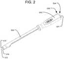
- FIG. 2is a perspective view of a delivery tool of the implant delivery system of FIG. 1 .
- FIG. 3is a perspective view of a rotatable threaded member.
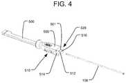
- FIG. 4is a perspective view of the insertion of the rotatable threaded member into the delivery tool.
- FIG. 5is a perspective view of the rotatable threaded member inserted into the delivery tool connected to an expandable implant.
- FIG. 6is a perspective view of a fluid delivery cannula.
- FIG. 7Ais a perspective view of the insertion of the fluid delivery cannula into the delivery tool.
- FIG. 7Bis a perspective view of the distal end of the delivery tool with the fluid delivery cannula inserted and projecting distally towards the expandable implant.
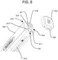
- FIG. 8is a perspective view of the attachment of a connect cap for impaction to the handle of the delivery tool.
- FIG. 9is a perspective view of the proximal end of the handle of the delivery tool.
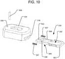
- FIG. 10is an exploded view of the connect cap of FIG. 8 .
- FIG. 11Ais a perspective, cross-sectional view showing a sliding lock mechanism within the connect cap of FIG. 8 .
- FIG. 11Bis a perspective view of the connect cap of FIG. 8 connected to the proximal end of the handle of the delivery tool.
- FIG. 12is a perspective view of a different connect cap with a plunger for the fluid delivery cannula.
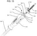
- FIG. 13is a perspective view of the attachment of the connect cap and plunger of FIG. 12 to the handle of the delivery tool.
- FIG. 14is a perspective, cross-sectional view of the connect cap and plunger of FIG. 12 attached to the proximal end of the handle of the delivery tool.
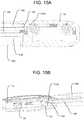
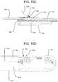
- FIGS. 15A, 15C and 15Dare top, cross-sectional views of the delivery tool connected to the expandable implant, showing the movement of the fluid delivery cannula by a flip lever of the delivery tool.
- FIG. 15Bis a perspective, cross-sectional view of the expandable implant connected to the distal end of the delivery tool.
- FIG. 16Ais a perspective view of an alternative embodiment of a plunger containing a pressure gauge for the fluid delivery cannula.
- FIG. 16Bis an exploded view of the plunger of FIG. 16A .
- FIG. 16Cis a cross-sectional view of the plunger of FIG. 16A .
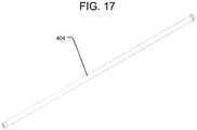
- FIG. 17is a perspective view of a bone graft supply line.
- FIG. 18is a perspective view of the insertion of the bone graft supply line into the delivery tool.
- FIG. 19is a perspective view of a plunger for the bone graft supply line.
- FIGS. 20A-20Bare perspective views of the insertion of the plunger into the bone graft supply line.
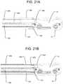
- FIGS. 21A-21Bare cross-sectional views of the movement of the plunger of FIG. 19 within the bone graft supply line.
- FIGS. 22A-22Bare perspective views of the attachment of a connect cap fitted with a pistol-grip handle.
- FIG. 23is a perspective view of the insertion of a plunger that fits within the pistol-grip handle.
- FIGS. 24A-24Bare side, cross-sectional views of the pistol-grip handle with the plunger inserted to deliver graft material to the expandable implant.
- FIG. 25is a perspective view of a grafting block.
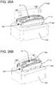
- FIGS. 26A-26Bare perspective views of the grafting block with the expandable implant placed upon it and a retaining mechanism at varying heights.
- FIG. 26Cis a perspective, cross sectional view of the grafting block with retaining mechanism having the expandable implant placed upon it.
- FIG. 27is a perspective view of the expandable implant on an alternative embodiment of a grafting block without a retaining mechanism.
- FIGS. 28A-28Bare perspective, cross-sectional views of the expandable implant on the grafting block of FIG. 27 .
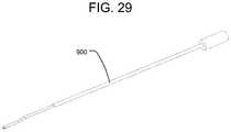
- FIG. 29is a perspective view of a graft reamer.
- FIGS. 30A-30Bare side, cross sectional views of the graft reamer inserted into the expandable implant.
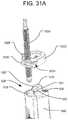
- FIG. 31Ais a perspective view of the attachment to the handle of the delivery tool of a connect cap with a fluid delivery plunger having two modes of travel.
- FIG. 31Bis an exploded view of the connect cap of FIG. 31A .
- FIG. 31Cis a perspective view of a lever of a selector mechanism of the connect cap of FIG. 31A .
- FIG. 31Dis a cross-sectional view of the selector mechanism of the connect cap of FIG. 31A in an engaged position.
- FIG. 31Eis a cross-sectional view of the selector mechanism of the connect cap of FIG. 31A in a disengaged position.
- FIG. 32is an exploded view of an implant delivery system in accordance with another embodiment of the present invention.
- FIG. 33Ais a perspective view of the attachment of a handle of the implant delivery system of FIG. 32 to an insertion shaft of the implant delivery system.
- FIG. 33Bis a cross-sectional view of the arrangement of FIG. 33A .
- FIG. 33Cis an enlarged, cross-sectional view of the handle and insertion shaft of FIGS. 33A-B connected to one another.
- FIG. 34Ais an exploded view of a delivery tool of the implant delivery system of FIG. 32 .
- FIG. 34Bis a perspective view of the delivery tool of FIG. 34A connected to an expandable implant.
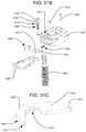
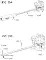
- FIG. 35Ais a perspective view of the delivery tool inserting and placing the implant into the intervertebral space.
- FIG. 35Bis a perspective view of the arrangement of FIG. 35A , with the handle removed from the insertion shaft of the delivery tool.
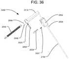
- FIG. 36is an exploded view of a fluid delivery system of the implant delivery system of FIG. 32 .
- FIGS. 37A-37Bare perspective views of the insertion of the fluid delivery system of FIG. 36 into the delivery tool.
- FIG. 38A-38Bare cross-sectional views of the insertion of a plunger of the fluid delivery system of FIG. 36 into a reservoir of the fluid delivery system.
- FIG. 38Cis a perspective, cross-sectional view of a plunger engagement mechanism engaging the plunger of the fluid delivery system of FIG. 36 .
- FIGS. 39A-39Bare perspective views of the insertion shaft of the implant delivery system of FIG. 32 connected to the expanded implant within the intervertebral space.
- FIGS. 40A-40Bare perspective views of the insertion of a bone graft supply line into a bone graft supply system of the implant delivery system of FIG. 32 .
- FIGS. 41A-41Bare perspective, cross-sectional views of the bone graft supply line connected to the bone graft supply system of FIGS. 40A-B .
- FIGS. 42A-42Bare perspective views of the insertion of a bone graft supply system into the implant delivery system of FIG. 32 .
- FIG. 42Cis a perspective view of the bone graft supply system of FIGS. 42A-B injecting bone graft material into the implant.
- FIG. 43is a simplified view showing a delivery tool in accordance with another embodiment of the present invention inserting an implant into an intervertebral space along a lateral approach.
- FIG. 44is a perspective view of a delivery tool in accordance with another embodiment of the present invention.
- FIG. 1illustrates an embodiment of an implant delivery system for insertion of an expandable implant 10 into an intervertebral space in accordance with the present invention.
- the expandable implant 10may, for example, be structured like any of the embodiments of expandable implants disclosed in the '199 Publication.
- a delivery tool 100 of the delivery systemis comprised of a handle 550 connected to an insertion shaft 500 .
- the handle 550is adapted to be grasped by a surgeon or other user while the expandable implant 10 is inserted into the intervertebral space using the delivery tool 100 , and the handle 550 includes features at its proximal end to facilitate engagement with, and control of, the expandable implant 10 .
- the expandable implant 10is connectable to the distal end of the insertion shaft 500 .
- connect caps of the delivery systemcan be fitted to the proximal end of the handle 550 via a connection mechanism that allows for connect caps to be interchanged.
- Each connect capserves a different purpose during implantation of the expandable implant 10 and can be readily switched without disconnecting the delivery tool 100 from the implant 10 and without removing the implant 10 from the intervertebral space.
- Connect cap 502allows for the advancement of plunger 506 for the fluid delivery system and plunger 508 for the bone graft supply line 404 .
- Connect cap 504provides for a durable impaction surface during insertion of the expandable implant 10 .
- Both connect cap 502 and connect cap 504have a button 503 that facilitates the attachment and removal of connect caps 502 and 504 .
- the delivery tool 100also has a flip lever 510 that allows for unlocking and collapsing the expandable implant 10 .
- FIGS. 2-5illustrate the insertion of rotatable threaded member 158 .
- FIG. 2illustrates the delivery tool 100 having a receptacle 512 for receiving a rotatable threaded member 158 , a receptacle 514 for the fluid delivery cannula 154 , and a receptacle 516 for the bone graft supply line 404 .
- the receptacle 512 for receiving the rotatable threaded member 158extends from the proximal end of the handle 500 through the distal end of the insertion shaft 500 .
- the distal end of the rotatable threaded member 158as illustrated in FIG.
- the expandable implant 10is secured to the delivery tool 100 by threading the threaded distal end of the rotatable threaded member 158 into a delivery tool anchor in the form of a threaded receptacle on the proximal end of the expandable implant 10 , as disclosed in the '199 Publication.
- connect cap 502 or 504need not be attached to the handle 550 of the delivery tool 100 .
- Receptacle 514is for receiving the fluid delivery cannula 154 of a fluid delivery system.
- the fluid delivery cannula 154allows for hydraulic fluid to be delivered to expandable implant 10 to expand expandable implant 10 .
- the delivery tool 100may be easier to manipulate than some delivery tools, which may include bulky external syringes for supplying hydraulic fluid.
- fluid delivery cannula 154includes a reservoir 518 at the proximal end of the fluid delivery cannula 154 and an outlet 152 for delivering pressurized fluid at the distal end of the fluid delivery cannula 154 .
- the reservoir 518has a rack mechanism 520 along its periphery that will interact with a pinion mechanism 522 at one end of flip lever 510 , as shown in FIG. 15C (and discussed below).
- Outlet 152 for delivering pressurized fluidis inserted into receptacle 514 for the fluid delivery cannula at the proximal end of the handle 550 , as illustrated in FIG. 7A .
- the outlet 152 for delivering pressurized fluidwill be located at the distal end of the insertion shaft 500 , where it can fluidly communicate with the inlet of a pressure channel on the proximal end of the expandable implant 10 .
- the outlet 152may project from the distal end of the insertion shaft 500 , such that it is partially received within the inlet of the expandable implant, where it can form a sealing connection by engaging an o-ring positioned within the pressure channel of the implant 10 , as disclosed in the '199 Publication.
- FIGS. 8-11Billustrate how connect cap 504 attaches to the proximal end of handle 550 of delivery tool 100 . Preparation for attachment of connect cap 504 to handle 550 is illustrated in FIG. 8 .
- Connect cap 504provides for a flat surface on its proximal end to provide a durable impaction surface to help insert or place expandable implant 10 .
- Connect cap 504can be interchanged with connect cap 502 and connect cap 702 at various points during the use of the delivery tool 100 .
- Connect cap 502provides for plunger 506 and plunger 508 to be used in conjunction with the delivery tool 100 .
- Connect cap 702provides a pistol-grip handle 700 that can be used to back-fill interior cavity 15 of expandable implant 10 with graft material.
- FIG. 9illustrates an attachment interface 528 at the proximal end of the handle 550 to which the connect cap 504 will be attached.
- the attachment interface 528includes two recesses 511 to allow for alignment between handle 550 and connect cap 504 , by receiving corresponding projections 505 of the connect cap 504 , as discussed below.
- the attachment interface 528also includes a locking mechanism 534 for keeping the connect cap 504 securely attached to the attachment interface 528 .
- the locking mechanism 534includes a projection 501 having a recess 532 and one or more (e.g., two) overhead projections 530 .
- the proximal end of the handle 550may also include a connection 536 (e.g., a threaded bore) for securely and removably connecting to a slap hammer to assist with removal of the delivery tool 100 and implant 10 in the proximal direction if the implant 10 becomes stuck in the intervertebral space.
- a connection 536e.g., a threaded bore
- connect cap 504is comprised of a sliding lock mechanism 535 having a central hole 537 in it that is shaped to receive the projection 501 on the proximal end of handle 550 .
- the sliding lock mechanism 535is spring-biased, using springs 507 .
- a stop pin 509is received through a slot 542 in the sliding lock mechanism 535 to constrain the travel of the sliding lock mechanism 535 , such that the sliding lock mechanism 535 is retained within the connect cap 504 .
- the sliding lock mechanism 535includes an outwardly projecting button 503 , which may be a projecting portion of the sliding lock mechanism 535 projecting out of slot 539 on connect cap 504 .
- the sliding lock mechanism 535allows for connect cap 504 to be locked to the locking mechanism 534 of the handle 550 .
- button 503is pressed, causing springs 507 to compress, so that the central hole 537 becomes aligned with projection 501 .
- Projections 505 on the distal end of connect cap 504align with recesses 511 on the proximal end of handle 550 .
- the sliding lock mechanism 535slides such that stop pin 509 slides within slot 542 , the end 540 of central opening 537 slides into the recess 532 of projection 501 , and the side peripheral edges 544 of the sliding lock mechanism 535 slide under the overhead projections 530 .
- the inter-engagement of all those structures discussed aboveprevents the connect cap 504 from becoming disconnected from handle 550 when the button 503 is in its undepressed position.
- Connect cap 504Removal of connect cap 504 is done through a similar process as attaching connect cap 504 . That is, to remove connect cap 504 , button 503 is pressed, causing springs 507 to compress. This shifts sliding lock mechanism 535 such that it is no longer locked into place by the overhead projections 530 on projection 501 or by the recess 532 in projection 501 . Once button 503 is pressed, connect cap 504 can be lifted off handle 550 .
- the connect cap 502may have substantially the same attachment structure as the connect cap 504 , and therefore attaching and removing connect cap 502 may use the same process as connect cap 504 , as described above.
- connect cap 502allows for either or both of plunger 506 or plunger 508 to be received through or removed from the connect cap 502 during the use of the delivery tool 100 .
- Receptacle 524is threaded to receive the plunger 506 of the fluid delivery system, which is used to push the hydraulic fluid into the expandable implant 10 .
- Receptacle 526receives plunger 508 that is used to push graft material in order to back-fill the expandable implant 10 after it has been expanded.
- FIG. 13illustrates how connect cap 502 can be attached to the proximal end of the handle 550 of the delivery tool 100 after having already received plunger 506 .
- FIG. 14illustrates how connect cap 502 with plunger 506 align and function with all the other elements of handle 550 .
- Plunger 506is seated within reservoir 518 . Threadedly advancing the plunger 506 pushes the hydraulic fluid through fluid delivery cannula 154 and out the outlet 152 , which is in fluid communication with the inlet of a pressure channel of the expandable implant 10 .
- FIGS. 16A-16Care exemplary of the shape of what the handle may look like.
- FIGS. 16A-16Cillustrate the handle 602 with a pressure gauge 600 embedded in the handle.
- Another embodiment of handle 602may be without such a recess or a pressure gauge embedded within it.
- Plunger 506can be operated by turning an attached handle. As the handle is turned, plunger 506 pushes hydraulic fluid from reservoir 518 through the fluid delivery cannula 154 and out the outlet 152 into the expandable implant 10 causing expandable implant 10 to expand.
- connect cap 502may be replaced with connect cap 1002 , which includes a selector mechanism 1004 for selecting between two modes of travel by the plunger 1006 that pushes the hydraulic fluid into the implant 10 .
- the plunger 1006may be threadedly engaged within a receptacle 1024 in the connect cap 1002 so that the plunger 1006 can travel (i.e., be advanced or retracted) by rotation about its longitudinal axis, similar to plunger 506 .
- the threadsmay be disengaged from the plunger 1006 so that the plunger can travel by sliding it linearly through the receptacle 1024 .
- the process of attaching and removing connect cap 1002is the same process as attaching and removing connect caps 502 and 504 . That is, the connect cap 1002 may have a sliding lock mechanism 1035 constrained by a stop pin 1009 in the same manner as the sliding lock mechanism 535 and stop pin 509 of connect caps 502 and 504 .
- the selector mechanism 1004 for selecting between the two modes of travelmay include a pivotable lever 1008 controllable by manipulating an external projection 1010 such that the lever 1008 pivots about a pivot pin 1012 received through a hole 1014 in the lever 1008 .
- Such pivoting of the lever 1008may selectively bring threads 1016 on the lever 1008 into engagement with threads on the plunger 1006 , as shown in FIG. 31D , or it may disengage the threads 1016 of the lever 1008 from the threads of the plunger 1006 , as shown in FIG. 31E .
- the lever 1008can be held in the engaged and disengaged positions by a pin 1018 that engages respective notches 1020 and 1022 formed on the lever 1008 .
- the lever 1008can be pivoted about the pivot pin 1012 to the disengaged position shown in FIG. 31E .
- the lever 1008can then be held in that disengaged position, in which the threads 1016 are spaced apart from the plunger 1006 , by having the pin 1018 positioned in notch 1022 .
- a biasing spring 1025may bias the lever 1008 back towards the engaged position.
- the lever 1008may be returned to the engaged position of FIG.
- the two modes of travel discussed abovemay desirably permit the plunger 1006 to advance the hydraulic fluid into the implant in the rotational, threaded engagement mode, and then the plunger 1006 can be quickly released by disengaging the lever 1008 and pulling the plunger 1006 in the proximal direction.
- the two states of engagement between the lever 1008 and the plunger 1006may also give the surgeon a choice between two modes for delivery of the hydraulic fluid into the implant. That is, the surgeon may use the threaded advancement mode if a slower and more controlled advancement is appropriate, and/or if it is desirable to employ the mechanical advantage provided by the screw drive to amplify the input force. The surgeon may also choose to use the sliding, non-threaded mode if more rapid advancement of the plunger is desirable.
- the sliding, non-threaded modemay also desirably allow the plunger 1006 to be initially positioned into or removed from the receptacle 1024 of the connect cap 1002 relatively quickly, by eliminating the need to threadedly advance or retract the plunger 1006 the entire distance to the desired position.
- FIGS. 15A-15Dillustrate the interaction between rack mechanism 520 on reservoir 518 and pinion mechanism 522 on flip lever 510 .
- outlet 152 for delivering pressurized fluid at the distal end of the fluid delivery cannula 154is a distance away from the pushable unlocking tether 212 a in the expandable implant 10 , as illustrated in FIGS. 15A-B .
- pressing distally on the pushable unlocking tether 212 aallows for expandable implant 10 to collapse so that it can be repositioned if necessary.
- the expandable implant 10may include a pushable unlocking tether 212 a engaged with a lower lock support so as to rotate the lower lock support 20 in the unlock direction when the pushable unlocking tether 212 a is pushed in the distal direction.
- FIG. 15Cillustrates the activation of flip lever 510 .
- the pinion mechanism 522 on the flip lever 510interacts with rack mechanism 520 on reservoir 518 to cause reservoir 518 and fluid delivery cannula 154 to move towards the distal end of insertion shaft 500 .
- outlet 152 for delivering pressurized fluidalso moves distally and pushes on the internal unlocking mechanism within the expandable implant 10 , as shown in FIG. 15D .
- the flip lever 510may beneficially allow for the relatively rigid structure of fluid delivery cannula 154 to move to activate the unlocking mechanism within expandable implant 10 .
- FIGS. 16A-16Cexemplify handle 602 having a pressure gauge 600 to measure the pressure of the fluid in the fluid delivery cannula 154 as the handle 602 is turned.
- Pressure gauge 600provides numerical readings of the pressure of the fluid inside the expandable implant 10 .
- Handle 602has a recess to receive pressure gauge 600 .
- the distal end of pressure gauge 600has a threaded member that allows for a secure connection between pressure gauge 600 and handle 602 .
- handle 602is threaded to receive the threaded proximal end of handle connector 610 .
- a secure connection between handle 602 and handle connector 610is formed such that the rotation of handle 602 is transmitted to the handle connector 610 .
- Handle connector 610connects handle 602 to plunger 606 .
- the proximal end of plunger 606is fitted to have o-ring 608 as part of its assembly when connected to the distal end of handle connector 610 .
- Plunger 606has a passageway 612 to provide fluid communication between the fluid delivery cannula 154 and the pressure gauge 600 , so that the pressure gauge 600 can read the pressure in the fluid delivery cannula 154 as hydraulic fluid is delivered to the expandable implant 10 .
- the passageway 612 in plunger 606communicates with passageways in handle 602 and handle connector 610 , as shown in FIG. 16C .
- O-ring 608is in place to create a seal between the plunger 606 and handle connector 610 to minimize leakage between those components.
- Plunger 606also has an o-ring 604 located at the distal end of plunger 606 that creates a movable seal between the plunger 606 and the reservoir 518 of the fluid delivery cannula 154 as the plunger 606 advances within the reservoir 518 .
- plunger 606The distal end of plunger 606 is inserted into the proximal end of receptacle 524 on connect cap 502 .
- the threading of plunger 606is the same as plunger 506 , allowing the threading of plunger 606 to also match the threading of receptacle.
- Plunger 606is operated by turning handle 602 . As the handle 602 is turned, plunger 606 pushes hydraulic fluid from reservoir 518 through the fluid delivery cannula 154 and out the outlet 152 into the expandable implant 10 , causing expandable implant 10 to expand.
- the pressure gauge 600may provide an absolute reading, instead of a relative measure, of the pressure of the fluid in the expandable implant 10 . This may help prevent the surgeon from over-pressurizing the expandable implant 10 .
- the gaugemay provide a relative pressure reading, such as by displaying color-coded regions associated with different pre-defined ranges of pressure.
- the delivery systemprovides a bone graft supply system for back-filling the expandable implant 10 with graft material.
- the bone graft supply line 404 of the bone graft supply systemis a cannula that does not have to be inserted into the delivery tool 100 until after the expandable implant 10 is inserted.
- the cannula used for the bone graft supply line 404may also be translucent, which allows for better visualization of the amount of graft material being delivered.
- a large diameter bone graft supply line 404for receiving different sizes of graft material.
- the diameter of the bone graft supply line 404is 6 mm ID.
- providing such a larger diameter bone graft supply line 404may beneficially allow for the use of more types of graft materials, such as cancellous chips, autograft, or synthetic bone graft materials such as those manufactured by Orthovita, Inc. under the trademark VITOSS®.
- the distal end of the bone graft supply line 404is inserted into the proximal end of receptacle 516 on the handle 550 .
- a plunger 508 of the bone graft supply systemis introduced and inserted into the proximal end of the bone graft supply line 404 , as illustrated in FIGS. 19-20B , for dispensing the graft material.
- plunger 508does not illustrate connect cap 502 being connected to handle 500 , it may be in place when using plunger 508 , in which case the plunger 508 can be introduced through the receptacle 526 of the connect cap when inserting the plunger 508 into the bone graft supply line 404 .
- plunger 508is pushed in the distal direction, causing graft material to move distally through the bone graft supply line 404 and into the passage for graft material 392 of the expandable implant 10 , to back-fill the interior cavity 15 of the expandable implant 10 .
- connect cap 502may be replaced with connect cap 702 , which is fitted with a pistol-grip handle 700 to form a bone graft gun for delivering graft material to the expandable implant 10 .
- the process of attaching and removing connect cap 702is the same process as attaching and removing connect caps 502 and 504 .
- plunger 708is inserted into the proximal end of the pistol-grip handle 700 , as illustrated in FIG. 23 .
- Plunger 708is designed to work with the pistol-grip handle 700 using a ratcheting advancement mechanism. As the pistol-grip trigger 714 is squeezed towards the handle 700 , the trigger 714 pivots about pivot point 706 such that movable pawl 710 connected to the trigger 714 engages ratchet teeth on the plunger 708 and pushes the plunger 708 distally. When the trigger 714 is released, a biasing spring 704 moves the trigger 714 back to its original position.
- the ratchet teethare pushed through a spring-biased fixed pawl 712 that prevents the plunger 708 from retracting in the proximal direction, unless the fixed pawl 712 is released from engagement with the plunger 708 by pushing the fixed pawl 712 against its spring 716 .
- the distal movement of the plunger 708pushes graft material through bone graft supply line 404 and into the passage for graft material 392 of the expandable implant 10 to fill the interior cavity 15 of the expandable implant 10 .
- This processis exemplified in FIGS. 24A-24B . It is believed that using a ratcheting mechanism in this manner is preferable over tamping the bone graft material, as tamping may cause jamming of the bone graft material.
- FIG. 25illustrates one embodiment of a grafting block 800 that can be used to help pre-pack the implant 10 with graft material.
- a projection 804 from a base 802 of the grafting block 800is shaped to be at least partially received within the interior cavity 15 of the expandable implant 10 , as shown in FIGS. 28A-28B , such that the projection 804 occupies a portion 808 of the interior cavity 15 extending from the passage 392 , while leaving a remaining open region 810 of the interior cavity 15 unoccupied.
- the projection 804will prevent graft material packed into the open region 810 of the interior cavity 15 from filling the portion 808 extending from the passage 392 , which might cause a blockage to the later-inserted graft material when back-filling the expandable implant 10 after insertion.
- the projection 804may be configured at one end to a height that matches the apex of the ramp 393 inside the expandable implant 10 .
- the remainder of the projection 804may be configured to a height that is aligned with the boundary between the implant housing 11 and the expandable top end plate 13 . In that way, any back-filled graft material added later will primarily fill the initial portion 808 that was blocked out, as well as the new volume created by the expansion of the implant.
- a retaining mechanism 806that will assist in keeping the expandable implant 10 on the grafting block 800 .
- the retaining mechanism 806is adjustable in height, as illustrated in FIGS. 26A-26C .
- Retaining mechanism 806allows for the expandable implant 10 to be placed on the projection 804 when the retaining mechanism 806 is in the raised position.
- the retaining mechanism 806assists in keeping the expandable implant 10 on the grafting block 800 .
- FIGS. 27-28Bshow an alternative embodiment of the grafting block 800 .
- the grafting block 800does not have the retaining mechanism 806 .
- the use of the grafting block 800is optional. In one example, when no pre-packing of the graft material is performed (e.g., where the graft material is entirely supplied via the bone graft supply line 404 after the implant 10 has been implanted), the grafting block 800 may not be used.
- the ramp 393 inside the expandable implant 10is used to guide graft material into the area of the interior cavity 15 that was not pre-packed using the grafting block 800 .
- the ramp 393guides new graft material into the expanded volume that is created once the expandable implant 10 is inserted and expanded.
- FIG. 29illustrates a flexible graft reamer 900 that can be used to clear blockages during backfilling. Graft reamer 900 can also be used to re-establish a grafting channel within passage 392 .
- the graft reamer 900fits within delivery tool 100 while the insertion shaft 500 is connected to the expandable implant 10 .
- the flexibility of graft reamer 900allows graft reamer 900 to fit within passage 392 in the expandable implant 10 and around ramp 393 in the expandable implant 10 .
- FIGS. 32-44The components of another embodiment of a delivery system are illustrated in FIGS. 32-44 .
- the components of such embodimentare adapted to provide a surgeon with improved viewability of the expandable implant 10 (both directly and using fluoroscopy), as well as to improve the speed and efficiency of surgery, so as to minimize the time that tissue is retracted.
- modular partscan be attached to and detached from the insertion shaft of the delivery tool between each phase of the procedure.
- the modular instrumentsconsist of a handle 2550 , an insertion shaft 2500 , a rotatable threaded member 2158 , a fluid delivery system 2400 , a bone graft gun 2750 , and a bone graft supply line 2404 .
- the modular partscan be attached to the insertion shaft using a sliding lock mechanism 2535 .
- the sliding lock mechanism 2535 of the handle 2550is illustrated in FIGS. 33A-C , but a similar sliding lock mechanism 2535 may be incorporated into the fluid delivery system 2400 and the bone graft gun 2750 for securely (yet removably) coupling those components with the insertion shaft 2500 .
- the proximal end of the insertion shaft 2500may define a locking mechanism 2534 for securely coupling to the sliding lock mechanism 2535 .
- the locking mechanism 2534is shaped to fit securely within a correspondingly shaped receptacle 2515 in the distal end of the handle 2550 .
- the locking mechanism 2534includes a recess 2532 for engaging the sliding lock mechanism 2535 , as discussed below.
- the sliding lock mechanism 2535operates similarly to the sliding lock mechanism 535 of the connect cap 504 illustrated in FIG. 11A .
- the sliding lock mechanism 2535may be slidable within the distal end of the handle 2550 , and it may be biased by one or more springs 2507 so that a button 2503 of the sliding lock mechanism 2535 is biased to project outwardly from an exterior surface of the handle 2550 .
- a stop pin 2509is received through a slot 2542 in the sliding lock mechanism 2535 to constrain the travel of the sliding lock mechanism 2535 , such that the sliding lock mechanism 2535 is retained within the handle 2550 .
- the sliding lock mechanism 2535includes a central hole 2537 that is shaped to receive the locking mechanism 2534 of the insertion shaft 2500 .
- button 2503is pressed, causing the springs 2507 to compress, so that the central hole 2537 becomes aligned with the locking mechanism 2534 .
- button 503is released, causing the springs 2507 to de-compress and lock the locking mechanism 2534 to the sliding lock mechanism 2535 .
- the sliding lock mechanism 2535slides such that stop pin 2509 slides within the slot 2542 , and the end 2540 of central opening 2537 slides into the recess 2532 of the locking mechanism 2534 .
- the engagement of the sliding lock mechanism 2535 with the recess 2532prevents the handle 2550 from moving longitudinally and becoming disconnected from the insertion shaft 2500 when the button is in its undepressed position. Removal of the handle 2550 is then done through the reverse process, by pressing the button 2503 of the sliding lock mechanism 2535 and lifting the handle 2550 off of the insertion shaft 2500 .
- FIG. 34Ashows an exploded view of the handle 2550 , the insertion shaft 2500 , the rotatable threaded member 2158 , and the implant 10 .
- the rotatable threaded member 2158includes a threaded portion on its distal end, which is inserted into the proximal end of a receptacle 2512 in the insertion shaft 2500 .
- the rotatable threaded member 2158then extends out the distal end of the insertion shaft 2500 and screws into the implant 10 to attach the implant 10 to the insertion shaft 2500 , a system which can remain intact throughout the procedure.
- the handle 2550then attaches to the proximal end of the insertion shaft 2500 , e.g., via sliding lock mechanism 2535 , so that the handle 2550 can be grasped by the surgeon during insertion of the implant 10 into the intervertebral space.
- the proximal end of the handle 2550also desirably provides a durable impaction surface to help insert or place expandable implant 10 .
- the handle 2550includes a threaded bore 2536 on its proximal end for receiving a slap hammer, which can help with removal of the implant 10 if necessary. Placement of the implant 10 into the disc space is shown in FIG. 35A .
- the handle 2550can be removed from the insertion shaft 2500 , as shown in FIG. 35B .
- the insertion shaft 2500is designed to have minimal cross-sectional dimensions, so as to increase visualization of the implant and its expansion, both directly by the surgeon as well as via fluoroscopy. The removal of the handle 2550 enhances visibility even further.
- the fluid delivery system 2400may be attached to the insertion shaft 2500 to expand the implant 10 .
- An exploded view of the fluid delivery system 2400is illustrated in FIG. 36 .
- the fluid delivery system 2400includes a fluid delivery cannula 2154 , a reservoir 2518 , a plunger 2506 , and a connect cap 2502 .
- the connect cap 2502desirably includes a sliding lock mechanism 2535 for attaching the fluid delivery system 2400 to the locking mechanism 2534 at the proximal end of the insertion shaft 2500 , in the same manner shown in FIGS. 33A-C . As shown in FIGS.
- the distal end of the fluid delivery cannula 2154may be inserted into a receptacle 2514 on the proximal end of the insertion shaft 2500 .
- the outlet 2152 for delivering pressurized fluidwill be located at the distal end of the insertion shaft 2500 , where it can fluidly communicate with the inlet of a pressure channel on the proximal end of the expandable implant 10 .
- the outlet 2152 of this embodimentmay likewise project from the distal end of the insertion shaft 2500 , such that it is partially received within the inlet of the expandable implant, where it can form a sealing connection by engaging an o-ring positioned within the pressure channel of the implant 10 .
- the reservoir 2518may be angled with respect to the fluid delivery cannula 2154 , which preferably positions the reservoir 2518 out of the line of site of the surgeon and/or the fluoroscope to the implant. Desirably, such positioning improves visibility for viewing the implant 10 , as well as relocating a user's hands outside the radiation area of the fluoroscope.
- the reservoir 2518may be angled at 90 degrees with respect to the fluid delivery cannula 2154 , although other angles to position the reservoir 2518 away from the viewing area could also be used.
- the reservoir 2518may receive the threaded plunger 2506 to pressurize the system.
- the plunger 2506may be engaged by a plunger engagement mechanism 2008 , as shown in FIGS. 38A-C .
- the plunger engagement mechanism 2008 of the embodiment of FIGS. 38A-Cmay be designed to allow two modes of travel by the plunger 2506 .
- the plunger engagement mechanism 2008is slidable within a proximal portion of the reservoir 2518 , and it may be biased by one or more springs 2025 so that a button 2003 of plunger engagement mechanism 2008 is biased to project outwardly from an exterior surface of the reservoir 2518 .
- a stop pin 2009is received through a slot 2042 in the plunger engagement mechanism 2008 to constrain the travel of the plunger engagement mechanism 2008 , such that the plunger engagement mechanism 2008 is retained within the reservoir 2518 .
- the plunger engagement mechanism 2008includes a central hole 2037 that is shaped to receive the plunger 2506 through it. At least one side of the hole includes a threaded portion 2016 structured to engage the threads of the plunger 2506 .
- the button 2003holding the button 2003 in a depressed state allows for one of the two modes of travel by the plunger 2506 , in which the threaded portion 2016 of the plunger engagement mechanism 2008 is disengaged from the threads of the plunger 2506 , so that the plunger can travel along the reservoir 2518 by sliding the plunger 2506 linearly through the opening 2037 in the plunger engagement mechanism 2008 .
- the spring 2025will de-compress and cause the threaded portion 2016 of the plunger engagement mechanism 2008 to move into engagement with the threads of the plunger 2506 , which activates the other mode of travel by the plunger 2506 . That is, due to the threaded engagement between the threads of the plunger 2506 and the threaded portion 2016 of the plunger engagement mechanism 2008 , the plunger can travel along the reservoir 2518 by rotation about the longitudinal axis of the plunger.
- the two modes of travel of the plunger 2506 through the plunger engagement mechanism 2008may desirably permit the plunger 2506 to advance the hydraulic fluid into the implant in the rotational, threaded engagement mode, and then the plunger 2506 can be quickly released by depressing the button 2003 and pulling the plunger 2506 in the proximal direction.
- the two states of engagement between the plunger engagement mechanism 2008 and the plunger 2506may also give the surgeon a choice between two modes for delivery of the hydraulic fluid into the implant.
- the surgeonmay use the threaded advancement mode if a slower and more controlled advancement is appropriate, and/or if it is desirable to employ the mechanical advantage provided by the screw drive to amplify the input force.
- the surgeonmay also choose to use the sliding, non-threaded mode if more rapid advancement of the plunger is desirable.
- the sliding, non-threaded modemay also desirably allow the plunger 2506 to be initially positioned into or removed from the reservoir 2518 relatively quickly, by eliminating the need to threadedly advance or retract the plunger 2506 the entire distance to the desired position.
- the implant 10may be repositioned (if desired) by unlocking the expansion mechanism, such as by pressing distally on the unlocking tether 212 a .
- the fluid delivery cannula 2154may be advanceable distally relative to the reservoir 2518 , so as to push on the unlocking tether 212 a within the expandable implant 10 , in the same manner as illustrated in FIG. 15D .
- the fluid delivery system 2400may be removed from the insertion shaft 2500 , and then a tube or other rigid, elongate component may be inserted into the same receptacle 2514 at the proximal end of the insertion shaft, so as to travel through the insertion shaft 2500 and push the unlocking tether 212 a of the implant 10 .
- the fluid delivery system 2400may be removed from the insertion shaft 2500 , as shown in FIGS. 39A-B .
- the bone graft supply systemmay then be attached to the insertion shaft 2500 to fill the expanded implant 10 with bone graft material.
- the bone graft supply systemmay include a bone graft gun 2750 having a connect cap 2702 and a bone graft supply line 2404 .
- the steps of using the bone graft gun 2750are shown in FIGS. 40A-42C .
- the bone graft supply line 2404may first be connected to the bone graft gun 2750 , as shown in FIGS. 40A-B .
- the proximal portion of the bone graft supply line 2404includes a recess 2519 around at least a portion of its outer periphery. That recess 2519 is shaped to engage the sliding lock mechanism 2535 of the connect cap 2702 of the bone graft gun 2750 in much the same manner that the recess 2532 on the insertion shaft 2500 engages the end 2540 of the central opening 2537 of the sliding lock mechanism 2535 in order to secure the insertion shaft 2500 to the handle 2550 .
- both the bone graft supply line 2404 and the insertion shaft 2500can be secured to the connect cap 2702 of the bone graft gun 2750 via the sliding lock mechanism 2535 .
- the proximal portion of the bone graft supply line 2404is inserted into a corresponding receptacle 2526 on the connect cap 2702 of the bone graft gun 2750 while the button 2503 of the sliding lock mechanism 2535 is depressed.
- the depressing of the button 2503causes the central opening 2537 of the sliding lock mechanism 2535 to be positioned such that the proximal portion of the bone graft supply line 2404 can be received through the central opening 2537 .
- the bone graft supply line 2404can be secured to the bone graft gun 2740 by releasing the button 2503 , which results in the biasing of the sliding lock mechanism 2535 to a shifted position, in which a portion of the periphery of the central opening 2537 is received within the recess 2519 of the bone graft supply line 2404 , as shown in FIG. 41B .
- the bone graft gun 2750 with attached bone graft supply line 2404is then connected to the insertion shaft 2500 , as shown in FIGS. 42A-B .
- the distal end of the bone graft supply line 2404is placed within an opening 2516 at the distal end of the insertion shaft 2500 (see FIGS. 34B and 39A ), such that the bone graft supply line 2404 is positioned alongside the insertion shaft 2500 , where it may be partially received in and supported by a groove or channel 2517 extending along the insertion shaft 2500 (see FIG. 34B ).
- the connect cap 2702 of the bone graft supply gun 2750is also connected to the locking mechanism 2534 at the proximal end of the insertion shaft 2500 via a sliding lock mechanism 2535 like that of handle 2550 .
- the distal end of plunger 2508is then inserted into the proximal end of the bone graft supply line 2404 .
- Plunger 2508is designed to work with the bone graft gun 2750 using a pistol-grip trigger 2714 and a ratcheting advancement mechanism like that shown in FIGS. 24A-B .
- the insertion shaft 2500can be removed from the implant 10 by unthreading the rotatable threaded member 2158 .
- the insertion shaftmay include bend angles within one or more planes.
- an insertion shaft 3500may be provided having a single bend 3513 in a cephalad direction within the frontal or coronal plane. As shown in FIG. 43 , such bend 3515 may allow the insertion shaft 3500 to avoid the iliac crest IC.
- a bend in the anterior direction within the horizontal or transverse planemay additionally or alternatively be provided.
- an insertion shaft 4500may be provided having a compound bend 4513 , consisting of a cephalad bend like that shown in FIG. 43 , as well as a bend in the anterior direction within the horizontal or transverse plane, as shown in FIG. 44 . All of such bends are preferably located approximately 40 millimeters from the distal end of the insertion shaft 3500 , and the bends preferably have an angle between 15 and 30 degrees.
- One or more components of the delivery tool 100are desirably made of radiolucent material, such that they do not impair visualization of the implant 10 (e.g., by fluoroscopy) while it is being implanted and further manipulated.
- the components of the connect capsincluding the sliding lock mechanisms, may be fabricated from a plastic to reduce blockage of imaging, while the fluid delivery cannula 2154 and the reservoir 2518 may be fabricated from a metal for strength and durability.
- the rotatable threaded member 158may be made of a flexible material or it may have a flexible portion corresponding to the position of the bend.
- the fluid delivery cannula 154may also be fabricated from a flexible material, such as nitinol, to travel through the bent insertion shaft 3500 .
- the bone graft supply line 404may also be fabricated from a flexible material, or a non-flexible material having a bend that matches that of the insertion shaft 3500 .
Landscapes
- Health & Medical Sciences (AREA)
- Engineering & Computer Science (AREA)
- Biomedical Technology (AREA)
- Orthopedic Medicine & Surgery (AREA)
- Transplantation (AREA)
- Heart & Thoracic Surgery (AREA)
- Oral & Maxillofacial Surgery (AREA)
- Cardiology (AREA)
- Vascular Medicine (AREA)
- Life Sciences & Earth Sciences (AREA)
- Animal Behavior & Ethology (AREA)
- General Health & Medical Sciences (AREA)
- Public Health (AREA)
- Veterinary Medicine (AREA)
- Neurology (AREA)
- Physical Education & Sports Medicine (AREA)
- Prostheses (AREA)
Abstract
Description
Claims (17)
Priority Applications (3)
| Application Number | Priority Date | Filing Date | Title |
|---|---|---|---|
| US16/131,726US11083597B2 (en) | 2017-09-15 | 2018-09-14 | Instruments for expandable interbody implants |
| US17/373,117US11833062B2 (en) | 2017-09-15 | 2021-07-12 | Instruments for expandable interbody implants |
| US18/499,174US12226321B2 (en) | 2017-09-15 | 2023-10-31 | Instruments for expandable interbody implants |
Applications Claiming Priority (2)
| Application Number | Priority Date | Filing Date | Title |
|---|---|---|---|
| US201762559037P | 2017-09-15 | 2017-09-15 | |
| US16/131,726US11083597B2 (en) | 2017-09-15 | 2018-09-14 | Instruments for expandable interbody implants |
Related Child Applications (1)
| Application Number | Title | Priority Date | Filing Date |
|---|---|---|---|
| US17/373,117ContinuationUS11833062B2 (en) | 2017-09-15 | 2021-07-12 | Instruments for expandable interbody implants |
Publications (2)
| Publication Number | Publication Date |
|---|---|
| US20190083283A1 US20190083283A1 (en) | 2019-03-21 |
| US11083597B2true US11083597B2 (en) | 2021-08-10 |
Family
ID=63579247
Family Applications (3)
| Application Number | Title | Priority Date | Filing Date |
|---|---|---|---|
| US16/131,726Active2039-03-06US11083597B2 (en) | 2017-09-15 | 2018-09-14 | Instruments for expandable interbody implants |
| US17/373,117Active2039-08-13US11833062B2 (en) | 2017-09-15 | 2021-07-12 | Instruments for expandable interbody implants |
| US18/499,174ActiveUS12226321B2 (en) | 2017-09-15 | 2023-10-31 | Instruments for expandable interbody implants |
Family Applications After (2)
| Application Number | Title | Priority Date | Filing Date |
|---|---|---|---|
| US17/373,117Active2039-08-13US11833062B2 (en) | 2017-09-15 | 2021-07-12 | Instruments for expandable interbody implants |
| US18/499,174ActiveUS12226321B2 (en) | 2017-09-15 | 2023-10-31 | Instruments for expandable interbody implants |
Country Status (2)
| Country | Link |
|---|---|
| US (3) | US11083597B2 (en) |
| EP (1) | EP3456297B1 (en) |
Families Citing this family (13)
| Publication number | Priority date | Publication date | Assignee | Title |
|---|---|---|---|---|
| US8597360B2 (en) | 2004-11-03 | 2013-12-03 | Neuropro Technologies, Inc. | Bone fusion device |
| WO2013023096A1 (en) | 2011-08-09 | 2013-02-14 | Neuropro Technologies, Inc. | Bone fusion device, system and method |
| US9358123B2 (en) | 2011-08-09 | 2016-06-07 | Neuropro Spinal Jaxx, Inc. | Bone fusion device, apparatus and method |
| US9532883B2 (en) | 2012-04-13 | 2017-01-03 | Neuropro Technologies, Inc. | Bone fusion device |
| CA2906531C (en) | 2013-03-15 | 2020-10-06 | Neuropro Technologies, Inc. | Bodiless bone fusion device, apparatus and method |
| US10729560B2 (en) | 2017-01-18 | 2020-08-04 | Neuropro Technologies, Inc. | Bone fusion system, device and method including an insertion instrument |
| US10111760B2 (en) | 2017-01-18 | 2018-10-30 | Neuropro Technologies, Inc. | Bone fusion system, device and method including a measuring mechanism |
| US10973657B2 (en) | 2017-01-18 | 2021-04-13 | Neuropro Technologies, Inc. | Bone fusion surgical system and method |
| US10213321B2 (en) | 2017-01-18 | 2019-02-26 | Neuropro Technologies, Inc. | Bone fusion system, device and method including delivery apparatus |
| US11147690B2 (en)* | 2018-02-28 | 2021-10-19 | Globus Medical Inc. | Systems and methods for performing spinal surgery |
| US11191650B2 (en)* | 2020-02-03 | 2021-12-07 | Globus Medical Inc. | Expandable fusions devices, instruments, and methods thereof |
| EP4188235A4 (en)* | 2020-07-30 | 2024-10-23 | Tedan Surgical Innovations, Inc. | Anterior to the psoas surgical access system and a modified surgical approach technique |
| US20240293236A1 (en)* | 2021-06-23 | 2024-09-05 | NovApproach Spine, LLC | Spinal surgical approach method |
Citations (140)
| Publication number | Priority date | Publication date | Assignee | Title |
|---|---|---|---|---|
| US3581033A (en) | 1969-05-19 | 1971-05-25 | J B T Instr Inc | Toggle switch |
| US4743230A (en) | 1985-09-05 | 1988-05-10 | Advanced Cardiovascular Systems, Inc. | Inflating and deflating device for balloon dilatation catheters |
| WO1995031948A1 (en) | 1994-05-20 | 1995-11-30 | Kuslich Stephen D | Expandable fabric implant for stabilizing the spinal motion segment |
| US5800549A (en) | 1997-04-30 | 1998-09-01 | Howmedica Inc. | Method and apparatus for injecting an elastic spinal implant |
| US5993416A (en) | 1998-01-15 | 1999-11-30 | Medtronic Ave, Inc. | Method and apparatus for regulating the fluid flow rate to and preventing over-pressurization of a balloon catheter |
| US6004326A (en) | 1997-09-10 | 1999-12-21 | United States Surgical | Method and instrumentation for implant insertion |
| US6167787B1 (en) | 1995-03-06 | 2001-01-02 | Jack D. Jarvis | Locking swivel wrench |
| US6264659B1 (en) | 1999-02-22 | 2001-07-24 | Anthony C. Ross | Method of treating an intervertebral disk |
| US20010021853A1 (en) | 2000-03-10 | 2001-09-13 | Richard Wolf Gmbh | Surgical instrument for applying implants |
| US6332894B1 (en) | 2000-03-07 | 2001-12-25 | Zimmer, Inc. | Polymer filled spinal fusion cage |
| WO2002017823A1 (en) | 2000-08-28 | 2002-03-07 | Koo Ja Kyo | A prosthetic implant for spinal interbody fusion and a inserting apparatus thereof |
| US20020049449A1 (en) | 1999-03-16 | 2002-04-25 | Mohit Bhatnagar | Apparatus and method for fixation of osteoporotic bone |
| US6395007B1 (en) | 1999-03-16 | 2002-05-28 | American Osteomedix, Inc. | Apparatus and method for fixation of osteoporotic bone |
| US20020147497A1 (en) | 2001-04-06 | 2002-10-10 | Integrated Vascular Systems, Inc. | Methods for treating spinal discs |
| US20030018292A1 (en) | 2001-07-20 | 2003-01-23 | Kuslich Stephen D. | Device for inserting fill material particles into body cavities |
| US6706069B2 (en)* | 2001-09-13 | 2004-03-16 | J. Lee Berger | Spinal grooved director with built in balloon |
| US20040083002A1 (en) | 2001-04-06 | 2004-04-29 | Belef William Martin | Methods for treating spinal discs |
| US6764491B2 (en) | 1999-10-21 | 2004-07-20 | Sdgi Holdings, Inc. | Devices and techniques for a posterior lateral disc space approach |
| US20040143283A1 (en) | 2003-01-17 | 2004-07-22 | Mcgill Scott | Inflation adaptor and method of use |
| US20040186576A1 (en) | 2003-03-20 | 2004-09-23 | Spineco, Inc., An Ohio Corporation | Expandable spherical spinal implant |
| US6796959B2 (en) | 2001-03-19 | 2004-09-28 | Atrion Medical Products, Inc. | Actuating mechanism for fluid displacement and pressurizing device |
| US6830570B1 (en) | 1999-10-21 | 2004-12-14 | Sdgi Holdings, Inc. | Devices and techniques for a posterior lateral disc space approach |
| US20050113842A1 (en) | 2002-05-06 | 2005-05-26 | Rudolf Bertagnoli | Instrumentation and methods for preparation of an intervertebral space |
| US20050131419A1 (en) | 2003-12-16 | 2005-06-16 | Mccord David | Pivoting implant holder |
| US20050209698A1 (en) | 2003-08-05 | 2005-09-22 | Gordon Charles R | Expandable intervertebral implant |
| US20050222681A1 (en) | 2002-06-17 | 2005-10-06 | Richard Richley | Devices and methods for minimally invasive treatment of degenerated spinal discs |
| US20050245938A1 (en) | 2004-04-28 | 2005-11-03 | Kochan Jeffrey P | Method and apparatus for minimally invasive repair of intervertebral discs and articular joints |
| US20060004326A1 (en) | 2004-06-29 | 2006-01-05 | Keith Collins | Apparatus and kit for injecting a curable biomaterial into into an intervertebral space |
| US20060079898A1 (en) | 2003-10-23 | 2006-04-13 | Trans1 Inc. | Spinal motion preservation assemblies |
| US20060085075A1 (en) | 2004-10-04 | 2006-04-20 | Archus Orthopedics, Inc. | Polymeric joint complex and methods of use |
| US7060073B2 (en) | 1999-10-21 | 2006-06-13 | Sdgi Holdings, Inc. | Devices and techniques for a posterior lateral disc space approach |
| US20060155297A1 (en) | 2003-10-23 | 2006-07-13 | Ainsworth Stephen D | Driver assembly for simultaneous axial delivery of spinal implants |
| US20060206209A1 (en) | 2003-10-23 | 2006-09-14 | Cragg Andrew H | Prosthetic nucleus apparatus and methods |
| US7118579B2 (en) | 2001-02-04 | 2006-10-10 | Sdgi Holdings, Inc. | Instrumentation for inserting an expandable interbody spinal fusion implant |
| US20060235426A1 (en) | 2005-04-15 | 2006-10-19 | Sdgi Holdings, Inc. | Instruments, implants and methods for positioning implants into a spinal disc space |
| US20070093897A1 (en) | 2005-10-21 | 2007-04-26 | Stryker Spine (In France) | System and method for fusion cage implantation |
| US20070112299A1 (en) | 2005-05-27 | 2007-05-17 | Stryker Corporation | Hand-held fluid delivery device with sensors to determine fluid pressure and volume of fluid delivered to intervertebral discs during discography |
| US20070135921A1 (en) | 2005-12-09 | 2007-06-14 | Park Kee B | Surgical implant |
| US20070142843A1 (en) | 2005-12-21 | 2007-06-21 | Justin Dye | Articulated delivery instrument |
| US7235082B2 (en) | 2003-08-12 | 2007-06-26 | Depuy Spine, Inc. | Device for insertion of implants |
| US20070161962A1 (en) | 2006-01-09 | 2007-07-12 | Edie Jason A | Device and method for moving fill material to an implant |
| US20070179614A1 (en) | 2006-01-30 | 2007-08-02 | Sdgi Holdings, Inc. | Intervertebral prosthetic disc and method of installing same |
| US20070191860A1 (en) | 2006-01-30 | 2007-08-16 | Sdgi Holdings, Inc. | Intervertebral prosthetic disc inserter |
| US20070225726A1 (en) | 2006-03-23 | 2007-09-27 | Justin Dye | Instruments for delivering spinal implants |
| US20070225809A1 (en) | 2006-03-27 | 2007-09-27 | Ray Charles D | System and device for filling a human implantable container with a filler material |
| US20070233260A1 (en) | 2000-02-16 | 2007-10-04 | Trans1 Inc. | Articulating spinal implant |
| US20080021563A1 (en) | 2006-06-23 | 2008-01-24 | Surmodics, Inc. | Hydrogel-based joint repair system and method |
| US20080065082A1 (en) | 2006-09-08 | 2008-03-13 | Narissa Chang | Steerable rasp/trial inserter |
| US20080077150A1 (en) | 2006-09-22 | 2008-03-27 | Linh Nguyen | Steerable rasp/trial member inserter and method of use |
| WO2008041972A2 (en) | 2006-09-29 | 2008-04-10 | K2M, Inc. | Adjustable interbody introducer device and method |
| US20080091211A1 (en) | 2006-10-11 | 2008-04-17 | G & L Consulting | Spine implant insertion device and method |
| US20080161933A1 (en) | 2005-09-26 | 2008-07-03 | Innvotec Surgical, Inc. | Selectively expanding spine cage, hydraulically controllable in three dimensions for vertebral body replacement |
| US20080172127A1 (en) | 2007-01-16 | 2008-07-17 | Mi4Spine, Llc | Minimally Invasive Interbody Device |
| US20080172060A1 (en) | 2004-06-29 | 2008-07-17 | Spine Wave, Inc. | Articulating Injection Cannula and Seal Assembly |
| US20080221694A1 (en) | 2006-03-22 | 2008-09-11 | Warnick David R | Pivotable Interbody Spacer System and Method |
| US20080262502A1 (en) | 2006-10-24 | 2008-10-23 | Trans1, Inc. | Multi-membrane prosthetic nucleus |
| WO2008131498A1 (en) | 2007-05-01 | 2008-11-06 | Columna Pty Ltd | Systems methods and apparatuses for formation and insertion of tissue prostheses |
| US20080306557A1 (en) | 2007-06-11 | 2008-12-11 | Moti Altarac | Inserter for a spinal implant |
| US20090043312A1 (en) | 2007-08-06 | 2009-02-12 | Koulisis Christo | Articulating Transforaminal Lumbar Interbody Fusion Inserter Device and Associated Method of Use |
| US7500991B2 (en) | 2002-12-31 | 2009-03-10 | Depuy Acromed, Inc. | Banana cage |
| US7530970B2 (en) | 2004-11-29 | 2009-05-12 | Merit Medical Systems, Inc. | Inflation syringe quick release apparatus |
| US20090177236A1 (en) | 2002-09-30 | 2009-07-09 | Advanced Polymers, Inc. | Apparatus and methods for bone, tissue and duct dilatation |
| US20090240341A1 (en) | 2005-08-15 | 2009-09-24 | Columna Pty Ltd | Tissue prosthesis and a method of, and equipment for, forming a tissue prosthesis |
| US20090248163A1 (en) | 2008-03-31 | 2009-10-01 | King Emily E | Spinal surgery interbody |
| US20100070035A1 (en) | 2008-09-18 | 2010-03-18 | Mayer Peter L | Intervertebral disc prosthesis and method for implanting and explanting |
| US7708779B2 (en) | 2006-05-01 | 2010-05-04 | Warsaw Orthopedic, Inc. | Expandable intervertebral spacers and methods of use |
| US20100116360A1 (en) | 2008-11-13 | 2010-05-13 | Atrion Medical Products, Inc. | Actuating mechanism for fluid displacement and pressurizing device |
| US7799033B2 (en) | 2003-10-23 | 2010-09-21 | Trans1 Inc. | Access kits for enabling axial access and procedures in the spine |
| US7811292B2 (en) | 2004-03-02 | 2010-10-12 | Aesculap Implant Systems, Inc. | Surgical instrument for implants |
| US20100262188A1 (en) | 2009-04-07 | 2010-10-14 | Illuminoss Medical, Inc. | Photodynamic Bone Stabilization Systems and Methods for Treating Spine Conditions |
| US20100262245A1 (en) | 2009-02-18 | 2010-10-14 | Alfaro Arthur A | Intervertebral spacer |
| US20100305703A1 (en) | 2007-06-06 | 2010-12-02 | A-Spine Holding Group Corp. | Medical implant |
| US20110009968A1 (en) | 2006-12-29 | 2011-01-13 | Providence Medical Technology, Inc. | Cervical distraction method |
| US20110130835A1 (en) | 2008-12-10 | 2011-06-02 | Innvotec Surgical, Inc. | Adjustable Distraction Cage With Linked Locking Mechanisms |
| US20110137418A1 (en) | 2009-12-09 | 2011-06-09 | O'neil Michael J | Aspirating Implants and Method of Bony Regeneration |
| US7958804B2 (en)* | 2007-12-06 | 2011-06-14 | Custom Spec Engineering, Inc. | Screwdriver handle having removable rotating cap |
| US7985256B2 (en) | 2005-09-26 | 2011-07-26 | Coalign Innovations, Inc. | Selectively expanding spine cage, hydraulically controllable in three dimensions for enhanced spinal fusion |
| US20110230970A1 (en) | 2010-03-16 | 2011-09-22 | Pinnacle Spine Group, Llc | Intervertebral implants and graft delivery systems and methods |
| US20110257688A1 (en) | 2010-04-20 | 2011-10-20 | Warsaw Orthopedic, Inc. | Expandable medical device and method |
| US20110257745A1 (en) | 2010-04-20 | 2011-10-20 | Warsaw Orthopedic, Inc. | Implant with insertion device and method |
| US8043293B2 (en) | 2006-03-22 | 2011-10-25 | Beacon Biomedical, Llc | Pivotable interbody spacer |
| US20110276142A1 (en) | 2008-10-13 | 2011-11-10 | Marcin Niemiec | Articulating Spacer |
| US20110295370A1 (en) | 2010-06-01 | 2011-12-01 | Sean Suh | Spinal Implants and Methods of Use Thereof |
| US20120041557A1 (en) | 2010-08-10 | 2012-02-16 | Robert Frigg | Expandable implant |
| US20120065613A1 (en) | 2010-08-27 | 2012-03-15 | Pepper John R | Methods and Systems for Interbody Implant and Bone Graft Delivery |
| US20120067204A1 (en) | 2008-11-13 | 2012-03-22 | Atrion Medical Products, Inc. | Actuating mechanism for fluid displacement and pressurizing device |
| US8142435B2 (en)* | 2009-02-19 | 2012-03-27 | Aesculap Implant Systems, Llc | Multi-functional surgical instrument and method of use for inserting an implant between two bones |
| US8147554B2 (en) | 2008-10-13 | 2012-04-03 | Globus Medical, Inc. | Intervertebral spacer |
| US8157845B2 (en) | 2006-03-22 | 2012-04-17 | Beacon Biomedical, Llc | Pivotable vetrebral spacer |
| US20120101576A1 (en) | 2010-10-26 | 2012-04-26 | Warsaw Orthopedic | Expandable orthopedic implant system and method |
| US20120101577A1 (en) | 2010-10-26 | 2012-04-26 | Kyphon Sarl | Activatable devices containing a chemonucleolysis agent |
| US20120130387A1 (en) | 2009-04-16 | 2012-05-24 | Coalign Innovations, Inc. | Insertion Handle For Surgical Implants |
| US20120136315A1 (en) | 2009-06-05 | 2012-05-31 | Shl Group Ab | Medicament Delivery Device |
| US20120150241A1 (en) | 2010-12-13 | 2012-06-14 | Ragab Ashraf A | Bone Cage Placement Device |
| US8216317B2 (en) | 2008-03-31 | 2012-07-10 | Stryker Spine | Spinal implant apparatus and methods |
| US8241364B2 (en) | 2009-04-02 | 2012-08-14 | Globus Medical, Inc. | Method of installation of intervertebral spacers |
| US8252060B2 (en) | 2009-04-02 | 2012-08-28 | Globus Medical Inc. | Method of installation of intervertebral spacers |
| US20120265304A1 (en) | 2008-09-18 | 2012-10-18 | Mayer Peter L | Intervertebral disc prosthesis, method for assembling, method for implanting prosthesis, and method for explanting |
| US20130006365A1 (en) | 2010-08-27 | 2013-01-03 | Pepper John R | Methods and Systems for Interbody Implant and Bone Graft Delivery |
| US8414590B2 (en) | 2011-04-14 | 2013-04-09 | Custom Spine, Inc. | Pivoting insertion apparatus and method |
| US8419795B2 (en) | 2006-01-26 | 2013-04-16 | Spinal Generations, Llc | Interbody cage system |
| US20130190875A1 (en) | 2005-09-26 | 2013-07-25 | Coalign Innovations, Inc. | Selectively Expanding Spine Cage With Enhanced Bone Graft Infusion |
| US8506636B2 (en) | 2006-09-08 | 2013-08-13 | Theken Spine, Llc | Offset radius lordosis |
| US8568420B2 (en)* | 2010-06-11 | 2013-10-29 | Globus Medical, Inc. | Devices for delivering bone filler material and associated method of use |
| US20140005630A1 (en) | 2011-01-05 | 2014-01-02 | Spotlight Technology Partners Llc | Apparatus and Methods for Inflating and Deflating Balloon Catheters |
| US8663332B1 (en) | 2012-12-13 | 2014-03-04 | Ouroboros Medical, Inc. | Bone graft distribution system |
| US8690761B2 (en)* | 2008-10-07 | 2014-04-08 | Neurendo B.V. | Minimal invasive neurosurgery assembly as well as a method for neurosurgery using such a neurosurgery assembly |
| US20140107789A1 (en) | 2005-08-16 | 2014-04-17 | Benvenue Medical, Inc. | Devices for treating the spine |
| US8753377B2 (en)* | 2008-06-06 | 2014-06-17 | Providence Medical Technology, Inc. | Vertebral joint implants and delivery tools |
| US20140180415A1 (en) | 2012-12-26 | 2014-06-26 | Scott A. Koss | Apparatus, kit, and method for percutaneous intervertebral disc restoration |
| US20140303730A1 (en) | 2011-11-30 | 2014-10-09 | Beth Israel Deaconess Medical Center | Systems and methods for endoscopic vertebral fusion |
| US8992620B2 (en) | 2008-12-10 | 2015-03-31 | Coalign Innovations, Inc. | Adjustable distraction cage with linked locking mechanisms |
| US20150112437A1 (en) | 2013-05-14 | 2015-04-23 | Spine View, Inc. | Intervertebral devices and related methods |
| US9060876B1 (en) | 2015-01-20 | 2015-06-23 | Ouroboros Medical, Inc. | Stabilized intervertebral scaffolding systems |
| US20150190242A1 (en) | 2013-12-05 | 2015-07-09 | Spinal Elements, Inc. | Expandable interbody device |
| US20150351925A1 (en) | 2013-01-24 | 2015-12-10 | Biomet Spine, Llc | Adjustable interbody fusion device and method of use |
| US20160030195A1 (en) | 2014-08-01 | 2016-02-04 | Warsaw Orthopedic, Inc. | Surgical instrument system and method |
| US20160058575A1 (en) | 2013-03-14 | 2016-03-03 | K2M, Inc. | Spinal fixation device |
| US20160113776A1 (en) | 2014-10-27 | 2016-04-28 | Warsaw Orthopedic, Inc. | Spinal implant system and method |
| US20160120653A1 (en) | 2014-11-04 | 2016-05-05 | Spinal Stabilization Technologies Llc | Percutaneous Implantable Nuclear Prosthesis |
| US20160242823A1 (en) | 2015-02-19 | 2016-08-25 | Mi4Spine, Llc | Interspinous process spacer device including locking ring |
| US20160278822A1 (en) | 2015-03-24 | 2016-09-29 | Warsaw Orthopedic, Inc. | Surgical injection system and method |
| US20160296344A1 (en) | 2015-01-12 | 2016-10-13 | Surgical Device Exchange, Llc Doing Business Under The Fictitious Name Of Sierra Surgical | Bone graft delivery system and method for using same |
| US20160317324A1 (en) | 2015-04-28 | 2016-11-03 | Intai Technology Corporation | Spinal fusion surgery instrument for implanting and intervertebral cage thereof |
| US20160331542A1 (en) | 2015-05-14 | 2016-11-17 | Globus Medical, Inc. | Expandable intervertebral implants and methods of installation thereof |
| US20170056195A1 (en) | 2015-09-01 | 2017-03-02 | Spinal Stabilization Technologies Llc | Implantable Nuclear Prosthesis |
| US20170071753A1 (en) | 2015-09-14 | 2017-03-16 | Warsaw Orthopedic, Inc. | Spinal implant system and method |
| US20170196702A1 (en)* | 2014-06-24 | 2017-07-13 | The University Of Toledo | Apparatus and Method for Injecting Bone Graft Substitute and Other Materials |
| US20170224484A1 (en) | 2010-09-10 | 2017-08-10 | Edwards Lifesciences Corporation | Methods of rapidly deployable surgical heart valves |
| US20170290680A1 (en)* | 2016-04-07 | 2017-10-12 | Howmedica Osteonics Corp. | Surgical insertion instruments |
| US20170290671A1 (en) | 2016-04-07 | 2017-10-12 | Howmedica Osteonics Corp. | Expandable interbody implant |
| US9808355B2 (en) | 2010-09-29 | 2017-11-07 | Spinal Generations, Llc | Insertion tool for intervertebral insert |
| US9808354B2 (en) | 2014-01-17 | 2017-11-07 | Stryker European Holdings I, Llc | Implant insertion tool |
| US20170319352A1 (en) | 2016-05-05 | 2017-11-09 | Warsaw Orthopedic, Inc | Geared cam expandable interbody implant and method of implanting same |
| US20170333199A1 (en) | 2016-05-20 | 2017-11-23 | Howmedica Osteonics Corp. | Expandable interbody implant with lordosis correction |
| US20170340358A1 (en) | 2016-05-31 | 2017-11-30 | Bullard Spine, Llc | Systems and methods for adjacent vertebral fixation |
| US20170348115A1 (en) | 2005-07-14 | 2017-12-07 | E. Skott Greenhalgh | Expandable support device and method of use |
| US9855080B2 (en) | 2010-12-22 | 2018-01-02 | Illuminoss Medical, Inc. | Systems and methods for treating conditions and diseases of the spine |
| US20180014944A1 (en) | 2015-07-17 | 2018-01-18 | John Davis | Intervertebral devices and related methods |
| US20180021148A1 (en) | 2013-03-14 | 2018-01-25 | Atlas Spine, Inc. | Cannulated screw with balloon |
Family Cites Families (4)
| Publication number | Priority date | Publication date | Assignee | Title |
|---|---|---|---|---|
| US3142435A (en) | 1961-10-20 | 1964-07-28 | Charles W Stange | Shopping bag |
| US5702455A (en)* | 1996-07-03 | 1997-12-30 | Saggar; Rahul | Expandable prosthesis for spinal fusion |
| US8241294B2 (en)* | 2007-12-19 | 2012-08-14 | Depuy Spine, Inc. | Instruments for expandable corpectomy spinal fusion cage |
| US9271844B2 (en)* | 2013-03-13 | 2016-03-01 | Warsaw Orthopedic, Inc. | Expandable spinal implant system and method |
- 2018
- 2018-09-13EPEP18194369.7Apatent/EP3456297B1/enactiveActive
- 2018-09-14USUS16/131,726patent/US11083597B2/enactiveActive
- 2021
- 2021-07-12USUS17/373,117patent/US11833062B2/enactiveActive
- 2023
- 2023-10-31USUS18/499,174patent/US12226321B2/enactiveActive
Patent Citations (156)
| Publication number | Priority date | Publication date | Assignee | Title |
|---|---|---|---|---|
| US3581033A (en) | 1969-05-19 | 1971-05-25 | J B T Instr Inc | Toggle switch |
| US4743230A (en) | 1985-09-05 | 1988-05-10 | Advanced Cardiovascular Systems, Inc. | Inflating and deflating device for balloon dilatation catheters |
| WO1995031948A1 (en) | 1994-05-20 | 1995-11-30 | Kuslich Stephen D | Expandable fabric implant for stabilizing the spinal motion segment |
| US6167787B1 (en) | 1995-03-06 | 2001-01-02 | Jack D. Jarvis | Locking swivel wrench |
| US5800549A (en) | 1997-04-30 | 1998-09-01 | Howmedica Inc. | Method and apparatus for injecting an elastic spinal implant |
| US6004326A (en) | 1997-09-10 | 1999-12-21 | United States Surgical | Method and instrumentation for implant insertion |
| US5993416A (en) | 1998-01-15 | 1999-11-30 | Medtronic Ave, Inc. | Method and apparatus for regulating the fluid flow rate to and preventing over-pressurization of a balloon catheter |
| US6264659B1 (en) | 1999-02-22 | 2001-07-24 | Anthony C. Ross | Method of treating an intervertebral disk |
| US6395007B1 (en) | 1999-03-16 | 2002-05-28 | American Osteomedix, Inc. | Apparatus and method for fixation of osteoporotic bone |
| US20020049449A1 (en) | 1999-03-16 | 2002-04-25 | Mohit Bhatnagar | Apparatus and method for fixation of osteoporotic bone |
| US6764491B2 (en) | 1999-10-21 | 2004-07-20 | Sdgi Holdings, Inc. | Devices and techniques for a posterior lateral disc space approach |
| US6830570B1 (en) | 1999-10-21 | 2004-12-14 | Sdgi Holdings, Inc. | Devices and techniques for a posterior lateral disc space approach |
| US7481812B2 (en) | 1999-10-21 | 2009-01-27 | Warsaw Orthopedic, Inc. | Devices and techniques for a posterior lateral disc space approach |
| US7060073B2 (en) | 1999-10-21 | 2006-06-13 | Sdgi Holdings, Inc. | Devices and techniques for a posterior lateral disc space approach |
| US20070233260A1 (en) | 2000-02-16 | 2007-10-04 | Trans1 Inc. | Articulating spinal implant |
| US6332894B1 (en) | 2000-03-07 | 2001-12-25 | Zimmer, Inc. | Polymer filled spinal fusion cage |
| US20010021853A1 (en) | 2000-03-10 | 2001-09-13 | Richard Wolf Gmbh | Surgical instrument for applying implants |
| US6830574B2 (en) | 2000-03-10 | 2004-12-14 | Richard Wolf Gmbh | Surgical instrument for applying implants |
| WO2002017823A1 (en) | 2000-08-28 | 2002-03-07 | Koo Ja Kyo | A prosthetic implant for spinal interbody fusion and a inserting apparatus thereof |
| US7118579B2 (en) | 2001-02-04 | 2006-10-10 | Sdgi Holdings, Inc. | Instrumentation for inserting an expandable interbody spinal fusion implant |
| US6796959B2 (en) | 2001-03-19 | 2004-09-28 | Atrion Medical Products, Inc. | Actuating mechanism for fluid displacement and pressurizing device |
| US20040083002A1 (en) | 2001-04-06 | 2004-04-29 | Belef William Martin | Methods for treating spinal discs |
| US20020147497A1 (en) | 2001-04-06 | 2002-10-10 | Integrated Vascular Systems, Inc. | Methods for treating spinal discs |
| US20030018292A1 (en) | 2001-07-20 | 2003-01-23 | Kuslich Stephen D. | Device for inserting fill material particles into body cavities |
| US6706069B2 (en)* | 2001-09-13 | 2004-03-16 | J. Lee Berger | Spinal grooved director with built in balloon |
| US20050113842A1 (en) | 2002-05-06 | 2005-05-26 | Rudolf Bertagnoli | Instrumentation and methods for preparation of an intervertebral space |
| US20050222681A1 (en) | 2002-06-17 | 2005-10-06 | Richard Richley | Devices and methods for minimally invasive treatment of degenerated spinal discs |
| US20090177236A1 (en) | 2002-09-30 | 2009-07-09 | Advanced Polymers, Inc. | Apparatus and methods for bone, tissue and duct dilatation |
| US7500991B2 (en) | 2002-12-31 | 2009-03-10 | Depuy Acromed, Inc. | Banana cage |
| US20040143283A1 (en) | 2003-01-17 | 2004-07-22 | Mcgill Scott | Inflation adaptor and method of use |
| US20040186576A1 (en) | 2003-03-20 | 2004-09-23 | Spineco, Inc., An Ohio Corporation | Expandable spherical spinal implant |
| US20050209698A1 (en) | 2003-08-05 | 2005-09-22 | Gordon Charles R | Expandable intervertebral implant |
| US7235082B2 (en) | 2003-08-12 | 2007-06-26 | Depuy Spine, Inc. | Device for insertion of implants |
| US20060079898A1 (en) | 2003-10-23 | 2006-04-13 | Trans1 Inc. | Spinal motion preservation assemblies |
| US20060155297A1 (en) | 2003-10-23 | 2006-07-13 | Ainsworth Stephen D | Driver assembly for simultaneous axial delivery of spinal implants |
| US20060206209A1 (en) | 2003-10-23 | 2006-09-14 | Cragg Andrew H | Prosthetic nucleus apparatus and methods |
| US7799033B2 (en) | 2003-10-23 | 2010-09-21 | Trans1 Inc. | Access kits for enabling axial access and procedures in the spine |
| US20050131419A1 (en) | 2003-12-16 | 2005-06-16 | Mccord David | Pivoting implant holder |
| US7811292B2 (en) | 2004-03-02 | 2010-10-12 | Aesculap Implant Systems, Inc. | Surgical instrument for implants |
| US20050245938A1 (en) | 2004-04-28 | 2005-11-03 | Kochan Jeffrey P | Method and apparatus for minimally invasive repair of intervertebral discs and articular joints |
| US20060004326A1 (en) | 2004-06-29 | 2006-01-05 | Keith Collins | Apparatus and kit for injecting a curable biomaterial into into an intervertebral space |
| US20080172060A1 (en) | 2004-06-29 | 2008-07-17 | Spine Wave, Inc. | Articulating Injection Cannula and Seal Assembly |
| US20060085075A1 (en) | 2004-10-04 | 2006-04-20 | Archus Orthopedics, Inc. | Polymeric joint complex and methods of use |
| US7530970B2 (en) | 2004-11-29 | 2009-05-12 | Merit Medical Systems, Inc. | Inflation syringe quick release apparatus |
| US7575580B2 (en) | 2005-04-15 | 2009-08-18 | Warsaw Orthopedic, Inc. | Instruments, implants and methods for positioning implants into a spinal disc space |
| US20060235426A1 (en) | 2005-04-15 | 2006-10-19 | Sdgi Holdings, Inc. | Instruments, implants and methods for positioning implants into a spinal disc space |
| US20070112299A1 (en) | 2005-05-27 | 2007-05-17 | Stryker Corporation | Hand-held fluid delivery device with sensors to determine fluid pressure and volume of fluid delivered to intervertebral discs during discography |
| US20170348115A1 (en) | 2005-07-14 | 2017-12-07 | E. Skott Greenhalgh | Expandable support device and method of use |
| US20090240341A1 (en) | 2005-08-15 | 2009-09-24 | Columna Pty Ltd | Tissue prosthesis and a method of, and equipment for, forming a tissue prosthesis |
| US20140107789A1 (en) | 2005-08-16 | 2014-04-17 | Benvenue Medical, Inc. | Devices for treating the spine |
| US7985256B2 (en) | 2005-09-26 | 2011-07-26 | Coalign Innovations, Inc. | Selectively expanding spine cage, hydraulically controllable in three dimensions for enhanced spinal fusion |
| US20130190875A1 (en) | 2005-09-26 | 2013-07-25 | Coalign Innovations, Inc. | Selectively Expanding Spine Cage With Enhanced Bone Graft Infusion |
| US20080161933A1 (en) | 2005-09-26 | 2008-07-03 | Innvotec Surgical, Inc. | Selectively expanding spine cage, hydraulically controllable in three dimensions for vertebral body replacement |
| US20070093897A1 (en) | 2005-10-21 | 2007-04-26 | Stryker Spine (In France) | System and method for fusion cage implantation |
| US8551172B2 (en)* | 2005-12-09 | 2013-10-08 | Kee B. Park | Inflatable disk implant |
| US20070135921A1 (en) | 2005-12-09 | 2007-06-14 | Park Kee B | Surgical implant |
| US7988695B2 (en) | 2005-12-21 | 2011-08-02 | Theken Spine, Llc | Articulated delivery instrument |
| US20070142843A1 (en) | 2005-12-21 | 2007-06-21 | Justin Dye | Articulated delivery instrument |
| US20070161962A1 (en) | 2006-01-09 | 2007-07-12 | Edie Jason A | Device and method for moving fill material to an implant |
| US8419795B2 (en) | 2006-01-26 | 2013-04-16 | Spinal Generations, Llc | Interbody cage system |
| US20070191860A1 (en) | 2006-01-30 | 2007-08-16 | Sdgi Holdings, Inc. | Intervertebral prosthetic disc inserter |
| US20070179614A1 (en) | 2006-01-30 | 2007-08-02 | Sdgi Holdings, Inc. | Intervertebral prosthetic disc and method of installing same |
| US7892239B2 (en) | 2006-03-22 | 2011-02-22 | Beacon Biomedical, Llc | Pivotable interbody spacer system and method |
| US8043293B2 (en) | 2006-03-22 | 2011-10-25 | Beacon Biomedical, Llc | Pivotable interbody spacer |
| US20080221694A1 (en) | 2006-03-22 | 2008-09-11 | Warnick David R | Pivotable Interbody Spacer System and Method |
| US8157845B2 (en) | 2006-03-22 | 2012-04-17 | Beacon Biomedical, Llc | Pivotable vetrebral spacer |
| US20070225726A1 (en) | 2006-03-23 | 2007-09-27 | Justin Dye | Instruments for delivering spinal implants |
| US7976549B2 (en) | 2006-03-23 | 2011-07-12 | Theken Spine, Llc | Instruments for delivering spinal implants |
| US20070225809A1 (en) | 2006-03-27 | 2007-09-27 | Ray Charles D | System and device for filling a human implantable container with a filler material |
| US7708779B2 (en) | 2006-05-01 | 2010-05-04 | Warsaw Orthopedic, Inc. | Expandable intervertebral spacers and methods of use |
| US20080021563A1 (en) | 2006-06-23 | 2008-01-24 | Surmodics, Inc. | Hydrogel-based joint repair system and method |
| US20080065082A1 (en) | 2006-09-08 | 2008-03-13 | Narissa Chang | Steerable rasp/trial inserter |
| US8506636B2 (en) | 2006-09-08 | 2013-08-13 | Theken Spine, Llc | Offset radius lordosis |
| US20080077150A1 (en) | 2006-09-22 | 2008-03-27 | Linh Nguyen | Steerable rasp/trial member inserter and method of use |
| WO2008041972A2 (en) | 2006-09-29 | 2008-04-10 | K2M, Inc. | Adjustable interbody introducer device and method |
| US20080091211A1 (en) | 2006-10-11 | 2008-04-17 | G & L Consulting | Spine implant insertion device and method |
| US20080262502A1 (en) | 2006-10-24 | 2008-10-23 | Trans1, Inc. | Multi-membrane prosthetic nucleus |
| US20170216044A1 (en) | 2006-12-29 | 2017-08-03 | Providence Medical Technology, Inc. | Cervical distraction method |
| US20110009968A1 (en) | 2006-12-29 | 2011-01-13 | Providence Medical Technology, Inc. | Cervical distraction method |
| US20080172127A1 (en) | 2007-01-16 | 2008-07-17 | Mi4Spine, Llc | Minimally Invasive Interbody Device |
| WO2008131498A1 (en) | 2007-05-01 | 2008-11-06 | Columna Pty Ltd | Systems methods and apparatuses for formation and insertion of tissue prostheses |
| US20100305703A1 (en) | 2007-06-06 | 2010-12-02 | A-Spine Holding Group Corp. | Medical implant |
| US20080306557A1 (en) | 2007-06-11 | 2008-12-11 | Moti Altarac | Inserter for a spinal implant |
| US20090043312A1 (en) | 2007-08-06 | 2009-02-12 | Koulisis Christo | Articulating Transforaminal Lumbar Interbody Fusion Inserter Device and Associated Method of Use |
| US7958804B2 (en)* | 2007-12-06 | 2011-06-14 | Custom Spec Engineering, Inc. | Screwdriver handle having removable rotating cap |
| US8216317B2 (en) | 2008-03-31 | 2012-07-10 | Stryker Spine | Spinal implant apparatus and methods |
| US20090248163A1 (en) | 2008-03-31 | 2009-10-01 | King Emily E | Spinal surgery interbody |
| US20110125158A1 (en) | 2008-05-01 | 2011-05-26 | Ashish Dhar Diwan | Systems, methods and apparatuses for formation and insertion of tissue prostheses |
| US8753377B2 (en)* | 2008-06-06 | 2014-06-17 | Providence Medical Technology, Inc. | Vertebral joint implants and delivery tools |
| US20120265304A1 (en) | 2008-09-18 | 2012-10-18 | Mayer Peter L | Intervertebral disc prosthesis, method for assembling, method for implanting prosthesis, and method for explanting |
| US20100070035A1 (en) | 2008-09-18 | 2010-03-18 | Mayer Peter L | Intervertebral disc prosthesis and method for implanting and explanting |
| US8690761B2 (en)* | 2008-10-07 | 2014-04-08 | Neurendo B.V. | Minimal invasive neurosurgery assembly as well as a method for neurosurgery using such a neurosurgery assembly |
| US8147554B2 (en) | 2008-10-13 | 2012-04-03 | Globus Medical, Inc. | Intervertebral spacer |
| US20110276142A1 (en) | 2008-10-13 | 2011-11-10 | Marcin Niemiec | Articulating Spacer |
| US20120067204A1 (en) | 2008-11-13 | 2012-03-22 | Atrion Medical Products, Inc. | Actuating mechanism for fluid displacement and pressurizing device |
| US20100116360A1 (en) | 2008-11-13 | 2010-05-13 | Atrion Medical Products, Inc. | Actuating mechanism for fluid displacement and pressurizing device |
| US20110130835A1 (en) | 2008-12-10 | 2011-06-02 | Innvotec Surgical, Inc. | Adjustable Distraction Cage With Linked Locking Mechanisms |
| US8992620B2 (en) | 2008-12-10 | 2015-03-31 | Coalign Innovations, Inc. | Adjustable distraction cage with linked locking mechanisms |
| US20100262245A1 (en) | 2009-02-18 | 2010-10-14 | Alfaro Arthur A | Intervertebral spacer |
| US8142435B2 (en)* | 2009-02-19 | 2012-03-27 | Aesculap Implant Systems, Llc | Multi-functional surgical instrument and method of use for inserting an implant between two bones |
| US8241364B2 (en) | 2009-04-02 | 2012-08-14 | Globus Medical, Inc. | Method of installation of intervertebral spacers |
| US8252060B2 (en) | 2009-04-02 | 2012-08-28 | Globus Medical Inc. | Method of installation of intervertebral spacers |
| US20100262188A1 (en) | 2009-04-07 | 2010-10-14 | Illuminoss Medical, Inc. | Photodynamic Bone Stabilization Systems and Methods for Treating Spine Conditions |
| US20120130387A1 (en) | 2009-04-16 | 2012-05-24 | Coalign Innovations, Inc. | Insertion Handle For Surgical Implants |
| US8998924B2 (en) | 2009-04-16 | 2015-04-07 | Coalign Innovations, Inc. | Insertion handle for surgical implants |
| US9987149B2 (en) | 2009-04-16 | 2018-06-05 | Howmedica Osteonics Corp. | Insertion handle for surgical implants |
| US20120136315A1 (en) | 2009-06-05 | 2012-05-31 | Shl Group Ab | Medicament Delivery Device |
| US20110137418A1 (en) | 2009-12-09 | 2011-06-09 | O'neil Michael J | Aspirating Implants and Method of Bony Regeneration |
| US8343224B2 (en) | 2010-03-16 | 2013-01-01 | Pinnacle Spine Group, Llc | Intervertebral implants and graft delivery systems and methods |
| US20110230970A1 (en) | 2010-03-16 | 2011-09-22 | Pinnacle Spine Group, Llc | Intervertebral implants and graft delivery systems and methods |
| US20110257688A1 (en) | 2010-04-20 | 2011-10-20 | Warsaw Orthopedic, Inc. | Expandable medical device and method |
| US20110257745A1 (en) | 2010-04-20 | 2011-10-20 | Warsaw Orthopedic, Inc. | Implant with insertion device and method |
| US20110295370A1 (en) | 2010-06-01 | 2011-12-01 | Sean Suh | Spinal Implants and Methods of Use Thereof |
| US8568420B2 (en)* | 2010-06-11 | 2013-10-29 | Globus Medical, Inc. | Devices for delivering bone filler material and associated method of use |
| US20120041557A1 (en) | 2010-08-10 | 2012-02-16 | Robert Frigg | Expandable implant |
| US20120065613A1 (en) | 2010-08-27 | 2012-03-15 | Pepper John R | Methods and Systems for Interbody Implant and Bone Graft Delivery |
| US20130006365A1 (en) | 2010-08-27 | 2013-01-03 | Pepper John R | Methods and Systems for Interbody Implant and Bone Graft Delivery |
| US20170224484A1 (en) | 2010-09-10 | 2017-08-10 | Edwards Lifesciences Corporation | Methods of rapidly deployable surgical heart valves |
| US9808355B2 (en) | 2010-09-29 | 2017-11-07 | Spinal Generations, Llc | Insertion tool for intervertebral insert |
| US20120101577A1 (en) | 2010-10-26 | 2012-04-26 | Kyphon Sarl | Activatable devices containing a chemonucleolysis agent |
| US20120101576A1 (en) | 2010-10-26 | 2012-04-26 | Warsaw Orthopedic | Expandable orthopedic implant system and method |
| US20120150241A1 (en) | 2010-12-13 | 2012-06-14 | Ragab Ashraf A | Bone Cage Placement Device |
| US9855080B2 (en) | 2010-12-22 | 2018-01-02 | Illuminoss Medical, Inc. | Systems and methods for treating conditions and diseases of the spine |
| US20140005630A1 (en) | 2011-01-05 | 2014-01-02 | Spotlight Technology Partners Llc | Apparatus and Methods for Inflating and Deflating Balloon Catheters |
| US8414590B2 (en) | 2011-04-14 | 2013-04-09 | Custom Spine, Inc. | Pivoting insertion apparatus and method |
| US20140303730A1 (en) | 2011-11-30 | 2014-10-09 | Beth Israel Deaconess Medical Center | Systems and methods for endoscopic vertebral fusion |
| US8663332B1 (en) | 2012-12-13 | 2014-03-04 | Ouroboros Medical, Inc. | Bone graft distribution system |
| US20140180415A1 (en) | 2012-12-26 | 2014-06-26 | Scott A. Koss | Apparatus, kit, and method for percutaneous intervertebral disc restoration |
| US20150351925A1 (en) | 2013-01-24 | 2015-12-10 | Biomet Spine, Llc | Adjustable interbody fusion device and method of use |
| US20160058575A1 (en) | 2013-03-14 | 2016-03-03 | K2M, Inc. | Spinal fixation device |
| US20180021148A1 (en) | 2013-03-14 | 2018-01-25 | Atlas Spine, Inc. | Cannulated screw with balloon |
| US20150112437A1 (en) | 2013-05-14 | 2015-04-23 | Spine View, Inc. | Intervertebral devices and related methods |
| US20170258605A1 (en) | 2013-12-05 | 2017-09-14 | Spinal Elements, Inc. | Expandable interbody device |
| US9668876B2 (en) | 2013-12-05 | 2017-06-06 | Spinal Elements, Inc. | Expandable interbody device |
| US20150190242A1 (en) | 2013-12-05 | 2015-07-09 | Spinal Elements, Inc. | Expandable interbody device |
| US9808354B2 (en) | 2014-01-17 | 2017-11-07 | Stryker European Holdings I, Llc | Implant insertion tool |
| US20170196702A1 (en)* | 2014-06-24 | 2017-07-13 | The University Of Toledo | Apparatus and Method for Injecting Bone Graft Substitute and Other Materials |
| US20160030195A1 (en) | 2014-08-01 | 2016-02-04 | Warsaw Orthopedic, Inc. | Surgical instrument system and method |
| US9681961B2 (en) | 2014-08-01 | 2017-06-20 | Warsaw Orthopedic, Inc. | Surgical instrument system and method |
| US20160113776A1 (en) | 2014-10-27 | 2016-04-28 | Warsaw Orthopedic, Inc. | Spinal implant system and method |
| US20160120653A1 (en) | 2014-11-04 | 2016-05-05 | Spinal Stabilization Technologies Llc | Percutaneous Implantable Nuclear Prosthesis |
| US20160296344A1 (en) | 2015-01-12 | 2016-10-13 | Surgical Device Exchange, Llc Doing Business Under The Fictitious Name Of Sierra Surgical | Bone graft delivery system and method for using same |
| US9060876B1 (en) | 2015-01-20 | 2015-06-23 | Ouroboros Medical, Inc. | Stabilized intervertebral scaffolding systems |
| US20160242823A1 (en) | 2015-02-19 | 2016-08-25 | Mi4Spine, Llc | Interspinous process spacer device including locking ring |
| US20160278822A1 (en) | 2015-03-24 | 2016-09-29 | Warsaw Orthopedic, Inc. | Surgical injection system and method |
| US20160317324A1 (en) | 2015-04-28 | 2016-11-03 | Intai Technology Corporation | Spinal fusion surgery instrument for implanting and intervertebral cage thereof |
| US9814602B2 (en) | 2015-05-14 | 2017-11-14 | Globus Medical, Inc. | Expandable intervertebral implants and methods of installation thereof |
| US20160331542A1 (en) | 2015-05-14 | 2016-11-17 | Globus Medical, Inc. | Expandable intervertebral implants and methods of installation thereof |
| US20180014944A1 (en) | 2015-07-17 | 2018-01-18 | John Davis | Intervertebral devices and related methods |
| US20170056195A1 (en) | 2015-09-01 | 2017-03-02 | Spinal Stabilization Technologies Llc | Implantable Nuclear Prosthesis |
| US20170071753A1 (en) | 2015-09-14 | 2017-03-16 | Warsaw Orthopedic, Inc. | Spinal implant system and method |
| US20170290671A1 (en) | 2016-04-07 | 2017-10-12 | Howmedica Osteonics Corp. | Expandable interbody implant |
| US20170290680A1 (en)* | 2016-04-07 | 2017-10-12 | Howmedica Osteonics Corp. | Surgical insertion instruments |
| US20170319352A1 (en) | 2016-05-05 | 2017-11-09 | Warsaw Orthopedic, Inc | Geared cam expandable interbody implant and method of implanting same |
| US20170333199A1 (en) | 2016-05-20 | 2017-11-23 | Howmedica Osteonics Corp. | Expandable interbody implant with lordosis correction |
| US20170340358A1 (en) | 2016-05-31 | 2017-11-30 | Bullard Spine, Llc | Systems and methods for adjacent vertebral fixation |
Non-Patent Citations (6)
| Title |
|---|
| European Search Report for EP Application No. 18194369.7, dated Feb. 11, 2019, 2 pages. |
| Extended European Search Report for Application No. 15189369.0 dated May 4, 2016. |
| Extended European Search Report for Application No. 17165366.0 dated Aug. 29, 2017. |
| International Search Report and Written Opinion dated Nov. 11, 2010 in relation International Application No. PCT/US2010/031247. |
| Stryker, AccuLIF, Expandable TLIF and PLIF Technology, Surgical Technique Guide, Copyright 2015, pp. 1-48. |
| Supplementary European Search Report, issued Aug. 27, 2013, in connection with related EU10765185.3. |
Also Published As
| Publication number | Publication date |
|---|---|
| US11833062B2 (en) | 2023-12-05 |
| US20240058140A1 (en) | 2024-02-22 |
| EP3456297A1 (en) | 2019-03-20 |
| US20190083283A1 (en) | 2019-03-21 |
| US12226321B2 (en) | 2025-02-18 |
| EP3456297B1 (en) | 2023-10-04 |
| US20210338455A1 (en) | 2021-11-04 |
Similar Documents
| Publication | Publication Date | Title |
|---|---|---|
| US20210338455A1 (en) | Instruments For Expandable Interbody Implants | |
| US10702397B2 (en) | Insertion handle for surgical implants | |
| CN101720207B (en) | Devices, systems and methods for delivering orthotic material into bone | |
| US10687828B2 (en) | Bone graft delivery system and method for using same | |
| ES2357496T3 (en) | DEVICE AND SYSTEM FOR ADMINISTRATION OF A CURABLE MATERIAL IN A BONE. | |
| JP6077998B2 (en) | Minimally invasive intervertebral system and method | |
| KR102589243B1 (en) | Interbody spacer and bone plate assembly, mechanism and method of use thereof | |
| EP2222236B1 (en) | Steerable vertebroplasty system with cavity creation element | |
| US20050113843A1 (en) | Remotely actuated system for bone cement delivery | |
| US20100298832A1 (en) | Steerable curvable vertebroplasty drill | |
| US20170000628A1 (en) | Device for expanding and supporting body tissue | |
| WO2013074396A1 (en) | Spinal therapy lateral approach access instruments | |
| JP2017185239A (en) | Surgical insertion instruments | |
| US20200275966A1 (en) | Bone treatment systems and methods | |
| US20220039969A1 (en) | Bone graft delivery system and method for using same | |
| EP2023823A2 (en) | Vertebral treatment device , system and methods of use | |
| EP3154442B1 (en) | Tissue retractor | |
| US12201335B2 (en) | All in one plate holder and spring loaded awl | |
| US11065132B2 (en) | Method of expanding a space between opposing tissue surfaces | |
| AU2017204475B2 (en) | Steerable vertebroplasty system with cavity creation element |
Legal Events
| Date | Code | Title | Description |
|---|---|---|---|
| FEPP | Fee payment procedure | Free format text:ENTITY STATUS SET TO UNDISCOUNTED (ORIGINAL EVENT CODE: BIG.); ENTITY STATUS OF PATENT OWNER: LARGE ENTITY | |
| STPP | Information on status: patent application and granting procedure in general | Free format text:DOCKETED NEW CASE - READY FOR EXAMINATION | |
| STPP | Information on status: patent application and granting procedure in general | Free format text:RESPONSE TO NON-FINAL OFFICE ACTION ENTERED AND FORWARDED TO EXAMINER | |
| STPP | Information on status: patent application and granting procedure in general | Free format text:FINAL REJECTION MAILED | |
| AS | Assignment | Owner name:HOWMEDICA OSTEONICS CORP., NEW JERSEY Free format text:ASSIGNMENT OF ASSIGNORS INTEREST;ASSIGNORS:SHARIFI-MEHR, AMIR ALI;BUCHERT, OLIVER;MILLER, M. TODD;SIGNING DATES FROM 20181003 TO 20201215;REEL/FRAME:055363/0652 | |
| STPP | Information on status: patent application and granting procedure in general | Free format text:RESPONSE AFTER FINAL ACTION FORWARDED TO EXAMINER | |
| STPP | Information on status: patent application and granting procedure in general | Free format text:NOTICE OF ALLOWANCE MAILED -- APPLICATION RECEIVED IN OFFICE OF PUBLICATIONS | |
| STPP | Information on status: patent application and granting procedure in general | Free format text:PUBLICATIONS -- ISSUE FEE PAYMENT RECEIVED | |
| STPP | Information on status: patent application and granting procedure in general | Free format text:PUBLICATIONS -- ISSUE FEE PAYMENT VERIFIED | |
| STCF | Information on status: patent grant | Free format text:PATENTED CASE | |
| MAFP | Maintenance fee payment | Free format text:PAYMENT OF MAINTENANCE FEE, 4TH YEAR, LARGE ENTITY (ORIGINAL EVENT CODE: M1551); ENTITY STATUS OF PATENT OWNER: LARGE ENTITY Year of fee payment:4 | |
| AS | Assignment | Owner name:VB SPINE US OPCO LLC, DELAWARE Free format text:ASSIGNMENT OF ASSIGNORS INTEREST;ASSIGNOR:HOWMEDICA OSTEONICS CORP.;REEL/FRAME:071224/0768 Effective date:20250328 | |
| AS | Assignment | Owner name:ANKURA TRUST COMPANY, LLC, AS COLLATERAL AGENT, CONNECTICUT Free format text:PATENT SECURITY AGREEMENT;ASSIGNORS:K2M, INC.;VB SPINE US OPCO LLC;VB SPINE LLC;REEL/FRAME:071682/0116 Effective date:20250616 | |
| AS | Assignment | Owner name:TEXAS CAPITAL BANK, AS COLLATERAL AGENT, TEXAS Free format text:SECURITY INTEREST;ASSIGNORS:K2M, INC.;VB SPINE US OPCO LLC;REEL/FRAME:072340/0397 Effective date:20250401 |