US11083523B2 - Method and apparatus for treating dermal melasma - Google Patents
Method and apparatus for treating dermal melasmaDownload PDFInfo
- Publication number
- US11083523B2 US11083523B2US14/911,169US201414911169AUS11083523B2US 11083523 B2US11083523 B2US 11083523B2US 201414911169 AUS201414911169 AUS 201414911169AUS 11083523 B2US11083523 B2US 11083523B2
- Authority
- US
- United States
- Prior art keywords
- arrangement
- emr
- skin
- focal region
- exemplary
- Prior art date
- Legal status (The legal status is an assumption and is not a legal conclusion. Google has not performed a legal analysis and makes no representation as to the accuracy of the status listed.)
- Active, expires
Links
Images


Classifications
- A—HUMAN NECESSITIES
- A61—MEDICAL OR VETERINARY SCIENCE; HYGIENE
- A61B—DIAGNOSIS; SURGERY; IDENTIFICATION
- A61B18/00—Surgical instruments, devices or methods for transferring non-mechanical forms of energy to or from the body
- A61B18/18—Surgical instruments, devices or methods for transferring non-mechanical forms of energy to or from the body by applying electromagnetic radiation, e.g. microwaves
- A61B18/20—Surgical instruments, devices or methods for transferring non-mechanical forms of energy to or from the body by applying electromagnetic radiation, e.g. microwaves using laser
- A61B18/203—Surgical instruments, devices or methods for transferring non-mechanical forms of energy to or from the body by applying electromagnetic radiation, e.g. microwaves using laser applying laser energy to the outside of the body
- A—HUMAN NECESSITIES
- A61—MEDICAL OR VETERINARY SCIENCE; HYGIENE
- A61B—DIAGNOSIS; SURGERY; IDENTIFICATION
- A61B1/00—Instruments for performing medical examinations of the interior of cavities or tubes of the body by visual or photographical inspection, e.g. endoscopes; Illuminating arrangements therefor
- A—HUMAN NECESSITIES
- A61—MEDICAL OR VETERINARY SCIENCE; HYGIENE
- A61B—DIAGNOSIS; SURGERY; IDENTIFICATION
- A61B18/00—Surgical instruments, devices or methods for transferring non-mechanical forms of energy to or from the body
- A61B18/18—Surgical instruments, devices or methods for transferring non-mechanical forms of energy to or from the body by applying electromagnetic radiation, e.g. microwaves
- A61B18/20—Surgical instruments, devices or methods for transferring non-mechanical forms of energy to or from the body by applying electromagnetic radiation, e.g. microwaves using laser
- A61B18/201—Surgical instruments, devices or methods for transferring non-mechanical forms of energy to or from the body by applying electromagnetic radiation, e.g. microwaves using laser with beam delivery through a hollow tube, e.g. forming an articulated arm ; Hand-pieces therefor
- A—HUMAN NECESSITIES
- A61—MEDICAL OR VETERINARY SCIENCE; HYGIENE
- A61B—DIAGNOSIS; SURGERY; IDENTIFICATION
- A61B18/00—Surgical instruments, devices or methods for transferring non-mechanical forms of energy to or from the body
- A61B2018/00315—Surgical instruments, devices or methods for transferring non-mechanical forms of energy to or from the body for treatment of particular body parts
- A61B2018/00452—Skin
- A61B2018/00458—Deeper parts of the skin, e.g. treatment of vascular disorders or port wine stains
- A—HUMAN NECESSITIES
- A61—MEDICAL OR VETERINARY SCIENCE; HYGIENE
- A61B—DIAGNOSIS; SURGERY; IDENTIFICATION
- A61B18/00—Surgical instruments, devices or methods for transferring non-mechanical forms of energy to or from the body
- A61B2018/00571—Surgical instruments, devices or methods for transferring non-mechanical forms of energy to or from the body for achieving a particular surgical effect
- A61B2018/00577—Ablation
- A—HUMAN NECESSITIES
- A61—MEDICAL OR VETERINARY SCIENCE; HYGIENE
- A61B—DIAGNOSIS; SURGERY; IDENTIFICATION
- A61B18/00—Surgical instruments, devices or methods for transferring non-mechanical forms of energy to or from the body
- A61B18/18—Surgical instruments, devices or methods for transferring non-mechanical forms of energy to or from the body by applying electromagnetic radiation, e.g. microwaves
- A61B18/20—Surgical instruments, devices or methods for transferring non-mechanical forms of energy to or from the body by applying electromagnetic radiation, e.g. microwaves using laser
- A61B2018/2035—Beam shaping or redirecting; Optical components therefor
- A61B2018/20351—Scanning mechanisms
- A61B2018/20355—Special scanning path or conditions, e.g. spiral, raster or providing spot overlap
- A—HUMAN NECESSITIES
- A61—MEDICAL OR VETERINARY SCIENCE; HYGIENE
- A61B—DIAGNOSIS; SURGERY; IDENTIFICATION
- A61B18/00—Surgical instruments, devices or methods for transferring non-mechanical forms of energy to or from the body
- A61B18/18—Surgical instruments, devices or methods for transferring non-mechanical forms of energy to or from the body by applying electromagnetic radiation, e.g. microwaves
- A61B18/20—Surgical instruments, devices or methods for transferring non-mechanical forms of energy to or from the body by applying electromagnetic radiation, e.g. microwaves using laser
- A61B2018/2035—Beam shaping or redirecting; Optical components therefor
- A61B2018/20361—Beam shaping or redirecting; Optical components therefor with redirecting based on sensed condition, e.g. tissue analysis or tissue movement
Definitions
- Exemplary embodiments of the present disclosurerelates to treating pigmented tissue, and more particularly to methods and apparatus for treating dermal melasma.
- Melasmais a skin disorder of unknown etiology that causes a blotchy hyperpigmentation, often in the facial area. This condition is more common in women than in men. Although the specific cause(s) of melasma may not be well-understood, the pigmented appearance of melasma can be aggravated by certain conditions such as pregnancy, sun exposure, certain medications, such as, e.g., oral contraceptives, hormonal levels, genetics, etc.
- Exemplary symptoms of melasmainclude dark, irregularly-shaped patches or macules, which are commonly found on the upper cheek, nose, upper lip, and forehead. These patches often develop gradually over time. Melasma does not appear to cause any other symptoms, nor have other detrimental effects, beyond the cosmetic discoloration.
- dermal (or deep) melasmais often characterized by widespread presence of melanin and melanophages (including, e.g., excessively-pigmented cells) in portions or regions of the underlying dermis. Accordingly, treatment of dermal melasma (e.g., lightening of the appearance of darkened pigmented regions) can be particularly challenging because of the presence of the greater difficulty in accessing and affecting such pigmented cells and structures located deeper within the skin. Accordingly, conventional skin rejuvenation treatments such as facial peels (laser or chemical), dermabrasion, topical agents, and the like, which primarily affect the overlying epidermis, may not be effective in treating dermal melasma.
- melanin and melanophagesincluding, e.g., excessively-pigmented cells
- pigmented cells in the dermismust be targeted with sufficient optical energy of appropriate wavelength(s) to disrupt or damage them, which may release or destroy some of the pigmentation and reduce the pigmented appearance.
- optical energycan be absorbed by pigment (e.g., chromophores) in the overlying skin tissue, such as the epidermis and upper dermis. This near-surface absorption can lead to excessive damage of the outer portion of the skin, and insufficient delivery of energy to the deeper dermis to affect the pigmented cells therein.
- Fractional approacheshave been developed that involve application of optical energy to small, discrete locations on the skin that are separated by healthy tissue to facilitate healing.
- fractional approachesmay “miss” many of the pigmented cells in the dermis, and effective targeting of such deeper cells may again result in excessive damage to the nearby healthy tissue.
- Exemplary embodiments of methods and apparatuscan be provided for a treatment of dermal melasma and other pigmented defects within the dermis, e.g., to lighten the dark pigmented appearance of dermal melasma.
- the exemplary embodiments of the methods and apparatuscan facilitate selective energy absorption by, and thermal damage to, pigmented structures within the dermis by focusing highly-convergent electromagnetic radiation (EMR), e.g., optical energy, having appropriate wavelengths onto the pigmented regions within the dermis.
- EMRhighly-convergent electromagnetic radiation
- This exemplary procedurecan result in heating and/or thermal damage to the pigmented regions, thereby disrupting the pigment and lightening the appearance of the skin, while avoiding unwanted thermal damage to surrounding unpigmented tissue and the overlying tissue.
- an apparatuscan include a radiation emitter arrangement configured to emit EMR, and an optical arrangement configured to direct the EMR onto the skin being treated and focus it to a focal region within the dermis.
- a plate that is substantially optically transparent to the EMRcan be provided on a portion of the apparatus that is configured to contact the surface of the skin being treated. Such plate can stabilize the pliable skin tissue and facilitate better control of the depth of the focal region below the skin surface.
- a lower surface of the platecan be substantially planar, or it may optionally be slightly convex or concave.
- the apparatuscan further include a housing or handpiece that can contain these components and facilitate manipulation of the apparatus during its use.
- the EMR emittercan include, e.g., a waveguide or optical fiber configured to direct EMR from an external source, an EMR source such as one or more diode lasers, a fiber laser, or the like. If the emitter arrangement includes a source of EMR, it can optionally include a cooling arrangement configured to cool the EMR source(s) and prevent overheating of the source(s).
- a control arrangementcan be provided to control the operation of the emitter arrangement including, e.g., turning the EMR source on and off, controlling or varying the power output of the EMR source, etc.
- the EMRcan have a wavelengths that is preferably greater than about 600 nm, e.g., between about 625 nm and about 850 nm, or between about 650 nm and 750 nm.
- Smaller wavelengthse.g., less than about 600 nm
- Such smaller wavelengthscan also have a very high melanin absorbance, which can generate increased EMR absorption by melanin in the overlying epidermal region and unwanted thermal damage to the surface region.
- Such smaller wavelengthscan also have a higher absorbance by hemoglobin, a competing chromophore, which may be present in blood vessels.
- the exemplary apparatuscan include an optical arrangement configured to focus the EMR in a highly convergent beam.
- the optical arrangementcan include a focusing or converging lens arrangement having a numerical aperture (NA) of about 0.5 or greater, e.g., between about 0.5 and 0.9.
- NAnumerical aperture
- the correspondingly large convergence angle of the EMRcan provide a high fluence and intensity in the focal region of the lens (which can be located within the dermis) with a lower fluence in the overlying tissue above the focal region.
- Such focal geometrycan help reduce unwanted heating and thermal damage in the overlying tissue above the pigmented dermal regions.
- the exemplary optical arrangementcan further include a collimating lens arrangement configured to direct EMR from the emitting arrangement onto the focusing lens arrangement.
- the exemplary optical arrangementcan be configured to focus the EMR to a focal region having a width or spot size that is less than about 200 ⁇ m (microns), for example, less than 100 ⁇ m, or even less than about 50 ⁇ m, e.g., as small as 10 ⁇ m.
- Such spot sizecan be selected as a balance between being small enough to provide a high fluence or intensity of EMR in the focal region (to effectively irradiate pigmented structures in the dermis), and being large enough to facilitate irradiation of large regions/volumes of the skin tissue in a reasonable treatment time.
- the exemplary optical arrangementcan also be configured to direct the focal region of the EMR onto a location within the dermal tissue that is at a depth below the skin surface of between about 120 ⁇ m and 400 ⁇ m, e.g., between about 150 ⁇ m and 300 ⁇ m.
- exemplary depth rangecan correspond to typical observed depths of pigmented regions in skin that exhibits dermal melasma.
- This focal depthcan correspond to a distance from a lower surface of the apparatus configured to contact the skin surface and the location of the focal region.
- the positions and/or orientations of the EMR emitter arrangement and/or components of the optical arrangementcan be controllable or adjustable relative to one another, such that the path of the EMR can be varied.
- Such variation in the path of the EMRcan provide corresponding variations in the depth, width, and/or location of the focal region within the dermis, and can facilitate treatment of larger volumes of the skin tissue when the apparatus is translated with respect to the skin.
- Such relative movement of these componentscan also facilitate movement of the focal region within the skin tissue when the apparatus is held stationary relative to the skin, e.g., to treat larger regions of the skin without moving the overall apparatus.
- the exemplary focusing lens arrangementcan include a plurality of micro-lenses, e.g., convex lenses, plano-convex lenses, or the like.
- Each of the micro-lensescan have a large NA (e.g., between about 0.5 and 0.9).
- the micro-lensescan be provided in an array, e.g., a square or hexagonal array, to produce a plurality of focal regions in the dermal tissue in a similar pattern.
- a width of the micro-lensescan be small, e.g., between about 1 mm and 3 mm wide.
- Micro-lenses 300that are slightly wider or narrower than this can also be provided in certain embodiments.
- the micro-lensescan include cylindrical lenses, for example, convex cylindrical lenses or plano-convex cylindrical lenses.
- a width of such cylindrical micro-lensescan be small, e.g., between about 1 mm and 3 mm wide.
- a length of the cylindrical micro-lensescan be between, e.g., about 5 mm and 5 cm.
- the exemplary radiation emitter arrangement and/or the exemplary optical arrangementcan be configured to direct a single wide beam of EMR over the entire array of such micro-lenses or a portion thereof to simultaneously generate a plurality of focal regions in the dermis.
- radiation emitter arrangement and/or the optical arrangementcan be configured to direct a plurality of smaller beams of EMR onto individual ones of the micro-lenses.
- Such multiple beamscan be provided, e.g., by using a plurality of EMR sources (such as laser diodes), a beam splitter, or a plurality of waveguides, or by scanning a single beam over the individual micro-lenses. If cylindrical micro-lenses are provided, one or more beams of EMR can be scanned over such cylindrical lenses, e.g., in a direction parallel to the longitudinal axis of such cylindrical lenses.
- the exemplary cylindrical or spherical micro-lensescan different NA values, different sizes or radii, and/or different effective focal lengths than one another. Such variations in the geometry and optical properties of the micro-lenses can facilitate irradiation of larger volumes of the dermis.
- the plate configured to contact the skin surfacecan optionally be provided as part of the focusing lens arrangement, e.g., it can be formed as the lower surface of a plano-convex lens or a plurality of such micro-lenses.
- the platecan optionally be cooled, e.g., by pre-cooling it prior to use or with an active cooling arrangement (e.g. a Peltier device, a conductive cold conduit, or the like). Such cooling can help protect the epidermis and upper portions of the dermis from unwanted thermal damage.
- An optical gel or the likee.g. glycerol or a similar substance
- the exemplary apparatuscan include one or more sensors configured to detect contact of the apparatus with the skin and/or speed of the apparatus over the skin surface during use.
- Such exemplary sensorscan be coupled to a control arrangement of the EMR emitter or source, and adapted to generate signals capable of varying properties of the EMR, e.g., by varying the power emitted by the emitter arrangement based on the translational speed of the apparatus, by turning off the source(s) of EMR when the apparatus is stationary relative to the skin surface or moved away from the skin, etc.
- Such sensors and control arrangementscan improve safety of the apparatus by preventing excessive irradiation and unwanted thermal damage to the skin.
- irradiation timedwell time
- a short dwell timecan be achieved, e.g., by configuring the radiation emitter arrangement to provide discrete pulses of EMR.
- the exemplary interval between such pulses of EMRcan be, e.g., on the order of about 50 milliseconds or more to provide spatial separation between regions of the dermis irradiated by successive pulses when the apparatus is translated over the skin.
- Short dwell timescan also be achieved by translating the apparatus over the skin during use, e.g., at speeds of about 1 cm/s or greater, such that the focal region does not remain on a particular location in the dermis for longer than a few milliseconds.
- optional sensorscan also be used to control the EMR emitted by the apparatus to avoid longer local dwell times.
- the power output of the exemplary emitter arrangementcan be selected to provide a local fluence within each focal region that is between about 10-1000 J/cm 2 for EMR having a wavelength of about 650 nm, e.g., between about 50-500 J/cm 2 .
- the estimated fluence within the focal regioncan be related to the spot size, local dwell time, and total beam power using conventional equations. Larger or smaller local fluence values can also be used when using faster or slower scan speeds and/or with shorter or longer dwell times, respectively.
- the fluencecan be somewhat lower for shorter wavelengths (which is more readily absorbed by melanin) or larger for longer wavelengths, for which EMR absorption by melanin is weaker.
- a methodfor treating dermal melasma that includes focusing at least one beam of EMR onto at least one focal region within the dermis, to generate selective absorption by pigmented cells or structures within the dermis while avoiding unwanted heating and damage to unpigmented tissue and overlying tissue.
- the EMR wavelength used, focal properties (e.g., NA value, focal depth, spot size), scanning speeds and/or pulsed EMR properties, EMR beam power, fluence within the focal region(s), etc.can be provided in accordance with the various embodiments described herein.
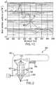
- FIG. 1Ais a side view of an illustration of one or more radiations being focused into pigmented dermal tissue
- FIG. 1Bis an exemplary absorbance spectrum graph for melanin
- FIG. 1Cis an exemplary absorbance spectrum graph for oxygenated and deoxygenated hemoglobin
- FIG. 2is a cross-sectional side view of a diagram of an exemplary apparatus in accordance with exemplary embodiments of the present disclosure
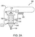
- FIG. 2Ais a cross-sectional side view of a diagram of another exemplary apparatus in accordance with exemplary embodiments of the present disclosure
- FIG. 3Ais a schematic side view of an arrangement of micro-lenses that can be used with certain exemplary embodiments of the present disclosure
- FIG. 3Bis a schematic top view of a first exemplary arrangement of the micro-lenses shown in FIG. 3A ;
- FIG. 3Cis a schematic top view of a second exemplary arrangement of the micro-lenses shown in FIG. 3A ;
- FIG. 3Dis a schematic top view of an exemplary arrangement of cylindrical micro-lenses that can be used with certain exemplary embodiments of the present disclosure
- FIG. 3Eis a schematic angled view of the exemplary arrangement of cylindrical micro-lenses shown in FIG. 3D ;
- FIG. 3Fis a schematic side view of a further exemplary arrangement of the micro-lenses that can be used with further exemplary embodiments of the present disclosure
- FIG. 4is a schematic cross-sectional side view of a further exemplary apparatus in accordance with still further exemplary embodiments of the present disclosure
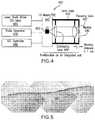
- FIG. 5is an exemplary biopsy image of pig skin tattooed with a melanin solution to simulate the effects of dermal melasma;
- FIG. 6Ais an exemplary surface image of a region of pig skin tattooed with a melanin solution to simulate the effects of dermal melasma;
- FIG. 6Bis an exemplary surface image of the tattooed region of pig skin shown in FIG. 6A after it has been irradiated with focused electromagnetic radiation in accordance with exemplary embodiments of the present disclosure.
- devices and methodscan be provided for treating dermal (or deep) melasma.
- electromagnetic radiationsuch as, e.g., optical energy
- the EMRcan optionally be pulsed and/or scanned, such that the radiation is selectively absorbed by the pigmented cells in the dermis.
- Such absorption of the energytogether with the focusing geometry and scanning parameters, can selectively damage or destroy many of the pigmented cells while reducing or avoiding damage to surrounding unpigmented cells and to the overlying epidermis.
- FIG. 1An exemplary schematic side view of a section of skin tissue is shown in FIG. 1 .
- the skin tissueincludes a skin surface 100 and an upper epidermal layer 110 , or epidermis, which can be, e.g., about 60-120 ⁇ m thick in the facial region.
- the dermiscan be slightly thicker in other parts of the body.
- the underlying dermal layer 120or dermis, extends from below the epidermis 110 to the deeper subcutaneous fat layer (not shown).
- Skin exhibiting deep or dermal melasmacan include a population of pigmented cells or regions 130 that contain excessive amounts of melanin.
- an electromagnetic radiation (EMR) 150(e.g., optical energy) can be focused into one or more focal regions 160 that can be located within the dermis 120 .
- the EMR 150can be provided at one or more appropriate wavelengths that can be absorbed by melanin.
- the EMR wavelength(s)can be selected to enhance selective absorption by the pigmented regions 130 in the dermis 120 .
- a graph of an exemplary absorption spectrum for melaninis shown in the graph of FIG. 1B .
- the absorption of EMR by melaninis observed to reach a peak value at a wavelength of about 350 nm, and then decreases with increasing wavelength.
- absorption of the EMR by the melaninfacilitates heating and/or disruption of the melanin-containing regions 130 , a very high melanin absorbance can result in high absorption by pigment in the epidermis 110 and reduced penetration of the EMR into the dermis 120 .
- FIG. 1Ba graph of an exemplary absorption spectrum for melanin is shown in the graph of FIG. 1B .
- melanin absorption at EMR wavelengths that are less than about 500 nmare relatively high, such that wavelengths less than about 500 nm may not be suitable for penetrating sufficiently into the dermis 120 to heat and damage or disrupt pigmented regions 130 therein.
- Such enhanced absorption at smaller wavelengthscan result in unwanted damage to the epidermis 110 and upper (superficial) portion of the dermis 120 , with relatively little unabsorbed EMR passing through the tissue into the deeper portions of the dermis 120 .
- HemoglobinAnother significant chromophore observed in skin tissue is hemoglobin, which is present in blood vessels. Hemoglobin can be oxygenated (HbO 2 ) or deoxygenated (Hb), where each form of Hemoglobin may exhibit slightly different EMR absorption properties. For example, exemplary absorption spectra for both Hb and HbO 2 are shown in the graph of FIG. 1C . These spectra indicate a high absorption coefficient for both Hb and HbO 2 at EMR wavelengths less than about 600 nm, with the absorbance decreasing significantly at higher wavelengths.
- Hb and/or HbO 2Strong absorption of EMR directed into skin tissue by hemoglobin (Hb and/or HbO 2 ) can result in heating of the hemoglobin-containing blood vessels, resulting in unwanted damage to these vascular structures and less EMR available to be absorbed by the melanin.
- EMRhaving wavelengths greater than 600 nm in certain exemplary embodiments of the present disclosure, e.g., about 625 nm or greater.
- Such wavelengthscan increase selectivity of EMR absorption in the dermis, e.g., by reducing competing absorption by hemoglobin, and by also avoiding excessive absorption of the EMR by epidermal melanin (as described above) such that the EMR can penetrate into the dermis 120 and target pigmented regions 130 therein.
- EMREMR having wavelengths less than about 750 nm or 850 nm be well-focused in tissue to generate sufficient local intensity within the dermis 120 , as well as sufficiently absorbed by dermal melanin to disrupt and/or damage pigmented regions 130 .
- EMRhaving one or more wavelengths between about 600 nm and about 850 nm, e.g., between about 625 nm and about 800 nm, which is mostly in the visible range of light.
- the wavelengthcan be between about 650 nm and 750 nm.
- wavelengths less than about 600 nm or greater than about 850 nmmay be used, although EMR having such wavelengths may be provided with sufficient focusing and/or appropriate power and fluence, as described herein, to achieve sufficient quantity and selectivity of absorption by melanin in the dermis.
- an apparatus 200can be provided to treat dermal melasma in skin using EMR 150 , e.g., optical energy.
- the apparatus 200can include a radiation emitter arrangement 210 , and an optical arrangement that can be provided between the radiation emitter arrangement 210 and the target tissue to be treated.
- the optical arrangementcan include a first lens arrangement 220 and a second lens arrangement 230 .
- These exemplary componentscan optionally be provided in a handpiece 250 or other housing or enclosure.
- the apparatus 200can further include a plate 240 having a lower surface configured to contact the surface 100 of the skin tissue being treated.
- An actuator arrangement 260can be provided to control the operation of the apparatus 200 , e.g., to activate and/or turn off the emitter arrangement 210 , control or adjust certain operational parameters of the apparatus 200 , etc.
- a power source (not shown) for the radiation emitter arrangement 210can be provided.
- the power sourcecan include a battery provided within the handpiece 250 , an electrical cord or other conductive connection provided between the emitter arrangement 210 and an external power source (e.g. an electrical outlet or the like), etc.
- the radiation emitter arrangement 210can include, e.g., one or more laser diodes, optical fibers, waveguides, or other components configured to generate and/or emit EMR 150 and direct it toward or onto the optical arrangement 220 , e.g., onto the first lens arrangement 220 .
- the radiation emitter arrangement 210can include one or more laser diodes that emit optical radiation 150 having one or more wavelengths between about 600 nm and 850 nm, e.g., between about 650 nm and 750 nm.
- the radiation emitter arrangement 210can include distal ends of one or more waveguides (e.g., optical fibers) (not shown), where the waveguides can be configured or adapted to direct EMR 150 from an external source (not shown) toward or onto the first lens arrangement 220 .
- Such exemplary external EMR sourcecan be configured to provide or direct EMR 150 to the radiation emitter arrangement 210 having one or more wavelengths between about 600 nm and 850 nm, e.g., between about 650 nm and 750 nm.
- the electromagnetic radiation (EMR) 150can be focused into one or more focal regions 160 that can be located within the dermis 120 , as shown schematically in FIGS. 1A and 2 .
- the exemplary optical arrangementcan be configured to provide one or more highly-convergent beams of EMR 150 , where each such beam can be emitted from a lower portion of the apparatus 200 and converge to a narrower focal region 160 located at a particular distance below the lower surface of the apparatus 200 , e.g., below the lower surface of the plate 240 .
- Such convergence of the EMR 150can produce a high local fluence and intensity within the focal region 160 , while irradiating the overlying tissue (e.g. epidermis 110 and upper portion of the dermis 120 ) at a lower fluence.
- the first lens arrangement 220can be adapted and/or configured to direct EMR 150 from the emitter arrangement 210 towards or onto the second lens arrangement 230 .
- the first lens arrangement 220can include, e.g., one or more lenses, reflectors, partially- or fully-silvered mirrors, prisms, and/or beam splitters.
- the first lens arrangement 220can be configured to collimate or align the EMR 150 emitted from the emitter arrangement 210 onto the second lens arrangement 230 , as shown in FIG. 2 .
- the first lens arrangement 220can include, e.g., an objective lens or the like.
- the second lens arrangement 230can be configured and/or adapted to receive EMR 150 from the first lens arrangement 220 , and direct it into one or more focal zones 160 within the dermis 120 , as shown in FIG. 1 .
- the first lens arrangement 220can be a collimating lens
- the second lens arrangement 230can serve as a focusing lens that includes, e.g., a single objective lens as shown in FIG. 2 , one or more plano-convex lenses or cylindrical lenses, or the like.
- Various exemplary embodiments of the optical arrangement that can be configured to produce one or more focal regions 160are described in more detail herein below.
- the highly-convergent beam of EMR 150is relatively “spread out” as it is passes through the plate 240 (e.g., as it enters the surface 100 of the skin tissue when the apparatus 200 is placed on the skin to irradiate it).
- Geometrical, temporal, and power characteristics of the EMR 150can be selected as described herein, such that the fluence and intensity of the EMR 150 at and near the skin surface 100 are sufficiently low to avoid unwanted heating and damage to the surface tissue.
- the EMR 150can then be focused to a sufficient intensity and fluence within the focal zone 160 to facilitate significant absorption of the EMR 150 by pigmented regions 130 within or proximal to the focal region 160 .
- exemplary embodiments of the present inventioncan target pigmented regions 130 within the dermis 120 to selectively heat and disrupt or damage them, without generating unwanted damage in the overlying tissue and surrounding unpigmented tissue.
- Exemplary beam convergent angles of about 70-80 degreesare illustrated in FIGS. 1A and 2 , although this approximate value is merely an exemplary one.
- the convergent anglecan be about 40 degrees or greater, e.g., even about 90 degrees or larger.
- Such non-narrow convergence anglescan generate a large local intensity and fluence of EMR 150 at the focal region 160 while the corresponding fluence in the overlying (and underlying) tissue may be lower due to the beam convergence/divergence. It should be understood that other convergence angles are possible, and are within the scope of the present disclosure.
- the effective numerical aperture (NA) of the second lens arrangement 230is preferably large, e.g., greater than about 0.5, such as between about 0.5 and 0.9.
- the EMR 150enters the lens through surrounding air, which has an index of refraction of about 1.
- an exemplary convergent half-angle ⁇ of the beam of EMR towards the focal region 160can be between about 30 and 65 degrees.
- the exemplary range of the total convergence anglecan be between about 60 and 130 degrees.
- a larger NA valuecan provide a greater “safety margin” by providing less intense irradiation levels to the overlying tissue than to the pigmented regions 130 , thereby reducing the likelihood of generating thermal damage in the overlying tissue.
- a larger NA valuecan decrease the size of the focal region 160 relative to the area of the incoming EMR beam, which can thereby irradiate a relatively smaller treatment volume of pigmented tissue within the dermis 120 . Such smaller treatment volumes can reduce the efficiency of treating large areas of skin in a reasonable time.
- Exemplary NA values between about 0.5 and 0.9can thus provide a reasonable compromise between safety factor and treatment efficiency, although slightly larger or smaller values of the NA may be used in certain embodiments (e.g., by adjusting other system parameters appropriately, such as beam power, scanning speed, etc.).
- a width of the focal region 160can be small, e.g., less than about 200 ⁇ m, for example, less than 100 ⁇ m.
- the focal regioncan be defined as the volumetric region in which the EMR 150 is present at a highest intensity.
- the focal region 160may not be present as an idealized spot because of such factors as scattering of the EMR 150 within the tissue, aberrations or nonidealities in the optical components (e.g. lenses and/or reflectors), variations in the path of the incident rays of EMR 150 , etc.
- the focal region 160can be spread over a small range of depths within the tissue, as shown schematically in FIGS. 1A and 2 .
- the size and location of the focal region relative to the apparatus 200can be determined or selected based on properties and configuration of the optical arrangement (e.g., the first and second lens arrangements 220 , 230 ), the characteristics of the EMR 150 provided by the emitting arrangement 210 , and optical properties of the skin tissue being treated.
- the optical arrangemente.g., the first and second lens arrangements 220 , 230
- the characteristics of the EMR 150 provided by the emitting arrangement 210e.g., the first and second lens arrangements 220 , 230
- optical properties of the skin tissue being treatede.g., the first and second lens arrangements 220 , 230
- the width of the focal region 160can be less than 50 ⁇ m, e.g., as small as 10 ⁇ m.
- a theoretical lower for the spot sizecan be approximated as 1.22 ⁇ /NA, where ⁇ is the wavelength of the electromagnetic radiation and NA is the numerical aperture of a lens.
- NAthe numerical aperture of a lens.
- the theoretical minimum spot sizeis about 1.6 microns.
- the actual spot size (or width of the focal region 160 )can be selected as a balance between being small enough to provide a high fluence or intensity of EMR 150 in the focal zone 160 (to damage pigmented cells 130 ), and being large enough to irradiate a sufficiently large volume of the skin tissue in a short time.
- a larger focal spot sizecan reduce the difference in fluence between the focal region and the overlying tissue for a given NA value, thereby increasing the possibility of unwanted heating and/or damage to overlying tissue.
- the beam radius at the surfacecan be estimated as the focal depth multiplied by the tangent of the half-angle of convergence provided by the focusing lens.
- an NA value of 0.5corresponds to a convergence half-angle of about 30 degrees, for which the tangent is 0.577.
- the radius of the converging EMR beam at the skin surface 100is about 115 microns (0.577 ⁇ 200), such that the total beam width at the surface is about 230 microns.
- the local fluenceis inversely proportional to the local cross-sectional area of the beam for a particular beam energy.
- the ratio of fluence at the focal region to that at the skin surfaceis about (230/20) 2 , or about 130:1.
- the actual fluence ratiomay be somewhat less due to absorption of some of the EMR energy between the skin surface and the focal region. Nevertheless, this exemplary calculation indicates the relatively low fluence in the surface regions of the skin (as compared to the fluence in the focal region) that can be generated when using a focusing lens having a high NA.
- a plurality of such focal regions 160can be generated simultaneously by the exemplary apparatus and/or the focal region(s) 160 may be scanned or traversed through the portions of dermis 120 containing pigmented cells 130 to irradiate larger volumes of the dermis 120 in a reasonable time, as described in more detail herein.
- the depth of the focal region 160 below the skin surface 100can be between about 120 ⁇ m and 400 ⁇ m, e.g., between about 150 ⁇ m and 300 ⁇ m.
- This exemplary depth rangecan generally correspond to the observed depths of pigmented regions 130 in skin that exhibits dermal melasma.
- the focal depthcan correspond to a distance from a lower contact surface of the apparatus 200 (e.g., the lower surface of the plate 240 ) and the focal region 160 of the EMR 150 , because the plate 240 may flatten out the underlying tissue when placed on the skin surface 100 . Accordingly, the depth of the focal region 160 within the skin may be selected or controlled based on a configuration of the optical arrangement within the housing 250 .
- the EMR 150can be collimated (e.g., rays within the EMR beam are substantially parallel to one another), convergent, or divergent between the first lens arrangement 220 and second lens arrangement 230 .
- the radiation emitter arrangement 210 and/or components of the optical arrangemente.g., the first lens arrangement 220 and/or the second lens arrangement 230
- the path of the EMR 150can be varied.
- Such exemplary variation in the path of the EMR 150can provide corresponding variations in the depth, width, and/or location of the focal region 160 within the dermis 120 when the apparatus is held stationary with respect to the skin.
- the position and/or angle of the EMR 150can be shifted relative to the optical axis of a lens in the second lens arrangement 230 .
- the convergence or divergence of the EMR 150 entering or within the optical arrangementcan be varied.
- Such variations in the EMR geometry and/or pathcan provide variations in the depth and/or lateral position of the focal region(s) 160 .
- larger volumes of the dermis 120can be irradiated while the apparatus 200 is held stationary over the area of skin being treated.
- Such exemplary variation of the focus region characteristicscan facilitate treatment of a plurality of depth ranges and/or locations within the dermis 120 containing pigmented cells or defects 130 .
- Exemplary adjustment and/or alteration of the geometry and/or path of the EMR 150can be achieved, e.g., using one or more translators, movable mirrors, beam splitters and/or prisms, or the like, which may be coupled to the radiation emitter arrangement 210 , the first lens arrangement 220 , and/or the second lens arrangement 230 . Further, these exemplary variations in locations of the focal region 160 can also be combined with a translation of the apparatus 200 over the area of skin being treated to irradiate larger volumes of the dermis 120 , thereby targeting a greater number of pigmented cells 130 that can be present.
- the second lens arrangement 230can include a plurality of micro-lenses 300 , e.g., as provided in a schematic side view of the exemplary configuration illustrated in FIG. 3A .
- the micro-lenses 300can include any conventional type of convergent lenses, e.g., convex lenses, or plano-convex lenses such as those shown in FIG. 3A .
- the micro-lenses 300can be configured to focus EMR 150 into a plurality of focal regions 160 within the underlying dermis 120 , as illustrated in FIG. 3A .
- Each of the micro-lensescan have a large NA (e.g., between about 0.5 and 0.9), such that the EMR 150 converges from a relatively wide area at or near the skin surface 100 (with a relatively low intensity or local fluence) to a small width (with higher intensity or local fluence) in the focal region 160 within the dermis 120 .
- NAe.g., between about 0.5 and 0.9
- Such optical propertiescan provide a sufficient intensity of EMR 150 within the focal region 160 to damage pigmented cells that absorb the radiation 150 , while avoiding areas or volumes of high fluence or intensity away from the volume of dermis 120 containing pigmented cells 130 , thereby reducing likelihood of damaging overlying, underlying, and/or adjacent volumes of unpigmented skin tissue.
- the micro-lenses 300can be provided in a substantially square or rectangular array, such as that shown in the top view of such exemplary configuration in FIG. 3B . According to further exemplary embodiments of the present disclosure, the micro-lenses 300 can be provided in a hexagonal array, as shown in FIG. 3C . Other exemplary patterns and/or shapes of the micro-lenses 300 can be provided in still further exemplary embodiments. A width of the micro-lenses 300 can be small, e.g., between about 1 mm and 3 mm wide. The exemplary micro-lenses 300 that are slightly wider or narrower than this can also be provided in certain exemplary embodiments.
- the radiation emitter arrangement 210 and/or the first lens arrangement 220can be configured to direct a single wide beam of EMR 150 (such as, e.g., that shown in FIG. 2 ) over the entire array of micro-lenses 300 or a substantial portion thereof. Such exemplary configuration can generate a plurality of focal regions 160 in the dermis 120 simultaneously.
- the radiation emitter arrangement 210 and/or the first lens arrangement 220can be configured to direct a plurality of smaller beams of EMR 150 onto individual ones of the micro-lenses 300 .
- the radiation emitter arrangement 210 and/or the first lens arrangement 220can be configured to direct one or more smaller beams of EMR 150 onto a portion of the array of micro-lenses 300 , e.g. onto a single micro-lens or a plurality of the micro-lenses 300 , and the smaller beam(s) can be scanned over the array of the micro-lenses 300 , such that a plurality of the focal regions 160 can be generated sequentially or non-simultaneously in the dermis 120 .
- the micro-lenses 300can include cylindrical lenses, for example, convex cylindrical lenses or plano-convex cylindrical lenses, e.g., as shown in an exemplary top view in FIG. 3D and exemplary angled view in FIG. 3E .
- cylindrical lensesfor example, convex cylindrical lenses or plano-convex cylindrical lenses, e.g., as shown in an exemplary top view in FIG. 3D and exemplary angled view in FIG. 3E .
- ‘cylindrical’does not necessarily require the rounded surface of the lens to be circular; it may have an elliptical or other smooth but non-circular profile in certain embodiments.
- Such cylindrical lensescan have a uniform profile in any cross-section that is perpendicular to the longitudinal axis of the lens.
- a width of the cylindrical micro-lenses 300can be small, e.g., between about 1 mm and 3 mm wide.
- the length of the cylindrical micro-lenses 300can be between about 5 mm and 5 cm, e.g., between about 5 mm and about 2 cm. This width and length can be selected based on such factors as the total power emitted by the radiation emitter arrangement 210 , the overall size of the array of micro-lenses 300 , etc.
- cylindrical micro-lenses 300that are slightly shorter or longer and/or slightly narrower or wider can be provided.
- any of the exemplary arrays of the micro-lenses 300can be provided on (or formed as part of) the plate 240 , as illustrated in FIG. 3E .
- Such configurationcan facilitate placement of the micro-lenses 300 close to the skin surface 100 , and also facilitate a more precise depth of the focal regions 160 within the dermis 120 , e.g., when the plate 240 contacts the skin surface 100 during use.
- the radiation emitter arrangement 210 and/or the first lens arrangement 220can be configured to direct a single wide beam of EMR 150 (such as that shown in FIG. 2 ) over the entire array of cylindrical micro-lenses 300 or a substantial portion thereof.
- Such exemplary configurationcan generate and/or produce a plurality of the focal regions 160 in the dermis 120 simultaneously that are elongated in one direction (e.g.
- Such “line-focused” EMR 150can be used to more efficiently irradiate larger volumes of the dermis 120 , e.g., when the exemplary apparatus 200 is scanned over the area of skin being treated, for example, in a direction substantially orthogonal to (or optionally at some other angle to) the longitudinal axis of the cylindrical micro-lenses 300 .
- the radiation emitter arrangement 210 and/or the first lens arrangement 220can be configured to direct one or more smaller beams of EMR 150 onto one or more of the cylindrical micro-lenses 300 .
- the EMR 150can be directed onto one or more cylindrical micro-lenses 300 , e.g., over an elongated area 320 such as that shown in FIG. 3D .
- the radiation emitter arrangement 210 and/or the first lens arrangement 220can be further configured to scan or traverse the irradiated area 320 over the cylindrical micro-lenses 300 (for example, using one or more movable mirrors, prisms, waveguides, or the like in the optical arrangement), e.g., along the longitudinal directions indicated by the arrows shown in FIGS. 3D and 3E (or back and forth along such direction), such that a plurality of the elongated focal regions 160 are progressively generated in the dermis 120 during the scan.
- Such scanning of the EMR 150can produce an irradiated focal region 160 having a shape of an extended line within the dermis 120 .
- the apparatus 200can also be traversed laterally over the region of skin being treated, e.g., in a direction not parallel to the longitudinal axes of the cylindrical micro-lenses 300 , during the irradiation such that the elongated focal regions 160 can travel through the dermis 120 and irradiate a larger volume of tissue.
- lateral traversalcan be between about 5 mm/sec and 5 cm/sec.
- the scanning speed of the EMR beam along the axes of the cylindricalcan be larger, e.g., greater than about 10 cm/sec, to provide a more uniform irradiation of such larger volumes of tissue.
- the scan rate of the EMR 150 along the cylindrical lens axes, traversal speed of the apparatus 200 over the skin, power of the EMR emitter arrangement 210 , and width of the focal region 160can be selected to provide a local fluence generated within portions of the the dermis 120 by the elongated focal region 160 that is within the exemplary fluence ranges described herein.
- some of the cylindrical or spherical micro-lenses 300can have different NA values, different sizes or radii, and/or different effective focal lengths, e.g., as shown in the exemplary schematic diagram in FIG. 3F .
- the different focal depths of the micro-lenses 300 below the skin surface 100can be, e.g., between about 120 ⁇ m and 400 ⁇ m, for example, between about 150 ⁇ m and 300 ⁇ m.
- Such exemplary variations in the focal lengthscan produce focal regions 160 at different depths, which can result in irradiation of larger volumes of the dermis 120 when the exemplary apparatus 200 is translated over the area of skin being treated, thereby targeting a greater number of pigmented cells 130 that may be present (e.g., irradiating both shallower and deeper pigmented cells 130 in the dermis 120 ).
- the window or plate 240can be configured and/or structured to contact the surface 100 of the area of skin being treated.
- the lower surface of the window 240can be substantially planar, or it may be convex or concave in further embodiments.
- the window 240can provide certain benefits during operation of the apparatus 200 .
- the window 240can facilitate precise positioning of the first and second optical arrangements 220 , 230 relative to the skin surface 100 , which can facilitate accurate control, selection and/or variation of the depth(s) of the focal region(s) 160 within the skin.
- the window 240can further stabilize the soft skin tissue while it is being irradiated by the apparatus 200 , which can facilitate control and uniformity of the irradiation profile.
- Pressure provided by the window 240 on the skin surface 100can also blanche (or remove some blood from) the volume of skin tissue being irradiated, thereby reducing the amount of pigmented structures present locally (e.g. blood-filled vessels containing hemoglobin).
- Such blanchingcan facilitate increased selectivity of absorption of the EMR 150 by pigmented cells 130 while reducing a risk of unwanted damage to blood vessels.
- the window 240can be cooled, e.g., by pre-cooling it prior to using the apparatus 200 or by active cooling using a conventional cooling arrangement C (e.g. a Peltier device, a conductive cold conduit, or the like).
- a conventional cooling arrangement Ce.g. a Peltier device, a conductive cold conduit, or the like.
- Such coolingcan facilitate protection of the epidermis 110 and/or upper portions of the dermis 120 from unwanted damage while the pigmented cells 130 are being irradiated and/or damaged.
- the window 240can be provided as part of the second lens arrangement 230 .
- the second lens arrangement 230can include a single plano-convex lens, as shown in FIG. 2A , or a plurality of plano-convex lenses, such as those shown in FIGS. 3A and 3D .
- Such lensescan be affixed to or formed as part of the window 240 .
- the lower (planar) surface of such lensescan provide the benefits of the window 240 as described herein, e.g., precise positioning of the second lens arrangement 230 relative to the skin surface 100 to control depth of the focal regions 160 arrangements can be used in embodiments of the present disclosure.
- the actuator arrangement 260can be configured to activate and/or control the radiation emitter arrangement 210 and/or an external EMR source that provides radiation to the radiation emitter arrangement 210 , such that the irradiation of an area of skin by the EMR 150 can be controlled.
- the radiation emitter arrangement 210 and/or the exemplary apparatus 200can further include a conventional control arrangement (not shown) that can be configured to control and/or adjust the properties of the EMR 150 directed onto the skin being treated.
- the apparatus 200can include one or more sensors S configured to detect contact of the apparatus 200 with the skin surface 100 and/or speed or displacement of the apparatus 200 over the skin surface 100 during use.
- sensors Scan generate signals capable of varying properties of the EMR 150 , e.g., by varying the power emitted by the radiation emitter arrangement 210 based on the translational speed of the apparatus 200 , by turning off the source(s) of EMR 150 when the apparatus 150 is stationary relative to the skin surface 100 , etc.
- sensors S and control arrangementscan be provided as a safety feature, e.g. to prevent excessive irradiation and unwanted damage to the skin being treated, and are generally known in the art. Further variations of such conventional sensing and/or control arrangements can be used in embodiments of the present disclosure.
- Long local irradiation times(or “dwell times”) can generate heat faster and to a greater extent than it can safely diffuse into the surrounding tissue, which may lead to unwanted damage to unpigmented tissue.
- short-duration, intense irradiation of small areas of pigmented features 130 within the dermis 120can disrupt the pigment and improve the appearance of melasma while avoiding excessive heat generation and unwanted thermal damage to surrounding unpigmented tissue.
- typical sizes of pigmented cells or structurescan be on the order of about 10 microns, and local thermal relaxation times can be on the order of about 0.1 to about 1-2 milliseconds. Longer local dwell times at irradiation intensities sufficient to heat and damage the pigmented structures 130 can build up heat locally faster than it can safely dissipate away.
- Limiting irradiation times (dwell times) at a particular focal region locationcan be achieved in various ways.
- the radiation emitter arrangement 210can be configured to provide discrete pulses of EMR 150 into the focal regions 160 .
- the interval between such pulses of EMRcan be, e.g., on the order of about 50 milliseconds or more even if the location of the focal region is moving through the skin tissue at a relatively slow speed of a few mm/s.
- These exemplary parameterscan result in a distance between focal regions 160 irradiated by successive pulses of, e.g., about 50-100 microns, which can be greater than a width of the focal region 160 itself.
- such general parameterscan facilitate spatial and temporal separation of the successive irradiated focal regions 160 , such that local thermal relaxation can occur and buildup of excess heat can be avoided.
- the spot size, pulse duration, and/or total pulse energycan be selected based on the principles and guidelines described herein, using simple calculations, to provide a sufficient fluence within the focal region 160 to affect the pigmented structures 130 while maintaining a sufficiently small dwell time (e.g. less than about 1-2 ms).
- the focused radiation 150can be scanned over a region of skin affected by dermal melasma, such that the focal region(s) 160 may irradiate and damage a large number of the pigmented cells 130 .
- Such scanningcan be performed with any of the embodiments described herein.
- the scanningcan be done manually, e.g., using a conventional method of translating a handpiece over the area of skin to be treated.
- the apparatus 200can optionally be coupled to a translating arrangement that can be configured to automatically move the apparatus (or certain components thereof) over an area of skin to be treated.
- Such automatic translationcan be provided as a pre-set pattern or as a random or semi-random path over the skin.
- one or more of the optical componentse.g. the first and/or second lens arrangement 220 , 230
- the radiation emitter arrangementcan be translated within the housing 250 , such that the focal region(s) 160 can translate within the tissue while the housing 250 is held in a single position relative to the skin.
- Average scan speedscan be determined based on the general exemplary guidelines described herein.
- the local dwell (irradiation) timecan be estimated as the spot size/width divided by the translational speed.
- dwell timeis preferably less than about 1-2 milliseconds to avoid local heat buildup and unwanted thermal damage of unpigmented tissue.
- a minimum scan speedcan be estimated as the width of the focal region 160 divided by 1 millisecond.
- a spot size of 10 microns (0.01 mm)would correspond to a minimum scan speed of 0.01 mm/0.001 seconds, or about 10 mm/sec (1 cm/sec).
- Scan rates for line-focused beamscan be estimated in a similar manner, e.g., where the width of the focal line corresponds to the width of the focal region and the scan speed is in a direction perpendicular to the focal line, or for other scanning configurations.
- a power output of the radiation emitter arrangement 210can be selected based on several factors including, e.g., the EMR wavelength, the number, size, and/or depth of the focal region(s) 160 , optical characteristics and geometry of the first and second lens arrangements 220 , 230 , etc.
- the power outputcan be selected such that the fluence in the focal region 160 is sufficiently high to damage pigmented cells 130 that absorb the EMR 150 for short exposure times, while fluence at other depths (e.g., in the epidermis 110 ) is sufficiently low to minimize or avoid unwanted damage there.
- a local fluence within the focal region 160 that may be sufficient to affect melanin-containing structurescan be between about 10-1000 J/cm 2 , for example, between about 50-500 J/cm 2 , for EMR 150 having a wavelength of about 650 nm.
- This range of effective local fluencescan increase slightly with increasing wavelength of the EMR 150 (and decrease with decreasing wavelength), based on the decreasing absorption factor for melanin at larger wavelengths.
- Larger or smaller local fluence valuesmay also be provided when using faster or slower scan speeds, in further exemplary embodiments. Larger or smaller local fluence values can also be provided when using shorter or longer dwell times, respectively.
- the local dwell timecan preferably remain less than about 1-2 milliseconds in such embodiments.
- the exemplary fluence values and dwell times described hereincan be understood to correspond to a single pulsed exposure onto, or a single traversal of a scanned focal region through, a particular location within the dermis.
- a particular location within the dermis 120may be irradiated by scanning more than one focal region 160 through it at different times, thereby providing a higher fluence at that location.
- local heat build-upcan be avoided by providing a time interval between successive irradiations of the same location that is greater than a few milliseconds.
- the total power output of the radiation emitter arrangement 210 directed onto a single focal spot 160can thus be estimated and/or determined based on the focal spot size and scan speed.
- the fluence Fe.g., in J/cm 2
- the power output P of a single EMR sourcee.g., a laser diode
- the power output P of a single EMR sourceis between about 15 mW and 1500 mW.
- Typical scan speeds for a handpiece that is manually translated over an area of skin to be treatedcan be, e.g., on the order of about 5 mm/sec to about 5 cm/sec. Such speeds correspond to traversing a distance of 5 cm (about 2 inches) in about 1-10 seconds.
- the power output and focal geometry of the apparatus 200can be selected to provide a fluence at the irradiated locations within the dermis that is within the general range described herein.
- Such exemplary power calculationscan be based on the entire output of the laser diode being focused into one focal region. If the output from a single source of EMR is focused onto a plurality of focal regions (e.g., when using an optical splitter or a wide beam directed onto a plurality of micro-lenses), then the power output of the EMR source can be multiplied by the number of focal spots 160 to achieve the same local fluence within each focal region 160 .
- EMR 150can be provided as a continuous wave (CW) or optionally as a plurality of pulses. Alternatively, a plurality of EMR sources (e.g.
- the laser diodes or the likecan be provided to generate a plurality of irradiated focal regions 160 simultaneously, with the appropriate power level for each EMR source being estimated as described above.
- the power of the EMR sourcecan be selected based on the lens properties, scan speed, etc. to provide fluences and dwell times at locations of the dermis irradiated by the focal regions 160 that are within the general ranges described herein.
- the radiation emitter arrangement 210can include a plurality of EMR emitters (e.g., laser diodes or waveguide ends). Such emitters can be provided in a linear array, such that they lie substantially along one or more straight lines. In further exemplary embodiments, the emitters can be arranged in a two-dimensional pattern, which can provide further patterns of EMR 150 directed onto the first lens arrangement 220 . As described above, the power output of each emitter can be selected using a routine calculation based on the focal spot size and scan speed to generate a local fluence within each focal zone 160 that is within the preferred range described herein.
- EMR emitterse.g., laser diodes or waveguide ends.
- Such emitterscan be provided in a linear array, such that they lie substantially along one or more straight lines.
- the emitterscan be arranged in a two-dimensional pattern, which can provide further patterns of EMR 150 directed onto the first lens arrangement 220 .
- the power output of each emittercan be selected using a routine calculation based on the focal
- FIG. 4A schematic diagram of a further exemplary apparatus 400 in accordance with certain exemplary embodiments of the present disclosure is shown in FIG. 4 .
- the exemplary apparatus 400can be generally similar to the apparatus 200 shown in FIG. 2 , and illustrates a few further features which may also be provided in the apparatus 200 such as, e.g., a cooling arrangement for the EMR source or a lens cage.
- Exemplary features of the exemplary apparatus 200can also be used with the exemplary apparatus 400 , including but not limited to an array of micro-lenses 300 , a housing 250 , etc.
- the apparatus 400includes a lens cage 410 that can be provided as an enclosure or housing that encloses optical lenses 420 , 430 .
- a window 240can be provided at one end of the lens cage 410 .
- An aspheric focusing lens 420can be used in certain embodiments to provide a larger front surface working distance than, e.g., a microscope objective lens.
- the distance between the front of the focusing lens 420 and the target tissuemay be less than about 1 cm for large NA values as described herein, such that the window 240 can also protect the lens 4 from contacting the tissue directly.
- the NA of the aspheric focusing lens 420can optionally be selectable, e.g. to vary the focal depth beyond the window 240 .
- the exemplary apparatus 400further includes a laser diode (LD) mounting arrangement 440 coupled to the lens cage 410 , which can accept one or more laser diodes 450 that can be selected to emit energy in the visible and/or NIR ranges.
- a driver 460 for the laser diode(s) 450can be provided, and the laser diodes 450 can be held slightly above threshold during operation with an applied DC bias current, which can facilitate a rapid rise-time in the pulse activation of the diode(s) 450 .
- the pulse propertiescan be controlled by a pulse generator arrangement 470 , e.g. a programmable function generator that can be configured to control the laser diode(s) 450 to produce single pulses or sequences of pulses, with selectable pulse widths (e.g. 30 ns and greater) and intervals between pulses.
- the LD mounting arrangement 440can also include a thermoelectric cooler (TEC) arrangement coupled or connected to the laser diode mounting arrangement 440 , which can be controlled (e.g. with a TEC controller 480 ) to prevent the laser diode(s) 450 from overheating during use.
- TECthermoelectric cooler
- the apparatus 400(as well as the apparatus 200 shown in FIG. 2 ) can be used in various orientations, e.g., vertically, horizontally, etc., with the window 240 pressed against a tissue provided at any angle to precisely position the optics relative to the tissue surface and thereby facilitate control of the focal depth of the beam within the tissue.
- the exemplary apparatus 200 shown in FIG. 2 and the exemplary apparatus 400 shown in FIG. 4are illustrations of exemplary configurations, and other embodiments using various combinations and/or configurations of similar components can also be used.
- different numbers and/or types of optical arrangements 220 , 230 and/or emitter arrangements 210can be used to provide irradiation characteristics and focal regions 160 within the dermis 120 as described herein.
- the apparatus 200can be provided in a shape factor similar to that of a handheld razor, with the radiation emitter arrangement 210 provided as one or more laser diodes, optical arrangements 220 , 230 provided in the “head” of the razor, and a power source (e.g. one or more conventional alkaline cells or the like) provided in the handle.
- a power sourcee.g. one or more conventional alkaline cells or the like
- Similar features, combinations and/or variationscan be provided for the apparatus 400 .
- Exemplary properties of the radiation emitter arrangement 210can be selected to provide appropriate fluence, intensity and/or dwell time of the EMR 150 on the pigmented cells during operation of the apparatus 200 .
- Exemplary values and/or ranges for such parameters, as well as certain basic approaches that can be used to estimate their values as needed,are described in more detail herein.
- such exemplary parameterscan be selected to provide sufficient local fluence at the pigmented cells 130 to damage them and reduce the pigmented appearance of the skin, while avoiding unwanted damage to the epidermis 110 and unpigmented volumes of the dermis 120 .
- the exemplary effective dwell timecan be estimated using conventional techniques based on an approximate width of pigmented cells 130 of about 10 ⁇ m and the local width (e.g., focal diameter or width) and speed of the focal region 160 .
- the speed of the focal region 160can be estimated based on a scan speed of EMR 150 provided by the first lens arrangement 220 and/or radiation emitter arrangement 210 (if present), optical geometry of the optical arrangements 220 , 230 , and scan speed of the apparatus 200 over the area of skin being treated.
- One or more exemplary parameters of the apparatus 200 , 400can be selected and/or adjusted once the other ones are known to provide a safe but effective irradiation of the pigmented cells 130 as described herein.
- the exemplary apparatus 200 , 400having known geometry (e.g. spot size or focal line width, and NA) of the lens arrangements 220 , 230 or lenses 420 , 430 (and internal scanning speed of EMR beams, if present), and a particular wavelength of EMR 150 can be provided.
- the power of the EMR source(s)can then be selected based on a target range of scanning speeds of the apparatus 200 over the area to be treated.
- the exemplary apparatus 200 , 400can be traversed over an area of skin at a speed between about 1-5 cm/s, which corresponds approximately to the speed at which a conventional razor is traversed over skin during shaving.
- the local speed and dwell time of the focal region(s) 160can be estimated, and a power output of the radiation emitter arrangement 210 can be selected or adjusted to provide an effective local fluence within the focal region 160 as described herein.
- Such calculationsare routine and can be done by a person of ordinary skill in the art.
- a method for reducing the pigmented appearance of dermal melasmacan be provided.
- the exemplary methodcan include directing and focusing electromagnetic radiation 150 as described herein onto a plurality of focal regions 160 within the dermis 120 using an optical arrangement, such that the EMR 150 is selectively absorbed by pigmented regions 130 to thermally damage or disrupt them, while avoiding unwanted thermal damage to unpigmented regions and overlying tissue (e.g., the epidermis 110 ).
- the EMR 150can have a wavelength greater than about 600 nm, e.g., between about 600 and 850 nm, or between 625 and 800 nm, or between about 650 and 750 nm.
- a width of the focal region within the dermiscan be less than about 200 microns, e.g., less than about 100 microns, or less than about 50 microns.
- the spot sizecan be greater than the theoretical lower limit of a few microns.
- the EMR 150can be focused using the optical arrangement, which can include one or more lens arrangements 220 , 230 .
- NA valuescan facilitate generation of high fluence in the focal regions 160 within the dermis 120 while avoiding large fluences that may generate unwanted damage in the overlying tissue.
- Such focusingcan be achieved using, e.g., the single focusing lens 230 (such as a convex objective lens or a plano-convex lens), a plurality of such lenses provided as an array of micro-lenses 300 , one or more convex or plano-convex cylindrical lenses, or the like.
- the EMR 150can be directed onto the focusing lens arrangements 230 , and optionally scanned or pulsed over the one or more focusing lens arrangements 230 , to irradiate a plurality of focal regions 160 in the dermis 120 , either simultaneously or sequentially.
- an optical gel or the likee.g. glycerol or a similar substance
- a gelcan reduce an optical index mismatch between the window 240 and the skin, and it may improve transmission of the EMR 150 from the apparatus 200 into the dermis 120 .
- the gelcan also reduce friction between the exemplary apparatus 200 and skin surface 100 , thereby facilitating a smoother translation of the apparatus 200 over the area of skin being treated.
- a particular location within the dermis 120can be irradiated by the focal region with an irradiation (dwell) time that is less than about 2 milliseconds, e.g., to facilitate local thermal relaxation of tissue that absorbs the EMR 150 and avoid local buildup of excess heat.
- Such short dwell timescan be provided, e.g., by scanning an apparatus that provides the focused EMR 150 over the area of skin being treated, by pulsing the EMR source, and/or by moving components of the EMR source or emitter 210 and/or optical arrangement, such that the location of the focal region(s) 160 within the dermis 120 varies with time.
- the local fluence within the focal region 160can be, e.g., between about 10-1000 J/cm 2 , e.g., between about 50-500 J/cm 2 , for EMR 150 having a wavelength of about 650 nm.
- This range of effective local fluencescan increase slightly with increasing wavelength of the EMR 150 (and decrease with decreasing wavelength), based on the decreasing absorption factor for melanin at larger wavelengths.
- Such fluencecan be related to the focal properties of the optical arrangement (e.g., the focal spot size), the translational speed of the focal region 160 within the dermis 120 , pulse duration of the applied EMR 150 , etc.
- the surface of the skin 100can optionally be cooled to further prevent unwanted thermal damage in the epidermis and/or upper dermis.
- the exemplary method and apparatus and the associated parameters described hereincan be generally based on a single pass of a focal region 160 over a pigmented cell 130 .
- the fluence needed to achieve the same thermal damage effect based on a plurality of passesvaries approximately as the fourth root of the number of passes n.
- a single pass of a focal region 160 over a pigmented cell 130 at a particular fluencewould have a similar effect as 16 passes made with a focal region 160 having half the particular fluence.
- the exemplary apparatus 200 , 400can be configured to provide an effective fluence after a particular number of passes have been made.
- a plurality of passescan provide a greater safety margin to avoid unwanted damage to the epidermis while damaging the pigmented cells 130 , e.g., it can accommodate a greater range of effective translation speeds of the apparatus 200 over the treated area for multiple passes as compared to if just a single pass is made.
- the number of passes of the focal region(s) 160 through a particular location in the dermis 120can depend, e.g., on the internal scan rate of EMR 150 over the second lens arrangement 230 , if present, the number of focal regions 160 that may pass through a given location during one pass of the entire apparatus 200 (e.g., a function of the number, size, and arrangement of micro-lenses 300 , if present), as well as the number of times the apparatus 200 is translated over the area to be treated.
- exemplary features and/or functions of the exemplary apparatus 200 , 400 described hereincan also be used in conjunction with the exemplary disclosed methods for treating dermal melasma.
- An animal study using an exemplary spot-focused laser device and model systemwere used to test the efficacy of treating deep melasma using optical radiation.
- the studywas performed on a female Yorkshire pig, as described below.
- a deep-melasma conditionwas simulated by tattooing the dermis using a melanin-based ink.
- the inkwas prepared by mixing synthetic melanin at a concentration of 20 mg/mL in a 50:50 saline/glycerol solution.
- the resulting suspensionwas then agitated prior to being injected into 1 cm by 1 cm test sites on the animal subject using a standard tattoo gun.
- the tattooed siteswere then allowed to settle over a period of a week to allow melanophages to phagocytoze the melanin granules in the dermis.
- the melanin left in the epidermiswas substantially eliminated over this time period through natural bodily processes.
- FIG. 5An exemplary biopsy image from a tattooed site that was allowed to settle as described herein, is shown in FIG. 5 .
- the tissue samplewas stained with Fontana-Masson stain to better image any melanin present.
- the dark spots evident in the dermal layer in FIG. 5appear to be generally similar to those observed in patients having deep/dermal melasma. No such dark spots were seen in biopsy samples taken from untattooed sites that were similarly stained. Accordingly, the tattoo process described herein appears to provide a useful in vivo model of dermal melasma.
- An exemplary melasma treatment systemwas constructed based on exemplary embodiments of the present disclosure described herein, which includes a 200 mW continuous wave (CW) diode laser configured to emit optical energy having a wavelength of about 658 nm, mounted on an x-y scanning platform.
- the scannerwas capable of scanning speeds up to 15 mm/s.
- the laser beamwas collimated and focused using two lenses having a numerical aperture (NA) of 0.62 to a depth of about 200 ⁇ m.
- NAnumerical aperture
- FIG. 6AAn exemplary tattooed test site is shown in FIG. 6A .
- This imageshows the test site after the tattoo has been allowed to settle for a week, just prior to scanning with the laser apparatus.
- the test sitewas scanned with the laser at a speed of 1-3 mm/sec, using a 200 mW CW output.
- the same test siteis shown in FIG. 6B two weeks after it was scanned with the laser.
Landscapes
- Health & Medical Sciences (AREA)
- Life Sciences & Earth Sciences (AREA)
- Physics & Mathematics (AREA)
- Surgery (AREA)
- Optics & Photonics (AREA)
- Molecular Biology (AREA)
- General Health & Medical Sciences (AREA)
- Nuclear Medicine, Radiotherapy & Molecular Imaging (AREA)
- Engineering & Computer Science (AREA)
- Biomedical Technology (AREA)
- Heart & Thoracic Surgery (AREA)
- Medical Informatics (AREA)
- Veterinary Medicine (AREA)
- Animal Behavior & Ethology (AREA)
- Public Health (AREA)
- Electromagnetism (AREA)
- Otolaryngology (AREA)
- Biophysics (AREA)
- Pathology (AREA)
- Radiology & Medical Imaging (AREA)
- Radiation-Therapy Devices (AREA)
- Condensed Matter Physics & Semiconductors (AREA)
- General Physics & Mathematics (AREA)
- Medicines Containing Plant Substances (AREA)
Abstract
Description
Claims (19)
Priority Applications (1)
| Application Number | Priority Date | Filing Date | Title |
|---|---|---|---|
| US14/911,169US11083523B2 (en) | 2013-08-09 | 2014-08-11 | Method and apparatus for treating dermal melasma |
Applications Claiming Priority (3)
| Application Number | Priority Date | Filing Date | Title |
|---|---|---|---|
| US201361864238P | 2013-08-09 | 2013-08-09 | |
| PCT/US2014/050518WO2015021462A1 (en) | 2013-08-09 | 2014-08-11 | Method and apparatus for treating dermal melasma |
| US14/911,169US11083523B2 (en) | 2013-08-09 | 2014-08-11 | Method and apparatus for treating dermal melasma |
Related Parent Applications (1)
| Application Number | Title | Priority Date | Filing Date |
|---|---|---|---|
| PCT/US2014/050518A-371-Of-InternationalWO2015021462A1 (en) | 2013-08-09 | 2014-08-11 | Method and apparatus for treating dermal melasma |
Related Child Applications (3)
| Application Number | Title | Priority Date | Filing Date |
|---|---|---|---|
| US16/401,988DivisionUS11071587B2 (en) | 2013-08-09 | 2019-05-02 | Method and apparatus for treating dermal melasma |
| US16/696,518ContinuationUS11039887B2 (en) | 2013-08-09 | 2019-11-26 | Method and apparatus for treating dermal melasma |
| US17/397,521ContinuationUS20220022959A1 (en) | 2013-08-09 | 2021-08-09 | Method and apparatus for treating dermal melasma |
Publications (2)
| Publication Number | Publication Date |
|---|---|
| US20160199132A1 US20160199132A1 (en) | 2016-07-14 |
| US11083523B2true US11083523B2 (en) | 2021-08-10 |
Family
ID=52461981
Family Applications (4)
| Application Number | Title | Priority Date | Filing Date |
|---|---|---|---|
| US14/911,169Active2034-10-19US11083523B2 (en) | 2013-08-09 | 2014-08-11 | Method and apparatus for treating dermal melasma |
| US16/401,988ActiveUS11071587B2 (en) | 2013-08-09 | 2019-05-02 | Method and apparatus for treating dermal melasma |
| US16/696,518ActiveUS11039887B2 (en) | 2013-08-09 | 2019-11-26 | Method and apparatus for treating dermal melasma |
| US17/397,521PendingUS20220022959A1 (en) | 2013-08-09 | 2021-08-09 | Method and apparatus for treating dermal melasma |
Family Applications After (3)
| Application Number | Title | Priority Date | Filing Date |
|---|---|---|---|
| US16/401,988ActiveUS11071587B2 (en) | 2013-08-09 | 2019-05-02 | Method and apparatus for treating dermal melasma |
| US16/696,518ActiveUS11039887B2 (en) | 2013-08-09 | 2019-11-26 | Method and apparatus for treating dermal melasma |
| US17/397,521PendingUS20220022959A1 (en) | 2013-08-09 | 2021-08-09 | Method and apparatus for treating dermal melasma |
Country Status (11)
| Country | Link |
|---|---|
| US (4) | US11083523B2 (en) |
| EP (2) | EP3498211B1 (en) |
| JP (1) | JP6552493B2 (en) |
| KR (1) | KR102364395B1 (en) |
| CN (2) | CN110840556B (en) |
| CA (1) | CA2920858C (en) |
| DK (2) | DK3030186T3 (en) |
| ES (2) | ES2707725T3 (en) |
| IL (1) | IL244030B (en) |
| PT (1) | PT3498211T (en) |
| WO (1) | WO2015021462A1 (en) |
Families Citing this family (22)
| Publication number | Priority date | Publication date | Assignee | Title |
|---|---|---|---|---|
| KR102276229B1 (en) | 2016-12-23 | 2021-07-13 | 더 제너럴 하스피탈 코포레이션 | Method and apparatus for selective processing of biological tissue |
| CN106730402A (en)* | 2017-01-05 | 2017-05-31 | 海南瑞韩医学美容医院管理有限公司海口龙华京华城红妆医学美容门诊部 | A kind of hand for treating chloasma has |
| KR101998251B1 (en)* | 2017-12-05 | 2019-07-10 | 주식회사 루트로닉 | Microlens array, laser beam handpiece and medical laser device including the microlens array |
| BR112020011689A2 (en)* | 2017-12-14 | 2020-11-17 | Avava, Inc. | electromagnetic radiation beam scanning system and method |
| AU2019252443A1 (en)* | 2018-04-12 | 2020-10-29 | Avava, Inc. | Diffractive optics for EMR-based tissue treatment |
| AU2019288652B2 (en) | 2018-06-22 | 2023-06-08 | Avava, Inc. | Feedback detection for a treatment device |
| WO2019246089A1 (en) | 2018-06-22 | 2019-12-26 | Avava, Inc. | Apparatus for selective treatment of tissue |
| WO2019246374A1 (en)* | 2018-06-22 | 2019-12-26 | Avava, Inc. | Optical array for tissue treatment |
| CN109276430A (en)* | 2018-09-29 | 2019-01-29 | 绿之韵生物工程集团有限公司 | A kind of swing type negative pressure health-preserving instrument |
| US10617468B1 (en) | 2018-12-31 | 2020-04-14 | Avava, Inc. | System and method for tissue treatment |
| DK3905977T5 (en) | 2018-12-31 | 2025-01-02 | Avava Inc | TISSUE PROCESSING SYSTEMS |
| US11185234B2 (en)* | 2019-05-02 | 2021-11-30 | Hugh Beckman | System and method of using ultrafast Raman spectroscopy and an ablative laser for quasi-real time removal of skin cancer and other anomalous tissues with clear tissue margins formed by array created displays |
| US12172027B2 (en) | 2019-11-13 | 2024-12-24 | Avava, Inc. | Feedback detection for a treatment device |
| KR20220119438A (en) | 2019-12-23 | 2022-08-29 | 아바바, 인코포레이티드 | Systems, methods and computer-accessible media for analyzing and/or processing feedback of at least one patient using an electromagnetic radiation processing device |
| JP7707481B2 (en) | 2020-06-05 | 2025-07-15 | クラッシーズ インコーポレイテッド | Laser treatment of skin lesions under dermal vasoconstriction. |
| KR102151923B1 (en)* | 2020-07-30 | 2020-09-03 | 박인규 | Needle laser treatment system |
| KR102252648B1 (en) | 2020-09-28 | 2021-05-17 | 서상호 | Structure Of Assemble For Steel Frame |
| CN112221021B (en)* | 2020-11-02 | 2023-02-07 | 中南大学湘雅三医院 | A dermatology intelligent laser freckle removal control system |
| KR20220097825A (en)* | 2020-12-31 | 2022-07-08 | 주식회사 이루다 | Laser device for laser treatment of skin lesions under dermal vasoconstriction |
| CN113100928B (en)* | 2021-03-25 | 2023-03-24 | 苏州芙迈蕾医疗科技有限公司 | Multi-wavelength picosecond laser beauty instrument based on photoacoustic imaging guidance and control method thereof |
| TWI806062B (en)* | 2021-06-07 | 2023-06-21 | 新加坡商克雷多生醫有限公司 | Method and device for opening the external layer structure of cells using laser |
| CN115505588A (en)* | 2021-06-07 | 2022-12-23 | 克雷多诊断生物医学私人有限公司 | Method and device for opening outer layer structure of cell by using laser |
Citations (104)
| Publication number | Priority date | Publication date | Assignee | Title |
|---|---|---|---|---|
| US5743902A (en)* | 1995-01-23 | 1998-04-28 | Coherent, Inc. | Hand-held laser scanner |
| US6287549B1 (en) | 1997-04-29 | 2001-09-11 | Centre International De Recherche Dermatologiques Galderma (C.I.R.D.) Galderma | Method for removing superfluous hairs |
| US6408212B1 (en) | 1999-04-13 | 2002-06-18 | Joseph Neev | Method for treating acne |
| US20020077678A1 (en)* | 2000-12-15 | 2002-06-20 | Andersen Dan E. | Laser treatment for reducing wrinkles |
| US20020161357A1 (en)* | 2000-12-28 | 2002-10-31 | Anderson R. Rox | Method and apparatus for EMR treatment |
| US20020169442A1 (en) | 1997-08-12 | 2002-11-14 | Joseph Neev | Device and a method for treating skin conditions |
| US6509548B1 (en) | 2000-10-04 | 2003-01-21 | Igor Troitski | Method and laser system for production of high-resolution laser-induced damage images inside transparent materials by generating small etch points |
| US6621040B1 (en) | 1996-01-11 | 2003-09-16 | The Regents Of The University Of California | Ultrashort pulse laser machining of metals and alloys |
| US6624719B1 (en) | 2000-04-05 | 2003-09-23 | Asi Technology Corporation | Reconfigurable electromagnetic waveguide |
| US20030216719A1 (en) | 2001-12-12 | 2003-11-20 | Len Debenedictis | Method and apparatus for treating skin using patterns of optical energy |
| US20040005349A1 (en) | 2000-05-12 | 2004-01-08 | Joseph Neev | Opto-thermal material modification |
| US6695870B2 (en) | 2002-02-25 | 2004-02-24 | Nanocomp, L.L.C. | Process for treating disease |
| US6720521B2 (en) | 2000-05-30 | 2004-04-13 | Igor Troitski | Method and laser system controlling breakdown process development and space structure of laser radiation for production of high quality laser-induced damage images |
| US20040158192A1 (en) | 2001-06-25 | 2004-08-12 | The General Hospital Corporation, A Massachusetts Corporation | Compound delivery using impulse transients |
| US6787730B2 (en) | 1998-07-09 | 2004-09-07 | Damian Coccio | Device for plasma incision of matter with a specifically tuned radiofrequency electromagnetic field generator |
| US20050049582A1 (en)* | 2001-12-12 | 2005-03-03 | Debenedictis Leonard C. | Method and apparatus for fractional photo therapy of skin |
| US20050055055A1 (en) | 1999-04-13 | 2005-03-10 | Joseph Neev | Method for treating acne |
| US20050058701A1 (en)* | 2003-01-29 | 2005-03-17 | Yossi Gross | Active drug delivery in the gastrointestinal tract |
| US20050065503A1 (en) | 2003-08-19 | 2005-03-24 | Richard Anderson | Method and apparatus for reducing the appearance of skin markings |
| US6873444B1 (en) | 1999-08-24 | 2005-03-29 | U. C. Laser Ltd. | Volume holograms in transparent materials |
| US20050224460A1 (en)* | 2002-05-31 | 2005-10-13 | Hutson Michael S | Method and apparatus for infrared tissue ablation |
| WO2005099369A2 (en) | 2004-04-09 | 2005-10-27 | Palomar Medical Technologies, Inc. | Emr treated islets |
| US20050256519A1 (en) | 2000-02-22 | 2005-11-17 | Rhytec Limited | Tissue resurfacing |
| US7020516B2 (en) | 1999-03-26 | 2006-03-28 | Flock Stephen T | Catheter for delivering electromagnetic energy for enhanced permeation of substances |
| US7018395B2 (en) | 1999-01-15 | 2006-03-28 | Light Sciences Corporation | Photodynamic treatment of targeted cells |
| US20060095097A1 (en)* | 1996-10-30 | 2006-05-04 | Provectus Devicetech, Inc. | Treatment of pigmented tissue using optical energy |
| US20070045255A1 (en) | 2005-08-23 | 2007-03-01 | Klaus Kleine | Laser induced plasma machining with an optimized process gas |
| US20070045252A1 (en) | 2005-08-23 | 2007-03-01 | Klaus Kleine | Laser induced plasma machining with a process gas |
| US7217266B2 (en) | 2001-05-30 | 2007-05-15 | Anderson R Rox | Apparatus and method for laser treatment with spectroscopic feedback |
| US7244253B2 (en) | 1998-12-08 | 2007-07-17 | Joseph Neev | Energy application with cooling |
| US20070198003A1 (en)* | 2005-12-23 | 2007-08-23 | Yacov Domankevitz | Treating dermatological conditions using an alexandrite laser |
| US20070213695A1 (en)* | 2006-03-08 | 2007-09-13 | Paul Perl | Continuous skin contact handpiece system for cooling during controlled emmission of light and a method thereof |
| US7270657B2 (en) | 2001-08-24 | 2007-09-18 | Biolase Technology, Inc. | Radiation emitting apparatus with spatially controllable output energy distributions |
| US20070260230A1 (en) | 2006-05-04 | 2007-11-08 | Reliant Technologies, Inc. | Opto-mechanical Apparatus and Method for Dermatological Treatment |
| US20070299331A1 (en) | 2002-12-11 | 2007-12-27 | Beth Friedman | Device for inducing vascular injury and/or blockage in an animal model |
| US7326199B2 (en) | 2003-12-22 | 2008-02-05 | Cutera, Inc. | System and method for flexible architecture for dermatologic treatments utilizing multiple light sources |
| US20080058783A1 (en) | 2003-11-04 | 2008-03-06 | Palomar Medical Technologies, Inc. | Handheld Photocosmetic Device |
| US7421186B2 (en) | 2005-01-10 | 2008-09-02 | Biolase Technology, Inc. | Modified-output fiber optic tips |
| US20080262488A1 (en) | 2007-04-12 | 2008-10-23 | Rhytec Limited | Tissue treatment system and a method of cosmetic tissue treatment |
| US20080287941A1 (en) | 2003-11-10 | 2008-11-20 | Jones Jeffrey W | Tapered fused waveguide for teeth whitening |
| US7474919B2 (en) | 2002-08-29 | 2009-01-06 | The Regents Of The University Of Michigan | Laser-based method and system for enhancing optical breakdown |
| US7608839B2 (en) | 2005-08-05 | 2009-10-27 | Mcgill University | Plasma source and applications thereof |
| US20100063490A1 (en) | 2006-06-26 | 2010-03-11 | Koninklijke Philips Electronics N.V. | Device and method for the treatment of skin, and use of the device |
| US20100069897A1 (en) | 2007-03-29 | 2010-03-18 | Koninklijke Philips Electronics N.V. | Method and device for generating a laser beam, a laser treatment device and a laser detection device |
| US20100100084A1 (en) | 2005-08-03 | 2010-04-22 | Bruno Girard | Hybrid Ultrafast Laser Surgery and Growth Factor Stimulation for Ultra-Precision Surgery with Healing. |
| US20100160903A1 (en) | 2008-12-22 | 2010-06-24 | Yosef Krespi | Process and system for treating a vascular occlusion or other endoluminal structure |
| US20100217254A1 (en) | 2009-02-25 | 2010-08-26 | Primaeva Medical, Inc. | Methods for applying energy to tissue using isolated energy sources |
| US20100249771A1 (en) | 2009-03-31 | 2010-09-30 | Pearson Robert M | System and method for interactively planning and controlling a treatment of a patient with a medical treatment device |
| US7824395B2 (en) | 2005-08-29 | 2010-11-02 | Reliant Technologies, Inc. | Method and apparatus for monitoring and controlling thermally induced tissue treatment |
| US20100292684A1 (en) | 2009-05-15 | 2010-11-18 | Cybulski James S | Tissue modification devices and methods of the same |
| US20100312054A1 (en) | 2008-05-06 | 2010-12-09 | N.M.B. Medical Applications Ltd. | Prostatic tissue removal and/or prostatic capsulotomy for treatment of conditions |
| US7887533B2 (en) | 2004-02-06 | 2011-02-15 | Clinique Dr Daniel Barolet Inc. | Device for the treatment of mammalian tissues |
| US20110036991A1 (en) | 2008-04-03 | 2011-02-17 | Pixer Technology Ltd. | Method for creating, trapping and manipulating a gas bubble in liquid |
| US20110130618A1 (en)* | 2008-06-29 | 2011-06-02 | Venus Technologies Ltd | Esthetic apparatus useful for increasing skin rejuvenation and methods thereof |
| US20110166562A1 (en) | 2010-01-04 | 2011-07-07 | Ceramoptec Industries, Inc. | High Durability Side Fire Optical Fiber for High Power Applications |
| US20110313407A1 (en) | 2010-06-18 | 2011-12-22 | Rafailov Edik U | Quantum-dot laser diode |
| US20120010603A1 (en) | 2005-08-12 | 2012-01-12 | Dermalucent, LLC | Tissue optical clearing devices for subsurface light-induced phase-change and method of use |
| US20120029394A1 (en) | 2010-02-05 | 2012-02-02 | Bacoustics, Llc | Ultrasound Assisted Laser Skin and Tissue Treatment |
| US8130904B2 (en) | 2009-01-29 | 2012-03-06 | The Invention Science Fund I, Llc | Diagnostic delivery service |
| US8246611B2 (en) | 2006-06-14 | 2012-08-21 | Candela Corporation | Treatment of skin by spatial modulation of thermal heating |
| US8259771B1 (en) | 2009-07-22 | 2012-09-04 | Kla-Tencor Corporation | Initiating laser-sustained plasma |
| US20120226268A1 (en) | 2011-02-03 | 2012-09-06 | Tria Beauty, Inc. | Radiation-Based Dermatological Devices and Methods |
| US20120226130A1 (en) | 2008-10-07 | 2012-09-06 | Mc10, Inc. | Systems, methods, and devices having stretchable integrated circuitry for sensing and delivering therapy |
| US8264174B2 (en) | 2009-07-24 | 2012-09-11 | University Of Maryland | Laser acceleration system for generating monoenergetic protons |
| US20120265164A1 (en) | 2011-04-14 | 2012-10-18 | Medtronic, Inc. | Flow restrictor for medical devices |
| US20120314214A1 (en) | 2011-06-07 | 2012-12-13 | Alexander Dennis R | Laser Induced Breakdown Spectroscopy Having Enhanced Signal-to-Noise Ratio |
| US8523926B2 (en) | 2007-01-19 | 2013-09-03 | Joseph Neev | Devices and methods for generation of subsurface microdisruptions for biomedical applications |
| US20140017635A1 (en) | 2012-07-13 | 2014-01-16 | GME German Medical Engineering GmbH | Medical treatment apparatus with laser pulses in the femtosecond range |
| US8672926B2 (en) | 2003-08-04 | 2014-03-18 | Koninklijke Philips N.V. | Device for shortening hairs by means of laser induced optical breakdown effects |
| US8675192B2 (en) | 2008-03-20 | 2014-03-18 | Commissariat A L'energie Atomique Et Aux Energies Alternatives | Method and device for high speed quantitative measurement of biomolecular targets on or in biological analysis medium |
| US20140081255A1 (en) | 2000-07-25 | 2014-03-20 | Angiodynamics, Inc. | Method and Apparatuses for Tissue Treatment |
| US8699026B2 (en) | 2009-03-19 | 2014-04-15 | Koninklijke Philips N.V. | Detector for birefringent objects |
| US20140243804A1 (en)* | 2013-02-28 | 2014-08-28 | Fotona D.D. | Method for lightening or eradicating pigments in human skin |
| US20140379052A1 (en) | 2005-03-02 | 2014-12-25 | Yolo Medical Inc. | System and method for low-power laser treatment of adipose cells |
| US8932278B2 (en) | 2004-07-12 | 2015-01-13 | Nikolai Tankovich | Skin treatment system with time modulated laser pulses |
| US8936629B2 (en) | 2006-04-12 | 2015-01-20 | Invention Science Fund I Llc | Autofluorescent imaging and target ablation |
| US20150032191A1 (en) | 2012-02-28 | 2015-01-29 | Koninklijke Philips N.V. | Device for light based skin treatment |
| US20150216598A1 (en) | 2013-03-13 | 2015-08-06 | Cynosure, Inc. | Controlled photomechanical and photothermal tissue treatment in the picosecond regime |
| US20150257828A1 (en) | 2013-03-15 | 2015-09-17 | Nikolai Tankovich | Laser filler |
| US9161815B2 (en) | 2004-06-21 | 2015-10-20 | Kilolambda Technologies Ltd. | Dermatological laser system and Method for Skin Resurfacing |
| US9186066B2 (en) | 2006-02-01 | 2015-11-17 | The General Hospital Corporation | Apparatus for applying a plurality of electro-magnetic radiations to a sample |
| US20150327777A1 (en) | 2014-05-14 | 2015-11-19 | Stryker Corporation | Tissue monitoring apparatus and system |
| US9202600B2 (en) | 2005-01-14 | 2015-12-01 | Paul Scherrer Institut | Method for production of radioisotope preparations and their use in life science, research, medical application and industry |
| US9247995B2 (en) | 2007-06-15 | 2016-02-02 | Trustees Of Princeton University | Tattoo removal with two laser beams via multi-photon processes |
| US9265576B2 (en) | 2010-02-21 | 2016-02-23 | C Laser, Inc. | Laser generator for medical treatment |
| US9314302B2 (en) | 2004-06-24 | 2016-04-19 | Virulite Llc | Cosmetic uses of electromagnetic radiation |
| US9333371B2 (en) | 2012-11-01 | 2016-05-10 | Seminex Corporation | Variable intensity laser treatments of the skin |
| US20160128777A1 (en) | 2013-03-13 | 2016-05-12 | Cynosure, Inc. | Controlled Photomechanical and Photothermal Treatment of Mucosal Tissue |
| US20160149370A1 (en) | 2014-11-24 | 2016-05-26 | Fotona D.D. | Laser system and method for controlling the laser pulse shape |
| US20160184019A1 (en) | 2014-12-29 | 2016-06-30 | InnovaQuartz LLC | Multiwavelength Surgical Laser |
| US20160220849A1 (en) | 2003-03-31 | 2016-08-04 | Edward W. Knowlton | Method for treatment of tissue |
| US20160278924A1 (en) | 2013-03-15 | 2016-09-29 | University Of North Texas | Laser-assisted machining (lam) of hard tissues and bones |
| US20160287894A1 (en) | 2013-11-07 | 2016-10-06 | Arai Medphoton Research Laboratories, Corporation | Medical instrument and light-ray treatment device |
| US20160310055A1 (en) | 2013-03-19 | 2016-10-27 | Surgisense Corporation | Apparatus, systems and methods for determining tissue oxygenation |
| US20160318790A1 (en) | 2015-04-30 | 2016-11-03 | Rofin-Sinar Technologies Inc. | Method and system for scribing heat processed transparent materials |
| US9523804B2 (en) | 2006-07-08 | 2016-12-20 | Cirrex Systems, Llc | Method and system for managing light at an optical interface |
| US20170035507A1 (en) | 2015-08-03 | 2017-02-09 | Po-Han Huang | Method and system for skin blemishes layered skin treatment |
| US9622817B2 (en) | 2005-10-03 | 2017-04-18 | Koninklijke Philips N.V. | Hair shortening device |
| US20170127507A1 (en) | 2015-11-04 | 2017-05-04 | The Boeing Company | Defense mechanism against directed-energy systems based on laser induced atmospheric optical breakdown |
| US9663754B2 (en) | 2009-08-11 | 2017-05-30 | Leibniz-Institut Fuer Plasmaforschun Und Technologie E.V | Atmosphereic pressure plasma jet for delivering active substances encapsulated in nanoparticles or microparticles to tissue |
| US9695505B2 (en) | 2006-09-11 | 2017-07-04 | Enbio Limited | Method of treating surfaces |
| US20170189117A1 (en) | 2010-04-22 | 2017-07-06 | Precise Light Surgical, Inc. | Flash vaporization surgical systems |
| US20170209213A1 (en) | 2013-03-15 | 2017-07-27 | Paul Binun | Laser shaving |
| US9750572B2 (en) | 2013-01-10 | 2017-09-05 | Koninklijke Philips N.V. | Cutting head for a device for cutting hair |
Family Cites Families (18)
| Publication number | Priority date | Publication date | Assignee | Title |
|---|---|---|---|---|
| US4468551A (en)* | 1982-07-30 | 1984-08-28 | Armco Inc. | Laser treatment of electrical steel and optical scanning assembly therefor |
| US4865923A (en)* | 1986-10-09 | 1989-09-12 | Amoco Corporation | Selective intermixing of layered structures composed of thin solid films |
| US7036516B1 (en)* | 1996-10-30 | 2006-05-02 | Xantech Pharmaceuticals, Inc. | Treatment of pigmented tissues using optical energy |
| US7204832B2 (en)* | 1996-12-02 | 2007-04-17 | Pálomar Medical Technologies, Inc. | Cooling system for a photo cosmetic device |
| US6165170A (en)* | 1998-01-29 | 2000-12-26 | International Business Machines Corporation | Laser dermablator and dermablation |
| US6749602B2 (en)* | 2001-03-03 | 2004-06-15 | Cynosure, Inc. | Method and apparatus for the double output treatment of pigmented lesions and tattoos |
| WO2003053269A1 (en)* | 2001-12-12 | 2003-07-03 | Bernstein Eric F | Laser treatment for reduction of pore size |
| WO2004000098A2 (en)* | 2002-06-19 | 2003-12-31 | Palomar Medical Technologies, Inc. | Method and apparatus for treatment of cutaneous and subcutaneous conditions |
| ATE497807T1 (en)* | 2003-03-27 | 2011-02-15 | Gen Hospital Corp | DEVICE FOR DERMATOLOGICAL TREATMENT AND FRACTIONAL SURFACE RENEWAL OF THE SKIN |
| GB2439286B (en)* | 2006-06-22 | 2010-09-15 | Dezac Group Ltd | Apparatus and methods for skin treatment |
| US9084622B2 (en)* | 2006-08-02 | 2015-07-21 | Omnitek Partners Llc | Automated laser-treatment system with real-time integrated 3D vision system for laser debridement and the like |
| WO2008070851A2 (en) | 2006-12-07 | 2008-06-12 | Palomar Medical Technologies, Inc. | Use of fractional emr technology on incisions and internal tissues |
| US8568393B2 (en)* | 2007-03-13 | 2013-10-29 | Topcon Medical Laser Systems, Inc. | Computer guided patterned laser trabeculoplasty |
| KR100820164B1 (en)* | 2007-03-31 | 2008-04-08 | 한국전기연구원 | Laser device for skin disease treatment |
| US8920409B2 (en)* | 2007-10-04 | 2014-12-30 | Cutera, Inc. | System and method for dermatological lesion treatment using gas discharge lamp with controllable current density |
| JP5766123B2 (en)* | 2008-12-31 | 2015-08-19 | アイ オプティマ リミテッド | Apparatus and method for laser-based deep scleral ablation |
| DE102011006085A1 (en)* | 2011-03-25 | 2012-09-27 | Carl Zeiss Meditec Ag | Ophthalmic device |
| EP4591925A2 (en)* | 2013-03-13 | 2025-07-30 | Cynosure, LLC | Controlled photomechanical and photothermal tissue treatment in the picosecond regime |
- 2014
- 2014-08-11EPEP18201589.1Apatent/EP3498211B1/enactiveActive
- 2014-08-11WOPCT/US2014/050518patent/WO2015021462A1/enactiveApplication Filing
- 2014-08-11CNCN201911035100.7Apatent/CN110840556B/enactiveActive
- 2014-08-11DKDK14834457.5Tpatent/DK3030186T3/enactive
- 2014-08-11USUS14/911,169patent/US11083523B2/enactiveActive
- 2014-08-11ESES14834457Tpatent/ES2707725T3/enactiveActive
- 2014-08-11KRKR1020167006196Apatent/KR102364395B1/enactiveActive
- 2014-08-11CACA2920858Apatent/CA2920858C/enactiveActive
- 2014-08-11ILIL244030Apatent/IL244030B/enunknown
- 2014-08-11DKDK18201589.1Tpatent/DK3498211T3/enactive
- 2014-08-11CNCN201480049685.7Apatent/CN105530886B/enactiveActive
- 2014-08-11EPEP14834457.5Apatent/EP3030186B1/enactiveActive
- 2014-08-11ESES18201589Tpatent/ES3015160T3/enactiveActive
- 2014-08-11JPJP2016533490Apatent/JP6552493B2/enactiveActive
- 2014-08-11PTPT182015891Tpatent/PT3498211T/enunknown
- 2019
- 2019-05-02USUS16/401,988patent/US11071587B2/enactiveActive
- 2019-11-26USUS16/696,518patent/US11039887B2/enactiveActive
- 2021
- 2021-08-09USUS17/397,521patent/US20220022959A1/enactivePending
Patent Citations (121)
| Publication number | Priority date | Publication date | Assignee | Title |
|---|---|---|---|---|
| US5743902A (en)* | 1995-01-23 | 1998-04-28 | Coherent, Inc. | Hand-held laser scanner |
| US6621040B1 (en) | 1996-01-11 | 2003-09-16 | The Regents Of The University Of California | Ultrashort pulse laser machining of metals and alloys |
| US20060095097A1 (en)* | 1996-10-30 | 2006-05-04 | Provectus Devicetech, Inc. | Treatment of pigmented tissue using optical energy |
| US6287549B1 (en) | 1997-04-29 | 2001-09-11 | Centre International De Recherche Dermatologiques Galderma (C.I.R.D.) Galderma | Method for removing superfluous hairs |
| US20020169442A1 (en) | 1997-08-12 | 2002-11-14 | Joseph Neev | Device and a method for treating skin conditions |
| US6787730B2 (en) | 1998-07-09 | 2004-09-07 | Damian Coccio | Device for plasma incision of matter with a specifically tuned radiofrequency electromagnetic field generator |
| US6867387B2 (en) | 1998-07-09 | 2005-03-15 | Richard J. Fugo | Device for plasma incision of matter with a specifically tuned radiofrequency electromagnetic field generator |
| US7244253B2 (en) | 1998-12-08 | 2007-07-17 | Joseph Neev | Energy application with cooling |
| US7018395B2 (en) | 1999-01-15 | 2006-03-28 | Light Sciences Corporation | Photodynamic treatment of targeted cells |
| US7020516B2 (en) | 1999-03-26 | 2006-03-28 | Flock Stephen T | Catheter for delivering electromagnetic energy for enhanced permeation of substances |
| US7020528B2 (en) | 1999-04-13 | 2006-03-28 | Joseph Neev | Method for treating acne |
| US6408212B1 (en) | 1999-04-13 | 2002-06-18 | Joseph Neev | Method for treating acne |
| US20050055055A1 (en) | 1999-04-13 | 2005-03-10 | Joseph Neev | Method for treating acne |
| US6873444B1 (en) | 1999-08-24 | 2005-03-29 | U. C. Laser Ltd. | Volume holograms in transparent materials |
| US20050256519A1 (en) | 2000-02-22 | 2005-11-17 | Rhytec Limited | Tissue resurfacing |
| US6624719B1 (en) | 2000-04-05 | 2003-09-23 | Asi Technology Corporation | Reconfigurable electromagnetic waveguide |
| US20040005349A1 (en) | 2000-05-12 | 2004-01-08 | Joseph Neev | Opto-thermal material modification |
| US6734389B2 (en) | 2000-05-30 | 2004-05-11 | Igor Troitski | Method and laser system controlling breakdown process development and space structure of laser radiation for production of high quality laser-induced damage images |
| US6720521B2 (en) | 2000-05-30 | 2004-04-13 | Igor Troitski | Method and laser system controlling breakdown process development and space structure of laser radiation for production of high quality laser-induced damage images |
| US20140081255A1 (en) | 2000-07-25 | 2014-03-20 | Angiodynamics, Inc. | Method and Apparatuses for Tissue Treatment |
| US6509548B1 (en) | 2000-10-04 | 2003-01-21 | Igor Troitski | Method and laser system for production of high-resolution laser-induced damage images inside transparent materials by generating small etch points |
| US20020077678A1 (en)* | 2000-12-15 | 2002-06-20 | Andersen Dan E. | Laser treatment for reducing wrinkles |
| US20020161357A1 (en)* | 2000-12-28 | 2002-10-31 | Anderson R. Rox | Method and apparatus for EMR treatment |
| US6997923B2 (en)* | 2000-12-28 | 2006-02-14 | Palomar Medical Technologies, Inc. | Method and apparatus for EMR treatment |
| US7967016B2 (en) | 2001-05-30 | 2011-06-28 | The General Hospital Corporation | Apparatus and method for laser treatment with spectroscopic feedback |
| US8740958B2 (en) | 2001-05-30 | 2014-06-03 | Massachusetts Institute Of Technology | Apparatus and method for laser treatment with spectroscopic feedback |
| US7217266B2 (en) | 2001-05-30 | 2007-05-15 | Anderson R Rox | Apparatus and method for laser treatment with spectroscopic feedback |
| US20040158192A1 (en) | 2001-06-25 | 2004-08-12 | The General Hospital Corporation, A Massachusetts Corporation | Compound delivery using impulse transients |
| US7270657B2 (en) | 2001-08-24 | 2007-09-18 | Biolase Technology, Inc. | Radiation emitting apparatus with spatially controllable output energy distributions |
| US7697814B2 (en) | 2001-08-24 | 2010-04-13 | Biolase Technology, Inc. | Radiation emitting apparatus with spatially controllable output energy distributions |
| US20030216719A1 (en) | 2001-12-12 | 2003-11-20 | Len Debenedictis | Method and apparatus for treating skin using patterns of optical energy |
| US20050049582A1 (en)* | 2001-12-12 | 2005-03-03 | Debenedictis Leonard C. | Method and apparatus for fractional photo therapy of skin |
| US6695870B2 (en) | 2002-02-25 | 2004-02-24 | Nanocomp, L.L.C. | Process for treating disease |
| US20050224460A1 (en)* | 2002-05-31 | 2005-10-13 | Hutson Michael S | Method and apparatus for infrared tissue ablation |
| US7474919B2 (en) | 2002-08-29 | 2009-01-06 | The Regents Of The University Of Michigan | Laser-based method and system for enhancing optical breakdown |
| JP2006503681A (en) | 2002-10-22 | 2006-02-02 | リライアント・テクノロジーズ・インコーポレイテッド | Method and apparatus for treating skin using light energy patterns |
| CN1728970A (en) | 2002-10-22 | 2006-02-01 | 雷利恩特技术公司 | Method and apparatus for treating skin using patterns of optical energy |
| US20070299331A1 (en) | 2002-12-11 | 2007-12-27 | Beth Friedman | Device for inducing vascular injury and/or blockage in an animal model |
| US20050058701A1 (en)* | 2003-01-29 | 2005-03-17 | Yossi Gross | Active drug delivery in the gastrointestinal tract |
| US20160220849A1 (en) | 2003-03-31 | 2016-08-04 | Edward W. Knowlton | Method for treatment of tissue |
| US8672926B2 (en) | 2003-08-04 | 2014-03-18 | Koninklijke Philips N.V. | Device for shortening hairs by means of laser induced optical breakdown effects |
| US20050065503A1 (en) | 2003-08-19 | 2005-03-24 | Richard Anderson | Method and apparatus for reducing the appearance of skin markings |
| US20080058783A1 (en) | 2003-11-04 | 2008-03-06 | Palomar Medical Technologies, Inc. | Handheld Photocosmetic Device |
| US20080287941A1 (en) | 2003-11-10 | 2008-11-20 | Jones Jeffrey W | Tapered fused waveguide for teeth whitening |
| US7998136B2 (en) | 2003-11-10 | 2011-08-16 | Biolase Technology, Inc. | Medical radiation device with a tapered fused waveguide |
| US7326199B2 (en) | 2003-12-22 | 2008-02-05 | Cutera, Inc. | System and method for flexible architecture for dermatologic treatments utilizing multiple light sources |
| US7780652B2 (en) | 2003-12-22 | 2010-08-24 | Cutera, Inc. | System and method for flexible architecture for dermatologic treatments utilizing multiple light sources |
| US7887533B2 (en) | 2004-02-06 | 2011-02-15 | Clinique Dr Daniel Barolet Inc. | Device for the treatment of mammalian tissues |
| US20060004306A1 (en) | 2004-04-09 | 2006-01-05 | Palomar Medical Technologies, Inc. | Methods and products for producing lattices of EMR-treated islets in tissues, and uses therefor |
| WO2005099369A2 (en) | 2004-04-09 | 2005-10-27 | Palomar Medical Technologies, Inc. | Emr treated islets |
| JP2008500846A (en) | 2004-04-09 | 2008-01-17 | パロマー メディカル テクノロジーズ,インク. | Method and product for making a grid of EMR-treated isolated points in tissue and use thereof |
| US9161815B2 (en) | 2004-06-21 | 2015-10-20 | Kilolambda Technologies Ltd. | Dermatological laser system and Method for Skin Resurfacing |
| US9314302B2 (en) | 2004-06-24 | 2016-04-19 | Virulite Llc | Cosmetic uses of electromagnetic radiation |
| US8932278B2 (en) | 2004-07-12 | 2015-01-13 | Nikolai Tankovich | Skin treatment system with time modulated laser pulses |
| US7421186B2 (en) | 2005-01-10 | 2008-09-02 | Biolase Technology, Inc. | Modified-output fiber optic tips |
| US9202600B2 (en) | 2005-01-14 | 2015-12-01 | Paul Scherrer Institut | Method for production of radioisotope preparations and their use in life science, research, medical application and industry |
| US20140379052A1 (en) | 2005-03-02 | 2014-12-25 | Yolo Medical Inc. | System and method for low-power laser treatment of adipose cells |
| US20100100084A1 (en) | 2005-08-03 | 2010-04-22 | Bruno Girard | Hybrid Ultrafast Laser Surgery and Growth Factor Stimulation for Ultra-Precision Surgery with Healing. |
| US7608839B2 (en) | 2005-08-05 | 2009-10-27 | Mcgill University | Plasma source and applications thereof |
| US20120010603A1 (en) | 2005-08-12 | 2012-01-12 | Dermalucent, LLC | Tissue optical clearing devices for subsurface light-induced phase-change and method of use |
| US20070045255A1 (en) | 2005-08-23 | 2007-03-01 | Klaus Kleine | Laser induced plasma machining with an optimized process gas |
| US20070045252A1 (en) | 2005-08-23 | 2007-03-01 | Klaus Kleine | Laser induced plasma machining with a process gas |
| US7824395B2 (en) | 2005-08-29 | 2010-11-02 | Reliant Technologies, Inc. | Method and apparatus for monitoring and controlling thermally induced tissue treatment |
| US9622817B2 (en) | 2005-10-03 | 2017-04-18 | Koninklijke Philips N.V. | Hair shortening device |
| US20070198003A1 (en)* | 2005-12-23 | 2007-08-23 | Yacov Domankevitz | Treating dermatological conditions using an alexandrite laser |
| US9186067B2 (en) | 2006-02-01 | 2015-11-17 | The General Hospital Corporation | Apparatus for applying a plurality of electro-magnetic radiations to a sample |
| US9186066B2 (en) | 2006-02-01 | 2015-11-17 | The General Hospital Corporation | Apparatus for applying a plurality of electro-magnetic radiations to a sample |
| US20070213695A1 (en)* | 2006-03-08 | 2007-09-13 | Paul Perl | Continuous skin contact handpiece system for cooling during controlled emmission of light and a method thereof |
| US8936629B2 (en) | 2006-04-12 | 2015-01-20 | Invention Science Fund I Llc | Autofluorescent imaging and target ablation |
| US20070260230A1 (en) | 2006-05-04 | 2007-11-08 | Reliant Technologies, Inc. | Opto-mechanical Apparatus and Method for Dermatological Treatment |
| US8246611B2 (en) | 2006-06-14 | 2012-08-21 | Candela Corporation | Treatment of skin by spatial modulation of thermal heating |
| US20100063490A1 (en) | 2006-06-26 | 2010-03-11 | Koninklijke Philips Electronics N.V. | Device and method for the treatment of skin, and use of the device |
| US9523804B2 (en) | 2006-07-08 | 2016-12-20 | Cirrex Systems, Llc | Method and system for managing light at an optical interface |
| US9695505B2 (en) | 2006-09-11 | 2017-07-04 | Enbio Limited | Method of treating surfaces |
| US8523926B2 (en) | 2007-01-19 | 2013-09-03 | Joseph Neev | Devices and methods for generation of subsurface microdisruptions for biomedical applications |
| US7702196B2 (en) | 2007-01-26 | 2010-04-20 | Biolase Technology, Inc. | Modified-output fiber optic tips |
| US20100069897A1 (en) | 2007-03-29 | 2010-03-18 | Koninklijke Philips Electronics N.V. | Method and device for generating a laser beam, a laser treatment device and a laser detection device |
| US20080262488A1 (en) | 2007-04-12 | 2008-10-23 | Rhytec Limited | Tissue treatment system and a method of cosmetic tissue treatment |
| US9247995B2 (en) | 2007-06-15 | 2016-02-02 | Trustees Of Princeton University | Tattoo removal with two laser beams via multi-photon processes |
| US8675192B2 (en) | 2008-03-20 | 2014-03-18 | Commissariat A L'energie Atomique Et Aux Energies Alternatives | Method and device for high speed quantitative measurement of biomolecular targets on or in biological analysis medium |
| US20110036991A1 (en) | 2008-04-03 | 2011-02-17 | Pixer Technology Ltd. | Method for creating, trapping and manipulating a gas bubble in liquid |
| US20100312054A1 (en) | 2008-05-06 | 2010-12-09 | N.M.B. Medical Applications Ltd. | Prostatic tissue removal and/or prostatic capsulotomy for treatment of conditions |
| US20110130618A1 (en)* | 2008-06-29 | 2011-06-02 | Venus Technologies Ltd | Esthetic apparatus useful for increasing skin rejuvenation and methods thereof |
| US20120226130A1 (en) | 2008-10-07 | 2012-09-06 | Mc10, Inc. | Systems, methods, and devices having stretchable integrated circuitry for sensing and delivering therapy |
| US20100160903A1 (en) | 2008-12-22 | 2010-06-24 | Yosef Krespi | Process and system for treating a vascular occlusion or other endoluminal structure |
| US8130904B2 (en) | 2009-01-29 | 2012-03-06 | The Invention Science Fund I, Llc | Diagnostic delivery service |
| US20100217254A1 (en) | 2009-02-25 | 2010-08-26 | Primaeva Medical, Inc. | Methods for applying energy to tissue using isolated energy sources |
| US8699026B2 (en) | 2009-03-19 | 2014-04-15 | Koninklijke Philips N.V. | Detector for birefringent objects |
| US20100249771A1 (en) | 2009-03-31 | 2010-09-30 | Pearson Robert M | System and method for interactively planning and controlling a treatment of a patient with a medical treatment device |
| US20100292684A1 (en) | 2009-05-15 | 2010-11-18 | Cybulski James S | Tissue modification devices and methods of the same |
| US8259771B1 (en) | 2009-07-22 | 2012-09-04 | Kla-Tencor Corporation | Initiating laser-sustained plasma |
| US8264174B2 (en) | 2009-07-24 | 2012-09-11 | University Of Maryland | Laser acceleration system for generating monoenergetic protons |
| US9663754B2 (en) | 2009-08-11 | 2017-05-30 | Leibniz-Institut Fuer Plasmaforschun Und Technologie E.V | Atmosphereic pressure plasma jet for delivering active substances encapsulated in nanoparticles or microparticles to tissue |
| US20110166562A1 (en) | 2010-01-04 | 2011-07-07 | Ceramoptec Industries, Inc. | High Durability Side Fire Optical Fiber for High Power Applications |
| US20120029394A1 (en) | 2010-02-05 | 2012-02-02 | Bacoustics, Llc | Ultrasound Assisted Laser Skin and Tissue Treatment |
| US9265576B2 (en) | 2010-02-21 | 2016-02-23 | C Laser, Inc. | Laser generator for medical treatment |
| US20170189117A1 (en) | 2010-04-22 | 2017-07-06 | Precise Light Surgical, Inc. | Flash vaporization surgical systems |
| US20110313407A1 (en) | 2010-06-18 | 2011-12-22 | Rafailov Edik U | Quantum-dot laser diode |
| US20120226268A1 (en) | 2011-02-03 | 2012-09-06 | Tria Beauty, Inc. | Radiation-Based Dermatological Devices and Methods |
| US20120265164A1 (en) | 2011-04-14 | 2012-10-18 | Medtronic, Inc. | Flow restrictor for medical devices |
| US20120314214A1 (en) | 2011-06-07 | 2012-12-13 | Alexander Dennis R | Laser Induced Breakdown Spectroscopy Having Enhanced Signal-to-Noise Ratio |
| US20150032191A1 (en) | 2012-02-28 | 2015-01-29 | Koninklijke Philips N.V. | Device for light based skin treatment |
| US20140017635A1 (en) | 2012-07-13 | 2014-01-16 | GME German Medical Engineering GmbH | Medical treatment apparatus with laser pulses in the femtosecond range |
| US9333371B2 (en) | 2012-11-01 | 2016-05-10 | Seminex Corporation | Variable intensity laser treatments of the skin |
| US20160250498A1 (en) | 2012-11-01 | 2016-09-01 | Seminex Corporation | Variable Intensity Laser Treatments of the Skin |
| US9750572B2 (en) | 2013-01-10 | 2017-09-05 | Koninklijke Philips N.V. | Cutting head for a device for cutting hair |
| US20140243804A1 (en)* | 2013-02-28 | 2014-08-28 | Fotona D.D. | Method for lightening or eradicating pigments in human skin |
| US9254174B2 (en) | 2013-02-28 | 2016-02-09 | Fotona D.O.O. | Method for lightening or eradicating pigments in human skin |
| US20150216598A1 (en) | 2013-03-13 | 2015-08-06 | Cynosure, Inc. | Controlled photomechanical and photothermal tissue treatment in the picosecond regime |
| US20160128777A1 (en) | 2013-03-13 | 2016-05-12 | Cynosure, Inc. | Controlled Photomechanical and Photothermal Treatment of Mucosal Tissue |
| US20160278924A1 (en) | 2013-03-15 | 2016-09-29 | University Of North Texas | Laser-assisted machining (lam) of hard tissues and bones |
| US20170209213A1 (en) | 2013-03-15 | 2017-07-27 | Paul Binun | Laser shaving |
| US20150257828A1 (en) | 2013-03-15 | 2015-09-17 | Nikolai Tankovich | Laser filler |
| US20160310055A1 (en) | 2013-03-19 | 2016-10-27 | Surgisense Corporation | Apparatus, systems and methods for determining tissue oxygenation |
| US20160287894A1 (en) | 2013-11-07 | 2016-10-06 | Arai Medphoton Research Laboratories, Corporation | Medical instrument and light-ray treatment device |
| US20150327777A1 (en) | 2014-05-14 | 2015-11-19 | Stryker Corporation | Tissue monitoring apparatus and system |
| US20160149370A1 (en) | 2014-11-24 | 2016-05-26 | Fotona D.D. | Laser system and method for controlling the laser pulse shape |
| US20160184019A1 (en) | 2014-12-29 | 2016-06-30 | InnovaQuartz LLC | Multiwavelength Surgical Laser |
| US20160318790A1 (en) | 2015-04-30 | 2016-11-03 | Rofin-Sinar Technologies Inc. | Method and system for scribing heat processed transparent materials |
| US20170035507A1 (en) | 2015-08-03 | 2017-02-09 | Po-Han Huang | Method and system for skin blemishes layered skin treatment |
| US20170127507A1 (en) | 2015-11-04 | 2017-05-04 | The Boeing Company | Defense mechanism against directed-energy systems based on laser induced atmospheric optical breakdown |
Non-Patent Citations (42)
| Title |
|---|
| Balu, Mihaela et al., "In Vivo Multiphoton-Microscopy of Picosecond-Laser-Induced Optical Breakdown in Human Skin," Lasers in Surgery and Medicine, vol. 49, pp. 555-562, 2017. |
| Cencic, Boris et al., "Optodynamic Monitoring of Laser Tattoo Removal," Journal of Biomedical Optics, vol. 17, No. 4, pp. 1-6, Apr. 2012. |
| Chinese Office Action dated May 10, 2019 for Chinese Patent Application No. 201480049685.7. |
| Communication pursuant to Article 94(3) EPC dated Aug. 17, 2020 for European application No. 18201589.1. |
| Extended European Search Report dated Mar. 31, 2017 for European National Phase Application No. 14834457.5. |
| Fitzpatrick, R., et al., "A Retrospective Analysis of the Safety Profiles of a New Plasmas Skin Regeneration Device Compared to C02 Lasers," Mosby-Elsevier, vol. 58, pp. 1-37, 2008. |
| Gamaly, E.G. et al., "Laser Ablation of Carbon at the Threshold of Plasma Formation," Appl. Phys. A., vol. 69, pp. S121-S127, 1999. |
| Habbema, Louis et al., "Efficacy of Minimally Invasive Nonthermal Laser-Induced Optical Breakdown Technology for Skin Rejuvenation," Lasers Med. Sci., vol. 28, pp. 935-940, 2013. |
| Habbema, Louis et al., "Minimally Invasive Non-Thermal Laser Technology using Laser-Induced Optical Breakdown for Skin Rejuvenation," J. Biophotonics, vol. 5, No. 2, pp. 194-199, 2012. |
| International Search Report for International Patent Application No. PCT/US2014/050518 dated Nov. 19, 2014. |
| International Written Opinion for International Patent Application No. PCT/US2014/050518 dated Nov. 19, 2014. |
| Israeli Office Action dated Jun. 19, 2019 for Israeli Patent Application No. 244030 |
| Jha, Nayansi et al., "Treatment of Oral Hyperpigmentation of and Gummy Smile using Laser and Role of Plasma as a Novel Treatment Technique in Dentisty: An Introductory Review," Oncotarget, vol. 8, No. 12, pp. 20496-20509, 2017. |
| Jiao, J. et al., "Modeling of Ultrashort Pulsed Laser Ablation in Water and Biological Tissues in Cylindrical Coordinates," Appl. Phys. B., vol. 103, pp. 195-205, 2011. |
| Kincade, K., "Laser-Tissue Interaction—Endogenous Chromophores Alter Plasma Formation During Microsurgery," Pennwell Publ Co., vol. 43, pp. 1-4, Dec. 1, 2007. |
| Loesel, F.H. et al., "Non-Thermal Ablation of Neural Tissue with Femtosecond Laser Pulses," Appl. Phys. b., vol. 66, pp. 121-128, 1998. |
| Lubatschowski, Holger et al., "Interaction with Biological Tissue," Topics, Appl. Phys., vol. 96, pp. 91-105, 2004. |
| Minai, Limor et al., "Experimental Proof for the Role of Nonlinear Photoionization in Plasmonic Phototherapy," American Chemical Society, vol. 16, pp. 4601-4607, 2016. |
| Naock, Joachim et al., "Influence of Pulse Duration on Mechanical Effects After Laser-Induced Breakdown in Water," Journal of Applied Physics, vol. 83, No, 12, pp. 7488-7495, Jun. 15, 1998. |
| Notice of Grounds for Rejection dated Jan. 25, 2021 for Korean National phase Application No. 10-2016-7006196. |
| Notice of Reasons for Rejection dated Jun. 26, 2018 for Japanese Patent Application No. 2016-533490. |
| Notification of the English translation of First Office Action dated Sep. 7, 2017 for Chinese Patent Application No. 201480049685.7. |
| Pustovalov, V.K. et al., "Theoretical Investigations of the Processes of Selective Lasers Interaction with Melanin Granules in Pigmented Tissues for Lasers Applications in Medicine," Laser Physics, vol. 16, No. 7, pp. 1011-1028, 2006. |
| Quinto-Su, Pedro A. et al., "Mechanisms of Laser Cellular Microsurgery," Methods in Cell Biology, vol. 82, pp. 113-151, 2007. |
| Rau, Lih-Rou et al., "Selective Targeting and Restrictive Damage for Nonspecific Cells by Pulsed Laser-Activated Hyaluronan-Gold Nanoparticles," American Chemical Society, vol. 17, pp. 2514-2521, 2016. |
| Schaffer, Chris B. et al., "Dynamics of Femtosecond Laser-Induced Breakdown in Water from Femtoseconds to Microseconds," Optics Express, vol. 10, No. 3, pp. 196-203, Feb. 11, 2002. |
| Shin, Min-Kyung et al., "Platelet-Rich Plasma Combined with Fractional Laser Therapy for Skin Rejuvenation," Dermatologic Surgery, vol. 38, No. 4, pp. 623-630, Apr. 2012. |
| Shore, B.W. et al., "Brief Intense Laser Fields in Bulk Matter," Laser Physics, vol. 7, No. 1, pp. 119-125, 1997. |
| Smith, Nicholas I. et al., "Three-Dimensional Subsurface Microprocessing of Collagen by Ultrashort Laser Pulses," Applied Physics Letters, vol. 78, No. 7, pp. 999-1001, Feb. 12, 2001. |
| Stewart, Nicholas et al., "Lasers and Laser-Like Devices: Part one," Australasian Journal of Dermatology, vol. 54, pp. 173-183, 2013. |
| Tanghetti, Emil A., "The Histology of Skin Treated with a Picosecond Alexandrite Laser and a Fractional Lens Array," Lasers in Sugery and Medicine, vol. 46, pp. 646-652, 2016. |
| Tinne, Nadine et al., "Interaction Dynamics of Spatially Separated Cavitation Bubbles in Water," Journal of Biomedical Optics, vol. 15, No. 6, pp. 1-10, Nov./Dec. 2010 |
| Ushenko, O.G. et al., "Wavelet Analysis for Polarization Inhomogeneous Laser Images of Blood Plasma,"Proc. of SPIE, vol. 8338, pp. 1-11, 2011. |
| Varghese, Babu et al., "Effects of Polarization and Absorption on Laser Induced Optical Breakdown Threshold for Skin Rejuvenation," Proc. of SPIE, vol. 9740, pp. 1-6, 2016. |
| Varghese, Babu et al., "Effects of Polarization and Apodization on Laser Induced Optical Breakdown Threshold," Optics Express, vol. 21, No. 15, pp. 1-7, Jul. 29, 2013. |
| Varghese, Babu et al., "Influence of Absorption Induced Thermal Initiation Pathway on Irradiance Threshold for Laser Induced Breakdown," Biomedical Optics Express, vol. 6, No. 4, pp. 1234-1240, Apr. 1, 2015. |
| Vogel, A. et al., "Mechanisms of Femtosecond Laser Nanosurgery of Cells and Tissues," Appl, Phys. B., vol. 81, pp. 1015-1047, 2005. |
| Vogel, Aldred, "Nonlinear Absorption: Intraocular Microsurgery and Laser Lithotripsy," Phys. Med. Biol., vol. 42, pp. 895-912, 1997. |
| Ye, Jing Yong et al., "Enhancement of Laser-Induced Optical Breakdown Using Metal/Dendrimer Nanocomposites," Applied Physics Letters, vol. 80, No. 10, pp. 1713-1715, Mar. 11, 2002. |
| Zhou, J. et al., "Numerical Modeling of Transient Progression of Plasma Formation in Biological Tissues Induced by Short Laser Pulses," Appl. Phys. B. vol. 90, pp. 141-148, 2008. |
| Zhu, Jiang-Ting et al., "The Efficacy of Autologous Platelet-Rich Plasma Combined with Erbium Fractional Laser Therapy for Facial Acne Scars or Acne," Molecular Medicine Reports, vol. 8, pp. 233-237, 2013. |
| Zou, Dandan et al., "Chiral Streamers," Physics of Plasmas, vol. 22, pp. 1-6, 2015. |
Also Published As
| Publication number | Publication date |
|---|---|
| CA2920858C (en) | 2024-04-09 |
| WO2015021462A1 (en) | 2015-02-12 |
| EP3498211A1 (en) | 2019-06-19 |
| JP2016537133A (en) | 2016-12-01 |
| CN105530886B (en) | 2019-11-26 |
| US11071587B2 (en) | 2021-07-27 |
| KR102364395B1 (en) | 2022-02-17 |
| EP3030186A1 (en) | 2016-06-15 |
| US11039887B2 (en) | 2021-06-22 |
| HK1222781A1 (en) | 2017-07-14 |
| IL244030B (en) | 2022-09-01 |
| EP3030186A4 (en) | 2017-05-03 |
| CN105530886A (en) | 2016-04-27 |
| CA2920858A1 (en) | 2015-02-12 |
| US20220022959A1 (en) | 2022-01-27 |
| EP3030186B1 (en) | 2018-10-24 |
| EP3498211B1 (en) | 2024-12-25 |
| ES2707725T3 (en) | 2019-04-04 |
| KR20160042069A (en) | 2016-04-18 |
| IL244030A0 (en) | 2016-04-21 |
| ES3015160T3 (en) | 2025-04-29 |
| US20200163714A1 (en) | 2020-05-28 |
| PT3498211T (en) | 2025-03-26 |
| CN110840556B (en) | 2023-05-26 |
| US20160199132A1 (en) | 2016-07-14 |
| DK3498211T3 (en) | 2025-03-24 |
| DK3030186T3 (en) | 2019-01-28 |
| JP6552493B2 (en) | 2019-07-31 |
| CN110840556A (en) | 2020-02-28 |
| US20190374287A1 (en) | 2019-12-12 |
Similar Documents
| Publication | Publication Date | Title |
|---|---|---|
| US11039887B2 (en) | Method and apparatus for treating dermal melasma | |
| US12336756B2 (en) | Method and apparatus for selective treatment of biological tissue | |
| HK40010246A (en) | Apparatus for treating dermal melasma | |
| HK40010246B (en) | Apparatus for treating dermal melasma | |
| HK40021580A (en) | Method and apparatus for treating dermal melasma | |
| HK40021580B (en) | Method and apparatus for treating dermal melasma | |
| HK1222781B (en) | Method and apparatus for treating dermal melasma |
Legal Events
| Date | Code | Title | Description |
|---|---|---|---|
| AS | Assignment | Owner name:THE GENERAL HOSPITAL CORPORATION, MASSACHUSETTS Free format text:ASSIGNMENT OF ASSIGNORS INTEREST;ASSIGNORS:ANDERSON, RICHARD R.;MANSTEIN, DIETER;CHAN, HENRY HIN LEE;AND OTHERS;SIGNING DATES FROM 20160510 TO 20160520;REEL/FRAME:038724/0515 | |
| STPP | Information on status: patent application and granting procedure in general | Free format text:ADVISORY ACTION MAILED | |
| STPP | Information on status: patent application and granting procedure in general | Free format text:DOCKETED NEW CASE - READY FOR EXAMINATION | |
| STPP | Information on status: patent application and granting procedure in general | Free format text:NON FINAL ACTION MAILED | |
| STPP | Information on status: patent application and granting procedure in general | Free format text:FINAL REJECTION MAILED | |
| STPP | Information on status: patent application and granting procedure in general | Free format text:ADVISORY ACTION MAILED | |
| STPP | Information on status: patent application and granting procedure in general | Free format text:NON FINAL ACTION MAILED | |
| STPP | Information on status: patent application and granting procedure in general | Free format text:FINAL REJECTION MAILED | |
| STPP | Information on status: patent application and granting procedure in general | Free format text:DOCKETED NEW CASE - READY FOR EXAMINATION | |
| STPP | Information on status: patent application and granting procedure in general | Free format text:NOTICE OF ALLOWANCE MAILED -- APPLICATION RECEIVED IN OFFICE OF PUBLICATIONS | |
| STPP | Information on status: patent application and granting procedure in general | Free format text:NOTICE OF ALLOWANCE MAILED -- APPLICATION RECEIVED IN OFFICE OF PUBLICATIONS | |
| STPP | Information on status: patent application and granting procedure in general | Free format text:PUBLICATIONS -- ISSUE FEE PAYMENT RECEIVED | |
| STPP | Information on status: patent application and granting procedure in general | Free format text:PUBLICATIONS -- ISSUE FEE PAYMENT VERIFIED | |
| STCF | Information on status: patent grant | Free format text:PATENTED CASE | |
| MAFP | Maintenance fee payment | Free format text:PAYMENT OF MAINTENANCE FEE, 4TH YR, SMALL ENTITY (ORIGINAL EVENT CODE: M2551); ENTITY STATUS OF PATENT OWNER: SMALL ENTITY Year of fee payment:4 |