US11083517B2 - Enhancing efficiency of repeat ablation by merging current and previous maps - Google Patents
Enhancing efficiency of repeat ablation by merging current and previous mapsDownload PDFInfo
- Publication number
- US11083517B2 US11083517B2US15/811,856US201715811856AUS11083517B2US 11083517 B2US11083517 B2US 11083517B2US 201715811856 AUS201715811856 AUS 201715811856AUS 11083517 B2US11083517 B2US 11083517B2
- Authority
- US
- United States
- Prior art keywords
- map
- ablation
- initial
- electrical activity
- chamber
- Prior art date
- Legal status (The legal status is an assumption and is not a legal conclusion. Google has not performed a legal analysis and makes no representation as to the accuracy of the status listed.)
- Active, expires
Links
- 238000002679ablationMethods0.000titleclaimsabstractdescription117
- 230000002708enhancing effectEffects0.000title1
- 238000000034methodMethods0.000claimsabstractdescription89
- 230000003902lesionEffects0.000claimsabstractdescription45
- 238000011282treatmentMethods0.000claimsabstractdescription15
- 230000000747cardiac effectEffects0.000claimsabstractdescription7
- 238000002360preparation methodMethods0.000claimsabstractdescription7
- 230000000694effectsEffects0.000claimsdescription46
- 210000005246left atriumAnatomy0.000claimsdescription26
- 239000000523sampleSubstances0.000claimsdescription24
- 210000003492pulmonary veinAnatomy0.000claimsdescription16
- 230000002107myocardial effectEffects0.000claimsdescription5
- 230000001746atrial effectEffects0.000claimsdescription4
- 238000003780insertionMethods0.000claimsdescription2
- 230000037431insertionEffects0.000claimsdescription2
- 238000007674radiofrequency ablationMethods0.000description27
- 210000001519tissueAnatomy0.000description16
- 206010003658Atrial FibrillationDiseases0.000description9
- 238000013507mappingMethods0.000description9
- 206010003119arrhythmiaDiseases0.000description4
- 230000006793arrhythmiaEffects0.000description4
- 210000002837heart atriumAnatomy0.000description4
- 238000011298ablation treatmentMethods0.000description3
- 230000003126arrythmogenic effectEffects0.000description3
- 210000005242cardiac chamberAnatomy0.000description3
- 210000005003heart tissueAnatomy0.000description3
- 238000002955isolationMethods0.000description3
- 210000000056organAnatomy0.000description3
- 238000002560therapeutic procedureMethods0.000description3
- 206010047302ventricular tachycardiaDiseases0.000description3
- 230000006870functionEffects0.000description2
- 230000004807localizationEffects0.000description2
- 238000005259measurementMethods0.000description2
- 230000009467reductionEffects0.000description2
- 230000004044responseEffects0.000description2
- 230000002792vascularEffects0.000description2
- 238000012800visualizationMethods0.000description2
- 238000010317ablation therapyMethods0.000description1
- 230000002159abnormal effectEffects0.000description1
- 230000004913activationEffects0.000description1
- 238000007792additionMethods0.000description1
- 230000008901benefitEffects0.000description1
- 230000005540biological transmissionEffects0.000description1
- 210000004375bundle of hisAnatomy0.000description1
- 210000003748coronary sinusAnatomy0.000description1
- 208000037265diseases, disorders, signs and symptomsDiseases0.000description1
- 238000011156evaluationMethods0.000description1
- 238000010348incorporationMethods0.000description1
- 238000011221initial treatmentMethods0.000description1
- 230000033001locomotionEffects0.000description1
- 230000007246mechanismEffects0.000description1
- 238000012986modificationMethods0.000description1
- 230000004048modificationEffects0.000description1
- 230000017074necrotic cell deathEffects0.000description1
- 230000003287optical effectEffects0.000description1
- 230000037361pathwayEffects0.000description1
- 230000008569processEffects0.000description1
- 230000033458reproductionEffects0.000description1
- 230000033764rhythmic processEffects0.000description1
- 238000010561standard procedureMethods0.000description1
- 230000008685targetingEffects0.000description1
- 238000012546transferMethods0.000description1
- 210000001075venae cavaeAnatomy0.000description1
- 230000000007visual effectEffects0.000description1
Images


Classifications
- A—HUMAN NECESSITIES
- A61—MEDICAL OR VETERINARY SCIENCE; HYGIENE
- A61B—DIAGNOSIS; SURGERY; IDENTIFICATION
- A61B18/00—Surgical instruments, devices or methods for transferring non-mechanical forms of energy to or from the body
- A61B18/04—Surgical instruments, devices or methods for transferring non-mechanical forms of energy to or from the body by heating
- A61B18/12—Surgical instruments, devices or methods for transferring non-mechanical forms of energy to or from the body by heating by passing a current through the tissue to be heated, e.g. high-frequency current
- A61B18/14—Probes or electrodes therefor
- A61B18/1492—Probes or electrodes therefor having a flexible, catheter-like structure, e.g. for heart ablation
- A—HUMAN NECESSITIES
- A61—MEDICAL OR VETERINARY SCIENCE; HYGIENE
- A61B—DIAGNOSIS; SURGERY; IDENTIFICATION
- A61B5/00—Measuring for diagnostic purposes; Identification of persons
- A61B5/48—Other medical applications
- A61B5/4848—Monitoring or testing the effects of treatment, e.g. of medication
- A—HUMAN NECESSITIES
- A61—MEDICAL OR VETERINARY SCIENCE; HYGIENE
- A61B—DIAGNOSIS; SURGERY; IDENTIFICATION
- A61B34/00—Computer-aided surgery; Manipulators or robots specially adapted for use in surgery
- A61B34/20—Surgical navigation systems; Devices for tracking or guiding surgical instruments, e.g. for frameless stereotaxis
- A—HUMAN NECESSITIES
- A61—MEDICAL OR VETERINARY SCIENCE; HYGIENE
- A61B—DIAGNOSIS; SURGERY; IDENTIFICATION
- A61B5/00—Measuring for diagnostic purposes; Identification of persons
- A61B5/06—Devices, other than using radiation, for detecting or locating foreign bodies ; Determining position of diagnostic devices within or on the body of the patient
- A61B5/061—Determining position of a probe within the body employing means separate from the probe, e.g. sensing internal probe position employing impedance electrodes on the surface of the body
- A61B5/062—Determining position of a probe within the body employing means separate from the probe, e.g. sensing internal probe position employing impedance electrodes on the surface of the body using magnetic field
- A—HUMAN NECESSITIES
- A61—MEDICAL OR VETERINARY SCIENCE; HYGIENE
- A61B—DIAGNOSIS; SURGERY; IDENTIFICATION
- A61B18/00—Surgical instruments, devices or methods for transferring non-mechanical forms of energy to or from the body
- A61B2018/00315—Surgical instruments, devices or methods for transferring non-mechanical forms of energy to or from the body for treatment of particular body parts
- A61B2018/00345—Vascular system
- A61B2018/00351—Heart
- A61B2018/00357—Endocardium
- A—HUMAN NECESSITIES
- A61—MEDICAL OR VETERINARY SCIENCE; HYGIENE
- A61B—DIAGNOSIS; SURGERY; IDENTIFICATION
- A61B18/00—Surgical instruments, devices or methods for transferring non-mechanical forms of energy to or from the body
- A61B2018/00571—Surgical instruments, devices or methods for transferring non-mechanical forms of energy to or from the body for achieving a particular surgical effect
- A61B2018/00577—Ablation
- A—HUMAN NECESSITIES
- A61—MEDICAL OR VETERINARY SCIENCE; HYGIENE
- A61B—DIAGNOSIS; SURGERY; IDENTIFICATION
- A61B18/00—Surgical instruments, devices or methods for transferring non-mechanical forms of energy to or from the body
- A61B2018/00636—Sensing and controlling the application of energy
- A61B2018/00773—Sensed parameters
- A61B2018/00839—Bioelectrical parameters, e.g. ECG, EEG
- A—HUMAN NECESSITIES
- A61—MEDICAL OR VETERINARY SCIENCE; HYGIENE
- A61B—DIAGNOSIS; SURGERY; IDENTIFICATION
- A61B18/00—Surgical instruments, devices or methods for transferring non-mechanical forms of energy to or from the body
- A61B2018/00636—Sensing and controlling the application of energy
- A61B2018/00773—Sensed parameters
- A61B2018/00875—Resistance or impedance
- A—HUMAN NECESSITIES
- A61—MEDICAL OR VETERINARY SCIENCE; HYGIENE
- A61B—DIAGNOSIS; SURGERY; IDENTIFICATION
- A61B18/00—Surgical instruments, devices or methods for transferring non-mechanical forms of energy to or from the body
- A61B2018/00988—Means for storing information, e.g. calibration constants, or for preventing excessive use, e.g. usage, service life counter
- A—HUMAN NECESSITIES
- A61—MEDICAL OR VETERINARY SCIENCE; HYGIENE
- A61B—DIAGNOSIS; SURGERY; IDENTIFICATION
- A61B34/00—Computer-aided surgery; Manipulators or robots specially adapted for use in surgery
- A61B34/10—Computer-aided planning, simulation or modelling of surgical operations
- A61B2034/107—Visualisation of planned trajectories or target regions
- A—HUMAN NECESSITIES
- A61—MEDICAL OR VETERINARY SCIENCE; HYGIENE
- A61B—DIAGNOSIS; SURGERY; IDENTIFICATION
- A61B34/00—Computer-aided surgery; Manipulators or robots specially adapted for use in surgery
- A61B34/20—Surgical navigation systems; Devices for tracking or guiding surgical instruments, e.g. for frameless stereotaxis
- A61B2034/2046—Tracking techniques
- A61B2034/2051—Electromagnetic tracking systems
- A—HUMAN NECESSITIES
- A61—MEDICAL OR VETERINARY SCIENCE; HYGIENE
- A61B—DIAGNOSIS; SURGERY; IDENTIFICATION
- A61B34/00—Computer-aided surgery; Manipulators or robots specially adapted for use in surgery
- A61B34/20—Surgical navigation systems; Devices for tracking or guiding surgical instruments, e.g. for frameless stereotaxis
- A61B2034/2046—Tracking techniques
- A61B2034/2063—Acoustic tracking systems, e.g. using ultrasound
- A—HUMAN NECESSITIES
- A61—MEDICAL OR VETERINARY SCIENCE; HYGIENE
- A61B—DIAGNOSIS; SURGERY; IDENTIFICATION
- A61B34/00—Computer-aided surgery; Manipulators or robots specially adapted for use in surgery
- A61B34/20—Surgical navigation systems; Devices for tracking or guiding surgical instruments, e.g. for frameless stereotaxis
- A61B2034/2046—Tracking techniques
- A61B2034/2065—Tracking using image or pattern recognition
- A—HUMAN NECESSITIES
- A61—MEDICAL OR VETERINARY SCIENCE; HYGIENE
- A61B—DIAGNOSIS; SURGERY; IDENTIFICATION
- A61B90/00—Instruments, implements or accessories specially adapted for surgery or diagnosis and not covered by any of the groups A61B1/00 - A61B50/00, e.g. for luxation treatment or for protecting wound edges
- A61B90/06—Measuring instruments not otherwise provided for
- A61B2090/064—Measuring instruments not otherwise provided for for measuring force, pressure or mechanical tension
- A61B2090/065—Measuring instruments not otherwise provided for for measuring force, pressure or mechanical tension for measuring contact or contact pressure
Definitions
- the present inventionrelates generally to systems and methods for-invasive medical treatment, and specifically to tracking and evaluating such treatment.
- Minimally-invasive intracardiac ablationis the treatment of choice for various types of arrhythmias.
- the physiciantypically inserts a catheter through the vascular system into the heart, brings the distal end of the catheter into contact with myocardial tissue in areas of abnormal electrical activity, and then energizes one or more electrodes at or near the distal end in order to create tissue necrosis.
- CARTOintracardiac ablation therapy
- Biosense Webster Inc.Irvine, Calif.
- CARTOtracks the position and operating parameters of the distal end of the catheter and displays this information electronically on a three-dimensional (3D) anatomical map of the heart.
- CARTOenables the system operator to electronically tag locations that have been ablated on the map and thus to keep track of the progress of the procedure.
- Atrial fibrillationoften stems from arrhythmogenic electrical activity originating in areas in and around the pulmonary veins.
- This conditioncan be treated by a pulmonary vein isolation (PVI) procedure, in which a catheter is inserted into the left atrium and ablates myocardial tissue around the ostia of the pulmonary veins, typically by applying radio frequency (RF) energy to create lesions in the tissue.
- RFradio frequency
- the operating physicianuses the catheter to create multiple overlapping ablation lesions, which form wide circumferential ablation (WCA) lines in the tissue around the pulmonary veins and thus interrupt any conductive pathways between the pulmonary veins and the atrium.
- WCAwide circumferential ablation
- This treatmentcan be carried out, for example, using the above-mentioned CARTO system, which is capable of both mapping the shape of and electrical activity in the heart and applying the RF energy to ablate the tissue.
- PVI by RF ablationRAA
- RAARF ablation
- Embodiments of the present inventionthat are described hereinbelow provide methods and systems for performing ablation procedures, and particularly for improving the ease and efficacy of redo ablation.
- a method for cardiac treatmentwhich includes acquiring and saving an initial map of a chamber of a heart of a patient in an initial ablation procedure, with locations of ablation lesions marked on the initial map.
- a current map of the chamberis acquired, the initial map is registered with the current map, and the locations of the ablation lesions from the registered initial map are marked and displayed on the current map.
- registering the initial mapincludes identifying at least one anatomical landmark in both the initial map and the current map, and aligning the at least one landmark identified in the initial map with a position of the at least one landmark identified in the current map.
- the chamberis a left atrium of the heart, and the at least one landmark includes a carina between superior and inferior pulmonary veins connecting to the left atrium.
- displaying the locations of the ablation lesionsincludes superimposing on the current map wide circumferential ablation (WCA) lines produced in the initial ablation procedure, and the redo ablation procedure includes ablating further tissue in the chamber at sites chosen to close at least one conduction gap in the WCA.
- WCAwide circumferential ablation
- the methodincludes sensing electrical activity in the chamber of the heart, and displaying an indication of the sensed electrical activity on the current map, showing a conduction gap between the ablation lesions.
- the redo ablation procedureincludes ablating further tissue in the chamber, and the method includes marking and displaying on the current map the locations of further ablation lesions created by ablating the further tissue together with the ablation lesions from the registered initial map.
- the ablation lesionsare produced by application of radio frequency (RF) energy to myocardial tissue in the chamber of the heart, and the initial map and the current map are acquired by inserting a probe into the chamber of the heart, and tracking coordinates of the probe while moving the catheter within the heart.
- RFradio frequency
- a system for cardiac treatmentincluding a probe configured for insertion into a chamber of a heart of a patient.
- a processoris configured to receive an initial map of a chamber of a heart of a patient, acquired in an initial ablation procedure, with locations of ablation lesions marked on the initial map, and is coupled to acquire a current map of the chamber using the probe in preparation for a redo ablation procedure, subsequent to the initial ablation procedure, and to register the initial map with the current map and to mark and display on the current map the locations of the ablation lesions from the registered initial map.
- a computer software productincluding a computer-readable medium in which program instructions are stored, which instructions, when read by a processor, cause the processor to receive an initial map of a chamber of a heart of a patient, acquired in an initial ablation procedure, with locations of ablation lesions marked on the initial map, and to acquire a current map of the chamber in preparation for a redo ablation procedure, subsequent to the initial ablation procedure, and to register the initial map with the current map and to mark and display on the current map the locations of the ablation lesions from the registered initial map.
- FIG. 1is a schematic pictorial illustration of a system for intracardiac ablation, in accordance with an embodiment of the invention
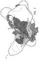
- FIG. 2is a schematic representation of a map of the left atrium of a patient at the conclusion of an initial ablation treatment, in accordance with an embodiment of the invention
- FIG. 3is a schematic representation of a map of the left atrium shown in FIG. 2 , produced just before beginning a redo ablation procedure, in accordance with an embodiment of the invention
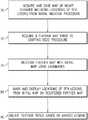
- FIG. 4is a flow chart that schematically illustrates a method for performing a redo ablation procedure, in accordance with an embodiment of the invention
- FIG. 5is a schematic representation of the maps of FIGS. 2 and 3 , illustrating landmarks used in registering the maps with one another, in accordance with an embodiment of the invention
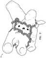
- FIGS. 6 and 7are schematic representations of a map of the left atrium, with tags representing both previous and current ablation lesions, in accordance with an embodiment of the invention.
- One of the challenges in a redo ablation procedureis to find the precise locations of the WCA lines made in the previous procedure, so that new RFA lesions can be placed exactly where necessary in order to achieve re-isolation of the pulmonary veins.
- some existing mapping toolspermit the user to superimpose and register different images of the heart, they do not enable the physician to view and make use of the mapping and ablation data, including the WCA lines, from a previous procedure on the current map.
- the inability to incorporate the previously-acquired map and ablation data in the current mapresults in unnecessary repetitions of RFA and prolongs procedure time.
- VTventricular tachycardia
- Embodiments of the present inventionthat are described herein provide novel techniques, implemented in software, for registering and superimposing a previously-acquired map and RFA data onto the current map that is in use by the physician in a redo ablation procedure.
- the registration and superimpositionrely on accurate alignment of the previous and current maps, so that the inner surfaces of the heart chamber in the previous and current maps are precisely registered with one another, even when a long period (possibly on the order of a year or more) has elapsed between the previous and current procedures.
- the alignmentis typically based, inter alia, on matching anatomical landmarks, such as the carina-between superior and inferior pulmonary veins, which the inventors have found to facilitate accurate and reliable registration of the left atrium, or other fixed anatomical landmarks in other arrhythmias and chambers of the heart.
- anatomical landmarkssuch as the coronary sinus, bundle of His, or superior and inferior venae cavae can be use individually or in combination for map registration and alignment.
- the embodiments that are illustrated in the figuresrelate specifically to RFA treatment of atrial fibrillation in the left atrium, the principles of the present invention may similarly be applied in treatment of other conditions in the atria or ventricles, such as ventricular tachycardia.
- FIG. 1is a schematic, pictorial illustration of a cardiac mapping and ablation system 20 , which operates in accordance with an embodiment of the invention.
- System 20may be based, for example, on the above-mentioned CARTO system, with suitable additions to the system software.
- System 20comprises a probe, such as a catheter 24 , and a control console 34 .
- catheter 24is used in ablating sites of arrhythmias in one or more chambers of a heart 26 of a patient 30 .
- An operator 22such as a cardiologist inserts catheter 24 through the vascular system of patient 30 so that the distal end of the catheter enters a chamber of heart 26 .
- Operator 22advances the catheter so that an electrode 28 at the distal tip of the catheter engages endocardial tissue at desired ablation sites.
- Catheter 24is typically connected by a suitable connector at its proximal end to console 34 , and specifically to a radio frequency (RF) generator 36 , which generates RF energy for transmission via catheter 24 to electrode 28 .
- RFradio frequency
- system 20uses magnetic position sensing to determine position coordinates of the distal end of catheter 24 inside heart 26 .
- a driver circuit 38 in console 34drives field generators 32 to generate magnetic fields within the body of patient 30 .
- field generators 32comprise coils, which are placed below the patient's torso at fixed, known positions. These coils generate magnetic fields in a predefined working volume that contains heart 26 .
- a magnetic field sensor (not shown) within the distal end of catheter 24generates electrical signals in response to these magnetic fields.
- a signal processor 40processes these signals in order to determine the position coordinates of the distal end of catheter 24 , typically including both location and orientation coordinates, and tracking these coordinates in order to create a map of the interior surface of the heart.
- system 20may use other methods of position sensing that are known in the art, such as ultrasonic or electrical impedance-based methods.
- catheter 24may comprise a force sensor (not shown) in its distal end, for measuring the contact force between the catheter tip and the wall of heart 26 .
- a force sensor(not shown) in its distal end, for measuring the contact force between the catheter tip and the wall of heart 26 .
- the SmartTouchTM catheterdeveloped by Biosense Webster Inc. for the CARTO system offers this sort of capability.
- a catheter of this sortis described, for example, in U.S. Patent Application Publication 2011/0130648, whose disclosure is incorporated herein by reference.
- the force measurementis useful in ensuring that electrode 28 is in sufficiently firm contact with the heart wall to effectively transfer RF energy and ablate the heart tissue.
- the force measurementscan also be used by processor 40 in tagging ablation sites, as described below.
- Processor 40 in console 34typically comprises a general-purpose computer processor, with suitable front end and interface circuits for receiving signals from catheter 24 and for controlling and receiving inputs from the other components of console 34 .
- Processor 40may be programmed in software to carry out the functions that are described herein.
- the softwaremay be downloaded to processor 40 in electronic form, over a network, for example, or it may be provided, alternatively or additionally, on tangible, non-transitory media, such as optical, magnetic or electronic memory media. Further alternatively or additionally, some or all of the functions of processor 40 may be carried out by dedicated or programmable digital hardware components.
- processor 40drives a display 42 to present operator 22 with a three-dimensional (3D) map 44 of heart 26 .
- the mapmay indicate cardiac electrophysiological activity measured by catheter 24 , as well as providing visual feedback regarding the position of the catheter in the patient's body and status information and guidance regarding the procedure that is in progress.
- Other parameters that may be measured by catheter 24 and by other elements of system 20 and may be shown on display 42can include, for example, contact force between the catheter and heart tissue, electrical impedance of the heart tissue, local temperature, and RF power delivered through the catheter.
- Processor 40assesses the parameters that it receives from system 20 as indicators of the adequacy of ablation at each treated site in heart 26 .
- the processorautomatically places a mark 46 , also referred to as a “tag,” on map 44 to indicate the site.
- the processormay vary the appearance of marks 46 (such as their color) in response to the parameters at each site.
- the criteria for automatic marking of the ablation sitesmay be preconfigured, or they may, alternatively or additionally, be set by operator 22 , typically using user interface controls 50 and on-screen menus. Additionally or alternatively, operator 22 can use controls 50 to instruct processor to place marks 46 at ablation sites.
- system 20may alternatively or additionally comprise an automated mechanism (not shown) for maneuvering and operating the catheter within the body of patient 30 .
- processor 40generates a control input for controlling the motion of catheter 24 based on the signals provided by the magnetic field sensor in the catheter and other system parameters, such as those mentioned above.
- FIGS. 2 and 3are schematic representations of maps 60 and 62 , respectively, of the left atrium of a patient during an initial PVI treatment to treat AF, and a subsequent redo ablation treatment, in order to resolve a recurrence of the AF.
- These figuresare reproductions of actual maps, taken from procedures performed about one year apart. The procedures were performed using a CARTO system, and maps 60 and 62 were acquired automatically by the system as the operating physician manipulated a mapping and ablation catheter within the heart.
- the markings shown on map 60were likewise created by the CARTO system and include VisitagTM marks 46 (which appear in the figures as small balls superimposed on the heart surface), which indicate RFA locations and may also hold data regarding ablation parameters at each location.
- Map 60shows the left atrium at the conclusion of the initial ablation treatment, while map 62 shows the same atrium just before beginning the redo ablation procedure (a year later).
- Visitag marks 46 on map 60show the locations of circumferential WCA lines that were ablated by the physician in the initial treatment, around the ostia of the pulmonary veins. No such marks appear initially on map 62 , thus making it difficult for operator 22 to identify during the redo procedure which locations were already ablated in the previous procedure.
- FIG. 4is a flow chart that schematically illustrates a method for performing a redo ablation procedure, while automatically transferring the locations of RFA lesions from a previous map (such as map 60 ) to the current map (such as map 62 ), in accordance with an embodiment of the invention.
- the methodis described, for the sake of concreteness and clarity, with reference to the elements of system 20 ( FIG. 1 ) and to a sequence of example maps of the left atrium, shown in FIGS. 2, 3 and 5-7 .
- the methodcan be carried out using other sorts of ablation systems and can be applied to other chambers of the heart, as well.
- console 34acquired and saved an initial map of the heart chamber, with locations of RFA lesions marked in the initial map, as shown in FIG. 2 , for example.
- console 34acquires a current map of the chamber, such as map 62 , illustrated in FIG. 3 , at a map acquisition step 72 .
- Console 34registers the initial map with the current map, at a map registration step 74 . This registration can be performed by identifying one or more anatomical landmarks in both the initial map and the current map, and aligning the landmarks identified in the initial map with the positions of the same landmarks identified in the current map.
- FIG. 5is a schematic representation of maps 60 and 62 (from FIGS. 2 and 3 ), illustrating landmarks 76 , 78 , 80 that are used in registering the maps, in accordance with an embodiment of the invention.
- Maps 60 and 62are shown side by side in FIG. 5 as an aid to visualization.
- the carina between superior and inferior pulmonary veins 82 on the left and right sides of the left atriumserve as landmarks 76 and 78 .
- Landmark 80is chosen in the present example to be the apex of an isosceles triangle, with its base drawn between landmarks 76 and 78 .
- Console 34aligns landmarks 76 , 78 and 80 in maps 60 and 62 and thus registers the initial map with the map surface in the current map.
- console 34marks and displays on the current map (i.e., on map 62 in the present example) the locations of the RFA lesions from the initial map, at a marking step 84 .
- the Visitag and/or other RFA marks corresponding to the WCA lines from the initial mapare displayed at the precise corresponding locations on the current map.
- Operator 22manipulates catheter 24 and actuates system 20 to ablate further tissue in the left atrium, at an ablation step 90 .
- the operator(or system 20 , operating automatically) can use the markings on the current map to choose ablation sites in proximity to the previous RFA lesions, and specifically to close any gaps that have opened in the WCA lines that were ablated previously.
- FIGS. 6 and 7are schematic representations of map 62 , seen from two different angles, illustrating the operations carried out in steps 84 and 90 , in accordance with an embodiment of the invention.
- Map 62now includes both marks 86 , representing ablation lesions made previously in the initial ablation procedure, and new marks 92 at the sites ablated in the current procedure. Marks 86 are transferred to map 62 from map 60 on the basis of the registration performed at step 74 , while marks 92 are added to map 62 by console 34 as the corresponding sites are ablated in step 90 .
- FIGS. 6 and 7also show an electrical activity map 88 , which is superimposed on the surface of map 62 .
- System 20acquires this electrical activity map by sensing electrical activity in the left atrium, using catheter 24 or another sensing catheter (not shown).
- Electrical activity map 88gives an indication of the electrical activity in the atrial wall, which is useful, together with marks 86 showing past RFA locations, in visualizing the locations of gaps in the WCA lines, where arrhythmogenic electrical activity “leaks through.” The operator thus can create new RFA lesions at locations that are chosen in order to close the gaps and can observe the effect of these new lesions (indicated by the corresponding marks 92 ) on the electrical activity shown in map 88 .
- the inventorsperformed a clinical study to examine the efficacy of utilizing the present techniques in reducing procedure and RFA time in redo PVI.
- Software running on the CARTO systemwas used in incorporation of a previously-acquired map and RFA lesion marks for use in the current active map.
- Group (GR) 1included 23 Pts who had prior maps that could be merged into the current map.
- GR 2included the 27 Pts without available prior maps. Both groups underwent CARTO 3D mapping of the left atrium and pulmonary veins to create an anatomical structural shell. In GR 1, the prior map was merged into the current, active map. Electrical activity maps (specifically, activation maps) were created to localize conduction gaps (CGs), and focal RFA was delivered only to target the CGs on the WCA lines in order to achieve pulmonary vein isolation (PVI). In GR 2, standard methods for CG localization and guiding RFA to achieve PVI were used.
- RFA timeRFA time
- RFA-Dduration to complete RFA
- TP-Dtotal procedure duration
Landscapes
- Health & Medical Sciences (AREA)
- Life Sciences & Earth Sciences (AREA)
- Engineering & Computer Science (AREA)
- Surgery (AREA)
- General Health & Medical Sciences (AREA)
- Veterinary Medicine (AREA)
- Biomedical Technology (AREA)
- Heart & Thoracic Surgery (AREA)
- Medical Informatics (AREA)
- Molecular Biology (AREA)
- Public Health (AREA)
- Animal Behavior & Ethology (AREA)
- Nuclear Medicine, Radiotherapy & Molecular Imaging (AREA)
- Physics & Mathematics (AREA)
- Cardiology (AREA)
- Plasma & Fusion (AREA)
- Otolaryngology (AREA)
- Robotics (AREA)
- Biophysics (AREA)
- Pathology (AREA)
- Human Computer Interaction (AREA)
- Surgical Instruments (AREA)
Abstract
Description
| TABLE I |
| STUDY RESULTS |
| PVP | TP-D/PVP | ||||
| with CG | RFA-T/PVP | RFA-D/PVP | for PVI | ||
| GR 1 | 19 | 3.5 ± 2.1 | 4.8 ± 4.2 | 7.7 ± 7.5 |
| GR 2 | 32 | 19.3 ± 10.2 | 38.4 ± 39.3 | 40.7 ± 39.8 |
| 82% | 88% | 81% | ||
| P value | 0.002 | <0.001 | <0.001 | |
Claims (9)
Priority Applications (8)
| Application Number | Priority Date | Filing Date | Title |
|---|---|---|---|
| US15/811,856US11083517B2 (en) | 2017-01-19 | 2017-11-14 | Enhancing efficiency of repeat ablation by merging current and previous maps |
| IL256890AIL256890B (en) | 2017-01-19 | 2018-01-14 | Enhancing efficiency of repeat ablation by merging current and previous maps |
| CA2992245ACA2992245A1 (en) | 2017-01-19 | 2018-01-17 | Enhancing efficiency of repeat ablation by merging current and previous maps |
| EP19213200.9AEP3636191B1 (en) | 2017-01-19 | 2018-01-18 | Enhancing efficiency of repeat ablation by merging current and previous maps |
| ES18152349TES2772846T3 (en) | 2017-01-19 | 2018-01-18 | Improving the efficiency of repeat ablation by merging current and previous maps |
| JP2018006200AJP7013253B2 (en) | 2017-01-19 | 2018-01-18 | Efficient iterative ablation by merging current and previous maps |
| EP18152349.9AEP3351197B1 (en) | 2017-01-19 | 2018-01-18 | Enhancing efficiency of repeat ablation by merging current and previous maps |
| CN201810053357.4ACN108324245B (en) | 2017-01-19 | 2018-01-19 | Improving efficiency of repeated ablations by merging current and previous maps |
Applications Claiming Priority (2)
| Application Number | Priority Date | Filing Date | Title |
|---|---|---|---|
| US201762447936P | 2017-01-19 | 2017-01-19 | |
| US15/811,856US11083517B2 (en) | 2017-01-19 | 2017-11-14 | Enhancing efficiency of repeat ablation by merging current and previous maps |
Publications (2)
| Publication Number | Publication Date |
|---|---|
| US20180199990A1 US20180199990A1 (en) | 2018-07-19 |
| US11083517B2true US11083517B2 (en) | 2021-08-10 |
Family
ID=61007530
Family Applications (1)
| Application Number | Title | Priority Date | Filing Date |
|---|---|---|---|
| US15/811,856Active2038-11-10US11083517B2 (en) | 2017-01-19 | 2017-11-14 | Enhancing efficiency of repeat ablation by merging current and previous maps |
Country Status (7)
| Country | Link |
|---|---|
| US (1) | US11083517B2 (en) |
| EP (2) | EP3636191B1 (en) |
| JP (1) | JP7013253B2 (en) |
| CN (1) | CN108324245B (en) |
| CA (1) | CA2992245A1 (en) |
| ES (1) | ES2772846T3 (en) |
| IL (1) | IL256890B (en) |
Families Citing this family (13)
| Publication number | Priority date | Publication date | Assignee | Title |
|---|---|---|---|---|
| US9119633B2 (en) | 2006-06-28 | 2015-09-01 | Kardium Inc. | Apparatus and method for intra-cardiac mapping and ablation |
| US11389232B2 (en) | 2006-06-28 | 2022-07-19 | Kardium Inc. | Apparatus and method for intra-cardiac mapping and ablation |
| US8906011B2 (en) | 2007-11-16 | 2014-12-09 | Kardium Inc. | Medical device for use in bodily lumens, for example an atrium |
| US9198592B2 (en) | 2012-05-21 | 2015-12-01 | Kardium Inc. | Systems and methods for activating transducers |
| US9017321B2 (en) | 2012-05-21 | 2015-04-28 | Kardium, Inc. | Systems and methods for activating transducers |
| US10827977B2 (en) | 2012-05-21 | 2020-11-10 | Kardium Inc. | Systems and methods for activating transducers |
| US10368936B2 (en) | 2014-11-17 | 2019-08-06 | Kardium Inc. | Systems and methods for selecting, activating, or selecting and activating transducers |
| US10722184B2 (en) | 2014-11-17 | 2020-07-28 | Kardium Inc. | Systems and methods for selecting, activating, or selecting and activating transducers |
| US11854217B2 (en) | 2019-05-03 | 2023-12-26 | Koninklijke Philips N.V. | Co-registration of cardiac images |
| US11564738B2 (en)* | 2019-05-06 | 2023-01-31 | Biosense Webster (Israel) Ltd. | Using pulmonary vein isolation for patients with atrial fibrillation |
| US11998265B2 (en) | 2019-12-23 | 2024-06-04 | Biosense Webster (Israel) Ltd. | Respiration control during cardiac ablation |
| US11911167B2 (en)* | 2021-01-19 | 2024-02-27 | Biosense Webster (Israel) Ltd. | Automatic mesh reshaping of an anatomical map to expose internal points of interest |
| US20250134574A1 (en)* | 2023-10-25 | 2025-05-01 | Biosense Webster (Israel) Ltd. | Graphically encoded ablation tags according to regions of anatomy |
Citations (26)
| Publication number | Priority date | Publication date | Assignee | Title |
|---|---|---|---|---|
| US20030093067A1 (en) | 2001-11-09 | 2003-05-15 | Scimed Life Systems, Inc. | Systems and methods for guiding catheters using registered images |
| US20060241445A1 (en)* | 2005-04-26 | 2006-10-26 | Altmann Andres C | Three-dimensional cardial imaging using ultrasound contour reconstruction |
| US20070049817A1 (en) | 2005-08-30 | 2007-03-01 | Assaf Preiss | Segmentation and registration of multimodal images using physiological data |
| US20070167784A1 (en) | 2005-12-13 | 2007-07-19 | Raj Shekhar | Real-time Elastic Registration to Determine Temporal Evolution of Internal Tissues for Image-Guided Interventions |
| US7517318B2 (en) | 2005-04-26 | 2009-04-14 | Biosense Webster, Inc. | Registration of electro-anatomical map with pre-acquired image using ultrasound |
| US20090268955A1 (en) | 2008-04-23 | 2009-10-29 | Aditya Koolwal | Systems, Methods and Devices for Correlating Reference Locations Using Image Data |
| US20100016712A1 (en) | 2007-02-27 | 2010-01-21 | Meir Bartal | Method and Device for Visually Assisting a Catheter Application |
| US7855723B2 (en) | 2006-03-21 | 2010-12-21 | Biosense Webster, Inc. | Image registration using locally-weighted fitting |
| US7918793B2 (en) | 2005-10-28 | 2011-04-05 | Biosense Webster, Inc. | Synchronization of ultrasound imaging data with electrical mapping |
| US20110130648A1 (en) | 2009-11-30 | 2011-06-02 | Christopher Thomas Beeckler | Catheter with pressure measuring tip |
| US20110160569A1 (en) | 2009-12-31 | 2011-06-30 | Amit Cohen | system and method for real-time surface and volume mapping of anatomical structures |
| WO2011135482A1 (en) | 2010-04-28 | 2011-11-03 | Koninklijke Philips Electronics N.V. | Property determining apparatus for determining a property of an object |
| US20120035459A1 (en) | 2008-11-27 | 2012-02-09 | "Amycard" Llc | Method of noninvasive electrophysiological study of the heart |
| US8320711B2 (en) | 2007-12-05 | 2012-11-27 | Biosense Webster, Inc. | Anatomical modeling from a 3-D image and a surface mapping |
| US8320771B2 (en) | 2008-01-22 | 2012-11-27 | Mitsubishi Electric Corporation | Optical transmission system and repeater |
| US20130066193A1 (en) | 2011-09-13 | 2013-03-14 | Eric S. Olson | Catheter navigation using impedance and magnetic field measurements |
| US20130072773A1 (en)* | 2011-09-19 | 2013-03-21 | Siemens Aktiengesellschaft | Method and System for Ablation Catheter and Circumferential Mapping Catheter Tracking in Fluoroscopic Images |
| US20130116681A1 (en) | 2011-11-09 | 2013-05-09 | Siemens Medical Solutions Usa, Inc. | System for Automatic Medical Ablation Control |
| US20130296845A1 (en)* | 2012-05-07 | 2013-11-07 | Meir Bar-tal | Automatic ablation tracking |
| US20140107512A1 (en) | 2011-09-20 | 2014-04-17 | Albert Einstein Healthcare Network | Cardio mapping system and method for cardio mapping |
| US20140200467A1 (en) | 2013-01-17 | 2014-07-17 | Cardioinsight Technologies, Inc. | Composite singularity mapping |
| WO2016014949A1 (en) | 2014-07-24 | 2016-01-28 | Blake Robert C | System and method for cardiac ablation |
| US20160120426A1 (en) | 2014-11-03 | 2016-05-05 | Biosense Webster (Israel) Ltd. | Registration maps using intra-cardiac signals |
| US9364251B2 (en) | 2009-03-06 | 2016-06-14 | Procept Biorobotics Corporation | Automated image-guided tissue resection and treatment |
| US9439735B2 (en) | 2009-06-08 | 2016-09-13 | MRI Interventions, Inc. | MRI-guided interventional systems that can track and generate dynamic visualizations of flexible intrabody devices in near real time |
| US20180042671A1 (en)* | 2006-06-28 | 2018-02-15 | Kardium Inc. | Apparatus and method for intra-cardiac mapping and ablation |
Family Cites Families (8)
| Publication number | Priority date | Publication date | Assignee | Title |
|---|---|---|---|---|
| US7681579B2 (en)* | 2005-08-02 | 2010-03-23 | Biosense Webster, Inc. | Guided procedures for treating atrial fibrillation |
| US7877128B2 (en)* | 2005-08-02 | 2011-01-25 | Biosense Webster, Inc. | Simulation of invasive procedures |
| WO2007023407A1 (en)* | 2005-08-25 | 2007-03-01 | Koninklijke Philips Electronics, N.V. | System and method for electrophysiology regaining support to continue line and ring ablations |
| US20070100223A1 (en)* | 2005-10-14 | 2007-05-03 | Rui Liao | Method and system for cardiac imaging and catheter guidance for radio frequency (RF) ablation |
| CN102625670B (en) | 2009-06-16 | 2015-07-15 | 核磁共振成像介入技术有限公司 | MRI-guided devices and MRI-guided interventional systems that can track and generate dynamic visualizations of the devices in near real time |
| US20130282005A1 (en) | 2012-04-24 | 2013-10-24 | Siemens Corporation | Catheter navigation system |
| US9757182B2 (en)* | 2014-06-02 | 2017-09-12 | Biosense Webster (Israel) Ltd. | Identification and visualization of gaps between cardiac ablation sites |
| US20160331262A1 (en)* | 2015-05-13 | 2016-11-17 | Ep Solutions Sa | Combined Electrophysiological Mapping and Cardiac Ablation Methods, Systems, Components and Devices |
- 2017
- 2017-11-14USUS15/811,856patent/US11083517B2/enactiveActive
- 2018
- 2018-01-14ILIL256890Apatent/IL256890B/enunknown
- 2018-01-17CACA2992245Apatent/CA2992245A1/ennot_activeAbandoned
- 2018-01-18JPJP2018006200Apatent/JP7013253B2/enactiveActive
- 2018-01-18EPEP19213200.9Apatent/EP3636191B1/enactiveActive
- 2018-01-18EPEP18152349.9Apatent/EP3351197B1/enactiveActive
- 2018-01-18ESES18152349Tpatent/ES2772846T3/enactiveActive
- 2018-01-19CNCN201810053357.4Apatent/CN108324245B/enactiveActive
Patent Citations (27)
| Publication number | Priority date | Publication date | Assignee | Title |
|---|---|---|---|---|
| US20030093067A1 (en) | 2001-11-09 | 2003-05-15 | Scimed Life Systems, Inc. | Systems and methods for guiding catheters using registered images |
| US20060241445A1 (en)* | 2005-04-26 | 2006-10-26 | Altmann Andres C | Three-dimensional cardial imaging using ultrasound contour reconstruction |
| US7517318B2 (en) | 2005-04-26 | 2009-04-14 | Biosense Webster, Inc. | Registration of electro-anatomical map with pre-acquired image using ultrasound |
| US20070049817A1 (en) | 2005-08-30 | 2007-03-01 | Assaf Preiss | Segmentation and registration of multimodal images using physiological data |
| US7918793B2 (en) | 2005-10-28 | 2011-04-05 | Biosense Webster, Inc. | Synchronization of ultrasound imaging data with electrical mapping |
| US20070167784A1 (en) | 2005-12-13 | 2007-07-19 | Raj Shekhar | Real-time Elastic Registration to Determine Temporal Evolution of Internal Tissues for Image-Guided Interventions |
| US7855723B2 (en) | 2006-03-21 | 2010-12-21 | Biosense Webster, Inc. | Image registration using locally-weighted fitting |
| US20180042671A1 (en)* | 2006-06-28 | 2018-02-15 | Kardium Inc. | Apparatus and method for intra-cardiac mapping and ablation |
| US20100016712A1 (en) | 2007-02-27 | 2010-01-21 | Meir Bartal | Method and Device for Visually Assisting a Catheter Application |
| US8320711B2 (en) | 2007-12-05 | 2012-11-27 | Biosense Webster, Inc. | Anatomical modeling from a 3-D image and a surface mapping |
| US8320771B2 (en) | 2008-01-22 | 2012-11-27 | Mitsubishi Electric Corporation | Optical transmission system and repeater |
| US20090268955A1 (en) | 2008-04-23 | 2009-10-29 | Aditya Koolwal | Systems, Methods and Devices for Correlating Reference Locations Using Image Data |
| US20120035459A1 (en) | 2008-11-27 | 2012-02-09 | "Amycard" Llc | Method of noninvasive electrophysiological study of the heart |
| US9364251B2 (en) | 2009-03-06 | 2016-06-14 | Procept Biorobotics Corporation | Automated image-guided tissue resection and treatment |
| US9439735B2 (en) | 2009-06-08 | 2016-09-13 | MRI Interventions, Inc. | MRI-guided interventional systems that can track and generate dynamic visualizations of flexible intrabody devices in near real time |
| US20110130648A1 (en) | 2009-11-30 | 2011-06-02 | Christopher Thomas Beeckler | Catheter with pressure measuring tip |
| US20110160569A1 (en) | 2009-12-31 | 2011-06-30 | Amit Cohen | system and method for real-time surface and volume mapping of anatomical structures |
| WO2011135482A1 (en) | 2010-04-28 | 2011-11-03 | Koninklijke Philips Electronics N.V. | Property determining apparatus for determining a property of an object |
| US20130066193A1 (en) | 2011-09-13 | 2013-03-14 | Eric S. Olson | Catheter navigation using impedance and magnetic field measurements |
| US20130072773A1 (en)* | 2011-09-19 | 2013-03-21 | Siemens Aktiengesellschaft | Method and System for Ablation Catheter and Circumferential Mapping Catheter Tracking in Fluoroscopic Images |
| US20140107512A1 (en) | 2011-09-20 | 2014-04-17 | Albert Einstein Healthcare Network | Cardio mapping system and method for cardio mapping |
| US20130116681A1 (en) | 2011-11-09 | 2013-05-09 | Siemens Medical Solutions Usa, Inc. | System for Automatic Medical Ablation Control |
| US8900225B2 (en) | 2012-05-07 | 2014-12-02 | Biosense Webster (Israel) Ltd. | Automatic ablation tracking |
| US20130296845A1 (en)* | 2012-05-07 | 2013-11-07 | Meir Bar-tal | Automatic ablation tracking |
| US20140200467A1 (en) | 2013-01-17 | 2014-07-17 | Cardioinsight Technologies, Inc. | Composite singularity mapping |
| WO2016014949A1 (en) | 2014-07-24 | 2016-01-28 | Blake Robert C | System and method for cardiac ablation |
| US20160120426A1 (en) | 2014-11-03 | 2016-05-05 | Biosense Webster (Israel) Ltd. | Registration maps using intra-cardiac signals |
Non-Patent Citations (3)
| Title |
|---|
| Extended European Search Report for corresponding European patent application No. EP 18152349.9, dated Jun. 13, 2018. |
| Salas, Atrial mapping during pulmonary vein pacing: a novel maneuver to detect and close residual conduction gaps in an ablation line 2016, J of Card Electrophysio, vol. 47, pp. 299-307 (Year: 2016).* |
| U.S. Appl. No. 62/447,936, filed Jan. 19, 2017. |
Also Published As
| Publication number | Publication date |
|---|---|
| JP7013253B2 (en) | 2022-01-31 |
| IL256890B (en) | 2021-08-31 |
| EP3636191B1 (en) | 2024-08-07 |
| CN108324245A (en) | 2018-07-27 |
| CA2992245A1 (en) | 2018-07-19 |
| IL256890A (en) | 2018-02-28 |
| US20180199990A1 (en) | 2018-07-19 |
| EP3636191C0 (en) | 2024-08-07 |
| EP3636191A1 (en) | 2020-04-15 |
| ES2772846T3 (en) | 2020-07-08 |
| JP2018114285A (en) | 2018-07-26 |
| CN108324245B (en) | 2023-10-20 |
| EP3351197A1 (en) | 2018-07-25 |
| EP3351197B1 (en) | 2019-12-04 |
Similar Documents
| Publication | Publication Date | Title |
|---|---|---|
| US11083517B2 (en) | Enhancing efficiency of repeat ablation by merging current and previous maps | |
| US9883918B2 (en) | Method for mapping ventricular/atrial premature beats during sinus rhythm | |
| US9101333B2 (en) | Integrative atrial fibrillation ablation | |
| EP2689722B1 (en) | An apparatus for mapping cardiac electrical activity | |
| US9326700B2 (en) | Catheter display showing tip angle and pressure | |
| JP2019051309A (en) | Automatic display of the earliest LAT | |
| US9622821B2 (en) | System and method for structure-function fusion for surgical interventions | |
| US12268413B2 (en) | Recommending transseptal needle curvature based on anatomy | |
| CN106236257B (en) | Alignment of coronary sinus catheter images | |
| Dixit et al. | Role of contact and noncontact mapping in the curative ablation of tachyarrhythmias | |
| Markides et al. | New mapping technologies: an overview with a clinical perspective | |
| AU2018200387A1 (en) | Enhancing efficiency of repeat ablation by merging current and previous maps | |
| Heemeyer et al. | An evaluation platform for catheter ablation navigation | |
| US12419693B2 (en) | Applying ablation signals to both sides of tissue | |
| JP2025088770A (en) | Guiding entrance to the epicardial bag by transthoracic ultrasound | |
| CN120112235A (en) | Alignment aid for ablation procedures | |
| Swygman et al. | EP Mapping System Technologies |
Legal Events
| Date | Code | Title | Description |
|---|---|---|---|
| FEPP | Fee payment procedure | Free format text:ENTITY STATUS SET TO UNDISCOUNTED (ORIGINAL EVENT CODE: BIG.); ENTITY STATUS OF PATENT OWNER: LARGE ENTITY | |
| AS | Assignment | Owner name:BIOSENSE WEBSTER (ISRAEL) LTD., ISRAEL Free format text:ASSIGNMENT OF ASSIGNORS INTEREST;ASSIGNORS:TURGEMAN, AHARON;BARON, TAL HAIM;HAYAM, GAL;SIGNING DATES FROM 20171115 TO 20171213;REEL/FRAME:044421/0878 | |
| STPP | Information on status: patent application and granting procedure in general | Free format text:DOCKETED NEW CASE - READY FOR EXAMINATION | |
| STPP | Information on status: patent application and granting procedure in general | Free format text:NON FINAL ACTION MAILED | |
| STPP | Information on status: patent application and granting procedure in general | Free format text:RESPONSE TO NON-FINAL OFFICE ACTION ENTERED AND FORWARDED TO EXAMINER | |
| STPP | Information on status: patent application and granting procedure in general | Free format text:FINAL REJECTION MAILED | |
| STPP | Information on status: patent application and granting procedure in general | Free format text:DOCKETED NEW CASE - READY FOR EXAMINATION | |
| STPP | Information on status: patent application and granting procedure in general | Free format text:NOTICE OF ALLOWANCE MAILED -- APPLICATION RECEIVED IN OFFICE OF PUBLICATIONS | |
| STPP | Information on status: patent application and granting procedure in general | Free format text:PUBLICATIONS -- ISSUE FEE PAYMENT RECEIVED | |
| STPP | Information on status: patent application and granting procedure in general | Free format text:PUBLICATIONS -- ISSUE FEE PAYMENT VERIFIED | |
| STCF | Information on status: patent grant | Free format text:PATENTED CASE | |
| MAFP | Maintenance fee payment | Free format text:PAYMENT OF MAINTENANCE FEE, 4TH YEAR, LARGE ENTITY (ORIGINAL EVENT CODE: M1551); ENTITY STATUS OF PATENT OWNER: LARGE ENTITY Year of fee payment:4 |