US11083265B2 - Magnetic pouch attachment mechanism with crash stable locking teeth - Google Patents
Magnetic pouch attachment mechanism with crash stable locking teethDownload PDFInfo
- Publication number
- US11083265B2 US11083265B2US15/283,975US201615283975AUS11083265B2US 11083265 B2US11083265 B2US 11083265B2US 201615283975 AUS201615283975 AUS 201615283975AUS 11083265 B2US11083265 B2US 11083265B2
- Authority
- US
- United States
- Prior art keywords
- pouch
- magnetic
- latch
- vehicular
- mount
- Prior art date
- Legal status (The legal status is an assumption and is not a legal conclusion. Google has not performed a legal analysis and makes no representation as to the accuracy of the status listed.)
- Active, expires
Links
Images


Classifications
- A—HUMAN NECESSITIES
- A45—HAND OR TRAVELLING ARTICLES
- A45C—PURSES; LUGGAGE; HAND CARRIED BAGS
- A45C13/00—Details; Accessories
- A45C13/10—Arrangement of fasteners
- A45C13/1069—Arrangement of fasteners magnetic
- A—HUMAN NECESSITIES
- A45—HAND OR TRAVELLING ARTICLES
- A45C—PURSES; LUGGAGE; HAND CARRIED BAGS
- A45C13/00—Details; Accessories
- A45C13/005—Hinges
- A—HUMAN NECESSITIES
- A45—HAND OR TRAVELLING ARTICLES
- A45C—PURSES; LUGGAGE; HAND CARRIED BAGS
- A45C7/00—Collapsible or extensible purses, luggage, bags or the like
- A45C7/0018—Rigid or semi-rigid luggage
- A45C7/0045—Rigid or semi-rigid luggage comprising a plurality of separable elements which can be used independently of one another
- B—PERFORMING OPERATIONS; TRANSPORTING
- B60—VEHICLES IN GENERAL
- B60R—VEHICLES, VEHICLE FITTINGS, OR VEHICLE PARTS, NOT OTHERWISE PROVIDED FOR
- B60R11/00—Arrangements for holding or mounting articles, not otherwise provided for
- B60R11/06—Arrangements for holding or mounting articles, not otherwise provided for for tools or spare parts
- E—FIXED CONSTRUCTIONS
- E05—LOCKS; KEYS; WINDOW OR DOOR FITTINGS; SAFES
- E05C—BOLTS OR FASTENING DEVICES FOR WINGS, SPECIALLY FOR DOORS OR WINDOWS
- E05C19/00—Other devices specially designed for securing wings, e.g. with suction cups
- E05C19/16—Devices holding the wing by magnetic or electromagnetic attraction
- B—PERFORMING OPERATIONS; TRANSPORTING
- B60—VEHICLES IN GENERAL
- B60R—VEHICLES, VEHICLE FITTINGS, OR VEHICLE PARTS, NOT OTHERWISE PROVIDED FOR
- B60R11/00—Arrangements for holding or mounting articles, not otherwise provided for
- B60R2011/0042—Arrangements for holding or mounting articles, not otherwise provided for characterised by mounting means
- B60R2011/0049—Arrangements for holding or mounting articles, not otherwise provided for characterised by mounting means for non integrated articles
- B60R2011/005—Connection with the vehicle part
- B60R2011/0057—Connection with the vehicle part using magnetic means
Definitions
- the present specificationgenerally relates to a portable compartmentalization device for use in various configurations with a vehicle or a structure and, more specifically, a crash-ready, portable, compartmentalization device that is used with an equipment mounting system.
- a magnetic pouch attachment mechanismmay include one or more magnetic pouch mounts and one or more pouches.
- Each magnetic pouch mountmay include an alignment plate, one or more magnetic areas disposed within the alignment plate, one or more mounting apertures disposed in the alignment plate, one or more latch apertures disposed in the alignment plate, and a latch with a latch handle and one or more latch teeth, each latch tooth protrudes into each latch aperture when the latch is in a retention position and each latch tooth is retracted out of each latch aperture when the latch is in a release position.
- the latch handletransitions the latch between the retention position and the release position.
- the one or more pouchesmay be removably coupled with the one or more magnetic pouch mounts such that when each pouch is placed in proximity to the one or more magnetic pouch mounts, an attractive magnetic force is exerted between the pouch and the one or more magnetic pouch mounts such that the pouch aligns with and couples to the one or more magnetic pouch mounts.
- Each pouchincludes a container defining an interior compartment and having an opening for receiving items into the interior compartment, a flap hingedly coupled to the container and sized to cover the opening and at least a portion of an outer surface of the container, means for securing the flap to the outer surface of the container, and a mounting bracket coupled to the container.
- the mounting bracketmay include one or more bracket magnetic areas disposed within the mounting bracket and configured to induce an attractive magnetic force with the one or more magnetic areas, one or more alignment pegs configured to removably couple with the one or more mounting apertures of the magnetic pouch mount, and one or more catches configured to removably couple with the one or more latch apertures of the magnetic pouch mount.
- a method of utilizing a pouch assemblymay include moving a pouch into proximity of one or more magnetic pouch mounts.
- the pouchmay include a container defining an interior compartment and having an opening for receiving items into the interior compartment, a flap hingedly coupled to the container and sized to cover the opening and at least a portion of an outer surface of the container, means for securing the flap to the outer surface of the container, and a mounting bracket coupled to the container.
- the mounting bracketmay include one or more bracket magnetic areas disposed within the mounting bracket and configured to induce an attractive magnetic force with the one or more magnetic areas, one or more alignment pegs configured to removably couple with the one or more mounting apertures of the magnetic pouch mount, and one or more catches configured to removably couple with the one or more latch apertures of the magnetic pouch mount.
- the one or more magnetic pouch mountsmay include an alignment plate, one or more magnetic areas disposed within the alignment plate, one or more mounting apertures disposed in the alignment plate, one or more latch apertures disposed in the alignment plate, and a latch comprising a latch handle and one or more latch teeth, each latch tooth protrudes into each latch aperture when the latch is in a retention position and each latch tooth is retracted out of each latch aperture when the latch is in a release position, and the latch handle transitions the latch between the retention position and the release position.
- the methodmay also include allowing an attractive magnetic force between the pouch and the one or more magnetic pouch mounts to draw and removably couple the pouch to the one or more magnetic pouch mounts.
- a pouch retrofit kitmay include one or more magnetic pouch mounts which may include an alignment plate coupled to a surface, one or more magnetic areas disposed within the alignment plate, one or more mounting apertures disposed in the alignment plate, one or more latch apertures disposed in the alignment plate, and a latch comprising a latch handle and one or more latch teeth, each latch tooth protrudes into each latch aperture when the latch is in a retention position and each latch tooth is retracted out of each latch aperture when the latch is in a release position, and the latch handle transitions the latch between the retention position and the release position.
- the retrofit kitmay also include a mounting bracket coupled to a pre-existing pouch, the mounting bracket may include one or more bracket magnetic areas disposed within the mounting bracket and configured to induce an attractive magnetic force with the one or more magnetic areas, one or more alignment pegs configured to removably couple with the one or more mounting apertures of the magnetic pouch mount, and one or more catches configured to removably couple with the one or more latch apertures of the magnetic pouch mount.
- the mounting bracketWhen the mounting bracket is placed in proximity to the one or more magnetic pouch mounts, an attractive magnetic force is exerted between the mounting bracket and the one or more magnetic pouch mounts such that the mounting bracket aligns with and couples to the one or more magnetic pouch mounts.
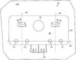
- FIG. 1is a front view of a magnetic pouch mount according to one or more embodiments shown and described herein;
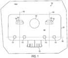
- FIG. 2is a rear view of the magnetic pouch mount according to one or more embodiments shown and described herein;
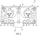
- FIG. 3is a front view of a pouch according to one or more embodiments shown and described herein;
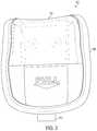
- FIG. 4is a rear view of the pouch according to one or more embodiments shown and described herein;
- FIG. 5is a top view of the pouch according to one or more embodiments shown and described herein;
- FIG. 6Ais an isometric view of the mounting bracket according to one or more embodiments shown and described herein;
- FIG. 6Bis a bottom view of the pouch according to one or more embodiments shown and described herein;
- FIG. 7is another front view of the pouch according to one or more embodiments shown and described herein;
- FIG. 8is a front view of a single pouch according to one or more embodiments shown and described herein;
- FIG. 9is a rear view of the single pouch according to one or more embodiments shown and described herein;
- FIG. 10is another front view of the single pouch according to one or more embodiments shown and described herein;
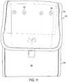
- FIG. 11is a front view of a tall pouch according to one or more embodiments shown and described herein;
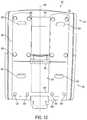
- FIG. 12is a rear view of the tall pouch according to one or more embodiments shown and described herein;
- FIG. 13is an isometric view of a latch adapter according to one or more embodiments shown and described herein;
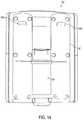
- FIG. 14depicts the latch adapter in an actuate position according to one or more embodiments shown and described herein;
- FIG. 15is another front view of the tall pouch according to one or more embodiments shown and described herein;
- FIG. 16is an isometric view of the tall pouch coupled to the magnetic pouch mount according to one or more embodiments shown and described herein;
- FIG. 17is an isometric view of the tall pouch coupled to two magnetic pouch mounts according to one or more embodiments shown and described herein;
- FIG. 18illustrates an pouch mounted to a surface according to one or more embodiments shown and described herein;
- FIG. 19a front view of a crash-ready, portable, item compartmentalization device (softwall) according to one or more embodiments shown and described herein;
- FIG. 20is a rear view of the softwall according to one or more embodiments shown and described herein;
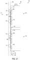
- FIG. 21is a side view of a shell of the softwall according to one or more embodiments shown and described herein;
- FIG. 22is a bottom view of the softwall according to one or more embodiments shown and described herein;
- FIG. 23is a top view of the softwall in an open position according to one or more embodiments shown and described herein;
- FIG. 24is a cross-sectional view of the softwall 100 according to one or more embodiments shown and described herein;
- FIG. 25is another top view of the softwall according to one or more embodiments shown and described herein;
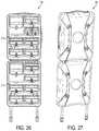
- FIG. 26is a front view of a first embodiment of the softwall according to one or more embodiments shown and described herein;
- FIG. 27is a rear view of the first embodiment of the softwall according to one or more embodiments shown and described herein;
- FIG. 28is a front view of a second embodiment of the softwall according to one or more embodiments shown and described herein;
- FIG. 29is a rear view of the second embodiment the softwall according to one or more embodiments shown and described herein;
- FIG. 30is an isometric view of one embodiment of a restraint strap and an anchor according to one or more embodiments shown and described herein;
- FIG. 31is a cross-sectional view of a vehicle with the softwall coupled to a wall of the vehicle according to one or more embodiments shown and described herein;
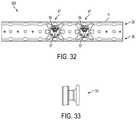
- FIG. 32illustrates an equipment mounting system according to one or more embodiments shown and described herein;
- FIG. 33is a side view of a mount stud according to one or more embodiments shown and described herein;
- FIG. 34is a isometric view of a wedge interface according to one or more embodiments shown and described herein;
- FIG. 35is a front view of the wedge interface according to one or more embodiments shown and described herein.
- FIGS. 26 and 27generally depict one embodiment of a crash-ready, portable, modular, compartmentalization softwall device and system for organizing and securing items for transport.
- the softwall devicegenerally includes two half shells forming a complete shell, each half shell has a backing plate with a number of removable means to secure a plurality of pouches to each half shell.
- the plurality of pouchesmay be configured to be secured to each half shell in a variety of configurations.
- each removable meansmay secure only one pouch.
- a large pouchmay be secured to two or more removable means.
- two small pouchesmay be secured to a single removable means.
- the configuration of the removable means in each half shellmay allow for multiple configurations of various size pouches within the softwall device.
- Each half shellmay be secured to the other half shell to form the complete shell and protect the pouches and the items held within.
- the shell, pouches, and the various removable means and connectorsare all crash-ready as defined below.
- the complete shell, pouches, and various means to secure a plurality of pouches, and connectorsare designed to survive and withstand inertial and impact forces normally occurring during a crash and still retain functionality and contain the various items stored within.
- the magnetic pouch mount 500may include an alignment plate 505 , one or more mounting apertures 510 , a mount indicia 540 , one or more latch apertures 530 , and a latch 600 ( FIG. 2 ).
- the latch 600may include a latch handle 525 and one or more latch teeth 535 . Each latch tooth 535 may protrude into each latch aperture 530 as shown in FIG. 1 in the retention position.
- Each latch toothmay be crash-ready.
- “crash-ready”means that a device, equipment, mount, track, fastening devices, or a structure may be configured to survive an inertial force, an impact, a vehicle crash, or a sudden vehicle maneuver and retain functionality afterwards where the force exerted upon the device, equipment, mount, track, fastening devices, or a structure may exceed about 15 Gs (i.e., units of gravitational force or g-force) in a fore-aft direction and exceed about 17 Gs in a lateral direction.
- 15 Gsi.e., units of gravitational force or g-force
- the force exerted upon the device, equipment, mount, track, fastening devices, or a structuremay exceed about 22 Gs (i.e., units of gravitational force or g-force) in a fore-aft direction and exceed about 26 Gs in a lateral direction.
- a latch axis 550may be centered on each of the one or more latch apertures 530 .
- the one or more mounting apertures 510may be positioned such that they are a mirror image of each other across the latch axis 550 .
- a mounting aperture axis 555bisects each of the one or more mounting apertures 510 .
- the mounting aperture axis 555may be substantially orthogonal to the latch axis 550 .
- the mount indicia 540may be used to indicate which pouch or combination of pouches should be secured to the magnetic pouch mount 500 .
- the term “pouch” without a reference numberindicates it may be a pouch 900 ( FIG. 3 ), a single pouch 901 ( FIG. 8 ), a tall pouch 902 ( FIG. 11 ), and a long pouch 903 ( FIG. 25 ).
- the pouchmay have corresponding indicia to allow for ease in matching the pouch to the magnetic pouch mount 500 .
- a plate surface 545 of the alignment plate 505may be color coded to allow for ease in matching the pouch to the magnetic pouch mount 500 .
- FIG. 2is a rear view of the magnetic pouch mount 500 with an optional protective cover (not shown) removed to identify the internal components of the magnetic pouch mount 500 .
- the optional protective covermay be used to seal the magnetic pouch mount 500 from dust and other contaminates.
- the latch 600may include the latch handle 525 and one or more transitioning blocks 610 . Each transitioning block 610 may be coupled to each latch tooth 535 of FIG. 1 . Each transitioning block 610 may be slidably coupled with a latch aperture housing 615 . A tooth aperture (not shown) in the latch aperture housing 615 may allow each latch tooth 535 to transition between the retention position and a release position as explained in greater detail below.
- the one or more transitioning blocks 610are biased in the retention position (i.e., each latch tooth 535 protruding into each latch aperture 530 ) by one or more latch springs 605 .
- Each transitioning block 610may be biased by at least one latch spring 605 in the retention position.
- the latch handle 525may include one or more latch arms 616 .
- Each latch arm 616may be coupled to the each transitioning block 610 .
- each latch arm 616may be in contact with each transitioning block 610 .
- the latch handle 525may be transitioned from the retention position shown in FIG. 1 to the release position. In the release position, the latch handle 525 may be transitioned in the direction of arrow “B.”
- the latch arms 616may exert a release force on the transitioning blocks 610 thereby overcoming the biasing force of the one or more latch springs 605 and retracting each latch tooth 535 out of the latch aperture 530 .
- the operation of the latch 600 in relation to the pouchis described in greater detail below.
- the alignment plate 505may include one or more plate mounting points 620 and one or more mounting aperture housings 625 .
- Each plate mounting point 620may be used to secure the alignment plate 505 to a surface or device.
- Each mounting aperture housing 625may define each mounting aperture 510 of FIG. 1 in the alignment plate 505 .
- the alignment plate 505may also include one or more magnetic areas 520 disposed within the alignment plate 505 .
- Each magnetic area 520may include any device or object that creates or maintains a magnetic field.
- the device or object that creates or maintains a magnetic fieldmay include a magnet, a rare earth magnet, an electromagnet, or a magnetized metal. In one embodiment, each magnetic area 520 may not be visible when viewing the plate surface 545 .
- the magnetic pouch mount 500may be configured to secure the pouch to a surface 1800 or device.
- the surface 1800 or devicemay include, but is not limited to, a vehicle wall, a vehicle structure, a building wall, a building structure, a cot, a chair, a bag, a cart, or the like.
- the magnetic pouch mount 500may be configured to crash-ready.
- FIG. 3is a front view of the pouch 900 .
- the pouch 900may include a flap 905 .
- the flap 905may include a flexible window 910 and a tab 915 .
- the flexible window 910may be made from plastic or acrylic or the like and may allow viewing of the items in an interior compartment 970 ( FIG. 7 ).
- the dimensions of the pouch 900may be from about 4 in tall to about 7 in tall and from about 2 in wide to about 6 in wide. All pouches may have about the same thickness which may be from about 2 in thick to about 6 in thick. In one embodiment, the pouch may have a thickness from about 2 in thick to about 8 in thick if only one half shell is configured with removable means as described below.
- FIG. 4is a rear view of the pouch 900 .
- the pouch 900may include a container 906 and a mounting bracket 920 .
- the container 906is discussed in greater detail below in relation to FIG. 7 .
- the mounting bracket 920may include one or more alignment pegs 925 , a catch 930 , and one or more bracket magnetic areas 935 .
- the one or more alignment pegs 925may be configured to slidably couple with the one or more mounting apertures 510 shown in FIG. 1 .
- the catch 930may be configured to removably couple with the latch aperture 530 shown in FIG. 1 .
- the one or more bracket magnetic areas 935may be disposed within the mounting bracket 920 and configured to induce an attractive magnetic force with the one or more magnetic areas 520 shown in FIG.
- the one or more bracket magnetic areas 935 and the one or more magnetic areas 520may be polar opposites of each to induce the attractive magnetic force between them.
- the attractive magnetic forcewill align and couple the pouch 900 to the magnetic pouch mount 500 .
- the one or more magnetic areas 520may be an electromagnet and the one or more bracket magnetic areas 935 may be a ferrous metal that is attracted to the electromagnet with the electromagnet is energized.
- the mounting bracket 920may be coupled to the container 906 of the pouch 900 by one or more fastening means 950 .
- “Fastening means”, as used throughout,may include, but are not limited to, screws, bolts, rivets, nails, adhesive, Velcro, weld, epoxy, or any similar devices that mechanically joins or affixes two or more objects together.
- the mounting bracket 920may be configured to removably couple with half of the magnetic pouch mount 500 shown in FIG. 1 .
- the pouch 900is shown in FIG. 4 with only one mounting bracket 920 .
- the pouch 900may couple with half of one magnetic pouch mount 500 or two pouches 900 may couple, side by side, with one magnetic pouch mount 500 .
- a catch axis 940may be centered on the catch 930 .
- the one or more alignment pegs 925may be positioned such that they are a mirror image of each other across the catch axis 940 .
- An alignment peg axis 945may bisects each of the one or more alignment pegs 925 .
- the catch axis 940may be substantially orthogonal to the alignment peg axis 945 .
- FIG. 5is a top view of the pouch 900 .
- the flap 905may be hingedly coupled to the container 906 by a pouch hinge 955 .
- the pouch hinge 955may be constructed from the same material that the container 906 is constructed from and resemble a piano hinge.
- Other examples of mechanisms to hingedly couple the flap 905 and the container 906may include, but are not limited to, a butt hinge, a strap hinge, a t-hinge, and a double-acting hinge.
- the catch 930 on the mounting bracket 920may include a tooth aperture 960 configured to receive the latch tooth 535 ( FIG. 1 ).
- FIG. 6Ais an isometric view of the mounting bracket 920 .
- the catch 930may be configured to removably couple with the latch aperture 530 ( FIG. 1 ) and slidably couple with the latch aperture housing 615 of FIG. 2 .
- a rounded surface 965may be configured to transition the latch tooth 535 from the retention position to the release position when the catch 930 is coupled with the latch aperture 530 with actuation of the latch handle 525 .
- the rounded surface 965may be an inclined edge, a tapered edge, or the like.
- the one or more alignment pegs 925may also include a rounded surface 965 to slidably couple each alignment peg 925 into each mounting aperture 510 of FIG. 1 .
- the rounded surface 965may aid in aligning the catch 930 with the latch aperture 530 and aid in aligning the each alignment pegs 925 with each latch aperture 530 .
- FIG. 6Bis a bottom view of the pouch 900 .
- the mounting bracket 920may include an L-shaped extension 995 that is configured to wrap under the container 906 and support some of a weight of the items in the interior compartment 970 shown in FIG. 7 .
- the fastening means 950may be used to couple the L-shaped extension 995 to the container 906 .
- a securing means 985may be used to secure the flap 905 to the container 906 . Securing means are discussed in greater detail below.
- FIG. 7is another front view of the pouch 900 with the flap 905 in an open position.
- the container 906may include a partial enclosure and an opening 975 .
- the partial enclosure and the opening 975may define an interior compartment 970 and the opening 975 may allow items to be received into the interior compartment 970 .
- the container 906may include a flexible window to allow viewing of the items in the interior compartment 970 .
- the flap 905may be sized to cover the opening 975 and at least a portion of an outer surface 980 of the container 906 .
- the flap 905may be made from the same material as the container 906 . In one embodiment, and as shown in FIGS.
- the fastening means 950may be coupled through the container 906 to the mounting bracket 920 (not shown).
- the container 906may be a water tight container.
- the fastening meansmay not penetrate the container 906 to ensure that the container 906 remains water tight.
- the fastening means used to maintain a water tight containermay be adhesive, weld, epoxy, or any similar devices that mechanically joins or affixes two or more objects together without creating or using an aperture.
- the pouch 900may also include securing means 985 ( FIG. 6B ) to secure the flap 905 to the outer surface 980 of the container 906 .
- Securing means 985may include Velcro®, a button snap, a button and hole, a hook and bar, a zipper, a snap buckle, a buckle, a Fidlock® Slider fastener, a Fidlock® SNAP fastener, a Fidlock® SNAP buckle fastener, a Fidlock® SNAP push fastener, a Fidlock® SNAP pull fastener, a Fidlock® MINI TURN fastener, a Fidlock® Hook fastener, or the like.
- the securing means 985may be crash-ready.
- the securing means 985may include a snap 985 a and a post 985 b. Both the snap 985 a and the post 985 b may include a set of magnets that are polar opposites of each other such that when the snap 985 a and the post 985 b are in close proximity to each other, the snap 985 a is attracted to and couples with the post 985 b. Transitioning the flap from the open position to the closed position and vice versus are performed in a cycle. The transition from the open position to the closed position part of the cycle may include:
- Phase 1During the approach of snap 985 a to the post 985 b, i.e., in the effective region of the magnetic forces between the set of magnets, the snap 985 a and the post 985 b are urged laterally into the closed position with maximum attraction of the attractive magnetic force between the set of magnets.
- Phase 2The attractive magnetic force between the set of magnets in the closed position overcomes the forced needed to couple the snap 985 a with the post 985 b.
- the attractive force of the magnetstransitions the flap 905 from the open position to the closed position and the coupling of the snap 985 a and the post 985 b overcomes the attractive magnetic force to retain the flap 905 in the closed position.
- the snap 985 a and the post 985 bare coupled together such that any item in the interior compartment 970 is retained within the interior compartment 970 until the flap is transitioned from the closed position to the open position.
- the transition from the closed position to the open position of the cyclemay include:
- Phase 3The attractive magnetic force between the set of magnets is weakened by lateral displacement of the snap 985 a in relation to the post 985 b.
- a usermay grab the tab 915 shown in FIG. 3 and pull down on the flap 905 thereby causing the set of magnets in the snap 985 a and the post 985 b to no longer be adjacent to each other.
- the attractive magnetic forcegets weaker as the snap 985 a and the post 985 b are separated by an increase in distance
- Phase 4Together with this lateral displacement, the post 985 b is removed from the snap 985 a such that the snap 985 a is moved out of engagement with the post 985 b by a lateral displacement thereby separating the snap 985 a and the post 985 b from each other.
- the snap 985 a and the post 985 b incorporating a set of magnetsallows a user to release the flap 905 into a freefall and the flap 905 , through the attractive magnetic force between the set of magnets, will transition from the open position to the closed position and will couple with the outer surface 980 of the container 906 without further intervention on the part of the user. Further explanation and examples may be found in U.S. Pat. No. 8,430,434 which is herein incorporated by reference in its entirety.
- FIG. 8is a front view of a single pouch 901 .
- the single pouch 901may include the flap 905 , the tab 915 , and the flexible window 910 .
- FIG. 9is a rear view of the single pouch 901 .
- the single pouch 901may include a first mounting bracket 920 a and a second mounting bracket 920 b coupled to the container 906 .
- the first mounting bracket 920 a and the second mounting bracket 920 bmay be coupled together with a frame 990 .
- the first mounting bracket 920 a and the second mounting bracket 920 bare configured to couple with a magnetic pouch mount 500 shown in FIG. 1 .
- the first mounting bracket 920 a and the second mounting bracket 920 bmay include the one or more bracket magnetic areas 935 .
- FIG. 10is another front view of the single pouch 901 with the flap 905 in an open position.
- the interior compartment 970 of the single pouch 901is about twice as much volume as the pouch 900 of FIG. 7 .
- the dimensions of the single pouch 901may be from about 4 inches (in) tall to about 7 in tall and from about 5 in wide to about 10 in wide.
- FIG. 11is a front view of a tall pouch 902 .
- the tall pouch 902may include the flap 905 , the tab 915 , and the flexible window 910 .
- the outer surface 980 of the container 906extends below the flap 905 when the flap is in the closed position.
- FIG. 12is a rear view of the tall pouch 902 .
- the container 906may be coupled to a modified mounting bracket 921 by the use of fastening means 950 .
- the modified mounting bracket 921may include the L-shaped extension 995 , the one or more alignment pegs 925 , the frame 990 , one or more catches 930 , and a latch adapter 526 .
- the latch adapter 526is captured between the container 906 and the frame 990 .
- the latch adapter 526transitions along a bracket axis 907 .
- the bracket axisis centrally and vertically located along the modified mounting bracket 921 .
- the latch adapter 526is described in greater detail below in relation to FIGS. 13 and 15 .
- FIG. 13is an isometric view of the latch adapter 526 .
- the latch adapter 526may include a first latch handle engagement surface 450 and a second latch handle engagement surface 455 , a plurality of stops 460 , and a sliding structure 465 having a sliding surface 470 .
- the plurality of stopsare configured to limit an amount of travel of the latch adapter 526 between a rest position, shown in FIG. 12 , and an actuate position, shown in FIG. 14 .
- a rest positionan upper plurality of stops 461 are in contact with the frame 990 as shown in FIG. 12 .
- a lower plurality of stops 462are in contact with the frame 990 as shown in FIG. 14 .
- the sliding surface 470allows for a smooth transition between the rest position and the actuate position.
- the sliding surface 470may be slidably coupled with the frame 990 .
- the frame 990may define the rest position and the actuate position.
- FIG. 14is a rear view of another embodiment of the tall pouch 902 .
- the latch adapter 526is shown in the actuate position. This embodiment may negate the need to secure the tall pouch 902 to a lower magnetic pouch mount 500 as described below in relation to FIGS. 12, 13, and 17 .
- FIG. 15is another front view of the tall pouch 902 with the flap 905 in an open position.
- the interior compartment 970 of the tall pouch 902is about twice as much volume as the single pouch 901 of FIG. 8 .
- the dimensions of the tall pouch 902may be from about 8 in tall to about 12 in tall and from about 8 in wide to about 10 in wide.
- FIG. 16is an isometric view of the tall pouch 902 coupled to the magnetic pouch mount 500 of FIG. 1 .
- the tall pouch 902may be removably coupled with a single magnetic pouch mount 500 .
- the first latch handle engagement surface 450may make contact with the latch handle 525 .
- the latch adapter 526is transitioned from the rest position to the actuate position in the direction of arrow “C”
- the first latch handle engagement surface 450transitions the latch 600 of FIG. 2 from the retention position to the release position thereby releasing the tall pouch 902 from the magnetic pouch mount 500 .
- the one or more latch springs 605bias the latch handle 525 in the retention position and the latch adapter 526 in the rest position.
- the tall pouch 902may be removably coupled with two magnetic pouch mounts 500 ( FIG. 1 ) wherein each magnetic pouch mount 500 is positioned vertically along the bracket axis 907 of FIG. 12 such that an upper magnetic pouch mount 501 (shown in FIG. 17 ) is removably coupled with an upper set of catches 931 ( FIG. 12 ) and a lower magnetic pouch mount 502 (shown in FIG. 17 ) may be removably coupled with a lower set of catches 932 ( FIG. 12 ).
- the first latch handle engagement surface 450may make contact with the latch handle 525 of the upper pouch mount 501 and the second latch handle engagement surface 455 may make contact with the latch handle 525 of the lower pouch mount 502 .
- the first latch handle engagement surface 450transitions the latch 600 of FIG. 2 of the upper magnetic pouch mount 501 from the retention position to the release position and simultaneously transitions the latch 600 of the lower magnetic pouch mount 502 from the retention position to the release position thereby releasing the tall pouch 902 from both the upper magnetic pouch mount 501 and the lower magnetic pouch mount 502 .
- the one or more latch springs 605bias the latch handle 525 in the retention position and the latch adapter 526 in the rest position.
- the pouch 900 , the single pouch 901 , the tall pouch 902 , and the long pouch 903are configured to removably couple with one or more magnetic pouch mounts 500 .
- Each pouchmay have a variant of the mounting bracket 920 . Therefore, the operation of removably coupling the pouch to the magnetic pouch mount 500 is the same. The only difference is in the arrangement and/or orientation of two or more magnetic pouch mounts 500 to successfully couple the pouch 900 , the single pouch 901 , the tall pouch 902 , and the long pouch 903 to a surface or device.
- the mounting bracket 920may be removably coupled to the magnetic pouch mount 500 such that the latch axis 550 and the catch axis 940 are substantially parallel to each other. As the pouch 900 is moved into close proximity to the magnetic pouch mount 500 , an attractive magnetic force between the one or more magnetic areas 520 ( FIG.
- the pouch 900could be released into a freefall in the vicinity of the magnetic pouch mount and the attractive magnetic force would draw in and removably couple the pouch 900 to the magnetic pouch mount 500 .
- the magnetic pouch mount 500may be coupled to a wall 1800 under a cabinet as shown in FIG. 18 .
- the pouch 900may be held near to the magnetic pouch mount 500 and the magnetic attractive force would draw and removably couple the pouch 900 to the magnetic pouch mount 500 without the need for a user to visually align the catch 930 with the latch aperture 530 or actuate a locking mechanism to removably couple the pouch 900 to the magnetic pouch mount 500 .
- the one or more alignment pegs 925 and the one or more mounting apertures 510further aid in aligning the latch axis 550 and the catch axis 940 so that they are substantially parallel with each other.
- the substantial alignment of the latch axis 550 and the catch axisallow the latch tooth 535 to fully engage the catch 930 and provide a crash-ready coupling of the pouch 900 and the magnetic pouch mount 500 .
- the pouchmay be coupled to a surface or device by removable means instead of the magnetic pouch mount 500 ( FIG. 1 ) and mounting bracket 920 ( FIG. 3 ) described above.
- Removable meansmay include, but is not limited to, screws, bolts, hook and loop fasteners, magnets, tape, latches, clasps, push-type plastic rivets, panel fasteners, twist lock fasteners, ball stud and ball receiver, tinnerman fastener, strap, twist-tie, suction cups, or any similar devices that mechanically joins or affixes two or more objects together and is easily separated.
- the pouchmay be secured to a surface or device with magnets coupled to the pouch.
- the surface or devicemay have magnets that are polar opposites of the magnets in the pouch or the surface or device may be made from a ferromagnetic material. As the pouch is moved into proximity of the surface or device, an attractive magnetic force draws the pouch to the surface or device and couples the pouch to the surface or device.
- the container 906 and the flap 905may be made from a fabric material to include nylon and carbon fiber, a rigid fabric material which is a fabric impregnated with a resin or a fabric with an increased thickness to reduce pliability, a plastic material, a rubber material, or the like.
- the pouchmay be crash-ready.
- a retrofit kit including the one or more magnetic pouch mounts 500 and the mounting bracketi.e., as used throughout, the “mounting bracket” includes the mounting bracket 920 of FIG. 4 , the first mounting bracket 920 a and the second mounting bracket 920 b of FIG.
- the modified mounting bracket 9may be used to retrofit an pre-existing pouch to use the magnetic pouch attachment system.
- Fastening means 950may be used to couple the mounting brackets to the pre-existing pouches.
- the mounting bracketsmay be modified to conform to the shape and size of the pre-existing pouch.
- the softwall 100may include a shell 300 ( FIG. 3 ) comprising a first half shell 105 and a second half shell 205 ( FIG. 2 ).
- the first half shell 105may include a first handle 110 , a second handle 115 , one or more impact areas 120 , one or more spacers 125 , one or more mount locations 130 , one or more reflective areas 135 , indicia 140 , and one or more feet 145 .
- the first handle 110may span a first handle area 150 and the second handle 115 may span a second handle area 155 (refer to FIG. 3 ).
- the first handle area 150 and the second handle area 155may be depressions in the first half shell 105 and the second half shell 205 respectively that may allow a user to obtain a better grasp on either the first handle 110 or the second handle 115 .
- the first handle 110may be coupled to the first half shell 105 along a side substantially parallel to a central axis 175 and the second handle 115 may be coupled to the first half shell 105 along a side substantially parallel to a mount axis 170 and opposite from one or more feet 145 .
- the one or more mount locations 130may be coupled to a first exterior surface 165 of the first half shell 105 .
- the one or more mount locations 130may be used to secure the softwall 100 to a surface (not shown) or structure (not shown).
- the one or more mount locations 130may be a hook or other fastening means.
- the one or more mount locations 130may include a mount stud ( FIG. 33 ).
- the one or more mount locations 130may be a wedge interface 72 shown in FIGS. 34 and 35 .
- the coupling of the softwall 100 to a surface or structureis described in greater detail below in relation to an equipment mounting system 380 ( FIG. 31 ).
- FIG. 20is a rear view of the softwall 100 and depicts the second half shell 205 .
- the second half shell 205may include one or more impact areas 120 , the one or more spacers 125 , one or more reflective areas 135 , one or more indicia 140 , one or more restraint straps 210 , and one or more feet 145 .
- the one or more spacersmay be coupled to the first half shell and the second half shell in the exterior space
- the one or more impact areas 120may be made from rubber or the like.
- the one or more impact areas 120are positioned at a plurality of corner areas 160 , 161 , 162 , 163 , 260 , 261 , 262 , and 263 .
- the one or more impact areas 120may be used to absorb the force of an impact on the plurality of corner areas 160 , 161 , 162 , 163 , 260 , 261 , 262 , and 263 of the softwall 100 .
- the one or more spacers 125may be made from rubber or the like.
- a surface axis 805may define the outermost extent the one or more spacers 125 .
- the surface axis 805may be a distance h from an exterior axis 810 .
- the surface axis 805may correspond to a surface that the softwall 100 is resting against or coupled to.
- the exterior axis 810may be defined as the substantial alignment of the planes created by the first exterior surface 165 and the second exterior surface 265 .
- the one or more spacers 125may be used to substantially align the exterior axis 810 with the surface axis 805 along parallel lines and maintain an alignment with the surface while the shell is in the open position.
- the surfacemay be a wall, a floor, ground, inclined surface, or the like.
- the distance h for each spacer of the one or more spacers 125may be varied as needed to maintain the substantially parallel relationship between the exterior axis 810 and the surface axis 805 .
- the surface axis 805may also define the outermost extent of the one or more mount locations 130 .
- the one or more mount locations 130may be varied as needed to allow the softwall 100 to couple a surface or device and still maintain the substantially parallel relationship between the exterior axis 810 and the surface axis 805 .
- the one or more reflective areas 135may be arranged on the first exterior surface 165 of the first half shell 105 and the second exterior surface 265 of the second half shell 205 to provide identification or signally in all light level conditions.
- the one or more reflective areas 135may be used to signal the presence of the softwall 100 .
- the one or more reflective areas 135may be a light emitting diode (LED) or other luminary device that may be used to light the softwall 100 and the surrounding area.
- the first exterior surface 165 and the second exterior surface 265may be color coded and/or may include one or more indicia 140 to indicate the contents of the softwall 100 or a designated use of the softwall 100 .
- the one or more reflective areas 135 , the one or more indicia 140 , color coding of the first exterior surface 165 and the second exterior surface 265 , and the coloring of the one or more impact areas 120may serve to indicate the designated use of the softwall 100 or the contents of the softwall 100 .
- the contents and the designated use of the softwall 100are explained in greater detail below.
- FIG. 21is a side view of the shell 300 of the softwall 100 .
- the shell 300may include the first half shell 105 and the second half shell 205 .
- the shell 300is shown in a closed position where the first half shell 105 and the second 205 are couple together such that the primary shell defines an interior space 710 ( FIG. 7 ) and an exterior space 715 ( FIG. 7 ).
- the first half shell 105 and the second half shell 205may have substantially similar dimensions and may be hingedly coupled along a common side.
- a hinge 305may be constructed from cloth and may resemble a piano hinge.
- the hinge 305may also be constructed from metal, plastic, rubber, or the like.
- the hinge 305may be an example of a mechanism to hingedly couple the first half shell 105 and the second half shell 205 together along a common side to define the shell 300 .
- Other examples of mechanisms to hingedly couple the first half shell 105 and the second half shell 205 together along a common side to define the shell 300may include, but are not limited to, a butt hinge, a strap hinge, a t-hinge, and a double-acting hinge.
- the first half shell 105 and the second half shell 205may be constructed from a flexible material such as fabric, semi-rigid material such as a thick rubber or layered fibers mats, or rigid material such as polycarbonates.
- a mount axis 170may be substantially orthogonal to a central axis 175 of the first half shell 105 .
- the mount axis 170may bisect each of the one or more mounting locations 130 .
- the one or more mounting locations 130 and some of the one or more spacers 125may lie along an upper spacer axis 315 .
- the upper spacer axis 315may also be substantially orthogonal to the central axis 175 .
- Some of the one or more spacers 125may lie along a lower spacer axis 320 .
- the upper spacer axis 315 and the lower spacer axis 320may be substantially parallel to each other.
- the upper spacer axis 315 and the mount axis 170may define an upper plane and the lower spacer axis may lie along a lower plane where the upper plane and the lower plane are substantially parallel to each other.
- FIG. 22is a bottom view of the softwall 100 .
- the hinge 305may hingedly couple the first half shell 105 and the second half shell 205 substantially along a common side along a common axis 410 .
- the one or more impact areas 120are shown to wrap around the plurality of corner areas 161 , 162 , 261 , and 262 respectively.
- a first strap slot 400 , a second strap slot 401 , a third strap slot 403 , and a fourth strap slot 404may be positioned at each of the plurality of corner areas 162 , 262 , 161 , and 261 respectively.
- the first strap slot 400 , the second strap slot 401 , the third strap slot 403 , and the fourth strap slot 404are explained in greater detail below in the description for FIG. 24 .
- the first half shell 105 and the second half shell 205 of FIGS. 19 through 22may also include one or more feet 145 .
- the one or more feet 145may be used to provide a contact points for the softwall 100 when the softwall 100 is placed on a surface.
- the one or more feet 145may include characteristics to prevent the softwall 100 from sliding on the surface or the one or more feet 145 may include characteristics to prevent scratching of the softwall 100 and or the surface should the surface be non-planar in shape.
- the one or more feet 145may also serve to protect the one or more impact areas 120 from the surface such that the one or more impact areas 120 are not resting directing on the surface when the softwall 100 is placed on the surface.
- FIG. 23is a top view of the softwall 100 in an open position.
- the first half shell 105is hingedly coupled to the second half shell 205 along the common axis 410 .
- Within the interior space 710 of the first half shell 105 and the second half shell 205may be one or more backing plates 225 and one or more removable means 230 .
- Each backing plate 225may be coupled to the first half shell 105 and the second half shell 205 .
- Each removable means 230may be coupled to the backing plate 225 such that the various embodiments of the pouch 900 may be coupled to and arranged within the interior space 710 .
- the backing plate 225may be a ferrous metal to allow a magnetic attractive force be created between the various embodiments of the pouch 900 and the backing plate 225 .
- the removable meansmay be a button or clasp.
- the removable meansmay be a thumb latch.
- the combination of the magnetic pouch mount 500 ( FIG. 1 ) and the mounting bracket 920may be used.
- a seam fastener 735may be coupled to the outer edge 730 of the first half shell 105 and the second half shell 205 .
- the seam fastener 735may be unfastened to transition the softwall 100 to the open position and fastened to transition the softwall 100 to the closed position.
- the seam fastener 735may include, but is not limited to, a zipper, a plurality of buttons, hook and loop fastener, a plurality of snaps, or the like.
- the same fasteneris configured to secure the first half shell 105 to the second half shell 205 when the shell 300 ( FIG. 21 ) is in the closed position.
- the backing plate 225may be coupled to one or more spacers 125 and the one or more mounting locations 130 through fastening means 950 .
- One or more restraint straps 235may be coupled to the first half shell 105 and the second half shell 205 and may be configured to secure the second half shell 205 and provide a tensioning force between the first half shell 105 and the second half shell 205 when the shell 300 is in an open position such that the interior spaced 710 remain vertically aligned.
- the one or more restraint straps 235may be anchored to the fastening means 950 or at one or more anchor points 240 .
- An anchor 245may be coupled to an external end 250 of each restraint strap 235 .
- the anchor 245may include, but is not limited to, a hook, a clasp, a latch, a grommet, and the like.
- the interior compartment of the long pouch 903is about twice as much volume as the single pouch 901 of FIG. 8 .
- the dimensions of the long pouch 903may be from about 3 in tall to about 7 in tall and from about 14 in wide to about 18 in wide.
- FIGS. 25-29various pouch configurations are shown in the interior space 710 of the softwall 100 .
- FIGS. 25, 26, and 28illustrate different arrangements of the various pouches within the interior space 710 of the softwall 100 .
- FIGS. 26 and 27illustrate a 4-row by 2-column grid of removable means 230 ( FIG. 23 ).
- the dimensions of the 4-row by 2-column embodiment of the softwall 100may be from about 23 in tall to about 25 in tall and from about 16 in wide to about 20 in wide in the closed position and from about 48 in tall to about 52 in tall in the open position.
- FIGS. 23, 28, and 29illustrate a 3-row by 2 column grid of removable means 230 .
- the dimensions of the 3-row by 2 column embodiment of the softwall 100may be from about 16 in tall to about 20 in tall and from about 16 in wide to about 20 in wide in the closed position and from about 35 in tall to about 40 in tall in the open position.
- the shape of the shell 300may be dictated by the arrangement of the removable means 230 in the interior space 710 .
- FIG. 30is an isometric view of one embodiment of the restraint strap 235 and the anchor 245 .
- the anchor 245may include an adjustment means 255 to change the length of the external end 250 of the restraint strap 235 .
- Adjustment meansmay include, but is not limited to, a tri-bar slide, a strap adjuster, a D-ring, a 2-sided halter ring, a 3-sided halter ring, a buckle, a post and grommet, and the like.
- FIG. 31is a cross-sectional view of a vehicle 350 with the softwall 100 removably coupled to the equipment mounting system 380 on a wall 355 of the vehicle 350 .
- the softwall 100allows a user to either hang the softwall 100 in the open position as shown in FIG. 31 or allows the user to remove the softwall 100 , transition it the closed position, and carry it to another location.
- the removable means 230 of FIG. 23allows the pouch to be removed and either moved to a different surface or device or swapped out with another pouch.
- a stock roommay have a plurality of pouches already filled with supplies. When the user exhausts the supplies of one pouch, he can visit the stock room and swap out the pouch for a stocked pouch.
- the removable meansallows the user to restock the softwall 100 without the need to assess a quantity of supplies within each pouch within the softwall 100 .
- the usermay be able to swap out the whole softwall 100 for another stock softwall 100 .
- the usermay then couple the stocked softwall 100 to the wall 355 of the vehicle 350 .
- FIG. 32is one embodiment of the equipment mounting system 380 .
- the equipment mounting system 380may include the quick mount track 11 and a wedge mount 47 .
- the one or more mount locations 130( FIG. 19 ) may be configured to removably couple with either the quick mount track 11 or the wedge mount 47 .
- the one or more mount locations 130may be the mount stud 141 shown in FIG. 33 .
- the mount stud 141may be configured to slidably couple with a first outer slot 20 and/or a second outer slot 30 of the quick mount track 11 .
- the one or more mount locations 130may be the wedge interface 72 .
- the spacing between the one or more mount locations 130 on the first exterior surface 165 of the first half shell 105may be defined by the spacing between two wedge mounts 47 as shown in FIG. 32 .
- the distance between the one or more mount locations 130 along the mount axis 170is substantially the same as the distance between a bowl aperture 54 on each wedge mount 47 .
- One or more restraint straps 235 and the anchor 245may be removably coupled to the equipment mounting system 380 and may secure the lower end 385 of the softwall 100 and prevent it from being swinging feely within the vehicle 350 .
- FIG. 35a front view of the wedge interface 72 .
- a wedge 79is situated between and couples a equipment plate 74 and a plurality of capture guides 78 a and 78 b together.
- the wedge 79has a lead-in surface 83 which is configured to engage a keyhole slot aperture 57 on the wedge mount 47 and aid in rotational alignment of the wedge interface 72 and the wedge mount 47 .
- the lead-in surface 83is configured to rotationally align the wedge interface 72 and the wedge mount 47 by ensuring the lead-in surface 83 is the only part of the wedge interface 72 that may enter the keyhole slot aperture 57 .
- the wedge 79also includes a first incline surface 84 and a second incline surface 85 .
- the first incline surface 84 and the second incline surface 85are opposite each other and are coupled to the lead-in surface 83 .
- the softwall 100may be used to quickly restock an emergency vehicle 350 between emergency calls.
- the softwall 100may be removed from the equipment mounting system 380 within the emergency vehicle and taken to a room to be replenished.
- the vehicle 350may be replenished with either another softwall 100 or the individual pouches (i.e., as used throughout, “pouches” may include the pouch 900 of FIG. 3 , the single pouch 901 of FIG. 8 , the tall pouch 902 of FIG. 11 , and the long pouch 903 of 25) of the softwall 100 may be removed and replaced.
- the one or more pouches within the softwall 100may also be color coded to indicate their contents.
- the color coded pouchesmay aid in the replenishment of the softwall 100 .
- the removable meansmay also be color coded to quickly assess which pouches were removed and need replacement.
- the removal of the softwall 100 and/or the one or more pouchesmay allow ease of cleaning of the interior of the vehicle 350 .
- the equipment mounting system 380may enable the interior of the vehicle 350 to be reconfigurable. In other words, if a specific softwall 100 is needed on a specific side of the vehicle 350 , a user may remove the specific softwall 100 from within the vehicle 350 and re-couple it to the equipment mounting system 380 in another location within the vehicle 350 .
Landscapes
- Engineering & Computer Science (AREA)
- Mechanical Engineering (AREA)
- Physics & Mathematics (AREA)
- Electromagnetism (AREA)
- Purses, Travelling Bags, Baskets, Or Suitcases (AREA)
- Vehicle Step Arrangements And Article Storage (AREA)
Abstract
Description
Claims (14)
Priority Applications (1)
| Application Number | Priority Date | Filing Date | Title |
|---|---|---|---|
| US15/283,975US11083265B2 (en) | 2014-02-11 | 2016-10-03 | Magnetic pouch attachment mechanism with crash stable locking teeth |
Applications Claiming Priority (6)
| Application Number | Priority Date | Filing Date | Title |
|---|---|---|---|
| US201414015898A | 2014-02-11 | 2014-02-11 | |
| US201461763045P | 2014-02-11 | 2014-02-11 | |
| US201462026520P | 2014-07-18 | 2014-07-18 | |
| US201414050306A | 2014-08-08 | 2014-08-08 | |
| PCT/US2014/050306WO2016010567A1 (en) | 2014-07-18 | 2014-08-08 | A magnetic pouch attachment mechanism with crash stable locking teeth |
| US15/283,975US11083265B2 (en) | 2014-02-11 | 2016-10-03 | Magnetic pouch attachment mechanism with crash stable locking teeth |
Related Parent Applications (1)
| Application Number | Title | Priority Date | Filing Date |
|---|---|---|---|
| PCT/US2014/050306ContinuationWO2016010567A1 (en) | 2014-02-11 | 2014-08-08 | A magnetic pouch attachment mechanism with crash stable locking teeth |
Publications (2)
| Publication Number | Publication Date |
|---|---|
| US20170021775A1 US20170021775A1 (en) | 2017-01-26 |
| US11083265B2true US11083265B2 (en) | 2021-08-10 |
Family
ID=57836757
Family Applications (1)
| Application Number | Title | Priority Date | Filing Date |
|---|---|---|---|
| US15/283,975Active2035-08-01US11083265B2 (en) | 2014-02-11 | 2016-10-03 | Magnetic pouch attachment mechanism with crash stable locking teeth |
Country Status (1)
| Country | Link |
|---|---|
| US (1) | US11083265B2 (en) |
Cited By (4)
| Publication number | Priority date | Publication date | Assignee | Title |
|---|---|---|---|---|
| US20220243869A1 (en)* | 2019-07-23 | 2022-08-04 | Valeda Company, Llc | Remote Release Assembly for a Surface Mount |
| US11490700B2 (en)* | 2014-07-18 | 2022-11-08 | Ferno-Washington, Inc. | Crash-ready, portable, compartmentalization device |
| US12214838B2 (en) | 2015-11-02 | 2025-02-04 | Trek Armor Incorporated | Vehicle seat with storage capacity |
| WO2025078572A1 (en)* | 2023-10-12 | 2025-04-17 | Strub Alex Eric | Container, designed as a suitcase, and associated combinations of fastening systems |
Families Citing this family (10)
| Publication number | Priority date | Publication date | Assignee | Title |
|---|---|---|---|---|
| US8992238B2 (en) | 2010-07-12 | 2015-03-31 | Ferno-Washington, Inc. | Mounting system having a mounting plate with mounting studs and electrical contacts |
| BR112015019242A2 (en) | 2013-02-11 | 2020-01-28 | Ferno Washington | equipment support |
| US9944217B2 (en) | 2013-02-11 | 2018-04-17 | Ferno-Washington, Inc. | Equipment mounting system |
| US10307313B2 (en) | 2013-02-11 | 2019-06-04 | Ferno-Washington, Inc. | Equipment mounting system |
| US11083265B2 (en) | 2014-02-11 | 2021-08-10 | Ferno-Washington, Inc. | Magnetic pouch attachment mechanism with crash stable locking teeth |
| US10398203B2 (en)* | 2014-02-11 | 2019-09-03 | Ferno-Washington, Inc. | Crash-ready, portable, compartmentalization device |
| US10398207B2 (en)* | 2014-02-11 | 2019-09-03 | Ferno-Washington, Inc. | Crash-ready, portable, compartmentalization device |
| US10309128B2 (en)* | 2016-08-11 | 2019-06-04 | Carrington D. Horton | Changeable lock cover |
| EP4110256A4 (en)* | 2020-02-28 | 2024-03-27 | Technologies CGC Inc. | Coupling systems for releasably coupling equipment to a patient transport system |
| US12064048B1 (en)* | 2021-12-15 | 2024-08-20 | No Sacrifice Bags Inc. | Support for a purse |
Citations (188)
| Publication number | Priority date | Publication date | Assignee | Title |
|---|---|---|---|---|
| US269985A (en) | 1883-01-02 | adgate | ||
| US619174A (en) | 1899-02-07 | haskins | ||
| US716852A (en) | 1901-03-09 | 1902-12-30 | James Roy Baker | Book-shelf support. |
| US1178360A (en) | 1915-08-14 | 1916-04-04 | Addison W Creekmore | Field-ambulance. |
| US1263918A (en) | 1917-08-17 | 1918-04-23 | Emma L N Miller | Ambulance. |
| US1288010A (en) | 1918-07-06 | 1918-12-17 | William Harry Isaac | Shelf-bracket. |
| US1576034A (en) | 1923-05-11 | 1926-03-09 | Edna M Butt | Collapsible support for tables, seats, shelves, and the like |
| US1702937A (en) | 1927-01-24 | 1929-02-19 | Matthew M Friedemann | Fixture |
| US1817962A (en) | 1930-10-17 | 1931-08-11 | Breuer Fred | Adjustable curtain holder |
| US2391051A (en) | 1944-02-12 | 1945-12-18 | George H Windsor | Litter supporting apparatus |
| US2456024A (en) | 1945-03-05 | 1948-12-14 | Du Pont | Foldable stretcher carrier for ambulances |
| US2473364A (en) | 1945-03-15 | 1949-06-14 | Curtiss Wright Corp | Litter installation for vehicles |
| US2480322A (en) | 1944-11-09 | 1949-08-30 | Fairchild Engine & Airplane | Aircraft ambulance |
| US2556076A (en) | 1944-09-15 | 1951-06-05 | Robert B Evans | Troopship type airplane seat structure |
| US2644591A (en) | 1948-12-10 | 1953-07-07 | Mcmahan Roy Franklin | Shelving and partition support |
| US2685912A (en) | 1951-06-20 | 1954-08-10 | Evans Prod Co | Troopship type airplane seat structure |
| US2688504A (en) | 1952-03-05 | 1954-09-07 | Pan American World Airways Inc | Cargo tie-down assembly |
| FR1085340A (en) | 1952-10-21 | 1955-01-31 | Device intended to support one or more stretchers | |
| US3042221A (en) | 1960-08-19 | 1962-07-03 | Acme Steel Co | Pallet rack |
| US3116773A (en) | 1962-12-26 | 1964-01-07 | Kikas Leonhard | Snap-on utility bag |
| US3204998A (en) | 1963-07-23 | 1965-09-07 | Stollenwerk Hans | Ambulance |
| CH432266A (en) | 1966-03-08 | 1967-03-15 | Banz Hans | Filing device for utensils, in particular utensils, in vehicles |
| US3358300A (en) | 1966-05-23 | 1967-12-19 | Lockheed Aircraft Corp | Mounting and supporting apparatus for litters |
| US3375936A (en) | 1966-08-03 | 1968-04-02 | Westinghouse Electric Corp | Shelf and shelf support structure |
| US3392848A (en) | 1966-06-06 | 1968-07-16 | Interlake Steel Corp | Pallet rack |
| US3451580A (en) | 1967-12-28 | 1969-06-24 | Phillips Petroleum Co | Fire extinguisher box |
| US3591121A (en) | 1969-08-14 | 1971-07-06 | Fridair Ind | Cargo pallet |
| DE2000967B1 (en) | 1970-01-10 | 1971-07-15 | Stollenwerk Hans | Device for holding a stretcher in a vehicle |
| US3605637A (en) | 1970-09-02 | 1971-09-20 | Ancra Corp | Anchor fitting for securing loads to a retainer track |
| US3606619A (en) | 1968-06-29 | 1971-09-21 | Hans Stollenwerk | Apparatus for accommodating a stretcher |
| US3613900A (en) | 1968-07-02 | 1971-10-19 | Chiu S Joint System Ltd | Constructional systems |
| US3718886A (en) | 1969-05-31 | 1973-02-27 | Nokia Ab Finnish Cable Works O | Connection plug for a current supply rail |
| US3770234A (en) | 1971-07-23 | 1973-11-06 | N Fovall | Caddy for handled appliance |
| US3840265A (en) | 1971-09-13 | 1974-10-08 | Inst For Ind Res & Standards | Construction of stabilised platform |
| US3846944A (en) | 1970-12-21 | 1974-11-12 | Barton King Syst Corp | Structural self-supporting system |
| US3973818A (en) | 1972-12-07 | 1976-08-10 | Maurice Soquenne | Multi-purpose prefabricated electrical installation |
| US4114947A (en) | 1977-11-18 | 1978-09-19 | Chas. Olson & Sons | Detachable seat mounting for buses |
| GB1530794A (en) | 1976-02-04 | 1978-11-01 | Secr Defence | First aid equipment |
| US4170335A (en) | 1978-05-19 | 1979-10-09 | William C. Rodgers | Infinitely adjustable support bracket |
| US4173382A (en) | 1977-01-27 | 1979-11-06 | Booty Donald J | Portable track lighting |
| US4178032A (en) | 1978-05-01 | 1979-12-11 | United Technologies Corporation | Apparatus for synchronously elevating and lowering air-ambulance litter with crash attenuation capability |
| US4210355A (en) | 1978-01-11 | 1980-07-01 | A.C.M.A.T. Ateliers De Constructions Mecaniques De L'atlantique | Air-transportable highly autonomous cross-country medical vehicle |
| US4230432A (en) | 1979-02-27 | 1980-10-28 | Fairchild Industries, Inc. | Track fastener |
| EP0021526A2 (en) | 1979-06-15 | 1981-01-07 | Automobielbedrijf Unihef B.V. | Ambulance |
| US4256424A (en) | 1979-08-20 | 1981-03-17 | Ancra Corporation | Rattle-proof anchor fitting for securing loads to a retainer track |
| US4263951A (en) | 1979-06-18 | 1981-04-28 | Amba Marketing Systems, Inc. | Interchangeable accessory system for handbags |
| FR2481110A1 (en) | 1980-04-24 | 1981-10-30 | Heuliez Henri Holding | Movable support for stretcher in ambulance - has lifting and tilting mechanisms mounted between stretcher base and false vehicle floor |
| US4386642A (en) | 1980-12-02 | 1983-06-07 | Durbin William H | Universal portable pack |
| US4397432A (en) | 1981-06-02 | 1983-08-09 | The Boeing Company | Adjustable litter support assembly |
| DE3209092A1 (en) | 1982-03-12 | 1983-09-22 | Hipro, 61100 Pesaro | Collapsible bunk bed |
| DE3209091A1 (en) | 1982-03-12 | 1983-09-22 | Hans 8574 Lengwil Thurgau Wenger | COMPOSITE PLATE FOR UNDERFLOOR HEATING |
| US4423817A (en) | 1980-08-08 | 1984-01-03 | Monjo Rufi Jesus | Shelf rack |
| US4425978A (en) | 1981-09-14 | 1984-01-17 | Star Leon D | Mobile hospital unit |
| DE3230905A1 (en) | 1982-08-19 | 1984-02-23 | Hans Stollenwerk u. Cie GmbH & Co, 5000 Köln | Bearing device for stretchers or the like |
| EP0105675A2 (en) | 1982-09-30 | 1984-04-18 | East/West Industries, Inc. | Restraining fittings |
| US4458864A (en) | 1978-01-31 | 1984-07-10 | Hosp. Ital Ll. E.M. S.P.A. | Medical complex for installation in a standard aircraft to convert it into an ambulance aircraft |
| US4513866A (en) | 1982-09-29 | 1985-04-30 | Thomas Frank O | Emergency medical pack |
| US4568050A (en) | 1983-11-25 | 1986-02-04 | St. Charles Manufacturing Co. | Component furniture assembly |
| US4576319A (en) | 1984-10-05 | 1986-03-18 | Brown Bill G | Block storage |
| US4602756A (en) | 1984-11-26 | 1986-07-29 | Chatfield Alan M | Instrument fastening system |
| US4677794A (en) | 1982-08-25 | 1987-07-07 | Ivan Parron | Support assembly for a shelf or like structure |
| EP0260726A2 (en) | 1986-09-17 | 1988-03-23 | The Boeing Company | Passenger entertainment system having direct coupled seat receivers |
| US4783034A (en) | 1985-08-13 | 1988-11-08 | General Datacomm, Inc. | Slide lock mechanism |
| US4853555A (en) | 1988-04-21 | 1989-08-01 | The Boeing Company | Electrical power transfer system for aircraft passenger entertainment system |
| DE8910460U1 (en) | 1989-09-01 | 1989-10-26 | Karosseriewerke Weinsberg Gmbh, 7102 Weinsberg | Stretcher storage for ambulance vehicles |
| US4915435A (en) | 1989-04-05 | 1990-04-10 | Levine Brian M | Mobile operating room with pre and post-operational areas |
| FR2647323A1 (en) | 1989-05-25 | 1990-11-30 | Pinaud Jean Claude | Assembly of retractible superimposed beds |
| US4974377A (en) | 1988-03-18 | 1990-12-04 | The Mitre Corporation | Integrated enclosure and adjustable electronic equipment mounting system |
| FR2649007A1 (en) | 1989-07-03 | 1991-01-04 | Gruau Laval Sa | Stretcher supports which can be lifted and lowered adjustably |
| US5007608A (en) | 1989-08-28 | 1991-04-16 | Kim Manufacturing Company | Television wall bracket |
| WO1991015178A1 (en) | 1990-04-11 | 1991-10-17 | E.M.S. Technik Gmbh | Stretcher rack |
| US5096030A (en) | 1991-07-25 | 1992-03-17 | Espinosa Erlinda O | Luggage unit with pull-out article-receiving pouch |
| US5157409A (en) | 1991-08-07 | 1992-10-20 | Radio Frequency Systems, Inc. | Cam lock antenna mounting assembly |
| US5207303A (en) | 1991-07-15 | 1993-05-04 | Oswalt Brenda K | Medical emergency carrying case |
| EP0583491A1 (en) | 1992-08-08 | 1994-02-23 | HÜBNER Gummi- und Kunststoff GmbH | Bridge elements of a disconnectable intercommunication passage between articulated vehicles |
| EP0583492A1 (en) | 1992-07-31 | 1994-02-23 | Aphex Systems, Ltd. | Audio signal bass frequency enhancement device |
| US5383629A (en) | 1992-10-07 | 1995-01-24 | Air Methods Corporation International | Emergency medical system |
| US5425520A (en) | 1992-03-18 | 1995-06-20 | Hideki Ueda | Corner bracket for use in a sectional shelf |
| US5490703A (en) | 1993-06-04 | 1996-02-13 | Vancouver Island Helicopters Ltd. | Patient transport system |
| US5604958A (en) | 1995-11-06 | 1997-02-25 | National Molding Corp. | Attachment system for backpacks, vests, belts and the like |
| US5615848A (en) | 1993-12-23 | 1997-04-01 | Agusta Eli S.R.L. | Rescue and ambulance helicopter |
| US5732867A (en)* | 1996-11-26 | 1998-03-31 | Crush Innovative Sports Systems, Inc. | Releasable backpack |
| US5732965A (en) | 1996-02-07 | 1998-03-31 | Willey; Barry A. | Mounting system for motorcyle accessories |
| US5738306A (en) | 1995-10-13 | 1998-04-14 | Air Methods Corporation | Articulating patient loading system and transport device for aircraft |
| US5755478A (en) | 1995-06-06 | 1998-05-26 | Northrop Grumman Corporation | Mobile self-contained trauma care system |
| US5779296A (en) | 1993-06-04 | 1998-07-14 | Vancouver Island Helicopters, Ltd. | Patient transport system |
| US5785277A (en) | 1995-10-13 | 1998-07-28 | Air Methods Corporation | Patient loading system and transport device for aircraft |
| US5815629A (en) | 1995-08-18 | 1998-09-29 | Siemens Aktiengesellschaft | Cap sleeve for light waveguide cables |
| DE19716046A1 (en) | 1997-04-17 | 1998-10-22 | Michael Kiefer | Current conducting strip |
| US5833095A (en) | 1997-12-05 | 1998-11-10 | Task Corporation | Tool and fastener holder with detachable holding belt |
| US5845780A (en) | 1997-06-24 | 1998-12-08 | Allen; Vickey L. | Athletic bag |
| US5850891A (en) | 1997-10-30 | 1998-12-22 | Trimble Navigation Limited | Motorized rack system |
| US5865314A (en) | 1996-06-21 | 1999-02-02 | Medport, Inc. | Case for injectable medication with cooling compartment |
| US5886674A (en) | 1996-02-29 | 1999-03-23 | Mitsubishi Denki Kabushiki Kaisha | Antenna mount |
| WO1999027881A1 (en) | 1997-11-27 | 1999-06-10 | Skilled Equipment Manufacturing Pty. Limited | Emergency vehicle stretcher support |
| US5988409A (en) | 1995-07-21 | 1999-11-23 | Industrial Wire Products, Inc. | Vertical wall rack and variable shelf arrangement |
| US6000509A (en) | 1997-11-26 | 1999-12-14 | Kingport International Corporation | Compartmented suitcase |
| EP0972616A2 (en) | 1998-07-17 | 2000-01-19 | Continental Aktiengesellschaft | Repair kit and its portable container |
| WO2000059446A1 (en) | 1999-04-02 | 2000-10-12 | Integrated Medical Systems, Inc. | Automatic mechanical lock down for transportable life support system |
| US6157350A (en) | 1999-10-07 | 2000-12-05 | Motorola, Inc. | Antenna latching mechanism |
| US6241109B1 (en) | 1999-02-05 | 2001-06-05 | Interlake Material Handling, Inc. | Load lock for rack |
| US6244400B1 (en) | 2000-01-10 | 2001-06-12 | Susan D. Bowers | Personalized, modularized carrying case |
| US6273366B1 (en) | 1998-06-19 | 2001-08-14 | Daimlerchrysler Aerospace Airbus Gmbh | Patient transport arrangement in an aircraft |
| US6296094B1 (en) | 1999-03-11 | 2001-10-02 | Wendy S. Knecht | Combination cosmetic bag and travel bag with multiple carrying modes |
| WO2001087665A1 (en) | 2000-05-18 | 2001-11-22 | Rieter Automotive (International) Ag | Profile rail for an installation element |
| US6367603B1 (en) | 2000-02-04 | 2002-04-09 | 500 Group, Inc. | Containment article having a pair of hingedly connected, substantially identical plastic shells and related improvements |
| US6585188B2 (en) | 2001-04-04 | 2003-07-01 | Agusta S.P.A. | Rescue vehicle |
| US6595379B1 (en) | 2002-02-01 | 2003-07-22 | United Steel Enterprises, Inc. | Lock for preventing inadvertent removal of a first frame component of an adjustable storage system from a second frame component of the adjustable storage system and the adjustable storage system |
| US20030143052A1 (en) | 2002-01-30 | 2003-07-31 | Arinc Incorporated | Medical evacuation patient support pallet |
| US6618018B1 (en) | 2001-11-08 | 2003-09-09 | Bellsouth Intellectual Property Corporation | Mounting assembly for mounting antenna to vehicle |
| US6726075B1 (en) | 2001-06-27 | 2004-04-27 | Rajiv P. Patel | Modular tool and materials carrying apparatus |
| US6746138B1 (en) | 2002-05-28 | 2004-06-08 | Genlyte Thomas Group Llc | Support plate for a luminaire |
| US6762727B2 (en) | 2001-10-09 | 2004-07-13 | Tyco Electronics Corporation | Quick-attach, single-sided automotive antenna attachment assembly |
| US6789714B1 (en) | 2002-07-05 | 2004-09-14 | Kerry J. Benson | Movable rack item storage system |
| US20040178309A1 (en) | 2003-03-13 | 2004-09-16 | Crowley Robert O. | Support system for loads |
| GB2401541A (en) | 2003-05-14 | 2004-11-17 | Astor Bannerman | Wall mounted, stretcher / bed support |
| US20040253856A1 (en) | 2003-03-18 | 2004-12-16 | Erco Leuchten Gmbh | Current-rail adapter |
| US20050039644A1 (en) | 2003-08-18 | 2005-02-24 | Sheahan Kevin Patrick | Modular workbench |
| US20050098510A1 (en) | 2003-11-10 | 2005-05-12 | Lom Timothy M. | Organizer component system |
| US6945414B1 (en) | 2002-10-18 | 2005-09-20 | Products Of Tomorrow, Inc. | Wall panel and system |
| US20050232519A1 (en) | 2004-04-15 | 2005-10-20 | Grimes Charles O Jr | Sock laundry and storage utility device |
| US7000810B1 (en) | 2003-04-30 | 2006-02-21 | Farmer Timothy R | Vehicle mounted tool pouch |
| US7048242B2 (en) | 2003-06-13 | 2006-05-23 | Innovative Office Products, Inc. | Tilter apparatus for electronic device having bias assembly |
| US7097204B2 (en) | 2002-07-22 | 2006-08-29 | Indiana Mills & Manufacturing, Inc. | Sleeper bunk restraint system |
| US20060243766A1 (en) | 2005-04-29 | 2006-11-02 | Jeff Lan | Mobile electronic audio-visual product carrier |
| US20060255221A1 (en) | 2005-05-16 | 2006-11-16 | Chun-Hsien Tseng | Bracket device |
| WO2006122351A1 (en) | 2005-05-19 | 2006-11-23 | Telezygology Inc | Tracks, power and data blocks and releasable fastening system |
| US20060283906A1 (en) | 2005-06-16 | 2006-12-21 | Laughton Bruce L | Modular and customizable photographic equipment packing system |
| US20070056921A1 (en) | 2005-09-09 | 2007-03-15 | Lo Wen P | Adjustable wall rack |
| US7200871B1 (en) | 2005-10-07 | 2007-04-10 | Safari Land Ltd., Inc. | Fabric for load bearing vests having a pocket fastening system |
| US20070097617A1 (en) | 2005-10-31 | 2007-05-03 | Searby Tom J | Electronic device quick connect system |
| EP1790521A1 (en) | 2005-11-23 | 2007-05-30 | Hermann Schnierle Gesellschaft mit beschränkter Haftung | Adjustable seat support for a passenger seat |
| US7234619B2 (en) | 2003-11-03 | 2007-06-26 | International Automotive Components Group North America, Inc. | Accessory strip for securing articles within a vehicle interior |
| DE202006020143U1 (en) | 2006-04-25 | 2007-11-29 | Wero-Medical, Werner Michallik Gmbh & Co Kg | emergency kits |
| EP1863119A1 (en) | 2006-05-30 | 2007-12-05 | Siemens Aktiengesellschaft | Antenna module, in particular as a central transmission and/or receiver module for a vehicle, with several antennas |
| US20080023976A1 (en) | 2006-07-28 | 2008-01-31 | Myers Will J | Patient support system for medical transport vehicles |
| US20080121730A1 (en) | 2006-04-19 | 2008-05-29 | Calkin Carston R | Medical chest bag for military, emergency rescue and other personnel |
| US20080302553A1 (en) | 2007-06-07 | 2008-12-11 | Ross Steven L | Data and Power Distribution System for an Electrical Busway |
| US20090014602A1 (en) | 2007-07-09 | 2009-01-15 | Andrew Meyer Frost | Load Bearing Bracket for Adjustable Gear Bags |
| GB2452083A (en) | 2007-08-24 | 2009-02-25 | Avf Group Ltd | A mounting bracket for a flat panel display |
| US7507005B1 (en) | 2007-01-30 | 2009-03-24 | Genlyte Thomas Group Llc | Sliding flexible track lighting |
| US20090140112A1 (en) | 2007-11-30 | 2009-06-04 | Carnevali Jeffrey D | Dual T-slot adaptor |
| US20090165208A1 (en) | 2007-12-31 | 2009-07-02 | Monster Medic, Inc. | Ambulance cot system |
| US7600619B2 (en) | 2003-06-02 | 2009-10-13 | Perfect World Luggage, Inc. | Storage container and display system for toys and other items |
| US7654834B1 (en) | 2008-05-05 | 2010-02-02 | Genlyte Thomas Group, Llc | Track lighting assembly |
| US7669945B2 (en) | 2004-11-05 | 2010-03-02 | Liebherr-Hausegeraete Ochsenhausen Gmbh | Refrigerating or freezing apparatus |
| US7677400B2 (en) | 2005-04-07 | 2010-03-16 | Adc Telecommunications, Inc. | Cable management assembly, system and method |
| EP2206623A1 (en) | 2009-01-07 | 2010-07-14 | C.N. Unwin Limited | Anchorage systems |
| US7798323B1 (en) | 2009-06-19 | 2010-09-21 | Dhs Systems Llc | Portable medical emergency equipment pack |
| US20100307649A1 (en) | 2008-01-15 | 2010-12-09 | Elite Bags, Sl | First-aid case for home visits |
| WO2011006163A2 (en) | 2009-07-10 | 2011-01-13 | Ferno-Washington, Inc. | Litter support systems for medical care units and methods of their use |
| DE102009039471A1 (en) | 2009-08-31 | 2011-03-03 | GM Global Technology Operations, Inc., Detroit | Seat i.e. front seat, for motor vehicle, has detachable holder for folding bag, and recess for accommodating bag at rear side i.e. backrest, where recess is formed for form-fitting retention of rigid frame of bag |
| US7946771B2 (en) | 2005-06-13 | 2011-05-24 | Gvbb Holdings S.A.R.L. | Camera support and respective camera assembly |
| US20110147428A1 (en)* | 2009-12-17 | 2011-06-23 | Tom Crawford | Tool Retention Device |
| US7984889B2 (en) | 2008-06-18 | 2011-07-26 | Peerless Industries, Inc. | Rotatable mount for a display |
| US8011484B2 (en) | 2003-11-10 | 2011-09-06 | Mcintyre Lynne | Reconfigurable travel trunk |
| DE102010024544A1 (en) | 2010-06-22 | 2011-12-22 | Gm Global Technology Operations Llc (N.D.Ges.D. Staates Delaware) | Bag, particularly map bag or portable bag, particularly shopping bag for mounting at backrest of motor vehicle seat in detached manner, comprises mounting device which is provided for mounting of bag at another part of motor vehicle |
| US20120006873A1 (en) | 2010-07-12 | 2012-01-12 | Ferno-Washington, Inc. | Litter support systems for medical care units and methods of their use |
| US8167131B1 (en) | 2010-06-10 | 2012-05-01 | Anderson Debra A | Carrying device for art and craft supplies |
| US8172077B1 (en) | 2011-03-01 | 2012-05-08 | Gray Jack D | Portable workstation |
| US20120126075A1 (en) | 2010-05-26 | 2012-05-24 | Ferno-Washington, Inc. | Mounting Device Providing A Pivotal Interface For Attachment Of Emergency Equipment Thereto And A Method Thereof |
| US8276795B1 (en) | 2010-05-11 | 2012-10-02 | The United States Of America As Represented By The Secretary Of The Army | Modular ammunition restraint system for ambush protected vehicles |
| US8387783B2 (en) | 2009-10-13 | 2013-03-05 | Skip Hop, Inc. | Device for holding bath toys |
| US20130081233A1 (en) | 2011-09-30 | 2013-04-04 | Jung-Wen Lu | Positioning and Binding Buckle |
| US20130193179A1 (en) | 2012-01-27 | 2013-08-01 | Joseph M. Davidson | Equipment-storage/carrying apparatus |
| US8505794B2 (en) | 2010-11-29 | 2013-08-13 | Faurecia Interior Systems, Inc. | Flexible storage system |
| US20140016503A1 (en) | 2012-07-10 | 2014-01-16 | Girish Altekar | Track Light Powered Adapter for Wireless Networking Device |
| US8701952B1 (en) | 2012-08-22 | 2014-04-22 | Byron Z. Tripp | Tool storage organizer |
| US20140227892A1 (en) | 2010-07-12 | 2014-08-14 | Ferno-Washington, Inc. | Electrified Equipment Mounting System |
| US20140226315A1 (en) | 2012-06-15 | 2014-08-14 | Rtc Industries, Inc. | Low voltage power supply for a merchandise display system |
| US8807376B1 (en)* | 2010-07-23 | 2014-08-19 | Patricia M. Mastors | Container for hospital patients |
| US20140263502A1 (en)* | 2013-03-15 | 2014-09-18 | John Byham | Bag for transporting gas cylinder |
| US20140374564A1 (en) | 2013-02-11 | 2014-12-25 | Ferno-Washington, Inc. | Equipment mounting system |
| US9072653B2 (en) | 2012-04-23 | 2015-07-07 | Linda Nemard | Medication support case having removable and form-fitting support |
| US9078501B2 (en) | 2011-03-24 | 2015-07-14 | Rw Johnson Inventive Solutions Llc | Carrying case with removable and interchangeable inserts |
| US20150233669A1 (en)* | 2014-02-18 | 2015-08-20 | Wild Bucks Outdoors, LLC | Hands-Free Support Device, a Subassembly of a Hands-Free Support Device and Methods for Operating the Same |
| US20150344089A1 (en)* | 2014-05-27 | 2015-12-03 | Timbuk 2 Designs, Inc. | Pannier mounting system |
| US20160031382A1 (en) | 2013-02-11 | 2016-02-04 | Ferno-Washington, Inc. | Equipment mounting system |
| US9282794B2 (en) | 2012-11-09 | 2016-03-15 | Samsonite Ip Holdings S.A.R.L. | Luggage with shells having varied depths |
| US20170021775A1 (en) | 2014-02-11 | 2017-01-26 | Ferno-Washington, Inc. | Magnetic pouch attachment mechanism with crash stable locking teeth |
| US20170020249A1 (en) | 2014-02-11 | 2017-01-26 | Ferno-Washington, Inc. | Crash-ready, portable, compartmentalization device |
| US20170197558A1 (en) | 2014-02-11 | 2017-07-13 | Ferno-Washington, Inc. | Magnetic pouch attachment mechanism with crash stable locking teeth |
| US20170209318A1 (en) | 2013-02-11 | 2017-07-27 | Ferno-Washington, Inc. | Equipment mounting system |
| US9820556B2 (en) | 2015-06-16 | 2017-11-21 | Xpansion Gear, Llc | System for storing, organizing, and transporting portable items |
| US9861178B1 (en) | 2014-10-23 | 2018-01-09 | WatchGuard, Inc. | Method and system of securing wearable equipment |
| US20180073676A1 (en) | 2015-04-21 | 2018-03-15 | Ferno-Washington, Inc. | Container mounting assembly |
| US10413046B2 (en) | 2015-04-28 | 2019-09-17 | Axon Enterprise, Inc. | Methods and apparatus for a low-profile coupler |
| US20200039056A1 (en) | 2014-07-09 | 2020-02-06 | Raaco A/S | Inserts for an Assortment Box |
- 2016
- 2016-10-03USUS15/283,975patent/US11083265B2/enactiveActive
Patent Citations (209)
| Publication number | Priority date | Publication date | Assignee | Title |
|---|---|---|---|---|
| US269985A (en) | 1883-01-02 | adgate | ||
| US619174A (en) | 1899-02-07 | haskins | ||
| US716852A (en) | 1901-03-09 | 1902-12-30 | James Roy Baker | Book-shelf support. |
| US1178360A (en) | 1915-08-14 | 1916-04-04 | Addison W Creekmore | Field-ambulance. |
| US1263918A (en) | 1917-08-17 | 1918-04-23 | Emma L N Miller | Ambulance. |
| US1288010A (en) | 1918-07-06 | 1918-12-17 | William Harry Isaac | Shelf-bracket. |
| US1576034A (en) | 1923-05-11 | 1926-03-09 | Edna M Butt | Collapsible support for tables, seats, shelves, and the like |
| US1702937A (en) | 1927-01-24 | 1929-02-19 | Matthew M Friedemann | Fixture |
| US1817962A (en) | 1930-10-17 | 1931-08-11 | Breuer Fred | Adjustable curtain holder |
| US2391051A (en) | 1944-02-12 | 1945-12-18 | George H Windsor | Litter supporting apparatus |
| US2556076A (en) | 1944-09-15 | 1951-06-05 | Robert B Evans | Troopship type airplane seat structure |
| US2480322A (en) | 1944-11-09 | 1949-08-30 | Fairchild Engine & Airplane | Aircraft ambulance |
| US2456024A (en) | 1945-03-05 | 1948-12-14 | Du Pont | Foldable stretcher carrier for ambulances |
| US2473364A (en) | 1945-03-15 | 1949-06-14 | Curtiss Wright Corp | Litter installation for vehicles |
| US2644591A (en) | 1948-12-10 | 1953-07-07 | Mcmahan Roy Franklin | Shelving and partition support |
| US2685912A (en) | 1951-06-20 | 1954-08-10 | Evans Prod Co | Troopship type airplane seat structure |
| US2688504A (en) | 1952-03-05 | 1954-09-07 | Pan American World Airways Inc | Cargo tie-down assembly |
| FR1085340A (en) | 1952-10-21 | 1955-01-31 | Device intended to support one or more stretchers | |
| US3042221A (en) | 1960-08-19 | 1962-07-03 | Acme Steel Co | Pallet rack |
| US3116773A (en) | 1962-12-26 | 1964-01-07 | Kikas Leonhard | Snap-on utility bag |
| US3204998A (en) | 1963-07-23 | 1965-09-07 | Stollenwerk Hans | Ambulance |
| CH432266A (en) | 1966-03-08 | 1967-03-15 | Banz Hans | Filing device for utensils, in particular utensils, in vehicles |
| US3358300A (en) | 1966-05-23 | 1967-12-19 | Lockheed Aircraft Corp | Mounting and supporting apparatus for litters |
| US3392848A (en) | 1966-06-06 | 1968-07-16 | Interlake Steel Corp | Pallet rack |
| US3375936A (en) | 1966-08-03 | 1968-04-02 | Westinghouse Electric Corp | Shelf and shelf support structure |
| US3451580A (en) | 1967-12-28 | 1969-06-24 | Phillips Petroleum Co | Fire extinguisher box |
| US3606619A (en) | 1968-06-29 | 1971-09-21 | Hans Stollenwerk | Apparatus for accommodating a stretcher |
| US3613900A (en) | 1968-07-02 | 1971-10-19 | Chiu S Joint System Ltd | Constructional systems |
| US3718886A (en) | 1969-05-31 | 1973-02-27 | Nokia Ab Finnish Cable Works O | Connection plug for a current supply rail |
| US3591121A (en) | 1969-08-14 | 1971-07-06 | Fridair Ind | Cargo pallet |
| DE2000967B1 (en) | 1970-01-10 | 1971-07-15 | Stollenwerk Hans | Device for holding a stretcher in a vehicle |
| US3605637A (en) | 1970-09-02 | 1971-09-20 | Ancra Corp | Anchor fitting for securing loads to a retainer track |
| US3846944A (en) | 1970-12-21 | 1974-11-12 | Barton King Syst Corp | Structural self-supporting system |
| US3770234A (en) | 1971-07-23 | 1973-11-06 | N Fovall | Caddy for handled appliance |
| US3840265A (en) | 1971-09-13 | 1974-10-08 | Inst For Ind Res & Standards | Construction of stabilised platform |
| US3973818A (en) | 1972-12-07 | 1976-08-10 | Maurice Soquenne | Multi-purpose prefabricated electrical installation |
| GB1530794A (en) | 1976-02-04 | 1978-11-01 | Secr Defence | First aid equipment |
| US4173382A (en) | 1977-01-27 | 1979-11-06 | Booty Donald J | Portable track lighting |
| US4114947A (en) | 1977-11-18 | 1978-09-19 | Chas. Olson & Sons | Detachable seat mounting for buses |
| US4210355A (en) | 1978-01-11 | 1980-07-01 | A.C.M.A.T. Ateliers De Constructions Mecaniques De L'atlantique | Air-transportable highly autonomous cross-country medical vehicle |
| US4458864A (en) | 1978-01-31 | 1984-07-10 | Hosp. Ital Ll. E.M. S.P.A. | Medical complex for installation in a standard aircraft to convert it into an ambulance aircraft |
| US4178032A (en) | 1978-05-01 | 1979-12-11 | United Technologies Corporation | Apparatus for synchronously elevating and lowering air-ambulance litter with crash attenuation capability |
| US4170335A (en) | 1978-05-19 | 1979-10-09 | William C. Rodgers | Infinitely adjustable support bracket |
| US4230432A (en) | 1979-02-27 | 1980-10-28 | Fairchild Industries, Inc. | Track fastener |
| EP0021526A2 (en) | 1979-06-15 | 1981-01-07 | Automobielbedrijf Unihef B.V. | Ambulance |
| US4263951A (en) | 1979-06-18 | 1981-04-28 | Amba Marketing Systems, Inc. | Interchangeable accessory system for handbags |
| US4256424A (en) | 1979-08-20 | 1981-03-17 | Ancra Corporation | Rattle-proof anchor fitting for securing loads to a retainer track |
| FR2481110A1 (en) | 1980-04-24 | 1981-10-30 | Heuliez Henri Holding | Movable support for stretcher in ambulance - has lifting and tilting mechanisms mounted between stretcher base and false vehicle floor |
| US4423817A (en) | 1980-08-08 | 1984-01-03 | Monjo Rufi Jesus | Shelf rack |
| US4386642A (en) | 1980-12-02 | 1983-06-07 | Durbin William H | Universal portable pack |
| US4397432A (en) | 1981-06-02 | 1983-08-09 | The Boeing Company | Adjustable litter support assembly |
| US4425978A (en) | 1981-09-14 | 1984-01-17 | Star Leon D | Mobile hospital unit |
| DE3209092A1 (en) | 1982-03-12 | 1983-09-22 | Hipro, 61100 Pesaro | Collapsible bunk bed |
| DE3209091A1 (en) | 1982-03-12 | 1983-09-22 | Hans 8574 Lengwil Thurgau Wenger | COMPOSITE PLATE FOR UNDERFLOOR HEATING |
| DE3230905A1 (en) | 1982-08-19 | 1984-02-23 | Hans Stollenwerk u. Cie GmbH & Co, 5000 Köln | Bearing device for stretchers or the like |
| US4677794A (en) | 1982-08-25 | 1987-07-07 | Ivan Parron | Support assembly for a shelf or like structure |
| US4513866A (en) | 1982-09-29 | 1985-04-30 | Thomas Frank O | Emergency medical pack |
| EP0105675A2 (en) | 1982-09-30 | 1984-04-18 | East/West Industries, Inc. | Restraining fittings |
| US4568050A (en) | 1983-11-25 | 1986-02-04 | St. Charles Manufacturing Co. | Component furniture assembly |
| US4576319A (en) | 1984-10-05 | 1986-03-18 | Brown Bill G | Block storage |
| US4602756A (en) | 1984-11-26 | 1986-07-29 | Chatfield Alan M | Instrument fastening system |
| US4783034A (en) | 1985-08-13 | 1988-11-08 | General Datacomm, Inc. | Slide lock mechanism |
| EP0260726A2 (en) | 1986-09-17 | 1988-03-23 | The Boeing Company | Passenger entertainment system having direct coupled seat receivers |
| US4763360A (en) | 1986-09-17 | 1988-08-09 | The Boeing Company | Passenger entertainment system having direct coupled seat receivers |
| US4974377A (en) | 1988-03-18 | 1990-12-04 | The Mitre Corporation | Integrated enclosure and adjustable electronic equipment mounting system |
| US4853555A (en) | 1988-04-21 | 1989-08-01 | The Boeing Company | Electrical power transfer system for aircraft passenger entertainment system |
| US4915435A (en) | 1989-04-05 | 1990-04-10 | Levine Brian M | Mobile operating room with pre and post-operational areas |
| FR2647323A1 (en) | 1989-05-25 | 1990-11-30 | Pinaud Jean Claude | Assembly of retractible superimposed beds |
| FR2649007A1 (en) | 1989-07-03 | 1991-01-04 | Gruau Laval Sa | Stretcher supports which can be lifted and lowered adjustably |
| US5007608A (en) | 1989-08-28 | 1991-04-16 | Kim Manufacturing Company | Television wall bracket |
| DE8910460U1 (en) | 1989-09-01 | 1989-10-26 | Karosseriewerke Weinsberg Gmbh, 7102 Weinsberg | Stretcher storage for ambulance vehicles |
| WO1991015178A1 (en) | 1990-04-11 | 1991-10-17 | E.M.S. Technik Gmbh | Stretcher rack |
| US5207303A (en) | 1991-07-15 | 1993-05-04 | Oswalt Brenda K | Medical emergency carrying case |
| US5096030A (en) | 1991-07-25 | 1992-03-17 | Espinosa Erlinda O | Luggage unit with pull-out article-receiving pouch |
| US5157409A (en) | 1991-08-07 | 1992-10-20 | Radio Frequency Systems, Inc. | Cam lock antenna mounting assembly |
| US5425520A (en) | 1992-03-18 | 1995-06-20 | Hideki Ueda | Corner bracket for use in a sectional shelf |
| EP0583492A1 (en) | 1992-07-31 | 1994-02-23 | Aphex Systems, Ltd. | Audio signal bass frequency enhancement device |
| EP0583491A1 (en) | 1992-08-08 | 1994-02-23 | HÜBNER Gummi- und Kunststoff GmbH | Bridge elements of a disconnectable intercommunication passage between articulated vehicles |
| US5383629A (en) | 1992-10-07 | 1995-01-24 | Air Methods Corporation International | Emergency medical system |
| US5490703A (en) | 1993-06-04 | 1996-02-13 | Vancouver Island Helicopters Ltd. | Patient transport system |
| US5779296A (en) | 1993-06-04 | 1998-07-14 | Vancouver Island Helicopters, Ltd. | Patient transport system |
| US5615848A (en) | 1993-12-23 | 1997-04-01 | Agusta Eli S.R.L. | Rescue and ambulance helicopter |
| US5755478A (en) | 1995-06-06 | 1998-05-26 | Northrop Grumman Corporation | Mobile self-contained trauma care system |
| US5988409A (en) | 1995-07-21 | 1999-11-23 | Industrial Wire Products, Inc. | Vertical wall rack and variable shelf arrangement |
| US5815629A (en) | 1995-08-18 | 1998-09-29 | Siemens Aktiengesellschaft | Cap sleeve for light waveguide cables |
| US5738306A (en) | 1995-10-13 | 1998-04-14 | Air Methods Corporation | Articulating patient loading system and transport device for aircraft |
| US5785277A (en) | 1995-10-13 | 1998-07-28 | Air Methods Corporation | Patient loading system and transport device for aircraft |
| US5604958A (en) | 1995-11-06 | 1997-02-25 | National Molding Corp. | Attachment system for backpacks, vests, belts and the like |
| US5729869A (en) | 1995-11-06 | 1998-03-24 | National Molding Corp. | Attachment system for backpacks vests, belts and the like |
| US5732965A (en) | 1996-02-07 | 1998-03-31 | Willey; Barry A. | Mounting system for motorcyle accessories |
| US5886674A (en) | 1996-02-29 | 1999-03-23 | Mitsubishi Denki Kabushiki Kaisha | Antenna mount |
| US5865314A (en) | 1996-06-21 | 1999-02-02 | Medport, Inc. | Case for injectable medication with cooling compartment |
| US5732867A (en)* | 1996-11-26 | 1998-03-31 | Crush Innovative Sports Systems, Inc. | Releasable backpack |
| DE19716046A1 (en) | 1997-04-17 | 1998-10-22 | Michael Kiefer | Current conducting strip |
| US5845780A (en) | 1997-06-24 | 1998-12-08 | Allen; Vickey L. | Athletic bag |
| US5850891A (en) | 1997-10-30 | 1998-12-22 | Trimble Navigation Limited | Motorized rack system |
| US6000509A (en) | 1997-11-26 | 1999-12-14 | Kingport International Corporation | Compartmented suitcase |
| WO1999027881A1 (en) | 1997-11-27 | 1999-06-10 | Skilled Equipment Manufacturing Pty. Limited | Emergency vehicle stretcher support |
| US5833095A (en) | 1997-12-05 | 1998-11-10 | Task Corporation | Tool and fastener holder with detachable holding belt |
| US6273366B1 (en) | 1998-06-19 | 2001-08-14 | Daimlerchrysler Aerospace Airbus Gmbh | Patient transport arrangement in an aircraft |
| EP0972616A2 (en) | 1998-07-17 | 2000-01-19 | Continental Aktiengesellschaft | Repair kit and its portable container |
| US6241109B1 (en) | 1999-02-05 | 2001-06-05 | Interlake Material Handling, Inc. | Load lock for rack |
| US6296094B1 (en) | 1999-03-11 | 2001-10-02 | Wendy S. Knecht | Combination cosmetic bag and travel bag with multiple carrying modes |
| WO2000059446A1 (en) | 1999-04-02 | 2000-10-12 | Integrated Medical Systems, Inc. | Automatic mechanical lock down for transportable life support system |
| US6157350A (en) | 1999-10-07 | 2000-12-05 | Motorola, Inc. | Antenna latching mechanism |
| US6244400B1 (en) | 2000-01-10 | 2001-06-12 | Susan D. Bowers | Personalized, modularized carrying case |
| US6367603B1 (en) | 2000-02-04 | 2002-04-09 | 500 Group, Inc. | Containment article having a pair of hingedly connected, substantially identical plastic shells and related improvements |
| WO2001087665A1 (en) | 2000-05-18 | 2001-11-22 | Rieter Automotive (International) Ag | Profile rail for an installation element |
| US6585188B2 (en) | 2001-04-04 | 2003-07-01 | Agusta S.P.A. | Rescue vehicle |
| US6726075B1 (en) | 2001-06-27 | 2004-04-27 | Rajiv P. Patel | Modular tool and materials carrying apparatus |
| US6762727B2 (en) | 2001-10-09 | 2004-07-13 | Tyco Electronics Corporation | Quick-attach, single-sided automotive antenna attachment assembly |
| US6618018B1 (en) | 2001-11-08 | 2003-09-09 | Bellsouth Intellectual Property Corporation | Mounting assembly for mounting antenna to vehicle |
| US20030143052A1 (en) | 2002-01-30 | 2003-07-31 | Arinc Incorporated | Medical evacuation patient support pallet |
| US6595379B1 (en) | 2002-02-01 | 2003-07-22 | United Steel Enterprises, Inc. | Lock for preventing inadvertent removal of a first frame component of an adjustable storage system from a second frame component of the adjustable storage system and the adjustable storage system |
| US6746138B1 (en) | 2002-05-28 | 2004-06-08 | Genlyte Thomas Group Llc | Support plate for a luminaire |
| US6789714B1 (en) | 2002-07-05 | 2004-09-14 | Kerry J. Benson | Movable rack item storage system |
| US7097204B2 (en) | 2002-07-22 | 2006-08-29 | Indiana Mills & Manufacturing, Inc. | Sleeper bunk restraint system |
| US6945414B1 (en) | 2002-10-18 | 2005-09-20 | Products Of Tomorrow, Inc. | Wall panel and system |
| US20040178309A1 (en) | 2003-03-13 | 2004-09-16 | Crowley Robert O. | Support system for loads |
| US20040253856A1 (en) | 2003-03-18 | 2004-12-16 | Erco Leuchten Gmbh | Current-rail adapter |
| US7000810B1 (en) | 2003-04-30 | 2006-02-21 | Farmer Timothy R | Vehicle mounted tool pouch |
| GB2401541A (en) | 2003-05-14 | 2004-11-17 | Astor Bannerman | Wall mounted, stretcher / bed support |
| US7600619B2 (en) | 2003-06-02 | 2009-10-13 | Perfect World Luggage, Inc. | Storage container and display system for toys and other items |
| US7048242B2 (en) | 2003-06-13 | 2006-05-23 | Innovative Office Products, Inc. | Tilter apparatus for electronic device having bias assembly |
| US20050039644A1 (en) | 2003-08-18 | 2005-02-24 | Sheahan Kevin Patrick | Modular workbench |
| US7234619B2 (en) | 2003-11-03 | 2007-06-26 | International Automotive Components Group North America, Inc. | Accessory strip for securing articles within a vehicle interior |
| US8011484B2 (en) | 2003-11-10 | 2011-09-06 | Mcintyre Lynne | Reconfigurable travel trunk |
| US20050098510A1 (en) | 2003-11-10 | 2005-05-12 | Lom Timothy M. | Organizer component system |
| US20050232519A1 (en) | 2004-04-15 | 2005-10-20 | Grimes Charles O Jr | Sock laundry and storage utility device |
| US7669945B2 (en) | 2004-11-05 | 2010-03-02 | Liebherr-Hausegeraete Ochsenhausen Gmbh | Refrigerating or freezing apparatus |
| US7677400B2 (en) | 2005-04-07 | 2010-03-16 | Adc Telecommunications, Inc. | Cable management assembly, system and method |
| US20060243766A1 (en) | 2005-04-29 | 2006-11-02 | Jeff Lan | Mobile electronic audio-visual product carrier |
| US20060255221A1 (en) | 2005-05-16 | 2006-11-16 | Chun-Hsien Tseng | Bracket device |
| WO2006122351A1 (en) | 2005-05-19 | 2006-11-23 | Telezygology Inc | Tracks, power and data blocks and releasable fastening system |
| US20090014584A1 (en) | 2005-05-19 | 2009-01-15 | Telezygology Inc | Tracks, Power, and Data Blocks and Releasable Fastening System |
| US7946771B2 (en) | 2005-06-13 | 2011-05-24 | Gvbb Holdings S.A.R.L. | Camera support and respective camera assembly |
| US20060283906A1 (en) | 2005-06-16 | 2006-12-21 | Laughton Bruce L | Modular and customizable photographic equipment packing system |
| US20070056921A1 (en) | 2005-09-09 | 2007-03-15 | Lo Wen P | Adjustable wall rack |
| US7200871B1 (en) | 2005-10-07 | 2007-04-10 | Safari Land Ltd., Inc. | Fabric for load bearing vests having a pocket fastening system |
| US20070097617A1 (en) | 2005-10-31 | 2007-05-03 | Searby Tom J | Electronic device quick connect system |
| US7502226B2 (en) | 2005-10-31 | 2009-03-10 | Hewlett-Packard Development Company, L.P. | Electronic device quick connect system |
| EP1790521A1 (en) | 2005-11-23 | 2007-05-30 | Hermann Schnierle Gesellschaft mit beschränkter Haftung | Adjustable seat support for a passenger seat |
| US20080121730A1 (en) | 2006-04-19 | 2008-05-29 | Calkin Carston R | Medical chest bag for military, emergency rescue and other personnel |
| DE202006020143U1 (en) | 2006-04-25 | 2007-11-29 | Wero-Medical, Werner Michallik Gmbh & Co Kg | emergency kits |
| EP1863119A1 (en) | 2006-05-30 | 2007-12-05 | Siemens Aktiengesellschaft | Antenna module, in particular as a central transmission and/or receiver module for a vehicle, with several antennas |
| US20080023976A1 (en) | 2006-07-28 | 2008-01-31 | Myers Will J | Patient support system for medical transport vehicles |
| US7328926B1 (en) | 2006-07-28 | 2008-02-12 | Myers Will J | Patient support system for medical transport vehicles |
| US7507005B1 (en) | 2007-01-30 | 2009-03-24 | Genlyte Thomas Group Llc | Sliding flexible track lighting |
| US20080302553A1 (en) | 2007-06-07 | 2008-12-11 | Ross Steven L | Data and Power Distribution System for an Electrical Busway |
| US20090014602A1 (en) | 2007-07-09 | 2009-01-15 | Andrew Meyer Frost | Load Bearing Bracket for Adjustable Gear Bags |
| GB2452083A (en) | 2007-08-24 | 2009-02-25 | Avf Group Ltd | A mounting bracket for a flat panel display |
| US20090140112A1 (en) | 2007-11-30 | 2009-06-04 | Carnevali Jeffrey D | Dual T-slot adaptor |
| US20090165208A1 (en) | 2007-12-31 | 2009-07-02 | Monster Medic, Inc. | Ambulance cot system |
| US20100307649A1 (en) | 2008-01-15 | 2010-12-09 | Elite Bags, Sl | First-aid case for home visits |
| US7654834B1 (en) | 2008-05-05 | 2010-02-02 | Genlyte Thomas Group, Llc | Track lighting assembly |
| US7984889B2 (en) | 2008-06-18 | 2011-07-26 | Peerless Industries, Inc. | Rotatable mount for a display |
| EP2206623A1 (en) | 2009-01-07 | 2010-07-14 | C.N. Unwin Limited | Anchorage systems |
| US7798323B1 (en) | 2009-06-19 | 2010-09-21 | Dhs Systems Llc | Portable medical emergency equipment pack |
| WO2011006163A2 (en) | 2009-07-10 | 2011-01-13 | Ferno-Washington, Inc. | Litter support systems for medical care units and methods of their use |
| EP2614804A1 (en) | 2009-07-10 | 2013-07-17 | Ferno-Washington, Inc. | Litter support systems for medical care units |
| EP2451418B1 (en) | 2009-07-10 | 2013-05-15 | Ferno-Washington, Inc. | Litter support systems for medical care units |
| EP2614805A1 (en) | 2009-07-10 | 2013-07-17 | Ferno-Washington, Inc. | Litter support systems for medical care units |
| DE102009039471A1 (en) | 2009-08-31 | 2011-03-03 | GM Global Technology Operations, Inc., Detroit | Seat i.e. front seat, for motor vehicle, has detachable holder for folding bag, and recess for accommodating bag at rear side i.e. backrest, where recess is formed for form-fitting retention of rigid frame of bag |
| US8387783B2 (en) | 2009-10-13 | 2013-03-05 | Skip Hop, Inc. | Device for holding bath toys |
| US20110147428A1 (en)* | 2009-12-17 | 2011-06-23 | Tom Crawford | Tool Retention Device |
| US8864004B2 (en) | 2009-12-17 | 2014-10-21 | Blade-Tech Industries, Inc. | Tool retention device |
| US8276795B1 (en) | 2010-05-11 | 2012-10-02 | The United States Of America As Represented By The Secretary Of The Army | Modular ammunition restraint system for ambush protected vehicles |
| US20120126075A1 (en) | 2010-05-26 | 2012-05-24 | Ferno-Washington, Inc. | Mounting Device Providing A Pivotal Interface For Attachment Of Emergency Equipment Thereto And A Method Thereof |
| US8661583B2 (en) | 2010-05-26 | 2014-03-04 | Ferno-Washington, Inc. | Mounting device providing a pivotal interface for attachment of emergency equipment thereto and a method thereof |
| US8167131B1 (en) | 2010-06-10 | 2012-05-01 | Anderson Debra A | Carrying device for art and craft supplies |
| DE102010024544A1 (en) | 2010-06-22 | 2011-12-22 | Gm Global Technology Operations Llc (N.D.Ges.D. Staates Delaware) | Bag, particularly map bag or portable bag, particularly shopping bag for mounting at backrest of motor vehicle seat in detached manner, comprises mounting device which is provided for mounting of bag at another part of motor vehicle |
| US8992238B2 (en) | 2010-07-12 | 2015-03-31 | Ferno-Washington, Inc. | Mounting system having a mounting plate with mounting studs and electrical contacts |
| US20140227892A1 (en) | 2010-07-12 | 2014-08-14 | Ferno-Washington, Inc. | Electrified Equipment Mounting System |
| US20120006873A1 (en) | 2010-07-12 | 2012-01-12 | Ferno-Washington, Inc. | Litter support systems for medical care units and methods of their use |
| US8636154B2 (en) | 2010-07-12 | 2014-01-28 | Ferno-Washington, Inc. | Litter support systems for medical care units and methods of their use |
| US8807376B1 (en)* | 2010-07-23 | 2014-08-19 | Patricia M. Mastors | Container for hospital patients |
| US8505794B2 (en) | 2010-11-29 | 2013-08-13 | Faurecia Interior Systems, Inc. | Flexible storage system |
| US8172077B1 (en) | 2011-03-01 | 2012-05-08 | Gray Jack D | Portable workstation |
| US9078501B2 (en) | 2011-03-24 | 2015-07-14 | Rw Johnson Inventive Solutions Llc | Carrying case with removable and interchangeable inserts |
| US20130081233A1 (en) | 2011-09-30 | 2013-04-04 | Jung-Wen Lu | Positioning and Binding Buckle |
| US20130193179A1 (en) | 2012-01-27 | 2013-08-01 | Joseph M. Davidson | Equipment-storage/carrying apparatus |
| US9072653B2 (en) | 2012-04-23 | 2015-07-07 | Linda Nemard | Medication support case having removable and form-fitting support |
| US20140226315A1 (en) | 2012-06-15 | 2014-08-14 | Rtc Industries, Inc. | Low voltage power supply for a merchandise display system |
| US20140016503A1 (en) | 2012-07-10 | 2014-01-16 | Girish Altekar | Track Light Powered Adapter for Wireless Networking Device |
| US8701952B1 (en) | 2012-08-22 | 2014-04-22 | Byron Z. Tripp | Tool storage organizer |
| US9282794B2 (en) | 2012-11-09 | 2016-03-15 | Samsonite Ip Holdings S.A.R.L. | Luggage with shells having varied depths |
| US20170209318A1 (en) | 2013-02-11 | 2017-07-27 | Ferno-Washington, Inc. | Equipment mounting system |
| US20170158145A1 (en) | 2013-02-11 | 2017-06-08 | Ferno-Washington, Inc. | Equipment mounting system |
| US10544895B2 (en) | 2013-02-11 | 2020-01-28 | Ferno-Washington, Inc. | Equipment mounting system |
| US20160031382A1 (en) | 2013-02-11 | 2016-02-04 | Ferno-Washington, Inc. | Equipment mounting system |
| US20140374564A1 (en) | 2013-02-11 | 2014-12-25 | Ferno-Washington, Inc. | Equipment mounting system |
| US9379504B2 (en) | 2013-02-11 | 2016-06-28 | Ferno-Washington, Inc. | Track having a backing plate with a plurality of slots and electrical contacts adjacent to each other |
| US10307313B2 (en) | 2013-02-11 | 2019-06-04 | Ferno-Washington, Inc. | Equipment mounting system |
| US9944217B2 (en) | 2013-02-11 | 2018-04-17 | Ferno-Washington, Inc. | Equipment mounting system |
| US9611975B2 (en) | 2013-02-11 | 2017-04-04 | Ferno-Washington, Inc. | Equipment mounting system |
| US20140263502A1 (en)* | 2013-03-15 | 2014-09-18 | John Byham | Bag for transporting gas cylinder |
| US20170020249A1 (en) | 2014-02-11 | 2017-01-26 | Ferno-Washington, Inc. | Crash-ready, portable, compartmentalization device |
| US20170021775A1 (en) | 2014-02-11 | 2017-01-26 | Ferno-Washington, Inc. | Magnetic pouch attachment mechanism with crash stable locking teeth |
| US20170197558A1 (en) | 2014-02-11 | 2017-07-13 | Ferno-Washington, Inc. | Magnetic pouch attachment mechanism with crash stable locking teeth |
| US20170202330A1 (en) | 2014-02-11 | 2017-07-20 | Ferno-Washington, Inc. | Crash-ready, portable, compartmentalization device |
| US10398207B2 (en) | 2014-02-11 | 2019-09-03 | Ferno-Washington, Inc. | Crash-ready, portable, compartmentalization device |
| US20150233669A1 (en)* | 2014-02-18 | 2015-08-20 | Wild Bucks Outdoors, LLC | Hands-Free Support Device, a Subassembly of a Hands-Free Support Device and Methods for Operating the Same |
| US9428234B2 (en) | 2014-05-27 | 2016-08-30 | Timbuk 2 Designs, Inc. | Pannier mounting system |
| US20150344089A1 (en)* | 2014-05-27 | 2015-12-03 | Timbuk 2 Designs, Inc. | Pannier mounting system |
| US20200039056A1 (en) | 2014-07-09 | 2020-02-06 | Raaco A/S | Inserts for an Assortment Box |
| US9861178B1 (en) | 2014-10-23 | 2018-01-09 | WatchGuard, Inc. | Method and system of securing wearable equipment |
| US20180073676A1 (en) | 2015-04-21 | 2018-03-15 | Ferno-Washington, Inc. | Container mounting assembly |
| US10413046B2 (en) | 2015-04-28 | 2019-09-17 | Axon Enterprise, Inc. | Methods and apparatus for a low-profile coupler |
| US9820556B2 (en) | 2015-06-16 | 2017-11-21 | Xpansion Gear, Llc | System for storing, organizing, and transporting portable items |
Non-Patent Citations (37)
| Title |
|---|
| Examination Report dated Feb. 5, 2016, pertaining to European Patent Application No. 14703501.8. |
| Examination Report dated Mar. 1, 2016, pertaining to EP Patent Application No. 14/707550.1. |
| Examination Report, pertaining to Australian Application No. 2010271194 dated Nov. 27, 2013. |
| Examination Report, pertaining to Australian Application No. 2013203990 dated Aug. 18, 2014. |
| Examination Report, pertaining to Australian Patent Application No. 2014203593 dated Feb. 20, 2015. |
| Examination Report, pertaining to Australian Patent Application No. 2014203595 dated Jul. 23, 2015. |
| Examination Report, pertaining to Canadian Application No. 2767547 dated Jul. 7, 2015. |
| Examination Report, pertaining to EP Patent Application No. 13163007.1 dated Nov. 17, 2014. |
| Extended European Search Report from EP Application No. 13163002.2 dated Jun. 11, 2013. |
| Extended European Search Report from EP Application No. 13163007.1 dated Jun. 11, 2013. |
| Extended European Search Report pertaining to European Patent Application No. 18189787.7 dated Oct. 22, 2018. |
| Final Office Action dated Jun. 10, 2019, pertaining to U.S. Appl. No. 15/326,847. |
| International Preliminary Report on Patentability, pertaining to International Application No. PCT/US2010/041724 dated Jan. 19, 2012. |
| International Preliminary Report on Patentability, pertaining to International Application No. PCT/US2013/026129 dated Aug. 28, 2014. |
| International Preliminary Report on Patentability, pertaining to International Application No. PCT/US2014/012492 dated Aug. 20, 2015. |
| International Search Report and Written Opinion dated Apr. 16, 2013, pertaining to International Application No. PCT/US2013/026129 dated Apr. 16, 2013. |
| International Search Report and Written Opinion dated Jun. 27, 2014, pertaining to International Application No. PCT/US2014/015898. |
| International Search Report and Written Opinion dated Mar. 3, 2015, pertaining to International Application No. PCT/US2014/050288. |
| International Search Report and Written Opinion dated Mar. 3, 2015, pertaining to International Application No. PCT/US2014/050306. |
| International Search Report and Written Opinion dated Nov. 3, 2011, pertaining to International Application No. PCT/US2010/041724. |
| International Search Report and Written Opinion dated Sep. 29, 2015, pertaining to International Application No. PCT/US2014/050392. |
| International Search Report and Written Opinion, pertaining to PCT/2014/012492 dated Apr. 3, 2014. |
| International Search Report dated Aug. 8, 2006 pertaining to Australian Patent Application No. PCT/AU2006/000645. |
| Non-Final Office Action dated Jun. 7, 2017, pertaining to U.S. Appl. No. 15/435,373, filed Feb. 17, 2017. |
| Notice of Allowance dated Jan. 20, 2016, pertaining to U.S. Appl. No. 14/633,797. |
| Office Action dated Dec. 16, 2015, pertaining to Japanese Patent Application No. 2015-020347. |
| Office Action dated Dec. 22, 2015, pertaining to Chinese Patent Application No. 201410247226.1. |
| Office Action dated Jul. 29, 2014, pertaining to Russian Application No. 2012101216. |
| Office Action dated May 18, 2018 Pertaining to U.S. Appl. No. 15/283,981, 11 pages. |
| Office Action dated May 18, 2018 Pertaining to U.S. Appl. No. 15/326,805 10 pages. |
| Office Action dated Sep. 26, 2019 pertaining to corresponding U.S. Appl. No. 15/326,847. |
| Office Action pertaining to Chinese Application No. 201080038769.2 dated Jan. 24, 2014. |
| Office Action pertaining to U.S. Appl. No. 16/522,728, dated Mar. 2, 2020. |
| Official Action dated Feb. 29, 2016, pertaining to Egyptian Patent Application No. PCT/NA/50/2012. |
| Preliminary Rejection, pertaining to Korean Application No. 10-2012-7003477 dated Jul. 27, 2015. |
| Search Report dated Jan. 22, 2018, pertaining to Singapore Patent Application No. 10201708460R, 2 pages. |
| Written Opinion dated Jan. 22, 2018, pertaining to Singapore Patent Application No. 10201708460R, 7 pages. |
Cited By (5)
| Publication number | Priority date | Publication date | Assignee | Title |
|---|---|---|---|---|
| US11490700B2 (en)* | 2014-07-18 | 2022-11-08 | Ferno-Washington, Inc. | Crash-ready, portable, compartmentalization device |
| US12214838B2 (en) | 2015-11-02 | 2025-02-04 | Trek Armor Incorporated | Vehicle seat with storage capacity |
| US20220243869A1 (en)* | 2019-07-23 | 2022-08-04 | Valeda Company, Llc | Remote Release Assembly for a Surface Mount |
| US11821575B2 (en)* | 2019-07-23 | 2023-11-21 | Valeda Company, Llc | Remote release assembly for a surface mount |
| WO2025078572A1 (en)* | 2023-10-12 | 2025-04-17 | Strub Alex Eric | Container, designed as a suitcase, and associated combinations of fastening systems |
Also Published As
| Publication number | Publication date |
|---|---|
| US20170021775A1 (en) | 2017-01-26 |
Similar Documents
| Publication | Publication Date | Title |
|---|---|---|
| US11083265B2 (en) | Magnetic pouch attachment mechanism with crash stable locking teeth | |
| US10912360B2 (en) | Magnetic pouch attachment mechanism with crash stable locking teeth | |
| US10398203B2 (en) | Crash-ready, portable, compartmentalization device | |
| US11490700B2 (en) | Crash-ready, portable, compartmentalization device | |
| HK1236901B (en) | A magnetic pouch attachment mechanism with crash stable locking teeth | |
| HK1236901A1 (en) | A magnetic pouch attachment mechanism with crash stable locking teeth | |
| HK1236900B (en) | A crash-ready, portable, compartmentalization device |
Legal Events
| Date | Code | Title | Description |
|---|---|---|---|
| STPP | Information on status: patent application and granting procedure in general | Free format text:NON FINAL ACTION MAILED | |
| STPP | Information on status: patent application and granting procedure in general | Free format text:RESPONSE TO NON-FINAL OFFICE ACTION ENTERED AND FORWARDED TO EXAMINER | |
| STPP | Information on status: patent application and granting procedure in general | Free format text:FINAL REJECTION MAILED | |
| STPP | Information on status: patent application and granting procedure in general | Free format text:DOCKETED NEW CASE - READY FOR EXAMINATION | |
| STPP | Information on status: patent application and granting procedure in general | Free format text:NON FINAL ACTION MAILED | |
| STPP | Information on status: patent application and granting procedure in general | Free format text:RESPONSE TO NON-FINAL OFFICE ACTION ENTERED AND FORWARDED TO EXAMINER | |
| STPP | Information on status: patent application and granting procedure in general | Free format text:RESPONSE AFTER FINAL ACTION FORWARDED TO EXAMINER | |
| STPP | Information on status: patent application and granting procedure in general | Free format text:ADVISORY ACTION MAILED | |
| AS | Assignment | Owner name:FERNO-WASHINGTON, INC., OHIO Free format text:ASSIGNMENT OF ASSIGNORS INTEREST;ASSIGNOR:SCHROEDER, TIMOTHY PAUL;REEL/FRAME:053973/0216 Effective date:20140929 | |
| STPP | Information on status: patent application and granting procedure in general | Free format text:NON FINAL ACTION MAILED | |
| AS | Assignment | Owner name:SHELL CASE LIMITED, CHINA Free format text:ASSIGNMENT OF ASSIGNORS INTEREST;ASSIGNORS:SPECTOR, YUVAL;BAR-EREZ, EYAL;REEL/FRAME:054579/0499 Effective date:20170306 | |
| STPP | Information on status: patent application and granting procedure in general | Free format text:RESPONSE TO NON-FINAL OFFICE ACTION ENTERED AND FORWARDED TO EXAMINER | |
| STPP | Information on status: patent application and granting procedure in general | Free format text:NOTICE OF ALLOWANCE MAILED -- APPLICATION RECEIVED IN OFFICE OF PUBLICATIONS | |
| STPP | Information on status: patent application and granting procedure in general | Free format text:PUBLICATIONS -- ISSUE FEE PAYMENT RECEIVED | |
| STPP | Information on status: patent application and granting procedure in general | Free format text:PUBLICATIONS -- ISSUE FEE PAYMENT VERIFIED | |
| STCF | Information on status: patent grant | Free format text:PATENTED CASE | |
| FEPP | Fee payment procedure | Free format text:MAINTENANCE FEE REMINDER MAILED (ORIGINAL EVENT CODE: REM.); ENTITY STATUS OF PATENT OWNER: LARGE ENTITY | |
| AS | Assignment | Owner name:FERNO FINANCE I, LLC, ILLINOIS Free format text:SECURITY INTEREST;ASSIGNOR:FERNO-WASHINGTON, INC., SUBSIDIARY OF FERNO GROUP, INC.;REEL/FRAME:071168/0422 Effective date:20250502 | |
| FEPP | Fee payment procedure | Free format text:SURCHARGE FOR LATE PAYMENT, LARGE ENTITY (ORIGINAL EVENT CODE: M1554); ENTITY STATUS OF PATENT OWNER: LARGE ENTITY | |
| MAFP | Maintenance fee payment | Free format text:PAYMENT OF MAINTENANCE FEE, 4TH YEAR, LARGE ENTITY (ORIGINAL EVENT CODE: M1551); ENTITY STATUS OF PATENT OWNER: LARGE ENTITY Year of fee payment:4 |