US11083237B2 - Impact absorbing apparatus - Google Patents
Impact absorbing apparatusDownload PDFInfo
- Publication number
- US11083237B2 US11083237B2US16/056,058US201816056058AUS11083237B2US 11083237 B2US11083237 B2US 11083237B2US 201816056058 AUS201816056058 AUS 201816056058AUS 11083237 B2US11083237 B2US 11083237B2
- Authority
- US
- United States
- Prior art keywords
- pad
- structural member
- membrane
- pads
- interior volume
- Prior art date
- Legal status (The legal status is an assumption and is not a legal conclusion. Google has not performed a legal analysis and makes no representation as to the accuracy of the status listed.)
- Active
Links
Images


Classifications
- A—HUMAN NECESSITIES
- A42—HEADWEAR
- A42B—HATS; HEAD COVERINGS
- A42B3/00—Helmets; Helmet covers ; Other protective head coverings
- A42B3/04—Parts, details or accessories of helmets
- A42B3/10—Linings
- A42B3/12—Cushioning devices
- A42B3/121—Cushioning devices with at least one layer or pad containing a fluid
- A42B3/122—Cushioning devices with at least one layer or pad containing a fluid inflatable
- A—HUMAN NECESSITIES
- A42—HEADWEAR
- A42B—HATS; HEAD COVERINGS
- A42B3/00—Helmets; Helmet covers ; Other protective head coverings
- A42B3/04—Parts, details or accessories of helmets
- A42B3/10—Linings
- A42B3/12—Cushioning devices
- A42B3/121—Cushioning devices with at least one layer or pad containing a fluid
- A—HUMAN NECESSITIES
- A63—SPORTS; GAMES; AMUSEMENTS
- A63B—APPARATUS FOR PHYSICAL TRAINING, GYMNASTICS, SWIMMING, CLIMBING, OR FENCING; BALL GAMES; TRAINING EQUIPMENT
- A63B60/00—Details or accessories of golf clubs, bats, rackets or the like
- A63B60/54—Details or accessories of golf clubs, bats, rackets or the like with means for damping vibrations
- A—HUMAN NECESSITIES
- A63—SPORTS; GAMES; AMUSEMENTS
- A63B—APPARATUS FOR PHYSICAL TRAINING, GYMNASTICS, SWIMMING, CLIMBING, OR FENCING; BALL GAMES; TRAINING EQUIPMENT
- A63B71/00—Games or sports accessories not covered in groups A63B1/00 - A63B69/00
- A63B71/08—Body-protectors for players or sportsmen, i.e. body-protecting accessories affording protection of body parts against blows or collisions
- A63B71/10—Body-protectors for players or sportsmen, i.e. body-protecting accessories affording protection of body parts against blows or collisions for the head
Definitions
- An impact absorbing apparatuscan be a protective head device, such as an athletic helmet including impact absorbing pads.
- Some known impact absorbing paddingsinclude ethyl vinyl acetate (EVA) foam.
- EVAethyl vinyl acetate
- Such known padsabsorb energy through a single mode, deformation.
- pads designed to mitigate the transmission of forces and/or accelerations associated with a high-energy impactcan provide inadequate energy absorption for lower energy impacts, i.e., the pad can be “hard.”
- a pad designed to mitigate the transmission of forces and/or accelerations associated with lower energy impactscan cease to be effective after exceeding their energy absorbing capacity, i.e., the pad can “bottom out.”
- athletic helmetssuch as football helmets have been designed primarily to mitigate the effect of high-energy impacts with the potential to cause immediate injury, such as concussions.
- the ability of an athletic helmet to mitigate lower energy impactshas traditionally been viewed as an incidental benefit, and, as such, relatively little attention has been paid to the effectiveness of athletic helmets and impact absorbing paddings to mitigate routine lower energy impacts.
- the traditional viewhas been that if a wearer is able to walk away from a routine lower energy impact without suffering immediate injury, the athletic helmet has accomplished its purpose.
- Recent researchhas suggested that the relatively lower energy impacts may contribute to long-term neurological problems such as chronic traumatic encephalopathy (CTE).
- CTEchronic traumatic encephalopathy
- FIG. 1is a schematic diagram illustrating a protective device, according to an embodiment.
- FIGS. 2, 3, and 3Aare schematic diagrams that illustrate impact absorbing pads, according to various embodiments.
- FIGS. 4A and 4Bare exploded views of an impact absorbing pad, according to an embodiment.
- FIG. 4Cis a front isometric view of the impact absorbing pad illustrated in FIGS. 4A and 4B .
- FIG. 4Dis a bottom front isometric view of the impact absorbing pad illustrated in FIGS. 4A-4C .
- FIG. 4Eis a bottom view of the impact absorbing pad illustrated in FIGS. 4A-4D .
- FIG. 4Fis a bottom front isometric view of the impact absorbing pad illustrated in FIGS. 4A-4E .
- FIG. 4Gis a an inverted, rear isometric view of the impact absorbing pad illustrated in FIGS. 4A-4F .
- FIG. 4His a top view of the impact absorbing pad illustrated in FIGS. 4A-4G .
- FIG. 4Iis a left side view of the impact absorbing pad illustrated in FIGS. 4A-4H .
- FIG. 4Jis a right side view of the impact absorbing pad illustrated in FIGS. 4A-4I .
- FIGS. 5-7are impact absorbing pads, according to three embodiments.
- FIG. 8Ais an exploded view of an impact absorbing pad, according to an embodiment.
- FIG. 8Bis an isometric view of the impact absorbing pad illustrated in FIG. 8A .
- FIG. 9is an isometric view of pads and a suspension chassis, according to an embodiment.
- FIG. 10is a side cross-sectional view of a pad, a suspension chassis, and a shell, according to an embodiment.
- FIGS. 11 and 12are views of helmets, according to two embodiments.
- FIG. 13is view of forehead pads, according to an embodiment.
- FIGS. 14 and 15depict an arraignment of pads relative to a helmet shell and a wearer's head.
- FIGS. 16-19are isometric views of suspension chassis, according to four embodiments.
- the athletic helmetcan include a shell, a suspension chassis, and several impact-absorbing pads.
- the suspension chassiscan be disposed within the shell and configured to couple the pads to the shell.
- Each padcan include a membrane defining an interior volume.
- a valvecan place the interior volume in fluid communication with the exterior of the membrane.
- two or more structural memberscan be disposed within the interior volume. One structural member can be at least partially deformed when the athletic helmet is worn by a user.
- an athletic helmetcan include a shell, a suspension chassis, and several impact-absorbing pads.
- the suspension chassiscan be disposed within the shell and configured to couple the pads to the shell.
- a padcan include a membrane defining an interior volume.
- two or more structural memberscan be disposed within the interior volume. One structural member can be at least partially deformed when the athletic helmet is worn by a user. When a force is applied to the pad, the structural members can deform, and the interior volume can decrease.
- a valvecan place the interior volume in fluid communication with the exterior of the membrane. In some embodiments, the valve can restrict the flow of fluid (such as air) from the interior volume to the exterior, which can decrease the rate at which the pad deforms.
- an athletic helmetcan include a shell, a suspension chassis, and several impact-absorbing pads.
- a padcan include an outer membrane and a bisecting membrane that can collectively define two interior volumes.
- a structural membercan be disposed within each interior volume, and a valve can place at least one of the interior volumes in fluid communication with an exterior of the pad.
- the suspension chassiscan couple at least one pad to the shell.
- the suspension chassiscan be coupled to a middle portion of the pad, such that the end of the pad that is in contact with the shell can move relative to the shell.
- an athletic helmetcan include a shell, a suspension chassis, and several impact-absorbing pads.
- a padcan include a membrane defining an interior volume.
- the membranemay not be sufficiently rigid to define a predefined shape of the membrane.
- the membranecan be a relatively thin film that lacks the structural strength to support its own weight.
- Two structural memberscan be disposed within the interior volume. The structural members can support the membrane and/or define the shape of the pad.
- a first structural membercan be configured to be disposed adjacent the shell when the helmet is worn, and a second structural member can be configured to be disposed adjacent the head of a wearer when the helmet is worn. Similarly stated, the second structural member can be disposed between the head and the first structural member when the helmet is worn.
- the second structural membercan be softer than the first structural member.
- the second structural membercan have a lower elastic modulus, can be configured to exert a lower reaction force when the force is applied (e.g., the first structural member can have a greater indention force deflection as described in further detail herein), and/or can have a lower density than the first structural member.
- a valvewhich can place the interior volume in fluid communication with an exterior of the pad, can limit the rate of deformation, for example, by restricting rate at which fluid (e.g., air) leaves the interior volume when the pad is deformed.
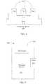
- FIG. 1is a schematic diagram of a protective device, according to an embodiment.
- the protective device 100can be, for example a helmet, such as a football helmet, a batting helmet, a hockey helmet, etc.
- the protective device 100can be operable to mitigate impacts, for example by absorbing forces and/or accelerations associated with an impact.
- the protective device 100can, for example, be operable to mitigate head and/or brain injuries, such as concussions, by absorbing impact forces and/or reducing impact-related acceleration.
- the protective device 100can be operable to sustain and mitigate the risk of injury from repeated impacts, such as impacts that might occur during a contact sport, for example, resulting from collisions with other players or the ground.
- the protective device 100can include a shell 110 , a suspension chassis 115 , and one or more pads 120 .
- the shell 110can be a rigid structure operable to spread the force associated with an impact over a larger area.
- the shell 110can be operable to spread the impact to pads 120 not immediately adjacent to the impact site.
- the shell 110can be constructed of, for example, polycarbonate or any other suitable material.
- One or more pads 120can be disposed within the shell 110 .
- the pads 120can be configured to be placed between the head of a user and the shell 110 .
- the pads 120can be configured to deform upon receiving a force and/or impact.
- the pads 120can elastically, plastically, visco-elastically, and/or non-linearly deform when the helmet 100 is subject to an impact.
- the pads 120 deformthe force and/or acceleration transmitted through the pads 120 , for example, to the head of the user, can be reduced.
- the pads 120can be rigidly coupled to the shell 110 .
- the pads 120can be moveably coupled, such that the shell 110 , the pads 120 , and/or the user's head can move relative to each other when the protective device 100 sustains an impact.
- the pads 120can be coupled to the shell 110 via a suspension chassis 115 that can be operable to define a range of movement of the pads 120 within the shell 110 The suspension chassis 115 can prevent the pads 120 from falling out of the shell 110 , but can allow the pads 120 to move a limited or predefined distance within the shell 110 for example by stretching and/or flexing.
- the protective device 110when the protective device 110 is subjected to an impact, a portion of the impact energy can be dissipated by the movement of pads 120 relative to the shell 110 .
- the pads 120 and/or the suspension chassis 115can be removeably coupled to the shell 110 .
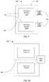
- FIG. 2is a schematic diagram of an impact absorbing pad, according to an embodiment.
- the pad 220can be placed between the shell of a helmet and the head of a user. As shown, the pad 220 includes a structural element 230 , a membrane 240 , and a valve 245 .
- the structural element 230can be an energy absorption material, such as an open-cell foam or a closed-cell foam.
- the structural element 230can be constructed of foamed polyurethane, foamed rubber, expanded polypropylene (EPP), expanded polystyrene (EPS), ethylene vinyl acetate (EVA), memory foam, and/or any other suitable material.
- the structural element 230can be constructed of, for example, Guirit® PVCell® G-Foam, such as G25, G60, G170, or G430; Wm. T. Burnett & Co. foam, such as G430 or FS170; Rubberlite HyPUR-cel T151515; Poron XRD-09500-65; and/or any other suitable foam.
- the structural element 230can be configured to deform elastically, plastically, and/or visco-elastically when subject to a force thereby reducing peak forces and accelerations transmitted through the pad 220 during an impact.
- the structural element 230can be configured to return to its original shape and/or configuration when a force is removed within, for example, less than 90 seconds, less than 30 seconds, less than 5 seconds, less than 1 second, etc.
- the structural element 230can at least partially define the shape of the pad 220 .
- the membrane 240can substantially surround, envelop, and/or encase the structural element 230 .
- the membrane 240can have a size and/or shape similar to the structural element 230 .
- the membrane 240is not coupled to the structural element 230 .
- the membrane 240can be a closed bag containing the structural element 240 .
- the membrane 240can be a flexible film, sheet, and/or cloth.
- the membrane 240can be constructed of polyurethane, polyethelene, nylon, paper, cotton, and/or any other suitable material.
- the membrane 240can have a thickness of less than 2 mm, less than 1 mm, less than 0.5 mm, and/or any other suitable thickness. In some embodiments, the membrane 240 does not have a structural strength or rigidity sufficient to define the shape of the pad 220 . For example, the membrane 240 may not have sufficient structural strength to support its own weight. In such an embodiment, the membrane can conform or substantially conform to the shape of the pad 220 .
- the membrane 240can define an interior volume.
- the structural element 230can be disposed within the interior volume.
- the membrane 240can be operable to prevent and/or impede air contained within the interior volume from exiting.
- the membrane 240can define an air-cushion, such that a force applied to the pad 220 can be transmitted to the air contained within the interior volume.
- the valve 245can allow air to exit the internal volume, for example, when a force is applied to the pad 220 .
- the valve 245can be an opening in the membrane 240 , such as a vent, hole, flap, and/or perforation.
- the valve 245can be a porous portion of the membrane 240 .
- the valve 245can be directional. For example, the valve 245 can apply a greater restriction to air flowing in one direction, such as air exiting the interior volume than air flowing in another direction, such as entering the interior volume.
- the valve 245can be configured to limit the volume and/or rate of air exiting the internal volume. For example, when the pad 220 is subject to a force, air flowing within the membrane 240 can be impeded from exiting through the valve 245 .
- the valve 245can be a small perforation relative to the volume of air contained within the membrane 240 such that a force applied to the pad 220 can produce laminar and/or turbulent flows within the membrane 240 , inhibiting the air from flowing through the valve 245 . In this way, the valve can limit the upper rate at which the force can transmitted from the membrane 240 to the structural element 230 .
- the pad 220can be configured such that the force transmitted through the pad is dependent on the magnitude of the force and/or the duration of the force.
- the pad 220can be configured such that a relatively low-energy impact, a relatively small force, and/or a force gradually applied over a relatively long period of time is absorbed and/or transmitted substantially entirely by the structural element 230 .
- the valve 245can be configured such that when a relatively small force is applied and/or when a force is gradually applied, the air contained in the interior volume can flow through the valve 245 relatively unimpeded as the structural element 230 is compressed.
- the volume and/or shape of the pad 220can change relatively gradually or slowly, and the characteristics of the structural element 230 can substantially govern or define the performance of the pad 220 .
- the valve 245can restrict the flow of air from the interior volume, thus resisting a sudden change in size and/or shape of the pad 220 .
- both the structural element 230 and the air in the interior volumecan resist changing shape and/or size, thereby absorbing energy.
- the pressure of the air within the interior volumecan increase, thereby absorbing energy from the impact.
- aircan escape from the interior volume via the valve 245 , the restricted flow further absorbing energy from the impact.
- the structural element 230can absorb energy through deformation.
- the structural element 230 and resistance of flowcan provide parallel energy absorbing modes. These parallel energy absorbing modes can provide the pad 220 with a non-linear response to impacts.
- the restriction of flow provided by the valve 245can provide greater resistance to rapid changes in shape and/or volume of the pad 220
- the structural element 230can provide greater resistance to changes in shape and/or volume over a longer period of time than the membrane 240 .
- the density, porosity, compressive strength, and/or other material properties of the structural element 230can affect the rate at which the air pressure within the pad 220 changes. For example, if the structural element 230 has relatively large pore size, relatively low density, and/or relatively low compressive strength, the structural element 230 can be deformed relatively easily, thereby displacing air relatively quickly and increasing the pressure within the interior volume upon impact. In embodiments in which the structural element 230 can be relatively easily deformed, and/or during a relatively high-energy impact, the impact mitigation properties of the pad 220 can be largely determined by the flow-restricting characteristics of the valve 245 .
- the structural element 230can displace less air as it deforms, thereby absorbing a larger portion of the energy.
- the structural element 230 , the size of the interior volume defined by the membrane 240 , and the valve 245 , collectively,can be configured to reduce the transmission of forces and/or acceleration across the pad 220 for particular impact characteristics.
- the pad 220in embodiments where the pad 220 is intended to form part of a helmet configured to mitigate the transmission of forces/impacts associated with playing football, the pad 220 can be configured to resist or reduce the transmission of concussion-causing accelerations.
- the force and/or acceleration absorption characteristics of the pad 220can be primarily dependent on the structural element 230 for relatively low forces and/or accelerations, while the force and/or acceleration absorption characteristics for relatively high forces and/or accelerations can be primarily dependent on the exit of air from the inner volume through the valve 245 .
- the pad 220can be configured to resist a particular range of forces and/or accelerations.
- the characteristics and/or configurations of the pad 220can define how forces and/or accelerations are transmitted.
- such characteristicscan include or such configurations can be based on the volume of the interior region, the shape, size, and/or material properties of the structural element 230 , and/or ability of the valve 245 to resist the flow of air.
- the pad 220can be tuned to absorb particular forces and/or accelerations, for example, by decreasing peak acceleration and increasing the duration of the acceleration associated with an impact event.
- the pad 220can be configured to absorb impacts imparting peak accelerations of approximately 50-100 g.
- the membrane 240 and the valve 245can be operable to decrease the transmitted peak acceleration and/or increase the duration of the transmitted acceleration.
- the upper rate at which air flows from the interior volumecan be limited to reduce the maximum rate at which the pad 220 deforms.
- the flow restriction induced by the valve 245can cause the deformation of the pad 220 to be too slow to effectively absorb the energy of the impact.
- type and/or configuration of the padcan be preselected based on its location within a helmet. For example, a pad configured to be disposed on a crown of a helmet can be configured to mitigate higher energy impacts than a pad disposed on a side of the helmet.
- the valve 245may not effectively restrict the flow of air from the pad.
- the rate of air flowcan be too low for the valve 245 to effectively resist changes of volume of the pad 220 .
- Such accelerationsmay be unlikely to cause injury, and thus little need exists for a pad to mitigate such accelerations.
- the structural element 230 of the padcan adequately mitigate low-acceleration impacts.
- FIG. 3is a schematic diagram of an impact absorbing pad, according to an embodiment.
- the pad 320can be placed between the shell of a helmet and the head of a user.
- the pad 320includes structural elements 330 , a membrane 340 , a bisecting membrane 342 (also referred to herein as an interior membrane), and valves 345 .
- the pad 320can be functionally similar to the pad 220 of FIG. 2 .
- Each of the structural elements 330 , the membrane 320 , and the valves 345can be structurally and/or functionally similar to the structural element 230 , the membrane 220 , and the valve 245 , respectively, as shown and described above with reference to FIG. 2 .
- the bisecting membrane 342can divide the pad 330 into two chambers, each containing a structural element 330 and a valve 345 (in other embodiments, for example, as shown in FIG. 3A , a single valve 345 ′ disposed adjacent to, on, or across the bisecting membrane 342 can place both chambers in fluid communication with an exterior of the pad 320 ).
- the bisecting membrane 342can prevent air from flowing from the chamber containing structural element 330 A to the chamber containing structural element 330 B.
- the bisecting membrane 342can be constructed of materials suitable for the construction of the membrane 330 .
- the chambers defined by the membrane 340 and the structural element 330can be symmetric, i.e., they can be substantially the same size and shape, contain similar structural elements 330 and similar valves 345 .
- the chamberscan be asymmetrical.
- the structural element 330 Acan be a different size and/or shape than the structural element 330 B
- the structural element 330 Acan be constructed from a different material than the structural element 330 B
- the valve 345 Acan have different flow restricting properties than the valve 345 B.
- the pad 320can be configured to absorb force and/or acceleration over a greater range of forces and/or accelerations than the pad 220 of FIG. 2 of a similar overall size and/or shape.
- the chamber containing structural element 330 Acan have a larger volume than the chamber containing structural element 330 B and/or valve 345 A can have greater flow restricting properties than the valve 345 B.
- the chamber containing structural element 330 Acan be optimized to absorb higher forces and/or accelerations
- the chamber containing structural element 345 Bcan be optimized to absorb lower forces and/or accelerations
- collectively the two-chamber structurecan absorb impacts over a greater range of forces and/or accelerations.
- the pad 320can be configured to receive a force such that the chamber containing structural element 330 A and the chamber containing structural element 330 B are deformed in series or in parallel. Although shown with one bisecting membrane 342 defining two chambers, in other embodiments any number of membranes can define any number of chambers. Similarly, although shown with a membrane 340 and a bisecting membrane 342 , in other embodiments, the pad 320 can be formed by coupling a first membrane, substantially enclosing a first structural element to a second membrane, substantially enclosing a second structural element.
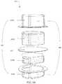
- FIGS. 4A-4J, 5-7, and 8A and 8Bare impact absorbing pads, according to various embodiments.
- the pads 420 , 520 , 620 , 720 , and 820can be structurally and/or functionally similar to the pad 320 as shown and described above with reference to FIG. 3 .
- the pad 420includes two foam discs 430 , a top pad membrane 440 A and a bottom pad membrane 440 B.
- FIGS. 4A and 4Bare exploded views of pad 420 .
- FIG. 4Cis a front isometric view of pad 420 .
- FIG. 4Dis a bottom front isometric view of pad 420
- FIG. 4Eis a bottom view of pad 420 .
- FIG. 4Fis another bottom front isometric view of pad 420 .
- FIG. 4Gis an inverted, rear isometric view of pad 420 .
- FIG. 4His a top view of pad 420 .
- FIG. 4Iis a left side view of pad 420 .
- FIG. 4Jis a front side view of pad 420 .
- the top pad membrane 440 A and the bottom pad membrane 440 Bcan be operable to be coupled together to define a membrane 440 .
- the pad 420can also includes a bisecting membrane 442 and two valves 445 .
- the foam members 430 , the membrane 440 , the bisecting membrane 442 , and the valves 445can be structurally and/or functionally similar to the structural elements 330 , the membrane 340 , the bisecting membrane 342 , and the valves 345 , respectively, described above with reference to FIG. 3 .
- pad 520 , pad 620 , and pad 720shown in FIGS.
- foam discs 530 , 630 , and 730include foam discs 530 , 630 , and 730 , membranes 530 , 640 , and 740 , bisecting membranes 542 , 642 , and 742 , and valves 545 , 645 and 745 , which can be structurally and/or functionally similar to the structural elements 330 , the membrane 340 , the bisecting membrane 342 , and the valves 345 , respectively, described above with reference to FIG. 3 .
- the pads 520 , 620 , and 720are substantially symmetric.
- the upper and lower foam discs 530 , 630 , and 740are approximately the same shape and size.
- each of the upper and lower foam discs 530 , 630 , and 740can be about 2 inches across in diameter and one inch in thickness.
- the pads 520 , 620 and 720about can be about 2 inches across in diameter and two inches in thickness.
- the foam discs 530 , 630 , and 730are constructed of G25 foam.
- the pads 520 , 620 , and/or 720can be asymmetric; for example, the foam disc 530 A can be G60 foam while the foam disc 530 B can be G170 foam.
- foam disk/member size, material, shape, etc.can differ or can be asymmetric.
- valvescan differ or can be asymmetric.
- valves 545 Acan be a different size and/or shape then valves 545 B.
- Pad 420is asymmetric. As shown, the foam member 430 A is larger than the bottom foam member 430 B. Foam member 430 B can be disposed between foam member 430 A and a head of a wearer when a helmet containing pad 420 is worn. The pad 420 can be configured to partially deform when the helmet containing pad 420 is worn. Foam member 430 B can be configured to deform more than foam member 430 A when the helmet containing pad 420 is worn. In some embodiments, foam member 430 A can be undeformed or substantially undeformed when the helmet containing pad 420 is worn. For example, foam member 430 B can be “softer” than foam member 430 A.
- foam member 430 Bcan have a lower elastic modulus, can be configured to exert a lower reaction force when the force is applied (e.g., foam member 430 B can have a greater indentation force deflection), and/or can have a lower density than foam member 430 A.
- foam member 430 Bcan allow the helmet to fit snuggly on the head of the wearer and/or can increase the comfort of the helmet as compared to, for example, a helmet having a single foam member and/or foam members of similar “hardness.” Furthermore, the “softer” foam member 430 B can be configured to mitigate relatively lower energy impacts than the “harder” foam member 430 A. As described above, the combination of two foam members having different impact absorbing characteristics can synergistically mitigate a wider range of impacts than a pad having a single foam member and/or a pad using a single “hardness” foam.
- foam member 430 Bcan be constructed of Wm. T. Burnett & Co. FS170 foam.
- Foam member 430 Bcan have a density approximately 4.0 to 5.0 lbf/ft 3 (or any other suitable density).
- Foam member 430 Bcan have an indentation force deflection for 25% deflection (i.e., the pressure to compress the foam by 25%) of approximately 150 to 180 lbs/50 in 2 (or any other suitable indentation force deflection).
- foam member 430 Acan be constructed of Wm. T. Burnett & Co. G430 foam.
- Foam member 430 Acan have a density approximately 4.0 to 4.8 lbf/ft 3 (or any other suitable density).
- Foam member 430 Acan have a 25% an indentation force deflection for 25% deflection of approximately 225 to 235 lbs/50 in 2 (or any other suitable indention force deflection).
- Pad 820an exploded view of which is shown in FIG. 8A and an isometric view of which is shown in FIG. 8B , includes a top pad membrane 840 A and a bottom pad membrane 840 B.
- the top pad membrane 840 A and the bottom bad membrane 840 Bcan be operable to be coupled to together to define a membrane 840 .
- the pad 820also includes a bisecting membrane 842 .
- the padfurther includes four structural members, 830 A, 830 B, 830 C, and 830 D. In some embodiments, each of the structural members 830 A, 830 B, 830 C, and 830 D is substantially rectangular and has a width of approximately 1.9 inches and a depth of approximately 2.5 inches.
- the first structural member 830 Acan be constructed of Wm.
- the first structural member 830 Acan be the structural member configured to be closest to the head of the wearer when a helmet containing the pad 820 is worn.
- the second structural member 830 Bcan be constructed of XRD-1550035 having a thickness of approximately 0.125 inches.
- the third structural member 830 Ccan be constructed of XRD-1550035 having a thickness of approximately 0.25 inches.
- the fourth structural member 830 Dcan be constructed of R-Lite T1515 Hypur-cell having a thickness of approximately 0.75 inches.
- the fourth structural member 830 Dcan be configured to be disposed closest to the shell of the helmet containing pad 820 when the helmet is worn.
- the pad 820can be configured to be coupled to a forehead portion of a helmet.
- the pads 420 , 520 , 620 , 720 , and 820are configured to be compressed along the axis of the foam members and/or disks, e.g., axis 690 .
- the upper and lower chambersare configured to be compressed in series.
- the valves 454 , 545 , 645 , and 745are disposed substantially orthogonally to the axis of compression. In other embodiments, a valve can be disposed substantially parallel to the axis of compression.
- the valves 545are approximately 2.5 by 2.5 mm cruciforms cut through the membrane 540 .
- the valves 545allow air to flow from the interior volumes containing the foam discs 530 when the pad is deformed.
- the valves 645are approximately 1.0 by 1.0 mm cruciforms cut through the membrane 640 .
- the size of the valves 545 and 645affects the rate at which air can flow from the interior of the pads 520 and 620 when deformed.
- the smaller valves 645 of FIG. 5can provide greater resistance to the flow of air than the larger valves 545 of FIG. 4 . In this way, pad 620 can be more effective at absorbing lower accelerations, while pad 520 can be more effective at absorbing higher accelerations.
- Each of the valves 745 of pad 720is an approximately 0.8 mm circular hole in the membrane 740 .
- the circular hole of valve 745can allow the pad 720 to refill more quickly and provide similar acceleration mitigating performance to the valves 545 . By providing faster refill performance, the time between effectively mitigated impacts can be shorter for pad 720 than for pad 520 .
- any other valve geometry and/or sizecan be chosen to mitigate particular impacts.
- the valvescan be, for example 0.5-10 mm cruciforms and/or 0.5-10 mm circular holes.
- each padhas one valve per chamber, any number of valves can be incorporated into a pad as appropriate for the forces and/or accelerations expected during use of that pad.
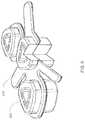
- FIG. 9is an isometric view of pads 920 and a suspension chassis 915 , according to an embodiment.
- FIG. 10is a side cross-sectional view of the suspension chassis 915 and a pad 920 of FIG. 9 coupled to a shell 910 of a helmet 900 .
- the suspension chassis 915can be coupled to several pads 920 .
- the pads 920can be structurally and/or functionally to the pads 420 , 520 , 620 , 720 , and/or 820 as described with respect to FIGS. 4A-8B .
- the suspension chassis 915can be operable to maintain the position of the pads 920 relative to each other, the shell 910 , and/or the head, for example, in a configuration or position to protect a user's head. As shown, the suspension chassis 915 is configured to hold the pads 920 such that one chamber of the pad is configured to contact the head of the user, and the other chamber of the pad is configured to contact the shell of a helmet.
- the suspension chassis 915can be constructed from EVA, nylon, cloth, natural and/or synthetic leather, and/or any other suitable material. In some embodiments, multiple suspension chassis, each containing one or more pads 920 can be coupled to the shell.
- the suspension chassis 915can be coupled to the shell via projections, and/or tabs operable to be received by slots and/or grooves of the helmet. Straps and/or ties can also be coupled to the suspension chassis 915 and used to couple the suspension chassis 915 to the shell 910 .
- the suspension chassis 915can be fixedly and/or removeably coupled to the shell 910 .
- the suspension chassis 915can be coupled to the shell 910 via a connector 912 , such as, for example, snaps, rivets, glue, or any other suitable means such that the suspension chassis 915 cannot move relative to the shell.
- the pads 920can be coupled to the shell 910 only via the suspension chassis 915 .
- the suspension chassis 915can be operable to flex, bend, stretch and/or otherwise enable the pads 910 to move a limited distance relative to the shell 910 .
- the suspension chassis 915is coupled to a middle portion of the pads 920 (and not in direct contact with the top surface or bottom surface of the pads 920 ) such that the end (or top surface) of the pads 920 that are in contact with the shell 910 are not directly coupled to the shell 910 . In this way, the end (or top) surface of the pads 920 contacting the shell 910 can move relative to the shell 910 .
- coupling the pads 920 about the middle portioncan reduce or eliminate the potential tendency of the pads 920 to buckle or bend over when a force is applied (which may result in a side or side surface of a pad 920 contacting the head of the user rather than the bottom surface).
- the suspension chassis 915can be moveably coupled to the shell 910 .
- the suspension chassis 915can be placed within the shell 910 such that the suspension chassis 915 maintains the same general position by a friction fit between the suspension chassis 915 and/or the pads 920 and the shell 910 .
- the suspension chassis 915can be operable to move relative to the shell 910 , for example, when the helmet 900 receives an impact. Such relative movement, can reduce rotational acceleration of the user's head and thereby reduce the risk of injury.
- the suspension chassis 915can be removeably coupled to the shell 910 .
- the suspension chassis 915can be configured to locate the pads 920 adjacent to the user's head. For example, when the helmet 900 is placed on the user's head, the pads 920 can be snug against both the user's head and the shell 910 (e.g., the pads 920 can experience a small amount of deformation). In this way, the pads 920 can form a friction fit between the user's head and the shell 910 . Thus, the helmet 900 can be oriented and/or maintain its location on the user's head during use.
- the pad 920has a top foam disk 930 A and a bottom foam disk 930 B.
- the top foam disk 930 Ahas a height that is shorter than a height of the bottom foam disk 930 B.
- the top foam disk 930 Acan be configured to be in contact the user's head.
- the top foam disk 930 Acan be less dense and/or have a lower resistance to compression than the bottom foam disk 930 B.
- a valve disposed on the top of the pad 920can be larger than a valve disposed on the bottom of the pad, as described with reference to FIGS. 4-8 .
- the top of the pad 920can be more easily compressed than the bottom of the pad 920 , which can increase the comfort of the user, for example, when the helmet 900 is placed on the user's head.
- the suspension chassis 915can be configured to position the pads 920 such that the shell 910 can distribute an impact to one or more pads 920 .
- the suspension chassis 915can be configured to space the pads 920 such that impacts from various angles can be mitigated or absorbed. In some embodiments, impacts from multiple angles occurring simultaneously and/or in close temporal proximity can be absorbed.
- the helmet 900can be operable to absorb the forces and accelerations transmitted to a user wearing the helmet 900 , playing football, and/or colliding with more than one player at the same and/or different angles. Similarly, if the user collides with the ground shortly after experiencing such collisions, the associated impact can be absorbed by a different pad 920 and/or the pads 920 that absorbed the previous impacts can have returned to their original configurations.
- FIGS. 11 and 12are views of helmets 1100 , 1210 , respectively.
- Helmet 1100includes a shell 1110 and pads 1120 .
- Helmet 1210includes a shell 1210 and pads 1220 .
- the shells 1110 , 1210 and pads 1120 , 1220can be structurally and/or functionally similar to any of the shells or pads discussed herein.
- Helmets 1100 and 1200also include forehead pads 1180 , 1280 , respectively.
- the forehead pads 1180 , 1280are each constructed of two structural members.
- a first structural member of the forehead pad 1180 and/or 1280 configured to be disposed adjacent to the shell 1110 , 1210can be constructed of Rubberlite HyPur-cel T1515.
- a second structural member of the forehead pad 1180 and/or 1280 configured to be disposed adjacent to the head of the wearercan be constructed of Poron XRD-09500-65.
- the forehead pads 1180 , 1280can include a membrane, a bisecting membrane and/or a valve similar to any of the membranes, bisecting membranes, and/or valves discussed herein.
- a membranea bisecting membrane and/or a valve similar to any of the membranes, bisecting membranes, and/or valves discussed herein.
- three pads 820shown and described above with reference to FIGS. 8A and 8B , and a pad 420 can be disposed adjacent to and/or contacting a forehead of a wearer when a helmet 1100 , 1200 , is worn.
- the forehead pad 1180 , 1120 shown in FIGS. 11 and 12can be replaced by previously described pads 820 and/or 420 .
- the shells 1110 , 1210can be configured to disposed about a portion of a user's head.
- the shells 1110 , 1210can be partially spherical and operable to sustain impacts from several directions.
- the shells 1110 , 1210can be substantially rigid and configured to experience relatively little deformation and/or deflection upon receiving an impact.
- the shells 1110 , 1210can, in some embodiments, be configured to sustain multiple impacts without substantially deforming, cracking, and/or otherwise sustaining damage.
- the shells 1110 , 1210can be, for example, the polycarbonate shell of a football helmet, or any other suitable outer shell for head protection.
- the shells 1110 , 1210can be operable to distribute an impact to one or more of the pads 1120 , 1220 .
- the shell 1110can receive an impact in an area not immediately adjacent to a pad 1120 . Because the shell 1110 can be configured to experience little deformation, the shell 1120 can spread the forces and/or accelerations associated with the impact to nearby pads 1120 .
- the helmets 1100 , 1200can be configured to mitigate or absorb multiple impacts from multiple angles. Because the shells 1110 , 1210 can be configured to substantially enclose a user's head, and the pads 1120 , 1220 can be distributed around the user's head, the helmets 1100 , 1200 can be configured to receive and absorb impacts to, for example, the top of a user's head, the sides of a user's head, the back of a user's head, and so forth.
- the helmets 1100 , 1200can be configured to mitigate an impact to one side of the helmet (such as the front or top) followed, in relatively rapid succession (e.g., within 0.5 seconds, within 1 second, within 2 seconds, within 30 seconds, etc.) by a second impact to another side of the helmet (such as the back or side).
- the helmets 1100 , 1200can be suitable to absorb an impact associated with a tackle followed by an impact associated with the user and the helmet hitting the ground.
- the helmets 1100 , 1200can be configured to mitigate multiple impacts from multiple directions occurring in relatively rapid succession, for example, through different pads 1120 , 1220 .
- the same pads 1120 , 1220 that mitigate a first impactcan recover in a relatively short amount of time to mitigate a second impact.
- pads 1120 , 1220 with different impact absorbing characteristicscan be placed in different locations in the helmets 1100 , 1200 .
- the severity of an impactcan be statistically correlated with location for a given application of the helmet 1100 , 1200 (e.g. for a particular sport or activity)
- pads operable to absorb higher energy impactscan be disposed in those regions.
- pads 1120 , 1220 operable to absorb higher energy impactscan be positioned such that they are disposed adjacent to the crown of the user's head.
- the crown of the helmetmay be at risk for receiving relatively higher energy impacts than, for example, the side of the helmet.
- Different activities or sportsmay be associated with different patterns of impact. For example, in hockey, it may be determined that the back of the helmet is prone to relatively high-energy impacts, while in cycling, it may be determined that high-energy impacts to the back of the helmet are improbable. In this way, the location of pads configured to mitigate high-energy impacts and the location of pads configured to mitigate low-energy impacts can be optimized.
- a hockey helmetcan be constructed having relatively “hard” pads in the back of the helmet and relatively “soft” pads on the crown, while a cycling helmet can be constructed having relatively “hard” pads on the crown and/or sides and relatively “soft” pads in the back.
- a first pad associated with (e.g., disposed adjacent to, coupled to, and/or configured to mitigate impacts to) a first portion of the shell 1110 , 1210 , such as the crown, but not associated with (e.g., disposed adjacent to, coupled to, and/or configured to mitigate impacts to) a second portion of the shell 1110 , 1210 , such as the side,can be preselected to mitigate higher energy impacts than a second pad associated with the second portion of the shell but not the first portion of the shell.
- the first padcan absorb a greater amount of energy associated with a relatively high-energy impact (e.g., an impact associated with a relatively high force) than the second pad.
- a pad 1120 , 1220 disposed adjacent the crown of the user's headcan include a first structural member constructed of Rubber-lite hypur-cell T1515 and a second structural member constructed of FS 170, while the pads disposed adjacent the side of the head (such as near the jaw) can include two structural members each constructed of G430.
- the structural members of the pads disposed adjacent the side of the headcan have similar or different thicknesses.
- the wearer's headcan experience a smaller acceleration when the first portion (e.g., the crown) of the shell receives a relatively high-energy impact as compared to when the second portion (e.g. the side) of the shell receives the relatively high-intensity impact.
- the second padcan absorb a greater amount of energy associated with a relatively low-energy impact (e.g., an impact associated with a relatively low force) than the first pad.
- the wearer's headcan experience a smaller acceleration when the second portion of the shell receives a relatively low-energy impact as compared to when the first portion of the shell receives the relatively low-energy impact.
- Thiscan be beneficial if, for example, relatively high-energy impacts are probable for the first portion (e.g., the crown) of the shell, but relatively improbable for the second portion (e.g., the side).
- the helmets 1100 , 1200can also be configured to absorb the effects of multiple impacts occurring in relatively rapid succession.
- the pads 1120 , 1220can be configured to return to their original configuration in a relatively short period of time. Because the pads 1120 , 1220 can return to their original configuration, and because the shell 1110 , 1210 can be resilient, the helmet 1100 , 1200 can absorb multiple impacts to the same area.
- the pads 1120 , 1220can be configured to return to their original configuration in an amount of time shorter than the amount of time expected to elapse between impacts.
- the pads 1120 , 1220can return to their original configuration in less time than is expected to elapse between colliding with an athlete and striking the ground.
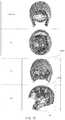
- FIGS. 14 and 15depict an arraignment of pads relative to a helmet shell and a wearer's head. As shown in FIGS. 14 and 15 , a total of 23 triangular pads and one forehead pad 1480 are disposed within an interior of a helmet shell 1410 . FIG. 14 depicts the pads in relationship to a head of a wearer. FIG. 14 includes an isometric view of a head and a helmet with a partially transparent shell 1410 , as well as a forehead view, a top view, a rear view, and a side view of a head including the location of the pads (without the shell 1410 shown for purposes of clarity). FIG.
- the triangular padscan be coupled to the helmet shell 1410 via one or more suspension chassis, such as the suspension chassis described in further detail herein with reference to FIGS. 16-19 .
- a crown pad 1520can be “harder” than other triangular pads disposed within the helmet.
- jaw pads 1420can be “softer” than other triangular pads disposed within the helmet.
- the forehead pad 1480can be similar to the forehead pad 1280 as shown and described above with reference to FIG. 12 .
- FIGS. 16-19are isometric views of suspension chassis, according to various embodiments.
- the chassis 1615can hold two pads, the chassis 1715 and 1815 can hold three pads, and the chassis 1915 can hold five pads.
- a chassiscan hold any number of pads.
- multiple chassis, including chassis having different sizes and/or configurationscan be disposed within a shell of a helmet. Chassis having different configurations can be used, for example, in different areas of a helmet so that pads can be a disposed in different patterns. For example, one chassis can be configured to position pads relatively close together, while another chassis can be configured to space pads more widely.
- the selection of different chassiscan allow the relative density of pads to be adjusted, for example, a chassis can be selected to space pads differently in different portions of the helmet, or interchangeable chassis can be used to select the number of pads for a particular activity.
- the chassis 1615 , 1715 , 1815 , and/or 1915can structurally and/or functionally similar to the chassis 915 , as shown and described above.
- the suspension chassis 1615 , 1715 , 1815 , and/or 1915can be coupled to a shell of a helmet via a connector, such as, for example, snaps, rivets, glue, or any other suitable means such that the suspension chassis 1615 , 1715 , 1815 , and/or 1915 cannot move relative to the shell.
- the chassiscan include projections, e.g. the projection 1717 , that can be operable to couple the chassis to a shell of a helmet.
- the projection 1717can be operable to be disposed in a slot or groove of the shell, and/or can include a fastener, such as a snap and/or a hook-and-loop fastener, such that the chassis can be coupled to the shell of the helmet.
- Chassis having different shapescan be operable to be disposed in different areas of the helmet.
- a relatively small chassis, such as chassis 1615can be configured to be disposed near an ear or cheek portion of the helmet
- a relatively large chassise.g., chassis 1915
- the helmets and/or pads described hereincan operate to mitigate impacts via two or more modes operating synergistically.
- a pad including a structural member and a membranecan operate to mitigate an impact via deformation of the structural member as well as via restriction of flow exiting an interior volume defined by the membrane as the pad is deformed.
- a padcan use a “softer” structural member than a pad devoid of a membrane (i.e., exposed foam).
- the use of the “softer” structural membercan more efficiently mitigate relatively low-energy impacts. Performance mitigating relatively high-energy impacts is not sacrificed, as would traditionally be the case using a “soft” structural member, by disposing the structural member within an interior region of membrane.
- the rate of deformation of the padcan be constrained, such that the air pressure within the interior region operates as a second mode of dissipating impact energy.
- the padcan appear “hard” to a relatively high-energy impact and “soft” to a relatively low-energy impact.
- a padcan include multiple structural members.
- the structural memberscan be stacked such that they each contribute to mitigate an impact.
- the structural memberscan be constructed of different materials, such that one structural member is more effective at mitigating relatively higher energy impacts (e.g., it is “harder”) while the other structural member is more effective at mitigating relatively lower energy impacts (e.g., it is “softer”).
- a padcan be operable to mitigate a relatively low-energy impact in a first mode primarily through deformation of the “softer” pad and operable to mitigate a relatively high-energy impact primarily through deformation of the “harder” pad.
- Such a padcan be further include a membrane surrounding the structural members and/or each structural member can be disposed within an interior region of the pad to provide further synergistic impact mitigation capability.
- a helmetcan be constructed with pads having different impact absorbing characteristics associated with (e.g., coupled to, disposed adjacent to, etc.) different portions of the helmet shell.
- padscan be designed for a specific activity or sport based on the type of impacts and impact locations associated with the activity or sport.
- different areas of helmet shellscan have different degrees of structural rigidity, which can alter impact transmission characteristics.
- a relatively “harder” padcan be associated with relatively rigid portions of the helmet shell (such as the crown), while relatively “soft” pads can be associated with relatively flexible portions of the helmet shell since shell flexion can be operable to mitigate a portion of the impact.
- “harder” padscan be disposed adjacent to less structurally rigid portions of a helmet shell if relatively high-energy impacts are probable in that area of the shell.
- a helmet containing pads containing structural members and membranescan be operable to mitigate repeated impacts from a variety of directions.
- the helmets described hereincan be suitable to receive an impact from a first direction (and/or to a first area of the helmet) followed in relatively rapid succession by a second impact from a second direction (and/or to a second area of the helmet).
- the padscan be configured to recover within the time between impacts and/or different pads can be configured to mitigate subsequent impacts.
- one structural member of a padcan be configured to mitigate a first impact and a second structural member can be configured to mitigate a second impact occurring in relatively rapid succession.
- a padconfigured to be placed in a football helmet
- the padis a hockey helmet, a cycling helmet, a lacrosse helmet, a baseball helmet, and/or any other suitable helmet
- a padcan be placed in any other structure designed to absorb impacts, such as automotive bumpers, shipping materials, or other athletic equipment, such as shoulder pads or chest protectors.
- such a padcan be incorporated into a barrier, such as athletic boundaries, e.g., hockey boards and/or goal posts.
- a valvecan be configured to release air from two internal volumes.
- a valvecan be disposed between the chamber containing structural element 530 A and the chamber containing structural element 530 B.
- pads configured to absorb higher energy impactsare described as being placed at the top of the helmet with respect to, for example, FIGS. 14 and 15 , in other embodiments, the same pads can be used at all locations, or pads operable to absorb high and/or low-energy impacts can be placed at any location.
- the terms “force(s),” “acceleration(s),” “energy,” and/or other terms associated with impactsare used to describe magnitudes and/or relative magnitudes of the impacts. As such, such terms should be considered directionless unless the context clearly indicates otherwise. For example, if a first impact is associated with an acceleration of 5 g in a positive direction and a second impact is associated with an acceleration of 20 g in a negative direction, the second impact is associated with a greater acceleration than the first impact.
Landscapes
- Helmets And Other Head Coverings (AREA)
- Health & Medical Sciences (AREA)
- General Health & Medical Sciences (AREA)
- Physical Education & Sports Medicine (AREA)
Abstract
Description
Claims (16)
Priority Applications (2)
| Application Number | Priority Date | Filing Date | Title |
|---|---|---|---|
| US16/056,058US11083237B2 (en) | 2011-10-14 | 2018-08-06 | Impact absorbing apparatus |
| US17/397,401US20220061447A1 (en) | 2013-01-18 | 2021-08-09 | Impact absorbing apparatus |
Applications Claiming Priority (6)
| Application Number | Priority Date | Filing Date | Title |
|---|---|---|---|
| US201161547254P | 2011-10-14 | 2011-10-14 | |
| US201361754254P | 2013-01-18 | 2013-01-18 | |
| PCT/US2014/012257WO2014113767A1 (en) | 2013-01-18 | 2014-01-21 | Impact absorbing apparatus |
| US14/173,548US8863320B2 (en) | 2013-01-18 | 2014-02-05 | Impact absorbing apparatus |
| US14/516,107US10039338B2 (en) | 2013-01-18 | 2014-10-16 | Impact absorbing apparatus |
| US16/056,058US11083237B2 (en) | 2011-10-14 | 2018-08-06 | Impact absorbing apparatus |
Related Parent Applications (1)
| Application Number | Title | Priority Date | Filing Date |
|---|---|---|---|
| US14/516,107ContinuationUS10039338B2 (en) | 2011-10-14 | 2014-10-16 | Impact absorbing apparatus |
Related Child Applications (1)
| Application Number | Title | Priority Date | Filing Date |
|---|---|---|---|
| US17/397,401ContinuationUS20220061447A1 (en) | 2013-01-18 | 2021-08-09 | Impact absorbing apparatus |
Publications (2)
| Publication Number | Publication Date |
|---|---|
| US20190208853A1 US20190208853A1 (en) | 2019-07-11 |
| US11083237B2true US11083237B2 (en) | 2021-08-10 |
Family
ID=51210124
Family Applications (4)
| Application Number | Title | Priority Date | Filing Date |
|---|---|---|---|
| US14/173,548ActiveUS8863320B2 (en) | 2011-10-14 | 2014-02-05 | Impact absorbing apparatus |
| US14/516,107Active2035-05-01US10039338B2 (en) | 2011-10-14 | 2014-10-16 | Impact absorbing apparatus |
| US16/056,058ActiveUS11083237B2 (en) | 2011-10-14 | 2018-08-06 | Impact absorbing apparatus |
| US17/397,401AbandonedUS20220061447A1 (en) | 2013-01-18 | 2021-08-09 | Impact absorbing apparatus |
Family Applications Before (2)
| Application Number | Title | Priority Date | Filing Date |
|---|---|---|---|
| US14/173,548ActiveUS8863320B2 (en) | 2011-10-14 | 2014-02-05 | Impact absorbing apparatus |
| US14/516,107Active2035-05-01US10039338B2 (en) | 2011-10-14 | 2014-10-16 | Impact absorbing apparatus |
Family Applications After (1)
| Application Number | Title | Priority Date | Filing Date |
|---|---|---|---|
| US17/397,401AbandonedUS20220061447A1 (en) | 2013-01-18 | 2021-08-09 | Impact absorbing apparatus |
Country Status (6)
| Country | Link |
|---|---|
| US (4) | US8863320B2 (en) |
| EP (1) | EP2945503A4 (en) |
| CN (2) | CN112515278A (en) |
| BR (1) | BR112015016922B1 (en) |
| CA (1) | CA2936088C (en) |
| WO (1) | WO2014113767A1 (en) |
Cited By (1)
| Publication number | Priority date | Publication date | Assignee | Title |
|---|---|---|---|---|
| US20220061447A1 (en)* | 2013-01-18 | 2022-03-03 | Windpact, Inc. | Impact absorbing apparatus |
Families Citing this family (43)
| Publication number | Priority date | Publication date | Assignee | Title |
|---|---|---|---|---|
| US9516910B2 (en) | 2011-07-01 | 2016-12-13 | Intellectual Property Holdings, Llc | Helmet impact liner system |
| US9763488B2 (en) | 2011-09-09 | 2017-09-19 | Riddell, Inc. | Protective sports helmet |
| US9320311B2 (en)* | 2012-05-02 | 2016-04-26 | Intellectual Property Holdings, Llc | Helmet impact liner system |
| US9894953B2 (en) | 2012-10-04 | 2018-02-20 | Intellectual Property Holdings, Llc | Helmet retention system |
| US10159296B2 (en) | 2013-01-18 | 2018-12-25 | Riddell, Inc. | System and method for custom forming a protective helmet for a customer's head |
| US9770060B2 (en) | 2013-02-12 | 2017-09-26 | Riddell, Inc. | Pad assemblies for a protective sports helmet |
| US10350477B2 (en)* | 2013-10-18 | 2019-07-16 | Composite Technology Concepts, Llc | Sports equipment that employ force-absorbing elements |
| AU2014342635B2 (en) | 2013-10-28 | 2019-07-11 | Team Wendy, Llc | Helmet retention system |
| US10362829B2 (en) | 2013-12-06 | 2019-07-30 | Bell Sports, Inc. | Multi-layer helmet and method for making the same |
| US9468249B2 (en)* | 2014-02-11 | 2016-10-18 | Janice Geraldine Fraser | Protective headgear |
| US10219572B1 (en)* | 2014-03-10 | 2019-03-05 | John E. Whitcomb | Baseball cap having impact protection |
| US10092057B2 (en) | 2014-08-01 | 2018-10-09 | Carter J. Kovarik | Helmet for reducing concussive forces during collision and facilitating rapid facemask removal |
| US11178930B2 (en) | 2014-08-01 | 2021-11-23 | Carter J. Kovarik | Helmet for reducing concussive forces during collision and facilitating rapid facemask removal |
| US10721987B2 (en) | 2014-10-28 | 2020-07-28 | Bell Sports, Inc. | Protective helmet |
| US9943129B2 (en)* | 2015-04-06 | 2018-04-17 | Cascade Maverik Lacrosse, Llc | Protective headgear |
| US9756891B1 (en)* | 2015-06-11 | 2017-09-12 | James Robb McGhie | Apparatus for protecting the head of a person from an external force |
| WO2017008080A1 (en) | 2015-07-09 | 2017-01-12 | Skydex Technologies, Inc. | Pressure distributing aligned arrays of cushioning void cells |
| US10219573B2 (en) | 2016-01-12 | 2019-03-05 | Ronald A. Podboy | Helmet to reduce traumatic brain injuries |
| US10455077B2 (en)* | 2016-03-31 | 2019-10-22 | International Business Machines Corporation | Contextually configuring consistent proximity beacon identifiers |
| WO2018017867A1 (en) | 2016-07-20 | 2018-01-25 | Riddell, Inc. | System and methods for designing and manufacturing a bespoke protective sports helmet |
| EP3554299B1 (en)* | 2016-12-13 | 2022-06-29 | Mips Ab | Cushion with shear force management |
| US12297884B2 (en)* | 2016-12-30 | 2025-05-13 | James Kelly | Impact absorbing apparatus |
| US10520056B2 (en)* | 2016-12-30 | 2019-12-31 | Klnp, Llc | Impact absorbing apparatus |
| US11425952B2 (en)* | 2017-01-03 | 2022-08-30 | Kimpex Inc. | Helmet with cheek pads and method for the use thereof |
| CA3056429A1 (en)* | 2017-03-17 | 2018-09-20 | VICIS, Inc. | Removable communications module pocket |
| CA3008514A1 (en)* | 2017-06-16 | 2018-12-16 | Sekund Skull Inc. | Protective device for use with helmets |
| US20190174859A1 (en)* | 2017-12-07 | 2019-06-13 | Rawlings Sporting Goods Company, Inc. | Helmet liner |
| US11089826B2 (en)* | 2018-04-06 | 2021-08-17 | Siena Lending Group Llc | Sports shoulder pads with hybrid foam body pad |
| WO2019237025A1 (en)* | 2018-06-07 | 2019-12-12 | VICIS, Inc. | Impact mitigation fit pods |
| US11946525B2 (en) | 2018-06-18 | 2024-04-02 | Hexnest Inc. | Impact absorbing devices and processes of operation of the impact absorbing devices |
| WO2020037279A1 (en) | 2018-08-16 | 2020-02-20 | Riddell, Inc. | System and method for designing and manufacturing a protective helmet |
| CA3018929A1 (en)* | 2018-09-27 | 2020-03-27 | Chacha Y. Fouanta | Airbag pad for clothing and equipment system and method |
| CA3169309A1 (en) | 2018-11-21 | 2020-05-28 | Riddell, Inc. | Protective recreational sports helmet with components additively manufactured to manage impact forces |
| USD927084S1 (en) | 2018-11-22 | 2021-08-03 | Riddell, Inc. | Pad member of an internal padding assembly of a protective sports helmet |
| USD927073S1 (en) | 2019-04-16 | 2021-08-03 | Safer Sports, LLC | Football helmet |
| USD935106S1 (en) | 2019-11-22 | 2021-11-02 | Safer Sports, LLC | Helmet |
| US20210153592A1 (en) | 2019-11-22 | 2021-05-27 | Safer Sports, LLC DBA Light Helmets | Soft shell helmet |
| US11341831B2 (en) | 2020-01-22 | 2022-05-24 | James Kelly | Device and system for ultrasonic transmission of accelerometer data |
| USD965915S1 (en)* | 2020-05-01 | 2022-10-04 | 4D Tactical | Padding suspension system for a combat/tactical helmet |
| CA3177316A1 (en) | 2020-05-12 | 2021-11-18 | Joseph R. WORPLE | Hard hat with impact protection material |
| US11965573B2 (en) | 2020-08-10 | 2024-04-23 | Accelerated Research LLC | Device for attenuating energy |
| WO2022204545A1 (en)* | 2021-03-26 | 2022-09-29 | INO Armor LLC | Silk pillow impact protection device |
| WO2022266148A1 (en)* | 2021-06-14 | 2022-12-22 | Savior Brain Inc. | Devices, systems, and methods for shock absorption |
Citations (81)
| Publication number | Priority date | Publication date | Assignee | Title |
|---|---|---|---|---|
| US1348950A (en) | 1919-12-22 | 1920-08-10 | Kaminski Andzei | Aviator's helmet |
| US3248738A (en) | 1963-05-28 | 1966-05-03 | John T Riddell Inc | Protective padding structures |
| US3600714A (en) | 1969-03-19 | 1971-08-24 | Hop N Gator Inc | Hydraulic helmet |
| US3713640A (en) | 1970-07-27 | 1973-01-30 | Riddell | Energy absorbing and sizing means for helmets |
| US3849801A (en) | 1972-12-20 | 1974-11-26 | Medalist Ind Inc | Protective gear with hydraulic liner |
| US3882547A (en)* | 1973-10-09 | 1975-05-13 | Riddell | Padding structure |
| US3994021A (en) | 1975-06-05 | 1976-11-30 | The Kendall Company | Protective helmet |
| US4086664A (en) | 1976-08-26 | 1978-05-02 | Schutt Manufacturing Company | Football face guard |
| USD249397S (en) | 1976-09-30 | 1978-09-19 | Schutt Manufacturing Company | Face guard for mounting on an athletic helmet |
| US4287613A (en) | 1979-07-09 | 1981-09-08 | Riddell, Inc. | Headgear with energy absorbing and sizing means |
| US4354284A (en) | 1981-01-28 | 1982-10-19 | The Regents Of The University Of Michigan | Protective liner for outdoor headgear |
| US4566137A (en) | 1984-01-20 | 1986-01-28 | Gooding Elwyn R | Inflatable baffled liner for protective headgear and other protective equipment |
| US4627114A (en) | 1984-08-23 | 1986-12-09 | Figgie International, Inc. | Shock attenuation structure |
| US4633531A (en) | 1985-05-03 | 1987-01-06 | Schutt Manufacturing Co., Inc. | Tension mounting for face guard |
| US4646368A (en) | 1986-07-18 | 1987-03-03 | Riddell, Inc. | Adjustable chin strap assembly for athletic helmets |
| USD289569S (en) | 1984-09-19 | 1987-04-28 | Schutt Manufacturing Company | Faceguard for a batter's helmet |
| USD289568S (en) | 1984-09-19 | 1987-04-28 | Schutt Manufacturing Company | Faceguard for a helmet |
| US4831668A (en) | 1988-06-23 | 1989-05-23 | Riddell, Inc. | Padding structure for use in protective headgear |
| US4991230A (en)* | 1989-08-25 | 1991-02-12 | Vacanti Eugene J | Shock absorbing body protective pads |
| US5035009A (en) | 1990-09-27 | 1991-07-30 | Riddell, Inc. | Protective helmet and liner |
| US5168576A (en)* | 1990-10-03 | 1992-12-08 | Krent Edward D | Body protective device |
| US5175889A (en) | 1990-08-29 | 1993-01-05 | Riddell, Inc. | Inflatable liner for protective headgear |
| US5263203A (en) | 1991-10-07 | 1993-11-23 | Riddell, Inc. | Integrated pump mechanism and inflatable liner for protective |
| US5404590A (en) | 1993-10-01 | 1995-04-11 | Riddell, Inc. | Football helmet motion restrictor |
| USD358686S (en) | 1993-04-19 | 1995-05-23 | Riddell, Inc. | Faceguard for a batter's helmet |
| US5713082A (en) | 1996-03-13 | 1998-02-03 | A.V.E. | Sports helmet |
| US5794274A (en) | 1997-04-24 | 1998-08-18 | Riddell, Inc. | Chin protector for helmets |
| US6081932A (en) | 1997-04-24 | 2000-07-04 | Riddell, Inc. | Chin strap assembly for use with an athletic helmet |
| US6093468A (en) | 1997-03-14 | 2000-07-25 | The Procter & Gamble Company | Flexible lightweight protective pad with energy absorbing inserts |
| US6240571B1 (en) | 1999-11-09 | 2001-06-05 | Riddell, Inc. | Protective helmet with adjustable sizes |
| US6282724B1 (en) | 2001-02-21 | 2001-09-04 | Carl Joel Abraham | Apparatus for enhancing absorption and dissipation of impact forces for all helmets and protective equipment |
| US6314586B1 (en) | 2000-10-24 | 2001-11-13 | John R. Duguid | Supplemental protective pad for a sports helmet |
| USD465067S1 (en) | 2002-02-11 | 2002-10-29 | Riddell, Inc. | Football helmet |
| USD475486S1 (en) | 2002-07-18 | 2003-06-03 | Riddell, Inc. | Inflatable crown liner for a protective helmet |
| USD492818S1 (en) | 2002-10-15 | 2004-07-06 | Riddell, Inc. | Jaw pad for a protective helmet |
| US20040226077A1 (en) | 2003-05-14 | 2004-11-18 | Toth Gregory T. | Systems and methods for providing a headgear cooling liner |
| US6826509B2 (en) | 2000-10-11 | 2004-11-30 | Riddell, Inc. | System and method for measuring the linear and rotational acceleration of a body part |
| US6871525B2 (en) | 2002-06-14 | 2005-03-29 | Riddell, Inc. | Method and apparatus for testing football helmets |
| US6934971B2 (en) | 2002-05-01 | 2005-08-30 | Riddell, Inc. | Football helmet |
| USD511026S1 (en) | 2004-04-29 | 2005-10-25 | Riddell, Inc. | Sport helmet |
| US20060059605A1 (en) | 2004-09-22 | 2006-03-23 | Xenith Athletics, Inc. | Layered construction of protective headgear with one or more compressible layers of thermoplastic elastomer material |
| US20060059606A1 (en) | 2004-09-22 | 2006-03-23 | Xenith Athletics, Inc. | Multilayer air-cushion shell with energy-absorbing layer for use in the construction of protective headgear |
| USD521191S1 (en) | 2004-04-07 | 2006-05-16 | Crescendo As | Helmet liner |
| US7089602B2 (en) | 2003-06-30 | 2006-08-15 | Srikrishna Talluri | Multi-layered, impact absorbing, modular helmet |
| USD528705S1 (en) | 2003-05-01 | 2006-09-19 | Riddell, Inc. | Football helmet |
| US7234771B2 (en) | 2003-10-23 | 2007-06-26 | Britax Child Safety, Inc. | Child safety seat with adjustable head restraint |
| US20070190293A1 (en) | 2006-02-16 | 2007-08-16 | Xenith, Inc. | Protective Structure and Method of Making Same |
| USD570055S1 (en) | 2007-09-20 | 2008-05-27 | Xenith, Llc | Protective helmet liner |
| US20080256686A1 (en) | 2005-02-16 | 2008-10-23 | Xenith, Llc. | Air Venting, Impact-Absorbing Compressible Members |
| USD581599S1 (en) | 2008-02-11 | 2008-11-25 | Xenith, Llc | Protective helmet shell |
| USD582607S1 (en) | 2007-09-20 | 2008-12-09 | Xenith, Llc | Protective helmet |
| USD584456S1 (en) | 2008-02-05 | 2009-01-06 | Xenith, Llc | Helmet liner cell |
| US20090038055A1 (en) | 2007-08-06 | 2009-02-12 | Ferrara Vincent R | Headgear securement system |
| US7526389B2 (en) | 2000-10-11 | 2009-04-28 | Riddell, Inc. | Power management of a system for measuring the acceleration of a body part |
| US7547079B2 (en) | 2003-12-04 | 2009-06-16 | Xenith Track Co., Ltd. | Elastic crawler |
| US20090179469A1 (en) | 2008-01-14 | 2009-07-16 | Eric Bass | Head and Body Protection System for a Child Safety Seat |
| US20090224580A1 (en) | 2008-03-05 | 2009-09-10 | Cosco Management, Inc. | Juvenile motion-inhibitor system |
| US20090233511A1 (en)* | 2008-03-14 | 2009-09-17 | Nike, Inc. | Pad Elements For Apparel And Other Products |
| USD603099S1 (en) | 2008-10-08 | 2009-10-27 | Riddell, Inc, | Sports helmet |
| USD603100S1 (en) | 2008-10-08 | 2009-10-27 | Riddell, Inc, | Sports helmet |
| USD603103S1 (en) | 2008-10-17 | 2009-10-27 | Xenith, Llc | Protective helmet compression member |
| US20090289026A1 (en) | 2008-05-21 | 2009-11-26 | Ferrara Vincent R | Intake tracking hydration container |
| USD608688S1 (en) | 2009-03-03 | 2010-01-26 | Xenith, Llc | Snap buckle |
| US20100026064A1 (en) | 2008-07-30 | 2010-02-04 | Cosco Management, Inc. | Energy-dissipation system |
| US20100026059A1 (en) | 2008-07-30 | 2010-02-04 | Cosco Management, Inc. | Energy-dissipation system |
| US20100186150A1 (en) | 2009-01-28 | 2010-07-29 | Xenith, Llc | Protective headgear compression member |
| US7774866B2 (en) | 2006-02-16 | 2010-08-17 | Xenith, Llc | Impact energy management method and system |
| US20100282554A1 (en) | 2009-05-11 | 2010-11-11 | Stone Thomas D | Multi-chamber impact absorption system to protect individual |
| US20100295342A1 (en) | 2009-05-20 | 2010-11-25 | Cosco Management, Inc. | Energy-dissipation system |
| US20100295344A1 (en) | 2009-05-20 | 2010-11-25 | Cosco Management, Inc. | Energy-dissipation system |
| US20100295347A1 (en) | 2009-05-20 | 2010-11-25 | Cosco Management, Inc. | Energy-dissipation system |
| US20100295343A1 (en) | 2009-05-20 | 2010-11-25 | Cosco Management, Inc. | Energy-dissipation system |
| US20100295270A1 (en) | 2009-05-20 | 2010-11-25 | Cosco Management, Inc. | Energy-dissipation system |
| US20100295341A1 (en) | 2009-05-20 | 2010-11-25 | Cosco Management, Inc. | Energy-dissipation system |
| US20100295346A1 (en) | 2009-05-20 | 2010-11-25 | Cosco Management, Inc. | Energy-dissipation system |
| US20100295345A1 (en) | 2009-05-20 | 2010-11-25 | Cosco Management, Inc. | Energy-dissipation system |
| US20110047685A1 (en) | 2006-02-16 | 2011-03-03 | Ferrara Vincent R | Impact energy management method and system |
| US7900279B2 (en) | 2006-09-08 | 2011-03-08 | Riddell, Inc. | Sports helmet with clamp for securing a chin protector |
| US20110171420A1 (en) | 2010-01-11 | 2011-07-14 | Shih-Sheng Yang | Air cushion pad |
| US8336122B1 (en) | 2010-09-16 | 2012-12-25 | Harris Kerry S | Method of manufacturing a cranial shock absorption system |
| US20140201890A1 (en) | 2013-01-18 | 2014-07-24 | Windpact, Inc. | Impact absorbing apparatus |
Family Cites Families (3)
| Publication number | Priority date | Publication date | Assignee | Title |
|---|---|---|---|---|
| US5235715A (en)* | 1987-09-21 | 1993-08-17 | Donzis Byron A | Impact asborbing composites and their production |
| US5918383A (en)* | 1995-10-16 | 1999-07-06 | Fila U.S.A., Inc. | Sports shoe having an elastic insert |
| US20090265841A1 (en) | 2008-04-28 | 2009-10-29 | Ferrara Vincent R | Chinstrap assembly |
- 2014
- 2014-01-21BRBR112015016922-8Apatent/BR112015016922B1/ennot_activeIP Right Cessation
- 2014-01-21CACA2936088Apatent/CA2936088C/enactiveActive
- 2014-01-21WOPCT/US2014/012257patent/WO2014113767A1/enactiveApplication Filing
- 2014-01-21CNCN202011154870.6Apatent/CN112515278A/enactivePending
- 2014-01-21EPEP14740156.6Apatent/EP2945503A4/ennot_activeWithdrawn
- 2014-01-21CNCN201480016436.8Apatent/CN105050439B/enactiveActive
- 2014-02-05USUS14/173,548patent/US8863320B2/enactiveActive
- 2014-10-16USUS14/516,107patent/US10039338B2/enactiveActive
- 2018
- 2018-08-06USUS16/056,058patent/US11083237B2/enactiveActive
- 2021
- 2021-08-09USUS17/397,401patent/US20220061447A1/ennot_activeAbandoned
Patent Citations (103)
| Publication number | Priority date | Publication date | Assignee | Title |
|---|---|---|---|---|
| US1348950A (en) | 1919-12-22 | 1920-08-10 | Kaminski Andzei | Aviator's helmet |
| US3248738A (en) | 1963-05-28 | 1966-05-03 | John T Riddell Inc | Protective padding structures |
| US3600714A (en) | 1969-03-19 | 1971-08-24 | Hop N Gator Inc | Hydraulic helmet |
| US3713640A (en) | 1970-07-27 | 1973-01-30 | Riddell | Energy absorbing and sizing means for helmets |
| US3849801A (en) | 1972-12-20 | 1974-11-26 | Medalist Ind Inc | Protective gear with hydraulic liner |
| US3882547A (en)* | 1973-10-09 | 1975-05-13 | Riddell | Padding structure |
| US3994021A (en) | 1975-06-05 | 1976-11-30 | The Kendall Company | Protective helmet |
| US4086664A (en) | 1976-08-26 | 1978-05-02 | Schutt Manufacturing Company | Football face guard |
| USD249397S (en) | 1976-09-30 | 1978-09-19 | Schutt Manufacturing Company | Face guard for mounting on an athletic helmet |
| US4287613A (en) | 1979-07-09 | 1981-09-08 | Riddell, Inc. | Headgear with energy absorbing and sizing means |
| US4354284A (en) | 1981-01-28 | 1982-10-19 | The Regents Of The University Of Michigan | Protective liner for outdoor headgear |
| US4566137A (en) | 1984-01-20 | 1986-01-28 | Gooding Elwyn R | Inflatable baffled liner for protective headgear and other protective equipment |
| US4627114A (en) | 1984-08-23 | 1986-12-09 | Figgie International, Inc. | Shock attenuation structure |
| USD289569S (en) | 1984-09-19 | 1987-04-28 | Schutt Manufacturing Company | Faceguard for a batter's helmet |
| USD289568S (en) | 1984-09-19 | 1987-04-28 | Schutt Manufacturing Company | Faceguard for a helmet |
| US4633531A (en) | 1985-05-03 | 1987-01-06 | Schutt Manufacturing Co., Inc. | Tension mounting for face guard |
| US4646368A (en) | 1986-07-18 | 1987-03-03 | Riddell, Inc. | Adjustable chin strap assembly for athletic helmets |
| US4831668A (en) | 1988-06-23 | 1989-05-23 | Riddell, Inc. | Padding structure for use in protective headgear |
| US4991230A (en)* | 1989-08-25 | 1991-02-12 | Vacanti Eugene J | Shock absorbing body protective pads |
| US5175889A (en) | 1990-08-29 | 1993-01-05 | Riddell, Inc. | Inflatable liner for protective headgear |
| US5035009A (en) | 1990-09-27 | 1991-07-30 | Riddell, Inc. | Protective helmet and liner |
| US5168576A (en)* | 1990-10-03 | 1992-12-08 | Krent Edward D | Body protective device |
| US5263203A (en) | 1991-10-07 | 1993-11-23 | Riddell, Inc. | Integrated pump mechanism and inflatable liner for protective |
| USD358686S (en) | 1993-04-19 | 1995-05-23 | Riddell, Inc. | Faceguard for a batter's helmet |
| US5404590A (en) | 1993-10-01 | 1995-04-11 | Riddell, Inc. | Football helmet motion restrictor |
| US5713082A (en) | 1996-03-13 | 1998-02-03 | A.V.E. | Sports helmet |
| US6093468A (en) | 1997-03-14 | 2000-07-25 | The Procter & Gamble Company | Flexible lightweight protective pad with energy absorbing inserts |
| US5794274A (en) | 1997-04-24 | 1998-08-18 | Riddell, Inc. | Chin protector for helmets |
| US6081932A (en) | 1997-04-24 | 2000-07-04 | Riddell, Inc. | Chin strap assembly for use with an athletic helmet |
| US6240571B1 (en) | 1999-11-09 | 2001-06-05 | Riddell, Inc. | Protective helmet with adjustable sizes |
| US6826509B2 (en) | 2000-10-11 | 2004-11-30 | Riddell, Inc. | System and method for measuring the linear and rotational acceleration of a body part |
| US7526389B2 (en) | 2000-10-11 | 2009-04-28 | Riddell, Inc. | Power management of a system for measuring the acceleration of a body part |
| US20050177335A1 (en) | 2000-10-11 | 2005-08-11 | Riddell, Inc. | System and method for measuring the linear and rotational acceleration of a body part |
| US6314586B1 (en) | 2000-10-24 | 2001-11-13 | John R. Duguid | Supplemental protective pad for a sports helmet |
| US6282724B1 (en) | 2001-02-21 | 2001-09-04 | Carl Joel Abraham | Apparatus for enhancing absorption and dissipation of impact forces for all helmets and protective equipment |
| USD465067S1 (en) | 2002-02-11 | 2002-10-29 | Riddell, Inc. | Football helmet |
| US7240376B2 (en) | 2002-05-01 | 2007-07-10 | Riddell, Inc. | Sports helmet |
| US7036151B2 (en) | 2002-05-01 | 2006-05-02 | Riddell, Inc. | Face guard for a sports helmet |
| US6934971B2 (en) | 2002-05-01 | 2005-08-30 | Riddell, Inc. | Football helmet |
| US7146652B2 (en) | 2002-05-01 | 2006-12-12 | Riddell, Inc. | Face guard connector assembly for a sports helmet |
| US6871525B2 (en) | 2002-06-14 | 2005-03-29 | Riddell, Inc. | Method and apparatus for testing football helmets |
| USD475486S1 (en) | 2002-07-18 | 2003-06-03 | Riddell, Inc. | Inflatable crown liner for a protective helmet |
| USD492818S1 (en) | 2002-10-15 | 2004-07-06 | Riddell, Inc. | Jaw pad for a protective helmet |
| USD528705S1 (en) | 2003-05-01 | 2006-09-19 | Riddell, Inc. | Football helmet |
| US20040226077A1 (en) | 2003-05-14 | 2004-11-18 | Toth Gregory T. | Systems and methods for providing a headgear cooling liner |
| US7089602B2 (en) | 2003-06-30 | 2006-08-15 | Srikrishna Talluri | Multi-layered, impact absorbing, modular helmet |
| US7234771B2 (en) | 2003-10-23 | 2007-06-26 | Britax Child Safety, Inc. | Child safety seat with adjustable head restraint |
| US7547079B2 (en) | 2003-12-04 | 2009-06-16 | Xenith Track Co., Ltd. | Elastic crawler |
| USD521191S1 (en) | 2004-04-07 | 2006-05-16 | Crescendo As | Helmet liner |
| USD511026S1 (en) | 2004-04-29 | 2005-10-25 | Riddell, Inc. | Sport helmet |
| US20060059606A1 (en) | 2004-09-22 | 2006-03-23 | Xenith Athletics, Inc. | Multilayer air-cushion shell with energy-absorbing layer for use in the construction of protective headgear |
| US20060059605A1 (en) | 2004-09-22 | 2006-03-23 | Xenith Athletics, Inc. | Layered construction of protective headgear with one or more compressible layers of thermoplastic elastomer material |
| US20080155735A1 (en) | 2005-02-16 | 2008-07-03 | Xenith, Llc | Energy-Absorbing Liners and Shape Conforming Layers for Use with Pro-Tective Headgear |
| US20080256686A1 (en) | 2005-02-16 | 2008-10-23 | Xenith, Llc. | Air Venting, Impact-Absorbing Compressible Members |
| US20070190293A1 (en) | 2006-02-16 | 2007-08-16 | Xenith, Inc. | Protective Structure and Method of Making Same |
| US20110047685A1 (en) | 2006-02-16 | 2011-03-03 | Ferrara Vincent R | Impact energy management method and system |
| US8528119B2 (en) | 2006-02-16 | 2013-09-10 | Xenith Llc | Impact energy management method and system |
| US7895681B2 (en) | 2006-02-16 | 2011-03-01 | Xenith, Llc | Protective structure and method of making same |
| US7774866B2 (en) | 2006-02-16 | 2010-08-17 | Xenith, Llc | Impact energy management method and system |
| US7900279B2 (en) | 2006-09-08 | 2011-03-08 | Riddell, Inc. | Sports helmet with clamp for securing a chin protector |
| US20090038055A1 (en) | 2007-08-06 | 2009-02-12 | Ferrara Vincent R | Headgear securement system |
| USD582607S1 (en) | 2007-09-20 | 2008-12-09 | Xenith, Llc | Protective helmet |
| USD570055S1 (en) | 2007-09-20 | 2008-05-27 | Xenith, Llc | Protective helmet liner |
| US20090179469A1 (en) | 2008-01-14 | 2009-07-16 | Eric Bass | Head and Body Protection System for a Child Safety Seat |
| USD584456S1 (en) | 2008-02-05 | 2009-01-06 | Xenith, Llc | Helmet liner cell |
| USD581599S1 (en) | 2008-02-11 | 2008-11-25 | Xenith, Llc | Protective helmet shell |
| US20090224580A1 (en) | 2008-03-05 | 2009-09-10 | Cosco Management, Inc. | Juvenile motion-inhibitor system |
| US8104829B2 (en) | 2008-03-05 | 2012-01-31 | Cosco Management, Inc. | Juvenile motion-inhibitor system |
| US20090233511A1 (en)* | 2008-03-14 | 2009-09-17 | Nike, Inc. | Pad Elements For Apparel And Other Products |
| US20090289026A1 (en) | 2008-05-21 | 2009-11-26 | Ferrara Vincent R | Intake tracking hydration container |
| US20100026059A1 (en) | 2008-07-30 | 2010-02-04 | Cosco Management, Inc. | Energy-dissipation system |
| US7744154B2 (en) | 2008-07-30 | 2010-06-29 | Cosco Management, Inc. | Energy-dissipation system |
| US7850234B2 (en) | 2008-07-30 | 2010-12-14 | Cosco Management, Inc. | Energy-dissipation system |
| US8061768B2 (en) | 2008-07-30 | 2011-11-22 | Cosco Management, Inc. | Energy-dissipation system |
| US20100026064A1 (en) | 2008-07-30 | 2010-02-04 | Cosco Management, Inc. | Energy-dissipation system |
| USD603100S1 (en) | 2008-10-08 | 2009-10-27 | Riddell, Inc, | Sports helmet |
| USD603099S1 (en) | 2008-10-08 | 2009-10-27 | Riddell, Inc, | Sports helmet |
| USD603103S1 (en) | 2008-10-17 | 2009-10-27 | Xenith, Llc | Protective helmet compression member |
| US20100186150A1 (en) | 2009-01-28 | 2010-07-29 | Xenith, Llc | Protective headgear compression member |
| USD608688S1 (en) | 2009-03-03 | 2010-01-26 | Xenith, Llc | Snap buckle |
| US20100282554A1 (en) | 2009-05-11 | 2010-11-11 | Stone Thomas D | Multi-chamber impact absorption system to protect individual |
| US20100295341A1 (en) | 2009-05-20 | 2010-11-25 | Cosco Management, Inc. | Energy-dissipation system |
| US8029054B2 (en) | 2009-05-20 | 2011-10-04 | Cosco Management, Inc. | Energy-dissipation system |
| US20100295346A1 (en) | 2009-05-20 | 2010-11-25 | Cosco Management, Inc. | Energy-dissipation system |
| US20100295270A1 (en) | 2009-05-20 | 2010-11-25 | Cosco Management, Inc. | Energy-dissipation system |
| US20100295343A1 (en) | 2009-05-20 | 2010-11-25 | Cosco Management, Inc. | Energy-dissipation system |
| US7959223B2 (en) | 2009-05-20 | 2011-06-14 | Cosco Management, Inc. | Energy-dissipation system |
| US20100295345A1 (en) | 2009-05-20 | 2010-11-25 | Cosco Management, Inc. | Energy-dissipation system |
| US20100295342A1 (en) | 2009-05-20 | 2010-11-25 | Cosco Management, Inc. | Energy-dissipation system |
| US8038209B2 (en) | 2009-05-20 | 2011-10-18 | Cosco Management, Inc. | Energy-dissipation system |
| US8052210B2 (en) | 2009-05-20 | 2011-11-08 | Cosco Management, Inc. | Energy-dissipation system |
| US8056972B2 (en) | 2009-05-20 | 2011-11-15 | Cosco Management, Inc. | Energy-dissipation system |
| US8056971B2 (en) | 2009-05-20 | 2011-11-15 | Cosco Management, Inc. | Energy-dissipation system |
| US20100295347A1 (en) | 2009-05-20 | 2010-11-25 | Cosco Management, Inc. | Energy-dissipation system |
| US20100295344A1 (en) | 2009-05-20 | 2010-11-25 | Cosco Management, Inc. | Energy-dissipation system |
| US8128165B2 (en) | 2009-05-20 | 2012-03-06 | Cosco Management, Inc. | Energy-dissipation system |
| US20110171420A1 (en) | 2010-01-11 | 2011-07-14 | Shih-Sheng Yang | Air cushion pad |
| US20130142985A1 (en) | 2010-01-11 | 2013-06-06 | Universal Trim Supply Co., Ltd. | Air cushion pad |
| US8336122B1 (en) | 2010-09-16 | 2012-12-25 | Harris Kerry S | Method of manufacturing a cranial shock absorption system |
| US20140201890A1 (en) | 2013-01-18 | 2014-07-24 | Windpact, Inc. | Impact absorbing apparatus |
| US8863320B2 (en)* | 2013-01-18 | 2014-10-21 | Windpact, Inc. | Impact absorbing apparatus |
| US20150033454A1 (en) | 2013-01-18 | 2015-02-05 | Windpact, Inc. | Impact absorbing apparatus |
| US10039338B2 (en)* | 2013-01-18 | 2018-08-07 | Windpact, Inc. | Impact absorbing apparatus |
Non-Patent Citations (14)
| Title |
|---|
| Communication Pursuant to Article 94(3) issued by the European Patent Office for Application No. 14740156.6, dated Sep. 17, 2018, 5 pages. |
| European Search Report issued by the European Patent Office for Application No. 14740156.6, dated Mar. 29, 2017, 14 pages. |
| Final Office Action issued by The United States Patent and Trademark Office for U.S. Appl. No. 14/516,107, dated Sep. 21, 2017, 18 pages. |
| International Search Report and Written Opinion for International Patent Application No. PCT/US2014/012257, dated May 12, 2014. |
| Non-Final Office Action issued by The United States Patent and Trademark Office for U.S. Appl. No. 14/516,107, dated Mar. 15, 2017, 19 pages. |
| Non-Final Office Action issued by The United States Patent and Trademark Office for U.S. Appl. No. 14/516,107, dated Sep. 15, 2016, 14 pages. |
| Notification of First Office Action for Chinese Application No. 201480016436.8, dated Jul. 5, 2017, 17 pages. |
| Notification of Fourth Office Action for Chinese Application No. 201480016436.8, dated Jun. 12, 2019, 15 pages including English translation. |
| Notification of Third Office Action for Chinese Application No. 201480016436.8, dated Nov. 15, 2018, 7 pages including English translation. |
| Office Action for Chinese Application No. 201480016436.8, dated Mar. 4, 2020, 15 pages including English translation. |
| Office Action issued by the Brazilian Patent Office for Application No. BR112015016922-8, dated Jan. 14, 2020, 5 pages including one page Informal English translation. |
| Office Action issued by the Canadian Patent Office for Application No. 2,936,088, dated Jul. 22, 2020, 3 pages. |
| Office Action issued by the Canadian Patent Office for Application No. 2,936,088, dated Nov. 27, 2019, 4 pages. |
| Summons to Attend Oral Hearing issued by the European Patent Office for Application No. 14740156.6, dated Nov. 8, 2019, 5 pages. |
Cited By (1)
| Publication number | Priority date | Publication date | Assignee | Title |
|---|---|---|---|---|
| US20220061447A1 (en)* | 2013-01-18 | 2022-03-03 | Windpact, Inc. | Impact absorbing apparatus |
Also Published As
| Publication number | Publication date |
|---|---|
| BR112015016922A2 (en) | 2017-07-11 |
| CA2936088C (en) | 2022-02-22 |
| US20150033454A1 (en) | 2015-02-05 |
| CA2936088A1 (en) | 2014-07-24 |
| US10039338B2 (en) | 2018-08-07 |
| WO2014113767A1 (en) | 2014-07-24 |
| CN105050439A (en) | 2015-11-11 |
| EP2945503A4 (en) | 2017-04-26 |
| US20140201890A1 (en) | 2014-07-24 |
| EP2945503A1 (en) | 2015-11-25 |
| CN105050439B (en) | 2020-11-17 |
| BR112015016922B1 (en) | 2022-09-13 |
| US8863320B2 (en) | 2014-10-21 |
| US20190208853A1 (en) | 2019-07-11 |
| CN112515278A (en) | 2021-03-19 |
| US20220061447A1 (en) | 2022-03-03 |
Similar Documents
| Publication | Publication Date | Title |
|---|---|---|
| US20220061447A1 (en) | Impact absorbing apparatus | |
| US10583346B2 (en) | Liner assembly for a protective helmet | |
| CN110545686B (en) | Helmet with shear force management | |
| US20200253314A1 (en) | Omnidirectional energy management systems and methods | |
| US9023441B2 (en) | Impact energy attenuation module | |
| US7089602B2 (en) | Multi-layered, impact absorbing, modular helmet | |
| US11471745B2 (en) | Helmet | |
| JP2015151667A (en) | helmet with varying shock absorption | |
| JP2008529747A (en) | Energy absorbing liner and shape matching layer for use in protective headgear | |
| US9220311B1 (en) | External helmet cushioning system | |
| US20250280914A1 (en) | Omnidirectional energy management systems and methods | |
| US20160286886A1 (en) | Helmet | |
| US12302975B1 (en) | Protective headgear | |
| US20110283430A1 (en) | Blunt force protection ball cap technology |
Legal Events
| Date | Code | Title | Description |
|---|---|---|---|
| FEPP | Fee payment procedure | Free format text:ENTITY STATUS SET TO UNDISCOUNTED (ORIGINAL EVENT CODE: BIG.); ENTITY STATUS OF PATENT OWNER: SMALL ENTITY | |
| STPP | Information on status: patent application and granting procedure in general | Free format text:NON FINAL ACTION MAILED | |
| AS | Assignment | Owner name:WINDPACT, INC., VIRGINIA Free format text:ASSIGNMENT OF ASSIGNORS INTEREST;ASSIGNORS:KELLY, MAURICE A.;SPRINGS, SHAWN A.;REEL/FRAME:053123/0168 Effective date:20140624 Owner name:MPR ASSOCIATES, INC., VIRGINIA Free format text:ASSIGNMENT OF ASSIGNORS INTEREST;ASSIGNORS:MARUCCHI, LEON A.;HADLEY, MARCUS A.;CARLTON, ROBERT A.;REEL/FRAME:053123/0191 Effective date:20140624 Owner name:WINDPACT, INC., VIRGINIA Free format text:ASSIGNMENT OF ASSIGNORS INTEREST;ASSIGNOR:MPR ASSOCIATES, INC.;REEL/FRAME:053123/0225 Effective date:20140624 | |
| STPP | Information on status: patent application and granting procedure in general | Free format text:FINAL REJECTION MAILED | |
| FEPP | Fee payment procedure | Free format text:ENTITY STATUS SET TO SMALL (ORIGINAL EVENT CODE: SMAL); ENTITY STATUS OF PATENT OWNER: SMALL ENTITY | |
| STPP | Information on status: patent application and granting procedure in general | Free format text:RESPONSE AFTER FINAL ACTION FORWARDED TO EXAMINER | |
| STPP | Information on status: patent application and granting procedure in general | Free format text:ADVISORY ACTION MAILED | |
| STPP | Information on status: patent application and granting procedure in general | Free format text:RESPONSE AFTER FINAL ACTION FORWARDED TO EXAMINER | |
| STPP | Information on status: patent application and granting procedure in general | Free format text:NOTICE OF ALLOWANCE MAILED -- APPLICATION RECEIVED IN OFFICE OF PUBLICATIONS | |
| STPP | Information on status: patent application and granting procedure in general | Free format text:PUBLICATIONS -- ISSUE FEE PAYMENT VERIFIED | |
| STCF | Information on status: patent grant | Free format text:PATENTED CASE | |
| CC | Certificate of correction | ||
| FEPP | Fee payment procedure | Free format text:MAINTENANCE FEE REMINDER MAILED (ORIGINAL EVENT CODE: REM.); ENTITY STATUS OF PATENT OWNER: SMALL ENTITY | |
| FEPP | Fee payment procedure | Free format text:SURCHARGE FOR LATE PAYMENT, SMALL ENTITY (ORIGINAL EVENT CODE: M2554); ENTITY STATUS OF PATENT OWNER: SMALL ENTITY | |
| MAFP | Maintenance fee payment | Free format text:PAYMENT OF MAINTENANCE FEE, 4TH YR, SMALL ENTITY (ORIGINAL EVENT CODE: M2551); ENTITY STATUS OF PATENT OWNER: SMALL ENTITY Year of fee payment:4 |