US11080848B2 - Image-based disease diagnostics using a mobile device - Google Patents
Image-based disease diagnostics using a mobile deviceDownload PDFInfo
- Publication number
- US11080848B2 US11080848B2US16/155,829US201816155829AUS11080848B2US 11080848 B2US11080848 B2US 11080848B2US 201816155829 AUS201816155829 AUS 201816155829AUS 11080848 B2US11080848 B2US 11080848B2
- Authority
- US
- United States
- Prior art keywords
- optical property
- property modifying
- mobile device
- test
- image
- Prior art date
- Legal status (The legal status is an assumption and is not a legal conclusion. Google has not performed a legal analysis and makes no representation as to the accuracy of the status listed.)
- Active, expires
Links
Images


Classifications
- A—HUMAN NECESSITIES
- A61—MEDICAL OR VETERINARY SCIENCE; HYGIENE
- A61B—DIAGNOSIS; SURGERY; IDENTIFICATION
- A61B5/00—Measuring for diagnostic purposes; Identification of persons
- A61B5/68—Arrangements of detecting, measuring or recording means, e.g. sensors, in relation to patient
- A61B5/6887—Arrangements of detecting, measuring or recording means, e.g. sensors, in relation to patient mounted on external non-worn devices, e.g. non-medical devices
- A61B5/6898—Portable consumer electronic devices, e.g. music players, telephones, tablet computers
- G—PHYSICS
- G06—COMPUTING OR CALCULATING; COUNTING
- G06T—IMAGE DATA PROCESSING OR GENERATION, IN GENERAL
- G06T7/00—Image analysis
- G06T7/0002—Inspection of images, e.g. flaw detection
- G06T7/0012—Biomedical image inspection
- A—HUMAN NECESSITIES
- A61—MEDICAL OR VETERINARY SCIENCE; HYGIENE
- A61B—DIAGNOSIS; SURGERY; IDENTIFICATION
- A61B5/00—Measuring for diagnostic purposes; Identification of persons
- A61B5/0059—Measuring for diagnostic purposes; Identification of persons using light, e.g. diagnosis by transillumination, diascopy, fluorescence
- A—HUMAN NECESSITIES
- A61—MEDICAL OR VETERINARY SCIENCE; HYGIENE
- A61B—DIAGNOSIS; SURGERY; IDENTIFICATION
- A61B5/00—Measuring for diagnostic purposes; Identification of persons
- A61B5/103—Measuring devices for testing the shape, pattern, colour, size or movement of the body or parts thereof, for diagnostic purposes
- A61B5/1032—Determining colour of tissue for diagnostic purposes
- A—HUMAN NECESSITIES
- A61—MEDICAL OR VETERINARY SCIENCE; HYGIENE
- A61B—DIAGNOSIS; SURGERY; IDENTIFICATION
- A61B5/00—Measuring for diagnostic purposes; Identification of persons
- A61B5/72—Signal processing specially adapted for physiological signals or for diagnostic purposes
- A61B5/7271—Specific aspects of physiological measurement analysis
- A61B5/7282—Event detection, e.g. detecting unique waveforms indicative of a medical condition
- A—HUMAN NECESSITIES
- A61—MEDICAL OR VETERINARY SCIENCE; HYGIENE
- A61B—DIAGNOSIS; SURGERY; IDENTIFICATION
- A61B5/00—Measuring for diagnostic purposes; Identification of persons
- A61B5/74—Details of notification to user or communication with user or patient; User input means
- A61B5/742—Details of notification to user or communication with user or patient; User input means using visual displays
- G—PHYSICS
- G06—COMPUTING OR CALCULATING; COUNTING
- G06T—IMAGE DATA PROCESSING OR GENERATION, IN GENERAL
- G06T7/00—Image analysis
- G06T7/60—Analysis of geometric attributes
- G—PHYSICS
- G06—COMPUTING OR CALCULATING; COUNTING
- G06T—IMAGE DATA PROCESSING OR GENERATION, IN GENERAL
- G06T7/00—Image analysis
- G06T7/90—Determination of colour characteristics
- G—PHYSICS
- G06—COMPUTING OR CALCULATING; COUNTING
- G06T—IMAGE DATA PROCESSING OR GENERATION, IN GENERAL
- G06T7/00—Image analysis
- G06T7/97—Determining parameters from multiple pictures
- G—PHYSICS
- G16—INFORMATION AND COMMUNICATION TECHNOLOGY [ICT] SPECIALLY ADAPTED FOR SPECIFIC APPLICATION FIELDS
- G16B—BIOINFORMATICS, i.e. INFORMATION AND COMMUNICATION TECHNOLOGY [ICT] SPECIALLY ADAPTED FOR GENETIC OR PROTEIN-RELATED DATA PROCESSING IN COMPUTATIONAL MOLECULAR BIOLOGY
- G16B40/00—ICT specially adapted for biostatistics; ICT specially adapted for bioinformatics-related machine learning or data mining, e.g. knowledge discovery or pattern finding
- G—PHYSICS
- G16—INFORMATION AND COMMUNICATION TECHNOLOGY [ICT] SPECIALLY ADAPTED FOR SPECIFIC APPLICATION FIELDS
- G16H—HEALTHCARE INFORMATICS, i.e. INFORMATION AND COMMUNICATION TECHNOLOGY [ICT] SPECIALLY ADAPTED FOR THE HANDLING OR PROCESSING OF MEDICAL OR HEALTHCARE DATA
- G16H10/00—ICT specially adapted for the handling or processing of patient-related medical or healthcare data
- G16H10/40—ICT specially adapted for the handling or processing of patient-related medical or healthcare data for data related to laboratory analysis, e.g. patient specimen analysis
- G—PHYSICS
- G16—INFORMATION AND COMMUNICATION TECHNOLOGY [ICT] SPECIALLY ADAPTED FOR SPECIFIC APPLICATION FIELDS
- G16H—HEALTHCARE INFORMATICS, i.e. INFORMATION AND COMMUNICATION TECHNOLOGY [ICT] SPECIALLY ADAPTED FOR THE HANDLING OR PROCESSING OF MEDICAL OR HEALTHCARE DATA
- G16H30/00—ICT specially adapted for the handling or processing of medical images
- G16H30/40—ICT specially adapted for the handling or processing of medical images for processing medical images, e.g. editing
- G—PHYSICS
- G16—INFORMATION AND COMMUNICATION TECHNOLOGY [ICT] SPECIALLY ADAPTED FOR SPECIFIC APPLICATION FIELDS
- G16H—HEALTHCARE INFORMATICS, i.e. INFORMATION AND COMMUNICATION TECHNOLOGY [ICT] SPECIALLY ADAPTED FOR THE HANDLING OR PROCESSING OF MEDICAL OR HEALTHCARE DATA
- G16H50/00—ICT specially adapted for medical diagnosis, medical simulation or medical data mining; ICT specially adapted for detecting, monitoring or modelling epidemics or pandemics
- G16H50/20—ICT specially adapted for medical diagnosis, medical simulation or medical data mining; ICT specially adapted for detecting, monitoring or modelling epidemics or pandemics for computer-aided diagnosis, e.g. based on medical expert systems
- A—HUMAN NECESSITIES
- A61—MEDICAL OR VETERINARY SCIENCE; HYGIENE
- A61B—DIAGNOSIS; SURGERY; IDENTIFICATION
- A61B2576/00—Medical imaging apparatus involving image processing or analysis
Definitions
- This descriptiongenerally relates to disease diagnostics, and particularly to a portable system to perform image-based disease diagnostic tests.
- the hardware required to complete an immunoassay for a diagnostic testcan be fit into a handheld device.
- trained personnelsuch as a nurse, physician, or lab technician must analyze the handheld device to determine the test result.
- a patientwould have to visit a facility such as a healthcare clinic, or the trained personnel would have to visit the patient at the patient's home, for example.
- the patientcan collect a biological sample of the patient (such as a mouth or nostril swab) at the patient's home and mail the biological sample to a laboratory to perform the immunoassay using the biological sample.
- a diagnostic systemperforms disease diagnostic tests (also referred to herein as a “diagnostic test” or a “nucleic acid disease diagnostic test”) using at least an optical property modifying device and a mobile device.
- a userprovides a biological sample from a patient to the optical property modifying device that reacts with an optical property modifying reagent in reaction chambers of the device.
- the optical property modifying deviceperforms a nucleic acid amplification assay that changes the color of a solution including the biological sample and the optical property modifying reagent in the reaction chambers.
- the usercaptures one or more images of the reaction chambers using an optical sensor (e.g., camera) of the mobile device.
- an optical sensore.g., camera
- the optical property modifying device or a user interface displayed on the mobile devicecan provide visual markers.
- the diagnostic systemcan determine a quality level of the images based on factors such as skew, scale, focusing, shadowing, or white-balancing. The diagnostic system determines whether to select an image for further analysis based on the corresponding quality level.
- the diagnostic systemanalyzes one or more selected images to determine a test result of a disease diagnostic test for the patient. For example, based on known reference information, the diagnostic system matches a color change of the reaction chambers to a particular test result, for instance, positive, negative, or undetermined.
- the diagnostic systemmay communicate the test result, as well as instructions for the disease diagnostic test, to the user via the mobile device.
- the diagnostic systemcan also provide the test result and relevant metadata to other health care providers such as a physician or a pharmacy to provide suitable treatment if the patient tests positive for a disease.
- the diagnostic systemis a point-of-care system that enables patients to conveniently complete disease diagnostic tests at their homes (or other patient locations) without having to leave their homes, mail test material to a lab, or have a health care personnel visit them at their homes.
- the optical property modifying device, mobile device, and any other required test equipment, such as a swab and collection tube for the biological sample,are all portable. Since the mobile device (or a computer server in communication with the mobile device) performs image analysis to determine the test result, the diagnostic system can provide a quick diagnosis without requiring any input from health care personnel. Further, test results of the diagnostic system are mobile device hardware-independent because the diagnostic system can normalize images captured from different types of mobile devices and optical sensors.
- a methodreceives at least one image of an optical property modifying device for a nucleic acid disease diagnostic test captured by an optical sensor of a mobile device of a user.
- the optical property modifying deviceincludes a plurality of reaction chambers on a surface of the optical property modifying device and configured to react a biological sample with an optical property modifying reagent.
- the methoddetermines whether the surface of the optical property modifying device is shown in the image based on at least one of a known geometric characteristic and a known color characteristic associated with the surface of the optical property modifying device.
- the methodselects one or more images of the at least one image that are determined to show the surface.
- the methoddetermines a test result for the nucleic acid disease diagnostic test based at least in part on the one or more images and at least one of the reaction chambers.
- the methodprovides the test result for display on an electronic display of the mobile device.
- the methodprovides the test result, a geographical location of the mobile device, and a timestamp of the geographical location to a computer server, which compiles epidemiological data based on aggregated test results.
- the methodprovides information associated with the test result to a pharmacy to allow the pharmacy to fulfill a prescription for a patient.
- the methodgenerates a message including sponsored content based on the test result and provides the message to the mobile device.
- the methodprovides the test result to a health care provider located within a predetermined distance from the patient and provides a recommendation from the health care provider to treat the disease.
- the methodprovides the test result to a computer server of a third party including health information based on aggregated test results for a population of patients.
- the sensitivity and specificity of the test resultsare adjusted to account for geospatial and seasonal variations in disease prevalence.
- the diagnostic system and methods described hereindo not require a central lab to perform disease diagnostic tests. Further, the diagnostic system may provide test results and related information directly to a pharmacy or other health care providers.
- a non-transitory computer-readable storage mediumstores instructions that when executed by a processor causes the processor to execute the above-described method.
- FIG. 1is a diagram of a system environment for performing disease diagnostic tests according to one embodiment.
- FIG. 2Ais a diagram of an optical property modifying device for use with a mobile device according to one embodiment.
- FIG. 2Bis a diagram of another optical property modifying device for use with a mobile device according to one embodiment.
- FIG. 3is a block diagram of a diagnostic system according to one embodiment.
- FIG. 4Ashows a user interface of a mobile application for a disease diagnostic test according to one embodiment.
- FIG. 4Bshows another user interface of the mobile application shown in FIG. 4A including information about the disease diagnostic test according to one embodiment.
- FIG. 4Cshows another user interface of the mobile application shown in FIG. 4A including instructions to use a swab according to one embodiment.
- FIG. 4Dshows another user interface of the mobile application shown in FIG. 4A including instructions to use a collection tube according to one embodiment.
- FIG. 4Eshows another user interface of the mobile application shown in FIG. 4A including instructions to use a cartridge according to one embodiment.
- FIG. 4Fshows another user interface of the mobile application shown in FIG. 4A including instructions to wait for a chemical reaction of the disease diagnostic test to complete according to one embodiment.
- FIG. 4Gshows another user interface of the mobile application shown in FIG. 4A including instructions to scan the cartridge according to one embodiment.
- FIG. 4Hshows another user interface of the mobile application shown in FIG. 4A including results for the disease diagnostic test according to one embodiment.
- FIG. 5Ais a data flow diagram for performing a disease diagnostic test in a conventional system environment according to one embodiment.
- FIG. 5Bis a data flow diagram for performing a disease diagnostic test in a system environment including the diagnostic system according to one embodiment.
- FIG. 6is a flowchart illustrating a process for determining test results for a disease diagnostic test according to one embodiment.
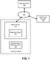
- FIG. 1is a diagram of a system environment for performing disease diagnostic tests according to one embodiment.
- the system environmentincludes a diagnostic server 150 , a mobile device 110 , an optical property modifying device 120 , and one or more health care providers 130 .
- the diagnostic server 150 , mobile device 110 , and health care providers 130can be connected to each other via a network 140 .
- different and/or additional entitiescan be included in the system environment.
- the functions performed by the various entities of FIG. 1may vary in different embodiments.
- the mobile device 110is an electronic device that includes a diagnostic system 100 to determine test results for disease diagnostic tests performed by users using at least the mobile device 110 (e.g., a smartphone, tablet, laptop computer, etc.) and optical property modifying device 120 . Since the mobile device 110 and optical property modifying device 120 are portable, users can perform disease diagnostic tests at the patient's home or any other suitable location outside of health care facilities such as hospitals or central labs for disease diagnostic tests.
- the diagnostic server 150is a computer server that can perform some or all functionality of the diagnostic system 100 in some embodiments.
- a user of the mobile device 110interacts with the diagnostic system 100 via a mobile application.
- the mobile applicationcommunicates information from the diagnostic system 100 .
- the mobile applicationpresents instructions or results for a disease diagnostic test on a graphical user interface displayed on an electronic display on the mobile device 110 .
- the mobile applicationprovides information via audio signals or tactile feedback (e.g., vibrating the mobile device 110 ).
- the mobile application running on the mobile device 110can provide data from sensors of the mobile device 110 the diagnostic system 100 .
- the mobile device 110includes an optical sensor such as a camera to capture images of the optical property modifying device 120 .
- the mobile device 110can provide the captured images to the diagnostic system 100 for further processing, which is further described with reference to FIG. 3 .
- the mobile device 110may also include a Global Positioning System (GPS) sensor, motion sensors (e.g., accelerometer, gyroscope, or inertial measurement unit), proximity sensors, or temperature sensors.
- GPSGlobal Positioning System
- the mobile device 110can communicate with the diagnostic server 150 and health care providers 130 via the network 140 , which may comprise any combination of local area and wide area networks employing wired or wireless communication links.
- the network 140uses standard communications technologies and Internet protocols.
- all or some of the communication links of the network 140may be encrypted, for example, to provide a technical safeguard for Health Insurance Portability and Accountability Act (HIPAA) compliance.
- HIPAAHealth Insurance Portability and Accountability Act
- the health care provider 130is a computer server associated a health care provider such as a pharmacy, a central laboratory (e.g., for completing chemical reactions for disease diagnostic tests), a hospital, other types of healthcare facilities, or any other suitable provider of health care services.
- a health care providersuch as a pharmacy, a central laboratory (e.g., for completing chemical reactions for disease diagnostic tests), a hospital, other types of healthcare facilities, or any other suitable provider of health care services.
- the diagnostic system 100provides a disease diagnostic test result of a patient to a pharmacy. Based on the results, the pharmacy determines an appropriate prescription for the patient.
- FIG. 2Ais a diagram of the optical property modifying device 120 for use with a mobile device 110 according to one embodiment.
- the optical property modifying device 120(also referred to herein as a “cartridge”) includes a collection tube interface 230 , one or more reaction chambers 240 , an indicator 250 , and a QR code 260 .
- a useruses the optical property modifying device 120 to react a biological sample (e.g., including a nucleic acid) of a patient with an optical property modifying reagent in the reaction chambers 240 .
- the reaction chambers 240are at least partially visible from a surface of the optical property modifying device 120 .
- the optical property modifying device 120can receive the biological sample from a collection tube 200 via the collection tube interface 230 . While performing the disease diagnostic test, the mobile device 110 may provide instructions for the test to the user, for example, via graphical user interfaces further described with reference to FIGS. 4A-H .
- the indicator 250may be a light-emitting diode (LED) that provides an indication of a status of a disease diagnostic test being performed by the optical property modifying device 120 .
- the indicator 250provides a red colored light indicating that the test has not yet started, a yellow colored light indicating that the test is in progress, and a green colored light indicating that the test has completed.
- the indicator 250may be another type of indicator different than an LED (e.g., an audio indicator) and the optical property modifying device 120 may include any number of indicators 250 (including zero).
- the QR code 260may be associated with information for a disease diagnostic test such as a type of the test or expiration date of the test.
- the diagnostic system 100can determine the information for disease diagnostic test by processing images of the QR code 260 scanned by an optical sensor of the mobile device 110 .
- the QR code 260can also be another type of code, such as a barcode, or other identifier or machine-readable signature.
- the optical property modifying device 120performs a type of disease diagnostic test involving nucleic acid(s), e.g. nucleic acid amplification, using the reaction chambers 240 to determine the presence or amount of a particular genetic target in the biological sample.
- the optical property modifying device 120includes an optical property modifying reagent, which is a solution comprising nucleic acid enzymes and primers which specifically a target nucleic acid sequence specific to an organism of interest. The presence or amount of this target nucleic acid sequence within the biological sample may indicate that a patient is infected with a particular pathogen or carries a particular genetic disease.
- the optical property modifying reagentincludes a dye which changes color or fluoresces upon target amplification, resulting in a visible change in the solution's optical properties.
- the diagnostic system 100can analyze the optical properties of the solution of the biological sample and the optical property modifying reagent to determine results of the disease diagnostic test.
- the optical property modifying device 120can perform other tests such as immunoassays or enzyme-linked immunosorbent assays (ELISAs).
- An optical property modifying device 120may perform multiple disease diagnostic tests in parallel or in series.
- the optical property modifying device 120 shown in the example in FIG. 2Aincludes five reaction chambers 240 (in other embodiments, the number of reaction chambers may vary). Each reaction chamber may or may not be coupled to another reaction chamber. Further, a given disease diagnostic test can be associated with one or more reaction chambers.
- the optical property modifying device 120 shown in FIG. 2Ais used to perform an influenza type A test associated with two of the reaction chambers, an influenza type B test associated with one of the reaction chambers, a positive internal control test associated with one of the reaction chambers, and a negative internal control test associated with one of the reaction chambers.
- multiple testsare associated with at least one common reaction chamber, which may be advantageous to consolidate the number of reaction chambers required for the optical property modifying device 120 .
- the optical property modifying device 120includes a user control such as a tab, a button, or a switch.
- the optical property modifying device 120starts the chemical reaction of the disease diagnostic test when the user interacts with the user control. For example, when the user pulls the tab, presses the button, or activates the switch, the optical property modifying device 120 starts to mix the optical property modifying reagent with the biological sample and regulate temperature of the reaction chambers to an appropriate set temperature point. In other embodiments, the optical property modifying device starts mixing and regulating temperature of the reaction chambers automatically once a biological sample is presented.
- the collection tube 200is configured to store a biological sample and includes a cartridge interface 210 and a cap 220 .
- a usercan provide a biological sample to the collection tube 200 using a swab, for example.
- the cap 220encloses the biological sample in the collection tube 200 .
- a usercan attach the collection tube 200 to the optical property modifying device 120 by physically contacting the cartridge interface 210 of the collection tube 200 to the collection tube interface 230 of the optical property modifying device 120 .
- the collection tube 200can provide a stored biological sample to the optical property modifying device 120 via the interfaces 210 and 230 .
- the collection tube 200 shown in FIG. 2Ais a cylindrical tube, in other embodiments, the collection tube 200 may have a different overall shape or form factor such as a rectangular prism.
- FIG. 2Bis a diagram of another optical property modifying device for use with a mobile device according to one embodiment.
- the optical property modifying device 270includes an electronic display 275 on a surface.
- the electronic display 275may be, for example, a liquid crystal display (LCD), organic light emitting diode (OLED) display, electronic paper display, or one or more individual light emitting diodes (LEDs), among other types of displays.
- the electronic display 275may provide one or more results for presentation on an electronic readout or analysis of one or more properties (e.g., optical, color, or geometric) of at least one reaction chamber within the optical property modifying device 270 .
- propertiese.g., optical, color, or geometric
- the electronic display 275may provide a result using human-readable symbols (e.g., alphanumeric characters or graphics) or machine-readable symbols (e.g., a barcode or QR code).
- the resultmay be based on a reaction using samples from the collection tube 280 within one of the reaction chambers.
- the optical property modifying device 270may include a QR code 285 on a surface that may be used to identify the optical property modifying device 270 as a test for influenza A & B.
- a mobile device 285reads and interprets information (e.g., test results) presented by the electronic display 275 using an onboard camera or another type of sensor. Furthermore, the mobile device 285 may use image recognition processes to determine geometric, color, or other visual attributes of the information presented, e.g., for interpreting a diagnostic result from the optical property modifying device 270 .
- the image recognition processesmay include, for example, optical pattern matching or optical character recognition (OCR) algorithms known to one skilled in the art.
- OCRoptical character recognition
- the mobile device 285may be positioned over the optical property modifying device 270 to scan or take a photo or video of the surface of the optical property modifying device 270 having the electronic display 275 .
- the mobile device 285may detect that the optical property modifying device 270 presents a message indicating a positive diagnosis for influenza A. Responsive to the detection, the mobile device 285 may provide further interpretation or options for next steps to a user.
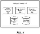
- FIG. 3is a block diagram of a diagnostic system 100 according to one embodiment.
- the diagnostic system 100includes a user data store 310 , image processing engine 320 , image analysis engine 325 , diagnostic test engine 330 , and test data store 340 .
- the diagnostic system 100may include additional, fewer, or different components for various applications.
- the functionality of the diagnostic system 100may be performed by or implemented on the diagnostic server 150 instead of the mobile device 110 .
- the mobile device 110acquires images of an optical property modifying device 120 using the image processing engine 320 and provides the images to the diagnostic server 150 for further processing by the image analysis engine 325 .
- the mobile device 110can receive a test result determined by the diagnostic server 150 and communicate the test result to a user. This may be advantageous because the image analysis engine 325 may require more computational resources relative to the image processing engine 320 or other components of the diagnostic system 100 on the mobile device 110 .
- the user data store 310stores information about users of the diagnostic system 100 such as patients who have completed—or will complete—a diagnostic test.
- the informationmay include user information such as name, demographics, family data, geographical location, contact information, or physiological data.
- the informationmay describe user's medical history such as prescriptions, health conditions, genetic data, visits to health care providers, past or current medical services or interventions received, or previously completed diagnostic tests along with relevant details such as the date that the tests were taken and the test results.
- the image processing engine 320acquires and processes images from a mobile device 110 .
- the image processing engine 320may implement image processing techniques known to one skilled in the art such as noise reduction using different types of filters, skew correction, resizing, rescaling, rotation, equalization, focusing/sharpening, or edge detection.
- the image processing engine 320can determine whether the surface of an optical property modifying device 120 is shown in the image based on various parameters associated with the surface.
- a parametermay be a known geometric characteristic of the optical property modifying device 120 .
- the QR code 260 shown in FIG. 2Ais unique to the optical property modifying device 120 , a batch of optical property modifying devices 120 (e.g., having a certain expiration date based on a manufacturing date), or a particular type of diagnostic test.
- Other types of geometric characteristicinclude, for example, a border of the optical property modifying device 120 , a two-dimensional (2D) or three-dimensional (3D) barcode, an alignment marker (e.g., the reaction chambers 240 , the indicator 250 , the example text “Flu A+B Test” shown in FIG. 2A ), or any other type of fiducial marker that may be a point of reference in an image.
- the image processing engine 320may transform an acquired image (e.g. translate, skew, scale, or rotate) based on geometric characteristics, or in other words, spatial data of the image determined by the image processing engine 320 .
- the image processing engine 320may leave the image unchanged but instead transform the coordinates it uses to identify regions of interest for analysis within the image.
- a fiducial marker of the optical property modifying device 120has a reference orientation and/or size.
- the QR code 260 shown in FIG. 2Ais known to have a length and width of one centimeter (e.g., dimensions of a square) and be orientated with the text “Flu A+B Test” labeled on the optical property modifying device 120 .
- the image processing engine 320determines that the QR code 260 appears smaller or larger than expected based on the reference size, the image processing engine 320 can scale the image up or down, respectively. If the image processing engine 320 determines that the QR code 260 shown in an image is skewed in shape (e.g., a trapezoid or rhombus), the image processing engine 320 can adjust the skew of the image so that the QR code 260 is rendered more closely as the expected shape of a square. If the image processing engine 320 determines that the QR code 260 shown in the image is not aligned to the reference orientation (e.g., the image has been rotated by 45, 60, or 90 degrees), the image processing engine 320 can rotate the image to the reference orientation. Further, the image processing engine 320 can determine a level of focus of the image by resolving two or more features of the optical property modifying device 120 such as the QR code 260 and another fiducial marker.
- the image processing engine 320can determine a level of focus of the image
- a parametermay also be a known color characteristic of the optical property modifying device 120 .
- the image processing engine 320has information indicating that the surface (or a fiducial marker) of the optical property modifying device 120 is known to be a certain color(s).
- the surface of the optical property modifying device 120is known to have a uniform white color (or approximately white color).
- an image of the optical property modifying device 120may be tinted with warmer colors (e.g., red) or cooler colors (e.g., blue) depending on lighting conditions when the image was captured.
- the image processing engine 320may use white balancing (e.g., color balancing) to determine the lighting conditions of the image and adjust the colors of the image; thus, the image processing engine 320 can properly match the known white color of the surface of the optical property modifying device 120 with the adjusted image.
- white balancinge.g., color balancing
- the image processing engine 320can also use shadowing techniques to remove or otherwise account for shadows in images that may skew the color of certain portions of the images. For instance, the image processing engine 320 measures the uniformity of a known color of the surface of the optical property modifying device 120 to identify shadows in an image.
- the image processing engine 320continuously monitors images captured by an optical sensor of the mobile device 110 .
- the mobile device 110displays a live stream of images captured by the optical sensor (e.g., representing the field of view of the optical sensor) to provide a real-time visual guide for a user to align the mobile device 110 with the optical property modifying device 120 being imaged.
- the image processing engine 320can determine a quality level of each image. If the quality level of an image meets a threshold level, the image processing engine 320 selects the image for further processing.
- the image processing engine 320may determine the quality level and threshold level based on, for instance, the focus, shadowing, white-balancing level, or illumination level of an image.
- the image processing engine 320can normalize images captured by mobile devices 110 having different technical specifications. This may be advantageous because users may likely have different types of mobile devices 110 . For instance, one mobile device has a higher resolution camera with stronger white flash light than another mobile device. By normalizing images captured from these two mobile devices, the image processing engine 320 can effectively process images regardless of the particular specifications of the mobile devices.
- the image analysis engine 325analyzes images acquired and processed by the image processing engine 320 .
- the image analysis engine 325analyzes one or more reaction chambers 240 in the image of an optical property modifying device 120 .
- the image analysis engine 325determines one or more optical properties of the reaction chambers 240 such as the color, transparency, translucency, opacity, or uniformity of the reaction chambers 240 and/or contents within the reaction chambers 240 .
- the image analysis engine 325determines information about the optical properties of the reaction chambers 240 , e.g., the average and variance of color of a group of pixels in an image corresponding to each reaction chamber.
- the image analysis engine 325may determine the color average and variance (or any other statistical analysis) based on a RGB (red-green-blue) color model, hue-saturation-value (HSV) color model, or any other suitable color model.
- the image analysis engine 325identifies these optical properties based on known geometric parameters of the optical property modifying device 120 such as size, shape, orientation, or identifying fiducial marks.
- the image analysis engine 325retrieves a color image (e.g., to use as a reference image) from the test data store 340 , identifies the size and orientation of a QR code in the color image, and uses a known size (e.g., 1 ⁇ 1 cm) of the QR code and known relative positions of the five reaction chambers to the QR code (e.g., 2 cm to the right and above, spaced at 1 cm increments) to extract the color average and variance of each reaction chamber.
- a color imagee.g., to use as a reference image
- a known sizee.g., 1 ⁇ 1 cm
- known relative positions of the five reaction chambers to the QR codee.g., 2 cm to the right and above, spaced at 1 cm increments
- the image analysis engine 325can determine test results for a disease diagnostic test by comparing the determined color information of a reaction chamber 240 to reference information that indicates one or more color ranges (e.g., based on the RGB or HSV color model).
- a color rangemay correspond to a diagnosis for a disease diagnostic test associated with the reaction chamber 240 .
- the image analysis engine 325determines a test result based on the color range within which the determined color of the reaction chamber 240 falls. In other words, the image analysis engine 325 can match color changes of the reaction chambers 240 to a particular test result. For instance, the image analysis engine 325 determines a negative diagnosis of the disease responsive to matching the determined color to a first color range (e.g., yellow to green colors).
- the image analysis engine 325determines a positive diagnosis of the disease responsive to matching the determined color to a second color range (e.g., blue to violet colors).
- the image analysis engine 325determines an undetermined (e.g., “not available” or “unknown”) diagnosis of the disease responsive to matching the determined color to a third color range (or any colors that do not fall within any specified range).
- the image analysis engine 325can determine a test result based on the distribution and clustering of colors of the individual pixels comprising the image of a reaction chamber 240 , rather than a point estimate of color average or variance. For example, the image analysis engine 325 can classify each pixel within the image of reaction chamber 240 as falling within one of the three color ranges described above. If a plurality of pixels falls within the first color range, the image analysis engine 325 determines a negative diagnosis of the disease. If a plurality of pixels falls within the second color range, the image analysis engine 325 determines a positive diagnosis of the disease. If a plurality of pixels falls within the third color range, the image analysis engine 325 determines an undetermined diagnosis of the disease. In this way, the image analysis engine 325 is robust to, for example, black and white pixels representing reflections from chamber edges that are substantially different colors from the solution within the reaction chambers 240 and might confound a point estimate-based approach to determining the color of the solution.
- the image analysis engine 325determines a severity level of the disease or a confidence level of test result based on the comparing the color information with the reference information. For example, relative to a lighter color, a darker color within a certain color range may indicate that the disease diagnosis is more severe or that there is a greater confidence level.
- An undetermined test resultmay occur due to various factors such as a defect in the collection tube 200 or optical property modifying device 120 , variation in the captured image, or human error by the user or patient, e.g., contaminating the biological sample provided for the diagnostic test or not waiting long enough (or too long) for a chemical reaction of the diagnostic test to complete.
- the image analysis engine 325may also determine test results further based on information other than analyzed images in some embodiments. For example, the image analysis engine 325 determines test results based on a geographical location and/or timestamp of the diagnostic test. In particular, a certain disease may be more prevalent in a certain geographical region (e.g., an area with a tropical climate or a dry climate) or during a certain time range (e.g., during the summer or winter season). In some embodiments, the performance (e.g., sensitivity vs. specificity) of the test can be adjusted based upon known epidemiological factors such as disease prevalence so that during times of low prevalence, the sensitivity of the test can be decreased to prevent false positive test results.
- a geographical location and/or timestamp of the diagnostic teste.g., a certain disease may be more prevalent in a certain geographical region (e.g., an area with a tropical climate or a dry climate) or during a certain time range (e.g., during the summer or winter season).
- the image analysis engine 325implements defect detection algorithms to analyze an image of an optical property modifying device 120 .
- the image analysis engine 325identifies bubbles in the reaction chambers 240 of the optical property modifying device 120 or other types of defects such as debris or scratches inside or on the exterior of the reaction chambers 240 .
- the image analysis engine 325may use image processing techniques to remove the defects from the image, e.g., removing a cluster of pixels corresponding to a defect.
- the image analysis engine 325can exclude anomalous color values from the determination of color information (e.g., average and variance), which may improve the accuracy of the corresponding test result.
- the diagnostic test engine 330provides information to and/or receives information from mobile devices 110 and health care providers 130 for disease diagnostic tests.
- the diagnostic test engine 330receives data from a mobile device 110 such as images of an optical property modifying device 120 captured by an optical sensor of the mobile device 110 and/or metadata such as the geographical location of the mobile device 110 , a timestamp of a captured image, or information describing the optical sensor (e.g., pixel resolution, aperture, or flash).
- the diagnostic test engine 330determines information for diagnostic tests (e.g., a type of diagnostic test or a result of the diagnostic test) based on images processed and analyzed by the image processing engine 320 and/or the image analysis engine 325 .
- the diagnostic test engine 330may provide instructions for a diagnostic test to the mobile device 110 and provide test results of the diagnostic test to the mobile device 110 or a health care provider 130 .
- the diagnostic test engine 330can retrieve the instructions for the diagnostic test (e.g., including text, graphics, audio, or other media content) from the test data store 340 . Further, the diagnostic test engine 330 can store test results in the test data store 340 or the user data store 310 along with relevant information such as the analyzed images of the optical property modifying device 120 and reaction chambers 240 , information about the patient who took the diagnostic test, or a geographical location and/or timestamp associated with the diagnostic test.
- the diagnostic test engine 330can provide test results and associated metadata to a computer server (e.g., a health care provider 130 ), which can render epidemiological data based on aggregated test results from multiple mobile devices 110 and a population of patients.
- the epidemiological datamay be organized based on various parameters (e.g., demographics, geographical location, temporal information, or types of diseases) and used to determine risk factors or preventative measures for certain diseases.
- the diagnostic test engine 330may communicate sponsored content based on test results of diagnostic tests to users via the mobile device 110 .
- the sponsored contentis a content item displayed on a user interface of the mobile device 110 .
- Examples of sponsored contentinclude information from vendors of goods or services that may help treat diseases tested by the diagnostic system 100 .
- the vendorsprovide prescription medicines, over-the-counter medicines, physical therapy, rehabilitative services, etc.
- the diagnostic test engine 330can provide test results to a computer server of a third party, e.g., a health provider or a government health organization such as the Centers for Disease Control and Prevention (CDC).
- the computer serverincludes aggregated health information of a population of people, and may organize the health information based on geographical location.
- the CDCcan use the test results and health information to evaluate the well-being of a population within the government's jurisdiction, e.g., monitoring the spread and prevalence of a disease such as influenza.
- FIG. 4Ashows a user interface 400 of a mobile application for a disease diagnostic test according to one embodiment.
- the user interface 400shows an image 405 of an optical property modifying device 120 .
- the image 405is the field of view of the camera of the mobile device 110 displaying the user interface 400 , for example.
- the imageis oriented to align with the mobile device 110 because the edges of optical property modifying device 120 are approximately parallel to the edges of the user interface 400 , and in extension, the mobile device 110 .
- the user interface 400includes one or more alignment markers overlaying the field of view to assist a user of the mobile device 110 in aligning the mobile device 110 to the optical property modifying device 120 for capturing the image 405 .
- an alignment markeris a semi-transparent graphic of the optical property modifying device 120 that the user can use to overlap with the physical optical property modifying device 120 .
- the alignment markercorresponds to a graphic of an element of the optical property modifying device 120 (e.g., the QR code 260 ), or a line that should be aligned with an edge of the optical property modifying device 120 .
- FIG. 4Bshows another user interface 410 of the mobile application shown in FIG. 4A including information about the disease diagnostic test according to one embodiment.
- the image processing engine 320 and image analysis engine 325process the image 405 of the optical property modifying device 120 shown in FIG. 4A .
- the diagnostic test engine 330determines a disease diagnostic test of the optical property modifying device 120 and provides information about the disease diagnostic test for display.
- the user interface 410indicates the type of test (e.g., influenza type A and B), expiration date (e.g., Jan. 30, 2020), test description, duration in time (e.g., 20 minutes for a chemical reaction of the test), and cartridge ID (e.g., 0x34E) of the optical property modifying device 120 .
- type of teste.g., influenza type A and B
- expiration datee.g., Jan. 30, 2020
- test descriptione.g., duration in time
- duration in timee.g., 20 minutes for a chemical reaction of the test
- FIG. 4Cshows another user interface 415 of the mobile application shown in FIG. 4A including instructions to use a swab 420 according to one embodiment.
- the user interface 415indicates instructions for an example step of the disease diagnostic test shown in FIG. 4B .
- the useris instructed to remove the swab 420 from a sterile package 425 and swab the nostril of a patient undergoing the disease diagnostic test to collect a biological sample of the patient.
- FIG. 4Dshows another user interface 430 of the mobile application shown in FIG. 4A including instructions to use a collection tube 200 according to one embodiment.
- the user interface 430indicates instructions for an example step of the disease diagnostic test shown in FIG. 4B .
- the useris instructed to insert the swab 420 into the collection tube 200 and swirl the swab 420 around for 10 seconds. Afterwards, the swab 420 should be discarded.
- the cap 220 of the collection tube 200is removed so that the swab 420 may be inserted inside.
- FIG. 4Eshows another user interface 435 of the mobile application shown in FIG. 4A including instructions to use a cartridge according to one embodiment.
- the user interface 435indicates instructions for an example step of the disease diagnostic test shown in FIG. 4B .
- the useris instructed to place the collection tube 200 onto the cartridge (the optical property modifying device 120 ) and close the cap 220 .
- the cartridge interface 210should be coupled to the collection tube interface 230 , which provides the biological sample of the patient to the optical property modifying device 120 .
- the useris also instructed to pull the tab of the optical property modifying device 120 to start the chemical reaction of the disease diagnostic test.
- FIG. 4Fshows another user interface 440 of the mobile application shown in FIG. 4A including instructions to wait for a chemical reaction of the disease diagnostic test to complete according to one embodiment.
- the user interface 440displays a timer that indicates the time remaining until the chemical reaction of the disease diagnostic test shown in FIG. 4B should be complete. Though the total time for this example disease diagnostic test is 20 minutes, in other embodiments, the time may vary, e.g., between 1 and 60 minutes.
- FIG. 4Gshows another user interface 445 of the mobile application shown in FIG. 4A including instructions to scan the cartridge according to one embodiment.
- the user interface 445indicates instructions for an example step of the disease diagnostic test shown in FIG. 4B .
- the useris instructed to scan (take one or more images of) the cartridge (the optical property modifying device 120 ). Since the chemical reaction of the disease diagnostic test has completed after waiting the duration of time for the test, the optical properties of the reaction chambers 240 of the imaged optical property modifying device 120 have changed. Specifically, the image 450 of the optical property modifying device 120 shows that the two of the reaction chambers 455 and 460 have changed at least in color as result of the biological sample of the patient reacting with an optical property modifying reagent.
- FIG. 4Hshows another user interface 465 of the mobile application shown in FIG. 4A including results for the disease diagnostic test according to one embodiment.
- the image processing engine 320 and image analysis engine 325process and analyze the image 445 of the optical property modifying device 120 shown in FIG. 4G .
- the diagnostic test engine 330determines test results of the disease diagnostic test and provides information associated with the test results for display on the user interface 465 .
- the user interface 465indicates the patient has tested positive for influenza A and negative for influenza B.
- the user interface 465also shows an option for the user or patient to call a treatment hotline.
- the treatment hotlineis a phone number of a health care provider that can provide pharmaceutical drugs or other health care services for treating influenza.
- the user interface 465provides an option for the user to modify, verify/confirm, or cancel the test result, which may be performed before the diagnostic system 100 provides (via the diagnostic test engine 330 ) the test result to a health care provider 130 , for example. If the test result is updated after the test results has been provided the health care provider 130 , the diagnostic test engine 330 may automatically provide the updated test result as well. In one embodiment, if the test result is positive, the diagnostic test engine 330 provides a notification for display on the mobile device 110 indicating that a health care provider will be contacted on behalf of the patient regarding the test result. For example, the diagnostic test engine 330 provides the test result to a physician. The diagnostic test engine 330 may receive a recommendation (e.g., taking vitamins or medication) from the physician in response to providing the test result and communicate the recommendation to the user.
- a recommendatione.g., taking vitamins or medication
- the diagnostic test engine 330provides the test result to a pharmacy to allow the pharmacy to fulfill a prescription for the patient to treat the disease associated with the test result.
- the diagnostic test engine 330may determine a pharmacy that is located nearby the patient (e.g., within a predetermined distance such as a threshold radius of 10 kilometers) based on geographical information, for instance, the location where the diagnostic test was taken or the address of the patient).
- FIG. 5Ais a data flow diagram for performing a disease diagnostic test in a conventional system environment according to one embodiment.
- a patient 500 who wants to complete a disease diagnostic testvisits a physician 510 at a hospital or clinic.
- the physician 510collects a biological sample of the patient 500 .
- the physician 510provides the biological sample to a central lab 530 with staff that performs the chemical reaction portion of the disease diagnostic test using lab equipment and the biological sample.
- the central lab 530provides test results of the disease diagnostic test to the physician 510 .
- the physician 510provides the test results to the patient 500 . If the patient tested positive for a disease, the test results may indicate a prescription for medication or another type of medical treatment.
- step 5the physician 510 provides the prescription to a pharmacy 520 .
- the pharmacy 520consults with the physician 510 to verify or clarify the prescription.
- step 6the patient 500 visits the pharmacy 520 to request the medication for the prescription.
- step 7the pharmacy 520 fulfills the prescription by providing the medication to the patient 500 .
- FIG. 5Bis a data flow diagram for performing a disease diagnostic test in a system environment including the diagnostic system 100 according to one embodiment.
- a patient 500 who wants to complete a disease diagnostic testuses the diagnostic system 100 , e.g., by completing steps of the disease diagnostic test as shown in FIGS. 4A-H .
- the diagnostic system 100may simultaneously provide the test results to the patient 500 and the pharmacy 520 in steps 2 A and B.
- the diagnostic system 100provides the test results for display on a user interface of a mobile application.
- the diagnostic system 100may automatically provide the test results to the pharmacy 520 without requiring further input from the patient 500 (and/or a physician 510 ), or in response to receiving a confirmation of the test result from the patient 500 , in some embodiments.
- the pharmacy 520fulfills a prescription for the patient 500 based on the test results, e.g., the pharmacy 520 delivers medications to the home of the patient 500 or prepares the medications for pickup at a location nearby the patient 500 .
- the diagnostic server 150may consult a physician 510 in an automated manner without requiring that the patient specify the physician or manually facilitate this consultation.
- one or more physicians 510are affiliated with the diagnostic server 150 .
- the diagnostic system 100may also provide the test results to the physician 510 , e.g., in response to a request by the patient. Thus, if the patient 500 visits the physician 510 to seek treatment for the disease, the physician 510 can determine an appropriate treatment based on the test results.
- the system environment including the diagnostic system 100 shown in FIG. 5Bfacilitates a process requiring fewer steps for the patient 500 to complete a disease diagnostic test and receive appropriate medications to treat the disease if the patient 500 tested positive.
- the diagnostic system 100enables patients to receive treatment for diseases more promptly.
- the system environment shown in FIG. 5Bdoes not require the central lab 530 because the diagnostic system 100 allows the patient 500 to complete the chemical reaction portion of the disease diagnostic test at home using the optical property modifying device 120 . This may be particularly advantageous for patients residing far away from the nearest central lab 530 , for example, rural areas or developing countries.
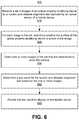
- FIG. 6is a flowchart illustrating a process 600 for determining test results for a disease diagnostic test according to one embodiment.
- the process 600is used by the diagnostic system 100 —e.g., modules of the diagnostic system 100 described with reference to FIG. 3 —within the system environment in FIG. 1 .
- the process 600may include different or additional steps than those described in conjunction with FIG. 6 in some embodiments or perform steps in different orders than the order described in conjunction with FIG. 6 .
- the image processing engine 320receives 610 a set of images of an optical property modifying device 120 for a nucleic acid disease diagnostic test captured by an optical sensor of a mobile device 110 .
- the image processing engine 320determines 620 , for each image in the set, whether the surface of the optical property modifying device 120 is shown in the image.
- the image processing engine 320selects 630 one or more images of the set that are determined to show the surface.
- the image analysis engine 325determines 640 a test result for the nucleic acid disease diagnostic test based on the one or more images.
- the diagnostic test engine 330provides 650 the test result for display on the mobile device 110 .
- any reference to “one embodiment” or “an embodiment”means that a particular element, feature, structure, or characteristic described in connection with the embodiment is included in at least one embodiment.
- the appearances of the phrase “in one embodiment” in various places in the specificationare not necessarily all referring to the same embodiment.
- Coupledand “connected” along with their derivatives.
- some embodimentsmay be described using the term “coupled” to indicate that two or more elements are in direct physical or electrical contact.
- the term “coupled,” however,may also mean that two or more elements are not in direct contact with each other, but yet still co-operate or interact with each other.
- the embodimentsare not limited in this context unless otherwise explicitly stated.
- the terms “comprises,” “comprising,” “includes,” “including,” “has,” “having” or any other variation thereof,are intended to cover a non-exclusive inclusion.
- a process, method, article, or apparatus that comprises a list of elementsis not necessarily limited to only those elements but may include other elements not expressly listed or inherent to such process, method, article, or apparatus.
- “or”refers to an inclusive or and not to an exclusive or. For example, a condition A or B is satisfied by any one of the following: A is true (or present) and B is false (or not present), A is false (or not present) and B is true (or present), and both A and B are true (or present).
- a software moduleis implemented with a computer program product including a computer-readable non-transitory medium containing computer program code, which can be executed by a computer processor for performing any or all of the steps, operations, or processes described.
- Embodiments of the inventionmay also relate to a product that is produced by a computing process described herein.
- a productmay include information resulting from a computing process, where the information is stored on a non-transitory, tangible computer readable storage medium and may include any embodiment of a computer program product or other data combination described herein.
Landscapes
- Health & Medical Sciences (AREA)
- Engineering & Computer Science (AREA)
- Life Sciences & Earth Sciences (AREA)
- Medical Informatics (AREA)
- Physics & Mathematics (AREA)
- Public Health (AREA)
- General Health & Medical Sciences (AREA)
- Biomedical Technology (AREA)
- Pathology (AREA)
- Biophysics (AREA)
- Animal Behavior & Ethology (AREA)
- Veterinary Medicine (AREA)
- Surgery (AREA)
- Molecular Biology (AREA)
- Heart & Thoracic Surgery (AREA)
- Computer Vision & Pattern Recognition (AREA)
- Epidemiology (AREA)
- Theoretical Computer Science (AREA)
- Primary Health Care (AREA)
- General Physics & Mathematics (AREA)
- Nuclear Medicine, Radiotherapy & Molecular Imaging (AREA)
- Radiology & Medical Imaging (AREA)
- Artificial Intelligence (AREA)
- Databases & Information Systems (AREA)
- Data Mining & Analysis (AREA)
- Multimedia (AREA)
- Signal Processing (AREA)
- Psychiatry (AREA)
- Physiology (AREA)
- Dentistry (AREA)
- Oral & Maxillofacial Surgery (AREA)
- Quality & Reliability (AREA)
- Geometry (AREA)
- Evolutionary Computation (AREA)
- Software Systems (AREA)
- Bioinformatics & Cheminformatics (AREA)
- Bioinformatics & Computational Biology (AREA)
- Biotechnology (AREA)
- Evolutionary Biology (AREA)
- Spectroscopy & Molecular Physics (AREA)
Abstract
Description
Claims (19)
Priority Applications (13)
| Application Number | Priority Date | Filing Date | Title |
|---|---|---|---|
| US16/155,829US11080848B2 (en) | 2017-04-06 | 2018-10-09 | Image-based disease diagnostics using a mobile device |
| EP19872211.8AEP3864393A4 (en) | 2018-10-09 | 2019-10-09 | Consumer-based disease diagnostics |
| JP2021519556AJP2022504506A (en) | 2018-10-09 | 2019-10-09 | How to Diagnose Consumer-Based Diseases |
| CN201980066514.8ACN112823276A (en) | 2018-10-09 | 2019-10-09 | Consumer-based disease diagnosis |
| MX2021004018AMX2021004018A (en) | 2018-10-09 | 2019-10-09 | CONSUMER-BASED DISEASE DIAGNOSIS. |
| PCT/US2019/055365WO2020076928A1 (en) | 2018-10-09 | 2019-10-09 | Consumer-based disease diagnostics |
| MYPI2021001379AMY202663A (en) | 2018-10-09 | 2019-10-09 | Consumer-based disease diagnostics |
| CA3114215ACA3114215A1 (en) | 2018-10-09 | 2019-10-09 | Consumer-based disease diagnostics |
| MX2024014635AMX2024014635A (en) | 2018-10-09 | 2021-04-07 | Consumer-based disease diagnostics |
| DO2021000058ADOP2021000058A (en) | 2018-10-09 | 2021-04-07 | CONSUMER-BASED DIAGNOSIS OF DISEASES |
| US17/364,773US11954851B2 (en) | 2017-04-06 | 2021-06-30 | Image-based disease diagnostics using a mobile device |
| US18/364,401US20240020836A1 (en) | 2017-04-06 | 2023-08-02 | Image-based disease diagnostics using a mobile device |
| JP2024134314AJP2024156975A (en) | 2018-10-09 | 2024-08-09 | Consumer-Based Disease Diagnostics |
Applications Claiming Priority (2)
| Application Number | Priority Date | Filing Date | Title |
|---|---|---|---|
| US15/481,349US10146909B2 (en) | 2017-04-06 | 2017-04-06 | Image-based disease diagnostics using a mobile device |
| US16/155,829US11080848B2 (en) | 2017-04-06 | 2018-10-09 | Image-based disease diagnostics using a mobile device |
Related Parent Applications (1)
| Application Number | Title | Priority Date | Filing Date |
|---|---|---|---|
| US15/481,349Continuation-In-PartUS10146909B2 (en) | 2017-04-06 | 2017-04-06 | Image-based disease diagnostics using a mobile device |
Related Child Applications (1)
| Application Number | Title | Priority Date | Filing Date |
|---|---|---|---|
| US17/364,773ContinuationUS11954851B2 (en) | 2017-04-06 | 2021-06-30 | Image-based disease diagnostics using a mobile device |
Publications (2)
| Publication Number | Publication Date |
|---|---|
| US20190050988A1 US20190050988A1 (en) | 2019-02-14 |
| US11080848B2true US11080848B2 (en) | 2021-08-03 |
Family
ID=65275285
Family Applications (3)
| Application Number | Title | Priority Date | Filing Date |
|---|---|---|---|
| US16/155,829Active2038-03-05US11080848B2 (en) | 2017-04-06 | 2018-10-09 | Image-based disease diagnostics using a mobile device |
| US17/364,773Active2037-07-06US11954851B2 (en) | 2017-04-06 | 2021-06-30 | Image-based disease diagnostics using a mobile device |
| US18/364,401AbandonedUS20240020836A1 (en) | 2017-04-06 | 2023-08-02 | Image-based disease diagnostics using a mobile device |
Family Applications After (2)
| Application Number | Title | Priority Date | Filing Date |
|---|---|---|---|
| US17/364,773Active2037-07-06US11954851B2 (en) | 2017-04-06 | 2021-06-30 | Image-based disease diagnostics using a mobile device |
| US18/364,401AbandonedUS20240020836A1 (en) | 2017-04-06 | 2023-08-02 | Image-based disease diagnostics using a mobile device |
Country Status (1)
| Country | Link |
|---|---|
| US (3) | US11080848B2 (en) |
Cited By (7)
| Publication number | Priority date | Publication date | Assignee | Title |
|---|---|---|---|---|
| US20200310395A1 (en)* | 2019-03-25 | 2020-10-01 | Roche Diagnostics Operations, Inc. | Method of operating a diagnostic instrument |
| US11352675B2 (en) | 2020-01-03 | 2022-06-07 | Visby Medical, Inc. | Devices and methods for antibiotic susceptability testing |
| US11448658B2 (en)* | 2017-06-29 | 2022-09-20 | Seegene, Inc. | Method and device for controlling detection-composition preparation instrument |
| US12037635B2 (en) | 2017-11-09 | 2024-07-16 | Visby Medical, Inc. | Portable molecular diagnostic device and methods for the detection of target viruses |
| USD1055307S1 (en) | 2021-08-13 | 2024-12-24 | Visby Medical, Inc. | Molecular diagnostic device |
| US12239993B2 (en) | 2018-09-03 | 2025-03-04 | Visby Medical, Inc. | Devices and methods for antibiotic susceptibility testing |
| US12263478B2 (en) | 2019-04-28 | 2025-04-01 | Visby Medical, Inc. | Molecular diagnostic devices with digital detection capability and wireless connectivity |
Families Citing this family (20)
| Publication number | Priority date | Publication date | Assignee | Title |
|---|---|---|---|---|
| DK3134553T3 (en) | 2014-04-24 | 2019-11-18 | Lucira Health Inc | COLORIMETRIC DETECTION OF NUCLEIC ACID AMPLIFICATION |
| WO2017160839A1 (en) | 2016-03-14 | 2017-09-21 | Diassess Inc. | Devices and methods for modifying optical properties |
| AU2017232340B2 (en) | 2016-03-14 | 2022-04-28 | Pfizer Inc. | Systems and methods for performing biological assays |
| EP3430372A4 (en) | 2016-03-14 | 2019-10-16 | Lucira Health, Inc. | DEVICES AND METHODS FOR PREPARING AND DELIVERING BIOLOGICAL TEST SAMPLE |
| WO2017160840A1 (en) | 2016-03-14 | 2017-09-21 | Diassess Inc. | Selectively vented biological assay devices and associated methods |
| US11080848B2 (en) | 2017-04-06 | 2021-08-03 | Lucira Health, Inc. | Image-based disease diagnostics using a mobile device |
| WO2019055135A1 (en) | 2017-09-14 | 2019-03-21 | Diassess Inc. | Multiplexed biological assay device with electronic readout |
| US10549275B2 (en) | 2017-09-14 | 2020-02-04 | Lucira Health, Inc. | Multiplexed biological assay device with electronic readout |
| JP2022504506A (en)* | 2018-10-09 | 2022-01-13 | ルシラ ヘルス インコーポレイテッド | How to Diagnose Consumer-Based Diseases |
| USD910200S1 (en) | 2018-12-21 | 2021-02-09 | Lucira Health, Inc. | Test tube |
| US11308618B2 (en) | 2019-04-14 | 2022-04-19 | Holovisions LLC | Healthy-Selfie(TM): a portable phone-moving device for telemedicine imaging using a mobile phone |
| US12014500B2 (en) | 2019-04-14 | 2024-06-18 | Holovisions LLC | Healthy-Selfie(TM): methods for remote medical imaging using a conventional smart phone or augmented reality eyewear |
| GB201911095D0 (en)* | 2019-08-02 | 2019-09-18 | Randox Laboratories Ltd | Biological status classification |
| US11151820B1 (en) | 2020-04-21 | 2021-10-19 | Openclear, Inc. | Method and apparatus for personal pathogen status verification at point of entry into an area of congregation |
| USD953561S1 (en) | 2020-05-05 | 2022-05-31 | Lucira Health, Inc. | Diagnostic device with LED display |
| USD962470S1 (en) | 2020-06-03 | 2022-08-30 | Lucira Health, Inc. | Assay device with LCD display |
| EP4278366A4 (en) | 2021-01-12 | 2024-12-11 | Emed Labs, LLC | HEALTH TESTING AND DIAGNOSIS PLATFORM |
| US20230057531A1 (en)* | 2021-08-17 | 2023-02-23 | Emed Labs, Llc | Mobile device stands for at-home diagnostics and healthcare |
| WO2023069889A1 (en)* | 2021-10-19 | 2023-04-27 | Emed Labs, Llc | Remote diagnostic testing systems and methods |
| US11810662B2 (en)* | 2022-03-04 | 2023-11-07 | Imagemovermd, Inc. | Collection, storage, and management of images or image results |
Citations (154)
| Publication number | Priority date | Publication date | Assignee | Title |
|---|---|---|---|---|
| USD244555S (en) | 1975-03-25 | 1977-05-31 | Greiner Electronic Ag | Covered test tube |
| US4310488A (en) | 1980-05-19 | 1982-01-12 | Hoffmann-La Roche Inc. | Sample or reagent container for analyzers |
| EP0056241A1 (en) | 1981-01-12 | 1982-07-21 | MetPath, Inc. | Apparatus for collecting saliva |
| US4379848A (en) | 1981-09-28 | 1983-04-12 | Eastman Kodak Company | Method of analyzing an aqueous liquid for hexacyanoferrates |
| US4624929A (en) | 1984-12-03 | 1986-11-25 | Syntex (U.S.A.) Inc. | Sample collector and assay device and method for its use |
| US4849340A (en) | 1987-04-03 | 1989-07-18 | Cardiovascular Diagnostics, Inc. | Reaction system element and method for performing prothrombin time assay |
| US4859610A (en) | 1985-06-05 | 1989-08-22 | Synbiotics Corporation | Immunoassay incubation device |
| US4936682A (en) | 1987-08-11 | 1990-06-26 | Associates Of Cape Cod, Inc. | Instrument for independently and kinetically measuring light transpassion through a plurality of samples |
| EP0520408A2 (en) | 1991-06-25 | 1992-12-30 | Saliva Diagnostic Systems, Inc. | Sampling device and sample adequacy system |
| USD334065S (en) | 1991-12-05 | 1993-03-16 | Miles Inc. | Diagnostic reflectance photometer |
| USD371605S (en) | 1994-10-26 | 1996-07-09 | Avocet Medical, Inc. | Combined blood collection and analysis instrument |
| US5580794A (en) | 1993-08-24 | 1996-12-03 | Metrika Laboratories, Inc. | Disposable electronic assay device |
| WO1997012681A1 (en) | 1995-10-02 | 1997-04-10 | Analyte Diagnostics, Inc. | Sample collection, recovery and dispensing device for saliva |
| WO1997041421A1 (en) | 1996-04-30 | 1997-11-06 | Metrika, Inc. | Method and device for measuring reflected optical radiation |
| US5830714A (en) | 1996-04-17 | 1998-11-03 | Molecular Biology Resources, Inc. | Biologically active fragment of bacillus stearothermophilus DNA polymerase |
| US5837546A (en) | 1993-08-24 | 1998-11-17 | Metrika, Inc. | Electronic assay device and method |
| US5888826A (en) | 1994-06-30 | 1999-03-30 | Dade Behring Inc. | Combination reagent holding and test device |
| US6074606A (en) | 1998-10-19 | 2000-06-13 | Sayles; Philip W. | One-step test device |
| US6180395B1 (en) | 1995-07-12 | 2001-01-30 | Charm Sciences, Inc. | Reagent chamber for test apparatus and test apparatus |
| US6198107B1 (en) | 1997-03-07 | 2001-03-06 | Clare Chemical Research, Inc. | Fluorometric detection using visible light |
| US6336900B1 (en) | 1999-04-12 | 2002-01-08 | Agilent Technologies, Inc. | Home hub for reporting patient health parameters |
| US6352838B1 (en) | 1999-04-07 | 2002-03-05 | The Regents Of The Universtiy Of California | Microfluidic DNA sample preparation method and device |
| US6564968B1 (en) | 2002-10-03 | 2003-05-20 | Brian Terrell | Automated fluid dispenser |
| US6565808B2 (en) | 2001-05-18 | 2003-05-20 | Acon Laboratories | Line test device and methods of use |
| US20030123994A1 (en) | 2001-12-31 | 2003-07-03 | Industrial Technology Research Institute | Thermolysis reaction actuating pump |
| US20030157503A1 (en) | 2003-04-04 | 2003-08-21 | Mcgarry Mark W | Compositions and methods for performing biological reactions |
| US20040018634A1 (en) | 2002-07-29 | 2004-01-29 | Kiamars Hajizadeh | Sample-collection and preparation device and method |
| US20040052689A1 (en) | 1999-08-17 | 2004-03-18 | Porex Technologies Corporation | Self-sealing materials and devices comprising same |
| CA2495252A1 (en) | 2002-09-12 | 2004-03-25 | Chondrogene Inc. | Identification of sequences particularly useful for the diagnosis and identification of therapeutic targets for osteoarthritis |
| US20040118189A1 (en) | 2002-10-31 | 2004-06-24 | Nanostream, Inc. | Pressurized microfluidic devices with optical detection regions |
| US20040166569A1 (en) | 2001-07-13 | 2004-08-26 | Andre Marziali | Thermal cycling methods and apparatus |
| US6817256B2 (en) | 2001-02-27 | 2004-11-16 | Alfa Wassermann, Inc. | Pipette sampling system |
| US20050022895A1 (en) | 2003-07-30 | 2005-02-03 | Barth Phillip W. | Methods and apparatus for introducing liquids into microfluidic chambers |
| WO2005012518A1 (en) | 2003-07-30 | 2005-02-10 | Riken | Kit for nucleic acid detection |
| US6900059B1 (en) | 1999-11-26 | 2005-05-31 | Associates Of Cape Cod, Inc. | Reader for conducting assays |
| USD507351S1 (en) | 2002-12-06 | 2005-07-12 | Dna Genotek Inc. | Saliva collection tube |
| US20050221281A1 (en) | 2003-01-08 | 2005-10-06 | Ho Winston Z | Self-contained microfluidic biochip and apparatus |
| US20060078929A1 (en) | 2003-04-02 | 2006-04-13 | Clondiag Chip Technologies Gmbh | Device for the amplification and detection of nucleic acids |
| US20060094004A1 (en) | 2004-10-28 | 2006-05-04 | Akihisa Nakajima | Micro-reactor, biological material inspection device, and microanalysis system |
| US20060166354A1 (en) | 2002-08-27 | 2006-07-27 | Vanderbilt University | Bioreactors with multiple chambers |
| US20060245977A1 (en) | 2005-05-02 | 2006-11-02 | Saliva Diagnostic Systems Inc. | Collection device for a fluid specimen |
| US7156809B2 (en) | 1999-12-17 | 2007-01-02 | Q-Tec Systems Llc | Method and apparatus for health and disease management combining patient data monitoring with wireless internet connectivity |
| US20070166200A1 (en) | 2006-01-19 | 2007-07-19 | Kionix Corporation | Microfluidic chips and assay systems |
| US20070183934A1 (en) | 2006-02-03 | 2007-08-09 | Institute For Systems Biology | Multiplexed, microfluidic molecular assay device and assay method |
| US20070217963A1 (en) | 2005-09-29 | 2007-09-20 | Elizarov Arkadij M | Microfluidic chip capable of synthesizing radioactively labeled molecules on a scale suitable for human imaging with positron emission tomography |
| US20080000892A1 (en) | 2006-06-26 | 2008-01-03 | Applera Corporation | Heated cover methods and technology |
| USD559996S1 (en) | 2006-05-26 | 2008-01-15 | Fujifilm Corporation | Component extractor for extracting nucleic acids |
| USD560812S1 (en) | 2006-03-01 | 2008-01-29 | Home Access Health Corporation | Specimen collection device |
| USD561905S1 (en) | 2006-05-02 | 2008-02-12 | Metrika, Inc. | Body fluid sample test meter |
| US20080038713A1 (en) | 2005-11-02 | 2008-02-14 | Affymetrix, Inc. | System and Method for Biological Assay |
| US20080149840A1 (en) | 2006-03-24 | 2008-06-26 | Kalyan Handique | Fluorescence Detector for Microfluidic Diagnostic System |
| JP2008173218A (en) | 2007-01-17 | 2008-07-31 | Aloka Co Ltd | Blood collection tube |
| USD574507S1 (en) | 2005-12-09 | 2008-08-05 | Dna Genotek Inc. | Vial |
| US20080204380A1 (en) | 2007-02-23 | 2008-08-28 | Shin Hye-Jin | Organic light emitting diode display and driving method thereof |
| WO2008107014A1 (en) | 2007-03-02 | 2008-09-12 | Dna Electronics Ltd | Qpcr using solid-state ph sensing |
| US20080233015A1 (en) | 2007-03-23 | 2008-09-25 | Bioinnovations Oy | Device and method for use in analysis |
| US7438852B2 (en) | 2003-11-14 | 2008-10-21 | Inverness Medical Switzerland Gmbh | Sample collection cup with integrated sample analysis system |
| US20090004732A1 (en) | 2007-06-06 | 2009-01-01 | Labarre Paul Donald | Chemical Temperature Control |
| US20090071911A1 (en) | 2007-09-19 | 2009-03-19 | Thomas Irvin Folden | Safety Vent Structure for Extracorporeal Circuit |
| US20090151864A1 (en) | 2003-06-20 | 2009-06-18 | Burke David W | Reagent stripe for test strip |
| US20090203973A1 (en) | 2008-02-08 | 2009-08-13 | Iseeu Global Limited | Conveying Real Time Medical Data |
| US20090305315A1 (en) | 2008-06-09 | 2009-12-10 | Kent Raphael Gandola | Hubbed dual cannula device for closed container sampling systems |
| US20090308185A1 (en) | 2005-10-25 | 2009-12-17 | Yuzhang Wu | Device for detecting analytes in fluid samples |
| US20090320684A1 (en) | 2007-09-19 | 2009-12-31 | Fresenius Medical Care North America | Medical hemodialysis container including a self sealing vent |
| US20100015611A1 (en) | 2006-04-19 | 2010-01-21 | It-Is International Limited | Reaction monitoring |
| USD608885S1 (en) | 2007-10-16 | 2010-01-26 | Methven Limited | Dispenser cartridge |
| WO2010091080A2 (en) | 2009-02-03 | 2010-08-12 | Network Biosystems, Inc. | Nucleic acid purification |
| US20100229956A1 (en) | 2009-03-16 | 2010-09-16 | Caterpillar Inc. | Extendable fluid coupler |
| EP2251435A1 (en) | 2007-03-02 | 2010-11-17 | DNA Electronics Ltd | Sensing apparatus for monitoring nucleic acid amplification, using an ion-sensitive field effect transistor (ISFET) for pH sensing |
| US7850922B2 (en) | 2008-02-13 | 2010-12-14 | Capitol Vial Inc. | Fluid sample collection system |
| US20100331219A1 (en) | 2005-10-04 | 2010-12-30 | Canon Kabushiki Kaisha | Temperature controller for structure |
| US20110003330A1 (en) | 2009-07-06 | 2011-01-06 | Durack Gary P | Microfluidic device |
| US20110124098A1 (en) | 2009-11-24 | 2011-05-26 | Rose Klint A | Modular Microfluidic System for Biological Sample Preparation |
| US20110151432A1 (en) | 2008-07-16 | 2011-06-23 | Boston Microfluidics | Methods and systems to collect and prepare samples, to implement, initiate and perform assays, and to control and manage fluid flow |
| WO2011110873A1 (en) | 2010-03-12 | 2011-09-15 | Dna Electronics Ltd | Detection of methylated dna |
| WO2011123064A1 (en) | 2010-03-30 | 2011-10-06 | Clearbridge Bioloc Pte Ltd. | Assay |
| WO2011144345A1 (en) | 2010-05-19 | 2011-11-24 | Curetis Ag | Reaction vessel for pcr device and method of performing pcr |
| US20110294112A1 (en) | 2010-05-25 | 2011-12-01 | Bearinger Jane P | Methods for point-of-care detection of nucleic acid in a sample |
| US20110294205A1 (en) | 2010-03-23 | 2011-12-01 | Hukari Kyle W | Automated cellular material preparation |
| WO2012018741A2 (en) | 2010-08-02 | 2012-02-09 | Weight Brent L | Pressurizable cartridge for polymerase chain reactions |
| WO2012045889A1 (en) | 2010-10-08 | 2012-04-12 | Dna Electronics Ltd | Ionic signal enhancement |
| US20120100624A1 (en) | 2009-06-19 | 2012-04-26 | Kowa Company, Ltd. | Optical reaction measurement device and optical reaction measurement method |
| US20120105837A1 (en)* | 2010-11-03 | 2012-05-03 | Pocared Diagnostics Ltd. | Optical Cup |
| USD659848S1 (en) | 2011-04-22 | 2012-05-15 | Streck, Inc. | Sample tube |
| USD669375S1 (en) | 2011-12-20 | 2012-10-23 | Industrial Technology Research Institute | Gas detector |
| US20120285562A1 (en) | 2011-05-10 | 2012-11-15 | Brandon Richardson | Control mechanism for a pressurized system |
| US20130003162A1 (en) | 2011-06-29 | 2013-01-03 | Napoleon Leoni | Electronic paper with porous standoff layer |
| WO2013008042A1 (en) | 2011-07-14 | 2013-01-17 | Dna Electronics Ltd | Nucleic acid amplification |
| US20130130232A1 (en) | 2011-11-23 | 2013-05-23 | Wisconsin Alumni Research Foundation (Warf) | Self-loading microfluidic device and methods of use |
| WO2013080154A1 (en) | 2011-11-29 | 2013-06-06 | Genefast S.R.L. | Method for the detection of nucleic acid synthesis and/or amplification |
| USD686311S1 (en) | 2011-05-10 | 2013-07-16 | Fujifilm Corporation | Cartridge for immunochromatographic test device |
| USD687564S1 (en) | 2011-10-31 | 2013-08-06 | Personal Diagnostix, Inc. | Combined sample container and processor with screw cap |
| US20130244241A1 (en) | 2012-03-16 | 2013-09-19 | Stat-Diagnostica & Innovation, S.L. | Test Cartridge With Integrated Transfer Module |
| US20130266948A1 (en) | 2005-10-19 | 2013-10-10 | Dylan Hilmer BIRD | Apparatus and Methods for Integrated Sample PReparation, Reaction and Detection |
| US20130323738A1 (en) | 2012-06-04 | 2013-12-05 | New England Biolabs, Inc. | Detection of Amplification Products |
| US20130323793A1 (en) | 2012-06-04 | 2013-12-05 | New England Biolabs, Inc. | Compositions and Methods for Reducing Background DNA Amplification |
| WO2014018828A1 (en) | 2012-07-27 | 2014-01-30 | New England Biolabs, Inc. | Detection of amplification products |
| US20140031248A1 (en) | 2012-07-27 | 2014-01-30 | New England Biolabs, Inc. | Detection of Amplification Products |
| WO2014020326A2 (en) | 2012-07-30 | 2014-02-06 | University Of Huddersfield | Indicator system and method of use thereof |
| WO2014031783A1 (en) | 2012-08-23 | 2014-02-27 | New England Biolabs, Inc. | Detection of an amplification reaction product using ph-sensitive dyes |
| US20140073043A1 (en) | 2011-09-25 | 2014-03-13 | Theranos, Inc. | Systems and methods for multi-analysis |
| US8719989B1 (en) | 2013-10-24 | 2014-05-13 | Ahmd Abdallah Al-Jassem Qanaei | Chemical pigging apparatus for pipelines |
| US20140188089A1 (en) | 2012-12-28 | 2014-07-03 | Porex Corporation | Sintered porous polymeric caps and vents for components of medical devices |
| US20140228773A1 (en) | 2013-02-13 | 2014-08-14 | Becton, Dickinson And Company | Needleless connector and access port disinfection cleaner and antimicrobial protection cap |
| US20140242612A1 (en) | 2011-07-14 | 2014-08-28 | Shuqi Wang | System and method for integration of mobile device imaging with microchip elisa |
| WO2014144548A2 (en) | 2013-03-15 | 2014-09-18 | Nanobiosym, Inc. | Systems and methods for mobile device analysis of nucleic acids and proteins |
| US20140335505A1 (en)* | 2011-09-25 | 2014-11-13 | Theranos, Inc. | Systems and methods for collecting and transmitting assay results |
| US20140356874A1 (en) | 2011-04-14 | 2014-12-04 | Jane P. Bearinger | Methods and apparatus for point-of-care nucleic acid amplification and detection |
| US20150024436A1 (en) | 2011-10-21 | 2015-01-22 | Integenx Inc, | Sample preparation, processing and analysis systems |
| US20150111201A1 (en) | 2012-02-06 | 2015-04-23 | The Regents Of The University Of California | Portable rapid diagnostic test reader and methods of using the same |
| US20150132795A1 (en) | 2013-03-13 | 2015-05-14 | GeneWeave Biosciences, Inc. | Systems and methods for detection of cells using engineered transduction particles |
| US20150151300A1 (en) | 2012-02-13 | 2015-06-04 | Neumodx Molecular, Inc. | System and method for processing and detecting nucleic acids |
| US20150182966A1 (en) | 2013-12-31 | 2015-07-02 | Canon U.S. Life Sciences, Inc. | Field deployable small format fast first result microfluidic system |
| US20150247190A1 (en) | 2012-10-05 | 2015-09-03 | California Institute Of Technology | Methods and systems for microfluidics imaging and analysis |
| US20150298118A1 (en) | 2012-09-28 | 2015-10-22 | Agplus Diagnostics Ltd | Test Device and Sample Carrier |
| WO2015164770A1 (en) | 2014-04-24 | 2015-10-29 | Diassess Inc. | Colorimetric detection of nucleic acid amplification |
| US20150321193A1 (en) | 2012-12-21 | 2015-11-12 | Micronics, Inc. | Low elasticity films for microfluidic use |
| USD743571S1 (en) | 2014-05-27 | 2015-11-17 | Dna Genotek Inc. | Sample collection device |
| US20150328638A1 (en) | 2006-03-24 | 2015-11-19 | Handylab, Inc. | Integrated system for processing microfluidic samples, and method of using same |
| WO2015184360A1 (en) | 2014-05-30 | 2015-12-03 | Pressure Biosciences, Inc. | Sample preparation devices and methods |
| US20150359458A1 (en) | 2013-01-21 | 2015-12-17 | Cornell University | Smartphone-based apparatus and method for obtaining repeatable, quantitative colorimetric measurement |
| USD748813S1 (en) | 2013-03-26 | 2016-02-02 | Hitachi High-Technologies Corporation | Sample preparation container |
| USD749420S1 (en) | 2014-04-24 | 2016-02-16 | Hans Kahlau | Packaging tube |
| US9278321B2 (en) | 2006-09-06 | 2016-03-08 | Canon U.S. Life Sciences, Inc. | Chip and cartridge design configuration for performing micro-fluidic assays |
| US20160077015A1 (en)* | 2011-09-25 | 2016-03-17 | Theranos, Inc. | Systems and methods for multi-analysis |
| CN105441312A (en) | 2007-07-13 | 2016-03-30 | 汉迪实验室公司 | Integrated apparatus for performing nucleic acid extraction and diagnostic testing on multiple biological samples |
| US20160194685A1 (en) | 2004-06-07 | 2016-07-07 | Fluidigm Corporation | Optical lens system and method for microfluidic devices |
| US20160216287A1 (en)* | 2011-09-25 | 2016-07-28 | Theranos, Inc. | Systems and methods for multi-analysis |
| US20160275149A1 (en) | 2013-06-28 | 2016-09-22 | Life Technologies Corporation | Methods and Systems for Visualizing Data Quality |
| US20160334403A1 (en) | 2011-01-21 | 2016-11-17 | Theranos, Inc. | Systems and methods for sample use maximization |
| USD773069S1 (en) | 2012-04-12 | 2016-11-29 | Becton, Dickinson And Company | Vial assembly |
| USD791952S1 (en) | 2015-12-18 | 2017-07-11 | Silicon Biodevices, Inc. | Analysis device |
| US9739743B2 (en) | 2012-03-28 | 2017-08-22 | Dnae Group Holdings Limited | Biosensor device and system |
| WO2017160839A1 (en) | 2016-03-14 | 2017-09-21 | Diassess Inc. | Devices and methods for modifying optical properties |
| WO2017160836A1 (en) | 2016-03-14 | 2017-09-21 | Diassess Inc. | Systems and methods for performing biological assays |
| WO2017160840A1 (en) | 2016-03-14 | 2017-09-21 | Diassess Inc. | Selectively vented biological assay devices and associated methods |
| WO2017160838A1 (en) | 2016-03-14 | 2017-09-21 | Diassess Inc. | Devices and methods for biological assay sample preparation and delivery |
| USD800912S1 (en) | 2016-06-17 | 2017-10-24 | Abreos Biosciences, Inc. | Point-of-care diagnostic device |
| USD808833S1 (en) | 2016-07-25 | 2018-01-30 | Now Group Uk Ltd | Testing apparatus |
| USD820130S1 (en) | 2014-05-12 | 2018-06-12 | Cue Health Inc. | Analyte detection system |
| US9999889B2 (en) | 2015-07-17 | 2018-06-19 | Cue Health Inc. | Cartridges, kits, and methods for enhanced detection and quantification of analytes |
| WO2018140540A1 (en) | 2017-01-25 | 2018-08-02 | Cue Health Inc. | Systems and methods for enhanced detection and quantification of analytes |
| WO2018185573A1 (en) | 2017-04-06 | 2018-10-11 | Diassess Inc. | Image-based disease diagnostics using a mobile device |
| USD838379S1 (en) | 2012-04-20 | 2019-01-15 | Stratec Biomedical Ag | Sheath for a test tube |
| US10195606B2 (en) | 2013-03-11 | 2019-02-05 | Cue Health Inc. | Systems and methods for detection and quantification of analytes |
| US20190076841A1 (en) | 2017-09-14 | 2019-03-14 | Diassess Inc. | Multiplexed biological assay device with electronic readout |
| WO2019055135A1 (en) | 2017-09-14 | 2019-03-21 | Diassess Inc. | Multiplexed biological assay device with electronic readout |
| US10272434B2 (en) | 2013-03-11 | 2019-04-30 | Cue Health Inc. | Cartridges, kits, and methods for amplification and detection of analytes |
| USD855212S1 (en) | 2017-02-07 | 2019-07-30 | Nippon Sheet Glass Company, Limited | Gene amplification apparatus |
| USD859683S1 (en) | 2017-09-21 | 2019-09-10 | Becton, Dickinson And Company | Collection device |
| USD860472S1 (en) | 2016-12-27 | 2019-09-17 | Illumina, Inc. | Library tube |
| USD865212S1 (en) | 2016-08-15 | 2019-10-29 | Kobe Bio Robotix Co., Ltd | Sample storage |
| USD867584S1 (en) | 2014-04-25 | 2019-11-19 | Siemens Healthcare Diagnostics Inc. | Urine collection insert for placement in a urine sample collection tube and for use with a urine test strip |
| US10545161B2 (en) | 2013-03-11 | 2020-01-28 | Cue Health Inc. | Systems and methods for detection and quantification of analytes |
Family Cites Families (88)
| Publication number | Priority date | Publication date | Assignee | Title |
|---|---|---|---|---|
| JPS62151198A (en) | 1985-12-24 | 1987-07-06 | Terumo Corp | Culture medium composition for testing data utilization ability |
| US6071394A (en) | 1996-09-06 | 2000-06-06 | Nanogen, Inc. | Channel-less separation of bioparticles on a bioelectronic chip by dielectrophoresis |
| DE19500915A1 (en) | 1995-01-13 | 1996-07-18 | Sarstedt Walter Geraete | Method and device for removing and spreading liquids |
| US5662866A (en) | 1995-09-25 | 1997-09-02 | Steris Corporation | Two compartment cup for powdered sterilant reagent components |
| US5958349A (en) | 1997-02-28 | 1999-09-28 | Cepheid | Reaction vessel for heat-exchanging chemical processes |
| US6426050B1 (en) | 1997-05-16 | 2002-07-30 | Aurora Biosciences Corporation | Multi-well platforms, caddies, lids and combinations thereof |
| US5922604A (en) | 1997-06-05 | 1999-07-13 | Gene Tec Corporation | Thin reaction chambers for containing and handling liquid microvolumes |
| AU745989B2 (en) | 1997-08-13 | 2002-04-11 | Cepheid | Microstructures for the manipulation of fluid samples |
| DE69811268T2 (en) | 1997-11-28 | 2003-07-10 | Provalis Dianostics Ltd | SYSTEM AND APPARATUS FOR CARRYING OUT AN ASSAY PROCEDURE |
| EP1179585B1 (en) | 1997-12-24 | 2008-07-09 | Cepheid | Device and method for lysis |
| EP1180135B1 (en) | 1999-05-28 | 2005-08-17 | Cepheid | Apparatus and method for cell disruption |
| US6878540B2 (en) | 1999-06-25 | 2005-04-12 | Cepheid | Device for lysing cells, spores, or microorganisms |
| EP1080785A1 (en) | 1999-09-04 | 2001-03-07 | F. Hoffmann-La Roche Ag | System for thermocycling of fluids in cartridges |
| US6699384B1 (en) | 1999-09-21 | 2004-03-02 | Battelle Memorial Institute | Compact electrochemical sensor system and method for field testing for metals in saliva or other fluids |
| US6699713B2 (en) | 2000-01-04 | 2004-03-02 | The Regents Of The University Of California | Polymerase chain reaction system |
| US6548018B2 (en) | 2000-03-31 | 2003-04-15 | Neogen Corporation | Apparatus for chemiluminescent assays |
| DE50110742D1 (en) | 2000-10-25 | 2006-09-28 | Boehringer Ingelheim Micropart | Microstructured platform for studying a liquid |
| USD456082S1 (en) | 2001-06-25 | 2002-04-23 | Bayer Corporation | Lateral flow immunoassay cassette |
| USD631553S1 (en) | 2001-09-28 | 2011-01-25 | Orasure Technologies, Inc. | Test device |
| US7879293B2 (en) | 2001-09-28 | 2011-02-01 | Orasure Technologies, Inc. | Sample collector and test device |
| US20030082632A1 (en) | 2001-10-25 | 2003-05-01 | Cytoprint, Inc. | Assay method and apparatus |
| JP4262466B2 (en) | 2002-10-28 | 2009-05-13 | アークレイ株式会社 | Analysis tool and analyzer |
| US7682565B2 (en) | 2002-12-20 | 2010-03-23 | Biotrove, Inc. | Assay apparatus and method using microfluidic arrays |
| US7122153B2 (en) | 2003-01-08 | 2006-10-17 | Ho Winston Z | Self-contained microfluidic biochip and apparatus |
| US7419638B2 (en) | 2003-01-14 | 2008-09-02 | Micronics, Inc. | Microfluidic devices for fluid manipulation and analysis |
| US7025935B2 (en) | 2003-04-11 | 2006-04-11 | Illumina, Inc. | Apparatus and methods for reformatting liquid samples |
| USD567961S1 (en) | 2004-05-13 | 2008-04-29 | Koganei Corporation | Tube for chemical supply pump |
| JP2008505346A (en) | 2004-06-07 | 2008-02-21 | アイキューム, インク. | Sample multi-processing |
| US20070014695A1 (en) | 2005-04-26 | 2007-01-18 | Applera Corporation | Systems and Methods for Multiple Analyte Detection |
| US7794656B2 (en) | 2006-01-23 | 2010-09-14 | Quidel Corporation | Device for handling and analysis of a biological sample |
| US20080293156A1 (en) | 2007-05-22 | 2008-11-27 | 3M Innovative Properties Company | Devices and methods for dispensing reagents into samples |
| GB0715171D0 (en) | 2007-08-03 | 2007-09-12 | Enigma Diagnostics Ltd | Sample processor |
| MX2010002556A (en) | 2007-09-07 | 2010-08-02 | Fluidigm Corp | Copy number variation determination, methods and systems. |
| USD602599S1 (en) | 2007-10-04 | 2009-10-20 | Inverness Medical Switzerland Gmbh | Testing device |
| GB0806771D0 (en) | 2008-04-12 | 2008-05-14 | Spd Swiss Prec Diagnostics Gmb | Assay devices comprising bubble-forming means |
| JP2010061383A (en) | 2008-09-03 | 2010-03-18 | Nikon Corp | Automatic recipe creation apparatus and program |
| USD618351S1 (en) | 2008-12-24 | 2010-06-22 | Panasonic Electric Works Co., Ltd. | Blood pressure measuring apparatus |
| CN102348986B (en) | 2009-01-13 | 2015-05-06 | Fio公司 | Handheld diagnostic test device and method for use in combination with electronic devices and test cartridges in rapid diagnostic tests |
| CN104722342B (en) | 2009-03-24 | 2017-01-11 | 芝加哥大学 | Slip chip device and method |
| US8638441B2 (en) | 2009-04-07 | 2014-01-28 | Nexus Dx, Inc. | Hand-held scanner systems and methods for reading point of care test results |
| US20120040445A1 (en) | 2009-04-15 | 2012-02-16 | Koninklijke Philips Electronics N.V. | Gas-free fluid chamber |
| JP2012526990A (en) | 2009-05-11 | 2012-11-01 | ネクサス・ディーエックス・インコーポレイテッド | Methods and compositions for analyte detection |
| CN102803147B (en) | 2009-06-05 | 2015-11-25 | 尹特根埃克斯有限公司 | Universal sample preparation system and the purposes in integrated analysis system |
| EP2449129B1 (en) | 2009-07-01 | 2014-04-16 | Board Of Regents, The University Of Texas System | Methods of determining the presence and/or concentration of an analyte in a sample |
| CN102811754B (en) | 2010-01-13 | 2017-05-17 | 第七感生物系统有限公司 | Rapid delivery and/or withdrawal of fluids |
| CN102740976B (en) | 2010-01-29 | 2016-04-20 | 精密公司 | Sample-Response Microfluidic Cartridges |
| US8968585B2 (en) | 2010-12-23 | 2015-03-03 | California Institute Of Technology | Methods of fabrication of cartridges for biological analysis |
| USD675335S1 (en) | 2011-10-03 | 2013-01-29 | Biocartis Sa | Diagnosis apparatus for laboratories |
| KR101306338B1 (en) | 2011-11-09 | 2013-09-06 | 삼성전자주식회사 | Microfluidic device and microfluidic system including thereof |
| USD736403S1 (en) | 2012-02-29 | 2015-08-11 | Agilent Technologies, Inc. | Modular dried matrix spotting device |
| WO2013159116A1 (en) | 2012-04-20 | 2013-10-24 | University Of Chicago | Fluidic devices for biospecimen preservation |
| JP2013228350A (en) | 2012-04-24 | 2013-11-07 | Masayasu Enomoto | Analyte extraction liquid and inspection method using the same |
| JP6222671B2 (en) | 2012-06-27 | 2017-11-01 | アドバンスト リキッド ロジック インコーポレイテッドAdvanced Liquid Logic, Inc. | Technology and droplet actuator design to reduce bubble formation |
| DE102012213756A1 (en) | 2012-08-03 | 2014-02-06 | Robert Bosch Gmbh | Reagent vessel insert, insert component and reagent vessel |
| US20140073013A1 (en) | 2012-08-07 | 2014-03-13 | California Institute Of Technology | Ultrafast thermal cycler |
| EP2883037B1 (en) | 2012-08-08 | 2023-06-07 | Healthy.io Ltd. | Method and apparatus for performing and quantifying color changes induced by specific concentrations of biological analytes in an automatically calibrated environment |
| NL2017959B1 (en) | 2016-12-08 | 2018-06-19 | Illumina Inc | Cartridge assembly |
| USD683642S1 (en) | 2012-10-31 | 2013-06-04 | Thermo Scientific Portable Analytical Instruments Inc. | Analytical instrument |
| WO2015038717A1 (en) | 2013-09-11 | 2015-03-19 | Wellumina Health, Inc. | System for diagnostic testing of liquid samples |
| JP2015054002A (en) | 2013-09-11 | 2015-03-23 | 株式会社日立システムズ | Examination system for fatigue and stress |
| USD787682S1 (en) | 2013-10-11 | 2017-05-23 | Immunetics, Inc. | LED assay reader |
| US9540675B2 (en) | 2013-10-29 | 2017-01-10 | GeneWeave Biosciences, Inc. | Reagent cartridge and methods for detection of cells |
| JP6194777B2 (en) | 2013-11-29 | 2017-09-13 | 富士通株式会社 | Operation determination method, operation determination apparatus, and operation determination program |
| US10576468B2 (en) | 2014-01-20 | 2020-03-03 | Abogen, Inc. | Devices, solutions and methods for sample collection |
| USD829336S1 (en) | 2015-07-23 | 2018-09-25 | Meso Scale Technologies, Llc. | Automated assay system |
| USD879994S1 (en) | 2015-07-23 | 2020-03-31 | Meso Scale Technologies, Llc. | Automated assay system |
| LT3325159T (en) | 2015-07-24 | 2021-10-25 | Novel Microdevices, Inc. | SAMPLE PROCESSING DEVICE INCLUDING MAGNETIC AND MECHANICAL ACTIVATING ELEMENTS USING LINEAR OR ROTARY MOVEMENT |
| EP3394293B1 (en) | 2015-12-22 | 2021-05-26 | Canon U.S. Life Sciences, Inc. | Sample-to-answer system for microorganism detection featuring target enrichment, amplification and detection |
| WO2017165967A1 (en) | 2016-04-01 | 2017-10-05 | Chromedx Corp. | Point-of-care testing system for blood gases and co-oximetry |
| JP1583615S (en) | 2016-04-15 | 2017-08-14 | ||
| USD823047S1 (en) | 2016-06-27 | 2018-07-17 | National Presto Industires, Inc. | Griddle |
| GB2554377A (en) | 2016-09-23 | 2018-04-04 | Dnanudge Ltd | Method and apparatus for analysing a biological sample |
| USD840049S1 (en) | 2016-11-11 | 2019-02-05 | Robert Bosch Gmbh | Cartridge for an analysis unit |
| US11080848B2 (en) | 2017-04-06 | 2021-08-03 | Lucira Health, Inc. | Image-based disease diagnostics using a mobile device |
| USD829337S1 (en) | 2017-04-17 | 2018-09-25 | Neogen Corporation | Assay reader |
| USD874677S1 (en) | 2017-04-20 | 2020-02-04 | Biomerieux, Inc. | Testing apparatus set |
| US10843185B2 (en) | 2017-07-12 | 2020-11-24 | Ca Casyso Gmbh | Autoplatelet cartridge device |
| USD875963S1 (en) | 2017-11-08 | 2020-02-18 | EUROIMMUN Medizinsche Labordiagnostika AG | Diagnostic instrument for medical or laboratory purposes |
| USD865218S1 (en) | 2017-11-10 | 2019-10-29 | Life Technologies Corporation | Thermal cycler housing |
| USD923797S1 (en) | 2018-05-15 | 2021-06-29 | Galil Medical Inc. | Medical device console |
| USD883515S1 (en) | 2018-07-11 | 2020-05-05 | Hologic, Inc. | Tube printer |
| US10717080B2 (en) | 2018-09-05 | 2020-07-21 | Paratus Diagnostics, LLC | Systems and method for metering and timing of fluid flow in a point-of-care diagnostic cartridge |
| USD886901S1 (en) | 2018-10-23 | 2020-06-09 | Talis Biomedical Corporation | Cartridge |
| USD907232S1 (en) | 2018-12-21 | 2021-01-05 | Lucira Health, Inc. | Medical testing device |
| CN116727019A (en) | 2019-03-05 | 2023-09-12 | 卢西拉健康公司 | Bubble-free liquid filling of a fluid chamber |
| US11717202B2 (en) | 2019-04-10 | 2023-08-08 | Foothold Labs Inc. | Mobile lab-on-a-chip diagnostic system |
| US20210378643A1 (en) | 2020-06-04 | 2021-12-09 | Detect, Inc. | Breakable sample collection swab |
| USD928341S1 (en) | 2020-10-09 | 2021-08-17 | Freestyle Partners, LLC | Handheld ultraviolet sterilization device |
- 2018
- 2018-10-09USUS16/155,829patent/US11080848B2/enactiveActive
- 2021
- 2021-06-30USUS17/364,773patent/US11954851B2/enactiveActive
- 2023
- 2023-08-02USUS18/364,401patent/US20240020836A1/ennot_activeAbandoned
Patent Citations (193)
| Publication number | Priority date | Publication date | Assignee | Title |
|---|---|---|---|---|
| USD244555S (en) | 1975-03-25 | 1977-05-31 | Greiner Electronic Ag | Covered test tube |
| US4310488A (en) | 1980-05-19 | 1982-01-12 | Hoffmann-La Roche Inc. | Sample or reagent container for analyzers |
| EP0056241A1 (en) | 1981-01-12 | 1982-07-21 | MetPath, Inc. | Apparatus for collecting saliva |
| US4379848A (en) | 1981-09-28 | 1983-04-12 | Eastman Kodak Company | Method of analyzing an aqueous liquid for hexacyanoferrates |
| US4624929A (en) | 1984-12-03 | 1986-11-25 | Syntex (U.S.A.) Inc. | Sample collector and assay device and method for its use |
| US4859610A (en) | 1985-06-05 | 1989-08-22 | Synbiotics Corporation | Immunoassay incubation device |
| US4849340A (en) | 1987-04-03 | 1989-07-18 | Cardiovascular Diagnostics, Inc. | Reaction system element and method for performing prothrombin time assay |
| US4936682A (en) | 1987-08-11 | 1990-06-26 | Associates Of Cape Cod, Inc. | Instrument for independently and kinetically measuring light transpassion through a plurality of samples |
| EP0520408A2 (en) | 1991-06-25 | 1992-12-30 | Saliva Diagnostic Systems, Inc. | Sampling device and sample adequacy system |
| USD334065S (en) | 1991-12-05 | 1993-03-16 | Miles Inc. | Diagnostic reflectance photometer |
| US5580794A (en) | 1993-08-24 | 1996-12-03 | Metrika Laboratories, Inc. | Disposable electronic assay device |
| US5837546A (en) | 1993-08-24 | 1998-11-17 | Metrika, Inc. | Electronic assay device and method |
| US5888826A (en) | 1994-06-30 | 1999-03-30 | Dade Behring Inc. | Combination reagent holding and test device |
| USD371605S (en) | 1994-10-26 | 1996-07-09 | Avocet Medical, Inc. | Combined blood collection and analysis instrument |
| US6180395B1 (en) | 1995-07-12 | 2001-01-30 | Charm Sciences, Inc. | Reagent chamber for test apparatus and test apparatus |
| WO1997012681A1 (en) | 1995-10-02 | 1997-04-10 | Analyte Diagnostics, Inc. | Sample collection, recovery and dispensing device for saliva |
| US5830714A (en) | 1996-04-17 | 1998-11-03 | Molecular Biology Resources, Inc. | Biologically active fragment of bacillus stearothermophilus DNA polymerase |
| WO1997041421A1 (en) | 1996-04-30 | 1997-11-06 | Metrika, Inc. | Method and device for measuring reflected optical radiation |
| US6198107B1 (en) | 1997-03-07 | 2001-03-06 | Clare Chemical Research, Inc. | Fluorometric detection using visible light |
| US6074606A (en) | 1998-10-19 | 2000-06-13 | Sayles; Philip W. | One-step test device |
| US6352838B1 (en) | 1999-04-07 | 2002-03-05 | The Regents Of The Universtiy Of California | Microfluidic DNA sample preparation method and device |
| US6336900B1 (en) | 1999-04-12 | 2002-01-08 | Agilent Technologies, Inc. | Home hub for reporting patient health parameters |
| US20040052689A1 (en) | 1999-08-17 | 2004-03-18 | Porex Technologies Corporation | Self-sealing materials and devices comprising same |
| US6900059B1 (en) | 1999-11-26 | 2005-05-31 | Associates Of Cape Cod, Inc. | Reader for conducting assays |
| US7156809B2 (en) | 1999-12-17 | 2007-01-02 | Q-Tec Systems Llc | Method and apparatus for health and disease management combining patient data monitoring with wireless internet connectivity |
| US6817256B2 (en) | 2001-02-27 | 2004-11-16 | Alfa Wassermann, Inc. | Pipette sampling system |
| US6565808B2 (en) | 2001-05-18 | 2003-05-20 | Acon Laboratories | Line test device and methods of use |
| US20040166569A1 (en) | 2001-07-13 | 2004-08-26 | Andre Marziali | Thermal cycling methods and apparatus |
| US20030123994A1 (en) | 2001-12-31 | 2003-07-03 | Industrial Technology Research Institute | Thermolysis reaction actuating pump |
| US20040018634A1 (en) | 2002-07-29 | 2004-01-29 | Kiamars Hajizadeh | Sample-collection and preparation device and method |
| US20060166354A1 (en) | 2002-08-27 | 2006-07-27 | Vanderbilt University | Bioreactors with multiple chambers |
| US20040209275A1 (en) | 2002-09-12 | 2004-10-21 | Chondrogene Limited | Identification of sequences particularly useful for the diagnosis and identification of therapeutic targets for osteoarthritis |
| AU2003272465A1 (en) | 2002-09-12 | 2004-04-30 | Chondrogene Inc. | Identification of sequences particularly useful for the diagnosis and identification of therapeutic targets for osteoarthritis |
| WO2004024892A2 (en) | 2002-09-12 | 2004-03-25 | Chondrogene Inc. | Identification of sequences particularly useful for the diagnosis and identification of therapeutic targets for osteoarthritis |
| CA2495252A1 (en) | 2002-09-12 | 2004-03-25 | Chondrogene Inc. | Identification of sequences particularly useful for the diagnosis and identification of therapeutic targets for osteoarthritis |
| US20090048115A1 (en) | 2002-09-12 | 2009-02-19 | Genenews, Inc. | Identification of sequences particularly useful for the diagnosis and identification of therapeutic targets for osteoarthritis |
| US7452667B2 (en) | 2002-09-12 | 2008-11-18 | Genenews, Inc. | Diagnosis of mild osteoarthritis by determination of TNFAIP6 and TGFBI RNA levels |
| US6564968B1 (en) | 2002-10-03 | 2003-05-20 | Brian Terrell | Automated fluid dispenser |
| US20040118189A1 (en) | 2002-10-31 | 2004-06-24 | Nanostream, Inc. | Pressurized microfluidic devices with optical detection regions |
| USD507351S1 (en) | 2002-12-06 | 2005-07-12 | Dna Genotek Inc. | Saliva collection tube |
| US20050221281A1 (en) | 2003-01-08 | 2005-10-06 | Ho Winston Z | Self-contained microfluidic biochip and apparatus |
| US20060078929A1 (en) | 2003-04-02 | 2006-04-13 | Clondiag Chip Technologies Gmbh | Device for the amplification and detection of nucleic acids |
| US20030157503A1 (en) | 2003-04-04 | 2003-08-21 | Mcgarry Mark W | Compositions and methods for performing biological reactions |
| US20090151864A1 (en) | 2003-06-20 | 2009-06-18 | Burke David W | Reagent stripe for test strip |
| US20050022895A1 (en) | 2003-07-30 | 2005-02-03 | Barth Phillip W. | Methods and apparatus for introducing liquids into microfluidic chambers |
| US20060194207A1 (en) | 2003-07-30 | 2006-08-31 | Riken | Kit for detecting nucleic acids |
| EP1661988A1 (en) | 2003-07-30 | 2006-05-31 | Riken | Kit for nucleic acid detection |
| WO2005012518A1 (en) | 2003-07-30 | 2005-02-10 | Riken | Kit for nucleic acid detection |
| US7438852B2 (en) | 2003-11-14 | 2008-10-21 | Inverness Medical Switzerland Gmbh | Sample collection cup with integrated sample analysis system |
| US20160194685A1 (en) | 2004-06-07 | 2016-07-07 | Fluidigm Corporation | Optical lens system and method for microfluidic devices |
| US20060094004A1 (en) | 2004-10-28 | 2006-05-04 | Akihisa Nakajima | Micro-reactor, biological material inspection device, and microanalysis system |
| US20060245977A1 (en) | 2005-05-02 | 2006-11-02 | Saliva Diagnostic Systems Inc. | Collection device for a fluid specimen |
| US20070217963A1 (en) | 2005-09-29 | 2007-09-20 | Elizarov Arkadij M | Microfluidic chip capable of synthesizing radioactively labeled molecules on a scale suitable for human imaging with positron emission tomography |
| US20100331219A1 (en) | 2005-10-04 | 2010-12-30 | Canon Kabushiki Kaisha | Temperature controller for structure |
| US20130266948A1 (en) | 2005-10-19 | 2013-10-10 | Dylan Hilmer BIRD | Apparatus and Methods for Integrated Sample PReparation, Reaction and Detection |
| US20090308185A1 (en) | 2005-10-25 | 2009-12-17 | Yuzhang Wu | Device for detecting analytes in fluid samples |
| US20080038713A1 (en) | 2005-11-02 | 2008-02-14 | Affymetrix, Inc. | System and Method for Biological Assay |
| USD574507S1 (en) | 2005-12-09 | 2008-08-05 | Dna Genotek Inc. | Vial |
| US20070166200A1 (en) | 2006-01-19 | 2007-07-19 | Kionix Corporation | Microfluidic chips and assay systems |
| US20070183934A1 (en) | 2006-02-03 | 2007-08-09 | Institute For Systems Biology | Multiplexed, microfluidic molecular assay device and assay method |
| USD560812S1 (en) | 2006-03-01 | 2008-01-29 | Home Access Health Corporation | Specimen collection device |
| US20150328638A1 (en) | 2006-03-24 | 2015-11-19 | Handylab, Inc. | Integrated system for processing microfluidic samples, and method of using same |
| US20080149840A1 (en) | 2006-03-24 | 2008-06-26 | Kalyan Handique | Fluorescence Detector for Microfluidic Diagnostic System |
| US20100015611A1 (en) | 2006-04-19 | 2010-01-21 | It-Is International Limited | Reaction monitoring |
| USD561905S1 (en) | 2006-05-02 | 2008-02-12 | Metrika, Inc. | Body fluid sample test meter |
| USD559996S1 (en) | 2006-05-26 | 2008-01-15 | Fujifilm Corporation | Component extractor for extracting nucleic acids |
| US20080000892A1 (en) | 2006-06-26 | 2008-01-03 | Applera Corporation | Heated cover methods and technology |
| US9278321B2 (en) | 2006-09-06 | 2016-03-08 | Canon U.S. Life Sciences, Inc. | Chip and cartridge design configuration for performing micro-fluidic assays |
| JP2008173218A (en) | 2007-01-17 | 2008-07-31 | Aloka Co Ltd | Blood collection tube |
| US20080204380A1 (en) | 2007-02-23 | 2008-08-28 | Shin Hye-Jin | Organic light emitting diode display and driving method thereof |
| EP2251435A1 (en) | 2007-03-02 | 2010-11-17 | DNA Electronics Ltd | Sensing apparatus for monitoring nucleic acid amplification, using an ion-sensitive field effect transistor (ISFET) for pH sensing |
| WO2008107014A1 (en) | 2007-03-02 | 2008-09-12 | Dna Electronics Ltd | Qpcr using solid-state ph sensing |
| US20080233015A1 (en) | 2007-03-23 | 2008-09-25 | Bioinnovations Oy | Device and method for use in analysis |
| US20090004732A1 (en) | 2007-06-06 | 2009-01-01 | Labarre Paul Donald | Chemical Temperature Control |
| CN105441312A (en) | 2007-07-13 | 2016-03-30 | 汉迪实验室公司 | Integrated apparatus for performing nucleic acid extraction and diagnostic testing on multiple biological samples |
| JP2010538801A (en) | 2007-09-19 | 2010-12-16 | フレゼニウス メディカル ケア ホールディングス インコーポレーテッド | Safety ventilation structure for extracorporeal circuits |
| US20090320684A1 (en) | 2007-09-19 | 2009-12-31 | Fresenius Medical Care North America | Medical hemodialysis container including a self sealing vent |
| US20090071911A1 (en) | 2007-09-19 | 2009-03-19 | Thomas Irvin Folden | Safety Vent Structure for Extracorporeal Circuit |
| WO2009039259A1 (en) | 2007-09-19 | 2009-03-26 | Fresenius Medical Care Holdings, Inc. | Safety vent structure for extracorporeal circuit |
| USD608885S1 (en) | 2007-10-16 | 2010-01-26 | Methven Limited | Dispenser cartridge |
| US20090203973A1 (en) | 2008-02-08 | 2009-08-13 | Iseeu Global Limited | Conveying Real Time Medical Data |
| US7850922B2 (en) | 2008-02-13 | 2010-12-14 | Capitol Vial Inc. | Fluid sample collection system |
| US20090305315A1 (en) | 2008-06-09 | 2009-12-10 | Kent Raphael Gandola | Hubbed dual cannula device for closed container sampling systems |
| US20110151432A1 (en) | 2008-07-16 | 2011-06-23 | Boston Microfluidics | Methods and systems to collect and prepare samples, to implement, initiate and perform assays, and to control and manage fluid flow |
| WO2010091080A2 (en) | 2009-02-03 | 2010-08-12 | Network Biosystems, Inc. | Nucleic acid purification |
| US20100229956A1 (en) | 2009-03-16 | 2010-09-16 | Caterpillar Inc. | Extendable fluid coupler |
| US20120100624A1 (en) | 2009-06-19 | 2012-04-26 | Kowa Company, Ltd. | Optical reaction measurement device and optical reaction measurement method |
| US20110003330A1 (en) | 2009-07-06 | 2011-01-06 | Durack Gary P | Microfluidic device |
| US20110124098A1 (en) | 2009-11-24 | 2011-05-26 | Rose Klint A | Modular Microfluidic System for Biological Sample Preparation |
| WO2011110873A1 (en) | 2010-03-12 | 2011-09-15 | Dna Electronics Ltd | Detection of methylated dna |
| US20110294205A1 (en) | 2010-03-23 | 2011-12-01 | Hukari Kyle W | Automated cellular material preparation |
| WO2011123064A1 (en) | 2010-03-30 | 2011-10-06 | Clearbridge Bioloc Pte Ltd. | Assay |
| WO2011144345A1 (en) | 2010-05-19 | 2011-11-24 | Curetis Ag | Reaction vessel for pcr device and method of performing pcr |
| JP2013526867A (en) | 2010-05-19 | 2013-06-27 | クレティス・アクチェンゲゼルシャフト | Reaction vessel for PCR apparatus and method for performing PCR |
| US20110294112A1 (en) | 2010-05-25 | 2011-12-01 | Bearinger Jane P | Methods for point-of-care detection of nucleic acid in a sample |
| WO2012018741A2 (en) | 2010-08-02 | 2012-02-09 | Weight Brent L | Pressurizable cartridge for polymerase chain reactions |
| US20130295663A1 (en) | 2010-08-02 | 2013-11-07 | Dxna Llc | Pressurizable Cartridge for Polymerase Chain Reactions |
| JP2013532488A (en) | 2010-08-02 | 2013-08-19 | ウェイト、ブレント、エル. | Pressurizable cartridge for polymerase chain reaction |
| WO2012045889A1 (en) | 2010-10-08 | 2012-04-12 | Dna Electronics Ltd | Ionic signal enhancement |
| US20120105837A1 (en)* | 2010-11-03 | 2012-05-03 | Pocared Diagnostics Ltd. | Optical Cup |
| US20160334403A1 (en) | 2011-01-21 | 2016-11-17 | Theranos, Inc. | Systems and methods for sample use maximization |
| US20140356874A1 (en) | 2011-04-14 | 2014-12-04 | Jane P. Bearinger | Methods and apparatus for point-of-care nucleic acid amplification and detection |
| USD659848S1 (en) | 2011-04-22 | 2012-05-15 | Streck, Inc. | Sample tube |
| USD686311S1 (en) | 2011-05-10 | 2013-07-16 | Fujifilm Corporation | Cartridge for immunochromatographic test device |
| US20120285562A1 (en) | 2011-05-10 | 2012-11-15 | Brandon Richardson | Control mechanism for a pressurized system |
| US20130003162A1 (en) | 2011-06-29 | 2013-01-03 | Napoleon Leoni | Electronic paper with porous standoff layer |
| US20140242612A1 (en) | 2011-07-14 | 2014-08-28 | Shuqi Wang | System and method for integration of mobile device imaging with microchip elisa |
| WO2013008042A1 (en) | 2011-07-14 | 2013-01-17 | Dna Electronics Ltd | Nucleic acid amplification |
| US20160216287A1 (en)* | 2011-09-25 | 2016-07-28 | Theranos, Inc. | Systems and methods for multi-analysis |
| US20160077015A1 (en)* | 2011-09-25 | 2016-03-17 | Theranos, Inc. | Systems and methods for multi-analysis |
| US20140073043A1 (en) | 2011-09-25 | 2014-03-13 | Theranos, Inc. | Systems and methods for multi-analysis |
| US20140335505A1 (en)* | 2011-09-25 | 2014-11-13 | Theranos, Inc. | Systems and methods for collecting and transmitting assay results |
| US20150024436A1 (en) | 2011-10-21 | 2015-01-22 | Integenx Inc, | Sample preparation, processing and analysis systems |
| USD687564S1 (en) | 2011-10-31 | 2013-08-06 | Personal Diagnostix, Inc. | Combined sample container and processor with screw cap |
| US20130130232A1 (en) | 2011-11-23 | 2013-05-23 | Wisconsin Alumni Research Foundation (Warf) | Self-loading microfluidic device and methods of use |
| WO2013080154A1 (en) | 2011-11-29 | 2013-06-06 | Genefast S.R.L. | Method for the detection of nucleic acid synthesis and/or amplification |
| USD669375S1 (en) | 2011-12-20 | 2012-10-23 | Industrial Technology Research Institute | Gas detector |
| US20150111201A1 (en) | 2012-02-06 | 2015-04-23 | The Regents Of The University Of California | Portable rapid diagnostic test reader and methods of using the same |
| US20150151300A1 (en) | 2012-02-13 | 2015-06-04 | Neumodx Molecular, Inc. | System and method for processing and detecting nucleic acids |
| US20130244241A1 (en) | 2012-03-16 | 2013-09-19 | Stat-Diagnostica & Innovation, S.L. | Test Cartridge With Integrated Transfer Module |
| US9739743B2 (en) | 2012-03-28 | 2017-08-22 | Dnae Group Holdings Limited | Biosensor device and system |
| USD773069S1 (en) | 2012-04-12 | 2016-11-29 | Becton, Dickinson And Company | Vial assembly |
| USD838379S1 (en) | 2012-04-20 | 2019-01-15 | Stratec Biomedical Ag | Sheath for a test tube |
| US20130323738A1 (en) | 2012-06-04 | 2013-12-05 | New England Biolabs, Inc. | Detection of Amplification Products |
| US9074249B2 (en) | 2012-06-04 | 2015-07-07 | New England Biolabs, Inc. | Detection of amplification products |
| US9546358B2 (en) | 2012-06-04 | 2017-01-17 | New England Biolabs, Inc. | Compositions and methods for reducing background DNA amplification |
| US20130323793A1 (en) | 2012-06-04 | 2013-12-05 | New England Biolabs, Inc. | Compositions and Methods for Reducing Background DNA Amplification |
| WO2014018828A1 (en) | 2012-07-27 | 2014-01-30 | New England Biolabs, Inc. | Detection of amplification products |
| US9074243B2 (en) | 2012-07-27 | 2015-07-07 | New England Biolabs, Inc. | Detection of amplification products |
| US20140031248A1 (en) | 2012-07-27 | 2014-01-30 | New England Biolabs, Inc. | Detection of Amplification Products |
| WO2014020326A2 (en) | 2012-07-30 | 2014-02-06 | University Of Huddersfield | Indicator system and method of use thereof |
| US20150240293A1 (en) | 2012-08-23 | 2015-08-27 | New England Biolabs, Inc. | Detection of an Amplification Reaction Product Using pH-sensitive Dyes |
| CN104937108A (en) | 2012-08-23 | 2015-09-23 | 新英格兰生物实验室公司 | Detection of amplification reaction products using pH-sensitive dyes |
| US9034606B2 (en) | 2012-08-23 | 2015-05-19 | New England Biolabs, Inc. | Detection of an amplification reaction product using pH-sensitive dyes |
| US20140057268A1 (en) | 2012-08-23 | 2014-02-27 | New England Biolabs, Inc. | Detection of an Amplification Reaction Product Using pH-sensitive Dyes |
| WO2014031783A1 (en) | 2012-08-23 | 2014-02-27 | New England Biolabs, Inc. | Detection of an amplification reaction product using ph-sensitive dyes |
| US20150298118A1 (en) | 2012-09-28 | 2015-10-22 | Agplus Diagnostics Ltd | Test Device and Sample Carrier |
| US20150247190A1 (en) | 2012-10-05 | 2015-09-03 | California Institute Of Technology | Methods and systems for microfluidics imaging and analysis |
| US20150321193A1 (en) | 2012-12-21 | 2015-11-12 | Micronics, Inc. | Low elasticity films for microfluidic use |
| US20140188089A1 (en) | 2012-12-28 | 2014-07-03 | Porex Corporation | Sintered porous polymeric caps and vents for components of medical devices |
| US20150359458A1 (en) | 2013-01-21 | 2015-12-17 | Cornell University | Smartphone-based apparatus and method for obtaining repeatable, quantitative colorimetric measurement |
| US20140228773A1 (en) | 2013-02-13 | 2014-08-14 | Becton, Dickinson And Company | Needleless connector and access port disinfection cleaner and antimicrobial protection cap |
| US10272434B2 (en) | 2013-03-11 | 2019-04-30 | Cue Health Inc. | Cartridges, kits, and methods for amplification and detection of analytes |
| US10545161B2 (en) | 2013-03-11 | 2020-01-28 | Cue Health Inc. | Systems and methods for detection and quantification of analytes |
| US10603664B2 (en) | 2013-03-11 | 2020-03-31 | Cue Health Inc. | Cartridges, kits, and methods for amplification and detection of analytes |
| US10195606B2 (en) | 2013-03-11 | 2019-02-05 | Cue Health Inc. | Systems and methods for detection and quantification of analytes |
| US10589267B2 (en) | 2013-03-11 | 2020-03-17 | Cue Health Inc. | System for portable and easy-to-use detection of analytes with mobile computing device |
| US20190314810A1 (en) | 2013-03-11 | 2019-10-17 | Cue Health Inc. | Cartridges, kits, and methods for amplification and detection of analytes |
| US20200164373A1 (en) | 2013-03-11 | 2020-05-28 | Cue Health Inc. | System for portable and easy-to-use detection of analytes with mobile computing device |
| US20150132795A1 (en) | 2013-03-13 | 2015-05-14 | GeneWeave Biosciences, Inc. | Systems and methods for detection of cells using engineered transduction particles |
| WO2014144548A2 (en) | 2013-03-15 | 2014-09-18 | Nanobiosym, Inc. | Systems and methods for mobile device analysis of nucleic acids and proteins |
| USD748813S1 (en) | 2013-03-26 | 2016-02-02 | Hitachi High-Technologies Corporation | Sample preparation container |
| US20160275149A1 (en) | 2013-06-28 | 2016-09-22 | Life Technologies Corporation | Methods and Systems for Visualizing Data Quality |
| US8719989B1 (en) | 2013-10-24 | 2014-05-13 | Ahmd Abdallah Al-Jassem Qanaei | Chemical pigging apparatus for pipelines |
| US20150182966A1 (en) | 2013-12-31 | 2015-07-02 | Canon U.S. Life Sciences, Inc. | Field deployable small format fast first result microfluidic system |
| USD749420S1 (en) | 2014-04-24 | 2016-02-16 | Hans Kahlau | Packaging tube |
| US20190309356A1 (en) | 2014-04-24 | 2019-10-10 | Diassess Inc. | Colorimetric Detection of Nucleic Acid Amplification |
| US20170044599A1 (en) | 2014-04-24 | 2017-02-16 | Diassess Inc. | Colorimetric Detection of Nucleic Acid Amplification |
| US10253357B2 (en) | 2014-04-24 | 2019-04-09 | Diassess Inc. | Colorimetric detection of nucleic acid amplification |
| WO2015164770A1 (en) | 2014-04-24 | 2015-10-29 | Diassess Inc. | Colorimetric detection of nucleic acid amplification |
| USD867584S1 (en) | 2014-04-25 | 2019-11-19 | Siemens Healthcare Diagnostics Inc. | Urine collection insert for placement in a urine sample collection tube and for use with a urine test strip |
| USD820130S1 (en) | 2014-05-12 | 2018-06-12 | Cue Health Inc. | Analyte detection system |
| USD869311S1 (en) | 2014-05-12 | 2019-12-10 | Cue Health Inc. | Analyte detection system |
| USD743571S1 (en) | 2014-05-27 | 2015-11-17 | Dna Genotek Inc. | Sample collection device |
| WO2015184360A1 (en) | 2014-05-30 | 2015-12-03 | Pressure Biosciences, Inc. | Sample preparation devices and methods |
| USD821602S1 (en) | 2015-07-17 | 2018-06-26 | Cue Health Inc. | Sample collection device of an analyte detection system |
| USD825772S1 (en) | 2015-07-17 | 2018-08-14 | Cue Health Inc. | Sample collection device of an analyte detection system |
| US9999889B2 (en) | 2015-07-17 | 2018-06-19 | Cue Health Inc. | Cartridges, kits, and methods for enhanced detection and quantification of analytes |
| USD791952S1 (en) | 2015-12-18 | 2017-07-11 | Silicon Biodevices, Inc. | Analysis device |
| US20200030798A1 (en) | 2016-03-14 | 2020-01-30 | Diassess Inc. | Selectively Vented Biological Assay Devices and Associated Methods |
| WO2017160838A1 (en) | 2016-03-14 | 2017-09-21 | Diassess Inc. | Devices and methods for biological assay sample preparation and delivery |
| US20190083975A1 (en) | 2016-03-14 | 2019-03-21 | Diassess Inc. | Systems and Methods for Performing Biological Assays |
| US20190060895A1 (en) | 2016-03-14 | 2019-02-28 | Diassess Inc. | Devices and Methods for Modifying Optical Properties |
| US20190094114A1 (en) | 2016-03-14 | 2019-03-28 | Diassess Inc. | Devices and Methods for Biological Assay Sample Preparation and Delivery |
| WO2017160840A1 (en) | 2016-03-14 | 2017-09-21 | Diassess Inc. | Selectively vented biological assay devices and associated methods |
| WO2017160836A1 (en) | 2016-03-14 | 2017-09-21 | Diassess Inc. | Systems and methods for performing biological assays |
| WO2017160839A1 (en) | 2016-03-14 | 2017-09-21 | Diassess Inc. | Devices and methods for modifying optical properties |
| USD800912S1 (en) | 2016-06-17 | 2017-10-24 | Abreos Biosciences, Inc. | Point-of-care diagnostic device |
| USD808833S1 (en) | 2016-07-25 | 2018-01-30 | Now Group Uk Ltd | Testing apparatus |
| USD879320S1 (en) | 2016-08-15 | 2020-03-24 | Kobe Bio Robotix Co., Ltd. | Sample storage |
| USD879319S1 (en) | 2016-08-15 | 2020-03-24 | Kobe Bio Robotix Co., Ltd. | Sample storage |
| USD865212S1 (en) | 2016-08-15 | 2019-10-29 | Kobe Bio Robotix Co., Ltd | Sample storage |
| USD860472S1 (en) | 2016-12-27 | 2019-09-17 | Illumina, Inc. | Library tube |
| WO2018140540A1 (en) | 2017-01-25 | 2018-08-02 | Cue Health Inc. | Systems and methods for enhanced detection and quantification of analytes |
| USD855212S1 (en) | 2017-02-07 | 2019-07-30 | Nippon Sheet Glass Company, Limited | Gene amplification apparatus |
| US10146909B2 (en) | 2017-04-06 | 2018-12-04 | Diassess Inc. | Image-based disease diagnostics using a mobile device |
| US20180293350A1 (en) | 2017-04-06 | 2018-10-11 | Diassess Inc. | Image-based disease diagnostics using a mobile device |
| WO2018185573A1 (en) | 2017-04-06 | 2018-10-11 | Diassess Inc. | Image-based disease diagnostics using a mobile device |
| WO2019055135A1 (en) | 2017-09-14 | 2019-03-21 | Diassess Inc. | Multiplexed biological assay device with electronic readout |
| US10549275B2 (en) | 2017-09-14 | 2020-02-04 | Lucira Health, Inc. | Multiplexed biological assay device with electronic readout |
| US20190076841A1 (en) | 2017-09-14 | 2019-03-14 | Diassess Inc. | Multiplexed biological assay device with electronic readout |
| US20200122142A1 (en) | 2017-09-14 | 2020-04-23 | Lucira Health, Inc. | Multiplexed biological assay device with electronic readout |
| USD859683S1 (en) | 2017-09-21 | 2019-09-10 | Becton, Dickinson And Company | Collection device |
Non-Patent Citations (25)
| Title |
|---|
| Anonymous: "Image Enhancement and Verification Tools—ABBYY Mobile Imaging SDK," Jul. 13, 2014, 12 pages. |
| Canadian Office Action for Application No. 2,944,994, dated Aug. 8, 2019, 3 pages. |
| Cao et al., "Microfluidic Chip for Molecular Amplication of Influenza A RNA in Human Respiratory Specimens," PLoS One, Mar. 2012, vol. 7, Issue 3, pp. 1-11. |
| European Application No. 17767336.5, Extended European Search Report dated Sep. 26, 2019, 14 pages. |
| European Application No. 17767337.3, Extended European Search Report dated Sep. 18, 2019, 6 pages. |
| European Application No. 17767339.9, Extended European Search Report dated Oct. 4, 2019, 11 pages. |
| European Search Report for European Patent Application No. EP 19178796.9, dated Oct. 9, 2019, 7 Pages. |
| European Search Report, International Application No. EP18780624, dated Dec. 4, 2020, 10 pages. |
| Foo et al., "Rapid Tests for the Diagnosis of Influenza," Australian Prescriber, vol. 32, No. 3, Jun. 2009, pp. 64-67. |
| Goto., M., et al., "Colorimetric detection of loop-mediated isothermal amplification reaction by using hydroxy naphthol blue", Biotechniques, Mar. 1, 2009, pp. 167-172, vol. 46, No. 3. |
| Non-Final Office Action for U.S. Appl. No. 15/306,240, dated Jul. 24, 2018, 8 pages. |
| Non-Final Office Action for U.S. Appl. No. 16/359,913, dated Oct. 1, 2019, 9 pages. |
| Non-Final Office Action for U.S. Appl. No. 29/674,581, dated Jan. 8, 2020, 11 pages. |
| Partial Supplemental European Search Report for European Patent Application No. EP 17767338.1, dated Oct. 10, 2019, 15 Pages. |
| Patent Cooperation Treaty, International Search Report and Written Opinion of the International Searching Authority, International Patent Application No. PCT/US19/55365, dated Feb. 5, 2020, 20 Pages. |
| Patent Cooperation Treaty, International Search Report and Written Opinion of the International Searching Authority, International Patent Application No. PCT/US2015/027556, dated Sep. 15, 2015, 18 Pages. |
| Patent Cooperation Treaty, International Search Report and Written Opinion of the International Searching Authority, International Patent Application No. PCT/US2017/022300, dated Jul. 10, 2017, 15 Pages. |
| Patent Cooperation Treaty, International Search Report and Written Opinion of the International Searching Authority, International Patent Application No. PCT/US2017/022304, dated Jul. 25, 2017, 20 Pages. |
| Patent Cooperation Treaty, International Search Report and Written Opinion of the International Searching Authority, International Patent Application No. PCT/US2017/022305, dated Jul. 19, 2017, 20 Pages. |
| Patent Cooperation Treaty, International Search Report and Written Opinion of the International Searching Authority, International Patent Application No. PCT/US2017/022306, dated Jun. 5, 2017, 18 Pages. |
| PCT International Search Report and Written Opinion for PCT/IB2018/051326, dated Jun. 26, 2018, 15 pages. |
| PCT International Search Report and Written Opinion for PCT/US2018/044044, dated Sep. 26, 2018, 13 Pages. |
| Supplementary European Search Report for European Patent Application No. EP 15783787, dated Nov. 28, 2017, 8 Pages. |
| Supplementary European Search Report for European Patent Application No. EP 17767338.1, dated Jan. 10, 2020, 13 Pages. |
| Westcott, S.L., et al., "Broadband optical absorbance spectroscopy using a whispering gallery mode microsphere resonator," Review of Scientific Instruments, vol. 79, No. 3, Mar. 13, 2008, 9 Pages. |
Cited By (11)
| Publication number | Priority date | Publication date | Assignee | Title |
|---|---|---|---|---|
| US11448658B2 (en)* | 2017-06-29 | 2022-09-20 | Seegene, Inc. | Method and device for controlling detection-composition preparation instrument |
| US12037635B2 (en) | 2017-11-09 | 2024-07-16 | Visby Medical, Inc. | Portable molecular diagnostic device and methods for the detection of target viruses |
| US12239993B2 (en) | 2018-09-03 | 2025-03-04 | Visby Medical, Inc. | Devices and methods for antibiotic susceptibility testing |
| US20200310395A1 (en)* | 2019-03-25 | 2020-10-01 | Roche Diagnostics Operations, Inc. | Method of operating a diagnostic instrument |
| US11947344B2 (en)* | 2019-03-25 | 2024-04-02 | Roche Diagnostics Operations, Inc. | Method of operating a diagnostic instrument |
| US12263478B2 (en) | 2019-04-28 | 2025-04-01 | Visby Medical, Inc. | Molecular diagnostic devices with digital detection capability and wireless connectivity |
| US11352675B2 (en) | 2020-01-03 | 2022-06-07 | Visby Medical, Inc. | Devices and methods for antibiotic susceptability testing |
| US11952636B2 (en) | 2020-01-03 | 2024-04-09 | Visby Medical, Inc. | Devices and methods for antibiotic susceptibility testing |
| USD1055307S1 (en) | 2021-08-13 | 2024-12-24 | Visby Medical, Inc. | Molecular diagnostic device |
| USD1064314S1 (en) | 2021-08-13 | 2025-02-25 | Visby Medical, Inc. | Molecular diagnostic device |
| USD1076140S1 (en) | 2021-08-13 | 2025-05-20 | Visby Medical, Inc. | Molecular diagnostic device |
Also Published As
| Publication number | Publication date |
|---|---|
| US20240020836A1 (en) | 2024-01-18 |
| US20190050988A1 (en) | 2019-02-14 |
| US11954851B2 (en) | 2024-04-09 |
| US20220108439A1 (en) | 2022-04-07 |
Similar Documents
| Publication | Publication Date | Title |
|---|---|---|
| US11954851B2 (en) | Image-based disease diagnostics using a mobile device | |
| US10146909B2 (en) | Image-based disease diagnostics using a mobile device | |
| US11087467B2 (en) | Systems and methods for urinalysis using a personal communications device | |
| US11468980B2 (en) | Home testing data automatically changes insurance status | |
| US20210241456A1 (en) | Utilizing personal communications devices for medical testing | |
| US11412931B2 (en) | System and method for image processing of medical test results using generalized curve field transform | |
| US11996183B2 (en) | Methods of analyzing diagnostic test kits | |
| US20190384890A1 (en) | System and method for digital remote primary, secondary, and tertiary color calibration via smart device in analysis of medical test results | |
| Park et al. | The design and evaluation of a mobile system for rapid diagnostic test interpretation | |
| EP4026140B1 (en) | Adjustment method for an analytical determination of an analyte in a bodily fluid | |
| Dell et al. | Mobile tools for point-of-care diagnostics in the developing world | |
| US20210192265A1 (en) | Method and devices for assessing the suitability of a sample tube for use in a laboratory automation system | |
| US20240153617A1 (en) | Information processing method and information processing system | |
| WO2020076928A1 (en) | Consumer-based disease diagnostics | |
| US20250314594A1 (en) | Method of determining a numerical analyte result value | |
| CN117079779A (en) | Method for operating medical data management platform, device and storage medium | |
| Ozkan et al. | Research Article A Novel Automatic Rapid Diagnostic Test Reader Platform | |
| Test et al. | Hindawi Publishing Corporation Computational and Mathematical Methods in Medicine Volume 2016, Article ID 7498217, 10 pages |
Legal Events
| Date | Code | Title | Description |
|---|---|---|---|
| FEPP | Fee payment procedure | Free format text:ENTITY STATUS SET TO UNDISCOUNTED (ORIGINAL EVENT CODE: BIG.); ENTITY STATUS OF PATENT OWNER: SMALL ENTITY | |
| FEPP | Fee payment procedure | Free format text:ENTITY STATUS SET TO SMALL (ORIGINAL EVENT CODE: SMAL); ENTITY STATUS OF PATENT OWNER: SMALL ENTITY | |
| AS | Assignment | Owner name:DIASSESS INC., CALIFORNIA Free format text:ASSIGNMENT OF ASSIGNORS INTEREST;ASSIGNORS:DIMOV, IVAN KRASTEV;MYERS, III, FRANK B.;WALDEISEN, JOHN ROBERT;AND OTHERS;SIGNING DATES FROM 20181013 TO 20181030;REEL/FRAME:047479/0249 | |
| STPP | Information on status: patent application and granting procedure in general | Free format text:DOCKETED NEW CASE - READY FOR EXAMINATION | |
| AS | Assignment | Owner name:LUCIRA HEALTH, INC., CALIFORNIA Free format text:CHANGE OF NAME;ASSIGNOR:DIASSESS INC.;REEL/FRAME:049179/0068 Effective date:20190422 | |
| STPP | Information on status: patent application and granting procedure in general | Free format text:RESPONSE TO NON-FINAL OFFICE ACTION ENTERED AND FORWARDED TO EXAMINER | |
| STPP | Information on status: patent application and granting procedure in general | Free format text:NOTICE OF ALLOWANCE MAILED -- APPLICATION RECEIVED IN OFFICE OF PUBLICATIONS | |
| STPP | Information on status: patent application and granting procedure in general | Free format text:PUBLICATIONS -- ISSUE FEE PAYMENT VERIFIED | |
| STCF | Information on status: patent grant | Free format text:PATENTED CASE | |
| CC | Certificate of correction | ||
| AS | Assignment | Owner name:PFIZER INC., NEW YORK Free format text:ASSIGNMENT OF ASSIGNORS INTEREST;ASSIGNOR:LUCIRA HEALTH, INC.;REEL/FRAME:064784/0948 Effective date:20230826 | |
| FEPP | Fee payment procedure | Free format text:ENTITY STATUS SET TO UNDISCOUNTED (ORIGINAL EVENT CODE: BIG.); ENTITY STATUS OF PATENT OWNER: LARGE ENTITY | |
| FEPP | Fee payment procedure | Free format text:SURCHARGE FOR LATE PAYMENT, LARGE ENTITY (ORIGINAL EVENT CODE: M1554); ENTITY STATUS OF PATENT OWNER: LARGE ENTITY | |
| MAFP | Maintenance fee payment | Free format text:PAYMENT OF MAINTENANCE FEE, 4TH YEAR, LARGE ENTITY (ORIGINAL EVENT CODE: M1551); ENTITY STATUS OF PATENT OWNER: LARGE ENTITY Year of fee payment:4 |