US11078997B2 - Motor driven electromechanical actuator - Google Patents
Motor driven electromechanical actuatorDownload PDFInfo
- Publication number
- US11078997B2 US11078997B2US15/746,281US201615746281AUS11078997B2US 11078997 B2US11078997 B2US 11078997B2US 201615746281 AUS201615746281 AUS 201615746281AUS 11078997 B2US11078997 B2US 11078997B2
- Authority
- US
- United States
- Prior art keywords
- motor
- drive
- shaft
- actuator
- torque
- Prior art date
- Legal status (The legal status is an assumption and is not a legal conclusion. Google has not performed a legal analysis and makes no representation as to the accuracy of the status listed.)
- Active, expires
Links
- 230000005355Hall effectEffects0.000claimsdescription8
- 230000000007visual effectEffects0.000claimsdescription7
- 230000004044responseEffects0.000claimsdescription5
- 238000013021overheatingMethods0.000description5
- 238000000034methodMethods0.000description4
- 230000009467reductionEffects0.000description3
- 230000000694effectsEffects0.000description2
- 239000002184metalSubstances0.000description2
- 229910052751metalInorganic materials0.000description2
- 238000012986modificationMethods0.000description2
- 230000004048modificationEffects0.000description2
- 238000013459approachMethods0.000description1
- 238000005452bendingMethods0.000description1
- 230000008901benefitEffects0.000description1
- 230000006698inductionEffects0.000description1
- 238000012423maintenanceMethods0.000description1
- 239000000463materialSubstances0.000description1
- 230000007246mechanismEffects0.000description1
- 150000002739metalsChemical class0.000description1
- 230000003287optical effectEffects0.000description1
- 230000002265preventionEffects0.000description1
- 230000002035prolonged effectEffects0.000description1
- 230000008439repair processEffects0.000description1
- 230000000630rising effectEffects0.000description1
- 239000007787solidSubstances0.000description1
Images


Classifications
- F—MECHANICAL ENGINEERING; LIGHTING; HEATING; WEAPONS; BLASTING
- F16—ENGINEERING ELEMENTS AND UNITS; GENERAL MEASURES FOR PRODUCING AND MAINTAINING EFFECTIVE FUNCTIONING OF MACHINES OR INSTALLATIONS; THERMAL INSULATION IN GENERAL
- F16H—GEARING
- F16H37/00—Combinations of mechanical gearings, not provided for in groups F16H1/00 - F16H35/00
- F16H37/02—Combinations of mechanical gearings, not provided for in groups F16H1/00 - F16H35/00 comprising essentially only toothed or friction gearings
- F16H37/04—Combinations of toothed gearings only
- F16H37/041—Combinations of toothed gearings only for conveying rotary motion with constant gear ratio
- F—MECHANICAL ENGINEERING; LIGHTING; HEATING; WEAPONS; BLASTING
- F16—ENGINEERING ELEMENTS AND UNITS; GENERAL MEASURES FOR PRODUCING AND MAINTAINING EFFECTIVE FUNCTIONING OF MACHINES OR INSTALLATIONS; THERMAL INSULATION IN GENERAL
- F16H—GEARING
- F16H1/00—Toothed gearings for conveying rotary motion
- F16H1/02—Toothed gearings for conveying rotary motion without gears having orbital motion
- F16H1/04—Toothed gearings for conveying rotary motion without gears having orbital motion involving only two intermeshing members
- F16H1/12—Toothed gearings for conveying rotary motion without gears having orbital motion involving only two intermeshing members with non-parallel axes
- F16H1/16—Toothed gearings for conveying rotary motion without gears having orbital motion involving only two intermeshing members with non-parallel axes comprising worm and worm-wheel
- F—MECHANICAL ENGINEERING; LIGHTING; HEATING; WEAPONS; BLASTING
- F16—ENGINEERING ELEMENTS AND UNITS; GENERAL MEASURES FOR PRODUCING AND MAINTAINING EFFECTIVE FUNCTIONING OF MACHINES OR INSTALLATIONS; THERMAL INSULATION IN GENERAL
- F16H—GEARING
- F16H57/00—General details of gearing
- F16H57/02—Gearboxes; Mounting gearing therein
- F16H57/031—Gearboxes; Mounting gearing therein characterised by covers or lids for gearboxes
- F—MECHANICAL ENGINEERING; LIGHTING; HEATING; WEAPONS; BLASTING
- F16—ENGINEERING ELEMENTS AND UNITS; GENERAL MEASURES FOR PRODUCING AND MAINTAINING EFFECTIVE FUNCTIONING OF MACHINES OR INSTALLATIONS; THERMAL INSULATION IN GENERAL
- F16H—GEARING
- F16H57/00—General details of gearing
- F16H57/02—Gearboxes; Mounting gearing therein
- F16H57/035—Gearboxes for gearing with endless flexible members
- F—MECHANICAL ENGINEERING; LIGHTING; HEATING; WEAPONS; BLASTING
- F16—ENGINEERING ELEMENTS AND UNITS; GENERAL MEASURES FOR PRODUCING AND MAINTAINING EFFECTIVE FUNCTIONING OF MACHINES OR INSTALLATIONS; THERMAL INSULATION IN GENERAL
- F16H—GEARING
- F16H57/00—General details of gearing
- F16H57/02—Gearboxes; Mounting gearing therein
- F16H57/039—Gearboxes for accommodating worm gears
- F—MECHANICAL ENGINEERING; LIGHTING; HEATING; WEAPONS; BLASTING
- F16—ENGINEERING ELEMENTS AND UNITS; GENERAL MEASURES FOR PRODUCING AND MAINTAINING EFFECTIVE FUNCTIONING OF MACHINES OR INSTALLATIONS; THERMAL INSULATION IN GENERAL
- F16H—GEARING
- F16H7/00—Gearings for conveying rotary motion by endless flexible members
- F16H7/02—Gearings for conveying rotary motion by endless flexible members with belts; with V-belts
- F16H7/023—Gearings for conveying rotary motion by endless flexible members with belts; with V-belts with belts having a toothed contact surface or regularly spaced bosses or hollows for slipless or nearly slipless meshing with complementary profiled contact surface of a pulley
- H—ELECTRICITY
- H02—GENERATION; CONVERSION OR DISTRIBUTION OF ELECTRIC POWER
- H02K—DYNAMO-ELECTRIC MACHINES
- H02K11/00—Structural association of dynamo-electric machines with electric components or with devices for shielding, monitoring or protection
- H02K11/20—Structural association of dynamo-electric machines with electric components or with devices for shielding, monitoring or protection for measuring, monitoring, testing, protecting or switching
- H02K11/21—Devices for sensing speed or position, or actuated thereby
- H02K11/215—Magnetic effect devices, e.g. Hall-effect or magneto-resistive elements
- H—ELECTRICITY
- H02—GENERATION; CONVERSION OR DISTRIBUTION OF ELECTRIC POWER
- H02K—DYNAMO-ELECTRIC MACHINES
- H02K11/00—Structural association of dynamo-electric machines with electric components or with devices for shielding, monitoring or protection
- H02K11/20—Structural association of dynamo-electric machines with electric components or with devices for shielding, monitoring or protection for measuring, monitoring, testing, protecting or switching
- H02K11/25—Devices for sensing temperature, or actuated thereby
- H—ELECTRICITY
- H02—GENERATION; CONVERSION OR DISTRIBUTION OF ELECTRIC POWER
- H02K—DYNAMO-ELECTRIC MACHINES
- H02K7/00—Arrangements for handling mechanical energy structurally associated with dynamo-electric machines, e.g. structural association with mechanical driving motors or auxiliary dynamo-electric machines
- H02K7/10—Structural association with clutches, brakes, gears, pulleys or mechanical starters
- H02K7/116—Structural association with clutches, brakes, gears, pulleys or mechanical starters with gears
- H02K7/1163—Structural association with clutches, brakes, gears, pulleys or mechanical starters with gears where at least two gears have non-parallel axes without having orbital motion
- H02K7/1166—Structural association with clutches, brakes, gears, pulleys or mechanical starters with gears where at least two gears have non-parallel axes without having orbital motion comprising worm and worm-wheel
- F—MECHANICAL ENGINEERING; LIGHTING; HEATING; WEAPONS; BLASTING
- F16—ENGINEERING ELEMENTS AND UNITS; GENERAL MEASURES FOR PRODUCING AND MAINTAINING EFFECTIVE FUNCTIONING OF MACHINES OR INSTALLATIONS; THERMAL INSULATION IN GENERAL
- F16H—GEARING
- F16H57/00—General details of gearing
- F16H57/02—Gearboxes; Mounting gearing therein
- F16H2057/02034—Gearboxes combined or connected with electric machines
Definitions
- the present subject matteris related to an actuator and, more particularly, to a motor driven electromechanical actuator that has a relatively small space envelope.
- Actuatorsare used in myriad devices and systems. For example, many vehicles such as aircraft, spacecraft, watercraft, and numerous other terrestrial and non-terrestrial vehicles, include one or more actuators to effect the movement of various control surfaces and/or components therein. No matter the specific end-use, actuators are often classified based on the power source that is used to effect actuation. For example, actuators are often classified as hydraulic-operated, pneumatic-operated, or electrically-operated (also known as electromechanical) actuators.
- Electromechanical actuatorstypically include an actuation element, such as a gear assembly or screw, which is driven by an electric motor.
- an electromechanical actuatorhaving a relatively small size and low weight.
- Other actuatorshave achieved these goals by using a relatively small electric motor that rotates at a relatively high rotational speed, and then including some type of gear reduction to increase the output torque of the actuator. While this approach generally works well, it has noticeable drawbacks.
- the gear reduction needed to achieve the desired torque outputmay cause the size and/or weight of the actuator to be greater than desired, as gears are typically made of heavy and dense metals.
- actuatorshave achieved the high torque and low size/weight goals by implementing a low profile motors with worm drives and mechanical switches; however, these low profile style actuators have major drawbacks in that their motors are cantilevered.
- the cantilevered motorcauses a bending moment on the actuator, which, along with the mechanical switches, is a source of failure.
- the most common source of failure in actuatorsis due to motor overheating, which is often caused by a stall condition such as a blockage that, for example, prohibits an output drive from rotation.
- Some actuatorsprotect against this stall condition and the resulting overheating by measuring the motor's current draw rather than measuring the motor's temperature.
- an electromechanical actuatorthat includes a small, high speed motor with sufficient gear reduction having a relatively small space envelope and/or relatively smaller weight as compared to known electromechanical actuator configurations, and/or an actuator assembly that can be configured with an output disposed at an angle relative to the motor axis of rotation without the need for relatively heavy, large, and complex gearing.
- a stall torque prevention systemthat doesn't detect stall conditions by current draw, but instead detects stall conditions by sensing engine temperature. The present invention addresses one or more of these needs.
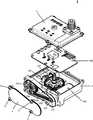
- FIG. 1is an exploded isometric top view of the actuator.
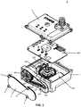
- FIG. 2Ais an exploded isometric top view of the actuator that is rotated ninety degrees (90°) to the right from the view depicted in FIG. 1 .
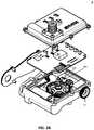
- FIG. 2Bis an exploded isometric top view of the actuator that is rotated ninety degrees (90°) to the left from the view depicted in FIG. 1 .
- FIG. 3is an exploded isometric top view of the actuator that is rotated ninety degrees (90°) to the right from the view depicted in FIG. 2A .
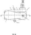
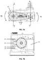
- FIG. 4Ais a side view of the actuator.
- FIG. 4Bis a cut-a-way side view of the actuator illustrated in FIG. 4A .
- FIG. 5is a cut-a-way top view of the actuator.
- FIG. 6is a cut-a-way side view of the actuator that is rotated one-hundred and eighty degrees (180°) from the view depicted in FIGS. 4A and 4B .
- FIG. 7Ais another cut-a-way side view of the actuator.
- FIG. 7Bis another cut-a-way top view of the actuator.
- FIG. 8Ais an exploded isometric bottom view of the actuator.
- FIG. 8Bis an exploded isometric bottom view of the actuator that is rotated ninety degrees (90°) from the view depicted in FIG. 8A .
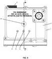
- FIG. 9is a top view of the actuator within a housing.
- the actuator 1generally includes a motor assembly 100 , a gear assembly 200 , and a circuit board 300 , which may include any number of sensing systems and other features.
- the motor assembly 100 , a gear assembly 200 , and a circuit board 300may be enclosed in a housing 2 , such as the illustrated two (2) piece housing.
- Housing 2may include a drive belt cover 3 that is removable to expose the drive belt 201 and facilitate replacement and/or maintenance of the same.
- Belt cover 3may be fixed to housing 2 by any commercially available means and, in one embodiment, belt cover screws 9 are utilized to fix belt cover 3 to housing 2 .
- Drive belt cover 3may include a back drive cap 11 that is removable to expose the sprocket end 216 of the worm screw shaft 210 , such that a user may manually back drive the worm screw shaft 210 , thereby reversing rotation of the drive shaft 230 .
- sprocket end 216may be adapted to receive an Allen wrench or other means by which a user may manually rotate worm screw shaft 210 , which effectively results in manual drive shaft 230 rotation.
- An alternate method of manually back driving worm screw shaft 210 and drive shaft 230is also depicted.
- back-drive wheel 12may be connected to the other end of worm screw shaft 210 (i.e., opposite sprocket end 216 ) and disposed on the exterior of housing 2 , so that a user may manually access and rotate wheel 12 .
- This manual rotation of wheel 12results in rotation of worm screw shaft 210 and drive shaft 230 , and is best illustrated in FIGS. 3 and 5 .
- housing 2is a two-part housing comprising a housing cover 5 and housing base 6 such that a user may access the internal components of actuator 1 such as the motor assembly 100 and/or the gear assembly 200 .
- the user of actuator 1may access the internal envelope defined by housing 2 to repair and/or replace components of actuator 1 .
- housing 2may include housing cover 5 that may be mounted to housing base 6 of housing 2 by any number of screws 7 .
- housing cover 5could be mounted to housing base 6 by way of magnets or other latching mechanisms.
- housing cover 5could be hinged along a side of housing base 6 to facilitate the “opening” of housing cover 5 with respect to housing base 6 in the same manner in which a door is opened. In this latter embodiment, when housing cover 5 is in a “closed” position with respect to housing base 6 , the housing cover 5 could be secured to housing base 6 by any commercially available means including those described above.
- the motor assembly 100includes a motor (not shown), which is preferably enclosed within a motor housing 102 , and motor shaft 103 .
- the motoris preferably an electric motor, and may be any one of numerous types of AC or DC motors now known or developed in the future including, for example, an AC induction motor, a brushless DC motor, or a brushed DC motor. In a preferred embodiment, however, the motor is implemented as a brushless DC motor.
- the motoris preferably implemented as an electric motor, it will nonetheless be appreciated that the motor could be implemented, if so desired, as a pneumatic or hydraulic motor.
- the motor shaft 103extends from the motor housing 102 and is coupled to the gear assembly 200 .
- the motor shaft 103has two ends, a motor end (not shown) that is situated within the motor housing 102 and a sprocket end 106 .
- the sprocket end 106 of the motor shaft 103is adapted to receive a drive belt 201 along the outer circumferential surface of the sprocket end 106 .
- the sprocket end 106receives drive belt 201 by way of a plurality of driving teeth (not shown) that engage a plurality of drive belt teeth 202 on the drive belt 201 .
- the gear assembly 200 of actuator 1comprises a drive belt 201 (having a plurality of drive belt teeth 202 ); a sprocket 203 having a plurality of sprocket teeth 204 along the sprocket's 203 outer circumferential surface; a worm screw shaft 210 having a worm screw portion 211 , a sprocket end 216 and an opposing end 213 ; and a drive gear 220 that is disposed on the drive shaft 230 .
- Gear assembly 200is coupled to the motor assembly 100 by way of the drive belt 201 .
- Sprocket 203is adapted to receive a drive belt 201 along its outer circumferential surface whereby the plurality of drive belt teeth 202 engage the plurality of sprocket teeth 204 .
- the worm screw shaft 210has a worm screw portion 211 , a sprocket end 216 and an opposing end 213 .
- Sprocket 203is rotatably mounted about a longitudinal axis X-X of the worm screw shaft 210 , for example, at the sprocket end 216 , such that sprocket 203 and worm screw shaft 210 rotate in tandem about axis X-X.
- the drive gear 220may have a plurality of teeth 221 along the circumference of its outer surface. Teeth 221 of drive gear 220 are engaged by screws 212 threaded along the outer surface of worm screw portion 211 .
- Drive shaft 230includes a sensor end 231 , a middle portion 232 , and a drive end 233 .
- Drive gear 220is longitudinally mounted along an axis Y-Y of drive shaft 230 , preferably in the middle portion 232 thereof, such that drive gear 220 and drive shaft 230 rotate in tandem about axis Y-Y. As illustrated in FIG. 6 , drive end 233 of drive shaft 230 may protrude from housing 2 at housing aperture 8 , such that external equipment may be attached to drive shaft 230 and utilize the output of actuator 1 .
- gear assembly 200 configuration described abovehas a relatively small and compact size when adapted for use within housing 2 such that there is extra unused space within the internal cavity of housing 2 , and this extra unused space may be utilized by incorporating additional gearing and/or componentry.
- gear assembly 200may be implemented using any one of numerous configurations, and not just those configurations shown in the figures. For example, in applications where additional output torque is needed, additional gears may be incorporated within gear assembly 200 in addition to drive gear 230 or, alternatively, drive gear 230 may be replaced by a planetary gearing system or other gearing system that would offer increased output torque.
- actuator 1is lighter in weight and more efficient than other commercially available actuators.
- motorWhen in use and as depicted in FIGS. 7A and 7B , motor rotates and imparts a first torque (denoted by arrow T 1 ) on motor shaft 103 .
- Motor shaft 103drives drive belt 201 , which in turn imparts a second torque (denoted by arrow T 2 ) on sprocket 203 .
- Second torque T 2rotates sprocket 203 as well as worm screw shaft 210 .
- a third torque(denoted by arrow T 3 ) is imparted on worm screw portion 211 via sprocket 203 , causing worm screw shaft 210 to rotate about axis X-X.
- worm screw portion 211 of worm screw shaft 210rotates, it in turn causes drive gear 220 (and drive shaft 230 fixed thereto) to rotate about axis Y-Y, thereby supplying a rotational drive force (i.e., the output torque denoted by arrow T 4 ) to drive shaft 230 .
- This resulting output torque T 4may be utilized by external equipment that is connected to actuator 1 , for example, at drive end 233 of drive shaft 230 .
- Actuator 1may include a position sensor system.
- the position sensoris an integrated chip 301 on circuit board 300 .
- Position sensor integrated chip 301is adapted to receive sensor end 231 of drive shaft 230 and, in embodiments incorporating housing 2 , circuit board 300 and the position sensor integrated chip 301 may be adapted to fit within the internal envelope defined by the cavity of housing 2 .
- the integrated chip 301may include a rotational collar 302 that is positioned to rotate within a receiving port 303 and oriented along axis Y-Y. Collar 302 may span the entire height of integrated chip 301 along axis Y-Y or, alternatively, be disposed on a top side or bottom side of the integrated chip 301 , or on both top and bottom sides of integrated chip 301 .
- the position sensor integrated chip 301may also include a Hall effect sensor (not shown) and magnet (not shown).
- sensor end 231 of drive shaft 230may be inserted into receiving port 303 and fastened to rotational collar 302 .
- sensor end 231 of drive shaft 230is fastened to rotational collar 302 , the two elements rotate in tandem such that the Hall effect sensor and magnet of integrated chip 301 may determine a rotational characteristic of the rotational collar 302 and, thereby, determine the rotational position of drive shaft 230 along with any external equipment attached thereto.
- Position sensor integrated chip 301may also provide a user with feedback concerning the foregoing rotational characteristic and/or rotational position of drive shaft 230 .
- the position sensor integrated chip 301may determine whether the external equipment is in the open or closed condition based upon the position of the drive shaft 230 and/or rotational collar 302 within the receiving port 303 , as determined by the Hall effect sensor and magnet, and transmit that information to a user/operator.
- the position sensor integrated chip 301may be any type of commercially available Hall effect rotary position sensor.
- the position sensor integrated chip 301may be a through shaft Hall-Effect rotary position sensor obtained from the company Piher Sensors & Controls SA (“Piher”), such as the MTS-360, PST-360 or MTS-360 PCB. It should be appreciated, however, that other models and varieties of positions sensors may be utilized, regardless of whether they are manufactured by Piher.
- PiherPiher Sensors & Controls SA
- the actuator 1 depicted and described hereinincludes a relatively small, low power electric motor that is configured to run at a relatively high rotational speed and relatively low torque.
- Gear assembly 200reduces that rotational speed and increases the output torque (T 4 ) as exerted through drive 230 .
- drive belt 201is incorporated into gear assembly 200
- actuator 1will be lighter and more efficient than other actuators on the market that utilize gears in lieu of belt drives. This is because belts are manufactured of materials that are lighter in weight than typical gearing systems that are comprised of solid and dense metal components. Belt drive systems are therefore more efficient than other system configurations comprised entirely of gears.
- actuator 1includes a temperature sensor (not shown). If housing 2 is utilized, temperature sensor would be situated therein, for example, on circuit board 300 . Where utilized, temperature sensor 400 will sense the temperature of motor assembly 100 and, in response to increased motor temperatures, the pulse width modulation control of the motor would be proportionately reduced in response to rising temperatures as sensed by temperature sensor.
- temperature sensor 400will sense the temperature of motor assembly 100 and, in response to increased motor temperatures, the pulse width modulation control of the motor would be proportionately reduced in response to rising temperatures as sensed by temperature sensor.
- electric motorscontinue to provide torque when in a stalled condition; however, electric motors left in such a stalled condition are prone to overheating and possible damage resulting therefrom, as the current flow into the motor is maximized under these conditions. Overheating is therefore a prevalent source of failure for actuators.
- actuator 1could include a temperature sensor to directly measure motor assembly's 100 temperature, which is the source of any damage resulting from the stall condition, rather than the increased current draw resulting from the stall condition.
- temperature sensorcould measure the temperature of motor housing 102 and, when continuous temperatures above a certain threshold are detected for a prolonged period of time (e.g., 10 seconds of operation), motor would switch to a secondary stall condition mode by way of a microcontroller (not shown).
- This secondary stall condition modewould protect the motor assembly 100 from the combination of high ambient temperature conditions, as well as extended current draw resulting in motor over-heating and failure.
- no resetwould be required, as the power is maintained to the actuator 1 , and the actuator 1 and any external equipment attached thereto would continue to operate as intended.
- housing 2 of actuator 1contains a visual position indicator 10 .
- visual position indicator 10may be located on the external surface of housing cover 5 such that the operator of actuator 1 may determine the rotational configuration of drive shaft 230 .
- sensor end 231 of drive shaft 230may be inserted into a first receiving port 303 on the underside of integrated chip 301 and continue through and exit a second receiving port 303 on the upper side of integrated chip 301 , such that sensor end 231 contacts visual position indicator 10 of housing 2 , rather than terminating at some point within integrated chip 301 .
- Housing 2may also include, in addition to visual position indicator 10 or in lieu thereof, one or more electrical position indicators 11 , for example, one or more optical light tubes (i.e., light pipes) such as those purchased from the Dialight company.
Landscapes
- Engineering & Computer Science (AREA)
- General Engineering & Computer Science (AREA)
- Mechanical Engineering (AREA)
- Power Engineering (AREA)
- Microelectronics & Electronic Packaging (AREA)
- Connection Of Motors, Electrical Generators, Mechanical Devices, And The Like (AREA)
Abstract
Description
Claims (20)
Priority Applications (1)
| Application Number | Priority Date | Filing Date | Title |
|---|---|---|---|
| US15/746,281US11078997B2 (en) | 2015-07-20 | 2016-07-20 | Motor driven electromechanical actuator |
Applications Claiming Priority (3)
| Application Number | Priority Date | Filing Date | Title |
|---|---|---|---|
| US201562194611P | 2015-07-20 | 2015-07-20 | |
| US15/746,281US11078997B2 (en) | 2015-07-20 | 2016-07-20 | Motor driven electromechanical actuator |
| PCT/US2016/043115WO2017015355A1 (en) | 2015-07-20 | 2016-07-20 | Motor driven electromechanical actuator |
Publications (2)
| Publication Number | Publication Date |
|---|---|
| US20180216712A1 US20180216712A1 (en) | 2018-08-02 |
| US11078997B2true US11078997B2 (en) | 2021-08-03 |
Family
ID=57835277
Family Applications (1)
| Application Number | Title | Priority Date | Filing Date |
|---|---|---|---|
| US15/746,281Active2038-05-07US11078997B2 (en) | 2015-07-20 | 2016-07-20 | Motor driven electromechanical actuator |
Country Status (3)
| Country | Link |
|---|---|
| US (1) | US11078997B2 (en) |
| EP (1) | EP3325845B1 (en) |
| WO (1) | WO2017015355A1 (en) |
Cited By (2)
| Publication number | Priority date | Publication date | Assignee | Title |
|---|---|---|---|---|
| US20200290200A1 (en)* | 2017-08-02 | 2020-09-17 | Berkshire Grey, Inc. | Systems and methods for acquiring and moving objects having complex outer surfaces |
| US20230034890A1 (en)* | 2019-12-27 | 2023-02-02 | Takatori Seisakusho Co., Ltd. | Valve actuator |
Families Citing this family (6)
| Publication number | Priority date | Publication date | Assignee | Title |
|---|---|---|---|---|
| US10703198B2 (en)* | 2017-01-31 | 2020-07-07 | Brp-Rotax Gmbh & Co. Kg | Kart and drive assembly for a kart |
| US11149846B2 (en) | 2017-07-18 | 2021-10-19 | Dus Operating Inc. | Actuator assembly for a transmission shifter |
| US20190024789A1 (en)* | 2017-07-18 | 2019-01-24 | Dura Operating, Llc | Actuator assembly for a transmission shifter |
| US10955051B2 (en) | 2017-07-18 | 2021-03-23 | Dura Operating, Llc | Actuator assembly for a transmission shifter |
| US11555719B2 (en)* | 2018-12-12 | 2023-01-17 | Hl Mando Corporation | Actuator assembly having rotary sensor responsive to rotation of magnet |
| US11906023B2 (en)* | 2022-03-02 | 2024-02-20 | Herbert Thomas Baumgartner | System and methods for a gear reducer |
Citations (38)
| Publication number | Priority date | Publication date | Assignee | Title |
|---|---|---|---|---|
| US3572449A (en)* | 1967-11-29 | 1971-03-30 | Mason & Porter Ltd | Machines for boring holes |
| US3651711A (en) | 1970-04-16 | 1972-03-28 | Anderson Greenwood & Co | Shaft rotating device |
| US4403449A (en) | 1980-03-03 | 1983-09-13 | Richmond Moscow K | Gate-opening and closing apparatus and method |
| US4827790A (en)* | 1986-12-02 | 1989-05-09 | Bisiach & Carru' S.P.A. | System for the automatic recovery of play between a worm and worm gear |
| US5127113A (en) | 1991-06-10 | 1992-07-07 | Nova Technologies, Inc. | Invalid transfer arrangement |
| US5345834A (en)* | 1991-01-08 | 1994-09-13 | Kabushiki Kaisha Sankyo Seiki Seisakusho | Velocity-reduced drive system |
| US5475930A (en)* | 1993-06-29 | 1995-12-19 | Kabushiki Kaisha Topcon | Rotating and driving system for survey instrument |
| DE29600462U1 (en) | 1996-01-12 | 1996-04-25 | Getriebebau-Nord Schlicht + Küchenmeister GmbH & Co, 22941 Bargteheide | Motor gear arrangement |
| US5584515A (en) | 1994-12-30 | 1996-12-17 | Kelsey-Hayes Company | Double locking vehicle door latch |
| US5661384A (en) | 1995-06-05 | 1997-08-26 | Lucas Western, Inc. | Motor control system and method |
| FR2756318A1 (en) | 1996-11-25 | 1998-05-29 | Peugeot | ELECTRIC WINDOW REGULATOR SYSTEM ESPECIALLY FOR A MOTOR VEHICLE |
| US5801501A (en) | 1995-06-30 | 1998-09-01 | Siemens Aktiengesellschaft | Arrangement for moving window panes in a motor vehicle |
| US5823054A (en)* | 1994-02-02 | 1998-10-20 | Iku Holding Montfoort B.V. | Movement actuator |
| US5970813A (en)* | 1997-09-17 | 1999-10-26 | Abl Boat Lifts | Drive system |
| US6195940B1 (en)* | 1997-10-22 | 2001-03-06 | Saturn Electronics & Engineering, Inc. | Power actuator for a vehicle window |
| WO2002084151A1 (en) | 2001-04-12 | 2002-10-24 | Valeo Motoren Und Aktuatoren Gmbh | Driving gear, especially worm gear |
| US6554337B2 (en) | 2000-12-07 | 2003-04-29 | Homayoon Kazerooni | Mechanical grapple for grabbing and holding sacks and bags |
| US6603305B2 (en)* | 2000-12-27 | 2003-08-05 | Alps Electric Co., Ltd. | Rotary encoder having code member rotating along accurate circle as shaft rotates |
| US6820579B2 (en) | 2002-07-22 | 2004-11-23 | Nissan Motor Co., Ltd. | Variable valve operating system of engine enabling variation of working angle and phase |
| US6883999B1 (en)* | 2003-11-07 | 2005-04-26 | Wacker Corporation | Trowel gearbox brake |
| US7140571B2 (en) | 2003-06-11 | 2006-11-28 | Autoliv, Asp, Inc. | Electric seat belt retractor system |
| US7161322B2 (en) | 2003-11-18 | 2007-01-09 | Intouch Technologies, Inc. | Robot with a manipulator arm |
| US7215115B2 (en)* | 2001-12-21 | 2007-05-08 | Hitachi, Ltd. | Module to control a rotating output shaft and module to change a driving condition of vehicle |
| US7261012B2 (en)* | 2001-07-18 | 2007-08-28 | Robert Bosch Gmbh | Gear drive unit with speed measurement |
| US20070205232A1 (en)* | 2006-03-03 | 2007-09-06 | Kevin Doyle | Electronically controlled valve actuator in a plumbed water line within a water conditioning management system |
| US7308873B2 (en) | 2004-04-15 | 2007-12-18 | Nissan Motor Co., Ltd. | Variable valve control system for internal combustion engine |
| US20080017150A1 (en) | 2004-09-15 | 2008-01-24 | Yamaha Hatsudoki Kabushiki Kaisha | Variable Valve Drive Device, Engine, and Motorcycle |
| US20080045925A1 (en) | 2006-06-19 | 2008-02-21 | Stepovich Matthew J | Drug delivery system |
| US20090078489A1 (en) | 2007-09-25 | 2009-03-26 | Magna Powertrain Ag & Co Kg | Transmission unit |
| US20110041800A1 (en)* | 2009-04-29 | 2011-02-24 | Ray Tat Lung Wong | Position sensor for an output shaft used in a shift and throttle system |
| US7950550B2 (en) | 2004-05-06 | 2011-05-31 | Diversey, Inc. | Metering and dispensing closure |
| US8333129B2 (en) | 2008-10-29 | 2012-12-18 | S.A. Robotics | Robotic manipulator arm |
| US8744621B2 (en) | 2009-01-09 | 2014-06-03 | Automed Technologies, Inc. | Medical cabinet access belt optimization system |
| US20140202274A1 (en)* | 2013-01-24 | 2014-07-24 | Micro Controle - Spectra Physics | Device for driving in rotation a toothed wheel, in particular a turntable |
| US20150035658A1 (en) | 2012-06-13 | 2015-02-05 | William R. Provancher | Skin stretch feedback devices, systems, and methods |
| US8994776B2 (en) | 2010-11-12 | 2015-03-31 | Crosswing Inc. | Customizable robotic system |
| US9068903B2 (en) | 2011-09-14 | 2015-06-30 | GM Global Technology Operations LLC | Sensor multiplexing in actuation systems comprising active-material actuators |
| US9550262B2 (en)* | 2012-07-13 | 2017-01-24 | Smc Kabushiki Kaisha | Electric clamp apparatus |
- 2016
- 2016-07-20EPEP16828462.8Apatent/EP3325845B1/enactiveActive
- 2016-07-20WOPCT/US2016/043115patent/WO2017015355A1/ennot_activeCeased
- 2016-07-20USUS15/746,281patent/US11078997B2/enactiveActive
Patent Citations (38)
| Publication number | Priority date | Publication date | Assignee | Title |
|---|---|---|---|---|
| US3572449A (en)* | 1967-11-29 | 1971-03-30 | Mason & Porter Ltd | Machines for boring holes |
| US3651711A (en) | 1970-04-16 | 1972-03-28 | Anderson Greenwood & Co | Shaft rotating device |
| US4403449A (en) | 1980-03-03 | 1983-09-13 | Richmond Moscow K | Gate-opening and closing apparatus and method |
| US4827790A (en)* | 1986-12-02 | 1989-05-09 | Bisiach & Carru' S.P.A. | System for the automatic recovery of play between a worm and worm gear |
| US5345834A (en)* | 1991-01-08 | 1994-09-13 | Kabushiki Kaisha Sankyo Seiki Seisakusho | Velocity-reduced drive system |
| US5127113A (en) | 1991-06-10 | 1992-07-07 | Nova Technologies, Inc. | Invalid transfer arrangement |
| US5475930A (en)* | 1993-06-29 | 1995-12-19 | Kabushiki Kaisha Topcon | Rotating and driving system for survey instrument |
| US5823054A (en)* | 1994-02-02 | 1998-10-20 | Iku Holding Montfoort B.V. | Movement actuator |
| US5584515A (en) | 1994-12-30 | 1996-12-17 | Kelsey-Hayes Company | Double locking vehicle door latch |
| US5661384A (en) | 1995-06-05 | 1997-08-26 | Lucas Western, Inc. | Motor control system and method |
| US5801501A (en) | 1995-06-30 | 1998-09-01 | Siemens Aktiengesellschaft | Arrangement for moving window panes in a motor vehicle |
| DE29600462U1 (en) | 1996-01-12 | 1996-04-25 | Getriebebau-Nord Schlicht + Küchenmeister GmbH & Co, 22941 Bargteheide | Motor gear arrangement |
| FR2756318A1 (en) | 1996-11-25 | 1998-05-29 | Peugeot | ELECTRIC WINDOW REGULATOR SYSTEM ESPECIALLY FOR A MOTOR VEHICLE |
| US5970813A (en)* | 1997-09-17 | 1999-10-26 | Abl Boat Lifts | Drive system |
| US6195940B1 (en)* | 1997-10-22 | 2001-03-06 | Saturn Electronics & Engineering, Inc. | Power actuator for a vehicle window |
| US6554337B2 (en) | 2000-12-07 | 2003-04-29 | Homayoon Kazerooni | Mechanical grapple for grabbing and holding sacks and bags |
| US6603305B2 (en)* | 2000-12-27 | 2003-08-05 | Alps Electric Co., Ltd. | Rotary encoder having code member rotating along accurate circle as shaft rotates |
| WO2002084151A1 (en) | 2001-04-12 | 2002-10-24 | Valeo Motoren Und Aktuatoren Gmbh | Driving gear, especially worm gear |
| US7261012B2 (en)* | 2001-07-18 | 2007-08-28 | Robert Bosch Gmbh | Gear drive unit with speed measurement |
| US7215115B2 (en)* | 2001-12-21 | 2007-05-08 | Hitachi, Ltd. | Module to control a rotating output shaft and module to change a driving condition of vehicle |
| US6820579B2 (en) | 2002-07-22 | 2004-11-23 | Nissan Motor Co., Ltd. | Variable valve operating system of engine enabling variation of working angle and phase |
| US7140571B2 (en) | 2003-06-11 | 2006-11-28 | Autoliv, Asp, Inc. | Electric seat belt retractor system |
| US6883999B1 (en)* | 2003-11-07 | 2005-04-26 | Wacker Corporation | Trowel gearbox brake |
| US7161322B2 (en) | 2003-11-18 | 2007-01-09 | Intouch Technologies, Inc. | Robot with a manipulator arm |
| US7308873B2 (en) | 2004-04-15 | 2007-12-18 | Nissan Motor Co., Ltd. | Variable valve control system for internal combustion engine |
| US7950550B2 (en) | 2004-05-06 | 2011-05-31 | Diversey, Inc. | Metering and dispensing closure |
| US20080017150A1 (en) | 2004-09-15 | 2008-01-24 | Yamaha Hatsudoki Kabushiki Kaisha | Variable Valve Drive Device, Engine, and Motorcycle |
| US20070205232A1 (en)* | 2006-03-03 | 2007-09-06 | Kevin Doyle | Electronically controlled valve actuator in a plumbed water line within a water conditioning management system |
| US20080045925A1 (en) | 2006-06-19 | 2008-02-21 | Stepovich Matthew J | Drug delivery system |
| US20090078489A1 (en) | 2007-09-25 | 2009-03-26 | Magna Powertrain Ag & Co Kg | Transmission unit |
| US8333129B2 (en) | 2008-10-29 | 2012-12-18 | S.A. Robotics | Robotic manipulator arm |
| US8744621B2 (en) | 2009-01-09 | 2014-06-03 | Automed Technologies, Inc. | Medical cabinet access belt optimization system |
| US20110041800A1 (en)* | 2009-04-29 | 2011-02-24 | Ray Tat Lung Wong | Position sensor for an output shaft used in a shift and throttle system |
| US8994776B2 (en) | 2010-11-12 | 2015-03-31 | Crosswing Inc. | Customizable robotic system |
| US9068903B2 (en) | 2011-09-14 | 2015-06-30 | GM Global Technology Operations LLC | Sensor multiplexing in actuation systems comprising active-material actuators |
| US20150035658A1 (en) | 2012-06-13 | 2015-02-05 | William R. Provancher | Skin stretch feedback devices, systems, and methods |
| US9550262B2 (en)* | 2012-07-13 | 2017-01-24 | Smc Kabushiki Kaisha | Electric clamp apparatus |
| US20140202274A1 (en)* | 2013-01-24 | 2014-07-24 | Micro Controle - Spectra Physics | Device for driving in rotation a toothed wheel, in particular a turntable |
Non-Patent Citations (4)
| Title |
|---|
| Dual Motor Low Profile Actuator. ITT Aerospace. Jun. 22, 2016. https://www.ittaerospace.com/Products/Dual-Motor-Low-Profile-Actuator/. |
| How to achieve very accurate/fine rotation with motor. Oct. 7, 2015. StackExchange. http://electronics.stackexchange.com/questions/193905/how-to-achieve-very-accurate-fine-rotation-with-motor. |
| Industrial Robot: An International Journal, vol. 28, No. 4, 2001, pp. 346 and 347. http://dialog.proquest.com/professional/docview/2017022421?accountid=157282. |
| International Search Report and Written Opinion. International Application No. PCT/US2016/043115. Applicant: National Machine Group. Authorized Officer Blaine R. Copenheaver. International Filing Date Jul. 20, 2016. dated Sep. 22, 2016. Forms PCT/ISA/220, PCT/ISA/210 and PCT/ISA/237. |
Cited By (4)
| Publication number | Priority date | Publication date | Assignee | Title |
|---|---|---|---|---|
| US20200290200A1 (en)* | 2017-08-02 | 2020-09-17 | Berkshire Grey, Inc. | Systems and methods for acquiring and moving objects having complex outer surfaces |
| US11724389B2 (en)* | 2017-08-02 | 2023-08-15 | Berkshire Grey Operating Company, Inc. | Systems and methods for acquiring and moving objects having complex outer surfaces |
| US20230034890A1 (en)* | 2019-12-27 | 2023-02-02 | Takatori Seisakusho Co., Ltd. | Valve actuator |
| US11614180B2 (en)* | 2019-12-27 | 2023-03-28 | Takatori Seisakusho Co., Ltd. | Valve actuator |
Also Published As
| Publication number | Publication date |
|---|---|
| EP3325845A4 (en) | 2019-01-02 |
| US20180216712A1 (en) | 2018-08-02 |
| EP3325845A1 (en) | 2018-05-30 |
| EP3325845B1 (en) | 2021-08-04 |
| WO2017015355A1 (en) | 2017-01-26 |
Similar Documents
| Publication | Publication Date | Title |
|---|---|---|
| US11078997B2 (en) | Motor driven electromechanical actuator | |
| US20080184828A1 (en) | Linear Actuator with a Redundant Structure | |
| US8508168B2 (en) | Linear actuator | |
| EP2321558B1 (en) | Motorized gear and coupling system | |
| CA2420748A1 (en) | Drive system | |
| AU2005213848A1 (en) | A linear actuator comprising an overload clutch | |
| CA2613625A1 (en) | Remote control for braking system of progressive cavity pump | |
| JP4986640B2 (en) | Constant torque electric screwdriver | |
| US20160271772A1 (en) | Screwdriver | |
| ATE404428T1 (en) | ELECTRO-MECHANICAL LINEAR DRIVE | |
| CA2735114C (en) | Electric gripper drive with a torsional compliance device | |
| US9868347B2 (en) | Adjustment device and method for adjusting shutoff elements | |
| PL365308A1 (en) | Window, door and the like equipped with actuating rod motor drive unit | |
| ES3009024T3 (en) | Method for state analysis of an electromechanical joining system and electromechanical joining system for carrying out this method | |
| KR101706602B1 (en) | Apparatus of controlling for flow regulating valve by stepping control | |
| RU164884U1 (en) | ELECTRIC ACTUATOR OF PIPELINE FITTINGS | |
| EP3433512B1 (en) | Linear drive apparatus | |
| US20090308191A1 (en) | Lifting motor drive | |
| SE515375C2 (en) | Temperature monitoring device | |
| FR3080234B1 (en) | COMPACT LINEAR ELECTRIC ACTUATOR WITH ELASTIC DRIVE CHAIN | |
| ATE547645T1 (en) | LINEAR ELECTROMECHANICAL ACTUATOR | |
| GB2185731A (en) | Small electro-mechanical linear actuator | |
| JP2009121663A (en) | Actuator for electric valve | |
| ATE306602T1 (en) | DRIVE ROD FITTING WITH A MOTOR DRIVE UNIT | |
| TWI586561B (en) | The information feedback device and its data feedback method |
Legal Events
| Date | Code | Title | Description |
|---|---|---|---|
| FEPP | Fee payment procedure | Free format text:ENTITY STATUS SET TO UNDISCOUNTED (ORIGINAL EVENT CODE: BIG.); ENTITY STATUS OF PATENT OWNER: SMALL ENTITY | |
| FEPP | Fee payment procedure | Free format text:ENTITY STATUS SET TO SMALL (ORIGINAL EVENT CODE: SMAL); ENTITY STATUS OF PATENT OWNER: SMALL ENTITY | |
| STPP | Information on status: patent application and granting procedure in general | Free format text:DOCKETED NEW CASE - READY FOR EXAMINATION | |
| AS | Assignment | Owner name:NATIONAL MACHINE GROUP, OHIO Free format text:ASSIGNMENT OF ASSIGNORS INTEREST;ASSIGNOR:HYDE, ROBERT WILLIAM;REEL/FRAME:051217/0450 Effective date:20191203 Owner name:NATIONAL MACHINE GROUP, OHIO Free format text:ASSIGNMENT OF ASSIGNORS INTEREST;ASSIGNOR:FORRESTER, RAYMOND ALVERO, JR;REEL/FRAME:051218/0477 Effective date:20180508 | |
| STPP | Information on status: patent application and granting procedure in general | Free format text:NON FINAL ACTION MAILED | |
| STPP | Information on status: patent application and granting procedure in general | Free format text:RESPONSE TO NON-FINAL OFFICE ACTION ENTERED AND FORWARDED TO EXAMINER | |
| STPP | Information on status: patent application and granting procedure in general | Free format text:FINAL REJECTION MAILED | |
| STPP | Information on status: patent application and granting procedure in general | Free format text:ADVISORY ACTION MAILED | |
| STPP | Information on status: patent application and granting procedure in general | Free format text:DOCKETED NEW CASE - READY FOR EXAMINATION | |
| STPP | Information on status: patent application and granting procedure in general | Free format text:NOTICE OF ALLOWANCE MAILED -- APPLICATION RECEIVED IN OFFICE OF PUBLICATIONS | |
| STPP | Information on status: patent application and granting procedure in general | Free format text:PUBLICATIONS -- ISSUE FEE PAYMENT RECEIVED | |
| STPP | Information on status: patent application and granting procedure in general | Free format text:PUBLICATIONS -- ISSUE FEE PAYMENT VERIFIED | |
| STCF | Information on status: patent grant | Free format text:PATENTED CASE | |
| AS | Assignment | Owner name:NATIONAL MACHINE COMPANY, OHIO Free format text:ASSIGNMENT OF ASSIGNORS INTEREST;ASSIGNOR:NATIONAL MACHINE GROUP;REEL/FRAME:064559/0927 Effective date:20230802 | |
| MAFP | Maintenance fee payment | Free format text:PAYMENT OF MAINTENANCE FEE, 4TH YR, SMALL ENTITY (ORIGINAL EVENT CODE: M2551); ENTITY STATUS OF PATENT OWNER: SMALL ENTITY Year of fee payment:4 |