US11078945B2 - Coupler to attach robotic arm to surgical table - Google Patents
Coupler to attach robotic arm to surgical tableDownload PDFInfo
- Publication number
- US11078945B2 US11078945B2US15/934,709US201815934709AUS11078945B2US 11078945 B2US11078945 B2US 11078945B2US 201815934709 AUS201815934709 AUS 201815934709AUS 11078945 B2US11078945 B2US 11078945B2
- Authority
- US
- United States
- Prior art keywords
- coupler
- cam
- post
- axis
- along
- Prior art date
- Legal status (The legal status is an assumption and is not a legal conclusion. Google has not performed a legal analysis and makes no representation as to the accuracy of the status listed.)
- Active, expires
Links
- 230000008878couplingEffects0.000claimsabstractdescription74
- 238000010168coupling processMethods0.000claimsabstractdescription74
- 238000005859coupling reactionMethods0.000claimsabstractdescription74
- 230000007246mechanismEffects0.000claimsabstractdescription54
- 238000013519translationMethods0.000claimsdescription36
- 230000007704transitionEffects0.000claimsdescription3
- 238000000034methodMethods0.000description27
- 230000013011matingEffects0.000description13
- 230000006835compressionEffects0.000description12
- 238000007906compressionMethods0.000description12
- 239000000463materialSubstances0.000description11
- 238000001356surgical procedureMethods0.000description10
- 230000008901benefitEffects0.000description4
- 210000000078clawAnatomy0.000description4
- NJPPVKZQTLUDBO-UHFFFAOYSA-NnovaluronChemical compoundC1=C(Cl)C(OC(F)(F)C(OC(F)(F)F)F)=CC=C1NC(=O)NC(=O)C1=C(F)C=CC=C1FNJPPVKZQTLUDBO-UHFFFAOYSA-N0.000description3
- 230000008569processEffects0.000description3
- 230000009977dual effectEffects0.000description2
- 230000004044responseEffects0.000description2
- 230000003068static effectEffects0.000description2
- 230000005355Hall effectEffects0.000description1
- 230000008859changeEffects0.000description1
- 150000001875compoundsChemical class0.000description1
- 238000012790confirmationMethods0.000description1
- 239000000470constituentSubstances0.000description1
- 230000007423decreaseEffects0.000description1
- 238000013461designMethods0.000description1
- 239000000835fiberSubstances0.000description1
- 230000005484gravityEffects0.000description1
- 239000007788liquidSubstances0.000description1
- 230000001105regulatory effectEffects0.000description1
- 230000003746surface roughnessEffects0.000description1
- 238000012549trainingMethods0.000description1
Images


Classifications
- A—HUMAN NECESSITIES
- A61—MEDICAL OR VETERINARY SCIENCE; HYGIENE
- A61B—DIAGNOSIS; SURGERY; IDENTIFICATION
- A61B34/00—Computer-aided surgery; Manipulators or robots specially adapted for use in surgery
- A61B34/30—Surgical robots
- A—HUMAN NECESSITIES
- A61—MEDICAL OR VETERINARY SCIENCE; HYGIENE
- A61B—DIAGNOSIS; SURGERY; IDENTIFICATION
- A61B34/00—Computer-aided surgery; Manipulators or robots specially adapted for use in surgery
- A61B34/30—Surgical robots
- A61B34/37—Leader-follower robots
- A—HUMAN NECESSITIES
- A61—MEDICAL OR VETERINARY SCIENCE; HYGIENE
- A61B—DIAGNOSIS; SURGERY; IDENTIFICATION
- A61B34/00—Computer-aided surgery; Manipulators or robots specially adapted for use in surgery
- A61B34/70—Manipulators specially adapted for use in surgery
- A—HUMAN NECESSITIES
- A61—MEDICAL OR VETERINARY SCIENCE; HYGIENE
- A61B—DIAGNOSIS; SURGERY; IDENTIFICATION
- A61B90/00—Instruments, implements or accessories specially adapted for surgery or diagnosis and not covered by any of the groups A61B1/00 - A61B50/00, e.g. for luxation treatment or for protecting wound edges
- A61B90/50—Supports for surgical instruments, e.g. articulated arms
- A61B90/57—Accessory clamps
- B—PERFORMING OPERATIONS; TRANSPORTING
- B25—HAND TOOLS; PORTABLE POWER-DRIVEN TOOLS; MANIPULATORS
- B25J—MANIPULATORS; CHAMBERS PROVIDED WITH MANIPULATION DEVICES
- B25J18/00—Arms
- B—PERFORMING OPERATIONS; TRANSPORTING
- B25—HAND TOOLS; PORTABLE POWER-DRIVEN TOOLS; MANIPULATORS
- B25J—MANIPULATORS; CHAMBERS PROVIDED WITH MANIPULATION DEVICES
- B25J3/00—Manipulators of leader-follower type, i.e. both controlling unit and controlled unit perform corresponding spatial movements
- B—PERFORMING OPERATIONS; TRANSPORTING
- B25—HAND TOOLS; PORTABLE POWER-DRIVEN TOOLS; MANIPULATORS
- B25J—MANIPULATORS; CHAMBERS PROVIDED WITH MANIPULATION DEVICES
- B25J9/00—Programme-controlled manipulators
- B25J9/0009—Constructional details, e.g. manipulator supports, bases
- B—PERFORMING OPERATIONS; TRANSPORTING
- B25—HAND TOOLS; PORTABLE POWER-DRIVEN TOOLS; MANIPULATORS
- B25J—MANIPULATORS; CHAMBERS PROVIDED WITH MANIPULATION DEVICES
- B25J9/00—Programme-controlled manipulators
- B25J9/0096—Programme-controlled manipulators co-operating with a working support, e.g. work-table
- F—MECHANICAL ENGINEERING; LIGHTING; HEATING; WEAPONS; BLASTING
- F16—ENGINEERING ELEMENTS AND UNITS; GENERAL MEASURES FOR PRODUCING AND MAINTAINING EFFECTIVE FUNCTIONING OF MACHINES OR INSTALLATIONS; THERMAL INSULATION IN GENERAL
- F16B—DEVICES FOR FASTENING OR SECURING CONSTRUCTIONAL ELEMENTS OR MACHINE PARTS TOGETHER, e.g. NAILS, BOLTS, CIRCLIPS, CLAMPS, CLIPS OR WEDGES; JOINTS OR JOINTING
- F16B21/00—Means for preventing relative axial movement of a pin, spigot, shaft or the like and a member surrounding it; Stud-and-socket releasable fastenings
- F16B21/10—Means for preventing relative axial movement of a pin, spigot, shaft or the like and a member surrounding it; Stud-and-socket releasable fastenings by separate parts
- F16B21/16—Means for preventing relative axial movement of a pin, spigot, shaft or the like and a member surrounding it; Stud-and-socket releasable fastenings by separate parts with grooves or notches in the pin or shaft
- F16B21/165—Means for preventing relative axial movement of a pin, spigot, shaft or the like and a member surrounding it; Stud-and-socket releasable fastenings by separate parts with grooves or notches in the pin or shaft with balls or rollers
- A—HUMAN NECESSITIES
- A61—MEDICAL OR VETERINARY SCIENCE; HYGIENE
- A61B—DIAGNOSIS; SURGERY; IDENTIFICATION
- A61B17/00—Surgical instruments, devices or methods
- A61B2017/00477—Coupling
- A—HUMAN NECESSITIES
- A61—MEDICAL OR VETERINARY SCIENCE; HYGIENE
- A61B—DIAGNOSIS; SURGERY; IDENTIFICATION
- A61B90/00—Instruments, implements or accessories specially adapted for surgery or diagnosis and not covered by any of the groups A61B1/00 - A61B50/00, e.g. for luxation treatment or for protecting wound edges
- A61B90/50—Supports for surgical instruments, e.g. articulated arms
- A61B90/57—Accessory clamps
- A61B2090/571—Accessory clamps for clamping a support arm to a bed or other supports
- A—HUMAN NECESSITIES
- A61—MEDICAL OR VETERINARY SCIENCE; HYGIENE
- A61B—DIAGNOSIS; SURGERY; IDENTIFICATION
- A61B2560/00—Constructional details of operational features of apparatus; Accessories for medical measuring apparatus
- A61B2560/04—Constructional details of apparatus
- F—MECHANICAL ENGINEERING; LIGHTING; HEATING; WEAPONS; BLASTING
- F16—ENGINEERING ELEMENTS AND UNITS; GENERAL MEASURES FOR PRODUCING AND MAINTAINING EFFECTIVE FUNCTIONING OF MACHINES OR INSTALLATIONS; THERMAL INSULATION IN GENERAL
- F16B—DEVICES FOR FASTENING OR SECURING CONSTRUCTIONAL ELEMENTS OR MACHINE PARTS TOGETHER, e.g. NAILS, BOLTS, CIRCLIPS, CLAMPS, CLIPS OR WEDGES; JOINTS OR JOINTING
- F16B2/00—Friction-grip releasable fastenings
- F16B2/02—Clamps, i.e. with gripping action effected by positive means other than the inherent resistance to deformation of the material of the fastening
- F16B2/16—Clamps, i.e. with gripping action effected by positive means other than the inherent resistance to deformation of the material of the fastening using rollers or balls
Definitions
- Robotic armsmay be coupled to a surgical table to provide power, data, and mechanical support to the arms.
- the functionality of the surgical table coupled to one or more robotic armscan be limited by the volume of space occupied by the robotic arms and which are generally fixed to the table and difficult to remove.
- Some conventional robotic armsrequire a technician having specialized training to connect and disconnect the robotic arms to the table such that changing and/or servicing a robotic arm is a time-consuming and expensive task.
- trained techniciansmay drop and damage a robotic arm during a coupling or decoupling operation because they do not force a user to support the arm during coupling or decoupling.
- robotic arms coupled to a surgical tableare considered generally fixed to each other.
- robotic arms coupled to a surgical tableshould adhere to IPX4 requirements related to ingress protection against foreign objects (e.g., liquids). Adhering to this regulatory standard further complicates the design and cost of a robotic surgical arm.
- Removal and reattachment of a robotic armmay introduce misalignment between the robotic arm and surgical table.
- conventional coupling mechanisms between a robotic arm and a surgical tabledo not register and/or provide confirmation that the robotic arm is positioned at a precise set of coordinates relative to the surgical table.
- some conventional robotic arm coupling mechanismsuse removable components (e.g., bolts) that may be misplaced and result in misalignment and/or failure of an arm to table coupling. Additional apparatus and methods for coupling a robotic arm to a surgical table are desirable.
- the present inventionis directed to an apparatus and methods for coupling robotic arms to a surgical table having a table top on which a patient can be disposed are described herein.
- the apparatus and methodsmay allow a robotic arm to be securely coupled to and aligned with a surgical table.
- the robotic armmay be quickly released from the surgical table (e.g., quick release, bail-out) such as for an emergency situation where access to the surgical table top is necessary.
- the robotic armmay include a first portion of a coupler and the surgical table may include a second portion of the coupler where the first portion complements the second portion. After inserting the first portion having a post into a ball bearing holder of the second portion, a user may rotate a handle to secure the coupling between the first and second portion.
- the couplercan include kinematic mounts configured to precisely and repeatably align the first and second portions.
- a motorized locking mechanism of a couplermay generate high forces to ensure the coupling is constrained and maintained in six degrees of freedom even in the presence of external loads.
- the robotic armmay include a first portion of a coupler and the surgical table may include a second portion of the coupler where the first portion complements the second portion. After inserting the first portion having a lead screw into a corresponding threaded portion of a collet, a motor may rotate the collet to bring the first portion into the second portion and secure the coupling between the first and second portion.
- a couplermay include a first portion having a cone with a conical taper and a second portion having corresponding conical hole that may constrain translational and rotational movement of the first and second portions along multiple axes.
- the couplermay include a multi-stage locking mechanism actuated by a handle and/or switch to couple and decouple the first and second portions from each other.
- a couplermay include a multi-stage locking mechanism including a radial clamp configured to secure a coupling between a first portion and a second portion using rotational and/or translational motion.
- a couplermay include a catch mechanism configured as a locking mechanism.
- the mechanismmay include a linearly driven dual sided rack with a set of rotating cam claws.
- the coupling mechanismcan be manually back driven.
- the apparatus and methodscan allow a robotic arm to be quickly released from a surgical table (e.g., quick release, bail-out) using a pin release mechanism such as for an emergency situation where access to the surgical table top is necessary.
- FIGS. 1A and 1Bare a schematic side view and a schematic top view, respectively, of a surgical table, according to an embodiment.
- FIG. 1Cis a schematic side view of a robotic arm, according to an embodiment, shown in an extended or use configuration; and FIG. 1D is a schematic side view of the robotic arm of FIG. 1C , shown in a collapsed or folded configuration.
- FIG. 2Ais a schematic top view of a surgical table with robotic arms coupled thereto, according to an embodiment.
- FIG. 2Bis a schematic top view of a surgical table with robotic arms and an arm adapter coupled thereto, according to an embodiment.
- FIG. 3is a schematic illustration of a coupler for attachment of a robotic arm to a surgical table, according to an embodiment.
- FIGS. 4A-4Lillustrate a coupler, according to an embodiment.
- FIGS. 4A and 4Eare side views
- FIGS. 4B-4Dare perspective views
- FIGS. 4F and 4H-4Lare cross-sectional side views
- FIG. 4Gis a cross-sectional perspective view.
- FIG. 5is a flowchart of a method of attaching a robotic arm to a surgical table, according to an embodiment.
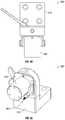
- FIGS. 6A-6Cillustrate a coupler, according to an embodiment.
- FIGS. 6A-6Bare cross-sectional perspective views and
- FIG. 6Cis a perspective view.
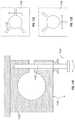
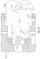
- FIGS. 7A-7Dillustrate a coupler, according to an embodiment.
- FIG. 7Ais a cross-sectional perspective view and FIGS. 7B-7D are cross-sectional side views.
- FIG. 8is a cross-sectional side view of a coupler, according to an embodiment.
- FIGS. 9A-9Millustrate a coupler, according to an embodiment.
- FIGS. 9A-9B, 9D, 9G, and 9Lare perspective views
- FIGS. 9C and 9I-9Jare side views
- FIGS. 9E-9F and 9Kare top views
- FIGS. 9H and 9Mare cross-sectional top views.
- FIG. 10is a flowchart of a method of attaching a robotic arm to a surgical table, according to an embodiment.
- FIGS. 11A-11Iillustrate a coupler, according to an embodiment.
- FIGS. 11A-11F and FIG. 11Hare cross-sectional side views
- FIGS. 11G and 11Iare perspective views.
- FIG. 12is a flowchart of a method of attaching a robotic arm to a surgical table, according to an embodiment.
- FIGS. 13A-13Dare perspective views of a coupler, according to an embodiment.
- FIGS. 14A-14Eare exterior perspective views of a linear rack and cam, according to an embodiment.
- FIG. 15A - FIG. 15Care internal perspective views of a coupler, according to an embodiment.
- FIG. 16A - FIG. 16Bare internal and external views of a coupler, according to an embodiment.
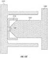
- FIGS. 17A-17Dare schematic side views of a coupler, according to an embodiment.
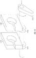
- FIG. 18A-18Bare side views of a grasper, according to an embodiment.
- Apparatus and methods for providing a coupler to attach robotic arms to a surgical table having a table top on which a patient can be disposedare described herein. These apparatus and methods can be used to securely attach and align and/or quickly detach one or more robotic arms to a surgical table in a consistent manner, thereby increasing flexibility in configuring and customizing a surgical table with one or more robotic arms.
- the coupling mechanisms described hereincan be oriented and constrained in six degrees of freedom with high mechanical stiffness in the presence of external loads (e.g., robotic arm static and inertial loads during a surgical procedure).
- a surgical table 100includes a table top 120 , a table support 122 and a table base 124 .
- the table top 120has an upper surface on which a patient P can be disposed during a surgical procedure, as shown schematically in FIG. 1A .
- the table top 120is disposed on the support 122 , which can be, for example, a pedestal, at a suitable height above the floor.
- the support 122may provide for movement of the table top 120 in a desired number of degrees of freedom, such as translation in the Z-axis (height above the floor), Y-axis (along the longitudinal axis of the table), and/or X-axis (along the lateral axis of the table), and/or rotation about the Z, Y, and/or X-axes.
- the table top 120may also include multiple sections that are movable relative to each other along/about any suitable axes, e.g., separate sections for each of the torso, one or both legs, and/or one or both arms, and a head support section.
- Movement of the table top 120 and/or its constituent sectionsmay be performed manually, driven by motors, controlled remotely, or through any other suitable means.
- the support 122 for the table topmay be mounted to the base 124 , which can be fixed to the floor of the operating room, or can be movable relative to the floor, e.g., by use of wheels on the base 124 .
- the height of the support 122can be adjusted, which together with, for example, the motion (e.g., axial (longitudinal) or lateral motion) of the table top 120 , can allow for the table top 120 to be positioned at a desired surgical site at a certain height above the floor (e.g., to allow surgeon access) and a certain distance from the support 120 .
- Thisalso can allow robotic arms (e.g., arms 130 discussed below) coupled to the table 100 to reach a desired treatment target on a patient P disposed on the table top 120 .
- one or more robotic arms 130can be disposed in a desired operative position relative to a patient disposed on the table top 120 of the surgical table 100 (also referred to herein as “table”).
- the robotic arm(s)can be used to perform a surgical procedure on a patient disposed on the surgical table 100 .
- the distal end of each robotic armcan be disposed in a desired operative position so that a medical instrument coupled to the distal end of the robotic arm can perform a desired function.
- each robotic arm 130can include a distal end portion 137 and a proximal end portion 136 .
- the distal end portion 137(also referred to herein as “operating end”) can include or have coupled thereto a medical instrument or tool 115 .
- the proximal end portion 136(also referred to herein as the “mounting end portion” or “mounting end”) can include the coupling portion to allow the robotic arm 130 to be coupled to the table 100 .
- the robotic arm 130can include two or more link members or segments 110 coupled together at joints that can provide for translation along and/or rotation about one or more of the X, Y and/or Z-axes (shown, for example, in FIGS.
- the coupling portion of the robotic arm 130can include a coupling mechanism 139 .
- the coupling mechanism 139can be disposed at the mounting end 136 of the arm 130 and may be coupled to a segment 110 or incorporated within a segment 110 .
- the robotic arm 130also includes a target joint J 1 disposed at or near the mounting end 136 of the robotic arm 130 that can be included within the coupling mechanism 139 and/or the coupling portion or can be disposed on a link or segment 110 of the robotic arm 130 that is coupled to the coupling portion.
- the target joint J 1can provide a pivot joint to allow a distal segment of the robotic arm 130 to pivot relative to the table 100 .
- the robotic arm 130can be moved between various extended configurations for use during a surgical procedure, as shown in FIG. 1C , and various folded or collapsed configurations for storage when not in use, as shown in FIG. 1D .
- a robotic arm for use in performing a surgical proceduremay be releasably coupled to a surgical table.
- robotic armscan be coupled at a fixed location on the table or can be coupled such that the robotic arms can be movable to multiple locations relative to the table top.
- robotic arms 230can be coupled to a table top 220 of a surgical table 200 .
- the surgical table 200can be the same or similar in structure and function to the surgical table 100 described above.
- the table top 220has an upper surface on which a patient P can be disposed during a surgical procedure.
- the robotic arms 230can be permanently or releasably coupled, in a fixed or movable location, to an arm adapter that is coupled to or separate from the surgical table.
- an arm adapter 246can be coupled to or separate from but engageable with or couplable to the table top 220 .
- the robotic arms 230can be coupled to the arm adapter 246 .
- a coupler 310may be provided to couple a robotic arm 320 to a surgical table 300 .
- the coupler 310 as described hereinis usable with any of the surgical tables and robotic arms (e.g., surgical table 100 , 200 , robotic arms 130 , 230 ), and methods described herein.
- the coupler 310can include a first portion 312 (e.g., arm adapter) such as a terminal base portion A for a robotic arm.
- the coupler 310can include a second portion 314 such as a base portion B for mounting to the surgical table 300 .
- the robotic arm 320can be coupled to the first portion 312 and the table top 302 can be coupled to the second portion 314 prior to coupling of the first portion 312 to the second portion 314 .
- the coupling of the robotic arm 320 to the surgical table 300can allow the robotic arm coupled to the table 300 to reach a desired treatment target on a patient disposed on the table top 302 .
- the first portion 312 and the second portion 314may further include electrical power and data connectors. It should be appreciated that the first portion 312 and second portion 314 may be reversed such that the first portion 312 couples to the table 300 and the second portion 314 couples to the robotic arm 320 .
- a surgical table 300includes a table top 302 , a table support 304 and a table base 306 .
- the table top 302has an upper surface on which a patient can be disposed during a surgical procedure, as shown schematically in FIG. 1A .
- the table top 302is disposed on the support 304 , which can be, for example, a pedestal, at a suitable height above the floor.
- the support 302may provide for movement of the table top 302 in a desired number of degrees of freedom, such as translation in the Z-axis (height above the floor), Y axis (along the longitudinal axis of the table), and/or X-axis (along the lateral axis of the table), and/or rotation about the Z, Y, and/or X axes.
- the support 304 for the table top 302may be mounted to the base 306 , which can be fixed to the floor of the operating room, or can be movable relative to the floor, e.g., by use of wheels on the base 306 .
- one or more robotic arms 320shown schematically in FIGS. 1C and 1D ) can be disposed in a desired operative position relative to a patient disposed on the table top 302 of the surgical table 300 .
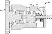
- FIG. 4Ais a side view of an embodiment of a coupler 400 including a first portion 410 and a second portion 420 .
- Coupling of the first portion 410 and second portion 420forms a secure mating connection where six degrees of freedom are constrained.
- the secure mating connectiony-axis constrains a translation in the Z-axis, a Y axis, and/or X-axis, and/or rotation about the Z, Y, and/or X-axes, of the first portion 410 with respect to the second portion 420 .
- the first portion 410includes a handle 454 configured to lock and secure the coupling between the first portion 410 and second portion 420 , and a set of V-grooves 432 configured to contact a corresponding kinematic mount 430 , as described herein.
- the second portion 420includes a post 422 (e.g., locking post) that may be translated along a Y axis to mate with the first portion 410 . Coupling the post 422 to the first portion 410 may constrain translation along the Y axis.
- FIG. 4Billustrates the X-axis, Y axis, and Z-axis relative to the coupler 400 .
- the second portion 420may further include a set of kinematic mounts 430 that may include at least three kinematic mounts that protrude from a surface of the second portion 420 and are configured to slide into and mate with a corresponding V-groove 432 .
- the kinematic mounts 430 and V-grooves 432are configured to locate, constrain, and support the coupling between the first portion 410 and second portion 420 .
- the kinematic mounts 430may include a spherical or semi-spherical shape.
- the kinematic mounts 430may be equally spaced apart around the post 422 of the second portion 420 .
- the V-grooves 432may form a V-shaped cut-out in the first portion 410 and may further include a groove at a vertex of the “V”.
- the sphere-in-groove mating connection between the kinematic mounts 430 and V-grooves 432may constrain translation in the X-axis and Z-axis and constrain rotation about the X-axis, Y axis, and Z-axis.
- the second portion 420may include one or more alignment protrusions 434 configured to contact and slide into and mate with a corresponding hole (not shown) in the first portion 410 .
- the alignment protrusion 434is asymmetrical in that alignment of the protrusion 434 with the first portion 410 is configured to prevent a user from inserting the first portion 410 incorrectly into the second portion 420 . This process may be referred to herein as registration.
- the shape of the alignment protrusion 434 shownis having a semispherical end, but is not particularly limited.
- FIG. 4Cillustrates the second portion 420 partially inserted into the first portion 410 .
- the alignment protrusion 434 and alignment hole 436are oriented so as to permit the post 422 of the second portion 420 to be fully translated into the first portion 410 . Otherwise, the alignment protrusion 434 contacts the housing of the first portion 410 to create a gap between the first portion 410 and the second portion 420 that prevents their coupling.
- FIG. 4Dillustrates a perspective view of the first portion 410 aligned and having an initial engagement with the second portion 420 .
- the handle 454e.g., lock handle
- the handle 454is in a first position corresponding to a first position (e.g., unlocked position) of the coupler 400 .
- a usermay rotate the handle 454 into a second position (e.g., locked position) to transition the coupler 400 from a first configuration (e.g., unlocked state or position) to a second configuration (e.g., locked state or position).
- each of the kinematic mounts 430are aligned with and engaged to contact and mate with a corresponding V-groove 432 .
- FIG. 4Fis a cross-sectional side view of the initial translation of the second portion 420 into the first portion 410 .
- first portion 410includes a first end 456 (the end that attaches to the robotic arm) and a second end 458 (the end that attaches to second portion 420 ), and an interior cavity 464 formed within first portion 410 , between the first and second ends. An opening to the interior cavity is formed through the second end 458 .
- the first portion 410further includes a ball bearing holder 440 (e.g., draw bar) coupled to a set of ball bearings 442 , which are positioned within interior cavity 464 .
- a ball bearing holder 440e.g., draw bar
- the set of ball bearings 442may include four or more ball bearings equally spaced apart along a circumference of the ball bearing holder 440 .
- the handle 454may be coupled to a pair of cams including a first face cam 450 and a second face cam 452 .
- a set of Belleville washers 460may be coupled a shaft of the ball bearing holder 440 .
- the post 422 of the second portion 420may include a first surface 423 (e.g., lead in taper) configured to permit misalignment during translation and sliding of the post 422 into the ball bearing holder 440 .
- the postmay further include a second surface 424 (e.g., angled face) configured to press against the ball bearings 442 when the mating connection is locked.
- the first surface 423 and second surface 424experience Hertzian stresses based on the curvature of the surfaces.
- the curvature and material properties, along with the ball bearing 442 diameter and materialmay be configured to generate contact conditions that do not
- the ball bearing holder 440is configured to hold the ball bearings 442 and surround the post 422 .
- the ball bearing holder 440is configured to translate along the Y axis relative to a housing of the first portion 410 when the face cams are rotated by the handle 454 .
- the translation of the ball bearing holder 440 into the first portion 410presses the ball bearings 442 into surfaces in the first portion 410 , surfaces in the ball bearing holder 440 , and surfaces in the post 422 .
- the ball bearing holder 440may include a lip on each ball bearing pocket configured to retain the ball bearing 442 within the holder 440 when the ball bearings 442 are not in contact with the post 422 .
- the curvature and material properties, along with the ball bearing 442 diameter and materialmay be configured to generate contact conditions that do not deteriorate the surfaces.
- the ball bearings 442move within a predetermined range within the ball bearing holder 440 and serve as a locking mechanism to apply forces to both the first portion 410 and second portion 420 to securely lock them together and form a coupling between the first portion 410 and the second portion 420 .
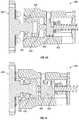
- FIG. 4Gis a cross-sectional perspective view of the coupler 400 in a locked state (or locked position) illustrating the first face cam 450 and second face cam 452 in a maximally separated position where the ball bearing holder 440 is maximally translated into the first portion 410 and the ball bearings 442 have engaged the post 442 and housing 410 to securely lock and couple the first portion 410 to the second portion 420 (e.g., the locked position).
- the first face cam 450 and second face cam 452are coupled to the ball bearing holder 440 such that translation of the face cams along the Y-axis also translates the ball bearing holder 440 along the Y-axis.
- Each of the face camsmay include a profile that converts rotational motion (e.g., from motion of handle 454 ) about the Y-axis into translational motion about the Y-axis.
- the handle 454may be threaded directly into one of the face cams, thereby allowing for a torque advantage when the face cams are rotated into the locked position.
- the face camsmay include a variable cam profile having a first and second profile.
- a first profilemay be configured to permit relatively greater translation and a relatively lower axial force advantage.
- a second profilemay be configured to permit a relatively lower translation and a relatively greater axial force advantage.
- the first profilemay be steep and a second profile may be shallow.
- the varying cam profilemay be configured to permit a large translation (e.g., 0.25′′) followed by a very small (e.g., 0.04′′) translation.
- the face camsmay include a compound profile that decreases the pitch as the ball bearing holder reaches full engagement (e.g., as the ball bearing holder translates towards a lock position.
- the face camsmay include a thrust bearing to reduce friction on the outer surfaces of the face cam.
- the face camsmay include lobes configured to distribute pressure evenly.
- different portions of the face camsmay be made of different materials in order to variably change friction and/or strength of the face cams.
- FIGS. 4H-4Lare cross-sectional side views of the coupler 400 in various states (e.g., unlocked and locked).
- FIG. 4Hillustrates an initial engagement state where surfaces of the post 422 are in contact with the ball bearing 442 within the ball bearing holder 440 .
- the handle 454 (not shown) and the face cams 450 , 452are in an unlocked position.
- FIG. 4Iillustrates a locked position of the coupler 400 after rotation of the handle 454 (not shown) to a locked position.
- the rotation of the handle 454is converted into translational motion of the face cams 450 , 452 along the Y-axis such that the first face cam 450 and the second face cam 452 are maximally separated.
- FIG. 4Jis a detailed view of the locking mechanism of the coupler 400 .
- the ball bearing holder 440 in a locked positiontranslates the ball bearings 442 into the first portion 410 to make contact with a contact surface 411 of the first portion 410 , a ball bearing lip 441 of the ball bearing holder 440 , and a second surface 424 of the post 422 .
- the coupler 400is self-locking in that the coupling will not become disengaged without user input.
- FIG. 4Killustrates a set of Belleville washers 460 coupled to a threaded shaft of the ball bearing holder 440 .
- the Belleville washers 460may be configured to apply a holding force to ball bearing holder 440 .
- the Belleville washersmay apply between about 200 lb force and about 300 lb force.
- FIG. 4Lillustrates a spring 462 (e.g., compression spring) coupled between an end of the housing of the first portion 410 and the Belleville washers 460 .
- the spring 462may be configured to provide the spring force to reset the position of the ball bearing holder 440 and hold the handle 454 in the unlocked position.
- the spring 462may be configured to bias the ball bearing holder 440 into an unlocked position such that when a user rotates the handle 454 to an unlocked position, the ball bearing holder 440 will translate along the Y-axis towards an initial position such as shown in FIG. 4F .
- the Belleville washers 460may be configured to vary a force of the lock.
- FIG. 5is a flowchart of a method 500 of coupling a robotic arm to a surgical table, such as by using any of the couplers described herein.
- the method 500includes translating at 502 a second portion (e.g., robotic arm base portion) of a coupler into a first portion of the coupler (e.g., mounting portion of a surgical table top) ( FIG. 4F ).
- a post of the second portionmay begin to align at 504 as the post moves into the first portion ( FIG. 4C ).
- the locking mechanism of the first portione.g., ball bearing holder, ball bearings, face cams, handle
- the handleWhen the post is in an initial engagement state with the ball bearing holder ( FIG. 4H ), the handle may be rotated at 506 to rotate the two face cams.
- the lockmay rotate about 90 degrees from an unlocked position to a locked position.
- the face camsmove apart and translate the ball bearing holder further into the first portion ( FIG. 4I ).
- the ball bearing holderengages the set of ball bearings so as to press the ball bearings against surfaces of the first portion and the second portion ( FIG. 4J ).
- the pressing forcelocks at 508 the first and second portions together.
- a set of kinematic mountsengage with corresponding V-grooves to precisely align the first and second portions ( FIG. 4E ).
- a usermay rotate the handle at 510 towards the unlocked position. This rotates the face cams towards each other and translates the ball bearing holder towards the second portion, thereby releasing the force between the ball bearings and the housing of the first portion. With the lock disengaged, the second portion may be fully decoupled from the first portion by translating the second portion out of the first portion at 512 .
- FIGS. 6A-6Care perspective views of an embodiment of a coupler 600 driven by a motor and having a manual coupling mechanism that may be used to couple and decouple in cases where power is lost and/or emergency operation.
- the coupler 600may include a first portion 610 and a second portion 620 . Coupling of the first portion 610 and the second portion 620 forms a secure mating connection where six degrees of freedom are constrained.
- the second portion 620may include a post 622 configured to surround the first portion 610 .
- the post 622may be translated along a Y-axis to mate with the first portion 610 to constrain the translation along the Y-axis.
- the first portion 610may include a set of ball bearings 640 , a cam 630 coupled to a bushing 632 , and a shaft 634 .
- the set of ball bearings 640may include four or more ball bearings equally spaced apart along a circumference of the first portion 610 .
- the set of ball bearings 640may be moved by a locking mechanism configured to securely engage and lock the first portion 610 to the second portion 620 .
- the cam 630is configured to translate along the Y-axis relative to a housing of the first portion 610 when driven by a motor and/or handle 650 .
- the post 622 and the cam 630experience Hertzian stresses based on the curvature of those surfaces.
- the curvature and material properties, along with the ball bearing 640 diameter and materialmay be configured to generate contact conditions that do not deteriorate those surfaces. Movement of a cam 630 into a locked position will position the set of ball bearings 640 in holding contact force between surfaces of the post 622 of the second portion and surfaces of the cam 630 .
- the cam 630 and the bushing 632may be configured to be slidable along the shaft 634 . Movement of the cam 630 along the shaft 634 may vary a contact force of the set of ball bearings 640 against a contact surface of the post 622 when the first portion 610 and the second portion 620 are translated into each other.
- a contact surface of the post 622may include a post lip 624 configured to retain the ball bearings 640 within the second portion 620 .
- the ball bearings 640move within a predetermined range first portion 610 and serve as a locking mechanism to apply forces to both the first portion 610 and second portion 620 to securely lock them together and form a coupling between the first portion 610 and the second portion 620 .
- the cam 630may be driven by a worm gear including a worm wheel 660 and worm 662 ) using a motor 670 to couple and decouple the first portion 610 and the second portion 620 .
- the motor 670may be, for example, a brushless DC motor.
- the first portion 610may include a handle 650 configured to permit a user to actuate in order to slide the cam 630 along the shaft 634 and engage or release the set of ball bearings 640 from contact with a contact surface of the post 622 .
- the handle 650may rotate between a locked position and an unlocked position and transition the coupler 600 between a locked configuration and an unlocked configuration.
- FIG. 6Aillustrates a locked position of the coupler 600 . In the locked position, the contact between the ball bearings 640 and the post 622 of the second portion 620 and the cam 630 securely engage and lock the first portion 610 to the second portion 620 .
- Rotation of the handle 650 towards the unlocked positionis converted into translational motion of the cam 630 along the Y-axis to disengage contact between the ball bearings 640 and surfaces of the post 622 and the cam 630 .
- a spring 664may be coupled between the bushing 632 and the worm wheel 660 and configured to provide the spring force to reset the position of the cam 630 into an unlocked position where the cam 630 is biased towards the worm gear.
- the post 622may include one or more relief cuts 626 that may be configured to provide a desired level of holding force between the first portion 610 and the second portion 620 .
- a wider and/or longer gap in the relief cuts 626may reduce the maximum holding force between the first portion 610 and the second portion 620 .
- the second portion 620may further include a post lip 624 .
- the coupler 600may include kinematic mounts, V-grooves, and/or alignment elements as described herein.
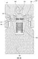
- FIG. 7Ais a cross-sectional perspective view of an embodiment of a coupler 700 .
- the coupler 700includes a first portion 710 having an outer housing 712 and a first portion threading 714 .
- the coupler 700also includes a second portion 720 having a post 722 . That may be translated along a Y-axis to mate with the first portion 710 to constrain translation along the Y-axis. Coupling of the first portion 710 and the second portion 720 forms a secure mating connection where six degrees of freedom are constrained.
- the first portion 710may include a collet 750 configured to lock and secure the coupling between the first portion 710 and the second portion 720 .
- the first portion 710includes a ball bearing holder 740 configured to receive, engage, and lock with the post 722 .
- the ball bearing holder 740is configured to hold the ball bearings 742 and surround the post 722 .
- the ball bearing holder 740is configured to translate along the Y-axis relative to a housing of the first portion 710 when the collet 750 is rotated. The translation of the ball bearing holder 740 into the first portion 710 presses the ball bearings 742 into the first portion 710 , the ball bearing holder 740 , and the post 722 .
- the ball bearing holder 740may include a lip on each ball bearing pocket configured to retain the ball bearing 742 within the holder 740 when the ball bearings 742 are not in contact with the post 722 .
- These surfacesexperience Hertzian stresses based on the curvature of the surfaces.
- the curvature and material properties, along with the ball bearing 742 diameter and materialmay be configured to generate contact conditions that do not deteriorate the surfaces.
- the ball bearings 742move within a predetermined range within the ball bearing holder 740 and serve as a locking mechanism to apply forces to both the first portion 710 and second portion 720 to securely lock them together and form a coupling between the first portion 710 and the second portion 720 .
- a set of Belleville washers 760 , a lock collar 746 , and a thrust bearing 744may be coupled to the ball bearing holder 740 .
- the collet 750may be configured to rotate about the first portion 710 so as to lock and unlock the post 722 from the ball bearing holder 740 .
- An outer surface of the collet 750may be a locking knob that the user can rotate to couple and decouple the first portion 710 and second portion 720 .
- FIGS. 7B-7Dare cross-sectional side views of the coupler 700 in different coupling states.
- the set of Belleville washers 760are compressed and the knob portion (of the collet 750 ) is turned in.
- the second portion 720is being translated into the first portion 710 but has not made contact with the ball bearing holder 740 .
- the first portion 710 and second portion 720have made an initial engagement where the post 722 contacts the ball bearing holder 740 .
- the collet 750is in a first position corresponding to an unlocked position of the coupler 700 .
- the set of Belleville washers 760are fully compressed and the knob portion of the collet 750 is turned in.
- FIG. 7B-7Dare cross-sectional side views of the coupler 700 in different coupling states.
- the collet knobis rotated so as to be turned out so as to draw the ball bearing holder 740 into the first portion 710 and lock the post 722 to the first portion 710 .
- the set of Belleville washers 760are at a work load compression. Both the post 722 and the first portion 711 are held by a holding force using a set of ball bearings 742 .
- the set of ball bearings 742may include four or more ball bearings equally spaced apart along a circumference of ball bearing holder 740 .
- the coupler 700may include kinematic mounts, V-grooves, and/or alignment elements as describe herein.
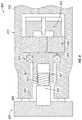
- FIG. 8is a cross-sectional side view of an embodiment of a coupler 800 driven by a motorized locking mechanism that may generate high forces to ensure the coupling is constrained and maintained in six degrees of freedom even in the presence of external loads (e.g., robotic arm static and inertial loads during a surgical procedure).
- the coupler 800may include a first portion 810 and a second portion 820 . Coupling of the first portion 810 and second portion 820 forms a secure mating connection where six degrees of freedom are constrained.
- first portion 810includes a first end 856 (the end coupled to the robotic arm) and a second end 858 (the end coupled to second portion 820 ), and an interior cavity 864 formed within first portion 810 , between the first and second ends. An opening to the interior cavity 864 is formed through the second end 858 .
- the first portion 810may include a locking mechanism coupled to a drive mechanism configured to lock and secure the coupling between the first portion 810 and the second portion 820 .
- the second portionincludes a post 822 that may be translated along a Y-axis to mate with the first portion 810 to constrain translation along the Y-axis.
- the post 822includes a lead screw 824 that may be coupled to a corresponding threaded portion 832 of a rotatable collet 830 .
- a motor 850may drive the collet 830 to rotate about the lead screw 924 - 824 in a first direction so as to translate the lead screw 824 into the first portion 810 along the Y-axis.
- the collet 830may be engaged with the post 822 to securely lock and couple the first portion 810 to the second portion 820 .
- Rotation of the collet 830 in a second direction opposite the first directionmay translate the lead screw 824 out of the first portion 810 along the Y-axis.
- the pitch angle of the lead screw 824may be between about 2 degrees and about 30 degrees. In some embodiments, the pitch angle of the lead screw 824 may be between about 10 degrees and about 15 degrees. In some embodiments, the pitch angle of the lead screw 824 may be configured to prevent the lead screw 824 from being backdriven.
- the motor 850may be coupled to a gearbox 840 and configured to rotate the collet 830 .
- the collet 830may be coupled to one or more bearings 834 .
- the bearings 834may be, for example, a deep groove ball bearing.
- the gearbox 840may be, for example, a planetary or harmonic gear box and may have a gear ratio of about 20 to about 200.
- the motor 850may be, for example, a brushless DC motor.
- the motorized locking mechanismmay generate a force of at least 500 N. In some embodiments, the motorized locking mechanism may generate a force of at least 1400 N.
- the motor 850may be coupled to a controller (not shown) configured to receive input commands from a user.
- a robotic armmay include a switch that may input a coupling command to lock and unlock the first portion 810 from the second portion 820 by driving the lead screw in either direction, thereby attaching and detaching the robotic arm from a surgical table.
- the switchmay be provided on a surgical table, medical cart, and/or portable computing device.
- the coupler 800may include a connection sensor 852 configured to detect coupling and decoupling between the first portion 810 and the second portion 820 .
- the connection sensormay include one or more of a force sensor, Hall effect sensor, and electrical switch located on either the first portion 810 and the second portion 820 (e.g., at an interface between the first portion 810 and the second portion 820 ).
- the connection sensormay include an encoder on the motor 850 .
- a controllermay be configured to drive the collet 830 using the motor 850 until a coupling or decoupling has been detected.
- the coupler 800may include kinematic mounts, V-grooves, and/or alignment elements as described herein.
- the motorized locking mechanism of coupler 800may reduce user error in coupling the first portion 810 to the second portion 820 including partial coupling and decoupling, usability risk (e.g., non-intuitive use), and increase safety (e.g., robotic arm falling to the floor on onto a user's foot or leg).
- FIG. 9Ais a perspective side view of an embodiment of a coupler 900 .
- the coupler 900can include a first portion 910 such as a base portion for mounting to a surgical table (e.g., surgical table 300 ).
- the coupler 900can include a second portion 920 (e.g., arm adapter) such as a terminal base portion for a robotic arm. Coupling of the first portion 910 and second portion 920 forms a secure mating connection where six degrees of freedom are constrained.
- the first portion 910includes a handle 940 configured to lock and secure the coupling between the first portion 910 and second portion 920 , and an alignment protrusion 960 configured to contact a corresponding alignment hole (not shown), as described herein.
- the first portion 910includes a cone 930 that may be translated along a Y-axis to mate with a conical receiving hole 912 ( FIG. 9D ) of the second portion 920 to constrain translation along the Y-axis.
- FIG. 9Billustrates the X-axis, Y-axis, and Z-axis relative to the coupler 900 . It should be appreciated that the first portion 910 and second portion 920 may be reversed such that the first portion 910 couples to a surgical table and the second portion 920 couples to a robotic arm.
- the first portion 910may include one or more alignment protrusions 960 configured to contact and slide into and mate with a corresponding alignment hole 962 in the second portion 962 .
- the alignment protrusion 960is asymmetrical in that alignment of the protrusion 960 with the second portion 920 is configured to prevent a user from inserting the first portion 910 incorrectly into the second portion 920 . This process may be referred to herein as registration.
- the shape of the alignment protrusion 960is shown having a cylindrical shape, but is not particularly limited.
- the alignment protrusion 960may include a spring loaded/split pin.
- FIG. 9Dillustrates the alignment protrusion 960 of the first portion 910 aligned with the alignment hole 962 of the second portion 920 so as to permit the cone 930 to be fully translated into the second portion 920 .
- the alignment protrusion 960contacts the housing of the second portion 920 to create a gap between the first portion 910 and the second portion 920 that prevents their coupling.
- the cone 930is configured to provide a large surface area to form a mechanical coupling having rigidity.
- the cone 930is configured to couple the first portion 910 and second portion 920 so as to constrain translation in the X-axis and Y-axis, and constrain rotation about the X-axis and Z-axis.
- the surface of the cone 930forms mating surfaces that may have tight tolerances and a surface finish ensuring proper contact with the second portion 920 .
- the contact surfacemay include a surface roughness configured to increase friction between the first portion 910 and the second portion 920 .
- a taper angle of the cone 930may be configured for low release forces while maintaining high rigidity of the coupling.
- the cone 930may have a taper angle of about 14 degrees.
- the cone 930may include edges or planes that contact the alternating mating surface.
- a pin 934may be disposed at a nose of the cone 930 and may be configured to protrude from and recess into a surface of the cone 930 .
- the pinWhen the handle 940 is rotated to an unlock position, the pin may be configured to protrude from the cone 930 to aid in the release and translation of the second portion 920 away from the first portion 910 by pushing the first portion 910 and second portion 920 away from each other in the event that they remain in contact due to friction.
- FIG. 9Cillustrates a side view of the first portion 910 and second portion 920 .
- the cone 930may include two or more catches 950 configured to constrain translation of the second portion 920 along the Y-axis.
- the catches 950may be disposed along opposite lateral sides of the conical taper of the cone 930 .
- the catches 950may be configured as an initial locking mechanism (e.g., spring catch) to prevent a robotic arm attached to the second portion 920 from falling out and away from the cone 930 of the first portion 910 .
- the catch 950may include an angled, flat surface configured to slide easily over a surface of a conical hole 912 .
- the catch 950may include a tapered portion configured to hold the first portion 910 against the second portion 920 .
- the second portion 920includes a switch 952 having a corresponding catch 950 configured to move the catches 950 from a first configuration to a second configuration.
- the catches 950may be biased to protrude from the cone 930 in the first configuration and be recessed into the cone 930 in the second configuration.
- FIG. 9Eshows the second portion 920 being translated over the cone 930 .
- the catches 950make contact with the surface of the conical hole 912 and are recessed into the cone 930 .
- the catches 950advanced over corresponding axial grooves 932 ( FIG.
- FIG. 9Dallows the catches 950 to protrude out in the first configuration to thereby couple and secure the first portion 910 to the second portion 920 in an initial lock state, as shown in FIG. 9F .
- FIG. 9Gis a perspective view of the first portion 910 and second portion 920 in the initial lock state.
- the handle 940is in an unlocked state throughout the steps shown in FIGS. 9D-9G .
- FIGS. 9H and 9Mshows a first surface 951 and a second surface 953 of the catch 950 .
- the first surface 951may be an angled, flat surface having an angled similar to that of the taper angle of the cone 930 .
- the first surface 951may be configured to permit the catch 950 to slide easily over a surface of a conical hole 912 . As the first surface 951 translates through the conical hole 912 of the second portion 920 , the catch 950 is recessed into the cone 930 .
- the second surface 953may a tapered portion configured to hold the first portion 910 against the second portion 920 .
- the second surface 953 of the catch 950may include an anti-release angle 1044 configured to prevent the catch 950 from decoupling from the second portion 920 when the catch 950 is in a protruding configuration.
- the catches 950may be configured to be biased towards the protruding configuration.
- the catches 950may include a camming surface configured to contact a corresponding surface such that by wedging the catches outward rather than being pulled back, the first portion 910 and second portion 920 may be secured and locked together.
- the camming surfacemay include an angle surface, a ball and socket surface, and/or the like.
- FIG. 9Hillustrates a set of Belleville washers 958 coupled to the catches 950 and shuttle 970 .
- the Belleville washers 958may be configured to apply a holding force to the catch 950 .
- the Belleville washers 958may apply between about 130 lb force and about 230 lb force.
- the Belleville washers 958may be configured to vary a force of the lock (e.g., handle 940 , cam 942 , and shuttle 970 ).
- a precompression force of the Belleville washers 958may be adjusted using an auxiliary input.
- the handle 940 coupled to the cam 942is illustrated in FIGS. 9H and 9M .
- the cam 942is configured to rotate in response to rotation of the handle 940 between unlocked and locked positions. Rotation of the cam 942 towards a locked position applies contact forces to the shuttle 970 disposed within the cone 930 . As the handle 940 rotates through its arc, the cam 942 applies force against the shuttle 970 of the first portion 910 to bring the first portion 910 and second portion 920 together and securely lock the first portion 910 to the second portion 920 with high rigidity. When the handle 940 is in the locked position, the first portion 910 and second portion 920 are securely engaged and locked to each other.
- the first portionmay include a motorized locking mechanism as described herein, in place of the handle 940 and cam 942 .
- the cam 942may be rotated indirectly through, for example, a set of right angle gears or rotational motion about an axis separate from the cam 942 axis.
- FIG. 9I - FIG. 9Lillustrates front, side, top, and perspective views, respectively, of the switches 952 .
- a switch 952may include a release point 956 configured to make contact with and push a corresponding axial switch 950 into the recessed second configuration.
- the switch 952may rotate about a hinge 1054 when actuated. In some embodiments, the switches 952 may be spaced apart by about 3.5 inches.
- Each switch 952may include a torsion spring configured to bias the switch 952 to an initial, reset position.
- the first portion 910 and the second portion 920may each include an electrical interface 938 to provide a power and/or data connection between the first portion 910 and the second portion 920 .
- the electrical interfacemay include one or more of a spring contact pin, wiping contacts, a fiber optic interface, transformers, or any other power and/or data connector.
- the electrical interface of the first portion 910may be disposed on the tapered surface of the cone 930 or on the base flange of the first portion 910 that supports the cone 930 .
- one or more of the catches 950may include an electrical interface since the catches 950 contact the second portion 920 .
- the coupler 900may include one or more connection sensors 936 , as described herein, and configured to detect coupling and decoupling between the first portion 910 and the second portion 920 .
- connection sensorsmay be configured to detect one or more of an amount of force the catches 950 are holding, a location of the catches 950 (e.g., amount that the catches have moved), and a contact state between the cone 930 and the second portion 920 .
- one or more of the first portion 910 and second portion 920may include a dampener configured to vibrationally isolate the first portion 910 from the second portion 920 .
- FIG. 10is a flowchart of a method 1000 of coupling a robotic arm to a surgical table, such as by using any of the couplers described herein.
- the method 1000includes translating at 1002 a second portion (e.g., robotic arm base portion) of a coupler over a first portion of the coupler (e.g., mounting portion of a surgical table top) ( FIG. 9E ).
- a conical taper of the first portionmay provide initial alignment.
- the second portion at 1004is further aligned with the first portion as the second portion is translated over a cone of the first portion by aligning corresponding alignment elements on each of the first and second portions.
- the locking mechanism of the first portion(e.g., catches) will not engage with the second portion if the alignment element(s) of the first portion are not aligned with the second portion.
- the catchesare engaged with the second portion at 1006 ( FIG. 9F ).
- This initial coupling of the catches to the second portionis self-locking in that the coupling will not become disengaged (e.g., released) without user input (e.g., user actuation of a switch).
- the first portion and second portionare coupled in an initial engagement state such that the second portion is unable to fall away from the first portion if the second portion was unsupported by a user.
- a handleWhile in the initial engagement state, a handle may be rotated at 1008 to rotate a two position cam of the first portion to apply contact forces to a shuttle disposed within the cone. As the handle rotates through its arc, the cam applies force against the shuttle of the first portion to bring the first portion and second portion together and securely lock the first portion to the second portion with high rigidity. In some embodiments, the handle may rotate about 90 degrees from an unlocked position to a locked position. The first portion and second portion are locked at 1010 .
- the handleTo disengage the first portion from the second portion, the handle must be rotated to an unlock position before a catch switch is actuated. Accidental decoupling is reduced by required both locks to be decoupled by a user.
- the handlemay be rotated at 1012 towards an unlocked position to rotate the cam and decouple it from the shuttle. Rotation of the handle to the unlocked position does not fully decouple the first portion and second portion, and permits the user to support the mass of a robotic arm coupled to the second portion. Actuation of one or more switches at 1014 recesses the catches into the cone and allows the second portion to translate at 1016 out and away from the cone of the first portion.
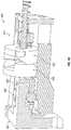
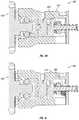
- FIGS. 11A, 11E, and 11Hare cross-sectional side views of embodiments of a coupler 1100 including a first portion 1110 and a second portion 1120 . Coupling of the first portion 1110 and second portion 1120 forms a secure mating connection where six degrees of freedom are constrained.
- the first and second portionmay each include an electrical interface 1126 to provide power and data through the coupler 1100 .
- the first portion 1110includes a ball bearing 1112 coupled to a spring 1114 configured to couple the first portion 1110 to the second portion 1120 .
- a positive lockmay be further coupled to spring 1114 to prevent spring back.
- the second portion 1120includes a post 1122 that may be translated along a Y-axis to mate with the first portion 1110 .
- the second portion 1120may include a first surface 1123 and a second surface 1124 .
- the second surface 1124may have a steeper angle relative to the first surface 1123 .
- a radial clamp 1130may be disposed around the second portion 1120 . Coupling of the post 1122 to the first portion 1110 may constrain translation along the Y-axis.
- FIG. 11Aillustrates the first portion 1110 aligned and having an initial engagement with the second portion 1120 .
- the post 1122 of the second portion 1120may include the first surface 1123 (e.g., lead in taper) configured to permit misalignment during translation and sliding of the post 1122 into the first portion 1110 .
- the post 1122may further include a second surface 1124 (e.g., angled face) configured to press against the ball bearings 1124 .
- the first surface 1123 and second surface 1124experience Hertzian stresses based on the curvature of the surfaces.
- the curvature and material properties, along with the ball bearing 1124 diameter and materialmay be configured to generate contact conditions that do not deteriorate the surfaces.
- FIGS. 11B-11Dare front cross-sectional view of the radial clamp 1130 coupled to an actuator 1140 .
- the actuator 1140may include a screw 1142 and handle 1144 .
- a user actuating the handle 1144may turn the screw 1142 to vary a radial compression force of the clamp 1130 on the second portion 1120 .
- the actuator 1140may be pivoted or rotated. In some embodiments, the actuator 1140 may be rotated a quarter turn to achieve a desired radial compression of clamp 1130 .
- the clamp 1130may also include one or more reliefs 1132 to distribute compression forces. The clamp compresses within a predetermined range and serve as a locking mechanism to apply forces to both the first portion 1110 and second portion 1120 to securely lock them together and form a coupling between the first portion 1110 and the second portion 1120 .
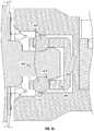
- FIG. 11Eillustrates a coupler 1100 including a first collet 1150 and a second collet 1152 .
- the first collet 1150may be configured to couple to an end of the second portion 1120 between the first portion 1110 and the second portion 1120 .
- the second collet 1152may be configured to couple to a base portion of the second portion 1120 between the first portion 1110 and the second portion 1120 .
- the first collet 1150 and second collet 1152are both coupled to a toggle 1160 having a handle 1162 for a user to translate along a Y-axis.
- the outer and inner surfaces of the colletsmay match an angle of respective first and second portions such that the collets may translate and compress between the first and second portions.
- the colletsmay be coupled to a set of Belleville washers to provide a predetermined compression force.
- the first collet 1150 and second collet 1152may each include one or more slits 1151 , 1153 (see FIGS. 11F-11G ) such that translation of the toggle 1160 towards the first portion 1110 will compress the collets and secure the coupling between the first and second portions.
- the colletstranslate and compress within a predetermined range and serve as a locking mechanism to apply forces to both the first portion 1110 and second portion 1120 to securely lock them together and form a coupling between the first portion 1110 and the second portion 1120 .
- compression of the collets at a predetermined forceforms an electrical interface connection.
- FIG. 11Hillustrates a coupler 1100 including a first clamp 1134 and a second clamp 1136 .
- the first clamp 1134may be configured to couple to and vary a radial compression force to an end of the second portion 1120 .
- the second clamp 1136may be configured to couple and vary a radial compression force.
- the first clamp 1134 and second clamp 1136may be coupled to a respective first cam 1170 and second cam 1172 , as shown in FIG. 11I .
- Each of the camsmay be coupled to a handle and actuated together to vary a radial compression force on the second portion 1120 .
- the first cam 1170 and second cam 1172may have different profiles and may be actuated using rotary or linear motion.
- cams 1170 , 1172may allow for different timing, different compression and/or linear motion and clamping of the clamps 1134 , 1136 .
- Each of the clampscompresses within a predetermined range and serve as a locking mechanism to apply forces to both the first portion 1110 and second portion 1120 to securely lock them together and form a coupling between the first portion 1110 and the second portion 1120 .
- compression of the radial clamp at a predetermined forceforms an electrical interface connection.
- FIG. 12is a flowchart of a method 1200 of coupling a robotic arm to a surgical table, such as by using any of the couplers described herein.
- the method 1200includes translating at 1202 a second portion (e.g., robotic arm base portion) of a coupler into a first portion of the coupler (e.g., mounting portion of a surgical table top).
- a post of the second portionmay begin to align at 1204 as the post moves into the first portion.
- the locking mechanism of the first portione.g., radial clamp, handle, actuator, knob
- the handleWhen the post is in an initial engagement state against a set of ball bearings, the handle may be rotated at 1206 to compress the radial clamp. The pressing force of the radial clamp locks at 1208 the first and second portions together.
- a usermay rotate the handle at 1210 towards the unlocked position. This decompresses the radial clamp, thereby releasing the force between the ball bearings and the housing of the second portion. With the lock disengaged, the second portion may be fully decoupled from the first portion by translating the second portion out of the first portion at 1212 .
- FIGS. 13A-13Dare perspective views of embodiments of a coupler 1300 including a first portion 1310 and a second portion 1320 . Coupling of the first portion 1310 and second portion 1320 forms a secure mating connection where six degrees of freedom are constrained.
- the first and second portionmay each include an electrical interface to provide power and data through the coupler 1300 .
- the post hole 1312may include a first electrical connector 1316 shown in FIG. 13C configured to couple to a second electrical connector 1330 shown in FIG. 13A-13C .
- the second portion 1320includes a post 1322 that may be translated along a Y-axis to mate with the first portion 1310 .
- the post 1322may include a set of catches 1324 biased to protrude from the post 1322 in the first configuration and be recessed into the post 1322 in the second configuration.
- the first portion 1320includes a post hole 1312 and a set of catch holes 1314 corresponding to the set of catches 1324 of the second portion 1320 .
- the catches 1324may be driven by a lead screw 1342 coupled to a motor 1340 .
- a linear rack 1350 coupled to the lead screw 1342translates along a Y-axis and rotates a catch 1360 between the first and second configurations.
- This motorized locking mechanismmay ensure a secure coupling between the first portion 1310 and second portion 1320 .
- the second portion 1320may include an access port 1370 (see FIG. 13D ) for a user to manually insert a tool (e.g., Allen wrench) to manually backdrive the linear rack 1350 and enable decoupling of the robotic arm from the surgical table.
- the motor 1340may be, for example, a brushless DC motor.
- FIGS. 14A-14Eare exterior views of a linear rack assembly 1400 including a linear rack 1420 and catch 1410 .
- the linear rack 1420may be dual sided in that the rack 1422 of one side (see FIG. 14C ) is interchangeable with that of the other side. In other words, the rack 1422 of FIG. 14C may be flipped and mated to be symmetric.
- the linear rack 1420may include one or more Belleville washers to increase compliance for the catches 1410 (e.g., rotating cam claws).
- a postmay be provided at one end of each rack to allow each rack to press together.
- a washer 1430may be disposed between the mating surfaces of the racks 1422 to add compliance and spring resistance.
- the catch 1410may include a spur gear 1412 and a cam claw 1414 separated in height by an offset 1418 as illustrated by FIGS. 14D-14E .
- the catch 1410may rotate about an axis 1416 .
- the cam claw 1414may mate with a corresponding surface of the first portion as the catch rotates.
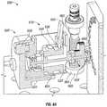
- FIGS. 15A-15Care internal perspective views of a coupler 1500 , according to an embodiment.
- the coupler 1500may include a set of three catches biased to protrude from the surface of a housing in the first configuration and be recessed into the housing in the second configuration.
- the catches 1560 , 1562 , 1564may be driven by a lead screw 1542 coupled to a motor 1540 .
- a linear rack 1550 coupled to the lead screw 1542translates along a Y-axis and rotates the catch 1560 , 1562 , 1564 between the first and second configurations.
- the coupler 1500may include an access port 1570 for a user to manually insert a tool (e.g., Allen wrench) to manually backdrive the linear rack 1550 and enable decoupling of the robotic arm from the surgical table.
- a toole.g., Allen wrench
- the motor 1540may be, for example, a brushless DC motor.
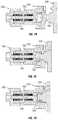
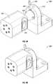
- FIGS. 16A-16Bis an internal and external view of a coupler 1600 including a motorized locking mechanism.
- a first portion 1610may include a motor 1640 coupled to a ball bearing 1650 configured to apply a holding force against a release member 1630 of a second portion 1620 .
- the motor 1640applies a downward force within a predetermined range and serves as a vibration damper and locking mechanism to apply forces to both the first portion 1610 and second portion 1620 to securely lock them together and form a coupling between the first portion 1610 and the second portion 1620 .
- the release member 1630includes a bearing surface 1634 configured to contact the ball bearing 1650 .
- the bearing surface 1634includes a tapered or ramped surface to allow the bearing 1650 to recess into the release member 1630 .
- the release member 1630may rotate about a hinge 1632 .
- a pin 1640may secure the release member 1630 .
- the force of gravity and the downward pressure of the bearing 1650will cause the release member 1630 to swing open so as to release the contact force between the first portion 1610 and second portion 1620 , thereby decoupling the first portion 1610 and the second portion 1620 .
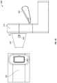
- FIGS. 17A-17Dare schematic side views of a coupler 1700 including a translation mechanism.
- a first portion 1710may include a carriage including a set of latches 1730 to secure a post 1722 of a second portion 1720 .
- the post 1722is translated into the first portion 1710 .
- the postis further translated into the first portion 1710 for a predetermined distance, and then may be retracted to decouple the first portion 1710 and second portion 1720 .
- a distal head 1724is translated into the first portion 1710 to contact an angled first surface 1732 of the latches 1730 .
- the latchesmay be coupled to springs 1740 biased to extend toward the other latch.
- the distal head 1724slides through the latches such that the latches 1730 contact a second diameter portion 1723 of the post 1722 .
- the post 1722is prevented from retracting from the first portion 1710 by the contact between the latch 1730 and proximal end of the distal head 1724 .
- the post 1722includes a sliding collar 1726 that may slide along the second diameter portion 1723 of the post 1722 .
- the post 1722is further translated into the first portion 1710 such that the latch 1730 slides along the second diameter portion 1723 .
- the first surface 1732 of the latch 1730is configured to slide against the first surface 1927 of the sliding collar 1726 such that the latches 1730 hold the sliding collar 1726 in place.
- retraction of the post 1722 away from the first portion 1710will translate the distal head 1724 in a reverse direction while the sliding collar remains fixed with respect to the latches 1730 .
- the sliding collar 1726will slide along the second diameter portion 1723 from a proximal end to a distal end.
- the opening of the latches 1730is of a diameter such that distal head 1724 is not prevented from retracting away from the first portion 1710 .
- the distal head 1724 at a proximal endmay include a recess to hold the sliding collar 1726 .
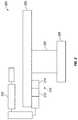
- FIGS. 18A-18Bare side views of a grasper 1800 configured to surround and grasp a post of a coupler of any of the previous embodiments.
- the grasper 1800includes arms 1802 , 1804 operable to apply a lateral force to a longitudinal axis of the post (e.g., post 422 ) of the coupler (e.g., coupler 400 ).
Landscapes
- Engineering & Computer Science (AREA)
- Health & Medical Sciences (AREA)
- Surgery (AREA)
- Life Sciences & Earth Sciences (AREA)
- Robotics (AREA)
- Mechanical Engineering (AREA)
- Animal Behavior & Ethology (AREA)
- Veterinary Medicine (AREA)
- Medical Informatics (AREA)
- Molecular Biology (AREA)
- Biomedical Technology (AREA)
- General Health & Medical Sciences (AREA)
- Public Health (AREA)
- Heart & Thoracic Surgery (AREA)
- Nuclear Medicine, Radiotherapy & Molecular Imaging (AREA)
- General Engineering & Computer Science (AREA)
- Oral & Maxillofacial Surgery (AREA)
- Pathology (AREA)
- Manipulator (AREA)
- Accommodation For Nursing Or Treatment Tables (AREA)
Abstract
Description
Claims (20)
Priority Applications (11)
| Application Number | Priority Date | Filing Date | Title |
|---|---|---|---|
| US15/934,709US11078945B2 (en) | 2017-03-26 | 2018-03-23 | Coupler to attach robotic arm to surgical table |
| CN201880021052.3ACN110709025B (en) | 2017-03-26 | 2018-03-26 | Coupler for attaching a robotic arm to an operating table |
| CA3054431ACA3054431C (en) | 2017-03-26 | 2018-03-26 | Coupler to attach robotic arm to surgical table |
| PCT/US2018/024393WO2018183212A1 (en) | 2017-03-26 | 2018-03-26 | Coupler to attach robotic arm to surgical table |
| EP18774510.4AEP3579783B1 (en) | 2017-03-26 | 2018-03-26 | Coupler to attach robotic arm to surgical table |
| JP2019551299AJP6905162B2 (en) | 2017-03-26 | 2018-03-26 | Coupler for attaching the robot arm to the surgical table |
| BR112019017981-0ABR112019017981B1 (en) | 2017-03-26 | 2018-03-26 | COUPLER FOR ATTACHING A ROBOTIC ARM TO A SURGICAL TABLE |
| KR1020197027941AKR102326102B1 (en) | 2017-03-26 | 2018-03-26 | Coupler for attaching the robotic arm to the operating table |
| AU2018243738AAU2018243738B2 (en) | 2017-03-26 | 2018-03-26 | Coupler to attach robotic arm to surgical table |
| US17/365,766US12140172B2 (en) | 2017-03-26 | 2021-07-01 | Coupler to attach robotic arm to surgical table |
| US18/907,404US20250109762A1 (en) | 2017-03-26 | 2024-10-04 | Coupler to attach robotic arm to surgical table |
Applications Claiming Priority (2)
| Application Number | Priority Date | Filing Date | Title |
|---|---|---|---|
| US201762476816P | 2017-03-26 | 2017-03-26 | |
| US15/934,709US11078945B2 (en) | 2017-03-26 | 2018-03-23 | Coupler to attach robotic arm to surgical table |
Related Child Applications (1)
| Application Number | Title | Priority Date | Filing Date |
|---|---|---|---|
| US17/365,766DivisionUS12140172B2 (en) | 2017-03-26 | 2021-07-01 | Coupler to attach robotic arm to surgical table |
Publications (2)
| Publication Number | Publication Date |
|---|---|
| US20180271604A1 US20180271604A1 (en) | 2018-09-27 |
| US11078945B2true US11078945B2 (en) | 2021-08-03 |
Family
ID=63581657
Family Applications (3)
| Application Number | Title | Priority Date | Filing Date |
|---|---|---|---|
| US15/934,709Active2039-07-18US11078945B2 (en) | 2017-03-26 | 2018-03-23 | Coupler to attach robotic arm to surgical table |
| US17/365,766ActiveUS12140172B2 (en) | 2017-03-26 | 2021-07-01 | Coupler to attach robotic arm to surgical table |
| US18/907,404PendingUS20250109762A1 (en) | 2017-03-26 | 2024-10-04 | Coupler to attach robotic arm to surgical table |
Family Applications After (2)
| Application Number | Title | Priority Date | Filing Date |
|---|---|---|---|
| US17/365,766ActiveUS12140172B2 (en) | 2017-03-26 | 2021-07-01 | Coupler to attach robotic arm to surgical table |
| US18/907,404PendingUS20250109762A1 (en) | 2017-03-26 | 2024-10-04 | Coupler to attach robotic arm to surgical table |
Country Status (8)
| Country | Link |
|---|---|
| US (3) | US11078945B2 (en) |
| EP (1) | EP3579783B1 (en) |
| JP (1) | JP6905162B2 (en) |
| KR (1) | KR102326102B1 (en) |
| CN (1) | CN110709025B (en) |
| AU (1) | AU2018243738B2 (en) |
| CA (1) | CA3054431C (en) |
| WO (1) | WO2018183212A1 (en) |
Cited By (19)
| Publication number | Priority date | Publication date | Assignee | Title |
|---|---|---|---|---|
| US20210212684A1 (en)* | 2017-09-01 | 2021-07-15 | RevMedica, Inc. | Proximal loaded disposable loading unit for surgical stapler |
| KR20210127264A (en)* | 2019-03-13 | 2021-10-22 | 엘지전자 주식회사 | robot |
| TWI795941B (en)* | 2021-10-08 | 2023-03-11 | 恒昌行精密工業有限公司 | Board-to-Board Positioning Device |
| US20230150764A1 (en)* | 2020-04-01 | 2023-05-18 | Kuka Deutschland Gmbh | Logistics system |
| US11839440B2 (en) | 2021-07-30 | 2023-12-12 | Corindus, Inc. | Attachment for robotic medical system |
| US12053177B2 (en) | 2017-09-01 | 2024-08-06 | RevMedica, Inc. | Surgical stapler with removable power pack and interchangeable battery pack |
| US12064111B2 (en) | 2019-07-19 | 2024-08-20 | RevMedica, Inc. | Surgical stapler with removable power pack |
| US12144503B2 (en) | 2017-09-01 | 2024-11-19 | RevMedica, Inc. | Loadable power pack for surgical instruments |
| US12178535B2 (en) | 2021-03-01 | 2024-12-31 | RevMedica, Inc. | Power pack for activating surgical instruments |
| US12232838B2 (en) | 2021-08-12 | 2025-02-25 | Imperative Care, Inc. | Method of robotically performing a neurovascular procedure |
| US12279771B2 (en) | 2019-07-19 | 2025-04-22 | RevMedica, Inc. | Power pack for activating surgical instruments and providing user feedback |
| US12279770B2 (en) | 2019-07-19 | 2025-04-22 | RevMedica, Inc. | Power pack for activating surgical instruments and providing user feedback |
| US12290257B2 (en) | 2019-07-19 | 2025-05-06 | RevMedica, Inc. | Surgical clip applier with removable power pack |
| US12329397B2 (en) | 2022-08-02 | 2025-06-17 | Imperative Care, Inc. | Fluidics management system |
| US12357307B2 (en) | 2022-05-13 | 2025-07-15 | RevMedica, Inc. | Power pack for activating surgical instruments and providing user feedback |
| US12377206B2 (en) | 2023-05-17 | 2025-08-05 | Imperative Care, Inc. | Fluidics control system for multi catheter stack |
| US12419703B2 (en) | 2022-08-01 | 2025-09-23 | Imperative Care, Inc. | Robotic drive system for achieving supra-aortic access |
| US12433702B2 (en) | 2022-12-01 | 2025-10-07 | Imperative Care, Inc. | Telescoping drive table |
| US12440289B2 (en) | 2022-12-01 | 2025-10-14 | Imperative Care, Inc. | Method of priming an interventional device assembly |
Families Citing this family (395)
| Publication number | Priority date | Publication date | Assignee | Title |
|---|---|---|---|---|
| US9060770B2 (en) | 2003-05-20 | 2015-06-23 | Ethicon Endo-Surgery, Inc. | Robotically-driven surgical instrument with E-beam driver |
| US20070084897A1 (en) | 2003-05-20 | 2007-04-19 | Shelton Frederick E Iv | Articulating surgical stapling instrument incorporating a two-piece e-beam firing mechanism |
| US9072535B2 (en) | 2011-05-27 | 2015-07-07 | Ethicon Endo-Surgery, Inc. | Surgical stapling instruments with rotatable staple deployment arrangements |
| US11998198B2 (en) | 2004-07-28 | 2024-06-04 | Cilag Gmbh International | Surgical stapling instrument incorporating a two-piece E-beam firing mechanism |
| US11890012B2 (en) | 2004-07-28 | 2024-02-06 | Cilag Gmbh International | Staple cartridge comprising cartridge body and attached support |
| US8215531B2 (en) | 2004-07-28 | 2012-07-10 | Ethicon Endo-Surgery, Inc. | Surgical stapling instrument having a medical substance dispenser |
| US7934630B2 (en) | 2005-08-31 | 2011-05-03 | Ethicon Endo-Surgery, Inc. | Staple cartridges for forming staples having differing formed staple heights |
| US7669746B2 (en) | 2005-08-31 | 2010-03-02 | Ethicon Endo-Surgery, Inc. | Staple cartridges for forming staples having differing formed staple heights |
| US11484312B2 (en) | 2005-08-31 | 2022-11-01 | Cilag Gmbh International | Staple cartridge comprising a staple driver arrangement |
| US11246590B2 (en) | 2005-08-31 | 2022-02-15 | Cilag Gmbh International | Staple cartridge including staple drivers having different unfired heights |
| US9237891B2 (en) | 2005-08-31 | 2016-01-19 | Ethicon Endo-Surgery, Inc. | Robotically-controlled surgical stapling devices that produce formed staples having different lengths |
| US10159482B2 (en) | 2005-08-31 | 2018-12-25 | Ethicon Llc | Fastener cartridge assembly comprising a fixed anvil and different staple heights |
| US20070106317A1 (en) | 2005-11-09 | 2007-05-10 | Shelton Frederick E Iv | Hydraulically and electrically actuated articulation joints for surgical instruments |
| US20110024477A1 (en) | 2009-02-06 | 2011-02-03 | Hall Steven G | Driven Surgical Stapler Improvements |
| US20120292367A1 (en) | 2006-01-31 | 2012-11-22 | Ethicon Endo-Surgery, Inc. | Robotically-controlled end effector |
| US8820603B2 (en) | 2006-01-31 | 2014-09-02 | Ethicon Endo-Surgery, Inc. | Accessing data stored in a memory of a surgical instrument |
| US11278279B2 (en) | 2006-01-31 | 2022-03-22 | Cilag Gmbh International | Surgical instrument assembly |
| US7753904B2 (en) | 2006-01-31 | 2010-07-13 | Ethicon Endo-Surgery, Inc. | Endoscopic surgical instrument with a handle that can articulate with respect to the shaft |
| US8186555B2 (en) | 2006-01-31 | 2012-05-29 | Ethicon Endo-Surgery, Inc. | Motor-driven surgical cutting and fastening instrument with mechanical closure system |
| US11793518B2 (en) | 2006-01-31 | 2023-10-24 | Cilag Gmbh International | Powered surgical instruments with firing system lockout arrangements |
| US20110295295A1 (en) | 2006-01-31 | 2011-12-01 | Ethicon Endo-Surgery, Inc. | Robotically-controlled surgical instrument having recording capabilities |
| US11224427B2 (en) | 2006-01-31 | 2022-01-18 | Cilag Gmbh International | Surgical stapling system including a console and retraction assembly |
| US7845537B2 (en) | 2006-01-31 | 2010-12-07 | Ethicon Endo-Surgery, Inc. | Surgical instrument having recording capabilities |
| US8708213B2 (en) | 2006-01-31 | 2014-04-29 | Ethicon Endo-Surgery, Inc. | Surgical instrument having a feedback system |
| US8992422B2 (en) | 2006-03-23 | 2015-03-31 | Ethicon Endo-Surgery, Inc. | Robotically-controlled endoscopic accessory channel |
| US8322455B2 (en) | 2006-06-27 | 2012-12-04 | Ethicon Endo-Surgery, Inc. | Manually driven surgical cutting and fastening instrument |
| US10568652B2 (en) | 2006-09-29 | 2020-02-25 | Ethicon Llc | Surgical staples having attached drivers of different heights and stapling instruments for deploying the same |
| US11980366B2 (en) | 2006-10-03 | 2024-05-14 | Cilag Gmbh International | Surgical instrument |
| US8632535B2 (en) | 2007-01-10 | 2014-01-21 | Ethicon Endo-Surgery, Inc. | Interlock and surgical instrument including same |
| US8684253B2 (en) | 2007-01-10 | 2014-04-01 | Ethicon Endo-Surgery, Inc. | Surgical instrument with wireless communication between a control unit of a robotic system and remote sensor |
| US11291441B2 (en) | 2007-01-10 | 2022-04-05 | Cilag Gmbh International | Surgical instrument with wireless communication between control unit and remote sensor |
| US20080169333A1 (en) | 2007-01-11 | 2008-07-17 | Shelton Frederick E | Surgical stapler end effector with tapered distal end |
| US11039836B2 (en) | 2007-01-11 | 2021-06-22 | Cilag Gmbh International | Staple cartridge for use with a surgical stapling instrument |
| US7673782B2 (en) | 2007-03-15 | 2010-03-09 | Ethicon Endo-Surgery, Inc. | Surgical stapling instrument having a releasable buttress material |
| US11564682B2 (en) | 2007-06-04 | 2023-01-31 | Cilag Gmbh International | Surgical stapler device |
| US8931682B2 (en) | 2007-06-04 | 2015-01-13 | Ethicon Endo-Surgery, Inc. | Robotically-controlled shaft based rotary drive systems for surgical instruments |
| US7753245B2 (en) | 2007-06-22 | 2010-07-13 | Ethicon Endo-Surgery, Inc. | Surgical stapling instruments |
| US11849941B2 (en) | 2007-06-29 | 2023-12-26 | Cilag Gmbh International | Staple cartridge having staple cavities extending at a transverse angle relative to a longitudinal cartridge axis |
| US11986183B2 (en) | 2008-02-14 | 2024-05-21 | Cilag Gmbh International | Surgical cutting and fastening instrument comprising a plurality of sensors to measure an electrical parameter |
| US8573465B2 (en) | 2008-02-14 | 2013-11-05 | Ethicon Endo-Surgery, Inc. | Robotically-controlled surgical end effector system with rotary actuated closure systems |
| JP5410110B2 (en) | 2008-02-14 | 2014-02-05 | エシコン・エンド−サージェリィ・インコーポレイテッド | Surgical cutting / fixing instrument with RF electrode |
| US8636736B2 (en) | 2008-02-14 | 2014-01-28 | Ethicon Endo-Surgery, Inc. | Motorized surgical cutting and fastening instrument |
| US9179912B2 (en) | 2008-02-14 | 2015-11-10 | Ethicon Endo-Surgery, Inc. | Robotically-controlled motorized surgical cutting and fastening instrument |
| US7866527B2 (en) | 2008-02-14 | 2011-01-11 | Ethicon Endo-Surgery, Inc. | Surgical stapling apparatus with interlockable firing system |
| US7819298B2 (en) | 2008-02-14 | 2010-10-26 | Ethicon Endo-Surgery, Inc. | Surgical stapling apparatus with control features operable with one hand |
| US8758391B2 (en) | 2008-02-14 | 2014-06-24 | Ethicon Endo-Surgery, Inc. | Interchangeable tools for surgical instruments |
| US9585657B2 (en) | 2008-02-15 | 2017-03-07 | Ethicon Endo-Surgery, Llc | Actuator for releasing a layer of material from a surgical end effector |
| US11648005B2 (en) | 2008-09-23 | 2023-05-16 | Cilag Gmbh International | Robotically-controlled motorized surgical instrument with an end effector |
| US9005230B2 (en) | 2008-09-23 | 2015-04-14 | Ethicon Endo-Surgery, Inc. | Motorized surgical instrument |
| US8210411B2 (en) | 2008-09-23 | 2012-07-03 | Ethicon Endo-Surgery, Inc. | Motor-driven surgical cutting instrument |
| US9386983B2 (en) | 2008-09-23 | 2016-07-12 | Ethicon Endo-Surgery, Llc | Robotically-controlled motorized surgical instrument |
| US8608045B2 (en) | 2008-10-10 | 2013-12-17 | Ethicon Endo-Sugery, Inc. | Powered surgical cutting and stapling apparatus with manually retractable firing system |
| US8517239B2 (en) | 2009-02-05 | 2013-08-27 | Ethicon Endo-Surgery, Inc. | Surgical stapling instrument comprising a magnetic element driver |
| RU2525225C2 (en) | 2009-02-06 | 2014-08-10 | Этикон Эндо-Серджери, Инк. | Improvement of drive surgical suturing instrument |
| US8220688B2 (en) | 2009-12-24 | 2012-07-17 | Ethicon Endo-Surgery, Inc. | Motor-driven surgical cutting instrument with electric actuator directional control assembly |
| US8851354B2 (en) | 2009-12-24 | 2014-10-07 | Ethicon Endo-Surgery, Inc. | Surgical cutting instrument that analyzes tissue thickness |
| US8783543B2 (en) | 2010-07-30 | 2014-07-22 | Ethicon Endo-Surgery, Inc. | Tissue acquisition arrangements and methods for surgical stapling devices |
| US11812965B2 (en) | 2010-09-30 | 2023-11-14 | Cilag Gmbh International | Layer of material for a surgical end effector |
| US9016542B2 (en) | 2010-09-30 | 2015-04-28 | Ethicon Endo-Surgery, Inc. | Staple cartridge comprising compressible distortion resistant components |
| US11298125B2 (en) | 2010-09-30 | 2022-04-12 | Cilag Gmbh International | Tissue stapler having a thickness compensator |
| US9629814B2 (en) | 2010-09-30 | 2017-04-25 | Ethicon Endo-Surgery, Llc | Tissue thickness compensator configured to redistribute compressive forces |
| US9788834B2 (en) | 2010-09-30 | 2017-10-17 | Ethicon Llc | Layer comprising deployable attachment members |
| US10945731B2 (en) | 2010-09-30 | 2021-03-16 | Ethicon Llc | Tissue thickness compensator comprising controlled release and expansion |
| US12213666B2 (en) | 2010-09-30 | 2025-02-04 | Cilag Gmbh International | Tissue thickness compensator comprising layers |
| US9386988B2 (en) | 2010-09-30 | 2016-07-12 | Ethicon End-Surgery, LLC | Retainer assembly including a tissue thickness compensator |
| US9351730B2 (en) | 2011-04-29 | 2016-05-31 | Ethicon Endo-Surgery, Llc | Tissue thickness compensator comprising channels |
| US11925354B2 (en) | 2010-09-30 | 2024-03-12 | Cilag Gmbh International | Staple cartridge comprising staples positioned within a compressible portion thereof |
| US8695866B2 (en) | 2010-10-01 | 2014-04-15 | Ethicon Endo-Surgery, Inc. | Surgical instrument having a power control circuit |
| AU2012250197B2 (en) | 2011-04-29 | 2017-08-10 | Ethicon Endo-Surgery, Inc. | Staple cartridge comprising staples positioned within a compressible portion thereof |
| US11207064B2 (en) | 2011-05-27 | 2021-12-28 | Cilag Gmbh International | Automated end effector component reloading system for use with a robotic system |
| JP6224070B2 (en) | 2012-03-28 | 2017-11-01 | エシコン・エンド−サージェリィ・インコーポレイテッドEthicon Endo−Surgery,Inc. | Retainer assembly including tissue thickness compensator |
| MX358135B (en) | 2012-03-28 | 2018-08-06 | Ethicon Endo Surgery Inc | Tissue thickness compensator comprising a plurality of layers. |
| BR112014024098B1 (en) | 2012-03-28 | 2021-05-25 | Ethicon Endo-Surgery, Inc. | staple cartridge |
| US9101358B2 (en) | 2012-06-15 | 2015-08-11 | Ethicon Endo-Surgery, Inc. | Articulatable surgical instrument comprising a firing drive |
| US9289256B2 (en) | 2012-06-28 | 2016-03-22 | Ethicon Endo-Surgery, Llc | Surgical end effectors having angled tissue-contacting surfaces |
| JP6290201B2 (en) | 2012-06-28 | 2018-03-07 | エシコン・エンド−サージェリィ・インコーポレイテッドEthicon Endo−Surgery,Inc. | Lockout for empty clip cartridge |
| US9408606B2 (en) | 2012-06-28 | 2016-08-09 | Ethicon Endo-Surgery, Llc | Robotically powered surgical device with manually-actuatable reversing system |
| US20140001231A1 (en) | 2012-06-28 | 2014-01-02 | Ethicon Endo-Surgery, Inc. | Firing system lockout arrangements for surgical instruments |
| US11278284B2 (en) | 2012-06-28 | 2022-03-22 | Cilag Gmbh International | Rotary drive arrangements for surgical instruments |
| US12383267B2 (en) | 2012-06-28 | 2025-08-12 | Cilag Gmbh International | Robotically powered surgical device with manually-actuatable reversing system |
| US9282974B2 (en) | 2012-06-28 | 2016-03-15 | Ethicon Endo-Surgery, Llc | Empty clip cartridge lockout |
| BR112014032776B1 (en) | 2012-06-28 | 2021-09-08 | Ethicon Endo-Surgery, Inc | SURGICAL INSTRUMENT SYSTEM AND SURGICAL KIT FOR USE WITH A SURGICAL INSTRUMENT SYSTEM |
| US20140148673A1 (en) | 2012-11-28 | 2014-05-29 | Hansen Medical, Inc. | Method of anchoring pullwire directly articulatable region in catheter |
| BR112015021082B1 (en) | 2013-03-01 | 2022-05-10 | Ethicon Endo-Surgery, Inc | surgical instrument |
| RU2672520C2 (en) | 2013-03-01 | 2018-11-15 | Этикон Эндо-Серджери, Инк. | Hingedly turnable surgical instruments with conducting ways for signal transfer |
| US9808244B2 (en) | 2013-03-14 | 2017-11-07 | Ethicon Llc | Sensor arrangements for absolute positioning system for surgical instruments |
| US9629629B2 (en) | 2013-03-14 | 2017-04-25 | Ethicon Endo-Surgey, LLC | Control systems for surgical instruments |
| BR112015026109B1 (en) | 2013-04-16 | 2022-02-22 | Ethicon Endo-Surgery, Inc | surgical instrument |
| US9826976B2 (en) | 2013-04-16 | 2017-11-28 | Ethicon Llc | Motor driven surgical instruments with lockable dual drive shafts |
| US9775609B2 (en) | 2013-08-23 | 2017-10-03 | Ethicon Llc | Tamper proof circuit for surgical instrument battery pack |
| MX369362B (en) | 2013-08-23 | 2019-11-06 | Ethicon Endo Surgery Llc | Firing member retraction devices for powered surgical instruments. |
| US9962161B2 (en) | 2014-02-12 | 2018-05-08 | Ethicon Llc | Deliverable surgical instrument |
| EP3243476B1 (en) | 2014-03-24 | 2019-11-06 | Auris Health, Inc. | Systems and devices for catheter driving instinctiveness |
| US10004497B2 (en) | 2014-03-26 | 2018-06-26 | Ethicon Llc | Interface systems for use with surgical instruments |
| US20150272580A1 (en) | 2014-03-26 | 2015-10-01 | Ethicon Endo-Surgery, Inc. | Verification of number of battery exchanges/procedure count |
| US12232723B2 (en) | 2014-03-26 | 2025-02-25 | Cilag Gmbh International | Systems and methods for controlling a segmented circuit |
| US10013049B2 (en) | 2014-03-26 | 2018-07-03 | Ethicon Llc | Power management through sleep options of segmented circuit and wake up control |
| BR112016021943B1 (en) | 2014-03-26 | 2022-06-14 | Ethicon Endo-Surgery, Llc | SURGICAL INSTRUMENT FOR USE BY AN OPERATOR IN A SURGICAL PROCEDURE |
| CN106456176B (en) | 2014-04-16 | 2019-06-28 | 伊西康内外科有限责任公司 | Fastener Cartridge Including Extensions With Different Configurations |
| BR112016023825B1 (en) | 2014-04-16 | 2022-08-02 | Ethicon Endo-Surgery, Llc | STAPLE CARTRIDGE FOR USE WITH A SURGICAL STAPLER AND STAPLE CARTRIDGE FOR USE WITH A SURGICAL INSTRUMENT |
| US20150297225A1 (en) | 2014-04-16 | 2015-10-22 | Ethicon Endo-Surgery, Inc. | Fastener cartridges including extensions having different configurations |
| US10327764B2 (en) | 2014-09-26 | 2019-06-25 | Ethicon Llc | Method for creating a flexible staple line |
| US10470768B2 (en) | 2014-04-16 | 2019-11-12 | Ethicon Llc | Fastener cartridge including a layer attached thereto |
| CN106456159B (en) | 2014-04-16 | 2019-03-08 | 伊西康内外科有限责任公司 | Fastener Cartridge Assembly and Nail Retainer Cover Arrangement |
| US11311294B2 (en) | 2014-09-05 | 2022-04-26 | Cilag Gmbh International | Powered medical device including measurement of closure state of jaws |
| BR112017004361B1 (en) | 2014-09-05 | 2023-04-11 | Ethicon Llc | ELECTRONIC SYSTEM FOR A SURGICAL INSTRUMENT |
| US10135242B2 (en) | 2014-09-05 | 2018-11-20 | Ethicon Llc | Smart cartridge wake up operation and data retention |
| US10105142B2 (en) | 2014-09-18 | 2018-10-23 | Ethicon Llc | Surgical stapler with plurality of cutting elements |
| US11523821B2 (en) | 2014-09-26 | 2022-12-13 | Cilag Gmbh International | Method for creating a flexible staple line |
| CN107427300B (en) | 2014-09-26 | 2020-12-04 | 伊西康有限责任公司 | Surgical suture buttresses and auxiliary materials |
| EP3200718A4 (en) | 2014-09-30 | 2018-04-25 | Auris Surgical Robotics, Inc | Configurable robotic surgical system with virtual rail and flexible endoscope |
| US9924944B2 (en) | 2014-10-16 | 2018-03-27 | Ethicon Llc | Staple cartridge comprising an adjunct material |
| US10314463B2 (en) | 2014-10-24 | 2019-06-11 | Auris Health, Inc. | Automated endoscope calibration |
| US10517594B2 (en) | 2014-10-29 | 2019-12-31 | Ethicon Llc | Cartridge assemblies for surgical staplers |
| US11141153B2 (en) | 2014-10-29 | 2021-10-12 | Cilag Gmbh International | Staple cartridges comprising driver arrangements |
| US9844376B2 (en) | 2014-11-06 | 2017-12-19 | Ethicon Llc | Staple cartridge comprising a releasable adjunct material |
| US10736636B2 (en) | 2014-12-10 | 2020-08-11 | Ethicon Llc | Articulatable surgical instrument system |
| US9844374B2 (en) | 2014-12-18 | 2017-12-19 | Ethicon Llc | Surgical instrument systems comprising an articulatable end effector and means for adjusting the firing stroke of a firing member |
| MX389118B (en) | 2014-12-18 | 2025-03-20 | Ethicon Llc | SURGICAL INSTRUMENT WITH AN ANVIL THAT CAN BE SELECTIVELY MOVED ON A DISCRETE, NON-MOBILE AXIS RELATIVE TO A STAPLE CARTRIDGE. |
| US9943309B2 (en) | 2014-12-18 | 2018-04-17 | Ethicon Llc | Surgical instruments with articulatable end effectors and movable firing beam support arrangements |
| US9987000B2 (en) | 2014-12-18 | 2018-06-05 | Ethicon Llc | Surgical instrument assembly comprising a flexible articulation system |
| US10085748B2 (en) | 2014-12-18 | 2018-10-02 | Ethicon Llc | Locking arrangements for detachable shaft assemblies with articulatable surgical end effectors |
| US9844375B2 (en) | 2014-12-18 | 2017-12-19 | Ethicon Llc | Drive arrangements for articulatable surgical instruments |
| KR20230162122A (en) | 2015-02-20 | 2023-11-28 | 스트리커 코포레이션 | Sterile barrier assembly, mounting system, and method for coupling surgical components |
| US11154301B2 (en) | 2015-02-27 | 2021-10-26 | Cilag Gmbh International | Modular stapling assembly |
| US9993248B2 (en) | 2015-03-06 | 2018-06-12 | Ethicon Endo-Surgery, Llc | Smart sensors with local signal processing |
| US10441279B2 (en) | 2015-03-06 | 2019-10-15 | Ethicon Llc | Multiple level thresholds to modify operation of powered surgical instruments |
| JP2020121162A (en) | 2015-03-06 | 2020-08-13 | エシコン エルエルシーEthicon LLC | Time dependent evaluation of sensor data to determine stability element, creep element and viscoelastic element of measurement |
| US9901342B2 (en) | 2015-03-06 | 2018-02-27 | Ethicon Endo-Surgery, Llc | Signal and power communication system positioned on a rotatable shaft |
| US10245033B2 (en) | 2015-03-06 | 2019-04-02 | Ethicon Llc | Surgical instrument comprising a lockable battery housing |
| US10548504B2 (en) | 2015-03-06 | 2020-02-04 | Ethicon Llc | Overlaid multi sensor radio frequency (RF) electrode system to measure tissue compression |
| US10433844B2 (en) | 2015-03-31 | 2019-10-08 | Ethicon Llc | Surgical instrument with selectively disengageable threaded drive systems |
| US10835249B2 (en) | 2015-08-17 | 2020-11-17 | Ethicon Llc | Implantable layers for a surgical instrument |
| US10238386B2 (en) | 2015-09-23 | 2019-03-26 | Ethicon Llc | Surgical stapler having motor control based on an electrical parameter related to a motor current |
| US10105139B2 (en) | 2015-09-23 | 2018-10-23 | Ethicon Llc | Surgical stapler having downstream current-based motor control |
| US10299878B2 (en) | 2015-09-25 | 2019-05-28 | Ethicon Llc | Implantable adjunct systems for determining adjunct skew |
| US10478188B2 (en) | 2015-09-30 | 2019-11-19 | Ethicon Llc | Implantable layer comprising a constricted configuration |
| US10980539B2 (en) | 2015-09-30 | 2021-04-20 | Ethicon Llc | Implantable adjunct comprising bonded layers |
| US10433846B2 (en) | 2015-09-30 | 2019-10-08 | Ethicon Llc | Compressible adjunct with crossing spacer fibers |
| US11890015B2 (en) | 2015-09-30 | 2024-02-06 | Cilag Gmbh International | Compressible adjunct with crossing spacer fibers |
| US10143526B2 (en) | 2015-11-30 | 2018-12-04 | Auris Health, Inc. | Robot-assisted driving systems and methods |
| US10292704B2 (en) | 2015-12-30 | 2019-05-21 | Ethicon Llc | Mechanisms for compensating for battery pack failure in powered surgical instruments |
| US10265068B2 (en) | 2015-12-30 | 2019-04-23 | Ethicon Llc | Surgical instruments with separable motors and motor control circuits |
| US10368865B2 (en) | 2015-12-30 | 2019-08-06 | Ethicon Llc | Mechanisms for compensating for drivetrain failure in powered surgical instruments |
| US11213293B2 (en) | 2016-02-09 | 2022-01-04 | Cilag Gmbh International | Articulatable surgical instruments with single articulation link arrangements |
| BR112018016098B1 (en) | 2016-02-09 | 2023-02-23 | Ethicon Llc | SURGICAL INSTRUMENT |
| US11224426B2 (en) | 2016-02-12 | 2022-01-18 | Cilag Gmbh International | Mechanisms for compensating for drivetrain failure in powered surgical instruments |
| US10448948B2 (en) | 2016-02-12 | 2019-10-22 | Ethicon Llc | Mechanisms for compensating for drivetrain failure in powered surgical instruments |
| US10357247B2 (en) | 2016-04-15 | 2019-07-23 | Ethicon Llc | Surgical instrument with multiple program responses during a firing motion |
| US11179150B2 (en) | 2016-04-15 | 2021-11-23 | Cilag Gmbh International | Systems and methods for controlling a surgical stapling and cutting instrument |
| US10426467B2 (en) | 2016-04-15 | 2019-10-01 | Ethicon Llc | Surgical instrument with detection sensors |
| US11607239B2 (en) | 2016-04-15 | 2023-03-21 | Cilag Gmbh International | Systems and methods for controlling a surgical stapling and cutting instrument |
| US10828028B2 (en) | 2016-04-15 | 2020-11-10 | Ethicon Llc | Surgical instrument with multiple program responses during a firing motion |
| US10456137B2 (en) | 2016-04-15 | 2019-10-29 | Ethicon Llc | Staple formation detection mechanisms |
| US10335145B2 (en) | 2016-04-15 | 2019-07-02 | Ethicon Llc | Modular surgical instrument with configurable operating mode |
| US10492783B2 (en) | 2016-04-15 | 2019-12-03 | Ethicon, Llc | Surgical instrument with improved stop/start control during a firing motion |
| US20170296173A1 (en) | 2016-04-18 | 2017-10-19 | Ethicon Endo-Surgery, Llc | Method for operating a surgical instrument |
| US10363037B2 (en) | 2016-04-18 | 2019-07-30 | Ethicon Llc | Surgical instrument system comprising a magnetic lockout |
| US11317917B2 (en) | 2016-04-18 | 2022-05-03 | Cilag Gmbh International | Surgical stapling system comprising a lockable firing assembly |
| US10500000B2 (en) | 2016-08-16 | 2019-12-10 | Ethicon Llc | Surgical tool with manual control of end effector jaws |
| US9931025B1 (en)* | 2016-09-30 | 2018-04-03 | Auris Surgical Robotics, Inc. | Automated calibration of endoscopes with pull wires |
| US20180168625A1 (en) | 2016-12-21 | 2018-06-21 | Ethicon Endo-Surgery, Llc | Surgical stapling instruments with smart staple cartridges |
| US10568625B2 (en) | 2016-12-21 | 2020-02-25 | Ethicon Llc | Staple cartridges and arrangements of staples and staple cavities therein |
| US10582928B2 (en) | 2016-12-21 | 2020-03-10 | Ethicon Llc | Articulation lock arrangements for locking an end effector in an articulated position in response to actuation of a jaw closure system |
| US10813638B2 (en) | 2016-12-21 | 2020-10-27 | Ethicon Llc | Surgical end effectors with expandable tissue stop arrangements |
| US10980536B2 (en) | 2016-12-21 | 2021-04-20 | Ethicon Llc | No-cartridge and spent cartridge lockout arrangements for surgical staplers |
| US10542982B2 (en) | 2016-12-21 | 2020-01-28 | Ethicon Llc | Shaft assembly comprising first and second articulation lockouts |
| US10485543B2 (en) | 2016-12-21 | 2019-11-26 | Ethicon Llc | Anvil having a knife slot width |
| US11134942B2 (en) | 2016-12-21 | 2021-10-05 | Cilag Gmbh International | Surgical stapling instruments and staple-forming anvils |
| US20180168615A1 (en) | 2016-12-21 | 2018-06-21 | Ethicon Endo-Surgery, Llc | Method of deforming staples from two different types of staple cartridges with the same surgical stapling instrument |
| JP7010957B2 (en) | 2016-12-21 | 2022-01-26 | エシコン エルエルシー | Shaft assembly with lockout |
| MX2019007295A (en) | 2016-12-21 | 2019-10-15 | Ethicon Llc | Surgical instrument system comprising an end effector lockout and a firing assembly lockout. |
| US10973516B2 (en) | 2016-12-21 | 2021-04-13 | Ethicon Llc | Surgical end effectors and adaptable firing members therefor |
| JP6983893B2 (en) | 2016-12-21 | 2021-12-17 | エシコン エルエルシーEthicon LLC | Lockout configuration for surgical end effectors and replaceable tool assemblies |
| JP2020501815A (en) | 2016-12-21 | 2020-01-23 | エシコン エルエルシーEthicon LLC | Surgical stapling system |
| US11090048B2 (en) | 2016-12-21 | 2021-08-17 | Cilag Gmbh International | Method for resetting a fuse of a surgical instrument shaft |
| US10898186B2 (en) | 2016-12-21 | 2021-01-26 | Ethicon Llc | Staple forming pocket arrangements comprising primary sidewalls and pocket sidewalls |
| US11419606B2 (en) | 2016-12-21 | 2022-08-23 | Cilag Gmbh International | Shaft assembly comprising a clutch configured to adapt the output of a rotary firing member to two different systems |
| JP7010956B2 (en) | 2016-12-21 | 2022-01-26 | エシコン エルエルシー | How to staple tissue |
| CN110087565A (en) | 2016-12-21 | 2019-08-02 | 爱惜康有限责任公司 | Surgical stapling system |
| US10244926B2 (en) | 2016-12-28 | 2019-04-02 | Auris Health, Inc. | Detecting endolumenal buckling of flexible instruments |
| KR102643758B1 (en) | 2017-05-12 | 2024-03-08 | 아우리스 헬스, 인코포레이티드 | Biopsy devices and systems |
| US10792119B2 (en) | 2017-05-22 | 2020-10-06 | Ethicon Llc | Robotic arm cart and uses therefor |
| US10856948B2 (en) | 2017-05-31 | 2020-12-08 | Verb Surgical Inc. | Cart for robotic arms and method and apparatus for registering cart to surgical table |
| US10485623B2 (en) | 2017-06-01 | 2019-11-26 | Verb Surgical Inc. | Robotic arm cart with fine position adjustment features and uses therefor |
| US10913145B2 (en)* | 2017-06-20 | 2021-02-09 | Verb Surgical Inc. | Cart for robotic arms and method and apparatus for cartridge or magazine loading of arms |
| US11653914B2 (en) | 2017-06-20 | 2023-05-23 | Cilag Gmbh International | Systems and methods for controlling motor velocity of a surgical stapling and cutting instrument according to articulation angle of end effector |
| USD879809S1 (en) | 2017-06-20 | 2020-03-31 | Ethicon Llc | Display panel with changeable graphical user interface |
| US11382638B2 (en) | 2017-06-20 | 2022-07-12 | Cilag Gmbh International | Closed loop feedback control of motor velocity of a surgical stapling and cutting instrument based on measured time over a specified displacement distance |
| US10881399B2 (en) | 2017-06-20 | 2021-01-05 | Ethicon Llc | Techniques for adaptive control of motor velocity of a surgical stapling and cutting instrument |
| US10307170B2 (en) | 2017-06-20 | 2019-06-04 | Ethicon Llc | Method for closed loop control of motor velocity of a surgical stapling and cutting instrument |
| US10888321B2 (en) | 2017-06-20 | 2021-01-12 | Ethicon Llc | Systems and methods for controlling velocity of a displacement member of a surgical stapling and cutting instrument |
| US11071554B2 (en) | 2017-06-20 | 2021-07-27 | Cilag Gmbh International | Closed loop feedback control of motor velocity of a surgical stapling and cutting instrument based on magnitude of velocity error measurements |
| US10980537B2 (en) | 2017-06-20 | 2021-04-20 | Ethicon Llc | Closed loop feedback control of motor velocity of a surgical stapling and cutting instrument based on measured time over a specified number of shaft rotations |
| US11090046B2 (en) | 2017-06-20 | 2021-08-17 | Cilag Gmbh International | Systems and methods for controlling displacement member motion of a surgical stapling and cutting instrument |
| US10779820B2 (en) | 2017-06-20 | 2020-09-22 | Ethicon Llc | Systems and methods for controlling motor speed according to user input for a surgical instrument |
| US11517325B2 (en) | 2017-06-20 | 2022-12-06 | Cilag Gmbh International | Closed loop feedback control of motor velocity of a surgical stapling and cutting instrument based on measured displacement distance traveled over a specified time interval |
| US11090049B2 (en) | 2017-06-27 | 2021-08-17 | Cilag Gmbh International | Staple forming pocket arrangements |
| US11266405B2 (en) | 2017-06-27 | 2022-03-08 | Cilag Gmbh International | Surgical anvil manufacturing methods |
| US11324503B2 (en) | 2017-06-27 | 2022-05-10 | Cilag Gmbh International | Surgical firing member arrangements |
| US10993716B2 (en) | 2017-06-27 | 2021-05-04 | Ethicon Llc | Surgical anvil arrangements |
| US11484310B2 (en) | 2017-06-28 | 2022-11-01 | Cilag Gmbh International | Surgical instrument comprising a shaft including a closure tube profile |
| US10299870B2 (en) | 2017-06-28 | 2019-05-28 | Auris Health, Inc. | Instrument insertion compensation |
| US10758232B2 (en) | 2017-06-28 | 2020-09-01 | Ethicon Llc | Surgical instrument with positive jaw opening features |
| US10903685B2 (en) | 2017-06-28 | 2021-01-26 | Ethicon Llc | Surgical shaft assemblies with slip ring assemblies forming capacitive channels |
| US11259805B2 (en) | 2017-06-28 | 2022-03-01 | Cilag Gmbh International | Surgical instrument comprising firing member supports |
| US10765427B2 (en) | 2017-06-28 | 2020-09-08 | Ethicon Llc | Method for articulating a surgical instrument |
| USD906355S1 (en) | 2017-06-28 | 2020-12-29 | Ethicon Llc | Display screen or portion thereof with a graphical user interface for a surgical instrument |
| US11246592B2 (en) | 2017-06-28 | 2022-02-15 | Cilag Gmbh International | Surgical instrument comprising an articulation system lockable to a frame |
| EP3420947B1 (en) | 2017-06-28 | 2022-05-25 | Cilag GmbH International | Surgical instrument comprising selectively actuatable rotatable couplers |
| US11564686B2 (en) | 2017-06-28 | 2023-01-31 | Cilag Gmbh International | Surgical shaft assemblies with flexible interfaces |
| US10932772B2 (en) | 2017-06-29 | 2021-03-02 | Ethicon Llc | Methods for closed loop velocity control for robotic surgical instrument |
| US10426559B2 (en) | 2017-06-30 | 2019-10-01 | Auris Health, Inc. | Systems and methods for medical instrument compression compensation |
| US11471155B2 (en) | 2017-08-03 | 2022-10-18 | Cilag Gmbh International | Surgical system bailout |
| US11974742B2 (en) | 2017-08-03 | 2024-05-07 | Cilag Gmbh International | Surgical system comprising an articulation bailout |
| US11944300B2 (en)* | 2017-08-03 | 2024-04-02 | Cilag Gmbh International | Method for operating a surgical system bailout |
| US11304695B2 (en) | 2017-08-03 | 2022-04-19 | Cilag Gmbh International | Surgical system shaft interconnection |
| US10743872B2 (en) | 2017-09-29 | 2020-08-18 | Ethicon Llc | System and methods for controlling a display of a surgical instrument |
| USD907647S1 (en) | 2017-09-29 | 2021-01-12 | Ethicon Llc | Display screen or portion thereof with animated graphical user interface |
| USD917500S1 (en) | 2017-09-29 | 2021-04-27 | Ethicon Llc | Display screen or portion thereof with graphical user interface |
| US11399829B2 (en) | 2017-09-29 | 2022-08-02 | Cilag Gmbh International | Systems and methods of initiating a power shutdown mode for a surgical instrument |
| USD907648S1 (en) | 2017-09-29 | 2021-01-12 | Ethicon Llc | Display screen or portion thereof with animated graphical user interface |
| US10145747B1 (en) | 2017-10-10 | 2018-12-04 | Auris Health, Inc. | Detection of undesirable forces on a surgical robotic arm |
| US11134944B2 (en) | 2017-10-30 | 2021-10-05 | Cilag Gmbh International | Surgical stapler knife motion controls |
| US11090075B2 (en) | 2017-10-30 | 2021-08-17 | Cilag Gmbh International | Articulation features for surgical end effector |
| US10842490B2 (en) | 2017-10-31 | 2020-11-24 | Ethicon Llc | Cartridge body design with force reduction based on firing completion |
| EP3684282B1 (en) | 2017-12-06 | 2024-02-21 | Auris Health, Inc. | Systems to correct for uncommanded instrument roll |
| US11510736B2 (en) | 2017-12-14 | 2022-11-29 | Auris Health, Inc. | System and method for estimating instrument location |
| US11197670B2 (en) | 2017-12-15 | 2021-12-14 | Cilag Gmbh International | Surgical end effectors with pivotal jaws configured to touch at their respective distal ends when fully closed |
| US11033267B2 (en) | 2017-12-15 | 2021-06-15 | Ethicon Llc | Systems and methods of controlling a clamping member firing rate of a surgical instrument |
| US10966718B2 (en) | 2017-12-15 | 2021-04-06 | Ethicon Llc | Dynamic clamping assemblies with improved wear characteristics for use in connection with electromechanical surgical instruments |
| US10779825B2 (en) | 2017-12-15 | 2020-09-22 | Ethicon Llc | Adapters with end effector position sensing and control arrangements for use in connection with electromechanical surgical instruments |
| US10779826B2 (en) | 2017-12-15 | 2020-09-22 | Ethicon Llc | Methods of operating surgical end effectors |
| US10869666B2 (en) | 2017-12-15 | 2020-12-22 | Ethicon Llc | Adapters with control systems for controlling multiple motors of an electromechanical surgical instrument |
| US11071543B2 (en) | 2017-12-15 | 2021-07-27 | Cilag Gmbh International | Surgical end effectors with clamping assemblies configured to increase jaw aperture ranges |
| US10828033B2 (en) | 2017-12-15 | 2020-11-10 | Ethicon Llc | Handheld electromechanical surgical instruments with improved motor control arrangements for positioning components of an adapter coupled thereto |
| US10743875B2 (en) | 2017-12-15 | 2020-08-18 | Ethicon Llc | Surgical end effectors with jaw stiffener arrangements configured to permit monitoring of firing member |
| US10729509B2 (en) | 2017-12-19 | 2020-08-04 | Ethicon Llc | Surgical instrument comprising closure and firing locking mechanism |
| US11020112B2 (en) | 2017-12-19 | 2021-06-01 | Ethicon Llc | Surgical tools configured for interchangeable use with different controller interfaces |
| US10835330B2 (en) | 2017-12-19 | 2020-11-17 | Ethicon Llc | Method for determining the position of a rotatable jaw of a surgical instrument attachment assembly |
| USD910847S1 (en) | 2017-12-19 | 2021-02-16 | Ethicon Llc | Surgical instrument assembly |
| US11179151B2 (en) | 2017-12-21 | 2021-11-23 | Cilag Gmbh International | Surgical instrument comprising a display |
| US11076853B2 (en) | 2017-12-21 | 2021-08-03 | Cilag Gmbh International | Systems and methods of displaying a knife position during transection for a surgical instrument |
| US11311290B2 (en) | 2017-12-21 | 2022-04-26 | Cilag Gmbh International | Surgical instrument comprising an end effector dampener |
| US11129680B2 (en) | 2017-12-21 | 2021-09-28 | Cilag Gmbh International | Surgical instrument comprising a projector |
| US12336705B2 (en) | 2017-12-21 | 2025-06-24 | Cilag Gmbh International | Continuous use self-propelled stapling instrument |
| KR20240118200A (en) | 2018-02-13 | 2024-08-02 | 아우리스 헬스, 인코포레이티드 | System and method for driving medical instrument |
| US11077535B2 (en)* | 2018-02-14 | 2021-08-03 | Samsung Electronics Co., Ltd. | Process system having locking pin and locking pin |
| US10912559B2 (en) | 2018-08-20 | 2021-02-09 | Ethicon Llc | Reinforced deformable anvil tip for surgical stapler anvil |
| US11083458B2 (en) | 2018-08-20 | 2021-08-10 | Cilag Gmbh International | Powered surgical instruments with clutching arrangements to convert linear drive motions to rotary drive motions |
| US11207065B2 (en) | 2018-08-20 | 2021-12-28 | Cilag Gmbh International | Method for fabricating surgical stapler anvils |
| US11253256B2 (en) | 2018-08-20 | 2022-02-22 | Cilag Gmbh International | Articulatable motor powered surgical instruments with dedicated articulation motor arrangements |
| US10856870B2 (en) | 2018-08-20 | 2020-12-08 | Ethicon Llc | Switching arrangements for motor powered articulatable surgical instruments |
| US11324501B2 (en) | 2018-08-20 | 2022-05-10 | Cilag Gmbh International | Surgical stapling devices with improved closure members |
| US11291440B2 (en) | 2018-08-20 | 2022-04-05 | Cilag Gmbh International | Method for operating a powered articulatable surgical instrument |
| US11045192B2 (en) | 2018-08-20 | 2021-06-29 | Cilag Gmbh International | Fabricating techniques for surgical stapler anvils |
| USD914878S1 (en) | 2018-08-20 | 2021-03-30 | Ethicon Llc | Surgical instrument anvil |
| US20200054321A1 (en) | 2018-08-20 | 2020-02-20 | Ethicon Llc | Surgical instruments with progressive jaw closure arrangements |
| US11039834B2 (en) | 2018-08-20 | 2021-06-22 | Cilag Gmbh International | Surgical stapler anvils with staple directing protrusions and tissue stability features |
| JP6745306B2 (en)* | 2018-08-28 | 2020-08-26 | 株式会社メディカロイド | Adapter and connection method |
| CN112804959B (en) | 2018-09-28 | 2025-01-28 | 奥瑞斯健康公司 | Robotic systems and methods for accompanying endoscopic and percutaneous medical procedures |
| KR102852843B1 (en) | 2018-09-28 | 2025-09-03 | 아우리스 헬스, 인코포레이티드 | System and method for docking medical devices |
| AU2019391083B2 (en) | 2018-12-04 | 2025-07-24 | Mako Surgical Corp. | Mounting system with sterile barrier assembly for use in coupling surgical components |
| US11172929B2 (en) | 2019-03-25 | 2021-11-16 | Cilag Gmbh International | Articulation drive arrangements for surgical systems |
| US11147553B2 (en) | 2019-03-25 | 2021-10-19 | Cilag Gmbh International | Firing drive arrangements for surgical systems |
| US11147551B2 (en) | 2019-03-25 | 2021-10-19 | Cilag Gmbh International | Firing drive arrangements for surgical systems |
| US11696761B2 (en) | 2019-03-25 | 2023-07-11 | Cilag Gmbh International | Firing drive arrangements for surgical systems |
| US11903581B2 (en) | 2019-04-30 | 2024-02-20 | Cilag Gmbh International | Methods for stapling tissue using a surgical instrument |
| US11426251B2 (en) | 2019-04-30 | 2022-08-30 | Cilag Gmbh International | Articulation directional lights on a surgical instrument |
| US11253254B2 (en) | 2019-04-30 | 2022-02-22 | Cilag Gmbh International | Shaft rotation actuator on a surgical instrument |
| US11432816B2 (en) | 2019-04-30 | 2022-09-06 | Cilag Gmbh International | Articulation pin for a surgical instrument |
| US11452528B2 (en) | 2019-04-30 | 2022-09-27 | Cilag Gmbh International | Articulation actuators for a surgical instrument |
| US11648009B2 (en) | 2019-04-30 | 2023-05-16 | Cilag Gmbh International | Rotatable jaw tip for a surgical instrument |
| US11471157B2 (en) | 2019-04-30 | 2022-10-18 | Cilag Gmbh International | Articulation control mapping for a surgical instrument |
| US11771419B2 (en) | 2019-06-28 | 2023-10-03 | Cilag Gmbh International | Packaging for a replaceable component of a surgical stapling system |
| US11497492B2 (en) | 2019-06-28 | 2022-11-15 | Cilag Gmbh International | Surgical instrument including an articulation lock |
| US11259803B2 (en) | 2019-06-28 | 2022-03-01 | Cilag Gmbh International | Surgical stapling system having an information encryption protocol |
| US11399837B2 (en) | 2019-06-28 | 2022-08-02 | Cilag Gmbh International | Mechanisms for motor control adjustments of a motorized surgical instrument |
| US11660163B2 (en) | 2019-06-28 | 2023-05-30 | Cilag Gmbh International | Surgical system with RFID tags for updating motor assembly parameters |
| US11553971B2 (en) | 2019-06-28 | 2023-01-17 | Cilag Gmbh International | Surgical RFID assemblies for display and communication |
| US11638587B2 (en) | 2019-06-28 | 2023-05-02 | Cilag Gmbh International | RFID identification systems for surgical instruments |
| US11376098B2 (en) | 2019-06-28 | 2022-07-05 | Cilag Gmbh International | Surgical instrument system comprising an RFID system |
| US11224497B2 (en) | 2019-06-28 | 2022-01-18 | Cilag Gmbh International | Surgical systems with multiple RFID tags |
| US11464601B2 (en) | 2019-06-28 | 2022-10-11 | Cilag Gmbh International | Surgical instrument comprising an RFID system for tracking a movable component |
| US11051807B2 (en) | 2019-06-28 | 2021-07-06 | Cilag Gmbh International | Packaging assembly including a particulate trap |
| US11291451B2 (en) | 2019-06-28 | 2022-04-05 | Cilag Gmbh International | Surgical instrument with battery compatibility verification functionality |
| US11219455B2 (en) | 2019-06-28 | 2022-01-11 | Cilag Gmbh International | Surgical instrument including a lockout key |
| US11246678B2 (en) | 2019-06-28 | 2022-02-15 | Cilag Gmbh International | Surgical stapling system having a frangible RFID tag |
| US11298132B2 (en) | 2019-06-28 | 2022-04-12 | Cilag GmbH Inlernational | Staple cartridge including a honeycomb extension |
| US11684434B2 (en) | 2019-06-28 | 2023-06-27 | Cilag Gmbh International | Surgical RFID assemblies for instrument operational setting control |
| US11478241B2 (en) | 2019-06-28 | 2022-10-25 | Cilag Gmbh International | Staple cartridge including projections |
| US11523822B2 (en) | 2019-06-28 | 2022-12-13 | Cilag Gmbh International | Battery pack including a circuit interrupter |
| US12004740B2 (en) | 2019-06-28 | 2024-06-11 | Cilag Gmbh International | Surgical stapling system having an information decryption protocol |
| US11627959B2 (en) | 2019-06-28 | 2023-04-18 | Cilag Gmbh International | Surgical instruments including manual and powered system lockouts |
| US11426167B2 (en) | 2019-06-28 | 2022-08-30 | Cilag Gmbh International | Mechanisms for proper anvil attachment surgical stapling head assembly |
| US11241235B2 (en) | 2019-06-28 | 2022-02-08 | Cilag Gmbh International | Method of using multiple RFID chips with a surgical assembly |
| US11298127B2 (en) | 2019-06-28 | 2022-04-12 | Cilag GmbH Interational | Surgical stapling system having a lockout mechanism for an incompatible cartridge |
| US11529139B2 (en) | 2019-12-19 | 2022-12-20 | Cilag Gmbh International | Motor driven surgical instrument |
| US11931033B2 (en) | 2019-12-19 | 2024-03-19 | Cilag Gmbh International | Staple cartridge comprising a latch lockout |
| US11911032B2 (en) | 2019-12-19 | 2024-02-27 | Cilag Gmbh International | Staple cartridge comprising a seating cam |
| US11446029B2 (en) | 2019-12-19 | 2022-09-20 | Cilag Gmbh International | Staple cartridge comprising projections extending from a curved deck surface |
| US12035913B2 (en) | 2019-12-19 | 2024-07-16 | Cilag Gmbh International | Staple cartridge comprising a deployable knife |
| US11576672B2 (en) | 2019-12-19 | 2023-02-14 | Cilag Gmbh International | Surgical instrument comprising a closure system including a closure member and an opening member driven by a drive screw |
| US11844520B2 (en) | 2019-12-19 | 2023-12-19 | Cilag Gmbh International | Staple cartridge comprising driver retention members |
| US11291447B2 (en) | 2019-12-19 | 2022-04-05 | Cilag Gmbh International | Stapling instrument comprising independent jaw closing and staple firing systems |
| US11529137B2 (en) | 2019-12-19 | 2022-12-20 | Cilag Gmbh International | Staple cartridge comprising driver retention members |
| US11464512B2 (en) | 2019-12-19 | 2022-10-11 | Cilag Gmbh International | Staple cartridge comprising a curved deck surface |
| US11504122B2 (en) | 2019-12-19 | 2022-11-22 | Cilag Gmbh International | Surgical instrument comprising a nested firing member |
| US11234698B2 (en) | 2019-12-19 | 2022-02-01 | Cilag Gmbh International | Stapling system comprising a clamp lockout and a firing lockout |
| US11607219B2 (en) | 2019-12-19 | 2023-03-21 | Cilag Gmbh International | Staple cartridge comprising a detachable tissue cutting knife |
| US11701111B2 (en) | 2019-12-19 | 2023-07-18 | Cilag Gmbh International | Method for operating a surgical stapling instrument |
| US11304696B2 (en) | 2019-12-19 | 2022-04-19 | Cilag Gmbh International | Surgical instrument comprising a powered articulation system |
| US11559304B2 (en) | 2019-12-19 | 2023-01-24 | Cilag Gmbh International | Surgical instrument comprising a rapid closure mechanism |
| US20210259693A1 (en)* | 2020-02-26 | 2021-08-26 | Covidien Lp | Surgical stapling device with flexible shaft |
| USD974560S1 (en) | 2020-06-02 | 2023-01-03 | Cilag Gmbh International | Staple cartridge |
| USD967421S1 (en) | 2020-06-02 | 2022-10-18 | Cilag Gmbh International | Staple cartridge |
| USD975278S1 (en) | 2020-06-02 | 2023-01-10 | Cilag Gmbh International | Staple cartridge |
| USD975851S1 (en) | 2020-06-02 | 2023-01-17 | Cilag Gmbh International | Staple cartridge |
| USD975850S1 (en) | 2020-06-02 | 2023-01-17 | Cilag Gmbh International | Staple cartridge |
| USD966512S1 (en) | 2020-06-02 | 2022-10-11 | Cilag Gmbh International | Staple cartridge |
| USD976401S1 (en) | 2020-06-02 | 2023-01-24 | Cilag Gmbh International | Staple cartridge |
| US11871925B2 (en) | 2020-07-28 | 2024-01-16 | Cilag Gmbh International | Surgical instruments with dual spherical articulation joint arrangements |
| US11779330B2 (en) | 2020-10-29 | 2023-10-10 | Cilag Gmbh International | Surgical instrument comprising a jaw alignment system |
| US12053175B2 (en) | 2020-10-29 | 2024-08-06 | Cilag Gmbh International | Surgical instrument comprising a stowed closure actuator stop |
| USD1013170S1 (en) | 2020-10-29 | 2024-01-30 | Cilag Gmbh International | Surgical instrument assembly |
| US11931025B2 (en) | 2020-10-29 | 2024-03-19 | Cilag Gmbh International | Surgical instrument comprising a releasable closure drive lock |
| US11896217B2 (en) | 2020-10-29 | 2024-02-13 | Cilag Gmbh International | Surgical instrument comprising an articulation lock |
| USD980425S1 (en) | 2020-10-29 | 2023-03-07 | Cilag Gmbh International | Surgical instrument assembly |
| US11534259B2 (en) | 2020-10-29 | 2022-12-27 | Cilag Gmbh International | Surgical instrument comprising an articulation indicator |
| US11617577B2 (en) | 2020-10-29 | 2023-04-04 | Cilag Gmbh International | Surgical instrument comprising a sensor configured to sense whether an articulation drive of the surgical instrument is actuatable |
| US11517390B2 (en) | 2020-10-29 | 2022-12-06 | Cilag Gmbh International | Surgical instrument comprising a limited travel switch |
| US11844518B2 (en) | 2020-10-29 | 2023-12-19 | Cilag Gmbh International | Method for operating a surgical instrument |
| US11452526B2 (en) | 2020-10-29 | 2022-09-27 | Cilag Gmbh International | Surgical instrument comprising a staged voltage regulation start-up system |
| US11717289B2 (en) | 2020-10-29 | 2023-08-08 | Cilag Gmbh International | Surgical instrument comprising an indicator which indicates that an articulation drive is actuatable |
| US11678882B2 (en) | 2020-12-02 | 2023-06-20 | Cilag Gmbh International | Surgical instruments with interactive features to remedy incidental sled movements |
| US11627960B2 (en) | 2020-12-02 | 2023-04-18 | Cilag Gmbh International | Powered surgical instruments with smart reload with separately attachable exteriorly mounted wiring connections |
| US11653915B2 (en) | 2020-12-02 | 2023-05-23 | Cilag Gmbh International | Surgical instruments with sled location detection and adjustment features |
| US11849943B2 (en) | 2020-12-02 | 2023-12-26 | Cilag Gmbh International | Surgical instrument with cartridge release mechanisms |
| US11737751B2 (en) | 2020-12-02 | 2023-08-29 | Cilag Gmbh International | Devices and methods of managing energy dissipated within sterile barriers of surgical instrument housings |
| US11944296B2 (en) | 2020-12-02 | 2024-04-02 | Cilag Gmbh International | Powered surgical instruments with external connectors |
| US11744581B2 (en) | 2020-12-02 | 2023-09-05 | Cilag Gmbh International | Powered surgical instruments with multi-phase tissue treatment |
| US11890010B2 (en) | 2020-12-02 | 2024-02-06 | Cllag GmbH International | Dual-sided reinforced reload for surgical instruments |
| US11653920B2 (en) | 2020-12-02 | 2023-05-23 | Cilag Gmbh International | Powered surgical instruments with communication interfaces through sterile barrier |
| US11950777B2 (en) | 2021-02-26 | 2024-04-09 | Cilag Gmbh International | Staple cartridge comprising an information access control system |
| US11696757B2 (en) | 2021-02-26 | 2023-07-11 | Cilag Gmbh International | Monitoring of internal systems to detect and track cartridge motion status |
| US11950779B2 (en) | 2021-02-26 | 2024-04-09 | Cilag Gmbh International | Method of powering and communicating with a staple cartridge |
| US11751869B2 (en) | 2021-02-26 | 2023-09-12 | Cilag Gmbh International | Monitoring of multiple sensors over time to detect moving characteristics of tissue |
| US12108951B2 (en) | 2021-02-26 | 2024-10-08 | Cilag Gmbh International | Staple cartridge comprising a sensing array and a temperature control system |
| US11980362B2 (en) | 2021-02-26 | 2024-05-14 | Cilag Gmbh International | Surgical instrument system comprising a power transfer coil |
| US11925349B2 (en) | 2021-02-26 | 2024-03-12 | Cilag Gmbh International | Adjustment to transfer parameters to improve available power |
| US11812964B2 (en) | 2021-02-26 | 2023-11-14 | Cilag Gmbh International | Staple cartridge comprising a power management circuit |
| US11730473B2 (en) | 2021-02-26 | 2023-08-22 | Cilag Gmbh International | Monitoring of manufacturing life-cycle |
| US11701113B2 (en) | 2021-02-26 | 2023-07-18 | Cilag Gmbh International | Stapling instrument comprising a separate power antenna and a data transfer antenna |
| US12324580B2 (en) | 2021-02-26 | 2025-06-10 | Cilag Gmbh International | Method of powering and communicating with a staple cartridge |
| US11793514B2 (en) | 2021-02-26 | 2023-10-24 | Cilag Gmbh International | Staple cartridge comprising sensor array which may be embedded in cartridge body |
| US11723657B2 (en) | 2021-02-26 | 2023-08-15 | Cilag Gmbh International | Adjustable communication based on available bandwidth and power capacity |
| US11749877B2 (en) | 2021-02-26 | 2023-09-05 | Cilag Gmbh International | Stapling instrument comprising a signal antenna |
| US11744583B2 (en) | 2021-02-26 | 2023-09-05 | Cilag Gmbh International | Distal communication array to tune frequency of RF systems |
| US11717291B2 (en) | 2021-03-22 | 2023-08-08 | Cilag Gmbh International | Staple cartridge comprising staples configured to apply different tissue compression |
| US11826042B2 (en) | 2021-03-22 | 2023-11-28 | Cilag Gmbh International | Surgical instrument comprising a firing drive including a selectable leverage mechanism |
| US11759202B2 (en) | 2021-03-22 | 2023-09-19 | Cilag Gmbh International | Staple cartridge comprising an implantable layer |
| US11723658B2 (en) | 2021-03-22 | 2023-08-15 | Cilag Gmbh International | Staple cartridge comprising a firing lockout |
| US11826012B2 (en) | 2021-03-22 | 2023-11-28 | Cilag Gmbh International | Stapling instrument comprising a pulsed motor-driven firing rack |
| US11806011B2 (en) | 2021-03-22 | 2023-11-07 | Cilag Gmbh International | Stapling instrument comprising tissue compression systems |
| US11737749B2 (en) | 2021-03-22 | 2023-08-29 | Cilag Gmbh International | Surgical stapling instrument comprising a retraction system |
| US11793516B2 (en) | 2021-03-24 | 2023-10-24 | Cilag Gmbh International | Surgical staple cartridge comprising longitudinal support beam |
| US11849945B2 (en) | 2021-03-24 | 2023-12-26 | Cilag Gmbh International | Rotary-driven surgical stapling assembly comprising eccentrically driven firing member |
| US11903582B2 (en) | 2021-03-24 | 2024-02-20 | Cilag Gmbh International | Leveraging surfaces for cartridge installation |
| US12102323B2 (en) | 2021-03-24 | 2024-10-01 | Cilag Gmbh International | Rotary-driven surgical stapling assembly comprising a floatable component |
| US11857183B2 (en) | 2021-03-24 | 2024-01-02 | Cilag Gmbh International | Stapling assembly components having metal substrates and plastic bodies |
| US11944336B2 (en) | 2021-03-24 | 2024-04-02 | Cilag Gmbh International | Joint arrangements for multi-planar alignment and support of operational drive shafts in articulatable surgical instruments |
| US11786239B2 (en) | 2021-03-24 | 2023-10-17 | Cilag Gmbh International | Surgical instrument articulation joint arrangements comprising multiple moving linkage features |
| US11896219B2 (en) | 2021-03-24 | 2024-02-13 | Cilag Gmbh International | Mating features between drivers and underside of a cartridge deck |
| US11744603B2 (en) | 2021-03-24 | 2023-09-05 | Cilag Gmbh International | Multi-axis pivot joints for surgical instruments and methods for manufacturing same |
| US11849944B2 (en) | 2021-03-24 | 2023-12-26 | Cilag Gmbh International | Drivers for fastener cartridge assemblies having rotary drive screws |
| US11786243B2 (en) | 2021-03-24 | 2023-10-17 | Cilag Gmbh International | Firing members having flexible portions for adapting to a load during a surgical firing stroke |
| US11896218B2 (en) | 2021-03-24 | 2024-02-13 | Cilag Gmbh International | Method of using a powered stapling device |
| US11832816B2 (en) | 2021-03-24 | 2023-12-05 | Cilag Gmbh International | Surgical stapling assembly comprising nonplanar staples and planar staples |
| US11826047B2 (en) | 2021-05-28 | 2023-11-28 | Cilag Gmbh International | Stapling instrument comprising jaw mounts |
| US11906009B2 (en)* | 2021-07-30 | 2024-02-20 | Corindus, Inc. | Rotational joint assembly for robotic medical system |
| US11877745B2 (en) | 2021-10-18 | 2024-01-23 | Cilag Gmbh International | Surgical stapling assembly having longitudinally-repeating staple leg clusters |
| US11957337B2 (en) | 2021-10-18 | 2024-04-16 | Cilag Gmbh International | Surgical stapling assembly with offset ramped drive surfaces |
| US12239317B2 (en) | 2021-10-18 | 2025-03-04 | Cilag Gmbh International | Anvil comprising an arrangement of forming pockets proximal to tissue stop |
| US11980363B2 (en) | 2021-10-18 | 2024-05-14 | Cilag Gmbh International | Row-to-row staple array variations |
| US12432790B2 (en) | 2021-10-28 | 2025-09-30 | Cilag Gmbh International | Method and device for transmitting UART communications over a security short range wireless communication |
| US12089841B2 (en) | 2021-10-28 | 2024-09-17 | Cilag CmbH International | Staple cartridge identification systems |
| US11937816B2 (en) | 2021-10-28 | 2024-03-26 | Cilag Gmbh International | Electrical lead arrangements for surgical instruments |
| US11963733B2 (en)* | 2021-12-01 | 2024-04-23 | Nuvasive Inc. | Connector assemblies for connecting a robotic arm with a medical end effector |
| TWI790025B (en)* | 2021-12-06 | 2023-01-11 | 直得科技股份有限公司 | Mechanism and method for mechanically and automatically changing tool on end shaft of robot arm |
| US12228161B2 (en)* | 2022-05-03 | 2025-02-18 | Ample, Inc. | Self-aligning mechanical fastener |
| TWI806612B (en)* | 2022-05-18 | 2023-06-21 | 直得科技股份有限公司 | Mechanicl automatic tool changing mechanism of end shaft of mechanical arm |
| US20230373081A1 (en)* | 2022-05-18 | 2023-11-23 | Delaware Capital Formation, Inc. | Robot Mounting Base |
| DE102022114975A1 (en)* | 2022-06-14 | 2023-12-14 | Andreas Maier Gmbh & Co. Kg | Clamping device for clamping an interchangeable body on a clamping surface and combination of such a tensioning device and an interchangeable body |
| CN116725682B (en)* | 2022-09-06 | 2024-09-13 | 北京和华瑞博医疗科技有限公司 | Connecting device and surgical robot |
| NL2034301B1 (en)* | 2023-03-09 | 2024-09-20 | Eindhoven Medical Robotics B V | Service trolley comprising a robot arm with a tool |
Citations (52)
| Publication number | Priority date | Publication date | Assignee | Title |
|---|---|---|---|---|
| US3430305A (en) | 1967-05-19 | 1969-03-04 | Ted Geffner | Releasable connectors |
| US3741573A (en)* | 1971-07-12 | 1973-06-26 | S Treer | Tool holder for a machine tool or the like |
| JPS60155387A (en) | 1983-12-29 | 1985-08-15 | ルーデイ・キルスト | Device for automatically exchanging and connecting gripper for robot or operating device |
| US4636135A (en)* | 1983-03-11 | 1987-01-13 | Societe Syspro | Tool-holder for industrial robot |
| US4655630A (en) | 1985-12-31 | 1987-04-07 | Dana Corporation | Robot arm end adapter |
| JPS62100889U (en) | 1985-12-11 | 1987-06-26 | ||
| US4875275A (en) | 1987-12-07 | 1989-10-24 | Megamation Incoporated | Novel automatic tool changer |
| US5243264A (en)* | 1991-03-12 | 1993-09-07 | Smc Corporation | Tool fastening apparatus for industrial robots |
| JPH07328014A (en) | 1994-06-10 | 1995-12-19 | Olympus Optical Co Ltd | Surgical device |
| JP3053042U (en) | 1998-04-08 | 1998-10-13 | 株式会社大協器械製作所 | Camera mounting arm for surgery |
| JP2001129038A (en) | 1999-11-08 | 2001-05-15 | Mizuho Co Ltd | Operating table |
| US20010043841A1 (en) | 1999-11-15 | 2001-11-22 | Wienhold James L. | Locking quick-change chuck assembly |
| US6451027B1 (en) | 1998-12-16 | 2002-09-17 | Intuitive Surgical, Inc. | Devices and methods for moving an image capture device in telesurgical systems |
| US6491701B2 (en) | 1998-12-08 | 2002-12-10 | Intuitive Surgical, Inc. | Mechanical actuator interface system for robotic surgical tools |
| DE10154876C1 (en)* | 2001-11-06 | 2003-02-13 | Schunk Gmbh & Co Kg | Tool changing system for handling device has locking element released by operation of release element via spring-biased sliding wedge |
| US6788018B1 (en) | 1999-08-03 | 2004-09-07 | Intuitive Surgical, Inc. | Ceiling and floor mounted surgical robot set-up arms |
| US6840895B2 (en) | 2003-03-12 | 2005-01-11 | Ati Industrial Automation, Inc. | Tool side robotic safety interlock |
| US7008362B2 (en) | 2003-01-20 | 2006-03-07 | Armstrong Healthcare Limited | Tool holder arrangement |
| US20060202480A1 (en) | 2005-03-04 | 2006-09-14 | Breeze-Torca Products, Llc | Pipe clamp assembly with v-ring insert |
| DE102005031784A1 (en)* | 2005-07-07 | 2007-01-11 | Zero-Point-Systems Günther Stark GmbH | Quick-clamping device with exchange cylinder for machine tool has pot-shaped exchange cylinder sealed into casing of device, forming running surfaces for piston |
| US20070228670A1 (en) | 2006-04-04 | 2007-10-04 | Ati Industrial Automation, Inc. | Electrically Actuated Robotic Tool Changer |
| US7331967B2 (en) | 2002-09-09 | 2008-02-19 | Hansen Medical, Inc. | Surgical instrument coupling mechanism |
| US7379790B2 (en) | 2004-05-04 | 2008-05-27 | Intuitive Surgical, Inc. | Tool memory-based software upgrades for robotic surgery |
| US20080223169A1 (en) | 2007-03-13 | 2008-09-18 | Star Seiki Co. Ltd. | Robot arm coupling device |
| US20090044655A1 (en) | 2007-07-05 | 2009-02-19 | Re2, Inc. | Defense Related Robotic Systems |
| WO2009027734A2 (en) | 2007-09-01 | 2009-03-05 | Torque Tension Systems Limited | A device for locking a first component to a second |
| US7654285B2 (en)* | 2003-04-15 | 2010-02-02 | Andreas Maier Gmbh & Co. Kg | High-pressure coupling device for directing media through quick-change systems |
| US7748690B2 (en)* | 2004-02-09 | 2010-07-06 | Andreas Maier Gmbh & Co. Kg | Quick-action clamping cylinder with an anti-blocking safety device |
| US7789875B2 (en) | 1998-02-24 | 2010-09-07 | Hansen Medical, Inc. | Surgical instruments |
| US7789874B2 (en) | 2005-05-03 | 2010-09-07 | Hansen Medical, Inc. | Support assembly for robotic catheter system |
| JP2010264130A (en) | 2009-05-15 | 2010-11-25 | Koshiya Co Ltd | Arm structure and surgical device holding device |
| US7955322B2 (en) | 2005-12-20 | 2011-06-07 | Intuitive Surgical Operations, Inc. | Wireless communication in a robotic surgical system |
| US8062288B2 (en) | 2004-09-30 | 2011-11-22 | Intuitive Surgical Operations, Inc. | Offset remote center manipulator for robotic surgery |
| US8126114B2 (en) | 2008-09-12 | 2012-02-28 | Accuray Incorporated | Seven or more degrees of freedom robotic manipulator having at least one redundant joint |
| US8147173B2 (en)* | 2007-05-11 | 2012-04-03 | Robert Bosch Gmbh | Adapter for operating a keyhole saw on a driving machine |
| US8506555B2 (en) | 2006-02-03 | 2013-08-13 | The European Atomic Energy Community (Euratom) | Robotic surgical system for performing minimally invasive medical procedures |
| US8747288B2 (en) | 2009-02-04 | 2014-06-10 | Ati Industrial Automation, Inc. | Power control of a robotic tool changer |
| US20140171965A1 (en) | 2005-12-20 | 2014-06-19 | Intuitive Surgical Operations, Inc. | Wireless communication in a robotic surgical system |
| US8777230B2 (en)* | 2010-05-04 | 2014-07-15 | The Gleason Works | Device for securing a tool to a spindle |
| US20150032126A1 (en) | 2005-05-19 | 2015-01-29 | Intuitive Surgical Operations, Inc. | Software center and highly configurable robotic systems for surgery and other uses |
| US20150045812A1 (en) | 2013-08-06 | 2015-02-12 | Samsung Electronics Co., Ltd. | Surgical robot system and method of controlling the same |
| US8992113B2 (en) | 2009-06-08 | 2015-03-31 | Re2, Inc. | Robust manual connector for robotic arm end effector |
| US9078686B2 (en) | 2007-12-21 | 2015-07-14 | Intuitive Surgical Operations, Inc. | Robotic surgical system with patient support |
| JP2015198933A (en) | 2014-03-31 | 2015-11-12 | 学校法人慶應義塾 | Medical treatment tool gripping tool |
| US20150321355A1 (en) | 2012-11-30 | 2015-11-12 | Olympus Corporation | Operation support system and control method of operation support system |
| US9254572B2 (en) | 2009-02-04 | 2016-02-09 | Ati Industrial Automation, Inc. | Power control of a robotic tool changer |
| US20160059424A1 (en)* | 2014-08-20 | 2016-03-03 | Ati Industrial Automation, Inc. | Safe robotic tool changer |
| US9295524B2 (en) | 2012-06-01 | 2016-03-29 | Intuitive Surgical Operations, Inc. | Redundant axis and degree of freedom for hardware-constrained remote center robotic manipulator |
| US20160250989A1 (en) | 2015-02-27 | 2016-09-01 | Tk Holdings Inc | Fastener and fastening system for an airbag assembly |
| US20170021431A1 (en) | 2015-07-03 | 2017-01-26 | Hiwin Technologies Corp. | Mechanical end-effector changer and method of using same |
| US9827615B2 (en)* | 2015-12-10 | 2017-11-28 | Hsu-Pin Chuang | Float type clamping mechanism |
| US9863456B2 (en)* | 2012-07-11 | 2018-01-09 | Almerino Canuto | Device for compensating offset in automatic locking systems |
Family Cites Families (27)
| Publication number | Priority date | Publication date | Assignee | Title |
|---|---|---|---|---|
| US2489864A (en)* | 1948-08-17 | 1949-11-29 | Pittsburgh Plate Glass Co | Automatic coupling |
| US3252124A (en)* | 1961-03-10 | 1966-05-17 | Wago Klemmenwerk G M B H | Push-in connector |
| US4198110A (en)* | 1978-06-08 | 1980-04-15 | General Energy Development Corp. | Connector |
| US4211461A (en)* | 1978-11-27 | 1980-07-08 | Industrial Electronic Hardware Corp. | Axially mating cable connector |
| US4664588A (en)* | 1984-03-09 | 1987-05-12 | Applied Robotics Inc. | Apparatus and method for connecting and exchanging remote manipulable elements to a central control source |
| DE3710472A1 (en)* | 1987-03-30 | 1988-10-20 | Erowa Ag | DEVICE FOR DETACHABLE FASTENING OF TOOLS ON A HANDLING DEVICE |
| US5069524A (en)* | 1988-03-07 | 1991-12-03 | Honda Giken Kogyo Kabushiki Kaisha | Robot hand optical fiber connector coupling assembly |
| US4990022A (en)* | 1988-03-07 | 1991-02-05 | Honda Giken Kogyo Kabushiki Kaisha | Robot hand coupling assembly |
| US5018901A (en)* | 1988-07-21 | 1991-05-28 | Space Industries Partnership, L. P. | Ring latched coupler |
| FR2797789B1 (en)* | 1999-08-30 | 2001-11-23 | Sames Sa | METHOD AND DEVICE FOR MOUNTING A SUB-ASSEMBLY INCLUDING AT LEAST ONE COATING PROJECTOR ON A MOBILE PART OF A ROBOT |
| NO311816B1 (en)* | 2000-04-13 | 2002-01-28 | Knut Ove Steinhovden | Detachable locking device for mechanical coupling |
| US6491612B1 (en)* | 2000-10-23 | 2002-12-10 | Ati Industrial Automation, Inc. | Stud welding tool changer |
| US6533594B1 (en)* | 2000-11-16 | 2003-03-18 | Ati Industrial Automation | Apparatus and method for transferring secondary current across a robotic tool changer |
| NL1016794C1 (en)* | 2000-12-05 | 2002-06-06 | Imc Corporate Licensing | Automatic coupling mechanism. |
| US6478503B1 (en)* | 2001-06-26 | 2002-11-12 | Pao-Hsien Cheng | Locking device for a detachable handrest of a stroller |
| DE10313170B3 (en)* | 2003-03-25 | 2004-08-26 | Otto Ganter Gmbh & Co. Kg Normteilefabrik | Insertion bolt with axial lock to put through hole in machine component has locking elements forming virtual free running turning axis in their connection region |
| EP1815949A1 (en)* | 2006-02-03 | 2007-08-08 | The European Atomic Energy Community (EURATOM), represented by the European Commission | Medical robotic system with manipulator arm of the cylindrical coordinate type |
| US8601667B2 (en)* | 2006-04-04 | 2013-12-10 | Ati Industrial Automation, Inc. | Rotating coupling for robotic tool changer with actuation mechanism |
| DE102009031533A1 (en)* | 2009-07-02 | 2010-02-11 | Daimler Ag | Fastening arrangement for fastening cover part i.e. door cover inner part, at supporting component i.e. door carrier, in motor vehicle, has stud that is received in stud receiver for fixing cover part at supporting component |
| US8926484B1 (en)* | 2010-03-29 | 2015-01-06 | Stratasys, Inc. | Head tool changer for use with deposition-based digital manufacturing systems |
| CN103732844B (en)* | 2011-06-20 | 2015-10-07 | 威克赛特公司 | With the manual actuation formula electrical pins lock set of free rotative connector |
| US9115744B1 (en)* | 2012-07-19 | 2015-08-25 | Lockheed Martin Corporation | Captive fastener with engaging and locking mechanism |
| JP6195333B2 (en)* | 2012-08-08 | 2017-09-13 | キヤノン株式会社 | Robot equipment |
| US10441372B2 (en)* | 2014-03-17 | 2019-10-15 | Intuitive Surgical Operations, Inc. | Manipulator arm having connection interface, and related devices and systems |
| US11097390B2 (en)* | 2014-08-20 | 2021-08-24 | Ati Industrial Automation, Inc. | Pneumatic safety interlock |
| EP3259101B1 (en)* | 2015-02-16 | 2019-10-02 | Norgren Automation Solutions, LLC | Quick disconnect apparatus for modular tooling |
| KR101887538B1 (en)* | 2016-06-23 | 2018-08-10 | 한국과학기술연구원 | Module connection mechanism capable of genderless coupling |
- 2018
- 2018-03-23USUS15/934,709patent/US11078945B2/enactiveActive
- 2018-03-26CNCN201880021052.3Apatent/CN110709025B/enactiveActive
- 2018-03-26CACA3054431Apatent/CA3054431C/enactiveActive
- 2018-03-26KRKR1020197027941Apatent/KR102326102B1/enactiveActive
- 2018-03-26WOPCT/US2018/024393patent/WO2018183212A1/ennot_activeCeased
- 2018-03-26JPJP2019551299Apatent/JP6905162B2/enactiveActive
- 2018-03-26EPEP18774510.4Apatent/EP3579783B1/enactiveActive
- 2018-03-26AUAU2018243738Apatent/AU2018243738B2/enactiveActive
- 2021
- 2021-07-01USUS17/365,766patent/US12140172B2/enactiveActive
- 2024
- 2024-10-04USUS18/907,404patent/US20250109762A1/enactivePending
Patent Citations (69)
| Publication number | Priority date | Publication date | Assignee | Title |
|---|---|---|---|---|
| US3430305A (en) | 1967-05-19 | 1969-03-04 | Ted Geffner | Releasable connectors |
| US3741573A (en)* | 1971-07-12 | 1973-06-26 | S Treer | Tool holder for a machine tool or the like |
| US4636135A (en)* | 1983-03-11 | 1987-01-13 | Societe Syspro | Tool-holder for industrial robot |
| JPS60155387A (en) | 1983-12-29 | 1985-08-15 | ルーデイ・キルスト | Device for automatically exchanging and connecting gripper for robot or operating device |
| US4759686A (en) | 1983-12-29 | 1988-07-26 | Rudi Kirst | Device for automatic interchange and coupling of grippers to robots or manipulating devices |
| JPS62100889U (en) | 1985-12-11 | 1987-06-26 | ||
| US4655630A (en) | 1985-12-31 | 1987-04-07 | Dana Corporation | Robot arm end adapter |
| US4875275A (en) | 1987-12-07 | 1989-10-24 | Megamation Incoporated | Novel automatic tool changer |
| US5243264A (en)* | 1991-03-12 | 1993-09-07 | Smc Corporation | Tool fastening apparatus for industrial robots |
| JPH07328014A (en) | 1994-06-10 | 1995-12-19 | Olympus Optical Co Ltd | Surgical device |
| US7789875B2 (en) | 1998-02-24 | 2010-09-07 | Hansen Medical, Inc. | Surgical instruments |
| JP3053042U (en) | 1998-04-08 | 1998-10-13 | 株式会社大協器械製作所 | Camera mounting arm for surgery |
| US7524320B2 (en) | 1998-12-08 | 2009-04-28 | Intuitive Surgical, Inc. | Mechanical actuator interface system for robotic surgical tools |
| US6491701B2 (en) | 1998-12-08 | 2002-12-10 | Intuitive Surgical, Inc. | Mechanical actuator interface system for robotic surgical tools |
| US8142447B2 (en) | 1998-12-08 | 2012-03-27 | Intuitive Surgical Operations Inc. | Mechanical actuator interface system for robotic surgical tools |
| US7048745B2 (en) | 1998-12-08 | 2006-05-23 | Intuitive Surgical | Surgical robotic tools, data architecture, and use |
| US6451027B1 (en) | 1998-12-16 | 2002-09-17 | Intuitive Surgical, Inc. | Devices and methods for moving an image capture device in telesurgical systems |
| US6788018B1 (en) | 1999-08-03 | 2004-09-07 | Intuitive Surgical, Inc. | Ceiling and floor mounted surgical robot set-up arms |
| JP2001129038A (en) | 1999-11-08 | 2001-05-15 | Mizuho Co Ltd | Operating table |
| US20010043841A1 (en) | 1999-11-15 | 2001-11-22 | Wienhold James L. | Locking quick-change chuck assembly |
| DE10154876C1 (en)* | 2001-11-06 | 2003-02-13 | Schunk Gmbh & Co Kg | Tool changing system for handling device has locking element released by operation of release element via spring-biased sliding wedge |
| US7331967B2 (en) | 2002-09-09 | 2008-02-19 | Hansen Medical, Inc. | Surgical instrument coupling mechanism |
| US7008362B2 (en) | 2003-01-20 | 2006-03-07 | Armstrong Healthcare Limited | Tool holder arrangement |
| US6840895B2 (en) | 2003-03-12 | 2005-01-11 | Ati Industrial Automation, Inc. | Tool side robotic safety interlock |
| US7654285B2 (en)* | 2003-04-15 | 2010-02-02 | Andreas Maier Gmbh & Co. Kg | High-pressure coupling device for directing media through quick-change systems |
| US7748690B2 (en)* | 2004-02-09 | 2010-07-06 | Andreas Maier Gmbh & Co. Kg | Quick-action clamping cylinder with an anti-blocking safety device |
| US7983793B2 (en) | 2004-05-04 | 2011-07-19 | Intuitive Surgical Operations, Inc. | Tool memory-based software upgrades for robotic surgery |
| US7379790B2 (en) | 2004-05-04 | 2008-05-27 | Intuitive Surgical, Inc. | Tool memory-based software upgrades for robotic surgery |
| US8634957B2 (en) | 2004-05-04 | 2014-01-21 | Intuitive Surgical Operations, Inc. | Tool memory-based software upgrades for robotic surgery |
| US9345546B2 (en) | 2004-05-04 | 2016-05-24 | Intuitive Surgical Operations, Inc. | Tool memory-based software upgrades for robotic surgery |
| US8256319B2 (en) | 2004-09-30 | 2012-09-04 | Intuitive Surgical Operations, Inc. | Offset remote center manipulator for robotic surgery |
| US8062288B2 (en) | 2004-09-30 | 2011-11-22 | Intuitive Surgical Operations, Inc. | Offset remote center manipulator for robotic surgery |
| US8562594B2 (en) | 2004-09-30 | 2013-10-22 | Intuitive Surgical Operations, Inc. | Offset remote center manipulator for robotic surgery |
| US20060202480A1 (en) | 2005-03-04 | 2006-09-14 | Breeze-Torca Products, Llc | Pipe clamp assembly with v-ring insert |
| US7789874B2 (en) | 2005-05-03 | 2010-09-07 | Hansen Medical, Inc. | Support assembly for robotic catheter system |
| US8968333B2 (en) | 2005-05-03 | 2015-03-03 | Hansen Medical, Inc. | Support assembly for robotic catheter system |
| US20150032126A1 (en) | 2005-05-19 | 2015-01-29 | Intuitive Surgical Operations, Inc. | Software center and highly configurable robotic systems for surgery and other uses |
| DE102005031784A1 (en)* | 2005-07-07 | 2007-01-11 | Zero-Point-Systems Günther Stark GmbH | Quick-clamping device with exchange cylinder for machine tool has pot-shaped exchange cylinder sealed into casing of device, forming running surfaces for piston |
| US8888764B2 (en) | 2005-12-20 | 2014-11-18 | Intuitive Surgical Operations, Inc. | Wireless communication in a robotic surgical system |
| US7955322B2 (en) | 2005-12-20 | 2011-06-07 | Intuitive Surgical Operations, Inc. | Wireless communication in a robotic surgical system |
| US20140171965A1 (en) | 2005-12-20 | 2014-06-19 | Intuitive Surgical Operations, Inc. | Wireless communication in a robotic surgical system |
| US8469947B2 (en) | 2005-12-20 | 2013-06-25 | Intuitive Surgical Operations, Inc. | Wireless communication in a robotic surgical system |
| US8506555B2 (en) | 2006-02-03 | 2013-08-13 | The European Atomic Energy Community (Euratom) | Robotic surgical system for performing minimally invasive medical procedures |
| US20070228670A1 (en) | 2006-04-04 | 2007-10-04 | Ati Industrial Automation, Inc. | Electrically Actuated Robotic Tool Changer |
| US7559265B2 (en) | 2007-03-13 | 2009-07-14 | Star Seiki Co., Ltd. | Robot arm coupling device |
| JP2008221390A (en) | 2007-03-13 | 2008-09-25 | Star Seiki Co Ltd | Robot arm coupling device |
| US20080223169A1 (en) | 2007-03-13 | 2008-09-18 | Star Seiki Co. Ltd. | Robot arm coupling device |
| US8147173B2 (en)* | 2007-05-11 | 2012-04-03 | Robert Bosch Gmbh | Adapter for operating a keyhole saw on a driving machine |
| US20090044655A1 (en) | 2007-07-05 | 2009-02-19 | Re2, Inc. | Defense Related Robotic Systems |
| WO2009027734A2 (en) | 2007-09-01 | 2009-03-05 | Torque Tension Systems Limited | A device for locking a first component to a second |
| US20150265356A1 (en) | 2007-12-21 | 2015-09-24 | Intuitive Surgical Operations, Inc. | Robotic surgical system with patient support |
| US9078686B2 (en) | 2007-12-21 | 2015-07-14 | Intuitive Surgical Operations, Inc. | Robotic surgical system with patient support |
| US8761337B2 (en) | 2008-09-12 | 2014-06-24 | Accuray Incorporated | Seven or more degrees of freedom robotic manipulator having at least one redundant joint |
| US8126114B2 (en) | 2008-09-12 | 2012-02-28 | Accuray Incorporated | Seven or more degrees of freedom robotic manipulator having at least one redundant joint |
| US8747288B2 (en) | 2009-02-04 | 2014-06-10 | Ati Industrial Automation, Inc. | Power control of a robotic tool changer |
| US9254572B2 (en) | 2009-02-04 | 2016-02-09 | Ati Industrial Automation, Inc. | Power control of a robotic tool changer |
| JP2010264130A (en) | 2009-05-15 | 2010-11-25 | Koshiya Co Ltd | Arm structure and surgical device holding device |
| US8992113B2 (en) | 2009-06-08 | 2015-03-31 | Re2, Inc. | Robust manual connector for robotic arm end effector |
| US8777230B2 (en)* | 2010-05-04 | 2014-07-15 | The Gleason Works | Device for securing a tool to a spindle |
| US9295524B2 (en) | 2012-06-01 | 2016-03-29 | Intuitive Surgical Operations, Inc. | Redundant axis and degree of freedom for hardware-constrained remote center robotic manipulator |
| US9863456B2 (en)* | 2012-07-11 | 2018-01-09 | Almerino Canuto | Device for compensating offset in automatic locking systems |
| US20150321355A1 (en) | 2012-11-30 | 2015-11-12 | Olympus Corporation | Operation support system and control method of operation support system |
| US20150045812A1 (en) | 2013-08-06 | 2015-02-12 | Samsung Electronics Co., Ltd. | Surgical robot system and method of controlling the same |
| JP2015198933A (en) | 2014-03-31 | 2015-11-12 | 学校法人慶應義塾 | Medical treatment tool gripping tool |
| US20160059424A1 (en)* | 2014-08-20 | 2016-03-03 | Ati Industrial Automation, Inc. | Safe robotic tool changer |
| US10661449B2 (en)* | 2014-08-20 | 2020-05-26 | Ati Industrial Automation, Inc. | Safe robotic tool changer |
| US20160250989A1 (en) | 2015-02-27 | 2016-09-01 | Tk Holdings Inc | Fastener and fastening system for an airbag assembly |
| US20170021431A1 (en) | 2015-07-03 | 2017-01-26 | Hiwin Technologies Corp. | Mechanical end-effector changer and method of using same |
| US9827615B2 (en)* | 2015-12-10 | 2017-11-28 | Hsu-Pin Chuang | Float type clamping mechanism |
Non-Patent Citations (10)
| Title |
|---|
| Examination Report for Australian Application No. 2018243738 dated Mar. 17, 2021, 5 pages. |
| Examination Report No. 2 of the Australian Patent Office dated Nov. 17, 2020 for related Australian Patent Application No. 2018243738. |
| Examination Report of the Australian Patent Office dated Aug. 5, 2020 for related Australian Patent Application No. 2018243738. |
| Examination Search Report of the Canadian Patent Office dated Nov. 13, 2020 for related Canadian Patent Application No. 3054431. |
| International Preliminary Report on Patentability (Chapter 1 of PCT) dated Oct. 1, 2019, for PCT application No. US2018/024393. |
| International Search Report dated Jul. 16, 2018, for PCT application No. US2018/024393. |
| Notice of Office Action of the Korean Patent Office dated Jan. 29, 2021 for related Korean Patent Application No. 10-2019-7027941. |
| Notice of Reasons for Rejection of the Japanese Patent Office dated Oct. 5, 2020 for related Japanese Patent Application No. 2019-551299. |
| Supplementary European Search Report and Search Opinion of the European Patent Office dated Nov. 13, 2020 for related European Patent Application No. 18774510.4. |
| Written Opinion of the International Searching Authority dated Jul. 16, 2018, for PCT application No. US2018/024393. |
Cited By (31)
| Publication number | Priority date | Publication date | Assignee | Title |
|---|---|---|---|---|
| US12144503B2 (en) | 2017-09-01 | 2024-11-19 | RevMedica, Inc. | Loadable power pack for surgical instruments |
| US12171430B2 (en) | 2017-09-01 | 2024-12-24 | RevMedica, Inc. | Loadable power pack for surgical instruments |
| US12364477B2 (en)* | 2017-09-01 | 2025-07-22 | RevMedica, Inc. | Proximal loaded disposable loading unit for surgical stapler |
| US12207818B2 (en) | 2017-09-01 | 2025-01-28 | RevMedica, Inc. | Surgical stapler with removable power pack |
| US12369910B2 (en) | 2017-09-01 | 2025-07-29 | RevMedica, Inc. | Surgical stapler with removable power pack and interchangeable battery pack |
| US11857186B2 (en) | 2017-09-01 | 2024-01-02 | Revmedica, Inc | Proximal loaded disposable loading unit for surgical stapler |
| US12016558B2 (en) | 2017-09-01 | 2024-06-25 | Revmedica, Inc | Surgical stapler with removable power pack |
| US12053177B2 (en) | 2017-09-01 | 2024-08-06 | RevMedica, Inc. | Surgical stapler with removable power pack and interchangeable battery pack |
| US20210212684A1 (en)* | 2017-09-01 | 2021-07-15 | RevMedica, Inc. | Proximal loaded disposable loading unit for surgical stapler |
| KR20210127264A (en)* | 2019-03-13 | 2021-10-22 | 엘지전자 주식회사 | robot |
| KR102729096B1 (en) | 2019-03-13 | 2024-11-13 | 엘지전자 주식회사 | Robot |
| US12064111B2 (en) | 2019-07-19 | 2024-08-20 | RevMedica, Inc. | Surgical stapler with removable power pack |
| US12167850B2 (en) | 2019-07-19 | 2024-12-17 | RevMedica, Inc. | Surgical stapler with removable power pack |
| US12290257B2 (en) | 2019-07-19 | 2025-05-06 | RevMedica, Inc. | Surgical clip applier with removable power pack |
| US12213669B2 (en) | 2019-07-19 | 2025-02-04 | RevMedica, Inc. | Surgical stapler with removable power pack |
| US12279771B2 (en) | 2019-07-19 | 2025-04-22 | RevMedica, Inc. | Power pack for activating surgical instruments and providing user feedback |
| US12279770B2 (en) | 2019-07-19 | 2025-04-22 | RevMedica, Inc. | Power pack for activating surgical instruments and providing user feedback |
| US20230150764A1 (en)* | 2020-04-01 | 2023-05-18 | Kuka Deutschland Gmbh | Logistics system |
| US12421028B2 (en)* | 2020-04-01 | 2025-09-23 | Kuka Deutschland Gmbh | Logistics system |
| US12178535B2 (en) | 2021-03-01 | 2024-12-31 | RevMedica, Inc. | Power pack for activating surgical instruments |
| US12178526B2 (en) | 2021-07-30 | 2024-12-31 | Siemens Healthineers Endovascular Robotics, Inc. | Attachment for robotic medical system |
| US11839440B2 (en) | 2021-07-30 | 2023-12-12 | Corindus, Inc. | Attachment for robotic medical system |
| US12232838B2 (en) | 2021-08-12 | 2025-02-25 | Imperative Care, Inc. | Method of robotically performing a neurovascular procedure |
| US12376928B2 (en) | 2021-08-12 | 2025-08-05 | Imperative Care, Inc. | Catheter drive system for supra-aortic access |
| TWI795941B (en)* | 2021-10-08 | 2023-03-11 | 恒昌行精密工業有限公司 | Board-to-Board Positioning Device |
| US12357307B2 (en) | 2022-05-13 | 2025-07-15 | RevMedica, Inc. | Power pack for activating surgical instruments and providing user feedback |
| US12419703B2 (en) | 2022-08-01 | 2025-09-23 | Imperative Care, Inc. | Robotic drive system for achieving supra-aortic access |
| US12329397B2 (en) | 2022-08-02 | 2025-06-17 | Imperative Care, Inc. | Fluidics management system |
| US12433702B2 (en) | 2022-12-01 | 2025-10-07 | Imperative Care, Inc. | Telescoping drive table |
| US12440289B2 (en) | 2022-12-01 | 2025-10-14 | Imperative Care, Inc. | Method of priming an interventional device assembly |
| US12377206B2 (en) | 2023-05-17 | 2025-08-05 | Imperative Care, Inc. | Fluidics control system for multi catheter stack |
Also Published As
| Publication number | Publication date |
|---|---|
| JP6905162B2 (en) | 2021-07-21 |
| US20180271604A1 (en) | 2018-09-27 |
| WO2018183212A1 (en) | 2018-10-04 |
| CN110709025B (en) | 2024-03-01 |
| JP2020512076A (en) | 2020-04-23 |
| CA3054431A1 (en) | 2018-10-04 |
| US20210341007A1 (en) | 2021-11-04 |
| KR102326102B1 (en) | 2021-11-17 |
| EP3579783B1 (en) | 2025-05-07 |
| CA3054431C (en) | 2023-07-25 |
| BR112019017981A2 (en) | 2020-05-19 |
| KR20190112829A (en) | 2019-10-07 |
| EP3579783A1 (en) | 2019-12-18 |
| US12140172B2 (en) | 2024-11-12 |
| EP3579783A4 (en) | 2020-12-16 |
| EP3579783C0 (en) | 2025-05-07 |
| AU2018243738B2 (en) | 2021-08-12 |
| CN110709025A (en) | 2020-01-17 |
| AU2018243738A1 (en) | 2019-09-12 |
| US20250109762A1 (en) | 2025-04-03 |
Similar Documents
| Publication | Publication Date | Title |
|---|---|---|
| US20210341007A1 (en) | Coupler to attach robotic arm to surgical table | |
| JP6918975B2 (en) | Robot arm carts with lock swivel joints and other positioning adjustment features, and their use | |
| JP7636356B2 (en) | Radial Latch Interface System | |
| US8601667B2 (en) | Rotating coupling for robotic tool changer with actuation mechanism | |
| CN110877308B (en) | Robot balancer maintenance jig | |
| US20160120611A1 (en) | Medical Robot | |
| TW201000782A (en) | Small handling pole locking assembly | |
| JP2020533189A (en) | How and system to automatically replace the shaft | |
| US20190298597A1 (en) | Surgical head fixation apparatus | |
| JP2015121330A (en) | Nut for screw fastening | |
| RU2580505C2 (en) | Device for manual unlocking of loaded locking mechanism | |
| CN111844126B (en) | Six-degree-of-freedom passive mechanical arm based on inclined shaft self-locking | |
| CN113148244B (en) | On-orbit assembling and butting mechanism and method for spacecraft group | |
| BR112019017981B1 (en) | COUPLER FOR ATTACHING A ROBOTIC ARM TO A SURGICAL TABLE | |
| CN113090639A (en) | Ball joint device and mechanical electronic equipment | |
| CN114043524B (en) | Foldable mechanical arm capable of being locked | |
| CN117680963A (en) | Changer unit for clamping heads | |
| KR102133069B1 (en) | Pipe machining apparatuses and methods of operating the same | |
| WO2023216428A1 (en) | Locking device and medical mechanical arm | |
| US20240342926A1 (en) | Tool coupling device, tool coupling device set, robot and manufacturing or handling system | |
| CN216955151U (en) | Crankshaft-driven automatic butt joint mechanism for engine performance test | |
| US20240335955A1 (en) | Motorized connector assemblies for connecting a robotic arm with a medical end effector | |
| CN119589413A (en) | A method and system for automatically assembling components in a narrow lock cavity of a folding hinged pair | |
| CN119022171A (en) | Quick connection device for medical equipment and medical equipment | |
| CN107405764A (en) | The stall bar attachment of belt lacing |
Legal Events
| Date | Code | Title | Description |
|---|---|---|---|
| FEPP | Fee payment procedure | Free format text:ENTITY STATUS SET TO UNDISCOUNTED (ORIGINAL EVENT CODE: BIG.); ENTITY STATUS OF PATENT OWNER: LARGE ENTITY | |
| AS | Assignment | Owner name:VERB SURGICAL INC., CALIFORNIA Free format text:ASSIGNMENT OF ASSIGNORS INTEREST;ASSIGNORS:GROUT, WAYNE;CAGLE, DAVID JAMES;TIMM, RICHARD WILLIAM;AND OTHERS;REEL/FRAME:046192/0723 Effective date:20180323 | |
| STPP | Information on status: patent application and granting procedure in general | Free format text:DOCKETED NEW CASE - READY FOR EXAMINATION | |
| AS | Assignment | Owner name:JOHNSON & JOHNSON INNOVATION - JJDC, INC., NEW JER Free format text:SECURITY INTEREST;ASSIGNOR:VERB SURGICAL INC.;REEL/FRAME:049474/0591 Effective date:20190612 Owner name:VERILY LIFE SCIENCES LLC, CALIFORNIA Free format text:SECURITY INTEREST;ASSIGNOR:VERB SURGICAL INC.;REEL/FRAME:049474/0591 Effective date:20190612 Owner name:JOHNSON & JOHNSON INNOVATION - JJDC, INC., NEW JERSEY Free format text:SECURITY INTEREST;ASSIGNOR:VERB SURGICAL INC.;REEL/FRAME:049474/0591 Effective date:20190612 | |
| AS | Assignment | Owner name:VERB SURGICAL INC., CALIFORNIA Free format text:RELEASE BY SECURED PARTY;ASSIGNOR:JOHNSON & JOHNSON INNOVATION - JJDC, INC.;REEL/FRAME:051983/0028 Effective date:20200218 Owner name:VERB SURGICAL INC., CALIFORNIA Free format text:RELEASE BY SECURED PARTY;ASSIGNOR:VERILY LIFE SCIENCES LLC;REEL/FRAME:051986/0252 Effective date:20200218 | |
| STPP | Information on status: patent application and granting procedure in general | Free format text:NON FINAL ACTION MAILED | |
| STPP | Information on status: patent application and granting procedure in general | Free format text:RESPONSE TO NON-FINAL OFFICE ACTION ENTERED AND FORWARDED TO EXAMINER | |
| STPP | Information on status: patent application and granting procedure in general | Free format text:FINAL REJECTION MAILED | |
| STPP | Information on status: patent application and granting procedure in general | Free format text:RESPONSE AFTER FINAL ACTION FORWARDED TO EXAMINER | |
| STPP | Information on status: patent application and granting procedure in general | Free format text:NOTICE OF ALLOWANCE MAILED -- APPLICATION RECEIVED IN OFFICE OF PUBLICATIONS | |
| STPP | Information on status: patent application and granting procedure in general | Free format text:AWAITING TC RESP., ISSUE FEE NOT PAID | |
| STPP | Information on status: patent application and granting procedure in general | Free format text:PUBLICATIONS -- ISSUE FEE PAYMENT VERIFIED | |
| STCF | Information on status: patent grant | Free format text:PATENTED CASE | |
| MAFP | Maintenance fee payment | Free format text:PAYMENT OF MAINTENANCE FEE, 4TH YEAR, LARGE ENTITY (ORIGINAL EVENT CODE: M1551); ENTITY STATUS OF PATENT OWNER: LARGE ENTITY Year of fee payment:4 |