US11078671B2 - Middle flashing assembly and a method for weather-proofing a roof window arrangement - Google Patents
Middle flashing assembly and a method for weather-proofing a roof window arrangementDownload PDFInfo
- Publication number
- US11078671B2 US11078671B2US16/737,802US202016737802AUS11078671B2US 11078671 B2US11078671 B2US 11078671B2US 202016737802 AUS202016737802 AUS 202016737802AUS 11078671 B2US11078671 B2US 11078671B2
- Authority
- US
- United States
- Prior art keywords
- edge
- middle flashing
- connector element
- roof window
- gasket
- Prior art date
- Legal status (The legal status is an assumption and is not a legal conclusion. Google has not performed a legal analysis and makes no representation as to the accuracy of the status listed.)
- Active
Links
- 238000000034methodMethods0.000titleclaimsabstractdescription8
- 238000005253claddingMethods0.000description13
- 239000000463materialSubstances0.000description8
- 229920002943EPDM rubberPolymers0.000description4
- 239000004411aluminiumSubstances0.000description3
- 229910052782aluminiumInorganic materials0.000description3
- XAGFODPZIPBFFR-UHFFFAOYSA-NaluminiumChemical compound[Al]XAGFODPZIPBFFR-UHFFFAOYSA-N0.000description3
- 229920001971elastomerPolymers0.000description3
- 229920000642polymerPolymers0.000description3
- 230000005855radiationEffects0.000description3
- 238000007789sealingMethods0.000description3
- 229920002725thermoplastic elastomerPolymers0.000description3
- 239000004743PolypropyleneSubstances0.000description2
- 239000012963UV stabilizerSubstances0.000description2
- 229920002877acrylic styrene acrylonitrilePolymers0.000description2
- 239000000806elastomerSubstances0.000description2
- 238000000465mouldingMethods0.000description2
- 229920002647polyamidePolymers0.000description2
- -1polybutylene terephthalatePolymers0.000description2
- 229920001707polybutylene terephthalatePolymers0.000description2
- 229920001155polypropylenePolymers0.000description2
- 230000003014reinforcing effectEffects0.000description2
- 229920006342thermoplastic vulcanizatePolymers0.000description2
- XLYOFNOQVPJJNP-UHFFFAOYSA-NwaterSubstancesOXLYOFNOQVPJJNP-UHFFFAOYSA-N0.000description2
- 229920000443XenoyPolymers0.000description1
- 239000004676acrylonitrile butadiene styreneSubstances0.000description1
- 239000000654additiveSubstances0.000description1
- 230000000996additive effectEffects0.000description1
- 230000000712assemblyEffects0.000description1
- 238000000429assemblyMethods0.000description1
- 239000002131composite materialSubstances0.000description1
- 238000006073displacement reactionMethods0.000description1
- 239000013013elastic materialSubstances0.000description1
- 239000000835fiberSubstances0.000description1
- 239000002657fibrous materialSubstances0.000description1
- 238000009434installationMethods0.000description1
- 239000011159matrix materialSubstances0.000description1
- 229910052751metalInorganic materials0.000description1
- 239000002184metalSubstances0.000description1
- 239000000203mixtureSubstances0.000description1
- 230000000704physical effectEffects0.000description1
- 229920000515polycarbonatePolymers0.000description1
- 239000004417polycarbonateSubstances0.000description1
- QMRNDFMLWNAFQR-UHFFFAOYSA-Nprop-2-enenitrile;prop-2-enoic acid;styreneChemical compoundC=CC#N.OC(=O)C=C.C=CC1=CC=CC=C1QMRNDFMLWNAFQR-UHFFFAOYSA-N0.000description1
- 238000007665saggingMethods0.000description1
- 229920003031santoprenePolymers0.000description1
- 229920005992thermoplastic resinPolymers0.000description1
- 230000003313weakening effectEffects0.000description1
Images


Classifications
- E—FIXED CONSTRUCTIONS
- E04—BUILDING
- E04D—ROOF COVERINGS; SKY-LIGHTS; GUTTERS; ROOF-WORKING TOOLS
- E04D13/00—Special arrangements or devices in connection with roof coverings; Protection against birds; Roof drainage ; Sky-lights
- E04D13/03—Sky-lights; Domes; Ventilating sky-lights
- E—FIXED CONSTRUCTIONS
- E04—BUILDING
- E04D—ROOF COVERINGS; SKY-LIGHTS; GUTTERS; ROOF-WORKING TOOLS
- E04D13/00—Special arrangements or devices in connection with roof coverings; Protection against birds; Roof drainage ; Sky-lights
- E04D13/14—Junctions of roof sheathings to chimneys or other parts extending above the roof
- E04D13/147—Junctions of roof sheathings to chimneys or other parts extending above the roof specially adapted for inclined roofs
- E04D13/1473—Junctions of roof sheathings to chimneys or other parts extending above the roof specially adapted for inclined roofs specially adapted to the cross-section of the parts extending above the roof
- E04D13/1475—Junctions of roof sheathings to chimneys or other parts extending above the roof specially adapted for inclined roofs specially adapted to the cross-section of the parts extending above the roof wherein the parts extending above the roof have a generally rectangular cross-section
- E—FIXED CONSTRUCTIONS
- E04—BUILDING
- E04B—GENERAL BUILDING CONSTRUCTIONS; WALLS, e.g. PARTITIONS; ROOFS; FLOORS; CEILINGS; INSULATION OR OTHER PROTECTION OF BUILDINGS
- E04B7/00—Roofs; Roof construction with regard to insulation
- E04B7/18—Special structures in or on roofs, e.g. dormer windows
- E—FIXED CONSTRUCTIONS
- E04—BUILDING
- E04D—ROOF COVERINGS; SKY-LIGHTS; GUTTERS; ROOF-WORKING TOOLS
- E04D13/00—Special arrangements or devices in connection with roof coverings; Protection against birds; Roof drainage ; Sky-lights
- E04D13/03—Sky-lights; Domes; Ventilating sky-lights
- E04D13/0305—Supports or connecting means for sky-lights of flat or domed shape
- E04D13/031—Supports or connecting means for sky-lights of flat or domed shape characterised by a frame for connection to an inclined roof
- E—FIXED CONSTRUCTIONS
- E04—BUILDING
- E04D—ROOF COVERINGS; SKY-LIGHTS; GUTTERS; ROOF-WORKING TOOLS
- E04D13/00—Special arrangements or devices in connection with roof coverings; Protection against birds; Roof drainage ; Sky-lights
- E04D13/03—Sky-lights; Domes; Ventilating sky-lights
- E04D13/0305—Supports or connecting means for sky-lights of flat or domed shape
- E04D13/0315—Supports or connecting means for sky-lights of flat or domed shape characterised by a curb frame
- E—FIXED CONSTRUCTIONS
- E04—BUILDING
- E04D—ROOF COVERINGS; SKY-LIGHTS; GUTTERS; ROOF-WORKING TOOLS
- E04D3/00—Roof covering by making use of flat or curved slabs or stiff sheets
- E04D3/38—Devices for sealing spaces or joints between roof-covering elements
- E—FIXED CONSTRUCTIONS
- E06—DOORS, WINDOWS, SHUTTERS, OR ROLLER BLINDS IN GENERAL; LADDERS
- E06B—FIXED OR MOVABLE CLOSURES FOR OPENINGS IN BUILDINGS, VEHICLES, FENCES OR LIKE ENCLOSURES IN GENERAL, e.g. DOORS, WINDOWS, BLINDS, GATES
- E06B1/00—Border constructions of openings in walls, floors, or ceilings; Frames to be rigidly mounted in such openings
- E06B1/62—Tightening or covering joints between the border of openings and the frame or between contiguous frames
Definitions
- the present inventionrelates to a middle flashing assembly for use in a roof window arrangement mounted in an inclined roof structure and including at least two roof windows each comprising a frame and a pane, where a first roof window is located above a second roof window when seen in the direction of inclination of the roof structure, said middle flashing assembly comprising a middle flashing member comprising a first part and a second part, where the first part is configured for extending between a bottom frame member of the first roof window and a top frame member of the second roof window in the mounted state, said first part having an interior side adapted for facing the interior of a building covered by the roof structure, an exterior side adapted for facing an exterior, a first edge adapted for being located at the first roof window in the mounted state, a second edge adapted for being located at the second roof window and defining a length direction of the middle flashing assembly, and two side edges extending between the first and second edges, where an engagement section configured for engagement with a connector element extending from the frame of the first roof window towards the second roof window
- Such middle flashing assembliesare known, but it remains a problem to achieve satisfactory weather-proofing of large roof windows mounted in groups, where two or more are mounted in continuation of each other when seen in the direction of inclination of the roof structure. Particularly, it has been a problem to achieve sufficient water-tightness during heavy winds when the inclination of the roof structure is below 25 degrees.
- a middle flashing assemblyfurther comprising an edge supporting rail and an edge gasket both extending on the interior side of the middle flashing member in parallel with the second edge in the mounted state, said edge gasket being located between the middle flashing member and the edge supporting rail in the mounted state and having a gasket end section extending beyond the middle flashing member in the length direction, said gasket end section being configured for engagement with the connector element.
- edge supporting railprovides extra stiffness to the middle flashing assembly along the second edge of the middle flashing member. This prevents or at least reduces sagging, which has especially been seen in very long middle flashing members and potentially also counters lifting of the middle flashing member, which may occur during heavy winds. In this way the middle flashing member is kept in place and the risk of water and wind being able to penetrate into the roof window or roof structure is thus reduced without having to change the middle flashing member itself. This for example allows the use of the same middle flashing member for different installation situations, for example in different climate zones with different wind patterns.
- the edge gasketnot only ensures a tight connection between the middle flashing member and the edge supporting rail. Its elasticity may also contribute to keeping the middle flashing member in place as described above by keeping a tight contact between the edge supporting rail and the middle flashing member.
- the gasket end section extending beyond the middle flashing member in the length direction and being configured for engagement with the connector elementnot only provides an improved sealing at the end of the middle flashing member.
- the engagement with both the middle flashing member and the connector elementhinders a displacement of the middle flashing member in relation to the connector element, thereby contributing to the tightness of the middle flashing assembly.
- the edge supporting railmay have a rail end section extending beyond the middle flashing member in the length direction, said rail end section being configured for engagement with the connector element. This also allows for a connection between the connector element and the rail end section, which may provide a more rigid interconnection of the middle flashing member with the connector element.
- one, two or all of themmay be provided with at least one attachment element.
- the attachment elementsmay for example be a projection on the connector element matching an opening in the end section or vice versa.
- the rail end sectionis shorter than the gasket end section, so that it projects further from the side edge of the middle flashing member.
- the edge gasketprojects over the end of the edge supporting rail and thus efficiently prevents direct contact between the edge supporting rail and the middle flashing member.
- the gasket end sectionis configured to extend across the entire width of the connector element, thus also sealing between the connector element and a flashing member covering it, and thus providing a continuous sealing across the width of the roof window.
- roof windowsare mounted in a group, where they are mounted side-by-side in addition to one above the other, a gasket end section extending relatively far from the middle flashing member may reach over to meet or even overlap with a similar edge gasket on a neighbouring roof window.
- the edge supporting railmay in principle have any elongate shape allowing it to extend in the length direction of the middle flashing assembly, but in one embodiment it has L-shaped cross-section, where a first leg of the L extends in parallel with the first part of the middle flashing member in the mounted state and the second leg of the L extends in parallel with the second part of the middle flashing member.
- This shapenot only provides good torsional strength, it also contributes to correct mounting of the middle flashing member as the corner of the L-shape, where the two legs meet, will fit into the bend where the two parts of the middle flashing member meet.
- the edge gasket toomay have an L-shaped cross-section, where a first leg of the L extends in parallel with the first part of the middle flashing member in the mounted state and the second leg of the L extends in parallel with the second part of the middle flashing member.
- ithas an S-shaped cross-section where the upper part of the S is adapted for hooking over the L-shape of the edge supporting rail while the lower part of the S fits into a hollow between the edge supporting rail and a cover member positioned below it. In this way the edge gasket too fits into and stabilizes the bend on the middle flashing member and the lower part overlaps the joint between the edge supporting rail and cover member, thus weather proofing this joint.
- the connector elementmay form part of the middle flashing assembly.
- the connector elementis configured for being arranged with an exterior side facing the exterior in the mounted state, an interior side facing the roof structure, a first end facing the first roof window, and a length direction of the connector element extending from the first end towards a second opposite open end, where the exterior side comprises a gutter with two longitudinal edges extending between the first and second ends, at least one of said longitudinal edges being configured for engagement with an engagement section of a flashing member, where a connecting section on the interior side is configured for being connected to a bracket used for connecting a roof window to a load-bearing structure of the roof structure, and where the connector element is configured for being arranged with the first end at an outer side of a bottom frame member of the first roof window, said outer side being substantially perpendicular to the exterior side, and the second end at the second roof window.
- an attachment element adapted for engagement with the edge supporting rail and/or the edge gasketis preferably provided on an end surface at the second end of the connector element, which end surface extends from the exterior side towards the interior side in a direction, which is non-parallel to the length direction.
- the connector elementis substantially symmetrical and has two longitudinal edges both intended for engagement with an engagement section of a flashing member
- the end surfaceis preferably provided with two attachment elements, one at each side.
- an edge supporting railmay be attached to each of these attachment elements, or a different supporting element adapted for example for supporting a side flashing member may be attached to one of them.
- an edge gasketmay extend over both attachment elements, possibly being attached to them, so that both edge supporting rails or the edge supporting rail and the different supporting element are covered or overlapped by the edge gasket.
- the edge supporting rail as well as other supporting elementsis preferably made from a dimensionally stable material, such as aluminium, a high-density polymer, and/or a thermoplastic resin, and will typically be made from moulding, possibly moulding two or more parts separately and interconnecting them afterwards.
- aluminiumis considered to be the most promising material for the edge supporting rail, but is opting for a polymer Xenoy, which is a blend of polycarbonate (PC) and polybutylene terephthalate (PBT), can be used.
- PCpolycarbonate
- PBTpolybutylene terephthalate
- Alternative materialsare acrylonitrile styrene acrylate (ASA), polyamid (PA), specifically PA 6 with a UV stabilizer, and acrylonitrile butadiene styrene (ABS).
- UV stabilizerwhich increases the resistance of the material to ultra-violet radiation
- an additiveincreasing the temperature resistance of the material, specifically making the material better suited for use at temperatures below 0 degrees Celcius.
- the edge gasketis made from an elastic material, such as rubber.
- ethylene propylene diene monomerEPDM
- EPDMethylene propylene diene monomer
- a vulcanized thermoplastic elastomer (TPV) or another elastomermay, however, also be used.
- TPVvulcanized thermoplastic elastomer
- PPpolypropylene
- TPEthermoplastic elastomers
- Most types of elastomers and particularly thermoplastic elastomers (TPE)may in principle be used, but a relatively high resistance to ultraviolet radiation is required. Fibers or inlays may be used for reinforcing the edge gasket, possibly giving different parts of the end gasket different physical properties such as different elasticity.
- the objectis achieved with a method for weather-proofing a roof window arrangement mounted in an inclined roof structure and including at least two roof windows each comprising a frame and a pane, where a first roof window is located above a second roof window when seen in the direction of inclination of the roof structure, said method comprising the following steps:
- FIG. 1is a perspective partially cut-away view of a roof window arrangement according to the invention
- FIG. 2corresponds to FIG. 1 but with some of the flashing members removed
- FIG. 3shows the detail marked III in FIG. 2 , where covering and cladding members of the flashing assembly have been removed
- FIGS. 4-8are perspective views of different stages of the mounting of a middle flashing assembly, each view corresponding substantially to the view in FIG. 3 , but seen from a different angle,
- FIG. 9is a perspective cross-section along the line IX in FIG. 1 .
- FIG. 10is a simplified cross-section corresponding to FIG. 9 , but seen directly from the side and with back-ground items removed.
- a roof window arrangement in an inclined roof structure including a first roof window 1 located above a second roof window 2 when seen in the direction of inclination of the roof structureis seen in FIG. 1 .
- a flashing assembly 3which includes a middle flashing member 30 extending between the two roof windows, a bottom covering 31 and a cladding 32 on the first window, a cladding 34 on the second window, and side flashing members 35 , 36 at the first and second roof windows, respectively.
- itincludes a connector flashing member 33 extending between the middle flashing member 30 and the side flashing member 35 of the first roof window 1 and between the claddings 32 , 34 on the two windows.
- the connector flashing member 33covers a connector element 6 , which is attached to a connector bracket 41 interconnecting the mounting brackets 11 , 21 of the two roof windows 1 , 2 .
- the attachment of the connector element to the connector bracketmay for example be achieved by passing bolts through openings 611 (shown in FIG. 3 ) in the connector element and through similar aligned openings in the connector bracket.
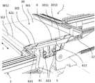
- FIG. 3where the bottom covering 31 and the claddings 32 , 34 have also been removed, the detail marked III in FIG. 2 is seen more clearly.
- the middle flashing member 30comprises a first part 301 having a first edge 3011 located at the first roof window 1 and a second edge 3012 located at the second roof window 2 .
- the middle flashing memberthus extends between a bottom frame member 12 of the first roof window 1 and a top frame member (not visible in FIG. 3 ) of the second roof window 2 .
- the extend of the second edge 3012defines a length direction L of the middle flashing assembly.
- the middle flashing member 30further comprises two side edges extending between the first and second edges 3011 , 3012 . Only one 3013 is seen in FIGS. 1-3 and this side edge has a bent edge 303 serving as an engagement section, which projects into the gutter on the exterior side of the connector element 6 .
- This engagement with the flange 621 defining the longitudinal edges of the gutterprevents the middle flashing member from moving away from the connector element and from moving towards the interior.
- the middle flashing member 33is mounted on top and attached to the tubular attachment element 622 , for example by means of a screw, the middle flashing member is further prevented from moving towards the exterior.
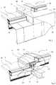
- FIGS. 4-8an example of the mounting of a flashing assembly by means of a connector element according to the invention is shown.
- FIG. 4shows the connector element 6 mounted on the connector bracket (not visible) as in FIG. 2 and extending between the cladding 32 of the first roof window and the cladding 34 of the second roof window.
- the mounting bracket 11 and frame 12 of the first roof windowsis seen in the background and a cover rail 371 is attached to the top frame member (not visible) of the second roof window.
- a supporting element 372has been attached to the top corner of the frame of the second roof window so that is supports the upper end 341 of the cladding 34 and a cover member 373 has been arranged on the exterior side of the cladding 34 , so that the upper end 341 is sandwiched between the two.
- a cover gasket 374extends along the exterior edge of the cover rail 371 and has a length so that it overlaps with the cover member 373 on the cladding 34 . Both the cover member 373 and the cover gasket 374 may be arranged behind attachment sections 63 of the connector element 6 so that they are prevented from moving away from the first roof window.
- an edge supporting rail 375has been arranged on one side of the connector element 6 on top of the cover gasket 374 and a side flashing supporting element 376 has been arranged on the other side of the connector element overlapping the cladding support element 372 and the cover member 373 .
- Both the edge supporting rail 375 and the side flashing supporting element 376are provided with circular openings which have been fitted over the attachment elements 632 of the connector element 6 so that the attachment elements project through the openings.
- the edge supporting rail 375has an L-shaped cross-sectional shape and is arranged with a first leg 3751 of the L extends extending towards the first roof window and the second leg 3752 extending downwards towards the cover rail 371 .
- an edge gasket 377has been attached to both attachment elements 632 by two openings in the edge gasket fitting over them, so that the edge gasket 377 overlaps the gap between the edge supporting rail 375 and the side flashing supporting element 376 .
- the outer ends of the attachment elements 632are substantially flush with the outer side of the edge gasket 377 .
- the edge gasket 377has an S-shaped cross-section where an upper part of the S hooks over the edge supporting rail 375 , while a lower part overlaps the cover rail 371 , thus weather-proofing the joint between the edge supporting rail and the cover rail.
- the middle flashing member 30has been arranged with the bent edge 301 projecting into the gutter of the connector element 6 as described above and with the second part 302 hooking over the edge supporting rail 375 and the edge gasket 377 .
- the system of rails 371 , 375 and gaskets 374 , 377thus provides a weather-proof connection between the middle flashing member 30 and the second roof window.
- the end section 3770 of the edge gasket 377extends beyond the middle flashing member in the length direction L.
- the middle flashing element 30too has an opening 304 , which in the correctly mounted state is aligned with the left-hand attachment element 632 on the connector element 6 .
- a screw or like fastener(not shown) may be passed through this opening 304 and directly into the elongate receiver 633 of the connector element 6 .
- the attachment element 632slightly bigger, so that it also projects through the opening 304 in the middle flashing element, and it may even be provided with barb-like projections (not shown) allowing it to snap out on the outer side of the second part 302 of the middle flashing member.
- the side flashing member 35(shown only in FIG. 1 ) is provided with a similar opening fitting with the right-hand attachment element 632 and corresponding elongate receiver 633 , and the connector flashing member 33 has two openings matching the position of the attachment elements 632 in the same way as described for the second gasket 377 .
- Thisprovides for a simple, reliable, and cost-efficient attachment of the flashing assembly, and the resilience of the edge gasket may help maintain a tight connection between the connector element 6 and the flashing members 30 , 33 , 35 .
- edge supporting rail 375 and the edge gasket 377in relation to the other parts of the roof window assembly is seen more clearly in FIGS. 9 and 10 .
- edge supporting rail 375has a third leg 3753 , which extends from the L-shape described above and the cover gasket 374 is attached to this leg by an engagement section of the cover gasket being inserted in a groove at the end of the third leg.
- the cover gasket 374is here shown in its uncompressed state, but is will be understood that it will be deformed by the contact with the cover rail 371 in the mounted state.
- the cover rail 371is here composed of three interconnected aluminium profiles, one of which is attached to the top frame member 22 of the second roof window, but it may be embodied differently.
- the edge gasket 377 toois shown in its uncompressed state.
- the section of the lower part 3771which is here illustrated as coinciding with the cover rail 371 , will be pressed slightly upwards in the mounted state so that it abuts on the outer surface of the cover rail.
- the lower part 3771 of the edge gasketfits into a hollow formed by the inwards bend on the cover rail 371 and the inclination of the third leg 3753 of the edge supporting rail 375 .
- This in combination with the tight contact between the lower part 3771 of the edge gasket and the cover rail 371 caused by the elasticity of the edge gasket 377means that water will be kept away from the joint between the cover rail 371 and the edge supporting rail 375 .
- a weakening in the form of a reduced material thicknessdefines the bend on the lower part of the edge gasket 377 , but the S-shape could also be achieved in other ways.
Landscapes
- Engineering & Computer Science (AREA)
- Architecture (AREA)
- Civil Engineering (AREA)
- Structural Engineering (AREA)
- Physics & Mathematics (AREA)
- Electromagnetism (AREA)
- Roof Covering Using Slabs Or Stiff Sheets (AREA)
- Fittings On The Vehicle Exterior For Carrying Loads, And Devices For Holding Or Mounting Articles (AREA)
Abstract
Description
- arranging a middle flashing member with a first part extending between a bottom frame member of the first roof window and a top frame member of the second roof window, said first part having an interior side facing the interior of a building covered by the roof structure, an exterior side facing an exterior, a first edge located at the first roof window, a second edge located at the second roof window and defining a length direction of the middle flashing assembly, and two side edges extending between the first and second edges, and with an engagement section at one or both side edges in engagement with a connector element extending from the frame of the first roof window towards the second roof window, and with a second part on the interior side of the first part extending from the second edge away from the first part,
- arranging an edge supporting rail on the interior side of the middle flashing member in parallel with the second edge,
- arranging an edge gasket on the interior side of the middle flashing member in parallel with the second edge so that it is located between the middle flashing member and the edge supporting rail and so that a gasket end section extends beyond the middle flashing member in the length direction, and so that said gasket end section is in engagement with the connector element.
- 1 First roof windows
- 11 Mounting bracket
- 12 Bottom frame member
- 2 Second roof window
- 21 Mounting bracket
- 3 Flashing assembly
- 30 Middle flashing member
- 301 First part
- 3011 First edge
- 3012 Second edge
- 3013 Side edge
- 302 Second part
- 303 Bent edge
- 304 Opening
- 31 Bottom covering
- 32 Cladding
- 33 Connector flashing member
- 34 Cladding
- 35 Side flashing members
- 36 Side flashing members
- 371 Cover rail
- 372 Supporting element
- 341 Upper end
- 373 Cover member
- 374 Cover gasket
- 375 Edge supporting rail
- 3751 First leg
- 3752 Second leg
- 3753 Third leg
- 376 Side flashing supporting element
- 377 Edge gasket
- 3770 End section
- 3771 Lower part of edge gasket
- 41 Connector bracket
- 6 Connector element
- 611 Openings
- 621 Flange
- 622 Tubular attachment element
- 63 Attachment section
- 632 Attachment element
- 633 Elongate receiver
- L Length direction
Claims (20)
Applications Claiming Priority (2)
| Application Number | Priority Date | Filing Date | Title |
|---|---|---|---|
| DKPA201970015ADK180344B1 (en) | 2019-01-10 | 2019-01-10 | A middle flashing assembly and a method for weather-proofing a roof window arrangement |
| DKPA201970015 | 2019-01-10 |
Publications (2)
| Publication Number | Publication Date |
|---|---|
| US20200224425A1 US20200224425A1 (en) | 2020-07-16 |
| US11078671B2true US11078671B2 (en) | 2021-08-03 |
Family
ID=69156309
Family Applications (1)
| Application Number | Title | Priority Date | Filing Date |
|---|---|---|---|
| US16/737,802ActiveUS11078671B2 (en) | 2019-01-10 | 2020-01-08 | Middle flashing assembly and a method for weather-proofing a roof window arrangement |
Country Status (6)
| Country | Link |
|---|---|
| US (1) | US11078671B2 (en) |
| EP (1) | EP3680417B1 (en) |
| CN (1) | CN212053504U (en) |
| DK (2) | DK180344B1 (en) |
| ES (1) | ES2905074T3 (en) |
| PL (1) | PL3680417T3 (en) |
Families Citing this family (4)
| Publication number | Priority date | Publication date | Assignee | Title |
|---|---|---|---|---|
| US12139914B2 (en)* | 2020-08-26 | 2024-11-12 | Vkr Holding A/S | Connector arrangement and a method for weather proofing a roof window arrangement |
| USD1014792S1 (en) | 2021-09-07 | 2024-02-13 | Vkr Holding A/S | Skylight inner frame |
| USD1033678S1 (en) | 2021-09-07 | 2024-07-02 | Vkr Holding A/S | Skylight outer frame |
| DK181526B1 (en)* | 2022-03-31 | 2024-04-05 | Vkr Holding As | A covering device and a method for mounting a covering device at a skylight |
Citations (34)
| Publication number | Priority date | Publication date | Assignee | Title |
|---|---|---|---|---|
| US2851973A (en)* | 1955-06-28 | 1958-09-16 | Owens Illinois Glass Co | Skylight construction |
| DE7829553U1 (en) | 1978-10-04 | 1979-01-18 | Stiebel Eltron Gmbh & Co Kg, 3450 Holzminden | MOUNTING FRAME FOR SOLAR COLLECTORS |
| EP0087647A1 (en) | 1982-02-26 | 1983-09-07 | V. Kann Rasmussen Holding A/S | Combined covering frame for skylights embedded side by side |
| US4520604A (en)* | 1983-11-23 | 1985-06-04 | Rca Corporation | Skylight structure |
| US4570393A (en)* | 1983-01-06 | 1986-02-18 | Rolscreen Company | Weather seal for frame and movable panel assembly |
| DE7920893U1 (en) | 1979-07-21 | 1986-11-13 | Blefa GmbH, 5910 Kreuztal | Covering collar for roof windows, solar panels or other roof fittings located in the roof area |
| US4680905A (en)* | 1985-08-26 | 1987-07-21 | Ppg Industries, Inc. | Rafter with internal drainage feature and sloped glazing system incorporating same |
| US4776141A (en)* | 1987-03-02 | 1988-10-11 | Powell J William | Skylights |
| EP0428921A1 (en) | 1989-11-03 | 1991-05-29 | Safiza S.A. | Lighting and/or ventilating set of elements for closed space comprising a roof and wall window |
| US5044133A (en)* | 1988-12-13 | 1991-09-03 | Wasco Products, Inc. | Skylight construction |
| US5355644A (en)* | 1991-08-20 | 1994-10-18 | Andersen Corporation | Roof window-venting and stationary |
| US6052956A (en)* | 1997-01-02 | 2000-04-25 | Fox Lite, Inc. | Skylight assembly |
| US6195948B1 (en)* | 1999-07-23 | 2001-03-06 | Poly Lite Windows Ltd. | Skylights to accommodate on site adjustments for variations in installations |
| US6263623B1 (en)* | 1998-12-07 | 2001-07-24 | Andersen Corporation | Method and apparatus for using a detent arrangement on a roof window frame and sash |
| DE20206327U1 (en) | 2002-04-22 | 2002-07-18 | Vkr Holding A/S, Soeborg | Device for shielding windows installed in an extension to one another |
| WO2004055294A1 (en) | 2002-12-16 | 2004-07-01 | Vkr Holding A/S | Side flashing member method of making such a side flashing member and a flashing assembly |
| EP1533436A2 (en) | 2003-11-21 | 2005-05-25 | VKR Holding A/S | Covering sealing element for roof window |
| WO2005116365A1 (en) | 2004-05-24 | 2005-12-08 | Srb Construction Technologies | Concrete sideform system |
| US7658356B1 (en) | 2009-01-29 | 2010-02-09 | Unistrut International Corporation | Mounting bracket for solar panel applications |
| US20110277402A1 (en)* | 2009-01-27 | 2011-11-17 | Mounting Systems Gmbh | Solar panel mount |
| EP2472025A1 (en) | 2010-12-29 | 2012-07-04 | VKR Holding A/S | A flashing member with a compensation member and a kit including such a flashing member |
| EP2472043A1 (en) | 2010-12-29 | 2012-07-04 | VKR Holding A/S | A window system having a concealed operator |
| US20120167483A1 (en)* | 2010-12-29 | 2012-07-05 | Claes Lindgren | Flashing Member with a Compensation Member, a Kit Including Such a Flashing Member and a Method for Mounting a Flashing for a Roof Window |
| DE202012006688U1 (en) | 2012-07-10 | 2013-10-14 | Vkr Holding A/S | Roof window with cover means for a frame |
| DE202014000149U1 (en) | 2013-01-07 | 2014-05-20 | Vkr Holding A/S | Gutter-like cover and roof structure including such a cover |
| US20140305046A1 (en) | 2010-01-25 | 2014-10-16 | Vermont Slate & Copper Services, Inc. | Roof mount assembly |
| US20140366468A1 (en)* | 2010-12-29 | 2014-12-18 | Vkr Holdings A/S | Window system having flexible means for mounting |
| WO2015028032A1 (en) | 2013-08-30 | 2015-03-05 | Vkr Holding A/S | A window system adapted for being mounted in an inclined surface of a building and a method for draining condensation from such a window system |
| WO2015028030A1 (en) | 2013-08-30 | 2015-03-05 | Vkr Holding A/S | A connector element for use in a flashing assembly for roof windows mounted side-by-side and a method for mounting a flashing assembly |
| US20150267412A1 (en)* | 2014-03-24 | 2015-09-24 | Bluescope Buildings North America, Inc. | Roof Ridge Integrated Water-Shedding Apparatus |
| EP3252256A1 (en) | 2016-05-31 | 2017-12-06 | VKR Holding A/S | Window bracket assembly |
| EP3282064A1 (en) | 2016-08-03 | 2018-02-14 | VKR Holding A/S | A connector element for use in a flashing assembly for roof windows mounted side-by-side and a connector set including such a connector element |
| DK201670572A1 (en) | 2016-08-03 | 2018-03-12 | Vkr Holding As | A connector element for use in a flashing assembly for roof windows mounted side-by-side and a connector set including such a connector element |
| US9920532B1 (en)* | 2015-08-28 | 2018-03-20 | Wayne Conklin | Skylight framing system |
- 2019
- 2019-01-10DKDKPA201970015Apatent/DK180344B1/enactiveIP Right Grant
- 2020
- 2020-01-08USUS16/737,802patent/US11078671B2/enactiveActive
- 2020-01-09PLPL20150912Tpatent/PL3680417T3/enunknown
- 2020-01-09EPEP20150912.2Apatent/EP3680417B1/enactiveActive
- 2020-01-09ESES20150912Tpatent/ES2905074T3/enactiveActive
- 2020-01-09DKDK20150912.2Tpatent/DK3680417T3/enactive
- 2020-01-10CNCN202020057428.0Upatent/CN212053504U/enactiveActive
Patent Citations (37)
| Publication number | Priority date | Publication date | Assignee | Title |
|---|---|---|---|---|
| US2851973A (en)* | 1955-06-28 | 1958-09-16 | Owens Illinois Glass Co | Skylight construction |
| DE7829553U1 (en) | 1978-10-04 | 1979-01-18 | Stiebel Eltron Gmbh & Co Kg, 3450 Holzminden | MOUNTING FRAME FOR SOLAR COLLECTORS |
| DE7920893U1 (en) | 1979-07-21 | 1986-11-13 | Blefa GmbH, 5910 Kreuztal | Covering collar for roof windows, solar panels or other roof fittings located in the roof area |
| EP0087647A1 (en) | 1982-02-26 | 1983-09-07 | V. Kann Rasmussen Holding A/S | Combined covering frame for skylights embedded side by side |
| US4621466A (en)* | 1982-02-26 | 1986-11-11 | Rasmussen Holding S/A | Flashing frame for the installation of adjacent roof windows |
| US4570393A (en)* | 1983-01-06 | 1986-02-18 | Rolscreen Company | Weather seal for frame and movable panel assembly |
| US4520604A (en)* | 1983-11-23 | 1985-06-04 | Rca Corporation | Skylight structure |
| US4680905A (en)* | 1985-08-26 | 1987-07-21 | Ppg Industries, Inc. | Rafter with internal drainage feature and sloped glazing system incorporating same |
| US4776141A (en)* | 1987-03-02 | 1988-10-11 | Powell J William | Skylights |
| US5044133A (en)* | 1988-12-13 | 1991-09-03 | Wasco Products, Inc. | Skylight construction |
| EP0428921A1 (en) | 1989-11-03 | 1991-05-29 | Safiza S.A. | Lighting and/or ventilating set of elements for closed space comprising a roof and wall window |
| US5355644A (en)* | 1991-08-20 | 1994-10-18 | Andersen Corporation | Roof window-venting and stationary |
| US6052956A (en)* | 1997-01-02 | 2000-04-25 | Fox Lite, Inc. | Skylight assembly |
| US6263623B1 (en)* | 1998-12-07 | 2001-07-24 | Andersen Corporation | Method and apparatus for using a detent arrangement on a roof window frame and sash |
| US6195948B1 (en)* | 1999-07-23 | 2001-03-06 | Poly Lite Windows Ltd. | Skylights to accommodate on site adjustments for variations in installations |
| DE20206327U1 (en) | 2002-04-22 | 2002-07-18 | Vkr Holding A/S, Soeborg | Device for shielding windows installed in an extension to one another |
| WO2004055294A1 (en) | 2002-12-16 | 2004-07-01 | Vkr Holding A/S | Side flashing member method of making such a side flashing member and a flashing assembly |
| EP1533436A2 (en) | 2003-11-21 | 2005-05-25 | VKR Holding A/S | Covering sealing element for roof window |
| WO2005116365A1 (en) | 2004-05-24 | 2005-12-08 | Srb Construction Technologies | Concrete sideform system |
| US20110277402A1 (en)* | 2009-01-27 | 2011-11-17 | Mounting Systems Gmbh | Solar panel mount |
| US7658356B1 (en) | 2009-01-29 | 2010-02-09 | Unistrut International Corporation | Mounting bracket for solar panel applications |
| US20140305046A1 (en) | 2010-01-25 | 2014-10-16 | Vermont Slate & Copper Services, Inc. | Roof mount assembly |
| US20120167483A1 (en)* | 2010-12-29 | 2012-07-05 | Claes Lindgren | Flashing Member with a Compensation Member, a Kit Including Such a Flashing Member and a Method for Mounting a Flashing for a Roof Window |
| EP2472043A1 (en) | 2010-12-29 | 2012-07-04 | VKR Holding A/S | A window system having a concealed operator |
| EP2472025A1 (en) | 2010-12-29 | 2012-07-04 | VKR Holding A/S | A flashing member with a compensation member and a kit including such a flashing member |
| US20140366468A1 (en)* | 2010-12-29 | 2014-12-18 | Vkr Holdings A/S | Window system having flexible means for mounting |
| DE202012006688U1 (en) | 2012-07-10 | 2013-10-14 | Vkr Holding A/S | Roof window with cover means for a frame |
| DE202014000149U1 (en) | 2013-01-07 | 2014-05-20 | Vkr Holding A/S | Gutter-like cover and roof structure including such a cover |
| EP2752531A2 (en) | 2013-01-07 | 2014-07-09 | VKR Holding A/S | A gutter-like flashing member and a roof structure including such a flashing member |
| WO2015028032A1 (en) | 2013-08-30 | 2015-03-05 | Vkr Holding A/S | A window system adapted for being mounted in an inclined surface of a building and a method for draining condensation from such a window system |
| WO2015028030A1 (en) | 2013-08-30 | 2015-03-05 | Vkr Holding A/S | A connector element for use in a flashing assembly for roof windows mounted side-by-side and a method for mounting a flashing assembly |
| EP3039198A1 (en) | 2013-08-30 | 2016-07-06 | VKR Holding A/S | A connector element for use in a flashing assembly for roof windows mounted side-by-side and a method for mounting a flashing assembly |
| US20150267412A1 (en)* | 2014-03-24 | 2015-09-24 | Bluescope Buildings North America, Inc. | Roof Ridge Integrated Water-Shedding Apparatus |
| US9920532B1 (en)* | 2015-08-28 | 2018-03-20 | Wayne Conklin | Skylight framing system |
| EP3252256A1 (en) | 2016-05-31 | 2017-12-06 | VKR Holding A/S | Window bracket assembly |
| EP3282064A1 (en) | 2016-08-03 | 2018-02-14 | VKR Holding A/S | A connector element for use in a flashing assembly for roof windows mounted side-by-side and a connector set including such a connector element |
| DK201670572A1 (en) | 2016-08-03 | 2018-03-12 | Vkr Holding As | A connector element for use in a flashing assembly for roof windows mounted side-by-side and a connector set including such a connector element |
Non-Patent Citations (15)
| Title |
|---|
| Danish Search Report issued in Danish Patent Application No. PA2019 70013 dated Jun. 28, 2019, four pages. |
| Danish Search Report issued in Danish Patent Application No. PA2019 70014 dated Jun. 25, 2019, four pages. |
| Danish Search Report issued in Danish Patent Application No. PA2019 70015 dated Jun. 6, 2019, four pages. |
| Danish Search Report issued in Danish Patent Application No. PA2019 70016 dated Aug. 27, 2019, four pages. |
| European Extended Search Report dated Apr. 23, 2020, 8 Pages Issued in Connection With European Application No. 20150910 Which is Related to U.S. Appl. No. 16/737,820. |
| European Extended Search Report dated Jun. 16, 2020, 5 Pages Issued in Connection With European Application No. 20150914 Which is Related to U.S. Appl. No. 16/737,811. |
| European Extended Search Report dated May 29, 2020, 8 Pages Issued in Connection With European Application No. 20150909 Which is Related to U.S. Appl. No. 16/737,834. |
| European Search Report dated May 25, 2020, 5 Pages Issued in Connection With European Application No. 20150912 Which is Related to U.S. Appl. No. 16/737,802. |
| Machine generated translation of DE202012006688. |
| Machine generated translation of DE202014000149. |
| Machine generated translation of DE7829553. |
| Machine generated translation of DE7920893. |
| U.S. Appl. No. 16/737,811, filed Jan. 8, 2020 as entitled "An End Closure for a Cladding for a Roof Window and a Roof Window Arrangement". |
| U.S. Appl. No. 16/737,820, filed Jan. 8, 2020 as entitled "A Connector Bracket for Interconnecting Roof Windows, a Roof Window Arrangement, and a Method for Mounting at least two Windows in an Inclined Roof Structure". |
| U.S. Appl. No. 16/737,834, filed Jan. 8, 2020 as entitled "A Connector Element for a Flashing Assembly for use in a Roof Window Arrangement, and a Method for Weather Proofing a Roof Window Arrangement". |
Also Published As
| Publication number | Publication date |
|---|---|
| DK3680417T3 (en) | 2022-01-17 |
| CN212053504U (en) | 2020-12-01 |
| EP3680417B1 (en) | 2021-11-10 |
| DK180344B1 (en) | 2021-01-15 |
| ES2905074T3 (en) | 2022-04-07 |
| EP3680417A1 (en) | 2020-07-15 |
| US20200224425A1 (en) | 2020-07-16 |
| DK201970015A1 (en) | 2020-09-09 |
| PL3680417T3 (en) | 2022-04-04 |
Similar Documents
| Publication | Publication Date | Title |
|---|---|---|
| US11078671B2 (en) | Middle flashing assembly and a method for weather-proofing a roof window arrangement | |
| US5199234A (en) | Skylight assembly | |
| EP3680416B1 (en) | A connector element for a flashing assembly for use in a roof window arrangement and a method for weather proofing a roof window arrangement | |
| US20090031640A1 (en) | Roof Flashing Connections | |
| EP3396100B1 (en) | Flat roof window with external screen | |
| US8322091B2 (en) | Window frame assembly with integral seals | |
| US7331145B2 (en) | Flashing component for a roof window assembly | |
| RU2630944C2 (en) | Profiled element for vehicle glass connection to cladding component, and profiled element assembly | |
| US9482009B2 (en) | Connector element for use in a flashing assembly for roof windows mounted side-by-side and a method for mounting a flashing assembly | |
| US5150983A (en) | Corner lock | |
| US20110138717A1 (en) | Window remediation system and method | |
| CN119053759B (en) | Waterproof device and method for installing the waterproof device at a roof window | |
| EP0990761A2 (en) | Composite wood-aluminium window frame | |
| EP1521888B1 (en) | Sheet flashing member and a flashing kit | |
| US7698857B2 (en) | Roof assembly method and apparatus | |
| JP3742068B2 (en) | End connection structure of metal plate lateral wall | |
| GB2385868A (en) | Ring beams | |
| CN113802781A (en) | Panel system with mounting and hinge assemblies with mounting profiles and hinges |
Legal Events
| Date | Code | Title | Description |
|---|---|---|---|
| FEPP | Fee payment procedure | Free format text:ENTITY STATUS SET TO UNDISCOUNTED (ORIGINAL EVENT CODE: BIG.); ENTITY STATUS OF PATENT OWNER: LARGE ENTITY | |
| AS | Assignment | Owner name:VKR HOLDING A/S, DENMARK Free format text:ASSIGNMENT OF ASSIGNORS INTEREST;ASSIGNOR:ALLESEN, TORBEN KROGSGAARD;REEL/FRAME:051680/0320 Effective date:20200117 | |
| STPP | Information on status: patent application and granting procedure in general | Free format text:DOCKETED NEW CASE - READY FOR EXAMINATION | |
| STPP | Information on status: patent application and granting procedure in general | Free format text:NON FINAL ACTION MAILED | |
| STPP | Information on status: patent application and granting procedure in general | Free format text:RESPONSE TO NON-FINAL OFFICE ACTION ENTERED AND FORWARDED TO EXAMINER | |
| STPP | Information on status: patent application and granting procedure in general | Free format text:NOTICE OF ALLOWANCE MAILED -- APPLICATION RECEIVED IN OFFICE OF PUBLICATIONS | |
| STPP | Information on status: patent application and granting procedure in general | Free format text:PUBLICATIONS -- ISSUE FEE PAYMENT RECEIVED | |
| STPP | Information on status: patent application and granting procedure in general | Free format text:PUBLICATIONS -- ISSUE FEE PAYMENT VERIFIED | |
| STCF | Information on status: patent grant | Free format text:PATENTED CASE | |
| MAFP | Maintenance fee payment | Free format text:PAYMENT OF MAINTENANCE FEE, 4TH YEAR, LARGE ENTITY (ORIGINAL EVENT CODE: M1551); ENTITY STATUS OF PATENT OWNER: LARGE ENTITY Year of fee payment:4 |