US11078652B2 - Faucet including capacitive sensors for hands free fluid flow control - Google Patents
Faucet including capacitive sensors for hands free fluid flow controlDownload PDFInfo
- Publication number
- US11078652B2 US11078652B2US16/422,925US201916422925AUS11078652B2US 11078652 B2US11078652 B2US 11078652B2US 201916422925 AUS201916422925 AUS 201916422925AUS 11078652 B2US11078652 B2US 11078652B2
- Authority
- US
- United States
- Prior art keywords
- detection
- spout
- electrically operable
- faucet
- detection field
- Prior art date
- Legal status (The legal status is an assumption and is not a legal conclusion. Google has not performed a legal analysis and makes no representation as to the accuracy of the status listed.)
- Active, expires
Links
- 239000012530fluidSubstances0.000titleclaimsdescription29
- 238000001514detection methodMethods0.000claimsabstractdescription145
- XLYOFNOQVPJJNP-UHFFFAOYSA-NwaterSubstancesOXLYOFNOQVPJJNP-UHFFFAOYSA-N0.000claimsabstractdescription57
- 238000004891communicationMethods0.000claimsdescription9
- 230000004044responseEffects0.000claimsdescription6
- 238000010586diagramMethods0.000description8
- 230000004913activationEffects0.000description7
- 238000000034methodMethods0.000description6
- 239000007788liquidSubstances0.000description5
- 238000012544monitoring processMethods0.000description4
- 230000008569processEffects0.000description3
- 238000012986modificationMethods0.000description2
- 230000004048modificationEffects0.000description2
- 230000006978adaptationEffects0.000description1
- 230000004075alterationEffects0.000description1
- 230000008859changeEffects0.000description1
- 230000009849deactivationEffects0.000description1
- 230000001737promoting effectEffects0.000description1
Images


Classifications
- E—FIXED CONSTRUCTIONS
- E03—WATER SUPPLY; SEWERAGE
- E03C—DOMESTIC PLUMBING INSTALLATIONS FOR FRESH WATER OR WASTE WATER; SINKS
- E03C1/00—Domestic plumbing installations for fresh water or waste water; Sinks
- E03C1/02—Plumbing installations for fresh water
- E03C1/05—Arrangements of devices on wash-basins, baths, sinks, or the like for remote control of taps
- E03C1/055—Electrical control devices, e.g. with push buttons, control panels or the like
- E03C1/057—Electrical control devices, e.g. with push buttons, control panels or the like touchless, i.e. using sensors
- E—FIXED CONSTRUCTIONS
- E03—WATER SUPPLY; SEWERAGE
- E03C—DOMESTIC PLUMBING INSTALLATIONS FOR FRESH WATER OR WASTE WATER; SINKS
- E03C1/00—Domestic plumbing installations for fresh water or waste water; Sinks
- E03C1/02—Plumbing installations for fresh water
- E03C1/04—Water-basin installations specially adapted to wash-basins or baths
- E03C1/0412—Constructional or functional features of the faucet handle
Definitions
- the present disclosurerelates generally to improvements in capacitive sensors for activation of faucets. More particularly, the present invention relates to the placement of a capacitive sensors in or adjacent to faucet spouts and/or faucet handles to sense proximity of a user of the faucet and then control the faucet based on output signals from the capacitive sensors.
- Electronic faucetsare often used to control fluid flow.
- Electronic faucetsmay include proximity sensors such as active infrared (“IR”) proximity detectors or capacitive proximity sensors. Such proximity sensors are used to detect a user's hands positioned near the faucet, and turn the water on and off in response to detection of the user's hands.
- Other electronic faucetsmay use touch sensors to control the faucet.
- touch sensorsinclude capacitive touch sensors or other types of touch sensors located on a spout of the faucet or on a handle for controlling the faucet. Capacitive sensors on the faucet may also be used to detect both touching of faucet components and proximity of the user's hands adjacent the faucet.
- a faucetcomprising: a spout; a passageway that conducts water flow through the spout; an electrically operable valve disposed within the passageway and having an opened position, in which water is free to flow through the passageway, and a closed position, in which the passageway is blocked; a first capacitive sensor having a first detection field that generates a first output signal upon detection of a user's hands in the first detection field; a second capacitive sensor having a second detection field that generates a second output signal upon detection of a user's hands in the second detection field; and a controller coupled to the first and second capacitive sensors and the electrically operable valve, the controller being programmed to actuate the electrically operable valve in response to detecting the user's hands in the first detection field but not in the second detection field.
- a method of actuating a faucetcomprising: monitoring a first capacitive sensor having a first detection field that generates a first output signal upon detection of a user's hands in the first detection field; monitoring a second capacitive sensor having a second detection field that generates a second output signal upon detection of a user's hands in the second detection field; and toggling an electrically operable valve within the faucet between an opened position, in which water is free to flow through the faucet, and a closed position, in which the faucet is blocked and water flow through the faucet is inhibited, upon receipt of the first output signal but not the second output signal.
- FIG. 1Ais a block diagram of an illustrative embodiment electronic faucet
- FIG. 1Bis a block diagram of another illustrative embodiment electronic faucet
- FIG. 1Cis a block diagram of another illustrative embodiment electronic faucet
- FIG. 2is a block diagram illustrating an embodiment of the present disclosure including first and second capacitive sensors each having a separate detection field positioned to define an overlapping central detection region or detection zone, wherein a controller processes output signals from the first and second capacitive sensors to detect when a user is positioned within the detection zone;
- FIG. 3is a block diagram illustrating the first and second capacitive sensors of FIG. 2 positioned on a spout of a faucet to define a detection zone adjacent the spout;
- FIG. 4illustrates exemplary output signals from the first and second capacitive sensors of FIGS. 2 and 3 as a user's hands move relative to the first and second capacitive sensors;
- FIG. 5is a block diagram illustrating another embodiment of the present disclosure including three capacitive sensors each having separate detection fields positioned to define a plurality of overlapping detection zones;
- FIG. 6is a block diagram illustrating another embodiment of the present disclosure including first and second capacitive sensors each having a separate detection field, wherein a controller processes output signals from the first and second capacitive sensors such that the second capacitive sensor acts as an inhibit to the first capacitive sensor;
- FIG. 7illustrates exemplary output signals from the first and second capacitive sensors of FIG. 6 as a user's hands more relative to the first and second capacitive sensors
- FIG. 8is a flow chart illustrating operation of the embodiment of FIG. 6 .
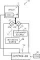
- FIG. 1Ais a block diagram showing one illustrative embodiment of an electronic faucet 10 of the present disclosure.
- the faucet 10illustratively includes an outlet (e.g., a spout 12 ) for delivering fluids such as water and at least one manual valve handle 14 for controlling the flow of fluid through the spout 12 in a manual mode.
- a hot water source 16 and a cold water source 18are coupled to a manual valve body assembly 20 by fluid supply lines 17 and 19 , respectively.
- the valve handle 14is operably coupled to the manual valve body assembly 20 to control water flow therethrough.
- separate manual valve handles 14are provided for the hot and cold water sources 16 , 18 .
- a single manual valve handle 14is used for both hot and cold water delivery.
- the manual valve handle 14 and spout 12are typically coupled to a basin through a single hole mount.
- An output of valve body assembly 20is coupled to an actuator driven valve 22 which is controlled electronically by input signals received from a controller 24 .
- actuator driven valve 22is an electrically operable valve, such as a solenoid valve.
- An output of actuator driven valve 22supplies fluid to the spout 12 through a water output or supply line 23 .
- the hot water source 16 and the cold water source 18are connected directly to actuator driven valve 22 to provide a fully automatic faucet without any manual controls.
- the controller 24controls at least one electronic proportioning valve (not shown) to supply fluid to the spout 12 from hot and cold water sources 16 and 18 .
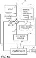
- FIG. 1Bfurther shows an illustrative embodiment faucet 10 ′ including a first or hot water actuator driven (e.g., electrically operable) valve 22 a , and a second or cold water actuator driven (e.g., electrically operable) valve 22 b .
- the hot water electrically operable valve 22 ais fluidly coupled to the hot water source 16
- the cold water electrically operable valve 22 bis fluidly coupled to the cold water source 18 .
- the outputs of the electrically operable valves 22 a and 22 bare in fluid communication with the supply line 23 .
- Each electrically operable valve 22 a and 22 bmay be independently operated by the controller 24 to define proportioning valves. More particularly, the electrically operable valves 22 a and 22 b are configured to cooperate to change the flow rate and temperature of water supplied to the supply line 23 and hence the spout 12 .
- FIG. 1Cfurther shows an illustrative embodiment faucet 10 ′′ including a first or temperature control actuator driven (e.g., electrically operable) valve 22 a , and a second or flow control actuator driven (e.g., electrically operable) valve 22 b .
- the output of the temperature control actuator driven valve 22 ais in fluid communication with the flow control actuator driven valve 22 b .
- the temperature control electrically operable valve 22 ais fluidly coupled to both the hot water source 16 and the cold water source 18 .
- the valve 22 acontrols the mixing ratio of hot water and cold water from the hot water source 16 and the cold water source 18 .
- the electrically operable valve 22 adefines a mixing valve controlling the temperature of water delivered to the flow control actuator driven valve 22 b .
- the electrically operable valve 22 bcontrols the flow rate of water supplied to the supply line 23 and hence the spout 12 .
- the actuator driven valve 22is controlled electronically by controller 24 , flow of water is controlled using outputs from sensors such as capacitive sensors 26 , 28 and/or 30 .
- the faucet 10may be operated in a conventional manner, i.e., in a manual control mode through operation of the handle(s) 14 and the manual valve member of valve body assembly 20 .
- the actuator driven valve 22can be touch controlled, or activated by proximity sensors when an object (such as a user's hands) are within a detection zone to toggle water flow on and off.
- spout 12has at least one capacitive sensor 26 connected to controller 24 .
- the manual valve handle(s) 14may also have capacitive sensor(s) 28 mounted thereon which are electrically coupled to controller 24 .
- Additional capacitive sensors 30may be located near the spout 12 of faucet 10 , such as in an adjacent sink basin.
- the output signals from capacitive sensors 26 , 28 and/or 30are used to control actuator driven valve 22 which thereby controls flow of water to the spout 12 from the hot and cold water sources 16 and 18 .
- the controller 24can make logical decisions to control different modes of operation of faucet 10 such as changing between a manual mode of operation and a hands free mode of operation as further described in U.S. Pat. Nos. 8,613,419; 7,690,395 and 7,150,293; and 7,997,301, the disclosures of which are all expressly incorporated herein by reference.
- Another illustrated configuration for a proximity detector and logical control for the faucet in response to the proximity detectoris described in greater detail in U.S. Pat. No. 7,232,111, which is hereby incorporated by reference in its entirety.
- the amount of fluid from hot water source 16 and cold water source 18is determined based on one or more user inputs, such as desired fluid temperature, desired fluid flow rate, desired fluid volume, various task based inputs, various recognized presentments, and/or combinations thereof.
- the faucet 10may also include an electronically controlled proportioning or mixing valve which is in fluid communication with both hot water source 16 and cold water source 18 .
- Exemplary electronically controlled mixing valvesare described in U.S. Pat. No. 7,458,520 and PCT International Publication No. WO 2007/082301, the disclosures of which are expressly incorporated by reference herein.
- the present disclosurerelates generally to faucets including hands free flow control and, more particularly, to a faucet including at least two capacitive sensors to detect a user's hands in a detection zone to control water flow. It is known to provide capacitive sensors on faucet components which create a detection zone near the faucet. When a user's hands are detected in the detection zone, the capacitive sensor signals a controller to turn on the flow of water to the faucet. See, for example, Masco's U.S. Pat. No. 8,127,782; U.S. Patent Application Publication No. 2010/0170570; or U.S. Patent Application Publication No. 2010/0108165.
- FIG. 2illustrates an embodiment of an electronic faucet system 10 of the present disclosure including a hands-free capacitive sensing system.
- the system 10includes a controller 24 and first and second capacitive sensors 32 and 34 located on or near the faucet and coupled to the controller 24 .
- the first capacitive sensor 32has a generally spherical detection field 36 surrounding sensor 32
- the second capacitive sensor 34has a generally spherical detection field 38 surrounding sensor 34 .
- Capacitive sensors 32 and 34detect objects, such as the user's hands, anywhere in the entire spherical detection regions 36 and 38 , respectively.
- detection field 36overlaps detection field 38 in a generally prolate spheroid or “football” shaped region or detection zone 40 .
- the controller 24processes output signals from the first and second capacitive sensors 32 and 34 to detect when a user's hands are positioned within the detection zone 40 .
- controller 24opens a valve 22 to provide fluid flow to an outlet of the faucet.
- FIG. 3illustrates the embodiment of FIG. 2 in which the capacitive sensors 32 and 34 are both coupled to a spout 12 of the faucet.
- the spoutincludes an upwardly extending portion 42 which is pivotably mounted to a hub 44 so that the spout 12 can swivel about an axis of the upwardly extending portion 42 .
- Spout 12further includes a curved portion 46 and an outlet 48 so that the spout 12 generally has an inverted J-shape.
- the first capacitive sensor 32is coupled to the spout 12 near outlet 48 .
- the second capacitive sensor 34is coupled to hub 44 or a lower section of upwardly extending portion 42 of spout 12 .
- detection field 36 of capacitive sensor 32 and detection field 38 of capacitive sensor 34overlap to define a detection zone 40 .
- the first and second sensors 32 and 34are positioned on the spout 12 so that the detection zone 40 is positioned at a desired location for detecting the user's hands.
- the detection zone 40may be located near the outlet 48 of spout 12 .
- the detection zone 40is beneath the curved portion 46 of spout 12 between the upwardly extending portion 42 and the outlet 48 . Therefore, a user can turn the faucet on and off by placing the user's hand in the detection zone 40 .
- FIG. 4illustrates output signals from the first and second capacitive sensors 32 and 34 of the embodiment shown in FIGS. 2 and 3 as a user's hands move back and forth between the first and second capacitive sensors 32 and 34 .
- signal 50is an output from the first capacitive sensor 32
- signal 52is an output signal from the second capacitive sensor 34 .
- the output signal 52 from the capacitive sensor 34 mounted on the hub 44 of spout 12has a greater amplitude than the output signal 50 from the capacitive sensor 32 located near the outlet 48 of spout 12 .
- the peaks 54 of output signal 50indicate when the user's hands are approaching the first capacitive sensor 32 and the valleys 56 indicate when the user's hands are moving further away from capacitive sensor 32 .
- the peaks 58 in output signal 52illustrate when the user's hands are moving closer to the second capacitive sensor 34 on hub 44 .
- the valleys 60indicate when the user's hands have moved further away from the second capacitive sensor 34 .
- Controller 24monitors the output signals 50 and 52 to determine when the user's hands are in the detection zone 40 . For example, when both the amplitudes of output signals 50 and 52 are within preselected ranges defining the boundaries of the detection zone 40 , the controller 24 determines that the user's hands are in the detection zone 40 and opens the valve 22 to begin fluid flow through the spout 12 .
- Controller 24determines when the user's hands are in the detection zone 40 by looking at the signal strengths of the output signals 50 and 52 from capacitive sensors 32 and 34 , respectively. The stronger the output signal, the closer the user's hands are to that sensor 32 or 34 .
- the output signal 52 from the second capacitive sensor 34is strong while the output signal 50 from the first capacitive sensor 32 is weak. This indicates that the user's hands are located closer to the second capacitive sensor 34 .
- the output signal 52 from the second capacitive sensor 34is weak and the output signal 50 from the first capacitive sensor 32 is strong. This indicates that that the user's hands are located closer to the first capacitive sensor 32 .
- both output signals 50 , 52are strong. This indicates that the user's hands are located in the middle of detection zone 40 .
- first, second and third capacitive sensors 70 , 72 , and 74are provided. Capacitive sensors 70 , 72 , and 74 each have separate detection fields 76 , 78 , and 80 .
- the first capacitive sensor 70is mounted on a spout 12 of the faucet.
- the second and third capacitive sensors 72 and 74are mounted on handles 14 , a sink basin, or other location adjacent the spout 12 .
- detection fields 76 and 78overlap within a detection zone 82 .
- Detection fields 78 and 80overlap within a detection zone 84 .
- Detection fields 76 and 80overlap within a detection zone 86 .
- all three detection fields 76 , 78 and 80overlap within a central detection zone 88 .
- the controller 24determines whether the user's hands are in one of the detection zones 82 , 84 , 86 or 88 .
- the controller 24controls the faucet differently depending on the detection zone 82 , 84 , 86 or 88 in which the user's hands are located.
- the controller 24may increase or decrease fluid flow, increase or decrease temperature, turn on or off fluid flow, or otherwise control the faucet or other components based upon which detection zone 82 , 84 , 86 or 88 the user's hands are located.
- the system 10illustratively includes a controller 24 and first and second capacitive sensors 32 and 34 located on or near the faucet 10 ( FIG. 1 ) and coupled to the controller 24 .
- the first capacitive sensor 32has a general spherical detection field 36 surrounding sensor 32
- the second capacitive sensor 34has a general spherical detection region 38 surrounding sensor 34 .
- Capacitive sensors 32 and 34detect objects, such as user's hands, anywhere in the spherical detection region 36 and 38 , respectively.
- Detection field 36overlaps detection field 38 in a generally prolate spheroid or “football” shaped region or detection zone 40 .
- the first capacitive sensor 32 and the related or associated detection region 36not including the overlapping detection zone 40 , defines an activation field.
- the second capacitive sensor 34 and associated detection field 38including the overlapping detection field 40 , define an inhibit field. More particularly, detection of an object or user's hands, within the inhibit field (i.e., detection fields 38 and/or 40 ) will inhibit operation (e.g., activation or deactivation) of the valve 22 ( FIG. 1A ).
- valve 22may be toggled from the open position to the closed position or vice-versa if detection of an object or user's hands in the activation field (i.e., detection field 36 ), without detecting an object or user's hands within the inhibit field (i.e., detection fields 38 and/or 40 ) occurs. It is also within the scope of the present disclosure that the overlapping detection field 40 may be considered part of the activation field 36 rather than part of the inhibit field 38 .
- FIG. 8illustrates the functionality of controller 24 of FIG. 6 with respect to capacitive sensors 32 and 34 by a method 100 .
- faucet 10FIG. 1A
- controller 24monitors capacitive sensor 32 to determine whether capacitive sensor 32 has transmitted a first output signal to controller 24 .
- Capacitive sensor 32transmits a first output signal to controller 24 when an object (e.g., a user's hand) is detected within detection field 36 for a specified period of time.
- capacitive sensor 32transmits a first output signal when the object is detected within detection field 36 for a time period between 60 milliseconds and 270 milliseconds (which is illustratively called a “swipe”). However, it is contemplated that other time periods may be used. If controller 24 receives a first output signal from capacitive sensor 32 in block 104 , then controller 24 moves on to block 106 and determines whether a second output signal was received by capacitive sensor 34 based on whether an object or a user's hand was detected in detection fields 38 and/or 40 as discussed further herein. If controller 24 does not receive a first output signal from capacitive sensor 32 in block 104 , then controller 24 continues to monitor the state of capacitive sensor 32 .
- controller 24monitors capacitive sensor 34 to determine whether a second output signal from capacitive sensor 34 has been transmitted to controller 24 .
- Controller 24monitors capacitive sensor 34 for a predetermined period of time surrounding (e.g., before and/or after) the reception of the first output signal from capacitive sensor 32 at block 104 .
- controller 24monitors capacitive sensor 36 for no greater than 120 milliseconds to determine whether an object (e.g., a user's hand) is present within detection field 38 and/or 40 .
- an objecte.g., a user's hand
- it is contemplated that other time rangesmay be used.
- controller 24If controller 24 detects a second output signal from capacitive sensor 34 within the predetermined time period, controller 24 moves to block 108 and ignores the previous signal received from capacitive sensor 32 at block 104 . As discussed above, ignoring capacitive sensor 32 may maintain (i.e., prevent toggling) the valve 22 in its current state (e.g., deactivate valve 22 , and thereby inhibit liquid from exiting spout 12 , or allow liquid to continue to exit from the spout 12 ( FIG. 1A )). Controller 24 then returns to monitor the status of capacitive sensor 32 at block 104 .
- controller 24If, on the other hand, controller 24 does not detect a second output signal from capacitive sensor 34 in block 106 within the predetermined time period, controller 24 continues to block 110 and operates valve 22 normally, such as by toggling valve 22 between open and closed positions, where liquid is dispensed from spout 12 in the open position and dispensing of liquid is stopped in the closed position.
- FIG. 7illustrates output signals from the first and second capacitive sensors 32 and 34 of the embodiment shown in FIG. 6 as a user's hands move back and forth between the first and second capacitive sensors 32 and 34 .
- signal 52is an output from the first capacitive sensor 32
- signal 50is an output signal from the second capacitive sensor 34 .
- the output signal 52 from the capacitive sensor 32 mounted on the hub 44 of spout 12has a greater amplitude than the output signal 50 from the capacitive sensor 34 located near the outlet 48 of spout 12 .
- the peaks 54 of output signal 50indicate when the user's hands are approaching the first capacitive sensor 34 and the valleys 56 indicate when the user's hands are moving further away from capacitive sensor 34 .
- the peaks 58 in output signal 52illustrate when the user's hands are moving closer to the second capacitive sensor 32 on hub 44 .
- the valleys 60indicate when the user's hands have moved further away from the second capacitive sensor 34 .
- Controller 24controls the behavior of spout 12 by monitoring output signals 50 and 52 to determine when the user's hands are in detection zone 36 and/or detection zones 38 , 40 , respectively. That is, controller 24 monitors the spatial relation between the signal strengths of output signals 52 and output signals 50 .
- controller 24receives a peak from output signal 52 (e.g., peak 58 ) for capacitive sensor 32
- controller 24monitors a predetermined time interval surrounding the peak to determine whether liquid should be inhibited from flowing through spout 12 due to the presence of a peak from output signal 50 (e.g., peak 54 ) for capacitive sensor 34 .
- controller 24may determine that the user's hands are in detection zone 36 and open valve 22 to begin fluid flow through the spout 12 .
- Exemplary time periods with this configurationare shown as regions I and V.
- controller 24may illustratively determine that the user's hands are in the detection zone 38 and/or 40 and maintain valve 22 in the closed position if valve 22 is already in the closed position (and/or close valve 22 if open) to inhibit fluid flow through the spout 12 .
- Exemplary time periods with this configurationare shown as regions II-IV and VI. With respect to regions II and VI, valve 22 is illustratively toggled to the closed position from the open position of regions I and V discussed previously.
- capacitive sensors 32 and 34may toggle valve 22 between the opened and closed positions. More particularly, the capacitive signals emitted by sensors 32 and 34 directly toggle valve 22 between the opened and closed positions depending on whether detection of an object or user's hands in the activation field (i.e., detection field 36 ), without detection of an object or user's hands within the inhibit field (i.e., detection fields 38 and/or 40 ) occurs, as previously discussed.
- the exemplary time period shown as region VIIcan be ignored by controller 24 as there is no peak from output signal 52 from which to measure to determine whether valve 22 should be opened.
Landscapes
- Health & Medical Sciences (AREA)
- Life Sciences & Earth Sciences (AREA)
- Engineering & Computer Science (AREA)
- Hydrology & Water Resources (AREA)
- Public Health (AREA)
- Water Supply & Treatment (AREA)
- Domestic Plumbing Installations (AREA)
Abstract
Description
Claims (19)
Priority Applications (3)
| Application Number | Priority Date | Filing Date | Title |
|---|---|---|---|
| US16/422,925US11078652B2 (en) | 2014-12-18 | 2019-05-24 | Faucet including capacitive sensors for hands free fluid flow control |
| CA3080534ACA3080534C (en) | 2019-05-24 | 2020-05-08 | Faucet including capacitive sensors for hands free fluid flow control |
| CN202010449146.XACN111981179A (en) | 2019-05-24 | 2020-05-25 | Water tap |
Applications Claiming Priority (3)
| Application Number | Priority Date | Filing Date | Title |
|---|---|---|---|
| US14/575,925US9702128B2 (en) | 2014-12-18 | 2014-12-18 | Faucet including capacitive sensors for hands free fluid flow control |
| US15/645,966US10301801B2 (en) | 2014-12-18 | 2017-07-10 | Faucet including capacitive sensors for hands free fluid flow control |
| US16/422,925US11078652B2 (en) | 2014-12-18 | 2019-05-24 | Faucet including capacitive sensors for hands free fluid flow control |
Related Parent Applications (1)
| Application Number | Title | Priority Date | Filing Date |
|---|---|---|---|
| US15/645,966Continuation-In-PartUS10301801B2 (en) | 2014-12-18 | 2017-07-10 | Faucet including capacitive sensors for hands free fluid flow control |
Publications (2)
| Publication Number | Publication Date |
|---|---|
| US20190292757A1 US20190292757A1 (en) | 2019-09-26 |
| US11078652B2true US11078652B2 (en) | 2021-08-03 |
Family
ID=67984825
Family Applications (1)
| Application Number | Title | Priority Date | Filing Date |
|---|---|---|---|
| US16/422,925Active2035-03-25US11078652B2 (en) | 2014-12-18 | 2019-05-24 | Faucet including capacitive sensors for hands free fluid flow control |
Country Status (1)
| Country | Link |
|---|---|
| US (1) | US11078652B2 (en) |
Families Citing this family (4)
| Publication number | Priority date | Publication date | Assignee | Title |
|---|---|---|---|---|
| US9458612B2 (en) | 2013-03-15 | 2016-10-04 | Delta Faucet Company | Integrated solenoid valve for an electronic faucet |
| CN115654173A (en) | 2017-11-21 | 2023-01-31 | 德尔塔阀门公司 | Electronic faucet and wireless control module |
| CA3113677A1 (en)* | 2018-09-14 | 2020-03-19 | Delta Faucet Company | Capacitive sensing faucet |
| EP4058639A4 (en)* | 2019-11-14 | 2024-01-03 | AS America, Inc. | AUTOMATIC FAUCET |
Citations (92)
| Publication number | Priority date | Publication date | Assignee | Title |
|---|---|---|---|---|
| US3505692A (en) | 1967-09-18 | 1970-04-14 | American Standard Inc | Proximity control for a lavatory |
| US4716605A (en) | 1986-08-29 | 1988-01-05 | Shepherd Philip E | Liquid sensor and touch control for hydrotherapy baths |
| US4823414A (en) | 1986-01-22 | 1989-04-25 | Water-Matic Corporation | Automatic faucet-sink control system |
| US5549273A (en) | 1993-03-22 | 1996-08-27 | Aharon; Carmel | Electrically operated faucet including sensing means |
| US5670945A (en) | 1995-07-06 | 1997-09-23 | Applonie; Alan R. | Self-monitoring hand-sanitizing station |
| US5694653A (en) | 1992-06-18 | 1997-12-09 | Harald; Phillipp | Water control sensor apparatus and method |
| US6250601B1 (en) | 1997-07-18 | 2001-06-26 | Kohler Company | Advanced touchless plumbing systems |
| US6452514B1 (en) | 1999-01-26 | 2002-09-17 | Harald Philipp | Capacitive sensor and array |
| US20040025248A1 (en) | 2000-10-03 | 2004-02-12 | Edo Lang | Device for controlling and/or regulating the supply of a medium, devices of this type comprising washing or drying units and a corresponding method |
| US20050199841A1 (en) | 2004-03-09 | 2005-09-15 | O'maley James | Adapter for touch-free operation of gooseneck faucet |
| US6962168B2 (en) | 2004-01-14 | 2005-11-08 | Masco Corporation Of Indiana | Capacitive touch on/off control for an automatic residential faucet |
| US6968860B1 (en) | 2004-08-05 | 2005-11-29 | Masco Corporation Of Indiana | Restricted flow hands-free faucet |
| US7083156B2 (en) | 2003-01-16 | 2006-08-01 | Technical Concepts, Llc | Automatic proximity faucet with override control system and method |
| US7150293B2 (en) | 2004-01-12 | 2006-12-19 | Masco Corporation Of Indiana | Multi-mode hands free automatic faucet |
| US20070057215A1 (en) | 2001-11-20 | 2007-03-15 | Parsons Natan E | Passive sensors and control algorithms for faucets and bathroom flushers |
| US7232111B2 (en) | 2004-01-12 | 2007-06-19 | Masco Corporation Of Indiana | Control arrangement for an automatic residential faucet |
| WO2007082301A2 (en) | 2006-01-12 | 2007-07-19 | Masco Corporation Of Indiana | Electronic mixing valve assembly |
| US20070170384A1 (en) | 2006-01-23 | 2007-07-26 | Matthew Philip Goodman | Faucet with automatic temperature control and method |
| WO2008094651A1 (en) | 2007-01-31 | 2008-08-07 | Masco Corporation Of Indiana | Capacitive sensing apparatus and method for faucets |
| WO2008118402A1 (en) | 2007-03-28 | 2008-10-02 | Masco Corporation Of Indiana | Improved capacitive touch sensor |
| US7458520B2 (en) | 2005-04-19 | 2008-12-02 | Masco Corporation Of Indiana | Electronic proportioning valve |
| US20090056011A1 (en) | 2007-09-05 | 2009-03-05 | Wolf James L | Electronic Faucet with Voice, Temperature, Flow and Volume Control |
| US7537023B2 (en) | 2004-01-12 | 2009-05-26 | Masco Corporation Of Indiana | Valve body assembly with electronic switching |
| WO2009075858A1 (en) | 2007-12-11 | 2009-06-18 | Masco Corporation Of Indiana | Capacitive coupling arrangement for a faucet |
| US7631372B2 (en) | 2005-03-14 | 2009-12-15 | Masco Corporation Of Indiana | Method and apparatus for providing strain relief of a cable |
| US7690395B2 (en) | 2004-01-12 | 2010-04-06 | Masco Corporation Of Indiana | Multi-mode hands free automatic faucet |
| US20100089472A1 (en) | 2007-10-31 | 2010-04-15 | Meza Humberto V | Faucet with Integral Filter and Method of Installation |
| US7743782B2 (en) | 2006-02-14 | 2010-06-29 | Technical Concepts Llc | Wave control circuit |
| US7806141B2 (en) | 2007-01-31 | 2010-10-05 | Masco Corporation Of Indiana | Mixing valve including a molded waterway assembly |
| US7942013B2 (en) | 2006-01-03 | 2011-05-17 | Lg Electronics Inc. | Display for refrigerator and display mounting frame, display mounting structure comprising the same |
| US7997301B2 (en) | 2004-01-12 | 2011-08-16 | Masco Corporation Of Indiana | Spout assembly for an electronic faucet |
| US8028355B2 (en) | 2005-11-11 | 2011-10-04 | Masco Corporation Of Indiana | Integrated bathroom electronic system |
| WO2011133665A1 (en) | 2010-04-20 | 2011-10-27 | Masco Corporation Of Indiana | Electronic faucet with a capacitive sensing system and a method therefor. |
| US20120017367A1 (en) | 2005-11-11 | 2012-01-26 | Reeder Ryan A | Integrated electronic shower system |
| US20120055557A1 (en) | 2010-09-08 | 2012-03-08 | Belz Jeffrey J | Faucet including a capacitance based sensor |
| US8162236B2 (en) | 2006-04-20 | 2012-04-24 | Masco Corporation Of Indiana | Electronic user interface for electronic mixing of water for residential faucets |
| US8171578B2 (en) | 2007-07-31 | 2012-05-08 | Toto Ltd. | Water discharge system |
| US8381329B2 (en) | 2006-10-24 | 2013-02-26 | Bradley Fixtures Corporation | Capacitive sensing for washroom fixture |
| US8407827B1 (en) | 2009-07-06 | 2013-04-02 | Adam Michael Friedman | Spatially reactive water system |
| US8418993B2 (en) | 2010-02-02 | 2013-04-16 | Chung-Chia Chen | System and method of touch free automatic faucet |
| US20130100033A1 (en) | 2011-04-29 | 2013-04-25 | Shanghai Kohler Electronics Ltd. | Touch-type sensing apparatus for bathroom product and controlling method thereof |
| WO2013086206A1 (en) | 2011-12-06 | 2013-06-13 | Masco Corporation Of Indiana | Electronic faucet |
| US20130146160A1 (en) | 2006-04-20 | 2013-06-13 | Masco Corporation Of Indiana | Capacitive user interface |
| WO2013086217A1 (en) | 2011-12-06 | 2013-06-13 | Masco Corporation Of Indiana | Ozone distribution in a faucet |
| US20130186196A1 (en) | 2011-06-16 | 2013-07-25 | Masco Corporation Of Indiana | Apparatus and method for reducing cross-talk between capacitive sensors |
| US20130276911A1 (en) | 2012-04-20 | 2013-10-24 | Masco Corporation Of Indiana | Faucet including a pullout wand with a capacitive sensing |
| US20140015595A1 (en) | 2012-07-13 | 2014-01-16 | Semtech Corporation | Capacitive body proximity sensor system |
| US8776817B2 (en) | 2010-04-20 | 2014-07-15 | Masco Corporation Of Indiana | Electronic faucet with a capacitive sensing system and a method therefor |
| US8823642B2 (en) | 2011-07-04 | 2014-09-02 | 3Divi Company | Methods and systems for controlling devices using gestures and related 3D sensor |
| US20140261750A1 (en) | 2013-03-14 | 2014-09-18 | Masco Corporation Of Indiana | Capacitive sensing faucet including a conductive polymer |
| WO2014150123A1 (en) | 2013-03-15 | 2014-09-25 | Masco Corporation Of Indiana | Faucet including capacitive and ultrasonic sensing |
| US20140366264A1 (en) | 2013-06-13 | 2014-12-18 | Gojo Industries, Inc. | Systems and methods for controlling a plurality of touch-free devices in a coordinated manner |
| US20150013064A1 (en) | 2006-12-19 | 2015-01-15 | Masco Corporation Of Indiana | Resistive coupling for an automatic faucet |
| US8939429B2 (en) | 2004-01-12 | 2015-01-27 | Masco Corporation Of Indiana | Spout assembly for an electronic faucet |
| US8950730B2 (en) | 2012-03-09 | 2015-02-10 | Murisis Incorporated | Automatic sensor control panel |
| US8962168B2 (en) | 2011-04-04 | 2015-02-24 | Hitachi Automotive Systems, Ltd. | Storage battery module |
| US8973612B2 (en) | 2011-06-16 | 2015-03-10 | Masco Corporation Of Indiana | Capacitive sensing electronic faucet including differential measurements |
| US8976136B2 (en) | 2011-10-13 | 2015-03-10 | Autodesk, Inc. | Proximity-aware multi-touch tabletop |
| US20150074893A1 (en) | 2012-03-13 | 2015-03-19 | Masco Corporation Of Indiana | Toilet with overflow protection |
| US8997270B2 (en) | 2010-09-08 | 2015-04-07 | Toto Ltd. | Automatic faucet |
| US9032565B2 (en) | 2009-12-16 | 2015-05-19 | Kohler Co. | Touchless faucet assembly and method of operation |
| US9057182B1 (en) | 2009-07-06 | 2015-06-16 | Adam Friedman | Spatially reactive water system incorporating a non tactile control module |
| US9057183B2 (en) | 2010-02-02 | 2015-06-16 | Chung-Chia Chen | Touch free automatic faucet |
| US9062790B2 (en) | 2012-08-24 | 2015-06-23 | Kohler Co. | System and method to position and retain a sensor in a faucet spout |
| US9074698B2 (en) | 2012-08-24 | 2015-07-07 | Kohler Co. | System and method to detect and communicate faucet valve position |
| US20150308084A1 (en) | 2014-04-23 | 2015-10-29 | Kohler Mira Limited | Systems and methods for programming and controlling water delivery devices |
| US20160024767A1 (en) | 2014-07-25 | 2016-01-28 | Globe Union Industrial Corp. | Sensor faucet and infrared sensor thereof |
| US20160117022A1 (en) | 2014-10-24 | 2016-04-28 | Lg Electronics Inc. | Touch Sensor Assembly And Refrigerator Door With Touch Sensor Assembly And Method For Manufacturing The Same |
| US9347207B2 (en) | 2013-03-15 | 2016-05-24 | Chung-Chia Chen | Faucet assembly |
| US20160177550A1 (en) | 2014-12-18 | 2016-06-23 | Masco Corporation Of Indiana | Faucet including capacitive sensors for hands free fluid flow control |
| US20160208947A1 (en) | 2015-01-19 | 2016-07-21 | Moen Incorporated | Electronic plumbing fixture fitting with electronic valves having sequential operation |
| US20160208949A1 (en) | 2015-01-19 | 2016-07-21 | Moen Incorporated | Electronic plumbing fixture fitting with electronic valve having low seal force |
| US20160208946A1 (en) | 2015-01-19 | 2016-07-21 | Moen Incorporated | Electronic plumbing fixture fitting with electronic valve having low closing force |
| US20160208948A1 (en) | 2015-01-19 | 2016-07-21 | Moen Incorporated | Electronic plumbing fixture fitting with electronic valve having operation modes |
| US20160208467A1 (en) | 2015-01-19 | 2016-07-21 | Moen Incorporated | Electronic plumbing fixture fitting with sensor mounting on electronic board |
| US20160208465A1 (en) | 2015-01-19 | 2016-07-21 | Moen Incorporated | Electronic plumbing fixture fitting with flow module |
| US20160208945A1 (en) | 2015-01-19 | 2016-07-21 | Moen Incorporated | Electronic plumbing fixture fitting with electronic valve inculding piston and seat |
| WO2016118529A2 (en) | 2015-01-19 | 2016-07-28 | Moen Incorporated | Electronic plumbing fixture fitting with electronic valve including piston and seat, sensor mounted on electronic board, and flow module |
| WO2016118528A1 (en) | 2015-01-19 | 2016-07-28 | Moen Corporation | Electronic plumbing fixture fitting with electronic valve having low closing force, low seal force, sequential operation, and operation modes |
| US20160235239A1 (en) | 2013-10-07 | 2016-08-18 | Bhagirath Ghanshyambhai PATADIA | Portable fully automatic cooking system |
| US20170003253A1 (en) | 2015-07-01 | 2017-01-05 | Toto Ltd. | Touch detection device used in water handling equipment, and faucet apparatus including the same |
| US20170051481A1 (en) | 2015-08-17 | 2017-02-23 | Zurn Industries, Llc | Time-of-Flight Recognition System for a Bathroom Fixture |
| US20170059050A1 (en) | 2015-08-25 | 2017-03-02 | Globe Union Industrial Corp. | Touch Faucet |
| US20170068228A1 (en) | 2015-09-04 | 2017-03-09 | Grohe Ag | Method and assembly for operating a sanitary fixture |
| US20170081832A1 (en) | 2015-09-17 | 2017-03-23 | Grohe Ag | Method for operating a sanitary fitting |
| US9624655B2 (en) | 2015-03-17 | 2017-04-18 | Evalving Systems, LLC | Touchless control of electronic water faucets |
| US9655172B2 (en) | 2012-06-04 | 2017-05-16 | Panasonic Intellectual Property Management Co., Ltd. | Touch slider unit and microwave oven having touch slider unit |
| US9677255B2 (en) | 2013-05-31 | 2017-06-13 | Lixil Corporation | Person-detecting sensor and automatic water faucet |
| US9695579B2 (en) | 2011-03-15 | 2017-07-04 | Sloan Valve Company | Automatic faucets |
| US20170212599A1 (en) | 2016-01-21 | 2017-07-27 | Microchip Technology Incorporated | Proximity Activated Gesture |
| US20170256974A1 (en) | 2016-03-01 | 2017-09-07 | Moen Incorporated | Systems and methods of powering circuits with near end-of-life batteries |
| US20170306596A1 (en) | 2014-12-18 | 2017-10-26 | Delta Faucet Company | Faucet including capacitive sensors for hands free fluid flow control |
- 2019
- 2019-05-24USUS16/422,925patent/US11078652B2/enactiveActive
Patent Citations (125)
| Publication number | Priority date | Publication date | Assignee | Title |
|---|---|---|---|---|
| US3505692A (en) | 1967-09-18 | 1970-04-14 | American Standard Inc | Proximity control for a lavatory |
| US4823414A (en) | 1986-01-22 | 1989-04-25 | Water-Matic Corporation | Automatic faucet-sink control system |
| US4716605A (en) | 1986-08-29 | 1988-01-05 | Shepherd Philip E | Liquid sensor and touch control for hydrotherapy baths |
| US5694653A (en) | 1992-06-18 | 1997-12-09 | Harald; Phillipp | Water control sensor apparatus and method |
| US5549273A (en) | 1993-03-22 | 1996-08-27 | Aharon; Carmel | Electrically operated faucet including sensing means |
| US5670945A (en) | 1995-07-06 | 1997-09-23 | Applonie; Alan R. | Self-monitoring hand-sanitizing station |
| US6250601B1 (en) | 1997-07-18 | 2001-06-26 | Kohler Company | Advanced touchless plumbing systems |
| US6452514B1 (en) | 1999-01-26 | 2002-09-17 | Harald Philipp | Capacitive sensor and array |
| US20040025248A1 (en) | 2000-10-03 | 2004-02-12 | Edo Lang | Device for controlling and/or regulating the supply of a medium, devices of this type comprising washing or drying units and a corresponding method |
| US20070057215A1 (en) | 2001-11-20 | 2007-03-15 | Parsons Natan E | Passive sensors and control algorithms for faucets and bathroom flushers |
| US7083156B2 (en) | 2003-01-16 | 2006-08-01 | Technical Concepts, Llc | Automatic proximity faucet with override control system and method |
| US7537023B2 (en) | 2004-01-12 | 2009-05-26 | Masco Corporation Of Indiana | Valve body assembly with electronic switching |
| US8424569B2 (en) | 2004-01-12 | 2013-04-23 | Masco Corporation Of Indiana | Spout assembly for an electronic faucet |
| US7997301B2 (en) | 2004-01-12 | 2011-08-16 | Masco Corporation Of Indiana | Spout assembly for an electronic faucet |
| US7150293B2 (en) | 2004-01-12 | 2006-12-19 | Masco Corporation Of Indiana | Multi-mode hands free automatic faucet |
| US7537195B2 (en) | 2004-01-12 | 2009-05-26 | Masco Corporation Of Indiana | Control arrangement for an automatic residential faucet |
| US7232111B2 (en) | 2004-01-12 | 2007-06-19 | Masco Corporation Of Indiana | Control arrangement for an automatic residential faucet |
| US7690395B2 (en) | 2004-01-12 | 2010-04-06 | Masco Corporation Of Indiana | Multi-mode hands free automatic faucet |
| US8528579B2 (en) | 2004-01-12 | 2013-09-10 | Masco Corporation Of Indiana | Multi-mode hands free automatic faucet |
| US8939429B2 (en) | 2004-01-12 | 2015-01-27 | Masco Corporation Of Indiana | Spout assembly for an electronic faucet |
| US20140000733A1 (en) | 2004-01-12 | 2014-01-02 | Masco Corporation Of Indiana | Multi-mode hands free automatic faucet |
| US6962168B2 (en) | 2004-01-14 | 2005-11-08 | Masco Corporation Of Indiana | Capacitive touch on/off control for an automatic residential faucet |
| US20050199841A1 (en) | 2004-03-09 | 2005-09-15 | O'maley James | Adapter for touch-free operation of gooseneck faucet |
| US7104519B2 (en) | 2004-03-09 | 2006-09-12 | Ultraclenz Llc | Adapter for touch-free operation of gooseneck faucet |
| US6968860B1 (en) | 2004-08-05 | 2005-11-29 | Masco Corporation Of Indiana | Restricted flow hands-free faucet |
| US7631372B2 (en) | 2005-03-14 | 2009-12-15 | Masco Corporation Of Indiana | Method and apparatus for providing strain relief of a cable |
| US7458520B2 (en) | 2005-04-19 | 2008-12-02 | Masco Corporation Of Indiana | Electronic proportioning valve |
| US8438672B2 (en) | 2005-11-11 | 2013-05-14 | Masco Corporation Of Indiana | Integrated electronic shower system |
| US8028355B2 (en) | 2005-11-11 | 2011-10-04 | Masco Corporation Of Indiana | Integrated bathroom electronic system |
| US20120017367A1 (en) | 2005-11-11 | 2012-01-26 | Reeder Ryan A | Integrated electronic shower system |
| US7942013B2 (en) | 2006-01-03 | 2011-05-17 | Lg Electronics Inc. | Display for refrigerator and display mounting frame, display mounting structure comprising the same |
| WO2007082301A2 (en) | 2006-01-12 | 2007-07-19 | Masco Corporation Of Indiana | Electronic mixing valve assembly |
| US20070170384A1 (en) | 2006-01-23 | 2007-07-26 | Matthew Philip Goodman | Faucet with automatic temperature control and method |
| US7743782B2 (en) | 2006-02-14 | 2010-06-29 | Technical Concepts Llc | Wave control circuit |
| US20120227849A1 (en) | 2006-04-20 | 2012-09-13 | Rodenbeck Robert W | Electronic user interface for electronic mixing of water for residential faucets |
| US8162236B2 (en) | 2006-04-20 | 2012-04-24 | Masco Corporation Of Indiana | Electronic user interface for electronic mixing of water for residential faucets |
| US20130146160A1 (en) | 2006-04-20 | 2013-06-13 | Masco Corporation Of Indiana | Capacitive user interface |
| US8381329B2 (en) | 2006-10-24 | 2013-02-26 | Bradley Fixtures Corporation | Capacitive sensing for washroom fixture |
| US20150013064A1 (en) | 2006-12-19 | 2015-01-15 | Masco Corporation Of Indiana | Resistive coupling for an automatic faucet |
| US8127782B2 (en) | 2006-12-19 | 2012-03-06 | Jonte Patrick B | Multi-mode hands free automatic faucet |
| US8844564B2 (en) | 2006-12-19 | 2014-09-30 | Masco Corporation Of Indiana | Multi-mode hands free automatic faucet |
| US7806141B2 (en) | 2007-01-31 | 2010-10-05 | Masco Corporation Of Indiana | Mixing valve including a molded waterway assembly |
| WO2008094651A1 (en) | 2007-01-31 | 2008-08-07 | Masco Corporation Of Indiana | Capacitive sensing apparatus and method for faucets |
| US8944105B2 (en) | 2007-01-31 | 2015-02-03 | Masco Corporation Of Indiana | Capacitive sensing apparatus and method for faucets |
| US20100108165A1 (en) | 2007-01-31 | 2010-05-06 | Rodenbeck Robert W | Capacitive sensing apparatus and method for faucets |
| US8469056B2 (en) | 2007-01-31 | 2013-06-25 | Masco Corporation Of Indiana | Mixing valve including a molded waterway assembly |
| WO2008118402A1 (en) | 2007-03-28 | 2008-10-02 | Masco Corporation Of Indiana | Improved capacitive touch sensor |
| US8376313B2 (en) | 2007-03-28 | 2013-02-19 | Masco Corporation Of Indiana | Capacitive touch sensor |
| US8171578B2 (en) | 2007-07-31 | 2012-05-08 | Toto Ltd. | Water discharge system |
| US20090056011A1 (en) | 2007-09-05 | 2009-03-05 | Wolf James L | Electronic Faucet with Voice, Temperature, Flow and Volume Control |
| US8572772B2 (en) | 2007-09-05 | 2013-11-05 | James L. Wolf | Electronic faucet with voice, temperature, flow and volume control |
| US20100089472A1 (en) | 2007-10-31 | 2010-04-15 | Meza Humberto V | Faucet with Integral Filter and Method of Installation |
| US8613419B2 (en) | 2007-12-11 | 2013-12-24 | Masco Corporation Of Indiana | Capacitive coupling arrangement for a faucet |
| US20100170570A1 (en) | 2007-12-11 | 2010-07-08 | Masco Corporation Of Indiana | Capacitive coupling arrangement for a faucet |
| WO2009075858A1 (en) | 2007-12-11 | 2009-06-18 | Masco Corporation Of Indiana | Capacitive coupling arrangement for a faucet |
| US20140109984A1 (en) | 2007-12-11 | 2014-04-24 | Masco Corporation Of Indiana | Capacitive coupling arrangement for a faucet |
| US8407827B1 (en) | 2009-07-06 | 2013-04-02 | Adam Michael Friedman | Spatially reactive water system |
| US9057182B1 (en) | 2009-07-06 | 2015-06-16 | Adam Friedman | Spatially reactive water system incorporating a non tactile control module |
| US20150233100A1 (en) | 2009-12-16 | 2015-08-20 | Kohler Co. | Touchless faucet assembly and method of operation |
| US9032565B2 (en) | 2009-12-16 | 2015-05-19 | Kohler Co. | Touchless faucet assembly and method of operation |
| US8827239B2 (en) | 2010-02-02 | 2014-09-09 | Chung-Chia Chen | Touch-free automatic faucet |
| US9551137B2 (en) | 2010-02-02 | 2017-01-24 | Chung-Chia Chen | Touch-free water-control system |
| US20170292253A1 (en) | 2010-02-02 | 2017-10-12 | Chung-Chia Chen | Touch-free water-control system |
| US9057183B2 (en) | 2010-02-02 | 2015-06-16 | Chung-Chia Chen | Touch free automatic faucet |
| US8418993B2 (en) | 2010-02-02 | 2013-04-16 | Chung-Chia Chen | System and method of touch free automatic faucet |
| US8827240B2 (en) | 2010-02-02 | 2014-09-09 | Chung-Chia Chen | Touch-free water-control system |
| US8776817B2 (en) | 2010-04-20 | 2014-07-15 | Masco Corporation Of Indiana | Electronic faucet with a capacitive sensing system and a method therefor |
| US8561626B2 (en) | 2010-04-20 | 2013-10-22 | Masco Corporation Of Indiana | Capacitive sensing system and method for operating a faucet |
| WO2011133665A1 (en) | 2010-04-20 | 2011-10-27 | Masco Corporation Of Indiana | Electronic faucet with a capacitive sensing system and a method therefor. |
| US20140326321A1 (en) | 2010-04-20 | 2014-11-06 | Masco Corporation Of Indiana | Capacitive sensing system and method for operating a faucet |
| US20120055557A1 (en) | 2010-09-08 | 2012-03-08 | Belz Jeffrey J | Faucet including a capacitance based sensor |
| US9187884B2 (en) | 2010-09-08 | 2015-11-17 | Delta Faucet Company | Faucet including a capacitance based sensor |
| US8997270B2 (en) | 2010-09-08 | 2015-04-07 | Toto Ltd. | Automatic faucet |
| US9695579B2 (en) | 2011-03-15 | 2017-07-04 | Sloan Valve Company | Automatic faucets |
| US8962168B2 (en) | 2011-04-04 | 2015-02-24 | Hitachi Automotive Systems, Ltd. | Storage battery module |
| US20130100033A1 (en) | 2011-04-29 | 2013-04-25 | Shanghai Kohler Electronics Ltd. | Touch-type sensing apparatus for bathroom product and controlling method thereof |
| US20130186196A1 (en) | 2011-06-16 | 2013-07-25 | Masco Corporation Of Indiana | Apparatus and method for reducing cross-talk between capacitive sensors |
| US8973612B2 (en) | 2011-06-16 | 2015-03-10 | Masco Corporation Of Indiana | Capacitive sensing electronic faucet including differential measurements |
| US8823642B2 (en) | 2011-07-04 | 2014-09-02 | 3Divi Company | Methods and systems for controlling devices using gestures and related 3D sensor |
| US8976136B2 (en) | 2011-10-13 | 2015-03-10 | Autodesk, Inc. | Proximity-aware multi-touch tabletop |
| WO2013086206A1 (en) | 2011-12-06 | 2013-06-13 | Masco Corporation Of Indiana | Electronic faucet |
| US20140359935A1 (en) | 2011-12-06 | 2014-12-11 | Masco Corporation Of Indiana | Electronic faucet |
| WO2013086217A1 (en) | 2011-12-06 | 2013-06-13 | Masco Corporation Of Indiana | Ozone distribution in a faucet |
| US20140352799A1 (en) | 2011-12-06 | 2014-12-04 | Masco Corporation Of Indiana | Ozone distribution in a faucet |
| US8950730B2 (en) | 2012-03-09 | 2015-02-10 | Murisis Incorporated | Automatic sensor control panel |
| US20150074893A1 (en) | 2012-03-13 | 2015-03-19 | Masco Corporation Of Indiana | Toilet with overflow protection |
| US20130276911A1 (en) | 2012-04-20 | 2013-10-24 | Masco Corporation Of Indiana | Faucet including a pullout wand with a capacitive sensing |
| US9655172B2 (en) | 2012-06-04 | 2017-05-16 | Panasonic Intellectual Property Management Co., Ltd. | Touch slider unit and microwave oven having touch slider unit |
| US20140015595A1 (en) | 2012-07-13 | 2014-01-16 | Semtech Corporation | Capacitive body proximity sensor system |
| US9062790B2 (en) | 2012-08-24 | 2015-06-23 | Kohler Co. | System and method to position and retain a sensor in a faucet spout |
| US9074698B2 (en) | 2012-08-24 | 2015-07-07 | Kohler Co. | System and method to detect and communicate faucet valve position |
| US9695580B2 (en) | 2012-08-24 | 2017-07-04 | Kohler Co. | System and method to position and retain a sensor in a faucet spout |
| US9243390B2 (en) | 2013-03-14 | 2016-01-26 | Delta Faucet Company | Capacitive sensing faucet including a conductive polymer |
| US20140261750A1 (en) | 2013-03-14 | 2014-09-18 | Masco Corporation Of Indiana | Capacitive sensing faucet including a conductive polymer |
| US20160340879A1 (en) | 2013-03-15 | 2016-11-24 | Chung-Chia Chen | Faucet assembly |
| US20160024766A1 (en) | 2013-03-15 | 2016-01-28 | Joel D. Sawaski | Faucet including capacitive and ultrasonic sensing |
| US9347207B2 (en) | 2013-03-15 | 2016-05-24 | Chung-Chia Chen | Faucet assembly |
| WO2014150123A1 (en) | 2013-03-15 | 2014-09-25 | Masco Corporation Of Indiana | Faucet including capacitive and ultrasonic sensing |
| US9677255B2 (en) | 2013-05-31 | 2017-06-13 | Lixil Corporation | Person-detecting sensor and automatic water faucet |
| US20140366264A1 (en) | 2013-06-13 | 2014-12-18 | Gojo Industries, Inc. | Systems and methods for controlling a plurality of touch-free devices in a coordinated manner |
| US20160235239A1 (en) | 2013-10-07 | 2016-08-18 | Bhagirath Ghanshyambhai PATADIA | Portable fully automatic cooking system |
| US20150308084A1 (en) | 2014-04-23 | 2015-10-29 | Kohler Mira Limited | Systems and methods for programming and controlling water delivery devices |
| US20160024767A1 (en) | 2014-07-25 | 2016-01-28 | Globe Union Industrial Corp. | Sensor faucet and infrared sensor thereof |
| US20160117022A1 (en) | 2014-10-24 | 2016-04-28 | Lg Electronics Inc. | Touch Sensor Assembly And Refrigerator Door With Touch Sensor Assembly And Method For Manufacturing The Same |
| US9702128B2 (en) | 2014-12-18 | 2017-07-11 | Delta Faucet Company | Faucet including capacitive sensors for hands free fluid flow control |
| US10301801B2 (en) | 2014-12-18 | 2019-05-28 | Delta Faucet Company | Faucet including capacitive sensors for hands free fluid flow control |
| US20170306596A1 (en) | 2014-12-18 | 2017-10-26 | Delta Faucet Company | Faucet including capacitive sensors for hands free fluid flow control |
| US20160177550A1 (en) | 2014-12-18 | 2016-06-23 | Masco Corporation Of Indiana | Faucet including capacitive sensors for hands free fluid flow control |
| US20160208467A1 (en) | 2015-01-19 | 2016-07-21 | Moen Incorporated | Electronic plumbing fixture fitting with sensor mounting on electronic board |
| US20160208947A1 (en) | 2015-01-19 | 2016-07-21 | Moen Incorporated | Electronic plumbing fixture fitting with electronic valves having sequential operation |
| US20160208945A1 (en) | 2015-01-19 | 2016-07-21 | Moen Incorporated | Electronic plumbing fixture fitting with electronic valve inculding piston and seat |
| WO2016118528A1 (en) | 2015-01-19 | 2016-07-28 | Moen Corporation | Electronic plumbing fixture fitting with electronic valve having low closing force, low seal force, sequential operation, and operation modes |
| US20160208465A1 (en) | 2015-01-19 | 2016-07-21 | Moen Incorporated | Electronic plumbing fixture fitting with flow module |
| WO2016118529A2 (en) | 2015-01-19 | 2016-07-28 | Moen Incorporated | Electronic plumbing fixture fitting with electronic valve including piston and seat, sensor mounted on electronic board, and flow module |
| US20160208949A1 (en) | 2015-01-19 | 2016-07-21 | Moen Incorporated | Electronic plumbing fixture fitting with electronic valve having low seal force |
| US20160208948A1 (en) | 2015-01-19 | 2016-07-21 | Moen Incorporated | Electronic plumbing fixture fitting with electronic valve having operation modes |
| US20160208946A1 (en) | 2015-01-19 | 2016-07-21 | Moen Incorporated | Electronic plumbing fixture fitting with electronic valve having low closing force |
| US9624655B2 (en) | 2015-03-17 | 2017-04-18 | Evalving Systems, LLC | Touchless control of electronic water faucets |
| US20170003253A1 (en) | 2015-07-01 | 2017-01-05 | Toto Ltd. | Touch detection device used in water handling equipment, and faucet apparatus including the same |
| US20170051481A1 (en) | 2015-08-17 | 2017-02-23 | Zurn Industries, Llc | Time-of-Flight Recognition System for a Bathroom Fixture |
| US20170059050A1 (en) | 2015-08-25 | 2017-03-02 | Globe Union Industrial Corp. | Touch Faucet |
| US20170068228A1 (en) | 2015-09-04 | 2017-03-09 | Grohe Ag | Method and assembly for operating a sanitary fixture |
| US20170081832A1 (en) | 2015-09-17 | 2017-03-23 | Grohe Ag | Method for operating a sanitary fitting |
| US20170212599A1 (en) | 2016-01-21 | 2017-07-27 | Microchip Technology Incorporated | Proximity Activated Gesture |
| US20170256974A1 (en) | 2016-03-01 | 2017-09-07 | Moen Incorporated | Systems and methods of powering circuits with near end-of-life batteries |
Non-Patent Citations (1)
| Title |
|---|
| Leonardo Bonanni et al.; "Context-Aware Work Surfaces"; MIT Media Laboratory; Sep. 21, 2004. |
Also Published As
| Publication number | Publication date |
|---|---|
| US20190292757A1 (en) | 2019-09-26 |
Similar Documents
| Publication | Publication Date | Title |
|---|---|---|
| US10301801B2 (en) | Faucet including capacitive sensors for hands free fluid flow control | |
| CA2913613C (en) | Faucet including capacitive sensors for hands free fluid flow control | |
| US11078652B2 (en) | Faucet including capacitive sensors for hands free fluid flow control | |
| CA2779925C (en) | Capacitive sensing electronic faucet including differential measurements | |
| CN102822426B (en) | Systems and methods for touch-free automatic faucets | |
| US10287760B2 (en) | Faucet including passive and active sensing | |
| US9010377B1 (en) | Electronic plumbing fixture fitting | |
| US8561626B2 (en) | Capacitive sensing system and method for operating a faucet | |
| US9394675B2 (en) | Capacitive sensing system and method for operating a faucet | |
| US9175458B2 (en) | Faucet including a pullout wand with a capacitive sensing | |
| CA3007543C (en) | Faucet including capacitive sensors for hands free fluid flow control | |
| US10941548B2 (en) | Faucet including passive and active sensing | |
| US8863774B2 (en) | Water flow controller for faucet | |
| CA3080534C (en) | Faucet including capacitive sensors for hands free fluid flow control |
Legal Events
| Date | Code | Title | Description |
|---|---|---|---|
| FEPP | Fee payment procedure | Free format text:ENTITY STATUS SET TO UNDISCOUNTED (ORIGINAL EVENT CODE: BIG.); ENTITY STATUS OF PATENT OWNER: LARGE ENTITY | |
| STPP | Information on status: patent application and granting procedure in general | Free format text:DOCKETED NEW CASE - READY FOR EXAMINATION | |
| AS | Assignment | Owner name:DELTA FAUCET COMPANY, INDIANA Free format text:ASSIGNMENT OF ASSIGNORS INTEREST;ASSIGNOR:SAWASKI, JOEL D.;REEL/FRAME:050462/0301 Effective date:20170921 | |
| STPP | Information on status: patent application and granting procedure in general | Free format text:NON FINAL ACTION MAILED | |
| STPP | Information on status: patent application and granting procedure in general | Free format text:RESPONSE TO NON-FINAL OFFICE ACTION ENTERED AND FORWARDED TO EXAMINER | |
| STPP | Information on status: patent application and granting procedure in general | Free format text:NOTICE OF ALLOWANCE MAILED -- APPLICATION RECEIVED IN OFFICE OF PUBLICATIONS | |
| STPP | Information on status: patent application and granting procedure in general | Free format text:PUBLICATIONS -- ISSUE FEE PAYMENT RECEIVED | |
| STPP | Information on status: patent application and granting procedure in general | Free format text:PUBLICATIONS -- ISSUE FEE PAYMENT VERIFIED | |
| STCF | Information on status: patent grant | Free format text:PATENTED CASE | |
| MAFP | Maintenance fee payment | Free format text:PAYMENT OF MAINTENANCE FEE, 4TH YEAR, LARGE ENTITY (ORIGINAL EVENT CODE: M1551); ENTITY STATUS OF PATENT OWNER: LARGE ENTITY Year of fee payment:4 |