US11078409B2 - Electrically conductive proppant coating and related methods - Google Patents
Electrically conductive proppant coating and related methodsDownload PDFInfo
- Publication number
- US11078409B2 US11078409B2US14/278,124US201414278124AUS11078409B2US 11078409 B2US11078409 B2US 11078409B2US 201414278124 AUS201414278124 AUS 201414278124AUS 11078409 B2US11078409 B2US 11078409B2
- Authority
- US
- United States
- Prior art keywords
- fracture
- proppant
- electrical signal
- time
- varying electrical
- Prior art date
- Legal status (The legal status is an assumption and is not a legal conclusion. Google has not performed a legal analysis and makes no representation as to the accuracy of the status listed.)
- Active, expires
Links
- 238000000034methodMethods0.000titleclaimsabstractdescription32
- 239000011248coating agentSubstances0.000titleclaimsabstractdescription18
- 238000000576coating methodMethods0.000titleclaimsabstractdescription18
- 230000015572biosynthetic processEffects0.000claimsabstractdescription14
- 239000000463materialSubstances0.000claimsdescription36
- 239000002904solventSubstances0.000claimsdescription28
- OKTJSMMVPCPJKN-UHFFFAOYSA-NCarbonChemical group[C]OKTJSMMVPCPJKN-UHFFFAOYSA-N0.000claimsdescription21
- YXFVVABEGXRONW-UHFFFAOYSA-NTolueneChemical compoundCC1=CC=CC=C1YXFVVABEGXRONW-UHFFFAOYSA-N0.000claimsdescription17
- 239000007800oxidant agentSubstances0.000claimsdescription14
- CXWXQJXEFPUFDZ-UHFFFAOYSA-NtetralinChemical compoundC1=CC=C2CCCCC2=C1CXWXQJXEFPUFDZ-UHFFFAOYSA-N0.000claimsdescription13
- 239000000203mixtureSubstances0.000claimsdescription11
- UFWIBTONFRDIAS-UHFFFAOYSA-NNaphthaleneChemical compoundC1=CC=CC2=CC=CC=C21UFWIBTONFRDIAS-UHFFFAOYSA-N0.000claimsdescription10
- SMWDFEZZVXVKRB-UHFFFAOYSA-NQuinolineChemical compoundN1=CC=CC2=CC=CC=C21SMWDFEZZVXVKRB-UHFFFAOYSA-N0.000claimsdescription10
- WYURNTSHIVDZCO-UHFFFAOYSA-NTetrahydrofuranChemical compoundC1CCOC1WYURNTSHIVDZCO-UHFFFAOYSA-N0.000claimsdescription10
- 239000012799electrically-conductive coatingSubstances0.000claimsdescription8
- CTQNGGLPUBDAKN-UHFFFAOYSA-NO-XyleneChemical compoundCC1=CC=CC=C1CCTQNGGLPUBDAKN-UHFFFAOYSA-N0.000claimsdescription6
- 239000008096xyleneSubstances0.000claimsdescription6
- YLQBMQCUIZJEEH-UHFFFAOYSA-NtetrahydrofuranNatural productsC=1C=COC=1YLQBMQCUIZJEEH-UHFFFAOYSA-N0.000claimsdescription5
- 239000011301petroleum pitchSubstances0.000claimsdescription4
- -1gaseous oxidesSubstances0.000claimsdescription2
- MWUXSHHQAYIFBG-UHFFFAOYSA-NNitric oxideChemical compoundO=[N]MWUXSHHQAYIFBG-UHFFFAOYSA-N0.000claims3
- NINIDFKCEFEMDL-UHFFFAOYSA-NSulfurChemical compound[S]NINIDFKCEFEMDL-UHFFFAOYSA-N0.000claims1
- 239000012080ambient airSubstances0.000claims1
- QVGXLLKOCUKJST-UHFFFAOYSA-Natomic oxygenChemical compound[O]QVGXLLKOCUKJST-UHFFFAOYSA-N0.000claims1
- 239000003517fumeSubstances0.000claims1
- 239000007789gasSubstances0.000claims1
- 229910052736halogenInorganic materials0.000claims1
- 150000002367halogensChemical class0.000claims1
- 229910052760oxygenInorganic materials0.000claims1
- 239000001301oxygenSubstances0.000claims1
- 229910052717sulfurInorganic materials0.000claims1
- 239000011593sulfurSubstances0.000claims1
- 125000003944tolyl groupChemical group0.000claims1
- 238000004519manufacturing processMethods0.000description9
- 238000005087graphitizationMethods0.000description8
- 239000002245particleSubstances0.000description8
- 229930195733hydrocarbonNatural products0.000description5
- 150000002430hydrocarbonsChemical class0.000description5
- 239000011295pitchSubstances0.000description4
- CSCPPACGZOOCGX-UHFFFAOYSA-NAcetoneChemical compoundCC(C)=OCSCPPACGZOOCGX-UHFFFAOYSA-N0.000description3
- UHOVQNZJYSORNB-UHFFFAOYSA-NBenzeneChemical compoundC1=CC=CC=C1UHOVQNZJYSORNB-UHFFFAOYSA-N0.000description3
- 230000008901benefitEffects0.000description3
- 238000001514detection methodMethods0.000description3
- 238000003384imaging methodMethods0.000description3
- RTZKZFJDLAIYFH-UHFFFAOYSA-NDiethyl etherChemical compoundCCOCCRTZKZFJDLAIYFH-UHFFFAOYSA-N0.000description2
- 229910052799carbonInorganic materials0.000description2
- 238000003763carbonizationMethods0.000description2
- 238000006243chemical reactionMethods0.000description2
- 238000007796conventional methodMethods0.000description2
- 229920005610ligninPolymers0.000description2
- 238000012986modificationMethods0.000description2
- 230000004048modificationEffects0.000description2
- 238000012544monitoring processMethods0.000description2
- 230000035515penetrationEffects0.000description2
- 239000003208petroleumSubstances0.000description2
- 230000008569processEffects0.000description2
- 238000005067remediationMethods0.000description2
- 239000004576sandSubstances0.000description2
- 238000011282treatmentMethods0.000description2
- 238000012800visualizationMethods0.000description2
- 239000004215Carbon black (E152)Substances0.000description1
- XDTMQSROBMDMFD-UHFFFAOYSA-NCyclohexaneChemical compoundC1CCCCC1XDTMQSROBMDMFD-UHFFFAOYSA-N0.000description1
- SECXISVLQFMRJM-UHFFFAOYSA-NN-MethylpyrrolidoneChemical compoundCN1CCCC1=OSECXISVLQFMRJM-UHFFFAOYSA-N0.000description1
- 230000003213activating effectEffects0.000description1
- 230000032683agingEffects0.000description1
- 230000004075alterationEffects0.000description1
- 150000004945aromatic hydrocarbonsChemical class0.000description1
- 125000003118aryl groupChemical group0.000description1
- 229910001570bauxiteInorganic materials0.000description1
- 238000009835boilingMethods0.000description1
- 150000001720carbohydratesChemical class0.000description1
- 235000014633carbohydratesNutrition0.000description1
- 238000010000carbonizingMethods0.000description1
- 229910010293ceramic materialInorganic materials0.000description1
- 238000001311chemical methods and processMethods0.000description1
- 239000011280coal tarSubstances0.000description1
- 239000011294coal tar pitchSubstances0.000description1
- 150000001875compoundsChemical class0.000description1
- 239000004020conductorSubstances0.000description1
- 239000013078crystalSubstances0.000description1
- 238000000354decomposition reactionMethods0.000description1
- 238000004821distillationMethods0.000description1
- 239000007772electrode materialSubstances0.000description1
- 230000005670electromagnetic radiationEffects0.000description1
- 238000005516engineering processMethods0.000description1
- 238000004880explosionMethods0.000description1
- 238000001914filtrationMethods0.000description1
- 239000012530fluidSubstances0.000description1
- 238000010438heat treatmentMethods0.000description1
- 150000002391heterocyclic compoundsChemical class0.000description1
- 239000012535impuritySubstances0.000description1
- 238000002844meltingMethods0.000description1
- 230000008018meltingEffects0.000description1
- 150000002894organic compoundsChemical class0.000description1
- 239000011368organic materialSubstances0.000description1
- 238000007254oxidation reactionMethods0.000description1
- 230000035699permeabilityEffects0.000description1
- 239000005011phenolic resinSubstances0.000description1
- 229920001568phenolic resinPolymers0.000description1
- 229920002239polyacrylonitrilePolymers0.000description1
- 238000000197pyrolysisMethods0.000description1
- 238000011084recoveryMethods0.000description1
- 230000000717retained effectEffects0.000description1
- 238000000926separation methodMethods0.000description1
- 239000007787solidSubstances0.000description1
- 230000000087stabilizing effectEffects0.000description1
- 230000000638stimulationEffects0.000description1
- 210000000352storage cellAnatomy0.000description1
- 238000006467substitution reactionMethods0.000description1
- 235000000346sugarNutrition0.000description1
- 150000008163sugarsChemical class0.000description1
- 239000011269tarSubstances0.000description1
- 230000001131transforming effectEffects0.000description1
Images

Classifications
- C—CHEMISTRY; METALLURGY
- C09—DYES; PAINTS; POLISHES; NATURAL RESINS; ADHESIVES; COMPOSITIONS NOT OTHERWISE PROVIDED FOR; APPLICATIONS OF MATERIALS NOT OTHERWISE PROVIDED FOR
- C09K—MATERIALS FOR MISCELLANEOUS APPLICATIONS, NOT PROVIDED FOR ELSEWHERE
- C09K8/00—Compositions for drilling of boreholes or wells; Compositions for treating boreholes or wells, e.g. for completion or for remedial operations
- C09K8/60—Compositions for stimulating production by acting on the underground formation
- C09K8/80—Compositions for reinforcing fractures, e.g. compositions of proppants used to keep the fractures open
- C09K8/805—Coated proppants
- E—FIXED CONSTRUCTIONS
- E21—EARTH OR ROCK DRILLING; MINING
- E21B—EARTH OR ROCK DRILLING; OBTAINING OIL, GAS, WATER, SOLUBLE OR MELTABLE MATERIALS OR A SLURRY OF MINERALS FROM WELLS
- E21B43/00—Methods or apparatus for obtaining oil, gas, water, soluble or meltable materials or a slurry of minerals from wells
- E21B43/25—Methods for stimulating production
- E21B43/26—Methods for stimulating production by forming crevices or fractures
- E21B43/267—Methods for stimulating production by forming crevices or fractures reinforcing fractures by propping
- E—FIXED CONSTRUCTIONS
- E21—EARTH OR ROCK DRILLING; MINING
- E21B—EARTH OR ROCK DRILLING; OBTAINING OIL, GAS, WATER, SOLUBLE OR MELTABLE MATERIALS OR A SLURRY OF MINERALS FROM WELLS
- E21B47/00—Survey of boreholes or wells
- E21B47/12—Means for transmitting measuring-signals or control signals from the well to the surface, or from the surface to the well, e.g. for logging while drilling
- E21B47/125—Means for transmitting measuring-signals or control signals from the well to the surface, or from the surface to the well, e.g. for logging while drilling using earth as an electrical conductor
Definitions
- the present disclosuregenerally relates to an electrically conductive proppant coating and a method for applying the coating to the proppant, whereby the coated electrically conductive proppant can determine formation characteristics, such as dimensions, orientation, and conductivity.
- a method for producing an electrically conductive proppantincludes: (a) obtaining a proppant; (b) suspending the proppant in a coating material thereby producing a coated proppant, wherein the coating material includes a mixture of carbon residue forming material and a solvent or combination of solvents; (c) stabilizing the coated proppant with an oxidizing agent; (d) subsequently carbonizing the coated proppant; and (e) graphitizing the coated proppant thereafter.
- a method for determining the geometry of a fracture in a subterranean formationincludes: (a) injecting a proppant coated with an electrically conductive coating into the fracture thereby producing a coated proppant, wherein the electrically conductive coating includes a coating material wherein the proppant is suspended in the coating material, stabilized with an oxidizing agent, subsequently carbonized and graphitized, wherein the coating material includes a mixture of carbon residue forming material and a solvent or combination of solvents, wherein the carbon residue forming material is petroleum pitch, wherein the solvent or combination of solvents includes is selected from a group consisting of toluene, xylene, quinoline, tetrahydrofuran, tetralin, naphthalene or combinations thereof; (b) charging the coated proppant with an electrical signal; (c) detecting the electrical signal with one or more surface antennae; and (d) determining the geometry of the fracture.
- a method for determining the geometry of a fracture in a subterranean formationincludes: (a) injecting a proppant coated with an electrically conductive coating into the fracture thereby producing a coated proppant, wherein the electrically conductive coating includes a coating material wherein the proppant is suspended in the coating material, stabilized with an oxidizing agent, subsequently carbonized and graphitized; (b) charging the coated proppant with an electrical signal; (c) detecting the electrical signal with one or more surface antennae; and (d) determining the geometry of the fracture.
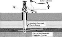
- FIG. 1depicts proppant visualization within a subterranean formation, according to one embodiment of the invention.
- Proppantis coated with a coating material, transforming the proppant into an electrically conductive proppant.
- a “proppant”is a composition of sized particles mixed with fracturing fluid to open and/or hold fractures open during and after a hydraulic fracturing treatment.
- the sized proppant particlescan be man-made or specially engineered particles, such as high-strength ceramic materials like sintered bauxite. Proppant particles are carefully sorted for size and sphericity to provide an efficient conduit for hydrocarbon production to the wellbore.
- the coating materialincludes a mixture of carbon residue forming materials and a solvent or combination of solvents.
- the carbon residue forming materialsmay include compounds with a high melting point and a high carbon yield after decomposition.
- Useful carbon residue forming materialsmay include heavy aromatic residues from petroleum, chemical process pitches; lignin from pulp industry; phenolic resins, and carbohydrate materials such as sugars and polyacrylonitriles. Petroleum and coal tar pitches, and lignin may also be used as carbon residue forming materials.
- “pitch”refers to a residue derived from pyrolysis of organic material or tar distillation that is solid at room temperature and consists primarily of a complex mixture of aromatic hydrocarbons and heterocyclic compounds.
- the carbon residue forming materialsmay further by any material which can react with an oxidizing agent. Upon reacting with the oxidizing agent, the carbon residue forming material may be thermally decomposed.
- the carbon residue forming materialis then combined with a solvent or combination of solvents.
- the solventshould be compatible with the carbon residue forming material.
- Solventsinclude pure organic compounds or a mixture of different solvents. The choice of solvent(s) depends on the particular carbon residue forming materials used. Suitable solvents for dissolving the carbon residue forming material include, for example, benzene, toluene, xylene, quinoline, tetrahydrofuran, naphthalene, acetone, cyclohexane, tetrahydronaphthalene, ether, methylpyrrolidinone, etc.
- solventssuch as toluene, xylene, quinoline, tetrahydrofuran, tetralin and naphthalene are preferred.
- the mixture of carbon residue forming material and solvent or combination of solventsis then heated to a desired temperature, preferably below the boiling point of the solvent(s).
- the proppantis then suspended in the mixture causing a certain portion of the coating material to be deposited substantially uniformly on the surface of the proppant.
- the coated proppantsare separated from the coating material using conventional methods such as, for example, centrifugal separation, or filtration.
- the coated proppantis then optionally washed with solvent to remove residual pitch (or other carbon forming residue material) solution and dried using conventional methods.
- the coated proppantis then stabilized by subjecting the proppant to an oxidizing agent under appropriate reaction conditions. Generally, only mild or moderate conditions are required.
- the oxidation reactionmay be performed by contacting the coated proppant with an oxidizing agent at elevated temperatures or by contacting the coated proppant with an oxidizing agent at mild conditions and activating the oxidizing agent at elevated temperatures.
- the coated proppantare subsequently carbonized and then graphitized.
- the coated particlescan be graphitized by heating them to a still higher elevated temperature.
- the advantage of graphitizationis many-fold, and most significantly the graphitization process frequently allows for the generation of a more-ordered crystal lattice in the coated proppant.
- Graphitizationalso removes impurities.
- graphitizationoccurs in the temperature range of about 200° C.-3,200° C., although lower or higher temperature may also be used in this step. It is required that only satisfactory degree of graphitization be obtained during this step.
- Graphitizationcan immediately follow carbonization, in which case the carbonized coated proppants are retained in a reaction apparatus, i.e., an oven, and the temperature is raised up to an appropriate graphitization temperature. With regard to the rate of this temperature rise, desirably this is maintained in the same rate as used for the carbonization step although, greater or lesser rates of temperature rise can also be utilized depending upon the nature of the carbonized coated proppants.
- a reaction apparatusi.e., an oven
- the electrically conductive coated proppantmay then be injected into a subterranean formation.
- a wireline toolmay be run into the formation to the fracture and electrical signal maybe sent into the fracture.
- the electric signalmay be introduced into the fracture from the surface via electrical connections to the casing or the mud pit. Either an AC or reversing DC current maybe used to generate a time-varying signal or pulse. Since the proppant has been coated with an electrically conductive material, the entire fracture (where the proppant is located) may carry the electrical signal and behave like an emitting antenna. One or more surface antenna may detect and record the emitted signal to determine the geometry of the fracture.
- a monitoring stationsuch as, for example, a truck, backpack, recorder, or transmitter, is set up near the subterranean formation to be fractured.
- the fracture device and an electromagnetic sourceare placed in the formation, electromagnetic receivers are dispersed over the fracture area and a background signal is measured.
- An electrically conductive coated proppantis injected into the fracture and held the fracture open. The fracture is visualized as shown in FIG. 1 . In one alternative, the electrically conductive coated proppant is visualized during fracturing.
Landscapes
- Engineering & Computer Science (AREA)
- Life Sciences & Earth Sciences (AREA)
- Geology (AREA)
- Mining & Mineral Resources (AREA)
- General Life Sciences & Earth Sciences (AREA)
- Physics & Mathematics (AREA)
- Chemical & Material Sciences (AREA)
- Geochemistry & Mineralogy (AREA)
- Fluid Mechanics (AREA)
- Environmental & Geological Engineering (AREA)
- Materials Engineering (AREA)
- Organic Chemistry (AREA)
- Remote Sensing (AREA)
- Geophysics (AREA)
- Carbon And Carbon Compounds (AREA)
- Analytical Chemistry (AREA)
Abstract
Description
- 1. U.S. Pat. No. 7,323,120 (Mao et al.); “Coated Carbonaceous Particles Particularly Useful as Electrode Materials in Electrical Storage Cells, and Methods of Making the Same” (2008).
- 2. US Publ. No. 2010/0147512 (Cramer et al.); “Controlled Source Fracture Monitoring” (2010).
Claims (18)
Priority Applications (2)
| Application Number | Priority Date | Filing Date | Title |
|---|---|---|---|
| US14/278,124US11078409B2 (en) | 2013-05-17 | 2014-05-15 | Electrically conductive proppant coating and related methods |
| PCT/US2014/038150WO2014186550A1 (en) | 2013-05-17 | 2014-05-15 | Electrically conductive proppant coating and related methods |
Applications Claiming Priority (2)
| Application Number | Priority Date | Filing Date | Title |
|---|---|---|---|
| US201361824811P | 2013-05-17 | 2013-05-17 | |
| US14/278,124US11078409B2 (en) | 2013-05-17 | 2014-05-15 | Electrically conductive proppant coating and related methods |
Publications (2)
| Publication Number | Publication Date |
|---|---|
| US20140338898A1 US20140338898A1 (en) | 2014-11-20 |
| US11078409B2true US11078409B2 (en) | 2021-08-03 |
Family
ID=51894849
Family Applications (1)
| Application Number | Title | Priority Date | Filing Date |
|---|---|---|---|
| US14/278,124Active2036-02-22US11078409B2 (en) | 2013-05-17 | 2014-05-15 | Electrically conductive proppant coating and related methods |
Country Status (2)
| Country | Link |
|---|---|
| US (1) | US11078409B2 (en) |
| WO (1) | WO2014186550A1 (en) |
Cited By (1)
| Publication number | Priority date | Publication date | Assignee | Title |
|---|---|---|---|---|
| US12365828B2 (en) | 2021-05-11 | 2025-07-22 | ExxonMobil Technology and Engineering Company | Polyolefin-coke composite granules as a hydraulic fracturing proppant |
Families Citing this family (8)
| Publication number | Priority date | Publication date | Assignee | Title |
|---|---|---|---|---|
| US20140096952A1 (en)* | 2012-10-04 | 2014-04-10 | Geosierra Llc | Enhanced hydrocarbon recovery from a single well by electrical resistive heating of a single inclusion in an oil sand formation |
| US20140096953A1 (en)* | 2012-10-04 | 2014-04-10 | Geosierra Llc | Enhanced hydrocarbon recovery from multiple wells by electrical resistive heating of oil sand formations |
| US20140096951A1 (en)* | 2012-10-04 | 2014-04-10 | Geosierra Llc | Enhanced hydrocarbon recovery from a single well by electrical resistive heating of multiple inclusions in an oil sand formation |
| US11008505B2 (en) | 2013-01-04 | 2021-05-18 | Carbo Ceramics Inc. | Electrically conductive proppant |
| US8931553B2 (en)* | 2013-01-04 | 2015-01-13 | Carbo Ceramics Inc. | Electrically conductive proppant and methods for detecting, locating and characterizing the electrically conductive proppant |
| US10106732B2 (en)* | 2013-01-04 | 2018-10-23 | Carbo Ceramics Inc. | Proppant having non-uniform electrically conductive coatings and methods for making and using same |
| US20160282502A1 (en)* | 2013-11-08 | 2016-09-29 | Board Of Regents, The University Of Texas System | Fracture diagnosis using electromagnetic methods |
| CA3049959A1 (en)* | 2017-01-13 | 2018-07-19 | Board Of Regents, University Of Texas System | Modular electrode tool for improved hydraulic fracture diagnostics |
Citations (18)
| Publication number | Priority date | Publication date | Assignee | Title |
|---|---|---|---|---|
| US4446433A (en) | 1981-06-11 | 1984-05-01 | Shuck Lowell Z | Apparatus and method for determining directional characteristics of fracture systems in subterranean earth formations |
| US4511843A (en)* | 1980-10-17 | 1985-04-16 | Schlumberger Technology Corporation | Electromagnetic logging sonde having improved housing |
| US20030136560A1 (en) | 2002-01-23 | 2003-07-24 | Ali Mese | Method for drilling and completing boreholes with electro-rheological fluids |
| US20030205376A1 (en) | 2002-04-19 | 2003-11-06 | Schlumberger Technology Corporation | Means and Method for Assessing the Geometry of a Subterranean Fracture During or After a Hydraulic Fracturing Treatment |
| US6725930B2 (en) | 2002-04-19 | 2004-04-27 | Schlumberger Technology Corporation | Conductive proppant and method of hydraulic fracturing using the same |
| US6898529B2 (en) | 2003-09-05 | 2005-05-24 | Halliburton Energy Services, Inc. | Method and system for determining parameters inside a subterranean formation using data sensors and a wireless ad hoc network |
| US20060102345A1 (en)* | 2004-10-04 | 2006-05-18 | Mccarthy Scott M | Method of estimating fracture geometry, compositions and articles used for the same |
| US7073581B2 (en) | 2004-06-15 | 2006-07-11 | Halliburton Energy Services, Inc. | Electroconductive proppant compositions and related methods |
| US20070209795A1 (en) | 2006-03-08 | 2007-09-13 | Bj Services Company | Method of using lightweight polyamides in hydraulic fracturing and sand control operations |
| US7323120B2 (en) | 2002-01-31 | 2008-01-29 | Conocophillips Company | Coated carbonaceous particles particulary useful as electrode materials in electrical storage cells, and methods of making the same |
| US20080062036A1 (en) | 2006-09-13 | 2008-03-13 | Hexion Specialty Chemicals, Inc. | Logging device with down-hole transceiver for operation in extreme temperatures |
| US20080283243A1 (en) | 2007-05-15 | 2008-11-20 | Georgia-Pacific Chemicals Llc | Reducing flow-back in well treating materials |
| US20090087912A1 (en) | 2007-09-28 | 2009-04-02 | Shlumberger Technology Corporation | Tagged particles for downhole application |
| US7597999B2 (en) | 2006-06-07 | 2009-10-06 | Conocophillips Company | Methods of preparing carbonaceous anode materials and using same |
| US20100038083A1 (en) | 2008-08-15 | 2010-02-18 | Sun Drilling Corporation | Proppants coated by piezoelectric or magnetostrictive materials, or by mixtures or combinations thereof, to enable their tracking in a downhole environment |
| US20100147512A1 (en) | 2008-12-12 | 2010-06-17 | Conocophillips Company | Controlled source fracture monitoring |
| US7964240B2 (en) | 2009-01-19 | 2011-06-21 | Conocophillips Company | Producing coated graphitic anode powders by extracting pitch from high volatile matter coke and coating the same in-situ |
| US20120133367A1 (en)* | 2009-08-20 | 2012-05-31 | Halliburton Energy Services, Inc. | Fracture Characterization Using Directional Electromagnetic Resistivity Measurements |
- 2014
- 2014-05-15USUS14/278,124patent/US11078409B2/enactiveActive
- 2014-05-15WOPCT/US2014/038150patent/WO2014186550A1/enactiveApplication Filing
Patent Citations (19)
| Publication number | Priority date | Publication date | Assignee | Title |
|---|---|---|---|---|
| US4511843A (en)* | 1980-10-17 | 1985-04-16 | Schlumberger Technology Corporation | Electromagnetic logging sonde having improved housing |
| US4446433A (en) | 1981-06-11 | 1984-05-01 | Shuck Lowell Z | Apparatus and method for determining directional characteristics of fracture systems in subterranean earth formations |
| US20030136560A1 (en) | 2002-01-23 | 2003-07-24 | Ali Mese | Method for drilling and completing boreholes with electro-rheological fluids |
| US7323120B2 (en) | 2002-01-31 | 2008-01-29 | Conocophillips Company | Coated carbonaceous particles particulary useful as electrode materials in electrical storage cells, and methods of making the same |
| US20030205376A1 (en) | 2002-04-19 | 2003-11-06 | Schlumberger Technology Corporation | Means and Method for Assessing the Geometry of a Subterranean Fracture During or After a Hydraulic Fracturing Treatment |
| US6725930B2 (en) | 2002-04-19 | 2004-04-27 | Schlumberger Technology Corporation | Conductive proppant and method of hydraulic fracturing using the same |
| US6898529B2 (en) | 2003-09-05 | 2005-05-24 | Halliburton Energy Services, Inc. | Method and system for determining parameters inside a subterranean formation using data sensors and a wireless ad hoc network |
| US7073581B2 (en) | 2004-06-15 | 2006-07-11 | Halliburton Energy Services, Inc. | Electroconductive proppant compositions and related methods |
| WO2007013883A2 (en) | 2004-10-04 | 2007-02-01 | Hexion Specialty Chemicals Inc. | Method of estimating fracture geometry, compositions and articles used for the same |
| US20060102345A1 (en)* | 2004-10-04 | 2006-05-18 | Mccarthy Scott M | Method of estimating fracture geometry, compositions and articles used for the same |
| US20070209795A1 (en) | 2006-03-08 | 2007-09-13 | Bj Services Company | Method of using lightweight polyamides in hydraulic fracturing and sand control operations |
| US7597999B2 (en) | 2006-06-07 | 2009-10-06 | Conocophillips Company | Methods of preparing carbonaceous anode materials and using same |
| US20080062036A1 (en) | 2006-09-13 | 2008-03-13 | Hexion Specialty Chemicals, Inc. | Logging device with down-hole transceiver for operation in extreme temperatures |
| US20080283243A1 (en) | 2007-05-15 | 2008-11-20 | Georgia-Pacific Chemicals Llc | Reducing flow-back in well treating materials |
| US20090087912A1 (en) | 2007-09-28 | 2009-04-02 | Shlumberger Technology Corporation | Tagged particles for downhole application |
| US20100038083A1 (en) | 2008-08-15 | 2010-02-18 | Sun Drilling Corporation | Proppants coated by piezoelectric or magnetostrictive materials, or by mixtures or combinations thereof, to enable their tracking in a downhole environment |
| US20100147512A1 (en) | 2008-12-12 | 2010-06-17 | Conocophillips Company | Controlled source fracture monitoring |
| US7964240B2 (en) | 2009-01-19 | 2011-06-21 | Conocophillips Company | Producing coated graphitic anode powders by extracting pitch from high volatile matter coke and coating the same in-situ |
| US20120133367A1 (en)* | 2009-08-20 | 2012-05-31 | Halliburton Energy Services, Inc. | Fracture Characterization Using Directional Electromagnetic Resistivity Measurements |
Non-Patent Citations (1)
| Title |
|---|
| International Search Report. PCT/US2014/038150. dated Oct. 8, 2014. |
Cited By (1)
| Publication number | Priority date | Publication date | Assignee | Title |
|---|---|---|---|---|
| US12365828B2 (en) | 2021-05-11 | 2025-07-22 | ExxonMobil Technology and Engineering Company | Polyolefin-coke composite granules as a hydraulic fracturing proppant |
Also Published As
| Publication number | Publication date |
|---|---|
| WO2014186550A1 (en) | 2014-11-20 |
| US20140338898A1 (en) | 2014-11-20 |
Similar Documents
| Publication | Publication Date | Title |
|---|---|---|
| US11078409B2 (en) | Electrically conductive proppant coating and related methods | |
| US11993749B2 (en) | Electrically conductive proppant and methods for detecting, locating and characterizing the electrically conductive proppant | |
| CA2582695C (en) | Method of estimating fracture geometry, compositions and articles used for the same | |
| US7631691B2 (en) | Methods of treating a subterranean formation to convert organic matter into producible hydrocarbons | |
| CN102027196B (en) | Radio and microwave treatment of oil wells | |
| US9803135B2 (en) | Method of manufacture and the use of a functional proppant for determination of subterranean fracture geometries | |
| CN100392206C (en) | Methods of treating a subterranean formation to convert organic matter into producible hydrocarbons | |
| CN110159242B (en) | A Stimulation Method Suitable for Shale Oil/Gas Reservoirs | |
| US20150027722A1 (en) | Oil Well Gas Lift by Hydrogen Production Through Produced Water Electrolysis Completion | |
| US10400563B2 (en) | Pyrolysis to pressurise oil formations | |
| Kang et al. | Heating-induced enhancement of shale gas transport and its application for improving hydraulic fracturing performance | |
| WO2020159933A1 (en) | Measuring total organic content of source rock | |
| Khan et al. | An Experimental Study for the Impact of Heating and Cooling on Strength of Unconventional Reservoirs | |
| CN203702120U (en) | Gasifying device adopted by underground gasifying method of hydrocarbon-contained ore stratum | |
| US20110174694A1 (en) | Producing hydrocarbons from oil shale based on conditions under which production of oil and bitumen are optimized | |
| Rezaeyan et al. | Recovery Enhancement in Unconventional Shale Resources | |
| Rezaeyan et al. | 7 Recovery Enhancement | |
| AU2004260008B2 (en) | Methods of treating a subterranean formation to convert organic matter into producible hydrocarbons | |
| US20170183949A1 (en) | Controlled Delivery of Heat Applied To A Subsurface Formation | |
| CN103711472A (en) | Underground gasification method of hydrocarbon-bearing ore bed |
Legal Events
| Date | Code | Title | Description |
|---|---|---|---|
| STPP | Information on status: patent application and granting procedure in general | Free format text:NON FINAL ACTION MAILED | |
| STPP | Information on status: patent application and granting procedure in general | Free format text:RESPONSE TO NON-FINAL OFFICE ACTION ENTERED AND FORWARDED TO EXAMINER | |
| STPP | Information on status: patent application and granting procedure in general | Free format text:FINAL REJECTION MAILED | |
| STCV | Information on status: appeal procedure | Free format text:NOTICE OF APPEAL FILED | |
| STCV | Information on status: appeal procedure | Free format text:APPEAL BRIEF (OR SUPPLEMENTAL BRIEF) ENTERED AND FORWARDED TO EXAMINER | |
| STCV | Information on status: appeal procedure | Free format text:EXAMINER'S ANSWER TO APPEAL BRIEF MAILED | |
| STCV | Information on status: appeal procedure | Free format text:ON APPEAL -- AWAITING DECISION BY THE BOARD OF APPEALS | |
| STCV | Information on status: appeal procedure | Free format text:BOARD OF APPEALS DECISION RENDERED | |
| STPP | Information on status: patent application and granting procedure in general | Free format text:DOCKETED NEW CASE - READY FOR EXAMINATION | |
| AS | Assignment | Owner name:CONOCOPHILLIPS COMPANY, TEXAS Free format text:ASSIGNMENT OF ASSIGNORS INTEREST;ASSIGNOR:ALLISON, JOE D.;REEL/FRAME:055476/0348 Effective date:20210211 | |
| STPP | Information on status: patent application and granting procedure in general | Free format text:NOTICE OF ALLOWANCE MAILED -- APPLICATION RECEIVED IN OFFICE OF PUBLICATIONS | |
| STPP | Information on status: patent application and granting procedure in general | Free format text:PUBLICATIONS -- ISSUE FEE PAYMENT RECEIVED | |
| STPP | Information on status: patent application and granting procedure in general | Free format text:PUBLICATIONS -- ISSUE FEE PAYMENT VERIFIED | |
| STCF | Information on status: patent grant | Free format text:PATENTED CASE | |
| MAFP | Maintenance fee payment | Free format text:PAYMENT OF MAINTENANCE FEE, 4TH YEAR, LARGE ENTITY (ORIGINAL EVENT CODE: M1551); ENTITY STATUS OF PATENT OWNER: LARGE ENTITY Year of fee payment:4 |