US11074794B2 - Systems and methods for activating and deactivating controlled devices in a secured area - Google Patents
Systems and methods for activating and deactivating controlled devices in a secured areaDownload PDFInfo
- Publication number
- US11074794B2 US11074794B2US16/205,608US201816205608AUS11074794B2US 11074794 B2US11074794 B2US 11074794B2US 201816205608 AUS201816205608 AUS 201816205608AUS 11074794 B2US11074794 B2US 11074794B2
- Authority
- US
- United States
- Prior art keywords
- user
- controlled devices
- secured area
- route
- sensor module
- Prior art date
- Legal status (The legal status is an assumption and is not a legal conclusion. Google has not performed a legal analysis and makes no representation as to the accuracy of the status listed.)
- Active, expires
Links
Images


Classifications
- G—PHYSICS
- G08—SIGNALLING
- G08B—SIGNALLING OR CALLING SYSTEMS; ORDER TELEGRAPHS; ALARM SYSTEMS
- G08B13/00—Burglar, theft or intruder alarms
- G08B13/22—Electrical actuation
- G08B13/24—Electrical actuation by interference with electromagnetic field distribution
- G08B13/2491—Intrusion detection systems, i.e. where the body of an intruder causes the interference with the electromagnetic field
- G—PHYSICS
- G01—MEASURING; TESTING
- G01S—RADIO DIRECTION-FINDING; RADIO NAVIGATION; DETERMINING DISTANCE OR VELOCITY BY USE OF RADIO WAVES; LOCATING OR PRESENCE-DETECTING BY USE OF THE REFLECTION OR RERADIATION OF RADIO WAVES; ANALOGOUS ARRANGEMENTS USING OTHER WAVES
- G01S13/00—Systems using the reflection or reradiation of radio waves, e.g. radar systems; Analogous systems using reflection or reradiation of waves whose nature or wavelength is irrelevant or unspecified
- G01S13/88—Radar or analogous systems specially adapted for specific applications
- G01S13/886—Radar or analogous systems specially adapted for specific applications for alarm systems
- G—PHYSICS
- G08—SIGNALLING
- G08B—SIGNALLING OR CALLING SYSTEMS; ORDER TELEGRAPHS; ALARM SYSTEMS
- G08B13/00—Burglar, theft or intruder alarms
- G08B13/22—Electrical actuation
- G08B13/24—Electrical actuation by interference with electromagnetic field distribution
- G08B13/2491—Intrusion detection systems, i.e. where the body of an intruder causes the interference with the electromagnetic field
- G08B13/2494—Intrusion detection systems, i.e. where the body of an intruder causes the interference with the electromagnetic field by interference with electro-magnetic field distribution combined with other electrical sensor means, e.g. microwave detectors combined with other sensor means
- G—PHYSICS
- G08—SIGNALLING
- G08B—SIGNALLING OR CALLING SYSTEMS; ORDER TELEGRAPHS; ALARM SYSTEMS
- G08B29/00—Checking or monitoring of signalling or alarm systems; Prevention or correction of operating errors, e.g. preventing unauthorised operation
- G08B29/02—Monitoring continuously signalling or alarm systems
- G08B29/04—Monitoring of the detection circuits
- G—PHYSICS
- G01—MEASURING; TESTING
- G01S—RADIO DIRECTION-FINDING; RADIO NAVIGATION; DETERMINING DISTANCE OR VELOCITY BY USE OF RADIO WAVES; LOCATING OR PRESENCE-DETECTING BY USE OF THE REFLECTION OR RERADIATION OF RADIO WAVES; ANALOGOUS ARRANGEMENTS USING OTHER WAVES
- G01S13/00—Systems using the reflection or reradiation of radio waves, e.g. radar systems; Analogous systems using reflection or reradiation of waves whose nature or wavelength is irrelevant or unspecified
- G01S13/88—Radar or analogous systems specially adapted for specific applications
- G01S13/89—Radar or analogous systems specially adapted for specific applications for mapping or imaging
- G01S13/90—Radar or analogous systems specially adapted for specific applications for mapping or imaging using synthetic aperture techniques, e.g. synthetic aperture radar [SAR] techniques
- H—ELECTRICITY
- H04—ELECTRIC COMMUNICATION TECHNIQUE
- H04L—TRANSMISSION OF DIGITAL INFORMATION, e.g. TELEGRAPHIC COMMUNICATION
- H04L67/00—Network arrangements or protocols for supporting network services or applications
- H04L67/01—Protocols
- H04L67/10—Protocols in which an application is distributed across nodes in the network
Definitions
- the present inventionrelates generally to device control systems. More particularly, the present invention relates to systems and methods for activating and deactivating controlled devices in a secured area based on a location of an end of a route for a user tracked within the secured area.
- Known systems and methods for activating and deactivating controlled devices based on a presence of a userare susceptible to false alarms and failure to detect the user in a secured area. For example, such known systems and methods may falsely indicate the presence of the user due to hot air, vibrations, a flash of light, or the like, thereby triggering unnecessary activation of the controlled devices, or falsely indicate a non-presence of the user, thereby causing premature deactivation of the controlled devices.
- FIG. 1is a block diagram of a device control system in accordance with disclosed embodiments
- FIG. 2is a block diagram of a device control system in accordance with disclosed embodiments
- FIG. 3is a flow diagram of a method in accordance with disclosed embodiments.
- FIG. 4Ais a diagram of a simulated tracking scenario in accordance with disclosed embodiments.
- FIG. 4Bis a diagram of a simulated tracking scenario in accordance with disclosed embodiments.
- FIG. 4Cis a diagram of a simulated tracking scenario in accordance with disclosed embodiments.
- FIG. 4Dis a diagram of a simulated tracking scenario in accordance with disclosed embodiments.
- Embodiments disclosed hereinmay include systems and methods for activating and deactivating controlled devices by monitoring a secured area and determining and verifying a presence of a user within the secured area, for example, by identifying a velocity, a position, and a moving direction of the user.
- systems and methods disclosed hereinmay include a microprocessor unit sampling sensor data from a smart microwave sensor module to detect the sensor data indicative of the presence of the user, use the sensor data to track a route for the user within the secured area, and activate or deactivate the controlled devices located within the secured area based on a location of an end of the route.
- a device control systemmay include, but is not limited to the smart microwave sensor module, the microprocessor unit electrically connected to the smart microwave sensor module, and a device controller deployed in the secured area or at a location that is remote from the secured area.
- a device control systemmay include, but is not limited to the smart microwave sensor module, the microprocessor unit electrically connected to the smart microwave sensor module, and a device controller deployed in the secured area or at a location that is remote from the secured area.
- systems and methods disclosed hereinare not so limited and may be used in connection with other systems, including home automation systems and security systems with security alarms.
- systems and methods disclosed hereincan be used in connection with or as modifications to the systems and methods disclosed in U.S. application Ser. No.
- the microprocessor unitmay sample first sensor data from the smart microwave sensor module to detect the presence of the user within the secured area. In some embodiments, the microprocessor unit may use the first sensor data to calculate the velocity of the user, a distance of the user from the smart microwave sensor module, and the moving direction of the user. For example, in some embodiments, the microprocessor unit can employ known techniques relating to smart microwave Doppler theory with related algorithmic processing to calculate the velocity, the distance, and the moving direction.
- the controlled devicescan be activated when the location of the end of the route is within the secured area and deactivated when the location of the end of the route is outside of the secured area.
- the microprocessor unitcan use the first sensor data to calculate and transmit route data indicative of the end of the route to the device controller, which can activate or deactivate the controlled devices based on whether the location of the end of the route is within or outside of the secured area.
- the device controllercan include a cloud server remote from the secured area.
- deactivating the controlled devicescan include automatically cutting off power to the controlled devices, and in some embodiments, activating the controlled devices can include granting the user control over the controlled devices.
- the controlled devicescan include, but are not limited to climate control units, air conditioners, heaters, light sources, printers, and phones.
- the secured areacan be defined by a designated protection territory of the smart microwave sensor module.
- the microprocessor unitcan receive user input adjusting the designated protection territory and can verify that the designated protection territory conforms to the user input.
- each of the microprocessor unit, the device controller, and the controlled devices disclosed hereincan include a respective transceiver device and a respective memory device, each of which can be in communication with respective control circuitry, one or more respective programmable processors, and respective executable control software as would be understood by one of ordinary skill in the art.
- the respective executable control software of each of the microprocessor unit, the device controller, and the controlled devicescan be stored on a respective transitory or non-transitory computer readable medium, including, but not limited to local computer memory, RAM, optical storage media, magnetic storage media, flash memory, and the like, and some or all of the respective control circuitry, the respective programmable processors, and the respective executable control software of each of the microprocessor unit, the device controller, and the controlled devices can execute and control at least some of the methods disclosed herein.
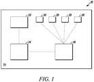
- FIG. 1 and FIG. 2are block diagrams of a device control system 20 in accordance with disclosed embodiments.
- the device control system 20may include a smart microwave sensor module 22 , a microprocessor unit 24 , a device controller 26 in communication with the microprocessor unit 24 , and a plurality of controlled devices 28 .
- each of the smart microwave sensor module 22 , the microprocessor unit 24 , the device controller 26 , and the plurality of controlled devices 28can be deployed in a secured area SA, and in some embodiments, the device controller 26 can include a cloud server that is remote from the secured area SA.
- the smart microwave sensor module 22may include transmitting and receiving antennas, a Monolithic Microwave Integrated Circuit (MMIC), two-level signal-processing circuits, such as filters and amplifiers, a digital potentiometer to adjust a gain of a microwave intermediate frequency signal output from the two-level signal-processing circuits, and a modulation/waveform generating module.
- MMICMonolithic Microwave Integrated Circuit
- the microprocessor unit 24may control the modulation/waveform generating module to transmit a VCO control signal to drive the MMIC.
- the microprocessor unit 24may sample the microwave intermediate frequency signal output from the two-level signal-processing circuits to determine whether a user is present within the secured area SA and to use in tracking a route of the user within the secured area SA.
- the device control system 20may also include a communication module 30 for use in dual direction data transferring, such as linking to a cloud server and receiving commands for the controlled devices 28 from the user.
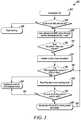
- FIG. 3is a flow diagram of a method 100 in accordance with disclosed embodiments.
- the method 100can include the microprocessor unit 24 conducting a self-test of the smart microwave sensor module 22 , as in 104 , and when the self-test fails, outputting a fault warning, as in 106 .
- the method 100can include the microprocessor unit 24 receiving user input adjusting a pattern or a designated protection territory of the smart microwave sensor 22 , as in 108 , and verifying whether the pattern or the designated protection territory matches the user input, as in 110 .
- the method 100can continue receiving the user input, as in 112 .
- the method 100can include prompting an installer to double check the pattern or the designated protection territory, as in 114 .
- the method 100can include determining whether the smart microwave sensor module 22 has been triggered by a user within the secured area SA, as in 116 . When the smart microwave sensor module 22 has not been triggered, the method 100 can include continuing to receive the user input, as in 118 . However, when the smart microwave sensor module 22 is triggered, the method 100 can include the microprocessor unit 24 activating the controlled devices 28 , as in 120 , tracking a route of the user, as in 122 , and determining whether a location of an end of the route is within the secured area SA, as in 124 . When the location of the end of the route is within the secured area, the method 100 can include keeping the controlled devices 28 activated, as in 126 . However, when the location of the end of the route is outside of the secured area SA, the method 100 can include cutting off power to the controlled devices 28 , as in 128 , and continuing to receive the user input, as in 130 .
- FIG. 4A - FIG. 4Dare diagrams of simulated tracking scenarios for a user 34 in accordance with disclosed embodiments.
- the secured area SAcan be defined by a pattern or a designated protection territory 30 , and a user 34 can enter and exit the secured area SA at identical locations and traverse a route 32 that is simple/uncomplicated, as in FIG. 4A , can enter and exit the secured area SA at different locations and traverse a route 36 that is complicated, as in FIG. 4B , or can enter and exit the secured area SA at identical locations and traverse a route 38 that is simple/uncomplicated, as in FIG. 4C .
- the device control system 20can deactivate the controlled devices 28 responsive to determining that the route 32 , 36 , 38 extends or ends outside of a boundary of the pattern or the designated protection territory 30 .
- the user 34can enter the secured area SA, traverse a route 40 and end the route 40 within the secured area SA. Accordingly, in FIG. 4D , the device control system 20 can activate the controlled devices 28 or keep the controlled devices 28 activated responsive to determining that the route 40 ends within the boundary of the pattern or the designated protection territory 30 .
Landscapes
- Physics & Mathematics (AREA)
- Electromagnetism (AREA)
- General Physics & Mathematics (AREA)
- Engineering & Computer Science (AREA)
- Remote Sensing (AREA)
- Radar, Positioning & Navigation (AREA)
- Computer Security & Cryptography (AREA)
- Computer Networks & Wireless Communication (AREA)
- Train Traffic Observation, Control, And Security (AREA)
- Human Computer Interaction (AREA)
- Manufacturing & Machinery (AREA)
- Automation & Control Theory (AREA)
- Selective Calling Equipment (AREA)
Abstract
Description
Claims (16)
Priority Applications (3)
| Application Number | Priority Date | Filing Date | Title |
|---|---|---|---|
| US16/205,608US11074794B2 (en) | 2018-11-30 | 2018-11-30 | Systems and methods for activating and deactivating controlled devices in a secured area |
| EP21186821.1AEP3920157A1 (en) | 2018-11-30 | 2019-11-27 | Systems and methods for activating and deactivating controlled devices in a secured area |
| EP19211968.3AEP3660800A1 (en) | 2018-11-30 | 2019-11-27 | Systems and methods for activating and deactivating controlled devices in a secured area |
Applications Claiming Priority (1)
| Application Number | Priority Date | Filing Date | Title |
|---|---|---|---|
| US16/205,608US11074794B2 (en) | 2018-11-30 | 2018-11-30 | Systems and methods for activating and deactivating controlled devices in a secured area |
Publications (2)
| Publication Number | Publication Date |
|---|---|
| US20200174452A1 US20200174452A1 (en) | 2020-06-04 |
| US11074794B2true US11074794B2 (en) | 2021-07-27 |
Family
ID=68731747
Family Applications (1)
| Application Number | Title | Priority Date | Filing Date |
|---|---|---|---|
| US16/205,608Active2039-04-16US11074794B2 (en) | 2018-11-30 | 2018-11-30 | Systems and methods for activating and deactivating controlled devices in a secured area |
Country Status (2)
| Country | Link |
|---|---|
| US (1) | US11074794B2 (en) |
| EP (2) | EP3660800A1 (en) |
Families Citing this family (5)
| Publication number | Priority date | Publication date | Assignee | Title |
|---|---|---|---|---|
| US11348428B2 (en)* | 2020-03-12 | 2022-05-31 | Sam Heidari | System and methods for identifying a subject through device-free and device-oriented sensing technologies |
| IT202000006883A1 (en)* | 2020-04-01 | 2021-10-01 | St Microelectronics Srl | SYSTEM AND METHOD OF DETECTION OF PRESENCE IN AN ENVIRONMENT TO BE MONITORED |
| IT202100019814A1 (en) | 2021-07-26 | 2023-01-26 | St Microelectronics Srl | METHOD OF DETECTING A USER OF AN APPLIANCE TO CHECK ONE OR MORE FUNCTIONS OF THE APPLIANCE |
| IT202100019808A1 (en) | 2021-07-26 | 2023-01-26 | St Microelectronics Srl | METHOD OF CONTROLLING A DEVICE FOR THE ACTIVATION OF ONE OR MORE FUNCTIONS OF THE SAME |
| CN116110184B (en)* | 2023-04-11 | 2023-08-22 | 深圳泛和科技有限公司 | Building fire early warning circuit, method, equipment and computer storage medium |
Citations (55)
| Publication number | Priority date | Publication date | Assignee | Title |
|---|---|---|---|---|
| US4191953A (en) | 1975-01-23 | 1980-03-04 | Microwave and Electronic System Limited | Intrusion sensor and aerial therefor |
| GB2078413A (en) | 1980-06-03 | 1982-01-06 | Edwards Derek | Intruder detecting systems |
| US4527151A (en) | 1982-05-03 | 1985-07-02 | Sri International | Method and apparatus for intrusion detection |
| ES1006935U (en) | 1988-02-22 | 1989-01-16 | Electronic Trafic, S.A. | Device detection of human presence applied to traffic control. (Machine-translation by Google Translate, not legally binding) |
| US5331308A (en) | 1992-07-30 | 1994-07-19 | Napco Security Systems, Inc. | Automatically adjustable and self-testing dual technology intrusion detection system for minimizing false alarms |
| US5781108A (en) | 1995-11-14 | 1998-07-14 | Future Tech Systems, Inc. | Automated detection and monitoring (ADAM) |
| US5839096A (en)* | 1997-03-10 | 1998-11-17 | Hittite Microwave Corporation | Self-implementing diagnostic system |
| US5936524A (en)* | 1996-05-02 | 1999-08-10 | Visonic Ltd. | Intrusion detector |
| US6353385B1 (en) | 2000-08-25 | 2002-03-05 | Hyperon Incorporated | Method and system for interfacing an intrusion detection system to a central alarm system |
| US20020175815A1 (en) | 2001-05-22 | 2002-11-28 | Baldwin John R. | Dual technology occupancy sensor and method for using the same |
| CA2351138A1 (en) | 2001-06-20 | 2002-12-20 | Standard Tool & Mold Inc. | Automobile proximity warning system |
| US20030030557A1 (en) | 2001-08-08 | 2003-02-13 | Trw Inc. | Apparatus and method for detecting intrusion and non-intrusion events |
| US20030112142A1 (en)* | 2001-12-19 | 2003-06-19 | Hitachi, Ltd. | Security system |
| US6778092B2 (en) | 2001-10-24 | 2004-08-17 | Sick Ag | Method of, and apparatus for, controlling a safety-specific function of a machine |
| US20050128067A1 (en) | 2003-12-11 | 2005-06-16 | Honeywell International, Inc. | Automatic sensitivity adjustment on motion detectors in security system |
| US6943685B2 (en) | 2002-02-18 | 2005-09-13 | Optex Co., Ltd. | Intrusion detecting device |
| US6992577B2 (en) | 2003-09-04 | 2006-01-31 | Optex Co., Ltd. | Combined sensor |
| US20060125621A1 (en)* | 2004-11-29 | 2006-06-15 | Honeywell International, Inc. | Motion detector wireless remote self-test |
| US20060139164A1 (en) | 2004-12-14 | 2006-06-29 | Masatoshi Tsuji | Composite intrusion detection sensor |
| US20070018106A1 (en) | 2005-03-21 | 2007-01-25 | Visonic Ltd. | Passive infra-red detectors |
| US20070115164A1 (en) | 2005-11-23 | 2007-05-24 | Honeywell International, Inc. | Microwave smart motion sensor for security applications |
| US20070176765A1 (en) | 2006-01-27 | 2007-08-02 | Honeywell International Inc. | Dual technology sensor device with range gated sensitivity |
| US7274387B2 (en) | 2002-10-15 | 2007-09-25 | Digicomp Research Corporation | Automatic intrusion detection system for perimeter defense |
| US20070252720A1 (en) | 2006-04-27 | 2007-11-01 | U.S. Safety And Security, L.L.C. | Multifunction portable security system |
| US20070253461A1 (en) | 2006-04-13 | 2007-11-01 | Scott Billington | Method of sensor multiplexing for rotating machinery |
| US7327253B2 (en) | 2005-05-04 | 2008-02-05 | Squire Communications Inc. | Intruder detection and warning system |
| US20080100498A1 (en) | 1999-06-14 | 2008-05-01 | Time Domain Corporation | System and method for intrusion detection using a time domain radar array |
| EP1968024A1 (en) | 2007-03-07 | 2008-09-10 | Robert Bosch GmbH | System and method for improving microwave detector performance using ranging microwave function |
| US20080218340A1 (en) | 2007-03-07 | 2008-09-11 | Gregory Royer | System and method for improving infrared detector performance in dual detector system |
| US7463182B1 (en) | 2005-11-30 | 2008-12-09 | Hitachi, Ltd. | Radar apparatus |
| US20080310254A1 (en) | 2007-06-12 | 2008-12-18 | Honeywell International, Inc. | System and method for adjusting sensitivity of an acoustic sensor |
| US20090051529A1 (en) | 2005-04-11 | 2009-02-26 | Masatoshi Tsuji | Intrusion Detection Sensor |
| US20100013636A1 (en) | 2008-07-17 | 2010-01-21 | Honeywell International Inc. | Microwave ranging sensor |
| US20100201527A1 (en) | 2009-02-09 | 2010-08-12 | Jensen Bradford B | Peripheral event indication with pir-based motion detector |
| US20100201267A1 (en)* | 2007-06-29 | 2010-08-12 | Carmanah Technologies Corp. | Intelligent Area Lighting System |
| US20100201787A1 (en) | 2009-02-09 | 2010-08-12 | Ron Zehavi | Continuous geospatial tracking system and method |
| EP2260563B1 (en) | 2008-03-07 | 2011-10-26 | Alertme.com Ltd. | Electrical appliance monitoring systems |
| US8432448B2 (en) | 2006-08-10 | 2013-04-30 | Northrop Grumman Systems Corporation | Stereo camera intrusion detection system |
| US8519883B2 (en) | 2008-09-30 | 2013-08-27 | Cooper Technologies Company | Adjusting the sensitivity of a PIR sensor or a doppler radar sensor disposed within a light fixture |
| US20130300566A1 (en) | 2012-05-08 | 2013-11-14 | Brent Charles Kumfer | Methods, systems, and apparatus for protection system activation and dynamic labeling |
| US20150212205A1 (en) | 2013-06-21 | 2015-07-30 | Ninve Jr. Inc. | Dual differential doppler motion detection |
| US9125144B1 (en) | 2006-10-20 | 2015-09-01 | Avaya Inc. | Proximity-based feature activation based on programmable profile |
| US20150276238A1 (en)* | 2014-03-28 | 2015-10-01 | Google Inc. | User-relocatable self-learning environmental control device capable of adapting previous learnings to current location in controlled environment |
| US9189751B2 (en) | 2012-09-30 | 2015-11-17 | Google Inc. | Automated presence detection and presence-related control within an intelligent controller |
| US20150369618A1 (en) | 2014-06-18 | 2015-12-24 | Chris Barnard | Interactive applications using data from light sensory networks |
| US9237315B2 (en) | 2014-03-03 | 2016-01-12 | Vsk Electronics Nv | Intrusion detection with directional sensing |
| US20160226892A1 (en) | 2012-12-18 | 2016-08-04 | Department 13, LLC | Intrusion Detection and Radio Fingerprint Tracking |
| US20160240056A1 (en) | 2015-02-13 | 2016-08-18 | Chia-Teh Chen | Microwave motion sensing technology and its application thereof |
| US9498885B2 (en) | 2013-02-27 | 2016-11-22 | Rockwell Automation Technologies, Inc. | Recognition-based industrial automation control with confidence-based decision support |
| US20170059197A1 (en)* | 2015-08-26 | 2017-03-02 | Google Inc. | Thermostat with multiple sensing systems including presence detection systems integrated therein |
| US20170103648A1 (en) | 2015-10-12 | 2017-04-13 | The Chamberlain Group, Inc. | Remotely Configurable Sensor System and Method of Use |
| US9655217B2 (en) | 2006-03-28 | 2017-05-16 | Michael V. Recker | Cloud connected motion sensor lighting grid |
| US20170328997A1 (en)* | 2016-05-13 | 2017-11-16 | Google Inc. | Systems, Methods, and Devices for Utilizing Radar with Smart Devices |
| EP3355289A1 (en) | 2017-01-25 | 2018-08-01 | Honeywell International Inc. | Apparatus and method for accurate monitoring of space |
| US20190086266A1 (en) | 2017-09-21 | 2019-03-21 | Lite-On Technology Corporation | Motion detection method and motion detection device |
Family Cites Families (3)
| Publication number | Priority date | Publication date | Assignee | Title |
|---|---|---|---|---|
| US5724040A (en)* | 1995-06-23 | 1998-03-03 | Northrop Grumman Corporation | Aircraft wake vortex hazard warning apparatus |
| EP1856677B1 (en)* | 2005-03-10 | 2009-04-08 | Pyronix Limited | Detector and optical system |
| CN108344580B (en)* | 2017-01-22 | 2020-09-29 | 北京百度网讯科技有限公司 | Self-checking method and device for self-driving car |
- 2018
- 2018-11-30USUS16/205,608patent/US11074794B2/enactiveActive
- 2019
- 2019-11-27EPEP19211968.3Apatent/EP3660800A1/ennot_activeWithdrawn
- 2019-11-27EPEP21186821.1Apatent/EP3920157A1/ennot_activeWithdrawn
Patent Citations (61)
| Publication number | Priority date | Publication date | Assignee | Title |
|---|---|---|---|---|
| US4191953A (en) | 1975-01-23 | 1980-03-04 | Microwave and Electronic System Limited | Intrusion sensor and aerial therefor |
| GB2078413A (en) | 1980-06-03 | 1982-01-06 | Edwards Derek | Intruder detecting systems |
| US4527151A (en) | 1982-05-03 | 1985-07-02 | Sri International | Method and apparatus for intrusion detection |
| ES1006935U (en) | 1988-02-22 | 1989-01-16 | Electronic Trafic, S.A. | Device detection of human presence applied to traffic control. (Machine-translation by Google Translate, not legally binding) |
| US5331308A (en) | 1992-07-30 | 1994-07-19 | Napco Security Systems, Inc. | Automatically adjustable and self-testing dual technology intrusion detection system for minimizing false alarms |
| US5781108A (en) | 1995-11-14 | 1998-07-14 | Future Tech Systems, Inc. | Automated detection and monitoring (ADAM) |
| US5936524A (en)* | 1996-05-02 | 1999-08-10 | Visonic Ltd. | Intrusion detector |
| US5839096A (en)* | 1997-03-10 | 1998-11-17 | Hittite Microwave Corporation | Self-implementing diagnostic system |
| US20080100498A1 (en) | 1999-06-14 | 2008-05-01 | Time Domain Corporation | System and method for intrusion detection using a time domain radar array |
| US6353385B1 (en) | 2000-08-25 | 2002-03-05 | Hyperon Incorporated | Method and system for interfacing an intrusion detection system to a central alarm system |
| US20020175815A1 (en) | 2001-05-22 | 2002-11-28 | Baldwin John R. | Dual technology occupancy sensor and method for using the same |
| CA2351138A1 (en) | 2001-06-20 | 2002-12-20 | Standard Tool & Mold Inc. | Automobile proximity warning system |
| US20030030557A1 (en) | 2001-08-08 | 2003-02-13 | Trw Inc. | Apparatus and method for detecting intrusion and non-intrusion events |
| US6778092B2 (en) | 2001-10-24 | 2004-08-17 | Sick Ag | Method of, and apparatus for, controlling a safety-specific function of a machine |
| US20030112142A1 (en)* | 2001-12-19 | 2003-06-19 | Hitachi, Ltd. | Security system |
| US7084761B2 (en) | 2001-12-19 | 2006-08-01 | Hitachi, Ltd. | Security system |
| US6943685B2 (en) | 2002-02-18 | 2005-09-13 | Optex Co., Ltd. | Intrusion detecting device |
| US7274387B2 (en) | 2002-10-15 | 2007-09-25 | Digicomp Research Corporation | Automatic intrusion detection system for perimeter defense |
| US6992577B2 (en) | 2003-09-04 | 2006-01-31 | Optex Co., Ltd. | Combined sensor |
| US20050128067A1 (en) | 2003-12-11 | 2005-06-16 | Honeywell International, Inc. | Automatic sensitivity adjustment on motion detectors in security system |
| US20060125621A1 (en)* | 2004-11-29 | 2006-06-15 | Honeywell International, Inc. | Motion detector wireless remote self-test |
| US7636039B2 (en) | 2004-11-29 | 2009-12-22 | Honeywell International Inc. | Motion detector wireless remote self-test |
| US20060139164A1 (en) | 2004-12-14 | 2006-06-29 | Masatoshi Tsuji | Composite intrusion detection sensor |
| US20070018106A1 (en) | 2005-03-21 | 2007-01-25 | Visonic Ltd. | Passive infra-red detectors |
| US20090051529A1 (en) | 2005-04-11 | 2009-02-26 | Masatoshi Tsuji | Intrusion Detection Sensor |
| US7327253B2 (en) | 2005-05-04 | 2008-02-05 | Squire Communications Inc. | Intruder detection and warning system |
| US20070115164A1 (en) | 2005-11-23 | 2007-05-24 | Honeywell International, Inc. | Microwave smart motion sensor for security applications |
| US7463182B1 (en) | 2005-11-30 | 2008-12-09 | Hitachi, Ltd. | Radar apparatus |
| US20070176765A1 (en) | 2006-01-27 | 2007-08-02 | Honeywell International Inc. | Dual technology sensor device with range gated sensitivity |
| US9655217B2 (en) | 2006-03-28 | 2017-05-16 | Michael V. Recker | Cloud connected motion sensor lighting grid |
| US20070253461A1 (en) | 2006-04-13 | 2007-11-01 | Scott Billington | Method of sensor multiplexing for rotating machinery |
| US20070252720A1 (en) | 2006-04-27 | 2007-11-01 | U.S. Safety And Security, L.L.C. | Multifunction portable security system |
| US8432448B2 (en) | 2006-08-10 | 2013-04-30 | Northrop Grumman Systems Corporation | Stereo camera intrusion detection system |
| US9125144B1 (en) | 2006-10-20 | 2015-09-01 | Avaya Inc. | Proximity-based feature activation based on programmable profile |
| US20080218339A1 (en) | 2007-03-07 | 2008-09-11 | Gregory Royer | System and method for improving microwave detector performance using ranging microwave function |
| US7679509B2 (en) | 2007-03-07 | 2010-03-16 | Robert Bosch Gmbh | System and method for improving infrared detector performance in dual detector system |
| US20080218340A1 (en) | 2007-03-07 | 2008-09-11 | Gregory Royer | System and method for improving infrared detector performance in dual detector system |
| EP1968024A1 (en) | 2007-03-07 | 2008-09-10 | Robert Bosch GmbH | System and method for improving microwave detector performance using ranging microwave function |
| US20080310254A1 (en) | 2007-06-12 | 2008-12-18 | Honeywell International, Inc. | System and method for adjusting sensitivity of an acoustic sensor |
| US20100201267A1 (en)* | 2007-06-29 | 2010-08-12 | Carmanah Technologies Corp. | Intelligent Area Lighting System |
| EP2260563B1 (en) | 2008-03-07 | 2011-10-26 | Alertme.com Ltd. | Electrical appliance monitoring systems |
| US8102261B2 (en) | 2008-07-17 | 2012-01-24 | Honeywell International Inc. | Microwave ranging sensor |
| US20100013636A1 (en) | 2008-07-17 | 2010-01-21 | Honeywell International Inc. | Microwave ranging sensor |
| US8519883B2 (en) | 2008-09-30 | 2013-08-27 | Cooper Technologies Company | Adjusting the sensitivity of a PIR sensor or a doppler radar sensor disposed within a light fixture |
| US20100201787A1 (en) | 2009-02-09 | 2010-08-12 | Ron Zehavi | Continuous geospatial tracking system and method |
| US20100201527A1 (en) | 2009-02-09 | 2010-08-12 | Jensen Bradford B | Peripheral event indication with pir-based motion detector |
| US20130300566A1 (en) | 2012-05-08 | 2013-11-14 | Brent Charles Kumfer | Methods, systems, and apparatus for protection system activation and dynamic labeling |
| US9189751B2 (en) | 2012-09-30 | 2015-11-17 | Google Inc. | Automated presence detection and presence-related control within an intelligent controller |
| US20160226892A1 (en) | 2012-12-18 | 2016-08-04 | Department 13, LLC | Intrusion Detection and Radio Fingerprint Tracking |
| US9498885B2 (en) | 2013-02-27 | 2016-11-22 | Rockwell Automation Technologies, Inc. | Recognition-based industrial automation control with confidence-based decision support |
| US20150212205A1 (en) | 2013-06-21 | 2015-07-30 | Ninve Jr. Inc. | Dual differential doppler motion detection |
| US9237315B2 (en) | 2014-03-03 | 2016-01-12 | Vsk Electronics Nv | Intrusion detection with directional sensing |
| US20150276238A1 (en)* | 2014-03-28 | 2015-10-01 | Google Inc. | User-relocatable self-learning environmental control device capable of adapting previous learnings to current location in controlled environment |
| US20150369618A1 (en) | 2014-06-18 | 2015-12-24 | Chris Barnard | Interactive applications using data from light sensory networks |
| US20160240056A1 (en) | 2015-02-13 | 2016-08-18 | Chia-Teh Chen | Microwave motion sensing technology and its application thereof |
| US20170059197A1 (en)* | 2015-08-26 | 2017-03-02 | Google Inc. | Thermostat with multiple sensing systems including presence detection systems integrated therein |
| US20170103648A1 (en) | 2015-10-12 | 2017-04-13 | The Chamberlain Group, Inc. | Remotely Configurable Sensor System and Method of Use |
| US20170328997A1 (en)* | 2016-05-13 | 2017-11-16 | Google Inc. | Systems, Methods, and Devices for Utilizing Radar with Smart Devices |
| EP3355289A1 (en) | 2017-01-25 | 2018-08-01 | Honeywell International Inc. | Apparatus and method for accurate monitoring of space |
| US20190086266A1 (en) | 2017-09-21 | 2019-03-21 | Lite-On Technology Corporation | Motion detection method and motion detection device |
| TW201915660A (en) | 2017-09-21 | 2019-04-16 | 光寶科技股份有限公司 | Motion detection method and motion detection device |
Non-Patent Citations (12)
| Title |
|---|
| English language translation of ES patent publication 1 006 935 U, dated Jan. 16, 1989. |
| English-language translation of TW patent 201915660, dated Apr. 16, 2019. |
| Essential Video Analytics 6.30, @ Bosch Security Systems 2017, V3, Feb. 16, 2017, www.boschsecurity.com. |
| Extended European Search Report for corresponding EP patent application 19211968.3, dated Mar. 13, 2020. |
| Extended European search report for related EP patent application 18153319.1, dated May 8, 2018. |
| Extended European search report for related EP patent application 18183507.5, dated Oct. 26, 2018. |
| Extended European Search Report from EP patent application 19211966.7, dated Mar. 11, 2020. |
| Office action for related CA patent application 2,992,039, dated Sep. 25, 2018. |
| Rytec Corporation—Motion Detector—Installation and Operating Instructions, Revision: Jan. 21, 2003. |
| Stanley—SU 100 Motion Sensor—© 2000. |
| T.K. Hareendran, HB100 Microwave Motion Sensor—An Introduction, Electro Schematics, © 2017. |
| United States Nuclear Regulatory Commission, Office of Nuclear Security and Incident Response, Intrusion Detection Systems and Subsystems, Technical Information for NRC Licensees, Published Mar. 2011. |
Also Published As
| Publication number | Publication date |
|---|---|
| EP3920157A1 (en) | 2021-12-08 |
| US20200174452A1 (en) | 2020-06-04 |
| EP3660800A1 (en) | 2020-06-03 |
Similar Documents
| Publication | Publication Date | Title |
|---|---|---|
| US11074794B2 (en) | Systems and methods for activating and deactivating controlled devices in a secured area | |
| US9651656B2 (en) | Real-time location system in wireless sensor network | |
| EP3111246B1 (en) | Real-time location system in wireless sensor network | |
| US9940820B2 (en) | Systems and methods for verified threat detection | |
| US10121357B2 (en) | Systems and methods of location based awareness of life safety sensors | |
| US10388139B2 (en) | Method and apparatus for detecting an emergency situation in a room | |
| US10438464B1 (en) | Systems and methods for determining and verifying a presence of an object or an intruder in a secured area | |
| JP2016172303A (en) | Robot control system having feature that generates alarm on basis of distance between machine and portable wireless operation console or stops machine | |
| US8880376B2 (en) | Apparatus and method for distinguishing between human being and animal using selective stimuli | |
| US20190114883A1 (en) | Systems and methods for providing a plurality of alarm levels for a motion detector monitoring a region | |
| US9964627B1 (en) | System and method for detecting movement of a mobile asset and controlling operations of the asset based on its movement | |
| CN108367734B (en) | Vehicle safety system and method therefor | |
| EP3089130B1 (en) | Monitoring system and method for combining detector and camera outputs | |
| US20180359113A1 (en) | Systems and methods for indoor tracking via wi-fi fingerprinting and electromagnetic fingerprinting | |
| US9991975B2 (en) | Method and device for triggering specified operation | |
| KR102637585B1 (en) | Apparatus, method and computer readable recording medium for detecting target object by using controllable ultrasonic wave | |
| KR20240100880A (en) | Sensor fusion system and control method thereof | |
| JP4673162B2 (en) | Disaster prevention system | |
| JP2005345283A (en) | Poor transponder response removal system and method in ssr mode s aeronautical station | |
| RU2593439C1 (en) | System and method of detecting wing unmanned aerial vehicles | |
| KR20180058331A (en) | Security apparatus and method using drone | |
| KR20170139386A (en) | Method and Apparatus for Interfering Flight of Unmanned Aerial Vehicle | |
| US20210264206A1 (en) | Apparatus and method for operating a detection and response system | |
| US20190094336A1 (en) | Systems and methods for self-adjusting a monitoring pattern range of a microwave sensing device | |
| KR101855204B1 (en) | A integrated sensor module for security and monitoring system using the same |
Legal Events
| Date | Code | Title | Description |
|---|---|---|---|
| FEPP | Fee payment procedure | Free format text:ENTITY STATUS SET TO UNDISCOUNTED (ORIGINAL EVENT CODE: BIG.); ENTITY STATUS OF PATENT OWNER: LARGE ENTITY | |
| STPP | Information on status: patent application and granting procedure in general | Free format text:NON FINAL ACTION MAILED | |
| AS | Assignment | Owner name:ADEMCO INC., MINNESOTA Free format text:ASSIGNMENT OF ASSIGNORS INTEREST;ASSIGNOR:HONEYWELL INTERNATIONAL INC.;REEL/FRAME:054627/0806 Effective date:20201120 | |
| STPP | Information on status: patent application and granting procedure in general | Free format text:FINAL REJECTION MAILED | |
| AS | Assignment | Owner name:JPMORGAN CHASE BANK, N.A., AS ADMINISTRATIVE AGENT, NEW YORK Free format text:SECURITY INTEREST;ASSIGNORS:ADEMCO INC.;RSI VIDEO TECHNOLOGIES, LLC;REEL/FRAME:055313/0715 Effective date:20210212 | |
| STPP | Information on status: patent application and granting procedure in general | Free format text:RESPONSE AFTER FINAL ACTION FORWARDED TO EXAMINER | |
| STPP | Information on status: patent application and granting procedure in general | Free format text:DOCKETED NEW CASE - READY FOR EXAMINATION | |
| STPP | Information on status: patent application and granting procedure in general | Free format text:NOTICE OF ALLOWANCE MAILED -- APPLICATION RECEIVED IN OFFICE OF PUBLICATIONS | |
| STPP | Information on status: patent application and granting procedure in general | Free format text:AWAITING TC RESP., ISSUE FEE NOT PAID | |
| STPP | Information on status: patent application and granting procedure in general | Free format text:NOTICE OF ALLOWANCE MAILED -- APPLICATION RECEIVED IN OFFICE OF PUBLICATIONS | |
| STPP | Information on status: patent application and granting procedure in general | Free format text:PUBLICATIONS -- ISSUE FEE PAYMENT VERIFIED | |
| STCF | Information on status: patent grant | Free format text:PATENTED CASE | |
| MAFP | Maintenance fee payment | Free format text:PAYMENT OF MAINTENANCE FEE, 4TH YEAR, LARGE ENTITY (ORIGINAL EVENT CODE: M1551); ENTITY STATUS OF PATENT OWNER: LARGE ENTITY Year of fee payment:4 | |
| AS | Assignment | Owner name:RESIDEO LLC, DELAWARE Free format text:CHANGE OF NAME;ASSIGNOR:ADEMCO INC.;REEL/FRAME:071546/0001 Effective date:20241227 |