US11073670B2 - Device and method for sealing multiport splitters - Google Patents
Device and method for sealing multiport splittersDownload PDFInfo
- Publication number
- US11073670B2 US11073670B2US15/235,623US201615235623AUS11073670B2US 11073670 B2US11073670 B2US 11073670B2US 201615235623 AUS201615235623 AUS 201615235623AUS 11073670 B2US11073670 B2US 11073670B2
- Authority
- US
- United States
- Prior art keywords
- fiber optic
- fiber
- chamber
- optical
- multiport
- Prior art date
- Legal status (The legal status is an assumption and is not a legal conclusion. Google has not performed a legal analysis and makes no representation as to the accuracy of the status listed.)
- Active
Links
Images


Classifications
- G—PHYSICS
- G02—OPTICS
- G02B—OPTICAL ELEMENTS, SYSTEMS OR APPARATUS
- G02B6/00—Light guides; Structural details of arrangements comprising light guides and other optical elements, e.g. couplings
- G02B6/44—Mechanical structures for providing tensile strength and external protection for fibres, e.g. optical transmission cables
- G02B6/4439—Auxiliary devices
- G02B6/4471—Terminating devices ; Cable clamps
- G02B6/4472—Manifolds
- G—PHYSICS
- G02—OPTICS
- G02B—OPTICAL ELEMENTS, SYSTEMS OR APPARATUS
- G02B6/00—Light guides; Structural details of arrangements comprising light guides and other optical elements, e.g. couplings
- G02B6/24—Coupling light guides
- G02B6/36—Mechanical coupling means
- G02B6/38—Mechanical coupling means having fibre to fibre mating means
- G02B6/3807—Dismountable connectors, i.e. comprising plugs
- G02B6/3887—Anchoring optical cables to connector housings, e.g. strain relief features
- G02B6/3889—Anchoring optical cables to connector housings, e.g. strain relief features using encapsulation for protection, e.g. adhesive, molding or casting resin
- G—PHYSICS
- G02—OPTICS
- G02B—OPTICAL ELEMENTS, SYSTEMS OR APPARATUS
- G02B6/00—Light guides; Structural details of arrangements comprising light guides and other optical elements, e.g. couplings
- G02B6/24—Coupling light guides
- G02B6/36—Mechanical coupling means
- G02B6/38—Mechanical coupling means having fibre to fibre mating means
- G02B6/3807—Dismountable connectors, i.e. comprising plugs
- G02B6/3897—Connectors fixed to housings, casing, frames or circuit boards
- G—PHYSICS
- G02—OPTICS
- G02B—OPTICAL ELEMENTS, SYSTEMS OR APPARATUS
- G02B6/00—Light guides; Structural details of arrangements comprising light guides and other optical elements, e.g. couplings
- G02B6/44—Mechanical structures for providing tensile strength and external protection for fibres, e.g. optical transmission cables
- G02B6/4439—Auxiliary devices
- G02B6/444—Systems or boxes with surplus lengths
- G02B6/4441—Boxes
- G02B6/4442—Cap coupling boxes
- G02B6/4444—Seals
- G—PHYSICS
- G02—OPTICS
- G02B—OPTICAL ELEMENTS, SYSTEMS OR APPARATUS
- G02B6/00—Light guides; Structural details of arrangements comprising light guides and other optical elements, e.g. couplings
- G02B6/44—Mechanical structures for providing tensile strength and external protection for fibres, e.g. optical transmission cables
- G02B6/4439—Auxiliary devices
- G02B6/444—Systems or boxes with surplus lengths
- G02B6/44528—Patch-cords; Connector arrangements in the system or in the box
- G—PHYSICS
- G02—OPTICS
- G02B—OPTICAL ELEMENTS, SYSTEMS OR APPARATUS
- G02B6/00—Light guides; Structural details of arrangements comprising light guides and other optical elements, e.g. couplings
- G02B6/44—Mechanical structures for providing tensile strength and external protection for fibres, e.g. optical transmission cables
- G02B6/4439—Auxiliary devices
- G02B6/4471—Terminating devices ; Cable clamps
- G02B6/44775—Cable seals e.g. feed-through
- G—PHYSICS
- G02—OPTICS
- G02B—OPTICAL ELEMENTS, SYSTEMS OR APPARATUS
- G02B6/00—Light guides; Structural details of arrangements comprising light guides and other optical elements, e.g. couplings
- G02B6/44—Mechanical structures for providing tensile strength and external protection for fibres, e.g. optical transmission cables
- G02B6/4439—Auxiliary devices
- G02B6/444—Systems or boxes with surplus lengths
- G02B6/4441—Boxes
- G02B6/4446—Cable boxes, e.g. splicing boxes with two or more multi fibre cables
- G02B6/4447—Cable boxes, e.g. splicing boxes with two or more multi fibre cables with divided shells
- G—PHYSICS
- G02—OPTICS
- G02B—OPTICAL ELEMENTS, SYSTEMS OR APPARATUS
- G02B6/00—Light guides; Structural details of arrangements comprising light guides and other optical elements, e.g. couplings
- G02B6/44—Mechanical structures for providing tensile strength and external protection for fibres, e.g. optical transmission cables
- G02B6/4439—Auxiliary devices
- G02B6/4471—Terminating devices ; Cable clamps
- G02B6/4477—Terminating devices ; Cable clamps with means for strain-relieving to interior strengths element
Definitions
- the disclosurerelates generally to fiber optic multiports, including multiports with optical splitters and more particularly to a device and method for sealing an optical splitter within a fiber optic multiport, which may be used in fiber optic networks.
- Fiber optic solutionshave become the main part of telecommunication networks. Optical cables can transmit voice, data and video signals over very long distances at very high speed. Because of this, developments in fiber optic telecommunication networks have consistently focused on extending the optical fiber closer to the subscriber to the point that currently the subscriber can be connected directly to the fiber optic network through FTTx (fiber to the specific location “x”) technology, including FTTH (fiber-to-the-home) technology, which provides an “all optical” communication network right to the subscribers at their homes.
- FTTxfiber to the specific location “x”
- FTTHfiber-to-the-home
- fiber optic devicesespecially ones that provide optical signal splitting, must be sufficiently sealed against the environment and the ingress of any water or other contamination.
- fiber optic devicesare fully assembled at the factory with a potting material, such as a gel or epoxy, used to seal the interior of the fiber optic device.
- a potting materialsuch as a gel or epoxy
- One embodiment of the disclosurerelates to a fiber optic multiport comprising an enclosure defining an interior.
- the fiber optic multiportalso comprises a first chamber defined by the interior, wherein the first chamber has an optical splitter with a plurality of splitter legs extended therefrom and optically connected to a plurality of optical fibers located therein, and wherein a potting material is disposed in the first chamber to physically secure the optical splitter, the plurality of splitter legs and the plurality of optical fibers in the first chamber.
- the fiber optic multiportalso comprises a second chamber defined by the interior adjacent the first chamber.
- the fiber optic multiportalso comprises a wall separating the first chamber from the second chamber, wherein the wall has a first face and a second face, and wherein the wall has a plurality of slots extended therethrough from the first face to the second face, and wherein the plurality of optical fibers route through the plurality of slots between the first chamber and the second chamber.
- the fiber optic multiportalso comprises a blocking material positioned adjacent to the wall to retain the potting material in the first chamber.
- a fiber optic multiportcomprising an enclosure having a base and a cover, and defining an interior.
- the fiber optic multiportalso comprises a first chamber in the interior, wherein the first chamber has an optical splitter with a plurality of splitter legs extended therefrom and optically connected to a plurality of optical fibers located therein, and wherein a potting material is disposed in the first chamber to physically secure the optical splitter, the plurality of splitter legs and the plurality of optical fibers in the first chamber.
- the fiber optic multiportalso comprises a second chamber in the interior adjacent the first chamber.
- the fiber optic multiportalso comprises a wall separating the first chamber from the second chamber, wherein the wall has a first face and a second face, and wherein the wall has a plurality of slots extended therethrough from the first face to the second face.
- the fiber optic multiportalso comprises a foam pad comprising a compressible material attached to the wall, wherein the foam pad has a plurality of slits with at least one slit of the plurality of slits aligned with at least one slot of the plurality of slots of the wall, and wherein an optical fiber passage between the first chamber and the second chamber is formed thereby.
- the fiber optic multiportalso comprises a plurality of fiber organizers positioned in the second chamber and comprising a first end and a second end, wherein at least one of the plurality of fiber organizers receives at the first end at least one of the plurality of optical fibers extended between the first chamber and the second chamber through the optical fiber passage, and receives at the second end a fiber optic cable comprising the at least one of the plurality of optical fibers at the first end; and wherein the plurality of fiber organizers presses against the foam pad for sealing the optical fiber passage in the wall and inhibiting ingress of the potting material into the second chamber.
- the fiber optic multiportcomprises an enclosure defining an interior.
- the fiber optic multiportalso comprises a first chamber positioned in the interior, wherein the first chamber has an optical splitter with a plurality of splitter legs extended therefrom and connected to a plurality of optical fibers located therein, and wherein potting material is disposed in the first chamber to physically secure the optical splitter, the plurality of splitter legs and the plurality of optical fibers in the first chamber.
- the fiber optic multiportalso comprises a second chamber positioned in the interior adjacent the first chamber.
- the fiber optic multiportalso comprises a wall separating the first chamber from the second chamber, wherein the wall has a first face and a second face, and wherein the wall has a plurality of slots extended therethrough from the first face to the second face, and wherein the plurality of optical fibers route through the plurality of slots between the first chamber and the second chamber.
- the fiber optic multiportalso comprises a fiber organizer having a first end and a second end, wherein the fiber organizer is positioned in the second chamber and receives at the first end at least one of the plurality of optical fibers extended between the first chamber and the second chamber.
- Yet another embodiment of the disclosurerelates to a method of sealing a fiber optic multiport.
- the methodcomprises separating an interior of an enclosure of a multiport into a first chamber and a second chamber; positioning a wall having a plurality of slots between the first chamber and the second chamber; locating an optical splitter in the first chamber and extending optical fibers connected to the optical splitter through at least one of the plurality of slots to the second chamber; fitting a fiber retainer over the optical splitter and the optical fibers in the first chamber; positioning blocking material adjacent to the wall; pressing against the blocking material to seal gaps in the wall; disposing potting material over the fiber retainer, the optical splitter and the optical fibers in the first chamber to physically secure the optical splitter and the optical fibers in the first chamber; and curing the potting material.
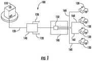
- FIG. 1is a plan diagram of a fiber optic network with a fiber optic distribution cable routed from a service provider's central office to subscriber premises;
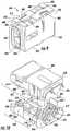
- FIG. 2is an exploded, perspective view of an exemplary fiber optic multiport having a first chamber and a second chamber, with an optical splitter and optical fibers located in the first chamber, and with potting material being disposed in the first chamber;
- FIG. 2Ais a partial detail view of the fiber organizer, blocking material and wall of FIG. 2 ;
- FIG. 3is an underside, perspective view of a cover of the fiber optic multiport shown in FIG. 2 ;
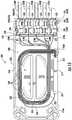
- FIG. 4is a top perspective view of the fiber optic multiport of FIG. 2 showing an interior in an unpopulated state
- FIG. 5is a flowchart diagram illustrating an exemplary process for sealing a fiber optic multiport that may utilize a blocking material adjacent to a wall separating a first chamber and a second chamber;
- FIG. 6is a side perspective view of an exemplary fiber organizer of the fiber optic multiport of FIG. 2 shown in an assembled state;
- FIG. 7is an exploded, perspective view of the fiber organizer of FIG. 6 ;
- FIG. 8is a partial detail, plan view of the fiber organizer of FIGS. 6 and 7 showing the interior of a first segment of the fiber organizer;
- FIG. 9is a side perspective view of an exemplary fiber organizer of the fiber optic multiport of FIG. 2 shown in an assembled state
- FIG. 10is an exploded, perspective view of the fiber organizer of FIG. 9 ;
- FIG. 11is a partial detail, plan view of the fiber organizer of FIGS. 9 and 10 showing the interior of a first segment of the fiber organizer;
- FIGS. 12A-12Care front elevation views of fiber organizers with different interior space configurations
- FIG. 13is a top, perspective view of a fiber retainer shown in FIG. 2 ;
- FIG. 14is a front, perspective view of blocking material in the form of a foam pad with slits cut therethrough shown in FIG. 2 ;
- FIG. 15is a top, plan view of the fiber optic multiport of FIG. 2 showing the optical splitter, splitter legs, optical fibers, fiber organizers and fiber optic cables installed;
- FIG. 16is a top plan view of the fiber optic multiport of FIG. 15 showing the fiber retainer installed in the first chamber;
- FIG. 17is a top, plan view of the fiber optic multiport of FIG. 15 , showing the potting material disposed in the first chamber;
- FIG. 18is a top, plan view of a fiber optic multiport shown with one input fiber optic pigtail and eight output fiber optic pigtails.
- FIG. 1there is shown a simplified fiber optic network 100 directed to supporting a fiber to the home (FTTH) solution.
- a service providerprovides optical communication service over the fiber optic network 100 from a central office 110 through distribution cabling 120 and hardware to the user or subscriber at a subscriber premises 130 .
- the distribution cabling 120extends from the central office 110 toward subscriber premises 130 utilizing intermediate distribution points or nodes 140 having fiber optic devices 150 , such as a multiport, for example.
- the fiber optic devices 150may include optical splitters used to split the optical signal into multiple optical signals which may be carried by drop cables 160 to the subscriber premises 130 .
- optical communication servicemay properly be viewed as originating with the service provider at the central office 110
- the actual flow of optical communication transmissionis bidirectional.
- Optical signalsare both sent and received at both ends of the fiber optic network 100 and points in between.
- the perspective of the fiber optic network 100 from the central office 110 toward the subscriber premises 130is typically referred to as “downstream,” while the perspective from the subscriber premises 130 back to the central office 110 is typically referred to as “upstream.”
- upstream and downstreamdo not necessarily denote or control actual optical signal transmission direction, but refer to a physical direction in the fiber optic network that is either toward the service provider (upstream) or toward the subscriber (downstream).
- the fiber optic multiport 200may be used to split an optical signal transmitted by an optical service provider, which, typically, is initially transmitted from a central office (not shown in FIG. 2 ). As the optical signal moves downstream in the fiber optic network and closer to the user/subscriber premises, the optical signal may be required to be split multiple times in locations having conditions that are not the most conducive for placement and operation of fiber optic equipment. Accordingly, the fiber optic hardware needs to be designed to withstand such conditions.
- the fiber optic multiport 200 in FIG. 2has an enclosure 202 with a base 204 and a cover 206 , and defines an interior 208 .
- the fiber optic multiport 200may be sectioned into certain areas such that the interior 208 defines chambers to provide separation or isolation between functions and/or connections.
- a first chamber 210is defined by the interior 208 .
- An optical splitter 212may be located in the first chamber 210 .
- the optical splitter 212may friction fit to the base 204 by two retainer clips 214 formed in the base 204 . In this way, the optical splitter 212 may easily locate in the first chamber 210 of the interior 208 .
- a plurality of splitter legs 216extend from the optical splitter 212 and connect to a plurality of optical fibers 218 also located in the first chamber 210 .
- the plurality of splitter legs 216may connect to the plurality of optical fibers 218 using fusion splices 220 applied to the respective ones of the splitter legs 216 and optical fibers 218 .
- the optical fibers 218may each be from separate fiber optic cable 250 .
- the fiber optic cables 250may include an input fiber optic cable 250 A having an input optical fiber 218 A, and several output fiber optic cables 250 B, each having an output optical fiber 218 B. In FIG. 2 the input and output designations for fiber optic cables 250 and optical fiber 218 : 250 A, 250 B, 218 A, 218 B, respectively, are not shown.
- optical fiber 218may still be contained in a buffer tube 300 to provide appropriate protection to the optical fiber 218 .
- references to optical fiber 218shall be understood to include reference to the buffer tube 300 unless the context of the discussion indicates otherwise.
- fiber optic cable 250shall be understood to refer to both fiber optic cables and fiber optic pigtails.
- the fiber optic cables 250may connect to other fiber optic equipment, such as another multiport, or may function as drop cables and be routed to the subscriber premises. In either situation, the integrity of the connection, i.e., fusion splice 220 , between the splitter legs 216 and the optical fibers 218 may be maintained. Further, it is important that the splitter legs 216 and the optical fibers 218 may be managed and protected.
- a mandrel 222 having a center cut 224protrudes from the base 204 into the interior 208 . The plurality of splitter legs 216 and the plurality of optical fibers 218 may be routed around the mandrel 222 for fiber management purposes.
- External connections to the fiber optic multiport 200may be designated to an area of the fiber optic multiport 200 separate from the first chamber 210 .
- a second chamber 226is defined by the interior 208 adjacent the first chamber 210 .
- a wall 228 interposed between the first chamber 210 and the second chamber 226separates and isolates the first chamber 210 from the second chamber 226 .
- the wall 228has a first face 230 and a second face 232 .
- a plurality of slots 234extend through the wall 228 between the first face 230 and the second face 232 .
- a blocking material 236is attached to the wall 228 .
- any reference to “seal” or “sealing” with regard to the first chamber 210 from the second chamber 226refers to and means inhibiting any material, such as for example potting material, from leaking or flowing from its intended location, such as the first chamber 210 into the second chamber 226 .
- the blocking material 236may be attached on the first face 230 or the second face 232 and may be a compressible foam piece that seals any gaps upon pressure being applied to it. Since the plurality of optical fibers 218 located in the first chamber 210 are extended from fiber optic cables 250 external to the fiber optic multiport 200 , the optical fibers 218 may need to route between the first chamber 210 and the second chamber 226 .
- the optical fibers 218may be routed between the first chamber 210 and the second chamber 226 through the plurality of slots 234 in the wall 228 and through the blocking material 236 without compromising the integrity of the wall 228 and the sealing and/or isolation between the first chamber 210 and the second chamber 226 .
- the blocking material 236is shown as a foam pad 238 attached to the second face 232 of the wall 228 .
- the foam pad 238has a plurality of slits 240 and may be attached to the wall 228 in such a way that the plurality of slits 240 align with the plurality of slots 234 to form optical fiber passages 242 between the first chamber 210 and the second chamber 226 .
- the plurality of optical fibers 218may then be routed through the foam pad 238 between the first chamber 210 and the second chamber 226 through the optical fiber passages 242 formed by the slots 234 in the wall 228 and the slits 240 in the foam pad 238 .
- the foam pad 238may be constructed of a compressible material which fills any gaps in the wall 228 , including the optical fiber passages 242 formed by the plurality of slots 234 in the wall 228 and the plurality of slits 240 in the foam pad 238 , when pressure is applied to the foam pad 238 , thereby sealing the first chamber 210 from the second chamber 226 .
- the optical fibers 218 located in the first chamber 210 and the second chamber 226are from fiber optic cables 250 , which enter the fiber optic multiport 200 at the second chamber 226 .
- a plurality of fiber organizers 244may be used.
- the plurality of fiber organizers 244may be positioned in the second chamber 226 in separate placement partitions 252 .
- the placement partitions 252may be arranged to coordinate with the optical fiber passages 242 , and, thereby, the slits 240 in the foam pad 238 and the slots 234 in the wall 228 .
- the fiber organizer 244When installed in the placement partition 252 , the fiber organizer 244 may have a first end 246 facing toward the wall 228 , and a second end 248 facing away from the wall 228 and the second end 248 provides access for the fiber optic cable 250 to enter the fiber optic multiport 200 .
- the fiber organizer 244also provides a protected location at the point in which the jacket 296 , strength member 298 and other material has been removed to expose the optical fiber 218 in its buffer tube 300 , which may route between the second chamber 226 and the first chamber 210 , as discussed above.
- the fiber organizers 244when the fiber organizers 244 are installed in the respective placement partitions 252 , the fiber organizers 244 provide pressure to the foam pad 238 , compressing the foam pad 238 and causing it to seal any gaps in the wall 228 , including the optical fiber passages 242 through which the optical fibers 218 have been routed.
- a fiber retainer 254is shown in FIG. 2 .
- the fiber retainer 254positions over the optical splitter 212 , the plurality of splitter legs 216 and the plurality of optical fibers 218 .
- a mid-span member 256 of the fiber retainer 254friction fits into the center cut 224 of the mandrel 222 to maintain the fiber retainer 254 in place in the first chamber 210 over the optical splitter 212 , the plurality of splitter legs 216 and the plurality of optical fibers 218 .
- the optical splitter 212 , plurality of splitter legs 216 and the plurality of optical fibers 218are set in their installed positions in the first chamber 210 and are restricted from any upward movement.
- the potting material 258may be any suitable compound used for potting applications, such as a non-limiting example SSP5 gel.
- FIGS. 3 and 4there are shown perspective views of an underside 205 of the cover 206 ( FIG. 3 ) and the base 204 ( FIG. 4 ).
- the cover 206closes onto the base 204 using tabs 260 that extend downward from angled cover corners 262 .
- the tabs 260insert into receivers 264 formed at angled base corners 266 .
- Hooked ends 268 on the tabs 260latch to protrusions (not shown in FIG. 4 ) located in the receivers 264 to provide for a secure, tight fit of the cover 206 to the base 204 , such that a perimeter ridge 270 of the cover 206 is forced against a portion of the perimeter edge 272 of the base 204 and the wall 228 .
- loops 274 extending from the cover 206fit over and are captured by detents 276 that extend out from the sides 280 of the base 204 .
- Stiffeners 282 extending from the underside 205 of the cover 206strengthen the cover 206 and restrict any bowing of the cover 206 so that the cover 206 maintains a flat, planar orientation to allow for consistent contact of the perimeter ridge 270 of the cover 206 to the perimeter edge 272 of the base 204 .
- a tight fit of the cover 206 to the base 204may be maintained, and the interior 208 , as shown in FIG. 4 with the mandrel 222 and the retainer clips 214 , may be secured.
- top separators 284align with bottom separators 286 to define, with the wall 228 , the placement partitions 252 .
- cover face molding 288meets base face molding 290 to form a plurality of front openings 292 for each placement partition 252 with each of the plurality of front openings 292 centrally aligned with each of the plurality of slots 234 in the wall 228 .
- Mounting holes 294are formed into and extend from the base 204 to allow the base 204 to be securely fastened to a support.
- FIG. 5depicts a method of sealing a fiber optic multiport 200 .
- the methodmay be implemented by separating an interior 208 of an enclosure 202 of the fiber optic multiport 200 into a first chamber 210 and a second chamber 226 (block 500 ); positioning a wall 228 having a plurality of slots 234 between the first chamber 210 and the second chamber 226 (block 502 ); locating an optical splitter 212 in the first chamber 210 and extending optical fibers 218 optically connected to the optical splitter 212 through at least one of the plurality of slots 234 to the second chamber 226 ; (block 504 ); fitting a fiber retainer 254 over the optical splitter 212 and the optical fibers 218 in the first chamber 210 ; (block 506 ); positioning blocking material 236 adjacent to the wall 228 (block 508 ), the blocking material 236 may be a foam pad 238 constructed of a compressible material, and having a plurality of slits 240 with at least one slit 240 of the pluralit
- the methodmay further include positioning at least one fiber organizer 244 in the second chamber 226 with the at least one fiber organizer 244 having a first end 246 and a second end 248 and with the at least one fiber organizer 244 pressing against the foam pad 238 to compress the foam pad 238 (block 516 ); receiving at the first end 246 of at least one fiber organizer 244 at least one of the optical fibers 218 extended between the first chamber 210 and the second chamber 226 through the at least one slot 234 of the plurality of slots 234 (block 518 ); seating a fiber optic cable 250 covering the optical fiber 218 , received external from the enclosure 202 at the second end 248 of the at least one fiber organizer 244 (block 520 ) and disposing potting material 258 in the at least one fiber organizer 244 (block 522 ).
- FIGS. 6-12Cthere are shown views of exemplary fiber organizers 244 .
- the fiber organizers 244are shown as having a first segment 600 and a second segment 602 each with a complementary attachment structure 603 .
- the complementary attachment structure 603may include a first side tab 604 , a first side latch 606 , a second side tab 608 and a second side latch 610 .
- the first segment 600 and the second segment 602may be attached together by mating first side tab 604 with second side latch 610 , and second side tab 608 with first side latch 606 .
- first segment 600 and the second segment 602are attached together, a first hook end 612 of first side tab 604 positions in and is retained by a second latch slot 614 of second side latch 610 , while a second hook end 616 of second side tab 608 positions in and is retained by a first latch slot 618 of first side latch 606 .
- first segment 600may attach to the second segment 602 by the attachment structure 603 to define an interior space configuration 619 having a fiber optic cable seating area 621 and an optical fiber pass-through 623 .
- the first segment 600may be one of a first design type 622 or a second design type 632
- the second segment 602may also be one of the first design type 622 or the second design type 632
- the first design type 622may form one half of the interior space configuration 619 having a first fiber optic cable seating area 624 , a second fiber optic cable seating area 626 , a first optical fiber pass-through 627 , and a second optical fiber pass-through 628 as shown in FIG. 7 .
- the second design type 632may form one half of the interior space configuration 619 having a first fiber optic cable seating area 624 and a blocked second fiber optic cable seating area 626 , and a first optical fiber pass-through 627 and a blocked second optical fiber pass-through 628 as shown in FIG. 10 .
- whether the first segment 600 is a first design type 622 or a second design type 632 ; and whether the second segment 602 is a first design type 622 or a second design type 632may determine whether the interior space configuration 619 is a first interior space configuration 620 , a second interior space configuration 630 or a third interior space configuration 640 .
- the fiber organizer 244is depicted in an assembled state, while, in FIG. 7 the fiber organizer 244 is shown in an exploded view.
- the fiber organizer 244is shown as having the first interior space configuration 620 .
- the first interior space configuration 620may be formed when both the first segment 600 and the second segment 602 are first design types 622 .
- a first design type 622provides for a first fiber optic cable seating area 624 , a second fiber optic cable seating area 626 , a first optical fiber pass-through 627 , and a second optical fiber pass-through 628 .
- a first interior space configuration 620is formed providing for two fiber optic cables 250 and their respective optical fibers 218 to be received.
- the fiber optic cables 250are shown as having only one optical fiber 218 , the fiber optic cables 250 each may have one or multiple optical fibers 218 .
- FIG. 8an internal view of the first segment 600 of the fiber organizer 244 having a first interior space configuration 620 is shown. Since the first segment 600 and the second segment 602 of the fiber organizer 244 with a first interior space configuration 620 in FIGS. 6 and 7 are both first design types 622 , the internal views of the first segment 600 and the second segment 602 are the same.
- two fiber optic cables 250 received at the second end 248 of the fiber organizer 244are shown seated in the first fiber optic cable seating area 624 and the second fiber optic cable seating area 626 of the first segment 600 .
- the jackets 296 and strength members 298 of the fiber optic cables 250are shown as terminated in the fiber organizer 244 and removed with the strength members 298 extending slightly past the end of the jackets 296 .
- the optical fibers 218(not visible in FIG. 8 ), which may be covered by buffer tubes 300 , may continue and extend from the fiber organizer 244 at the first end 246 .
- potting materialsuch as for example, epoxy (not shown in FIG. 8 ), may be disposed in the fiber organizer 244 to seal the first segment 600 and the second segment 602 with the fiber optic cables 250 therein.
- the potting materialsecures the jacket 296 and strength members 298 such that the fiber optic cable 250 is restrained and the optical fibers 218 are restricted from pistoning into and out of the jacket 296 .
- the potting materialmay be any suitable epoxy, for example, URB 144 or Loctite 3360.
- FIGS. 9 and 10there are shown views of an exemplary fiber organizer 244 .
- the fiber organizer 244 in FIG. 9is depicted in an assembled state, while, in a similar manner to FIG. 7 , the fiber organizer 244 in FIG. 10 is shown in an exploded view.
- the first segment 600 and the second segment 602 of fiber organizer 244are attached together in the same manner as discussed above.
- the fiber organizer 244is shown as having a second interior space configuration 630 .
- the second interior space configuration 630results when the first segment 600 is the first design type 622 and the second segment 602 is the second design type 632 .
- the first design type 622has the first fiber optic cable seating area 624 , a second fiber optic cable seating area 626 , a first optical fiber pass-through 627 , and a second optical fiber pass-through 628 .
- the second design type 632may have the first fiber optic cable seating area 624
- the second design type 632may have a blocked second fiber optic cable seating area 626 .
- the second design type 632may have the first optical fiber pass-through 627
- the second design type 632may have a blocked second optical fiber pass-through 628 .
- the second interior space configuration 630may be formed providing for one fiber optic cable 250 and its optical fibers 218 to be received.
- a second fiber optic cable 250 and its optical fibers 218may not be received by the fiber organizer 244 due to the blocked second fiber optic cable seating area 626 and the blocked second optical fiber pass-through 628 .
- the fiber optic cable 250is shown as having one optical fiber 218
- the fiber optic cables 250each may have one or multiple optical fibers 218 .
- FIG. 11an internal view of the second segment 602 of the fiber organizer 244 is shown.
- a fiber optic cable 250 received at the second end 248 of the fiber organizer 244is shown seated in the first fiber optic cable seating area 624 of the second segment 602 .
- the jacket 296 and strength members 298 of the fiber optic cable 250are shown as terminated in the fiber organizer 244 and removed with the strength members 298 extending slightly past the end of the jacket 296 .
- the optical fiber 218(not visible in FIG. 11 ), which may be covered by buffer tube 300 , may continue and extend from the fiber organizer 244 at the first end 246 .
- the second fiber optic cable seating area 626is blocked by a cap 636 which may be formed in the second segment 602 (shown in FIG. 10 ).
- potting materialsuch as for example epoxy, may be disposed in the fiber organizer 244 to seal the first segment 600 and the second segment 602 with the fiber optic cable 250 therein.
- the first design type 622 and second design type 632may be used in different combinations as the first segment 600 and second segment 602 of a fiber organizer 244 to provide the first interior space configuration 620 or the second interior space configuration 630 .
- a third interior space configuration 640may also be provided by using the second design type 632 as both the first segment 600 and the second segment 602 .
- both the first fiber optic cable seating area 624 and the second fiber optic cable seating area 626 , as well as both the first optical fiber pass-through 627 and the second optical fiber pass-through 628may be blocked by caps 636 .
- a fiber organizer 244 having a third interior space configuration 640may be used in a fiber optic multiport 200 which has an optical splitter 212 that splits an input optical signal into six or less output optical signals, examples of which may include 1:2, 1:4 and 1:6 optical splitter.
- an optical splitter 212that splits an input optical signal into six or less output optical signals, examples of which may include 1:2, 1:4 and 1:6 optical splitter.
- not all slots 234 in the wall 228 and slits 240 in the foam pad 238may be used, and, additionally, one or more placement partitions 252 in the second chamber 226 may not require the fiber organizers 244 to receive optical fiber(s) 218 and the respective fiber optic cable(s) 250 .
- a fiber organizer 244that does not receive a fiber optic cable 250 and its optical fiber 218 but does apply pressure on the foam pad 238 may be needed.
- a fiber organizer 244 having the third interior space configuration 640may be used for such purpose.
- FIGS. 12A-12Cdepict three views of the second end 248 of the fiber organizer 244 illustrating the first interior space configuration 620 , the second interior space configuration 630 and the third interior space configuration 640 , respectively.
- both the first segment 600 and the second segment 602are the first design types 622 attached together to form the first fiber optic cable seating area 624 , the second fiber optic cable seating area 626 , the first optical fiber pass-through 267 (not shown in FIG. 12A ), and the second optical fiber pass-through 628 (not shown in FIG. 12A ).
- FIG. 12Aboth the first segment 600 and the second segment 602 are the first design types 622 attached together to form the first fiber optic cable seating area 624 , the second fiber optic cable seating area 626 , the first optical fiber pass-through 267 (not shown in FIG. 12A ), and the second optical fiber pass-through 628 (not shown in FIG. 12A ).
- FIG. 12Aboth the first segment 600 and the second segment 602 are the first design types 622 attached together to form
- the first segment 600is the first design type 622
- the second segment 602is the second design type 632 attached together to form the first fiber optic cable seating area 624 , but blocked second fiber optic cable seating area 626 ; and the first optical fiber pass-through 627 (not shown in FIG. 12B ), but blocked second optical fiber pass-through 628 (not shown in FIG. 12B ).
- the cap 636blocks the second fiber optic cable seating area 626 and the second optical fiber pass-through 628 .
- both the first segment 600 and the second segment 602are second design type 632 attached together to provide two caps 636 blocking the first fiber optic cable seating area 624 , the second fiber optic cable seating area 626 , the first optical fiber pass-through 627 and the second optical fiber pass-through 628 (not shown in FIG. 12C ). Accordingly, fiber organizer 244 having a third interior space configuration 640 may not receive any fiber optic cables 250 or their optical fibers 218 .
- the fiber retainer 254is shown.
- the fiber retainer 254is shaped generally to align with the footprint of the base 204 .
- the mid-span member 256fits into the center cut 224 of the mandrel 222 with the two portions of the mandrel 222 positioning through the mandrel cut-outs 306 as the fiber retainer 254 descends in the base 204 .
- Side extension 302may be used to cover the area where the optical splitter 212 is situated, while end extension 304 covers the area between the angled base corners 266 (shown in FIG. 4 ).
- Apertures 308allow the potting material to flow down past the fiber retainer 254 to cover the optical splitter 212 , splitter legs 216 , optical fiber 218 and splices 220 .
- the foam pad 238is illustrated in FIG. 14 .
- the foam pad 238may be constructed from any suitable thermoplastic or thermoset rubber material, although silicone based foam may be preferred.
- the foam pad 238may need to withstand temperatures as high as 100° C.
- the surface of the foam pad 238may be open cell or closed cell foam sheet. Open cell may be preferred.
- the surface of the foam pad 238may be smooth with no openings and no texture.
- the foam pad 238may have a thickness of between about 1/16-1 ⁇ 8 inches, with 1/16 inches preferred.
- the hardness of the foamshould be between Shore 00 20 and Shore A 30, with Shore 00 45 preferred.
- the foam materialshould not react with the liquid potting compound or cause any cure issue with the compound.
- the foam pad 238may be constructed of a microcellular urethane foam material having an adhesive backing, such as, for example, a black Poron® foam.
- a thixotropic gel applied to the wall 228may be used as the blocking material 236 .
- fiber optic multiport 200is shown in three different stages of the first chamber 210 assembly.
- one input fiber optic cable 250 A and eight (8) output fiber optic cables 250 Bare shown being received by five (5) fiber organizers 244 installed in the second chamber 226 in respective placement partitions 252 .
- the one input fiber optic cable 250 Ais received by one (1) fiber organizer 244 .
- fiber organizer 244may have a second seating configuration 630 with a first cable seat 624 and a cap 636 .
- the eight (8) output fiber optic cables 250 Bare shown being received by four (4) fiber organizers 244 with two (2) output fiber optic cables 250 B being received by each fiber organizer 244 . Accordingly, and as discussed above with respect to FIGS. 8-10 , those four (4) fiber organizers may have a first seating configuration 620 with a first cable seat 624 and a second cable seat 626 .
- Optical fibers 218 in individual buffer tubes 300extend through the optical fiber passages 242 (see FIG. 2A ) formed through the slits 240 in the foam pad 238 and the slots 234 in the wall 228 into the first chamber 210 .
- optical fiber 218 A from the input fiber optic cable 250 Aextends in one optical fiber passage 242
- two optical fibers 218 B from two output fiber optic cables 250 Bextend through one optical fiber passage 242 (see FIG. 2A ).
- four (4) optical fiber passages 242each have two optical fibers 218 B extending through it to the first chamber 210 from the second chamber 226 .
- the optical fiber 218 A from the input fiber optic cable 250 Ais spliced to the input splitter leg 216 A of the optical splitter 212 .
- the eight optical fibers 218 B from the output fiber optic cables 250 Beach are fusion spliced to one of the output splitter legs 216 B.
- the optical splitter 212 situated in the interior 208 in the retainer clips 214may be a 1:8 optical splitter.
- the optical fibers 218 A, 218 B, input splitter leg 216 A and output splitter legs 216 Broute in the first chamber 210 around the mandrel 222 , but not through the center cut 224 .
- the fiber retainer 254is positioned in the first chamber 210 with the mid-span member 256 friction fit into the center cut 224 .
- the side extension 302 of the fiber retainer 254locates over the optical splitter 212
- the end extension 304locates over the optical fibers 218 A, 218 B and splitter legs 216 A, 216 B that are routed between the angled base corners 266 .
- the two portions of the mandrel 222are positioned through the mandrel cut-outs 306 .
- Apertures 308provide access to the optical fibers 218 A, 218 B and splitter legs 216 A, 216 B.
- the potting material 258is shown disposed in the first chamber 210 , encasing the fiber retainer 254 , optical splitter 212 , optical fibers 218 A, 218 B, input splitter leg 216 A and output splitter legs 216 B, through apertures 308 .
- the fiber organizers 244applied pressure to the foam pad 238 , compressing the foam pad 238 and sealing any gaps in the wall 228 and the optical fiber passages 242 through which the optical fibers 218 A, 218 B were routed to the first chamber 210 from the second chamber 226 .
- FIG. 18illustrates the exemplary fiber optic multiport 200 in a complete assembled state, with the cover 206 attached and with one input fiber optic cable 250 A in the form of an input fiber optic pigtail terminated with a hardened fiber optic connector 310 A, and eight (8) output fiber optic cables 205 B each in the form of an output fiber optic pigtail, and each terminated with a hardened fiber optic connector 310 B.
- the hardened fiber optic connectors 310 A, 310 Bmay be OptiTap® connectors as supplied by Corning Optical Communications, LLC of Hickory, N.C.
- the input fiber optic cable 250 A and the output fiber optic cables 250 Bmay each have port connection indicia 312 A, 312 B, respectively, which is indicative of a port connection type to which the input fiber optic cable 250 A and the output fiber optic cables 250 B may be attached, such as for example, an input port and an output port.
- the multiports disclosed hereinmay use the concepts disclosed in U.S. Provisional Patent Application No. 62/199,545 filed Jul. 31, 2015 and titled “Fiber Optic Multiport Having Different Types of Ports for Multi-Use”, the content of which is incorporated herein by reference in its entirety.
Landscapes
- Physics & Mathematics (AREA)
- General Physics & Mathematics (AREA)
- Optics & Photonics (AREA)
- Light Guides In General And Applications Therefor (AREA)
- Mechanical Coupling Of Light Guides (AREA)
- Telescopes (AREA)
Abstract
Description
Claims (27)
Priority Applications (8)
| Application Number | Priority Date | Filing Date | Title |
|---|---|---|---|
| US15/235,623US11073670B2 (en) | 2016-08-12 | 2016-08-12 | Device and method for sealing multiport splitters |
| BR112019002535ABR112019002535A2 (en) | 2016-08-12 | 2017-08-10 | device and method for sealing multiport splitters |
| PCT/US2017/046230WO2018031732A1 (en) | 2016-08-12 | 2017-08-10 | Device and method for sealing multiport splitters |
| CA3034708ACA3034708A1 (en) | 2016-08-12 | 2017-08-10 | Device and method for sealing multiport splitters |
| AU2017311399AAU2017311399B2 (en) | 2016-08-12 | 2017-08-10 | Device and method for sealing multiport splitters |
| MX2019001565AMX2019001565A (en) | 2016-08-12 | 2017-08-10 | DEVICE AND METHOD TO SEAL MULTIPORT DIVIDERS. |
| EP17754959.9AEP3497497B1 (en) | 2016-08-12 | 2017-08-10 | Device and method for sealing multiport splitters |
| CONC2019/0002220ACO2019002220A2 (en) | 2016-08-12 | 2019-03-11 | Device and method for sealing multiport dividers |
Applications Claiming Priority (1)
| Application Number | Priority Date | Filing Date | Title |
|---|---|---|---|
| US15/235,623US11073670B2 (en) | 2016-08-12 | 2016-08-12 | Device and method for sealing multiport splitters |
Publications (2)
| Publication Number | Publication Date |
|---|---|
| US20180045905A1 US20180045905A1 (en) | 2018-02-15 |
| US11073670B2true US11073670B2 (en) | 2021-07-27 |
Family
ID=59677387
Family Applications (1)
| Application Number | Title | Priority Date | Filing Date |
|---|---|---|---|
| US15/235,623ActiveUS11073670B2 (en) | 2016-08-12 | 2016-08-12 | Device and method for sealing multiport splitters |
Country Status (8)
| Country | Link |
|---|---|
| US (1) | US11073670B2 (en) |
| EP (1) | EP3497497B1 (en) |
| AU (1) | AU2017311399B2 (en) |
| BR (1) | BR112019002535A2 (en) |
| CA (1) | CA3034708A1 (en) |
| CO (1) | CO2019002220A2 (en) |
| MX (1) | MX2019001565A (en) |
| WO (1) | WO2018031732A1 (en) |
Families Citing this family (5)
| Publication number | Priority date | Publication date | Assignee | Title |
|---|---|---|---|---|
| US10852490B2 (en)* | 2018-06-10 | 2020-12-01 | Senko Advanced Components, Inc. | Fiber optic connector clip |
| EP3736613B1 (en)* | 2019-03-04 | 2022-11-30 | Huawei Technologies Co., Ltd. | Optical splitter chip, optical splitter assembly, optical splitter device, and fiber optic enclosure |
| US12153270B2 (en)* | 2021-01-15 | 2024-11-26 | Go!Foton Holdings, Inc. | Drop cable box |
| PL130284U1 (en)* | 2021-09-23 | 2023-03-27 | Fca Spółka Z Ograniczoną Odpowiedzialnością | Subscriber socket |
| US20230125728A1 (en)* | 2021-10-21 | 2023-04-27 | Go!Foton Holdings, Inc. | Outside Plant Cable Add And Drop Enclosure |
Citations (67)
| Publication number | Priority date | Publication date | Assignee | Title |
|---|---|---|---|---|
| JPS6389421A (en) | 1986-09-30 | 1988-04-20 | Nippon Electric Glass Co Ltd | Device for forming sheet glass |
| US5007860A (en) | 1990-01-19 | 1991-04-16 | Leviton Manufacturing Co., Inc. | Modular higher density communications coupling system |
| US5097529A (en)* | 1991-03-22 | 1992-03-17 | At&T Bell Laboratories | Space-saving optical fiber cable closure |
| US5280556A (en)* | 1992-09-25 | 1994-01-18 | At&T Bell Laboratories | Cable closure which includes a cable sheath gripping assembly |
| US5408570A (en) | 1994-06-30 | 1995-04-18 | Minnesota Mining And Manufacturing Company | Fiber optic housing with low part count |
| US5420957A (en)* | 1994-06-22 | 1995-05-30 | At&T Corp. | Optical fiber cable splitter |
| US5553186A (en) | 1995-03-31 | 1996-09-03 | Minnesota Mining And Manufacturing Company | Fiber optic dome closure |
| US5647045A (en) | 1996-02-23 | 1997-07-08 | Leviton Manufacturing Co., Inc. | Multi-media connection housing |
| US5862290A (en) | 1997-05-01 | 1999-01-19 | Lucent Technologies Inc. | Optical fiber cable splice closure |
| US6112006A (en) | 1995-11-22 | 2000-08-29 | Spirent Plc | Splice arrangements for optical fibre cables |
| US20020064364A1 (en) | 2000-11-29 | 2002-05-30 | Battey Jennifer A. | Apparatus and method for splitting optical fibers |
| US6738555B1 (en) | 2001-03-28 | 2004-05-18 | Corning Cable Systems Llc | Furcation kit |
| US6771861B2 (en) | 2002-05-07 | 2004-08-03 | Corning Cable Systems Llc | High performance, flexible optical fiber furcation |
| US20050129379A1 (en) | 2003-11-17 | 2005-06-16 | Fiber Optic Network Solutions Corporation | Systems and methods for optical fiber distribution and management |
| US20050175307A1 (en) | 2004-02-06 | 2005-08-11 | Battey Jennifer A. | Optical connection closure having at least one connector port |
| US20060045430A1 (en) | 2004-08-24 | 2006-03-02 | Thomas Theuerkorn | Fiber optic receptacle and plug assemblies with alignment and keying features |
| US20060120672A1 (en) | 2004-12-03 | 2006-06-08 | Cody Joseph T | Tether assembly having individual connector ports |
| US20060133759A1 (en) | 2004-12-22 | 2006-06-22 | Julian Mullaney | Optical fiber termination apparatus, entry sealing members and methods for using the same |
| US20060147172A1 (en) | 2004-12-30 | 2006-07-06 | Luther James P | Overmolded multi-port optical connection terminal having means for accommodating excess fiber length |
| US20060153517A1 (en) | 2004-11-03 | 2006-07-13 | Randy Reagan | Methods for configuring and testing fiber drop terminals |
| US7120347B2 (en) | 2004-01-27 | 2006-10-10 | Corning Cable Systems Llc | Multi-port optical connection terminal |
| WO2006113726A1 (en) | 2005-04-19 | 2006-10-26 | Adc Telecommunications, Inc. | Loop back plug and method |
| US20060269204A1 (en) | 2005-05-25 | 2006-11-30 | Michael Barth | Outside plant fiber distribution enclosure with radial arrangement |
| US20060269208A1 (en)* | 2005-05-31 | 2006-11-30 | Barry Allen | Optical network architecture, terminals for use in such networks and methods for using the same |
| US20070003204A1 (en)* | 2005-06-30 | 2007-01-04 | Elli Makrides-Saravanos | Methods and apparatus for splitter modules and splitter module housings |
| US20070031103A1 (en)* | 2005-03-28 | 2007-02-08 | Thomas Tinucci | Dust plug for hardened fiber optic connector |
| US20070031100A1 (en) | 2005-08-04 | 2007-02-08 | Garcia Cesar G | Optical fiber distribution cabinet |
| US7330629B2 (en) | 2005-08-31 | 2008-02-12 | Corning Cable Systems Llc | Fiber optic universal bracket apparatus and methods |
| US20080175548A1 (en) | 2007-01-23 | 2008-07-24 | Dennis Michael Knecht | Preconnectorized fiber optic cable assembly |
| US20080264664A1 (en) | 2007-04-27 | 2008-10-30 | Thomas & Betts International, Inc. | Multi-media recess data low voltage box with slide-away hidden cover |
| US7489849B2 (en) | 2004-11-03 | 2009-02-10 | Adc Telecommunications, Inc. | Fiber drop terminal |
| US20090060421A1 (en) | 2007-03-16 | 2009-03-05 | 3M Innovative Properties Company | Optical fiber cable inlet device |
| US20090185835A1 (en) | 2008-01-21 | 2009-07-23 | Samsung Electronics Co., Ltd. | Image forming apparatus |
| US20090245743A1 (en) | 2008-03-27 | 2009-10-01 | Cote Monique L | Compact, high-density adapter module, housing assembly and frame assembly for optical fiber telecommunications |
| US20090263097A1 (en) | 2007-12-18 | 2009-10-22 | Adc Telecommunications, Inc. | Multi-Configuration Mounting System for Fiber Distribution Hub |
| US7709733B1 (en) | 2003-12-12 | 2010-05-04 | Gary Dean Plankell | Recessed signal-receiver mounting system for a building structure and associated methods |
| US7740409B2 (en) | 2007-09-19 | 2010-06-22 | Corning Cable Systems Llc | Multi-port optical connection terminal |
| US7753596B2 (en) | 2005-11-22 | 2010-07-13 | Corning Cable Systems Llc | Fiber optic closure methods and apparatus |
| US20100197222A1 (en) | 2009-01-30 | 2010-08-05 | Karl Frederick Scheucher | In-building-communication apparatus and method |
| US20100247053A1 (en) | 2009-03-31 | 2010-09-30 | Cowen Andrew P | Removably mountable fiber optic terminal |
| US7844160B2 (en) | 2006-04-05 | 2010-11-30 | Adc Telecommunications, Inc. | Universal bracket for mounting a drop terminal |
| US20100303426A1 (en) | 2009-05-29 | 2010-12-02 | Baker Hughes Incorporated | Downhole optical fiber spice housing |
| CN201704194U (en) | 2010-04-16 | 2011-01-12 | 信义光伏产业(安徽)控股有限公司 | Glass rolling device |
| US20110019964A1 (en) | 2009-01-15 | 2011-01-27 | Ponharith Nhep | Fiber optic module and chassis |
| US7903923B2 (en) | 2007-10-09 | 2011-03-08 | Adc Telecommunications, Inc. | Drop terminal releasable engagement mechanism |
| US20110108719A1 (en) | 2009-11-06 | 2011-05-12 | Precision Energy Services, Inc. | Multi-Channel Source Assembly for Downhole Spectroscopy |
| US20110164854A1 (en) | 2008-09-23 | 2011-07-07 | Christophe Desard | Fiber distribution enclosure with extractable organizer |
| US20110222829A1 (en)* | 2010-03-11 | 2011-09-15 | Todd Loeffelholz | Fiber optic enclosure with internal cable spool assembly |
| US8025445B2 (en) | 2009-05-29 | 2011-09-27 | Baker Hughes Incorporated | Method of deployment for real time casing imaging |
| US20120008909A1 (en) | 2004-03-08 | 2012-01-12 | Adc Telecommunications, Inc. | Fiber access terminal |
| US8213761B2 (en) | 2007-10-09 | 2012-07-03 | Adc Telecommunications | Mini drop terminal |
| US8301004B2 (en) | 2008-08-29 | 2012-10-30 | Corning Cable Systems Llc | Fiber optic cable assemblies employing a furcation body having anti-rotation feature |
| US20130034333A1 (en) | 2008-01-09 | 2013-02-07 | Adc Telecommunications, Inc. | Wall box adapted to be mounted at a mid-span access location of a telecommunications cable |
| US8466262B2 (en) | 2006-09-01 | 2013-06-18 | Zymogenetics, Inc. | Variable region sequences of IL-31 monoclonal antibodies and methods of use |
| US20130243386A1 (en)* | 2010-12-01 | 2013-09-19 | 3M Innovative Properties Company | Fiber organizer and distribution box |
| US20130272671A1 (en)* | 2012-04-13 | 2013-10-17 | Ashley W. Jones | Adapter for fiber optic connectors |
| US20140133806A1 (en) | 2012-11-14 | 2014-05-15 | John P. Hill | Multiport optical fiber terminal |
| US8737837B2 (en) | 2008-10-14 | 2014-05-27 | Corning Cable Systems Llc | Multi-level distributed fiber optic architectures |
| US8755663B2 (en) | 2010-10-28 | 2014-06-17 | Corning Cable Systems Llc | Impact resistant fiber optic enclosures and related methods |
| US20140166342A1 (en) | 2011-06-20 | 2014-06-19 | Tyco Electronics Raychem Bvba | Sealing device for feeding through filaments |
| US8770861B2 (en) | 2011-09-27 | 2014-07-08 | Tyco Electronics Corporation | Outside plant termination enclosure |
| US20140219622A1 (en) | 2011-06-24 | 2014-08-07 | Adc Telecommunications, Inc. | Fiber termination enclosure with modular plate assemblies |
| WO2014123940A1 (en) | 2013-02-06 | 2014-08-14 | Corning Optical Communications LLC | Fiber optic multiport |
| WO2014167447A1 (en) | 2013-04-07 | 2014-10-16 | Tyco Electronics (Shanghai) Co. Ltd. | Fiber optic connection assembly |
| WO2014197894A1 (en) | 2013-06-07 | 2014-12-11 | Adc Telecommunications, Inc. | Telecommunications connection device |
| US20160187607A1 (en)* | 2007-08-06 | 2016-06-30 | Commscope Technologies Llc | Fiber optic enclosure with internal cable spool |
| US9529173B2 (en)* | 2013-06-10 | 2016-12-27 | Afl Telecommunications Llc | Optical fiber furcation assembly and method |
- 2016
- 2016-08-12USUS15/235,623patent/US11073670B2/enactiveActive
- 2017
- 2017-08-10EPEP17754959.9Apatent/EP3497497B1/enactiveActive
- 2017-08-10WOPCT/US2017/046230patent/WO2018031732A1/ennot_activeCeased
- 2017-08-10CACA3034708Apatent/CA3034708A1/ennot_activeAbandoned
- 2017-08-10MXMX2019001565Apatent/MX2019001565A/enunknown
- 2017-08-10AUAU2017311399Apatent/AU2017311399B2/enactiveActive
- 2017-08-10BRBR112019002535Apatent/BR112019002535A2/ennot_activeApplication Discontinuation
- 2019
- 2019-03-11COCONC2019/0002220Apatent/CO2019002220A2/enunknown
Patent Citations (82)
| Publication number | Priority date | Publication date | Assignee | Title |
|---|---|---|---|---|
| JPS6389421A (en) | 1986-09-30 | 1988-04-20 | Nippon Electric Glass Co Ltd | Device for forming sheet glass |
| US5007860A (en) | 1990-01-19 | 1991-04-16 | Leviton Manufacturing Co., Inc. | Modular higher density communications coupling system |
| US5097529A (en)* | 1991-03-22 | 1992-03-17 | At&T Bell Laboratories | Space-saving optical fiber cable closure |
| US5280556A (en)* | 1992-09-25 | 1994-01-18 | At&T Bell Laboratories | Cable closure which includes a cable sheath gripping assembly |
| US5420957A (en)* | 1994-06-22 | 1995-05-30 | At&T Corp. | Optical fiber cable splitter |
| US5408570A (en) | 1994-06-30 | 1995-04-18 | Minnesota Mining And Manufacturing Company | Fiber optic housing with low part count |
| US5553186A (en) | 1995-03-31 | 1996-09-03 | Minnesota Mining And Manufacturing Company | Fiber optic dome closure |
| US6112006A (en) | 1995-11-22 | 2000-08-29 | Spirent Plc | Splice arrangements for optical fibre cables |
| US5647045A (en) | 1996-02-23 | 1997-07-08 | Leviton Manufacturing Co., Inc. | Multi-media connection housing |
| US5781686A (en) | 1996-02-23 | 1998-07-14 | Leviton Manufacturing Co., Inc. | Multi-media connection housing |
| US5862290A (en) | 1997-05-01 | 1999-01-19 | Lucent Technologies Inc. | Optical fiber cable splice closure |
| US6466725B2 (en) | 2000-11-29 | 2002-10-15 | Corning Cable Systems Llc | Apparatus and method for splitting optical fibers |
| US20020064364A1 (en) | 2000-11-29 | 2002-05-30 | Battey Jennifer A. | Apparatus and method for splitting optical fibers |
| US6738555B1 (en) | 2001-03-28 | 2004-05-18 | Corning Cable Systems Llc | Furcation kit |
| US6771861B2 (en) | 2002-05-07 | 2004-08-03 | Corning Cable Systems Llc | High performance, flexible optical fiber furcation |
| US20050129379A1 (en) | 2003-11-17 | 2005-06-16 | Fiber Optic Network Solutions Corporation | Systems and methods for optical fiber distribution and management |
| US7709733B1 (en) | 2003-12-12 | 2010-05-04 | Gary Dean Plankell | Recessed signal-receiver mounting system for a building structure and associated methods |
| US7120347B2 (en) | 2004-01-27 | 2006-10-10 | Corning Cable Systems Llc | Multi-port optical connection terminal |
| US7653282B2 (en) | 2004-01-27 | 2010-01-26 | Corning Cable Systems Llc | Multi-port optical connection terminal |
| US7333708B2 (en) | 2004-01-27 | 2008-02-19 | Corning Cable Systems Llc | Multi-port optical connection terminal |
| US20060280420A1 (en) | 2004-01-27 | 2006-12-14 | Blackwell Chois A Jr | Multi-port optical connection terminal |
| US20050175307A1 (en) | 2004-02-06 | 2005-08-11 | Battey Jennifer A. | Optical connection closure having at least one connector port |
| US20120008909A1 (en) | 2004-03-08 | 2012-01-12 | Adc Telecommunications, Inc. | Fiber access terminal |
| USRE43762E1 (en) | 2004-03-08 | 2012-10-23 | Adc Telecommunications, Inc. | Fiber access terminal |
| US20060045430A1 (en) | 2004-08-24 | 2006-03-02 | Thomas Theuerkorn | Fiber optic receptacle and plug assemblies with alignment and keying features |
| US20060153517A1 (en) | 2004-11-03 | 2006-07-13 | Randy Reagan | Methods for configuring and testing fiber drop terminals |
| US7489849B2 (en) | 2004-11-03 | 2009-02-10 | Adc Telecommunications, Inc. | Fiber drop terminal |
| US7627222B2 (en) | 2004-11-03 | 2009-12-01 | Adc Telecommunications, Inc. | Fiber drop terminal |
| US20120251063A1 (en) | 2004-11-03 | 2012-10-04 | Adc Telecommunications, Inc. | Fiber drop terminal |
| US7680388B2 (en) | 2004-11-03 | 2010-03-16 | Adc Telecommunications, Inc. | Methods for configuring and testing fiber drop terminals |
| US20060120672A1 (en) | 2004-12-03 | 2006-06-08 | Cody Joseph T | Tether assembly having individual connector ports |
| US7277614B2 (en) | 2004-12-03 | 2007-10-02 | Corning Cable Systems Llc | Tether assembly having individual connector ports |
| US20060133759A1 (en) | 2004-12-22 | 2006-06-22 | Julian Mullaney | Optical fiber termination apparatus, entry sealing members and methods for using the same |
| US7302152B2 (en) | 2004-12-30 | 2007-11-27 | Corning Cable Systems Llc | Overmolded multi-port optical connection terminal having means for accommodating excess fiber length |
| US20060147172A1 (en) | 2004-12-30 | 2006-07-06 | Luther James P | Overmolded multi-port optical connection terminal having means for accommodating excess fiber length |
| US20070031103A1 (en)* | 2005-03-28 | 2007-02-08 | Thomas Tinucci | Dust plug for hardened fiber optic connector |
| WO2006113726A1 (en) | 2005-04-19 | 2006-10-26 | Adc Telecommunications, Inc. | Loop back plug and method |
| US7565055B2 (en) | 2005-04-19 | 2009-07-21 | Adc Telecommunications, Inc. | Loop back plug and method |
| US20060269204A1 (en) | 2005-05-25 | 2006-11-30 | Michael Barth | Outside plant fiber distribution enclosure with radial arrangement |
| US20060269208A1 (en)* | 2005-05-31 | 2006-11-30 | Barry Allen | Optical network architecture, terminals for use in such networks and methods for using the same |
| US7444056B2 (en) | 2005-05-31 | 2008-10-28 | Tyco Electronics Corporation | Optical network architecture and terminals for use in such networks |
| US20070003204A1 (en)* | 2005-06-30 | 2007-01-04 | Elli Makrides-Saravanos | Methods and apparatus for splitter modules and splitter module housings |
| US20070031100A1 (en) | 2005-08-04 | 2007-02-08 | Garcia Cesar G | Optical fiber distribution cabinet |
| US7330629B2 (en) | 2005-08-31 | 2008-02-12 | Corning Cable Systems Llc | Fiber optic universal bracket apparatus and methods |
| US7753596B2 (en) | 2005-11-22 | 2010-07-13 | Corning Cable Systems Llc | Fiber optic closure methods and apparatus |
| US8218935B2 (en) | 2006-04-05 | 2012-07-10 | Adc Telecommunications, Inc. | Universal bracket for mounting a drop terminal |
| US7844160B2 (en) | 2006-04-05 | 2010-11-30 | Adc Telecommunications, Inc. | Universal bracket for mounting a drop terminal |
| US8466262B2 (en) | 2006-09-01 | 2013-06-18 | Zymogenetics, Inc. | Variable region sequences of IL-31 monoclonal antibodies and methods of use |
| US20080175548A1 (en) | 2007-01-23 | 2008-07-24 | Dennis Michael Knecht | Preconnectorized fiber optic cable assembly |
| US20090060421A1 (en) | 2007-03-16 | 2009-03-05 | 3M Innovative Properties Company | Optical fiber cable inlet device |
| US20080264664A1 (en) | 2007-04-27 | 2008-10-30 | Thomas & Betts International, Inc. | Multi-media recess data low voltage box with slide-away hidden cover |
| US20160187607A1 (en)* | 2007-08-06 | 2016-06-30 | Commscope Technologies Llc | Fiber optic enclosure with internal cable spool |
| US7740409B2 (en) | 2007-09-19 | 2010-06-22 | Corning Cable Systems Llc | Multi-port optical connection terminal |
| US8213761B2 (en) | 2007-10-09 | 2012-07-03 | Adc Telecommunications | Mini drop terminal |
| US7903923B2 (en) | 2007-10-09 | 2011-03-08 | Adc Telecommunications, Inc. | Drop terminal releasable engagement mechanism |
| US20090263097A1 (en) | 2007-12-18 | 2009-10-22 | Adc Telecommunications, Inc. | Multi-Configuration Mounting System for Fiber Distribution Hub |
| US20130034333A1 (en) | 2008-01-09 | 2013-02-07 | Adc Telecommunications, Inc. | Wall box adapted to be mounted at a mid-span access location of a telecommunications cable |
| US20090185835A1 (en) | 2008-01-21 | 2009-07-23 | Samsung Electronics Co., Ltd. | Image forming apparatus |
| US20090245743A1 (en) | 2008-03-27 | 2009-10-01 | Cote Monique L | Compact, high-density adapter module, housing assembly and frame assembly for optical fiber telecommunications |
| US8301004B2 (en) | 2008-08-29 | 2012-10-30 | Corning Cable Systems Llc | Fiber optic cable assemblies employing a furcation body having anti-rotation feature |
| US20110164854A1 (en) | 2008-09-23 | 2011-07-07 | Christophe Desard | Fiber distribution enclosure with extractable organizer |
| US8737837B2 (en) | 2008-10-14 | 2014-05-27 | Corning Cable Systems Llc | Multi-level distributed fiber optic architectures |
| US20110019964A1 (en) | 2009-01-15 | 2011-01-27 | Ponharith Nhep | Fiber optic module and chassis |
| US20100197222A1 (en) | 2009-01-30 | 2010-08-05 | Karl Frederick Scheucher | In-building-communication apparatus and method |
| US8520996B2 (en) | 2009-03-31 | 2013-08-27 | Corning Cable Systems Llc | Removably mountable fiber optic terminal |
| US20100247053A1 (en) | 2009-03-31 | 2010-09-30 | Cowen Andrew P | Removably mountable fiber optic terminal |
| US20100303426A1 (en) | 2009-05-29 | 2010-12-02 | Baker Hughes Incorporated | Downhole optical fiber spice housing |
| US8025445B2 (en) | 2009-05-29 | 2011-09-27 | Baker Hughes Incorporated | Method of deployment for real time casing imaging |
| US20110108719A1 (en) | 2009-11-06 | 2011-05-12 | Precision Energy Services, Inc. | Multi-Channel Source Assembly for Downhole Spectroscopy |
| US20110222829A1 (en)* | 2010-03-11 | 2011-09-15 | Todd Loeffelholz | Fiber optic enclosure with internal cable spool assembly |
| CN201704194U (en) | 2010-04-16 | 2011-01-12 | 信义光伏产业(安徽)控股有限公司 | Glass rolling device |
| US8755663B2 (en) | 2010-10-28 | 2014-06-17 | Corning Cable Systems Llc | Impact resistant fiber optic enclosures and related methods |
| US20130243386A1 (en)* | 2010-12-01 | 2013-09-19 | 3M Innovative Properties Company | Fiber organizer and distribution box |
| US20140166342A1 (en) | 2011-06-20 | 2014-06-19 | Tyco Electronics Raychem Bvba | Sealing device for feeding through filaments |
| US20140219622A1 (en) | 2011-06-24 | 2014-08-07 | Adc Telecommunications, Inc. | Fiber termination enclosure with modular plate assemblies |
| US8770861B2 (en) | 2011-09-27 | 2014-07-08 | Tyco Electronics Corporation | Outside plant termination enclosure |
| US20130272671A1 (en)* | 2012-04-13 | 2013-10-17 | Ashley W. Jones | Adapter for fiber optic connectors |
| US20140133806A1 (en) | 2012-11-14 | 2014-05-15 | John P. Hill | Multiport optical fiber terminal |
| WO2014123940A1 (en) | 2013-02-06 | 2014-08-14 | Corning Optical Communications LLC | Fiber optic multiport |
| WO2014167447A1 (en) | 2013-04-07 | 2014-10-16 | Tyco Electronics (Shanghai) Co. Ltd. | Fiber optic connection assembly |
| WO2014197894A1 (en) | 2013-06-07 | 2014-12-11 | Adc Telecommunications, Inc. | Telecommunications connection device |
| US9529173B2 (en)* | 2013-06-10 | 2016-12-27 | Afl Telecommunications Llc | Optical fiber furcation assembly and method |
Non-Patent Citations (5)
| Title |
|---|
| AU2013206651 Examination Report No. 1; dated March 10, 2016, 4 Pages. |
| Coaxum, L., et al., U.S. Appl. No. 62/341,947, "Fiber Optic Multiport Having Different Types of Ports for Multi-Use,", filed May 26, 2016. |
| EP14707013, Rules 161 and 162 Communication, dated September 17, 2015, 16 Pages. |
| International Search Report and Written Opinion PCT/US2017/04230 dated Nov. 15, 2017. |
| International Search Report; PCT/US2014/014764; dated May 27, 2014. |
Also Published As
| Publication number | Publication date |
|---|---|
| AU2017311399B2 (en) | 2022-05-12 |
| CO2019002220A2 (en) | 2019-03-18 |
| EP3497497B1 (en) | 2020-09-30 |
| CA3034708A1 (en) | 2018-02-15 |
| WO2018031732A1 (en) | 2018-02-15 |
| MX2019001565A (en) | 2019-07-01 |
| BR112019002535A2 (en) | 2019-05-21 |
| AU2017311399A1 (en) | 2019-02-21 |
| US20180045905A1 (en) | 2018-02-15 |
| EP3497497A1 (en) | 2019-06-19 |
Similar Documents
| Publication | Publication Date | Title |
|---|---|---|
| AU2017311399B2 (en) | Device and method for sealing multiport splitters | |
| US11460656B2 (en) | Enclosure for use in a fiber optic distribution network | |
| US7428366B2 (en) | Optical fiber termination apparatus with connector adaptor and method for using the same | |
| EP3311210B1 (en) | Optical termination enclosure | |
| US8180191B2 (en) | Mounting platforms for integrally supporting an optical splice tray(s) and/or an optical splitter(s) in a multi-port optical connection terminal and related methods | |
| AU2015230758B2 (en) | Removable fiber optic splice tray | |
| US8275229B2 (en) | Sealing gland system | |
| US20110293277A1 (en) | Reconfigurable multi-zoned fiber optic network architecture having fiber optic devices | |
| US10007080B2 (en) | Flex port enabled telecommunications closure | |
| CA2751027A1 (en) | Reconfigurable multi-zoned fiber optic network architecture having fiber optic devices | |
| AU2015203506A1 (en) | Reconfigurable multi-zoned fiber optic network architecture having fiber optic devices |
Legal Events
| Date | Code | Title | Description |
|---|---|---|---|
| AS | Assignment | Owner name:CORNING OPTICAL COMMUNICATIONS LLC, NORTH CAROLINA Free format text:ASSIGNMENT OF ASSIGNORS INTEREST;ASSIGNORS:COTE, MONIQUE LISE;LINDBLAD, TROY DEAN;LIU, ZIWEI;SIGNING DATES FROM 20160822 TO 20160831;REEL/FRAME:039780/0781 | |
| STPP | Information on status: patent application and granting procedure in general | Free format text:FINAL REJECTION MAILED | |
| STPP | Information on status: patent application and granting procedure in general | Free format text:DOCKETED NEW CASE - READY FOR EXAMINATION | |
| STPP | Information on status: patent application and granting procedure in general | Free format text:NON FINAL ACTION MAILED | |
| STPP | Information on status: patent application and granting procedure in general | Free format text:RESPONSE TO NON-FINAL OFFICE ACTION ENTERED AND FORWARDED TO EXAMINER | |
| STPP | Information on status: patent application and granting procedure in general | Free format text:FINAL REJECTION MAILED | |
| STPP | Information on status: patent application and granting procedure in general | Free format text:DOCKETED NEW CASE - READY FOR EXAMINATION | |
| STPP | Information on status: patent application and granting procedure in general | Free format text:NOTICE OF ALLOWANCE MAILED -- APPLICATION RECEIVED IN OFFICE OF PUBLICATIONS | |
| STPP | Information on status: patent application and granting procedure in general | Free format text:PUBLICATIONS -- ISSUE FEE PAYMENT VERIFIED | |
| STCF | Information on status: patent grant | Free format text:PATENTED CASE | |
| CC | Certificate of correction | ||
| MAFP | Maintenance fee payment | Free format text:PAYMENT OF MAINTENANCE FEE, 4TH YEAR, LARGE ENTITY (ORIGINAL EVENT CODE: M1551); ENTITY STATUS OF PATENT OWNER: LARGE ENTITY Year of fee payment:4 |