US11072378B2 - Active air dam - Google Patents
Active air damDownload PDFInfo
- Publication number
- US11072378B2 US11072378B2US15/073,835US201615073835AUS11072378B2US 11072378 B2US11072378 B2US 11072378B2US 201615073835 AUS201615073835 AUS 201615073835AUS 11072378 B2US11072378 B2US 11072378B2
- Authority
- US
- United States
- Prior art keywords
- air deflector
- vehicle
- driver
- controller
- linear actuators
- Prior art date
- Legal status (The legal status is an assumption and is not a legal conclusion. Google has not performed a legal analysis and makes no representation as to the accuracy of the status listed.)
- Active, expires
Links
- 239000012530fluidSubstances0.000claimsdescription18
- 230000002441reversible effectEffects0.000claimsdescription6
- 230000003247decreasing effectEffects0.000description5
- 230000009286beneficial effectEffects0.000description4
- 238000001816coolingMethods0.000description4
- 239000000446fuelSubstances0.000description4
- 230000004048modificationEffects0.000description3
- 238000012986modificationMethods0.000description3
- 230000003111delayed effectEffects0.000description2
- 230000000977initiatory effectEffects0.000description2
- 210000001015abdomenAnatomy0.000description1
- 230000007423decreaseEffects0.000description1
- 230000006735deficitEffects0.000description1
- 230000001934delayEffects0.000description1
- 230000000694effectsEffects0.000description1
- 230000008676importEffects0.000description1
- 238000002955isolationMethods0.000description1
- 230000007246mechanismEffects0.000description1
- 230000009467reductionEffects0.000description1
Images


Classifications
- B—PERFORMING OPERATIONS; TRANSPORTING
- B62—LAND VEHICLES FOR TRAVELLING OTHERWISE THAN ON RAILS
- B62D—MOTOR VEHICLES; TRAILERS
- B62D35/00—Vehicle bodies characterised by streamlining
- B62D35/005—Front spoilers
- B—PERFORMING OPERATIONS; TRANSPORTING
- B62—LAND VEHICLES FOR TRAVELLING OTHERWISE THAN ON RAILS
- B62D—MOTOR VEHICLES; TRAILERS
- B62D37/00—Stabilising vehicle bodies without controlling suspension arrangements
- B62D37/02—Stabilising vehicle bodies without controlling suspension arrangements by aerodynamic means
- Y—GENERAL TAGGING OF NEW TECHNOLOGICAL DEVELOPMENTS; GENERAL TAGGING OF CROSS-SECTIONAL TECHNOLOGIES SPANNING OVER SEVERAL SECTIONS OF THE IPC; TECHNICAL SUBJECTS COVERED BY FORMER USPC CROSS-REFERENCE ART COLLECTIONS [XRACs] AND DIGESTS
- Y02—TECHNOLOGIES OR APPLICATIONS FOR MITIGATION OR ADAPTATION AGAINST CLIMATE CHANGE
- Y02T—CLIMATE CHANGE MITIGATION TECHNOLOGIES RELATED TO TRANSPORTATION
- Y02T10/00—Road transport of goods or passengers
- Y02T10/80—Technologies aiming to reduce greenhouse gasses emissions common to all road transportation technologies
- Y02T10/82—Elements for improving aerodynamics
Definitions
- This disclosurerelates generally to airflow control for motor vehicles.
- the disclosurerelates to an airflow control assembly for controlling deployment of an air deflector.
- air deflectorsfor motor vehicles, to assist in managing airflow passing beneath the vehicle.
- air deflectorsassist in limiting motor vehicle lift.
- vehicle front air damslimit motor vehicle front end lift by creating a down-force, forcing the vehicle nose down and so improving vehicle handling and stability.
- properly designed front air damsmay assist in engine cooling and therefore efficiency.
- Other air deflectorssuch as spoilers can provide a similar effect, for example by creating a down force near a vehicle rear end to improve rear wheel contact with a road surface.
- air deflectors extending below the motor vehicle chassisreduce ground clearance. This may be of little import when the vehicle is traveling on a smooth road. However, when the vehicle is travelling on a rough road, excessive reduction in ground clearance may result in vehicle damage and potentially a loss of stability and handling. For example, even if the vehicle does not actually strike an obstacle in the road, sudden braking or steering may cause the vehicle nose to dip or roll, in turn causing a portion of a front air dam to strike the road surface and cause damage and potential impairment of vehicle stability and handling. Moreover, at lower speeds the air deflector may not be needed to improve fuel efficiency and handling, and retraction of the air deflector may be desirable.
- the present disclosurerelates to a compact and efficient system for deploying and retracting a motor vehicle air deflector.
- an airflow control assembly for a vehiclecomprising a vertically translatable air deflector and a plurality of linear actuators actuated in series by a driver to vertically translate the air deflector.
- the air deflectorcomprises one or more rails configured for sliding translation within one or more cooperating vehicle-mounted tracks.
- the one or more railsare configured as T-channel sliders and the cooperating tracks define corresponding female receivers.
- a controllermay be operatively connected to the driver.
- the drivermay be a fluid driver.
- the controllercomprises logic including executable instructions to cause vertical translation of the air deflector to a predetermined position according to a vehicle rate of travel.
- the driveris a hydraulic pump which may be reversibly operated to selectively cause the plurality of linear actuators to raise or lower the air deflector.
- each of the plurality of linear actuatorsis a hydraulic piston, the plurality of linear actuators in combination with the hydraulic pump defining a hydraulic circuit.
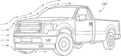
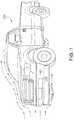
- FIG. 1shows a vehicle including a front air dam
- FIG. 2shows an active air deflector according to the present disclosure
- FIG. 3shows in isolation an air deflector-mounted rail and cooperating vehicle-mounted track for the active air deflector if FIG. 2 ;
- FIG. 4shows a linear actuator for actuating the air deflector for vertical translation by the rail and cooperating track of FIG. 3 ;
- FIG. 5is a schematic depiction of an airflow control assembly according to the present disclosure.
- FIG. 6is a schematic depiction of a control system for the airflow control assembly of FIG. 5 ;
- FIG. 7is a flow chart depicting control logic for controlling the airflow control assembly of FIG. 5 via the control system of FIG. 6 .
- the present disclosuredescribes a vehicle air deflector primarily in the context of a front-mounted air deflector for altering air flow beneath/around a vehicle chassis, specifically a front air dam.
- a front-mounted air deflectorfor altering air flow beneath/around a vehicle chassis, specifically a front air dam.
- the disclosed systems and devicesare readily adaptable to other types of vehicle air deflector, including without intending any limitation fender flares, side skirt cribs, top and/or rear spoilers, and others. Application of the presently described devices and systems to all such embodiments is contemplated herein.
- FIG. 2there is shown a vehicle air deflector assembly 200 according to the present disclosure, associated with a vehicle bumper 202 .
- the assembly 200includes a driver 204 configured to actuate a plurality of linear actuators 206 in series, i.e. as a unit, to vertically translate an air deflector 208 (arrows A).
- the air deflectoris configured for vertical translation by one or more air deflector-mounted rails 210 configured to be slidingly received by one or more cooperating vehicle mounted tracks (not shown in this view).
- the air deflector-mounted rails 210are configured as T-channel sliders, and the vehicle-mounted tracks define cooperating female receivers therefore on a vehicle surface, for example cooperating tracks 300 associated with the vehicle belly pan 302 .
- cooperating tracks 300associated with the vehicle belly pan 302 .
- other configurations for rails 210 and tracks 300are possible, and contemplated for use herein.
- each linear actuator 206includes a piston head 400 coupled to a drive shaft 402 which in turn is operationally coupled to the air deflector 208 .
- the piston head 400is received in an interior chamber 404 such that an upper chamber 406 and a lower chamber 408 are defined.
- the upper chamber 406includes an inlet 410 a and the lower chamber 408 includes an inlet 410 b , allowing placing the upper and lower chambers 406 , 408 in fluid operational communication with the driver 204 (not shown in this view).
- supplying a driving fluid to the upper chamber 406 via inlet 410 awill displace the piston head 400 downwardly, causing the air deflector 208 to deploy by likewise translating vertically downwardly.
- supplying a driving fluid to the lower chamber 408 via inlet 410 bwill displace the piston head 400 upwardly, causing the air deflector 208 to retract by likewise translating vertically upwardly.
- the piston head 400may include a seal 412 for controlling a fluid leakage between upper chamber 406 and lower chamber 408 .
- a seal 412is selected which allows a limited fluid leakage between upper chamber 406 and lower chamber 408 , which as will be appreciated provides a self-bleeding function to remove air from the high pressure side of the piston head 400 .
- driver 204is a fluid driver such as a reversible hydraulic pump supplied by a reservoir 500 with a suitable hydraulic fluid 502 .
- the reversible hydraulic pump driver 204includes two fluid outlets 504 a , 504 b .
- Fluid outlet 504 ais in serial fluid communication with each actuator inlet 410 a
- fluid outlet 504 bis in serial fluid communication with each actuator inlet 410 b , such as by suitable hoses 506 .
- the hydraulic pump 204 motormay be actuated in a first direction to supply fluid to hydraulic actuators upper chambers 406 to vertically translate piston head 400 and thereby air deflector 208 downwardly.
- fluidis supplied to hydraulic actuators lower chambers 408 to vertically translate piston head 400 and thereby air deflector 208 upwardly.
- the controller 604is provided with logic for controlling operation of the driver 204 according to a variety of inputs.
- the logicmay include computer-executable instructions for operating the driver 204 in a first direction and in a second direction based on an input from a vehicle system 606 .
- the controller 604is configured for receiving an input from the vehicle speedometer 606 .
- the controller 604on receiving the input from the speedometer 606 that the predetermined speed has been reached or exceeded issues a signal to the driver 204 to perform a predetermined operation of actuating the linear actuators 206 to vertically translate the air deflector 208 (not shown in this view) as needed.
- a representative control logic 700 flowis shown in FIG. 7 .
- deployment of the air deflector 208is controlled by a vehicle 100 speed, and therefore the configuration of the control system 600 is substantially as depicted in FIG. 6 .
- a Start pointfor example when the vehicle 100 motor is started, the system is activated.
- a determinationis made whether the vehicle 100 is traveling at a first preset speed, such as by input provided from the speedometer 606 to the controller 604 . If so, at step 704 a command is issued leading to a delayed deployment of the air deflector 208 , for example by initiating a 10 second timer included in the controller 604 logic.
- the first preset speedcould be 40 miles/hour, indicative that the vehicle is accelerating to a speed wherein deployment of an air dam 208 would be beneficial to fuel economy, motor cooling, etc.
- logic 700may include a step 706 of determining whether the vehicle 100 is traveling at a second preset speed, such as by input provided from the speedometer 606 to the controller 604 . If not, the timer initiated at step 704 continues to run. If so, at step 708 a command is issued causing deployment of the air deflector 208 .
- the deployment of air deflector 208occurs by a command issued by controller 604 actuating driver 204 to supply fluid to first chambers 406 of linear actuators 206 via inlets 410 a , thus causing deployment of air deflector 208 as described above.
- the second preset speedcould be 50 miles/hour, being a speed at which it has been determined that deployment of an air dam 208 would be beneficial to fuel economy, motor cooling, etc.
- the system 700is configured to retract the air deflector 208 at need.
- a determinationis made whether the vehicle 100 speed has decreased to at or below the second preset speed, again such as by input provided from the speedometer 606 to the controller 604 . If not, the air deflector 208 remains deployed. If so, at step 712 a command is issued leading to a delayed retraction of the air deflector 208 , for example by initiating a 10 second timer included in the controller 604 logic.
- logic 700may include a step 714 of determining whether the vehicle 100 speed has decreased to at or below the first preset speed, again such as by input provided from the speedometer 606 to the controller 604 . If not, the timer initiated at step 712 continues to run. If so, at step 716 a command is issued causing retraction of the air deflector 208 . As will be appreciated, the retraction of air deflector 208 occurs by a command issued by controller 604 actuating driver 204 to supply fluid to second chambers 408 of linear actuators 206 via inlets 410 b , thus causing retraction of air deflector 208 as described above.
- Vehicle 100 speed decreasing to the first preset speedwould serve as an indicator that the vehicle has encountered rough ground necessitating retraction of the air deflector 208 .
- the first preset speedit may have been determined that deployment of the air deflector is not beneficial.
- the above parametersare presented as examples only, and are not to be taken as limiting.
- the first and second preset speeds, the timer delays, etc.can be adjusted as needed in accordance with the vehicle type, capacity of the driver 204 and air deflector 208 , and in accordance with other parameters.
- an airflow control assembly and systemare provided for raising and lowering of an air deflector in accordance with a vehicle speed and other parameters.
- the systemis simple, robust, and efficient, requiring only a single driver 204 for operation and controllable from existing vehicle controllers provided input from existing vehicle systems such as the speedometer.
- Obvious modifications and variationsare possible in light of the above teachings. All such modifications and variations are within the scope of the appended claims when interpreted in accordance with the breadth to which they are fairly, legally and equitably entitled.
Landscapes
- Engineering & Computer Science (AREA)
- Chemical & Material Sciences (AREA)
- Combustion & Propulsion (AREA)
- Transportation (AREA)
- Mechanical Engineering (AREA)
- Physics & Mathematics (AREA)
- Fluid Mechanics (AREA)
- Cooling, Air Intake And Gas Exhaust, And Fuel Tank Arrangements In Propulsion Units (AREA)
- Vehicle Body Suspensions (AREA)
- Lighting Device Outwards From Vehicle And Optical Signal (AREA)
Abstract
Description
Claims (10)
Priority Applications (4)
| Application Number | Priority Date | Filing Date | Title |
|---|---|---|---|
| US15/073,835US11072378B2 (en) | 2016-03-18 | 2016-03-18 | Active air dam |
| DE202017101183.6UDE202017101183U1 (en) | 2016-03-18 | 2017-03-02 | Active air deflector |
| MX2017003581AMX2017003581A (en) | 2016-03-18 | 2017-03-17 | Active air dam. |
| CN201710160747.7ACN107200071B (en) | 2016-03-18 | 2017-03-17 | Active guide plate |
Applications Claiming Priority (1)
| Application Number | Priority Date | Filing Date | Title |
|---|---|---|---|
| US15/073,835US11072378B2 (en) | 2016-03-18 | 2016-03-18 | Active air dam |
Publications (2)
| Publication Number | Publication Date |
|---|---|
| US20170267294A1 US20170267294A1 (en) | 2017-09-21 |
| US11072378B2true US11072378B2 (en) | 2021-07-27 |
Family
ID=58722415
Family Applications (1)
| Application Number | Title | Priority Date | Filing Date |
|---|---|---|---|
| US15/073,835Active2038-09-20US11072378B2 (en) | 2016-03-18 | 2016-03-18 | Active air dam |
Country Status (4)
| Country | Link |
|---|---|
| US (1) | US11072378B2 (en) |
| CN (1) | CN107200071B (en) |
| DE (1) | DE202017101183U1 (en) |
| MX (1) | MX2017003581A (en) |
Cited By (1)
| Publication number | Priority date | Publication date | Assignee | Title |
|---|---|---|---|---|
| US20220130183A1 (en)* | 2020-10-23 | 2022-04-28 | Ford Global Technologies, Llc | Active air dam notification method and system |
Families Citing this family (4)
| Publication number | Priority date | Publication date | Assignee | Title |
|---|---|---|---|---|
| US10315711B2 (en)* | 2017-07-25 | 2019-06-11 | Gm Global Technology Operations Llc. | Vehicle ride-height dependent control of air deflector |
| DE102018213251A1 (en)* | 2018-08-07 | 2020-02-13 | Röchling Automotive SE & Co. KG | Motor vehicle with synchronously operable actuators |
| JP7153238B2 (en)* | 2019-03-27 | 2022-10-14 | いすゞ自動車株式会社 | bumper skirt |
| CN114852197B (en)* | 2022-06-02 | 2023-03-14 | 岚图汽车科技有限公司 | Control method and system of front wheel spoiler |
Citations (31)
| Publication number | Priority date | Publication date | Assignee | Title |
|---|---|---|---|---|
| DE3145258A1 (en)* | 1981-11-14 | 1983-05-19 | Daimler-Benz Ag, 7000 Stuttgart | Front spoiler for motor vehicles |
| US4457558A (en)* | 1981-04-22 | 1984-07-03 | Aisin Seiki Kabushiki Kaisha | Up and down moving mechanism for an air spoiler associated with a movable grill |
| US4659130A (en)* | 1982-12-10 | 1987-04-21 | Alfa Romeo Auto S.P.A. | Automatically positionable spoiler for a motor vehicle |
| US4758037A (en)* | 1985-03-29 | 1988-07-19 | Nissan Motor Company, Limited | Movable front spoiler device for automotive vehicle |
| US4770457A (en) | 1986-04-19 | 1988-09-13 | Daimler-Benz Aktiengesellschaft | Lowerable underfloor panel for the front end of motor vehicles |
| US4778212A (en)* | 1986-04-19 | 1988-10-18 | Daimler-Benz Aktiengesellschaft | Motor vehicle front bumper molding with air spoiler |
| US4810022A (en)* | 1984-04-04 | 1989-03-07 | Nissan Motor Company, Limited | Automotive vehicle with adjustable aerodynamic accessory and control therefor |
| FR2626544A1 (en)* | 1988-02-03 | 1989-08-04 | Llansola Jose | Movable wind cutter (spoiler) for a vehicle |
| FR2698446A1 (en)* | 1992-11-24 | 1994-05-27 | Peugeot | Speed sensor for motor vehicle with movable front spoiler - uses movement of pivoted deflector to actuate hydraulic cylinder in proportion to vehicle speed, with movement of front spoiler controlling extension of rear spoiler |
| US6079769A (en) | 1999-03-01 | 2000-06-27 | Fannin; Dawn B. | Retractable air turbulence device for vehicles |
| US6089628A (en)* | 1998-09-02 | 2000-07-18 | Ford Global Technologies, Inc. | Stiffener assembly for bumper system of motor vehicles |
| US6209947B1 (en)* | 1998-01-02 | 2001-04-03 | Daimlerchrysler Corporation | Adjustable aerodynamic system for a motor vehicle |
| WO2006052447A2 (en) | 2004-11-05 | 2006-05-18 | General Motors Corporation | Control logic for fluid flow control devices |
| US7178859B2 (en) | 2003-12-04 | 2007-02-20 | General Motors Corporation | Method for controlling airflow |
| US20080303309A1 (en) | 2005-04-21 | 2008-12-11 | Roderick Dayton | Vehicle Air Dam System |
| US7686383B2 (en) | 2008-08-27 | 2010-03-30 | Gm Global Technology Operations, Inc. | Retractable curved air dam |
| US7780223B2 (en) | 2007-08-09 | 2010-08-24 | Bayerische Motoren Werke Aktiengesellschaft | Aerodynamically activated front skirt for a vehicle |
| US20120001450A1 (en)* | 2010-06-30 | 2012-01-05 | Gm Global Technology Operations, Inc. | Air dam deployment and retraction system |
| US8292350B2 (en)* | 2010-04-26 | 2012-10-23 | GM Global Technology Operations LLC | Inflatable vehicle air dam with bidirectional deploy/stow system |
| US20120330513A1 (en)* | 2011-06-24 | 2012-12-27 | Gm Global Technology Operations Llc. | Air dam actuation system |
| US8646552B2 (en)* | 2010-07-21 | 2014-02-11 | Shape Corp. | Integrated energy absorber and air flow management structure |
| US20140076645A1 (en)* | 2012-09-14 | 2014-03-20 | GM Global Technology Operations LLC | Stow-away air dam |
| US8702152B1 (en)* | 2013-01-11 | 2014-04-22 | Ford Global Technologies, Llc | Deployable front air dam |
| US9102366B1 (en)* | 2014-05-02 | 2015-08-11 | Hyundai Motor Company | Front spoiler apparatus for vehicle |
| WO2015124281A1 (en) | 2014-02-20 | 2015-08-27 | Daimler Ag | Bumper assembly for a commercial vehicle |
| US20160229467A1 (en)* | 2015-02-10 | 2016-08-11 | Ford Global Technologies, Llc | Compact efficient system to quickly raise and slowly lower an air dam |
| US9469354B1 (en)* | 2015-06-29 | 2016-10-18 | Ford Global Technologies, Llc | Airfoil with adjustable tail flap |
| US20170088193A1 (en)* | 2015-09-25 | 2017-03-30 | GM Global Technology Operations LLC | Aerodynamic system and method for diagnosing the aerodynamic system and verify downforce estimation based on electric motor current |
| US20170101136A1 (en)* | 2014-06-11 | 2017-04-13 | Magna Exteriors Inc. | Active front deflector |
| US20170120967A1 (en)* | 2015-10-30 | 2017-05-04 | Hyundai Motor Company | Active air skirt device for vehicle |
| US9783153B2 (en)* | 2015-11-11 | 2017-10-10 | Ford Global Technologies, Llc | Bumper assembly including lower leg stiffener |
Family Cites Families (1)
| Publication number | Priority date | Publication date | Assignee | Title |
|---|---|---|---|---|
| CN204937284U (en)* | 2015-08-21 | 2016-01-06 | 武汉燎原模塑有限公司 | A kind of Federal bumper being integrated with spoiler structure |
- 2016
- 2016-03-18USUS15/073,835patent/US11072378B2/enactiveActive
- 2017
- 2017-03-02DEDE202017101183.6Upatent/DE202017101183U1/enactiveActive
- 2017-03-17CNCN201710160747.7Apatent/CN107200071B/enactiveActive
- 2017-03-17MXMX2017003581Apatent/MX2017003581A/enunknown
Patent Citations (31)
| Publication number | Priority date | Publication date | Assignee | Title |
|---|---|---|---|---|
| US4457558A (en)* | 1981-04-22 | 1984-07-03 | Aisin Seiki Kabushiki Kaisha | Up and down moving mechanism for an air spoiler associated with a movable grill |
| DE3145258A1 (en)* | 1981-11-14 | 1983-05-19 | Daimler-Benz Ag, 7000 Stuttgart | Front spoiler for motor vehicles |
| US4659130A (en)* | 1982-12-10 | 1987-04-21 | Alfa Romeo Auto S.P.A. | Automatically positionable spoiler for a motor vehicle |
| US4810022A (en)* | 1984-04-04 | 1989-03-07 | Nissan Motor Company, Limited | Automotive vehicle with adjustable aerodynamic accessory and control therefor |
| US4758037A (en)* | 1985-03-29 | 1988-07-19 | Nissan Motor Company, Limited | Movable front spoiler device for automotive vehicle |
| US4778212A (en)* | 1986-04-19 | 1988-10-18 | Daimler-Benz Aktiengesellschaft | Motor vehicle front bumper molding with air spoiler |
| US4770457A (en) | 1986-04-19 | 1988-09-13 | Daimler-Benz Aktiengesellschaft | Lowerable underfloor panel for the front end of motor vehicles |
| FR2626544A1 (en)* | 1988-02-03 | 1989-08-04 | Llansola Jose | Movable wind cutter (spoiler) for a vehicle |
| FR2698446A1 (en)* | 1992-11-24 | 1994-05-27 | Peugeot | Speed sensor for motor vehicle with movable front spoiler - uses movement of pivoted deflector to actuate hydraulic cylinder in proportion to vehicle speed, with movement of front spoiler controlling extension of rear spoiler |
| US6209947B1 (en)* | 1998-01-02 | 2001-04-03 | Daimlerchrysler Corporation | Adjustable aerodynamic system for a motor vehicle |
| US6089628A (en)* | 1998-09-02 | 2000-07-18 | Ford Global Technologies, Inc. | Stiffener assembly for bumper system of motor vehicles |
| US6079769A (en) | 1999-03-01 | 2000-06-27 | Fannin; Dawn B. | Retractable air turbulence device for vehicles |
| US7178859B2 (en) | 2003-12-04 | 2007-02-20 | General Motors Corporation | Method for controlling airflow |
| WO2006052447A2 (en) | 2004-11-05 | 2006-05-18 | General Motors Corporation | Control logic for fluid flow control devices |
| US20080303309A1 (en) | 2005-04-21 | 2008-12-11 | Roderick Dayton | Vehicle Air Dam System |
| US7780223B2 (en) | 2007-08-09 | 2010-08-24 | Bayerische Motoren Werke Aktiengesellschaft | Aerodynamically activated front skirt for a vehicle |
| US7686383B2 (en) | 2008-08-27 | 2010-03-30 | Gm Global Technology Operations, Inc. | Retractable curved air dam |
| US8292350B2 (en)* | 2010-04-26 | 2012-10-23 | GM Global Technology Operations LLC | Inflatable vehicle air dam with bidirectional deploy/stow system |
| US20120001450A1 (en)* | 2010-06-30 | 2012-01-05 | Gm Global Technology Operations, Inc. | Air dam deployment and retraction system |
| US8646552B2 (en)* | 2010-07-21 | 2014-02-11 | Shape Corp. | Integrated energy absorber and air flow management structure |
| US20120330513A1 (en)* | 2011-06-24 | 2012-12-27 | Gm Global Technology Operations Llc. | Air dam actuation system |
| US20140076645A1 (en)* | 2012-09-14 | 2014-03-20 | GM Global Technology Operations LLC | Stow-away air dam |
| US8702152B1 (en)* | 2013-01-11 | 2014-04-22 | Ford Global Technologies, Llc | Deployable front air dam |
| WO2015124281A1 (en) | 2014-02-20 | 2015-08-27 | Daimler Ag | Bumper assembly for a commercial vehicle |
| US9102366B1 (en)* | 2014-05-02 | 2015-08-11 | Hyundai Motor Company | Front spoiler apparatus for vehicle |
| US20170101136A1 (en)* | 2014-06-11 | 2017-04-13 | Magna Exteriors Inc. | Active front deflector |
| US20160229467A1 (en)* | 2015-02-10 | 2016-08-11 | Ford Global Technologies, Llc | Compact efficient system to quickly raise and slowly lower an air dam |
| US9469354B1 (en)* | 2015-06-29 | 2016-10-18 | Ford Global Technologies, Llc | Airfoil with adjustable tail flap |
| US20170088193A1 (en)* | 2015-09-25 | 2017-03-30 | GM Global Technology Operations LLC | Aerodynamic system and method for diagnosing the aerodynamic system and verify downforce estimation based on electric motor current |
| US20170120967A1 (en)* | 2015-10-30 | 2017-05-04 | Hyundai Motor Company | Active air skirt device for vehicle |
| US9783153B2 (en)* | 2015-11-11 | 2017-10-10 | Ford Global Technologies, Llc | Bumper assembly including lower leg stiffener |
Cited By (2)
| Publication number | Priority date | Publication date | Assignee | Title |
|---|---|---|---|---|
| US20220130183A1 (en)* | 2020-10-23 | 2022-04-28 | Ford Global Technologies, Llc | Active air dam notification method and system |
| US11651629B2 (en)* | 2020-10-23 | 2023-05-16 | Ford Global Technologies, Llc | Active air dam notification method and system |
Also Published As
| Publication number | Publication date |
|---|---|
| CN107200071B (en) | 2022-05-10 |
| MX2017003581A (en) | 2018-08-16 |
| DE202017101183U1 (en) | 2017-04-27 |
| CN107200071A (en) | 2017-09-26 |
| US20170267294A1 (en) | 2017-09-21 |
Similar Documents
| Publication | Publication Date | Title |
|---|---|---|
| US11072378B2 (en) | Active air dam | |
| US8702152B1 (en) | Deployable front air dam | |
| US10384730B2 (en) | Electronic active air dam | |
| US11772722B2 (en) | Active diffuser mechanism | |
| CN108146518B (en) | Active tire spoiler system and method | |
| US9932074B2 (en) | Active vehicle skirt panel and the method of controlling the same | |
| US10589804B2 (en) | Rear diffuser system for an automotive vehicle | |
| US20160244107A1 (en) | Aerodynamic control device of a mobile body | |
| US9481407B2 (en) | Drag reduction system | |
| JP6549696B2 (en) | Change the aerodynamic performance of the vehicle | |
| JP2017531590A (en) | Vehicle airflow control device | |
| US20180009450A1 (en) | System for Repositioning Weight in Response to Vehicle Speed | |
| KR20090108554A (en) | Vehicle with roof device | |
| CN104843092A (en) | Automobile tail part double-turbulence device | |
| CN203439006U (en) | Lateral sliding prevention auxiliary braking device for automobile on ice snow covered pavement | |
| RU2391243C1 (en) | Car body rear | |
| CN104986230A (en) | Automobile downward pressure adjusting device | |
| CN104908826A (en) | Auxiliary regulating device of travelling airflow | |
| CN104875795A (en) | Rear diffuser structure for vehicular body | |
| US10875588B2 (en) | Active deck-lid spoiler control system for a motor vehicle | |
| CN107839769B (en) | Front flow guiding device | |
| CN104828158A (en) | Adjustable turbulent flow system | |
| WO2015124281A1 (en) | Bumper assembly for a commercial vehicle | |
| EP1905674A1 (en) | System for controlling and managing the actions of inflation and deflation of inflatable spoilers for an industrial vehicle | |
| RU149359U1 (en) | EXTENDABLE FRONT SPOILER FOR VEHICLE |
Legal Events
| Date | Code | Title | Description |
|---|---|---|---|
| AS | Assignment | Owner name:FORD GLOBAL TECHNOLOGIES, LLC, MICHIGAN Free format text:ASSIGNMENT OF ASSIGNORS INTEREST;ASSIGNORS:KLOP, AARON PETER;NESS, KYLE;REEL/FRAME:038077/0102 Effective date:20160315 | |
| STCV | Information on status: appeal procedure | Free format text:APPEAL BRIEF (OR SUPPLEMENTAL BRIEF) ENTERED AND FORWARDED TO EXAMINER | |
| STCV | Information on status: appeal procedure | Free format text:EXAMINER'S ANSWER TO APPEAL BRIEF MAILED | |
| STCV | Information on status: appeal procedure | Free format text:APPEAL AWAITING BPAI DOCKETING Free format text:ON APPEAL -- AWAITING DECISION BY THE BOARD OF APPEALS | |
| STPP | Information on status: patent application and granting procedure in general | Free format text:AMENDMENT / ARGUMENT AFTER BOARD OF APPEALS DECISION | |
| STPP | Information on status: patent application and granting procedure in general | Free format text:NOTICE OF ALLOWANCE MAILED -- APPLICATION RECEIVED IN OFFICE OF PUBLICATIONS | |
| STPP | Information on status: patent application and granting procedure in general | Free format text:PUBLICATIONS -- ISSUE FEE PAYMENT RECEIVED | |
| STPP | Information on status: patent application and granting procedure in general | Free format text:PUBLICATIONS -- ISSUE FEE PAYMENT VERIFIED | |
| STCF | Information on status: patent grant | Free format text:PATENTED CASE | |
| MAFP | Maintenance fee payment | Free format text:PAYMENT OF MAINTENANCE FEE, 4TH YEAR, LARGE ENTITY (ORIGINAL EVENT CODE: M1551); ENTITY STATUS OF PATENT OWNER: LARGE ENTITY Year of fee payment:4 |