US11071869B2 - Implantable device having removable portion - Google Patents
Implantable device having removable portionDownload PDFInfo
- Publication number
- US11071869B2 US11071869B2US15/336,662US201615336662AUS11071869B2US 11071869 B2US11071869 B2US 11071869B2US 201615336662 AUS201615336662 AUS 201615336662AUS 11071869 B2US11071869 B2US 11071869B2
- Authority
- US
- United States
- Prior art keywords
- implantable
- magnet
- coil
- coil assembly
- stimulator unit
- Prior art date
- Legal status (The legal status is an assumption and is not a legal conclusion. Google has not performed a legal analysis and makes no representation as to the accuracy of the status listed.)
- Active, expires
Links
Images


Classifications
- A—HUMAN NECESSITIES
- A61—MEDICAL OR VETERINARY SCIENCE; HYGIENE
- A61N—ELECTROTHERAPY; MAGNETOTHERAPY; RADIATION THERAPY; ULTRASOUND THERAPY
- A61N1/00—Electrotherapy; Circuits therefor
- A61N1/18—Applying electric currents by contact electrodes
- A61N1/32—Applying electric currents by contact electrodes alternating or intermittent currents
- A61N1/36—Applying electric currents by contact electrodes alternating or intermittent currents for stimulation
- A61N1/372—Arrangements in connection with the implantation of stimulators
- A61N1/375—Constructional arrangements, e.g. casings
- A—HUMAN NECESSITIES
- A61—MEDICAL OR VETERINARY SCIENCE; HYGIENE
- A61N—ELECTROTHERAPY; MAGNETOTHERAPY; RADIATION THERAPY; ULTRASOUND THERAPY
- A61N1/00—Electrotherapy; Circuits therefor
- A61N1/18—Applying electric currents by contact electrodes
- A61N1/32—Applying electric currents by contact electrodes alternating or intermittent currents
- A61N1/36—Applying electric currents by contact electrodes alternating or intermittent currents for stimulation
- A61N1/36036—Applying electric currents by contact electrodes alternating or intermittent currents for stimulation of the outer, middle or inner ear
- A61N1/36038—Cochlear stimulation
- A—HUMAN NECESSITIES
- A61—MEDICAL OR VETERINARY SCIENCE; HYGIENE
- A61N—ELECTROTHERAPY; MAGNETOTHERAPY; RADIATION THERAPY; ULTRASOUND THERAPY
- A61N1/00—Electrotherapy; Circuits therefor
- A61N1/18—Applying electric currents by contact electrodes
- A61N1/32—Applying electric currents by contact electrodes alternating or intermittent currents
- A61N1/36—Applying electric currents by contact electrodes alternating or intermittent currents for stimulation
- A61N1/372—Arrangements in connection with the implantation of stimulators
- A61N1/37211—Means for communicating with stimulators
- A61N1/37217—Means for communicating with stimulators characterised by the communication link, e.g. acoustic or tactile
- A61N1/37223—Circuits for electromagnetic coupling
- A—HUMAN NECESSITIES
- A61—MEDICAL OR VETERINARY SCIENCE; HYGIENE
- A61N—ELECTROTHERAPY; MAGNETOTHERAPY; RADIATION THERAPY; ULTRASOUND THERAPY
- A61N1/00—Electrotherapy; Circuits therefor
- A61N1/02—Details
- A61N1/08—Arrangements or circuits for monitoring, protecting, controlling or indicating
- A—HUMAN NECESSITIES
- A61—MEDICAL OR VETERINARY SCIENCE; HYGIENE
- A61N—ELECTROTHERAPY; MAGNETOTHERAPY; RADIATION THERAPY; ULTRASOUND THERAPY
- A61N1/00—Electrotherapy; Circuits therefor
- A61N1/18—Applying electric currents by contact electrodes
- A61N1/32—Applying electric currents by contact electrodes alternating or intermittent currents
- A61N1/36—Applying electric currents by contact electrodes alternating or intermittent currents for stimulation
- A61N1/362—Heart stimulators
- A61N1/37—Monitoring; Protecting
- A61N1/3718—Monitoring of or protection against external electromagnetic fields or currents
- A—HUMAN NECESSITIES
- A61—MEDICAL OR VETERINARY SCIENCE; HYGIENE
- A61N—ELECTROTHERAPY; MAGNETOTHERAPY; RADIATION THERAPY; ULTRASOUND THERAPY
- A61N1/00—Electrotherapy; Circuits therefor
- A61N1/18—Applying electric currents by contact electrodes
- A61N1/32—Applying electric currents by contact electrodes alternating or intermittent currents
- A61N1/36—Applying electric currents by contact electrodes alternating or intermittent currents for stimulation
- A61N1/372—Arrangements in connection with the implantation of stimulators
- A61N1/37211—Means for communicating with stimulators
- A61N1/37217—Means for communicating with stimulators characterised by the communication link, e.g. acoustic or tactile
- A61N1/37223—Circuits for electromagnetic coupling
- A61N1/37229—Shape or location of the implanted or external antenna
Definitions
- Hearing losswhich can be due to many different causes, is generally of two types: conductive and sensorineural. In many people who are profoundly deaf, the reason for their deafness is sensorineural hearing loss. Those suffering from some forms of sensorineural hearing loss are unable to derive suitable benefit from auditory prostheses that generate mechanical motion of the cochlea fluid. Such individuals can benefit from implantable auditory prostheses that stimulate nerve cells of the recipient's auditory system in other ways (e.g., electrical, optical, and the like). Cochlear implants are often proposed when the sensorineural hearing loss is due to the absence or destruction of the cochlea hair cells, which transduce acoustic signals into nerve impulses. Auditory brainstem implants might also be proposed when a recipient experiences sensorineural hearing loss if the auditory nerve, which sends signals from the cochlear to the brain, is severed or not functional.
- Conductive hearing lossoccurs when the normal mechanical pathways that provide sound to hair cells in the cochlea are impeded, for example, by damage to the ossicular chain or the ear canal. Individuals suffering from conductive hearing loss can retain some form of residual hearing because some or all of the hair cells in the cochlea function normally.
- a hearing aidtypically uses an arrangement positioned in the recipient's ear canal or on the outer ear to amplify a sound received by the outer ear of the recipient. This amplified sound reaches the cochlea causing motion of the perilymph and stimulation of the auditory nerve.
- Bone conduction devicesIn contrast to conventional hearing aids, which rely primarily on the principles of air conduction, certain types of hearing prostheses commonly referred to as bone conduction devices, convert a received sound into vibrations. The vibrations are transferred through the skull to the cochlea causing motion of the perilymph and stimulation of the auditory nerve, which results in the perception of the received sound. Bone conduction devices are suitable to treat a variety of types of hearing loss and can be suitable for individuals who cannot derive sufficient benefit from conventional hearing aids.
- Implantable medical devicessuch as auditory prostheses, often utilize an implanted component and an external component. Both components can include a magnet so as to hold the external component proximate the implanted component. The implanted magnet can interfere with MRI procedures. The medical devices described herein allow for the complete removal of a portion of the implantable component that contains the magnet.
- FIG. 1is a partial view of a behind-the-ear auditory prosthesis worn on a recipient.
- FIG. 2is a side view of an example of an implantable portion of an auditory prosthesis.
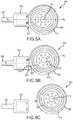
- FIGS. 3A-3Dare partial top views of implantable portions of cochlear implants in accordance with examples of the technology.
- FIG. 4is a partial side sectional view of an implantable coil assembly of a cochlear implant in accordance with an example of the technology.
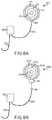
- FIGS. 5A-5Cdepict a method of disconnecting an implantable coil assembly to an implantable stimulator unit, in vivo.
- FIG. 6is a partial top view of an implantable portion of a cochlear implant in accordance with another example of the technology.
- FIG. 7is a partial top view of an implantable portion of a cochlear implant in accordance with another example of the technology.
- FIGS. 8A and 8Bare examples of implantable auditory prostheses.
- FIG. 9depicts a method of replacing, in vivo, a portion of an implanted medical device.
- the technologies described hereincan typically be utilized with auditory prostheses such as cochlear implants. Such devices utilize one or more magnets disposed in an external portion of the cochlear implant. The magnetic field of this external magnet interacts with a magnetic field of a magnet disposed in an implanted portion of the cochlear implant.
- the technologies disclosed hereincan have further application in other types of medical device implanted in a recipient.
- other types of auditory prosthesessuch as transcutaneous bone conduction devices, totally implantable cochlear implants, and direct acoustic stimulators utilize a similar configuration where a magnet is implanted below the skin of a recipient. Accordingly, the technologies described herein can be similarly leveraged in such devices.
- the technologies described hereincan also be utilized in medical devices having certain components that can require removal (and replacement) at some point after implantation. For clarity, however, the technologies will be described in the context of cochlear implants.
- One advantage to medical devices constructed in accordance with the following disclosureis that a portion of the device containing the magnet can be easily removed after implantation. This is particularly useful when a recipient of, e.g., a cochlear implant, must undergo an MRI procedure.
- a key issue in preforming MRI on a patient with an implanted medical device magnetis that the strong magnetic field applied by the MRI exerts a significant torque on the implanted magnet, regardless of magnet implantation location. For example, the torque exerted on a typical cochlear implant magnet in a 3T MRI machine is up to about 0.38 Nm. If the implanted magnet is inadequately constrained, the magnet can become dislodged, causing pain and potentially requiring surgery to correct.
- the magnetdistorts the MRI magnetic field and causes a large image artifact.
- the image artifact for a cochlear implant with magnetis typically about 100 mm. As such, when imaging the head it can be very desirable to remove the magnet.
- the technologies described hereinmay be leveraged to allow for replacement of existing components (e.g., due to damage or failure) or as desired to upgrade certain components.
- cochlear implant system 100includes an implantable component 144 typically having an internal receiver/transceiver unit 132 , a stimulator unit 120 , and an elongate lead 118 .
- the internal receiver/transceiver unit 132permits the cochlear implant system 110 to receive and/or transmit signals to an external device.
- the external devicecan be a button sound processor worn on the head that includes a receiver/transceiver coil and sound processing components. Alternatively, the external device can be just a receiver/transceiver coil in communication with a BTE device that includes the sound processing components and microphone.
- the implantable component 144includes an internal coil 136 , and preferably, a magnet (not shown) fixed relative to the internal coil 136 .
- the magnetis embedded in a pliable silicone or other biocompatible encapsulant, along with the internal coil 136 . Signals sent generally correspond to external sound 113 .
- Internal receiver unit 132 and stimulator unit 120are hermetically sealed within a biocompatible housing, sometimes collectively referred to as a stimulator/receiver unit.
- the magnetsfacilitate the operational alignment of the external and internal coils, enabling internal coil 136 to receive power and stimulation data from external coil 130 .
- the external coil 130is contained within an external portion.
- Elongate lead 118has a proximal end connected to stimulator unit 120 , and a distal end implanted in cochlea 140 . Elongate lead 118 extends from stimulator unit 120 to cochlea 140 through mastoid bone 119 .
- external coil 130transmits electrical signals (e.g., power and stimulation data) to internal coil 136 via a radio frequency (RF) link, as noted above.
- Internal coil 136is typically a wire antenna coil comprised of multiple turns of electrically insulated single-strand or multi-strand platinum or gold wire. The electrical insulation of internal coil 136 is provided by a flexible silicone molding.
- Various types of energy transfersuch as infrared (IR), electromagnetic, capacitive and inductive transfer, can be used to transfer the power and/or data from external device to cochlear implant.
- FIG. 2is a simplified side view of an internal component 244 having a stimulator/receiver unit 202 which receives encoded signals from an external component of the cochlear implant system. More specifically, the stimulator/receiver unit 202 includes an implantable stimulator unit or portion 222 and an implantable coil assembly or portion 224 . Signals sent from an external sound processor (as described above) are received by a radio frequency induction coil 226 disposed within a polymer encapsulant 228 of the coil portion 224 .
- the encapsulant 228is a pliable biocompatible material (e.g., silicone) that displays flexibility sufficient to allow the coil assembly to substantially conform to the skull when implanted.
- a magnet chassis 232is permanently embedded in the encapsulant 228 and contains therein a retention magnet (not shown). This magnet magnetically engages with an external magnet disposed on an external device that also includes a radio frequency induction coil. Signals, such as those corresponding to detected sound, are sent between the external coil and the implanted coil 226 . These signals are processed by the stimulator unit 222 and sent as stimuli to the cochlear, via the remaining components of the internal component 244 , as described below.
- the stimulator unit 222 and the coil portion 224are releasably connected at an interface 234 .
- the configuration of the connection elements at the interface 234enables flexibility at the interface 234 , which allows the stimulator/receiver unit 202 to more easily conform to the skull.
- the coil portion 224defines a coil portion axis A C
- the stimulator unit 222defines a simulator unit axis A S .
- these axes A C , A Scan be substantially parallel or aligned or misaligned by a small angle, for example about 10 to about 15 degrees, prior to implantation. After implantation, however, the axes A C , A S can deflect, such that an implantation angle ⁇ is formed by the axes A C , A S .
- Internal component 244terminates in a stimulating assembly 218 that comprises an extra-cochlear region 210 and an intra-cochlear region 212 .
- Intra-cochlear region 212is configured to be implanted in the recipient's cochlea and has disposed thereon a contact array 216 .
- contact array 216comprises electrical contacts 230 .
- the extra-cochlear region 210 and the intra-cochlear region 212form a stimulating assembly 218 .
- Internal component 244further comprises a lead region 208 coupling stimulator/receiver unit 202 to stimulating assembly 218 .
- Lead region 208comprises a region 204 which is commonly referred to as a helix region, however, the required property is that the lead accommodate movement and is flexible, it does not need to be formed from wire wound helically.
- Lead regionalso comprises a transition region 206 which connects helix region 204 to stimulating assembly 218 .
- electrical stimulation signals generated by stimulator/receiver unit 202are delivered to contact array 216 via lead region 208 .
- Helix region 204prevents lead region 208 and its connection to stimulator/receiver 202 and stimulating assembly 218 from being damaged due to movement of internal component 244 (or part of 244 ) which can occur, for example, during mastication.
- FIGS. 3A-3Care partial top views of implantable portions of cochlear implants 300 A-D in accordance with examples of the technology and are generally described simultaneously.
- the stimulator units 302 A-Dinclude electronics and a hermetic enclosure therearound, typically made of titanium, ceramic or a biocompatible polymer (such as PEEK), which encases the electronics of the stimulator units 302 A-D.
- Coil assemblies or portions 304 A-Dare also depicted.
- a portion of helix regions 306 A-Dis depicted, but is described in further detail elsewhere herein.
- the hermetic enclosures containing the stimulator units 302 A-Dare encased in a pliable, biocompatible encapsulant 308 A-D, such as silicone.
- Leads 310 A-Dare in electrical communication with the stimulator units 302 A-D.
- the coil assemblies 304 A-Dinclude radio frequency induction coils 312 A-D that are configured to wirelessly receive signals from an external portion of a cochlear implant, as described above.
- Leads 314 A-Dare in electrical communication with the induction coils 312 A-D.
- magnet chasses 316 A-Dare permanently embedded in the coil assemblies 304 A-D, more specifically within the biocompatible polymer encapsulant 318 A-D that forms a body of the coil assemblies 304 A-D.
- the illustrated magnet chasses 316 A-Dinclude therein a number of through-holes 322 A-D.
- Magnets 320 A-Dare disposed in the chasses 316 A-D.
- the stimulator units 302 A-D and coil assemblies 304 A-Dare releasably connected at junctions or interfaces 324 A-D at structures described generally as connectors, connector elements, or connector parts. These connectors releasably connect the stimulator units 302 A-D to the coil assemblies 304 A-D. As such, when connected via the connectors, the stimulator units 302 A-D are in electrical communication with the coil assemblies 304 A-D, can receive signals sent therefrom, and can send stimuli corresponding to such signals to the recipient.
- Various connectors, connection elements, or connector parts disposed at these interfaces 324 A-Dare described below.
- connection elementsare depicted and described in U.S. Pat. Nos. 7,844,329; 7,822,479; and 6,517,476, the disclosures of which are hereby incorporated by reference herein in their entireties. Connectors manufactured by Bal Seal Engineering, Inc., of Foothill Collins, Calif., are also contemplated. In each of FIGS. 3A-3C , two connection elements are disposed at the interfaces 324 A-C, but a single element can be used if required or desired.
- discrete connector elements or parts 326 Aare disposed at the interface 324 A.
- the connector elements 326 Aeach include a conductive path 328 A that is coupled to both of the leads 310 A, 314 A.
- the connector elements 326 Acan be sleeves or sheaths discrete from both the stimulator unit encapsulant 308 A and the coil assembly encapsulant 318 A.
- the conductive path 328 Acan be a conductive conduit or tube into which the leads 310 A, 314 A are inserted. In such a case, the conductive tube 328 A can have an inner diameter slightly smaller than the outer diameter of the leads 310 A, 314 A.
- the tube 328 Acan form an interference fit with the leads 310 A, 314 A that is sufficient to hold them in place without damage to the leads 310 A, 314 A. Later removal of the leads 310 A, 314 A from the tube 328 A can render the connector elements 326 A unusable, thereby requiring new connector elements 326 A, should reconnection of the stimulator unit 302 A and coil assembly 304 A be required or desired.
- the tube 328 Acan be crimped or deformed to as to be secured to the leads 310 A, 314 A.
- FIG. 3Bdepicts a different connector structure at the interface 324 B.
- a male connector element or part 330 Bextends from and is optionally integral with the coil assembly encapsulant 318 B.
- the leads 314 Bextend through the male connector element 330 B.
- a mating female connector element or part 332 Bcan extend from and be integral with the stimulation unit encapsulant 308 B.
- Either or both of the male connector element 330 B and the female connector element 332 Bcan include one or more engaging tabs, detents, recesses, teeth, washers, or other retention elements that enable the male connector element 330 B to be securely restrained within the female connector element 332 B. Certain of these retention elements can provide tactile or audible feedback (e.g., a “click” sound) to ensure a proper connection.
- FIG. 3Cdepicts a different connector structure at the interface 324 C.
- a male connector element or part 330 Cextends from and is optionally integral with the coil assembly encapsulant 318 C.
- the leads 314 Cextend through the male connector element 330 C.
- a mating female connector element or part 332 Cis formed within the stimulation unit encapsulant 308 C.
- either or both of the male connector element 330 C and the female connector element 332 Ccan include one or more engaging tabs, detents, recesses, teeth, washers, or other retention elements that enable to male connector element 330 C to be securely restrained within the female connector element 332 C. Certain of these retention elements can provide tactile or audible feedback to ensure a proper connection.
- the spacing between the stimulator unit 302 C and coil assembly 304 Ccan be minimal in the configuration of FIG. 3C . This can help prevent the growth of biofilm at the interface 324 C.
- Additional configurations to control or eliminate the growth of biofilmare known and can include the outer surfaces (upper, lower, perimeter, etc.) of the stimulator unit 302 C and coil assembly 304 C being formed with a smooth finish. Additionally, in configurations where the stimulator unit 302 C and the coil assembly 304 C abut each other, the abutments at the interfaces can be formed so as to reduce or eliminate discontinuities at the interface 324 C that can cause biofilm to forms.
- FIG. 3Ddepicts a different connector structure at the interface 324 D.
- a single male connector element or part 330 Dextends from and is optionally integral with the coil assembly encapsulant 318 D.
- the leads 314 Dextend through the male connector element 330 D.
- a mating female connector element or part 332 Dis formed within the stimulation unit encapsulant 308 D.
- either or both of the male connector element 330 D and the female connector element 332 Dcan include one or more engaging tabs, detents, recesses, teeth, washers, or other retention elements that enable to male connector element 330 D to be securely restrained within the female connector element 332 D. Certain of these retention elements can provide tactile or audible feedback to ensure a proper connection.
- the length of the male connector element 330 Dcan be any length as required or desired for a particular application. This can help ease connection of the stimulator unit 302 D and coil assembly 304 D.
- FIG. 4is a partial side sectional view of an implantable coil assembly 400 of a cochlear implant in accordance with an example of the technology.
- the interface 402is depicted as a broken line, but connectors disposed thereon will be apparent to a person of skill in the art upon review of this disclosure.
- the implantable coil assembly 400includes a body formed primarily of a polymer encapsulant 404 .
- the encapsulant 404permanently encases a radio frequency induction coil 406 and a magnet chassis 408 in which is disposed a magnet 410 .
- the induction coil 406defines a surface P along which all three of these elements 406 , 408 , 410 can be disposed.
- the surface Pis generally planar and can incorporate a slight curvature to improve conformity with the shape of a recipient's skull.
- a coil assembly axis A Cis generally parallel to or disposed within the surface P.
- the magnet chassis 408is formed of a material having a hardness greater than the hardness of the polymer encapsulant 404 .
- the polymer encapsulantcan be silicone such as Nusil Med4860.
- the magnet chassis 408can be formed of polyether ether ketone (PEEK), polyphenylsulfone (PPSU), or other rigid plastics.
- PEEKpolyether ether ketone
- PPSUpolyphenylsulfone
- Thickness of the polymer encapsulant 404 on upper and lower surfaces of the chassiscan be between about 0.2 mm and about 0.3 mm. A thicker layer of encapsulant can be applied to the lower surface of the chassis to the improve the magnet assembly's adaption to skull curvature.
- the illustrated chassis 408defines a number of through holes 412 that act as conduits into which the polymer encapsulant 404 enters during manufacture of the coil assembly 400 . This can improve the mechanical linkage between the encapsulant 404 and the chassis 408 .
- the through holes 412are depicted as round, but any configuration can be utilized. Additionally or alternatively, other features around the edge of the chassis 408 (e.g., crenellations, serrations, etc.) can be utilized to engage with the polymer encapsulant 404 .
- the size and configuration of the magnet chassis 408 and its mechanical linkage to the encapsulant 404helps the magnet chassis 408 resist rotational forces imposed thereon when the magnet 410 is disposed in a magnetic field (e.g., when the recipient is subject to an MRI procedure).
- the polymer encapsulant 404 of the bodyhas a generally planar surface area P E parallel to the skull that is at least about 1.5 times greater than the corresponding surface area P C of the magnet chassis 408 , which in turn has a surface area at least about 3 times greater than the magnet 410 .
- the bodyhas a generally planar surface area P E that is at least about 2.2 times greater than a corresponding surface area P C of the magnet chassis 408 and over about 6 times greater than that of the magnet 410 .
- a torque resistance of the magnet chassis 408 and encapsulant 404 orthogonal to the plane of the coil 406can be at least about 1.5 times greater than a corresponding torque resistance of the magnet 410 alone.
- torque resistance of the magnet chassis 408can be 2-5 times greater than the torque resistance of the magnet 410 alone. This is because the magnet chassis 408 acts as an enlarged lever arm that resists rotation of the magnet 410 .
- the larger magnet chassis 408effectively increases the effective planar size of the magnet 410 (with regard to torque resistance), without actually increasing the physical size of the magnet 410 (with regard to torque generated thereon in a magnetic field).
- Coil assemblies 400 having configurations such as those depictedcan resist torque generated by magnet fields up to about 1.5 T, with little discomfort or risk to the recipient. This configuration can also resist torque generated by magnetic fields up to about 3 T.
- the coil assembly 400can be sized and configured such that higher magnetic fields can be resisted. Additionally, the coil assembly 400 can be disconnectable from the stimulator unit, as described elsewhere herein, so as to improve image quality or reduce discomfort.
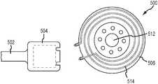
- FIGS. 5A-5Cdepict a method of disconnecting components of a cochlear implant 500 , in vivo. More specifically, the cochlear implant 500 includes a helix region 502 , implantable stimulator unit 504 , and an implantable coil assembly 506 .
- FIGS. 5A-5Ca portion of the helix region 502 is depicted, but not described, and the implantable stimulator unit 504 is implanted in a recipient.
- the coil assembly 506is connected to the stimulator unit 504 at the interface 507 .
- the stimulator unit axis A S and the coil assembly axis A Care substantially aligned.
- disconnection of the coil assembly 506 from the stimulator unit 504begins. After forming an incision in the head of the recipient, a surgeon can twist the coil assembly 506 relative to the stimulator unit 504 so as to misalign the axes A S , A C . Once sufficiently misaligned, the male and female connectors 508 , 510 begin to disconnect. Once disconnected, as depicted in FIG. 5C , the stimulator unit 504 enters an MRI compatibility mode, where operation of the stimulator unit 504 ceases and wherein, due to removal of the coil assembly 506 (more specifically the magnet 512 therein), patient comfort and reduced artifacts are ensured.
- a controller within the stimulator unit 504can include a physical or electronic switch that can automatically shut down the stimulator unit 504 and open the circuit or circuits associated with the stimulating electrodes (described elsewhere herein), thus preventing stimuli from being sent to the recipient.
- the cochlear implant 500is now in an MRI compatibility mode and the recipient can undergo an MRI procedure, at any field strength.
- the surgeoncan cap or otherwise isolate the female connectors 510 , then close the incision. Once the procedure is complete, the surgeon can re-open the incision and re-connect the coil assembly 506 in the reverse order ( FIGS. 5C-5A ).
- a so-called “dummy coil assembly”can be connected to the stimulator unit 504 .
- the dummy coil assemblyhas a form factor substantially similar to the coil assembly 506 , includes a coil 514 , but lacks a magnet 512 .
- Such a componentcan be desirable because it enables the recipient to still receive sound stimuli, even if she is undergoing prolonged or multiple MRI procedures.
- the coil assembly 506 and the dummy coil assemblyare both selectively releasably connectable to the stimulator unit 504 . Once connected, the coil of the dummy coil assembly is in communication with the stimulator unit 504 .
- An external portion of the cochlear implant 500 containing an external coilcan then be secured to the head (e.g., with an adhesive, headband, or other non-magnetic component) and signals can be sent between the two coils, as per normal operation.
- the coil assembly 506 containing a magnet 512can be re-connected and the device used normally.
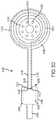
- FIG. 6is a partial top view of an implantable portion of a cochlear implant 600 in accordance with another example of the technology.
- the stimulator unit 602includes electronics and a hermetic enclosure therearound.
- a coil assembly or portion 604as well as a portion of a helix region 606 are also depicted.
- the hermetic enclosureis encased in a pliable, biocompatible encapsulant 608 .
- the coil assembly 604includes a radio frequency induction coil 612 and leads 614 that are in communication with the stimulator unit 602 via leads 610 .
- a magnet chassis 616is permanently embedded in the coil assembly 604 , more specifically within the biocompatible polymer encapsulant 618 that forms a body of the coil assembly 604 .
- the magnet chassis 616can include therein a number of through-holes 622 , as well as a magnet 620 .
- the stimulator unit 602 and coil assembly 604are releasably connected at junctions or interfaces 624 at structures described generally as connectors, connector elements, or connector parts. These connectors releasably connect the stimulator units 602 to the coil assemblies 604 . Examples of such connectors are described elsewhere herein, but the depicted example utilizes a configuration similar to that depicted and described in FIG. 3C . As such, the interface 624 is not described further.
- the magnet chassis 616has a diameter nearly the same as that of the outer perimeter of the coil encapsulant 618 .
- the coil 612 and magnet chassis 616overlap.
- the coil 612can be embedded within the chassis 616 , along with the magnet 620 , or overlay the skin facing surface of the magnet chassis 616 , between the chassis 616 and encapsulant 618 .
- This larger magnet chassis 616further increases the size of the lever arm that opposes forces generated by a magnetic field, e.g., during an MRI procedure. Chasses having other diameters are contemplated.
- chassescan have diameters slightly smaller than the smallest diameter of the coil. In such an example, the coil may be wrapped tightly about the outer perimeter of the chassis.
- it can be desirable that the underside of the chassishas a slight concave curvature, so as to rest more evenly on the surface of the skull.
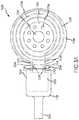
- FIG. 7is a partial top view of an implantable portion of a cochlear implant 700 in accordance with another example of the technology.
- a stimulator unit 702includes electronics and a hermetic enclosure therearound, typically made of titanium, ceramic or a biocompatible polymer (such as PEEK), which encases the electronics of the stimulator unit 702 .
- a coil assembly 704 and a portion of a helix region 706are also depicted.
- the hermetic enclosure containing the stimulator unit 702is encased in a pliable, biocompatible encapsulant 708 , such as silicone.
- Leads 710are in electrical communication with and extend from the stimulator unit 702 .
- the leads 710connect to one or more conductive male prongs 728 that extend from the encapsulant 708 .
- the coil assembly 704includes a radio frequency induction coil 712 that, in the depicted example, is in a two-turn configuration.
- the induction coil 712is configured to wirelessly receive signals from an external portion of a cochlear implant, as described above.
- Conductive sleeves, pockets, or receivers 714are formed in an extension 730 of a magnet chassis 716 and are in electrical communication with the induction coil 712 . More particularly, the extension 730 provides a rigid body into which the prongs 728 may be securely inserted, so as to form a positive connection to the coil assembly 704 .
- the extension 730may be completely encased in a biocompatible polymer encapsulant 718 or, as depicted, may extend slightly therefrom. As such, the magnet chassis 716 and extension 730 should be manufactured of a biocompatible material, if any portion thereof is disposed outside of the encapsulant 718 .
- the magnet chassis 716include therein a number of through-holes 722 and a magnet 720 is disposed in the chassis 716 .
- the stimulator unit 702 and coil assembly 704are releasable connected at an interface 724 that may be defined at least in part by the exposed chassis extension 730 .
- a biocompatible gasket or seal(not shown) may be disposed at the interface 724 between the prongs 728 and the chassis extension 730 , so as to prevent the ingress of fluids into receivers 730 or into contact with the prongs 728 , which may cause short-circuiting, interference, or other performance problems.
- Each conductive receiver 714may form an interference fit with an associated conductive prong 728 .
- this interference fitmay be formed by a smaller diameter receiver 714 and a larger diameter prong 728 .
- the interference fitmay be formed by a resilient element disposed in the receiver 714 or on the prong 728 .
- This resilient elementmay be an O-ring, tine or toothed element, or other structure. This interference may be overcome by a sufficient application of force to separate the stimulator unit 702 from the coil assembly 704 .
- a portion 732 of the induction coil 712is routed through the chassis extension 730 .
- This portion 732may be disposed in a channel having a diameter larger than an outer diameter of the induction coil 712 material. This would allow for a movement of the induction coil within the chassis extension 730 . Such movement may be desirable since the biocompatible polymer encapsulant 718 is more flexible than the chassis 716 . Movement of the encapsulant 718 moves the coil 712 , which could cause stress points on the coil 712 where the coil penetrates the chassis extension 730 , potentially leading to failure thereof. By locating the portion 732 of the coil 712 within a larger channel, such stress points may be reduced or eliminated.
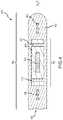
- FIGS. 8A and 8Bdepict a cochlear implant 800 including an electrode 802 and a stimulator unit 804 connected thereto.
- a lead 806extends from the stimulator unit 804 and includes a connector 808 at a distal end thereof.
- the interfaces(the location where a coil assembly may be disconnected from an electrode) are depicted as a part of a stimulator unit that is, in turn, integral with the electrode.
- the connector technologies described herein, however,may also be used at the ends of leads that are permanently secured to the stimulator unit, as depicted in FIG. 8A .
- the depicted connector 808may be a disconnectable component configured as in any of the configurations depicted herein (e.g., having mating components that enable disconnection of a coil assembly 810 from the connector 808 ).
- the coil assembly 810may include a coil 811 , a magnet chassis 812 , and a magnet 813 , as described in the various examples above.
- the coil assembly 810may be easily disconnected from the connector 808 , with little or no movement of the electrode 808 . As such, the possibility of dislocation of the electrode within, or trauma to, the cochlea may be reduced or eliminated.
- the coil assembly 810may be replaced with a different coil assembly (that is, e.g., having a stronger magnet, a different coil, or other feature or component). In the example depicted in FIG. 8B , however, the coil assembly 810 (from FIG. 8A ) is replaced with an upgraded coil assembly 810 A.
- the upgraded coil assembly 810 Amay include a coil 811 A, a magnet 813 A, and a magnet chassis 812 A that may be similar to or different from those in the embodiment of FIG. 8A .
- the upgraded coil assembly 810 Aalso includes a module 814 that, when connected to the connector 808 , forms an upgraded auditory prosthesis 800 A.
- the auditory prosthesis 800 of FIG. 8Amay be a cochlear implant that utilizes an external coil unit, sound processor, and microphone.
- the upgraded auditory prosthesis 800 Amay be a totally implantable cochlear implant.
- the module 814may include a sound processor, microphone, and other required or desired components.
- the upgraded coil assembly 810 Ais utilized with an external component to adjust settings of a totally implantable cochlear implant, as known in the art.
- a cochlear implantmay be easily upgraded to a totally implantable cochlear implant, while reusing certain components that are common to both types of auditory prostheses (e.g., electrode 802 , stimulator unit 804 , and lead 806 ).
- FIG. 9depicts a method 900 of replacing, in vivo, a component from an implanted medical device.
- the method 900is described in the context of removing a coil assembly from an auditory prosthesis such as a cochlear implant.
- the method 900can also be used to remove any type of component from a medical device, without having to remove the entire medical device from the body.
- the method 900begins by making an incision in the implant recipient, operation 902 .
- the skincan be withdrawn such that the incision exposes at least a portion of the cochlear implant, operation 904 , typically a coil assembly.
- the coil assemblycan be disconnected from the stimulator unit, consistent connector technologies described herein, in operation 906 .
- operation 906contemplates disconnecting an electrical connection between the coil assembly and the stimulator unit upon disconnection of those two components.
- the disconnected portione.g., the coil assembly
- a second componente.g., a different coil assembly with a stronger or weaker magnet, or no magnet at all
- the second componentcan also be the same coil assembly initially removed.
- the second componentcan be an identical, sterile coil assembly used to replace a damaged, non-sterile, or inoperable coil assembly.
- the incisionis then closed at the conclusion of the method 900 , in operation 914 .
Landscapes
- Health & Medical Sciences (AREA)
- General Health & Medical Sciences (AREA)
- Veterinary Medicine (AREA)
- Biomedical Technology (AREA)
- Nuclear Medicine, Radiotherapy & Molecular Imaging (AREA)
- Radiology & Medical Imaging (AREA)
- Life Sciences & Earth Sciences (AREA)
- Engineering & Computer Science (AREA)
- Animal Behavior & Ethology (AREA)
- Public Health (AREA)
- Physics & Mathematics (AREA)
- Otolaryngology (AREA)
- Electromagnetism (AREA)
- Acoustics & Sound (AREA)
- Prostheses (AREA)
- Heart & Thoracic Surgery (AREA)
- Neurology (AREA)
Abstract
Description
Claims (19)
Priority Applications (1)
| Application Number | Priority Date | Filing Date | Title |
|---|---|---|---|
| US15/336,662US11071869B2 (en) | 2016-02-24 | 2016-10-27 | Implantable device having removable portion |
Applications Claiming Priority (2)
| Application Number | Priority Date | Filing Date | Title |
|---|---|---|---|
| US201662299467P | 2016-02-24 | 2016-02-24 | |
| US15/336,662US11071869B2 (en) | 2016-02-24 | 2016-10-27 | Implantable device having removable portion |
Publications (2)
| Publication Number | Publication Date |
|---|---|
| US20170239474A1 US20170239474A1 (en) | 2017-08-24 |
| US11071869B2true US11071869B2 (en) | 2021-07-27 |
Family
ID=59631431
Family Applications (1)
| Application Number | Title | Priority Date | Filing Date |
|---|---|---|---|
| US15/336,662Active2037-05-01US11071869B2 (en) | 2016-02-24 | 2016-10-27 | Implantable device having removable portion |
Country Status (1)
| Country | Link |
|---|---|
| US (1) | US11071869B2 (en) |
Cited By (2)
| Publication number | Priority date | Publication date | Assignee | Title |
|---|---|---|---|---|
| US20220285005A1 (en)* | 2019-08-26 | 2022-09-08 | Vanderbilt University | Patient customized electro-neural interface models for model-based cochlear implant programming and applications of same |
| US12053629B2 (en) | 2020-09-09 | 2024-08-06 | Med-El Elektromedizinische Geraete Gmbh | Holding magnets and magnet system for implantable systems optimized for MRI |
Families Citing this family (3)
| Publication number | Priority date | Publication date | Assignee | Title |
|---|---|---|---|---|
| CN107585735B (en)* | 2017-09-22 | 2019-10-29 | 上海交通大学 | A kind of artificial cochlea electrode and preparation method thereof |
| CN111135459B (en)* | 2020-01-16 | 2023-06-20 | 上海力声特医学科技有限公司 | Artificial cochlea implant |
| WO2022153135A1 (en) | 2021-01-12 | 2022-07-21 | Cochlear Limited | Electrical connector with torsion resistance |
Citations (179)
| Publication number | Priority date | Publication date | Assignee | Title |
|---|---|---|---|---|
| US3244174A (en) | 1964-01-31 | 1966-04-05 | Gen Electric | Body implantable conductor |
| US3875349A (en) | 1972-02-02 | 1975-04-01 | Bommer Ag | Hearing aid |
| US4388523A (en) | 1981-06-10 | 1983-06-14 | Multistress, Inc. | Electrical heating cable connector |
| US4443666A (en) | 1980-11-24 | 1984-04-17 | Gentex Corporation | Electret microphone assembly |
| US4450930A (en) | 1982-09-03 | 1984-05-29 | Industrial Research Products, Inc. | Microphone with stepped response |
| US4504703A (en) | 1981-06-01 | 1985-03-12 | Asulab S.A. | Electro-acoustic transducer |
| US4532930A (en) | 1983-04-11 | 1985-08-06 | Commonwealth Of Australia, Dept. Of Science & Technology | Cochlear implant system for an auditory prosthesis |
| US4606329A (en) | 1985-05-22 | 1986-08-19 | Xomed, Inc. | Implantable electromagnetic middle-ear bone-conduction hearing aid device |
| US4607383A (en) | 1983-08-18 | 1986-08-19 | Gentex Corporation | Throat microphone |
| US4621171A (en) | 1982-05-29 | 1986-11-04 | Tokoyo Shibaura Denki Kabushiki Kaisha | Electroacoustic transducer and a method for manufacturing thereof |
| US4744370A (en) | 1987-04-27 | 1988-05-17 | Cordis Leads, Inc. | Lead assembly with selectable electrode connection |
| US4774933A (en) | 1987-05-18 | 1988-10-04 | Xomed, Inc. | Method and apparatus for implanting hearing device |
| US4815560A (en) | 1987-12-04 | 1989-03-28 | Industrial Research Products, Inc. | Microphone with frequency pre-emphasis |
| US4837833A (en) | 1988-01-21 | 1989-06-06 | Industrial Research Products, Inc. | Microphone with frequency pre-emphasis channel plate |
| USRE33170E (en) | 1982-03-26 | 1990-02-27 | The Regents Of The University Of California | Surgically implantable disconnect device |
| US4932405A (en) | 1986-08-08 | 1990-06-12 | Antwerp Bionic Systems N.V. | System of stimulating at least one nerve and/or muscle fibre |
| US4936305A (en) | 1988-07-20 | 1990-06-26 | Richards Medical Company | Shielded magnetic assembly for use with a hearing aid |
| US4961434A (en) | 1988-08-30 | 1990-10-09 | Stypulkowski Paul H | Array of recessed radially oriented bipolar electrodes |
| US5000194A (en) | 1988-08-25 | 1991-03-19 | Cochlear Corporation | Array of bipolar electrodes |
| US5015224A (en) | 1988-10-17 | 1991-05-14 | Maniglia Anthony J | Partially implantable hearing aid device |
| US5042084A (en) | 1989-09-07 | 1991-08-20 | Cochlear Pty. Limited | Three wire system for Cochlear implant processor |
| US5105811A (en) | 1982-07-27 | 1992-04-21 | Commonwealth Of Australia | Cochlear prosthetic package |
| US5163957A (en) | 1991-09-10 | 1992-11-17 | Smith & Nephew Richards, Inc. | Ossicular prosthesis for mounting magnet |
| US5176620A (en) | 1990-10-17 | 1993-01-05 | Samuel Gilman | Hearing aid having a liquid transmission means communicative with the cochlea and method of use thereof |
| US5276739A (en) | 1989-11-30 | 1994-01-04 | Nha A/S | Programmable hybrid hearing aid with digital signal processing |
| US5277694A (en) | 1991-02-13 | 1994-01-11 | Implex Gmbh | Electromechanical transducer for implantable hearing aids |
| US5363452A (en) | 1992-05-19 | 1994-11-08 | Shure Brothers, Inc. | Microphone for use in a vibrating environment |
| US5411467A (en) | 1989-06-02 | 1995-05-02 | Implex Gmbh Spezialhorgerate | Implantable hearing aid |
| US5443493A (en) | 1989-09-22 | 1995-08-22 | Alfred E. Mann Foundation For Scientific Research | Cochlea stimulating electrode assembly, insertion tool, holder and method of implantation |
| US5456654A (en) | 1993-07-01 | 1995-10-10 | Ball; Geoffrey R. | Implantable magnetic hearing aid transducer |
| US5507303A (en) | 1991-06-06 | 1996-04-16 | Cochlear Pty. Limited | Percutaneous connector |
| US5522865A (en) | 1989-09-22 | 1996-06-04 | Alfred E. Mann Foundation For Scientific Research | Voltage/current control system for a human tissue stimulator |
| US5531774A (en) | 1989-09-22 | 1996-07-02 | Alfred E. Mann Foundation For Scientific Research | Multichannel implantable cochlear stimulator having programmable bipolar, monopolar or multipolar electrode configurations |
| US5549658A (en) | 1994-10-24 | 1996-08-27 | Advanced Bionics Corporation | Four-Channel cochlear system with a passive, non-hermetically sealed implant |
| US5554096A (en) | 1993-07-01 | 1996-09-10 | Symphonix | Implantable electromagnetic hearing transducer |
| US5558618A (en) | 1995-01-23 | 1996-09-24 | Maniglia; Anthony J. | Semi-implantable middle ear hearing device |
| US5571148A (en) | 1994-08-10 | 1996-11-05 | Loeb; Gerald E. | Implantable multichannel stimulator |
| US5578084A (en) | 1991-09-27 | 1996-11-26 | Cochlear Ltd. | Self-curving cochlear electrode array |
| US5613935A (en) | 1994-12-16 | 1997-03-25 | Jarvik; Robert | High reliability cardiac assist system |
| US5624376A (en) | 1993-07-01 | 1997-04-29 | Symphonix Devices, Inc. | Implantable and external hearing systems having a floating mass transducer |
| US5649970A (en) | 1995-08-18 | 1997-07-22 | Loeb; Gerald E. | Edge-effect electrodes for inducing spatially controlled distributions of electrical potentials in volume conductive media |
| US5653742A (en) | 1995-09-20 | 1997-08-05 | Cochlear Pty. Ltd. | Use of bioresorbable polymers in cochlear implants and other implantable devices |
| US5674264A (en) | 1995-12-01 | 1997-10-07 | Cochlear Ltd. | Feedback system to control electrode voltages in a cochlear stimulator and the like |
| US5702431A (en) | 1995-06-07 | 1997-12-30 | Sulzer Intermedics Inc. | Enhanced transcutaneous recharging system for battery powered implantable medical device |
| US5720099A (en) | 1996-01-31 | 1998-02-24 | Cochlear Limited | Thin film fabrication technique for implantable electrodes |
| US5755747A (en) | 1995-12-19 | 1998-05-26 | Daly; Christopher | Cochlear implant system with soft turn on electrodes |
| US5755743A (en) | 1996-06-05 | 1998-05-26 | Implex Gmbh Spezialhorgerate | Implantable unit |
| US5824022A (en) | 1996-03-07 | 1998-10-20 | Advanced Bionics Corporation | Cochlear stimulation system employing behind-the-ear speech processor with remote control |
| US5876429A (en) | 1995-06-07 | 1999-03-02 | Intermedics, Inc. | Methods and devices for in vivo repair of cardiac stimulator leads |
| US5876443A (en) | 1996-02-26 | 1999-03-02 | Med-El Elektromedizinisch Gerate Ges.M.B.H. | Structure, method of use, and method of manufacture of an implanted hearing prosthesis |
| US5897486A (en) | 1993-07-01 | 1999-04-27 | Symphonix Devices, Inc. | Dual coil floating mass transducers |
| US5922017A (en) | 1996-03-13 | 1999-07-13 | Med-El Elektromedizinische Gerate Gmbh | Device and method for implants in ossified cochleas |
| US5957958A (en) | 1997-01-15 | 1999-09-28 | Advanced Bionics Corporation | Implantable electrode arrays |
| US5999859A (en) | 1997-03-10 | 1999-12-07 | Med-El- Elektromedizinische Gerate G.M.B.H. | Apparatus and method for perimodiolar cochlear implant with retro-positioning |
| US6035237A (en) | 1995-05-23 | 2000-03-07 | Alfred E. Mann Foundation | Implantable stimulator that prevents DC current flow without the use of discrete output coupling capacitors |
| US6039685A (en) | 1998-09-14 | 2000-03-21 | St. Croix Medical, Inc. | Ventable connector with seals |
| US6067474A (en) | 1997-08-01 | 2000-05-23 | Advanced Bionics Corporation | Implantable device with improved battery recharging and powering configuration |
| US6068652A (en) | 1996-05-16 | 2000-05-30 | Cohen; Lawrence T. | Method and means for calculating electrode frequency allocation |
| US6070105A (en) | 1997-09-02 | 2000-05-30 | Advanced Bionics Corporation | Modiolus-hugging cochlear electrodes |
| US6074422A (en) | 1998-04-22 | 2000-06-13 | Epic Biosonics Inc. | Inner ear implant device |
| US6078841A (en) | 1998-03-27 | 2000-06-20 | Advanced Bionics Corporation | Flexible positioner for use with implantable cochlear electrode array |
| US6119044A (en) | 1997-06-02 | 2000-09-12 | Advanced Bionics Corporation | Cochlear electrode array with positioning stylet |
| US6125302A (en) | 1997-09-02 | 2000-09-26 | Advanced Bionics Corporation | Precurved modiolar-hugging cochlear electrode |
| US6129753A (en) | 1998-03-27 | 2000-10-10 | Advanced Bionics Corporation | Cochlear electrode array with electrode contacts on medial side |
| US6151400A (en) | 1994-10-24 | 2000-11-21 | Cochlear Limited | Automatic sensitivity control |
| US6157861A (en) | 1996-06-20 | 2000-12-05 | Advanced Bionics Corporation | Self-adjusting cochlear implant system and method for fitting same |
| US6163729A (en) | 1998-08-26 | 2000-12-19 | Advanced Bionics Corporation | Method of positioning an implantable cochlear electrode array within a cochlea |
| US6219580B1 (en) | 1995-04-26 | 2001-04-17 | Advanced Bionics Corporation | Multichannel cochlear prosthesis with flexible control of stimulus waveforms |
| US6259951B1 (en) | 1999-05-14 | 2001-07-10 | Advanced Bionics Corporation | Implantable cochlear stimulator system incorporating combination electrode/transducer |
| US6266568B1 (en) | 1998-06-02 | 2001-07-24 | Advanced Bionics Corporation | Inflatable cochlear electrode array and method of making same |
| US6272382B1 (en) | 1998-07-31 | 2001-08-07 | Advanced Bionics Corporation | Fully implantable cochlear implant system |
| US6289246B1 (en) | 1998-10-13 | 2001-09-11 | Cochlear Pty. Ltd. | High compliance output stage for a tissue stimulator |
| US6293903B1 (en) | 2000-05-30 | 2001-09-25 | Otologics Llc | Apparatus and method for mounting implantable hearing aid device |
| US6301505B1 (en) | 1999-06-11 | 2001-10-09 | Cochlear Limited | Stimulus output monitor and control circuit for electrical tissue stimulator |
| WO2001074447A2 (en) | 2000-03-31 | 2001-10-11 | Cardiac Pacemakers, Inc. | Inductive coil apparatus for bio-medical telemetry |
| US6304787B1 (en) | 1998-08-26 | 2001-10-16 | Advanced Bionics Corporation | Cochlear electrode array having current-focusing and tissue-treating features |
| US6308101B1 (en) | 1998-07-31 | 2001-10-23 | Advanced Bionics Corporation | Fully implantable cochlear implant system |
| US6321126B1 (en) | 1998-12-07 | 2001-11-20 | Advanced Bionics Corporation | Implantable connector |
| US6321125B1 (en) | 1998-08-26 | 2001-11-20 | Advanced Bionics Corporation | Cochlear electrode system including distally attached flexible positioner |
| US6325755B1 (en) | 1997-08-07 | 2001-12-04 | St. Croix Medical, Inc. | Mountable transducer assembly with removable sleeve |
| WO2001091678A1 (en) | 2000-05-30 | 2001-12-06 | Otologics Llc | Connector for implantable hearing aid |
| US6355064B1 (en) | 1996-04-17 | 2002-03-12 | Cochlear Ltd | Implanted hearing prosthesis |
| US20020032401A1 (en) | 1999-12-27 | 2002-03-14 | Pamela Fereira | Osmotic beneficial agent delivery system |
| US6358281B1 (en) | 1999-11-29 | 2002-03-19 | Epic Biosonics Inc. | Totally implantable cochlear prosthesis |
| US6374143B1 (en) | 1999-08-18 | 2002-04-16 | Epic Biosonics, Inc. | Modiolar hugging electrode array |
| US6397110B1 (en) | 1998-08-26 | 2002-05-28 | Advanced Bionics Corporation | Cochlear electrode system including detachable flexible positioner |
| US20020076071A1 (en) | 2000-09-25 | 2002-06-20 | Peter Single | Multiple battery management system |
| US6411855B1 (en) | 1999-01-28 | 2002-06-25 | Cochlear Limited | Auditive prosthesis comprising a carrier which can be implanted in a cochlea |
| US6421569B1 (en) | 1999-05-21 | 2002-07-16 | Cochlear Limited | Cochlear implant electrode array |
| US20020124857A1 (en) | 1997-08-19 | 2002-09-12 | Intermedics Inc. | Apparatus for imparting physician-determined shapes to implantable tubular devices |
| US6482144B1 (en) | 1999-10-07 | 2002-11-19 | Phonak Ag | Arrangement for mechanical coupling of a driver to a coupling site of the ossicular chain |
| US6498954B1 (en) | 2000-01-14 | 2002-12-24 | Advanced Bionics Corporation | Apex to base cochlear implant electrode |
| US20030031336A1 (en) | 2001-08-10 | 2003-02-13 | Harrison William V. | In the ear auxiliary microphone for behind the ear hearing prosthetic |
| US20030050680A1 (en)* | 2001-09-07 | 2003-03-13 | Gibson Scott R. | Electronic lead for a medical implant device, method of making same, and method and apparatus for inserting same |
| US20030055311A1 (en) | 1996-02-15 | 2003-03-20 | Neukermans Armand P. | Biocompatible transducers |
| US6542777B1 (en) | 2001-01-19 | 2003-04-01 | Advanced Bionics Corporation | Spiral shield for a flexible high-Q implantable inductively coupled device |
| US6556870B2 (en) | 2000-01-31 | 2003-04-29 | Med-El Elektromedizinische Geraete Gmbh | Partially inserted cochlear implant |
| US6554761B1 (en) | 1999-10-29 | 2003-04-29 | Soundport Corporation | Flextensional microphones for implantable hearing devices |
| US6565503B2 (en) | 2000-04-13 | 2003-05-20 | Cochlear Limited | At least partially implantable system for rehabilitation of hearing disorder |
| US6572531B2 (en) | 2000-06-17 | 2003-06-03 | Alfred E. Mann Foundation For Scientific Reseach | Implantable middle ear implant |
| US20030120327A1 (en) | 2001-12-20 | 2003-06-26 | Mark Tobritzhofer | Medical lead adaptor assembly with retainer |
| US6592512B2 (en) | 2000-08-11 | 2003-07-15 | Phonak Ag | At least partially implantable system for rehabilitation of a hearing disorder |
| US6600955B1 (en) | 1999-07-21 | 2003-07-29 | Med-El Elektromedizinishe Geraete Gmbh | Multichannel cochlear implant with neural response telemetry |
| US6620094B2 (en) | 2001-11-21 | 2003-09-16 | Otologics, Llc | Method and apparatus for audio input to implantable hearing aids |
| US20030181956A1 (en) | 2002-01-21 | 2003-09-25 | Michael Duncan | Multi-purpose FES system |
| US6629923B2 (en) | 2000-09-21 | 2003-10-07 | Phonak Ag | At least partially implantable hearing system with direct mechanical stimulation of a lymphatic space of the inner ear |
| WO2003101535A1 (en) | 2002-06-03 | 2003-12-11 | Med-El Elektromedizinische Geraete Gmbh | Implantable device with flexible interconnect to coil |
| US6697674B2 (en) | 2000-04-13 | 2004-02-24 | Cochlear Limited | At least partially implantable system for rehabilitation of a hearing disorder |
| WO2004024212A2 (en) | 2002-09-10 | 2004-03-25 | Vibrant Med-El Hearing Technology Gmbh | Implantable medical devices with multiple transducers |
| US20040059403A1 (en) | 2002-09-24 | 2004-03-25 | Geriche, Inc. | Suture sleeve |
| US6736770B2 (en) | 2000-08-25 | 2004-05-18 | Cochlear Limited | Implantable medical device comprising an hermetically sealed housing |
| US6757970B1 (en) | 2000-11-07 | 2004-07-06 | Advanced Bionics Corporation | Method of making multi-contact electrode array |
| US6778858B1 (en) | 1999-09-16 | 2004-08-17 | Advanced Bionics N.V. | Cochlear implant |
| US6786860B2 (en) | 2001-10-03 | 2004-09-07 | Advanced Bionics Corporation | Hearing aid design |
| US6807445B2 (en) | 2001-03-26 | 2004-10-19 | Cochlear Limited | Totally implantable hearing system |
| US20050004629A1 (en)* | 2003-04-09 | 2005-01-06 | Peter Gibson | Implant magnet system |
| US20050005421A1 (en) | 2002-09-13 | 2005-01-13 | Knowles Electronics, Llc | High performance silicon condenser microphone with perforated single crystal silicon backplate |
| US6889094B1 (en) | 1999-05-14 | 2005-05-03 | Advanced Bionics Corporation | Electrode array for hybrid cochlear stimulator |
| US20050096561A1 (en) | 2003-11-03 | 2005-05-05 | Conn Brian M. | Method for obtaining diagnostic information relating to a patient having an implanted transducer |
| US20050101832A1 (en) | 2003-11-07 | 2005-05-12 | Miller Scott A.Iii | Microphone optimized for implant use |
| US6909917B2 (en) | 1999-01-07 | 2005-06-21 | Advanced Bionics Corporation | Implantable generator having current steering means |
| US20050137664A1 (en) | 2003-12-18 | 2005-06-23 | Medtronic, Inc. | Suture sleeve |
| US6921295B2 (en) | 2001-04-19 | 2005-07-26 | Medtronic, Inc. | Medical lead extension and connection system |
| US20050234522A1 (en) | 2000-12-15 | 2005-10-20 | Cardiac Pacemakers, Inc. | Terminal connector assembly for a medical device and method therefor |
| US6996438B1 (en) | 2000-06-01 | 2006-02-07 | Advanced Bionics Corporation | Envelope-based amplitude mapping for cochlear implant stimulus |
| US20060040541A1 (en) | 2004-08-17 | 2006-02-23 | Vaughn James T | Self sealing electrical connector |
| US7039466B1 (en) | 2003-04-29 | 2006-05-02 | Advanced Bionics Corporation | Spatial decimation stimulation in an implantable neural stimulator, such as a cochlear implant |
| US7054691B1 (en) | 2002-01-02 | 2006-05-30 | Advanced Bionics Corporation | Partitioned implantable system |
| US20060122664A1 (en) | 2004-12-07 | 2006-06-08 | Michael Sacha | Cochlear ear implant |
| US7072717B1 (en) | 1999-07-13 | 2006-07-04 | Cochlear Limited | Multirate cochlear stimulation strategy and apparatus |
| US7076308B1 (en) | 2001-08-17 | 2006-07-11 | Advanced Bionics Corporation | Cochlear implant and simplified method of fitting same |
| US7082332B2 (en) | 2000-06-19 | 2006-07-25 | Cochlear Limited | Sound processor for a cochlear implant |
| US7085605B2 (en) | 2003-01-23 | 2006-08-01 | Epic Biosonics Inc. | Implantable medical assembly |
| WO2006081361A2 (en) | 2005-01-27 | 2006-08-03 | Cochlear Americas | Implantable medical device |
| US20060183965A1 (en) | 2005-02-16 | 2006-08-17 | Kasic James F Ii | Integrated implantable hearing device, microphone and power unit |
| US7146227B2 (en) | 2000-10-04 | 2006-12-05 | Cochlear Limited | Combination stylet and straightening coating for a cochlear implant electrode array |
| US20070016267A1 (en) | 2005-07-08 | 2007-01-18 | Cochlear Limited | Directional sound processing in a cochlear implant |
| US7197152B2 (en) | 2002-02-26 | 2007-03-27 | Otologics Llc | Frequency response equalization system for hearing aid microphones |
| US7204800B2 (en) | 2003-11-07 | 2007-04-17 | Otologics, Llc | Implantable hearing aid transducer interface |
| US7214179B2 (en) | 2004-04-01 | 2007-05-08 | Otologics, Llc | Low acceleration sensitivity microphone |
| US20070167671A1 (en) | 2005-11-30 | 2007-07-19 | Miller Scott A Iii | Dual feedback control system for implantable hearing instrument |
| US7260436B2 (en) | 2001-10-16 | 2007-08-21 | Case Western Reserve University | Implantable networked neural system |
| US20070280495A1 (en) | 2006-05-30 | 2007-12-06 | Sonitus Medical, Inc. | Methods and apparatus for processing audio signals |
| US20080009202A1 (en) | 2006-07-05 | 2008-01-10 | K.S. Terminals, Inc. | Wire connector and method of fabricating the same |
| US20080027515A1 (en) | 2006-06-23 | 2008-01-31 | Neuro Vista Corporation A Delaware Corporation | Minimally Invasive Monitoring Systems |
| US20080049953A1 (en) | 2006-07-25 | 2008-02-28 | Analog Devices, Inc. | Multiple Microphone System |
| US7354394B2 (en) | 2005-06-20 | 2008-04-08 | Otologics, Llc | Soft tissue placement of implantable microphone |
| US20080085023A1 (en) | 2006-09-25 | 2008-04-10 | Abhijit Kulkarni | Auditory Front End Customization |
| US20080132750A1 (en) | 2005-01-11 | 2008-06-05 | Scott Allan Miller | Adaptive cancellation system for implantable hearing instruments |
| US20080167516A1 (en) | 1997-12-16 | 2008-07-10 | Vibrant Med-El | Implantable Microphone Having Sensitivity And Frequency Response |
| WO2008089505A1 (en) | 2007-01-22 | 2008-07-31 | Cochlear Limited | Cochlear implant upgrade method and apparatus |
| US20080221641A1 (en)* | 2007-03-07 | 2008-09-11 | Med-El Elektromedizinische Geraete Gmbh | Implantable Device with Removable Magnet |
| US20080243214A1 (en) | 2007-03-26 | 2008-10-02 | Boston Scientific Scimed, Inc. | High resolution electrophysiology catheter |
| US7489793B2 (en) | 2005-07-08 | 2009-02-10 | Otologics, Llc | Implantable microphone with shaped chamber |
| US20090163978A1 (en) | 2007-11-20 | 2009-06-25 | Otologics, Llc | Implantable electret microphone |
| US7556597B2 (en) | 2003-11-07 | 2009-07-07 | Otologics, Llc | Active vibration attenuation for implantable microphone |
| US20090187065A1 (en) | 2008-01-21 | 2009-07-23 | Otologics, Llc | Automatic gain control for implanted microphone |
| US20090187233A1 (en) | 2008-01-18 | 2009-07-23 | Stracener Steve W | Connector for implantable hearing aid |
| WO2009117767A1 (en) | 2008-03-25 | 2009-10-01 | Cochlear Limited | Electronic component configuration |
| US20090283294A1 (en) | 2008-05-16 | 2009-11-19 | Rudolf Robert Bukovnik | Cover Assembly for Cables and Electrical Connections and Methods for Using the Same |
| US20090287277A1 (en) | 2008-05-19 | 2009-11-19 | Otologics, Llc | Implantable neurostimulation electrode interface |
| US20100032205A1 (en) | 2008-08-08 | 2010-02-11 | Tyco Electronics Corporation | High performance cable splice |
| WO2010028436A1 (en) | 2008-09-10 | 2010-03-18 | Cochlear Limited | An upgradeable cochlear implant |
| US7775964B2 (en) | 2005-01-11 | 2010-08-17 | Otologics Llc | Active vibration attenuation for implantable microphone |
| US20100256693A1 (en) | 2009-04-07 | 2010-10-07 | Boston Scientific Neuromodulation Corporation | Insulator layers for leads of implantable electric stimulation systems and methods of making and using |
| US20100272287A1 (en) | 2009-04-28 | 2010-10-28 | Otologics, Llc | Patterned implantable electret microphone |
| US7840020B1 (en) | 2004-04-01 | 2010-11-23 | Otologics, Llc | Low acceleration sensitivity microphone |
| US7844329B2 (en) | 2008-02-22 | 2010-11-30 | Cochlear Limited | Implantable electrical connector |
| US20100317913A1 (en) | 2009-05-29 | 2010-12-16 | Otologics, Llc | Implantable auditory stimulation system and method with offset implanted microphones |
| US20110034755A1 (en) | 2008-03-31 | 2011-02-10 | John Parker | Implantable universal docking station for prosthetic hearing devices |
| US20110178575A1 (en) | 2008-09-10 | 2011-07-21 | Cryer Adrian R | Insulated electrical connection in an implantable medical device |
| US20110264155A1 (en) | 2008-10-14 | 2011-10-27 | Cochlear Americas | Implantable hearing prosthesis |
| US20120022647A1 (en)* | 2009-01-19 | 2012-01-26 | Leigh C Roger | Implantable medical device including surface geometry having reduced biofilm formation characteristics |
| US20120109297A1 (en) | 2010-10-29 | 2012-05-03 | Van Den Heuvel Koen | Universal implant |
| US8185212B2 (en) | 2002-06-28 | 2012-05-22 | Boston Scientific Neuromodulation Corporation | Chair pad charging and communication system for a battery-powered microstimulator |
| US20140343626A1 (en)* | 2011-09-22 | 2014-11-20 | Advanced Bionics Ag | Retention of a magnet in a cochlear implant |
| US20150367126A1 (en)* | 2014-06-20 | 2015-12-24 | Daniel Smyth | Implantable auditory prosthesis having isolated components |
| US20160008601A1 (en)* | 2013-03-07 | 2016-01-14 | Imthera Medical, Inc. | Lead Splitter for Neurostimulation Systems |
| US20180028811A1 (en) | 2016-08-01 | 2018-02-01 | Peter Bart Jos Van Gerwen | Intelligent modularization |
- 2016
- 2016-10-27USUS15/336,662patent/US11071869B2/enactiveActive
Patent Citations (202)
| Publication number | Priority date | Publication date | Assignee | Title |
|---|---|---|---|---|
| US3244174A (en) | 1964-01-31 | 1966-04-05 | Gen Electric | Body implantable conductor |
| US3875349A (en) | 1972-02-02 | 1975-04-01 | Bommer Ag | Hearing aid |
| US4443666A (en) | 1980-11-24 | 1984-04-17 | Gentex Corporation | Electret microphone assembly |
| US4504703A (en) | 1981-06-01 | 1985-03-12 | Asulab S.A. | Electro-acoustic transducer |
| US4388523A (en) | 1981-06-10 | 1983-06-14 | Multistress, Inc. | Electrical heating cable connector |
| USRE33170E (en) | 1982-03-26 | 1990-02-27 | The Regents Of The University Of California | Surgically implantable disconnect device |
| US4621171A (en) | 1982-05-29 | 1986-11-04 | Tokoyo Shibaura Denki Kabushiki Kaisha | Electroacoustic transducer and a method for manufacturing thereof |
| US5105811A (en) | 1982-07-27 | 1992-04-21 | Commonwealth Of Australia | Cochlear prosthetic package |
| US4450930A (en) | 1982-09-03 | 1984-05-29 | Industrial Research Products, Inc. | Microphone with stepped response |
| US4532930A (en) | 1983-04-11 | 1985-08-06 | Commonwealth Of Australia, Dept. Of Science & Technology | Cochlear implant system for an auditory prosthesis |
| US4607383A (en) | 1983-08-18 | 1986-08-19 | Gentex Corporation | Throat microphone |
| US4606329A (en) | 1985-05-22 | 1986-08-19 | Xomed, Inc. | Implantable electromagnetic middle-ear bone-conduction hearing aid device |
| US4932405A (en) | 1986-08-08 | 1990-06-12 | Antwerp Bionic Systems N.V. | System of stimulating at least one nerve and/or muscle fibre |
| US4744370A (en) | 1987-04-27 | 1988-05-17 | Cordis Leads, Inc. | Lead assembly with selectable electrode connection |
| US4774933A (en) | 1987-05-18 | 1988-10-04 | Xomed, Inc. | Method and apparatus for implanting hearing device |
| US4815560A (en) | 1987-12-04 | 1989-03-28 | Industrial Research Products, Inc. | Microphone with frequency pre-emphasis |
| US4837833A (en) | 1988-01-21 | 1989-06-06 | Industrial Research Products, Inc. | Microphone with frequency pre-emphasis channel plate |
| US4936305A (en) | 1988-07-20 | 1990-06-26 | Richards Medical Company | Shielded magnetic assembly for use with a hearing aid |
| US5000194A (en) | 1988-08-25 | 1991-03-19 | Cochlear Corporation | Array of bipolar electrodes |
| US4961434A (en) | 1988-08-30 | 1990-10-09 | Stypulkowski Paul H | Array of recessed radially oriented bipolar electrodes |
| US5015224A (en) | 1988-10-17 | 1991-05-14 | Maniglia Anthony J | Partially implantable hearing aid device |
| US5411467A (en) | 1989-06-02 | 1995-05-02 | Implex Gmbh Spezialhorgerate | Implantable hearing aid |
| US5042084A (en) | 1989-09-07 | 1991-08-20 | Cochlear Pty. Limited | Three wire system for Cochlear implant processor |
| US5443493A (en) | 1989-09-22 | 1995-08-22 | Alfred E. Mann Foundation For Scientific Research | Cochlea stimulating electrode assembly, insertion tool, holder and method of implantation |
| US5531774A (en) | 1989-09-22 | 1996-07-02 | Alfred E. Mann Foundation For Scientific Research | Multichannel implantable cochlear stimulator having programmable bipolar, monopolar or multipolar electrode configurations |
| US5522865A (en) | 1989-09-22 | 1996-06-04 | Alfred E. Mann Foundation For Scientific Research | Voltage/current control system for a human tissue stimulator |
| US5276739A (en) | 1989-11-30 | 1994-01-04 | Nha A/S | Programmable hybrid hearing aid with digital signal processing |
| US5176620A (en) | 1990-10-17 | 1993-01-05 | Samuel Gilman | Hearing aid having a liquid transmission means communicative with the cochlea and method of use thereof |
| US5277694A (en) | 1991-02-13 | 1994-01-11 | Implex Gmbh | Electromechanical transducer for implantable hearing aids |
| US5507303A (en) | 1991-06-06 | 1996-04-16 | Cochlear Pty. Limited | Percutaneous connector |
| US5163957A (en) | 1991-09-10 | 1992-11-17 | Smith & Nephew Richards, Inc. | Ossicular prosthesis for mounting magnet |
| US5578084A (en) | 1991-09-27 | 1996-11-26 | Cochlear Ltd. | Self-curving cochlear electrode array |
| US5363452A (en) | 1992-05-19 | 1994-11-08 | Shure Brothers, Inc. | Microphone for use in a vibrating environment |
| US5456654A (en) | 1993-07-01 | 1995-10-10 | Ball; Geoffrey R. | Implantable magnetic hearing aid transducer |
| US5897486A (en) | 1993-07-01 | 1999-04-27 | Symphonix Devices, Inc. | Dual coil floating mass transducers |
| US5624376A (en) | 1993-07-01 | 1997-04-29 | Symphonix Devices, Inc. | Implantable and external hearing systems having a floating mass transducer |
| US5554096A (en) | 1993-07-01 | 1996-09-10 | Symphonix | Implantable electromagnetic hearing transducer |
| US6190305B1 (en) | 1993-07-01 | 2001-02-20 | Symphonix Devices, Inc. | Implantable and external hearing systems having a floating mass transducer |
| US5571148A (en) | 1994-08-10 | 1996-11-05 | Loeb; Gerald E. | Implantable multichannel stimulator |
| US5549658A (en) | 1994-10-24 | 1996-08-27 | Advanced Bionics Corporation | Four-Channel cochlear system with a passive, non-hermetically sealed implant |
| US6151400A (en) | 1994-10-24 | 2000-11-21 | Cochlear Limited | Automatic sensitivity control |
| US5613935A (en) | 1994-12-16 | 1997-03-25 | Jarvik; Robert | High reliability cardiac assist system |
| US5558618A (en) | 1995-01-23 | 1996-09-24 | Maniglia; Anthony J. | Semi-implantable middle ear hearing device |
| US6219580B1 (en) | 1995-04-26 | 2001-04-17 | Advanced Bionics Corporation | Multichannel cochlear prosthesis with flexible control of stimulus waveforms |
| US6035237A (en) | 1995-05-23 | 2000-03-07 | Alfred E. Mann Foundation | Implantable stimulator that prevents DC current flow without the use of discrete output coupling capacitors |
| US5702431A (en) | 1995-06-07 | 1997-12-30 | Sulzer Intermedics Inc. | Enhanced transcutaneous recharging system for battery powered implantable medical device |
| US5876429A (en) | 1995-06-07 | 1999-03-02 | Intermedics, Inc. | Methods and devices for in vivo repair of cardiac stimulator leads |
| US5649970A (en) | 1995-08-18 | 1997-07-22 | Loeb; Gerald E. | Edge-effect electrodes for inducing spatially controlled distributions of electrical potentials in volume conductive media |
| US5653742A (en) | 1995-09-20 | 1997-08-05 | Cochlear Pty. Ltd. | Use of bioresorbable polymers in cochlear implants and other implantable devices |
| US5674264A (en) | 1995-12-01 | 1997-10-07 | Cochlear Ltd. | Feedback system to control electrode voltages in a cochlear stimulator and the like |
| US5755747A (en) | 1995-12-19 | 1998-05-26 | Daly; Christopher | Cochlear implant system with soft turn on electrodes |
| US5720099A (en) | 1996-01-31 | 1998-02-24 | Cochlear Limited | Thin film fabrication technique for implantable electrodes |
| US20030055311A1 (en) | 1996-02-15 | 2003-03-20 | Neukermans Armand P. | Biocompatible transducers |
| US5876443A (en) | 1996-02-26 | 1999-03-02 | Med-El Elektromedizinisch Gerate Ges.M.B.H. | Structure, method of use, and method of manufacture of an implanted hearing prosthesis |
| US5824022A (en) | 1996-03-07 | 1998-10-20 | Advanced Bionics Corporation | Cochlear stimulation system employing behind-the-ear speech processor with remote control |
| US5922017A (en) | 1996-03-13 | 1999-07-13 | Med-El Elektromedizinische Gerate Gmbh | Device and method for implants in ossified cochleas |
| US6355064B1 (en) | 1996-04-17 | 2002-03-12 | Cochlear Ltd | Implanted hearing prosthesis |
| US6068652A (en) | 1996-05-16 | 2000-05-30 | Cohen; Lawrence T. | Method and means for calculating electrode frequency allocation |
| US5755743A (en) | 1996-06-05 | 1998-05-26 | Implex Gmbh Spezialhorgerate | Implantable unit |
| US6157861A (en) | 1996-06-20 | 2000-12-05 | Advanced Bionics Corporation | Self-adjusting cochlear implant system and method for fitting same |
| US5957958A (en) | 1997-01-15 | 1999-09-28 | Advanced Bionics Corporation | Implantable electrode arrays |
| US5999859A (en) | 1997-03-10 | 1999-12-07 | Med-El- Elektromedizinische Gerate G.M.B.H. | Apparatus and method for perimodiolar cochlear implant with retro-positioning |
| US6119044A (en) | 1997-06-02 | 2000-09-12 | Advanced Bionics Corporation | Cochlear electrode array with positioning stylet |
| US6067474A (en) | 1997-08-01 | 2000-05-23 | Advanced Bionics Corporation | Implantable device with improved battery recharging and powering configuration |
| US6325755B1 (en) | 1997-08-07 | 2001-12-04 | St. Croix Medical, Inc. | Mountable transducer assembly with removable sleeve |
| US20020124857A1 (en) | 1997-08-19 | 2002-09-12 | Intermedics Inc. | Apparatus for imparting physician-determined shapes to implantable tubular devices |
| US6070105A (en) | 1997-09-02 | 2000-05-30 | Advanced Bionics Corporation | Modiolus-hugging cochlear electrodes |
| US6125302A (en) | 1997-09-02 | 2000-09-26 | Advanced Bionics Corporation | Precurved modiolar-hugging cochlear electrode |
| US6604283B1 (en) | 1997-09-02 | 2003-08-12 | Advanced Bionics Corporation | Method of making precurved, modiolar-hugging cochlear electrode |
| US20080167516A1 (en) | 1997-12-16 | 2008-07-10 | Vibrant Med-El | Implantable Microphone Having Sensitivity And Frequency Response |
| US6144883A (en) | 1998-03-27 | 2000-11-07 | Advanced Bionics Corporation | Method of making a cochlear electrode array with electrode contacts on medial side |
| US6129753A (en) | 1998-03-27 | 2000-10-10 | Advanced Bionics Corporation | Cochlear electrode array with electrode contacts on medial side |
| US6078841A (en) | 1998-03-27 | 2000-06-20 | Advanced Bionics Corporation | Flexible positioner for use with implantable cochlear electrode array |
| US6074422A (en) | 1998-04-22 | 2000-06-13 | Epic Biosonics Inc. | Inner ear implant device |
| US6266568B1 (en) | 1998-06-02 | 2001-07-24 | Advanced Bionics Corporation | Inflatable cochlear electrode array and method of making same |
| US6272382B1 (en) | 1998-07-31 | 2001-08-07 | Advanced Bionics Corporation | Fully implantable cochlear implant system |
| US6308101B1 (en) | 1998-07-31 | 2001-10-23 | Advanced Bionics Corporation | Fully implantable cochlear implant system |
| US6397110B1 (en) | 1998-08-26 | 2002-05-28 | Advanced Bionics Corporation | Cochlear electrode system including detachable flexible positioner |
| US6321125B1 (en) | 1998-08-26 | 2001-11-20 | Advanced Bionics Corporation | Cochlear electrode system including distally attached flexible positioner |
| US6304787B1 (en) | 1998-08-26 | 2001-10-16 | Advanced Bionics Corporation | Cochlear electrode array having current-focusing and tissue-treating features |
| US6163729A (en) | 1998-08-26 | 2000-12-19 | Advanced Bionics Corporation | Method of positioning an implantable cochlear electrode array within a cochlea |
| US6039685A (en) | 1998-09-14 | 2000-03-21 | St. Croix Medical, Inc. | Ventable connector with seals |
| US6289246B1 (en) | 1998-10-13 | 2001-09-11 | Cochlear Pty. Ltd. | High compliance output stage for a tissue stimulator |
| US6321126B1 (en) | 1998-12-07 | 2001-11-20 | Advanced Bionics Corporation | Implantable connector |
| US6909917B2 (en) | 1999-01-07 | 2005-06-21 | Advanced Bionics Corporation | Implantable generator having current steering means |
| US6411855B1 (en) | 1999-01-28 | 2002-06-25 | Cochlear Limited | Auditive prosthesis comprising a carrier which can be implanted in a cochlea |
| US6259951B1 (en) | 1999-05-14 | 2001-07-10 | Advanced Bionics Corporation | Implantable cochlear stimulator system incorporating combination electrode/transducer |
| US6889094B1 (en) | 1999-05-14 | 2005-05-03 | Advanced Bionics Corporation | Electrode array for hybrid cochlear stimulator |
| US6421569B1 (en) | 1999-05-21 | 2002-07-16 | Cochlear Limited | Cochlear implant electrode array |
| US6301505B1 (en) | 1999-06-11 | 2001-10-09 | Cochlear Limited | Stimulus output monitor and control circuit for electrical tissue stimulator |
| US7072717B1 (en) | 1999-07-13 | 2006-07-04 | Cochlear Limited | Multirate cochlear stimulation strategy and apparatus |
| US6600955B1 (en) | 1999-07-21 | 2003-07-29 | Med-El Elektromedizinishe Geraete Gmbh | Multichannel cochlear implant with neural response telemetry |
| US6374143B1 (en) | 1999-08-18 | 2002-04-16 | Epic Biosonics, Inc. | Modiolar hugging electrode array |
| US6778858B1 (en) | 1999-09-16 | 2004-08-17 | Advanced Bionics N.V. | Cochlear implant |
| US6482144B1 (en) | 1999-10-07 | 2002-11-19 | Phonak Ag | Arrangement for mechanical coupling of a driver to a coupling site of the ossicular chain |
| US6554761B1 (en) | 1999-10-29 | 2003-04-29 | Soundport Corporation | Flextensional microphones for implantable hearing devices |
| US6358281B1 (en) | 1999-11-29 | 2002-03-19 | Epic Biosonics Inc. | Totally implantable cochlear prosthesis |
| US6648914B2 (en) | 1999-11-29 | 2003-11-18 | Epic Biosonics Inc. | Totally implantable cochlear prosthesis |
| US20020032401A1 (en) | 1999-12-27 | 2002-03-14 | Pamela Fereira | Osmotic beneficial agent delivery system |
| US6498954B1 (en) | 2000-01-14 | 2002-12-24 | Advanced Bionics Corporation | Apex to base cochlear implant electrode |
| US6556870B2 (en) | 2000-01-31 | 2003-04-29 | Med-El Elektromedizinische Geraete Gmbh | Partially inserted cochlear implant |
| WO2001074447A2 (en) | 2000-03-31 | 2001-10-11 | Cardiac Pacemakers, Inc. | Inductive coil apparatus for bio-medical telemetry |
| US6697674B2 (en) | 2000-04-13 | 2004-02-24 | Cochlear Limited | At least partially implantable system for rehabilitation of a hearing disorder |
| US6565503B2 (en) | 2000-04-13 | 2003-05-20 | Cochlear Limited | At least partially implantable system for rehabilitation of hearing disorder |
| WO2001091678A1 (en) | 2000-05-30 | 2001-12-06 | Otologics Llc | Connector for implantable hearing aid |
| US6517476B1 (en) | 2000-05-30 | 2003-02-11 | Otologics Llc | Connector for implantable hearing aid |
| US6293903B1 (en) | 2000-05-30 | 2001-09-25 | Otologics Llc | Apparatus and method for mounting implantable hearing aid device |
| US6996438B1 (en) | 2000-06-01 | 2006-02-07 | Advanced Bionics Corporation | Envelope-based amplitude mapping for cochlear implant stimulus |
| US6572531B2 (en) | 2000-06-17 | 2003-06-03 | Alfred E. Mann Foundation For Scientific Reseach | Implantable middle ear implant |
| US7082332B2 (en) | 2000-06-19 | 2006-07-25 | Cochlear Limited | Sound processor for a cochlear implant |
| US6592512B2 (en) | 2000-08-11 | 2003-07-15 | Phonak Ag | At least partially implantable system for rehabilitation of a hearing disorder |
| US6736770B2 (en) | 2000-08-25 | 2004-05-18 | Cochlear Limited | Implantable medical device comprising an hermetically sealed housing |
| US6629923B2 (en) | 2000-09-21 | 2003-10-07 | Phonak Ag | At least partially implantable hearing system with direct mechanical stimulation of a lymphatic space of the inner ear |
| US20020076071A1 (en) | 2000-09-25 | 2002-06-20 | Peter Single | Multiple battery management system |
| US6922591B2 (en) | 2000-09-26 | 2005-07-26 | Cochlear Limited | Multiple battery management system |
| US7146227B2 (en) | 2000-10-04 | 2006-12-05 | Cochlear Limited | Combination stylet and straightening coating for a cochlear implant electrode array |
| US6757970B1 (en) | 2000-11-07 | 2004-07-06 | Advanced Bionics Corporation | Method of making multi-contact electrode array |
| US20050234522A1 (en) | 2000-12-15 | 2005-10-20 | Cardiac Pacemakers, Inc. | Terminal connector assembly for a medical device and method therefor |
| US6542777B1 (en) | 2001-01-19 | 2003-04-01 | Advanced Bionics Corporation | Spiral shield for a flexible high-Q implantable inductively coupled device |
| US6807445B2 (en) | 2001-03-26 | 2004-10-19 | Cochlear Limited | Totally implantable hearing system |
| US6921295B2 (en) | 2001-04-19 | 2005-07-26 | Medtronic, Inc. | Medical lead extension and connection system |
| US20030031336A1 (en) | 2001-08-10 | 2003-02-13 | Harrison William V. | In the ear auxiliary microphone for behind the ear hearing prosthetic |
| US7076308B1 (en) | 2001-08-17 | 2006-07-11 | Advanced Bionics Corporation | Cochlear implant and simplified method of fitting same |
| US20030050680A1 (en)* | 2001-09-07 | 2003-03-13 | Gibson Scott R. | Electronic lead for a medical implant device, method of making same, and method and apparatus for inserting same |
| US6786860B2 (en) | 2001-10-03 | 2004-09-07 | Advanced Bionics Corporation | Hearing aid design |
| US20070217640A1 (en) | 2001-10-03 | 2007-09-20 | Advanced Bionics Corporation | Hearing Aid Design |
| US7260436B2 (en) | 2001-10-16 | 2007-08-21 | Case Western Reserve University | Implantable networked neural system |
| US6620094B2 (en) | 2001-11-21 | 2003-09-16 | Otologics, Llc | Method and apparatus for audio input to implantable hearing aids |
| US20030120327A1 (en) | 2001-12-20 | 2003-06-26 | Mark Tobritzhofer | Medical lead adaptor assembly with retainer |
| US7054691B1 (en) | 2002-01-02 | 2006-05-30 | Advanced Bionics Corporation | Partitioned implantable system |
| US20030181956A1 (en) | 2002-01-21 | 2003-09-25 | Michael Duncan | Multi-purpose FES system |
| US7197152B2 (en) | 2002-02-26 | 2007-03-27 | Otologics Llc | Frequency response equalization system for hearing aid microphones |
| WO2003101535A1 (en) | 2002-06-03 | 2003-12-11 | Med-El Elektromedizinische Geraete Gmbh | Implantable device with flexible interconnect to coil |
| US8185212B2 (en) | 2002-06-28 | 2012-05-22 | Boston Scientific Neuromodulation Corporation | Chair pad charging and communication system for a battery-powered microstimulator |
| US20070282397A1 (en) | 2002-09-10 | 2007-12-06 | Vibrant Med-El Hearing Technology Gmbh | Implantable medical devices with multiple transducers |
| US20040133250A1 (en) | 2002-09-10 | 2004-07-08 | Vibrant Med-El Hearing Technology Gmbh | Implantable medical devices with multiple transducers |
| WO2004024212A2 (en) | 2002-09-10 | 2004-03-25 | Vibrant Med-El Hearing Technology Gmbh | Implantable medical devices with multiple transducers |
| US20050005421A1 (en) | 2002-09-13 | 2005-01-13 | Knowles Electronics, Llc | High performance silicon condenser microphone with perforated single crystal silicon backplate |
| US20040059403A1 (en) | 2002-09-24 | 2004-03-25 | Geriche, Inc. | Suture sleeve |
| US7085605B2 (en) | 2003-01-23 | 2006-08-01 | Epic Biosonics Inc. | Implantable medical assembly |
| US20050004629A1 (en)* | 2003-04-09 | 2005-01-06 | Peter Gibson | Implant magnet system |
| US7039466B1 (en) | 2003-04-29 | 2006-05-02 | Advanced Bionics Corporation | Spatial decimation stimulation in an implantable neural stimulator, such as a cochlear implant |
| US20050096561A1 (en) | 2003-11-03 | 2005-05-05 | Conn Brian M. | Method for obtaining diagnostic information relating to a patient having an implanted transducer |
| US20050101832A1 (en) | 2003-11-07 | 2005-05-12 | Miller Scott A.Iii | Microphone optimized for implant use |
| US7556597B2 (en) | 2003-11-07 | 2009-07-07 | Otologics, Llc | Active vibration attenuation for implantable microphone |
| US7204799B2 (en) | 2003-11-07 | 2007-04-17 | Otologics, Llc | Microphone optimized for implant use |
| US7204800B2 (en) | 2003-11-07 | 2007-04-17 | Otologics, Llc | Implantable hearing aid transducer interface |
| US20050137664A1 (en) | 2003-12-18 | 2005-06-23 | Medtronic, Inc. | Suture sleeve |
| US7214179B2 (en) | 2004-04-01 | 2007-05-08 | Otologics, Llc | Low acceleration sensitivity microphone |
| US7840020B1 (en) | 2004-04-01 | 2010-11-23 | Otologics, Llc | Low acceleration sensitivity microphone |
| US20060040541A1 (en) | 2004-08-17 | 2006-02-23 | Vaughn James T | Self sealing electrical connector |
| WO2006062545A2 (en) | 2004-12-07 | 2006-06-15 | Auragin, Inc. | Cochlear ear implant |
| US20060122664A1 (en) | 2004-12-07 | 2006-06-08 | Michael Sacha | Cochlear ear implant |
| US20080132750A1 (en) | 2005-01-11 | 2008-06-05 | Scott Allan Miller | Adaptive cancellation system for implantable hearing instruments |
| US7775964B2 (en) | 2005-01-11 | 2010-08-17 | Otologics Llc | Active vibration attenuation for implantable microphone |
| WO2006081361A2 (en) | 2005-01-27 | 2006-08-03 | Cochlear Americas | Implantable medical device |
| US8550977B2 (en) | 2005-02-16 | 2013-10-08 | Cochlear Limited | Integrated implantable hearing device, microphone and power unit |
| US20060183965A1 (en) | 2005-02-16 | 2006-08-17 | Kasic James F Ii | Integrated implantable hearing device, microphone and power unit |
| US7354394B2 (en) | 2005-06-20 | 2008-04-08 | Otologics, Llc | Soft tissue placement of implantable microphone |
| US20080234539A1 (en) | 2005-06-20 | 2008-09-25 | William Howard Slattery | Soft tissue placement of implantable microphone |
| US20070016267A1 (en) | 2005-07-08 | 2007-01-18 | Cochlear Limited | Directional sound processing in a cochlear implant |
| US7489793B2 (en) | 2005-07-08 | 2009-02-10 | Otologics, Llc | Implantable microphone with shaped chamber |
| US20070167671A1 (en) | 2005-11-30 | 2007-07-19 | Miller Scott A Iii | Dual feedback control system for implantable hearing instrument |
| US7522738B2 (en) | 2005-11-30 | 2009-04-21 | Otologics, Llc | Dual feedback control system for implantable hearing instrument |
| US20070280495A1 (en) | 2006-05-30 | 2007-12-06 | Sonitus Medical, Inc. | Methods and apparatus for processing audio signals |
| US20080027515A1 (en) | 2006-06-23 | 2008-01-31 | Neuro Vista Corporation A Delaware Corporation | Minimally Invasive Monitoring Systems |
| US20080009202A1 (en) | 2006-07-05 | 2008-01-10 | K.S. Terminals, Inc. | Wire connector and method of fabricating the same |
| US20080049953A1 (en) | 2006-07-25 | 2008-02-28 | Analog Devices, Inc. | Multiple Microphone System |
| US20080085023A1 (en) | 2006-09-25 | 2008-04-10 | Abhijit Kulkarni | Auditory Front End Customization |
| WO2008089505A1 (en) | 2007-01-22 | 2008-07-31 | Cochlear Limited | Cochlear implant upgrade method and apparatus |
| US20080221641A1 (en)* | 2007-03-07 | 2008-09-11 | Med-El Elektromedizinische Geraete Gmbh | Implantable Device with Removable Magnet |
| US20080243214A1 (en) | 2007-03-26 | 2008-10-02 | Boston Scientific Scimed, Inc. | High resolution electrophysiology catheter |
| US20090163978A1 (en) | 2007-11-20 | 2009-06-25 | Otologics, Llc | Implantable electret microphone |
| US20090187233A1 (en) | 2008-01-18 | 2009-07-23 | Stracener Steve W | Connector for implantable hearing aid |
| US7822479B2 (en) | 2008-01-18 | 2010-10-26 | Otologics, Llc | Connector for implantable hearing aid |
| US20090187065A1 (en) | 2008-01-21 | 2009-07-23 | Otologics, Llc | Automatic gain control for implanted microphone |
| US7844329B2 (en) | 2008-02-22 | 2010-11-30 | Cochlear Limited | Implantable electrical connector |
| WO2009117767A1 (en) | 2008-03-25 | 2009-10-01 | Cochlear Limited | Electronic component configuration |
| US8657734B2 (en) | 2008-03-31 | 2014-02-25 | Cochlear Limited | Implantable universal docking station for prosthetic hearing devices |
| US20110034755A1 (en) | 2008-03-31 | 2011-02-10 | John Parker | Implantable universal docking station for prosthetic hearing devices |
| US20090283294A1 (en) | 2008-05-16 | 2009-11-19 | Rudolf Robert Bukovnik | Cover Assembly for Cables and Electrical Connections and Methods for Using the Same |
| US20130079844A1 (en) | 2008-05-19 | 2013-03-28 | Otologics, Llc | Implantable Neurostimulation Electrode Interface |
| US20090287277A1 (en) | 2008-05-19 | 2009-11-19 | Otologics, Llc | Implantable neurostimulation electrode interface |
| US20100032205A1 (en) | 2008-08-08 | 2010-02-11 | Tyco Electronics Corporation | High performance cable splice |
| WO2010028436A1 (en) | 2008-09-10 | 2010-03-18 | Cochlear Limited | An upgradeable cochlear implant |
| US20110178575A1 (en) | 2008-09-10 | 2011-07-21 | Cryer Adrian R | Insulated electrical connection in an implantable medical device |
| US20110218605A1 (en) | 2008-09-10 | 2011-09-08 | Adrian Cryer | Upgradeable implantable device |
| US20160235993A1 (en) | 2008-09-10 | 2016-08-18 | Adrian Robert Cryer | Insulated electrical connection in an implantable medical device |
| US20110264155A1 (en) | 2008-10-14 | 2011-10-27 | Cochlear Americas | Implantable hearing prosthesis |
| US20120022647A1 (en)* | 2009-01-19 | 2012-01-26 | Leigh C Roger | Implantable medical device including surface geometry having reduced biofilm formation characteristics |
| US20100256693A1 (en) | 2009-04-07 | 2010-10-07 | Boston Scientific Neuromodulation Corporation | Insulator layers for leads of implantable electric stimulation systems and methods of making and using |
| US20100272287A1 (en) | 2009-04-28 | 2010-10-28 | Otologics, Llc | Patterned implantable electret microphone |
| WO2010126996A1 (en) | 2009-04-28 | 2010-11-04 | Otologics, Llc | Patterned implantable electret microphone |
| US20100317913A1 (en) | 2009-05-29 | 2010-12-16 | Otologics, Llc | Implantable auditory stimulation system and method with offset implanted microphones |
| US8771166B2 (en) | 2009-05-29 | 2014-07-08 | Cochlear Limited | Implantable auditory stimulation system and method with offset implanted microphones |
| US20140316190A1 (en) | 2009-05-29 | 2014-10-23 | Cochlear Limited | Implantable auditory stimulation system and method with offset implanted microphones |
| US20110288614A1 (en) | 2010-05-21 | 2011-11-24 | Cryer Adrian R | Insulated electrical connection in an implantable medical device |
| US20120109297A1 (en) | 2010-10-29 | 2012-05-03 | Van Den Heuvel Koen | Universal implant |
| US20140343626A1 (en)* | 2011-09-22 | 2014-11-20 | Advanced Bionics Ag | Retention of a magnet in a cochlear implant |
| US20160008601A1 (en)* | 2013-03-07 | 2016-01-14 | Imthera Medical, Inc. | Lead Splitter for Neurostimulation Systems |
| US20150367126A1 (en)* | 2014-06-20 | 2015-12-24 | Daniel Smyth | Implantable auditory prosthesis having isolated components |
| US20180028811A1 (en) | 2016-08-01 | 2018-02-01 | Peter Bart Jos Van Gerwen | Intelligent modularization |
Non-Patent Citations (5)
| Title |
|---|
| A. Rens Leeuw et al., "Advantages of Directional Hearing Aid Microphones Related to Room Acoustics," Audiology, Jan. 1991, 30: 330-344. |
| Bal Seal® Engineering, Inc., "Sealing, Connecting Conducting and Shielding Solutions for Healthcare," 8 pages, 2013. |
| C. Gibbons et al., "Design of a Biomimetic Directional Microphone Diaphragm," Proceedings of International Mechanical Engineering Congress and Exposition, Nov. 5-10, 2000, Orlando, FL, pp. 1-7. |
| Specification sheet for beyerdynamic MCE 60 Condenser Microphone, pp. 1-2, accessible on line at http://northamerica.beyerdynamic.com/shop/mce-60-09-cable-with-free-ends-4.html, available Feb. 21, 2009. |
| W. West et al., "The Design of a Loud-Speaker," I.E.E. Wireless Proceedings, vol. 15, No. 44, Jun. 1940, pp. 4 and 54-67. |
Cited By (3)
| Publication number | Priority date | Publication date | Assignee | Title |
|---|---|---|---|---|
| US20220285005A1 (en)* | 2019-08-26 | 2022-09-08 | Vanderbilt University | Patient customized electro-neural interface models for model-based cochlear implant programming and applications of same |
| US11990222B2 (en)* | 2019-08-26 | 2024-05-21 | Vanderbilt University | Patient customized electro-neural interface models for model-based cochlear implant programming and applications of same |
| US12053629B2 (en) | 2020-09-09 | 2024-08-06 | Med-El Elektromedizinische Geraete Gmbh | Holding magnets and magnet system for implantable systems optimized for MRI |
Also Published As
| Publication number | Publication date |
|---|---|
| US20170239474A1 (en) | 2017-08-24 |
Similar Documents
| Publication | Publication Date | Title |
|---|---|---|
| US11883662B2 (en) | Implantable magnet arrangements | |
| EP2890443B1 (en) | Connectorized cochlear implant systems | |
| US20210093861A1 (en) | Monolithic component for an implantable medical device | |
| US8657734B2 (en) | Implantable universal docking station for prosthetic hearing devices | |
| EP2758125B1 (en) | Retention of a magnet in a cochlear implant | |
| US11071869B2 (en) | Implantable device having removable portion | |
| US20210121710A1 (en) | Distributed implantable hearing systems | |
| US9056204B2 (en) | Universal implant | |
| US12138467B2 (en) | External and implantable coils for auditory prostheses | |
| CN105579092A (en) | Connectable to cochlear implant systems | |
| CN104159542B (en) | Tissue stimulation electrode accessory | |
| US20240120685A1 (en) | Electrical connector with torsion resistance | |
| US11266844B2 (en) | Feedthrough arrangement for medical device | |
| WO2022153136A1 (en) | Electrical connector with multiple seals inhibiting liquid ingress | |
| US20130041428A1 (en) | Upgradeable Cochlear Implant |
Legal Events
| Date | Code | Title | Description |
|---|---|---|---|
| AS | Assignment | Owner name:COCHLEAR LIMITED, AUSTRALIA Free format text:ASSIGNMENT OF ASSIGNORS INTEREST;ASSIGNORS:LEIGH, CHARLES ROGER;HURLEY, PADRAIG;REEL/FRAME:043587/0802 Effective date:20161128 | |
| STPP | Information on status: patent application and granting procedure in general | Free format text:NON FINAL ACTION MAILED | |
| STPP | Information on status: patent application and granting procedure in general | Free format text:RESPONSE TO NON-FINAL OFFICE ACTION ENTERED AND FORWARDED TO EXAMINER | |
| STPP | Information on status: patent application and granting procedure in general | Free format text:FINAL REJECTION MAILED | |
| STPP | Information on status: patent application and granting procedure in general | Free format text:RESPONSE AFTER FINAL ACTION FORWARDED TO EXAMINER | |
| STPP | Information on status: patent application and granting procedure in general | Free format text:ADVISORY ACTION MAILED | |
| STCV | Information on status: appeal procedure | Free format text:NOTICE OF APPEAL FILED | |
| STCV | Information on status: appeal procedure | Free format text:APPEAL BRIEF (OR SUPPLEMENTAL BRIEF) ENTERED AND FORWARDED TO EXAMINER | |
| STCV | Information on status: appeal procedure | Free format text:APPEAL READY FOR REVIEW | |
| STCV | Information on status: appeal procedure | Free format text:BOARD OF APPEALS DECISION RENDERED | |
| STPP | Information on status: patent application and granting procedure in general | Free format text:AMENDMENT / ARGUMENT AFTER BOARD OF APPEALS DECISION | |
| STPP | Information on status: patent application and granting procedure in general | Free format text:NOTICE OF ALLOWANCE MAILED -- APPLICATION RECEIVED IN OFFICE OF PUBLICATIONS | |
| STPP | Information on status: patent application and granting procedure in general | Free format text:PUBLICATIONS -- ISSUE FEE PAYMENT RECEIVED | |
| STPP | Information on status: patent application and granting procedure in general | Free format text:PUBLICATIONS -- ISSUE FEE PAYMENT VERIFIED | |
| STPP | Information on status: patent application and granting procedure in general | Free format text:AWAITING TC RESP, ISSUE FEE PAYMENT VERIFIED | |
| STPP | Information on status: patent application and granting procedure in general | Free format text:PUBLICATIONS -- ISSUE FEE PAYMENT VERIFIED | |
| STCF | Information on status: patent grant | Free format text:PATENTED CASE | |
| MAFP | Maintenance fee payment | Free format text:PAYMENT OF MAINTENANCE FEE, 4TH YEAR, LARGE ENTITY (ORIGINAL EVENT CODE: M1551); ENTITY STATUS OF PATENT OWNER: LARGE ENTITY Year of fee payment:4 |