US11071665B2 - Method and apparatus for setting or modifying programmable parameter in power driven wheelchair - Google Patents
Method and apparatus for setting or modifying programmable parameter in power driven wheelchairDownload PDFInfo
- Publication number
- US11071665B2 US11071665B2US16/194,814US201816194814AUS11071665B2US 11071665 B2US11071665 B2US 11071665B2US 201816194814 AUS201816194814 AUS 201816194814AUS 11071665 B2US11071665 B2US 11071665B2
- Authority
- US
- United States
- Prior art keywords
- storage medium
- power driven
- portable storage
- driven wheelchair
- menu
- Prior art date
- Legal status (The legal status is an assumption and is not a legal conclusion. Google has not performed a legal analysis and makes no representation as to the accuracy of the status listed.)
- Active, expires
Links
- 238000000034methodMethods0.000titleclaimsabstractdescription112
- 238000004891communicationMethods0.000claimsdescription61
- 230000004044responseEffects0.000claimsdescription13
- 230000004913activationEffects0.000description117
- 238000001994activationMethods0.000description117
- 230000008569processEffects0.000description42
- 230000006870functionEffects0.000description24
- 238000010586diagramMethods0.000description12
- PWPJGUXAGUPAHP-UHFFFAOYSA-NlufenuronChemical compoundC1=C(Cl)C(OC(F)(F)C(C(F)(F)F)F)=CC(Cl)=C1NC(=O)NC(=O)C1=C(F)C=CC=C1FPWPJGUXAGUPAHP-UHFFFAOYSA-N0.000description8
- 230000003287optical effectEffects0.000description8
- 238000012559user support systemMethods0.000description7
- 230000009471actionEffects0.000description6
- 238000012545processingMethods0.000description6
- 230000007613environmental effectEffects0.000description4
- 239000000835fiberSubstances0.000description3
- 241000251730ChondrichthyesSpecies0.000description2
- 230000003213activating effectEffects0.000description2
- 238000010276constructionMethods0.000description2
- 230000000694effectsEffects0.000description2
- 238000005516engineering processMethods0.000description2
- 230000007246mechanismEffects0.000description2
- 230000005055memory storageEffects0.000description2
- 238000012986modificationMethods0.000description2
- 230000004048modificationEffects0.000description2
- 230000000737periodic effectEffects0.000description2
- 230000002441reversible effectEffects0.000description2
- 230000000007visual effectEffects0.000description2
- 230000008901benefitEffects0.000description1
- 239000000872bufferSubstances0.000description1
- 230000001413cellular effectEffects0.000description1
- 230000008859changeEffects0.000description1
- 230000008878couplingEffects0.000description1
- 238000010168coupling processMethods0.000description1
- 238000005859coupling reactionMethods0.000description1
- 230000003247decreasing effectEffects0.000description1
- 230000006735deficitEffects0.000description1
- 230000001419dependent effectEffects0.000description1
- 238000011161developmentMethods0.000description1
- 230000005670electromagnetic radiationEffects0.000description1
- 238000004100electronic packagingMethods0.000description1
- 238000003780insertionMethods0.000description1
- 230000037431insertionEffects0.000description1
- 239000004973liquid crystal related substanceSubstances0.000description1
- 230000013011matingEffects0.000description1
- 230000009467reductionEffects0.000description1
Images


Classifications
- A—HUMAN NECESSITIES
- A61—MEDICAL OR VETERINARY SCIENCE; HYGIENE
- A61G—TRANSPORT, PERSONAL CONVEYANCES, OR ACCOMMODATION SPECIALLY ADAPTED FOR PATIENTS OR DISABLED PERSONS; OPERATING TABLES OR CHAIRS; CHAIRS FOR DENTISTRY; FUNERAL DEVICES
- A61G5/00—Chairs or personal conveyances specially adapted for patients or disabled persons, e.g. wheelchairs
- A61G5/10—Parts, details or accessories
- G—PHYSICS
- G05—CONTROLLING; REGULATING
- G05B—CONTROL OR REGULATING SYSTEMS IN GENERAL; FUNCTIONAL ELEMENTS OF SUCH SYSTEMS; MONITORING OR TESTING ARRANGEMENTS FOR SUCH SYSTEMS OR ELEMENTS
- G05B19/00—Programme-control systems
- G05B19/02—Programme-control systems electric
- G05B19/04—Programme control other than numerical control, i.e. in sequence controllers or logic controllers
- G05B19/10—Programme control other than numerical control, i.e. in sequence controllers or logic controllers using selector switches
- G05B19/106—Programme control other than numerical control, i.e. in sequence controllers or logic controllers using selector switches for selecting a programme, variable or parameter
- A—HUMAN NECESSITIES
- A61—MEDICAL OR VETERINARY SCIENCE; HYGIENE
- A61G—TRANSPORT, PERSONAL CONVEYANCES, OR ACCOMMODATION SPECIALLY ADAPTED FOR PATIENTS OR DISABLED PERSONS; OPERATING TABLES OR CHAIRS; CHAIRS FOR DENTISTRY; FUNERAL DEVICES
- A61G5/00—Chairs or personal conveyances specially adapted for patients or disabled persons, e.g. wheelchairs
- A61G5/04—Chairs or personal conveyances specially adapted for patients or disabled persons, e.g. wheelchairs motor-driven
- A—HUMAN NECESSITIES
- A61—MEDICAL OR VETERINARY SCIENCE; HYGIENE
- A61G—TRANSPORT, PERSONAL CONVEYANCES, OR ACCOMMODATION SPECIALLY ADAPTED FOR PATIENTS OR DISABLED PERSONS; OPERATING TABLES OR CHAIRS; CHAIRS FOR DENTISTRY; FUNERAL DEVICES
- A61G5/00—Chairs or personal conveyances specially adapted for patients or disabled persons, e.g. wheelchairs
- A61G5/10—Parts, details or accessories
- A61G5/1089—Anti-tip devices
- A—HUMAN NECESSITIES
- A61—MEDICAL OR VETERINARY SCIENCE; HYGIENE
- A61G—TRANSPORT, PERSONAL CONVEYANCES, OR ACCOMMODATION SPECIALLY ADAPTED FOR PATIENTS OR DISABLED PERSONS; OPERATING TABLES OR CHAIRS; CHAIRS FOR DENTISTRY; FUNERAL DEVICES
- A61G5/00—Chairs or personal conveyances specially adapted for patients or disabled persons, e.g. wheelchairs
- A61G5/10—Parts, details or accessories
- A61G5/12—Rests specially adapted therefor, e.g. for the head or the feet
- A61G5/128—Rests specially adapted therefor, e.g. for the head or the feet for feet
- A—HUMAN NECESSITIES
- A61—MEDICAL OR VETERINARY SCIENCE; HYGIENE
- A61G—TRANSPORT, PERSONAL CONVEYANCES, OR ACCOMMODATION SPECIALLY ADAPTED FOR PATIENTS OR DISABLED PERSONS; OPERATING TABLES OR CHAIRS; CHAIRS FOR DENTISTRY; FUNERAL DEVICES
- A61G7/00—Beds specially adapted for nursing; Devices for lifting patients or disabled persons
- A61G7/05—Parts, details or accessories of beds
- A61G7/057—Arrangements for preventing bed-sores or for supporting patients with burns, e.g. mattresses specially adapted therefor
- A61G7/05784—Arrangements for preventing bed-sores or for supporting patients with burns, e.g. mattresses specially adapted therefor with ventilating means, e.g. mattress or cushion with ventilating holes or ventilators
- H—ELECTRICITY
- H02—GENERATION; CONVERSION OR DISTRIBUTION OF ELECTRIC POWER
- H02P—CONTROL OR REGULATION OF ELECTRIC MOTORS, ELECTRIC GENERATORS OR DYNAMO-ELECTRIC CONVERTERS; CONTROLLING TRANSFORMERS, REACTORS OR CHOKE COILS
- H02P21/00—Arrangements or methods for the control of electric machines by vector control, e.g. by control of field orientation
- H02P21/14—Estimation or adaptation of machine parameters, e.g. flux, current or voltage
- H02P21/18—Estimation of position or speed
- A—HUMAN NECESSITIES
- A61—MEDICAL OR VETERINARY SCIENCE; HYGIENE
- A61G—TRANSPORT, PERSONAL CONVEYANCES, OR ACCOMMODATION SPECIALLY ADAPTED FOR PATIENTS OR DISABLED PERSONS; OPERATING TABLES OR CHAIRS; CHAIRS FOR DENTISTRY; FUNERAL DEVICES
- A61G2203/00—General characteristics of devices
- A61G2203/10—General characteristics of devices characterised by specific control means, e.g. for adjustment or steering
- A61G2203/14—Joysticks
- A—HUMAN NECESSITIES
- A61—MEDICAL OR VETERINARY SCIENCE; HYGIENE
- A61G—TRANSPORT, PERSONAL CONVEYANCES, OR ACCOMMODATION SPECIALLY ADAPTED FOR PATIENTS OR DISABLED PERSONS; OPERATING TABLES OR CHAIRS; CHAIRS FOR DENTISTRY; FUNERAL DEVICES
- A61G2203/00—General characteristics of devices
- A61G2203/10—General characteristics of devices characterised by specific control means, e.g. for adjustment or steering
- A61G2203/20—Displays or monitors
- A—HUMAN NECESSITIES
- A61—MEDICAL OR VETERINARY SCIENCE; HYGIENE
- A61G—TRANSPORT, PERSONAL CONVEYANCES, OR ACCOMMODATION SPECIALLY ADAPTED FOR PATIENTS OR DISABLED PERSONS; OPERATING TABLES OR CHAIRS; CHAIRS FOR DENTISTRY; FUNERAL DEVICES
- A61G5/00—Chairs or personal conveyances specially adapted for patients or disabled persons, e.g. wheelchairs
- A61G5/10—Parts, details or accessories
- A61G5/1056—Arrangements for adjusting the seat
- A61G5/1059—Arrangements for adjusting the seat adjusting the height of the seat
- A—HUMAN NECESSITIES
- A61—MEDICAL OR VETERINARY SCIENCE; HYGIENE
- A61G—TRANSPORT, PERSONAL CONVEYANCES, OR ACCOMMODATION SPECIALLY ADAPTED FOR PATIENTS OR DISABLED PERSONS; OPERATING TABLES OR CHAIRS; CHAIRS FOR DENTISTRY; FUNERAL DEVICES
- A61G5/00—Chairs or personal conveyances specially adapted for patients or disabled persons, e.g. wheelchairs
- A61G5/10—Parts, details or accessories
- A61G5/1056—Arrangements for adjusting the seat
- A61G5/1075—Arrangements for adjusting the seat tilting the whole seat backwards
- A—HUMAN NECESSITIES
- A61—MEDICAL OR VETERINARY SCIENCE; HYGIENE
- A61G—TRANSPORT, PERSONAL CONVEYANCES, OR ACCOMMODATION SPECIALLY ADAPTED FOR PATIENTS OR DISABLED PERSONS; OPERATING TABLES OR CHAIRS; CHAIRS FOR DENTISTRY; FUNERAL DEVICES
- A61G5/00—Chairs or personal conveyances specially adapted for patients or disabled persons, e.g. wheelchairs
- A61G5/10—Parts, details or accessories
- A61G5/12—Rests specially adapted therefor, e.g. for the head or the feet
- B—PERFORMING OPERATIONS; TRANSPORTING
- B60—VEHICLES IN GENERAL
- B60Y—INDEXING SCHEME RELATING TO ASPECTS CROSS-CUTTING VEHICLE TECHNOLOGY
- B60Y2200/00—Type of vehicle
- B60Y2200/80—Other vehicles not covered by groups B60Y2200/10 - B60Y2200/60
- B60Y2200/84—Wheelchairs
- G—PHYSICS
- G05—CONTROLLING; REGULATING
- G05B—CONTROL OR REGULATING SYSTEMS IN GENERAL; FUNCTIONAL ELEMENTS OF SUCH SYSTEMS; MONITORING OR TESTING ARRANGEMENTS FOR SUCH SYSTEMS OR ELEMENTS
- G05B2219/00—Program-control systems
- G05B2219/20—Pc systems
- G05B2219/23—Pc programming
- G05B2219/23128—Switch from one kind of display to other when parameter is changed
- G—PHYSICS
- G05—CONTROLLING; REGULATING
- G05B—CONTROL OR REGULATING SYSTEMS IN GENERAL; FUNCTIONAL ELEMENTS OF SUCH SYSTEMS; MONITORING OR TESTING ARRANGEMENTS FOR SUCH SYSTEMS OR ELEMENTS
- G05B2219/00—Program-control systems
- G05B2219/20—Pc systems
- G05B2219/23—Pc programming
- G05B2219/23129—Animated display, changes as function of parameters
- G—PHYSICS
- G05—CONTROLLING; REGULATING
- G05B—CONTROL OR REGULATING SYSTEMS IN GENERAL; FUNCTIONAL ELEMENTS OF SUCH SYSTEMS; MONITORING OR TESTING ARRANGEMENTS FOR SUCH SYSTEMS OR ELEMENTS
- G05B2219/00—Program-control systems
- G05B2219/20—Pc systems
- G05B2219/23—Pc programming
- G05B2219/23159—Display plurality of parameters simultaneously
- G—PHYSICS
- G05—CONTROLLING; REGULATING
- G05B—CONTROL OR REGULATING SYSTEMS IN GENERAL; FUNCTIONAL ELEMENTS OF SUCH SYSTEMS; MONITORING OR TESTING ARRANGEMENTS FOR SUCH SYSTEMS OR ELEMENTS
- G05B2219/00—Program-control systems
- G05B2219/20—Pc systems
- G05B2219/23—Pc programming
- G05B2219/23193—Memory stores lifetime, different settings, configurations of controlled device
- G—PHYSICS
- G05—CONTROLLING; REGULATING
- G05B—CONTROL OR REGULATING SYSTEMS IN GENERAL; FUNCTIONAL ELEMENTS OF SUCH SYSTEMS; MONITORING OR TESTING ARRANGEMENTS FOR SUCH SYSTEMS OR ELEMENTS
- G05B2219/00—Program-control systems
- G05B2219/20—Pc systems
- G05B2219/23—Pc programming
- G05B2219/23332—Overide stored parameters
- G—PHYSICS
- G05—CONTROLLING; REGULATING
- G05B—CONTROL OR REGULATING SYSTEMS IN GENERAL; FUNCTIONAL ELEMENTS OF SUCH SYSTEMS; MONITORING OR TESTING ARRANGEMENTS FOR SUCH SYSTEMS OR ELEMENTS
- G05B2219/00—Program-control systems
- G05B2219/20—Pc systems
- G05B2219/23—Pc programming
- G05B2219/23388—Mixture of different means, joystick, keys, pedals, fader, potentiometer
- G—PHYSICS
- G05—CONTROLLING; REGULATING
- G05B—CONTROL OR REGULATING SYSTEMS IN GENERAL; FUNCTIONAL ELEMENTS OF SUCH SYSTEMS; MONITORING OR TESTING ARRANGEMENTS FOR SUCH SYSTEMS OR ELEMENTS
- G05B2219/00—Program-control systems
- G05B2219/20—Pc systems
- G05B2219/26—Pc applications
- G05B2219/2637—Vehicle, car, auto, wheelchair
- Y—GENERAL TAGGING OF NEW TECHNOLOGICAL DEVELOPMENTS; GENERAL TAGGING OF CROSS-SECTIONAL TECHNOLOGIES SPANNING OVER SEVERAL SECTIONS OF THE IPC; TECHNICAL SUBJECTS COVERED BY FORMER USPC CROSS-REFERENCE ART COLLECTIONS [XRACs] AND DIGESTS
- Y02—TECHNOLOGIES OR APPLICATIONS FOR MITIGATION OR ADAPTATION AGAINST CLIMATE CHANGE
- Y02T—CLIMATE CHANGE MITIGATION TECHNOLOGIES RELATED TO TRANSPORTATION
- Y02T10/00—Road transport of goods or passengers
- Y02T10/60—Other road transportation technologies with climate change mitigation effect
- Y02T10/64—Electric machine technologies in electromobility
- Y—GENERAL TAGGING OF NEW TECHNOLOGICAL DEVELOPMENTS; GENERAL TAGGING OF CROSS-SECTIONAL TECHNOLOGIES SPANNING OVER SEVERAL SECTIONS OF THE IPC; TECHNICAL SUBJECTS COVERED BY FORMER USPC CROSS-REFERENCE ART COLLECTIONS [XRACs] AND DIGESTS
- Y02—TECHNOLOGIES OR APPLICATIONS FOR MITIGATION OR ADAPTATION AGAINST CLIMATE CHANGE
- Y02T—CLIMATE CHANGE MITIGATION TECHNOLOGIES RELATED TO TRANSPORTATION
- Y02T10/00—Road transport of goods or passengers
- Y02T10/60—Other road transportation technologies with climate change mitigation effect
- Y02T10/72—Electric energy management in electromobility
Definitions
- Power driven wheelchairsgenerally include right and left drive wheels driven by a motor controller via corresponding right and left drive motors.
- a power driven wheelchairmay also include actuators, motors, or other devices to control user support surfaces, such as seats, backs, leg rests, foot rests, or head rests. These various actuators, motors, and other devices may be controlled via a user interface device.
- the user interface devicemay include input devices, such as a joystick, pushbuttons and other types of switches, potentiometers and other types of control devices, and output devices, such as a graphic display, alphanumeric display, or indicators.
- Input devices for special needs userssuch as a proportional head control, a sip n′ puff system, a fiber optic tray array, a proximity head array, or a proximity switch array, may also be provided as a user interface device or as a remote input to the user interface device.
- Examples of power driven wheelchairsare provided in a product brochure entitled “Invacare® Storm® Series TDXTM Power Wheelchairs, including FormulaTM Powered Seating,” Form No. 03-018, 2004 from Invacare Corporation of Elyria, Ohio, the contents of which are fully incorporated herein by reference. Additional examples of power driven wheelchairs are provided in another product brochure entitled “Invacare® Tarsys® Series Powered Seating System,” Form No. 00-313, 2002 from Invacare Corporation, the contents of which are fully incorporated herein by reference.
- a separate remote programmer unitmay be used to set or modify programmable parameters associated with operation of a given power driven wheelchair.
- Examples of remote programmers and their use in conjunction with a power driven wheelchairare provided in U.S. Pat. No. 6,871,122 to Wakefield, II and U.S. Pat. No. 6,819,981 to Wakefield, II et al., both assigned to Invacare Corporation. The contents of both of these patents are fully incorporated herein by reference. ⁇
- an apparatus associated with a power driven wheelchair for setting or modifying a programmable parameterincludes: a user interface device associated with a power driven wheelchair and adapted to operate in a programming mode and a first storage device in operative communication with the user interface device with at least a portion designated for storage of a programmable operating parameter associated with operation of the power driven wheelchair.
- the user interface deviceis used to select the programmable operating parameter, select a value for the programmable operating parameter, and save the selected value for the programmable operating parameter in the portion of the first storage device.
- a method associated with a power driven wheelchair for setting or modifying a programmable parameterincludes: a) operating a user interface device associated with a power driven wheelchair in a programming mode, b) selecting a programmable operating parameter associated with operation of the power driven wheelchair using the user interface device, c) selecting a value for the programmable operating parameter using the user interface device, and d) saving the selected value for the programmable operating parameter in a portion of a storage device associated with the power driven wheelchair using the user interface device.
- an apparatus associated with a power driven wheelchair for communicating a programmable parameter setincludes: a user interface device associated with a power driven wheelchair and adapted to operate in a programming mode, a portable storage medium in operative communication with the user interface device with at least a portion designated for storage of one or more programmable parameter sets associated with operation of the power driven wheelchair, and a local storage device in operative communication with the user interface device with at least a portion designated for storage of one or more programmable parameter sets associated with operation of the power driven wheelchair.
- the user interface deviceis used to select one or more programmable parameter sets from the portable storage medium and save said selected programmable parameter sets to the local storage device or vice versa.
- a method associated with a power driven wheelchair for communicating a programmable parameter setincludes: a) operating a user interface device associated with a power driven wheelchair in a programming mode, b) selecting at least one programmable parameter set associated with the power driven wheelchair using the user interface device, and c) communicating each selected programmable parameter set from a portable storage medium associated with the power driven wheelchair to a local storage device associated with the power driven wheelchair or vice versa using the user interface device.
- the portable storage deviceincludes at least a portion designated for storage of one or more programmable parameter sets and the local storage device includes at least a portion designated for storage of one or more programmable parameter sets.
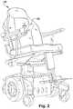
- FIGS. 1 and 2show exemplary embodiments of power driven wheelchairs.
- FIG. 3is a block diagram of an exemplary embodiment of a power driven wheelchair.
- FIG. 4is a block diagram of an exemplary embodiment of a system controller for a power driven wheelchair.
- FIG. 5is a block diagram of an exemplary embodiment of a programmer used in conjunction with related embodiments of power driven wheelchairs.
- FIG. 6is a block diagram of an exemplary embodiment of a local storage device associated with a system controller.
- FIG. 7is a block diagram of an exemplary embodiment of a portable storage medium associated with a system controller or a programmer.
- FIGS. 8 through 11are perspective views of exemplary embodiments of a system controller for a power driven wheelchair.
- FIG. 12is a perspective view of an exemplary embodiment of a programmer used in conjunction with related embodiments of power driven wheelchairs.
- FIGS. 13 and 14are examples of sequences of display screens associated with setting or modifying an exemplary programmable parameter within a selected programmable parameter set associated with a power driven wheelchair.
- FIG. 15is an exemplary menu hierarchy for a programming mode associated with operation or support of a power driven wheelchair.
- FIG. 16is a flow chart of an exemplary mode select monitor process associated with setting or modifying a programmable parameter.
- FIG. 17is a flow chart of an exemplary programming process associated with setting or modifying a programmable parameter.
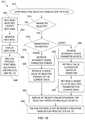
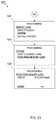
- FIG. 18is a flow chart of an exemplary menu navigation sub-process associated with setting or modifying a programmable parameter.
- FIG. 19is a flow chart of an exemplary menu item selection handler sub-process associated with setting or modifying a programmable parameter.
- FIG. 20is a flow chart of an exemplary set/modify parameter handler sub-process associated with setting or modifying a programmable parameter.
- FIG. 21is a flow chart of an exemplary drive select monitor sub-process associated with setting or modifying a programmable parameter.
- FIGS. 22 and 23are examples of sequences of display screens on an apparatus associated with a power driven wheelchair for communicating one or more library parameter sets from a portable storage medium to a local storage device associated with the power driven wheelchair.
- FIGS. 24 and 25are examples of sequences of display screens on an apparatus associated with a power driven wheelchair for communicating one or more programmable parameter sets from a local storage device associated with the power driven wheelchair to a portable storage medium.
- FIG. 26is an exemplary block diagram of an apparatus associated with a power driven wheelchair for setting or modifying a programmable parameter.
- FIG. 27is an exemplary flow chart of a process associated with a power driven wheelchair for setting or modifying a programmable parameter.
- FIG. 28is an exemplary block diagram of an apparatus associated with a power driven wheelchair for communicating a programmable parameter set.
- FIG. 29is an exemplary flow chart of a process associated with a power driven wheelchair for communicating a programmable parameter set.
- Circuitincludes, but is not limited to, hardware, firmware, software or combinations of each to perform a function(s) or an action(s). For example, based on a desired feature or need, a circuit may include a software controlled microprocessor, discrete logic such as an application specific integrated circuit (ASIC), or other programmed logic device. A circuit may also be fully embodied as software. As used herein, “circuit” is considered synonymous with “logic.”
- Controllerincludes, but is not limited to, any circuit or device that coordinates and controls the operation of one or more input or output devices.
- a controllercan include a device having one or more processors, microprocessors, or central processing units (CPUs) capable of being programmed to perform input or output functions.
- Logicincludes, but is not limited to, hardware, firmware, software or combinations of each to perform a function(s) or an action(s), or to cause a function or action from another component. For example, based on a desired application or need, logic may include a software controlled microprocessor, discrete logic such as an application specific integrated circuit (ASIC), or other programmed logic device. Logic may also be fully embodied as software. As used herein, “logic” is considered synonymous with “circuit.”
- “Operative communication,” as used hereinincludes, but is not limited to, a communicative relationship between devices, logic, or circuits, including mechanical and pneumatic relationships. Direct electrical, electromagnetic, and optical connections and indirect electrical, electromagnetic, and optical connections are examples of such communications. Linkages, gears, chains, push rods, cams, keys, attaching hardware, and other components facilitating mechanical connections are also examples of such communications. Pneumatic devices and interconnecting pneumatic tubing may also contribute to operative communications. Two devices are in operative communication if an action from one causes an effect in the other, regardless of whether the action is modified by some other device.
- two devicesseparated by one or more of the following: i) amplifiers, ii) filters, iii) transformers, iv) optical isolators, v) digital or analog buffers, vi) analog integrators, vii) other electronic circuitry, viii) fiber optic transceivers, ix) Bluetooth communications links, x) 802.11 communications links, xi) satellite communication links, and xii) other wireless communication links.
- an electromagnetic sensoris in operative communication with a signal if it receives electromagnetic radiation from the signal.
- two devices not directly connected to each other, but both capable of interfacing with a third device, e.g., a central processing unit (CPU),are in operative communication.
- processorincludes, but is not limited to, one or more of virtually any number of processor systems or stand-alone processors, such as microprocessors, microcontrollers, central processing units (CPUs), and digital signal processors (DSPs), in any combination.
- the processormay be associated with various other circuits that support operation of the processor, such as random access memory (RAM), read-only memory (ROM), programmable read-only memory (PROM), erasable programmable read-only memory (EPROM), clocks, decoders, memory controllers, or interrupt controllers, etc.
- RAMrandom access memory
- ROMread-only memory
- PROMprogrammable read-only memory
- EPROMerasable programmable read-only memory
- clocksdecoders
- memory controllersor interrupt controllers, etc.
- These support circuitsmay be internal or external to the processor or its associated electronic packaging.
- the support circuitsare in operative communication with the processor.
- the support circuitsare not necessarily shown separate from the processor in block diagrams or
- Signalincludes, but is not limited to, one or more electrical signals, including analog or digital signals, one or more computer instructions, a bit or bit stream, or the like.
- Softwareincludes, but is not limited to, one or more computer readable or executable instructions that cause a computer or other electronic device to perform functions, actions, or behave in a desired manner.
- the instructionsmay be embodied in various forms such as routines, algorithms, modules or programs including separate applications or code from dynamically linked libraries.
- Softwaremay also be implemented in various forms such as a stand-alone program, a function call, a servlet, an applet, instructions stored in a memory, part of an operating system, or other types of executable instructions. It will be appreciated by one of ordinary skill in the art that the form of software is dependent on, for example, requirements of a desired application, the environment it runs on, or the desires of a designer/programmer or the like.
- an exemplary embodiment of a power driven wheelchair 10includes a system controller 12 .
- the system controller 12controls operation of the power driven wheelchair 10 .
- Other embodiments of power driven wheelchairs and other embodiments of system controllersare available in various combinations.
- another exemplary embodiment of a power driven wheelchair 20includes a system controller 22 .
- the power driven wheelchair 30may include a system controller 32 , a drive controller 34 , a left drive motor 36 , a right drive motor 38 , and a suitable power source (e.g., battery) (not shown).
- the system controller 32may include a user interface device and may control the drive controller 34 in response to activation of one or more input devices associated with the user interface device and in response to software programs for one or more operating or support modes.
- the software programsmay use a plurality of programmable parameters arranged in sets associated with, for example, different environmental conditions to define driving response characteristics.
- the drive controller 34may control the left and right drive motors 36 , 38 in response to commands from the system controller 32 .
- Communication between the system controller 32 and drive controller 34may be via serial or parallel bus connections or via discrete signal connections.
- a Shark serial communication busdeveloped by Dynamic Controls of New Zealand, may be used to communicate with the drive controller 34 .
- the system controller 34may communicate directly with a left drive motor and a right drive motor via a serial communication bus, such as a controller area network (CAN) bus, where the left and right drive motors include a serial bus interface and local intelligence.
- CANcontroller area network
- the power driven wheelchair 30may also include various options, such as powered seating, powered front rigging, and powered steering.
- the powered seating optionmay include a tilt actuator 40 , a recline actuator 42 , an elevation actuator 44 , a horizontal actuator 46 , and a ventilator tray actuator 48 .
- the powered front rigging optionmay include a common leg rest actuator 50 and a common foot rest actuator 52 .
- the powered front rigging optionmay include independent left and right leg rest actuators and independent left and right foot rest actuators.
- the powered steering optionmay include one or more powered steering actuators 54 . These options may be added to the wheelchair in any combination. Likewise, various combinations of actuators may be selected for each option.
- a powered seating optionmay be limited to tilt and recline actuators 40 , 42 , tilt and elevation actuators 40 , 44 , recline and elevation actuators 40 , 46 , or tilt, recline, and elevation actuators 40 , 42 , 44 .
- individual right and left leg rest actuatorsmay be provided in lieu of the common leg rest actuator 50 .
- Back and seat shear reductionmay be provided by coordinated movement of the recline and horizontal actuators 42 , 46 .
- the system controller 32may control the actuators in response to activation of one or more input devices associated with the user interface device and in response to software programs for one or more operating or support modes.
- the software programsmay use a plurality of programmable parameters, for example, to define desired positions for user support surfaces and actuator response characteristics. Communication between the system controller 32 and actuators may be via serial or parallel bus connections or via discrete signal connections.
- actuatorsmay include sensors and local electronics which provides an interface to a CAN bus. It is understood that any actuator may include a variable speed reversible motor, a stepper motor, a linear motor, a servo motor, or another suitable device associated with position control of an actuator mechanism.
- the actuator mechanismfor example, controlling the position of user support surfaces, such as seat, back, leg rest, foot rest, or head rest support surfaces, via a suitable linkage, drive train, coupling, or another type of mechanical interface.
- providing modularization of actuators, motors, and other output devices with sensors, detectors, or other devices providing feedback for closed loop control of the corresponding output devicefacilitates the use of a serial or parallel bus architecture in the power driven wheelchair 30 .
- Thisalso simplifies the addition or removal of optional output devices and streamlines upgrades and retrofits.
- distributing intelligence, including interface circuits for output devices and associated feedback components, from the centralized controller to the modular output devicesfurther improves performance through parallel processing.
- distributing additional intelligence, including closed-loop control algorithms, from the centralized controller to the modular output devicesfurther improves performance through additional parallel processing and reduced bus traffic.
- One or more remote input devices 58may also be provided as options in the power driven wheelchair 30 .
- user interface devices for special needs userssuch as a proportional head control, a sip n′ puff system, a fiber optic tray array, a proximity head array, or a proximity switch array, may be provided as a remote input to the system controller 32 .
- Additional examples of remote input devices 58include, a 4-way toggle switch assembly, a quad pushbutton assembly, and a compact proportional joystick assembly.
- the 4-way toggle switch assembly or the quad pushbutton assemblymay be used for controlling powered seating systems.
- the compact proportional joystick assemblyfor example, may be used as a proportional attendant control.
- Communication between the system controller 32 and the remote input device(s) 58may be via serial or parallel bus connections or via discrete signal connections.
- a remote input devicemay be connected to a serial port on the system controller 32 . If the remote input device includes the appropriate electronics and local intelligence (e.g., processes for composing and de-composing bus messages), communications with the system controller 32 may, for example, be via a CAN bus or another type of bus or network connection.
- a programmer 60may be used in conjunction with the power driven wheelchair 30 .
- the programmer 60 described hereinmay be an optional accessory or special tool for dealers or technicians.
- the programmer 60may be adapted for use on various models and configurations of power driven wheelchairs.
- Communication between the system controller 32 and the programmer 60may be via serial or parallel bus connections or via discrete signal connections.
- the programmer 60may be connected to a serial port on the system controller 32 .
- the programmer 60includes the appropriate electronics and local intelligence (e.g., processes for composing and de-composing bus messages)
- communications with the system controller 32may, for example, be via a CAN bus or another type of bus or network connection.
- the various aspects of FIG. 3 described abovemay be automated, semi-automated, or manual and may be implemented through hardware, software, firmware, or combinations thereof.
- a block diagram of an exemplary embodiment of a system controller 32may include a microcontroller 62 , one or more input devices 64 , a display 66 , one or more indicators 68 , an on-board storage device 70 , a storage medium interface 72 , an output device interface 74 , one or more remote input device interfaces 76 , and a programmer interface 78 .
- the microcontroller 62may include a central processing unit (CPU) 80 , an on-chip storage device 82 , and an analog-to-digital (A/D) converter 84 .
- the A/D converter 84may provide the microcontroller 62 with an interface to receive analog input signals.
- the microcontroller 62may include an SAF-XC164CS 16-bit single-chip microcontroller by Infineon Technologies of München, Germany.
- the display 66may include a 128 ⁇ 64 pixel graphic display or a 160 ⁇ 160 pixel graphic display.
- the displaymay include a graphic display in a different size or a different arrangement of pixels. Any type of graphic display may be used, such as a liquid crystal display (LCD). Additionally, an alphanumeric display or another type of display may be used.
- the one or more indicators 68may include light emitting diodes (LEDs), lamps, other types of visual indicators, or audible devices.
- the one or more input devices 64may include a proportional analog joystick, a three position toggle or rotary switch, a return-to-center momentary three position switch, a rotary potentiometer, and a plurality of momentary pushbuttons.
- the one or more input devices 64may include other types of joysticks, switches, potentiometers, pushbuttons, or other types of control devices.
- the output device interface 74may be connected, for example, to a motor controller, actuators, motors, or similar devices associated with the power driven wheelchair.
- the output device interface 74may include one or more serial ports, one or more parallel ports, or discrete wiring connections in any combination.
- the output device interface 74may include a CAN bus serial port and a Shark bus serial port.
- the one or more remote input device interfaces 76 and programmer interface 78may each include a serial port, parallel port, or discrete wiring connections.
- the microcontroller 62may receive input signals from the one or more input devices 64 , remote input devices 58 ( FIG. 2 ) connected to the one or more remote input device interfaces 76 , or a programmer 60 ( FIG. 2 ) connected to the programmer interface 78 .
- the microcontroller 62may control the display 66 , the one or more indicators 68 , and various motors, actuators, and other output devices connected to the output device interface 74 , at least in part, in response to the input signals from the one or more input devices 64 , remote input devices 58 ( FIG. 2 ), or programmer 60 ( FIG. 2 ).
- the on-board storage device 70 and on-chip storage device 82each may include a volatile storage device, such as random access memory (RAM), and a non-volatile storage device, such as non-volatile memory, a fixed disk device, a removable disc device, an optical storage device, etc.
- Non-volatile memorymay include read-only memory (ROM), programmable read-only memory (PROM), erasable programmable read-only memory (EPROM), electrically erasable programmable read only memory (EEPROM), or flash memory.
- ROMread-only memory
- PROMprogrammable read-only memory
- EPROMerasable programmable read-only memory
- EEPROMelectrically erasable programmable read only memory
- software programs, one or more programmable parameter sets, and help informationmay be stored in one or more non-volatile memory storage devices associated with the on-board storage device 70 or on-chip storage device 82 .
- Each programmable parameter setmay include a plurality of programmable operating parameters for the power driven wheelchair 20 .
- the microcontroller 62may run the software programs and may control the display 66 , indicators 68 , and various motors, actuators, and other output devices connected to the output device interface 74 based, at least in part, on one or more of the programmable operating parameters.
- a portable storage medium 86may be used in conjunction with the system controller 32 .
- the portable storage medium 86may include a plurality of storage locations which may store a security key, one or more library parameter sets, and a collection of help information.
- the portable storage medium 86 described hereinmay be an optional accessory or special tool for dealers or technicians. In some cases, the portable storage medium 86 may also be used in conjunction with normal operation of the power driven wheelchair by its owner or end user.
- the portable storage medium 86 described hereinmay be suitable for use on various models and configurations of power driven wheelchairs. However, in another scheme for protection and security of the information stored therein, a given portable storage medium 86 may be serialized or otherwise tailored and keyed to an individual system controller 32 and corresponding power driven wheelchair. Communication between the microcontroller 62 and the portable storage medium 86 may be via the storage medium interface 72 .
- the portable storage medium 86may include a non-volatile storage medium, such as non-volatile memory.
- the portable storage medium 86may include, for example, a type of removable storage medium known as a removable memory card.
- the portable storage medium 86may include a secure digital (SD) card.
- the storage medium interface 72may include, for example, a corresponding removable memory interface (e.g., an SD card reader) to communicate and exchange information with the microcontroller 62 .
- the portable storage mediummay include other types of removable memory, such as a compact flash (CF) card, a flash memory pen drive, a memory stick, a microdrive, a multimedia memory card (MMC), a smart media (SM) card, an xD picture card, a subscriber identity module (SIM) card, a memory chip (e.g., ROM, PROM, EPROM, EEPROM), or another suitable form of removable, separable, or detachable memory.
- the portable storage mediummay include other forms of removable storage medium, such as optical discs (e.g., compact discs (CDs), digital video discs (DVDs)) or floppy disks (e.g., zip disks).
- the portable storage mediummay include a portable storage device, such as an external memory card reader, an external optical disc drive, an external floppy disk drive, a portable computer (e.g., laptops, notebooks, personal digital assistants (PDAs)), a mobile telephone (e.g., cellular telephone, personal communication system, satellite telephone), a digital camera, an MP3 player, or any type of portable storage device capable of wired or wireless communication with another compatible communication device.
- a portable storage devicesuch as an external memory card reader, an external optical disc drive, an external floppy disk drive, a portable computer (e.g., laptops, notebooks, personal digital assistants (PDAs)), a mobile telephone (e.g., cellular telephone, personal communication system, satellite telephone), a digital camera, an MP3 player, or any type of portable storage device capable of wired or wireless communication with another compatible communication device.
- a portable storage devicesuch as an external memory card reader, an external optical disc drive, an external floppy disk drive, a portable computer (e.
- the storage medium interface 72may include a connector or socket that mates with the portable storage medium 86 and an electronic circuit that supports communication between the microcontroller 62 and the portable storage medium 86 .
- the storage medium interface 72may include a memory card reader, a memory chip socket, an optical disc drive, a floppy disk drive, a serial port (e.g., universal serial bus (USB) port, RS-232), a parallel port (e.g., small computer system interface (SCSI) port), a modem, an Ethernet port, a wireless Ethernet transceiver (e.g., IEEE 802.11b), a Bluetooth transceiver, an infrared (IR) transceiver, a radio frequency (RF) transceiver, a mobile telephone interface, a cable television interface, a satellite television interface, or any communication device capable of wired or wireless communication with a corresponding portable storage medium.
- the various aspects of FIG. 4 described abovemay be automated, semi-automated, or manual and may be implemented through
- an exemplary embodiment of a programmer 60may include a microcontroller 88 , one or more input devices 90 , a display 92 , one or more indicators 94 , an on-board storage device 96 , a storage medium interface 98 , and a controller interface 100 .
- the microcontroller 88may include a CPU 102 and an on-chip storage device 104 .
- the microcontroller 88may include an SAF-XC164CS 16-bit single-chip microcontroller by Infineon Technologies of München, Germany.
- the display 92may include a 160 ⁇ 160 pixel graphic display.
- the displaymay include a graphic display in a different size or a different arrangement of pixels. Any type of graphic display may be used, such as an LCD. Additionally, an alphanumeric display or another type of display may be used.
- the one or more indicators 94may include LEDs, lamps, other types of visual indicators, or audible devices.
- the one or more input devices 90may include a plurality of momentary pushbuttons. In additional embodiments, the one or more input devices 90 , may include other types of pushbuttons or other types of control devices.
- the controller interface 100may include a serial port, parallel port, or discrete wiring connections for interfacing with a system controller 32 ( FIG. 2 ) of a power driven wheelchair.
- the microcontroller 88may receive input signals from the one or more input devices 90 and the system controller connected to the controller interface 100 .
- the microcontroller 88may latch or store activations of the one or more input devices 90 or other input signals over time.
- the microcontroller 88may control the display 92 and the one or more indicators 94 , at least in part, in response to the input signals from the one or more input devices or the system controller.
- the microcontroller 88may periodically (e.g., every 10 ms) receive a status check message from the system controller 32 ( FIG. 2 ) via the controller interface 100 . For example, if an activation of the one or more input devices 90 has occurred since the last status check, the microcontroller 88 may send a response to the status check message via the controller interface 100 that may include information regarding the latched or stored activations from the one or more input devices 90 . Once the response is sent, certain latched or stored activations may be cleared. If no activations occurred since the last status check, the microcontroller 88 may send a response to the status check message indicating there is no new data to send. The microcontroller 88 , for example, may also receive messages from system controller via the controller interface 100 containing information to be displayed on the display 92 or commands regarding control of the display 92 .
- the on-board storage device 96 and on-chip storage device 104each may include a volatile storage device, such as RAM, and a non-volatile storage device, such as non-volatile memory, a fixed disk device, a removable disc device, an optical storage device, etc.
- Non-volatile memoryfor example, may include ROM, PROM, EPROM, EEPROM, or flash memory.
- software programs, a plurality of programmable parameter sets, and help informationmay be stored in one or more non-volatile memory storage devices associated with the on-board storage device 96 or on-chip storage device 104 .
- the microcontroller 88may run the software programs and may control the display 92 and indicators 94 based, at least in part, on one or more of the programmable operating parameters.
- a portable storage medium 106may be used in conjunction with the programmer 60 . Like the portable storage medium 86 ( FIG. 4 ) associated with the system controller 32 ( FIG. 4 ), the portable storage medium 106 may also be an optional accessory or special tool for dealers or technicians. Therefore, the various characteristics, options, and alternatives described above for the portable storage medium 86 ( FIG. 4 ) and storage medium interface 72 ( FIG. 4 ) also apply to the portable storage medium 106 and storage medium interface 98 in the programmer 60 .
- the microcontroller 88is in communication with the portable storage medium 106 via the storage medium interface 98 . This enables the microcontroller 88 to retrieve data from the portable storage medium 106 and provide it to the system controller via the controller interface 100 or to save data received from the system controller to the portable storage medium 106 .
- the portable storage medium 106 associated with the programmer 60 and the portable storage medium 86 ( FIG. 4 ) associated with the system controller 32 ( FIG. 2 )may be interchangeable.
- the portable storage medium 106may be used in conjunction with the system controller and vice versa.
- the portable storage medium 86 ( FIG. 4 ) or 106 ( FIG. 5 ) associated with the power driven wheelchair 10 ( FIG. 1 )may be used in system controllers or programmers associated with other power driven wheelchairs. This facilitates development of a master copy of library parameter sets on one or more portable storage medium that can be transported to multiple power driven wheelchairs for selective communication of library parameter sets from the master copy to corresponding system controllers associated with each power driven wheelchair. Additionally, programmable parameter sets can be selectively uploaded to the master copy to build or grow the library parameter sets from individual power driven wheelchairs.
- an exemplary embodiment of a local storage device 107 associated with a system controller 32may include a plurality of storage locations that may store software programs 108 and a plurality of programmable parameter sets.
- the local storage device 107may include an on-board storage device 70 ( FIG. 4 ), 96 ( FIG. 5 ) or an on-chip storage device 82 ( FIG. 4 ), 104 ( FIG. 5 ).
- a first programmable parameter setis identified as drive 1 parameter set 110
- another programmable parameter setis identified as drive 4 parameter set 112
- additional programmable parameter setsare identified as drive N parameter set 114 .
- the local memory device 107may include four programmable parameter sets. However, there may be more or less programmable parameter sets in additional embodiments. Each programmable parameter set may include multiple programmable operating parameters. The programmable parameter sets may also be viewed as a plurality of programmable operating parameters that may be arranged in sets according to, for example, different environmental conditions for the power driven wheelchair (e.g., indoor, outdoor, etc.).
- an exemplary embodiment of the portable storage medium 115may include a plurality of storage locations that may store a security key 116 and a plurality of library parameter sets.
- the portable storage medium 115has the same characteristics and features of the portable storage medium 86 ( FIG. 4 ), 106 ( FIG. 5 ) described above.
- a first library parameter setis identified as library 1 parameter set 117
- another library parameter setis identified as library 4 parameter set 118
- additional library parameter setsare identified as library N parameter set 119 .
- the portable storage medium 115may include four library parameter sets. However, there may be more or less library parameter sets in additional embodiments.
- Each library parameter setmay include multiple programmable operating parameters.
- the library parameter setsmay also be viewed as a plurality of programmable operating parameters that may be arranged in sets according to, for example, different environmental conditions for the power driven wheelchair (e.g., indoor, outdoor, etc.).
- the same portable storage medium 115may be used effectively when installed directly in a system controller or when installed in a programmer connected to the same system controller.
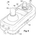
- an exemplary embodiment of a system controller 120may include a power/drive select switch 122 , a mode select switch 124 , a graphic display 126 , a joystick control 128 , a speed control 130 , and a mounting hub 132 .
- This configuration of the system controller 120may be referred to as a multi-purpose joystick (MPJ) model.
- the MPJ modelmay also include a removable memory card slot (not shown) for receiving a portable storage medium 86 ( FIG. 4 ), such as a removable memory card.
- the power/drive select switch 122may include a three position rotary switch.
- the “on” positionfor example, is a center position where the power driven wheelchair is powered on.
- the “drive select” positionis a return-to-center position that advances through the available drives (i.e., programmable parameter sets). For example, when the “drive select” position is activated in programming mode, a next programmable parameter set from a group of programmable parameter sets stored in the system controller 32 is selected in relation to a currently-selected programmable parameter set.
- the plurality of programmable parametersmay include four programmable parameter sets. However, there may be more or less programmable parameter sets in additional embodiments.
- the “off” position of the power/drive select switch 122is, for example, a latching position opposite the “drive select” position where the power driven wheelchair is powered down.
- the mode select switch 103is a momentary pushbutton switch. When the mode select switch 103 is activated, for example, a next mode from a plurality of modes is selected in relation to a currently-selected mode.
- the plurality of modesmay include a driving mode, an automated positioning mode associated with powered seating or powered front rigging, a 4-way switch positioning mode associated with powered seating or powered front rigging, and an environmental control unit (ECU) mode.
- ECUenvironmental control unit
- Other embodimentsmay include any combination of these modes and additional modes.
- the graphic display 126may include a 128 ⁇ 64 pixel display.
- a screen on the graphic display 126may include about five or six lines of text by about 32 characters, about two large icons (e.g., 64 ⁇ 64 pixels icons), about eight small icons (e.g., 32 ⁇ 32 pixel icons), or various combinations thereof. Of course, larger or smaller icons may also be used in various combinations.
- the joystick control 128may include a proportional analog joystick.
- the joystick control 128may be used for directional control for menu or icon navigation, setting or modifying a programmable parameter, saving a selected programmable parameter value, directional control for driving the power driven wheelchair, positional control of a selected user support surface, and other selection-type functions when directional or positional control is not required.
- the joystick control 128is an example of a screen navigation control.
- the speed control 130may include a rotary potentiometer. Turning the speed control 130 between counter-clockwise and clockwise limits adjusts the maximum speed of the power driven wheelchair in relation to operation using the joystick control 128 .
- the mounting hub 132may be inserted in a mating receptacle on the power driven wheelchair to mount the system controller 32 .
- a system controller 140may include a mode select switch 124 , a graphic display 126 , a joystick control 128 , a speed control 130 , a mounting hub 132 , a power/drive select switch 142 , and a removable memory card slot 144 .
- This system controller 140may be referred to as a personalized switch rear-mount (PSR) joystick model or simply a PSR model.
- PSRswitch rear-mount
- the components of the PSR modelhave the same functional characteristics as the components described above for the MPJ model ( FIG. 8 ).
- the PSR modelprovides an alternate construction of a system controller.
- a system controller 150may include a mode select switch 124 , a graphic display 126 , a joystick control 128 , a speed control 130 , and a power/drive select switch 142 .
- This system controller 150may be referred to as a personalized switch front-mount (PSF) joystick model or simply a PSF model.
- a mounting hub(not shown) may also be provided on the PSF model for mounting the system controller 150 .
- the PSF modelmay also include a removable memory card slot (not shown) for receiving a portable storage medium 86 ( FIG. 4 ), such as a removable memory card.
- the components of the PSF modelhave the same functional characteristics as the components described above for the MPJ model ( FIG. 8 ).
- the PSF modelprovides an alternate construction of a system controller.
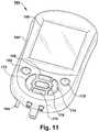
- yet another exemplary embodiment of a system controller 160may include a removable memory card slot 144 , an info switch 162 , a power switch 164 , a graphic display 166 , an up direction switch 168 , a down direction switch 170 , a menu/left direction switch 172 , a right direction switch 174 , a select switch 176 , and a save switch 178 .
- This system controller 160may be referred to as a DISPLAY model.
- the DISPLAY modelmay also include a mounting hub (not shown) for mounting the system controller 160 .
- the removable memory card slot 144has the same functional characteristics as described above for the MPJ model ( FIG. 8 ).
- the info switch 162may include a momentary pushbutton switch. Activation of the info switch 162 may cause the controller 160 to access and display help information. Certain information from help information file(s) may be provided on the graphic display 166 . The help information provided may be related to the content of the display at or about the time the info switch 162 was activated. For example, information retrieved from help information file(s) may be context-sensitive with respect to an active screen object, such as a current menu or icon selection, a current programmable parameter selection, a current drive selection, a current mode selection, or a current error message. This provides information about a specific item as it is currently being used.
- help information file(s)may be context-sensitive with respect to an active screen object, such as a current menu or icon selection, a current programmable parameter selection, a current drive selection, a current mode selection, or a current error message. This provides information about a specific item as it is currently being used.
- the context-sensitive help informationmay: i) explain current selections for operation or support of the power driven wheelchair, ii) current settings for programmable parameters, iii) current selection(s) with respect to screen objects (i.e., active screen object(s)) of the display, and iv) describe an expected result from activation of the selected option.
- retrieval of specific information from the help information file(s)may be menu-driven, topic-driven, or driven by another suitable means.
- the power switch 164may include a two position toggle switch with on and off positions. When the power switch 164 is set to the “on” position the power driven wheelchair is powered on. When the power switch 164 is switched from the “on” position to the “off” position, for example, the power driven wheelchair may begin a predetermined shutdown sequence.
- the graphic display 166for example, is a 160 ⁇ 160 pixel display. A screen on the graphic display 166 may include about twelve lines of text by about 40 characters, about four large icons (e.g., 64 ⁇ 64 pixels icons), about 25 small icons (e.g., 32 ⁇ 32 pixel icons), or various combinations thereof. Of course, larger or smaller icons may also be used in various combinations.
- the up, down, menu/left, and right direction switches 168 , 170 , 172 , 174may include momentary pushbutton switches.
- the up, down, menu/left, and right direction switches 168 , 170 , 172 , 174may be used for directional control for menu or icon navigation, setting or modifying a programmable parameter, positional control of a selected user support surface, and other selection-type functions when directional or positional control is not required.
- activation of the menu/left direction switch 172may cause the controller 160 to present the previous menu on the graphic display 166 .
- the up, down, menu/left, and right direction switches 168 , 170 , 172 , 174are examples of a screen navigation control.
- the up, down, menu/left, and right direction switches 168 , 170 , 172 , 174may also be used for directional control for certain power driven wheelchair driving operations.
- the select switch 176may include a momentary pushbutton switch.
- the select switch 176may be used for selection of menu items or icons.
- the save switch 178may include a momentary pushbutton switch.
- the save switch 178may be used for saving a displayed value of a selected programmable parameter as the current value for the parameter.
- the mode select, drive select, and speed control functions described above for the MPJ modelmay be implemented through the graphic display 166 , navigational control using the up, down, menu/left, and right direction switches 168 , 170 , 172 , 174 , and activation of the select or save switches 176 , 178 .
- an exemplary embodiment of a programmer 180may include a removable memory card slot 144 , a graphic display 166 , an up direction switch 168 , a down direction switch 170 , a menu/left direction switch 172 , a right direction switch 174 , a select switch 176 , a save switch 178 , and a power/info switch 182 .
- the components of the programmer 180have the same functional characteristics as the components described above for the DISPLAY model of the system controller 160 ( FIG. 11 ).
- the programmer 180may combine the power and info functions in the power/info switch 182 .
- the programmer 180may not require the speed control functionality of the DISPLAY model.
- the programmer 180may also not require other functionality of the DISPLAY model in relation to driving the power driven wheelchair or positioning the user support surfaces.
- the power/info switch 182may include a momentary switch. Pressing and holding the power/info switch 182 for at least a predetermined time (e.g., three seconds) may provide control of toggling power on and power off functions. For example, if the programmer 180 is powered off, pressing and holding the power/info switch 182 for at least the predetermined time may cause the programmer 180 to be powered on. Similarly, if the programmer 180 is powered on, pressing and holding the power/info switch 182 for at least the predetermined time may cause the programmer 180 to begin a predetermined shutdown sequence.
- the info functionmay be provided by pressing and releasing the power/info switch 182 within a predetermined time (e.g., two seconds). The characteristics of the info function of the power/info switch 182 are otherwise the same as those described above for the info switch 162 of the DISPLAY model of the system controller 160 ( FIG. 11 ).
- an exemplary sequence 200 of display screens on a system controller or programmer associated with setting or modifying an exemplary programmable parameter within a selected programmable parameter set associated with a power driven wheelchairbegins at a first screen 202 .
- the first screen 202depicts an exemplary main menu for a programming mode of the power driven wheelchair.
- a currently selected programmable parameter setis named DRIVE 1 .
- DRIVE 1is also labeled OUTDOOR which infers that its programmable parameters are set to values suitable for driving the power driven wheelchair in an outdoor environment.
- a SPEED programmable parameter in DRIVE 1is currently set to 90%.
- Bold highlightingindicates that the SPEED programmable parameter is currently selected.
- a “select” activationadvances the sequence 200 to the second screen 204 .
- the “select” activationmay be performed by moving a joystick control to the right or by activating a select switch.
- the second screen 204depicts an exemplary set/modify screen for the SPEED programmable parameter.
- the current value of the SPEED programmable parameter for drive 1i.e., D 1
- a progress barmay provide a graphical representation of the current 90% value.
- the MORE and LESS objectsindicate that the programmable parameter is a “range” parameter and that the value of the parameter may be selected by activation of, for example, a joystick control or up or down direction switches. For example, moving a joystick control on a system controller forward may be a MORE activation and moving it back may be a LESS activation.
- pressing an up direction switch on a system controller or programmermay be a MORE activation and pressing a down direction switch may be a LESS activation.
- the MORE objectmay have been the last control activation.
- use of a pointer or any other suitable form of highlightingmay be used to indicate the last control activation.
- the LESS objectmay be highlighted in bold. For example, after one or more LESS activations, the third screen 206 may be displayed.
- the third screen 206shows that the current value for the SPEED programmable parameter is now 80%. For example, if the SPEED programmable parameter is adjusted in five percent intervals, this change from 90% to 80% is based on two LESS activations. Alternatively, if the resolution for adjusting the programmable parameter is two percent, five LESS activations would produce the ten percent adjustment shown in the third screen 206 .
- the interval or resolution for adjustment of a given programmable parametercan be any suitable value and can be linear or non-linear. In one embodiment, neither the LESS nor the MORE objects are initially highlighted by default. However, the LESS object is highlighted, for example, in bold and the MORE object is returned to normal text following a LESS activation.
- activation of a save switchsaves the displayed value (i.e., 80%) for the SPEED programmable parameter in a corresponding storage location associated with the selected programmable parameter set (e.g., D 1 ).
- Activation of the save switchmay also automatically advance the sequence 200 to the fourth screen 208 which is the main menu for the programming mode.
- a previous menu activationmay be required to reverse the sequence 200 until the main menu is again displayed as shown in the fourth screen 208 .
- moving a joystick control on a system controller to the leftmay be interpreted as a previous menu activation.
- pressing a left direction switch on a system controller or programmermay be interpreted as a previous menu activation.
- the fourth screen 208depicts the exemplary main menu of the programming mode with the current value of the SPEED programmable parameter for DRIVE 1 now set to 80%.
- FIG. 14another exemplary sequence 210 of display screens on a system controller or programmer associated with setting or modifying another exemplary programmable parameter within a selected programmable parameter set associated with a power driven wheelchair begins at a first screen 212 .
- the first screen 212depicts an exemplary main menu for a programming mode of the power driven wheelchair.
- a currently selected programmable parameter setis named DRIVE 1 .
- DRIVE 1is also labeled OUTDOOR which infers that its programmable parameters are set to values suitable for driving the power driven wheelchair in an outdoor environment.
- Bold highlightingindicates that the ADVANCED MENU is currently selected.
- Thismay be the default selection when the main menu is initially displayed or it may be the result of one or more down or up activations using a joystick control or an up or down direction switch.
- use of a pointer or any other suitable form of highlightingmay be used to indicate the current or active selection in this menu and subsequent menus or other types of screens.
- a “select” activationadvances the sequence 210 to the second screen 214 .
- the “select” activationfor example, may be performed by moving the joystick control to the right or by activating a select switch.
- the second screen 214depicts an exemplary ADVANCED MENU.
- the ADVANCED MENUmay include five or more menu items in a list. An individual menu item may be selected by navigating up or down the list of menu items. The display, however, may not be able to display all of the menu items together. As shown in 214 , the first four items are initially displayed on the screen and bold highlighting indicates that the first menu item, PERFORMANCE ADJUST, is currently selected. In order to select the last menu item, five down activations may be required. With the fourth down activation, the screen may begin to scroll down the list of menu items. After the last menu item selected, for example, the display may continue to scroll to the beginning of the list with additional down activations.
- PERFORMANCE ADJUSTis selected and a “select” activation advances the sequence 210 to the third screen 215 .
- the third screen 215depicts an exemplary DRIVE SELECT list.
- the DRIVE SELECT listidentifies multiple programmable parameter sets for selection of a specific set for which programmable parameters are to be set or modified. As shown in 215 , there may be four programmable parameter sets and a currently selected programmable parameter set (i.e., DRIVE 1 ) may be initially selected by default and highlighted in bold. Up or down activations using the joystick control or up and down direction switches may be used to navigate the list of menu items. For the third screen 215 , a “select” activation selects the programmable parameter set associated with the highlighted menu item and advances the sequence 210 to the fourth screen 216 .
- the fourth screen 216depicts an exemplary PARAMETER SELECT list of programmable parameters.
- the PARAMETER SELECT listmay include a plurality of programmable parameters for DRIVE 1 which may be individually selected by navigating up or down the list. For example, after eleven down activations, the display has scrolled down the list to an INPUT TYPE programmable parameter associated with DRIVE 1 and the fifth screen 218 is displayed. At this point, the INPUT TYPE programmable parameter is selected and a “select” activation advances the sequence 210 to the sixth screen 220 .
- the sixth screen 220depicts an exemplary set/modify screen for the INPUT TYPE programmable parameter.
- the current value of the INPUT TYPE programmable parameter for DRIVE 1is MPJ.
- MPJmay represent an MPJ model system controller.
- the list of four optionsindicates that programmable parameter is a “choice” parameter and that the value of the parameter may be selected by navigating up or down the list. For example, two down activations moves the pointer down to the PSF option and a “select” activation advances the sequence 210 to the seventh screen 222 .
- PSFmay represent a PSF model system controller.
- the seventh screen 222shows that the current value for the INPUT TYPE programmable parameter is now PSF.
- a “save” activationsaves the current value of the INPUT TYPE programmable parameter for DRIVE 1 in a corresponding storage location.
- activation of the save switchmay also automatically advance to the eighth screen 224 .
- one or more previous menu activationmay be required to reach the eighth screen 224 .
- the select switch and the save switchcan be a common multi-function switch, such as moving a joystick control to the right.
- the select and save switchesmay be separate switches.
- the eighth screen 224depicts the exemplary PARAMETER SELECT list of programmable parameters as displayed in the fourth screen 216 .
- the current valuewould be PSF.
- a previous menu activationfor example, may result in display of the ADVANCE MENU screen 214 again.
- another previous menu activationfor example, may result in display of the main menu again, as shown in the first screen 212 .
- an exemplary programming mode menu hierarchy 264 for setting or modifying a programmable parameter associated with operation of a power driven wheelchairbegins with a main menu 266 .
- a similar embodiment of the main menu 266is also depicted in FIG. 13 and described above in more detail.
- An advanced menu 268may be selected from the main menu 266 .
- a similar embodiment of the advanced menu 268is described above in more detail with reference to FIG. 14 .
- Performance adjust 270may be selected after from the advanced menu 268 .
- a similar embodiment of the performance adjust 270is described above in more detail with reference to FIG. 14 .
- a standard programs menu 272may be selected from the advanced menu 268 .
- An SD card menu 274may also be selected from the advanced menu 254 .
- Additional menus or itemssuch as a drive pgrm (program) item 276 , a store (drive program) to SD card item 278 , a read (drive program) from SD card item 280 , a system item 282 , a store (system) to SD card item 284 , and a read (system) from SD card item 286 may be selected within the hierarchy of the SD card menu 274 .
- the SD card menu 274may be referred to as a removable memory card menu or a portable storage medium menu.
- Additional menus or listssuch as a diagnostics menu 288 , a powered seating menu 290 , and a calibrations menu 292 may also be selected from the advanced menu 268 .
- an exemplary mode select monitor process 300 associated with setting or modifying a programmable parameterbegins at 302 where the process starts.
- the processmay detect activation of a mode select switch (e.g., 124 ( FIG. 8 )).
- the processmay periodically check the condition of the mode select switch. If the mode select switch was activated, system programs that are running for a current mode, such as a driving mode, may be suspended or ended so that a system mode can be selected ( 306 ). After a mode is selected, suspended system programs that are compatible with the selected mode may be continued while those that are not compatible may be ended. If the programming mode is selected in 308 , the programming process (see FIG. 17 ) may be started in 310 .
- the programming processwas suspended in 306 , it may be continued in 310 .
- the mode select monitor processis repeated.
- the various aspects of FIG. 16 described abovemay be automated, semi-automated, or manual and may be implemented through hardware, software, firmware, or combinations thereof.
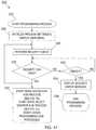
- an exemplary programming process 320 associated with setting or modifying a programmable parameterbegins at 322 where the process starts.
- programming process settingsmay be initialized and a main menu may be displayed on a graphic display (e.g., 124 ( FIG. 8 )).
- a security checkmay be performed prior to advancing from the main menu to prevent unauthorized setting or modifying of programmable parameters ( 326 ). This security check is optional and not required, particularly in regard to the programming functions. It is described here because in certain applications users, attendants, and technicians may have different privileges with regard to operation and support of the power driven wheelchair.
- a security checkfacilitates limiting access to one or more features provided in the power driven wheelchair. For example, a security check may be used to limit access to programming function to technicians.
- the security checkmay include a hardware or software key associated with insertion of an appropriate portable storage medium (e.g., 86 ( FIG. 4 )), such as a removable memory card, in a storage medium interface (e.g., 72 ( FIG. 4 )), such as removable memory card slot (e.g., 144 ( FIG. 9 )).
- an appropriate portable storage mediume.g., 86 ( FIG. 4 )
- a storage medium interfacee.g., 72 ( FIG. 4 )
- removable memory card slote.g., 144 ( FIG. 9 )
- the security checkmay include a hardware or software key associated with connection of the programmer (e.g., 60 ( FIG. 3 )) to the system controller (e.g., 32 ( FIG. 3 )). If the programmer is being used, the security check may include a key status signal transmitted by the programmer to the system controller.
- the programming processmay return to 326 to repeat the security check and also may advance to 330 to start or continue a menu navigation sub-process (see FIG. 18 ) and to start or continue a drive select monitor sub-process (see FIG. 21 ).
- other programming sub-processesmay also be started or continued.
- the security checkfor example, may be repeated about every ten milliseconds while the programming process is running. In additional embodiments, the security check may be repeated at a different periodic interval. Moreover, the interval between successive security checks may be aperiodic, rather than periodic. Since 326 - 330 are repeated, after the initial successful pass through the security check the menu navigation sub-process, drive select monitor sub-process, and any other programming sub-process may be continued in 330 after additional successful passes through the security check.
- the programming processmay advance to 332 to determine if a predetermined timeout period has expired. If the timeout period is not expired, the process may return to 328 to determine if the security check passed. If the timeout period is expired at 332 , a security error message may be displayed ( 334 ) and the programming process may be ended ( 336 ).
- the various aspects of FIG. 17 described abovemay be automated, semi-automated, or manual and may be implemented through hardware, software, firmware, or combinations thereof.
- an exemplary menu navigation sub-process 340 associated with setting or modifying a programmable parameterbegins at 342 where the sub-process starts.
- the processmay detect an up activation. If an up activation is not detected, the process does not advance beyond 344 . For example, moving a joystick control (e.g., 128 ( FIG. 8 )) forward or pressing an up direction switch (e.g., 168 ( FIG. 11 )) may provide an up activation. If an up activation is detected, the menu item above the current menu item may be selected and highlighted to indicate the newly selected menu item ( 346 ). The previously highlighted menu item may be returned to normal text. Next, at 348 , the menu navigation sub-process may be repeated.
- the processmay detect a previous menu activation. If a previous menu activation is not detected, the process does not advance beyond 350 . For example, moving a joystick control (e.g., 128 ( FIG. 8 )) to the left or pressing a menu/left direction switch (e.g., 172 ( FIG. 11 )) may provide an previous menu activation. If a previous menu activation is detected, the previous menu in a menu hierarchy (e.g., 264 ( FIG. 15 )) may be displayed ( 352 ), unless, for example, the current menu is the main menu. Next, at 348 , the menu navigation sub-process may be repeated with respect to the previous menu.
- a previous menu activationmay be moved to the left or pressing a menu/left direction switch (e.g., 172 ( FIG. 11 )
- the previous menu in a menu hierarchye.g., 264 ( FIG. 15 )
- the menu navigation sub-processmay be repeated with respect to the previous menu.
- the processdetects a down activation. If a down activation is not detected, the process does not advance beyond 354 . For example, moving a joystick control (e.g., 128 ( FIG. 8 )) backward or pressing a down direction switch (e.g., 174 ( FIG. 11 )) may provide a down activation. If a down activation is detected, the menu item below the current menu item may be selected and highlighted to indicate the newly selected menu item ( 356 ). The previously highlighted menu item may be returned to normal text. Next, at 348 , the menu navigation sub-process may be repeated.
- a joystick controle.g., 128 ( FIG. 8 )
- a down direction switche.g., 174 ( FIG. 11 )
- the processdetects a select activation. If a select activation is not detected, the process does not advance beyond 358 . For example, moving a joystick control (e.g., 128 ( FIG. 8 )) to the right or pressing a select switch (e.g., 174 ( FIG. 11 )) may provide a select activation. If a select activation is detected, the menu navigation sub-process may be ended and a menu item selection handler sub-process (see FIG. 19 ) may be started.
- a joystick controle.g., 128 ( FIG. 8 )
- a select switche.g., 174 ( FIG. 11 )
- the menu navigation sub-process 340may periodically check the condition of the corresponding components associated with an up activation, previous menu activation, down activation, and select activation in a loop to determine if corresponding activations occur.
- the various aspects of FIG. 18 described abovemay be automated, semi-automated, or manual and may be implemented through hardware, software, firmware, or combinations thereof.
- an exemplary menu item selection handler sub-process 370 associated with setting or modifying a programmable parameterbegins at 372 where the sub-process starts.
- the sub-processmay advance to 376 to determine whether the programmable parameter is a “range” parameter or a “choice” parameter.
- a “range” parameteris a programmable parameter that may be set or modified to a value within a predetermined range of values (e.g., 204 ( FIG. 13 )).
- a “choice” parameteris a programmable parameter that may be set to any value within a list of value choices (e.g., 220 ( FIG. 14 )).
- a set/modify “range” parameter screenmay be retrieved ( 378 ).
- a current value for the selected programmable parameter associated with a currently selected drivemay be retrieved ( 380 ).
- the currently selected drivemay be based on, for example, a default drive selection or activations of the power/drive select switch (e.g., 122 ( FIG. 8 )).
- the currently selected drivemay also be based on drive selection using a drive select screen (e.g., 215 ( FIG. 14 )) and corresponding menu navigation (see FIG. 18 ) to select the drive.
- the currently selected drivecorresponds to a programmable parameter set from a plurality of programmable parameters.
- the set/modify parameter screen with the current value for the selected programmable parameter and selected drivemay be displayed on a graphic display (e.g., 126 ( FIG. 8 )).
- the menu item selection handler sub-processmay be ended and the set/modify parameter handler sub-process (see FIG. 20 ) may be started.
- a set/modify choice parameter screenmay be retrieved ( 386 ). Then, values for each item in the list of choices for the selected programmable parameter may be retrieved ( 388 ). Next, a current value for the selected programmable parameter associated with a currently selected drive may be retrieved ( 390 ). At this point, the process advances to 382 and continues as described above.
- a new (i.e., lower level) menuwas selected and the sub-process may advance to 392 to identify the new menu.
- the new menumay be retrieved ( 394 ).
- the new menumay be displayed.
- the menu item selection handler sub-processmay be ended and the menu navigation sub-process (see FIG. 18 ) may be started.
- the various aspects of FIG. 19 described abovemay be automated, semi-automated, or manual and may be implemented through hardware, software, firmware, or combinations thereof.
- an exemplary set/modify parameter handler sub-process 400 associated with setting or modifying a programmable parameterbegins at 402 where the sub-process starts.
- the processmay detect an up activation. If an up activation is not detected, the process does not advance beyond 404 . If an up activation is detected, the parameter value choice above the current parameter value choice may be selected and highlighted to indicate the newly selected parameter value from a list of parameter value choices (i.e., when the selected programmable parameter is a “choice” parameter) ( 406 ).
- the selected programmable parameteris a “range” parameter
- the selected parameter valuemay be increased to the next predetermined higher value within the range of values for the corresponding programmable parameter ( 406 ).
- a MORE screen objectmay be highlighted to indicate the last adjustment made to the selected programmable parameter was based on an up activation.
- the set/modify parameter handler sub-processmay be repeated.
- the processmay detect a save activation. If a save activation is not detected, the process does not advance beyond 410 . For example, moving a joystick control (e.g., 128 ( FIG. 8 )) to the right or pressing a save switch (e.g., 178 ( FIG. 11 )) may provide a save activation. If a save activation is detected, the new parameter value may be stored as the current parameter value for the selected programmable parameter of the currently selected drive ( 412 ). At 414 , the set/modify parameter display may be updated with the new current parameter value for the selected programmable parameter of the currently selected drive. Next, at 408 , the set/modify parameter handler sub-process may be repeated.
- the processmay detect a down activation. If a down activation is not detected, the process does not advance beyond 416 . If an down activation is detected, the parameter value choice below the current parameter value choice may be selected and highlighted to indicate the newly selected parameter value from the list of parameter value choices (i.e., when the selected programmable parameter is a “choice” parameter) ( 406 ). Alternatively, when the selected programmable parameter is a “range” parameter, if a down activation is detected, the selected parameter value may be decreased to the next predetermined lower value within the range of values for the corresponding programmable parameter ( 406 ). For the “range” parameter adjustment, a LESS screen object may be highlighted to indicate the last adjustment made to the selected programmable parameter was based on a down activation. Next, at 408 , the set/modify parameter handler sub-process may be repeated.
- the processdetects a previous menu activation. If a previous menu activation is not detected, the process does not advance beyond 420 . If a previous menu activation is detected, the previous menu in a menu hierarchy (e.g., 264 ( FIG. 15 )) may be displayed ( 422 ), unless, for example, the current menu is the main menu.
- the set/modify parameter handler sub-processmay be ended and a menu navigation sub-process (see FIG. 18 ) may be started.
- set/modify parameter handler sub-process 400may periodically check the condition of the corresponding components associated with an up activation, save activation, down activation, and previous menu activation in a loop to determine if corresponding activations occur.
- the various aspects of FIG. 20 described abovemay be automated, semi-automated, or manual and may be implemented through hardware, software, firmware, or combinations thereof.
- an exemplary drive select monitor sub-process 430 associated with setting or modifying a programmable parameterbegins at 432 where the sub-process starts.
- the sub-processmay detect a drive select activation of a power/drive select switch (e.g., FIG. 8, 122 ). In another embodiment, the process may periodically check the condition of the drive select position of the power/drive select switch. If there is a drive select activation, the sub-process may determine if the set/modify parameter handler sub-process is running ( 436 ). If the set/modify parameter handler sub-process is not running, the next drive after the currently selected drive in a predetermined list of drives may become the current drive ( 438 ).
- the list of drivescorresponds to a list of programmable parameter sets.
- the list of drivesmay be advanced through in a continuous loop so that the selected drive advances incrementally from the first drive to the last drive with the first drive following the last drive.
- the selected drive identified on the displaymay be updated to reflect the newly selected drive and the sub-process returns to 434 .
- the drive select monitor sub-processmay be repeated until the programming process ends.
- the next drive after the currently selected drivemay become the current drive ( 442 ).
- a current value for the selected programmable parameter associated with the new current drivemay be retrieved ( 444 ).
- the selected drive identified on the displayis updated to reflect the newly selected drive
- the current value of the selected programmable parameter on the displaymay be updated to reflect the current value associated with the newly selected drive, and the sub-process returns to 434 .
- the various aspects of FIG. 21 described abovemay be automated, semi-automated, or manual and may be implemented through hardware, software, firmware, or combinations thereof.
- an exemplary sequence of display screens 500 on an apparatus associated with a power driven wheelchair for communicating a library parameter set from a portable storage medium to a local storage device associated with the power driven wheelchairbegins at a first screen 502 .
- the library parameter setmay also be referred to as a programmable parameter set.
- the library parameter setmay be read from the portable storage medium and saved to the local storage device in storage locations for a programmable parameter set.
- the display screens 500may be presented on a display 66 ( FIG. 4 ) of a system controller 32 ( FIG. 4 ) or on a display 92 ( FIG. 5 ) of a programmer 60 ( FIG. 5 ) connected to the system controller.
- the first screen 502depicts an exemplary main menu for a programming mode of the power driven wheelchair.
- a currently selected programmable parameter setmay be identified as DRIVE 1 and may be named OUTDOOR.
- the main menumay include three menu items and bold highlighting may indicate that the third menu item, ADVANCED MENU, is currently selected.
- use of a pointer or any other suitable form of highlightingmay be used to indicate the current or active selection in this menu and subsequent menus or other types of screens.
- a “select” activationmay advance the sequence 500 to the second screen 504 .
- a “select” activationmay be provided by moving a joystick control 128 ( FIG. 8 ) to the right or by pressing a select switch 176 ( FIG. 12 ).
- the second screen 504depicts an exemplary ADVANCED MENU.
- the ADVANCED MENUmay include four menu items and bold highlighting may indicate that the third menu item, MEMORY CARD, is currently selected. With the MEMORY CARD selected, a “select” activation may advance the sequence 500 to the third screen 506 .
- the third screen 506depicts an exemplary MEMORY CARD menu.
- the MEMORY CARD menumay include three menu items and bold highlighting may indicate that the first menu item, DRIVE PROGRAM, is currently selected. With the DRIVE PROGRAM selected, a “select” activation may advance the sequence 500 to the fourth screen 508 .
- the fourth screen 508depicts an exemplary DRIVE PROGRAM menu.
- the DRIVE PROGRAM menumay include two menu items and bold highlighting may indicate that the second menu item, READ FROM MEMORY CARD, is currently selected. With READ FROM MEMORY CARD selected, a “select” activation may advance the sequence 500 to the fifth screen 510 .
- the fifth screen 510depicts a SELECT DESTINATION menu.
- the SELECT DESTINATION menumay include four menu items and bold highlighting may indicate that the first menu item, DRIVE 1 , is currently selected.
- a “select” activationmay select a storage area designated for a programmable parameter set named DRIVE 1 as the destination location for a library parameter set from the portable storage medium. Additionally, the “select” activation may advance the sequence 500 to the sixth screen 512 .
- the sixth screen 512depicts an exemplary READ FROM MEMORY CARD screen.
- the READ FROM MEMORY CARD screenmay include three menu items and bold highlighting may indicate that the third menu item, START, is currently selected.
- the first and second menu itemsmay include fields that are used to identify a desired library parameter set to be read.
- a GROUP menu itemmay include a [FOLDER NAME] field that may identify a folder on the portable storage medium within which the desired library parameter set is stored.
- a NAME menu itemmay include a [LIBRARY NAME] field that may identify a physical or logical name (e.g., library 1 parameter set) associated with the desired library parameter set.
- the [FOLDER NAME] and [LIBRARY NAME] fieldsmay be filled by browsing a pull-down list using a navigation control and selecting a desired item.
- any suitable technique for filling the [FOLDER NAME] and [LIBRARY NAME] fieldsmay be implemented.
- a “select” activationwill initiate reading the selected library parameter set from the portable storage medium at storage locations associated with the [FOLDER NAME] and [LIBRARY NAME] and saving it to the local storage device as a programmable parameter set at storage locations associated with the selected destination (i.e., DRIVE 1 ).
- an exemplary sequence of display screens 520 on an apparatus associated with a power driven wheelchair for communicating a group of library parameter sets from a portable storage medium to a local storage device associated with the power driven wheelchairbegins with the first two screens ( 502 , 504 ) of FIG. 22 .
- the third screen 522depicts an exemplary MEMORY CARD menu. As shown in 522 , bold highlighting may indicate that the second menu item, SYSTEM, is currently selected. With SYSTEM selected, a “select” activation may advance the sequence 520 to the fourth screen 524 .
- the fourth screen 524depicts an exemplary SYSTEM menu.
- the SYSTEM menumay include two menu items and bold highlighting may indicate that the second menu item, READ FROM MEMORY CARD, is currently selected. With READ FROM MEMORY CARD selected, a “select” activation may advance the sequence 520 to the fifth screen 526 .
- the fifth screen 526depicts an exemplary READ FROM MEMORY CARD screen.
- the READ FROM MEMORY CARD screenmay include two menu items and bold highlighting may indicate that the second menu item, START, is currently selected.
- the first menu itemmay include a field that is used to identify a desired group of library parameter sets to be read.
- a GROUP menu itemmay include a [FOLDER NAME] field that may identify a folder on the portable storage medium within which the desired group of library parameter sets is stored.
- the [FOLDER NAME] fieldfor example, may be filled by browsing a pull-down list using a navigation control and selecting a desired item. Alternatively, any suitable technique for filling the [FOLDER NAME] field may be implemented.
- an exemplary sequence of display screens 530 on an apparatus associated with a power driven wheelchair for communicating a programmable parameter set from a local storage device associated with the power driven wheelchair to a portable storage mediumbegins with the first three screens ( 502 , 504 , 506 ) of FIG. 22 .
- the fourth screen 532depicts an exemplary DRIVE PROGRAM menu.
- the DRIVE PROGRAM menumay include two menu items and bold highlighting may indicate that the first menu item, SAVE TO MEMORY CARD, is currently selected. With SAVE TO MEMORY CARD selected, a “select” activation may advance the sequence 530 to the fifth screen 534 .
- the fifth screen 534depicts a SELECT SOURCE menu.
- the SELECT SOURCE menumay include four menu items and bold highlighting may indicate that the first menu item, DRIVE 1 , is currently selected.
- a “select” activationmay select a storage area designated for a programmable parameter set named DRIVE 1 as the source location of a programmable parameter set from the local storage device. Additionally, the “select” activation may advance the sequence 530 to the sixth screen 536 .
- the sixth screen 536depicts an exemplary SAVE TO MEMORY CARD screen.
- the SAVE TO MEMORY CARD screenmay include three menu items and bold highlighting may indicate that the third menu item, START, is currently selected.
- the first and second menu itemsmay include fields that are used to identify the programmable parameter set to be saved as a library parameter set.
- a GROUP menu itemmay include a [FOLDER NAME] field that may identify a folder on the portable storage medium within which the library parameter set will be saved.
- a NAME menu itemmay include a [LIBRARY NAME] field that may identify a physical or logical name (e.g., library 1 parameter set) associated with the library parameter set to be saved.
- the [FOLDER NAME] and [LIBRARY NAME] fieldsmay be filled by browsing a pull-down list using a navigation control and selecting a desired item.
- any suitable technique for filling the [FOLDER NAME] and [LIBRARY NAME] fieldsmay be implemented.
- a “select” activationwill initiate reading the selected programmable parameter set from the local storage device at storage locations associated with the selected source (i.e., DRIVE 1 ) and saving it to the portable storage medium as a library parameter set at storage locations associated with the [FOLDER NAME] and [LIBRARY NAME] fields.
- an exemplary sequence of display screens 540 on an apparatus associated with a power driven wheelchair for communicating a group of programmable parameter sets from a local storage device associated with the power driven wheelchair to a portable storage mediumbegins with the first two screens ( 502 , 504 ) of FIG. 22 .
- the third screen 542depicts an exemplary MEMORY CARD menu. As shown in 542 , bold highlighting may indicate that the second menu item, SYSTEM, is currently selected. With SYSTEM selected, a “select” activation may advance the sequence 540 to the fourth screen 544 .
- the fourth screen 544depicts an exemplary SYSTEM menu.
- the SYSTEM menumay include two menu items and bold highlighting may indicate that the first menu item, SAVE TO MEMORY CARD, is currently selected. With SAVE TO MEMORY CARD selected, a “select” activation may advance the sequence 540 to the fifth screen 546 .
- the fifth screen 546depicts an exemplary SAVE TO MEMORY CARD screen.
- the SAVE TO MEMORY CARD screenmay include two menu items and bold highlighting may indicate that the second menu item, START, is currently selected.
- the first menu itemmay include a field that is used to identify where a group of library parameter sets are to be saved.
- a GROUP menu itemmay include a [FOLDER NAME] field that may identify a folder on the portable storage medium within which the group of programmable parameter sets are to be saved.
- the [FOLDER NAME] fieldfor example, may be filled by browsing a pull-down list using a navigation control and selecting a desired item.
- any suitable technique for filling the [FOLDER NAME] fieldmay be implemented. Once the [FOLDER NAME] field is filled, with START selected, a “select” activation will initiate reading a group of programmable parameter sets from the local storage device at storage locations designated for programmable parameter sets and saving the group to the portable storage medium as library parameter sets at storage locations associated with the [FOLDER NAME].
- similar exemplary sequences of display screens on an apparatus associated with a power driven wheelchairmay be associated with selection of the third menu item, SEATING CONTROL, in the MEMORY CARD menu 506 .
- SEATING CONTROLthe parameters being read from the portable storage medium or saved to the portable storage medium may be associated with control of powered seating functions or powered front rigging functions.
- DRIVE PROGRAMthe parameters being read from the portable storage medium or saved to the portable storage medium may be associated with control of powered driving functions and other non-seating control functions.
- parameters for powered driving functions, powered seating functions, and powered front rigging functionsmay be included when the DRIVE PROGRAM is selected.
- a block diagram 600depicts an apparatus 602 associated with a power driven wheelchair 604 for setting or modifying a programmable parameter.
- the apparatus 602may include a user interface device 606 and a first storage device 608 .
- the user interface devicemay be associated with the power driven wheelchair 604 and may be adapted to operate in a programming mode.
- the first storage device 608may be in operative communication with the user interface device 606 . At least a portion of the first storage device 608 may be designated for storage of a programmable operating parameter 610 .
- the programmable operating parameter 610may be associated with operation of the power driven wheelchair 604 .
- the user interface device 606may be used to select the programmable operating parameter 610 , select a value for the programmable operating parameter 610 , and save the selected value for the programmable operating parameter 610 in the portion of the first storage device 608 .
- the user interface device 606may be separate from the power driven wheelchair 604 , like the programmer 60 ( FIG. 5 ) described above. In another embodiment, as shown by the dotted line, the user interface device 606 may be part of the power driven wheelchair 604 , like the system controller 32 ( FIG. 4 ) described above. Accordingly, in one embodiment, the user interface device 606 and the first storage device 608 may form at least a portion of a system controller 32 ( FIG. 4 ) associated with the power driven wheelchair 604 . In this embodiment, at least one of an on-board storage device 70 ( FIG. 4 ) and an on-chip storage device 82 ( FIG. 4 ) may form at least a portion of the first storage device 608 .
- the user interface device 606may form at least a portion of a programmer 60 ( FIG. 5 ) associated with the power driven wheelchair 604 and the first storage device 608 may form at least a portion of a system controller 32 ( FIG. 4 ) associated with the power driven wheelchair 604 .
- the programmermay be in operative communication with the system controller.
- at least one of an on-board storage device 70 ( FIG. 4 ) and an on-chip storage device 82 ( FIG. 4 )may form at least a portion of the first storage device 608 .
- the various aspects of FIG. 26 described abovemay be automated, semi-automated, or manual and may be implemented through hardware, software, firmware, or combinations thereof.
- a process 620 associated with a power driven wheelchair for setting or modifying a programmable parametermay begin at 622 .
- a user interface device associated with a power driven wheelchairmay be operated in a programming mode.
- a programmable operating parameter associated with operation of the power driven wheelchairmay be selected using the user interface device ( 626 ).
- a value for the programmable operating parametermay be selected using the user interface device.
- the selected value for the programmable operating parametermay be saved in a portion of a storage device associated with the power driven wheelchair using the user interface device ( 630 ). From 630 , the selecting and saving in 626 , 628 , and 630 , respectively, may be repeated.
- the user interface device and the storage devicemay form at least a portion of a system controller 32 ( FIG. 4 ) associated with the power driven wheelchair.
- the user interface devicemay form at least a portion of a programmer 60 ( FIG. 5 ) associated with the power driven wheelchair and the storage device may form at least a portion of a system controller associated with the power driven wheelchair.
- the programmermay be in operative communication with the system controller.
- the programmable operating parametermay be a range parameter with selectable parameter values within a range defined by a lower parameter limit and an upper parameter limit.
- the selectable parameter values for the range parameterare further defined by predetermined increments between a next higher parameter value or a next lower parameter value for a currently selected parameter value.
- the programmable operating parametermay be a choice parameter with a plurality of selectable parameter values.
- a block diagram 640depicts an apparatus 642 associated with a power driven wheelchair 644 for communicating a programmable parameter set.
- the apparatus 642may include a user interface device 646 , a portable storage medium 648 , and a local storage device 650 .
- the user interface device 646may be associated with the power driven wheelchair 644 and may be adapted to operate in a programming mode.
- the portable storage medium 648may be in operative communication with the user interface device 646 with at least a portion 652 designated for storage of one or more programmable parameter sets 654 associated with operation of the power driven wheelchair 644 .
- the local storage device 650may be in operative communication with the user interface device 646 with at least a portion 656 designated for storage of one or more programmable parameter sets 658 associated with operation of the power driven wheelchair 644 .
- the user interface device 646may be used to select one or more programmable parameter sets 654 from the portable storage medium 648 and save said selected programmable parameter sets 654 to the local storage device 650 or vice versa.
- the user interface device 646 and the local storage device 650may form at least a portion of a system controller 32 ( FIG. 4 ) associated with the power driven wheelchair 644 .
- the system controller 32( FIG. 4 ) may include a storage medium interface 72 ( FIG. 4 ) adapted to receive the portable storage medium 648 and facilitate operative communication between the user interface device 646 and the portable storage medium 648 .
- the user interface device 646may form at least a portion of a programmer 60 ( FIG. 5 ) associated with the power driven wheelchair 644 and the local storage device 650 may form at least a portion of a system controller 32 ( FIG. 4 ) associated with the power driven wheelchair 644 .
- the programmer 60( FIG. 5 ) may be in operative communication with the system controller 32 ( FIG. 4 ).
- the system controller 32may include a storage medium interface 72 ( FIG. 4 ) adapted to receive the portable storage medium 648 and facilitate operative communication between the user interface device 646 and the portable storage medium 648 .
- the user interface device 646may form at least a portion of a programmer 60 ( FIG. 5 ) associated with the power driven wheelchair 644 and the local storage device 650 may form at least a portion of a system controller 32 ( FIG. 4 ) associated with the power driven wheelchair 644 .
- the programmer 60( FIG. 5 ) may be in operative communication with the system controller 32 ( FIG. 4 ).
- the programmer 60 ( FIG. 5 )may include a storage medium interface 98 ( FIG. 5 ) adapted to receive the portable storage medium 648 and facilitate operative communication between the user interface device 646 and the portable storage medium 648 .
- the various aspects of FIG. 28 described abovemay be automated, semi-automated, or manual and may be implemented through hardware, software, firmware, or combinations thereof.
- a process 670 associated with a power driven wheelchair for communicating a programmable parameter setmay start at 672 .
- a user interface device associated with a power driven wheelchairmay be operated in a programming mode.
- at least one programmable parameter set associated with the power driven wheelchairmay be selected using the user interface device ( 676 ).
- each selected programmable parameter setmay be communicated from a portable storage medium associated with the power driven wheelchair to a local storage device associated with the power driven wheelchair or vice versa using the user interface device.
- the portable storage devicemay include at least a portion designated for storage of one or more programmable parameter sets and the local storage device may include at least a portion designated for storage of one or more programmable parameter sets. From 678 , the selecting and communicating in 676 and 678 , respectively, may be repeated.
- the user interface device and the local storage devicemay form at least a portion of a system controller 32 ( FIG. 4 ) associated with the power driven wheelchair.
- the system controller 32FIG. 4
- the system controller 32may include a storage medium interface 72 ( FIG. 4 ) adapted to receive the portable storage medium and facilitate operative communication between the user interface device and the portable storage medium.
- the user interface devicemay form at least a portion of a programmer 60 ( FIG. 5 ) associated with the power driven wheelchair and the local storage device may form at least a portion of a system controller 32 ( FIG. 4 ) associated with the power driven wheelchair.
- the programmer 60( FIG. 5 ) may be in operative communication with the system controller 32 ( FIG. 4 ).
- the programmer 60 ( FIG. 5 )may include a storage medium interface 98 ( FIG. 5 ) adapted to receive the portable storage medium and facilitate operative communication between the user interface device and the portable storage medium.
- the programmable parameter setsmay include programmable operating parameters associated with driving the power driven wheelchair. In another embodiment, the programmable parameter sets may include programmable operating parameters associated with operating powered seating for the power driven wheelchair. In still another embodiment, the programmable parameter sets may include programmable operating parameters associated with operating powered front rigging for the power driven wheelchair.
- the selecting in 676may include selecting all programmable parameter sets stored on the local storage device and the communicating in 678 may include communicating said selected programmable parameter sets from the local storage device to the portable storage medium.
- the selecting in 676may include selecting all programmable parameter sets stored within a select folder on the portable storage medium and the communicating in 678 may include communicating said selected programmable parameter sets from the portable storage medium to the local storage device.
Landscapes
- Health & Medical Sciences (AREA)
- Life Sciences & Earth Sciences (AREA)
- Animal Behavior & Ethology (AREA)
- General Health & Medical Sciences (AREA)
- Public Health (AREA)
- Veterinary Medicine (AREA)
- Engineering & Computer Science (AREA)
- Physics & Mathematics (AREA)
- General Physics & Mathematics (AREA)
- Automation & Control Theory (AREA)
- Power Engineering (AREA)
- Nursing (AREA)
- Programmable Controllers (AREA)
- User Interface Of Digital Computer (AREA)
- Electric Propulsion And Braking For Vehicles (AREA)
- Seats For Vehicles (AREA)
- Testing And Monitoring For Control Systems (AREA)
- Stored Programmes (AREA)
- Control Of Multiple Motors (AREA)
- Control Of Position Or Direction (AREA)
- Air-Conditioning For Vehicles (AREA)
- Management, Administration, Business Operations System, And Electronic Commerce (AREA)
- Emergency Protection Circuit Devices (AREA)
- Control Of Electric Motors In General (AREA)
Abstract
Description
Claims (29)
Priority Applications (1)
| Application Number | Priority Date | Filing Date | Title |
|---|---|---|---|
| US16/194,814US11071665B2 (en) | 2005-08-31 | 2018-11-19 | Method and apparatus for setting or modifying programmable parameter in power driven wheelchair |
Applications Claiming Priority (15)
| Application Number | Priority Date | Filing Date | Title |
|---|---|---|---|
| US71298705P | 2005-08-31 | 2005-08-31 | |
| US72698105P | 2005-10-15 | 2005-10-15 | |
| US72698305P | 2005-10-15 | 2005-10-15 | |
| US72700505P | 2005-10-15 | 2005-10-15 | |
| US72724905P | 2005-10-15 | 2005-10-15 | |
| US72699305P | 2005-10-15 | 2005-10-15 | |
| US72666605P | 2005-10-15 | 2005-10-15 | |
| US72725005P | 2005-10-15 | 2005-10-15 | |
| US11/513,750US8073585B2 (en) | 2005-08-31 | 2006-08-31 | Method and apparatus for setting or modifying programmable parameters in power driven wheelchair |
| US13/228,677US8285440B2 (en) | 2005-08-31 | 2011-09-09 | Method and apparatus for setting or modifying programmable parameters in power driven wheelchair |
| US13/646,989US20130096798A1 (en) | 2005-08-31 | 2012-10-08 | Method and apparatus for setting or modifying programmable parameters in power driven wheelchair |
| US13/975,614US9084705B2 (en) | 2005-08-31 | 2013-08-26 | Method and apparatus for setting or modifying programmable parameters in power driven wheelchair |
| US14/802,221US9522091B2 (en) | 2005-08-31 | 2015-07-17 | Method and apparatus for automated positioning of user support surfaces in power driven wheelchair |
| US15/381,649US10130534B2 (en) | 2005-08-31 | 2016-12-16 | Method and apparatus for automated positioning of user support surfaces in power driven wheelchair |
| US16/194,814US11071665B2 (en) | 2005-08-31 | 2018-11-19 | Method and apparatus for setting or modifying programmable parameter in power driven wheelchair |
Related Parent Applications (1)
| Application Number | Title | Priority Date | Filing Date |
|---|---|---|---|
| US15/381,649ContinuationUS10130534B2 (en) | 2005-08-31 | 2016-12-16 | Method and apparatus for automated positioning of user support surfaces in power driven wheelchair |
Publications (2)
| Publication Number | Publication Date |
|---|---|
| US20190254894A1 US20190254894A1 (en) | 2019-08-22 |
| US11071665B2true US11071665B2 (en) | 2021-07-27 |
Family
ID=37763781
Family Applications (19)
| Application Number | Title | Priority Date | Filing Date |
|---|---|---|---|
| US11/511,606ActiveUS7403844B2 (en) | 2005-08-31 | 2006-08-29 | Method and apparatus for programming parameters of a power driven wheelchair for a plurality of drive settings |
| US11/513,802Active2028-07-03US8127875B2 (en) | 2005-08-31 | 2006-08-31 | Power driven wheelchair |
| US11/513,750Active2028-12-21US8073585B2 (en) | 2005-08-31 | 2006-08-31 | Method and apparatus for setting or modifying programmable parameters in power driven wheelchair |
| US11/514,016Active2029-06-16US8073588B2 (en) | 2005-08-31 | 2006-08-31 | Method and apparatus for setting or modifying programmable parameter in power driven wheelchair |
| US12/064,697Active2029-06-09US8145373B2 (en) | 2005-08-31 | 2006-08-31 | Method and apparatus for programming parameters of a power driven wheelchair for a plurality of drive settings |
| US11/513,854Active2029-02-27US8065051B2 (en) | 2005-08-31 | 2006-08-31 | Context-sensitive help for display device associated with power driven wheelchair |
| US13/228,677ActiveUS8285440B2 (en) | 2005-08-31 | 2011-09-09 | Method and apparatus for setting or modifying programmable parameters in power driven wheelchair |
| US13/301,051AbandonedUS20120130590A1 (en) | 2005-08-31 | 2011-11-21 | Context-sensitive help for display device associated with power driven wheelchair |
| US13/301,061AbandonedUS20120064502A1 (en) | 2005-08-31 | 2011-11-21 | Context-sensitive help for display associate with power driven wheelchair |
| US13/311,140ActiveUS8793032B2 (en) | 2005-08-31 | 2011-12-05 | Method and apparatus for setting or modifying programmable parameter in power driven wheelchair |
| US13/412,034ActiveUS8646551B2 (en) | 2005-08-31 | 2012-03-05 | Power driven wheelchair |
| US13/430,011ActiveUS8437899B2 (en) | 2005-08-31 | 2012-03-26 | Method and apparatus for programming parameters of a power driven wheelchair for a plurality of drive settings |
| US13/646,989AbandonedUS20130096798A1 (en) | 2005-08-31 | 2012-10-08 | Method and apparatus for setting or modifying programmable parameters in power driven wheelchair |
| US13/975,614ActiveUS9084705B2 (en) | 2005-08-31 | 2013-08-26 | Method and apparatus for setting or modifying programmable parameters in power driven wheelchair |
| US14/027,970ActiveUS8977431B2 (en) | 2005-08-31 | 2013-09-16 | Method and apparatus for setting or modifying programmable parameter in power driven wheelchair |
| US14/641,880ActiveUS9456942B2 (en) | 2005-08-31 | 2015-03-09 | Method and apparatus for setting or modifying programmable parameter in power driven wheelchair |
| US14/802,221ActiveUS9522091B2 (en) | 2005-08-31 | 2015-07-17 | Method and apparatus for automated positioning of user support surfaces in power driven wheelchair |
| US15/381,649ActiveUS10130534B2 (en) | 2005-08-31 | 2016-12-16 | Method and apparatus for automated positioning of user support surfaces in power driven wheelchair |
| US16/194,814Active2027-02-17US11071665B2 (en) | 2005-08-31 | 2018-11-19 | Method and apparatus for setting or modifying programmable parameter in power driven wheelchair |
Family Applications Before (18)
| Application Number | Title | Priority Date | Filing Date |
|---|---|---|---|
| US11/511,606ActiveUS7403844B2 (en) | 2005-08-31 | 2006-08-29 | Method and apparatus for programming parameters of a power driven wheelchair for a plurality of drive settings |
| US11/513,802Active2028-07-03US8127875B2 (en) | 2005-08-31 | 2006-08-31 | Power driven wheelchair |
| US11/513,750Active2028-12-21US8073585B2 (en) | 2005-08-31 | 2006-08-31 | Method and apparatus for setting or modifying programmable parameters in power driven wheelchair |
| US11/514,016Active2029-06-16US8073588B2 (en) | 2005-08-31 | 2006-08-31 | Method and apparatus for setting or modifying programmable parameter in power driven wheelchair |
| US12/064,697Active2029-06-09US8145373B2 (en) | 2005-08-31 | 2006-08-31 | Method and apparatus for programming parameters of a power driven wheelchair for a plurality of drive settings |
| US11/513,854Active2029-02-27US8065051B2 (en) | 2005-08-31 | 2006-08-31 | Context-sensitive help for display device associated with power driven wheelchair |
| US13/228,677ActiveUS8285440B2 (en) | 2005-08-31 | 2011-09-09 | Method and apparatus for setting or modifying programmable parameters in power driven wheelchair |
| US13/301,051AbandonedUS20120130590A1 (en) | 2005-08-31 | 2011-11-21 | Context-sensitive help for display device associated with power driven wheelchair |
| US13/301,061AbandonedUS20120064502A1 (en) | 2005-08-31 | 2011-11-21 | Context-sensitive help for display associate with power driven wheelchair |
| US13/311,140ActiveUS8793032B2 (en) | 2005-08-31 | 2011-12-05 | Method and apparatus for setting or modifying programmable parameter in power driven wheelchair |
| US13/412,034ActiveUS8646551B2 (en) | 2005-08-31 | 2012-03-05 | Power driven wheelchair |
| US13/430,011ActiveUS8437899B2 (en) | 2005-08-31 | 2012-03-26 | Method and apparatus for programming parameters of a power driven wheelchair for a plurality of drive settings |
| US13/646,989AbandonedUS20130096798A1 (en) | 2005-08-31 | 2012-10-08 | Method and apparatus for setting or modifying programmable parameters in power driven wheelchair |
| US13/975,614ActiveUS9084705B2 (en) | 2005-08-31 | 2013-08-26 | Method and apparatus for setting or modifying programmable parameters in power driven wheelchair |
| US14/027,970ActiveUS8977431B2 (en) | 2005-08-31 | 2013-09-16 | Method and apparatus for setting or modifying programmable parameter in power driven wheelchair |
| US14/641,880ActiveUS9456942B2 (en) | 2005-08-31 | 2015-03-09 | Method and apparatus for setting or modifying programmable parameter in power driven wheelchair |
| US14/802,221ActiveUS9522091B2 (en) | 2005-08-31 | 2015-07-17 | Method and apparatus for automated positioning of user support surfaces in power driven wheelchair |
| US15/381,649ActiveUS10130534B2 (en) | 2005-08-31 | 2016-12-16 | Method and apparatus for automated positioning of user support surfaces in power driven wheelchair |
Country Status (9)
| Country | Link |
|---|---|
| US (19) | US7403844B2 (en) |
| EP (3) | EP1928387B1 (en) |
| AU (7) | AU2006284742A1 (en) |
| CA (7) | CA2615083A1 (en) |
| DK (1) | DK1928387T3 (en) |
| ES (1) | ES2855685T3 (en) |
| NZ (6) | NZ591831A (en) |
| PT (1) | PT1928387T (en) |
| WO (6) | WO2007027845A2 (en) |
Families Citing this family (111)
| Publication number | Priority date | Publication date | Assignee | Title |
|---|---|---|---|---|
| US7159181B2 (en)* | 2003-10-01 | 2007-01-02 | Sunrise Medical Hhg Inc. | Control system with customizable menu structure for personal mobility vehicle |
| US7403844B2 (en) | 2005-08-31 | 2008-07-22 | Invacare Corporation | Method and apparatus for programming parameters of a power driven wheelchair for a plurality of drive settings |
| WO2007027846A2 (en)* | 2005-08-31 | 2007-03-08 | Invacare Corporation | Method and apparatus for automated positioning of user support surfaces in power driven wheelchair |
| NZ592317A (en)* | 2005-08-31 | 2012-08-31 | Invacare Corp | Adjustable mount for controller of power driven wheelchair |
| US20070050096A1 (en)* | 2005-08-31 | 2007-03-01 | Invacare Corporation | Programmable actuator controller for power positioning seat or leg support of a wheelchair |
| US7931101B2 (en)* | 2006-10-13 | 2011-04-26 | Invacare Corporation | Proportional joystick with integral switch |
| US7635164B2 (en) | 2006-10-23 | 2009-12-22 | Hank Torres | Therapeutic automated automatically controlled shifting wheelchair seat |
| US20080133089A1 (en)* | 2006-11-30 | 2008-06-05 | Ahmad Bayomy | Height-Adjusting Wheelchair |
| US8078297B2 (en)* | 2006-12-01 | 2011-12-13 | Trimble Navigation Limited | Interface for retrofitting a manually controlled machine for automatic control |
| US7675257B2 (en)* | 2007-03-09 | 2010-03-09 | Regal Beloit Corporation | Methods and systems for recording operating information of an electronically commutated motor |
| FI123985B (en) | 2007-03-19 | 2014-01-15 | Planmeca Oy | User friendly dental unit |
| TW200843992A (en)* | 2007-05-02 | 2008-11-16 | Univ Nat Chiao Tung | Carrier with barrier-overpassing |
| EP1995653A1 (en)* | 2007-05-22 | 2008-11-26 | Abb Research Ltd. | System for controlling an automation process |
| US20090084617A1 (en)* | 2007-10-01 | 2009-04-02 | Curtis Instruments, Inc. | Integrated reminder function in a personal mobility vehicle, such as a wheelchair |
| DE102008000561A1 (en)* | 2008-03-07 | 2009-09-10 | Robert Bosch Gmbh | Communication system with a CAN bus and method for operating such a communication system |
| US20100073132A1 (en)* | 2008-09-19 | 2010-03-25 | Delphi Technologies, Inc. | Ignition system for a vehicle |
| US8188885B2 (en)* | 2008-09-22 | 2012-05-29 | Badger Meter, Inc. | Wireless data programmer for electronic utility registers and meters |
| US9201514B1 (en)* | 2008-10-16 | 2015-12-01 | Danfoss Power Solutions Inc. | Joystick grip with integrated display |
| FR2939555B1 (en) | 2008-12-10 | 2015-09-18 | Somfy Sas | METHOD FOR OPERATING A DEVICE FOR CONTROLLING DOMOTIC EQUIPMENT |
| US8737800B2 (en)* | 2008-12-16 | 2014-05-27 | At&T Intellectual Property I, L.P. | System and method to display a progress bar |
| NL2002903C2 (en)* | 2009-01-20 | 2010-07-22 | Exodus Holding B V | Drive system for patient support. |
| US8271876B2 (en)* | 2009-01-26 | 2012-09-18 | International Business Machines Corporation | Trigger, generate, and display hover helps for multiple user interface elements |
| US8762982B1 (en)* | 2009-06-22 | 2014-06-24 | Yazaki North America, Inc. | Method for programming an instrument cluster |
| US20120073843A1 (en)* | 2009-06-24 | 2012-03-29 | Kazuki Kure | Suspension device for a work vehicle |
| US8535152B2 (en)* | 2009-06-26 | 2013-09-17 | Curtis Instruments, Inc. | Integrated game function in a personal mobility vehicle, such as a wheelchair |
| US8793082B2 (en) | 2009-07-24 | 2014-07-29 | Mks Instruments, Inc. | Upstream volume mass flow verification systems and methods |
| US8594868B2 (en)* | 2009-07-31 | 2013-11-26 | Control Solutions LLC | Controller and methods of controlling a personal electric motorized vehicle based on a weight of an operator |
| US8430192B2 (en)* | 2010-01-04 | 2013-04-30 | Carla R. Gillett | Robotic omniwheel vehicle |
| GB2478957B (en)* | 2010-03-24 | 2014-07-09 | Penny & Giles Controls Ltd | A controller and control method for a motorised vehicle |
| NZ588233A (en)* | 2010-09-28 | 2011-06-30 | Dynamic Controls | Dynamically adjusting a compensation term based on a stored profile for a motor |
| US8718536B2 (en) | 2011-01-18 | 2014-05-06 | Marwan Hannon | Apparatus, system, and method for detecting the presence and controlling the operation of mobile devices within a vehicle |
| US8686864B2 (en) | 2011-01-18 | 2014-04-01 | Marwan Hannon | Apparatus, system, and method for detecting the presence of an intoxicated driver and controlling the operation of a vehicle |
| DE102011010194B4 (en)* | 2011-01-31 | 2014-05-15 | Keiper Gmbh & Co. Kg | Actuator for a vehicle seat |
| WO2012118561A1 (en)* | 2011-03-03 | 2012-09-07 | Flowersip, L.L.C. | Moveable steering and universal charger |
| DE102011050194A1 (en)* | 2011-05-06 | 2012-11-08 | Dewert Antriebs- Und Systemtechnik Gmbh | Electromotive furniture drive with a power supply device |
| US9398990B2 (en) | 2011-07-06 | 2016-07-26 | W Mark Richter | Motion-based power assist system for wheelchairs |
| US20130030646A1 (en)* | 2011-07-28 | 2013-01-31 | Honda Motor Co., Ltd. | Interactive vehicle help menu |
| US8775001B2 (en)* | 2012-02-17 | 2014-07-08 | Alan C. Phillips | Motorized wheelchair interlock |
| US9659336B2 (en) | 2012-04-10 | 2017-05-23 | Bags, Inc. | Mobile baggage dispatch system and method |
| US9286264B2 (en) | 2012-04-30 | 2016-03-15 | Arctic Cat Inc. | Vehicle speed limiter via gauge interface |
| CA149384S (en) | 2012-07-31 | 2014-04-16 | Invacare Internat S Rl | Wheelchair |
| USD735021S1 (en) | 2012-07-31 | 2015-07-28 | Invacare International Sarl | Caster wheel |
| USD722286S1 (en) | 2012-07-31 | 2015-02-10 | Invacare International Sarl | Wheelchair frame |
| US9294023B2 (en)* | 2012-08-13 | 2016-03-22 | Dynamic Controls | Method or system for minimizing the impact of back EMF sampling for motor resistance profiling |
| GB2504979B (en)* | 2012-08-16 | 2017-03-01 | Penny & Giles Controls Ltd | Remote interaction with an electrically powered vehicle |
| GB2506208A (en)* | 2012-09-25 | 2014-03-26 | Penny & Giles Controls Ltd | Control module for electric wheelchair |
| CA150085S (en)* | 2012-10-31 | 2014-05-29 | Roger Thomas Mascull | Headrest mechanism |
| US9322146B2 (en)* | 2012-12-05 | 2016-04-26 | Caterpillar Inc. | Joystick input arbitration |
| US9033088B2 (en)* | 2013-02-14 | 2015-05-19 | Toyota Motor Engineering & Manufacturing North America, Inc. | Ergonomic work operation method and apparatus |
| WO2014159117A2 (en)* | 2013-03-14 | 2014-10-02 | Arctic Cat Inc. | Vehicle speed limiter via gauge interface |
| US9144525B2 (en) | 2013-03-14 | 2015-09-29 | Max Mobility, Llc. | Motion assistance system for wheelchairs |
| USD726664S1 (en) | 2013-03-14 | 2015-04-14 | Invacare Corporation | Controller |
| US9499069B2 (en) | 2013-06-20 | 2016-11-22 | Elwha Llc | Systems and methods for adjusting the position of a wheelchair occupant |
| US9393165B2 (en) | 2013-09-13 | 2016-07-19 | Dynamic Controls | Method for producing or calibrating a control profile for a wheelchair |
| EP2906169B1 (en)* | 2013-09-13 | 2016-11-02 | Dynamic Controls | Method for producing a control profile to operate a mobility device |
| TWI542339B (en)* | 2013-12-12 | 2016-07-21 | dun-ji Li | Wheelchair equipment and systems for self care |
| US9383751B2 (en) | 2013-12-12 | 2016-07-05 | Medicraft Holdings (Taiwan) Co., Ltd. | Self operable wheelchair |
| CN103784269B (en)* | 2014-01-22 | 2016-10-19 | 广东省工伤康复中心 | A kind of boosting type can lower jaw control intelligent wheel chair |
| AU2015210824A1 (en)* | 2014-01-30 | 2016-06-30 | The United States Government As Represented By The Department Of Veterans Affairs | Seating function monitoring and coaching system |
| CA158705S (en) | 2014-03-13 | 2015-04-22 | Invacare Internat Sàrl | Wheelchair frame element |
| US9297346B2 (en) | 2014-03-17 | 2016-03-29 | Ford Global Technologies, Llc | Camshaft position determination |
| USD765839S1 (en) | 2014-05-15 | 2016-09-06 | Invacare International Sarl | Wheelchair table |
| FR3020942A1 (en)* | 2014-05-19 | 2015-11-20 | Centre Nat Rech Scient | METHOD FOR PROPULSION OF A WHEELCHAIR, KIT AND ARMCHAIR USING SUCH A METHOD |
| US9314929B2 (en)* | 2014-08-21 | 2016-04-19 | Elwha Llc | Systems, devices, and methods including a wheelchair-assist robot |
| US10099379B2 (en) | 2014-08-21 | 2018-10-16 | Elwha Llc | Systems, devices, and methods including a wheelchair-assist robot |
| US9314928B2 (en) | 2014-08-21 | 2016-04-19 | Elwha Llc | Systems, devices, and methods including a wheelchair-assist robot |
| US9795524B2 (en) | 2015-02-24 | 2017-10-24 | Max Mobility, Llc | Assistive driving system for a wheelchair |
| US10130531B1 (en)* | 2015-03-02 | 2018-11-20 | Gregory Edward Laconis | Apparatus for constructing variable configurations of an attachable/detachable motorized drive for standard wheelchairs |
| CN104922879B (en)* | 2015-06-11 | 2017-05-10 | 浙江大学 | Robotic pulmonary rehabilitation training system based on dyspnea feedback |
| US10176094B2 (en) | 2015-06-30 | 2019-01-08 | Renesas Electronics America Inc. | Common MCU self-identification information |
| US10205819B2 (en) | 2015-07-14 | 2019-02-12 | Driving Management Systems, Inc. | Detecting the location of a phone using RF wireless and ultrasonic signals |
| US10466977B2 (en) | 2015-10-11 | 2019-11-05 | Renesas Electronics America Inc. | Data driven embedded application building and configuration |
| CN105717861A (en)* | 2016-01-23 | 2016-06-29 | 上海健医实业有限公司 | Intelligent controller of rehabilitation training device |
| US11399995B2 (en) | 2016-02-23 | 2022-08-02 | Deka Products Limited Partnership | Mobility device |
| WO2017147347A1 (en) | 2016-02-23 | 2017-08-31 | Deka Products Limited Partnership | Mobility device control system |
| US10908045B2 (en) | 2016-02-23 | 2021-02-02 | Deka Products Limited Partnership | Mobility device |
| US10926756B2 (en) | 2016-02-23 | 2021-02-23 | Deka Products Limited Partnership | Mobility device |
| US10052246B2 (en)* | 2016-03-15 | 2018-08-21 | Denso International America, Inc. | Autonomous wheelchair |
| US20170293281A1 (en)* | 2016-04-06 | 2017-10-12 | Raffel Systems, Llc | Systems and methods for controlling power motion furniture |
| CA3024145A1 (en) | 2016-04-14 | 2017-10-19 | Deka Products Limited Partnership | User control device for a transporter |
| DE102016007925B4 (en)* | 2016-06-29 | 2019-05-29 | Carla Hardenberg | Independently moving special wheelchair |
| US10816937B2 (en)* | 2016-07-12 | 2020-10-27 | Stryker Corporation | Patient support apparatuses with clocks |
| CN106782661B (en)* | 2016-12-12 | 2019-10-25 | 中国航空工业集团公司洛阳电光设备研究所 | A kind of hand PROM data write device |
| DE102016124957A1 (en)* | 2016-12-20 | 2018-06-21 | Minebea Mitsumi Inc. | Actuator with changeable firmware |
| US11491884B2 (en)* | 2017-01-19 | 2022-11-08 | Curtis Instruments Inc. | Magnetic charger connector for wheelchair |
| US10386936B2 (en)* | 2017-01-19 | 2019-08-20 | Curtis Instruments Inc. | Power wheelchair hand control with dual configurable keypads |
| BR102017001670B1 (en)* | 2017-01-26 | 2021-01-12 | Kléber Elias Tavares | oscillating bed for the prevention of decubitus ulcers |
| US10864127B1 (en) | 2017-05-09 | 2020-12-15 | Pride Mobility Products Corporation | System and method for correcting steering of a vehicle |
| USD1047785S1 (en) | 2017-05-20 | 2024-10-22 | Deka Products Limited Partnership | Toggle control device |
| WO2019018235A1 (en)* | 2017-07-15 | 2019-01-24 | Deka Products Limited Partnership | Mobility device |
| WO2019046272A1 (en) | 2017-08-28 | 2019-03-07 | Invacare Corporation | Methods and systems for inertial measurement of pressure management movements |
| US10945900B1 (en) | 2017-11-08 | 2021-03-16 | Jeffrey J. Ousborne | Powered wheelchair for beach terrain |
| US10167051B1 (en) | 2017-12-12 | 2019-01-01 | Max Mobility, Llc | Assistive driving system for a wheelchair and method for controlling assistive driving system |
| US10627826B2 (en)* | 2018-03-27 | 2020-04-21 | Toyota Motor Engineering & Manufacturing North America, Inc. | Systems and methods for pairing a power base of a modular wheelchair system with a guide robot |
| US10744048B2 (en) | 2018-04-09 | 2020-08-18 | Toyota Motor North America, Inc. | Wheelchair apparatuses including usage features |
| JP2021527204A (en) | 2018-06-07 | 2021-10-11 | デカ・プロダクツ・リミテッド・パートナーシップ | Systems and methods for delivery multipurpose service execution |
| DE102018122359B4 (en)* | 2018-09-13 | 2025-06-18 | Alber Gmbh | Control satellite for controlling a drive device for a wheelchair and drive device with a control satellite |
| DE102018122360B4 (en)* | 2018-09-13 | 2025-06-26 | Alber Gmbh | Auxiliary drive device for a wheelchair |
| US11045369B2 (en) | 2019-02-05 | 2021-06-29 | Juanita Williams | Adjustable seat comfort wheelchair |
| CN113905703B (en)* | 2019-04-05 | 2025-03-21 | 尤迪阁有限公司 | Transport wheelchair electric assist device |
| US12090629B2 (en)* | 2019-04-16 | 2024-09-17 | University Of Louisville Research Foundation, Inc. | Adaptive robotic nursing assistant |
| US11730645B1 (en)* | 2019-04-26 | 2023-08-22 | Patroness, LLC | Systems and methods to upgrade a motorized mobile chair to a smart motorized mobile chair |
| GB2583529B (en)* | 2019-05-03 | 2023-06-14 | Taur Tech Limited | Motorized scooter |
| CN110333676A (en)* | 2019-07-03 | 2019-10-15 | 吉林大学 | Electric wheelchair control device based on Android mobile phone |
| WO2021048847A1 (en)* | 2019-09-09 | 2021-03-18 | Resymmetry Ltd | Dynamic proactive system and method to support and change sitting positions and postures |
| US20210072027A1 (en)* | 2019-09-09 | 2021-03-11 | Caci, Inc. - Federal | Systems and methods for providing localization and navigation services |
| CN111026098B (en)* | 2019-12-30 | 2021-06-25 | 臻驱科技(上海)有限公司 | Fault diagnosis method, device and electronic device for vehicle motor controller |
| US20220363128A1 (en)* | 2021-05-17 | 2022-11-17 | Invacare Corp. | Configurable power wheelchair systems and methods |
| JP7727446B2 (en)* | 2021-08-30 | 2025-08-21 | 株式会社エクセディ | Assist control device |
| EP4302741B1 (en) | 2022-07-07 | 2025-01-29 | Permobil AB | Powered midwheel drive wheelchair with standing capability |
| EP4378440A1 (en)* | 2022-11-30 | 2024-06-05 | Permobil AB | Configuration device for configuring a power wheelchair |
Citations (102)
| Publication number | Priority date | Publication date | Assignee | Title |
|---|---|---|---|---|
| US1114948A (en) | 1912-12-10 | 1914-10-27 | Willard R Walker | Swinging shelf. |
| US2759525A (en) | 1954-12-28 | 1956-08-21 | Elmer F Ries | Multiple purpose invalid walker |
| US3454305A (en) | 1967-02-27 | 1969-07-08 | James Gilmour Jr | Axle mount |
| US4207959A (en) | 1978-06-02 | 1980-06-17 | New York University | Wheelchair mounted control apparatus |
| US4736921A (en) | 1985-05-24 | 1988-04-12 | Kbl Corporation | Clamp for holding bicycle lock |
| US4779884A (en) | 1986-03-11 | 1988-10-25 | Minati Frank E | Portable table for a wheelchair |
| EP0345785A2 (en) | 1988-06-09 | 1989-12-13 | Natco Corporation | Variable keyed power distribution and control system for motorized wheelchair |
| DE3923937A1 (en) | 1988-07-23 | 1990-01-25 | Fuji Heavy Ind Ltd | DIAGNOSTIC DEVICE FOR A MOTOR VEHICLE |
| DE3832844A1 (en) | 1988-09-28 | 1990-03-29 | John & Bamberg Orthopaedietech | Mounting for operating instruments for wheel-chairs |
| US4951766A (en) | 1988-01-12 | 1990-08-28 | Octopedia Gmbh | Electric wheel-chair |
| EP0436103A2 (en) | 1989-11-21 | 1991-07-10 | Quest Technologies, Inc. | Electronic control system for stair climbing vehicle |
| US5157768A (en) | 1989-03-15 | 1992-10-20 | Sun Microsystems, Inc. | Method and apparatus for displaying context sensitive help information on a display |
| US5187797A (en) | 1988-09-28 | 1993-02-16 | Solatrol, Inc. | Machine interface system with hierarchal menus allowing user sequencing and selection of menu items by actuation of three switches |
| US5197559A (en) | 1990-09-04 | 1993-03-30 | Fortress Life-Style, Inc. | Foldable wheelchair with optional power or manual drive |
| US5234066A (en) | 1990-11-13 | 1993-08-10 | Staodyn, Inc. | Power-assisted wheelchair |
| US5245558A (en) | 1992-03-11 | 1993-09-14 | Synergy | Computer system for disabled user |
| US5261715A (en) | 1988-11-14 | 1993-11-16 | John A. Blatt | Work holder support apparatus |
| US5299824A (en) | 1992-10-21 | 1994-04-05 | Roberts Richard D | Wheel chair with rotatable tray |
| US5516021A (en) | 1993-09-23 | 1996-05-14 | Douglass; Karl J. | Attachable container particularly, suited for ambulatory aids |
| US5547038A (en) | 1991-08-01 | 1996-08-20 | Madwed; Albert | Wheeled chassis having independently pivotable drivewheels for omnidirectional motion |
| US5555949A (en) | 1992-02-18 | 1996-09-17 | Cerebral Palsy Research Foundation Of Kansas | Electricaly operable wheelchair having a controller responsive to different types of inputs |
| US5647520A (en) | 1995-12-01 | 1997-07-15 | Kryptonite Corporation | Bicycle lock bracket with splines |
| US5701965A (en) | 1993-02-24 | 1997-12-30 | Deka Products Limited Partnership | Human transporter |
| US5718442A (en) | 1995-12-27 | 1998-02-17 | Mechanical Application Designs, Inc. | Power wheelchair with extended power seat frame tilt |
| US5817137A (en) | 1996-01-16 | 1998-10-06 | Medtronic, Inc. | Compressed patient narrative storage in and full text reconstruction from implantable medical devices |
| US5899526A (en) | 1998-07-30 | 1999-05-04 | La-Z-Boy Incorporated | Tray table for health case chairs |
| US5961561A (en) | 1997-08-14 | 1999-10-05 | Invacare Corporation | Method and apparatus for remote maintenance, troubleshooting, and repair of a motorized wheelchair |
| US6068280A (en) | 1996-09-13 | 2000-05-30 | Torres; Hank G. | Self-leveling seat for a wheelchair |
| US6135476A (en) | 1998-11-13 | 2000-10-24 | Sunrise Medical Hhg Inc. | Wheelchair seat support bracket |
| US6138970A (en) | 1999-05-07 | 2000-10-31 | Sohrt; Thomas M. | Universally adjustable mounting system |
| US6154690A (en) | 1999-10-08 | 2000-11-28 | Coleman; Raquel | Multi-feature automated wheelchair |
| US6152246A (en) | 1998-12-02 | 2000-11-28 | Noble Drilling Services, Inc. | Method of and system for monitoring drilling parameters |
| US6170598B1 (en) | 1998-09-11 | 2001-01-09 | Nissin Medical Industries, Co., Ltd. | Support structure of operator control panel in electrically-driven wheelchair |
| US6290011B1 (en) | 1999-11-01 | 2001-09-18 | Burke Mobility Products, Inc. | Front wheel/rear wheel drive convertible wheelchair |
| EP1148394A2 (en) | 2000-04-04 | 2001-10-24 | Yamaha Hatsudoki Kabushiki Kaisha | Characteristic control device |
| US20020008718A1 (en) | 1997-08-01 | 2002-01-24 | American Calcar Inc. | Centralized control and management system for automobiles |
| US6354390B1 (en) | 1996-09-27 | 2002-03-12 | Yamaha Hatsudoki Kabushiki Kaisha | Power assisted wheelchair |
| US6390426B1 (en) | 1996-04-03 | 2002-05-21 | Blackberry Technologies | Device for mounting an accessory to a wheelchair |
| US6409265B1 (en) | 2000-05-31 | 2002-06-25 | Sunrise Medical Hhg, Inc. | Tilting and reclining wheelchair |
| US6425635B1 (en) | 1999-11-01 | 2002-07-30 | Invacare Corporation | Weight-shifting reclining and tilting wheelchair seat |
| US20020173993A1 (en) | 2001-05-10 | 2002-11-21 | Decode Genetics Ehf. Corporation | Drug advice expert |
| US20030001875A1 (en) | 2001-06-29 | 2003-01-02 | Black Jason E. | Context-sensitive help for a Web-based user interface |
| WO2003034967A2 (en) | 2001-10-19 | 2003-05-01 | Sunrise Medical Hhg Inc. | Method programming and operating a wheelchair having tilt and recline functions |
| US20030109973A1 (en) | 2001-07-17 | 2003-06-12 | Bernard Hensey | Electronic operations and maintenance log and system for an aircraft |
| US20030120601A1 (en) | 2001-12-12 | 2003-06-26 | Secretseal Inc. | Dynamic evaluation of access rights |
| US6588792B1 (en) | 2000-05-31 | 2003-07-08 | Sunrise Medical Hhg Inc. | Method of programming and operating tilt and recline functions in a wheelchair |
| US20030127261A1 (en) | 2001-12-07 | 2003-07-10 | Borroni-Bird Christopher E. | Wheelchair mobility system and method |
| US20040002305A1 (en) | 2002-06-26 | 2004-01-01 | Nokia Corporation | System, apparatus, and method for effecting network connections via wireless devices using radio frequency identification |
| US20040006422A1 (en) | 2002-07-02 | 2004-01-08 | Linda Fehr | Computer-controlled power wheelchair navigation system |
| US20040004372A1 (en) | 2002-07-08 | 2004-01-08 | Mullen Paul T. | Articulating tray |
| US6688571B1 (en) | 2001-10-12 | 2004-02-10 | Sunrise Medical Hhc Inc. | Adjustable joystick support and wheelchair therewith |
| WO2004036390A2 (en) | 2002-10-18 | 2004-04-29 | Trustees Of Boston University | Patient activity monitor |
| US20040085295A1 (en) | 2001-10-01 | 2004-05-06 | Cowen John R. | Pivotal joystick base |
| US20040094936A1 (en) | 2000-05-31 | 2004-05-20 | Koerlin James M. | Coordinated articulation of wheelchair members |
| US20040195173A1 (en) | 2003-04-02 | 2004-10-07 | Yeu Ming Tai Chemical Industrial Co., Ltd. | Asymmetric porous polytetrafluoroethylene membrane for a filter |
| US20040210351A1 (en) | 2003-04-21 | 2004-10-21 | Wakefield Theodore D. | Method and apparatus for setting speed/response performance parameters of a power driven wheelchair |
| US20040227728A1 (en) | 2000-11-14 | 2004-11-18 | Mcalindon Peter J. | Apparatus and method for generating data signals |
| US20040252341A1 (en) | 2003-06-13 | 2004-12-16 | Canon Kabushiki Kaisha | Layout apparatus, layout method, and program product |
| US6832745B2 (en) | 2003-05-06 | 2004-12-21 | Mini-Fini, Llc | Beverage container holder assembly for vehicle |
| US20040259591A1 (en) | 2003-06-17 | 2004-12-23 | Motorola, Inc. | Gesture-based interface and method for wireless device |
| US6866107B2 (en) | 2000-10-13 | 2005-03-15 | Deka Products Limited Partnership | Method and device for battery load sharing |
| US6868931B2 (en) | 1994-05-27 | 2005-03-22 | Deka Products Limited Partnership | Speed limiting for a balancing transporter accounting for variations in system capability |
| US6871122B1 (en) | 2003-09-22 | 2005-03-22 | Invacare Corporation | Method of adjusting globally performance parameters of a power driven wheelchair |
| US20050062726A1 (en) | 2003-09-18 | 2005-03-24 | Marsden Randal J. | Dual display computing system |
| US6874591B2 (en) | 1994-05-27 | 2005-04-05 | Deka Products Limited Partnership | Speed limiting for a balancing transporter |
| US20050076308A1 (en) | 2003-10-01 | 2005-04-07 | Mansell Wayne T. | Control system with customizable menu structure for personal mobility vehicle |
| US20050075758A1 (en) | 2003-10-06 | 2005-04-07 | Wakefield Theodore D. | Method and apparatus for reprogramming a programmed controller of a power driven wheelchair |
| US20050080518A1 (en) | 2003-10-09 | 2005-04-14 | Wakefield Theodore D. | Integral joystick display for a powder driven wheelchair |
| US20050082995A1 (en) | 2003-10-16 | 2005-04-21 | Wakefield Theodore D.Ii | Method and apparatus for embedding motor error parameter data in a drive motor of a power driven wheelchair |
| WO2005039930A2 (en) | 2003-10-22 | 2005-05-06 | Sunrise Medical Hhg Inc. | Personal mobility vehicle control system with input functions programmably mapped to output functions |
| WO2005039473A2 (en) | 2003-10-24 | 2005-05-06 | Sunrise Medical Hhg Inc. | Active stability wheelchair based on positive angle sensors |
| US20050107925A1 (en) | 2001-04-06 | 2005-05-19 | Holger Enigk | Method and divece for outputting data relating to information of a motor vehicle |
| US6926106B2 (en) | 1999-10-12 | 2005-08-09 | Invacare Corporation | Wheelchair having speed and direction control touchpad |
| US6938923B2 (en) | 2002-04-30 | 2005-09-06 | Pride Mobility Products Corporation | Power wheelchair |
| US20050195173A1 (en) | 2001-08-30 | 2005-09-08 | Mckay Brent | User Interface for Large-Format Interactive Display Systems |
| US20050236217A1 (en) | 2004-04-27 | 2005-10-27 | Koelin James M | Wheelchair |
| US20050236208A1 (en) | 2004-04-27 | 2005-10-27 | Richard Runkles | Power wheelchair |
| US20050236196A1 (en) | 2004-04-27 | 2005-10-27 | Richard Runkles | Wheelchair with drive wheels responsive to operational characteristics of casters |
| US6974194B2 (en) | 2002-06-06 | 2005-12-13 | Sunrise Medical Hhg Inc. | Wheel mount assembly |
| US6991292B2 (en) | 2004-05-27 | 2006-01-31 | Adaptive Engineering Lab, Inc. | Dynamic seat support for a wheelchair |
| US7083019B2 (en) | 2003-09-10 | 2006-08-01 | National Chung-Hsing University | Electrical wheelchair with an electrical seat-rotating device |
| US20070050096A1 (en) | 2005-08-31 | 2007-03-01 | Invacare Corporation | Programmable actuator controller for power positioning seat or leg support of a wheelchair |
| US20070050111A1 (en) | 2005-08-31 | 2007-03-01 | Invacare Corp. | Method and apparatus for automated positioning of user support surfaces in power driven wheelchair |
| WO2007027851A2 (en) | 2005-08-31 | 2007-03-08 | Invacare Corporation | Method and apparatus for setting or modifying programable parameter in power driven wheelchair |
| WO2007027872A2 (en) | 2005-08-31 | 2007-03-08 | Invacare Corporation | Adjustable mount for controller of power driven wheelchair |
| US20070080003A1 (en) | 2005-10-11 | 2007-04-12 | Sunrise Medical Hhg, Inc. | Mode selection for wheelchairs |
| US7246856B2 (en) | 2003-12-05 | 2007-07-24 | Hoveround Corporation | Seat positioning and control system |
| US7296312B2 (en) | 2002-09-06 | 2007-11-20 | Hill-Rom Services, Inc. | Hospital bed |
| US20080030463A1 (en) | 1995-03-27 | 2008-02-07 | Forest Donald K | User interface apparatus and method |
| US20080097254A1 (en) | 2006-10-23 | 2008-04-24 | Hank Torres | Therapeutic Automated Automatically Controlled Shifting Wheelchair Seat |
| JP2008194183A (en) | 2007-02-09 | 2008-08-28 | Amano:Kk | Wheelchair bath equipment |
| JP2009078028A (en) | 2007-09-27 | 2009-04-16 | Og Giken Co Ltd | Wheelchair for bathing |
| US20090153370A1 (en) | 2002-08-29 | 2009-06-18 | Cooper Rory A | Variable compliance joystick with compensation algorithms |
| JP2009261472A (en) | 2008-04-22 | 2009-11-12 | Iura Co Ltd | Reclinable wheelchair |
| JP2010017354A (en) | 2008-07-10 | 2010-01-28 | Sumitomo Electric Ind Ltd | Wheelchair |
| US20100082182A1 (en) | 2008-09-09 | 2010-04-01 | Toronto Rehabilitation Institute | Powered wheelchair |
| US8315753B2 (en) | 2009-01-07 | 2012-11-20 | Texas Instruments Incorporated | Wheelchair control system |
| US20140005852A1 (en) | 2012-06-28 | 2014-01-02 | Nec Laboratories America, Inc. | Reduction of operational cost using energy storage management and demand response |
| US9236822B2 (en)* | 2011-05-06 | 2016-01-12 | Dewertokin Gmbh | Electromotive furniture drive including a power supply device |
| US9314929B2 (en)* | 2014-08-21 | 2016-04-19 | Elwha Llc | Systems, devices, and methods including a wheelchair-assist robot |
| US10099379B2 (en)* | 2014-08-21 | 2018-10-16 | Elwha Llc | Systems, devices, and methods including a wheelchair-assist robot |
| US10744048B2 (en)* | 2018-04-09 | 2020-08-18 | Toyota Motor North America, Inc. | Wheelchair apparatuses including usage features |
Family Cites Families (5)
| Publication number | Priority date | Publication date | Assignee | Title |
|---|---|---|---|---|
| US5823745A (en)* | 1996-08-01 | 1998-10-20 | General Electric Co. | Method of repairing a steam turbine rotor |
| IT1311696B1 (en) | 1999-06-22 | 2002-03-19 | Zanussi Elettromecc | REFRIGERANT FLUID COMPRESSOR OPERATED BY AN ELECTRIC MOTOR WITH VARIABLE POWER FREQUENCY |
| US6823745B2 (en) | 2001-04-11 | 2004-11-30 | Amiteq Co., Ltd. | Relative-rotational-position detection apparatus |
| US20040263099A1 (en)* | 2002-07-31 | 2004-12-30 | Maslov Boris A | Electric propulsion system |
| US7563748B2 (en) | 2003-06-23 | 2009-07-21 | Cognis Ip Management Gmbh | Alcohol alkoxylate carriers for pesticide active ingredients |
- 2006
- 2006-08-29USUS11/511,606patent/US7403844B2/enactiveActive
- 2006-08-31USUS11/513,802patent/US8127875B2/enactiveActive
- 2006-08-31EPEP06813991.4Apatent/EP1928387B1/enactiveActive
- 2006-08-31EPEP06813984.9Apatent/EP1928386B2/enactiveActive
- 2006-08-31NZNZ591831Apatent/NZ591831A/enunknown
- 2006-08-31NZNZ565934Apatent/NZ565934A/enunknown
- 2006-08-31WOPCT/US2006/033963patent/WO2007027845A2/enactiveApplication Filing
- 2006-08-31CACA002615083Apatent/CA2615083A1/ennot_activeAbandoned
- 2006-08-31WOPCT/US2006/033971patent/WO2007027851A2/enactiveApplication Filing
- 2006-08-31AUAU2006284742Apatent/AU2006284742A1/ennot_activeAbandoned
- 2006-08-31PTPT68139914Tpatent/PT1928387T/enunknown
- 2006-08-31USUS11/513,750patent/US8073585B2/enactiveActive
- 2006-08-31NZNZ565932Apatent/NZ565932A/enunknown
- 2006-08-31AUAU2006284741Apatent/AU2006284741B2/enactiveActive
- 2006-08-31CACA2616325Apatent/CA2616325C/enactiveActive
- 2006-08-31WOPCT/US2006/033972patent/WO2007027852A2/enactiveApplication Filing
- 2006-08-31DKDK06813991.4Tpatent/DK1928387T3/enactive
- 2006-08-31NZNZ565930Apatent/NZ565930A/enunknown
- 2006-08-31WOPCT/US2006/034149patent/WO2007027971A2/enactiveApplication Filing
- 2006-08-31USUS11/514,016patent/US8073588B2/enactiveActive
- 2006-08-31USUS12/064,697patent/US8145373B2/enactiveActive
- 2006-08-31NZNZ565931Apatent/NZ565931A/enunknown
- 2006-08-31EPEP06802770Apatent/EP1928385A2/ennot_activeWithdrawn
- 2006-08-31ESES06813991Tpatent/ES2855685T3/enactiveActive
- 2006-08-31AUAU2006284748Apatent/AU2006284748A1/ennot_activeAbandoned
- 2006-08-31CACA2931730Apatent/CA2931730C/enactiveActive
- 2006-08-31AUAU2006284687Apatent/AU2006284687B2/enactiveActive
- 2006-08-31CACA2615091Apatent/CA2615091C/enactiveActive
- 2006-08-31CACA2614744Apatent/CA2614744C/enactiveActive
- 2006-08-31WOPCT/US2006/033973patent/WO2007027853A2/enactiveApplication Filing
- 2006-08-31CACA002615084Apatent/CA2615084A1/ennot_activeAbandoned
- 2006-08-31AUAU2006284747Apatent/AU2006284747B2/enactiveActive
- 2006-08-31CACA2615087Apatent/CA2615087C/enactiveActive
- 2006-08-31NZNZ591829Apatent/NZ591829A/enunknown
- 2006-08-31WOPCT/US2006/033978patent/WO2007027857A2/enactiveApplication Filing
- 2006-08-31USUS11/513,854patent/US8065051B2/enactiveActive
- 2006-08-31AUAU2006284749Apatent/AU2006284749B2/enactiveActive
- 2006-08-31AUAU2006284753Apatent/AU2006284753B2/enactiveActive
- 2011
- 2011-09-09USUS13/228,677patent/US8285440B2/enactiveActive
- 2011-11-21USUS13/301,051patent/US20120130590A1/ennot_activeAbandoned
- 2011-11-21USUS13/301,061patent/US20120064502A1/ennot_activeAbandoned
- 2011-12-05USUS13/311,140patent/US8793032B2/enactiveActive
- 2012
- 2012-03-05USUS13/412,034patent/US8646551B2/enactiveActive
- 2012-03-26USUS13/430,011patent/US8437899B2/enactiveActive
- 2012-10-08USUS13/646,989patent/US20130096798A1/ennot_activeAbandoned
- 2013
- 2013-08-26USUS13/975,614patent/US9084705B2/enactiveActive
- 2013-09-16USUS14/027,970patent/US8977431B2/enactiveActive
- 2015
- 2015-03-09USUS14/641,880patent/US9456942B2/enactiveActive
- 2015-07-17USUS14/802,221patent/US9522091B2/enactiveActive
- 2016
- 2016-12-16USUS15/381,649patent/US10130534B2/enactiveActive
- 2018
- 2018-11-19USUS16/194,814patent/US11071665B2/enactiveActive
Patent Citations (160)
| Publication number | Priority date | Publication date | Assignee | Title |
|---|---|---|---|---|
| US1114948A (en) | 1912-12-10 | 1914-10-27 | Willard R Walker | Swinging shelf. |
| US2759525A (en) | 1954-12-28 | 1956-08-21 | Elmer F Ries | Multiple purpose invalid walker |
| US3454305A (en) | 1967-02-27 | 1969-07-08 | James Gilmour Jr | Axle mount |
| US4207959A (en) | 1978-06-02 | 1980-06-17 | New York University | Wheelchair mounted control apparatus |
| US4736921A (en) | 1985-05-24 | 1988-04-12 | Kbl Corporation | Clamp for holding bicycle lock |
| US4779884A (en) | 1986-03-11 | 1988-10-25 | Minati Frank E | Portable table for a wheelchair |
| US4951766A (en) | 1988-01-12 | 1990-08-28 | Octopedia Gmbh | Electric wheel-chair |
| EP0345785A2 (en) | 1988-06-09 | 1989-12-13 | Natco Corporation | Variable keyed power distribution and control system for motorized wheelchair |
| US5033000A (en) | 1988-06-09 | 1991-07-16 | Natco Corporation | Variable keyed power distribution and control system for motorized wheelchair |
| GB2222701A (en) | 1988-07-23 | 1990-03-14 | Fuji Heavy Ind Ltd | Engine diagnosis |
| DE3923937A1 (en) | 1988-07-23 | 1990-01-25 | Fuji Heavy Ind Ltd | DIAGNOSTIC DEVICE FOR A MOTOR VEHICLE |
| DE3832844A1 (en) | 1988-09-28 | 1990-03-29 | John & Bamberg Orthopaedietech | Mounting for operating instruments for wheel-chairs |
| US5187797A (en) | 1988-09-28 | 1993-02-16 | Solatrol, Inc. | Machine interface system with hierarchal menus allowing user sequencing and selection of menu items by actuation of three switches |
| US5261715A (en) | 1988-11-14 | 1993-11-16 | John A. Blatt | Work holder support apparatus |
| US5157768A (en) | 1989-03-15 | 1992-10-20 | Sun Microsystems, Inc. | Method and apparatus for displaying context sensitive help information on a display |
| EP0436103A2 (en) | 1989-11-21 | 1991-07-10 | Quest Technologies, Inc. | Electronic control system for stair climbing vehicle |
| US5248007A (en) | 1989-11-21 | 1993-09-28 | Quest Technologies, Inc. | Electronic control system for stair climbing vehicle |
| US5197559A (en) | 1990-09-04 | 1993-03-30 | Fortress Life-Style, Inc. | Foldable wheelchair with optional power or manual drive |
| US5234066A (en) | 1990-11-13 | 1993-08-10 | Staodyn, Inc. | Power-assisted wheelchair |
| US5547038A (en) | 1991-08-01 | 1996-08-20 | Madwed; Albert | Wheeled chassis having independently pivotable drivewheels for omnidirectional motion |
| US5555949A (en) | 1992-02-18 | 1996-09-17 | Cerebral Palsy Research Foundation Of Kansas | Electricaly operable wheelchair having a controller responsive to different types of inputs |
| US5245558A (en) | 1992-03-11 | 1993-09-14 | Synergy | Computer system for disabled user |
| US5299824A (en) | 1992-10-21 | 1994-04-05 | Roberts Richard D | Wheel chair with rotatable tray |
| US5794730A (en) | 1993-02-24 | 1998-08-18 | Deka Products Limited Partnership | Indication system for vehicle |
| US5701965A (en) | 1993-02-24 | 1997-12-30 | Deka Products Limited Partnership | Human transporter |
| US5516021A (en) | 1993-09-23 | 1996-05-14 | Douglass; Karl J. | Attachable container particularly, suited for ambulatory aids |
| US6868931B2 (en) | 1994-05-27 | 2005-03-22 | Deka Products Limited Partnership | Speed limiting for a balancing transporter accounting for variations in system capability |
| US6874591B2 (en) | 1994-05-27 | 2005-04-05 | Deka Products Limited Partnership | Speed limiting for a balancing transporter |
| US20080030463A1 (en) | 1995-03-27 | 2008-02-07 | Forest Donald K | User interface apparatus and method |
| US5647520A (en) | 1995-12-01 | 1997-07-15 | Kryptonite Corporation | Bicycle lock bracket with splines |
| US5718442A (en) | 1995-12-27 | 1998-02-17 | Mechanical Application Designs, Inc. | Power wheelchair with extended power seat frame tilt |
| US5817137A (en) | 1996-01-16 | 1998-10-06 | Medtronic, Inc. | Compressed patient narrative storage in and full text reconstruction from implantable medical devices |
| US6390426B1 (en) | 1996-04-03 | 2002-05-21 | Blackberry Technologies | Device for mounting an accessory to a wheelchair |
| US6068280A (en) | 1996-09-13 | 2000-05-30 | Torres; Hank G. | Self-leveling seat for a wheelchair |
| US6354390B1 (en) | 1996-09-27 | 2002-03-12 | Yamaha Hatsudoki Kabushiki Kaisha | Power assisted wheelchair |
| US20020008718A1 (en) | 1997-08-01 | 2002-01-24 | American Calcar Inc. | Centralized control and management system for automobiles |
| US5961561A (en) | 1997-08-14 | 1999-10-05 | Invacare Corporation | Method and apparatus for remote maintenance, troubleshooting, and repair of a motorized wheelchair |
| US5899526A (en) | 1998-07-30 | 1999-05-04 | La-Z-Boy Incorporated | Tray table for health case chairs |
| US6170598B1 (en) | 1998-09-11 | 2001-01-09 | Nissin Medical Industries, Co., Ltd. | Support structure of operator control panel in electrically-driven wheelchair |
| US6135476A (en) | 1998-11-13 | 2000-10-24 | Sunrise Medical Hhg Inc. | Wheelchair seat support bracket |
| US6152246A (en) | 1998-12-02 | 2000-11-28 | Noble Drilling Services, Inc. | Method of and system for monitoring drilling parameters |
| US6138970A (en) | 1999-05-07 | 2000-10-31 | Sohrt; Thomas M. | Universally adjustable mounting system |
| US6154690A (en) | 1999-10-08 | 2000-11-28 | Coleman; Raquel | Multi-feature automated wheelchair |
| US6926106B2 (en) | 1999-10-12 | 2005-08-09 | Invacare Corporation | Wheelchair having speed and direction control touchpad |
| US6425635B1 (en) | 1999-11-01 | 2002-07-30 | Invacare Corporation | Weight-shifting reclining and tilting wheelchair seat |
| US6290011B1 (en) | 1999-11-01 | 2001-09-18 | Burke Mobility Products, Inc. | Front wheel/rear wheel drive convertible wheelchair |
| EP1148394A2 (en) | 2000-04-04 | 2001-10-24 | Yamaha Hatsudoki Kabushiki Kaisha | Characteristic control device |
| US6976699B2 (en) | 2000-05-31 | 2005-12-20 | Sunrise Medical Hhg Inc. | Coordinated articulation of wheelchair members |
| US6409265B1 (en) | 2000-05-31 | 2002-06-25 | Sunrise Medical Hhg, Inc. | Tilting and reclining wheelchair |
| US20030090089A1 (en) | 2000-05-31 | 2003-05-15 | Koerlin James M. | Method programming and operating a wheelchair having tilt and recline functions |
| US6588792B1 (en) | 2000-05-31 | 2003-07-08 | Sunrise Medical Hhg Inc. | Method of programming and operating tilt and recline functions in a wheelchair |
| US6715784B2 (en) | 2000-05-31 | 2004-04-06 | Sunrise Medical Hhg Inc. | Method programming and operating a wheelchair having tilt and recline functions |
| US20040094936A1 (en) | 2000-05-31 | 2004-05-20 | Koerlin James M. | Coordinated articulation of wheelchair members |
| US6866107B2 (en) | 2000-10-13 | 2005-03-15 | Deka Products Limited Partnership | Method and device for battery load sharing |
| US20040227728A1 (en) | 2000-11-14 | 2004-11-18 | Mcalindon Peter J. | Apparatus and method for generating data signals |
| US7262762B2 (en) | 2000-11-14 | 2007-08-28 | Keybowl, Inc. | Apparatus and method for generating data signals |
| US20050107925A1 (en) | 2001-04-06 | 2005-05-19 | Holger Enigk | Method and divece for outputting data relating to information of a motor vehicle |
| US20020173993A1 (en) | 2001-05-10 | 2002-11-21 | Decode Genetics Ehf. Corporation | Drug advice expert |
| US20030001875A1 (en) | 2001-06-29 | 2003-01-02 | Black Jason E. | Context-sensitive help for a Web-based user interface |
| US6816762B2 (en) | 2001-07-17 | 2004-11-09 | Flightman Research Limited | Electronic operations and maintenance log and system for an aircraft |
| US20030109973A1 (en) | 2001-07-17 | 2003-06-12 | Bernard Hensey | Electronic operations and maintenance log and system for an aircraft |
| US20050195173A1 (en) | 2001-08-30 | 2005-09-08 | Mckay Brent | User Interface for Large-Format Interactive Display Systems |
| US20040085295A1 (en) | 2001-10-01 | 2004-05-06 | Cowen John R. | Pivotal joystick base |
| US6688571B1 (en) | 2001-10-12 | 2004-02-10 | Sunrise Medical Hhc Inc. | Adjustable joystick support and wheelchair therewith |
| WO2003034967A2 (en) | 2001-10-19 | 2003-05-01 | Sunrise Medical Hhg Inc. | Method programming and operating a wheelchair having tilt and recline functions |
| US20030127261A1 (en) | 2001-12-07 | 2003-07-10 | Borroni-Bird Christopher E. | Wheelchair mobility system and method |
| US20030120601A1 (en) | 2001-12-12 | 2003-06-26 | Secretseal Inc. | Dynamic evaluation of access rights |
| US6938923B2 (en) | 2002-04-30 | 2005-09-06 | Pride Mobility Products Corporation | Power wheelchair |
| US6974194B2 (en) | 2002-06-06 | 2005-12-13 | Sunrise Medical Hhg Inc. | Wheel mount assembly |
| US20040002305A1 (en) | 2002-06-26 | 2004-01-01 | Nokia Corporation | System, apparatus, and method for effecting network connections via wireless devices using radio frequency identification |
| US6842692B2 (en) | 2002-07-02 | 2005-01-11 | The United States Of America As Represented By The Department Of Veterans Affairs | Computer-controlled power wheelchair navigation system |
| US20040006422A1 (en) | 2002-07-02 | 2004-01-08 | Linda Fehr | Computer-controlled power wheelchair navigation system |
| US20040004372A1 (en) | 2002-07-08 | 2004-01-08 | Mullen Paul T. | Articulating tray |
| US20090153370A1 (en) | 2002-08-29 | 2009-06-18 | Cooper Rory A | Variable compliance joystick with compensation algorithms |
| US7296312B2 (en) | 2002-09-06 | 2007-11-20 | Hill-Rom Services, Inc. | Hospital bed |
| WO2004036390A2 (en) | 2002-10-18 | 2004-04-29 | Trustees Of Boston University | Patient activity monitor |
| US20040195173A1 (en) | 2003-04-02 | 2004-10-07 | Yeu Ming Tai Chemical Industrial Co., Ltd. | Asymmetric porous polytetrafluoroethylene membrane for a filter |
| US7374679B2 (en) | 2003-04-02 | 2008-05-20 | Yeu Ming Tai Chemical Industrial Co., Ltd. | Asymmetric porous polytetrafluoroethylene membrane for a filter |
| US20040210351A1 (en) | 2003-04-21 | 2004-10-21 | Wakefield Theodore D. | Method and apparatus for setting speed/response performance parameters of a power driven wheelchair |
| US6819981B2 (en) | 2003-04-21 | 2004-11-16 | Invacare Corporation | Method and apparatus for setting speed/response performance parameters of a power driven wheelchair |
| US6832745B2 (en) | 2003-05-06 | 2004-12-21 | Mini-Fini, Llc | Beverage container holder assembly for vehicle |
| US20040252341A1 (en) | 2003-06-13 | 2004-12-16 | Canon Kabushiki Kaisha | Layout apparatus, layout method, and program product |
| US20040259591A1 (en) | 2003-06-17 | 2004-12-23 | Motorola, Inc. | Gesture-based interface and method for wireless device |
| US7083019B2 (en) | 2003-09-10 | 2006-08-01 | National Chung-Hsing University | Electrical wheelchair with an electrical seat-rotating device |
| US20050062726A1 (en) | 2003-09-18 | 2005-03-24 | Marsden Randal J. | Dual display computing system |
| US6871122B1 (en) | 2003-09-22 | 2005-03-22 | Invacare Corporation | Method of adjusting globally performance parameters of a power driven wheelchair |
| US20050076308A1 (en) | 2003-10-01 | 2005-04-07 | Mansell Wayne T. | Control system with customizable menu structure for personal mobility vehicle |
| US7310776B2 (en) | 2003-10-01 | 2007-12-18 | Sunrise Medical Hhg Inc. | Control system with customizable menu structure for personal mobility vehicle |
| US20070130522A1 (en) | 2003-10-01 | 2007-06-07 | Sunrise Medical Hhg Inc. | Control system with customizable menu structure for personal mobility vehicle |
| WO2005032924A2 (en) | 2003-10-01 | 2005-04-14 | Sunrise Medical Hhg Inc. | Control system with customizable menu structure for personal mobility vehicle |
| US7159181B2 (en) | 2003-10-01 | 2007-01-02 | Sunrise Medical Hhg Inc. | Control system with customizable menu structure for personal mobility vehicle |
| US20050075758A1 (en) | 2003-10-06 | 2005-04-07 | Wakefield Theodore D. | Method and apparatus for reprogramming a programmed controller of a power driven wheelchair |
| WO2005038542A2 (en) | 2003-10-06 | 2005-04-28 | Invacare Corporation | Method and apparatus for reprogramming a programmed controller of a power driven wheelchair |
| US7171288B2 (en) | 2003-10-06 | 2007-01-30 | Invacare Corporation | Method and apparatus for reprogramming a programmed controller of a power driven wheelchair |
| WO2005037168A1 (en) | 2003-10-09 | 2005-04-28 | Invacare Corporation | Integral joystick display for a power driven wheelchair |
| US20050080518A1 (en) | 2003-10-09 | 2005-04-14 | Wakefield Theodore D. | Integral joystick display for a powder driven wheelchair |
| US7003381B2 (en) | 2003-10-09 | 2006-02-21 | Invacare Corporation | Integral joystick display for a powder driven wheelchair |
| US7148638B2 (en) | 2003-10-16 | 2006-12-12 | Invacare Corporation | Method and apparatus for embedding motor error parameter data in a drive motor of a power driven wheelchair |
| US6989642B2 (en) | 2003-10-16 | 2006-01-24 | Invacare Corporation | Method and apparatus for embedding motor error parameter data in a drive motor of a power driven wheelchair |
| US20050082995A1 (en) | 2003-10-16 | 2005-04-21 | Wakefield Theodore D.Ii | Method and apparatus for embedding motor error parameter data in a drive motor of a power driven wheelchair |
| US7113854B2 (en) | 2003-10-22 | 2006-09-26 | Sunrise Medical Hhg Inc. | Personal mobility vehicle control system with input functions programmably mapped to output functions |
| US20060247836A1 (en) | 2003-10-22 | 2006-11-02 | Mansell Wayne T | Personal mobility vehicle control system with input functions programmably mapped to output functions |
| WO2005039930A2 (en) | 2003-10-22 | 2005-05-06 | Sunrise Medical Hhg Inc. | Personal mobility vehicle control system with input functions programmably mapped to output functions |
| US7668634B2 (en) | 2003-10-22 | 2010-02-23 | Mansell Wayne T | Personal mobility vehicle control system with input functions programmably mapped to output functions |
| WO2005039473A2 (en) | 2003-10-24 | 2005-05-06 | Sunrise Medical Hhg Inc. | Active stability wheelchair based on positive angle sensors |
| US7461897B2 (en) | 2003-12-05 | 2008-12-09 | Hoveround Corporation | Seat positioning and control system |
| US20090121532A1 (en) | 2003-12-05 | 2009-05-14 | Thomas Kruse | Seat positioning and control system |
| US20070262629A1 (en) | 2003-12-05 | 2007-11-15 | Thomas Kruse | Seat positioning and control system |
| US7246856B2 (en) | 2003-12-05 | 2007-07-24 | Hoveround Corporation | Seat positioning and control system |
| US20050236208A1 (en) | 2004-04-27 | 2005-10-27 | Richard Runkles | Power wheelchair |
| US20050236196A1 (en) | 2004-04-27 | 2005-10-27 | Richard Runkles | Wheelchair with drive wheels responsive to operational characteristics of casters |
| US20050236217A1 (en) | 2004-04-27 | 2005-10-27 | Koelin James M | Wheelchair |
| US6991292B2 (en) | 2004-05-27 | 2006-01-31 | Adaptive Engineering Lab, Inc. | Dynamic seat support for a wheelchair |
| US7403844B2 (en) | 2005-08-31 | 2008-07-22 | Invacare Corporation | Method and apparatus for programming parameters of a power driven wheelchair for a plurality of drive settings |
| WO2007027846A2 (en) | 2005-08-31 | 2007-03-08 | Invacare Corporation | Method and apparatus for automated positioning of user support surfaces in power driven wheelchair |
| US20070056782A1 (en) | 2005-08-31 | 2007-03-15 | Invacare Corporation | Context-sensitive help for display device associated with power driven wheelchair |
| US20070056781A1 (en) | 2005-08-31 | 2007-03-15 | Invacare Corporation | Power driven wheelchair |
| US20070056780A1 (en) | 2005-08-31 | 2007-03-15 | Invacare Corporation | Method and apparatus for setting or modifying programmable parameters in power driven wheelchair |
| US20070055424A1 (en) | 2005-08-31 | 2007-03-08 | Darryl Peters | Method and apparatus for setting or modifying programmable parameter in power driven wheelchair |
| WO2007027852A2 (en) | 2005-08-31 | 2007-03-08 | Invacare Corporation | Programmable actuator controller for power positioning seat or leg support of a wheelchair |
| WO2007027845A2 (en) | 2005-08-31 | 2007-03-08 | Invacare Corporation | Method and apparatus for programming parameters of a power driven wheelchair for a plurality of drive settings |
| WO2007027857A2 (en) | 2005-08-31 | 2007-03-08 | Invacare Corporation | Method and apparatus for setting or modifying programmable parameters in power driven wheelchair |
| US20070067072A1 (en) | 2005-08-31 | 2007-03-22 | Invacare Corporation | Method and apparatus for programming parameters of a power driven wheelchair for a plurality of drive settings |
| US20070074917A1 (en) | 2005-08-31 | 2007-04-05 | Invacare Corp. | Adjustable mount for controller of power driven wheelchair |
| US20140067158A1 (en) | 2005-08-31 | 2014-03-06 | Invacare Corporation | Method and apparatus for setting or modifying programmable parameter in power driven wheelchair |
| US8646551B2 (en) | 2005-08-31 | 2014-02-11 | Invacare Corporation | Power driven wheelchair |
| WO2007027971A2 (en) | 2005-08-31 | 2007-03-08 | Invacare Corporation | Power driven wheelchair |
| WO2007027872A2 (en) | 2005-08-31 | 2007-03-08 | Invacare Corporation | Adjustable mount for controller of power driven wheelchair |
| US8977431B2 (en) | 2005-08-31 | 2015-03-10 | Invacare Corporation | Method and apparatus for setting or modifying programmable parameter in power driven wheelchair |
| US20080249694A1 (en) | 2005-08-31 | 2008-10-09 | Invacare Corporation | Method and Apparatus for Programming Parameters of a Power Driven Wheelchair for a Plurality of Drive Settings |
| WO2007027851A2 (en) | 2005-08-31 | 2007-03-08 | Invacare Corporation | Method and apparatus for setting or modifying programable parameter in power driven wheelchair |
| US8437899B2 (en) | 2005-08-31 | 2013-05-07 | Invacare Corporation | Method and apparatus for programming parameters of a power driven wheelchair for a plurality of drive settings |
| US8793032B2 (en) | 2005-08-31 | 2014-07-29 | Invacare Corporation | Method and apparatus for setting or modifying programmable parameter in power driven wheelchair |
| US20070050111A1 (en) | 2005-08-31 | 2007-03-01 | Invacare Corp. | Method and apparatus for automated positioning of user support surfaces in power driven wheelchair |
| US9084705B2 (en) | 2005-08-31 | 2015-07-21 | Invacare Corporation | Method and apparatus for setting or modifying programmable parameters in power driven wheelchair |
| US8285440B2 (en) | 2005-08-31 | 2012-10-09 | Invacare Corporation | Method and apparatus for setting or modifying programmable parameters in power driven wheelchair |
| WO2007027853A2 (en) | 2005-08-31 | 2007-03-08 | Invacare Corporation | Context-sensitive help for display device associated with power driven wheelchair |
| US20070050096A1 (en) | 2005-08-31 | 2007-03-01 | Invacare Corporation | Programmable actuator controller for power positioning seat or leg support of a wheelchair |
| US9456942B2 (en) | 2005-08-31 | 2016-10-04 | Invacare Corporation | Method and apparatus for setting or modifying programmable parameter in power driven wheelchair |
| US8065051B2 (en) | 2005-08-31 | 2011-11-22 | Invacare Corporation | Context-sensitive help for display device associated with power driven wheelchair |
| US8073588B2 (en) | 2005-08-31 | 2011-12-06 | Invacare Corporation | Method and apparatus for setting or modifying programmable parameter in power driven wheelchair |
| US8073585B2 (en) | 2005-08-31 | 2011-12-06 | Invacare Corporation | Method and apparatus for setting or modifying programmable parameters in power driven wheelchair |
| US8127875B2 (en) | 2005-08-31 | 2012-03-06 | Invacare Corporation | Power driven wheelchair |
| US20120064502A1 (en) | 2005-08-31 | 2012-03-15 | Invacare Corporation | Context-sensitive help for display associate with power driven wheelchair |
| US8145373B2 (en) | 2005-08-31 | 2012-03-27 | Invacare Corporation | Method and apparatus for programming parameters of a power driven wheelchair for a plurality of drive settings |
| US20120166020A1 (en) | 2005-08-31 | 2012-06-28 | Invacare Corporation | Power driven wheelchair |
| US20070080003A1 (en) | 2005-10-11 | 2007-04-12 | Sunrise Medical Hhg, Inc. | Mode selection for wheelchairs |
| US7635164B2 (en) | 2006-10-23 | 2009-12-22 | Hank Torres | Therapeutic automated automatically controlled shifting wheelchair seat |
| US20080097254A1 (en) | 2006-10-23 | 2008-04-24 | Hank Torres | Therapeutic Automated Automatically Controlled Shifting Wheelchair Seat |
| JP2008194183A (en) | 2007-02-09 | 2008-08-28 | Amano:Kk | Wheelchair bath equipment |
| JP2009078028A (en) | 2007-09-27 | 2009-04-16 | Og Giken Co Ltd | Wheelchair for bathing |
| JP2009261472A (en) | 2008-04-22 | 2009-11-12 | Iura Co Ltd | Reclinable wheelchair |
| JP2010017354A (en) | 2008-07-10 | 2010-01-28 | Sumitomo Electric Ind Ltd | Wheelchair |
| US20100082182A1 (en) | 2008-09-09 | 2010-04-01 | Toronto Rehabilitation Institute | Powered wheelchair |
| US8315753B2 (en) | 2009-01-07 | 2012-11-20 | Texas Instruments Incorporated | Wheelchair control system |
| US9236822B2 (en)* | 2011-05-06 | 2016-01-12 | Dewertokin Gmbh | Electromotive furniture drive including a power supply device |
| US20140005852A1 (en) | 2012-06-28 | 2014-01-02 | Nec Laboratories America, Inc. | Reduction of operational cost using energy storage management and demand response |
| US9314929B2 (en)* | 2014-08-21 | 2016-04-19 | Elwha Llc | Systems, devices, and methods including a wheelchair-assist robot |
| US10099379B2 (en)* | 2014-08-21 | 2018-10-16 | Elwha Llc | Systems, devices, and methods including a wheelchair-assist robot |
| US10744048B2 (en)* | 2018-04-09 | 2020-08-18 | Toyota Motor North America, Inc. | Wheelchair apparatuses including usage features |
Non-Patent Citations (266)
| Title |
|---|
| "DX-ACU3 Installation Manual (GBK60064)",, Sep. 1, 1999 (Sep. 1, 1999), pp. 1-44, XP055531748, Retrieved from the Internet: URL:https ://dynamiccontrols.com/sites/default/files/201 8-05/master-attendent-control-i nstal lation-manual. pdf [retrieved on Dec. 7, 2018]. |
| "ECU Fault Codes", 6 pgs, Revision 6, Aug. 5, 2002, retrieved from the Internet: www.topbuzz.com.uk/info/fault_codes/fault_codes.pdf (05609 OA). |
| "Errors: Linux System Errors", Nov. 18, 2004, 3 pgs, retrieved from the Internet: web.archive.org/web/20041118004818/http://www-numi.fnal.gov/offline_software/srt_public-context/WebDocs/Errors/unix_system_errors.html (05609 OA). |
| "Invacare, Owner's Operator and Maintenance Manual, Formula, CG Powered Seating Tilt Only", 48 pgs., Part No. 1143155, dated Jun. 30, 2006. |
| 2nd Examination Report from AU Application No. 2006284747 dated Mar. 21, 2013. |
| Advisory Action from U.S. Appl. No. 13/301,051 dated Nov. 7, 2013. |
| Amendment from U.S. Appl. No. 13/228,677 dated May 2, 2012. |
| Amendment from U.S. Appl. No. 14/641,880 dated Mar. 18, 2016. |
| Amendment in Canadian Application No. 2,615,091 dated Jul. 30, 2013. |
| Amendment in Canadian Application No. 2,616,325 dated Aug. 6, 2013. |
| Amendment to Office Action for U.S. Appl. No. 13/301,051 dated Aug. 9, 2013. |
| Amendment with Terminal Disclaimer from U.S. Appl. No. 12/064,697 dated Sep. 22, 2011. |
| Amendment with Terminal Disclaimer from U.S. Appl. No. 13/430,011 dated Dec. 7, 2012. |
| Applicant Initiated Interview Summary Action from U.S. Appl. No. 11/513,740 dated Jan. 27, 2012. |
| Asakawa et al., "Experiment on operating methods of an electric wheelchair for a system of detecting position and direction", Robotics and Biomimetics, ROBIO 2007, IEEE Int'l Conf on Digital Object Identifier, 10.1109/ROBIO.2007.4522345, pp. 1260-1265 (2007). |
| Barea, R., et al., "EOG guidance of a wheelchair using nerual networks", Proceedings 15th Intl Conf. on Pattern Recognition, vol. 4, Digital Object Identifier 10.1109/ICPR.2000.903006, pp. 668-671, published 2000. |
| Comments on Statement of Reasons for Allowance from U.S. Appl. No. 11/514,016 dated Oct. 29, 2010. |
| Comments on Statement of Reasons for Allowance from U.S. Appl. No. 13/311,140 dated Aug. 13, 2013. |
| Communication Pursuant to Article 94(3) EPC from European Application No. 06813991.4 dated Jul. 11, 2016. |
| Cooper et al., "Analysis of position and isometric joysticks for powered wheelchair driving", Biomedical Engineering, IEEE Transactions on Digital Object Identifier, vol. 47, issue 7, 10.1109/10.846684, published 2000, pp. 902-910. |
| Corrected Notice of Allowability for U.S. Appl. No. 13/430,011 dated Feb. 19, 2013. |
| Curtis Instruments: "MC-2 Generic OEM Manual",, Dec. 17, 2002 (Dec. 17, 2002), XP055531745, Retrieved from the Internet: URL:http://www.saything.co.jp/products/curtis/pdf3/mc2manual.pdf [retrieved on Dec. 7, 2018]. |
| Dynamic, Actuator Remote Control Module DX-ARC5 Installation Manual, copyright Jun. 2004, 10 pgs. |
| Dynamic, DX Attendant Control Unit (ACU) Installation Manual, No. 60013, issue 4, Nov. 1998, 30 pgs. |
| Dynamic, DX Dolphin Remote (DX-Rem34) Installation Manual, No. 60025, issue 5, Jan. 1999, 69 pgs. |
| Dynamic, DX Power Module (PMB, PMB1, PMB2, PMB-S) Installation Manual, No. 63824, issue 2, Jul. 1998, 85 pgs. |
| Dynamic, DX Remote Joystick Module (RJM) Installation Manual, No. 60014, iss. 4, Apr. 1997, 13 pgs. |
| Dynamic, DX Two Actuator Module (TAM) Installation Manual, No. 60026, issue 5, Jul. 1998, 45 pgs. |
| Dynamic, DX-GB, The Complete Gearless Brushless DC Control System brochure, 2 pgs., date unknown. |
| Dynamic, DX-REMG90, DX-REMG90A, DX-REMG90T Master Remotes Installation Manual, GBK64048, issue 1, Jan. 2005, 61 pgs. |
| Electric Motors Reference Center by Machine Design, DC Motors, seven page printout dated Jul. 25, 2006 from http://www.electricmotors.machinedesign.com/guiEdits/Content/bdeee3//bdeee3_1 . . . . |
| Ex Parte Quayle Action for U.S. Appl. No. 13/646,989 dated Jun. 27, 2013. |
| Exam Report from Australian Application No. 2006284748 dated Aug. 29, 2011. |
| Exam Report from Australian Application No. 2006284768 dated Aug. 24, 2011. |
| Exam Report from Australian Application No. 2013211496 dated Mar. 13, 2015. |
| Exam Report from Australian Application No. 2016201588 dated Nov. 10, 2016. |
| Exam Report from Australian Application No. 2017261589 dated Feb. 26, 2018. |
| Examiner Initiated Interview Summary from U.S. Appl. No. 13/228,677 dated Jun. 5, 2012. |
| Final action from Canadian Application No. 2,616,332 dated Sep. 14, 2015. |
| Final Office Action for U.S. Appl. No. 13/301,051 dated Aug. 29, 2013. |
| Final Office Action from U.S. Appl. No. 11/511,606, 5 pages, dated Jun. 7, 2007. |
| Final Office Action from U.S. Appl. No. 11/513,740 dated Apr. 13, 2012. |
| First Examiner's Report from Australia Patent Application No. 2009230795 dated Nov. 24, 2010. |
| First Office Action from Canadian Application No. 2,614,752 dated Feb. 5, 2013. |
| First Office Action from Canadian Application No. 2,615,084 dated Feb. 1, 2013. |
| First Office Action from Canadian Application No. 2,615,091 dated Jan. 30, 2013. |
| First Office Action from EP Application No. 06813984.9 dated Apr. 24, 2012. |
| First Office Action in Canadian Application No. 2,614,744 dated Feb. 1, 2013. |
| First Office Action in Canadian Application No. 2,615,087 dated Feb. 6, 2013. |
| First Office Action in Canadian Application No. 2,616,325 dated Feb. 4, 2013. |
| First Office Action in Canadian Application No. 2,616,332 dated Feb. 5, 2013. |
| Flash, New and Notable Product Design, p. 28 from Design News Oct. 10, 2005. |
| Infineon Technologies, "XC164CS 16-Bit Single-Chip Microcontroller", Data Sheet, V2.1, Jun. 2003, 71 pgs. |
| Int'l App. No. PCT/US06/33963, International Preliminary Report on Patentability, dated Mar. 4, 2008, 7 pages. |
| Int'l App. No. PCT/US06/33963, International Search Report, dated May 4, 2007, 3 pages. |
| Int'l App. No. PCT/US06/33963, Written Opinion of the International Searching Authority, dated May 4, 2007, 6 pages. |
| Int'l App. No. PCT/US06/33964, International Preliminary Report on Patentability, dated Mar. 4, 2008, 11 pages. |
| Int'l App. No. PCT/US06/33964, International Search Report, dated May 4, 2007, 3 pages. |
| Int'l App. No. PCT/US06/33964, Written Opinion of the International Searching Authority, dated May 4, 2007, 10 pages. |
| Int'l App. No. PCT/US06/33971, International Preliminary Report on Patentability, dated Mar. 4, 2008, 7 pages. |
| Int'l App. No. PCT/US06/33971, International Search Report, dated Mar. 9, 2007, 4 pages. |
| Int'l App. No. PCT/US06/33971, Written Opinion of the International Searching Authority, dated Mar. 9, 2007, 6 pages. |
| Int'l App. No. PCT/US06/33972, International Preliminary Report on Patentability, dated Mar. 4, 2008, 6 pages. |
| Int'l App. No. PCT/US06/33972, International Search Report, dated May 8, 2007, 2 pages. |
| Int'l App. No. PCT/US06/33972, Written Opinion of the International Searching Authority, dated May 8, 2007, 5 pages. |
| Int'l App. No. PCT/US06/33973, International Preliminary Report on Patentability, dated Mar. 4, 2008, 6 pages. |
| Int'l App. No. PCT/US06/33973, International Search Report, dated Mar. 16, 2007, 3 pages. |
| Int'l App. No. PCT/US06/33973, Written Opinion of the International Searching Authority, dated Mar. 16, 2007, 5 pages. |
| Int'l App. No. PCT/US06/33978, International Preliminary Report on Patentability, dated Mar. 4, 2008, 9 pages. |
| Int'l App. No. PCT/US06/33978, International Search Report, dated Jun. 5, 2007, 7 pages. |
| Int'l App. No. PCT/US06/33978, Invitation to Pay Additional Fees and Communication Relating to the Results of the Partial International Search, dated Apr. 5, 2007, 8 pages. |
| Int'l App. No. PCT/US06/33978, Written Opinion of the International Searching Authority, dated Jun. 5, 2007, 8 pages. |
| Int'l App. No. PCT/US06/33998, International Preliminary Report on Patentability, dated Mar. 4, 2008, 7 pages. |
| Int'l App. No. PCT/US06/33998, International Search Report, dated Mar. 9, 2007, 4 pages. |
| Int'l App. No. PCT/US06/33998, Written Opinion of the International Searching Authority, dated Mar. 9, 2007, 6 pages. |
| Int'l App. No. PCT/US06/34149, International Preliminary Report on Patentability, dated Mar. 4, 2008, 7 pages. |
| Int'l App. No. PCT/US06/34149, International Search Report, dated Jun. 8, 2007, 3 pages. |
| Int'l App. No. PCT/US06/34149, Written Opinion of the International Searching Authority, dated Jun. 8, 2007, 7 pages. |
| Invacare Corporation—Brochure "Invacare Storm Series TDX Power Wheelchairs, including Formula Powered Seating", Form No. 03-018, rev. Jul. 2004, 32 pgs. |
| Invacare Corporation—Brochure—"Invacare Tarsys Series Powered Seating Systems", Form No. 00-313, rev. Sep. 2002, 16 pgs. |
| Invacare Corporation—Brochure—"Storm Series Power Wheelchairs including Fomula CG Powered Seating, MK6i Electronics", 16 pgs., 2006, Form No. 06-040. |
| Invacare, Owner's Operator and Maintenance Manual, 3G Storm Series Wheelchair Bases, Arrow RWD, Torque SP RWD, Ranger X RWD, dated Jun. 30, 2006, 88 pgs., Part No. 1143151. |
| Jones et al., "Powered wheelchair driving performance using force-and position-sensing joysticks", Bioengineering Conference, Proceedings of the IEEE 24th Annual Northeast, Digital Object identifier, 10.1109/NEBC.1998.664901, pp. 130-132, published 1998. |
| Katsura et al., "Semiautonomous wheelchair based on quarry of environmental information", IEEE Translations on Industrial Electronics, vol. 53, issue 4, Digital Object Identifier 10.1109/TIE.2006.878294, pp. 1373-1382, published 2006. |
| Linak, Product Data Sheet, Actuator LA30, 8 pgs, Chapter 2.1, copyright May 2002. |
| Linak, Product Data Sheet, Actuator LA31, 8 pgs, Chapter 5.8.2, copyright May 2005. |
| MK5 Electronics Top 10 Application Features, 2005 Spring Update, 10 pgs (2005). |
| Non Final Office Action for U.S. Appl. No. 13/301,061 dated Jul. 19, 2013. |
| Non-final Office Action from U.S. Appl. No. 11/511,606, 4 pages, dated Dec. 21, 2006. |
| Non-final Office Action from U.S. Appl. No. 11/513,746, 7 pages, dated Jun. 26, 2008. |
| Notice of Allowance and Fees Due with Notice of Allowability from U.S. Appl. No. 11/511,606, 5 pages, dated May 8, 2008. |
| Notice of Allowance from Office Action from U.S. Appl. No. 14/641,880 dated May 25, 2016. |
| Notice of Allowance from U.S. Appl. No. 11/513,750 dated Dec. 2, 2010. |
| Notice of Allowance from U.S. Appl. No. 11/513,750 dated Jan. 20, 2011. |
| Notice of Allowance from U.S. Appl. No. 11/513,750 dated May 5, 2011. |
| Notice of Allowance from U.S. Appl. No. 11/513,750 dated Oct. 12, 2011. |
| Notice of Allowance from U.S. Appl. No. 11/513,802 dated Aug. 25, 2011. |
| Notice of Allowance from U.S. Appl. No. 11/513,802 dated Oct. 3, 2011. |
| Notice of Allowance from U.S. Appl. No. 11/513,854 dated Jul. 18, 2011. |
| Notice of Allowance from U.S. Appl. No. 11/513,854 dated Oct. 4, 2011. |
| Notice of Allowance from U.S. Appl. No. 11/514,016 dated Jan. 19, 2011. |
| Notice of Allowance from U.S. Appl. No. 11/514,016 dated May 5, 2011. |
| Notice of Allowance from U.S. Appl. No. 11/514,016 dated Sep. 12, 2011. |
| Notice of Allowance from U.S. Appl. No. 11/514,016 dated Sep. 30, 2010. |
| Notice of Allowance from U.S. Appl. No. 12/064,697 dated Nov. 23, 2011. |
| Notice of Allowance from U.S. Appl. No. 13/228,677 dated Jun. 5, 2012. |
| Notice of Allowance from U.S. Appl. No. 13/311,140 dated Mar. 31, 2014. |
| Notice of Allowance from U.S. Appl. No. 13/311,140 dated May 15, 2013. |
| Notice of Allowance from U.S. Appl. No. 13/412,034 dated Sep. 30, 2013. |
| Notice of Allowance from U.S. Appl. No. 13/975,614 dated Dec. 10, 2014. |
| Notice of Allowance from U.S. Appl. No. 14/027,970 dated Oct. 28, 2014. |
| Notice of Allowance from U.S. Appl. No. 14/802,221 dated Aug. 10, 2016. |
| Notice of Allowance from U.S. Appl. No. 15/381,649 dated Sep. 27, 2018. |
| Notice of Allowance in U.S. Appl. No. 13/430,011 dated Jan. 9, 2013. |
| Office Action for U.S. Appl. No. 13/301,051 dated May 9, 2013. |
| Office Action for U.S. Appl. No. 13/311,140 dated Jan. 10, 2013. |
| Office Action for U.S. Appl. No. 13/412,034 dated Mar. 19, 2013. |
| Office action from Australian Application No. 2006284687 dated Jul. 26, 2011. |
| Office action from Australian Application No. 2006284741 dated May 9, 2011. |
| Office action from Australian Application No. 2006284747 dated Jul. 1, 2011. |
| Office action from Australian Application No. 2006284749 dated Apr. 28, 2011. |
| Office action from Australian Application No. 2006284753 dated Jul. 22, 2011. |
| Office action from Canadian Application No. 2,614,744 dated Nov. 19, 2013. |
| Office action from Canadian Application No. 2,615,087 dated Sep. 20, 2013. |
| Office action from Canadian Application No. 2,616,325 dated Jul. 14, 2014. |
| Office action from Canadian Application No. 2,616,325 dated Nov. 22, 2013. |
| Office action from Canadian Application No. 2,616,332 dated Sep. 23, 2014. |
| Office action from Canadian Application No. 2,616,332 dated Sep. 26, 2013. |
| Office Action from Canadian Application No. 2,858,951 dated Jan. 21, 2015. |
| Office Action from Canadian Application No. 2,931,730 dated Mar. 21, 2017. |
| Office Action from European Appl. No. 06813991.4 dated Jan. 3, 2019. |
| Office Action from European Appl. No. 06814005.2 dated May 21, 2013. |
| Office action from European Application No. 06813984.9 dated Apr. 25, 2013. |
| Office action from European Application No. 06813984.9 dated Apr. 30, 2014. |
| Office action from European Application No. 06813991.4 dated Feb. 24, 2014. |
| Office Action from European Application No. 06814005.2 dated Nov. 2, 2011. |
| Office action from New Zealand Application No. 565,929 dated Mar. 25, 2011. |
| Office action from New Zealand Application No. 565,929 dated Oct. 8, 2009. |
| Office action from New Zealand Application No. 565,930 dated Mar. 10, 2011. |
| Office action from New Zealand Application No. 565,930 dated May 26, 2011. |
| Office action from New Zealand Application No. 565,930 dated Oct. 7, 2009. |
| Office action from New Zealand Application No. 565,931 dated Mar. 25, 2011. |
| Office action from New Zealand Application No. 565,931 dated Oct. 8, 2009. |
| Office action from New Zealand Application No. 565,932 dated Mar. 29, 2011. |
| Office action from New Zealand Application No. 565,932 dated Oct. 12, 2009. |
| Office action from New Zealand Application No. 565,933 dated Feb. 28, 2011. |
| Office action from New Zealand Application No. 565,933 dated Sep. 28, 2009. |
| Office action from New Zealand Application No. 565,934 dated Mar. 28, 2011. |
| Office action from New Zealand Application No. 565,934 dated Oct. 12, 2009. |
| Office action from New Zealand Application No. 565,935 dated Feb. 18, 2011. |
| Office action from New Zealand Application No. 565,935 dated Oct. 5, 2009. |
| Office action from New Zealand Application No. 591,829 dated Mar. 28, 2011. |
| Office action from New Zealand Application No. 591,831 dated Mar. 28, 2011. |
| Office action from New Zealand Application No. 592,271 dated Apr. 20, 2011. |
| Office Action from New Zealand Application No. 592,271 dated Nov. 16, 2012. |
| Office action from New Zealand Application No. 592,317 dated Apr. 21, 2011. |
| Office Action from U.S. Appl. No. 11/511,606, 5 pages, dated Sep. 13, 2007. |
| Office action from U.S. Appl. No. 11/513,740 dated Apr. 21, 2011. |
| Office action from U.S. Appl. No. 11/513,740 dated Feb. 4, 2010. |
| Office action from U.S. Appl. No. 11/513,740 dated Oct. 18, 2011. |
| Office action from U.S. Appl. No. 11/513,740 dated Oct. 4, 2010. |
| Office action from U.S. Appl. No. 11/513,746 dated Jan. 15, 2009. |
| Office action from U.S. Appl. No. 11/513,750 dated Nov. 23, 2009. |
| Office action from U.S. Appl. No. 11/513,780 dated Aug. 2, 2011. |
| Office action from U.S. Appl. No. 11/513,780 dated Jan. 27, 2011. |
| Office Action from U.S. Appl. No. 11/513,780 dated Mar. 30, 2012. |
| Office action from U.S. Appl. No. 11/513,802 dated Apr. 14, 2011. |
| Office action from U.S. Appl. No. 11/513,802 dated Aug. 7, 2009. |
| Office action from U.S. Appl. No. 11/513,802 dated Mar. 19, 2010. |
| Office action from U.S. Appl. No. 11/513,802 dated Oct. 6, 2010. |
| Office action from U.S. Appl. No. 11/513,854 dated Apr. 15, 2009. |
| Office action from U.S. Appl. No. 11/513,854 dated Feb. 3, 2010. |
| Office action from U.S. Appl. No. 11/514,016 dated Feb. 22, 2010. |
| Office action from U.S. Appl. No. 12/064,697 dated Jun. 22, 2011. |
| Office action from U.S. Appl. No. 13/228,677 dated Feb. 2, 2012. |
| Office action from U.S. Appl. No. 13/301,061 dated Aug. 6, 2014. |
| Office action from U.S. Appl. No. 13/301,061 dated Mar. 27, 2014. |
| Office action from U.S. Appl. No. 13/301,061 dated Nov. 5, 2013. |
| Office Action from U.S. Appl. No. 13/412,034 dated Jul. 19, 2012. |
| Office action from U.S. Appl. No. 13/412,034 dated Mar. 19, 2013. |
| Office Action from U.S. Appl. No. 13/430,011 dated Aug. 8, 2012. |
| Office action from U.S. Appl. No. 13/975,614 dated Apr. 30, 2014. |
| Office action from U.S. Appl. No. 14/027,970 dated May 16, 2014. |
| Office Action from U.S. Appl. No. 14/641,880 dated Nov. 18, 2015. |
| Office Action from U.S. Appl. No. 15/381,649 dated Feb. 13, 2018. |
| Office Action in European Application No. 06802770.5 dated Jul. 1, 2013. |
| Paula, Taking sensors out of motors, Mechanical Engineering, The American Society of Mechanical Engineers, www.memagazine.org/ backissues/ january98/ features/ sensout/ sensout.html, printed Aug. 16, 2006, 5 pgs (1998). |
| PG Drives Technology—R-Net Rehab-Powerchair Control System (Presentation), 30 pages, date unknown. |
| QR-ED Owners's Manual, Quickie Enhanced Display, Sunrise Medical, Inc., Longmont,Colorado, 10519 Rev. A, 2006 (51 pages). |
| Quantum Rehab Innovative Rehab Solutions, a division of Pride Mobility Products Corp., one page brochure, Q-Logic Drive Control System, QLOGIC—Mar. 13, 2006 (Mar. 13, 2006). |
| Quantum Rehab Innovative Rehab Solutions, a division of Pride Mobility Products Group, Q controls, page from http://www.pridemobility.com/quantum/Electronics/Q_Controls/q_controls.html, printed Jun. 9, 2006, copyright 1995-2006. |
| Quayle Action from U.S. Appl. No. 14/802,221 dated Apr. 28, 2016. |
| Quickie HHP Programming Tree, Sunrise Medical, Inc., Longmont, Colorado (7 pages) date unknown. |
| Response from Australian Patent Application No. 2009230795 dated Nov. 30, 2011. |
| Response from Canadian Application No. 2,616,325 dated May 22, 2014. |
| Response from Canadian Application No. 2,616,332 dated Mar. 26, 2014. |
| Response from Canadian Application No. 2,616,332 dated May 23, 2015. |
| Response from European Application No. 06802770.5 dated Nov. 11, 2013. |
| Response from European Application No. 06813984.9 dated Nov. 4, 2013. |
| Response from European Application No. 06813984.9 dated Oct. 31, 2014. |
| Response from European Application No. 06813991.4 dated Aug. 21, 2014. |
| Response from European Application No. 06814005.2 dated May 4, 2012. |
| Response from New Zealand Application No. 565,929 dated Mar. 7, 2011. |
| Response from New Zealand Application No. 565,929 dated May 11, 2011. |
| Response from New Zealand Application No. 565,930 dated Feb. 22, 2011. |
| Response from New Zealand Application No. 565,930 dated Jun. 24, 2011. |
| Response from New Zealand Application No. 565,930 dated May 5, 2011. |
| Response from New Zealand Application No. 565,931 dated Mar. 7, 2011. |
| Response from New Zealand Application No. 565,931 dated May 4, 2011. |
| Response from New Zealand Application No. 565,932 dated Mar. 21, 2011. |
| Response from New Zealand Application No. 565,932 dated May 13, 2011. |
| Response from New Zealand Application No. 565,933 dated Apr. 18, 2011. |
| Response from New Zealand Application No. 565,933 dated Feb. 16, 2011. |
| Response from New Zealand Application No. 565,934 dated Mar. 7, 2011. |
| Response from New Zealand Application No. 565,934 dated May 13, 2011. |
| Response from New Zealand Application No. 565,935 dated Apr. 15, 2011. |
| Response from New Zealand Application No. 565,935 dated Feb. 4, 2011. |
| Response from U.S. Appl. No. 11/513,740 dated Feb. 4, 2011. |
| Response from U.S. Appl. No. 11/513,740 dated Jul. 21, 2011. |
| Response from U.S. Appl. No. 11/513,740 dated Jul. 6, 2010. |
| Response from U.S. Appl. No. 11/513,750 dated May 21, 2010. |
| Response from U.S. Appl. No. 11/513,780 dated Apr. 27, 2011. |
| Response from U.S. Appl. No. 11/513,802 dated Aug. 19, 2010. |
| Response from U.S. Appl. No. 11/513,802 dated Dec. 3, 2009. |
| Response from U.S. Appl. No. 11/513,802 dated Feb. 4, 2011. |
| Response from U.S. Appl. No. 11/513,802 dated Jul. 14, 2011. |
| Response from U.S. Appl. No. 11/513,854 dated Aug. 3, 2010. |
| Response from U.S. Appl. No. 11/513,854 dated Oct. 15, 2009. |
| Response from U.S. Appl. No. 11/514,016 dated Aug. 4, 2011. |
| Response from U.S. Appl. No. 11/514,016 filed Jul. 21, 2010. |
| Response from U.S. Appl. No. 13/301,051 dated Oct. 28, 2013. |
| Response from U.S. Appl. No. 13/301,061 dated Jun. 26, 2014. |
| Response from U.S. Appl. No. 13/301,061 dated Mar. 5, 2014. |
| Response from U.S. Appl. No. 13/301,061 dated Oct. 21, 2013. |
| Response from U.S. Appl. No. 14/027,970 dated Aug. 18, 2014. |
| Response to Election Requirement for U.S. Appl. No. 13/412,034 dated Nov. 19, 2012. |
| Response to First Examiner's Report from Australian application No. 2006284687 dated Dec. 19, 2012. |
| Response to First Office Action from EP Application No. 06813984.9 dated Oct. 18, 2012. |
| Response to Office Action for U.S. Appl. No. 13/311,140 dated Apr. 10, 2013. |
| Response to Office Action for U.S. Appl. No. 13/412,034 dated Jun. 18, 2013. |
| Response to Office Action from AU Application No. 2006284747 dated Feb. 26, 2013. |
| Response to Office Action from Australian Application No. 2006284741 dated May 17, 2012. |
| Response to Office Action from Australian Application No. 2006284749 dated Apr. 30, 2012. |
| Response to Office Action from New Zealand Appl. No. 591831 dated Nov. 12, 2012. |
| Response to Office Action from New Zealand Application No. 591,831 dated Jul. 23, 2012. |
| Response to Office action from U.S. Appl. No. 11/511,606 dated Aug. 24, 2007. |
| Response to Office action from U.S. Appl. No. 11/511,606 dated Jan. 8, 2008. |
| Response to Office action from U.S. Appl. No. 11/511,606 submitted Mar. 21, 2007. |
| Response to Office action from U.S. Appl. No. 11/513,746 dated Oct. 27, 2008. |
| Response to Office Action from U.S. Appl. No. 15/381,649 dated Jun. 1, 2018. |
| Response to Office Action in Au Application No. 2006284753 dated Feb. 27, 2013. |
| Response to Office Action in CA Application No. 2,616,332 dated Aug. 6, 2013. |
| Response to Office Action in Canadian Application No. 2,614,744 dated Aug. 1, 2013. |
| Response to Office Action in Canadian Application No. 2,615,087 dated Aug. 6, 2013. |
| Response with RCE from U.S. Appl. No. 11/513,780 dated Feb. 2, 2012. |
| Sasaki et al., "Development of a new adaptation system for a manual wheelchair based on human body function", MHS '07 International Symposium on Micro-NanoMechatronics and Human Science, Digital Object Identifier, 10.1109/MHS.2007.4420902, pp. 478-484, published 2007. |
| Second Examination Report from New Zealand Application No. 591,831 dated Aug. 16, 2012. |
| Second Office from European Application No. 06813991.4 dated Jan. 20, 2016. |
| Seong-Pal Kang, "A hand gesture controlled semi-autonomous wheelchair", IEEE/RSJ Intl Conf on Intelligent Robots and Systems, Digital Object Identifier: 10.1109/IROS.2004.1389968, pp. 3565-3570, vol. 4, published 2004. |
| Service Manual, Quickie Rhythm & Groove, Sunrise Medical, Inc., Longmont, Colorado, 014061 Rev. A, 2006 (104 pages). |
| Specialty Control Set Up & Programming Guide, QR-SCM Owner's Manual, Quickie Electronics Platform powered by Delphi, Sunrise Medical, Inc., Longmont, Colorado, 101748 Rev. A, 2006 (15 pages). |
| Statement of Substance of Interview from U.S. Appl. No. 11/513,740 dated Feb. 23, 2012. |
| Supplemental Amendment from U.S. Appl. No. 13/228,677 dated May 30, 2012. |
| Tanimoto et al., "Measurement of wheelchair position for analyzing transfer motion for SCI patient", Imaging Systems and Techniques, IST '07, IEEE International Workshop on Digital Object Identifier, 10.1009/IST.2007.379605, pp. 1-6, published 2007. |
| Teknic, Inc. "The price/performance leader for OEM machine automation", Investigating Servo Architectures, 14 pgs. printed Aug. 15, 2006 from http://www.teknic.com/systems/, copyright 2006. |
| US 8,538,599 B2, 09/2013, Peters et al. (withdrawn) |
Also Published As
Similar Documents
| Publication | Publication Date | Title |
|---|---|---|
| US11071665B2 (en) | Method and apparatus for setting or modifying programmable parameter in power driven wheelchair | |
| AU2017261589B2 (en) | Method and apparatus for setting or modifying programmable parameters in power driven wheelchair | |
| CA2858951C (en) | Method and apparatus for setting or modifying programmable parameters in power driven wheelchair | |
| NZ565929A (en) | Displaying help on a power driven wheelchair which is contextually related to wheelchair performance | |
| AU2013211496A1 (en) | Method and apparatus for setting or modifying programmable parameters in power driven wheelchair |
Legal Events
| Date | Code | Title | Description |
|---|---|---|---|
| FEPP | Fee payment procedure | Free format text:ENTITY STATUS SET TO UNDISCOUNTED (ORIGINAL EVENT CODE: BIG.); ENTITY STATUS OF PATENT OWNER: LARGE ENTITY | |
| STPP | Information on status: patent application and granting procedure in general | Free format text:DOCKETED NEW CASE - READY FOR EXAMINATION | |
| AS | Assignment | Owner name:INVACARE CORPORATION, OHIO Free format text:ASSIGNMENT OF ASSIGNORS INTEREST;ASSIGNORS:PETERS, DARRYL;JAENKE, BRUCE A.;BURKE, CARRIE L.;AND OTHERS;SIGNING DATES FROM 20060830 TO 20061210;REEL/FRAME:053659/0171 | |
| STPP | Information on status: patent application and granting procedure in general | Free format text:RESPONSE TO NON-FINAL OFFICE ACTION ENTERED AND FORWARDED TO EXAMINER | |
| STPP | Information on status: patent application and granting procedure in general | Free format text:NOTICE OF ALLOWANCE MAILED -- APPLICATION RECEIVED IN OFFICE OF PUBLICATIONS | |
| STPP | Information on status: patent application and granting procedure in general | Free format text:PUBLICATIONS -- ISSUE FEE PAYMENT RECEIVED | |
| STPP | Information on status: patent application and granting procedure in general | Free format text:PUBLICATIONS -- ISSUE FEE PAYMENT VERIFIED | |
| STCF | Information on status: patent grant | Free format text:PATENTED CASE | |
| AS | Assignment | Owner name:GLAS TRUST CORPORATION LIMITED, AS COLLATERAL AGENT, UNITED KINGDOM Free format text:PATENT SECURITY AGREEMENT (TRANCHE II NOTES);ASSIGNORS:INVACARE CORPORATION;FREEDOM DESIGNS, INC.;REEL/FRAME:061131/0852 Effective date:20220726 Owner name:GLAS TRUST CORPORATION LIMITED, AS COLLATERAL AGENT, UNITED KINGDOM Free format text:PATENT SECURITY AGREEMENT (TRANCHE I NOTES);ASSIGNORS:INVACARE CORPORATION;FREEDOM DESIGNS, INC.;REEL/FRAME:061131/0833 Effective date:20220726 Owner name:GLAS TRUST CORPORATION LIMITED, AS COLLATERAL AGENT, UNITED KINGDOM Free format text:PATENT SECURITY AGREEMENT (TERM LOAN);ASSIGNORS:INVACARE CORPORATION;FREEDOM DESIGNS, INC.;REEL/FRAME:061131/0814 Effective date:20220726 | |
| AS | Assignment | Owner name:GLAS TRUST CORPORATION LIMITED, AS COLLATERAL AGENT, UNITED KINGDOM Free format text:PATENT SECURITY AGREEMENT;ASSIGNORS:INVACARE CORPORATION;MOTION CONCEPTS L.P.;FREEDOM DESIGNS, INC.;REEL/FRAME:063090/0603 Effective date:20230202 Owner name:PNC BANK, NATIONAL ASSOCIATION, PENNSYLVANIA Free format text:SECURITY INTEREST;ASSIGNORS:INVACARE CORPORATION;ADAPTIVE SWITCH LABORATORIES, INC.;FREEDOM DESIGNS, INC.;AND OTHERS;REEL/FRAME:062739/0687 Effective date:20230202 | |
| AS | Assignment | Owner name:WHITE OAK COMMERCIAL FINANCE, LLC, AS COLLATERAL AGENT, CALIFORNIA Free format text:SECURITY INTEREST;ASSIGNORS:INVACARE CORPORATION;FREEDOM DESIGNS, INC.;MOTION CONCEPTS L.P.;REEL/FRAME:063553/0217 Effective date:20230505 | |
| AS | Assignment | Owner name:FREEDOM DESIGNS, INC., CALIFORNIA Free format text:INTELLECTUAL PROPERTY RELEASE (TRANCHE II NOTES);ASSIGNOR:GLAS TRUST CORPORATION LIMITED, AS COLLATERAL AGENT;REEL/FRAME:063601/0183 Effective date:20230505 Owner name:INVACARE CORPORATION, OHIO Free format text:INTELLECTUAL PROPERTY RELEASE (TRANCHE II NOTES);ASSIGNOR:GLAS TRUST CORPORATION LIMITED, AS COLLATERAL AGENT;REEL/FRAME:063601/0183 Effective date:20230505 Owner name:MOTION CONCEPTS L.P., CANADA Free format text:INTELLECTUAL PROPERTY RELEASE (DIP PAYOFF);ASSIGNOR:GLAS TRUST CORPORATION LIMITED, AS COLLATERAL AGENT;REEL/FRAME:063594/0272 Effective date:20230505 Owner name:FREEDOM DESIGNS, INC., CALIFORNIA Free format text:INTELLECTUAL PROPERTY RELEASE (DIP PAYOFF);ASSIGNOR:GLAS TRUST CORPORATION LIMITED, AS COLLATERAL AGENT;REEL/FRAME:063594/0272 Effective date:20230505 Owner name:INVACARE CORPORATION, OHIO Free format text:INTELLECTUAL PROPERTY RELEASE (DIP PAYOFF);ASSIGNOR:GLAS TRUST CORPORATION LIMITED, AS COLLATERAL AGENT;REEL/FRAME:063594/0272 Effective date:20230505 Owner name:FREEDOM DESIGNS, INC., CALIFORNIA Free format text:INTELLECTUAL PROPERTY RELEASE (TRANCHE I NOTES);ASSIGNOR:GLAS TRUST CORPORATION LIMITED, AS COLLATERAL AGENT;REEL/FRAME:063594/0906 Effective date:20230505 Owner name:INVACARE CORPORATION, OHIO Free format text:INTELLECTUAL PROPERTY RELEASE (TRANCHE I NOTES);ASSIGNOR:GLAS TRUST CORPORATION LIMITED, AS COLLATERAL AGENT;REEL/FRAME:063594/0906 Effective date:20230505 | |
| AS | Assignment | Owner name:GLAS TRUST COMPANY LLC, AS SUCCESSOR COLLATERAL AGENT, NEW JERSEY Free format text:ASSIGNMENT OF SECURITY INTEREST IN INTELLECTUAL PROPERTY RIGHTS;ASSIGNOR:GLAS TRUST CORPORATION LIMITED, AS EXISTING COLLATERAL AGENT;REEL/FRAME:063625/0607 Effective date:20230505 | |
| AS | Assignment | Owner name:GLAS TRUST COMPANY LLC, AS COLLATERAL AGENT, NEW JERSEY Free format text:PATENT SECURITY AGREEMENT (TRANCHE I NOTES);ASSIGNORS:INVACARE CORPORATION;MOTION CONCEPTS L.P;FREEDOM DESIGNS, INC.;REEL/FRAME:064005/0231 Effective date:20230505 | |
| AS | Assignment | Owner name:GLAS TRUST COMPANY LLC, AS COLLATERAL AGENT, NEW JERSEY Free format text:PATENT SECURITY AGREEMENT (TRANCHE II NOTES);ASSIGNORS:INVACARE CORPORATION;MOTION CONCEPTS L.P;FREEDOM DESIGNS, INC.;REEL/FRAME:063637/0705 Effective date:20230505 | |
| AS | Assignment | Owner name:INVAMEX HOLDINGS LLC, OHIO Free format text:RELEASE BY SECURED PARTY;ASSIGNOR:PNC BANK, NATIONAL ASSOCIATION;REEL/FRAME:063695/0106 Effective date:20230505 Owner name:INVACARE HOLDINGS, LLC, OHIO Free format text:RELEASE BY SECURED PARTY;ASSIGNOR:PNC BANK, NATIONAL ASSOCIATION;REEL/FRAME:063695/0106 Effective date:20230505 Owner name:INVACARE CREDIT CORPORATION, OHIO Free format text:RELEASE BY SECURED PARTY;ASSIGNOR:PNC BANK, NATIONAL ASSOCIATION;REEL/FRAME:063695/0106 Effective date:20230505 Owner name:MEDBLOC, INC., OHIO Free format text:RELEASE BY SECURED PARTY;ASSIGNOR:PNC BANK, NATIONAL ASSOCIATION;REEL/FRAME:063695/0106 Effective date:20230505 Owner name:FREEDOM DESIGNS, INC., OHIO Free format text:RELEASE BY SECURED PARTY;ASSIGNOR:PNC BANK, NATIONAL ASSOCIATION;REEL/FRAME:063695/0106 Effective date:20230505 Owner name:ADAPTIVE SWITCH LABORATORIES, INC., OHIO Free format text:RELEASE BY SECURED PARTY;ASSIGNOR:PNC BANK, NATIONAL ASSOCIATION;REEL/FRAME:063695/0106 Effective date:20230505 Owner name:INVACARE CORPORATION, OHIO Free format text:RELEASE BY SECURED PARTY;ASSIGNOR:PNC BANK, NATIONAL ASSOCIATION;REEL/FRAME:063695/0106 Effective date:20230505 | |
| AS | Assignment | Owner name:WILMINGTON SAVINGS FUND SOCIETY, FSB, DELAWARE Free format text:ASSIGNMENT OF PATENT SECURITY AGREEMENT;ASSIGNOR:WHITE OAK COMMERCIAL FINANCE, LLC;REEL/FRAME:068895/0111 Effective date:20240913 | |
| AS | Assignment | Owner name:WILMINGTON SAVINGS FUND SOCIETY, FSB, AS COLLATERAL AGENT, DELAWARE Free format text:SECURITY INTEREST;ASSIGNORS:INVACARE CORPORATION;MOTION CONCEPTS L.P.;FREEDOM DESIGNS, INC.;REEL/FRAME:069340/0095 Effective date:20241029 | |
| AS | Assignment | Owner name:MOTION CONCEPTS L.P., CANADA Free format text:RELEASE BY SECURED PARTY;ASSIGNOR:WILMINGTON SAVINGS FUND SOCIETY, FSB;REEL/FRAME:069352/0322 Effective date:20241104 Owner name:FREEDOM DESIGNS, INC, CALIFORNIA Free format text:RELEASE BY SECURED PARTY;ASSIGNOR:WILMINGTON SAVINGS FUND SOCIETY, FSB;REEL/FRAME:069352/0322 Effective date:20241104 Owner name:INVACARE CORPORATION, OHIO Free format text:RELEASE BY SECURED PARTY;ASSIGNOR:WILMINGTON SAVINGS FUND SOCIETY, FSB;REEL/FRAME:069352/0322 Effective date:20241104 | |
| AS | Assignment | Owner name:MOTION CONCEPTS L.P., CANADA Free format text:RELEASE BY SECURED PARTY;ASSIGNOR:GLAS TRUST COMPANY LLC;REEL/FRAME:069386/0475 Effective date:20241105 Owner name:FREEDOM DESIGNS, INC., CALIFORNIA Free format text:RELEASE BY SECURED PARTY;ASSIGNOR:GLAS TRUST COMPANY LLC;REEL/FRAME:069386/0475 Effective date:20241105 Owner name:INVACARE CORPORATION, OHIO Free format text:RELEASE BY SECURED PARTY;ASSIGNOR:GLAS TRUST COMPANY LLC;REEL/FRAME:069386/0475 Effective date:20241105 | |
| MAFP | Maintenance fee payment | Free format text:PAYMENT OF MAINTENANCE FEE, 4TH YEAR, LARGE ENTITY (ORIGINAL EVENT CODE: M1551); ENTITY STATUS OF PATENT OWNER: LARGE ENTITY Year of fee payment:4 |