US11071586B2 - Cooling systems for energy delivery devices - Google Patents
Cooling systems for energy delivery devicesDownload PDFInfo
- Publication number
- US11071586B2 US11071586B2US15/989,006US201815989006AUS11071586B2US 11071586 B2US11071586 B2US 11071586B2US 201815989006 AUS201815989006 AUS 201815989006AUS 11071586 B2US11071586 B2US 11071586B2
- Authority
- US
- United States
- Prior art keywords
- fluid
- reservoir
- cooling fluid
- cooling
- color
- Prior art date
- Legal status (The legal status is an assumption and is not a legal conclusion. Google has not performed a legal analysis and makes no representation as to the accuracy of the status listed.)
- Active, expires
Links
- 238000001816coolingMethods0.000titleclaimsdescription48
- 239000012530fluidSubstances0.000claimsabstractdescription99
- 239000012809cooling fluidSubstances0.000claimsabstractdescription55
- 238000002679ablationMethods0.000claimsabstractdescription42
- 239000000463materialSubstances0.000claimsabstractdescription41
- 239000000523sampleSubstances0.000claimsabstractdescription29
- 238000004891communicationMethods0.000claimsabstractdescription19
- FAPWRFPIFSIZLT-UHFFFAOYSA-MSodium chlorideChemical compound[Na+].[Cl-]FAPWRFPIFSIZLT-UHFFFAOYSA-M0.000claimsdescription16
- 239000011780sodium chlorideSubstances0.000claimsdescription13
- 230000008878couplingEffects0.000claimsdescription2
- 238000010168coupling processMethods0.000claimsdescription2
- 238000005859coupling reactionMethods0.000claimsdescription2
- 238000000034methodMethods0.000description18
- 230000002572peristaltic effectEffects0.000description7
- 230000000007visual effectEffects0.000description6
- 238000013461designMethods0.000description5
- 239000007788liquidSubstances0.000description5
- 230000008859changeEffects0.000description4
- 239000004020conductorSubstances0.000description4
- 230000006378damageEffects0.000description4
- 238000009792diffusion processMethods0.000description4
- 230000002093peripheral effectEffects0.000description4
- XLYOFNOQVPJJNP-UHFFFAOYSA-NwaterSubstancesOXLYOFNOQVPJJNP-UHFFFAOYSA-N0.000description4
- 238000013459approachMethods0.000description3
- 239000011248coating agentSubstances0.000description3
- 238000000576coating methodMethods0.000description3
- 230000005484gravityEffects0.000description3
- 238000002156mixingMethods0.000description3
- 230000004048modificationEffects0.000description3
- 238000012986modificationMethods0.000description3
- 230000003134recirculating effectEffects0.000description3
- 208000027418Wounds and injuryDiseases0.000description2
- 239000003086colorantSubstances0.000description2
- 239000003989dielectric materialSubstances0.000description2
- 230000009977dual effectEffects0.000description2
- 230000006870functionEffects0.000description2
- 208000014674injuryDiseases0.000description2
- 238000012546transferMethods0.000description2
- 230000005355Hall effectEffects0.000description1
- 206010028980NeoplasmDiseases0.000description1
- 239000004677NylonSubstances0.000description1
- 230000006793arrhythmiaEffects0.000description1
- 206010003119arrhythmiaDiseases0.000description1
- 230000005540biological transmissionEffects0.000description1
- 201000011510cancerDiseases0.000description1
- 239000002131composite materialSubstances0.000description1
- 238000010276constructionMethods0.000description1
- 239000002826coolantSubstances0.000description1
- 230000007423decreaseEffects0.000description1
- 239000008367deionised waterSubstances0.000description1
- 230000008021depositionEffects0.000description1
- 238000001514detection methodMethods0.000description1
- 238000007598dipping methodMethods0.000description1
- 239000003814drugSubstances0.000description1
- 230000000694effectsEffects0.000description1
- 239000000284extractSubstances0.000description1
- 238000007667floatingMethods0.000description1
- -1for exampleSubstances0.000description1
- 238000007710freezingMethods0.000description1
- 230000008014freezingEffects0.000description1
- 238000000265homogenisationMethods0.000description1
- 239000005457ice waterSubstances0.000description1
- 238000002347injectionMethods0.000description1
- 239000007924injectionSubstances0.000description1
- 239000002991molded plasticSubstances0.000description1
- 238000000465mouldingMethods0.000description1
- 229920001778nylonPolymers0.000description1
- 230000000149penetrating effectEffects0.000description1
- 239000004033plasticSubstances0.000description1
- 229920003023plasticPolymers0.000description1
- 229920000642polymerPolymers0.000description1
- 229920000098polyolefinPolymers0.000description1
- 239000004800polyvinyl chlorideSubstances0.000description1
- 239000000843powderSubstances0.000description1
- 230000001681protective effectEffects0.000description1
- 230000005855radiationEffects0.000description1
- 230000003252repetitive effectEffects0.000description1
- 230000004044responseEffects0.000description1
- 239000007787solidSubstances0.000description1
- 238000005507sprayingMethods0.000description1
- 230000000451tissue damageEffects0.000description1
- 231100000827tissue damageToxicity0.000description1
- 230000007704transitionEffects0.000description1
Images


Classifications
- A—HUMAN NECESSITIES
- A61—MEDICAL OR VETERINARY SCIENCE; HYGIENE
- A61B—DIAGNOSIS; SURGERY; IDENTIFICATION
- A61B18/00—Surgical instruments, devices or methods for transferring non-mechanical forms of energy to or from the body
- A61B18/18—Surgical instruments, devices or methods for transferring non-mechanical forms of energy to or from the body by applying electromagnetic radiation, e.g. microwaves
- A61B18/1815—Surgical instruments, devices or methods for transferring non-mechanical forms of energy to or from the body by applying electromagnetic radiation, e.g. microwaves using microwaves
- A—HUMAN NECESSITIES
- A61—MEDICAL OR VETERINARY SCIENCE; HYGIENE
- A61B—DIAGNOSIS; SURGERY; IDENTIFICATION
- A61B18/00—Surgical instruments, devices or methods for transferring non-mechanical forms of energy to or from the body
- A61B18/04—Surgical instruments, devices or methods for transferring non-mechanical forms of energy to or from the body by heating
- A61B18/12—Surgical instruments, devices or methods for transferring non-mechanical forms of energy to or from the body by heating by passing a current through the tissue to be heated, e.g. high-frequency current
- A61B18/14—Probes or electrodes therefor
- A61B18/1492—Probes or electrodes therefor having a flexible, catheter-like structure, e.g. for heart ablation
- F—MECHANICAL ENGINEERING; LIGHTING; HEATING; WEAPONS; BLASTING
- F25—REFRIGERATION OR COOLING; COMBINED HEATING AND REFRIGERATION SYSTEMS; HEAT PUMP SYSTEMS; MANUFACTURE OR STORAGE OF ICE; LIQUEFACTION SOLIDIFICATION OF GASES
- F25D—REFRIGERATORS; COLD ROOMS; ICE-BOXES; COOLING OR FREEZING APPARATUS NOT OTHERWISE PROVIDED FOR
- F25D1/00—Devices using naturally cold air or cold water
- F25D1/02—Devices using naturally cold air or cold water using naturally cold water, e.g. household tap water
- A—HUMAN NECESSITIES
- A61—MEDICAL OR VETERINARY SCIENCE; HYGIENE
- A61B—DIAGNOSIS; SURGERY; IDENTIFICATION
- A61B18/00—Surgical instruments, devices or methods for transferring non-mechanical forms of energy to or from the body
- A61B18/04—Surgical instruments, devices or methods for transferring non-mechanical forms of energy to or from the body by heating
- A61B18/12—Surgical instruments, devices or methods for transferring non-mechanical forms of energy to or from the body by heating by passing a current through the tissue to be heated, e.g. high-frequency current
- A61B18/1206—Generators therefor
- A—HUMAN NECESSITIES
- A61—MEDICAL OR VETERINARY SCIENCE; HYGIENE
- A61B—DIAGNOSIS; SURGERY; IDENTIFICATION
- A61B18/00—Surgical instruments, devices or methods for transferring non-mechanical forms of energy to or from the body
- A61B18/04—Surgical instruments, devices or methods for transferring non-mechanical forms of energy to or from the body by heating
- A61B18/12—Surgical instruments, devices or methods for transferring non-mechanical forms of energy to or from the body by heating by passing a current through the tissue to be heated, e.g. high-frequency current
- A61B18/14—Probes or electrodes therefor
- A61B18/1477—Needle-like probes
- A—HUMAN NECESSITIES
- A61—MEDICAL OR VETERINARY SCIENCE; HYGIENE
- A61B—DIAGNOSIS; SURGERY; IDENTIFICATION
- A61B18/00—Surgical instruments, devices or methods for transferring non-mechanical forms of energy to or from the body
- A61B2018/00005—Cooling or heating of the probe or tissue immediately surrounding the probe
- A61B2018/00011—Cooling or heating of the probe or tissue immediately surrounding the probe with fluids
- A61B2018/00023—Cooling or heating of the probe or tissue immediately surrounding the probe with fluids closed, i.e. without wound contact by the fluid
- A—HUMAN NECESSITIES
- A61—MEDICAL OR VETERINARY SCIENCE; HYGIENE
- A61B—DIAGNOSIS; SURGERY; IDENTIFICATION
- A61B18/00—Surgical instruments, devices or methods for transferring non-mechanical forms of energy to or from the body
- A61B2018/00005—Cooling or heating of the probe or tissue immediately surrounding the probe
- A61B2018/00011—Cooling or heating of the probe or tissue immediately surrounding the probe with fluids
- A61B2018/00029—Cooling or heating of the probe or tissue immediately surrounding the probe with fluids open
- A61B2018/00035—Cooling or heating of the probe or tissue immediately surrounding the probe with fluids open with return means
- A—HUMAN NECESSITIES
- A61—MEDICAL OR VETERINARY SCIENCE; HYGIENE
- A61B—DIAGNOSIS; SURGERY; IDENTIFICATION
- A61B18/00—Surgical instruments, devices or methods for transferring non-mechanical forms of energy to or from the body
- A61B2018/00053—Mechanical features of the instrument of device
- A61B2018/00059—Material properties
- A61B2018/00071—Electrical conductivity
- A61B2018/00083—Electrical conductivity low, i.e. electrically insulating
- A—HUMAN NECESSITIES
- A61—MEDICAL OR VETERINARY SCIENCE; HYGIENE
- A61B—DIAGNOSIS; SURGERY; IDENTIFICATION
- A61B18/00—Surgical instruments, devices or methods for transferring non-mechanical forms of energy to or from the body
- A61B2018/00571—Surgical instruments, devices or methods for transferring non-mechanical forms of energy to or from the body for achieving a particular surgical effect
- A61B2018/00577—Ablation
- A—HUMAN NECESSITIES
- A61—MEDICAL OR VETERINARY SCIENCE; HYGIENE
- A61B—DIAGNOSIS; SURGERY; IDENTIFICATION
- A61B18/00—Surgical instruments, devices or methods for transferring non-mechanical forms of energy to or from the body
- A61B2018/00636—Sensing and controlling the application of energy
- A61B2018/00642—Sensing and controlling the application of energy with feedback, i.e. closed loop control
- A—HUMAN NECESSITIES
- A61—MEDICAL OR VETERINARY SCIENCE; HYGIENE
- A61B—DIAGNOSIS; SURGERY; IDENTIFICATION
- A61B18/00—Surgical instruments, devices or methods for transferring non-mechanical forms of energy to or from the body
- A61B2018/00636—Sensing and controlling the application of energy
- A61B2018/00666—Sensing and controlling the application of energy using a threshold value
- A61B2018/00672—Sensing and controlling the application of energy using a threshold value lower
- A—HUMAN NECESSITIES
- A61—MEDICAL OR VETERINARY SCIENCE; HYGIENE
- A61B—DIAGNOSIS; SURGERY; IDENTIFICATION
- A61B18/00—Surgical instruments, devices or methods for transferring non-mechanical forms of energy to or from the body
- A61B2018/00636—Sensing and controlling the application of energy
- A61B2018/00666—Sensing and controlling the application of energy using a threshold value
- A61B2018/00678—Sensing and controlling the application of energy using a threshold value upper
- A—HUMAN NECESSITIES
- A61—MEDICAL OR VETERINARY SCIENCE; HYGIENE
- A61B—DIAGNOSIS; SURGERY; IDENTIFICATION
- A61B18/00—Surgical instruments, devices or methods for transferring non-mechanical forms of energy to or from the body
- A61B2018/00636—Sensing and controlling the application of energy
- A61B2018/00696—Controlled or regulated parameters
- A61B2018/00702—Power or energy
- A61B2018/00708—Power or energy switching the power on or off
- A—HUMAN NECESSITIES
- A61—MEDICAL OR VETERINARY SCIENCE; HYGIENE
- A61B—DIAGNOSIS; SURGERY; IDENTIFICATION
- A61B18/00—Surgical instruments, devices or methods for transferring non-mechanical forms of energy to or from the body
- A61B2018/00636—Sensing and controlling the application of energy
- A61B2018/00773—Sensed parameters
- A61B2018/00791—Temperature
- A61B2018/00809—Temperature measured thermochromatically
- A—HUMAN NECESSITIES
- A61—MEDICAL OR VETERINARY SCIENCE; HYGIENE
- A61B—DIAGNOSIS; SURGERY; IDENTIFICATION
- A61B18/00—Surgical instruments, devices or methods for transferring non-mechanical forms of energy to or from the body
- A61B2018/00636—Sensing and controlling the application of energy
- A61B2018/00773—Sensed parameters
- A61B2018/00791—Temperature
- A61B2018/00821—Temperature measured by a thermocouple
- A—HUMAN NECESSITIES
- A61—MEDICAL OR VETERINARY SCIENCE; HYGIENE
- A61B—DIAGNOSIS; SURGERY; IDENTIFICATION
- A61B18/00—Surgical instruments, devices or methods for transferring non-mechanical forms of energy to or from the body
- A61B2018/00636—Sensing and controlling the application of energy
- A61B2018/00773—Sensed parameters
- A61B2018/00863—Fluid flow
- A—HUMAN NECESSITIES
- A61—MEDICAL OR VETERINARY SCIENCE; HYGIENE
- A61B—DIAGNOSIS; SURGERY; IDENTIFICATION
- A61B18/00—Surgical instruments, devices or methods for transferring non-mechanical forms of energy to or from the body
- A61B18/04—Surgical instruments, devices or methods for transferring non-mechanical forms of energy to or from the body by heating
- A61B18/12—Surgical instruments, devices or methods for transferring non-mechanical forms of energy to or from the body by heating by passing a current through the tissue to be heated, e.g. high-frequency current
- A61B18/14—Probes or electrodes therefor
- A61B2018/1405—Electrodes having a specific shape
- A61B2018/1425—Needle
- A—HUMAN NECESSITIES
- A61—MEDICAL OR VETERINARY SCIENCE; HYGIENE
- A61B—DIAGNOSIS; SURGERY; IDENTIFICATION
- A61B18/00—Surgical instruments, devices or methods for transferring non-mechanical forms of energy to or from the body
- A61B18/18—Surgical instruments, devices or methods for transferring non-mechanical forms of energy to or from the body by applying electromagnetic radiation, e.g. microwaves
- A61B18/1815—Surgical instruments, devices or methods for transferring non-mechanical forms of energy to or from the body by applying electromagnetic radiation, e.g. microwaves using microwaves
- A61B2018/1823—Generators therefor
- A—HUMAN NECESSITIES
- A61—MEDICAL OR VETERINARY SCIENCE; HYGIENE
- A61B—DIAGNOSIS; SURGERY; IDENTIFICATION
- A61B18/00—Surgical instruments, devices or methods for transferring non-mechanical forms of energy to or from the body
- A61B18/18—Surgical instruments, devices or methods for transferring non-mechanical forms of energy to or from the body by applying electromagnetic radiation, e.g. microwaves
- A61B18/1815—Surgical instruments, devices or methods for transferring non-mechanical forms of energy to or from the body by applying electromagnetic radiation, e.g. microwaves using microwaves
- A61B2018/1861—Surgical instruments, devices or methods for transferring non-mechanical forms of energy to or from the body by applying electromagnetic radiation, e.g. microwaves using microwaves with an instrument inserted into a body lumen or cavity, e.g. a catheter
- A—HUMAN NECESSITIES
- A61—MEDICAL OR VETERINARY SCIENCE; HYGIENE
- A61B—DIAGNOSIS; SURGERY; IDENTIFICATION
- A61B18/00—Surgical instruments, devices or methods for transferring non-mechanical forms of energy to or from the body
- A61B18/18—Surgical instruments, devices or methods for transferring non-mechanical forms of energy to or from the body by applying electromagnetic radiation, e.g. microwaves
- A61B18/1815—Surgical instruments, devices or methods for transferring non-mechanical forms of energy to or from the body by applying electromagnetic radiation, e.g. microwaves using microwaves
- A61B2018/1869—Surgical instruments, devices or methods for transferring non-mechanical forms of energy to or from the body by applying electromagnetic radiation, e.g. microwaves using microwaves with an instrument interstitially inserted into the body, e.g. needles
Definitions
- the present disclosurerelates to the use of energy delivery devices. More particularly, the present disclosure is directed to cooling systems for energy delivery devices.
- Energy delivery proceduressuch as tissue ablation are used in numerous medical procedures to treat many conditions. Ablation can be performed to remove undesired tissue such as cancer cells. Ablation procedures may also involve the modification of the tissue without removal, such as to stop electrical propagation through the tissue in patients with an arrhythmia condition. Often the ablation is performed by passing energy, such as electrical energy, through one or more electrodes and causing the tissue in contact with the electrodes to heat up to an ablative temperature.
- Electromagnetic (EM) ablationmay also be used instead of direct energy discharge into tissue.
- microwave (MW) ablationis a common example of such EM ablation where energy is applied to tissue through microwave radiation.
- EM ablation devicesmay require cooling to operate within desired parameters without damaging the ablation device or causing unintended tissue damage.
- Examples of EM ablation medical devicesinclude percutaneous needle ablation probes and flexible intraluminal ablation catheters.
- Some devicesimplement cooling systems including a peristaltic pump that forces saline or another fluid through a tubing system operably connected to an energy delivery device. The saline solution draws heat from the energy delivery device and is then pumped out into a receptacle or to a drain.
- the present disclosureprovides a medical ablation device cooling system including an outlet tube configured to be coupled to an outlet fluid port of an ablation probe and an inlet tube configured to be coupled to an inlet fluid port of the ablation probe.
- the cooling systemfurther includes a reservoir containing a cooling fluid and a thermochromic material thermally coupled to the cooling fluid.
- the reservoiris configured to be coupled to the ablation probe via the outlet and inlet tubes.
- the thermochromic materialis configured to exhibit a first color when the cooling fluid is below a threshold temperature, and a second color when the cooling fluid is above the threshold temperature.
- thermochromic materialmay be disposed within the reservoir and/or outside of the reservoir.
- the cooling systemmay further include a float disposed within the reservoir for indicating the level of the cooling fluid within the reservoir.
- the thermochromic materialmay be coupled to the float.
- thermochromic materialmay be coupled to a wall of the reservoir.
- the cooling systemmay include a sticker adhered to the wall of the reservoir, and the thermochromic material may be coupled to the sticker.
- the first colormay be associated with a cool temperature
- the second colormay be associated with a warm temperature
- the threshold temperaturemay be between approximately 10° C. and approximately 60° C.
- the cooling systemmay further include a drip chamber fluidly coupling the reservoir and the outlet tube.
- the thermochromic materialmay be coupled to the drip chamber.
- the reservoirmay be a saline bag.
- a reservoir for supplying a cooling fluid to a medical ablation probeincludes a wall defining a chamber therein, an outlet fluid port and an inlet fluid port each in fluid communication with the chamber, cooling fluid disposed within the chamber, and a thermochromic material thermally coupled to the cooling fluid.
- the thermochromic materialis configured to exhibit a first color when the cooling fluid is below a threshold temperature, and a second color when the cooling fluid is above the threshold temperature.
- FIG. 1is a side view of a portion of a cooling system in accordance with the present disclosure
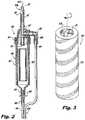
- FIG. 2is a cross-sectional view of a drip chamber and flow indicator, in accordance with the present disclosure
- FIG. 3is a perspective view of a flow indicator of a cooling system in accordance with the present disclosure
- FIG. 4Ais an exploded view of a portion of the cooling system in accordance with the present disclosure.
- FIG. 4Bis a side view of the portion of the cooling system of FIG. 4A ;
- FIG. 5Ais a cross-sectional view of a fluid return elbow member in accordance with the present disclosure.
- FIG. 5Bis a front view of the fluid return elbow of FIG. 5A ;
- FIG. 5Cis a bottom view of the fluid return elbow of FIG. 5A ;
- FIG. 6is a side view of a cooling system in accordance with the present disclosure.
- FIGS. 7A and 7Bare cross-sectional views of a drip chamber and a flow indicator, in accordance with the present disclosure.
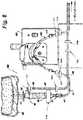
- FIG. 8is a side view of a cooling system in accordance with the present disclosure depicting locations of flow sensors and thermocouples;
- FIG. 9is a schematic illustration of a microwave ablation system including a cooling system
- FIG. 10is a perspective view of a reservoir of the cooling system of FIG. 9 ;
- FIG. 11is a perspective view of another embodiment of a reservoir of the coolant system of FIG. 9 .
- proximalrefers to the end of the apparatus that is closer to the user and the term “distal” refers to the end of the apparatus that is farther away from the user.
- distalrefers to the end of the apparatus that is farther away from the user.
- clinicalrefers to any medical professional (e.g., doctor, surgeon, nurse, or the like) performing a medical procedure involving the use of embodiments described herein.
- microwavegenerally refers to electromagnetic waves in the frequency range of 300 megahertz (MHz) (3 ⁇ 10 8 cycles/second) to 300 gigahertz (GHz) (3 ⁇ 10 11 cycles/second).
- ablation proceduregenerally refers to any ablation procedure, such as, for example, microwave ablation or radiofrequency (RF) ablation.
- fluidgenerally refers to a liquid, a gas, or both.
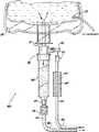
- an energy delivery device cooling systemis disclosed.
- the system 1000includes a reservoir connector assembly 100 in communication with a reservoir 200 .
- the reservoir 200is configured to contain or hold a cooling fluid.
- the reservoir connector assembly 100may include an elongate member 101 configured to extend into the reservoir 200 .
- Tubing system 400connects the reservoir 200 with a medical device having inlet and outlet ports and forming a closed loop cooling system 1000 , as will be described in greater detail below.
- the elongate member 101can have any length and shape capable of being inserted into the reservoir 200 .
- the elongate member 101can be a spike with a penetrating tip.
- the elongate member 101can have a blunt or substantially flat tip.
- the elongate member 101can be substantially cylindrical, and in the embodiments with a piercing tip, the tip can be symmetrically conical or non-symmetrically conical.
- the elongate member 101has at least a first lumen 105 and a second lumen 107 defined therethrough.
- Each lumen 105 , 107is configured to be in fluid communication with the reservoir 200 shown in FIG. 1 at openings 105 a and 107 a respectively.
- the first lumen 105may act as an inflow lumen for drawing fluid from the reservoir 200 and the second lumen 107 may act as a return lumen for returning fluid to the reservoir 200 .
- Lumens 105 , 107 and openings 105 a , 107 amay have the same or different diameters.
- the diameter of the lumens 105 , 107may be selected based on a desired volumetric flow rate and fluid velocity for a given medical device. For example, to promote mixing in the reservoir 200 , a smaller diameter lumen 107 can be chosen to achieve a higher velocity of the fluid for a given pressure.
- the increased velocitycan increase turbulent flow within the reservoir 200 and/or the tubing system 400 , resulting in increased mixing of the fluid. This increased mixing can promote homogenization of the fluid temperature within the reservoir 200 and/or the tubing system 400 .
- the turbulent flowcan also increase the efficiency of the transfer of heat from the fluid to the surrounding environment.
- At least one outflow port 109is in fluid communication with the first lumen 105 and allows fluid to flow from the reservoir 200 into a drip chamber or directly into the tubing system 400 .
- the reservoir connector assembly 100includes a return port 103 configured to allow cooling fluid to return to the reservoir connector assembly 100 from the tubing system 400 .
- the return port 103is in fluid communication with the second lumen 107 and may be configured to allow for direct or indirect fluid communication with tubing system 400 . It is also envisioned that the reservoir connector assembly 100 includes more than one return port 103 .
- the elongate member 101further includes a third lumen and a fourth lumen having third and fourth openings, respectively, and in fluid communication with the reservoir 200 and the outflow port 109 .
- added lumensmay also connect to the return port 103 .
- the elongate member 101 or the reservoir 200may include a thermocouple 202 operably connected thereto to monitor a temperature of the fluid inside the reservoir 200 .
- the thermocouple 202may be placed in various locations to measure the temperature of the fluid in the system 1000 , as shown in FIG. 8 .
- the thermocouple 202may be placed near the opening of the second lumen 107 to measure the temperature of the fluid flowing into the reservoir 200 , near the first lumen 105 to measure the temperature of the fluid flowing out of the reservoir 200 , in a portion of the tubing system 400 to measure the temperature of fluid flowing therein, or any combination thereof.
- the thermocouple 202may be connected to an energy source for the medical device, for example a microwave generator (not shown), and may be employed as a safety shut off for the energy source such that if the temperature of the fluid rises beyond a set threshold that indicates insufficient cooling, the energy source is shut off to prevent undesired damage to patient tissue during treatment.
- an energy source for the medical devicefor example a microwave generator (not shown)
- a safety shut off for the energy sourcesuch that if the temperature of the fluid rises beyond a set threshold that indicates insufficient cooling, the energy source is shut off to prevent undesired damage to patient tissue during treatment.
- a reservoir connector assembly 100fluidly connects the reservoir 200 with a drip chamber 300 .
- the drip chamber 300may include a top portion 301 ( FIG. 4A ) configured to receive a portion of the reservoir connector assembly 100 and a bottom portion 303 configured to connect the drip chamber 300 in fluid communication with the tubing system 400 .
- a fluid connector 305connects the bottom portion 303 with the tubing system 400 and facilitates fluid communication therebetween.
- a central portion 307which may be formed as a cylinder.
- the central portion 307 of the drip chamber 300may also include a flow indicator 309 for indicating that a fluid is flowing from the reservoir 200 through the drip chamber 300 to the tubing system 400 .
- the flow indicator 309may be formed of a hollow cylinder 310 with hydrofoils 311 configured to rotate the hollow cylinder 310 in the drip chamber 300 when fluid flows through the flow indicator 309 .
- the flow indicator 309may include a design 313 disposed on an outer surface thereof that visually indicates that the cylinder 309 is rotating, and thus that fluid is flowing therethrough.
- the design 313may resemble a barber-shop pole, however, other designs can be used to indicate fluid flow, for example a corporate logo COVIDIEN® or other graphic design.
- the cylinder 310may be formed of a material with a specific gravity causing the cylinder 310 to either be neutrally buoyant in the cooling fluid or to float in the cooling fluid.
- Other embodiments of flow indicators 309may be utilized that are suitable for indicating flow in the drip chamber 300 including but not limited to low density balls, floating material indicators, paddle wheel indicators, or the like.
- FIGS. 7A and 7BAn alternative arrangement of a flow indicator 309 a is depicted in FIGS. 7A and 7B .
- the flow indicator 309 ais generally in the shape of a cube, though other geometric shapes may be employed without departing from the scope of the present disclosure.
- the cube shapemay be advantageous by eliminating the possibility of the flow indicator 309 a occluding the bottom portion 303 of the drip chamber 300 when the system 1000 is initially primed with the fluid.
- the flow indicator 309 ahas a density related to the cooling fluid such that when fluid is not flowing through the drip container 300 the flow indicator 309 a floats to the upper surface 700 of the fluid in the drip container 300 as shown in FIG. 7A and when fluid is flowing through the drip container 300 the flow indicator 309 a partially submerges beneath the surface 700 and may also rotate to provide visual indicia of fluid flow as shown in FIG. 7B .
- the tubing system 400may include one or more return fluid flow indicators disposed thereon to indicate that a fluid is returning from the medical device to the reservoir 200 through tubing system 400 .
- return flow indicatorexamples include bubble indicators and traps, Venturi-style indicators, Hall-effect fluid flow indicators, and the like.
- Indicators, such as bubble indicators and venturi devices,also have the dual purpose of removing any gas which may have entered the system or vapor from the liquid flow to prevent disruption in the flow.
- Other fluid flow indicatorsmay also be employed to measure fluid velocity, pressure, or volumetric flow rate.
- fluid flow indicatorsare currently sold by Introtek International under the name BDC and BER Ultrasonic Clamp-on Air Bubble, Air-in-line & Liquid level Detection Systems as well as the Drip Chamber Ultrasonic Liquid Level Sensors.
- FIG. 8illustrates numerous locations where flow indicators 309 b and thermocouples 202 , as described above, may be employed within system 1000 .
- the flow indicators 309 bare flow sensors that detect flow of a fluid between portions of the flow indicators 309 b .
- the flow indicators 309 b and thermocouples 202may be attached to various portions of the system 1000 and may be attached to devices (not shown) that provide audible and/or visual indicia of fluid flow within the system 1000 . Further, the devices themselves may provide audible and/or visual indicia when fluid is not flowing within portions of the system 1000 , e.g. when a tube is kinked or blocked.
- the tubing system 400includes one or more tubes 401 that allow a fluid to flow from the reservoir connector assembly 100 , through an energy delivery device 12 (see FIG. 9 ) such as an ablation needle or catheter or an energy source, and back to the reservoir connector assembly 100 .
- the tubing system 400may include a first end 403 and a second end 405 .
- the first end 403is in fluid communication with the outflow port 109 , either indirectly through the bottom portion 303 of drip chamber 300 or by direct connection to outflow port 109 , and is configured to allow fluid to flow into tubing system 400 .
- the second end 405is in fluid communication with the return port 103 , and is configured to allow fluid to return to the reservoir 200 through the second lumen 107 .
- Tubing system 400may also include one or more thermal diffusion devices 407 configured to draw heat from the fluid and diffuse the heat to the ambient environment.
- the thermal diffusion device 407includes a series of fins 409 in contact with the tube 401 returning from a medical device.
- a fanmay be employed to direct airflow over the fins and increase the cooling effect.
- a thermal diffusion device 409could also or alternatively be employed on the reservoir 200 .
- a further alternativecould employ passing the tube 401 returning from the medical device through a reservoir containing cold water or ice water in order to further draw heat out of the fluid flowing through the tubes 401 .
- the system 1000may further include an elbow member 500 connected to the second end 405 of the tubing system 400 as shown in FIGS. 5A-C .
- the second end 405 of the tubing system 400in fluid communication with the return port 103 through the elbow member 500 .
- the elbow member 500may include a body 501 defining a lumen 503 , an inflow port 505 in fluid communication with the lumen 503 , and an outflow port 507 in fluid communication with the lumen 503 .
- the inflow port 505is configured to connect to a return section or second end 405 of a tubing system 400
- the outflow port 507is configured to connect to or accept the return port 103 of the reservoir connection assembly 100 .
- the elbow member 500may further have a flange 509 disposed around the outflow port 507 to ensure proper alignment of the elbow 500 with the reservoir connection assembly 100 as shown in FIGS. 4A and 4B .
- flange 509has a tombstone shape with a flat portion on a bottom portion thereof to allowing for connection with return port 103 in only one orientation of the elbow 500 .
- the elbow 500is formed of molded plastic.
- the elbow 500may be injection molded, blow molded, or formed in any other suitable manner known in the art.
- the elbow 500may be made of one solid piece or a conglomeration of subparts.
- one or more pumpsmay be used to control fluid flow through the cooling system 1000 .
- a pump 600may be connected to the tubing system 400 to pressurize a fluid in the tubing 401 .
- the type of pump 600 usedis a peristaltic pump which applies pressure to compress the outside of a pump tubing 602 forcing fluid downstream towards the medical device.
- the pump tubing 602may be made of a thicker gauge of the same material or a different material than the tubing 401 , thus allowing it to withstand the repetitive stresses of the peristaltic pump for the duration of a medical procedure.
- Connectors 604may be used to fluidly connect the pump tubing 602 to the tubing 401 .
- a protective slip cover 606may alternatively be used to protect either the pump tubing 602 , or the tubing 401 , if no pump tubing 602 is utilized.
- any device suitable to create a pressure to advance fluid through the tubing 401 in the cooling system 1000may be used.
- the entire system 1000may rely on gravity and the change in density of the fluid as it is heated to allow the fluid to circulate through the system 1000 .
- its density at 1 atmdecreases from about 62.4 lb/ft 3 at 60° F. to about 60 lb/ft 3 at 212° F. This difference in density may in some circumstances promote sufficient circulation of the fluid through the system 1000 to maintain proper cooling of the medical device.
- the fluid used in cooling system 1000may be any suitable liquid such as saline solution, de-ionized water, sugar water, and combinations thereof, or the like.
- the reservoir 200may be a saline bag traditionally used in medicine.
- the tubing system 400is connected to a medical device (not shown) to cool the medical device.
- the medical devicemay have cooling lumens such as those found in microwave ablation probes and microwave ablation catheters.
- the tubing system 400connects to an inflow port of the medical device allowing cooling fluid to flow through the lumens of the medical device to and flow out of an outflow port on the medical device.
- the cooling fluidmay pumped from the reservoir 200 through the medical device, as described above, or alternatively, the cooling fluid may be gravity fed to the medical device.
- the cooling system 1000may include the reservoir connection assembly 100 and the drip chamber 300 in fluid communication with the tubing system 400 , as described above.
- the cooling fluidflows from the reservoir 200 through the reservoir connection assembly 100 , drip chamber 300 , and the tubing system 400 into the inflow port of the medical device.
- the fluidreturns to the reservoir 200 flowing from the outflow port of the medical device through tubing system 400 , the return port 103 , and the second lumen 107 of reservoir connection assembly 100 .
- the fluidextracts or absorbs heat from the medical device to cool the device. As the fluid is traveling through system 1000 , it releases some heat into the environment surrounding the tubing system 400 . If thermal diffusion devices 407 are connected to the system 1000 , heat may be released from the fluid more efficiently, allowing for a reduced operating temperature of the system 1000 .
- Temperatures maintained in the system 1000 and the energy delivery deviceshould be within a range to avoid injury to the patient and adequate to allow flow through the system.
- the temperatureshould be below approximately 113° F. to avoid injury to the patient and above the freezing temperature of the fluid.
- Pressures and flow rates within the system 1000 and the components thereofmay be varied through variations in pump speed, and through design of the system 1000 and the components thereof.
- cooling system 1000can employ standard sterile saline bags as the fluid reservoir, which eliminates the need for a specialized fluid source. Further the system 1000 recirculates fluid as opposed to simply dumping the cooling fluid after one pass through the medical device, thereby conserving cooling fluid and eliminating the need for a collection bucket or bag.
- a methodmay include providing a saline bag or other fluid reservoir and a saline bag elongate member having multiple lumens defined therein.
- the saline bag elongate memberincludes at least one return port connected to at least one of the lumens.
- the methodmay also include providing a drip container such as the drip container 300 disclosed herein.
- the methodmay further include providing an elbow 500 as disclosed herein.
- the methodfurther includes connecting the elbow 500 to the return port of the saline bag elongate member to allow fluid flow to return into the saline bag through the return port.
- the methodalso includes the step of connecting a return portion of the tubing system 400 to the elbow 500 .
- the methodincludes providing an energy delivery device, providing a recirculating cooling system connected to the energy delivery device, and recirculating a fluid through the cooling system and energy delivery device to maintain the energy delivery device at a desired temperature or within a desired temperature range to prevent undesired damage to tissue.
- the desired temperature rangemay include an upper limit corresponding to a temperature above which tissue is damaged and a lower limit below which the fluid will not flow within the system.
- the flow rate of fluid within the systemmay be adjusted as the temperature approaches the upper limit or the lower limit. For example, when the temperature approaches the upper limit the flow rate may be increased to increase the cooling of the medical device.
- the systemmay include visual or audible indicia when the temperature approaches the upper or lower limit.
- the ablation system 10generally includes a microwave ablation probe 12 , a microwave generator 14 , and a medical ablation device cooling system 34 .
- the generator 14is configured to provide microwave energy at an operational frequency from about 500 MHz to about 5000 MHz, although other suitable frequencies are also contemplated.
- the generator 14may generate any suitable type of energy, for example, RF energy, or ultrasonic energy.
- the probe 12 and the generator 14are coupled to one another via a connector assembly 16 and a cable assembly 20 .
- the connector assembly 16is a cable connector suitable to operably connect the cable assembly 20 to the generator 14 .
- the connector assembly 16may house a memory (e.g., an EEPROM) storing a variety of information regarding various components of the system 10 .
- the memorymay store identification information that can be used by the generator 14 to determine the identification of probes connected to the generator 14 . Based on the determined identification of a probe, the generator 14 may or may not provide energy to the probe. For example, if the identification information stored in memory does not match identification information provided by the probe (e.g., via a RFID tag on the probe), the generator 14 will not provide energy to the connected probe.
- the cable assembly 20interconnects the connector assembly 16 and the probe 12 to allow for the transfer of energy from the generator 14 to the probe 12 .
- the cable assembly 20may be any suitable, flexible transmission line, such as a coaxial cable, including an inner conductor, a dielectric material coaxially surrounding the inner conductor, and an outer conductor coaxially surrounding the dielectric material.
- the cable assembly 20may be provided with an outer coating or sleeve disposed about the outer conductor.
- the sleevemay be formed of any suitable insulative material, and may be applied by any suitable method, e.g., heat shrinking, over-molding, coating, spraying, dipping, powder coating, and/or film deposition.
- the probe 12includes a radiating portion 18 that radiates energy provided by the generator 14 .
- the radiating portion 18is coupled to the cable assembly 20 through a handle assembly 22 .
- the handle assembly 22has an outlet fluid port 30 and an inlet fluid port 32 each in fluid communication with an interior chamber (not explicitly shown) defined in the probe 12 .
- the cooling fluidmay circulate from the ports 30 and 32 around the interior chamber or chambers of the probe 12 to cool the probe 12 during use.
- the ports 30 and 32 of the handle assembly 22are coupled to the cooling system 34 via outlet and inlet tubes 38 , 40 , respectively.
- the cooling system 34similar to the cooling system 1000 of FIGS. 1-6 , includes a reservoir 36 and a supply pump (not explicitly shown).
- the supply pumpmay be a peristaltic pump, such as the peristaltic pump 600 of FIGS. 1-6 , or any other suitable pump configured to circulate cooling fluid “F” ( FIG. 10 ) from the reservoir 36 and into the probe 12 .
- the reservoir 36stores the cooling fluid “F” and may be in the form of a saline bag or any other suitable container for holding the cooling fluid “F” (e.g., saline, water, etc.).
- the cooling system 34may incorporate some or all of the features of the cooling system 1000 of FIGS. 1-6 , such as, for example, the reservoir connector assembly 100 , the drip chamber 300 , the tubing system 400 , and the elbow member 500 .
- the reservoir 36includes an outlet fluid port 44 a , similar to the lumen 107 of FIG. 2 , coupled to the outlet tube 38 ( FIG. 9 ), and an inlet fluid port 44 b , similar to the lumen 105 of FIG. 2 , coupled to the inlet tube 40 ( FIG. 9 ).
- the reservoir 36has a wall 46 fabricated from a flexible material, such as, for example, polyvinyl chloride (PVC), polyolefins, nylon, or a composite thereof.
- the wall 46has an inner peripheral surface 46 a defining an inner chamber 48 , and an outer peripheral surface 46 b .
- the chamber 48is in fluid communication with the outlet and inlet fluid ports 44 a , 44 b , such that the cooling fluid “F” may be circulated out of the chamber 48 via the outlet fluid port 44 a , into the probe 12 ( FIG. 9 ) to cool the probe 12 , and returned back to the chamber 48 via the inlet fluid port 44 b.
- the cooling system 34further includes a thermochromic material 50 thermally coupled to the cooling fluid “F” for providing a visual indication of a temperature of the cooling fluid “F” during use of the ablation system 10 .
- the thermochromic material 50may be a thermochromic paper, polymer, and/or ink and is configured to change its color in response to a change in temperature of the cooling fluid “F.”
- the thermochromic material 50may be configured to exhibit a first color when the cooling fluid “F” is at or below a threshold temperature, and may exhibit a second color, different from the first color, when the cooling fluid “F” is above the threshold temperature.
- the first color of the thermochromic materialmay be one that is typically used as an identifier of cooler temperatures, and the second color may be one that is typically used as an identifier of warmer temperatures.
- the first colormay be blue, black or green, and the second color may be red, orange, white, or yellow.
- any suitable colormay be selected to visually indicate the change in temperature of the cooling fluid “F.”
- the threshold temperature at which the hermochromic material 50 is configured to transitionis between approximately 10° C. and approximately 60° C., and in some embodiments, may be approximately 30° C.
- the thermochromic material 50may be configured to exhibit more than two colors, such as, for example, three or more colors with each corresponding to a discreet temperature or temperature range of the cooling fluid “F.”
- the thermochromic material 50may be coupled directly or indirectly to the inner or outer peripheral surfaces 46 a , 46 b of the wall 46 .
- One or both of the inner and outer peripheral surfaces 46 a , 46 b of the wall 46may have a laser-marked symbol having the same color as the thermochromic material 50 when the thermochromic material 50 is cool, such that the laser-marked symbol reveals itself after the thermochromic material 50 warms.
- the laser-marked symbolmay have the same color as the thermochromic material 50 when the thermochromic material 50 is warm.
- the reservoir 36may have a sticker 52 incorporating the thermochromic material 50 and may be adhered to the wall 46 of the reservoir 36 .
- the thermochromic material 50changes from the first color to the second color to indicate to the clinician that the cooling fluid “F” is at a temperature unsuitable for cooling the probe 12 , and therefore should be changed.
- FIG. 11illustrates an embodiment of the reservoir 36 that includes a float 54 disposed within the chamber 48 thereof for indicating the level of the cooling fluid “F.”
- the float 54may have the thermochromic material 50 coupled thereto.
- the float 54serves the dual function of indicating the level of the cooling fluid “F” while also providing a visual cue of the temperature of the cooling fluid “F.” It is contemplated that the float may be fabricated from a plastic thermochromic material 50 .
- thermochromic material 50may be coupled to the drip chamber 300 of the cooling system 1000 of FIGS. 1-6 . It is contemplated that the thermochromic material 50 , whether incorporated into the float 54 or the sticker 52 , may be coupled to the reservoir 200 , the drip chamber 300 , the tubing system 400 , or the elbow member 500 of the cooling system 1000 .
Landscapes
- Health & Medical Sciences (AREA)
- Surgery (AREA)
- Life Sciences & Earth Sciences (AREA)
- Engineering & Computer Science (AREA)
- Physics & Mathematics (AREA)
- Animal Behavior & Ethology (AREA)
- Public Health (AREA)
- Nuclear Medicine, Radiotherapy & Molecular Imaging (AREA)
- Biomedical Technology (AREA)
- Heart & Thoracic Surgery (AREA)
- Medical Informatics (AREA)
- Molecular Biology (AREA)
- Veterinary Medicine (AREA)
- General Health & Medical Sciences (AREA)
- Otolaryngology (AREA)
- Plasma & Fusion (AREA)
- Electromagnetism (AREA)
- Cardiology (AREA)
- Chemical & Material Sciences (AREA)
- Combustion & Propulsion (AREA)
- Mechanical Engineering (AREA)
- Thermal Sciences (AREA)
- General Engineering & Computer Science (AREA)
- Thermotherapy And Cooling Therapy Devices (AREA)
- Surgical Instruments (AREA)
Abstract
Description
Claims (9)
Priority Applications (4)
| Application Number | Priority Date | Filing Date | Title |
|---|---|---|---|
| US15/989,006US11071586B2 (en) | 2017-06-05 | 2018-05-24 | Cooling systems for energy delivery devices |
| EP18175785.7AEP3412237B1 (en) | 2017-06-05 | 2018-06-04 | Cooling systems for energy delivery devices |
| CN201810570309.2ACN108969090B (en) | 2017-06-05 | 2018-06-05 | Cooling system for an energy delivery device |
| CN201820867127.7UCN209392085U (en) | 2017-06-05 | 2018-06-05 | Medical ablation device cooling system |
Applications Claiming Priority (2)
| Application Number | Priority Date | Filing Date | Title |
|---|---|---|---|
| US201762515224P | 2017-06-05 | 2017-06-05 | |
| US15/989,006US11071586B2 (en) | 2017-06-05 | 2018-05-24 | Cooling systems for energy delivery devices |
Publications (2)
| Publication Number | Publication Date |
|---|---|
| US20180344399A1 US20180344399A1 (en) | 2018-12-06 |
| US11071586B2true US11071586B2 (en) | 2021-07-27 |
Family
ID=62528347
Family Applications (1)
| Application Number | Title | Priority Date | Filing Date |
|---|---|---|---|
| US15/989,006Active2039-07-14US11071586B2 (en) | 2017-06-05 | 2018-05-24 | Cooling systems for energy delivery devices |
Country Status (3)
| Country | Link |
|---|---|
| US (1) | US11071586B2 (en) |
| EP (1) | EP3412237B1 (en) |
| CN (2) | CN108969090B (en) |
Families Citing this family (3)
| Publication number | Priority date | Publication date | Assignee | Title |
|---|---|---|---|---|
| US11071586B2 (en)* | 2017-06-05 | 2021-07-27 | Covidien Lp | Cooling systems for energy delivery devices |
| US11076904B2 (en) | 2018-12-20 | 2021-08-03 | Avent, Inc. | Flow rate control for a cooled medical probe assembly |
| CN115778532A (en)* | 2022-12-20 | 2023-03-14 | 杭州佳量医疗科技有限公司 | Monitoring system, cooling system and ablation system |
Citations (59)
| Publication number | Priority date | Publication date | Assignee | Title |
|---|---|---|---|---|
| US3739777A (en) | 1971-05-10 | 1973-06-19 | D Gregg | Intravenous feeding apparatus and system |
| US3832998A (en) | 1973-01-30 | 1974-09-03 | D Gregg | Intravenous feeding apparatus |
| US3990443A (en) | 1975-10-14 | 1976-11-09 | Data Service Co. Of America, Inc. | Drop rate sensing and regulating apparatus |
| US4105028A (en) | 1976-10-12 | 1978-08-08 | Sadlier Patricia M | Positive control intravenous fluid administration |
| JPS55159393A (en) | 1979-05-29 | 1980-12-11 | Dow Chemical Co | Improved inner lining pipe assembly |
| US5049129A (en) | 1986-05-29 | 1991-09-17 | Zdeb Brian D | Adapter for passive drug delivery system |
| US5304130A (en) | 1992-02-26 | 1994-04-19 | Baxter International Inc. | Container for the controlled administration of a beneficial agent |
| US5411052A (en) | 1992-04-15 | 1995-05-02 | Fisher & Paykel Limited | Liquid supply apparatus |
| US5545161A (en) | 1992-12-01 | 1996-08-13 | Cardiac Pathways Corporation | Catheter for RF ablation having cooled electrode with electrically insulated sleeve |
| US5733319A (en) | 1996-04-25 | 1998-03-31 | Urologix, Inc. | Liquid coolant supply system |
| US5941848A (en) | 1996-11-14 | 1999-08-24 | Baxter International Inc. | Passive drug delivery apparatus |
| US6036680A (en) | 1997-01-27 | 2000-03-14 | Baxter International Inc. | Self-priming solution lines and a method and system for using same |
| US6478793B1 (en) | 1999-06-11 | 2002-11-12 | Sherwood Services Ag | Ablation treatment of bone metastases |
| US6506189B1 (en) | 1995-05-04 | 2003-01-14 | Sherwood Services Ag | Cool-tip electrode thermosurgery system |
| US6514251B1 (en) | 1998-08-14 | 2003-02-04 | K.U. Leuven Research & Development | Cooled-wet electrode |
| US6575969B1 (en) | 1995-05-04 | 2003-06-10 | Sherwood Services Ag | Cool-tip radiofrequency thermosurgery electrode system for tumor ablation |
| US6679865B2 (en) | 2001-12-07 | 2004-01-20 | Nedrip Ltd. | Fluid flow meter for gravity fed intravenous fluid delivery systems |
| JP2004097402A (en) | 2002-09-06 | 2004-04-02 | Toshiba Corp | Ultrasonic irradiation equipment |
| WO2004034940A1 (en) | 2002-10-18 | 2004-04-29 | Radiant Medical, Inc. | Valved connector assembly and sterility barriers for heat exchange catheters and other closed loop catheters |
| US20040127840A1 (en) | 2002-03-04 | 2004-07-01 | Steve Gara | Blood separation apparatus and method of using the same |
| US20040267339A1 (en) | 1998-01-23 | 2004-12-30 | Innercool Therapies, Inc. | System and method for inducing hypothermia with active patient temperature control employing catheter-mounted temperature sensor and temperature projection algorithm |
| US6979120B1 (en)* | 2002-12-18 | 2005-12-27 | Wynn Wolfe | Article of manufacture having non-uniform thermochromic display |
| US20060031099A1 (en) | 2003-06-10 | 2006-02-09 | Vitello Christopher J | System and methods for administering bioactive compositions |
| US7052463B2 (en) | 2002-09-25 | 2006-05-30 | Koninklijke Philips Electronics, N.V. | Method and apparatus for cooling a contacting surface of an ultrasound probe |
| US20060272120A1 (en)* | 2005-06-01 | 2006-12-07 | Kenneth Barrick | Extraction cleaner |
| US20070060915A1 (en) | 2005-09-15 | 2007-03-15 | Cannuflow, Inc. | Arthroscopic surgical temperature control system |
| US20080051732A1 (en) | 2006-06-23 | 2008-02-28 | Thaiping Chen | Drop sensing device for monitoring intravenous fluid flow |
| US7425208B1 (en) | 2003-08-29 | 2008-09-16 | Vitello Jonathan J | Needle assembly facilitating complete removal or nearly complete removal of a composition from a container |
| US20090149930A1 (en) | 2007-12-07 | 2009-06-11 | Thermage, Inc. | Apparatus and methods for cooling a treatment apparatus configured to non-invasively deliver electromagnetic energy to a patient's tissue |
| US20090145349A1 (en) | 2007-12-07 | 2009-06-11 | Hebert William C | Fluid Flow Indicator |
| US20090222002A1 (en) | 2008-03-03 | 2009-09-03 | Vivant Medical, Inc. | Intracooled Percutaneous Microwave Ablation Probe |
| US20100053015A1 (en) | 2008-08-28 | 2010-03-04 | Vivant Medical, Inc. | Microwave Antenna |
| US20100057074A1 (en) | 2008-09-02 | 2010-03-04 | Roman Ricardo D | Irrigated Ablation Catheter System and Methods |
| US20100228162A1 (en) | 2009-03-09 | 2010-09-09 | Sliwa John W | Apparatus and Method for Tissue Ablation with Near-Field Cooling |
| KR101016566B1 (en) | 2010-12-27 | 2011-02-24 | 주식회사 투유 | Injector inspection device and injection quantity measuring method using the same |
| US20110077637A1 (en)* | 2009-09-29 | 2011-03-31 | Vivant Medical, Inc. | Flow Rate Monitor for Fluid Cooled Microwave Ablation Probe |
| WO2011056684A2 (en) | 2009-10-27 | 2011-05-12 | Innovative Pulmonary Solutions, Inc. | Delivery devices with coolable energy emitting assemblies |
| US20110118724A1 (en) | 2009-11-17 | 2011-05-19 | Bsd Medical Corporation | Microwave coagulation applicator and system with fluid injection |
| US20110230753A1 (en)* | 2010-03-09 | 2011-09-22 | Cameron Mahon | Fluid circuits for temperature control in a thermal therapy system |
| US8038670B2 (en)* | 2000-03-06 | 2011-10-18 | Salient Surgical Technologies, Inc. | Fluid-assisted medical devices, systems and methods |
| US20110295245A1 (en) | 2010-05-25 | 2011-12-01 | Vivant Medical, Inc. | Flow Rate Verification Monitor for Fluid-Cooled Microwave Ablation Probe |
| US20120039355A1 (en)* | 2010-08-11 | 2012-02-16 | Wolosuk Susan M | Shielded Meat Temperature Sensing Device |
| US8292880B2 (en) | 2007-11-27 | 2012-10-23 | Vivant Medical, Inc. | Targeted cooling of deployable microwave antenna |
| US8308726B2 (en) | 2004-09-03 | 2012-11-13 | Atul Kumar | Electromagnetically controlled tissue cavity distending system |
| US8334812B2 (en) | 2009-06-19 | 2012-12-18 | Vivant Medical, Inc. | Microwave ablation antenna radiation detector |
| US20120323296A1 (en) | 2010-02-22 | 2012-12-20 | Kaiken Iki Kabushiki Kaisha | Brain cooling apparatus and brain cooling device suitable thereto |
| EP2550924A1 (en) | 2011-07-28 | 2013-01-30 | Biosense Webster (Israel), Ltd. | Integrated ablation system using catheter with multiple irrigation lumens |
| US8430871B2 (en) | 2009-10-28 | 2013-04-30 | Covidien Lp | System and method for monitoring ablation size |
| US20130178841A1 (en) | 2012-01-05 | 2013-07-11 | Vivant Medical, Inc. | Ablation Systems, Probes, and Methods for Reducing Radiation from an Ablation Probe into the Environment |
| US20130237901A1 (en) | 2010-07-01 | 2013-09-12 | The Board Of Trustees Of The Leland Stanford Junior University | Apparatus and methods to treat or prevent kidney and urologic disease |
| US20140081218A1 (en) | 2012-09-06 | 2014-03-20 | Memorial Sloan-Kettering Cancer Center | Intravenous device having a movable arrangement |
| US20140209486A1 (en) | 2013-01-28 | 2014-07-31 | Actherm Inc | Detecting device and method applying a detecting strip |
| EP2777765A2 (en) | 2013-03-15 | 2014-09-17 | Covidien LP | Recirculating cooling system for energy delivery device |
| US20140281961A1 (en) | 2013-03-15 | 2014-09-18 | Covidien Lp | Pathway planning system and method |
| US20140262201A1 (en) | 2013-03-15 | 2014-09-18 | Covidien Lp | Recirculating Cooling System For Energy Delivery Device |
| US20140276033A1 (en) | 2013-03-15 | 2014-09-18 | Covidien Lp | Microwave energy-device and system |
| US20140350401A1 (en)* | 2012-06-30 | 2014-11-27 | Yegor D. Sinelnikov | Carotid body ablation via directed energy |
| US20160022477A1 (en)* | 2014-07-25 | 2016-01-28 | Cascade Wellness Technologies, Inc. | Thermal contrast therapy devices, methods and systems |
| CN209392085U (en) | 2017-06-05 | 2019-09-17 | 柯惠有限合伙公司 | Medical ablation device cooling system |
- 2018
- 2018-05-24USUS15/989,006patent/US11071586B2/enactiveActive
- 2018-06-04EPEP18175785.7Apatent/EP3412237B1/enactiveActive
- 2018-06-05CNCN201810570309.2Apatent/CN108969090B/enactiveActive
- 2018-06-05CNCN201820867127.7Upatent/CN209392085U/ennot_activeExpired - Fee Related
Patent Citations (67)
| Publication number | Priority date | Publication date | Assignee | Title |
|---|---|---|---|---|
| US3739777A (en) | 1971-05-10 | 1973-06-19 | D Gregg | Intravenous feeding apparatus and system |
| US3832998A (en) | 1973-01-30 | 1974-09-03 | D Gregg | Intravenous feeding apparatus |
| US3990443A (en) | 1975-10-14 | 1976-11-09 | Data Service Co. Of America, Inc. | Drop rate sensing and regulating apparatus |
| US4105028A (en) | 1976-10-12 | 1978-08-08 | Sadlier Patricia M | Positive control intravenous fluid administration |
| JPS55159393A (en) | 1979-05-29 | 1980-12-11 | Dow Chemical Co | Improved inner lining pipe assembly |
| US5049129A (en) | 1986-05-29 | 1991-09-17 | Zdeb Brian D | Adapter for passive drug delivery system |
| US5304130A (en) | 1992-02-26 | 1994-04-19 | Baxter International Inc. | Container for the controlled administration of a beneficial agent |
| US5411052A (en) | 1992-04-15 | 1995-05-02 | Fisher & Paykel Limited | Liquid supply apparatus |
| US5545161A (en) | 1992-12-01 | 1996-08-13 | Cardiac Pathways Corporation | Catheter for RF ablation having cooled electrode with electrically insulated sleeve |
| US6506189B1 (en) | 1995-05-04 | 2003-01-14 | Sherwood Services Ag | Cool-tip electrode thermosurgery system |
| US6575969B1 (en) | 1995-05-04 | 2003-06-10 | Sherwood Services Ag | Cool-tip radiofrequency thermosurgery electrode system for tumor ablation |
| US5733319A (en) | 1996-04-25 | 1998-03-31 | Urologix, Inc. | Liquid coolant supply system |
| US5941848A (en) | 1996-11-14 | 1999-08-24 | Baxter International Inc. | Passive drug delivery apparatus |
| US6036680A (en) | 1997-01-27 | 2000-03-14 | Baxter International Inc. | Self-priming solution lines and a method and system for using same |
| US20040267339A1 (en) | 1998-01-23 | 2004-12-30 | Innercool Therapies, Inc. | System and method for inducing hypothermia with active patient temperature control employing catheter-mounted temperature sensor and temperature projection algorithm |
| US6514251B1 (en) | 1998-08-14 | 2003-02-04 | K.U. Leuven Research & Development | Cooled-wet electrode |
| US6478793B1 (en) | 1999-06-11 | 2002-11-12 | Sherwood Services Ag | Ablation treatment of bone metastases |
| US8038670B2 (en)* | 2000-03-06 | 2011-10-18 | Salient Surgical Technologies, Inc. | Fluid-assisted medical devices, systems and methods |
| US6679865B2 (en) | 2001-12-07 | 2004-01-20 | Nedrip Ltd. | Fluid flow meter for gravity fed intravenous fluid delivery systems |
| US20040127840A1 (en) | 2002-03-04 | 2004-07-01 | Steve Gara | Blood separation apparatus and method of using the same |
| JP2004097402A (en) | 2002-09-06 | 2004-04-02 | Toshiba Corp | Ultrasonic irradiation equipment |
| US7052463B2 (en) | 2002-09-25 | 2006-05-30 | Koninklijke Philips Electronics, N.V. | Method and apparatus for cooling a contacting surface of an ultrasound probe |
| WO2004034940A1 (en) | 2002-10-18 | 2004-04-29 | Radiant Medical, Inc. | Valved connector assembly and sterility barriers for heat exchange catheters and other closed loop catheters |
| US6979120B1 (en)* | 2002-12-18 | 2005-12-27 | Wynn Wolfe | Article of manufacture having non-uniform thermochromic display |
| US20060031099A1 (en) | 2003-06-10 | 2006-02-09 | Vitello Christopher J | System and methods for administering bioactive compositions |
| US7425208B1 (en) | 2003-08-29 | 2008-09-16 | Vitello Jonathan J | Needle assembly facilitating complete removal or nearly complete removal of a composition from a container |
| US8308726B2 (en) | 2004-09-03 | 2012-11-13 | Atul Kumar | Electromagnetically controlled tissue cavity distending system |
| US20060272120A1 (en)* | 2005-06-01 | 2006-12-07 | Kenneth Barrick | Extraction cleaner |
| US20070060915A1 (en) | 2005-09-15 | 2007-03-15 | Cannuflow, Inc. | Arthroscopic surgical temperature control system |
| US20080051732A1 (en) | 2006-06-23 | 2008-02-28 | Thaiping Chen | Drop sensing device for monitoring intravenous fluid flow |
| US8292880B2 (en) | 2007-11-27 | 2012-10-23 | Vivant Medical, Inc. | Targeted cooling of deployable microwave antenna |
| US20090145349A1 (en) | 2007-12-07 | 2009-06-11 | Hebert William C | Fluid Flow Indicator |
| US20090149930A1 (en) | 2007-12-07 | 2009-06-11 | Thermage, Inc. | Apparatus and methods for cooling a treatment apparatus configured to non-invasively deliver electromagnetic energy to a patient's tissue |
| US20090222002A1 (en) | 2008-03-03 | 2009-09-03 | Vivant Medical, Inc. | Intracooled Percutaneous Microwave Ablation Probe |
| US20100053015A1 (en) | 2008-08-28 | 2010-03-04 | Vivant Medical, Inc. | Microwave Antenna |
| US20100057074A1 (en) | 2008-09-02 | 2010-03-04 | Roman Ricardo D | Irrigated Ablation Catheter System and Methods |
| US20100228162A1 (en) | 2009-03-09 | 2010-09-09 | Sliwa John W | Apparatus and Method for Tissue Ablation with Near-Field Cooling |
| US8334812B2 (en) | 2009-06-19 | 2012-12-18 | Vivant Medical, Inc. | Microwave ablation antenna radiation detector |
| US20110077637A1 (en)* | 2009-09-29 | 2011-03-31 | Vivant Medical, Inc. | Flow Rate Monitor for Fluid Cooled Microwave Ablation Probe |
| WO2011056684A2 (en) | 2009-10-27 | 2011-05-12 | Innovative Pulmonary Solutions, Inc. | Delivery devices with coolable energy emitting assemblies |
| US8430871B2 (en) | 2009-10-28 | 2013-04-30 | Covidien Lp | System and method for monitoring ablation size |
| US20110118724A1 (en) | 2009-11-17 | 2011-05-19 | Bsd Medical Corporation | Microwave coagulation applicator and system with fluid injection |
| WO2011063061A2 (en) | 2009-11-17 | 2011-05-26 | Bsd Medical Corporation | Microwave coagulation applicator and system |
| EP2540260A1 (en) | 2010-02-22 | 2013-01-02 | National University Corporation Okayama University | Brain cooling apparatus and brain cooling device suitable thereto |
| US20120323296A1 (en) | 2010-02-22 | 2012-12-20 | Kaiken Iki Kabushiki Kaisha | Brain cooling apparatus and brain cooling device suitable thereto |
| US20110230753A1 (en)* | 2010-03-09 | 2011-09-22 | Cameron Mahon | Fluid circuits for temperature control in a thermal therapy system |
| US20110295245A1 (en) | 2010-05-25 | 2011-12-01 | Vivant Medical, Inc. | Flow Rate Verification Monitor for Fluid-Cooled Microwave Ablation Probe |
| US20130237901A1 (en) | 2010-07-01 | 2013-09-12 | The Board Of Trustees Of The Leland Stanford Junior University | Apparatus and methods to treat or prevent kidney and urologic disease |
| US20120039355A1 (en)* | 2010-08-11 | 2012-02-16 | Wolosuk Susan M | Shielded Meat Temperature Sensing Device |
| KR101016566B1 (en) | 2010-12-27 | 2011-02-24 | 주식회사 투유 | Injector inspection device and injection quantity measuring method using the same |
| EP2550924A1 (en) | 2011-07-28 | 2013-01-30 | Biosense Webster (Israel), Ltd. | Integrated ablation system using catheter with multiple irrigation lumens |
| US20130030426A1 (en) | 2011-07-28 | 2013-01-31 | Diana Gallardo | Integrated ablation system using catheter with multiple irrigation lumens |
| US20130178841A1 (en) | 2012-01-05 | 2013-07-11 | Vivant Medical, Inc. | Ablation Systems, Probes, and Methods for Reducing Radiation from an Ablation Probe into the Environment |
| US20140350401A1 (en)* | 2012-06-30 | 2014-11-27 | Yegor D. Sinelnikov | Carotid body ablation via directed energy |
| US20140081218A1 (en) | 2012-09-06 | 2014-03-20 | Memorial Sloan-Kettering Cancer Center | Intravenous device having a movable arrangement |
| US20140209486A1 (en) | 2013-01-28 | 2014-07-31 | Actherm Inc | Detecting device and method applying a detecting strip |
| CN104042338A (en) | 2013-03-15 | 2014-09-17 | 柯惠有限合伙公司 | Medical device cooling system and system for cooling a medical ablation device |
| US20140281961A1 (en) | 2013-03-15 | 2014-09-18 | Covidien Lp | Pathway planning system and method |
| US20140276740A1 (en)* | 2013-03-15 | 2014-09-18 | Covidien Lp | Recirculating Cooling System For Energy Delivery Device |
| US20140262201A1 (en) | 2013-03-15 | 2014-09-18 | Covidien Lp | Recirculating Cooling System For Energy Delivery Device |
| US20140276033A1 (en) | 2013-03-15 | 2014-09-18 | Covidien Lp | Microwave energy-device and system |
| CN203915069U (en) | 2013-03-15 | 2014-11-05 | 柯惠有限合伙公司 | Medical treatment device cooling system and for the system of cooling medical ablating device |
| EP2777765A2 (en) | 2013-03-15 | 2014-09-17 | Covidien LP | Recirculating cooling system for energy delivery device |
| US9101344B2 (en) | 2013-03-15 | 2015-08-11 | Covidien Lp | Recirculating cooling system for energy delivery device |
| US9962214B2 (en) | 2013-03-15 | 2018-05-08 | Covidien Lp | Recirculating cooling system for energy deliver device |
| US20160022477A1 (en)* | 2014-07-25 | 2016-01-28 | Cascade Wellness Technologies, Inc. | Thermal contrast therapy devices, methods and systems |
| CN209392085U (en) | 2017-06-05 | 2019-09-17 | 柯惠有限合伙公司 | Medical ablation device cooling system |
Non-Patent Citations (8)
| Title |
|---|
| Australian Office Action, dated Mar. 1, 2018, issued in Australian Application No. 2014201315; 4 pages. |
| Chinese Office Action (English translation), dated Apr. 15, 2016, issued in Chinese Application No. 201410093847.9; 10 pages. |
| Chinese Office Action (with English translation), dated Oct. 17, 2016, issued in Chinese Application No. 201410093847.9; 16 total pages. |
| Chinese Office Action dated Oct. 30, 2020, issued in corresponding Chinese Appln. No. 201810570309. |
| European Search Report dated Nov. 26, 2018, corresponding to counterpart European Application No. 18175785; 7 pages. |
| European Search Report, dated Oct. 1, 2014, issued in European Application No. 14 15 9833.4; 12 pages. |
| Japanese Office Action (with English translation), dated Jan. 16, 2018, issued in Japanese Application No. 2014-045881; 10 pages. |
| Partial European Search Report dated Jun. 3, 2014 issued in European Application No. 14159833.4; 6 pages. |
Also Published As
| Publication number | Publication date |
|---|---|
| CN108969090A (en) | 2018-12-11 |
| US20180344399A1 (en) | 2018-12-06 |
| CN209392085U (en) | 2019-09-17 |
| EP3412237A1 (en) | 2018-12-12 |
| EP3412237B1 (en) | 2021-01-27 |
| CN108969090B (en) | 2021-04-06 |
Similar Documents
| Publication | Publication Date | Title |
|---|---|---|
| US10966774B2 (en) | Recirculating cooling system for energy delivery device | |
| CN101437477B (en) | Heat exchange conduit with multilumen tube with liquid return channel | |
| US11071586B2 (en) | Cooling systems for energy delivery devices | |
| US20090082837A1 (en) | Hand-held Thermal Ablation Device | |
| US20170266376A1 (en) | Recirculating cooling system for energy delivery device | |
| US7621889B2 (en) | Heat exchange catheter and method of use | |
| CN109069197B (en) | Recirculation cooling system for use with energy delivery devices | |
| CN108904036B (en) | Skin frostbite prevention device, skin frostbite prevention bag and use method thereof |
Legal Events
| Date | Code | Title | Description |
|---|---|---|---|
| FEPP | Fee payment procedure | Free format text:ENTITY STATUS SET TO UNDISCOUNTED (ORIGINAL EVENT CODE: BIG.); ENTITY STATUS OF PATENT OWNER: LARGE ENTITY | |
| STPP | Information on status: patent application and granting procedure in general | Free format text:DOCKETED NEW CASE - READY FOR EXAMINATION | |
| AS | Assignment | Owner name:COVIDIEN LP, MASSACHUSETTS Free format text:ASSIGNMENT OF ASSIGNORS INTEREST;ASSIGNOR:DICKHANS, WILLIAM J.;REEL/FRAME:049887/0196 Effective date:20190717 | |
| STPP | Information on status: patent application and granting procedure in general | Free format text:RESPONSE TO NON-FINAL OFFICE ACTION ENTERED AND FORWARDED TO EXAMINER | |
| STPP | Information on status: patent application and granting procedure in general | Free format text:FINAL REJECTION MAILED | |
| STPP | Information on status: patent application and granting procedure in general | Free format text:RESPONSE AFTER FINAL ACTION FORWARDED TO EXAMINER | |
| STPP | Information on status: patent application and granting procedure in general | Free format text:NOTICE OF ALLOWANCE MAILED -- APPLICATION RECEIVED IN OFFICE OF PUBLICATIONS | |
| STPP | Information on status: patent application and granting procedure in general | Free format text:PUBLICATIONS -- ISSUE FEE PAYMENT RECEIVED | |
| STPP | Information on status: patent application and granting procedure in general | Free format text:PUBLICATIONS -- ISSUE FEE PAYMENT VERIFIED | |
| STCF | Information on status: patent grant | Free format text:PATENTED CASE | |
| MAFP | Maintenance fee payment | Free format text:PAYMENT OF MAINTENANCE FEE, 4TH YEAR, LARGE ENTITY (ORIGINAL EVENT CODE: M1551); ENTITY STATUS OF PATENT OWNER: LARGE ENTITY Year of fee payment:4 |