US11071541B2 - Loading unit including shipping member - Google Patents
Loading unit including shipping memberDownload PDFInfo
- Publication number
- US11071541B2 US11071541B2US16/027,609US201816027609AUS11071541B2US 11071541 B2US11071541 B2US 11071541B2US 201816027609 AUS201816027609 AUS 201816027609AUS 11071541 B2US11071541 B2US 11071541B2
- Authority
- US
- United States
- Prior art keywords
- loading unit
- shipping
- locking portion
- shipping member
- base portion
- Prior art date
- Legal status (The legal status is an assumption and is not a legal conclusion. Google has not performed a legal analysis and makes no representation as to the accuracy of the status listed.)
- Active
Links
- 230000000717retained effectEffects0.000description4
- 230000007246mechanismEffects0.000description3
- 238000000926separation methodMethods0.000description3
- 230000008901benefitEffects0.000description2
- 230000002028prematureEffects0.000description2
- 230000004913activationEffects0.000description1
- 239000000853adhesiveSubstances0.000description1
- 230000001070adhesive effectEffects0.000description1
- 230000009286beneficial effectEffects0.000description1
- 238000010276constructionMethods0.000description1
- 230000008878couplingEffects0.000description1
- 238000010168coupling processMethods0.000description1
- 238000005859coupling reactionMethods0.000description1
- 238000010304firingMethods0.000description1
- 238000003780insertionMethods0.000description1
- 230000037431insertionEffects0.000description1
- 238000009434installationMethods0.000description1
- 238000000034methodMethods0.000description1
- 238000012986modificationMethods0.000description1
- 230000004048modificationEffects0.000description1
- 230000008569processEffects0.000description1
- 238000001356surgical procedureMethods0.000description1
- 238000003466weldingMethods0.000description1
Images


Classifications
- A—HUMAN NECESSITIES
- A61—MEDICAL OR VETERINARY SCIENCE; HYGIENE
- A61B—DIAGNOSIS; SURGERY; IDENTIFICATION
- A61B17/00—Surgical instruments, devices or methods
- A61B17/068—Surgical staplers, e.g. containing multiple staples or clamps
- A—HUMAN NECESSITIES
- A61—MEDICAL OR VETERINARY SCIENCE; HYGIENE
- A61B—DIAGNOSIS; SURGERY; IDENTIFICATION
- A61B17/00—Surgical instruments, devices or methods
- A61B17/068—Surgical staplers, e.g. containing multiple staples or clamps
- A61B17/072—Surgical staplers, e.g. containing multiple staples or clamps for applying a row of staples in a single action, e.g. the staples being applied simultaneously
- A—HUMAN NECESSITIES
- A61—MEDICAL OR VETERINARY SCIENCE; HYGIENE
- A61B—DIAGNOSIS; SURGERY; IDENTIFICATION
- A61B17/00—Surgical instruments, devices or methods
- A61B17/11—Surgical instruments, devices or methods for performing anastomosis; Buttons for anastomosis
- A61B17/115—Staplers for performing anastomosis, e.g. in a single operation
- A61B17/1155—Circular staplers comprising a plurality of staples
- A—HUMAN NECESSITIES
- A61—MEDICAL OR VETERINARY SCIENCE; HYGIENE
- A61B—DIAGNOSIS; SURGERY; IDENTIFICATION
- A61B17/00—Surgical instruments, devices or methods
- A61B2017/0023—Surgical instruments, devices or methods disposable
- A—HUMAN NECESSITIES
- A61—MEDICAL OR VETERINARY SCIENCE; HYGIENE
- A61B—DIAGNOSIS; SURGERY; IDENTIFICATION
- A61B17/00—Surgical instruments, devices or methods
- A61B2017/0046—Surgical instruments, devices or methods with a releasable handle; with handle and operating part separable
- A61B2017/00473—Distal part, e.g. tip or head
- A—HUMAN NECESSITIES
- A61—MEDICAL OR VETERINARY SCIENCE; HYGIENE
- A61B—DIAGNOSIS; SURGERY; IDENTIFICATION
- A61B17/00—Surgical instruments, devices or methods
- A61B17/068—Surgical staplers, e.g. containing multiple staples or clamps
- A61B17/072—Surgical staplers, e.g. containing multiple staples or clamps for applying a row of staples in a single action, e.g. the staples being applied simultaneously
- A61B2017/07214—Stapler heads
- A61B2017/07271—Stapler heads characterised by its cartridge
- A—HUMAN NECESSITIES
- A61—MEDICAL OR VETERINARY SCIENCE; HYGIENE
- A61B—DIAGNOSIS; SURGERY; IDENTIFICATION
- A61B90/00—Instruments, implements or accessories specially adapted for surgery or diagnosis and not covered by any of the groups A61B1/00 - A61B50/00, e.g. for luxation treatment or for protecting wound edges
- A61B90/03—Automatic limiting or abutting means, e.g. for safety
- A61B2090/038—Automatic limiting or abutting means, e.g. for safety during shipment
Definitions
- the present disclosurerelates to surgical stapling devices including replaceable loading units. More particularly, the present disclosure relates to replaceable loading units including a shipping member.
- Endoscopic surgical devices for applying surgical fastenersinclude an actuation unit, i.e., a handle assembly for actuating the device and a shaft for endoscopic access, and a tool assembly disposed at a distal end of the shaft. Certain of these devices are designed for use with a replaceable loading unit which includes the tool assembly and houses the staples or fasteners.
- the replaceable loading unitmay include staples of various sizes and the staples may be arranged in one or more configurations.
- the usermay remove the empty loading unit, select and attach to the stapler another loading unit having staples of the same or different size and the same or different staple arrangement, and fire the stapler again. This process may be performed repeatedly during a surgical procedure.
- loading unitstypically include a staple cartridge, a staple pusher assembly, and, optionally, a knife assembly.
- Loading units including a knife assemblyhave the benefit of providing a new knife with each loading unit.
- the staple pusher assembly and the knife assemblygenerally include one or more movable parts positioned to engage one or more drive members of the actuation unit. If the moving parts are not properly retained in a proper position prior to and during attachment of the loading unit to the actuation unit, the loading unit may not properly engage the actuation unit, and thus, may not function properly.
- Some loading unitsare provided with automatic locking systems which block movement of the components of the loading unit prior to attachment of the loading unit to the actuation unit and allow free movement of the movable parts of the loading unit once the loading unit has been properly positioned on the actuation unit.
- these automatic locking systemsare not configured to retain staples within the staple cartridge prior to activation of the loading unit.
- a loading unitincluding a shipping member.
- the loading unitincludes a housing, a staple pusher assembly operably retained within the housing, a knife assembly operably retained within the housing, and a staple cartridge disposed on a distal end of the housing and including a plurality of staples.
- the shipping memberis selectively secured to the housing.
- a base portionincludes an inner surface disposed adjacent the staple cartridge for maintaining the plurality of staples within the staple cartridge.
- a leg portionextends proximally from the base portion.
- a locking portion of the shipping memberis disposed near a free end of the leg portion and is configured to selectively engage the housing and the knife assembly.
- the locking portion of the shipping memberincludes a latch member and the knife assembly includes a knife carrier having a lock member configured for selective engagement with the latch member of the locking portion.
- the knife carriermay be movable from an initial position in which the lock member of the knife carrier is engaged with the latch member of the shipping member to a retracted position in which the lock member is disengaged from the latch member.
- the shipping membermay be secured to the housing when the knife carrier is in the initial position, and the lock member of the knife carrier may be engaged with the latch member of the locking portion of the shipping member.
- the shipping membermay be separable from the housing when the knife carrier is in the retracted position.
- the knife carriermay be movable to an advanced position.
- the latch membermay define an opening configured to selectively receive an engagement portion of the lock member when the knife carrier is in a distal position.
- the engagement portion of the lock membermay extend parallel to a longitudinal axis of the housing.
- the locking portion of the shipping membermay be received through an opening in the housing.
- the locking portionmay be received through an opening formed in a pusher adapter of the pusher assembly. Receipt of the locking portion through the opening of the pusher adapter may secure the pusher adapter relative to the housing.
- the locking portion of the shipping memberextends parallel to the base portion.
- the locking portion of the shipping membermay extend perpendicular to the leg portion.
- a proximal end of the housingis configured for operable engagement with a stapling device.
- a shipping memberincluding a base portion including a planar body, a leg portion extending proximally from the base portion, and a locking portion disposed near a free end of the leg portion and extending parallel to the base portion.
- the locking portionmay include a latch member.
- the leg portionextends perpendicular to the base portion and may define an opening.
- FIG. 1is a perspective side view of a loading unit, according to an embodiment of the present disclosure, including a shipping member, according to an embodiment of the present disclosure, secured thereto;
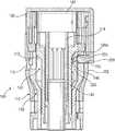
- FIG. 2is a cross-sectional side view of the loading unit and the shipping member shown in FIG. 1 , including a knife carrier in a first or initial position;
- FIG. 3is a cross-sectional side view of the loading unit and the shipping member shown in FIG. 2 , including the knife carrier in a second or proximal position;
- FIG. 4is a perspective side view of the shipping member shown in FIG. 1 ;
- FIG. 5is a cross-sectional side view of the loading unit and the shipping member shown in FIG. 3 , separated from one another;
- FIG. 6is a cross-sectional side view of the loading unit shown in FIG. 5 , including the knife carrier in a third or distal position.
- proximalrefers to that part or component closer to the user or operator, i.e. surgeon or clinician
- distalrefers to that part or component further away from the user.
- a replaceable loading unitis shown generally as loading unit 100 and includes a shipping member, according to an embodiment of the present disclosure, shown generally as shipping cap 200 .
- Loading unit 100is configured for operable connection to a surgical stapling device (not shown).
- Shipping cap 200is selectively received on a distal end of loading unit 100 and operates to maintain staples (not shown) within a staple cartridge 120 of loading unit 100 .
- Shipping cap 200also operates to prevent premature advancement of a staple pusher assembly 130 ( FIG. 2 ) of loading unit 100 and a knife assembly 140 ( FIG.
- loading unit 100prior to and during attachment of loading unit 100 to an actuation unit (not shown) of the stapling device (not shown) or an adapter assembly (not shown) that is connected to the actuation unit (not shown) of the stapling device (not shown).
- loading unit 100will be described with reference to shipping cap 200 , and shipping cap 200 will be described with reference to loading unit 100 , it is envisioned that the aspects of the present disclosure may be modified for use with loading units and shipping caps having different configurations. Loading unit 100 will only be described to the extent necessary to fully disclose the aspects of the present disclosure. For a more detailed description of an exemplary loading unit, please refer to commonly owned U.S. Patent Application Publication No. 2013/0181035, the content of which is incorporated by reference herein in its entirety.
- loading unit 100includes a housing 110 , a staple cartridge 120 selectively secured to a distal end of housing 110 , a staple pusher assembly 130 operably received within housing 110 , and a knife assembly 140 operably received within housing 110 .
- Housing 110 of loading unit 100includes an outer cylindrical portion 112 and an inner cylindrical portion 114 .
- a plurality of ribs(not shown) interconnects outer and inner cylindrical portions 112 , 114 .
- Inner cylindrical portion 114 and outer cylindrical portion 112 of housing 110are coaxial and define a recess 113 therebetween configured to operably receive staple pusher assembly 120 and knife assembly 140 .
- a proximal end of housing 110is configured for selective connection to an actuation unit (not shown) of a stapling device (not shown) or an adapter assembly (not shown) that is connected to an actuation unit (not shown) of a stapling device (not shown).
- housing 110 of loading unit 100is configured for bayonet coupling to the actuation unit and/or the adapter assembly, however, it is envisioned that housing 110 may be connected to the actuation unit and/or the adapter assembly in any suitable manner.
- outer cylindrical portion 112 of housing 110defines an opening 115 longitudinally spaced from the distal end of loading unit 100 and extending through outer cylindrical portion 112 .
- opening 115 in outer cylindrical portion 112 of housing 110is configured to selectively receive a locking portion 230 of shipping cap 200 .
- Staple cartridge 120 of loading unit 100is disposed on a distal end of housing 110 and includes a plurality of staple pockets 121 configured to selectively retain a plurality of staples (not show). Staple cartridge 120 may be selectively secured to housing 110 to allow replacement of staple cartridge 120 to permit reuse of the actuation unit with a fresh cartridge. Alternatively, staple cartridge 120 is securely affixed to housing 110 allowing for only a single use of loading unit 100 .
- staple pusher assembly 130 of loading unit 100includes a pusher adapter 132 and a pusher 134 .
- a proximal end of pusher adapter 132is configured for operable connection to a drive mechanism (not shown) for advancing pusher adapter 132 and pusher 134 from a first or proximal position ( FIG. 2 ) to a second or distal position (not shown) during actuation of the stapler device (not shown).
- Pusher adapter 132 of staple pusher assembly 130defines an opening 135 positioned to align with opening 115 formed in outer cylindrical portion 112 of housing 110 when pusher adapter 132 is in the proximal position ( FIG. 2 ).
- Pusher 134includes a plurality of pusher members 138 ( FIG. 2 ) aligned with staples (not shown) received within staple pockets 121 of staple cartridge 120 . Advancement of pusher 134 relative to staple cartridge 120 causes ejection of the staples from staple cartridge 120 .
- knife assembly 140 of loading unit 100includes a knife carrier 142 and a circular knife 144 .
- a proximal end of knife carrier 142is configured for operable connection with a drive mechanism (not shown).
- the drive mechanismis configured to move knife carrier 142 and circular knife 144 from a first or initial position ( FIG. 2 ) proximally to a second or retracted position ( FIG. 3 ) to permit the separation of shipping cap 200 from loading unit 100 , and subsequently to move knife carrier 142 and circular knife 144 distally to a third or advanced position ( FIG. 6 ) to cause the cutting of tissue (not shown) disposed adjacent to staple cartridge 120 and within the staple line of staple cartridge 120 .
- Knife carrier 142 of knife assembly 140includes a hook member 146 configured to selectively engage shipping cap 200 .
- hook member 146may be include any suitable shape for selectively engaging shipping cap 200 .
- Hook member 146opens in a distal facing direction and includes an engagement portion 146 a extending longitudinally relative to knife carrier 142 and is configured to be received within an opening 233 formed in a latch member 232 of locking portion 230 of shipping cap 200 when knife carrier 142 is in the first position ( FIG. 2 ).
- Engagement portion 146 amay include an enlarged portion (not shown) or be otherwise configured to be snuggly received, i.e., friction fit, within opening 233 of latch member 232 of locking portion 230 to prevent inadvertent disengagement of hook member 146 from latch member 232 during shipping, installation, and/or placement of loading unit 100 .
- knife carrier 142 of knife assembly 140is configured to be retracted proximally to the second or retracted position ( FIG. 3 ) to disengage engagement portion 146 a of hook member 146 from latch member 232 of locking portion 230 of shipping member 200 .
- shipping cap 200may be separated from loading unit 100 thereby permitting advancement of knife carrier 142 to the third or advanced position ( FIG. 6 ) to cause the cutting of tissue.
- shipping cap 200is configured to be selectively received on a distal end of loading unit 100 .
- Shipping cap 200includes a base portion 210 , a leg portion 220 , and a locking portion 230 .
- base portion 210 , leg portion 220 , and/or locking portion 230may be independently formed and secured together with adhesive, welding, or in any other suitable manner.
- base portion 210 of shipping cap 200includes a substantially flat or planar body having a circular shape. Although shown having a circular shape, it is envisioned that base portion 210 may include any shape corresponding to the cross-sectional shape of loading unit 100 ( FIG. 1 ). It is further envisioned that base portion 210 may be conical in shape or otherwise configured to facilitate insertion and positioning of loading unit 100 within tissue (not shown) of a patient (not shown).
- a proximal facing surface 212 of base portion 210 of shipping cap 200forms a staple retaining surface configured to abut staple cartridge 120 of loading unit 100 when shipping cap 100 is attached to the distal end of loading unit 100 .
- Staple retaining surface 212operates to retain staples (not shown) within staple pockets 121 of staple cartridge 120 during shipment and attachment of loading unit 100 to an actuation unit (not shown) of the stapling device (not shown) or an adapter (not shown) that is connected to the actuation unit of the stapling device.
- staple retaining surface 212 of base portion 210may be modified to correspond with staple cartridges having other cross-sectional configurations.
- Leg portion 220 of shipping cap 200extends proximally from base portion 210 .
- leg portion 220may be integrally formed with base portion 210 , or may be independently formed and fixedly secured to base portion 210 .
- Leg portion 220includes an elongated substantially rigid body and is configured to extend between staple cartridge 120 of loading unit 100 and opening 115 formed in outer cylindrical portion 112 of housing 110 of loading unit 100 .
- Leg portion 220may include a tab (not shown) or other feature configured for engagement by a user to facilitate separation of shipping cap 200 from loading unit 100 .
- Locking portion 230 of shipping cap 200is disposed on a free end of leg portion 220 and extends radially inward from leg portion 220 . Although shown as extending perpendicular to leg portion 220 of shipping cap 200 and extending parallel to base portion 210 of shipping cap 200 , it is envisioned that locking portion 230 may be otherwise configured relative to base portion 210 and leg portion 220 . For example, locking portion 230 may extend away from base portion 210 and at an angle relative to leg portion 220 .
- locking portion 230 of shipping cap 200may include any other suitable shape.
- the diameter of locking portion 230is the same as or only slightly smaller then the diameter of opening 115 in outer cylindrical portion 112 of housing 110 of loading unit 100 and opening 135 in pusher adapter 132 of pushing assembly 130 of loading unit 100 .
- the relative size of the diameters of opening 115 in outer cylindrical portion 112 of housing 110 and opening 135 in pusher adapter 132 of pushing assembly 130 and the diameter of locking portion 230 of shipping cap 200ensures pusher adapter 132 of pushing assembly 130 is fixedly maintained within housing 100 when shipping cap 200 is attached to loading unit 100 .
- the relative size of the diameters of openings 115 , 135 and locking portion 230also ensures that shipping cap 200 is fixedly maintained relative to loading unit 100 , thereby maintaining base portion 210 of shipping cap 200 securely against staple cartridge 120 of loading unit 100 .
- Locking portion 230 of shipping cap 200is of sufficient length to be received through opening 115 formed in outer cylindrical portion 112 of housing 110 of loading unit 100 and through opening 135 formed in pusher adapter 132 of pusher assembly 130 of loading unit 100 . As noted above, receipt of locking portion 230 of shipping cap 200 within opening 135 of pusher adapter 132 secures pusher adapter 132 relative to housing 110 and prevents premature advancement of pusher adapter 132 .
- Latch member 232 of locking portion 230 of shipping cap 200is formed on a free end of locking portion 230 and defines an opening 233 . As described above, opening 233 is configured to selectively receive engagement portion 146 a of hook member 146 formed on knife carrier 142 of knife assembly 140 of loading unit 100 .
- shipping cap 200When loading unit 100 is in a first or locked condition ( FIG. 2 ), shipping cap 200 is securely received on the distal end of loading unit 100 .
- locking portion 230 of shipping cap 200is received within opening 115 formed in outer cylindrical portion 112 of housing 110 of loading unit 100 and through opening 135 formed in pusher adapter 132 of pusher assembly 130 of loading unit 100 such that staple retaining surface 212 of base portion 210 of shipping cap 200 is maintained adjacent staple cartridge 120 of loading unit 100 .
- staple retaining surface 212 of shipping cap 200retains staples (not shown) within staple pockets 121 of staple cartridge 120 of loading unit 100 .
- knife carrier 142 of knife assembly 140 of loading unit 100In the locked condition, knife carrier 142 of knife assembly 140 of loading unit 100 is in the first or initial position.
- Shipping cap 200is securely attached to loading unit 100 during the assembly of loading unit 100 . More particularly, shipping cap 200 is secured to loading unit 100 subsequent to attachment of staple cartridge 120 to housing 110 of loading unit 100 to retain staples (not shown) within staple pockets 121 of staple cartridge 120 . Prior to attachment of shipping cap 200 to loading unit 100 , knife carrier 142 of knife assembly 140 is maintained in the second or retracted position ( FIG. 3 ) to permit complete reception of locking portion 230 of shipping cap 200 through opening 115 in outer cylindrical portion 112 of housing 110 and through opening 135 in pusher adapter 132 of pusher assembly 130 . Once locking portion 230 of shipping cap 200 is fully received within openings 115 , 135 , knife carrier 142 of knife assembly 144 is advanced to the initial position ( FIG. 2 ) to cause engagement portion 146 a of hook member 146 of knife carrier 140 to be received within opening 233 of latch member 232 of locking member 230 of shipping cap 200 , thereby securing shipping cap 200 to loading unit 100 .
- Shipping cap 200remains on loading unit 100 during shipping of loading unit 100 and during attachment of loading unit 100 to an actuation unit (not shown) of a stapling device (not shown) or an adapter assembly (not shown) that is connected to an actuation unit (not shown) of a stapling device (not shown).
- knife carrier 142 of knife assembly 140is manually retracted by the user. As noted above, retraction of knife carrier 142 may occur any time subsequent to operable attachment of loading unit 100 to the stapling device.
- shipping cap 200remains attached to loading unit 100 subsequent to operable attachment of the loading unit 100 to the stapling device to facilitate placement of loading unit 100 within a patient. Alternatively, shipping cap 200 is immediately separable from loading unit 100 upon operable attachment of the loading unit 100 with the stapling device.
- shipping cap 200may be separated from loading unit 100 .
- locking portion 230 of shipping cap 200is withdrawn from within opening 135 in pusher adapter 132 of pusher assembly 130 and from within opening 115 in outer cylindrical portion 112 of housing 110 .
- loading unit 100may be used in a traditional manner.
- the shipping capcan be used on a surgical stapling instrument that has a knife assembly permanently attached to the handle portion of the instrument, and can be used in conjunction with instruments having manually operated, manually powered handle portions, or motorized handle portions or other motorized components.
- the shipping capcan be used on a stapling component made for use in a robotic surgical system.
Landscapes
- Health & Medical Sciences (AREA)
- Life Sciences & Earth Sciences (AREA)
- Surgery (AREA)
- Heart & Thoracic Surgery (AREA)
- Engineering & Computer Science (AREA)
- Biomedical Technology (AREA)
- Nuclear Medicine, Radiotherapy & Molecular Imaging (AREA)
- Medical Informatics (AREA)
- Molecular Biology (AREA)
- Animal Behavior & Ethology (AREA)
- General Health & Medical Sciences (AREA)
- Public Health (AREA)
- Veterinary Medicine (AREA)
- Surgical Instruments (AREA)
Abstract
Description
Claims (20)
Priority Applications (1)
| Application Number | Priority Date | Filing Date | Title |
|---|---|---|---|
| US16/027,609US11071541B2 (en) | 2013-12-23 | 2018-07-05 | Loading unit including shipping member |
Applications Claiming Priority (3)
| Application Number | Priority Date | Filing Date | Title |
|---|---|---|---|
| US201361919861P | 2013-12-23 | 2013-12-23 | |
| US14/308,731US10039546B2 (en) | 2013-12-23 | 2014-06-19 | Loading unit including shipping member |
| US16/027,609US11071541B2 (en) | 2013-12-23 | 2018-07-05 | Loading unit including shipping member |
Related Parent Applications (1)
| Application Number | Title | Priority Date | Filing Date |
|---|---|---|---|
| US14/308,731DivisionUS10039546B2 (en) | 2013-12-23 | 2014-06-19 | Loading unit including shipping member |
Publications (2)
| Publication Number | Publication Date |
|---|---|
| US20180310934A1 US20180310934A1 (en) | 2018-11-01 |
| US11071541B2true US11071541B2 (en) | 2021-07-27 |
Family
ID=52272901
Family Applications (2)
| Application Number | Title | Priority Date | Filing Date |
|---|---|---|---|
| US14/308,731Active2036-11-27US10039546B2 (en) | 2013-12-23 | 2014-06-19 | Loading unit including shipping member |
| US16/027,609ActiveUS11071541B2 (en) | 2013-12-23 | 2018-07-05 | Loading unit including shipping member |
Family Applications Before (1)
| Application Number | Title | Priority Date | Filing Date |
|---|---|---|---|
| US14/308,731Active2036-11-27US10039546B2 (en) | 2013-12-23 | 2014-06-19 | Loading unit including shipping member |
Country Status (6)
| Country | Link |
|---|---|
| US (2) | US10039546B2 (en) |
| EP (1) | EP2886071A1 (en) |
| JP (1) | JP2015119955A (en) |
| CN (1) | CN104720858B (en) |
| AU (1) | AU2014233546A1 (en) |
| CA (1) | CA2869483A1 (en) |
Families Citing this family (145)
| Publication number | Priority date | Publication date | Assignee | Title |
|---|---|---|---|---|
| US11871901B2 (en) | 2012-05-20 | 2024-01-16 | Cilag Gmbh International | Method for situational awareness for surgical network or surgical network connected device capable of adjusting function based on a sensed situation or usage |
| US10039546B2 (en) | 2013-12-23 | 2018-08-07 | Covidien Lp | Loading unit including shipping member |
| US9579099B2 (en)* | 2014-01-07 | 2017-02-28 | Covidien Lp | Shipping member for loading unit |
| US9730694B2 (en) | 2014-07-01 | 2017-08-15 | Covidien Lp | Loading unit including shipping assembly |
| US11504192B2 (en) | 2014-10-30 | 2022-11-22 | Cilag Gmbh International | Method of hub communication with surgical instrument systems |
| US9745064B2 (en)* | 2015-11-26 | 2017-08-29 | Goodrich Corporation | Aircraft overhead bin monitoring and alert system |
| US10925607B2 (en)* | 2017-02-28 | 2021-02-23 | Covidien Lp | Surgical stapling apparatus with staple sheath |
| US10433842B2 (en) | 2017-04-07 | 2019-10-08 | Lexington Medical, Inc. | Surgical handle assembly |
| US10912560B2 (en) | 2017-06-23 | 2021-02-09 | Lexington Medical, Inc. | Surgical reloadable cartridge assembly |
| US11026687B2 (en) | 2017-10-30 | 2021-06-08 | Cilag Gmbh International | Clip applier comprising clip advancing systems |
| US11229436B2 (en) | 2017-10-30 | 2022-01-25 | Cilag Gmbh International | Surgical system comprising a surgical tool and a surgical hub |
| US11564756B2 (en) | 2017-10-30 | 2023-01-31 | Cilag Gmbh International | Method of hub communication with surgical instrument systems |
| US11510741B2 (en) | 2017-10-30 | 2022-11-29 | Cilag Gmbh International | Method for producing a surgical instrument comprising a smart electrical system |
| US11317919B2 (en) | 2017-10-30 | 2022-05-03 | Cilag Gmbh International | Clip applier comprising a clip crimping system |
| US11911045B2 (en) | 2017-10-30 | 2024-02-27 | Cllag GmbH International | Method for operating a powered articulating multi-clip applier |
| US11801098B2 (en) | 2017-10-30 | 2023-10-31 | Cilag Gmbh International | Method of hub communication with surgical instrument systems |
| US11291510B2 (en) | 2017-10-30 | 2022-04-05 | Cilag Gmbh International | Method of hub communication with surgical instrument systems |
| US11925373B2 (en) | 2017-10-30 | 2024-03-12 | Cilag Gmbh International | Surgical suturing instrument comprising a non-circular needle |
| US11311342B2 (en) | 2017-10-30 | 2022-04-26 | Cilag Gmbh International | Method for communicating with surgical instrument systems |
| US11311306B2 (en) | 2017-12-28 | 2022-04-26 | Cilag Gmbh International | Surgical systems for detecting end effector tissue distribution irregularities |
| US11857152B2 (en) | 2017-12-28 | 2024-01-02 | Cilag Gmbh International | Surgical hub spatial awareness to determine devices in operating theater |
| US20190201112A1 (en) | 2017-12-28 | 2019-07-04 | Ethicon Llc | Computer implemented interactive surgical systems |
| US11633237B2 (en) | 2017-12-28 | 2023-04-25 | Cilag Gmbh International | Usage and technique analysis of surgeon / staff performance against a baseline to optimize device utilization and performance for both current and future procedures |
| US11744604B2 (en) | 2017-12-28 | 2023-09-05 | Cilag Gmbh International | Surgical instrument with a hardware-only control circuit |
| US11389164B2 (en) | 2017-12-28 | 2022-07-19 | Cilag Gmbh International | Method of using reinforced flexible circuits with multiple sensors to optimize performance of radio frequency devices |
| US11559308B2 (en) | 2017-12-28 | 2023-01-24 | Cilag Gmbh International | Method for smart energy device infrastructure |
| US11026751B2 (en) | 2017-12-28 | 2021-06-08 | Cilag Gmbh International | Display of alignment of staple cartridge to prior linear staple line |
| US11304763B2 (en) | 2017-12-28 | 2022-04-19 | Cilag Gmbh International | Image capturing of the areas outside the abdomen to improve placement and control of a surgical device in use |
| US11013563B2 (en) | 2017-12-28 | 2021-05-25 | Ethicon Llc | Drive arrangements for robot-assisted surgical platforms |
| US11308075B2 (en) | 2017-12-28 | 2022-04-19 | Cilag Gmbh International | Surgical network, instrument, and cloud responses based on validation of received dataset and authentication of its source and integrity |
| US11273001B2 (en) | 2017-12-28 | 2022-03-15 | Cilag Gmbh International | Surgical hub and modular device response adjustment based on situational awareness |
| US11786245B2 (en) | 2017-12-28 | 2023-10-17 | Cilag Gmbh International | Surgical systems with prioritized data transmission capabilities |
| US20190201142A1 (en) | 2017-12-28 | 2019-07-04 | Ethicon Llc | Automatic tool adjustments for robot-assisted surgical platforms |
| US20190201090A1 (en) | 2017-12-28 | 2019-07-04 | Ethicon Llc | Capacitive coupled return path pad with separable array elements |
| US11179175B2 (en) | 2017-12-28 | 2021-11-23 | Cilag Gmbh International | Controlling an ultrasonic surgical instrument according to tissue location |
| US11696760B2 (en) | 2017-12-28 | 2023-07-11 | Cilag Gmbh International | Safety systems for smart powered surgical stapling |
| US12127729B2 (en) | 2017-12-28 | 2024-10-29 | Cilag Gmbh International | Method for smoke evacuation for surgical hub |
| US10892995B2 (en) | 2017-12-28 | 2021-01-12 | Ethicon Llc | Surgical network determination of prioritization of communication, interaction, or processing based on system or device needs |
| US11304745B2 (en) | 2017-12-28 | 2022-04-19 | Cilag Gmbh International | Surgical evacuation sensing and display |
| US11464535B2 (en) | 2017-12-28 | 2022-10-11 | Cilag Gmbh International | Detection of end effector emersion in liquid |
| US11304699B2 (en) | 2017-12-28 | 2022-04-19 | Cilag Gmbh International | Method for adaptive control schemes for surgical network control and interaction |
| US11324557B2 (en) | 2017-12-28 | 2022-05-10 | Cilag Gmbh International | Surgical instrument with a sensing array |
| US11234756B2 (en) | 2017-12-28 | 2022-02-01 | Cilag Gmbh International | Powered surgical tool with predefined adjustable control algorithm for controlling end effector parameter |
| US11202570B2 (en) | 2017-12-28 | 2021-12-21 | Cilag Gmbh International | Communication hub and storage device for storing parameters and status of a surgical device to be shared with cloud based analytics systems |
| US11076921B2 (en) | 2017-12-28 | 2021-08-03 | Cilag Gmbh International | Adaptive control program updates for surgical hubs |
| US11659023B2 (en) | 2017-12-28 | 2023-05-23 | Cilag Gmbh International | Method of hub communication |
| WO2019133144A1 (en) | 2017-12-28 | 2019-07-04 | Ethicon Llc | Detection and escalation of security responses of surgical instruments to increasing severity threats |
| US11571234B2 (en) | 2017-12-28 | 2023-02-07 | Cilag Gmbh International | Temperature control of ultrasonic end effector and control system therefor |
| US11284936B2 (en) | 2017-12-28 | 2022-03-29 | Cilag Gmbh International | Surgical instrument having a flexible electrode |
| US11166772B2 (en) | 2017-12-28 | 2021-11-09 | Cilag Gmbh International | Surgical hub coordination of control and communication of operating room devices |
| US11291495B2 (en) | 2017-12-28 | 2022-04-05 | Cilag Gmbh International | Interruption of energy due to inadvertent capacitive coupling |
| US11786251B2 (en) | 2017-12-28 | 2023-10-17 | Cilag Gmbh International | Method for adaptive control schemes for surgical network control and interaction |
| US20190201039A1 (en) | 2017-12-28 | 2019-07-04 | Ethicon Llc | Situational awareness of electrosurgical systems |
| US11464559B2 (en) | 2017-12-28 | 2022-10-11 | Cilag Gmbh International | Estimating state of ultrasonic end effector and control system therefor |
| US20190206569A1 (en) | 2017-12-28 | 2019-07-04 | Ethicon Llc | Method of cloud based data analytics for use with the hub |
| US11903601B2 (en) | 2017-12-28 | 2024-02-20 | Cilag Gmbh International | Surgical instrument comprising a plurality of drive systems |
| US11529187B2 (en) | 2017-12-28 | 2022-12-20 | Cilag Gmbh International | Surgical evacuation sensor arrangements |
| US11602393B2 (en) | 2017-12-28 | 2023-03-14 | Cilag Gmbh International | Surgical evacuation sensing and generator control |
| US11317937B2 (en) | 2018-03-08 | 2022-05-03 | Cilag Gmbh International | Determining the state of an ultrasonic end effector |
| US11832899B2 (en) | 2017-12-28 | 2023-12-05 | Cilag Gmbh International | Surgical systems with autonomously adjustable control programs |
| US11446052B2 (en) | 2017-12-28 | 2022-09-20 | Cilag Gmbh International | Variation of radio frequency and ultrasonic power level in cooperation with varying clamp arm pressure to achieve predefined heat flux or power applied to tissue |
| US11540855B2 (en) | 2017-12-28 | 2023-01-03 | Cilag Gmbh International | Controlling activation of an ultrasonic surgical instrument according to the presence of tissue |
| US12396806B2 (en) | 2017-12-28 | 2025-08-26 | Cilag Gmbh International | Adjustment of a surgical device function based on situational awareness |
| US11419667B2 (en) | 2017-12-28 | 2022-08-23 | Cilag Gmbh International | Ultrasonic energy device which varies pressure applied by clamp arm to provide threshold control pressure at a cut progression location |
| US11832840B2 (en) | 2017-12-28 | 2023-12-05 | Cilag Gmbh International | Surgical instrument having a flexible circuit |
| US11410259B2 (en) | 2017-12-28 | 2022-08-09 | Cilag Gmbh International | Adaptive control program updates for surgical devices |
| US11179208B2 (en) | 2017-12-28 | 2021-11-23 | Cilag Gmbh International | Cloud-based medical analytics for security and authentication trends and reactive measures |
| US11666331B2 (en) | 2017-12-28 | 2023-06-06 | Cilag Gmbh International | Systems for detecting proximity of surgical end effector to cancerous tissue |
| US11864728B2 (en) | 2017-12-28 | 2024-01-09 | Cilag Gmbh International | Characterization of tissue irregularities through the use of mono-chromatic light refractivity |
| US11376002B2 (en) | 2017-12-28 | 2022-07-05 | Cilag Gmbh International | Surgical instrument cartridge sensor assemblies |
| US12376855B2 (en) | 2017-12-28 | 2025-08-05 | Cilag Gmbh International | Safety systems for smart powered surgical stapling |
| US11896322B2 (en) | 2017-12-28 | 2024-02-13 | Cilag Gmbh International | Sensing the patient position and contact utilizing the mono-polar return pad electrode to provide situational awareness to the hub |
| US11364075B2 (en) | 2017-12-28 | 2022-06-21 | Cilag Gmbh International | Radio frequency energy device for delivering combined electrical signals |
| US11132462B2 (en) | 2017-12-28 | 2021-09-28 | Cilag Gmbh International | Data stripping method to interrogate patient records and create anonymized record |
| US12062442B2 (en) | 2017-12-28 | 2024-08-13 | Cilag Gmbh International | Method for operating surgical instrument systems |
| US11419630B2 (en) | 2017-12-28 | 2022-08-23 | Cilag Gmbh International | Surgical system distributed processing |
| US11266468B2 (en) | 2017-12-28 | 2022-03-08 | Cilag Gmbh International | Cooperative utilization of data derived from secondary sources by intelligent surgical hubs |
| US10758310B2 (en) | 2017-12-28 | 2020-09-01 | Ethicon Llc | Wireless pairing of a surgical device with another device within a sterile surgical field based on the usage and situational awareness of devices |
| US12096916B2 (en) | 2017-12-28 | 2024-09-24 | Cilag Gmbh International | Method of sensing particulate from smoke evacuated from a patient, adjusting the pump speed based on the sensed information, and communicating the functional parameters of the system to the hub |
| US11424027B2 (en) | 2017-12-28 | 2022-08-23 | Cilag Gmbh International | Method for operating surgical instrument systems |
| US11937769B2 (en) | 2017-12-28 | 2024-03-26 | Cilag Gmbh International | Method of hub communication, processing, storage and display |
| US10918310B2 (en) | 2018-01-03 | 2021-02-16 | Biosense Webster (Israel) Ltd. | Fast anatomical mapping (FAM) using volume filling |
| US11253315B2 (en) | 2017-12-28 | 2022-02-22 | Cilag Gmbh International | Increasing radio frequency to create pad-less monopolar loop |
| US11998193B2 (en) | 2017-12-28 | 2024-06-04 | Cilag Gmbh International | Method for usage of the shroud as an aspect of sensing or controlling a powered surgical device, and a control algorithm to adjust its default operation |
| US11818052B2 (en) | 2017-12-28 | 2023-11-14 | Cilag Gmbh International | Surgical network determination of prioritization of communication, interaction, or processing based on system or device needs |
| US11559307B2 (en) | 2017-12-28 | 2023-01-24 | Cilag Gmbh International | Method of robotic hub communication, detection, and control |
| US11432885B2 (en) | 2017-12-28 | 2022-09-06 | Cilag Gmbh International | Sensing arrangements for robot-assisted surgical platforms |
| US11576677B2 (en) | 2017-12-28 | 2023-02-14 | Cilag Gmbh International | Method of hub communication, processing, display, and cloud analytics |
| US11896443B2 (en) | 2017-12-28 | 2024-02-13 | Cilag Gmbh International | Control of a surgical system through a surgical barrier |
| US11423007B2 (en) | 2017-12-28 | 2022-08-23 | Cilag Gmbh International | Adjustment of device control programs based on stratified contextual data in addition to the data |
| US11969142B2 (en) | 2017-12-28 | 2024-04-30 | Cilag Gmbh International | Method of compressing tissue within a stapling device and simultaneously displaying the location of the tissue within the jaws |
| US11589888B2 (en) | 2017-12-28 | 2023-02-28 | Cilag Gmbh International | Method for controlling smart energy devices |
| US11109866B2 (en) | 2017-12-28 | 2021-09-07 | Cilag Gmbh International | Method for circular stapler control algorithm adjustment based on situational awareness |
| US11678881B2 (en) | 2017-12-28 | 2023-06-20 | Cilag Gmbh International | Spatial awareness of surgical hubs in operating rooms |
| US11969216B2 (en) | 2017-12-28 | 2024-04-30 | Cilag Gmbh International | Surgical network recommendations from real time analysis of procedure variables against a baseline highlighting differences from the optimal solution |
| US11304720B2 (en) | 2017-12-28 | 2022-04-19 | Cilag Gmbh International | Activation of energy devices |
| US11160605B2 (en) | 2017-12-28 | 2021-11-02 | Cilag Gmbh International | Surgical evacuation sensing and motor control |
| US11257589B2 (en) | 2017-12-28 | 2022-02-22 | Cilag Gmbh International | Real-time analysis of comprehensive cost of all instrumentation used in surgery utilizing data fluidity to track instruments through stocking and in-house processes |
| US11278281B2 (en) | 2017-12-28 | 2022-03-22 | Cilag Gmbh International | Interactive surgical system |
| US11612444B2 (en) | 2017-12-28 | 2023-03-28 | Cilag Gmbh International | Adjustment of a surgical device function based on situational awareness |
| US12303159B2 (en) | 2018-03-08 | 2025-05-20 | Cilag Gmbh International | Methods for estimating and controlling state of ultrasonic end effector |
| US11986233B2 (en) | 2018-03-08 | 2024-05-21 | Cilag Gmbh International | Adjustment of complex impedance to compensate for lost power in an articulating ultrasonic device |
| US11259830B2 (en) | 2018-03-08 | 2022-03-01 | Cilag Gmbh International | Methods for controlling temperature in ultrasonic device |
| US11534196B2 (en) | 2018-03-08 | 2022-12-27 | Cilag Gmbh International | Using spectroscopy to determine device use state in combo instrument |
| US11207067B2 (en) | 2018-03-28 | 2021-12-28 | Cilag Gmbh International | Surgical stapling device with separate rotary driven closure and firing systems and firing member that engages both jaws while firing |
| US11589865B2 (en) | 2018-03-28 | 2023-02-28 | Cilag Gmbh International | Methods for controlling a powered surgical stapler that has separate rotary closure and firing systems |
| US11090047B2 (en) | 2018-03-28 | 2021-08-17 | Cilag Gmbh International | Surgical instrument comprising an adaptive control system |
| US11219453B2 (en) | 2018-03-28 | 2022-01-11 | Cilag Gmbh International | Surgical stapling devices with cartridge compatible closure and firing lockout arrangements |
| US11471156B2 (en) | 2018-03-28 | 2022-10-18 | Cilag Gmbh International | Surgical stapling devices with improved rotary driven closure systems |
| US11278280B2 (en) | 2018-03-28 | 2022-03-22 | Cilag Gmbh International | Surgical instrument comprising a jaw closure lockout |
| US11213294B2 (en) | 2018-03-28 | 2022-01-04 | Cilag Gmbh International | Surgical instrument comprising co-operating lockout features |
| US10595873B2 (en)* | 2018-04-19 | 2020-03-24 | Franklin Institute of Innovation, LLC | Surgical staplers and related methods |
| JP7539364B2 (en)* | 2018-07-09 | 2024-08-23 | コヴィディエン リミテッド パートナーシップ | Handheld electromechanical surgical system |
| CN112384155B (en) | 2018-07-12 | 2024-08-23 | 达沃有限公司 | Surgical instrument with fastener preload lockout |
| US11166723B2 (en) | 2018-09-21 | 2021-11-09 | Lexington Medical, Inc. | Surgical handle assembly modes of operation |
| US11147561B2 (en)* | 2018-11-28 | 2021-10-19 | Covidien Lp | Reload assembly for a circular stapling device |
| US10856871B2 (en) | 2019-01-16 | 2020-12-08 | Lexington Medical, Inc. | Advancing a toothed rack of a surgical handle assembly |
| US11166728B2 (en)* | 2019-02-08 | 2021-11-09 | Covidien Lp | Reload assembly for a circular stapling device |
| US11331100B2 (en) | 2019-02-19 | 2022-05-17 | Cilag Gmbh International | Staple cartridge retainer system with authentication keys |
| US11464511B2 (en)* | 2019-02-19 | 2022-10-11 | Cilag Gmbh International | Surgical staple cartridges with movable authentication key arrangements |
| US11317915B2 (en) | 2019-02-19 | 2022-05-03 | Cilag Gmbh International | Universal cartridge based key feature that unlocks multiple lockout arrangements in different surgical staplers |
| US11369377B2 (en) | 2019-02-19 | 2022-06-28 | Cilag Gmbh International | Surgical stapling assembly with cartridge based retainer configured to unlock a firing lockout |
| US11357503B2 (en) | 2019-02-19 | 2022-06-14 | Cilag Gmbh International | Staple cartridge retainers with frangible retention features and methods of using same |
| US11324509B2 (en)* | 2019-03-28 | 2022-05-10 | Covidien Lp | Spline crash correction with motor oscillation |
| US12029416B2 (en) | 2019-04-17 | 2024-07-09 | Davol Inc. | Surgical instrument with fastener preload lock-out |
| US11399838B2 (en)* | 2019-04-22 | 2022-08-02 | Covidien Lp | Reload assembly for circular stapling devices |
| USD952144S1 (en) | 2019-06-25 | 2022-05-17 | Cilag Gmbh International | Surgical staple cartridge retainer with firing system authentication key |
| USD950728S1 (en) | 2019-06-25 | 2022-05-03 | Cilag Gmbh International | Surgical staple cartridge |
| USD964564S1 (en) | 2019-06-25 | 2022-09-20 | Cilag Gmbh International | Surgical staple cartridge retainer with a closure system authentication key |
| US11192227B2 (en)* | 2019-07-16 | 2021-12-07 | Covidien Lp | Reload assembly for circular stapling devices |
| US11464510B2 (en)* | 2019-07-26 | 2022-10-11 | Covidien Lp | Reload assembly with knife carrier lockout |
| US11253255B2 (en)* | 2019-07-26 | 2022-02-22 | Covidien Lp | Knife lockout wedge |
| CN110652344B (en)* | 2019-11-08 | 2020-12-15 | 常州安康医疗器械有限公司 | Foreskin cutting anastomat with safety mechanism |
| WO2021120046A1 (en)* | 2019-12-18 | 2021-06-24 | Covidien Lp | Surgical stapling device with shipping cap |
| US11298131B2 (en) | 2020-01-15 | 2022-04-12 | Lexington Medical, Inc. | Multidirectional apparatus |
| US11382630B2 (en)* | 2020-02-25 | 2022-07-12 | Covidien Lp | Surgical stapling device with two part knife assembly |
| US11116501B1 (en) | 2020-04-10 | 2021-09-14 | Lexington Medical, Inc. | Surgical handle articulation assemblies |
| WO2021222172A2 (en) | 2020-04-29 | 2021-11-04 | DePuy Synthes Products, Inc. | Knotless anchor insertion |
| US11426171B2 (en)* | 2020-05-29 | 2022-08-30 | Cilag Gmbh International | Knife for circular surgical stapler |
| US11497494B2 (en)* | 2020-06-30 | 2022-11-15 | Cilag Gmbh International | Surgical stapler cartridge retainer with ejector feature |
| EP4185215A4 (en)* | 2020-07-21 | 2024-04-03 | Covidien LP | Shipping cover for staple cartridge |
| USD1028232S1 (en) | 2021-04-27 | 2024-05-21 | Medos International Sarl | Suture anchor insertion device |
| US12343009B2 (en) | 2021-06-07 | 2025-07-01 | Lexington Medical, Inc. | Motorized surgical handle assembly |
| USD1019945S1 (en) | 2021-12-30 | 2024-03-26 | Medos International Sarl | Suture anchor insertion device |
| US12137894B2 (en) | 2021-12-30 | 2024-11-12 | Medos International Sarl | Knotless anchor inserter tool extraction |
Citations (28)
| Publication number | Priority date | Publication date | Assignee | Title |
|---|---|---|---|---|
| US4505272A (en) | 1982-02-23 | 1985-03-19 | Vsesojozny Naucho-Issledovatelsky i Ispytatelny Institut Meditsinskoi Tekhniki | Surgical suturing instrument for performing anastomoses between structures of the digestive tract |
| US4881544A (en) | 1988-12-19 | 1989-11-21 | United States Surgical Corporation | Surgical stapler apparatus with improved tissue shield |
| US4930674A (en)* | 1989-02-24 | 1990-06-05 | Abiomed, Inc. | Surgical stapler |
| US5669918A (en) | 1995-03-16 | 1997-09-23 | Deutsche Forschungsanstalt Fur Luft-Und Raumfahrt E.V. | Surgical instrument for preparing an anastomosis in minimally invasive surgery |
| US5836503A (en) | 1996-04-22 | 1998-11-17 | United States Surgical Corporation | Insertion device for surgical apparatus |
| US20030178465A1 (en) | 2001-11-28 | 2003-09-25 | Federico Bilotti | Surgical stapling instrument |
| WO2003079909A2 (en) | 2002-03-19 | 2003-10-02 | Tyco Healthcare Group, Lp | Surgical fastener applying apparatus |
| US20050139635A1 (en) | 2003-12-30 | 2005-06-30 | Wukusick Peter M. | Staple cartridge for a curved cutter stapler |
| US20050222616A1 (en)* | 2001-10-05 | 2005-10-06 | Rethy Csaba L | Surgical fastener applying apparatus |
| US7182239B1 (en) | 2004-08-27 | 2007-02-27 | Myers Stephan R | Segmented introducer device for a circular surgical stapler |
| US20090082777A1 (en) | 2007-09-24 | 2009-03-26 | Milliman Keith L | Insertion Aid with Interference Fit |
| US20100147921A1 (en)* | 2008-12-16 | 2010-06-17 | Lee Olson | Surgical Apparatus Including Surgical Buttress |
| US20100163598A1 (en) | 2008-12-23 | 2010-07-01 | Belzer George E | Shield for surgical stapler and method of use |
| US8006701B2 (en) | 2004-11-05 | 2011-08-30 | Ethicon Endo-Surgery, Inc. | Device and method for the therapy of obesity |
| US8118206B2 (en) | 2008-03-15 | 2012-02-21 | Surgisense Corporation | Sensing adjunct for surgical staplers |
| EP2462875A2 (en) | 2010-12-10 | 2012-06-13 | Tyco Healthcare Group LP | Cartridge shipping aid |
| US20120145767A1 (en) | 2010-12-10 | 2012-06-14 | Tyco Healthcare Group Lp | Surgical Apparatus Including Surgical Buttress |
| US20120168486A1 (en)* | 2009-10-15 | 2012-07-05 | Tyco Healthcare Group Lp | Staple Line Reinforcement For Anvil And Cartridge |
| CN102579096A (en) | 2012-03-31 | 2012-07-18 | 常州市康迪医用吻合器有限公司 | Linear cutting element with E-shaped guiding element |
| EP2499987A2 (en) | 2011-03-18 | 2012-09-19 | Tyco Healthcare Group LP | Shipping wedge with lockout |
| US8328060B2 (en) | 2002-12-20 | 2012-12-11 | Covidien Lp | Vacuum assisted surgical stapler |
| WO2013026402A1 (en) | 2011-08-24 | 2013-02-28 | 苏州天臣国际医疗科技有限公司 | Guiding device |
| US20130146643A1 (en) | 2010-09-30 | 2013-06-13 | Ethicon Endo-Surgery, Inc. | Adhesive film laminate |
| EP2604195A1 (en) | 2011-12-14 | 2013-06-19 | Covidien LP | Surgical Stapling Apparatus Including Buttress Attachment Via Tabs |
| EP2604197A2 (en) | 2011-12-14 | 2013-06-19 | Covidien LP | Buttress assembly for use with surgical stapling device |
| US20130214024A1 (en)* | 2010-04-08 | 2013-08-22 | Hidehisa Thomas Takei | Introducer System and Assembly for Surgical Staplers |
| EP2638866A2 (en) | 2012-03-16 | 2013-09-18 | Covidien LP | Travel clip for surgical staple cartridge |
| US10039546B2 (en) | 2013-12-23 | 2018-08-07 | Covidien Lp | Loading unit including shipping member |
Family Cites Families (4)
| Publication number | Priority date | Publication date | Assignee | Title |
|---|---|---|---|---|
| AU2003234551A1 (en)* | 2002-05-13 | 2003-11-11 | Tyco Healthcare Group, Lp | Surgical stapler and disposable loading unit having different size staples |
| US7354447B2 (en)* | 2005-11-10 | 2008-04-08 | Ethicon Endo-Surgery, Inc. | Disposable loading unit and surgical instruments including same |
| US7980443B2 (en)* | 2008-02-15 | 2011-07-19 | Ethicon Endo-Surgery, Inc. | End effectors for a surgical cutting and stapling instrument |
| US9168042B2 (en) | 2012-01-12 | 2015-10-27 | Covidien Lp | Circular stapling instruments |
- 2014
- 2014-06-19USUS14/308,731patent/US10039546B2/enactiveActive
- 2014-09-23AUAU2014233546Apatent/AU2014233546A1/ennot_activeAbandoned
- 2014-11-03CACA2869483Apatent/CA2869483A1/ennot_activeAbandoned
- 2014-11-12JPJP2014229820Apatent/JP2015119955A/enactivePending
- 2014-12-22CNCN201410806443.XApatent/CN104720858B/ennot_activeExpired - Fee Related
- 2014-12-22EPEP14199687.6Apatent/EP2886071A1/ennot_activeWithdrawn
- 2018
- 2018-07-05USUS16/027,609patent/US11071541B2/enactiveActive
Patent Citations (30)
| Publication number | Priority date | Publication date | Assignee | Title |
|---|---|---|---|---|
| US4505272A (en) | 1982-02-23 | 1985-03-19 | Vsesojozny Naucho-Issledovatelsky i Ispytatelny Institut Meditsinskoi Tekhniki | Surgical suturing instrument for performing anastomoses between structures of the digestive tract |
| US4881544A (en) | 1988-12-19 | 1989-11-21 | United States Surgical Corporation | Surgical stapler apparatus with improved tissue shield |
| US4930674A (en)* | 1989-02-24 | 1990-06-05 | Abiomed, Inc. | Surgical stapler |
| US5669918A (en) | 1995-03-16 | 1997-09-23 | Deutsche Forschungsanstalt Fur Luft-Und Raumfahrt E.V. | Surgical instrument for preparing an anastomosis in minimally invasive surgery |
| US5836503A (en) | 1996-04-22 | 1998-11-17 | United States Surgical Corporation | Insertion device for surgical apparatus |
| US20120085808A1 (en) | 2000-10-13 | 2012-04-12 | Tyco Healthcare Group Lp | Surgical Fastener Applying Apparatus |
| US20050222616A1 (en)* | 2001-10-05 | 2005-10-06 | Rethy Csaba L | Surgical fastener applying apparatus |
| US20030178465A1 (en) | 2001-11-28 | 2003-09-25 | Federico Bilotti | Surgical stapling instrument |
| WO2003079909A2 (en) | 2002-03-19 | 2003-10-02 | Tyco Healthcare Group, Lp | Surgical fastener applying apparatus |
| US8328060B2 (en) | 2002-12-20 | 2012-12-11 | Covidien Lp | Vacuum assisted surgical stapler |
| US20050139635A1 (en) | 2003-12-30 | 2005-06-30 | Wukusick Peter M. | Staple cartridge for a curved cutter stapler |
| US7182239B1 (en) | 2004-08-27 | 2007-02-27 | Myers Stephan R | Segmented introducer device for a circular surgical stapler |
| US8006701B2 (en) | 2004-11-05 | 2011-08-30 | Ethicon Endo-Surgery, Inc. | Device and method for the therapy of obesity |
| US20090082777A1 (en) | 2007-09-24 | 2009-03-26 | Milliman Keith L | Insertion Aid with Interference Fit |
| US8118206B2 (en) | 2008-03-15 | 2012-02-21 | Surgisense Corporation | Sensing adjunct for surgical staplers |
| US20100147921A1 (en)* | 2008-12-16 | 2010-06-17 | Lee Olson | Surgical Apparatus Including Surgical Buttress |
| US20100163598A1 (en) | 2008-12-23 | 2010-07-01 | Belzer George E | Shield for surgical stapler and method of use |
| US20120168486A1 (en)* | 2009-10-15 | 2012-07-05 | Tyco Healthcare Group Lp | Staple Line Reinforcement For Anvil And Cartridge |
| US20130214024A1 (en)* | 2010-04-08 | 2013-08-22 | Hidehisa Thomas Takei | Introducer System and Assembly for Surgical Staplers |
| US20130146643A1 (en) | 2010-09-30 | 2013-06-13 | Ethicon Endo-Surgery, Inc. | Adhesive film laminate |
| US20120145767A1 (en) | 2010-12-10 | 2012-06-14 | Tyco Healthcare Group Lp | Surgical Apparatus Including Surgical Buttress |
| EP2462875A2 (en) | 2010-12-10 | 2012-06-13 | Tyco Healthcare Group LP | Cartridge shipping aid |
| EP2499987A2 (en) | 2011-03-18 | 2012-09-19 | Tyco Healthcare Group LP | Shipping wedge with lockout |
| US20120234894A1 (en) | 2011-03-18 | 2012-09-20 | Stanislaw Kostrzewski | Shipping Wedge With Lockout |
| WO2013026402A1 (en) | 2011-08-24 | 2013-02-28 | 苏州天臣国际医疗科技有限公司 | Guiding device |
| EP2604195A1 (en) | 2011-12-14 | 2013-06-19 | Covidien LP | Surgical Stapling Apparatus Including Buttress Attachment Via Tabs |
| EP2604197A2 (en) | 2011-12-14 | 2013-06-19 | Covidien LP | Buttress assembly for use with surgical stapling device |
| EP2638866A2 (en) | 2012-03-16 | 2013-09-18 | Covidien LP | Travel clip for surgical staple cartridge |
| CN102579096A (en) | 2012-03-31 | 2012-07-18 | 常州市康迪医用吻合器有限公司 | Linear cutting element with E-shaped guiding element |
| US10039546B2 (en) | 2013-12-23 | 2018-08-07 | Covidien Lp | Loading unit including shipping member |
Non-Patent Citations (2)
| Title |
|---|
| Chinese Office Action dated Apr. 4, 2018 in Chinese Appln. No. 201410806443. |
| European Search Report 14199687.6-1654 dated May 12, 2015. |
Also Published As
| Publication number | Publication date |
|---|---|
| CN104720858A (en) | 2015-06-24 |
| US20150173757A1 (en) | 2015-06-25 |
| JP2015119955A (en) | 2015-07-02 |
| CA2869483A1 (en) | 2015-06-23 |
| AU2014233546A1 (en) | 2015-07-09 |
| CN104720858B (en) | 2019-03-01 |
| US10039546B2 (en) | 2018-08-07 |
| US20180310934A1 (en) | 2018-11-01 |
| EP2886071A1 (en) | 2015-06-24 |
Similar Documents
| Publication | Publication Date | Title |
|---|---|---|
| US11071541B2 (en) | Loading unit including shipping member | |
| US10709445B2 (en) | Loading unit including shipping assembly | |
| US10342629B2 (en) | Shipping member for loading unit | |
| US9987001B2 (en) | Surgical anastomosis apparatus | |
| US10405864B2 (en) | Loading unit with shipping member for surgical stapling device | |
| US10881408B2 (en) | Interlock assembly for replaceable loading units | |
| US11147561B2 (en) | Reload assembly for a circular stapling device |
Legal Events
| Date | Code | Title | Description |
|---|---|---|---|
| AS | Assignment | Owner name:COVIDIEN LP, MASSACHUSETTS Free format text:ASSIGNMENT OF ASSIGNORS INTEREST;ASSIGNORS:WILLIAMS, JUSTIN;PENNA, CHRISTOPHER;SCIRICA, PAUL A.;SIGNING DATES FROM 20140527 TO 20140703;REEL/FRAME:046269/0810 | |
| FEPP | Fee payment procedure | Free format text:ENTITY STATUS SET TO UNDISCOUNTED (ORIGINAL EVENT CODE: BIG.); ENTITY STATUS OF PATENT OWNER: LARGE ENTITY | |
| STPP | Information on status: patent application and granting procedure in general | Free format text:RESPONSE TO NON-FINAL OFFICE ACTION ENTERED AND FORWARDED TO EXAMINER | |
| STPP | Information on status: patent application and granting procedure in general | Free format text:FINAL REJECTION MAILED | |
| STPP | Information on status: patent application and granting procedure in general | Free format text:ADVISORY ACTION MAILED | |
| STPP | Information on status: patent application and granting procedure in general | Free format text:NON FINAL ACTION MAILED | |
| STPP | Information on status: patent application and granting procedure in general | Free format text:FINAL REJECTION MAILED | |
| STPP | Information on status: patent application and granting procedure in general | Free format text:ADVISORY ACTION MAILED | |
| STCV | Information on status: appeal procedure | Free format text:NOTICE OF APPEAL FILED | |
| STCV | Information on status: appeal procedure | Free format text:APPEAL BRIEF (OR SUPPLEMENTAL BRIEF) ENTERED AND FORWARDED TO EXAMINER | |
| STPP | Information on status: patent application and granting procedure in general | Free format text:NOTICE OF ALLOWANCE MAILED -- APPLICATION RECEIVED IN OFFICE OF PUBLICATIONS | |
| STPP | Information on status: patent application and granting procedure in general | Free format text:PUBLICATIONS -- ISSUE FEE PAYMENT VERIFIED | |
| STCF | Information on status: patent grant | Free format text:PATENTED CASE | |
| MAFP | Maintenance fee payment | Free format text:PAYMENT OF MAINTENANCE FEE, 4TH YEAR, LARGE ENTITY (ORIGINAL EVENT CODE: M1551); ENTITY STATUS OF PATENT OWNER: LARGE ENTITY Year of fee payment:4 |