US11071511B2 - Radiation tomographic imaging system and program for controlling the same - Google Patents
Radiation tomographic imaging system and program for controlling the sameDownload PDFInfo
- Publication number
- US11071511B2 US11071511B2US16/077,536US201716077536AUS11071511B2US 11071511 B2US11071511 B2US 11071511B2US 201716077536 AUS201716077536 AUS 201716077536AUS 11071511 B2US11071511 B2US 11071511B2
- Authority
- US
- United States
- Prior art keywords
- referential
- radiation
- subject
- emission condition
- width
- Prior art date
- Legal status (The legal status is an assumption and is not a legal conclusion. Google has not performed a legal analysis and makes no representation as to the accuracy of the status listed.)
- Active, expires
Links
Images


Classifications
- A—HUMAN NECESSITIES
- A61—MEDICAL OR VETERINARY SCIENCE; HYGIENE
- A61B—DIAGNOSIS; SURGERY; IDENTIFICATION
- A61B6/00—Apparatus or devices for radiation diagnosis; Apparatus or devices for radiation diagnosis combined with radiation therapy equipment
- A61B6/54—Control of apparatus or devices for radiation diagnosis
- A61B6/542—Control of apparatus or devices for radiation diagnosis involving control of exposure
- A61B6/544—Control of apparatus or devices for radiation diagnosis involving control of exposure dependent on patient size
- A—HUMAN NECESSITIES
- A61—MEDICAL OR VETERINARY SCIENCE; HYGIENE
- A61B—DIAGNOSIS; SURGERY; IDENTIFICATION
- A61B6/00—Apparatus or devices for radiation diagnosis; Apparatus or devices for radiation diagnosis combined with radiation therapy equipment
- A61B6/02—Arrangements for diagnosis sequentially in different planes; Stereoscopic radiation diagnosis
- A61B6/03—Computed tomography [CT]
- A61B6/032—Transmission computed tomography [CT]
- A—HUMAN NECESSITIES
- A61—MEDICAL OR VETERINARY SCIENCE; HYGIENE
- A61B—DIAGNOSIS; SURGERY; IDENTIFICATION
- A61B6/00—Apparatus or devices for radiation diagnosis; Apparatus or devices for radiation diagnosis combined with radiation therapy equipment
- A61B6/48—Diagnostic techniques
- A61B6/488—Diagnostic techniques involving pre-scan acquisition
- H—ELECTRICITY
- H05—ELECTRIC TECHNIQUES NOT OTHERWISE PROVIDED FOR
- H05G—X-RAY TECHNIQUE
- H05G1/00—X-ray apparatus involving X-ray tubes; Circuits therefor
- H05G1/08—Electrical details
- H05G1/26—Measuring, controlling or protecting
- A—HUMAN NECESSITIES
- A61—MEDICAL OR VETERINARY SCIENCE; HYGIENE
- A61B—DIAGNOSIS; SURGERY; IDENTIFICATION
- A61B6/00—Apparatus or devices for radiation diagnosis; Apparatus or devices for radiation diagnosis combined with radiation therapy equipment
- A61B6/04—Positioning of patients; Tiltable beds or the like
- A61B6/0407—Supports, e.g. tables or beds, for the body or parts of the body
Definitions
- the present inventionrelates to a radiation tomographic imaging system and a program for controlling the same, for setting conditions for radiation emission to a subject based on at least one of the subject's width and body depth.
- Functions provided in a radiation tomographic imaging apparatusinclude an automatic exposure control mechanism.
- the automatic exposure control mechanismautomatically controls the output power of radiation emitted to a subject based on data indicating a distribution of a radiation absorbed dose in the subject acquired beforehand so that the power is increased for a position at which the radiation absorbed dose is greater and is decreased for a position at which the radiation absorbed dose is smaller.
- a preliminary scan in which a low dose of radiation is emitted onto a subjecti.e., a scout scan
- a scout scanis performed.
- an area of a profile of the projection dataan ellipticity obtained by elliptically approximating a cross section across the body axis of the subject, a radiation decrement, etc. for each position in a direction of the body axis of the subject.
- the output power of emitted radiationfor example, the tube current value for a radiation tube, is then set for each position in the body-axis direction of the subject based on information on the area, ellipticity, decrement, etc. so that the amount of noise is uniform over a reconstructed image (see Patent Document 1).
- a main scanis then performed with the set output power.
- Patent Document 1Japanese Patent Application KOKAI No. 2001-043993
- the scout scanis performed twice: one from just above the subject, and the other from just the side of the subject. Specifically, a first scout scan is performed by moving a table carrying thereon the subject while emitting radiation from the radiation tube lying at a 0-degree position, and then, the table is brought back to its original position, whereafter a second scout scan is performed by moving the table carrying thereon the subject again while emitting radiation from the radiation tube lying at a 90-degree position. Therefore, a more improved throughput is desired.
- the radiation exposure dose for the subjectincreases corresponding to the fact that the scout scan should be performed. From such circumstances, it is desired to set conditions for radiation emission in the automatic exposure control mechanism without performing a scout scan. Nevertheless, it is also desired to set suitable conditions for radiation emission without performing a scout scan to a degree of suitability comparable to a degree that would be otherwise achieved when the scout scan is performed, that is, to set conditions for radiation emission with which the amount of noise in a reconstructed image fulfills a required amount of noise.
- the inventionmade for solving the aforementioned problems is a radiation tomographic imaging system characterized in comprising: a radiation tube for emitting radiation onto a subject; a storage device for storing therein a referential emission condition for radiation emitted by said radiation tube, said referential emission condition being defined assuming at least one of a required referential width and a required referential body depth in said subject and defined taking account of a degree of absorption of said radiation in said subject; an optical sensor for detecting at least one of a width and a body depth of said subject; and an emission condition setting section for setting an emission condition for radiation emitted by said radiation tube in imaging after correcting said referential emission condition according to at least one of a difference between the width of said subject detected by said optical sensor and said referential width, and a difference between the body depth of said subject detected by said optical sensor and said referential body depth.
- the referential emission conditionis corrected according to at least one of a difference between the subject's width detected by the optical sensor and the referential width and a difference between the subject's body depth detected by the optical sensor and the referential body depth to set a condition for radiation emission in imaging.
- the referential emission conditionis defined taking account of a degree of absorption of radiation reflecting factors like the subject's width and body depth, and in addition, other factors.
- Such a referential emission conditionis corrected according to at least one of a difference between the subject's width detected by the optical sensor and the referential width and a difference between the subject's body depth detected by the optical sensor and the referential body depth, it is possible to set a suitable condition for radiation emission without performing a scout scan to a degree of suitability comparable to a degree that would be otherwise achieved when the scout scan is performed.
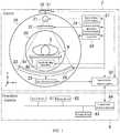
- FIG. 1A diagram schematically showing a hardware configuration of an X-ray CT system in accordance with embodiments.
- FIG. 2A view showing an exemplary overview of an imaging room.
- FIG. 3A functional block diagram of an operation console in the X-ray CT system shown in FIG. 1 .
- FIG. 4A flow chart showing the flow of processing in the X-ray CT system in accordance with the embodiments.
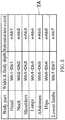
- FIG. 5A diagram showing a table stored in a storage device.
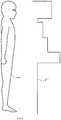
- FIG. 6A diagram showing a line chart representing a change of the tube current and a pictorial diagram representing a subject in a first embodiment.
- FIG. 7A diagram explaining a relationship between the view angle and the subject's width and body depth.
- FIG. 8A diagram showing a line chart representing a change of the tube current and a pictorial diagram representing the subject in a second embodiment.
- FIG. 9A view showing another exemplary overview of the imaging room.
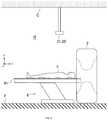
- FIG. 1shows an X-ray CT system 1 , which is an exemplary embodiment of the radiation tomographic imaging system in the present invention.
- the X-ray CT system 1comprises a gantry 2 , an imaging table 4 , and an operation console 6 .
- the gantry 2 and imaging table 4are installed in an imaging room R, as shown in FIG. 2 .
- the console 6is installed in an operation room (not shown) different from the imaging room R.
- reference symbol Fdesignates a floor of the imaging room R
- reference symbol Cdesignates a ceiling of the imaging room R.
- the gantry 2has an X-ray tube 21 , an aperture 22 , a collimator device 23 , an X-ray detector 24 , a data collecting section 25 , a rotating section 26 , a high-voltage power source 27 , an aperture driving apparatus 28 , a rotation driving apparatus 29 , and a gantry/table control section 30 , a camera 31 and a distance sensor 32 .
- the rotating section 26is rotatably supported around a bore 2 B of the gantry 2 .
- the rotating section 26has the X-ray tube 21 , aperture 22 , collimator device 23 , X-ray detector 24 , and data collecting section 25 mounted thereon.
- the X-ray tube 21 and X-ray detector 24are disposed to face each other across the bore 2 B.
- the X-ray tube 21is an exemplary embodiment of the radiation tube in the present invention.
- the aperture 22is disposed between the X-ray tube 21 and bore 2 B. It shapes X-rays emitted from an X-ray focus of the X-ray tube 21 toward the X-ray detector 24 into a fan beam or a cone beam.
- the collimator device 23is disposed between the bore 2 B and X-ray detector 24 .
- the collimator device 23removes scatter rays that would otherwise impinge upon the X-ray detector 24 .
- the X-ray detector 24has a plurality of X-ray detector elements two-dimensionally arranged in a direction (referred to as channel direction) of the span of the fan-shaped X-ray beam emitted from the X-ray tube 21 and a direction (referred to as row direction) of the thickness thereof.
- Each respective X-ray detector elementdetects X-rays passing through a subject 5 laid in the bore 2 B, and outputs an electric signal depending upon the intensity of the X-rays.
- the data collecting section 25receives the electric signal output from each X-ray detector element in the X-ray detector 24 , and converts it into X-ray data for collection.
- the imaging table 4has a cradle 41 and a cradle driving apparatus 42 .
- the subject 5is laid on the cradle 41 .
- the cradle driving apparatus 42moves the cradle 41 into/out of the bore 2 B, i.e., an imaging volume, in the gantry 2 .
- the high-voltage power source 27supplies high voltage and current to the X-ray tube 21 .
- the aperture driving apparatus 28drives the aperture 22 and modifies the shape of its opening.
- the rotation driving apparatus 29rotationally drives the rotating section 26 .
- the gantry/table control section 30controls several apparatuses and sections in the gantry 2 , the imaging table 4 , and the like.
- the camera 31 and distance sensor 32are attached to the gantry 20 on its upper portion.
- the camera 31is an optical imaging apparatus for detecting visible light and acquires an image of the subject 5 laid on the cradle 41 of the imaging table 4 .
- the distance sensor 32has an emitting section (not shown) for emitting, for example, infrared rays, and a detecting section (not shown) for detecting the infrared rays emitted from the emitting section and reflected back. By the distance sensor 32 , a distance between the distance sensor 32 and an infrared reflector is detected. It should be noted that image signals from the camera 31 and detection signals from the distance sensor 32 are passed through the gantry/table control section 30 and input into a computational processing apparatus 64 in the operation console 6 .
- a width of the subject 5may be detected.
- a body depth of the subject 5may be detected. Details thereof will be discussed later.
- the camera 31 and distance sensor 32constitute an exemplary embodiment of the optical sensor in the present invention.
- the operation console 6accepts several kinds of operation from an operator.
- the operation console 6has an input device 61 , a display device 62 , a storage device 63 , and the computational processing apparatus 64 .
- the operation console 6is constructed from a computer.
- the input device 61is configured to include a button, a keyboard, etc. for accepting an input of a command and information from the operator, and to further include a pointing device, and the like.
- the display device 62is an LCD (Liquid Crystal Display), an organic EL (Electro-Luminescence) display, or the like.
- the display device 62is an exemplary embodiment of the display device in the present invention.
- the storage device 63is an HDD (Hard Disk Drive), semiconductor memory, such as RAM (Random Access Memory) and ROM (Read Only Memory), and the like.
- the operation console 6may have all of the HDD, RAM, and ROM as the storage device 63 .
- the storage device 63may also comprise a portable storage medium, such as a CD (Compact Disk) or a DVD (Digital Versatile Disk).
- the storage device 63is an exemplary embodiment of the storage device in the present invention.
- the computational processing apparatus 64is a processor such as a CPU (central processing unit).
- a direction of the body axis of the subject 5i.e., a direction of transportation of the subject 5 by the imaging table 4
- z-directiona direction of transportation of the subject 5 by the imaging table 4
- y-directiona vertical direction
- x-directiona horizontal direction orthogonal to the y- and z-directions
- the operation console 6has, as its function blocks, a scan control section 71 , an image reconstructing section 72 , a scan protocol setting section 73 , a width identifying section 74 , a body-depth identifying section 75 , an emission condition setting section 76 , and a display control section 77 .
- the computational processing apparatus 64executes functions of these scan control section 71 , image reconstructing section 72 , scan protocol setting section 73 , width identifying section 74 , body-depth identifying section 75 , emission condition setting section 76 , and display control section 77 by prespecified programs.
- the prespecified programsare stored in, for example, a non-transitory storage medium, such as the HDD or ROM, constituting the storage device 63 .
- the programsmay also be stored in a non-transitory storage medium having portability, such as the CD or DVD, constituting the storage device 63 .
- the scan control section 71controls the gantry/table control section 30 in response to an operation by the operator to perform a scan.
- the image reconstructing section 72executes image reconstruction processing based on projection data obtained by scanning the subject 5 with X-rays emitted from the X-ray tube 21 to provide tomographic image data.
- the scan protocol setting section 73sets a scan protocol for use in performing the scan.
- the width identifying section 74identifies a width W of the subject 5 based on an image acquired by the camera 31 .
- the width Wis the dimension of the subject 5 in the x-axis direction.
- the width Wmay be identified at a plurality of positions in the body-axis direction.
- the body-depth identifying section 75identifies a body depth D of the subject 5 based on a detection signal from the distance sensor 32 .
- the body depth Dis the dimension of the subject 5 in the y-axis direction.
- the body depth Dis identified in a portion for which the width W is identified.
- the body depth Dmay be identified at a plurality of positions in the body-axis direction.
- the emission condition setting section 76sets emission conditions for X-rays emitted by the X-ray tube 21 in imaging. For example, the emission condition setting section 76 sets a tube current in imaging (during a scan). Details thereof will be discussed later.
- the emission condition setting section 76is an exemplary embodiment of the emission condition setting section in the present invention.
- the function by the emission condition setting section 76is an exemplary embodiment of the emission condition setting function in the present invention.
- the display control section 75displays several kinds of images, including a tomographic image, and text on the display device 62 .
- Step S 1the operator selects an imaging protocol.
- the imaging protocolis input at the input device 61 , for example.
- the referential emission conditionis an emission condition when emitting X-rays by the X-ray tube 21 onto a subject of standard body shape.
- the referential emission conditionis defined assuming a standard body shape, i.e., assuming a required referential width and a required referential body depth in the subject, and also defined taking account of the degree of X-ray absorption in the subject.
- the referential emission conditionis an emission condition defined so that the noise level in a reconstructed image for a subject of standard body shape fulfills a level indicated by a required noise index value.
- the referential emission conditionis stored in the storage device 63 for each body part in a subject.
- the referential emission conditionis defined so that the noise level in a reconstructed image is uniform across body parts.
- the referential emission conditionis a referential tube current.
- the degree of X-ray absorption in a subjectvaries with the cross-sectional area of the subject determined by the width and body depth, and in addition, with what kind of substance, such as air or bone, is present in that body part. Accordingly, the referential tube current is set taking account of the degree of X-ray absorption in which the width and body depth, and in addition, other factors are reflected.
- the referential tube currentis stored in the storage device 63 as Table TA shown in FIG. 5 .
- Table TAis a table defining referential tube currents mAb1 to mAb7 depending upon the body part (a head, a neck, shoulders, lungs, an abdomen, hips, and lower limbs) of the subject. Some of the values mAb1 to mAb7 may be the same.
- Table TAmay include referential widths Wb1 to Wb7 and referential body depths Db1 to Db7. These referential widths Wb1 to Wb7 and referential body depths Db1 to Db7 constitute an exemplary embodiment of the required referential width and required referential body depth.
- the emission condition setting section 76loads from the storage device 63 information in Table TA for a body part according to the imaging protocol selected at Step S 1 .
- the information in Table TA loaded from the storage device 63includes the referential tube current, referential width, and referential body depth for that body part.
- the body partmay be a single part or comprises a plurality of parts.
- the width identifying section 74identifies a width W of the subject 5 .
- the body-depth identifying section 75identifies a body depth D of the subject 5 .
- the width identifying section 74 and body-depth identifying section 75identify the width W and body depth D for the body part according to the imaging protocol selected at Step S 1 .
- the width identifying section 74identifies the width W of the subject 5 based on an image acquired by the camera 31 .
- the body-depth identifying section 75identifies the body depth D by a difference between two distances: one being from the distance sensor 32 to the subject 5 at the body part, and the other being from the distance sensor 32 to a plane over which the subject 5 is laid on the imaging table 4 .
- the emission condition setting section 76decides whether the width W identified by the width identifying section 74 and body depth D identified by the body-depth identifying section 75 fall within respective ranges of the referential values.
- the range of the referential valueis a range approved as representing the standard body shape, and is stored in the storage device 63 .
- the range of the referential value approved as representing the standard body shapeis such a range that the noise level in a reconstructed image fulfills a level indicated by a required noise index value when emitting X-rays with the referential tube current.
- the emission condition setting section 76corrects the referential emission condition to set a condition for emission of X-rays to the subject 5 in imaging.
- the referential tube current loaded at Step S 2is corrected to set a tube current in imaging.
- imagingrefers to a scan at Step S 7 , i.e., X-ray CT imaging, which will be discussed later.
- the emission condition setting section 76corrects the referential tube current according to two differences: one being between the width W of the subject 5 and referential width Wb, and the other being between the body depth D of the subject 5 and referential body depth Db.
- the differencemay be a ratio or a (arithmetic) difference, for example.
- the referential widthis one of the referential widths Wb1 to Wb7 in Table TA for the body part according to the imaging protocol.
- the referential body depthis one of the referential body depths Db1 to Db7 in Table TA for the body part according to the imaging protocol.
- the emission condition setting section 76corrects the referential tube current so that a higher tube current in imaging results as at least one of the width W and body depth D is larger, and a lower tube current in imaging results as at least one of the width W and body depth D is smaller.
- the emission condition setting section 76corrects the referential tube current mAb for each of the plurality of body parts according to (EQ. 1) for each of the plurality of body parts.
- the display control section 77displays on the display device 62 the X-ray emission condition, i.e., a tube current mA, set at Step S 5 .
- the display control section 77displays on the display device 62 a line chart L representing a change of the tube current mA in a direction of the body axis (z-axis direction) of the subject 5 , as shown in FIG. 6 .
- the horizontal directionrepresents the z-direction while the vertical direction represents the magnitude of the tube current mA.
- the line chart Lrepresents a change of the tube current mA in the whole body of the subject 5 .
- the display control section 77may display a pictorial diagram I representing the subject along with the line chart L on the display device 62 .
- the line chart Lis displayed so that the pictorial diagram I and the position in the z-axis direction correspond to each other.
- Step S 7a scan of the subject 5 with X-rays, i.e., X-ray CT imaging, is performed.
- the scanis performed by the scan control section 71 controlling the gantry/table control section 30 .
- a scanis performed with the tube current mA.
- the width W and body depth Dare decided to fall within the respective ranges of the referential values at Step S 4 .
- the referential tube current mAbis corrected according to the width W and body depth D of the subject 5 to set a tube current in imaging mA without performing a scout scan separately from the scan performed at Step S 7 .
- the referential tube current mAbis defined taking account of a degree of X-ray absorption reflecting factors like the subject's width and body depth, and in addition, other factors; therefore, it is possible to set a suitable tube current mA without performing a scout scan to a degree of suitability comparable to a degree that would be otherwise achieved when the scout scan is performed.
- the elimination of the need for the scout scanenables improvement of the throughput and reduction of the exposure dose.
- the emission condition setting section 76may correct the referential tube current based on either one of the difference between the width W of the subject 5 and referential width Wb or the difference between the body depth D of the subject 5 and the referential body depth Db to set the tube current in imaging mA.
- the configuration of the X-ray CT system 1 in the second embodimentis identical to that in the first embodiment, and the operation is basically identical as well to that shown in the flow chart in FIG. 4 .
- the second embodimentis different from the first embodiment in the following points.
- the referential emission conditionis stored for each view angle of the X-ray tube 21 .
- referential emission conditions different from one anotherare stored for a plurality of required view angles.
- first referential emission condition for view angles of 0 and 180 degreesare stored for a plurality of required view angles.
- second referential emission conditionfor view angles of 90 and 270 degrees.
- the first and second referential emission conditionsare referential tube currents different from each other.
- the referential tube current for view angles of 0 and 180 degreesis a first referential tube current
- that for view angles of 90 and 270 degreesis a second referential tube current.
- the first and second referential tube currentsare stored for each body part of the subject.
- the subject P of standard body shapehas some body parts where the dimension of the body depth D, which is the X-ray transmission path length for view angles of 0 and 180 degrees, is smaller than the dimension of the width W, which is the X-ray transmission path length for view angles of 90 and 270 degrees, as shown in FIG. 7 .
- the first referential tube currentis set to a value smaller than that of the second referential tube current.
- the emission condition setting section 76performs correction on the referential tube current using either one of a difference between the subject's width W identified by the width identifying section 74 and referential width Wb or a difference between the subject's body depth D identified by the body-depth identifying section 75 and the referential body depth Db according to the view angle of the X-ray tube 21 .
- the first referential tube currentis corrected according to the difference between the subject's body depth D and referential body depth Db.
- the second referential tube currentis corrected according to the subject's width W and referential width Wb.
- the emission condition setting section 76corrects the first referential tube current mAbf based on (EQ.
- the first tube current mAf and second tube current mAsmay be set for a plurality of body parts.
- the emission condition setting section 76corrects the first referential tube current mAbf and second referential tube current mAbs for each of the plurality of body parts according to (EQ. 2) and (EQ. 3) above.
- the display control section 77displays on the display device 62 a first line chart L1 representing a change of the first tube current mAf in the direction of the body axis of the subject 5 and a second line chart L2 representing a change of the second tube current mAs in the direction of the body axis of the subject 5 , as shown in FIG. 8 .
- the display control section 77may also display a first pictorial diagram I1 and a second pictorial diagram 12 representing the subject along with the first line chart L1 and second line chart L2 on the display device 62 .
- the first pictorial diagram I1is a pictorial diagram of the subject as viewed in the x-axis direction so that the body depth is depicted, similarly to the pictorial diagram I in FIG. 6 .
- the second pictorial diagram 12is a pictorial diagram of the subject as viewed in the y-axis direction so that the width is depicted.
- a similar effect to that in the first embodimentmay be obtained, and besides, a scan may be achieved with a tube current set more suitably according to the view angle.
- the camera 31 and distance sensor 32are not necessarily provided on the gantry 2 .
- the camera 31 and distance sensor 32may be attached to the ceiling C of the examination room R, as shown in FIG. 9 .
- the referential emission conditionmay be set assuming either one of the required referential width or required referential body depth for a subject.
- the emission condition setting section 76corrects a referential emission condition based on either one of the difference between the width W of the subject 5 and referential width Wb or the difference between the body depth D of the subject 5 and referential body depth Db to set an emission condition in imaging.
- the technique for identifying the width W and body depth D of the subject 5is not limited to one that identifies them based on an image from the camera 31 and a detection signal from the infrared sensor 32 .
Landscapes
- Health & Medical Sciences (AREA)
- Life Sciences & Earth Sciences (AREA)
- Engineering & Computer Science (AREA)
- Medical Informatics (AREA)
- General Health & Medical Sciences (AREA)
- Radiology & Medical Imaging (AREA)
- Surgery (AREA)
- Nuclear Medicine, Radiotherapy & Molecular Imaging (AREA)
- Optics & Photonics (AREA)
- Pathology (AREA)
- Physics & Mathematics (AREA)
- Biomedical Technology (AREA)
- Heart & Thoracic Surgery (AREA)
- Molecular Biology (AREA)
- High Energy & Nuclear Physics (AREA)
- Animal Behavior & Ethology (AREA)
- Biophysics (AREA)
- Public Health (AREA)
- Veterinary Medicine (AREA)
- Pulmonology (AREA)
- Theoretical Computer Science (AREA)
- Toxicology (AREA)
- Apparatus For Radiation Diagnosis (AREA)
Abstract
Description
mA=mAb*F (EQ. 1)
- where
- F=(W/Wb)*(D/Db).
- where
mAf=mAbf*F1 (EQ. 2)
- where
- F1=D/Db, and
mAs=mAbs*F2 (EQ. 3)
- F1=D/Db, and
- where
- F2=W/Wb.
- where
Claims (11)
mA=mAb*F
Applications Claiming Priority (4)
| Application Number | Priority Date | Filing Date | Title |
|---|---|---|---|
| JP2016030889AJP6342437B2 (en) | 2016-02-22 | 2016-02-22 | Radiation tomography system and control program therefor |
| JP2016-030889 | 2016-02-22 | ||
| JPJP2016-030889 | 2016-02-22 | ||
| PCT/US2017/018121WO2017146985A1 (en) | 2016-02-22 | 2017-02-16 | Radiation tomographic imaging system and program for controlling the same |
Publications (2)
| Publication Number | Publication Date |
|---|---|
| US20190059843A1 US20190059843A1 (en) | 2019-02-28 |
| US11071511B2true US11071511B2 (en) | 2021-07-27 |
Family
ID=58191657
Family Applications (1)
| Application Number | Title | Priority Date | Filing Date |
|---|---|---|---|
| US16/077,536Active2037-07-24US11071511B2 (en) | 2016-02-22 | 2017-02-16 | Radiation tomographic imaging system and program for controlling the same |
Country Status (6)
| Country | Link |
|---|---|
| US (1) | US11071511B2 (en) |
| JP (1) | JP6342437B2 (en) |
| KR (1) | KR102710126B1 (en) |
| CN (1) | CN108697397A (en) |
| DE (1) | DE112017000923B4 (en) |
| WO (1) | WO2017146985A1 (en) |
Cited By (1)
| Publication number | Priority date | Publication date | Assignee | Title |
|---|---|---|---|---|
| US20220375621A1 (en)* | 2021-05-23 | 2022-11-24 | Innovision LLC | Digital twin |
Families Citing this family (10)
| Publication number | Priority date | Publication date | Assignee | Title |
|---|---|---|---|---|
| TWI606752B (en)* | 2016-10-28 | 2017-11-21 | Iner Aec | Automatic exposure control system for a digital x-ray imaging device and method thereof |
| CN111316132B (en) | 2017-10-31 | 2023-08-18 | 上海联影医疗科技股份有限公司 | PET correction system and method |
| JP6514756B1 (en)* | 2017-11-30 | 2019-05-15 | ゼネラル・エレクトリック・カンパニイ | Contact avoidance device, medical device, and program |
| CN108065952B (en)* | 2018-01-03 | 2021-08-13 | 东软医疗系统股份有限公司 | Dose modulation method and device |
| JP6688328B2 (en)* | 2018-01-31 | 2020-04-28 | ゼネラル・エレクトリック・カンパニイ | Medical devices and programs |
| JP6897625B2 (en)* | 2018-04-11 | 2021-06-30 | 株式会社島津製作所 | X-ray fluoroscopy equipment |
| JP7132092B2 (en)* | 2018-11-08 | 2022-09-06 | 富士フイルムヘルスケア株式会社 | X-ray fluoroscope |
| CN109745049A (en)* | 2019-01-15 | 2019-05-14 | 孙巧娟 | A kind of department, gynemetrics pelvis measuring device |
| KR102586361B1 (en) | 2019-02-26 | 2023-10-11 | 고쿠리츠 다이가꾸 호우진 시즈오까 다이가꾸 | X-ray imaging device |
| CN113456098A (en)* | 2021-06-09 | 2021-10-01 | 东软医疗系统股份有限公司 | Scanning view acquisition method and device, electronic equipment and storage medium |
Citations (25)
| Publication number | Priority date | Publication date | Assignee | Title |
|---|---|---|---|---|
| US4047036A (en)* | 1975-05-10 | 1977-09-06 | Heath (Gloucester) Ltd. | Strip profile measurement |
| US5379333A (en)* | 1993-11-19 | 1995-01-03 | General Electric Company | Variable dose application by modulation of x-ray tube current during CT scanning |
| US5386446A (en)* | 1992-07-06 | 1995-01-31 | Kabushiki Kaisha Toshiba | Positional adjustment of resolution in radiation CT scanner |
| US5692507A (en)* | 1990-07-02 | 1997-12-02 | Varian Associates, Inc. | Computer tomography apparatus using image intensifier detector |
| US5822393A (en)* | 1997-04-01 | 1998-10-13 | Siemens Aktiengesellschaft | Method for adaptively modulating the power level of an x-ray tube of a computer tomography (CT) system |
| US6385280B1 (en)* | 1998-08-18 | 2002-05-07 | Siemens Aktiengesellschaft | X-ray computed tomography apparatus with modulation of the x-ray power of the x-ray source |
| US20020080910A1 (en)* | 2000-12-15 | 2002-06-27 | Yoshiyasu Kuroda | Radiation tomographic imaging apparatus and method |
| US20030016778A1 (en)* | 2001-07-04 | 2003-01-23 | Hisashi Tachizaki | X-ray computer tomography apparatus |
| US20030099323A1 (en)* | 2001-11-29 | 2003-05-29 | Kabushiki Kaisha Toshiba | Computer tomography apparatus |
| US20030123603A1 (en)* | 2001-12-28 | 2003-07-03 | Kabushiki Kaisha Toshiba | Computed tomography apparatus |
| US20060182322A1 (en)* | 2005-02-15 | 2006-08-17 | Philipp Bernhardt | Generalized measure of image quality in medical X-ray imaging |
| US20060231590A1 (en)* | 2005-04-19 | 2006-10-19 | Akihiro Hirano | Glow discharge drilling apparatus and glow discharge drilling method |
| US20090154647A1 (en)* | 2007-12-12 | 2009-06-18 | Kabushiki Kaisha Toshiba | Medical image diagnostic device |
| US8300764B2 (en)* | 2008-09-16 | 2012-10-30 | Fujifilm Corporation | Method and device for detecting placement error of an imaging plane of a radiographic image detector, as well as method and device for correcting images |
| US20140355735A1 (en)* | 2013-05-31 | 2014-12-04 | Samsung Electronics Co., Ltd. | X-ray imaging apparatus and control method thereof |
| US8908832B2 (en)* | 2013-03-11 | 2014-12-09 | Shimadzu Corporation | Radiographic apparatus and method for the same |
| US20150104092A1 (en)* | 2013-10-14 | 2015-04-16 | Siemens Aktiengesellschaft | Determining a value of a recording parameter by use of an anatomic landmark |
| US20150327830A1 (en) | 2014-05-14 | 2015-11-19 | Swissray Asia Healthcare Co., Ltd. | Automatic x-ray exposure parameter control system with depth camera and method |
| US20150327821A1 (en)* | 2014-05-14 | 2015-11-19 | Swissray Asia Healthcare Co., Ltd. | Automatic collimator adjustment device with depth camera and method for medical treatment equipment |
| US20170007196A1 (en)* | 2013-11-27 | 2017-01-12 | Washington University | Automated apparatus to improve image quality in x-ray and associated method of use |
| US10004465B2 (en)* | 2015-03-12 | 2018-06-26 | Siemens Aktiengesellschaft | Method for determining an X-ray tube current profile, computer program, data carrier and X-ray image recording device |
| US20190035118A1 (en)* | 2017-07-28 | 2019-01-31 | Shenzhen United Imaging Healthcare Co., Ltd. | System and method for image conversion |
| US10430551B2 (en)* | 2014-11-06 | 2019-10-01 | Siemens Healthcare Gmbh | Scan data retrieval with depth sensor data |
| US10470738B2 (en)* | 2016-04-29 | 2019-11-12 | Siemens Healthcare Gmbh | Defining scanning parameters of a CT scan using external image capture |
| US10531850B2 (en)* | 2017-09-07 | 2020-01-14 | General Electric Company | Mobile X-ray imaging with detector docking within a spatially registered compartment |
Family Cites Families (13)
| Publication number | Priority date | Publication date | Assignee | Title |
|---|---|---|---|---|
| JPH043993A (en) | 1990-04-20 | 1992-01-08 | Mitsubishi Electric Corp | Housing container for electrical equipment |
| JP2704084B2 (en)* | 1992-05-01 | 1998-01-26 | 株式会社東芝 | X-ray CT system |
| EP0942682B1 (en)* | 1997-06-26 | 2008-12-03 | Koninklijke Philips Electronics N.V. | Adjustable computer tomography device |
| US6135870A (en) | 1999-04-22 | 2000-10-24 | Townsend Engineering Company | Mounting assembly for detachably supporting stuffing tubes on sausage encasing machines |
| JP4159188B2 (en) | 1999-07-30 | 2008-10-01 | ジーイー横河メディカルシステム株式会社 | Tube current adjusting method and apparatus, and X-ray CT apparatus |
| JP3977972B2 (en)* | 1999-12-13 | 2007-09-19 | ジーイー・メディカル・システムズ・グローバル・テクノロジー・カンパニー・エルエルシー | Scanning condition determination method for tomography, tomography method and X-ray CT apparatus |
| JP4532005B2 (en)* | 2001-03-09 | 2010-08-25 | 株式会社日立メディコ | X-ray CT apparatus and image display method thereof |
| JP2004033517A (en)* | 2002-07-04 | 2004-02-05 | Hitachi Medical Corp | X-ray ct apparatus |
| JP4554185B2 (en)* | 2003-11-18 | 2010-09-29 | 株式会社日立メディコ | X-ray CT system |
| EP1875865A4 (en)* | 2005-04-04 | 2009-12-02 | Hitachi Medical Corp | X-ray ct apparatus |
| JP2011139761A (en)* | 2010-01-06 | 2011-07-21 | Toshiba Corp | X-ray diagnostic apparatus, and controlling method for x-ray diagnostic apparatus |
| US9254107B2 (en)* | 2010-09-07 | 2016-02-09 | Hitachi Medical Corporation | X-ray CT apparatus and tube current determination method |
| JP2014121364A (en)* | 2012-12-20 | 2014-07-03 | Ge Medical Systems Global Technology Co Llc | Radiation tomographic apparatus and program |
- 2016
- 2016-02-22JPJP2016030889Apatent/JP6342437B2/enactiveActive
- 2017
- 2017-02-16KRKR1020187021729Apatent/KR102710126B1/enactiveActive
- 2017-02-16CNCN201780012778.6Apatent/CN108697397A/enactivePending
- 2017-02-16USUS16/077,536patent/US11071511B2/enactiveActive
- 2017-02-16DEDE112017000923.5Tpatent/DE112017000923B4/enactiveActive
- 2017-02-16WOPCT/US2017/018121patent/WO2017146985A1/ennot_activeCeased
Patent Citations (25)
| Publication number | Priority date | Publication date | Assignee | Title |
|---|---|---|---|---|
| US4047036A (en)* | 1975-05-10 | 1977-09-06 | Heath (Gloucester) Ltd. | Strip profile measurement |
| US5692507A (en)* | 1990-07-02 | 1997-12-02 | Varian Associates, Inc. | Computer tomography apparatus using image intensifier detector |
| US5386446A (en)* | 1992-07-06 | 1995-01-31 | Kabushiki Kaisha Toshiba | Positional adjustment of resolution in radiation CT scanner |
| US5379333A (en)* | 1993-11-19 | 1995-01-03 | General Electric Company | Variable dose application by modulation of x-ray tube current during CT scanning |
| US5822393A (en)* | 1997-04-01 | 1998-10-13 | Siemens Aktiengesellschaft | Method for adaptively modulating the power level of an x-ray tube of a computer tomography (CT) system |
| US6385280B1 (en)* | 1998-08-18 | 2002-05-07 | Siemens Aktiengesellschaft | X-ray computed tomography apparatus with modulation of the x-ray power of the x-ray source |
| US20020080910A1 (en)* | 2000-12-15 | 2002-06-27 | Yoshiyasu Kuroda | Radiation tomographic imaging apparatus and method |
| US20030016778A1 (en)* | 2001-07-04 | 2003-01-23 | Hisashi Tachizaki | X-ray computer tomography apparatus |
| US20030099323A1 (en)* | 2001-11-29 | 2003-05-29 | Kabushiki Kaisha Toshiba | Computer tomography apparatus |
| US20030123603A1 (en)* | 2001-12-28 | 2003-07-03 | Kabushiki Kaisha Toshiba | Computed tomography apparatus |
| US20060182322A1 (en)* | 2005-02-15 | 2006-08-17 | Philipp Bernhardt | Generalized measure of image quality in medical X-ray imaging |
| US20060231590A1 (en)* | 2005-04-19 | 2006-10-19 | Akihiro Hirano | Glow discharge drilling apparatus and glow discharge drilling method |
| US20090154647A1 (en)* | 2007-12-12 | 2009-06-18 | Kabushiki Kaisha Toshiba | Medical image diagnostic device |
| US8300764B2 (en)* | 2008-09-16 | 2012-10-30 | Fujifilm Corporation | Method and device for detecting placement error of an imaging plane of a radiographic image detector, as well as method and device for correcting images |
| US8908832B2 (en)* | 2013-03-11 | 2014-12-09 | Shimadzu Corporation | Radiographic apparatus and method for the same |
| US20140355735A1 (en)* | 2013-05-31 | 2014-12-04 | Samsung Electronics Co., Ltd. | X-ray imaging apparatus and control method thereof |
| US20150104092A1 (en)* | 2013-10-14 | 2015-04-16 | Siemens Aktiengesellschaft | Determining a value of a recording parameter by use of an anatomic landmark |
| US20170007196A1 (en)* | 2013-11-27 | 2017-01-12 | Washington University | Automated apparatus to improve image quality in x-ray and associated method of use |
| US20150327830A1 (en) | 2014-05-14 | 2015-11-19 | Swissray Asia Healthcare Co., Ltd. | Automatic x-ray exposure parameter control system with depth camera and method |
| US20150327821A1 (en)* | 2014-05-14 | 2015-11-19 | Swissray Asia Healthcare Co., Ltd. | Automatic collimator adjustment device with depth camera and method for medical treatment equipment |
| US10430551B2 (en)* | 2014-11-06 | 2019-10-01 | Siemens Healthcare Gmbh | Scan data retrieval with depth sensor data |
| US10004465B2 (en)* | 2015-03-12 | 2018-06-26 | Siemens Aktiengesellschaft | Method for determining an X-ray tube current profile, computer program, data carrier and X-ray image recording device |
| US10470738B2 (en)* | 2016-04-29 | 2019-11-12 | Siemens Healthcare Gmbh | Defining scanning parameters of a CT scan using external image capture |
| US20190035118A1 (en)* | 2017-07-28 | 2019-01-31 | Shenzhen United Imaging Healthcare Co., Ltd. | System and method for image conversion |
| US10531850B2 (en)* | 2017-09-07 | 2020-01-14 | General Electric Company | Mobile X-ray imaging with detector docking within a spatially registered compartment |
Non-Patent Citations (1)
| Title |
|---|
| International Search Report and Written Opinion for the following corresponding PCT application PCT/US2017/018121 dated May 9, 2017; having a total of 12 pages. |
Cited By (2)
| Publication number | Priority date | Publication date | Assignee | Title |
|---|---|---|---|---|
| US20220375621A1 (en)* | 2021-05-23 | 2022-11-24 | Innovision LLC | Digital twin |
| US12046374B2 (en)* | 2021-05-23 | 2024-07-23 | Zhiqing Cheng | Digital twin |
Also Published As
| Publication number | Publication date |
|---|---|
| DE112017000923B4 (en) | 2023-11-30 |
| KR102710126B1 (en) | 2024-09-25 |
| DE112017000923T5 (en) | 2018-11-22 |
| WO2017146985A1 (en) | 2017-08-31 |
| KR20180124019A (en) | 2018-11-20 |
| US20190059843A1 (en) | 2019-02-28 |
| JP6342437B2 (en) | 2018-06-13 |
| JP2017148110A (en) | 2017-08-31 |
| CN108697397A (en) | 2018-10-23 |
Similar Documents
| Publication | Publication Date | Title |
|---|---|---|
| US11071511B2 (en) | Radiation tomographic imaging system and program for controlling the same | |
| JP6379785B2 (en) | Tomographic image generation system | |
| US9848840B2 (en) | X-ray diagnostic apparatus comprising an X-ray filter movable along an imaging axis of X-rays | |
| US9949707B2 (en) | Radiographic imaging system, control method, and storage medium | |
| JP5432428B2 (en) | System and method for compensating table droop | |
| JP4880587B2 (en) | Dynamic dose control for computed tomography | |
| US9898839B2 (en) | Medical image diagnosis apparatus and mammography apparatus | |
| JP5123702B2 (en) | Radiation CT system | |
| JP2009531108A (en) | Efficient dual energy X-ray attenuation measurement | |
| JP2019191171A (en) | Scanning trajectories for region-of-interest tomography | |
| JP2010269048A (en) | X-ray CT system | |
| RU2700470C2 (en) | Imaging device and method | |
| US20170084059A1 (en) | Image Generating Apparatus, Radiation Tomography Imaging Apparatus, and Image Generating Method and Program | |
| JP5068604B2 (en) | Radiation CT system | |
| EP3912557B1 (en) | Radiological imaging device with advanced sensors | |
| JP2001314397A (en) | Method for detecting attached attitude of phantom and its x-ray ct device | |
| JP2017131496A (en) | X-ray CT apparatus, imaging condition setting method, and imaging condition setting program | |
| US11944479B2 (en) | Medical image diagnosis apparatus, x-ray computed tomography apparatus, and medical image diagnosis assisting method | |
| US10349903B2 (en) | X-ray computed tomography apparatus | |
| JP7148267B2 (en) | CT imaging device and imaging method | |
| JP2019024747A (en) | X-ray CT apparatus, image generation method, and image generation program | |
| JP6875960B2 (en) | X-ray CT device | |
| JP5138279B2 (en) | Computed tomography equipment | |
| US20240078723A1 (en) | Medical image processing apparatus and medical image processing method | |
| JP6996881B2 (en) | X-ray CT device |
Legal Events
| Date | Code | Title | Description |
|---|---|---|---|
| AS | Assignment | Owner name:GENERAL ELECTRIC COMPANY, NEW YORK Free format text:ASSIGNMENT OF ASSIGNORS INTEREST;ASSIGNOR:GE HEALTHCARE JAPAN CORPORATION;REEL/FRAME:046625/0501 Effective date:20161122 Owner name:GENERAL ELECTRIC COMPANY, NEW YORK Free format text:ASSIGNMENT OF ASSIGNORS INTEREST;ASSIGNORS:WATANABE, MOTOKI;ISHIHARA, YOTARO;REEL/FRAME:046625/0371 Effective date:20161118 | |
| FEPP | Fee payment procedure | Free format text:ENTITY STATUS SET TO UNDISCOUNTED (ORIGINAL EVENT CODE: BIG.); ENTITY STATUS OF PATENT OWNER: LARGE ENTITY | |
| AS | Assignment | Owner name:GE HEALTHCARE JAPAN CORPORATION, JAPAN Free format text:CORRECTIVE ASSIGNMENT TO CORRECT THE RECEIVING PARTY NAME PREVIOUSLY RECORDED AT REEL: 046625 FRAME: 0371. ASSIGNOR(S) HEREBY CONFIRMS THE ASSIGNMENT;ASSIGNORS:WATANABE, MOTOKI;ISHIHARA, YOTARO;REEL/FRAME:046949/0929 Effective date:20161118 | |
| STPP | Information on status: patent application and granting procedure in general | Free format text:APPLICATION DISPATCHED FROM PREEXAM, NOT YET DOCKETED | |
| STPP | Information on status: patent application and granting procedure in general | Free format text:DOCKETED NEW CASE - READY FOR EXAMINATION | |
| STPP | Information on status: patent application and granting procedure in general | Free format text:NON FINAL ACTION MAILED | |
| STPP | Information on status: patent application and granting procedure in general | Free format text:RESPONSE TO NON-FINAL OFFICE ACTION ENTERED AND FORWARDED TO EXAMINER | |
| STPP | Information on status: patent application and granting procedure in general | Free format text:DOCKETED NEW CASE - READY FOR EXAMINATION | |
| STPP | Information on status: patent application and granting procedure in general | Free format text:NOTICE OF ALLOWANCE MAILED -- APPLICATION RECEIVED IN OFFICE OF PUBLICATIONS | |
| STPP | Information on status: patent application and granting procedure in general | Free format text:PUBLICATIONS -- ISSUE FEE PAYMENT RECEIVED | |
| STPP | Information on status: patent application and granting procedure in general | Free format text:PUBLICATIONS -- ISSUE FEE PAYMENT VERIFIED | |
| STCF | Information on status: patent grant | Free format text:PATENTED CASE | |
| MAFP | Maintenance fee payment | Free format text:PAYMENT OF MAINTENANCE FEE, 4TH YEAR, LARGE ENTITY (ORIGINAL EVENT CODE: M1551); ENTITY STATUS OF PATENT OWNER: LARGE ENTITY Year of fee payment:4 | |
| AS | Assignment | Owner name:GE PRECISION HEALTHCARE LLC, WISCONSIN Free format text:NUNC PRO TUNC ASSIGNMENT;ASSIGNOR:GENERAL ELECTRIC COMPANY;REEL/FRAME:071225/0218 Effective date:20250505 |