US11070766B2 - Method and apparatus for reducing isolation in a home network - Google Patents
Method and apparatus for reducing isolation in a home networkDownload PDFInfo
- Publication number
- US11070766B2 US11070766B2US16/007,842US201816007842AUS11070766B2US 11070766 B2US11070766 B2US 11070766B2US 201816007842 AUS201816007842 AUS 201816007842AUS 11070766 B2US11070766 B2US 11070766B2
- Authority
- US
- United States
- Prior art keywords
- diplexer
- signal
- port
- pass node
- splitter
- Prior art date
- Legal status (The legal status is an assumption and is not a legal conclusion. Google has not performed a legal analysis and makes no representation as to the accuracy of the status listed.)
- Expired - Fee Related, expires
Links
Images


Classifications
- H—ELECTRICITY
- H04—ELECTRIC COMMUNICATION TECHNIQUE
- H04N—PICTORIAL COMMUNICATION, e.g. TELEVISION
- H04N7/00—Television systems
- H04N7/10—Adaptations for transmission by electrical cable
- H04N7/102—Circuits therefor, e.g. noise reducers, equalisers, amplifiers
- H04N7/104—Switchers or splitters
- H—ELECTRICITY
- H04—ELECTRIC COMMUNICATION TECHNIQUE
- H04N—PICTORIAL COMMUNICATION, e.g. TELEVISION
- H04N21/00—Selective content distribution, e.g. interactive television or video on demand [VOD]
- H04N21/40—Client devices specifically adapted for the reception of or interaction with content, e.g. set-top-box [STB]; Operations thereof
- H04N21/43—Processing of content or additional data, e.g. demultiplexing additional data from a digital video stream; Elementary client operations, e.g. monitoring of home network or synchronising decoder's clock; Client middleware
- H04N21/436—Interfacing a local distribution network, e.g. communicating with another STB or one or more peripheral devices inside the home
Definitions
- This disclosurerelates generally to community access or cable television (CATV) networks and to in-home entertainment (IHE) networks. More particularly, the present disclosure relates to a CATV signal distribution system for improving signal isolation problems within an in-home cable infrastructure that distributes both CATV signals and in-home entertainment signals.
- CATVcommunity access or cable television
- IHEin-home entertainment
- CATV networksuse an infrastructure of interconnected coaxial cables, splitters, amplifiers, filters, trunk lines, cable taps, drop lines and other signal-conducting devices to supply and distribute “downstream” signals from a main signal distribution facility, known as a head-end, toward subscriber premises such as homes and businesses.
- the downstream signalsoperate the subscriber equipment, such as television sets, telephones, and computers.
- the typical CATV networkis a two-way communication system.
- CATV networksalso transmit “upstream” signals from the subscriber equipment back to the head-end of the CATV network.
- upstream bandwidthmay include data related to video-on-demand services, such as video requests and billing authorization.
- Two-way communicationis also utilized when using a personal computer connected through the CATV infrastructure to the public Internet, for example when sharing photo albums or entering user account information.
- VoIPVoice over Internet Protocol
- VoIPVoice over Internet Protocol
- security monitoring equipmentuse the CATV infrastructure and the public Internet as the communication medium for transmitting two-way telephone conversations and monitoring functions.
- downstream and upstream CATV signalsare confined to two different frequency bands.
- the downstream frequency band, or downstream bandwidthis within the range of 54-1002 megahertz (MHz) and the upstream frequency band, or upstream bandwidth, is within the range of 5-42 MHz.
- An in-home entertainment (IHE) networkmay be coupled to the CATV network via the same coaxial cable delivering the downstream and upstream bandwidth of the CATV system.
- the in-home entertainment networkcan be a network providing multiple streams of high definition video and gaming entertainment. Examples of in-home entertainment network technologies include Ethernet, HomePlug, Home Phoneline Networking Alliance (ETNA), Multimedia over Coax Alliance (MoCA) and 802.11n protocols.
- the in-home entertainment (IHE) networkis coupled to the CATV network within a subscriber premises to allow the CATV network to distribute IHE signals from one multimedia device to another within the subscriber premises.
- the IHE signalsoften utilize a frequency range different from the frequency ranges of the CATV upstream and downstream signals.
- a typical IHE frequency bandis 1125-1675 MHz, which is referred to in this document as the multimedia-over-coax frequency range, or bandwidth.
- multimedia-over-coax signalsare IHE signals within this frequency range.
- a specific IHE network technologycan includes other frequency ranges, but the 1125 to 1675 MHz frequency range is of major relevance because of its principal use in establishing connections between the multimedia devices within a subscriber network.
- the CATV network and the in-home cable infrastructurewere originally intended for the distribution of CATV signals.
- the typical in-home cable infrastructureuses signal splitters to divide CATV downstream signals into multiple CATV downstream paths and to combine multiple CATV upstream signals into a single CATV upstream path.
- the CATV entry adapterwas not originally intended to communicate multimedia-over-coax signals between its ports, as is necessary to achieve multimedia-over-coax signal communication in the IHE network.
- the multimedia-over-coax signalsmust traverse between separate signal component legs of a signal splitter/combiner which are connected to the multiple ports.
- the typical signal splitterhas a high degree of signal rejection or isolation between its separate output signal component legs.
- the degree of signal rejection or isolationgreatly attenuates the strength of the multimedia-over-coax signals.
- IHE devices coupled to output ports of a two, three, or four-way signal splitterare able to communicate in the multimedia-over-coax frequency band.
- IHE-compatible devices coupled to the output ports of multi-port splitterssuch as six-way and eight-way signal splitters are having trouble communicating using multimedia-over-coax signals.
- the splittersmust have special circuitry to overcome communication problems in the multimedia-over-coax band.
- This disclosurerelates generally to community access or cable television (CATV) networks and to in-home entertainment (IHE) networks. More particularly, the present disclosure relates to a CATV signal distribution system for improving signal quality within an in-home cable infrastructure that includes both CATV signals and in-home entertainment signals.
- CATVcommunity access or cable television
- IHEin-home entertainment
- a community access television (CATV) signal distribution systemthat includes a signal input port, a first multi-port signal splitter, a second multi-port signal splitter, and a signal output port.
- a first multi-port signal splitter input port of the first multi-port signal splitteris coupled to the signal input port through a first diplexer.
- a second multi-port signal splitter input port of the second multi-port signal splitteris coupled to the signal input port through a second diplexer.
- the signal output portis coupled to the signal input port through a third diplexer.
- the signal input portis coupled to a first diplexer low-pass node of the first diplexer, a second diplexer low-pass node of the second diplexer, and a third diplexer low-pass node of the third diplexer.
- the third diplexerincludes a third diplexer common node coupled to the signal output port and a third diplexer high-pass node coupled to the first diplexer.
- the first diplexercomprises a first diplexer common node coupled to the first multi-port signal splitter input port, and a first diplexer high-pass node coupled to the third diplexer high-pass node.
- the second diplexerincludes a second diplexer common node coupled to the second multi-port signal splitter input port, and a second diplexer high-pass node coupled to the first diplexer high-pass node through an attenuator circuit.
- the attenuator circuitincludes an equalizer circuit.
- the attenuator circuitincludes a reflectance circuit.
- a community access television (CATV) signal distribution systemthat includes a signal input port, a first four-way signal splitter, a second four-way signal splitter, and a signal output port.
- a first four-way signal splitter input port of the first four-way signal splitteris coupled to the signal input port through a first diplexer.
- a second four-way signal splitter input port of the second four-way signal splitteris coupled to the signal input port through a second diplexer.
- the signal output portis coupled to the signal input port through a third diplexer.
- the signal input portis coupled to a first diplexer low-pass node of the first diplexer, a second diplexer low-pass node of the second diplexer, and a third diplexer low-pass node of the third diplexer.
- the third diplexerincludes a third diplexer common node coupled to the signal output port and a third diplexer high-pass node coupled to the first diplexer. In some embodiments the third diplexer includes a third diplexer common node coupled to the signal output port and a third diplexer high-pass node coupled to the first and the second diplexers. In some embodiments the first diplexer comprises a first diplexer common node coupled to the first four-way signal splitter input port, and a first diplexer high-pass node coupled to the third diplexer high-pass node.
- the second diplexerincludes a second diplexer common node coupled to the second four-way signal splitter input port, and a second diplexer high-pass node coupled to the first diplexer high-pass node through an attenuator circuit.
- the attenuator circuitincludes an equalizer circuit.
- the attenuator circuitincludes a reflectance circuit.
- a CATV signal distribution systemthat includes a signal input port, a first four-way signal splitter, and a second four-way signal splitter.
- the first four-way signal splitteris coupled to the signal input port through a first diplexer.
- the second four-way signal splitteris coupled to the signal input port through a second diplexer.
- a first diplexer high-pass node of the first diplexer and a second diplexer high-pass node of the second diplexerare coupled together.
- a first diplexer high-pass node of the first diplexer and a second diplexer high-pass node of the second diplexerare coupled together through an attenuator circuit.
- the attenuator circuitincludes an equalizer circuit. In some embodiments the attenuator circuit includes a reflectance circuit. In some embodiments the first diplexer includes a first diplexer common node coupled to a first four-way signal splitter input port, and a first diplexer low-pass node coupled to the signal input port. In some embodiments the second diplexer includes a second diplexer common node coupled to a second four-way splitter input port, and a second diplexer low-pass node coupled to the signal input port.
- a method of electrically coupling two multi-port signal splittersincludes the steps of coupling a first multi-port signal splitter to a signal input port through a first diplexer, coupling a second multi-port signal splitter to the signal input port through a second diplexer, and coupling a first diplexer high-pass node of the first diplexer to a second diplexer high-pass node of the second diplexer.
- coupling a first multi-port signal splitter to a signal input port through a first diplexerincludes the steps of coupling a first diplexer common node to a first multi-port signal splitter input port, and coupling a first diplexer low-pass node to the signal input port.
- coupling a second multi-port signal splitter to a signal input port through a second diplexerincludes the steps of coupling a second diplexer common node to a second multi-port signal splitter input port, and coupling a second diplexer low-pass node to the signal input port.
- the step of coupling a first diplexer high-pass node of the first diplexer to a second diplexer high-pass node of the second diplexerincludes coupling the first diplexer high-pass node of the first diplexer to the second diplexer high-pass node of the second diplexer through an attenuator circuit.
- the attenuator circuitincludes an equalizer circuit.
- the method of electrically coupling two multi-port signal splitters according to the inventionincludes the step of coupling a signal output port to the signal input port through a third diplexer, where a third diplexer common node is coupled to the signal output port, and where a third diplexer low-pass node is coupled to the signal input port.
- the methodincludes the step of coupling a high-pass node of the third diplexer to the high-pass node of the first diplexer. In some embodiments the method includes the step of coupling a high-pass node of the third diplexer to the high-pass nodes of the first and the second diplexers.
- a method of electrically coupling two four-way signal splittersincludes the steps of coupling a first four-way signal splitter to a signal input port through a first diplexer, coupling a second four-way signal splitter to the signal input port through a second diplexer, and coupling a first diplexer high-pass node of the first diplexer to a second diplexer high-pass node of the second diplexer.
- coupling a first four-way signal splitter to a signal input port through a first diplexerincludes the steps of coupling a first diplexer common node to a first four-way signal splitter input port, and coupling a first diplexer low-pass node to the signal input port.
- coupling a second four-way signal splitter to a signal input port through a second diplexerincludes the steps of coupling a second diplexer common node to a second four-way signal splitter input port, and coupling a second diplexer low-pass node to the signal input port.
- the step of coupling a first diplexer high-pass node of the first diplexer to a second diplexer high-pass node of the second diplexerincludes coupling the first diplexer high-pass node of the first diplexer to the second diplexer high-pass node of the second diplexer through an attenuator circuit.
- the attenuator circuitincludes an equalizer circuit.
- the method of electrically coupling two four-way signal splitters according to the inventionincludes the step of coupling a signal output port to the signal input port through a third diplexer, where a third diplexer common node is coupled to the signal output port, and where a third diplexer low-pass node is coupled to the signal input port.
- the methodincludes the step of coupling a high-pass node of the third diplexer to the high-pass node of the first diplexer. In some embodiments the method includes the step of coupling a high-pass node of the third diplexer to the high-pass nodes of the first and the second diplexers.
- FIG. 1shows a simplified schematic view of a prior art CATV signal distribution system in which the signal arriving at input port 112 is split eight ways;
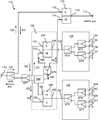
- FIG. 2shows a simplified schematic view of a prior art CATV signal distribution system that includes an output port used to connect to a piece of embedded multimedia terminal adapter (eMTA) subscriber equipment;
- eMTAembedded multimedia terminal adapter
- FIG. 3is a schematic diagram of one embodiment of CATV signal distribution system 110 according to the invention.
- FIG. 4is a schematic diagram of a further embodiment of CATV signal distribution system 110 according to the invention.
- FIG. 5is a schematic diagram of a further embodiment of CATV signal distribution system 110 according to the invention.
- FIG. 6is a schematic diagram of another embodiment of CATV signal distribution system 110 according to the invention.
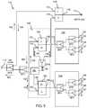
- FIG. 7is a schematic diagram of another embodiment of CATV signal distribution system 110 according to the invention.
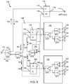
- FIG. 8illustrates method 200 of electrically coupling two four-way signal splitters according to the invention.
- CATV networksuse an infrastructure of interconnected coaxial cables, splitters, amplifiers, filters, trunk lines, cable taps, drop lines and other signal-conducting devices to supply and distribute “downstream” signals from a main CATV signal distribution facility, known as a head-end, toward subscriber premises such as homes and businesses.
- the downstream signalsoperate the subscriber equipment, such as television sets, telephones, and computers.
- the typical CATV networkis a two-way communication system.
- CATV networksalso transmit “upstream” signals from the subscriber equipment back to the head-end of the CATV network.
- upstream bandwidthmay include data related to video-on-demand services, such as video requests and billing authorization.
- Two-way communicationis also utilized when using a personal computer connected through the CATV infrastructure to the public Internet, for example when sharing photo albums or entering user account information.
- VoIPVoice over Internet protocol
- telephones and security monitoring equipmentuse the CATV infrastructure and the public Internet as the communication medium for passing two-way telephone conversations and monitoring functions.
- downstream and upstream signalsare confined to two different frequency bands.
- the downstream frequency band, or downstream bandwidthis within the range of 54-1002 megahertz (MHz) and the upstream frequency band, or upstream bandwidth, is within the range of 5-42 MHz.
- the downstream signalsare delivered from the CATV network infrastructure to the subscriber premises at a CATV entry adapter, which is also commonly referred to as an entry device, terminal adapter or a drop amplifier.
- the entry adapteris a multi-port device which connects at a premises entry port to a CATV drop cable from the CATV network infrastructure.
- the entry adapterconnects at a multiplicity of other distribution ports to coaxial cables which extend throughout the subscriber premises to a cable outlet. Each cable outlet is available to be connected to subscriber equipment.
- most homeshave coaxial cables extending to cable outlets in almost every room, because different types of subscriber equipment may be used in different rooms. For example, television sets, computers and telephone sets are commonly used in many different rooms of a home or office.
- the multiple distribution ports of the entry adapterdeliver the downstream signals to each cable outlet and conduct the upstream signals from the subscriber equipment through the entry adapter to the drop cable and the CATV infrastructure.
- a digital video recorder(DVR) is used to record broadcast programming, still photography and moving pictures in a memory medium so that the content can be replayed on a display or television set at a later time selected by the user.
- DVRdigital video recorder
- computer gamesare also played at displays or on television sets. Such computer games may be those obtained over the Internet from the CATV network or from media played on play-back devices connected to displays or television sets.
- receivers of satellite-broadcast signalsmay be distributed for viewing or listening throughout the home.
- An in-home entertainment (IHE) networkmay be coupled to the CATV network via the same coaxial cable delivering the downstream and upstream bandwidth of the CATV system.
- the in-home entertainment networkcan be a network providing multiple streams of high definition video and gaming entertainment. Examples of in-home entertainment network technologies include Ethernet, HomePlug, Home Phoneline Networking Alliance (HPNA), Multimedia over Coax Alliance (MoCA) and 802.11n protocols.
- the in-home entertainment (IHE) networkis coupled to the CATV network within a subscriber premises to allow the CATV network to distribute IHE signals from one multimedia device to another within the subscriber premises.
- the in-home entertainment networkmay employ technology standards developed to distribute multimedia-over-coax signals within the CATV subscriber premises.
- Products designed to use multimedia-over-coax signalscan be used to create an in-home entertainment network by interconnecting presently-known and future multimedia devices, such as set-top boxes, routers and gateways, bridges, optical network terminals, computers, gaming systems, display devices, printers, network-attached storage, and home automation such as furnace settings and lighting control.
- An IHE networkuses the in-home coaxial cable infrastructure originally established for distribution of CATV signals within the subscriber premises, principally because that coaxial cable infrastructure already exists in most homes and is capable of carrying much more information than is carried in the CATV frequency bands.
- An IHE networkis established by connecting IHE-enabled devices or multimedia-over-coax interface devices at the cable outlets in the rooms of the subscriber premises. Each IHE-enabled device is capable of communicating with every other IHE-enabled device in the in-home or subscriber premises network to deliver the multimedia content throughout the home or subscriber premises as long as IHE signal attenuation does not prohibit communication.
- the multimedia content that is available from one multimedia devicecan be displayed, played or otherwise used at a different location within the home, without having to physically relocate the originating multimedia device from one location to another within the subscriber premises.
- the communication of multimedia contentis considered beneficial in more fully utilizing the multimedia devices present in modern homes.
- the multimedia-over-coax signalsutilize a frequency range different from the frequency ranges of the CATV upstream and downstream signals.
- a typical multimedia-over-coax frequency bandis 1125-1675 MHz,
- a particular IHE network frequency bandmay include other frequency ranges, but the 1125-1675 MHz band is of major relevance because of its principal use in establishing connections between the multimedia-over-coax interface devices within the CATV network.
- the CATV network and the in-home cable infrastructurewere originally intended for the distribution of CATV signals.
- the typical in-home cable infrastructureuses signal splitters to divide CATV downstream signals into multiple CATV downstream paths and to combine multiple CATV upstream signals into a single CATV upstream path, as shown in FIG. 1 .
- FIG. 1shows a typical configuration for splitting/combining a CATV signal eight ways.
- two four-way signal splitters 130 and 140 , and two-way signal splitter SP 1are used to divide downstream CATV signal 102 eight ways.
- CATV downstream signals 102travel from input port 112 to first four-way signal splitter output ports 134 , 135 , 136 , and 137 and second four-way signal splitter output ports 144 , 145 , 146 , and 147 to the pieces of subscriber equipment 115 that may be connected to any or all of output ports 134 , 135 , 136 , 137 , 144 , 145 , 146 , or 147 .
- First four-way signal splitter 130 in this exampleuses two-way splitters SP 2 , SP 3 , and SP 4 to execute the four-way signal split
- second four-way signal splitter 140 in this exampleuses two-way splitters SP 5 , SP 6 , and SP 7 to make the four-way signal split.
- CATV upstream signals 104 that originate from pieces of subscriber equipment 115are combined by four-way splitters 130 and 140 and splitter SP 1 into a single upstream CATV signal 104 that is sent to the CATV network and head-end.
- Low-pass filter circuit 186is a circuit designed to keep IHE signals 106 from exiting the IHE network and entering the CATV network. Low-pass filter circuit 186 is optional and may be used in any of the systems shown or described in this document.
- the pieces of subscriber equipment 115 that are IHE-compatibleshould be able to communicate through the splitter legs to the other pieces of IHE-compatible subscriber equipment 115 with multimedia-over-coax signals 106 .
- subscriber equipment 115 at output port 134is IHE compatible, and can communicate with subscriber equipment 115 at output port 135 by sending multimedia-over-coax signals 106 to output port 135 by jumping the splitter legs of splitter SP 3 .
- Subscriber equipment 115should be able to communicate with subscriber equipment 115 at output port 147 by sending multimedia-over coax-signals 106 which jump several splitter legs to travel from output port 134 to output port 147 .
- the typical signal splitterhas a high degree of signal rejection or isolation between its separate output signal component legs. Because conventional signal splitters are designed for the CATV bandwidth signals (e.g., 5-1002 MHz), they have low and non-flat isolation as well as high and non-flat insertion loss in the IHE bands, in particular in the multimedia-over-coax band of 1125 to 1675 MHz. Additionally, inherent losses in coaxial cables also increase with increasing frequency, resulting in roll-off (e.g., non-flat insertion loss) characteristics in the multimedia-over-coax frequency band.
- CATV bandwidth signalse.g., 5-1002 MHz
- the degree of signal rejection or isolationgreatly attenuates the strength of the multimedia-over-coax signals 106 .
- IHE-enabled devices coupled to the output ports of a single two, three, or four-way signal splitterare able to communicate using the multimedia-over-coax frequency band.
- IHE-enabled devices coupled to the output ports of two different multi-port signal splittershave signal loss problems because of the high isolation and signal path loss of the system for multimedia-over-coax signals 106 .
- IHE-compatible subscriber equipment 115 at port 134for example, will have signal loss problems when trying to communicate with IHE-compatible subscriber equipment 115 at port 147 .
- Some IHE network communication protocolsrecognize the possibility of variable strength multimedia-over-coax signals 106 and provide the capability to boost the strength of multimedia-over-coax signals 106 to compensate for the variable strength of multimedia-over-coax signals 106 that would otherwise be communicated between IHE-enabled devices.
- boosting the strength of multimedia-over-coax signals 106can result in the strength or power of multimedia-over-coax signals 106 being substantially greater than the strength or power of CATV signals 102 and 104 communicated within the subscriber premises. Consequently, the multimedia-over-coax signals 106 have the capability of adversely affecting the proper functionality of standard CATV subscriber equipment, such as a digital video recorder or an embedded multimedia terminal adapter (eMTA).
- eMTAembedded multimedia terminal adapter
- FIG. 2shows a typical example of an IHE network that includes signal output port 114 for embedded multimedia terminal adapter (eMTA) 116 .
- An eMTA devicecombines a high-speed data cable modem with Voice over Internet Protocol technology to create a platform that connects analog telephones and terminal equipment (e.g., fax) to the cable operator's advanced Internet protocol communications network.
- the cable modemprovides a data interface for communicating Internet protocol packets to and from the CATV network and head-end, and an analog telephone adapter provides a Voice over Internet protocol (VoIP) interface for an analog telephone set.
- VoIPVoice over Internet protocol
- the eMTA deviceconverts between analog voice signals and packets.
- a lifeline telephoneis a well-known example of an eMTA device.
- the eMTA deviceis a device which must be assured of communication with the CATV network and head-end even when power is down, because the eMTA device is used for safety and security purposes.
- EMTA device 116can lose connection with the head-end of the CATV system because of the losses resulting from the multiple signal splits.
- splitter SP 8is added to separate signal output port 114 from the main signal branch coming from input port 112 .
- output port 114is assured of good communication with the CATV head-end,
- output port 114is used as the eMTA port.
- the problemsis that this approach will not only result in higher isolation between the output ports of four-way splitters 130 and 140 , it may prevent communication between the eMTA device 116 coupled to signal output port 114 and the IHE-compatible subscriber devices 115 that are coupled to any of output ports 134 , 135 , 136 , 137 , 144 , 145 , 146 , or 147 of the four-way splitters. Therefore, there is a need for a new approach for classic eight-way CATV signal splitters and eMTA-compatible multiport entry devices to solve these issues.
- FIG. 3shows a simplified schematic of an embodiment of CATV signal distribution system 110 according to the invention.
- CATV signal distribution system 110 according to the inventioncan be included in an entry adapter or other enclosed CATV device.
- CATV signal distribution system 110 according to the inventioncan be a distributed device with multiple pieces distributed throughout a home or business network, for example.
- CATV signal distribution system 110is contained within a single building.
- CATV signal distribution system 110is contained within a single premises network.
- CATV signal distribution system 110 of FIG. 3includes signal input port 112 , first multi-port signal splitter 130 , and second multi-port signal splitter 140 .
- CATV signal distribution system 110includes more than two multi-port signal splitters.
- multi-port signal splitter 130is a four-way signal splitter, but the invention is not limited in this aspect.
- multi-port signal splitter 140is a four-way signal splitter, but the invention is not limited in this aspect.
- CATV signal distribution system 110 according to the inventionincludes two or more multi-port signal splitters, where each of the multi-port signal splitters has two or more multi-port signal splitter output ports.
- CATV signal distribution system 110 of FIG. 3includes signal input port 112 , first four-way signal splitter 130 , and second four-way signal splitter 140 .
- first four-way signal splitter 130includes signal splitters SP 2 , SP 3 , and SP 4 , but other configurations of first four-way signal splitter 130 are envisioned.
- second four-way signal splitter 140includes signal splitters SP 5 , SP 6 , and SP 7 , but other configurations of second four-way signal splitter 130 are envisioned.
- Two-way splitter SP 1 and first and second four-way signal splitters 130 and 140split downstream CATV signals 102 eight ways such that downstream CATV signals 102 are received by first four-way signal splitter 130 output ports 134 , 135 , 136 , and 137 , and second four-way signal splitter 140 output ports 144 , 145 , 146 , and 147 .
- First four-way signal splitter 130is coupled to signal input port 112 through first diplexer 150 .
- First diplexer common node 156is coupled to first four-way signal splitter input port 132 .
- First diplexer low-pass node 152is coupled to signal input port 112 through first signal splitter SP 1 . In this way first four-way signal splitter 130 is coupled to signal input port 112 through first diplexer 150 .
- Second four-way splitter 140is coupled to signal input port 112 through second diplexer 160 .
- Second diplexer common node 166is coupled to second four-way signal splitter input port 142 .
- Second diplexer low-pass node 162is coupled to signal input port 112 through first signal splitter SP 1 . In this way second four-way signal splitter 40 is coupled to signal input port 112 through second diplexer 160 .
- a diplexeris a signal splitting device which splits signals according to frequency.
- multimedia-over-coax signals 106will be conducted through first diplexer 150 by being conducted back and forth between common node 156 and high-pass node 154
- downstream and upstream CATV signals 102 and 104will be conducted through first diplexer 150 by being conducted back and forth between common node 156 and low-pass node 152 .
- multimedia-over-coax signals 106will be conducted through second diplexer 160 by being conducted back and forth between common node 166 and high-pass node 164
- downstream and upstream CATV signals 102 and 104will be conducted through second diplexer 160 by being conducted back and forth between common node 166 and low-pass node 162 .
- CATV signal distribution system 110 of FIG. 3separates the multimedia-over-coax signal 106 path from the CATV signal 102 and 104 path.
- first diplexer 130 high-pass node 154is coupled to second diplexer high-pass node 164 .
- Thisallows multimedia-over-coax signals 106 to be conducted from first four-way splitter input port 132 to second four-way splitter input port 142 through diplexers 150 and 160 , avoiding two-way splitter SP 1 .
- Thiseliminates the signal isolation loss that would occur in the prior systems shown in FIG. 1 and FIG. 2 , where multimedia-over-coax signals 106 being conducted from output port 134 to output port 147 would undergo signal attenuation due to having to jump between the signal output legs of splitter SP 1 , from node 118 to node 119 .
- Subscriber devices 115 coupled to first four-way signal splitter ports 134 , 135 , 136 , and 137can communicate using multimedia-over-coax signals 106 with subscriber devices 115 coupled to second four-way signal splitter ports 144 , 145 , 146 , and 147 without the signal losses and possible loss of communication that would occur in the situations illustrated in FIG. 1 and FIG. 2 .
- CATV signal distribution system 110 of FIG. 3includes active circuit elements, such as one or more amplifier or other active network circuit elements.
- an active circuit elementis placed between first diplexer common node 156 and first four-way splitter input node 132 .
- an active circuit elementis placed between second diplexer common node 166 and second four-way splitter input node 142 .
- an active elementis placed elsewhere in CATV signal distribution system 110 of FIG. 3 .
- FIG. 4shows a further embodiment of CATV signal distribution system 110 according to the invention.
- CATV signal distribution circuit 110 of FIG. 4operates the same as CATV signal distribution system shown in FIG. 3 , except that in the embodiment of CATV signal distribution system 110 shown in FIG. 4 , first diplexer high-pass node 154 is coupled to second diplexer high-pass node 164 through attenuator circuit 180 .
- Attenuator circuit 180can be many different types of signal conditioning circuits. In this embodiment attenuator circuit 180 controls the attenuation of signals passing from first diplexer high-pass node 154 and second diplexer high-pass node 164 .
- Attenuator circuit 180 in this embodimentallows the level of attenuation of multimedia-over-coax signals 106 passing between first four-way splitter 130 and second four-way splitter 140 to be adjusted to a particular desired level of attenuation.
- attenuator circuit 180includes an equalizer circuit which allows equalization of multimedia signals 106 being conducted between first four-way signal splitter 130 and second four-way signal splitter 140 .
- attenuator circuit 180includes a reflectance circuit which controls signal reflection of multimedia signals 106 being conducted between first four-way signal splitter 130 and second four-way signal splitter 140 .
- Attenuator circuit 180can be have an adjustable amount of attenuation.
- attenuator circuit 180has an amount of attenuation that is adjustable from 0 dB to a predetermined amount of attenuation.
- Attenuator circuit 180can include an active circuit element such as an amplifier. Including an amplifier in circuit 180 allows multimedia-over-coax signals 106 to be amplified as well as attenuated.
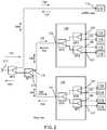
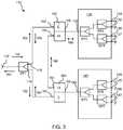
- FIG. 5 , FIG. 6 , and FIG. 7each show embodiments of CATV signal distribution system 110 according to the invention for systems which include eMTA port 114 .
- CATV signal distribution system 110includes signal input port 112 , first multi-port signal splitter 130 , second multi-port signal splitter 140 , and signal output port 114 , where output port 114 is meant to be coupled to a piece of eMTA equipment.
- First multi-port signal splitter 130is coupled to signal input port 112 through first diplexer 150 as explained with reference to FIG. 1 and FIG. 2 .
- Second multi-port signal splitter 140is coupled to signal input port 112 through second diplexer 160 as explained with reference to FIG.
- CATV signal distribution system 110includes more than two multi-port signal splitters.
- multi-port signal splitter 130is a four-way signal splitter, but the invention is not limited in this aspect.
- multi-port signal splitter 140is a four-way signal splitter, but the invention is not limited in this aspect.
- CATV signal distribution system 110 according to the inventionincludes two or more multi-port signal splitters, where each of the multi-port signal splitters has two or more multi-port signal splitter output ports.
- CATV signal distribution system 110includes signal input port 112 , first four-way signal splitter 130 , second four-way signal splitter 140 , and signal output port 114 , where output port 114 is meant to be coupled to a piece of eMTA equipment.
- First four-way signal splitter 130is coupled to signal input port 112 through first diplexer 150 as explained with reference to FIG. 1 and FIG. 2 .
- Second four-way signal splitter 140is coupled to signal input port 112 through second diplexer 160 as explained with reference to FIG. 1 and FIG. 2 .
- Signal output port 114is coupled to signal input port 112 through third diplexer 170 .
- Third diplexer 170is used to allow a piece of eMTA subscriber equipment such as subscriber equipment 116 , that is IHE compatible, to communicate with IHE-compatible subscriber equipment 115 coupled to first and second four-way splitters 130 and 140 .
- signal input port 112is coupled to first diplexer low-pass node 152 of first diplexer 150 , second diplexer low-pass node 162 of second diplexer 160 , and third diplexer low-pass node 172 of third diplexer 170 .
- Multimedia-over-coax signals 106 in the embodiments shown in FIG. 5 , FIG. 6 , and FIG. 7are conducted between signal output ports 114 , 134 , 135 , 136 , 137 , 144 , 145 , 146 , and 147 through the high-pass nodes of first diplexer 150 , second diplexer 160 , and third diplexer 170 , as explained further below.
- CATV signal distribution system 110 as shown in FIG. 5 , FIG. 6 , and FIG. 7is included in a CATV entry adapter. In some embodiments CATV signal distribution system 110 as shown in FIG. 5 , FIG. 6 , and FIG. 7 is distributed among several locations and enclosures within a home or business.
- first and second diplexers 150 and 160 and attenuator circuits 180 , 181 , and 182are include in a single module—an adjustable isolation module 190 as shown in the figures. Adjustable isolation module 190 allows the isolation of multimedia-over-coax signals 106 to be adjusted. It is to be understood that the figures show examples of CATV signal distribution system 110 and adjustable isolation module 190 , and that many other specific embodiments are possible with different components and interconnections.
- CATV signal distribution system 110 of FIG. 5 , FIG. 6 , and FIG. 7includes active circuit elements, such as one or more amplifier or other active network circuit elements.
- an active circuit elementis placed between splitter SP 8 and splitter SP 1 .
- an active circuit elementis placed within adjustable isolation module 190 .
- an amplifieris placed between splitter SP 8 and splitter SP 1 .
- an amplifieris placed within adjustable isolation module 190 .
- an active circuit elementis placed between first diplexer common node 156 and first four-way splitter input node 132 .
- an active circuit elementis placed between second diplexer common node 166 and second four-way splitter input node 142 .
- an active elementis placed elsewhere in CATV signal distribution system 110 of FIG. 5 , FIG. 6 , or FIG. 7 .
- first and second diplexer high-pass nodes 154 and 164are coupled together through attenuator circuit 180 , and third diplexer high-pass node 174 is coupled to first diplexer high-pass node 154 through splitter SP 9 .
- first diplexer 150includes first diplexer common node 156 coupled to first four-way signal splitter input port 132 , first diplexer high-pass node 154 coupled to third diplexer high-pass node 174 , and first diplexer low-pass node 152 coupled to signal input port 112 .
- first diplexer high-pass node 154is coupled to third diplexer high-pass node 174 through signal splitter SP 9 .
- first diplexer low-pass node 152is coupled to signal input port 112 through signal splitters SP 1 and SP 8 .
- second diplexer 160includes second diplexer common node 166 coupled to second four-way signal splitter input port 142 , second diplexer high-pass node 164 coupled to first diplexer high-pass node 154 through attenuator circuit 180 and splitter SP 9 , and second diplexer low-pass node 162 coupled to signal input port 112 .
- second diplexer low-pass node 162is coupled to signal input port 112 through signal splitters SN and SP 8 .
- Attenuator circuit 180allows adjustable attenuation of multimedia-over-coax signals 106 conducted between first diplexer high-pass node 154 and second diplexer high-pass node 164 .
- Attenuator circuit 180includes an equalizer circuit.
- An equalizer circuit section of attenuator circuit 180adjusts the frequency response tilt, when needed, in the multimedia-over-coax band.
- attenuator circuit 180includes a reflectance circuit.
- a reflectance circuit section of attenuator circuit 180is used to adjust the isolation level among output ports of the individual four-way splitters 130 and 140 , and signal output port 114 .
- attenuator circuit 180can include an active circuit element such as an amplifier. Including an amplifier in circuit 180 allows multimedia-over-coax signals 106 to be amplified as well as attenuated.
- multimedia-over-coax signals 106are conducted between signal output ports 114 , 134 , 135 , 136 , 137 , 144 , 145 , 146 , and 147 using the high-frequency signal path that connects high-pass nodes 154 , 164 , and 174 of first, second, and third diplexers 150 , 160 , and 170 .
- the eMTA subscriber equipment coupled to signal output port 114can communicate with IHE-compatible subscriber equipment 115 coupled to any of the output ports 134 , 135 , 136 , 137 , 144 , 145 , 146 , or 147 of first four-way signal splitter 130 and second four-way signal splitter 140 .
- This communicationis difficult to impossible in the prior art system shown in FIG. 2 due to multimedia-over-coax signal 106 losses due to the signals jumping the legs of the signal splitters. Also, in the system shown in FIG.
- IHE-compatible subscriber equipment 115 coupled to output ports 134 , 135 , 136 , or 137 of first four-way signal splitter 130can communicate using multimedia-over-coax signals 106 with any of the IRE-compatible subscriber equipment 115 coupled to output ports 144 , 145 , 146 , or 147 of second four-way signal splitter 140 .
- This communicationis difficult to impossible in the prior art systems shown in FIG. 1 and FIG. 2 due to multimedia-over-coax signal 106 losses from signals 106 jumping the legs of the signal splitters.
- first and second diplexer high-pass nodes 154 and 164are coupled together, and third diplexer high-pass node 174 is coupled to first diplexer high-pass node 154 and second diplexer high-pass node 164 through attenuator circuit 180 .
- first diplexer 150includes first diplexer common node 156 coupled to first four-way signal splitter input port 132 , first diplexer high-pass node 154 coupled to third diplexer high-pass node 174 , and first diplexer low-pass node 152 coupled to signal input port 112 .
- first diplexer high-pass node 154is coupled to third diplexer high-pass node 174 through signal splitter SP 9 and attenuator circuit 180 .
- first diplexer low-pass node 152is coupled to signal input port 112 through signal splitters SP 1 and SP 8 .
- Attenuator circuit 180allows adjustable attenuation of multimedia-over-coax signals 106 conducted between third diplexer high-pass node 174 and both first diplexer high-pass node 154 and second diplexer high-pass node 164 .
- Attenuator circuit 180includes an equalizer circuit that allows adjustment and equalization of the frequency response of multimedia-over-coax signals 106 conducted between third diplexer high-pass node 174 and both first diplexer high-pass node 154 and second diplexer high-pass node 164 .
- An equalizer circuit section of attenuator circuit 180adjusts the frequency response tilt when needed in the multimedia-over-coax band.
- attenuator circuit 180includes a reflectance circuit.
- a reflectance circuit section of attenuator circuit 180is used to adjust the isolation level among output ports of the individual four-way splitters 130 and 140 , and signal output port 114 .
- attenuator circuit 180can include an active circuit element such as an amplifier. Including an amplifier in circuit 180 allows multimedia-over-coax signals 106 to be amplified as well as attenuated.
- second diplexer 160includes second diplexer common node 166 coupled to second four-way signal splitter input port 142 , second diplexer high-pass node 164 coupled to first diplexer high-pass node 154 , and second diplexer low-pass node 162 coupled to signal input port 112 .
- second diplexer low-pass node 162is coupled to signal input port 112 through signal splitters SP 1 and SP 8 .
- second diplexer high-pass node 164is coupled to first diplexer high-pass node 154 through splitter SP 9 .
- multimedia-over-coax signals 106are conducted between signal output ports 114 , 134 , 135 , 136 , 137 , 144 , 145 , 146 , and 147 using the high-frequency signal path that connects high-pass nodes 154 , 164 , and 174 of first, second, and third diplexers 150 , 160 , and 170 .
- an eMTA subscriber devicesuch as eMTA device 116 , coupled to signal output port 114 can communicate with IHE-compatible subscriber equipment 115 coupled to any of the output ports 134 , 135 , 136 , 137 , 144 , 145 , 146 , or 147 of first four-way signal splitter 130 and second four-way signal splitter 140 .
- This communicationis difficult to impossible in the prior art system shown in FIG. 2 due to multimedia-over-coax signal 106 losses due to the signals jumping the legs of the signal splitters. Also, in the system shown in FIG.
- IHE-compatible subscriber equipment 115 coupled to output ports 134 , 135 , 136 , or 137 of first four-way signal splitter 130can communicate using multimedia-over-coax signals 106 with any of the IHE-compatible subscriber equipment coupled to the output ports 144 , 145 , 146 , or 147 of second four-way signal splitter 140 .
- This communicationis difficult to impossible in the prior art systems shown in FIG. 1 and FIG. 2 due to multimedia-over-coax signal 106 losses due to 106 signals jumping the legs of the signal splitters.
- FIG. 7shows a further embodiment of CATV signal distribution system 110 according to the invention.
- CATV signal distribution system 110 shown in FIG. 7is similar to the CATV signal distribution systems 110 shown in FIG. 5 and FIG. 6 , except CATV signal distribution system 110 shown in FIG. 7 includes several attenuator circuits, attenuator circuit 180 , attenuator circuit 181 , and attenuator circuit 182 .
- Attenuator circuits 180 , 181 , and 182are shown in dotted lines to indicate that each one of them is optional, and can be used in any combination with the other attenuator circuits.
- Attenuator circuits 180 , 181 , and 182can be used in combination or individually to adjust and/or balance the attenuation between four-way splitter output ports 134 , 135 , 136 , 137 , 144 , 145 , 146 , or 147 , and signal output port 114 used with the eMTA device.
- Any of attenuator circuits 180 , 182 , or 182can include an equalizer circuit.
- An equalizer circuit section of attenuator circuit 180 , 181 , or 182adjusts the frequency response tilt, when needed, in the multimedia-over-coax band.
- Any of attenuator circuits 180 , 181 , or 182can include a reflectance circuit.
- Attenuator circuit 180 , 181 , or 182is used to adjust the isolation level among output ports of the individual four-way splitters 130 and 140 , and signal output port 114 .
- Attenuator circuits 180 , 181 , or 182can be fixed or adjustable attenuator circuits. Attenuator circuit 180 , 181 , or 182 can be designed to have an attenuation level that is adjustable from 0 dB to a required attenuation level.
- attenuator circuit 180 , 181 , or 182can include an active circuit element such as an amplifier. Including an amplifier in circuit 180 , 182 , or 182 allows multimedia-over-coax signals 106 to be amplified as well as attenuated.
- FIG. 8shows method 200 of electrically coupling two four-way signal splitters according to the invention.
- Method 200 of electrically coupling two four-way signal splittersincludes step 210 of coupling a first four-way signal splitter to a signal input port through a first diplexer, and step 220 of coupling a second four-way signal splitter to the signal input port through a second diplexer.
- Method 200 of electrically coupling two four-way signal splitters according to the inventionalso includes step 230 of coupling a first diplexer high-pass node of the first diplexer to a second diplexer high-pass node of the second diplexer.
- Method 200can include many other steps.
- method 200includes the step of coupling a signal output port to the signal input port through a third diplexer.
- a third diplexer common nodeis coupled to the signal output port, and a third diplexer low-pass node is coupled to the signal input port.
- method 200includes the step of coupling a high-pass node of the third diplexer to the high-pass node of the first diplexer.
- method 200includes the step of coupling a high-pass node of the third diplexer to the high-pass node of the first diplexer through an attenuator circuit.
- the attenuator circuitincludes an equalizer circuit.
- the attenuator circuitincludes a reflectance circuit.
- Step 210 coupling a first four-way signal splitter to a signal input port through a first diplexercan include many other steps.
- step 210includes the step of coupling a first diplexer common node to a first four-way signal splitter input port.
- step 210includes the step of coupling a first diplexer low-pass node to the signal input port.
- Step 220 coupling a second four-way signal splitter to the signal input port through a second diplexercan include many other steps.
- step 220includes the step of coupling a second diplexer common node to a second four-way signal splitter input port.
- step 220includes the step of coupling a second diplexer low-pass node to the signal input port.
- Step 230 coupling a first diplexer high-pass node of the first diplexer to a second diplexer high-pass node of the second diplexercan include many other steps.
- step 230includes the step of coupling the first diplexer high-pass node of the first diplexer to the second diplexer high-pass node of the second diplexer through an attenuator circuit.
- the attenuator circuitincludes an equalizer circuit.
- the attenuator circuitincludes a reflectance circuit.
- a method of electrically coupling two multi-port signal splittersincludes the steps of coupling a first multi-port signal splitter to a signal input port through a first diplexer, coupling a second multi-port signal splitter to the signal input port through a second diplexer, and coupling a first diplexer high-pass node of the first diplexer to a second diplexer high-pass node of the second diplexer.
- coupling a first multi-port signal splitter to a signal input port through a first diplexerincludes the steps of coupling a first diplexer common node to a first multi-port signal splitter input port, and coupling a first diplexer low-pass node to the signal input port.
- coupling a second multi-port signal splitter to a signal input port through a second diplexerincludes the steps of coupling a second diplexer common node to a second multi-port signal splitter input port, and coupling a second diplexer low-pass node to the signal input port.
- the step of coupling a first diplexer high-pass node of the first diplexer to a second diplexer high-pass node of the second diplexerincludes coupling the first diplexer high-pass node of the first diplexer to the second diplexer high-pass node of the second diplexer through an attenuator circuit.
- the attenuator circuitincludes an equalizer circuit.
- the method of electrically coupling two multi-port signal splitters according to the inventionincludes the step of coupling a signal output port to the signal input port through a third diplexer, where a third diplexer common node is coupled to the signal output port, and where a third diplexer low-pass node is coupled to the signal input port.
- the methodincludes the step of coupling a high-pass node of the third diplexer to the high-pass node of the first diplexer. In some embodiments the method includes the step of coupling a high-pass node of the third diplexer to the high-pass nodes of the first and the second diplexers.
Landscapes
- Engineering & Computer Science (AREA)
- Multimedia (AREA)
- Signal Processing (AREA)
- Two-Way Televisions, Distribution Of Moving Picture Or The Like (AREA)
Abstract
Description
Claims (31)
Priority Applications (2)
| Application Number | Priority Date | Filing Date | Title |
|---|---|---|---|
| US16/007,842US11070766B2 (en) | 2010-12-21 | 2018-06-13 | Method and apparatus for reducing isolation in a home network |
| US17/376,267US20210344870A1 (en) | 2010-12-21 | 2021-07-15 | Method and apparatus for reducing isolation in a home network |
Applications Claiming Priority (5)
| Application Number | Priority Date | Filing Date | Title |
|---|---|---|---|
| US201061425680P | 2010-12-21 | 2010-12-21 | |
| US201061427351P | 2010-12-27 | 2010-12-27 | |
| US201161552458P | 2011-10-28 | 2011-10-28 | |
| US13/333,060US10021343B2 (en) | 2010-12-21 | 2011-12-21 | Method and apparatus for reducing isolation in a home network |
| US16/007,842US11070766B2 (en) | 2010-12-21 | 2018-06-13 | Method and apparatus for reducing isolation in a home network |
Related Parent Applications (1)
| Application Number | Title | Priority Date | Filing Date |
|---|---|---|---|
| US13/333,060DivisionUS10021343B2 (en) | 2010-12-21 | 2011-12-21 | Method and apparatus for reducing isolation in a home network |
Related Child Applications (1)
| Application Number | Title | Priority Date | Filing Date |
|---|---|---|---|
| US17/376,267DivisionUS20210344870A1 (en) | 2010-12-21 | 2021-07-15 | Method and apparatus for reducing isolation in a home network |
Publications (2)
| Publication Number | Publication Date |
|---|---|
| US20180295322A1 US20180295322A1 (en) | 2018-10-11 |
| US11070766B2true US11070766B2 (en) | 2021-07-20 |
Family
ID=46236291
Family Applications (5)
| Application Number | Title | Priority Date | Filing Date |
|---|---|---|---|
| US13/333,060Active2034-03-26US10021343B2 (en) | 2010-12-21 | 2011-12-21 | Method and apparatus for reducing isolation in a home network |
| US16/007,810Expired - Fee RelatedUS10750120B2 (en) | 2010-12-21 | 2018-06-13 | Method and apparatus for reducing isolation in a home network |
| US16/007,842Expired - Fee RelatedUS11070766B2 (en) | 2010-12-21 | 2018-06-13 | Method and apparatus for reducing isolation in a home network |
| US16/935,267AbandonedUS20200351470A1 (en) | 2010-12-21 | 2020-07-22 | Method and apparatus for reducing isolation in a home network |
| US17/376,267AbandonedUS20210344870A1 (en) | 2010-12-21 | 2021-07-15 | Method and apparatus for reducing isolation in a home network |
Family Applications Before (2)
| Application Number | Title | Priority Date | Filing Date |
|---|---|---|---|
| US13/333,060Active2034-03-26US10021343B2 (en) | 2010-12-21 | 2011-12-21 | Method and apparatus for reducing isolation in a home network |
| US16/007,810Expired - Fee RelatedUS10750120B2 (en) | 2010-12-21 | 2018-06-13 | Method and apparatus for reducing isolation in a home network |
Family Applications After (2)
| Application Number | Title | Priority Date | Filing Date |
|---|---|---|---|
| US16/935,267AbandonedUS20200351470A1 (en) | 2010-12-21 | 2020-07-22 | Method and apparatus for reducing isolation in a home network |
| US17/376,267AbandonedUS20210344870A1 (en) | 2010-12-21 | 2021-07-15 | Method and apparatus for reducing isolation in a home network |
Country Status (3)
| Country | Link |
|---|---|
| US (5) | US10021343B2 (en) |
| CA (1) | CA2831220C (en) |
| WO (1) | WO2012088350A2 (en) |
Families Citing this family (20)
| Publication number | Priority date | Publication date | Assignee | Title |
|---|---|---|---|---|
| US9351051B2 (en) | 2008-10-13 | 2016-05-24 | Ppc Broadband, Inc. | CATV entry adapter and method for distributing CATV and in-home entertainment signals |
| US10154302B2 (en) | 2008-10-13 | 2018-12-11 | Ppc Broadband, Inc. | CATV entry adapter and method for distributing CATV and in-home entertainment signals |
| US8356322B2 (en) | 2009-09-21 | 2013-01-15 | John Mezzalingua Associates, Inc. | Passive multi-port entry adapter and method for preserving downstream CATV signal strength within in-home network |
| US11910052B2 (en) | 2008-10-21 | 2024-02-20 | Ppc Broadband, Inc. | Entry device for communicating external network signals and in-home network signals |
| US8510782B2 (en) | 2008-10-21 | 2013-08-13 | Ppc Broadband, Inc. | CATV entry adapter and method for preventing interference with eMTA equipment from MoCA Signals |
| US8487717B2 (en) | 2010-02-01 | 2013-07-16 | Ppc Broadband, Inc. | Multipath mitigation circuit for home network |
| EP2536137A1 (en)* | 2011-06-17 | 2012-12-19 | Teleste Oyj | A splitter/combiner for CATV networks |
| US9264012B2 (en) | 2012-06-25 | 2016-02-16 | Ppc Broadband, Inc. | Radio frequency signal splitter |
| US20140029678A1 (en)* | 2012-07-27 | 2014-01-30 | MSD Data Stream, LLC | Data communications over coaxial cable |
| US8752114B1 (en)* | 2013-04-23 | 2014-06-10 | Extreme Broadband Engineering, Llc | MoCA gateway splitter |
| US9356796B2 (en)* | 2013-04-23 | 2016-05-31 | Times Fiber Communications, Inc. | MoCA gateway splitter |
| US20160277158A1 (en)* | 2015-03-16 | 2016-09-22 | Terry Brown | Data communications troubleshooting device |
| WO2018005951A1 (en) | 2016-06-30 | 2018-01-04 | Ppc Broadband, Inc. | Passive enhanced moca entry device |
| US10051321B2 (en)* | 2016-07-18 | 2018-08-14 | Cisco Technology, Inc. | Bidirectional amplifier or node supporting out-of-band signaling |
| US10616527B2 (en) | 2017-07-06 | 2020-04-07 | Ppc Broadband, Inc. | Cable television entry adapter |
| US10855489B2 (en)* | 2017-09-18 | 2020-12-01 | Commscope Technologies Llc | Point of entry (POE) splitter circuitry |
| CN111527707A (en)* | 2018-01-19 | 2020-08-11 | Ppc宽带股份有限公司 | Double-network splitter |
| CA3088988A1 (en) | 2018-01-19 | 2019-07-25 | Ppc Broadband, Inc. | Systems and methods for extending an in-home splitter network |
| US11044440B2 (en) | 2019-11-04 | 2021-06-22 | Times Fiber Communications, Inc. | Universal MoCA gateway splitter |
| MX2022009428A (en)* | 2020-02-03 | 2022-10-18 | Ppc Broadband Inc | A moca splitter device. |
Citations (219)
| Publication number | Priority date | Publication date | Assignee | Title |
|---|---|---|---|---|
| US2662217A (en) | 1949-03-30 | 1953-12-08 | Rca Corp | Multiple-neck filter |
| US3790909A (en) | 1973-01-26 | 1974-02-05 | Gte Sylvania Inc | Varactor tuner band switch circuitry |
| US3939431A (en) | 1974-11-25 | 1976-02-17 | Motorola, Inc. | Muting circuit for a radio receiver |
| US4027219A (en) | 1974-11-14 | 1977-05-31 | U.S. Philips Corporation | Device for displaying color television images |
| JPS5580989A (en) | 1978-12-15 | 1980-06-18 | Nec Corp | Automatic balancing system for exchange |
| JPS55132126A (en) | 1979-03-31 | 1980-10-14 | Fujitsu Ltd | Selective switching circuit of signal transmission line |
| US4306403A (en) | 1980-10-17 | 1981-12-22 | Deere & Company | Overload sensor for a cotton harvester unit drive |
| JPS5791055A (en) | 1980-11-27 | 1982-06-07 | Toshiba Corp | Branching device |
| US4344499A (en) | 1978-12-08 | 1982-08-17 | C. Van Der Lely N.V. | Tractor with anti-slipping and overloading controls |
| JPS5899913A (en) | 1981-12-10 | 1983-06-14 | 松下電工株式会社 | Chair |
| JPS58101582A (en) | 1981-12-12 | 1983-06-16 | Murata Mfg Co Ltd | Catv system |
| US4418424A (en) | 1980-03-17 | 1983-11-29 | Matsushita Electric Industrial Co., Ltd. | Cable television transmission control system |
| JPS5926709A (en) | 1982-08-04 | 1984-02-13 | Minolta Camera Co Ltd | Control device for driving of lens of automatic focus adjustment type camera |
| US4512033A (en) | 1982-11-29 | 1985-04-16 | C-Cor Labs, Inc. | Remote level adjustment system for use in a multi-terminal communications system |
| US4520508A (en) | 1982-12-21 | 1985-05-28 | General Instrument Corporation | Subscriber terminal for monitoring radio-frequency signal ingress into cable television systems |
| US4521920A (en) | 1980-09-01 | 1985-06-04 | Telefonaktiebolaget L M Ericsson | Method and an arrangement for increasing the dynamic range at the input stage of a receiver in an optical fibre information transmission system |
| JPS61157035A (en) | 1984-12-28 | 1986-07-16 | Fujitsu Ltd | Impedance matching system |
| US4648123A (en) | 1982-11-29 | 1987-03-03 | C-Cor Labs, Inc. | Remote level measurement system for use in a multi-terminal communications system |
| US4677390A (en) | 1985-05-31 | 1987-06-30 | Texscan Corporation | Low-power feedforward amplifier |
| US4715012A (en) | 1980-10-15 | 1987-12-22 | Massey-Ferguson Services N.V. | Electronic tractor control |
| US4961218A (en) | 1989-05-17 | 1990-10-02 | Tollgrade Communications, Inc. | Enhanced line powered amplifier |
| US4982440A (en) | 1988-04-21 | 1991-01-01 | Videotron Ltee | CATV network with addressable filters receiving MSK upstream signals |
| US5010399A (en) | 1989-07-14 | 1991-04-23 | Inline Connection Corporation | Video transmission and control system utilizing internal telephone lines |
| US5126840A (en) | 1988-04-21 | 1992-06-30 | Videotron Ltee | Filter circuit receiving upstream signals for use in a CATV network |
| US5126686A (en) | 1989-08-15 | 1992-06-30 | Astec International, Ltd. | RF amplifier system having multiple selectable power output levels |
| US5214505A (en) | 1991-04-08 | 1993-05-25 | Hughes Aircraft Company | Automatic rf equalization in passenger aircraft video distribution system |
| US5231660A (en) | 1988-03-10 | 1993-07-27 | Scientific-Atlanta, Inc. | Compensation control for off-premises CATV system |
| JPH05191416A (en) | 1992-01-10 | 1993-07-30 | Matsushita Electric Ind Co Ltd | Automatic termination resistor connector |
| US5235612A (en) | 1990-12-21 | 1993-08-10 | Motorola, Inc. | Method and apparatus for cancelling spread-spectrum noise |
| US5245300A (en) | 1991-04-17 | 1993-09-14 | Kokusai Electric Co., Ltd. | Intermediate frequency filter having a ceramic filter |
| US5247310A (en)* | 1992-06-24 | 1993-09-21 | The United States Of America As Represented By The Secretary Of The Navy | Layered parallel interface for an active antenna array |
| US5319709A (en)* | 1991-06-13 | 1994-06-07 | Scientific-Atlanta, Inc. | System for broadband descrambling of sync suppressed television signals |
| US5345504A (en) | 1988-03-10 | 1994-09-06 | Scientific-Atlanta, Inc. | Differential compensation control for off-premises CATV system |
| US5361394A (en) | 1989-12-19 | 1994-11-01 | Kabushiki Kaisha Toshiba | Upstream signal control apparatus for cable television system |
| US5369642A (en) | 1992-05-29 | 1994-11-29 | Nec Corporation | Switcher for redundant signal transmission system |
| JPH0738580A (en) | 1993-06-28 | 1995-02-07 | Nec Corp | Variable terminating system |
| US5389882A (en) | 1990-12-07 | 1995-02-14 | Hewlett-Packard Company | LAN measurement apparatus for determining voltage between packets |
| US5485630A (en) | 1994-03-31 | 1996-01-16 | Panasonic Technologies, Inc. | Audio/video distribution system |
| US5548255A (en) | 1995-06-23 | 1996-08-20 | Microphase Corporation | Compact diplexer connection circuit |
| US5557510A (en) | 1993-11-29 | 1996-09-17 | Gehl Company | Control system for a large round baler |
| US5557319A (en) | 1994-12-28 | 1996-09-17 | U.S. Philips Corporation | Subscriber return system for CATV full service networks |
| US5719792A (en) | 1995-10-17 | 1998-02-17 | Trilithic, Inc. | Isolator |
| US5729824A (en) | 1994-12-09 | 1998-03-17 | Raychem Corporation | Distributed digital loop carriers system using coaxial cable |
| US5740044A (en) | 1995-06-16 | 1998-04-14 | Caterpillar Inc. | Torque limiting power take off control and method of operating same |
| US5745838A (en) | 1997-03-14 | 1998-04-28 | Tresness Irrevocable Patent Trust | Return path filter |
| US5745836A (en) | 1995-09-01 | 1998-04-28 | Cable Television Laboratories, Inc. | Undesirable energy suppression system in a contention based communication network |
| US5815794A (en) | 1995-09-01 | 1998-09-29 | Cable Television Laboratories, Inc. | Undesirable energy suppression system in the return path of a bidirectional cable network having dynamically allocated time slots |
| US5818825A (en) | 1995-11-29 | 1998-10-06 | Motorola, Inc. | Method and apparatus for assigning communications channels in a cable telephony system |
| US5839052A (en) | 1996-02-08 | 1998-11-17 | Qualcom Incorporated | Method and apparatus for integration of a wireless communication system with a cable television system |
| US5845190A (en)* | 1996-02-28 | 1998-12-01 | Ericsson Raynet | Cable access device and method |
| JPH1169334A (en) | 1997-08-19 | 1999-03-09 | Miharu Tsushin Kk | Standby tv modulator for catv head end |
| US5893024A (en) | 1996-08-13 | 1999-04-06 | Motorola, Inc. | Data communication apparatus and method thereof |
| US5937330A (en) | 1997-02-18 | 1999-08-10 | General Instrument Corporation | Settop terminal controlled return path filter for minimizing noise ingress on bidirectional cable systems |
| US5950111A (en) | 1997-09-25 | 1999-09-07 | Lucent Technologies Inc. | Self-terminating coaxial to unshielded twisted-pair cable passive CATV distribution panel |
| US5956075A (en) | 1996-07-22 | 1999-09-21 | Nec Corporation | CATV terminal unit |
| US5970053A (en) | 1996-12-24 | 1999-10-19 | Rdl, Inc. | Method and apparatus for controlling peak factor of coherent frequency-division-multiplexed systems |
| US6014547A (en) | 1997-04-28 | 2000-01-11 | General Instrument Corporation | System for enhancing the performance of a CATV settop terminal |
| US6012271A (en) | 1997-01-17 | 2000-01-11 | Welger Gmbh | Round baler with a load sensor for actuating the wrapping apparatus and for turning off at least one delivery element |
| US6049693A (en) | 1996-08-15 | 2000-04-11 | Com21, Inc. | Upstream ingress noise blocking filter for cable television system |
| WO2000024124A1 (en) | 1998-10-22 | 2000-04-27 | Ericsson, Inc. | Dual-band, dual-mode power amplifier with reduced power loss |
| US6069960A (en) | 1996-09-05 | 2000-05-30 | Sony Corporation | Connector device for information-handling apparatus and connector device for stereophonic audio/video apparatus |
| US6101932A (en) | 1997-11-05 | 2000-08-15 | Welger Gmbh | Channel bale press for agricultural harvest crop and device and method for controlling operation of the bale press |
| US6128040A (en) | 1988-02-12 | 2000-10-03 | Canon Kabushiki Kaisha | Record medium erasing device with variable control in accordance with power supply characteristics |
| US6129187A (en) | 1996-11-15 | 2000-10-10 | Agco Sa | PTO shaft monitoring and control system |
| US6160990A (en) | 1996-05-13 | 2000-12-12 | Kabushiki Kaisha Toshiba | Cable network system with ingress noise suppressing function |
| US6173225B1 (en) | 1999-04-20 | 2001-01-09 | Case Corporation | Power takeoff control system |
| US6185432B1 (en) | 1997-10-13 | 2001-02-06 | Qualcomm Incorporated | System and method for selecting power control modes |
| US6205138B1 (en) | 1998-04-24 | 2001-03-20 | International Business Machines Corporation | Broadband any point to any point switch matrix |
| US6229375B1 (en) | 1999-08-18 | 2001-05-08 | Texas Instruments Incorporated | Programmable low noise CMOS differentially voltage controlled logarithmic attenuator and method |
| US6253077B1 (en) | 1997-05-16 | 2001-06-26 | Texas Instruments Incorporated | Downstream power control in point-to-multipoint systems |
| JP2001177580A (en) | 1999-12-20 | 2001-06-29 | Sony Corp | Impedance adapting system |
| US20010016950A1 (en) | 2000-02-14 | 2001-08-23 | Syuuji Matsuura | Cable modem tuner |
| WO2001072005A1 (en) | 2000-03-17 | 2001-09-27 | Transcorp Systems Pty Ltd | Digital data splitter with switch and automatic termination restoration |
| US6348955B1 (en) | 1998-02-23 | 2002-02-19 | Zenith Electronics Corporation | Tuner with switched analog and digital demodulators |
| US6348837B1 (en) | 2000-08-08 | 2002-02-19 | Scientific-Atlanta, Inc. | Bi-directional amplifier having a single gain block for amplifying both forward and reverse signals |
| US6373349B2 (en) | 2000-03-17 | 2002-04-16 | Bae Systems Information And Electronic Systems Integration Inc. | Reconfigurable diplexer for communications applications |
| US6377316B1 (en) | 1998-02-23 | 2002-04-23 | Zenith Electronics Corporation | Tuner with switched analog and digital modulators |
| WO2002033969A1 (en) | 2000-10-16 | 2002-04-25 | Xtend Networks Ltd. | System and method for expanding the operational bandwidth of a communication system |
| US20020052179A1 (en)* | 2000-10-28 | 2002-05-02 | Hwang Hee Yong | Circuit for correcting pass band flatness |
| US6388539B1 (en) | 2001-04-16 | 2002-05-14 | At&T Corp. | Broadband switch/coupler |
| US6425132B1 (en) | 1998-04-06 | 2002-07-23 | Wavetek Corporation | Ingress testing of CATV system utilizing remote selection of CATV node |
| US6430904B1 (en) | 2001-05-09 | 2002-08-13 | Deere & Company | Platform auger torque sensing brake activation |
| US20020141494A1 (en) | 2001-03-29 | 2002-10-03 | Chappell Daniel K. | Sweep method using digital signals |
| US20020144292A1 (en) | 2001-02-19 | 2002-10-03 | Jun Uemura | Bi-directional CATV system, line equipment, center equipment |
| US20020141347A1 (en) | 2001-03-30 | 2002-10-03 | Harp Jeffrey C. | System and method of reducing ingress noise |
| US20020166124A1 (en) | 2001-05-04 | 2002-11-07 | Itzhak Gurantz | Network interface device and broadband local area network using coaxial cable |
| WO2002091676A1 (en) | 2001-05-08 | 2002-11-14 | Hoseo Telecom Co., Ltd | Subscriber tap-off capable of monitoring state of transmission line at subscriber end, and remote control system and method using the same |
| US20020174423A1 (en) | 2001-05-17 | 2002-11-21 | David Fifield | Apparatus for transporting home networking frame-based communications signals over coaxial cables |
| US20020174435A1 (en) | 2001-02-27 | 2002-11-21 | Hillel Weinstein | System, apparatus and method for expanding the operational bandwidth of a communication system |
| US6486907B1 (en) | 1997-01-07 | 2002-11-26 | Foxcom Ltd. | Satellite distributed television |
| US6495998B1 (en) | 2000-09-28 | 2002-12-17 | Sunrise Telecom Corp. | Selectable band-pass filtering apparatus and method |
| US20020190811A1 (en) | 2001-05-07 | 2002-12-19 | Martin Sperber | RF equalizer |
| US6498925B1 (en) | 1999-05-13 | 2002-12-24 | Denso Corporation | Transmit power control circuit |
| US6510152B1 (en) | 1997-12-31 | 2003-01-21 | At&T Corp. | Coaxial cable/twisted pair fed, integrated residence gateway controlled, set-top box |
| US6550063B1 (en) | 1998-05-21 | 2003-04-15 | Sharp Kabushiki Kaisha | Network interface module for receiving cable television broadcasting |
| US6546705B2 (en) | 2000-05-13 | 2003-04-15 | New Holland North America, Inc. | Method and apparatus for controlling a tractor/baler combination |
| US20030084458A1 (en) | 1999-12-14 | 2003-05-01 | Ljungdahl Kjell Arne | Local network forming part of a cable tv system |
| US6560778B1 (en) | 1999-03-29 | 2003-05-06 | Masprodenkoh Kabushikikaisha | Tap device of cable broadcasting system |
| US6570928B1 (en) | 1999-01-05 | 2003-05-27 | Masprodenkoh Kabushikikaisha | Cable broadcasting system |
| US6570914B1 (en) | 1999-07-07 | 2003-05-27 | Nec Corporation | Amplitude calculation circuit |
| US6587012B1 (en) | 1999-10-01 | 2003-07-01 | Arris International, Inc. | Automatic slope and gain (ASG) detector technique including a pilot signal |
| US6622304B1 (en) | 1996-09-09 | 2003-09-16 | Thomas W. Carhart | Interface system for computing apparatus and communications stations |
| US6640338B1 (en) | 1999-01-27 | 2003-10-28 | Masprodenkoh Kabushikikaisha | Electronic device for cable broadcasting system |
| US6678893B1 (en) | 1997-12-26 | 2004-01-13 | Samsung Electronics Co., Ltd. | Bidirectional trunk amplifier and cable modem for cable hybrid fiber and coax network which utilizes an upstream pilot signal |
| US6683513B2 (en) | 2000-10-26 | 2004-01-27 | Paratek Microwave, Inc. | Electronically tunable RF diplexers tuned by tunable capacitors |
| JP2004080483A (en) | 2002-08-20 | 2004-03-11 | Ntt Communications Kk | Adapter for VoIP |
| US20040068753A1 (en)* | 2002-10-02 | 2004-04-08 | Robertson Neil C. | Video transmission systems and methods for a home network |
| US6725462B1 (en) | 2000-04-19 | 2004-04-20 | At&T Corp. | Optimizing upstream transmission in a cable television distribution plant |
| US6725463B1 (en) | 1997-08-01 | 2004-04-20 | Microtune (Texas), L.P. | Dual mode tuner for co-existing digital and analog television signals |
| US20040076192A1 (en) | 1999-10-19 | 2004-04-22 | Rambus Inc. | Calibrated data communication system and method |
| US6728968B1 (en) | 1999-06-17 | 2004-04-27 | Fujitsu Limited | Upward-joining-noise decreasing method and apparatus |
| US6737935B1 (en) | 2002-12-03 | 2004-05-18 | John Mezzalingua Associates, Inc. | Diplex circuit forming bandstop filter |
| US20040107445A1 (en) | 1999-04-12 | 2004-06-03 | Texas Instruments Incorporated | System and methods for home network communications |
| US20040113742A1 (en) | 2002-08-30 | 2004-06-17 | Hitachi Metals, Ltd. | Ferrite core, CATV equipment and bi-directional CATV system |
| US6757910B1 (en) | 2000-06-08 | 2004-06-29 | C-Cor.Net Corporation | Adaptive filter for reducing ingress noise in CATV return signals |
| US6758292B2 (en) | 2002-08-12 | 2004-07-06 | Deere & Company | Interlock system and a detent switch therefor |
| US20040147273A1 (en) | 2003-01-28 | 2004-07-29 | Morphy William F. | Vehicle intercom controller |
| US20040172659A1 (en) | 2001-07-13 | 2004-09-02 | Ljungdahl Kjell Arne | Arrangement for reduction of noise transmitted from a local cable tv network |
| US6804828B1 (en) | 1998-12-03 | 2004-10-12 | Masprodenkoh Kabushikikaisha | Tap device of cable broadcasting system |
| US20040229561A1 (en) | 2003-02-28 | 2004-11-18 | Cowley Nicholas Paul | Tuner |
| JP2005005875A (en) | 2003-06-10 | 2005-01-06 | Nec Tohoku Ltd | VoIP SWITCHING DEVICE |
| US6843044B2 (en) | 2002-09-06 | 2005-01-18 | Deere & Company | Detection arrangement for the detection of a crop jam in a harvesting machine |
| US6845232B2 (en) | 2002-03-25 | 2005-01-18 | Broadcom Corporation | Analog peak detection circuitry for radio receivers |
| US20050034168A1 (en) | 1993-05-28 | 2005-02-10 | Mediaone Group, Inc. | Method and apparatus for delivering secured telephony service in a hybrid coaxial cable network |
| US20050034167A1 (en)* | 2003-08-06 | 2005-02-10 | Hillel Weinstein | Wideband CATV tap device |
| US20050044573A1 (en)* | 2003-08-21 | 2005-02-24 | Preschutti Joseph P. | [cable signal distribution system] |
| US20050047051A1 (en) | 2003-08-26 | 2005-03-03 | Eagle Comtronics, Inc. | Voltage limiter for coaxial cable carrying RF signals and voltage |
| US6868552B1 (en) | 1999-06-07 | 2005-03-15 | Fujitsu Limited | Ingress noise control system and ingress noise blocking device |
| US6877166B1 (en) | 2000-01-18 | 2005-04-05 | Cisco Technology, Inc. | Intelligent power level adjustment for cable modems in presence of noise |
| US6880170B1 (en) | 1994-11-30 | 2005-04-12 | General Instrument Corporation | Ingress detection and attenuation |
| US20050144649A1 (en) | 2003-11-25 | 2005-06-30 | James Bertonis | Apparatus and method for reduction of wireless links noise injection to a DOCSIS cable modem service |
| US6915530B1 (en) | 1994-11-30 | 2005-07-05 | General Instrument Corporation | Ingress detection and characterization by time/frequency map |
| US20050155082A1 (en) | 2001-02-27 | 2005-07-14 | Hillel Weinstein | Device, system and method for connecting a subscriber device to a wideband distribution network |
| US6920614B1 (en) | 1995-07-17 | 2005-07-19 | Gateway Inc. | Computer user interface for product selection |
| US6928175B1 (en) | 2000-06-14 | 2005-08-09 | Creative Technology Ltd. | Audio system with optional auto-switching secondary connector, and method for same |
| US20050183130A1 (en) | 2004-02-12 | 2005-08-18 | Sadja Aran L. | Cable diagnostic and monitoring system |
| US20050190101A1 (en) | 2004-02-26 | 2005-09-01 | Kyocera Corporation | Transmitting/receiving antenna, isolator, high-frequency oscillator, and high-frequency transmitter-receiver using the same |
| US6942595B2 (en) | 2001-09-15 | 2005-09-13 | Cnh America Llc | Control system for the drive of a pto for an agricultural vehicle |
| US20050210529A1 (en)* | 2004-03-22 | 2005-09-22 | C-Cor.Net Corp. | Coaxial communication active tap device and distribution system |
| US20050210977A1 (en) | 2004-03-28 | 2005-09-29 | Hai Yan | A phase-locked mechanical resonator pair and its application in micromachined vibration gyroscope |
| US20050283815A1 (en) | 2004-06-01 | 2005-12-22 | Brooks Paul D | Apparatus and methods for network interface and spectrum management |
| US20050289632A1 (en)* | 2004-06-01 | 2005-12-29 | Brooks Paul D | Controlled isolation splitter apparatus and methods |
| US20060015921A1 (en) | 2004-07-19 | 2006-01-19 | Jay Vaughan | VoIP drop amplifier |
| US7003275B1 (en) | 2000-05-18 | 2006-02-21 | Broadband Innovations, Inc. | Agile frequency converter for multichannel systems using IF-RF level exhange and tunable filters |
| US20060041918A9 (en) | 1999-08-31 | 2006-02-23 | Currivan Bruce J | Signal processing under attenuated transmission conditions |
| US7029293B2 (en) | 2004-08-20 | 2006-04-18 | Extreme Broadband Engineering, Llc | Ground block connector |
| US7039432B2 (en) | 2001-12-04 | 2006-05-02 | General Instrument Corporation | Dynamic upstream attenuation for ingress noise reduction |
| US7048106B2 (en) | 2004-03-26 | 2006-05-23 | Cnh America Llc | Power take-off control system and method |
| US20060191359A1 (en) | 2005-01-21 | 2006-08-31 | Nicolai Tarasinski | Agricultural machine with PTO torque limiting feature |
| US20060205442A1 (en) | 2005-03-10 | 2006-09-14 | Neil Phillips | Bi-directional amplifier with non-interruptible port |
| US20060241838A1 (en) | 2005-04-20 | 2006-10-26 | Marcello Mongiardo | Input device for agricultural vehicle information display |
| US20060282871A1 (en) | 2005-06-13 | 2006-12-14 | Yao-Tsan Yo | Distribution method for noise control |
| US7162731B2 (en) | 2002-02-07 | 2007-01-09 | Advent Networks, Inc. | Radio frequency characterization of cable plant and corresponding calibration of communication equipment communicating via the cable plant |
| US7167693B2 (en) | 2001-03-06 | 2007-01-23 | Andrew Corporation | Scanning receiver for use in power amplifier linearization |
| US20070024393A1 (en) | 2005-07-27 | 2007-02-01 | Forse Roger J | Tunable notch duplexer |
| JP2007166109A (en) | 2005-12-12 | 2007-06-28 | Matsushita Electric Works Ltd | Branch device of transmission system, and transmission system |
| JP2007166110A (en) | 2005-12-12 | 2007-06-28 | Matsushita Electric Works Ltd | Transmission system and branch device thereof |
| US7254827B1 (en) | 2000-05-08 | 2007-08-07 | Sunrise Telecom Incorporated | Ingress monitoring system and method |
| US20070217436A1 (en)* | 2006-03-16 | 2007-09-20 | Markley Jeffrey P | Methods and apparatus for centralized content and data delivery |
| US7283479B2 (en) | 2000-02-16 | 2007-10-16 | Spacenet Proxilliant Systems Ab | Cable TV system or other similar communication system |
| US20070288981A1 (en) | 2006-06-13 | 2007-12-13 | Hwa Lin Electronic (Shenzhen)Co., Ltd. | CATV system and automatic noise controller |
| US20070288982A1 (en) | 2006-06-13 | 2007-12-13 | Comcast Cable Holdings, Llc | Dynamic ingress arrester |
| US20080001645A1 (en) | 2006-06-29 | 2008-01-03 | Nec Electronics Corporation | Phase shifter |
| US20080022344A1 (en) | 2006-07-07 | 2008-01-24 | Scientific-Atlanta, Inc. | Format Converter with Smart Multitap with Digital Forward and Reverse |
| US20080040764A1 (en) | 2001-07-20 | 2008-02-14 | Hillel Weinstein | System, apparatus and method for expanding the operational bandwidth of a communication system |
| US20080075012A1 (en) | 2006-09-25 | 2008-03-27 | Zielinski Stephen A | Handheld field maintenance bus monitor |
| US20080120667A1 (en) | 2006-11-17 | 2008-05-22 | Texas Instruments Incorporated | Hybrid mpeg/ip digital cable gateway device and architecture associated therewith |
| US20080127287A1 (en) | 2006-11-28 | 2008-05-29 | John Mezzalingua Associates, Inc. | Apparatus and method for embedding/detecting an auxiliary signal within a catv traffic stream |
| US20080157898A1 (en) | 2006-12-27 | 2008-07-03 | John Mezzalingua Associates, Inc. | Low-Pass Step Attenuator |
| US7399255B1 (en) | 2005-06-10 | 2008-07-15 | Polaris Industries Inc. | Engine and transmission control system and method for a vehicle accessory |
| US7404355B2 (en) | 2006-01-31 | 2008-07-29 | Deere & Company | Tractor and baler combination with automatic baling and tractor halt control |
| US7416068B2 (en) | 2004-11-03 | 2008-08-26 | Borgwarner Inc. | Power take-off clutch control system |
| US20080247401A1 (en) | 2007-04-06 | 2008-10-09 | Texas Instruments Incorporated | Remote Access to Home Communication Services |
| US20080247541A1 (en) | 2006-03-16 | 2008-10-09 | Chris Cholas | Methods and apparatus for connecting a cable network to other network and/or devices |
| US20080271094A1 (en) | 2000-08-30 | 2008-10-30 | Broadcom Corporation | Home network system and method |
| US7454252B2 (en) | 2006-03-08 | 2008-11-18 | Moore Industries International, Inc. | Redundant fieldbus system |
| US7464526B2 (en) | 2001-09-14 | 2008-12-16 | Gkn Walterscheid Gmbh | Drive assembly for locking one or several operating units of an agricultural implement or of a self-propelled implement |
| US20080313691A1 (en) | 2007-06-13 | 2008-12-18 | Chris Cholas | Premises gateway apparatus and methods for use in a content-based network |
| US20090031391A1 (en) | 2007-03-08 | 2009-01-29 | Emerson Network Power Connectivity Solutions | Electronically controlled catv system |
| US20090047917A1 (en) | 2005-03-10 | 2009-02-19 | Phillips Neil P | Signal Amplifiers Having Non-Interruptible Communication Paths |
| US7505819B2 (en) | 2006-02-08 | 2009-03-17 | Moore Industries International, Inc. | Redundant fieldbus system |
| US20090077608A1 (en) | 2007-09-14 | 2009-03-19 | Romerein Robert L | Constant input port impedance for CATV amplifier with passive modem port |
| US7508284B2 (en) | 2006-08-30 | 2009-03-24 | John Mezzalingua Associates, Inc. | Hybrid low pass diplex filter |
| US20090113511A1 (en) | 2007-10-25 | 2009-04-30 | Hoseo University Academic Cooperation Foundation | Distortion and noise canceling system for hfc networks |
| US20090153263A1 (en) | 2007-12-12 | 2009-06-18 | Cheng-I Lin | Modulized wave filter |
| US20090154369A1 (en) | 2007-12-18 | 2009-06-18 | Helvig William J | Digital-channel-monitor unit |
| US20090165070A1 (en) | 2007-12-19 | 2009-06-25 | Broadcom Corporation | SYSTEMS AND METHODS FOR PROVIDING A MoCA COMPATABILITY STRATEGY |
| US20090180782A1 (en) | 2008-01-14 | 2009-07-16 | Tellabs Vienna, Inc. | Apparatus, system, computer program, and method for providing a multimedia-over-coax-alliance network in conjunction with an optical network |
| US20090217325A1 (en) | 2000-08-30 | 2009-08-27 | Broadcom Corporation | Home network system and method |
| US7592883B2 (en) | 2007-02-22 | 2009-09-22 | John Mezzalingua Associates, Inc. | Dual bandstop filter with enhanced upper passband response |
| US7603693B2 (en) | 2002-05-15 | 2009-10-13 | Panasonic Corporation | CATV uplink optical transmission system |
| US20090316608A1 (en) | 2008-06-24 | 2009-12-24 | Lgc Wireless, Inc. | System and method for configurable time-division duplex interface |
| US20090320085A1 (en) | 2008-06-23 | 2009-12-24 | Jon-En Wang | House amplifier with return path gating |
| US20090320086A1 (en) | 2008-06-23 | 2009-12-24 | Technetix Group Limited | Loss reduction in a coaxial network |
| US20100017842A1 (en) | 2008-07-17 | 2010-01-21 | Wells Chad T | Passive-Active Terminal Adapter and Method Having Automatic Return Loss Control |
| US20100095344A1 (en) | 2008-10-13 | 2010-04-15 | Newby Charles F | Ingress Noise Inhibiting Network Interface Device and Method for Cable Television Networks |
| US20100100921A1 (en) | 2008-10-16 | 2010-04-22 | John Mezzalingua Associates, Inc. | Dynamically configurable frequency band selection device between catv distribution system and catv user |
| US20100100918A1 (en) | 2008-10-21 | 2010-04-22 | Egan Jr John M | Multi-Port Entry Adapter, Hub and Method for Interfacing a CATV Network and a MoCA Network |
| US20100100912A1 (en) | 2008-10-16 | 2010-04-22 | John Mezzalingua Associates, Inc. | Upstream bandwidth conditioning device between catv distribution system and catv user |
| US20100125877A1 (en) | 2008-10-21 | 2010-05-20 | Wells Chad T | CATV Entry Adapter and Method for Preventing Interference with eMTA Equipment from MoCA Signals |
| US20100146564A1 (en) | 2008-10-21 | 2010-06-10 | Halik Gregory F | CATV Entry Adapter and Method Utilizing Directional Couplers for MoCA Signal Communication |
| US20100194489A1 (en) | 2009-01-30 | 2010-08-05 | Tdk Corporation | Directional coupler including impedance matching and impedance transforming attenuator |
| US20100225813A1 (en) | 2009-03-03 | 2010-09-09 | Hitachi Consumer Electronics Co., Ltd. | Television receiver |
| US20100266000A1 (en) | 2009-04-20 | 2010-10-21 | Texas Instruments Incorporated | Discrete spurious leakage cancellation for use in a cable modem |
| US20110010749A1 (en) | 2009-07-10 | 2011-01-13 | John Mezzalingua Associates, Inc. | Filter circuit |
| US20110051014A1 (en) | 2009-09-02 | 2011-03-03 | Mstar Semiconductor, Inc. | Tuner and Front-end Circuit Thereof |
| US7908625B2 (en) | 2002-10-02 | 2011-03-15 | Robertson Neil C | Networked multimedia system |
| US20110072472A1 (en) | 2009-09-21 | 2011-03-24 | Wells Chad T | Passive Multi-Port Entry Adapter and Method for Preserving Downstream CATV Signal Strength within In-Home Network |
| US20110069740A1 (en) | 2009-09-23 | 2011-03-24 | Nicholas Cowley | Methods and systems to digitally switch between frequencies and corresponding bandwidths in a transceiver |
| US20110085586A1 (en) | 2009-10-09 | 2011-04-14 | John Mezzalingua Associates, Inc. | Total bandwidth conditioning device |
| US20110085480A1 (en) | 2009-10-09 | 2011-04-14 | John Mezzalingua Associates, Inc. | Upstream bandwidth conditioning device |
| US20110085452A1 (en) | 2009-10-09 | 2011-04-14 | John Mezzalingua Associates, Inc. | Upstream bandwidth level measurement device |
| US20110088077A1 (en) | 2009-10-09 | 2011-04-14 | John Mezzalingua Associates, Inc. | Downstream bandwidth conditioning device |
| US8001579B2 (en) | 2008-10-16 | 2011-08-16 | John Mezzalingua Associates, Inc. | Downstream output level and/or output level tilt compensation device between CATV distribution system and CATV user |
| US20120054805A1 (en) | 2010-08-30 | 2012-03-01 | John Mezzalingua Associates, Inc. | Home network frequency conditioning device |
| US20120054819A1 (en) | 2010-08-30 | 2012-03-01 | John Mezzalingua Associates, Inc. | Home network frequency conditioning device and method |
| US20120081190A1 (en)* | 2009-05-22 | 2012-04-05 | Technetix Group Limited | Signal splitter for use in moca/catv networks |
| US20120151548A1 (en) | 2010-01-22 | 2012-06-14 | Shlomo Selim Rakib | Methods of adaptive cancelling and secondary communications channels for extended capability hfc cable systems |
| US8695055B2 (en) | 2011-06-17 | 2014-04-08 | Teleste Oyj | Splitter/combiner for CATV networks |
Family Cites Families (2)
| Publication number | Priority date | Publication date | Assignee | Title |
|---|---|---|---|---|
| WO2003094347A1 (en)* | 2002-05-02 | 2003-11-13 | Xtend Networks Ltd. | A wideband catv signal splitter device |
| US7533403B1 (en)* | 2002-08-23 | 2009-05-12 | Vulcan Ventures, Inc. | Apparatus and method for distributing audio and video content using existing network wiring |
- 2011
- 2011-12-21CACA2831220Apatent/CA2831220C/enactiveActive
- 2011-12-21WOPCT/US2011/066645patent/WO2012088350A2/enactiveApplication Filing
- 2011-12-21USUS13/333,060patent/US10021343B2/enactiveActive
- 2018
- 2018-06-13USUS16/007,810patent/US10750120B2/ennot_activeExpired - Fee Related
- 2018-06-13USUS16/007,842patent/US11070766B2/ennot_activeExpired - Fee Related
- 2020
- 2020-07-22USUS16/935,267patent/US20200351470A1/ennot_activeAbandoned
- 2021
- 2021-07-15USUS17/376,267patent/US20210344870A1/ennot_activeAbandoned
Patent Citations (228)
| Publication number | Priority date | Publication date | Assignee | Title |
|---|---|---|---|---|
| US2662217A (en) | 1949-03-30 | 1953-12-08 | Rca Corp | Multiple-neck filter |
| US3790909A (en) | 1973-01-26 | 1974-02-05 | Gte Sylvania Inc | Varactor tuner band switch circuitry |
| US4027219A (en) | 1974-11-14 | 1977-05-31 | U.S. Philips Corporation | Device for displaying color television images |
| US3939431A (en) | 1974-11-25 | 1976-02-17 | Motorola, Inc. | Muting circuit for a radio receiver |
| US4344499A (en) | 1978-12-08 | 1982-08-17 | C. Van Der Lely N.V. | Tractor with anti-slipping and overloading controls |
| JPS5580989A (en) | 1978-12-15 | 1980-06-18 | Nec Corp | Automatic balancing system for exchange |
| JPS55132126A (en) | 1979-03-31 | 1980-10-14 | Fujitsu Ltd | Selective switching circuit of signal transmission line |
| US4418424A (en) | 1980-03-17 | 1983-11-29 | Matsushita Electric Industrial Co., Ltd. | Cable television transmission control system |
| US4521920A (en) | 1980-09-01 | 1985-06-04 | Telefonaktiebolaget L M Ericsson | Method and an arrangement for increasing the dynamic range at the input stage of a receiver in an optical fibre information transmission system |
| US4715012A (en) | 1980-10-15 | 1987-12-22 | Massey-Ferguson Services N.V. | Electronic tractor control |
| US4306403A (en) | 1980-10-17 | 1981-12-22 | Deere & Company | Overload sensor for a cotton harvester unit drive |
| JPS5791055A (en) | 1980-11-27 | 1982-06-07 | Toshiba Corp | Branching device |
| JPS5899913A (en) | 1981-12-10 | 1983-06-14 | 松下電工株式会社 | Chair |
| JPS58101582A (en) | 1981-12-12 | 1983-06-16 | Murata Mfg Co Ltd | Catv system |
| JPS5926709A (en) | 1982-08-04 | 1984-02-13 | Minolta Camera Co Ltd | Control device for driving of lens of automatic focus adjustment type camera |
| US4512033A (en) | 1982-11-29 | 1985-04-16 | C-Cor Labs, Inc. | Remote level adjustment system for use in a multi-terminal communications system |
| US4648123A (en) | 1982-11-29 | 1987-03-03 | C-Cor Labs, Inc. | Remote level measurement system for use in a multi-terminal communications system |
| US4520508A (en) | 1982-12-21 | 1985-05-28 | General Instrument Corporation | Subscriber terminal for monitoring radio-frequency signal ingress into cable television systems |
| JPS61157035A (en) | 1984-12-28 | 1986-07-16 | Fujitsu Ltd | Impedance matching system |
| US4677390A (en) | 1985-05-31 | 1987-06-30 | Texscan Corporation | Low-power feedforward amplifier |
| US6128040A (en) | 1988-02-12 | 2000-10-03 | Canon Kabushiki Kaisha | Record medium erasing device with variable control in accordance with power supply characteristics |
| US5345504A (en) | 1988-03-10 | 1994-09-06 | Scientific-Atlanta, Inc. | Differential compensation control for off-premises CATV system |
| US5231660A (en) | 1988-03-10 | 1993-07-27 | Scientific-Atlanta, Inc. | Compensation control for off-premises CATV system |
| US4982440A (en) | 1988-04-21 | 1991-01-01 | Videotron Ltee | CATV network with addressable filters receiving MSK upstream signals |
| US5126840A (en) | 1988-04-21 | 1992-06-30 | Videotron Ltee | Filter circuit receiving upstream signals for use in a CATV network |
| US4961218A (en) | 1989-05-17 | 1990-10-02 | Tollgrade Communications, Inc. | Enhanced line powered amplifier |
| US5010399A (en) | 1989-07-14 | 1991-04-23 | Inline Connection Corporation | Video transmission and control system utilizing internal telephone lines |
| US5126686A (en) | 1989-08-15 | 1992-06-30 | Astec International, Ltd. | RF amplifier system having multiple selectable power output levels |
| US5361394A (en) | 1989-12-19 | 1994-11-01 | Kabushiki Kaisha Toshiba | Upstream signal control apparatus for cable television system |
| US5389882A (en) | 1990-12-07 | 1995-02-14 | Hewlett-Packard Company | LAN measurement apparatus for determining voltage between packets |
| US5235612A (en) | 1990-12-21 | 1993-08-10 | Motorola, Inc. | Method and apparatus for cancelling spread-spectrum noise |
| US5214505A (en) | 1991-04-08 | 1993-05-25 | Hughes Aircraft Company | Automatic rf equalization in passenger aircraft video distribution system |
| US5245300A (en) | 1991-04-17 | 1993-09-14 | Kokusai Electric Co., Ltd. | Intermediate frequency filter having a ceramic filter |
| US5319709A (en)* | 1991-06-13 | 1994-06-07 | Scientific-Atlanta, Inc. | System for broadband descrambling of sync suppressed television signals |
| JPH05191416A (en) | 1992-01-10 | 1993-07-30 | Matsushita Electric Ind Co Ltd | Automatic termination resistor connector |
| US5369642A (en) | 1992-05-29 | 1994-11-29 | Nec Corporation | Switcher for redundant signal transmission system |
| US5247310A (en)* | 1992-06-24 | 1993-09-21 | The United States Of America As Represented By The Secretary Of The Navy | Layered parallel interface for an active antenna array |
| US20050034168A1 (en) | 1993-05-28 | 2005-02-10 | Mediaone Group, Inc. | Method and apparatus for delivering secured telephony service in a hybrid coaxial cable network |
| JPH0738580A (en) | 1993-06-28 | 1995-02-07 | Nec Corp | Variable terminating system |
| US5557510A (en) | 1993-11-29 | 1996-09-17 | Gehl Company | Control system for a large round baler |
| US5485630A (en) | 1994-03-31 | 1996-01-16 | Panasonic Technologies, Inc. | Audio/video distribution system |
| US6915530B1 (en) | 1994-11-30 | 2005-07-05 | General Instrument Corporation | Ingress detection and characterization by time/frequency map |
| US6880170B1 (en) | 1994-11-30 | 2005-04-12 | General Instrument Corporation | Ingress detection and attenuation |
| US5729824A (en) | 1994-12-09 | 1998-03-17 | Raychem Corporation | Distributed digital loop carriers system using coaxial cable |
| US5557319A (en) | 1994-12-28 | 1996-09-17 | U.S. Philips Corporation | Subscriber return system for CATV full service networks |
| US5740044A (en) | 1995-06-16 | 1998-04-14 | Caterpillar Inc. | Torque limiting power take off control and method of operating same |
| US5548255A (en) | 1995-06-23 | 1996-08-20 | Microphase Corporation | Compact diplexer connection circuit |
| US6920614B1 (en) | 1995-07-17 | 2005-07-19 | Gateway Inc. | Computer user interface for product selection |
| US5815794A (en) | 1995-09-01 | 1998-09-29 | Cable Television Laboratories, Inc. | Undesirable energy suppression system in the return path of a bidirectional cable network having dynamically allocated time slots |
| US5745836A (en) | 1995-09-01 | 1998-04-28 | Cable Television Laboratories, Inc. | Undesirable energy suppression system in a contention based communication network |
| US5719792A (en) | 1995-10-17 | 1998-02-17 | Trilithic, Inc. | Isolator |
| US5818825A (en) | 1995-11-29 | 1998-10-06 | Motorola, Inc. | Method and apparatus for assigning communications channels in a cable telephony system |
| US5839052A (en) | 1996-02-08 | 1998-11-17 | Qualcom Incorporated | Method and apparatus for integration of a wireless communication system with a cable television system |
| US5845190A (en)* | 1996-02-28 | 1998-12-01 | Ericsson Raynet | Cable access device and method |
| US6160990A (en) | 1996-05-13 | 2000-12-12 | Kabushiki Kaisha Toshiba | Cable network system with ingress noise suppressing function |
| US5956075A (en) | 1996-07-22 | 1999-09-21 | Nec Corporation | CATV terminal unit |
| US5893024A (en) | 1996-08-13 | 1999-04-06 | Motorola, Inc. | Data communication apparatus and method thereof |
| US6049693A (en) | 1996-08-15 | 2000-04-11 | Com21, Inc. | Upstream ingress noise blocking filter for cable television system |
| US6094211A (en) | 1996-08-15 | 2000-07-25 | Com21, Inc. | TV and data cable system ingress noise blocker |
| US6069960A (en) | 1996-09-05 | 2000-05-30 | Sony Corporation | Connector device for information-handling apparatus and connector device for stereophonic audio/video apparatus |
| US6622304B1 (en) | 1996-09-09 | 2003-09-16 | Thomas W. Carhart | Interface system for computing apparatus and communications stations |
| US6129187A (en) | 1996-11-15 | 2000-10-10 | Agco Sa | PTO shaft monitoring and control system |
| US5970053A (en) | 1996-12-24 | 1999-10-19 | Rdl, Inc. | Method and apparatus for controlling peak factor of coherent frequency-division-multiplexed systems |
| US6486907B1 (en) | 1997-01-07 | 2002-11-26 | Foxcom Ltd. | Satellite distributed television |
| US6012271A (en) | 1997-01-17 | 2000-01-11 | Welger Gmbh | Round baler with a load sensor for actuating the wrapping apparatus and for turning off at least one delivery element |
| US5937330A (en) | 1997-02-18 | 1999-08-10 | General Instrument Corporation | Settop terminal controlled return path filter for minimizing noise ingress on bidirectional cable systems |
| US5745838A (en) | 1997-03-14 | 1998-04-28 | Tresness Irrevocable Patent Trust | Return path filter |
| US6014547A (en) | 1997-04-28 | 2000-01-11 | General Instrument Corporation | System for enhancing the performance of a CATV settop terminal |
| US6253077B1 (en) | 1997-05-16 | 2001-06-26 | Texas Instruments Incorporated | Downstream power control in point-to-multipoint systems |
| US6725463B1 (en) | 1997-08-01 | 2004-04-20 | Microtune (Texas), L.P. | Dual mode tuner for co-existing digital and analog television signals |
| JPH1169334A (en) | 1997-08-19 | 1999-03-09 | Miharu Tsushin Kk | Standby tv modulator for catv head end |
| US5950111A (en) | 1997-09-25 | 1999-09-07 | Lucent Technologies Inc. | Self-terminating coaxial to unshielded twisted-pair cable passive CATV distribution panel |
| US6185432B1 (en) | 1997-10-13 | 2001-02-06 | Qualcomm Incorporated | System and method for selecting power control modes |
| US6101932A (en) | 1997-11-05 | 2000-08-15 | Welger Gmbh | Channel bale press for agricultural harvest crop and device and method for controlling operation of the bale press |
| US6678893B1 (en) | 1997-12-26 | 2004-01-13 | Samsung Electronics Co., Ltd. | Bidirectional trunk amplifier and cable modem for cable hybrid fiber and coax network which utilizes an upstream pilot signal |
| US6510152B1 (en) | 1997-12-31 | 2003-01-21 | At&T Corp. | Coaxial cable/twisted pair fed, integrated residence gateway controlled, set-top box |
| US6348955B1 (en) | 1998-02-23 | 2002-02-19 | Zenith Electronics Corporation | Tuner with switched analog and digital demodulators |
| US6377316B1 (en) | 1998-02-23 | 2002-04-23 | Zenith Electronics Corporation | Tuner with switched analog and digital modulators |
| US6425132B1 (en) | 1998-04-06 | 2002-07-23 | Wavetek Corporation | Ingress testing of CATV system utilizing remote selection of CATV node |
| US6205138B1 (en) | 1998-04-24 | 2001-03-20 | International Business Machines Corporation | Broadband any point to any point switch matrix |
| US6550063B1 (en) | 1998-05-21 | 2003-04-15 | Sharp Kabushiki Kaisha | Network interface module for receiving cable television broadcasting |
| WO2000024124A1 (en) | 1998-10-22 | 2000-04-27 | Ericsson, Inc. | Dual-band, dual-mode power amplifier with reduced power loss |
| US6804828B1 (en) | 1998-12-03 | 2004-10-12 | Masprodenkoh Kabushikikaisha | Tap device of cable broadcasting system |
| US6570928B1 (en) | 1999-01-05 | 2003-05-27 | Masprodenkoh Kabushikikaisha | Cable broadcasting system |
| US6640338B1 (en) | 1999-01-27 | 2003-10-28 | Masprodenkoh Kabushikikaisha | Electronic device for cable broadcasting system |
| US6560778B1 (en) | 1999-03-29 | 2003-05-06 | Masprodenkoh Kabushikikaisha | Tap device of cable broadcasting system |
| US20040107445A1 (en) | 1999-04-12 | 2004-06-03 | Texas Instruments Incorporated | System and methods for home network communications |
| US7127734B1 (en) | 1999-04-12 | 2006-10-24 | Texas Instruments Incorporated | System and methods for home network communications |
| US6173225B1 (en) | 1999-04-20 | 2001-01-09 | Case Corporation | Power takeoff control system |
| US6498925B1 (en) | 1999-05-13 | 2002-12-24 | Denso Corporation | Transmit power control circuit |
| US6868552B1 (en) | 1999-06-07 | 2005-03-15 | Fujitsu Limited | Ingress noise control system and ingress noise blocking device |
| US6728968B1 (en) | 1999-06-17 | 2004-04-27 | Fujitsu Limited | Upward-joining-noise decreasing method and apparatus |
| US6570914B1 (en) | 1999-07-07 | 2003-05-27 | Nec Corporation | Amplitude calculation circuit |
| US6229375B1 (en) | 1999-08-18 | 2001-05-08 | Texas Instruments Incorporated | Programmable low noise CMOS differentially voltage controlled logarithmic attenuator and method |
| US20060041918A9 (en) | 1999-08-31 | 2006-02-23 | Currivan Bruce J | Signal processing under attenuated transmission conditions |
| US6587012B1 (en) | 1999-10-01 | 2003-07-01 | Arris International, Inc. | Automatic slope and gain (ASG) detector technique including a pilot signal |
| US20040076192A1 (en) | 1999-10-19 | 2004-04-22 | Rambus Inc. | Calibrated data communication system and method |
| US20030084458A1 (en) | 1999-12-14 | 2003-05-01 | Ljungdahl Kjell Arne | Local network forming part of a cable tv system |
| JP2001177580A (en) | 1999-12-20 | 2001-06-29 | Sony Corp | Impedance adapting system |
| US6877166B1 (en) | 2000-01-18 | 2005-04-05 | Cisco Technology, Inc. | Intelligent power level adjustment for cable modems in presence of noise |
| US20010016950A1 (en) | 2000-02-14 | 2001-08-23 | Syuuji Matsuura | Cable modem tuner |
| US7283479B2 (en) | 2000-02-16 | 2007-10-16 | Spacenet Proxilliant Systems Ab | Cable TV system or other similar communication system |
| WO2001072005A1 (en) | 2000-03-17 | 2001-09-27 | Transcorp Systems Pty Ltd | Digital data splitter with switch and automatic termination restoration |
| US6373349B2 (en) | 2000-03-17 | 2002-04-16 | Bae Systems Information And Electronic Systems Integration Inc. | Reconfigurable diplexer for communications applications |
| US6725462B1 (en) | 2000-04-19 | 2004-04-20 | At&T Corp. | Optimizing upstream transmission in a cable television distribution plant |
| US7254827B1 (en) | 2000-05-08 | 2007-08-07 | Sunrise Telecom Incorporated | Ingress monitoring system and method |
| US6546705B2 (en) | 2000-05-13 | 2003-04-15 | New Holland North America, Inc. | Method and apparatus for controlling a tractor/baler combination |
| US7003275B1 (en) | 2000-05-18 | 2006-02-21 | Broadband Innovations, Inc. | Agile frequency converter for multichannel systems using IF-RF level exhange and tunable filters |
| US6757910B1 (en) | 2000-06-08 | 2004-06-29 | C-Cor.Net Corporation | Adaptive filter for reducing ingress noise in CATV return signals |
| US6928175B1 (en) | 2000-06-14 | 2005-08-09 | Creative Technology Ltd. | Audio system with optional auto-switching secondary connector, and method for same |
| US6348837B1 (en) | 2000-08-08 | 2002-02-19 | Scientific-Atlanta, Inc. | Bi-directional amplifier having a single gain block for amplifying both forward and reverse signals |
| US20080271094A1 (en) | 2000-08-30 | 2008-10-30 | Broadcom Corporation | Home network system and method |
| US20090217325A1 (en) | 2000-08-30 | 2009-08-27 | Broadcom Corporation | Home network system and method |
| US6495998B1 (en) | 2000-09-28 | 2002-12-17 | Sunrise Telecom Corp. | Selectable band-pass filtering apparatus and method |
| WO2002033969A1 (en) | 2000-10-16 | 2002-04-25 | Xtend Networks Ltd. | System and method for expanding the operational bandwidth of a communication system |
| US6683513B2 (en) | 2000-10-26 | 2004-01-27 | Paratek Microwave, Inc. | Electronically tunable RF diplexers tuned by tunable capacitors |
| US20020052179A1 (en)* | 2000-10-28 | 2002-05-02 | Hwang Hee Yong | Circuit for correcting pass band flatness |
| US20020144292A1 (en) | 2001-02-19 | 2002-10-03 | Jun Uemura | Bi-directional CATV system, line equipment, center equipment |
| US7748023B2 (en) | 2001-02-27 | 2010-06-29 | Xtend Networks Ltd. | Device, system and method for connecting a subscriber device to a wideband distribution network |
| US20020174435A1 (en) | 2001-02-27 | 2002-11-21 | Hillel Weinstein | System, apparatus and method for expanding the operational bandwidth of a communication system |
| US20050155082A1 (en) | 2001-02-27 | 2005-07-14 | Hillel Weinstein | Device, system and method for connecting a subscriber device to a wideband distribution network |
| US7167693B2 (en) | 2001-03-06 | 2007-01-23 | Andrew Corporation | Scanning receiver for use in power amplifier linearization |
| US20020141494A1 (en) | 2001-03-29 | 2002-10-03 | Chappell Daniel K. | Sweep method using digital signals |
| US20020141347A1 (en) | 2001-03-30 | 2002-10-03 | Harp Jeffrey C. | System and method of reducing ingress noise |
| US6388539B1 (en) | 2001-04-16 | 2002-05-14 | At&T Corp. | Broadband switch/coupler |
| US20020166124A1 (en) | 2001-05-04 | 2002-11-07 | Itzhak Gurantz | Network interface device and broadband local area network using coaxial cable |
| US20020190811A1 (en) | 2001-05-07 | 2002-12-19 | Martin Sperber | RF equalizer |
| WO2002091676A1 (en) | 2001-05-08 | 2002-11-14 | Hoseo Telecom Co., Ltd | Subscriber tap-off capable of monitoring state of transmission line at subscriber end, and remote control system and method using the same |
| US6430904B1 (en) | 2001-05-09 | 2002-08-13 | Deere & Company | Platform auger torque sensing brake activation |
| US20020174423A1 (en) | 2001-05-17 | 2002-11-21 | David Fifield | Apparatus for transporting home networking frame-based communications signals over coaxial cables |
| US20040172659A1 (en) | 2001-07-13 | 2004-09-02 | Ljungdahl Kjell Arne | Arrangement for reduction of noise transmitted from a local cable tv network |
| US20080040764A1 (en) | 2001-07-20 | 2008-02-14 | Hillel Weinstein | System, apparatus and method for expanding the operational bandwidth of a communication system |
| US7464526B2 (en) | 2001-09-14 | 2008-12-16 | Gkn Walterscheid Gmbh | Drive assembly for locking one or several operating units of an agricultural implement or of a self-propelled implement |
| US6942595B2 (en) | 2001-09-15 | 2005-09-13 | Cnh America Llc | Control system for the drive of a pto for an agricultural vehicle |
| US7039432B2 (en) | 2001-12-04 | 2006-05-02 | General Instrument Corporation | Dynamic upstream attenuation for ingress noise reduction |
| US20060148406A1 (en) | 2001-12-04 | 2006-07-06 | Jay Strater | Dynamic upstream attenuation for ingress noise reduction |
| US7742777B2 (en) | 2001-12-04 | 2010-06-22 | General Instrument Corporation | Dynamic upstream attenuation for ingress noise reduction |
| US7162731B2 (en) | 2002-02-07 | 2007-01-09 | Advent Networks, Inc. | Radio frequency characterization of cable plant and corresponding calibration of communication equipment communicating via the cable plant |
| US6845232B2 (en) | 2002-03-25 | 2005-01-18 | Broadcom Corporation | Analog peak detection circuitry for radio receivers |
| US7603693B2 (en) | 2002-05-15 | 2009-10-13 | Panasonic Corporation | CATV uplink optical transmission system |
| US6758292B2 (en) | 2002-08-12 | 2004-07-06 | Deere & Company | Interlock system and a detent switch therefor |
| JP2004080483A (en) | 2002-08-20 | 2004-03-11 | Ntt Communications Kk | Adapter for VoIP |
| US20040113742A1 (en) | 2002-08-30 | 2004-06-17 | Hitachi Metals, Ltd. | Ferrite core, CATV equipment and bi-directional CATV system |
| US6843044B2 (en) | 2002-09-06 | 2005-01-18 | Deere & Company | Detection arrangement for the detection of a crop jam in a harvesting machine |
| US20040068753A1 (en)* | 2002-10-02 | 2004-04-08 | Robertson Neil C. | Video transmission systems and methods for a home network |
| US7908625B2 (en) | 2002-10-02 | 2011-03-15 | Robertson Neil C | Networked multimedia system |
| US6737935B1 (en) | 2002-12-03 | 2004-05-18 | John Mezzalingua Associates, Inc. | Diplex circuit forming bandstop filter |
| US20040147273A1 (en) | 2003-01-28 | 2004-07-29 | Morphy William F. | Vehicle intercom controller |
| US20040229561A1 (en) | 2003-02-28 | 2004-11-18 | Cowley Nicholas Paul | Tuner |
| JP2005005875A (en) | 2003-06-10 | 2005-01-06 | Nec Tohoku Ltd | VoIP SWITCHING DEVICE |
| US20050034167A1 (en)* | 2003-08-06 | 2005-02-10 | Hillel Weinstein | Wideband CATV tap device |
| US20050044573A1 (en)* | 2003-08-21 | 2005-02-24 | Preschutti Joseph P. | [cable signal distribution system] |
| US20050047051A1 (en) | 2003-08-26 | 2005-03-03 | Eagle Comtronics, Inc. | Voltage limiter for coaxial cable carrying RF signals and voltage |
| US20050144649A1 (en) | 2003-11-25 | 2005-06-30 | James Bertonis | Apparatus and method for reduction of wireless links noise injection to a DOCSIS cable modem service |
| US20050183130A1 (en) | 2004-02-12 | 2005-08-18 | Sadja Aran L. | Cable diagnostic and monitoring system |
| US20050190101A1 (en) | 2004-02-26 | 2005-09-01 | Kyocera Corporation | Transmitting/receiving antenna, isolator, high-frequency oscillator, and high-frequency transmitter-receiver using the same |
| US20050210529A1 (en)* | 2004-03-22 | 2005-09-22 | C-Cor.Net Corp. | Coaxial communication active tap device and distribution system |
| US7048106B2 (en) | 2004-03-26 | 2006-05-23 | Cnh America Llc | Power take-off control system and method |
| US20050210977A1 (en) | 2004-03-28 | 2005-09-29 | Hai Yan | A phase-locked mechanical resonator pair and its application in micromachined vibration gyroscope |
| US20050283815A1 (en) | 2004-06-01 | 2005-12-22 | Brooks Paul D | Apparatus and methods for network interface and spectrum management |
| US20050289632A1 (en)* | 2004-06-01 | 2005-12-29 | Brooks Paul D | Controlled isolation splitter apparatus and methods |
| US20060015921A1 (en) | 2004-07-19 | 2006-01-19 | Jay Vaughan | VoIP drop amplifier |
| US7530091B2 (en) | 2004-07-19 | 2009-05-05 | Pct International, Inc. | VOIP drop amplifier |
| US7029293B2 (en) | 2004-08-20 | 2006-04-18 | Extreme Broadband Engineering, Llc | Ground block connector |
| US7416068B2 (en) | 2004-11-03 | 2008-08-26 | Borgwarner Inc. | Power take-off clutch control system |
| US20060191359A1 (en) | 2005-01-21 | 2006-08-31 | Nicolai Tarasinski | Agricultural machine with PTO torque limiting feature |
| US20090047917A1 (en) | 2005-03-10 | 2009-02-19 | Phillips Neil P | Signal Amplifiers Having Non-Interruptible Communication Paths |
| US20060205442A1 (en) | 2005-03-10 | 2006-09-14 | Neil Phillips | Bi-directional amplifier with non-interruptible port |
| US20060241838A1 (en) | 2005-04-20 | 2006-10-26 | Marcello Mongiardo | Input device for agricultural vehicle information display |
| US7399255B1 (en) | 2005-06-10 | 2008-07-15 | Polaris Industries Inc. | Engine and transmission control system and method for a vehicle accessory |
| US20060282871A1 (en) | 2005-06-13 | 2006-12-14 | Yao-Tsan Yo | Distribution method for noise control |
| US20070024393A1 (en) | 2005-07-27 | 2007-02-01 | Forse Roger J | Tunable notch duplexer |
| JP2007166110A (en) | 2005-12-12 | 2007-06-28 | Matsushita Electric Works Ltd | Transmission system and branch device thereof |
| JP2007166109A (en) | 2005-12-12 | 2007-06-28 | Matsushita Electric Works Ltd | Branch device of transmission system, and transmission system |
| US7404355B2 (en) | 2006-01-31 | 2008-07-29 | Deere & Company | Tractor and baler combination with automatic baling and tractor halt control |
| US7505819B2 (en) | 2006-02-08 | 2009-03-17 | Moore Industries International, Inc. | Redundant fieldbus system |
| US7454252B2 (en) | 2006-03-08 | 2008-11-18 | Moore Industries International, Inc. | Redundant fieldbus system |
| US20080247541A1 (en) | 2006-03-16 | 2008-10-09 | Chris Cholas | Methods and apparatus for connecting a cable network to other network and/or devices |
| US20070217436A1 (en)* | 2006-03-16 | 2007-09-20 | Markley Jeffrey P | Methods and apparatus for centralized content and data delivery |
| US20070288982A1 (en) | 2006-06-13 | 2007-12-13 | Comcast Cable Holdings, Llc | Dynamic ingress arrester |
| US20070288981A1 (en) | 2006-06-13 | 2007-12-13 | Hwa Lin Electronic (Shenzhen)Co., Ltd. | CATV system and automatic noise controller |
| US20080001645A1 (en) | 2006-06-29 | 2008-01-03 | Nec Electronics Corporation | Phase shifter |
| US20080022344A1 (en) | 2006-07-07 | 2008-01-24 | Scientific-Atlanta, Inc. | Format Converter with Smart Multitap with Digital Forward and Reverse |
| US7508284B2 (en) | 2006-08-30 | 2009-03-24 | John Mezzalingua Associates, Inc. | Hybrid low pass diplex filter |
| US20080075012A1 (en) | 2006-09-25 | 2008-03-27 | Zielinski Stephen A | Handheld field maintenance bus monitor |
| US20080120667A1 (en) | 2006-11-17 | 2008-05-22 | Texas Instruments Incorporated | Hybrid mpeg/ip digital cable gateway device and architecture associated therewith |
| US20080127287A1 (en) | 2006-11-28 | 2008-05-29 | John Mezzalingua Associates, Inc. | Apparatus and method for embedding/detecting an auxiliary signal within a catv traffic stream |
| US20080157898A1 (en) | 2006-12-27 | 2008-07-03 | John Mezzalingua Associates, Inc. | Low-Pass Step Attenuator |
| US7592883B2 (en) | 2007-02-22 | 2009-09-22 | John Mezzalingua Associates, Inc. | Dual bandstop filter with enhanced upper passband response |
| US20090031391A1 (en) | 2007-03-08 | 2009-01-29 | Emerson Network Power Connectivity Solutions | Electronically controlled catv system |
| US20080247401A1 (en) | 2007-04-06 | 2008-10-09 | Texas Instruments Incorporated | Remote Access to Home Communication Services |
| US20080313691A1 (en) | 2007-06-13 | 2008-12-18 | Chris Cholas | Premises gateway apparatus and methods for use in a content-based network |
| US20090077608A1 (en) | 2007-09-14 | 2009-03-19 | Romerein Robert L | Constant input port impedance for CATV amplifier with passive modem port |
| US20090113511A1 (en) | 2007-10-25 | 2009-04-30 | Hoseo University Academic Cooperation Foundation | Distortion and noise canceling system for hfc networks |
| US20090153263A1 (en) | 2007-12-12 | 2009-06-18 | Cheng-I Lin | Modulized wave filter |
| US7675381B2 (en) | 2007-12-12 | 2010-03-09 | Soontai Tech Co., Ltd. | Modulized wave filter |
| US20090154369A1 (en) | 2007-12-18 | 2009-06-18 | Helvig William J | Digital-channel-monitor unit |
| US20090165070A1 (en) | 2007-12-19 | 2009-06-25 | Broadcom Corporation | SYSTEMS AND METHODS FOR PROVIDING A MoCA COMPATABILITY STRATEGY |
| US20090180782A1 (en) | 2008-01-14 | 2009-07-16 | Tellabs Vienna, Inc. | Apparatus, system, computer program, and method for providing a multimedia-over-coax-alliance network in conjunction with an optical network |
| US20090320085A1 (en) | 2008-06-23 | 2009-12-24 | Jon-En Wang | House amplifier with return path gating |
| US20090320086A1 (en) | 2008-06-23 | 2009-12-24 | Technetix Group Limited | Loss reduction in a coaxial network |
| US20090316608A1 (en) | 2008-06-24 | 2009-12-24 | Lgc Wireless, Inc. | System and method for configurable time-division duplex interface |
| US20100017842A1 (en) | 2008-07-17 | 2010-01-21 | Wells Chad T | Passive-Active Terminal Adapter and Method Having Automatic Return Loss Control |
| US20100095344A1 (en) | 2008-10-13 | 2010-04-15 | Newby Charles F | Ingress Noise Inhibiting Network Interface Device and Method for Cable Television Networks |
| US8001579B2 (en) | 2008-10-16 | 2011-08-16 | John Mezzalingua Associates, Inc. | Downstream output level and/or output level tilt compensation device between CATV distribution system and CATV user |
| US20100100912A1 (en) | 2008-10-16 | 2010-04-22 | John Mezzalingua Associates, Inc. | Upstream bandwidth conditioning device between catv distribution system and catv user |
| US20100100921A1 (en) | 2008-10-16 | 2010-04-22 | John Mezzalingua Associates, Inc. | Dynamically configurable frequency band selection device between catv distribution system and catv user |
| US20100146564A1 (en) | 2008-10-21 | 2010-06-10 | Halik Gregory F | CATV Entry Adapter and Method Utilizing Directional Couplers for MoCA Signal Communication |
| US20100100918A1 (en) | 2008-10-21 | 2010-04-22 | Egan Jr John M | Multi-Port Entry Adapter, Hub and Method for Interfacing a CATV Network and a MoCA Network |
| US8286209B2 (en) | 2008-10-21 | 2012-10-09 | John Mezzalingua Associates, Inc. | Multi-port entry adapter, hub and method for interfacing a CATV network and a MoCA network |
| US20100125877A1 (en) | 2008-10-21 | 2010-05-20 | Wells Chad T | CATV Entry Adapter and Method for Preventing Interference with eMTA Equipment from MoCA Signals |
| US20100194489A1 (en) | 2009-01-30 | 2010-08-05 | Tdk Corporation | Directional coupler including impedance matching and impedance transforming attenuator |
| US20100225813A1 (en) | 2009-03-03 | 2010-09-09 | Hitachi Consumer Electronics Co., Ltd. | Television receiver |
| US20100266000A1 (en) | 2009-04-20 | 2010-10-21 | Texas Instruments Incorporated | Discrete spurious leakage cancellation for use in a cable modem |
| US20120081190A1 (en)* | 2009-05-22 | 2012-04-05 | Technetix Group Limited | Signal splitter for use in moca/catv networks |
| US20110010749A1 (en) | 2009-07-10 | 2011-01-13 | John Mezzalingua Associates, Inc. | Filter circuit |
| US20110051014A1 (en) | 2009-09-02 | 2011-03-03 | Mstar Semiconductor, Inc. | Tuner and Front-end Circuit Thereof |
| US20110072472A1 (en) | 2009-09-21 | 2011-03-24 | Wells Chad T | Passive Multi-Port Entry Adapter and Method for Preserving Downstream CATV Signal Strength within In-Home Network |
| US20110069740A1 (en) | 2009-09-23 | 2011-03-24 | Nicholas Cowley | Methods and systems to digitally switch between frequencies and corresponding bandwidths in a transceiver |
| US20110085586A1 (en) | 2009-10-09 | 2011-04-14 | John Mezzalingua Associates, Inc. | Total bandwidth conditioning device |
| US20110085480A1 (en) | 2009-10-09 | 2011-04-14 | John Mezzalingua Associates, Inc. | Upstream bandwidth conditioning device |
| US20110085452A1 (en) | 2009-10-09 | 2011-04-14 | John Mezzalingua Associates, Inc. | Upstream bandwidth level measurement device |
| US20110088077A1 (en) | 2009-10-09 | 2011-04-14 | John Mezzalingua Associates, Inc. | Downstream bandwidth conditioning device |
| US8213457B2 (en) | 2009-10-09 | 2012-07-03 | John Mezzalingua Associates, Inc. | Upstream bandwidth conditioning device |
| US20120151548A1 (en) | 2010-01-22 | 2012-06-14 | Shlomo Selim Rakib | Methods of adaptive cancelling and secondary communications channels for extended capability hfc cable systems |
| US20120054819A1 (en) | 2010-08-30 | 2012-03-01 | John Mezzalingua Associates, Inc. | Home network frequency conditioning device and method |
| US20120054805A1 (en) | 2010-08-30 | 2012-03-01 | John Mezzalingua Associates, Inc. | Home network frequency conditioning device |
| US8695055B2 (en) | 2011-06-17 | 2014-04-08 | Teleste Oyj | Splitter/combiner for CATV networks |
Non-Patent Citations (18)
| Title |
|---|
| Alkan, Home Network Frequency Conditioning Device and Method, U.S. Appl. No. 13/180,100, filed Jul. 11, 2011. |
| Alkan, Method and Apparatus for Reducing Isolation in a Home Network, U.S. Appl. No. 13/333,060, filed Dec. 21, 2011. |
| Author Unknown, International Search Report dated May 31, 2011, PCT Application No. PCT/US2010/049568. |
| Author Unknown, Office Action Summary dated Jan. 23, 2012, U.S. Appl. No. 12/250,229, dated Oct. 13, 2008. |
| Author Unknown, Office Action Summary dated Nov. 11, 2011, U.S. Appl. No. 12/255,008, dated Oct. 21, 2008. |
| Author Unknwon, Office Action Summary dated Mar. 6, 2012, U.S. Appl. No. 12/563,719, dated Sep. 21, 2009. |
| Egan, Multi-Port Entry Adapter, Hub and Method for Interfacing a CATV Network and a MoCA Network, U.S. Appl. No. 12/255,008, filed Oct. 21, 2008. |
| Final Office Action dated Nov. 25, 2019, U.S. Appl. No. 16/007,810, pp. 1-69. |
| Halik, CATV Entry Adapter and Method Utilizing Directional Couplers for MoCA Signal Communication, U.S. Appl. No. 12/704,833, filed Feb. 12, 2010. |
| Newby, Ingress Noise Inhibiting Network Interface Device and Method for Cable Television Networks, U.S. Appl. No. 12/250,229, filed Oct. 13, 2008. |
| Shafer, Home Network Frequency Conditioning Device, U.S. Appl. No. 13/178,149, filed Jul. 7, 2011. |
| Shafer, Low-Pass Filter Circuit, U.S. Appl. No. 13/167,497, filed Jun. 23, 2011. |
| Shafer, Upstream Bandwidth Conditioning Device, U.S. Appl. No. 12/760,153, filed Apr. 14, 2010. |
| Wells et al., Cable Television Entry Adapter, U.S. Appl. No. 13/245,510, filed Sep. 26, 2011. |
| Wells, Cable Television Entry Adapter, U.S. Appl. No. 13/245,510, filed Sep. 26, 2011. |
| Wells, CATV Entry Adapter and Method for Preventing Interference with eMTA Equipment from MoCA Signals, U.S. Appl. No. 12/691,149, filed Jan. 21, 2010. |
| Wells, Passive Multi-Port Entry Adapter and Method for Preserving Downstream CATV Signal Strength within In-Home Network, U.S. Appl. No. 12/563,719, filed Sep. 21, 2009. |
| Wells, Passive-Active Terminal Adapter and Method Having Automatic Return Loss Control, U.S. Appl. No. 12/175,366, filed Jul. 17, 2008. |
Also Published As
| Publication number | Publication date |
|---|---|
| WO2012088350A3 (en) | 2012-11-29 |
| US20200351470A1 (en) | 2020-11-05 |
| US20180295321A1 (en) | 2018-10-11 |
| CA2831220A1 (en) | 2012-06-28 |
| US10021343B2 (en) | 2018-07-10 |
| US20120159556A1 (en) | 2012-06-21 |
| WO2012088350A2 (en) | 2012-06-28 |
| US20210344870A1 (en) | 2021-11-04 |
| US10750120B2 (en) | 2020-08-18 |
| US20180295322A1 (en) | 2018-10-11 |
| CA2831220C (en) | 2022-05-31 |
Similar Documents
| Publication | Publication Date | Title |
|---|---|---|
| US20210344870A1 (en) | Method and apparatus for reducing isolation in a home network | |
| US11647162B2 (en) | MoCA entry device | |
| US8561125B2 (en) | Home network frequency conditioning device and method | |
| US8429695B2 (en) | CATV entry adapter and method utilizing directional couplers for MoCA signal communication | |
| US9516376B2 (en) | Passive multi-port entry adapter and method for preserving downstream CATV signal strength within in-home network | |
| US9351051B2 (en) | CATV entry adapter and method for distributing CATV and in-home entertainment signals | |
| US20120054805A1 (en) | Home network frequency conditioning device | |
| US11528526B2 (en) | Entry device for communicating external network signals and in-home network signals | |
| US11792362B2 (en) | Entry adapter for a cable television network | |
| US11910052B2 (en) | Entry device for communicating external network signals and in-home network signals |
Legal Events
| Date | Code | Title | Description |
|---|---|---|---|
| FEPP | Fee payment procedure | Free format text:ENTITY STATUS SET TO UNDISCOUNTED (ORIGINAL EVENT CODE: BIG.); ENTITY STATUS OF PATENT OWNER: LARGE ENTITY | |
| STPP | Information on status: patent application and granting procedure in general | Free format text:DOCKETED NEW CASE - READY FOR EXAMINATION | |
| STPP | Information on status: patent application and granting procedure in general | Free format text:NON FINAL ACTION MAILED | |
| AS | Assignment | Owner name:JOHN MEZZALINGUA ASSOCIATES, INC., NEW YORK Free format text:ASSIGNMENT OF ASSIGNORS INTEREST;ASSIGNOR:ALKAN, ERDOGAN;REEL/FRAME:051327/0822 Effective date:20111220 Owner name:PPC BROADBAND, INC., NEW YORK Free format text:CHANGE OF NAME;ASSIGNOR:MR ADVISERS LIMITED;REEL/FRAME:051370/0207 Effective date:20121105 Owner name:MR ADVISERS LIMITED, NEW YORK Free format text:CHANGE OF NAME;ASSIGNOR:JOHN MEZZALINGUA ASSOCIATES, INC.;REEL/FRAME:051370/0079 Effective date:20120911 | |
| STPP | Information on status: patent application and granting procedure in general | Free format text:FINAL REJECTION MAILED | |
| STPP | Information on status: patent application and granting procedure in general | Free format text:RESPONSE AFTER FINAL ACTION FORWARDED TO EXAMINER | |
| STPP | Information on status: patent application and granting procedure in general | Free format text:NON FINAL ACTION MAILED | |
| STPP | Information on status: patent application and granting procedure in general | Free format text:RESPONSE TO NON-FINAL OFFICE ACTION ENTERED AND FORWARDED TO EXAMINER | |
| STPP | Information on status: patent application and granting procedure in general | Free format text:NOTICE OF ALLOWANCE MAILED -- APPLICATION RECEIVED IN OFFICE OF PUBLICATIONS | |
| STPP | Information on status: patent application and granting procedure in general | Free format text:PUBLICATIONS -- ISSUE FEE PAYMENT RECEIVED | |
| STPP | Information on status: patent application and granting procedure in general | Free format text:PUBLICATIONS -- ISSUE FEE PAYMENT VERIFIED | |
| STCF | Information on status: patent grant | Free format text:PATENTED CASE | |
| FEPP | Fee payment procedure | Free format text:MAINTENANCE FEE REMINDER MAILED (ORIGINAL EVENT CODE: REM.); ENTITY STATUS OF PATENT OWNER: LARGE ENTITY | |
| LAPS | Lapse for failure to pay maintenance fees | Free format text:PATENT EXPIRED FOR FAILURE TO PAY MAINTENANCE FEES (ORIGINAL EVENT CODE: EXP.); ENTITY STATUS OF PATENT OWNER: LARGE ENTITY | |
| STCH | Information on status: patent discontinuation | Free format text:PATENT EXPIRED DUE TO NONPAYMENT OF MAINTENANCE FEES UNDER 37 CFR 1.362 | |
| FP | Lapsed due to failure to pay maintenance fee | Effective date:20250720 |