US11070654B2 - Sockets for shared link applications - Google Patents
Sockets for shared link applicationsDownload PDFInfo
- Publication number
- US11070654B2 US11070654B2US16/592,328US201916592328AUS11070654B2US 11070654 B2US11070654 B2US 11070654B2US 201916592328 AUS201916592328 AUS 201916592328AUS 11070654 B2US11070654 B2US 11070654B2
- Authority
- US
- United States
- Prior art keywords
- data replication
- type
- state
- network sockets
- processor
- Prior art date
- Legal status (The legal status is an assumption and is not a legal conclusion. Google has not performed a legal analysis and makes no representation as to the accuracy of the status listed.)
- Active, expires
Links
Images


Classifications
- H—ELECTRICITY
- H04—ELECTRIC COMMUNICATION TECHNIQUE
- H04L—TRANSMISSION OF DIGITAL INFORMATION, e.g. TELEGRAPHIC COMMUNICATION
- H04L67/00—Network arrangements or protocols for supporting network services or applications
- H04L67/01—Protocols
- H04L67/10—Protocols in which an application is distributed across nodes in the network
- H04L67/1095—Replication or mirroring of data, e.g. scheduling or transport for data synchronisation between network nodes
- G—PHYSICS
- G06—COMPUTING OR CALCULATING; COUNTING
- G06F—ELECTRIC DIGITAL DATA PROCESSING
- G06F3/00—Input arrangements for transferring data to be processed into a form capable of being handled by the computer; Output arrangements for transferring data from processing unit to output unit, e.g. interface arrangements
- G06F3/06—Digital input from, or digital output to, record carriers, e.g. RAID, emulated record carriers or networked record carriers
- G06F3/0601—Interfaces specially adapted for storage systems
- G06F3/0628—Interfaces specially adapted for storage systems making use of a particular technique
- G06F3/0646—Horizontal data movement in storage systems, i.e. moving data in between storage devices or systems
- G06F3/065—Replication mechanisms
- H—ELECTRICITY
- H04—ELECTRIC COMMUNICATION TECHNIQUE
- H04L—TRANSMISSION OF DIGITAL INFORMATION, e.g. TELEGRAPHIC COMMUNICATION
- H04L41/00—Arrangements for maintenance, administration or management of data switching networks, e.g. of packet switching networks
- H04L41/08—Configuration management of networks or network elements
- H04L41/0803—Configuration setting
- H04L41/0823—Configuration setting characterised by the purposes of a change of settings, e.g. optimising configuration for enhancing reliability
- H04L41/083—Configuration setting characterised by the purposes of a change of settings, e.g. optimising configuration for enhancing reliability for increasing network speed
- H—ELECTRICITY
- H04—ELECTRIC COMMUNICATION TECHNIQUE
- H04L—TRANSMISSION OF DIGITAL INFORMATION, e.g. TELEGRAPHIC COMMUNICATION
- H04L47/00—Traffic control in data switching networks
- H04L47/10—Flow control; Congestion control
- H—ELECTRICITY
- H04—ELECTRIC COMMUNICATION TECHNIQUE
- H04L—TRANSMISSION OF DIGITAL INFORMATION, e.g. TELEGRAPHIC COMMUNICATION
- H04L69/00—Network arrangements, protocols or services independent of the application payload and not provided for in the other groups of this subclass
- H04L69/16—Implementation or adaptation of Internet protocol [IP], of transmission control protocol [TCP] or of user datagram protocol [UDP]
- H04L69/161—Implementation details of TCP/IP or UDP/IP stack architecture; Specification of modified or new header fields
- H04L69/162—Implementation details of TCP/IP or UDP/IP stack architecture; Specification of modified or new header fields involving adaptations of sockets based mechanisms
- G06F2003/0691—
- G—PHYSICS
- G06—COMPUTING OR CALCULATING; COUNTING
- G06F—ELECTRIC DIGITAL DATA PROCESSING
- G06F3/00—Input arrangements for transferring data to be processed into a form capable of being handled by the computer; Output arrangements for transferring data from processing unit to output unit, e.g. interface arrangements
- G06F3/06—Digital input from, or digital output to, record carriers, e.g. RAID, emulated record carriers or networked record carriers
- G06F3/0601—Interfaces specially adapted for storage systems
- G06F3/0628—Interfaces specially adapted for storage systems making use of a particular technique
- G06F3/0655—Vertical data movement, i.e. input-output transfer; data movement between one or more hosts and one or more storage devices
- G06F3/0656—Data buffering arrangements
- H—ELECTRICITY
- H04—ELECTRIC COMMUNICATION TECHNIQUE
- H04L—TRANSMISSION OF DIGITAL INFORMATION, e.g. TELEGRAPHIC COMMUNICATION
- H04L43/00—Arrangements for monitoring or testing data switching networks
- H04L43/08—Monitoring or testing based on specific metrics, e.g. QoS, energy consumption or environmental parameters
- H04L43/0852—Delays
- H04L43/0864—Round trip delays
- H—ELECTRICITY
- H04—ELECTRIC COMMUNICATION TECHNIQUE
- H04L—TRANSMISSION OF DIGITAL INFORMATION, e.g. TELEGRAPHIC COMMUNICATION
- H04L47/00—Traffic control in data switching networks
- H04L47/10—Flow control; Congestion control
- H04L47/27—Evaluation or update of window size, e.g. using information derived from acknowledged [ACK] packets
- H—ELECTRICITY
- H04—ELECTRIC COMMUNICATION TECHNIQUE
- H04L—TRANSMISSION OF DIGITAL INFORMATION, e.g. TELEGRAPHIC COMMUNICATION
- H04L47/00—Traffic control in data switching networks
- H04L47/10—Flow control; Congestion control
- H04L47/28—Flow control; Congestion control in relation to timing considerations
Definitions
- a distributed storage systemmay include a plurality of storage devices (e.g., storage arrays) to provide data storage to a plurality of nodes.
- the plurality of storage devices and the plurality of nodesmay be situated in the same physical location, or in one or more physically remote locations.
- the plurality of nodesmay be coupled to the storage devices by a high-speed interconnect, such as a switch fabric.
- a methodcomprising: instantiating a first plurality of type-1 network sockets on a source computing system, each of the type-1 network sockets having a first queue depth; instantiating a second plurality of type-2 network sockets on the source computing system, each of the type-2 network sockets having a second queue depth that is greater than the first queue depth; transitioning the source computing system into a first state, the first state being one in which data replication messages are transmitted by the source computing system to a target computing system by using both the type-1 and type-2 network sockets; transitioning the source computing system from the first state into a second state, the second state being one in which data replication messages are transmitted by the source computing system to the target computing system by using only the type-2 network sockets, wherein the source computing system is transitioned from the first state to the second state in response to detecting a request to transmit a synchronous data replication message, and wherein, when the source computing system is in the second state, no type-1 network sockets are used, by the source computing system
- a systemcomprising: a memory; and at least one processor operatively coupled to the memory, the at least one processor being configured to perform the operations of: instantiating a first plurality of type-1 network sockets, each of the type-1 network sockets having a first queue depth; instantiating a second plurality of type-2 network sockets, each of the type-2 network sockets having a second queue depth that is greater than the first queue depth; transitioning the system into a first state, the first state being one in which data replication messages are transmitted by the at least one processor to another system by using both the type-1 and type-2 network sockets; transitioning the system from the first state into a second state, the second state being one in which data replication messages are transmitted by the at least one processor to the other system by using only the type-2 network sockets, wherein the transition from the first state to the second state is performed in response to detecting a request to transmit a synchronous data replication message, and wherein, when the source computing system is in the second state, no type-1 network socket
- a non-transitory computer-readable mediumstoring one or more processor-executable instructions, which when executed by at least one processor of a system cause the at least one processor to perform the operations of: instantiating a first plurality of type-1 network sockets, each of the type-1 network sockets having a first queue depth; instantiating a second plurality of type-2 network sockets, each of the type-2 network sockets having a second queue depth that is greater than the first queue depth; transitioning the system into a first state, the first state being one in which data replication messages are transmitted by the at least one processor to another system by using both the type-1 and type-2 network sockets; transitioning the system from the first state into a second state, the second state being one in which data replication messages are transmitted by the at least one processor to the other system by using only the type-2 network sockets, wherein the transition from the first state to the second state is performed in response to detecting a request to transmit a synchronous data replication message, and wherein, when the source computing system is in
- FIG. 1is a diagram of an example of a system, according to aspects of the disclosure.
- FIG. 2is a block diagram of an example of a computing system, according to aspects of the disclosure.
- FIG. 3is a block diagram illustrating the operation of the computing system of FIG. 2 , according to aspects of the disclosure
- FIG. 4is a state diagram illustrating the operation of the computing system of FIG. 2 , according to aspects of the disclosure
- FIG. 5is a flowchart of an example of a process, according to aspects of the disclosure.
- FIG. 6is a flowchart of an example of a process, according to aspects of the disclosure.
- FIG. 7is a flowchart of an example of a process, according to aspects of the disclosure.
- FIG. 8is a diagram of an example of a computing device, according to aspects of the disclosure.
- I/O requestor simply “I/O” may be used to refer to an input or output request.
- I/O requestmay refer to a data read or write request.
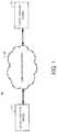
- FIG. 1is a diagram of an example of a system 100 , according to aspects of the disclosure.
- the system 110may include a source computing system 110 that is coupled to a target computing system 120 via a communications network 130 .
- the system 110may include any suitable type of computing device, such as a desktop computer, a smartphone, a laptop, or a server (e.g., storage server). Additionally or alternatively, in some implementations, the system 110 may include multiple computing devices, such as multiple servers, multiple laptops, a server cluster, a distributed computing system, etc. Additionally or alternatively, in some implementations, the system 110 may include a storage system (or portion thereof), such as a midrange storage system, an enterprise storage system, and/or any other suitable type of storage system. According to the present disclosure, the system 110 includes a storage server or a storage system. However, it will the understood that the present disclosure is not limited to any specific implementation of the system 110 .
- the system 120may include any suitable type of computing device, such as a desktop computer, a smartphone, a laptop, or a server (e.g., storage server). Additionally or alternatively, in some implementations, the system 120 may include multiple computing devices, such as multiple servers, multiple laptops, server cluster, a distributed computing system, etc. Additionally or alternatively, in some implementations, the system 120 may include a storage system (or portion thereof), such as a midrange storage system, an enterprise storage system, and/or any other suitable type of storage system. Stated succinctly, the present disclosure is not limited to any specific implementation of the system 120 .
- the network 130may include a Transport Control Protocol (TCP) network.
- TCPTransport Control Protocol
- the network 130includes a TCP network
- the communications networkincludes any other suitable type of network, such as an InfiniBand network, the Internet, etc. Stated succinctly, the present disclosure is not limited to using any specific type of network for connecting the system 110 to the system 120 .
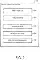
- FIG. 2is a diagram illustrating a logical organization of the system 110 in further detail.
- the system 110may include a set of type-1 sockets 210 , a set of type-2 sockets 220 , a message buffer 230 , an active socket pool 240 , and a data replication manager 250 .
- the set of type-1 sockets 210may include one or more type-1 sockets.
- Each of the type-1 socketsmay include (a representation of) an internal endpoint that is instantiated in a memory of the system 110 .
- each of the type-1 sockets 210is a TCP socket.
- another type of network socketsis used. Stated succinctly, the present disclosure is not limited to using any specific type of socket as a type-1 socket.
- the set of type-2 sockets 220may include one or more type-2 sockets.
- Each of the type-2 socketsmay include (a representation of) an internal endpoint that is instantiated in a memory of the system 110 .
- each of the type-2 sockets 220is a TCP socket.
- another type of network socketis used. Stated succinctly, the present disclosure is not limited to using any specific type of socket as a type-2 socket.
- the type-1 and type-2 socketsmay differ from one another in at least one characteristic.
- both the type-1 and type-2 socketsare TCP sockets that differ in queue depth.
- the type-1 socketsmay have a first queue depth.
- the type-2 socketsmay have a second queue depth that is greater than the first queue depth.
- queue depthrefers to the size of the socket's respective queue.
- the respective queue of a socketmay be a location in the memory of the computing system (e.g., random access memory, onboard memory of a network adapter, etc.), where data replication messages are stored before they are transmitted via the socket.
- each of the type-1 and type-2 socketshas a respective queue.
- the respective queue of each of the type-1 socketsmay have a first queue depth
- the respective queue of each of the type-2 socketsmay have a second queue depth that is greater than the first queue depth.
- the message buffer 230may include any memory location, or set of memory locations, where data replication messages are stored before being transferred into the respective queue of any of the type-1 or type-2 sockets.
- the message buffer 230includes a single queue that is populated with data replication messages by process(es) that are executed on the system 110 .
- the message buffer 230is composed of memory locations that are associated with the same data structure (or variable)
- alternative implementationsare possible in which the message buffer 230 is composed of memory locations that are associated with different data structures (or variables).
- the message buffer 230is large enough to hold multiple data replication messages, alternative implements are possible in which the message buffer 230 is the size of a single data replication message. Stated succinctly, the present disclosure is not limited to any specific implementation of the message buffer 230 .
- the active socket pool 240may include sockets that are available for transmitting the messages in the message buffer 230 . According to the present example, when a socket is part of the active socket pool 240 , that socket can be used to transmit (to the target system 120 ) data replication messages. By contrast, when a socket is not part of the active socket pool 240 , that socket cannot be used to transmit (to the target system 120 ) data replication messages.
- the active socket pool 240may include any of the type-1 sockets 210 and the type-2 sockets 220 . As is discussed further below, the type-1 sockets 210 may be dynamically added and removed from the pool depending on the type of data replication that is being performed by the source system 110 .
- the active socket pool 240may include a list of socket identifiers. When a given type-1 or type-2 socket is identified in the list, that socket may be considered to be part of the active socket pool 240 . Adding a socket to the active socket pool 240 may include adding an identifier corresponding of the socket to the list, Removing a socket from the active socket pool 240 may include deleting an identifier of the socket from the list.
- the data replication manager 250may include logic for the transmission of data replication messages.
- the data replication manager 250may be configured to change the state of the system 110 , as discussed further below with respect to FIG. 4 . Additionally or alternatively, in some implementations, the data replication manager 250 may be configured to perform the process 500 , which is discussed further below with respect to FIG. 5 .
- the data replication manager 250is implemented in software. However, alternative implementations are possible in which the data replication manager 250 is implemented in hardware or as a combination of software and hardware.
- FIG. 3is a block diagram illustrating the operation of the system 110 in further detail.
- one or more message sources 310may place data replication messages 320 in the message buffer 230 .
- Each of the message sources 310may include a process (or thread) that is executed on the system 110 or any other system.
- each of the data replication messages 320may be retrieved from the message buffer 230 and stored in the respective queue of one of the sockets in the active socket pool 240 .
- any of the data replication messages 320 that is placed in the respective queue of a socketmay be transmitted (by the system 110 ) to the target system 120 by using that socket. The transmission may take place over the communications network 130 , and it may be performed in a well-known fashion.
- Each of the data replication messages 320may include any suitable type of message that is used for backing up (or otherwise copying) data stored in the system 110 .
- each of the data replication messagesmay include either (i) a copy of data that is stored in the system 110 , or (ii) replication data (e.g., snapshot data) that is generated based on the data that is storage system.
- replication datae.g., snapshot data
- the present disclosureis not limited to any specific type of data replication messages being transmitted from the system 110 to the system 120 .
- the use of the phrase “data replication”is not intended to imply that any specific method for data copying, data generation, or data backup is being used by the system 110 .
- the data replication messages 320may include synchronous data replication messages and asynchronous data replication messages.
- the synchronous data replication messagesmay be messages that are desired to be transmitted (over the communications network) with lower latency than the asynchronous data replication messages.
- the synchronous data replication messagesmay or may not differ from asynchronous data replication messages in their content.
- the system 110may include a storage server or a storage system.
- the system 110may be arranged to service incoming I/O requests by storing data associated with the I/O requests in a memory of the system 110 in addition to storing the data, the system 110 may execute a synchronous data replication process that is used to back up the data associated with the I/O requests as the I/O requests are being serviced.
- the synchronous data replication processmay back up the data on the target system 120 .
- the synchronous data replication processmay back up the data by: (1) generating synchronous data replication messages based on the data associated with the I/O requests and (ii) transmitting the synchronous data replication messages to the target system 120 .
- an I/O requestmay not be considered complete unless one or more synchronous data replication messages associated with the request have been successfully received by the target system 120 .
- imposing low latency requirements on the synchronous data replication messagesmay be necessary in order for the storage system to meet operational constraints concerning the latency of the storage system as a whole.
- the storage system 110may be configured to execute an asynchronous data replication process.
- the asynchronous data replication processmay be configured to back up data stored on the system 100 at predetermined time intervals.
- the asynchronous data replication processmay back up the data that is stored on the system 110 by: (i) generating asynchronous data replication messages based on the data and (ii) transmitting the generated asynchronous data replication messages to the target system 120 . Because asynchronous data replication is not performed in line (e.g., concurrently) with the servicing of I/O requests (and/or inline with the performance of other tasks), asynchronous data replication messages may be subject to more relaxed latency requirements than synchronous data replication messages.
- FIG. 4is a state diagram illustrating the operation of the system 110 , according to aspects of the disclosure.
- the systemmay be in one of a first state 410 and a second state 420 .
- the state 410may include a state in which the system 110 (and/or data replication manager 250 ) uses both the type-1 sockets 210 and the type-2 sockets 220 to transmit data replication messages to the system 120 ).
- the state 420may include a state in which the system 110 (and/or the data replication manager 250 ) uses type-2 sockets to transmit data replication messages (e.g., to the system 120 ). While the system is in the state 420 , the system 110 (and/or the data replication manager 250 ) may abstain from using type-1 sockets for the transmission of data replication messages.
- the system 110may transition from the state 410 and 420 when the data replication manager 250 detects a request for the transmission of a synchronous data replication message.
- the system 110may transition from the state 410 to the state 420 , when a predetermined amount of time (e.g., 1 second) has passed since the last transmission of a synchronous data replication message 110 .
- a predetermined amount of timee.g. 1 second
- both synchronous and asynchronous data replication messagesmay be transmitted by using the type-2 sockets 220 only.
- the system 110may be transitioned from state 410 to state 420 by the data replication manager 250 .
- transitioning the system 110 from the state 410 to the state 420may include removing, from the active socket pool 240 , all type-1 sockets that are present in the active socket pool.
- the system 110may be transitioned from state 420 to state 410 by the data replication manager 250 . Transitioning the system 110 from state 420 to state 410 may include adding one or more type-1 sockets to the active socket pool 240 .
- the system 110is depicted as having only two possible data replication states, alternative implementations are possible in which the system 110 can assume additional states, such as a state in which no data replication messages are transmitted at all.
- the system 110may detect whether a message is a synchronous data replication message based on a type identifier that is present in the messages' headers.
- the type identifier for any data replication messagemay include any suitable identifier that indicates whether the message is a synchronous data replication message or an asynchronous data replication message.
- the system 110 (and/or the data replication manager 250 )may detect that a data replication message is a synchronous data replication message based on the type of API call that is used to request transmission of the data replication message.
- state 420may be more suitable for the transmission of synchronous data replication messages.
- synchronous data replication messagesmay require a lower network latency than asynchronous data replication messages.
- the latency of message transfer from the system 110 to the system 130may be proportional to the number of sockets that are used on the system 110 for the transmission of the messages. Increasing the number of sockets may result in increased latency.
- the number of sockets used to transmit data replication messages from the system 110 to the system 120is effectively reduced, which in turn may help decrease the transmission latency of data replication messages that are transmitted from the system 110 to the system 120 ,
- FIG. 5is a flowchart of an example of a process 500 , according to aspects of the disclosure.
- the process 500can be performed by the data replication manager 250 .
- alternative implementationsare possible in which the process 500 is performed by one or more other components of the system 110 instead of (or in addition to) the data replication manager 250 .
- the data replication manager 250identifies a first queue depth Q 1 .
- the value Q 1may be a positive number (e.g., an integer or a decimal number, etc.) greater than 1.
- identifying the first queue depth Qmay include retrieving the value Q; from a configuration file of the system 110 . Additionally or alternatively, in some implementations, identifying the value Q 1 may include receiving a user input (e.g., via a keyboard or a touch screen) that specifies the value Q 1 .
- the user inputmay be submitted by a system administrator who is tasked with configuring the data replication capabilities of the system 110 .
- the data replication manager 250identifies an average latency M which is associated with a flow control window of the system 110 .
- the flow control windowmay include a TCP window.
- the average latency Mmay be based on the average latency of data replication messages that are transmitted by using the flow control window.
- the average latency of any of the data replication messagesmay be based on the duration of the period starting when the data replication message is transmitted and ending when an acknowledgment is received that the data replication message has been successfully delivered.
- the present disclosureis not limited to any specific convention for calculating data replication message latency.
- the value Mmay be a number (e.g., an integer or a decimal number, etc.) greater than 0.
- identifying the value Mmay include retrieving the value M from a configuration file of the system 110 . Additionally or alternatively, in some implementations, identifying the value M may include receiving a user input (e.g., via a keyboard or a touch screen) that specifies the value M. In some implementations, the user input may be submitted by a system administrator who is tasked with configuring the data replication capabilities of the system 110 . Additionally or alternatively, in some implementations, identifying the value M may include recording the latency of data replication messages that are transmitted by using one or more flow control windows of the system 110 and calculating their average.
- the data replication manager 250identifies a required average latency N for synchronous data replication.
- the value Nmay specify the average latency, of message transmission, that is needed in order for synchronous data replication to be carried out successfully by the system 110 . Additionally or alternatively, the value N may specify the average latency at which synchronous data replication messages need to be delivered from the system 110 to the system 120 .
- the value Nmay be a number (e.g., an integer or a decimal number, etc.) greater than 0.
- identifying the value Nmay include retrieving the value N from a configuration file of the system 110 .
- identifying the value Nmay include receiving a user input (e.g., via a keyboard or a touch screen) that specifies the value N.
- the user inputmay be submitted by a system administrator who is tasked with configuring the data replication capabilities of the system 110 .
- the data replication manager 250identifies a maximum latency K for asynchronous data replication.
- the value Kmay specify the maximum latency, of message transmission, which can be tolerated if asynchronous data replication were to be carried out successfully by the system 110 . Additionally or alternatively, the value K may specify the maximum latency at which asynchronous data replication messages can be delivered from the system 110 to the system 120 .
- the value Kmay be a number (e.g., an integer or a decimal number, etc.) greater than N (e.g., at least twice as large as K, at least three times as large as K, etc.).
- identifying the value Kmay include retrieving the value K from a configuration file of the system 110 .
- identifying the value Kmay include receiving a user input (e.g., via a keyboard or a touch screen) that specifies the value K.
- the user inputmay be submitted by a system administrator who is tasked with configuring the data replication capabilities of the system 110 .
- data replication manager 250instantiates the plurality of type-1 sockets 210 .
- each of the type-1 socketsmay have a first queue depth that is equal to the value Q 1 , which is identified at step 502 .
- the number of type 1 sockets that are instantiated at step 510may be determined by using Equation 1 below:
- C 1K - N M * Q 1 , ( Eq . ⁇ 1 )
- Kis the maximum latency determined at step 508
- Nis the average latency value determined at step 506
- Mis the average latency value that is determined at step 504
- Q 1is the first queue depth that is determined at step 502 .
- the data replication manager 250instantiates the plurality of type-2 sockets 220 .
- the number of type-2 sockets that are instantiated at step 512may be determined by using Equation 2 below:
- C 2N M * Q , ( Eq . ⁇ 2 ) where C 2 is the count of type-2 sockets that are instantiated, N is the average latency value determined at step 506 , M is the average latency value that is determined at step 504 , and Q 1 is the first queue depth that is determined at step 502 .
- each of the type-2 socketsmay have a second queue depth that is determined based on the first queue depth.
- the second queue depthmay be determined by using Equation 3 below:
- Q 2Q 1 K - N , ( Eq . ⁇ 3 ) where Q 2 is the second queue depth, Q 1 is the first queue depth that is determined at step 502 , K is the maximum latency determined at step 508 , and N is the average latency value determined at step 506 .
- the data replication manager 250begins performing data replication by using the type-1 sockets 210 and the type-2 sockets 220 .
- the manner in which step 514 is performedis described further below with respect to FIGS. 6 and 7 .
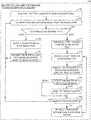
- FIG. 6is a flowchart of a process 600 , for transmitting data replication messages by using type-1 and type-2 sockets, as specified by step 514 of the process 500 .
- the data replication manager 250transitions the system 110 into the state 410 .
- the data replication manager 250detects whether a request is received (by the data replication manager 250 or another component of the system 110 ) for the transmission of a synchronous data replication message. If no such request is received, the system 110 remains in the state 410 and step 604 is repeated again. Otherwise, if such a request is received, the process 600 proceeds to step 606 .
- the data replication managertransitions the system 110 into the state 420 .
- the data replication manager 250detects whether a timeout period has expired.
- the timeout periodmay be a period starting when a synchronous data replication message is transmitted for the last time by the system 110 .
- the timeout periodmay be reset every time the system 110 transmits a new synchronous data replication message. If the time out period has expired, the process 600 returns to step 602 , and the system 110 is transitioned hack to the state 410 . Otherwise, if the timeout period has not expired, the system 110 remains in the state 420 , and step 608 is repeated again.
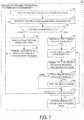
- FIG. 7is a flowchart of a process 700 , for transmitting data replication messages by using type-1 and type-2 sockets, as specified by step 514 of the process 500 .
- the data replication manageradds the plurality of type-1 sockets 210 and the plurality of type-2 sockets 220 to the active socket pool 240 .
- the data replication manager 250retrieves a data replication message from the message buffer 230 .
- the data replication manager 250determines whether the retrieved message is a synchronous data replication message or an asynchronous data replication message. If the retrieved message is a synchronous data replication message, the process 700 proceeds to step 708 . Otherwise, if the retrieved message is an asynchronous data replication message, the process 700 proceeds to step 712 .
- the data replication manager 250selects a socket from the active socket pool 240 .
- the selected socketmay be either a type-1 socket or a type-2 socket.
- the data replication manager 250transmits the retrieved message by using the selected socket. In some implementations, transmitting the selected message may include removing the selected message from the message buffer 230 and adding the selected message to the respective queue of the selected socket.
- the data replication manager 250removes, from the active socket pool 240 , all type-1 sockets that are present in the active socket pool 240 . After step 712 is complete, no type-1 sockets may remain in the active socket pool 240 .
- the data replication manager 250selects a socket from the active socket pool 240 . As can be readily appreciated, the selected socket is guaranteed to be a type-2 socket.
- the data replication manager 250transmits the retrieved message by using the selected socket. In some implementations, transmitting the selected message may include removing the selected message from the message buffer 230 and adding the selected data replication message to the respective queue of the selected socket.
- the data replication manager 250determines the type of the data replication message transmitted at step 716 . If the data replication message transmitted at step 716 is a synchronous data replication message, the process 700 proceeds to step 720 . On the other hand, if the transmitted message is an asynchronous data replication message, the process 700 proceeds to step 720 .
- a timeout counteris reset. The timeout counter may be configured to measure the duration of the period starting when a synchronous data replication message is transmitted for the last time, and it may be reset every time a new synchronous data replication message is transmitted.
- a determinationis made if a timeout counter has expired. If the timeout has expired, the process 700 proceeds to step 704 .
- step 724the data replication manager 250 retrieves another data replication message from the message buffer 230 . After the data replication message is retrieved, the process 700 returns to step 714 .
- the system 110may be implemented as a computing device 800 .
- the computing device 800may include processor 802 , volatile memory 804 (e.g., RAM), non-volatile memory 806 (e.g., a hard disk drive, a solid state drive such as a flash drive, a hybrid magnetic and solid state drive, etc.), graphical user interface (GUI) 808 (e.g., a touchscreen, a display, and so forth) and input/output (I/O) device 820 (e.g., a mouse, a keyboard, etc.).
- volatile memory 804e.g., RAM
- non-volatile memory 806e.g., a hard disk drive, a solid state drive such as a flash drive, a hybrid magnetic and solid state drive, etc.
- GUIgraphical user interface
- I/Oinput/output
- Non-volatile memory 806stores computer instructions 812 , an operating system 816 and data 818 such that, for example, the computer instructions 812 are executed by the processor 802 out of volatile memory 804 to perform at least a portion of the process 500 and/or any other function of the storage system 100 .
- FIGS. 1-8are provided as an example only. At least some of the steps discussed with respect to FIGS. 1-8 may be performed in parallel, in a different order, or altogether omitted.
- the word “exemplary”is used herein to mean serving as an example, may instance, or illustration.
- the term “data replication message”may include any message that contains data that is desired to be transferred from one computing system to another. It will be understood that, in the present disclosure, the definition of a “data replication message” is in no way limited to messages that are transmitted when a particular data replication/backup function of a storage system is performed. Any aspect or design described herein as “exemplary” is not necessarily to be construed as preferred or advantageous over other aspects or designs. Rather, use of the word exemplary is intended to present concepts in a concrete fashion.
- the term “or”is intended to mean an inclusive “or” rather than an exclusive “or”. That is, unless specified otherwise, or clear from context, “X employs A or B” is intended to mean any of the natural inclusive permutations. That is, if X employs A; X employs B; or X employs both A and B, then “X employs A or B” is satisfied under any of the foregoing instances.
- the articles “a” and “an” as used in this application and the appended claimsshould generally be construed to mean “one or more” unless specified otherwise or clear from context to be directed to a singular form.
- a componentmay be, but is not limited to being, a process running on a processor, a processor, an object, an executable, a thread of execution, a program, and/or a computer.
- an application running on a controller and the controllercan be a component.
- One or more componentsmay reside within a process and/or thread of execution and a component may be localized on one computer and/or distributed between two or more computers.
- circuitsincluding possible implementation as a single integrated circuit, a multi-chip module, a single card, or a multi-card circuit pack
- the described embodimentsare not so limited.
- various functions of circuit elementsmay also be implemented as processing blocks in a software program.
- Such softwaremay be employed in, for example, a digital signal processor, micro-controller, or general-purpose computer.
- Some embodimentsmight be implemented in the form of methods and apparatuses for practicing those methods. Described embodiments might also be implemented in the form of program code embodied in tangible media, such as magnetic recording media, optical recording media, solid state memory, floppy diskettes, CD-ROMs, hard drives, or any other machine-readable storage medium, wherein, when the program code is loaded into and executed by a machine, such as a computer, the machine becomes an apparatus for practicing the claimed invention.
- Described embodimentsmight also be implemented in the form of program code, for example, whether stored in a storage medium, loaded into and/or executed by a machine, or transmitted over some transmission medium or carrier, such as over electrical wiring or cabling, through fiber optics, or via electromagnetic radiation, wherein, when the program code is loaded into and executed by a machine, such as a computer, the machine becomes an apparatus for practicing the claimed invention.
- program codeWhen implemented on a general-purpose processor, the program code segments combine with the processor to provide a unique device that operates analogously to specific logic circuits.
- Described embodimentsmight also be implemented in the form of a bitstream or other sequence of signal values electrically or optically transmitted through a medium, stored magnetic-field variations in a magnetic recording medium, etc., generated using a method and/or an apparatus of the claimed invention.
- Couplerefers to any manner known in the art or later developed in which energy is allowed to be transferred between two or more elements, and the interposition of one or more additional elements is contemplated, although not required. Conversely, the terms “directly coupled,” “directly connected,” etc., imply the absence of such additional elements.
- the term “compatible”means that the element communicates with other elements in a manner wholly or partially specified by the standard, and would be recognized by other elements as sufficiently capable of communicating with the other elements in the manner specified by the standard.
- the compatible elementdoes not need to operate internally in a manner specified by the standard.
Landscapes
- Engineering & Computer Science (AREA)
- Computer Networks & Wireless Communication (AREA)
- Signal Processing (AREA)
- Theoretical Computer Science (AREA)
- Computer Security & Cryptography (AREA)
- Human Computer Interaction (AREA)
- Physics & Mathematics (AREA)
- General Engineering & Computer Science (AREA)
- General Physics & Mathematics (AREA)
- Computer And Data Communications (AREA)
- Information Transfer Between Computers (AREA)
Abstract
Description
where C1is the count of type-1 sockets that are instantiated, K is the maximum latency determined at
where C2is the count of type-2 sockets that are instantiated, N is the average latency value determined at
where Q2is the second queue depth, Q1is the first queue depth that is determined at
Claims (20)
Priority Applications (1)
| Application Number | Priority Date | Filing Date | Title |
|---|---|---|---|
| US16/592,328US11070654B2 (en) | 2019-10-03 | 2019-10-03 | Sockets for shared link applications |
Applications Claiming Priority (1)
| Application Number | Priority Date | Filing Date | Title |
|---|---|---|---|
| US16/592,328US11070654B2 (en) | 2019-10-03 | 2019-10-03 | Sockets for shared link applications |
Publications (2)
| Publication Number | Publication Date |
|---|---|
| US20210105343A1 US20210105343A1 (en) | 2021-04-08 |
| US11070654B2true US11070654B2 (en) | 2021-07-20 |
Family
ID=75274417
Family Applications (1)
| Application Number | Title | Priority Date | Filing Date |
|---|---|---|---|
| US16/592,328Active2039-10-10US11070654B2 (en) | 2019-10-03 | 2019-10-03 | Sockets for shared link applications |
Country Status (1)
| Country | Link |
|---|---|
| US (1) | US11070654B2 (en) |
Families Citing this family (1)
| Publication number | Priority date | Publication date | Assignee | Title |
|---|---|---|---|---|
| CN114095513B (en)* | 2021-11-26 | 2024-03-29 | 苏州盛科科技有限公司 | Method for forwarding traffic and mirror image traffic scheduling under limited bandwidth scene and application |
Citations (64)
| Publication number | Priority date | Publication date | Assignee | Title |
|---|---|---|---|---|
| US20040003085A1 (en)* | 2002-06-26 | 2004-01-01 | Joseph Paul G. | Active application socket management |
| US7475124B2 (en) | 2002-09-25 | 2009-01-06 | Emc Corporation | Network block services for client access of network-attached data storage in an IP network |
| US20100088423A1 (en)* | 2008-10-03 | 2010-04-08 | Canon Kabushiki Kaisha | Establishing and maintaining a connection by a client to a server within a network |
| US20100246398A1 (en)* | 2009-03-26 | 2010-09-30 | Mung Chiang | Tcp extension and variants for handling heterogeneous applications |
| US8327103B1 (en) | 2010-06-28 | 2012-12-04 | Emc Corporation | Scheduling data relocation activities using configurable fairness criteria |
| US8380928B1 (en) | 2009-12-17 | 2013-02-19 | Emc Corporation | Applying data access activity measurements |
| US8429346B1 (en) | 2009-12-28 | 2013-04-23 | Emc Corporation | Automated data relocation among storage tiers based on storage load |
| US20130191525A1 (en)* | 2012-01-25 | 2013-07-25 | Samsung Electronics Co. Ltd. | Method and apparatus for controlling http sockets |
| US8515911B1 (en) | 2009-01-06 | 2013-08-20 | Emc Corporation | Methods and apparatus for managing multiple point in time copies in a file system |
| US8539148B1 (en) | 2010-12-22 | 2013-09-17 | Emc Corporation | Deduplication efficiency |
| US8566483B1 (en) | 2009-12-17 | 2013-10-22 | Emc Corporation | Measuring data access activity |
| US8583607B1 (en) | 2012-03-28 | 2013-11-12 | Emc Corporation | Managing deduplication density |
| US8683153B1 (en) | 2010-09-29 | 2014-03-25 | Emc Corporation | Iterating for deduplication |
| US8712976B1 (en) | 2012-03-28 | 2014-04-29 | Emc Corporation | Managing deduplication density |
| US8775388B1 (en) | 2010-09-29 | 2014-07-08 | Emc Corporation | Selecting iteration schemes for deduplication |
| US8782324B1 (en) | 2012-06-28 | 2014-07-15 | Emc Corporation | Techniques for managing placement of extents based on a history of active extents |
| US8799601B1 (en) | 2012-06-28 | 2014-08-05 | Emc Corporation | Techniques for managing deduplication based on recently written extents |
| US8909887B1 (en) | 2012-09-25 | 2014-12-09 | Emc Corporation | Selective defragmentation based on IO hot spots |
| US8930746B1 (en) | 2012-06-30 | 2015-01-06 | Emc Corporation | System and method for LUN adjustment |
| US8954699B1 (en) | 2012-06-28 | 2015-02-10 | Emc Corporation | Techniques for identifying IO hot spots using range-lock information |
| US8977812B1 (en) | 2011-03-30 | 2015-03-10 | Emc Corporation | Iterating in parallel for deduplication |
| US9152336B1 (en) | 2012-06-30 | 2015-10-06 | Emc Corporation | System and method for LUN adjustment |
| US9304889B1 (en) | 2014-09-24 | 2016-04-05 | Emc Corporation | Suspending data replication |
| US9355112B1 (en) | 2012-12-31 | 2016-05-31 | Emc Corporation | Optimizing compression based on data activity |
| US20160191934A1 (en)* | 2014-12-29 | 2016-06-30 | Arris Enterprises, Inc. | Method to optimize the quality of video delivered over a network |
| US9384206B1 (en) | 2013-12-26 | 2016-07-05 | Emc Corporation | Managing data deduplication in storage systems |
| US9395937B1 (en) | 2013-12-27 | 2016-07-19 | Emc Corporation | Managing storage space in storage systems |
| US9449011B1 (en) | 2012-12-28 | 2016-09-20 | Emc Corporation | Managing data deduplication in storage systems |
| US9460102B1 (en) | 2013-12-26 | 2016-10-04 | Emc Corporation | Managing data deduplication in storage systems based on I/O activities |
| US9459809B1 (en) | 2014-06-30 | 2016-10-04 | Emc Corporation | Optimizing data location in data storage arrays |
| US9477431B1 (en) | 2012-12-28 | 2016-10-25 | EMC IP Holding Company LLC | Managing storage space of storage tiers |
| US9513814B1 (en) | 2011-03-29 | 2016-12-06 | EMC IP Holding Company LLC | Balancing I/O load on data storage systems |
| US9529545B1 (en) | 2013-12-26 | 2016-12-27 | EMC IP Holding Company LLC | Managing data deduplication in storage systems based on storage space characteristics |
| US9542125B1 (en) | 2012-09-25 | 2017-01-10 | EMC IP Holding Company LLC | Managing data relocation in storage systems |
| US9594514B1 (en) | 2013-06-27 | 2017-03-14 | EMC IP Holding Company LLC | Managing host data placed in a container file system on a data storage array having multiple storage tiers |
| US9684593B1 (en) | 2012-11-30 | 2017-06-20 | EMC IP Holding Company LLC | Techniques using an encryption tier property with application hinting and I/O tagging |
| US9710187B1 (en) | 2013-06-27 | 2017-07-18 | EMC IP Holding Company LLC | Managing data relocation in storage systems |
| US9811288B1 (en) | 2011-12-30 | 2017-11-07 | EMC IP Holding Company LLC | Managing data placement based on flash drive wear level |
| US20170324672A1 (en)* | 2016-05-03 | 2017-11-09 | Samsung Electronics Co., Ltd. | Device and method for transmitting packet in wireless communication system |
| US9817766B1 (en) | 2012-12-28 | 2017-11-14 | EMC IP Holding Company LLC | Managing relocation of slices in storage systems |
| US10037369B1 (en) | 2015-06-26 | 2018-07-31 | EMC IP Holding Company LLC | Storage tiering in replication target based on logical extents |
| US10082959B1 (en) | 2011-12-27 | 2018-09-25 | EMC IP Holding Company LLC | Managing data placement in storage systems |
| US10095428B1 (en) | 2016-03-30 | 2018-10-09 | EMC IP Holding Company LLC | Live migration of a tree of replicas in a storage system |
| US10114582B1 (en)* | 2016-12-28 | 2018-10-30 | EMC IP Holdinig Company LLC | Dynamically selecting between sync and async replication modes |
| US10152381B1 (en) | 2017-04-27 | 2018-12-11 | EMC IP Holding Company LLC | Using storage defragmentation function to facilitate system checkpoint |
| US10176046B1 (en) | 2017-06-29 | 2019-01-08 | EMC IP Holding Company LLC | Checkpointing of metadata into user data area of a content addressable storage system |
| US10235066B1 (en) | 2017-04-27 | 2019-03-19 | EMC IP Holding Company LLC | Journal destage relay for online system checkpoint creation |
| US10248623B1 (en) | 2015-03-30 | 2019-04-02 | EMC IP Holding Company LLC | Data deduplication techniques |
| US10261853B1 (en) | 2016-06-28 | 2019-04-16 | EMC IP Holding Company LLC | Dynamic replication error retry and recovery |
| US10310951B1 (en) | 2016-03-22 | 2019-06-04 | EMC IP Holding Company LLC | Storage system asynchronous data replication cycle trigger with empty cycle detection |
| US10324640B1 (en) | 2018-01-22 | 2019-06-18 | EMC IP Holding Company LLC | Storage system with consistent initiation of data replication across multiple distributed processing modules |
| US10338851B1 (en) | 2018-01-16 | 2019-07-02 | EMC IP Holding Company LLC | Storage system with consistent termination of data replication across multiple distributed processing modules |
| US10353616B1 (en) | 2013-06-27 | 2019-07-16 | EMC IP Holding Company LLC | Managing data relocation in storage systems |
| US10359968B1 (en) | 2018-01-31 | 2019-07-23 | EMC IP Holding Company LLC | Smart data movement among virtual storage domains |
| US10374792B1 (en) | 2016-09-29 | 2019-08-06 | EMC IP Holding Company LLC | Layout-independent cryptographic stamp of a distributed dataset |
| US10394485B1 (en) | 2018-03-29 | 2019-08-27 | EMC IP Holding Company LLC | Storage system with efficient re-synchronization mode for use in replication of data from source to target |
| US10402283B1 (en) | 2017-04-28 | 2019-09-03 | EMC IP Holding Company LLC | Online system checkpoint recovery orchestration |
| US10409493B1 (en) | 2017-04-28 | 2019-09-10 | EMC IP Holding Company LLC | Online system checkpoint alert and handling |
| US10459883B1 (en) | 2015-12-30 | 2019-10-29 | EMC IP Holding Company LLC | Retention policies for unscheduled replicas in backup, snapshots, and remote replication |
| US10459632B1 (en) | 2016-09-16 | 2019-10-29 | EMC IP Holding Company LLC | Method and system for automatic replication data verification and recovery |
| US10496672B2 (en) | 2015-12-30 | 2019-12-03 | EMC IP Holding Company LLC | Creating replicas at user-defined points in time |
| US10496668B1 (en) | 2016-06-28 | 2019-12-03 | EMC IP Holding Company LLC | Optimized tender processing of hash-based replicated data |
| US10496489B1 (en) | 2017-11-21 | 2019-12-03 | EMC IP Holding Company LLC | Storage system configured for controlled transition between asynchronous and synchronous replication modes |
| US10565058B1 (en) | 2016-03-30 | 2020-02-18 | EMC IP Holding Company LLC | Adaptive hash-based data replication in a storage system |
- 2019
- 2019-10-03USUS16/592,328patent/US11070654B2/enactiveActive
Patent Citations (64)
| Publication number | Priority date | Publication date | Assignee | Title |
|---|---|---|---|---|
| US20040003085A1 (en)* | 2002-06-26 | 2004-01-01 | Joseph Paul G. | Active application socket management |
| US7475124B2 (en) | 2002-09-25 | 2009-01-06 | Emc Corporation | Network block services for client access of network-attached data storage in an IP network |
| US20100088423A1 (en)* | 2008-10-03 | 2010-04-08 | Canon Kabushiki Kaisha | Establishing and maintaining a connection by a client to a server within a network |
| US8515911B1 (en) | 2009-01-06 | 2013-08-20 | Emc Corporation | Methods and apparatus for managing multiple point in time copies in a file system |
| US20100246398A1 (en)* | 2009-03-26 | 2010-09-30 | Mung Chiang | Tcp extension and variants for handling heterogeneous applications |
| US8566483B1 (en) | 2009-12-17 | 2013-10-22 | Emc Corporation | Measuring data access activity |
| US8380928B1 (en) | 2009-12-17 | 2013-02-19 | Emc Corporation | Applying data access activity measurements |
| US8429346B1 (en) | 2009-12-28 | 2013-04-23 | Emc Corporation | Automated data relocation among storage tiers based on storage load |
| US8327103B1 (en) | 2010-06-28 | 2012-12-04 | Emc Corporation | Scheduling data relocation activities using configurable fairness criteria |
| US8683153B1 (en) | 2010-09-29 | 2014-03-25 | Emc Corporation | Iterating for deduplication |
| US8775388B1 (en) | 2010-09-29 | 2014-07-08 | Emc Corporation | Selecting iteration schemes for deduplication |
| US8539148B1 (en) | 2010-12-22 | 2013-09-17 | Emc Corporation | Deduplication efficiency |
| US9513814B1 (en) | 2011-03-29 | 2016-12-06 | EMC IP Holding Company LLC | Balancing I/O load on data storage systems |
| US8977812B1 (en) | 2011-03-30 | 2015-03-10 | Emc Corporation | Iterating in parallel for deduplication |
| US10082959B1 (en) | 2011-12-27 | 2018-09-25 | EMC IP Holding Company LLC | Managing data placement in storage systems |
| US9811288B1 (en) | 2011-12-30 | 2017-11-07 | EMC IP Holding Company LLC | Managing data placement based on flash drive wear level |
| US20130191525A1 (en)* | 2012-01-25 | 2013-07-25 | Samsung Electronics Co. Ltd. | Method and apparatus for controlling http sockets |
| US8583607B1 (en) | 2012-03-28 | 2013-11-12 | Emc Corporation | Managing deduplication density |
| US8712976B1 (en) | 2012-03-28 | 2014-04-29 | Emc Corporation | Managing deduplication density |
| US8799601B1 (en) | 2012-06-28 | 2014-08-05 | Emc Corporation | Techniques for managing deduplication based on recently written extents |
| US8954699B1 (en) | 2012-06-28 | 2015-02-10 | Emc Corporation | Techniques for identifying IO hot spots using range-lock information |
| US8782324B1 (en) | 2012-06-28 | 2014-07-15 | Emc Corporation | Techniques for managing placement of extents based on a history of active extents |
| US9152336B1 (en) | 2012-06-30 | 2015-10-06 | Emc Corporation | System and method for LUN adjustment |
| US8930746B1 (en) | 2012-06-30 | 2015-01-06 | Emc Corporation | System and method for LUN adjustment |
| US9542125B1 (en) | 2012-09-25 | 2017-01-10 | EMC IP Holding Company LLC | Managing data relocation in storage systems |
| US8909887B1 (en) | 2012-09-25 | 2014-12-09 | Emc Corporation | Selective defragmentation based on IO hot spots |
| US9684593B1 (en) | 2012-11-30 | 2017-06-20 | EMC IP Holding Company LLC | Techniques using an encryption tier property with application hinting and I/O tagging |
| US9449011B1 (en) | 2012-12-28 | 2016-09-20 | Emc Corporation | Managing data deduplication in storage systems |
| US9817766B1 (en) | 2012-12-28 | 2017-11-14 | EMC IP Holding Company LLC | Managing relocation of slices in storage systems |
| US9477431B1 (en) | 2012-12-28 | 2016-10-25 | EMC IP Holding Company LLC | Managing storage space of storage tiers |
| US9355112B1 (en) | 2012-12-31 | 2016-05-31 | Emc Corporation | Optimizing compression based on data activity |
| US10353616B1 (en) | 2013-06-27 | 2019-07-16 | EMC IP Holding Company LLC | Managing data relocation in storage systems |
| US9594514B1 (en) | 2013-06-27 | 2017-03-14 | EMC IP Holding Company LLC | Managing host data placed in a container file system on a data storage array having multiple storage tiers |
| US9710187B1 (en) | 2013-06-27 | 2017-07-18 | EMC IP Holding Company LLC | Managing data relocation in storage systems |
| US9384206B1 (en) | 2013-12-26 | 2016-07-05 | Emc Corporation | Managing data deduplication in storage systems |
| US9529545B1 (en) | 2013-12-26 | 2016-12-27 | EMC IP Holding Company LLC | Managing data deduplication in storage systems based on storage space characteristics |
| US9460102B1 (en) | 2013-12-26 | 2016-10-04 | Emc Corporation | Managing data deduplication in storage systems based on I/O activities |
| US9395937B1 (en) | 2013-12-27 | 2016-07-19 | Emc Corporation | Managing storage space in storage systems |
| US9459809B1 (en) | 2014-06-30 | 2016-10-04 | Emc Corporation | Optimizing data location in data storage arrays |
| US9304889B1 (en) | 2014-09-24 | 2016-04-05 | Emc Corporation | Suspending data replication |
| US20160191934A1 (en)* | 2014-12-29 | 2016-06-30 | Arris Enterprises, Inc. | Method to optimize the quality of video delivered over a network |
| US10248623B1 (en) | 2015-03-30 | 2019-04-02 | EMC IP Holding Company LLC | Data deduplication techniques |
| US10037369B1 (en) | 2015-06-26 | 2018-07-31 | EMC IP Holding Company LLC | Storage tiering in replication target based on logical extents |
| US10496672B2 (en) | 2015-12-30 | 2019-12-03 | EMC IP Holding Company LLC | Creating replicas at user-defined points in time |
| US10459883B1 (en) | 2015-12-30 | 2019-10-29 | EMC IP Holding Company LLC | Retention policies for unscheduled replicas in backup, snapshots, and remote replication |
| US10310951B1 (en) | 2016-03-22 | 2019-06-04 | EMC IP Holding Company LLC | Storage system asynchronous data replication cycle trigger with empty cycle detection |
| US10565058B1 (en) | 2016-03-30 | 2020-02-18 | EMC IP Holding Company LLC | Adaptive hash-based data replication in a storage system |
| US10095428B1 (en) | 2016-03-30 | 2018-10-09 | EMC IP Holding Company LLC | Live migration of a tree of replicas in a storage system |
| US20170324672A1 (en)* | 2016-05-03 | 2017-11-09 | Samsung Electronics Co., Ltd. | Device and method for transmitting packet in wireless communication system |
| US10261853B1 (en) | 2016-06-28 | 2019-04-16 | EMC IP Holding Company LLC | Dynamic replication error retry and recovery |
| US10496668B1 (en) | 2016-06-28 | 2019-12-03 | EMC IP Holding Company LLC | Optimized tender processing of hash-based replicated data |
| US10459632B1 (en) | 2016-09-16 | 2019-10-29 | EMC IP Holding Company LLC | Method and system for automatic replication data verification and recovery |
| US10374792B1 (en) | 2016-09-29 | 2019-08-06 | EMC IP Holding Company LLC | Layout-independent cryptographic stamp of a distributed dataset |
| US10114582B1 (en)* | 2016-12-28 | 2018-10-30 | EMC IP Holdinig Company LLC | Dynamically selecting between sync and async replication modes |
| US10235066B1 (en) | 2017-04-27 | 2019-03-19 | EMC IP Holding Company LLC | Journal destage relay for online system checkpoint creation |
| US10152381B1 (en) | 2017-04-27 | 2018-12-11 | EMC IP Holding Company LLC | Using storage defragmentation function to facilitate system checkpoint |
| US10402283B1 (en) | 2017-04-28 | 2019-09-03 | EMC IP Holding Company LLC | Online system checkpoint recovery orchestration |
| US10409493B1 (en) | 2017-04-28 | 2019-09-10 | EMC IP Holding Company LLC | Online system checkpoint alert and handling |
| US10176046B1 (en) | 2017-06-29 | 2019-01-08 | EMC IP Holding Company LLC | Checkpointing of metadata into user data area of a content addressable storage system |
| US10496489B1 (en) | 2017-11-21 | 2019-12-03 | EMC IP Holding Company LLC | Storage system configured for controlled transition between asynchronous and synchronous replication modes |
| US10338851B1 (en) | 2018-01-16 | 2019-07-02 | EMC IP Holding Company LLC | Storage system with consistent termination of data replication across multiple distributed processing modules |
| US10324640B1 (en) | 2018-01-22 | 2019-06-18 | EMC IP Holding Company LLC | Storage system with consistent initiation of data replication across multiple distributed processing modules |
| US10359968B1 (en) | 2018-01-31 | 2019-07-23 | EMC IP Holding Company LLC | Smart data movement among virtual storage domains |
| US10394485B1 (en) | 2018-03-29 | 2019-08-27 | EMC IP Holding Company LLC | Storage system with efficient re-synchronization mode for use in replication of data from source to target |
Non-Patent Citations (33)
| Title |
|---|
| U.S. Appl. No. 15/499,943, filed Apr. 28, 2017, Kucherov et al. |
| U.S. Appl. No. 15/499,949, filed Apr. 28, 2017, Chen et al. |
| U.S. Appl. No. 15/499,951, filed Apr. 28, 2017, Chen et al. |
| U.S. Appl. No. 15/656,168, filed Jul. 21, 2017, Hu et al. |
| U.S. Appl. No. 15/656,170, filed Jul. 21, 2017, Chen et al. |
| U.S. Appl. No. 15/797,324, filed Oct. 30, 2017, Chen et al. |
| U.S. Appl. No. 16/038,543, filed Jul. 18, 2018, Chen et al. |
| U.S. Appl. No. 16/042,363, filed Jul. 23, 2018, Chen et al. |
| U.S. Appl. No. 16/048,767, filed Jul. 30, 2018, Chen et al. |
| U.S. Appl. No. 16/157,528, filed Oct. 11, 2018, Chen et al. |
| U.S. Appl. No. 16/162,786, filed Oct. 17, 2018, Hu et al. |
| U.S. Appl. No. 16/164,005, filed Oct. 18, 2018, Chen et al. |
| U.S. Appl. No. 16/167,858, filed Oct. 23, 2018, Chen et al. |
| U.S. Appl. No. 16/169,202, filed Oct. 24, 2018, Chen et al. |
| U.S. Appl. No. 16/175,979, filed Oct. 31, 2018, Hu et al. |
| U.S. Appl. No. 16/177,782, filed Nov. 1, 2018, Hu et al. |
| U.S. Appl. No. 16/254,897, filed Jan. 23, 2019, Chen et al. |
| U.S. Appl. No. 16/254,899, filed Jan. 23, 2019, Chen et al. |
| U.S. Appl. No. 16/263,414, filed Jan. 31, 2019, Meiri et al. |
| U.S. Appl. No. 16/264,825, filed Feb. 1, 2019, Chen et al. |
| U.S. Appl. No. 16/264,982, filed Feb. 1, 2019, Chen et al. |
| U.S. Appl. No. 16/375,001, filed Apr. 4, 2019, Chen et al. |
| U.S. Appl. No. 16/380,087, filed Apr. 10, 2019, Kronrod et al. |
| U.S. Appl. No. 16/511,676, filed Jul. 15, 2019, Chen et al. |
| U.S. Appl. No. 16/592,271, filed Oct. 3, 2019, Chen et al. |
| U.S. Appl. No. 16/592,328, filed Oct. 3, 2019, Barabash et al. |
| U.S. Appl. No. 16/667,453, filed Oct. 29, 2019, Chen et al. |
| U.S. Appl. No. 16/668,661, filed Oct. 30, 2019, Kronrod et al. |
| U.S. Appl. No. 16/743,274, filed Jan. 15, 2020, Chen et al. |
| U.S. Appl. No. 16/747,169, filed Jan. 20, 2020, Chen et al. |
| U.S. Appl. No. 16/773,303, filed Jan. 27, 2020, Hu et al. |
| U.S. Appl. No. 16/786,422, filed Feb. 10, 2020, Kronrod et al. |
| U.S. Appl. No. 16/788,461, filed Feb. 12, 2020, Chen et al. |
Also Published As
| Publication number | Publication date |
|---|---|
| US20210105343A1 (en) | 2021-04-08 |
Similar Documents
| Publication | Publication Date | Title |
|---|---|---|
| US11836135B1 (en) | Method and system for transparent database query caching | |
| US11243845B2 (en) | Method and device for data backup | |
| US20100299447A1 (en) | Data Replication | |
| US10579579B2 (en) | Programming interface operations in a port in communication with a driver for reinitialization of storage controller elements | |
| US10606780B2 (en) | Programming interface operations in a driver in communication with a port for reinitialization of storage controller elements | |
| US12079651B2 (en) | Serverless application function execution | |
| US20170149864A1 (en) | Distributed applications management with dependent resilient distributed services | |
| CN114730305A (en) | Control transaction requests between applications and servers | |
| US20190004870A1 (en) | Hierarchical process group management | |
| US9684475B2 (en) | Multi-mode hybrid storage drive | |
| US10341181B2 (en) | Method and apparatus to allow dynamic changes of a replica network configuration in distributed systems | |
| CN114647363A (en) | Method, electronic device and computer program product for data processing | |
| US10997058B2 (en) | Method for performance analysis in a continuous integration pipeline | |
| WO2024021554A1 (en) | Data migration method and device | |
| US11070654B2 (en) | Sockets for shared link applications | |
| CN115103006A (en) | Heartbeat message sending method and related components in distributed storage cluster scenario | |
| WO2022199204A1 (en) | Method and apparatus for determining resources | |
| CN111708644A (en) | Virtual world management method and system for autonomous driving simulation | |
| CN110413207B (en) | Method, apparatus and program product for reducing data recovery time of a storage system | |
| KR20190116034A (en) | Network interface apparatus and data processing method for network interface apparauts thereof | |
| US11281548B2 (en) | 2-phase sync replication recovery to optimize recovery point objective (RPO) | |
| US10713103B2 (en) | Lightweight application programming interface (API) creation and management | |
| US9191267B2 (en) | Device management for determining the effects of management actions | |
| US10083067B1 (en) | Thread management in a storage system | |
| US20240402918A1 (en) | Storage-driven power optimization |
Legal Events
| Date | Code | Title | Description |
|---|---|---|---|
| FEPP | Fee payment procedure | Free format text:ENTITY STATUS SET TO UNDISCOUNTED (ORIGINAL EVENT CODE: BIG.); ENTITY STATUS OF PATENT OWNER: LARGE ENTITY | |
| AS | Assignment | Owner name:EMC IP HOLDING COMPANY LLC, MASSACHUSETTS Free format text:ASSIGNMENT OF ASSIGNORS INTEREST;ASSIGNORS:BARABASH, ALEXANDER;RAVICH, LEONID;NER, EYAL BEN;AND OTHERS;SIGNING DATES FROM 20191001 TO 20191002;REEL/FRAME:050625/0933 | |
| AS | Assignment | Owner name:THE BANK OF NEW YORK MELLON TRUST COMPANY, N.A., AS COLLATERAL AGENT, TEXAS Free format text:PATENT SECURITY AGREEMENT (NOTES);ASSIGNORS:DELL PRODUCTS L.P.;EMC IP HOLDING COMPANY LLC;WYSE TECHNOLOGY L.L.C.;AND OTHERS;REEL/FRAME:051302/0528 Effective date:20191212 | |
| AS | Assignment | Owner name:CREDIT SUISSE AG, CAYMAN ISLANDS BRANCH, NORTH CAROLINA Free format text:SECURITY AGREEMENT;ASSIGNORS:DELL PRODUCTS L.P.;EMC IP HOLDING COMPANY LLC;WYSE TECHNOLOGY L.L.C.;AND OTHERS;REEL/FRAME:051449/0728 Effective date:20191230 | |
| AS | Assignment | Owner name:THE BANK OF NEW YORK MELLON TRUST COMPANY, N.A., TEXAS Free format text:SECURITY AGREEMENT;ASSIGNORS:CREDANT TECHNOLOGIES INC.;DELL INTERNATIONAL L.L.C.;DELL MARKETING L.P.;AND OTHERS;REEL/FRAME:053546/0001 Effective date:20200409 | |
| AS | Assignment | Owner name:THE BANK OF NEW YORK MELLON TRUST COMPANY, N.A., AS COLLATERAL AGENT, TEXAS Free format text:SECURITY INTEREST;ASSIGNORS:DELL PRODUCTS L.P.;EMC CORPORATION;EMC IP HOLDING COMPANY LLC;REEL/FRAME:053311/0169 Effective date:20200603 | |
| STPP | Information on status: patent application and granting procedure in general | Free format text:NOTICE OF ALLOWANCE MAILED -- APPLICATION RECEIVED IN OFFICE OF PUBLICATIONS | |
| STPP | Information on status: patent application and granting procedure in general | Free format text:PUBLICATIONS -- ISSUE FEE PAYMENT RECEIVED | |
| STPP | Information on status: patent application and granting procedure in general | Free format text:PUBLICATIONS -- ISSUE FEE PAYMENT VERIFIED | |
| STCF | Information on status: patent grant | Free format text:PATENTED CASE | |
| AS | Assignment | Owner name:EMC CORPORATION, MASSACHUSETTS Free format text:RELEASE OF SECURITY INTEREST AT REEL 051449 FRAME 0728;ASSIGNOR:CREDIT SUISSE AG, CAYMAN ISLANDS BRANCH;REEL/FRAME:058002/0010 Effective date:20211101 Owner name:SECUREWORKS CORP., DELAWARE Free format text:RELEASE OF SECURITY INTEREST AT REEL 051449 FRAME 0728;ASSIGNOR:CREDIT SUISSE AG, CAYMAN ISLANDS BRANCH;REEL/FRAME:058002/0010 Effective date:20211101 Owner name:WYSE TECHNOLOGY L.L.C., CALIFORNIA Free format text:RELEASE OF SECURITY INTEREST AT REEL 051449 FRAME 0728;ASSIGNOR:CREDIT SUISSE AG, CAYMAN ISLANDS BRANCH;REEL/FRAME:058002/0010 Effective date:20211101 Owner name:EMC IP HOLDING COMPANY LLC, TEXAS Free format text:RELEASE OF SECURITY INTEREST AT REEL 051449 FRAME 0728;ASSIGNOR:CREDIT SUISSE AG, CAYMAN ISLANDS BRANCH;REEL/FRAME:058002/0010 Effective date:20211101 Owner name:DELL PRODUCTS L.P., TEXAS Free format text:RELEASE OF SECURITY INTEREST AT REEL 051449 FRAME 0728;ASSIGNOR:CREDIT SUISSE AG, CAYMAN ISLANDS BRANCH;REEL/FRAME:058002/0010 Effective date:20211101 | |
| AS | Assignment | Owner name:EMC IP HOLDING COMPANY LLC, TEXAS Free format text:RELEASE OF SECURITY INTEREST IN PATENTS PREVIOUSLY RECORDED AT REEL/FRAME (053311/0169);ASSIGNOR:THE BANK OF NEW YORK MELLON TRUST COMPANY, N.A., AS NOTES COLLATERAL AGENT;REEL/FRAME:060438/0742 Effective date:20220329 Owner name:EMC CORPORATION, MASSACHUSETTS Free format text:RELEASE OF SECURITY INTEREST IN PATENTS PREVIOUSLY RECORDED AT REEL/FRAME (053311/0169);ASSIGNOR:THE BANK OF NEW YORK MELLON TRUST COMPANY, N.A., AS NOTES COLLATERAL AGENT;REEL/FRAME:060438/0742 Effective date:20220329 Owner name:DELL PRODUCTS L.P., TEXAS Free format text:RELEASE OF SECURITY INTEREST IN PATENTS PREVIOUSLY RECORDED AT REEL/FRAME (053311/0169);ASSIGNOR:THE BANK OF NEW YORK MELLON TRUST COMPANY, N.A., AS NOTES COLLATERAL AGENT;REEL/FRAME:060438/0742 Effective date:20220329 Owner name:SECUREWORKS CORP., DELAWARE Free format text:RELEASE OF SECURITY INTEREST IN PATENTS PREVIOUSLY RECORDED AT REEL/FRAME (051302/0528);ASSIGNOR:THE BANK OF NEW YORK MELLON TRUST COMPANY, N.A., AS NOTES COLLATERAL AGENT;REEL/FRAME:060438/0593 Effective date:20220329 Owner name:DELL MARKETING CORPORATION (SUCCESSOR-IN-INTEREST TO WYSE TECHNOLOGY L.L.C.), TEXAS Free format text:RELEASE OF SECURITY INTEREST IN PATENTS PREVIOUSLY RECORDED AT REEL/FRAME (051302/0528);ASSIGNOR:THE BANK OF NEW YORK MELLON TRUST COMPANY, N.A., AS NOTES COLLATERAL AGENT;REEL/FRAME:060438/0593 Effective date:20220329 Owner name:EMC IP HOLDING COMPANY LLC, TEXAS Free format text:RELEASE OF SECURITY INTEREST IN PATENTS PREVIOUSLY RECORDED AT REEL/FRAME (051302/0528);ASSIGNOR:THE BANK OF NEW YORK MELLON TRUST COMPANY, N.A., AS NOTES COLLATERAL AGENT;REEL/FRAME:060438/0593 Effective date:20220329 Owner name:DELL PRODUCTS L.P., TEXAS Free format text:RELEASE OF SECURITY INTEREST IN PATENTS PREVIOUSLY RECORDED AT REEL/FRAME (051302/0528);ASSIGNOR:THE BANK OF NEW YORK MELLON TRUST COMPANY, N.A., AS NOTES COLLATERAL AGENT;REEL/FRAME:060438/0593 Effective date:20220329 Owner name:DELL MARKETING L.P. (ON BEHALF OF ITSELF AND AS SUCCESSOR-IN-INTEREST TO CREDANT TECHNOLOGIES, INC.), TEXAS Free format text:RELEASE OF SECURITY INTEREST IN PATENTS PREVIOUSLY RECORDED AT REEL/FRAME (053546/0001);ASSIGNOR:THE BANK OF NEW YORK MELLON TRUST COMPANY, N.A., AS NOTES COLLATERAL AGENT;REEL/FRAME:071642/0001 Effective date:20220329 Owner name:DELL INTERNATIONAL L.L.C., TEXAS Free format text:RELEASE OF SECURITY INTEREST IN PATENTS PREVIOUSLY RECORDED AT REEL/FRAME (053546/0001);ASSIGNOR:THE BANK OF NEW YORK MELLON TRUST COMPANY, N.A., AS NOTES COLLATERAL AGENT;REEL/FRAME:071642/0001 Effective date:20220329 Owner name:DELL PRODUCTS L.P., TEXAS Free format text:RELEASE OF SECURITY INTEREST IN PATENTS PREVIOUSLY RECORDED AT REEL/FRAME (053546/0001);ASSIGNOR:THE BANK OF NEW YORK MELLON TRUST COMPANY, N.A., AS NOTES COLLATERAL AGENT;REEL/FRAME:071642/0001 Effective date:20220329 Owner name:DELL USA L.P., TEXAS Free format text:RELEASE OF SECURITY INTEREST IN PATENTS PREVIOUSLY RECORDED AT REEL/FRAME (053546/0001);ASSIGNOR:THE BANK OF NEW YORK MELLON TRUST COMPANY, N.A., AS NOTES COLLATERAL AGENT;REEL/FRAME:071642/0001 Effective date:20220329 Owner name:EMC CORPORATION, MASSACHUSETTS Free format text:RELEASE OF SECURITY INTEREST IN PATENTS PREVIOUSLY RECORDED AT REEL/FRAME (053546/0001);ASSIGNOR:THE BANK OF NEW YORK MELLON TRUST COMPANY, N.A., AS NOTES COLLATERAL AGENT;REEL/FRAME:071642/0001 Effective date:20220329 Owner name:DELL MARKETING CORPORATION (SUCCESSOR-IN-INTEREST TO FORCE10 NETWORKS, INC. AND WYSE TECHNOLOGY L.L.C.), TEXAS Free format text:RELEASE OF SECURITY INTEREST IN PATENTS PREVIOUSLY RECORDED AT REEL/FRAME (053546/0001);ASSIGNOR:THE BANK OF NEW YORK MELLON TRUST COMPANY, N.A., AS NOTES COLLATERAL AGENT;REEL/FRAME:071642/0001 Effective date:20220329 Owner name:EMC IP HOLDING COMPANY LLC, TEXAS Free format text:RELEASE OF SECURITY INTEREST IN PATENTS PREVIOUSLY RECORDED AT REEL/FRAME (053546/0001);ASSIGNOR:THE BANK OF NEW YORK MELLON TRUST COMPANY, N.A., AS NOTES COLLATERAL AGENT;REEL/FRAME:071642/0001 Effective date:20220329 | |
| MAFP | Maintenance fee payment | Free format text:PAYMENT OF MAINTENANCE FEE, 4TH YEAR, LARGE ENTITY (ORIGINAL EVENT CODE: M1551); ENTITY STATUS OF PATENT OWNER: LARGE ENTITY Year of fee payment:4 |