US11069986B2 - Omni-directional orthogonally-polarized antenna system for MIMO applications - Google Patents
Omni-directional orthogonally-polarized antenna system for MIMO applicationsDownload PDFInfo
- Publication number
- US11069986B2 US11069986B2US16/284,121US201916284121AUS11069986B2US 11069986 B2US11069986 B2US 11069986B2US 201916284121 AUS201916284121 AUS 201916284121AUS 11069986 B2US11069986 B2US 11069986B2
- Authority
- US
- United States
- Prior art keywords
- arrays
- elements
- antenna system
- slot
- dipole
- Prior art date
- Legal status (The legal status is an assumption and is not a legal conclusion. Google has not performed a legal analysis and makes no representation as to the accuracy of the status listed.)
- Active, expires
Links
Images


Classifications
- H—ELECTRICITY
- H01—ELECTRIC ELEMENTS
- H01Q—ANTENNAS, i.e. RADIO AERIALS
- H01Q1/00—Details of, or arrangements associated with, antennas
- H01Q1/42—Housings not intimately mechanically associated with radiating elements, e.g. radome
- H—ELECTRICITY
- H01—ELECTRIC ELEMENTS
- H01Q—ANTENNAS, i.e. RADIO AERIALS
- H01Q21/00—Antenna arrays or systems
- H01Q21/06—Arrays of individually energised antenna units similarly polarised and spaced apart
- H01Q21/061—Two dimensional planar arrays
- H01Q21/064—Two dimensional planar arrays using horn or slot aerials
- H—ELECTRICITY
- H01—ELECTRIC ELEMENTS
- H01Q—ANTENNAS, i.e. RADIO AERIALS
- H01Q21/00—Antenna arrays or systems
- H01Q21/06—Arrays of individually energised antenna units similarly polarised and spaced apart
- H01Q21/20—Arrays of individually energised antenna units similarly polarised and spaced apart the units being spaced along or adjacent to a curvilinear path
- H01Q21/205—Arrays of individually energised antenna units similarly polarised and spaced apart the units being spaced along or adjacent to a curvilinear path providing an omnidirectional coverage
- H—ELECTRICITY
- H01—ELECTRIC ELEMENTS
- H01Q—ANTENNAS, i.e. RADIO AERIALS
- H01Q21/00—Antenna arrays or systems
- H01Q21/24—Combinations of antenna units polarised in different directions for transmitting or receiving circularly and elliptically polarised waves or waves linearly polarised in any direction
- H01Q21/26—Turnstile or like antennas comprising arrangements of three or more elongated elements disposed radially and symmetrically in a horizontal plane about a common centre
- H—ELECTRICITY
- H01—ELECTRIC ELEMENTS
- H01Q—ANTENNAS, i.e. RADIO AERIALS
- H01Q21/00—Antenna arrays or systems
- H01Q21/28—Combinations of substantially independent non-interacting antenna units or systems
- H—ELECTRICITY
- H01—ELECTRIC ELEMENTS
- H01Q—ANTENNAS, i.e. RADIO AERIALS
- H01Q9/00—Electrically-short antennas having dimensions not more than twice the operating wavelength and consisting of conductive active radiating elements
- H01Q9/04—Resonant antennas
- H01Q9/0407—Substantially flat resonant element parallel to ground plane, e.g. patch antenna
- H01Q9/0428—Substantially flat resonant element parallel to ground plane, e.g. patch antenna radiating a circular polarised wave
- H—ELECTRICITY
- H04—ELECTRIC COMMUNICATION TECHNIQUE
- H04B—TRANSMISSION
- H04B7/00—Radio transmission systems, i.e. using radiation field
- H04B7/02—Diversity systems; Multi-antenna system, i.e. transmission or reception using multiple antennas
- H04B7/04—Diversity systems; Multi-antenna system, i.e. transmission or reception using multiple antennas using two or more spaced independent antennas
- H04B7/0413—MIMO systems
- H—ELECTRICITY
- H04—ELECTRIC COMMUNICATION TECHNIQUE
- H04B—TRANSMISSION
- H04B7/00—Radio transmission systems, i.e. using radiation field
- H04B7/02—Diversity systems; Multi-antenna system, i.e. transmission or reception using multiple antennas
- H04B7/10—Polarisation diversity; Directional diversity
Definitions
- Embodiments of the present disclosurerelate to antenna systems, and more specifically, to omni-directional orthogonally-polarized antenna systems for Multiple Inputs and Multiple Outputs (MIMO) applications.
- MIMOMultiple Inputs and Multiple Outputs
- a common and classical omni-directional antennais what is referred to as a half-wave dipole. When oriented vertically, it produces an omni-directional pattern in the azimuth plane, while the half-power beamwidth in the elevation plane is approximately 78 degrees.
- an associated access point(or base station) has to transmit its signal omni-directionally in the azimuth plane, but the beamwidth can afford to be narrow in the elevation plane, thereby allowing the gain of the antenna to be increased.
- Some omni-directional antennashave a narrow beamwidth in the elevation plane that is a produced by vertically stacking an array of dipole antennas, fed in a series arrangement from bottom of the array.
- These designsare representative of a “coaxial-collinear” array, as first described by Blumlein in 1935 (U.S. Pat. No. 2,115,761A).
- Many derivative designshave been described through the years, including Herber et al (U.S. Pat. No. 5,285,211A) and Ecklund et al (U.S. Pat. No. 5,600,338A).
- a coaxial collinear designsuffers from various performance deficiencies. For example, a series arrangement of the antenna elements makes the array frequency dependent. As the proper phase of the elements occurs at a particular mid-band frequency, the array will tend to steer up or down in elevation angle as the frequency deviates from mid-band.
- a coaxial, collinear arrayproduces a vertically polarized signal, whereas modern communication systems exploit two antenna polarizations so as to double the capacity for a given amount of spectrum.
- some antennascomprise a line of dual-polarization omni-directional antennas.
- Some designscomprise multiple bands, including the 2.4 GHz and 5 GHz Wi-Fi bands.
- some omni-directional antennasemploy a series-fed arrangement of antenna elements, resulting in an undesirable elevation steering over frequency.
- Some radiosemploy multiple inputs and multiple outputs (MIMO). While only two streams of information can be carried over two antenna polarizations, additional antennas in a MIMO system allow incremental antenna gain through a technique known as “beamforming.” As a generalization, each doubling of antennas within a polarization allows 3 dB greater gain than is possible with a single array. Current methods of achieving beamforming gain with omnidirectional antennas involve the use of multiple antennas, each mounted vertically, and being disposed in an arrangement occupying more space than a single antenna.
- the present disclosureis directed to an antenna system comprising two arrays of horizontally polarized radiating elements, and two arrays of vertically polarized radiating elements, each array having roughly 180-degree radiation pattern, disposed about a central axis in a common horizontal plane, arrays of common polarization separated by 180-degrees, such that MIMO processing of the signals to arrays of common polarization results in a radiation pattern that is substantially constant over 360-degrees in azimuth.
- the present disclosureis directed to a device, comprising: a cylindrical radome housing; and an antenna system located within the cylindrical radome housing, the antenna system comprising a core assembly comprising two tubular metal extrusions, the two tubular metal extrusions enclosing slot arrays comprising a first pair of printed circuit boards each having slot elements that are horizontally polarized, the antenna system further comprising dipole arrays comprising a second pair of printed circuit boards each having dipole elements that are vertically polarized, the second pair of printed circuit boards being positioned between the two tubular metal extrusions, wherein the slot arrays and the dipole arrays cooperatively emit a radiation pattern that is substantially constant over 360-degrees in azimuth.
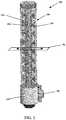
- FIG. 1is a perspective view of an example antenna system of the present disclosure.
- FIGS. 2A-2Ecollectively illustrate views of dipole element arrays and slot element arrays, as well as array assemblies comprising the same.
- FIG. 3is partial perspective view a core assembly of the example antenna system.
- FIG. 4is another partial perspective view a core assembly of the example antenna system.
- FIG. 5is a top down view of the example antenna system illustrating a core assembly.
- FIG. 6illustrates an exemplary computing device that may be used to implement embodiments according to the present technology.
- omni-directional antennasare desirable for a wide range of applications, as higher gain helps improve radio frequency (RF) link performance and reliability.
- Antenna gaincan be increased by reducing beamwidth in either the elevation plane, the azimuth plane, or both planes in combination. It will be understood that in general, the narrower the beamwidth, the higher the gain of the antenna.
- the present disclosureinvolves omni-directional orthogonally-polarized antenna systems for MIMO applications. The present disclosure provides several advantages over current and previous technologies referenced above, which will become readily apparent throughout this disclosure.
- the present disclosureis directed to a vertically oriented antenna system providing a complete 360 degree radiation pattern in the azimuth plane.
- the antenna systemcomprises two arrays of horizontally polarized radiating elements and two arrays of vertically polarized radiating elements.
- each array pairproduces an approximately 180-degree radiation pattern.
- some radiating elementsare disposed about a central axis in a common horizontal plane.
- arrays of common polarizationcan be separated by 180-degrees such that MIMO processing of signals to arrays of common polarization results in a radiation pattern that is substantially constant over 360-degrees in an azimuth plane.
- an example antenna system(hereinafter antenna system 100 ) comprises a radome housing 102 having a base 104 and a mounting plate 106 .
- the antenna system 100can be mounted in a vertical direction against a subordinate surface, such as a pole (no illustrated) using the mounting plate 106 . This orients the antenna system 100 substantially perpendicularly or orthogonal to the ground.
- the radome housing 102can be constructed from any plastic or polymeric, or other dielectric material.
- the antenna system 100comprises a four-port antenna (where each of four arrays are coupled to a feed) design that achieves a high-gain, omni-directional radiation pattern over a wide frequency range of operation.
- This antenna system 100has dual-polarization for maximum spectral efficiency, and employs two arrays, each polarization to exploit beamforming gain.
- These two arrays with vertical polarizationcomprise a plurality of dipole antenna elements. Dipole antenna elements are connected through a corporate feed network.
- arrays with horizontal polarizationcomprise slot antenna elements, which are connected through a corporate feed network.
- the antenna system 100 as described hereinadvantageously provides dual polarization (both vertical and horizontal) within a compact single package using four arrays (two vertically polarized and two horizontally polarized). Also, the antenna system 100 provides beamforming gain between two arrays of vertical polarization and two arrays of horizontal polarization.
- embodiments of the present technology as described hereinprovide uniform coverage in both vertical and horizontal polarization over 360 degrees using beamforming and polarization diversity.
- the designis based on a vertical array to achieve narrow beam-width in the elevation plane, and hence high antenna gain.
- An omni-pattern in the azimuthis achieved by coherently combining (also known as beamforming) two 180-degree beam patterns that are pointing in opposite directions, thereby realizing beamforming gain in both transmit and receive modes of operation.
- a first set of two arraysis vertically polarized, each with 180 degree azimuth beamwidth.
- a second set of two arraysis horizontally polarized, each with 180 degree azimuth beamwidth.
- vertical polarizationemploys vertically oriented dipole antennas.
- One example of horizontal polarizationemploys horizontally oriented slot antennas.
- the antenna system 100is not frequency dependent. That is, the antenna systems described herein are as frequency independent as possible.
- an example array assembly 108comprises a metal extrusion 110 , a dipole antenna element array 112 , and a slot element array 114 .
- the metal extrusion 110is a generally tubular member having a front surface 116 with slot openings, such as slot opening 118 .
- the dipole antenna element array 112comprises a printed circuit board 120 having a plurality of dipole elements such as dipole element 122 .
- the dipole element 122comprises a body 124 and a head 126 .
- the dipole element 122has a T-shaped configuration in some embodiments.
- the body 124 and the head 126 of the dipole element 122extend beyond an outer peripheral surface of the metal extrusion 110 when mounted to the metal extrusion 110 .
- the slot element array 114is positioned within an interior of the metal extrusion 110 as will be discussed in greater detail with reference to FIG. 5 .
- arrays of the antenna system 100are designed on a printed circuit board (PCB 120 ).
- PCB 120illustrates the dipole antenna element array 112 formed from the PCB 120 .
- the PCB 120is manufactured through cutting or printing to form the dipole elements such as the dipole element 122 .
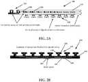
- FIG. 2Billustrates a rear plan view of the dipole antenna element array 112 which includes traces, such as trace 130 .
- Each dipole element 122is connected to a corporate feed 132 that is terminally connected to a feed point 134 .
- each of the dipole elementsis electrically coupled to the feed point 134 through the corporate feed 132 .
- the PCB 120can be manufactured from any suitable material that would be known to one of ordinary skill in the art.
- FIG. 2Cillustrates a front plan view of the dipole antenna element array 112 .
- a front surface 136 of the dipole antenna element array 112is coated with a metallic radiating material 137 that allows the dipole elements to radiate.
- Each of the dipole elements such as dipole element 122have a line of division 138 that separate two adjacent portions of metallic radiating material 137 .
- the line of division 138is not coated or printed with the metallic radiating material 137 . To be sure, the line of division 138 separates adjacent radiating portions of each dipole element 122 .
- the feed point 134 illustrated in FIG. 2Ais also illustrated in this view.
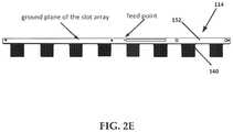
- FIG. 2Dis a front plan view of the slot element array 114 is a PCB 140 having a plurality of slot elements such as slot element 142 .
- Slot elementsextend as rectangular tabs that protrude from a body of the PCB 140 .
- the PCB 140 having slot elementsforms a saw-tooth pattern.
- the slot elementsare electrically coupled with a corporate feed 144 that terminates at a feed point 146 .
- the slot element 142comprises a coating of metallic radiating material 148 that allows the slot element 142 to radiate.
- the metallic radiating material 148is formed to have a substantially T-shaped configuration. That is, the radiating surface of the slot element 142 has a radiating portion (e.g., metallic radiating material) that is substantially T-shaped.
- the metallic radiating material 148is electrically coupled to a trace 150 that is in turn electrically coupled to the corporate feed 144 .
- the plurality of slot elements of the slot element array 114align with the slot openings (such as slot element 142 aligning with slot opening 118 in FIG. 1 ) of the front surface 116 of the metal extrusion 110 .
- FIG. 2Eis a rear plan view of a ground plane 152 of the slot element array 114 .
- the feed point 146is illustrated with respect to the ground plane 152 .
- PCB 140can be manufactured from any suitable material that would be known to one of ordinary skill in the art. In general, the metallic elements and traces provided on the PCBs 120 and 140 are created using any suitable printing process.
- One exemplary embodiment of a dipole antenna arrayuses printed traces on a PCB, one side which routes the corporate feed, and the other side is the array of printed dipole structures with the side routing to the corporate feed.
- An opposing side of the dipole arrayhas a feed point where radiation is launched by a MIMO radio and processor (see MIMO radio and processor 326 of FIG. 5 ).
- An exemplary embodiment of a slot antenna arraycomprises printed traces on a PCB, one side of which is the corporate feed routed to each radiating antenna element, and the other side is the ground plane, enclosed in a metal extrusion (e.g., tubular housing) with slot openings that coincide/align with the placement of the radiating antenna elements.
- a metal extrusione.g., tubular housing
- FIGS. 3-5collectively illustrate a core assembly 300 having two of the array assembly 108 combined together.
- a first array assembly 302one array assembly 108
- a second array assembly 304another array assembly 108
- fastenerssuch as fastener 305 .
- a dipole antenna element array 306 of the first array assembly 302is oriented such that the metallic surfaces of the dipole elements of the dipole antenna element array 306 are oriented in a first direction.
- the dipole antenna element array 307 of the second array assembly 304is oriented such that the metallic surfaces of the dipole elements of the dipole antenna element array 307 are oriented in a second direction that is opposite to the first direction. That is, the dipole antenna element array 306 and the dipole antenna element array 307 face away from one another which allows for the creation of a 180 degree beam pattern in the azimuth plane (see Ap of FIG. 1 ), referred to as a radiation pattern.
- FIG. 5is a top-down cross section view of the antenna system 100 that illustrates the orientation of various components.
- the first array assembly 302 and the second array assembly 304are illustrated in back-to-back orientation.
- a slot element array 308is positioned in a receiver slot 310 within the metal extrusion 312 .
- the receiver slot 310can include channels 314 and 316 formed into the sidewall of inner surface of the metal extrusion 312 .
- the dipole antenna element array 306is mounted to a rear surface 318 of the metal extrusion 312 and the dipole elements of the dipole antenna element array 306 extend outward of the metal extrusion 312 .
- the second array assembly 304also comprises a slot element array 322 .
- the second array assembly 304is configured similarly to the first array assembly 302 .
- the second array assembly 304comprises a metal extrusion 324 . When coupled, the metal extrusion 312 and the metal extrusion 324 form an octagonal structure.
- the dipole antenna element array 306 and the dipole antenna element array 307are positioned between the metal extrusion 312 of the first array assembly 302 and the metal extrusion 324 of the second array assembly 304 .
- the antenna systems disclosed hereinenable 180 degree beamwidths in an azimuth plane Ap for horizontal polarization. These 180 degree beamwidths are achieved using the first array assembly 302 and the second array assembly 304 coupled together in a center of the radome housing 102 that houses the two horizontally polarized arrays (e.g., slot element array 308 and slot element array 322 ).
- the metal extrusions 312 and 324provide isolation between a front and a back of the core assembly 300 , which is how the 180 degree beamwidths are achieved.
- 180 degree beamwidths in the azimuth plane Ap (see FIG. 1 ) for vertical polarizationare achieved by an outer enclosure 325 formed by the metal extrusions 312 and 324 .
- the core assembly 300comprises two arrays of horizontally polarized radiating elements (e.g., slot element array 308 and slot element array 322 ).
- the core assembly 300also comprises two arrays of vertically polarized radiating elements (e.g., dipole antenna element array 306 and dipole antenna element array 307 ) with each array having roughly 180-degree radiation pattern (see FIG. 5 ).
- the dipole antenna element array 306 and dipole antenna element array 307are disposed about a central axis Ca in a common horizontal plane.
- arrays of common polarizationare separated by 180-degrees, such that MIMO processing of signals (such as by a MIMO processor 326 ) received by the arrays of common polarization results in a radiation pattern 328 that is substantially constant over 360-degrees in azimuth Ap.
- the dipole antenna element array 306 and dipole antenna element array 307are aligned with a first plane P 1 .
- the slot element array 308 and slot element array 322are spaced apart from and are parallel with the first plane P 1 .
- slot element array 308is spaced apart from the first plane P 1 at a distance D 1 .
- Reference lineshave been illustrated for the first plane P 1 and a reference for the distance D 1 .
- the antenna systemcomprises a core assembly comprising two tubular metal extrusions.
- the two tubular metal extrusionsenclosing slot arrays 308 / 322 comprising a first pair of printed circuit boards each having slot elements that are horizontally polarized.
- the antenna systemfurther comprises dipole arrays 306 / 307 comprising a second pair of printed circuit boards each having dipole elements that are vertically polarized.
- the slot arrays and the dipole arrayscooperatively emit a radiation pattern that is substantially constant over 360-degrees in azimuth.
- FIG. 6illustrates an exemplary computer system 600 that may be used to implement some embodiments of the present invention.
- the computer system 600 of FIG. 6may be implemented in the contexts of the likes of computing systems, networks, servers, or combinations thereof.
- the computer system 600 of FIG. 6includes one or more processor units 610 and main memory 620 .
- Main memory 620stores, in part, instructions and data for execution by processor units 610 .
- Main memory 620stores the executable code when in operation, in this example.
- the computer system 600 of FIG. 6further includes a mass data storage 630 , portable storage device 640 , output devices 650 , user input devices 660 , a graphics display system 670 , and peripheral devices 680 .
- FIG. 6The components shown in FIG. 6 are depicted as being connected via a single bus 690 .
- the componentsmay be connected through one or more data transport means.
- Processor unit 610 and main memory 620is connected via a local microprocessor bus, and the mass data storage 630 , peripheral device(s) 680 , portable storage device 640 , and graphics display system 670 are connected via one or more input/output (I/O) buses.
- I/Oinput/output
- Mass data storage 630which can be implemented with a magnetic disk drive, solid state drive, or an optical disk drive, is a non-volatile storage device for storing data and instructions for use by processor unit 610 . Mass data storage 630 stores the system software for implementing embodiments of the present disclosure for purposes of loading that software into main memory 620 .
- Portable storage device 640operates in conjunction with a portable non-volatile storage medium, such as a flash drive, floppy disk, compact disk, digital video disc, or Universal Serial Bus (USB) storage device, to input and output data and code to and from the computer system 600 of FIG. 6 .
- a portable non-volatile storage mediumsuch as a flash drive, floppy disk, compact disk, digital video disc, or Universal Serial Bus (USB) storage device
- USBUniversal Serial Bus
- User input devices 660can provide a portion of a user interface.
- User input devices 660may include one or more microphones, an alphanumeric keypad, such as a keyboard, for inputting alphanumeric and other information, or a pointing device, such as a mouse, a trackball, stylus, or cursor direction keys.
- User input devices 660can also include a touchscreen.
- the computer system 600 as shown in FIG. 6includes output devices 650 . Suitable output devices 650 include speakers, printers, network interfaces, and monitors.
- Graphics display system 670include a liquid crystal display (LCD) or other suitable display device. Graphics display system 670 is configurable to receive textual and graphical information and processes the information for output to the display device. Peripheral devices 680 may include any type of computer support device to add additional functionality to the computer system.
- LCDliquid crystal display
- Peripheral devices 680may include any type of computer support device to add additional functionality to the computer system.
- the components provided in the computer system 600 of FIG. 6are those typically found in computer systems that may be suitable for use with embodiments of the present disclosure and are intended to represent a broad category of such computer components that are well known in the art.
- the computer system 600 of FIG. 6can be a personal computer (PC), hand held computer system, telephone, mobile computer system, workstation, tablet, phablet, mobile phone, server, minicomputer, mainframe computer, wearable, or any other computer system.
- the computermay also include different bus configurations, networked platforms, multi-processor platforms, and the like.
- Various operating systemsmay be used including UNIX, LINUX, WINDOWS, MAC OS, PALM OS, QNX ANDROID, IOS, CHROME, TIZEN, and other suitable operating systems.
- Some of the above-described functionsmay be composed of instructions that are stored on storage media (e.g., computer-readable medium).
- the instructionsmay be retrieved and executed by the processor.
- Some examples of storage mediaare memory devices, tapes, disks, and the like.
- the instructionsare operational when executed by the processor to direct the processor to operate in accord with the technology. Those skilled in the art are familiar with instructions, processor(s), and storage media.
- the computer system 600may be implemented as a cloud-based computing environment, such as a virtual machine operating within a computing cloud.
- the computer system 600may itself include a cloud-based computing environment, where the functionalities of the computer system 600 are executed in a distributed fashion.
- the computer system 600when configured as a computing cloud, may include pluralities of computing devices in various forms, as will be described in greater detail below.
- a cloud-based computing environmentis a resource that typically combines the computational power of a large grouping of processors (such as within web servers) and/or that combines the storage capacity of a large grouping of computer memories or storage devices.
- Systems that provide cloud-based resourcesmay be utilized exclusively by their owners or such systems may be accessible to outside users who deploy applications within the computing infrastructure to obtain the benefit of large computational or storage resources.
- the cloudis formed, for example, by a network of web servers that comprise a plurality of computing devices, such as the computer system 600 , with each server (or at least a plurality thereof) providing processor and/or storage resources.
- These serversmanage workloads provided by multiple users (e.g., cloud resource customers or other users).
- userse.g., cloud resource customers or other users.
- each userplaces workload demands upon the cloud that vary in real-time, sometimes dramatically. The nature and extent of these variations typically depends on the type of business associated with the user.
- Non-volatile mediainclude, for example, optical or magnetic disks, such as a fixed disk.
- Volatile mediainclude dynamic memory, such as system RAM.
- Transmission mediainclude coaxial cables, copper wire and fiber optics, among others, including the wires that comprise one embodiment of a bus.
- Transmission mediacan also take the form of acoustic or light waves, such as those generated during radio frequency (RF) and infrared (IR) data communications.
- RFradio frequency
- IRinfrared
- Common forms of computer-readable mediainclude, for example, a floppy disk, a flexible disk, a hard disk, magnetic tape, any other magnetic medium, a CD-ROM disk, digital video disk (DVD), any other optical medium, any other physical medium with patterns of marks or holes, a RAM, a PROM, an EPROM, an EEPROM, a FLASHEPROM, any other memory chip or data exchange adapter, a carrier wave, or any other medium from which a computer can read.
- a buscarries the data to system RAM, from which a CPU retrieves and executes the instructions.
- the instructions received by system RAMcan optionally be stored on a fixed disk either before or after execution by a CPU.
- Computer program code for carrying out operations for aspects of the present technologymay be written in any combination of one or more programming languages, including an object oriented programming language such as Java, Smalltalk, C++ or the like and conventional procedural programming languages, such as the “C” programming language or similar programming languages.
- the program codemay execute entirely on the user's computer, partly on the user's computer, as a stand-alone software package, partly on the user's computer and partly on a remote computer or entirely on the remote computer or server.
- the remote computermay be connected to the user's computer through any type of network, including a local area network (LAN) or a wide area network (WAN), or the connection may be made to an external computer (for example, through the Internet using an Internet Service Provider).
- LANlocal area network
- WANwide area network
- Internet Service Providerfor example, AT&T, MCI, Sprint, EarthLink, MSN, GTE, etc.
- These computer program instructionsmay also be stored in a computer readable medium that can direct a computer, other programmable data processing apparatus, or other devices to function in a particular manner, such that the instructions stored in the computer readable medium produce an article of manufacture including instructions which implement the function/act specified in the flowchart and/or block diagram block or blocks.
- the computer program instructionsmay also be loaded onto a computer, other programmable data processing apparatus, or other devices to cause a series of operational steps to be performed on the computer, other programmable apparatus or other devices to produce a computer implemented process such that the instructions which execute on the computer or other programmable apparatus provide processes for implementing the functions/acts specified in the flowchart and/or block diagram block or blocks.
- each block in the flowchart or block diagramsmay represent a module, segment, or portion of code, which comprises one or more executable instructions for implementing the specified logical function(s).
- the functions noted in the blockmay occur out of the order noted in the figures. For example, two blocks shown in succession may, in fact, be executed substantially concurrently, or the blocks may sometimes be executed in the reverse order, depending upon the functionality involved.
Landscapes
- Engineering & Computer Science (AREA)
- Computer Networks & Wireless Communication (AREA)
- Signal Processing (AREA)
- Variable-Direction Aerials And Aerial Arrays (AREA)
Abstract
Description
Claims (19)
Priority Applications (6)
| Application Number | Priority Date | Filing Date | Title |
|---|---|---|---|
| US16/284,121US11069986B2 (en) | 2018-03-02 | 2019-02-25 | Omni-directional orthogonally-polarized antenna system for MIMO applications |
| US17/323,679US11404796B2 (en) | 2018-03-02 | 2021-05-18 | Omni-directional orthogonally-polarized antenna system for MIMO applications |
| US17/827,360US11637384B2 (en) | 2018-03-02 | 2022-05-27 | Omni-directional antenna system and device for MIMO applications |
| US18/107,453US11936114B2 (en) | 2018-03-02 | 2023-02-08 | Omni-directional antenna system and device for MIMO applications |
| US18/420,616US12212070B2 (en) | 2018-03-02 | 2024-01-23 | Orthogonally-polarized antenna system and device for MIMO applications |
| US18/963,267US20250087902A1 (en) | 2018-03-02 | 2024-11-27 | High-gain, Omni-Directional Antenna Systems for MIMO Technologies |
Applications Claiming Priority (2)
| Application Number | Priority Date | Filing Date | Title |
|---|---|---|---|
| US201862637971P | 2018-03-02 | 2018-03-02 | |
| US16/284,121US11069986B2 (en) | 2018-03-02 | 2019-02-25 | Omni-directional orthogonally-polarized antenna system for MIMO applications |
Related Child Applications (1)
| Application Number | Title | Priority Date | Filing Date |
|---|---|---|---|
| US17/323,679ContinuationUS11404796B2 (en) | 2018-03-02 | 2021-05-18 | Omni-directional orthogonally-polarized antenna system for MIMO applications |
Publications (2)
| Publication Number | Publication Date |
|---|---|
| US20190273326A1 US20190273326A1 (en) | 2019-09-05 |
| US11069986B2true US11069986B2 (en) | 2021-07-20 |
Family
ID=67768781
Family Applications (6)
| Application Number | Title | Priority Date | Filing Date |
|---|---|---|---|
| US16/284,121Active2039-04-11US11069986B2 (en) | 2018-03-02 | 2019-02-25 | Omni-directional orthogonally-polarized antenna system for MIMO applications |
| US17/323,679ActiveUS11404796B2 (en) | 2018-03-02 | 2021-05-18 | Omni-directional orthogonally-polarized antenna system for MIMO applications |
| US17/827,360ActiveUS11637384B2 (en) | 2018-03-02 | 2022-05-27 | Omni-directional antenna system and device for MIMO applications |
| US18/107,453ActiveUS11936114B2 (en) | 2018-03-02 | 2023-02-08 | Omni-directional antenna system and device for MIMO applications |
| US18/420,616ActiveUS12212070B2 (en) | 2018-03-02 | 2024-01-23 | Orthogonally-polarized antenna system and device for MIMO applications |
| US18/963,267PendingUS20250087902A1 (en) | 2018-03-02 | 2024-11-27 | High-gain, Omni-Directional Antenna Systems for MIMO Technologies |
Family Applications After (5)
| Application Number | Title | Priority Date | Filing Date |
|---|---|---|---|
| US17/323,679ActiveUS11404796B2 (en) | 2018-03-02 | 2021-05-18 | Omni-directional orthogonally-polarized antenna system for MIMO applications |
| US17/827,360ActiveUS11637384B2 (en) | 2018-03-02 | 2022-05-27 | Omni-directional antenna system and device for MIMO applications |
| US18/107,453ActiveUS11936114B2 (en) | 2018-03-02 | 2023-02-08 | Omni-directional antenna system and device for MIMO applications |
| US18/420,616ActiveUS12212070B2 (en) | 2018-03-02 | 2024-01-23 | Orthogonally-polarized antenna system and device for MIMO applications |
| US18/963,267PendingUS20250087902A1 (en) | 2018-03-02 | 2024-11-27 | High-gain, Omni-Directional Antenna Systems for MIMO Technologies |
Country Status (2)
| Country | Link |
|---|---|
| US (6) | US11069986B2 (en) |
| WO (1) | WO2019168800A1 (en) |
Cited By (6)
| Publication number | Priority date | Publication date | Assignee | Title |
|---|---|---|---|---|
| US11251539B2 (en) | 2016-07-29 | 2022-02-15 | Airspan Ip Holdco Llc | Multi-band access point antenna array |
| US11289821B2 (en) | 2018-09-11 | 2022-03-29 | Air Span Ip Holdco Llc | Sector antenna systems and methods for providing high gain and high side-lobe rejection |
| US11404796B2 (en) | 2018-03-02 | 2022-08-02 | Airspan Ip Holdco Llc | Omni-directional orthogonally-polarized antenna system for MIMO applications |
| US11482789B2 (en) | 2013-06-28 | 2022-10-25 | Airspan Ip Holdco Llc | Ellipticity reduction in circularly polarized array antennas |
| US11626921B2 (en) | 2014-09-08 | 2023-04-11 | Airspan Ip Holdco Llc | Systems and methods of a Wi-Fi repeater device |
| US11888589B2 (en) | 2014-03-13 | 2024-01-30 | Mimosa Networks, Inc. | Synchronized transmission on shared channel |
Families Citing this family (28)
| Publication number | Priority date | Publication date | Assignee | Title |
|---|---|---|---|---|
| US9742077B2 (en)* | 2011-03-15 | 2017-08-22 | Intel Corporation | Mm-wave phased array antenna with beam tilting radiation pattern |
| US9179336B2 (en) | 2013-02-19 | 2015-11-03 | Mimosa Networks, Inc. | WiFi management interface for microwave radio and reset to factory defaults |
| US9930592B2 (en) | 2013-02-19 | 2018-03-27 | Mimosa Networks, Inc. | Systems and methods for directing mobile device connectivity |
| WO2014137370A1 (en) | 2013-03-06 | 2014-09-12 | Mimosa Networks, Inc. | Waterproof apparatus for cables and cable interfaces |
| US10742275B2 (en) | 2013-03-07 | 2020-08-11 | Mimosa Networks, Inc. | Quad-sector antenna using circular polarization |
| US9191081B2 (en) | 2013-03-08 | 2015-11-17 | Mimosa Networks, Inc. | System and method for dual-band backhaul radio |
| US9295103B2 (en) | 2013-05-30 | 2016-03-22 | Mimosa Networks, Inc. | Wireless access points providing hybrid 802.11 and scheduled priority access communications |
| US9001689B1 (en) | 2014-01-24 | 2015-04-07 | Mimosa Networks, Inc. | Channel optimization in half duplex communications systems |
| WO2017123558A1 (en) | 2016-01-11 | 2017-07-20 | Mimosa Networks, Inc. | Printed circuit board mounted antenna and waveguide interface |
| US10511074B2 (en) | 2018-01-05 | 2019-12-17 | Mimosa Networks, Inc. | Higher signal isolation solutions for printed circuit board mounted antenna and waveguide interface |
| KR102197412B1 (en)* | 2019-12-16 | 2020-12-31 | 한양대학교 산학협력단 | Millimeter Wave Band Array Antenna |
| WO2022046532A1 (en)* | 2020-08-28 | 2022-03-03 | Isco International, Llc | Method and system for polarization adjusting of orthogonally-polarized element pairs |
| US11799212B2 (en)* | 2021-10-04 | 2023-10-24 | Mirach Sas Di Annamaria Saveri & C. | Collinear antenna array |
| US11502404B1 (en) | 2022-03-31 | 2022-11-15 | Isco International, Llc | Method and system for detecting interference and controlling polarization shifting to mitigate the interference |
| US11476585B1 (en) | 2022-03-31 | 2022-10-18 | Isco International, Llc | Polarization shifting devices and systems for interference mitigation |
| US11476574B1 (en) | 2022-03-31 | 2022-10-18 | Isco International, Llc | Method and system for driving polarization shifting to mitigate interference |
| US11509071B1 (en) | 2022-05-26 | 2022-11-22 | Isco International, Llc | Multi-band polarization rotation for interference mitigation |
| US11509072B1 (en) | 2022-05-26 | 2022-11-22 | Isco International, Llc | Radio frequency (RF) polarization rotation devices and systems for interference mitigation |
| US11515652B1 (en) | 2022-05-26 | 2022-11-29 | Isco International, Llc | Dual shifter devices and systems for polarization rotation to mitigate interference |
| NL2032853B1 (en)* | 2022-08-25 | 2024-03-05 | Poynting Antennas Pty Ltd | Antenna dome assembly |
| US11956058B1 (en) | 2022-10-17 | 2024-04-09 | Isco International, Llc | Method and system for mobile device signal to interference plus noise ratio (SINR) improvement via polarization adjusting/optimization |
| US11985692B2 (en) | 2022-10-17 | 2024-05-14 | Isco International, Llc | Method and system for antenna integrated radio (AIR) downlink and uplink beam polarization adaptation |
| US11990976B2 (en) | 2022-10-17 | 2024-05-21 | Isco International, Llc | Method and system for polarization adaptation to reduce propagation loss for a multiple-input-multiple-output (MIMO) antenna |
| US11949489B1 (en) | 2022-10-17 | 2024-04-02 | Isco International, Llc | Method and system for improving multiple-input-multiple-output (MIMO) beam isolation via alternating polarization |
| US12219522B1 (en) | 2023-12-29 | 2025-02-04 | Isco International, Llc | Methods and systems for estimating the shape of an object generating passive intermodulation (PIM) interference |
| US12348285B1 (en) | 2023-12-29 | 2025-07-01 | Isco International, Llc | Methods and systems for detecting, measuring, and/or locating passive intermodulation (PIM) sources via beamforming |
| US12301315B1 (en) | 2023-12-29 | 2025-05-13 | Isco International, Llc | Methods and systems for detecting, measuring, and/or locating passive intermodulation sources via downlink (DL) signal injection |
| US12301298B1 (en) | 2023-12-29 | 2025-05-13 | Isco International, Llc | Methods and systems for locating interference sources via angle of arrival (AoA) |
Citations (300)
| Publication number | Priority date | Publication date | Assignee | Title |
|---|---|---|---|---|
| US2115761A (en) | 1935-02-28 | 1938-05-03 | Emi Ltd | Directional wireless aerial system |
| US2735993A (en) | 1956-02-21 | humphrey | ||
| US3182129A (en) | 1965-05-04 | Clark etalelectronic stethoscope | ||
| US4188633A (en) | 1978-01-26 | 1980-02-12 | Hazeltine Corporation | Phased array antenna with reduced phase quantization errors |
| US4402566A (en) | 1981-10-13 | 1983-09-06 | International Telephone & Telegraph Corporation | Field repairable electrical connector |
| USD273111S (en) | 1981-02-09 | 1984-03-20 | Canon Kabushiki Kaisha | Combined data input terminal and acoustic coupler |
| US4543579A (en) | 1983-03-29 | 1985-09-24 | Radio Research Laboratories, Ministry Of Posts And Telecommunications | Circular polarization antenna |
| US4562416A (en) | 1984-05-31 | 1985-12-31 | Sanders Associates, Inc. | Transition from stripline to waveguide |
| US4626863A (en) | 1983-09-12 | 1986-12-02 | Andrew Corporation | Low side lobe Gregorian antenna |
| US4835538A (en) | 1987-01-15 | 1989-05-30 | Ball Corporation | Three resonator parasitically coupled microstrip antenna array element |
| US4866451A (en) | 1984-06-25 | 1989-09-12 | Communications Satellite Corporation | Broadband circular polarization arrangement for microstrip array antenna |
| US4893288A (en) | 1986-12-03 | 1990-01-09 | Deutsche Thomson-Brandt Gmbh | Audible antenna alignment apparatus |
| US4903033A (en) | 1988-04-01 | 1990-02-20 | Ford Aerospace Corporation | Planar dual polarization antenna |
| US4986764A (en) | 1989-10-31 | 1991-01-22 | Amp Incorporated | High voltage lead assembly and connector |
| US5015195A (en) | 1990-03-13 | 1991-05-14 | Thomas & Betts Corporation | Plug and socket electrical connection assembly |
| US5087920A (en) | 1987-07-30 | 1992-02-11 | Sony Corporation | Microwave antenna |
| US5226837A (en) | 1990-11-16 | 1993-07-13 | Raychem Corporation | Environmentally protected connection |
| US5231406A (en) | 1991-04-05 | 1993-07-27 | Ball Corporation | Broadband circular polarization satellite antenna |
| US5285211A (en) | 1992-09-02 | 1994-02-08 | Unisys Corporation | Coaxial collinear element array antenna |
| USD346598S (en) | 1992-04-28 | 1994-05-03 | Coherent Communications Systems Corporation | Transceiver module for a table-top teleconferencing system |
| US5389941A (en) | 1992-02-28 | 1995-02-14 | Hughes Aircraft Company | Data link antenna system |
| USD355416S (en) | 1994-02-14 | 1995-02-14 | Coherent Communications Systems Corporation | Transceiver module for a table-top teleconferencing system |
| US5491833A (en) | 1993-12-27 | 1996-02-13 | Nec Corporation | Mobile radio communication system having radio zones of sector configurations and antenna selecting method employed therein |
| US5513380A (en) | 1992-09-23 | 1996-04-30 | Siemens Aktiengesellschaft | Mobile speed dependent handover techniques in hierarchical mobile radio networks |
| US5539361A (en) | 1995-05-31 | 1996-07-23 | The United States Of America As Represented By The Secretary Of The Air Force | Electromagnetic wave transfer |
| US5561434A (en) | 1993-06-11 | 1996-10-01 | Nec Corporation | Dual band phased array antenna apparatus having compact hardware |
| USD375501S (en) | 1994-01-28 | 1996-11-12 | American Phone Products, Inc. | Cup receptacle for telephone hand set |
| US5580264A (en) | 1994-08-09 | 1996-12-03 | Sumitomo Wiring Systems, Ltd. | Waterproofed connector |
| US5600338A (en) | 1995-02-27 | 1997-02-04 | Radian Corporation | Coaxial-collinear antenna |
| US5684495A (en) | 1995-08-30 | 1997-11-04 | Andrew Corporation | Microwave transition using dielectric waveguides |
| USD389575S (en) | 1996-10-22 | 1998-01-20 | Grasfield James A | Chestpiece of a stethoscope |
| US5724666A (en) | 1994-03-24 | 1998-03-03 | Ericsson Inc. | Polarization diversity phased array cellular base station and associated methods |
| US5742911A (en) | 1992-10-03 | 1998-04-21 | Motorola, Inc. | Sectorized cellular radio base station antenna |
| US5746611A (en) | 1996-07-15 | 1998-05-05 | The Whitaker Corporation | Electrical connector seal cap assembly |
| US5764696A (en) | 1995-06-02 | 1998-06-09 | Time Domain Corporation | Chiral and dual polarization techniques for an ultra-wide band communication system |
| US5797083A (en) | 1995-12-22 | 1998-08-18 | Hughes Electronics Corporation | Self-aligning satellite receiver antenna |
| US5831582A (en) | 1994-09-01 | 1998-11-03 | Easterisk Star, Inc. | Multiple beam antenna system for simultaneously receiving multiple satellite signals |
| US5966102A (en) | 1995-12-14 | 1999-10-12 | Ems Technologies, Inc. | Dual polarized array antenna with central polarization control |
| US5995063A (en) | 1998-08-13 | 1999-11-30 | Nortel Networks Corporation | Antenna structure |
| US6014372A (en) | 1997-12-08 | 2000-01-11 | Lockheed Martin Corp. | Antenna beam congruency system for spacecraft cellular communications system |
| US6057804A (en) | 1997-10-10 | 2000-05-02 | Tx Rx Systems Inc. | Parallel fed collinear antenna array |
| US6137449A (en) | 1996-09-26 | 2000-10-24 | Kildal; Per-Simon | Reflector antenna with a self-supported feed |
| US6140962A (en) | 1998-04-29 | 2000-10-31 | Hollandse Signaalapparaten B.V. | Antenna system |
| US6176739B1 (en) | 1997-02-20 | 2001-01-23 | The Whitaker Corporation | Sealed electrical conductor assembly |
| US6216266B1 (en) | 1999-10-28 | 2001-04-10 | Hughes Electronics Corporation | Remote control signal level meter |
| US6271802B1 (en) | 1997-04-14 | 2001-08-07 | Mems Optical, Inc. | Three dimensional micromachined electromagnetic device and associated methods |
| US6304762B1 (en) | 1996-12-23 | 2001-10-16 | Texas Instruments Incorporated | Point to multipoint communication system with subsectored upstream antennas |
| US20010033600A1 (en) | 2000-02-28 | 2001-10-25 | Golden Bridge Technology Inc. | Sectorized smart antenna system and method |
| USD455735S1 (en) | 1999-12-30 | 2002-04-16 | Telaxis Communications Corporation | Subscriber premises transceiver for a local multi-point distribution service |
| US6421538B1 (en) | 1993-12-22 | 2002-07-16 | Nokia Mobile Phones, Limited | Multi-mode radio telephone with velocity sensing mode selection |
| US20020102948A1 (en) | 2000-09-14 | 2002-08-01 | Stanwood Kenneth L. | System and method for wireless communication in a frequency division duplexing region |
| US20020159434A1 (en) | 2001-02-12 | 2002-10-31 | Eleven Engineering Inc. | Multipoint short range radio frequency system |
| US20030013452A1 (en) | 2001-07-13 | 2003-01-16 | Koninklijke Philips Electronics N.V. | Hierarchical cellular radio communication system |
| US20030027577A1 (en) | 2001-08-06 | 2003-02-06 | Metric Systems, Inc. | Wireless communication system control apparatus and method |
| US20030169763A1 (en) | 2002-03-07 | 2003-09-11 | Sunghyun Choi | Coexistence of stations capable of different modulation schemes in a wireless local area network |
| US20030224741A1 (en) | 2002-04-22 | 2003-12-04 | Sugar Gary L. | System and method for classifying signals occuring in a frequency band |
| US20030222831A1 (en) | 2002-05-31 | 2003-12-04 | Brian Dunlap | Three-dimensional spatial division multiplexing access (3D-SDMA) antenna system |
| US20040002357A1 (en) | 2002-06-25 | 2004-01-01 | Mathilde Benveniste | Directional antennas and wireless channel access |
| US20040029549A1 (en) | 2002-08-09 | 2004-02-12 | Fikart Josef Ludvik | Downconverter for the combined reception of linear and circular polarization signals from collocated satellites |
| US6716063B1 (en) | 2000-02-28 | 2004-04-06 | Pgs Exploration (Us), Inc. | Electrical cable insert |
| US20040110469A1 (en) | 2000-01-14 | 2004-06-10 | Judd Mano D. | Repeaters for wireless communication systems |
| US6754511B1 (en) | 2000-02-04 | 2004-06-22 | Harris Corporation | Linear signal separation using polarization diversity |
| US20040120277A1 (en) | 2002-11-18 | 2004-06-24 | Holur Balaji S. | Method and system for service portability across disjoint wireless networks |
| US20040155819A1 (en) | 2003-02-12 | 2004-08-12 | Smith Martin | Multibeam planar antenna structure and method of fabrication |
| US20040196812A1 (en) | 2003-04-07 | 2004-10-07 | Instant802 Networks Inc. | Multi-band access point with shared processor |
| US20040196813A1 (en) | 2003-04-07 | 2004-10-07 | Yoram Ofek | Multi-sector antenna apparatus |
| US20040242274A1 (en) | 2003-05-30 | 2004-12-02 | Corbett Christopher J. | Using directional antennas to mitigate the effects of interference in wireless networks |
| US20040240376A1 (en) | 2003-05-30 | 2004-12-02 | Agency For Science, Technology And Research | Method for reducing channel estimation error in an OFDM system |
| US20050012665A1 (en) | 2003-07-18 | 2005-01-20 | Runyon Donald L. | Vertical electrical downtilt antenna |
| US6847653B1 (en) | 1999-11-09 | 2005-01-25 | Interwave Communications International, Ltd. | Protocol for voice and data priority virtual channels in a wireless local area networking system |
| US6853336B2 (en) | 2000-06-21 | 2005-02-08 | International Business Machines Corporation | Display device, computer terminal, and antenna |
| US20050032479A1 (en) | 2003-07-28 | 2005-02-10 | Miller Karl A. | Signal classification methods for scanning receiver and other applications |
| USD501848S1 (en) | 2003-07-14 | 2005-02-15 | Sony Corporation | Transmitter |
| US20050058111A1 (en) | 2003-09-15 | 2005-03-17 | Pai-Fu Hung | WLAN device having smart antenna system |
| US6877277B2 (en) | 2000-12-10 | 2005-04-12 | Tiefenbach Bergbautechnik Gmbh | Coupling for explosion-proof connection of two electric line ends |
| US20050124294A1 (en) | 2003-11-17 | 2005-06-09 | Conextant Systems, Inc. | Wireless access point simultaneously supporting basic service sets on multiple channels |
| US20050143014A1 (en) | 2003-12-29 | 2005-06-30 | Intel Corporation | Antenna subsystem calibration apparatus and methods in spatial-division multiple-access systems |
| US20050195758A1 (en) | 2004-03-05 | 2005-09-08 | Interdigital Technology Corporation | Full duplex communication system using disjoint spectral blocks |
| US20050227625A1 (en) | 2004-03-25 | 2005-10-13 | Diener Neil R | User interface and time-shifted presentation of data in a system that monitors activity in a shared radio frequency band |
| US6962445B2 (en) | 2003-09-08 | 2005-11-08 | Adc Telecommunications, Inc. | Ruggedized fiber optic connection |
| US20050254442A1 (en) | 2004-05-13 | 2005-11-17 | Widefi, Inc. | Non-frequency translating repeater with detection and media access control |
| US20050271056A1 (en) | 2004-05-17 | 2005-12-08 | Matsushita Electronic Industrial Co., Ltd | Packet generation method, communication method, packet processing method and data structure |
| US20050275527A1 (en) | 2004-05-27 | 2005-12-15 | Lawrence Kates | Wireless repeater for sensor system |
| US20060025072A1 (en) | 2004-07-29 | 2006-02-02 | Lucent Technologies, Inc. | Extending wireless communication RF coverage inside building |
| US20060072518A1 (en) | 2000-07-10 | 2006-04-06 | Interdigital Technology Corporation | Code power measurement for dynamic channel allocation |
| US20060099940A1 (en) | 2004-11-10 | 2006-05-11 | Pfleging Gerald W | Method for changing the status of a mobile apparatus |
| US20060098592A1 (en) | 2002-12-16 | 2006-05-11 | Widefi, Inc. | Wireless network repeater |
| US20060132602A1 (en) | 2003-06-12 | 2006-06-22 | Denso Corporation | Image server, image acquisition device, and image display terminal |
| US20060132359A1 (en) | 2004-12-22 | 2006-06-22 | Tatung Co., Ltd. | Circularly polarized array antenna |
| US7075492B1 (en) | 2005-04-18 | 2006-07-11 | Victory Microwave Corporation | High performance reflector antenna system and feed structure |
| US20060172578A1 (en) | 2005-02-03 | 2006-08-03 | Pacific Wireless Manufacturing, Inc. | Low-cost weatherproof cable feedthrough |
| US20060187952A1 (en) | 2005-02-18 | 2006-08-24 | Avaya Technology Corp. | Methods and systems for providing priority access to 802.11 endpoints using DCF protocol |
| US20060211430A1 (en) | 2005-03-17 | 2006-09-21 | Persico Charles J | GPS position tracking method with variable updating rate for power conservation |
| US20060276073A1 (en) | 2005-04-07 | 2006-12-07 | Mcmurray William J | Accelerator |
| USD533899S1 (en) | 2003-09-18 | 2006-12-19 | Riso Kagaku Corporation | Hub for a printing paper roll |
| US20070001910A1 (en) | 2003-12-18 | 2007-01-04 | Fujitsu Limited | Antenna device, radio-wave receiver and radio-wave transmitter |
| US20070019664A1 (en) | 2000-11-03 | 2007-01-25 | At&T Corp. | Tiered contention multiple access (TCMA): a method for priority-based shared channel access |
| US7173570B1 (en) | 2004-07-12 | 2007-02-06 | Wensink Jan B | Cell phone tower antenna tilt and heading control |
| US20070035463A1 (en) | 2005-06-03 | 2007-02-15 | Sony Corporation | Antenna device, wireless communication apparatus using the same, and control method of controlling wireless communication apparatus |
| US7187328B2 (en) | 2002-10-25 | 2007-03-06 | National Institute Of Information And Communications Technology, Incorporated Administrative Agency | Antenna device |
| US20070060158A1 (en) | 2005-02-04 | 2007-03-15 | Toshiba American Research, Inc. | Channel partitioning forwireless local area networks |
| US7193562B2 (en) | 2004-11-22 | 2007-03-20 | Ruckus Wireless, Inc. | Circuit board having a peripheral antenna apparatus with selectable antenna elements |
| US7212162B2 (en) | 2003-11-22 | 2007-05-01 | Electronics And Telecommunications Research Institute | Horn antenna for circular polarization using planar radiator |
| US7212163B2 (en) | 2004-02-11 | 2007-05-01 | Sony Deutschland Gmbh | Circular polarized array antenna |
| EP1384285B1 (en) | 2001-04-11 | 2007-06-13 | Kyocera Wireless Corp. | Ferroelectric antenna and method for tuning same |
| US20070132643A1 (en) | 2005-12-14 | 2007-06-14 | Harris Corporation | Dual polarization antenna array with inter-element coupling and associated methods |
| US7245265B2 (en) | 2004-07-20 | 2007-07-17 | Vega Grieshaber Kg | Parabolic antenna of a level measuring instrument and level measuring instrument with a parabolic antenna |
| US20070173199A1 (en) | 2006-01-13 | 2007-07-26 | Amit Sinha | Systems and methods for wireless intrusion detection using spectral analysis |
| US20070173260A1 (en) | 2006-01-23 | 2007-07-26 | Love Robert T | Wireless communication network scheduling |
| US7253783B2 (en) | 2002-09-17 | 2007-08-07 | Ipr Licensing, Inc. | Low cost multiple pattern antenna for use with multiple receiver systems |
| US20070202809A1 (en) | 2006-02-28 | 2007-08-30 | Rotani, Inc. | Methods and apparatus for overlapping MIMO antenna physical sectors |
| US7264494B2 (en) | 2004-12-06 | 2007-09-04 | Weatherford/Lamb, Inc. | Electrical connector and socket assemblies |
| US20070210974A1 (en) | 2002-09-17 | 2007-09-13 | Chiang Bing A | Low cost multiple pattern antenna for use with multiple receiver systems |
| US20070223701A1 (en) | 2006-01-30 | 2007-09-27 | Motorola, Inc. | Method and apparatus for utilizing multiple group keys for secure communications |
| US20070238482A1 (en) | 2006-03-30 | 2007-10-11 | Giora Rayzman | Device, system and method of coordination among multiple transceivers |
| US7281856B2 (en) | 2005-08-15 | 2007-10-16 | Molex Incorporated | Industrial optical fiber connector assembly |
| US20070255797A1 (en) | 2006-04-28 | 2007-11-01 | Dunn Douglas L | Method for selecting an air interface using an access list on a multi-mode wireless device |
| US7292198B2 (en) | 2004-08-18 | 2007-11-06 | Ruckus Wireless, Inc. | System and method for an omnidirectional planar antenna apparatus with selectable elements |
| US20070268848A1 (en) | 2006-05-18 | 2007-11-22 | Qualcomm Incorporated | Half-duplex communication in a frequency division duplex system |
| US7306485B2 (en) | 2006-03-01 | 2007-12-11 | Hirose Electric Co., Ltd. | Waterproof device |
| US7316583B1 (en) | 2006-08-22 | 2008-01-08 | Mencom Corporation | Field wireable network plug |
| US7324057B2 (en) | 2005-09-26 | 2008-01-29 | Gideon Argaman | Low wind load parabolic dish antenna fed by crosspolarized printed dipoles |
| USD566698S1 (en) | 2006-03-03 | 2008-04-15 | Lite-On Technology Corp. | Wireless network device |
| US7362236B2 (en) | 2004-12-06 | 2008-04-22 | Itron, Inc. | Mobile utility data collection system with voice technology, such as for data collection relating to an electric, gas, or water utility |
| US7369095B2 (en) | 2000-06-09 | 2008-05-06 | Thomson Licensing | Source-antennas for transmitting/receiving electromagnetic waves |
| US20080109051A1 (en) | 2006-11-06 | 2008-05-08 | Tim John Splinter | System and method for operating a wireless medical device interrogation network |
| US20080112380A1 (en) | 2006-11-10 | 2008-05-15 | Fischer Matthew J | Serial clear to send (cts) to self (cts2self) messaging procedure |
| US7380984B2 (en) | 2005-03-28 | 2008-06-03 | Tokyo Electron Limited | Process flow thermocouple |
| US20080192707A1 (en) | 2006-06-13 | 2008-08-14 | Texas Instruments Incorporated | Reducing collisions in beamforming wireless systems |
| US20080218418A1 (en) | 2007-03-05 | 2008-09-11 | Gillette Marlin R | Patch antenna including septa for bandwidth conrol |
| US20080231541A1 (en) | 2004-11-15 | 2008-09-25 | Tasuku Teshirogi | Circularly Polarized Antenna and Radar Device Using the Same |
| US20080242342A1 (en) | 2007-03-26 | 2008-10-02 | Broadcom Corporation | Rf filtering at very high frequencies for substrate communications |
| US7431602B2 (en) | 2005-04-21 | 2008-10-07 | Dsm & T Co., Inc. | Electrical connector |
| US20090046673A1 (en) | 2007-08-17 | 2009-02-19 | Oren Kaidar | Method and apparatus for improved dual channel operation and access point discovery in wireless communication networks |
| US20090052362A1 (en) | 2004-05-12 | 2009-02-26 | Meier Robert C | Power-save apparatus for 802.11 multicast paging applications |
| US20090051597A1 (en) | 2007-08-23 | 2009-02-26 | Research In Motion Limited | Antenna, and associated method, for a multi-band radio device |
| US7498996B2 (en) | 2004-08-18 | 2009-03-03 | Ruckus Wireless, Inc. | Antennas with polarization diversity |
| US7498896B2 (en) | 2007-04-27 | 2009-03-03 | Delphi Technologies, Inc. | Waveguide to microstrip line coupling apparatus |
| US20090059794A1 (en) | 2007-08-29 | 2009-03-05 | Skypilot Networks, Inc. | Method and apparatus for wiFi long range radio coordination |
| US20090075606A1 (en) | 2005-06-24 | 2009-03-19 | Victor Shtrom | Vertical multiple-input multiple-output wireless antennas |
| US7507105B1 (en) | 2007-07-17 | 2009-03-24 | Ventek, Llc | Hazardous area coupler device |
| US20090096699A1 (en) | 2007-10-16 | 2009-04-16 | The Hong Kong University Of Science And Technology | Compact 3-port orthogonally polarized mimo antennas |
| US7522095B1 (en) | 2005-07-15 | 2009-04-21 | Lockheed Martin Corporation | Polygonal cylinder array antenna |
| US7542717B2 (en) | 1995-02-22 | 2009-06-02 | Global Communications, Inc. | Satellite broadcast receiving and distribution system |
| US7581976B2 (en) | 2004-06-02 | 2009-09-01 | Gl Tool & Manufacturing Company Inc. | Bulkhead connector |
| US7586891B1 (en) | 2005-12-08 | 2009-09-08 | The United States Of America As Represented By The Secretary Of The Army | Communication network optimization tool |
| US20090233475A1 (en) | 2008-03-11 | 2009-09-17 | Ametek Scp, Inc. | Waterproof gigabit ethernet connector |
| US20090232026A1 (en) | 2007-05-21 | 2009-09-17 | Arrowspan, Inc. | Multi-radio wireless mesh network solutions |
| US7616959B2 (en) | 2004-07-19 | 2009-11-10 | Rotani, Inc. | Method and apparatus for shaped antenna radiation patterns |
| US20090291690A1 (en) | 2008-05-22 | 2009-11-26 | Ntt Docomo, Inc. | Femtocell Channel Assignment and Power Control for Improved Femtocell Coverage and Efficient Cell Search |
| US20090315792A1 (en) | 2006-08-03 | 2009-12-24 | Norihiro Miyashita | Antenna apparatus utilizing small loop antenna element having munute length and two feeding points |
| US20100029282A1 (en) | 2008-07-31 | 2010-02-04 | Qualcomm Incorporated | Resource partitioning in heterogeneous access point networks |
| US20100034191A1 (en) | 2006-10-12 | 2010-02-11 | Koninklijke Philips Electronics N. V. | Method and system for time synchronization in a sensor network |
| US20100039340A1 (en) | 2007-10-19 | 2010-02-18 | Kenneth Brown | Rf waveform modulation apparatus and method |
| US20100046650A1 (en) | 2007-01-12 | 2010-02-25 | Joengren George | Method for Precoding Using a Block Diagonal Matrix |
| US7675473B2 (en) | 2005-10-14 | 2010-03-09 | Vega Grieshaber Kg | Parabolic antenna with rinsing connection |
| US20100067505A1 (en) | 2003-11-10 | 2010-03-18 | Yaron Fein | Performance of a Wireless Communication System |
| US20100085950A1 (en) | 2008-10-07 | 2010-04-08 | Masahiro Sekiya | Wireless communication device and wireless communication method |
| US20100091818A1 (en) | 2008-10-14 | 2010-04-15 | Sen Indranil S | Dynamic channel evaluation in wireless communication device |
| US20100103066A1 (en) | 2004-08-18 | 2010-04-29 | Victor Shtrom | Dual Band Dual Polarization Antenna Array |
| US20100103065A1 (en) | 2004-08-18 | 2010-04-29 | Victor Shtrom | Dual Polarization Antenna with Increased Wireless Coverage |
| US20100136978A1 (en) | 2008-12-03 | 2010-06-03 | Electronics And Telecommunications Research | Method for handoff of portable terminal between heterogeneous wireless networks |
| US20100151877A1 (en) | 2008-12-16 | 2010-06-17 | Seung-Hwan Lee | Smart radio communication system and method of operating the same |
| US20100167719A1 (en) | 2005-06-29 | 2010-07-01 | Koninklijke Philips Electronics N.V. | Method and apparatus for delegating signal quality handover measuring of a user equipment in wireless communication to a neighbouring user equipment |
| US20100171675A1 (en) | 2007-06-06 | 2010-07-08 | Carmen Borja | Dual-polarized radiating element, dual-band dual-polarized antenna assembly and dual-polarized antenna array |
| US20100171665A1 (en) | 2007-05-17 | 2010-07-08 | Omron Corporation | Array antenna |
| US20100189005A1 (en) | 2009-01-27 | 2010-07-29 | Bertani Torquato | Method for automatic selection of a mac protocol for a communication system and related system |
| US20100202613A1 (en) | 2009-01-07 | 2010-08-12 | Qualcomm Incorporated | Packet bundling at the pdcp layer with ciphering on the pdcp sdu |
| US20100210147A1 (en) | 2009-02-13 | 2010-08-19 | Itt Manufacturing Enterprises, Inc. | Connectors to connect electronic devices |
| US20100216412A1 (en) | 2009-02-26 | 2010-08-26 | Broadcom Corporation | Configurable transceiver and methods for use therewith |
| US20100225529A1 (en) | 2009-03-05 | 2010-09-09 | Southwest Research Institute | Unswitched, ultra low power, long range radar system |
| US20100238083A1 (en) | 2009-03-20 | 2010-09-23 | Rammohan Malasani | Long-distance wireless-lan directional antenna alignment |
| US20100304680A1 (en) | 2009-05-29 | 2010-12-02 | Motorola, Inc. | Method and apparatus for utilizing a transmission polarization to reduce interference with a primary incumbent signal |
| US20100311321A1 (en) | 2009-06-09 | 2010-12-09 | The Directv Group, Inc. | Omnidirectional switchable broadband wireless antenna system |
| US20100315307A1 (en) | 2009-06-12 | 2010-12-16 | Andrew Llc | Radome and Shroud Enclosure for Reflector Antenna |
| US20100322219A1 (en) | 2009-06-05 | 2010-12-23 | Broadcom Corporation | Management frame directed cluster assignment within multiple user, multiple access, and/or MIMO wireless communications |
| US7857523B2 (en) | 2008-06-04 | 2010-12-28 | Hirose Electric Co., Ltd. | Waterproof connector having movable connector member and waterproof apparatus using the same |
| US20110006956A1 (en) | 2006-06-27 | 2011-01-13 | Mccown James Charles | Passive parabolic antenna, wireless communication system and method of boosting signal strength of a subscriber module antenna |
| US20110028097A1 (en) | 2009-07-29 | 2011-02-03 | Gokhan Memik | Hierarchical spectrum sensing for cognitive radios |
| US20110032159A1 (en) | 2009-08-04 | 2011-02-10 | Min-Chung Wu | Antenna Apparatus with Adaptive Polarization Switching Function |
| US20110044186A1 (en) | 2009-08-19 | 2011-02-24 | Samsung Electronics Co. Ltd. | Apparatus and method for adaptively generating channel quality indicator in wireless communication system |
| US7929914B2 (en) | 2004-03-31 | 2011-04-19 | The Invention Science Fund I, Llc | Mote networks using directional antenna techniques |
| US20110090129A1 (en) | 2008-02-04 | 2011-04-21 | Commonwealth Scientific And Industrial Research Or | Circularly Polarised Array Antenna |
| US20110103309A1 (en) | 2009-10-30 | 2011-05-05 | Interdigital Patent Holdings, Inc. | Method and apparatus for concurrently processing multiple radio carriers |
| US20110111715A1 (en) | 2009-11-06 | 2011-05-12 | Viasat, Inc. | Outdoor unit installation aid feature |
| US20110112717A1 (en) | 2009-11-11 | 2011-05-12 | Benjamin Resner | Methods and Apparatus for Automatic Internet Logging and Social Comparison of Vehicular Driving Behavior |
| US20110133996A1 (en) | 2009-12-08 | 2011-06-09 | Motorola, Inc. | Antenna feeding mechanism |
| US20110172916A1 (en) | 2010-01-14 | 2011-07-14 | Qualcomm Incorporated | Mobile Device Positioning In A Constrained Environment |
| US20110170424A1 (en) | 2010-01-08 | 2011-07-14 | Saeid Safavi | Apparatus and methods for interference mitigation and coordination in a wireless network |
| US20110182277A1 (en) | 2005-12-29 | 2011-07-28 | Nir Shapira | Method, apparatus and system of spatial division multiple access communication in a wireless local area network |
| US20110182260A1 (en) | 2010-01-26 | 2011-07-28 | Georgia Tech Research Corporation | Systems and methods for achieving high data-rate wireless communication |
| US20110194644A1 (en) | 2010-02-10 | 2011-08-11 | Yong Liu | Transmission Protection For Wireless Communications |
| US20110206012A1 (en) | 2010-02-22 | 2011-08-25 | Sungkyunkwan University Foundation For Corporate Collaboration | Handover method and apparatus for providing mobile iptv service over heterogeneous wireless communication networks |
| US20110241969A1 (en) | 2008-12-12 | 2011-10-06 | Nanyang Technological University | Grid array antennas and an integration structure |
| US20110243291A1 (en) | 2010-03-31 | 2011-10-06 | Andrew Llc | Synchronous transfer of streaming data in a distributed antenna system |
| US20110256874A1 (en) | 2007-04-18 | 2011-10-20 | Masao Hayama | Handoff method between different systems and wireless terminal |
| US8069465B1 (en) | 2011-01-05 | 2011-11-29 | Domanicom Corp. | Devices, systems, and methods for managing multimedia traffic across a common wireless communication network |
| US20110291914A1 (en) | 2010-05-27 | 2011-12-01 | Andrew Llc | Segmented antenna reflector with shield |
| US20120008542A1 (en) | 2009-03-20 | 2012-01-12 | Luke Koleszar | Distributed Ad Hoc Mesh Network Protocol for Underground Mine and Hazardous Area Communications |
| US20120040700A1 (en) | 2010-02-12 | 2012-02-16 | Interdigital Patent Holdings, Inc. | Group paging for machine-type communications |
| US20120057533A1 (en) | 2010-09-03 | 2012-03-08 | Nokia Corporation | Resource sharing between secondary networks |
| US20120093091A1 (en) | 2010-10-17 | 2012-04-19 | Industrial Technology Research Institute | Method and system for extended service channel access on demand in an alternating wireless channel access environment |
| US20120115487A1 (en) | 2009-06-18 | 2012-05-10 | Nicolas Josso | Quality Control for Inter-Cell Handover |
| US20120134280A1 (en) | 2010-11-29 | 2012-05-31 | Rosemount, Inc. | Wireless sensor network access point and device rf spectrum analysis system and method |
| US20120140651A1 (en) | 2010-12-01 | 2012-06-07 | Deutsche Telekom Ag | System support for accessing and switching among multiple wireless interfaces on mobile devices |
| US20120200449A1 (en) | 2011-02-09 | 2012-08-09 | Raytheon Company- Waltham, MA | Adaptive electronically steerable array (aesa) system for multi-band and multi-aperture operation and method for maintaining data links with one or more stations in different frequency bands |
| US20120238201A1 (en) | 2009-04-17 | 2012-09-20 | Lingna Holdings Pte., Llc | Exploiting multiple antennas for spectrum sensing in cognitive radio networks |
| US8275265B2 (en) | 2010-02-15 | 2012-09-25 | Corning Cable Systems Llc | Dynamic cell bonding (DCB) for radio-over-fiber (RoF)-based networks and communication systems and related methods |
| US20120263145A1 (en) | 2011-04-13 | 2012-10-18 | Interdigital Patent Holdings, Inc | Method and apparatus for small cell discovery in heterogeneous networks |
| US20120282868A1 (en) | 2011-05-05 | 2012-11-08 | OMNI-WiFi, LLC | Pyramidal Antenna Apparatus |
| US20120299789A1 (en) | 2010-01-29 | 2012-11-29 | Daniel Orban | Circularly polarized antenna and feeding network |
| US20120314634A1 (en) | 2011-06-09 | 2012-12-13 | Symbol Technologies, Inc. | Client bridge between wired and wireless communication networks |
| US20130003645A1 (en) | 2011-06-15 | 2013-01-03 | Nir Shapira | Repeater for enhancing performance of a wireless lan network |
| US20130005350A1 (en) | 2011-06-30 | 2013-01-03 | Cable Television Laboratories, Inc. | Optimizing network access |
| USD674787S1 (en) | 2011-10-18 | 2013-01-22 | Yokogawa Electric Corporation | Field wireless access point |
| US20130023216A1 (en) | 2011-07-21 | 2013-01-24 | Microsoft Corporation | Cloud service for optimizing white-space networks coexistence |
| US20130044028A1 (en) | 2011-08-17 | 2013-02-21 | CBF Networks, Inc. | Intelligent backhaul radio and antenna system |
| US8385305B1 (en) | 2012-04-16 | 2013-02-26 | CBF Networks, Inc | Hybrid band intelligent backhaul radio |
| US20130064161A1 (en) | 2011-09-14 | 2013-03-14 | Cisco Technology, Inc. | Group Addressing for Multicast Transmissions for Power Savings at Physical Layer |
| US20130082899A1 (en) | 2011-09-30 | 2013-04-04 | Kabushiki Kaisha Toshiba | High-frequency line-waveguide converter |
| US20130095747A1 (en) | 2011-10-17 | 2013-04-18 | Mehran Moshfeghi | Method and system for a repeater network that utilizes distributed transceivers with array processing |
| US8425260B2 (en) | 2010-05-06 | 2013-04-23 | Leviton Manufacturing Co., Inc. | High speed data communications cable having reduced susceptibility to modal alien crosstalk |
| US20130128858A1 (en) | 2010-08-04 | 2013-05-23 | Nokia Corporation | Resolution method and apparatus for simultaneous transmission and receiving contention in a device-to-device cellular reuse system |
| US8482478B2 (en) | 2008-11-12 | 2013-07-09 | Xirrus, Inc. | MIMO antenna system |
| US20130176902A1 (en) | 2012-01-09 | 2013-07-11 | Qualcomm Incorporated | System and method of communication using distributed channel access parameters |
| US20130182652A1 (en) | 2012-01-13 | 2013-07-18 | Fei Tong | Methods and apparatus in a wireless network |
| US20130195081A1 (en) | 2011-09-29 | 2013-08-01 | Qualcomm Incorporated | Collision reduction mechanisms for wireless communication networks |
| US20130210457A1 (en) | 2010-03-01 | 2013-08-15 | Andrew Llc | System and method for location of mobile devices in confined environments |
| US8515434B1 (en) | 2010-04-08 | 2013-08-20 | Sprint Spectrum L.P. | Methods and devices for limiting access to femtocell radio access networks |
| US8515495B2 (en) | 2009-02-27 | 2013-08-20 | Nokia Siemens Networks Oy | MIMO communication system |
| US20130223398A1 (en) | 2010-11-25 | 2013-08-29 | Nokia Corporation | Network assisted sensing on a shared band for local communications |
| US20130234898A1 (en) | 2012-03-06 | 2013-09-12 | City University Of Hong Kong | Aesthetic dielectric antenna and method of discretely emitting radiation pattern using same |
| US20130271319A1 (en) | 2012-04-12 | 2013-10-17 | Alan Trerise | Method and system for aiming and aligning self-installed broadcast signal receivers |
| US20130286950A1 (en) | 2010-12-06 | 2013-10-31 | ST-Ericsson Semiconductor (Beijing) Co. Ltd. | Method and Mobile Terminal for Dealing with PS Domain Service and Realizing PS Domain Service Request |
| US20130286959A1 (en) | 2012-04-30 | 2013-10-31 | Interdigital Patent Holdings, Inc. | Method and apparatus for supporting coordinated orthogonal block-based resource allocation (cobra) operations |
| US20130288735A1 (en) | 2011-01-07 | 2013-10-31 | Sony Corporation | System and method for wireless network management |
| US20130301438A1 (en) | 2012-05-11 | 2013-11-14 | Qinghua Li | Apparatus and method to establish a device-to-device (d2d) connection in a 3gpp-lte network using a distributed channel scan |
| USD694740S1 (en) | 2011-10-25 | 2013-12-03 | Costa Apostolakis | Wireless communications gateway |
| US20130322276A1 (en) | 2012-05-31 | 2013-12-05 | Interdigital Patent Holdings, Inc. | Device-to-device (d2d) link adaptation |
| US20130322413A1 (en) | 2012-05-31 | 2013-12-05 | Interdigital Patent Holdings, Inc. | Methods to enable scheduling and control of direct link communication in cellular communication systems |
| US20140024328A1 (en) | 2012-07-19 | 2014-01-23 | Tensorcom, Inc. | Method and Apparatus for the Alignment of a 60 GHz Endfire Antenna |
| US20140051357A1 (en) | 2011-02-25 | 2014-02-20 | Research In Motion Limited | Determining device in-range proximity |
| US20140098748A1 (en) | 2012-10-09 | 2014-04-10 | Cisco Technology, Inc. | Dynamic Bandwidth Selection for Wide Bandwidth Wireless Local Area Networks |
| US20140113676A1 (en) | 2011-05-06 | 2014-04-24 | Nokia Siemens Networks Oy | Arrangements for Controlling Antennas |
| US20140145890A1 (en) | 2012-11-27 | 2014-05-29 | Laird Technologies, Inc. | Antenna Assemblies Including Dipole Elements and Vivaldi Elements |
| US20140154895A1 (en) | 2012-07-05 | 2014-06-05 | Leviton Manufacturing Co., Inc. | High density high speed data communications connector |
| US20140185494A1 (en) | 2011-12-27 | 2014-07-03 | Xue Yang | Method and system for coexistence of multiple collocated radios |
| US20140191918A1 (en) | 2013-01-07 | 2014-07-10 | Arcadyan Technology Corporation | Omnidirectional antenna |
| US8777660B2 (en) | 2011-07-26 | 2014-07-15 | Tyco Electronics Amp Italia Srl | Electric connector with a cable clamping portion |
| US20140198867A1 (en) | 2013-01-16 | 2014-07-17 | Broadcom Corporation | Communication System Having Cross Polarization Interference Cancellation (XPIC) |
| US20140206322A1 (en) | 2013-01-18 | 2014-07-24 | Telefonaktiebolaget L M Ericsson (Publ) | Network-assisted ue detection in direct mode ue-to-ue communication |
| US8792759B2 (en) | 2011-04-11 | 2014-07-29 | Advanced Fiber Products, LLC | Gigabit wet mate active cable |
| US20140225788A1 (en) | 2013-02-08 | 2014-08-14 | Ubiquiti Networks, Inc. | Radio system for long-range high speed wireless communication |
| US20140235244A1 (en) | 2013-02-19 | 2014-08-21 | Brian L. Hinman | Systems and Methods for Directing Mobile Device Connectivity |
| US20140233613A1 (en) | 2013-02-19 | 2014-08-21 | Jaime Fink | WiFi Management Interface for Microwave Radio and Reset to Factory Defaults |
| US8827729B2 (en) | 2010-04-09 | 2014-09-09 | Delphi International Operations Luxembourg S.A.R.L. | Electrical connector system |
| US20140254700A1 (en) | 2013-03-08 | 2014-09-11 | Brian L. Hinman | System and Method for Dual-Band Backhaul Radio |
| US20140253378A1 (en) | 2013-03-07 | 2014-09-11 | Brian L. Hinman | Quad-Sector Antenna Using Circular Polarization |
| US20140253402A1 (en) | 2013-03-06 | 2014-09-11 | Brian L. Hinman | Enclosure for Radio, Parabolic Dish Antenna, and Side Lobe Shields |
| US20140256166A1 (en) | 2013-03-06 | 2014-09-11 | Mimosa Networks, Inc. | Waterproof Apparatus for Cables and Cable Interfaces |
| US8836601B2 (en) | 2013-02-04 | 2014-09-16 | Ubiquiti Networks, Inc. | Dual receiver/transmitter radio devices with choke |
| US8848389B2 (en) | 2008-09-25 | 2014-09-30 | Sony Corporation | Transmission device and method for manufacturing same, and wireless transmission device and wireless transmission method |
| US8870069B2 (en) | 2012-08-22 | 2014-10-28 | Symbol Technologies, Inc. | Co-located antenna arrangement |
| US20140320377A1 (en) | 2013-04-27 | 2014-10-30 | Commsky Technologies, Inc. | Multi-channel multi-sector smart antenna system |
| US20140320306A1 (en) | 2011-11-24 | 2014-10-30 | Nisko Telematics 2012 Limited Partnership | Methods and systems of reading utility meters and methods and systems of transmitting utility meter data |
| US20140328238A1 (en) | 2011-11-24 | 2014-11-06 | Lg Electronics Inc. | Grouping-based data transceiving method in wireless lan system and apparatus for supporting same |
| US20140341013A1 (en) | 2013-05-16 | 2014-11-20 | Annop Kumar | SYSTEM AND METHOD FOR CREATING LOGICAL RADIO LINK CONTROL (RLC) AND MEDIUM ACCESS CONTROL (MAC) PROTOCOL DATA UNITS (PDUs) IN MOBILE COMMUNICATION SYSTEM |
| US20140355584A1 (en) | 2013-05-30 | 2014-12-04 | Mimosa Networks, Inc. | Wireless Access Points Providing Hybrid 802.11 and Scheduled Priority Access Communications |
| WO2014193394A1 (en) | 2013-05-30 | 2014-12-04 | Mimosa Networks, Inc. | Wireless access points providing hybrid 802.11 and scheduled priority access communications |
| US20150002335A1 (en) | 2013-06-28 | 2015-01-01 | Mimosa Networks, Inc. | Ellipticity reduction in circularly polarized array antennas |
| US20150002354A1 (en) | 2012-01-18 | 2015-01-01 | Thales Holdings Uk Plc | Horn antenna |
| US8935122B2 (en) | 2010-12-03 | 2015-01-13 | US Tower Corp. | Alignment detection device |
| US20150015435A1 (en) | 2012-03-14 | 2015-01-15 | Zte (Usa) Inc. | Receiver signal strength indicator meter for automatic antenna alignment in indoor and outdoor mount applications |
| US9001689B1 (en) | 2014-01-24 | 2015-04-07 | Mimosa Networks, Inc. | Channel optimization in half duplex communications systems |
| US9019874B2 (en) | 2012-06-27 | 2015-04-28 | Nokia Corporation | Method, apparatus, and computer program product for resolving hidden node in synchronized DCF based channel access |
| US20150116177A1 (en) | 2013-10-29 | 2015-04-30 | Radio Frequency Systems, Inc. | Vertically And Horizontally Polarized Omnidirectional Antennas And Related Methods |
| US20150156642A1 (en) | 2013-12-04 | 2015-06-04 | Css Antenna, Llc | Canister antenna producing a pseudo-omni radiation pattern for mitigating passive intermodulation (pim) |
| US9077071B2 (en) | 2004-08-18 | 2015-07-07 | Ruckus Wireless, Inc. | Antenna with polarization diversity |
| US9107134B1 (en) | 2011-01-12 | 2015-08-11 | Sprint Communications Company L.P. | Edge sector handoff determination |
| US20150256275A1 (en) | 2014-03-05 | 2015-09-10 | Mimosa Networks, Inc. | System and method for aligning a radio using an automated audio guide |
| US20150263816A1 (en) | 2014-03-13 | 2015-09-17 | Mimosa Networks, Inc. | Simultaneous transmission on shared channel |
| US20150321017A1 (en) | 2014-05-12 | 2015-11-12 | Micron Devices Llc | Remote rf power system with low profile transmitting antenna |
| CN303453662S (en) | 2015-11-18 | |||
| USD752566S1 (en) | 2014-09-12 | 2016-03-29 | Mimosa Networks, Inc. | Wireless repeater |
| US20160119018A1 (en) | 2013-06-18 | 2016-04-28 | Telefonaktiebolaget L M Ericsson (Publ) | Leakage Cancellation For a Multiple-Input Multiple-Output Transceiver |
| US20160149634A1 (en) | 2014-11-24 | 2016-05-26 | Vivint, Inc. | Quad-polarized sector and dimensional antenna for high throughput |
| US20160149635A1 (en) | 2014-09-08 | 2016-05-26 | Mimosa Networks, Inc. | Wi-Fi Hotspot Repeater |
| US9391375B1 (en) | 2013-09-27 | 2016-07-12 | The United States Of America As Represented By The Secretary Of The Navy | Wideband planar reconfigurable polarization antenna array |
| US20160211583A1 (en) | 2015-01-20 | 2016-07-21 | Electronics And Telecommunications Research Institute | Controlled reception pattern antenna |
| US9407012B2 (en) | 2010-09-21 | 2016-08-02 | Ruckus Wireless, Inc. | Antenna with dual polarization and mountable antenna elements |
| US9431702B2 (en) | 2011-05-24 | 2016-08-30 | Xirrus, Inc. | MIMO antenna system having beamforming networks |
| US20170048647A1 (en) | 2014-05-06 | 2017-02-16 | Lg Electronics Inc. | Method for device-to-device (d2d) operation executed by terminal in wireless communication system and terminal using the method |
| US9577340B2 (en) | 2014-03-18 | 2017-02-21 | Peraso Technologies Inc. | Waveguide adapter plate to facilitate accurate alignment of sectioned waveguide channel in microwave antenna assembly |
| US20170201028A1 (en) | 2016-01-11 | 2017-07-13 | Mimosa Networks, Inc. | Printed Circuit Board Mounted Antenna and Waveguide Interface |
| WO2018022526A1 (en) | 2016-07-29 | 2018-02-01 | Mimosa Networks, Inc. | Multi-band access point antenna array |
| US20180167105A1 (en)* | 2016-12-08 | 2018-06-14 | At&T Intellectual Property I, L.P. | Apparatus and methods for launching electromagnetic waves having a certain electric field structure |
| US10028154B2 (en) | 2015-06-25 | 2018-07-17 | Airspan Networks Inc. | Rotatable antenna apparatus |
| WO2019136257A1 (en) | 2018-01-05 | 2019-07-11 | Mimosa Networks, Inc. | Higher signal isolation solutions for printed circuit board mounted antenna and waveguide interface |
| WO2019168800A1 (en) | 2018-03-02 | 2019-09-06 | Mimosa Networks, Inc. | Omni-directional orthogonally-polarized antenna system for mimo applications |
| US20200083614A1 (en) | 2018-09-11 | 2020-03-12 | Mimosa Networks, Inc. | Sector Antenna Systems and Methods for Providing High-Gain and High Side-Lobe Rejection |
Family Cites Families (22)
| Publication number | Priority date | Publication date | Assignee | Title |
|---|---|---|---|---|
| US20050141459A1 (en) | 2003-12-29 | 2005-06-30 | Intel Corporation | Apparatus and associated methods to reduce management overhead in a wireless communication system |
| US20050152323A1 (en) | 2004-01-12 | 2005-07-14 | Vincent Bonnassieux | Plug-in Wi-Fi access point device and system |
| WO2005076408A1 (en) | 2004-02-10 | 2005-08-18 | Telefonaktiebolaget L M Ericsson (Publ) | Tunable arrangements |
| US20060056344A1 (en) | 2004-09-10 | 2006-03-16 | Interdigital Technology Corporation | Seamless channel change in a wireless local area network |
| US7436373B1 (en) | 2005-08-18 | 2008-10-14 | The United States Of America As Represented By The Secretary Of The Navy | Portable receiver for radar detection |
| US8457013B2 (en) | 2009-01-13 | 2013-06-04 | Metrologic Instruments, Inc. | Wireless dual-function network device dynamically switching and reconfiguring from a wireless network router state of operation into a wireless network coordinator state of operation in a wireless communication network |
| US8339327B2 (en) | 2009-06-03 | 2012-12-25 | Spx Corporation | Circularly-polarized antenna |
| US20150244077A1 (en) | 2014-02-25 | 2015-08-27 | Ubiquiti Networks Inc. | Antenna system and method |
| US8451165B2 (en) | 2010-12-06 | 2013-05-28 | Raytheon Company | Mobile radar system |
| AU2012210173A1 (en)* | 2011-01-27 | 2013-08-29 | Galtronics Corporation Ltd. | Broadband dual-polarized antenna |
| US8928542B2 (en) | 2011-08-17 | 2015-01-06 | CBF Networks, Inc. | Backhaul radio with an aperture-fed antenna assembly |
| US8890750B2 (en) | 2011-09-09 | 2014-11-18 | Hong Kong Applied Science And Technology Research Institute Co., Ltd. | Symmetrical partially coupled microstrip slot feed patch antenna element |
| US9742070B2 (en) | 2013-02-28 | 2017-08-22 | Samsung Electronics Co., Ltd | Open end antenna, antenna array, and related system and method |
| TWI514787B (en) | 2014-03-06 | 2015-12-21 | Wistron Neweb Corp | Radio-frequency transceiver system |
| US10284299B2 (en) | 2014-06-02 | 2019-05-07 | Belkin International, Inc. | Optimizing placement of a wireless range extender |
| GB201602840D0 (en) | 2016-02-18 | 2016-04-06 | Alpha Wireless Ltd | A multiple-input multiple-output (MIMO) omnidirectional antenna |
| EP3242358B1 (en)* | 2016-05-06 | 2020-06-17 | Amphenol Antenna Solutions, Inc. | High gain, multi-beam antenna for 5g wireless communications |
| US10044111B2 (en) | 2016-10-10 | 2018-08-07 | Phazr, Inc. | Wideband dual-polarized patch antenna |
| CN116826399A (en)* | 2017-01-13 | 2023-09-29 | 迈特斯因公司 | Multi-beam multiple-input multiple-output antenna system and method |
| EP3586470A4 (en)* | 2017-02-24 | 2021-03-10 | AMI Research & Development, LLC | Directional mimo antenna |
| US10244408B1 (en)* | 2017-10-19 | 2019-03-26 | At&T Intellectual Property I, L.P. | Dual mode communications device with null steering and methods for use therewith |
| CN111247695B (en) | 2017-10-18 | 2022-08-19 | 康普技术有限责任公司 | Wideband stacked patch radiating element and associated phased array antenna |
- 2019
- 2019-02-25USUS16/284,121patent/US11069986B2/enactiveActive
- 2019-02-25WOPCT/US2019/019462patent/WO2019168800A1/ennot_activeCeased
- 2021
- 2021-05-18USUS17/323,679patent/US11404796B2/enactiveActive
- 2022
- 2022-05-27USUS17/827,360patent/US11637384B2/enactiveActive
- 2023
- 2023-02-08USUS18/107,453patent/US11936114B2/enactiveActive
- 2024
- 2024-01-23USUS18/420,616patent/US12212070B2/enactiveActive
- 2024-11-27USUS18/963,267patent/US20250087902A1/enactivePending
Patent Citations (379)
| Publication number | Priority date | Publication date | Assignee | Title |
|---|---|---|---|---|
| CN303453662S (en) | 2015-11-18 | |||
| US3182129A (en) | 1965-05-04 | Clark etalelectronic stethoscope | ||
| US2735993A (en) | 1956-02-21 | humphrey | ||
| US2115761A (en) | 1935-02-28 | 1938-05-03 | Emi Ltd | Directional wireless aerial system |
| US4188633A (en) | 1978-01-26 | 1980-02-12 | Hazeltine Corporation | Phased array antenna with reduced phase quantization errors |
| USD273111S (en) | 1981-02-09 | 1984-03-20 | Canon Kabushiki Kaisha | Combined data input terminal and acoustic coupler |
| US4402566A (en) | 1981-10-13 | 1983-09-06 | International Telephone & Telegraph Corporation | Field repairable electrical connector |
| US4543579A (en) | 1983-03-29 | 1985-09-24 | Radio Research Laboratories, Ministry Of Posts And Telecommunications | Circular polarization antenna |
| US4626863A (en) | 1983-09-12 | 1986-12-02 | Andrew Corporation | Low side lobe Gregorian antenna |
| US4562416A (en) | 1984-05-31 | 1985-12-31 | Sanders Associates, Inc. | Transition from stripline to waveguide |
| US4866451A (en) | 1984-06-25 | 1989-09-12 | Communications Satellite Corporation | Broadband circular polarization arrangement for microstrip array antenna |
| US4893288A (en) | 1986-12-03 | 1990-01-09 | Deutsche Thomson-Brandt Gmbh | Audible antenna alignment apparatus |
| US4835538A (en) | 1987-01-15 | 1989-05-30 | Ball Corporation | Three resonator parasitically coupled microstrip antenna array element |
| US5087920A (en) | 1987-07-30 | 1992-02-11 | Sony Corporation | Microwave antenna |
| US4903033A (en) | 1988-04-01 | 1990-02-20 | Ford Aerospace Corporation | Planar dual polarization antenna |
| US4986764A (en) | 1989-10-31 | 1991-01-22 | Amp Incorporated | High voltage lead assembly and connector |
| US5015195A (en) | 1990-03-13 | 1991-05-14 | Thomas & Betts Corporation | Plug and socket electrical connection assembly |
| US5226837A (en) | 1990-11-16 | 1993-07-13 | Raychem Corporation | Environmentally protected connection |
| US5231406A (en) | 1991-04-05 | 1993-07-27 | Ball Corporation | Broadband circular polarization satellite antenna |
| US5389941A (en) | 1992-02-28 | 1995-02-14 | Hughes Aircraft Company | Data link antenna system |
| USD346598S (en) | 1992-04-28 | 1994-05-03 | Coherent Communications Systems Corporation | Transceiver module for a table-top teleconferencing system |
| US5285211A (en) | 1992-09-02 | 1994-02-08 | Unisys Corporation | Coaxial collinear element array antenna |
| US5513380A (en) | 1992-09-23 | 1996-04-30 | Siemens Aktiengesellschaft | Mobile speed dependent handover techniques in hierarchical mobile radio networks |
| US5742911A (en) | 1992-10-03 | 1998-04-21 | Motorola, Inc. | Sectorized cellular radio base station antenna |
| US5561434A (en) | 1993-06-11 | 1996-10-01 | Nec Corporation | Dual band phased array antenna apparatus having compact hardware |
| US6421538B1 (en) | 1993-12-22 | 2002-07-16 | Nokia Mobile Phones, Limited | Multi-mode radio telephone with velocity sensing mode selection |
| US5491833A (en) | 1993-12-27 | 1996-02-13 | Nec Corporation | Mobile radio communication system having radio zones of sector configurations and antenna selecting method employed therein |
| USD375501S (en) | 1994-01-28 | 1996-11-12 | American Phone Products, Inc. | Cup receptacle for telephone hand set |
| USD355416S (en) | 1994-02-14 | 1995-02-14 | Coherent Communications Systems Corporation | Transceiver module for a table-top teleconferencing system |
| US5724666A (en) | 1994-03-24 | 1998-03-03 | Ericsson Inc. | Polarization diversity phased array cellular base station and associated methods |
| US5580264A (en) | 1994-08-09 | 1996-12-03 | Sumitomo Wiring Systems, Ltd. | Waterproofed connector |
| US5831582A (en) | 1994-09-01 | 1998-11-03 | Easterisk Star, Inc. | Multiple beam antenna system for simultaneously receiving multiple satellite signals |
| US7542717B2 (en) | 1995-02-22 | 2009-06-02 | Global Communications, Inc. | Satellite broadcast receiving and distribution system |
| US5600338A (en) | 1995-02-27 | 1997-02-04 | Radian Corporation | Coaxial-collinear antenna |
| US5539361A (en) | 1995-05-31 | 1996-07-23 | The United States Of America As Represented By The Secretary Of The Air Force | Electromagnetic wave transfer |
| US5764696A (en) | 1995-06-02 | 1998-06-09 | Time Domain Corporation | Chiral and dual polarization techniques for an ultra-wide band communication system |
| US5684495A (en) | 1995-08-30 | 1997-11-04 | Andrew Corporation | Microwave transition using dielectric waveguides |
| US5966102A (en) | 1995-12-14 | 1999-10-12 | Ems Technologies, Inc. | Dual polarized array antenna with central polarization control |
| US6067053A (en) | 1995-12-14 | 2000-05-23 | Ems Technologies, Inc. | Dual polarized array antenna |
| US5797083A (en) | 1995-12-22 | 1998-08-18 | Hughes Electronics Corporation | Self-aligning satellite receiver antenna |
| US5746611A (en) | 1996-07-15 | 1998-05-05 | The Whitaker Corporation | Electrical connector seal cap assembly |
| US6137449A (en) | 1996-09-26 | 2000-10-24 | Kildal; Per-Simon | Reflector antenna with a self-supported feed |
| USD389575S (en) | 1996-10-22 | 1998-01-20 | Grasfield James A | Chestpiece of a stethoscope |
| US6304762B1 (en) | 1996-12-23 | 2001-10-16 | Texas Instruments Incorporated | Point to multipoint communication system with subsectored upstream antennas |
| US6176739B1 (en) | 1997-02-20 | 2001-01-23 | The Whitaker Corporation | Sealed electrical conductor assembly |
| US6271802B1 (en) | 1997-04-14 | 2001-08-07 | Mems Optical, Inc. | Three dimensional micromachined electromagnetic device and associated methods |
| US6057804A (en) | 1997-10-10 | 2000-05-02 | Tx Rx Systems Inc. | Parallel fed collinear antenna array |
| US6014372A (en) | 1997-12-08 | 2000-01-11 | Lockheed Martin Corp. | Antenna beam congruency system for spacecraft cellular communications system |
| US6140962A (en) | 1998-04-29 | 2000-10-31 | Hollandse Signaalapparaten B.V. | Antenna system |
| US5995063A (en) | 1998-08-13 | 1999-11-30 | Nortel Networks Corporation | Antenna structure |
| US6216266B1 (en) | 1999-10-28 | 2001-04-10 | Hughes Electronics Corporation | Remote control signal level meter |
| US6847653B1 (en) | 1999-11-09 | 2005-01-25 | Interwave Communications International, Ltd. | Protocol for voice and data priority virtual channels in a wireless local area networking system |
| USD455735S1 (en) | 1999-12-30 | 2002-04-16 | Telaxis Communications Corporation | Subscriber premises transceiver for a local multi-point distribution service |
| US20040110469A1 (en) | 2000-01-14 | 2004-06-10 | Judd Mano D. | Repeaters for wireless communication systems |
| US6754511B1 (en) | 2000-02-04 | 2004-06-22 | Harris Corporation | Linear signal separation using polarization diversity |
| US20010033600A1 (en) | 2000-02-28 | 2001-10-25 | Golden Bridge Technology Inc. | Sectorized smart antenna system and method |
| US6716063B1 (en) | 2000-02-28 | 2004-04-06 | Pgs Exploration (Us), Inc. | Electrical cable insert |
| US7369095B2 (en) | 2000-06-09 | 2008-05-06 | Thomson Licensing | Source-antennas for transmitting/receiving electromagnetic waves |
| US6853336B2 (en) | 2000-06-21 | 2005-02-08 | International Business Machines Corporation | Display device, computer terminal, and antenna |
| US20060072518A1 (en) | 2000-07-10 | 2006-04-06 | Interdigital Technology Corporation | Code power measurement for dynamic channel allocation |
| US20020102948A1 (en) | 2000-09-14 | 2002-08-01 | Stanwood Kenneth L. | System and method for wireless communication in a frequency division duplexing region |
| US20070019664A1 (en) | 2000-11-03 | 2007-01-25 | At&T Corp. | Tiered contention multiple access (TCMA): a method for priority-based shared channel access |
| US6877277B2 (en) | 2000-12-10 | 2005-04-12 | Tiefenbach Bergbautechnik Gmbh | Coupling for explosion-proof connection of two electric line ends |
| US20020159434A1 (en) | 2001-02-12 | 2002-10-31 | Eleven Engineering Inc. | Multipoint short range radio frequency system |
| EP1384285B1 (en) | 2001-04-11 | 2007-06-13 | Kyocera Wireless Corp. | Ferroelectric antenna and method for tuning same |
| US20030013452A1 (en) | 2001-07-13 | 2003-01-16 | Koninklijke Philips Electronics N.V. | Hierarchical cellular radio communication system |
| US20030027577A1 (en) | 2001-08-06 | 2003-02-06 | Metric Systems, Inc. | Wireless communication system control apparatus and method |
| US20030169763A1 (en) | 2002-03-07 | 2003-09-11 | Sunghyun Choi | Coexistence of stations capable of different modulation schemes in a wireless local area network |
| US20030224741A1 (en) | 2002-04-22 | 2003-12-04 | Sugar Gary L. | System and method for classifying signals occuring in a frequency band |
| US20030222831A1 (en) | 2002-05-31 | 2003-12-04 | Brian Dunlap | Three-dimensional spatial division multiplexing access (3D-SDMA) antenna system |
| US20040002357A1 (en) | 2002-06-25 | 2004-01-01 | Mathilde Benveniste | Directional antennas and wireless channel access |
| US20040029549A1 (en) | 2002-08-09 | 2004-02-12 | Fikart Josef Ludvik | Downconverter for the combined reception of linear and circular polarization signals from collocated satellites |
| US7253783B2 (en) | 2002-09-17 | 2007-08-07 | Ipr Licensing, Inc. | Low cost multiple pattern antenna for use with multiple receiver systems |
| US20070210974A1 (en) | 2002-09-17 | 2007-09-13 | Chiang Bing A | Low cost multiple pattern antenna for use with multiple receiver systems |
| US7187328B2 (en) | 2002-10-25 | 2007-03-06 | National Institute Of Information And Communications Technology, Incorporated Administrative Agency | Antenna device |
| US20040120277A1 (en) | 2002-11-18 | 2004-06-24 | Holur Balaji S. | Method and system for service portability across disjoint wireless networks |
| US20060098592A1 (en) | 2002-12-16 | 2006-05-11 | Widefi, Inc. | Wireless network repeater |
| US20040155819A1 (en) | 2003-02-12 | 2004-08-12 | Smith Martin | Multibeam planar antenna structure and method of fabrication |
| US20040196812A1 (en) | 2003-04-07 | 2004-10-07 | Instant802 Networks Inc. | Multi-band access point with shared processor |
| US20040196813A1 (en) | 2003-04-07 | 2004-10-07 | Yoram Ofek | Multi-sector antenna apparatus |
| US20040240376A1 (en) | 2003-05-30 | 2004-12-02 | Agency For Science, Technology And Research | Method for reducing channel estimation error in an OFDM system |
| US20040242274A1 (en) | 2003-05-30 | 2004-12-02 | Corbett Christopher J. | Using directional antennas to mitigate the effects of interference in wireless networks |
| US20060132602A1 (en) | 2003-06-12 | 2006-06-22 | Denso Corporation | Image server, image acquisition device, and image display terminal |
| USD501848S1 (en) | 2003-07-14 | 2005-02-15 | Sony Corporation | Transmitter |
| US20050012665A1 (en) | 2003-07-18 | 2005-01-20 | Runyon Donald L. | Vertical electrical downtilt antenna |
| US6864837B2 (en) | 2003-07-18 | 2005-03-08 | Ems Technologies, Inc. | Vertical electrical downtilt antenna |
| US20050032479A1 (en) | 2003-07-28 | 2005-02-10 | Miller Karl A. | Signal classification methods for scanning receiver and other applications |
| US6962445B2 (en) | 2003-09-08 | 2005-11-08 | Adc Telecommunications, Inc. | Ruggedized fiber optic connection |
| USRE42522E1 (en) | 2003-09-08 | 2011-07-05 | Adc Telecommunications, Inc. | Ruggedized fiber optic connection |
| US20050058111A1 (en) | 2003-09-15 | 2005-03-17 | Pai-Fu Hung | WLAN device having smart antenna system |
| USD533899S1 (en) | 2003-09-18 | 2006-12-19 | Riso Kagaku Corporation | Hub for a printing paper roll |
| US20100067505A1 (en) | 2003-11-10 | 2010-03-18 | Yaron Fein | Performance of a Wireless Communication System |
| US20050124294A1 (en) | 2003-11-17 | 2005-06-09 | Conextant Systems, Inc. | Wireless access point simultaneously supporting basic service sets on multiple channels |
| US7212162B2 (en) | 2003-11-22 | 2007-05-01 | Electronics And Telecommunications Research Institute | Horn antenna for circular polarization using planar radiator |
| US20070001910A1 (en) | 2003-12-18 | 2007-01-04 | Fujitsu Limited | Antenna device, radio-wave receiver and radio-wave transmitter |
| US20050143014A1 (en) | 2003-12-29 | 2005-06-30 | Intel Corporation | Antenna subsystem calibration apparatus and methods in spatial-division multiple-access systems |
| US7212163B2 (en) | 2004-02-11 | 2007-05-01 | Sony Deutschland Gmbh | Circular polarized array antenna |
| US20050195758A1 (en) | 2004-03-05 | 2005-09-08 | Interdigital Technology Corporation | Full duplex communication system using disjoint spectral blocks |
| US20050227625A1 (en) | 2004-03-25 | 2005-10-13 | Diener Neil R | User interface and time-shifted presentation of data in a system that monitors activity in a shared radio frequency band |
| US7929914B2 (en) | 2004-03-31 | 2011-04-19 | The Invention Science Fund I, Llc | Mote networks using directional antenna techniques |
| US20090052362A1 (en) | 2004-05-12 | 2009-02-26 | Meier Robert C | Power-save apparatus for 802.11 multicast paging applications |
| US20050254442A1 (en) | 2004-05-13 | 2005-11-17 | Widefi, Inc. | Non-frequency translating repeater with detection and media access control |
| US20050271056A1 (en) | 2004-05-17 | 2005-12-08 | Matsushita Electronic Industrial Co., Ltd | Packet generation method, communication method, packet processing method and data structure |
| US20050275527A1 (en) | 2004-05-27 | 2005-12-15 | Lawrence Kates | Wireless repeater for sensor system |
| US7581976B2 (en) | 2004-06-02 | 2009-09-01 | Gl Tool & Manufacturing Company Inc. | Bulkhead connector |
| US7173570B1 (en) | 2004-07-12 | 2007-02-06 | Wensink Jan B | Cell phone tower antenna tilt and heading control |
| US7616959B2 (en) | 2004-07-19 | 2009-11-10 | Rotani, Inc. | Method and apparatus for shaped antenna radiation patterns |
| US7245265B2 (en) | 2004-07-20 | 2007-07-17 | Vega Grieshaber Kg | Parabolic antenna of a level measuring instrument and level measuring instrument with a parabolic antenna |
| US20060025072A1 (en) | 2004-07-29 | 2006-02-02 | Lucent Technologies, Inc. | Extending wireless communication RF coverage inside building |
| US20100103066A1 (en) | 2004-08-18 | 2010-04-29 | Victor Shtrom | Dual Band Dual Polarization Antenna Array |
| US7292198B2 (en) | 2004-08-18 | 2007-11-06 | Ruckus Wireless, Inc. | System and method for an omnidirectional planar antenna apparatus with selectable elements |
| US9077071B2 (en) | 2004-08-18 | 2015-07-07 | Ruckus Wireless, Inc. | Antenna with polarization diversity |
| US7498996B2 (en) | 2004-08-18 | 2009-03-03 | Ruckus Wireless, Inc. | Antennas with polarization diversity |
| US20100103065A1 (en) | 2004-08-18 | 2010-04-29 | Victor Shtrom | Dual Polarization Antenna with Increased Wireless Coverage |
| US20060099940A1 (en) | 2004-11-10 | 2006-05-11 | Pfleging Gerald W | Method for changing the status of a mobile apparatus |
| US20080231541A1 (en) | 2004-11-15 | 2008-09-25 | Tasuku Teshirogi | Circularly Polarized Antenna and Radar Device Using the Same |
| US7193562B2 (en) | 2004-11-22 | 2007-03-20 | Ruckus Wireless, Inc. | Circuit board having a peripheral antenna apparatus with selectable antenna elements |
| US7726997B2 (en) | 2004-12-06 | 2010-06-01 | Oilfield Equpiment Development Center Limited | Electrical connector and socket assemblies |
| US7264494B2 (en) | 2004-12-06 | 2007-09-04 | Weatherford/Lamb, Inc. | Electrical connector and socket assemblies |
| US7362236B2 (en) | 2004-12-06 | 2008-04-22 | Itron, Inc. | Mobile utility data collection system with voice technology, such as for data collection relating to an electric, gas, or water utility |
| US20060132359A1 (en) | 2004-12-22 | 2006-06-22 | Tatung Co., Ltd. | Circularly polarized array antenna |
| US20060172578A1 (en) | 2005-02-03 | 2006-08-03 | Pacific Wireless Manufacturing, Inc. | Low-cost weatherproof cable feedthrough |
| US20070060158A1 (en) | 2005-02-04 | 2007-03-15 | Toshiba American Research, Inc. | Channel partitioning forwireless local area networks |
| US20060187952A1 (en) | 2005-02-18 | 2006-08-24 | Avaya Technology Corp. | Methods and systems for providing priority access to 802.11 endpoints using DCF protocol |
| US20060211430A1 (en) | 2005-03-17 | 2006-09-21 | Persico Charles J | GPS position tracking method with variable updating rate for power conservation |
| US7380984B2 (en) | 2005-03-28 | 2008-06-03 | Tokyo Electron Limited | Process flow thermocouple |
| US20060276073A1 (en) | 2005-04-07 | 2006-12-07 | Mcmurray William J | Accelerator |
| US7075492B1 (en) | 2005-04-18 | 2006-07-11 | Victory Microwave Corporation | High performance reflector antenna system and feed structure |
| US7431602B2 (en) | 2005-04-21 | 2008-10-07 | Dsm & T Co., Inc. | Electrical connector |
| US20070035463A1 (en) | 2005-06-03 | 2007-02-15 | Sony Corporation | Antenna device, wireless communication apparatus using the same, and control method of controlling wireless communication apparatus |
| US7646343B2 (en) | 2005-06-24 | 2010-01-12 | Ruckus Wireless, Inc. | Multiple-input multiple-output wireless antennas |
| US20090075606A1 (en) | 2005-06-24 | 2009-03-19 | Victor Shtrom | Vertical multiple-input multiple-output wireless antennas |
| US7675474B2 (en) | 2005-06-24 | 2010-03-09 | Ruckus Wireless, Inc. | Horizontal multiple-input multiple-output wireless antennas |
| US20100167719A1 (en) | 2005-06-29 | 2010-07-01 | Koninklijke Philips Electronics N.V. | Method and apparatus for delegating signal quality handover measuring of a user equipment in wireless communication to a neighbouring user equipment |
| US7522095B1 (en) | 2005-07-15 | 2009-04-21 | Lockheed Martin Corporation | Polygonal cylinder array antenna |
| US7281856B2 (en) | 2005-08-15 | 2007-10-16 | Molex Incorporated | Industrial optical fiber connector assembly |
| US7324057B2 (en) | 2005-09-26 | 2008-01-29 | Gideon Argaman | Low wind load parabolic dish antenna fed by crosspolarized printed dipoles |
| US7675473B2 (en) | 2005-10-14 | 2010-03-09 | Vega Grieshaber Kg | Parabolic antenna with rinsing connection |
| US7586891B1 (en) | 2005-12-08 | 2009-09-08 | The United States Of America As Represented By The Secretary Of The Army | Communication network optimization tool |
| US20070132643A1 (en) | 2005-12-14 | 2007-06-14 | Harris Corporation | Dual polarization antenna array with inter-element coupling and associated methods |
| US20110182277A1 (en) | 2005-12-29 | 2011-07-28 | Nir Shapira | Method, apparatus and system of spatial division multiple access communication in a wireless local area network |
| US20070173199A1 (en) | 2006-01-13 | 2007-07-26 | Amit Sinha | Systems and methods for wireless intrusion detection using spectral analysis |
| US20070173260A1 (en) | 2006-01-23 | 2007-07-26 | Love Robert T | Wireless communication network scheduling |
| US20070223701A1 (en) | 2006-01-30 | 2007-09-27 | Motorola, Inc. | Method and apparatus for utilizing multiple group keys for secure communications |
| US20070202809A1 (en) | 2006-02-28 | 2007-08-30 | Rotani, Inc. | Methods and apparatus for overlapping MIMO antenna physical sectors |
| US8345651B2 (en) | 2006-02-28 | 2013-01-01 | Rotani, Inc. | Methods and apparatus for overlapping MIMO antenna physical sectors |
| US8009646B2 (en) | 2006-02-28 | 2011-08-30 | Rotani, Inc. | Methods and apparatus for overlapping MIMO antenna physical sectors |
| US8111678B2 (en) | 2006-02-28 | 2012-02-07 | Rotani, Inc. | Methods and apparatus for overlapping MIMO antenna physical sectors |
| US8270383B2 (en) | 2006-02-28 | 2012-09-18 | Rotani, Inc. | Methods and apparatus for overlapping MIMO physical sectors |
| US8325695B2 (en) | 2006-02-28 | 2012-12-04 | Rotani, Inc. | Methods and apparatus for overlapping MIMO physical sectors |
| US7306485B2 (en) | 2006-03-01 | 2007-12-11 | Hirose Electric Co., Ltd. | Waterproof device |
| USD566698S1 (en) | 2006-03-03 | 2008-04-15 | Lite-On Technology Corp. | Wireless network device |
| US7778226B2 (en) | 2006-03-30 | 2010-08-17 | Intel Corporation | Device, system and method of coordination among multiple transceivers |
| US20070238482A1 (en) | 2006-03-30 | 2007-10-11 | Giora Rayzman | Device, system and method of coordination among multiple transceivers |
| US20070255797A1 (en) | 2006-04-28 | 2007-11-01 | Dunn Douglas L | Method for selecting an air interface using an access list on a multi-mode wireless device |
| US20070268848A1 (en) | 2006-05-18 | 2007-11-22 | Qualcomm Incorporated | Half-duplex communication in a frequency division duplex system |
| US20080192707A1 (en) | 2006-06-13 | 2008-08-14 | Texas Instruments Incorporated | Reducing collisions in beamforming wireless systems |
| US20110006956A1 (en) | 2006-06-27 | 2011-01-13 | Mccown James Charles | Passive parabolic antenna, wireless communication system and method of boosting signal strength of a subscriber module antenna |
| US20090315792A1 (en) | 2006-08-03 | 2009-12-24 | Norihiro Miyashita | Antenna apparatus utilizing small loop antenna element having munute length and two feeding points |
| US7316583B1 (en) | 2006-08-22 | 2008-01-08 | Mencom Corporation | Field wireable network plug |
| US20100034191A1 (en) | 2006-10-12 | 2010-02-11 | Koninklijke Philips Electronics N. V. | Method and system for time synchronization in a sensor network |
| US20080109051A1 (en) | 2006-11-06 | 2008-05-08 | Tim John Splinter | System and method for operating a wireless medical device interrogation network |
| US20080112380A1 (en) | 2006-11-10 | 2008-05-15 | Fischer Matthew J | Serial clear to send (cts) to self (cts2self) messaging procedure |
| US20100046650A1 (en) | 2007-01-12 | 2010-02-25 | Joengren George | Method for Precoding Using a Block Diagonal Matrix |
| US20080218418A1 (en) | 2007-03-05 | 2008-09-11 | Gillette Marlin R | Patch antenna including septa for bandwidth conrol |
| US20080242342A1 (en) | 2007-03-26 | 2008-10-02 | Broadcom Corporation | Rf filtering at very high frequencies for substrate communications |
| US20110256874A1 (en) | 2007-04-18 | 2011-10-20 | Masao Hayama | Handoff method between different systems and wireless terminal |
| US7498896B2 (en) | 2007-04-27 | 2009-03-03 | Delphi Technologies, Inc. | Waveguide to microstrip line coupling apparatus |
| US20100171665A1 (en) | 2007-05-17 | 2010-07-08 | Omron Corporation | Array antenna |
| US20090232026A1 (en) | 2007-05-21 | 2009-09-17 | Arrowspan, Inc. | Multi-radio wireless mesh network solutions |
| US20100171675A1 (en) | 2007-06-06 | 2010-07-08 | Carmen Borja | Dual-polarized radiating element, dual-band dual-polarized antenna assembly and dual-polarized antenna array |
| US7507105B1 (en) | 2007-07-17 | 2009-03-24 | Ventek, Llc | Hazardous area coupler device |
| US20090046673A1 (en) | 2007-08-17 | 2009-02-19 | Oren Kaidar | Method and apparatus for improved dual channel operation and access point discovery in wireless communication networks |
| US20090051597A1 (en) | 2007-08-23 | 2009-02-26 | Research In Motion Limited | Antenna, and associated method, for a multi-band radio device |
| US20090059794A1 (en) | 2007-08-29 | 2009-03-05 | Skypilot Networks, Inc. | Method and apparatus for wiFi long range radio coordination |
| US20090096699A1 (en) | 2007-10-16 | 2009-04-16 | The Hong Kong University Of Science And Technology | Compact 3-port orthogonally polarized mimo antennas |
| US20100039340A1 (en) | 2007-10-19 | 2010-02-18 | Kenneth Brown | Rf waveform modulation apparatus and method |
| US20110090129A1 (en) | 2008-02-04 | 2011-04-21 | Commonwealth Scientific And Industrial Research Or | Circularly Polarised Array Antenna |
| US20090233475A1 (en) | 2008-03-11 | 2009-09-17 | Ametek Scp, Inc. | Waterproof gigabit ethernet connector |
| US20090291690A1 (en) | 2008-05-22 | 2009-11-26 | Ntt Docomo, Inc. | Femtocell Channel Assignment and Power Control for Improved Femtocell Coverage and Efficient Cell Search |
| US7857523B2 (en) | 2008-06-04 | 2010-12-28 | Hirose Electric Co., Ltd. | Waterproof connector having movable connector member and waterproof apparatus using the same |
| US20100029282A1 (en) | 2008-07-31 | 2010-02-04 | Qualcomm Incorporated | Resource partitioning in heterogeneous access point networks |
| US8848389B2 (en) | 2008-09-25 | 2014-09-30 | Sony Corporation | Transmission device and method for manufacturing same, and wireless transmission device and wireless transmission method |
| US20100085950A1 (en) | 2008-10-07 | 2010-04-08 | Masahiro Sekiya | Wireless communication device and wireless communication method |
| US20100091818A1 (en) | 2008-10-14 | 2010-04-15 | Sen Indranil S | Dynamic channel evaluation in wireless communication device |
| US8482478B2 (en) | 2008-11-12 | 2013-07-09 | Xirrus, Inc. | MIMO antenna system |
| US20100136978A1 (en) | 2008-12-03 | 2010-06-03 | Electronics And Telecommunications Research | Method for handoff of portable terminal between heterogeneous wireless networks |
| US20110241969A1 (en) | 2008-12-12 | 2011-10-06 | Nanyang Technological University | Grid array antennas and an integration structure |
| US20100151877A1 (en) | 2008-12-16 | 2010-06-17 | Seung-Hwan Lee | Smart radio communication system and method of operating the same |
| US20100202613A1 (en) | 2009-01-07 | 2010-08-12 | Qualcomm Incorporated | Packet bundling at the pdcp layer with ciphering on the pdcp sdu |
| US20100189005A1 (en) | 2009-01-27 | 2010-07-29 | Bertani Torquato | Method for automatic selection of a mac protocol for a communication system and related system |
| US20100210147A1 (en) | 2009-02-13 | 2010-08-19 | Itt Manufacturing Enterprises, Inc. | Connectors to connect electronic devices |
| US20100216412A1 (en) | 2009-02-26 | 2010-08-26 | Broadcom Corporation | Configurable transceiver and methods for use therewith |
| US8515495B2 (en) | 2009-02-27 | 2013-08-20 | Nokia Siemens Networks Oy | MIMO communication system |
| US20100225529A1 (en) | 2009-03-05 | 2010-09-09 | Southwest Research Institute | Unswitched, ultra low power, long range radar system |
| US20120008542A1 (en) | 2009-03-20 | 2012-01-12 | Luke Koleszar | Distributed Ad Hoc Mesh Network Protocol for Underground Mine and Hazardous Area Communications |
| US20100238083A1 (en) | 2009-03-20 | 2010-09-23 | Rammohan Malasani | Long-distance wireless-lan directional antenna alignment |
| US20120238201A1 (en) | 2009-04-17 | 2012-09-20 | Lingna Holdings Pte., Llc | Exploiting multiple antennas for spectrum sensing in cognitive radio networks |
| US20100304680A1 (en) | 2009-05-29 | 2010-12-02 | Motorola, Inc. | Method and apparatus for utilizing a transmission polarization to reduce interference with a primary incumbent signal |
| US8254844B2 (en) | 2009-05-29 | 2012-08-28 | Motorola Solutions, Inc. | Method and apparatus for utilizing a transmission polarization to reduce interference with a primary incumbent signal |
| US20100322219A1 (en) | 2009-06-05 | 2010-12-23 | Broadcom Corporation | Management frame directed cluster assignment within multiple user, multiple access, and/or MIMO wireless communications |
| US20100311321A1 (en) | 2009-06-09 | 2010-12-09 | The Directv Group, Inc. | Omnidirectional switchable broadband wireless antenna system |
| US20100315307A1 (en) | 2009-06-12 | 2010-12-16 | Andrew Llc | Radome and Shroud Enclosure for Reflector Antenna |
| US20120115487A1 (en) | 2009-06-18 | 2012-05-10 | Nicolas Josso | Quality Control for Inter-Cell Handover |
| US20110028097A1 (en) | 2009-07-29 | 2011-02-03 | Gokhan Memik | Hierarchical spectrum sensing for cognitive radios |
| US20110032159A1 (en) | 2009-08-04 | 2011-02-10 | Min-Chung Wu | Antenna Apparatus with Adaptive Polarization Switching Function |
| US20110044186A1 (en) | 2009-08-19 | 2011-02-24 | Samsung Electronics Co. Ltd. | Apparatus and method for adaptively generating channel quality indicator in wireless communication system |
| US20110103309A1 (en) | 2009-10-30 | 2011-05-05 | Interdigital Patent Holdings, Inc. | Method and apparatus for concurrently processing multiple radio carriers |
| US20110111715A1 (en) | 2009-11-06 | 2011-05-12 | Viasat, Inc. | Outdoor unit installation aid feature |
| US20110112717A1 (en) | 2009-11-11 | 2011-05-12 | Benjamin Resner | Methods and Apparatus for Automatic Internet Logging and Social Comparison of Vehicular Driving Behavior |
| US20110133996A1 (en) | 2009-12-08 | 2011-06-09 | Motorola, Inc. | Antenna feeding mechanism |
| US20110170424A1 (en) | 2010-01-08 | 2011-07-14 | Saeid Safavi | Apparatus and methods for interference mitigation and coordination in a wireless network |
| US20110172916A1 (en) | 2010-01-14 | 2011-07-14 | Qualcomm Incorporated | Mobile Device Positioning In A Constrained Environment |
| US20110182260A1 (en) | 2010-01-26 | 2011-07-28 | Georgia Tech Research Corporation | Systems and methods for achieving high data-rate wireless communication |
| US20120299789A1 (en) | 2010-01-29 | 2012-11-29 | Daniel Orban | Circularly polarized antenna and feeding network |
| US20110194644A1 (en) | 2010-02-10 | 2011-08-11 | Yong Liu | Transmission Protection For Wireless Communications |
| US20120040700A1 (en) | 2010-02-12 | 2012-02-16 | Interdigital Patent Holdings, Inc. | Group paging for machine-type communications |
| US8275265B2 (en) | 2010-02-15 | 2012-09-25 | Corning Cable Systems Llc | Dynamic cell bonding (DCB) for radio-over-fiber (RoF)-based networks and communication systems and related methods |
| US20110206012A1 (en) | 2010-02-22 | 2011-08-25 | Sungkyunkwan University Foundation For Corporate Collaboration | Handover method and apparatus for providing mobile iptv service over heterogeneous wireless communication networks |
| US20130210457A1 (en) | 2010-03-01 | 2013-08-15 | Andrew Llc | System and method for location of mobile devices in confined environments |
| US20110243291A1 (en) | 2010-03-31 | 2011-10-06 | Andrew Llc | Synchronous transfer of streaming data in a distributed antenna system |
| US8515434B1 (en) | 2010-04-08 | 2013-08-20 | Sprint Spectrum L.P. | Methods and devices for limiting access to femtocell radio access networks |
| US8827729B2 (en) | 2010-04-09 | 2014-09-09 | Delphi International Operations Luxembourg S.A.R.L. | Electrical connector system |
| US8425260B2 (en) | 2010-05-06 | 2013-04-23 | Leviton Manufacturing Co., Inc. | High speed data communications cable having reduced susceptibility to modal alien crosstalk |
| US20110291914A1 (en) | 2010-05-27 | 2011-12-01 | Andrew Llc | Segmented antenna reflector with shield |
| US20130128858A1 (en) | 2010-08-04 | 2013-05-23 | Nokia Corporation | Resolution method and apparatus for simultaneous transmission and receiving contention in a device-to-device cellular reuse system |
| US20120057533A1 (en) | 2010-09-03 | 2012-03-08 | Nokia Corporation | Resource sharing between secondary networks |
| US9407012B2 (en) | 2010-09-21 | 2016-08-02 | Ruckus Wireless, Inc. | Antenna with dual polarization and mountable antenna elements |
| US20120093091A1 (en) | 2010-10-17 | 2012-04-19 | Industrial Technology Research Institute | Method and system for extended service channel access on demand in an alternating wireless channel access environment |
| US20130223398A1 (en) | 2010-11-25 | 2013-08-29 | Nokia Corporation | Network assisted sensing on a shared band for local communications |
| US20120134280A1 (en) | 2010-11-29 | 2012-05-31 | Rosemount, Inc. | Wireless sensor network access point and device rf spectrum analysis system and method |
| US20120140651A1 (en) | 2010-12-01 | 2012-06-07 | Deutsche Telekom Ag | System support for accessing and switching among multiple wireless interfaces on mobile devices |
| US8935122B2 (en) | 2010-12-03 | 2015-01-13 | US Tower Corp. | Alignment detection device |
| US20130286950A1 (en) | 2010-12-06 | 2013-10-31 | ST-Ericsson Semiconductor (Beijing) Co. Ltd. | Method and Mobile Terminal for Dealing with PS Domain Service and Realizing PS Domain Service Request |
| US8069465B1 (en) | 2011-01-05 | 2011-11-29 | Domanicom Corp. | Devices, systems, and methods for managing multimedia traffic across a common wireless communication network |
| US20130288735A1 (en) | 2011-01-07 | 2013-10-31 | Sony Corporation | System and method for wireless network management |
| US9107134B1 (en) | 2011-01-12 | 2015-08-11 | Sprint Communications Company L.P. | Edge sector handoff determination |
| US20120200449A1 (en) | 2011-02-09 | 2012-08-09 | Raytheon Company- Waltham, MA | Adaptive electronically steerable array (aesa) system for multi-band and multi-aperture operation and method for maintaining data links with one or more stations in different frequency bands |
| US20140051357A1 (en) | 2011-02-25 | 2014-02-20 | Research In Motion Limited | Determining device in-range proximity |
| US8792759B2 (en) | 2011-04-11 | 2014-07-29 | Advanced Fiber Products, LLC | Gigabit wet mate active cable |
| US20120263145A1 (en) | 2011-04-13 | 2012-10-18 | Interdigital Patent Holdings, Inc | Method and apparatus for small cell discovery in heterogeneous networks |
| US20120282868A1 (en) | 2011-05-05 | 2012-11-08 | OMNI-WiFi, LLC | Pyramidal Antenna Apparatus |
| US20140113676A1 (en) | 2011-05-06 | 2014-04-24 | Nokia Siemens Networks Oy | Arrangements for Controlling Antennas |
| US9431702B2 (en) | 2011-05-24 | 2016-08-30 | Xirrus, Inc. | MIMO antenna system having beamforming networks |
| US20120314634A1 (en) | 2011-06-09 | 2012-12-13 | Symbol Technologies, Inc. | Client bridge between wired and wireless communication networks |
| US20130003645A1 (en) | 2011-06-15 | 2013-01-03 | Nir Shapira | Repeater for enhancing performance of a wireless lan network |
| US20130005350A1 (en) | 2011-06-30 | 2013-01-03 | Cable Television Laboratories, Inc. | Optimizing network access |
| US20130023216A1 (en) | 2011-07-21 | 2013-01-24 | Microsoft Corporation | Cloud service for optimizing white-space networks coexistence |
| US8777660B2 (en) | 2011-07-26 | 2014-07-15 | Tyco Electronics Amp Italia Srl | Electric connector with a cable clamping portion |
| US20130044028A1 (en) | 2011-08-17 | 2013-02-21 | CBF Networks, Inc. | Intelligent backhaul radio and antenna system |
| US20130064161A1 (en) | 2011-09-14 | 2013-03-14 | Cisco Technology, Inc. | Group Addressing for Multicast Transmissions for Power Savings at Physical Layer |
| US20130195081A1 (en) | 2011-09-29 | 2013-08-01 | Qualcomm Incorporated | Collision reduction mechanisms for wireless communication networks |
| US20130082899A1 (en) | 2011-09-30 | 2013-04-04 | Kabushiki Kaisha Toshiba | High-frequency line-waveguide converter |
| US20130095747A1 (en) | 2011-10-17 | 2013-04-18 | Mehran Moshfeghi | Method and system for a repeater network that utilizes distributed transceivers with array processing |
| USD674787S1 (en) | 2011-10-18 | 2013-01-22 | Yokogawa Electric Corporation | Field wireless access point |
| USD694740S1 (en) | 2011-10-25 | 2013-12-03 | Costa Apostolakis | Wireless communications gateway |
| US20140320306A1 (en) | 2011-11-24 | 2014-10-30 | Nisko Telematics 2012 Limited Partnership | Methods and systems of reading utility meters and methods and systems of transmitting utility meter data |
| US20140328238A1 (en) | 2011-11-24 | 2014-11-06 | Lg Electronics Inc. | Grouping-based data transceiving method in wireless lan system and apparatus for supporting same |
| US20140185494A1 (en) | 2011-12-27 | 2014-07-03 | Xue Yang | Method and system for coexistence of multiple collocated radios |
| US20130176902A1 (en) | 2012-01-09 | 2013-07-11 | Qualcomm Incorporated | System and method of communication using distributed channel access parameters |
| US20130182652A1 (en) | 2012-01-13 | 2013-07-18 | Fei Tong | Methods and apparatus in a wireless network |
| US20150002354A1 (en) | 2012-01-18 | 2015-01-01 | Thales Holdings Uk Plc | Horn antenna |
| US20130234898A1 (en) | 2012-03-06 | 2013-09-12 | City University Of Hong Kong | Aesthetic dielectric antenna and method of discretely emitting radiation pattern using same |
| US20150015435A1 (en) | 2012-03-14 | 2015-01-15 | Zte (Usa) Inc. | Receiver signal strength indicator meter for automatic antenna alignment in indoor and outdoor mount applications |
| US20130271319A1 (en) | 2012-04-12 | 2013-10-17 | Alan Trerise | Method and system for aiming and aligning self-installed broadcast signal receivers |
| US8385305B1 (en) | 2012-04-16 | 2013-02-26 | CBF Networks, Inc | Hybrid band intelligent backhaul radio |
| US20130286959A1 (en) | 2012-04-30 | 2013-10-31 | Interdigital Patent Holdings, Inc. | Method and apparatus for supporting coordinated orthogonal block-based resource allocation (cobra) operations |
| US20130301438A1 (en) | 2012-05-11 | 2013-11-14 | Qinghua Li | Apparatus and method to establish a device-to-device (d2d) connection in a 3gpp-lte network using a distributed channel scan |
| US20130322413A1 (en) | 2012-05-31 | 2013-12-05 | Interdigital Patent Holdings, Inc. | Methods to enable scheduling and control of direct link communication in cellular communication systems |
| US20130322276A1 (en) | 2012-05-31 | 2013-12-05 | Interdigital Patent Holdings, Inc. | Device-to-device (d2d) link adaptation |
| CN104335654A (en) | 2012-05-31 | 2015-02-04 | 交互数字专利控股公司 | Method of enabling scheduling and control of direct link communications in a cellular communication system |
| US9019874B2 (en) | 2012-06-27 | 2015-04-28 | Nokia Corporation | Method, apparatus, and computer program product for resolving hidden node in synchronized DCF based channel access |
| US20140154895A1 (en) | 2012-07-05 | 2014-06-05 | Leviton Manufacturing Co., Inc. | High density high speed data communications connector |
| US20140024328A1 (en) | 2012-07-19 | 2014-01-23 | Tensorcom, Inc. | Method and Apparatus for the Alignment of a 60 GHz Endfire Antenna |
| US8870069B2 (en) | 2012-08-22 | 2014-10-28 | Symbol Technologies, Inc. | Co-located antenna arrangement |
| US20140098748A1 (en) | 2012-10-09 | 2014-04-10 | Cisco Technology, Inc. | Dynamic Bandwidth Selection for Wide Bandwidth Wireless Local Area Networks |
| US20140145890A1 (en) | 2012-11-27 | 2014-05-29 | Laird Technologies, Inc. | Antenna Assemblies Including Dipole Elements and Vivaldi Elements |
| US20140191918A1 (en) | 2013-01-07 | 2014-07-10 | Arcadyan Technology Corporation | Omnidirectional antenna |
| US20140198867A1 (en) | 2013-01-16 | 2014-07-17 | Broadcom Corporation | Communication System Having Cross Polarization Interference Cancellation (XPIC) |
| US20140206322A1 (en) | 2013-01-18 | 2014-07-24 | Telefonaktiebolaget L M Ericsson (Publ) | Network-assisted ue detection in direct mode ue-to-ue communication |
| US8836601B2 (en) | 2013-02-04 | 2014-09-16 | Ubiquiti Networks, Inc. | Dual receiver/transmitter radio devices with choke |
| US20140225788A1 (en) | 2013-02-08 | 2014-08-14 | Ubiquiti Networks, Inc. | Radio system for long-range high speed wireless communication |
| US20190215745A1 (en) | 2013-02-19 | 2019-07-11 | Mimosa Networks, Inc. | Systems and Methods for Directing Mobile Device Connectivity |
| US20200015231A1 (en) | 2013-02-19 | 2020-01-09 | Mimosa Networks, Inc. | WiFi Management Interface for Microwave Radio and Reset to Factory Defaults |
| US10425944B2 (en) | 2013-02-19 | 2019-09-24 | Mimosa Networks, Inc. | WiFi management interface for microwave radio and reset to factory defaults |
| US10595253B2 (en) | 2013-02-19 | 2020-03-17 | Mimosa Networks, Inc. | Systems and methods for directing mobile device connectivity |
| US20150327272A1 (en) | 2013-02-19 | 2015-11-12 | Mimosa Networks, Inc. | WiFi Management Interface for Microwave Radio and Reset to Factory Defaults |
| US20180199345A1 (en) | 2013-02-19 | 2018-07-12 | Mimosa Networks, Inc. | WiFi Management Interface for Microwave Radio and Reset to Factory Defaults |
| US20140233613A1 (en) | 2013-02-19 | 2014-08-21 | Jaime Fink | WiFi Management Interface for Microwave Radio and Reset to Factory Defaults |
| US20140235244A1 (en) | 2013-02-19 | 2014-08-21 | Brian L. Hinman | Systems and Methods for Directing Mobile Device Connectivity |
| US9179336B2 (en) | 2013-02-19 | 2015-11-03 | Mimosa Networks, Inc. | WiFi management interface for microwave radio and reset to factory defaults |
| US20180160353A1 (en) | 2013-02-19 | 2018-06-07 | Mimosa Networks, Inc. | Systems and Methods for Directing Mobile Device Connectivity |
| US9986565B2 (en) | 2013-02-19 | 2018-05-29 | Mimosa Networks, Inc. | WiFi management interface for microwave radio and reset to factory defaults |
| US10200925B2 (en) | 2013-02-19 | 2019-02-05 | Mimosa Networks, Inc. | Systems and methods for directing mobile device connectivity |
| US9930592B2 (en) | 2013-02-19 | 2018-03-27 | Mimosa Networks, Inc. | Systems and methods for directing mobile device connectivity |
| US10096933B2 (en) | 2013-03-06 | 2018-10-09 | Mimosa Networks, Inc. | Waterproof apparatus for cables and cable interfaces |
| US9871302B2 (en) | 2013-03-06 | 2018-01-16 | Mimosa Networks, Inc. | Enclosure for radio, parabolic dish antenna, and side lobe shields |
| US10186786B2 (en) | 2013-03-06 | 2019-01-22 | Mimosa Networks, Inc. | Enclosure for radio, parabolic dish antenna, and side lobe shields |
| US9130305B2 (en) | 2013-03-06 | 2015-09-08 | Mimosa Networks, Inc. | Waterproof apparatus for cables and cable interfaces |
| US9531114B2 (en) | 2013-03-06 | 2016-12-27 | Mimosa Networks, Inc. | Waterproof apparatus for cables and cable interfaces |
| US20160365666A1 (en) | 2013-03-06 | 2016-12-15 | Mimosa Networks, Inc. | Waterproof Apparatus for Cables and Cable Interfaces |
| WO2014138292A1 (en) | 2013-03-06 | 2014-09-12 | Mimosa Networks, Inc. | Enclosure for radio, parabolic dish antenna, and side lobe shields |
| US20160240929A1 (en) | 2013-03-06 | 2016-08-18 | Mimosa Networks, Inc. | Enclosure for radio, parabolic dish antenna, and side lobe shields |
| WO2014137370A1 (en) | 2013-03-06 | 2014-09-12 | Mimosa Networks, Inc. | Waterproof apparatus for cables and cable interfaces |
| US20150325945A1 (en) | 2013-03-06 | 2015-11-12 | Mimosa Networks, Inc. | Waterproof Apparatus for Cables and Cable Interfaces |
| US20190006789A1 (en) | 2013-03-06 | 2019-01-03 | Mimosa Networks, Inc. | Waterproof Apparatus for Cables and Cable Interfaces |
| US9362629B2 (en) | 2013-03-06 | 2016-06-07 | Mimosa Networks, Inc. | Enclosure for radio, parabolic dish antenna, and side lobe shields |
| US20180083365A1 (en) | 2013-03-06 | 2018-03-22 | Mimosa Networks, Inc. | Enclosure for Radio, Parabolic Dish Antenna, and Side Lobe Shields |
| US20140256166A1 (en) | 2013-03-06 | 2014-09-11 | Mimosa Networks, Inc. | Waterproof Apparatus for Cables and Cable Interfaces |
| US20140253402A1 (en) | 2013-03-06 | 2014-09-11 | Brian L. Hinman | Enclosure for Radio, Parabolic Dish Antenna, and Side Lobe Shields |
| US20140253378A1 (en) | 2013-03-07 | 2014-09-11 | Brian L. Hinman | Quad-Sector Antenna Using Circular Polarization |
| US20140254700A1 (en) | 2013-03-08 | 2014-09-11 | Brian L. Hinman | System and Method for Dual-Band Backhaul Radio |
| US9843940B2 (en) | 2013-03-08 | 2017-12-12 | Mimosa Networks, Inc. | System and method for dual-band backhaul radio |
| US20160366601A1 (en) | 2013-03-08 | 2016-12-15 | Mimosa Networks, Inc. | System and Method for Dual-Band Backhaul Radio |
| US9191081B2 (en) | 2013-03-08 | 2015-11-17 | Mimosa Networks, Inc. | System and method for dual-band backhaul radio |
| US20180035317A1 (en) | 2013-03-08 | 2018-02-01 | Mimosa Networks, Inc. | System and Method for Dual-Band Backhaul Radio |
| US10117114B2 (en) | 2013-03-08 | 2018-10-30 | Mimosa Networks, Inc. | System and method for dual-band backhaul radio |
| US20180192305A1 (en) | 2013-03-08 | 2018-07-05 | Mimosa Networks, Inc. | System and Method for Dual-Band Backhaul Radio |
| US9949147B2 (en) | 2013-03-08 | 2018-04-17 | Mimosa Networks, Inc. | System and method for dual-band backhaul radio |
| US20150365866A1 (en) | 2013-03-08 | 2015-12-17 | Mimosa Networks, Inc. | System and Method for Dual-Band Backhaul Radio |
| US20190182686A1 (en)* | 2013-03-08 | 2019-06-13 | Mimosa Networks, Inc. | System and Method for Dual-Band Backhaul Radio |
| US10257722B2 (en) | 2013-03-08 | 2019-04-09 | Mimosa Networks, Inc. | System and method for dual-band backhaul radio |
| US9537204B2 (en) | 2013-04-27 | 2017-01-03 | Commsky Technologies, Inc. | Multi-channel multi-sector smart antenna system |
| US20140320377A1 (en) | 2013-04-27 | 2014-10-30 | Commsky Technologies, Inc. | Multi-channel multi-sector smart antenna system |
| US20140341013A1 (en) | 2013-05-16 | 2014-11-20 | Annop Kumar | SYSTEM AND METHOD FOR CREATING LOGICAL RADIO LINK CONTROL (RLC) AND MEDIUM ACCESS CONTROL (MAC) PROTOCOL DATA UNITS (PDUs) IN MOBILE COMMUNICATION SYSTEM |
| US9161387B2 (en) | 2013-05-30 | 2015-10-13 | Mimosa Networks, Inc. | Wireless access points providing hybrid 802.11 and scheduled priority access communications |
| US20140355584A1 (en) | 2013-05-30 | 2014-12-04 | Mimosa Networks, Inc. | Wireless Access Points Providing Hybrid 802.11 and Scheduled Priority Access Communications |
| US20150319584A1 (en) | 2013-05-30 | 2015-11-05 | Mimosa Networks, Inc. | Wireless Access Points Providing Hybrid 802.11 and Scheduled Fixed Access Communications |
| WO2014193394A1 (en) | 2013-05-30 | 2014-12-04 | Mimosa Networks, Inc. | Wireless access points providing hybrid 802.11 and scheduled priority access communications |
| US20140355578A1 (en) | 2013-05-30 | 2014-12-04 | Mimosa Networks, Inc. | Wireless Access Points Providing Hybrid 802.11 and Scheduled Priority Access Communications |
| US9693388B2 (en) | 2013-05-30 | 2017-06-27 | Mimosa Networks, Inc. | Wireless access points providing hybrid 802.11 and scheduled priority access communications |
| US9295103B2 (en) | 2013-05-30 | 2016-03-22 | Mimosa Networks, Inc. | Wireless access points providing hybrid 802.11 and scheduled priority access communications |
| US20170238151A1 (en) | 2013-05-30 | 2017-08-17 | Mimosa Networks, Inc. | Wireless Access Points Providing Hybrid 802.11 and Scheduled Priority Access Communications |
| US20160119018A1 (en) | 2013-06-18 | 2016-04-28 | Telefonaktiebolaget L M Ericsson (Publ) | Leakage Cancellation For a Multiple-Input Multiple-Output Transceiver |
| US20150002335A1 (en) | 2013-06-28 | 2015-01-01 | Mimosa Networks, Inc. | Ellipticity reduction in circularly polarized array antennas |
| US10938110B2 (en) | 2013-06-28 | 2021-03-02 | Mimosa Networks, Inc. | Ellipticity reduction in circularly polarized array antennas |
| US9391375B1 (en) | 2013-09-27 | 2016-07-12 | The United States Of America As Represented By The Secretary Of The Navy | Wideband planar reconfigurable polarization antenna array |
| US20150116177A1 (en) | 2013-10-29 | 2015-04-30 | Radio Frequency Systems, Inc. | Vertically And Horizontally Polarized Omnidirectional Antennas And Related Methods |
| US20150156642A1 (en) | 2013-12-04 | 2015-06-04 | Css Antenna, Llc | Canister antenna producing a pseudo-omni radiation pattern for mitigating passive intermodulation (pim) |
| CN105191204B (en) | 2014-01-24 | 2019-05-14 | 米莫萨网络公司 | Method and apparatus for the channel optimization in semi-duplex communication system |
| US9504049B2 (en) | 2014-01-24 | 2016-11-22 | Mimosa Networks, Inc. | Channel optimization in half duplex communications systems |
| US9888485B2 (en) | 2014-01-24 | 2018-02-06 | Mimosa Networks, Inc. | Channel optimization in half duplex communications systems |
| US20180084563A1 (en) | 2014-01-24 | 2018-03-22 | Mimosa Networks, Inc. | Channel Optimization in Half Duplex Communications Systems |
| US20150215952A1 (en) | 2014-01-24 | 2015-07-30 | Mimosa Networks, Inc. | Channel Optimization in Half Duplex Communications Systems |
| US10616903B2 (en) | 2014-01-24 | 2020-04-07 | Mimosa Networks, Inc. | Channel optimization in half duplex communications systems |
| WO2015112627A2 (en) | 2014-01-24 | 2015-07-30 | Mimosa Networks, Inc. | Channel optimization in half duplex communications systems |
| US9001689B1 (en) | 2014-01-24 | 2015-04-07 | Mimosa Networks, Inc. | Channel optimization in half duplex communications systems |
| CN105191204A (en) | 2014-01-24 | 2015-12-23 | 米莫萨网络公司 | Channel optimization in half duplex communications systems |
| US20160338076A1 (en) | 2014-01-24 | 2016-11-17 | Mimosa Networks, Inc. | Channel Optimization in Half Duplex Communications Systems |
| US20150256275A1 (en) | 2014-03-05 | 2015-09-10 | Mimosa Networks, Inc. | System and method for aligning a radio using an automated audio guide |
| US20170294975A1 (en) | 2014-03-05 | 2017-10-12 | Mimosa Networks, Inc. | System and Method for Aligning a Radio Using an Automated Audio Guide |
| US9780892B2 (en) | 2014-03-05 | 2017-10-03 | Mimosa Networks, Inc. | System and method for aligning a radio using an automated audio guide |
| US10090943B2 (en) | 2014-03-05 | 2018-10-02 | Mimosa Networks, Inc. | System and method for aligning a radio using an automated audio guide |
| US9998246B2 (en) | 2014-03-13 | 2018-06-12 | Mimosa Networks, Inc. | Simultaneous transmission on shared channel |
| US20150263816A1 (en) | 2014-03-13 | 2015-09-17 | Mimosa Networks, Inc. | Simultaneous transmission on shared channel |
| US10447417B2 (en) | 2014-03-13 | 2019-10-15 | Mimosa Networks, Inc. | Synchronized transmission on shared channel |
| US20180241491A1 (en) | 2014-03-13 | 2018-08-23 | Mimosa Networks, Inc. | Synchronized Transmission on Shared Channel |
| US20200036465A1 (en) | 2014-03-13 | 2020-01-30 | Mimosa Networks, Inc. | Synchronized Transmission on Shared Channel |
| US9577340B2 (en) | 2014-03-18 | 2017-02-21 | Peraso Technologies Inc. | Waveguide adapter plate to facilitate accurate alignment of sectioned waveguide channel in microwave antenna assembly |
| US20170048647A1 (en) | 2014-05-06 | 2017-02-16 | Lg Electronics Inc. | Method for device-to-device (d2d) operation executed by terminal in wireless communication system and terminal using the method |
| US20150321017A1 (en) | 2014-05-12 | 2015-11-12 | Micron Devices Llc | Remote rf power system with low profile transmitting antenna |
| US10958332B2 (en) | 2014-09-08 | 2021-03-23 | Mimosa Networks, Inc. | Wi-Fi hotspot repeater |
| US20160149635A1 (en) | 2014-09-08 | 2016-05-26 | Mimosa Networks, Inc. | Wi-Fi Hotspot Repeater |
| USD752566S1 (en) | 2014-09-12 | 2016-03-29 | Mimosa Networks, Inc. | Wireless repeater |
| US20160149634A1 (en) | 2014-11-24 | 2016-05-26 | Vivint, Inc. | Quad-polarized sector and dimensional antenna for high throughput |
| US20160211583A1 (en) | 2015-01-20 | 2016-07-21 | Electronics And Telecommunications Research Institute | Controlled reception pattern antenna |
| US10028154B2 (en) | 2015-06-25 | 2018-07-17 | Airspan Networks Inc. | Rotatable antenna apparatus |
| WO2017123558A1 (en) | 2016-01-11 | 2017-07-20 | Mimosa Networks, Inc. | Printed circuit board mounted antenna and waveguide interface |
| US20170201028A1 (en) | 2016-01-11 | 2017-07-13 | Mimosa Networks, Inc. | Printed Circuit Board Mounted Antenna and Waveguide Interface |
| WO2018022526A1 (en) | 2016-07-29 | 2018-02-01 | Mimosa Networks, Inc. | Multi-band access point antenna array |
| EP3491697A1 (en) | 2016-07-29 | 2019-06-05 | Mimosa Networks, Inc. | Multi-band access point antenna array |
| US20180034166A1 (en) | 2016-07-29 | 2018-02-01 | Mimosa Networks, Inc. | Multi-Band Access Point Antenna Array |
| US20180167105A1 (en)* | 2016-12-08 | 2018-06-14 | At&T Intellectual Property I, L.P. | Apparatus and methods for launching electromagnetic waves having a certain electric field structure |
| US10511074B2 (en) | 2018-01-05 | 2019-12-17 | Mimosa Networks, Inc. | Higher signal isolation solutions for printed circuit board mounted antenna and waveguide interface |
| US20190214699A1 (en) | 2018-01-05 | 2019-07-11 | Mimosa Networks, Inc. | Higher Signal Isolation Solutions for Printed Circuit Board Mounted Antenna and Waveguide Interface |
| US20200067164A1 (en) | 2018-01-05 | 2020-02-27 | Mimosa Networks, Inc. | Higher Signal Isolation Solutions for Printed Circuit Board Mounted Antenna and Waveguide Interface |
| WO2019136257A1 (en) | 2018-01-05 | 2019-07-11 | Mimosa Networks, Inc. | Higher signal isolation solutions for printed circuit board mounted antenna and waveguide interface |
| WO2019168800A1 (en) | 2018-03-02 | 2019-09-06 | Mimosa Networks, Inc. | Omni-directional orthogonally-polarized antenna system for mimo applications |
| US20200083614A1 (en) | 2018-09-11 | 2020-03-12 | Mimosa Networks, Inc. | Sector Antenna Systems and Methods for Providing High-Gain and High Side-Lobe Rejection |
Non-Patent Citations (27)
| Title |
|---|
| "Extended European Search Report", European Patent Application No. 17835073.2, dated Jun. 30, 2020, 15 pages. |
| "International Search Report" and "Written Opinion of the International Search Authority," dated Aug. 9, 2013 in Patent Cooperation Treaty Application No. PCT/US2013/043436, filed May 30, 2013, 13 pages. |
| "International Search Report" and "Written Opinion of the International Search Authority," dated Jul. 1, 2014 in Patent Cooperation Treaty Application No. PCT/US2014/020880, filed Mar. 5, 2014, 14 pages. |
| "International Search Report" and "Written Opinion of the International Search Authority," dated Jun. 29, 2015 in Patent Cooperation Treaty Application No. PCT/US2015/012285, filed Jan. 21, 2015, 15 pages. |
| "International Search Report" and "Written Opinion of the International Search Authority," dated Mar. 22, 2019 in Patent Cooperation Treaty Application No. PCT/US2019/012358, filed Jan. 4, 2019, 9 pages. |
| "International Search Report" and "Written Opinion of the International Search Authority," dated May 23, 2019 in Patent Cooperation Treaty Application No. PCT/US2019/019462, filed Feb. 25, 2019, 8 pages. |
| "International Search Report" and "Written Opinion of the International Search Authority," dated Nov. 26, 2013 in Patent Cooperation Treaty Application No. PCT/US2013/047406, filed Jun. 24, 2013, 9 pages. |
| "International Search Report" and "Written Opinion of the International Searching Authority," Patent Cooperation Treaty Application No. PCT/US2017/012884, dated Apr. 6, 2017, 9 pages. |
| "International Search Report" and "Written Opinion of the International Searching Authority," Patent Cooperation Treaty Application No. PCT/US2017/043560, dated Nov. 16, 2017, 11 pages. |
| "Notice of Allowance," Chinese Patent Application No. 201580000078.6, dated Feb. 11, 2019, 2 pages. |
| "Office Action," Chinese Patent Application No. 201580000078.6, dated Jul. 30, 2018, 5 pages [11 pages including translation]. |
| "Office Action," Chinese Patent Application No. 201580000078.6, dated Nov. 3, 2017, 5 pages [10 pages including translation]. |
| "Office Action," Chinese Patent Application No. 201580000078.6, dated Oct. 31, 2018, 3 pages [6 pages including translation]. |
| "Partial Supplemental European Search Report," European Patent Application No. 17835073.2, dated Feb. 13, 2020, 17 pages. |
| "Sector Antennas," Radiowaves.com, [online], [retrieved Oct. 10, 2019], Retrieved from the Internet: <URL:https://www.radiowaves.com/en/products/sector-antennas>, 4 pages. |
| "Wireless Access Point," Wikipedia.org, Jan. 6, 2020 [retrieved on Feb. 3, 2020], Retrieved from the Internet: <https://en.wikipedia.org/wiki/Wireless_access_point>, 5 pages. |
| FCC Regulations, 47 CFR § 15.407, 63 FR 40836, Jul. 31, 1998, as amended at 69 FR 2687, Jan. 20, 2004; 69 FR 54036, Sep. 7, 2004; pp. 843-846. |
| Haupt, R.T., "Antenna Arrays: A Computational Approach", Chapter 5: Non-Planar Arrays; Wiley-IEEE Press (2010), pp. 287-338. |
| Hinman et al., U.S. Appl. No. 61/774,632, filed Mar. 7, 2013, 23 pages. |
| Illustration of Cisco Aironet 1552S Outdoor Wi-Fi Access Point; from Sanford, John et al., "Omni-Directional Orthogonally-Polarized Antenna System for MIMO Applications," U.S. Appl. No. 62/637,971, filed Mar. 2, 2018, Drawings, 1 page. |
| Illustration of Ubiquiti Networks airMax® Antenna; from Sanford, John et al., "Omni-Directional Orthogonally-Polarized Antenna System for MIMO Applications," U.S. Appl. No. 62/637,971, filed Mar. 2, 2018, Drawings, 1 page. |
| KP Performance Antennas Search Results for Antennas, Sector, Single, [online], KPPerformance.com [retrieved Oct. 10, 2019], Retrieved from the Internet: <URL:https://www.kpperformance.com/search?Category=Antennas&Rfpsan99design=Sector&Rfpsan99option=Single&view_type=grid>, 6 pages. |
| Liu, Lingjia et al., "Downlink MIMO in LTE-Advanced: SU-MIMO vs. MU-MIMO," IEEE Communications Magazine, Feb. 2012, pp. 140-147. |
| Notice of Allowance dated Sep. 8, 2015 in Chinese Design Patent Application 201530058063.8, filed Mar. 11, 2015, 3 pages. |
| Office Action dated Jun. 15, 2015 in Chinese Design Patent Application 201530058063.8, filed Mar. 11, 2015, 1 page. |
| Teshirogi, Tasuku et al., "Wideband Circularly Polarized Array Antenna with Sequential Rotations and Phase Shift of Elements," Proceedings of the International Symposium on Antennas and Propagation, 1985, pp. 117-120. |
| Weisstein, Eric, "Electric Polarization", Wolfram Reasearch [online], Retrieved from the Internet [retrieved Mar. 23, 2017] <URL:http://scienceworld.wolfram.com/physics/ElectricPolarization.html>, 2007, 1 page. |
Cited By (10)
| Publication number | Priority date | Publication date | Assignee | Title |
|---|---|---|---|---|
| US11482789B2 (en) | 2013-06-28 | 2022-10-25 | Airspan Ip Holdco Llc | Ellipticity reduction in circularly polarized array antennas |
| US11888589B2 (en) | 2014-03-13 | 2024-01-30 | Mimosa Networks, Inc. | Synchronized transmission on shared channel |
| US11626921B2 (en) | 2014-09-08 | 2023-04-11 | Airspan Ip Holdco Llc | Systems and methods of a Wi-Fi repeater device |
| US11251539B2 (en) | 2016-07-29 | 2022-02-15 | Airspan Ip Holdco Llc | Multi-band access point antenna array |
| US12316014B2 (en) | 2016-07-29 | 2025-05-27 | Mimosa Networks, Inc. | Multi-band antenna array devices having a tubular configuration |
| US11404796B2 (en) | 2018-03-02 | 2022-08-02 | Airspan Ip Holdco Llc | Omni-directional orthogonally-polarized antenna system for MIMO applications |
| US11637384B2 (en) | 2018-03-02 | 2023-04-25 | Airspan Ip Holdco Llc | Omni-directional antenna system and device for MIMO applications |
| US11936114B2 (en) | 2018-03-02 | 2024-03-19 | Mimosa Networks, Inc. | Omni-directional antenna system and device for MIMO applications |
| US12212070B2 (en) | 2018-03-02 | 2025-01-28 | Mimosa Networks, Inc. | Orthogonally-polarized antenna system and device for MIMO applications |
| US11289821B2 (en) | 2018-09-11 | 2022-03-29 | Air Span Ip Holdco Llc | Sector antenna systems and methods for providing high gain and high side-lobe rejection |
Also Published As
| Publication number | Publication date |
|---|---|
| WO2019168800A1 (en) | 2019-09-06 |
| US20230187846A1 (en) | 2023-06-15 |
| US11936114B2 (en) | 2024-03-19 |
| US20190273326A1 (en) | 2019-09-05 |
| US11404796B2 (en) | 2022-08-02 |
| US12212070B2 (en) | 2025-01-28 |
| US20240170856A1 (en) | 2024-05-23 |
| US20250087902A1 (en) | 2025-03-13 |
| US11637384B2 (en) | 2023-04-25 |
| US20220285855A1 (en) | 2022-09-08 |
| US20210273346A1 (en) | 2021-09-02 |
Similar Documents
| Publication | Publication Date | Title |
|---|---|---|
| US12212070B2 (en) | Orthogonally-polarized antenna system and device for MIMO applications | |
| US10892543B2 (en) | Radiating closures | |
| KR102568207B1 (en) | Electronic devices equipped with 5G antennas | |
| US10910700B2 (en) | Omnidirectional antenna for mobile communication service | |
| US10658762B2 (en) | Multi-band millimeter wave antenna arrays | |
| US10742275B2 (en) | Quad-sector antenna using circular polarization | |
| US20190267710A1 (en) | Dual-band millimeter-wave antenna system | |
| US20190097328A1 (en) | Systems and Methods for Mitigating Polarization Loss | |
| CN110783692A (en) | Antenna arrays and electronic equipment | |
| CN114583446B (en) | Ultra-bandwidth antenna array and electronic equipment | |
| US20160359237A1 (en) | Wideband antenna star array | |
| US20230379023A1 (en) | Array antenna and system and method for element configuration in array antenna | |
| WO2023186033A1 (en) | Ultra-wideband antenna array and electronic device | |
| US20220247087A1 (en) | Antenna module and electronic device including same | |
| CN106463841A (en) | Dual vertical beam cellular array | |
| WO2018228122A1 (en) | Antenna structure | |
| US20250210884A1 (en) | Access point with multiple antenna arrays | |
| US20250149803A1 (en) | Antenna array | |
| US11462839B2 (en) | Phase antenna assembly and electronic device | |
| US20250183540A1 (en) | Communication Terminal with Interwoven and Free-Standing Antenna Radiators |
Legal Events
| Date | Code | Title | Description |
|---|---|---|---|
| FEPP | Fee payment procedure | Free format text:ENTITY STATUS SET TO UNDISCOUNTED (ORIGINAL EVENT CODE: BIG.); ENTITY STATUS OF PATENT OWNER: LARGE ENTITY | |
| AS | Assignment | Owner name:MIMOSA NETWORKS, INC., CALIFORNIA Free format text:ASSIGNMENT OF ASSIGNORS INTEREST;ASSIGNORS:SANFORD, JOHN;HINMAN, BRIAN;LEE, JUSTIN;AND OTHERS;REEL/FRAME:048586/0044 Effective date:20180302 | |
| AS | Assignment | Owner name:MIMOSA NETWORKS, INC., CALIFORNIA Free format text:CORRECTIVE ASSIGNMENT TO CORRECT THE POSTAL CODE PREVIOUSLY RECORDED AT REEL: 048586 FRAME: 0044. ASSIGNOR(S) HEREBY CONFIRMS THE ASSIGNMENT;ASSIGNORS:SANFORD, JOHN;HINMAN, BRIAN;LEE, JUSTIN;AND OTHERS;REEL/FRAME:050140/0629 Effective date:20180302 | |
| AS | Assignment | Owner name:MIMOSA NETWORKS, INC., CALIFORNIA Free format text:CORRECTIVE ASSIGNMENT TO CORRECT THE CORRECT CONVEYING PARTY DATA EXECUTION DATE PREVIOUSLY RECORDED AT REEL: 050140 FRAME: 0629. ASSIGNOR(S) HEREBY CONFIRMS THE ASSIGNMENT;ASSIGNORS:SANFORD, JOHN;HINMAN, BRIAN;LEE, JUSTIN;AND OTHERS;SIGNING DATES FROM 20180302 TO 20180303;REEL/FRAME:051517/0061 | |
| AS | Assignment | Owner name:PACIFIC WESTERN BANK, AS AGENT, NORTH CAROLINA Free format text:SECURITY INTEREST;ASSIGNOR:MIMOSA NETWORKS, INC.;REEL/FRAME:052428/0948 Effective date:20200402 | |
| STPP | Information on status: patent application and granting procedure in general | Free format text:NON FINAL ACTION MAILED | |
| STPP | Information on status: patent application and granting procedure in general | Free format text:RESPONSE TO NON-FINAL OFFICE ACTION ENTERED AND FORWARDED TO EXAMINER | |
| STPP | Information on status: patent application and granting procedure in general | Free format text:FINAL REJECTION MAILED | |
| AS | Assignment | Owner name:AIRSPAN IP HOLDCO LLC, FLORIDA Free format text:ASSIGNMENT OF ASSIGNORS INTEREST;ASSIGNORS:AIRSPAN NETWORKS INC.;MIMOSA NETWORKS, INC.;REEL/FRAME:054884/0251 Effective date:20201230 | |
| AS | Assignment | Owner name:DBFIP ANI LLC, NEW YORK Free format text:SECURITY INTEREST;ASSIGNOR:AIRSPAN IP HOLDCO LLC;REEL/FRAME:055472/0384 Effective date:20201230 | |
| AS | Assignment | Owner name:MIMOSA NETWORKS, INC., CALIFORNIA Free format text:RELEASE BY SECURED PARTY;ASSIGNOR:PACIFIC WESTERN BANK, AS AGENT;REEL/FRAME:055326/0317 Effective date:20210218 | |
| STPP | Information on status: patent application and granting procedure in general | Free format text:NOTICE OF ALLOWANCE MAILED -- APPLICATION RECEIVED IN OFFICE OF PUBLICATIONS | |
| STPP | Information on status: patent application and granting procedure in general | Free format text:AWAITING TC RESP., ISSUE FEE NOT PAID | |
| STPP | Information on status: patent application and granting procedure in general | Free format text:NOTICE OF ALLOWANCE MAILED -- APPLICATION RECEIVED IN OFFICE OF PUBLICATIONS | |
| STPP | Information on status: patent application and granting procedure in general | Free format text:PUBLICATIONS -- ISSUE FEE PAYMENT RECEIVED | |
| STPP | Information on status: patent application and granting procedure in general | Free format text:PUBLICATIONS -- ISSUE FEE PAYMENT VERIFIED | |
| STPP | Information on status: patent application and granting procedure in general | Free format text:AWAITING TC RESP, ISSUE FEE PAYMENT VERIFIED | |
| STPP | Information on status: patent application and granting procedure in general | Free format text:PUBLICATIONS -- ISSUE FEE PAYMENT VERIFIED | |
| STCF | Information on status: patent grant | Free format text:PATENTED CASE | |
| AS | Assignment | Owner name:DBFIP ANI LLC, NEW YORK Free format text:SECURITY INTEREST;ASSIGNOR:AIRSPAN IP HOLDCO LLC;REEL/FRAME:057183/0733 Effective date:20210813 | |
| AS | Assignment | Owner name:MIMOSA NETWORKS, INC., CALIFORNIA Free format text:ASSIGNMENT OF ASSIGNORS INTEREST;ASSIGNOR:AIRSPAN IP HOLDCO LLC;REEL/FRAME:064673/0601 Effective date:20230811 Owner name:MIMOSA NETWORKS, INC., CALIFORNIA Free format text:RELEASE BY SECURED PARTY;ASSIGNOR:DBFIP ANI LLC;REEL/FRAME:064571/0900 Effective date:20230811 | |
| MAFP | Maintenance fee payment | Free format text:PAYMENT OF MAINTENANCE FEE, 4TH YEAR, LARGE ENTITY (ORIGINAL EVENT CODE: M1551); ENTITY STATUS OF PATENT OWNER: LARGE ENTITY Year of fee payment:4 |